csm io-link serise y229 e1 7 1 - omron...overall equipment effectiveness *1 = availability (stop...
TRANSCRIPT

IO-Link Series
Using IoT to Bring Innovation to Manufacturing Sites.
Every thing from the Sensors to the Equipment is Made Visible with IO-LinkNew Safety Light Curtains Prevent Unplanned Stoppages by Outputting Light Intensity Data for Monitoring
Using IoT to enhance the value of manufacturing
• “Condition monitoring” for predictive maintenance
• “Abnormality detection” for shortest recovery
• “Individual identification” for reduction of man hours

IO-Link Series2
Toward the Factory of the Future
with Onsite IoT Today’s manufacturing industry is facing the need for high-mix low-volume production and advanced manufacturing. On the other hand, with the technology of digital fields, ICT and analysis technology are advancing by leaps and bounds.We aim to achieve the Factory of the Future through the use of the IoT (Internet of Things) in order to respond to such changes in the environment.
What we are aiming for isthe Factory of the Future in which human intention and equipment convergeUsing the IoT to connect things at the manufacturing site with each other and with people from equipment down to the individual components makes it possible to detect signs that may indicate problems before the equipment stops and for the equipment to handle this autonomously and analyze the causes of defects.This allows personnel to concentrate on higher added-value work without the need for emergency maintenance or for going back over work already completed.Attaining this Factory of the Future means onsite IoT.

3
Manufacturing More Enjoyable
Onsite IoT from OMRON
The Strength of the Manufacturing Site Developed by OMRON
Automation in Manufacturi ng with IntelligenceWith OMRON, you can collect a wide variety of data at the manufacturing site level simply and without omission or excess effort.The implicit knowledge of proficient skills and manufacturing know-how is turned into explicit knowledge and fed back to the manufacturing site to improve productivity. We are aiming to further use data for automation in manufacturing with intelligent equipment, inclu ding ac hieving production lines that do not stop and equipment that learns and evolves.
At OMRON, we have the product know-how of a manufacturer who has produced control components for decades, the manufacturing know-how of a user who uses these control components on its own lines, and the know-how to handle open network environments.With these three types of know-how, nurtured with the strength of manufacturing sites as only OMRON can, the customer’s application is achieved and onsite IoT is moved forward powerfully.
Three Forms of Know-how Moving IoT Forward
Attaining the Factory of the Future Makes
Maintenance
Production Technology
Development
Predictive control of the production line as a whole
Concentrating on work that creates innovative products
From emergency maintenance to planned maintenance, which generates improvements

Component data
Production data
Equipment status data
Step 1
Step 2
Step 3
Data Analysis
Data Application
Data Collection
Improvement CycleThrough the IoT
IO-Link Series4
The First Step to the Factory of the Future Informationization of the Manufacturing SiteAttaining the Factory of the Future through the IoT starts with informationization of manufacturing sites.OMRON itself started with visualization of the production lines in its own factories.Data collected through EtherNet/IPTM, EtherCAT, and other open networks is accumulated on the server and analyzed, and the results are used at the manufacturing site to improve productivity and quality.We have already achieved major improvements by repeating this cycle of improvements through the IoT.
Productivity Improvement
Predictive Maintenance
Examples from Kusatsu Factory and Shanghai Factory
Example from Ayabe Factory
*In-house comparison.
Through High-Speed Collection of Big Data
Through Application of Big Data
Improved Operating Rates
Improved Equipment Maintenance with Less Waste
∙ Time to identify areas for improvement reduced to 1/6 or less*
∙ Productivity improved by 30%*
∙ Productivity improved by avoiding intermittent stops∙ Costs reduced through accurate parts replacement
The Cycle of Improvements Through the IoT Has Been Verified in OMRON’s Own Factories We provide our customers with the know-how to achieve this and the results.
Improvement Results
Improvement Results
Data Collection
Data Collection
Data Analysis
Data Analysis
Data Application
Data Application
Visualizing the line productivity in a time series
Collecting process data (alignment machines No. 1 and No. 2)
Analyzing the product flow and equipment operating status
Analyzing the pick-up nozzle washing time and flow rate
We deployed a visualization system in our overseas factories too.
Pick-up nozzle washed at the right time
Identification of equipment stoppage for changeovers and locations where processing time increases due to warnings and retries
Identification of the flow rate that causes intermittent stops due to nozzle suction failure
5
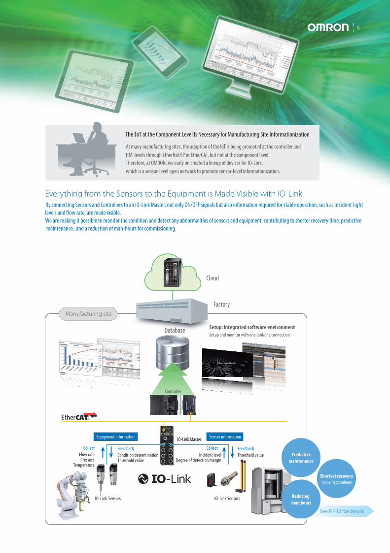
By connecting Sensors and Controllers to an IO-Link Master, not only ON/OFF signals but also information required for stable operation, such as incident light levels and flow rate, are made visible. We are making it possible to monitor the condition and detect any abnormalities of sensors and equipment, contributing to shorter recovery time, predictive maintenance, and a reduction of man-hours for commissioning.
Everything from the Sensors to the Equipment is Made Visible with IO-Link
Cloud
Database Setup: integrated software environment
Factory
CollectFlow ratePressure
Temperature
Incident levelDegree of detection margin
IO-Link Sensors IO-Link Sensors
IO-Link Master
Controller
Condition determinationThreshold value
Threshold valueCollectFeed back Feed back
See P.7-12 for details
Manufacturing site
At many manufacturing sites, the adoption of the IoT is being promoted at the controller and HMI levels through EtherNet/IP or EtherCAT, but not at the component level.Therefore, at OMRON, we early on created a lineup of devices for IO-Link, which is a sensor-level open network to promote sensor-level informationization.
The I oT at the Component Level Is Necessary for Manufacturing Site Informationization
Setup and monitor with one tool/one connection
Equipment information Sensor information
Predictivemaintenance
Reducing man hours
Shortest recovery (reducing downtime)

IO-Link Series6
What makes the reduction of the frequency of sudden errors and reinstatement of defective products possible is...
What makes the shortening of downtime possible is...
What makes the improvement of changeover efficiency possible is...
“Condition monitoring” for predictive maintenance
“Abnormality detection” for the shortest recovery
“Individual identification” for the reduction of man-hours
Value Provided by IO-Link
Supporting Solutions to Management Issues in the Manufacturing Industry Through Abnormality Detection/Condition Monitoring/Individual Identification
“Improving an equipment operation rate” is a universal management issue at manufacturing sites. As the calculation formula below shows, an overall equipment operation rate is determined by how stops, drops in speed and defects are avoided.
Overall Equipment Effectiveness *1 = Availability (stop loss) × speed performance (performance loss) × quality (defect loss)
These three loss occurrence factors are divided into the following (1) to (4). Of these, the causes of stop loss are the three major issues at the manufacturing sites (shown in orange on the right diagram) and the defect loss is the fourth issue (shown in green on the chart on the right).
Loading time
(2) Arrangements/adjustmentsOperating time Stoploss
Perfor-mance
loss
Defect loss
Net operating time
Value o pe r ation time
Omron’s IO-Link Compliant Components Solve “Stop Loss” "Defect Loss" Issues and Improve Equipment Operation Rate
P. 7
P. 11
P. 12
Manufacturing site issues of the manufacturing industry
Others
Reduce wiring man-hours
Reduce installationman-hours
Improve efficiency of system com mi ssioning/ changeover
Reduce the reinstatement of defective
products
Reduce the frequency of sudden errors
Shorten downtime
Reduce thefrequency of
plannedmaintenance
Note: Based on Omron’s surveys as of Jun 2016.
*1. OEE: overall equipment effectiveness. An index that stratifies the effectiveness of production equipment developed and advocated by the Japan Institute of Plant Maintenance.
(3) Speed reduction
(4) Defect/ repair manually
(1) Breakdown
Flow SensorE8FC
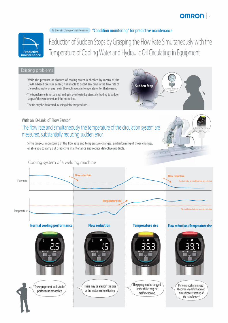
Normal cooling performance Flow reduction Temperature rise Flow reduction × Temperature rise
Flow reduction
Temperature rise
Flow reduction
Threshold value for insu�cient �ow rate detec tion
Threshold value for temperature r ise detec tion
Flow rate
Temperature
7
Existing problems
Supporting Solutions to Management Issues in the Manufacturing Industry Through Abnormality Detection/Condition Monitoring/Individual Identification
Simultaneous monitoring of the flow rate and temperature changes, and informing of those changes, enable you to carry out predictive maintenance and reduce defective products.
Cooling system of a welding machine
Reduction of Sudden Stops by Grasping the Flow Rate Simultaneously with theTemperature of Cooling Water and Hydraulic Oil Circulating in Equipment
“Condition monitoring” for predictive maintenanceTo those in charge of maintenance
The equipment looks to be performing smoothly.
There may be a leak in the pipe or the motor malfunctioning.
The piping may be clogged or the chiller may be
malfunctioning.
Performance has dropped ! Check for any deformation of
tip and/or overheating of the transformer !
While the presence or absence of cooling water is checked by means of the ON/OFF-based pressure sensor, it is unable to detect any drop in the flow rate of the cooling water or any rise in the cooling water temperature. For that reason,
∙ The transformer is not cooled, and gets overheated, potentially leading to sudden stops of the equipment and the entire line.
∙ The tip may be deformed, causing defective products.
With an IO-Link IoT Flow Sensor
The flow rate and simultaneously the temperature of the circulation system aremeasured, substantially reducing sudden error.
Predictivemaintenance
General pressure gauge
Sudden Stop

80%Distance
100%Sensing distance
100%DistanceSensing distance
IO-Link Series8
Existing problems
You are n otified of excessive remoteness or proximity, and the occurrence of sudden defects is greatly reduced
Constantly monitoring the position of the sensing object and notifying of excessive remoteness or proximity can be used for predictive maintenance of the equipment.
With an IO-Link Proximity Sensor
At installation
Rattling and wobbling due to a machinereaching its life limit causes the sensing object to approach at an excessive proximity and ultimately collide with the sensor.
Rattling and wobbling due to a machine reaching its life limit causes false detection due to the sensing object becoming remote.
Instability detection threshold
Excessive proximity detection threshold
Instability detection threshold
Detection threshold Detection threshold
Excessive proximity detection threshold
Sensing area
Sensing object
Sensing object
Monitor output Monitor output
Sensing object
The excessive proximity detection thresholdcan be selected from three setting levels.*
Sensing object becomes excessively proximate Sensing object becomes excessively remote
Excessiveproximity
Warning that an excessiveproximity has been detected Warning that instability
has been detected
Excessiveremoteness
Breakage (False detection)
False detection (breakage)
* Two levels for aluminum
Note: The instability detection threshold is fixed at 80%.
The Proximity Sensor Indicates an Excessive Proximity to the Sensing Object.Understand the Changes in Equipment Condition in Advance and Reduce Sudden Stops
“Condition monitoring” for predictive maintenanceTo those in charge of maintenance
Predictivemaintenance
The detection position changes due to wear and vibration in the equipment’s mechanical parts and as a result, false detection and collision with the sensor have a negative impact on the equipment...
9
Existing problems
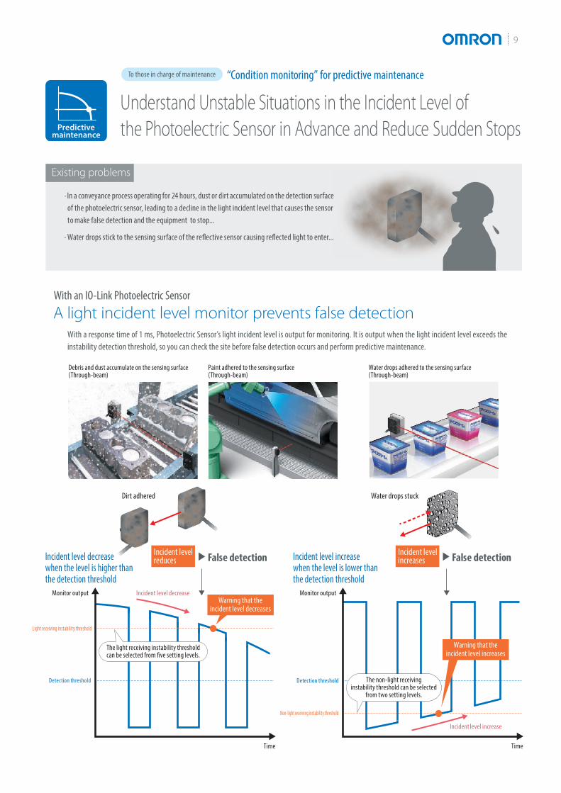
With a response time of 1 ms, Photoelectric Sensor’s light incident level is output for monitoring. It is output when the light incident level exceeds the instability detection threshold, so you can check the site before false detection occurs and perform predictive maintenance.
With an IO-Link Photoelectric Sensor
A light incident level monitor prevents false detection
Light receiving instability threshold
Incident level decrease
Incident level increase
Non-light receiving instability threshold
Detection threshold Detection threshold
Dirt adhered
Monitor output Monitor output
Time Time
Water drops stuck
Incident level decreasewhen the level is higher than the detection threshold
Incident level increase when the level is lower than the detection threshold
Incident levelreduces
Warning that theincident level decreases
Warning that theincident level increases
Incident level increasesFalse detection False detection
Understand Unstable Situations in the Incident Level of the Photoelectric Sensor in Advance and Reduce Sudden Stops
“Condition monitoring” for predictive maintenanceTo those in charge of maintenance
Predictivemaintenance
∙ In a conveyance process operating for 24 hours, dust or dirt accumulated on the detection surface of the photoelectric sensor, leading to a decline in the light incident level that causes the sensor t o make false detection and the equipment to stop...
∙ Water drops stick to the sensing surface of the reflective sensor causing reflected light to enter...
Debris and dust accumulate on the sensing surface (Through-beam)
Paint adhered to the sensing surface (Through-beam)
Water drops adhered to the sensing surface (Through-beam)
The light receiving instability thresholdcan be selected from five setting levels.
The non-light receivinginstability threshold can be selected
from two setting levels.

IO-Link Series10
Existing problems
The HMI shows the light curtain with low light intensity, helping quickly locate errors at production sites.
Area Beam Indicators of the light curtain allow an at-a-glance check of areas where light intensity is low.
Monitor changes in light intensity on HMI
Take actions on site
HMI
HMIWorkpiece A
Workpiece B
Workpiece C
Note: The Screen is a conceptual illustration.
* The screen is a conceptual illustration.
* The indicator of an unblocked area is OFF. Note : Factor y default setting.
Stable stateGreen : Safety outputs ON
The beams are unblocked.
Low light intensityOrange : Safety outputs ON
Adjust beams or checkif the light curtain is dirty.
Beams blockedRed : Safety outputs OFF*
The beamsin the area are blocked.
Incident Light Level Monitoring MinimizesMachine Downtime
“Condition monitoring” for predictive maintenanceTo those in charge of maintenance
Predictivemaintenance
Incident light levels of light curtains are monitored to provide advance warning of light intensity drops due to dirtor other factors, preventing false detection by light curtains.
With an IO-Link Safety Light Curtain
Incident light levels are monitored to warn of low light intensity
When a light curtain is installed in a harsh environment,its optical surface gets dirt easily. It is hard to notice the light intensity drop until the machine stops...
Use for scan monitoringMonitoring incident light levels of all beams of the lightcurtain enables workpiece shapes to be detected, which helps identify workpieces.
A B C
Identified as Workpiece A!
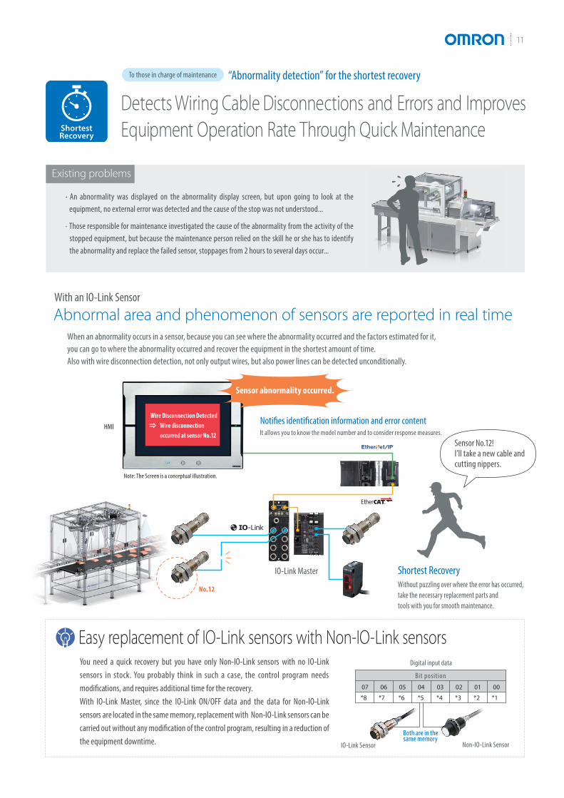
You need a quick recovery but you have only Non-IO-Link sensors with no IO-Link sensors in stock. You probably think in such a case, the control program needs modifications, and requires additional time for the recovery. With IO-Link Master, since the IO-Link ON/OFF data and the data for Non-IO-Link sensors are located in the same memory, replacement with Non-IO-Link sensors can be carried out without any modification of the control program, resulting in a reduction of the equipment downtime.
Bit position07
*8 *7 *6 *5 *4 *3 *2 *1
06 05 04 03 02 01 00
No.12
Easy replacement of IO-Link sensors with Non-IO-Link sensors
11
Wire Disconnection Detected Wire disconnection occurred at sensor No.12
IO-Link Master
Digital input data
IO-Link Sensor Non-IO-Link Sensor
Both are in the same memory
HMI
Note: The Screen is a conceptual illustration.
Existing problems
When an abnormality occurs in a sensor, because you can see where the abnormality occurred and the factors estimated for it, you can go to where the abnormality occurred and recover the equipment in the shortest amount of time. Also with wire disconnection detection, not only output wires, but also power lines can be detected unconditionally.
With an IO-Link Sensor
Abnormal area and phenomenon of sensors are reported in real time
Detects Wiring Cable Disconnections and Errors and Improves Equipment Operation Rate Through Quick Maintenance
“Abnormality detection” for the shortest recoveryTo those in charge of maintenance
∙ ∙ An abnormality was displayed on the abnormality display screen, but upon going to look at the equipment, no external error was detected and the cause of the stop was not understood...
∙ Those responsible for maintenance investigated the cause of the abnormality from the activity of the stopped equipment, but because the maintenance person relied on the skill he or she has to identify the abnormality and replace the failed sensor, stoppages from 2 hours to several days occur...
Sensor abnormality occurred.
Notifies identification information and error content
Shortest Recovery
It allows you to know the model number and to consider response measures.
Without puzzling over where the error has occurred, take the necessary replacement parts and tools with you for smooth maintenance.
Sensor No.12! I’ll take a new cable and cutting nippers.
ShortestRecovery

An incorrect sensor is installed for No.5!
IO-Link Series12
Existing problems
Program all at once to reduce commissioning time and inconsistent settings Makes it possible to check for sensor installation mistakes before commissioningSetting all sensors from a host device at the same time Use identification checks with HMI to prevent installation mistakes
Note: The graph above is a conceptual illustration.
Wiring Setup
Switching/rewiringSetup I/O check
I/O check Switching/rewiring
Wiring
From
To
This isn’t the sensor for No.5 ...I could find that out before commissioning!
An incorrect sensor is installed for No.5!
Sysmac Studio
Controller
IO-Link Masters
IO-Link Sensors
HMINote: Screen is a conceptual illustration.
Improving System Commissioning and Changeover Efficiencyby Checking Identifications in Batches
“Individual identification” for the reduction of man-hoursTo those in charge of production engineering
∙ During system start-up or changeover, operators had to perform the I/O check for eachof the thousands of sensors installed on the line, and it took an enormous amount of time...
∙ When a sensor is installed wrong or an error occurs, wasteful work occurred that would normally be unnecessary...
By checking the sensor identification (manufacturer/sensor type/model number), you can easily check mistakes such as misconnected or unconnected sensors and installation mistakes. Also, because it is possible to program multiple sensors at once using the command language used only for the controller, it is also possible to reduce commissioning time sharply.
With an IO-Link Sensor
Without going to the site, you can check individual sensor identifications in batches, resulting in a sharp reduction of commissioning time
ReducingMan-hours
Reducing Man-hours
Setup I/O check
Setup
Unit ID
Note: Setting of the IO-Link master or programming for the PLC is required.
ReducingMan-hours
No need to enter
Sysmac Studio
13
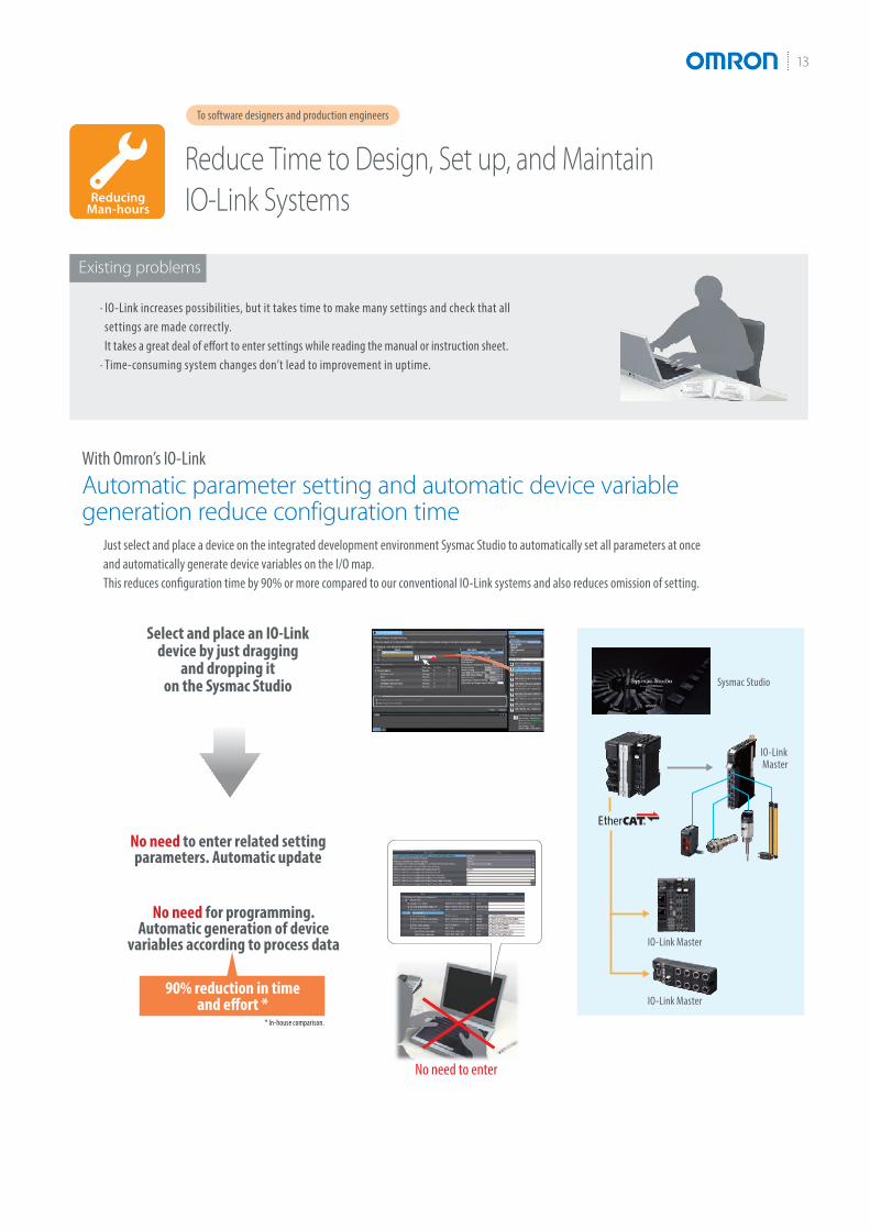
Reduce Time to Design, Set up, and Maintain IO-Link Systems
To software designers and production engineers
Just select and place a device on the integrated development environment Sysmac Studio to automatically set all parameters at once and automatically generate device variables on the I/O map.This reduces configuration time by 90% or more compared to our conventional IO-Link systems and also reduces omission of setting.
With Omron’s IO-Link
Automatic parameter setting and automatic device variable generation reduce configuration time
90% reduction in time and effort *
* In-house comparison.
IO-Link Master
IO-Link Master
IO-Link Master
No need to enter related setting parameters. Automatic update
No need for programming.Automatic generation of device
variables according to process data
Select and place an IO-Link device by just dragging
and dropping it on the Sysmac Studio
Existing problems
∙ IO-Link increases possibilities, but it takes time to make many settings and check that all settings are made correctly. It takes a great deal of effort to enter settings while reading the manual or instruction sheet. ∙ Time-consuming system changes don’t lead to improvement in uptime.
Note: Setting of the IO-Link master or programming for the PLC is required.
IO-Link Series14
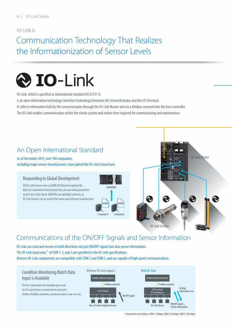
IO-Link Is
Communication Technology That Realizes the Informationization of Sensor Levels
An Open International Standard
Communications of the ON/OFF Signals and Sensor Information
IO-Link, which is specified as international standard IEC 61131-9, is an open information technology (interface technology) between the Sensor/Actuator and the I/O Terminal. It collects information held by the sensor/actuator through the IO-Link Master and via a fieldbus network into the host controller. The IO-Link enables communication within the whole system and reduce time required for commissioning and maintenance.
All IO-Link Sensors have an IODD (IO Data Description) file that lists what kind of instrument they are and what parameters need to be set for them. IODD files are globally common, so IO-Link Sensors can be used in the same way with any manufacturer.
Responding to Global Development
Condition Monitoring/Batch DataInput is Available The IO-Link master has multiple ports and an IO-Link Sensor is connected to each port.Unlike a fieldbus network, communication is one-to-one.
As of December 2015, over 100 companies, including major sensor manufacturers, have joined the IO-Link Consortium.
IO-Link can send and receive in both directions not just ON/OFF signals but also sensor information.The IO-Link baud rates*1 of COM 1, 2, and 3 are specified in the IO-Link specifications. Omron's IO-Link components are compatible with COM 2 and COM 3, and are capable of high speed communications.
Controller
Company A Company B
IO-Link Sensors
IO-Link Master
Without IO-Link support With IO-Link
Fieldbus Network Master Fieldbus Network Master
I/O Terminal I/O TerminalIO-Link Master
ON/OFF signal
Non-IO-Link compliant Sensors IO-Link Sensor
*1. Baud rates are as follows. COM 1: 4.8 kbps, COM 2: 38.4 kbps, COM 3: 230.4 kbps
Fieldbus network Fieldbus networkSetting information, etc.
ON/OFF signal + Sensor information

1
L+
L-
C /Q
32 4
15
Uses 3-wire Unshielded Cable
Capable of Intermixing IO-Link Sensors and Sensors That Are Not Compliant with IO-Link
A dedicated communication cable is unnecessary and a conventional 3-wire unshielded cable can be used for the IO-Link, because the IO-Link has both an IO-Link Mode which performs a digital communication and Standard I/O (SIO) Mode which uses conventional contact input/output.
Can Be Used with a Conventional 3-wire Unshielded Cable or Integrated I/F Connector
A Part of the Existing Equipment Can Be Replaced with the IO-LinkIn situations where you want to improve only one part of your existing equipment, such as when “errors often occur” or “I want to import sensor information,” IO-Link Sensors can be mixed with non-supported sensors.
No dedicated communication cable required. A communication system that can be used both as an ON/OFF line and a communication line.
You can connect an IO-Link Sensor and a Sensor/Actuator that is not compliant with IO-Link to a single IO-Link Master.
PC HMI
Controller
Fieldbus network
3-wire unshielded cable
Maximum length20 m
IO-Link Master
IO-Link Sensors
IO-Link Mode (process data)
Standard I/O (SIO) Mode (ON/OFF data)
Computer network
Controller
IO-LinkPhotoelectric Sensor
IO-Link Master
Non-IO-LinkProximity Sensor
Non-IO-LinkPhotoelectric Sensor
Non-IO-LinkProximity Sensor

IO-Link Series16
For the connection of IO-Link Sensors and IO-Link Masters, two types are available: a screw-less clamp terminal block and an M12 connector.In addition, NX-ILM400 IO-Link Master with screw-less clamp terminal block is connectable not only to EtherCAT, but also to EtherNet/IP communication coupler units, and you can choose between them according to the system configuration.
IO-Link Masters
IO-Link Sensors
Corresponding to our shared Value Design for Panel concept for the specifications of products.
EtherCAT CouplerEtherNet/IP Coupler
NX-series IO-Link Master UnitNX-ILM4004-port/screw-less clamp terminal block
The Unit with Screw-less Clamp Terminal Blocks Allows Wiring Man-hours to be Reduced
Flow sensor / Pressure Sensor Photoelectric Sensor
P33 Note: Four sensors can be connected to one unit.
Omron’s IO-Link Compliant Equipment
Masters and Sensors Can Be Chosen to Match Your Situation
IoT Flow SensorE8FC-25□M12 Connector Models
IoT Flow SensorE8PC-□M12 Connector Models
Color Mark Photoelectric SensorE3S-DCP21-IL-□M12 Connector Models
Photoelectric SensorE3Z-□-IL□Pre-wired ModelsM8 Connector ModelsM12 Pre-wired Connector Models
P18 P18 P20
P19-20

Just plug it in and turn it 1/8 of a rotation
17
Environment-resistant UnitGX-ILM08C8-port/M12 Smartclick connector
The Unit for M12 Smartclick Connector Can Be Used in Watery, and Dusty Environments
Proximity Sensor Safety Light Curtain
P33 Note: Eight sensors can be connected to one device.
Note: Smartclick is a registered trademark of Omron.
*F3SG-PG : Coming soon
Proximity SensorE2E/E2EQ NEXTPre-wired ModelsM8 Connector ModelsM12 Connector ModelsM12 Pre-wired Connector Models
Safety Light CurtainF3SG-SR/PG*Connector Models
P21-29
P30-32
IP67 Type

IO-Link Series18
Overview of IO-Link Compliant Devices
IoT Flow Sensor
E8FCDetect Signs of Abnormalities in Cooling Water by Simultaneous Measurement of “Flow Rate + Temperature”
• Multi-sensing of “Flow rate + temperature” for preventing a sudden stops or manufacturing defects.
• Various lineup of replacement adapters to enable easy replacement of your current pressure gauges and flow meters.
• Analog current output function in addition to the IO-Link communications function that can perform self-diagnosis of abnormalities in the sensor itself.
Appearance Applicable fluid * Control output Communication method IO-Link baud rate Model
Liquid PNP IO-LinkAnalog
COM2 (38.4 kbps) E8FC-25D
COM3 (230.4 kbps) E8FC-25T
* The applicable fluid is a liquid that does not erode the wetted part materials (for example, water or a fluid whose conductivity is equivalent to that of water).
For details, refer to E8FC/E8PC Series Catalog (No. E472).
IoT Pressure Sensor
E8PCDetect Signs of Abnormalities in Cooling Water and Hydraulic Oil by Simultaneous Measurement of “Pressure + Temperature”
• Multi-sensing of “Pressure + temperature” for preventing a sudden stops or manufacturing defects.
• Various lineup of replacement adapters to enable easy replacement of your current pressure gauges and flow meters.
• Analog current output function in addition to the IO-Link communications function that can perform self-diagnosis of abnormalities in the sensor itself.
Appearance Applicable fluid * Rated pressure range Control output Communication
method IO-Link baud rate Model
Liquid and gas -0.1 to 1 MPa PNP IO-LinkAnalog
COM2 (38.4 kbps) E8PC-010D-E
COM3 (230.4 kbps) E8PC-010T-E
Liquid
0 to 10 MPa PNP IO-LinkAnalog
COM2 (38.4 kbps) E8PC-100D-E
COM3 (230.4 kbps) E8PC-100T-E
0 to 40 MPa PNP IO-LinkAnalog
COM2 (38.4 kbps) E8PC-400D-E
COM3 (230.4 kbps) E8PC-400T-E
* The applicable fluid is a liquid that do not erode the liquid contact part materials (such as water, glycol solution, and oil).
For details, refer to E8FC/E8PC Series Catalog (No. E472).
IO-Link Sensors

19
Photoelectric Sensor
E3Z--ILIO-Link Makes Sensor Level Information Visible and Solves the Three Major Issues at Manufacturing Sites! Standard Photoelectric Sensor.
• Downtime can be reduced. Notifies you of faulty parts and such phenomena in the Sensor in real time.
• The frequency of sudden failure can be decreased. The light incident level monitor prevents false detection before it happens.
• The efficiency of changeover can be improved. The batch check for individual sensor IDs significantly decreases commissioning time.
• Three types of sensing methods and three types of connection methods are available.
Red light Infrared light
Sensing method Appearance Connection method Sensing distance IO-Linkbaud rate
Model
PNP
Through-beam(Emitter + Receiver)
*3
Pre-wired (2 m)
15 m
COM2(38.4 kbps)
E3Z-T81-IL2 2MEmitterReceiver
E3Z-T81-L-IL2 2ME3Z-T81-D-IL2 2M
Pre-wired M12 connectorE3Z-T81-M1TJ-IL2 0.3MEmitterReceiver
E3Z-T81-L-M1TJ-IL2 0.3ME3Z-T81-D-M1TJ-IL2 0.3M
Standard M8 connectorE3Z-T86-IL2EmitterReceiver
E3Z-T86-L-IL2E3Z-T86-D-IL2
Pre-wired (2 m)
COM3(230.4 kbps)
E3Z-T81-IL3 2MEmitterReceiver
E3Z-T81-L-IL3 2ME3Z-T81-D-IL3 2M
Pre-wired M12 connectorE3Z-T81-M1TJ-IL3 0.3MEmitterReceiver
E3Z-T81-L-M1TJ-IL3 0.3ME3Z-T81-D-M1TJ-IL3 0.3M
Standard M8 connectorE3Z-T86-IL3EmitterReceiver
E3Z-T86-L-IL3E3Z-T86-D-IL3
Retro-reflective with MSR function
*1
Pre-wired (2 m)
4 m (100 mm)
(When using E39-R1S)
*2COM2
(38.4 kbps)
E3Z-R81-IL2 2M
Pre-wired M12 connector E3Z-R81-M1TJ-IL2 0.3M
Standard M8 connector E3Z-R86-IL2
Pre-wired (2 m)COM3
(230.4 kbps)
E3Z-R81-IL3 2M
Pre-wired M12 connector E3Z-R81-M1TJ-IL3 0.3M
Standard M8 connector E3Z-R86-IL3
*1. The Reflector is sold separately. Select the Reflector model most suited to the application.*2. The sensing distance specified is possible when the E39-R1S is used. Values in parentheses indicate the minimum required distance between the Sensor and Reflector.*3. Through-beam Sensors are normally sold in sets that include both the Emitter and Receiver.
For details, refer to E3Z--IL Data sheet.
Note: Please contact your OMRON sales representative regarding the IO-Link setup file (IODD file).
IO-Link Series20
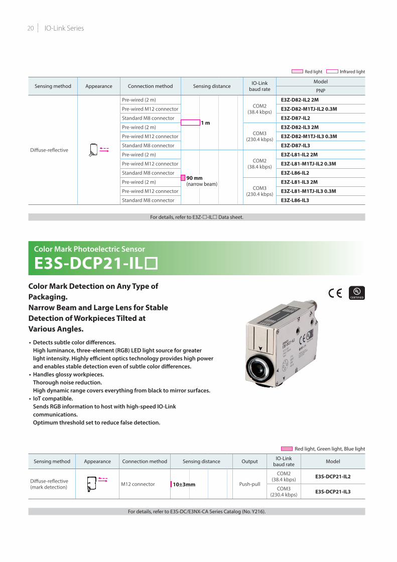
Sensing method Appearance Connection method Sensing distance IO-Linkbaud rate
Model
PNP
Diffuse-reflective
Pre-wired (2 m)
1 m
COM2(38.4 kbps)
E3Z-D82-IL2 2M
Pre-wired M12 connector E3Z-D82-M1TJ-IL2 0.3M
Standard M8 connector E3Z-D87-IL2
Pre-wired (2 m)COM3
(230.4 kbps)
E3Z-D82-IL3 2M
Pre-wired M12 connector E3Z-D82-M1TJ-IL3 0.3M
Standard M8 connector E3Z-D87-IL3
Pre-wired (2 m)
90 mm (narrow beam)
COM2(38.4 kbps)
E3Z-L81-IL2 2M
Pre-wired M12 connector E3Z-L81-M1TJ-IL2 0.3M
Standard M8 connector E3Z-L86-IL2
Pre-wired (2 m)COM3
(230.4 kbps)
E3Z-L81-IL3 2M
Pre-wired M12 connector E3Z-L81-M1TJ-IL3 0.3M
Standard M8 connector E3Z-L86-IL3
For details, refer to E3Z--IL Data sheet.
Color Mark Photoelectric Sensor
E3S-DCP21-ILColor Mark Detection on Any Type of Packaging. Narrow Beam and Large Lens for Stable Detection of Workpieces Tilted at Various Angles.
• Detects subtle color differences. High luminance, three-element (RGB) LED light source for greater light intensity. Highly efficient optics technology provides high power and enables stable detection even of subtle color differences.
• Handles glossy workpieces. Thorough noise reduction. High dynamic range covers everything from black to mirror surfaces.
• IoT compatible. Sends RGB information to host with high-speed IO-Link communications. Optimum threshold set to reduce false detection.
Red light, Green light, Blue light
Sensing method Appearance Connection method Sensing distance Output IO-Linkbaud rate Model
Diffuse-reflective (mark detection) M12 connector 10±3mm Push-pull
COM2 (38.4 kbps) E3S-DCP21-IL2
COM3 (230.4 kbps) E3S-DCP21-IL3
For details, refer to E3S-DC/E3NX-CA Series Catalog (No. Y216).
Red light Infrared light

21
Proximity Sensor
E2E/E2EQ NEXT SeriesEnables easier and standardized designs previously not possible
• The world’s longest sensing distance*1 Nearly double the sensing distance of previous
• With high-brightness LED, the indicator is visible anywhere from 360°.• Only 10 Seconds*2 to Replace a Proximity Sensor with the “e-jig”
(Mounting Sleeve).• Cables with enhanced oil resistance enabled 2-year oil resistance*3.• IP69K compliant for water resistance and wash resistance*4
• Comes in a wide variation to make sensor selection easy• UL certification (UL60947-5-2)*5 and CSA certification
(CSA C22.2 UL60947-5-2-14)
*1. Based on December 2018 OMRON investigation.*2. Time required to adjust the distance when installing a Sensor. Based on OMRON investigation.*3. Refer to Ratings and Specifications of E2E/E2EQ Series Catalog (No. D121) for details.
However, E2E Connector Models and E2EQ series is excluded.*4. E2EQ series is excluded.*5. M8 (4-pin) Connector Models are not UL certified.
PREMIUM ModelE2E NEXT Series (Quadruple distance model)Shielded
Size (Sensing distance) Connection method Body size Operation
modeModel
IO-Link baud rate COM2 IO-Link baud rate COM3
M8 (4 mm)
Pre-wired (2 m) *138 mm *2
NO
E2E-X4B1D8 2M E2E-X4B1T8 2M48 mm E2E-X4B1DL8 2M E2E-X4B1TL8 2M
M12 Pre-wired Smartclick Connector (0.3 m)
38 mm *3 E2E-X4B1D8-M1TJ 0.3M E2E-X4B1T8-M1TJ 0.3M48 mm E2E-X4B1DL8-M1TJ 0.3M E2E-X4B1TL8-M1TJ 0.3M
M12 Connector43 mm E2E-X4B1D8-M1 E2E-X4B1T8-M153 mm E2E-X4B1DL8-M1 E2E-X4B1TL8-M1
M8 Connector (4-pin)39 mm E2E-X4B1D8-M3 E2E-X4B1T8-M349 mm E2E-X4B1DL8-M3 E2E-X4B1TL8-M3
M8 Connector (3-pin)39 mm E2E-X4B1D8-M5 E2E-X4B1T8-M549 mm E2E-X4B1DL8-M5 E2E-X4B1TL8-M5
M12 (9 mm)
Pre-wired (2 m) *147 mm *2 E2E-X9B1D12 2M E2E-X9B1T12 2M69 mm E2E-X9B1DL12 2M E2E-X9B1TL12 2M
M12 Pre-wired Smartclick Connector (0.3 m)
47 mm *3 E2E-X9B1D12-M1TJ 0.3M E2E-X9B1T12-M1TJ 0.3M69 mm E2E-X9B1DL12-M1TJ 0.3M E2E-X9B1TL12-M1TJ 0.3M
M12 Connector48 mm E2E-X9B1D12-M1 E2E-X9B1T12-M170 mm E2E-X9B1DL12-M1 E2E-X9B1TL12-M1
M18 (14 mm)
Pre-wired (2 m) *155 mm *2 E2E-X14B1D18 2M E2E-X14B1T18 2M77 mm E2E-X14B1DL18 2M E2E-X14B1TL18 2M
M12 Pre-wired Smartclick Connector (0.3 m)
55 mm *3 E2E-X14B1D18-M1TJ 0.3M E2E-X14B1T18-M1TJ 0.3M77 mm E2E-X14B1DL18-M1TJ 0.3M E2E-X14B1TL18-M1TJ 0.3M
M12 Connector53 mm E2E-X14B1D18-M1 E2E-X14B1T18-M175 mm E2E-X14B1DL18-M1 E2E-X14B1TL18-M1
M30 (23 mm)
Pre-wired (2 m) *160 mm *2 E2E-X23B1D30 2M E2E-X23B1T30 2M82 mm E2E-X23B1DL30 2M E2E-X23B1TL30 2M
M12 Pre-wired Smartclick Connector (0.3 m)
60 mm *3 E2E-X23B1D30-M1TJ 0.3M E2E-X23B1T30-M1TJ 0.3M82 mm E2E-X23B1DL30-M1TJ 0.3M E2E-X23B1TL30-M1TJ 0.3M
M12 Connector58 mm E2E-X23B1D30-M1 E2E-X23B1T30-M180 mm E2E-X23B1DL30-M1 E2E-X23B1TL30-M1
*1. Models with 5-m cable length are also available with “5M” suffix. (Example: E2E-X9B1D12 5M)*2. Models with 2-m and 5-m robot (bending-resistant) cables are also available with “-R” in the model number. (Example: E2E-X9B1D12-R 2M/E2E-X9B1D12-R 5M)*3. Models with M12 Smartclick connector model robot (bending-resistant) cables are also available with “R” in the model number. (Example: E2E-X9B1D12-M1TJR 0.3M)
For details, refer to E2E/E2EQ Series Catalog (No. D121).
Note: Please contact your OMRON sales representative regarding the IO-Link setup file (IODD file).

IO-Link Series22
PREMIUM ModelE2E NEXT Series (Quadruple distance model)Unshielded
Size (Sensing distance) Connection method Body size Operation
modeModel
IO-Link baud rate COM2 IO-Link baud rate COM3
M8 (8 mm)
Pre-wired (2 m) *138 mm *2
NO
E2E-X8MB1D8 2M E2E-X8MB1T8 2M
48 mm E2E-X8MB1DL8 2M E2E-X8MB1TL8 2M
M12 Pre-wired Smartclick Connector (0.3 m)
38 mm *3 E2E-X8MB1D8-M1TJ 0.3M E2E-X8MB1T8-M1TJ 0.3M
48 mm E2E-X8MB1DL8-M1TJ 0.3M E2E-X8MB1TL8-M1TJ 0.3M
M12 Connector43 mm E2E-X8MB1D8-M1 E2E-X8MB1T8-M1
53 mm E2E-X8MB1DL8-M1 E2E-X8MB1TL8-M1
M8 Connector (4-pin)39 mm E2E-X8MB1D8-M3 E2E-X8MB1T8-M3
49 mm E2E-X8MB1DL8-M3 E2E-X8MB1TL8-M3
M8 Connector (3-pin)39 mm E2E-X8MB1D8-M5 E2E-X8MB1T8-M5
49 mm E2E-X8MB1DL8-M5 E2E-X8MB1TL8-M5
M12 (16 mm)
Pre-wired (2 m) *147 mm *2 E2E-X16MB1D12 2M E2E-X16MB1T12 2M
69 mm E2E-X16MB1DL12 2M E2E-X16MB1TL12 2M
M12 Pre-wired Smartclick Connector (0.3 m)
47 mm *3 E2E-X16MB1D12-M1TJ 0.3M E2E-X16MB1T12-M1TJ 0.3M
69 mm E2E-X16MB1DL12-M1TJ 0.3M E2E-X16MB1TL12-M1TJ 0.3M
M12 Connector48 mm E2E-X16MB1D12-M1 E2E-X16MB1T12-M1
70 mm E2E-X16MB1DL12-M1 E2E-X16MB1TL12-M1
M18 (30 mm)
Pre-wired (2 m) *1 77 mm *2 E2E-X30MB1DL18 2M E2E-X30MB1TL18 2M
M12 Pre-wired Smartclick Connector (0.3 m) 77 mm *3 E2E-X30MB1DL18-M1TJ 0.3M E2E-X30MB1TL18-M1TJ 0.3M
M12 Connector 75 mm E2E-X30MB1DL18-M1 E2E-X30MB1TL18-M1
M30 (50 mm)
Pre-wired (2 m) *1 97 mm *2 E2E-X50MB1DL30 2M E2E-X50MB1TL30 2M
M12 Pre-wired Smartclick Connector (0.3 m) 97 mm *3 E2E-X50MB1DL30-M1TJ 0.3M E2E-X50MB1TL30-M1TJ 0.3M
M12 Connector 95 mm E2E-X50MB1DL30-M1 E2E-X50MB1TL30-M1
*1. Models with 5-m cable length are also available (Example: E2E-X16MB1D12 5M)*2. Models with 2-m and 5-m robot (bending-resistant) cables are also available with “-R” in the model number. (Example: E2E-X16MB1D12-R 2M/E2E-X16MB1D12-R 5M)*3. Models with M12 Smartclick connector model robot (bending-resistant) cables are also available with “R” in the model number. (Example: E2E-X16MB1D12-M1TJR 0.3M)
For details, refer to E2E/E2EQ Series Catalog (No. D121).
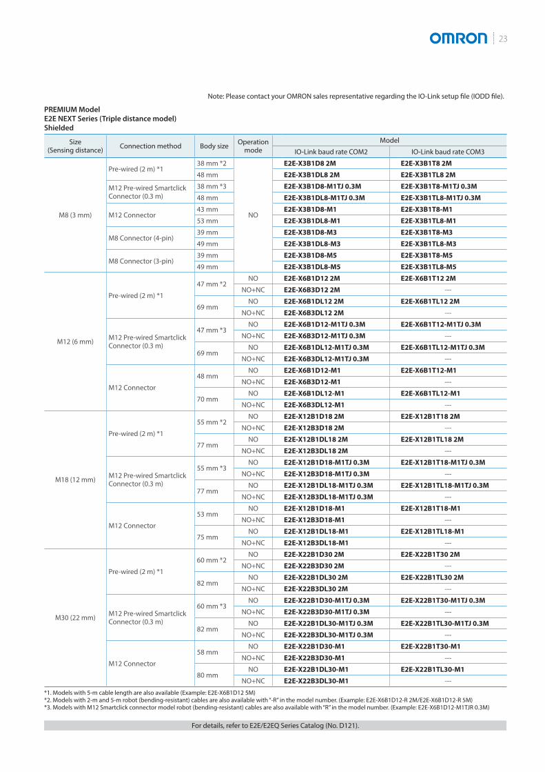
23
PREMIUM ModelE2E NEXT Series (Triple distance model)Shielded
Size (Sensing distance) Connection method Body size Operation
modeModel
IO-Link baud rate COM2 IO-Link baud rate COM3
M8 (3 mm)
Pre-wired (2 m) *138 mm *2
NO
E2E-X3B1D8 2M E2E-X3B1T8 2M
48 mm E2E-X3B1DL8 2M E2E-X3B1TL8 2M
M12 Pre-wired Smartclick Connector (0.3 m)
38 mm *3 E2E-X3B1D8-M1TJ 0.3M E2E-X3B1T8-M1TJ 0.3M
48 mm E2E-X3B1DL8-M1TJ 0.3M E2E-X3B1TL8-M1TJ 0.3M
M12 Connector43 mm E2E-X3B1D8-M1 E2E-X3B1T8-M1
53 mm E2E-X3B1DL8-M1 E2E-X3B1TL8-M1
M8 Connector (4-pin)39 mm E2E-X3B1D8-M3 E2E-X3B1T8-M3
49 mm E2E-X3B1DL8-M3 E2E-X3B1TL8-M3
M8 Connector (3-pin)39 mm E2E-X3B1D8-M5 E2E-X3B1T8-M5
49 mm E2E-X3B1DL8-M5 E2E-X3B1TL8-M5
M12 (6 mm)
Pre-wired (2 m) *1
47 mm *2NO E2E-X6B1D12 2M E2E-X6B1T12 2M
NO+NC E2E-X6B3D12 2M ---
69 mmNO E2E-X6B1DL12 2M E2E-X6B1TL12 2M
NO+NC E2E-X6B3DL12 2M ---
M12 Pre-wired Smartclick Connector (0.3 m)
47 mm *3NO E2E-X6B1D12-M1TJ 0.3M E2E-X6B1T12-M1TJ 0.3M
NO+NC E2E-X6B3D12-M1TJ 0.3M ---
69 mmNO E2E-X6B1DL12-M1TJ 0.3M E2E-X6B1TL12-M1TJ 0.3M
NO+NC E2E-X6B3DL12-M1TJ 0.3M ---
M12 Connector
48 mmNO E2E-X6B1D12-M1 E2E-X6B1T12-M1
NO+NC E2E-X6B3D12-M1 ---
70 mmNO E2E-X6B1DL12-M1 E2E-X6B1TL12-M1
NO+NC E2E-X6B3DL12-M1 ---
M18 (12 mm)
Pre-wired (2 m) *1
55 mm *2NO E2E-X12B1D18 2M E2E-X12B1T18 2M
NO+NC E2E-X12B3D18 2M ---
77 mmNO E2E-X12B1DL18 2M E2E-X12B1TL18 2M
NO+NC E2E-X12B3DL18 2M ---
M12 Pre-wired Smartclick Connector (0.3 m)
55 mm *3NO E2E-X12B1D18-M1TJ 0.3M E2E-X12B1T18-M1TJ 0.3M
NO+NC E2E-X12B3D18-M1TJ 0.3M ---
77 mmNO E2E-X12B1DL18-M1TJ 0.3M E2E-X12B1TL18-M1TJ 0.3M
NO+NC E2E-X12B3DL18-M1TJ 0.3M ---
M12 Connector
53 mmNO E2E-X12B1D18-M1 E2E-X12B1T18-M1
NO+NC E2E-X12B3D18-M1 ---
75 mmNO E2E-X12B1DL18-M1 E2E-X12B1TL18-M1
NO+NC E2E-X12B3DL18-M1 ---
M30 (22 mm)
Pre-wired (2 m) *1
60 mm *2NO E2E-X22B1D30 2M E2E-X22B1T30 2M
NO+NC E2E-X22B3D30 2M ---
82 mmNO E2E-X22B1DL30 2M E2E-X22B1TL30 2M
NO+NC E2E-X22B3DL30 2M ---
M12 Pre-wired Smartclick Connector (0.3 m)
60 mm *3NO E2E-X22B1D30-M1TJ 0.3M E2E-X22B1T30-M1TJ 0.3M
NO+NC E2E-X22B3D30-M1TJ 0.3M ---
82 mmNO E2E-X22B1DL30-M1TJ 0.3M E2E-X22B1TL30-M1TJ 0.3M
NO+NC E2E-X22B3DL30-M1TJ 0.3M ---
M12 Connector
58 mmNO E2E-X22B1D30-M1 E2E-X22B1T30-M1
NO+NC E2E-X22B3D30-M1 ---
80 mmNO E2E-X22B1DL30-M1 E2E-X22B1TL30-M1
NO+NC E2E-X22B3DL30-M1 ---
*1. Models with 5-m cable length are also available (Example: E2E-X6B1D12 5M)*2. Models with 2-m and 5-m robot (bending-resistant) cables are also available with “-R” in the model number. (Example: E2E-X6B1D12-R 2M/E2E-X6B1D12-R 5M)*3. Models with M12 Smartclick connector model robot (bending-resistant) cables are also available with “R” in the model number. (Example: E2E-X6B1D12-M1TJR 0.3M)
For details, refer to E2E/E2EQ Series Catalog (No. D121).
Note: Please contact your OMRON sales representative regarding the IO-Link setup file (IODD file).

IO-Link Series24
PREMIUM ModelE2E NEXT Series (Triple distance model)Unshielded
Size (Sensing distance) Connection method Body size Operation
modeModel
IO-Link baud rate COM2 IO-Link baud rate COM3
M8 (6 mm)
Pre-wired (2 m) *138 mm *2
NO
E2E-X6MB1D8 2M E2E-X6MB1T8 2M48 mm E2E-X6MB1DL8 2M E2E-X6MB1TL8 2M
M12 Pre-wired Smartclick Connector (0.3 m)
38 mm *3 E2E-X6MB1D8-M1TJ 0.3M E2E-X6MB1T8-M1TJ 0.3M48 mm E2E-X6MB1DL8-M1TJ 0.3M E2E-X6MB1TL8-M1TJ 0.3M
M12 Connector43 mm E2E-X6MB1D8-M1 E2E-X6MB1T8-M153 mm E2E-X6MB1DL8-M1 E2E-X6MB1TL8-M1
M8 Connector (4-pin)39 mm E2E-X6MB1D8-M3 E2E-X6MB1T8-M349 mm E2E-X6MB1DL8-M3 E2E-X6MB1TL8-M3
M8 Connector (3-pin)39 mm E2E-X6MB1D8-M5 E2E-X6MB1T8-M549 mm E2E-X6MB1DL8-M5 E2E-X6MB1TL8-M5
M12 (10 mm)
Pre-wired (2 m) *147 mm *2
NO E2E-X10MB1D12 2M E2E-X10MB1T12 2MNO+NC E2E-X10MB3D12 2M ---
69 mmNO E2E-X10MB1DL12 2M E2E-X10MB1TL12 2M
NO+NC E2E-X10MB3DL12 2M ---
M12 Pre-wired Smartclick Connector (0.3 m)
47 mm *3NO E2E-X10MB1D12-M1TJ 0.3M E2E-X10MB1T12-M1TJ 0.3M
NO+NC E2E-X10MB3D12-M1TJ 0.3M ---
69 mmNO E2E-X10MB1DL12-M1TJ 0.3M E2E-X10MB1TL12-M1TJ 0.3M
NO+NC E2E-X10MB3DL12-M1TJ 0.3M ---
M12 Connector48 mm
NO E2E-X10MB1D12-M1 E2E-X10MB1T12-M1NO+NC E2E-X10MB3D12-M1 ---
70 mmNO E2E-X10MB1DL12-M1 E2E-X10MB1TL12-M1
NO+NC E2E-X10MB3DL12-M1 ---
M18 (20 mm)
Pre-wired (2 m) *1 77 mm *2NO E2E-X20MB1DL18 2M E2E-X20MB1TL18 2M
NO+NC E2E-X20MB3DL18 2M ---M12 Pre-wired Smartclick Connector (0.3 m) 77 mm *3
NO E2E-X20MB1DL18-M1TJ 0.3M E2E-X20MB1TL18-M1TJ 0.3MNO+NC E2E-X20MB3DL18-M1TJ 0.3M ---
M12 Connector 75 mmNO E2E-X20MB1DL18-M1 E2E-X20MB1TL18-M1
NO+NC E2E-X20MB3DL18-M1 ---
M30 (40 mm)
Pre-wired (2 m) *1 82 mm *2NO E2E-X40MB1DL30 2M E2E-X40MB1TL30 2M
NO+NC E2E-X40MB3DL30 2M ---M12 Pre-wired Smartclick Connector (0.3 m) 82 mm *3
NO E2E-X40MB1DL30-M1TJ 0.3M E2E-X40MB1TL30-M1TJ 0.3MNO+NC E2E-X40MB3DL30-M1TJ 0.3M ---
M12 Connector 80 mmNO E2E-X40MB1DL30-M1 E2E-X40MB1TL30-M1
NO+NC E2E-X40MB3DL30-M1 ---*1. Models with 5-m cable length are also available (Example: E2E-X10MB1D12 5M)*2. Models with 2-m and 5-m robot (bending-resistant) cables are also available with “-R” in the model number. (Example: E2E-X10MB1D12-R 2M/E2E-X10MB1D12-R 5M)*3. Models with M12 Smartclick connector model robot (bending-resistant) cables are also available with “R” in the model number. (Example: E2E-X10MB1D12-M1TJR 0.3M)
PREMIUM ModelE2EQ NEXT Series (Spatter-resistant Triple distance model)Shielded
Size (Sensing distance) Connection method Body size Operation
modeModel
IO-Link baud rate COM2 IO-Link baud rate COM3
M8 (3 mm)
Pre-wired (2 m) * 38 mm
NO
E2EQ-X3B1D8 2M E2EQ-X3B1T8 2MM12 Pre-wired Smartclick Connector (0.3 m) 38 mm E2EQ-X3B1D8-M1TJ 0.3M E2EQ-X3B1T8-M1TJ 0.3M
M12 Connector 43 mm E2EQ-X3B1D8-M1 E2EQ-X3B1T8-M1
M12 (6 mm)
Pre-wired (2 m) * 47 mmNO E2EQ-X6B1D12 2M E2EQ-X6B1T12 2M
NO+NC E2EQ-X6B3D12 2M ---M12 Pre-wired Smartclick Connector (0.3 m) 47 mm
NO E2EQ-X6B1D12-M1TJ 0.3M E2EQ-X6B1T12-M1TJ 0.3MNO+NC E2EQ-X6B3D12-M1TJ 0.3M ---
M12 Connector 48 mmNO E2EQ-X6B1D12-M1 E2EQ-X6B1T12-M1
NO+NC E2EQ-X6B3D12-M1 ---
M18 (12 mm)
Pre-wired (2 m) * 55 mmNO E2EQ-X12B1D18 2M E2EQ-X12B1T18 2M
NO+NC E2EQ-X12B3D18 2M ---M12 Pre-wired Smartclick Connector (0.3 m) 55 mm
NO E2EQ-X12B1D18-M1TJ 0.3M E2EQ-X12B1T18-M1TJ 0.3MNO+NC E2EQ-X12B3D18-M1TJ 0.3M ---
M12 Connector 53 mmNO E2EQ-X12B1D18-M1 E2EQ-X12B1T18-M1
NO+NC E2EQ-X12B3D18-M1 ---
M30 (22 mm)
Pre-wired (2 m) * 60 mmNO E2EQ-X22B1D30 2M E2EQ-X22B1T30 2M
NO+NC E2EQ-X22B3D30 2M ---M12 Pre-wired Smartclick Connector (0.3 m) 60 mm
NO E2EQ-X22B1D30-M1TJ 0.3M E2EQ-X22B1T30-M1TJ 0.3MNO+NC E2EQ-X22B3D30-M1TJ 0.3M ---
M12 Connector 58 mmNO E2EQ-X22B1D30-M1 E2EQ-X22B1T30-M1
NO+NC E2EQ-X22B3D30-M1 ---* Models with 5-m cable length are also available (Example: E2EQ-X6B1D12 5M)
For details, refer to E2E/E2EQ Series Catalog (No. D121).
25
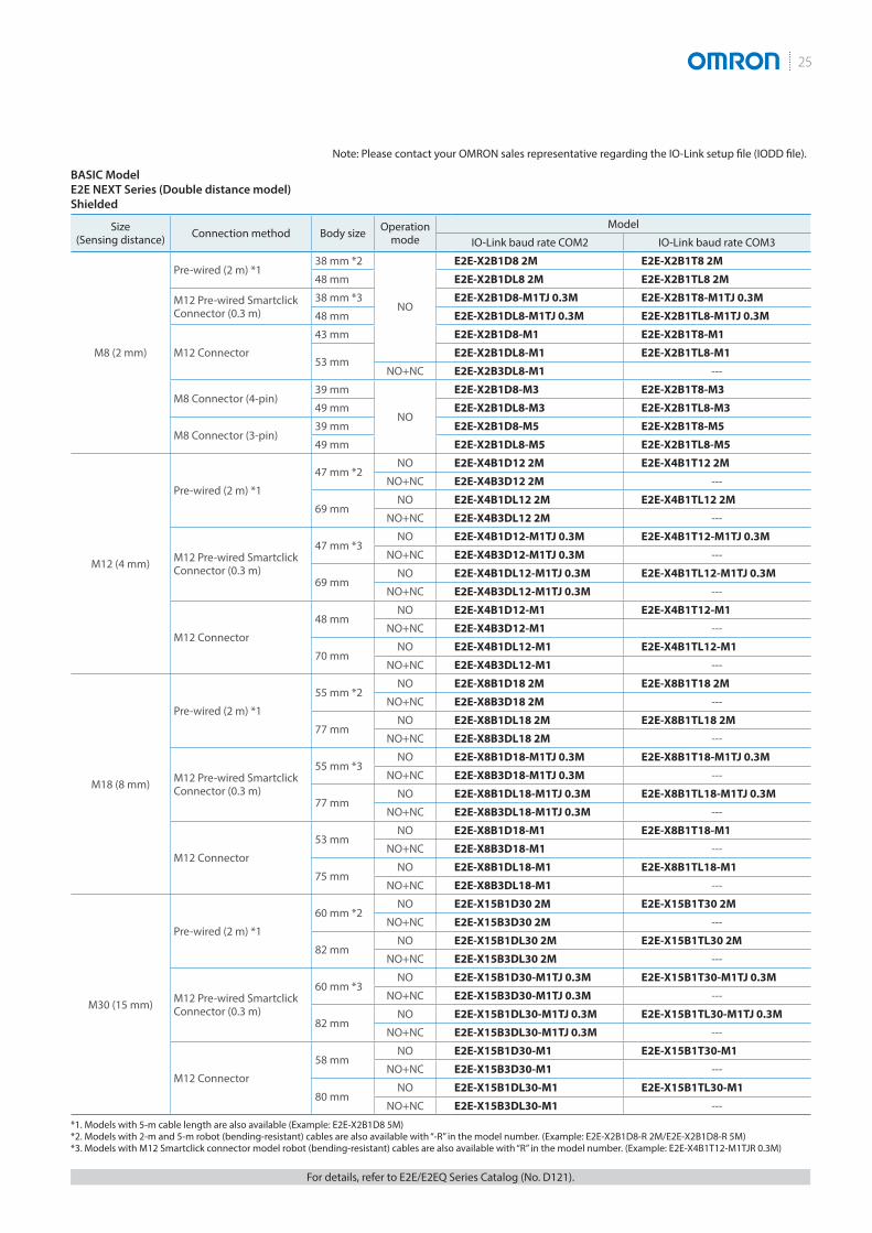
BASIC ModelE2E NEXT Series (Double distance model)Shielded
Size (Sensing distance) Connection method Body size Operation
modeModel
IO-Link baud rate COM2 IO-Link baud rate COM3
M8 (2 mm)
Pre-wired (2 m) *138 mm *2
NO
E2E-X2B1D8 2M E2E-X2B1T8 2M
48 mm E2E-X2B1DL8 2M E2E-X2B1TL8 2M
M12 Pre-wired Smartclick Connector (0.3 m)
38 mm *3 E2E-X2B1D8-M1TJ 0.3M E2E-X2B1T8-M1TJ 0.3M
48 mm E2E-X2B1DL8-M1TJ 0.3M E2E-X2B1TL8-M1TJ 0.3M
M12 Connector
43 mm E2E-X2B1D8-M1 E2E-X2B1T8-M1
53 mmE2E-X2B1DL8-M1 E2E-X2B1TL8-M1
NO+NC E2E-X2B3DL8-M1 ---
M8 Connector (4-pin)39 mm
NO
E2E-X2B1D8-M3 E2E-X2B1T8-M3
49 mm E2E-X2B1DL8-M3 E2E-X2B1TL8-M3
M8 Connector (3-pin)39 mm E2E-X2B1D8-M5 E2E-X2B1T8-M5
49 mm E2E-X2B1DL8-M5 E2E-X2B1TL8-M5
M12 (4 mm)
Pre-wired (2 m) *1
47 mm *2NO E2E-X4B1D12 2M E2E-X4B1T12 2M
NO+NC E2E-X4B3D12 2M ---
69 mmNO E2E-X4B1DL12 2M E2E-X4B1TL12 2M
NO+NC E2E-X4B3DL12 2M ---
M12 Pre-wired Smartclick Connector (0.3 m)
47 mm *3NO E2E-X4B1D12-M1TJ 0.3M E2E-X4B1T12-M1TJ 0.3M
NO+NC E2E-X4B3D12-M1TJ 0.3M ---
69 mmNO E2E-X4B1DL12-M1TJ 0.3M E2E-X4B1TL12-M1TJ 0.3M
NO+NC E2E-X4B3DL12-M1TJ 0.3M ---
M12 Connector
48 mmNO E2E-X4B1D12-M1 E2E-X4B1T12-M1
NO+NC E2E-X4B3D12-M1 ---
70 mmNO E2E-X4B1DL12-M1 E2E-X4B1TL12-M1
NO+NC E2E-X4B3DL12-M1 ---
M18 (8 mm)
Pre-wired (2 m) *1
55 mm *2NO E2E-X8B1D18 2M E2E-X8B1T18 2M
NO+NC E2E-X8B3D18 2M ---
77 mmNO E2E-X8B1DL18 2M E2E-X8B1TL18 2M
NO+NC E2E-X8B3DL18 2M ---
M12 Pre-wired Smartclick Connector (0.3 m)
55 mm *3NO E2E-X8B1D18-M1TJ 0.3M E2E-X8B1T18-M1TJ 0.3M
NO+NC E2E-X8B3D18-M1TJ 0.3M ---
77 mmNO E2E-X8B1DL18-M1TJ 0.3M E2E-X8B1TL18-M1TJ 0.3M
NO+NC E2E-X8B3DL18-M1TJ 0.3M ---
M12 Connector
53 mmNO E2E-X8B1D18-M1 E2E-X8B1T18-M1
NO+NC E2E-X8B3D18-M1 ---
75 mmNO E2E-X8B1DL18-M1 E2E-X8B1TL18-M1
NO+NC E2E-X8B3DL18-M1 ---
M30 (15 mm)
Pre-wired (2 m) *1
60 mm *2NO E2E-X15B1D30 2M E2E-X15B1T30 2M
NO+NC E2E-X15B3D30 2M ---
82 mmNO E2E-X15B1DL30 2M E2E-X15B1TL30 2M
NO+NC E2E-X15B3DL30 2M ---
M12 Pre-wired Smartclick Connector (0.3 m)
60 mm *3NO E2E-X15B1D30-M1TJ 0.3M E2E-X15B1T30-M1TJ 0.3M
NO+NC E2E-X15B3D30-M1TJ 0.3M ---
82 mmNO E2E-X15B1DL30-M1TJ 0.3M E2E-X15B1TL30-M1TJ 0.3M
NO+NC E2E-X15B3DL30-M1TJ 0.3M ---
M12 Connector
58 mmNO E2E-X15B1D30-M1 E2E-X15B1T30-M1
NO+NC E2E-X15B3D30-M1 ---
80 mmNO E2E-X15B1DL30-M1 E2E-X15B1TL30-M1
NO+NC E2E-X15B3DL30-M1 ---
*1. Models with 5-m cable length are also available (Example: E2E-X2B1D8 5M)*2. Models with 2-m and 5-m robot (bending-resistant) cables are also available with “-R” in the model number. (Example: E2E-X2B1D8-R 2M/E2E-X2B1D8-R 5M)*3. Models with M12 Smartclick connector model robot (bending-resistant) cables are also available with “R” in the model number. (Example: E2E-X4B1T12-M1TJR 0.3M)
For details, refer to E2E/E2EQ Series Catalog (No. D121).
Note: Please contact your OMRON sales representative regarding the IO-Link setup file (IODD file).

IO-Link Series26
BASIC ModelE2E NEXT Series (Double distance model)Unshielded
Size (Sensing distance) Connection method Body size Operation
modeModel
IO-Link baud rate COM2 IO-Link baud rate COM3
M8 (4 mm)
Pre-wired (2 m) *138 mm *2
NO
E2E-X4MB1D8 2M E2E-X4MB1T8 2M
48 mm E2E-X4MB1DL8 2M E2E-X4MB1TL8 2M
M12 Pre-wired Smartclick Connector (0.3 m)
38 mm *3 E2E-X4MB1D8-M1TJ 0.3M E2E-X4MB1T8-M1TJ 0.3M
48 mm E2E-X4MB1DL8-M1TJ 0.3M E2E-X4MB1TL8-M1TJ 0.3M
M12 Connector
43 mm E2E-X4MB1D8-M1 E2E-X4MB1T8-M1
53 mmE2E-X4MB1DL8-M1 E2E-X4MB1TL8-M1
NO+NC E2E-X4MB3DL8-M1 ---
M8 Connector (4-pin)39 mm
NO
E2E-X4MB1D8-M3 E2E-X4MB1T8-M3
49 mm E2E-X4MB1DL8-M3 E2E-X4MB1TL8-M3
M8 Connector (3-pin)39 mm E2E-X4MB1D8-M5 E2E-X4MB1T8-M5
49 mm E2E-X4MB1DL8-M5 E2E-X4MB1TL8-M5
M12 (8 mm)
Pre-wired (2 m) *1
47 mm *2NO E2E-X8MB1D12 2M E2E-X8MB1T12 2M
NO+NC E2E-X8MB3D12 2M ---
69 mmNO E2E-X8MB1DL12 2M E2E-X8MB1TL12 2M
NO+NC E2E-X8MB3DL12 2M ---
M12 Pre-wired Smartclick Connector (0.3 m)
47 mm *3NO E2E-X8MB1D12-M1TJ 0.3M E2E-X8MB1T12-M1TJ 0.3M
NO+NC E2E-X8MB3D12-M1TJ 0.3M ---
69 mmNO E2E-X8MB1DL12-M1TJ 0.3M E2E-X8MB1TL12-M1TJ 0.3M
NO+NC E2E-X8MB3DL12-M1TJ 0.3M ---
M12 Connector
48 mmNO E2E-X8MB1D12-M1 E2E-X8MB1T12-M1
NO+NC E2E-X8MB3D12-M1 ---
70 mmNO E2E-X8MB1DL12-M1 E2E-X8MB1TL12-M1
NO+NC E2E-X8MB3DL12-M1 ---
M18 (16 mm)
Pre-wired (2 m) *1
55 mm *2NO E2E-X16MB1D18 2M E2E-X16MB1T18 2M
NO+NC E2E-X16MB3D18 2M ---
77 mmNO E2E-X16MB1DL18 2M E2E-X16MB1TL18 2M
NO+NC E2E-X16MB3DL18 2M ---
M12 Pre-wired Smartclick Connector (0.3 m)
55 mm *3NO E2E-X16MB1D18-M1TJ 0.3M E2E-X16MB1T18-M1TJ 0.3M
NO+NC E2E-X16MB3D18-M1TJ 0.3M ---
77 mmNO E2E-X16MB1DL18-M1TJ 0.3M E2E-X16MB1TL18-M1TJ 0.3M
NO+NC E2E-X16MB3DL18-M1TJ 0.3M ---
M12 Connector
53 mmNO E2E-X16MB1D18-M1 E2E-X16MB1T18-M1
NO+NC E2E-X16MB3D18-M1 ---
75 mmNO E2E-X16MB1DL18-M1 E2E-X16MB1TL18-M1
NO+NC E2E-X16MB3DL18-M1 ---
M30 (30 mm)
Pre-wired (2 m) *1 82 mm *2NO E2E-X30MB1DL30 2M E2E-X30MB1TL30 2M
NO+NC E2E-X30MB3DL30 2M ---
M12 Pre-wired Smartclick Connector (0.3 m) 82 mm *3
NO E2E-X30MB1DL30-M1TJ 0.3M E2E-X30MB1TL30-M1TJ 0.3M
NO+NC E2E-X30MB3DL30-M1TJ 0.3M ---
M12 Connector 80 mmNO E2E-X30MB1DL30-M1 E2E-X30MB1TL30-M1
NO+NC E2E-X30MB3DL30-M1 ---
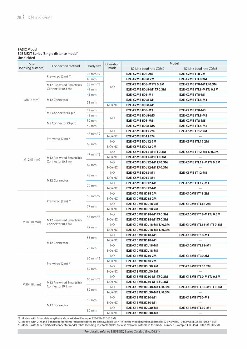
*1. Models with 5-m cable length are also available (Example: E2E-X8MB1D12 5M)*2. Models with 2-m and 5-m robot (bending-resistant) cables are also available with “-R” in the model number. (Example: E2E-X8MB1D12-R 2M/E2E-X8MB1D12-R 5M)*3. Models with M12 Smartclick connector model robot (bending-resistant) cables are also available with “R” in the model number. (Example: E2E-X8MB1D12-M1TJR 0.3M)
For details, refer to E2E/E2EQ Series Catalog (No. D121).
27
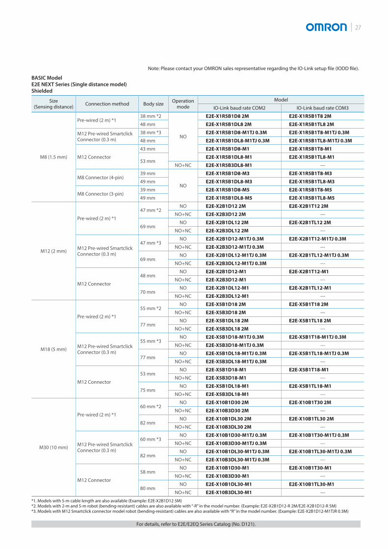
BASIC ModelE2E NEXT Series (Single distance model)Shielded
Size (Sensing distance) Connection method Body size Operation
modeModel
IO-Link baud rate COM2 IO-Link baud rate COM3
M8 (1.5 mm)
Pre-wired (2 m) *138 mm *2
NO
E2E-X1R5B1D8 2M E2E-X1R5B1T8 2M
48 mm E2E-X1R5B1DL8 2M E2E-X1R5B1TL8 2M
M12 Pre-wired Smartclick Connector (0.3 m)
38 mm *3 E2E-X1R5B1D8-M1TJ 0.3M E2E-X1R5B1T8-M1TJ 0.3M
48 mm E2E-X1R5B1DL8-M1TJ 0.3M E2E-X1R5B1TL8-M1TJ 0.3M
M12 Connector
43 mm E2E-X1R5B1D8-M1 E2E-X1R5B1T8-M1
53 mmE2E-X1R5B1DL8-M1 E2E-X1R5B1TL8-M1
NO+NC E2E-X1R5B3DL8-M1 ---
M8 Connector (4-pin)39 mm
NO
E2E-X1R5B1D8-M3 E2E-X1R5B1T8-M3
49 mm E2E-X1R5B1DL8-M3 E2E-X1R5B1TL8-M3
M8 Connector (3-pin)39 mm E2E-X1R5B1D8-M5 E2E-X1R5B1T8-M5
49 mm E2E-X1R5B1DL8-M5 E2E-X1R5B1TL8-M5
M12 (2 mm)
Pre-wired (2 m) *1
47 mm *2NO E2E-X2B1D12 2M E2E-X2B1T12 2M
NO+NC E2E-X2B3D12 2M ---
69 mmNO E2E-X2B1DL12 2M E2E-X2B1TL12 2M
NO+NC E2E-X2B3DL12 2M ---
M12 Pre-wired Smartclick Connector (0.3 m)
47 mm *3NO E2E-X2B1D12-M1TJ 0.3M E2E-X2B1T12-M1TJ 0.3M
NO+NC E2E-X2B3D12-M1TJ 0.3M ---
69 mmNO E2E-X2B1DL12-M1TJ 0.3M E2E-X2B1TL12-M1TJ 0.3M
NO+NC E2E-X2B3DL12-M1TJ 0.3M ---
M12 Connector
48 mmNO E2E-X2B1D12-M1 E2E-X2B1T12-M1
NO+NC E2E-X2B3D12-M1 ---
70 mmNO E2E-X2B1DL12-M1 E2E-X2B1TL12-M1
NO+NC E2E-X2B3DL12-M1 ---
M18 (5 mm)
Pre-wired (2 m) *1
55 mm *2NO E2E-X5B1D18 2M E2E-X5B1T18 2M
NO+NC E2E-X5B3D18 2M ---
77 mmNO E2E-X5B1DL18 2M E2E-X5B1TL18 2M
NO+NC E2E-X5B3DL18 2M ---
M12 Pre-wired Smartclick Connector (0.3 m)
55 mm *3NO E2E-X5B1D18-M1TJ 0.3M E2E-X5B1T18-M1TJ 0.3M
NO+NC E2E-X5B3D18-M1TJ 0.3M ---
77 mmNO E2E-X5B1DL18-M1TJ 0.3M E2E-X5B1TL18-M1TJ 0.3M
NO+NC E2E-X5B3DL18-M1TJ 0.3M ---
M12 Connector
53 mmNO E2E-X5B1D18-M1 E2E-X5B1T18-M1
NO+NC E2E-X5B3D18-M1 ---
75 mmNO E2E-X5B1DL18-M1 E2E-X5B1TL18-M1
NO+NC E2E-X5B3DL18-M1 ---
M30 (10 mm)
Pre-wired (2 m) *1
60 mm *2NO E2E-X10B1D30 2M E2E-X10B1T30 2M
NO+NC E2E-X10B3D30 2M ---
82 mmNO E2E-X10B1DL30 2M E2E-X10B1TL30 2M
NO+NC E2E-X10B3DL30 2M ---
M12 Pre-wired Smartclick Connector (0.3 m)
60 mm *3NO E2E-X10B1D30-M1TJ 0.3M E2E-X10B1T30-M1TJ 0.3M
NO+NC E2E-X10B3D30-M1TJ 0.3M ---
82 mmNO E2E-X10B1DL30-M1TJ 0.3M E2E-X10B1TL30-M1TJ 0.3M
NO+NC E2E-X10B3DL30-M1TJ 0.3M ---
M12 Connector
58 mmNO E2E-X10B1D30-M1 E2E-X10B1T30-M1
NO+NC E2E-X10B3D30-M1 ---
80 mmNO E2E-X10B1DL30-M1 E2E-X10B1TL30-M1
NO+NC E2E-X10B3DL30-M1 ---
*1. Models with 5-m cable length are also available (Example: E2E-X2B1D12 5M)*2. Models with 2-m and 5-m robot (bending-resistant) cables are also available with “-R” in the model number. (Example: E2E-X2B1D12-R 2M/E2E-X2B1D12-R 5M)*3. Models with M12 Smartclick connector model robot (bending-resistant) cables are also available with “R” in the model number. (Example: E2E-X2B1D12-M1TJR 0.3M)
For details, refer to E2E/E2EQ Series Catalog (No. D121).
Note: Please contact your OMRON sales representative regarding the IO-Link setup file (IODD file).
IO-Link Series28
BASIC ModelE2E NEXT Series (Single distance model)Unshielded
Size (Sensing distance) Connection method Body size Operation
modeModel
IO-Link baud rate COM2 IO-Link baud rate COM3
M8 (2 mm)
Pre-wired (2 m) *138 mm *2
NO
E2E-X2MB1D8 2M E2E-X2MB1T8 2M
48 mm E2E-X2MB1DL8 2M E2E-X2MB1TL8 2M
M12 Pre-wired Smartclick Connector (0.3 m)
38 mm *3 E2E-X2MB1D8-M1TJ 0.3M E2E-X2MB1T8-M1TJ 0.3M
48 mm E2E-X2MB1DL8-M1TJ 0.3M E2E-X2MB1TL8-M1TJ 0.3M
M12 Connector
43 mm E2E-X2MB1D8-M1 E2E-X2MB1T8-M1
53 mmE2E-X2MB1DL8-M1 E2E-X2MB1TL8-M1
NO+NC E2E-X2MB3DL8-M1 ---
M8 Connector (4-pin)39 mm
NO
E2E-X2MB1D8-M3 E2E-X2MB1T8-M3
49 mm E2E-X2MB1DL8-M3 E2E-X2MB1TL8-M3
M8 Connector (3-pin)39 mm E2E-X2MB1D8-M5 E2E-X2MB1T8-M5
49 mm E2E-X2MB1DL8-M5 E2E-X2MB1TL8-M5
M12 (5 mm)
Pre-wired (2 m) *1
47 mm *2NO E2E-X5MB1D12 2M E2E-X5MB1T12 2M
NO+NC E2E-X5MB3D12 2M ---
69 mmNO E2E-X5MB1DL12 2M E2E-X5MB1TL12 2M
NO+NC E2E-X5MB3DL12 2M ---
M12 Pre-wired Smartclick Connector (0.3 m)
47 mm *3NO E2E-X5MB1D12-M1TJ 0.3M E2E-X5MB1T12-M1TJ 0.3M
NO+NC E2E-X5MB3D12-M1TJ 0.3M ---
69 mmNO E2E-X5MB1DL12-M1TJ 0.3M E2E-X5MB1TL12-M1TJ 0.3M
NO+NC E2E-X5MB3DL12-M1TJ 0.3M ---
M12 Connector
48 mmNO E2E-X5MB1D12-M1 E2E-X5MB1T12-M1
NO+NC E2E-X5MB3D12-M1 ---
70 mmNO E2E-X5MB1DL12-M1 E2E-X5MB1TL12-M1
NO+NC E2E-X5MB3DL12-M1 ---
M18 (10 mm)
Pre-wired (2 m) *1
55 mm *2NO E2E-X10MB1D18 2M E2E-X10MB1T18 2M
NO+NC E2E-X10MB3D18 2M ---
77 mmNO E2E-X10MB1DL18 2M E2E-X10MB1TL18 2M
NO+NC E2E-X10MB3DL18 2M ---
M12 Pre-wired Smartclick Connector (0.3 m)
55 mm *3NO E2E-X10MB1D18-M1TJ 0.3M E2E-X10MB1T18-M1TJ 0.3M
NO+NC E2E-X10MB3D18-M1TJ 0.3M ---
77 mmNO E2E-X10MB1DL18-M1TJ 0.3M E2E-X10MB1TL18-M1TJ 0.3M
NO+NC E2E-X10MB3DL18-M1TJ 0.3M ---
M12 Connector
53 mmNO E2E-X10MB1D18-M1 E2E-X10MB1T18-M1
NO+NC E2E-X10MB3D18-M1 ---
75 mmNO E2E-X10MB1DL18-M1 E2E-X10MB1TL18-M1
NO+NC E2E-X10MB3DL18-M1 ---
M30 (18 mm)
Pre-wired (2 m) *1
60 mm *2NO E2E-X18MB1D30 2M E2E-X18MB1T30 2M
NO+NC E2E-X18MB3D30 2M ---
82 mmNO E2E-X18MB1DL30 2M E2E-X18MB1TL30 2M
NO+NC E2E-X18MB3DL30 2M ---
M12 Pre-wired Smartclick Connector (0.3 m)
60 mm *3NO E2E-X18MB1D30-M1TJ 0.3M E2E-X18MB1T30-M1TJ 0.3M
NO+NC E2E-X18MB3D30-M1TJ 0.3M ---
82 mmNO E2E-X18MB1DL30-M1TJ 0.3M E2E-X18MB1TL30-M1TJ 0.3M
NO+NC E2E-X18MB3DL30-M1TJ 0.3M ---
M12 Connector
58 mmNO E2E-X18MB1D30-M1 E2E-X18MB1T30-M1
NO+NC E2E-X18MB3D30-M1 ---
80 mmNO E2E-X18MB1DL30-M1 E2E-X18MB1TL30-M1
NO+NC E2E-X18MB3DL30-M1 ---
*1. Models with 5-m cable length are also available (Example: E2E-X5MB1D12 5M)*2. Models with 2-m and 5-m robot (bending-resistant) cables are also available with “-R” in the model number. (Example: E2E-X5MB1D12-R 2M/E2E-X5MB1D12-R 5M)*3. Models with M12 Smartclick connector model robot (bending-resistant) cables are also available with “R” in the model number. (Example: E2E-X5MB1D12-M1TJR 2M)
For details, refer to E2E/E2EQ Series Catalog (No. D121).

29
BASIC ModelE2EQ NEXT Series (Spatter-resistant Double distance model)Shielded
Size (Sensing distance) Connection method Body size Operation
modeModel
IO-Link baud rate COM2 IO-Link baud rate COM3
M8 (2 mm)
Pre-wired (2 m) * 38 mm
NO
E2EQ-X2B1D8 2M E2EQ-X2B1T8 2MM12 Pre-wired Smartclick Connector (0.3 m) 38 mm E2EQ-X2B1D8-M1TJ 0.3M E2EQ-X2B1T8-M1TJ 0.3M
M12 Connector 43 mm E2EQ-X2B1D8-M1 E2EQ-X2B1T8-M1
M12 (4 mm)
Pre-wired (2 m) * 47 mmNO E2EQ-X4B1D12 2M E2EQ-X4B1T12 2M
NO+NC E2EQ-X4B3D12 2M ---
M12 Pre-wired Smartclick Connector (0.3 m) 47 mm
NO E2EQ-X4B1D12-M1TJ 0.3M E2EQ-X4B1T12-M1TJ 0.3MNO+NC E2EQ-X4B3D12-M1TJ 0.3M ---
M12 Connector 48 mmNO E2EQ-X4B1D12-M1 E2EQ-X4B1T12-M1
NO+NC E2EQ-X4B3D12-M1 ---
M18 (8 mm)
Pre-wired (2 m) * 55 mmNO E2EQ-X8B1D18 2M E2EQ-X8B1T18 2M
NO+NC E2EQ-X8B3D18 2M ---
M12 Pre-wired Smartclick Connector (0.3 m) 55 mm
NO E2EQ-X8B1D18-M1TJ 0.3M E2EQ-X8B1T18-M1TJ 0.3MNO+NC E2EQ-X8B3D18-M1TJ 0.3M ---
M12 Connector 53 mmNO E2EQ-X8B1D18-M1 E2EQ-X8B1T18-M1
NO+NC E2EQ-X8B3D18-M1 ---
M30 (15 mm)
Pre-wired (2 m) * 60 mmNO E2EQ-X15B1D30 2M E2EQ-X15B1T30 2M
NO+NC E2EQ-X15B3D30 2M ---
M12 Pre-wired Smartclick Connector (0.3 m) 60 mm
NO E2EQ-X15B1D30-M1TJ 0.3M E2EQ-X15B1T30-M1TJ 0.3MNO+NC E2EQ-X15B3D30-M1TJ 0.3M ---
M12 Connector 58 mmNO E2EQ-X15B1D30-M1 E2EQ-X15B1T30-M1
NO+NC E2EQ-X15B3D30-M1 ---
* Models with 5-m cable length are also available (Example: E2EQ-X6B1D12 5M)
BASIC ModelE2EQ NEXT Series (Spatter-resistant Single distance model)Shielded
Size (Sensing distance) Connection method Body size Operation
modeModel
IO-Link baud rate COM2 IO-Link baud rate COM3
M8 (1.5 mm)
Pre-wired (2 m) * 38 mm
NO
E2EQ-X1R5B1D8 2M E2EQ-X1R5B1T8 2MM12 Pre-wired Smartclick Connector (0.3 m) 38 mm E2EQ-X1R5B1D8-M1TJ 0.3M E2EQ-X1R5B1T8-M1TJ 0.3M
M12 Connector 43 mm E2EQ-X1R5B1D8-M1 E2EQ-X1R5B1T8-M1
M12 (2 mm)
Pre-wired (2 m) * 47 mmNO E2EQ-X2B1D12 2M E2EQ-X2B1T12 2M
NO+NC E2EQ-X2B3D12 2M ---
M12 Pre-wired Smartclick Connector (0.3 m) 47 mm
NO E2EQ-X2B1D12-M1TJ 0.3M E2EQ-X2B1T12-M1TJ 0.3MNO+NC E2EQ-X2B3D12-M1TJ 0.3M ---
M12 Connector 48 mmNO E2EQ-X2B1D12-M1 E2EQ-X2B1T12-M1
NO+NC E2EQ-X2B3D12-M1 ---
M18 (5 mm)
Pre-wired (2 m) * 55 mmNO E2EQ-X5B1D18 2M E2EQ-X5B1T18 2M
NO+NC E2EQ-X5B3D18 2M ---
M12 Pre-wired Smartclick Connector (0.3 m) 55 mm
NO E2EQ-X5B1D18-M1TJ 0.3M E2EQ-X5B1T18-M1TJ 0.3MNO+NC E2EQ-X5B3D18-M1TJ 0.3M ---
M12 Connector 53 mmNO E2EQ-X5B1D18-M1 E2EQ-X5B1T18-M1
NO+NC E2EQ-X5B3D18-M1 ---
M30 (10 mm)
Pre-wired (2 m) * 60 mmNO E2EQ-X10B1D30 2M E2EQ-X10B1T30 2M
NO+NC E2EQ-X10B3D30 2M ---
M12 Pre-wired Smartclick Connector (0.3 m) 60 mm
NO E2EQ-X10B1D30-M1TJ 0.3M E2EQ-X10B1T30-M1TJ 0.3MNO+NC E2EQ-X10B3D30-M1TJ 0.3M ---
M12 Connector 58 mmNO E2EQ-X10B1D30-M1 E2EQ-X10B1T30-M1
NO+NC E2EQ-X10B3D30-M1 ---
* Models with 5-m cable length are also available (Example: E2EQ-X6B1D12 5M)
For details, refer to E2E/E2EQ Series Catalog (No. D121).
Note: Please contact your OMRON sales representative regarding the IO-Link setup file (IODD file).
IO-Link Series30
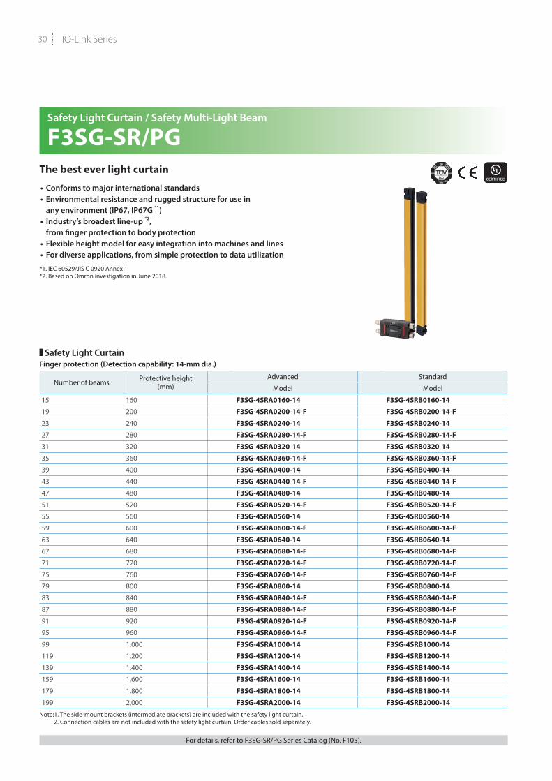
Safety Light Curtain / Safety Multi-Light Beam
F3SG-SR/PGThe best ever light curtain
• Conforms to major international standards• Environmental resistance and rugged structure for use in
any environment (IP67, IP67G *1)• Industry’s broadest line-up *2,
from finger protection to body protection • Flexible height model for easy integration into machines and lines• For diverse applications, from simple protection to data utilization
*1. IEC 60529/JIS C 0920 Annex 1*2. Based on Omron investigation in June 2018.
Safety Light CurtainFinger protection (Detection capability: 14-mm dia.)
Number of beams Protective height (mm)
Advanced Standard
Model Model
15 160 F3SG-4SRA0160-14 F3SG-4SRB0160-14
19 200 F3SG-4SRA0200-14-F F3SG-4SRB0200-14-F
23 240 F3SG-4SRA0240-14 F3SG-4SRB0240-14
27 280 F3SG-4SRA0280-14-F F3SG-4SRB0280-14-F
31 320 F3SG-4SRA0320-14 F3SG-4SRB0320-14
35 360 F3SG-4SRA0360-14-F F3SG-4SRB0360-14-F
39 400 F3SG-4SRA0400-14 F3SG-4SRB0400-14
43 440 F3SG-4SRA0440-14-F F3SG-4SRB0440-14-F
47 480 F3SG-4SRA0480-14 F3SG-4SRB0480-14
51 520 F3SG-4SRA0520-14-F F3SG-4SRB0520-14-F
55 560 F3SG-4SRA0560-14 F3SG-4SRB0560-14
59 600 F3SG-4SRA0600-14-F F3SG-4SRB0600-14-F
63 640 F3SG-4SRA0640-14 F3SG-4SRB0640-14
67 680 F3SG-4SRA0680-14-F F3SG-4SRB0680-14-F
71 720 F3SG-4SRA0720-14-F F3SG-4SRB0720-14-F
75 760 F3SG-4SRA0760-14-F F3SG-4SRB0760-14-F
79 800 F3SG-4SRA0800-14 F3SG-4SRB0800-14
83 840 F3SG-4SRA0840-14-F F3SG-4SRB0840-14-F
87 880 F3SG-4SRA0880-14-F F3SG-4SRB0880-14-F
91 920 F3SG-4SRA0920-14-F F3SG-4SRB0920-14-F
95 960 F3SG-4SRA0960-14-F F3SG-4SRB0960-14-F
99 1,000 F3SG-4SRA1000-14 F3SG-4SRB1000-14
119 1,200 F3SG-4SRA1200-14 F3SG-4SRB1200-14
139 1,400 F3SG-4SRA1400-14 F3SG-4SRB1400-14
159 1,600 F3SG-4SRA1600-14 F3SG-4SRB1600-14
179 1,800 F3SG-4SRA1800-14 F3SG-4SRB1800-14
199 2,000 F3SG-4SRA2000-14 F3SG-4SRB2000-14
Note:1. The side-mount brackets (intermediate brackets) are included with the safety light curtain. 2. Connection cables are not included with the safety light curtain. Order cables sold separately.
For details, refer to F3SG-SR/PG Series Catalog (No. F105).

31
Hand protection (Detection capability: 25-mm dia.)
Number of beams Protective height (mm)
Advanced StandardModel Model
8 160 F3SG-4SRA0160-25 F3SG-4SRB0160-2510 200 F3SG-4SRA0200-25-F F3SG-4SRB0200-25-F12 240 F3SG-4SRA0240-25 F3SG-4SRB0240-2514 280 F3SG-4SRA0280-25-F F3SG-4SRB0280-25-F16 320 F3SG-4SRA0320-25 F3SG-4SRB0320-2518 360 F3SG-4SRA0360-25-F F3SG-4SRB0360-25-F20 400 F3SG-4SRA0400-25 F3SG-4SRB0400-2522 440 F3SG-4SRA0440-25-F F3SG-4SRB0440-25-F24 480 F3SG-4SRA0480-25 F3SG-4SRB0480-2526 520 F3SG-4SRA0520-25-F F3SG-4SRB0520-25-F28 560 F3SG-4SRA0560-25 F3SG-4SRB0560-2530 600 F3SG-4SRA0600-25-F F3SG-4SRB0600-25-F32 640 F3SG-4SRA0640-25 F3SG-4SRB0640-2534 680 F3SG-4SRA0680-25-F F3SG-4SRB0680-25-F36 720 F3SG-4SRA0720-25 F3SG-4SRB0720-2538 760 F3SG-4SRA0760-25-F F3SG-4SRB0760-25-F40 800 F3SG-4SRA0800-25 F3SG-4SRB0800-2542 840 F3SG-4SRA0840-25-F F3SG-4SRB0840-25-F44 880 F3SG-4SRA0880-25 F3SG-4SRB0880-2546 920 F3SG-4SRA0920-25-F F3SG-4SRB0920-25-F48 960 F3SG-4SRA0960-25 F3SG-4SRB0960-2550 1,000 F3SG-4SRA1000-25-F F3SG-4SRB1000-25-F52 1,040 F3SG-4SRA1040-25 F3SG-4SRB1040-2556 1,120 F3SG-4SRA1120-25 F3SG-4SRB1120-2560 1,200 F3SG-4SRA1200-25 F3SG-4SRB1200-2564 1,280 F3SG-4SRA1280-25 F3SG-4SRB1280-2568 1,360 F3SG-4SRA1360-25 F3SG-4SRB1360-2572 1,440 F3SG-4SRA1440-25 F3SG-4SRB1440-2576 1,520 F3SG-4SRA1520-25 F3SG-4SRB1520-2580 1,600 F3SG-4SRA1600-25 F3SG-4SRB1600-2584 1,680 F3SG-4SRA1680-25 F3SG-4SRB1680-2588 1,760 F3SG-4SRA1760-25 F3SG-4SRB1760-2592 1,840 F3SG-4SRA1840-25 F3SG-4SRB1840-2596 1,920 F3SG-4SRA1920-25 F3SG-4SRB1920-25104 2,080 F3SG-4SRA2080-25 F3SG-4SRB2080-25114 2,280 F3SG-4SRA2280-25 F3SG-4SRB2280-25124 2,480 F3SG-4SRA2480-25 F3SG-4SRB2480-25
Arm/Leg protection (Detection capability: 45-mm dia.)
Number of beams Protective height (mm)
Advanced StandardModel Model
6 240 F3SG-4SRA0240-45 F3SG-4SRB0240-4510 400 F3SG-4SRA0400-45 F3SG-4SRB0400-4514 560 F3SG-4SRA0560-45 F3SG-4SRB0560-4518 720 F3SG-4SRA0720-45 F3SG-4SRB0720-4522 880 F3SG-4SRA0880-45 F3SG-4SRB0880-4530 1,200 F3SG-4SRA1200-45 F3SG-4SRB1200-4538 1,520 F3SG-4SRA1520-45 F3SG-4SRB1520-45
Body (Detection capability: 85-mm dia.)
Number of beams Protective height (mm)
Advanced StandardModel Model
4 280 F3SG-4SRA0280-85 F3SG-4SRB0280-856 440 F3SG-4SRA0440-85 F3SG-4SRB0440-858 600 F3SG-4SRA0600-85 F3SG-4SRB0600-8510 760 F3SG-4SRA0760-85 F3SG-4SRB0760-8512 920 F3SG-4SRA0920-85 F3SG-4SRB0920-85
Note:1. The side-mount brackets (intermediate brackets) are included with the safety light curtain. 2. Connection cables are not included with the safety light curtain. Order cables sold separately.
For details, refer to F3SG-SR/PG Series Catalog (No. F105).
Note: Please contact your OMRON sales representative regarding the IO-Link setup file (IODD file).
IO-Link Series32
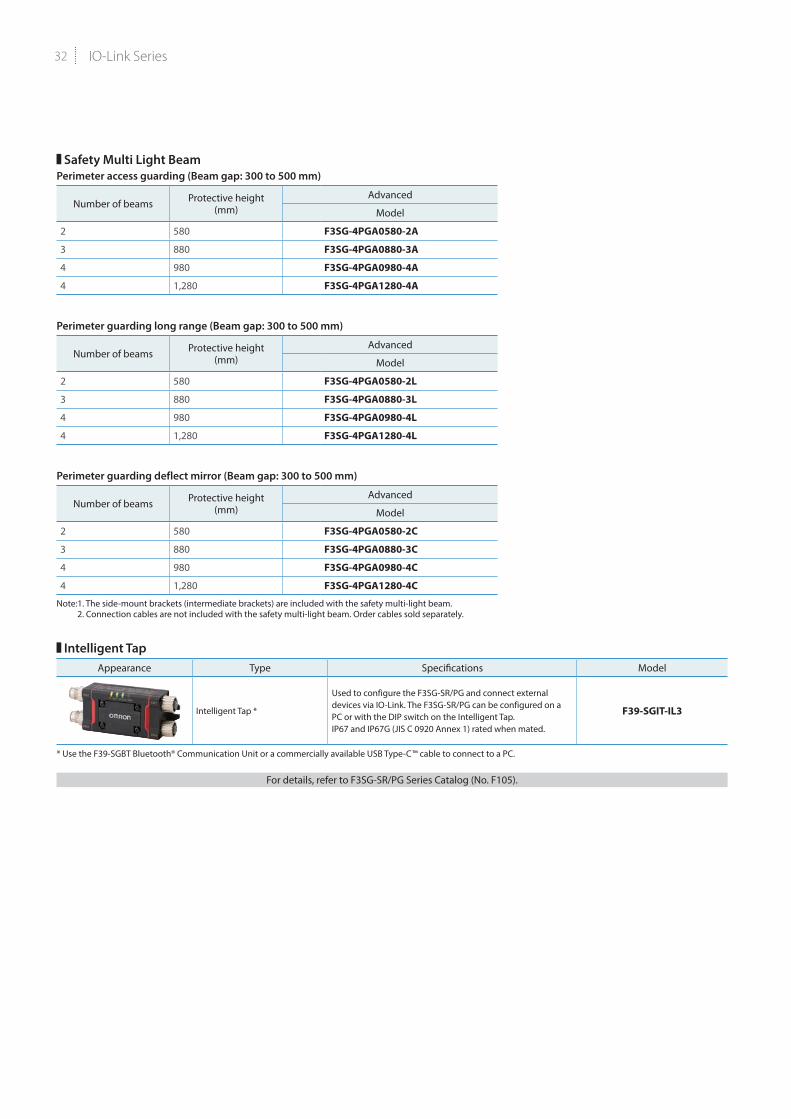
Safety Multi Light BeamPerimeter access guarding (Beam gap: 300 to 500 mm)
Number of beams Protective height (mm)
Advanced
Model
2 580 F3SG-4PGA0580-2A
3 880 F3SG-4PGA0880-3A
4 980 F3SG-4PGA0980-4A
4 1,280 F3SG-4PGA1280-4A
Perimeter guarding long range (Beam gap: 300 to 500 mm)
Number of beams Protective height (mm)
Advanced
Model
2 580 F3SG-4PGA0580-2L
3 880 F3SG-4PGA0880-3L
4 980 F3SG-4PGA0980-4L
4 1,280 F3SG-4PGA1280-4L
Perimeter guarding deflect mirror (Beam gap: 300 to 500 mm)
Number of beams Protective height (mm)
Advanced
Model
2 580 F3SG-4PGA0580-2C
3 880 F3SG-4PGA0880-3C
4 980 F3SG-4PGA0980-4C
4 1,280 F3SG-4PGA1280-4C
Note:1. The side-mount brackets (intermediate brackets) are included with the safety multi-light beam. 2. Connection cables are not included with the safety multi-light beam. Order cables sold separately.
Intelligent TapAppearance Type Specifications Model
Intelligent Tap *
Used to configure the F3SG-SR/PG and connect external devices via IO-Link. The F3SG-SR/PG can be configured on a PC or with the DIP switch on the Intelligent Tap.IP67 and IP67G (JIS C 0920 Annex 1) rated when mated.
F39-SGIT-IL3
* Use the F39-SGBT Bluetooth® Communication Unit or a commercially available USB Type-C™ cable to connect to a PC.
For details, refer to F3SG-SR/PG Series Catalog (No. F105).

33
NX-series IO-Link Master Unit
NX-ILM400IO-Link makes sensor level information visible and solves the three major issues at manufacturing sites! The screwless clamping terminal block reduces wiring work.
• Downtime can be reduced. Notifies you of faulty parts and such phenomena in the Sensor in real time.
• The frequency of sudden failure can be decreased. Condition monitoring of sensors and equipment to prevent troubles.
• The efficiency of changeover can be improved. The batch check for individual sensor IDs significantly decreases commissioning time.
Product nameSpecification
ModelNumber of IO-Link ports I/O refreshing method I/O connection terminals
NX-series IO-Link Master Unit 4 Free-Run refreshing Screwless clampingterminal block NX-ILM400
For details, refer to NX-ILM400 Data sheet.
GX-series IO-Link Master Unit
GX-ILM08CIO-Link makes sensor level information visible and solves the three major issues at manufacturing sites! The unit for M12 Smartclick connector can be used in watery, and dusty environments.
• Downtime can be reduced. Notifies you of faulty parts and such phenomena in the Sensor in real time.
• The frequency of sudden failure can be decreased. Condition monitoring of sensors and equipment to prevent troubles.
• The efficiency of changeover can be improved. The batch check for individual sensor IDs significantly decreases commissioning time.
Product NameSpecification
ModelEnvironmentalresistance
Number of IO-Link ports I/O connection terminals
GX-series IO-Link Master Unit IP67 8 M12 connector (A-cording, female) GX-ILM08C
For details, refer to GX Series Data sheet.
SoftwareProduct name Model
* CX-ConfiguratorFDT for IO-Link sensor setup is included in Sysmac Studio.Sysmac Studio * SYSMAC-SE2
For details, refer to Sysmac Studio Ver.1. Data sheet.
IO-Link Master Unit Note: Please contact your OMRON sales representative regarding the IO-Link setup file (IODD file).

IO-Link Series34
MEMO

35
MEMO

EtherCAT ® is a registered trademark and patented technology , licensed by Beckhoff Automation GmbH, Germany.
EtherNet/IPTM is the trademarks of ODVA.
The Bluetooth® word mark and logo are registered trademarks and are owned by the Bluetooth SIG, Inc. and any use of such mark by OMRON Corporation is under license.
USB Type-C™ is a trademark of USB Implementers Forum.
Other company names and product names in this document are the trade marks or registered trademarks of their respective companies.
The product photographs and figures that are used in this catalog may vary somewhat from the actual products.
Authorized Distributor:
In the interest of product improvement, specifications are subject to change without notice.
OMRON Corporation Industrial Automation Company
OMRON ELECTRONICS LLC2895 Greenspoint Parkway, Suite 200 Hoffman Estates, IL 60169 U.S.A.Tel: (1) 847-843-7900/Fax: (1) 847-843-7787
Regional HeadquartersOMRON EUROPE B.V.Wegalaan 67-69, 2132 JD HoofddorpThe NetherlandsTel: (31)2356-81-300/Fax: (31)2356-81-388
Contact: www.ia.omron.comKyoto, JAPAN
OMRON ASIA PACIFIC PTE. LTD.No. 438A Alexandra Road # 05-05/08 (Lobby 2), Alexandra Technopark, Singapore 119967Tel: (65) 6835-3011/Fax: (65) 6835-2711
OMRON (CHINA) CO., LTD.Room 2211, Bank of China Tower, 200 Yin Cheng Zhong Road, PuDong New Area, Shanghai, 200120, ChinaTel: (86) 21-5037-2222/Fax: (86) 21-5037-2200 Cat. No. Y229-E1-03
© OMRON Corporation 2016-2019 All Rights Reserved.
0619 (0618)CSM_7_1_0619