cspr1-v24 self powered relay · protection relay for mv switchboards. specifically in compact...
TRANSCRIPT
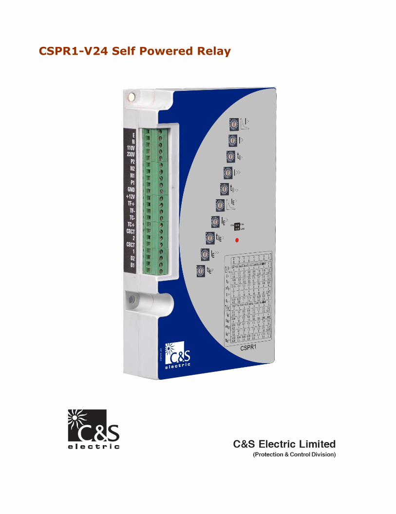
CSPR1-V24 Self Powered Relay
ContentsContentsContentsContents
1.1.1.1.
2.2.2.2.
3.3.3.3.
IntroductionIntroductionIntroductionIntroduction
FeaturesFeaturesFeaturesFeatures aaaand Characteristicsnd Characteristicsnd Characteristicsnd Characteristics
Product DescriptionProduct DescriptionProduct DescriptionProduct Description
3.1 Operation
3.2 Installation
4.4.4.4. Inputs and OutputsInputs and OutputsInputs and OutputsInputs and Outputs
4.1 Inputs
4.2 Outputs
4.2.1 Impulse Output
4.2.2 Flag Indicator Outputs
4.3 LED
5.5.5.5. Fault Value MemoryFault Value MemoryFault Value MemoryFault Value Memory
6.6.6.6. CommunicationCommunicationCommunicationCommunication
7777.... Technical dataTechnical dataTechnical dataTechnical data
7777.1.1.1.1 Characteristics
7777.2.2.2.2 Earth Current Protection
7.7.7.7.3333 Settings
7.47.47.47.4 IDMT Characteristics
7.57.57.57.5 Characteristics Curves
8888.... Product Specific FeaturesProduct Specific FeaturesProduct Specific FeaturesProduct Specific Features
8888.1.1.1.1 Earthing
8888.2.2.2.2 Assignment of terminals
8888.3.3.3.3 Back up Protection
9999.... Terminal DetailsTerminal DetailsTerminal DetailsTerminal Details
10101010.... System DataSystem DataSystem DataSystem Data
11110000....1111 EMC
10101010....2222 Accuracy
10101010.3.3.3.3 Common Data
10101010....4444 Ambient Conditions
10101010.5.5.5.5 Insulation Voltage Withstand
11111111.... Connection DiagramConnection DiagramConnection DiagramConnection Diagram
11111111.1.1.1.1 Terminal Block
11111111.2.2.2.2 Connections
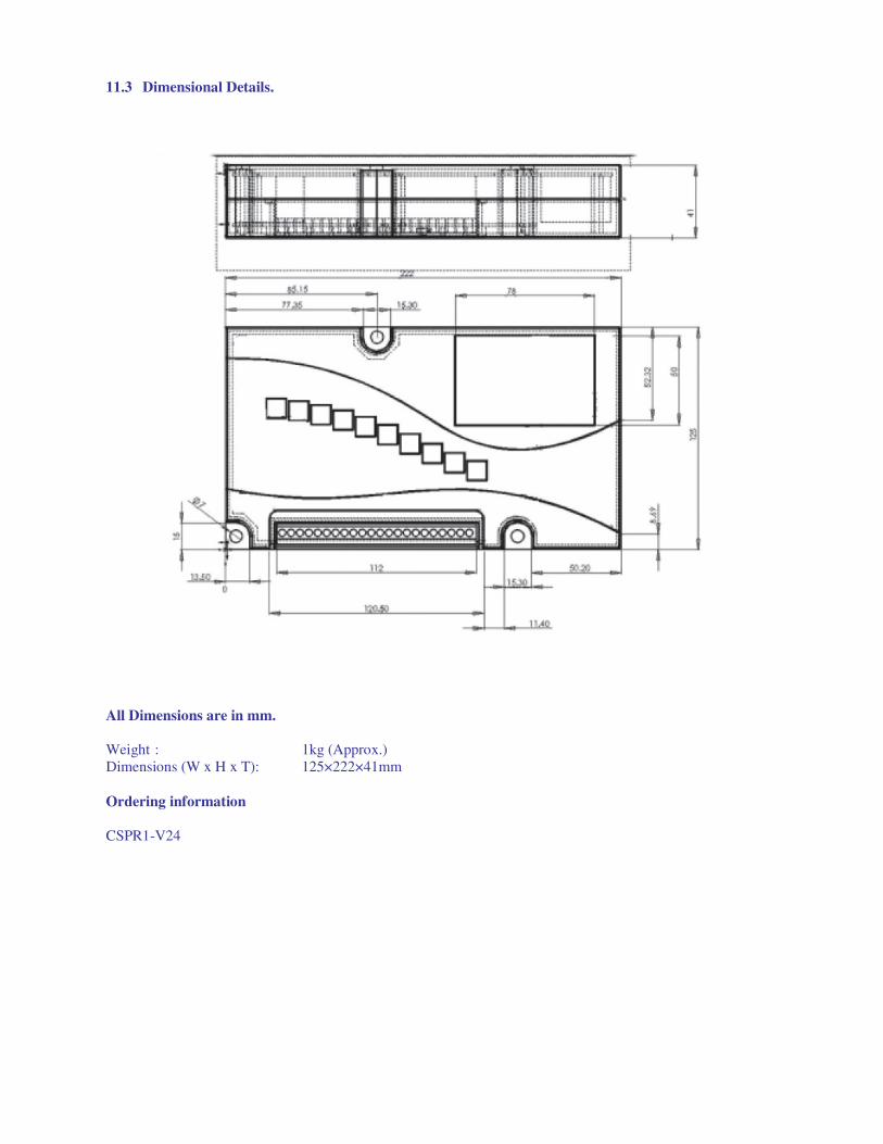
11111111.3.3.3.3 Dimensional Details

1. Introduction
CSE offers a wide range of CT powered relays
which provide over current, short circuit,
instantaneous phase and earth fault functions.
CSPR-V1--1 is a compact relay specifically
designed for compact MV switchboards with circuit
breakers. CSPR-V1 uses CTs with secondary rated
for 1A.
2. Features & Characteristics
• CT powered relay.
• O/C, S/C, E/F and E/F High Set protection
• DEFT and Inverse characteristics for O/C
and E/F
• Impulse output for tripping coil
• Impulse output for hand reset type
magnetic flag. (Magnetic flag is not a part
of standard supply)
• Remote Trip input
• Fault value memory
• Serial communication for remote read-out
on MODBUS RTU
• Parameter setting by rotary switches
• Inverse characteristics can be individually
selected for phase and earth fault
3. Product Description
The CSPR-V1 is a CT-powered protection relay
with inverse time and definite time protection
characteristics.
CSPR-V1 provides following protection functions:
• 3 phase definite time over current and
short-circuit protection with variable
tripping times (ANSI 50/51)
• 3 phase over current protection with
selectable inverse time characteristics and
definite time short-circuit current element
(ANSI 50/51)
• Definite time and inverse time earth over
current protection by internal calculation
(ANSI 50N/51N).
3.1 Operation
CSPR-V1 is a high tech and cost optimised
protection relay for MV switchboards. Specifically in compact switchboards, the CSPR-V1 can replace
the combination of load break switch.
CSPR-V1 is provided with four analogue
measuring inputs [Phase current CTs and CBCT].
Setting of parameters is done by means of HEX
switches.
The CSPR-V1 is provided with an input for remote
tripping to which 110 VAC or 230 VAC can be
connected. Tripping is realised via the electric
impulse output even without presence of phase
current.
A flag indicator can be installed for signaling
occurrence of trip conditions.
As a CT powered relay CSPR1 takes the energy
from phase CTs[not from CBCT] for energizing the
internal circuit. Relay gets energized as soon as CT
current in single phase is at least 45% of rated
current. In case of three phases, relay will get
energize from 25% of rated current.
[For CBCT/Earth fault protection, minimum required
current must flow in any or all phases].
3.2 Installation of the Relay
The requirements on MS distribution stations with
circuit breakers call for a robust protection relay
which is optimized accordingly and an integral part of the respective switchboard. CSPR-V1 with
minimal space requirements, simple but safe
wiring, high electromagnetic immunity, and
uncomplicated adjustments complies with the
highest demands on a digital protection device.
4. Inputs and Outputs
4.1 Inputs
The analog input signal of the conductor currents
are fed to the protective device via separate input
transformers. The continuously measured current
values are galvanically isolated, analog filtered and
finally fed to the analog/digital converter.
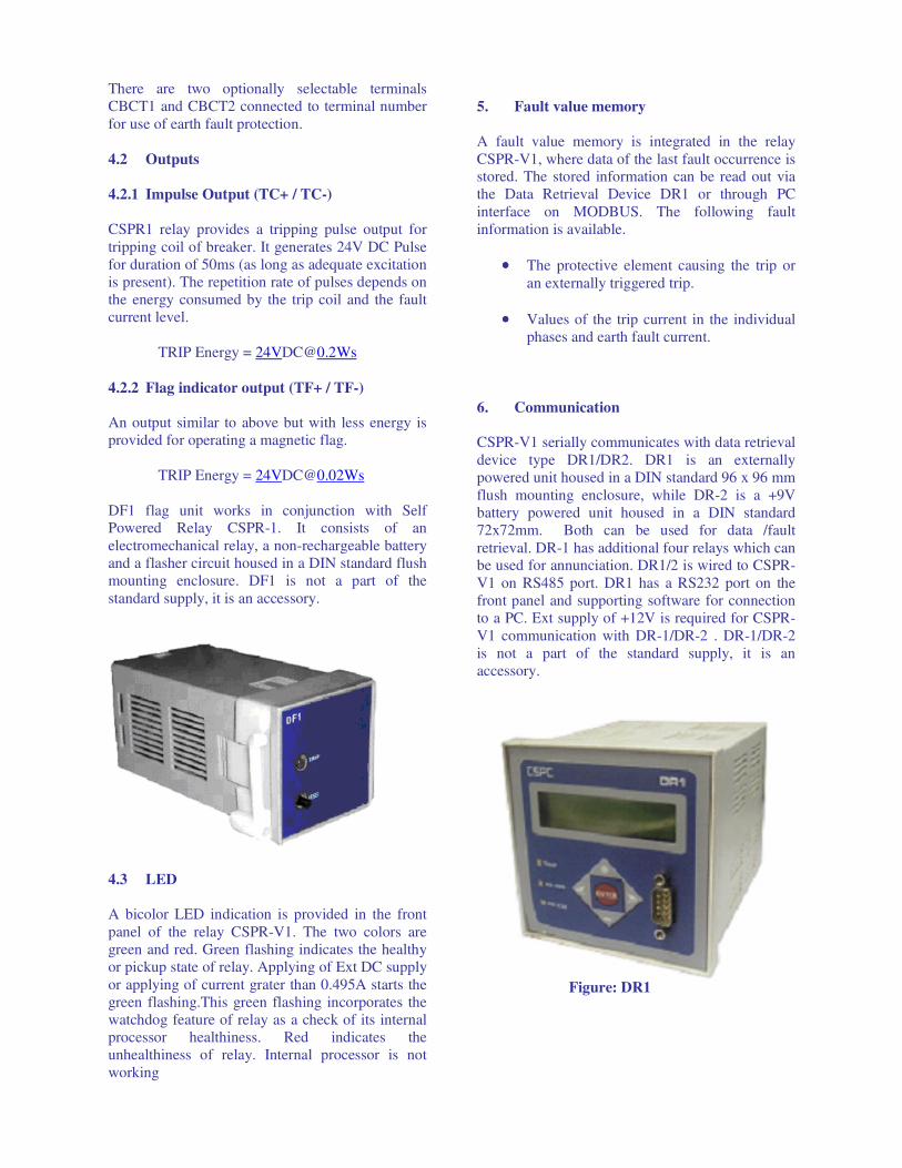
There are two optionally selectable terminals
CBCT1 and CBCT2 connected to terminal number
for use of earth fault protection.
4.2 Outputs
4.2.1 Impulse Output (TC+ / TC-)
CSPR1 relay provides a tripping pulse output for
tripping coil of breaker. It generates 24V DC Pulse
for duration of 50ms (as long as adequate excitation
is present). The repetition rate of pulses depends on
the energy consumed by the trip coil and the fault
current level.
TRIP Energy = [email protected]
4.2.2 Flag indicator output (TF+ / TF-)
An output similar to above but with less energy is
provided for operating a magnetic flag.
TRIP Energy = [email protected]
DF1 flag unit works in conjunction with Self Powered Relay CSPR-1. It consists of an
electromechanical relay, a non-rechargeable battery
and a flasher circuit housed in a DIN standard flush
mounting enclosure. DF1 is not a part of the
standard supply, it is an accessory.
4.3 LED
A bicolor LED indication is provided in the front
panel of the relay CSPR-V1. The two colors are
green and red. Green flashing indicates the healthy
or pickup state of relay. Applying of Ext DC supply
or applying of current grater than 0.495A starts the
green flashing.This green flashing incorporates the
watchdog feature of relay as a check of its internal
processor healthiness. Red indicates the
unhealthiness of relay. Internal processor is not
working
5. Fault value memory
A fault value memory is integrated in the relay
CSPR-V1, where data of the last fault occurrence is stored. The stored information can be read out via
the Data Retrieval Device DR1 or through PC
interface on MODBUS. The following fault
information is available.
•••• The protective element causing the trip or
an externally triggered trip.
•••• Values of the trip current in the individual
phases and earth fault current.
6. Communication
CSPR-V1 serially communicates with data retrieval
device type DR1/DR2. DR1 is an externally
powered unit housed in a DIN standard 96 x 96 mm
flush mounting enclosure, while DR-2 is a +9V
battery powered unit housed in a DIN standard
72x72mm. Both can be used for data /fault
retrieval. DR-1 has additional four relays which can be used for annunciation. DR1/2 is wired to CSPR-
V1 on RS485 port. DR1 has a RS232 port on the
front panel and supporting software for connection
to a PC. Ext supply of +12V is required for CSPR-
V1 communication with DR-1/DR-2 . DR-1/DR-2
is not a part of the standard supply, it is an
accessory.
Figure: DR1

CSPR-V1 supports External MODBUS
communication on RS485 with following settings.
Baud rate : 9600 baud
Parity : Even
Stop Bit : 1 bit
Data Bit : 8 bit data
Remote
Address
: 1-32(settable through
PC with default factory
setting of 2 )
All parameters of CSPR-V1 relay can be accessed
through “MODBUS” using external RS485 to
RS232 converter.
6.1 Circuit Breaker Trip Counter
CSPR-V1 maintains a counter for running count of
the number of times a circuit breaker has been
tripped. CSPR-V1 permanently stores this number
in its EEPROM. CSPR-V1 can maintain maximum
upto 65535 trip counts in its internal memory after
that counter gets automatically reset. This
information is accessible through MODBUS / PC front end software/DR1/DR2. Similarly one can
also reset this count through MODBUS / PC front
end software / DR1/DR2.
7. Technical Data
7.1 Characteristics
Hex switches are provided for parameter setting.
Switch Setting Parameter
1 Characteristics for O/C
2 I> Pick-up value of phase O/C
3 tI>
Tripping time of the definite
time over current element or
time multiplier of the inverse
time characteristic
4 I>> Pick-up value of the phase S/C
element
5 tI>> Tripping time of the short-
circuit element
6 Characteristic for E/F
7 IE> Pick-up value of the definite
time Earth O/C element
8 tIE> Tripping time of the definite
time earth over current element
or time multiplier of Earth O/C
element
9 IE>> Pick up value of E/F high set
10 tIE>> Tripping time of the definite
time Earth High Set element
7.2 Assignment of terminals
The protection relay CSPR-V1 is equipped with 22
screw-type plug in terminals. For Details see
section 9 terminal details.
I>
IE>

7.3 Setting Ranges and Steps
HEX - Switch 1 HEX 1 0 1 2 3 4 5 6 7 8 9 A B C D E F
CHAR DEFT N-
INV
V-
INV
E-
INV
L-
INV
RI-
INV
HV-
Fuse x x x x x x x x x
I>: HEX - Switch 2 HEX 3 0 1 2 3 4 5 6 7 8 9 A B C D E F
x IS 0.5 0.6 0.7 0.8 0.9 1 1.15 1.3 1.4 1.5 1.6 1.8 2 2.25 2.5 Exit
tI>: HEX – Switch 3 HEX 3 0 1 2 3 4 5 6 7 8 9 A B C D E F
Time(s)
(DEFT) 0.04 0.3 0.4 0.5 0.6 0.7 0.8 0.9 1.0 1.5 2.0 3.0 10 20 100 300
Factor
“a” 0.05 0.1 0.2 0.3 0.4 0.5 0.6 0.8 1 2 3 4 5 6 8 10
I>>: HEX – Switch 4 HEX 4 0 1 2 3 4 5 6 7 8 9 A B C D E F
x IS 1 2 3 4 5 6 7 8 9 10 12 14 16 18 20 Exit
tI>> : HEX – Switch 5 HEX5 0 1 2 3 4 5 6 7 8 9 A B C D E F
Time(s) 0.04 0.07 0.1 0.15 0.2 0.25 0.3 0.4 0.6 0.8 1.0 1.4 1.8 2.2 2.6 3.0
HEX - Switch 6
HEX 6 0 1 2 3 4 5 6 7 8 9 A B C D E F
CHAR DEFT N-
INV
V-
INV
E-
INV
L-
INV
RI-
INV
HV-
Fuse x x x x x x x x x
IE>: HEX – Switch 7 HEX 7 0 1 2 3 4 5 6 7 8 9 A B C D E F
x IS 0.1 0.2 0.3 0.4 0.5 0.6 0.7 0.8 0.9 1 1.2 1.4 1.6 2.0 2.5 Exit
tIE>: HEX – Switch 8
HEX 8 0 1 2 3 4 5 6 7 8 9 A B C D E F
Time(s)
(DEFT) 0.06 0.1 0.2 0.4 0.6 1 2 4 6 10 20 40 60 100 200 300
Factor
“a” 0.05 0.07 0.1 0.2 0.3 0.4 0.5 0.6 0.8 1 2 3 4 6 8 10
IE>>: HEX – Switch 9
HEX 9 0 1 2 3 4 5 6 7 8 9 A B C D E F
x IS 0.5 0.7 1.0 1.2 1.8 2 2.5 3.0 3.5 4 5 6 7 8 10 Exit
tIE>> : HEX – Switch 10
HEX10 0 1 2 3 4 5 6 7 8 9 A B C D E F
Time(s) 0.03 0.04 0.05 0.06 0.08 0.1 0.15 0.20 0.25 0.3 0.4 0.6 0.8 1 1.5 2
Steps for changing Nominal Frequency:
Step1. Put the front switch 1 on 50Hz or 60Hz position, as per requirement.
Step2. Power ON the CSPR-V1 (through current
or external DC supply)
Note: Once after getting energized, change of Freq
selector switch position will not be effected.
Caution: Selection of wrong nominal freq can
result in wrong pickup/trip.
Steps for Modbus Slave Address Configuration:
Step1. SW1 (Phase Characteristic Selection
Switch) & SW2 (Overload Pickup
Selection Switch) will be used for Slave
Address configuration as per following table
SW1
Position
SW2
Position
Slave Address for
CSPR-V1
0 X 1
1 X 2
2 X 3
3 X 4
4 X 5
5 X 6
6 X 7
7 X 8
8 X 9
9 X 10
A X 11
B X 12
C X 13
D X 14
E X 15
F 0 16
F 1 17
F 2 18
F 3 19
F 4 20
F 5 21
F 6 22
F 7 23
F 8 24
F 9 25
F A 26
F B 27
F C 28
F D 29
F E 30
F F 31
X: Don’t Care Condition
Step2: Now do the settings of SW1 & SW2 as per above selection chart & put the front switch 2 on
Slave Address position.
Step3: Switch ON the unit for one 1sec & put the
switch back on back position.
Note: If the switch2 remains in S.ADD position,
then CSPR-V1 will keep changing the Slave
address as per current position of SW1 & SW2
switches.
Caution: Change in S.ADD will not effect any
protection, but selection of wrong Slave address
can halt the running communication of Modbus.
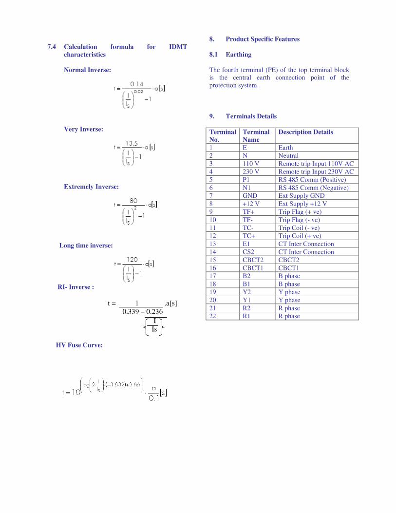
7.4 Calculation formula for IDMT
characteristics
Normal Inverse:
Very Inverse:
Extremely Inverse:
Long time inverse:
RI- Inverse :
t = 1 .a[s] 0.339 – 0.236
I
Is
HV Fuse Curve:
8. Product Specific Features
8.1 Earthing
The fourth terminal (PE) of the top terminal block is the central earth connection point of the
protection system.
9. Terminals Details
Terminal
No.
Terminal
Name
Description Details
1 E Earth
2 N Neutral
3 110 V Remote trip Input 110V AC
4 230 V Remote trip Input 230V AC
5 P1 RS 485 Comm (Positive)
6 N1 RS 485 Comm (Negative)
7 GND Ext Supply GND
8 +12 V Ext Supply +12 V
9 TF+ Trip Flag (+ ve)
10 TF- Trip Flag (- ve)
11 TC- Trip Coil (- ve)
12 TC+ Trip Coil (+ ve)
13 E1 CT Inter Connection
14 CS2 CT Inter Connection
15 CBCT2 CBCT2
16 CBCT1 CBCT1
17 B2 B phase
18 B1 B phase
19 Y2 Y phase
20 Y1 Y phase
21 R2 R phase
22 R1 R phase
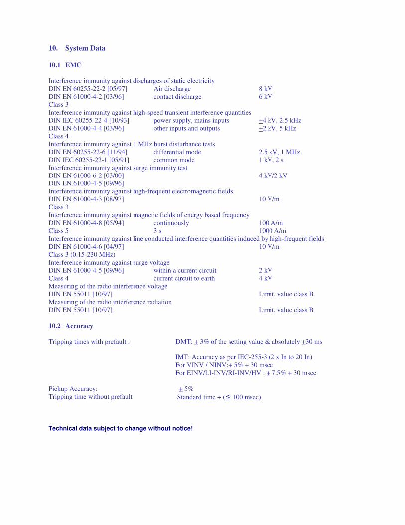
10. System Data
10.1 EMC
Interference immunity against discharges of static electricity
DIN EN 60255-22-2 [05/97]
DIN EN 61000-4-2 [03/96]
Class 3
Air discharge
contact discharge
8 kV
6 kV
Interference immunity against high-speed transient interference quantities
DIN IEC 60255-22-4 [10/93]
DIN EN 61000-4-4 [03/96]
Class 4
power supply, mains inputs
other inputs and outputs
+4 kV, 2.5 kHz
+2 kV, 5 kHz
Interference immunity against 1 MHz burst disturbance tests
DIN EN 60255-22-6 [11/94]
DIN IEC 60255-22-1 [05/91]
differential mode
common mode
2.5 kV, 1 MHz
1 kV, 2 s
Interference immunity against surge immunity test
DIN EN 61000-6-2 [03/00]
DIN EN 61000-4-5 [09/96]
4 kV/2 kV
Interference immunity against high-frequent electromagnetic fields
DIN EN 61000-4-3 [08/97]
Class 3
10 V/m
Interference immunity against magnetic fields of energy based frequency
DIN EN 61000-4-8 [05/94] continuously 100 A/m Class 5 3 s 1000 A/m
Interference immunity against line conducted interference quantities induced by high-frequent fields
DIN EN 61000-4-6 [04/97]
Class 3 (0.15-230 MHz)
10 V/m
Interference immunity against surge voltage
DIN EN 61000-4-5 [09/96]
Class 4
within a current circuit
current circuit to earth
2 kV
4 kV
Measuring of the radio interference voltage
DIN EN 55011 [10/97] Limit. value class B
Measuring of the radio interference radiation
DIN EN 55011 [10/97] Limit. value class B
10.2 Accuracy
Tripping times with prefault : DMT: + 3% of the setting value & absolutely +30 ms
IMT: Accuracy as per IEC-255-3 (2 x In to 20 In)
For VINV / NINV:+ 5% + 30 msec
For EINV/LI-INV/RI-INV/HV : + 7.5% + 30 msec
Pickup Accuracy: + 5%
Tripping time without prefault Standard time + (≤ 100 msec)
Technical data subject to change without notice!
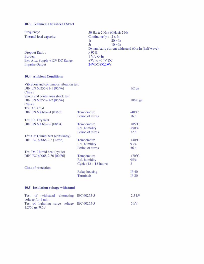
10.3 Technical Datasheet CSPR1
Frequency: 50 Hz ± 2 Hz / 60Hz ± 2 Hz
Thermal load capacity: Continuously : 2 x In
1s 20 x In
5s 10 x In
Dynamically current withstand 60 x In (half wave)
Dropout Ratio : > 95%
Burden 1 VA @ In
Ext. Aux. Supply +12V DC Range +7V to +14V DC
Impulse Output [email protected]
10.4 Ambient Conditions
Vibration and continuous vibration test
DIN EN 60255-21-1 [05/96]
Class 2
1/2 gn
Shock and continuous shock test
DIN EN 60255-21-2 [05/96]
Class 2
10/20 gn
Test Ad: Cold
DIN EN 60068-2-1 [03/95] Temperature Period of stress
-40°C 16 h
Test Bd: Dry heat
DIN EN 60068-2-2 [08/94] Temperature
Rel. humidity
Period of stress
+85°C
<50%
72 h
Test Ca: Humid heat (constantly)
DIN IEC 60068-2-3 [12/86] Temperature
Rel. humidity
Period of stress
+40°C
93%
56 d
Test Db :Humid heat (cyclic)
DIN IEC 60068-2-30 [09/86] Temperature
Rel. humidity
Cycle (12 + 12-hours)
+70°C
95%
2
Class of protection
Relay housing
Terminals
IP 40
IP 20
10.5 Insulation voltage withstand
Test of withstand alternating
voltage for 1 min:
IEC 60255-5 2.5 kV
Test of lightning surge voltage
1.2/50 µs, 0.5 J
IEC 60255-5 5 kV
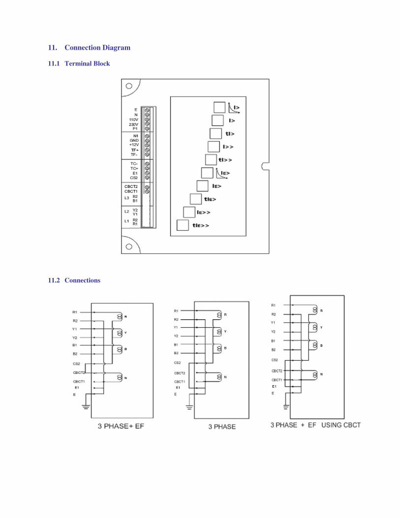
11. Connection Diagram
11.1 Terminal Block
11.2 Connections
11.3 Dimensional Details.
All Dimensions are in mm.
Weight : 1kg (Approx.)
Dimensions (W x H x T): 125×222×41mm
Ordering information
CSPR1-V24