ct oben manual new3 - b&h photo · 2 thank you for choosing oben! congratulations on your...
TRANSCRIPT

1
CT-2300/CT-2400 SeriesTripod
You’re on steady ground™

2
Thank You for choosing Oben!Congratulations on your purchase of this sturdy, multi-featured Oben CT-2300/2400 Series tripod. It will deliver lightweight, rock-solid camera support for years to come.
Adjusting the tripod’s height is simple: just loosen a twist-lock by turning it three-quarters of a turn counterclockwise, and extend or close one section of each telescopic leg separately. When the leg is the desired length, turn the twist-lock clockwise to tighten it. The center column locking knob releases the center column in a split second to slide up or down for further height adjustment. The center column is grooved to prevent it from rotating accidentally.
Each leg can be positioned independently at 3 locking angles (24˚, 55˚, or 80˚), and a built-in bubble level helps keep the tripod aligned with the horizon — both essential when working on uneven terrain.
Please read this entire manual before using the CT-2300/2400 Series tripod.
Note: Images are for illustrative purposes only. Actual product may vary.
IntroductIon
3
Key Features 5
Leg Length Adjustment 6
Leg Angle Adjustment 6
Center Column Adjustment 7
Low-Angle Setup 7
Counterweight 9
Mounting the Head 9
Retractable Spiked Feet 10
Warnings 11
tABLE oF contEntS

4
KEY FEAturES
A
E
I
JG
D
B
C
H
K
F

5
KEY FEAturES
A
B
K
H
I
J
F
G
E
D
C
Center column locking knob
Short split-column
Grooved reversible center column
Head locking screws
Leg angle adjustment lock
Twist-style leg lock levers
Bubble level
All-terrain feet
Dual 3/8”-1/4”-20 head mounting screw
Strap mount
Retractable and removable weight hook
6
oPErAtIon
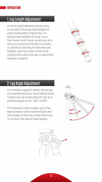
2. Leg Angle AdjustmentFor stable support when shooting on uneven terrain, each leg of your tripod can be individually set at a preset angle of 24˚, 55˚ or 80˚.
To change a leg’s angle, pull the adjustment lock outward and set the angle of the leg. Push the lock in to lock the leg at that angle.
oPErAtIon
1. Leg Length AdjustmentA twist-lock design allows you to quickly change the height of each telescopic tripod leg. To adjust the height of a leg, turn the twist-lock three-quarters of a turn counterclockwise to loosen it, position the leg at the desired height, and turn the twist-lock clockwise until the leg is securely locked in place.
7
oPErAtIonoPErAtIon
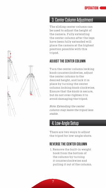
There are two ways to adjust the tripod for low-angle shots.
rEVErSE thE cEntEr coLumn1. Remove the built-in weight
hook from the bottom of the column by turning it counterclockwise and pulling it out of the column.
3. Center Column Adjustment
4. Low-Angle Setup
The sliding center column can be used to adjust the height of the camera. Fully extending the center column after the legs have been fully extended will place the camera at the highest position possible with this tripod.
AdjuSt thE cEntEr coLumn
Turn the center column locking knob counterclockwise, adjust the center column to the desired height, and lock it in place by turning the center column locking knob clockwise. Ensure that the knob is secure, but do not over-tighten it to avoid damaging the tripod.
Note: Extending the center column may leave the tripod less stable.

8
oPErAtIon
4. Low-Angle Setup2. Turn the center column locking
knob counterclockwise to unlock the center column. Remove the center column from the tripod.
3. Reverse the center column and insert it up the bottom of the tripod top plate.
4.Slide the column into the desired position. Turn the center column locking knob clockwise to lock at the desired height. Replace the weight hook by screwing it into the center column.
SPLIt thE cEntEr coLumn1. Remove the weight hook from
the bottom of the column by turning it counterclockwise and pulling it out of the column.
2. Turn the center column locking knob counterclockwise to unlock the center column. Remove the center column from the tripod.
3. Using the smallest included Allen wrench, loosen the Allen screw located near the top of the center column. When the Allen screw is loosened, unscrew the top part of the center column and remove it from the column.

9
oPErAtIon
5. CounterweightWhen shooting under windy conditions or when using a telephoto lens, the stability of your camera is critical. The built-in spring-loaded hook at the bottom of the center column allows you to hang a counter-weight for increased stabilization, such as a (not included) sandbag or loaded equipment bag.
The tripod includes a mounting screw with a 1/4” screw on one end and a 3/8” screw on the other, allowing you to mount either size tripod head. To switch between the two sizes, remove the plate from the tripod by turning it counter-clockwise.
Remove the screw, and insert the opposite end back into the plate. Mount the plate back onto the tripod by turning it clockwise.To mount a head, align the bottom of the tripod mount with the tripod’s mounting screw, then twist clockwise until fully secured. Do not over-tighten, as this may cause damage.
6. Mounting the Head
4. Put the main column aside. Tighten the Allen screw with the Allen wrench so that the screw is flush with the surface of the center column. Insert the short column into the tripod. Tighten the center column locking knob securely.
10
7. Retractable Spiked Feet*
6. Mounting the Head
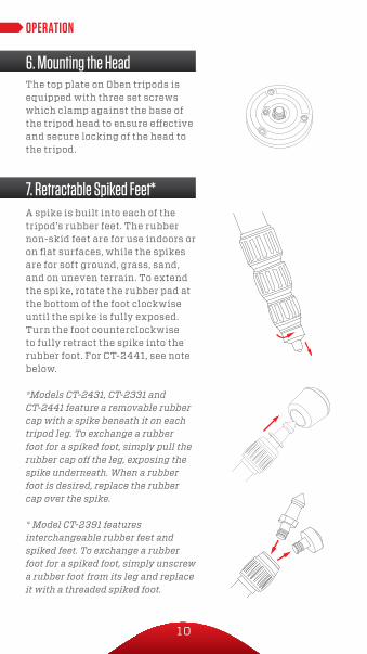
A spike is built into each of the tripod’s rubber feet. The rubber non-skid feet are for use indoors or on flat surfaces, while the spikes are for soft ground, grass, sand, and on uneven terrain. To extend the spike, rotate the rubber pad at the bottom of the foot clockwise until the spike is fully exposed. Turn the foot counterclockwise to fully retract the spike into the rubber foot. For CT-2441, see note below.
*Models CT-2431, CT-2331 and CT-2441 feature a removable rubber cap with a spike beneath it on each tripod leg. To exchange a rubber foot for a spiked foot, simply pull the rubber cap off the leg, exposing the spike underneath. When a rubber foot is desired, replace the rubber cap over the spike.
* Model CT-2391 features interchangeable rubber feet and spiked feet. To exchange a rubber foot for a spiked foot, simply unscrew a rubber foot from its leg and replace it with a threaded spiked foot.
The top plate on Oben tripods is equipped with three set screws which clamp against the base of the tripod head to ensure effective and secure locking of the head to the tripod.
callouts
leg angle adj
center clm adj attaching head
low angle adj
180°
oPErAtIon

11
!Warnings: • Do not exceed the tripod’s maximum load
capacity (see tag on tripod).
• Ensure that all appropriate locks are engaged when necessary.
• Tripod should only be used in temperatures between -22° and 140° Fahrenheit.
• Do not operate in salt water. Dry tripod off if it becomes wet.
• Remove the camera from the tripod during transport.
• Keep out of reach of children.
• To avoid injury, always support the top of the center column with one hand while adjusting height and locking the knob with the other hand.
oPtIonAL AccESSorIES • TS-110 Deluxe Padded Neoprene Tripod Strap
with zippered pocket
• TS-100 Padded Neoprene Tripod Strap
Visit our website at ObenSupports.comfor more Oben products.
WArnInGS

12
www.obensupports.com
© Co
pyrig
ht 20
14 Th
e Grad
us Gr
oup
All ot
her tr
adem
arks
are t
he pr
opert
y of th
eir re
spec
tive o
wners