ct8 repair manual - marmon-herringtonmh.dfl-studios.com/pdf/ct-8_service.pdf · tm 1 workshop...
TRANSCRIPT
1TM
WORKSHOP MANUAL
DRIVEN FRONT AXLE
CT8 SERIES
MARMON-HERRINGTON ALL-WHEEL DRIVE13001 Magisterial Drive • Louisville, KY 40223
(502) 253-0277 • (800) 227-0727 • Fax (502) 253-0317
E-mail: [email protected]
TM

2 TM
SECTION 202
CONTENTS
PAGE SECTION
FOREWORD ................................................................................................................... 4 203
DRAWINGS OF THE AXLES ......................................................................................... 5 204
TECHNICAL DATA ......................................................................................................... 7 205Types ...................................................................................................................... 7Wheel brake ........................................................................................................... 8Rolling bearings .................................................................................................... 9Seals ....................................................................................................................... 9
TORQUE RATINGS ........................................................................................................10 206Wheel hub ..............................................................................................................10Axle housing ..........................................................................................................10Differential .............................................................................................................. 11
ADJUSTMENT DATA .....................................................................................................12 207Wheel hub, steering knuckle ................................................................................12Differential ..............................................................................................................12
GENERAL SERVICE INSTRUCTIONS ..........................................................................13 209Wheel hub ..............................................................................................................13Axle housing ..........................................................................................................13Differential ..............................................................................................................13General instructions .............................................................................................13
Application of “LOCTITE” bolt securing materials ....................................................13
WHEEL HUB ..................................................................................................................14 210
SECTIONAL VIEW OF THE WHEEL HUB ....................................................................14 210
PARTS OF THE WHEEL HUB .......................................................................................15 211
REMOVING AND REINSTALLING THE WHEEL DISK .................................................16 212
REMOVING AND REINSTALLING THE COVER AND THE TOOTHED HUB ..............16 214
REMOVING AND REINSTALLING THE WHEEL HUB ..................................................16 223
DISASSEMBLING AND REASSEMBLING THE WHEEL HUB.....................................17 224
REMOVING AND REINSTALLING THE BRAKE DISK .................................................18 227
INSTALLATION INSTRUCTIONS FOR PARTS OF ANTIBLOCKING SYSTEM...........18 229
FRONT AXLE HOUSING................................................................................................19 240
3TM
PAGE SECTION
SECTIONAL VIEW OF THE AXLE HOUSING ...............................................................19 240
PARTS OF THE AXLE HOUSING ..................................................................................20 241
REMOVING AND REINSTALLING AND REPAIRING THE TIE-ROD,ADJUSTING THE TOE-IN AND THE WHEEL TURN ANGLES.............................20 242
REMOVING AND REINSTALLING THE STEERING KNUCKLES, REMOVING ANDREINSTALLING THE DOUBLE JOINTS, ASSEMBLING THE BRAKESUPPORT AND THE SPINDLE .............................................................................21 243
ASSEMBLING THE KNUCKLE PIN BEARING BUSHESAND THE SEALING RINGS ON THE STEERING KNUCKLE ..............................23 244
ASSEMBLING THE STEERING AND TIE-ROD ARMS.................................................24 245
ASSEMBLING THE DOUBLE JOINT (AXLE SHAFT REPLACEMENT) ......................25 246
REMOVING AND REINSTALLING THE INNER BEARING AND SEALSOF THE SPINDLE...................................................................................................27 247
REMOVING AND REINSTALLING BEARING AND ......................................................28 248SEALS OF THE KNUCKLE CARRIER
DISK WHEEL BRAKE ....................................................................................................28 270
DIFFERENTIAL ..............................................................................................................29 310
DIFFERENTIAL SECTIONAL VIEW ..............................................................................29 310
PARTS OF THE DIFFERENTIAL ...................................................................................29 311
REMOVING AND REINSTALLING THE DIFFERENTIAL .............................................30 312
REMOVING AND REINSTALLING THE COMPANION FLANGE,REPLACING THE OIL SEAL .................................................................................30 313
REMOVING AND REINSTALLING THE DIFFERENTIAL,ADJUSTING THE BACKLASH AND THE CONTACT PATTERN .........................31 314
DISASSEMBLING AND REASSEMBLING THE DIFFERENTIAL ................................33 315
REMOVING AND REINSTALLING THE BEARING CAGE,ADJUSTING THE AXIS DISTANCE .......................................................................35 316
DISASSEMBLING AND REASSEMBLING THE BEARING CAGE ..............................36 317
OIL FILL-UP, RUN, CHECK ...........................................................................................41 395
4 TM
SECTION 203
FOREWORD
This production “GENERAL WORKSHOPMANUAL” was prepared for workshops and con-tains all the necessary assembly instructions aswell as data to be checked and adjusted duringrepair, with the knowledge of which repair andadjustment of the
CT8
type driven front axles can properly be per-formed.
For technical data on the specific type versions ofthe CT8 type driven front axles refer to the publica-tion “TECHNICAL DATA”, while for the spare partsof that “PARTS CATALOG” grouped according tothe Orderers.
The “GENERAL WORKSHOP MANUAL” containdivided into sections the technical data and the ser-vice instructions of the axle. The sections of theservice instructions contain the disassembly and re-assembly operations of the individual assembly unit,stating the special tools to be used.
The serial numbers of the figures are started fromthe beginning in each section. The item numbers ofthe figures for an assembly unit are referred to ineach section dealing with the assembly procedures.
For service operations it is recommended to use thetools shown in the figures in order to assure properassembly of the individual units. The figures showeach essential service operation stating the desig-nation of the tool and its service position. The toolsare partly available from commerce and partly canbe fabricated in the workshop according to the toolblueprint ordered on basis of tool list supplementedto the “GENERAL WORKSHOP MANUAL”.
The manufacturer shall not be liable for warrantyclaims on damages resulting from negligence of thegeneral service practice required for normal serviceoperations but not contained in this Manual.
For replacing assembly units or individual parts useONLY genuine MARMON-HERRINGTON madeproducts.
RIGHTS FOR ALTERATIONS RESERVED!
MARMON-HERRINGTON COMPANY13001 MAGISTERIAL DRIVE
LOUISVILLE, KY 40245TEL.: 502-253-0277 FAX: 502-253-0317
5TM
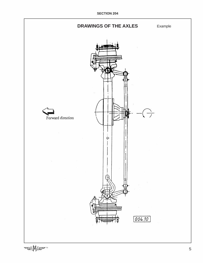
SECTION 204
DRAWINGS OF THE AXLES Example
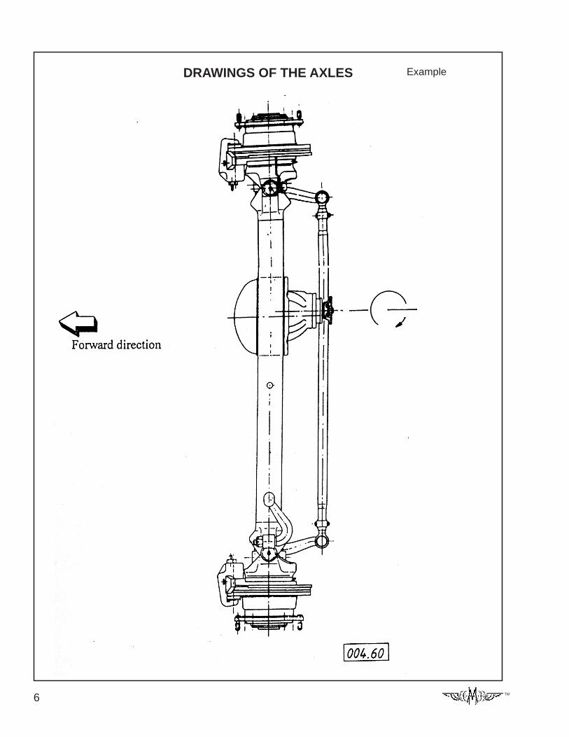
6 TM
DRAWINGS OF THE AXLES Example
7TM
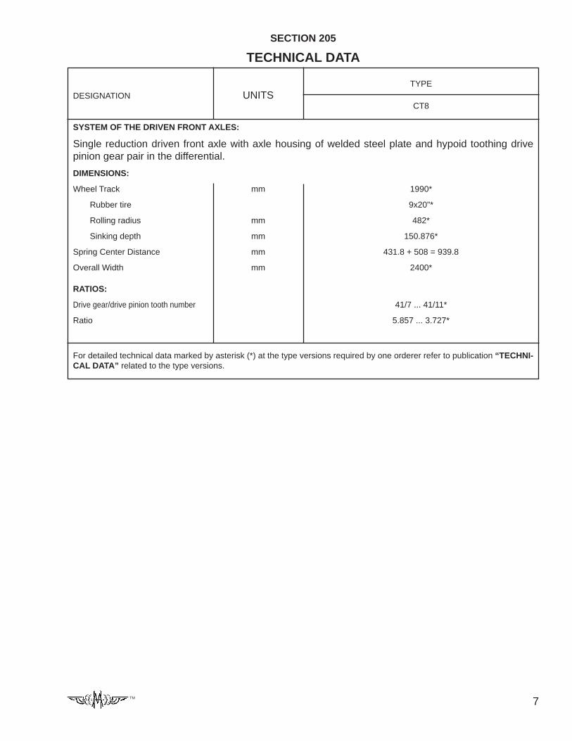
SECTION 205
TECHNICAL DATA
TYPE
CT8
SYSTEM OF THE DRIVEN FRONT AXLES:
Single reduction driven front axle with axle housing of welded steel plate and hypoid toothing drivepinion gear pair in the differential.
DIMENSIONS:
Wheel Track mm 1990*
Rubber tire 9x20"*
Rolling radius mm 482*
Sinking depth mm 150.876*
Spring Center Distance mm 431.8 + 508 = 939.8
Overall Width mm 2400*
RATIOS:
Drive gear/drive pinion tooth number 41/7 ... 41/11*
Ratio 5.857 ... 3.727*
For detailed technical data marked by asterisk (*) at the type versions required by one orderer refer to publication “TECHNI-CAL DATA” related to the type versions.
DESIGNATION UNITS
8 TM
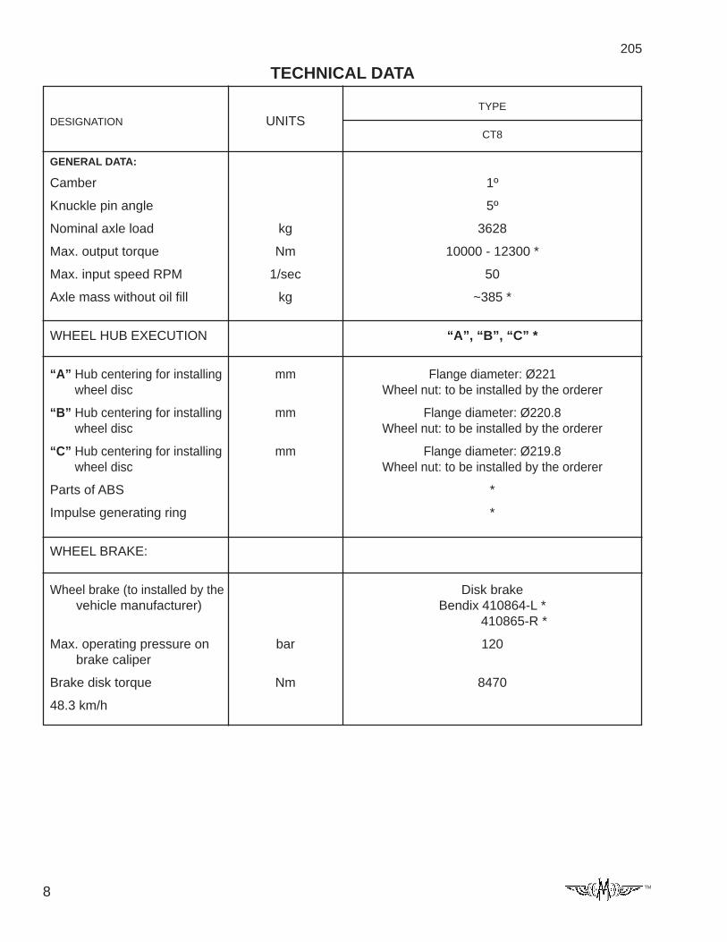
205
TECHNICAL DATA
TYPE
CT8
GENERAL DATA:
Camber 1º
Knuckle pin angle 5º
Nominal axle load kg 3628
Max. output torque Nm 10000 - 12300 *
Max. input speed RPM 1/sec 50
Axle mass without oil fill kg ~385 *
WHEEL HUB EXECUTION “A”, “B”, “C” *
“A” Hub centering for installing mm Flange diameter: Ø221wheel disc Wheel nut: to be installed by the orderer
“B” Hub centering for installing mm Flange diameter: Ø220.8wheel disc Wheel nut: to be installed by the orderer
“C” Hub centering for installing mm Flange diameter: Ø219.8wheel disc Wheel nut: to be installed by the orderer
Parts of ABS *
Impulse generating ring *
WHEEL BRAKE:
Wheel brake (to installed by the Disk brakevehicle manufacturer) Bendix 410864-L *
410865-R *
Max. operating pressure on bar 120brake caliper
Brake disk torque Nm 8470
48.3 km/h
DESIGNATION UNITS
9TM
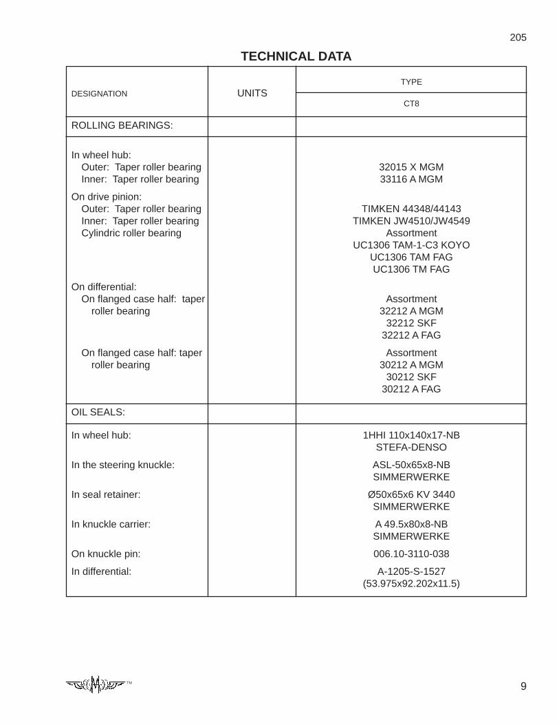
205
TECHNICAL DATA
TYPE
CT8
ROLLING BEARINGS:
In wheel hub:Outer: Taper roller bearing 32015 X MGMInner: Taper roller bearing 33116 A MGM
On drive pinion:Outer: Taper roller bearing TIMKEN 44348/44143Inner: Taper roller bearing TIMKEN JW4510/JW4549Cylindric roller bearing Assortment
UC1306 TAM-1-C3 KOYOUC1306 TAM FAGUC1306 TM FAG
On differential:On flanged case half: taper Assortment
roller bearing 32212 A MGM32212 SKF
32212 A FAG
On flanged case half: taper Assortmentroller bearing 30212 A MGM
30212 SKF30212 A FAG
OIL SEALS:
In wheel hub: 1HHI 110x140x17-NBSTEFA-DENSO
In the steering knuckle: ASL-50x65x8-NBSIMMERWERKE
In seal retainer: Ø50x65x6 KV 3440SIMMERWERKE
In knuckle carrier: A 49.5x80x8-NBSIMMERWERKE
On knuckle pin: 006.10-3110-038
In differential: A-1205-S-1527(53.975x92.202x11.5)
DESIGNATION UNITS
10 TM
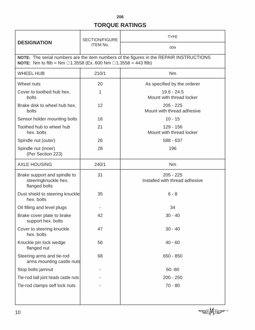
DESIGNATIONSECTION/FIGURE
ITEM No.
206
TORQUE RATINGS
TYPE
004
NOTE: The serial numbers are the item numbers of the figures in the REPAIR INSTRUCTIONSNOTE: Nm to ftlb = Nm ÷ 1.3558 (Ex. 600 Nm ÷ 1.3558 = 443 ftlb)
WHEEL HUB 210/1 Nm
Wheel nuts 20 As specified by the orderer
Cover to toothed hub hex. 1 19.6 - 24.5bolts Mount with thread locker
Brake disk to wheel hub hex. 12 205 - 225bolts Mount with thread adhesive
Sensor holder mounting bolts 16 10 - 15
Toothed hub to wheel hub 21 129 - 156hex. bolts Mount with thread locker
Spindle nut (outer) 26 588 - 637
Spindle nut (inner) 28 196(Per Section 223)
AXLE HOUSING 240/1 Nm
Brake support and spindle to 31 205 - 225steeringknuckle hex. Installed with thread adhesiveflanged bolts
Dust shield to steering knuckle 35 6 - 8hex. bolts
Oil filling and level plugs - 34
Brake cover plate to brake 42 30 - 40support hex. bolts
Cover to steering knuckle 47 30 - 40hex. bolts
Knuckle pin lock wedge 56 40 - 60flanged nut
Steering arms and tie-rod 68 650 - 850arms mounting castle nuts
Stop bolts jamnut - 60 -80
Tie-rod ball joint heads castle nuts - 200 - 250
Tie-rod clamps self lock nuts - 70 - 80
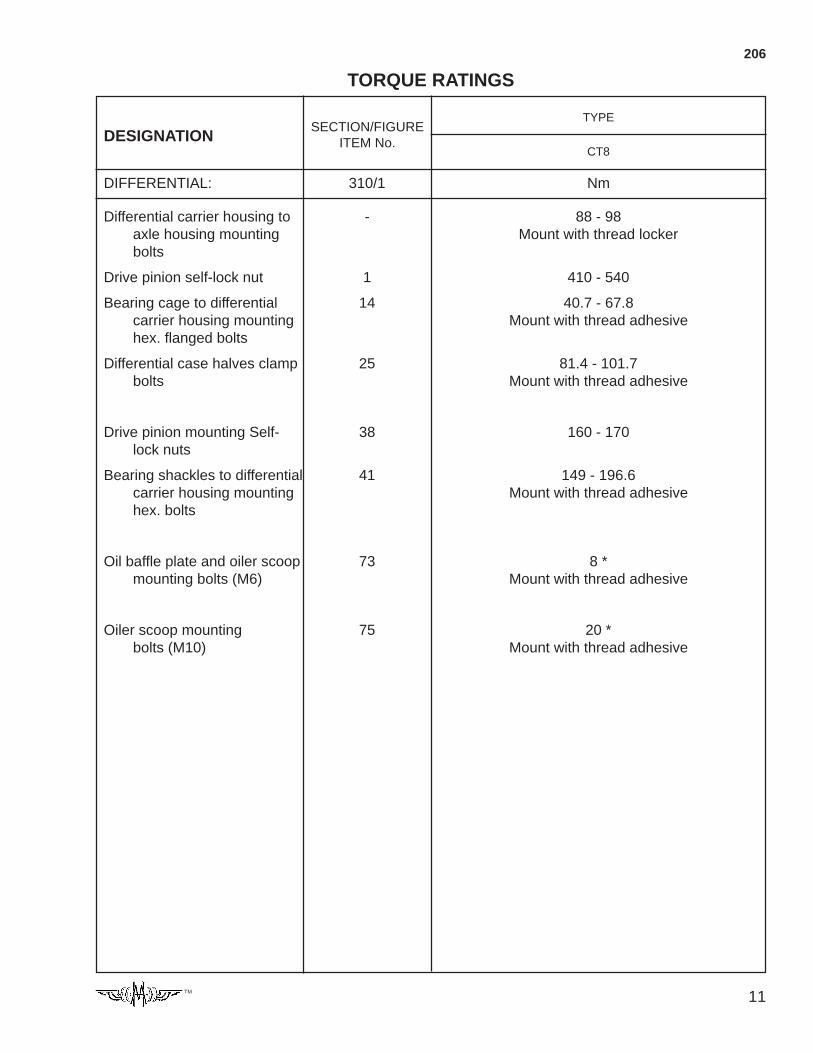
11TM
206
TORQUE RATINGS
TYPE
CT8
DIFFERENTIAL: 310/1 Nm
Differential carrier housing to - 88 - 98axle housing mounting Mount with thread lockerbolts
Drive pinion self-lock nut 1 410 - 540
Bearing cage to differential 14 40.7 - 67.8carrier housing mounting Mount with thread adhesivehex. flanged bolts
Differential case halves clamp 25 81.4 - 101.7bolts Mount with thread adhesive
Drive pinion mounting Self- 38 160 - 170lock nuts
Bearing shackles to differential 41 149 - 196.6carrier housing mounting Mount with thread adhesivehex. bolts
Oil baffle plate and oiler scoop 73 8 *mounting bolts (M6) Mount with thread adhesive
Oiler scoop mounting 75 20 *bolts (M10) Mount with thread adhesive
DESIGNATIONSECTION/FIGURE
ITEM No.

12 TM
207
ADJUSTMENT DATA
TYPE
CT8
WHEEL HUB, STEERINGKNUCKLE:
Axial play of wheel hub bearings mm 0.01 - 0.04(adjustment by shims)
Axial play of steering knuckle mm 0.0 - 0.3
Shim thicknesses mm 0.4; 0.6; 1.0; 1.2; 1.4
Toe-in mm 0 … 2.5
Max. inner wheel turn angle 40º
DIFFERENTIAL
Drive pinion to drive gear mm 0.2 - 0.28 *backlash: 0.18 - 0.25 *
Drive pinion rolling torque. Nm 1.0 - 5.0after preloading the bear-ings (the oil seal is notinstalled), adjustment bythe distance rings
Size of distance ring mm Spacers from 8.755 to 9.530 mmin 0.025 mm steps. totally 32 off.
Theoretical distance between mm 77.44the drive pinion face andthe drive gear centerline“AXIS DISTANCE”
Shim thicknesses mm 0.10; 0.12; 0.25
DESIGNATION UNITS
13TM
This section summarizes the service operations andadjustment data considered by us to be most impor-tant and which should thoroughly be observed andfollowed during assembling the axle.
WHEEL HUB
Assure 0.01 - 0.04 mm axial play for the wheel hub bear-ings after securing the spindle nut. For adjustment referto Section 223.
Fill up the wheel hub with LZS-2 EP grease as describedin the Section 223.
AXLE HOUSING
For axial bearing play assure 0.0 - 0.3 mm clearancebetween the knuckle carrier mounted in the steeringknuckle and the steering knuckle. For adjustment referto Section 243.
For adjustment of the 0 … 2.5 mm toe-in and the max.inner wheel lock-out angles refer to Section 241.
DIFFERENTIAL
Install the taper roller bearings of the drive pinion withpreload. Assure such a preload the bearings shall roll ontorque of 1.0 - 5.0 Nm. During check the sealing ring (4)is not equipped. for adjustment refer to Section 317.
The differential gears should be rotatable without jam-ming.
Install the taper roller bearings supporting the differentialwithout clearance.
Adjust clearance as described in “Technical data” andcheck the contact pattern. After checking adjust the bear-ing preload. The bearing preload must beØ300+0.35
+0.25 mm on the plane of the bearings.
For check and adjustment refer to Section 314.
GENERAL INSTRUCTIONS
For purposes of labor safety during service operationsperformed on the axle removing the individual assemblyunits make sure to assure safe backing, fixing or sus-pension.
Install only clean and sound parts free of burr and knock-outs. Before installation wipe the mating surfaces of theparts clean and apply thin coat of oil.
For assembly operations use ONLY plastic or copper-insert hammer.
Before installing the oil seals make sure to check if thesealing lip is sound and apply specified grease to be-tween the sealing lip and the dust protection edge. In-stall the o-rings also with grease.
When installing the taper roller bearings take care of thepairing according to the original packing or to themanufacturer’s specification.
SECTION 209
GENERAL SERVICE INSTRUCTIONSThe following thread cementing, locking and surface seal-ing materials are used at the axle, e.g.:
Thread adhesive: LOCTITE 277High-strength Omni FIT 1550 HENKELThread locker: LOCTITE 243Medium-strength Omni FIT 230 M HENKELSurface sealant: LOCTITE 518
Omni FIT 58 H HENKEL
Clean and degrease the surfaces before applying thethread adhesive and thread locker.
Clean and degrease the surfaces before applying the air-curing sealant. Apply a continuous strip of min. 3 mmdiameter to the specified surface. The time betweenapplying the sealant and assembling the parts togethermay not exceed 10 min.
Instead of the above cementing, fixing and sealing mate-rials other equivalent grade ones may also be used.
APPLICATION OF “LOCTITE” BOLT
LOCKING MATERIALS
The LOCTITE 277 thread adhesive material needs min.3-4 hrs. on 22º C temperature, the LOCTITE 243 threadlocking needs 1-2 hrs in the same conditions - to 75%solidification - based on the LOCTITE catalogue. Theproper bonding strength does not develop on greasy, oilysurfaces even after a longer period. Oil must not reachthe surface even after the application of the LOCTITE277 and 243 bolt locking materials and after the bolts aredriven in, within the curing time.
REPAIR OF THE PARTS ASSEMBLED WITH LOCTITETHREAD ADHESIVE AND THREAD LOCKING MATE-RIALS:
In case of a defect during the operation and during a gen-eral overhaul, after the assembly unit had been previ-ously washed, the first thing to do is to dismount thebonded joints. Clean carefully the matching surfaces andthe threaded bores of the dismounted units from the dirtand the remains of the adhesive. The remains of theadhesive shall be removed both by mechanical cleaningand with LOCTITE 806 solvent. The threaded bores canbe considered to be cleaned, when the bolts can easilybe driven up to the total thread length.
Prior to assembly, degrease carefully the bores of theparts to be assembled and the bolts. If oil/dirt is detectedin the bores of the washed parts, drop the oil from boresthen spray with LOCTITE 7061 cleaning spray then dry itin free air. (Blowing is permitted only with oil-free com-pressed air!) Spray the bores and the bolts with LOCTITE7649 activator, then let them dry at least for 10 minutes.
Before driving in, apply LOCTITE on the bolts around 4-5 threads from the end of the shank. (If steel is to bebonded to steel, the curing time is 1-3 hrs for achieving50-80% strength which provides the loadability).
14 TM
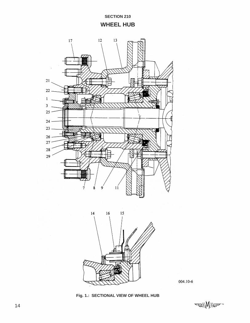
SECTION 210
WHEEL HUB
SECTIONAL VIEW OF WHEEL HUB
Fig. 1.: SECTIONAL VIEW OF WHEEL HUB
15TM
1 - Hex. bolt
—
3 - Cover
—
7 - Taper roller bearing
8 - Wheel hub
9 - Taper roller bearing
—
11 - Sealing ring
12 - Hex. flanged bolt
13 - Brake disk
14 - Impulse generating ring
15 - Sensor holder
SECTION 211
PARTS OF THE WHEEL HUB16 - Hex. bolt
17 - Wheel bolt
—
21 - Hex. bolt
22 - Washer
23 - Toothed hub
24 - Outer axle shaft
25 - Snap ring
26 - Outer shaft-end nut
27 - Lock plate
28 - Inner shaft-end nut
29 - Bearing retainer
16 TM
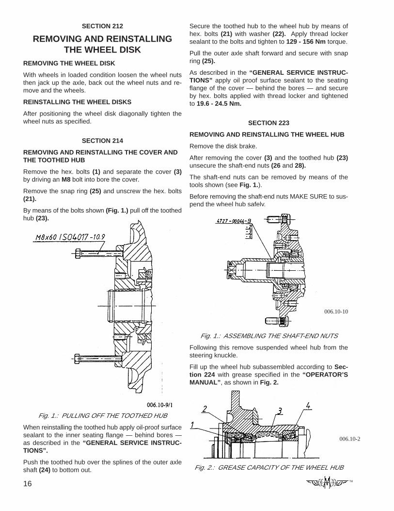
Secure the toothed hub to the wheel hub by means ofhex. bolts (21) with washer (22). Apply thread lockersealant to the bolts and tighten to 129 - 156 Nm torque.
Pull the outer axle shaft forward and secure with snapring (25).
As described in the “GENERAL SERVICE INSTRUC-TIONS” apply oil proof surface sealant to the seatingflange of the cover — behind the bores — and secureby hex. bolts applied with thread locker and tightenedto 19.6 - 24.5 Nm.
SECTION 223
REMOVING AND REINSTALLING THE WHEEL HUB
Remove the disk brake.
After removing the cover (3) and the toothed hub (23)unsecure the shaft-end nuts (26 and 28).
The shaft-end nuts can be removed by means of thetools shown (see Fig. 1.).
Before removing the shaft-end nuts MAKE SURE to sus-pend the wheel hub safely.
Fig. 1.: ASSEMBLING THE SHAFT-END NUTS
Following this remove suspended wheel hub from thesteering knuckle.
Fill up the wheel hub subassembled according to Sec-tion 224 with grease specified in the “OPERATOR’SMANUAL”, as shown in Fig. 2.
SECTION 212
REMOVING AND REINSTALLINGTHE WHEEL DISK
REMOVING THE WHEEL DISK
With wheels in loaded condition loosen the wheel nutsthen jack up the axle, back out the wheel nuts and re-move and the wheels.
REINSTALLING THE WHEEL DISKS
After positioning the wheel disk diagonally tighten thewheel nuts as specified.
SECTION 214
REMOVING AND REINSTALLING THE COVER ANDTHE TOOTHED HUB
Remove the hex. bolts (1) and separate the cover (3)by driving an M8 bolt into bore the cover.
Remove the snap ring (25) and unscrew the hex. bolts(21).
By means of the bolts shown (Fig. 1.) pull off the toothedhub (23).
Fig. 1.: PULLING OFF THE TOOTHED HUB
When reinstalling the toothed hub apply oil-proof surfacesealant to the inner seating flange — behind bores —as described in the “GENERAL SERVICE INSTRUC-TIONS”.
Push the toothed hub over the splines of the outer axleshaft (24) to bottom out.
006.10-10
Fig. 2.: GREASE CAPACITY OF THE WHEEL HUB
006.10-2
17TM
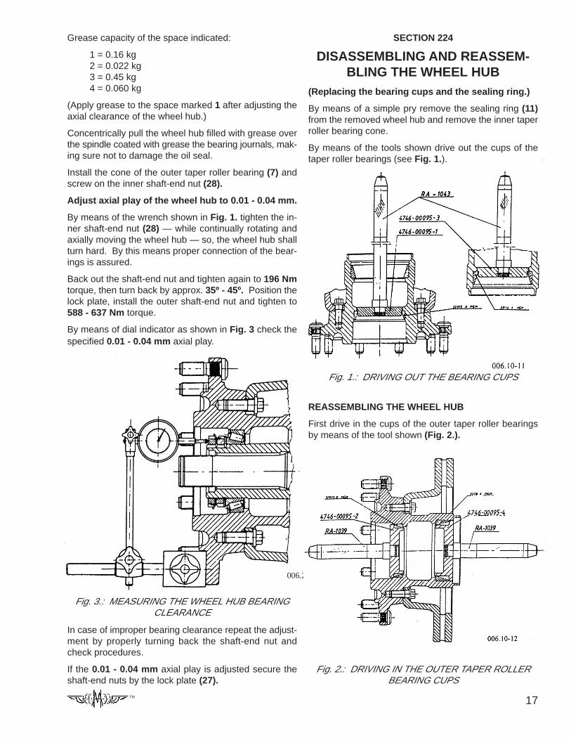
Grease capacity of the space indicated:
1 = 0.16 kg2 = 0.022 kg3 = 0.45 kg4 = 0.060 kg
(Apply grease to the space marked 1 after adjusting theaxial clearance of the wheel hub.)
Concentrically pull the wheel hub filled with grease overthe spindle coated with grease the bearing journals, mak-ing sure not to damage the oil seal.
Install the cone of the outer taper roller bearing (7) andscrew on the inner shaft-end nut (28).
Adjust axial play of the wheel hub to 0.01 - 0.04 mm.
By means of the wrench shown in Fig. 1. tighten the in-ner shaft-end nut (28) — while continually rotating andaxially moving the wheel hub — so, the wheel hub shallturn hard. By this means proper connection of the bear-ings is assured.
Back out the shaft-end nut and tighten again to 196 Nmtorque, then turn back by approx. 35º - 45º. Position thelock plate, install the outer shaft-end nut and tighten to588 - 637 Nm torque.
By means of dial indicator as shown in Fig. 3 check thespecified 0.01 - 0.04 mm axial play.
Fig. 3.: MEASURING THE WHEEL HUB BEARINGCLEARANCE
In case of improper bearing clearance repeat the adjust-ment by properly turning back the shaft-end nut andcheck procedures.
If the 0.01 - 0.04 mm axial play is adjusted secure theshaft-end nuts by the lock plate (27).
006.20-2
SECTION 224
DISASSEMBLING AND REASSEM-BLING THE WHEEL HUB
(Replacing the bearing cups and the sealing ring.)
By means of a simple pry remove the sealing ring (11)from the removed wheel hub and remove the inner taperroller bearing cone.
By means of the tools shown drive out the cups of thetaper roller bearings (see Fig. 1.).
Fig. 1.: DRIVING OUT THE BEARING CUPS
REASSEMBLING THE WHEEL HUB
First drive in the cups of the outer taper roller bearingsby means of the tool shown (Fig. 2.).
Fig. 2.: DRIVING IN THE OUTER TAPER ROLLERBEARING CUPS
18 TM
Inset the cone of the inner taper roller bearing (9) intobore of the installed cup.
As described in the “GENERAL SERVICE INSTRUC-TION” apply thin coat of oil-proof sealant to seat of theoil seal.
Drive the sealing ring into the seat until the tool bottomsout (see Fig. 3.).
Fig. 3.: DRIVING IN THE SEALING RING
SECTION 227
REMOVING AND REINSTALLINGTHE BRAKE DISC
When the brake disc (13) is to be replaced remove thehex. flanged bolts (12) installed with thread locker andpull the brake disc off the wheel hub.
During reinstalling the new brake disc tighten the hex.flanged bolts applied with thread locker to 205 - 225 Nmtorque.
SECTION 229
INSTALLATION INSTRUCTIONS FORPARTS OF ANTILOCKING SYSTEM
The models given in “TECHNICAL DATA” contain theitems (A, C), necessary at the installation of the anti-block and anti-skid systems (1).
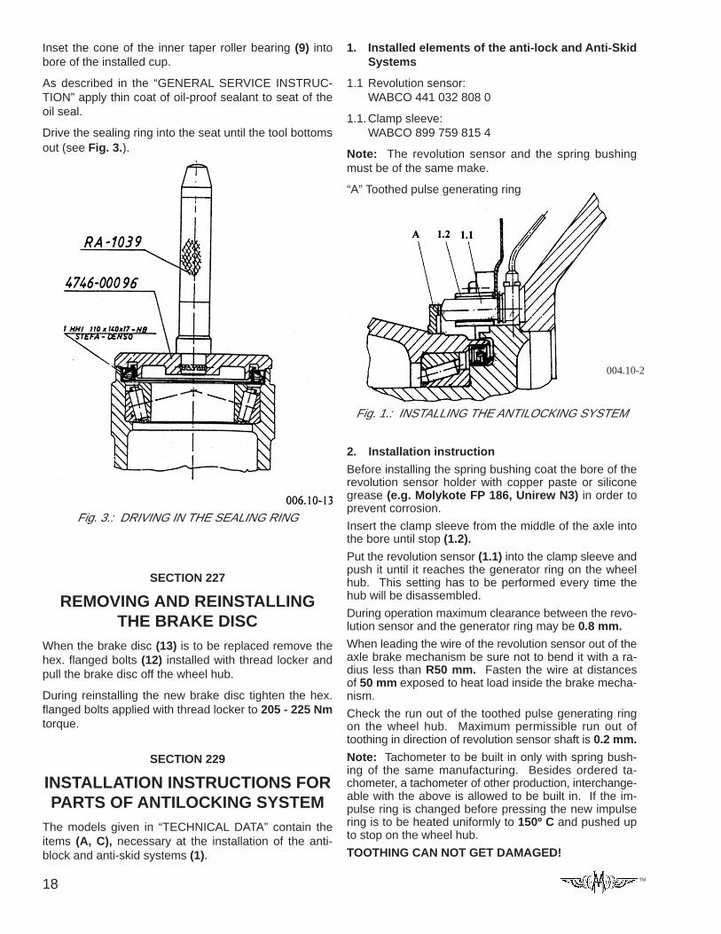
1. Installed elements of the anti-lock and Anti-SkidSystems
1.1 Revolution sensor:WABCO 441 032 808 0
1.1.Clamp sleeve:WABCO 899 759 815 4
Note: The revolution sensor and the spring bushingmust be of the same make.
“A” Toothed pulse generating ring
Fig. 1.: INSTALLING THE ANTILOCKING SYSTEM
2. Installation instruction
Before installing the spring bushing coat the bore of therevolution sensor holder with copper paste or siliconegrease (e.g. Molykote FP 186, Unirew N3) in order toprevent corrosion.
Insert the clamp sleeve from the middle of the axle intothe bore until stop (1.2).
Put the revolution sensor (1.1) into the clamp sleeve andpush it until it reaches the generator ring on the wheelhub. This setting has to be performed every time thehub will be disassembled.
During operation maximum clearance between the revo-lution sensor and the generator ring may be 0.8 mm.
When leading the wire of the revolution sensor out of theaxle brake mechanism be sure not to bend it with a ra-dius less than R50 mm. Fasten the wire at distancesof 50 mm exposed to heat load inside the brake mecha-nism.
Check the run out of the toothed pulse generating ringon the wheel hub. Maximum permissible run out oftoothing in direction of revolution sensor shaft is 0.2 mm.
Note: Tachometer to be built in only with spring bush-ing of the same manufacturing. Besides ordered ta-chometer, a tachometer of other production, interchange-able with the above is allowed to be built in. If the im-pulse ring is changed before pressing the new impulsering is to be heated uniformly to 150º C and pushed upto stop on the wheel hub.
TOOTHING CAN NOT GET DAMAGED!
004.10-2
19TM
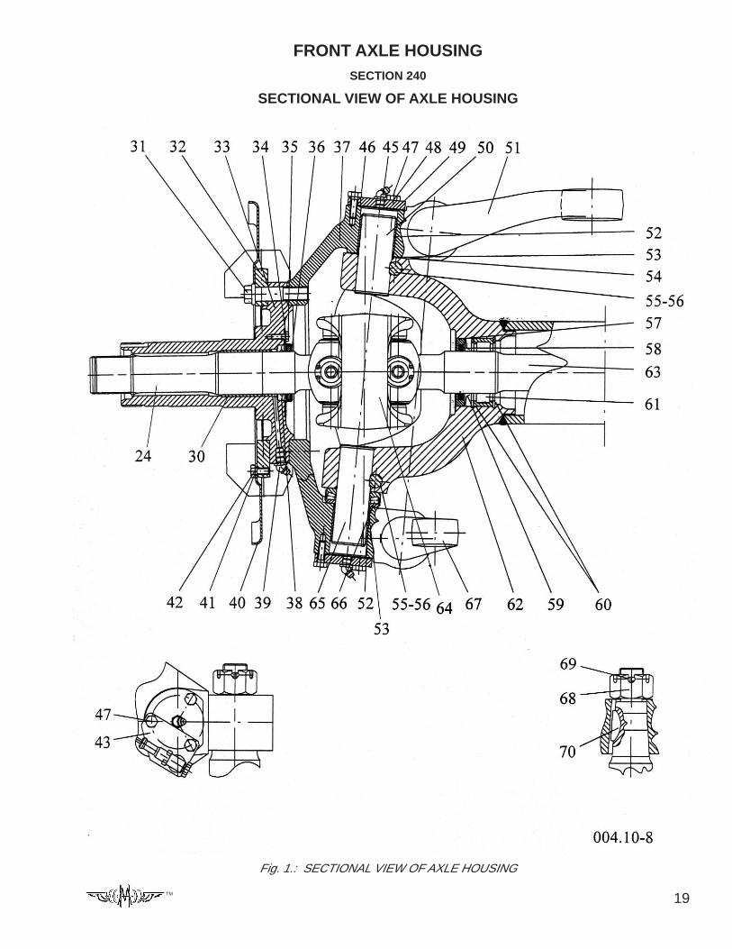
FRONT AXLE HOUSINGSECTION 240
SECTIONAL VIEW OF AXLE HOUSING
Fig. 1.: SECTIONAL VIEW OF AXLE HOUSING
20 TM
24 – Outer axle shaft
30 – Bush
31 – Hex. flanged bolt
32 – Brake support
33 – Spindle
34 – Lock washer
35 – Hex. bolt
36 – Dust shield with sealing ring
37 – Steering knuckle
38 – Sealing ring
39 – Grease fitting
40 – Brake cover plate
41 – Lock washer
42 – Hex. bolt
43 – Holder of the tachometer’s wire
—
45 – Gasket
46 – Ball grease fitting
47 – Hex. bolt
48 – Lock washer
49 – Cover
50 – Knuckle pin, upper
51 – Steering arm
52 – Knuckle pin bush
53 – Sealing ring
54 – Shim
55 – Lock wedge
56 – Flanged nut
57 – Seal retainer
58 – Sealing ring
59 – Oil seal
60 – Snap ring
61 – Cylindric roller bearing
62 – Knuckle carrier
63 – Inner axle shaft
64 – Double joint head
65 – Knuckle pin, lower
66 – Axial bearing
67 – Tie-rod arm
68 – Castle nut
69 – Cotter
70 – Woodruff key
SECTION 241
PARTS OF THE AXLEHOUSING
SECTION 242
REMOVING AND REINSTALLING AND REPAIR-ING THE TIE-ROD, ADJUSTING THE TOE-IN
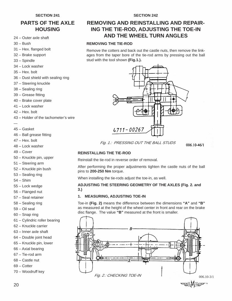
AND THE WHEEL TURN ANGLESREMOVING THE TIE-ROD
Remove the cotters and back out the castle nuts, then remove the link-ages from the taper bore of the tie-rod arms by pressing out the ballstud with the tool shown (Fig.1.).
Fig. 1.: PRESSING OUT THE BALL STUDS
REINSTALLING THE TIE-ROD
Reinstall the tie-rod in reverse order of removal.
After performing the proper adjustments tighten the castle nuts of the ballpins to 200-250 Nm torque.
When installing the tie-rods adjust the toe-in, as well.
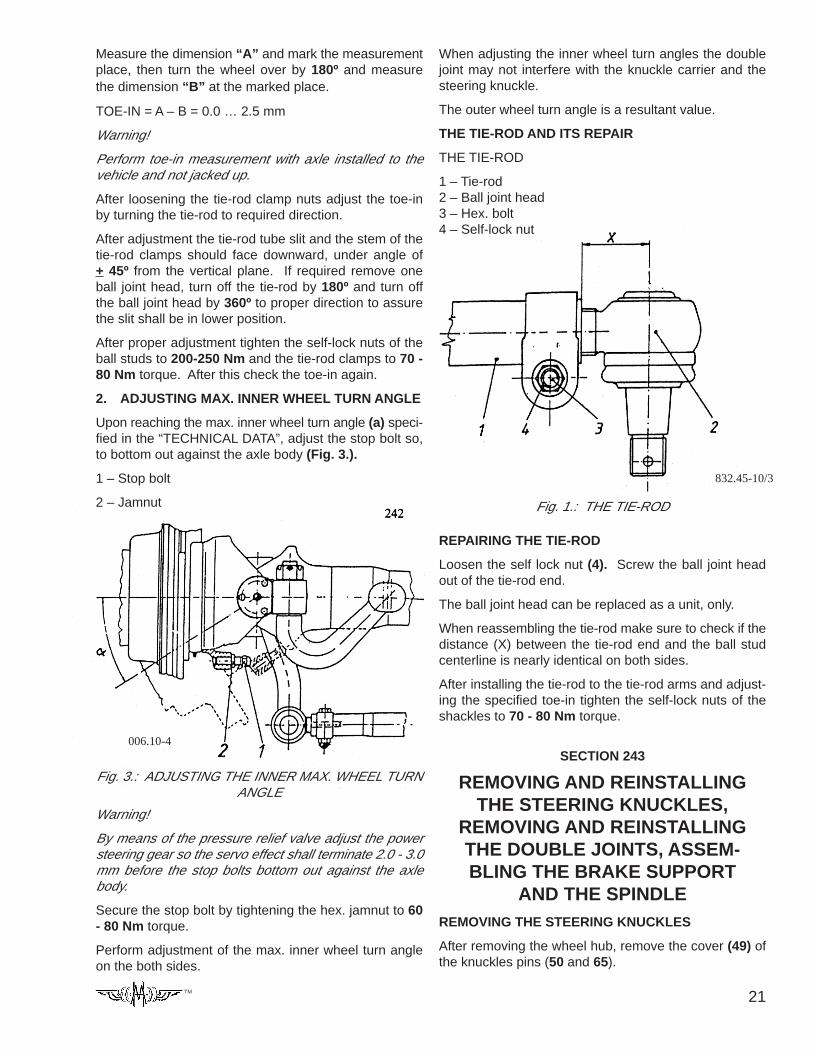
ADJUSTING THE STEERING GEOMETRY OF THE AXLES (Fig. 2. and3.)
1. MEASURING, ADJUSTING TOE-IN
Toe-in (Fig. 2) means the difference between the dimensions “A” and “B”as measured at the height of the wheel center in front and rear on the brakedisc flange. The value “B” measured at the front is smaller.
Fig. 2.: CHECKING TOE-IN 006.10-3/1
21TM
006.10-4
Fig. 3.: ADJUSTING THE INNER MAX. WHEEL TURNANGLE
Measure the dimension “A” and mark the measurementplace, then turn the wheel over by 180º and measurethe dimension “B” at the marked place.
TOE-IN = A – B = 0.0 … 2.5 mm
Warning!
Perform toe-in measurement with axle installed to thevehicle and not jacked up.
After loosening the tie-rod clamp nuts adjust the toe-inby turning the tie-rod to required direction.
After adjustment the tie-rod tube slit and the stem of thetie-rod clamps should face downward, under angle of+ 45º from the vertical plane. If required remove oneball joint head, turn off the tie-rod by 180º and turn offthe ball joint head by 360º to proper direction to assurethe slit shall be in lower position.
After proper adjustment tighten the self-lock nuts of theball studs to 200-250 Nm and the tie-rod clamps to 70 -80 Nm torque. After this check the toe-in again.
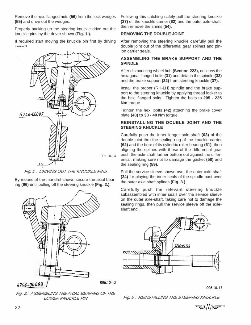
2. ADJUSTING MAX. INNER WHEEL TURN ANGLE
Upon reaching the max. inner wheel turn angle (a) speci-fied in the “TECHNICAL DATA”, adjust the stop bolt so,to bottom out against the axle body (Fig. 3.).
1 – Stop bolt
2 – Jamnut
Warning!
By means of the pressure relief valve adjust the powersteering gear so the servo effect shall terminate 2.0 - 3.0mm before the stop bolts bottom out against the axlebody.
Secure the stop bolt by tightening the hex. jamnut to 60- 80 Nm torque.
Perform adjustment of the max. inner wheel turn angleon the both sides.
When adjusting the inner wheel turn angles the doublejoint may not interfere with the knuckle carrier and thesteering knuckle.
The outer wheel turn angle is a resultant value.
THE TIE-ROD AND ITS REPAIR
THE TIE-ROD
1 – Tie-rod2 – Ball joint head3 – Hex. bolt4 – Self-lock nut
REPAIRING THE TIE-ROD
Loosen the self lock nut (4). Screw the ball joint headout of the tie-rod end.
The ball joint head can be replaced as a unit, only.
When reassembling the tie-rod make sure to check if thedistance (X) between the tie-rod end and the ball studcenterline is nearly identical on both sides.
After installing the tie-rod to the tie-rod arms and adjust-ing the specified toe-in tighten the self-lock nuts of theshackles to 70 - 80 Nm torque.
SECTION 243
REMOVING AND REINSTALLINGTHE STEERING KNUCKLES,
REMOVING AND REINSTALLINGTHE DOUBLE JOINTS, ASSEM-BLING THE BRAKE SUPPORT
AND THE SPINDLEREMOVING THE STEERING KNUCKLES
After removing the wheel hub, remove the cover (49) ofthe knuckles pins (50 and 65).
Fig. 1.: THE TIE-ROD
832.45-10/3
22 TM
Remove the hex. flanged nuts (56) from the lock wedges(55) and drive out the wedges.
Properly backing up the steering knuckle drive out theknuckle pins by the driver shown (Fig. 1.).
If required start moving the knuckle pin first by drivinginward.
Fig. 1.: DRIVING OUT THE KNUCKLE PINS
006.10-14
By means of the mandrel shown secure the axial bear-ing (66) until pulling off the steering knuckle (Fig. 2.).
Fig. 2.: ASSEMBLING THE AXIAL BEARING OF THELOWER KNUCKLE PIN
Following this catching safely pull the steering knuckle(37) off the knuckle carrier (62) and the outer axle-shaft,then remove the shims (54).
REMOVING THE DOUBLE JOINT
After removing the steering knuckle carefully pull thedouble joint out of the differential gear splines and pin-ion carrier seals.
ASSEMBLING THE BRAKE SUPPORT AND THESPINDLE
After dismounting wheel hub (Section 223), unscrew thehexagonal flanged bolts (31) and detach the spindle (33)and the brake support (32) from steering knuckle (37).
Install the proper (RH-LH) spindle and the brake sup-port to the steering knuckle by applying thread locker tothe hex. flanged bolts. Tighten the bolts to 205 - 225Nm torque.
Tighten the hex. bolts (42) attaching the brake coverplate (40) to 30 - 40 Nm torque.
REINSTALLING THE DOUBLE JOINT AND THESTEERING KNUCKLE
Carefully push the inner longer axle-shaft (63) of thedouble joint thru the sealing ring of the knuckle carrier(62) and the bore of its cylindric roller bearing (61), thenaligning the splines with those of the differential gearpush the axle-shaft further bottom out against the differ-ential, making sure not to damage the gasket (58) andthe sealing ring (59).
Pull the service sleeve shown over the outer axle shaft(24) for playing the inner seals of the spindle past overthe outer axle shaft splines (Fig. 3.).
Carefully push the relevant steering knucklesubassembled with inner seals over the service sleeveon the outer axle-shaft, taking care not to damage thesealing rings, then pull the service sleeve off the axle-shaft end.
Fig. 3.: REINSTALLING THE STEERING KNUCKLE
23TM
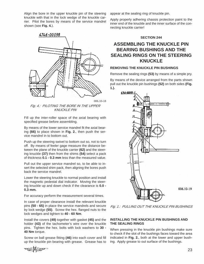
Align the bore in the upper knuckle pin of the steeringknuckle with that in the lock wedge of the knuckle car-rier. Pilot the bores by means of the service mandrelshown (see Fig. 4.).
Fig. 4.: PILOTING THE BORE IN THE UPPERKNUCKLE PIN
Fill up the inter-roller space of the axial bearing withspecified grease before assembling.
By means of the lower service mandrel fit the axial bear-ing (66) to place shown in Fig. 2., then push the ser-vice mandrel in to bottom out.
Push up the steering swivel to bottom out so, not to turnoff. By means of feeler gage measure the distance be-tween the plane of the knuckle carrier (62) and the steer-ing knuckle (37) then from the shims (54) select a packof thickness 0.1 - 0.3 mm less than the measured value.
Pull out the upper service mandrel so, to be able to in-sert the selected shim pack, then aligning the bores pushback the service mandrel.
Lower the steering knuckle to normal position and installthe magnetic pedestal dial indicator. Moving the steer-ing knuckle up and down check if the clearance is 0.0 -0.3 mm.
For accuracy perform the measurement several times.
In case of proper clearance install the relevant knucklepins (50 - 65) in place the service mandrels and secureby lock wedge (55). Screw the hex. flanged nuts to thelock wedges and tighten to 40 - 60 Nm.
Install the covers (49) together with gasket (45) and theholder (43) of the tachometer’s wire over the knucklepins. Tighten the hex. bolts with lock washers to 30 -40 Nm torque.
Screw on ball grease fitting (46) into each cover and fillup the knuckle pin bearing with grease. Grease has to
appear at the sealing ring of knuckle pin.
Apply properly adhering chassis protection paint to theinner end of the knuckle and the inner surface of the con-necting knuckle carrier!
SECTION 244
ASSEMBLING THE KNUCKLE PINBEARING BUSHINGS AND THE
SEALING RINGS ON THE STEERINGKNUCKLE
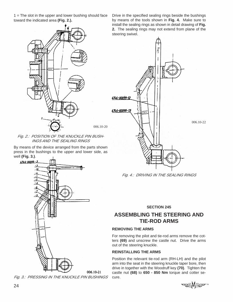
REMOVING THE KNUCKLE PIN BUSHINGS
Remove the sealing rings (53) by means of a simple pry.
By means of the device arranged from the parts shownpull out the knuckle pin bushings (52) on both sides (Fig.1.).
006.10-18
Fig. 1.: PULLING OUT THE KNUCKLE PIN BUSHINGS
INSTALLING THE KNUCKLE PIN BUSHINGS ANDTHE SEALING RINGS
When pressing in the knuckle pin bushings make sureto check if the slot of the bushings faces toward the areaindicated in Fig. 2., both at the lower and upper bush-ing. Apply grease to out surface of the bushings.
24 TM
Fig. 2.: POSITION OF THE KNUCKLE PIN BUSH-INGS AND THE SEALING RINGS
1 = The slot in the upper and lower bushing should facetoward the indicated area (Fig. 2.).
By means of the device arranged from the parts shownpress in the bushings to the upper and lower side, aswell (Fig. 3.).
Fig. 3.: PRESSING IN THE KNUCKLE PIN BUSHINGS
006.10-20
Drive in the specified sealing rings beside the bushingsby means of the tools shown in Fig. 4. Make sure toinstall the sealing rings as shown in detail drawing of Fig.2. The sealing rings may not extend from plane of thesteering swivel.
Fig. 4.: DRIVING IN THE SEALING RINGS
006.10-22
SECTION 245
ASSEMBLING THE STEERING ANDTIE-ROD ARMS
REMOVING THE ARMS
For removing the pilot and tie-rod arms remove the cot-ters (69) and unscrew the castle nut. Drive the armsout of the steering knuckle.
REINSTALLING THE ARMS
Position the relevant tie-rod arm (RH-LH) and the pilotarm into the seat in the steering knuckle taper bore, thendrive in together with the Woodruff key (70). Tighten thecastle nut (68) to 650 - 850 Nm torque and cotter se-cure.
25TM
SECTION 246
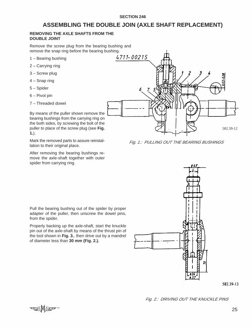
ASSEMBLING THE DOUBLE JOIN (AXLE SHAFT REPLACEMENT)REMOVING THE AXLE SHAFTS FROM THEDOUBLE JOINT
Remove the screw plug from the bearing bushing andremove the snap ring before the bearing bushing.
1 – Bearing bushing
2 – Carrying ring
3 – Screw plug
4 – Snap ring
5 – Spider
6 – Pivot pin
7 – Threaded dowel
Fig. 1.: PULLING OUT THE BEARING BUSHINGS
582.39-12
By means of the puller shown remove thebearing bushings from the carrying ring onthe both sides, by screwing the bolt of thepuller to place of the screw plug (see Fig.1.).
Mark the removed parts to assure reinstal-lation to their original place.
After removing the bearing bushings re-move the axle-shaft together with outerspider from carrying ring.
Pull the bearing bushing out of the spider by properadapter of the puller, then unscrew the dowel pins,from the spider.
Properly backing up the axle-shaft, start the knucklepin out of the axle-shaft by means of the thrust pin ofthe tool shown in Fig. 3., then drive out by a mandrelof diameter less than 30 mm (Fig. 2.).
Fig. 2.: DRIVING OUT THE KNUCKLE PINS
26 TM
REASSEMBLING THE DOUBLE JOINT
Reassemble the new axle-shaft in reverse order of re-moval.
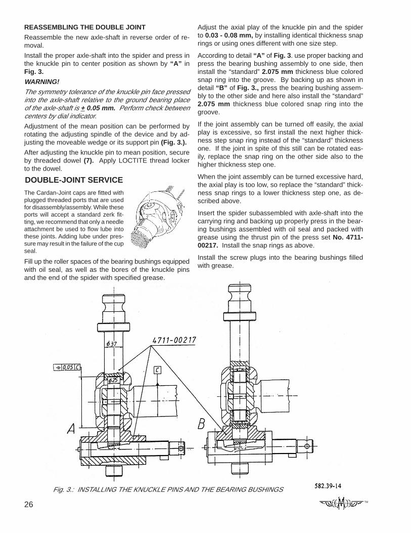
Install the proper axle-shaft into the spider and press inthe knuckle pin to center position as shown by “A” inFig. 3.
WARNING!The symmetry tolerance of the knuckle pin face pressedinto the axle-shaft relative to the ground bearing placeof the axle-shaft is + 0.05 mm. Perform check betweencenters by dial indicator.Adjustment of the mean position can be performed byrotating the adjusting spindle of the device and by ad-justing the moveable wedge or its support pin (Fig. 3.).
After adjusting the knuckle pin to mean position, secureby threaded dowel (7). Apply LOCTITE thread lockerto the dowel.
Fill up the roller spaces of the bearing bushings equippedwith oil seal, as well as the bores of the knuckle pinsand the end of the spider with specified grease.
Adjust the axial play of the knuckle pin and the spiderto 0.03 - 0.08 mm, by installing identical thickness snaprings or using ones different with one size step.
According to detail “A” of Fig. 3. use proper backing andpress the bearing bushing assembly to one side, theninstall the “standard” 2.075 mm thickness blue coloredsnap ring into the groove. By backing up as shown indetail “B” of Fig. 3., press the bearing bushing assem-bly to the other side and here also install the “standard”2.075 mm thickness blue colored snap ring into thegroove.
If the joint assembly can be turned off easily, the axialplay is excessive, so first install the next higher thick-ness step snap ring instead of the “standard” thicknessone. If the joint in spite of this still can be rotated eas-ily, replace the snap ring on the other side also to thehigher thickness step one.
When the joint assembly can be turned excessive hard,the axial play is too low, so replace the “standard” thick-ness snap rings to a lower thickness step one, as de-scribed above.
Insert the spider subassembled with axle-shaft into thecarrying ring and backing up properly press in the bear-ing bushings assembled with oil seal and packed withgrease using the thrust pin of the press set No. 4711-00217. Install the snap rings as above.
Install the screw plugs into the bearing bushings filledwith grease.
Fig. 3.: INSTALLING THE KNUCKLE PINS AND THE BEARING BUSHINGS
DOUBLE-JOINT SERVICE
The Cardan-Joint caps are fitted withplugged threaded ports that are usedfor disassembly/assembly. While theseports will accept a standard zerk fit-ting, we recommend that only a needleattachment be used to flow lube intothese joints. Adding lube under pres-sure may result in the failure of the cupseal.
27TM
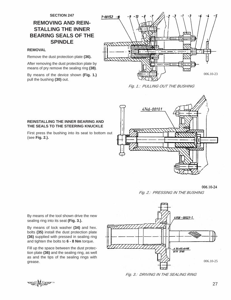
SECTION 247
REMOVING AND REIN-STALLING THE INNER
BEARING SEALS OF THESPINDLE
REMOVAL
Remove the dust protection plate (36).
After removing the dust protection plate bymeans of pry remove the sealing ring (38).
By means of the device shown (Fig. 1.)pull the bushing (30) out.
Fig. 1.: PULLING OUT THE BUSHING
REINSTALLING THE INNER BEARING ANDTHE SEALS TO THE STEERING KNUCKLE
First press the bushing into its seat to bottom out(see Fig. 2.).
006.10-23
Fig. 2.: PRESSING IN THE BUSHING
Fig. 3.: DRIVING IN THE SEALING RING
By means of the tool shown drive the newsealing ring into its seat (Fig. 3.).
By means of lock washer (34) and hex.bolts (35) install the dust protection plate(36) supplied with pressed in sealing ringand tighten the bolts to 6 - 8 Nm torque.
Fill up the space between the dust protec-tion plate (36) and the sealing ring, as wellas and the tips of the sealing rings withgrease. 006.10-25
28 TM
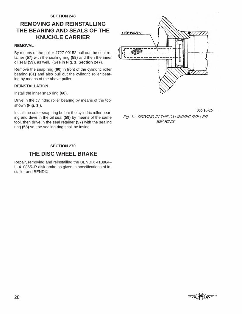
SECTION 248
REMOVING AND REINSTALLINGTHE BEARING AND SEALS OF THE
KNUCKLE CARRIERREMOVAL
By means of the puller 4727-00152 pull out the seal re-tainer (57) with the sealing ring (58) and then the inneroil seal (59), as well. (See in Fig. 1. Section 247).
Remove the snap ring (60) in front of the cylindric rollerbearing (61) and also pull out the cylindric roller bear-ing by means of the above puller.
REINSTALLATION
Install the inner snap ring (60).
Drive in the cylindric roller bearing by means of the toolshown (Fig. 1.).
Install the outer snap ring before the cylindric roller bear-ing and drive in the oil seal (59) by means of the sametool, then drive in the seal retainer (57) with the sealingring (58) so, the sealing ring shall be inside.
SECTION 270
THE DISC WHEEL BRAKERepair, removing and reinstalling the BENDIX 410864–L, 410865–R disk brake as given in specifications of in-staller and BENDIX.
Fig. 1.: DRIVING IN THE CYLINDRIC ROLLERBEARING
29TM
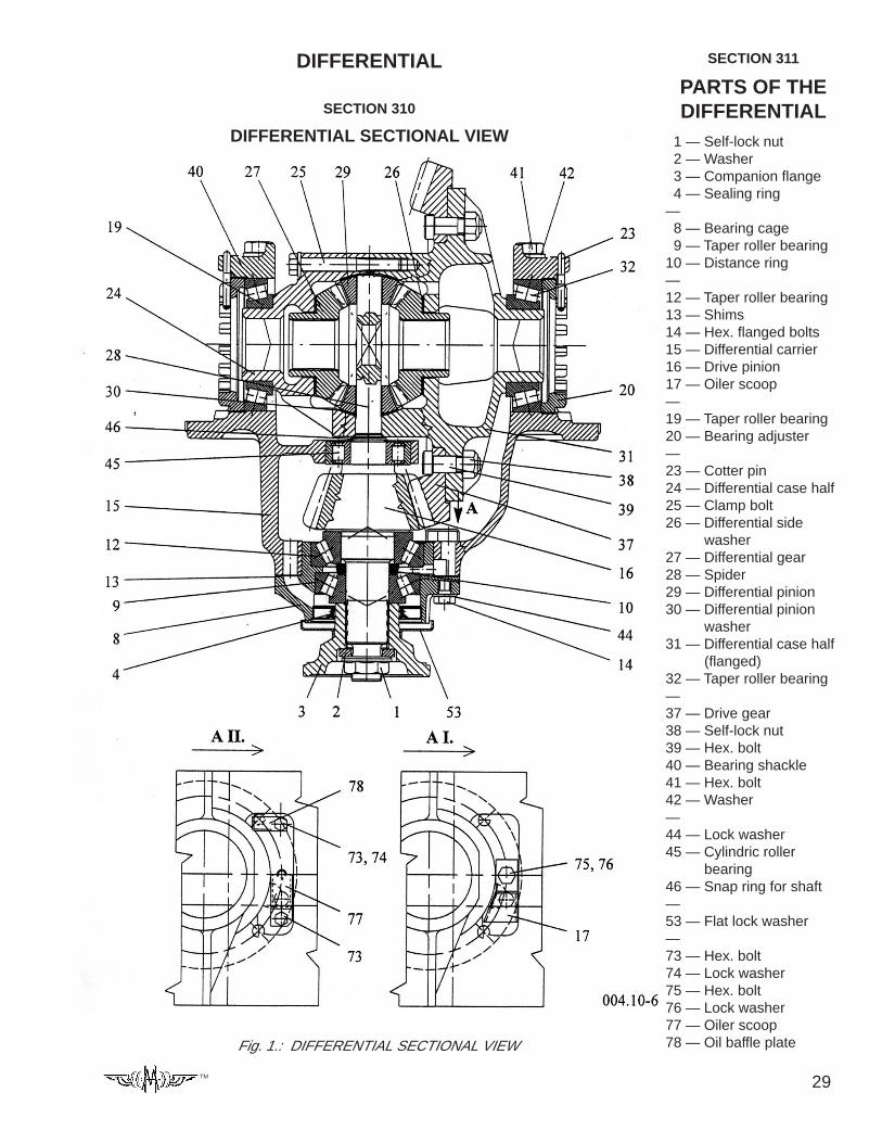
DIFFERENTIAL
SECTION 310
DIFFERENTIAL SECTIONAL VIEW
Fig. 1.: DIFFERENTIAL SECTIONAL VIEW
SECTION 311
PARTS OF THEDIFFERENTIAL
1 — Self-lock nut 2 — Washer 3 — Companion flange 4 — Sealing ring— 8 — Bearing cage 9 — Taper roller bearing10 — Distance ring—12 — Taper roller bearing13 — Shims14 — Hex. flanged bolts15 — Differential carrier16 — Drive pinion17 — Oiler scoop—19 — Taper roller bearing20 — Bearing adjuster—23 — Cotter pin24 — Differential case half25 — Clamp bolt26 — Differential side
washer27 — Differential gear28 — Spider29 — Differential pinion30 — Differential pinion
washer31 — Differential case half
(flanged)32 — Taper roller bearing—37 — Drive gear38 — Self-lock nut39 — Hex. bolt40 — Bearing shackle41 — Hex. bolt42 — Washer—44 — Lock washer45 — Cylindric roller
bearing46 — Snap ring for shaft—53 — Flat lock washer—73 — Hex. bolt74 — Lock washer75 — Hex. bolt76 — Lock washer77 — Oiler scoop78 — Oil baffle plate
30 TM
SECTION 312
REMOVING AND REINSTALLING THE DIFFERENTIAL
REINSTALLING THE DIFFERENTIAL
As described in the “GENERAL SERVICE INSTRUC-TIONS” apply oil-proof surface sealant to flange of theaxle.
Put the differential into the axle housing and screw thebolts with thread locker. Tighten the bolts to 88 - 98 Nmtorque.
REMOVING THE DIFFERENTIAL
Drain the oil from the axle.
Remove the axle shafts with double joint as describedin Section 246.
Remove the hex. flanged bolts attaching the differentialcarrier assembly to the axle housing.
Pull the differential out from axle housing by companionflange.
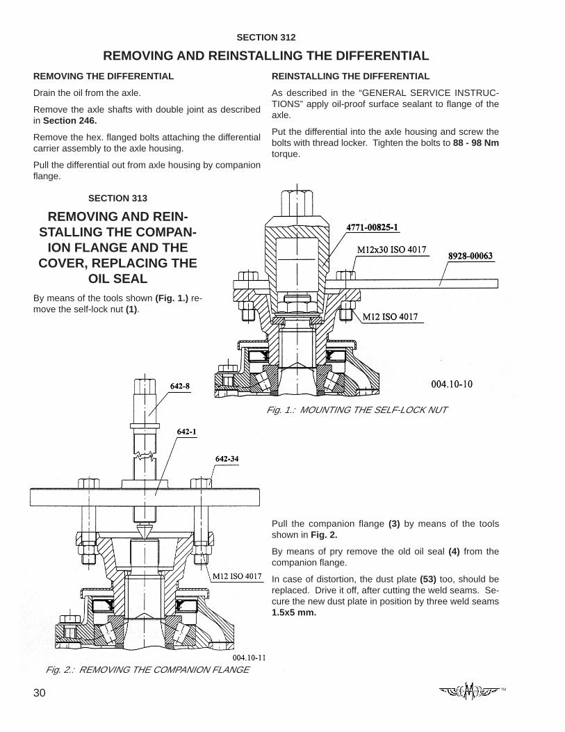
SECTION 313
REMOVING AND REIN-STALLING THE COMPAN-
ION FLANGE AND THECOVER, REPLACING THE
OIL SEALBy means of the tools shown (Fig. 1.) re-move the self-lock nut (1).
Fig. 1.: MOUNTING THE SELF-LOCK NUT
Pull the companion flange (3) by means of the toolsshown in Fig. 2.
By means of pry remove the old oil seal (4) from thecompanion flange.
In case of distortion, the dust plate (53) too, should bereplaced. Drive it off, after cutting the weld seams. Se-cure the new dust plate in position by three weld seams1.5x5 mm.
Fig. 2.: REMOVING THE COMPANION FLANGE

31TM
Fig. 5.: PRESSING ON THE COMPANION FLANGE
By means of the tool shown press the companion flange(3) to the drive pinion splines to bottom out (Fig. 5.).
Install the washer (2), screw on self-lock nut (1) andtighten to 410 - 540 Nm torque.
Fig. 4.: HAMMERING SEAL RING IN
Pull the old oil seal (4) out from the bearing cage.
Coat the surface of the bearing cage contacting the oilseal with grease LZS2 and drive in the oil seal to thebearing cage by means of tool shown (Fig. 4.).
Fig. 1.: ASSEMBLING THE BEARING ADJUSTERS
SECTION 314
REMOVING AND REINSTALLINGTHE DIFFERENTIAL, ADJUSTINGTHE BACKLASH AND THE CON-
TACT PATTERNREMOVING THE DIFFERENTIAL
Remove the cotter pin (23) from both of sides.
Back out the hex. bolts (41) and remove the bearingshackles (40). Following this remove the differential fromthe differential carrier and remove the outer race of thetaper roller bearing (19, 32) and the bearing adjusters(20).
REINSTALLING THE DIFFERENTIAL
Reinstall the differential only after installing the bearingcage and adjusting the axis distance (see Section 316)!
Assemble the bearing adjusters by means of the toolshown (Fig. 1.).
Fit the assembled differential together with cups of thetaper roller bearings (19, 32) into the differential carrier,then screw on the bearing shackles to the original place,adjust on the bearing adjusters and secure by hex. boltsapplied with thread adhesive and washers (42).
Tighten the hex. bolts (41) applied with thread adhesiveto 149 - 196.6 Nm torque.
32 TM
ADJUSTING THE BACKLASH AND THE BEARINGPRELOAD
By means of the bearing adjusters adjust the drive pin-ion to gear backlash as described in “TECHNICAL DATA”(GLEASON toothing).
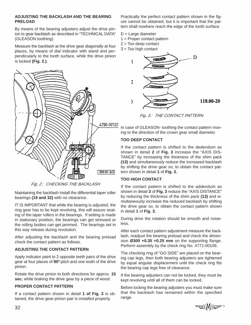
Measure the backlash at the drive gear diagonally at fourplaces, by means of dial indicator with stand and per-pendicularly to the tooth surface, while the drive pinionis locked (Fig. 2.).
Fig. 2.: CHECKING THE BACKLASH
Maintaining the backlash install the differential taper rollerbearings (19 and 32) with no clearance.
IT IS IMPORTANT that while the bearing is adjusted, thering gear has to be kept revolving, this will assure seat-ing of the taper rollers in the bearings. If setting is madein stationary position, the bearings can get stressed orthe rolling bodies can get jammed. The bearings set inthis way release during revolution.
After adjusting the backlash and the bearing preloadcheck the contact pattern as follows.
ADJUSTING THE CONTACT PATTERN
Apply indicator paint to 2 opposite teeth pairs of the drivegear at four places of 90º pitch and one tooth of the drivepinion.
Rotate the drive pinion to both directions for approx. 15sec. while braking the drive gear by a piece of wood.
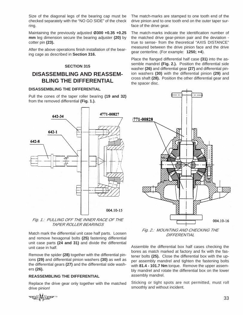
PROPER CONTACT PATTERN
If a contact pattern shown in detail 1 of Fig. 3 is ob-tained, the drive gear-pinion pair is installed properly.
Practically the perfect contact pattern shown in the fig-ure cannot be obtained, but it is important that the pat-tern shall nowhere reach the edge of the tooth surface.
D = Large diameter1 = Proper contact pattern2 = Too deep contact3 = Too high contact
In case of GLEASON- toothing the contact pattern mov-ing to the direction of the crown gear small diameter.
TOO DEEP CONTACT
If the contact pattern is shifted to the dedendum asshown in detail 2 of Fig. 3 increase the “AXIS DIS-TANCE” by increasing the thickness of the shim pack(13) and simultaneously reduce the increased backlashby shifting the drive gear so, to obtain the contact pat-tern shown in detail 1 of Fig. 3.
TOO HIGH CONTACT
If the contact pattern is shifted to the addendum asshown in detail 3 of Fig. 3 reduce the “AXIS DISTANCE”by reducing the thickness of the shim pack (13) and si-multaneously increase the reduced backlash by shiftingthe drive gear so, to obtain the contact pattern shownin detail 1 of Fig. 3.
During drive the rotation should be smooth and noise-less.
After each contact pattern adjustment measure the back-lash, readjust the bearing preload and check the dimen-sion Ø300 +0.35 +0.25 mm on the supporting flange.Perform assembly by the check ring No. 4771-00106.
The checking ring of “GO SIDE” are placed on the bear-ing cap legs, then both bearing adjusters are tightenedby equal angular displacement until the check ring fitsthe bearing cap legs free of clearance.
If the bearing adjusters can not be locked, they must bekept revolving until all of them can be locked.
Before locking the bearing adjusters you must make surethat the backlash has remained within the specifiedrange.
Fig. 3.: THE CONTACT PATTERN
33TM
Size of the diagonal legs of the bearing cap must bechecked separately with the “NO GO SIDE” of the checkring.
Maintaining the previously adjusted Ø300 +0.35 +0.25mm leg dimension secure the bearing adjuster (20) bycotter pin (23).
After the above operations finish installation of the bear-ing cage as described in Section 316.
SECTION 315
DISASSEMBLING AND REASSEM-BLING THE DIFFERENTIAL
DISASSEMBLING THE DIFFERENTIAL
Pull the cones of the taper roller bearing (19 and 32)from the removed differential (Fig. 1.).
Fig. 1.: PULLING OFF THE INNER RACE OF THETAPER ROLLER BEARINGS
Match mark the differential unit case half parts. Loosenand remove hexagonal bolts (25) fastening differentialunit case parts (24 and 31) and divide the differentialunit case in half.
Remove the spider (28) together with the differential pin-ions (29) and differential pinion washers (30) as well asthe differential gears (27) and the differential side wash-ers (26).
REASSEMBLING THE DIFFERENTIAL
Replace the drive gear only together with the matcheddrive pinion!
The match-marks are stamped to one tooth end of thedrive pinion and to one tooth end on the outer taper sur-face of the drive gear.
The match-marks indicate the identification number ofthe matched drive gear-pinion pair and the deviation -true to sense- from the theoretical “AXIS DISTANCE”measured between the drive pinion face and the drivegear centerline. (For example: 1250; +4).
Place the flanged differential half case (31) into the as-semble mandrel (Fig. 2.). Position the differential sidewasher (26) and differential gear (27) and differential pin-ion washers (30) with the differential pinion (29) andcross shaft (28). Position the other differential gear andthe spacer disc.
Fig. 2.: MOUNTING AND CHECKING THEDIFFERENTIAL
Assemble the differential box half cases checking thebores as match marked at factory and fix with the fas-tener bolts (25). Close the differential box with the up-per assembly mandrel and tighten the fastening boltswith 81.4 - 101.7 Nm torque. Remove the upper assem-bly mandrel and rotate the differential box on the lowerassembly mandrel.
Sticking or tight spots are not permitted, must rollsmoothly and without incident.
34 TM
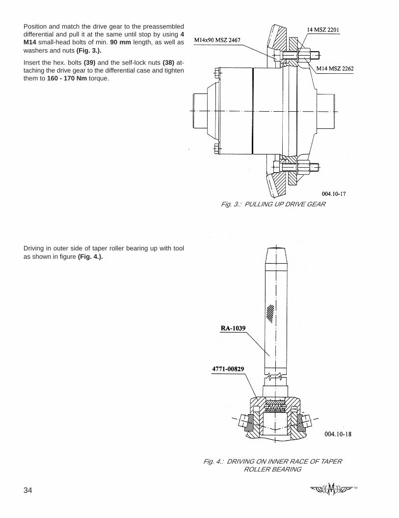
Position and match the drive gear to the preassembleddifferential and pull it at the same until stop by using 4M14 small-head bolts of min. 90 mm length, as well aswashers and nuts (Fig. 3.).
Insert the hex. bolts (39) and the self-lock nuts (38) at-taching the drive gear to the differential case and tightenthem to 160 - 170 Nm torque.
Fig. 3.: PULLING UP DRIVE GEAR
Driving in outer side of taper roller bearing up with toolas shown in figure (Fig. 4.).
Fig. 4.: DRIVING ON INNER RACE OF TAPERROLLER BEARING

35TM
REMOVING THE BEARING CAGE
The bearing cage can be removed after removal of thedifferential (see Section 314).
Remove the hex. bolts (14) attaching the bearing cageto the differential carrier. Pull out bearing tube from thedifferential carrier housing with the aid of shift hub.
Remove the shim (13) from the flange of bearing cage.
REINSTALLING THE BEARING CAGE
Prior to mounting the bearing tube, be sure the pre-scribed rolling torque (bearing prestress) (Section 317),the axis distance and the contact pattern (Section 314)were adjusted!
I. * After reinstalling the bearing cage install the oilerscoop (17) by the bolts (75) with lock washers (76).Tighten the bolts to 20 Nm torque.
II. * After reinstalling the bearing cage install the oil baffleplate (78) and the oiler scoop (77) by the bolts (73) withlock washers (74). Tighten the bolts to 8 Nm torque.
ADJUSTING THE AXIS DISTANCE
After assembling the bearing cage and adjusting thebearing preload (Section 317), screw M10 pilot studbolts into two opposite bores of the differential carrierhousing for piloting purposes. Stack the shim pack nec-essary for adjusting the “AXIS DISTANCE” and the con-tact pattern over these studs so, the two extreme onesshall be thicker. Make sure to align the oil pass boresin the differential carrier housing and the bearing cage.
SECTION 316
REMOVING AND REINSTALLING THE BEARING CAGE, ADJUSTING THEAXIS DISTANCE
It is advisable to start assembling with approx. 1.4 mmshim pack thickness.
Push the bearing cage subassembled with drive pinioninto the differential carrier housing. then provisionallysecure it by 2 off hex. bolts (14) and lock washers (44)in opposite bores. Tighten the bolts to 40.7 - 67.8 Nmtorque.
On the suitable master pin of accessory “A” of the mea-suring device shown in Fig. 1 adjust the theoretical “AXISDISTANCE” B = 77.44 mm - 10 mm (measuring platethickness) = 67.44 mm by setting the dial indicator tozero.
The measuring plate has to be fastened to the drive pin-ion face by means of the pressure plate attached to theflange of the differential carrier housing.
As shown in Fig. 1 insert the device set to 67.44 mminto the differential carrier housing.
and measure the “AXIS DISTANCE” deviation. Checkif the measured value is identical to that stamped in theend of the drive pinion.
In case of identical values the adjustment is proper. oth-erwise correct the “AXIS DISTANCE” deviation by chang-ing the thickness of the shim pack (13). The adjustmentaccuracy is + 0.025.
For example: If the axis distance deviation stamped inthe drive pinion is +3 the value to be set is 77.44 +0.03= 77.47 + 0.025.
Fig. 1.: MEASURING THE AXIS DISTANCE
36 TM
INSTALLING THE BEARING CAGE FINALLY
If contact pattern adjustment (Section 314) and opera-tion are proper, lift the bearing cage assembled with thedrive pinion and as described in the “GENERAL SER-VICE INSTRUCTIONS” apply some sealant to the innerflange.
Fig. 1.: PRESSING OUT THE DRIVE PINION
Fig. 2.: PULLING THE INNER RACE OF THE INNER TAPERROLLER BEARING
Fit back the bearing cage, making sure that the oil passbores are aligned then secure the cage by hex. bolts (14)and lock washers (44) coated with thread adhesive.Tighten the hex. bolts to 40.7 - 67.8 Nm torque.
SECTION 317
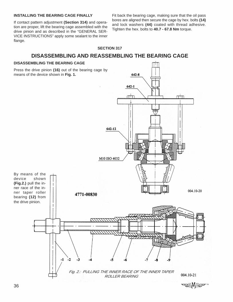
DISASSEMBLING AND REASSEMBLING THE BEARING CAGEDISASSEMBLING THE BEARING CAGE
Press the drive pinion (16) out of the bearing cage bymeans of the device shown in Fig. 1.
By means of thedevice shown(Fig.2.) pull the in-ner race of the in-ner taper rollerbearing (12) fromthe drive pinion.
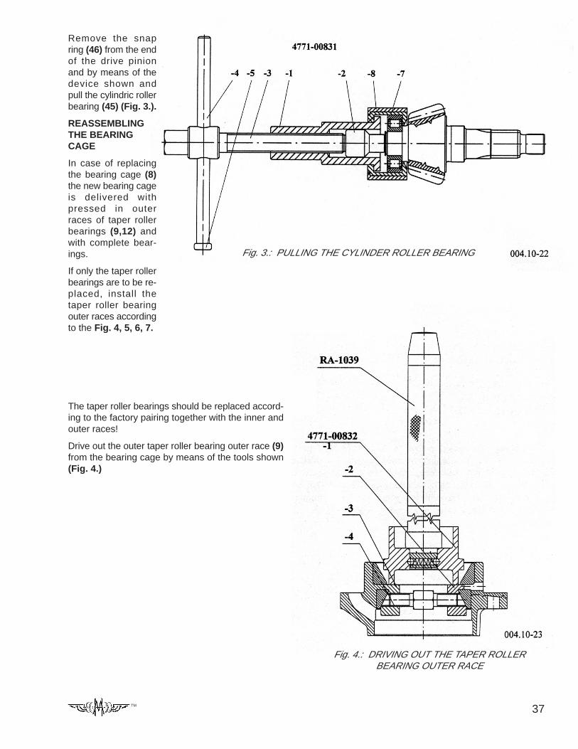
37TM
Remove the snapring (46) from the endof the drive pinionand by means of thedevice shown andpull the cylindric rollerbearing (45) (Fig. 3.).
REASSEMBLINGTHE BEARINGCAGE
In case of replacingthe bearing cage (8)the new bearing cageis delivered withpressed in outerraces of taper rollerbearings (9,12) andwith complete bear-ings.
If only the taper rollerbearings are to be re-placed, install thetaper roller bearingouter races accordingto the Fig. 4, 5, 6, 7.
Fig. 3.: PULLING THE CYLINDER ROLLER BEARING
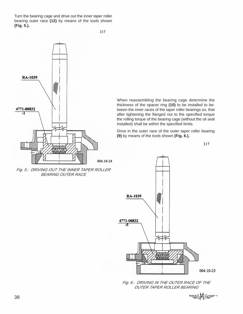
The taper roller bearings should be replaced accord-ing to the factory pairing together with the inner andouter races!
Drive out the outer taper roller bearing outer race (9)from the bearing cage by means of the tools shown(Fig. 4.)
Fig. 4.: DRIVING OUT THE TAPER ROLLERBEARING OUTER RACE
38 TM
Turn the bearing cage and drive out the inner taper rollerbearing outer race (12) by means of the tools shown(Fig. 5.).
Fig. 5.: DRIVING OUT THE INNER TAPER ROLLERBEARING OUTER RACE
When reassembling the bearing cage determine thethickness of the spacer ring (10) to be installed to be-tween the inner races of the taper roller bearings so, thatafter tightening the flanged nut to the specified torquethe rolling torque of the bearing cage (without the oil sealinstalled) shall be within the specified limits.
Drive in the outer race of the outer taper roller bearing(9) by means of the tools shown (Fig. 6.).
Fig. 6.: DRIVING IN THE OUTER RACE OF THEOUTER TAPER ROLLER BEARING
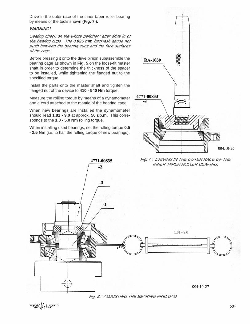
39TM
Drive in the outer race of the inner taper roller bearingby means of the tools shown (Fig. 7.).
WARNING!
Seating check on the whole periphery after drive in ofthe bearing cups. The 0.025 mm backlash gauge notpush between the bearing cups and the face surfacesof the cage.
Before pressing it onto the drive pinion subassemble thebearing cage as shown in Fig. 5 on the loose-fit mastershaft in order to determine the thickness of the spacerto be installed, while tightening the flanged nut to thespecified torque.
Install the parts onto the master shaft and tighten theflanged nut of the device to 410 - 540 Nm torque.
Measure the rolling torque by means of a dynamometerand a cord attached to the mantle of the bearing cage.
When new bearings are installed the dynamometershould read 1.81 - 9.0 at approx. 50 r.p.m. This corre-sponds to the 1.0 - 5.0 Nm rolling torque.
When installing used bearings, set the rolling torque 0.5- 2.5 Nm (i.e. to half the rolling torque of new bearings).
Fig. 7.: DRIVING IN THE OUTER RACE OF THEINNER TAPER ROLLER BEARING.
Fig. 8.: ADJUSTING THE BEARING PRELOAD
1.81 - 9.0
40 TM
In case of deviation perform correction by replacing thespacer ring (10). With rolling torque higher than speci-fied use a thicker spacer and at lower torque a thinnerone.
In case of proper adjustment transfer the parts from themaster shaft to the drive pinion. (Do not install the oilseal yet.)
Make sure the install only the parts used for the previ-ous adjustment onto the drive pinion.
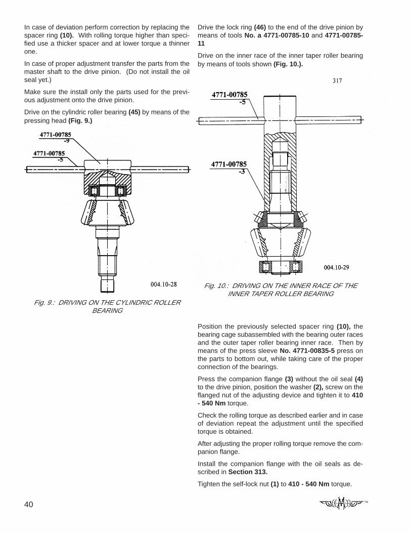
Drive on the cylindric roller bearing (45) by means of thepressing head (Fig. 9.)
Fig. 9.: DRIVING ON THE CYLINDRIC ROLLERBEARING
Fig. 10.: DRIVING ON THE INNER RACE OF THEINNER TAPER ROLLER BEARING
Drive the lock ring (46) to the end of the drive pinion bymeans of tools No. a 4771-00785-10 and 4771-00785-11
Drive on the inner race of the inner taper roller bearingby means of tools shown (Fig. 10.).
Position the previously selected spacer ring (10), thebearing cage subassembled with the bearing outer racesand the outer taper roller bearing inner race. Then bymeans of the press sleeve No. 4771-00835-5 press onthe parts to bottom out, while taking care of the properconnection of the bearings.
Press the companion flange (3) without the oil seal (4)to the drive pinion, position the washer (2), screw on theflanged nut of the adjusting device and tighten it to 410- 540 Nm torque.
Check the rolling torque as described earlier and in caseof deviation repeat the adjustment until the specifiedtorque is obtained.
After adjusting the proper rolling torque remove the com-panion flange.
Install the companion flange with the oil seals as de-scribed in Section 313.
Tighten the self-lock nut (1) to 410 - 540 Nm torque.
41TM
SECTION 395
OIL FILL-UP, RUN, CHECKFill up the finish-assembled axle with oil of grade andquantity as specified in the “OPERATING AND MAIN-TENANCE INSTRUCTIONS”.
Fill only perfectly clean oil into the axle.
After fill-up install the screw plugs to be leak-tight andtighten. Following this run the axle with varying speedto both directions.
DURING RUNNING CHECK THE FOLLOWING:
THE AXLE FOR LEAKS:
No oil leaks are permitted.
THE AXLE FOR OPERATION:
At the rotated mechanisms, in the differential and thewheel hub — no excessive noise or sound of friction ispermitted. The meshing gears should roll on one an-other smoothly, without noise.
THE BRAKE FOR OPERATION:
As described in documentation of BENDIX.
THE AXLE FOR WARMING:
At the end of the run temperature may not exceedapprox. 60º C at the wheel hub and approx. 80º C atthe input section.
42 TM
13001 Magisterial Drive • Louisville, KY 40223
(502) 253-0277 • (800) 227-0727 • Fax (502) 253-0317
E-mail: [email protected]
TM