ctbuh research paper ctbuh.org/papers haut - a 21-storey
TRANSCRIPT

CTBUH Research Paper
Title: Haut - A 21-storey Tall Timber Residential Building
Authors: Mathew Vola, ArupRob Verhaegn, ArupJorn de Jong, Arup
Subjects: Architectural/DesignBuilding Case StudyConstructionStructural EngineeringWind Engineering
Keywords: ConstructionCross-Laminated TimberHolistic DesignTimber
Publication Date: 2020
Original Publication: International Journal of High-Rise Buildings Volume 9 Number 2
Paper Type: 1. Book chapter/Part chapter2. Journal paper3. Conference proceeding4. Unpublished conference paper5. Magazine article6. Unpublished
© Council on Tall Buildings and Urban Habitat / Mathew Vola; Rob Verhaegn; Jorn de Jong
ctbuh.org/papers

International Journal of High-Rise Buildings
September 2020, Vol 9, No 3, 213-220
https://doi.org/10.21022/IJHRB.2020.9.3.213
International Journal of
High-Rise Buildingswww.ctbuh-korea.org/ijhrb/index.php
Haut – A 21-storey Tall Timber Residential Building
Rob Verhaegh1, Mathew Vola1 and Jorn de Jong1
Arup, Amsterdam, the Netherlands
Abstract
This paper reflects on the structural design of Haut; a 21-storey high-end residential development in Amsterdam, the Netherlands. Construction started in 2019 and is in progress at the time of writing. Upon completion in 2021, Haut will be the first residential building in the Netherlands to achieve a ‘BREEAM-outstanding’ classification. The building will reach a height of 73 m, making it the highest timber structure in the Netherlands. It contains some 14.500 m2 of predominantly residential functions. It features a hybrid concrete-timber stability system and concrete-timber floor panels. This paper describes the concepts behind the structural design for Haut and will touch upon the main challenges that have arisen from the specific combination of characteristics of the project. The paper describes the design of the stability system and -floor system, the analysis of differential movements between concrete and timber structures and wind vibrations. The paper aims to show how the design team has met these specific challenges by implementing a holistic design approach and integrating market knowledge at an early stage of the design.
Keywords: Tall Timber Buildings, Mass Timber, TCC Floors, Holistic design
1. Introduction
Haut is a 21-storey residence, located in Amsterdam,
the Netherlands. It will reach a height of 73 m, making it
the tallest timber building in the country, and incidentally
one of the tallest in the world upon completion. In
addition, it will be the first residential high-rise project to
achieve a BREEAM outstanding classification in the
Netherlands. The project is the result of a design competition
initiated by the municipality of Amsterdam, in which
sustainability aspects were highly appreciated in the
scoring. This challenge was met by proposing a design
that prioritizes the use of (mass) timber structural elements
over other structural materials, thus minimising the structures
embodied carbon.
The competition was organised in January 2016, and
the start of construction was in 2019. At the time of
writing, construction of the structure has progressed to
the second floor, which is also the first hybrid timber
floor. The building features a public plinth, which timber
structure has already been completed. The remainder of
the structure is to be completed in 2020, completion of
the building is scheduled for 2021. The project was com-
missioned by the Amsterdam based developer Lingotto. The
main contractor is JP van Eesteren, working with Brüninghoff
for the assembly of all timber structures. Arup provided
all technical design services for the project, including
structural engineering, building physics, fire safety, sustaina-
bility and building services. Team V is the architect for
the project.
This paper provides a high-level description of the
choices that were made during the design, the design
challenges and the structural solutions. In this process, it
has become evident that each of these choices were
influenced by three central characteristics of the project:
the height of the building, its residential function and the
conscious decision to use mass timber as much as possible.
The goal of this paper is to explain the answers that have
been formulated to these technical challenges for Haut, in
order to further develop existing knowledge on timber
high-rise projects. In this way, the authors hope to
contribute to further development and innovation in the
use of mass timber in large scale and tall building
projects.
†Corresponding author: Rob Verhaegh
Tel: +31 (0) 20 305 8500, Fax: E-mail: [email protected] Figure 1. Construction site in June 2020.
214 Rob Verhaegh et al. | International Journal of High-Rise Buildings
2. Design Concepts
2.1. General Concepts
The plot for Haut is located alongside the Amstel river
at the edge of Amsterdam’s city centre. The beautiful
views that a high-rise project at this site can provide for
its residents have been considered a prime quality from
the very start of the design process. The architectural
concept of Haut therefore relies on façade transparency,
providing residents with lots of daylight, and unobstructed
views of the city and countryside. Due to the project’s
high sustainability- and quality ambitions, mass timber
was considered the most suitable option for this develop-
ment. The choice for timber as a structural material leads
to a significant reduction of the buildings embodied CO2-
footprint, compared to a similar development in any other
structural material. By exposing the structural timber in
the buildings ceilings, the aesthetic qualities of the structure
are incorporated into the architecture.
2.2. Structural Concepts
In order to accommodate the desired unobstructed
views, a load-bearing façade structure was ruled out at an
early stage. Timber high-rise typologies relying on braced
frames or CLT-panels in the façade were therefore not an
option. The structural design relies on internal load bearing
walls, which may function as separation-walls between
residences as well. Floors consist of prefabricated timber-
concrete composite (TCC) panels, which are supported
on top of the CLT load bearing walls. Wherever the floor
edges are not supported by a load bearing wall, glulam
downstand beams are introduced. These beams are
designed to transfer façade- and balcony loads and
provide additional stiffness to the floor. They double as a
tension ring around the perimeter of the floor, transferring
diaphragm forces and acting as a structural tie. All
residences have balconies extending beyond the façade,
which are designed to be attached to the floor edges using
steel brackets, with thermal breaks. This allows the
contractor to first apply the façade, minimizing the time
the timber structure is exposed to weather influences. The
apartments in the ‘wedge-shaped’ north part of the
building feature can-tilevering floors. These floors are
realised with steel- and concrete edge beams, supported by
two concrete columns. An alternative in timber would
require large members, compromising the unobstructed
views from these corner apartments.
The substructure consists of a two layer basement, the
ground floor and first floor, which have been constructed
in concrete. This provides a robust ‘plinth’ supporting the
timber tower. From the first floor upwards, the gravity
system consists of load bearing timber walls supporting
the TCC floors, spanning in one direction. The lateral
stability is provided by a concrete core and two CLT
walls, which help to resist torsional effects resulting from
wind loads.
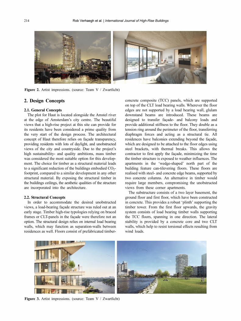
Figure 2. Artist impressions. (source: Team V / Zwartlicht)
Figure 3. Artist impressions. (source: Team V / Zwartlicht)

Haut – A 21-storey Tall Timber Residential Building 215
The foundation design consists of ground displacing
steel screw grout injection (‘Tubex’) piles. In addition, a
load bearing diaphragm wall was required along the edge
of the building plot. The foundation design was mainly
governed by stiffness demands, and heavily influenced by
the local soft soils, the presence of a pre-existing
embankment and data cables which could not be moved.
3. Design Challenges
3.1. Stability System
3.1.1. Design
Keeping the projects ambitions in mind, the stability
system was designed to leave the facades unobstructed.
Initial studies showed that this ruled out the possibility of
a full timber stability-structure, as the internal wall dimensions
were insufficient to provide sufficient lateral stiffness.
Two hybrid options were explored in parallel during the
early stages of the design: a steel-timber hybrid and
concrete-timber hybrid lateral stability system. The steel-
timber hybrid system was based on CLT shear walls
combined with a single steel braced frame, where the
concrete-timber hybrid system relied on the same CLT
walls, combined with a concrete core.
The main design challenges in the steel-timber scheme
were twofold, and related to the lateral stiffness of the
CLT shear walls. Although the stiffness of CLT itself is
comparable to (cracked) concrete, the stiffness of a CLT
wall consisting of multiple panels is highly influenced by
its panel-to-panel connections. It was estimated that using
typical connectors would reduce the global stiffness of
the wall by some 70%. The proposed solution to this
issue consisted of the implementation of a full height
Figure 4. Building Structure.
Figure 5. Stability system, steel-timber hybrid (left) and concrete-timber hybrid (right).

216 Rob Verhaegh et al. | International Journal of High-Rise Buildings
steel tie along the height of the wall. The second
challenge resulted from functional demands of residential
architecture; the architectural plans demanded a number
of penetrations through the stability walls. Typically, no
stiffness is attributed to lintels in CLT walls, as their
moment capacity is insufficient for adequate coupling of
walls. Therefore, a series of wall penetrations positioned
directly above each other would have seriously compromised
the global stiffness of the walls. This issue was resolved
in close collaboration with the architect, placing wall
penetrations in a ‘staggered’ pattern (see figure 6). This
approach ensured the wall elements would function as a
single -coupled- wall, rather than two separate -and
therefore much weaker- individual walls.
The concrete-timber lateral stability system consists of
a slender concrete core, and two CLT shear walls. A
specific challenge in the design of this alternative was
that for architectural reasons, the concrete core could only
be placed eccentrically in the plan. This eccentricity
introduces torsional effects under wind loads, increasing
lateral deflections and wind induced vibrations. To reduce
these effects, the load bearing CLT walls are designed to
be part of the stability system. For the same reason, the
concrete core is stiffened by extending its ‘flanges’ up to
a particular height (see figure 6).
After the preliminary design phase, the steel timber-
hybrid was compared to the concrete-timber system.
Based on this comparison, the design team reached the
conclusion that the concrete-timber hybrid would be the
best fit for the project. The choice was driven by the
following aspects: ● The concrete-timber alternative did not require a steel
braced frame, providing flexibility in floor plans and
reducing steel tonnage;● The additional mass of the concrete core increased the
performance of the structure with regards to wind
induced vibrations and lateral deflections;
● The detailing of the steel strips in the steel-timber
alternative was considered challenging and costly, as
this would require a fully stiff tensile connection,
while accommodating the shrinkage of the CLT walls;● The embodies carbon of the concrete-timber alternative
was considered lower, as the significant reduction in
steel usage outweighed the adverse effects of the
application of a larger volume of concrete.
Therefore, the concrete-steel hybrid system was not
only perceived more feasible, but also more sustainable.
3.1.2. Analysis
The system is statically indeterminate, and lateral
deflections are influenced by many factors. To determine
expected maximum lateral deflections and perform sensitivity
studies, two FEM-models were created.
The first model was a 3D-model of the entire lateral
load-bearing system, including the concrete plinth, base-
ment and foundations. The model was mainly used as a
means of assessing total deflection and the sensitivity to
stiffness of individual structural elements, including the
foundations. In this model, the CLT shear wall is
represented by a beam element with manually defined
stiffness properties, allowing for an estimation of the
influence of CLT material properties, connections and
wall openings. To validate this estimated stiffness of the
CLT wall, a second -more detailed- model was introduced.
The second model consists of a 2D-model of the CLT
wall, including specific wall openings, orthotropic material
behavior and locally reduced stiffness to allow for
acoustical decoupling and connection details. The model
was subjected to gravity loads and lateral loads taken
from the 3D-model. Subsequently, the resulting deflection
in the 2D-model was compared to the deflection in the
3D-model, allowing for a check of the initially assumed
stiffness.
Figure 6. Lateral force resisting system (left) and elevation of CLT shear walls.

Haut – A 21-storey Tall Timber Residential Building 217
The stiffness of the CLT-walls depends on many factors,
and although thoroughly analyzed, there will be a margin
of error in any prediction of it. In addition, there was no
prior experience with CLT stability walls on this scale.
Therefore it was decided to only rely on the CLT walls in
the serviceability limit states (SLS). The core has been
designed to transfer full wind loads in the ultimate limit
states (ULS).
3.2. Wind Induced Vibrations
If Haut were to have a full concrete structure of similar
height, wind induced vibrations would probably not be
considered in the design process. After all, there is plenty of
experience which such buildings to conclude that demands
will be met, even without analyzing these explicitly.
Because Haut’s hybrid structure is a lot lighter, wind
induced vibrations were considered a risk and where
investigated in detail.
With regards to wind-induced vibrations, the resulting
accelerations at the top floor depend on stiffness, mass
and damping of the structure. The first two aspects can be
determined within a reasonable margin of error. The
damping ratio is more difficult to predict. Due to the
innovative character of high-rise structures in timber, and
the large differences between structural system of the
realised projects, the available data does not offer a
definitive insight into appropriate damping values. For
this project, a value of 1,5% structural damping was
adapted for purposes of checking the wind-induced
vibrations. The design team intends to measure accelerations
after completion.
To calculate the expected maximum accelerations due
to wind induced vibrations, a modal analysis was performed
on the 3D-model of the structure described earlier. The
dominant fundamental periods were determined, both
represented orthogonal modes. It was of importance to
prevent a dominant torsional mode, because this was
believed to dramatically increase accelerations at the top
floors. Based on a number of sensitivity studies, an upper
bound for the governing acceleration was determined at
10 mg for a 1 year return period, using the method
outlined in the NBCC [1]. This acceleration complies
with the demands as stated in the Dutch national annex to
Eurocode 1990 [2].
The calculated vibrations were sensitive to the mass of
the building. This was one of the most important
motivations for choosing the specific floor build-up that
is used in Haut.
3.3. Floor Build-up
The floors play a critical role in Haut’s design, as they
are key to the construction sequence, the stability system
and many of the strict comfort criteria that were expected
to be met for the residential units in Haut. In addition, the
ambition was to leave the structural timber exposed
where possible for architectural reasons. The floor system
that was deemed to meet these requirements best, was a
prefabricated timber-concrete composite (TCC) floor.
This type of floor consists of a CLT plate (160 mm), with
a concrete top layer (80 mm). In this build-up, the two
layers collaborate as a hybrid system in which the CLT
takes tension forces, and concrete takes the compression.
Shear between the two layers is transferred by means of
a series of notches, that are milled out of the CLT. The
ratio between CLT and concrete is adjusted in some
cases, to allow for thinner floors where these are required,
for example to accommodate thermal insulation in
loggia’s. In this way, the floor system provides flexibility
to allow for local deviations in the architectural design.
Another reason for choosing a TCC floor over a full
CLT plate is its mass. This additional mass increases
acoustical performance, has a beneficial influence on footfall
induced vibrations, and helps to increase performance
with regards to wind induced vibrations as well. Extending
the concrete layer to the full height of the floor at both
load-bearing ends of the plate, allowed for a ‘platform’
type wall-to-floor detail. This has significant benefits to
the construction sequence. This would not have been
possible using CLT plates, as it would introduce large
cross-grain stresses in the timber.
The main challenge in the detailing of the floors was
the integration of acoustical- and structural design
aspects. To achieve proper diaphragm action in the floors,
the individual plates are to be connected in-plane. Due to
Figure 7. Floor build-up.

218 Rob Verhaegh et al. | International Journal of High-Rise Buildings
the low mass of the floors and walls, it is important to
acoustically decouple floors wherever they cross separating
walls between residences. Several solutions to resolve
this problem where considered, before the final design
was determined. Based on preferences related to constructa-
bility, the contractor came up with an optimisation of the
initial detailing, in which the floor was essentially divided
into multiple diaphragms, one for each residence on a
floor. All of these sub-diaphragms are connected to the
structural core and CLT stability walls, but remain largely
decoupled from each other. Along the perimeter of the
floor diaphragm, a ring beam ensures the separate
diaphragms will act as one under wind loads. This ring
beam doubles as a horizontal tie with regards to the
robustness strategy.
3.4. Differential Movements
A number of floor fields are supported by a concrete
wall on one side, and a timber wall or beam on the other.
The difference in mechanical properties between these
supporting elements will cause differential movements
between the two. Although this issue is a common
challenge in high-rise design, it would not be considered
significant for a structure of this height, consisting of a
single material. The combination of timber and concrete
requires the issue to be studied in greater detail, despite
the limited height of the tower.
This was also acknowledged in the design of Brock
Commons [3], in which some projections were done with
regards to the expected differential movements. Similar
studies were performed for Haut. Based on these studies,
the -unmitigated- final axial shortening on the top floor of
the two projects was determined. Haut was expected to
experience slightly higher movements which were mainly
attributed to the greater height of Haut and the more
conservative assumptions on the moisture content of the
CLT. Contrary to Brock Commons, Haut features load
bearing walls rather than columns, which complicates the
mitigation of these movements.
If the walls in Haut were to actually undergo a differential
movement of the predicted magnitude of 48 mm, it would
lead to various architectural and functional issues.
However, that number does not include the movement of
the adjacent concrete structural elements. To determine
the maximum differential movement, the shortening
caused by elastic-, creep- and shrinkage-effects were
calculated for the course of the construction and lifespan
of the building, for three governing spans in the building.
The occurring differential movements depend on many
factors, and are expected to be subject to change during
construction and over the course of the building’s design
life. Therefore two scenarios were analysed, the first of
which represents a best estimate for the various starting
points, the latter representing a worst-case scenario. For a
number of positions, the expected movements were
calculated over time, yielding a maximum value for
Figure 8. Diaphragm principle.
Figure 9. Expected Axial shortening of load bearing elements [3].

Haut – A 21-storey Tall Timber Residential Building 219
differential movement at a certain point in time. From
these analyses, a maximum differential movement of ca.
20 mm was determined between the core wall to the CLT
wall, occurring at the 21st floor. This value is considered
comparable to non-timber structures of similar height
No requirements were found in relevant design codes.
The design team decided to adopt a requirement of span/
500, which is equal to the demands that the Dutch
National Annex to Eurcode 1994 [1] describes for
structural elements that support ‘partition walls prone to
cracking’. Although no such walls are envisioned this
demand seemed suitable due to the presence of brittle
finishes (e.g. bathroom tiling).
In an unmitigated situation, the differential movements
would not meet this criterion. Therefore, a number of
changes were incorporated in the design with the sole
purpose of limiting differential movements:● To increase creep and shrinkage effect, the concrete
core is constructed using in-situ concrete, rather than
assembled from prefabricated concrete elements;● Material of the columns at the cantilever in ‘wedge’ of
the building were changed from steel to concrete, as
the creep of concrete will partly offset the timber’s
shrinkage;● Rotation is concentrated in lintel beam for load
bearing walls adjacent to concrete core (see figure 11)
As a result of these changes to the design, the issue of
differential movements is considered entirely manageable by
implementing techniques commonly used in construction.
The moisture content in the timber elements will be
monitored during construction, along with the occurring
movements in these elements and the concrete core. The
contractor has developed a protocol to mitigate possible
deviations from permissible values, by slightly adjusting
heights at which the timber elements are mounted.
4. Conclusions
Haut is an ambitious project, aiming to provide high
quality for its residents. In addition, Haut is innovative in
its choice of structural materials. This paper has provided
an overview of the design principles that were developed
to meet the projects high demands, and it describes the
specific challenges the project has posed to the design
team. These challenges find their origin in the specific
combination of characteristics of the project: the height of
the building, its residential function with open facades
and the conscious decision to use timber structures wherever
possible. It is the combination of these factors that shaped
Haut’s design.
Only a handful of timber structures of similar size and
height has been realised at this point. Therefore, many
aspects of Haut are unique. This has required an explorative
attitude from all parties involved, and a holistic approach
to the design. In the structural design, this attitude
manifested itself in a high number of studies into various
aspects. These studies often required a return to first
principles, or reliance on expert knowledge pre-existing
in Arup or industry partners.
Figure 10. Differential movement over first 1200 days of design life.
Figure 11. Expected Axial shortening of load bearing elements.

220 Rob Verhaegh et al. | International Journal of High-Rise Buildings
Due to the immense positive influence a timber structure
can have on a projects embodied carbon footprint, it is
believed that timber is an inevitable alternative and/or
supplement to the use of steel and concrete in modern
construction. The design of Haut shows that challenges
associated with building in this material can be overcome.
At completion, the goal of designing a sustainable yet
high-quality residential building will have been achieved,
marking a new milestone in the development of mass
timber high-rise structures. The knowledge that has been
acquired in the design process will aide designers to
recognise relevant design challenges in the early stages of
design for future projects.
5. Acknowledgements
The authors would like to acknowledge the vision of
the developer Lingotto, and thank Bob Jansen, Gerard
Comello and Thijs Croon specifically. In addition, we
would like to thank Do-Janne Vermeulen and Thomas
Harms of Team V architecten, for the close collaboration
and open mind that is essential for such a project. Finally,
we would like to thank JP van Eesteren and Brüninghoff
who are currently in the process of bringing Haut to
realisation.
References
National Building Code of Canada, 2015
Normcommissie 351 001 “Technische Grondslagen voor
Bouwconstructies”, National Annex to NEN-EN 1990+
A1+A1/C2: Eurocode: Basis of structural design, 2011
Fast P., Gafner B., Jackson R., Li, J: Case Study: An 18
Storey Tall Mass Timber Hybrid Student Residence at the
University of British Columbia, Vancouver. In: World
Conference on Timber Engineering, 2016
Normcommissie 351 001 “Technische Grondslagen voor
Bouwconstructies”, National Annex to NEN-EN 1991-1-
4+A1=C2: Eurocode 1: Actions on structures – Part 1-4:
General Actions – wind actions, 2011