ctp 5.2 software configuration guide - juniper networks
TRANSCRIPT
Juniper Networks, Inc.
1194 North Mathilda Avenue
Sunnyvale, CA 94089
USA
408-745-2000
www.juniper.net
Part Number: 530-026439-01, Revision 01
CTP System
CTP Software Configuration Guide
CTP Release 5.2CTPView Release 3.2

Juniper Networks, the Juniper Networks logo, JUNOS, NetScreen, and ScreenOS are registered trademarks of Juniper Networks, Inc. in the United States and other countries. JUNOSe is a trademark of Juniper Networks, Inc. All other trademarks, service marks, registered trademarks, or registered service marks are the property of their respective owners.
Products made or sold by Juniper Networks (including the ERX-310, ERX-705, ERX-710, ERX-1410, ERX-1440, M5, M7i, M10, M10i, M20, M40, M40e, M160, M320, and T320 routers, T640 routing node, and the JUNOS, JUNOSe, and SDX-300 software) or components thereof might be covered by one or more of the following patents that are owned by or licensed to Juniper Networks: U.S. Patent Nos. 5,473,599, 5,905,725, 5,909,440, 6,192,051, 6,333,650, 6,359,479, 6,406,312, 6,429,706, 6,459,579, 6,493,347, 6,538,518, 6,538,899, 6,552,918, 6,567,902, 6,578,186, and 6,590,785.Copyright © 2008, Juniper Networks, Inc.
All rights reserved. Printed in USA.
CTP System CTP Software Configuration Guide, CTP Release 5.2, CTPView Release 3.2Writing: John Borelli, Jim Lawson, Bill Lemons, Mike SkerrittEditing: Fran MuesIllustration: John Borelli, Jim Lawson, Bill Lemons
Revision History19 September 2008—Revision 1
The information in this document is current as of the date listed in the revision history.
Juniper Networks assumes no responsibility for any inaccuracies in this document. Juniper Networks reserves the right to change, modify, transfer or otherwise revise this publication without notice.
FCC Notice
This CTP products have been tested and found to comply with the limits for a Class A digital device, pursuant to part 15 of the FCC Rules. These limits are designed to provide reasonable protection against harmful interference when the equipment is operated in a commercial environment. This equipment generates, uses, and can radiate radio frequency energy and, if not installed and used in accordance with the instruction manual, may cause harmful interference to radio communications. Operation of this equipment in a residential area is likely to cause harmful interference in which case the user will be required to correct the interference at his own expense.
Software License
The terms and conditions for using this software are described in the software license contained in the acknowledgment to your purchase order or, to the extent applicable, to any reseller agreement or end-user purchase agreement executed between you and Juniper Networks. By using this software, you indicate that you understand and agree to be bound by those terms and conditions.
Generally speaking, the software license restricts the manner in which you are permitted to use the software and may contain prohibitions against certain uses. The software license may state conditions under which the license is automatically terminated. You should consult the license for further details.
For complete product documentation, please see the Juniper Networks Web site at www.juniper.net/techpubs.
END USER LICENSE AGREEMENT
READ THIS END USER LICENSE AGREEMENT ("AGREEMENT") BEFORE DOWNLOADING, INSTALLING, OR USING THE SOFTWARE. BY DOWNLOADING, INSTALLING, OR USING THE SOFTWARE OR OTHERWISE EXPRESSING YOUR AGREEMENT TO THE TERMS CONTAINED HEREIN, YOU (AS CUSTOMER OR IF YOU ARE NOT THE CUSTOMER, AS A REPRESENTATIVE/AGENT AUTHORIZED TO BIND THE CUSTOMER) CONSENT TO BE BOUND BY THIS AGREEMENT. IF YOU DO NOT OR CANNOT AGREE TO THE TERMS CONTAINED HEREIN, THEN (A) DO NOT DOWNLOAD, INSTALL, OR USE THE SOFTWARE, AND (B) YOU MAY CONTACT JUNIPER NETWORKS REGARDING LICENSE TERMS.
1.The Parties. The parties to this Agreement are (i) Juniper Networks, Inc. (if the Customer's principal office is located in the Americas) or Juniper Networks (Cayman) Limited (if the Customer's principal office is located outside the Americas) (such applicable entity being referred to herein as "Juniper"), and (ii) the person or organization that originally purchased from Juniper or an authorized Juniper reseller the applicable license(s) for use of the Software ("Customer") (collectively, the "Parties").
2.The Software. In this Agreement, "Software" means the program modules and features of the Juniper or Juniper-supplied software, for which Customer has paid the applicable license or support fees to Juniper or an authorized Juniper reseller, or which was embedded by Juniper in equipment which Customer purchased from Juniper or an authorized Juniper reseller. "Software" also includes updates, upgrades and new releases of such software. "Embedded Software" means Software which Juniper has embedded in or loaded onto the Juniper equipment and any updates, upgrades, additions or replacements which are subsequently embedded in or loaded onto the equipment.
3. License Grant. Subject to payment of the applicable fees and the limitations and restrictions set forth herein, Juniper grants to Customer a non-exclusive and non-transferable license, without right to sublicense, to use the Software, in executable form only, subject to the following use restrictions:
a. Customer shall use Embedded Software solely as embedded in, and for execution on, Juniper equipment originally purchased by Customer from Juniper or an authorized Juniper reseller.
b. Customer shall use the Software on a single hardware chassis having a single processing unit, or as many chassis or processing units for which Customer has paid the applicable license fees; provided, however, with respect to the Steel-Belted Radius or Odyssey Access Client software only, Customer shall use such Software on a single computer containing a single physical random access memory space and containing any number of processors. Use of the Steel-Belted Radius or IMS AAA software on multiple computers or virtual machines (e.g., Solaris zones) requires multiple licenses, regardless of whether such computers or virtualizations are physically contained on a single chassis.
c. Product purchase documents, paper or electronic user documentation, and/or the particular licenses purchased by Customer may specify limits to Customer's use of the Software. Such limits may restrict use to a maximum number of seats, registered endpoints, concurrent users, sessions, calls, connections, subscribers, clusters, nodes, realms, devices, links, ports or transactions, or require the purchase of separate licenses to use particular features, functionalities, services, applications, operations, or capabilities, or provide throughput, performance, configuration, bandwidth, interface, processing, temporal, or geographical limits. In addition, such limits may restrict the use of the Software to managing certain kinds of networks or require the Software to be used only in conjunction with other specific Software. Customer's use of the Software shall be subject to all such limitations and purchase of all applicable licenses.

d. For any trial copy of the Software, Customer's right to use the Software expires 30 days after download, installation or use of the Software. Customer may operate the Software after the 30-day trial period only if Customer pays for a license to do so. Customer may not extend or create an additional trial period by re-installing the Software after the 30-day trial period.
e. The Global Enterprise Edition of the Steel-Belted Radius software may be used by Customer only to manage access to Customer's enterprise network. Specifically, service provider customers are expressly prohibited from using the Global Enterprise Edition of the Steel-Belted Radius software to support any commercial network access services.
The foregoing license is not transferable or assignable by Customer. No license is granted herein to any user who did not originally purchase the applicable license(s) for the Software from Juniper or an authorized Juniper reseller.
4. Use Prohibitions. Notwithstanding the foregoing, the license provided herein does not permit the Customer to, and Customer agrees not to and shall not: (a) modify, unbundle, reverse engineer, or create derivative works based on the Software; (b) make unauthorized copies of the Software (except as necessary for backup purposes); (c) rent, sell, transfer, or grant any rights in and to any copy of the Software, in any form, to any third party; (d) remove any proprietary notices, labels, or marks on or in any copy of the Software or any product in which the Software is embedded; (e) distribute any copy of the Software to any third party, including as may be embedded in Juniper equipment sold in the secondhand market; (f) use any 'locked' or key-restricted feature, function, service, application, operation, or capability without first purchasing the applicable license(s) and obtaining a valid key from Juniper, even if such feature, function, service, application, operation, or capability is enabled without a key; (g) distribute any key for the Software provided by Juniper to any third party; (h) use the Software in any manner that extends or is broader than the uses purchased by Customer from Juniper or an authorized Juniper reseller; (i) use Embedded Software on non-Juniper equipment; (j) use Embedded Software (or make it available for use) on Juniper equipment that the Customer did not originally purchase from Juniper or an authorized Juniper reseller; (k) disclose the results of testing or benchmarking of the Software to any third party without the prior written consent of Juniper; or (l) use the Software in any manner other than as expressly provided herein.
5. Audit. Customer shall maintain accurate records as necessary to verify compliance with this Agreement. Upon request by Juniper, Customer shall furnish such records to Juniper and certify its compliance with this Agreement.
6. Confidentiality. The Parties agree that aspects of the Software and associated documentation are the confidential property of Juniper. As such, Customer shall exercise all reasonable commercial efforts to maintain the Software and associated documentation in confidence, which at a minimum includes restricting access to the Software to Customer employees and contractors having a need to use the Software for Customer's internal business purposes.
7. Ownership. Juniper and Juniper's licensors, respectively, retain ownership of all right, title, and interest (including copyright) in and to the Software, associated documentation, and all copies of the Software. Nothing in this Agreement constitutes a transfer or conveyance of any right, title, or interest in the Software or associated documentation, or a sale of the Software, associated documentation, or copies of the Software.
8. Warranty, Limitation of Liability, Disclaimer of Warranty. The warranty applicable to the Software shall be as set forth in the warranty statement that accompanies the Software (the "Warranty Statement"). Nothing in this Agreement shall give rise to any obligation to support the Software. Support services may be purchased separately. Any such support shall be governed by a separate, written support services agreement. TO THE MAXIMUM EXTENT PERMITTED BY LAW, JUNIPER SHALL NOT BE LIABLE FOR ANY LOST PROFITS, LOSS OF DATA, OR COSTS OR PROCUREMENT OF SUBSTITUTE GOODS OR SERVICES, OR FOR ANY SPECIAL, INDIRECT, OR CONSEQUENTIAL DAMAGES ARISING OUT OF THIS AGREEMENT, THE SOFTWARE, OR ANY JUNIPER OR JUNIPER-SUPPLIED SOFTWARE. IN NO EVENT SHALL JUNIPER BE LIABLE FOR DAMAGES ARISING FROM UNAUTHORIZED OR IMPROPER USE OF ANY JUNIPER OR JUNIPER-SUPPLIED SOFTWARE. EXCEPT AS EXPRESSLY PROVIDED IN THE WARRANTY STATEMENT TO THE EXTENT PERMITTED BY LAW, JUNIPER DISCLAIMS ANY AND ALL WARRANTIES IN AND TO THE SOFTWARE (WHETHER EXPRESS, IMPLIED, STATUTORY, OR OTHERWISE), INCLUDING ANY IMPLIED WARRANTY OF MERCHANTABILITY, FITNESS FOR A PARTICULAR PURPOSE, OR NONINFRINGEMENT. IN NO EVENT DOES JUNIPER WARRANT THAT THE SOFTWARE, OR ANY EQUIPMENT OR NETWORK RUNNING THE SOFTWARE, WILL OPERATE WITHOUT ERROR OR INTERRUPTION, OR WILL BE FREE OF VULNERABILITY TO INTRUSION OR ATTACK. In no event shall Juniper's or its suppliers' or licensors' liability to Customer, whether in contract, tort (including negligence), breach of warranty, or otherwise, exceed the price paid by Customer for the Software that gave rise to the claim, or if the Software is embedded in another Juniper product, the price paid by Customer for such other product. Customer acknowledges and agrees that Juniper has set its prices and entered into this Agreement in reliance upon the disclaimers of warranty and the limitations of liability set forth herein, that the same reflect an allocation of risk between the Parties (including the risk that a contract remedy may fail of its essential purpose and cause consequential loss), and that the same form an essential basis of the bargain between the Parties.
9. Termination. Any breach of this Agreement or failure by Customer to pay any applicable fees due shall result in automatic termination of the license granted herein. Upon such termination, Customer shall destroy or return to Juniper all copies of the Software and related documentation in Customer's possession or control.
10. Taxes. All license fees payable under this agreement are exclusive of tax. Customer shall be responsible for paying Taxes arising from the purchase of the license, or importation or use of the Software. If applicable, valid exemption documentation for each taxing jurisdiction shall be provided to Juniper prior to invoicing, and Customer shall promptly notify Juniper if their exemption is revoked or modified. All payments made by Customer shall be net of any applicable withholding tax. Customer will provide reasonable assistance to Juniper in connection with such withholding taxes by promptly: providing Juniper with valid tax receipts and other required documentation showing Customer's payment of any withholding taxes; completing appropriate applications that would reduce the amount of withholding tax to be paid; and notifying and assisting Juniper in any audit or tax proceeding related to transactions hereunder. Customer shall comply with all applicable tax laws and regulations, and Customer will promptly pay or reimburse Juniper for all costs and damages related to any liability incurred by Juniper as a result of Customer's non-compliance or delay with its responsibilities herein. Customer's obligations under this Section shall survive termination or expiration of this Agreement.
11. Export. Customer agrees to comply with all applicable export laws and restrictions and regulations of any United States and any applicable foreign agency or authority, and not to export or re-export the Software or any direct product thereof in violation of any such restrictions, laws or regulations, or without all necessary approvals. Customer shall be liable for any such violations. The version of the Software supplied to Customer may contain encryption or other capabilities restricting Customer's ability to export the Software without an export license.
12. Commercial Computer Software. The Software is "commercial computer software" and is provided with restricted rights. Use, duplication, or disclosure by the United States government is subject to restrictions set forth in this Agreement and as provided in DFARS 227.7201 through 227.7202-4, FAR 12.212, FAR 27.405(b)(2), FAR 52.227-19, or FAR 52.227-14(ALT III) as applicable.
13. Interface Information. To the extent required by applicable law, and at Customer's written request, Juniper shall provide Customer with the interface information needed to achieve interoperability between the Software and another independently created program, on payment of applicable fee, if any. Customer shall observe strict obligations of confidentiality with respect to such information and shall use such information in compliance with any applicable terms and conditions upon which Juniper makes such information available.
14. Third Party Software. Any licensor of Juniper whose software is embedded in the Software and any supplier of Juniper whose products or technology are embedded in (or services are accessed by) the Software shall be a third party beneficiary with respect to this Agreement, and such licensor or vendor shall have the right to enforce this Agreement in its own name as if it were Juniper. In addition, certain third party software may be provided with the Software and is subject to the accompanying license(s), if any, of its respective owner(s). To the extent portions of the Software are distributed under and subject to open source licenses obligating Juniper to make the source code for such portions publicly available (such as the GNU General Public License

("GPL") or the GNU Library General Public License ("LGPL")), Juniper will make such source code portions (including Juniper modifications, as appropriate) available upon request for a period of up to three years from the date of distribution. Such request can be made in writing to Juniper Networks, Inc., 1194 N. Mathilda Ave., Sunnyvale, CA 94089, ATTN: General Counsel. You may obtain a copy of the GPL at http://www.gnu.org/licenses/gpl.html, and a copy of the LGPL at http://www.gnu.org/licenses/lgpl.html.
15. Miscellaneous. This Agreement shall be governed by the laws of the State of California without reference to its conflicts of laws principles. The provisions of the U.N. Convention for the International Sale of Goods shall not apply to this Agreement. For any disputes arising under this Agreement, the Parties hereby consent to the personal and exclusive jurisdiction of, and venue in, the state and federal courts within Santa Clara County, California. This Agreement constitutes the entire and sole agreement between Juniper and the Customer with respect to the Software, and supersedes all prior and contemporaneous agreements relating to the Software, whether oral or written (including any inconsistent terms contained in a purchase order), except that the terms of a separate written agreement executed by an authorized Juniper representative and Customer shall govern to the extent such terms are inconsistent or conflict with terms contained herein. No modification to this Agreement nor any waiver of any rights hereunder shall be effective unless expressly assented to in writing by the party to be charged. If any portion of this Agreement is held invalid, the Parties agree that such invalidity shall not affect the validity of the remainder of this Agreement. This Agreement and associated documentation has been written in the English language, and the Parties agree that the English version will govern. (For Canada: Les parties aux présentés confirment leur volonté que cette convention de même que tous les documents y compris tout avis qui s'y rattaché, soient redigés en langue anglaise. (Translation: The parties confirm that this Agreement and all related documentation is and will be in the English language)).
Table of Contents v
Table of Contents
Part 1 CTP Software Configuration
Chapter 1 CTP Overview 3
Overview .........................................................................................................3Serial Stream Processing ...........................................................................4Transmit Packet Processing.......................................................................5
Packet Processing ............................................................................................5Receive Packet Processing.........................................................................5Serial Stream Creation...............................................................................5
Clock Options ..................................................................................................6
Chapter 2 Software Configuration 7
Overview .........................................................................................................7First Boot Configuration .................................................................................10Bundle Operations .........................................................................................11
Bundles Overview....................................................................................12Workflow Changes ..................................................................................12Establishing a Virtual Circuit Across the Packet Network .........................12
Bundle Operations—CTPOS CLI Menu Commands ........................................13Query ......................................................................................................14Config......................................................................................................15
Configuration Notes for CESoPSN .....................................................15Port Config ..............................................................................................17Activate ...................................................................................................17Disable ....................................................................................................18Recenter ..................................................................................................18Delete......................................................................................................18Runtime Diags.........................................................................................18Creating a New Bundle with the CTPOS CLI Interface..............................19Modifying an Existing Bundle with the CTPOS CLI Interface....................20
Configuring Voice Compression (Vcomp) .......................................................22Configuring Port Mirroring .............................................................................24Bundle Operations—CTPView Interface Commands ......................................27
Configuration...........................................................................................27Change Status..........................................................................................29Query ......................................................................................................29Runtime Query........................................................................................30Diagnostics ..............................................................................................30
Configuring Bundle Parameters......................................................................30Interface Type .........................................................................................30
4WTO Voice Interface .......................................................................30T1/E1 Interface .................................................................................31

vi Table of Contents
CTP 5.2 Software Configuration Guide
Fractional T1/E1 Interface .................................................................31Voice Compression ...........................................................................32Configuring the Interface Type with the CLI ......................................37Configuring the Interface Type with CTPView ...................................43
Interface Mode ........................................................................................43Configuring Interface Mode with CTPView ........................................44
Interface Encoding ..................................................................................44Configuring Encoding with the CLI ....................................................45Configuring Encoding with CTPView.................................................45
Packet Size ..............................................................................................46Determining Optimal Packet Size......................................................46Configuring Packet Size with the CLI.................................................47Configuring Packet Size with CTPView..............................................48
Clock Configuration .................................................................................48Adaptive Clocking Options ................................................................49Custom Clocking Options..................................................................50Configuring Port Clocking with the CLI..............................................51Configuring Port Clocking with CTPView...........................................53
Port Speed...............................................................................................53Configuring the Port Speed with the CLI............................................54Configuring the Port Speed with CTPView.........................................54
Buffer Settings .........................................................................................54Minimum Buffer................................................................................55Packet Buffer ....................................................................................55Maximum Buffer ...............................................................................55Configuring the Buffer Settings with the CLI......................................55Configuring the Buffer Settings with CTPView...................................56
Service Type............................................................................................56Configuring the Service Type with the CLI.........................................57Configuring the Service Type with CTPView......................................57
Time to Live ............................................................................................57Configuring Time to Live with the CLI ...............................................57
Signaling Configurations ..........................................................................58Configuring the Signals with CTPView...............................................59
Advanced Options ...................................................................................60Implementing Y Cable Redundancy ..................................................61Configuring Advanced Options with the CLI......................................62Configuring Advanced Options with CTPView...................................63
Port Configuration—Packet-Bearing Serial Interface.......................................63Packet-Bearing Serial Interface Parameters .......................................64Configuring the Packet-Bearing Serial Interface with the CLI .............65
Node Synchronization....................................................................................65Configuring References .....................................................................6632-KHz Reference Output .................................................................67Calibrate Node to Current Reference.................................................67
Node Summary..............................................................................................68Node Operations and Maintenance ................................................................69
Node Operations Menu............................................................................71Change Node Date/Time ...................................................................71Display Network Settings ..................................................................71Configure Network Settings...............................................................71Initialize Database.............................................................................72Ping IP address .................................................................................72Traceroute IP Address .......................................................................73
Table of Contents
Table of Contents vii
SSH to Another Host .........................................................................73System Descriptor Field ....................................................................73Reboot Node .....................................................................................73Powerdown Node..............................................................................73Display Ethernet Media .....................................................................73Configure Ethernet Media .................................................................73Set Your Password ............................................................................73System Port Speed Range .................................................................74Config Security Profile.......................................................................74
Chapter 3 CTP Layer 2 Bridging 75
Overview .......................................................................................................75Packet Performance and Throttling .........................................................75Other Requirements ................................................................................76
Enabling Ports for Layer 2 Bridging................................................................76Configuring Layer 2 Bridging Port Parameters ...............................................79Options for Layer 2 Bridging Ports .................................................................81
Encapsulation ..........................................................................................81Cisco HDLC .......................................................................................81PPP ...................................................................................................82Frame Relay......................................................................................82
Interface/VLAN ........................................................................................84Static Destination MAC Address...............................................................84AutoMAC .................................................................................................85AutoARP..................................................................................................86Advanced Options (Crypto Resync) .........................................................87
Port Query and Node Summary Examples.....................................................89
Chapter 4 Software Queries and Operations 93
Overview .......................................................................................................93Port Queries and Operations..........................................................................94
Port Query with the CLI ...........................................................................96Port Query with CTPView ........................................................................97Technical Notes—Port Operations ...........................................................98
Missing Packets and Late Packets .....................................................98Buffer Recenter Count.......................................................................98
Port Database States................................................................................99Port Recenter ........................................................................................101Advanced Query Menu ..........................................................................101
Serial Loops ....................................................................................102BERT Testing...................................................................................104SCC Counts .....................................................................................108Buffer Counts ..................................................................................110Clear All Counts ..............................................................................111I/F Signaling Query..........................................................................111Modify Runtime Configuration ........................................................111Diagnostics .....................................................................................111
Node Summary............................................................................................113Node Diagnostics .........................................................................................114
Run Diags on Card/Ports........................................................................114Set Log Print Level.................................................................................115Show Node Log......................................................................................116Set Lab Mode ........................................................................................116

viii Table of Contents
CTP 5.2 Software Configuration Guide
Node Synchronization..................................................................................116Query Sync Status .................................................................................116
Chapter 5 Security Profile Menu 119
Overview .....................................................................................................119User Management........................................................................................120Password Management ................................................................................121
Changing a User Password ....................................................................122Secure Log Management ..............................................................................122Login Banner................................................................................................124
Part 2 CTPView Server Installation and Configuration 125
Chapter 6 Installing the Software and Configuring Security Settings 127
Overview .....................................................................................................127Scheme 1—Install FC9 OS and CTPView Software ................................128Scheme 2—Upgrade CTPView Software Only........................................128Scheme 3—Upgrade to FC9 OS and CTPView Software.........................129Scheme 4—Configure Administrative Settings Only ..............................129
Schemes 1 and 3—Installing or Upgrading the CTPView Server Operating System ..................................................................................................129Requirements ........................................................................................129Saving Current Data and Settings to External Storage Device ................130
Using the CTPView Data Backup Utility...........................................130Using Server Synchronization .........................................................130
Installing or Upgrading Operating Systems............................................130Restoring Configuration Settings and Data ............................................131
Using the CTPView Restore Utility...................................................131Using Server Synchronization .........................................................131Review the Installation Log for Errors .............................................131Administrative Configuration Modifications ....................................132Verifying That the Operating Stem Was Successfully Upgraded ......132Validating the System Configuration ...............................................132
Scheme 2—Upgrade CTPView Software Only ..............................................132For Systems with FC1............................................................................133For Systems with FC4 Running CTPView 2.2R1 or Earlier .....................133For Systems with FC4 Running CTPView 2.2R2 or Later .......................133For Systems with FC9 Running CTPView 3.2R1 ....................................134
Scheme 4—Configuring Administrative Settings ..........................................134Rack-Mounting the CTPView Server.......................................................135Connecting a Management Console.......................................................135Connecting an Ethernet Cable ...............................................................135Powering On the CTPView Server..........................................................135Changing the BIOS Menu Password.......................................................135Changing the Server's Default User Account Password..........................136Changing the Server's Root Account Password......................................136Changing the GRUB Boot Loader Password ...........................................136Changing the MySQL Apache Account Password ...................................137Changing the MySQL Root Account Password .......................................137Configuring the Network Access ............................................................137Creating a Self-Signed Web Certificate...................................................138
Table of Contents
Table of Contents ix
Updating the CTPView Software ............................................................138Logging In with a Browser .....................................................................138Changing the CTPView Default User Account Password ........................138Creating a New Global_Admin Account .................................................139
Part 3 CTPView Server Functions
Chapter 7 CTPView Administration Center 143
Overview .....................................................................................................143Accessing the Admin Center ........................................................................144Navigating Within the Admin Center............................................................144Setting Global CTPView Access ....................................................................144Admin Center Option Descriptions ..............................................................144
Chapter 8 Support for CTP Features 149
SysMon ........................................................................................................150Node Settings...............................................................................................151AutoSwitch...................................................................................................152Virtual IP Designation for CTP Systems........................................................154Autobaud Support ........................................................................................154DTE Interface Support..................................................................................155Hardware Monitoring...................................................................................155IPv6 Support ................................................................................................155PWE3 Support (SAToP) ................................................................................155Transparent Mode Support...........................................................................156VLAN Support ..............................................................................................156Support for Multiple Ethernets on CTPs........................................................156
NID Selection.........................................................................................156Updating NID Information .....................................................................157
Packet-Based Serial (PBS) Port Configuration ...............................................157PBS Port Designation.............................................................................157Port Display Limits ................................................................................157
Chapter 9 CTPView Server Management Functions 159
CTPView Server Administration ...................................................................160Adding and Deleting CTP Hosts and Groups.................................................160Managing CTP Network Hosts ......................................................................161Configuring E-Mail Notifications ...................................................................162Configuring Automatic Functions .................................................................163Node Maintenance Functions.......................................................................165Saving Port, Node, and CTP Configurations .................................................166Updating CTP Software ................................................................................170Formatting Maintenance Reports .................................................................171Network Monitoring .....................................................................................172Statistics and IP Performance Reports .........................................................174CTPView Server Synchronization .................................................................176
Requirements ........................................................................................176Setup Procedure ....................................................................................176Definitions.............................................................................................177Configuration.........................................................................................178

x Table of Contents
CTP 5.2 Software Configuration Guide
Miscellaneous ........................................................................................178Automatically Saving CTP System Configurations ........................................179
Configuration.........................................................................................179Restoring Saved Configurations .............................................................179
CTPView Connection Throttling ...................................................................179Configuration.........................................................................................179Scope ....................................................................................................179
Support for Tabbed Browsers.......................................................................180Limitations ............................................................................................180Using the Tabbed Style ..........................................................................180Browser Configuration...........................................................................180
Server Configuration Validation ...................................................................180Using Configuration Validation ..............................................................180
SSH Port Forwarding....................................................................................181Using SSH Port Forwarding ...................................................................181
Updating CTP Software Directory.................................................................181Obtaining New CTP Software ................................................................181Directory Location .................................................................................181
Burning CTP Compact Flash Media ..............................................................182Obtaining CTP Flash Image Files ...........................................................182Directory Location .................................................................................182
Network Monitoring .....................................................................................182Audible Alarm........................................................................................182Manual Override....................................................................................183
AutoSwitch Connection Check .....................................................................183Using Connection Check........................................................................183
Network Host Reports ..................................................................................184Accessing Reports..................................................................................184Database Updates..................................................................................184Exporting to Spreadsheet Program ........................................................184
Part 4 Appendixes
Appendix A Previous CTPView Software Release Enhancements 187
CTPView Release 3.0 ...................................................................................187CTPView Release 3.1.0 ................................................................................188
Port Selection ........................................................................................188Port Selection Section .....................................................................188Type Selection Section ....................................................................188
Previous Port Configuration Page and Related Port-Centric Pages .........189New Functionality ...........................................................................189
Bundle Configuration.............................................................................189Adding a New Bundle......................................................................189Reconfiguring an Existing Bundle....................................................189Bundle Change Status .....................................................................190Bundle Query..................................................................................190Bundle Runtime Query....................................................................190Bundle Diagnostics..........................................................................191Node Maintenance ..........................................................................191AutoSwitch......................................................................................191Network Statistics ...........................................................................192

Table of Contents
Table of Contents xi
Network Monitoring ........................................................................192Flash Card.......................................................................................192
Appendix B CTPView Troubleshooting and Recovery 195
Restoring Shell Access to a CTPView Server .................................................195Login Restrictions ..................................................................................195Getting Access to a Shell ........................................................................196Setting a New Password for a Root User Account ..................................196Setting a New Password for a Nonroot User Account.............................197Creating a Temporary Nonroot User Account and Password .................197
Changing a User Password...........................................................................198Restoring Browser Access to a CTPView Server ...........................................198
Creating or Resetting a Default Account ................................................198Booting CTPView from a CD-ROM ...............................................................199
Modifying the Setting in the BIOS Menu ................................................199Restoring the Setting in the BIOS Menu.................................................199
Appendix C Default CTPView Accounts and Passwords 201
Default Accounts and Passwords..................................................................201
Appendix D Tripwire v2.3 Software on CTPView 203
Appendix E Antivirus Software on CTPView 205
Antivirus Installation Directory.....................................................................205
Appendix F CTP Declaration of Conformity 207
Declaration of Conformity — CTP1000 Models............................................207Declaration of Conformity — CTP 2000 series .............................................208
Index 209

xii Table of Contents
CTP 5.2 Software Configuration Guide

CTP Software Configuration 1
Part 1
CTP Software Configuration

CTP 5.2 Software Configuration Guide
2 CTP Software Configuration
Overview 3
Chapter 1
CTP Overview
The CTP products are designed to create an IP packet flow from a serial data stream or analog voice connection, providing the necessary processing to re-create the serial bit stream or analog signal from an IP packet flow.
This chapter contains the following sections:
Overview on page 3
Packet Processing on page 5
Clock Options on page 6
Overview
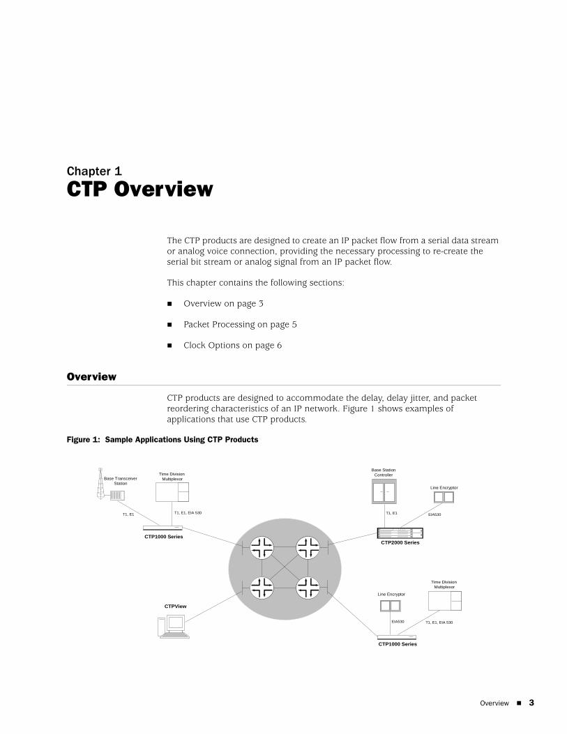
CTP products are designed to accommodate the delay, delay jitter, and packet reordering characteristics of an IP network. Figure 1 shows examples of applications that use CTP products.
Figure 1: Sample Applications Using CTP Products
Time Division Multiplexor
Line Encryptor
Line Encryptor
Base TransceiverStation
Base StationControllerTime Division
Multiplexor
CTPView
CTP1000 Series
CTP1000 Series
CTP2000 Series
T1, E1, EIA 530
T1, E1, EIA 530
T1, E1 T1, E1 EIA530
EIA530

CTP 5.2 Software Configuration Guide
4 Overview
Numerous processes must occur to adapt serial data to and from IP packets. These processes are summarized in Figure 2. You configure the characteristics of the processes by using the CTP menu interface or the CTPView graphical user interface.
Figure 2: Processes
Using the menu interface, you can configure the CTP products to accept a serial data stream and create an IP flow that will be transferred across an IP network. The connection provided by the CTP system is a physical layer circuit between the end user equipment.
Serial Stream ProcessingFor a summary of this process, see Figure 2.
Rate selection and clock configuration allow the serial interface rate to be configured through the software. Rates supported range from less than 300 bps to 12.288 Mbps (in subhertz increments).
You can configure the CTP systems by using the menu interface to provide multiple prioritized node clock references. An external reference input and any of the serial interfaces may be used for the node reference clock. Reference frequencies must be 32 KHz, n x 64 KHz, or 1544 KHz up to a maximum of 4096 KHz (2048 KHz maximum on the CTP1002).
The electrical characteristics and encoding of the CTP ports are software configurable. The available options are EIA530, EIA530A, RS-232, V.35, analog 4W-TO, conditioned diphase, isochronous, T1, and E1.
An analog voice signal terminated on the 4W-TO interface is converted into a 64-kbps PCM digital bit stream before adaptation to and from an IP flow. The analog interface allows transmit and receive levels to be adjusted.
Packet Processing 5
Chapter 1: CTP Overview
Transmit Packet ProcessingFor a summary of this process, see Figure 2 on page 4.
The CTP system is configured with the remote IP address of the system where the packets created from the local serial port are to be routed.
The CTP remote port is specified by the IP address and physical port number of the remote unit and port.
The packet size created by the CTP system may be set from 32 to 1456 bytes. As discussed in Chapter 2, Software Configuration, larger packet sizes are more bandwidth-efficient but introduce more serialization delay when the packet is created. The menu interface checks to verify that the combination of packet size and data rate does not result in a packet rate exceeding 1200 packets per second.
Time to live (TTL) may be set from 0 to 255 (see Time to Live in Chapter 2, Software Configuration). The TTL is the maximum number of hops in the IP network that the packet may travel before it is discarded by the network. You can configure the service type byte (see Service Type in Chapter 2, Software Configuration), which some IP networks use to determine the quality of service provided to the IP flow.
Packet Processing
Using the CTP menu interface, you can configure the unit to accept the IP flow and create a serial data stream that meets your application requirements. For a summary of this process, see Figure 2 on page 4.
Receive Packet ProcessingA receive buffer is required to “smooth” the timing jitter of received packets because of the delay variance that is inevitably encountered in the IP network. The configuration allows you to configure both the size of the buffer (in 1-msec increments) and the maximum amount of buffering delay allowed before the buffer will recenter. The size of the buffer configured should be dependent on the performance and characteristics of the IP network.
The CTP system automatically re-sequences packets when they arrive out of order. If a packet is not received, the CTP system inserts all data in lieu of the packet information so that bit count integrity is maintained.
You can prompt the menu interface to display detailed information about the port status, such as packet counts, late packets, missing packets, and buffer fill.
Serial Stream CreationThe packet receive process allows the serial data rate to be configured through the software. Rates supported range from less than 300 bps to 12.288 Mbps in subhertz increments as described in Chapter 2, Software Configuration. Conditioned diphase and isochronous interfaces operate at rates up to 1.024 Mbps.

CTP 5.2 Software Configuration Guide
6 Clock Options
Clock Options
The CTP system provides numerous options for physical layer clocking:
Interface clocking options—As detailed in Clock Configuration on page 48 in Chapter 2, Software Configuration, the CTP system allows complete configuration flexibility of interface clocking. This flexibility includes your ability to specify how clocks are generated (that is, from the node clock, which can be phase locked to an external clock input) and what clocks are used to process the data from the attached device. The CTP system can synthesize over 1.5 billion rates between 1 bps and 12.288 Mbps.
Asymmetric clocking—As detailed in Custom Clock Options—CLI on page 52 in Chapter 2, Software Configuration, you can configure CTP circuits to synthesize asymmetric rates.
Reference clock input—The CTP system can phase lock its node clock to an interface clock or external reference input. Up to five prioritized references can be configured. The node provides a reference holdover if all references are lost.
Plesiochronous operation—Calibrated Clock is a patented CTP feature that allows the one-time calibration of the CTP oscillator to a known reference. Depending on environmental factors, two units calibrated to the same clock will have a clock difference as small as 100 parts per billion. This allows CTP circuits to operate for long periods of time before a buffer recenter occurs.
Adaptive clocking—Although IP router networks do not transfer physical layer clocking, the CTP adaptive clocking feature, using patented Advanced Time Domain Processing (ATDP), allows the CTP system to recover clocking information from the remote CTP port and adjust the local clock accordingly. ATDP provides rapid convergence to the correct clock, and does not vary due to changes in the average jitter buffer fill. As a result, a CTP circuit will continuously operate without a buffer recenter, even when clock references are not used.
Overview 7
Chapter 2
Software Configuration
This chapter provides information about CTP configuration parameters and about configuring the systems with both the command-line interface (CLI) and CTPView. The chapter contains the following sections:
Overview on page 7
First Boot Configuration on page 10
Bundle Operations on page 11
Bundle Operations—CTPOS CLI Menu Commands on page 13
Configuring Voice Compression (Vcomp) on page 22
Configuring Port Mirroring on page 24
Bundle Operations—CTPView Interface Commands on page 27
Configuring Bundle Parameters on page 30
Port Configuration—Packet-Bearing Serial Interface on page 63
Node Synchronization on page 65
Node Summary on page 68
Node Operations and Maintenance on page 69
Overview
See Figure 3 on page 9 for a hierarchy of the CLI menus used to configure the CTP system. Corresponding CTPView configuration windows are included throughout this section. For up-to-date CTPView information, see the Release Notes.
Menu options include:
Bundle and port configuration commands—Use these commands to configure bundle interface and port interface parameters, such as bundle type, port clock, serial interface rates, interface type, buffering, and distant port IP address.

CTP 5.2 Software Configuration Guide
8 Overview
Bundles are the packetization and transport mechanisms of the physical port data, including signaling. Three bundle types are supported: circuit-to-packet (CTP), structure-agnostic TDM over packet (SAToP), and circuit emulation services of packet structure network (CESoPSN). Ports are the physical interface that can be configured and managed.
Both bundles and ports are configured through the Bundle Operations menu.
Node synchronization commands—Use these commands to configure the clock reference to be used by the CTP system. (See Port Configuration—Packet-Bearing Serial Interface on page 63.)
Node operation commands—Use these commands to perform infrequent operations such as setting the CTP IP address when the unit is first installed, upgrading the CTP software, and initializing the database. (See Node Operations and Maintenance on page 69.)
Commands to monitor the CTP system, circuits, and the IP network (such as activate, disable, and query) are described in Chapter 4, Software Queries and Operations.

Overview 9
Chapter 2: Software Configuration
Figure 3: CTP Menu Tree
In the CLI, the default setting for each configuration parameter appears in brackets whenever you are prompted for input. The default setting is implemented when the only input is a return. Whenever you enter an acceptable nondefault setting, that setting becomes the new default for the configuration parameter. When you are configuring the CTP system, any configuration changes take effect immediately and are implemented when you exit the configuration or activate the port.
CTP 5.2 Software Configuration Guide
10 First Boot Configuration
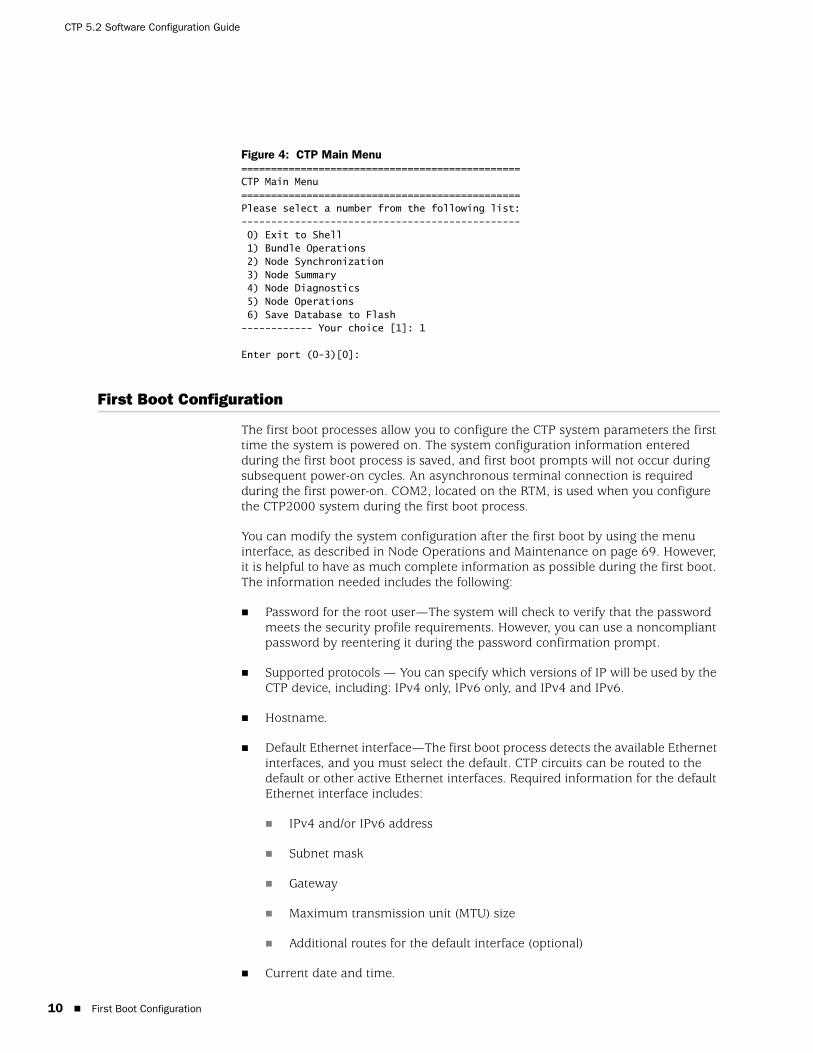
Figure 4: CTP Main Menu===============================================CTP Main Menu ===============================================Please select a number from the following list:----------------------------------------------- 0) Exit to Shell 1) Bundle Operations 2) Node Synchronization 3) Node Summary 4) Node Diagnostics5) Node Operations6) Save Database to Flash------------ Your choice [1]: 1
Enter port (0-3)[0]:
First Boot Configuration
The first boot processes allow you to configure the CTP system parameters the first time the system is powered on. The system configuration information entered during the first boot process is saved, and first boot prompts will not occur during subsequent power-on cycles. An asynchronous terminal connection is required during the first power-on. COM2, located on the RTM, is used when you configure the CTP2000 system during the first boot process.
You can modify the system configuration after the first boot by using the menu interface, as described in Node Operations and Maintenance on page 69. However, it is helpful to have as much complete information as possible during the first boot. The information needed includes the following:
Password for the root user—The system will check to verify that the password meets the security profile requirements. However, you can use a noncompliant password by reentering it during the password confirmation prompt.
Supported protocols — You can specify which versions of IP will be used by the CTP device, including: IPv4 only, IPv6 only, and IPv4 and IPv6.
Hostname.
Default Ethernet interface—The first boot process detects the available Ethernet interfaces, and you must select the default. CTP circuits can be routed to the default or other active Ethernet interfaces. Required information for the default Ethernet interface includes:
IPv4 and/or IPv6 address
Subnet mask
Gateway
Maximum transmission unit (MTU) size
Additional routes for the default interface (optional)
Current date and time.
Bundle Operations 11
Chapter 2: Software Configuration
Additional management and/or data interfaces can be configured through the CLI. This includes the ability to configure virtual IPs as well as VLAN interfaces. Details on configuring these interfaces can be found in Node Operations and Maintenance on page 69.
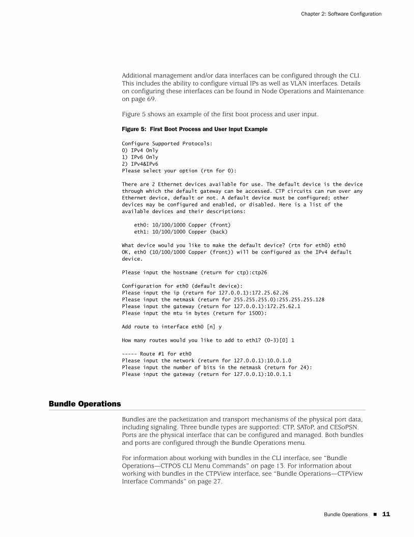
Figure 5 shows an example of the first boot process and user input.
Figure 5: First Boot Process and User Input Example
Configure Supported Protocols:0) IPv4 Only1) IPv6 Only2) IPv4&IPv6Please select your option (rtn for 0):
There are 2 Ethernet devices available for use. The default device is the device through which the default gateway can be accessed. CTP circuits can run over any Ethernet device, default or not. A default device must be configured; other devices may be configured and enabled, or disabled. Here is a list of the available devices and their descriptions:
eth0: 10/100/1000 Copper (front)eth1: 10/100/1000 Copper (back)
What device would you like to make the default device? (rtn for eth0) eth0OK, eth0 (10/100/1000 Copper (front)) will be configured as the IPv4 default device.
Please input the hostname (return for ctp):ctp26
Configuration for eth0 (default device):Please input the ip (return for 127.0.0.1):172.25.62.26Please input the netmask (return for 255.255.255.0):255.255.255.128Please input the gateway (return for 127.0.0.1):172.25.62.1Please input the mtu in bytes (return for 1500):
Add route to interface eth0 [n] y
How many routes would you like to add to eth1? (0-3)[0] 1
----- Route #1 for eth0Please input the network (return for 127.0.0.1):10.0.1.0Please input the number of bits in the netmask (return for 24):Please input the gateway (return for 127.0.0.1):10.0.1.1
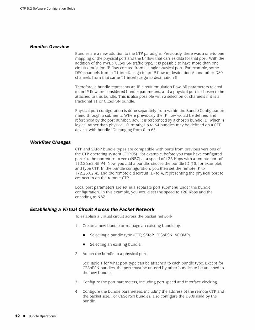
Bundle Operations
Bundles are the packetization and transport mechanisms of the physical port data, including signaling. Three bundle types are supported: CTP, SAToP, and CESoPSN. Ports are the physical interface that can be configured and managed. Both bundles and ports are configured through the Bundle Operations menu.
For information about working with bundles in the CLI interface, see “Bundle Operations—CTPOS CLI Menu Commands” on page 13. For information about working with bundles in the CTPView interface, see “Bundle Operations—CTPView Interface Commands” on page 27.
CTP 5.2 Software Configuration Guide
12 Bundle Operations
Bundles OverviewBundles are a new addition to the CTP paradigm. Previously, there was a one-to-one mapping of the physical port and the IP flow that carries data for that port. With the addition of the PWE3 CESoPSN traffic type, it is possible to have more than one circuit emulation IP flow created from a single physical port. For example, some DS0 channels from a T1 interface go in an IP flow to destination A, and other DS0 channels from that same T1 interface go to destination B.
Therefore, a bundle represents an IP circuit emulation flow. All parameters related to an IP flow are considered bundle parameters, and a physical port is chosen to be attached to this bundle. This is also possible with a selection of channels if it is a fractional T1 or CESoPSN bundle.
Physical port configuration is done separately from within the Bundle Configuration menu through a submenu. Where previously the IP flow would be defined and referenced by the port number, now it is referenced by a chosen bundle ID, which is logical rather than physical. Currently, up to 64 bundles may be defined on a CTP device, with bundle IDs ranging from 0 to 63.
Workflow ChangesCTP and SAToP bundle types are compatible with ports from previous versions of the CTP operating system (CTPOS). For example, before you may have configured port 4 to be nonreturn to zero (NRZ) at a speed of 128 Kbps with a remote port of 172.25.62.45:P4. Now, you add a bundle, choose the bundle ID (10, for example), and type CTP. In the bundle configuration, you then set the remote IP to 172.25.62.45 and the remote cid (circuit ID) to 4, representing the physical port to connect to on the remote CTP.
Local port parameters are set in a separate port submenu under the bundle configuration. In this example, you would set the speed to 128 Kbps and the encoding to NRZ.
Establishing a Virtual Circuit Across the Packet NetworkTo establish a virtual circuit across the packet network:
1. Create a new bundle or manage an existing bundle by:
Selecting a bundle type (CTP, SAToP, CESoPSN, VCOMP).
Selecting an existing bundle.
2. Attach the bundle to a physical port.
See Table 1 for what port type can be attached to each bundle type. Except for CESoPSN bundles, the port must be unused by other bundles to be attached to the new bundle.
3. Configure the port parameters, including port speed and interface clocking.
4. Configure the bundle parameters, including the address of the remote CTP and the packet size. For CESoPSN bundles, also configure the DS0s used by the bundle.

Bundle Operations—CTPOS CLI Menu Commands 13
Chapter 2: Software Configuration
5. Activate the bundle.
Table 1: Bundle Types and Allowed Port Types
Bundle Operations—CTPOS CLI Menu Commands
The Bundle Operations menu enables you to configure bundles on a CTP device. To display the Bundle Operation menu, select 1) Bundle Operations from the CTP Main Menu.
=========================================================================== (nova49 01/24/08 15:30:13 GMT) | CTP Main Menu ==========================================================================
Please select a number from the following list:------------------------------------- 0) Exit to Shell 1) Bundle Operations 2) Node Synchronization 3) Node Summary 4) Node Diagnostics 5) Node Operations 6) Save Database to Flash------------ Your choice [1]:
Bundle Type Allowed Port Types
CTP CTP-1000
Serial interface
Serial interface with T1/E1 daughter card
Serial interface with 4WTO daughter card
CTP-2000
Serial interface
Serial interface with T1/E1 daughter card
Serial interface with 4W-E&M daughter card
T1/E1 interface
SAToP CTP-1000
Serial interface with T1/E1 daughter card
CTP-2000
Serial interface with T1/E1 daughter card
T1/E1 interface
CESoPSN CTP-2000
T1/E1 interface with unused DS0s
An unused DS0 is a DS0 not assigned to another bundle. When a CESoPSN bundle is attached to a port, by default all unused DS0s are assigned to the bundle.
Voice Compression (VCOMP)
CTP-2000
T1/E1 interface
4W-E&M interface
Voice compression module
CTP 5.2 Software Configuration Guide
14 Bundle Operations—CTPOS CLI Menu Commands
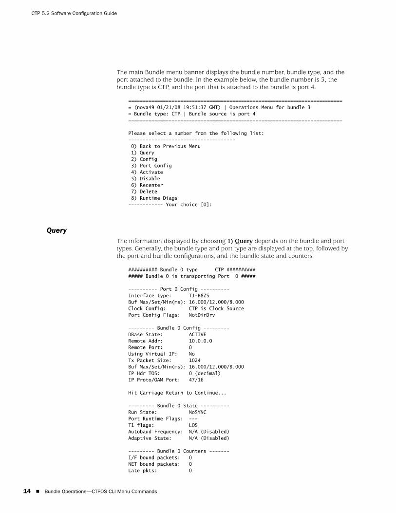
The main Bundle menu banner displays the bundle number, bundle type, and the port attached to the bundle. In the example below, the bundle number is 3, the bundle type is CTP, and the port that is attached to the bundle is port 4.
=========================================================================== (nova49 01/21/08 19:51:37 GMT) | Operations Menu for bundle 3= Bundle type: CTP | Bundle source is port 4==========================================================================
Please select a number from the following list:------------------------------------- 0) Back to Previous Menu 1) Query 2) Config 3) Port Config 4) Activate 5) Disable 6) Recenter 7) Delete 8) Runtime Diags------------ Your choice [0]:
QueryThe information displayed by choosing 1) Query depends on the bundle and port types. Generally, the bundle type and port type are displayed at the top, followed by the port and bundle configurations, and the bundle state and counters.
########## Bundle 0 type CTP ############### Bundle 0 is transporting Port 0 #####
---------- Port 0 Config ----------Interface type: T1-B8ZSBuf Max/Set/Min(ms): 16.000/12.000/8.000Clock Config: CTP is Clock SourcePort Config Flags: NotDirDrv
--------- Bundle 0 Config ---------DBase State: ACTIVERemote Addr: 10.0.0.0Remote Port: 0Using Virtual IP: NoTx Packet Size: 1024Buf Max/Set/Min(ms): 16.000/12.000/8.000IP Hdr TOS: 0 (decimal)IP Proto/OAM Port: 47/16
Hit Carriage Return to Continue...
--------- Bundle 0 State ----------Run State: NoSYNC Port Runtime Flags: ---T1 flags: LOS Autobaud Frequency: N/A (Disabled)Adaptive State: N/A (Disabled)
--------- Bundle 0 Counters -------I/F bound packets: 0NET bound packets: 0Late pkts: 0
Bundle Operations—CTPOS CLI Menu Commands 15
Chapter 2: Software Configuration
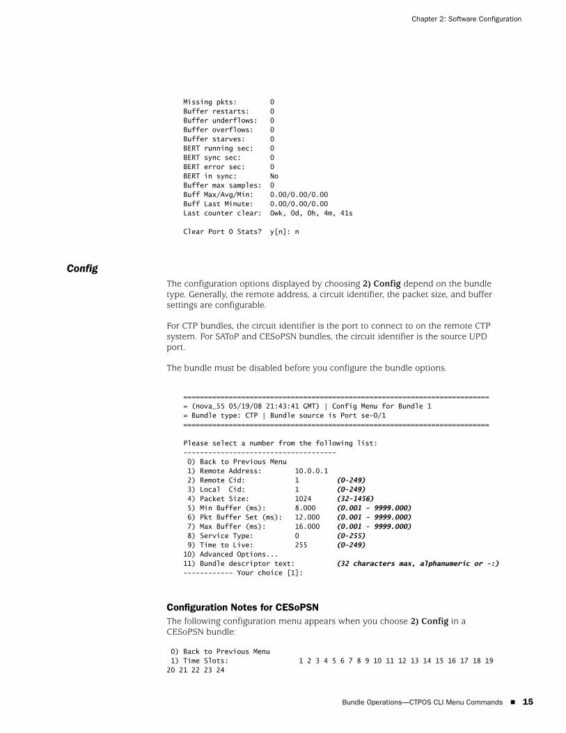
Missing pkts: 0Buffer restarts: 0Buffer underflows: 0Buffer overflows: 0Buffer starves: 0BERT running sec: 0BERT sync sec: 0BERT error sec: 0BERT in sync: NoBuffer max samples: 0Buff Max/Avg/Min: 0.00/0.00/0.00Buff Last Minute: 0.00/0.00/0.00Last counter clear: 0wk, 0d, 0h, 4m, 41s
Clear Port 0 Stats? y[n]: n
ConfigThe configuration options displayed by choosing 2) Config depend on the bundle type. Generally, the remote address, a circuit identifier, the packet size, and buffer settings are configurable.
For CTP bundles, the circuit identifier is the port to connect to on the remote CTP system. For SAToP and CESoPSN bundles, the circuit identifier is the source UPD port.
The bundle must be disabled before you configure the bundle options.
=========================================================================== (nova_55 05/19/08 21:43:41 GMT) | Config Menu for Bundle 1= Bundle type: CTP | Bundle source is Port se-0/1==========================================================================
Please select a number from the following list:------------------------------------- 0) Back to Previous Menu 1) Remote Address: 10.0.0.1 2) Remote Cid: 1 (0-249) 3) Local Cid: 1 (0-249) 4) Packet Size: 1024 (32-1456) 5) Min Buffer (ms): 8.000 (0.001 - 9999.000) 6) Pkt Buffer Set (ms): 12.000 (0.001 - 9999.000) 7) Max Buffer (ms): 16.000 (0.001 - 9999.000) 8) Service Type: 0 (0-255) 9) Time to Live: 255 (0-249)10) Advanced Options... 11) Bundle descriptor text: (32 characters max, alphanumeric or -:)------------ Your choice [1]:
Configuration Notes for CESoPSNThe following configuration menu appears when you choose 2) Config in a CESoPSN bundle:
0) Back to Previous Menu 1) Time Slots: 1 2 3 4 5 6 7 8 9 10 11 12 13 14 15 16 17 18 19 20 21 22 23 24

CTP 5.2 Software Configuration Guide
16 Bundle Operations—CTPOS CLI Menu Commands
2) Destination IP: 10.0.0.1 3) Source UDP port: 1064 4) Max Buffer (ms): 192.000 5) Pkt Buffer Set (ms): 60.000 7) Packet Size: 1152------------ Your choice [9]:
Refer to the following notes on specific menu commands.
3) Source UDP port—CESoPSN uses the source UDP port plus the destination IP address as the routing index. Be sure that the source UDP port does not overlap across the whole system.
------------ Your choice [2]: 3Enter Source UDP Port (0-65535)[1064]: 6021
4) Max Buffer (ms)—Unlike CTP configuration, contiguous buffer size configuration up to byte level is not allowed with CESoPSN. Instead, the number of packets are used as basic units to configure the buffer. The number has to be a power of 2. You can choose from ten common choices that apply to most scenarios.
------------ Your choice [3]: 4Enter Max buffer sizeChoices are:1: 8.000ms 2 packets2: 16.000ms 4 packets3: 32.000ms 8 packets4: 64.000ms 16 packets5: 128.000ms 32 packets6: 256.000ms 64 packets7: 512.000ms 128 packets8: 1024.000ms 256 packets9: 2048.000ms 512 packets10: 4096.000ms 1024 packets (1-10)[5]
5) Pkt Buffer Set (ms)—Similar to max buffer size configuration. Packet numbers are used. The buffer is measured in milliseconds and the value entered is converted to the closest packet number if the buffer is not divisible by the packet size.
------------ Your choice [5]:5 (1-128)[40]: 20
7) Packet Size—The following configuration rules must be followed:
For SAToP mode, the packet size must be divisible by 32.
For non-CAS mode, the packet size must be divisible by the total number of time slots.
For CAS mode, the packet size must be non-CAS mode packet size plus CAS size.
After the packet size has changed, the maximum buffer size and packet buffer size change in terms of milliseconds, but not in terms of packet number.
Bundle Operations—CTPOS CLI Menu Commands 17
Chapter 2: Software Configuration
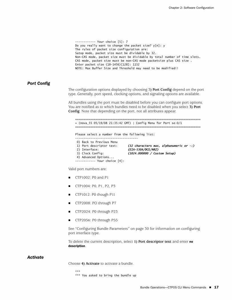
------------ Your choice [5]: 7Do you really want to change the packet size? y[n]: yThe rules of packet size configuration are:Satop mode, packet size must be dividable by 32.Non-CAS mode, packet size must be dividable by total number of time slots.CAS mode, packet size must be non-CAS mode packetsize plus CAS size .Enter packet size (18-1456)[128]: 1152NOTE: Max Buffer Size and Threshold may need to be modified!!
Port ConfigThe configuration options displayed by choosing 3) Port Config depend on the port type. Generally, port speed, clocking options, and signaling options are available.
All bundles using the port must be disabled before you can configure port options. You are notified as to which bundles need to be disabled when you select 3) Port Config. Note that depending on the port, not all attributes appear.
=========================================================================== (nova_55 05/19/08 21:35:42 GMT) | Config Menu for Port se-0/1==========================================================================
Please select a number from the following list:------------------------------------- 0) Back to Previous Menu 1) Port descriptor text: (32 characters max, alphanumeric or -:) 2) Interface: (EIA-530A/DCE/NRZ) 3) Clock Config: (1024.000000 / Custom Setup) 4) Advanced Options...------------ Your choice [4]:
Valid port numbers are:
CTP1002: P0 and P1
CTP1004: P0, P1, P2, P3
CTP1012: P0 though P11
CTP2008: PO through P7
CTP2024: P0 through P23
CTP2056: P0 through P55
See “Configuring Bundle Parameters” on page 30 for information on configuring port interface type.
To delete the current description, select 1) Port descriptor text and enter no description.
ActivateChoose 4) Activate to activate a bundle.
****** You asked to bring the bundle up
CTP 5.2 Software Configuration Guide
18 Bundle Operations—CTPOS CLI Menu Commands
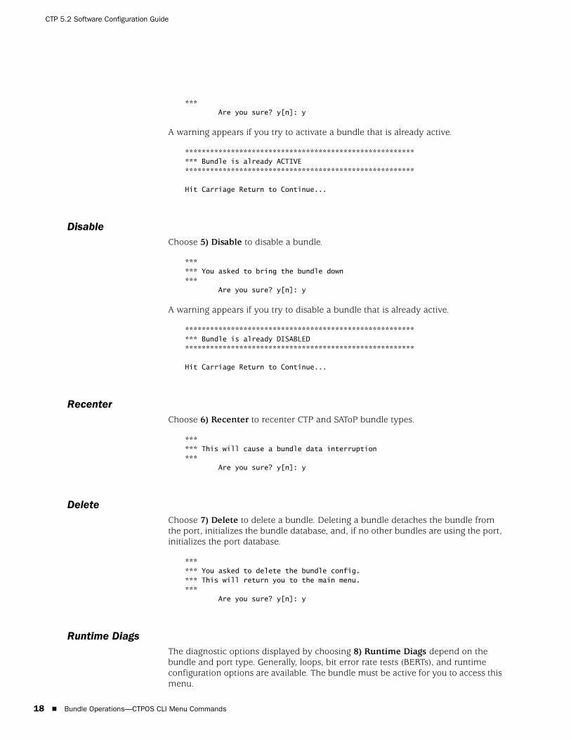
*** Are you sure? y[n]: y
A warning appears if you try to activate a bundle that is already active.
********************************************************** Bundle is already ACTIVE*******************************************************
Hit Carriage Return to Continue...
DisableChoose 5) Disable to disable a bundle.
****** You asked to bring the bundle down*** Are you sure? y[n]: y
A warning appears if you try to disable a bundle that is already active.
********************************************************** Bundle is already DISABLED*******************************************************
Hit Carriage Return to Continue...
RecenterChoose 6) Recenter to recenter CTP and SAToP bundle types.
****** This will cause a bundle data interruption*** Are you sure? y[n]: y
DeleteChoose 7) Delete to delete a bundle. Deleting a bundle detaches the bundle from the port, initializes the bundle database, and, if no other bundles are using the port, initializes the port database.
****** You asked to delete the bundle config.*** This will return you to the main menu.*** Are you sure? y[n]: y
Runtime DiagsThe diagnostic options displayed by choosing 8) Runtime Diags depend on the bundle and port type. Generally, loops, bit error rate tests (BERTs), and runtime configuration options are available. The bundle must be active for you to access this menu.
Bundle Operations—CTPOS CLI Menu Commands 19
Chapter 2: Software Configuration
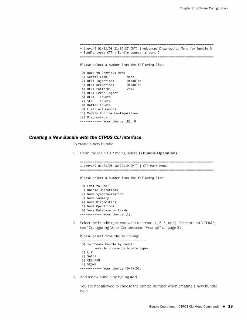
=========================================================================== (nova49 01/21/08 21:50:37 GMT) | Advanced Diagnostics Menu for bundle 0= Bundle type: CTP | Bundle source is port 0==========================================================================
Please select a number from the following list:------------------------------------- 0) Back to Previous Menu 1) Serial Loop: None 2) BERT Injection: Disabled 3) BERT Reception: Disabled 4) BERT Pattern: 2^15-1 5) BERT Error Inject 6) BERT Counts 7) SCC Counts 8) Buffer Counts 9) Clear All Counts11) Modify Runtime Configuration12) Diagnostics...------------ Your choice [8]: 0
Creating a New Bundle with the CTPOS CLI InterfaceTo create a new bundle:
1. From the Main CTP menu, select 1) Bundle Operations.
=========================================================================== (nova49 01/21/08 18:29:19 GMT) | CTP Main Menu ==========================================================================
Please select a number from the following list:------------------------------------- 0) Exit to Shell 1) Bundle Operations 2) Node Synchronization 3) Node Summary 4) Node Diagnostics 5) Node Operations 6) Save Database to Flash------------ Your choice [1]:
2. Select the bundle type you want to create (1, 2, 3, or 4). For more on VCOMP, see “Configuring Voice Compression (Vcomp)” on page 22.
Please select from the following:------------------------------------- 0) To choose bundle by number. -or- To choose by bundle type- 1) CTP 2) SAToP 3) CESoPSN4) VCOMP------------ Your choice (0-4)[0]:
3. Add a new bundle by typing add.
You are not allowed to choose the bundle number when creating a new bundle type.
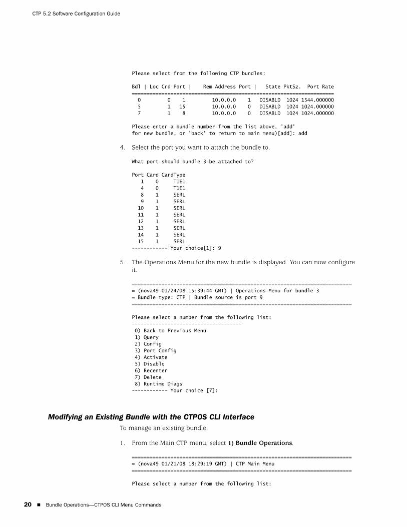
CTP 5.2 Software Configuration Guide
20 Bundle Operations—CTPOS CLI Menu Commands
Please select from the following CTP bundles:
Bdl | Loc Crd Port | Rem Address Port | State PktSz. Port Rate==================================================================== 0 0 1 10.0.0.0 1 DISABLD 1024 1544.000000 5 1 15 10.0.0.0 0 DISABLD 1024 1024.000000 7 1 8 10.0.0.0 0 DISABLD 1024 1024.000000
Please enter a bundle number from the list above, 'add'for new bundle, or 'back' to return to main menu)[add]: add
4. Select the port you want to attach the bundle to.
What port should bundle 3 be attached to?
Port Card CardType 1 0 T1E1 4 0 T1E1 8 1 SERL 9 1 SERL 10 1 SERL 11 1 SERL 12 1 SERL 13 1 SERL 14 1 SERL 15 1 SERL------------ Your choice[1]: 9
5. The Operations Menu for the new bundle is displayed. You can now configure it.
=========================================================================== (nova49 01/24/08 15:39:44 GMT) | Operations Menu for bundle 3= Bundle type: CTP | Bundle source is port 9==========================================================================
Please select a number from the following list:------------------------------------- 0) Back to Previous Menu 1) Query 2) Config 3) Port Config 4) Activate 5) Disable 6) Recenter 7) Delete 8) Runtime Diags------------ Your choice [7]:
Modifying an Existing Bundle with the CTPOS CLI InterfaceTo manage an existing bundle:
1. From the Main CTP menu, select 1) Bundle Operations.
=========================================================================== (nova49 01/21/08 18:29:19 GMT) | CTP Main Menu ==========================================================================
Please select a number from the following list:
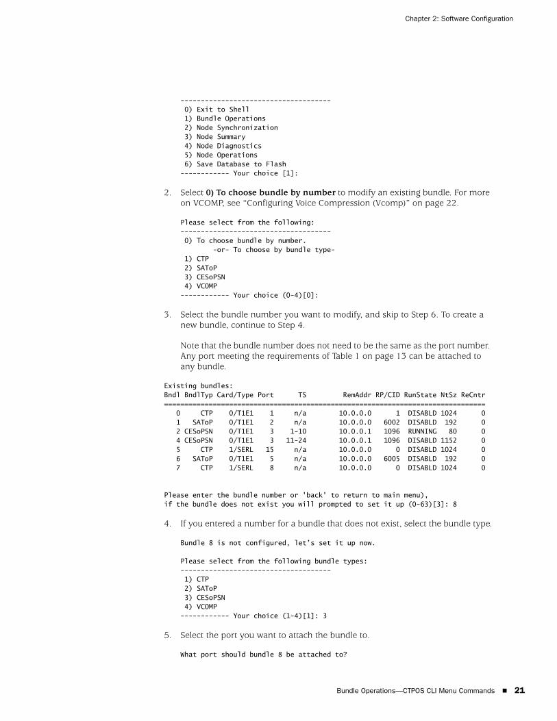
Bundle Operations—CTPOS CLI Menu Commands 21
Chapter 2: Software Configuration
------------------------------------- 0) Exit to Shell 1) Bundle Operations 2) Node Synchronization 3) Node Summary 4) Node Diagnostics 5) Node Operations 6) Save Database to Flash------------ Your choice [1]:
2. Select 0) To choose bundle by number to modify an existing bundle. For more on VCOMP, see “Configuring Voice Compression (Vcomp)” on page 22.
Please select from the following:------------------------------------- 0) To choose bundle by number. -or- To choose by bundle type- 1) CTP 2) SAToP 3) CESoPSN4) VCOMP------------ Your choice (0-4)[0]:
3. Select the bundle number you want to modify, and skip to Step 6. To create a new bundle, continue to Step 4.
Note that the bundle number does not need to be the same as the port number. Any port meeting the requirements of Table 1 on page 13 can be attached to any bundle.
Existing bundles:Bndl BndlTyp Card/Type Port TS RemAddr RP/CID RunState NtSz ReCntr=============================================================================== 0 CTP 0/T1E1 1 n/a 10.0.0.0 1 DISABLD 1024 0 1 SAToP 0/T1E1 2 n/a 10.0.0.0 6002 DISABLD 192 0 2 CESoPSN 0/T1E1 3 1-10 10.0.0.1 1096 RUNNING 80 0 4 CESoPSN 0/T1E1 3 11-24 10.0.0.1 1096 DISABLD 1152 0 5 CTP 1/SERL 15 n/a 10.0.0.0 0 DISABLD 1024 0 6 SAToP 0/T1E1 5 n/a 10.0.0.0 6005 DISABLD 192 0 7 CTP 1/SERL 8 n/a 10.0.0.0 0 DISABLD 1024 0
Please enter the bundle number or 'back' to return to main menu),if the bundle does not exist you will prompted to set it up (0-63)[3]: 8
4. If you entered a number for a bundle that does not exist, select the bundle type.
Bundle 8 is not configured, let’s set it up now.
Please select from the following bundle types:------------------------------------- 1) CTP 2) SAToP 3) CESoPSN4) VCOMP------------ Your choice (1-4)[1]: 3
5. Select the port you want to attach the bundle to.
What port should bundle 8 be attached to?

CTP 5.2 Software Configuration Guide
22 Configuring Voice Compression (Vcomp)
Port Card CardType 1 0 T1E1 4 0 T1E1 6 0 T1E1------------ Your choice[1]: 6
6. The Operations Menu for the bundle is displayed. You can now configure it.
=========================================================================== (nova49 01/24/08 15:38:22 GMT) | Operations Menu for bundle 8= Bundle type: CESoPSN | Bundle source is port 6==========================================================================
Please select a number from the following list:------------------------------------- 0) Back to Previous Menu 1) Query 2) Config 3) Port Config 4) Activate 5) Disable 6) Recenter 7) Delete 8) Runtime Diags------------ Your choice [7]:
Configuring Voice Compression (Vcomp)
Voice compression (Vcomp) enables serial data and voice bundles to be compressed and passed through a CTP2000 system.
Vcomp bundles can be configured with up to 30 voice channels. These channels may be one type only. For example, if the first channel of a Vcomp bundle is a 4WE&M type; any additional channels added to that bundle must be of the same type.
If Vcomp bundles are built from T1/E1 channels, all channels for that bundle must come from the same T1/E1 port.
All channels in a Vcomp bundle must have the same compression options.
For a T1/E1 module, if a port is selected for use in a Vcomp bundle, the entire module is configured for use only in Vcomp bundles. Other ports may not be used for other bundle types (CTP, CESoPSN, SAToP).
Conversely, if a T1/E1 port is configured for a non-Vcomp bundle, other ports on that card may not be used for Vcomp bundles.
When a port is selected on a T1/E1 card for use in a Vcomp bundle, the first port of a group of four must be used first. For example, if ports 0-3 are available, port 0 must be used first.
To configure a Vcomp bundle:
1. From the Main CTP menu, select 1) Bundle Operations.

Configuring Voice Compression (Vcomp) 23
Chapter 2: Software Configuration
=========================================================================== (nova49 01/21/08 18:29:19 GMT) | CTP Main Menu ==========================================================================
Please select a number from the following list:------------------------------------- 0) Exit to Shell 1) Bundle Operations 2) Node Synchronization 3) Node Summary 4) Node Diagnostics 5) Node Operations 6) Save Database to Flash------------ Your choice [1]: 1
2. Select 4) VCOMP.
Please select from the following:------------------------------------- 0) To choose bundle by number. -or- To choose by bundle type- 1) CTP 2) SAToP 3) CESoPSN4) VCOMP------------ Your choice (0-4)[0]: 4
Please select from the following VCOMP bundles:
Bdl | Port | Rem Address CID | State PktSz Compand Codec============================================================================ 0 4w-3/4 172.25.60.119 1 ACTIVE 107 Mu-Law G.729AB (8k) 10 te-0/0 172.25.60.119 10 ACTIVE 191 Mu-Law G.729AB (8k) 17 te-5/0 172.25.60.119 77 ACTIVE 158 Mu-Law G.729AB (8k) 60 te-0/0 172.25.60.119 100 ACTIVE 125 Mu-Law G.729AB (8k)
Please enter a bundle number from the list above, 'add'for new bundle, or 'back' to return to main menu[0]: add
3. Add a new bundle by typing add.
When you select a new Vcomp bundle for addition, only ports that are available for Vcomp bundles are shown. In this example, because card 0, ports 1-3 are available, you can see that card 0, port 0 is already completely used on one or more other Vcomp bundles (since it cannot be selected). Card 5, port 0 is partially used for other Vcomp bundles because it is still selected to use for the new Vcomp bundle and appears in the list.
4. Select the port you want to attach the bundle to.
What port should bundle 1 be attached to?
Port CardType Dcardte-0/1 T1E1 T1/E1te-0/2 T1E1 T1/E1te-0/3 T1E1 T1/E1te-0/4 T1E1 T1/E14w-3/0 4WEM Not Installed4w-3/1 4WEM Not Installed4w-3/2 4WEM Not Installed4w-3/3 4WEM Not Installed

CTP 5.2 Software Configuration Guide
24 Configuring Port Mirroring
4w-3/5 4WEM Not Installed4w-3/6 4WEM Not Installed4w-3/7 4WEM Not Installedte-5/0 T1E1 T1/E1te-5/1 T1E1 T1/E1te-5/2 T1E1 T1/E1te-5/3 T1E1 T1/E1te-5/4 T1E1 T1/E1------------ Your choice [te-0/1]: te-0/1
5. The Operations menu for the Vcomp bundle is displayed. You can now configure it.
=========================================================================== (ctp2056_voice_top 08/26/08 16:33:19 GMT) | Operations Menu for bundle 1= Bundle type: VCOMP= Bundle description:==========================================================================
Please select a number from the following list:------------------------------------- 0) Back to Previous Menu 1) Query 2) Config 3) Port Config 4) Activate 5) Disable 6) Recenter 7) Delete 8) Runtime Diags------------ Your choice [0]: 3
See “Voice Compression” on page 32 for more configuration details.
Configuring Port Mirroring
Port mirroring enables you to mirror traffic to a third port. The packet generated from the source is sent to an assigned destination and to another port whether it is on the local node or remote node.
Figure 6 illustrates all the possibilities of port-mirroring destinations on a unidirectional circuit. Bidirectional circuits copy the same configuration in the other direction. Possible port mirrorings on a unidirectional circuit from Port A1 to Port B1 include:
Circuit can be mirrored to another port on the source node (Port A2).
Circuit can be mirrored to another port on the destination node (Port B2).
Circuit can be mirrored to another port on another node (Port C1).
The tail port can also mirror the circuit to another destination (Port D1).

Configuring Port Mirroring 25
Chapter 2: Software Configuration
Figure 6: Port-Mirroring Example
To configure port mirroring:
1. From the Main CTP menu, select 1) Bundle Operations.
=========================================================================== (nova49 01/21/08 18:29:19 GMT) | CTP Main Menu ==========================================================================
Please select a number from the following list:------------------------------------- 0) Exit to Shell 1) Bundle Operations 2) Node Synchronization 3) Node Summary 4) Node Diagnostics 5) Node Operations 6) Save Database to Flash------------ Your choice [1]:
2. Select 0) To choose bundle by number to modify an existing bundle.
Please select from the following:------------------------------------- 0) To choose bundle by number. -or- To choose by bundle type- 1) CTP 2) SAToP 3) CESoPSN4) VCOMP
Node A
Port A1 (src)
Node B
Node C
Node D
Port B1 (dst)
Port B2 (Tail 1)
Port C1 (Tail 2)
Port C2 (Tail 3)
Port D1 (Tail 4)
Port A2 (Tail 5)

CTP 5.2 Software Configuration Guide
26 Configuring Port Mirroring
------------ Your choice (0-4)[0]:
3. Select the bundle number you want to mirror. The Operations menu for the bundle is displayed.
4. Select 2) Config.
=========================================================================== (nova49 01/24/08 15:38:22 GMT) | Operations Menu for bundle 8= Bundle type: CESoPSN | Bundle source is port 6==========================================================================
Please select a number from the following list:-------------------------------------0) Back to Previous Menu 1) Query 2) Config 3) Port Config 4) Activate 5) Disable 6) Recenter 7) Delete 8) Runtime Diags------------ Your choice [2]: 2
5. From the Config menu, select 10) Advanced Options.
Please select a number from the following list:------------------------------------- 0) Back to Previous Menu 1) Remote Address: 10.0.0.1 2) Remote Cid: 1 3) Local Cid: 1 4) Packet Size: 1024 5) Min Buffer (ms): 8.000 6) Pkt Buffer Set (ms): 12.000 7) Max Buffer (ms): 16.000 8) Service Type: 0 9) Time to Live: 25510) Advanced Options... 11) Bundle descriptor text: ------------ Your choice [10]: 10
6. From the Advanced Option menu, select 12) Port mirror Config.
Please select a number from the following list:------------------------------------- 0) Back to Previous Menu 1) Use virtual ip for port NO 2) Virtual ip for port: 10.0.0.1 3) Missing pkt fill pattern: 0xff 4) Consecutive pkts loss to starve: 5 5) In sequence pkts after starve: 15 6) OAM Chan Rate (sec/pkt): 1 7) OAM pkts for Sync: 2 8) OAM pkts for Sync Loss: 5 9) Packet Protector(tm) Disabled10) Unidirectional circuit: NO11) Signaling Config 12) Port mirror Config 13) Disable direct drive: YES------------ Your choice [1]:
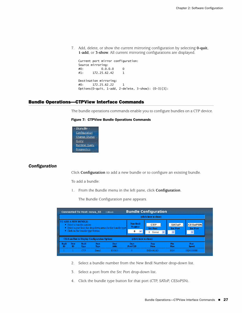
Bundle Operations—CTPView Interface Commands 27
Chapter 2: Software Configuration
7. Add, delete, or show the current mirroring configuration by selecting 0-quit, 1-add, or 3-show. All current mirroring configurations are displayed.
Current port mirror configuration: Source mirroring: #0: 0.0.0.0 0#1: 172.25.62.42 1
Destination mirroring: #0: 172.25.62.22 1Options(0-quit, 1-add, 2-delete, 3-show): (0-3)[3]:
Bundle Operations—CTPView Interface Commands
The bundle operations commands enable you to configure bundles on a CTP device.
Figure 7: CTPView Bundle Operations Commands
ConfigurationClick Configuration to add a new bundle or to configure an existing bundle.
To add a bundle:
1. From the Bundle menu in the left pane, click Configuration.
The Bundle Configuration pane appears.
2. Select a bundle number from the New Bndl Number drop-down list.
3. Select a port from the Src Port drop-down list.
4. Click the bundle type button for that port (CTP, SAToP, CESoPSN).
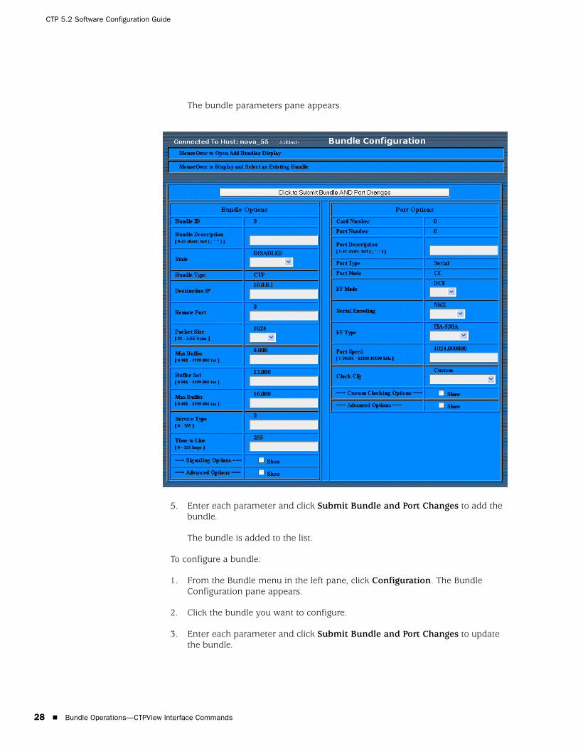
CTP 5.2 Software Configuration Guide
28 Bundle Operations—CTPView Interface Commands
The bundle parameters pane appears.
5. Enter each parameter and click Submit Bundle and Port Changes to add the bundle.
The bundle is added to the list.
To configure a bundle:
1. From the Bundle menu in the left pane, click Configuration. The Bundle Configuration pane appears.
2. Click the bundle you want to configure.
3. Enter each parameter and click Submit Bundle and Port Changes to update the bundle.

Bundle Operations—CTPView Interface Commands 29
Chapter 2: Software Configuration
Change StatusClick Change Status to activate, disable, delete, or recenter a bundle. The Change Bundle Status pane appears. Make any updates and then click Submit.
QueryClick Query and then select a bundle on which to perform a query. The Bundle Configuration pane appears.

CTP 5.2 Software Configuration Guide
30 Configuring Bundle Parameters
Runtime QueryClick Runtime Query to display runtime statistics for a selected bundle. The Bundle Runtime Information pane appears.
DiagnosticsClick Diagnostics to perform port diagnostics. The Port Diagnostics pane appears.
Configuring Bundle Parameters
You can use the CLI and CTPView interface to configure bundle parameters.
Interface TypeYou can configure the interface attributes, including the interface type and the serial encoding. The standard interface types are RS-232, V.35, EIA530, and EIA530A. 4WTO analog voice, T1/E1, and fractional T1/E1 interface types are available when you order the optional hardware and install it on the CTP interface module. The optional interfaces are software configurable, and the system automatically detects when the necessary hardware is installed.
4WTO Voice InterfaceAdditional parameters associated with the 4WTO voice interface include the following:

Configuring Bundle Parameters 31
Chapter 2: Software Configuration
Dual Channel—Each CTP port with the optional voice daughter card is capable of supporting either one or two voice channels. For one channel, disable the parameter. For two channels, enable the parameter.
Enabled Channel—If Dual Channel is disabled, then use this parameter to select which channel is enabled. The parameter is not available (N/A) if the Dual Channel parameter is enabled.
Input level—The input level can be adjusted to a value between 0 and 255. The value of 25 is the default and is the unity value (no attenuation or gain). Setting the value to 0 attenuates the signal 33% (1.8 dB). Setting the value to 255 amplifies the signal 400% (6 dB). Intermediate values are derived with linear interpolation. The actual gain depends on the impedance of the attached device.
Output level—The output level can be adjusted to a value between 0 and 255. The value of 25 is the default and is the unity value (no attenuation or gain). Setting the value to 0 attenuates the signal 33% (1.8 dB). Setting the value to 255 amplifies the signal 400% (6 dB). Intermediate values are derived with linear interpolation. The actual gain depends on the impedance of the attached devise.
Talk Squelch—This parameter allows the active squelch circuit to be enabled or disabled.
T1/E1 InterfaceAdditional parameters are associated with the optional T1/E1 interface. When the T1 interface is configured, then you can configure the encoding for either B8ZS or AMI. When the E1 interface is configured, then you can configure the termination to work with either Coax or RJ-48.
Fractional T1/E1 InterfaceFractional T1/E1 transports the first n DS0 channels across the IP network, where n is configurable. There are slight differences depending on whether the fractional support is for T1 or E1. Fractional T1 supports only extended superframe (ESF) framing. CRC generation/checking is not supported in either.
For fractional T1, this implementation can also transport the framing bits across the IP network in addition to the DS0s. Transport of the framing bits is configurable, and the default configuration transports the framing.
For ESF framing, the frame synchronization, data link, and CRC framing bits are passed across the IP network untouched. When the framing bits are not transported across the IP network, the regenerated T1 stream at the far end most likely will not have the same data alignment within the nonidle DS0s. In addition, the CRC and data link framing bits are set to 0 in the regenerated T1 stream.
For fractional E1, the framing is contained in the first DS0. This DS0 is always transported unaltered in this implementation. In addition, CAS support is optional. When CAS support is enabled, the sixteenth DS0 is transported. DS0s that are not transported across the IP network must be idle if CRC checking is enabled by the customer equipment.

CTP 5.2 Software Configuration Guide
32 Configuring Bundle Parameters
There is no internal BERT support for fractional T1/E1 circuits. Fractional T1 circuit emulation supports only T1 circuits with ESF framing. CTPOS 4.4 does not support CRC generation. Fractional T1/E1 circuit transport can be run only on ports 0 and 1 on CTP-1000 series products.
Voice CompressionMany of the Port Configuration menu options are similar to CESoPSN bundles. One notable exception is the signal option, which if set to on will transport signaling lead input on each channel from end-to-end on a per-channel basis.
See the following port configuration example where signaling is turned on and channel allocation is configured.
=========================================================================== (ctp2056_voice_top 08/26/08 16:33:40 GMT) | T1E1 Config Menu for Port Portte-0/1==========================================================================
Please select a number from the following list:------------------------------------- 0) Back to Previous Menu 1) Type: T1 2) LineCoding: B8ZS 3) BuildOut: ~133 ft 4) Frame Mode: ESF 5) Signal: Off 6) Port descriptor text:------------ Your choice [1]: 5
Please select a number from the following list:----------------------------------------------- 0) Off 1) On------------ Your choice [0]: 1
Signaling is turned on.
=========================================================================== (ctp2056_voice_top 08/26/08 16:33:43 GMT) | T1E1 Config Menu for Port Portte-0/1==========================================================================
Please select a number from the following list:------------------------------------- 0) Back to Previous Menu 1) Type: T1 2) LineCoding: B8ZS 3) BuildOut: ~133 ft 4) Frame Mode: ESF 5) Signal: On 6) Port descriptor text:------------ Your choice [5]: 0
NOTE: Both endpoints must be configured with the same fractional T1/E1 options. If not, the port runtime state will go to MisCFG as a result of the endpoint clocking check.
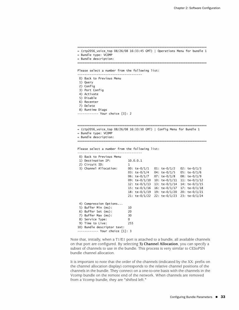
Configuring Bundle Parameters 33
Chapter 2: Software Configuration
=========================================================================== (ctp2056_voice_top 08/26/08 16:33:45 GMT) | Operations Menu for bundle 1= Bundle type: VCOMP= Bundle description:==========================================================================
Please select a number from the following list:------------------------------------- 0) Back to Previous Menu 1) Query 2) Config 3) Port Config 4) Activate 5) Disable 6) Recenter 7) Delete 8) Runtime Diags------------ Your choice [3]: 2
=========================================================================== (ctp2056_voice_top 08/26/08 16:33:50 GMT) | Config Menu for Bundle 1= Bundle type: VCOMP= Bundle description:==========================================================================
Please select a number from the following list:------------------------------------- 0) Back to Previous Menu 1) Destination IP: 10.0.0.1 2) Circuit ID: 1 3) Channel Allocation: 00: te-0/1/1 01: te-0/1/2 02: te-0/1/3 03: te-0/1/4 04: te-0/1/5 05: te-0/1/6 06: te-0/1/7 07: te-0/1/8 08: te-0/1/9 09: te-0/1/10 10: te-0/1/11 11: te-0/1/12 12: te-0/1/13 13: te-0/1/14 14: te-0/1/15 15: te-0/1/16 16: te-0/1/17 17: te-0/1/18 18: te-0/1/19 19: te-0/1/20 20: te-0/1/21 21: te-0/1/22 22: te-0/1/23 23: te-0/1/24
4) Compression Options... 5) Buffer Min (ms): 10 6) Buffer Set (ms): 20 7) Buffer Max (ms): 30 8) Service Type: 0 9) Time to Live: 25510) Bundle descriptor text:------------ Your choice [1]: 3
Note that, initially, when a T1/E1 port is attached to a bundle, all available channels on that port are configured. By selecting 3) Channel Allocation, you can specify a subset of channels to use in the bundle. This process is very similar to CESoPSN bundle channel allocation.
It is important to note that the order of the channels (indicated by the XX: prefix on the channel allocation display) corresponds to the relative channel positions of the channels in the bundle. They connect on a one-to-one basis with the channels in the Vcomp bundle on the remote end of the network. When channels are removed from a Vcomp bundle, they are "shifted left."
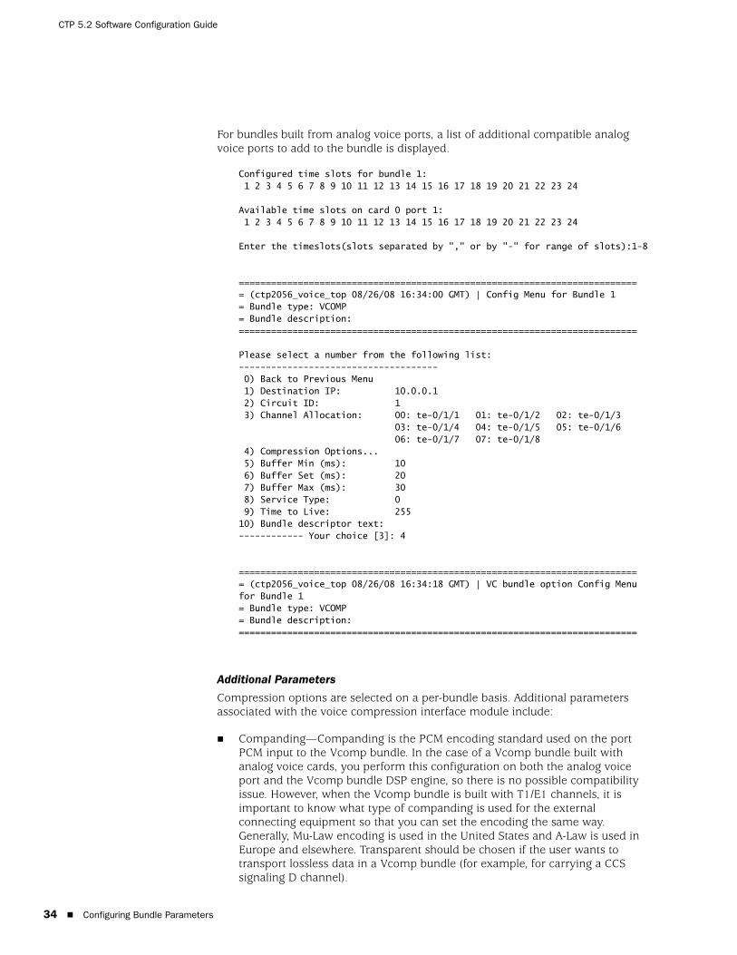
CTP 5.2 Software Configuration Guide
34 Configuring Bundle Parameters
For bundles built from analog voice ports, a list of additional compatible analog voice ports to add to the bundle is displayed.
Configured time slots for bundle 1: 1 2 3 4 5 6 7 8 9 10 11 12 13 14 15 16 17 18 19 20 21 22 23 24
Available time slots on card 0 port 1: 1 2 3 4 5 6 7 8 9 10 11 12 13 14 15 16 17 18 19 20 21 22 23 24
Enter the timeslots(slots separated by "," or by "-" for range of slots):1-8
=========================================================================== (ctp2056_voice_top 08/26/08 16:34:00 GMT) | Config Menu for Bundle 1= Bundle type: VCOMP= Bundle description:==========================================================================
Please select a number from the following list:------------------------------------- 0) Back to Previous Menu 1) Destination IP: 10.0.0.1 2) Circuit ID: 1 3) Channel Allocation: 00: te-0/1/1 01: te-0/1/2 02: te-0/1/3 03: te-0/1/4 04: te-0/1/5 05: te-0/1/6 06: te-0/1/7 07: te-0/1/8 4) Compression Options... 5) Buffer Min (ms): 10 6) Buffer Set (ms): 20 7) Buffer Max (ms): 30 8) Service Type: 0 9) Time to Live: 25510) Bundle descriptor text:------------ Your choice [3]: 4
=========================================================================== (ctp2056_voice_top 08/26/08 16:34:18 GMT) | VC bundle option Config Menu for Bundle 1= Bundle type: VCOMP= Bundle description:==========================================================================
Additional Parameters
Compression options are selected on a per-bundle basis. Additional parameters associated with the voice compression interface module include:
Companding—Companding is the PCM encoding standard used on the port PCM input to the Vcomp bundle. In the case of a Vcomp bundle built with analog voice cards, you perform this configuration on both the analog voice port and the Vcomp bundle DSP engine, so there is no possible compatibility issue. However, when the Vcomp bundle is built with T1/E1 channels, it is important to know what type of companding is used for the external connecting equipment so that you can set the encoding the same way. Generally, Mu-Law encoding is used in the United States and A-Law is used in Europe and elsewhere. Transparent should be chosen if the user wants to transport lossless data in a Vcomp bundle (for example, for carrying a CCS signaling D channel).
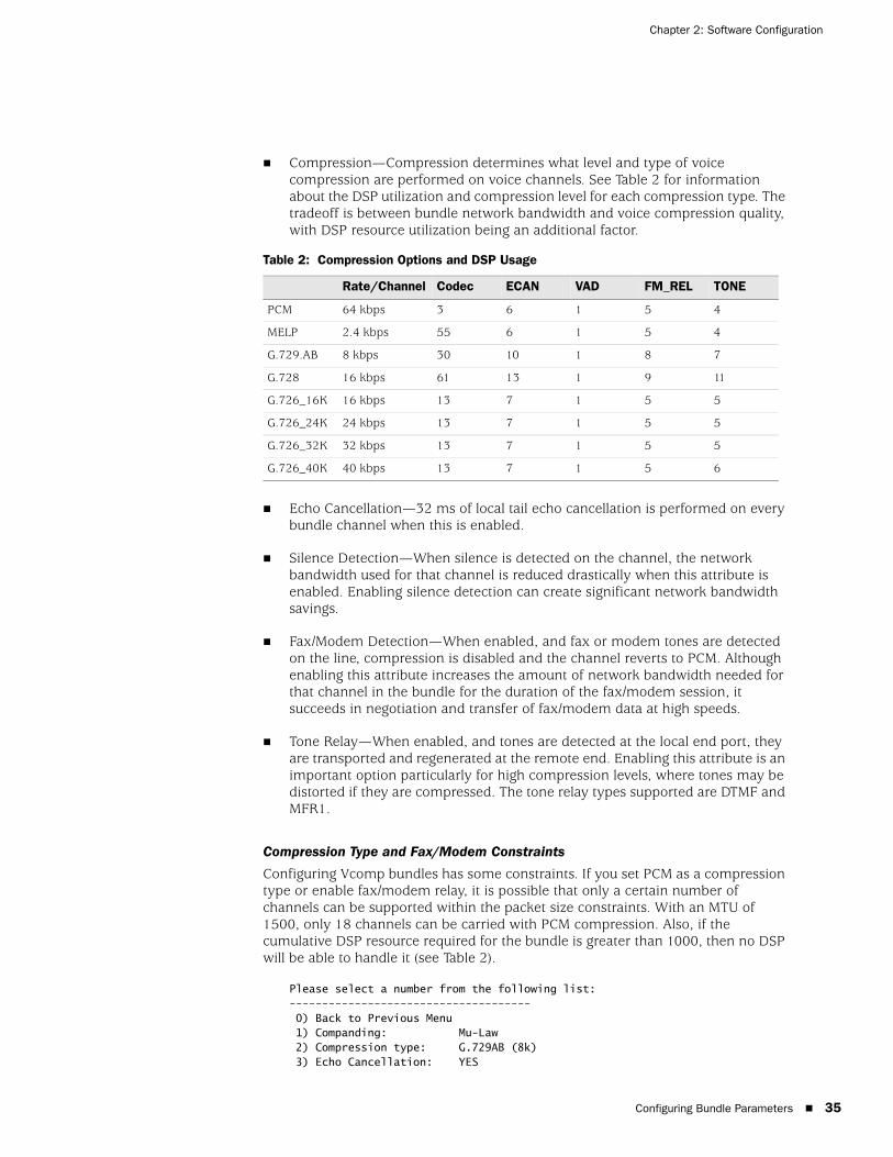
Configuring Bundle Parameters 35
Chapter 2: Software Configuration
Compression—Compression determines what level and type of voice compression are performed on voice channels. See Table 2 for information about the DSP utilization and compression level for each compression type. The tradeoff is between bundle network bandwidth and voice compression quality, with DSP resource utilization being an additional factor.
Echo Cancellation—32 ms of local tail echo cancellation is performed on every bundle channel when this is enabled.
Silence Detection—When silence is detected on the channel, the network bandwidth used for that channel is reduced drastically when this attribute is enabled. Enabling silence detection can create significant network bandwidth savings.
Fax/Modem Detection—When enabled, and fax or modem tones are detected on the line, compression is disabled and the channel reverts to PCM. Although enabling this attribute increases the amount of network bandwidth needed for that channel in the bundle for the duration of the fax/modem session, it succeeds in negotiation and transfer of fax/modem data at high speeds.
Tone Relay—When enabled, and tones are detected at the local end port, they are transported and regenerated at the remote end. Enabling this attribute is an important option particularly for high compression levels, where tones may be distorted if they are compressed. The tone relay types supported are DTMF and MFR1.
Compression Type and Fax/Modem Constraints
Configuring Vcomp bundles has some constraints. If you set PCM as a compression type or enable fax/modem relay, it is possible that only a certain number of channels can be supported within the packet size constraints. With an MTU of 1500, only 18 channels can be carried with PCM compression. Also, if the cumulative DSP resource required for the bundle is greater than 1000, then no DSP will be able to handle it (see Table 2).
Please select a number from the following list:------------------------------------- 0) Back to Previous Menu 1) Companding: Mu-Law 2) Compression type: G.729AB (8k) 3) Echo Cancellation: YES
Table 2: Compression Options and DSP Usage
Rate/Channel Codec ECAN VAD FM_REL TONE
PCM 64 kbps 3 6 1 5 4
MELP 2.4 kbps 55 6 1 5 4
G.729.AB 8 kbps 30 10 1 8 7
G.728 16 kbps 61 13 1 9 11
G.726_16K 16 kbps 13 7 1 5 5
G.726_24K 24 kbps 13 7 1 5 5
G.726_32K 32 kbps 13 7 1 5 5
G.726_40K 40 kbps 13 7 1 5 6
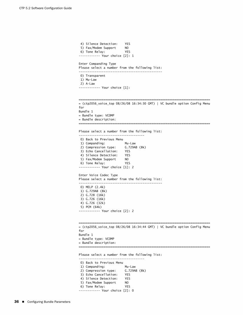
CTP 5.2 Software Configuration Guide
36 Configuring Bundle Parameters
4) Silence Detection: YES 5) Fax/Modem Support NO 6) Tone Relay: YES------------ Your choice [2]: 1
Enter Companding TypePlease select a number from the following list:----------------------------------------------- 0) Transparent 1) Mu-Law 2) A-Law------------ Your choice [1]:
=========================================================================== (ctp2056_voice_top 08/26/08 16:34:30 GMT) | VC bundle option Config Menu forBundle 1= Bundle type: VCOMP= Bundle description:==========================================================================
Please select a number from the following list:------------------------------------- 0) Back to Previous Menu 1) Companding: Mu-Law 2) Compression type: G.729AB (8k) 3) Echo Cancellation: YES 4) Silence Detection: YES 5) Fax/Modem Support NO 6) Tone Relay: YES------------ Your choice [1]: 2
Enter Voice Codec TypePlease select a number from the following list:----------------------------------------------- 0) MELP (2.4k) 1) G.729AB (8k) 2) G.728 (16k) 3) G.726 (16k) 4) G.726 (32k) 5) PCM (64k)------------ Your choice [2]: 2
=========================================================================== (ctp2056_voice_top 08/26/08 16:34:44 GMT) | VC bundle option Config Menu forBundle 1= Bundle type: VCOMP= Bundle description:==========================================================================
Please select a number from the following list:------------------------------------- 0) Back to Previous Menu 1) Companding: Mu-Law 2) Compression type: G.729AB (8k) 3) Echo Cancellation: YES 4) Silence Detection: YES 5) Fax/Modem Support NO 6) Tone Relay: YES------------ Your choice [2]: 0
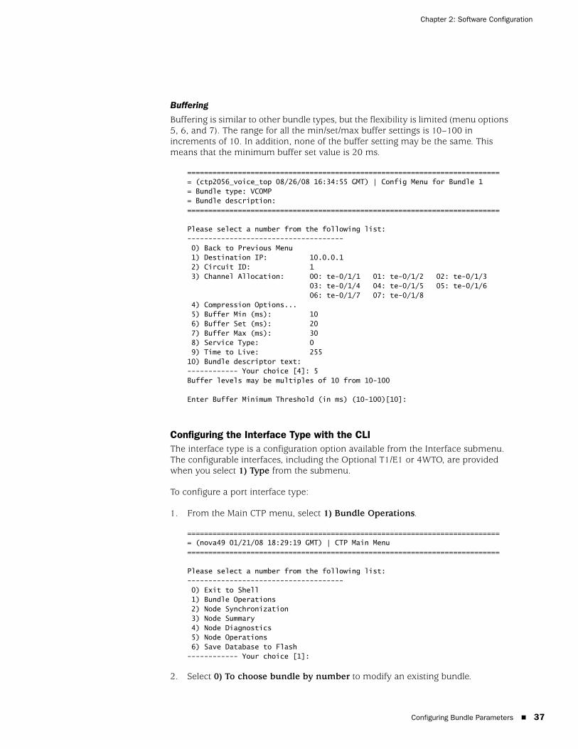
Configuring Bundle Parameters 37
Chapter 2: Software Configuration
Buffering
Buffering is similar to other bundle types, but the flexibility is limited (menu options 5, 6, and 7). The range for all the min/set/max buffer settings is 10–100 in increments of 10. In addition, none of the buffer setting may be the same. This means that the minimum buffer set value is 20 ms.
=========================================================================== (ctp2056_voice_top 08/26/08 16:34:55 GMT) | Config Menu for Bundle 1= Bundle type: VCOMP= Bundle description:==========================================================================
Please select a number from the following list:------------------------------------- 0) Back to Previous Menu 1) Destination IP: 10.0.0.1 2) Circuit ID: 1 3) Channel Allocation: 00: te-0/1/1 01: te-0/1/2 02: te-0/1/3 03: te-0/1/4 04: te-0/1/5 05: te-0/1/6 06: te-0/1/7 07: te-0/1/8 4) Compression Options... 5) Buffer Min (ms): 10 6) Buffer Set (ms): 20 7) Buffer Max (ms): 30 8) Service Type: 0 9) Time to Live: 25510) Bundle descriptor text:------------ Your choice [4]: 5Buffer levels may be multiples of 10 from 10-100
Enter Buffer Minimum Threshold (in ms) (10-100)[10]:
Configuring the Interface Type with the CLIThe interface type is a configuration option available from the Interface submenu. The configurable interfaces, including the Optional T1/E1 or 4WTO, are provided when you select 1) Type from the submenu.
To configure a port interface type:
1. From the Main CTP menu, select 1) Bundle Operations.
=========================================================================== (nova49 01/21/08 18:29:19 GMT) | CTP Main Menu ==========================================================================
Please select a number from the following list:------------------------------------- 0) Exit to Shell 1) Bundle Operations 2) Node Synchronization 3) Node Summary 4) Node Diagnostics 5) Node Operations 6) Save Database to Flash------------ Your choice [1]:
2. Select 0) To choose bundle by number to modify an existing bundle.

CTP 5.2 Software Configuration Guide
38 Configuring Bundle Parameters
3. Select the bundle number you want to modify. The Operations Menu for the bundle is displayed.
4. Select 3) Port Config.
Please select a number from the following list:------------------------------------- 0) Back to Previous Menu 1) Query 2) Config 3) Port Config 4) Activate 5) Disable 6) Recenter 7) Delete 8) Runtime Diags------------ Your choice [3]: 3
5. Select 2) Interface.
Please select a number from the following list:------------------------------------- 0) Back to Previous Menu 1) Port descriptor text: 2) Interface: OFF/DCE/NRZ 3) Clock Config: 1024.000000 / Custom Setup 4) Advanced Options...------------ Your choice [2]:
6. Choose 1) Type and then choose a type from the list.
Please select a number from the following list:------------------------------------- 0) Back to Previous Menu 1) Type: OFF (EIA-530,EIA-530A,RS-232,V.35, Optional: Voice 4W/TO or T1/E1, IRIG-B, OFF) 2) Mode: DCE (DCE,DTE, N/A) 3) Encoding: NRZ (NRZ, ISOCH, CDI, TRANS, N/A)------------ Your choice [1]:
You can now configure additional channel option for some types. See Figure 8, Figure 9, Figure 10, Figure 11, and Figure 12.
Figure 8: 4WTO Analog Voice Submenu
Please select a number from the following list:----------------------------------------------- 0) Back to Previous Menu 1) Dual Channel: (Enable,Disabled) 2) Enabled Channel: (Chan 0, Chan 1, N/A) 3) Input level: (0 – 255) 4) Output level: (0 – 255) 5) Talk Squelch: (Enable,Disable Active Squelch)------------ Your choice [0]:
NOTE: Selecting the optional voice interface results in the clock rate and clocking configuration being set automatically.

Configuring Bundle Parameters 39
Chapter 2: Software Configuration
Selecting the optional T1/E1 interface displays additional channel options that you can configure. When you configure the type for T1, you then have an option to set the encoding for B8ZS or AMI (Figure 9).
CTP Release 4.3 introduced support for structure-agnostic time division multiplexing (TDM) over packet (SAToP) circuit emulation. This is an implementation of the IETF’s PWE3 working group Structure Agnostic TDM over Packet RFC 4553. By default, standard CTP circuit emulation techniques are used. Setting Option 3 to Yes enables standards-compliant circuit emulation.
The default packet size for SAToP encapsulation is 192. The remote port (for example, P1) is not used to identify the circuit endpoints. The source UDP port is used as the circuit identifier; you must configure both circuit endpoints to use the same UDP port. The UDP port must be unique on the CTP system. You will not be able to activate a port if another port is using the same source UPD port number.
Figure 9: Configuring a T1 Interface and Options—CLI==========================================================================(intel_52 10/09/06 21:28:43 GMT) | Voice T1E1 Config Menu for Port 0==========================================================================Please select a number from the following list:------------------------------------- 0) Back to Previous Menu 1) Type: T1 2) Option: B8ZS3) SAToP: No8) BuildOut: ~133ft
Encoding Example Example of configuring the encoding (2):
------------ Your choice [2]: 2Please select a number from the following list:----------------------------------------------- 0) B8ZS 1) AMI------------ Your choice [0]:
SAToP Example Example of configuring the SAToP (3):
------------ Your choice [1]: 3Enable SAToP for T1 using UDP for transport? y[n]: y
Enter source UDP port: (1-65535)[6000]: 2142
Build Out Example Example of configuring the Build Out (8):
------------ Your choice [1]: 8
Please select a number from the following list:----------------------------------------------- 0) ~133 ft 1) ~266 ft

CTP 5.2 Software Configuration Guide
40 Configuring Bundle Parameters
2) ~399 ft 3) ~533 ft 4) ~655 ft 5) -7.5dB CSU 6) -15dB CSU 7) -22.5dBCSU------------ Your choice [0]:
E1 Interface Example
When you configure the type for E1, then you have the option to select the impedance for a Coax or an RJ-48 termination (Figure 10).
Figure 10: Configuring an E1 Interface and Options—CLI==========================================================================(intel_52 10/09/06 21:34:49 GMT) | Voice T1E1 Config Menu for Port 0==========================================================================
Please select a number from the following list:------------------------------------- 0) Back to Previous Menu 1) Type: E1 2) Option: RJ483) SAToP: No
------------ Your choice [1]: 2
Please select a number from the following list:----------------------------------------------- 0) RJ48 1) COAX------------ Your choice [0]:
Fractional T1 Interface ExampleFigure 11 is an example of configuring a fractional T1 interface.
Figure 11: Configuring a Fractional T1/E1 Interface and Options—CLI==========================================================================(ctp23 6/13/07 21:34:49 GMT) | Voice T1E1 Config Menu for Port 1==========================================================================
Please select a number from the following list:------------------------------------- 0) Back to Previous Menu 1) Type: T1 2) Option: B8ZS3) SAToP: No
------------ Your choice [1]: 2
Then enable fractional T1 or fractional E1 support:
Please select a number from the following list:----------------------------------------------- 0) T1 1) E12) Fractional T1
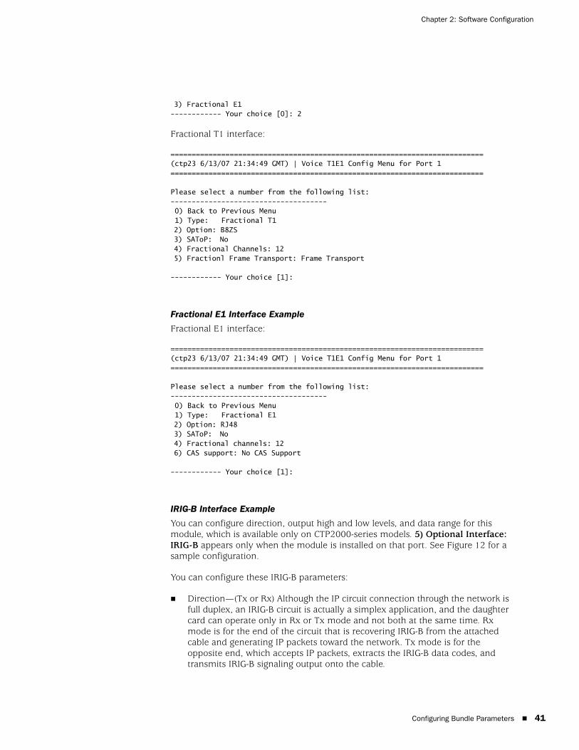
Configuring Bundle Parameters 41
Chapter 2: Software Configuration
3) Fractional E1------------ Your choice [0]: 2
Fractional T1 interface:
==========================================================================(ctp23 6/13/07 21:34:49 GMT) | Voice T1E1 Config Menu for Port 1==========================================================================
Please select a number from the following list:------------------------------------- 0) Back to Previous Menu 1) Type: Fractional T12) Option: B8ZS3) SAToP: No4) Fractional Channels: 125) Fractionl Frame Transport: Frame Transport
------------ Your choice [1]:
Fractional E1 Interface Example
Fractional E1 interface:
==========================================================================(ctp23 6/13/07 21:34:49 GMT) | Voice T1E1 Config Menu for Port 1==========================================================================
Please select a number from the following list:------------------------------------- 0) Back to Previous Menu 1) Type: Fractional E12) Option: RJ483) SAToP: No4) Fractional channels: 126) CAS support: No CAS Support
------------ Your choice [1]:
IRIG-B Interface Example
You can configure direction, output high and low levels, and data range for this module, which is available only on CTP2000-series models. 5) Optional Interface: IRIG-B appears only when the module is installed on that port. See Figure 12 for a sample configuration.
You can configure these IRIG-B parameters:
Direction—(Tx or Rx) Although the IP circuit connection through the network is full duplex, an IRIG-B circuit is actually a simplex application, and the daughter card can operate only in Rx or Tx mode and not both at the same time. Rx mode is for the end of the circuit that is recovering IRIG-B from the attached cable and generating IP packets toward the network. Tx mode is for the opposite end, which accepts IP packets, extracts the IRIG-B data codes, and transmits IRIG-B signaling output onto the cable.
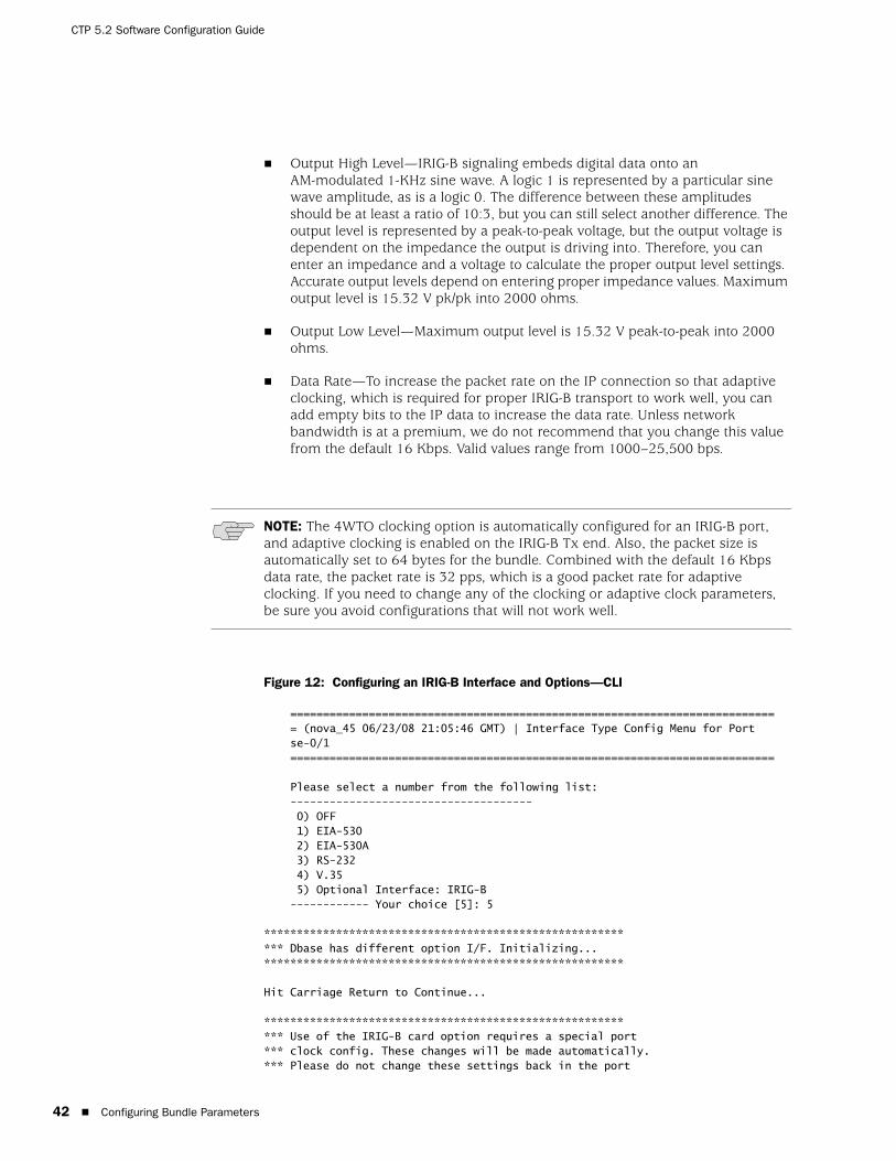
CTP 5.2 Software Configuration Guide
42 Configuring Bundle Parameters
Output High Level—IRIG-B signaling embeds digital data onto an AM-modulated 1-KHz sine wave. A logic 1 is represented by a particular sine wave amplitude, as is a logic 0. The difference between these amplitudes should be at least a ratio of 10:3, but you can still select another difference. The output level is represented by a peak-to-peak voltage, but the output voltage is dependent on the impedance the output is driving into. Therefore, you can enter an impedance and a voltage to calculate the proper output level settings. Accurate output levels depend on entering proper impedance values. Maximum output level is 15.32 V pk/pk into 2000 ohms.
Output Low Level—Maximum output level is 15.32 V peak-to-peak into 2000 ohms.
Data Rate—To increase the packet rate on the IP connection so that adaptive clocking, which is required for proper IRIG-B transport to work well, you can add empty bits to the IP data to increase the data rate. Unless network bandwidth is at a premium, we do not recommend that you change this value from the default 16 Kbps. Valid values range from 1000–25,500 bps.
Figure 12: Configuring an IRIG-B Interface and Options—CLI
=========================================================================== (nova_45 06/23/08 21:05:46 GMT) | Interface Type Config Menu for Port se-0/1==========================================================================
Please select a number from the following list:------------------------------------- 0) OFF 1) EIA-530 2) EIA-530A 3) RS-232 4) V.35 5) Optional Interface: IRIG-B------------ Your choice [5]: 5
********************************************************** Dbase has different option I/F. Initializing...*******************************************************
Hit Carriage Return to Continue...
********************************************************** Use of the IRIG-B card option requires a special port*** clock config. These changes will be made automatically.*** Please do not change these settings back in the port
NOTE: The 4WTO clocking option is automatically configured for an IRIG-B port, and adaptive clocking is enabled on the IRIG-B Tx end. Also, the packet size is automatically set to 64 bytes for the bundle. Combined with the default 16 Kbps data rate, the packet rate is 32 pps, which is a good packet rate for adaptive clocking. If you need to change any of the clocking or adaptive clock parameters, be sure you avoid configurations that will not work well.
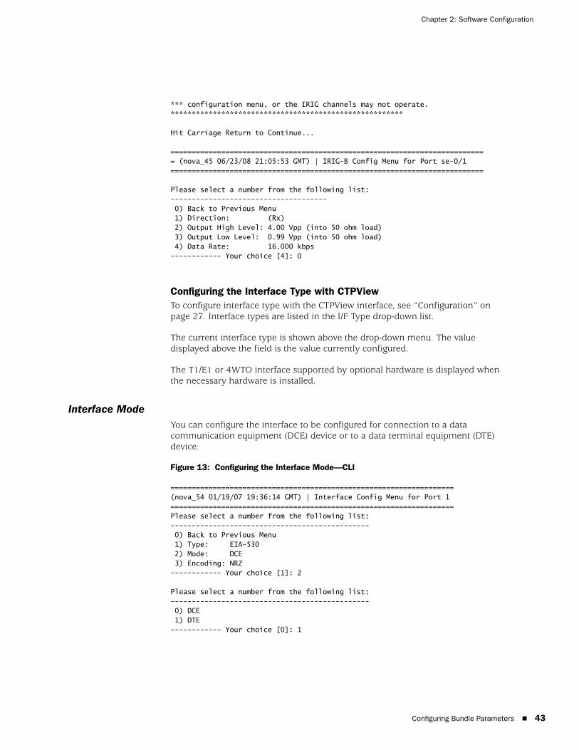
Configuring Bundle Parameters 43
Chapter 2: Software Configuration
*** configuration menu, or the IRIG channels may not operate.*******************************************************
Hit Carriage Return to Continue...
=========================================================================== (nova_45 06/23/08 21:05:53 GMT) | IRIG-B Config Menu for Port se-0/1==========================================================================
Please select a number from the following list:------------------------------------- 0) Back to Previous Menu 1) Direction: (Rx) 2) Output High Level: 4.00 Vpp (into 50 ohm load) 3) Output Low Level: 0.99 Vpp (into 50 ohm load) 4) Data Rate: 16.000 kbps------------ Your choice [4]: 0
Configuring the Interface Type with CTPViewTo configure interface type with the CTPView interface, see “Configuration” on page 27. Interface types are listed in the I/F Type drop-down list.
The current interface type is shown above the drop-down menu. The value displayed above the field is the value currently configured.
The T1/E1 or 4WTO interface supported by optional hardware is displayed when the necessary hardware is installed.
Interface ModeYou can configure the interface to be configured for connection to a data communication equipment (DCE) device or to a data terminal equipment (DTE) device.
Figure 13: Configuring the Interface Mode—CLI
===================================================================(nova_54 01/19/07 19:36:14 GMT) | Interface Config Menu for Port 1===================================================================Please select a number from the following list:----------------------------------------------- 0) Back to Previous Menu 1) Type: EIA-530 2) Mode: DCE 3) Encoding: NRZ------------ Your choice [1]: 2
Please select a number from the following list:----------------------------------------------- 0) DCE 1) DTE------------ Your choice [0]: 1
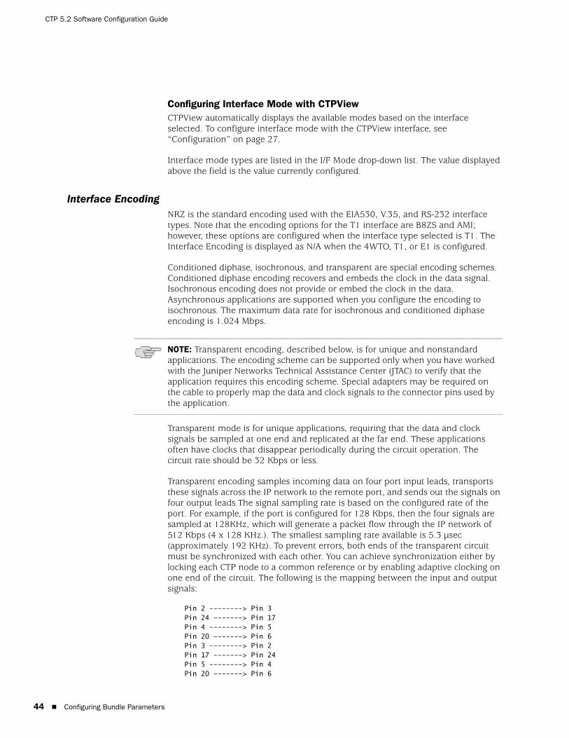
CTP 5.2 Software Configuration Guide
44 Configuring Bundle Parameters
Configuring Interface Mode with CTPViewCTPView automatically displays the available modes based on the interface selected. To configure interface mode with the CTPView interface, see “Configuration” on page 27.
Interface mode types are listed in the I/F Mode drop-down list. The value displayed above the field is the value currently configured.
Interface EncodingNRZ is the standard encoding used with the EIA530, V.35, and RS-232 interface types. Note that the encoding options for the T1 interface are B8ZS and AMI; however, these options are configured when the interface type selected is T1. The Interface Encoding is displayed as N/A when the 4WTO, T1, or E1 is configured.
Conditioned diphase, isochronous, and transparent are special encoding schemes. Conditioned diphase encoding recovers and embeds the clock in the data signal. Isochronous encoding does not provide or embed the clock in the data. Asynchronous applications are supported when you configure the encoding to isochronous. The maximum data rate for isochronous and conditioned diphase encoding is 1.024 Mbps.
Transparent mode is for unique applications, requiring that the data and clock signals be sampled at one end and replicated at the far end. These applications often have clocks that disappear periodically during the circuit operation. The circuit rate should be 32 Kbps or less.
Transparent encoding samples incoming data on four port input leads, transports these signals across the IP network to the remote port, and sends out the signals on four output leads.The signal sampling rate is based on the configured rate of the port. For example, if the port is configured for 128 Kbps, then the four signals are sampled at 128KHz, which will generate a packet flow through the IP network of 512 Kbps (4 x 128 KHz.). The smallest sampling rate available is 5.3 µsec (approximately 192 KHz). To prevent errors, both ends of the transparent circuit must be synchronized with each other. You can achieve synchronization either by locking each CTP node to a common reference or by enabling adaptive clocking on one end of the circuit. The following is the mapping between the input and output signals:
Pin 2 --------> Pin 3Pin 24 -------> Pin 17Pin 4 --------> Pin 5Pin 20 -------> Pin 6Pin 3 --------> Pin 2Pin 17 -------> Pin 24Pin 5 --------> Pin 4Pin 20 -------> Pin 6
NOTE: Transparent encoding, described below, is for unique and nonstandard applications. The encoding scheme can be supported only when you have worked with the Juniper Networks Technical Assistance Center (JTAC) to verify that the application requires this encoding scheme. Special adapters may be required on the cable to properly map the data and clock signals to the connector pins used by the application.

Configuring Bundle Parameters 45
Chapter 2: Software Configuration
Transparent encoding provides the option by means of a phase correction FIFO buffer. This FIFO buffer will correct the clock/data phase relationship in which the clock travels in one direction through the network and the data returns in the other direction. The correction is made on the RD output (pin 3) based on the clock input provided on Pin 4. Figure 14 show the data flows and FIFO when transparent encoding is used.
Figure 14: Transparent (TRANS) Encoding Signal Flow
Configuring Encoding with the CLIThe Encoding options are provided in the Encoding submenu (Figure 15). The menu displays the currently configured encoding. The encoding options available depend on the interface type selected. The encoding option is N/A (not available) when the 4WTO interface type is selected.
Figure 15: Encoding Submenu
Please select a number from the following list: ---------------------------------------------- 0) Back to Previous Menu 1) Type: {EIA530,EIA530A,RS-232,V.35,T1,E1,Optional,OFF} 2) Mode: {DCE,DTE, N/A} 3) Encoding: {NRZ, ISOCH, CDI, TRANS, N/A}------------ Your choice [1]: 3
Please select a number from the following list:----------------------------------------------- 0) NRZ 1) ISOCH 2) CDI 3) MSTAR 4) TRANS------------ Your choice [2]: 1
Configuring Encoding with CTPViewCTPView automatically displays the available encoding based on the interface selected. To configure interface encoding with the CTPView interface, see “Configuration” on page 27.

CTP 5.2 Software Configuration Guide
46 Configuring Bundle Parameters
Encoding types are listed in the Serial Encoding drop-down list. The value displayed above the field is the value currently configured.
Packet Size The Packet Size parameter specifies the IP packet size that will be created from data received at the serial port. Packet size ranges from 32 to 1456 bytes and must be a multiple of 16 bytes. The local and remote port packet size can be set to different values, except when adaptive clocking is configured.
The packet rate is calculated based on the packet size and serial interface rate, and the rate is limited to less than 1200 packets per second. You are prompted to change the rate or packet size if the packet rate exceeds this limit.
Determining Optimal Packet SizeDetermining the optimal packet size for a particular application involves several important considerations, including:
Performance limitations (if any) of the IP network
Bandwidth for transporting serial data
Packet creation delay
The most significant considerations are the serialization (packet creation) delay and the bandwidth required to transport the serial data.
IP Network Performance
The number of packets created (packet rate) is inversely related to the packet size configured. For example, smaller packets result in a greater packet rate. When you configure the Packet Size parameter, consider the packet-forwarding performance of the attached router and network. Table 3 provides examples of packet rates for various packet sizes and serial interface rates. The CTP system limits the packet rate per interface to 1200 pps and will prompt you if the configuration exceeds this limit.
Table 3: Packet Rate for Various Packet Size and Serial Interface Rate Settings
Packet Rate (Packets per Second)
Packet Size (Bytes)
Interface Rate (Kbps) 128 256 512 768 1024 1400
64 62.5 31.3 15.6 10.4 7.8 5.7
128 125.0 62.5 31.3 20.8 15.6 11.4
256 250.0 125.0 62.5 41.7 31.3 22.9
1024 1000.0 500.0 250.0 166.7 125.0 91.4
1544 1507.8 753.9 377.0 251.3 188.5 137.9
2048 2000.0 1000.0 500.0 333.3 250.0 182.9
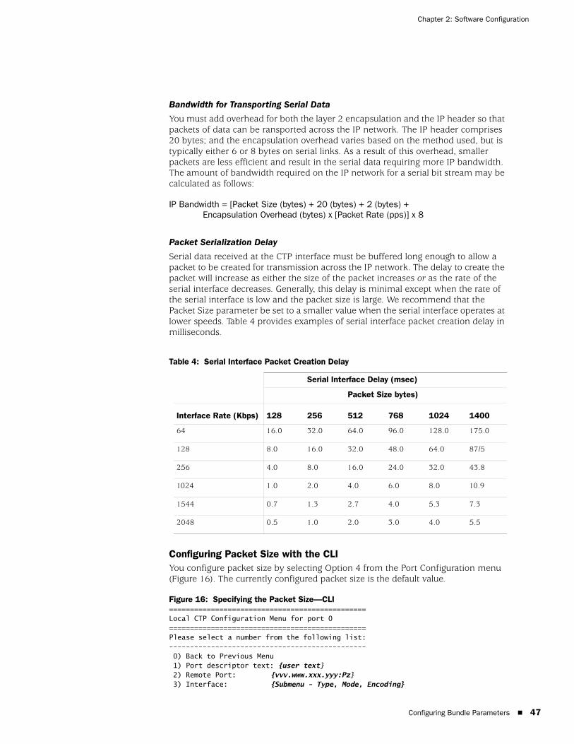
Configuring Bundle Parameters 47
Chapter 2: Software Configuration
Bandwidth for Transporting Serial Data
You must add overhead for both the layer 2 encapsulation and the IP header so that packets of data can be ransported across the IP network. The IP header comprises 20 bytes; and the encapsulation overhead varies based on the method used, but is typically either 6 or 8 bytes on serial links. As a result of this overhead, smaller packets are less efficient and result in the serial data requiring more IP bandwidth. The amount of bandwidth required on the IP network for a serial bit stream may be calculated as follows:
IP Bandwidth = [Packet Size (bytes) + 20 (bytes) + 2 (bytes) +Encapsulation Overhead (bytes) x [Packet Rate (pps)] x 8
Packet Serialization Delay
Serial data received at the CTP interface must be buffered long enough to allow a packet to be created for transmission across the IP network. The delay to create the packet will increase as either the size of the packet increases or as the rate of the serial interface decreases. Generally, this delay is minimal except when the rate of the serial interface is low and the packet size is large. We recommend that the Packet Size parameter be set to a smaller value when the serial interface operates at lower speeds. Table 4 provides examples of serial interface packet creation delay in milliseconds.
Configuring Packet Size with the CLIYou configure packet size by selecting Option 4 from the Port Configuration menu (Figure 16). The currently configured packet size is the default value.
Figure 16: Specifying the Packet Size—CLI===============================================Local CTP Configuration Menu for port 0===============================================Please select a number from the following list:----------------------------------------------- 0) Back to Previous Menu 1) Port descriptor text: {user text} 2) Remote Port: {vvv.www.xxx.yyy:Pz} 3) Interface: {Submenu - Type, Mode, Encoding}
Table 4: Serial Interface Packet Creation Delay
Serial Interface Delay (msec)
Packet Size bytes)
Interface Rate (Kbps) 128 256 512 768 1024 1400
64 16.0 32.0 64.0 96.0 128.0 175.0
128 8.0 16.0 32.0 48.0 64.0 87/5
256 4.0 8.0 16.0 24.0 32.0 43.8
1024 1.0 2.0 4.0 6.0 8.0 10.9
1544 0.7 1.3 2.7 4.0 5.3 7.3
2048 0.5 1.0 2.0 3.0 4.0 5.5

CTP 5.2 Software Configuration Guide
48 Configuring Bundle Parameters
4) Packet Size: {32 - 1456 1Bytes} 5) Clock Config: Submenu - Rate and Config} 6) Min Buffer (ms): {0.001 - 9999.000} 7) Pkt Buffer Set (ms): {0.001 - 9999.000} 8) Max Buffer (ms): {0.001 - 9999.000} 9) Service Type: {0 - 255}10) Time to Live: {0 - 255}11) Signaling In Config: | RL = --- | RTS= --- | DTR=--- | LL = ---|12) Signaling Out Config: | DSR= --- | CTS= --- | DCD= --- | TM =--- |13) Advanced Options...------------ Your choice [3]: 4
Enter packet size in bytes (32-1456)[1024]: {Input Value}
Configuring Packet Size with CTPViewCTPView automatically displays the available encoding based on the interface selected. To configure interface encoding with the CTPView interface, see “Configuration” on page 27.
Select a packet size from the Packet Size drop-down list. The value displayed above the field is the value currently configured.
Clock Configuration The following list summarizes clocking options with a data interface and NRZ encoding:
Configured Rate w/o External Tx Clock (TT)—The CTP system expects that the transmit data from the attached DTE will be at the rate specified in the configuration and that the transmit data from the DTE will be sampled at the CTP based on the transmit timing (TT) provided by the CTP system.
Configured Rate w/ External Tx Clock (TT)—The CTP system expects that the transmit data from the attached DTE will be at the rate specified in the configuration and that the data will be sampled based on the external timing provided by the attached DTE. This option is a common configuration for long cables or high data rates because clock and data signals will travel the same cable length from the DTE and the CTP will sample the data based on the TT input.
All Clocked w/ External TX Clock (TT)—The clock received from the attached device is received on the external TT clock input and is used for all interface clocks. This option includes transmit and receiving timing and the clock used to clock data out of the receive FIFO buffer toward the IP network.
Adaptive Rate w/o External Tx Clock (TT)—The CTP system generates the transmit and receive timing based on the clock of the distant CTP system using Advanced Time Domain Processing (ATDP) adaptive clocking. This option allows the clock to rapidly adjust, or adapt, to the remote clock. The circuit will run continuously without buffer overruns or underruns, even when no reference clock is provided to the CTP1004.
Autobaud Rate w/ External TX Clock (TT)—The CTP system calculates the transmit data rate of the attached DTE by processing the external timing (TT) from the DTE. Autobaud will be supported in a future release.

Configuring Bundle Parameters 49
Chapter 2: Software Configuration
The custom clocking options are described in Custom Clock Options—CLI on page 52.
The following are the clocking options when the configured Interface Type is T1 or E1:
The CTP system is clock source. In this configuration, the PBX is returning the clock received from the CTP, or it is returning a clock that is traceable to the same source as the CTP node clock reference. You typically use this configuration when you configure the CTP system with a clock reference input.
The CTP system is loop timed. In this configuration, the PBX is providing the clock and the CTP is returning the same clock to the PBX. You typically use this configuration when the PBX has the more accurate clock source. You can configure the far end of the circuit with adaptive clocking to recover this clock if necessary.
The CTP system is clock source (adaptive). In this configuration, the PBX returns the clock received from the CTP, and the CTP uses the adaptive recovered clock. You typically use this configuration when the CTP does not have a reference input and the PBX typically requires clock from the distant PBX.
The custom clocking options are described in Custom Clock Options—CLI on page 52.
Adaptive Clocking OptionsThere are configurable attributes that affect the Adaptive Clocking algorithm. The attributes are configured only when the clocking configuration specifies adaptive. The default settings are acceptable for the majority of applications. Consider using the assistance of JTAC before changing these parameters since they affect how the clocking and circuit functions. The parameters are as follows:
AGGR Seconds/Calc—The default is 20. The valid range is 2–60. Sets the time period during initial start of adaptive clocking for identifying packet samples experiencing the least delay through the network. Samples are used in aggressive state calculations.
MNTN Seconds/Calc—The default is 45. The valid range is 1–60. Sets the time period during normal adaptive clocking for identifying packets experiencing the least delay through the network. Samples are used in maintenance state calculations.
Slope for MNTN in ppm—The default is 5. The valid range is 1–10. Sets the value for changing that adaptive clocking algorithm from aggressive to maintenance state. Lower values result in longer switchover times with a clock value closer to the distant clock.
NOTE: The clock configuration is automatically configured when isochronous, conditioned diphase, or transparent encoding is configured. The user should not change the clock configuration when these encoding options have been selected.

CTP 5.2 Software Configuration Guide
50 Configuring Bundle Parameters
Maintenance Decay in calcs—The default is 3. The valid range is 2–10. Sets how quickly the clocking corrects to buffer set point in maintenance state.
Max Clock Adjust in ppb—The default is 200. The valid range is 1–1000. Constrains the frequency adjustments to the adaptive clock. This parameter has the effect of capping the frequency acceleration.
Max Clock Offset in ppm—The default is 200. The valid range is 1–400. Constrains the frequency of the adaptive clock. This parameter has the effect of capping the frequency velocity.
Max Buffer Error in µsec—The default is 2000. The valid range is 100–5000. Sets the buffer error required to change the adaptive clocking algorithm state from maintenance to aggressive.
Custom Clocking OptionsCustom clocking gives you flexibility in the configuration to provide services such as asymmetric rates. This section provides an overview of the port clocking subsystem and how the custom clocking options can be used.
The major sections are:
OSC: node clock oscillator—There is one central clock oscillator for every node, and it runs at a nominal rate of 32.768 MHz. This oscillator is part of a phase-locked loop (PLL), which can be locked to the incoming clock on a CTP port or the external reference input.
DDS: direct digital synthesizer —This is a type of clock generator that is capable of synthesizing a clock at nearly any desired rate. The range of clock output is 1 Hz–12.288 MHz in increments of 1/128 Hz. Because the node OSC provides the reference clock to the DDS, the DDS output will be as accurate at the OSC. The DDS rate is configured in the port clock menu.
DIV—This is a programmable divider that can divide a clock by an even number between 2 and 16384, inclusive. It may accept as its input clock either the OSC (32.768 MHz) or DDS output clock.
Packet engine—This block is responsible for conversion of a constant stream of serial data to IP packets and vice versa. In the network-bound direction, incoming serial data is partitioned into packets of data (according to the packet size configured in the Port Configuration menu) and sent into the IP network toward a remote port. In the reverse (interface-bound) direction, IP packets are received from the IP network, stripped of their IP headers, reordered to accommodate packet delay, buffered to accommodate packet delay jitter, and transmitted to the serial interface as a constant stream of data.
NOTE: With the flexibility of custom clocking comes the opportunity to misconfigure the port so that it will not operate according to expectations. Use caution when configuring custom clocking.

Configuring Bundle Parameters 51
Chapter 2: Software Configuration
Rx FIFO memory—First-in first-out (FIFO) memory is used to accommodate small amounts of jitter and/or phase shift in the data because of the use of different clocks in the network-bound path (that is, TT [user] clock) or to accommodate the transmit data and transmit clock phase shift experienced on longer cables at higher data rates.
The standard port timing options described in the previous section are used in most network applications. Based on the option that you select, the settings for the multiplexers and clocking elements on the clock diagram are configured automatically. When you select Custom from the Clock Options menu, the Advanced Clock menu (Figure 18 on page 52) is presented, allowing you to configure the clocking elements.
Configuring Port Clocking with the CLIThe Clock Config submenu is available when you select Option 5 from the Port Configuration menu. The menu shown in Figure 17 allows you to set the serial interface rate and select port clocking options. You do not need to configure port speed and clocking when you select the optional analog 4WTO interface. Selecting this interface causes the port speed and clocking to be automatically configured.
Figure 17: Port Clock Configuration Menu—CLI===============================================Port Clock Configuration Menu 0===============================================Please select a number from the following list:-----------------------------------------------0) Back to Previous Menu1) Port Clock Config: Configured Rate, NO Ext Tx Clk (TT)2) Port Speed (KHz): 1024.0000003) Send User Clock thru Network: NO------------ Your choice [2]:1
===============================================Clock Options Menu for Port 0 (DCE Mode)===============================================Please select a number from the following list:-----------------------------------------------0) Back to Previous Menu1) Configured Rate w/o External Tx Clock (TT)2) Configured Rate w/ External Tx Clock (TT)3) All Clocked w/ External Tx Clock (TT)4) Adaptive Rate w/o External Tx Clock (TT)5) Autobaud Rate w/ External Tx Clock (TT)6) Custom... 7) Set Adaptive Parameters... ------------ Your choice [0]:
===============================================Clock Options Menu for Port 1 (DTE Mode)===============================================Please select a number from the following list:-----------------------------------------------0) Back to Previous Menu1) .....2) ....3) ....4) .....5) ....6) DTE, All Clocked by Ext Clk (ST/RT)

CTP 5.2 Software Configuration Guide
52 Configuring Bundle Parameters
8) Custom...9) Set Adaptive Parameters...------------ Your choice [0]:
The custom clocking and adaptive parameters are available by when you select select Options 6 and 7, respectively, from the Clock Options menu. Figure 18 shows the Custom Clocking menu (Advanced Clock Options).
Figure 18: Custom Clock Options—CLI
===============================================Advanced Clock Options for Port 0===============================================Please select a number from the following list:----------------------------------------------- 0) Back to Previous Menu 1) DDS Synthesizer Source: User (OI) 2) DIV (clk divider) Source: Oscillator 3) DIV (clk divider) Value: 16384 4) ST (net bound i/f) clk sel: DDS (synth) 5) RF (net bound fifo) clk sel: DDS (synth) 6) RX (net bound scc) clk sel: DDS (synth) 7) RT (i/f bound i/f) clk sel: DDS (synth) 8) TX (i/f bound scc) clk sel: DDS (synth)------------ Your choice [0]:
The clocking options menu shown in Figure 19 is provided when the interface type is T1 or E1.
Figure 19: Port Clock Configuration (T1/E1)—CLI===============================================Port Clock Configuration Menu 0===============================================Please select a number from the following list:----------------------------------------------- 0) Back to Previous Menu 1) Port Clock Config: ..... 2) Port Speed (KHz): 1544.000000------------ Your choice [2]: 1===============================================Clock Options Menu for Port 0===============================================Please select a number from the following list:----------------------------------------------- 0) Back to Previous Menu 1) ..... 2) CTP is Clock Source 3) CTP is Loop Timed 4) ..... 5) PBX is Clock Source (Adaptive End) 6) ..... 7) Custom... 8) Set Adaptive Parameters...
------------ Your choice [0]:

Configuring Bundle Parameters 53
Chapter 2: Software Configuration
Example of an Asymmetric Configuration with the CLI
The following is a description of an asymmetric circuit configuration with custom clocking. Assume that you want the network-bound direction (toward the remote DTE) to operate at 2.048 MHz and the interface-bound data (toward the local DTE) to operate at 64 KHz. You first configure the DDS for 2048.0 KHz; set the DIV source to DDS; and set the DIV value to 32 (because 2048/32 = 64). Set the network-bound multiplexers (Options 4, 5, and 6) for DDS, which sets the network-bound data rate to 2.048 Mbps. Set the interface-bound multiplexers (Options 7 and 8) for DIV, which sets the interface-bound data rate to 64 Kbps.
If the cable length of this port is long, it might be desirable to switch multiplexer 4 from DDS to TT, and have the DTE equipment loop the ST clock back to TT so that it travels in phase with the network-bound user data. Figure 20 shows an example of the above configuration.
At the remote CTP asymmetric port, the DDS and DIV settings would be identical, but the clock multiplexer selections would be configured appropriately for the speed of that data direction.
Figure 20: Example of Asymmetric Configuration===============================================Advanced Clock Options for Port 0===============================================Please select a number from the following list:----------------------------------------------- 0) Back to Previous Menu 1) DDS Synthesizer Source: User (OI) 2) DIV (clk divider) Source: DDS Output 3) DIV (clk divider) Value: 32 4) ST (net bound i/f) clk sel: DDS (synth) 5) RF (net bound fifo) clk sel: DDS (synth) 6) RX (net bound scc) clk sel: DDS (synth) 7) RT (i/f bound i/f) clk sel: DIV (synth) 8) TX (i/f bound scc) clk sel: DIV (synth)------------ Your choice [6]:
Configuring Port Clocking with CTPViewCTPView automatically displays the available clocking based on the interface selected. To configure interface encoding with the CTPView interface, see “Configuration” on page 27.
Clocking types are listed in the Clock Cfg drop-down list. Select Show Custom Clocking Options to display more clocking parameters. The value displayed above the field is the value currently configured.
Port SpeedThe port speed is specified in Kbps ranging from 0.001000 to 12288.000000; however, the CTP1002 is limited to a port speed of 2048.000000. The aggregate port rate (sum of the rates of all ports) of the CTP1012 cannot exceed 49.152 Mbps, and the aggregate port rate of the CTP2008, CTP2024, and CTP2056 cannot exceed 114.688 Mbps. The clock rate of ports using either conditioned diphase and isochronous encoding is limited to 1024 Kbps.
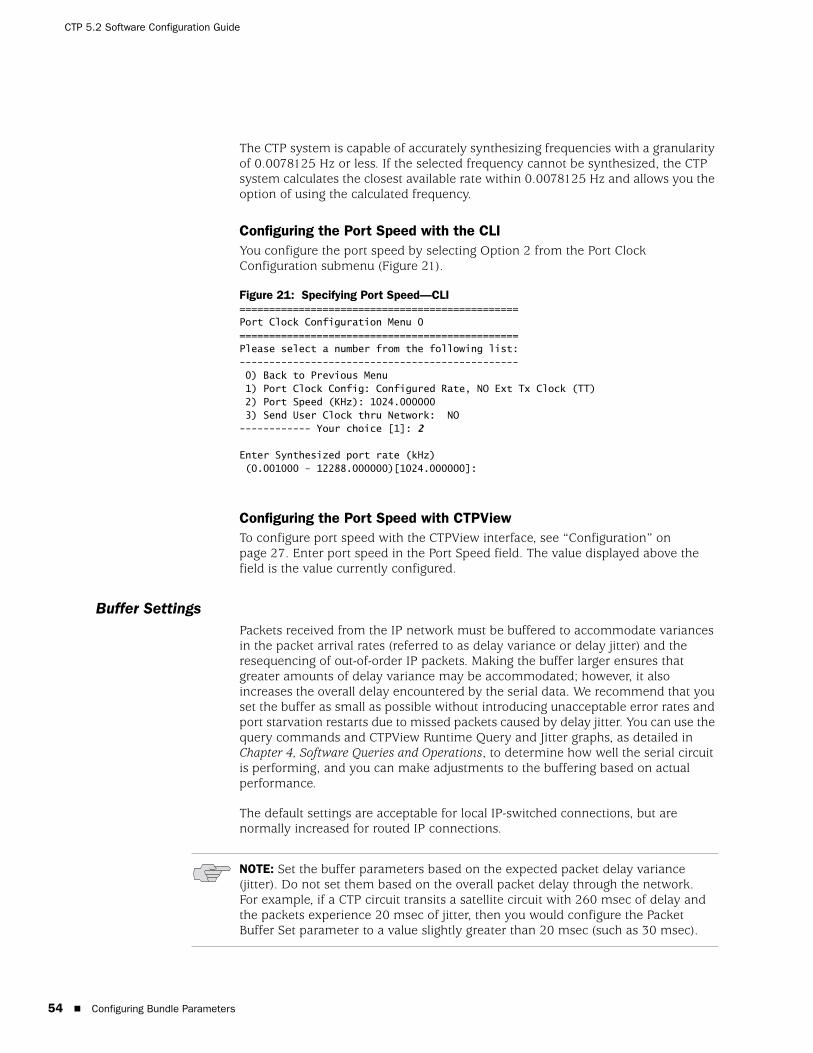
CTP 5.2 Software Configuration Guide
54 Configuring Bundle Parameters
The CTP system is capable of accurately synthesizing frequencies with a granularity of 0.0078125 Hz or less. If the selected frequency cannot be synthesized, the CTP system calculates the closest available rate within 0.0078125 Hz and allows you the option of using the calculated frequency.
Configuring the Port Speed with the CLIYou configure the port speed by selecting Option 2 from the Port Clock Configuration submenu (Figure 21).
Figure 21: Specifying Port Speed—CLI===============================================Port Clock Configuration Menu 0===============================================Please select a number from the following list:----------------------------------------------- 0) Back to Previous Menu 1) Port Clock Config: Configured Rate, NO Ext Tx Clock (TT) 2) Port Speed (KHz): 1024.000000 3) Send User Clock thru Network: NO------------ Your choice [1]: 2
Enter Synthesized port rate (kHz) (0.001000 - 12288.000000)[1024.000000]:
Configuring the Port Speed with CTPViewTo configure port speed with the CTPView interface, see “Configuration” on page 27. Enter port speed in the Port Speed field. The value displayed above the field is the value currently configured.
Buffer SettingsPackets received from the IP network must be buffered to accommodate variances in the packet arrival rates (referred to as delay variance or delay jitter) and the resequencing of out-of-order IP packets. Making the buffer larger ensures that greater amounts of delay variance may be accommodated; however, it also increases the overall delay encountered by the serial data. We recommend that you set the buffer as small as possible without introducing unacceptable error rates and port starvation restarts due to missed packets caused by delay jitter. You can use the query commands and CTPView Runtime Query and Jitter graphs, as detailed in Chapter 4, Software Queries and Operations, to determine how well the serial circuit is performing, and you can make adjustments to the buffering based on actual performance.
The default settings are acceptable for local IP-switched connections, but are normally increased for routed IP connections.
NOTE: Set the buffer parameters based on the expected packet delay variance (jitter). Do not set them based on the overall packet delay through the network. For example, if a CTP circuit transits a satellite circuit with 260 msec of delay and the packets experience 20 msec of jitter, then you would configure the Packet Buffer Set parameter to a value slightly greater than 20 msec (such as 30 msec).
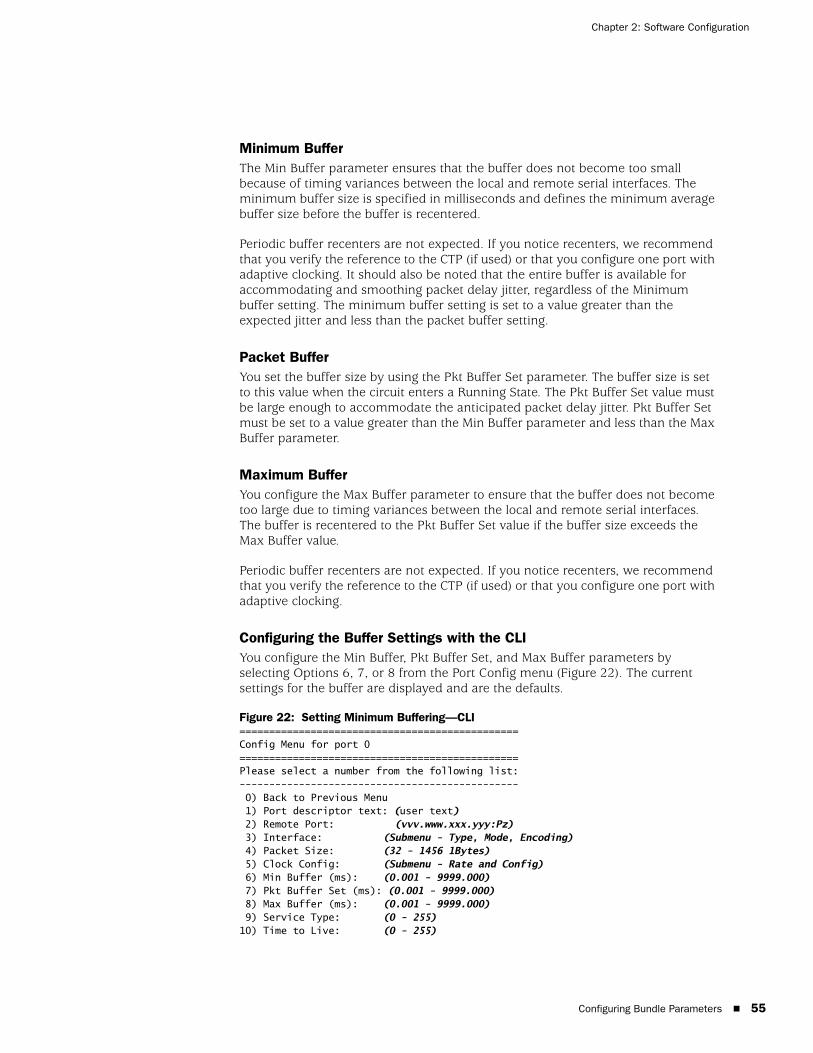
Configuring Bundle Parameters 55
Chapter 2: Software Configuration
Minimum BufferThe Min Buffer parameter ensures that the buffer does not become too small because of timing variances between the local and remote serial interfaces. The minimum buffer size is specified in milliseconds and defines the minimum average buffer size before the buffer is recentered.
Periodic buffer recenters are not expected. If you notice recenters, we recommend that you verify the reference to the CTP (if used) or that you configure one port with adaptive clocking. It should also be noted that the entire buffer is available for accommodating and smoothing packet delay jitter, regardless of the Minimum buffer setting. The minimum buffer setting is set to a value greater than the expected jitter and less than the packet buffer setting.
Packet BufferYou set the buffer size by using the Pkt Buffer Set parameter. The buffer size is set to this value when the circuit enters a Running State. The Pkt Buffer Set value must be large enough to accommodate the anticipated packet delay jitter. Pkt Buffer Set must be set to a value greater than the Min Buffer parameter and less than the Max Buffer parameter.
Maximum BufferYou configure the Max Buffer parameter to ensure that the buffer does not become too large due to timing variances between the local and remote serial interfaces. The buffer is recentered to the Pkt Buffer Set value if the buffer size exceeds the Max Buffer value.
Periodic buffer recenters are not expected. If you notice recenters, we recommend that you verify the reference to the CTP (if used) or that you configure one port with adaptive clocking.
Configuring the Buffer Settings with the CLIYou configure the Min Buffer, Pkt Buffer Set, and Max Buffer parameters by selecting Options 6, 7, or 8 from the Port Config menu (Figure 22). The current settings for the buffer are displayed and are the defaults.
Figure 22: Setting Minimum Buffering—CLI===============================================Config Menu for port 0===============================================Please select a number from the following list:----------------------------------------------- 0) Back to Previous Menu 1) Port descriptor text: (user text) 2) Remote Port: (vvv.www.xxx.yyy:Pz) 3) Interface: (Submenu - Type, Mode, Encoding) 4) Packet Size: (32 - 1456 1Bytes) 5) Clock Config: (Submenu - Rate and Config) 6) Min Buffer (ms): (0.001 - 9999.000) 7) Pkt Buffer Set (ms): (0.001 - 9999.000) 8) Max Buffer (ms): (0.001 - 9999.000) 9) Service Type: (0 - 255)10) Time to Live: (0 - 255)

CTP 5.2 Software Configuration Guide
56 Configuring Bundle Parameters
11) Signaling In Config: | RL = --- | RTS= --- | DTR=--- | LL = ---|12) Signaling Out Config: | DSR= --- | CTS= --- | DCD= --- | TM =--- |13) Advanced Options...------------ Your choice [3]: 6
Enter minimum buffer fill (in ms) (0.001 - 9999.000)[8.000]:
Configuring the Buffer Settings with CTPViewTo configure buffer settings with the CTPView interface, see “Configuration” on page 27. Enter buffer settings in the Min Buffer, Buffer Set, and Max Buffer fields. The value displayed above the field is the value currently configured.
Service TypeYou can configure the ToS byte in the IP header. The ToS setting is specific to the port being configured, and the value is set in the IP packets transmitted from the CTP system into the IP network. The ToS setting does not need to be the same value on the local and remote ports.
Because you can configure the entire byte, the options are 0–255. Packet classification in IP networks is frequently based on the Differentiated Services code point (DSCP) as specified in the ToS byte. Table 5 shows the service type settings for all DSCP classes.
Table 5: DSCP Classes and Service Type
Class DSCP Setting TOS Setting
CS7 56 224
CS6 48 192
EF 46 184
CS5 40 160
AF43 38 152
AF42 36 144
AF41 34 136
CS4 32 128
AF33 30 120
AF32 28 112
AF31 26 104
CS3 24 96
AF23 22 88
AF22 20 80
AF21 18 72
CS2 16 64
AF13 13 52
AF12 12 48
AF11 10 40
CS1 8 32

Configuring Bundle Parameters 57
Chapter 2: Software Configuration
Configuring the Service Type with the CLIYou configure the Service Type parameters by selecting Option 9 from the Port Config menu (Figure 23).
Figure 23: Service Type Settings—CLI===============================================Config Menu for port 0===============================================Please select a number from the following list:----------------------------------------------- 0) Back to Previous Menu 1) Port descriptor text: {user text} 2) Remote Port: {vvv.www.xxx.yyy:Pz} 3) Interface: {Submenu - Type, Mode, Encoding} 4) Packet Size: {32 - 1456 1Bytes} 5) Clock Config: {Submenu - Rate and Config} 6) Min Buffer (ms): {0.001 - 9999.000} 7) Pkt Buffer Set (ms): {0.001 - 9999.000} 8) Max Buffer (ms): {0.001 - 9999.000} 9) Service Type: {0 - 255}10) Time to Live: {0 - 255}11) Signaling In Config: | RL = --- | RTS= --- | DTR=--- | LL = ---|12) Signaling Out Config: | DSR= --- | CTS= --- | DCD= --- | TM =--- |13) Advanced Options...------------ Your choice [8]: 9
Enter Time to Live (0-255)[255]:
Configuring the Service Type with CTPViewTo configure service type with the CTPView interface, see “Configuration” on page 27. Enter the service type in the Service Type field. The value displayed above the field is the value currently configured.
Time to Live You can configure the IP packet time to live (TTL). The acceptable values range from 0 to 255; the default is 255. The TTL value specifies the maximum number of router hops that a packet can traverse, and the value is set in the IP packets transmitted from the CTP system into the IP network. Note that the IP network does not alter or optimize the packet routing based on the TTL setting, and the setting does not need to be the same value on the local and remote ports.
Configuring Time to Live with the CLIYou configure the TTL setting by selecting Option 10 from the Port Config menu (Figure 24). The current settings for TTL are displayed and are the defaults.
Figure 24: Configuring Time to Live—CLI===============================================Config Menu for port 0===============================================Please select a number from the following list:----------------------------------------------- 0) Back to Previous Menu 1) Port descriptor text: {user text} 2) Remote Port: {vvv.www.xxx.yyy:Pz} 3) Interface: {Submenu - Type, Mode, Encoding} 4) Packet Size: {32 - 1456 1Bytes}
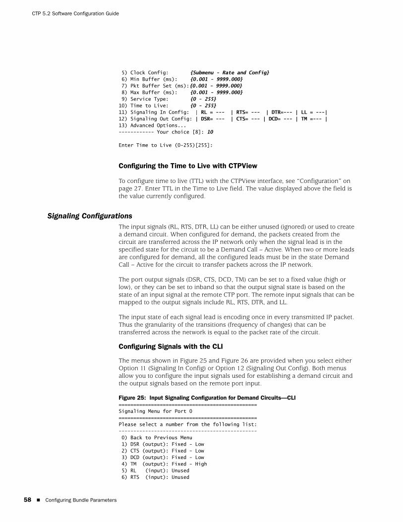
CTP 5.2 Software Configuration Guide
58 Configuring Bundle Parameters
5) Clock Config: {Submenu - Rate and Config} 6) Min Buffer (ms): {0.001 - 9999.000} 7) Pkt Buffer Set (ms):{0.001 - 9999.000} 8) Max Buffer (ms): {0.001 - 9999.000} 9) Service Type: {0 - 255}10) Time to Live: {0 - 255}11) Signaling In Config: | RL = --- | RTS= --- | DTR=--- | LL = ---|12) Signaling Out Config: | DSR= --- | CTS= --- | DCD= --- | TM =--- |13) Advanced Options...------------ Your choice [8]: 10
Enter Time to Live (0-255)[255]:
Configuring the Time to Live with CTPView
To configure time to live (TTL) with the CTPView interface, see “Configuration” on page 27. Enter TTL in the Time to Live field. The value displayed above the field is the value currently configured.
Signaling Configurations The input signals (RL, RTS, DTR, LL) can be either unused (ignored) or used to create a demand circuit. When configured for demand, the packets created from the circuit are transferred across the IP network only when the signal lead is in the specified state for the circuit to be a Demand Call – Active. When two or more leads are configured for demand, all the configured leads must be in the state Demand Call – Active for the circuit to transfer packets across the IP network.
The port output signals (DSR, CTS, DCD, TM) can be set to a fixed value (high or low), or they can be set to inband so that the output signal state is based on the state of an input signal at the remote CTP port. The remote input signals that can be mapped to the output signals include RL, RTS, DTR, and LL.
The input state of each signal lead is encoding once in every transmitted IP packet. Thus the granularity of the transitions (frequency of changes) that can be transferred across the network is equal to the packet rate of the circuit.
Configuring Signals with the CLI
The menus shown in Figure 25 and Figure 26 are provided when you select either Option 11 (Signaling In Config) or Option 12 (Signaling Out Config). Both menus allow you to configure the input signals used for establishing a demand circuit and the output signals based on the remote port input.
Figure 25: Input Signaling Configuration for Demand Circuits—CLI===============================================Signaling Menu for Port 0===============================================Please select a number from the following list:----------------------------------------------- 0) Back to Previous Menu 1) DSR (output): Fixed - Low 2) CTS (output): Fixed - Low 3) DCD (output): Fixed - Low 4) TM (output): Fixed - High 5) RL (input): Unused 6) RTS (input): Unused
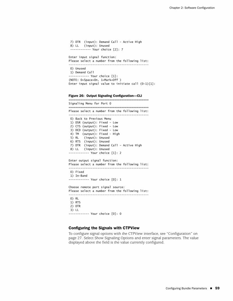
Configuring Bundle Parameters 59
Chapter 2: Software Configuration
7) DTR (input): Demand Call - Active High 8) LL (input): Unused ------------ Your choice [2]: 7 Enter input signal function:Please select a number from the following list:----------------------------------------------- 0) Unused 1) Demand Call------------ Your choice [1]:(NOTE: 0=Space=On, 1=Mark=Off )Enter input signal value to initiate call (0-1)[1]:
Figure 26: Output Signaling Configuration—CLI===============================================Signaling Menu for Port 0===============================================Please select a number from the following list:----------------------------------------------- 0) Back to Previous Menu 1) DSR (output): Fixed - Low 2) CTS (output): Fixed - Low 3) DCD (output): Fixed - Low 4) TM (output): Fixed - High 5) RL (input): Unused 6) RTS (input): Unused 7) DTR (input): Demand Call - Active High 8) LL (input): Unused------------ Your choice [1]: 2 Enter output signal function:Please select a number from the following list:----------------------------------------------- 0) Fixed 1) In-Band------------ Your choice [0]: 1 Choose remote port signal source:Please select a number from the following list:----------------------------------------------- 0) RL 1) RTS 2) DTR 3) LL------------ Your choice [0]: 0
Configuring the Signals with CTPViewTo configure signal options with the CTPView interface, see “Configuration” on page 27. Select Show Signaling Options and enter signal parameters. The value displayed above the field is the value currently configured.
CTP 5.2 Software Configuration Guide
60 Configuring Bundle Parameters
Advanced Options The default Advanced Option settings are acceptable for the majority of circuits and applications. The advanced options allow the user to configure nonstandard attributes that may be required by some applications. The following list summarizes Advanced Option parameters:
OAM Configuration—The CTP system uses periodic UDP OAM packets to determine the connectivity between the two CTP systems that are providing the circuit’s ports. These parameters allow you to configure the OAM packet rate: the number of consecutive OAM packets that must be received before the circuit will change to IN-SYNC, and the number of consecutive OAM packets that must be missed before the circuit state is changed to NO-SYNC.
Virtual IP address—This parameter allows you to use and configure an IP address for the circuit’s data and OAM flow that is different from the IP address of the CTP system. This virtual IP address is used in the IP packet’s Origination Address field, and the distant CTP system must be configured with the virtual IP address of the port.
Packet Protector—In a network where significant IP packet loss is expected, you can configure this option to send and/or receive cloned (duplicated) packets. When configured to receive cloned packets, the CTP system automatically uses the cloned packet when the original packet is dropped by the IP network. The system ignores the cloned packet when both the original and cloned packets are received.
The following are the configuration options for the Packet Protector feature:
0—Disable packet protector
1—Send cloned packets to NET
2—Expect cloned packets from NET
3—Send and expect cloned packets
Missing pkt fill pattern—When an IP packet is dropped, the CTP system automatically inserts data into the circuit bit stream in lieu of the actual data. The number of bits inserted is equal to the number of bits in the missed packet. This data insertion method prevents a loss of bit count integrity to attached circuit devices and encryptors. This parameter allows you to configure the fill-pattern byte to a value other than ff. You enter the number as two hexadecimal digits. Note that the input does not require the 0x characters.
Consecutive pkts loss to starve—Specifies how many consecutive circuit packets must be dropped by the IP network for the CTP circuit state to process the loss as a starvation and to recenter the buffer. The circuit state will also change from RUNNING to IN-SYNC, depending on the duration of the loss. This parameter allows you to change the number of consecutive lost packets required for a starvation from the default value of 5 to a value between 1 and 64.

Configuring Bundle Parameters 61
Chapter 2: Software Configuration
We recommend that you set the parameter to a larger value when the IP network uses packet-encrypting devices. These devices will cause momentary interruption in packet flows when encryption keys are periodically updated.
In sequence pkts after starve—After a starvation, the CTP circuit must begin receiving circuit packets before the port recovers from the packet starvation and resets the jitter buffer. The circuit state may also change from IN-SYNC to RUNNING. This parameter allows you to change the number of required in-sequence packets received by the CTP system from the default of 15 to a value between 1 and 64.
Y cable redundancy—Set to YES when the CTP system is configured with a redundant Y cable.
Implementing Y Cable RedundancyCustomers use Y cable redundancy to increase circuit availability to a site (typically a remote site), as shown in Figure 27 on page 61. Configuring Y cable redundancy switches the circuit to a co-located alternate CTP and port during an unlikely network or equipment failure. The objective of this redundancy scheme is to maximize network availability by providing complete hardware redundancy that protects from failures that include chassis, processor, power supplies, and the interface module. The process of switching the circuit to the redundant system is controlled by the AutoSwitch feature running at the hub CTP system.
Figure 27: Y Cable Redundancy
CTPView
CTP Hub CTP #1
CTP #2
Cable: CTP-CBL-4Q-Y
ATTACHEDDTE
AutoSwitch is configuredby the CTPView andused to manage theswitching between thetwo redundant remotePorts.
CTPView
CTP Hub CTP #1 Failure
CTP #2
Cable: CTP-CBL-4Q-Y
ATTACHEDDTE
ConfigureAutoSwitch

CTP 5.2 Software Configuration Guide
62 Configuring Bundle Parameters
Using this feature requires a special Y cable (Juniper Networks part number CTP-CBL-4Q-Y). The Y cable provides control leads between the two CTP systems in addition to the standard signal, clock and data leads connected to the attached device.
The following are technical considerations to keep in mind when you use Y cable redundancy.
The Y cable is short to maintain signal quality. The two CTP systems connected to the Y cable must be in close proximity to each other.
The redundant port numbers may be different provided that they are using the same port on the CPT 100 pin connector. For example, a Y cable100-pin connector could be attached to ports 0-3 on the first CTP system, with the second connector attached to ports 8-11 on the second system. The redundant ports would be P0/P8, P1/P9, P2/P10 and P3/P11 on the first and second CTP systems, respectively.
Use CTPView to configure the Autoswitch at the hub CTP system. CTPView is not required, however, to initiate or control the switchover.
The rate of the switchover is determined by the AutoSwitch Check Period and Switch Count values configured at the hub CTP. The default values are 60 seconds, with a Switch Count of 3. The default configuration minimizes unnecessary switchovers due to transient failures, such as might occur with a brief network problem.
Configuring Advanced Options with the CLIFigure 28 shows the Advanced Options menu provided when you select it from the Port Config menu. The CTP system automatically configures parameters 11 through 14. Do not change these values without consulting JTAC.
Figure 28: Advanced Options Menu
Please select a number from the following list:----------------------------------------------- 0) Back to Previous Menu 1) OAM Chan Rate (sec/pkt): 1 2) OAM pkts for Sync: 2 3) OAM pkts for Sync Loss: 5 4) Use virtual ip for port NO 5) Virtual ip for port: 0.0.0.0 6) Packet Protector(tm) Disabled 7) Missing pkt fill pattern: 0xff 8) Consecutive pkts loss to starve: 5 9) In sequence pkts after starve: 1510) Y cable redundancy: NO11) Single ended data/clock outputs: NO12) Reclock RD to align RD/RT: YES13) Send pkts to stack: NO14) Unidirectional circuit:No------------ Your choice [1]: Parameters 1 through 3
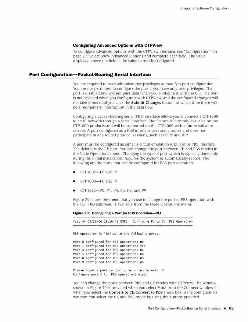
Port Configuration—Packet-Bearing Serial Interface 63
Chapter 2: Software Configuration
Configuring Advanced Options with CTPViewTo configure advanced options with the CTPView interface, see “Configuration” on page 27. Select Show Advanced Options and complete each field. The value displayed above the field is the value currently configured.
Port Configuration—Packet-Bearing Serial Interface
You are required to have administrative privileges to modify a port configuration. You are not permitted to configure the port if you have only user privileges. The port is disabled and will not pass data when you configure it with the CLI. The port is not disabled when you configure it with CTPView, and the configured changes will not take effect until you click the Submit Changes button, at which time there will be a momentary interruption in the data flow.
Configuring a packet-bearing serial (PBS) interface allows you to connect a CTP1000 to an IP network through a serial interface. The feature is currently available on the CTP1000 products and will be supported on the CTP2000 with a future software release. A port configured as a PBS interface uses static routes and does not participate in any routed protocol sessions, such as OSPF and RIP.
A port must be configured as either a circuit emulation (CE) port or PBS interface. The default is the CE port. You can change the port between CE and PBS modes in the Node Operations menu. Changing the type of port, which is typically done only during the initial installation, requires the system to automatically reboot. The following are the ports that can be configured for PBS port operation:
CTP1002—P0 and P1
CTP1004—P0 and P1
CTP1012—P0, P1, P4, P5, P8, and P9
Figure 29 shows the menu that you use to change the port to PBS operation with the CLI. This submenu is available from the Node Operations menu.
Figure 29: Configuring a Port for PBS Operation—CLI==================================================================(ctp_44 09/26/06 11:16:45 GMT) | Configure Ports for PBS Operation ==================================================================
PBS operation is limited to the following ports:
Port 0 configured for PBS operation: noPort 1 configured for PBS operation: yesPort 4 configured for PBS operation: noPort 5 configured for PBS operation: noPort 8 configured for PBS operation: noPort 9 configured for PBS operation: no
Please input a port to configure, <rtn> to exit: 0Configure port 1 for PBS operation? n[y]:
You can change the ports between PBS and CE modes with CTPView. The window shown in Figure 30 is provided when you select Ports from the Connect window or when you select the Convert to CE/Convert to PBS check box in the configuration window. You select the CE and PBS mode by using the buttons provided.

CTP 5.2 Software Configuration Guide
64 Port Configuration—Packet-Bearing Serial Interface
Figure 30: Specifying PBS and CE Port Types with CTPView
Packet-Bearing Serial Interface ParametersThe following list summarizes the parameters used to configure a packet-bearing serial interface.
Encapsulation—PPP and HDLC encapsulation are supported by PBS interfaces. Select the encapsulation from the CLI or from the CTPView drop-down menu.
Local and remote IP address—The PBS interface requires that the IP address of the local and remote IP interfaces be specified. Both addresses must be on the same network.
Clock configuration—The clock configuration submenu lets you configure port speed and clock configuration. The clocking options include configured rate with and without external TT, all clocked by external TT, and custom clocking. The custom configuration is as detailed in Bundle Operations on page 11.
CTPView allows you to configure the rate using a input field and specify the clocking from a pull down menu of valid options.
MTU—The MTU can be configured to a value up to 1500 bytes. MTU fragmentation is not supported.
Menu for SelectingPBS or CE Operation
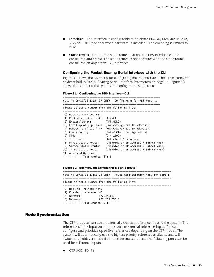
Node Synchronization 65
Chapter 2: Software Configuration
Interface—The Interface is configurable to be either EIA530, EIA530A, RS232, V.35 or T1/E1 (optional when hardware is installed). The encoding is limited to NRZ.
Static routes—Up to three static routes that use the PBS interface can be configured and active. The static routes cannot conflict with the static routes configured on any other PBS Interfaces.
Configuring the Packet-Bearing Serial Interface with the CLIFigure 31 shows the CLI menu for configuring the PBS interface. The parameters are as described in Packet-Bearing Serial Interface Parameters on page 64. Figure 32 shows the submenu that you use to configure the static route.
Figure 31: Configuring the PBS Interface—CLI==============================================================(ctp_44 09/26/06 13:54:27 GMT) | Config Menu for PBS Port 1==============================================================Please select a number from the following list:-------------------------------------------------------------- 0) Back to Previous Menu 1) Port descriptor text: {Text} 2) Encapsulation: {PPP,HDLC) 3) Local ip of p2p link: {www.xxx.yyy.zzz IP address) 4) Remote ip of p2p link: {www.xxx.yyy.zzz IP address) 5) Clock Config: {Rate/ Clock Configuration} 6) MTU: {0 - 1500} 7) Interface: {Interface / Encoding} 8) First static route: {Disabled or IP Address / Subnet Mask} 9) Second static route: {Disabled or IP Address / Subnet Mask}10) Third static route: {Disabled or IP Address / Subnet Mask}11) Advanced Options...------------ Your choice [6]: 8
Figure 32: Submenu for Configuring a Static Route=====================================================================(ctp_44 09/26/06 13:56:26 GMT) | Route Configuration Menu for Port 1=====================================================================Please select a number from the following list:--------------------------------------------------------------------- 0) Back to Previous Menu 1) Enable this route: NO 2) Network: 172.25.61.0 3) Netmask: 255.255.255.0------------ Your choice [0]:
Node Synchronization
The CTP products can use an external clock as a reference input to the system. The reference can be input on a port or on the external reference input. You can configure and prioritize up to five references depending on the CTP model. The system will automatically use the highest priority reference available, and will switch to a holdover mode if all the references are lost. The following ports can be used for reference inputs:
CTP1002: P0–P1

CTP 5.2 Software Configuration Guide
66 Node Synchronization
CPT1004: P0–P3
CTP1012: P0–P3
CTP2008, CTP20024, CTP2056: P0–P3
The CTP2000 external reference input is provide by the CLK-RTM module through a DB-25 connector.
The CTP1000 external input is provided on either a rear BNC or D-B9 connector depending on the chassis revision. The input is differential with one of the two differential leads input on the BNC outer ring. This outer ring is isolated from the chassis ground. More information about the external clock inputs is available in Clock Configuration on page 48.
Configuring ReferencesYou can define multiple clocks as references, each with a priority, to ensure that a reference with lower priority is available if the primary clock reference fails. The reference inputs to the CTP system must be 32 Kbps, an n x 64 Kbps (up to 4096), or 1.544 Mbps. The CTP system provides a reference holdover with an accuracy of approximately 100 parts per billion if the reference is lost and no backup is defined or available.
Figure 33 shows the Node Synchronization menu. When you select the reference, you may either disable it or specify both the reference input (port number or external) and frequency. Figure 34 shows the CTPView Node Configuration window.
Figure 33: Node Synchronization Options Menu—CLI===============================================CTP Main Menu ===============================================Please select a number from the following list:----------------------------------------------- 0) Exit to Shell 1) Bundle Operations 2) Node Synchronization 3) Node Summary 4) Node Diagnostics5) Node Operations6) Save Database to Flash------------ Your choice [1]: 2
===============================================Node Synchronization Options Menu ===============================================
Please select a number from the following list:----------------------------------------------- 0) Back to Previous Menu 1) 1st Priority, Reference 0: Disabled 2) 2nd Priority, Reference 1: Disabled 3) 3rd Priority, Reference 2: Disabled
NOTE: An interface module must be present in slot one of the CTP2000 chassis to provide reference synchronization throughout the system.
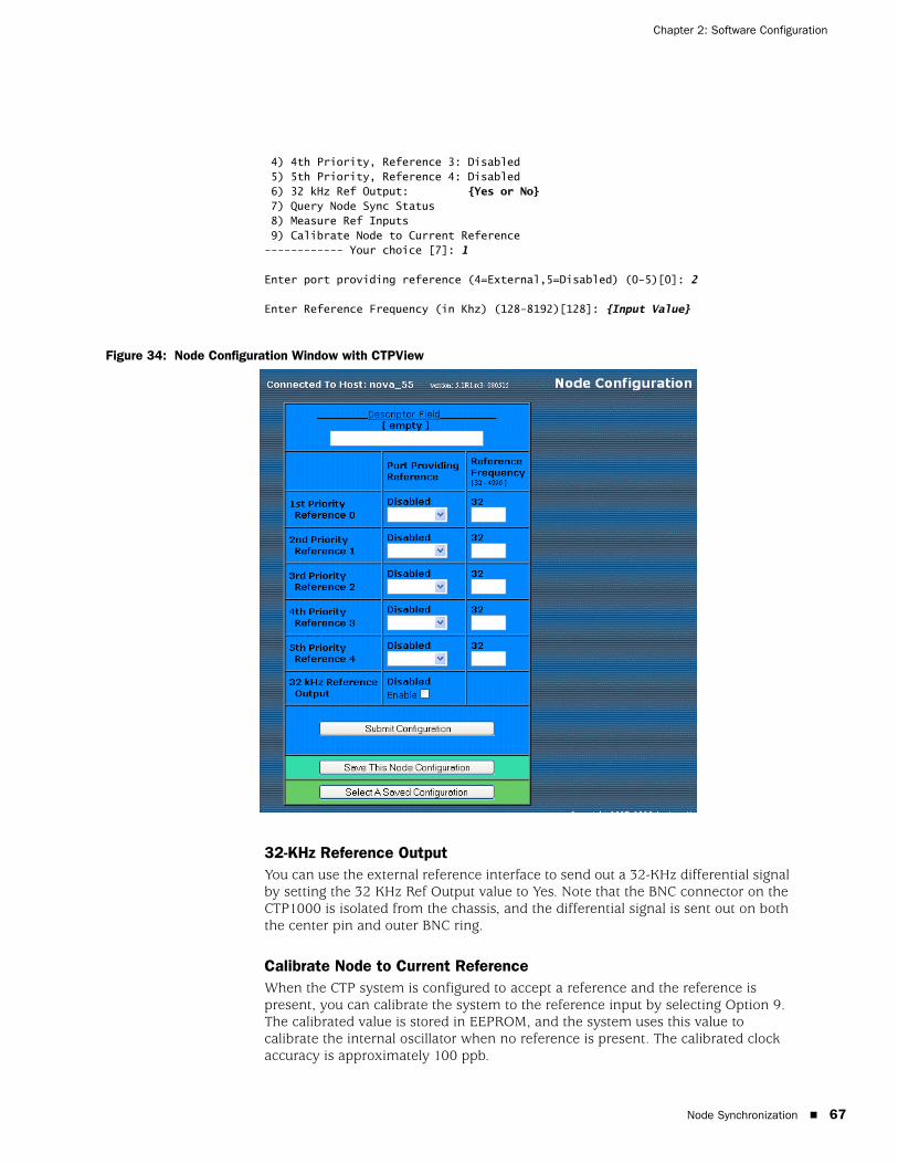
Node Synchronization 67
Chapter 2: Software Configuration
4) 4th Priority, Reference 3: Disabled 5) 5th Priority, Reference 4: Disabled 6) 32 kHz Ref Output: {Yes or No} 7) Query Node Sync Status 8) Measure Ref Inputs 9) Calibrate Node to Current Reference------------ Your choice [7]: 1
Enter port providing reference (4=External,5=Disabled) (0-5)[0]: 2
Enter Reference Frequency (in Khz) (128-8192)[128]: {Input Value}
Figure 34: Node Configuration Window with CTPView
32-KHz Reference OutputYou can use the external reference interface to send out a 32-KHz differential signal by setting the 32 KHz Ref Output value to Yes. Note that the BNC connector on the CTP1000 is isolated from the chassis, and the differential signal is sent out on both the center pin and outer BNC ring.
Calibrate Node to Current ReferenceWhen the CTP system is configured to accept a reference and the reference is present, you can calibrate the system to the reference input by selecting Option 9. The calibrated value is stored in EEPROM, and the system uses this value to calibrate the internal oscillator when no reference is present. The calibrated clock accuracy is approximately 100 ppb.

CTP 5.2 Software Configuration Guide
68 Node Summary
Node Summary
The Node Summary menu enables you to display summary bundle and ports information for the CTP chassis.
The first block of information lists the ports and generic port information, as well as if the port is being used by a bundle and, if so, which bundle, the bundle type, and some generic bundle information. Ports that are not attached to an existing bundle are shown with a bundle type of NotCfgd. They are displayed with a run state of DISABLD.
The second block of information concerns only bundles. A list of the existing bundles, their types, and generic port and bundle information is displayed.
=========================================================================== (nova49 01/21/08 22:13:30 GMT) | CTP Main Menu ==========================================================================
Please select a number from the following list:------------------------------------- 0) Exit to Shell 1) Bundle Operations 2) Node Synchronization 3) Node Summary 4) Node Diagnostics 5) Node Operations 6) Save Database to Flash------------ Your choice [1]: 3
CTP Code version : 5.0R1- 080121 (Compile Time 03:39:50 PM)CTP CPU eth addr : 00:40:9e:00:93:e6
Port Summary:Port Bndl BndlTyp RemAddr RP/CID RunState NtSz IfSz PortRate ReCntr=============================================================================== 0 -- NotCfgd 10.0.0.0 n/a DISABLD 1024 N/A 1544.000000 0 1 1 SAToP 10.0.0.0 6001 DISABLD 192 N/A 1544.000000 0 2 2 CESoPSN 10.0.0.1 1064 RUNNING 1152 -- 1544.000000 0 3 5 CESoPSN 10.0.0.1 1096 DISABLD 1152 -- 1544.000000 0 4 3 CTP 10.0.0.0 0 NoSYNC 1024 N/A 1544.000000 0 5 -- NotCfgd 10.0.0.0 n/a DISABLD 1024 N/A 1544.000000 0 6 -- NotCfgd 10.0.0.0 n/a DISABLD 1024 N/A 1544.000000 0 7 -- NotCfgd 10.0.0.0 n/a DISABLD 1024 N/A 1544.000000 0 8 -- NotCfgd 10.0.0.0 n/a DISABLD 1024 N/A 1024.000000 0 9 -- NotCfgd 10.0.0.0 n/a DISABLD 1024 N/A 1024.000000 0 10 -- NotCfgd 10.0.0.0 n/a DISABLD 1024 N/A 1024.000000 0 11 -- NotCfgd 10.0.0.0 n/a DISABLD 1024 N/A 1024.000000 0 12 -- NotCfgd 10.0.0.0 n/a DISABLD 1024 N/A 1024.000000 0 13 -- NotCfgd 10.0.0.0 n/a DISABLD 1024 N/A 1024.000000 0 14 -- NotCfgd 10.0.0.0 n/a DISABLD 1024 N/A 1024.000000 0 15 -- NotCfgd 10.0.0.0 n/a DISABLD 1024 N/A 1024.000000 0===============================================================================Legend:-------Bndl - Bundle number port is assigned toBndlTyp - Bundle typeRemAddr - Remote port to which local port is connectedRP/CID - Bundle Type: Port/Circuit ID - CTP: Remote Port - SAToP: Source UDP Port - CESoPSN: Source UDP Port

Node Operations and Maintenance 69
Chapter 2: Software Configuration
RemState - Sync state of local node with remote port's nodeRunState - Local port's run state (i.e. DISABLD, NoSync, RUNNING, etc...)NtSz - Configured packet size for NET bound packetsIfSz - Recovered packet size for I/F bound packetsPortRate - Configured data rate towards networkReCtr - Local port's buffer recenter event counter
Hit Carriage Return to Continue...
Bundle Summary:Bndl BndlTyp Card/Type Port TS RemAddr RP/CID RunState NtSz ReCntr=============================================================================== 1 SAToP 0/T1E1 1 n/a 10.0.0.0 6001 DISABLD 192 0 2 CESoPSN 0/T1E1 2 1-24 10.0.0.1 1064 RUNNING 1152 0 3 CTP 0/T1E1 4 n/a 10.0.0.0 0 NoSYNC 1024 0 5 CESoPSN 0/T1E1 3 1-24 10.0.0.1 1096 DISABLD 1152 0===============================================================================Legend:-------Bndl - Bundle number port is assigned toBndlTyp - Bundle typeCard - Local card with port.Port - Local port.TS - Time slot(s) in bundle.RemAddr - Remote port to which local port is connectedRP/CID - Bundle Type: Port/Circuit ID - CTP: Remote Port - SAToP: Source UDP Port - CESoPSN: Source UDP PortRunState - Local port's run state (i.e. DISABLD, NoSync, RUNNING, etc...)NtSz - Configured packet size for NET bound packetsReCntr - Local port's buffer recenter event counter
Hit Carriage Return to Continue...
Node Operations and Maintenance
When you use the Node Operations menu to change the name, IP address, network mask gateway, or Ethernet configuration of the unit, the system reboots. Before you are allowed to change these node settings, you are asked to confirm that you want to reboot the system. If not confirmed, you are returned to the main menu without the system’s rebooting.

CTP 5.2 Software Configuration Guide
70 Node Operations and Maintenance
Figure 35: Node Operations Menu—CLI=========================================================================== (nova_55 05/30/08 20:13:34 GMT) | Node Operations Menu ==========================================================================
Please select a number from the following list:------------------------------------- 0) Back to Previous Menu 1) Change Node Date/Time 2) Display network settings 3) Configure network settings 4) Initialize Database 5) Ping IP address 6) Traceroute IP address 7) ssh to another host 8) System descriptor field: 9) Reboot Node10) Powerdown Node11) Display ethernet media12) Config ethernet media13) Set your password 14) System port speed range: 0 kHz - 12288 kHz15) Config security profile------------ Your choice [0]:
You can also perform some functions that are available in the Node Operations menu from the CTPView Node Maintenance window (Figure 36).
Figure 36: CTPView Node Maintenance Window
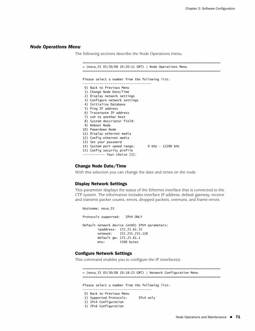
Node Operations and Maintenance 71
Chapter 2: Software Configuration
Node Operations MenuThe following sections describe the Node Operations menu.
=========================================================================== (nova_55 05/30/08 20:20:11 GMT) | Node Operations Menu ==========================================================================
Please select a number from the following list:------------------------------------- 0) Back to Previous Menu 1) Change Node Date/Time 2) Display network settings 3) Configure network settings 4) Initialize Database 5) Ping IP address 6) Traceroute IP address 7) ssh to another host 8) System descriptor field: 9) Reboot Node10) Powerdown Node11) Display ethernet media12) Config ethernet media13) Set your password 14) System port speed range: 0 kHz - 12288 kHz15) Config security profile------------ Your choice [3]:
Change Node Date/TimeWith this selection you can change the date and times on the node.
Display Network SettingsThis parameter displays the status of the Ethernet interface that is connected to the CTP system. The information includes interface IP address, default gateway, receive and transmit packet counts, errors, dropped packets, overruns, and frame errors.
Hostname: nova_55
Protocols supported: IPV4 ONLY
Default network device (eth0) IPV4 parameters: ipaddress: 172.25.61.55 netmask: 255.255.255.128 default gw: 172.25.61.1 mtu: 1500 bytes
Configure Network SettingsThis command enables you to configure the IP interface(s).
=========================================================================== (nova_55 05/30/08 20:18:23 GMT) | Network Configuration Menu ==========================================================================
Please select a number from the following list:------------------------------------- 0) Back to Previous Menu 1) Supported Protocols: IPv4 only 2) IPv4 Configuration 3) IPv6 Configuration
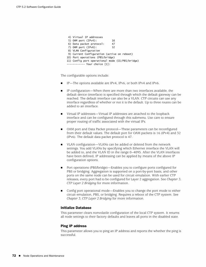
CTP 5.2 Software Configuration Guide
72 Node Operations and Maintenance
4) Virtual IP addresses 5) OAM port (IPv4): 16 6) Data packet protocol: 47 7) OAM port (IPv6): 32 8) VLAN Configuration 9) Current Configuration (active on reboot)10) Port operations (PBS/bridge)11) Config port operational mode (CE/PBS/bridge)------------ Your choice [1]:
The configurable options include:
IP—The options available are IPv4, IPv6, or both IPv4 and IPv6.
IP configuration—When there are more than two interfaces available, the default device (interface) is specified through which the default gateway can be reached. The default interface can also be a VLAN. CTP circuits can use any interface regardless of whether or not it is the default. Up to three routes can be added to an interface.
Virtual IP addresses—Virtual IP addresses are attached to the loopback interface and can be configured through this submenu. Use care to ensure proper routing of traffic associated with the virtual IPs.
OAM port and Data Packet protocol—These parameters can be reconfigured from their default values. The default port for OAM packets is 16 (IPv4) and 32 (IPv6). The default data packet protocol is 47.
VLAN configuration—VLANs can be added or deleted from the network settings. You add VLANs by specifying which Ethernet interface the VLAN will be added to, and the VLAN ID in the range 0–4095. After the VLAN interfaces have been defined, IP addressing can be applied by means of the above IP configuration options.
Port operations (PBS/bridge)—Enables you to configure ports configured for PBS or bridging. Aggregation is supported on a port-by-port basis, and other ports on the same node can be used for circuit emulation. With earlier CTP releases, every port had to be configured for Layer 2 aggregation. See Chapter 3, CTP Layer 2 Bridging for more information.
Config port operational mode—Enables you to change the port mode to either circuit emulation, PBS, or bridging. Requires a reboot of the CTP system. See Chapter 3, CTP Layer 2 Bridging for more information.
Initialize DatabaseThis parameter clears nonvolatile configuration of the local CTP system. It returns all node settings to their factory defaults and leaves all ports in the disabled state.
Ping IP addressThis parameter allows you to ping an IP address and reports the whether the ping is successful.
Node Operations and Maintenance 73
Chapter 2: Software Configuration
Traceroute IP AddressThis parameter allows you to enter an IP address and get a traceroute to that address.
SSH to Another HostThis parameter allows you to enter an IP address of a host; the system establishes an SSH session with that host. You must know the login and password to the remote host. You can also use the CTPView Node Maintenance window (Figure 36 on page 70) to establish an SSH session to a host.
System Descriptor FieldThis parameter allows you to enter a system descriptor that will be displayed in the top banner of each menu.
Reboot NodeThis parameter allows you to reboot the CTP system. You can also use the CTPView Node Maintenance window (Figure 36 on page 70) to reboot the CTP system.
Powerdown NodeThis parameter allows you to gracefully power down the system. You can also use the CTPView Node Maintenance window (Figure 36 on page 70) to shut down the system.
Display Ethernet MediaThis parameter displays the supported link modes (speed and duplex) and the configuration of the Ethernet media.
Configure Ethernet MediaYou can configure the CTP Ethernet media to autonegotiate the duplex mode and speed, to set the duplex to either half or full, and to set the speed to either 100 or 10 Mbps. If you answer No to Enable Autonegotiate, you will receive prompts for the Ethernet speed and duplex settings. If you answer No to Setup Ethernet for 100 Mbps, the speed will be set to 10 Mbps. If you answer No to Setup Ethernet full duplex, the configuration will be half duplex.
The Ethernet configurations of the CTP must match the configuration of the connected router or switch. Mismatched configurations, such as setting the CTP system to autonegotiate and the router to full duplex, will result in a misconfiguration and dropped packets. You must disable Cisco Discovery Protocol on the Fast Ethernet port connected to the CTP system.
Set Your PasswordYou can log in to the system to change your password. The password must meet the criteria established in the Configuration Security Profile menu, and you must have the current password to make any changes.
CAUTION: Always use the powerdown option provided in the Node Operations menu when maintenance or other activity requires a system powerdown.

CTP 5.2 Software Configuration Guide
74 Node Operations and Maintenance
System Port Speed RangeThe parameter sets one of two valid port speed ranges for the CTP1000 series. The first range allows ports to run at rates from 1 bps through 8 Mbps. The second range allows ports to run at rates from 4 Kbps to 12.288 Mbps. There is only one port speed range for the CTP2000 series, which is 0 KHz to 12288 kHz.
Config Security ProfileThe Config Security Profile menu is covered in Chapter 5, Security Profile Menu. The administrator must have the root password to gain access to the menu.
Overview 75
Chapter 3
CTP Layer 2 Bridging
This chapter provides information about CTP layer 2 bridging configuration. The chapter contains the following sections:
Overview on page 75
Enabling Ports for Layer 2 Bridging on page 76
Configuring Layer 2 Bridging Port Parameters on page 79
Options for Layer 2 Bridging Ports on page 81
Port Query and Node Summary Examples on page 89
Overview
CTP layer 2 bridging mode is used to aggregate many serial interfaces into one or several Ethernet interfaces. Each physical serial interface on the CTP chassis maps to a separate Ethernet VLAN interface on the destination router. Aggregation is supported on a port-by-port basis, and other ports on the same node can be used for circuit emulation.
In layer 2 bridging mode, packets are extracted from the line on the serial interface. This is in contrast to circuit emulation mode where every bit on the serial interface is received (regardless of content) and formed into packets
You can use the CTP CLI menu to configure these interfaces. Layer 2 bridging is supported on CTPView release 3.1 and later.
Packet Performance and ThrottlingBecause there is no way to prevent large numbers of small packets from arriving at the packet-bearing serial (PBS) interfaces, policing is performed on the CTP system. Bridged packets are identifed and throttled before they exit the CTP system onto the Ethernet line, and offending packets are dropped.

CTP 5.2 Software Configuration Guide
76 Enabling Ports for Layer 2 Bridging
This action is done with a throttling mechanism implemented in the serial driver. At the beginning of every second, the driver is deposited with a fixed number of tokens. For each token, a packet may be received by the driver and sent to the system for forwarding. After the tokens have been used up, no more packets may be received, and any subsequent packets that arrive are discarded (and the dropped counter incremented). At the beginning of the next second, that driver receives another allotment of tokens, and packet reception resumes. If there are any unused tokens at the end of the second, they are discarded.
The overall bridged packet forwarding budget of a CTP2000 system is 25,000 packets/sec.
Other RequirementsFor packet bridging to work properly, it is important to have an attached router on the Ethernet side that provides advanced functions. Specifically, the router should support:
VLAN tagging for particular IP addresses/subnets—To support the routing function in the CTP system.
Per-VLAN bandwidth shaping—To avoid overloading the CTP bridged Ethernet-to-serial link with too much bandwidth. Otherwise, packets will eventually be dropped because the serial packet driver to the line will not be able to accept the packet.
Per-VLAN pps shaping—To avoid overloading the CTP system with too high of a packet rate.
Enabling Ports for Layer 2 Bridging
You must enable layer 2 bridging for a port (select its operational mode) before you can configure its layer 2 bridging parameters. To configure serial aggreagation parameters, see “Configuring Layer 2 Bridging Port Parameters” on page 79.
To enable ports for layer 2 bridging:
1. From the CTP Main menu, select 5) Node Operations menu.
=========================================================================== (nova_45 06/06/08 21:43:33 GMT) | CTP Main Menu ==========================================================================
Please select a number from the following list:------------------------------------- 0) Exit to Shell 1) Bundle Operations 2) Node Synchronization 3) Node Summary 4) Node Diagnostics 5) Node Operations 6) Save Database to Flash------------ Your choice [5]:
2. On the Node Operations menu, select 3) Configure network settings.

Enabling Ports for Layer 2 Bridging 77
Chapter 3: CTP Layer 2 Bridging
=========================================================================== (nova_45 06/06/08 21:47:24 GMT) | Node Operations Menu ==========================================================================
Please select a number from the following list:------------------------------------- 0) Back to Previous Menu 1) Change Node Date/Time 2) Display network settings 3) Configure network settings 4) Initialize Database 5) Ping IP address 6) Traceroute IP address 7) ssh to another host 8) System descriptor field: 9) Reboot Node10) Powerdown Node11) Display ethernet media12) Config ethernet media13) Set your password 14) System port speed range: 0 kHz - 12288 kHz15) Config security profile------------ Your choice [0]: 3

CTP 5.2 Software Configuration Guide
78 Enabling Ports for Layer 2 Bridging
3. In the Network Configuration menu, select 11) Config port operational mode (CE/PBS/bridge).
=========================================================================== (nova_45 06/06/08 21:49:05 GMT) | Network Configuration Menu ==========================================================================
Please select a number from the following list:------------------------------------- 0) Back to Previous Menu 1) Supported Protocols: IPv4 only 2) IPv4 Configuration 3) IPv6 Configuration 4) Virtual IP addresses 5) OAM port (IPv4): 16 6) Data packet protocol: 47 7) OAM port (IPv6): 32 8) VLAN Configuration 9) Current Configuration (active on reboot)10) Port operations (PBS/bridge)11) Config port operational mode (CE/PBS/bridge)------------ Your choice [0]: 11
****** You are about to modify a system parameter that will require*** a system reboot when complete.****** If you decide to continue, the system will automatically*** reboot upon leaving these menus.****** Note: If these parameters are changed incorrectly,*** system may not be reachable via the network*** after the system reboots.*** Are you sure? y[n]:
4. Type Y and press Enter twice.
A list of available ports is displayed in the Configure Port Operational Mode menu.
*** Please note, changing the operation of a port will clear the database*** for that port. All parameters for the port will be set to defaults. *** Existing settings will be lost.
Hit Carriage Return to Continue...
=========================================================================== (nova_45 06/06/08 21:57:10 GMT) | Configure Port Operational Mode ==========================================================================
PBS or bridging operation is limited to the following ports:
Port 0 operational mode: BridgedPort 1 operational mode: Circuit-emulation
NOTE: After you have configured port types, you must exit to the top-level CTP Main menu so that the CTP system can reboot and your changes can be applied.
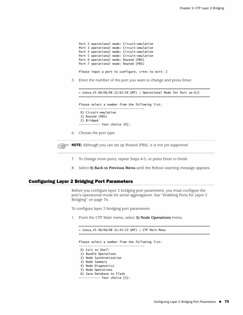
Configuring Layer 2 Bridging Port Parameters 79
Chapter 3: CTP Layer 2 Bridging
Port 2 operational mode: Circuit-emulationPort 3 operational mode: Circuit-emulationPort 4 operational mode: Circuit-emulationPort 5 operational mode: Circuit-emulationPort 6 operational mode: Routed (PBS)Port 7 operational mode: Routed (PBS)
Please input a port to configure, <rtn> to exit: 2
5. Enter the number of the port you want to change and press Enter.
=========================================================================== (nova_45 06/06/08 22:02:56 GMT) | Operational Mode for Port se-0/2==========================================================================
Please select a number from the following list:------------------------------------- 0) Circuit-emulation 1) Routed (PBS) 2) Bridged------------ Your choice [0]:
6. Choose the port type.
7. To change more ports, repeat Steps 4-5, or press Enter to finish.
8. Select 0) Back to Previous Menu until the Reboot warning message appears.
Configuring Layer 2 Bridging Port Parameters
Before you configure layer 2 bridging port parameters, you must configure the port’s operational mode for serial aggreagation. See “Enabling Ports for Layer 2 Bridging” on page 76.
To configure layer 2 bridging port parameters:
1. From the CTP Main menu, select 5) Node Operations menu.
=========================================================================== (nova_45 06/06/08 21:43:33 GMT) | CTP Main Menu ==========================================================================
Please select a number from the following list:------------------------------------- 0) Exit to Shell 1) Bundle Operations 2) Node Synchronization 3) Node Summary 4) Node Diagnostics 5) Node Operations 6) Save Database to Flash------------ Your choice [5]:
NOTE: Although you can set up Routed (PBS), it is not yet supported.
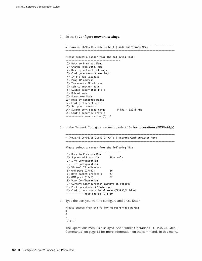
CTP 5.2 Software Configuration Guide
80 Configuring Layer 2 Bridging Port Parameters
2. Select 3) Configure network settings.
=========================================================================== (nova_45 06/06/08 21:47:24 GMT) | Node Operations Menu ==========================================================================
Please select a number from the following list:------------------------------------- 0) Back to Previous Menu 1) Change Node Date/Time 2) Display network settings 3) Configure network settings 4) Initialize Database 5) Ping IP address 6) Traceroute IP address 7) ssh to another host 8) System descriptor field: 9) Reboot Node10) Powerdown Node11) Display ethernet media12) Config ethernet media13) Set your password 14) System port speed range: 0 kHz - 12288 kHz15) Config security profile------------ Your choice [0]: 3
3. In the Network Configuration menu, select 10) Port operations (PBS/bridge).
=========================================================================== (nova_45 06/06/08 21:49:05 GMT) | Network Configuration Menu ==========================================================================
Please select a number from the following list:------------------------------------- 0) Back to Previous Menu 1) Supported Protocols: IPv4 only 2) IPv4 Configuration 3) IPv6 Configuration 4) Virtual IP addresses 5) OAM port (IPv4): 16 6) Data packet protocol: 47 7) OAM port (IPv6): 32 8) VLAN Configuration 9) Current Configuration (active on reboot)10) Port operations (PBS/bridge)11) Config port operational mode (CE/PBS/bridge)------------ Your choice [0]: 10
4. Type the port you want to configure and press Enter.
Please choose from the following PBS/bridge ports:067[0]: 0
The Operations menu is displayed. See “Bundle Operations—CTPOS CLI Menu Commands” on page 13 for more information on the commands in this menu.
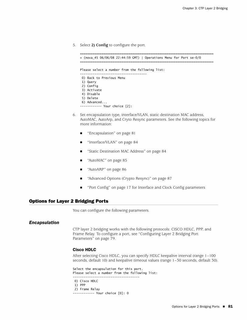
Options for Layer 2 Bridging Ports 81
Chapter 3: CTP Layer 2 Bridging
5. Select 2) Config to configure the port.
=========================================================================== (nova_45 06/06/08 22:44:59 GMT) | Operations Menu for Port se-0/0==========================================================================
Please select a number from the following list:------------------------------------- 0) Back to Previous Menu 1) Query 2) Config 3) Activate 4) Disable 5) Delete 6) Advanced...------------ Your choice [2]:
6. Set encapsulation type, interface/VLAN, static destination MAC address, AutoMAC, AutoArp, and Cryto Resync parameters. See the following topics for more information:
“Encapsulation” on page 81
“Interface/VLAN” on page 84
“Static Destination MAC Address” on page 84
“AutoMAC” on page 85
“AutoARP” on page 86
“Advanced Options (Crypto Resync)” on page 87
“Port Config” on page 17 for Interface and Clock Config parameters
Options for Layer 2 Bridging Ports
You can configure the following parameters.
EncapsulationCTP layer 2 bridging works with the following protocols: CISCO HDLC, PPP, and Frame Relay. To configure a port, see “Configuring Layer 2 Bridging Port Parameters” on page 79.
Cisco HDLCAfter selecting Cisco HDLC, you can specify HDLC keepalive interval (range 1–100 seconds, default 10) and keepalive timeout values (range 1–30 seconds, default 30).
Select the encapsulation for this port.Please select a number from the following list:------------------------------------- 0) Cisco HDLC 1) PPP 2) Frame Relay------------ Your choice [0]: 0

CTP 5.2 Software Configuration Guide
82 Options for Layer 2 Bridging Ports
Enter the HDLC keepalive interval.
(1-100)[10]: 10
Enter the HDLC keepalive timeout.
(1-100)[30]: 30
PPPThere are no values to specify for PPP.
Frame RelayAfter selecting Frame Relay, you can configure individual permanent virtual circuits (PVCs). Ethernet interface, AutoMAC, AutoARP, and static MAC options do not appear on the menu when Frame Relay encapsulation is selected because these options are configured per PVC.
Select the encapsulation for this port.Please select a number from the following list:------------------------------------- 0) Cisco HDLC 1) PPP 2) Frame Relay------------ Your choice [2]: 2
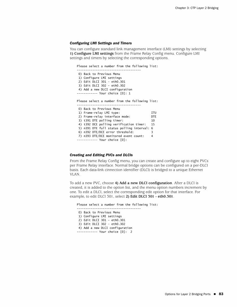
Options for Layer 2 Bridging Ports 83
Chapter 3: CTP Layer 2 Bridging
Configuring LMI Settings and Timers
You can configure standard link management interface (LMI) settings by selecting 1) Configure LMI settings from the Frame Relay Config menu. Configure LMI settings and timers by selecting the corresponding options.
Please select a number from the following list:------------------------------------- 0) Back to Previous Menu 1) Configure LMI settings 2) Edit DLCI 301 - eth0.301 3) Edit DLCI 302 - eth0.302 4) Add a new DLCI configuration------------ Your choice [0]: 1
Please select a number from the following list:------------------------------------- 0) Back to Previous Menu 1) Frame-relay LMI type: ITU 2) Frame-relay interface mode: DTE 3) t391 DTE polling timer: 10 4) t392 DCE polling verification timer: 15 5) n391 DTE full status polling interval: 6 6) n392 DTE/DCE error threshold: 3 7) n393 DTE/DCE monitored event count: 4------------ Your choice [0]:
Creating and Editing PVCs and DLCIs
From the Frame Relay Config menu, you can create and configure up to eight PVCs per Frame Relay interface. Normal bridge options can be configured on a per-DLCI basis. Each data-link cinnection identifier (DLCI) is bridged to a unique Ethernet VLAN.
To add a new PVC, choose 4) Add a new DLCI configuration. After a DLCI is created, it is added to the option list, and the menu option numbers increment by one. To edit a DLCI, select the corresponding edit option for that interface. For example, to edit DLCI 301, select 2) Edit DLCI 301 - eth0.301.
Please select a number from the following list:------------------------------------- 0) Back to Previous Menu 1) Configure LMI settings 2) Edit DLCI 301 - eth0.301 3) Edit DLCI 302 - eth0.302 4) Add a new DLCI configuration------------ Your choice [0]: 2

CTP 5.2 Software Configuration Guide
84 Options for Layer 2 Bridging Ports
Deleting a PVC
To delete a PVC, you must first edit it and then select 1) Delete this PVC.
Please select a number from the following list:------------------------------------- 0) Back to Previous Menu 1) Delete this PVC 2) Frame-relay DLCI: 301 3) Interface/VLAN: eth0.301 4) AutoMAC: enabled 5) AutoARP: enabled 6) Static dst-MAC for TX: ffff.ffff.ffff------------ Your choice [0]:
Interface/VLANMake the mapping, or bridge, between the serial and Ethernet interfaces by selecting 5) Interface/VLAN from the Config menu. After selecting the bridge, you can enter the VLAN IDs on the Ethernet interface that will be mapped to the serial port.
Please select a number from the following list:------------------------------------- 0) Back to Previous Menu 1) Port descriptor text: 2) Interface: RS-232/DCE/NRZ 3) Clock config: 128.000000 / Configured Rate, w/o Ext Tx Clk (TT) 4) Encapsulation: cisco-hdlc / interval=10 timeout=30 5) Interface/VLAN: eth0.200 6) AutoMAC: enabled 7) AutoARP: enabled 8) Static dst-MAC for TX: ffff.ffff.ffff 9) Advanced options...
------------ Your choice [0]: 5Select the Ethernet interface to bridge this port to.Please select a number from the following list:------------------------------------- 0) Interface eth0------------ Your choice [0]: 0
Enter the VLAN ID on interface eth0 to bridge this port to.(1-4095)[200]: 200
Static Destination MAC AddressAny packets bridged from the serial interface to the Ethernet interface need to have an Ethernet header added. Because the destination MAC address is usually unknown, by default ffff.ffff.ffff is used. This default guarantees that the attached router will see the packet. You can define the destination MAC address for packets sent out the Ethernet interface by using the static dst-MAC option.
To set the static destination MAC address, select 8) Static dst-MAC for TX from the Config menu. Note that AutoMAC must be disabled before you set a static dst-MAC.
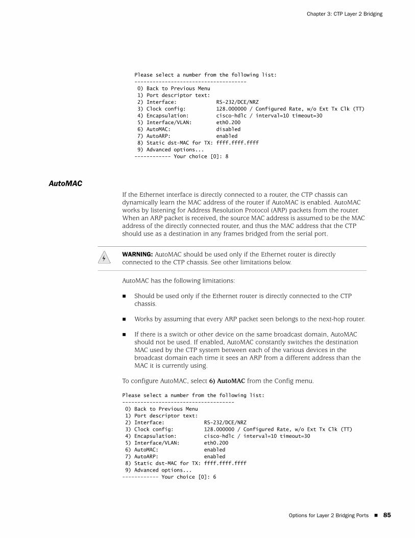
Options for Layer 2 Bridging Ports 85
Chapter 3: CTP Layer 2 Bridging
Please select a number from the following list:------------------------------------- 0) Back to Previous Menu 1) Port descriptor text: 2) Interface: RS-232/DCE/NRZ 3) Clock config: 128.000000 / Configured Rate, w/o Ext Tx Clk (TT) 4) Encapsulation: cisco-hdlc / interval=10 timeout=30 5) Interface/VLAN: eth0.200 6) AutoMAC: disabled 7) AutoARP: enabled 8) Static dst-MAC for TX: ffff.ffff.ffff 9) Advanced options...------------ Your choice [0]: 8
AutoMACIf the Ethernet interface is directly connected to a router, the CTP chassis can dynamically learn the MAC address of the router if AutoMAC is enabled. AutoMAC works by listening for Address Resolution Protocol (ARP) packets from the router. When an ARP packet is received, the source MAC address is assumed to be the MAC address of the directly connected router, and thus the MAC address that the CTP should use as a destination in any frames bridged from the serial port.
AutoMAC has the following limitations:
Should be used only if the Ethernet router is directly connected to the CTP chassis.
Works by assuming that every ARP packet seen belongs to the next-hop router.
If there is a switch or other device on the same broadcast domain, AutoMAC should not be used. If enabled, AutoMAC constantly switches the destination MAC used by the CTP system between each of the various devices in the broadcast domain each time it sees an ARP from a different address than the MAC it is currently using.
To configure AutoMAC, select 6) AutoMAC from the Config menu.
Please select a number from the following list:------------------------------------- 0) Back to Previous Menu 1) Port descriptor text: 2) Interface: RS-232/DCE/NRZ 3) Clock config: 128.000000 / Configured Rate, w/o Ext Tx Clk (TT) 4) Encapsulation: cisco-hdlc / interval=10 timeout=30 5) Interface/VLAN: eth0.200 6) AutoMAC: enabled 7) AutoARP: enabled 8) Static dst-MAC for TX: ffff.ffff.ffff 9) Advanced options...------------ Your choice [0]: 6
WARNING: AutoMAC should be used only if the Ethernet router is directly connected to the CTP chassis. See other limitations below.
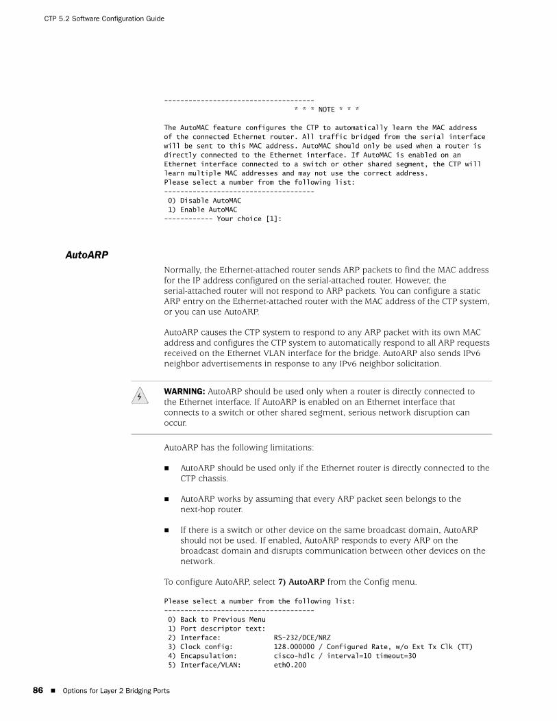
CTP 5.2 Software Configuration Guide
86 Options for Layer 2 Bridging Ports
------------------------------------- * * * NOTE * * *
The AutoMAC feature configures the CTP to automatically learn the MAC addressof the connected Ethernet router. All traffic bridged from the serial interfacewill be sent to this MAC address. AutoMAC should only be used when a router isdirectly connected to the Ethernet interface. If AutoMAC is enabled on anEthernet interface connected to a switch or other shared segment, the CTP willlearn multiple MAC addresses and may not use the correct address.Please select a number from the following list:------------------------------------- 0) Disable AutoMAC 1) Enable AutoMAC------------ Your choice [1]:
AutoARPNormally, the Ethernet-attached router sends ARP packets to find the MAC address for the IP address configured on the serial-attached router. However, the serial-attached router will not respond to ARP packets. You can configure a static ARP entry on the Ethernet-attached router with the MAC address of the CTP system, or you can use AutoARP.
AutoARP causes the CTP system to respond to any ARP packet with its own MAC address and configures the CTP system to automatically respond to all ARP requests received on the Ethernet VLAN interface for the bridge. AutoARP also sends IPv6 neighbor advertisements in response to any IPv6 neighbor solicitation.
AutoARP has the following limitations:
AutoARP should be used only if the Ethernet router is directly connected to the CTP chassis.
AutoARP works by assuming that every ARP packet seen belongs to the next-hop router.
If there is a switch or other device on the same broadcast domain, AutoARP should not be used. If enabled, AutoARP responds to every ARP on the broadcast domain and disrupts communication between other devices on the network.
To configure AutoARP, select 7) AutoARP from the Config menu.
Please select a number from the following list:------------------------------------- 0) Back to Previous Menu 1) Port descriptor text: 2) Interface: RS-232/DCE/NRZ 3) Clock config: 128.000000 / Configured Rate, w/o Ext Tx Clk (TT) 4) Encapsulation: cisco-hdlc / interval=10 timeout=30 5) Interface/VLAN: eth0.200
WARNING: AutoARP should be used only when a router is directly connected to the Ethernet interface. If AutoARP is enabled on an Ethernet interface that connects to a switch or other shared segment, serious network disruption can occur.

Options for Layer 2 Bridging Ports 87
Chapter 3: CTP Layer 2 Bridging
6) AutoMAC: enabled 7) AutoARP: enabled 8) Static dst-MAC for TX: ffff.ffff.ffff 9) Advanced options...------------ Your choice [0]: 7
------------------------------------- * * * WARNING * * *
The AutoARP feature configures the CTP to automatically respond to *ALL* ARPrequests received on the Ethernet VLAN interface for this bridge.
AutoARP should only be used when a router is directly connected to the Ethernetinterface. If AutoARP is enabled on an Ethernet interface that connects to aswitch or other shared segment, SERIOUS NETWORK DISRUPTION can occur.Please select a number from the following list:------------------------------------- 0) Disable AutoARP 1) Enable AutoARP------------ Your choice [1]:
Advanced Options (Crypto Resync)CTP chassis can be used with federally approved cryptographic (crypto) devices. You can configure synchronized (in-sync) and pulse crypto resynchronized (resync) options for use with these devices.
If an error occurs on a secure link, the crypto devices may get out of sync. When the CTP software detects that a crypto device is out of sync or that keepalives or LMI has been lost, it signals to the crypto device to resync by pulsing DSR and/or CTS.
You can configure how long the CTP software waits before requesting a resynchronization, set the pulse width, and set the pulse period of the resync request. You can also configure the direction of the pulse (0 to 1 or 1 to 0). (Other common terms for 0 are space, low, and on; and other commons terms for 1 are mark, high, and off). To disable the pulse, set the in-sync and pulse value to the same value.
Crypto resync wait time—Time between loss of sync and the first pulse (range 1-60 seconds).
Crypto resync pulse width—Time that the pulse is asserted (range 1–15 seconds).
Crypto resync pulse period—Time between the beginnings of each pulse (range 1–1000 seconds). Should be greater than the pulse width; otherwise, the pulse will always be asserted.

CTP 5.2 Software Configuration Guide
88 Options for Layer 2 Bridging Ports
Figure 37: Crypto Sync Timeline
To set crypto resync parameters, select 9) Advanced options from the Config menu.
Please select a number from the following list:------------------------------------- 0) Back to Previous Menu 1) Port descriptor text: 2) Interface: V.35/DCE/NRZ 3) Clock config: 128.000000 / Configured Rate, w/o Ext Tx Clk (TT) 4) Encapsulation: ppp 5) Interface/VLAN: eth0.201 6) AutoMAC: enabled 7) AutoARP: enabled 8) Static dst-MAC for TX: ffff.ffff.ffff 9) Advanced options...------------ Your choice [4]: 9
=========================================================================== (ctp 05/26/07 10:55:17 GMT) | Advanced Option Menu for PBS port 1==========================================================================
Please select a number from the following list:------------------------------------- 0) Back to Previous Menu3) Crypto resync wait time: 4 sec 4) Crypto resync pulse width: 1 sec 5) Crypto resync pulse period: 8 sec 6) Crypto resync DSR in-sync value: 1 (mark/high/off) 7) Crypto resync DSR pulse value: 0 (space/low/on) 8) Crypto resync CTS in-sync value: 1 (mark/high/off) 9) Crypto resync CTS pulse value: 0 (space/low/on)------------ Your choice [5]:
When you use a DTE cable, the DSR settings apply to DTR, and the CTS settings apply to RTS. Both signals are provided to allow for different requirements of the crypto device:
DSR (DTR) provides an unbalanced signal
CTS (RTS) provides a balanced signal
������� ��� �������� ��������
��� ������� ���� �����
��� ��������������
��������������� ���������
���������������������������

Port Query and Node Summary Examples 89
Chapter 3: CTP Layer 2 Bridging
Port Query and Node Summary Examples
You can view port configuration settings by selecting Query Port from the Port Operations menu. Figure 38 shows a Cisco HDLC configuration, and Figure 39 shows a Frame Relay configuration. Note that separate statistics are provided for each DLCI in the Frame Relay example.
Figure 38: Port Query—Cisco HDLC Configuration
Detail query display for bridge port 2===============================================================================General status: Device name: scc2 Port admin state: ACTIVE Port link state: UP
Serial interface: Interface: EIA-530A/DCE/NRZ Clock Config: 1024.000000 / Configured Rate, w/o Ext Tx Clk (TT) Measured TT(Ext Clock): 1023.999600 Encapsulation: CISCO HDLC HDLC keepalive status: up
Bridge configuration: Interface/VLAN: eth0.202 AutoARP: enabled (1 ARP reply sent) AutoMAC: enabled Dst-MAC for TX pkts: 0012.1e71.85a1 (auto)
Statistics: Serial RX packets: 301 (53 pps) Serial TX packets: 302 (53 pps) Serial RX bytes: 16888 (23744 bps) Serial TX bytes: 16912 (23744 bps)===============================================================================
Time since last port counter clear: 0 wks, 0 days, 0 hrs, 0 mins 19 secs
Clear Port 2 Stats? y[n]:
Figure 39: Port Query—Frame Relay Configuration
Detail query display for bridge port 2===============================================================================General status: Device name: scc2 Port admin state: ACTIVE Port link state: UP
Serial interface: Interface: EIA-530A/DCE/NRZ Clock Config: 1024.000000 / Configured Rate, w/o Ext Tx Clk (TT) Measured TT(Ext Clock): 1023.999600 Encapsulation: FRAME RELAY Frame-relay LMI status: up
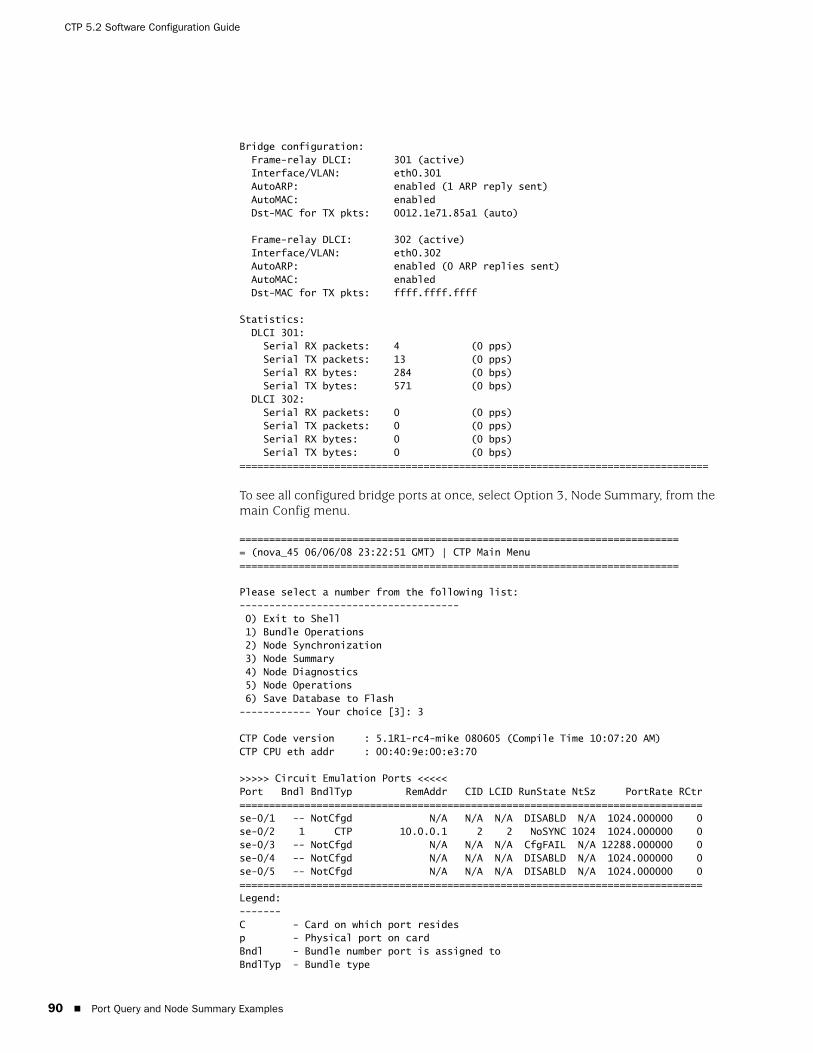
CTP 5.2 Software Configuration Guide
90 Port Query and Node Summary Examples
Bridge configuration: Frame-relay DLCI: 301 (active) Interface/VLAN: eth0.301 AutoARP: enabled (1 ARP reply sent) AutoMAC: enabled Dst-MAC for TX pkts: 0012.1e71.85a1 (auto)
Frame-relay DLCI: 302 (active) Interface/VLAN: eth0.302 AutoARP: enabled (0 ARP replies sent) AutoMAC: enabled Dst-MAC for TX pkts: ffff.ffff.ffff
Statistics: DLCI 301: Serial RX packets: 4 (0 pps) Serial TX packets: 13 (0 pps) Serial RX bytes: 284 (0 bps) Serial TX bytes: 571 (0 bps) DLCI 302: Serial RX packets: 0 (0 pps) Serial TX packets: 0 (0 pps) Serial RX bytes: 0 (0 bps) Serial TX bytes: 0 (0 bps)===============================================================================
To see all configured bridge ports at once, select Option 3, Node Summary, from the main Config menu.
=========================================================================== (nova_45 06/06/08 23:22:51 GMT) | CTP Main Menu ==========================================================================
Please select a number from the following list:------------------------------------- 0) Exit to Shell 1) Bundle Operations 2) Node Synchronization 3) Node Summary 4) Node Diagnostics 5) Node Operations 6) Save Database to Flash------------ Your choice [3]: 3
CTP Code version : 5.1R1-rc4-mike 080605 (Compile Time 10:07:20 AM)CTP CPU eth addr : 00:40:9e:00:e3:70
>>>>> Circuit Emulation Ports <<<<<Port Bndl BndlTyp RemAddr CID LCID RunState NtSz PortRate RCtr==============================================================================se-0/1 -- NotCfgd N/A N/A N/A DISABLD N/A 1024.000000 0se-0/2 1 CTP 10.0.0.1 2 2 NoSYNC 1024 1024.000000 0se-0/3 -- NotCfgd N/A N/A N/A CfgFAIL N/A 12288.000000 0se-0/4 -- NotCfgd N/A N/A N/A DISABLD N/A 1024.000000 0se-0/5 -- NotCfgd N/A N/A N/A DISABLD N/A 1024.000000 0==============================================================================Legend:-------C - Card on which port residesp - Physical port on cardBndl - Bundle number port is assigned toBndlTyp - Bundle type
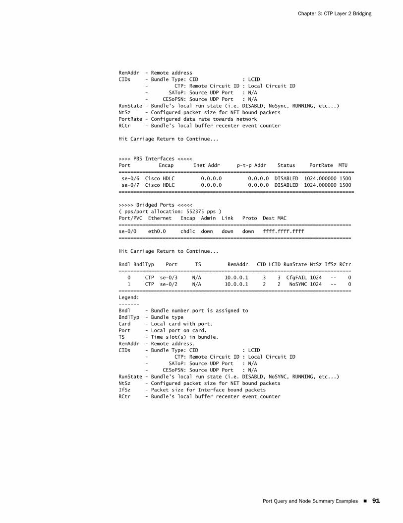
Port Query and Node Summary Examples 91
Chapter 3: CTP Layer 2 Bridging
RemAddr - Remote addressCIDs - Bundle Type: CID : LCID - CTP: Remote Circuit ID : Local Circuit ID - SAToP: Source UDP Port : N/A - CESoPSN: Source UDP Port : N/ARunState - Bundle's local run state (i.e. DISABLD, NoSync, RUNNING, etc...)NtSz - Configured packet size for NET bound packetsPortRate - Configured data rate towards networkRCtr - Bundle's local buffer recenter event counter
Hit Carriage Return to Continue...
>>>> PBS Interfaces <<<<<Port Encap Inet Addr p-t-p Addr Status PortRate MTU ================================================================================ se-0/6 Cisco HDLC 0.0.0.0 0.0.0.0 DISABLED 1024.000000 1500 se-0/7 Cisco HDLC 0.0.0.0 0.0.0.0 DISABLED 1024.000000 1500================================================================================
>>>>> Bridged Ports <<<<<( pps/port allocation: 552375 pps )Port/PVC Ethernet Encap Admin Link Proto Dest MAC ===============================================================================se-0/0 eth0.0 chdlc down down down ffff.ffff.ffff===============================================================================
Hit Carriage Return to Continue...
Bndl BndlTyp Port TS RemAddr CID LCID RunState NtSz IfSz RCtr=============================================================================== 0 CTP se-0/3 N/A 10.0.0.1 3 3 CfgFAIL 1024 -- 0 1 CTP se-0/2 N/A 10.0.0.1 2 2 NoSYNC 1024 -- 0===============================================================================Legend:-------Bndl - Bundle number port is assigned toBndlTyp - Bundle typeCard - Local card with port.Port - Local port on card.TS - Time slot(s) in bundle.RemAddr - Remote address.CIDs - Bundle Type: CID : LCID - CTP: Remote Circuit ID : Local Circuit ID - SAToP: Source UDP Port : N/A - CESoPSN: Source UDP Port : N/ARunState - Bundle's local run state (i.e. DISABLD, NoSYNC, RUNNING, etc...)NtSz - Configured packet size for NET bound packetsIfSz - Packet size for Interface bound packetsRCtr - Bundle's local buffer recenter event counter

CTP 5.2 Software Configuration Guide
92 Port Query and Node Summary Examples

Overview 93
Chapter 4
Software Queries and Operations
The CTP command-line interface (CLI) and CTPView provide extensive capabilities that allow you to diagnose problems and assess the performance of both circuits and the IP network. The CLI and CTPView also provide tools to assist with the diagnosis of problems. These diagnostic tools include integral bit error rate tests (BERTs), circuit loops, IP pings, IP traceroutes, packet delay jitter, and dropped packet plots.
The chapter contains the following sections:
Overview on page 93
Port Queries and Operations on page 94
Node Summary on page 113
Node Diagnostics on page 114
Node Synchronization on page 116
Overview
The CTP menu interface provides a set of menu-driven operational commands. You can use these commands to determine the status of the node or ports and to perform operations such as looping ports or saving the database. Figure 40 shows the Main menu interface with Software Queries and Operations highlighted.

CTP 5.2 Software Configuration Guide
94 Port Queries and Operations
Figure 40: Software Queries and Operations Menu Tree
You can find software queries and operations under the Port Operations, Node Summary, and Node Diagnostics menus. The Port Operations CLI menu is shown in Figure 41 on page 96.
Port Queries and Operations
Port queries and advanced operations are available from the CLI or from CTPView. Both provide information on the port configuration, database state, runtime state, and performance when running. The following summarizes the type of information provided by the CLI and CTPView displays:
Remote Port—Remote port to which the queried port is connected. The variable vvv.www.xxx.yyy specifies the IP address of the remote CTP, and z specifies the port number (0-4).
Port Database State—Specifies whether the port is active or disabled in the database. Ports disabled in the database will not connect to the remote port or pass serial data.
Port Runtime State —Indicates whether the active local CTP port is communicating with the remote node, as follows:
N/A—Not applicable; is displayed when the port database state is disabled.
No Sync—Indicates that the local CTP system is not able to communicate with the remote CTP system.
In Sync—Indicates that the local CTP system is communicating properly with the remote system, but data is not flowing to the interface.
Exit to Shell Port Operations
Node Synchronization
System Summary
Diagnostics System Operations
Query
Config
Activate
Disable
Delete
Re-Center
Advanced
Query Sync Status
Run Card / Port Diags
Print Log Level
Show System Log
Set Lab Mode
Test Menu
Main Menu
Serial Loop
BERT Inject
BERT Reception
SCC Counts
ETH Counts
Buffer Counts
BERT Counts
Change Date/Time
Local Host Name
Local Node IP Addr
Local Node IP Mask
Local Node Gateway
Initialize Database
Ping IP Address
Telnet to IP AddressReboot Node
Start Buffer Capture
Stop Buffer Capture
I/F Signaling Query
Diagnostics
Port Queries and Operations 95
Chapter 4: Software Queries and Operations
Running—Indicates that the local CTP system is communicating and is synchronized with the remote CTP system. The circuit is established between the ports.
Cfg Fail—Indicates that the database configuration for the port cannot be supported. You will not typically encounter this state. If you do, delete and reinstall the port.
MisCfg —Indicates that a misconfiguration between the local and remote ports prevents bringing up the circuit. Examples of misconfigurations are incorrectly configured IP addresses or ports, and mismatched speeds.
Too Slow—Encountered on a port when the port clock configured is TT ALL and either no clock is provided by the external device or the rate is different from the configured rate.
Net Bound Data Info—Indicates the packet size created for transfer, the short-term average number of packets per second being sent out to the remote port, and the approximate data rate of information being received at the serial interface and sent into the IP network to the remote port.
Pkt Size—Size of packets created for transfer across the network. You can modify the packet size by using the Packet Size Configuration command (Port Operations>Config>Parameter 4).
Pkt/sec—Short-term average number of packets per second being sent to the remote port.
Data Rate—Approximate data rate in bits per second of information being received at the serial interface and sent into the IP network to the remote port. The data rate is calculated based on packets per second and packet size, and should be approximately the same as the configured port speed or the expected rate from the data terminal equipment (DTE) when autobaud is configured.
I/F Bound Data Info—Indicates the following information:
Pkt Size—Size of packets received from the IP network destined for the queried port. You can modify the packet size.
Pkt/sec—Short-term average number of packets per second being received from the IP network.
Data Rate—Displays in bits per second the approximate data rate of information being received from the IP network and sent to the queried serial port. The data rate is calculated based on packets per second and packet size, and should be approximately the same as the configured remote port speed or the expected rate from the remote DTE when autobaud is configured.
Late Pkts —Counter of packets that arrives too late to be sent to the serial interface. You may need to increase the buffer size if the late packet count continually increments.
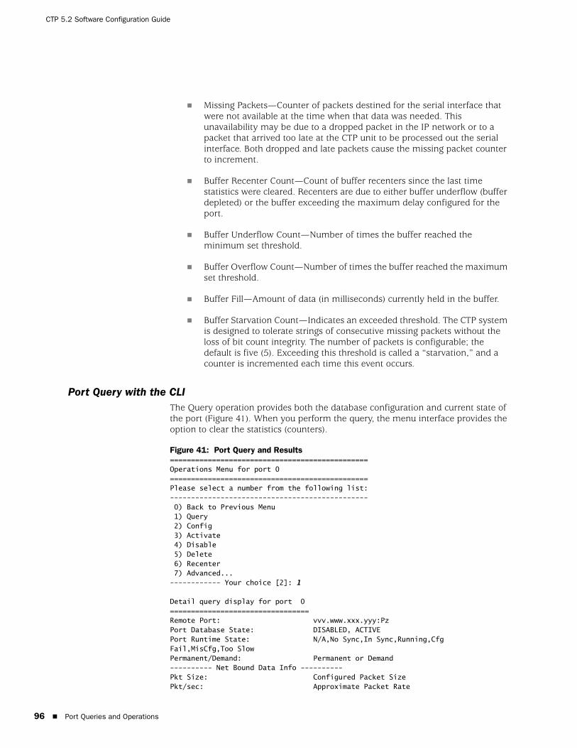
CTP 5.2 Software Configuration Guide
96 Port Queries and Operations
Missing Packets—Counter of packets destined for the serial interface that were not available at the time when that data was needed. This unavailability may be due to a dropped packet in the IP network or to a packet that arrived too late at the CTP unit to be processed out the serial interface. Both dropped and late packets cause the missing packet counter to increment.
Buffer Recenter Count—Count of buffer recenters since the last time statistics were cleared. Recenters are due to either buffer underflow (buffer depleted) or the buffer exceeding the maximum delay configured for the port.
Buffer Underflow Count—Number of times the buffer reached the minimum set threshold.
Buffer Overflow Count—Number of times the buffer reached the maximum set threshold.
Buffer Fill—Amount of data (in milliseconds) currently held in the buffer.
Buffer Starvation Count—Indicates an exceeded threshold. The CTP system is designed to tolerate strings of consecutive missing packets without the loss of bit count integrity. The number of packets is configurable; the default is five (5). Exceeding this threshold is called a “starvation,” and a counter is incremented each time this event occurs.
Port Query with the CLIThe Query operation provides both the database configuration and current state of the port (Figure 41). When you perform the query, the menu interface provides the option to clear the statistics (counters).
Figure 41: Port Query and Results===============================================Operations Menu for port 0===============================================Please select a number from the following list:----------------------------------------------- 0) Back to Previous Menu 1) Query 2) Config 3) Activate 4) Disable 5) Delete 6) Recenter 7) Advanced...------------ Your choice [2]: 1
Detail query display for port 0=================================Remote Port: vvv.www.xxx.yyy:PzPort Database State: DISABLED, ACTIVEPort Runtime State: N/A,No Sync,In Sync,Running,Cfg Fail,MisCfg,Too SlowPermanent/Demand: Permanent or Demand---------- Net Bound Data Info ----------Pkt Size: Configured Packet SizePkt/sec: Approximate Packet Rate
Port Queries and Operations 97
Chapter 4: Software Queries and Operations
Data Rate (Approx bps): Calculated Rate---------- I/F Bound Data Info ----------Pkt Size: Packet Size from RemotePkt/sec: Approximate Packet Rate From RemoteData Rate (Approx bps): Approximate Date RateLate/Missing Pkts: Late Packets/Missing Packets Since Last ClearBuffer Recntr/Underflow/Overflow: Recenter/Underflow/Overflow Since Last ClearBuffer Fill (in Msec): 0.000Buffer Starvation Count: 0
Clear Port 0 Stats? y[n]:
Port Query with CTPViewA superset of Port Query attributes is described at the beginning of the Port Queries and Operations section on page 94. The CTPView Port Runtime option provides the status of the port (Figure 42). Additional information provided by the Runtime query includes the status of internal BERTs and port loops. The display will periodically be updated at the rate specified in the drop-down menu. The Reset ALL System Counters button at the bottom of the display resets the counters.
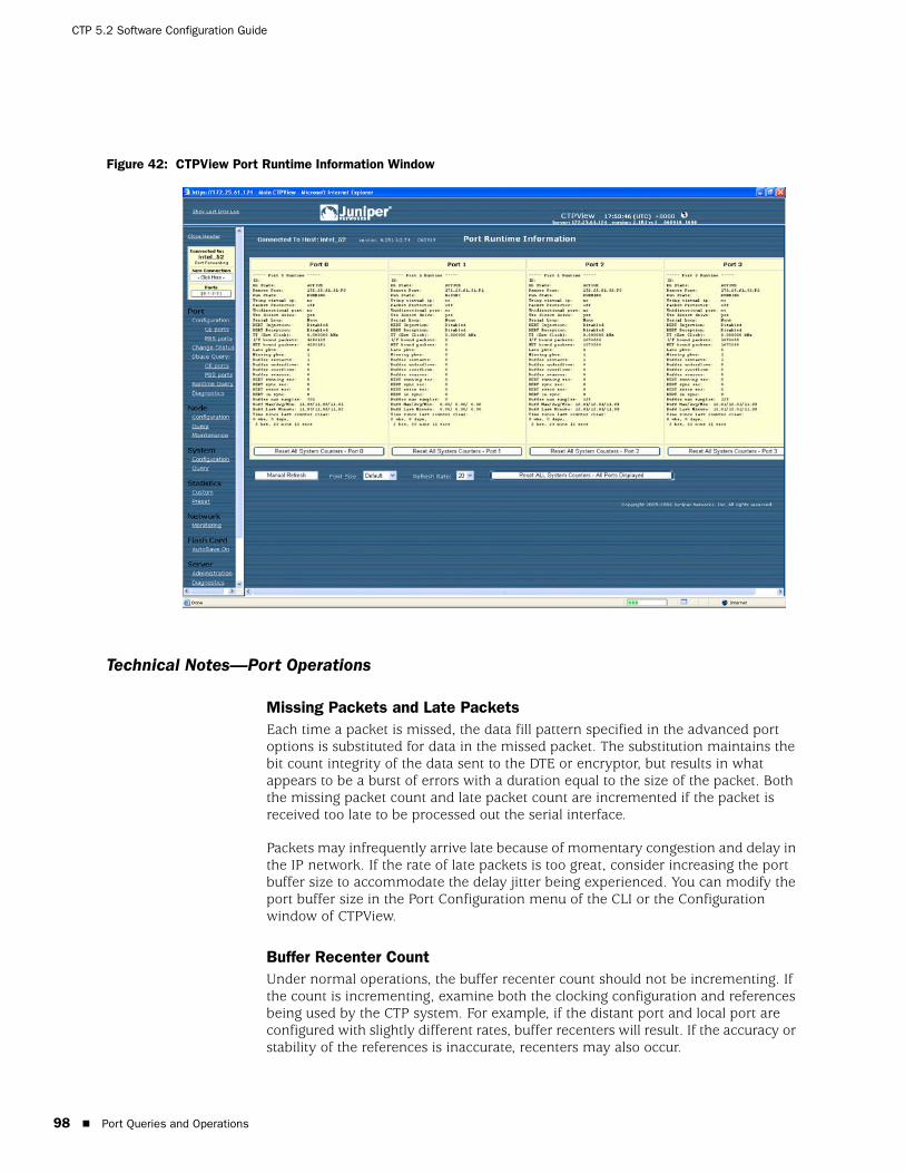
CTP 5.2 Software Configuration Guide
98 Port Queries and Operations
Figure 42: CTPView Port Runtime Information Window
Technical Notes—Port Operations
Missing Packets and Late PacketsEach time a packet is missed, the data fill pattern specified in the advanced port options is substituted for data in the missed packet. The substitution maintains the bit count integrity of the data sent to the DTE or encryptor, but results in what appears to be a burst of errors with a duration equal to the size of the packet. Both the missing packet count and late packet count are incremented if the packet is received too late to be processed out the serial interface.
Packets may infrequently arrive late because of momentary congestion and delay in the IP network. If the rate of late packets is too great, consider increasing the port buffer size to accommodate the delay jitter being experienced. You can modify the port buffer size in the Port Configuration menu of the CLI or the Configuration window of CTPView.
Buffer Recenter CountUnder normal operations, the buffer recenter count should not be incrementing. If the count is incrementing, examine both the clocking configuration and references being used by the CTP system. For example, if the distant port and local port are configured with slightly different rates, buffer recenters will result. If the accuracy or stability of the references is inaccurate, recenters may also occur.

Port Queries and Operations 99
Chapter 4: Software Queries and Operations
Port Database StatesA port’s database state can be set to Active or Disabled, or the port can be deleted. Deleting the port disables it and returns the port configuration to default values the next time it is configured. As shown in Figure 43, the commands to activate, disable or delete the port are provided in the Port Operations menu. You will be prompted to confirm your command before it will take effect.
Ports must be disabled when configured from the CLI. When you select Config from the menu, you will be prompted to confirm that the port can be disabled.
Figure 43: Activating Port Command===============================================Operations Menu for port 0===============================================Please select a number from the following list:----------------------------------------------- 0) Back to Previous Menu 1) Query 2) Config 3) Activate 4) Disable 5) Delete 6) Recenter 7) Advanced...------------ Your choice [7]: 3
*** You asked to bring the port up. Are you sure? y[n]:
You can activate or disable the port by using either of two CTPView windows. The Port Configuration window allows you to change the state by checking the appropriate box near the top of the display (Figure 44). You can also open the Change Port Status window (Figure 45). This window allows you to change the state of the port from active to disabled or disabled to active, to delete the port, and to recenter the buffer.
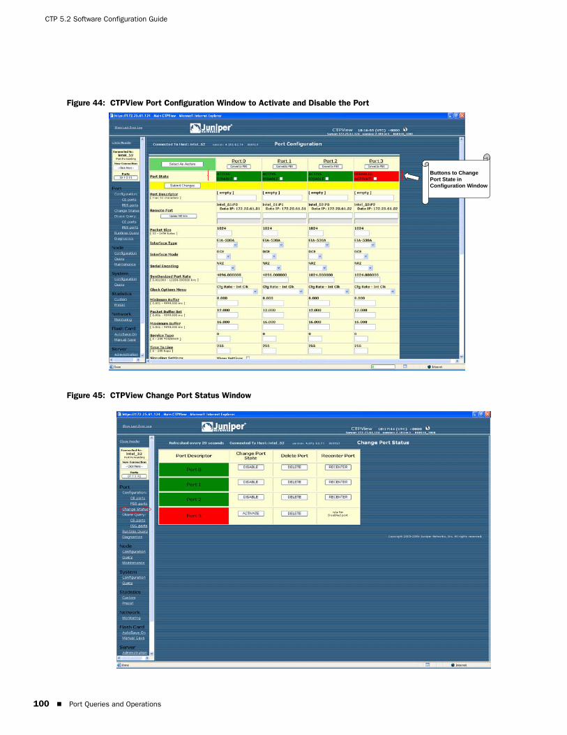
CTP 5.2 Software Configuration Guide
100 Port Queries and Operations
Figure 44: CTPView Port Configuration Window to Activate and Disable the Port
Figure 45: CTPView Change Port Status Window
Buttons to ChangePort State inConfiguration Window
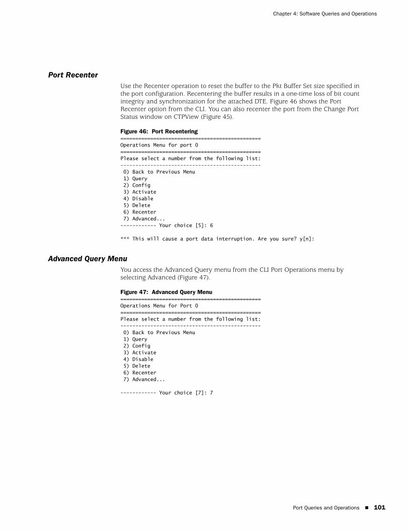
Port Queries and Operations 101
Chapter 4: Software Queries and Operations
Port Recenter Use the Recenter operation to reset the buffer to the Pkt Buffer Set size specified in the port configuration. Recentering the buffer results in a one-time loss of bit count integrity and synchronization for the attached DTE. Figure 46 shows the Port Recenter option from the CLI. You can also recenter the port from the Change Port Status window on CTPView (Figure 45).
Figure 46: Port Recentering===============================================Operations Menu for port 0===============================================Please select a number from the following list:----------------------------------------------- 0) Back to Previous Menu 1) Query 2) Config 3) Activate 4) Disable 5) Delete 6) Recenter 7) Advanced...------------ Your choice [5]: 6
*** This will cause a port data interruption. Are you sure? y[n]:
Advanced Query Menu You access the Advanced Query menu from the CLI Port Operations menu by selecting Advanced (Figure 47).
Figure 47: Advanced Query Menu===============================================Operations Menu for Port 0===============================================Please select a number from the following list:----------------------------------------------- 0) Back to Previous Menu 1) Query 2) Config 3) Activate 4) Disable 5) Delete 6) Recenter 7) Advanced...
------------ Your choice [7]: 7
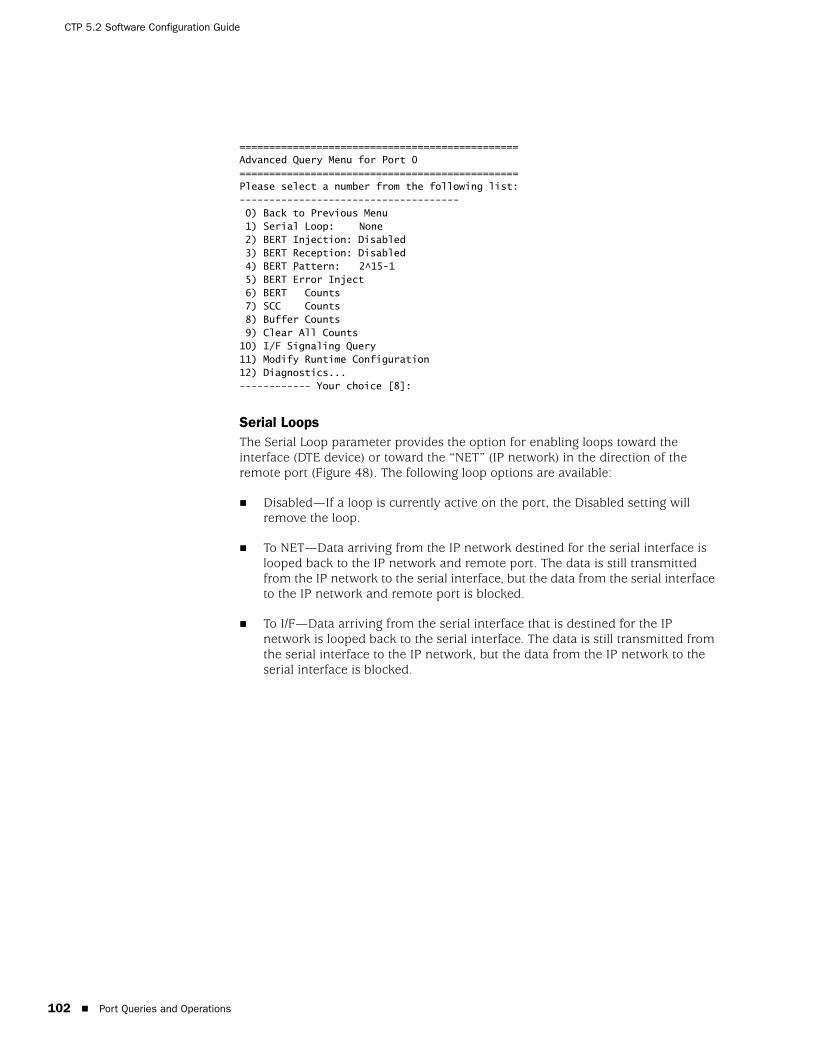
CTP 5.2 Software Configuration Guide
102 Port Queries and Operations
===============================================Advanced Query Menu for Port 0===============================================Please select a number from the following list:------------------------------------- 0) Back to Previous Menu 1) Serial Loop: None 2) BERT Injection: Disabled 3) BERT Reception: Disabled 4) BERT Pattern: 2^15-1 5) BERT Error Inject 6) BERT Counts 7) SCC Counts 8) Buffer Counts 9) Clear All Counts10) I/F Signaling Query11) Modify Runtime Configuration12) Diagnostics...------------ Your choice [8]:
Serial LoopsThe Serial Loop parameter provides the option for enabling loops toward the interface (DTE device) or toward the “NET” (IP network) in the direction of the remote port (Figure 48). The following loop options are available:
Disabled—If a loop is currently active on the port, the Disabled setting will remove the loop.
To NET—Data arriving from the IP network destined for the serial interface is looped back to the IP network and remote port. The data is still transmitted from the IP network to the serial interface, but the data from the serial interface to the IP network and remote port is blocked.
To I/F—Data arriving from the serial interface that is destined for the IP network is looped back to the serial interface. The data is still transmitted from the serial interface to the IP network, but the data from the IP network to the serial interface is blocked.

Port Queries and Operations 103
Chapter 4: Software Queries and Operations
Figure 48: CTP Serial Loops
Figure 49 shows the CLI Advanced Query menu that you use for setting the loops.
Figure 49: Serial Loop Menu===============================================Advanced Query Menu for Port 0===============================================Please select a number from the following list:-----------------------------------------------0) Back to Previous Menu 1) Serial Loop: None 2) BERT Injection: Disabled 3) BERT Reception: Disabled 4) BERT Pattern: 2^15-1 5) BERT Error Inject 6) BERT Counts 7) SCC Counts 8) Buffer Counts 9) Clear All Counts10) I/F Signaling Query11) Modify Runtime Configuration12) Diagnostics...------------ Your choice [8]:1
Enter Loop Function
ReceiveData
TransmitData
ReceiveData
TransmitData
Serial Loop: None
CTP Port I/FCTP PortI/F
ReceiveData
TransmitData
ReceiveData
TransmitData
Serial Loop: To NET
CTP Port I/FCTP PortI/F
X
IP NETWORK
IP NETWORK
ReceiveData
TransmitData
ReceiveData
TransmitData
Serial Loop: To I/F
CTP Port I/FCTP PortI/F
IP NETWORK
X
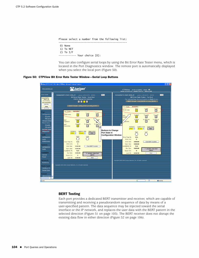
CTP 5.2 Software Configuration Guide
104 Port Queries and Operations
Please select a number from the following list:-----------------------------------------------0) None1) To NET2) To I/F------------ Your choice [0]:
You can also configure serial loops by using the Bit Error Rate Tester menu, which is located in the Port Diagnostics window. The remote port is automatically displayed when you select the local port (Figure 50).
Figure 50: CTPView Bit Error Rate Tester Window—Serial Loop Buttons
BERT Testing Each port provides a dedicated BERT transmitter and receiver, which are capable of transmitting and receiving a pseudorandom sequence of data by means of a user-specified pattern. The data sequence may be injected toward the serial interface or the IP network, and replaces the user data with the BERT pattern in the selected direction (Figure 51 on page 105). The BERT receiver does not disrupt the existing data flow in either direction (Figure 52 on page 106).
Buttons to ChangePort State inConfiguration Window

Port Queries and Operations 105
Chapter 4: Software Queries and Operations
You can select the type of BERT pattern. The BERT patterns are compatible with the Firebird 6000, with the exception of pattern 2^31-1, which is not a Firebird option. You must configure the same pattern on both ports when performing a bidirectional end-to-end BERT. The available patterns include MARK, ALT, 511m 2047, 2^15-1, 2^20-1, 2^23-1, 2^29-1, and 2^31-1.
Figure 51: BERT Injection
BERTTransmitter
IP NETWORK
ReceiveData
TransmitData
BERTReceiver
ReceiveData
TransmitData
BERT Injection: Disabled
BERTTransmitter
IP NETWORK
ReceiveData
TransmitData
BERTReceiver
ReceiveData
TransmitData
BERT Injection: TX to NET
BERTTransmitter
IP NETWORK
ReceiveData
TransmitData
BERTReceiver
ReceiveData
TransmitData
BERT Injection: TX to I/F
X
XCTP Port I/F
CTP Port I/F
CTP Port I/FCTP PortI/F
CTP PortI/F
CTP PortI/F
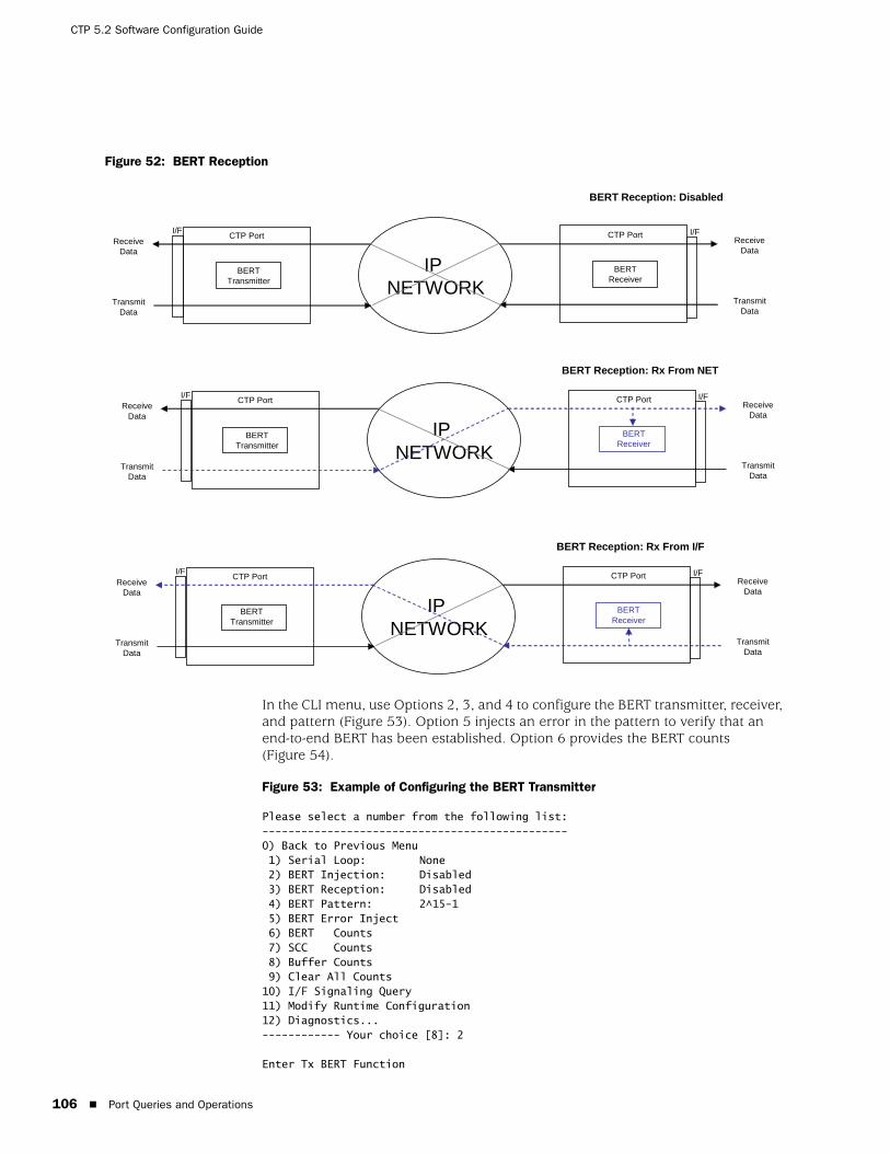
CTP 5.2 Software Configuration Guide
106 Port Queries and Operations
Figure 52: BERT Reception
In the CLI menu, use Options 2, 3, and 4 to configure the BERT transmitter, receiver, and pattern (Figure 53). Option 5 injects an error in the pattern to verify that an end-to-end BERT has been established. Option 6 provides the BERT counts (Figure 54).
Figure 53: Example of Configuring the BERT Transmitter
Please select a number from the following list:-----------------------------------------------0) Back to Previous Menu 1) Serial Loop: None 2) BERT Injection: Disabled 3) BERT Reception: Disabled 4) BERT Pattern: 2^15-1 5) BERT Error Inject 6) BERT Counts 7) SCC Counts 8) Buffer Counts 9) Clear All Counts10) I/F Signaling Query11) Modify Runtime Configuration12) Diagnostics...------------ Your choice [8]: 2
Enter Tx BERT Function
BERTTransmitter
IP NETWORK
ReceiveData
TransmitData
BERTReceiver
ReceiveData
TransmitData
BERT Reception: Disabled
CTP Port I/FCTP PortI/F
BERTTransmitter
IP NETWORK
ReceiveData
TransmitData
BERTReceiver
ReceiveData
TransmitData
BERT Reception: Rx From NET
CTP Port I/FCTP PortI/F
BERTTransmitter
IP NETWORK
ReceiveData
TransmitData
BERTReceiver
ReceiveData
TransmitData
BERT Reception: Rx From I/F
CTP Port I/FCTP PortI/F

Port Queries and Operations 107
Chapter 4: Software Queries and Operations
Please select a number from the following list:----------------------------------------------- 0) Disabled 1) Tx to NET 2) Tx to I/F------------ Your choice [0]: 1
Figure 54: BERT Counts===============================================Advanced Query Menu for Port 0===============================================Please select a number from the following list:-----------------------------------------------0) Back to Previous Menu 1) Serial Loop: None 2) BERT Injection: Disabled 3) BERT Reception: Disabled 4) BERT Pattern: 2^15-1 5) BERT Error Inject 6) BERT Counts 7) SCC Counts 8) Buffer Counts 9) Clear All Counts10) I/F Signaling Query11) Modify Runtime Configuration12) Diagnostics...
------------ Your choice [2]: 6
BERT query display for port 0=======================================BERT Running time: Sync Seconds: 0Errored Seconds: 0Error Count: 0Sync Loss Count: 0Currently in SYNC: NO
Time since last counter clear: 0 wks, 0 days, 1 hrs, 34 mins 20 secs
Clear Port 0 BERT Stats? y[n]:
Figure 55 on page 108 shows the BERT pane, which is displayed when you select Port>Diagnostics in the left pane of the CTPView window. The remote port is automatically displayed when you select the local port. You can use this window to specify whether the BERT transmitter and receiver will be directed toward the network (NET) or serial interface (I/F). You choose the pattern by using the drop-down menu. CTPView checks the status of the BERT at the rate specified in the Update Rate drop-down menu and updates the synchronization status and counter accordingly.
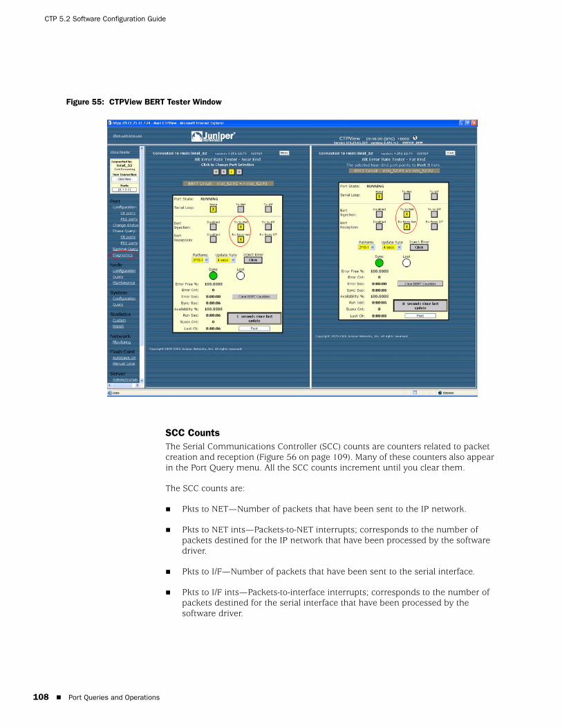
CTP 5.2 Software Configuration Guide
108 Port Queries and Operations
Figure 55: CTPView BERT Tester Window
SCC Counts The Serial Communications Controller (SCC) counts are counters related to packet creation and reception (Figure 56 on page 109). Many of these counters also appear in the Port Query menu. All the SCC counts increment until you clear them.
The SCC counts are:
Pkts to NET—Number of packets that have been sent to the IP network.
Pkts to NET ints—Packets-to-NET interrupts; corresponds to the number of packets destined for the IP network that have been processed by the software driver.
Pkts to I/F—Number of packets that have been sent to the serial interface.
Pkts to I/F ints—Packets-to-interface interrupts; corresponds to the number of packets destined for the serial interface that have been processed by the software driver.
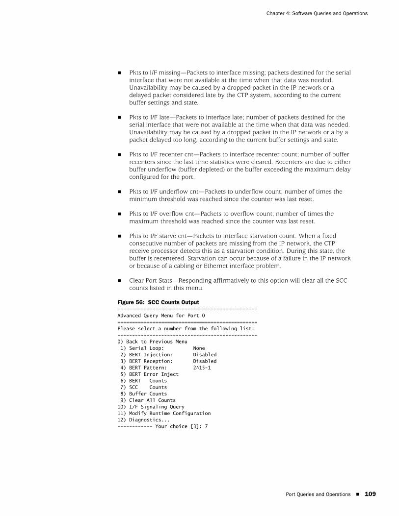
Port Queries and Operations 109
Chapter 4: Software Queries and Operations
Pkts to I/F missing—Packets to interface missing; packets destined for the serial interface that were not available at the time when that data was needed. Unavailability may be caused by a dropped packet in the IP network or a delayed packet considered late by the CTP system, according to the current buffer settings and state.
Pkts to I/F late—Packets to interface late; number of packets destined for the serial interface that were not available at the time when that data was needed. Unavailability may be caused by a dropped packet in the IP network or a by a packet delayed too long, according to the current buffer settings and state.
Pkts to I/F recenter cnt—Packets to interface recenter count; number of buffer recenters since the last time statistics were cleared. Recenters are due to either buffer underflow (buffer depleted) or the buffer exceeding the maximum delay configured for the port.
Pkts to I/F underflow cnt—Packets to underflow count; number of times the minimum threshold was reached since the counter was last reset.
Pkts to I/F overflow cnt—Packets to overflow count; number of times the maximum threshold was reached since the counter was last reset.
Pkts to I/F starve cnt—Packets to interface starvation count. When a fixed consecutive number of packets are missing from the IP network, the CTP receive processor detects this as a starvation condition. During this state, the buffer is recentered. Starvation can occur because of a failure in the IP network or because of a cabling or Ethernet interface problem.
Clear Port Stats—Responding affirmatively to this option will clear all the SCC counts listed in this menu.
Figure 56: SCC Counts Output================================================Advanced Query Menu for Port 0================================================Please select a number from the following list:------------------------------------------------0) Back to Previous Menu 1) Serial Loop: None 2) BERT Injection: Disabled 3) BERT Reception: Disabled 4) BERT Pattern: 2^15-1 5) BERT Error Inject 6) BERT Counts 7) SCC Counts 8) Buffer Counts 9) Clear All Counts10) I/F Signaling Query11) Modify Runtime Configuration12) Diagnostics...------------ Your choice [3]: 7

CTP 5.2 Software Configuration Guide
110 Port Queries and Operations
Advanced Packet query display for port 0========================================Pkts to NET: 0Pkts to NET ints: 0 ----------------------------------------Pkts to I/F: 0Pkts to I/F ints: 0Pkts to I/F missing: 0Pkts to I/F late: 0Pkts to I/F recenter cnt: 0Pkts to I/F underflow cnt: 0Pkts to I/F overflow cnt: 0Pkts to I/F starve cnt: 0
Clear Port 0 Stats? y[n]:
Buffer Counts The CTP system monitors packet delay. The time is measured from when a packet arrives from the Ethernet interface to when it is completely transmitted out the serial interface. This interval represents an instantaneous measure of the buffer fill. Short-term changes in the value of this measured delay correspond to the packet delay jitter in the network. These values are stored in an array where the average may be calculated over a large number of samples.
Figure 57 on page 111 shows the Buffer Counts menu, which provides the following counts:
Sample Buffer Size—Total number of samples in the array used for averaging.
Valid Buffer Samples—Number of currently valid samples in the array.
Total Samples—Number of packets measured since the last time the count was cleared.
Smallest Sample—Within the total number of samples, the smallest sample measured (in milliseconds).
Average Sample—Within the valid array samples, the average buffer fill (in milliseconds).
Largest Sample—Within the total number of samples, the largest sample measured (in milliseconds).
Largest Buffer Jitter—Difference between the largest sample and the smallest sample measured. This corresponds to system packet delay jitter.
Reset Array Monitor—An affirmative response will reset the counter for all statistics in this menu.

Port Queries and Operations 111
Chapter 4: Software Queries and Operations
Figure 57: Buffer Counts Command===============================================Advanced Query Menu for Port 0===============================================Please select a number from the following list:-----------------------------------------------0) Back to Previous Menu 1) Serial Loop: None 2) BERT Injection: Disabled 3) BERT Reception: Disabled 4) BERT Pattern: 2^15-1 5) BERT Error Inject 6) BERT Counts 7) SCC Counts 8) Buffer Counts 9) Clear All Counts10) I/F Signaling Query11) Modify Runtime Configuration12) Diagnostics...------------ Your choice [5]: 9
Advanced Buffer query display for port 0=========================================Sample Buffer Size: 2048Valid Buffer Samples: 0Total Samples: 0-----------------------------------------Smallest Sample: 0.000 msAverage Sample: 0.000 msLargest Sample: 0.000 msLargest Buffer Jitter: 0.000 ms
Reset Buffer Monitor? y[n]:
Clear All Counts Select this option to clear all the counts on all the ports.
I/F Signaling QuerySelect this option to record the state of the signaling leads.
Modify Runtime Configuration Selecting this option allows you to modify parameters that affect adaptive clocking, signal output, interface mode, and buffer configurations without your having to disable the port. The changes are valid only while the port is active and are not stored in the database. We recommend that you do not make port changes with this option except in a lab or test environment.
Diagnostics You can perform diagnostic tests on a port by using the Diagnostics menu. Running the diagnostics on a port will automatically test the port with the integral BERT. The port will not transfer user data during the test.

CTP 5.2 Software Configuration Guide
112 Port Queries and Operations
Figure 58 shows the CLI Diagnostics menu. The system reports results as pass or fail. A failed test indicates possible faulty hardware. You can select one diagnostic test from this menu at a time. The test menu (parameter 5) allows additional functions, such as intentionally dropping an IP packet that should be used only in a test or lab environment. Tests include:
Test Port Data Path (towards NET fast and slow)—Data path test toward the IP network.
Test Port Data Path (towards I/F)—Data path test toward the serial interface.
Test Port Signaling—Tests the signaling leads on the serial interface.
Figure 58: Diagnostics Command================================================Advanced Query Menu for Port 0================================================Please select a number from the following list:------------------------------------------------0) Back to Previous Menu 1) Serial Loop: None 2) BERT Injection: Disabled 3) BERT Reception: Disabled 4) BERT Pattern: 2^15-1 5) BERT Error Inject 6) BERT Counts 7) SCC Counts 8) Buffer Counts 9) Clear All Counts10) I/F Signaling Query11) Modify Runtime Configuration12) Diagnostics...------------ Your choice [8]: 9
===============================================Diagnostics Menu for Port 0===============================================Please select a number from the following list:----------------------------------------------- 0) Back to Previous Menu 1) Test Port Data Path (towards NET fast) 2) Test Port Data Path (towards NET Slow) 3) Test Port Data Path (towards I/F) 4) Test Port Signalling
------------ Your choice [2]:
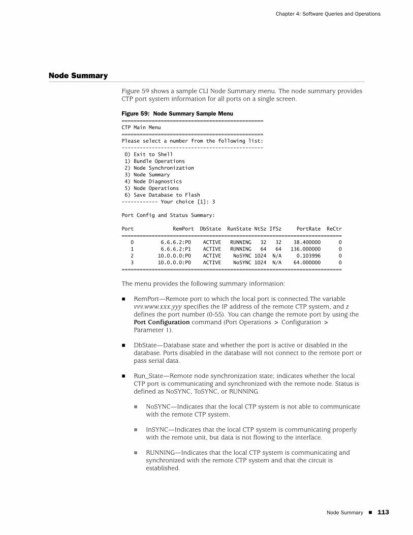
Node Summary 113
Chapter 4: Software Queries and Operations
Node Summary
Figure 59 shows a sample CLI Node Summary menu. The node summary provides CTP port system information for all ports on a single screen.
Figure 59: Node Summary Sample Menu===============================================CTP Main Menu ===============================================Please select a number from the following list:----------------------------------------------- 0) Exit to Shell 1) Bundle Operations 2) Node Synchronization 3) Node Summary 4) Node Diagnostics5) Node Operations6) Save Database to Flash------------ Your choice [1]: 3
Port Config and Status Summary:
Port RemPort DbState RunState NtSz IfSz PortRate ReCtr========================================================================= 0 6.6.6.2:P0 ACTIVE RUNNING 32 32 38.400000 0 1 6.6.6.2:P1 ACTIVE RUNNING 64 64 136.000000 0 2 10.0.0.0:P0 ACTIVE NoSYNC 1024 N/A 0.103996 0 3 10.0.0.0:P0 ACTIVE NoSYNC 1024 N/A 64.000000 0=========================================================================
The menu provides the following summary information:
RemPort—Remote port to which the local port is connected.The variable vvv.www.xxx.yyy specifies the IP address of the remote CTP system, and z defines the port number (0-55). You can change the remote port by using the Port Configuration command (Port Operations > Configuration > Parameter 1).
DbState—Database state and whether the port is active or disabled in the database. Ports disabled in the database will not connect to the remote port or pass serial data.
Run_State—Remote node synchronization state; indicates whether the local CTP port is communicating and synchronized with the remote node. Status is defined as NoSYNC, ToSYNC, or RUNNING.
NoSYNC—Indicates that the local CTP system is not able to communicate with the remote CTP system.
InSYNC—Indicates that the local CTP system is communicating properly with the remote unit, but data is not flowing to the interface.
RUNNING—Indicates that the local CTP system is communicating and synchronized with the remote CTP system and that the circuit is established.

CTP 5.2 Software Configuration Guide
114 Node Diagnostics
MisCfg—Indicates that there is a misconfiguration between the local and remote ports that prevent bringing up the circuit. Examples of misconfigurations are incorrectly configured IP addresses or ports, and mismatched speeds.
N/A—Not applicable; displayed when the port database state is disabled.
Cfg Fail—Indicates that the database configuration for the port cannot be supported. You will not typically encounter this state. If you do, delete and reinstall the port.
Too Slow—Encountered on a port when the port clock configured is TT ALL and either no clock is provided by the external device or the rate is different from the configured rate.
NtSz—Network-bound data packet size. You can modify the packet size by using the Packet Size Configuration command.
IfSz—Interface-bound data packet size. You can modify the packet size only at the remote CTP system.
PortRate—User-specified port speed in kilohertz. (For further details, see Port Speed on page 53 in Chapter 2, Software Configuration.)
ReCtr—Number of times the buffer has been recentered to the size specified in the port configuration.
Node Diagnostics
By using the Node Diagnostics menu, you can troubleshoot suspected problems with the CTP hardware or software configuration.
Run Diags on Card/Ports This parameter runs data path tests on each port (Figure 60) using the built-in BERT testers. The test will loop back data at both the serial and packet interfaces on all ports. In addition, the system tests signaling loopback on the serial interface. Ports will be disabled for the duration of the tests and then reactivated after the diagnostic is complete. The system reports results as pass or fail. A failed test may indicate a hardware problem.
Figure 60: Run Diagnostics on Card/Ports===============================================Diagnostics Menu ===============================================Please select a number from the following list:----------------------------------------------- 0) Back to Previous Menu 1) Run Diags on Card/Ports 2) Set Log Print Level: EVE 3) Show Node Log 4) Set Lab Mode: Disable------------ Your choice [0]: 1
****** This will cause a port data interruption

Node Diagnostics 115
Chapter 4: Software Queries and Operations
***Are you sure? y[n]: y
PLL Lock Test... Passed External Reference Test... Passed Port 0 Net-Bound Data Test... Passed
Port 0 I/F-Bound Data Test... PassedPort 0 I/F Signaling Test... PassedPort 1 Net-Bound Data Test... PassedPort 1 I/F-Bound Data Test... PassedPort 1 I/F Signaling Test... PassedPort 2 Net-Bound Data Test... PassedPort 2 I/F-Bound Data Test... PassedPort 2 I/F Signaling Test... PassedPort 3 Net-Bound Data Test... PassedPort 3 I/F-Bound Data Test... PassedPort 3 I/F Signaling Test... Passed
Set Log Print Level By selecting Set Log Print Level, you can set the level of stored node event messages that the CTP system logs. Figure 61 shows the Set Log Print Level menu. The settings range from most detailed (Level 1: debug) to least detailed (Level 8: fatal alarm):
DBG—debug
GEN—general
FNC—function entry
EVE—event
TMP—temporary; not a user setting; for system development only
MIN—minor alarm
MAJ—major alarm
FAT—fatal alarm
Figure 61: Set Log Print Level Menu===============================================Diagnostics Menu ===============================================Please select a number from the following list:----------------------------------------------- 0) Back to Previous Menu 1) Run Diags on Card/Ports 2) Set Log Print Level: EVE 3) Show Node Log 4) Set Lab Mode: Disable------------ Your choice [0]:2

CTP 5.2 Software Configuration Guide
116 Node Synchronization
Please select a number from the following list:----------------------------------------------- 0) OFF 1) DBG 2) GEN 3) FNC 4) EVE 5) TMP 6) MIN 7) MAJ 8) FAT------------ Your choice [4]:
Show Node LogBy selecting Show Node Log, you can review stored node event messages that the CTP system logs. The node prompts you to specify the number of most recent events to be reviewed and the number of events to be presented per page.
Set Lab Mode Set Lab Mode is not a user parameter; this parameter is for system development use only.
Node Synchronization
Query Sync StatusFigure 62 shows the Node Synchronization menu provided by the CLI, and Figure 63 shows the Node Synchronization Query window provided by CTPView. The Query Node Sync Status option (option 7 on the CLI menu) provides details of the current state of the node synchronization:
PLL Monitor Runtime—Time (in seconds) that the phase lock loop (PLL) has been monitored since the last restart of the CTP or reconfiguration of the CTP reference.
PLL Locked—Indicates whether the PLL is currently locked to a valid reference (YES) or whether no reference is available (NO).
PLL Loss Seconds—Indicates the number of seconds during the PLL monitor runtime that the PLL has not been locked.
Reference in Use:
Fixed/Calibrated—The CTP unit is not locked to a reference and has loaded and used the calibrated value (provides improved clock accuracy). Setting a calibrated value is discussed in Chapter 2, Software Configuration.
Center—The CTP unit is not locked to a reference, and the clock is based on the natural frequency of the internal oscillator.
Ref (0–4)—The CTP unit is currently using a reference defined in the configuration.

Node Synchronization 117
Chapter 4: Software Queries and Operations
Holdover—The CTP unit acquired a valid reference that was subsequently lost. The clock is biased to the reference until it is restored.
Reference Info:
Valid—Indicates whether the reference is valid for the configuration (Yes) or invalid (No)
PPM—Measured difference in parts per million from the current state of the clock and the reference.
Count—Progress (1–5) of the system’s assessment of the reference before its use.
Holdover Info
Valid—Indicates whether the reference is valid for holdover use.
Value—Numerical value between 1 and 4096 used to profile the reference for holdover if the reference is lost.
Count—Progress (1–5) of the system’s assessment of the reference before determining the holdover value.
Figure 62: Node Synchronization Status Menu===============================================Node Synchronization Menu===============================================Please select a number from the following list:----------------------------------------------- 0) Back to Previous Menu 1) 1st Priority, Reference 0: Disabled 2) 2nd Priority, Reference 1: Disabled 3) 3rd Priority, Reference 2: Disabled 4) 4th Priority, Reference 3: Disabled 5) 5th Priority, Reference 4: Disabled 6) 32 kHz Ref Output: NO 7) Query Node Sync Status 8) Measure Ref Inputs 9) Calibrate Node to Current Reference------------ Your choice [2]: 7 Node Synchronization Info=========================PLL Monitor Runtime: 1056PLL Locked: NOPLL Loss Seconds: 1056Reference in use: Fixed/Calibrated +--------------------+-------------------+ | Reference Info | HoldOver Info | +--------------------+-------------------+ Ref | Valid PPM Count | Valid Value Count |==== ===== ====== ===== ===== ===== ===== 0: ----- ------ ----- ----- ----- ----- 1: ----- ------ ----- ----- ----- ----- 2: ----- ------ ----- ----- ----- ----- 3: ----- ------ ----- ----- ----- ----- 4: ----- ------ ----- ----- ----- ----- Clear Counters? y[n]:

CTP 5.2 Software Configuration Guide
118 Node Synchronization
Figure 63: CTPView Node Synchronization Query Window
Overview 119
Chapter 5
Security Profile Menu
This chapter describes security profile options available on CTP systems through the command-line interface (CLI). The chapter contains the following sections:
Overview on page 119
User Management on page 120
Password Management on page 121
Secure Log Management on page 122
Login Banner on page 124
Overview
The Security Profile menu is available from the Node Operations menu to administrators who have the root password. The Security Profile menu provides the following functions:
User management
Adding or deleting user and administrator profiles
Displaying user and administrator profiles
Password management
Displaying and managing password expirations
Displaying and managing password requirements
Secure log management
Scanning and viewing the secure log
Following log entries
Copying logs to a remote host
Configuring and showing remote logging options

CTP 5.2 Software Configuration Guide
120 User Management
User Management
User management functions are provided by Option 1 from the Security Profile menu (Figure 64). The submenu allows the security administrator access to the following functions:
Users and administrators logged in to the CTP—Users are able to execute menu commands to query the status of the ports and clocking. Administrators can configure the CTP system, configure loops and BERTs, and query the status of the ports and clocking.
User and administrator accounts currently configured.
Option to add or delete user accounts.
Figure 64: User Administration Menu**************************************************************** Security Profile Menu V 1.0 ******** Host lab_top: Mon Apr 11 14:56:20 2005**** User root logged in from 10.0.1.27 as ctp_cmd**** **** **** All actions are logged **** **** ****************************************************************
Main Configuration Menu
Please choose a menu item from the following list:0) Exit Security Profile Menu1) User Management2) Password Management3) Secure Log Management4) Change login banner
Please input your choice [1]:
**************************************************************** Profile Menu V 1.0 ******** Host lab_top: Mon Apr 11 14:56:42 2005**** User root logged in from 10.0.1.27 as ctp_cmd**** **** **** All actions are logged **** **** ****************************************************************
User Management Menu
Please choose a menu item from the following list:0) Return to main menu1) List users currently logged on2) List user & admin accounts3) Add user or admin accounts4) Delete user or admin account
Please input your choice [1]:
NOTE: When a user password need to be changed, you must follow the procedure described in Changing a User Password on page 122. All users are required to change their password at their initial login and at subsequent intervals of between 1 to 90 days, depending on how their account is configured.
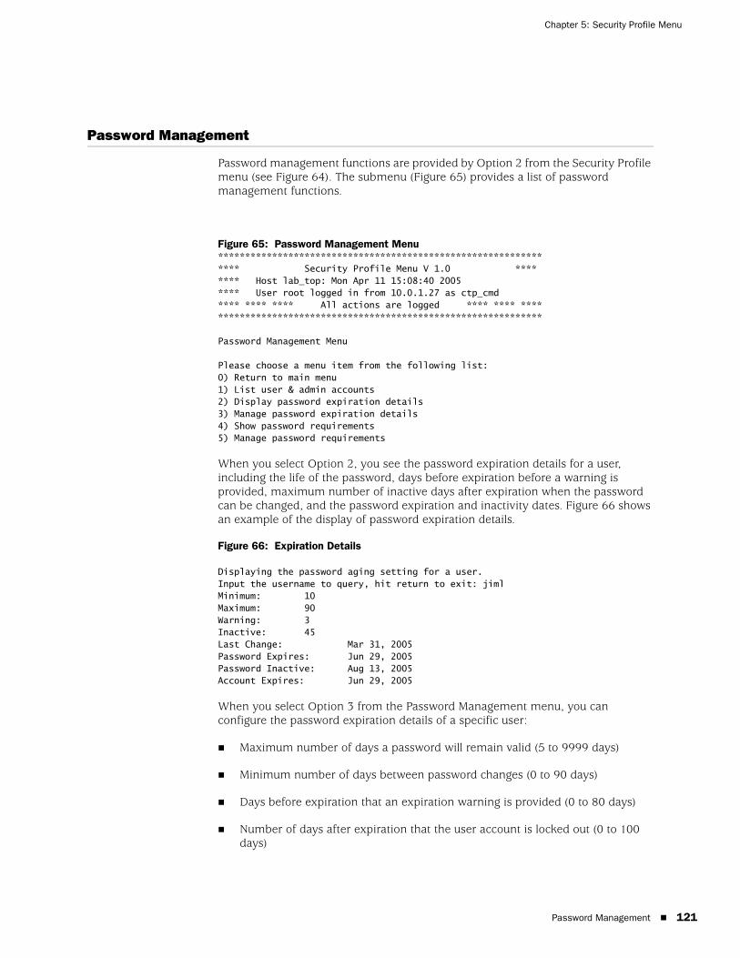
Password Management 121
Chapter 5: Security Profile Menu
Password Management
Password management functions are provided by Option 2 from the Security Profile menu (see Figure 64). The submenu (Figure 65) provides a list of password management functions.
Figure 65: Password Management Menu**************************************************************** Security Profile Menu V 1.0 ******** Host lab_top: Mon Apr 11 15:08:40 2005**** User root logged in from 10.0.1.27 as ctp_cmd**** **** **** All actions are logged **** **** ****************************************************************
Password Management Menu
Please choose a menu item from the following list:0) Return to main menu1) List user & admin accounts2) Display password expiration details3) Manage password expiration details4) Show password requirements5) Manage password requirements
When you select Option 2, you see the password expiration details for a user, including the life of the password, days before expiration before a warning is provided, maximum number of inactive days after expiration when the password can be changed, and the password expiration and inactivity dates. Figure 66 shows an example of the display of password expiration details.
Figure 66: Expiration Details
Displaying the password aging setting for a user.Input the username to query, hit return to exit: jimlMinimum: 10Maximum: 90Warning: 3Inactive: 45Last Change: Mar 31, 2005Password Expires: Jun 29, 2005Password Inactive: Aug 13, 2005Account Expires: Jun 29, 2005
When you select Option 3 from the Password Management menu, you can configure the password expiration details of a specific user:
Maximum number of days a password will remain valid (5 to 9999 days)
Minimum number of days between password changes (0 to 90 days)
Days before expiration that an expiration warning is provided (0 to 80 days)
Number of days after expiration that the user account is locked out (0 to 100 days)

CTP 5.2 Software Configuration Guide
122 Secure Log Management
When you select Options 4 and 5 from the Password Management menu, you can view and configure password requirements. The configurable password requirements are as follows:
Password length (0 to 20 characters)—No restriction is enforced if you enter 0.
Minimum number of lowercase characters (0 to 6)—No restriction is enforced if you enter 0.
Minimum number of uppercase characters (0 to 5)—No restriction is enforced if you enter 0.
Minimum number of numerals (0 to 4)—No restriction is enforced if you enter 0.
Minimum number of other characters (nonalphanumeric; 0 to 3)—No restriction is enforced if you enter 0.
Changing a User PasswordA speical procedure is required to change a user's password because the CTP OS is installed on a flash drive that normally operates in a read-only state. The flash drive must be made writable during the user account password modification process. Only the root user is allowed to make the flash drive writable. See Appendix B, CTPView Troubleshooting and Recovery for details.
These steps must occur to change a user's password:
1. The root user makes the flash drive writable by entering mfw at the CLI.
2. The user logins to the CTP, following the prompts to select a new password.
3. When the user has successfully changed his password, the root user makes the flash drive read-only by entering mfr at the CLI.
Secure Log Management
The secure log provides an audit trail of user and administrator activity on the CTP system. Figure 67 shows the Secure Log Management submenu, which you access from the CLI Security Profile menu>Option 3. You can view the log by selecting Option 1—Scan/view log entries. Use the Page Up and Page Down keys to move through the log; press q to exit the log view. You can view the secure log in real time when you select Option 2—Follow log entries. Enter ^c to terminate the real-time view and return to the submenu.
Options 3 and 4 allow you to copy the secure logs to a remote host or to configure a host for remote logging. Option 5 shows the remote logging configuration.
NOTE: For users who employ the utility SecureCRT to ssh into the CTP, the Authentication method on SecureCRT must be changed from the default setting of Password to Keyboard Interactive. Not doing this prevents the password prompts originating at the CTP from reaching your display and the password update procedure fails.

Secure Log Management 123
Chapter 5: Security Profile Menu
Figure 67: Secure Log Management Submenu
Please choose a menu item from the following list:0) Return to main menu1) Scan/view log entries2) Follow log entries3) Copy logs to remote host4) Configure remote logging options5) Show remote logging configuration
Please input your choice [1]:

CTP 5.2 Software Configuration Guide
124 Login Banner
Login Banner
You can configure the login banner by selecting Option 4—Change login banner— which you access from the CLI Security Profile menu. The banner can have multiple lines, up to 80 characters. The input is complete when you enter a blank line. Figure 68 shows an example of changing the login banner.
Figure 68: Login Banner
Main Configuration Menu
Please choose a menu item from the following list:0) Exit to shell1) User Management2) Password Management3) Secure Log Management4) Change login banner
Please input your choice [1]: 4In order to input a banner message to be displayed to users before theylog in, you will be asked to input alphanumeric text at the keyboard.
Would you like to continue? [n] yInput your text, 80 characters to a line. Enter a blank line when you are finished.CTP Security BannerLab Test Unit
125
Part 2
CTPView Server Installation and Configuration

CTP 5.2 Software Configuration Guide
126
Overview 127
Chapter 6
Installing the Software and Configuring Security Settings
The chapter describes how to install, manage, and configure CTPView and configure security features. The chapter contains the following sections:
Overview on page 127
Schemes 1 and 3—Installing or Upgrading the CTPView Server Operating System on page 129
Scheme 2—Upgrade CTPView Software Only on page 132
Scheme 4—Configuring Administrative Settings on page 134
Overview
All existing CTPView servers can upgrade to this CTPView release. However, your upgrade procedure will differ depending on your existing operating system (OS). This release of CTPView is compatible with CTPOS versions 5.2 and earlier.
CTPView version 2.2R2 introduced a new security-enhanced user login interface. To upgrade to the current release, your CTPView server must be running either Fedora Core 4 (FC4) OS or Fedora 9 (FC9) OS. Additionally, enabling all of the security updates requires that certain server settings be configured by an administrator as part of the installation process.
If the CTPView server you have is a Dell PowerEdge server, it was delivered with FC4 or FC9 OS already installed. Delivery of FC4 units started in November 2006 and delivery of FC9 units started in September 2008. Servers shipped before November 2006 were built with FC1 OS installed.)
See Figure 69 on page 128 to determine which scheme you should follow to get your server ready for use.

CTP 5.2 Software Configuration Guide
128 Overview
Figure 69: CTPView Server Configuration Flowchart
Scheme 1—Install FC9 OS and CTPView SoftwareThis procedure can be used for any system. The new installation of the operating system reformats the server hard drives and deletes all existing data and settings. The advantage to this method is that your server is left in a stable known state, with all of the security-related features enabled. The main steps are:
1. Saving existing server configuration and data.
2. Performing a new installation of FC9 OS.
3. Installing the current CTPView software.
4. Restoring the saved server configuration and data.
Scheme 2—Upgrade CTPView Software Only This option is only for servers already running FC4 or FC9 OS.
�� ��
��� ���
��������� ����������������������������������������� ��!���"�!�����������������������#���������������������$�%����� �������������$&
'�����������!���#���"���(������)
�����*���
���������+������������������#���������������������$
'�����������������������,�������+�������)
���������-������������������ ��!���"�!����������������������#���������������������$
Schemes 1 and 3—Installing or Upgrading the CTPView Server Operating System 129
Chapter 6: Installing the Software and Configuring Security Settings
Scheme 3—Upgrade to FC9 OS and CTPView SoftwareThis option can be used for any system. The steps are similar to Scheme 1, but the hard drive is not reformatted. The main steps are:
1. Saving existing server configuration and data.
2. Upgrading the existing OS to FC9.
3. Installing the current CTPView software.
Only if there is a loss of data or a configuration error will you need to restore the saved configuration and data.
Scheme 4—Configure Administrative Settings OnlyThis option is for new Dell servers that are delivered with CTPView version 3.2R1 or later software already installed.
Schemes 1 and 3—Installing or Upgrading the CTPView Server Operating System
Use the guidelines in the following sections for Schemes 1 and 3.
RequirementsCTPView server built according to Juniper Networks specifications
CTPView Management System for Fedora 9 CDs for the current software version (disks 1–3)
Monitor, keyboard, and mouse connected to server
Ethernet connection to the network
External storage device for saving the current CTPView data and settings
For FC1 servers, you must upgrade the CTPView software to at least version 2.1R2 if you want to back up your existing configuration and data before upgrading the server operating system. The upgrade is necessary to utilize the backup utility described in the next step.
The last released version of software that supports FC1 servers is 2.1R3. Install the required CTPView software before proceeding, and follow the separate installation instructions appropriate to the release version you will be installing.
If you are upgrading the CTPView software from a version earlier than 2.0.4R1, after upgrading you may need to update the server ethernet settings. Use the CLI menu: System Configuration>Display Current Configuration. Make any required modifications from within the CLI menu.
CTP 5.2 Software Configuration Guide
130 Schemes 1 and 3—Installing or Upgrading the CTPView Server Operating System
Saving Current Data and Settings to External Storage Device
Using the CTPView Data Backup UtilityRun the CTPView data backup utility from the CLI menu: Backup Functions>Save Current Settings and Data. The utility works for all systems.
The remote storage device can use any operating system; however, the backup utility function will automatically transfer the backup file only to a remote Unix-like system. A network path needs to exist between the upgrading server and the remote storage device being used for storing the backup file. If your remote storage computer is not running a Unix-like operating system, you will need to transfer the file with a copy utility compatible with that operating system.
Before running the backup utility, the hard drive on the upgrading server must have at least 25% free space. You can view the server's current usage from within CTPView. Go to the Server Diagnostics pane, and look in the Mounted Filesystems section.
You can create additional free space on the hard drive by deleting old data files. There is an automatic CTPView function for this. In the CTPView navigation pane, click Server>Administration. the Administrative Functions pane appears. Click Automatic Functions. There are three options to choose from: older than 6, 9, or 12 months. If the amount of free space on the hard drive is less than 25% when the backup utility is run, the utility will prompt you to delete more old data files before continuing.
Using Server SynchronizationEnsure that there has been a recent data synchronization. Use the Manual Synchronization function if an update is necessary. From the Administrative Functions window, click Server Synchronization. The button to start the processes is in the Server Synchronization pane of the primary server. The server synchronization works only with two or more CTPView servers.
After the synchronization is complete, be sure to isolate the server being upgraded from the synchronization function of other CTPView servers. From the Server Synchronization pane of the server to be upgraded, set the Server Type to Primary Server.
Note that some functions in the Server Synchronization pane are not available if you are accessing the pane by means of a management console. You must connect to the CTPView server using the Ethernet connection to be able to interact with the utility.
Installing or Upgrading Operating SystemsWorking from the monitor and keyboard connected to the upgrading server, insert the CTPView Management System for Fedora 9 CD #1 into the CD-ROM drive. Reboot the server by using the CLI: System Configuration>Reboot System.
The boot process stops at the Juniper CTPView Management System window. You have the choice here either to install a new instance of Fedora 9 or to only upgrade the existing operating system to Fedora 9. A new installation will reformat the hard drives and give you a conforming instance of the operating system.

Schemes 1 and 3—Installing or Upgrading the CTPView Server Operating System 131
Chapter 6: Installing the Software and Configuring Security Settings
At the bottom of the screen type either ctpview-install or ctpview-upgrade at the prompt for boot, and then press Enter.
The operating system update begins. On some early hardware systems a RAMDISK error may be reported at the beginning of the upgrade process. If this occurs, you must reboot the system using the power switch, leaving disk #1 in the CD-ROM drive. After the hard restart, at the “boot:” prompt type mediacheck, and then press Enter. The response will be “Could not find kernel image: mediacheck”; the “boot:” prompt will be reprinted. Now retype ctpview-install or ctpview-upgrade, and press Enter. The upgrade process should proceed normally.
When the upgrade process is complete, remove the last CD from the CD-ROM drive.
Restoring Configuration Settings and Data This step is required if you installed a new instance of the FC9 OS. If the existing operating system was only upgraded, this step is necessary only in the unlikely event of data loss.
Using the CTPView Restore UtilityOn the upgraded server, use the CTPView restore utility from the CLI menu by choosing Backup Functions>Restore Settings and Data. The utility works for all systems.
Before starting the restore utility, place the file that contains the data backup in the /var/www/html/acorn/data directory of the upgraded server.
The filename will be in this format: ctpview_data_<hostname>_<date>.tgz
Using Server SynchronizationThe server synchronization works only with two or more CTPView servers. On the upgraded server, go to the Server Synchronization pane, and verify that the server is not listed or its Server Type is set as Not Selected.
On the CTPView server with the intact data (the primary server), go to the Server Synchronization pane. Set the upgraded server as Server Type Secondary Server, the primary server as type Primary Server, and any other listed server as type Not Selected.
Click Manually Synchronize Network. A new window opens. In the new window, click Select All Hosts, and then click Synchronize Servers.
After the synchronization program finishes, restore the Server Type selections for all servers to the values normally used for your network.
Review the Installation Log for ErrorsFrom the command prompt, open the file /var/log/ctpview_autoinstall.log. This file has the log of all CTPView installations and upgrades beginning with version 2.1R1.
NOTE: Using the CTPView Management System CDs automatically installs the CTPView software on the system.
CTP 5.2 Software Configuration Guide
132 Scheme 2—Upgrade CTPView Software Only
Find the beginning of the latest upgrade. There should be no unresolved errors reported.
Administrative Configuration ModificationsFollow the steps detailed in the section Scheme 4—Configuring Administrative Settings on page 134 to complete the setup of the server and ensure that the new security enhancements are properly set.
After completing that section return to this point and continue with the next step.
Verifying That the Operating Stem Was Successfully UpgradedTo verify whether the upgrade has been successful:
1. In CTPview, go to the Server Diagnostics pane.
2. In the System Vital section, verify the following information:
Kernel Version: 2.6.25-14.fc9.i686
Distribution Name: Fedora release 9 (Sulphur)
The system information above can also be found in the heading on the CLI menu pages.
Validating the System ConfigurationFrom the Server Diagnostics pane, click Validate Server Configuration. All items should be set to default values. For any highlighted items, follow the supplied directions to correct the problem.
Scheme 2—Upgrade CTPView Software Only
For a successful installation, please follow the directions carefully. You can download updates from the CTP Support site at
https://www.juniper.net/customers/csc/software/ctp/
To install new software, you need the:
Root account password
Operating system version (FC1, FC4, or FC9)
CTPView software version that is currently running on your system
To find this information:
NOTE: Upgrading from a pre-2.2 version of CTPView to the current software does not change the existing server passwords or accounts except to add the user account “juniper”. However, all the existing pre-2.2 CTPView user accounts are removed. Browser access to the CTPView is through a new login interface, which requires that an administrator create new usernames and passwords.

Scheme 2—Upgrade CTPView Software Only 133
Chapter 6: Installing the Software and Configuring Security Settings
1. Log in to the server CLI and type the command uname -r. If the output starts with:
2.4, the operating system is FC1.
2.6.11, 2.6.16, or 2.6.17, the operating system is FC4.
2.6.25, the operating system is FC9.
2. To locate the current software version, open CTPView, and look in the header section of the page under the time.
For Systems with FC1Because this release is supported only by FC4 or FC9 systems, you will need to follow the steps described in “Schemes 1 and 3—Installing or Upgrading the CTPView Server Operating System” on page 129.
For Systems with FC4 Running CTPView 2.2R1 or EarlierFollow these steps:
1. Copy the archive file labeled “.._complete_..” to the /tmp directory on the server. The file name is in the format
ctpview_fc4_complete_<version>_<date>.tgz
2. Extract the archive by typing tar -xzvf <filename>.
3. Run the installation script by typing the command /tmp/upgrade while logged in as root.
4. Complete the steps in the section Scheme 4—Configuring Administrative Settings on page 134 to complete the setup of the server and ensure that the new security enhancements are properly set.
5. To validate the system configuration, in CTPView click Server>Server Diagnostics, and then click Validate Server Configuration.
For Systems with FC4 Running CTPView 2.2R2 or LaterFollow these steps:
1. Copy the archive file labeled web to the /tmp directory on the server. The file name is in the format
web_fc4_<version>_<date>.tgz
2. Run the installation script by typing the command upgrade while logged in as root.

CTP 5.2 Software Configuration Guide
134 Scheme 4—Configuring Administrative Settings
3. To validate the system configuration, in CTPView click Server>Server Diagnostics, and then click Validate Server Configuration.
For Systems with FC9 Running CTPView 3.2R1Follow these steps:
1. Copy the archive file labeled web to the /tmp directory on the server. The file name is in the format
web_fc9_<version>_<date>.tgz
2. Run the installation script by typing the command upgrade while logged in as root.
3. To validate the system configuration, in CTPView click Server>Server Diagnostics, and then click Validate Server Configuration
Scheme 4—Configuring Administrative Settings
If you have received a new Dell PowerEdge CTPView server or have upgraded your existing server, you must perform some additional configuration before using the system. To initialize the server for first use, complete the following tasks:
Rack-Mounting the CTPView Server on page 135
Connecting a Management Console on page 135
Connecting an Ethernet Cable on page 135
Powering On the CTPView Server on page 135
Changing the BIOS Menu Password on page 135
Changing the Server's Default User Account Password on page 136
Changing the Server's Root Account Password on page 136
Changing the GRUB Boot Loader Password on page 136
Changing the MySQL Apache Account Password on page 137
Changing the MySQL Root Account Password on page 137
Configuring the Network Access on page 137
Creating a Self-Signed Web Certificate on page 138
NOTE: Upgrading from a pre-2.2 version of CTPView to the current software does not change the existing server CLI passwords or accounts except to add the user account juniper. However, all the existing pre-2.2 CTPView browser user accounts are removed. Browser access to the CTPView is through a new login interface, which requires that an administrator create new usernames and passwords.

Scheme 4—Configuring Administrative Settings 135
Chapter 6: Installing the Software and Configuring Security Settings
Updating the CTPView Software on page 138
Logging In with a Browser on page 138
Changing the CTPView Default User Account Password on page 138
Creating a New Global_Admin Account on page 139
For information about which procedure to use to upgrade the software or operating system for a working CTPView server, see Figure 69 on page 128.
Rack-Mounting the CTPView ServerFollow the steps in the Rack Installation Guide, which came packed with your CTPView Server to install the server in a rack.
Connecting a Management ConsoleConnect a monitor and keyboard to the appropriate ports on the server. You may also connect a mouse or make a connection using a HyperTerminal utility on another device. The server's serial COM1 port connection is configured with these settings:
Speed—9600 bps
Data bits—8
Parity—none
Stop bits—1
Connecting an Ethernet CableInsert an Ethernet cable (RJ-45) connector into the 10/100Base-T (RJ-45) port labeled 1 until it clicks into place. Connect the other end of the cable to the appropriate Ethernet network.
Powering On the CTPView ServerVerify that the power source is operational and turned on. Inspect all grounding and power connections to the server chassis. Confirm that all connections are secure. Switch the power switch to ON, and monitor the LEDs on the front panel to verify that the system is booting properly.
Changing the BIOS Menu PasswordFor security purposes, change the default password for BIOS menu access. There is no username associated with this account.
During the boot process, while the Dell logo is displayed on the monitor, press F2. The boot process continues, displaying several messages on the screen. Wait until the process pauses and displays “Enter Setup Password.” Enter the default password to continue. See Appendix C, Default CTPView Accounts and Passwords.

CTP 5.2 Software Configuration Guide
136 Scheme 4—Configuring Administrative Settings
When you have gained access to the BIOS menu, highlight the line System Security, and press Enter. Highlight the line Setup Password. (Make sure that you have not selected System Password.) Press Enter, and type your new BIOS password. Press Enter, and then reenter your new password. Press Enter to continue.
Press the Esc key. In the pop-up window highlight the line Save Changes and Exit, and press Enter. The system will now restart.
Changing the Server's Default User Account PasswordFor security purposes, change the default password for the server's default user account.
Using the management console, log in as the default user. For the default account username and password, see Appendix C, Default CTPView Accounts and Passwords. Note that logging in using the root account is not allowed.
After successfully logging in as the default user, type passwd at the command line prompt. You will be prompted to select a new password. Alternatively, you may choose to delete the default user account at the conclusion of this configuration process.
Changing the Server's Root Account PasswordFor security purposes, change the default password for the server's root user account.
After logging in as a non-root user, switch to the root user account. For the default root account password, see Appendix C, Default CTPView Accounts and Passwords. At the command prompt type su - and then enter the password when prompted.
After successfully logging in as the root user, type passwd at the command line prompt. You will be prompted to select a new password.
Changing the GRUB Boot Loader PasswordFor security purposes, change the default password for the GRUB Boot Loader menu.
NOTE: Good security practice requires that the BIOS menu password be changed at least yearly or upon administrator reassignment.
CAUTION: Do not delete the default user account until after you have created another user account. Otherwise, you will not be able to log in to the server.
NOTE: Good security practice requires that the root account password be changed at least yearly or on administrator reassignment.

Scheme 4—Configuring Administrative Settings 137
Chapter 6: Installing the Software and Configuring Security Settings
Using the management console, log in as the default user, and then switch to the root user account. At the command prompt type menu. The CTPView Configuration Menu utility will open. Make a note of the CTPView version number displayed in the heading. You will need it later when checking for upgrades.
Select Option 8 (GRUB Functions). Then select Option 1 (Change GRUB password), and follow the prompts.
Changing the MySQL Apache Account PasswordFor security purposes, change the default password for the MySQL server Apache user account.
Using the management console, log in as the default user, and then switch to the root user account. At the command prompt type menu. The CTPView Configuration Menu utility will open.
Select Option 6 (MySQL Functions). Then select Option 2 (Change MySQL Apache password), and follow the prompts.
Changing the MySQL Root Account PasswordFor security purposes, change the default password for the MySQL server Root user account.
While in the main screen of the menu utility, select Option 6 (MySQL Functions). Then select Option 1 (Change MySQL Root password), and follow the prompts.
Configuring the Network AccessWhile in the main screen of the menu utility, select Option 2 (System Configuration). Answer y to continue. Select Option 1 (Display Current Configuration). Use Options 2 through 5 to configure the server to operate on your network. Exit the submenu to implement your changes.
NOTE: Good security practice requires that the GRUB Boot Loader password be changed at least yearly or on administrator reassignment.
NOTE: Good security practice requires that the MySQL Apache password be changed at least yearly or on administrator reassignment.
NOTE: Good security practice requires that the MySQL root password be changed at least yearly or on administrator reassignment.
CTP 5.2 Software Configuration Guide
138 Scheme 4—Configuring Administrative Settings
Creating a Self-Signed Web CertificateWhile in the main screen of the menu utility, select Option 4 (Advanced Functions). Then select Option 4 (Reset CTPView Self-Signed Certificate). Answer the list of questions that will be displayed. When asked for the Common Name, enter the IP address of the server. Otherwise, at login your users’ browsers will report a domain name mismatch when users connect to the server. In any event, the browser connection will be successfully completed.
Updating the CTPView SoftwareFrom a computer with access to the Web, use a browser to connect with the Juniper CTP Support site at
https://www.juniper.net/customers/csc/software/ctp/
You need your Juniper support username and password to access this site. If an update to the CTPView software is available, download the new archive along with the release notes. Your current CTPView version is listed in the header of the CLI menu utility.
After reviewing the release notes, see Scheme 2—Upgrade CTPView Software Only on page 132 to install a newer version of the CTPView software on the server. Then return to this point, and continue with the remaining steps below.
Logging In with a BrowserIn the address bar of a browser enter the address
https://<your server IP address>
Your browser then issues a warning that the security certificate presented by the website was not issued by a trusted certificate authority. Make the selection to accept the certificate, and continue.
The CTPView login page will load. Log in as the default CTPView user. For the default account username and password, see Appendix C, Default CTPView Accounts and Passwords.
Changing the CTPView Default User Account PasswordFor security purposes, change the default password for the CTPView default user account.
Click Edit My Account. Enter the new password. For help in determining acceptable passwords, click Password Help. Return to the login screen by clicking Return to Login Page.

Scheme 4—Configuring Administrative Settings 139
Chapter 6: Installing the Software and Configuring Security Settings
Creating a New Global_Admin AccountThe new security-enhanced CTPView interface introduced with version 2.2R2 allows only one active session per username. If a second user were to attempt to log in using the same username in an active session, both clients’ IP addresses and the username would be locked out from access for a preset lockout period. It is therefore imperative that each user have his or her own account and that the default user account not be used for normal access.
After logging into CTPView using the Juniper Networks user account, click Admin Center.
Add a new user account for yourself. Make sure that the user level is set to Global_Admin in order to access the CTPView User Administration Center.
After creating a new Global_Admin user account, log out of CTPView. Then log in using your new user account.

CTP 5.2 Software Configuration Guide
140 Scheme 4—Configuring Administrative Settings

CTPView Server Functions 141
Part 3
CTPView Server Functions

CTP 5.2 Software Configuration Guide
142 CTPView Server Functions
Overview 143
Chapter 7
CTPView Administration Center
The chapter describes the CTPView Administration Center. It contains the following sections:
Overview on page 143
Accessing the Admin Center on page 144
Navigating Within the Admin Center on page 144
Setting Global CTPView Access on page 144
Admin Center Option Descriptions on page 144
Overview
CTPView version 2.2R2 introduced a new security-enhanced login interface. There are now three user levels:
Net_View—Users belonging to this class are restricted to query-only access to CTP systems. This class was previously referred to as query-only.
Net_Admin—Members of this user level are able to configure CTP systems; however, they do not have the ability to create or modify CTPView user accounts. This class was previously referred to as administrators.
Global_Admin—This is a new user class. These users have all the privileges of the Net_Admin class. They are also able to create and modify user accounts.
Net_View and Net_Admin users will see a few new features. The significant ones are a new login dialog, a browser interface to change their own password, the ability to log out of CTPView, and more secure password requirements. These changes do not affect the appearance or functionality of the CTPView query or provisioning interface that previous users are accustomed to.
Each CTPView user has a profile that describes his or her privileges and restrictions, referred to here as user properties. For convenience, users are assigned to user groups. These groups have a set of default user properties that are transferred to new users; however, Global_Admin users can modify any of the user properties on a per-user basis.
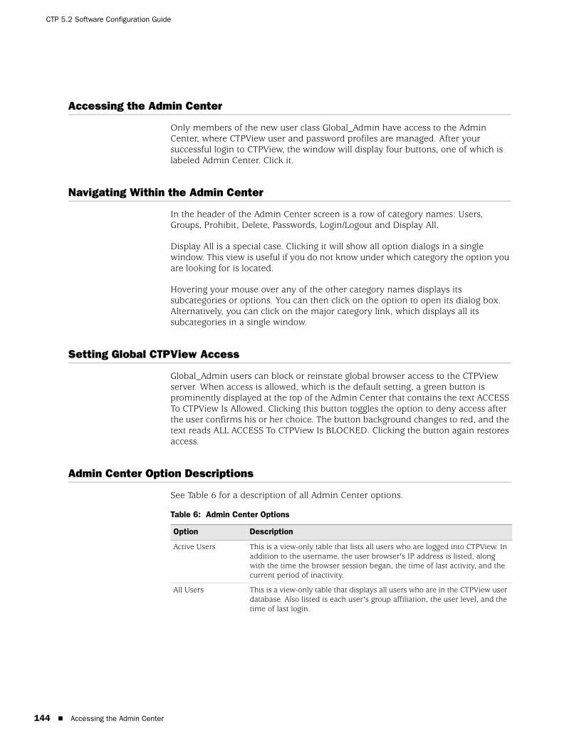
CTP 5.2 Software Configuration Guide
144 Accessing the Admin Center
Accessing the Admin Center
Only members of the new user class Global_Admin have access to the Admin Center, where CTPView user and password profiles are managed. After your successful login to CTPView, the window will display four buttons, one of which is labeled Admin Center. Click it.
Navigating Within the Admin Center
In the header of the Admin Center screen is a row of category names: Users, Groups, Prohibit, Delete, Passwords, Login/Logout and Display All.
Display All is a special case. Clicking it will show all option dialogs in a single window. This view is useful if you do not know under which category the option you are looking for is located.
Hovering your mouse over any of the other category names displays its subcategories or options. You can then click on the option to open its dialog box. Alternatively, you can click on the major category link, which displays all its subcategories in a single window.
Setting Global CTPView Access
Global_Admin users can block or reinstate global browser access to the CTPView server. When access is allowed, which is the default setting, a green button is prominently displayed at the top of the Admin Center that contains the text ACCESS To CTPView Is Allowed. Clicking this button toggles the option to deny access after the user confirms his or her choice. The button background changes to red, and the text reads ALL ACCESS To CTPView Is BLOCKED. Clicking the button again restores access.
Admin Center Option Descriptions
See Table 6 for a description of all Admin Center options.
Table 6: Admin Center Options
Option Description
Active Users This is a view-only table that lists all users who are logged into CTPView. In addition to the username, the user browser's IP address is listed, along with the time the browser session began, the time of last activity, and the current period of inactivity.
All Users This is a view-only table that displays all users who are in the CTPView user database. Also listed is each user's group affiliation, the user level, and the time of last login.
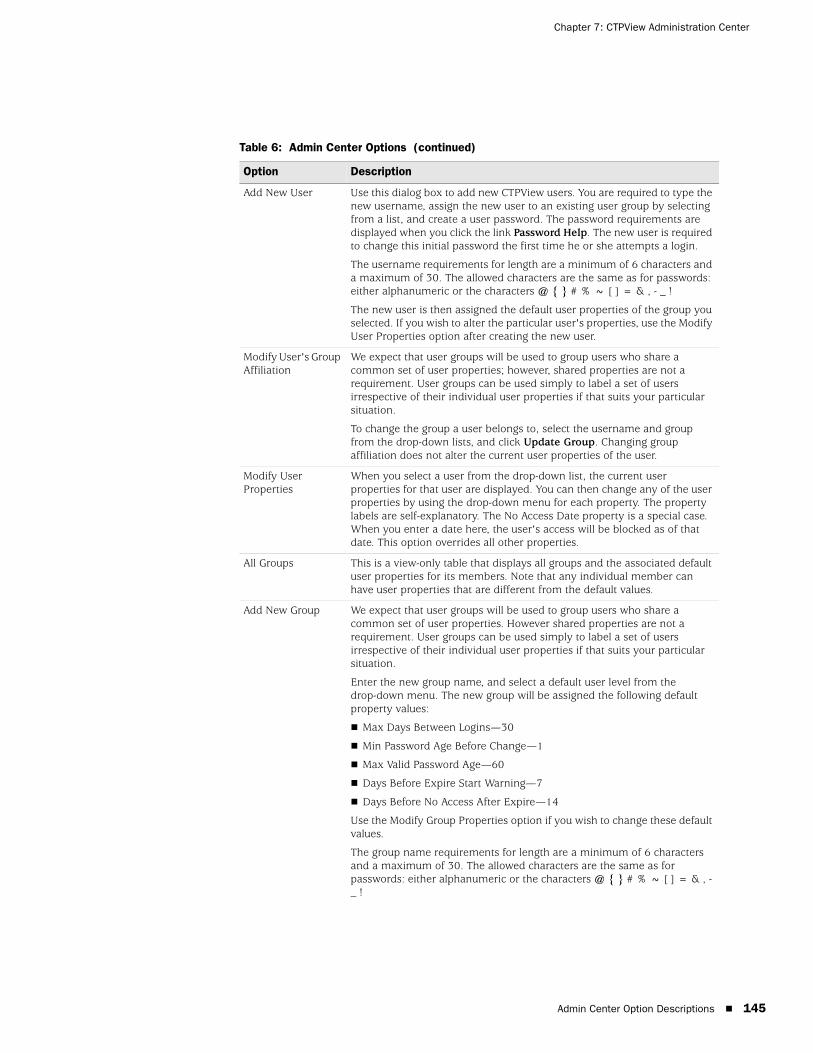
Admin Center Option Descriptions 145
Chapter 7: CTPView Administration Center
Add New User Use this dialog box to add new CTPView users. You are required to type the new username, assign the new user to an existing user group by selecting from a list, and create a user password. The password requirements are displayed when you click the link Password Help. The new user is required to change this initial password the first time he or she attempts a login.
The username requirements for length are a minimum of 6 characters and a maximum of 30. The allowed characters are the same as for passwords: either alphanumeric or the characters @ { } # % ~ [ ] = & , - _ !
The new user is then assigned the default user properties of the group you selected. If you wish to alter the particular user's properties, use the Modify User Properties option after creating the new user.
Modify User's Group Affiliation
We expect that user groups will be used to group users who share a common set of user properties; however, shared properties are not a requirement. User groups can be used simply to label a set of users irrespective of their individual user properties if that suits your particular situation.
To change the group a user belongs to, select the username and group from the drop-down lists, and click Update Group. Changing group affiliation does not alter the current user properties of the user.
Modify User Properties
When you select a user from the drop-down list, the current user properties for that user are displayed. You can then change any of the user properties by using the drop-down menu for each property. The property labels are self-explanatory. The No Access Date property is a special case. When you enter a date here, the user's access will be blocked as of that date. This option overrides all other properties.
All Groups This is a view-only table that displays all groups and the associated default user properties for its members. Note that any individual member can have user properties that are different from the default values.
Add New Group We expect that user groups will be used to group users who share a common set of user properties. However shared properties are not a requirement. User groups can be used simply to label a set of users irrespective of their individual user properties if that suits your particular situation.
Enter the new group name, and select a default user level from the drop-down menu. The new group will be assigned the following default property values:
Max Days Between Logins—30
Min Password Age Before Change—1
Max Valid Password Age—60
Days Before Expire Start Warning—7
Days Before No Access After Expire—14
Use the Modify Group Properties option if you wish to change these default values.
The group name requirements for length are a minimum of 6 characters and a maximum of 30. The allowed characters are the same as for passwords: either alphanumeric or the characters @ { } # % ~ [ ] = & , - _ !
Table 6: Admin Center Options (continued)
Option Description

CTP 5.2 Software Configuration Guide
146 Admin Center Option Descriptions
Modify Group Properties
When you select a group name from the drop-down list, the current default user properties for that group are displayed. You can then change any of the user properties by using the drop-down menu for each property. The property labels are self-explanatory. The No Access Date property is a special case. When you enter a date here, the user's access will be blocked as of that date. This option overrides all other properties.
Changes made to the group default user properties will not affect current members of the group unless you select Update current members before clicking Update Group Properties.
Current Prohibited Users
This is a view-only table that displays all users who have been manually added to this category. For each member of this list, the followng information is also displayed: the time added to this category, by whom, and the last time CTPView was accessed.
Designate Prohibited User
Individual users can be blocked from accessing CTPView for an indefinite period. Select the user from the drop-down menu, and click Add Prohibited User.
Reinstate Prohibited User
Select the user from the drop-down menu, and click Reinstate Prohibited User. The user will be removed from the prohibited list. However, if the user is excluded from access to CTPView due to some other cause, such as an expired password, those restrictions are still in effect.
Delete Prohibited User
Delete a user on the prohibited list from the CTPView user database.
Delete User Delete a user from the CTPView user database. If the user is on the Prohibited User or the Inactive User List, the username will not appear here. To remove those users, go to the delete option for those categories.
Delete Inactive User Delete a user on the Inactive list from the CTPView user database.
Delete Group Delete a user group and all of its members. If the group has members, you will be asked to confirm your desire to delete all the users belonging to the group before the request is executed.
Re-Use Password Limit
When a user changes a password, he or she is prohibited from reusing a password before using a certain number of new passwords. This option sets the number of new passwords that must be used before a reused password is allowed.
Excluded Passwords The administrator can create a list of passwords that are not allowed. Use this option to add or remove words from the excluded list.
Modify Password Requirements
The required password properties can be modified here. Parameters that can be specified are minimum length, maximum length, minimum number of lowercase letters, minimum number of uppercase letters, minimum number of digits, and minimum number of other characters. Changes do not affect existing passwords.
Logout Users Any active user, including oneself, can be logged off the system.
Auto Logout This option sets the allowed period of inactivity of a logged-in user after which time the user will be logged out automatically.
Lockout Period When a user exceeds the allowed failed login attempts or tries to open multiple CTPView sessions from unique IP addresses, the user will be locked out of accessing CTPView for the lockout period. This option sets the lockout period.
Login Limit This option sets the number of allowed failed login attempts before a user is locked out. The user lockout is effective for the lockout period.
Table 6: Admin Center Options (continued)
Option Description
Admin Center Option Descriptions 147
Chapter 7: CTPView Administration Center
Clear Counters Two counters are associated with each user. One counter is the number of failed login attempts. This counter is automatically reset to zero after a successful login. The other counter is the number of reminders that a user receives to change his or her password. This counter is automatically reset after the user has selected a new password.
If a counter exceeds the allowed limit, the user is locked out of CTPView access. Use this option to restore access by manually resetting the counters to zero.
UnLock IP When a user attempts to access CTPView with a currently active username from a second IP address, the username and both IP addresses are locked out for the lockout period. You can remove the IP addresses from the list.
IP Access Filter The IP address of the user's browser can filter access to CTPView. The default setting is to allow access from any IP address.
Defining a new filter is a two-step process
1. Specify an IP address or range of IP addresses.
2. Choose whether to allow or deny the specified address or range.
You can define multiple filters, In case of conflict, a rule to deny will override one that allows an IP address.
With this option, you can also remove filters from the set of rules.
Table 6: Admin Center Options (continued)
Option Description

CTP 5.2 Software Configuration Guide
148 Admin Center Option Descriptions

149
Chapter 8
Support for CTP Features
The chapter describes additional features of the CTP operating system. It contains the following sections:
SysMon on page 150
Node Settings on page 151
AutoSwitch on page 152
Virtual IP Designation for CTP Systems on page 154
Autobaud Support on page 154
DTE Interface Support on page 155
Hardware Monitoring on page 155
IPv6 Support on page 155
PWE3 Support (SAToP) on page 155
Transparent Mode Support on page 156
VLAN Support on page 156
Support for Multiple Ethernets on CTPs on page 156
Packet-Based Serial (PBS) Port Configuration on page 157
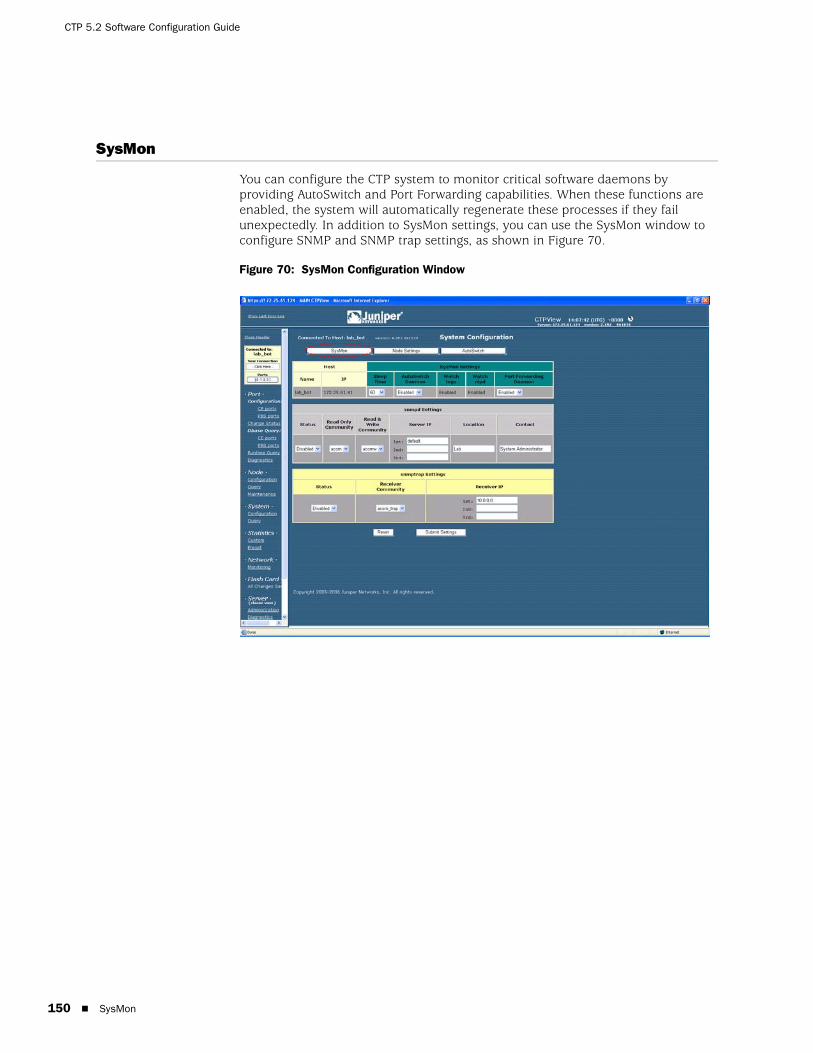
CTP 5.2 Software Configuration Guide
150 SysMon
SysMon
You can configure the CTP system to monitor critical software daemons by providing AutoSwitch and Port Forwarding capabilities. When these functions are enabled, the system will automatically regenerate these processes if they fail unexpectedly. In addition to SysMon settings, you can use the SysMon window to configure SNMP and SNMP trap settings, as shown in Figure 70.
Figure 70: SysMon Configuration Window
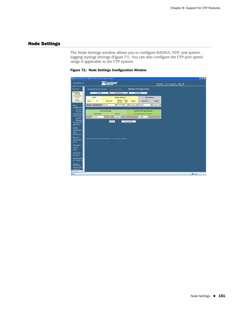
Node Settings 151
Chapter 8: Support for CTP Features
Node Settings
The Node Settings window allows you to configure RADIUS, NTP, and system logging (syslog) settings (Figure 71). You can also configure the CTP port speed range if applicable to the CTP system.
Figure 71: Node Settings Configuration Window
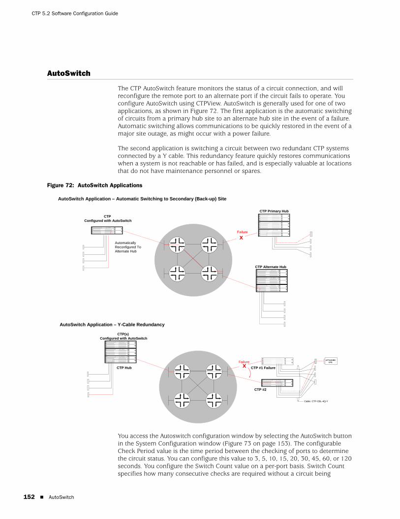
CTP 5.2 Software Configuration Guide
152 AutoSwitch
AutoSwitch
The CTP AutoSwitch feature monitors the status of a circuit connection, and will reconfigure the remote port to an alternate port if the circuit fails to operate. You configure AutoSwitch using CTPView. AutoSwitch is generally used for one of two applications, as shown in Figure 72. The first application is the automatic switching of circuits from a primary hub site to an alternate hub site in the event of a failure. Automatic switching allows communications to be quickly restored in the event of a major site outage, as might occur with a power failure.
The second application is switching a circuit between two redundant CTP systems connected by a Y cable. This redundancy feature quickly restores communications when a system is not reachable or has failed, and is especially valuable at locations that do not have maintenance personnel or spares.
Figure 72: AutoSwitch Applications
You access the Autoswitch configuration window by selecting the AutoSwitch button in the System Configuration window (Figure 73 on page 153). The configurable Check Period value is the time period between the checking of ports to determine the circuit status. You can configure this value to 3, 5, 10, 15, 20, 30, 45, 60, or 120 seconds. You configure the Switch Count value on a per-port basis. Switch Count specifies how many consecutive checks are required without a circuit being
CTP Configured with AutoSwitch
CTP Hub CTP #1 Failure
CTP #2
Cable: CTP-CBL-4Q-Y
ATTACHEDDTE
x
CTP Primary Hub
xAutomatically Reconfigured To Alternate Hub
CTP Alternate Hub
CTP(s) Configured with AutoSwitch
AutoSwitch Application – Y-Cable Redundancy
AutoSwitch Application – Automatic Switching to Secondary (Back-up) Site
Failure
Failure

AutoSwitch 153
Chapter 8: Support for CTP Features
established before the primary port is reconfigured to an alternate port. You must properly configure the alternate port to establish a circuit connection to the AutoSwitch port; AutoSwitch will not configure the alternate port. You can set the Switch Count value to 1, 2, 3, 4, or 5. We recommend that Switch Period and Switch Count be configured to values that prevent the circuit from switching in the event of a short transient outage.
You can configure the CTP system to periodically check the connectivity to the AutoSwitch primary port after a switch to the alternate. Setting the Secondary Revert value to Enabled allows the CTP system to reconfigure the port back to the primary when it is available.
You can verify the connectivity between a CTP port running AutoSwitch and its primary and secondary remote ports by using the Primary and Secondary Host Test buttons. When selected, the button will change to Testing while the system is checking connectivity. The results of the test will show Success with a green background or Failure with a red background. When you click Connection Check All, the system checks the connectivity to all primary and secondary hosts, and updates the display with the results.
Figure 73: CTPView AutoSwitch Configuration Window

CTP 5.2 Software Configuration Guide
154 Virtual IP Designation for CTP Systems
Virtual IP Designation for CTP Systems
Creating and selecting CTP virtual IP addresses are now separated into two distinct operations.
To create the virtual IP addresses that will be associated with a CTP system, click Node>Maintenance>Configure [CTP] Virtual IPs. Follow the simple instructions at the top of the pane. You can create a maximum of 56 virtual IP addresses. All current virtual IP addresses are shown. The system checks new IP addresses for proper format before submission.
To designate a source virtual IP when you configure a remote port, select the virtual IP from a drop-down menu by clicking Port>Configuration>Advanced Settings and then selecting Source Virtual IP.
Autobaud Support
Autobaud configuration depends on your first configuring a circuit to work properly in an adaptive clocking configuration. You can use many methods to configure the clocking that will allow adaptive clocking to work properly. Generally, however, you must configure one end to generate packets in the net-bound direction using the TT (user) clock, and then you must configure the other end for adaptive clocking.
From Port>Configuration, you can then switch this circuit over to Autobaud:
On the adaptive end, set DDS Synthesizer Source in the custom clocking menu from Adaptive to Autobaud. This setting enables the monitoring of OAM packets for the other end TT frequency, and processing to accommodate frequency changes that are detected.
On the other end, it is important to enable the port advance configuration for Only High TT Checking. This setting keeps the port from going to the TtFail state when the incoming user clock fluctuates, and allows a TT clock in the range of 0 to the configured port rate. However, it does check for the TT rate going above the configured port rate, and will send the port to the TtFail state if it goes above. This process protects the system from an overspeed TT causing problems for the port, CTP system, or network.
It is also important to set the port rate on both ends for the maximum required port operating speed. Although the port will autobaud to any rate between 0 and the configured rate, it will not operate above the configured speed of the port.
DTE Interface Support 155
Chapter 8: Support for CTP Features
DTE Interface Support
In the Port>Configuration window, you can configure a port for DTE Interface mode. In this mode:
There will be only one “canned” [meaning default?]clock configuration option available, which is DTE, All Clocked by Ext Clk. The other option available is “custom”.
The labels for the eight signaling parameters and the signaling menu options are labeled for both DCE and DTE encoding. Refer to the correct label when you choose the configuration options. The convention used is to list the DCE label first, followed by the DTE label.
Hardware Monitoring
CTPView does not provide a user interface for displaying sensor data from CTP platforms. You may use SNMP or the CTP CLI to obtain the hardware sensor data.
IPv6 Support
CTPView supports both IPv4 and IPv6 address protocols for CTP products, including the coexistence of both protocols on the same equipment. However, the current CTP operating system does not support some features—such as virtual IP, PWE3 and PBS. They may be supported in later releases.
The CTPView server is IPv6-capable. You configure an Ethernet port through the CLI menu. All ethernet ports are configurable and can have routes associated with them.
PWE3 Support (SAToP)
Structure-Agnostic Time Division Multiplexing (TDM) over Packet (SAToP) configuration appears as Port Configuration options after you have configured the port to use the T1/E1 interface type. You must install a T1/E1 DCARD before the configuration options are visible.
When the SAToP option is set to Enable, the packet size will be set to the default value of 192, and the Clock Option Menu will be set to CTP is Loop Timed. Both of these values may be modified if desired.
SAToP ports use the source UDP port as the circuit identifier. It must be the same on both pseudowire emulation (PE) endpoints and cannot be used by another SAToP port on either PE endpoint. The source UDP port is used instead of the remote port to define the circuit, and the configured remote port is not used during SAToP operation. All other configuration options are the same as those for standard CTP ports that are configured to use the T1/E1 DCARD, including buffer settings, remote node IP address, and clocking options.
CTP 5.2 Software Configuration Guide
156 Transparent Mode Support
Transparent Mode Support
Transparent circuit mode is available only on CTP2000 products and appears as a serial encoding Port Configuration option.
Transparent mode is intended to be used only for DCE NRZ serial circuits (default port configuration). Although it is possible to choose the interface electrical standard (EIA-530A, RS-232, V.35), it is not intended to work in conjunction with any other interface-related configurations (DCARD, encoding, interface mode) and is therefore not supported. Note that the menu interface and CTPView may not disallow these nonsupported configurations, so be careful if you choose these configurations.
BERTs will not work on transparent ports because of the location of the BERT tester in the data path.
Loops may not work on transparent circuits. The serial loop function connects the SD and RD leads of the interface (in the direction specified), and will work only if a transparent circuit actually uses these leads for data transport. You may use the transparent leads for any purpose you see fit.
When you select the TRANS serial encoding option, three additional advanced port configuration options are made available: 16-Bit Jitter Absorption FIFO, Invert FIFO Write Clock, and Invert FIFO Read Clock.
VLAN Support
You configure CTP VLANs through the CLI. CTPView displays all the configured CTP IP addresses (such as ethernet, virtual IP, and VLAN) in its port selection drop-down menus.
Support for Multiple Ethernets on CTPs
Also labeled as network interface devices (NIDs) in CTPView, this information is gathered from several sources. The actual configuration of the CTP interface device is done on the CTP itself. CTPView assembles, stores, and updates this information for display to the user during provisioning of the data circuits.
NID SelectionWhen in the port configuration process, as part of the Remote Port selection, you are presented with a list of NIDs and their respective IP addresses to choose from as the final step in designating the remote port. To help you identify the current NID/Remote Port pairings, the Remote Port display in the Port Configuration and AutoSwitch Configuration panes now show the IP address of the port along with the hostname.

Packet-Based Serial (PBS) Port Configuration 157
Chapter 8: Support for CTP Features
Updating NID InformationThe NID information on CTPView is compiled and updated through these methods:
When you add a CTP host to the CTPView database, you enter values for the management and default data IP addresses. If the CTP operating system is 4.2R1+, the CTP system is queried for NID information.
During the CTPView-to-CTP connection process, if the CTP operating system is 4.2R1+, the CTP system is queried for all of its NID information.
You can manually update NID information by clicking Update NID Info in the Port Configuration pane on the Remote Port line.
Packet-Based Serial (PBS) Port Configuration
During the CTP connection process, CTPView determines whether the PBS feature is supported on the CTP system. If it is, CTPView will present a modified set of configuration panes. Currently, the CTP 1000 series running CTP operating system 4.2+ supports this feature.
When CTPview is connected to a PBS-capable CTP system, the navigation pane shows submenus for Port Configuration and Port Dbase Query. These submenus are split into two categories: CE ports (the default type) and PBS ports. Because different configuration options are available for these two port types, separate port configuration panes are necessary.
PBS Port DesignationTo enable/disable PBS on a port, after making a CTP connection, click the gray Ports button inside the blue connection box at the top of the CTPView navigation pane. A configuration pane is displayed.
Not every port on a PBS-capable CTP system is available for designation as a PBS interface. The configuration pane displays which ports are available for PBS selection and what CE/PBS type has currently been assigned to each port.
In the main pane a set of simple instructions explains how to interpret the display and how to modify the current configuration.
Additional links to this CE/PBS configuration pane are in the Port Configuration pane at the top of each column directly under the port numbers.
Port Display LimitsThe CE/PBS configuration pane shares its window with the Ports to Display selection panel. The pane contains a set of simple instructions on how to interpret the display and how to modify the current configuration.

CTP 5.2 Software Configuration Guide
158 Packet-Based Serial (PBS) Port Configuration
You can select a maximum of 4 ports of each type—CE or PBS. When a change in the configuration of CE/PBS Interface Type results in the maximum number of ports to be displayed of any one type to exceed 4, only the first 4 ports of each type will remain selected, starting with port 0. You are notified when this happens. If you want to change this selection, you can use the normal process to modify the selected Ports to Display.

159
Chapter 9
CTPView Server Management Functions
This chapter describes the administration of the CTPView server, and about using the CTPView to monitor, manage, and maintain CTP systems.
This chapter contains the following sections:
CTPView Server Administration on page 160
Adding and Deleting CTP Hosts and Groups on page 160
Managing CTP Network Hosts on page 161
Configuring E-Mail Notifications on page 162
Configuring Automatic Functions on page 163
Node Maintenance Functions on page 165
Saving Port, Node, and CTP Configurations on page 166
Saving Port, Node, and CTP Configurations on page 166
Formatting Maintenance Reports on page 171
Network Monitoring on page 172
Statistics and IP Performance Reports on page 174
Automatically Saving CTP System Configurations on page 179
CTPView Connection Throttling on page 179
Support for Tabbed Browsers on page 180
Server Configuration Validation on page 180
SSH Port Forwarding on page 181
Updating CTP Software Directory on page 181
Burning CTP Compact Flash Media on page 182
Network Monitoring on page 182
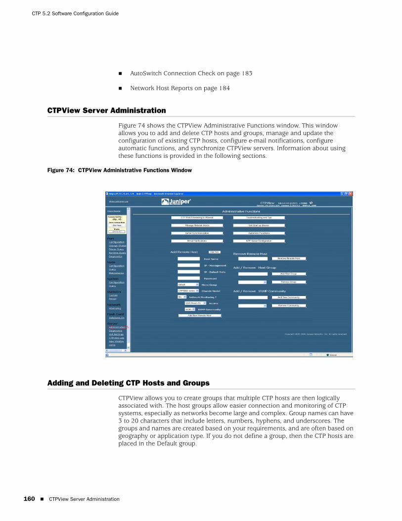
CTP 5.2 Software Configuration Guide
160 CTPView Server Administration
AutoSwitch Connection Check on page 183
Network Host Reports on page 184
CTPView Server Administration
Figure 74 shows the CTPView Administrative Functions window. This window allows you to add and delete CTP hosts and groups, manage and update the configuration of existing CTP hosts, configure e-mail notifications, configure automatic functions, and synchronize CTPView servers. Information about using these functions is provided in the following sections.
Figure 74: CTPView Administrative Functions Window
Adding and Deleting CTP Hosts and Groups
CTPView allows you to create groups that multiple CTP hosts are then logically associated with. The host groups allow easier connection and monitoring of CTP systems, especially as networks become large and complex. Group names can have 3 to 20 characters that include letters, numbers, hyphens, and underscores. The groups and names are created based on your requirements, and are often based on geography or application type. If you do not define a group, then the CTP hosts are placed in the Default group.

Managing CTP Network Hosts 161
Chapter 9: CTPView Server Management Functions
The Connected to area in the upper left pane provides a good example of how host groups are used. The available groups are first displayed in the window, and then the CTP hosts within the group are displayed after the group is selected. This process makes connecting to a CTP system easier compared with a connect window that lists every CTP host in a large network.
Figure 74 on page 160 shows the area that you use to add a host group and the area that you use to delete a selected group.
You add CTP systems to CTPView using the Add Remote Host field and drop-down menus (Figure 74 on page 160). To successfully add a CTP host, fill in the following fields, or select the appropriate parameter from the drop-down menus:
Host Name—A unique name for the CTP host.
IP–Management, IP–Default Data—IP addresses used for CTPView management connection and circuit data flow.
Password—Password on the CTP host that CTPView will use when accessing the system.
Menu Group—The group that the CTP host is be logically associated with. The available group names are displayed, and Default is used when no groups have been defined.
Chassis Model— CTPView will determine the type of CTP1000 system. You must specify the type of CTP2000 system when applicable (CTP2008, CTP2024, and CTP2056).
Network Monitoring—CTPView is capable of monitoring remote CTP hosts (see Network Monitoring on page 172). The drop-down list provides the option of including or excluding the CTP host for monitoring.
Access—When selected for monitoring, CTPView must periodically access the CTP host. The type of access can be either SSH or SNMP, as specified in this drop-down menu.
SNMP Community—Defines the SNMP community of the CTP host.
Managing CTP Network Hosts
The Manage Network window, which you access by clicking Manage Network Hosts in the Administration Functions window, allows you to change the configuration of an existing host (Figure 75 on page 162). After selecting the appropriate group, you are able to change the type of CTP system, group association, monitoring, monitoring connection type, and SNMP community of any CTP host within the selected group. The changes do not take effect until you click Submit.
NOTE: Deleting a group will delete all the CTP hosts within the group. Use the Network Hosts window to move CTP hosts to other groups before the group is deleted.
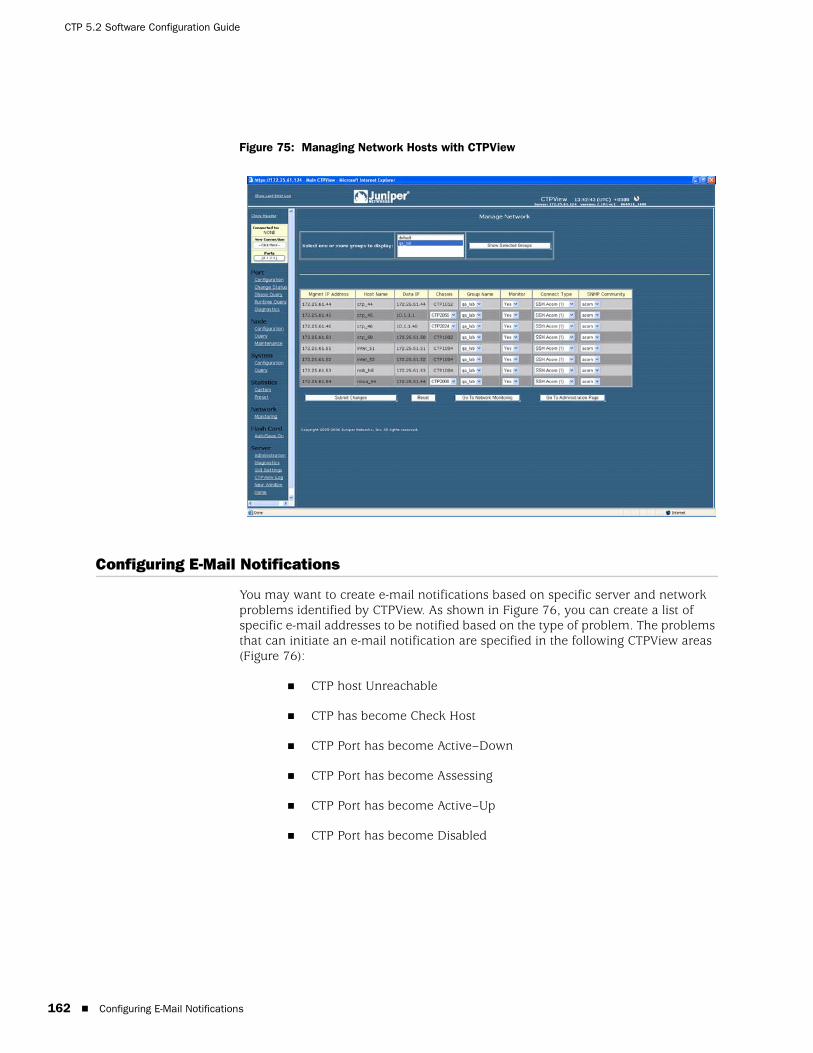
CTP 5.2 Software Configuration Guide
162 Configuring E-Mail Notifications
Figure 75: Managing Network Hosts with CTPView
Configuring E-Mail Notifications
You may want to create e-mail notifications based on specific server and network problems identified by CTPView. As shown in Figure 76, you can create a list of specific e-mail addresses to be notified based on the type of problem. The problems that can initiate an e-mail notification are specified in the following CTPView areas (Figure 76):
CTP host Unreachable
CTP has become Check Host
CTP Port has become Active–Down
CTP Port has become Assessing
CTP Port has become Active–Up
CTP Port has become Disabled
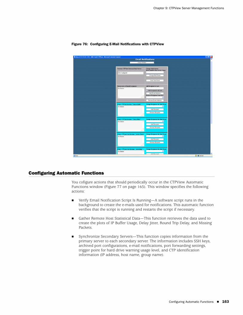
Configuring Automatic Functions 163
Chapter 9: CTPView Server Management Functions
Figure 76: Configuring E-Mail Notifications with CTPView
Configuring Automatic Functions
You cofigure actions that should periodically occur in the CTPView Automatic Functions window (Figure 77 on page 165). This window specifies the following actions:
Verify Email Notification Script Is Running—A software script runs in the background to create the e-mails used for notifications. This automatic function verifies that the script is running and restarts the script if necessary.
Gather Remote Host Statistical Data—This function retrieves the data used to create the plots of IP Buffer Usage, Delay Jitter, Round Trip Delay, and Missing Packets.
Synchronize Secondary Servers—This function copies information from the primary server to each secondary server. The information includes SSH keys, archived port configurations, e-mail notifications, port forwarding settings, trigger point for hard drive warning usage level, and CTP identification information (IP address, host name, group name).

CTP 5.2 Software Configuration Guide
164 Configuring Automatic Functions
Synchronize Secondary Servers and Remote Hosts—This function copies information from the primary to each secondary server and CTP host. The information transferred to the secondary servers includes SSH keys, archived port configurations, e-mail notifications, port forwarding settings, trigger point for hard drive warning usage level, CTP identification information (IP address, host name, group name) and CTP statistical data. The function copied from the primary server to CTP hosts includes each secondary server’s SSH key.
Remove Outdated Data Files (over 6, 9, or 12 months)—CTPView removes older files (typically CTP host statistical data) based on the age of the data. The age criterion can be set to 6, 9, or 12 months. We recommend that you configure the automatic function to ensure that the file system does not become filled.
Update Network Interface Device Information—CTPView collects network interface device information. Use this automatic function if you configure virtual IP addresses using the CLI or if you use multiple CTPView servers to configure CTP hosts and virtual IP addresses.
Save Current CTP Host System Configuration—CTPView saves every CTP host configuration at the specified time interval. CTPView will save the 10 most recent configurations.
In the CTPView Automatic Functions window (Figure 77 on page 165), you select the action in the area titled Add New Automatic Entry for Server serverName, and you specify when the action should take place. For example, the action being added in Figure 77 would occur every day at 01:00.
It may be necessary for an action to occur multiple times in a day. To add this configuration, you can add multiple entries for the same action and specify a different time for each entry. In the example shown in Figure 77, the Gather Remote Host Statistical Data action is to occur four times every day—at 00:45, 03:45, 05:45 and 8:45.
You can limit the bandwidth used to copy and retrieve information from the CTP hosts by using the Modify Throttle Value for Server serverName area in the CTPView Automatic Functions window. Throttling the bandwidth is typically not necessary and may be required only when the local LAN segment experiences significant load and bandwidth limitations.

Node Maintenance Functions 165
Chapter 9: CTPView Server Management Functions
Figure 77: Configuring Automatic Functions with CTPView
Node Maintenance Functions
The Node Maintenance window (Figure 78 on page 166) allows you to perform functions such as distributing and updating CTP software, saving port and node configurations, saving and restoring CTP databases, and creating reports that detail the provisioning of ports. Other functions provided are similar to those in the Node Operations command-line interface (CLI) menu, which includes opening SSH connections, shutting down and rebooting systems, and modifying banners.

CTP 5.2 Software Configuration Guide
166 Saving Port, Node, and CTP Configurations
Figure 78: CTPView Node Maintenance Window
Saving Port, Node, and CTP Configurations
CTPView allows you to save a port configuration using your naming convention. You can apply the saved port configuration as a template to other ports when you are configuring them. Reusing the configuration eliminates repetitive entries for common configurations. The saved configuration includes all the port attributes except the remote host and port.
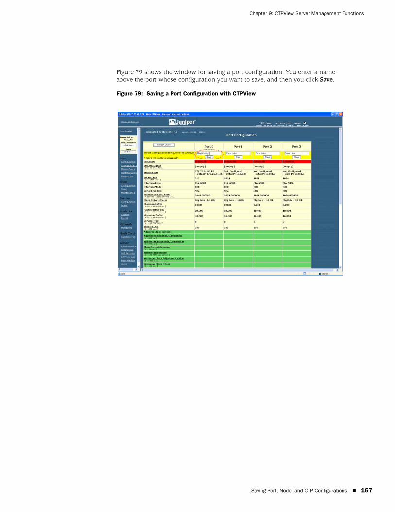
Saving Port, Node, and CTP Configurations 167
Chapter 9: CTPView Server Management Functions
Figure 79 shows the window for saving a port configuration. You enter a name above the port whose configuration you want to save, and then you click Save.
Figure 79: Saving a Port Configuration with CTPView
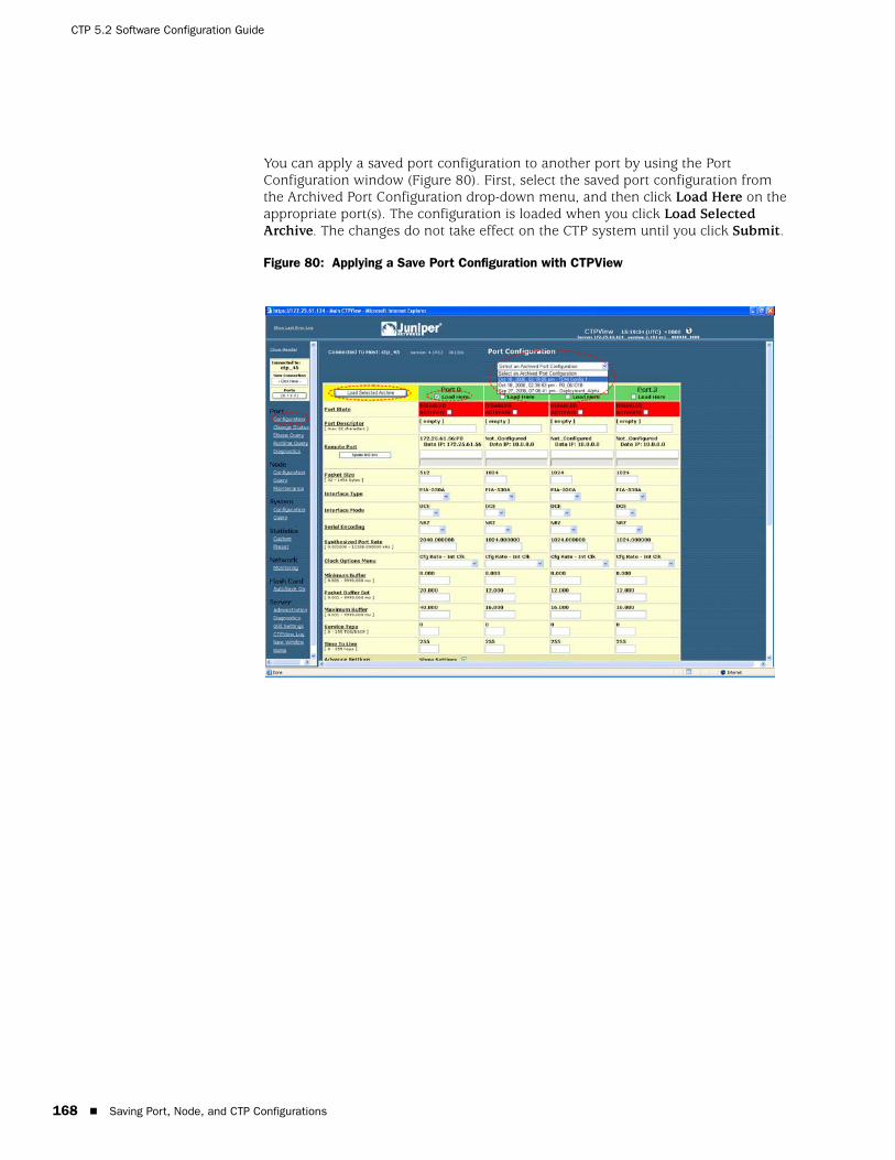
CTP 5.2 Software Configuration Guide
168 Saving Port, Node, and CTP Configurations
You can apply a saved port configuration to another port by using the Port Configuration window (Figure 80). First, select the saved port configuration from the Archived Port Configuration drop-down menu, and then click Load Here on the appropriate port(s). The configuration is loaded when you click Load Selected Archive. The changes do not take effect on the CTP system until you click Submit.
Figure 80: Applying a Save Port Configuration with CTPView
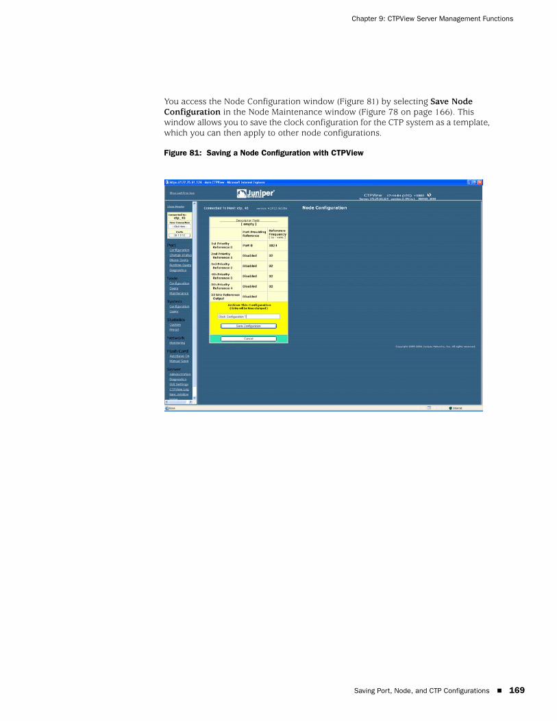
Saving Port, Node, and CTP Configurations 169
Chapter 9: CTPView Server Management Functions
You access the Node Configuration window (Figure 81) by selecting Save Node Configuration in the Node Maintenance window (Figure 78 on page 166). This window allows you to save the clock configuration for the CTP system as a template, which you can then apply to other node configurations.
Figure 81: Saving a Node Configuration with CTPView
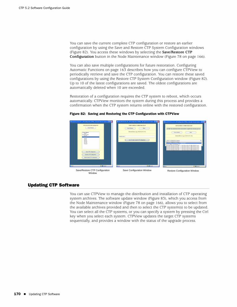
CTP 5.2 Software Configuration Guide
170 Updating CTP Software
You can save the current complete CTP configuration or restore an earlier configuration by using the Save and Restore CTP System Configuration windows (Figure 82). You access these windows by selecting the Save/Restore CTP Configuration button in the Node Maintenance window (Figure 78 on page 166).
You can also save multiple configurations for future restoration. Configuring Automatic Functions on page 163 describes how you can configure CTPView to periodically retrieve and save the CTP configuration. You can restore these saved configurations by using the Restore CTP System Configuration window (Figure 82). Up to 10 of the latest configurations are saved. The oldest configurations are automatically deleted when 10 are exceeded.
Restoration of a configuration requires the CTP system to reboot, which occurs automatically. CTPView monitors the system during this process and provides a confirmation when the CTP system returns online with the restored configuration.
Figure 82: Saving and Restoring the CTP Configuration with CTPView
Updating CTP Software
You can use CTPView to manage the distribution and installation of CTP operating system archives. The software update window (Figure 83), which you access from the Node Maintenance window (Figure 78 on page 166), allows you to select from the available archives provided and then to select the CTP system(s) to be updated. You can select all the CTP systems, or you can specify a system by pressing the Ctrl key when you select each system. CTPView updates the target CTP systems sequentially, and provides a window with the status of the upgrade process.
Save/Restore CTP ConfigurationWindow
Save Configuration Window Restore Configuration Window
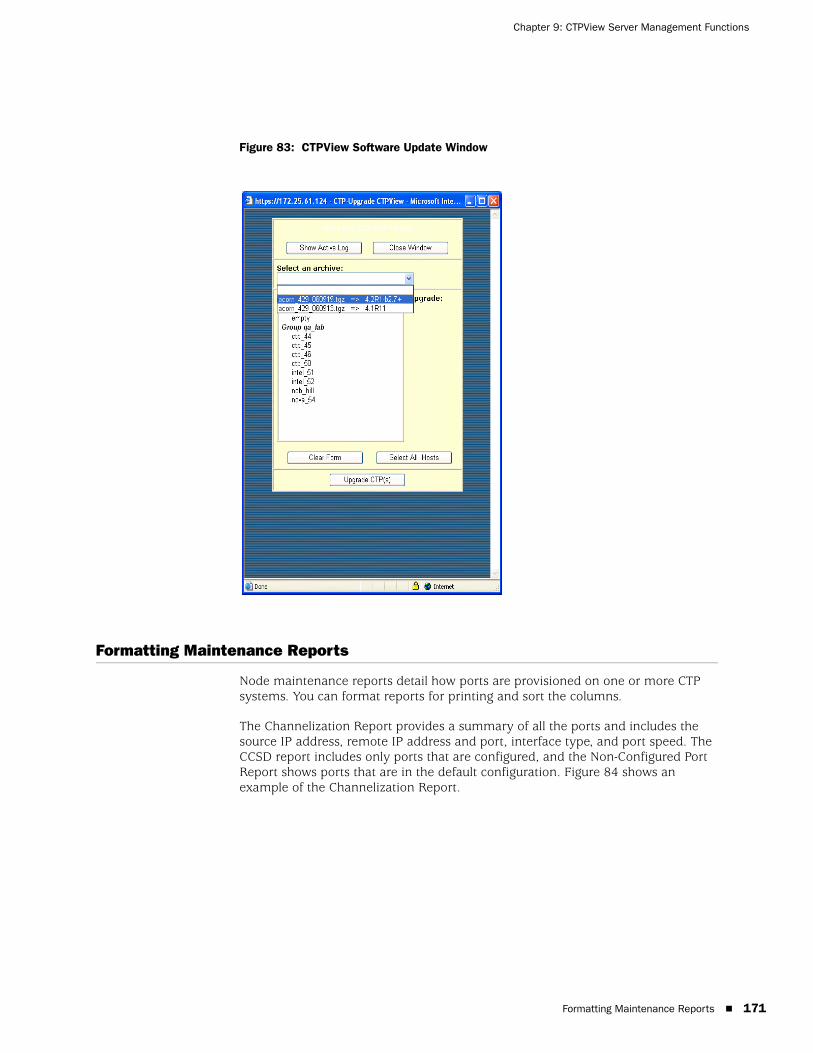
Formatting Maintenance Reports 171
Chapter 9: CTPView Server Management Functions
Figure 83: CTPView Software Update Window
Formatting Maintenance Reports
Node maintenance reports detail how ports are provisioned on one or more CTP systems. You can format reports for printing and sort the columns.
The Channelization Report provides a summary of all the ports and includes the source IP address, remote IP address and port, interface type, and port speed. The CCSD report includes only ports that are configured, and the Non-Configured Port Report shows ports that are in the default configuration. Figure 84 shows an example of the Channelization Report.

CTP 5.2 Software Configuration Guide
172 Network Monitoring
Figure 84: Node Maintenance Report
Network Monitoring
When Network Monitoring is in the Running state, CTPView periodically checks the reachability of CTP hosts if the host is configured with network monitoring enabled. If the host is reachable, CTPView obtains the status of the CTP host ports. Selecting Network Monitoring in the CTPView navigation pane opens the network monitoring window, which provides a summary of both the CTP host reachability and the port status. The highest alarm level on a CTP percolates up to the Group icon.
Figure 85 on page 173 provides an example of a network monitoring window. When you select a group, the window displays all CTP hosts within the group. The status or alarm associated with each CTP host and port is displayed:
Unreachable (alarm)—The CTPView server cannot reach the CTP host. This alarm could be due to a IP network problem, a site problem (such as a power outage), or a CTP equipment or configuration issue.
Active–Down (alarm)—The port on the CTP system is configured as active, but the port state is Down (that is, no circuit is established to the port).
Assessing (alarm)—The problem is being assessed, and a user has placed the CTP host into an Assessing state, as described below.
Active–Up (status)—The port is configured as active, and the port state is Up (that is, a circuit is established to the port).
Disabled (status)—The circuit is configured as disabled.
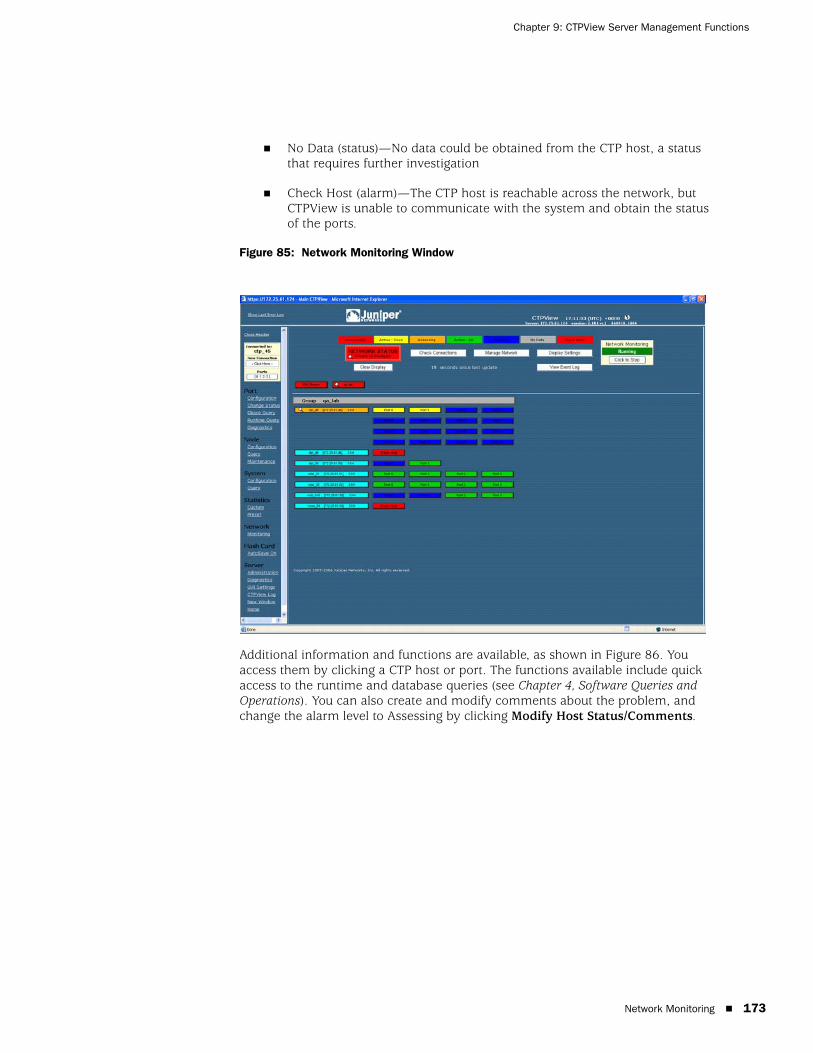
Network Monitoring 173
Chapter 9: CTPView Server Management Functions
No Data (status)—No data could be obtained from the CTP host, a status that requires further investigation
Check Host (alarm)—The CTP host is reachable across the network, but CTPView is unable to communicate with the system and obtain the status of the ports.
Figure 85: Network Monitoring Window
Additional information and functions are available, as shown in Figure 86. You access them by clicking a CTP host or port. The functions available include quick access to the runtime and database queries (see Chapter 4, Software Queries and Operations). You can also create and modify comments about the problem, and change the alarm level to Assessing by clicking Modify Host Status/Comments.

CTP 5.2 Software Configuration Guide
174 Statistics and IP Performance Reports
Figure 86: Additional Functions Accessed from the CTPView Network Monitoring Window
Statistics and IP Performance Reports
CTPView periodically retrieves IP performance information from each CTP system. The data retrieved includes 1-minute observations of the maximum, minimum, and average buffer state; calculated IP packet delay variance (jitter); round-trip delay; and missing packet counts. CTPView allows you to review this data using either preset or custom plots.
Preset plots are provided for the currently connected CTP system. The time periods displayed include the preceding 1, 6, 12, 24, 48, or 72 hours. The plot’s y axis is automatically scaled unless you specify the axis units with the minimum and maximum value in the three drop-down menus provided. You can make plots for a single port, for the four ports currently selected, or for all the ports on the CTP system. You can select and expand thumbnail plots.
Remote Host Options whenPort is Selected
Remote Host Options whenNode is Selected

Statistics and IP Performance Reports 175
Chapter 9: CTPView Server Management Functions
Figure 87 is an example of a preset report showing packet delay variance received at a port over a 12-hour period.
Figure 87: Viewing a Preset Statistics Report with CTPView
Custom statistics plots allow you to display graphs from one or more CTP systems during any period of time when CTPView has retrieved data from the system(s). The plot’s y axis is automatically scaled unless you specify the axis units with the minimum and maximum value in the drop-down menus provided. You can create up to four plots by specifying the CTP system and port, report type, and the start and finish time of the plot. Figure 88 on page 176 shows an example of a custom plot.
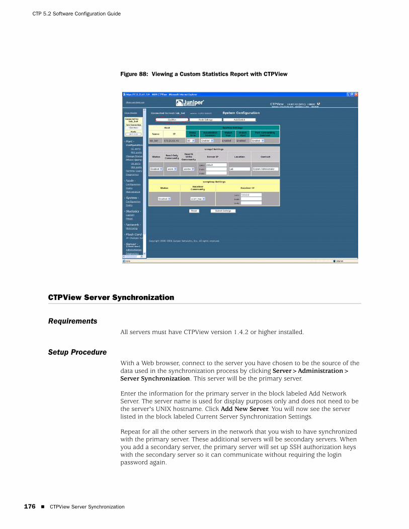
CTP 5.2 Software Configuration Guide
176 CTPView Server Synchronization
Figure 88: Viewing a Custom Statistics Report with CTPView
CTPView Server Synchronization
RequirementsAll servers must have CTPView version 1.4.2 or higher installed.
Setup ProcedureWith a Web browser, connect to the server you have chosen to be the source of the data used in the synchronization process by clicking Server>Administration> Server Synchronization. This server will be the primary server.
Enter the information for the primary server in the block labeled Add Network Server. The server name is used for display purposes only and does not need to be the server's UNIX hostname. Click Add New Server. You will now see the server listed in the block labeled Current Server Synchronization Settings.
Repeat for all the other servers in the network that you wish to have synchronized with the primary server. These additional servers will be secondary servers. When you add a secondary server, the primary server will set up SSH authorization keys with the secondary server so it can communicate without requiring the login password again.
CTPView Server Synchronization 177
Chapter 9: CTPView Server Management Functions
Now look in the Current Server Synchronization Settings area. You should see all the servers that you added listed here. The Server Type will be set to Not Selected. This is the default setting for all new entries. For each server, select the Server Type from the drop-down menu. Only the server you are logged in to can be set as the primary server. You can leave a server as Not Selected if you wish to temporarily remove it from the synchronization process. You can remove an entry entirely by checking the Remove box. After making your selections, click Commit Changes.
To set up the primary server to perform the synchronization at predetermined times, click Set Automatic Functions in the Synchronize Servers on Network area. This action opens a new window where you can set commands that CTPView will perform automatically, known as the Crontab function. Numerous commands are available; two relate to server synchronization. If you chose the option Synchronize Secondary Servers and Remote Hosts, the program copies the necessary SSH keys to each secondary server so that it will then be able to communicate with the remote hosts without requiring the login password to be typed. This is the default selection. The second synchronization option synchronizes only server-specific information.
After selecting your choice for Action, set the time for the command to be executed by using the drop-down menus. Remember that the numbers you select represent a specific time, not an interval of time. For example the default setting of [0,1,ANY,ANY,ANY] means that the command will be run at the 0 minute (that is, on the hour) of the first hour (1 AM) every day (that is, ANY day of ANY month, landing on ANY day of the week). A setting of [30,16,8,ANY,ANY] would result in the command being executed at 4:30 PM on the 8th of every month. You may add any number of entries as required to provide the result you desire. The optimal configuration will have the server synchronization being run shortly after the statistical data is obtained from the remote hosts. Commit your new selection by clicking Add New Entry.
The primary server is now set up to perform the synchronization process automatically at the times you have selected. More information about this process is detailed later in this document.
You may also manually execute the synchronization process. In the Server Synchronization window in the Synchronize Servers on Network area, click Manually Synchronize Network. This action opens a new window from which you can choose to synchronize only the servers or to include any number of remote hosts. From this window you can also access the logs generated from the synchronization process.
DefinitionsThe scope of these definitions is not global, but are locally restricted to the server that the user is logged in to. In other words, each server views the rest of the servers in the network according to its own designations. Each server maintains its own file of server designations that it refers to when performing a server synchronization. You do not need to configure a remote server for that server to be updated by the server that is performing the synchronization.
CTP 5.2 Software Configuration Guide
178 CTPView Server Synchronization
Primary server—Any server with the correct version of CTPView software can be designated as a primary server. The primary server executes the synchronization program and distributes data to the secondary servers. Regardless of how any other server is configured, when a server is designated as a primary server its data is safeguarded from being overwritten by any other server executing the server synchronization program. You set or change a server's designation by logging in to that server and entering the required information in the Server Synchronization CTPView window.
Secondary server—Any server with the correct version of CTPView software can be designated by a primary server as one of its secondary servers. The data files on the secondary server are updated to match those on the primary server on synchronization.
Data Files—The data which is synchronized is the:
Statistical history that has been archived from the CTP systems.
IP addresses, hostnames, host menus, and SSH authorization keys that are necessary to communicate with the CTP systems.
ConfigurationRemember that the settings described below are restricted to how this server views the world. The choices made here do not change any configuration or settings on remote servers.
Current Server Settings—This section displays the current configuration file of the server you are logged in to. You must have the local server listed here. This is also where you modify Server Type of the listed servers or remove a server from the list. The default type for newly added servers is Not Selected.
Synchronize Servers on Network—You can use the links here to modify the timing of the automatic synchronization schedule and to open a new window that allows you to manually start a synchronization process.
Add Network Server—You make additions to this server's configuration file here. The Server Name is for identification only. It is not used for any other purpose or passed to any other server. Because the default type for newly added servers is Not Selected, you need to modify the type designation before running the synchronization program.
MiscellaneousThere is a 15-second timeout limit on attempts of the primary server to establish contact with a remote host. If the timeout is reached, the primary server skips to the next remote host and continues executing the program. This information is displayed in the screen output and logs.
When you add a new remote host to a primary server, the new host's SSH RSA keys are also exchanged with each secondary server. You are given the option to disable this feature in the Administration window when you add the new remote host.
Automatically Saving CTP System Configurations 179
Chapter 9: CTPView Server Management Functions
Automatically Saving CTP System Configurations
You can now program an automatic function to save every CTP system configuration at a prescribed time and interval. The saved files are then available to restore the settings on a CTP system.
ConfigurationYou set automatic saving set in the Automatic Functions pane. Click the button in the Server Administration window to get there. In the Add New Automatic Entry dialog box, select Current CTP Host System Configurations from the Action drop-down menu.
CTPView will save the ten most recent configuration files for each CTP system. The Manual System Configuration Save is still available. In addition, each CTP upgrade automatically creates another system save before beginning the upgrade process.
Restoring Saved ConfigurationsFrom the Node Maintenance pane, click Save / Restore CTP Configuration to restore a saved configuration or to manually save one.
All available saved configurations appear in the drop-down list in the Restore CTP Configuration pane. Follow the prompts to complete the restoration.
CTPView Connection Throttling
File transfers between CTPView and CTP systems are now throttled to limit the used bandwidth during the file transfer. The selected throttle value is user configurable.
ConfigurationIn the Server Administration pane, click Automatic Functions. The Throttle dialog box is at the bottom of the pop-up screen. The default value is 100,000 Kbits/sec—that is, the full bandwidth of the server's Ethernet port.
ScopeThe following functions are affected by the bandwidth throttling:
Gathering statistical data for plots
Synchronizing secondary servers
Saving CTP system configurations
Modifying CTP login banners
Upgrading CTP operating system software

CTP 5.2 Software Configuration Guide
180 Support for Tabbed Browsers
Support for Tabbed Browsers
You can configure CTPView for use with tabbed Web browsers, such as Firefox, Mozilla, or Internet Explorer 7. You can select your own preference for the type of browser to support, either classic or tab. Your selection is stored in your browser settings, but you can change your preference at any time. After being enabled, the Tabbed Browsing feature applies to all new CTPView windows opened with the New Window link located in the Directory frame. The remaining links and window behavior of the two CTPView styles remain the same. The default CTPView style is Classic, which is suitable for earlier versions of Internet Explorer.
LimitationsThe current tabbed browsers do not support dynamically changing the tab's title after a page has been loaded onto the screen. CTPView uses frames to open new content in the viewing window without reloading the entire page, so the tab titles cannot describe the current content. However, to differentiate the tabs for easier browsing, we add a bracketed sequencing number in the tab's title when the tab is first opened.
Using the Tabbed StyleThe current browser style is displayed in the Directory frame just under the heading Server. Click on the style type or the GUI Settings link to go to the style configuration page.
On the configuration page you can choose the browser style. In addition, there is a button that will manually reset the tab index counter. The tab index is also reset after you close all browser windows.
You must configure each browser that you use separately, even when you open the browsers on the same desktop.
Browser ConfigurationWith default Firefox or Internet Explorer 7 settings, to open a new window as a tab, right-click the New Window link under the Server heading in the Directory frame. Select Open Link in New Tab from the pop-up menu. If the new tab does not open in focus (as the visible tab) on your desktop, you can modify your browser's tab options/preferences to change the behavior.
Server Configuration Validation
This utility tests and reports on a long list of system configuration details that are either critical or desirable for the proper operation of the CTPView Management System. For every item that is identified as out of compliance, instructions for correcting the problem are supplied.
Using Configuration ValidationTo run this utility, go to the Server Diagnostics window. At the bottom, click Validate Server Configuration. There will be a few seconds’ delay while the script is processing the configuration before the results appear.
SSH Port Forwarding 181
Chapter 9: CTPView Server Management Functions
Validate the server configuration after every CTPView software upgrade or any time you are experiencing a problem with the CTPView operations.
SSH Port Forwarding
This features creates a persistent encrypted and protected connection between CTPView and a remote CTP system. The reduction of overhead compared with using separate SSH connections for each command results in a noticeable performance increase of CTPView. This feature must be enabled on both CTPView and the CTP system. It is enabled by default.
Using SSH Port ForwardingIn the Server Administration pane in CTPView, the button labeled CTP Port Forwarding is [Allowed || Prohibited] indicates the current state of this function on CTPView. When clicked, the button will toggle CTPView to the other state.
After connecting to a remote CTP system with CTPView, go to the System Configuration window. In the SysMon pane, in the SysMon Settings area, the current state of the CTP port forwarding daemon is shown. You can also reconfigure it here.
When a port forwarding connection has been successfully established, the phrase Port Forwarding appears directly underneath the CTP hostname in the blue Connection Box located at the top of the navigation pane in CTPView.
Updating CTP Software Directory
Obtaining New CTP SoftwareBefore using CTPView to upgrade CTP software, you must copy the appropriate CTP archive files to the proper directory on the CTPView server. Released versions of CTP operating system software packages are available for download from the Juniper Networks CTP Support site at
https://www.juniper.net/customers/csc/software/ctp/
You need your Juniper Networks support username and password to access this site.
Directory LocationThe location to place the CTP archives into on the CTPView server is the /var/www/html/acorn/ctp/ directory. To copy software into this directory you must be a root user or a member of the UNIX group “server,” such as the default user “juniper”. The CTPview server automatically checks and modifies the copied file's ownership and permissions as necessary.
CTP 5.2 Software Configuration Guide
182 Burning CTP Compact Flash Media
Burning CTP Compact Flash Media
Obtaining CTP Flash Image FilesBefore using CTPView to burn CTP software images onto flash drives, you must copy the appropriate CTP image files to the proper directory on the CTPView server. Released versions of CTP operating system software images are available for download from the Juniper Networks CTP Support site at
https://www.juniper.net/customers/csc/software/ctp/
You need your Juniper Network support username and password to access this site.
Directory LocationPlace the CTP flash image file on the CTPView server in the /var/www/html/flash/ directory. To copy software into this directory, you must be a root user or a member of the UNIX group “server,” such as the default user “juniper”. You do not need to modify the file's ownership and permissions after you have copied it into the flash directory.
To burn a CTP image:
1. Place the new compact flash media into a USB compact flash adapter, and insert the adapter into one of the USB ports on the CTPView server. The adapter will be mounted automatically.
2. Using SSH from a remote computer or using a management console connected to the server, log in to the CTPView server. Switch to the root user account. Change to the /var/www/html/flash directory.
3. Type the command: ./burn_flash <version>, where flash_<version>.img is the image filename.
4. Typing just the command ./burn_flash will return the usage instructions and a list of flash images that are available.
5. Answer the screen prompts to complete the process.
6. Log out of the server, and remove the USB compact flash adapter.
Network Monitoring
Audible AlarmThis option is configurable at the user level. When Audible Alarm is enabled, your Web browser plays the selected audio file each time the Network Monitoring window refreshes and the Network Status is red or yellow. The state of this function is displayed within the Network Status indicator.
NOTE: You must have physical access to the CTPView server.
AutoSwitch Connection Check 183
Chapter 9: CTPView Server Management Functions
The audible alarm function has two configuration settings, which are accessible from the Display Settings button in the Network Monitoring pane. You can turn the sound on or off, and you can choose and preview the audio file that will be played.
The site administrator can add additional audio files to the list of available selections by copying the desired file to the directory /var/www/html/acorn/sounds/. Only wav files are supported, and the filename may consist only of alphanumeric characters and the underscore (_). The root of the filename is displayed as the label of the selection. CTPView automatically corrects illegal filenames and modifies the file permissions as necessary to enable the embedded media player to read the file.
For Linux users, your default browser installation probably does not have an embedded media player. If if you need a player, there is an easy-to-install multimedia plug-in named Plugger available at
http://fredrik.hubbe.net/plugger.html
Manual OverrideWhen you manually override the status of a host in the Network Monitoring pane, a magnifying glass icon appears within that host's button, its group button, and the network button. The overridden host's color status will not be passed on to the group and network buttons. In other words, the color of the buttons indicates the most severe status of only the hosts that are not overridden; and the icon indicates whether a host, and which one, has been manually excluded from the group and network color indicators.
AutoSwitch Connection Check
This new utility tests the connection between a CTP port running AutoSwitch and its primary and secondary remote ports. The function also verifies that the authorization keys have been correctly set. This feature is available only when the AutoSwitch host's CTP operating system is version 4.2R1 or later.
Using Connection CheckGo to the System Configuration pane, and click AutoSwitch. In the AutoSwitch pane, the Connection Check test buttons are on the extreme right end of each port line. There are individual buttons for each primary and secondary host plus a single button labeled All, which runs the test for every port with a single click.
When in the ready mode, the buttons will display “test”. While the script is running, the buttons will show “testing” and turn blue. The results of the test are displayed as text inside the buttons, and the background color around the buttons either turns green or red, for success or failure, respectively.
After a test has been completed, you may rerun the test by clicking the button again.

CTP 5.2 Software Configuration Guide
184 Network Host Reports
Network Host Reports
Three new database reports are available, in both onscreen and printer friendly formats. On an individual port basis for any or all CTP units in the system, the reports list selected information about the source and destination ports of the circuits. You can sort the reports and resize the font for easy viewing. The report database is updated in real time when CTPView is used for CTP provisioning. Additionally, a configurable automatic function queries for the current configuration data from all CTP units.
Accessing ReportsYou access Network Host Reports from the Node Configuration window. Click View Network Host Reports under the heading Reports.
The three reports are:
Channelization—Includes all ports.
Configured Ports—Displays only configured ports.
Non-Configured Ports—Shows just the nonconfigured ports.
Database UpdatesTo schedule the database updates to be done on a regular basis, from the Server Administration pane click Automatic Functions. Select the Save Current CTP Host System Configurations from the Action menu. Then set the time interval, and add the entry to the list of automatic functions. We recommend that you set this function to run on a daily basis.
You can also manually trigger a one-time database update by clicking Update Database in the Network Reports pane.
Exporting to Spreadsheet ProgramTo export data from the Reports pane:
1. From the CTPView Network Reports pane, create the report you want.
2. Click Printer Friendly Page.
3. Select all, copy, and then paste as HTML into your spreadsheet application.

Appendixes 185
Part 4
Appendixes

CTP 5.2 Software Configuration Guide
186 Appendixes

CTPView Release 3.0 187
Appendix A
Previous CTPView Software Release Enhancements
This appendix summarizes enhancements made to the CTPView software and is organized by release number. If the information in this appendix differs from the information found in previous chapters, follow this information.
It contains the following sections:
CTPView Release 3.0 on page 187
CTPView Release 3.1.0 on page 188
CTPView Release 3.0
The following enhancements were made to the software.
Port Selection page—This page's presentation is unchanged; port numbers are used for identification. To help you associate bundle numbers with their attached ports, a table has been inserted that maps port numbers to bundle numbers. Ports that are not attached to a bundle are also shown.
Before you switch ports between circuit emulation (CE) and packet-bearing serial (PBS) mode, the selected port must not be attached to a bundle. You are warned with a pop-up alert if you attempt this action, and will be prevented from performing the operation.
Directory pane—Port category has been replaced with Bundle.
Bundle > Configuration page—You can view and reconfigure existing bundles here. You can also create and configure new bundles.
PBS ports can also be configured here.
Bundle > Change Status page—Only configured bundles are displayed on this page. Possible user actions are Activate, Disable, Delete, and Recenter bundles. Options that are not available for a specific bundle do not appear.
Bundle > Runtime Query page—Only configured bundles are displayed on this page.

CTP 5.2 Software Configuration Guide
188 CTPView Release 3.1.0
Bundle > Diagnostics > CTP Traceroute page—This page requires that you make selections based on the port number that is attached to a bundle. A table showing the port-bundle association is displayed on the page.
Bundle > Diagnostics > Bit Error Rate Tester page and Bundle > Diagnostics > Network Interface Configuration page—These two pages have been disabled. They will be reenabled in Release 3.1.
System > Configuration > AutoSwitch page and System > Query > AutoSwitch page—These pages display only settings for bundles that are allowed to be configured for Autoswitch. This is limited to bundle types CTP and SAToP.
System > Statistics > Custom page and System > Statistics > Custom page—These pages remain organized by port number. A table showing the port-bundle association is displayed on the page.
Network > Monitoring page—This page remains organized by port number. For CTP nodes running CTPOS v5.0, the port state as indicated by the page is the state of the bundle that port is attached to. Ports that are not attached to a bundle are shown as disabled.
CTPView Release 3.1.0
The following enhancements and changes were made to the software.
Port SelectionThe Port Selection page is accessed from the blue connection box at the top of the Directory frame on the left of the main CTPView window. Click to open this page in the main frame.
Port Selection SectionThe scope for this area of control has been reduced with the introduction of the bundle-centric concept of defining circuits. For this release the page's presentation is unchanged but the process of choosing which circuits (bundles) to display has been transferred to the individual content pages.
This process is not complete in this release, but does include the Bundle Configuration and Runtime Query pages. The Statistics page (Plots) still relies on the selections made here to determine which graphs are displayed.
To assist you in associating the new bundle numbers with their attached ports, an expanding table has been added to this page that maps port numbers to bundle numbers. Mousing over the blue bar at the top of the page opens the table. Ports that are not attached to a bundle are not shown.
Type Selection SectionYou must be logged into the CTPView software as an administrator to change the port mode.

CTPView Release 3.1.0 189
Appendix A: Previous CTPView Software Release Enhancements
Before switching ports between CE and PBS modes, you must detach the selected port from any bundle. You detach the port on the Bundle Change Status page by deleting the appropriate bundle from the CTP node. To open this page, click Change Status in the Directory frame.
If you try to change a port's mode while it is still attached to a bundle, a pop-up warning appears and you are prevented from performing the operation.
Previous Port Configuration Page and Related Port-Centric PagesIn previous releases, these pages were accessed from the Directory frame by links under Port. Page headings were labeled Configuration, Change Status, Query, Runtime Query, and Diagnostics.
New FunctionalityPages have been replaced with versions that comply with the new bundle-centric method of circuit designation. See the following sections for descriptions of their new functions and current limitations.
Bundle ConfigurationYou must be logged into the CTPView software as an administrator to see the Bundle Configuration page. Starting in the Directory frame under Bundles, click Configuration. Two blue bars are displayed at the top of the page. Mousing over each bar expands them, allowing you to:
Add a new bundle to the node.
Reconfigure an existing bundle.
Adding a New BundleFollow the directions displayed. Select a bundle number, select a port number from the menu for the bundle type you wish to create (CTP, SAToP, CESoPSN), and click the bundle type button. The range of allowed bundle numbers is 0 to 63.
Once created, a bundle-port pairing cannot be modified directly. The bundle must be deleted and then a new bundle created with the desired pairing. You delete a bundle from the Change Status page.
Only available bundle numbers and appropriate port numbers for the indicated bundle types are displayed in the drop-down selection menus. An empty drop-down menu indicates that there are no more available ports for the bundle type.
Reconfiguring an Existing BundleDisplay the current configuration of a bundle by clicking on the appropriate row in the table displaying existing bundles. If the table is collapsed, mouse over the second blue bar to open it.
CTP 5.2 Software Configuration Guide
190 CTPView Release 3.1.0
After the page refreshes, the current configuration for the selected bundle and its attached port are displayed. Where appropriate, a drop-down menu or text field is displayed that enables you to insert new values for this bundle/port's configuration. Configuration is subject to the restrictions for the selected option as indicated under the option name and as described in the CTP Hardware, Installation, and Software Configuration Guide.
Changes to the configuration fields are not transmitted to the connected node or saved until you click Submit located at the top of the configuration table. After the new configuration is sent to the connected node, the page refreshes with the new bundle configuration. Review the settings to ensure the new configuration is accurate.
The list of options displayed may change depending on your choice for new option values. When the current value of a configuration option is made invalid by the change in a second option's configuration, a new value is inserted to update the invalid value. This new value is visible and may be changed if other valid configuration values are available.
There are four option fields that, when changed, force the browser to re-render the page. This causes a slight, but noticeable, delay before the page is updated (0.5-1.5 seconds). The fields are: Port I/F Mode, Port Serial Encoding, Port I/F Type, and Port Clock Cfg.
Bundle Change StatusStarting in the Directory frame under Bundles, click Change Status. You must be logged into CTPView as an administrator to see this page. You can perform these operations to existing bundles:
Activate
Disable
Delete
Reset
Previously, this page offered the same operations but the display was based on the node's physical ports. Now these functions are associated with bundles.
Bundle QueryStarting in the Directory frame under Bundles, click Query. All users have access to this read-only page, which displays the same information as the Bundle configuration page. However, you cannot change bundle configurations or add new bundles.
Bundle Runtime QueryIn the Directory frame under Bundles, click Runtime Query. All users have access to this page. The page displays configuration and runtime information on a per bundle basis, not port. Only active bundles are displayed.

CTPView Release 3.1.0 191
Appendix A: Previous CTPView Software Release Enhancements
Select which bundles to display from the expandable menu bar located at the top of the page. You can select up to 64 bundles. After selecting the bundle rows you want to display, click Display Selected Bundles.
Bundle DiagnosticsIn the Directory frame under Bundles, click Diagnostics. All users have access to this page and the linked utilities. The main Diagnostics page serves as a portal to open three utilities that assist you in evaluating CTP circuit operations and troubleshoot CTP connection problems. These utilities are:
CTP Traceroute
Bit Error Rate Test (BERT)
Network Interface Configuration (NIC)
Node MaintenanceYou must be logged into CTPView as an administrator to see this page. In the Directory frame under Node, click Maintenance. You can choose from a variety of utilities.
Archive Configuration Commands
The Save Port Configuration button is disabled when the CTPView system is connected to a CTP node running CTPOS 5.0 or greater due to the introduction of bundles. It will return in a later release.
Reports
Only information from CTP nodes running pre-5.0 CTPOS software appear in reports available from this page (View Network Host Reports). This page will include post-5.0 nodes in a later release.
AutoSwitchIn the Directory frame under System, click Bundle Configuration or Bundle Query. At the top of the new page, click the AutoSwitch tab.
Only users logged into CTPView as an administrator can see the Bundle Configuration link, and only they have the ability to modify the current configuration.
AutoSwitch settings are now tied to bundles. The individual settings themselves have not changed, but now each row in the AutoSwitch display represents a bundle configured on the local CTP node. You cannot preassign AutoSwitch values to a circuit before you create a bundle on the Bundle Configuration page.
NOTE: These utilities are currently disabled in the software.
CTP 5.2 Software Configuration Guide
192 CTPView Release 3.1.0
Network StatisticsIn the Directory frame under Statistics, click either Custom, which enables you to plot statistics of any CTP node in the CPTView network, or click Preset, which enables you to quickly select and display statistical plots for the currently connected CTP node. All users have access to these pages.
The Statistics pages are functional, but are still tied to the pre-5.0 port-centric selection method of identifying circuits. Using these pages requires you to make circuit selections based on port numbers, not bundle numbers. Only the port numbers selected on the Port Selection page are displayed on the Preset page.
To help the you map bundle IDs to port numbers, there is an expandable table at the top of both Statistics pages that displays a summary of the current bundle circuits of the connected CTP node.
Network MonitoringIn the Directory frame under Network, click Monitoring. All users have access to this page, but only users logged into CTPView as an administrator are allowed to reconfigure any setting on the page.
The Network Monitoring page is operational. However, like the Network Statistics pages, it is still uses a port-centric display for identifying CTP circuits. Because this page covers all CTP nodes in the network designated for monitoring, the table that maps port numbers to bundle IDs is not provided.
The status of a port that is not attached to a bundle is displayed as Disabled.
The Network Monitoring feature is functional on a mixed network of CTP systems running both pre-5.0 and post-5.0 versions of CTPOS code. To maintain this general capability, a few features on this page have been modified or disabled. These features are accessed by clicking a node or port button in the main body of the page. The features are still available in their full form when accessed from the Directory frame of the main CTPView window.
Runtime Query
When the runtime query feature is run from the network monitoring page, only the port information is displayed. No bundle information is included.
Dbase Query (Configuration Query)
This feature has been temporarily removed.
Flash CardWhen a configuration change is made through the CTPView software to a CTP system, the modification is saved only in RAM on the CTP system until the CTP system receives a command to write the change to its CompactFlash drive or on a normal shutdown.

CTPView Release 3.1.0 193
Appendix A: Previous CTPView Software Release Enhancements
To avoid unnecessary write cycles to the CompactFlash, CTPView software uses a timer set to a 5-minute interval. When called, a CTPView script checks for unsaved changes in the CTP system’s RAM and only then sends a command for the CTP system to save the changes to the CTP system's CompactFlash. When there are unsaved changes in RAM, a manual override link appears in the CTPView Directory frame under Flash Card.
The timer and the script executing the write-to-flash commands to the CTP nodes are run by the CTPView server itself, without relying on your browser. The check interval remains at 5 minutes and is not adjustable.
Commands are only sent to CTP nodes that have unsaved configuration changes in their RAM. The manual override link is still available in the CTPView Directory frame.

CTP 5.2 Software Configuration Guide
194 CTPView Release 3.1.0
Restoring Shell Access to a CTPView Server 195
Appendix B
CTPView Troubleshooting and Recovery
This appendix describes how to restore system settings. It contains the following sections:
Restoring Shell Access to a CTPView Server on page 195
Restoring Browser Access to a CTPView Server on page 198
Booting CTPView from a CD-ROM on page 199
Restoring Shell Access to a CTPView Server
Login RestrictionsYou cannot log in to the server as user root. You must first log in using an existing nonroot account. Then, if you are required to perform tasks as a root user, switch to the root account with the command su -. You are prompted for the root password.
This section describes a method that will help you regain access to the server if you have:
Lost the root password
Lost the passwords to all available nonroot user accounts and cannot log in to the server
To continue, you must have the GRUB Boot Loader password and physical access to the server with a connected monitor and keyboard.
If you have forgotten the GRUB Boot Loader password, you must use the system motherboard jumpers to disable the password protection feature before proceeding. You can find details about how to perform this task on the Dell PowerEdge Documentation CD P/N GJ625, which was included with the original packing material.

CTP 5.2 Software Configuration Guide
196 Restoring Shell Access to a CTPView Server
Getting Access to a ShellTo get access to a shell:
1. Use the power switch on the server to turn the power off.
2. Turn the server power back on.
3. When the blue GNU GRUB screen appears, type the letter p. You have only a few seconds to do this.
4. The system prompts you to enter the GRUB Boot Loader password.
5. Type the letter e.
6. Using the keyboard arrows, highlight the line that begins with the word kernel.
7. Type the letter e again.
8. Type the following code to the end of the highlighted line, and press Enter:
init=/bin/bash
9. Type the letter b. The system boots and gives a shell prompt of “bash-3.00#”.
10. Type the following phrase, and press Enter:
/bin/mount /dev/md2 -o remount,rw
11. Continue with the appropriate following section.
Setting a New Password for a Root User Account1. Prepare the server by following the instructions for Getting Access to a Shell on
page 196.
2. Type the following phrase, and press Enter:
/usr/bin/passwd
3. Type the new root password at the prompts.
4. Type the following phrase, and press Enter:
/bin/mount /dev/md2 -o remount,ro
5. Type the word reboot, and press Enter.
6. Allow the system to reboot.
Restoring Shell Access to a CTPView Server 197
Appendix B: CTPView Troubleshooting and Recovery
Setting a New Password for a Nonroot User Account1. Prepare the server by following the instructions for Getting Access to a Shell on
page 196.
2. Type the following phrase, and press Enter:
/usr/bin/passwd <username>
3. Type the new password for <username> at the prompts.
4. Type the following phrase, and press Enter:
/bin/mount /dev/md2 -o remount,ro
5. Type the word reboot, and press Enter.
6. Allow the system to reboot.
Creating a Temporary Nonroot User Account and Password1. Prepare the server by following the instructions for “Getting Access to a Shell”
on page 196.
2. Type the following phrase, and press Enter:
/usr/sbin/useradd <username>
3. Type the following phrase, and press Enter:
/usr/bin/passwd <username>
4. Type the new password for <username> at the prompts.
5. Type the following phrase, and press Enter
/bin/mount /dev/md2 -o remount,ro
6. Type the word reboot, and press Enter.
7. Allow the system to reboot.
8. Log in as Temporary User.
9. Switch to the root account by typing su -, and press Enter.
10. At the command prompt, type menu. The CTPView Configuration Menu utility opens. Create a new permanent nonroot user account.
11. Exit Menu, exit the root account, and then exit the temporary user account.
12. Log in again, this time as the new permanent user.

CTP 5.2 Software Configuration Guide
198 Changing a User Password
13. Switch to the root account by typing su - and press Enter.
14. Delete the temporary user account by typing the following phrase, and then press Enter:
/usr/bin/userdel -r <username>
Changing a User Password
A speical procedure is required to change a user's password because the CTP OS is installed on a flash drive that normally operates in a read-only state. The flash drive must be made writable during the user account password modification process. Only the root user is allowed to make the flash drive writable. See Appendix B, CTPView Troubleshooting and Recovery for details.
These steps must occur to change a user's password:
1. The root user makes the flash drive writable by entering mfw at the CLI.
2. The user logins to the CTP, following the prompts to select a new password.
3. When the user has successfully changed his password, the root user makes the flash drive read-only by entering mfr at the CLI.
Restoring Browser Access to a CTPView Server
Lost usernames and passwords cannot be recovered. If you have lost access to CTPView as a Global_Admin user, you can use the following procedure to re-create the default user account “Juniper,” re-create the default user group “TempGroup,” and select a new password for user “Juniper.”
After you have regained access to CTPView Admin Center, use its functions to create the desired user account.
Creating or Resetting a Default AccountUsing the terminal management console, log in as the default user, and then switch to the root user account. At the command prompt, type menu. The CTPView Configuration Menu utility opens.
Select Option 7 (CTPView Access Functions). Then select Option 1 (Reset password for default user Juniper), and follow the prompts.
NOTE: For users who employ the utility SecureCRT to ssh into the CTP, the Authentication method on SecureCRT must be changed from the default setting of Password to Keyboard Interactive. Not doing this prevents the password prompts originating at the CTP from reaching your display and the password update procedure fails.

Booting CTPView from a CD-ROM 199
Appendix B: CTPView Troubleshooting and Recovery
The user “Juniper” is assigned to the default user group “TempGroup” and is given default user properties. Review these values using CTPView Admin Center, and make any appropriate modifications.
Booting CTPView from a CD-ROM
For security purposes booting from the CD-ROM drive has been disabled in the system BIOS settings. If you need to boot from a CD-ROM, you need to reconfigure the BIOS. You must also have physical access to the server and have the BIOS Menu password.
If you have forgotten the BIOS Menu password, use the system motherboard jumpers to disable the password protection feature before proceeding. Details about how to perform this task are found on the Dell PowerEdge Documentation CD P/N GJ625, which was included with the original packing material.
Modifying the Setting in the BIOS MenuTo modify the BIOS setting:
1. Connect a monitor, PS/2 keyboard, and PS/2 mouse to the system.
2. Turn on the system. While the Dell logo is displayed, press F2. The phrase “Entering Setup” appears in the top right corner of the screen, and then the BIOS setup screen loads. If you miss entering F2 at the proper time, press Ctrl+Alt+Delete together to reboot the system so you can repeat this step.
3. The bottom line on the screen contains help for navigating and modifying this menu.
4. Insert the CD-ROM disk from which you intend to boot into the system's CD-ROM drive.
5. Enter the BIOS Menu password, and press Enter to continue.
6. Highlight the line Boot Sequence, press Enter, and select IDE CD-ROM device. Press Enter to continue.
7. Press the Esc key. In the pop-up window highlight the line Save Changes and Exit, and press Enter.
The system will now restart and boot from the CD-ROM disk you placed into the drive earlier.
Restoring the Setting in the BIOS MenuRepeat the procedure you used to modify the BIOS Menu, but this time remove the check mark next to the line for IDE CD-ROM device in the Boot Sequence menu.
For security considerations it is important that you leave the system's ability to boot from a CD-ROM in the disabled state.

CTP 5.2 Software Configuration Guide
200 Booting CTPView from a CD-ROM
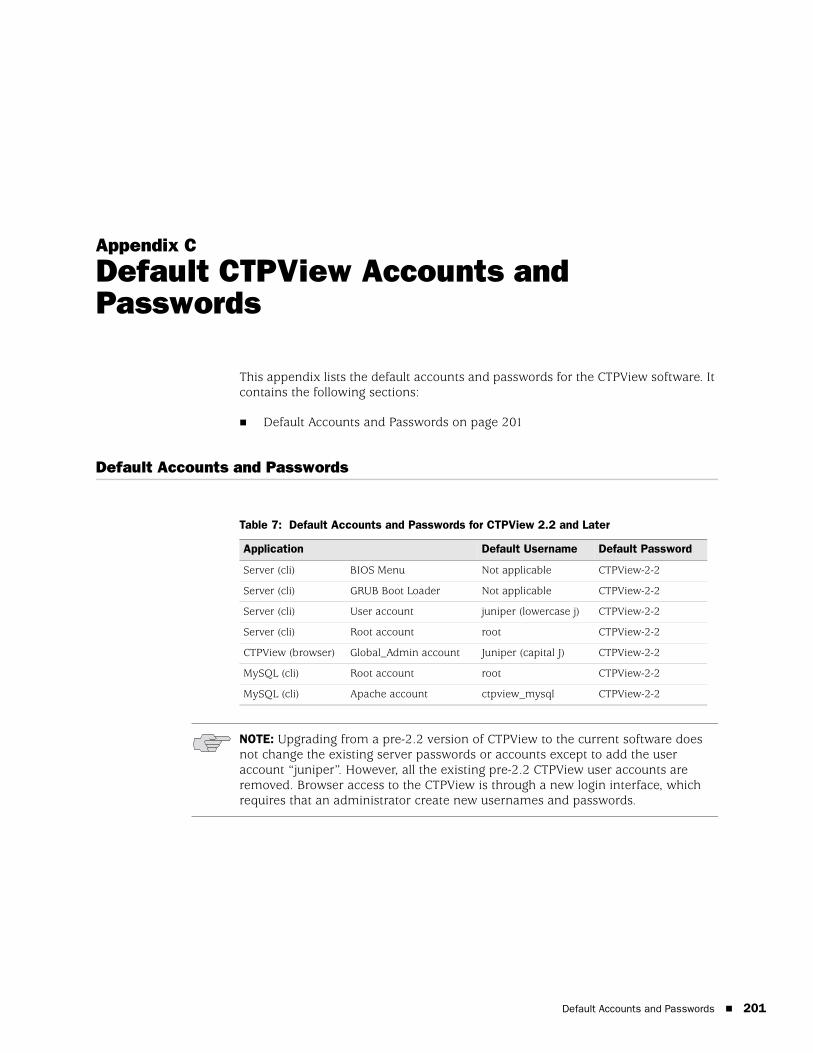
Default Accounts and Passwords 201
Appendix C
Default CTPView Accounts and Passwords
This appendix lists the default accounts and passwords for the CTPView software. It contains the following sections:
Default Accounts and Passwords on page 201
Default Accounts and Passwords
Table 7: Default Accounts and Passwords for CTPView 2.2 and Later
Application Default Username Default Password
Server (cli) BIOS Menu Not applicable CTPView-2-2
Server (cli) GRUB Boot Loader Not applicable CTPView-2-2
Server (cli) User account juniper (lowercase j) CTPView-2-2
Server (cli) Root account root CTPView-2-2
CTPView (browser) Global_Admin account Juniper (capital J) CTPView-2-2
MySQL (cli) Root account root CTPView-2-2
MySQL (cli) Apache account ctpview_mysql CTPView-2-2
NOTE: Upgrading from a pre-2.2 version of CTPView to the current software does not change the existing server passwords or accounts except to add the user account “juniper”. However, all the existing pre-2.2 CTPView user accounts are removed. Browser access to the CTPView is through a new login interface, which requires that an administrator create new usernames and passwords.
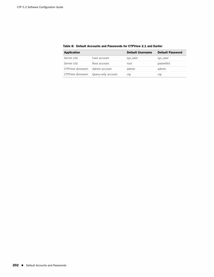
CTP 5.2 Software Configuration Guide
202 Default Accounts and Passwords
Table 8: Default Accounts and Passwords for CTPView 2.1 and Earlier
Application Default Username Default Password
Server (cli) User account sys_user sys_user
Server (cli) Root account root passw0rd
CTPView (browser) Admin account admin admin
CTPView (browser) Query-only account ctp ctp
203
Appendix D
Tripwire v2.3 Software on CTPView
NOTE: Tripwire is third-party software that is preloaded onto the CTPView server. It is not supported by Juniper Networks. Refer to the Tripwire documentation for more information.
Complete documentation is located on the CTPView server in the following directory:
/usr/share/doc/tripwire-2.3.1

CTP 5.2 Software Configuration Guide
204

Antivirus Installation Directory 205
Appendix E
Antivirus Software on CTPView
McAfee VirusScan for UNIX, version 5.10.0, is the only antivirus application from a DOD-approved vendor that is compatible with CTPView server software. You can download the software and documentation from the McAfee website.
Antivirus Installation Directory
A dedicated directory is on the CTPView server for the antivirus software installation:
/var/av
You may install the antivirus software directly into the directory /var/av if you are a member of the group "server.” After the software archive is in the /var/av directory, follow the installation directions in the McAfee product guide. We recommend that you select the default choices offered when installing the antivirus software.
NOTE: Third-party antivirus software is not supported by Juniper Networks. Refer to the antivirus documentation for more information.

CTP 5.2 Software Configuration Guide
206 Antivirus Installation Directory
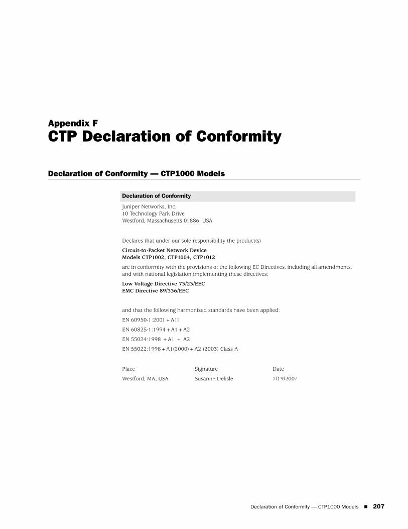
Declaration of Conformity — CTP1000 Models 207
Appendix F
CTP Declaration of Conformity
Declaration of Conformity — CTP1000 Models
Declaration of Conformity
Juniper Networks, Inc.10 Technology Park DriveWestford, Massachusetts 01886 USA
Declares that under our sole responsibility the product(s)
Circuit-to-Packet Network DeviceModels CTP1002, CTP1004, CTP1012
are in conformity with the provisions of the following EC Directives, including all amendments, and with national legislation implementing these directives:
Low Voltage Directive 73/23/EECEMC Directive 89/336/EEC
and that the following harmonized standards have been applied:
EN 60950-1:2001+A11
EN 60825-1:1994+A1+A2
EN 55024:1998 +A1 + A2
EN 55022:1998+A1(2000)+A2 (2003) Class A
Place
Westford, MA, USA
Signature
Susanne Delisle
Date
7/19/2007

CTP 5.2 Software Configuration Guide
208 Declaration of Conformity — CTP 2000 series
Declaration of Conformity — CTP 2000 series
Declaration of Conformity
Juniper Networks, Inc.10 Technology Park DriveWestford, Massachusetts 01886 USA
Declares that under our sole responsibility the product(s)
Circuit-to-Packet Network DeviceModel CTP 2000 series
are in conformity with the provisions of the following EC Directives, including all amendments, and with national legislation implementing these directives:
Low Voltage Directive 73/23/EECEMC Directive 89/336/EEC
and that the following harmonized standards have been applied:
EN 60950-1:2001+A11
EN 60825-1:1994+A1+A2
EN 300 386 V1.3.3:2005
EN 55024:1998 +A1 + A2
EN 55022:1998+A1(2000)+A2 (2003) Class A
Place
Westford, MA, USA
Signature
Susanne Delisle
Date
7/19/2007
Index 209
Index
Numerics4WTO Voice interface .......................................................30
Aaccounts, default.............................................................201asymmetric configuration, example..................................53Autobaud ........................................................................154AutoSwitch......................................................................152AutoSwitch connection check utility................................183avanced options, configuring ............................................62
BBERT testing ...................................................................104boot configuration, first ....................................................10buffer recenter count ........................................................98buffer settings...................................................................54bundle operations.............................................................11bundle types.....................................................................12bundles, creating ..............................................................19
CCESoPSN ....................................................................12, 15channel
dual ...........................................................................31enabled .....................................................................31
CLI menu....................................................................7, 8, 9clocking
options ......................................................6, 48, 49, 50clocking, configuring ........................................................51commands
node operation ............................................................8node synchronization ..................................................8port configuration........................................................7
configuring the software .....................................................7Connection Check utility.................................................183CTP...................................................................................12CTP groups, adding and removing ..................................160CTP hosts, adding and removing.....................................160CTP network hosts, managing.........................................161CTP operating system, updating .....................................170CTP overview......................................................................3CTP serial aggregation ......................................................75CTP software, burning images.........................................182CTPView
automatic functions.................................................163
booting from CD......................................................199configuring ..............................................................127connection throttling ...............................................179installing..........................................................127, 132restoring settings .....................................................131restoring shell access ...............................................195saving configurations...............................................166setting global access ................................................144updates....................................................................181
CTPView administration center ...............................143, 176CTPView server
configuring ..............................................................134restoring browser access .........................................198synchronization .......................................................176
DDeclaration of Conformity, EC.................................207, 208diagnostics......................................................................114direct digital synthesizer ...................................................50DTE interface ..................................................................155dual channel .....................................................................31
EEC Declaration of Conformity .................................207, 208e-mail notifications .........................................................162enabled channel ...............................................................31Ethernet support.............................................................156
FFedora Core 4 .................................................................127FIFO .................................................................................51Fractional T1/E1 interface .................................................31
GGRUB Boot Loader ..........................................................136
Hhardware monitoring ......................................................155
Iinput level .........................................................................31input signals .....................................................................58installing the software .....................................................127interface encoding, configuring...................................44, 45
CTP 5.2 Software Configuration Guide
210 Index
interface type, configuring................................................ 30IPv4................................................................................ 155IPv6................................................................................ 155IRIG-B............................................................................... 41
Llayer 2 bridging ................................................................75log print level, setting ..................................................... 115logging, secure................................................................ 122login banner, configuring................................................ 124
Mmaintenance reports ...................................................... 171mirroring.......................................................................... 24MySQL Apache account password .................................. 137
Nnetwork monitoring................................................ 172, 182NID selection.................................................................. 156node
maintenance ..................................................... 69, 165operations ................................................................. 69synchronization................................................. 65, 116
node operation command .................................................. 8node settings .................................................................. 151node synchronization command ........................................ 8
Ooutput level....................................................................... 31
Ppacket processing ............................................................... 5packet size, configuring .............................................. 46, 47packet-based serial (PBS) port configuration ................... 157packet-bearing serial interface .................................... 63, 64packets ............................................................................. 98passwords
changing ......................................................... 122, 198default..................................................................... 201managing ................................................................ 121setting ..................................................................... 196
PBS................................................................................. 157port clocking, configuring................................................. 51port configuration
packet-bearing serial interface................................... 63port configuration command.............................................. 7port database, state .......................................................... 99port forwarding ..............................................................181port mirroring................................................................... 24port operations ................................................................. 98port queries ................................................................ 94, 96port speed, configuring..................................................... 54PWE3 support ................................................................ 155
Qqueries
advanced................................................................. 101port ..................................................................... 94, 96
Rreceive packet processing ...................................................5reporting.........................................................................184reports............................................................................174
maintenance ...........................................................171restoring browser access to CTPView server....................198restoring shell access ......................................................195
SSAToP........................................................................12, 155SCC.................................................................................108secure log management..................................................122security profile................................................................119security settings, advanced .............................................127serial aggregation .............................................................75Serial Communications Controller (SCC) counts..............108serial loop.......................................................................102serial stream processing .....................................................4server configuration validation utility..............................180service type, configuring.............................................56, 57signaling configurations ....................................................58software
installation...............................................................127operations .................................................................93queries, performing...................................................93updates ...................................................................181
SSH.................................................................................181SSH port forwarding .......................................................181synchronization ................................................................65sytem saves, automatic...................................................179
TT1/E1 interface .................................................................31tabbed browser support ..................................................180talk squelch ......................................................................31time to live, configuring ....................................................57transmit packet processing .................................................5transparent circuit mode.................................................156Tripwire ..........................................................................203troubleshooting...............................................................195
Uuser management functions ...........................................120
VVcomp..............................................................................22virtual IP addresses.........................................................154VLAN support .................................................................156voice compression ......................................................22, 32
YY cable redundancy ..........................................................61