cu. e:;ii s-. · you can connect the rem pole to external switch for positive +12v on / off. * to...
TRANSCRIPT

IMf'DItTA NTl P AC"' CA,u:rUL LY IN o,ua.N AL CARTON II'" POSS' SLII:. WII: ARII: NCY
RII:SPONS.SLII: FOR OAMAall: , .. CURRCO ,,, RETUR"''' a ITItMS I'"OR REPAIR. A LII:T'rIl:R
"-ATIN a y OUR II:XACT STRCET ADDRItS, OAYYIMIt PH ONC NUMIIER, AND T HII: PROSLII:M
YOU A RII: II:XPItR. CNCI " a SH OULO liE I"CL UOED. You MUIIT ALSO II:N CLOSII: A COPY
o r T H E ORIaiNAL RECltiPT A SPROOI'" Dr OATil: OF PURC"AIIII:
TECHNICAL SUPPORT HOTLINE
QUill! TECHNICAL DEf'AItTMI:NT~' IiJ.!AC'LY AN SWER ANY QUESTICN •
. '~;;:-:7 U M A Y "'AV I: ABOUT CU. f' .~!I. Tt-t EY C AN NOT, HDWIE.V~ TI:LL Y OU THE S TATUe 0" A e:;iI S-. HAN OLI: OTHe::R CU S TOMER
S e::R V tCI: S ITUA.T I ONIII
I 6CC 63RO S TREET
B ROOI(LYN, NY 1 1204
l -BOC·934~.z 2 77
WWW.P YLEAUO} O. COM

20 1
z o !;;: u u.. U W 0.. U) • • · ~ 3 ..... · ~
· ~ • • • ~
1 i . . 0* 8
; H i o
... ~ ~ ... , ~
"." .. I a ~ 0;.: i' ~ ~ .
Congratulations on purchasing the High Speed Power Amplifier. The amplifier has been designed using the latest electronic technology available, allowing you to produce high quality stereo reproduction in mobile applications. This system provides you with low harmonic distortion, a huge considerable amount of reserve voltage and high temperature stability.
Just enjoy the perfect sound this amplifier takes to you!
INSTALLATION
* Since the amplifier is sensitive to electrical and motor noise and interference from the amplifier may affect your radio reception , try to mount it at least 3 feet away from the receiver. Good locations include under a seat, in the trunk or hatch area.
* Please remember this is a high power unit which generates high electrical energy and heal. Therefore be sure to install the unit in a place with sufficient airflow, a minimum of dust and no moisture. Allow enough space around the cooling fins to permit reasonable airflow and cooling. It is important to ensure that the cooling fins of the heat sink are not against a panel or a surface preventing air circulation.
* Never mount the amplifier in a location that is subject to direct sunlight or exposed to moisture. Be sure to mount the amplifier to a strong, solid surface which will not give way under the stress of a sudden stop or accident.
* When mounting the amplifier on a side wall , try to position it so that the slots in the cooling fins are vertical. Amplifier should not be mounted on the bottom of a rear deck with the fins facing down because the heat will radiate back up into the amplifier. Leave yourself enough room on either side of the amplifier to make all the wire connections and adjust the controls. If you have a subwoofer box in your vehicle , you can mount the amplifier on the outside of the box.
Caution : If you are mounting the amplifier to the vehicle's floor, check beneath the car to be sure your screws won't puncture a brake or gas line.
WAR NING !
Con ti nuo u s exposure to sound pressu re levels over lOOdB may cause permanent h eari n g loss. High power au tosound system may produce sound pressure levels well over 130dB, use common sense and practice safe sou nd please!

2 19
POWER CONNECTION
@
~, . ,,,;:;;;;;;;J I' "d
IMPORTANT ! Before making any connections, disconnect the car' s battery until the installation is completed to avoid possible damage to the electrical system
* The + 12V DC power cable should be heavy gauge stranded copper cable with heavy insulation, since it draws power directly from the positive battery terminal. Select the cable gauge al least 10mm
2• And the ground cable gauge should be
the same as the +12V DC.
* Connect the + 12V Power terminal to the battery ( +) position terminal. An in- line fuse must be installed in the + 12V power cable near the battery less than 50mm . Without one , an accidental short circuit could pose a fire hazard and damage your amplifier. Connect the fuse holder to battery, however, do not install fuse at this time .
* Connect the GROUND Power terminal direclly to the battery ( - ) position terminal or the car chassis. Ensure that all paint or other insulation is remove from around the hole area , and using self tapping screw, securely affix the bare wire ends to the vehicle chassis. Use as short as possible.
* Many radio ' s and other music sources have an output terminal for connection of the remote turn on of the power ampli fier. CONNECT the output terminal to the amplifier REM control jack. If a radio doesn ' t have a remote turn on feature , you can connect the REM pole to external switch for positive + 12V ON / OFF.
* To help minimize interference, it is best to run the Dower cables along the opposite side from the audio cables .
Caution : The power cables must be connected tightly. A loose connection may cause malfunctions or interference noise or distortion.
MONO CHANNEL AMPLIFIER - APPLICATIONS PLA3100D/PLA4600D
MASTER
SLAVE
MASTER
SLAVE
INTERCONNECTION EXAMPLE 1 Subwoofar wi th a Oual-Voicecoil
Subwoot.. Vol"" Coil 2 l_IOhm --........ VI! __
.... --. --. INTERCONNECTION EXAMPLE 2 Subwooler with a Singlel-Voicecoil
Subwoot.. l _ IOhm
S .. _.2 1_'Ohm
18 3
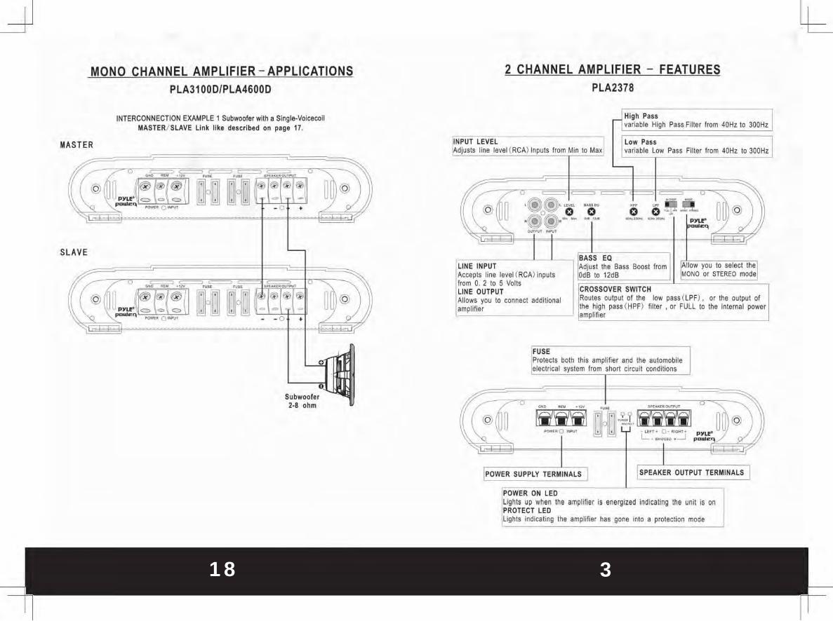
MONO CHANNEL AMPLIFIER - APPLICATIONS PLA3100DfPLA4600D
INTERCONNECTION EXAMPLE 1 Subwoofer with a Single-Voicecoil MASTER/ SLAVE link like described on p~ge 17.
MASTER
@
SLAVE
Subwoofer 2·8 ohm
2 CHANNEL AMPLIFIER - FEATURES PLA2378
from Min to
FUSE
Pass Filter from 40Hz to 300Hz
; I Pass Filter from 40Hz 10 300Hz
low pass (lPF), or the ou tput of '-,;:;; (HP;'; filter , or FULL to Ihe internal
Protects both this amplifier and the automobile elecuical system from short circuil conditions
- • • . ,. ...... ... "" . ,,~ ;f/ @(I ~ tfi1W OO.?d WWI ~ @ I
- 0 -'" •• 1 [ -""" 0-0_'. P)ll~ ",,,,- L _ ...... 0 • -.J po",'".::",
I ~OWfR SUPPLY TERMINALS I ISPEAKER OUTPUT TERMINALS
POWER ON LED lights up when the amplifier is energized indicating the unit is on PROTECT LED lights indicating the amplifier has gone inlo a protection mode

4 17
2 CHANNEL AMPLIFIER - FEATURES PLA2678
r1 HlglI Pass z variable High Pass Filler from 40Hz to 300Hz
~PUT LEVEL lxl djusts line level (RCA) Inputs from Min to Max
I Low Pass z variable Low Pass Filter from 40Hz to 300Hz
L-
// = == = = ~ .®(!}._. ,M -@( ~ ...... - 0 - -- ~lli@ o 0 0 0 .®®.-- -,- ---- r:~r" ~"'- . 0, -~ -
BASS eQ LINE INPUT Adjust the Bass Boost from I~IIOW you to select lh
l:1
Accepts line level (RCA) inputs OdS to 12dB MONO or STEREO mode from O. 2 to 5 VOlls LINE OUTPUT IlrROSSOVER SWITCH Allows you to connect additional Routes output of Ihe low pass { L?F), or the output of
amplifier J l:h8 high pass ( HPF) filter , or FULL to the internal power amplifier
FUSE Protects both th is amplifier and Ihe automobile electrical system from short Circuit conditions
tf/ ~ - .. . ," ......,.0""",,'
@ ( ~ ~ 00 .'2·1" WWI ~~ @ ..,.... 0_ I I L~~ ·"".0·.""". ~'-o. r-.;..",\ L'"7" '~
I IpOWER SUPPLY TERMINALS I ISPEAKER OUTPUT TERMINALS I
POWER ON lEO Lights up when the amplifier is energized indicating the unit is on PROTECT LEO Lights indicating the amplifier has gone into a protection mode
SLAVE
MONO CHANNEL AMPLIFIER - APPLICATIONS PLA3100D/PLA4600D
MASTER/ SLAVE Link like described on page 17.
~--
@ 00 @
MASTER
SLAVE
@

16 5
MONO CHANNEL AMPLIFIER - APPLICATIONS PLA3100D/PLA4600D
Car ster.e system
1- ' O~ml Speak ..
@
2- ' Ohm. Spllk.r
2 CHANNEL AMPLIFIER - FEATURES PLA2978
Pass Filter from 40Hz to 300Hz
Low Pass variable low Pass Filter from 40Hz to 300Hz
o 0 -... ,," --
I A~,;p"ljne level ( RCA) inputs 2 to 5 Vo lls
OUTPUT to connect addit ional low pass (LPF) , or the output of
pass ( HPF ) filter, or FULL to the internal power
both this amplifier and the automobile from short circui t conditions
TERMINALS
LED ';'Roi"c,'",iiii the amplifier is energized indicating the unit is on I ~ LED
Indicating the ampli fier has gone into a protect ion mode

6 15
4 CHANNEL AMPLIFIER - FEATURES PLA42781PLA4478
l ~ i 9h Pass variable High Pass Filter from
~~NE INPUT ccepls line level ( RCA) inputs from 0.2 to 6.0 Volts
15Hz to 250Hz
variable Low Pass Filler from I:LOW Pass
INPUT lEVEL lsi I ~djusts line level CRCA) Inputs from 0.2 to 6. 0 Volts
60Hz 10 200Hz r-
~(@(~ ,=. c =~
~ -- -- -"®~-- -- -- ~ 0
~ 000 0 000 @
I -- ----. !@i@ ... ------~ py~ v' -I~ I'D"'.,
L
CROSSOVER SWITCH ~tSSEQ sl djus! the Bass Boost from DdB to 18dS Routes output of the low pass ( LOW) . or the output of the high pass (HIGH) filter. or FULL [INPUT MODE
Allow ~ou to select the 2CH or 4CH mode I to the internal power amplifier
FUSE Protects both this amplifier and the automobile electrical system from short cireui! conditions
I POWER SUPPLY TERMINALS I I SPEAKER OUTPUT TER MINALS I
POWER ON LED lights up when the amplifier is energized indicating the unit is on PROTECTION LED Lights indicating the amplifier has gone in to a protection mode
MONO CHANNEL AMPLIFIER - APPLICATIONS PLA1800
Car stereo system
@
Ri hI
Lett
_ ... ,_ ...... _ .. -.. _ .... . -
I- a Ohm, Spu k. ,
== .... ""'"0Ul0'\IT
I~ I~I~I~ • 0
2- ' Ohm. Sp .. klf

14 7
MONO AMPLIFIER - APPLICATIONS
INPUT CONNECTIONS
* This amplifier has RCA connections for low level inputs. Low level signal is carried through RCA cables. it is preferred to use low level inputs to the amplifier if the head unit is equipped with the low level outputs.
SPEAKER OUTPUT CONNECTIONS
You do not need to make any adjustment for the input connection of amplifier before you connect the speaker output.
* Connect subwoofer wire to corresponding speaker output terminals of the amplifier.
* Be sure to have the positive wire from the speaker to the positive speaker terminal of the amplifier and the negative wire from the speaker must connect with the speaker terminal of the amplifier. Reversing any of these connections will result in the speaker cones moving out of phase which causes bass cancellation.
LEVEL CONTROLS
Turn the VOLUM E control on the amplifier to Min initially. Once the initi al power sequence has been performed, set the CD/ RADIO volume control to roughly 80% of full. Insert a CD or tune to a radio station and slowly turn up the amplifier VOLUME control until you hear some distortion , and then back it off for clean sound.
MONO CHANNEL AMPLIFIER - FEATURES PLA1800
SUBSONIC FILTER Sets the lower cu toff frequency. the frequency I ~~W PASS ariable Low Pass Filter from 40Hz to 300Hz is avriable from 10Hz to 40Hz
REMOTE CONTROL It PUT LEVEL djusl the low pass signal via the Accepts line level ( RCA) inputs from
enclosed remote control O. 4 10 4 volts
ff/ / .;;.,. ===== -U'" ~ ( @ ~ ~::P jM .!. _:_ ~"~o~: ~~ @
_·0 t --IrOWER ON LED I~~::" :~ ,,,' ,,,,,I f"~Od' to I2dB l lights up when the amplifier is energized
LIN E INPUT r;"uo, Ih' ,,;1 ;, '" PROTECT LED Accepts line level ( RCA) inputs from 0. 4 to 4 volts
~jghts indicati.ng the ampli fier has gone LINE OUTPUT
Into a protection mode Allows you to connect additional amplifier
FUSE Protects both this amplifier and Ihe automobile electrical system from short circuit conditions
I ( I POWER SUPPLY TERMINALS I I SPEAKER OUTPUT TERMINALS I

8 13
MONO CHANNEL AMPLIFIER - FEATURES PLA3100D/PLA4600D
REMOTE CONTROL Adjust the low pass signal via Iheenclosed remote control
Allowed you select MASTER OUTPUT mode or SLAVE INPUT
MASTER OUTPUT Allows 10 connect
Ii level (RCA) i
Sets the lower cutoff frequency, frequency is avriable from 15Hz
4 CHANNEL AMPLIFIER - APPLICATIONS PLA4278/PLA4478
3- CHANNEL MODE
POWER ON LED ,-,' _ , lights up when the amplifier is energized indicating the unit is on PROTECT LE D
ii i the amplifier has gone into
FUSE Protects both this amplifier and the automobile electrical system from short circuit condi tions
SPEAKER OUTPUT TERMINALS
2- CHANNEL MODE
~~Ii'fil _ 0_ lkn!l
.~ -o 0
- -.,,-. ,-,,-

12 9
4 CHANNEL AMPLIFIER APPLICATIONS PLA4278/PLA4478
4- CHANNEL MODE
CM1 CHI CHI CHI ] - 11 0 , ,,,, ] - 11 Oh .. , ] - 11 Oh .. , 2- 11 Oh .. ,
2 CHANNEL AMPLIFIER - APPLICATIONS
INPUT CONNECTIONS
* This amplifier has RCA connections for low level inputs . Low level signal is carried through RCA cables. it is preferred to use low level inputs to the amplifier if the head unit is equipped with the low level outputs .
* This amplifier has high input connection . High level input is used from radios that do nol have line - level outputs.
* Be sure not to use both low and high level inpu ts simultaneously !
SPEAKER OUTPUT CONNECTIONS
You do nol need to make any adjustment for the input connection of amplifier before you connect the speaker output.
* Connect right and left speaker wire to corresponding speaker output terminals of the amplifier.
* Be sure to have the positive wire from the speaker to the positive speaker terminal of the amplifier and the negative wire from the speaker must connect with the speaker terminal of the amplifier. Reversing any of these connections will result in the speaker cones moving out of phase which causes bass cancellation.
LEVEL CONTROLS
Turn the VOLUME control on the amplifier to Min initially. Once the initial power sequence has been performed, set the CD/ RADIO volume control to roughly 80% of fu ll. Insert a CD or tune to a radio station and slowly turn up the amplifier VOLUME control until you hear some distortion, and then back it off for clean sound.
-~

10 11
2 CHANNEL AMPLIFIER - APPLICATIONS PLA2378/PLA2678/PLA2978
STEREO MOOE
MONO MODE
o·
~M'£'iWW ~ _0_ ~ · ... '·0-.,· P>V'"
L._ • ...J
4 CHANNEL AMPLIFIER - APPLICATIONS
INPUT CONNECTIONS
* This amplifier has RCA connections for low level inputs. Low level signal is carried through RCA cables. it is preferred to use low level inputs to the amplifier if the head unit is equipped with the low level outputs.
SPEAKER OUTPUT CONNECTIONS
You do not need to make any adjustment for the input connection of amplifier before you connect the speaker output.
* Connect right and left speaker wire to corresponding speaker output terminals of the amplifier.
* Be sure to have the positive wire from the speaker to the positive speaker terminal of the amplifier and the negative wire from the speaker must connect with the speaker terminal of the amplifier. Reversing any of these connections will result in the speaker cones moving out of phase which causes bass cancellation.
LEVEL CONTROLS
Turn the VOLUME control on the amplifier to Min initially. Once the initial power sequence has been performed, set the CD/ RADIO volume control to roughly 80% of full. Insert a CD or tune to a radio station and slowly turn up the amplifier VOLUME control until you hear some distortion, and then back it off for clean sound.