cues by john bradford scott a dissertation submitted … · cues by john bradford scott a...
TRANSCRIPT

DEVELOPMENT OF A TISSUE ENGINEERED SKELETAL MUSCLE REPAIR
CONSTRUCT FEATURING BIOMIMETIC PHYSICAL, CHEMICAL, AND MECHANICAL
CUES
BY
JOHN BRADFORD SCOTT
A Dissertation Submitted to the Graduate Faculty of
WAKE FOREST UNIVERSITY GRADUATE SCHOOL OF ARTS AND SCIENCES
in Partial Fulfillment of the Requirements
for the Degree of
DOCTOR OF PHILOSOPHY
Biomedical Engineering
May 2015
Winston-Salem, North Carolina
Approved By:
George J. Christ, Ph.D., Advisor & Chair
Martin K. Childers, Ph.D.
Carolanne E. Milligan, Ph.D.
Aaron M. Mohs, Ph.D.
Justin M. Saul, Ph.D.
Abby R. Whittington, Ph.D. / Aaron S. Goldstein, Ph.D.
ii
TABLE OF CONTENTS
ACKNOWLEDGEMENTS ............................................................................................... iii
LIST OF FIGURES AND TABLES .................................................................................. iv
ABBREVIATIONS .......................................................................................................... vi
ABSTRACT .................................................................................................................. viii
CHAPTER I – INTRODUCTION ...................................................................................... 1
CHAPTER II – THE PROMOTION OF AXON EXTENSION IN VITRO USING
POLYMER-TEMPLATED FIBRIN SCAFFOLDS ...................................................... 37
CHAPTER III – IN VITRO AGRIN-INDUCED ACETYLCHOLINE RECEPTOR
CLUSTERING ON SKELETAL MUSCLE CELLS SEEDED ON A TUNABLE FIBRIN-
BASED SCAFFOLD ................................................................................................ 70
CHAPTER IV – ADVANCES TOWARD ENABLING THREE-DIMENSIONAL FIBRIN
SCAFFOLDS FOR TISSUE ENGINEERED MUSCLE REPAIR ............................. 109
CHAPTER V – PRELIMINARY EVALUATION OF INNERVATION AND REMODELING
OF A TISSUE ENGINEERED SKELETAL MUSCLE REPAIR CONSTRUCT IN VIVO
.............................................................................................................................. 152
CHAPTER VI – DISCUSSION, CONCLUSIONS, AND FUTURE DIRECTIONS .......... 173
CURRICULUM VITAE ................................................................................................. 183
iii
ACKNOWLEDGEMENTS
First, I would like to thank my brothers and friends – near and far, past and
present. Despite my best efforts to the contrary, you have kept me (mostly) sane through
difficult times, provided a constant reminder that life exists beyond my professional
commitments, and at times challenged me to think differently and grow beyond my
previous limitations.
I also acknowledge my parents – despite (and sometimes because of) our
diferrent points of view, the way I view and interact with the world has continually
evolved. Thank you for your encouragement and tolerance.
To those who have worked alongside me in the completion of this dissertation –
members of the Christ and Saul labs, WFIRM core technicians, you know who you are –
thank you for your constant assistance, willingness to discuss ideas, and academic
support. This work would have been impossible without you.
To members and staff of WFIRM, SBES, and the WFU Graduate School – thank
you for providing the framework and logistical support for my continuing education. I
would like especially to express my gratitude to members of my advisory committee,
who have shown remarkable patience during my candidacy.
Finally, I would like to thank the faculty and staff of Wake Forest who have
educated me about alternative careers in science. Your work gives hope to often
clueless graduate students on the cusp of entering a competitive world.
iv
LIST OF FIGURES AND TABLES
CHAPTER I
Fig. 1. Schematic of final tissue engineered muscle construct fabrication and
evaluation .......................................................................................................... 20
CHAPTER II
Fig. 1. Scaffold fabrication process .......................................................................... 41
Table 1. Template fiber fabrication parameters and resulting diameter .................... 43
Fig. 2. Scaffold morphology ..................................................................................... 51
Fig. 3. Conduit alignment within scaffolds ................................................................ 52
Fig. 4. Quantification of fiber template diameter relative to measured resulting
conduit diameter ................................................................................................ 53
Table 2. Scaffold porosity ........................................................................................ 54
Fig. 5. Scaffold mechanical properties ..................................................................... 55
Fig. 6. Axon infiltration of scaffolds .......................................................................... 57
Fig. 7. Quantification of axon infiltration ................................................................... 58
CHAPTER III
Fig. 1. Schematic of 3D tissue engineered muscle construct fabrication, seeding, and
preconditioning .................................................................................................. 84
Fig. 2. Efficacy of agrin treatment in 2D ................................................................... 88
Fig. 3. AChR clustering adjacent to agrin-presenting microparticles in 2D ............... 90
Fig. 4. Dramatic impact of bioreactor preconditioning on AChR expression and
organization in 3D tissue engineered constructs seeded with rat MDCs ............ 92
Fig. 5. Representative examples of AChR clustering in a bioreactor-preconditioned
agrin-presenting tissue engineered construct ..................................................... 93
v
CHAPTER IV
Fig. 1. Perfusion loop schematic ............................................................................ 117
Fig. 2. Cell-infiltrated fibrin scaffold ........................................................................ 126
Fig. 3. Cell seeding of patterned fibrin immediately after perfusion ........................ 128
Fig. 4. Cell density in rMDC-seeded fibrin scaffolds over time................................ 129
Fig. 5. Fibrin scaffolds with 12 μm diameter conduits after cell seeding with a 4.8
mL/min perfusion of rMDCs ............................................................................. 130
Fig. 6. Effect of directionality of perfusion and conduit lumen diameter on cell seeding
........................................................................................................................ 131
Fig. 7. Example melt extruded PVOH fiber ............................................................ 132
Table 1. Water solubility and composition of melt-extruded fibers .......................... 133
Fig. 8. Initial perfusion-seeded, microparticle-presenting 30 mm constructs........... 134
Fig. 9. Optimized microparticle loading of fibrin scaffold......................................... 135
Fig. 10. Initial perfusion cell seeding of 10-15 mm long fibrin scaffolds .................. 136
Fig. 11. rMDC perfusion of 15 mm long CA-templated fibrin scaffolds mounted in
silicone tubing .................................................................................................. 136
CHAPTER V
Fig. 1. Schematic overview of rat neurotization study ............................................ 157
Fig. 2. Overview of host response to construct implantation .................................. 164
Fig. 3. Glycogen content of explants in the construct area ..................................... 166
Fig. 4. Potential Interaction of immobilized femoral nerve stump with suture.......... 167
vi
ABBREVIATIONS
2D: two-dimensional
3D: three-dimensional
α-BTX: alpha bungarotoxin
ACh: acetylcholine
AChR: acetylcholine receptor
AJ1: 41 μm diameter pMMA fiber formed using the Alex James & Associates extruder
ANOVA: analysis of variance
BAM: bladder acellular matrix
BSA: bovine serum albumin
CA: cellulose acetate
DAPI: 4',6-diamidino-2-phenylindole
DI: deionized
DMEM: Dulbecco's modified Eagle's medium
DRG: dorsal root ganglia / ganglion
E: Young’s modulus
ECM: extracellular matrix
EDC: N-(3-dimethylaminopropyl)-N′-ethylcarbodiimide hydrochloride
FBR: foreign body response
FBS: fetal bovine serum
FDU: 5-fluoro-2′-deoxyuridine
H&E: hematoxylin and eosin
HS: horse serum
ID: inner diameter
LD: latissimus dorsi
vii
Lrp4: low-density lipoprotein receptor-related protein 4
(r)MDC(s): (rat) muscle-derived cell(s)
MEP: motor end plate
MMP(s): matrix metalloproteinase(s)
MuSK: muscle-specific kinase
MW: molecular weight
OD: outer diameter
NBF: neutral-buffered formalin
NGF: nerve growth factor
NMJ: neuromuscular junction
PAS: periodic acid - Schiff
PBS: phosphate-buffered saline
PEO: poly(ethylene oxide)
pMMA: poly(methyl-methacrylate)
PVOH: polyvinyl alcohol
s-NHS: N-hydroxysulfosuccinimide
SD: standard deviation
SEM: scanning electron microscopy
TEMR: tissue engineered muscle repair
viii
ABSTRACT
John Bradford Scott
DEVELOPMENT OF A TISSUE ENGINEERED SKELETAL MUSCLE REPAIR
CONSTRUCT FEATURING BIOMIMETIC PHYSICAL, CHEMICAL, AND MECHANICAL
CUES
Dissertation under the direction of
George J. Christ, Ph.D.
Volumetric muscle loss (VML), an injury to skeletal muscle which permanently
impairs appearance and function [1], commonly results from trauma, congenital defect,
or surgical side effect, and significantly affects quality of life. Unfortunately, clinical
treatments for VML are lacking. The "gold standard" treatment remains autografting,
which is often limited by donor site availability and morbidity as well as incomplete repair
of function or restoration of cosmesis. In the current work, we describe an in vitro
approach to tissue engineered skeletal muscle repair combining biomaterial-seeded
cells with pharmacological and mechanical cues. The overall goal of this work was to
develop and characterize a tissue engineered construct which could eventually form the
basis for a clinical alternative to autografting in VML.
This approach began with a fibrin scaffold patterned with an aligned array of
cylindrical pores. This scaffold was evaluated for its mechanical properties and its ability
to support neurite ingrowth and muscle cell seeding in vitro. The approach further
incorporated exogenous agrin, which was designed to mimic in vitro the neuronal
pharmacological cue initiating native assembly of the motor end plate (MEP) in vivo.
Agrin efficacy was evaluated both alone and in conjunction with mechanical stretch by
histological labeling of acetylcholine receptor (AChR) clusters, the presumptive in vitro
ix
analog of MEPs. Next, the ability of the construct to maintain these AChR clusters in the
complex biological environment in vivo was assessed. Constructs were implanted
subcutaneously in a rodent model and connected to the proximal stump of the femoral
nerve. This experiment was designed to assess the biocompatibility and initial
remodeling of the implanted construct as well as the potential formation and function of
neuromuscular junctions between host nerves and construct muscle cells.
These studies demonstrated that patterned scaffolds supported neurite ingrowth
and muscle cell seeding in vitro. Moreover, the combination of agrin and stretch in vitro
resulted in dramatic enhancement of AChR clustering, which is a key phenotypic aspect
of MEPs on innervated skeletal muscle in vivo. Taken together, these results represent
an important first step toward development of a novel tissue engineered muscle repair
treatment for potentially expanded clinical applications to VML injuries.
[1] Grogan BF, Hsu JR, Skeletal Trauma Research Consortium. Volumetric Muscle
Loss. J Am Acad Orthop Surg 2011;19:S35–7.

1
CHAPTER I
INTRODUCTION

2
1. Clinical significance of volumetric muscle loss and peripheral nerve injuries
In humans, muscles constitute nearly half of the body's mass [1] and are critical
to daily life. Skeletal muscle, the most common type in the body, is responsible for up to
85% of heat production and, through its anchorage to other structural elements - notably
the skeleton - movement of body parts leading to ambulation, breathing, and other
essential tasks [1]. To enable these functions, muscles are spread throughout the body
and are a particularly prevalent component in the extremities, which serve as the drivers
of locomotion.
Unfortunately, extremity injury is incredibly common in the current clinical setting
[2]. Advances in motor vehicle restraint systems in the civilian setting, and similar
advances in body armor in the military setting, have saved lives of patients who would
have otherwise died of their wounds - but these survivors now often present to the clinic
with extremity trauma [2,3]. This places a large financial burden on the health care
system. For example, when ranking resource utilization by injury in casualties from US
armed conflicts in Iraq and Afghanistan, extremity trauma comprised 65% [2]. This
proportion was estimated to correspond to costs totaling roughly $1.2 billion [2].
The vast majority of military injuries are caused by explosions [3], which are
associated with significant damage to extremity soft tissues [4], including muscle.
Injuries of this type can be so severe that they result in persistent functional impairment,
which is termed volumetric muscle loss (VML) [5]. Though the single greatest cause of
damage to skeletal muscle is trauma [3,5–8], it can also result from congenital or
acquired disease or tumor resection [9]. This places VML as a common, and costly,
problem in both military and civilian settings.
There are also over 50,000 surgical procedures for peripheral nerve injuries
reported annually [10] in both civilian and military settings due to motor vehicle
accidents, knife injuries, gunshot wounds, and other sources of trauma [11,12]. Injuries

3
to peripheral nerves are also quite debilitating, resulting in impairment or loss of function
in tissue they innervate — for example, weakness or paralysis of a body part by inability
to signal skeletal muscles to contract.
Co-morbid injuries of a critical size involving both skeletal muscle and the
innervating peripheral nerve represent an especially aggravated class of VML termed
total compartment loss [5]. Unsurprisingly, the prognosis for an injury of this extent is
extremely poor, with bracing by an external load-bearing device the only currently-
envisioned treatment strategy [5].
2. Development of the neuromuscular junction
The neuromuscular synapse is a highly organized structure designed to
efficiently transfer an electrical depolarization propagated down a nerve axon into a
resultant electrical event in the target muscle fiber by way of the chemical transmitter
acetylcholine (ACh) [1]. To establish and maintain this elegant function, the synapse
must be assembled by a carefully coordinated series of events. This begins in the
developing embryo, where differentiated muscle fibers appear prior to innervation of the
region by motor nerve axons [13]. These myofibers, and indeed less mature muscle cells
called myotubes (see Section 4) which are long, multinucleated cells that lack the size
and striations of myofibers, express acetylcholine receptors (AChRs) within their cell
membranes [14]. AChRs are initially "prepatterned" into a concentration of clusters near
the middle of the cell [13,15,16]. Formation of these prepatterns require the molecules
low-density lipoprotein receptor-related protein 4 (Lrp4) and muscle-specific kinase
(MuSK) [17]. Upon migration of the motor axon to the myofiber, these prepatterns have
been suggested to dictate where the axon grows and where the synapse between the
two cells will form [15]. Though a muscle fiber may initially be innervated by more than

4
one axon early in development, shortly after birth these excess connections will have
disappeared, leaving one axon to innervate each fiber [16].
Agrin is a heparan sulfate proteoglycan which, in synaptogenesis, is one of the
primary molecules responsible for accumulation of muscle AChRs directly opposite the
axon terminal. Agrin is also expressed in many other tissues and features many
isoforms. Splice differences near agrin's C-terminal dramatically alter the effects of the
molecule, the most relevant of which for the purpose of this review is an amino acid
insert at a location termed the z-site in mammals [14,18]. This z-site insertion is critical to
the behavior of neuronal agrins [14,18], and agrins carrying it are referred to as z+ agrin
where appropriate to facilitate discussion of this differential status. The work described
here is concerned solely with z+ agrin; therefore, any further references to "agrin"
indicate this splice variant. Many suppliers (e.g. R&D Systems, Minneapolis, MN)
produce recombinant C-terminal agrin fragments (sometimes referred to as mini-agrins)
based on this z+ isoform which are suitable for experimentation.
Agrin is synthesized within the cell body of the motor neuron but is subsequently
transported down the axon and anchored within the synaptic basal lamina [14,17,18].
This agrin then binds to Lrp4 on the muscle fiber surface, which in turn associates with
MuSK [17,19]. This association results in the concentration of AChRs underneath the
axon terminal [14], in the area of the muscle membrane that becomes the post-synaptic
structure or motor end plate (MEP). This process likely occurs by at least four different
mechanisms, all of which are linked to the agrin signal to some extent: first, AChRs
which normally randomly diffuse within the membrane become trapped when they
contact a growing aggregate of other AChRs [14]; second, the average time of individual
AChR molecule residence in the muscle membrane increases [14]; third, muscle nuclei
near the synapse specialize to express genes encoding AChR subunit proteins, thereby
increasing total AChR count in the membrane nearby [14,18]; fourth, AChR subunit

5
expression is suppressed in nuclei distant from the membrane [14], potentially due to
cell-wide inhibition resulting from ACh stimulation [16].
The initial assembly of the synapse leads to further differentiation both of the
presynaptic neuron and the postsynaptic muscle fiber. Lrp4 acts as a muscle-derived
retrograde differentiation signal to the motor axon [20]. Similarly, downstream effects of
MuSK activation by agrin-Lrp4 cause the cell membrane at the MEP to remodel into an
arrangement of invaginated junctional folds, with AChRs concentrated at high density at
the crests of the folds [14]. The structures - both nerve and muscle - comprising the
mature synaptic apparatus are collectively called the neuromuscular junction (NMJ).
Within the NMJ, the two apposing cell membranes remain separated by a space roughly
60-100 nm wide known as the synaptic cleft [1]. This cleft is isolated from fluid of the
surrounding tissue by a Schwann cell, which wraps the entire NMJ [1].
In summary, agrin signaling is a powerful regulator of neuromuscular synapse
assembly and, therefore, of vital importance to proper function of motor units that are
required for ambulation, breathing, and other required bodily functions.
3. Relevant aspects of structure and function in skeletal muscle and peripheral
nerve
Each skeletal muscle is composed primarily of numerous contractile muscle
cells, called myofibers, which can be oriented within the overall structure in a wide
variety of ways depending on the function of the muscle [1]. For example, myofibers
within fusiform muscles such as the biceps brachii have a largely parallel arrangement
designed to produce force in a single direction, while those within a circular muscle such
as the orbicularis oculi are arranged in a loop in order to produce an opening or closing
motion [1].
6
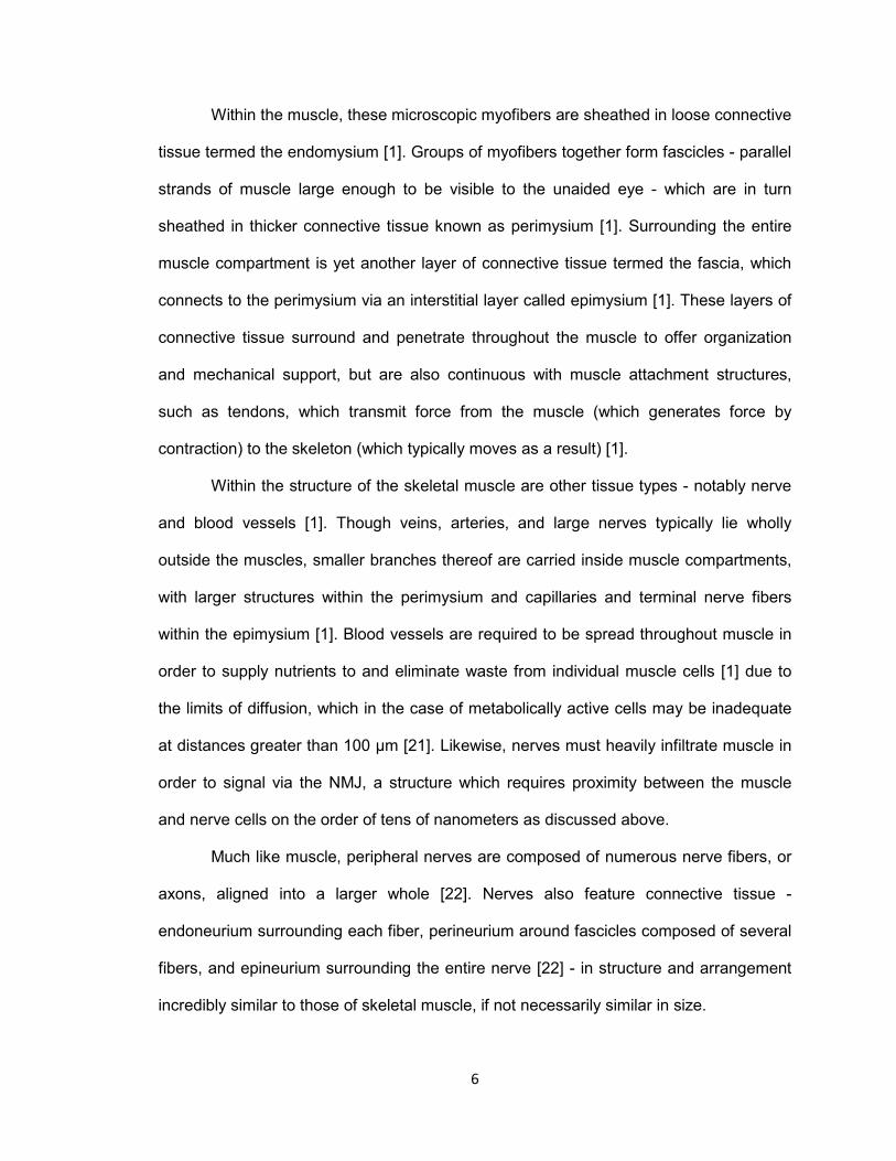
Within the muscle, these microscopic myofibers are sheathed in loose connective
tissue termed the endomysium [1]. Groups of myofibers together form fascicles - parallel
strands of muscle large enough to be visible to the unaided eye - which are in turn
sheathed in thicker connective tissue known as perimysium [1]. Surrounding the entire
muscle compartment is yet another layer of connective tissue termed the fascia, which
connects to the perimysium via an interstitial layer called epimysium [1]. These layers of
connective tissue surround and penetrate throughout the muscle to offer organization
and mechanical support, but are also continuous with muscle attachment structures,
such as tendons, which transmit force from the muscle (which generates force by
contraction) to the skeleton (which typically moves as a result) [1].
Within the structure of the skeletal muscle are other tissue types - notably nerve
and blood vessels [1]. Though veins, arteries, and large nerves typically lie wholly
outside the muscles, smaller branches thereof are carried inside muscle compartments,
with larger structures within the perimysium and capillaries and terminal nerve fibers
within the epimysium [1]. Blood vessels are required to be spread throughout muscle in
order to supply nutrients to and eliminate waste from individual muscle cells [1] due to
the limits of diffusion, which in the case of metabolically active cells may be inadequate
at distances greater than 100 μm [21]. Likewise, nerves must heavily infiltrate muscle in
order to signal via the NMJ, a structure which requires proximity between the muscle
and nerve cells on the order of tens of nanometers as discussed above.
Much like muscle, peripheral nerves are composed of numerous nerve fibers, or
axons, aligned into a larger whole [22]. Nerves also feature connective tissue -
endoneurium surrounding each fiber, perineurium around fascicles composed of several
fibers, and epineurium surrounding the entire nerve [22] - in structure and arrangement
incredibly similar to those of skeletal muscle, if not necessarily similar in size.
7
One motor neuron and all the skeletal muscle fibers it innervates are collectively
known as a motor unit [1]. All muscle fibers of a motor unit contract simultaneously when
stimulated by their innervating neuron [1] in a process known as excitation-contraction
coupling. When a nerve impulse reaches the NMJ, the neurotransmitter ACh is released
from synaptic vesicles into the synaptic cleft [1]. ACh diffuses across the cleft and binds
to AChRs accumulated at the MEP, beginning a cascade which causes the postsynaptic
muscle cell to contract [1]. ACh in the synapse is rapidly broken down by
acetylcholinesterase present in the synaptic muscle membrane and basal lamina,
ensuring that muscles relax as soon as the nerve ceases releasing ACh [1].
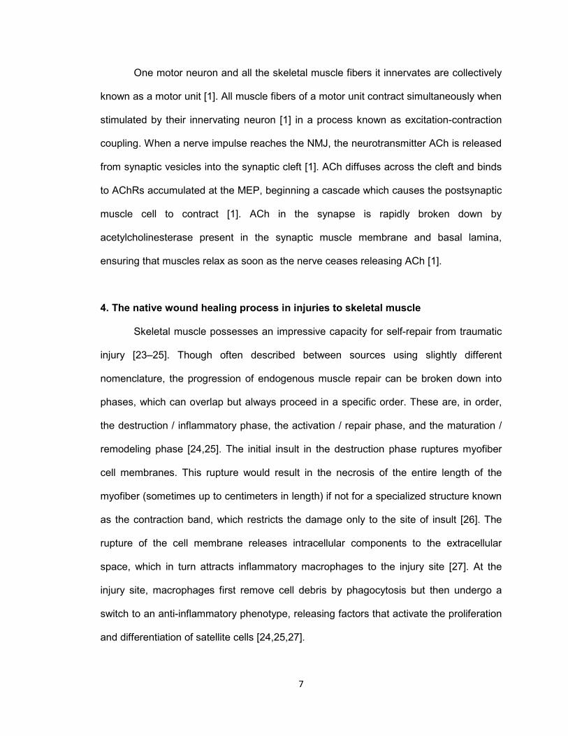
4. The native wound healing process in injuries to skeletal muscle
Skeletal muscle possesses an impressive capacity for self-repair from traumatic
injury [23–25]. Though often described between sources using slightly different
nomenclature, the progression of endogenous muscle repair can be broken down into
phases, which can overlap but always proceed in a specific order. These are, in order,
the destruction / inflammatory phase, the activation / repair phase, and the maturation /
remodeling phase [24,25]. The initial insult in the destruction phase ruptures myofiber
cell membranes. This rupture would result in the necrosis of the entire length of the
myofiber (sometimes up to centimeters in length) if not for a specialized structure known
as the contraction band, which restricts the damage only to the site of insult [26]. The
rupture of the cell membrane releases intracellular components to the extracellular
space, which in turn attracts inflammatory macrophages to the injury site [27]. At the
injury site, macrophages first remove cell debris by phagocytosis but then undergo a
switch to an anti-inflammatory phenotype, releasing factors that activate the proliferation
and differentiation of satellite cells [24,25,27].
8
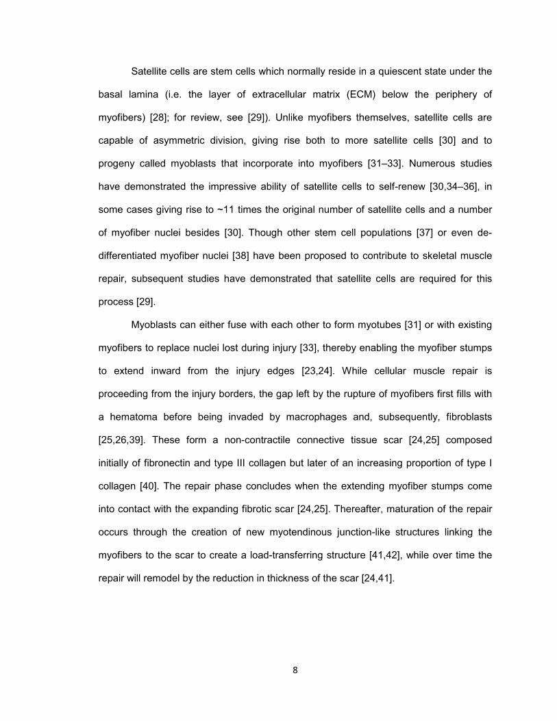
Satellite cells are stem cells which normally reside in a quiescent state under the
basal lamina (i.e. the layer of extracellular matrix (ECM) below the periphery of
myofibers) [28]; for review, see [29]). Unlike myofibers themselves, satellite cells are
capable of asymmetric division, giving rise both to more satellite cells [30] and to
progeny called myoblasts that incorporate into myofibers [31–33]. Numerous studies
have demonstrated the impressive ability of satellite cells to self-renew [30,34–36], in
some cases giving rise to ~11 times the original number of satellite cells and a number
of myofiber nuclei besides [30]. Though other stem cell populations [37] or even de-
differentiated myofiber nuclei [38] have been proposed to contribute to skeletal muscle
repair, subsequent studies have demonstrated that satellite cells are required for this
process [29].
Myoblasts can either fuse with each other to form myotubes [31] or with existing
myofibers to replace nuclei lost during injury [33], thereby enabling the myofiber stumps
to extend inward from the injury edges [23,24]. While cellular muscle repair is
proceeding from the injury borders, the gap left by the rupture of myofibers first fills with
a hematoma before being invaded by macrophages and, subsequently, fibroblasts
[25,26,39]. These form a non-contractile connective tissue scar [24,25] composed
initially of fibronectin and type III collagen but later of an increasing proportion of type I
collagen [40]. The repair phase concludes when the extending myofiber stumps come
into contact with the expanding fibrotic scar [24,25]. Thereafter, maturation of the repair
occurs through the creation of new myotendinous junction-like structures linking the
myofibers to the scar to create a load-transferring structure [41,42], while over time the
repair will remodel by the reduction in thickness of the scar [24,41].

9
5. Limitations of the native wound healing process in injuries to skeletal muscle
and peripheral nerve
Unfortunately, there are several steps during native skeletal muscle wound
healing that can be radically altered by the infliction of a large (i.e. VML) injury. The first
is that the proper progression of the steps above assumes that the basal lamina
surrounding the injury remains intact to serve as a physical guide for cellular activity [25].
However, larger injuries - especially those resulting from tissue transection, or VML
injuries such as ablation or excision, rather than blunt impact - are associated with
destruction of portions of the basal lamina along with more extensive necrosis of
myofibers. Without the basal lamina, the normal repair process can still lead to aberrant
anatomy due to the absence of appropriate environmental cues. For example, separate
myotubes formed by satellite cells within the same region can fuse incompletely, forming
a larger fiber which "forks" into two smaller fibers [25].
Further, stem cells within the injury site can differentiate toward a myofibroblast
lineage instead of the preferred myogenic lineage - thus, instead of fusing with the
stumps of injured myofibers, these cells act to contract the wound bed and overproduce
extracellular matrix that increases the size of the connective tissue scar [43]. Though
cells with this phenotype appear as early as 1 week after injury, their proportion within
the population increases over time until, after ~5 weeks, they have almost completely
supplanted myogenic cells in the injured site [43]. Thus, large injuries that take longer to
heal are more likely to develop an extensive, non-contractile scar where there was once
functional muscle. Importantly, this is the definition of VML - the "traumatic or surgical
loss of skeletal muscle with resultant functional impairment" [5].
Though peripheral nerves also have a significant innate capacity for self-repair
due to the ability of axons to migrate through endoneurial tubes left empty by Wallerian
degeneration distal to the injury [44], more severe injuries often leave a physical gap or
10
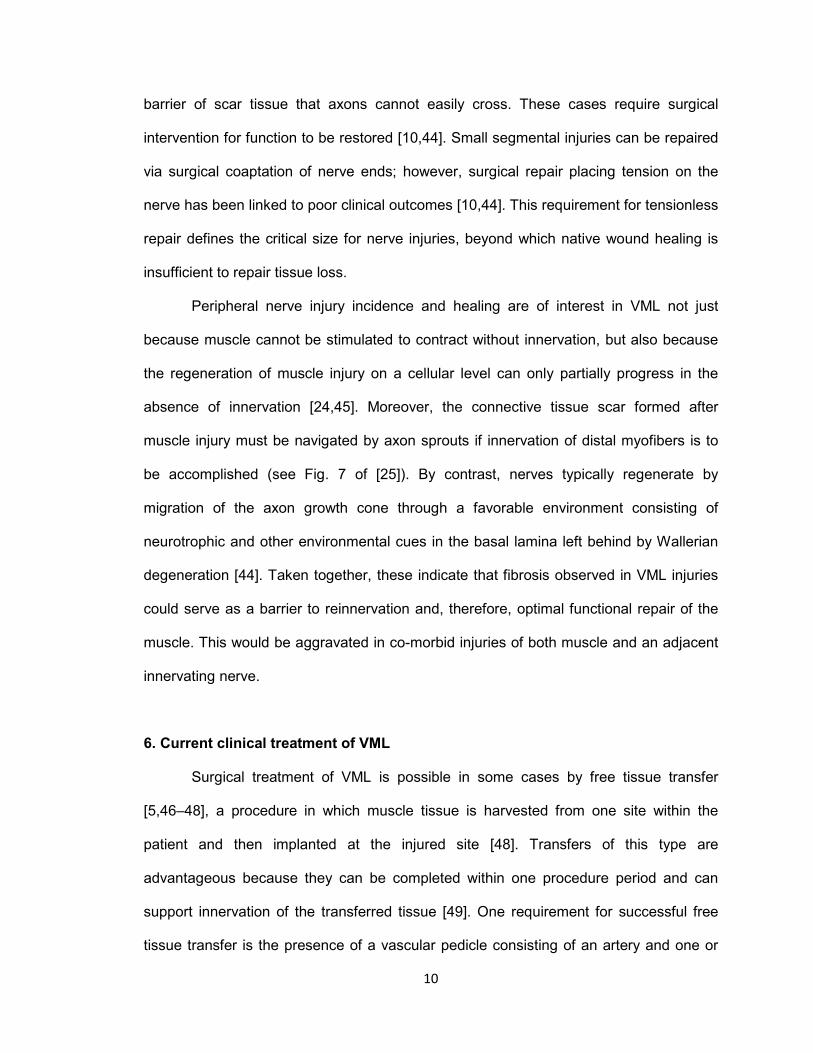
barrier of scar tissue that axons cannot easily cross. These cases require surgical
intervention for function to be restored [10,44]. Small segmental injuries can be repaired
via surgical coaptation of nerve ends; however, surgical repair placing tension on the
nerve has been linked to poor clinical outcomes [10,44]. This requirement for tensionless
repair defines the critical size for nerve injuries, beyond which native wound healing is
insufficient to repair tissue loss.
Peripheral nerve injury incidence and healing are of interest in VML not just
because muscle cannot be stimulated to contract without innervation, but also because
the regeneration of muscle injury on a cellular level can only partially progress in the
absence of innervation [24,45]. Moreover, the connective tissue scar formed after
muscle injury must be navigated by axon sprouts if innervation of distal myofibers is to
be accomplished (see Fig. 7 of [25]). By contrast, nerves typically regenerate by
migration of the axon growth cone through a favorable environment consisting of
neurotrophic and other environmental cues in the basal lamina left behind by Wallerian
degeneration [44]. Taken together, these indicate that fibrosis observed in VML injuries
could serve as a barrier to reinnervation and, therefore, optimal functional repair of the
muscle. This would be aggravated in co-morbid injuries of both muscle and an adjacent
innervating nerve.
6. Current clinical treatment of VML
Surgical treatment of VML is possible in some cases by free tissue transfer
[5,46–48], a procedure in which muscle tissue is harvested from one site within the
patient and then implanted at the injured site [48]. Transfers of this type are
advantageous because they can be completed within one procedure period and can
support innervation of the transferred tissue [49]. One requirement for successful free
tissue transfer is the presence of a vascular pedicle consisting of an artery and one or
11
more veins of appropriate length and caliber [48]. The implant is revascularized and
potentially reinnervated at the recipient site by connecting to local blood vessels of the
appropriate type and a source of donor axons, respectively, thereby providing blood
supply and an opportunity for neo-innervation to the graft [48].
Unfortunately, free muscle transfer is limited by the ability to locate donor tissue
of sufficient vascularity [48] and innervation [48,49] in an already-injured patient, and by
the associated, likely permanent morbidity at the harvest site [5,48]. Wound geometry is
a concern, as muscles available for transfer with large coverage area (e.g. the latissimus
dorsi at sizes up to 25 cm wide x 40 cm long, [48]) may be thin, and therefore incapable
of filling a thick defect. Even with modern advanced microsurgical techniques [48],
complication rates can approach 50% [49] and cosmetic scarring may limit patient
satisfaction [48].
Another, more limited type of tissue transfer is the rotational muscle flap. This
procedure is similar to free flap transfer, and has many of the same limitations [50], but
in this case a relatively dispensable donor muscle can be located in close proximity to
the injured site [51]. This allows the donor muscle to be dissected from most of the
surrounding tissue, but not completely removed [51]. Critically, the primary blood vessel
and, if possible, a nerve supplying the muscle remain attached and serve as the point
around which the flap is rotated to cover the injured site [51]. Another substantial
limitation of rotational flaps, beyond the requirement for donor and injury sites in
proximity, is that they typically cannot cover large defects [52]. Examples of this
technique include rotation of the inferior segment of the trapezius onto a craniofacial or
neck defect [51], rotation of the latissmus dorsi onto a deltoid defect [53], and rotation of
the sartorius to cover a femoral defect [54].
Beyond these already significant limitations, flap transfer is a technically complex
procedure, requiring an experienced surgical team and careful patient selection [5,48]. In

12
complex pathophysiologies that do not meet these criteria, amputation is the default
alternative [48]. These limitations in the standard of care for VML injuries combine with
their frequent presentation, as described in Section 1, to create a significant unmet need
in modern medicine for muscle reconstruction, repair, and replacement.
7. Single-component approaches in development for the repair of VML injuries
Several strategies are under investigation in an attempt to improve the standard
of care for VML injuries. The use of various biomaterial scaffolds alone has been
reported in multiple models of skeletal muscle repair [55–59], with varying results. One
potential advantage of scaffolds derived from ECM is that they can contain molecules
that provide mechanical support and mediate cell adhesion [60]. Moreover, these
scaffolds can be degraded and remodeled by endogenous processes at the implant site
[60]. In an example ECM-derived approach, a sponge composed of type I (~70%) and
type III (~30%) collagen had hemostatic and anti-inflammatory properties when placed
into a wounded muscle, but did not induce significant regeneration of muscle fibers [56].
One notable class of scaffold-only studies implanted decellularized muscle matrix
in an injury model. This approach was reported in some cases to be ineffective at
promoting functional recovery without the addition of cells [57], instead being remodeled
into fibrous tissue by native processes [55]. However, though the new tissue generated
by remodeling was non-contractile, it was somewhat counterintuitively shown on at least
one occasion to recover one-third the functional deficit created by the injury [59]. This
mechanism was termed "functional fibrosis," and presumably operates by shielding
remaining muscle mass from overload injury [59].
Of note, one scaffold-only repair has been performed in a human [61]. In this
study, an ECM scaffold derived from porcine small intestine submucosa was implanted
into a VML injury in the thigh of a marine. At 16 weeks postoperatively, torque generated
13
by the affected limb increased by a modest amount, while that generated by the
contralateral limb decreased slightly - presumably as it was forced to compensate less
[61]. At 36 weeks postoperatively, some new tissue formation was observed at the
implant site [61]. However, even this degree of success was higher than most studies in
this category - as described above - and was doubtless affected by careful patient
selection and a highly specialized surgical staff.
Similarly, pharmacological and / or genetic approaches (i.e., regenerative
pharmacology) have been investigated as a potential therapeutic for skeletal muscle
repair [62–66]. One study investigated mitigating the inflammatory response following
muscle injury by using anti-inflammatory or antioxidant small molecules, but concluded
that these drugs had no significant effect on function [62]. Another report demonstrated
that intramuscular injection of transgenic DNA-delivering microspheres could stably
induce transgene expression in muscle cells in vivo, though the DNA in this case
encoded for luciferase so no commentary could be made regarding changes to muscle
function [63]. In a further study using models of atrophic muscle in vitro and in vivo,
delivery of exogenous macrophage colony-stimulating factor increased functional protein
expression, potentially through enhancement of the anti-inflammatory macrophage
phenotype [64]. Losartan, a medication normally prescribed for hypertension, was shown
in a murine injury model to histologically and functionally improve muscle repair following
administration post-injury [65]. Though not a traditional pharmacologic per se, hyperbaric
oxygen treatment has been used in athletes with muscular injuries and was shown in a
rat injury model to increase force production and the prevalence of markers for satellite
cell proliferation and myofiber maturation [66]. Finally, a number of growth factors have
been investigated as candidates for exogenous delivery to supplement the native muscle
repair process (for review, see [67]). These have typically been hypothesized either to
14
promote myogenesis or to inhibit TGF-β1-induced fibrosis, and largely had the desired
effect, though a risk of side effects was documented.
8. Multi-component tissue engineering approaches in development for the repair
of VML injuries
Due to the potential limitations of materials, cells, or pharmacologics alone,
tissue engineered grafts or their analogs in vitro often feature two or more of these
components ([57,68–85]; see reviews [86,87]). Such approaches attempt to mimic the
structure and efficacy of autologous tissue transfer without the limitations associated
with harvest from a donor site. However, the degree to which these approaches
incorporate multiple components varies greatly.
In one example, tissue engineered skeletal muscle was created in vitro by
culturing a monolayer of isolated muscle cells, treating the monolayer with low-serum
differentiation medium supplemented with TGF-β1, and then initiating self-assembly of a
muscle strip by presenting the monolayer with opposing tendon fragments [83]. This
strategy represented the combination of a single cell type treated with pharmacologics,
but in the absence of a biomaterial scaffold. Similarly, an acellular combination
biomaterial-pharmacologic strategy designed to recruit and direct myogenic host cells
from the surrounding environment was evaluated in vivo by loading gelatin with
exogenous growth factors before implanting the construct in a rat model [88].
The vast majority of tissue engineering approaches, however, consist of a cell-
seeded biomaterial scaffold. These scaffolding materials are often designed to degrade
in vivo, being broken down and removed from the implant site over a time course that
corresponds to new tissue formation during wound healing / regeneration / repair [87].
Depending on the biomaterial, this remodeling of the scaffold may release myogenic
degradation products composed of the scaffold subunits themselves or, in the case of

15
scaffolds derived from tissue, of growth factors and other molecules previously trapped
within the material [89].
One important design consideration when selecting a biomaterial for tissue
engineering is its mechanical stiffness, which is quantified by the elastic or Young's
modulus (abbreviated E). This matrix stiffness has been shown to directly affect
adhesion and differentiation of muscle cells [79]. Another consideration is the chemical
composition of the scaffold surface, which has been shown to affect expression of
muscle proteins [80] and muscle cell force generation over time [75], presumably
mediated by the differing strength of cell-matrix interactions among substrate
chemistries.
This cell-seeded biomaterial construct can be further functionalized with one or
more additional cues designed to alter cell behavior. Pharmacologics, as described
above, are often incorporated, and may interact synergistically with other cues presented
by the biomaterial [87]. Critically, however, few studies to date have incorporated
exogenous agrin into muscle tissue engineering strategies [78,82]. One notable study
evaluated the presentation of soluble agrin to tissue engineered muscle constructs in
vitro [78]. In this case, agrin presentation had no effect on cell number, myosin
expression, or calcium dynamics, but increased the number of AChR clusters in scaffold-
resident cells, and most importantly increased contractile force generation of the
construct [78]. In a separate study, soluble agrin was used to condition C2C12 mouse
myoblast cells grown within a fibrin gel in vitro, which were subsequently implanted in
vivo in contact with a transected nerve [82]. Histological evaluation in this study indicated
that pre-treatment with agrin may have enhanced angiogenesis and NMJ formation (i.e.,
colocalized areas of neurofilament and AChR staining) in the area of the implant, but
critically did not result in well-oriented myofibers [82].
16
As such, initial efforts indicate that agrin may be a promising pharmacological
supplement for muscle tissue engineering. However, it has yet to be used in a non-
soluble embodiment analogous to its stably tethered location in normal NMJs [18], and
further has not been evaluated as an implanted component of the tissue engineered
construct in vivo - both of which may be required to provide optimal benefit to muscle
function.
Additionally, physical cues provided by the biomaterial such as microfibers [81],
microgrooves [70,79,80], and high aspect ratio pores [71], are another class of
functionalization. Importantly, aligned physical cues have been demonstrated to not only
orient skeletal muscle cells in a desired direction - such as a preferred direction of
contraction - but also to encourage myoblast fusion and expression of contractile
proteins [79–81]. In one noteworthy example, a cell culture substrate interrupted by a
series of posts was used to grow extensive hydrogel-cell networks [72]. In this case, the
size, spacing, and shape of the posts - which patterned pores within the resulting
construct - was found to affect the viability, alignment, and protein expression of
scaffold-resident muscle cells [72]. Thus, scaffold patterning is an incredibly powerful
means to modify muscle cell behavior for tissue engineering applications.
9. The importance of mechanical stretch in modulating muscle cell phenotype in
vitro
Like patterning, mechanical stretch applied in vitro is a cue which has been found
to enhance myogenesis within engineered muscle [68,90–95]. Early experimentation in
mechanical alteration of muscle cell phenotype aimed to mimic tensile forces
experienced in vivo [91,92,96]. In these studies, cyclic mechanical force was applied to
elastic biomaterials seeded with myoblasts, leading to stretch of the culture substrate
and the attached cells. Results indicated that mechanical stretch enhanced multiple
17
markers of muscle cell proliferation and maturation, including DNA content, protein
production, myoblast fusion, average myotube cross-sectional area (hypertrophy), total
myotube cross-sectional area (above the increase in per-cell area, indicating increase in
myotube count), and striations [68,91].
Recent efforts of our lab have expanded upon these findings using a
decellularized porcine bladder submucosa scaffold referred to as bladder acellular matrix
(BAM) [93–95]. This scaffold lends itself well to cell seeding and subsequent
preconditioning (i.e., cyclic mechanical stretch) in a bioreactor. We refer to this
multidisciplinary strategy as tissue engineered muscle repair (TEMR). Initial
experimentation using the TEMR construct indicated that sufficient preconditioning not
only increased the contractile force generated by TEMR constructs upon electrical
stimulation in vitro, but also that preconditioned constructs implanted in vivo for 2-4
weeks also generated more force than unconditioned controls [93].
Further studies evaluated the ability of TEMR to morphologically and functionally
repair a VML defect in the mouse latissimus dorsi (LD) [94,95]. The first of these found
that TEMR significantly restored 60-70% contractile function to injured muscles when
compared to unrepaired and scaffold-only controls [94]. Histologically, explanted TEMR
constructs also evidenced significant increases in markers of muscle repair and blood
vessel infiltration of the injured site, and may have supported axon infiltration at the
interface between TEMR and the remaining LD [94]. The second study confirmed the
essential nature of mechanical preconditioning to functional repair of an injury by
comparison to a cell-seeded but statically-cultured control [95]. Further, this study found
that an additional cell seeding step performed mid-way through preconditioning
enhanced TEMR cellularity, multinucleated cell count, and relevant protein expression
prior to implantation, as well as force production by explants at longer time points post-

18
implantation [95]. These observations were presumably due to the creation of distinct
"proliferating" and "differentiating" cell sub-populations within the construct [95].
Therefore, the TEMR strategy has documented utility in the repair of model VML
injuries. Creation of a platform of skeletal muscle tissue engineering technologies,
though, could enable treatment of a wider variety of injuries, such as thicker defects that
do not correspond in shape and size to seeded BAM. Further, additional
functionalizations as described above could be incorporated into the TEMR strategy to
repair the remaining 30-40% functional deficit between TEMR and the uninjured muscle.
As a final note, there are currently few tissue engineering strategies for muscle
repair that incorporate neural innervation / re-innervation as part of the core technology.
Given the importance of neural input to muscle formation, repair, physiology, and
function, this seems to be a key technological barrier to more widespread clinical
applications of tissue engineering for muscle repair. Moreover, an approach designed to
repair both components of total compartment loss injuries would be a huge step forward
for this unmet medical need.
10. Overview of Dissertation
The objective of this dissertation was to create a tissue engineered alternative to
autografting, lacking donor site morbidity and having the potential to restore function by
physical guidance of nerve axons and/or muscle progenitors and pharmacological
maintenance of a muscle phenotype similar to that seen in innervated myofibers. To this
end, we proposed a multidisciplinary tissue engineering approach incorporating
biomimetic materials, cell supplementation, and pharmacological signaling that
would represent an important step toward expanded clinical indications for
treatment of VML injuries. The basis of this technology was utilization of a biomaterial
with suitable physical properties for tunable patterning to a desired architecture, in order
19
to better recapitulate the anatomy of muscle tissue. Within this context, cell phenotype
could be further modulated by mechanical loading, delivery of exogenous cues, or a
combination of the two.
The central hypothesis of this dissertation was that biomimetic cues could be
leveraged to create a tissue engineered construct in vitro that would accelerate skeletal
muscle tissue formation and function following implantation in vivo, and furthermore,
maintain the skeletal muscle phenotype in vivo during reinnervation of VML injuries. The
specific cues under investigation included physical patterning to guide recapitulation of
native microanatomy, as well as chemical signaling and mechanical strain to promote
and maintain a more mature cellular phenotype in vitro and in vivo.
Therefore, this dissertation featured three broad objectives:
Objective 1: Construct a three-dimensional biomaterial scaffold with architecture
that would support aligned tissues such as nerve and muscle to encourage tissue
formation resembling native anatomy. The material would be characterized and its
performance evaluated by using an in vitro model for axon extension.
Objective 2: Functionalize the patterned biomaterial for skeletal muscle repair by
pharmacologic / chemical induction and maintenance of acetylcholine receptor clusters
with agrin, a hallmark of a more mature, innervated muscle phenotype in vitro.
Objective 3: Apply the fibrin construct featuring agrin-stimulated muscle cells to
a rodent neurotization model to assess its ability to maintain AChR clusters and support
innervation in the complex environment seen in vivo.
A summary of this approach is presented schematically in Fig. 1.
10.1. Rationale and research design of Objective 1
The templated fibrin biomaterial that served as the basis for the tissue
engineered muscle repair strategy described here was first developed in the context of a

20
Fig. 1. Schematic of final tissue engineered muscle construct fabrication and evaluation. (A) Pharmacologic delivery vehicles were formed by immobilization of agrin on a microcarrier surface (see Chapter III). These agrin carriers were then be suspended in a solution of fibrinogen, which was (B) polymerized to fibrin around a sacrificial template of polymer fibers (see Chapters II & III). Selective dissolution of the template resulted in a patterned hydrogel material that presented agrin via bound microcarriers. The patterning process created a porous microarchitecture within the scaffold, which was (C) seeded via perfusion of a suspension of muscle-derived cells (see Chapter IV). Resident cells then received a combination of physical cues from scaffold conduit pores, pharmacologic cues from scaffold agrin, and (D) mechanical cues from cyclic stretch in a bioreactor (see Chapter III). The final construct was then (E) evaluated in vivo using a rodent neurotization model (see Chapter V).
21
potential nerve graft. However, due to similarities in connective tissue architecture
between nerve and muscle as discussed in Section 3, it was also an ideal candidate for
muscle repair (see Objective 2). Further, the ability to support axon infiltration would be
useful in models of innervation in vivo (see Objective 3). Thus, Objective 1 centered on
characterization of patterned fibrin scaffolds and evaluation of their support of axon
extension in vitro.
Objective 1 featured two subordinate goals. The first was to adapt a fibrin
templating approach [97,98], which had been previously used by members of our team,
for creation of a biomaterial scaffold featuring biomimetic aligned pores. As sacrifical
templating requires only that the elected biomaterial and template feature differing
solubility in a chosen solvent, numerous natural and synthetic polymers are compatible
with this approach [99–102]. However, fibrin was elected for numerous reasons, as
follows:
• It has been highly studied as a tissue engineering substrate, not only for repair of
peripheral nerve [103–107] but also for skeletal muscle
[69,72,73,75,76,84,108,109].
• Fibrin serves as an endogenous provisional scaffold after injury and is therefore
a component of the native wound healing process; in peripheral nerve
regeneration, it is laid down in a cable-like fashion ahead of the growth cone as a
template for neural growth [110].
• It is naturally degradable into non-toxic byproducts and is capable of being
autologously sourced [97] to minimize potential foreign body response.
The sacrificial templating approach, in turn, has the advantage of generating a
customizable porous network corresponding to any possible arrangement of the
templating material. Wallerian degeneration leaves a series of axially-aligned lumens
formed by the connective tissue of the endoneurium, which serves to guide native
22
reinnervation after injury [44]. Aligned cylindrical conduits patterned within fibrin could
mimic the shape of these endoneurial tubes and potentially provide a substrate
conducive to axon migration.
The second goal of Objective 1 was to measure neurite length within these
scaffolds over time in vitro in order to determine the potential effect of conduit diameter
on the rate of neurite growth. This was relevant because the supportive expression of
growth associated genes in the neuron is transient after axon insult [111], making speed
of axon migration through a tissue engineered graft toward any resident muscle cells to
be innervated a critical concern. To evaluate this rate, we employed an embryonic
chicken dorsal root ganglia (DRG) model [112].
As a final design consideration, we aimed to incorporate scaffolds with elastic
modulus similar to that of native soft tissue - initially nerve, and later skeletal muscle -
because matrix stiffness has been shown to modulate differentiation of adherent cells
[113,114]. The findings of this objective were designed to inform material suitability for
later objectives, in terms of scaffold physical and mechanical properties for Objective 2
and estimated axonal ingrowth in vivo for Objective 3.
10.2. Rationale and research design of Objective 2
Though we have discussed scaffold fabrication primarily in terms of its
application to nerve grafting, it was also expected to result in parameters suitable for
muscle repair. Sacrificial patterning, for example, has the potential to produce scaffolds
with porosity in excess of 75%-90% [97], which would offer high surface area within
pores to enable robust cell seeding. Moreover, many skeletal muscle defects are
irregularly shaped, not only because of the inherent variability in anatomy amongst
human muscles (see Section 3) but also because they are often traumatic in origin [3,5–
8]. The enzymatic polymerization of fibrin could be leveraged to form the scaffold and its
23
associated pore network into any shape that can be molded and patterned, respectively,
a distinct advantage over more geometrically restrictive fabrication methods. Finally, use
of a fibrin substrate for muscle cell seeding has been shown to result in tissue
engineered muscle bundles with promising force generation in vitro [75].
Objective 2 featured four subordinate goals. First, we attempted to elicit AChR
clustering in vitro, which occurs in muscle cells presented with neural agrin in normal
physiology (see Section 2). Denervated muscle cells undergo significant atrophy in
cases of chronic denervation [24]. Moreover, clinical expectations for axon growth during
reinnervation of injured tissue are roughly 1 mm per day [111], resulting in potential
denervation for weeks or even months in sites substantially distant from the source of re-
innervation (e.g., the bulk of large injuries). If maintenance of AChR clustering created in
vitro (the presumptive correlates of MEPs in vivo) could be maintained in vivo, then
perhaps this approach could be used to counteract the atrophic effects of muscle
denervation during processing in vitro and colonization of the construct by host axons in
vivo after implantation. In this scenario, the capacity of the engineered construct to
restore function following implantation in vivo could ultimately be enhanced.
As a first step towards this goal, we investigated incorporating exogenous agrin
into the fibrin material in a manner that maintained its bioactivity on scaffold-seeded
muscle cells in vitro. As a vehicle to present agrin to cells, we selected microparticles
with surface-bound agrin molecules. This embodiment was chosen due to its similarity to
normal physiology, wherein neural agrin molecules are stably inserted within the
synaptic basal lamina after being synthesized by the nerve axon [18], an arrangement
mimicked more closely by surface-bound signal than by, for example, a soluble signal.
This strategy was initially evaluated in a 2D analog of the fibrin scaffold using a C2C12
mouse myoblast model system.
24
Second, we seeded 3D fibrin scaffolds as fabricated in pursuit of Objective 1 with
cells isolated from rat muscle explants. A tissue engineering strategy relevant for human
use would preferentially incorporate autologously sourced cells in order to minimize the
risk of immune rejection. Compared to the C2C12 cell line, then, expanded primary cells
were thought to be a more representative pre-clinical model. Additionally, higher cell
seeding densities have previously resulted in increased myoblast fusion and eventual
development of striated myofibers [84]. Accomplishing this robust seeding in 3D with
muscle cells, however, was expected to be challenging, as traditional static addition
(e.g., manual pipetting) of a cell suspension has been shown to be inefficient at seeding
cells within the interior of a porous scaffold [115]. Our strategy to overcome this obstacle
was through the use of flow perfusion of cell suspensions through the scaffold pore
network. In the literature, perfusion has most often been reported as a mechanism to
enhance nutrient exchange or modulate cellular phenotype in pre-seeded cells [116–
122], but has also been used to seed cells more deeply and uniformly within scaffolds
than static seeding [21,123–126]. Importantly, however, these prior studies evaluated
other combinations of cell type, scaffold material, and / or scaffold architecture than that
dicussed here, making the current effort a novel investigation.
The third goal of Objective 2 was to wed the advances of the first two goals,
combining agrin presentation with a highly cellularized muscle construct. To accomplish
this, we immobilized agrin-bound microparticles within the walls of the fibrin scaffold,
predicting that some proportion of these particles would extend partially into the pore
lumens and there make contact with seeded cells. This strategy would permit control of
agrin "dosing" as well as the stoichiometry of agrin particles relative to seeded myoblasts
and / or myotubes - both could be accomplished by adjustment of the microparticle
density incorporated into the fibrin scaffold.
25
Finally, as our fourth goal, we evaluated the effect of bioreactor preconditioning
via mechanical stretch on the cell-seeded agrin-presenting tissue engineered construct.
The rationale for this approach is related to observations (see Section 9) that mechanical
stimulation in vitro can encourage a more mature muscle phenotype as measured by: 1)
skeletal muscle protein-related second messenger activity [92], 2) increased average
muscle cell diameter [68,91], and 3) sum cross-sectional area of myofibers [68]. Thus,
we hypothesized that it might also affect AChR clustering either alone or synergistically
in the presence of agrin.
10.3. Rationale and research design of Objective 3
In Objective 3, we evaluated the characteristics of the optimized tissue
engineered muscle construct developed in pursuit of Objective 2 following implantation
in vivo using a rat neurotization model. The primary goal of this study was to determine if
agrin presentation would maintain AChR clusters in the complex in vivo environment.
Accordingly, we hypothesized that, due to prior optimization in vitro (Objectives 1 and 2),
the construct would better support axon ingrowth and augment muscle tissue formation
following implantation in vivo. To this end, we coapted the construct to a transected
nerve to see if it would yield self-assembled neuromuscular junctions (NMJs) linking
implanted muscle cells to the host nervous system. In this rat neurotization model, the
proximal stump of the femoral nerve was diverted to our ectopically implanted optimized
muscle construct (Fig. 1). This preliminary study was designed to provide important
information regarding the potential utility of the current technology to restore function in a
more complex VML injury model in vivo.

26
References [1] Saladin K. Chapter Ten: The Muscular System - Introduction. Hum. Anat. Second
Edition, 2008, p. 265–93.
[2] Masini BD, Waterman SM, Wenke JC, Owens BD, Hsu JR, Ficke JR. Resource utilization and disability outcome assessment of combat casualties from Operation Iraqi Freedom and Operation Enduring Freedom. J Orthop Trauma 2009;23:261–6. doi:10.1097/BOT.0b013e31819dfa04.
[3] Owens BD, Kragh JFJ, Wenke JC, Macaitis J, Wade CE, Holcomb JB. Combat Wounds in Operation Iraqi Freedom and Operation Enduring Freedom. J Trauma-Inj Infect 2008;64:295–9. doi:10.1097/TA.0b013e318163b875.
[4] Brown KV, Ramasamy A, Tai N, MacLeod J, Midwinter M, Clasper JC. Complications of extremity vascular injuries in conflict. J Trauma 2009;66:S145–9. doi:10.1097/TA.0b013e31819cdd82.
[5] Grogan BF, Hsu JR, Skeletal Trauma Research Consortium. Volumetric Muscle Loss. J Am Acad Orthop Surg 2011;19:S35–7.
[6] Holcomb JB, Stansbury LG, Champion HR, Wade C, Bellamy RF. Understanding Combat Casualty Care Statistics. J Trauma-Inj Infect 2006;60:397–401. doi:10.1097/01.ta.0000203581.75241.f1.
[7] Lew TA, Walker JA, Wenke JC, Blackbourne LH, Hale RG. Characterization of Craniomaxillofacial Battle Injuries Sustained by United States Service Members in the Current Conflicts of Iraq and Afghanistan. J Oral Maxillofac Surg 2010;68:3–7. doi:10.1016/j.joms.2009.06.006.
[8] Mazurek MT, Ficke JR. The Scope of Wounds Encountered in Casualties From the Global War on Terrorism: From the Battlefield to the Tertiary Treatment Facility. J Am Acad Orthop Surg 2006;14:S18–23.
[9] Pohlenz P, Klatt J, Schön G, Blessmann M, Li L, Schmelzle R. Microvascular free flaps in head and neck surgery: complications and outcome of 1000 flaps. Int J Oral Maxillofac Surg 2012;41:739–43. doi:10.1016/j.ijom.2012.02.012.
[10] Evans GRD. Peripheral nerve injury: A review and approach to tissue engineered constructs. Anat Rec 2001;263:396–404. doi:10.1002/ar.1120.
[11] Noble J, Munro CA, Prasad VS, Midha R. Analysis of upper and lower extremity peripheral nerve injuries in a population of patients with multiple injuries. J Trauma 1998;45:116–22.
[12] Nichols CM, Brenner MJ, Fox IK, Tung TH, Hunter DA, Rickman SR, et al. Effects of motor versus sensory nerve grafts on peripheral nerve regeneration. Exp Neurol 2004;190:347–55. doi:10.1016/j.expneurol.2004.08.003.
27
[13] Witzemann V. Development of the neuromuscular junction. Cell Tissue Res 2006;326:263–71. doi:10.1007/s00441-006-0237-x.
[14] Sanes JR, Lichtman JW. Development: Induction, assembly, maturation and maintenance of a postsynaptic apparatus. Nat Rev Neurosci 2001;2:791–805. doi:10.1038/35097557.
[15] Kim N, Burden SJ. MuSK controls where motor axons grow and form synapses.
Nat Neurosci 2008;11:19–27. doi:10.1038/nn2026. [16] Wu H, Xiong WC, Mei L. To build a synapse: signaling pathways in
neuromuscular junction assembly. Development 2010;137:1017–33. doi:10.1242/dev.038711.
[17] Zhang W, Coldefy A-S, Hubbard SR, Burden SJ. Agrin binds to the N-terminal
region of Lrp4 protein and stimulates association between Lrp4 and the first immunoglobulin-like domain in muscle-specific kinase (MuSK). J Biol Chem 2011;286:40624–30. doi:10.1074/jbc.M111.279307.
[18] Bezakova G, Ruegg MA. New insights into the roles of agrin. Nat Rev Mol Cell
Biol 2003;4:295–309. doi:10.1038/nrm1074. [19] Kim N, Stiegler AL, Cameron TO, Hallock PT, Gomez AM, Huang JH, et al. Lrp4
is a receptor for Agrin and forms a complex with MuSK. Cell 2008;135:334–42. doi:10.1016/j.cell.2008.10.002.
[20] Yumoto N, Kim N, Burden SJ. Lrp4 is a retrograde signal for presynaptic
differentiation at neuromuscular synapses. Nature 2012;489:438–42. doi:10.1038/nature11348.
[21] Kennedy JP, McCandless SP, Rauf A, Williams LM, Hillam J, Hitchcock RW.
Engineered channels enhance cellular density in perfused scaffolds. Acta Biomater 2011;7:3896–904. doi:10.1016/j.actbio.2011.06.037.
[22] Saladin K. Chapter Fourteen - The Spinal Cord and Spinal Nerves. Hum. Anat.
Second Edition, 2008, p. 395–421. [23] Chargé SBP, Rudnicki MA. Cellular and Molecular Regulation of Muscle
Regeneration. Physiol Rev 2004;84:209–38. doi:10.1152/physrev.00019.2003. [24] Järvinen TAH, Järvinen TLN, Kääriäinen M, Kalimo H, Järvinen M. Muscle
Injuries Biology and Treatment. Am J Sports Med 2005;33:745–64. doi:10.1177/0363546505274714.
[25] Ciciliot S, Schiaffino S. Regeneration of Mammalian Skeletal Muscle: Basic
Mechanisms and Clinical Implications. Curr Pharm Des 2010;16:906–14. doi:10.2174/138161210790883453.
28
[26] Hurme T, Kalimo H, Lehto M, Järvinen M. Healing of skeletal muscle injury: an ultrastructural and immunohistochemical study. Med Sci Sports Exerc 1991;23:801–10.
[27] Chazaud B, Brigitte M, Yacoub-Youssef H, Arnold L, Gherardi R, Sonnet C, et al.
Dual and beneficial roles of macrophages during skeletal muscle regeneration. Exerc Sport Sci Rev 2009;37:18–22. doi:10.1097/JES.0b013e318190ebdb.
[28] Mauro A. Satellite cell of skeletal muscle fibers. J Biophys Biochem Cytol
1961;9:493–5. [29] Relaix F, Zammit PS. Satellite cells are essential for skeletal muscle
regeneration: the cell on the edge returns centre stage. Dev Camb Engl 2012;139:2845–56. doi:10.1242/dev.069088.
[30] Collins CA, Olsen I, Zammit PS, Heslop L, Petrie A, Partridge TA, et al. Stem cell
function, self-renewal, and behavioral heterogeneity of cells from the adult muscle satellite cell niche. Cell 2005;122:289–301. doi:10.1016/j.cell.2005.05.010.
[31] Bischoff R. Regeneration of single skeletal muscle fibers in vitro. Anat Rec
1975;182:215–35. doi:10.1002/ar.1091820207. [32] Konigsberg UR, Lipton BH, Konigsberg IR. The regenerative response of single
mature muscle fibers isolated in vitro. Dev Biol 1975;45:260–75. [33] Lipton BH, Schultz E. Developmental fate of skeletal muscle satellite cells.
Science 1979;205:1292–4. [34] Moss FP, Leblond CP. Satellite cells as the source of nuclei in muscles of
growing rats. Anat Rec 1971;170:421–35. doi:10.1002/ar.1091700405. [35] Zammit PS, Golding JP, Nagata Y, Hudon V, Partridge TA, Beauchamp JR.
Muscle satellite cells adopt divergent fates: a mechanism for self-renewal? J Cell Biol 2004;166:347–57. doi:10.1083/jcb.200312007.
[36] Day K, Shefer G, Richardson JB, Enikolopov G, Yablonka-Reuveni Z. Nestin-
GFP reporter expression defines the quiescent state of skeletal muscle satellite cells. Dev Biol 2007;304:246–59. doi:10.1016/j.ydbio.2006.12.026.
[37] Ferrari G, Cusella-De Angelis G, Coletta M, Paolucci E, Stornaiuolo A, Cossu G,
et al. Muscle regeneration by bone marrow-derived myogenic progenitors. Science 1998;279:1528–30.
[38] Scharner J, Zammit PS. The muscle satellite cell at 50: the formative years.
Skelet Muscle 2011;1:28. doi:10.1186/2044-5040-1-28. [39] Lehto M, Järvinen M, Nelimarkka O. Scar formation after skeletal muscle injury. A
histological and autoradiographical study in rats. Arch Orthop Trauma Surg Arch Für Orthop Unf-Chir 1986;104:366–70.
29
[40] Hurme T, Kalimo H, Sandberg M, Lehto M, Vuorio E. Localization of type I and III collagen and fibronectin production in injured gastrocnemius muscle. Lab Investig J Tech Methods Pathol 1991;64:76–84.
[41] Lehto M, Duance VC, Restall D. Collagen and fibronectin in a healing skeletal
muscle injury. An immunohistological study of the effects of physical activity on the repair of injured gastrocnemius muscle in the rat. J Bone Joint Surg Br 1985;67:820–8.
[42] Lehto M, Sims TJ, Bailey AJ. Skeletal muscle injury--molecular changes in the
collagen during healing. Res Exp Med Z Für Gesamte Exp Med Einschl Exp Chir 1985;185:95–106.
[43] Li Y, Huard J. Differentiation of Muscle-Derived Cells into Myofibroblasts in
Injured Skeletal Muscle. Am J Pathol 2002;161:895–907. [44] Lee SK, Wolfe SW. Peripheral Nerve Injury and Repair. J Am Acad Orthop Surg
2000;8:243–52. [45] Rantanen J, Ranne J, Hurme T, Kalimo H. Denervated segments of injured
skeletal muscle fibers are reinnervated by newly formed neuromuscular junctions. J Neuropathol Exp Neurol 1995;54:188–94.
[46] Khouri RK, Cooley BC, Kunselman AR, Landis JR, Yeramian P, Ingram D, et al.
A prospective study of microvascular free-flap surgery and outcome. Plast Reconstr Surg 1998;102:711–21.
[47] Lin CH, Wei FC, Levin LS, Chen MC. Donor-site morbidity comparison between
endoscopically assisted and traditional harvest of free latissimus dorsi muscle flap. Plast Reconstr Surg 1999;104:1070–7; quiz 1078.
[48] Lawson R, Levin LS. Principles of Free Tissue Transfer in Orthopaedic Practice.
J Am Acad Orthop Surg 2007;15:290–9. [49] Bianchi B, Copelli C, Ferrari S, Ferri A, Sesenna E. Free flaps: outcomes and
complications in head and neck reconstructions. J Cranio-Maxillo-Fac Surg Off Publ Eur Assoc Cranio-Maxillo-Fac Surg 2009;37:438–42. doi:10.1016/j.jcms.2009.05.003.
[50] Hsu JR, Beltran MJ, Skeletal Trauma Research Consortium. Shortening and
angulation for soft-tissue reconstruction of extremity wounds in a combat support hospital. Mil Med 2009;174:838–42.
[51] Ariffin M, Lloyd S, Rhani S, Kamalnizat null, Baharudin A. Trapezius Rotational
Flap for Cervico-thoracic Wound Breakdown in Post-radiotherapy Necrosis : A Case Report. Malays Orthop J 2014;8:40–2. doi:10.5704/MOJ.1407.001.
[52] Beltran MJ, Blair JA, Rathbone CR, Hsu JR. The gradual expansion muscle flap.
J Orthop Trauma 2014;28:e15–20. doi:10.1097/BOT.0b013e3182940b65.

30
[53] Wang J, Shen J, Dickinson IC. Functional outcome of arthrodesis with a vascularized fibular graft and a rotational latissimus dorsi flap after proximal humerus sarcoma resection. Ann Surg Oncol 2011;18:1852–9. doi:10.1245/s10434-010-1443-z.
[54] Landry GJ, Carlson JR, Liem TK, Mitchell EL, Edwards JM, Moneta GL. The
sartorius muscle flap: an important adjunct for complicated femoral wounds involving vascular grafts. Am J Surg 2009;197:655–9; discussion 659. doi:10.1016/j.amjsurg.2008.12.020.
[55] Gamba P, Conconi M, Piccolo RL, Zara G, Spinazzi R, Parnigotto P.
Experimental abdominal wall defect repaired with acellular matrix. Pediatr Surg Int 2002;18:327–31. doi:10.1007/s00383-002-0849-5.
[56] Kin S, Hagiwara A, Nakase Y, Kuriu Y, Nakashima S, Yoshikawa T, et al.
Regeneration of Skeletal Muscle Using In Situ Tissue Engineering on an Acellular Collagen Sponge Scaffold in a Rabbit Model. [Miscellaneous Article]. J July 2007;53:506–13. doi:10.1097/MAT.0b013e3180d09d81.
[57] Merritt EK, Hammers DW, Tierney M, Suggs LJ, Walters TJ, Farrar RP.
Functional Assessment of Skeletal Muscle Regeneration Utilizing Homologous Extracellular Matrix as Scaffolding. Tissue Eng Part A 2009;16:1395–405. doi:10.1089/ten.tea.2009.0226.
[58] Turner NJ, Yates AJ, Weber DJ, Qureshi IR, Stolz DB, Gilbert TW, et al.
Xenogeneic Extracellular Matrix as an Inductive Scaffold for Regeneration of a Functioning Musculotendinous Junction. Tissue Eng Part A 2010;16:3309–17. doi:10.1089/ten.tea.2010.0169.
[59] Corona BT, Wu X, Ward CL, McDaniel JS, Rathbone CR, Walters TJ. The
promotion of a functional fibrosis in skeletal muscle with volumetric muscle loss injury following the transplantation of muscle-ECM. Biomaterials 2013;34:3324–35. doi:10.1016/j.biomaterials.2013.01.061.
[60] Rossi CA, Pozzobon M, De Coppi P. Advances in musculoskeletal tissue
engineering: moving towards therapy. Organogenesis 2010;6:167–72. [61] Mase VJ, Hsu JR, Wolf SE, Wenke JC, Baer DG, Owens J, et al. Clinical
application of an acellular biologic scaffold for surgical repair of a large, traumatic quadriceps femoris muscle defect. Orthopedics 2010;33:511. doi:10.3928/01477447-20100526-24.
[62] Vignaud A, Cebrian J, Martelly I, Caruelle J-P, Ferry A. Effect of anti-inflammatory
and antioxidant drugs on the long-term repair of severely injured mouse skeletal muscle. Exp Physiol 2005;90:487–95. doi:10.1113/expphysiol.2005.029835.
[63] Jang J-H, Shea LD. Intramuscular delivery of DNA releasing microspheres:
Microsphere properties and transgene expression. J Controlled Release 2006;112:120–8. doi:10.1016/j.jconrel.2006.01.013.
31
[64] Dumont NA, Frenette J. Macrophage Colony-Stimulating Factor–Induced Macrophage Differentiation Promotes Regrowth in Atrophied Skeletal Muscles and C2C12 Myotubes. Am J Pathol 2013;182:505–15. doi:10.1016/j.ajpath.2012.10.010.
[65] Kobayashi T, Uehara K, Ota S, Tobita K, Ambrosio F, Cummins JH, et al. The
timing of administration of a clinically relevant dose of losartan influences the healing process after contusion induced muscle injury. J Appl Physiol 2013;114:262–73. doi:10.1152/japplphysiol.00140.2011.
[66] Horie M, Enomoto M, Shimoda M, Okawa A, Miyakawa S, Yagishita K.
Enhancement of satellite cell differentiation and functional recovery in injured skeletal muscle by hyperbaric oxygen treatment. J Appl Physiol 2014;116:149–55. doi:10.1152/japplphysiol.00235.2013.
[67] Baoge L, Van Den Steen E, Rimbaut S, Philips N, Witvrouw E, Almqvist KF, et al.
Treatment of Skeletal Muscle Injury: A Review. ISRN Orthop 2012;2012. doi:10.5402/2012/689012.
[68] Powell CA, Smiley BL, Mills J, Vandenburgh HH. Mechanical stimulation
improves tissue-engineered human skeletal muscle. Am J Physiol - Cell Physiol 2002;283:C1557–65. doi:10.1152/ajpcell.00595.2001.
[69] Bach AD, Arkudas A, Tjiawi J, Polykandriotis E, Kneser U, Horch RE, et al. A new
approach to tissue engineering of vascularized skeletal muscle. J Cell Mol Med 2006;10:716–26.
[70] Yan W, George S, Fotadar U, Tyhovych N, Kamer A, Yost MJ, et al. Tissue
Engineering of Skeletal Muscle. Tissue Eng 2007;13:2781–90. doi:10.1089/ten.2006.0408.
[71] Kroehne V, Heschel I, Schügner F, Lasrich D, Bartsch JW, Jockusch H. Use of a
novel collagen matrix with oriented pore structure for muscle cell differentiation in cell culture and in grafts. J Cell Mol Med 2008;12:1640–8. doi:10.1111/j.1582-4934.2008.00238.x.
[72] Bian W, Bursac N. Engineered skeletal muscle tissue networks with controllable
architecture. Biomaterials 2009;30:1401–12. doi:10.1016/j.biomaterials.2008.11.015.
[73] Khodabukus A, Baar K. Regulating Fibrinolysis to Engineer Skeletal Muscle from
the C2C12 Cell Line. Tissue Eng Part C Methods 2009;15:501–11. doi:10.1089/ten.tec.2008.0286.
[74] Merritt EK, Cannon MV, Hammers DW, Le LN, Gokhale R, Sarathy A, et al.
Repair of traumatic skeletal muscle injury with bone-marrow-derived mesenchymal stem cells seeded on extracellular matrix. Tissue Eng Part A 2010;16:2871–81. doi:10.1089/ten.TEA.2009.0826.
32
[75] Hinds S, Bian W, Dennis RG, Bursac N. The role of extracellular matrix composition in structure and function of bioengineered skeletal muscle. Biomaterials 2011;32:3575–83. doi:10.1016/j.biomaterials.2011.01.062.
[76] Page RL, Malcuit C, Vilner L, Vojtic I, Shaw S, Hedblom E, et al. Restoration of
Skeletal Muscle Defects with Adult Human Cells Delivered on Fibrin Microthreads. Tissue Eng Part A 2011;17:2629–40. doi:10.1089/ten.tea.2011.0024.
[77] Rossi CA, Flaibani M, Blaauw B, Pozzobon M, Figallo E, Reggiani C, et al. In vivo
tissue engineering of functional skeletal muscle by freshly isolated satellite cells embedded in a photopolymerizable hydrogel. FASEB J 2011;25:2296–304. doi:10.1096/fj.10-174755.
[78] Bian W, Bursac N. Soluble miniagrin enhances contractile function of engineered
skeletal muscle. FASEB J Off Publ Fed Am Soc Exp Biol 2012;26:955–65. doi:10.1096/fj.11-187575.
[79] Monge C, Ren K, Berton K, Guillot R, Peyrade D, Picart C. Engineering Muscle
Tissues on Microstructured Polyelectrolyte Multilayer Films. Tissue Eng Part A 2012;18:1664–76. doi:10.1089/ten.tea.2012.0079.
[80] Wang P-Y, Thissen H, Tsai W-B. The roles of RGD and grooved topography in
the adhesion, morphology, and differentiation of C2C12 skeletal myoblasts. Biotechnol Bioeng 2012;109:2104–15. doi:10.1002/bit.24452.
[81] Chen M-C, Sun Y-C, Chen Y-H. Electrically conductive nanofibers with highly
oriented structures and their potential application in skeletal muscle tissue engineering. Acta Biomater 2013;9:5562–72. doi:10.1016/j.actbio.2012.10.024.
[82] Ko IK, Lee B-K, Lee SJ, Andersson K-E, Atala A, Yoo JJ. The effect of in vitro
formation of acetylcholine receptor (AChR) clusters in engineered muscle fibers on subsequent innervation of constructs in vivo. Biomaterials 2013;34:3246–55. doi:10.1016/j.biomaterials.2013.01.029.
[83] Weist MR, Wellington MS, Bermudez JE, Kostrominova TY, Mendias CL, Arruda
EM, et al. TGF-β1 enhances contractility in engineered skeletal muscle. J Tissue Eng Regen Med 2013;7:562–71. doi:10.1002/term.551.
[84] Martin NRW, Passey SL, Player DJ, Khodabukus A, Ferguson RA, Sharples AP,
et al. Factors affecting the structure and maturation of human tissue engineered skeletal muscle. Biomaterials 2013;34:5759–65. doi:10.1016/j.biomaterials.2013.04.002.
[85] Wang L, Cao L, Shansky J, Wang Z, Mooney D, Vandenburgh H. Minimally
Invasive Approach to the Repair of Injured Skeletal Muscle With a Shape-memory Scaffold. Mol Ther 2014;22:1441–9. doi:10.1038/mt.2014.78.
[86] Juhas M, Bursac N. Engineering Skeletal Muscle Repair. Curr Opin Biotechnol
2013;24:880–6. doi:10.1016/j.copbio.2013.04.013.
33
[87] Cezar CA, Mooney DJ. Biomaterial-based delivery for skeletal muscle repair. Adv Drug Deliv Rev 2014. doi:10.1016/j.addr.2014.09.008.
[88] Ju YM, Atala A, Yoo JJ, Lee SJ. In situ regeneration of skeletal muscle tissue
through host cell recruitment. Acta Biomater 2014;10:4332–9. doi:10.1016/j.actbio.2014.06.022.
[89] Wolf MT, Dearth CL, Sonnenberg SB, Loboa EG, Badylak SF. Naturally derived
and synthetic scaffolds for skeletal muscle reconstruction. Adv Drug Deliv Rev 2014. doi:10.1016/j.addr.2014.08.011.
[90] Vandenburgh HH, Karlisch P. Longitudinal growth of skeletal myotubes in vitro in
a new horizontal mechanical cell stimulator. Vitro Cell Dev Biol J Tissue Cult Assoc 1989;25:607–16.
[91] Vandenburgh HH, Hatfaludy S, Karlisch P, Shansky J. Skeletal muscle growth is
stimulated by intermittent stretch-relaxation in tissue culture. Am J Physiol 1989;256:C674–82.
[92] Vandenburgh HH, Hatfaludy S, Karlisch P, Shansky J. Mechanically induced
alterations in cultured skeletal muscle growth. J Biomech 1991;24, Supplement 1:91–9. doi:10.1016/0021-9290(91)90380-6.
[93] Moon DG, Christ G, Stitzel JD, Atala A, Yoo JJ. Cyclic Mechanical
Preconditioning Improves Engineered Muscle Contraction. Tissue Eng Part A 2008;14:473–82. doi:10.1089/tea.2007.0104.
[94] Machingal MA, Corona BT, Walters TJ, Kesireddy V, Koval CN, Dannahower A,
et al. A tissue-engineered muscle repair construct for functional restoration of an irrecoverable muscle injury in a murine model. Tissue Eng Part A 2011;17:2291–303. doi:10.1089/ten.TEA.2010.0682.
[95] Corona BT, Machingal MA, Criswell T, Vadhavkar M, Dannahower AC, Bergman
C, et al. Further development of a tissue engineered muscle repair construct in vitro for enhanced functional recovery following implantation in vivo in a murine model of volumetric muscle loss injury. Tissue Eng Part A 2012;18:1213–28. doi:10.1089/ten.TEA.2011.0614.
[96] Vandenburgh HH. Motion into mass: how does tension stimulate muscle growth?
Med Sci Sports Exerc 1987;19:S142–9. [97] Linnes MP, Ratner BD, Giachelli CM. A fibrinogen-based precision microporous
scaffold for tissue engineering. Biomaterials 2007;28:5298–306. doi:10.1016/j.biomaterials.2007.08.020.
[98] Saul JM, Linnes MP, Ratner BD, Giachelli CM, Pun SH. Delivery of non-viral
gene carriers from sphere-templated fibrin scaffolds for sustained transgene expression. Biomaterials 2007;28:4705–16. doi:10.1016/j.biomaterials.2007.07.026.

34
[99] Flynn L, Dalton PD, Shoichet MS. Fiber templating of poly(2-hydroxyethyl methacrylate) for neural tissue engineering. Biomaterials 2003;24:4265–72. doi:10.1016/S0142-9612(03)00334-X.
[100] Stokols S, Sakamoto J, Breckon C, Holt T, Weiss J, Tuszynski MH. Templated
Agarose Scaffolds Support Linear Axonal Regeneration. Tissue Eng 2006;12:2777–87. doi:10.1089/ten.2006.12.2777.
[101] Wei G, Ma PX. Macroporous and nanofibrous polymer scaffolds and
polymer/bone-like apatite composite scaffolds generated by sugar spheres. J Biomed Mater Res A 2006;78A:306–15. doi:10.1002/jbm.a.30704.
[102] Gros T, Sakamoto JS, Blesch A, Havton LA, Tuszynski MH. Regeneration of
long-tract axons through sites of spinal cord injury using templated agarose scaffolds. Biomaterials 2010;31:6719–29. doi:10.1016/j.biomaterials.2010.04.035.
[103] Nakayama K, Takakuda K, Koyama Y, Itoh S, Wang W, Shirahama N, et al.
Regeneration of peripheral nerves by bioabsorbable polymer tubes with fibrin gel. J Nanosci Nanotechnol 2007;7:730–3.
[104] Nakayama K, Takakuda K, Koyama Y, Itoh S, Wang W, Mukai T, et al.
Enhancement of Peripheral Nerve Regeneration Using Bioabsorbable Polymer Tubes Packed With Fibrin Gel. Artif Organs 2007;31:500–8. doi:10.1111/j.1525-1594.2007.00418.x.
[105] Kalbermatten DF, Kingham PJ, Mahay D, Mantovani C, Pettersson J, Raffoul W,
et al. Fibrin matrix for suspension of regenerative cells in an artificial nerve conduit. J Plast Reconstr Aesthet Surg 2008;61:669–75. doi:10.1016/j.bjps.2007.12.015.
[106] Kalbermatten D, Pettersson J, Kingham P, Pierer G, Wiberg M, Terenghi G. New
Fibrin Conduit for Peripheral Nerve Repair. J Reconstr Microsurg 2009;25:027–33. doi:10.1055/s-0028-1090619.
[107] Wood MD, Moore AM, Hunter DA, Tuffaha S, Borschel GH, Mackinnon SE, et al.
Affinity-based release of glial-derived neurotrophic factor from fibrin matrices enhances sciatic nerve regeneration. Acta Biomater 2009;5:959–68. doi:10.1016/j.actbio.2008.11.008.
[108] Dhawan V, Lytle IF, Dow DE, Huang Y-C, Brown DL. Neurotization Improves
Contractile Forces of Tissue-Engineered Skeletal Muscle. Tissue Eng 2007;13:2813–21. doi:10.1089/ten.2007.0003.
[109] Koning M, Harmsen MC, van Luyn MJA, Werker PMN. Current opportunities and
challenges in skeletal muscle tissue engineering. J Tissue Eng Regen Med 2009;3:407–15. doi:10.1002/term.190.
[110] Bellamkonda RV. Peripheral nerve regeneration: An opinion on channels,
scaffolds and anisotropy. Biomaterials 2006;27:3515–8. doi:10.1016/j.biomaterials.2006.02.030.
35
[111] Gordon T, Brushart TM, Chan KM. Augmenting nerve regeneration with electrical
stimulation. Neurol Res 2008;30:1012–22. doi:10.1179/174313208X362488. [112] Leon A, Benvegnù D, Toso RD, Presti D, Facci L, Giorgi O, et al. Dorsal root
ganglia and nerve growth factor: A model for understanding the mechanism of GM1 effects on neuronal repair. J Neurosci Res 1984;12:277–87. doi:10.1002/jnr.490120215.
[113] Engler AJ, Griffin MA, Sen S, Bönnemann CG, Sweeney HL, Discher DE.
Myotubes differentiate optimally on substrates with tissue-like stiffness: pathological implications for soft or stiff microenvironments. J Cell Biol 2004;166:877–87. doi:10.1083/jcb.200405004.
[114] Reilly GC, Engler AJ. Intrinsic extracellular matrix properties regulate stem cell
differentiation. J Biomech 2010;43:55–62. doi:10.1016/j.jbiomech.2009.09.009. [115] Burg KJ, Holder WD, Culberson CR, Beiler RJ, Greene KG, Loebsack AB, et al.
Comparative study of seeding methods for three-dimensional polymeric scaffolds. J Biomed Mater Res 2000;51:642–9.
[116] Goldstein AS, Juarez TM, Helmke CD, Gustin MC, Mikos AG. Effect of
convection on osteoblastic cell growth and function in biodegradable polymer foam scaffolds. Biomaterials 2001;22:1279–88.
[117] Cartmell SH, Porter BD, García AJ, Guldberg RE. Effects of medium perfusion
rate on cell-seeded three-dimensional bone constructs in vitro. Tissue Eng 2003;9:1197–203. doi:10.1089/10763270360728107.
[118] Kasper FK, Liao J, Kretlow JD, Sikavitsas VI, Mikos AG. Flow perfusion culture of
mesenchymal stem cells for bone tissue engineering. StemBook, Cambridge (MA): Harvard Stem Cell Institute; 2008.
[119] Issa RI, Engebretson B, Rustom L, McFetridge PS, Sikavitsas VI. The effect of
cell seeding density on the cellular and mechanical properties of a mechanostimulated tissue-engineered tendon. Tissue Eng Part A 2011;17:1479–87. doi:10.1089/ten.TEA.2010.0484.
[120] Gaspar DA, Gomide V, Monteiro FJ. The role of perfusion bioreactors in bone
tissue engineering. Biomatter 2012;2:167–75. doi:10.4161/biom.22170. [121] Gardel LS, Correia-Gomes C, Serra LA, Gomes ME, Reis RL. A novel
bidirectional continuous perfusion bioreactor for the culture of large-sized bone tissue-engineered constructs. J Biomed Mater Res B Appl Biomater 2013;101:1377–86. doi:10.1002/jbm.b.32955.
[122] Yeatts AB, Both SK, Yang W, Alghamdi HS, Yang F, Fisher JP, et al. In vivo bone
regeneration using tubular perfusion system bioreactor cultured nanofibrous scaffolds. Tissue Eng Part A 2014;20:139–46. doi:10.1089/ten.TEA.2013.0168.

36
[123] Alvarez-Barreto JF, Linehan SM, Shambaugh RL, Sikavitsas VI. Flow perfusion improves seeding of tissue engineering scaffolds with different architectures. Ann Biomed Eng 2007;35:429–42. doi:10.1007/s10439-006-9244-z.
[124] Alvarez-Barreto JF, Landy B, VanGordon S, Place L, DeAngelis PL, Sikavitsas
VI. Enhanced osteoblastic differentiation of mesenchymal stem cells seeded in RGD-functionalized PLLA scaffolds and cultured in a flow perfusion bioreactor. J Tissue Eng Regen Med 2011;5:464–75. doi:10.1002/term.338.
[125] Bartnikowski M, Klein TJ, Melchels FPW, Woodruff MA. Effects of scaffold
architecture on mechanical characteristics and osteoblast response to static and perfusion bioreactor cultures. Biotechnol Bioeng 2014;111:1440–51. doi:10.1002/bit.25200.
[126] Bonandrini B, Figliuzzi M, Papadimou E, Morigi M, Perico N, Casiraghi F, et al.
Recellularization of well-preserved acellular kidney scaffold using embryonic stem cells. Tissue Eng Part A 2014;20:1486–98. doi:10.1089/ten.TEA.2013.0269.
37
CHAPTER II
THE PROMOTION OF AXON EXTENSION IN VITRO USING POLYMER-TEMPLATED
FIBRIN SCAFFOLDS
John B. Scott, Mehdi Afshari, Richard Kotek, Justin M. Saul
The following chapter has been published in Biomaterials (2011 Jul;32(21):4830-9).
Citations, figure captions, and other stylistic elements of this chapter conform to the
demands of the publishing journal, and as such may differ from those found elsewhere in
this dissertation. The published version can be seen online at
http://www.sciencedirect.com/science/article/pii/S0142961211003061.
Elsevier, the publisher of Biomaterials and copyright holder of this chapter, has granted
John Scott permission to reproduce it as part of this dissertation (see “Author Use” at
http://www.elsevier.com/journal-authors/author-rights-and-responsibilities#author-use).
As primary author, John Scott performed experiments and prepared the manuscript for
all content in Chapter II except template fiber fabrication and the authorship of methods
relevant thereto (see first paragraph of Section 2.1), which were performed by Mehdi
Afshari and Richard Kotek.
38
Abstract
Biomaterial nerve cuffs are a clinical alternative to autografts and allografts as a
means to repair segmental peripheral nerve defects. However, existing clinical
biomaterial constructs lack true incorporation of physical guidance cues into their design.
In both two- and three-dimensional systems, it is known that substrate geometry directly
affects rates of axon migration. However, the ability to incorporate these cues into
biomaterial scaffolds of sufficient porosity to promote robust nerve regeneration in three-
dimensional systems is a challenge. We have developed fibrin constructs fabricated by a
sacrificial templating approach, yielding scaffolds with multiple 10–250 μm diameter
conduits depending on the diameter of the template fibers. The resulting scaffolds
contained numerous, highly aligned conduits, had porosity of ~ 80%, and showed
mechanical properties comparable to native nerve (150–300 kPa Young’s modulus). We
studied the effects of the conduit diameters on the rate of axon migration through the
scaffold to investigate if manipulation of this geometry could be used to ultimately
promote more rapid bridging of the scaffold. All diameters studied led to axon migration,
but in contrast to effects of fiber diameters in other systems, the rate of axon migration
was independent of conduit diameter in these templated scaffolds. However, aligned
conduits did support more rapid axon migration than non-aligned, tortuous controls.
Keywords:
Fibrin, Micropatterning, Nerve guide, Nerve tissue engineering, Scaffold
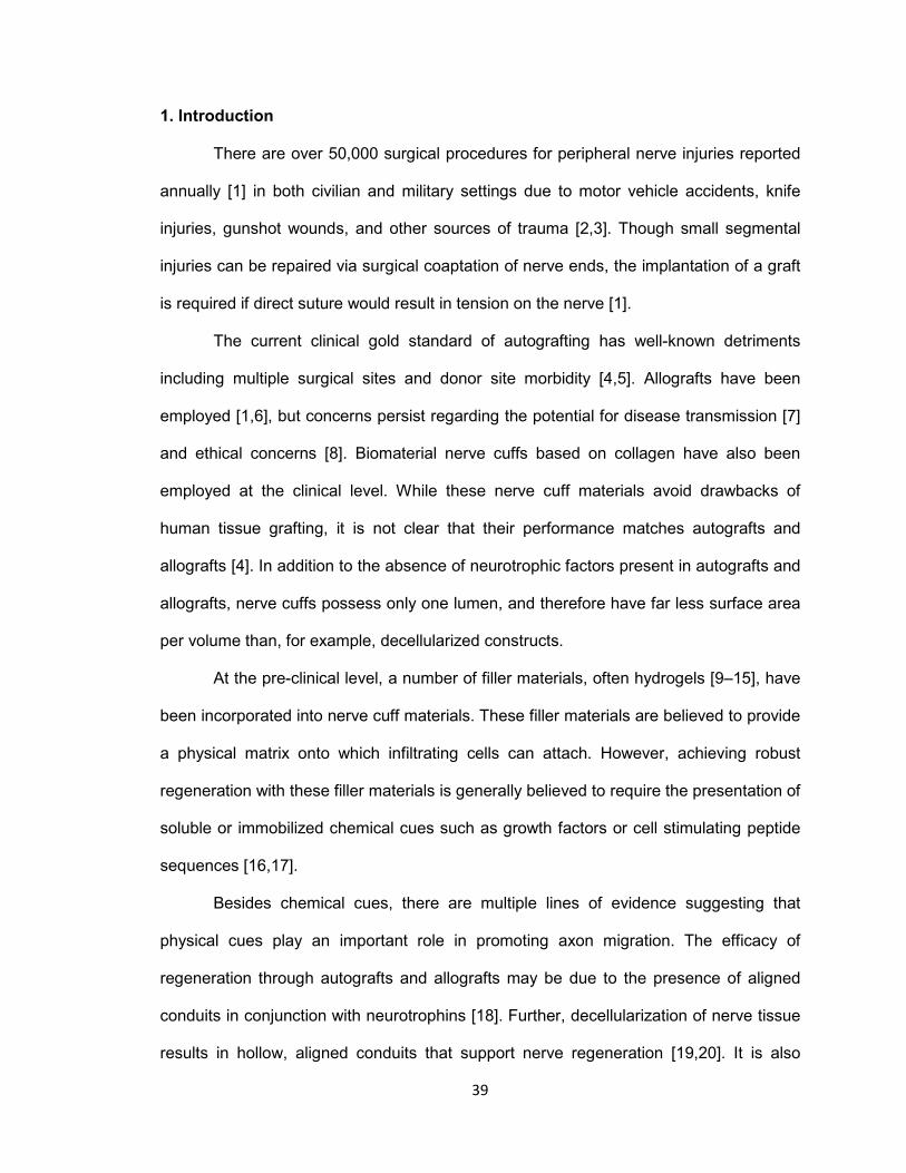
39
1. Introduction
There are over 50,000 surgical procedures for peripheral nerve injuries reported
annually [1] in both civilian and military settings due to motor vehicle accidents, knife
injuries, gunshot wounds, and other sources of trauma [2,3]. Though small segmental
injuries can be repaired via surgical coaptation of nerve ends, the implantation of a graft
is required if direct suture would result in tension on the nerve [1].
The current clinical gold standard of autografting has well-known detriments
including multiple surgical sites and donor site morbidity [4,5]. Allografts have been
employed [1,6], but concerns persist regarding the potential for disease transmission [7]
and ethical concerns [8]. Biomaterial nerve cuffs based on collagen have also been
employed at the clinical level. While these nerve cuff materials avoid drawbacks of
human tissue grafting, it is not clear that their performance matches autografts and
allografts [4]. In addition to the absence of neurotrophic factors present in autografts and
allografts, nerve cuffs possess only one lumen, and therefore have far less surface area
per volume than, for example, decellularized constructs.
At the pre-clinical level, a number of filler materials, often hydrogels [9–15], have
been incorporated into nerve cuff materials. These filler materials are believed to provide
a physical matrix onto which infiltrating cells can attach. However, achieving robust
regeneration with these filler materials is generally believed to require the presentation of
soluble or immobilized chemical cues such as growth factors or cell stimulating peptide
sequences [16,17].
Besides chemical cues, there are multiple lines of evidence suggesting that
physical cues play an important role in promoting axon migration. The efficacy of
regeneration through autografts and allografts may be due to the presence of aligned
conduits in conjunction with neurotrophins [18]. Further, decellularization of nerve tissue
results in hollow, aligned conduits that support nerve regeneration [19,20]. It is also

40
known that axons will track along fibers formed by extrusion or electrospinning in a
fashion dependent on the diameter of the fibers [21,22]. Importantly, neural scaffolds
consisting only of electrospun fibers are known to affect regenerative processes in vitro
[22] and have led to axonal bridging of large neural defects [23].
From a materials perspective, one drawback to bundled fiber approaches is that
the overall porosity of nerve guidance channels packed with these fibers is expected to
be quite low. In fact, approaches to provide physical cues with fibers while providing
sufficient porosity are being actively investigated [24]. Here, we describe a different
approach to the development of biomaterial scaffolds that can be fabricated de novo,
provide physical guidance cues, and provide sufficient porosity to allow robust axonal
growth.
The goals of the present study were twofold. The first goal was to fabricate highly
porous scaffolds containing large numbers of axially-aligned luminal conduits within a
biomaterial scaffold having mechanical properties suitable for neural repair. To
accomplish this, we utilized a sacrificial templating approach within the context of a
degradable fibrin hydrogel (see Fig. 1). Numerous natural and synthetic polymer
scaffolds are compatible with this type of approach [25–29]. However, we focused on the
use of fibrin in these studies in part because fibrin is a component of native peripheral
nerve repair, being laid down in a cable ahead of the growing axon bundle as a template
for growth [30]. Moreover, the sacrificial templating approach has the advantage of
generating aligned cylindrical conduits similar in morphology to denervated endoneurial
tubes left after Wallerian degeneration is complete [31], which we reasoned would
provide a conducive substrate to axon migration. As a final design consideration, we
aimed to incorporate scaffolds with mechanical integrity similar to that of native nerve so
they would handle well and could ultimately integrate properly with target tissue.
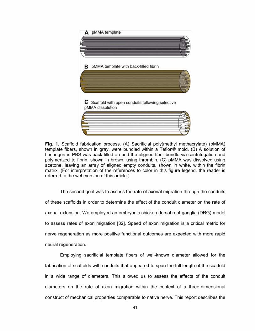
41
Fig. 1. Scaffold fabrication process. (A) Sacrificial poly(methyl methacrylate) (pMMA) template fibers, shown in gray, were bundled within a Teflon® mold. (B) A solution of fibrinogen in PBS was back-filled around the aligned fiber bundle via centrifugation and polymerized to fibrin, shown in brown, using thrombin. (C) pMMA was dissolved using acetone, leaving an array of aligned empty conduits, shown in white, within the fibrin matrix. (For interpretation of the references to color in this figure legend, the reader is referred to the web version of this article.)
The second goal was to assess the rate of axonal migration through the conduits
of these scaffolds in order to determine the effect of the conduit diameter on the rate of
axonal extension. We employed an embryonic chicken dorsal root ganglia (DRG) model
to assess rates of axon migration [32]. Speed of axon migration is a critical metric for
nerve regeneration as more positive functional outcomes are expected with more rapid
neural regeneration.
Employing sacrificial template fibers of well-known diameter allowed for the
fabrication of scaffolds with conduits that appeared to span the full length of the scaffold
in a wide range of diameters. This allowed us to assess the effects of the conduit
diameters on the rate of axon migration within the context of a three-dimensional
construct of mechanical properties comparable to native nerve. This report describes the

42
fabrication and characterization of the scaffolds as well as the axonal response as a
function of conduit diameter in these scaffolds.
2. Methods
2.1. Template fiber fabrication and characterization
Monofilament strands of poly(methyl-methacrylate) (pMMA) were formed by melt
extrusion at the North Carolina State University College of Textiles. 100 kDa pMMA
(Polysciences, Warrington, PA) was melt extruded on two different extruder systems to
achieve a range of fiber diameters by variation of system parameters including type of
extruder, temperature, rate of extrusion, and collection godet speed (see Table 1). One
set of extrusions was performed on an Alex James and Associates, Incorporated melt
extruder with a spinneret containing 64 holes. Each orifice had a diameter of 0.6 mm and
a length:diameter ratio of 2.3:1. The process temperatures were controlled at five
different zones in the extruder. The temperatures from the feed to the die zone were
210, 220, 240, 245, and 250 °C. Undrawn filaments were taken up at 200 or 800 m/min
(Table 1). Melt spinning was also performed on the Bradford piston system with a one
hole spinneret 0.5 mm in diameter and length:diameter ratio of 2. The piston
temperature was maintained between 240 and 250 °C (Table 1). The undrawn
monofilament was taken up at 27.5, 80 or 96.5 m/min (Table 1).
Cellulose acetate (CA) fibers (generous donation of Eastman Chemical Co., Kingsport,
TN) were also used. Brightfield imaging of both CA and pMMA fibers was performed on
a Zeiss Axiovert II microscope, and micrographs were captured with AxioVision software
(both Carl Zeiss, Inc. North America, Thornwood, NY). Images were imported into
ImageJ software (National Institutes of Health, Bethesda, MD) and fiber diameter was
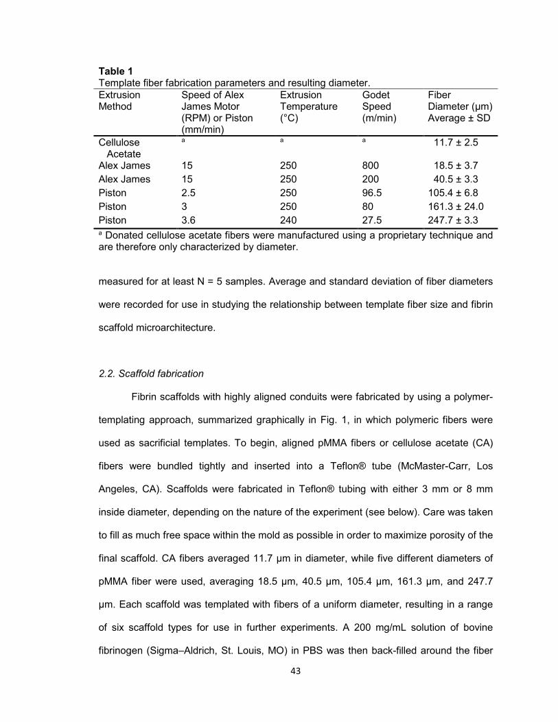
43
Table 1 Template fiber fabrication parameters and resulting diameter. Extrusion Method
Speed of Alex James Motor (RPM) or Piston (mm/min)
Extrusion Temperature (°C)
Godet Speed (m/min)
Fiber Diameter (μm) Average ± SD
Cellulose Acetate
a a a 11.7 ± 2.5
Alex James 15 250 800 18.5 ± 3.7
Alex James 15 250 200 40.5 ± 3.3
Piston 2.5 250 96.5 105.4 ± 6.8
Piston 3 250 80 161.3 ± 24.0
Piston 3.6 240 27.5 247.7 ± 3.3 a Donated cellulose acetate fibers were manufactured using a proprietary technique and are therefore only characterized by diameter.
measured for at least N = 5 samples. Average and standard deviation of fiber diameters
were recorded for use in studying the relationship between template fiber size and fibrin
scaffold microarchitecture.
2.2. Scaffold fabrication
Fibrin scaffolds with highly aligned conduits were fabricated by using a polymer-
templating approach, summarized graphically in Fig. 1, in which polymeric fibers were
used as sacrificial templates. To begin, aligned pMMA fibers or cellulose acetate (CA)
fibers were bundled tightly and inserted into a Teflon® tube (McMaster-Carr, Los
Angeles, CA). Scaffolds were fabricated in Teflon® tubing with either 3 mm or 8 mm
inside diameter, depending on the nature of the experiment (see below). Care was taken
to fill as much free space within the mold as possible in order to maximize porosity of the
final scaffold. CA fibers averaged 11.7 μm in diameter, while five different diameters of
pMMA fiber were used, averaging 18.5 μm, 40.5 μm, 105.4 μm, 161.3 μm, and 247.7
μm. Each scaffold was templated with fibers of a uniform diameter, resulting in a range
of six scaffold types for use in further experiments. A 200 mg/mL solution of bovine
fibrinogen (Sigma–Aldrich, St. Louis, MO) in PBS was then back-filled around the fiber
44
bundle by centrifugation in a Sorvall Legend RT benchtop centrifuge (Kendro Laboratory
Products, Newtown, CT) at 50 rcf. The fibrinogen surrounding the pMMA templates was
then polymerized for at least 16 h in a thrombin working solution consisting of 26 parts
PBS, two parts 5.5 mg/mL CaCl2 (Thermo Fisher Scientific, Waltham, MA), and two
parts 250 U/mL thrombin (Sigma). After polymerization, excess fibrin was removed from
each end of the fiber bundle with a razor blade. The resulting scaffold material was then
placed in acetone (Fisher) to selectively dissolve the sacrificial CA or pMMA fibers.
Three acetone washes were used lasting two hours, four hours, and 16 hours,
respectively. This acetone step also proved sufficient to sterilize scaffolds for use in
tissue culture experiments.
Random porous and non-porogen control scaffolds were fabricated similarly. To
create scaffolds incorporated with a random porous network, a template was formed by
filling the Teflon® mold with 180–212 μm diameter pMMA beads (Polysciences,
Warrington, PA). This size range of beads was obtained by sieving. The bead-filled
molds were vigorously tapped to settle beads into a close-packed arrangement and
heated at 140 °C for 22 h to sinter the beads together at points of contact [25] and [33].
Fibrinogen back-filling, polymerization into fibrin, and template removal with acetone
were performed as above for the sacrificial fibers. Non-porogen scaffolds were created
by omitting the inclusion of a polymer template. Instead, fibrinogen was pipetted into the
Teflon® mold, a wedge was removed from the wall of the mold with a razor blade, and
the entire assembly was immersed in thrombin working solution as described above to
polymerize the fibrin block. The remaining Teflon® was then removed, and acetone
washes were performed as above to sterilize the scaffolds. These resulting non-porogen
scaffolds were essentially a fibrin hydrogel plug.
45
2.3. Characterization of scaffold morphology
Scaffold morphology was evaluated by using scanning electron microscopy
(SEM) of scaffolds consisting of each different sacrificial template diameter. Scaffolds
fabricated as described above were cut in half longitudinally with a scalpel, hydrated in
sterile PBS, dried in a model EMS850X critical point dryer (Electron Microscopy
Sciences, Hatfield, PA), mounted on SEM chucks for longitudinal or cross-sectional
imaging, and sputter coated with an Au-Pd mixture using a Hummer 6.2 sputter coater
(Anatech Ltd., Battle Creek, MI). Scaffolds were imaged with an S-2600 N environmental
scanning electron microscope (Hitachi High Technologies America, Inc., Schaumburg,
IL) in either longitudinal- or cross-section. Images of the longitudinally-sectioned
scaffolds were imported into ImageJ software to quantify the degree of conduit alignment
within the scaffold. Five regions within the micrograph were randomly selected and,
within each region, the angular deviation from the scaffold longitudinal axis was recorded
for all observed conduits. Similarly, the diameters of the conduits were determined by
ImageJ analysis of the cross-sectional SEM images by measuring five separate regions
of a single scaffold.
2.4. Scaffold porosity determined by mercury porosimetry
Porosity was measured for scaffolds made with each fiber template by mercury
porosimetry. 8 mm diameter scaffolds of different luminal conduit dimensions were
prepared as described above. Samples were then trimmed to 1 cm length, weighed, and
evaluated using an AutoPore IV mercury porosimeter (Micromeritics, Norcross, GA).
Mercury intrusion was performed over a range of 0.10–33000 psia, and total intrusion
volume was measured over this range. Total pore volume was calculated automatically
by the bundled software package (AutoPore IV 9500 v1.09, Micromeritics) by subtracting
intrusion volume at maximum pressure from intrusion volume at zero pressure [34].
46
Sample bulk volume was assumed to equal total penetrometer volume minus intrusion
volume at zero pressure. Sample percent porosity was then calculated from bulk volume
and pore volume by software using the equation:
P% = (Vpore/Vbulk) ∗ 100% [34].
N = 3 were evaluated for each scaffold type, and analysis of variance (ANOVA)
was performed on resulting averages using Prism 5 (GraphPad Software, La Jolla, CA)
to determine if any significant differences existed between scaffold types using a value
of P < 0.05 to determine statistical significance.
2.5. Mechanical properties determined by tensile testing
To determine stiffness and strength, scaffolds were fabricated as described
above, re-hydrated in PBS for at least six hours, and trimmed to 3 cm length. Scaffolds
of each type (n = 3) were mounted into the grips of a Model 5544 tension tester (Instron,
Canton, MA) equipped with a 100 N load cell, and scaffold diameter and length were
measured. Samples were subjected to 10 cycles of 0.3 mm maximum extension at
0.1667 mm/s as a preconditioning step prior to tensile testing to failure. Raw data were
exported to MS Excel 2007 (Microsoft, Redmond, WA) and plotted as tensile load vs.
extension and tensile stress vs. strain. Maximum load was directly located in tabular raw
data and reported. The linear region of the stress vs. strain plot was selected manually,
and linear regression was performed on this data set. The slope of the resulting line was
reported as the scaffold Young’s Modulus (E). ANOVA and post-hoc Tukey’s test (where
indicated by positive ANOVA) of calculated E and maximum load were performed using
Prism 5. N = 3 samples were evaluated for each scaffold and P < 0.05 was taken as
statistically significant.
47
2.6. DRG seeding in vitro
To determine the rate of axon infiltration through the scaffolds in response to
scaffold architecture, we employed an embryonic chicken dorsal root ganglia (DRG)
model [32]. DRG culture medium was composed of HyClone high-glucose Dulbecco’s
modified Eagle’s medium (Fisher), 10% v/v fetal bovine serum (GIBCO Invitrogen,
Carlsbad, CA), 1% v/v 5-fluoro-2′-deoxyuridine (FDU, Sigma), 1% v/v Uridine (Sigma),
1% v/v penicillin-streptomycin (Invitrogen), 20 μg/mL bovine aprotinin (Sigma), and 50
ng/mL nerve growth factor (NGF, BD Biosciences). Aprotinin was included to reduce
fibrinolytic scaffold degradation, and NGF was used to stimulate axonal extension [32].
In particular, we note that FDU and uridine were added to minimize proliferation of non-
neuronal cells, especially Schwann cells. The purpose of inhibiting Schwann cell
proliferation was to allow us to focus on axonal extension in response to the conduit
diameters alone rather than in response to Schwann cells and other cell-based trophic
cues.
3 mm diameter aligned conduit scaffolds and control scaffolds, fabricated as
described above, were trimmed to 5 mm in length and washed three times in sterile PBS
for at least two hours, four hours, and 16 hours respectively to remove acetone. Small
amounts of 100 mg/mL fibrinogen and thrombin working solution were used as a glue to
attach scaffolds to the wall of individual wells in 24-well Falcon polystyrene culture
dishes (BD Biosciences, Franklin Lakes, NJ) under aseptic conditions. Scaffolds were
kept wetted with PBS to prevent contraction and retain normal morphology of the fibrin
matrix until DRG seeding.
DRG were dissected from E7-E8 chicken embryos (Tyson Chicken, Hays, NC)
and stored on ice in sterile 1% penicillin/streptomycin in PBS for a time not exceeding
one hour. Ten DRG were seeded on the top surface of each scaffold to increase the
likelihood of obtaining a longitudinal section from the scaffold that had a DRG and
48
associated axons (see below). DRG culture medium was added to a height just below
the seeded scaffold top to allow DRG attachment to the scaffolds. This cell cluster was
allowed to attach to the scaffold for 24 h, after which additional medium was added to
cover the top of the scaffold and DRG. Samples were removed after 1, 2, or 3 days, with
n = 3 for each combination of scaffold type and time point. Removed scaffolds were
briefly washed once in PBS, oriented in a plastic tray for longitudinal sectioning, and
then snap frozen in OCT compound (Sakura Finetek USA, Torrance, CA) with liquid
nitrogen.
2.7. Immunohistochemistry
Axon infiltration into fibrin scaffolds was determined by immunohistochemically
staining longitudinal sections for neurofilament. 50 μm-thick sections were cut from OCT-
embedded scaffolds along longitudinal planes using a CM 1950 cryostat (Leica
Microsystems, Bannockburn, IL) and immobilized on silane-coated glass slides
(LabScientific, Livingston, NJ). Sections containing DRG were fixed for 3 min in 10%
neutral-buffered formalin (Leica) and then washed to remove excess fixative and OCT
compound. Sections were blocked using Dual Endogenous Enzyme Block (Dako North
America, Carpinteria, CA) and Serum-Free Protein Block (Dako). Sections were then
treated with mouse monoclonal antibody to 160 kDa and 200 kDa neurofilament
(AbCam, Cambridge, MA) or to mouse IgG (isotype) control at 1:100 dilution in Antibody
Diluent Solution (Dako) for 30 min. Serum-Free Protein Block was applied a second time
before then treating sections with biotinylated goat anti-mouse IgG or horse anti-mouse
IgG (Vector Laboratories, Burlingame, CA) at 1:200 dilution in Antibody Diluent Solution.
Sections were then treated with ABC-AP reagent (Vector) before staining with Vector
Red Alkaline Phosphatase Substrate (Vector). Coverslips were mounted to slides using
Fluoromount-G (Southern Biotech, Birmingham, Alabama) and dried overnight at 4 °C.

49
2.8. Image analysis
Staining was imaged via brightfield microscopy using a DM4000 B microscope
(Leica) with attached Retiga 2000RV camera (QImaging, Surrey, BC, Canada), coupled
with ImagePro 6.2 software (Media Cybernetics Inc., Bethesda, MD). Maximum axon
length was measured using ImageJ software. After the longest axon was identified, a
line parallel to the scaffold longitudinal axis was drawn between the axon tip and scaffold
surface and the length of the line was measured. One image from each seeded scaffold
was analyzed and average maximum axon length calculated for each combination of
time point and scaffold type, resulting in N = 3 for each reported data point. This method
of quantification of maximum length of axon extension is consistent with those reported
by others [21]. Statistical analysis of these averages was performed in Prism 5 using
ANOVA and post-hoc pairwise Bonferroni comparisons where appropriate. P < 0.05 was
used as the significance threshold.
3. Results
3.1. Template fiber characterization
To fabricate scaffolds and assess the effects of conduit diameter on the rate of
axon extension, it was necessary to acquire polymeric fiber templates of a range of
diameters. Acetone-soluble polymer fibers were either custom extruded or donated to
serve as these templates. 12 μm templates were obtained by donation of cellulose
acetate fibers, but to obtain template fibers of other diameters, processing parameters
for extrusion were modulated to obtain fibers diameters from approximately 19–250 μm
as determined by light microscopy and summarized in Table 1. We anticipated that this
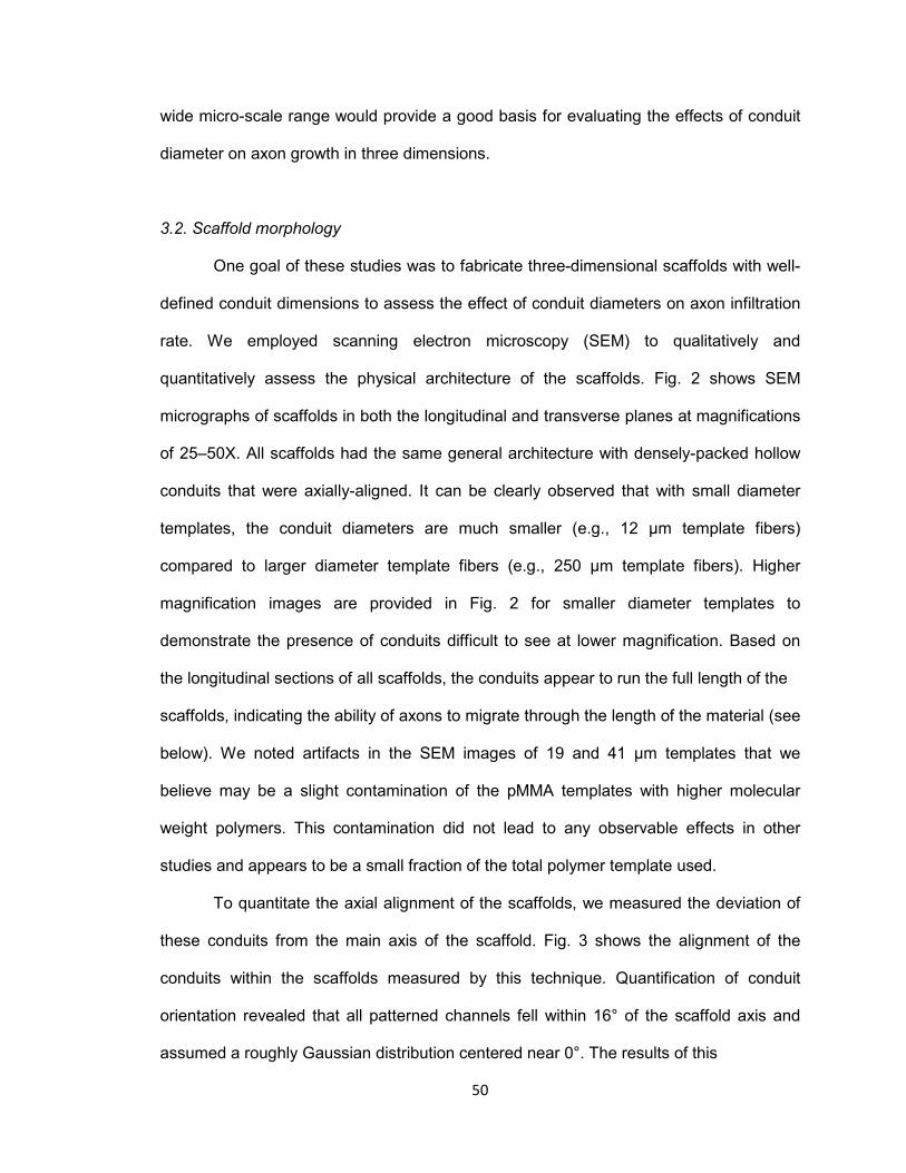
50
wide micro-scale range would provide a good basis for evaluating the effects of conduit
diameter on axon growth in three dimensions.
3.2. Scaffold morphology
One goal of these studies was to fabricate three-dimensional scaffolds with well-
defined conduit dimensions to assess the effect of conduit diameters on axon infiltration
rate. We employed scanning electron microscopy (SEM) to qualitatively and
quantitatively assess the physical architecture of the scaffolds. Fig. 2 shows SEM
micrographs of scaffolds in both the longitudinal and transverse planes at magnifications
of 25–50X. All scaffolds had the same general architecture with densely-packed hollow
conduits that were axially-aligned. It can be clearly observed that with small diameter
templates, the conduit diameters are much smaller (e.g., 12 μm template fibers)
compared to larger diameter template fibers (e.g., 250 μm template fibers). Higher
magnification images are provided in Fig. 2 for smaller diameter templates to
demonstrate the presence of conduits difficult to see at lower magnification. Based on
the longitudinal sections of all scaffolds, the conduits appear to run the full length of the
scaffolds, indicating the ability of axons to migrate through the length of the material (see
below). We noted artifacts in the SEM images of 19 and 41 μm templates that we
believe may be a slight contamination of the pMMA templates with higher molecular
weight polymers. This contamination did not lead to any observable effects in other
studies and appears to be a small fraction of the total polymer template used.
To quantitate the axial alignment of the scaffolds, we measured the deviation of
these conduits from the main axis of the scaffold. Fig. 3 shows the alignment of the
conduits within the scaffolds measured by this technique. Quantification of conduit
orientation revealed that all patterned channels fell within 16° of the scaffold axis and
assumed a roughly Gaussian distribution centered near 0°. The results of this

51
Fig. 2. Scaffold morphology. SEM micrographs of scaffolds in cross-section (top images) and longitudinal section (bottom images) are shown for each template type. For smaller diameter templates (top set of panels), the middle row shows higher magnification images to demonstrate the presence of the conduits present. Micrographs depict conduits of uniform diameter traveling the length of the scaffold. Scale is shown in the bottom right of individual images.

52
Fig. 3. Conduit alignment within scaffolds. Histograms represent number of conduits as a function of angle from the scaffold midline. All histograms are centered near 0°, indicating a high degree of alignment among all scaffold conduits.
characterization indicate that the scaffolds have highly aligned and densely-packed
conduits.
As described above, we had measured the diameters of the templating fibers,
which should provide an indication of the resulting conduits. However, we also estimated
the diameters of the conduits by measurement from the SEM images. Fig. 4 shows the
results of these SEM measurements compared to the template diameters. We note that
in the larger diameter scaffolds the SEM measurements are less than the templating
diameters. However, we observed significant contraction of the scaffolds during critical
point drying for these larger scaffolds (e.g., see Fig. 2F), which is the reason for the
difference. Error bars denote standard deviations of about 5–10% of the average,
indicating that the pores were quite uniform in their diameter for a given template. We

53
also noted that the scaffolds did have “memory” in that after contraction due to
dehydration, scaffolds immersed in aqueous media did return to normal size through
swelling of the hydrogel.
3.3. Scaffold porosity
To further characterize the observation of the packing density of the conduits
from the SEM studies, we performed mercury porosimetry. Table 2 summarizes the
scaffold porosity. These results indicate that the average porosity for all templates fell
near 80% with little variability. This is important for studies below with axon migration.
Because all scaffolds had nearly the same porosity, differences in axon migration could
Fig. 4. Quantification of fiber template diameter (white bars) relative to measured resulting conduit diameter (black bars). Results show the ability to generate scaffolds over a range of conduit diameters with good homogeneity of template and conduit diameters. Note that 161 μm and 248 μm template diameters showed contraction during critical point drying and conduit diameters are therefore underestimated.
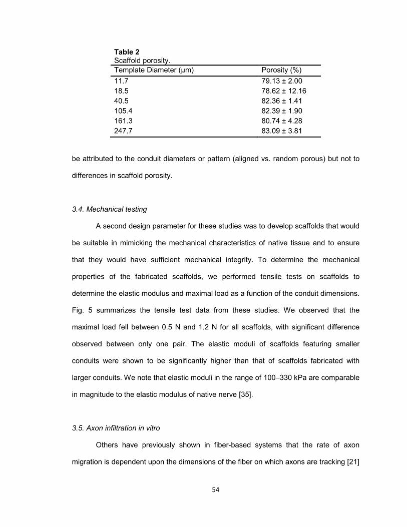
54
Table 2 Scaffold porosity.
Template Diameter (μm) Porosity (%)
11.7 79.13 ± 2.00
18.5 78.62 ± 12.16
40.5 82.36 ± 1.41
105.4 82.39 ± 1.90
161.3 80.74 ± 4.28
247.7 83.09 ± 3.81
be attributed to the conduit diameters or pattern (aligned vs. random porous) but not to
differences in scaffold porosity.
3.4. Mechanical testing
A second design parameter for these studies was to develop scaffolds that would
be suitable in mimicking the mechanical characteristics of native tissue and to ensure
that they would have sufficient mechanical integrity. To determine the mechanical
properties of the fabricated scaffolds, we performed tensile tests on scaffolds to
determine the elastic modulus and maximal load as a function of the conduit dimensions.
Fig. 5 summarizes the tensile test data from these studies. We observed that the
maximal load fell between 0.5 N and 1.2 N for all scaffolds, with significant difference
observed between only one pair. The elastic moduli of scaffolds featuring smaller
conduits were shown to be significantly higher than that of scaffolds fabricated with
larger conduits. We note that elastic moduli in the range of 100–330 kPa are comparable
in magnitude to the elastic modulus of native nerve [35].
3.5. Axon infiltration in vitro
Others have previously shown in fiber-based systems that the rate of axon
migration is dependent upon the dimensions of the fiber on which axons are tracking [21]
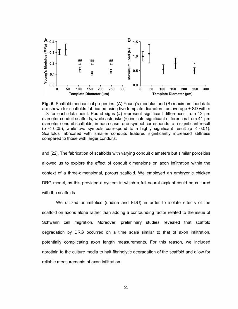
55
Fig. 5. Scaffold mechanical properties. (A) Young’s modulus and (B) maximum load data are shown for scaffolds fabricated using five template diameters, as average ± SD with n = 3 for each data point. Pound signs (#) represent significant differences from 12 μm diameter conduit scaffolds, while asterisks (∗) indicate significant differences from 41 μm diameter conduit scaffolds; in each case, one symbol corresponds to a significant result (p < 0.05), while two symbols correspond to a highly significant result (p < 0.01). Scaffolds fabricated with smaller conduits featured significantly increased stiffness compared to those with larger conduits.
and [22]. The fabrication of scaffolds with varying conduit diameters but similar porosities
allowed us to explore the effect of conduit dimensions on axon infiltration within the
context of a three-dimensional, porous scaffold. We employed an embryonic chicken
DRG model, as this provided a system in which a full neural explant could be cultured
with the scaffolds.
We utilized antimitotics (uridine and FDU) in order to isolate effects of the
scaffold on axons alone rather than adding a confounding factor related to the issue of
Schwann cell migration. Moreover, preliminary studies revealed that scaffold
degradation by DRG occurred on a time scale similar to that of axon infiltration,
potentially complicating axon length measurements. For this reason, we included
aprotinin to the culture media to halt fibrinolytic degradation of the scaffold and allow for
reliable measurements of axon infiltration.

56
To assess axonal response to the scaffolds, we used immunohistochemical
staining with anti-neurofilament antibodies. A colorimetric stain (Vector Red Alkaline
Phosphatase) was used instead of fluorometric staining methods due to the levels of
autofluorescence from the high fibrinogen (and ultimately fibrin) concentration used to
fabricate the scaffolds. A representative image from each scaffold type after one day in
culture is shown in Fig. 6. Similar results were obtained with anti-betaIII-tubulin
antibodies (images not shown), though staining was more intense with neurofilament. As
can be seen in Fig. 6, DRG attached to scaffolds after 24 h in culture and axons began
to migrate both across the scaffold edge and into the conduits of the scaffold.
We employed two control scaffolds to contrast the behavior with the axially-aligned
conduits. Fibrin plugs (non-porogen controls) were used to demonstrate the need for
porous patterning within dense fibrin hydrogels created using 200 mg/mL fibrinogen. As
shown in Fig. 6, no axon infiltration was observed into the non-porogen fibrin hydrogel
control. A fibrin scaffold with randomly oriented spherical pores (rather than axially-
aligned conduits) was also used to determine the effect of the axial alignment. As can be
seen in Fig. 6, we did not observe the same degree of axon infiltration into these
spherically-templated scaffolds. Dotted lines were added to Fig. 6 using Photoshop
Elements 6.0 (Adobe Systems Incorporated, San Jose, CA) to highlight the length of
axonal extension into the scaffolds.
To quantify these observations, we measured axonal extension into each
scaffold type. We collected images of immunohistochemically-stained scaffold sections
after 1, 2, or 3 days in culture to assess the rate of axonal migration into the scaffold.
Fig. 7B–D shows averaged maximum axon length for each template size at all three time
points evaluated, and the method used to determine these lengths is shown on a

57
Fig. 6. Axon infiltration of scaffolds. A representative image from each experimental and control scaffold type is shown after 1 day cultured in vitro. Dotted lines have been added to highlight the progression of axon infiltration. Aligned-conduit scaffolds supported faster axon ingrowth to the scaffold matrix than random porous controls. Axons could not infiltrate non-porogen controls, though some growth along the scaffold exterior was observed. Brightness and contrast of photos were adjusted and dotted lines were added using Photoshop Elements 6.0 (Adobe Systems Incorporated, San Jose, CA). An image of a scaffold (41 μm template) stained with an isotype IgG control antibody is shown to demonstrate the specificity of neurofilament staining observed in other images. Similar isotype controls were used for all scaffolds but only a representative image is shown. Scale bar shown in the bottom right of each image represents 500 μm.
58
Fig. 7. Quantification of axon infiltration. (A) Representative image of a scaffold after 1 day of culture and stained for neurofilament as in Fig. 7. The method of measuring the longest axon present in each histological image is shown. Length was measured parallel to the longitudinal axis of the scaffold, as shown by the black bracket in the example subfigure. The scale bar at the bottom right measures 500 μm. Maximum axon lengths are shown as average ± SD for culture in vitro after (B) 1 day, (C) 2 day, and (D) 3 day time points over the range of scaffold types studied, with n = 3 for each data point. Filled circles (●) represent experimental aligned conduit scaffolds, open squares (□) on each plot represent the random porous control, and open triangles (▵) represent the non-
porogen control scaffold. Note that non-porogen control scaffolds (▵) show no growth and are located near the origin. Asterisks report significant differences between experimental scaffolds and random porous controls, with one symbol corresponding to a significant result (p < 0.05) and two symbols corresponding to a highly significant result (p < 0.01). Results from all experimental and random porous scaffolds were significantly different (at least p < 0.05) from those of nonporous controls. Aligned-conduit scaffolds supported more rapid axon growth than both controls at 1 and 2 days over the entire range of conduit diameters. Similarly, nearly all conduit diameters showed significantly longer axon extension after 3 days than non-porogen and random porous control scaffolds.
59
representative scaffold from a 24-hour time point (Fig. 7A). This quantification reinforced
the observation of little growth into non-porogen control scaffolds (data point located
near origin), with axonal migration into the non-porogen scaffolds being highly
significantly different than axially-aligned scaffolds at all time points (P < 0.01). Though
axons were observed growing into random porous controls, the length of these axons
was significantly (P < 0.05) shorter than those infiltrating all aligned conduits at one- and
two-day time points.
Of particular interest was the comparison between axially-aligned scaffolds. In
contrast to previous studies indicating a role for the dimensions of aligned fiber
templates [21] and [22], in our sacrificial template system, we found no significant
differences between any of the template diameters investigated (ranging from 12 to 250
μm diameter) at any of the time points observed (1, 2, and 3 days).
4. Discussion
The success of autografts for neural regeneration likely involves the presentation
of physical guidance cues through the endoneurial channels and chemical factors [18]
(e.g., neurotrophins) in the graft secreted by Schwann cells. Several strategies for the
presentation of chemical cues to regenerating cells in biomaterial constructs have been
developed including delivery through soluble and immobilized factors [36]. The
incorporation of physical cues has been demonstrated [21], [23], [26], [27] and [37], but
relatively few studies have been directed at incorporating these cues into biomaterial
scaffolds or to the understanding of the geometrical requirements of these cues (e.g.,
effects of diameter on axonal regeneration). Several methods of incorporating physical
cues into scaffolds exist, including (1) alignment of fiber bundles [21] and [23] and
formation of aligned multi-luminal constructs via (2) sacrificial templating [26] and [29],
60
(3) phase separation [37], (4) lithography [38] and [39], and (5) solid free-form fabrication
[40].
For aligned fiber constructs it has been demonstrated that the diameter of the
fiber guides directly affect the rate of axon migration, providing an approach to increase
rates of axonal regeneration. However, these aligned fiber constructs have often been
used in two-dimensional systems (e.g. [22]) and translation of this technology to a three-
dimensional system will likely be problematic due to the low porosity of resulting three-
dimensional constructs. Sacrificial template methods provide an architecture similar to
native nerve and offer the potential for a more porous system. Existing needs for
materials formed by this approach include achieving sufficient porosity to support robust
axonal infiltration, provision of mechanical properties comparable to native nerve, and an
understanding of the effect of the conduit diameters on rates of axonal migration.
In these studies, we developed a fibrin-based construct in an effort to begin to
address these questions. Fibrin was selected because it is one of the earliest
components of the native nerve repair process [41] and [42], and several groups have
used this material as a filler for nerve cuff technology to enhance regeneration [43], [44],
[45] and [46] and/or deliver neurotrophic factors [47] and [48] or cells [49]. In addition,
the use of a sphere-templating approach to fabricate scaffolds from this material has
previously been reported [25].
We fabricated different scaffolds with a range of conduit diameters in an effort to
identify the relationship between conduit diameter and rate of axon regeneration in this
three-dimensional system. This was done because although the diameter (caliber) of the
endoneurium is known for mature native nerve, it is not clear that these diameters are
optimal for a regenerative process following injury.
The scaffolds fabricated by the sacrificial fiber approach in the current study had
a physical resemblance similar to native nerve tissue following decellularization or post-
61
injury Wallerian degeneration (compare Fig. 2 with [31]). This approach therefore offers
the ability to achieve important structure–function relationships of native tissue while
optimizing the system for regeneration. Although contraction during processing for SEM
was observed for larger diameter fiber templates (see Fig. 2), it is clear that conduit
diameter was directly related to the fiber template diameter. Further, the conduits were
highly aligned and SEM images suggest that the conduits spanned the length of the
scaffolds. We also note that there was no observed impediment to axon infiltration and
we were able to visually observe, for the large diameters, that conduits ran the full length
of the scaffold.
As a control for the role of alignment, we also incorporated porosity into the
scaffolds by the use of spherical templates [25] that created a more tortuous path than
the aligned fiber templates. The more tortuous spherical templates resulted in axon
infiltration into the scaffolds, but with a rate of extension significantly less than the less
tortuous aligned scaffold conduits (300 μm per day compared to 600–900 μm per day).
These results demonstrate the importance of non-tortuous paths for axonal extension in
three dimensional scaffolding systems and are consistent with previous results indicating
that oriented patterns are superior in directing rapid axon extension in two-dimensional
systems [50].
Importantly, the scaffolds were also highly porous, with porosity values of
approximately 80% regardless of the template fiber diameter. In addition, the mechanical
properties of these scaffolds (Fig. 5) were similar to native nerve, with an elastic
modulus of approximately 100–330 kPa compared to native nerve with an elastic
modulus of 580 kPa [35]. This combination of a highly porous scaffold material with
mechanical properties similar to native tissue is of considerable importance for several
reasons. Although the fibrin hydrogel alone has good mechanical properties, the porosity
provided by the conduits is necessary to allow the migration of axons through the

62
material. In addition, the material has sufficient mechanical strength to prevent collapse
of the conduits during handling, indicating the ability to handle these scaffolds within a
surgical setting. Lastly, the similarity of the mechanical properties of these scaffolds
relative to native nerve would likely minimize scarring that could occur due to mechanical
mismatch at site of implantation. Thus, the fibrin scaffolds fabricated by this approach
have material properties suitable and favorable for nerve grafting applications.
We evaluated the rate of axon migration into the scaffolds as a function of
conduit diameter by immunohistochemistry with histomorphometry. For these in vitro
studies we employed an embryonic chicken DRG model. This model was well-suited to
these studies as the size of the DRG allowed them to be placed on the top of the
scaffold (similar to the proximal end of a nerve injury) for all conduit diameters tested.
Dissociation of DRG to isolate neuronal cells was not feasible due to the small size of
the neurons and the large diameter of some conduits. We therefore elected to use whole
DRG explants for these studies. To focus on the axon extension through the conduits in
response to conduit diameters, we included uridine and FDU in the culture medium to
inhibit mitotic growth of Schwann cells. We observed during pilot studies that the smaller
diameter conduits (e.g., 12 and 19 μm) showed lower numbers of Schwann cells
because these cells were excluded by the diameter of the conduits. To achieve similar
trophic conditions for all scaffold types, we therefore inhibited Schwann cell mitosis with
uridine and FDU. While Schwann cells play a key role in the functional nerve recovery in
vivo, the hydrogel nature of these scaffolds offers the potential to provide exogenous
trophic support through controlled release until Schwann cells can ultimately associate
with the regenerated axons. We reason that if more rapid axon extension can be
achieved in vivo this will provide more favorable long-term functional recovery. Aprotinin
was also added to the culture to prevent degradation of the scaffold by matrix
metalloproteinases (MMPs) [49]. We also added exogenous NGF to the media to
63
stimulate axonal extension from the DRG. We recognize that future strategies utilizing
this approach may require means to prevent proteolytic degradation of fibrin and to
provide controlled release of growth factors to promote axonal extension. We have found
that the hydrogel nature of these scaffolds is compatible with the slow release of small
molecule proteins such as aprotinin and growth factors (data not shown).
We evaluated the maximum distance of axon migration through the scaffolds as
reported by others [21]. Other approaches to quantify number of axons were not used
because of variability observed in DRG spreading on the scaffold surfaces (e.g., see Fig.
2).
A key finding from these studies was that no significant differences in axon length
with time were observed over the wide range of conduit diameters studied. We had
hypothesized that smaller diameter conduits would lead to increased rates of axonal
extension based on previous studies that indicated changes in length of axon extension
at a given time point (indicating differences in the rate of extension [21] and [22]). Our
results may indicate that physical shape of the curvature observed by axonal growth
cones (i.e., convex for a fiber compared to concave for a conduit) affects axonal
migration. The results could also indicate that the porosity of the material, such as the
conduit scaffolds used in these studies, is a more important parameter than the
geometrical dimensions of the physical guidance cues. We speculate that one
advantage to the smaller diameter conduits is that they may prevent infiltration of
inflammatory cells (e.g., neutrophils and monocytes/macrophages), allowing unimpeded
infiltration of axons.
We note that other studies looking at effects of geometrical parameters on axon
migration have utilized different time points (5 or 7 days) rather than the 3 time points in
our studies [21] and [22]. It is conceivable that differences could occur at longer time
points in our system. However, because we observed multiple time points (1, 2, and 3
64
days), we can see the linear rate of axon migration, indicating that similar results would
be expected at 5 or 7 days. Unfortunately a direct comparison to these other studies was
not possible. Although the fibrin scaffolds can be fabricated in any length, the
mechanical properties were not sufficient to allow their use in the culture system used in
our study; that is, the scaffolds did not have sufficient rigidity to remain upright when
glued to the culture plate. Wen and Tresco were able to evaluate at longer time points,
presumably because the more rigid nature of their scaffolds allowed them to employ
longer scaffolds in a similar culture system [21]. It is also noteworthy that in the three-
dimensional fibrin system in our study the axon extension length was approximately
1500 μm at 3 days (∼500 μm/day), compared to Wang et al, who saw extension of 1400
μm over 5 days (∼280 μm/day) in the same chick DRG system. However, differences in
culture conditions and DRG model make direct comparisons to other studies challenging
[21] and [22].
5. Conclusions
In these studies, we have described an approach to the fabrication of fibrin
scaffolds suitable for peripheral nerve repair applications. Although the sacrificial
templating approach should be compatible with other materials, the mechanical
properties achieved with fibrin scaffolds are comparable to native nerve and are
expected to support axonal migration due to the role of fibrin in the natural repair
process following nerve injury. An important finding from these studies was that the use
of highly aligned conduits supports more rapid axon migration through the scaffolds than
tortuous, non-aligned pores. However, in contrast to two-dimensional fiber-based
systems, the diameters in these three-dimensional scaffolds were not found to
significantly affect the rate of axon migration through the materials. The approach used
for the fabrication of these scaffolds represent a useful means by which to incorporate
65
physical guidance cues and mechanical integrity into biomaterials useful for peripheral
nerve repair.
Acknowledgments
This work was funded by the Wake Forest University Health Sciences Venture
Fund, the Department of Biomedical Engineering, and the Wake Forest Institute for
Regenerative Medicine. The authors gratefully acknowledge the laboratory of Dr.
Carolanne Milligan, Wake Forest University Health Sciences Department of
Neurobiology and Anatomy, for assistance with isolation and culture of embryonic
chicken DRG.
References
[1] Evans GR. Peripheral nerve injury: a review and approach to tissue engineered constructs. Anat Rec 2001;263:396–404.
[2] Nichols CM, Brenner MJ, Fox IK, Tung TH, Hunter DA, Rickman SR, et al. Effects of
motor versus sensory nerve grafts on peripheral nerve regeneration. Exp Neurol 2004;190:347–55.
[3] Noble J, Munro CA, Prasad VS, Midha R. Analysis of upper and lower extremity
peripheral nerve injuries in a population of patients with multiple injuries. J Trauma 1998;45:116–22.
[4] Taras JS, Nanavati V, Steelman P. Nerve conduits. J Hand Ther 2005;18:191–7. [5] Siemionow M, Bozkurt M, Zor F. Regeneration and repair of peripheral nerves with
different biomaterials: review. Microsurgery 2010;30:574–88. [6] Whitlock EL, Tuffaha SH, Luciano JP, Yan Y, Hunter DA, Magill CK, et al. Processed
allografts and type I collagen conduits for repair of peripheral nerve gaps. Muscle Nerve 2009;39:787–99.
[7] Larsen M, Habermann TM, Bishop AT, Shin AY, Spinner RJ. Epstein-Barr virus
infection as a complication of transplantation of a nerve allograft from a living related donor. Case report. J Neurosurg 2007;106:924–8.
[8] Champney TH. A proposal for a policy on the ethical care and use of cadavers and
their tissues. Anat Sci Educ 2011;4:49–52.
66
[9] Madison RD, da Silva C, Dikkes P, Sidman RL, Chiu TH. Peripheral nerve regeneration with entubulation repair: comparison of biodegradeable nerve guides versus polyethylene tubes and the effects of a laminin-containing gel. Exp Neurol 1987;95:378–90.
[10] Midha R, Munro CA, Dalton PD, Tator CH, Shoichet MS. Growth factor
enhancement of peripheral nerve regeneration through a novel synthetic hydrogel tube. J Neurosurg 2003;99:555–65.
[11] Labrador RO, Buti M, Navarro X. Influence of collagen and laminin gels
concentration on nerve regeneration after resection and tube repair. Exp Neurol 1998;149:243–52.
[12] Sierpinski P, Garrett J, Ma J, Apel P, Klorig D, Smith T, et al. The use of keratin
biomaterials derived from human hair for the promotion of rapid regeneration of peripheral nerves. Biomaterials 2008;29:118–28.
[13] Yu TT, Shoichet MS. Guided cell adhesion and outgrowth in peptide-modified
channels for neural tissue engineering. Biomaterials 2005;26:1507–14. [14] Deister C, Aljabari S, Schmidt CE. Effects of collagen 1, fibronectin, laminin and
hyaluronic acid concentration in multi-component gels on neurite extension. J Biomater Sci Polym Ed 2007;18:983–97.
[15] Suri S, Schmidt CE. Cell-laden hydrogel constructs of hyaluronic acid, collagen, and
laminin for neural tissue engineering. Tissue Eng Part A 2010;16:1703–16. [16] Dodla MC, Bellamkonda RV. Differences between the effect of anisotropic and
isotropic laminin and nerve growth factor presenting scaffolds on nerve regeneration across long peripheral nerve gaps. Biomaterials 2008;29:33–46.
[17] Yu X, Bellamkonda RV. Tissue-engineered scaffolds are effective alternatives to
autografts for bridging peripheral nerve gaps. Tissue Eng 2003;9:421–30. [18] Nguyen QT, Sanes JR, Lichtman JW. Pre-existing pathways promote precise
projection patterns. Nat Neurosci 2002;5:861–7. [19] Hudson TW, Liu SY, Schmidt CE. Engineering an improved acellular nerve graft via
optimized chemical processing. Tissue Eng 2004;10:1346–58. [20] Hudson TW, Zawko S, Deister C, Lundy S, Hu CY, Lee K, et al. Optimized acellular
nerve graft is immunologically tolerated and supports regeneration. Tissue Eng 2004;10:1641–51.
[21] Wen X, Tresco PA. Effect of filament diameter and extracellular matrix molecule
precoating on neurite outgrowth and Schwann cell behavior on multifilament entubulation bridging device in vitro. J Biomed Mater Res A 2006;76:626–37.
[22] Wang HB, Mullins ME, Cregg JM, McCarthy CW, Gilbert RJ. Varying the diameter of
aligned electrospun fibers alters neurite outgrowth and Schwann cell migration. Acta Biomater 2010;6:2970–8.

67
[23] Kim YT, Haftel VK, Kumar S, Bellamkonda RV. The role of aligned polymer fiber-
based constructs in the bridging of long peripheral nerve gaps. Biomaterials; 2008. [24] Clements IP, Kim YT, English AW, Lu X, Chung A, Bellamkonda RV. Thin-film
enhanced nerve guidance channels for peripheral nerve repair. Biomaterials 2009;30:3834–46.
[25] Linnes MP, Ratner BD, Giachelli CM. A fibrinogen-based precision microporous
scaffold for tissue engineering. Biomaterials 2007;28:5298–306. [26] Flynn L, Dalton PD, Shoichet MS. Fiber templating of poly(2-hydroxyethyl
methacrylate) for neural tissue engineering. Biomaterials 2003;24:4265–72. [27] Gros T, Sakamoto JS, Blesch A, Havton LA, Tuszynski MH. Regeneration of long-
tract axons through sites of spinal cord injury using templated agarose scaffolds. Biomaterials 2010;31:6719–29.
[28] Wei G, Ma PX. Macroporous and nanofibrous polymer scaffolds and polymer/bone-
like apatite composite scaffolds generated by sugar spheres. J Biomed Mater Res A 2006;78:306–15.
[29] Stokols S, Sakamoto J, Breckon C, Holt T, Weiss J, Tuszynski MH. Templated
agarose scaffolds support linear axonal regeneration. Tissue Eng 2006;12:2777–87. [30] Bellamkonda RV. Peripheral nerve regeneration: an opinion on channels, scaffolds
and anisotropy. Biomaterials 2006;27:3515–8. [31] Lee SK, Wolfe SW. Peripheral nerve injury and repair. J Am Acad Orthop Surg
2000;8:243–52. [32] Leon A, Benvegnu D, Dal Toso R, Presti D, Facci L, Giorgi O, et al. Dorsal root
ganglia and nerve growth factor: a model for understanding the mechanism of GM1 effects on neuronal repair. J Neurosci Res 1984;12:277–87.
[33] Osathanon T, Linnes ML, Rajachar RM, Ratner BD, Somerman MJ, Giachelli CM.
Microporous nanofibrous fibrin-based scaffolds for bone tissue engineering. Biomaterials 2008;29:4091–9.
[34] Webb PA. An introduction to the physical characterization of materials by mercury
intrusion porosimetry with emphasis on reduction and presentation of experimental data. Micrometrics Instrument Corp; 2001:1–9.
[35] Borschel GH, Kia KF, Kuzon Jr WM, Dennis RG. Mechanical properties of acellular
peripheral nerve. J Surg Res 2003;114:133–9. [36] Mieszawska AJ, Kaplan DL. Smart biomaterials - regulating cell behavior through
signaling molecules. BMC Biol 2010;8:59.
68
[37] Bozkurt A, Brook GA, Moellers S, Lassner F, Sellhaus B, Weis J, et al. In vitro assessment of axonal growth using dorsal root ganglia explants in a novel three-dimensional collagen matrix. Tissue Eng 2007;13:2971–9.
[38] Wang DY, Huang YY. Fabricate coaxial stacked nerve conduits through soft
lithography and molding processes. J Biomed Mater Res A 2008;85:434–8. [39] Lacour SP, Fitzgerald JJ, Lago N, Tarte E, McMahon S, Fawcett J. Long
microchannel electrode arrays: a novel type of regenerative peripheral nerve interface. IEEE Trans Neural Syst Rehabil Eng 2009;17:454–60.
[40] Lee W, Lee V, Polio S, Keegan P, Lee JH, Fischer K, et al. On-demand three-
dimensional freeform fabrication of multi-layered hydrogel scaffold with fluidic channels. Biotechnol Bioeng 2010;105:1178–86.
[41] Williams LR. Exogenous fibrin matrix precursors stimulate the temporal progress of
nerve regeneration within a silicone chamber. Neurochem Res 1987;12:851–60. [42] Williams LR, Danielsen N, Muller H, Varon S. Exogenous matrix precursors promote
functional nerve regeneration across a 15-mm gap within a silicone chamber in the rat. J Comp Neurol 1987;264:284–90.
[43] Kalbermatten DF, Pettersson J, Kingham PJ, Pierer G, Wiberg M, Terenghi G. New
fibrin conduit for peripheral nerve repair. J Reconstr Microsurg 2009;25:27–33. [44] Kalbermatten DF, Kingham PJ, Mahay D, Mantovani C, Pettersson J, Raffoul W, et
al. Fibrin matrix for suspension of regenerative cells in an artificial nerve conduit. J Plast Reconstr Aesthet Surg 2008;61:669–75.
[45] Nakayama K, Takakuda K, Koyama Y, Itoh S, Wang W, Mukai T, et al.
Enhancement of peripheral nerve regeneration using bioabsorbable polymer tubes packed with fibrin gel. Artif Organs 2007;31:500–8.
[46] Nakayama K, Takakuda K, Koyama Y, Itoh S, Wang W, Shirahama N, et al.
Regeneration of peripheral nerves by bioabsorbable polymer tubes with fibrin gel. J Nanosci Nanotechnol 2007;7:730–3.
[47] Wood MD, Moore AM, Hunter DA, Tuffaha S, Borschel GH, Mackinnon SE, et al.
Affinity-based release of glial-derived neurotrophic factor from fibrin matrices enhances sciatic nerve regeneration. Acta Biomater 2009;5:959–68.
[48] Johnson PJ, Parker SR, Sakiyama-Elbert SE. Controlled release of neurotrophin-3
from fibrin-based tissue engineering scaffolds enhances neural fiber sprouting following subacute spinal cord injury. Biotechnol Bioeng 2009;104:1207–14.
[49] Hurtado A, Moon LD, Maquet V, Blits B, Jerome R, Oudega M. Poly (D, L-lactic
acid) macroporous guidance scaffolds seeded with Schwann cells genetically modified to secrete a bi-functional neurotrophin implanted in the completely transected adult rat thoracic spinal cord. Biomaterials 2006;27:430–42.

69
[50] Cao H, Liu T, Chew SY. The application of nanofibrous scaffolds in neural tissue engineering. Adv Drug Deliv Rev 2009;61:1055–64.
70
CHAPTER III
IN VITRO AGRIN-INDUCED ACETYLCHOLINE RECEPTOR CLUSTERING ON
SKELETAL MUSCLE CELLS SEEDED ON A TUNABLE FIBRIN-BASED SCAFFOLD
John B. Scott, Benjamin T. Corona, Catherine L. Ward, Micael R. Deschenes, Benjamin
S. Harrison, Justin M. Saul, and George J. Christ
The following chapter was written in a style acceptable for submission to a peer-
reviewed journal. As such, citations, figure captions, and other stylistic elements of this
chapter may differ from those found elsewhere in this dissertation.
As primary author, John Scott performed all experiments and prepared the manuscript
for Chapter III.

71
Abstract
Volumetric muscle loss (VML) injuries are particularly debilitating, and commonly
result from trauma, infection, congenital defect, or surgical side effect. Unfortunately,
current medical treatments for these injuries are lacking. The "gold standard" for
treatment of critical-size defects remains autografting, which is restricted by donor site
availability and morbidity, and further is often associated with incomplete repair of
function or restoration of cosmesis. In the current work, we describe an in vitro tissue
engineering approach incorporating biomimetic materials, cell supplementation,
pharmacologic signaling, and mechanical strain that recapitulates some phenotypic
aspects of motor end plates (MEPs) observed on innervated skeletal muscle in vivo.
C2C12 cells cultured on a 2D fibrin biomaterial and treated with neural (Z+) agrin
exhibited clusters of acetylcholine receptors (AChRs). When agrin was presented bound
to the surface of a carrier microparticle, this response was spatially restricted to areas of
cell – microparticle contact. Moreover, AChR clusters were observed from 16 – 72 hours
after treatment when Z+ agrin was adsorbed to the surface of microparticles, but this
time frame was extended to 120 hours and beyond when agrin was covalently linked to
the microparticle surface. Similar AChR clustering was observed both when covalent
agrin microparticles were allowed to settle from a culture medium suspension above a
cell-seeded fibrin surface and when C2C12 cells were seeded on an agrin microparticle-
containing fibrin surface. The latter microparticle delivery method enabled construction of
3D agrin-presenting fibrin scaffolds, which were seeded with expanded primary rodent
muscle derived cells (MDCs). Incorporation of agrin-presenting microparticles in 3D fibrin
constructs with surface-seeded rat MDCs resulted in little or no expression of AChR
clusters. However, cyclic stretch of an agrin-presenting 3D fibrin scaffold seeded with
MDCs resulted in dramatic enhancement of AChR clustering relative to samples lacking
72
either agrin or stretch, providing evidence that mechanical strain and agrin
supplementation may act synergistically in stimulating MEP-like structures in vitro. Taken
together, these results describe a multidisciplinary approach leading to an in vitro
phenotype that mimics some key structural features observed in innervated muscle in
vivo. This represents an important first step toward preservation of native muscle
phenotype following tissue engineered construct implantation in vivo.
Keywords:
Agrin, Bioreactor, Cyclic stretch, Drug delivery, Fibrin, Microparticles, Skeletal muscle
tissue engineering, Scaffold, Volumetric muscle loss
73
1. Introduction
The ability to voluntarily control skeletal muscle is critically important in daily life,
as it is responsible not only for mobility and manipulation but also for life-sustaining
functions such as breathing and swallowing. Skeletal muscle possesses an impressive
capacity for self-repair with a well-defined regenerative response, beginning with
inflammation of the wounded area and progressing, in turn, to satellite cell mobilization
and, ultimately, maturation of myofibers and remodeling of muscle architecture [1–4]. In
particularly extensive injuries to skeletal muscle, however, the native repair process is
insufficient to functionally regenerate the wound, which is instead covered over by scar
tissue [2]. As the connective tissue composing a scar is not contractile, and can often
serve as a barrier to reinnervation [4], a critical size of injury exists from which muscle
function can never be fully restored by native wound healing.
An injury of this type, in which muscle injury results in permanent loss of function,
is termed volumetric muscle loss (VML) [5]. Though VML can be caused by congenital
abnormalities, acquired disease, or tumor resection, the single greatest cause of
damage to skeletal muscle is trauma [5], largely because of its proportion in the human
body and location in extremities. Traumatic injuries are incredibly common among
military personnel [6,7], and while advances in personal protective equipment are saving
the lives of soldiers that would otherwise suffer fatal wounds, these individuals are often
left with significant injuries [8] including VML [5]. Moreover, similar phenomena are seen
in civilian settings, such as severe injuries among those in automobile collisions whose
lives were saved by safety mechanisms or improved emergent trauma care [8]. Thus,
VML is common in the current clinical setting.
Though surgical treatment of VML is possible in some cases by autologous
tissue transfer [9–11], the limitations of donor site size and morbidity remain and
treatment is largely incapable of restoring normal function or appearance. Alternative
74
strategies to directly repair VML or enhance the native healing process exist in various
stages of investigation or use, including cell transplantation [12,13], platelet-rich plasma
[14], growth factors [15], hyperbaric oxygen inhalation [16], gene therapy [17], and
traditional pharmacologics [18,19], but all feature characteristic limitations and none are
yet capable of restoring full function to critically injured skeletal muscle tissue. This,
combined with the frequent presentation of these injuries, represents a significant unmet
clinical need.
Several muscle tissue engineering strategies are under investigation in an
attempt to remedy the shortfall in standard of care for VML injuries. The use of various
biomaterial scaffolds has been reported in multiple models of skeletal muscle repair [20–
28], with varying results. For this and similar reasons, materials are often coupled with
relevant cells in an attempt to engineer skeletal muscle tissue in vitro or in vivo [22,29–
40]. Though these results overall have shown promise, there is still room for
therapaeutic improvement. Thus, many recent efforts have incorporated additional cues
into combination cell-material scaffolds, including mechanical stretch prior to
implantation [41–46] and chemical motifs [47–54], in an attempt to further enhance
tissue engineering strategies by better recapitulating the complex native skeletal muscle
microenvironment.
One important aspect of this microenvironment is signaling provided by axons
which innervate muscle, forming neuromuscular junctions [55–58]. Any tissue
engineered skeletal muscle implant must integrate with the host nerve supply to fully
restore voluntary motion. Muscle cells undergo significant atrophy if chronically
denervated [2]; moreover, clinical expectations for axon growth during reinnervation of
injured tissue are roughly 1 mm per day [59]. In this scenario, incorporation of
technologies that would maintain skeletal muscle phenotype and function during the host

75
re-innervation of treated VML injuries would be a valuable adjunct to prevent atrophy
during the interim period associated with lack of neuronal signals.
One promising candidate for pharmacological supplementation of tissue
engineered muscle repair strategies is neural agrin, a heparan sulfate proteoglycan
noteworthy for its ability to induce clustering of plasma membrane-bound actylcholine
receptors (AChRs) in skeletal muscle cells [55–58,60–62]. This clustering behavior is
unique to agrin isoforms featuring a splice insert at the Z-site that is specific to nerve-
derived (Z+) agrin [61], and is a critical first step in the assembly of a mature
postsynaptic apparatus, or motor end plate (MEP), on the muscle cell in normal
physiology [55–58]. Studies to date exploring neural agrin functionalization for skeletal
muscle tissue engineering applications [50,53] have shown promising results. However,
these studies have exclusively employed soluble agrin conditioning in vitro, which would
not be capable of maintaining the agrin signal within the tissue engineered construct if
implanted in vivo. By contrast, neural agrin is immobilized in the synaptic basal lamina in
normal physiology and is confined very tightly to areas of nerve-muscle contact [58].
In the current work, we describe efforts to develop a technology that generates a
cellular phenotype in vitro including the presence of AChR clusters via incorporation of
agrin into a fibrin biomaterial. Evidence of these AChR clusters in vitro would be an
important step in the development of tissue engineered skeletal muscle, as it would be
more reminiscent of the MEPs seen in innervated skeletal muscle in vivo. Such a
phenotype would be of significant utility in a tissue engineering approach, as it could
counteract the effects of muscle denervation during construct creation as well as after
construct implantation. In contrast to previous strategies, this approach utilizes
biomaterial microparticles as delivery vehicles exclusively for non-soluble, locally
immobilized neural agrin, which may produce more desirable results by bio-mimicry.
Further, we discuss potential synergy between mechanical stretch and agrin
76
presentation which may in the future be combined with a previously successful tissue
engineered skeletal muscle repair technology [44–46] to create a next-generation
strategy with expanded clinical applications for the treatment of devastating VML
injuries.
2. Methods
2.1. Culture medium formulation and preparation of agrin-presenting and control
materials
Four different culture medium formulations were used in subsequent
experiments, with all components expressed as % v/v and sourced from Thermo Fisher
Scientific (Waltham, MA) unless otherwise specified. C2C12 growth medium consisted
of 89% high-glucose Dulbecco’s modified Eagle’s medium (DMEM), 10% heat-
inactivated fetal bovine serum (FBS), and 1% penicillin/streptomycin. Differentiation
medium consisted of 97% 1:1 DMEM:F12 mixture, 2% horse serum (HS), and 1%
antibiotic-antimycotic. Myogenic medium consisted of 68% high-glucose DMEM, 20%
FBS, 10% horse serum, 1% chicken embryo extract (Sera Laboratories International Ltd,
West Sussex, UK), and 1% antibiotic-antimycotic. Rat muscle derived cell (rMDC)
growth medium consisted of 84% low-glucose DMEM, 15% FBS, and 1%
antibiotic/antimycotic.
Experimental cell cultures in vitro described below were supplemented with agrin
either dissolved within culture medium or bound to the surface of a microcarrier.
Solution-phase agrin culture medium was prepared by diluting a carrier-free recombinant
rat agrin (R&D Systems, Minneapolis, MN) stock at 100 μg/mL (~1.11 μM) in sterile PBS
by using an appropriate culture medium (as specified per-experiment below) to a final
agrin concentration of 50 ng/mL (~0.56 nM).

77
Agrin-adsorbed microcarriers were prepared from either 10 μm diameter
Polybead® microspheres or 10 μm diameter Fluoresbrite® yellow green microspheres
(both Polysciences, Inc., Warrington, PA). Microspheres were first centrifuged from stock
into a pellet and then sterilized by resuspension to a concentration of ~34 million
particles/mL in 95% v/v ethanol in water and agitation on a lab roller for at least 15
minutes at ~22°C, with subsequent steps carried out in a biological safety cabinet to
maintain sterility. Microspheres were centrifuged and washed in sterile water twice to
remove residual ethanol before being resuspended from a pellet to a concentration of
~84 million particles/mL in 100 μg/mL agrin stock and agitated on a lab roller for at least
1 hour at ~22°C to allow for agrin adsorption. Finally, microcarriers were centrifuged and
washed in sterile water three times to remove non-adsorbed agrin and then
resuspended to a functional microcarrier stock concentration of ~48 million particles/mL
in sterile water, in which form they were stored statically at 4°C for up to 2 months before
use.
Covalently-bound agrin microcarriers were prepared by using the zero-length
crosslinker N-(3-dimethylaminopropyl)-N′-ethylcarbodiimide hydrochloride (EDC, Sigma-
Aldrich, St. Louis, MO) to link amine groups on agrin molecules to either 10 μm diameter
Fluoresbrite® yellow green carboxylate microspheres (Polysciences) for 2D fibrin
systems, or 10 μm diameter SiO2 microspheres (Corpuscular, Cold Spring, NY) for 3D
fibrin systems. Microspheres were first centrifuged from stock into a pellet and then
washed twice in MES buffer, pH 5.7, consisting of 0.1 M MES (Acros Organics, Geel,
Belgium) and 0.5 M NaCl (Sigma). Microspheres were then centrifuged and
resuspended to ~42 million particles/mL in an intermediary crosslinking solution
consisting of MES buffer with 10 mg/mL (52 mM) EDC and 10 mg/mL (46 mM) N-
hydroxysulfosuccinimide sodium salt (sulfo-NHS, Sigma). This intermediary suspension
was agitated on a lab roller for 15 minutes at ~22°C before being quickly centrifuged and
78
washed twice in phosphate buffered saline (PBS, Thermo Fisher Scientific), pH 7.4.
These functionalized microspheres were centrifuged to a pellet and crosslinking to agrin
was accomplished by resuspending to a concentration of ~42 million particles/mL in a 50
μg/mL (~560 nM) solution of agrin in PBS and agitating on a lab roller for at least 6 hours
at ~22°C. Agrin-bound microcarriers were subsequently centrifuged, resuspended at a
concentration of ~34 million particles/mL in a solution of 95% v/v ethanol in water, and
agitated on a lab roller for at least 30 minutes at ~22°C to both remove any agrin simply
adsorbed to the microsphere surface as well as to sterilize the microcarriers. Finally,
microcarriers were centrifuged and washed twice with sterile water in a biological safety
cabinet to remove residual ethanol and then resuspended to a functional microcarrier
stock concentration of ~48 million particles/mL in sterile water, in which form they were
stored statically at 4°C for up to 3 months before use.
Control materials were prepared similarly. As a negative control to solution-phase
agrin in culture medium, culture medium of the appropriate type was used without added
agrin. As a negative control to agrin-adsorbed microcarriers, 10 μm diameter Polybead®
microspheres were sterilized in ethanol and washed in sterile water as above, but were
not subjected to further manipulation. As a negative control to covalently-bound agrin
microcarriers in 2D model systems, Polybead® carboxylate microspheres or
Fluoresbrite® yellow green carboxylate microspheres, as appropriate, were sterilized in
ethanol and washed in sterile water as above, but were not subjected to further
manipulation. As a negative control to covalently-bound agrin microcarriers in 3D model
systems, covalently-bound bovine serum albumin (BSA, Sigma) microcarriers were
fabricated. Polybead® carboxylate microspheres were treated as above, with the sole
change that the agrin solution was replaced with BSA in a 36.7 μg/mL (~560 nM)
solution in 50% v/v PBS/deionized water.
79
2.2. 2D Fibrin-seeded C2C12 cell response in vitro to agrin-adsorbed microcarriers
Two-dimensional fibrin biomaterial gels were created by immobilizing a thin sheet
of fibrin on a glass coverslip. 12 mm diameter round glass coverslips (Leica
Microsystems, Buffalo Grove, IL) were mechanically roughened with sandpaper to
provide an adherent surface before being rinsed with DI water and dried. A fibrin gel was
then applied to one side of each coverslip by mixing 7 μL fibrinogen (Sigma) at 10
mg/mL (~29 μM) in PBS with 10μL of a thrombin working solution containing 16.7 U/mL
thrombin and 367 μg/mL (~3.3 mM) CaCl2 (both Sigma) in PBS and spreading the
mixture evenly across the glass surface. After gel polymerization, coverslips were placed
into individual wells of a 24-well dish and then sterilized by exposure to ≥1 MRad γ
radiation.
AChR clustering in C2C12 cells in response to solution-phase agrin and agrin-
adsorbed microcarriers was evaluated by adding materials to a layer of fibrin-adherent
C2C12 cells. To initially seed fibrin gels, C2C12 mouse myoblasts (ATCC, Manassas,
Virginia) were suspended in C2C12 growth medium to a concentration of 50,000
cells/mL and then 1 mL of this suspension was added to each well containing a fibrin-
coated coverslip. Cells were allowed to settle by gravity, attach to fibrin, and multiply
over 16-24 hours. Growth medium was then removed and replaced with differentiation
medium supplemented with aprotinin (Sigma) at 20 μg/ml (~3.1 μM) to inhibit fibrinolysis.
This supplemented differentiation medium was exchanged every 2-3 days. After 6 days
of culture in differentiation medium, either (1) aprotinin-supplemented differentiation
medium alone, (2) a solution of agrin in aprotinin-supplemented differentiation medium,
(3) a suspension of control microparticles at ~1.19e6 particles / mL in aprotinin-
supplemented differentiation medium, or (4) a suspension of agrin-adsorbed
microcarriers at ~1.2 million particles/mL in aprotinin-supplemented differentiation
medium was added to fibrin-adherent C2C12 cells to evaluate cellular response. Cells
80
were then left for a final 16-24 hours to allow any AChR clustering to occur before being
evaluated by histology and epifluorescence microscopy as described in Sections 2.6 and
2.7 below.
2.3. 2D Fibrin-seeded C2C12 cell response in vitro to covalently bound agrin
microcarriers
Preliminary evaluation of AChR clustering in C2C12 cells in response to
covalently-bound agrin microcarriers was evaluated similarly to the previous experiment.
Aprotinin supplementation, medium changes, and histology were performed as in
Section 2.2 above, but experimental particles presenting covalently immobilized agrin or
control microparticles were added to C2C12 cell-seeded fibrin gels after only 2 days of
culture in differentiation medium, allowing for 5 days of cell-microcarrier contact.
Staining, evaluation of AChR localization using confocal microscopy, and image
processing were performed as described in Sections 2.6 and 2.7 below.
AChR clustering in C2C12 cells cultured on a fibrin-presenting surface was then
evaluated. Fibrin gels were polymerized on glass coverslips as above, with the following
two exceptions. First, fibrinogen was filter-sterilized by passing through a 0.2 μm-pore
filter before being used in gel polymerization and all other components were combined in
sterile form, eliminating the need for γ-irradiation of gels. Second, 10 μl of fibrinogen
solution containing a suspension of ~124 million mL-1 covalently-bound agrin
Fluoresbrite® particles or of untreated control Fluoresbrite® particles was polymerized to
fibrin using 2 μL of a solution consisting of 125 U/mL thrombin and 2.75 μg/mL (~25 mM)
CaCl2 in PBS. These agrin-presenting fibrin materials and controls were seeded with
C2C12 cells, cultured, stained, and imaged as above. Because microcarriers were
immobilized within the gel prior to cell seeding, no microparticles of any kind were added
in suspension.
81
2.4. Isolation of rat muscle derived cells
rMDCs used in 3D cell culture were obtained from 4-6 week old male Lewis rats
(Charles River, Raleigh, NC) and were isolated as previously described [45,46]. Briefly,
tissue culture plates were prepared by incubating 15 cm diameter tissue culture
polystyrene (Fisher) with Matrigel (Corning, Corning, NY) diluted 1:50 in PBS at 37°C for
≥4 hours.
Meanwhile, tibialis anterior and soleus muscles were removed from euthanized
donor rats, rinsed in 10% povidone iodine solution (McKesson Corporation, San
Francisco, CA), and transferred to a sterile environment where they were subsequently
washed in PBS, manually minced to a suspension of fine particles in low-glucose DMEM
supplemented with collagenase (Worthington Biochem, Lakewood, NJ) at 770 U/mL,
and incubated under static conditions at 37°C for 2 hours. Digested tissue suspensions
were centrifuged, the supernatant was removed, and tissue was resuspended in
myogenic medium at a proportion of all tissue from one animal in 100 mL medium. Dilute
Matrigel was removed from treated plates and resuspended tissue was then added at 20
mL/plate.
After 2 days, myogenic medium was removed and replaced with rMDC growth
medium. After a further 2 days, cells were dissociated from plates by incubating in a
solution of EDTA and 0.05% trypsin-EDTA (both Invitrogen Life Technologies, Grand
Island, NY) for 5-10 min at 37°C and mechanically agitating plates. Cells were then
replated on untreated 15 cm diameter tissue culture polystyrene in rMDC growth
medium at 1.5-2.5 million cells/plate. At ~70% confluence, usually after 3-4 days, cells
were again dissociated from plates and used for experimentation as described in Section
2.5 below.
82
This isolation protocol was approved by the Wake Forest University Institutional
Animal Care and Use Committee and complies with animal use guidelines established
by the American Physiological Society.
2.5. 3D in vitro model system for evaluation of rat muscle derived cell response to
combined agrin presentation, fibrin materials, and mechanical strain
AChR clustering in rMDCs in response to agrin presentation and mechanical
strain was evaluated in the context of a 3D fibrin scaffold. Scaffolds were fabricated
using methods similar to those previously described [63]. Cellulose acetate (CA) fibers
(generous donation of Eastman Chemical Company, Kingsport, TN) ~12 μm in diameter
were arranged into an aligned mat roughly 35 mm long x 1 mm thick, in a width
appropriate to the number of scaffolds desired. Experimental covalently-bound SiO2
agrin microcarriers or control covalently-bound BSA microcarriers were suspended in
200 mg/mL fibrinogen at a density of ~24 million particles/mL, and this suspension was
added to the fibers until the mat was completely impregnated.
Fibrinogen was polymerized to fibrin by adding a solution of 125 U/mL thrombin
and 2.75 μg/mL (~25 mM) CaCl2 in PBS and leaving undisturbed for at least 4 hours at
~22°C. This large scaffold was then trimmed into individual smaller scaffolds measuring
roughly 30 mm long x 3 mm wide x 1 mm thick using a razor blade. These were then
sequentially washed, first in acetone and then in sterile PBS, as described previously
[63] to yield sterilized 3D scaffolds of known mechanical properties [63].
One 30mm long x 3 mm wide plane of each scaffold was then seeded with
rMDCs by manually pipetting a ~30 μL suspension per scaffold of ~30 million cells/mL in
rMDC growth medium over a closely packed side-by-side arrangement of scaffolds. After
allowing an initial 30 minute period for cell attachment, ~700 μL rMDC growth medium
per scaffold was added to the arrangement to totally immerse cell-seeded scaffolds.
83
One group of cell-seeded scaffolds (consisting of two subgroups featuring
experimental agrin and control BSA microcarrier types, respectively) were left
mechanically undisturbed for 6 days, while a second group (also consisting of agrin and
BSA subgroups) was removed from static culture after allowing 16-24 hours for full cell
attachment and immediately clamped into the mounts of a custom-fabricated bioreactor.
This bioreactor was similar to those previously described [44–46], consisting of a
medium reservoir, a computer-controlled electromagnetic actuator, and a series of
opposing clamps to suspend scaffolds within the medium reservoir while anchoring one
scaffold end to a fixed point and the other to the linear actuator. This design allowed
repeated application of uniaxial cyclic stretch with high spatiotemporal control. The
bioreactor was used to “precondition” cell-seeded scaffolds by subjecting them to 10%
mechanical strain parallel to the long (i.e. 30 mm) axis of scaffolds 3 times per minute for
the first 5 minutes of every hour over a total time of 5 days. This experiment is depicted
schematically in Fig. 1.
In all groups, rMDC growth medium was exchanged every 2-3 days, and was
supplemented with aprotinin starting on day 3. After 6 days, AChR localization in
scaffold-resident muscle cells was evaluated by using histology and imaging methods
described in Section 2.6 and 2.7 below.
2.6. Histological preparation of samples
2D cultures on fibrin gels were evaluated histologically while still attached to
coverslips. Gel-adherent cells were fixed in 10% neutral-buffered formalin (Leica) for 3-5
min, washed three times for 5 minutes each in tris-buffered saline with Tween (TBST,
Dako, Glostrup, Denmark), blocked against non-specific binding using a blocking buffer
consisting of 5% v/v HS in TBST for at least 30 minutes at ~22°C, stained for AChR
localization using α-bungarotoxin conjugated with Alexa Fluor 594 (α-BTX, Invitrogen) at
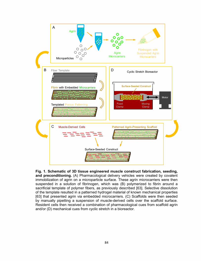
84
Fig. 1. Schematic of 3D tissue engineered muscle construct fabrication, seeding, and preconditioning. (A) Pharmacological delivery vehicles were created by covalent immobilization of agrin on a microparticle surface. These agrin microcarriers were then suspended in a solution of fibrinogen, which was (B) polymerized to fibrin around a sacrificial template of polymer fibers, as previously described [63]. Selective dissolution of the template resulted in a patterned hydrogel material of known mechanical properties [63] that presented agrin via embedded microcarriers. (C) Scaffolds were then seeded by manually pipetting a suspension of muscle-derived cells over the scaffold surface. Resident cells then received a combination of pharmacological cues from scaffold agrin and/or (D) mechanical cues from cyclic stretch in a bioreactor.
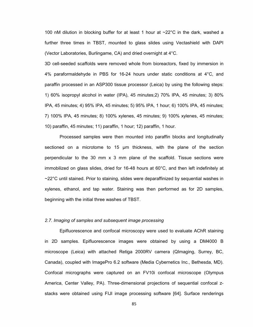
85
100 nM dilution in blocking buffer for at least 1 hour at ~22°C in the dark, washed a
further three times in TBST, mounted to glass slides using Vectashield with DAPI
(Vector Laboratories, Burlingame, CA) and dried overnight at 4°C.
3D cell-seeded scaffolds were removed whole from bioreactors, fixed by immersion in
4% paraformaldehyde in PBS for 16-24 hours under static conditions at 4°C, and
paraffin processed in an ASP300 tissue processor (Leica) by using the following steps:
1) 60% isopropyl alcohol in water (IPA), 45 minutes;2) 70% IPA, 45 minutes; 3) 80%
IPA, 45 minutes; 4) 95% IPA, 45 minutes; 5) 95% IPA, 1 hour; 6) 100% IPA, 45 minutes;
7) 100% IPA, 45 minutes; 8) 100% xylenes, 45 minutes; 9) 100% xylenes, 45 minutes;
10) paraffin, 45 minutes; 11) paraffin, 1 hour; 12) paraffin, 1 hour.
Processed samples were then mounted into paraffin blocks and longitudinally
sectioned on a microtome to 15 μm thickness, with the plane of the section
perpendicular to the 30 mm x 3 mm plane of the scaffold. Tissue sections were
immobilized on glass slides, dried for 16-48 hours at 60°C, and then left indefinitely at
~22°C until stained. Prior to staining, slides were deparaffinized by sequential washes in
xylenes, ethanol, and tap water. Staining was then performed as for 2D samples,
beginning with the initial three washes of TBST.
2.7. Imaging of samples and subsequent image processing
Epifluorescence and confocal microscopy were used to evaluate AChR staining
in 2D samples. Epifluorescence images were obtained by using a DM4000 B
microscope (Leica) with attached Retiga 2000RV camera (QImaging, Surrey, BC,
Canada), coupled with ImagePro 6.2 software (Media Cybernetics Inc., Bethesda, MD).
Confocal micrographs were captured on an FV10i confocal microscope (Olympus
America, Center Valley, PA). Three-dimensional projections of sequential confocal z-
stacks were obtained using FIJI image processing software [64]. Surface renderings

86
(see Fig. 3B, 3D, and 3F) were obtained by importing 3D projections of individual color
channels obtained in FIJI to ImageJ 3D Viewer [65] and manually adjusting each color
threshold until structures appeared visually similar to the native 3D projection.
AChR localization in 3D samples was imaged only with confocal microscopy.
Methods were identical to those above, except that areas for imaging were selected by
viewing DAPI and autofluorescence signals only before images of the α-BTX stain were
captured. Prior to 3D projection, a representative region of uniform intensity in the area
of fibrin material autofluorescence was located from one confocal z-slice from each
sample. Intensity within each region was then quantified in each color spectrum (405 nm
wavelength for DAPI, 473 nm for the fibrin scaffold, and 635 nm for α-BTX) by selecting
the region in FIJI and recording the mean value from the selection’s histogram. These
intensities were then averaged within each treatment group for each color, the treatment
group with all color averages nearest the center of the possible intensity range was
identified, and differences in selection intensity between each sample and this center
average were calculated for each color.
To allow direct comparison of all samples, brightness was normalized across
samples by adjusting maximum intensity in the FIJI B&C (Brightness & Contrast) window
for each color of each image in each confocal z-stack by the calculated difference. This
assured that α-BTX labeling of AChRs would not be differentially represented between
groups, and that DAPI and fibrin autofluorescence would not overpower any AChR
signal present. 3D projection was then performed in FIJI by using normalized z-stacks,
as described above. Scale bars and other image labels were applied in Powerpoint
(Microsoft, Redmond, WA).
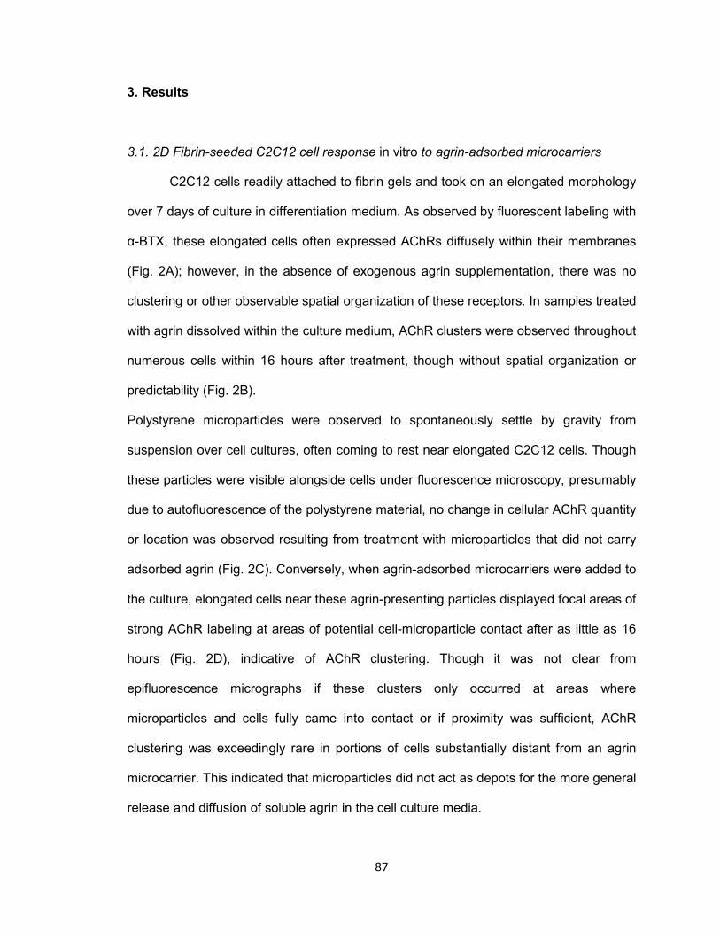
87
3. Results
3.1. 2D Fibrin-seeded C2C12 cell response in vitro to agrin-adsorbed microcarriers
C2C12 cells readily attached to fibrin gels and took on an elongated morphology
over 7 days of culture in differentiation medium. As observed by fluorescent labeling with
α-BTX, these elongated cells often expressed AChRs diffusely within their membranes
(Fig. 2A); however, in the absence of exogenous agrin supplementation, there was no
clustering or other observable spatial organization of these receptors. In samples treated
with agrin dissolved within the culture medium, AChR clusters were observed throughout
numerous cells within 16 hours after treatment, though without spatial organization or
predictability (Fig. 2B).
Polystyrene microparticles were observed to spontaneously settle by gravity from
suspension over cell cultures, often coming to rest near elongated C2C12 cells. Though
these particles were visible alongside cells under fluorescence microscopy, presumably
due to autofluorescence of the polystyrene material, no change in cellular AChR quantity
or location was observed resulting from treatment with microparticles that did not carry
adsorbed agrin (Fig. 2C). Conversely, when agrin-adsorbed microcarriers were added to
the culture, elongated cells near these agrin-presenting particles displayed focal areas of
strong AChR labeling at areas of potential cell-microparticle contact after as little as 16
hours (Fig. 2D), indicative of AChR clustering. Though it was not clear from
epifluorescence micrographs if these clusters only occurred at areas where
microparticles and cells fully came into contact or if proximity was sufficient, AChR
clustering was exceedingly rare in portions of cells substantially distant from an agrin
microcarrier. This indicated that microparticles did not act as depots for the more general
release and diffusion of soluble agrin in the cell culture media.

88
Fig. 2. Efficacy of agrin treatment in 2D. Epifluorescent micrographs of differentiated C2C12 cells stained with fluorescent α-bungarotoxin summarize the response of cultured muscle cells to agrin presented for 16-24 hours prior to staining. (A) Unconditioned cells are diffusely fluorescent when stained, indicating the presence of AChRs within the membrane. (B) When treated with agrin-conditioned culture medium, AChRs cluster together in a spatially uncoordinated fashion. (C) Though untreated polystyrene microparticles are visible after addition in suspension due to autofluorescence, there is no AChR clustering response. (D) AChR clusters are visible in the membranes of cells contacting microparticles carrying surface-adsorbed agrin in a spatially coordinated fashion. Arrows highlight examples of AChR clustering. Scale bar represents 15 μm.
To observe C2C12 cell response to microparticle-mediated agrin delivery in the
context of these planar 2D fibrin surfaces, samples were imaged with confocal
microscopy and reconstructed in ImageJ in all three dimensions. This technique allowed
resolution of the planar material, adherent cells, and nearby microparticles across their
vertical thickness, especially after combining horizontal planar “slice” images into a 3D
rendered image. 3D confocal images showed that, while cells sometimes exhibited
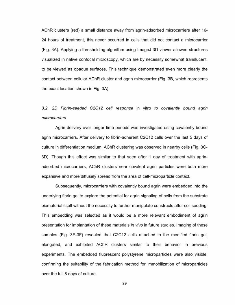
89
AChR clusters (red) a small distance away from agrin-adsorbed microcarriers after 16-
24 hours of treatment, this never occurred in cells that did not contact a microcarrier
(Fig. 3A). Applying a thresholding algorithm using ImageJ 3D viewer allowed structures
visualized in native confocal microscopy, which are by necessity somewhat translucent,
to be viewed as opaque surfaces. This technique demonstrated even more clearly the
contact between cellular AChR cluster and agrin microcarrier (Fig. 3B, which represents
the exact location shown in Fig. 3A).
3.2. 2D Fibrin-seeded C2C12 cell response in vitro to covalently bound agrin
microcarriers
Agrin delivery over longer time periods was investigated using covalently-bound
agrin microcarriers. After delivery to fibrin-adherent C2C12 cells over the last 5 days of
culture in differentiation medium, AChR clustering was observed in nearby cells (Fig. 3C-
3D). Though this effect was similar to that seen after 1 day of treatment with agrin-
adsorbed microcarriers, AChR clusters near covalent agrin particles were both more
expansive and more diffusely spread from the area of cell-microparticle contact.
Subsequently, microcarriers with covalently bound agrin were embedded into the
underlying fibrin gel to explore the potential for agrin signaling of cells from the substrate
biomaterial itself without the necessity to further manipulate constructs after cell seeding.
This embedding was selected as it would be a more relevant embodiment of agrin
presentation for implantation of these materials in vivo in future studies. Imaging of these
samples (Fig. 3E-3F) revealed that C2C12 cells attached to the modified fibrin gel,
elongated, and exhibited AChR clusters similar to their behavior in previous
experiments. The embedded fluorescent polystyrene microparticles were also visible,
confirming the suitability of the fabrication method for immobilization of microparticles
over the full 8 days of culture.
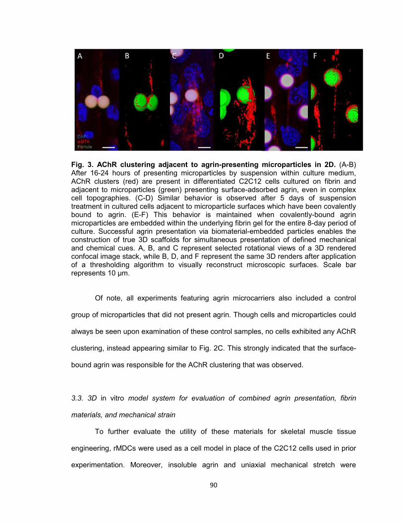
90
Fig. 3. AChR clustering adjacent to agrin-presenting microparticles in 2D. (A-B) After 16-24 hours of presenting microparticles by suspension within culture medium, AChR clusters (red) are present in differentiated C2C12 cells cultured on fibrin and adjacent to microparticles (green) presenting surface-adsorbed agrin, even in complex cell topographies. (C-D) Similar behavior is observed after 5 days of suspension treatment in cultured cells adjacent to microparticle surfaces which have been covalently bound to agrin. (E-F) This behavior is maintained when covalently-bound agrin microparticles are embedded within the underlying fibrin gel for the entire 8-day period of culture. Successful agrin presentation via biomaterial-embedded particles enables the construction of true 3D scaffolds for simultaneous presentation of defined mechanical and chemical cues. A, B, and C represent selected rotational views of a 3D rendered confocal image stack, while B, D, and F represent the same 3D renders after application of a thresholding algorithm to visually reconstruct microscopic surfaces. Scale bar represents 10 μm.
Of note, all experiments featuring agrin microcarriers also included a control
group of microparticles that did not present agrin. Though cells and microparticles could
always be seen upon examination of these control samples, no cells exhibited any AChR
clustering, instead appearing similar to Fig. 2C. This strongly indicated that the surface-
bound agrin was responsible for the AChR clustering that was observed.
3.3. 3D in vitro model system for evaluation of combined agrin presentation, fibrin
materials, and mechanical strain
To further evaluate the utility of these materials for skeletal muscle tissue
engineering, rMDCs were used as a cell model in place of the C2C12 cells used in prior
experimentation. Moreover, insoluble agrin and uniaxial mechanical stretch were

91
incorporated to explore their respective effects and possible synergy on AChR clustering
in rMDCs.
Microscopy of cell-seeded scaffold sections showed that fibrin, like polystyrene,
is autofluorescent. This allowed visualization of the scaffold (green) in resulting images
without requiring a specific label for fibrin, and controlled for potential non-specific
fluorescence in spectra used for labels when channels were overlaid. rMDCs seeded on
3D fibrin materials with embedded covalently-bound BSA control microcarriers, which
thereby lacked exogenous agrin, exhibited little AChR labeling of any kind and no AChR
clustering when not subjected to cyclic strain (Fig. 4A). This was consistent with a lack of
AChR expression. rMDCs seeded on 3D fibrin with embedded covalently-bound agrin
microcarriers exhibited a similar lack of AChRs and AChR clusters when cultured
statically (Fig. 4B). This suggested that agrin alone is insufficient to induce AChR
expression or clustering in rMDCs in the 3D fibrin environment.
In contrast, rMDCs seeded on BSA-presenting 3D fibrin scaffolds exhibited diffuse AChR
labeling (Fig. 4C) after bioreactor preconditioning, similar to elongated C2C12 cells in
the 2D model (Fig. 2A). However, these AChRs were spatially unorganized, indicating
that mechanical strain alone cannot induce AChR clustering. By contrast, rMDCs seeded
on agrin-presenting 3D fibrin scaffolds displayed extensive tracts of clustered AChRs
after bioreactor conditioning at all observed cell-seeded areas (Fig. 2D-2F). Interestingly,
these clusters were neither spatially limited to discrete areas of cell- particle contact nor
elliptical in shape as was often observed in 2D culture (compare to Fig. 2D and Fig 3A-
3F). Instead, they featured large, interconnected, complex geometry (Fig. 5A-5D
represent magnified views of Fig. 5E-5F, which are in turn selected areas from Fig. 4D
and Fig. 4F).
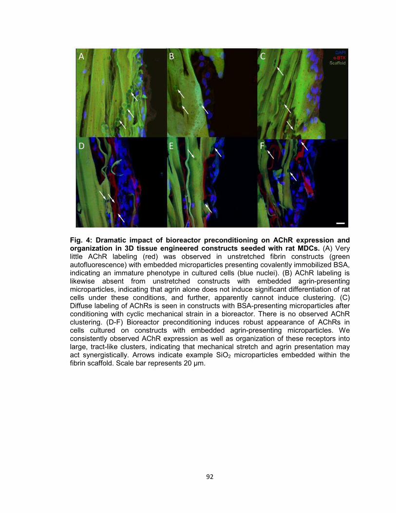
92
Fig. 4: Dramatic impact of bioreactor preconditioning on AChR expression and organization in 3D tissue engineered constructs seeded with rat MDCs. (A) Very little AChR labeling (red) was observed in unstretched fibrin constructs (green autofluorescence) with embedded microparticles presenting covalently immobilized BSA, indicating an immature phenotype in cultured cells (blue nuclei). (B) AChR labeling is likewise absent from unstretched constructs with embedded agrin-presenting microparticles, indicating that agrin alone does not induce significant differentiation of rat cells under these conditions, and further, apparently cannot induce clustering. (C) Diffuse labeling of AChRs is seen in constructs with BSA-presenting microparticles after conditioning with cyclic mechanical strain in a bioreactor. There is no observed AChR clustering. (D-F) Bioreactor preconditioning induces robust appearance of AChRs in cells cultured on constructs with embedded agrin-presenting microparticles. We consistently observed AChR expression as well as organization of these receptors into large, tract-like clusters, indicating that mechanical stretch and agrin presentation may act synergistically. Arrows indicate example SiO2 microparticles embedded within the fibrin scaffold. Scale bar represents 20 μm.

93
Fig. 5: Representative examples of AChR clustering in a bioreactor-preconditioned agrin-presenting tissue engineered construct. Shown are rMDCs (blue nuclei) seeded on the surface of fibrin scaffolds (green autofluorescence) carrying embedded SiO2 microparticles with covalently surface-bound agrin. Cells exhibited AChR clustering (red) after constructs were subjected to 5 days of cyclic mechanical strain. In contrast to the discrete geometry of AChR clusters observed under static culture with C2C12 cells (see Figs. 2-3), AChRs in these rMDCs cultured on bioreactor-conditioned agrin-presenting scaffolds clustered into extensive structures of complex geometry (A-D) more reminiscent of the appearance of native MEPs in vivo. By contrast, AChR clusters were never observed under static 3D culture conditions (see Fig. 4), indicating mechanical stretch and agrin presentation may act synergistically in the formation of mature MEP-like structures in vitro. A-D represent selected magnified views from a 3D-projected confocal z-stack, and are shown in the context of the larger section (E-F, compare to Fig. 4D & 4F). Scale bars represent 20 μm.
94
4. Discussion
4.1. Rationale and hypothesis
We previously described [45,46] efforts to functionally reconstruct rat skeletal
muscle in vivo using a tissue engineering approach combining biomaterials, cells, and
preconditioning via mechanical stimulation. We referred to that technology as a Tissue
Engineered Muscle Repair (TEMR) construct. That approach succeeded in restoring 60-
70% of native skeletal muscle force generation within 2 months of implantation of TEMR
in a surgically created rodent VML injury model. These improvements in contractile force
were significantly greater, with respect to the rate and / or magnitude of functional
recovery, to those observed following no repair of the VML injury [45,46], implantation of
a decellularized scaffold without cells [45], or a cell-seeded scaffold without a
preconditioning step [46]. However, as noted, no intervention fully restored injured
muscles to an uninjured native level of force generation.
These studies illustrate the need for further improvements in tissue engineered
skeletal muscle repair.The current study represents another step toward developing
additional technology platforms that may provide further functional improvements for
repair of VML injuries. Notably, though AChR clustering has been described in response
to adsorbed agrin microcarriers in the literature [60], the current approach critically
evaluated not only adsorption but also covalent linkage of agrin to microcarriers, both in
a biomaterial context. Fibrin was the selected biomaterial in the current study as it could
be assembled around agrin microcarriers, allowing their immobilization within the cell
seeding surface. Further, fibrin degrades by native bodily processes in vivo on the order
of weeks [66], and can be fabricated to possess mechanical stiffness similar to native
skeletal muscle (Young’s modulus: 110 – 320 kPa fibrin [63] vs. 7 – 127 kPa muscle
95
[67]). This combination of parameters suggested that fibrin would be an ideal material for
both this proof-of-concept study in vitro and potential further application in vivo.
The central hypothesis was that biomaterial-mediated agrin supplementation to
muscle cells in vitro, either alone or in combination with mechanical stimulation, would
result in creation of a nominally more native-like muscle phenotype as characterized by
the presence of agrin-mediated AChR clustering.
4.2. 2D Fibrin-seeded C2C12 cell response in vitro to agrin-adsorbed microcarriers
To begin, we formed 2D (planar) fibrin gels on cover glass and then seeded
these gels with C2C12 mouse myoblasts. After 7 days of culture, microparticles were
suspended in culture medium, which settled via gravity onto the cell layer. These
particles often aggregated near elongated cells (see Fig. 2C-2D), likely due to
topography – essentially “valleys” between cell edges and the biomaterial or between
parallel cells which discouraged lateral movement. Control microparticles lacking agrin
(Fig. 2C) and agrin microcarriers distant from cells (elements of Fig. 2D) shared a
uniformly fluorescent appearance, indicating autofluorescence of the polystyrene
material.
Following fluorescent α-BTX staining, spatially uncoordinated AChR clusters
were observed in cells treated with agrin in solution (Fig. 2B). By contrast, agrin
microcarriers adjacent to cells (Fig. 2D, see arrows) were often observed to have a
bright spot somewhere within the microparticle periphery. This indicated the presence of
a cluster of AChRs adjacent to or underneath the microparticle, as nonspecific artifacts
related to particle material or shape (e.g., refraction through a polstyrene sphere) would
have been observed independently of cells or agrin. Also of note was that all C2C12
cultures, regardless of exposure to agrin and / or polystyrene, contained cells which
expressed AChRs after 7 days of culture in differentiation medium. This result indicated
96
that neither material had a qualitatively-detectable effect on overall AChR expression,
only on clustering of AChRs.
We next employed confocal microscopy, which enabled 3D reconstruction of the
particle-cell interface. These experiments used fluorescent microparticles, as
polystyrene autofluorescence was less intense in confocal images than it was under
epifluorecence. Agrin microcarriers were observed to directly contact cells after settling
from suspension. Further, AChR clusters were closely associated with the cell-particle
interface (Fig. 3A-3B).
These results suggested the suitability of polymeric agrin microcarriers in the
context of a fibrin scaffold. While it is well-known that hydrogels can serve as depots for
protein delivery [68–73], this design would presumably lead to diffusion-based release of
the protein [73] and its eventual depletion from the system. By contrast, coupling agrin to
the surface of a microcarrier would allow spatial control of both location and dose, and
could focus a relatively small amount of protein to therapeutically high concentrations by
preventing diffusion. Moreover, in normal physiology, agrin is immobilized within the
synaptic basal lamina [58], a spatial arrangement more closely emulated by an agrin-
presenting surface.
Similar results were observed if agrin microcarriers were added during the last 1-
3 days of culture. However, no AChR clusters were observed if microcarriers were
added earlier (data not shown), which corresponded to an exchange of culture medium
after agrin addition. This may indicate that agrin desorbed from the microparticle surface,
either spontaneously or by a Vroman-like exchange [74], and was subsequently lost
upon media removal. Instead of a number of days, we reasoned that AChR clusters
should ideally be observed over weeks of culture. This is because presentation of
endogenous neural cues to implanted tissue engineered constructs could require weeks
to months at the clinically-expected reinnervation rate of 1 mm/day [59].
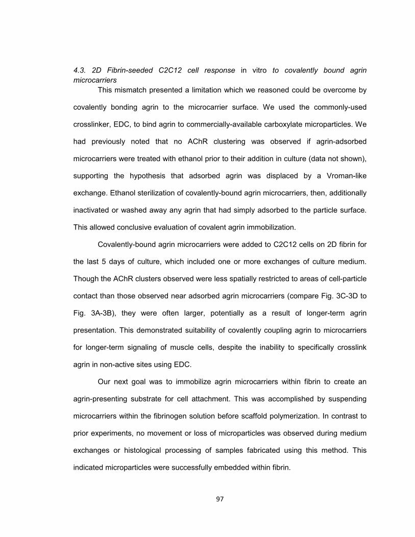
97
4.3. 2D Fibrin-seeded C2C12 cell response in vitro to covalently bound agrin
microcarriers
This mismatch presented a limitation which we reasoned could be overcome by
covalently bonding agrin to the microcarrier surface. We used the commonly-used
crosslinker, EDC, to bind agrin to commercially-available carboxylate microparticles. We
had previously noted that no AChR clustering was observed if agrin-adsorbed
microcarriers were treated with ethanol prior to their addition in culture (data not shown),
supporting the hypothesis that adsorbed agrin was displaced by a Vroman-like
exchange. Ethanol sterilization of covalently-bound agrin microcarriers, then, additionally
inactivated or washed away any agrin that had simply adsorbed to the particle surface.
This allowed conclusive evaluation of covalent agrin immobilization.
Covalently-bound agrin microcarriers were added to C2C12 cells on 2D fibrin for
the last 5 days of culture, which included one or more exchanges of culture medium.
Though the AChR clusters observed were less spatially restricted to areas of cell-particle
contact than those observed near adsorbed agrin microcarriers (compare Fig. 3C-3D to
Fig. 3A-3B), they were often larger, potentially as a result of longer-term agrin
presentation. This demonstrated suitability of covalently coupling agrin to microcarriers
for longer-term signaling of muscle cells, despite the inability to specifically crosslink
agrin in non-active sites using EDC.
Our next goal was to immobilize agrin microcarriers within fibrin to create an
agrin-presenting substrate for cell attachment. This was accomplished by suspending
microcarriers within the fibrinogen solution before scaffold polymerization. In contrast to
prior experiments, no movement or loss of microparticles was observed during medium
exchanges or histological processing of samples fabricated using this method. This
indicated microparticles were successfully embedded within fibrin.
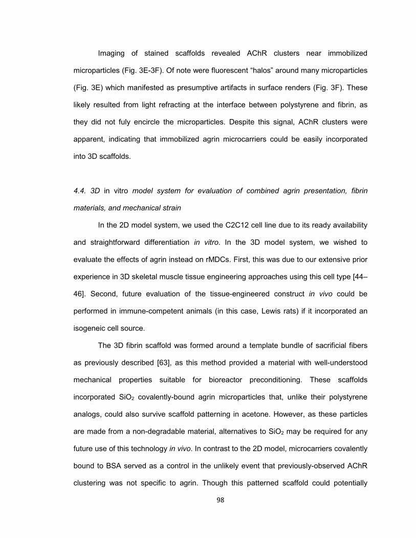
98
Imaging of stained scaffolds revealed AChR clusters near immobilized
microparticles (Fig. 3E-3F). Of note were fluorescent “halos” around many microparticles
(Fig. 3E) which manifested as presumptive artifacts in surface renders (Fig. 3F). These
likely resulted from light refracting at the interface between polystyrene and fibrin, as
they did not fuly encircle the microparticles. Despite this signal, AChR clusters were
apparent, indicating that immobilized agrin microcarriers could be easily incorporated
into 3D scaffolds.
4.4. 3D in vitro model system for evaluation of combined agrin presentation, fibrin
materials, and mechanical strain
In the 2D model system, we used the C2C12 cell line due to its ready availability
and straightforward differentiation in vitro. In the 3D model system, we wished to
evaluate the effects of agrin instead on rMDCs. First, this was due to our extensive prior
experience in 3D skeletal muscle tissue engineering approaches using this cell type [44–
46]. Second, future evaluation of the tissue-engineered construct in vivo could be
performed in immune-competent animals (in this case, Lewis rats) if it incorporated an
isogeneic cell source.
The 3D fibrin scaffold was formed around a template bundle of sacrificial fibers
as previously described [63], as this method provided a material with well-understood
mechanical properties suitable for bioreactor preconditioning. These scaffolds
incorporated SiO2 covalently-bound agrin microparticles that, unlike their polystyrene
analogs, could also survive scaffold patterning in acetone. However, as these particles
are made from a non-degradable material, alternatives to SiO2 may be required for any
future use of this technology in vivo. In contrast to the 2D model, microcarriers covalently
bound to BSA served as a control in the unlikely event that previously-observed AChR
clustering was not specific to agrin. Though this patterned scaffold could potentially
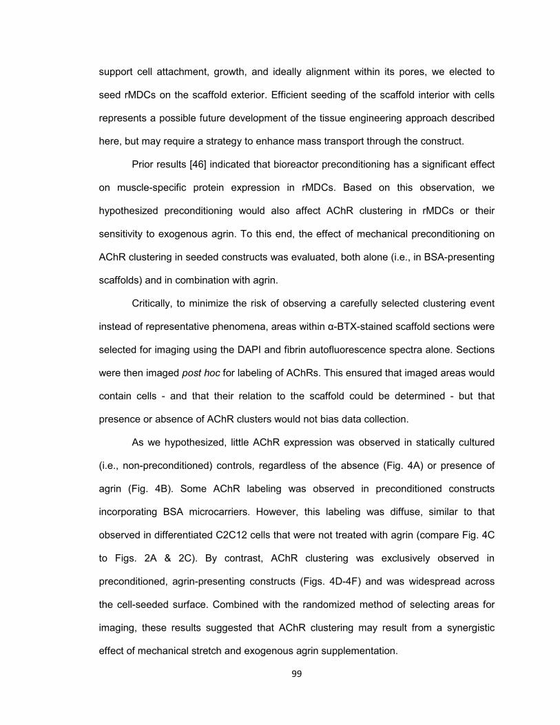
99
support cell attachment, growth, and ideally alignment within its pores, we elected to
seed rMDCs on the scaffold exterior. Efficient seeding of the scaffold interior with cells
represents a possible future development of the tissue engineering approach described
here, but may require a strategy to enhance mass transport through the construct.
Prior results [46] indicated that bioreactor preconditioning has a significant effect
on muscle-specific protein expression in rMDCs. Based on this observation, we
hypothesized preconditioning would also affect AChR clustering in rMDCs or their
sensitivity to exogenous agrin. To this end, the effect of mechanical preconditioning on
AChR clustering in seeded constructs was evaluated, both alone (i.e., in BSA-presenting
scaffolds) and in combination with agrin.
Critically, to minimize the risk of observing a carefully selected clustering event
instead of representative phenomena, areas within α-BTX-stained scaffold sections were
selected for imaging using the DAPI and fibrin autofluorescence spectra alone. Sections
were then imaged post hoc for labeling of AChRs. This ensured that imaged areas would
contain cells - and that their relation to the scaffold could be determined - but that
presence or absence of AChR clusters would not bias data collection.
As we hypothesized, little AChR expression was observed in statically cultured
(i.e., non-preconditioned) controls, regardless of the absence (Fig. 4A) or presence of
agrin (Fig. 4B). Some AChR labeling was observed in preconditioned constructs
incorporating BSA microcarriers. However, this labeling was diffuse, similar to that
observed in differentiated C2C12 cells that were not treated with agrin (compare Fig. 4C
to Figs. 2A & 2C). By contrast, AChR clustering was exclusively observed in
preconditioned, agrin-presenting constructs (Figs. 4D-4F) and was widespread across
the cell-seeded surface. Combined with the randomized method of selecting areas for
imaging, these results suggested that AChR clustering may result from a synergistic
effect of mechanical stretch and exogenous agrin supplementation.
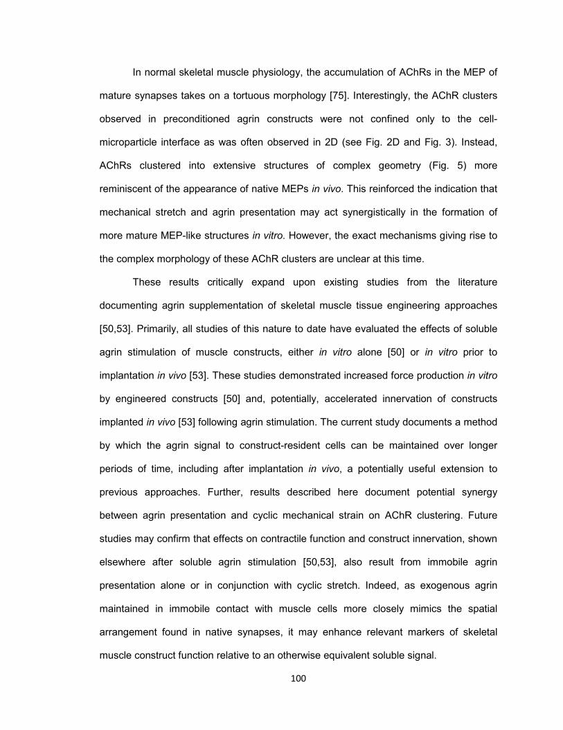
100
In normal skeletal muscle physiology, the accumulation of AChRs in the MEP of
mature synapses takes on a tortuous morphology [75]. Interestingly, the AChR clusters
observed in preconditioned agrin constructs were not confined only to the cell-
microparticle interface as was often observed in 2D (see Fig. 2D and Fig. 3). Instead,
AChRs clustered into extensive structures of complex geometry (Fig. 5) more
reminiscent of the appearance of native MEPs in vivo. This reinforced the indication that
mechanical stretch and agrin presentation may act synergistically in the formation of
more mature MEP-like structures in vitro. However, the exact mechanisms giving rise to
the complex morphology of these AChR clusters are unclear at this time.
These results critically expand upon existing studies from the literature
documenting agrin supplementation of skeletal muscle tissue engineering approaches
[50,53]. Primarily, all studies of this nature to date have evaluated the effects of soluble
agrin stimulation of muscle constructs, either in vitro alone [50] or in vitro prior to
implantation in vivo [53]. These studies demonstrated increased force production in vitro
by engineered constructs [50] and, potentially, accelerated innervation of constructs
implanted in vivo [53] following agrin stimulation. The current study documents a method
by which the agrin signal to construct-resident cells can be maintained over longer
periods of time, including after implantation in vivo, a potentially useful extension to
previous approaches. Further, results described here document potential synergy
between agrin presentation and cyclic mechanical strain on AChR clustering. Future
studies may confirm that effects on contractile function and construct innervation, shown
elsewhere after soluble agrin stimulation [50,53], also result from immobile agrin
presentation alone or in conjunction with cyclic stretch. Indeed, as exogenous agrin
maintained in immobile contact with muscle cells more closely mimics the spatial
arrangement found in native synapses, it may enhance relevant markers of skeletal
muscle construct function relative to an otherwise equivalent soluble signal.

101
5. Conclusions
In this work, we describe AChR clustering in muscle cells cultured in vitro on
agrin-presenting biomaterials suitable for skeletal muscle tissue engineering
applications. AChR clusters were observed in a C2C12 cell line in a 2D model system
and in a more relevant 3D model system using expanded rat MDCs. These models
demonstrated the utility of microparticles as an immobile, non-diffusion based platform
for presentation of agrin to cells over several days in culture. Moreover, extensive AChR
clustering may result from synergy between mechanical strain and exogenous agrin. The
3D model embodied a tissue-engineered muscle repair construct in vitro, consisting of
fibrin and microparticle biomaterials, pharmacological stimulation via agrin, and cell
signaling via mechanical stretch. Though promising, these results merit further
investigation in vivo to determine if agrin-presenting biomaterials described here will
enhance functional outcomes in tissue engineered repair of clinically intractable VML
injuries.
Acknowledgements
This work was funded by an award from the Telemedicine and Advanced
Technology Research Center, by the Wake Forest University Department of Biomedical
Engineering, and by the Wake Forest Institute for Regenerative Medicine. The authors
gratefully acknowledge the assistance of Hannah Baker, Christopher Bergman, Hayden
Holbrook, Venu Kesireddy, Juliana Passipieri, Pooja Patil, Mevan Siriwardane, Claire
Staley, and Taylor Zak in performing experiments described herein, as well as Cathy
Mathis and Cynthia Zimmerman for their assistance with histology and Christopher
Booth for his assistance in confocal microscopy.

102
References
[1] Chargé SBP, Rudnicki MA. Cellular and Molecular Regulation of Muscle Regeneration. Physiol Rev 2004;84:209–38. doi:10.1152/physrev.00019.2003.
[2] Järvinen TAH, Järvinen TLN, Kääriäinen M, Kalimo H, Järvinen M. Muscle
Injuries Biology and Treatment. Am J Sports Med 2005;33:745–64. doi:10.1177/0363546505274714.
[3] Ambrosio F, Kadi F, Lexell J, Fitzgerald GK, Boninger ML, Huard J. The effect of
muscle loading on skeletal muscle regenerative potential: an update of current research findings relating to aging and neuromuscular pathology. Am J Phys Med Rehabil Assoc Acad Physiatr 2009;88:145–55. doi:10.1097/PHM.0b013e3181951fc5.
[4] Ciciliot S, Schiaffino S. Regeneration of Mammalian Skeletal Muscle: Basic
Mechanisms and Clinical Implications. Curr Pharm Des 2010;16:906–14. doi:10.2174/138161210790883453.
[5] Grogan BF, Hsu JR, Skeletal Trauma Research Consortium. Volumetric Muscle
Loss. J Am Acad Orthop Surg 2011;19:S35–7. [6] Owens BD, Kragh JFJ, Wenke JC, Macaitis J, Wade CE, Holcomb JB. Combat
Wounds in Operation Iraqi Freedom and Operation Enduring Freedom. J Trauma-Inj Infect 2008;64:295–9. doi:10.1097/TA.0b013e318163b875.
[7] Lew TA, Walker JA, Wenke JC, Blackbourne LH, Hale RG. Characterization of
Craniomaxillofacial Battle Injuries Sustained by United States Service Members in the Current Conflicts of Iraq and Afghanistan. J Oral Maxillofac Surg 2010;68:3–7. doi:10.1016/j.joms.2009.06.006.
[8] Mazurek MT, Ficke JR. The Scope of Wounds Encountered in Casualties From
the Global War on Terrorism: From the Battlefield to the Tertiary Treatment Facility. J Am Acad Orthop Surg 2006;14:S18–23.
[9] Khouri RK, Cooley BC, Kunselman AR, Landis JR, Yeramian P, Ingram D, et al.
A prospective study of microvascular free-flap surgery and outcome. Plast Reconstr Surg 1998;102:711–21.
[10] Lin CH, Wei FC, Levin LS, Chen MC. Donor-site morbidity comparison between
endoscopically assisted and traditional harvest of free latissimus dorsi muscle flap. Plast Reconstr Surg 1999;104:1070–7; quiz 1078.
[11] Lawson R, Levin LS. Principles of Free Tissue Transfer in Orthopaedic Practice.
J Am Acad Orthop Surg 2007;15:290–9. [12] Ni X, Sun W, Sun S, Yu J, Wang J, Nie B, et al. Therapeutic potential of adipose
stem cells in tissue repair of irradiated skeletal muscle in a rabbit model. Cell Reprogramming 2014;16:140–50. doi:10.1089/cell.2013.0056.
103
[13] Oshima S, Kamei N, Nakasa T, Yasunaga Y, Ochi M. Enhancement of muscle repair using human mesenchymal stem cells with a magnetic targeting system in a subchronic muscle injury model. J Orthop Sci Off J Jpn Orthop Assoc 2014;19:478–88. doi:10.1007/s00776-014-0548-9.
[14] Hamid MSA, Yusof A, Mohamed Ali MR. Platelet-rich plasma (PRP) for acute
muscle injury: a systematic review. PloS One 2014;9:e90538. doi:10.1371/journal.pone.0090538.
[15] Dumont NA, Frenette J. Macrophage Colony-Stimulating Factor–Induced
Macrophage Differentiation Promotes Regrowth in Atrophied Skeletal Muscles and C2C12 Myotubes. Am J Pathol 2013;182:505–15. doi:10.1016/j.ajpath.2012.10.010.
[16] Horie M, Enomoto M, Shimoda M, Okawa A, Miyakawa S, Yagishita K.
Enhancement of satellite cell differentiation and functional recovery in injured skeletal muscle by hyperbaric oxygen treatment. J Appl Physiol 2014;116:149–55. doi:10.1152/japplphysiol.00235.2013.
[17] Jang J-H, Shea LD. Intramuscular delivery of DNA releasing microspheres:
Microsphere properties and transgene expression. J Controlled Release 2006;112:120–8. doi:10.1016/j.jconrel.2006.01.013.
[18] Vignaud A, Cebrian J, Martelly I, Caruelle J-P, Ferry A. Effect of anti-inflammatory
and antioxidant drugs on the long-term repair of severely injured mouse skeletal muscle. Exp Physiol 2005;90:487–95. doi:10.1113/expphysiol.2005.029835.
[19] Kobayashi T, Uehara K, Ota S, Tobita K, Ambrosio F, Cummins JH, et al. The
timing of administration of a clinically relevant dose of losartan influences the healing process after contusion induced muscle injury. J Appl Physiol 2013;114:262–73. doi:10.1152/japplphysiol.00140.2011.
[20] Gamba P, Conconi M, Piccolo RL, Zara G, Spinazzi R, Parnigotto P.
Experimental abdominal wall defect repaired with acellular matrix. Pediatr Surg Int 2002;18:327–31. doi:10.1007/s00383-002-0849-5.
[21] Kin S, Hagiwara A, Nakase Y, Kuriu Y, Nakashima S, Yoshikawa T, et al.
Regeneration of Skeletal Muscle Using In Situ Tissue Engineering on an Acellular Collagen Sponge Scaffold in a Rabbit Model. [Miscellaneous Article]. J July 2007;53:506–13. doi:10.1097/MAT.0b013e3180d09d81.
[22] Merritt EK, Hammers DW, Tierney M, Suggs LJ, Walters TJ, Farrar RP.
Functional Assessment of Skeletal Muscle Regeneration Utilizing Homologous Extracellular Matrix as Scaffolding. Tissue Eng Part A 2009;16:1395–405. doi:10.1089/ten.tea.2009.0226.
[23] Turner NJ, Yates AJ, Weber DJ, Qureshi IR, Stolz DB, Gilbert TW, et al.
Xenogeneic Extracellular Matrix as an Inductive Scaffold for Regeneration of a Functioning Musculotendinous Junction. Tissue Eng Part A 2010;16:3309–17. doi:10.1089/ten.tea.2010.0169.
104
[24] Valentin JE, Turner NJ, Gilbert TW, Badylak SF. Functional skeletal muscle formation with a biologic scaffold. Biomaterials 2010;31:7475–84. doi:10.1016/j.biomaterials.2010.06.039.
[25] McKeon-Fischer KD, Flagg DH, Freeman JW. Coaxial electrospun poly(ε-
caprolactone), multiwalled carbon nanotubes, and polyacrylic acid/polyvinyl alcohol scaffold for skeletal muscle tissue engineering. J Biomed Mater Res A 2011;99A:493–9. doi:10.1002/jbm.a.33116.
[26] Chen M-C, Sun Y-C, Chen Y-H. Electrically conductive nanofibers with highly
oriented structures and their potential application in skeletal muscle tissue engineering. Acta Biomater 2013;9:5562–72. doi:10.1016/j.actbio.2012.10.024.
[27] Shen Z, Guo S, Ye D, Chen J, Kang C, Qiu S, et al. Skeletal Muscle
Regeneration on Protein-Grafted and Microchannel-Patterned Scaffold for Hypopharyngeal Tissue Engineering. BioMed Res Int 2013;2013:e146953. doi:10.1155/2013/146953.
[28] Sun Y, Duffy R, Lee A, Feinberg AW. Optimizing the structure and contractility of
engineered skeletal muscle thin films. Acta Biomater 2013;9:7885–94. doi:10.1016/j.actbio.2013.04.036.
[29] Powell CA, Smiley BL, Mills J, Vandenburgh HH. Mechanical stimulation
improves tissue-engineered human skeletal muscle. Am J Physiol - Cell Physiol 2002;283:C1557–65. doi:10.1152/ajpcell.00595.2001.
[30] Bach AD, Arkudas A, Tjiawi J, Polykandriotis E, Kneser U, Horch RE, et al. A new
approach to tissue engineering of vascularized skeletal muscle. J Cell Mol Med 2006;10:716–26.
[31] Yan W, George S, Fotadar U, Tyhovych N, Kamer A, Yost MJ, et al. Tissue
Engineering of Skeletal Muscle. Tissue Eng 2007;13:2781–90. doi:10.1089/ten.2006.0408.
[32] Kroehne V, Heschel I, Schügner F, Lasrich D, Bartsch JW, Jockusch H. Use of a
novel collagen matrix with oriented pore structure for muscle cell differentiation in cell culture and in grafts. J Cell Mol Med 2008;12:1640–8. doi:10.1111/j.1582-4934.2008.00238.x.
[33] Bian W, Bursac N. Engineered skeletal muscle tissue networks with controllable
architecture. Biomaterials 2009;30:1401–12. doi:10.1016/j.biomaterials.2008.11.015.
[34] Khodabukus A, Baar K. Regulating Fibrinolysis to Engineer Skeletal Muscle from
the C2C12 Cell Line. Tissue Eng Part C Methods 2009;15:501–11. doi:10.1089/ten.tec.2008.0286.
[35] Merritt EK, Cannon MV, Hammers DW, Le LN, Gokhale R, Sarathy A, et al.
Repair of traumatic skeletal muscle injury with bone-marrow-derived mesenchymal stem cells seeded on extracellular matrix. Tissue Eng Part A 2010;16:2871–81. doi:10.1089/ten.TEA.2009.0826.
105
[36] Hinds S, Bian W, Dennis RG, Bursac N. The role of extracellular matrix
composition in structure and function of bioengineered skeletal muscle. Biomaterials 2011;32:3575–83. doi:10.1016/j.biomaterials.2011.01.062.
[37] Page RL, Malcuit C, Vilner L, Vojtic I, Shaw S, Hedblom E, et al. Restoration of
Skeletal Muscle Defects with Adult Human Cells Delivered on Fibrin Microthreads. Tissue Eng Part A 2011;17:2629–40. doi:10.1089/ten.tea.2011.0024.
[38] Rossi CA, Flaibani M, Blaauw B, Pozzobon M, Figallo E, Reggiani C, et al. In vivo
tissue engineering of functional skeletal muscle by freshly isolated satellite cells embedded in a photopolymerizable hydrogel. FASEB J 2011;25:2296–304. doi:10.1096/fj.10-174755.
[39] Monge C, Ren K, Berton K, Guillot R, Peyrade D, Picart C. Engineering Muscle
Tissues on Microstructured Polyelectrolyte Multilayer Films. Tissue Eng Part A 2012;18:1664–76. doi:10.1089/ten.tea.2012.0079.
[40] Martin NRW, Passey SL, Player DJ, Khodabukus A, Ferguson RA, Sharples AP,
et al. Factors affecting the structure and maturation of human tissue engineered skeletal muscle. Biomaterials 2013;34:5759–65. doi:10.1016/j.biomaterials.2013.04.002.
[41] Vandenburgh HH, Karlisch P. Longitudinal growth of skeletal myotubes in vitro in
a new horizontal mechanical cell stimulator. Vitro Cell Dev Biol J Tissue Cult Assoc 1989;25:607–16.
[42] Vandenburgh HH, Hatfaludy S, Karlisch P, Shansky J. Skeletal muscle growth is
stimulated by intermittent stretch-relaxation in tissue culture. Am J Physiol 1989;256:C674–82.
[43] Vandenburgh HH, Hatfaludy S, Karlisch P, Shansky J. Mechanically induced
alterations in cultured skeletal muscle growth. J Biomech 1991;24, Supplement 1:91–9. doi:10.1016/0021-9290(91)90380-6.
[44] Moon DG, Christ G, Stitzel JD, Atala A, Yoo JJ. Cyclic Mechanical
Preconditioning Improves Engineered Muscle Contraction. Tissue Eng Part A 2008;14:473–82. doi:10.1089/tea.2007.0104.
[45] Machingal MA, Corona BT, Walters TJ, Kesireddy V, Koval CN, Dannahower A,
et al. A tissue-engineered muscle repair construct for functional restoration of an irrecoverable muscle injury in a murine model. Tissue Eng Part A 2011;17:2291–303. doi:10.1089/ten.TEA.2010.0682.
[46] Corona BT, Machingal MA, Criswell T, Vadhavkar M, Dannahower AC, Bergman
C, et al. Further development of a tissue engineered muscle repair construct in vitro for enhanced functional recovery following implantation in vivo in a murine model of volumetric muscle loss injury. Tissue Eng Part A 2012;18:1213–28. doi:10.1089/ten.TEA.2011.0614.
106
[47] Falco EE, Wang MO, Thompson JA, Chetta JM, Yoon DM, Li EZ, et al. Porous EH and EH-PEG Scaffolds as Gene Delivery Vehicles to Skeletal Muscle. Pharm Res 2011;28:1306–16. doi:10.1007/s11095-010-0358-5.
[48] Koning M, Werker PMN, van der Schaft DWJ, Bank RA, Harmsen MC.
MicroRNA-1 and MicroRNA-206 Improve Differentiation Potential of Human Satellite Cells: A Novel Approach for Tissue Engineering of Skeletal Muscle. Tissue Eng Part A 2011;18:889–98. doi:10.1089/ten.tea.2011.0191.
[49] Sato M, Ito A, Kawabe Y, Nagamori E, Kamihira M. Enhanced contractile force
generation by artificial skeletal muscle tissues using IGF-I gene-engineered myoblast cells. J Biosci Bioeng 2011;112:273–8. doi:10.1016/j.jbiosc.2011.05.007.
[50] Bian W, Bursac N. Soluble miniagrin enhances contractile function of engineered
skeletal muscle. FASEB J Off Publ Fed Am Soc Exp Biol 2012;26:955–65. doi:10.1096/fj.11-187575.
[51] Wang L, Shansky J, Borselli C, Mooney D, Vandenburgh H. Design and
Fabrication of a Biodegradable, Covalently Crosslinked Shape-Memory Alginate Scaffold for Cell and Growth Factor Delivery. Tissue Eng Part A 2012;18:2000–7. doi:10.1089/ten.tea.2011.0663.
[52] Yun Y-R, Lee S, Jeon E, Kang W, Kim K-H, Kim H-W, et al. Fibroblast growth
factor 2-functionalized collagen matrices for skeletal muscle tissue engineering. Biotechnol Lett 2012;34:771–8. doi:10.1007/s10529-011-0812-4.
[53] Ko IK, Lee B-K, Lee SJ, Andersson K-E, Atala A, Yoo JJ. The effect of in vitro
formation of acetylcholine receptor (AChR) clusters in engineered muscle fibers on subsequent innervation of constructs in vivo. Biomaterials 2013;34:3246–55. doi:10.1016/j.biomaterials.2013.01.029.
[54] Wang L, Cao L, Shansky J, Wang Z, Mooney D, Vandenburgh H. Minimally
Invasive Approach to the Repair of Injured Skeletal Muscle With a Shape-memory Scaffold. Mol Ther 2014;22:1441–9. doi:10.1038/mt.2014.78.
[55] Sanes JR, Lichtman JW. Development: Induction, assembly, maturation and
maintenance of a postsynaptic apparatus. Nat Rev Neurosci 2001;2:791–805. doi:10.1038/35097557.
[56] Madhavan R, Peng HB. Molecular regulation of postsynaptic differentiation at the
neuromuscular junction. IUBMB Life 2005;57:719–30. doi:10.1080/15216540500338739.
[57] Witzemann V. Development of the neuromuscular junction. Cell Tissue Res
2006;326:263–71. doi:10.1007/s00441-006-0237-x. [58] Wu H, Xiong WC, Mei L. To build a synapse: signaling pathways in
neuromuscular junction assembly. Development 2010;137:1017–33. doi:10.1242/dev.038711.
107
[59] Gordon T, Brushart TM, Chan KM. Augmenting nerve regeneration with electrical stimulation. Neurol Res 2008;30:1012–22. doi:10.1179/174313208X362488.
[60] Daggett DF, Cohen MW, Stone D, Nikolics Karoly, Rauvala H, Peng HB. The
Role of an Agrin–Growth Factor Interaction in ACh Receptor Clustering. Mol Cell Neurosci 1996;8:272–85. doi:10.1006/mcne.1996.0063.
[61] Burgess RW, Nguyen QT, Son Y-J, Lichtman JW, Sanes JR. Alternatively
Spliced Isoforms of Nerve- and Muscle-Derived Agrin: Their Roles at the Neuromuscular Junction. Neuron 1999;23:33–44. doi:10.1016/S0896-6273(00)80751-5.
[62] Bezakova G, Ruegg MA. New insights into the roles of agrin. Nat Rev Mol Cell
Biol 2003;4:295–309. doi:10.1038/nrm1074. [63] Scott JB, Afshari M, Kotek R, Saul JM. The promotion of axon extension in vitro
using polymer-templated fibrin scaffolds. Biomaterials 2011;32:4830–9. doi:10.1016/j.biomaterials.2011.03.037.
[64] Schindelin J, Arganda-Carreras I, Frise E, Kaynig V, Longair M, Pietzsch T, et al.
Fiji: an open-source platform for biological-image analysis. Nat Methods 2012;9:676–82. doi:10.1038/nmeth.2019.
[65] Schmid B, Schindelin J, Cardona A, Longair M, Heisenberg M. A high-level 3D
visualization API for Java and ImageJ. BMC Bioinformatics 2010;11:274. doi:10.1186/1471-2105-11-274.
[66] Linnes MP, Ratner BD, Giachelli CM. A fibrinogen-based precision microporous
scaffold for tissue engineering. Biomaterials 2007;28:5298–306. doi:10.1016/j.biomaterials.2007.08.020.
[67] Levinson SF, Shinagawa M, Sato T. Sonoelastic determination of human skeletal
muscle elasticity. J Biomech 1995;28:1145–54. doi:10.1016/0021-9290(94)00173-2.
[68] Davis BK. Diffusion in Polymer Gel Implants. Proc Natl Acad Sci 1974;71:3120–3. [69] Gombotz WR, Pettit DK. Biodegradable polymers for protein and peptide drug
delivery. Bioconjug Chem 1995;6:332–51. [70] Mellott MB, Searcy K, Pishko MV. Release of protein from highly cross-linked
hydrogels of poly(ethylene glycol) diacrylate fabricated by UV polymerization. Biomaterials 2001;22:929–41.
[71] Cleland JL, Daugherty A, Mrsny R. Emerging protein delivery methods. Curr Opin
Biotechnol 2001;12:212–9. [72] Hatefi A, Amsden B. Biodegradable injectable in situ forming drug delivery
systems. J Control Release Off J Control Release Soc 2002;80:9–28.

108
[73] Leach JB, Schmidt CE. Characterization of protein release from photocrosslinkable hyaluronic acid-polyethylene glycol hydrogel tissue engineering scaffolds. Biomaterials 2005;26:125–35. doi:10.1016/j.biomaterials.2004.02.018.
[74] Noh H, Vogler EA. Volumetric interpretation of protein adsorption: Competition
from mixtures and the Vroman effect. Biomaterials 2007;28:405–22. doi:10.1016/j.biomaterials.2006.09.006.
[75] Marques MJ, Conchello J-A, Lichtman JW. From Plaque to Pretzel: Fold
Formation and Acetylcholine Receptor Loss at the Developing Neuromuscular Junction. J Neurosci 2000;20:3663–75.

109
CHAPTER IV
ADVANCES TOWARD ENABLING THREE-DIMENSIONAL FIBRIN SCAFFOLDS FOR
TISSUE ENGINEERED MUSCLE REPAIR
John B. Scott

110
1. Introduction
Prior Chapters explored fibrin biomaterials as a mechanical support and physical
guide for neurite extension from peripheral nerve (Chapter II) and as a substrate for the
presentation of insoluble agrin to adherent muscle cells in a tissue engineered muscle
repair construct (Chapter III). These results demonstrated that fibrin hydrogels can be
fabricated to withstand maximum loads over 1 N in magnitude and feature elastic moduli
between 110-330 kPa. Additionally, they can incorporate particulate drug delivery
vehicles and a porous network of aligned conduits.
However, Chapter II only demonstrated the use of fibrin in the guidance of nerve,
though many of the above parameters also suggested its use as a substrate for skeletal
muscle. For example, native skeletal muscle elastic modulus (79-126 kPa [1]) is similar
to that of the patterned fibrin. Further, native muscle is composed of myofibers aligned
along a preferred axis of contraction, surrounded in turn by layers of connective tissue
similar to the micro-architectural patterning of these scaffolds. This arrangement echoes
anatomy of a peripheral nerve (compare connective tissue components of Fig. 1.1 from
[2] and Fig. 1 from [3]) and cross-sections of patterned fibrin (Chapter II, Fig. 2). Also,
physical cues such as nano- and micro-fibers and microgrooves [4–9] have been
previously used to guide muscle cell alignment and / or mophology. This indicates that
patterned fibrin could also organize seeded muscle cells into the alignment necessary
for macroscopic force production.
Therefore, this Chapter describes efforts to create 3D tissue engineered muscle-
like constructs using patterned fibrin. One major goal was the robust seeding of muscle
cells within patterned fibrin scaffolds, which could potentially be achieved by perfusion of
muscle cell suspensions through the conduit network. Flow perfusion of engineered
tissue constructs has been significantly described in the literature, though typically as a
method to enhance mass transport and / or to modulate cellular behavior [10–16]. Some
111
studies, though, have explored perfusion of cell suspensions as a method to enact rapid
and uniform cell seeding within porous scaffolds [17–21]. The majority of investigation on
scaffold perfusion has focused on bone tissue engineering [10–12,14–18,20,22], though
it has also been applied to other tissues such as kidney [21], cartilage [23,24], tendon
[13], and cardiac muscle [25,26]. Of note, few perfusion approaches have attempted to
seed scaffolds with parallel longitudinal pores [19], and none of which we are aware
have done so using skeletal muscle cells.
A second goal of this study was to incorporate agrin microcarriers, studied
extensively in 2D using polystyrene microparticles, into the fibrin scaffold. This was
challenging, as polystyrene is dissolved by the same acetone immersion used to remove
sacrificial fibers during scaffold fabrication. To overcome this challenge, two parallel
strategies were employed. First, water soluble polymers - notably polyvinyl alcohol
(PVOH) and poly(ethylene oxide) (PEO) - were evaluated for the formation of fibers
which could pattern fibrin scaffolds without damaging polystyrene agrin microcarriers.
Second, a microparticle material which did not dissolve in acetone - silica - was
employed to fabricate agrin microcarriers compatible with existing scaffold fabrication
methods.
It is important to note that, though presented here after Chapter III due to
preparation of that Chapter for manuscript submission, experiments described below
were performed between the 2D and 3D experiments in Chapter III. The current Chapter
represents efforts to incorporate agrin delivery as described in 2D experiments of
Chapter III into 3D fibrin scaffolds, and further, to enable cell seeding throughout the
interior of such a scaffold. Due to continued difficulties in meeting the second of these
goals, as described below, the surface seeding methods described in 3D experiments in
Chapter III were elected to evaluate proof of concept of fibrin-mediated agrin delivery.
112
Nevertheless, the results discussed below represent important findings on which to base
future development of these technologies.
2. Methods
Unless otherwise noted, all aqueous formulations are described as % v/v.
Further, all methods were performed at ambient pressure on a lab bench at a room
temperature of ~22°C unless otherwise noted.
2.1. Surface seeding of 3D planar fibrin scaffolds
To evaluate the suitability of patterned fibrin for supporting the attachment and
growth of muscle cells, a flat (planar) block of fibrin was fabricated using methods similar
to those described in Chapter II. To begin, aligned cellulose acetate (CA) fibers
(generous donation of Eastman Chemical Company, Kingsport, TN) ~12 μm in diameter
were arranged into a mat ~1 mm thick. A solution of bovine fibrinogen (Sigma-Aldrich,
St. Louis, MO) at 200 mg/mL in PBS was added to the fibers and left undisturbed until it
completely impregnated the mat. Fibrinogen was polymerized to fibrin by adding a
solution of 125 U/mL thrombin and 2.75 μg/mL (~24.8 mM) CaCl2 (both Sigma) in PBS,
wrapping the wetted mat in Parafilm (Bemish Flexible Packaging, Oshkosh, WI) to
prevent evaporation, and leaving undisturbed for at least 4 hours.
This fibrin sheet was then sectioned into smaller scaffolds ~3 mm wide x 3 mm
long using a razor blade before being washed in acetone four times (at least 2 hr, 2 hr, 4
hr, and 8 hr in duration, respectively) to remove the CA fiber component and sterilize the
scaffolds. To remove acetone, scaffolds were then washed four times in sterile PBS
(same durations as acetone) in a biological safety cabinet and stored in the final sterile
wash at 4°C until use.
113
Scaffolds were then seeded with C2C12 mouse myoblasts to evaluate their
response to fibrin. One scaffold each was placed into the wells of a 24-well polystyrene
tissue culture plate (Thermo Fisher Scientific, Waltham, MA). C2C12 growth medium
consisted of 89% high-glucose Dulbecco’s modified Eagle’s medium (DMEM), 10%
heat-inactivated fetal bovine serum (FBS), and 1% penicillin/streptomycin (all Thermo
Fisher Scientific) and was supplemented with aprotinin (Sigma) at 20 μg/ml (~3.07 μM)
to inhibit fibrinolysis. A 1 mL suspension of C2C12 cells (ATCC, Manassas, VA) in this
growth medium at a concentration of 50,000 cells / mL was then added to each well, and
cultures were left undisturbed at 37°C and 5% CO2 in an incubator to allow cells to settle
by gravity onto scaffolds.
After 1 day, growth medium was aspirated and replaced with differentiation
medium consisting of 97% 1:1 DMEM:F12 mixture, 2% horse serum (HS), and 1%
antibiotic-antimycotic (all Thermo Fisher Scientific), which was also supplemented with
aprotinin as above. This medium was exchanged every 2-3 days. After 6 days in
differentiation medium, cultures were supplemented with carrier-free recombinant rat
agrin (R&D Systems, Minneapolis, MN) to a final concentration of 50 ng/mL (~5.55e-10
M) and left for one final day in culture to evaluate acetylcholine receptor (AChR)
clustering in scaffold-resident cells.
After the total 8-day culture period, scaffolds were removed and fixed overnight in
10% neutral buffered formalin (NBF). Fixed scaffolds were paraffin processed in an
ASP300 tissue processor (Leica Microsystems, Buffalo Grove, IL) using the following
steps: 1) 60% isopropyl alcohol in water (IPA), 45 minutes; 2) 70% IPA, 45 minutes; 3)
80% IPA, 45 minutes; 4) 95% IPA, 45 minutes; 5) 95% IPA, 1 hour; 6) 100% IPA, 45
minutes; 7) 100% IPA, 45 minutes; 8) 100% xylenes, 45 minutes; 9) 100% xylenes, 45
minutes; 10) paraffin, 45 minutes; 11) paraffin, 1 hour; 12) paraffin, 1 hour.
114
Processed samples were then mounted into paraffin blocks and sectioned to 15
μm thickness on a microtome. Tissue sections were immobilized on glass slides, dried
for 16-48 hours at 60°C, and then stored indefinitely until stained. Prior to staining, slides
were deparaffinized by sequential washes in xylenes, ethanol, and tap water.
The staining protocol was as follows. Slides were: 1) Washed three times for 5
minutes each in tris-buffered saline with Tween (TBST, Dako, Glostrup, Denmark); 2)
Blocked against non-specific binding using a blocking buffer consisting of 5% HS in
TBST for at least 30 minutes; 3) Stained for AChR localization using α-bungarotoxin
conjugated with Alexa Fluor 594 (α-BTX, Invitrogen Life Technologies, Grand Island,
NY) at 1e-7 M dilution in blocking buffer for at least 1 hour in the dark; 4) Washed a
further three times in TBST, 5 min each; 5) Mounted with cover glass using Vectashield
with DAPI (Vector Laboratories, Burlingame, CA) and dried overnight at 4°C.
Epifluorescence images were obtained with a DM4000 B microscope (Leica) with
attached Retiga 2000RV camera (QImaging, Surrey, BC, Canada), coupled with
ImagePro 6.2 software (Media Cybernetics Inc., Bethesda, MD).
2.2. 3D seeding of patterned fibrin via uni-directional perfusion of muscle cell
suspensions
Scaffolds were again fabricated by using the sacrificial templating method
described in Chapter II. Briefly, CA fibers 12 μm in diameter were arranged into a dense,
aligned bundle and placed into a cylindrical mold 4.5 mm in diameter. Fibrin was
polymerized around the fibers, the fibers were selectively removed with acetone,
patterned scaffolds were trimmed to 4 mm in length, and scaffolds were then rehydrated
in successive washes of sterile PBS.
Rat muscle derived cells (rMDCs) used throughout this Chapter were isolated,
expanded, and removed for use as described in Chapter III, Section 2.4. Likewise,
115
culture medium formulations for rMDC growth medium and differentiation medium were
identical to those used in Chapter III, Section 2.1.
To seed scaffolds with rMDCs, a closed perfusion loop (Fig. 1) was created by
linking a medium reservoir, a peristaltic pump, and a scaffold chamber in series by using
3.2 mm inner diameter (ID) x 4.8 mm outer diameter (OD) Tygon® silicone tubing
(United States Plastic Corp., Lima, OH) and barbed male-to-male plastic fittings of
appropriate diameter (McMaster-Carr, Atlanta, GA). The medium reservoir was an open-
topped 50 mL conical tube (Corning Life Sciences, Tewksbury, MA), the peristaltic pump
was an Ismatec model CP78016-10 (Cole-Parmer, London, UK), and the scaffold
chamber was fabricated by placing a 4 mm length of 4.5 mm ID x 6.4 mm OD Teflon®
tubing of the same type used in scaffold fabrication within a 6 mm length of 6.4 mm ID x
9.5 mm OD Silastic® tubing (Cole-Parmer).
The reusable scaffold chamber consisted of an outer silicone tube to contain flow
and two adapters to connect this outer tube to the rest of the flow loop. This chamber
allowed scaffolds to be placed at an accessible location at a known, reproducible
distance from the pump outlet. Basic versions of this design were found to poorly
immobilize the scaffold within the chamber, instead allowing it to be drawn into the
downstream flow loop were it could become stuck and block flow or wash out into the
medium reservoir. To correct this problem, the outer tube was made larger than the rest
of the flow tubing (as listed above) and Spectra/Mesh polypropylene screen (Cole-
Parmer) was placed at both ends of the scaffold to block it from entering the smaller
perfusion tubing. In this arrangement, the 4.5 mm ID mounting tube placed within the
outer tube served both to laterally immobilize the scaffold as well as to trap the
Spectra/Mesh against the plastic adapter fittings perpendicular to the flow direction.
This perfusion loop was sterilized by piecewise exposure to either γ radiation or ethylene
oxide and then assembled aseptically in a biological safety cabinet, with the final step

116
being to place a hydrated scaffold within the scaffold chamber. A 10 mL suspension of
rMDCs in rMDC growth medium at 500,000 cells/mL was then placed into the medium
reservoir and the pump was turned on for 30 minutes. The perfusate exiting the scaffold
was returned to the medium reservoir for recirculation.
Cell suspensions were perfused in two experimental groups at 1.2 mL/min and
4.8 mL/min to evaluate the effect of flow rate on cell seeding. To provide a baseline for
comparison, a static seeding control group was included by placing fibrin scaffolds
vertically in standard tissue culture polystyrene dishes and manually pipetting a
suspension of 5 million rMPCs in 100 μL growth medium over one face of the open
microarchitecture.
Regardless of treatment, scaffolds were briefly (~15 min) left undisturbed to allow
for initial cell attachment and then either immediately submerged in rMDC growth
medium to allow for cell expansion and migration or fixed (see below) for a first time
point. A second time point was taken after 24 hours in growth medium, after which
scaffolds were fixed as above. For the third time point, growth medium was exchanged
for differentiation medium after 24 hours total culture and seeded scaffolds were cultured
for a further 48 hours. At the end of all time points, experimental and control scaffolds
were fixed, embedded in paraffin, sectioned, dried, deparaffinized, and rehydrated as in
Section 2.1. Sections were then mounted using Vectashield with DAPI to allow
visualization of nuclei and counting of cell density.
Epifluorescence Images were captured as in Section 2.1. Images were analyzed
by separating each imaged scaffold section into three segments of equal length (top,
middle, and bottom) in ImageJ software, with the scaffold edge nearest the pump output
considered “top.” The area of each segment was measured and the total number of cells
in each segment was manually counted. These data were then used to calculate cell
density in each segment. As section area varies with depth of the section within the

117
Fig. 1. Perfusion loop schematic. A peristaltic pump was used to perfuse a recirculating suspension of muscle cells through a closed loop, ideally resulting in uniform cell seeding within the microarchitecture of a patterned fibrin scaffold.
cylindrical scaffold, it was important to report cell density to accurately evaluate cell
seeding.
For each combination of experimental / control group and time point, three
scaffolds each were seeded and three sections from each scaffold were stained and
imaged, for a total of n=9 replicates. Statistical analysis was performed as described
below (see Section 2.8). For the immediate time point, cell densities were compared
across experimental groups within segments as well as over entire scaffold sections. For
later time points, densities were compared only within the middle segment, which the
immediate time point showed to be the most difficult to seed.
2.3. 3D seeding of patterned fibrin via bi-directional perfusion of muscle cell suspensions
Cells were again perfused through scaffolds; however, in this experiment flow
direction was reversed halfway through the seeding step. Scaffold fabrication, rMDC
culture prior to seeding, perfusion loop assembly, scaffold fixation, sectioning, staining,
and imaging, and statistical analysis were performed as in Section 2.2, with the

118
exception that two groups of scaffolds were templated – one using 12 μm diameter CA
fibers and the second using 41 μm diameter poly(methyl-methacrylate) (pMMA) fibers.
Also as in Section 2.2, 5 million rMDCs were suspended in 10 mL rMDC growth
medium and perfused through a sacrificially-templated fibrin scaffold for a total of 30
min. In the first flow condition, the direction of flow in the continuous loop was simply
reversed at 15 min, leaving no delay. As this reversal had the potential to displace some
cells that had just been seeded, the flow was paused in the second group for 15 minutes
between direction changes to allow for cell attachment. Immediately after perfusion, all
seeded scaffolds were taken for an immediate time point. Cell density was counted only
for middle segments, as in later time points in Section 2.2.
Each of the four resulting experimental groups (12 μm template with no delay
between flow directions, 41 μm template with no delay, 12 μm template with a 15 minute
delay before reversing flow direction, and 41 μm template with a 15 minute delay) was
evaluated over three scaffolds. Three non-sequential sections were taken from each
scaffold for imaging and analysis, again totaling n=9 replicates.
2.4. Fabrication of water-soluble template fibers for 3D patterning
Polymers were then melt extruded, with the overall goal of producing water-
soluble fibers over a similar range of diameters to those used previously (i.e. 10–250
μm). All experimentation in Section 2.4 was performed using a Dynisco Laboratory
Mixing Extruder (LME) with a round 1/8” diameter output orifice. To extrude fibers,
polymer was melted and then forced through the heated orifice to form a preliminary
fiber. The cooling fiber was then drawn through ambient air into a smaller diameter by
tensile force using a rotating spool called the take-up system. The primary variables
when using this system, therefore, were polymer type (which dictated ideal temperature
119
settings within the LME), polymer flow rate through the orifice, and collection speed of
the take-up system.
An initial experimentation period was performed using polyvinyl alcohol (PVOH,
Polysciences, Inc., Warrington, PA), of MW ~25,000 Da and 88 mole % hydrolyzed. The
goal was to identify the bounds of settings capable of extruding uniform fibers.
With the range of feasible extruder temperatures, rotor (i.e. molten polymer)
output, and take-up speeds established, the next goal was to quantify fiber properties at
discrete settings within these ranges. Extruder temperatures, which were dictated by the
polymer, were only varied in minute amounts as required to maintain good polymer flow
through the orifice. Two rotor output settings – 10% and 20% of total capacity – were
evaluated. Likewise, four take-up speed settings – corresponding to roughly equally-
spaced increments of the middle third of total capacity – were used. Fibers were
produced using all 8 combinations of these two parameters, and then three samples
from each fiber were selected from widely-spaced areas on the strand to control for
variability over time. These samples were mounted to scanning electron microscope
(SEM) chucks, sputter coated with a mixture of gold/palladium, and imaged. Fiber
diameter was measured from SEM images using ImageJ. A further portion of each
created fiber type was immersed in water to test its solubility.
A second experiment was then performed to increase ease of extrusion and
uniformity of the resulting fiber diameter. In this experiment, pMMA (Polysciences) and
PVOH pellets in varying proportions by weight were mixed well before being extruded as
in the first experiment. Again, ideal extrusion temperatures were identified. Rotor output,
take-up speeds, SEM preparation, imaging, and diameter measurement were as
described above. To evaluate water solubility of resulting fibers, a portion of each fiber
type was immersed first in acetone and then in water.
120
Third, poly(ethylene oxide) (PEO, Polysciences) was evaluated by using a similar
range of extrusion parameters. After another initial evaluation of extruder temperatures
for this new polymer, rotor output, take-up speed, SEM preparation, imaging, diameter
measurement, and water solubility testing were performed as in the pure PVOH
experiment above.
Fourth, PVOH, again at ~25,000 Da MW but instead with 98 mole % hydrolyzed
(Polysciences), was evaluated over a similar range of extrusion parameters. This
material was evaluated both alone and mixed with pMMA as in the first and second
experiments above, with new extruder temperatures determined first but subsequently
using identical rotor output and take-up speeds. The resulting fibers were subjected to
SEM preparation, imaging, and diameter measurement as well as water- and acetone /
water-solubility testing as appropriate, as above.
Fifth, 88% hydrolyzed PVOH granules were extensively dried under vacuum prior
to adding them to the extruder. Moreover, extruder heat was increased, which was
predicted to be enabled by removal of surface water and would allow the take-up system
to draw the resultant fiber to a smaller diameter. The resulting fibers were subjected to
SEM preparation and analysis, as well as water solubility testing, as above.
A sixth and final experiment was then undertaken in an attempt to extrude fibers
by using varying amounts of dried 98% hydrolyzed PVOH with smaller amounts of dried
88% hydrolyzed PVOH. After again evaluating feasible extruder temperatures, fibers
were extruded using identical rotor output to that above, but were collected using a
custom-fabricated replacement take-up system which was capable of much faster
speeds and, ideally, production of smaller-diameter fibers. The resulting fibers were
again subjected to SEM preparation and analysis, as well as water solubility testing, as
above.
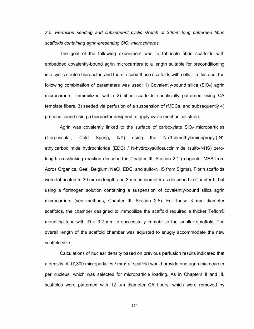
121
2.5. Perfusion seeding and subsequent cyclic stretch of 30mm long patterned fibrin
scaffolds containing agrin-presenting SiO2 microspheres
The goal of the following experiment was to fabricate fibrin scaffolds with
embedded covalently-bound agrin microcarriers to a length suitable for preconditioning
in a cyclic stretch bioreactor, and then to seed these scaffolds with cells. To this end, the
following combination of parameters was used: 1) Covalently-bound silica (SiO2) agrin
microcarriers, immobilized within 2) fibrin scaffolds sacrificially patterned using CA
template fibers, 3) seeded via perfusion of a suspension of rMDCs, and subsequently 4)
preconditioned using a bioreactor designed to apply cyclic mechanical strain.
Agrin was covalently linked to the surface of carboxylate SiO2 microparticles
(Corpuscular, Cold Spring, NY) using the N-(3-dimethylaminopropyl)-N′-
ethylcarbodiimide hydrochloride (EDC) / N-hydroxysulfosuccinimide (sulfo-NHS) zero-
length crosslinking reaction described in Chapter III, Section 2.1 (reagents: MES from
Acros Organics, Geel, Belgium; NaCl, EDC, and sulfo-NHS from Sigma). Fibrin scaffolds
were fabricated to 30 mm in length and 3 mm in diameter as described in Chapter II, but
using a fibrinogen solution containing a suspension of covalently-bound silica agrin
microcarriers (see methods, Chapter III, Section 2.5). For these 3 mm diameter
scaffolds, the chamber designed to immobilize the scaffold required a thicker Teflon®
mounting tube with ID = 3.2 mm to successfully immobilize the smaller smaffold. The
overall length of the scaffold chamber was adjusted to snugly accommodate the new
scaffold size.
Calculations of nuclear density based on previous perfusion results indicated that
a density of 17,300 microparticles / mm3 of scaffold would provide one agrin microcarrier
per nucleus, which was selected for microparticle loading. As in Chapters II and III,
scaffolds were patterned with 12 μm diameter CA fibers, which were removed by
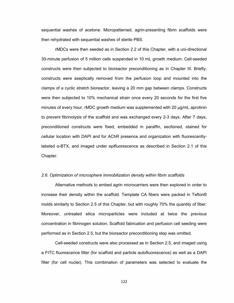
122
sequential washes of acetone. Micropatterned, agrin-presenting fibrin scaffolds were
then rehydrated with sequential washes of sterile PBS.
rMDCs were then seeded as in Section 2.2 of this Chapter, with a uni-directional
30-minute perfusion of 5 million cells suspended in 10 mL growth medium. Cell-seeded
constructs were then subjected to bioreactor preconditioning as in Chapter III. Briefly,
constructs were aseptically removed from the perfusion loop and mounted into the
clamps of a cyclic stretch bioreactor, leaving a 20 mm gap between clamps. Constructs
were then subjected to 10% mechanical strain once every 20 seconds for the first five
minutes of every hour. rMDC growth medium was supplemented with 20 μg/mL aprotinin
to prevent fibrinolysis of the scaffold and was exchanged every 2-3 days. After 7 days,
preconditioned constructs were fixed, embedded in paraffin, sectioned, stained for
cellular location with DAPI and for AChR presence and organization with fluorescently-
labeled α-BTX, and imaged under epifluorescence as described in Section 2.1 of this
Chapter.
2.6. Optimization of microsphere immobilization density within fibrin scaffolds
Alternative methods to embed agrin microcarriers were then explored in order to
increase their density within the scaffold. Template CA fibers were packed in Teflon®
molds similarly to Section 2.5 of this Chapter, but with roughly 70% the quantity of fiber.
Moreover, untreated silica microparticles were included at twice the previous
concentration in fibrinogen solution. Scaffold fabrication and perfusion cell seeding were
performed as in Section 2.5, but the bioreactor preconditioning step was omitted.
Cell-seeded constructs were also processed as in Section 2.5, and imaged using
a FITC fluorescence filter (for scaffold and particle autofluorescence) as well as a DAPI
filter (for cell nuclei). This combination of parameters was selected to evaluate the

123
hypothesis as simply and rapidly as possible, leaving the inclusion of agrin and
mechanical stretch for later evaluation.
2.7. 3D seeding of 15 mm long patterned fibrin via perfusion of muscle cell suspensions
The final perfusion seeding study consisted of two experiments. The first
experiment was performed to compare ten different experimental conditions, each
featuring one replicate. The goal in this case was to identify one or more parameters that
were common across highly-cellular groups, which could be used in the second
experiment. Again, the scaffold chamber length was adjusted to accommodate the new
scaffold size.
One parameter that had never been evaluated was stiffness of the mounting
material placed between the fibrin scaffold and the outer tubing. Any non-uniformities in
pump output could result in pulsatile changes in pressure. A scaffold mounted within a
rigid tube, such as the Teflon® employed by previous designs, could be compressed or
deformed by these pulses. By comparison, a less rigid mounting material such as
silicone tubing, could absorb some of the pressure pulses and potentially make flow
more uniform at the site of the scaffold. However, as the scaffold mounting material had
never been varied before, it was unknown if this new parameter would interact
unpredictably with others, giving rise to many possible experimental conditions.
The ten conditions evaluated in the first experiment were as follows:
1) More rigid (Teflon®) mount, 12 μm diameter (CA) fiber, 10 mm scaffold length, 30
min perfusion, 4.8 mL/min flow rate, bi-directional perfusion (with flow direction
changed immediately halfway through the total duration)
2) Teflon® mount, CA fiber, 15 mm scaffold length, 60 min perfusion, 4.8 mL/min flow
rate, bi-directional perfusion
124
3) Teflon® mount, 41 μm diameter Alex James pMMA (AJ1) fiber, 10 mm scaffold
length, 30 min perfusion, 4.8 mL/min flow rate, bi-directional perfusion
4) Teflon® mount, AJ1 fiber, 15 mm scaffold length, 60 min perfusion, 4.8 mL/min flow
rate, bi-directional perfusion
5) Teflon® mount, AJ1 fiber, 15 mm scaffold length, 60 min perfusion, 9.6 mL/min flow
rate, uni-directional perfusion
6) More compliant (silicone) mount, CA fiber, 10 mm scaffold length, 30 min perfusion,
4.8 mL/min flow rate, bi-directional perfusion
7) Silicone mount, CA fiber, 15 mm scaffold length, 60 min perfusion, 9.6 mL/min flow
rate, bi-directional perfusion
8) Silicone mount, AJ1 fiber, 10 mm scaffold length, 30 min perfusion, 4.8 mL/min flow
rate, uni-directional perfusion
9) Silicone mount, AJ1 fiber, 10 mm scaffold length, 30 min perfusion, 4.8 mL/min flow
rate, bi-directional perfusion
10) Silicone mount, AJ1 fiber, 15 mm scaffold length, 60 min perfusion, 9.6 mL/min flow
rate, bi-directional perfusion
The silicone mounting tube, where indicated, replaced the 3.2 mm ID x 6.4 mm
OD Teflon® mounting tube within the scaffold chamber of the perfusion loop, and had
identical dimensions.
The second experiment consisted of the following experimental groups (with
number of replicates shown in parentheses), using only scaffolds 15 mm in length
templated with CA fibers and mounted in silicone:
1) 30 min perfusion, 4.8 mL/min flow rate, bi-directional perfusion (n=2)
2) 30 min perfusion, 9.6 mL/min flow rate, bi-directional perfusion (n=2)
3) 60 min perfusion, 4.8 mL/min flow rate, bi-directional perfusion (n=2)
4) 60 min perfusion, 9.6 mL/min flow rate, bi-directional perfusion (n=2)

125
5) 60 min perfusion, 9.6 mL/min flow rate, uni-directional perfusion (n=3)
Microspheres were not included in scaffolds used in these experiments in order
to aid cell quantification by nuclear stain, as silica microspheres are autofluorescent and
similar in size to cell nuclei. Otherwise, scaffolds were fabricated as in Section 2.6
above. Perfusion of 5 million passage 2 rMDCs in 10 mL growth medium per scaffold
was carried out in a closed flow loop as in previous experiments. After perfusion,
scaffolds were processed and stained with DAPI as in Section 2.6 above. Again, cell
density was counted in the middle third of the scaffold length and used to evaluate
perfusion performance.
2.8. Statistical analysis and presentation of results
Statistical analysis was performed in GraphPad PRISM 5. ANOVA was first used
in each study to determine presence or absence of statistically significant differences
across an entire data set. When indicated by ANOVA, Tukey’s Test was used as post-
hoc analysis to identify individual pairwise differences. For all comparisons, p<0.05 was
considered statistically significant. All numerical results are presented as mean ±
standard deviation (SD) unless otherwise noted.
3. Results
3.1. Surface seeding of 3D planar fibrin scaffolds
The planar fibrin material supported attachment and growth of C2C12 cells, as
shown by presence of numerous nuclei stained with DAPI (blue) in Fig. 2. Cells were
observed not just on top of the scaffold, but also throughout the scaffold thickness (Fig.
2A). Therefore, cells appear to have migrated by native processes into the patterned
conduits, in some cases a few millimeters in distance, over a total period of 8 days.
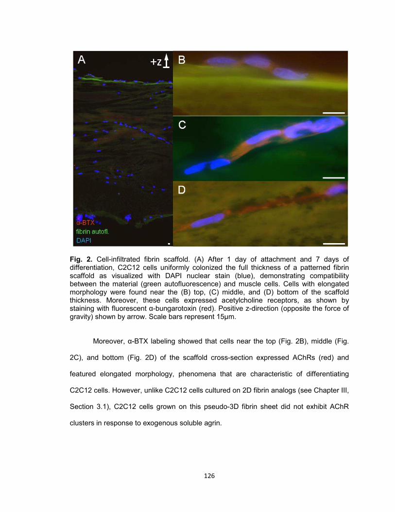
126
Fig. 2. Cell-infiltrated fibrin scaffold. (A) After 1 day of attachment and 7 days of differentiation, C2C12 cells uniformly colonized the full thickness of a patterned fibrin scaffold as visualized with DAPI nuclear stain (blue), demonstrating compatibility between the material (green autofluorescence) and muscle cells. Cells with elongated morphology were found near the (B) top, (C) middle, and (D) bottom of the scaffold thickness. Moreover, these cells expressed acetylcholine receptors, as shown by staining with fluorescent α-bungarotoxin (red). Positive z-direction (opposite the force of gravity) shown by arrow. Scale bars represent 15μm.
Moreover, α-BTX labeling showed that cells near the top (Fig. 2B), middle (Fig.
2C), and bottom (Fig. 2D) of the scaffold cross-section expressed AChRs (red) and
featured elongated morphology, phenomena that are characteristic of differentiating
C2C12 cells. However, unlike C2C12 cells cultured on 2D fibrin analogs (see Chapter III,
Section 3.1), C2C12 cells grown on this pseudo-3D fibrin sheet did not exhibit AChR
clusters in response to exogenous soluble agrin.
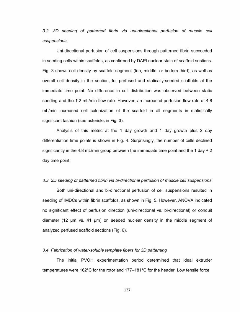
127
3.2. 3D seeding of patterned fibrin via uni-directional perfusion of muscle cell
suspensions
Uni-directional perfusion of cell suspensions through patterned fibrin succeeded
in seeding cells within scaffolds, as confirmed by DAPI nuclear stain of scaffold sections.
Fig. 3 shows cell density by scaffold segment (top, middle, or bottom third), as well as
overall cell density in the section, for perfused and statically-seeded scaffolds at the
immediate time point. No difference in cell distribution was observed between static
seeding and the 1.2 mL/min flow rate. However, an increased perfusion flow rate of 4.8
mL/min increased cell colonization of the scaffold in all segments in statistically
significant fashion (see asterisks in Fig. 3).
Analysis of this metric at the 1 day growth and 1 day growth plus 2 day
differentiation time points is shown in Fig. 4. Surprisingly, the number of cells declined
significantly in the 4.8 mL/min group between the immediate time point and the 1 day + 2
day time point.
3.3. 3D seeding of patterned fibrin via bi-directional perfusion of muscle cell suspensions
Both uni-directional and bi-directional perfusion of cell suspensions resulted in
seeding of rMDCs within fibrin scaffolds, as shown in Fig. 5. However, ANOVA indicated
no significant effect of perfusion direction (uni-directional vs. bi-directional) or conduit
diameter (12 μm vs. 41 μm) on seeded nuclear density in the middle segment of
analyzed perfused scaffold sections (Fig. 6).
3.4. Fabrication of water-soluble template fibers for 3D patterning
The initial PVOH experimentation period determined that ideal extruder
temperatures were 162°C for the rotor and 177–181°C for the header. Low tensile force

128
Fig. 3. Cell seeding of patterned fibrin immediately after perfusion. (A) Bar graphs depict cell density for individual thirds of overall scaffold length, as well as average total density over the entire scaffold, for experimental perfusion-seeded scaffolds as well as controls seeded by addition of static cell suspensions. Values are shown as average ± SD for n=9 replicates (3 separate sections from each of 3 distinct fibrin scaffolds). Counts were obtained by observation of scaffold sections labeled with DAPI nuclear stain. Oneway ANOVA revealed statistically significant differences among the 3 treatment groups at every region of the scaffold examined (p<0.0003 in all cases). Posthoc multiple pairwise comparisons indicated in all cases that perfusion of cell suspensions through scaffolds at a rate of 4.8 mL/min resulted in significantly greater engrafted cell density than either 1.2 mL/min flow rate perfusion or static seeding, which were indistinguishable. Asterisk denotes statistically significant difference from both the static seeded scaffolds as well as those seeded at the 1.2 mL/min flow rate; p<0.05, Tukey. (B) A representative DAPI-stained section of a 4.8 mL/min perfusionseeded fibrin scaffold illustrating cellular infiltration.
from the take-up system was necessary to avoid severing the fiber as it was extruded,
while high take-up speed was found to decrease fiber diameter. In addition, rotor output
was found to be positively correlated with fiber diameter. As such, extrusion was
accomplished between 10% and 20% of total rotor output, and over a range of take-up
speeds corresponding to roughly the middle third of overall capacity. Settings outside
these ranges rendered fibers produced, if any, unusable – including failure to force
polymer through the orifice, polymer decomposition by excess heat, the extrusion of
fibers of irregular diameter, or fiber breakage by excessive take-up tension.

129
Fig. 4. Cell density in rMDC-seeded fibrin scaffolds over time. Shown are average cell densities within the middle third of the scaffold length, which is the most difficult to seed being farthest from the open ends of the conduit microarchitecture. 4.8 mL/min flow rate perfusion was statistically superior to static seeding and 1.2 mL/min flow rate perfusion immediately after seeding. However, cell density declined in the 4.8 mL/min group over time, and was not significantly different than alternative seeding methods at later time points. In fact, cell density significantly declined in this group after 1 day in growth medium and a further 2 days in differentiation medium. Each bar represents average ± SD for n=9 replicates.
This initial experiment did produce fibers that dissolved in water, as desired. However,
melt extrusion of PVOH was found to be very sensitive to environmental and physical
factors such as extruder temperature and ambient moisture. The resulting fibers under
these circumstances were much larger than fibers used previously - ~250 μm in
diameter. Attempts to draw them to a finer size using low rotor speeds or high take-up
speeds caused the strand to break.
In the second experiment, fibers roughly 100 μm in diameter were produced. These
fibers dissolved in water after an acetone pretreatment removed the pMMA component.
However, the resulting fibers were porous, and dissolved very rapidly in water at room
temperature. This was problematic as fibers dissolved when fibrinogen in aqueous
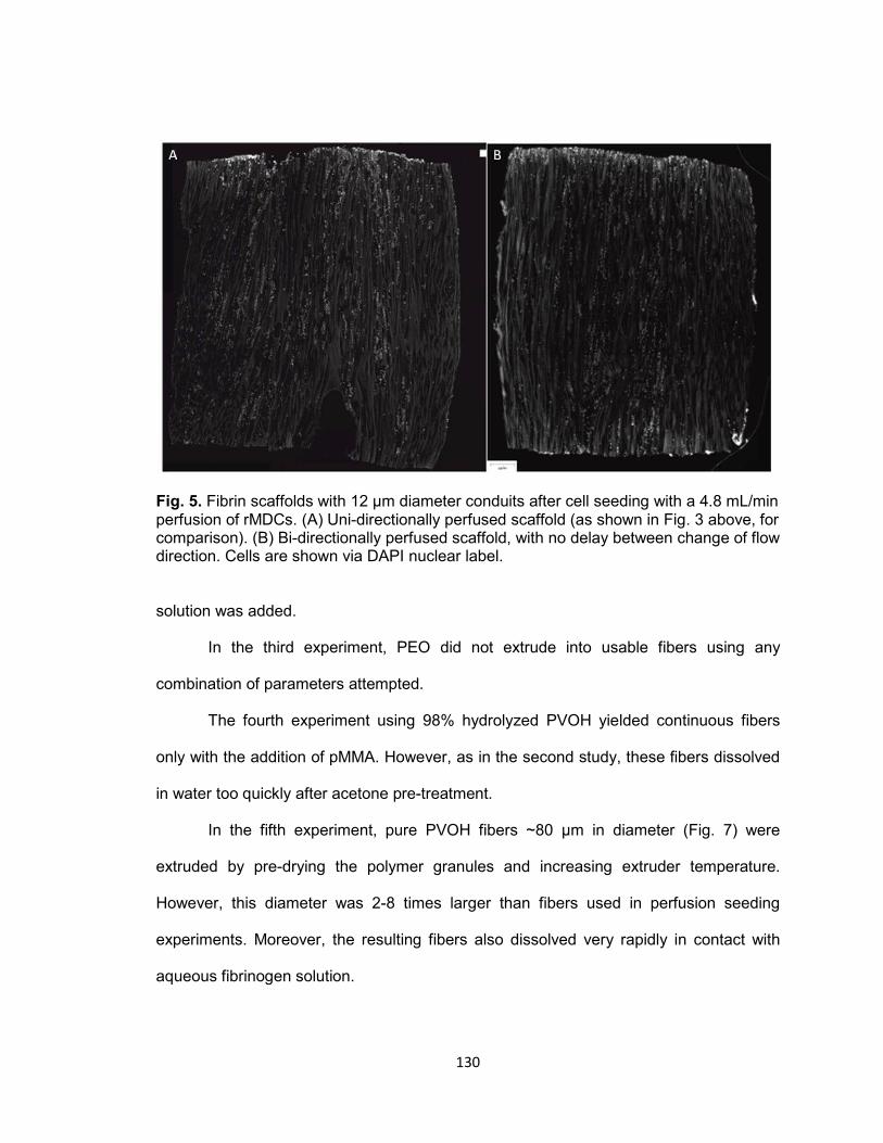
130
Fig. 5. Fibrin scaffolds with 12 μm diameter conduits after cell seeding with a 4.8 mL/min perfusion of rMDCs. (A) Uni-directionally perfused scaffold (as shown in Fig. 3 above, for comparison). (B) Bi-directionally perfused scaffold, with no delay between change of flow direction. Cells are shown via DAPI nuclear label.
solution was added.
In the third experiment, PEO did not extrude into usable fibers using any
combination of parameters attempted.
The fourth experiment using 98% hydrolyzed PVOH yielded continuous fibers
only with the addition of pMMA. However, as in the second study, these fibers dissolved
in water too quickly after acetone pre-treatment.
In the fifth experiment, pure PVOH fibers ~80 μm in diameter (Fig. 7) were
extruded by pre-drying the polymer granules and increasing extruder temperature.
However, this diameter was 2-8 times larger than fibers used in perfusion seeding
experiments. Moreover, the resulting fibers also dissolved very rapidly in contact with
aqueous fibrinogen solution.
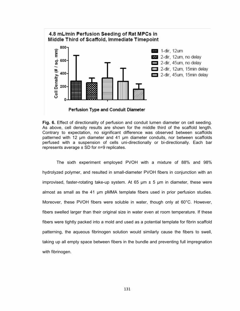
131
Fig. 6. Effect of directionality of perfusion and conduit lumen diameter on cell seeding. As above, cell density results are shown for the middle third of the scaffold length. Contrary to expectation, no significant difference was observed between scaffolds patterned with 12 μm diameter and 41 μm diameter conduits, nor between scaffolds perfused with a suspension of cells uni-directionally or bi-directionally. Each bar represents average ± SD for n=9 replicates.
The sixth experiment employed PVOH with a mixture of 88% and 98%
hydrolyzed polymer, and resulted in small-diameter PVOH fibers in conjunction with an
improvised, faster-rotating take-up system. At 65 μm ± 5 μm in diameter, these were
almost as small as the 41 μm pMMA template fibers used in prior perfusion studies.
Moreover, these PVOH fibers were soluble in water, though only at 60°C. However,
fibers swelled larger than their original size in water even at room temperature. If these
fibers were tightly packed into a mold and used as a potential template for fibrin scaffold
patterning, the aqueous fibrinogen solution would similarly cause the fibers to swell,
taking up all empty space between fibers in the bundle and preventing full impregnation
with fibrinogen.
132
Fig. 7. Example melt extruded PVOH fiber. SEM shows a water-soluble fiber roughly 80 μm in diameter, with uniform cylindrical structure.
Polymer compositions that resulted in successful fiber extrusion, and their water
solubility, are summarized in Table 1.
3.5. Perfusion seeding and subsequent cyclic stretch of 30mm long patterned fibrin
scaffolds containing agrin-presenting SiO2 microspheres
Fibrin scaffolds were successfully fabricated from fibrinogen containing a
suspension of microparticles and mounted in the stretch bioreactor. Though some
unavoidable macroscopic damage to the ends of the scaffold resulted from mechanical
compression in the mounting clamps, no slippage of the scaffold was noted, and no
gross defects or other macroscopic structural alterations were observed in the center of
the construct following cyclic mechanical strain (Fig. 8A).
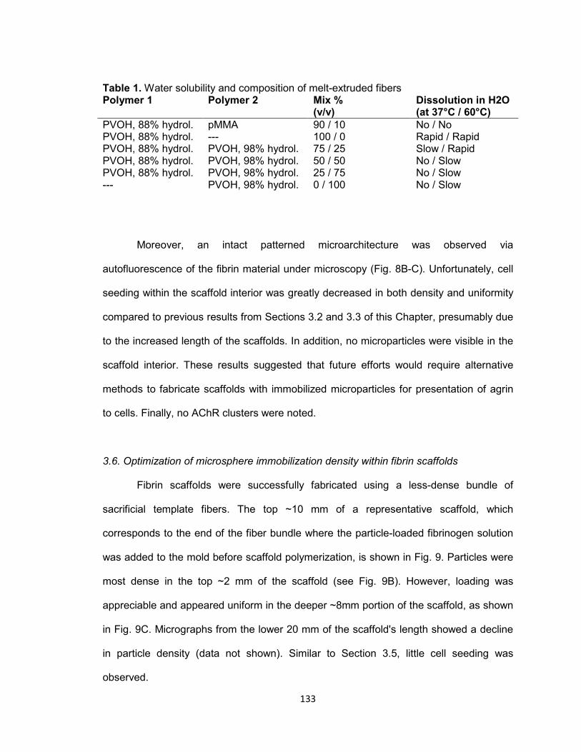
133
Table 1. Water solubility and composition of melt-extruded fibers Polymer 1 Polymer 2 Mix %
(v/v) Dissolution in H2O (at 37°C / 60°C)
PVOH, 88% hydrol. pMMA 90 / 10 No / No PVOH, 88% hydrol. --- 100 / 0 Rapid / Rapid PVOH, 88% hydrol. PVOH, 98% hydrol. 75 / 25 Slow / Rapid PVOH, 88% hydrol. PVOH, 98% hydrol. 50 / 50 No / Slow PVOH, 88% hydrol. PVOH, 98% hydrol. 25 / 75 No / Slow --- PVOH, 98% hydrol. 0 / 100 No / Slow
Moreover, an intact patterned microarchitecture was observed via
autofluorescence of the fibrin material under microscopy (Fig. 8B-C). Unfortunately, cell
seeding within the scaffold interior was greatly decreased in both density and uniformity
compared to previous results from Sections 3.2 and 3.3 of this Chapter, presumably due
to the increased length of the scaffolds. In addition, no microparticles were visible in the
scaffold interior. These results suggested that future efforts would require alternative
methods to fabricate scaffolds with immobilized microparticles for presentation of agrin
to cells. Finally, no AChR clusters were noted.
3.6. Optimization of microsphere immobilization density within fibrin scaffolds
Fibrin scaffolds were successfully fabricated using a less-dense bundle of
sacrificial template fibers. The top ~10 mm of a representative scaffold, which
corresponds to the end of the fiber bundle where the particle-loaded fibrinogen solution
was added to the mold before scaffold polymerization, is shown in Fig. 9. Particles were
most dense in the top ~2 mm of the scaffold (see Fig. 9B). However, loading was
appreciable and appeared uniform in the deeper ~8mm portion of the scaffold, as shown
in Fig. 9C. Micrographs from the lower 20 mm of the scaffold's length showed a decline
in particle density (data not shown). Similar to Section 3.5, little cell seeding was
observed.
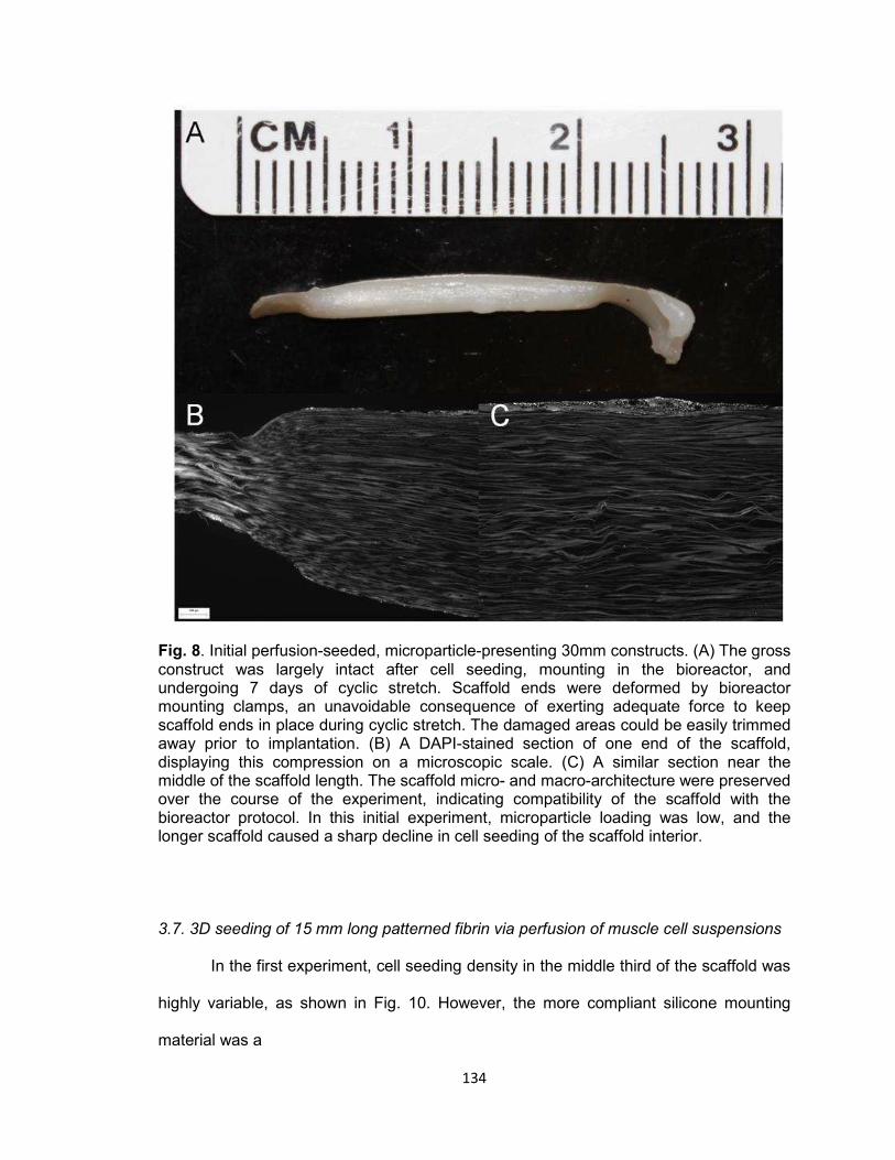
134
Fig. 8. Initial perfusion-seeded, microparticle-presenting 30mm constructs. (A) The gross construct was largely intact after cell seeding, mounting in the bioreactor, and undergoing 7 days of cyclic stretch. Scaffold ends were deformed by bioreactor mounting clamps, an unavoidable consequence of exerting adequate force to keep scaffold ends in place during cyclic stretch. The damaged areas could be easily trimmed away prior to implantation. (B) A DAPI-stained section of one end of the scaffold, displaying this compression on a microscopic scale. (C) A similar section near the middle of the scaffold length. The scaffold micro- and macro-architecture were preserved over the course of the experiment, indicating compatibility of the scaffold with the bioreactor protocol. In this initial experiment, microparticle loading was low, and the longer scaffold caused a sharp decline in cell seeding of the scaffold interior.
3.7. 3D seeding of 15 mm long patterned fibrin via perfusion of muscle cell suspensions
In the first experiment, cell seeding density in the middle third of the scaffold was
highly variable, as shown in Fig. 10. However, the more compliant silicone mounting
material was a

135
Fig. 9. Optimized microparticle loading of fibrin scaffold. By decreasing template fiber packing and doubling microparticle quantity suspended in fibrinogen solution before scaffold formation, microparticle density in the top 10 mm of the resulting scaffold (A) was substantially elevated. Insets are shown of the scaffold top (B), and of the uniformly seeded area (C). Though particle loading was elevated at the top, loading abruptly decreased roughly 2 mm deep into the scaffold. This indicated that trimming away and discarding the top 2 mm could produce a scaffold uniformly loaded with microparticles. Moreover, this result conclusively showed compatibility of the silica particles with the required acetone treatment. Scale bar represents 200 μm.

136
Fig. 10: Initial perfusion cell seeding of 10-15 mm long fibrin scaffolds. A wide array of parameters was attempted in multiple combinations with single replicates in an attempt to rapidly identify promising conduit diameter, mounting material, flow rate, or flow direction. Identifying one or more with particular promise would make a later study, with multiple replicates, feasible. As shown, several scaffolds mounted in more compliant silicone tubing were found to be promising. Cell density was reported in the middle third of scaffold length, which is the region characteristically most difficult to robustly seed with cells.
Fig. 11: rMDC perfusion of 15 mm long CA-templated fibrin scaffolds mounted in silicone tubing. Parameters including perfusion duration, directionality of perfusion, and perfusion flow rate, were found to have no significant effect on seeded cell density in the middle third of the scaffold (n=2 for bi-directionally perfused scaffold types, n=3 for uni-directionally perfused scaffold types; p < 0.05 used to determine significance of one-way ANOVA). Data presented as average ± standard error of the mean.

137
common parameter among several of the most densely seeded scaffolds. No other
parameters were consistently observed in scaffolds densely seeded with cells. Overall,
Teflon®-mounted groups were characterized by low cellularity (~2 to ~30 cells / mm2)
compared to silicone-mounted groups (~4 to ~150 cells / mm2). Moreover, scaffolds 10
mm in length were not appreciably more densely seeded than those 15 mm in length.
Results from the second experiment are shown in Fig. 11. All experimental
groups supported cell seeding of the middle third of the scaffold to a density between 80
and 100 cells / mm2, with no significant differences reported by ANOVA.
4. Discussion
4.1. Surface seeding of 3D planar fibrin scaffolds
One objective of the current study was to develop a scaffold seeding
methodology applicable to the creation of a tissue engineered muscle repair construct
featuring complex 3D geometries. In a first effort toward this goal, we hypothesized that
patterned fibrin scaffolds (see Chapter II) would readily support surface attachment and
growth of C2C12 mouse myoblast cells. To evaluate this hypothesis, we fabricated thin
(~1 mm thick) fibrin sheets and seeded them by addition of a suspension of C2C12 cells.
Presumably, this would have resulted in C2C12 cells seeded exclusively on the scaffold
exterior.
However, after 8 days of culture, cells were observed not just at the top surface
of the scaffold as expected, but also within the microscopic conduits (see Fig. 2). This
result was unexpected, as the porous microarchitecture was patterned parallel to the top
surface of the scaffold, and was nominally open only on two of the four 3 mm wide x 1
mm thick (i.e. side) faces of the scaffold. Moreover, aprotinin was added to culture
138
medium to prevent cells from accessing the conduit lumens by degrading the conduit
walls. Therefore, we concluded that cell infiltration resulted from cellular motility.
In addition, C2C12 cells were elongated and strongly oriented parallel to the
direction of the conduit lumens which housed them (Fig. 2B-2D), indicating that the
sacrificial patterning successfully guided muscle cell alignment. As force production by
muscle cells is critically tied to their directionality, inducing alignment of scaffold seeded
cells could accelerate tissue engineered construct processing.
These observations collectively supported our original hypothesis.
4.2. 3D seeding of patterned fibrin via uni-directional perfusion of muscle cell
suspensions
Thus, cells could be uniformly seeded throughout a scaffold by static seeding
followed by cell migration. However, observed cell density was low. Moreover, it is likely
that cells were initially distributed at the scaffold periphery and slowly migrated inwards.
As discussed in Chapter III, denervated muscle undergoes progressive atrophy [27].
Therefore, accelerating muscle cell seeding of scaffolds is necessary.
To this end, we hypothesized that perfusing a cell suspension through the
scaffold architecture via fluid flow would increase cell seeding density and uniformity of
cell distribution within the scaffold over a short period of time. In our initial perfusion
experiment, a suspension of rMDCs in culture medium was circulated through a fibrin
scaffold using a peristaltic pump and a closed flow loop, as depicted schematically in
Fig. 1.
Unsurprisingly, the scaffold edge first contacted by the cell suspension (the
scaffold "top") was most heavily seeded with cells, regardless of the experimental
condition (Fig. 3A). Indeed, in statically-seeded control samples and scaffolds perfused
at a lower flow rate of 1.2 mL/min, the top was the only area appreciably seeded with

139
cells 30 minutes after cells were first added. This was unsurprising, as the diameter of
conduits in this case (12 μm) was likely similar to that of the cells, resulting in many cells
becoming caught at the nearest edge of the scaffold. The middle third of the scaffold
was the least densely seeded area, indicating that this region is the most difficult to
seed. Because of our goal to uniformly seed scaffolds, and because quantification of cell
seeding density was a labor-intensive process, seeding in the middle third of the scaffold
was chosen as a metric for further perfusion experimentation.
4.8 mL/min perfusion significantly increased cell seeding in the scaffold interior
relative to 1.2 mL/min perfusion or static seeding. Using this treatment, cell seeding
density over the entire 15 μm thick scaffold section averaged ~500 cells / mm2,
indicating that slightly over 2 million of the total 5 million cells were captured within these
scaffolds. Qualitatively, DAPI labeling showed a relatively uniform distribution of cells
seeded within the scaffolds (Fig. 3B).
However, investigation of seeded scaffolds after further culture revealed that high
seeded cell density was not maintained over time by standard static culture in an
incubator (Fig. 4). In fact, cell density significantly declined over 1 day in growth medium
and 2 days in differentiation medium in the 4.8 mL/min perfusion group. At the final time
point, interior cell density had fallen below 80 cells / mm2 in all groups, and no significant
differences were observed. Collectively, these observations may indicate that the
scaffold represents a diffusional barrier which, combined with the significant nutrient
requirement of densely-seeded cells in 3D, leads to necrosis of cells seeded within the
scaffold interior.
These results strongly supported our hypothesis that perfusion of a cell
suspension could more densely and uniformly seed cells within a 4 mm long x 4.5 mm
diameter 3D scaffold.
140
4.3. 3D seeding of patterned fibrin via bi-directional perfusion of muscle cell suspensions
Though quantitative results from the uni-directional perfusion seeding study were
encouraging, qualitative analysis of images indicated that cell seeding across the width
of the scaffold may have been less uniform than overall cell density would indicate. In
Fig. 3B for example, longitudinal tracts of cell nuclei can be seen within certain conduits.
We reasoned that the scaffold fabrication method used may have created some conduits
that were better accessed from one end than the other, due to the inherent variability of
fabricating scaffolds by hand. We hypothesized that perfusing the cell suspension into
both open ends of the scaffold would further increase uniformity and density of cell
seeding.
Simultaneously, as viscous drag on cells was previously identified as a significant
factor, we hypothesized that perfusion seeding could be further optimized by varying
conduit diameter. To this end, experimental groups were included which featured two
different fiber template diameters of 12 μm (CA) and 41 μm (pMMA). These sizes were
the smallest and largest which resulted in a scaffold of identical bulk stiffness (see
Chapter III, Fig. 5A). We wished to stay within this range to minimize potential
confounding factors when comparing to uni-directional perfusion results.
Fig. 5 shows representative sections of scaffolds seeded via both uni-directional
(Fig. 5A) and bi-directional (Fig. 5B) perfusion. Qualitatively, the only observable
difference in cell engraftment within the scaffold was an increase of seeding at the
bottom edge, which became the first area contacted by the cell suspension after reversal
of flow direction. Like in uni-directionally perfused scaffolds, cells in bi-directionally
perfused scaffolds were still arranged into longitudinal tracts, with intervening areas of
relatively low seeding density. This allowed us to reject the first part of our hypothesis
predicting improved seeding uniformity using bi-directional perfusion.

141
Further, as shown in Fig. 6, no significant difference in cell seeding density was
seen resulting from altered conduit size, direction of perfusion, or delay between reversal
of flow direction using our prior metric within the middle third of the scaffold. This allowed
us to reject the second part of our hypothesis, which predicted an increase in seeded
cell density.
This lack of observed differences was unexpected, but potentially of interest for
future work. For further experimentation, CA fibers were selected for scaffold
fabrications, as they are readily available in larger quantity than pMMA fibers. We
elected to continue varying directionality of flow in some further experiments, as it was
technically straightforward and had potential to interact unpredictably with other
parameters yet to be evaluated.
4.4. Fabrication of water-soluble template fibers for 3D patterning
To this point, all fibrin scaffolds were templated with acetone-soluble CA or
pMMA fibers. Simultaneously, significant experimentation in agrin delivery to this point
(see Chapter III, Sections 2.2-2.3 and 3.1-3.2) utilized agrin delivery vehicles fabricated
using polystyrene (PS) microspheres, which are likewise soluble in acetone.
Incorporating agrin-presenting particles to patterned fibrin would therefore require a
change in one material.
One method to form a polymer into a usable template fiber is melt extrusion, by
which molten polymer is forced through a die of desired cross-sectional shape and then
drawn under tension into a long strand of smaller diameter. Melt extruded acetone-
soluble fibers used previously were generous gifts or created in collaboration with the
North Carolina State University College of Textiles.
By contrast, in the experiments described here, we chose to attempt melt
extrusion of the water-soluble polymers poly(vinyl alcohol) (PVOH) and poly (ethylene
142
oxide) (PEO). Though a series of experiments were performed, each with its own
specific hypothesis, the overall hypothesis of the series was that melt extrusion could be
employed to produce water-soluble fibers which would in turn allow incorporation of PS
microparticles into templated fibrin scaffolds.
During prior experimentation, we found that scaffolds templated using sacrificial
fibers 105 μm in diameter or larger were difficult to suture (data not shown) and had
lower stiffness than scaffolds used for muscle cell culture previously. Thus, water-soluble
polymers would ideally be in the 12 - 41 μm diameter range, which could be used to
fabricate scaffolds of understood perfusion kinetics and preferred mechanical properties.
Through sequential experimentation, relatively uniform water soluble fibers as
small as 65 μm were produced (an example fiber 80 μm in diameter is shown in Fig. 7).
Though larger than acetone-soluble fibers used previously to template fibrin, these fibers
demonstrated that melt extrusion of PVOH was feasible using the equipment described.
However, while nominally water soluble, these fibers often swelled during degradation,
or only dissolved in water when substantially heated. When attempting to polymerize
fibrin around these templates, fiber swelling would fill free space in the mold required for
fibrinogen and defeat, to an extent, the fabrication of smaller-diameter fibers. Further, we
reasoned that elevated temperatures required to dissolve some created fibers would
quickly denature any agrin present in a combined system.
In conclusion, though our experiments resulted in water-soluble fibers, they were
unsuitable for creation scaffold templating using methodology described. We were
therefore unable to support or reject the hypothesis that water-soluble fibers could be
used in the templating of a polystyrene-containing fibrin scaffold. As such, we elected an
alternative strategy simultaneously utilizing acetone-soluble CA or pMMA fibers and
acetone-stable agrin microcarriers made from silica. Though we recognized that silica is
143
not biodegradable, and therefore not an ideal biomterial for this application, it enabled
proof of concept at this early stage.
4.5. Perfusion seeding and subsequent cyclic stretch of 30mm long patterned fibrin
scaffolds containing agrin-presenting SiO2 microspheres
Lacking suitable water-soluble fibers, we hypothesized that acetone-insoluble
agrin microcarriers could be incorporated within fibrin scaffolds fabricated using prior
methods. If this were correct, these scaffolds could be seeded with cells by perfusion
and resulting constructs could undergo cyclic mechanical strain in a bioreactor based on
earlier sections of this Chapter and prior work [28,29], respectively. To this end, we
obtained microparticles made of SiO2, or silica, which is acetone-insoluble. These
particles were commercially available in identical sizes to PS microparticles used
previously, with the option of surface carboxyl groups which could take advantage of our
existing covalent coupling technique (see Chapter III, Section 2.1).
Covalently-bound agrin microparticles were fabricated using the zero-length
crosslinker EDC, which created a peptide bond between agrin molecules and SiO2
microparticle surfaces. Similarly to Chapter III, Section 2.5, these microparticles were
mixed into fibrinogen solutions used to fabricate fibrin scaffolds. Further, scaffold length
was increased to 30 mm and scaffold diameter was decreased to 3 mm, as this
represented a scaffold size which could be readily mounted in our available stretch
bioreactors.
30 mm long x 3 mm diameter fibrin scaffolds successfully underwent cell
seeding, cyclic stretch in the bioreactor preconditioning protocol, and histological
preparation. Imaged scaffold sections revealed intact conduit microarchitecture, which
showed for the first time that these fibrin scaffolds were mechanically compatible with
the stretch bioreactor. Though expected gross defects occurred at the scaffold ends

144
resulting from compression in bioreactor mounting clamps (Fig. 8A), the fibrin material
was easily trimmed, allowing damaged ends to be removed prior to any further use.
However, few cells or microparticles were observed by microscopy within the
conduits or conduit walls, respectively (Fig. 8B-8C). As cells were observed at the
scaffold periphery, the sharp decline in interior seeding likely resulted from fluid dynamic
changes in the perfusion process brought about by use of much longer scaffolds.
Moreover, the observed lack of AChR clusters was expected due to a corresponding
lack of cells and agrin microparticles in close proximity to one another.
Post hoc calculations predicted that average conduit wall thickness of 80%
porous scaffolds fabricated using these parameters was likely less than 2 μm. Therefore,
tight packing of sacrificial fibers within the scaffold mold likely excluded the 10 μm
diameter microparticles from the scaffold interior.
Without cells and microcarriers in proximity, the bioactivity of acetone-treated
agrin microcarriers could not be verified. Therefore, the hypothesis could not be
supported nor rejected in this experiment. Further experiments therefore refined the
incorporation of agrin presentation and 3D cell seeding portions of the hypothesis.
4.6. Optimization of microsphere immobilization density within fibrin scaffolds
As before, the goal of this experiment was to fabricate a patterned fibrin scaffold
containing microparticles made from SiO2. However, we hypothesized for the current
experiment that microparticle loading within the scaffold interior could be increased by
packing template fibers less densely within the Teflon® mold before the addition of
fibrinogen, as discussed in Section 4.5. Again, a cell perfusion step was included for the
dual purposes of enabling cell seeding and to evaluate whether any successfully
immobilized microparticles would be washed out of the scaffold under fluid flow. By
145
contrast, we simplified the experiment by removing the linkage of agrin to microparticles
and the bioreactor preconditioning of scaffolds.
Though the resulting scaffolds were still poorly seeded with rMDCs using the
perfusion methods specified, they featured three distinct areas of microparticle density:
the top ~2mm, which was heavily laden with particles (Fig. 9B); the ~8 mm below that,
which featured a relatively uniform and substantial density of embedded microparticles
(Fig. 9C); and the bottom ~20 mm, characterized by a decline in immobilized
microparticle density (not shown). This result supported the hypothesis that less
densely-packed fibers would allow elevated particle loading within the scaffold. Further,
it showed not only effective particle loading in the fabrication step and stability of silica
particles in acetone, but also that fluid flow through the scaffold did not displace
immobilized particles.
However, the preference for uniform microparticle loading recommended that the
top and bottom portions of the scaffold not be used in the final construct. As mounting
into the cyclic stretch bioreactor necessitated loss of scaffold ends, this was an
acceptable compromise. In addition, decreased fiber packing directly resulted in a less
porous scaffold, in turn reducing the potential 3D seeding area for cells. This
represented a necessary compromise to enable fabrication of an agrin-presenting
scaffold.
The decline in microparticle density in the ~20 mm of the scaffold below the area
shown in Fig. 9, along with difficulty in cell seeding of longer constructs, recommended
use of shorter constructs. However, scaffolds longer than the 4 mm previously perfused
were required for further experimentation due to loss of construct ends when clamped
into cyclic stretch bioreactors.
146
4.7. 3D seeding of 15 mm long patterned fibrin via perfusion of muscle cell suspensions
As a compromise between these size requirements and the constraints of
perfusion - chiefly poor cell density in longer perfusion-seeded scaffolds as stated, but
also the number of rMDCs required to seed longer scaffolds - 3 mm diameter cylindrical
scaffolds either 10 mm or 15 mm in length were selected for further experimentation.
This represented a total increase in scaffold volume of only 11% or 67%, respectively,
relative to 4 mm long x 4.5 mm diameter scaffolds previously seeded successfully by
perfusion, while increasing the length of the scaffold roughly two- to four-fold and
thereby reaching a size more relevant for future studies.
The additional inclusion of alternative scaffold mounting materials presented a
large array of potential combinations of experimental variables in concert with the new,
shorter scaffold length. To evaluate some of the most promising combinations as rapidly
as possible, we elected a two-phase experimental design. First, we evaluated common
parameters amongst densely cell-seeded scaffolds using groups with single replicates.
We then performed a second experiment with more replicates in fewer groups featuring
the common parameters. We hypothesized for this two-part experiment that 3 mm wide
x 10-15 mm long scaffolds could be seeded to similarly high interior cell densities as 4.5
mm wide x 4 mm long scaffolds.
Use of a more compliant silicone scaffold mounting material was suggested to be
of benefit by the small initial experiment. However, the follow-on experiment identified no
statistically significant differences between any groups evaluated. Moreover, seeded cell
densities in these scaffolds were ~75-95 cells / mm2, substantially lower than the ~250
cells / mm2 seen previously in 4.5 mm diameter x 4 mm long scaffolds (Fig. 3A).
Assuming similar distribution of cells throughout the entire scaffold, this indicated that 15
mm long x 3 mm diameter scaffolds captured 1 million to 1.25 million of the 5 million
147
cells in suspension, while 4 mm long x 4.5 mm diameter scaffolds captured over 2
million.
Therefore, it was concluded that the decreased cell density observed was not
simply a function of larger available surface area for cell seeding within the scaffold
microarchitecture, but instead a proportionally reduced efficiency in seeding longer,
narrower scaffolds. As such, the hypothesis in this experiment was rejected.
As the only parameter which could not be varied, we now hypothesize that the
scaffolds fabricated by hand using our current methodology possess interior architecture
that, while apparently uniform under light and electron microscopy as shown in the
original proposal, features subtle inconsistencies which undermine repeatability in
perfusion outcomes and which compound as the scaffold length increases.
Given these findings, we reevaluated advances to date and compared to the
remaining goal of evaluating cell-seeded agrin-presenting fibrin materials in vivo. In
Chapter III, we observed AChR clustering behavior in C2C12 cells resident on a 2D
fibrin layer featuring embedded agrin-presenting particles. Moreover, we demonstrated
that 3D fibrin scaffolds could incorporate immobilized agrin microcarriers. rMPCs
surface-seeded onto 3D scaffolds also exhibited extensive AChR clustering following
cyclic stretch.
Considering persistent difficulties reliably seeding cylindrical scaffold interiors via
perfusion of cell suspensions, we elected to evaluate planar, surface-seeded scaffolds
(as described in Chapter III) in vivo using a rat neurotization model. This model and the
results thereof are discussed in Chapter V.
5. Conclusions
In this Chapter, we describe efforts to translate promising fibrin biomaterials and
agrin pharmacologics from 2D forms, as successfully demonstrated in the first portion of

148
Chapter III, to 3D embodiments. These efforts were primarily twofold: first, to create a 3D
fibrin construct with patterned pores for muscle cell attachment and guidance which
presented an immobilized agrin signal; second, to densely seed the interior of such a
scaffold with muscle cells. The overall objective of this study was to create a highly
cellularized tissue engineered muscle repair construct which would be suitable for
implantation in vivo.
Toward this end, we found that fibrin biomaterials supported the attachment and
growth of both a C2C12 muscle cell line and expanded rMDCs. Moreover, agrin-
presenting microparticles were successfully embedded into fibrin in a manner compatible
with sacrificial templating methods.
Unfortunately, attempts to robustly seed the interior of such scaffolds only met
with success in scaffolds which were too short to feasibly use in conjunction with
mechanical preconditioning in a bioreactor. However, future efforts may yield improved
results, either through refinements of techniques described here, or through alternatives
such as assembly of pre-seeded scaffold components, enhancement of native cellular
motility into the scaffold, or other approaches not yet envisioned.
Acknowledgements
This work was funded by an award from the Telemedicine and Advanced
Technology Research Center, by the Wake Forest University Department of Biomedical
Engineering, and by the Wake Forest Institute for Regenerative Medicine. The authors
gratefully acknowledge the assistance of Hannah Baker, Christopher Bergman, Hayden
Holbrook, Venu Kesireddy, Juliana Passipieri, and Mevan Siriwardane in performing
experiments described herein, as well as Cathy Mathis and Cynthia Zimmerman for their
assistance with histology.
149
References [1] Levinson SF, Shinagawa M, Sato T. Sonoelastic determination of human skeletal
muscle elasticity. J Biomech 1995;28:1145–54. doi:10.1016/0021-9290(94)00173-2.
[2] Baechle T, Earle R, editors. Essentials of Strength Training and Conditioning. 3rd
ed. National Strength and Conditioning Association; 2008. [3] Lee SK, Wolfe SW. Peripheral Nerve Injury and Repair. J Am Acad Orthop Surg
2000;8:243–52. [4] Lee W-Y, Cheng W-Y, Yeh Y-C, Lai C-H, Hwang S-M, Hsiao C-W, et al.
Magnetically Directed Self-Assembly of Electrospun Superparamagnetic Fibrous Bundles to Form Three-Dimensional Tissues with a Highly Ordered Architecture. Tissue Eng Part C Methods 2011;17:651–61. doi:10.1089/ten.tec.2010.0621.
[5] Page RL, Malcuit C, Vilner L, Vojtic I, Shaw S, Hedblom E, et al. Restoration of
Skeletal Muscle Defects with Adult Human Cells Delivered on Fibrin Microthreads. Tissue Eng Part A 2011;17:2629–40. doi:10.1089/ten.tea.2011.0024.
[6] Jana S, Cooper A, Ohuchi F, Zhang M. Uniaxially Aligned Nanofibrous Cylinders
by Electrospinning. ACS Appl Mater Interfaces 2012;4:4817–24. doi:10.1021/am301803b.
[7] Monge C, Ren K, Berton K, Guillot R, Peyrade D, Picart C. Engineering Muscle
Tissues on Microstructured Polyelectrolyte Multilayer Films. Tissue Eng Part A 2012;18:1664–76. doi:10.1089/ten.tea.2012.0079.
[8] Wang P-Y, Thissen H, Tsai W-B. The roles of RGD and grooved topography in
the adhesion, morphology, and differentiation of C2C12 skeletal myoblasts. Biotechnol Bioeng 2012;109:2104–15. doi:10.1002/bit.24452.
[9] Palamà IE, D’Amone S, Coluccia AML, Gigli G. Micropatterned polyelectrolyte
nanofilms promote alignment and myogenic differentiation of C2C12 cells in standard growth media. Biotechnol Bioeng 2013;110:586–96. doi:10.1002/bit.24626.
[10] Goldstein AS, Juarez TM, Helmke CD, Gustin MC, Mikos AG. Effect of
convection on osteoblastic cell growth and function in biodegradable polymer foam scaffolds. Biomaterials 2001;22:1279–88.
[11] Cartmell SH, Porter BD, García AJ, Guldberg RE. Effects of medium perfusion
rate on cell-seeded three-dimensional bone constructs in vitro. Tissue Eng 2003;9:1197–203. doi:10.1089/10763270360728107.
[12] Kasper FK, Liao J, Kretlow JD, Sikavitsas VI, Mikos AG. Flow perfusion culture of
mesenchymal stem cells for bone tissue engineering. StemBook, Cambridge (MA): Harvard Stem Cell Institute; 2008.
150
[13] Issa RI, Engebretson B, Rustom L, McFetridge PS, Sikavitsas VI. The effect of cell seeding density on the cellular and mechanical properties of a mechanostimulated tissue-engineered tendon. Tissue Eng Part A 2011;17:1479–87. doi:10.1089/ten.TEA.2010.0484.
[14] Gaspar DA, Gomide V, Monteiro FJ. The role of perfusion bioreactors in bone
tissue engineering. Biomatter 2012;2:167–75. doi:10.4161/biom.22170. [15] Gardel LS, Correia-Gomes C, Serra LA, Gomes ME, Reis RL. A novel
bidirectional continuous perfusion bioreactor for the culture of large-sized bone tissue-engineered constructs. J Biomed Mater Res B Appl Biomater 2013;101:1377–86. doi:10.1002/jbm.b.32955.
[16] Yeatts AB, Both SK, Yang W, Alghamdi HS, Yang F, Fisher JP, et al. In vivo bone
regeneration using tubular perfusion system bioreactor cultured nanofibrous scaffolds. Tissue Eng Part A 2014;20:139–46. doi:10.1089/ten.TEA.2013.0168.
[17] Alvarez-Barreto JF, Linehan SM, Shambaugh RL, Sikavitsas VI. Flow perfusion
improves seeding of tissue engineering scaffolds with different architectures. Ann Biomed Eng 2007;35:429–42. doi:10.1007/s10439-006-9244-z.
[18] Alvarez-Barreto JF, Landy B, VanGordon S, Place L, DeAngelis PL, Sikavitsas
VI. Enhanced osteoblastic differentiation of mesenchymal stem cells seeded in RGD-functionalized PLLA scaffolds and cultured in a flow perfusion bioreactor. J Tissue Eng Regen Med 2011;5:464–75. doi:10.1002/term.338.
[19] Kennedy JP, McCandless SP, Rauf A, Williams LM, Hillam J, Hitchcock RW.
Engineered channels enhance cellular density in perfused scaffolds. Acta Biomater 2011;7:3896–904. doi:10.1016/j.actbio.2011.06.037.
[20] Bartnikowski M, Klein TJ, Melchels FPW, Woodruff MA. Effects of scaffold
architecture on mechanical characteristics and osteoblast response to static and perfusion bioreactor cultures. Biotechnol Bioeng 2014;111:1440–51. doi:10.1002/bit.25200.
[21] Bonandrini B, Figliuzzi M, Papadimou E, Morigi M, Perico N, Casiraghi F, et al.
Recellularization of well-preserved acellular kidney scaffold using embryonic stem cells. Tissue Eng Part A 2014;20:1486–98. doi:10.1089/ten.TEA.2013.0269.
[22] Bancroft GN, Sikavitsas VI, Mikos AG. Technical Note: Design of a Flow
Perfusion Bioreactor System for Bone Tissue-Engineering Applications. Tissue Eng 2003;9:549–54. doi:10.1089/107632703322066723.
[23] Petri M, Ufer K, Toma I, Becher C, Liodakis E, Brand S, et al. Effects of perfusion
and cyclic compression on in vitro tissue engineered meniscus implants. Knee Surg Sports Traumatol Arthrosc 2012;20:223–31. doi:10.1007/s00167-011-1600-3.
[24] Kock LM, Malda J, Dhert WJA, Ito K, Gawlitta D. Flow-perfusion interferes with
chondrogenic and hypertrophic matrix production by mesenchymal stem cells. J Biomech 2014;47:2122–9. doi:10.1016/j.jbiomech.2013.11.006.
151
[25] Muscari C, Giordano E, Bonafè F, Govoni M, Guarnieri C. Strategies affording
prevascularized cell-based constructs for myocardial tissue engineering. Stem Cells Int 2014;2014:434169. doi:10.1155/2014/434169.
[26] Pagliari S, Tirella A, Ahluwalia A, Duim S, Goumans M-J, Aoyagi T, et al. A
multistep procedure to prepare pre-vascularized cardiac tissue constructs using adult stem sells, dynamic cell cultures, and porous scaffolds. Front Physiol 2014;5:210. doi:10.3389/fphys.2014.00210.
[27] Järvinen TAH, Järvinen TLN, Kääriäinen M, Kalimo H, Järvinen M. Muscle
Injuries Biology and Treatment. Am J Sports Med 2005;33:745–64. doi:10.1177/0363546505274714.
[28] Machingal MA, Corona BT, Walters TJ, Kesireddy V, Koval CN, Dannahower A,
et al. A tissue-engineered muscle repair construct for functional restoration of an irrecoverable muscle injury in a murine model. Tissue Eng Part A 2011;17:2291–303. doi:10.1089/ten.TEA.2010.0682.
[29] Corona BT, Machingal MA, Criswell T, Vadhavkar M, Dannahower AC, Bergman
C, et al. Further development of a tissue engineered muscle repair construct in vitro for enhanced functional recovery following implantation in vivo in a murine model of volumetric muscle loss injury. Tissue Eng Part A 2012;18:1213–28. doi:10.1089/ten.TEA.2011.0614.
152
CHAPTER V
PRELIMINARY EVALUATION OF INNERVATION AND REMODELING OF A TISSUE
ENGINEERED SKELETAL MUSCLE REPAIR CONSTRUCT IN VIVO
John B. Scott
153
1. Introduction
Chapters II through IV describe sequential advances in the development and
evaluation in vitro of a biomimetic construct aimed at tissue engineered repair of
volumetric muscle loss (VML) injuries. Results showed that the construct could direct
neuronal process ingrowth, support muscle cell attachment, and incorporate
pharmacologic (immobilized neural agrin) and mechanical (bioreactor preconditioning)
cues designed to elicit acetylcholine receptor (AChR) clusters, the presumptive in vitro
analog of motor end plates (MEPs). This Chapter describes the implantation of these
constructs in vivo using a model of innervation, a necessary process in the healing of
large muscle injuries.
This study utilized a rat neurotization model wherein the cell-seeded scaffolds
were implanted in the subcutaneous space of a rat hindlimb and then sutured to the
proximal stump of the transected femoral nerve. Based on results from a study in the
literature [1] and our previous evaluation of neurite in-growth into the scaffold in vitro
(see Chapter II), axons were expected to grow out from the proximal femoral stump onto
the constructs.
Prior to implantation, experimental constructs were formed by mechanically
preconditioning surface rMDC-seeded, agrin-presenting planar fibrin scaffolds in vitro.
This embodiment was previously shown to exhibit substantial AChR clustering (see
Chapter III). We hypothesized first that neo-innervation of constructs would result in de
novo NMJ formation between the host nervous system and the tissue engineered
muscle construct, and second that AChR clusters formed prior to implantation could
enhance either these NMJs or ectopic muscle resulting from host remodeling of the
implant.
154
2. Methods
Unless otherwise noted, all culture medium formulations are described as % v/v
and all histological staining reagents are expressed as % w/v in deionized (DI) water.
Further, all methods were performed at ambient pressure on a lab bench at a room
temperature of ~22°C unless otherwise noted.
2.1. Culture medium formulations and isolation of rat muscle derived cells
Culture medium formulations for myogenic medium and rat muscle derived cell
(rMDC) growth medium were identical to those used in Chapter III, Section 2.1. Briefly,
these were myogenic medium: 68% high-glucose DMEM, 20% FBS, 10% horse serum,
1% chicken embryo extract, and 1% antibiotic-antimycotic; rMDC growth medium: 84%
low-glucose DMEM, 15% FBS, and 1% antibiotic/antimycotic.
rMDCs used in this Chapter were isolated and expanded using identical methods
to those described in Chapter III, Section 2.4. Briefly, Matrigel®-coated tissue culture
plates were prepared prior to isolation. Meanwhile, tibialis anterior and soleus muscles
were removed from euthanized donor rats, rinsed in 10% povidone iodine solution, and
transferred to a sterile environment where they were subsequently washed in PBS,
manually minced to a suspension of fine particles in collagenase-supplemented culture
medium, and incubated at 37°C. After 2 hours, digested tissue suspensions were
centrifuged, the supernatant was removed, and tissue was resuspended in myogenic
medium and added to Matrigel®-coated plates.
After 2 days, myogenic medium was removed and replaced with rMDC growth
medium. After a further 2 days, cells were dissociated from plates and then replated on
untreated tissue culture polystyrene in rMDC growth medium. At ~70% confluence,
usually after 3-4 days, cells were again dissociated from plates and used for
experimentation as described below.
155
This isolation protocol was approved by the Wake Forest University Institutional
Animal Care and Use Committee and complies with animal use guidelines established
by the American Physiological Society.
2.2. Preparation, cell seeding, and bioreactor preconditioning of agrin-presenting fibrin
scaffolds
3D patterned fibrin scaffolds embedded with covalently-bound agrin microcarriers
were fabricated, surface seeded with rMDCs, and preconditioned by cyclic mechanical
strain in a bioreactor as described in Chapter III, Section 2.5.
Briefly, the zero-length crosslinker N-(3-Dimethylaminopropyl)-N′-
ethylcarbodiimide hydrochloride (EDC, Sigma-Aldrich, St. Louis, MO) was used to
covalently bond either recombinant rat agrin (R&D Systems, Minneapolis, MN) or bovine
serum albumin (BSA, Sigma-Aldrich) molecules to 10 μm diameter SiO2 microspheres
(Corpuscular, Cold Spring, NY). Subsequently, cellulose acetate (CA) fibers (generous
donation of Eastman Chemical Company, Kingsport, TN) ~12 μm in diameter were
arranged into an aligned mat. Protein-bound microcarriers were suspended in fibrinogen
(Sigma-Aldrich) and this suspension was added to the fiber mat. Fibrinogen was
polymerized to fibrin in the presence of thrombin and CaCl2 in PBS, creating a large
fibrin scaffold which was then trimmed into individual smaller scaffolds measuring
roughly 30 mm long x 3 mm wide x 1 mm thick. These were then sequentially washed
four times each in acetone and then sterile PBS to yield scaffolds suitable for cell
seeding.
One 30mm long x 3 mm wide flat plane of each scaffold was then seeded with
cells by manually pipetting a suspension of rMDCs in growth medium over scaffold
surfaces. After allowing a brief initial period for cell attachment, growth medium was
added to totally immerse cell-seeded scaffold constructs.
156
Constructs were removed from static culture after allowing 16-24 hours for full
cell attachment and clamped into the mounts of a custom-fabricated bioreactor designed
to repeatedly apply uniaxial cyclic stretch to growth medium-immersed tissue constructs.
The bioreactor was used to precondition cell-seeded scaffolds by subjecting them to
10% mechanical strain parallel to the long axis of scaffolds, 3 times per minute for the
first 5 minutes of every hour over a total time of 5 days. In all groups, rMDC growth
medium was exchanged every 2-3 days, and was supplemented with aprotinin starting
on day 1. After completion of the 5 day preconditioning step, scaffolds were removed
from the bioreactor. Scaffold ends deformed by mounting in the bioreactor were
removed with sterile surgical scissors, and scaffolds were immediately implanted in vivo
(see Section 2.3).
2.3. Implantation of tissue engineered muscle repair constructs in vivo
After predoncitioning, constructs were implanted in vivo to histologically evaluate
structural and functional innervation by the host. The model is represented schematically
in Fig. 1.
The following experimental groups were included in this experiment. All groups
featured bioreactor-preconditioned fibrin constructs evaluated at a single 2 week time
point using histology (see Section 2.4 below).
• Covalently-bound agrin microcarriers, surface-seeded rMDCs (n=3)
• Covalently-bound BSA microcarriers, surface-seeded rMDCs (n=3)
• Covalently-bound agrin microcarriers, no rMDCs (n=3)
To begin, 12-16 week old male Lewis rats (Charles River, Raleigh, NC) were
placed under general anesthesia by isoflurane inhalation. The surgical site at the medial
left hindlimb was shaved and sterilized using sequential scrubs of povidone-iodine
(McKesson Corporation, San Francisco, CA) and ethanol, and the site was covered in a

157
Fig. 1: Schematic overview of rat neurotization study. (A) A longitudinal incision was made in the rat hindlimb to expose the femoral nerve (thin white structure between black arrowheads). (B) The femoral nerve was transected, and a bioreactor-preconditioned fibrin construct (pink structure between white brackets) was placed in contact with the proximal nerve stump. Suture loops (black arrowheads) were anchored in the underlying fascia and used to immobilize the construct in place, as well as to maintain contact between nerve and construct. (C) At a two week time point, the surgical site was reopened. Some construct integration with and remodeling by adjacent native tissue was observed, but constructs were still grossly visible (pale structure between white brackets) at this early time point. (D) Half of all animals were subjected to electrical stimulation of the femoral nerve (black arrowhead) proximal to the construct, which would deplete glycogen reserves of any newly innervated muscle in the construct (white bracket). Constructs and the adjacent femoral nerve were then explanted for histological analysis. (E) Sections for histology were parallel to the long axis of the construct with the aim to capture a plane including both the remodeled construct and the underlying nerve. (F) Visual observation of H&E staining was used to identify sections including both construct and nerve. Ideally, the nerve would have robustly innervated the construct area. Unfortunately, in most samples the nerve (gray) was disconnected from the remaining scaffold (orange), though in some samples it interfaced with the remodeled tissue (purple) surrounding the remaining scaffold. To best represent results and provide landmarks for reference, subsequent imaging (dashed box) was performed at the remaining scaffold nearest the nerve.

158
sterile drape. A longitudinal incision was made in the skin to expose the femoral nerve
(Fig. 1A).
One fibrin construct per animal was removed from the bioreactor, trimmed (as
described in Section 2.2), and immediately immobilized subcutaneously by anchoring
sutures into the nearby underlying muscle fascia and then looping these sutures around
the construct. The femoral nerve was then dissected away from the femoral vein and
artery and transected. The proximal stump of the femoral nerve was immobilized against
the scaffold surface by placing the stump within the proximal suture loop holding the
construct. The anchoring suture loops were then tightened and knotted securely in place
(Fig. 1B). The surgical site was sutured closed, and the animals were allowed to recover.
At the 2 week post-implantation time point, animals were again placed under
general anesthesia and the implant site was re-exposed (Fig. 1C) using similar methods.
To assess functional formation of neuromuscular junctions (NMJs) between host nerve
axons and engineered muscle constructs, half of all implanted constructs were
electrically stimulated by placing needle electrodes across the femoral nerve proximal to
its interface with the construct (Fig. 1D), subjecting the nerve to 100ms trains with 0.1ms
pulses at 100Hz every 0.5 seconds over a period of 15 minutes, and then explanting the
construct and attached nerve stump. This approach was previously shown to deplete
glycogen stores of innervated muscle [2], but would have no effect on non-innervated
muscle. Comparison of histological labeling of glycogen between stimulated and
unstimulated samples, then, could be used to assess functional innervation (see Section
2.9). The remaining half of implanted constructs were explanted immediately after
exposing the implant site, receiving no electrical stimulation. Animals were then
humanely euthanized.

159
2.4. Histological preparation of samples
All explanted constructs were prepared for histology identically to 3D cell-seeded
scaffolds previously evaluated in vitro (see Chapter III, Section 2.6). Briefly, immediately
after being explanted, samples were fixed overnight in 4% paraformaldehyde in PBS at
4°C before being paraffin processed, longitudinally sectioned to 15μm thickness (Fig.
1E), mounted to glass slides, dried at least 48 hours at 60°C, and stored indefinitely
before use.
Slides were deparaffinized and hydrated to water immediately before staining.
Histological staining included hematoxylin and eosin (H&E) to allow evaluation of
morphology of tissues and constructs, Holmes silver nitrate to label axons, Masson's
trichrome to label muscle and collagen, and periodic acid-Schiff (PAS) stain to label
glycogen. Unless otherwise noted, all histology reagents were sourced from Sigma-
Aldrich.
2.5. Hematoxylin and eosin staining and location of nerve in explants
H&E staining was performed first on every 13th sequential tissue section. After
being deparaffinized and rehydrated, sections were stained using the following steps: 1)
Immersed in Gill's hematoxylin (PolyScientific R&D Corp., Bay Shore, NY), 2 minutes; 2)
Washed twice in DI water, 2.5 minutes and 2 minutes, respectively; 3) Washed in Scott's
tap water (Leica Microsystems, Buffalo Grove, IL), 1 minute; 4) Immersed in 95%
ethanol, 1 minute; 5) Immersed in eosin; 20 seconds; 6) Dehydrated in two changes of
95% ethanol and three changes of 100% ethanol; 7) Cleared in two changes of xylenes;
8) Mounted with MM 24 mounting medium (Leica); 9) Allowed to dry.
H&E stained sections were then imaged to locate areas from each sample, if
any, where the femoral nerve stump remained attached to the construct at the end point
(see Fig. 1F). These identified areas (which numbered n=3 for the agrin+rMDCs group,
160
n=2 for the BSA+rMDCs group, and n=2 for the agrin+acellular group) were selected,
and where necessary, an area containing some of the remaining scaffold material was
selected from the remaining replicate.
Sequential sections near the areas selected using H&E were stained using the
other three labels to histologically evaluate n=3 from each group. Constructs could
become detached from the nerve at many points during the experiment, including by
surgeon error at implantation or explantation, by animal activity during the implantation
period, or by growth or infiltration of tissue between the nerve and the construct.
Therefore, it was necessary to evaluate this attachment and the experimental endpoint
after all sample processing was complete.
2.6. Holmes silver nitrate label for axons
Hydrated slides with 3 sections each were stained using the Holmes silver nitrate
label using the following steps: 1) Placed in 20% silver nitrate in the dark, 1 hour; 2)
Washed in 3 changes of DI water, 10 minutes each; 3) Placed in an impregnating
solution (0.11% boric acid, 0.075% sodium tetraborate decahydrate, 0.0017% silver
nitrate, and 0.083% pyridine) and incubated in the dark at 37ºC, overnight; 4) Removed
from solution and carefully drained; 5) Placed in a reducing solution (1% hydroquinone
and 10% sodium sulfite), 90 seconds; 6) Washed in running water, 3 minutes; 7) Rinsed
briefly in DI water; 8) Toned in 0.2% gold chloride, 3 minutes; 9) Quickly rinsed in DI
water; 10) Placed in 2% oxalic acid, 3 to 10 minutes; 11) Observed until axons began
turning blue-black; 12) Immediately placed into DI water to halt the reaction; 13) Further
rinsed in several changes of DI water; 14) Placed in 5% sodium thiosulfate, 5 minutes;
15) Washed in gently running tap water, 5 minutes.
After labeling all 3 sections with Holmes, PAS and Masson's staining were each
performed on one section of each slide.
161
2.7. Periodic acid - Schiff stain for glycogen
PAS staining was performed on one section of each slide already stained using
the Holmes method. Sections were first oxidized in 0.5% periodic acid solution for 5
minutes and then rinsed briefly in DI water. Sections were then placed in fresh Schiff
reagent (Leica) for 15 minutes before being washed in lukewarm tap water for 5 minutes.
Sections were counterstained with Gill’s hematoxylin as in H&E staining for 1 minute and
washed in running tap water for 5 minutes.
2.8. Masson's trichrome stain for collagen and muscle
Masson's trichrome stain was likewise applied after Holmes, on a different
section than that stained via PAS. Sections were stained by using the following steps: 1)
Immersed in Gill's hematoxylin, 2 minutes; 2) Rinsed in running tap water, 10 minutes; 3)
Quickly rinsed in 2-3 changes of DI water; 4) Stained briefly in Biebrich scarlet-acid
fuchsin solution (90 parts 1% Biebrich scarlet solution, 10 parts 1% acid fuchsin solution,
and 1 part glacial acetic acid); 5) Rinsed in 3-4 changes of DI water; 6) Differentiated in
a solution (2.5% phosphomolybdic acid and 2.5% phosphotungstic acid) until red dye
was removed from collagen (usually 5-15 minutes); 7) Drained; 8) Transferred briefly
into aniline blue solution (2.45% aniline blue in a mixture of 2 parts glacial acetic acid
and 100 parts DI water); 9) Rinsed briefly in 4-6 changes of DI water to remove excess
stain; 10) Differentiated in 1% acetic acid solution, 1-2 minutes.
After all three stains were completed, slides were dehydrated in two changes
each of 95% ethanol and 100% ethanol, cleared in xylenes, mounted with MM 24, and
allowed to dry. This left each slide with one sectioned labeled using Holmes alone, a
second section co-labeled with Holmes and PAS, and the third section co-labeled with

162
Holmes and Masson's trichrome. The sequential nature of scaffold sections allowed
comparison of the same observed structures using different labels.
2.9. Imaging and annotations
Brightfield images were obtained by using a DM4000 B microscope (Leica) with
attached Retiga 2000RV camera (QImaging, Surrey, BC, Canada), coupled with
ImagePro 6.2 software (Media Cybernetics Inc., Bethesda, MD). Images were cropped
and supplemented with scale bars and other annotations in Powerpoint (Microsoft,
Redmond, WA). Labels were added by investigators to aid readers in identifying the
fibrin scaffold and surrounding structures in presented images.
Images were analyzed for the presence of co-localized areas of Holmes and
Masson's staining (Fig. 2), which would indicate potential neuromuscular connections
between host axons and implanted constructs. Further, PAS-stained samples of
stimulated constructs were compared to those of unstimulated constructs within the
same experimental group (Fig. 3) to discern presence of functional innervation by the
femoral nerve.
3. Results
As indicated by gross examination of the exposed surgical site (representative
image in Fig. 1C), all samples histologically featured regions where the fibrin scaffold
was still largely intact (regions marked “Construct” in Fig. 2). All samples likewise
featured regions surrounding the scaffold where the host tissue had integrated with and
begun to remodel the implanted construct (regions marked “Native” in Fig. 2). Holmes
staining indicated that host axons may have innervated the construct surface (red
arrowheads in Fig. 2B, 2E, and 2H). In cell-seeded constructs, the integrated region
featured tissues which stained red via Masson’s trichrome, indicating potential immature
163
muscle (red arrowheads in Fig. 2C and 2F). These structures were observed much less
frequently in explants which were not seeded with MDCs prior to bioreactor conditioning
and implantation (see example in Fig. 2I).
No evidence of striations or cellular / structural alignment was seen in or amongst
the red-stained muscle areas in either the agrin-presenting or control BSA-presenting
samples. This suggested a lack of mature muscle phenotype regardless of treatment,
which was not unexpected at this early time point. However, all explants were
characterized by substantial infiltration of presumptive inflammatory cells (see multiple
round nuclei throughout areas of Fig. 2, especially in the integrated region labeled
“Native”), indicating that an aspect of the construct - likely the non-degradable silica
particles, which were present in all scaffolds - elicited an immune response. Significant
blue labeling was further observed in the partially-remodeled areas of trichrome-stained
sections (Fig. 2C, 2F, and 2I), indicative of collagen deposition / fibrosis.
PAS staining indicated no differences in glycogen content between stimulated
and unstimulated samples in any experimental group (compare Fig. 3A to Fig. 3B-3C,
Fig. 3D to Fig. 3E-3F, and Fig. 3G-3H to Fig. 3I). This suggested that functionally
innervated, contractile muscle did not exist in the explant.
One interesting result was seen in PAS-stained samples. Constructs which had
been cell-seeded in vitro were found to have substantial (~800 μm or greater) native
tissue ingrowth between the nerve stump and the remaining fibrin material. By contrast,
two out of three non-cell-seeded constructs featured remaining construct material within
~200 μm of the nerve. Using the nerve as a landmark, this result suggests that surface-
seeding constructs with MDCs may accelerate degradation of the scaffold.
Finally, one unexpected phenomenon was observed near sutures in some samples. In
these, the proximal femoral nerve stump was associated very closely with the suture
used to anchor it in place (Fig. 4). As shown by Holmes staining in one sample, axons
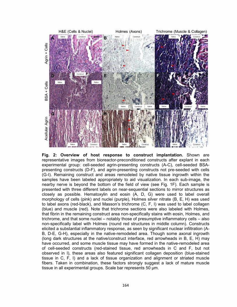
164
Fig. 2: Overview of host response to construct implantation. Shown are representative images from bioreactor-preconditioned constructs after explant in each experimental group: cell-seeded agrin-presenting constructs (A-C), cell-seeded BSA-presenting constructs (D-F), and agrin-presenting constructs not pre-seeded with cells (G-I). Remaining construct and areas remodeled by native tissue ingrowth within the samples have been labeled appropriately to aid visualization. In each sub-image, the nearby nerve is beyond the bottom of the field of view (see Fig. 1F). Each sample is presented with three different labels on near-sequential sections to mirror structures as closely as possible. Hematoxylin and eosin (A, D, G) were used to label overall morphology of cells (pink) and nuclei (purple), Holmes silver nitrate (B, E, H) was used to label axons (red-black), and Masson’s trichrome (C, F, I) was used to label collagen (blue) and muscle (red). Note that trichrome sections were also labeled with Holmes, that fibrin in the remaining construct area non-specifically stains with eosin, Holmes, and trichrome, and that some nuclei – notably those of presumptive inflammatory cells – also non-specifically label with Holmes (round red structures in middle column). Constructs elicited a substantial inflammatory response, as seen by significant nuclear infiltration (A-B, D-E, G-H), especially in the native-remodeled area. Though some axonal ingrowth (long dark structures at the native/construct interface, red arrowheads in B, E, H) may have occurred, and some muscle tissue may have formed in the native-remodeled area of cell-seeded constructs (red-stained tissue, red arrowheads in C and F, but not observed in I), these areas also featured significant collagen deposition (blue-stained tissue in C, F, I) and a lack of tissue organization and alignment or striated muscle fibers. Taken in combination, these factors strongly suggest a lack of mature muscle tissue in all experimental groups. Scale bar represents 50 μm.
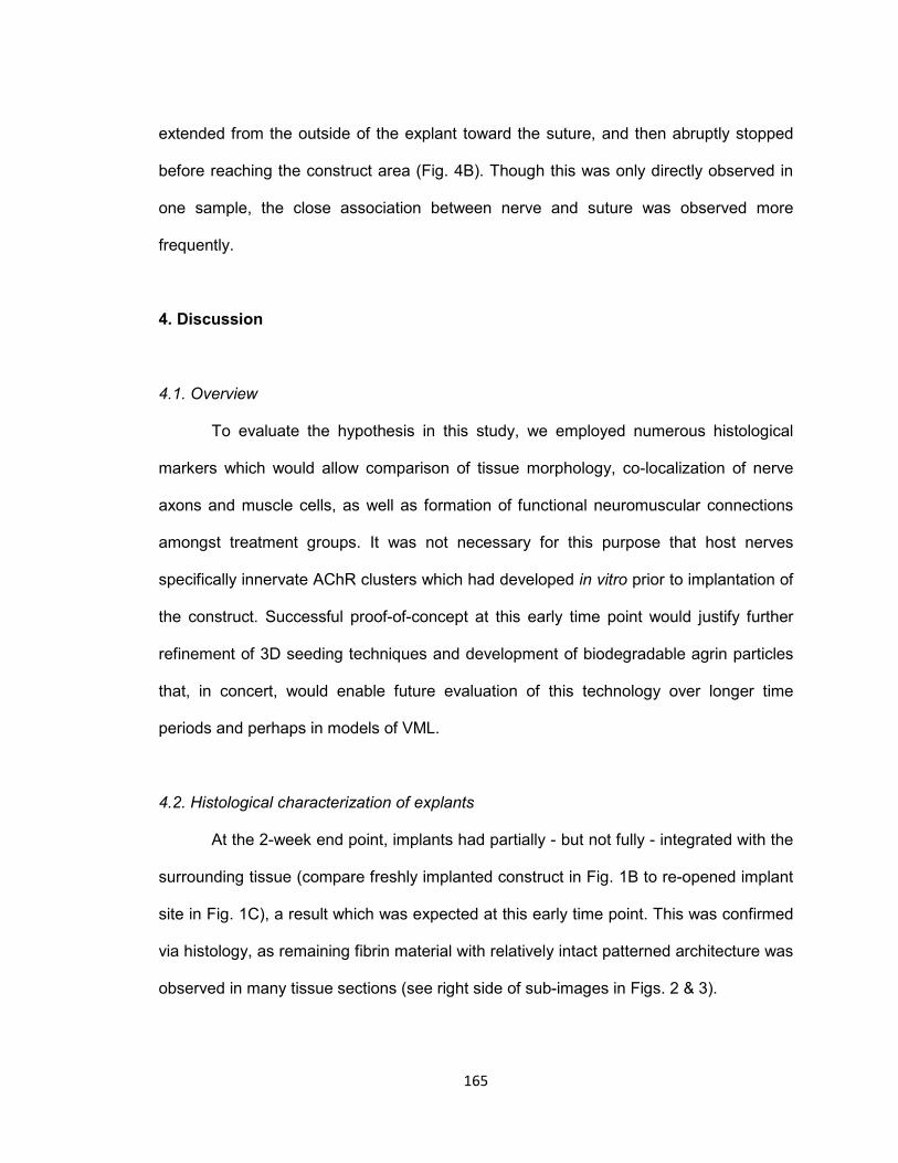
165
extended from the outside of the explant toward the suture, and then abruptly stopped
before reaching the construct area (Fig. 4B). Though this was only directly observed in
one sample, the close association between nerve and suture was observed more
frequently.
4. Discussion
4.1. Overview
To evaluate the hypothesis in this study, we employed numerous histological
markers which would allow comparison of tissue morphology, co-localization of nerve
axons and muscle cells, as well as formation of functional neuromuscular connections
amongst treatment groups. It was not necessary for this purpose that host nerves
specifically innervate AChR clusters which had developed in vitro prior to implantation of
the construct. Successful proof-of-concept at this early time point would justify further
refinement of 3D seeding techniques and development of biodegradable agrin particles
that, in concert, would enable future evaluation of this technology over longer time
periods and perhaps in models of VML.
4.2. Histological characterization of explants
At the 2-week end point, implants had partially - but not fully - integrated with the
surrounding tissue (compare freshly implanted construct in Fig. 1B to re-opened implant
site in Fig. 1C), a result which was expected at this early time point. This was confirmed
via histology, as remaining fibrin material with relatively intact patterned architecture was
observed in many tissue sections (see right side of sub-images in Figs. 2 & 3).
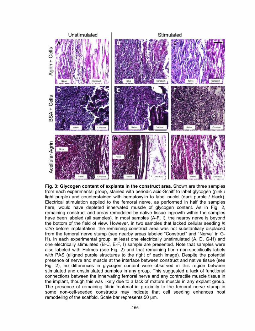
166
Fig. 3: Glycogen content of explants in the construct area. Shown are three samples from each experimental group, stained with periodic acid-Schiff to label glycogen (pink / light purple) and counterstained with hematoxylin to label nuclei (dark purple / black). Electrical stimulation applied to the femoral nerve, as performed in half the samples here, would have depleted innervated muscle of glycogen content. As in Fig. 2, remaining construct and areas remodeled by native tissue ingrowth within the samples have been labeled (all samples). In most samples (A-F, I), the nearby nerve is beyond the bottom of the field of view. However, in two samples that lacked cellular seeding in vitro before implantation, the remaining construct area was not substantially displaced from the femoral nerve stump (see nearby areas labeled “Construct” and “Nerve” in G-H). In each experimental group, at least one electrically unstimulated (A, D, G-H) and one electrically stimulated (B-C, E-F, I) sample are presented. Note that samples were also labeled with Holmes (see Fig. 2) and that remaining fibrin non-specifically labels with PAS (aligned purple structures to the right of each image). Despite the potential presence of nerve and muscle at the interface between construct and native tissue (see Fig. 2), no differences in glycogen content were observed in this region between stimulated and unstimulated samples in any group. This suggested a lack of functional connections between the innervating femoral nerve and any contractile muscle tissue in the implant, though this was likely due to a lack of mature muscle in any explant group. The presence of remaining fibrin material in proximity to the femoral nerve stump in some non-cell-seeded constructs may indicate that cell seeding enhances host remodeling of the scaffold. Scale bar represents 50 μm.
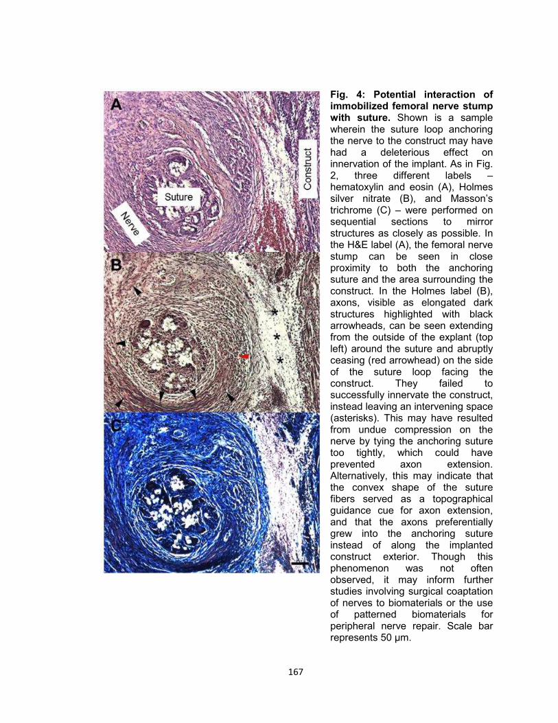
167
Fig. 4: Potential interaction of immobilized femoral nerve stump with suture. Shown is a sample wherein the suture loop anchoring the nerve to the construct may have had a deleterious effect on innervation of the implant. As in Fig. 2, three different labels – hematoxylin and eosin (A), Holmes silver nitrate (B), and Masson’s trichrome (C) – were performed on sequential sections to mirror structures as closely as possible. In the H&E label (A), the femoral nerve stump can be seen in close proximity to both the anchoring suture and the area surrounding the construct. In the Holmes label (B), axons, visible as elongated dark structures highlighted with black arrowheads, can be seen extending from the outside of the explant (top left) around the suture and abruptly ceasing (red arrowhead) on the side of the suture loop facing the construct. They failed to successfully innervate the construct, instead leaving an intervening space (asterisks). This may have resulted from undue compression on the nerve by tying the anchoring suture too tightly, which could have prevented axon extension. Alternatively, this may indicate that the convex shape of the suture fibers served as a topographical guidance cue for axon extension, and that the axons preferentially grew into the anchoring suture instead of along the implanted construct exterior. Though this phenomenon was not often observed, it may inform further studies involving surgical coaptation of nerves to biomaterials or the use of patterned biomaterials for peripheral nerve repair. Scale bar represents 50 μm.
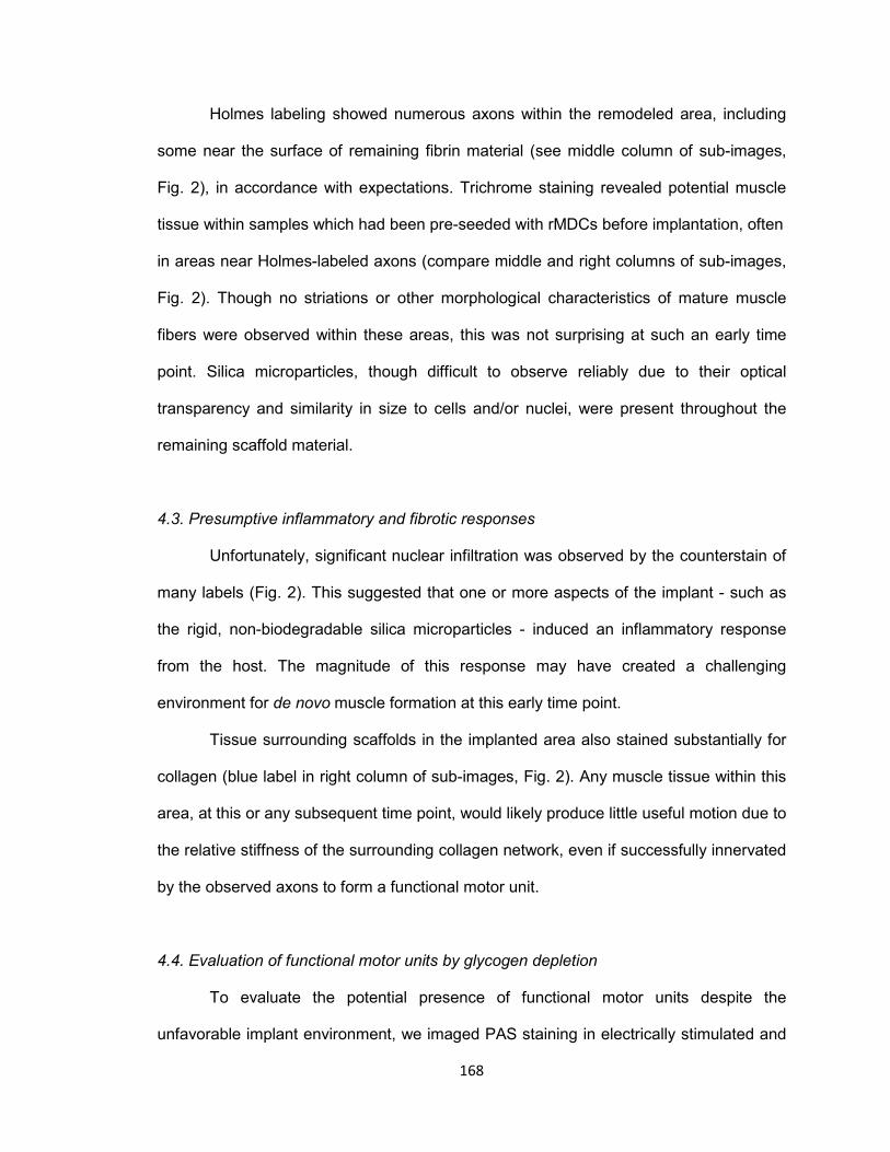
168
Holmes labeling showed numerous axons within the remodeled area, including
some near the surface of remaining fibrin material (see middle column of sub-images,
Fig. 2), in accordance with expectations. Trichrome staining revealed potential muscle
tissue within samples which had been pre-seeded with rMDCs before implantation, often
in areas near Holmes-labeled axons (compare middle and right columns of sub-images,
Fig. 2). Though no striations or other morphological characteristics of mature muscle
fibers were observed within these areas, this was not surprising at such an early time
point. Silica microparticles, though difficult to observe reliably due to their optical
transparency and similarity in size to cells and/or nuclei, were present throughout the
remaining scaffold material.
4.3. Presumptive inflammatory and fibrotic responses
Unfortunately, significant nuclear infiltration was observed by the counterstain of
many labels (Fig. 2). This suggested that one or more aspects of the implant - such as
the rigid, non-biodegradable silica microparticles - induced an inflammatory response
from the host. The magnitude of this response may have created a challenging
environment for de novo muscle formation at this early time point.
Tissue surrounding scaffolds in the implanted area also stained substantially for
collagen (blue label in right column of sub-images, Fig. 2). Any muscle tissue within this
area, at this or any subsequent time point, would likely produce little useful motion due to
the relative stiffness of the surrounding collagen network, even if successfully innervated
by the observed axons to form a functional motor unit.
4.4. Evaluation of functional motor units by glycogen depletion
To evaluate the potential presence of functional motor units despite the
unfavorable implant environment, we imaged PAS staining in electrically stimulated and
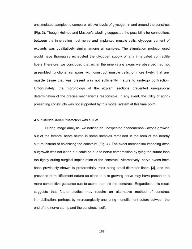
169
unstimulated samples to compare relative levels of glycogen in and around the construct
(Fig. 3). Though Holmes and Masson's labeling suggested the possibility for connections
between the innervating host nerve and implanted muscle cells, glycogen content of
explants was qualitatively similar among all samples. The stimulation protocol used
would have thoroughly exhausted the glycogen supply of any innervated contractile
fibers.Therefore, we concluded that either the innervating axons we observed had not
assembled functional synapses with construct muscle cells, or more likely, that any
muscle tissue that was present was not sufficiently mature to undergo contraction.
Unfortunately, the morphology of the explant sections prevented unequivocal
determination of the precise mechanisms responsible. In any event, the utility of agrin-
presenting constructs was not supported by this model system at this time point.
4.5. Potential nerve interaction with suture
During image analysis, we noticed an unexpected phenomenon - axons growing
out of the femoral nerve stump in some samples remained in the area of the nearby
suture instead of colonizing the construct (Fig. 4). The exact mechanism impeding axon
outgrowth was not clear, but could be due to nerve compression by tying the suture loop
too tightly during surgical implantation of the construct. Alternatively, nerve axons have
been previously shown to preferentially track along small-diameter fibers [3], and the
presence of multifilament suture so close to a re-growing nerve may have presented a
more competitive guidance cue to axons than did the construct. Regardless, this result
suggests that future studies may require an alternative method of construct
immobilization, perhaps by microsurgically anchoring monofilament suture between the
end of the nerve stump and the construct itself.

170
4.6. Fate of construct AChR clusters formed prior to implantation, evaluation of
hypothesis, and prospectives
In light of the observed histological characteristics and lack of functional
innervation - i.e., the lack of detectable differences in PAS staining between samples
receiving nerve stimulation in vivo and those that did not - the presence of significant
AChR clusters within the explants seemed improbable and was not examined herein. As
such, the maintenance in vivo post-implantation of the intricately clustered AChR
structures observed in vitro (see Chapter III, Fig. 3 & 4) remains to be determined.
Ultimately, pre-seeding of scaffolds with cells prior to bioreactor preconditioning was
shown to be important by the presence of muscle tissue in cellularized constructs (Fig.
2C & 2F), but not in acellular controls (Fig. 2I). Conversely, no differences were
observed between scaffolds fabricated with agrin-presenting microparticles (Fig. 2A-2C)
and those with control BSA-presenting particles (Fig. 2D-2F). Results, then, only partially
supported our original hypothesis – namely, that exogenous agrin presentation could
enhance either NMJs or ectopic muscle resulting from host remodeling of the implanted
tissue engineered muscle construct.
Despite the challenges ahead, these valuable preliminary data do indicate that
future pursuit of this promising technology may require strategies to reduce inflammation
likely resulting from non-degradable silica microparticles. Analysis of later time points
would also be informative regarding the duration and magnitude of the inflammatory
response to the implants fabricated using these methods. Such future studies might
utilize treatments of the fibrin biomaterial and / or development of less rigid,
biodegradable agrin-delivering microparticles designed to reduce immunogenicity of the
combined biomaterial, and thus, promote more functional remodeling of the implanted
construct.
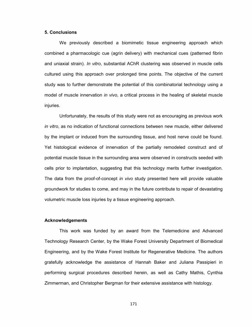
171
5. Conclusions
We previously described a biomimetic tissue engineering approach which
combined a pharmacologic cue (agrin delivery) with mechanical cues (patterned fibrin
and uniaxial strain). In vitro, substantial AChR clustering was observed in muscle cells
cultured using this approach over prolonged time points. The objective of the current
study was to further demonstrate the potential of this combinatorial technology using a
model of muscle innervation in vivo, a critical process in the healing of skeletal muscle
injuries.
Unfortunately, the results of this study were not as encouraging as previous work
in vitro, as no indication of functional connections between new muscle, either delivered
by the implant or induced from the surrounding tissue, and host nerve could be found.
Yet histological evidence of innervation of the partially remodeled construct and of
potential muscle tissue in the surrounding area were observed in constructs seeded with
cells prior to implantation, suggesting that this technology merits further investigation.
The data from the proof-of-concept in vivo study presented here will provide valuable
groundwork for studies to come, and may in the future contribute to repair of devastating
volumetric muscle loss injuries by a tissue engineering approach.
Acknowledgements
This work was funded by an award from the Telemedicine and Advanced
Technology Research Center, by the Wake Forest University Department of Biomedical
Engineering, and by the Wake Forest Institute for Regenerative Medicine. The authors
gratefully acknowledge the assistance of Hannah Baker and Juliana Passipieri in
performing surgical procedures described herein, as well as Cathy Mathis, Cynthia
Zimmerman, and Christopher Bergman for their extensive assistance with histology.
172
References [1] Dhawan V, Lytle IF, Dow DE, Huang Y-C, Brown DL. Neurotization Improves
Contractile Forces of Tissue-Engineered Skeletal Muscle. Tissue Eng 2007;13:2813–21. doi:10.1089/ten.2007.0003.
[2] Górski J, Krawczuk I, Górska M, Rutkiewicz J. Inhibition of glycogenesis in rat
muscles partially depleted of glycogen. Am J Physiol 1991;261:C305–9. [3] Wen X, Tresco PA. Effect of filament diameter and extracellular matrix molecule
precoating on neurite outgrowth and Schwann cell behavior on multifilament entubulation bridging device in vitro. J Biomed Mater Res A 2006;76A:626–37. doi:10.1002/jbm.a.30520.

173
CHAPTER VI
DISCUSSION, CONCLUSIONS, AND FUTURE DIRECTIONS
John B. Scott

174
1. Summary of doctoral dissertation
In summary, in this work we have described a skeletal muscle tissue engineering
approach combining a structural fibrin biomaterial and seeded isogeneic cells with
physical (porous patterning), chemical (neural agrin), and mechanical (cyclic stretch)
cues for the eventual application to repair of volumetric muscle loss injuries.
In Chapter II, we demonstrated that the scaffold featured stiffness of 100-320
kPa, similar to the 79-126 kPa reported for native skeletal muscle [1]. Further, the
scaffold supported ingrowth of axons at a rate of 600-900 μm / day, which was
comparable to clinical expectations of reinnervation at 1 mm / day [2] despite the lack of
specific chemical or cellular trophic support in the scaffold.
In Chapters III & IV, we found using a 2D model in vitro that linkage of agrin to
microparticle surfaces enabled pharmacological signaling to be incorporated into fibrin
scaffolds. Acetylcholine receptor (AChR) clustering, the outcome measure for these
studies, was observed after 1 week or more when agrin was covalently coupled to
microcarriers. Further experimentation using a 3D model in vitro indicated that AChR
clustering may be enhanced by a synergistic effect of agrin and mechanical stretch. In
addition, we described a perfusion method which was capable of uniformly seeding
small (4.5 mm diameter x 4 mm long) 3D scaffolds with cells in densities up to 30 million
cells / cm3.
In Chapter V, we found that tissue engineered muscle repair constructs
implanted in vivo for 2 weeks were partially remodeled by the host environment. These
constructs may have supported innervation by host axons, as predicted by results from
Chapter II, and formation of new muscle tissue, as predicted by those from Chapter III.
As stated in Chapter I, the central hypothesis of this dissertation was that
biomimetic cues could be leveraged to create a tissue engineered construct in vitro that
would accelerate skeletal muscle tissue formation and function following implantation in
175
vivo, and furthermore, maintain the skeletal muscle phenotype in vivo during
reinnervation of VML injuries. The observations summarized above provided substantial
support for some aspects of this hypothesis. Chief among these aspects was that AChR
clusters, the observable marker which defined the specified skeletal muscle phenotype,
were observed in vitro within the context of an implantable, 3D, biomimetic tissue
engineered construct. However, other aspects of the hypothesis could not be tested by
results described here due to technical challenges related to creating larger, more
robustly cell-seeded 3D scaffolds, and must be revised or investigated further. These
aspects, and potential avenues for future investigation, are discussed below.
2. Key limitations of the described work and resulting future directions
2.1. Biodegradable agrin microcarriers
Though the results described herein represent a significant proof-of-concept of
the envisioned skeletal muscle tissue engineering strategy, this approach is not without
limitations. The first is that the desired muscle phenotype was evaluated in vitro solely
using histochemical markers for AChR localization. The advantage of the α-bungarotoxin
label, and therefore the reason it was selected as the primary outcome measure in these
studies, is that it provides data on both the presence and, critically, location of AChRs.
Establishing the presence of AChR clustering in the vicinity of agrin-presenting
microparticles was a key aspect of the development of this technology. However, the
physiological relevance of these AChR clusters - specifically for skeletal muscle function
as stated in the central hypothesis - was not established by this dissertation. This was
primarily due to the inflammatory response elicited by constructs implanted in vivo as
discussed in Chapter V.
176
As fibrin has been employed by prior skeletal muscle tissue engineering
strategies in vivo [3–5], it is likely that the non-degradable SiO2 microparticles were
responsible for a large portion of the inflammation seen in Chapter V. Ideally, these
microparticles could be replaced by analogs which would degrade at a similar rate to
that of new tissue formation, thereby minimizing the elicited foreign body response
(FBR) [6,7]. As native innervation would obviate the need for exogenous agrin
presentation, the rate of microparticle degradation should also be correlated, if possible,
to innervation of the construct.
2.2. Acetylcholine release from microparticles
Moreover, degradable pharmacologic microparticles would eventually need to be
multi-functional. In normal physiology, acetylcholine (ACh) is believed to cause cell-wide
destabilization of AChR clusters, an effect which is offset at the synapse by the
presentation of agrin [8]. This results in further phenotypic maturity, as it prevents the
muscle from being stimulated to contract by an ectopic AChR cluster.
In Chapter III, AChR clusters apposing covalently-bound agrin microcarriers were
often larger than, and somewhat diffusely located around, areas of cell-particle contact.
Release of soluble ACh from an interior depot within agrin-presenting microparticles
could encourage remodeling of the AChR clusters within the construct in biomimetic
fashion. Nominally, this would maintain the appropriate physiological status of the
implanted and regenerating muscle until native re-innervation could occur.
Combining this ACh release with agrin presentation by a degradable microcarrier
would require a microparticle with very specific properties. As the presented agrin would
preferentially be immobilized on the microparticle surface rather than released as a
soluble signal, the exterior of the microparticle would ideally be the last component to
degrade. Simultaneously, release of soluble ACh would be most straightforward to
177
accomplish by diffusion out of an interior depot, which could be extended over a longer
time period if the outer layer of the microparticle served as a diffusion barrier.
Therefore, one potential embodiment of the microparticle would consist of a
faster-degrading polymer core containing ACh molecules surrounded by a slower-
degrading outer polymer shell with covalently-bound surface agrin. Alternatively, if the
degradation products of the core were found not to diffuse out through the shell
alongside the ACh, a composite microparticle could be designed. This would feature a
number of small-diameter, slowly-degrading microparticles with covalently-bound agrin
embedded within a faster-degrading bulk polymer containing diffusible ACh to form a
larger microparticle. Either of these strategies could immobilize an insoluble agrin signal
in one location (analogous to an immobile nerve terminal in vivo) while slowly releasing
ACh, all in the context of a degradable microparticle.
2.3. Modulation of fibrin degradation
Though evaluated at an early time point, the in vivo experiment herein (Chapter
V) was noteworthy in that it was our first significant use of a fibrin scaffold in an animal
model. Though fibrin is a common substrate for muscle tissue engineering, it is
commonly polymerized from fibrinogen solutions of much lower concentration than that
used in the studies discussed here [3,5,9–13]. The host response to implanted
constructs is therefore difficult to predict, even if incorporating degradable microparticles.
Further study on fibrin degradation dynamics in vivo may be required to completely
minimize the FBR. Fortunately, fibrin degradation can be accelerated by decreasing the
component fibrinogen concentration or delayed by chemically crosslinking the network
after gel formation, such as by treatment with genipin [10].
In short, mitigation of the FBR is the logical next step in the development of this
tissue engineering platform. Further characterization or optimization of constructs in vitro
178
could be wasted if it is later found that agrin-presenting fibrin elicits unavoidable
inflammation in vivo.
2.4. Functional characterization of tissue engineered muscle repair constructs
As stated above, skeletal muscle function following implantation in vivo
could not be evaluated. However, assuming a mild host response to the implanted
construct, one method of evaluating function is by measurement of force generated by
the construct in response to a contractile stimulus. We have extensively measured force
in response to electrical stimuli [14–16], an outcome measure which is applicable not
only to tissue explants but also to constructs generated in vitro prior to implantation.
Single-cell electrophysiology and / or calcium imaging also represent methods
which could be used to evaluate function. In this case, function refers to development of
excitation-contraction coupling, which can be evaluated even if the contractile apparatus
has not yet matured. However, these are more technically challenging than force
measurement in the context of a fibrin biomaterial because cells to be measured or
imaged must be located within the relative opacity of the fibrin scaffold.
2.5. Physical patterning for modulation of cell behavior
As noted in Chapter I, aligned physical cues have been demonstrated -
primarily in 2D culture in vitro - to encourage maturation of skeletal muscle cells [17–19].
The fibrin scaffold in the current study was designed to take advantage of this
phenomenon, incorporating an array of aligned parallel conduits that additionally
provided porosity for cell seeding. In Chapter IV, we did observe that 3D scaffolds
supported the static seeding and infiltration of C2C12 cells over 8 days of culture, and
that these cells morphologically elongated in the direction of the pores. However, to truly
comment on the potential effects of aligned pores would require:
179
1) A control pattern of similar porosity with cues of a different size or shape, such as
the random interconnected pore network in control scaffolds described in Chapter
I; and
2) A method of uniformly and repeatably seeding relevant cells within the pore
networks.
Flow perfusion of rat muscle derived cells (rMDCs), as described in Chapter IV,
filled the second requirement in 4.5 mm diameter x 4 mm long scaffolds. Though these
seeded constructs were too short for bioreactor preconditioning, they would be
sufficiently long for evaluation of physcial cues. Unfortunately, rMDCs which were initially
densely seeded in 3D by perfusion declined in number over 3 days of subsequent
culture. This was presumably due to mass transport limitations and resulting cell
necrosis within statically-cultured constructs.
However, future studies could overcome these limitations. For example, several
approaches to overcome mass transport limitations within other tissue engineering
strategies have been described in the literature. These include incorporation of oxygen-
generating materials [20,21], in vitro perfusion of culture medium after cell seeding of
constructs [22,23], and prevascularization of constructs before implantation in vivo [3].
Alternatively, or in parallel, enabling the robust perfusion seeding of scaffolds 15
mm or more in length would allow truly 3D-seeded scaffolds to be mechanically
preconditioned in the cyclic stretch bioreactor. We hypothesize that preconditioning itself
could enhance cell survival, either by the convection of culture medium through the
construct during actuation or by phenotypic modulation of the cells in question. Robust
3D seeding would also allow more conclusive determination of phenomena observed
herein using the surface-seeded proof of concept model.

180
3. Conclusion
In conclusion, this dissertation has described a significant proof-of-concept in this
biomimetic skeletal muscle tissue engineering approach. This concept holds great
potential, and numerous avenues exist for future development either in series or parallel.
It is our hope that the advances described herein one day enhance clinical treatment of
currently devastating and intractable volumetric muscle loss injuries.
References [1] Levinson SF, Shinagawa M, Sato T. Sonoelastic determination of human skeletal
muscle elasticity. J Biomech 1995;28:1145–54. doi:10.1016/0021-9290(94)00173-2.
[2] Gordon T, Brushart TM, Chan KM. Augmenting nerve regeneration with electrical
stimulation. Neurol Res 2008;30:1012–22. doi:10.1179/174313208X362488. [3] Bach AD, Arkudas A, Tjiawi J, Polykandriotis E, Kneser U, Horch RE, et al. A new
approach to tissue engineering of vascularized skeletal muscle. J Cell Mol Med 2006;10:716–26.
[4] Dhawan V, Lytle IF, Dow DE, Huang Y-C, Brown DL. Neurotization Improves
Contractile Forces of Tissue-Engineered Skeletal Muscle. Tissue Eng 2007;13:2813–21. doi:10.1089/ten.2007.0003.
[5] Ko IK, Lee B-K, Lee SJ, Andersson K-E, Atala A, Yoo JJ. The effect of in vitro
formation of acetylcholine receptor (AChR) clusters in engineered muscle fibers on subsequent innervation of constructs in vivo. Biomaterials 2013;34:3246–55. doi:10.1016/j.biomaterials.2013.01.029.
[6] Cezar CA, Mooney DJ. Biomaterial-based delivery for skeletal muscle repair. Adv
Drug Deliv Rev 2014. doi:10.1016/j.addr.2014.09.008. [7] Wolf MT, Dearth CL, Sonnenberg SB, Loboa EG, Badylak SF. Naturally derived
and synthetic scaffolds for skeletal muscle reconstruction. Adv Drug Deliv Rev 2014. doi:10.1016/j.addr.2014.08.011.
[8] Witzemann V. Development of the neuromuscular junction. Cell Tissue Res
2006;326:263–71. doi:10.1007/s00441-006-0237-x. [9] Bian W, Bursac N. Engineered skeletal muscle tissue networks with controllable
architecture. Biomaterials 2009;30:1401–12. doi:10.1016/j.biomaterials.2008.11.015.
181
[10] Khodabukus A, Baar K. Regulating Fibrinolysis to Engineer Skeletal Muscle from the C2C12 Cell Line. Tissue Eng Part C Methods 2009;15:501–11. doi:10.1089/ten.tec.2008.0286.
[11] Page RL, Malcuit C, Vilner L, Vojtic I, Shaw S, Hedblom E, et al. Restoration of
Skeletal Muscle Defects with Adult Human Cells Delivered on Fibrin Microthreads. Tissue Eng Part A 2011;17:2629–40. doi:10.1089/ten.tea.2011.0024.
[12] Martin NRW, Passey SL, Player DJ, Khodabukus A, Ferguson RA, Sharples AP,
et al. Factors affecting the structure and maturation of human tissue engineered skeletal muscle. Biomaterials 2013;34:5759–65. doi:10.1016/j.biomaterials.2013.04.002.
[13] Hinds S, Bian W, Dennis RG, Bursac N. The role of extracellular matrix
composition in structure and function of bioengineered skeletal muscle. Biomaterials 2011;32:3575–83. doi:10.1016/j.biomaterials.2011.01.062.
[14] Moon DG, Christ G, Stitzel JD, Atala A, Yoo JJ. Cyclic Mechanical
Preconditioning Improves Engineered Muscle Contraction. Tissue Eng Part A 2008;14:473–82. doi:10.1089/tea.2007.0104.
[15] Machingal MA, Corona BT, Walters TJ, Kesireddy V, Koval CN, Dannahower A,
et al. A tissue-engineered muscle repair construct for functional restoration of an irrecoverable muscle injury in a murine model. Tissue Eng Part A 2011;17:2291–303. doi:10.1089/ten.TEA.2010.0682.
[16] Corona BT, Machingal MA, Criswell T, Vadhavkar M, Dannahower AC, Bergman
C, et al. Further development of a tissue engineered muscle repair construct in vitro for enhanced functional recovery following implantation in vivo in a murine model of volumetric muscle loss injury. Tissue Eng Part A 2012;18:1213–28. doi:10.1089/ten.TEA.2011.0614.
[17] Monge C, Ren K, Berton K, Guillot R, Peyrade D, Picart C. Engineering Muscle
Tissues on Microstructured Polyelectrolyte Multilayer Films. Tissue Eng Part A 2012;18:1664–76. doi:10.1089/ten.tea.2012.0079.
[18] Wang P-Y, Thissen H, Tsai W-B. The roles of RGD and grooved topography in
the adhesion, morphology, and differentiation of C2C12 skeletal myoblasts. Biotechnol Bioeng 2012;109:2104–15. doi:10.1002/bit.24452.
[19] Chen M-C, Sun Y-C, Chen Y-H. Electrically conductive nanofibers with highly
oriented structures and their potential application in skeletal muscle tissue engineering. Acta Biomater 2013;9:5562–72. doi:10.1016/j.actbio.2012.10.024.
[20] Oh SH, Ward CL, Atala A, Yoo JJ, Harrison BS. Oxygen generating scaffolds for
enhancing engineered tissue survival. Biomaterials 2009;30:757–62. doi:10.1016/j.biomaterials.2008.09.065.
[21] Ward CL, Corona BT, Yoo JJ, Harrison BS, Christ GJ. Oxygen generating
biomaterials preserve skeletal muscle homeostasis under hypoxic and ischemic conditions. PloS One 2013;8:e72485. doi:10.1371/journal.pone.0072485.
182
[22] Goldstein AS, Juarez TM, Helmke CD, Gustin MC, Mikos AG. Effect of
convection on osteoblastic cell growth and function in biodegradable polymer foam scaffolds. Biomaterials 2001;22:1279–88.
[23] Muscari C, Giordano E, Bonafè F, Govoni M, Guarnieri C. Strategies affording
prevascularized cell-based constructs for myocardial tissue engineering. Stem Cells Int 2014;2014:434169. doi:10.1155/2014/434169.

183
CURRICULUM VITAE
JOHN BRADFORD SCOTT, B.S. Ph.D. Candidate
Virginia Tech – Wake Forest University School of Biomedical Engineering and Sciences Wake Forest Institute for Regenerative Medicine
EDUCATION Ph.D. Wake Forest University, Winston-Salem, NC
Biomedical Engineering 2008-Current
B.S. The University of Tennessee, Knoxville, TN
Biomedical Engineering Summa Cum Laude, with Honors 2004-2008
RESEARCH EXPERIENCE 2008-2015 Wake Forest Institute for Regenerative Medicine, Winston-Salem, NC
Graduate Research Associate, George J. Christ Laboratory (2011-2015) and Justin M. Saul Laboratory (2008-2011) • Directed $350,000 US Army-funded project aimed at healing
devastating, intractable muscle injuries. • Designed experiments by synthesizing literature findings and personal
expertise. • Developed material constructs incorporating biomimetic patterning,
drug delivery, and mechanical cues. 2007 The University of Tennessee REU Program, Knoxville, TN Undergraduate Researcher, Anthony E. English Laboratory
• Quantified effects of potential anti-cancer drugs. • Validated drug success using wavelet theory.
PEER-REVIEWED PUBLICATIONS 1. Scott JB, Ward CW, Corona BT, Deschenes MR, Harrison BS, Saul JM, Christ GJ. In
vitro development of a novel tissue engineered muscle repair construct. 2015. In preparation.
2. Scott JB, Afshari M, Kotek R, Saul JM. The promotion of axon extension in vitro using polymer-templated fibrin scaffolds. Biomaterials. 2011 Jul;32(21):4830-9.

184
PRESENTATIONS AND REPORTS TO RESEARCH SPONSORS
1. "Novel Methods for Enhanced Formation and Stabilization of Motor Endplates in Tissue Engineered Skeletal Muscle," Final Status Report; prepared by John B. Scott and George J. Christ, PhD (PI); December 2014
2. "Novel Methods for Enhanced Formation and Stabilization of Motor Endplates in Tissue Engineered Skeletal Muscle," Quarter 7 Status Report; prepared by John B. Scott and George J. Christ, PhD (PI); July 2014
3. "Novel Methods for Enhanced Formation and Stabilization of Motor Endplates in Tissue Engineered Skeletal Muscle," Quarter 6 Status Report; prepared by John B. Scott and George J. Christ, PhD (PI); April 2014
4. “Development of a Novel Tissue Engineered Muscle Repair Construct with Potential for Enhanced Motor End Plate Formation and Function” (poster), John B. Scott, Catherine L. Ward, Benjamin T. Corona, Benjamin S. Harrison, Justin M. Saul, and George J. Christ, WFIRM Annual Retreat, February 10, 2014
5. "Novel Methods for Enhanced Formation and Stabilization of Motor Endplates in Tissue Engineered Skeletal Muscle," Quarter 5 Status Report; prepared by John B. Scott and George J. Christ, PhD (PI); January 2014
6. “Development of a Novel Tissue Engineered Muscle Repair Construct with Potential for Enhanced Motor End Plate Formation and Function” (poster), John B. Scott, Catherine L. Ward, Benjamin T. Corona, Benjamin S. Harrison, Justin M. Saul, and George J. Christ, NCTERMS Annual Meeting, October 28, 2013
7. "Novel Methods for Enhanced Formation and Stabilization of Motor Endplates in Tissue Engineered Skeletal Muscle," Annual Status Report; prepared by John B. Scott and George J. Christ, PhD (PI); October 2013
8. "Novel Methods for Enhanced Formation and Stabilization of Motor Endplates in Tissue Engineered Skeletal Muscle," Quarter 3 Status Report; prepared by John B. Scott and George J. Christ, PhD (PI); July 2013
9. “Development of a Novel Tissue Engineered Muscle Repair Construct with Potential for Enhanced Motor End Plate Formation and Function” (poster), John B. Scott, Catherine L. Ward, Benjamin T. Corona, Benjamin S. Harrison, Justin M. Saul, and George J. Christ, SBES Student Research Symposium, May 16, 2013
10. "Novel Methods for Enhanced Formation and Stabilization of Motor Endplates in Tissue Engineered Skeletal Muscle," Quarter 2 Status Report; prepared by John B. Scott and George J. Christ, PhD (PI); April 2013
11. “Development of a Novel Tissue Engineered Muscle Repair Construct with Potential for Enhanced Motor End Plate Formation and Function" (podium), John B. Scott, Catherine L. Ward, Benjamin T. Corona, Benjamin S. Harrison, Justin M. Saul, and George J. Christ, Monthly Meeting Winston-Salem IEEE Chapter, April 10, 2013
12. “Development of a Novel Tissue Engineered Muscle Repair Construct with Potential for Enhanced Motor End Plate Formation and Function” (poster), John B. Scott, Catherine L. Ward, Benjamin T. Corona, Benjamin S. Harrison, Justin M. Saul, and George J. Christ, WFU Graduate Student Research Day, March 21, 2013
13. “Development of a Novel Tissue Engineered Muscle Repair Construct with Potential for Enhanced Motor End Plate Formation and Function” (poster), John B. Scott, Catherine L. Ward, Benjamin T. Corona, Benjamin S. Harrison, Justin M. Saul, and George J. Christ, WFIRM Annual Retreat, March 19, 2013
185
14. "Novel Methods for Enhanced Formation and Stabilization of Motor Endplates in Tissue Engineered Skeletal Muscle," Quarter 1 Status Report; prepared by John B. Scott and George J. Christ, PhD (PI); January 2013
15. “Development of a Novel Tissue Engineered Muscle Repair Construct with Potential for Enhanced Motor End Plate Formation and Function" (poster), John B. Scott, Catherine L. Ward, Benjamin T. Corona, Benjamin S. Harrison, Justin M. Saul, and George J. Christ, BMES Annual Meeting, October 2012
16. “Development of a Novel Tissue Engineered Muscle Repair Construct with Potential for Enhanced Motor End Plate Formation and Function" (poster), John B. Scott, Catherine L. Ward, Benjamin T. Corona, Benjamin S. Harrison, Justin M. Saul, and George J. Christ, BMES Annual Meeting, September 2012
17. “Development of a Novel Tissue Engineered Muscle Repair Construct with Potential for Enhanced Motor End Plate Formation and Function” (poster), John B. Scott, Justin M. Saul, and George J. Christ, NCTERMS Annual Meeting, September 10, 2012
18. “Development of a Novel Tissue Engineered Muscle Repair Construct with Potential for Enhanced Motor End Plate Formation and Function” (poster), John B. Scott, Justin M. Saul, and George J. Christ, SBES Student Research Symposium, May 10, 2012
19. “Development of a Novel Tissue Engineered Muscle Repair Construct with Potential for Enhanced Motor End Plate Formation and Function” (poster), John B. Scott, Justin M. Saul, and George J. Christ, WFIRM Annual Retreat, March 5, 2012
20. “Development of a Novel Tissue Engineered Muscle Repair Construct with Potential for Enhanced Motor End Plate Formation and Function In Vitro and In Vivo” (podium), John B. Scott, Justin M. Saul, and George J. Christ, TERMIS – North America Annual Meeting, December 13, 2011
21. “Development of a Novel Tissue Engineered Muscle Repair Construct with Potential for Enhanced Motor End Plate Formation and Function In Vitro and In Vivo” (poster), John B. Scott, Justin M. Saul, and George J. Christ, NCTERMS Annual Meeting, November 4, 2011
22. “Intraluminal Nerve Scaffolds Promote Axon Extension In Vitro” (poster), John B. Scott and Justin M. Saul, SBES Student Research Symposium, May 12, 2011
23. “Intraluminal Nerve Scaffolds Promote Axon Extension In Vitro” (poster), John B. Scott and Justin M. Saul, WFU Graduate Student Research Day, March 22, 2011
24. “Polymer-templated fibrin scaffolds promote axon extension in vitro” (podium), John B. Scott and Justin M. Saul, WFIRM Annual Retreat, March 7, 2011
25. “Intraluminal Nerve Scaffolds Promote Axon Extension In Vitro” (poster), John B. Scott and Justin M. Saul, WFIRM Annual Retreat, March 7, 2011
26. “Intraluminal Nerve Scaffolds Promote Axon Extension In Vitro” (poster), John B. Scott and Justin M. Saul, TERMIS – North America Annual Meeting, December 5, 2010
27. “Templated Biomaterial Scaffolds for Directed Neural Regeneration” (podium), John B. Scott and Justin M. Saul, Monthly Meeting Winston-Salem IEEE Chapter, August 11, 2010
28. “Intraluminal Nerve Scaffolds Promote Axon Extension and Cell Infiltration In Vitro” (poster), John B. Scott and Justin M. Saul, SBES Student Research Symposium, May 13, 2010
29. “Intraluminal Nerve Scaffolds Promote Axon Extension and Cell Infiltration In Vitro” (poster), John B. Scott and Justin M. Saul, WFU Graduate Student Research Day, March 23, 2010

186
30. “Intraluminal Nerve Scaffolds Promote Axon Extension and Cell Infiltration In Vitro” (poster), John B. Scott and Justin M. Saul, WFIRM Annual Retreat, March 8, 2010
31. “Templated Biomaterial Scaffolds for Directed Neural Regeneration” (podium), John B. Scott and Justin M. Saul, Monthly Meeting Winston-Salem IEEE Chapter, January 13, 2010
32. “Development of Polymer-Templated Intraluminal Nerve Scaffolds” (poster), John B. Scott and Justin M. Saul, NCTERMS Annual Meeting, November 2009
33. “Development of Polymer-Templated Intraluminal Nerve Scaffolds” (poster), John B. Scott and Justin M. Saul, BMES Annual Meeting, October 7, 2009
34. “Aligned Conduit Scaffolds Direct Neurite Extension In Vitro” (poster), John B. Scott and Justin M. Saul, WFU Graduate Student Research Day, April 6, 2009
35. “Aligned Conduit Scaffolds Direct Neurite Extension In Vitro” (poster), John B. Scott and Justin M. Saul, WFIRM Annual Retreat, March 23, 2009
36. “Development of Axially-Aligned Scaffolds for Optimization of Neural Regeneration” (poster), John B. Scott and Justin M. Saul, NCTERMS Annual Meeting, November 2008
AWARDS
• Outstanding Poster, North Carolina Tissue Engineering and Regenerative Medicine Society Annual Meeting. November 2011
• Best Presentation, Predoctoral Category, Wake Forest Institute for Regenerative Medicine Annual Retreat. March 2011
• Achieved rank of Eagle Scout after participation in Boy Scouts of America since age 5. May 2004
PROFESSIONAL EXPERIENCE 2014-Current Technology Commercialization Intern
Wake Forest Innovations, Winston-Salem, NC
• Interviewed Wake Forest inventors to assess IP protection and marketing potential of disclosed inventions.
• Analyzed geographic markets for solar technology to inform patent nationalization decisions.
• Drafted marketing materials to engage potential licensees for nanomaterials, oncology, and RFID inventions.
• Met with industry partners to discuss technologies and licensing options, both non-confidentially and under CDA.
2006 Reliability Technology Intern Eastman Chemical Company, Kingsport, TN
• Located historically unreliable equipment. • Isolated root causes of recurring malfunctions.

187
PATENT 2012 Application PCT/US2012/057094 “Bioscaffolds for Formation of Motor Endplates”
Co-Inventor ACTIVITIES 2013-2014 First-Ever Breast Cancer Startup Challenge
Member: Wake Forest Team 3
2009-2014 Biomedical Engineering Society Member 2009-2013 Wake Forest Institute for Regenerative Medicine Summer Scholars
Program, Minority Access to Research Careers Program, and Wake Forest University Work-Study Program
Mentor of seven visiting student researchers 2005-2008 Theta Tau Professional Engineering Fraternity, Chi Gamma Chapter
Founding Brother, Scribe, and Author of Colony Bylaws SKILLS Research Design
• Experimental design • Literature review
Technology Commercialization
• Intellectual property protection • Patent technology review • Market analysis • Drafting of non-confidential marketing materials • Legal agreements
Biomaterials Processing and Characterization
• Biomaterial scaffold design • Bioreactor design and operation • Covalent crosslinking • Tensile Testing • Critical point drying • Metallic sputtering • Scanning electron microscopy • Polymer melt extrusion
Cell Culture
• Aseptic technique • Primary cell isolation and expansion

188
Histology
• Immunohistochemistry • Special stains • Confocal microscopy • Fluorescence and brightfield microscopy
In Vivo Experimentation
• Rodent surgeries and explants • Electrophysiological assessment
Other
• Authorship of GLP / GMP compliant standard operating procedures and master batch records
• Microsoft Windows • Microsoft Office • FIJI / ImageJ • GraphPad PRISM
REFERENCES George Christ, Ph.D. Academic Advisor, 2011-Current
Professor, Wake Forest University School of Medicine [email protected] 434-924-5794
Charlie Shaw, Ph.D. Technology Commercialization Internship Mentor, 2014-Current Commercialization Associate, Wake Forest Innovations [email protected] 336-716-3729
Stephen Susalka, Ph.D., CLP Professor, Principles of Intellectual Property Development, 2014 Executive Director, Association of University Technology Managers [email protected] 336-546-7977
Peter Sheldrake, Ph.D. Professor, Commercializing Innovation, 2014 Adjunct Instructor, Wake Forest University School of Business [email protected] 336-705-0735

189
Justin Saul, Ph.D. Academic Advisor, 2008-2011 Associate Professor, Miami University College of Engineering & Computing [email protected] 513-529-0769