culverts, bridges, and storm drains
TRANSCRIPT

CULVERTS, BRIDGES, AND
STORM DRAINS
Walter F. Silva, Ph.D., P.E.
December 8 & 11, 2015
Walter F. Silva Araya, Ph.D., P.E.

Reference
Walter F. Silva Araya, Ph.D., P.E.

BRIDGE VS CULVERT
Culverts are used:
Where bridges are not hydraulically required
Where debris and ice potential are tolerable
Where more economical than a bridge (including guardrail and
safety concerns)
Walter F. Silva Araya, Ph.D., P.E.

BRIDGE VS CULVERT
Bridges are used:
Where culverts are impractical
Where more economical than a culvert
To satisfy land-use and access requirements
To mitigate environmental concerns not satisfied by a culvert
To avoid floodway encroachments
To accommodate ice and large debris
Walter F. Silva Araya, Ph.D., P.E.

BRIDGE VS CULVERT
CONSIDERATIONS
The initial cost for a culvert is usually less than a bridge
Consider possible flood damages associated with increased
headwater
Bridge maintenance is typically more costly
Safety and aesthetic considerations
Culverts exceeding a 20 ft (6.1 m) span width are considered
bridges according to the National Bridge Inspection Standards
(NBIS)
Walter F. Silva Araya, Ph.D., P.E.

BRIDGE VS CULVERT
Walter F. Silva Araya, Ph.D., P.E.

Differences in the hydraulic assumptions
and analyses used for culverts and
bridges.
Culvert
Normal depth analysis
Neglects approaching velocity
and downstream velocity
May overestimate entrance
and exit energy losses
Large culverts with free surface
flow requires GVF analysis
Span of 20 ft (6.1 m) or less
Bridge
Uses Gradually Varied Flow
(GVF)
Accounts for approach and
downstream velocities
Span larger than 20 ft (6.1 m)
Walter F. Silva Araya, Ph.D., P.E.

When does a long culvert begin to
resemble a "short" storm drain system?
Use storm drain analyses and computer programs if:
there are multiple inflow points along the culvert (such as
roadway or median inlets)
Multiple geometric changes (bends, pipe size changes, slope
changes, etc)
Potential changes in flow regime within the barrel
Walter F. Silva Araya, Ph.D., P.E.

CULVERT SHAPES
Walter F. Silva Araya, Ph.D., P.E.

MATERIALS
Concrete (both reinforced and non-reinforced)
Corrugated metal (aluminum or steel)
Plastic: high-density polyethylene (HDPE) or polyvinyl chloride (PVC)
Corrugated Polyethylene (PE)
Walter F. Silva Araya, Ph.D., P.E.

Terminology
WSu
HW
TW
Hl
Energy Losses = Hl
EGL = Energy Grade Line
HGL = Hydraulic Grade Line
HW = Headwater
WSu Upstream Water Surface Elevation
TW = Tailwater

CULVERT ANALYSIS Complicated hydraulic structures
Wide variety of conditions
Flow: gradually Varied, rapidly varied, transient
Flow full (under pressure) or as open channel
Open channels could be Subcritical or supercritical
Hydraulic jumps could occur inside the culvert
Control could be at the inlet or the outlet
Walter F. Silva Araya, Ph.D., P.E.
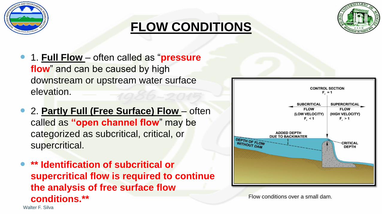
FLOW CONDITIONS
1. Full Flow – often called as “pressure
flow” and can be caused by high
downstream or upstream water surface
elevation.
2. Partly Full (Free Surface) Flow – often
called as “open channel flow” may be
categorized as subcritical, critical, or
supercritical.
** Identification of subcritical or
supercritical flow is required to continue
the analysis of free surface flow
conditions.** Flow conditions over a small dam.
Walter F. Silva Araya, Ph.D., P.E.

CONTROL SECTION
To analyze free surface flow conditions,
a point of known depth and flow must
first be identified.
The place where this condition occurs is
called a CONTROL SECTION
Common control sections are those
where critical depth occurs
The control section in a culvert
could occurs at the inlet or the
outlet
Walter F. Silva Araya, Ph.D., P.E.

INLET CONTROL1. The culvert barrel is capable of
conveying more flow than the inlet will
accept.
2. The control section is located just
inside the entrance.
3. Critical depth occurs near this location,
and the flow regime immediately
downstream is supercritical.
4. Hydraulic characteristics downstream
of the inlet control section do not affect
the culvert capacity.
Walter F. Silva Araya, Ph.D., P.E.
5. The upstream water surface
elevation and the inlet geometry
represent the major flow controls.
6. The inlet geometry includes the
inlet shape, inlet cross-sectional
area, and the inlet configuration

OUTLET CONTROL
1. The culvert barrel is not capable of conveying as much flow as the inlet opening will accept.
2. The control section for outlet control flow in a culvert is at the barrel exit or further downstream.
3. Either subcritical or pressure flow exists in the culvert barrel
4. All of the geometric and hydraulic characteristics of the culvert play a role in determining its capacity.
5. These characteristics include the factors governing inlet control, the water surface elevation at the outlet, and the barrel characteristics
Walter F. Silva Araya, Ph.D., P.E.

INLET AND OUTLET CONTROL
VARIABLES
Walter F. Silva Araya, Ph.D., P.E.

UNIFORM AND CRITICAL FLOW
PIPE FLOW
Learn something about..
Before continuing..
Walter F. Silva Araya, Ph.D., P.E.