current deployment impact of nde digital radiography … · this report focuses on the nde digital...
TRANSCRIPT

Proceedings of the National Seminar & Exhibitionon Non-Destructive Evaluation
NDE 2011, December 8-10, 2011
INTRODUCTION
Prevention of accidents, incidentaldamages, ecological disasters, lossof revenue, econogeography is oneof the major concerns that endusers and owners face. Theinternational directive on socialresponsibility dictates thatunprecedented compliance to theproduct liability requirement hasto be adhered. Owners have to putbest practice guidelines intopractice, which, if not adhered, arefaced with severe penalties. Theproduct liability applies to thecomplete product/component/plant life cycle management fromthe initial design to construction/manufacturing, operations,maintenance, end of life anddecommissioning phases. Theinternational directives are quietclear as illustrated below.
In case of failure of a componentor a component is not defective
CURRENT DEPLOYMENT IMPACT OF NDE DIGITAL RADIOGRAPHY ONINSPECTION METHODS FOR AEROSPACE, POWER GENERATION, NUCLEAR,
UTILTIES, RAIL AND SHIPBUILDING
S.C. Sood and C.Eng, MIOD, Mtech1974, B.Eng 1976Chairman/Managing Director of “Computerised Information Technology” United Kingdom
www.cituk.com
ABSTRACT
The realisation that digital radiography inspection technology can replace conventional film inspection method requiresstringent measures to achieve the matching acceptable results. If these measures are not accounted and a compromiseroute is taken, then the business technical objectives are far from being achieved. Yet some manufacturers haveproducts that do not meet the key requirements. The acceptance of the technology must be controlled on the basis ofstringent quality assurance measure to minimize the product liability risks. This directly impacts on the target objectivesof end customers. Inspection Qualification of the product under examination and qualification standards are importantcontributing factor in the product life cycle management. The presentation will address the different radiographicmethods and what needs to be addressed to fulfil the above criteria. This will address the systems as well as the humanresources that judge the quality control issues with the long-term reliability aspects of the NDT inspection processes.This presentation will open a new way of addressing the product liability issues and risk mitigation with a bestpractice for product life cycle monitoring and management of process plants.
Fig. 1 : Extracts from European law product liability

2 Sood and Eng : Proceedings of the National Seminar & Exhibition on Non-Destructive Evaluation
but fails to meet the technical standards, producer is heldresponsible as stated in the European council directive (85/374/EEC) – “liability without fault on the part of theproducer is the sole means of adequately solving theproblem, peculiar to our age of increasing technicality, ofa fair apportionment of the risks inherent in moderntechnological production”. This calls for a technology thatis faster, more efficient and reliable in testing a componentfor integrity. At the same time, a solution is required incoherence with the technology that provides an easy approachto handle, maintain, inter-link and coordinate large amountsof NDE data.
NDE Digital Radiography Inspection Method
The manufacturing/ operational/maintenance /safetymanagement sectors of the industry in aerospace, thermal,nuclear, fuels, alternative power energy, oil & gas, Rail industryare now adopting the modern emerging technologies toimprove and reduce total cost of ownership of their facilities.This report focuses on the NDE digital radiography facilitieswithin the above sectors that are now replacing theconventional film radiography.
The radiology method is renamed from traditionalconventional film radiography. The radiology is based uponthe following principles:
1. Radiation electromagnetic energy is used to penetrate thematerials based upon the absorption properties andattenuation of the energy of the material. The attenuationof radiation energy is dependent on the atomic numberof the material and its composition. This enablesvolumetric as well as material characterisation propertiesof materials to be inspected
2. Radiographic inspection method enables the surface aswell as the internal flaws to be detected. These flaws canbe sized and measured by using image processing routinesand electronic tools
INSPECTION CAPABILITY OF DIGITALRADIOGRAPHY
Digital Radiography covers a wide range of material typesand thicknesses in a wide variety of components from differentindustrial sectors. such as aerospace, ship building, railways,nuclear and thermal power plants, composite inspection,automobile industry, etc. Generally speaking, it can inspectwall thickness as thin as 0.1 mm to as thick as 300 mm forboth metallic and non-metallic materials.
It has been proven that during the product life cycle wheninspection is conducted regularly at various stages (figure 3)it can result in cost reduction, improved productivity,prolonged product life and minimises failures and disasters.
The inspection capability for digital radiography can beclassified as follows:
For welds (categorised as per material thickness)
o 10 µm to 2 mm
o 2 mm to 12 mm
Fig. 2 : Product liability statement
Fig. 3 : Process /component/plant life cycle

NDE 2011, December 8-10, 2011 3
o 2 mm to 25 mm
o 25 mm to 70 mm
o 70 mm to 125 mm
o 25 mm to 300 mm
For castings and fabricated technologies
o Thin wall castings from 0.7 mm to 18 mm
o Medium castings from 3 mm to 45 mm
o Thick wall castings from 10 mm to 300 mm +
The choice of radiography is dependent upon the productdesign acceptance criteria as required for the fitness forpurpose. The regulatory authorities have therefore designatedRT Level III to decide on the radiographic technique andqualification of the NDT system that will need to be used forthe inspection tasks. In retrospect some customers stipulatetheir acceptance standards well above the internationalstandards to mitigate any risk and failure of the component.
Inspection Technique Qualification by usingRadiographic Mathematical Simulation & ModellingTool
CIT/Artist and CIT/Moderato are types of simulation packages,which enable radiographic level III Consultant to qualify theradiographic technique and plan the inspection method forradiographic examination of any product. This simulationmethod reduces cost and time to technically justify theradiographic setup to meet the acceptance criteria of thecustomers. These tools can also be used educating and trainingof NDT technicians and mechanical engineers.
Fig. 5 : Inspection capability of Digital Radiography
Fig. 6 : CIT/Moderato and CIT/aRTist modelling andsimulation tools
Radiation Sources
Wide range of radiation sources are used in industrialradiography ranging from x-rays to betatrons to lineacs andgamma rays. These sources provide range of energies from aslow as 20 kV to as high as 15 MeV. The x-ray sources areavailable as constant potential or pulse wave and most of themare mobile units that can be easily carried on-site. The focal
4 Sood and Eng : Proceedings of the National Seminar & Exhibition on Non-Destructive Evaluation
spots available as mini-focus or micro-focus enableradiography of even small components such as micro-BGAs,micro cracking, stress corrosion cracking and hydrogencracking.
Best repeatable X-ray radiography is provided with highstability constant potential that gives maximum energy withsmallest focal spots size. On the basis of X-rays flux the overallquality of inspection is controlled along with the penetrationpower. Various types of x-ray sets are as follows:
• Pulse X-ray generators [3.00 mm focal spot] X-ray fluxstability variation ±20%
• Half wave rectified X-ray generator [2.5mm x3mm focalspot size] X-ray flux stability variation ±12.5%
• Full wave rectified wave generators [2.0 x2.0 mm focalspot] X-ray flux stability variation ±10%
• Constant potential x ray generators [0.1mm x0.1mm to0.8 x0.8 mm] X-ray flux stability variation +2.5 % to-5%
The best X-ray set is the one with smallest X-ray focal spotwith enough energy to penetrate the material.
On the other hand, gamma sources used in industry are asfollows:
• Ir192 (0.5x0.5 mm)
• Yb169 (1.0x1.0 mm)
• Co60 (2.0x2.0 mm to 3.5x3.5 mm)
• Se75 (1.0x1.0 mm to 2.0x2.0 mm)
Radiation isotopes offer radiation without any electric powerrequirements and access to restricted locations. However theradiographic quality has to satisfy the end user acceptancecriteria with compromise in radiographic image quality bylowering IQI detect ability.
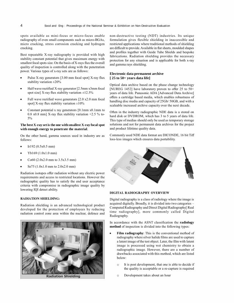
RADIATION SHIELDING:
Radiation shielding is an advanced technological productdeveloped for the protection of employees by reducingradiation control zone area within the nuclear, defence and
DIGITAL RADIOGRAPHY OVERVIEW
Digital radiography is a class of radiology where the image isacquired digitally. Broadly, it is divided into two categories –Computed Radiography and Direct Digital Radiography[ Realtime radiography], more commonly called DigitalRadiography.
In accordance with the ASNT classification the radiologymethod of inspection is divided into the following types:
• Film radiography: This is the conventional method ofradiography where silver halide films are used to capturea latent image of the test object. Later, the film with latentimage is processed using wet chemistry to obtain aradiographic image. However, there are a number ofdrawbacks associated with this method, which are listedbelow:
o It is post development, that one is able to decide ifthe quality is acceptable or a re-capture is required
o Development takes about an hour
non-destructive testing (NDT) industries. Its uniqueformulation gives flexible shielding in inaccessible andrestricted applications where traditional methods of shieldingare difficult to provide. Available in flat sheets, moulded shapesand profiles together with Guide Tube Shields and bespokefabrications. Radiation shielding provides the necessaryprotection for any situation and is applicable for both x-rayand gamma rays shielding.
Electronic data permanent archive[ 25 to 50+ years data life]
Optical data archive based on the phase change technology[NUREG 1452] have laboratory proven to offer 25 to 50+years of data life. Panasonic ADA [Advanced Data Archive]offers a cartridge based media, which enables robustness ofhandling disc media and capacity of 25Gb/ 50GB, and with ascaleable increased archive capacity over the next decade.
Often in the industry radiographic NDE data is a stored onhard disk or DVDROM, which has 3 to 5 years of data life.This type of medias should only be used as temporary storagesolutions and not for permanent data archives for the projectand product lifetime quality data.
Commonly used NDE data format are DICONDE, 16 bit Tiffloss-less images which ensures data portability.

NDE 2011, December 8-10, 2011 5
o Film is not flexible
o Requires utmost care during handling and storage
o Storage requires special rooms, temperaturecontrolled atmosphere
o Development requires dark rooms, chemicals, watersupply
o Uses hazardous chemicals that require specialdisposal as per regulations
o Not eco-friendly
• Computed Radiography: A higher adaptation of filmradiography, this method replaces films with flexibleimaging plates, which are simply scanned using a CRscanner. Hence, a digital image is obtained within fewminutes, without the need of wet chemistry and specialrooms storage facility. Key advantages of using thistechnology are as follows:
o Flexible and reusable imaging plates available inthree types – standard, high resolution and superhigh resolution
o Digital image can be manipulated for viewing,higher contrast and dynamic range can be achieved
o Electronic measurement tools, automated reportgeneration minimise the administration tasks andhuman errors
o A 25 GB Blu-ray disc can store radiographic imagesalong with reports
o It has a very low carbon-footprint, hence isenvironment friendly
Computed Radiography makes use of reusable and flexibleimaging plates as detector. The imaging plate is placed insideits protective jacket and placed under the component to beinspected, according to the radiographic technique. Theexposure is made and the imaging plate is scanned without itsjacket in special CR scanners to obtain a digital radiographicimage. CR scanners have a maximum resolution of 20 micronsand a wide dynamic range of 0 to 4000. This enables the digitalimage to be manipulated in case it is under or over exposed.Image manipulation results in good image quality without theneed for a re-exposure most of the times.
• Direct radiography: Computed direct radiography takento next level, with imaging plates being replaced by flatpanel detectors, which enable to carry out radiographyin real time. The image is instantly displayed on theViewing monitor as the exposure is being done.
Digital Radiography uses flat panel detectors varyingfrom a-Si to a-Se to CMOS as their core technology. Thedetectors are rigid and are available in various sizes fromsmall to large to simply one-dimensional line scandetectors and provide high resolution, high quality imagesin real time. The images from detector can be stored inPC at very fast rates and authorised, analysed, interpretedand archived.
Fig. 7 : Digital Radiography Technology overview

6 Sood and Eng : Proceedings of the National Seminar & Exhibition on Non-Destructive Evaluation
• Neutron radiography: High-energy neutrons are usedinstead of x-rays. Different results can be achieved usingneutron radiography as it can easily penetrate lead andother heavy metals but not plastic etc.
• Flaw depthoradiography™: Developed by CIT, thisvariation of digital radiography enables to view threedimensional “depth” view of the object. Hence, withdigital algorithms, one can calculate flaw depth andposition within the component to a great accuracy.Radiography is used to investigate the internal materialstructure and safety decisions are made based upon thedefects, their nature and localisation. Accurate methodsof measurements are required. Exact depth and locationof flaws within a component (metallic and non-metallic)has to be quantified for depth and height in order to decidethe risk and failure associated with it. NDT FlawDepthoradiography method has been validated andverified using Computed Digital Radiography andMathematical Simulation Modelling tool and followinginferences were made:
• Accuracies better than 2% were achieved.
• Depthoradiographic measurement demonstrates thecapability to analyse and measure accurately the locationof the flaws.
• The operator can visually see 3-dimensional radiographicimages and measure the points of interest with aninteractive control.
One has to check with the customer’s requirement onthe NDT Standards as EC standards for this technologyare being discussed, reviewed not yet ready forpublishing.
• Computed Tomography: Computed tomographycaptures image from multiple angles around an axis toclub them into a three-dimensional image. Key drawbackassociated with this technology is the increased exposuretime due to multiple captures, very large file size forstorage and transfer over the net. The technology isgenerally very expensive.
• Computed Tomo-synthesis: To reduce the number ofexposures for tomography but still achieve a three-dimensional image, only three shots are taken atmovement of 120 degree angle.
Fig. 8 : Types of Digital Radiography
Fig. 9 : Comparison of different radiographic inspection methods

NDE 2011, December 8-10, 2011 7
Reports generated from the application package illustrateinformation to the end customer in a form, from which onecan easily decide the safety of the situation.
Digital Radiography and the various modules implemented inCIT’s DR-Browser software package enable storage, retrieval,analysis, and measurement, reporting and archival of NDEmission critical information.
• Single-sided (backscatter) Radiography: The newinnovation enables us to inspect aircraft components,composite wing structures, and low density metallic andnon-metallic materials, corrosion under insulation for oiland gas, semiconductor electronic devices atcomparatively high speed, the results of which looksimilar to the radiographic image. This uses different x-ray sources to penetrate different depths. The creativeelement is the ability to achieve a resolution of 50 micronsand depths up to 5 – 7 mm.
Radiographic Quality Measurement
Digital radiographic quality is measured with differentparameters as compared to film radiography where opticaldensity plays a major role. However, in digital radiography,
four main parameters that govern the quality of a digitalradiographic image are:
• Contrast Sensitivity: Contrast sensitivity is the abilityof a digital detector to discern between various greyshades. It is measured using the Contrast Sensitivitygauge of CR Phantom.
• Spatial Resolution: Resolution of digital radiographyis related to the visibility of an element. It is the smallestdetail that can be detected by the system.
• Signal-to-noise ratio (SNR): SNR is the characteristicthat defines the resolvability of features in a digitalradiographic image. The SNR is defined as a scalarquantity equal to the ratio of the mean signal to thestandard deviation of fluctuations within an image. Themeasured signal to noise ratio, SNRmeasured, is typicallydetermined in a window of 20 x 55 pixels (also region ofinterest) as the quotient of the linearised mean grey valueand its standard deviation as described in 6.1.1 of ISO16371-1.
The normalization of the measured SNR is based on the basicspatial resolution value of the CR system (SRb) as providedby the manufacturer or determined by the user with theprocedure of this standard.
Fig. 10 : Radiographic images obtained from single sided radiography
Table 1: Required SNRmeasured values for selected CR systems with different SRb as equivalent to SNRN
System parameter High definition system Standard system
Duplex wirequalification 13+ 13 12 11 10 9 8 7 6
Basic spatialresolution SRb 40 µm 50 µm 63 µm 80 µm 100 µm 130 µm 160 µm 200 µm 250 µm
Required SNRN Required SNRmeasured
150 70 85 105 135 170 220 270 340 425
120 55 70 85 110 135 180 220 270 340
100 45 60 70 90 115 150 185 225 285
70 35 40 50 65 80 100 130 160 200

8 Sood and Eng : Proceedings of the National Seminar & Exhibition on Non-Destructive Evaluation
All measured SNRN values are corrected as follows forcalculation of SNRN.
• Contrast to noise ratio (CNR): CNR is the measure forassessing the ability of the digital radiographic systemto specify useful contrast. It is specially worth in case ofnoisy images, where actual contrast is difficult to qualify.
CNR = (SA – SB)/σ
DIGITAL RADIOGRAPHY/LONG-TERM STABILITYQUALIFICATION CR PHANTOM (ASTM 2445)
The need for Quality Control is emphasized throughout anyproduction system. Measurement and traceability of equipmentperformance, and assurance of repeatability and accuracy, areparamount in establishing correct working practices
There are several factors affecting the quality of a CR imageincluding the spatial resolution of the CR system, geometricalunsharpness, scatter and contrast sensitivity (signal/noiseratio). There are several additional factors (for example,scanning parameters), which affect the accurate reading ofimages on exposed IPS using can optical scanner.
The quality factors can be determined most accurately by theCR equipment manufacturer tests as described in PracticeE2446. Individual test targets, which are recommended forpractical user tests, are described for quality assurance. Thesetests can be carried out either separately or by the use of theCR Phantom.
This CR Phantom incorporates many of the basic qualityassessment methods and those associated with the correctfunctioning of a CR system, including the scanner, for readingexposed plates and incorrectly erasing DIPs for future use ofeach plate. This unit enables The NDT radiographyqualification methods ensure that in the productionenvironment. The equipment is operated within calibrationand delivers consistent and repeatable performance.
RADIOGRAPHIC RESULTS
Some of the results of radiographic images obtained of a typicalweld is shown below:
HUMAN RESOURCES FOR NDE DIGITALRADIOGRAPHY
Trainings are available under ASNT TC1 1 CA [2011] , EN473,ISO97012 standard provides guidelines to existing qualifiedwith RT Level I , II or III. Training provided by the system
CR Phantom as DR qualification tool andlong term stability
Typical radiographic setup Digital radiography of CR Phantom
Fig. 11 : 8 MM Steel Weld Plate

NDE 2011, December 8-10, 2011 9
provider for the familiarisation of the hardware and softwareof the system may not be sufficient to achieve the competencyand certifications. Product focussed training skills needs tobe developed for customer acceptance requirements. Periodicretraining are recommended to ensure repeatable andconsistent performance with continuity. This is to meet withthe new enhancement of the digital technology and thestandards
PROCESS / PLANT LIFECYCLE MANAGEMENT
Digital Radiography along with proper software solution takescare of major aspects of plant lifecycle management, whichinvolves tasks like:1. Optimisation of the operation, maintenance, and service
life of plant Structures, Systems and Components (SSCs)2. Maintaining an acceptable level of performance and
safety3. Maximising return on investment over the service life of
the plant
The above tasks of Plant Lifecycle Management take intoaccount several aspects, which are as follows:
• Safety management• Asset management• Predictive maintenance• Preventive maintenance• Risk management
• Ageing management• Knowledge management
Safety Management
The safety of an organisation is paramount for its owners,stakeholders and all other people associated with it. Therefore,its performance should be periodically assessed by means ofauditing and reviewing the following issues:
• The characteristics related to the safety of a plant/component/process should not degrade below the valuesconsidered in the design, which incorporates provisionsfor ageing effects.
• The expected and acceptable safety level at the time ofdesign may later come to be regarded as insufficient andits continued acceptability for further operation has tobe assessed.
• Adopting and adhering to any new standards andregulations imposed by the management and government
Asset Management
Asset management involves monitoring and tracking thelifecycle of the assets of plant /process. It provides informationthat empowers management to make strategic decisions relatedto the plant/process and therefore, helps in lowering the costsand increasing the safety/productivity of an asset over its life.Hence, it makes the plant/process more efficient andproductive.

10 Sood and Eng : Proceedings of the National Seminar & Exhibition on Non-Destructive Evaluation
Predictive Maintenance
Predictive or condition-based maintenance is either performedcontinuously or at specific intervals; the frequency of whichis governed by observed and measured condition. Theseconditions are used to monitor, diagnose and trend SSCs’condition in order to identify their current and future abilityand also to identify the nature and schedule of plannedmaintenance.
Preventive Maintenance
Preventive maintenance is performed to detect, prevent ormitigate the degradation of a SSC in order to sustain or extendits useful life by controlling degradation and failures to anacceptable level.
Risk Management
The organisation should develop an integrated approach torisk management in order to correlate and analyse safety,operational and financial risks in a portfolio context. It istherefore essential that lifecycle management properlyconsiders all risks particularly those of safety significance anddoes not make decisions from a short-term financialperspective.
Knowledge Management
Knowledge Management is essential to any plant/component/process, as it involves maintaining and managing theinformation from all the stages of its life. Loss of thisinformation is disastrous in a way, as it is costly to go throughthe learning process again, with a risk of potential events orincidents, programme delays, physical injury and increasedregulatory surveillance. In some cases, it may be impossibleto rebuild information. Consequently, assumptions may haveto be made that cannot be easily substantiated. Informationloss also deprives people, at later stages, of the knowledgethat could be important for safe and economic completion ofwork or which could aid in the analysis of problems andoptions.
Closely associated with mitigation methods is Plant /component/process Information Management, which requiresdesign data, failure and maintenance data (inspection results,condition monitoring and calibration data), and operating datain order to make decisions regarding safety issues.
The entire safety management programme must also considerfactors such as transfer of knowledge, maintenance practices,expertise and updated documents.
Recommendations for Deploying NDE DigitalRadiography
o Comprehend product inspection qualificationmethod
o Absorb the international acceptance code of practiceo Derive total radiographic unsharpness of the
inspection setup from QA requirements
o Verify the “total radiographic unsharpness”compliance delivered by the selected radiographicequipment and monitoring method
o Qualify your product radiographic techniqueo Identify the product life circle, life of data
requirement legally and contractually, method &technology available to fulfil all the above
SUMMARY
Product/Plant life cycle management of mission criticalinstallations relies on the plant governess of safetymanagement measures to be put in place to mitigate the productliability and the risks associated to prevent accidents. Thisrequires a structured discipline of information managementof products with evidence that is proactive and online for fastturnaround to take corrective action. The digital world ofcomputing deployment has provided bridge that transfersinformation from traditional methods to digital methods. Theinformation managed electronic archives related to the safetyrecords and access to physical products lifetime quality recordsthat cover the construction/manufacturing, quality control,quality assurance and operation-maintenance. These recordslead to critical decision based upon the information, whichcontributes to knowledge, which is exercised with actions bycompetent persons for corrective measures, which can avertaccidents thus fulfilling social responsibility.
REFERENCES
1. “Information Technology Impact on Nuclear Power PlantDocumentation”, IAEA, April 2002
2. “Safe and Effective Nuclear Power Plant Life CycleManagement Towards Decommissioning”, IAEA, August2002
3. “Procedure Guides for a Probabilistic Risk Assessment”,Brookhaven National Laboratory, Dec 2005
4. Robert C. McMaster, Non-destructive Testing Handbook,The Ronald Press Company, 1963
5. Kaveh Edalati, Naser Rastkhah, Amir Movafeghi, JalilRouzitalab “Digitised Radiograph Processing for BetterVision and Evaluation”
6. G. Vámos, I. Loványi, Á. Nagy, and B. Kiss, “FlawDetection in Metallic Fusion Welds on X-ray ImagesUsing Bayesian Networks
7. ASNT Level II Study Guide: Radiographic TestingMethod, Columbus, OH: The American Society forNondestructive Testing, Inc. Latest edition
8. ASNT Level III Study Guide: Radiographic TestingMethod, Columbus, OH: The American Society forNondestructive Testing, Inc. Latest edition
9. Bossi, R.H., F.A. Iddings and G.C. Wheeler, tech. eds.,P.O.Moore, ed, Nondestructive Testing Handbook, thirdedition: Volume 4, Radiographic Testing. Columbus, OH:American Society for Nondestructive Testing, Inc. 2002
10. Nondestructive Evaluation and Quality Control: ASMHandbook, Volume 17. Metals Park, OH: ASMInternational. 1989