current electricity. electrical circuits waterfalls and circuits: more in common than you think...
TRANSCRIPT

Current Electricity

Electrical Circuits

Waterfalls and Circuits:More in common than you think
Electrical Circuits can be thought of as a waterfallVoltage (V)
Height of WaterfallMeasured in volts (V)
Current (I)Amount of water falling at one point at any momentMeasured in amperes (A)
Resistance (R)Constriction of waterMeasured in ohms ()

Simple Electric Circuit
Voltage (V)Battery of the systemMeasured in volts
Current (I)Component using ElectricityMeasured in amperes
Resistance (R)Device inhibiting the flow of electronsMeasured in ohms

Current
Current is a flow of charge (the charge is usually electrons) flows from positive to negative
The unit of current is the amp (the symbol for the amp is A).
The symbol for current is I.Current is measured with an ammeter or
multimeter.

For current to flow we need two things:
1. There has to be a complete circuit.
2. There has to be a source of potential difference (power supplies and batteries both act as a source of potential difference).

Voltage

Potential difference (commonly called ‘voltage’)
Current will flow between two points if there is a potential difference between the two points.
This is a bit like saying that water will flow between two points if there is a height difference between the two points.
In an electric circuit current flows from the positive end of the battery to the negative end.
The positive end is represented with a long solid line, and the negative end is represented with a short solid line

Another way of thinking about potential difference is that it provides
the ‘push’ to move the electrons around a circuit.
The unit of potential difference is the volt (the symbol for the volt is V)
The symbol for potential difference is V.
Potential difference is measured with a voltmeter or multimeter.

Resistance
Resistance opposes the movement of electrons around a circuit.
The unit of resistance is the ohm (the symbol for the ohm is Ω).
The symbol for resistance is R.Resistance is measured with an ohmmeter or
mulitmeter.

Summary
Quantity Symbol Unit Symbol Measured with
Symbol
Current I Amps A Ammeter
Potentialdifference
V Volts V Voltmeter
Resistance R Ohms Ω Ohmmeter

Making circuits• Requires a full complete “circuit”
• Requires a potential difference (Voltage)
• Requires a resister to reduce the flow of current in a circuit
• Remember current flows from + to –
• Always double check circuit before turning circuit on.
An electric current is a flow of electric charge
Conductors are substances which allow current to flow through them freely
Conductors conduct electrical current very easily because of their free electrons. Most metals are good conductors of electrical current.
Electrical Circuits

Insulators are substances which do not allow electrical current to flow through them.
Electrical Circuits

Exp: To test electrical conduction in a variety of materials, and classify each material as a conductor or insulator.
Method:1. Set up the apparatus as shown in the diagram.2. Place the substance you want to test between the clips and see if the bulb lights.3. Repeat with different substances and draw up a table of conductors and insulators.Result:
Conclusion:If the bulb lights the material is a
conductor. If the material does not light the material is an insulator. Some materials are better conductors that others.
Conductor Insulator

Device:Digital Multimeter
Mathematically:Ohm’s Law
Very Important Rule
How do we test for V, I, and R in a Simple Circuit?
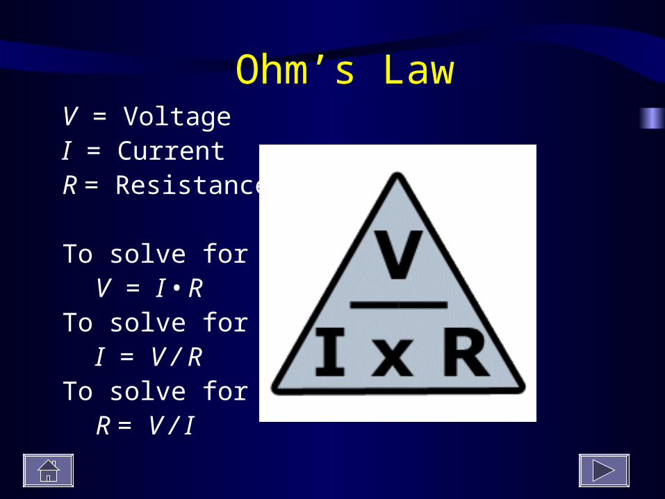
Ohm’s LawV = VoltageI = CurrentR = Resistance
To solve for VV = I • R
To solve for II = V / R
To solve for RR = V / I

Exp: Set up a simple circuit, use appropriate instruments to measure current, potential difference (voltage) and resistance, and establish the relationship between them.Method:1. Set up the apparatus as shown in the
diagram.2. Read the current from the ammeter.3. Read the voltage from the voltmeter.4. Now connect an ohmmeter from A to B and
read the resistance.5. Adjust the variable resistor to give a
slightly larger current, note voltage and resistance now.
6. Repeat a number of times.
Result:
Conclusion: Current = Voltage Resistance
This is know as Ohm’s Law.
Current Voltage Resistance

Current Voltage Resistance


OP 50

For each of the following pictures, determine what the following values are for when the light bulb is lit:
VoltageCurrentResistance
Check Your Understanding
#1
http://jersey.uoregon.edu/vlab/Voltage/
18 V3A R =
18 3
= 6

#2
#3
#4
R =36 3
= 6
R =54 3
= 18
R =72 3
= 24

1. A resistor has a voltage across it of 12 volts and a current through it of 2.5 amperes.Calculate the resistance of the resistor.
resistance =voltage
current
12
2.5=
4.8 =
V
I R

2. A voltage of 6 volts is across a resistor where the current is 0.5 amperes.What is the value of the resistor?
resistance =voltage
current
6
0.5=
12 =
V
I R

3. Calculate the resistance of a component when a voltage of 24 V causes a current of 0.1 amperes.
resistance =voltage
current
240.1
=
240 =
V
I R

4. If a current of 2 amperes exists through a lamp when it has 12 volts across it, what is the resistance of the lamp?
resistance =voltage
current
12
2=
6 =
V
I R

5. A torch bulb is marked "6 V, 0.25 A".Calculate the resistance of the bulb.
resistance =voltage
current
6
0.25=
24 =
V
I R

6. A resistor is placed in a circuit. The voltage across it and current through it are measured as 12 volts and 0.02 amperes.The resistor is now removed from the circuit and an ohmmeter connected across it.What is the reading on the ohmmeter?
resistance =voltage
current
12
0.02=
600 =
V
I R

7. Find the values of the resistors in the circuit below.
V
2 V
0.25 A
V V
3 V 5 V
R1 R2 R3
R1 =
VI
2
0.25= 8 =
R2 =
VI
3
0.25= 12 =
R3 =
VI
5
0.25= 20 =

8. A resistor of resistance 50 is placed in a circuit. The voltage across it is measured as 12 volts.What is the current in the resistor?
current =voltage
resistance
12
50=
0.24 A=
V
I R

9. A 15 resistor is connected to a 9.0 V battery.What is the current in the resistor?
current =voltage
resistance
9
15=
0.60 A=
V
I R

10. A 25 resistor is connected to a battery.The current in the resistor is 0.25 A.What is the voltage of the battery?
voltage = current x resistance
= 0.25 x 25
= 6.25 V
V
I R

11. A 480 resistor is connected to a battery.The current in the resistor is 26 mA.What is the voltage of the battery?
voltage = current x resistance
= 0.026 x 480
= 12.48 V
V
I R

Electric Circuits
• A circuit is a path where a current can flow
• If the flow is to be continuous, there can be no gaps in the path
• A closed circuit is required for a current to flow
• If the circuit is broken it is called an open circuit

A circuit is the path that is made for an electric current.
Electric Circuits
• There are two ways to connect multiple devices to a voltage source
• One is called series
• The other is called parallel
• Each has unique properties which we now examine

Series CircuitA circuit that only has one path for current to flow through is called a series circuit.

Parallel CircuitsA type of circuit that has more than one path for
current is called a parallel circuit.

If one part of the path is removed, the current continues to flow through the other paths of the circuit.

Series Circuits
RTotal = R1 + R2 + R3

Series Circuits
- A single pathway through the circuit
- The current is the same everywhere in the circuit
- Each device provides resistance and total resistance is the sum of the devices
- Voltage divides among the devices

Series Circuit Calculation
12 Volt
10 ohm 20 ohm 30 ohm
RTotal = R1 + R2 + R3

Parallel Circuits


Parallel Circuits
- Each device connects to the voltage source
- Voltage is the same across each device
- Current from source divides into devices
- Total current is the sum of device currents
- Current in each device is just V/R
- Add devices, lower total resistance

In a series circuit:
RTotal = R1 + R2 + R3

In a parallel circuit

Electric Power
- Moving charges do work
- We can heat the filament in a light bulb
- We can turn the rotor in a motor
- The rate at which work is done is power
- Electric Power = current x voltage
- Units are watts = joules/sec = amps x volts

Electric Power
Electric Power = current × voltage
P = I × V

Power Calculation
12 Volt
10 ohm 20 ohm 30 ohm
V
I R
current =voltage
resistance1260
=
0.20 A=
RTotal = R1 + R2 + R3
= 10 + 20 + 30
= 60 Ω

Find the power of the circuit
Current = 0.5A
Resistance = 50 Ohms
Alternating Current (a.c.) and Direct Current (d.c.)

Direct current is current which flows in one direction only;
alternating current is current which constantly changes
direction.

Mains Electricity
Electricity which comes through the sockets in your house is referred to as ‘mains’ electricity’.
It changes direction 50 times per second and so is called alternating current (a.c.).
‘Mains’ voltage is 230 volts

Fuses
- Limit the current that runs through wires in your house
- These wires have some resistance
- Energy loss converts to heat
- Hot wires can start a fire
- Limit the current with a fuse or circuit breaker

A fuse is a deliberate weak link in a circuit which will break
(melt) if the current exceeds a preset value


•The neutral wire is blue.The earth wire is yellow or green.The live wire is brown or red.The fuse is on the live wire.

In an electric circuit current flows from the positive end of the
battery to the negative end.The positive end is represented with a long solid line, and the
negative end is represented with a short solid line

Diode
A diode is a device that allows current to flow in one direction only
The arrow indicates the direction in which current can flow.

Image Symbol

Used to change AC current to DC current in circuits
Also to protect circuits in DC from batteries placed incorrectly

Simple series circuits using diodes

In the diagram on the right, current would normally flow in an anti-clockwise direction (from the positive end to the negative end).
In this case however current will only flow through part A, and not through part B because the diode in part B is pointing in the wrong direction.

Light Emitting Diodes (LEDs)
LEDs are similar to diodes but emit light when current passes through them
They are very important in electronics because they use very little electricity.

Image Symbol
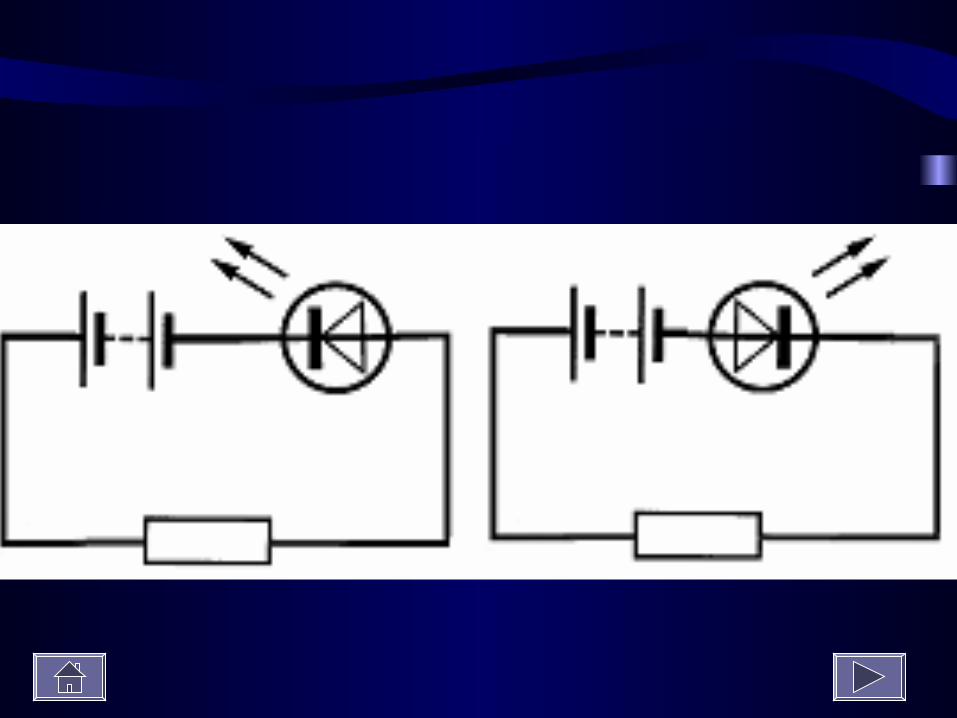

Simple series circuits using LEDs
Note that in both circuits the current flows in an anti-clockwise direction (can you remember why?).
However the LED in the second circuit is turned the wrong way around so no current will flow in the second circuit and no light will be emitted.

Light Dependent Resistors (LDRs)
A LDR is a resistor whose resistance decreases with increasing light intensity
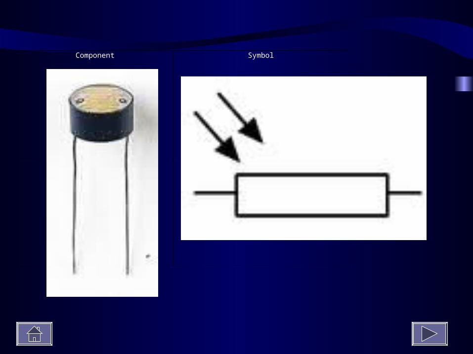
Component Symbol

To measure the resistance of a LDR under varying degrees of
brightness
Connect the LDR to an ohmmeter or to a multimeter set to read resistance and slowly shield the LDR from light.
Notice that the resistance increases


Applications of the diode
Almost all electronic appliances have diodes inside them which help turn alternating current into direct current.
Applications of the LED
LEDs used to be used primarily as indicators in electronic circuitry (e.g. as standby indicators in televisions, radios etc) but modern diodes can give out a lot of light efficiently and so are now used in many designs of flashlights.

Applications of the LDR
Textbooks often mention that LDRs are used to switch on street lights when it gets dark, yet this can seem confusing because the resistance of the LDR is high when it is dark so how can this be responsible for current flowing through the street-light?
What actually happens is that this reduced current is detected by a second circuit which in turn uses that information to turn on the street-light

1. What is the function of a diode in a circuit?
2. What is the function of a LED (Light Emitting Diode)?
1. What do the letters LDR stand for?
1. Draw the symbol for (i) ldr, (ii) led
1. Give one everyday use of (i) an led, (ii) an ldr.

Electronics at home

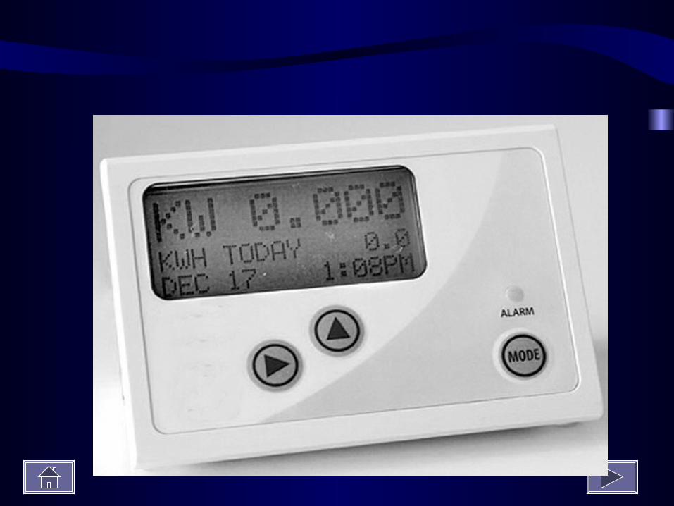
Cost of electricity - the kilowatt-hour
The kilowatt-hour is the unit electrical energy used by electricity suppliers.
The photograph shows a kWh (kilowatt-hour) meter.
This meter is connected into the electricity consumer’s domestic circuit and it can measure energy consumption in a selected part of the circuit, the total energy used and cost it.

The unit of electrical energy used by electricity supply
companies is the kilowatt-hour

The number of kilowatt-hours equals the number of kilowatts
multiplied by the number of hours
kWh = kW × hours
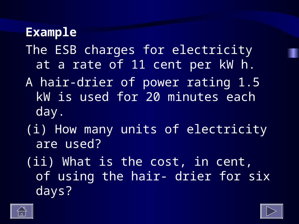
Example
The ESB charges for electricity at a rate of 11 cent per kW h.
A hair-drier of power rating 1.5 kW is used for 20 minutes each day.
(i) How many units of electricity are used?
(ii) What is the cost, in cent, of using the hair- drier for six days?

The power rating of various appliances
Appliance Power (in watts) kilowatts (kW)
Washing machine 2500 2.5
Microwave 700 .9
Light-bulb 40 .04
Lamp 60 .06
Hair-dryer 3000 3
Kettle 600 .6
Television

Effects of an electric current
There are three effects of an electric current; a heating effect, a magnetic effect and a chemical effect

Effect Demonstration Everyday application
Heating Effect
An electric current will cause a light-bulb to heat up and emit
light
Electric kettle, electric fire etc.
Magnetic Effect
An electric current will deflect a magnetic compass
Electromagnets
Chemical Effect
Electrolysis occurs when an electric current splits water into
hydrogen and oxygen
Electroplating
