curtin university project delivery guidelines · design and delivery guidelines. consultant...
TRANSCRIPT

CURTIN UNIVERSITY
PROJECT DELIVERY GUIDELINES
VERTICAL TRANSPORT
GUIDELINES
000322

000322 PDG Vertical Transport Guidelines Rev. No.2 Page 2 of 29
Details of revisions
Level Details Date Initial
1 Created for the Project Delivery Guidelines from Curtin Vertical Transportation Project Design
Guidelines - 111016
Jan-17 RPS
2 Update of minor details Aug-18 PFD
2 Inclusion of wording to allow departures from the existing
guideline Dec-19 RPS

000322 PDG Vertical Transport Guidelines Rev. No.2 Page 3 of 29
CONTENTS
1 INTRODUCTION ..................................................................... 6
1.1 PURPOSE ............................................................................................ 6
1.2 CURTIN REQUIREMENTS .................................................................... 6
DISABILITY ACCESS AND INCLUSION PLAN ................................. 6
HEALTH AND SAFETY .................................................................... 6
SUSTAINABILITY AT CURTIN ....................................................... 7
1.3 PREAMBLE .......................................................................................... 7
GENERAL ...................................................................................... 7
SPECIFICATION............................................................................ 7
OVERRIDING INTENT ................................................................... 8
1.4 DELIVERABLES ................................................................................... 8
2 ACCESS, MAINTENANCE, MANUALS AND DATA COLLECTION .. 9
2.1 GENERAL ............................................................................................ 9
2.2 DATA COLLECTION ............................................................................. 9
2.3 ACCESS FOR MAINTENANCE AND ENGINEERING SERVICES................ 9
2.4 LIFT MACHINE ROOMS ..................................................................... 10
3 RELATED WORK SPECIFIED ELSEWHERE ............................. 11
3.1 GENERAL .......................................................................................... 11
3.2 SHAFT AND PIT CONSTRUCTION ...................................................... 11
3.3 MACHINE ROOM ............................................................................... 11
3.4 ELECTRICAL SERVICES, CONDUCTORS AND DEVICES ....................... 12
3.5 STAND-BY POWER – PROVISION OF EMERGENCY GENERATOR ........ 12
3.6 REGULATORY AGENCY COMPLIANCE ................................................ 12
3.7 PERMIT, TEST AND INSPECTION ...................................................... 13
3.8 WARRANTY ....................................................................................... 13
3.9 MAINTENANCE ................................................................................. 13
WARRANTY MAINTENANCE – DEFECTS LIABILITY PERIOD ........ 13
CONTRACT COMPREHENSIVE MAINTENANCE ............................. 13
4 DESIGN CRITERIA ................................................................ 14
4.1 LIFT INSTALLATIONS ....................................................................... 14
4.2 DESIGN APPLICATION DOCUMENTS ................................................. 14

000322 PDG Vertical Transport Guidelines Rev. No.2 Page 4 of 29
4.3 TECHNICAL REVIEW GROUP ............................................................. 14
4.4 TRAFFIC ANALYSIS .......................................................................... 14
5 ELEVATOR CRITERIA ............................................................ 15
5.1 PREFERRED ELEVATOR SPECIFICATIONS ......................................... 15
6 ELEVATOR EQUIPMENT STANDARDS .................................... 16
6.1 ACCEPTABLE STANDARDS ................................................................ 16
6.2 TRACTION MACHINE ROOM AND SHAFT EQUIPMENT ....................... 16
6.3 SIGNALS ........................................................................................... 16
LOBBY HALL BUTTONS ............................................................... 16
LOBBY HALL LANTERNS .............................................................. 16
CAR POSITION INDICATOR ........................................................ 16
LOBBY POSITION INDICATOR .................................................... 16
VOICE ANNUNCIATION .............................................................. 17
6.4 LOBBY FIRE SERVICE CONTROL ....................................................... 17
6.5 MACHINE ROOM MONITORING SYSTEM ............................................ 17
6.6 EMERGENCY PHONE OR COMMUNICATION SYSTEM .......................... 17
7 ELEVATOR CONTROL SYSTEMS ............................................. 18
7.1 GROUP AUTOMATIC OPERATION ...................................................... 18
GENERAL .................................................................................... 18
HALL CALL ASSIGNMENT ............................................................ 18
7.2 DUPLEX SELECTIVE COLLECTIVE OPERATION .................................. 18
GENERAL .................................................................................... 18
7.3 SIMPLEX SELECTIVE COLLECTIVE ..................................................... 18
GENERAL .................................................................................... 18
SIMPLEX FULLY COLLECTIVE OPERATION .................................. 18
7.4 GENERAL REQUIREMENTS – ALL ELEVATOR CONTROL SYSTEMS ...... 19
LOAD WEIGHING ........................................................................ 19
SPECIAL OPERATIONS................................................................ 19
7.5 SECURITY CARD ACCESS .................................................................. 19
7.6 ELEVATOR LOSS OF POWER .............................................................. 20
7.7 DOOR HOLD FOR SERVICE ELEVATORS ............................................. 20
8 ELEVATOR PERFORMANCE STANDARDS ............................... 21
8.1 RUNNING SPEEDS ............................................................................ 21
8.2 CAPACITY ......................................................................................... 21
000322 PDG Vertical Transport Guidelines Rev. No.2 Page 5 of 29
8.3 LEVELLING ....................................................................................... 21
8.4 DOOR OPENING TIME ....................................................................... 21
8.5 DOOR CLOSING TIME ....................................................................... 21
8.6 DOOR DWELL TIME – CAR CALL ........................................................ 21
8.7 DOOR DWELL TIME – HALL CALL ...................................................... 21
8.8 NON-INTERFERENCE DOOR DWELL TIME.......................................... 21
8.9 DOOR NUDGING DWELL TIME .......................................................... 22
8.10 DOOR CLOSING PRESSURE ............................................................ 22
8.11 FLOOR-TO-FLOOR PERFORMANCE TIME ........................................ 22
8.12 RIDE QUALITY ............................................................................... 22
9 INSTALLATION .................................................................... 23
10 FIELD QUALITY CONTROL ................................................. 24
11 ACCEPTANCE INSPECTION AND TESTS .............................. 25
11.1 GENERAL ....................................................................................... 25
11.2 PERFORMANCE GUARANTEE .......................................................... 25
12 PURCHASER’S INFORMATION ........................................... 27
12.1 IDENTIFICATION OF EQUIPMENT .................................................. 27
12.2 PRACTICAL COMPLETION .............................................................. 27
12.3 DEFECTS LIABILITY PERIOD ......................................................... 27
12.4 OPERATIONS AND MAINTENANCE MANUALS ................................. 27
12.5 WIRING DIAGRAMS, KEYS AND DIAGNOSTIC EQUIPMENT ............ 28
13 REFERENCES ..................................................................... 29

000322 PDG Vertical Transport Guidelines Rev. No.2 Page 6 of 29
1 INTRODUCTION
1.1 PURPOSE
The purpose of this Project Delivery Guidelines document is to provide an overview of
the policy, planning and design principles to be considered when providing consultancy
and/or design of vertical transportation services for Curtin University projects. This
document is intended for use by consultants, architects, engineers and other design
services.
In the design phase of any project, both the best design outcomes and coordination of
services and installation must be considered by consultants for vertical transportation
services. The design should ensure that all selected building materials and services are
fit for purpose whilst also providing value for money. Building materials and services
must be of sound construction, offer local support and integrate with other services
and design concepts. Importantly these materials and services must be easily
maintained and able to be scaled to the University environment.
The Project Delivery Guidelines have been prepared in consultation with Curtin
University subject matter experts and stakeholders. It is recognised that the subject
matter of Guidelines will not always be suitable for all project elements and departures
from the Guidelines may be required or desirable. Departures from Guidelines must be
agreed upon in consultation with the relevant University Guideline subject matter
expert. Departures must be recorded in a project register and recorded and reviewed
in the Project Control Group meeting minutes under its own meeting agenda item
“Project Delivery Guideline Departures”. Where the University subject matter expert
identifies that a departure adds ongoing value to the University, the subject matter
expert will update the relevant Guideline.
1.2 CURTIN REQUIREMENTS
DISABILITY ACCESS AND INCLUSION PLAN
Curtin University believes in creating equitable and inclusive access for people with a
disability to its facilities, services, events and academic programs on all its Western
Australian campuses.
The Universal Design Guideline has been developed to reflect a commitment to equity
and inclusion for all by embedding Universal Design principles into project planning,
design and delivery guidelines. Consultant architects, designers and engineers should
make themselves familiar with the particular requirements of the Universal Design
Guideline before responding to a project brief.
HEALTH AND SAFETY
Curtin University is committed to providing and maintaining high standards of health
and safety in the workplace and will:
• ensure compliance with relevant legislation and the University’s Health and Safety
Management System

000322 PDG Vertical Transport Guidelines Rev. No.2 Page 7 of 29
• promote an organisational culture that adopts health and safety as an integral
component of its management philosophy
• ensure that health and safety is part of the business planning processes and that it is
adequately resourced by all areas
• maintain an effective mechanism for consultation and communication of health and
safety matters
• maintain an effective process for resolving health and safety issues and managing health
and safety risks
• provide appropriate health and safety training
• regularly review health and safety performance to monitor the effectiveness of health
and safety actions and ensure health and safety targets and objectives are met.
A copy of our Health and Safety Management Standards can be found at:
https://healthandsafety.curtin.edu.au/local/docs/HSManagementStandards.pdf
SUSTAINABILITY AT CURTIN
It is Curtin University policy that all new or refurbishment projects on site should
support its status as Australia's first university to achieve a 5-star Green Star ─
Communities rating from the Green Building Council of Australia (GBCA). Designers
should understand and incorporate the Green Star criteria into designs and
specifications in order to maintain and enhance Curtin’s Green Star status.
Information on the criteria can be found in the PDG Green Star – Communities Design
Guidelines.
1.3 PREAMBLE
GENERAL
Designers interpreting these guidelines are to understand that changes to technology
and policy may outpace the content of these guidelines. Prior to the calling of tenders
for building services the following must be approved by Curtin University’s Project
Manager and the appropriate Services Manager:
the scope document, which clearly indicates intent
equipment schedules where appropriate
a list of suggested tenderers.
SPECIFICATION
The content of these guidelines must be fully integrated into vertical transportation
specifications. Appending these guidelines to generic specifications will not be
accepted and any generic specification used must be edited to eliminate any conflict
with the content of these guidelines.
Specifications for vertical transportation installations shall ensure that, at the time of
the completion of the building works and prior to being put into service, the elevator/s
are completely adjusted and tested by the elevator contractor. Additionally, the
000322 PDG Vertical Transport Guidelines Rev. No.2 Page 8 of 29
specification must ensure that a ‘competent person’ independently tests, approves and
certifies that the elevator/s are in as-new operating condition.
Commissioning reports are to be submitted in accordance with procedures as
described in this section.
The vertical transportation specification must ensure that the elevator contractor
provides a works guarantee for a period of one year from the date of acceptance. This
guarantee to maintain elevators in a proper and safe operating condition shall include
the provision of 24-hour, seven-day-a-week call-back service and include regular
inspection; adjustment and lubrication; with repair and/or replacement of all defective
mechanical and electrical parts.
This specification must ensure that, at the expiry of the elevator contractor’s 12-
month defect liability period/guarantee period, the product provided is able to be
maintained by others. The requirement for the provision of any specific necessary
service diagnostic or maintenance tools must be included in the specification.
OVERRIDING INTENT
It is the overriding intent that, if possible and financially responsible, machine room-
less (MRL) product is to be used in the place of hydraulic lifts for all new, modernised
or replacement lifts.
1.4 DELIVERABLES
Continuous communication with the Responsible Officer for Vertical Transportation
Services Consultancy is required throughout service delivery, specifically as follows:
Schematic Stage
Design Development Stage
Tender Drawing Stage
Construction Stage
Defects Stage
Handover.

000322 PDG Vertical Transport Guidelines Rev. No.2 Page 9 of 29
2 ACCESS, MAINTENANCE, MANUALS AND DATA
COLLECTION
2.1 GENERAL
Maintenance of the University's facilities is funded from recurrent resources that
normally bear little relation to the capital program. It is therefore imperative to ensure
that all vertical transportation equipment is constructed and supplied bearing in mind
life-cycle costs and maintainability.
Designs will be rejected if they opt for minimising capital cost at the expense of
ongoing maintenance costs or make inadequate provision for:
servicing and maintenance
straightforward removal and replacement of plant and equipment
access
durability.
2.2 DATA COLLECTION
Facilities Management – Mechanical Engineering at Curtin University maintains a
comprehensive suite of data to assist the University with the master planning process
that underpins the University’s strategic development. Ensuring the currency of this
data is paramount and consultants and contractors are crucial to this process.
The elevator contractor and other engineering disciplines play their part in providing
this data to the University. It is therefore important that project specifications refer to
the capture of this data so that data sets can be updated. To assist in this process,
templates have been developed. The elevator contractor must use these templates to
record the required data and submit these to the Facilities Management – Mechanical
Engineering Department at the time of project practical completion.
2.3 ACCESS FOR MAINTENANCE AND ENGINEERING
SERVICES
Sample maintenance procedures for the vertical transportation to be installed
throughout the buildings are vital and shall be discussed with the University prior to
tendering.
All design and construction materials shall reflect low maintenance considerations.
Fabric, structural and service components shall be readily accessible to reduce labour
requirements and downtime should repairs be required after the defects liability
period.
Consultants shall ensure that they indicate:
how each item of plant is to be installed initially
how the University’s routine service personnel will access each plant item
the methodology to be used in changing the largest item of plant in any plant
area.
000322 PDG Vertical Transport Guidelines Rev. No.2 Page 10 of 29
‘Adequate access’ for routine servicing means the provision of sufficient space for a
service technician, irrespective of working age, to reach all items requiring routine
service safely and without undue stress.
Mechanical and electrical plant and equipment, particularly that requiring manual
operation or routine maintenance, shall have safe and comfortable access. Adequate
clearance is essential to enable work to be carried out.
Adequate space shall be allowed in conduits or ducts to allow for future growth of
services. Such items as electrical and telephone cables may be too big and heavy to
be pulled around conduit bends; straight access, without bends or obstructions, shall
be provided.
2.4 LIFT MACHINE ROOMS
Lift machine rooms are to be generally omitted in preference for new technology
utilising machine room-less (MRL) lifts.
In the event provision of lift machine rooms cannot be avoided, the project architect
shall request from consultants the range of sizes for all items of elevator plant. The
architect shall ensure that the final selection of lift and electrical equipment will not
require additional space. The lift machine rooms are to be located at roof top or
basement level rather than within the body of the building.
Direct access from corridors to roof areas, plant rooms, tunnels, etc. shall be provided
where possible to enable the independent control of these areas by Curtin’s Properties,
Facilities and Development department (PF & D).
Lift machine rooms shall be designed so that the noise level measured with all the
equipment operating under full load will not exceed the current exposure standard less
3 dbA. Where this cannot be achieved, the Responsible Officer shall be consulted.

000322 PDG Vertical Transport Guidelines Rev. No.2 Page 11 of 29
3 RELATED WORK SPECIFIED ELSEWHERE
3.1 GENERAL
This section of the guidelines outlines the University's minimum requirements for
vertical transportation systems for both new buildings and buildings in which lifts are
being refurbished.
The following functional requirements are to be given special design consideration:
energy efficiency
simplicity of design
accessibility, ease of operation, simple maintenance, combined with minimal
maintenance frequency
allowance of adequate space for installation and maintenance of machinery,
whether it be in a designated plant room, shaft space or otherwise
compliance with all statutory requirements
compliance with AS1735.1: 2016 and AS3000:2007. All required test results
including earth looping impedance testing shall be issued with as-constructed
documentation
provision for adequate supply of parts for the life of the product (15 years
minimum)
active movement away from hydraulic lifts.
3.2 SHAFT AND PIT CONSTRUCTION
It is a requirement that shaft and pit construction shall take into account:
clear, plumb, substantially flush shaft with variations not to exceed 25 mm at
any point
the loadings and reactions of the lift
bevels not less than 75º from the horizontal on any rear or side wall ledges
and beams that project or recess 20 mm or more into the shaft
divider beams between adjacent elevators at each floor, pit and overhead
wall pockets and/or structural beams for support of machine, sheave, and
dead-end hitch beams
lifting beam/s to suit the lift installation, tested and marked with SWL
pits impervious to water ingress with closed sumps.
3.3 MACHINE ROOM
It is generally envisioned that equipment will be MRL and will not normally require a
machine room however, if required, it must have:
constant cooling and heating to maintain temperature range between 18 °C
and 32 °C

000322 PDG Vertical Transport Guidelines Rev. No.2 Page 12 of 29
sufficient lighting, including emergency lighting as required by AS1735.1 and
electrical codes
GPO outlets
smoke and fire detection as required by code
sprinklers as applicable by code
machinery access hatches required for future maintenance
floor painted in grey paving paint.
3.4 ELECTRICAL SERVICES, CONDUCTORS AND DEVICES
Vertical transportation design must take into account and allow for:
lighting and GPO convenience outlet in machine room (traditional overhead
machine room only)
3-phase active, neutral and earth supplied to the elevator contractor’s located
terminal box
firefighters’ telephone (WIP Phone), if required by code, in the elevator car
with connection to the WIP system.
provision of a smoke detector at the top of the shaft
provision of a phone line to a location termination as provided by the elevator
contractor
provision of necessary security hardware and software.
3.5 STAND-BY POWER – PROVISION OF EMERGENCY
GENERATOR
For critical lifts where building-generated power is provided:
stand-by power of the same voltage characteristics, via normal electric
feeders to run one elevator at a time in each elevator group, and/or single
elevator unit, at full-rated car speed and capacity
change-over contactors and one pair of signal wires to the lift controllers
means for absorbing regenerated power.
3.6 REGULATORY AGENCY COMPLIANCE
All elevator equipment shall be designed, furnished and installed to comply with:
AS1735.1 – 2016
AS1735.12 – 1999
AS/NZS 3000 – 2007
Building Codes of Australia
Occupational Health and Safety (Plant) Regulations
Australian Communications and Media Authority (ACMA)
000322 PDG Vertical Transport Guidelines Rev. No.2 Page 13 of 29
local disability codes including mandatory Disability (Access to Premises —
Buildings) Standards 2010 Disability Discrimination Act 1992.
3.7 PERMIT, TEST AND INSPECTION
The elevator contractor shall obtain and pay for any and all permits, licences, and
inspection fees necessary to complete the installation, excluding development
applications and building permits. This shall include, but not be limited to, Lift Design
Registration and Plant Registration as required by Worksafe Western Australia.
3.8 WARRANTY
The elevator contractor’s warranty must correct defective material or workmanship
that develops within one year from the date of final acceptance of work, to the
satisfaction of the University, at no additional cost unless due to improper use by the
University.
The word ‘defective’ is defined to include, but not be limited to, operation or control
system failures, performance below the required minimum, excessive wear, unusual
deterioration or aging of materials or finishes, unsafe conditions, the need for
excessive maintenance, abnormal noise or vibration, and similar unsatisfactory
conditions.
3.9 MAINTENANCE
WARRANTY MAINTENANCE – DEFECTS LIABILITY PERIOD
The elevator contractor must visit the site regularly to provide preventive maintenance
and 24-hour emergency call-back service for a period of one year commencing on the
date of final acceptance by the University. It is a requirement of this maintenance that
the elevator machine room, shaft and pit are maintained in clean condition.
CONTRACT COMPREHENSIVE MAINTENANCE
Any specification must include a requirement for a quotation from the elevator
contractor for a monthly cost to provide for a five-year comprehensive maintenance
contract. This maintenance agreement shall be based upon terms and conditions of
the comprehensive maintenance contract included with the specification. This contract
must be priced to commence at the completion of the one-year warranty period
following the date of final acceptance by the University.
The intent of the University is to roll the maintenance of each unit into a combined
maintenance agreement across the campus following the warranty maintenance
period. This may or may not be awarded to the contractor who is providing the new
plant.

000322 PDG Vertical Transport Guidelines Rev. No.2 Page 14 of 29
4 DESIGN CRITERIA
4.1 LIFT INSTALLATIONS
The goal is to provide efficient and flexible transportation and passenger elevators are
to be located as centrally as possible within each building, with the objective of
providing passengers with quick and convenient access to their chosen floors.
4.2 DESIGN APPLICATION DOCUMENTS
All University lifts are to be designed to comply with the requirements of the Building
Codes of Australia (BCA) Part E3 Lift Installations and the references in section 3.6.
4.3 TECHNICAL REVIEW GROUP
Consulting engineers must ensure that representatives from Curtin University’s PF & D
Mechanical Engineering Department are included in the project Technical Review
Group. All design and development of vertical transportation services and equipment
selection must be undertaken in conjunction with these University representatives.
Prior to finalising tender documents, the elevator design consultant shall issue Curtin
University’s Manager Mechanical Infrastructure with one set of preliminary tender
drawings and specifications for review and comment.
4.4 TRAFFIC ANALYSIS
A traffic analysis shall be conducted as part of the design process with particular
reference to:
BCA Sections E and D 1.13
CIBSE Guide D ‘Transportation in Buildings’ for performance criteria
Benchmarking of performance criteria for similar buildings in Australia
TEFMA Space Planning Guidelines
Elevate Traffic Study Analysis Software or similar
known building use and traffic flow simulations.

000322 PDG Vertical Transport Guidelines Rev. No.2 Page 15 of 29
5 ELEVATOR CRITERIA
5.1 PREFERRED ELEVATOR SPECIFICATIONS
Passenger Goods
Capacity 1,275 kg 1,600 kg
Speeds
Levels 2–3
served
1.0 m/s 1.0 m/s
Levels 4–12
served
1.75 m/s 1.6 m/s
Car Size
Width 1,400 mm 1,600 mm
Depth 2,000 mm 2,100 mm
Clear Entrances
Width 1,000 mm 1,300 mm
Height 2,100 mm 2,200 mm
Type Centre Opening Centre Opening
or side
Cab Height
To False Ceiling 2,300 mm 2,500 mm
Interiors
Flooring Vinyl Chequer Plate
Walls Textured
Stainless
Stainless
Lighting LED Florescent
000322 PDG Vertical Transport Guidelines Rev. No.2 Page 16 of 29
6 ELEVATOR EQUIPMENT STANDARDS
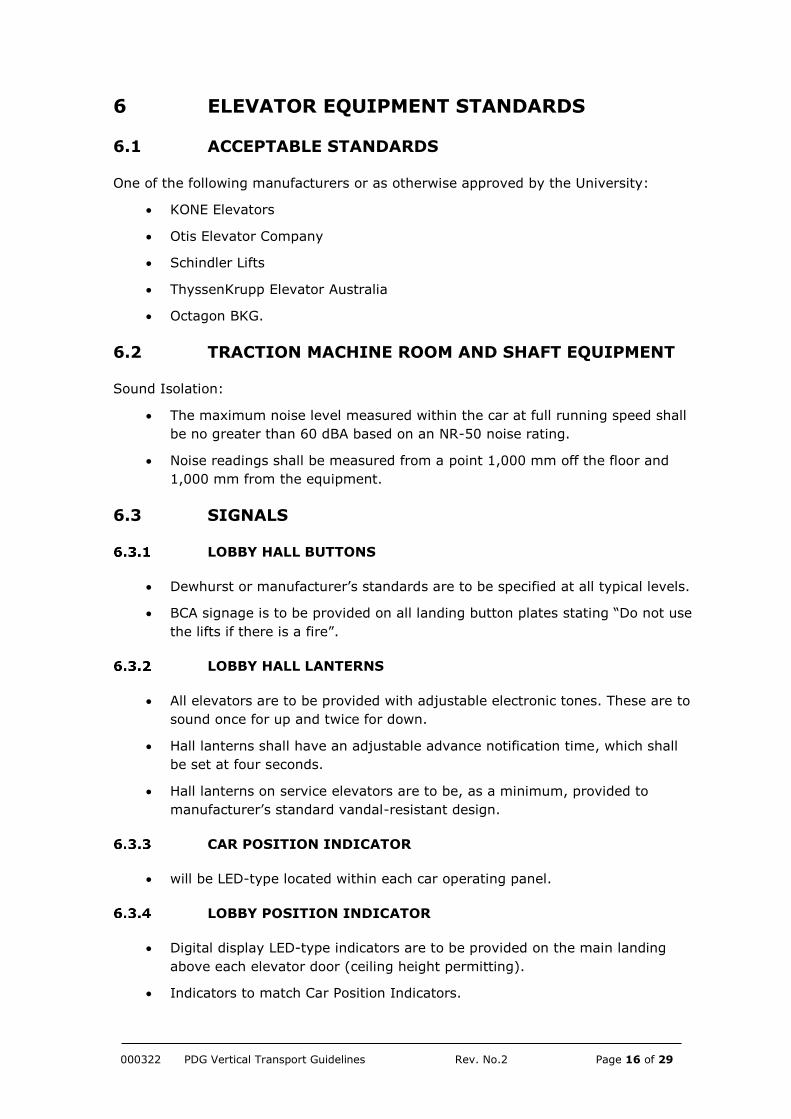
6.1 ACCEPTABLE STANDARDS
One of the following manufacturers or as otherwise approved by the University:
KONE Elevators
Otis Elevator Company
Schindler Lifts
ThyssenKrupp Elevator Australia
Octagon BKG.
6.2 TRACTION MACHINE ROOM AND SHAFT EQUIPMENT
Sound Isolation:
The maximum noise level measured within the car at full running speed shall
be no greater than 60 dBA based on an NR-50 noise rating.
Noise readings shall be measured from a point 1,000 mm off the floor and
1,000 mm from the equipment.
6.3 SIGNALS
LOBBY HALL BUTTONS
Dewhurst or manufacturer’s standards are to be specified at all typical levels.
BCA signage is to be provided on all landing button plates stating “Do not use
the lifts if there is a fire”.
LOBBY HALL LANTERNS
All elevators are to be provided with adjustable electronic tones. These are to
sound once for up and twice for down.
Hall lanterns shall have an adjustable advance notification time, which shall
be set at four seconds.
Hall lanterns on service elevators are to be, as a minimum, provided to
manufacturer’s standard vandal-resistant design.
CAR POSITION INDICATOR
will be LED-type located within each car operating panel.
LOBBY POSITION INDICATOR
Digital display LED-type indicators are to be provided on the main landing
above each elevator door (ceiling height permitting).
Indicators to match Car Position Indicators.
000322 PDG Vertical Transport Guidelines Rev. No.2 Page 17 of 29
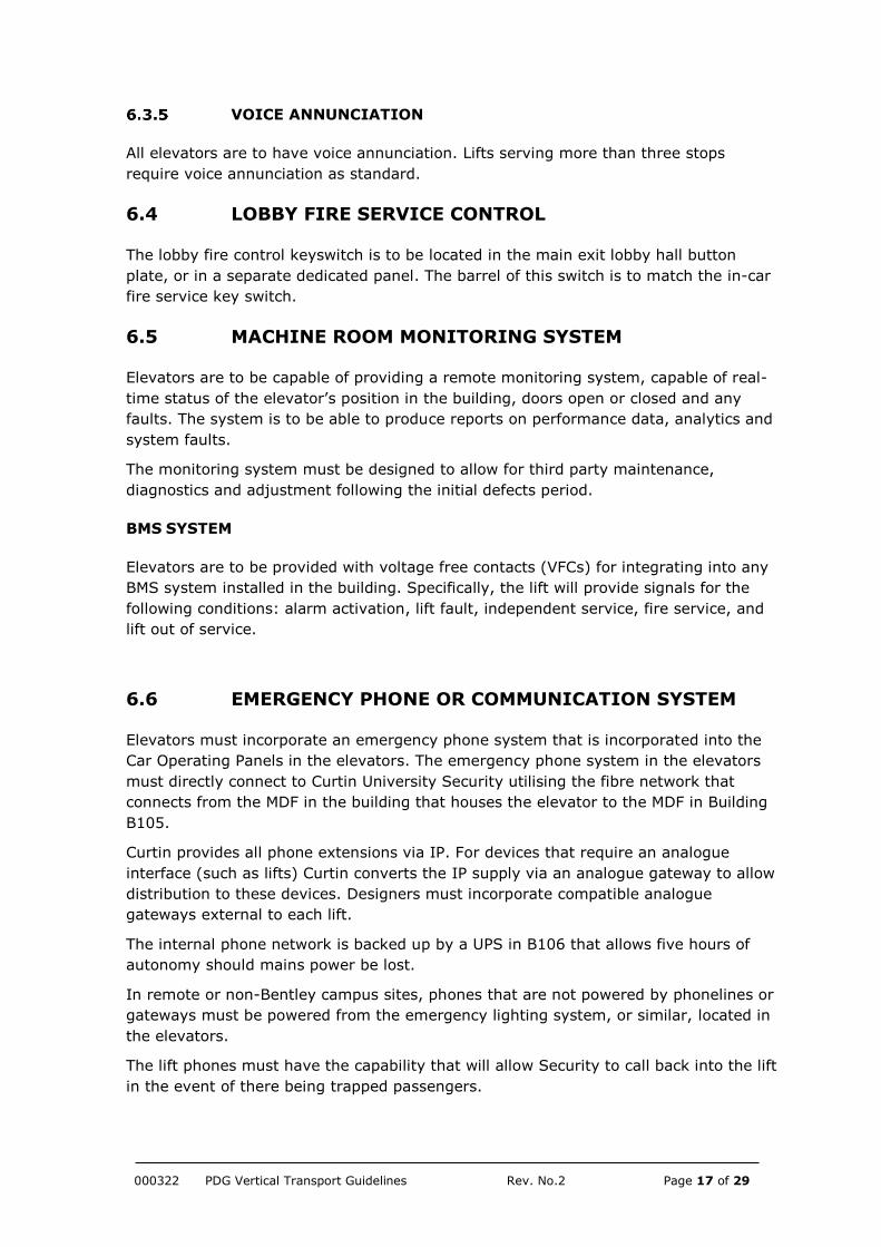
VOICE ANNUNCIATION
All elevators are to have voice annunciation. Lifts serving more than three stops
require voice annunciation as standard.
6.4 LOBBY FIRE SERVICE CONTROL
The lobby fire control keyswitch is to be located in the main exit lobby hall button
plate, or in a separate dedicated panel. The barrel of this switch is to match the in-car
fire service key switch.
6.5 MACHINE ROOM MONITORING SYSTEM
Elevators are to be capable of providing a remote monitoring system, capable of real-
time status of the elevator’s position in the building, doors open or closed and any
faults. The system is to be able to produce reports on performance data, analytics and
system faults.
The monitoring system must be designed to allow for third party maintenance,
diagnostics and adjustment following the initial defects period.
BMS SYSTEM
Elevators are to be provided with voltage free contacts (VFCs) for integrating into any
BMS system installed in the building. Specifically, the lift will provide signals for the
following conditions: alarm activation, lift fault, independent service, fire service, and
lift out of service.
6.6 EMERGENCY PHONE OR COMMUNICATION SYSTEM
Elevators must incorporate an emergency phone system that is incorporated into the
Car Operating Panels in the elevators. The emergency phone system in the elevators
must directly connect to Curtin University Security utilising the fibre network that
connects from the MDF in the building that houses the elevator to the MDF in Building
B105.
Curtin provides all phone extensions via IP. For devices that require an analogue
interface (such as lifts) Curtin converts the IP supply via an analogue gateway to allow
distribution to these devices. Designers must incorporate compatible analogue
gateways external to each lift.
The internal phone network is backed up by a UPS in B106 that allows five hours of
autonomy should mains power be lost.
In remote or non-Bentley campus sites, phones that are not powered by phonelines or
gateways must be powered from the emergency lighting system, or similar, located in
the elevators.
The lift phones must have the capability that will allow Security to call back into the lift
in the event of there being trapped passengers.

000322 PDG Vertical Transport Guidelines Rev. No.2 Page 18 of 29
7 ELEVATOR CONTROL SYSTEMS
7.1 GROUP AUTOMATIC OPERATION
IF THERE ARE THREE OR MORE ELEVATORS IN A GROUP:
GENERAL
A closed loop microprocessor-based control system must be provided that performs
functions including elevator motion, grouping, door control and car operations.
HALL CALL ASSIGNMENT
Car assignment and response times are to be determined by computing factors such
as relative distance from request; service response to any already allocated car and
hall calls; car loadings; direction of travel; door and car motion status; coincidence of
car and hall calls; and time to destination. The group system must be capable of
continuous computation of these factors to ensure assignment of the best available car
to answer a call.
7.2 DUPLEX SELECTIVE COLLECTIVE OPERATION
IF THERE ARE TWO ELEVATORS IN A GROUP:
Hall operation is to be fully collective with up and down buttons except on terminal
landings.
GENERAL
A microprocessor-based control system must be provided that is arranged for duplex
collective automatic operation.
Where multiple lifts are installed, a parking feature is to be provided that returns one
of the cars to the ‘Parking Floor’, the most likely main landing when there are no calls
in the system for a predetermined period of time. Where only one lift exists, then that
car will be provided with this function.
7.3 SIMPLEX SELECTIVE COLLECTIVE
IF THERE IS ONLY ONE ELEVATOR:
GENERAL
A microprocessor-based control system must be provided that is arranged for simplex
collective operation. This single elevator will be operated from a single riser of landing
buttons and operating devices (car operating panel(s)) in the lift car.
SIMPLEX FULLY COLLECTIVE OPERATION
Standard landing call operation shall be such that, so long as the lift is not already at
the landing, a service request is initiated by momentary pressure on one or more
000322 PDG Vertical Transport Guidelines Rev. No.2 Page 19 of 29
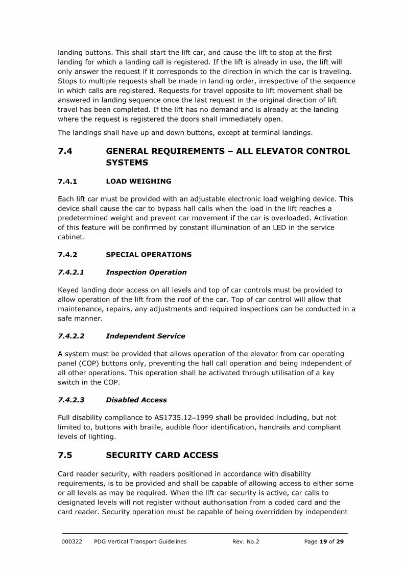
landing buttons. This shall start the lift car, and cause the lift to stop at the first
landing for which a landing call is registered. If the lift is already in use, the lift will
only answer the request if it corresponds to the direction in which the car is traveling.
Stops to multiple requests shall be made in landing order, irrespective of the sequence
in which calls are registered. Requests for travel opposite to lift movement shall be
answered in landing sequence once the last request in the original direction of lift
travel has been completed. If the lift has no demand and is already at the landing
where the request is registered the doors shall immediately open.
The landings shall have up and down buttons, except at terminal landings.
7.4 GENERAL REQUIREMENTS – ALL ELEVATOR CONTROL
SYSTEMS
LOAD WEIGHING
Each lift car must be provided with an adjustable electronic load weighing device. This
device shall cause the car to bypass hall calls when the load in the lift reaches a
predetermined weight and prevent car movement if the car is overloaded. Activation
of this feature will be confirmed by constant illumination of an LED in the service
cabinet.
SPECIAL OPERATIONS
7.4.2.1 Inspection Operation
Keyed landing door access on all levels and top of car controls must be provided to
allow operation of the lift from the roof of the car. Top of car control will allow that
maintenance, repairs, any adjustments and required inspections can be conducted in a
safe manner.
7.4.2.2 Independent Service
A system must be provided that allows operation of the elevator from car operating
panel (COP) buttons only, preventing the hall call operation and being independent of
all other operations. This operation shall be activated through utilisation of a key
switch in the COP.
7.4.2.3 Disabled Access
Full disability compliance to AS1735.12–1999 shall be provided including, but not
limited to, buttons with braille, audible floor identification, handrails and compliant
levels of lighting.
7.5 SECURITY CARD ACCESS
Card reader security, with readers positioned in accordance with disability
requirements, is to be provided and shall be capable of allowing access to either some
or all levels as may be required. When the lift car security is active, car calls to
designated levels will not register without authorisation from a coded card and the
card reader. Security operation must be capable of being overridden by independent

000322 PDG Vertical Transport Guidelines Rev. No.2 Page 20 of 29
or fire service operation. An unsecured floor with building egress access must be
provided to allow persons to exit the lift. The system must allow a person in the lift
without a security card to exit the lift by pressing the ‘door open’ button that will allow
travel to the egress floor, where the lift doors will open.
7.6 ELEVATOR LOSS OF POWER
Upon loss of formal building power and in the event the building does not have a
generator, a self-contained battery-operated system must be provided that
automatically returns elevator(s) to either a preselected landing or the next available
landing, where the doors shall fully open. The elevator(s) must have circuitry that
allows the elevator/s to automatically return to normal operation upon resumption of
normal building power.
7.7 DOOR HOLD FOR SERVICE ELEVATORS
A push button must be provided in the main car operating panel, such that
momentary depression of the button shall hold doors in the open position for a
predetermined period of time. A means of adjustment must be provided to adjust time
from five seconds to one minute in the main controller. Time duration shall cancel
upon activation of the ‘door close’ button.
000322 PDG Vertical Transport Guidelines Rev. No.2 Page 21 of 29
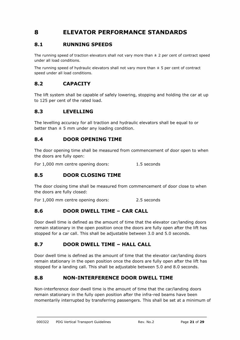
8 ELEVATOR PERFORMANCE STANDARDS
8.1 RUNNING SPEEDS
The running speed of traction elevators shall not vary more than ± 2 per cent of contract speed
under all load conditions.
The running speed of hydraulic elevators shall not vary more than ± 5 per cent of contract
speed under all load conditions.
8.2 CAPACITY
The lift system shall be capable of safely lowering, stopping and holding the car at up
to 125 per cent of the rated load.
8.3 LEVELLING
The levelling accuracy for all traction and hydraulic elevators shall be equal to or
better than ± 5 mm under any loading condition.
8.4 DOOR OPENING TIME
The door opening time shall be measured from commencement of door open to when
the doors are fully open:
For 1,000 mm centre opening doors: 1.5 seconds
8.5 DOOR CLOSING TIME
The door closing time shall be measured from commencement of door close to when
the doors are fully closed:
For 1,000 mm centre opening doors: 2.5 seconds
8.6 DOOR DWELL TIME – CAR CALL
Door dwell time is defined as the amount of time that the elevator car/landing doors
remain stationary in the open position once the doors are fully open after the lift has
stopped for a car call. This shall be adjustable between 3.0 and 5.0 seconds.
8.7 DOOR DWELL TIME – HALL CALL
Door dwell time is defined as the amount of time that the elevator car/landing doors
remain stationary in the open position once the doors are fully open after the lift has
stopped for a landing call. This shall be adjustable between 5.0 and 8.0 seconds.
8.8 NON-INTERFERENCE DOOR DWELL TIME
Non-interference door dwell time is the amount of time that the car/landing doors
remain stationary in the fully open position after the infra-red beams have been
momentarily interrupted by transferring passengers. This shall be set at a minimum of

000322 PDG Vertical Transport Guidelines Rev. No.2 Page 22 of 29
3.0 seconds. When the door beams are interrupted after the initial 3.0 second open
time subsequent open times shall be adjustable between 1.0 and 1.5 seconds.
8.9 DOOR NUDGING DWELL TIME
Door nudging dwell time is the amount of time that elapses before the infra-red door
protection is disabled and the car/landing doors begin to close at reduced speed and
torque. This shall be adjustable in a range between 20.0 and 25.0 seconds.
8.10 DOOR CLOSING PRESSURE
Door closing pressure shall comply with the code.
8.11 FLOOR-TO-FLOOR PERFORMANCE TIME
Floor-to-floor performance time is measured in seconds from the start of doors closing
at the initial floor until the doors are 3/4 open (1/2 open for side-opening doors) at
the next successive floor. This should be stable under any loading condition and in
either travel direction (The measurements given below relate to a typical floor to floor
height of 3,500 mm).
Traction lift: 7.0 seconds
Hydraulic lift: 10.0 seconds.
8.12 RIDE QUALITY
HORIZONTAL ACCELERATION WITHIN CAR DURING ALL RIDING AND DOOR OPERATING
CONDITIONS:
Front to back and side to side shall be no more than 10 mg peak to peak in the 1–10
Hz range.
ACCELERATION AND DECELERATION, TRACTION ELEVATORS
Acceleration and deceleration shall be smooth and constant with acceleration and
deceleration profiles not more than 1.0 m/s2.
SUSTAINED JERK, TRACTION ELEVATORS
To ensure that the ride in the lift is within comfortable limits, the jerk profile shall be
adjusted to be not more than 1.6 m/s2.

000322 PDG Vertical Transport Guidelines Rev. No.2 Page 23 of 29
9 INSTALLATION
All equipment must be installed in such a way that it may be easily removed for
maintenance and repair.
All equipment must be installed in such a way as to afford maximum accessibility,
safety and continuity of operation.

000322 PDG Vertical Transport Guidelines Rev. No.2 Page 24 of 29
10 FIELD QUALITY CONTROL
Guide rails must be installed so that rails are plumb and align vertically with tolerance
of 0.5 mm in 20 m. All rails must have secure joints without gaps and with any
irregularities filed to provide a smooth running surface.
Elevator cars must be static balanced to ensure equalised pressure on guide shoes on
guide rails.
The lift counterweight must be balanced to provide noise-free operation during lift
travel.
Motors, drive unit, brake, controllers, levelling switches, limit switches, stopping
switches, door operators, door locks and safety devices must be finally adjusted onsite
to achieve the required performance levels.

000322 PDG Vertical Transport Guidelines Rev. No.2 Page 25 of 29
11 ACCEPTANCE INSPECTION AND TESTS
Copies of the elevator contractor’s self-regulated testing procedures and
measurements must be provided on completion of provision of the elevator services to
facilitate independent inspection. All testing shall be undertaken in accordance with
the requirements of AS1735.1:2016.
11.1 GENERAL
All necessary labour, materials and equipment required for tests must be
furnished by the elevator contractor.
The elevator contractor must make contact with the lead consultant five days
in advance of when elevators are ready for testing and final review of each
unit or group.
Testing, together with inspection and review, will ensure that workmanship,
equipment and performance (including but not limited to contract speed,
capacity, noise, ride quality, floor-to-floor times, and door performance)
complies with all aspects of the specification.
Acceptance of results of all tests to confirm specified speed, performance
times, stopping accuracy without re-levelling and ride quality must be
confirmed by both Curtin University and the lead consultant.
Final acceptance of installation will only be made after all field quality control reviews
have been completed and all identified deficiencies have been corrected. Final
acceptance cannot be provided all until all information and certificates have been
received by Curtin University and the following items have been completed to the
satisfaction of Curtin University and the lead consultant:
overall ride quality including starting, accelerating, running quality,
deceleration and stopping accuracy
door operation and closing force
equipment noise levels
utility and installation quality of signal fixtures
performance of door control devices including door protection operation times
operation of special security operation and/or any floor lock-off provisions
adequacy and compliance with regard to car lighting including emergency
lighting
correct operation of car phone/emergency communication devices.
11.2 PERFORMANCE GUARANTEE
If any tests reveal defects, the elevator contractor shall complete corrective work to
the satisfaction of Curtin University and the lead consultant at no additional cost.
Identified defects may be due to poor workmanship, variance or noncompliance with
requirements of either specified codes and/or ordinances, or the requirements of the
specification.
000322 PDG Vertical Transport Guidelines Rev. No.2 Page 26 of 29
If a defect is identified, the elevator contractor must, at their own cost:
replace equipment that does not meet code or specification requirements
perform work and furnish labour, materials and equipment necessary to meet
specified operation and performance
perform, and assume the cost for, retesting required by Curtin University and
the lead consultant to verify specified operation and performance.

000322 PDG Vertical Transport Guidelines Rev. No.2 Page 27 of 29
12 PURCHASER’S INFORMATION
12.1 IDENTIFICATION OF EQUIPMENT
All items of equipment shall be identified with engraved Traffolyte labels in accordance
with Curtin University’s Project Delivery Guidelines using the University’s Archibus
asset coding structure, as described in the Curtin University Building Services Labelling
Standard. These guidelines stipulate the label size, colour and font standard that must
be adhered to. Prior to manufacture of the labels, the elevator contractor must submit
an equipment list in Microsoft Excel to the University’s Archibus System Administrator,
who will provide the relevant Archibus equipment codes.
Any pressure gauge tappings or remote sensing points on hydraulic elevators shall be
labelled to indicate their function.
12.2 PRACTICAL COMPLETION
At practical completion, the lead consultant shall forward all commissioning data, As-
Built drawings, O&M Manuals, Plant registration documentation to Curtin University’s
Manager Mechanical Engineering for review and comment by the University. The lead
consultant shall also coordinate and ensure that the defects inspection is carried out
with representatives of the elevator consultant, the elevator contractor and Curtin
University’s Mechanical Engineering section.
12.3 DEFECTS LIABILITY PERIOD
The elevator contractor shall ensure that all elevator equipment is serviced regularly
for a period of 12 months after practical completion and that maintenance service
sheets for all items of equipment are reviewed by the elevator consultant before being
forwarded to Curtin University for its review and comment.
At the end of the 12-months defects warranty period, a final inspection shall be
carried out by the elevator consultant, elevator contractor and a representative from
Curtin University’s Mechanical Engineering section. Copies of all service sheets shall be
forwarded to Curtin University’s Manager Maintenance Services for their records.
12.4 OPERATIONS AND MAINTENANCE MANUALS
The elevator consultant shall ensure that a complete set of operations and
maintenance manuals are reviewed as complete and approved by the consultant prior
to being forwarded on to Curtin University for review, comment and approval. Once
approved by Curtin, the consultant must forward two full and complete sets of
operations and maintenance manuals to Curtin University for its records. Each manual
must also include a full electronic version of the manuals provided on a DVD.
Operations and maintenance manuals for vertical transportation services must:
be contained within a three-ringed binder, navy blue in colour and A4 in size
comprise one or more binders as required to accommodate all the information
on the project services
000322 PDG Vertical Transport Guidelines Rev. No.2 Page 28 of 29
identify the campus, building name and number on the binding and front
cover with gold leaf lettering. (Note that the layout of the titles and headings
for the manuals shall be obtained from the Planning & Project Management
Section of PF & D within Curtin University).
identify the builder, architect, consultant and elevator contractor
identify the date of practical completion
incorporate a description of the works undertaken, description of operation,
equipment schedules, functional description of the control system including
flow diagrams and point schedules, manufacturer’s data, commissioning data,
maintenance procedures, fire testing procedures and as-constructed drawings
have the control system documents in a separate volume to match the project
manuals
incorporate one set of hard copy and one electronic copy of as-constructed
drawings per set of operations and maintenance manuals.
12.5 WIRING DIAGRAMS, KEYS AND DIAGNOSTIC
EQUIPMENT
Wiring diagrams must be mounted on panels; laminated and bound together; provided
in a binder; or similarly protected, in the elevator machine room or shaft.
Four sets of neatly tagged keys shall be provided for all switches and control features
properly tagged and marked in the machine room, control panel or shaft.
Diagnostic equipment complete with access codes, adjusters manuals and set-up
manuals for adjustment, diagnosis and troubleshooting of elevator system and
performance of routine safety tests must be left on site at completion of the works.
000322 PDG Vertical Transport Guidelines Rev. No.2 Page 29 of 29
13 REFERENCES
Curtin University Building Services Labelling Standard