cuscinetti di precisione per macchine utensili … · applicazioni e per la scelta del montaggio...
TRANSCRIPT

CUSCINETTI DI PRECISIONEPER MACCHINE UTENSILI
PRECISION BEARINGS FOR MACHINE TOOLS

Indice
Con
tent
s
PAG. 8
PAG. 9
PAG. 18
PAG. 20
PAG. 20
PAG. 24
PAG. 26
PAG. 26
PAG. 28
PAG. 30
PAG. 32
PAG. 34
PAG. 36
PAG. 38
PAG. 40
PAG. 42
PAG. 44
PAG. 45
PAG. 46
PAG. 47
PAG. 48
PAG. 50
PAG. 51
PAG. 52
PAG. 53
RTBCuscinetti assiali-radiali a rulli, per tavole di indexaggioCombined axial-radial roller bearings for indexing tables
• Specifiche tecnicheTechnical specifications
• Tabella cuscinetti RTBRTB bearings tables
RTB AMSCuscinetti assiali-radiali a rulli, con encoder induttivo integratoCombined axial-radial roller bearing, with integrated inductive encoder
• Specifiche tecnicheTechnical specifications
• Tabella cuscinetti RTB AMSRTB AMS bearings tables
SRBCuscinetti a rulli e rullini per viti a ricircolo di sfereNeedle and roller bearings for screw drives
• Descrizione e specificheDescription and specifications
• Tabella cuscinetti SRBSRB bearings table
• Tabella cuscinetti SRB_L - con ralla porta tenutaSRB_L bearings table - with extended washer
• Tabella cuscinetti SRB_F - con flangia di fissaggioSRB_F bearings table - with fixing flange
• Tabella cuscinetti SRB_FL - con flangia di fissaggio e ralla porta tenutaSRB_FL bearings table - with fixing flange and extended washer
• Tabella cuscinetti SRB_T - con fori di fissaggioSRB_T bearings table - with fixing holes
• Porta tenute tipo SHSH seal carrier
Ghiere di precisione MONDIALMONDIAL precision locknuts
• Selezionatura ghiereLocknuts selection
• HIFBloccaggio lateraleSide locking
• HIABloccaggio assialeAxial locking
• HIRBloccaggio radialeRadial locking
• HIKBloccaggio a mollaAxial locking with notch
XRBCuscinetti customizzati a rulli incrociatiCustomized cross roller bearings
• EsempiExamples
Designazione cuscinetti RTB / RTB-AMSBearings designation RTB / RTB-AMSDesignazione cuscinetti SRBBearings designation SRBDisegni speciali customizzatiCustom special drawings

Mondial is a leading company inthe import and distribution ofpower transmission components.Mondial always provides its customers with highly qualified products matched with an excellent logistical and technical support.Mondial is an ISO 9001:2000certified Company.
componenti meccanici innovativiMondial, Azienda leader nell’importazione e commercializzazione di componenti meccanici innovativi edi elevata qualità, offre un serviziocostantemente adeguato alle esigenze del mercato.Un servizio che integra dinamicamente l’organizzazione commerciale con quella tecnica elogistica, proponendo una completa gamma di organi di trasmissione, provenienti da tuttoil mondo, competitivi e all’avanguardia.Mondial è una Azienda certificataISO 9001:2000.
inno
vativ
e po
wer
tran
smiss
ion
com
pone
nts
4
UNITEC, azienda leader nella progettazione e costruzione di cuscinettispeciali di precisione a rulli cilindrici per macchine utensili e per altreapplicazioni industriali, offre ai suoi clienti in tutto il mondo un servizio dielevata qualità: assistenza tecnica qualificata sin dalle prime fasi delprogetto, una rete commerciale capillare, un servizio postvendita affidabile,costantemente adeguato alle esigenze del mercato.
UNITEC fa parte del Gruppo Mondial ed è un’azienda certificata ISO 9001:2000 e ISO 14001:2004.
UNITEC, leading company in the design and manufacturing of specialprecision cylindrical roller bearings for machine tools and general industry,delivers high quality service and support to customers world-wide. Engineering partnership, technical and logistic services and our commercialnetwork, supplied by different distribution channels, allows us to fulfil uniqueapplication requirements on the marketplace.
UNITEC is a certified ISO 9001:2000 and ISO 14001:2004 company,belonging to Mondial S.p.A. Group.
5
CU
SCIN
ETTI
DI P
RECIS
ION
EPR
ECIS
ION
BEA
RIN
GS

Tecnologia avanzata per soddisfarele esigenze di progetto dei vostri clienti.
Ingegneri e progettisti vi assisterannonella selezione del cuscinettoUNITEC più idoneo per le vostre nuoveapplicazioni e per la scelta del montaggio più appropriato.
Advanced technology to meet your customers requirements.
Our engineers will assist you in selecting the most suitable UNITEC bearing andmounting arrangement for your applications.
tecnologia avanzata
adva
nced
tech
nology
6

I vostri clienti vi richiedono macchine utensili
che siano precise, affidabili e che possano
garantire i più alti livelli di produttività.
Il cuscinetto di precisione UNITEC è il
cuore della vostra macchina.
Your customers require highly
precise and reliable machine
tools able to secure high productivity.
UNITEC precision bearing is the
heart of your machine.
alti livelli di produttività
7
high
pro
ductivity
CU
SCIN
ETTI
DI P
RECIS
ION
EPR
ECIS
ION
BEA
RIN
GS

RTBelevata rigidezza ed elevata precisione
high
rig
idity
toge
ther
with
hig
h ac
cura
cy
Cuscinetti assiali-radiali di precisioneper tavole di posizionamento e indexaggio.
L’elevata rigidezza assiale e la capacità di sopportare elevate coppie diribaltamento rende questo cuscinettoUNITEC serie RTB particolarmenteadatto all’impiego nelle tavole rotanti,di posizionamento e di indexaggio teste fresa.
Axial-radial precision bearings for indexing tables.
Due to their high axial stiffness andtheir capacity to bear high tilting moments, UNITEC bearings RTB series are particularly recommendedfor rotating, positioning and indexingtables and milling heads.
8
Cuscinetti assiali-radiali a rulli, per tavole di indexaggioCombined axial-radial roller bearing for indexing tables

9
1. Descrizione2. Rigidezza3. Indicazioni per il montaggio4. Precarico5. Attrito6. Velocità
1. DescrizioneI cuscinetti della serie RTB sono costituiti da un anellointerno sagomato (profilo ad L), integrato con una ralladi chiusura, da un anello esterno, da due gabbie assialia rulli e da un pieno riempimento radiale a rulli. I valoridelle capacità di carico assiali e radiali sono staticalcolati secondo le norme UNI ISO 76 e UNI ISO 281utilizzando coefficienti adeguati all’elevata qualità degliacciai impiegati ed ai trattamenti termici specificieseguiti. Alle norme su menzionate ed ai relativiaggiornamenti/integrazioni, si prega di riferirsi anche peril calcolo della durata. I cuscinetti RTB vengono forniti indue configurazioni base:• Non lubrificato – RTBIl cuscinetto è avvolto in carta oleata totalmentericoperto da film di olio protettivo. In questo caso, deveessere previsto da parte dell’utilizzatore un’adeguatalubrificazione ad olio o a grasso. I cuscinetti sonoprovvisti di fori radiali sull’anello interno ed esterno perconsentire l’apporto di lubrificante.• Lubrificato a grasso – RTB_GIl cuscinetto viene prelubrificato con grasso ai saponi dilitio, EP, NLGI 2, 150 cst a 40°C con un riempimento dicirca il 50 %. Per richiesta di utilizzo di grassi diversi, sisuggerisce di prevedere le configurazioni non lubrificatee procedere al caricamento del grasso specifico tramitegli appositi fori.
2. RigidezzaElevata rigidezza, grande capacità di carico, elevataprecisione di rotazione, sono i requisiti fondamentali deicuscinetti assiali – radiali UNITEC serie RTB. L’impiegodi gabbie assiali ad elevato numero di corpi volventi, concontatto lineare, contribuisce ad ottenere un movimentopreciso e rigido, così come l’elevatissima precisionedelle lavorazioni meccaniche. Le dimensioni dei rulli, siaassiali che radiali, e degli anelli interno ed esterno sonocalibrate in modo tale che al serraggio delle viti difissaggio si ottengano i precarichi previsti. Le tolleranze,imposte in produzione, del valore dei precarico sonoparticolarmente ristrette così da garantire un’elevatacostanza ed uniformità di fornitura nel tempo. Grazie alprecarico ed al contatto lineare dei corpi volventi, larigidezza assiale, radiale ed a ribaltamento dei cuscinettiRTB può considerarsi, con buona approssimazione, unagrandezza lineare (andamento quasi lineare delle curvedi rigidezza), per cui, i rispettivi valori Ka, Kr e Kmr,possono essere assunti come costanti e riportati cometali nella relativa tabella dimensionale (Tab. 1). Questivalori sono stati determinati con calcoli agli elementifiniti (FEM) mediante opportuna modellazione delcuscinetto assiale – radiale, relativamente alle diversetaglie, nelle due diverse condizioni di montaggioillustrate in Fig. 1 e Fig. 2.Al riguardo, si riportano le Fig. 3 e 4 quale esempio deglistati tensionali indotti nei cuscinetti RTB, nei due casi,rispettivamente.
1. Description2. Stiffness3. Mounting instructions4. Preload 5. Friction6. Operating speed
1. DescriptionRTB bearings consist of a moulded inner ring (Lsection) – completed with a washer -, an outer ring, tworoller thrust bearings and a cylindrical roller bearing, fullcomplement.The axial and radial load-carrying capacity have beencalculated according to UNI ISO 76 and UNI ISO 281standard, by using factors suitable for the high qualitysteels and the specific heat treatments connected withthese bearing series.As for the life calculation, also refer to the a.m. standard.RTB bearings are available in two different designs:• RTB - without lubricationThe bearing is wrapped in oil-paper, completely coveredwith a protective oil film. Customer must provide for anadequate oil or grease lubrication. For this purpose,bearings have radial holes on the inner and outer rings.• RTB_G – with grease lubricationThe bearing is pre-lubricatedwith (litium based grease, EP,NLGI 2, 150cst at 40 Celsiusdeg) – approx. 50% filling.If a different grease isrequested, we suggest to askfor a non lubricated designand then to fill with therequested grease through thelubrication hole.
2. StiffnessHigh stiffness, considerable load-carrying capacity, highrotational accuracy are the essential features of thecombined UNITEC RTB bearings. The axial cages witha big number of rolling elements with linear contact aswell as the very high precision of the machining permita precise and rigid movement.The size of the axial and radial rollers as well as of theinner and outer rings are carefully measured in order toobtain the requested preloads by tightening the capscrews. The manufacture tolerances of the preload valueare particularly restricted, so that a constant anduniform quality of the supplies can be granted over theyears. Thanks to the preload and the linear contact ofthe rolling elements, the axial, radial and tilting stiffnessof the RTB bearings can be considered, at a roughestimate, a linear magnitude (almost linear trend of thestiffness curves), so that the relevant values Ka, Kr andKmr can be assumed as a constant and stated as suchin the concerning dimensional table (Tab. 1).The a.m. values have been obtained by means of FEMcalculations, by modelling the different sizes of thecombined bearing according to the two differentassembly layouts (see Pics 1 and 2). In Pics 3 and 4 you can see a typical induced stress in the RTBbearings, according to the two different assemblylayouts.
Specifiche tecniche Technical specification
CU
SCIN
ETTI
DI P
RECIS
ION
EPR
ECIS
ION
BEA
RIN
GS

10
RTB
1Schema di montaggio senza ralla di supporto Assembly layout without thrust washer
2 Schema di montaggio con ralla di supportoAssembly layout with thrust washer
3Stato tensionale senza ralla di supportoStatic nodal stress without thrust washer
4Stato tensionale con ralla di supportoStatic nodal stress with thrust washer
Mr = tilting momentAx = axial loadRd = radial load
Appendice tecnica Technical abstract

11
Tab. 1 (°)
(°) I valori di rigidezza indicati tengono conto delledeformazioni di tutti i componenti del cuscinettomontato mediante collegamento con le viti di serraggiopreviste. Sono possibili scostamenti rispetto ai valorireali, relativi al grado di approssimazione del modellorispetto al sistema reale.
(**) Per i valori di rigidezza radiale, non si apprezzanosignificative variazioni nel passaggio da uno schema dimontaggio all’altro.
(°) A. m. stiffness values consider the deformationof all components of the bearing (assembled withcap screws). Deviations from the actual values arepossible, according to the approximation of themodel with respect to the real system.
(**) As for the radial stiffness values, thedifferences between the two assembly schemesare insignificant.
Diametro foro del cuscinettoBore diameter
(mm)
SiglaDesignation
Rigidezza assiale
Axial stiffness
KAX
(kN/µm)
Rigidezza amomentoribaltante
Tilting stiffness KMR
(kNm/mrad)
Rigidezza radiale
Radial stiffness
KRD
(kN/µm)
(**)con ralla di supporto With thrust washer
senza ralla di supportoWithout thrust washer
Rigidezza assiale
Axial stiffness
KAX
(kN/µm)
Rigidezza amomentoribaltante
Tilting stiffnessKMR
(kNm/mrad)
TABELLA VALORI DI RIGIDEZZA STIFFNESS VALUE
80 RTB 80 1,9 1,7 2,4 1,8 1,6
100 RTB 100 2,4 3,7 2,0 2,3 3,3
120 RTB 120 3,2 7,6 2,6 3,0 6,5
150 RTB 150 4,0 12,5 3,3 3,7 10,9
180 RTB 180 4,9 20 2,9 4,3 17,1
200 RTB 200 5,5 27,6 2,9 4,9 24,3
260 RTB 260 8,3 51,5 5,7 8,1 48,4
325 RTB 325 9,5 88,5 6,0 9,2 81,3
395 RTB 395 13,1 158,1 5,9 11,5 148,5
460 RTB 460 16,0 218,5 6,3 13,6 209,1 CU
SCIN
ETTI
DI P
RECIS
ION
EPR
ECIS
ION
BEA
RIN
GS

12
3. Indicazioni per il montaggioPer il montaggio si suggerisce di rispettare leprescrizioni indicate nello schema riportato in Fig. 5.
3. Mounting instructionsFor mounting instructions we recommend to followspecifications reported in Pic 5.
5Indicazioni di montaggioNota: diametro ralla e anello interno D1 (tabella dimensionale pag. 18) torniti.
Mounting instructionsNote: outer diameter of the washer and inner ring (dimensional table on page 18) are turned.
RTB

13
4. PrecaricoL’applicazione del precarico nei cuscinetti nascefondamentalmente dall’esigenza di avere un aumentodi rigidezza e di precisione della rotazione.In presenza di un carico esterno, precaricare ilcuscinetto significa recuperare o evitare il giuoco che sioriginerebbe in corrispondenza del cedimento elasticodovuto al carico stesso. Le deformazioni elasticheprovocate dal carico, sono, in tal caso, per un datocampo di carichi, minori che nel cuscinetto nonprecaricato. Assumendo che la caratteristica dirigidezza sia lineare (contatto di rulli su piste), lospostamento assiale in un sistema precaricato dicuscinetti è inferiore a quello in un sistema nonprecaricato, a parità di carico assiale (vedi Fig. 6, caricoFx). La Fig. 6 illustra i due casi. La linea (1)rappresenta la caratteristica di cedimento elastico di unsistema (ad esempio di due cuscinetti assiali uguali A eB) montato non precaricato, sottoposto ad un caricoesterno Fx. La linea (2), quello dello stesso sistemaassemblato con un precarico pari al valore Fo.Nel caso del sistema precaricato (linea 2),l’applicazione del carico assiale esterno Fx, carica ilcuscinetto A e scarica B di un valore corrispondente aFx/2, mentre nel caso senza precarico (linea 1), lastessa situazione comporta che il carico esterno Fxvenga integralmente supportato dal cuscinetto A condistacco del contatto di B. In conclusione, la rigidezzaassiale di un sistema precaricato è doppia. Aumentare ilvalore di precarico con i cuscinetti RTB non aumenta larigidezza ma semplicemente sposta il limite deldistacco a valori di forza Fx più elevati. In altre parole,se la forza assiale esterna supera un valore pari a duevolte quello del precarico (Fx > 2Fo), il cuscinetto B siscarica completamente e la rigidezza assiale delsistema è unicamente determinata dal cuscinetto A,come nel caso di cuscinetti montati senza precarico,però lo spostamento assiale nel caso (2), inquest’ultima situazione, rimane comunque inferiorerispetto al caso (1) (vedi Fig. 6).
4. PreloadThe preload of the bearings increases the stiffnessand the rotational accuracy. In presence of a load fromthe outside, the preload of the bearing eliminates oravoids the backlash corresponding to the elasticyielding due to the load itself. In this case, for a givenrange of loads, the elastic deformations caused by theload are smaller than in a non-preloaded bearing.Assuming the stiffness is linear (rollers in contact withtracks), at the same axial load the axial deflection issmaller in a preloaded bearings system than in a non-preloaded system (see Pic 6, load Fx).In Pic 6 the two different situations are represented.Line no. 1 represents the elastic yielding of a non-preloaded system (for instance of two similar axialbearings A) and B), put through the outside load Fx.Line no. 2 refers to the same system assembled withpreload equal to value Fo.As for the preloaded system (line no. 2), the outsideaxial load Fx charges bearing A and dischargesbearing B with a value corresponding to Fx/2. As for thenon-preloaded system (line no. 1), the outside axialload Fx is fully borne by bearing A with loss of contactof bearing B.To sum up, the axial stiffness of a preloaded system istwice as much. As for the RTB bearings, to increasethe preload value doesn’t increase the stiffness butsimply shifts the disconnection point to higher forcevalues Fx. In other words, if the axial force from theoutside exceeds a value equal to twice the preloadvalue (Fx>2Fo), the bearing B is fully discharged andthe axial stiffness of the system is entirely determinedby bearing A (as for non-preloaded bearings) but theaxial deflection in case (2), as for the last situation, isshorter than in case (1) (see Pic 6).
Fx2
1
Fx=2Fo
δ con prec.with prel.
δ con senza prec.without prel.
δ
(1) sistema senza precaricosystem without preload
(2) sistema con precarico Fosystem with preload Fo
Fx = forza assiale esternaexternal axial force
δ = spostamento assiale axial deflection
6
CU
SCIN
ETTI
DI P
RECIS
ION
EPR
ECIS
ION
BEA
RIN
GS

14
Si rititene importante ricordare che con la serie RTB(versioni standard), il serraggio delle viti dell’anellointerno comporta l’annullamento dei giochi assialidimensionali o interni e la compressione elasticadell’anello interno• Cuscinetti appena ingrassati, sono caratterizzati da
momenti d’attrito più elevati. • Una buona distribuzione del grasso o una
lubrificazione ad olio ottimale risulta determinante alfine di ottenere un basso valore del momentod’attrito.
I valori della coppia d’attrito per le diverse tipologie dicuscinetti RTB, riportati in Tab. 2, sono ottenuti conprove di funzionamento nelle seguenti condizioni:
1.montaggio tipo con ralla di supporto (vedi Fig.2). In assenza di anello di supporto, nelle taglie piùpiccole, si possono ottenere coppie di rotolamentoinferiori.
2.Lubrificazione a grassoGrasso ai saponi di litio, EP, NLGI 2, 150 cst a 40°C.
3.Velocità di rilevamento: 5rpm.Il valore indicato include l’eventuale spunto che ingenere è inferiore al 10% del valore costante.
4.Temperatura di prova: 30÷40°C.
5. AttritoNei cuscinetti la resistenza complessiva al motodipende da molti fattori, i più importanti dei quali sono:• precarico• viscosità e quantità del lubrificante• carico applicato • dimensione del cuscinetto • velocità di rotazione
Più in dettaglio:• Un precarico maggiore porta ad una coppia di
rotolamento superiore • Nei cuscinetti RTB si suggerisce di rispettare i
seguenti valori relativi alle coppie di serraggio delleviti di fissaggio:
We remind you that as for the RTB bearings (standardtypes), the fixing of the inner ring screws involves theannulment of the dimensional or inner axial backlashas well as the elastic compression of the inner ring.• Newly greased bearings have higher friction torques.• A good grease distribution or an ideal oil lubrication is
decisive to obtain a lower friction torque.
The friction torque values of the various RTB bearingdesigns (see Tab. 2) are obtained in the following testconditions:
1.Assembly with thrust washer (see Pic 2). Failing the thrust ring, in the smaller sizes, it ispossible to obtain lower rolling resistance moments.
2.Grease lubrificationLitium based grease, EP, NLGI 2, 150cst at 40Celsius deg.
3.Operating speed: 5 rpmA.m. value includes the starting frictional torque (as arule the starting torque is lower than 10% of the evenvalue).
4.Test temperature: 30°÷40°C
5. FrictionAs for the bearings, the friction depends on manyfactors, the most important of which are:• preload• viscosity and amount of the lubricant• applied load• bearing size• rpm
That is:• A bigger preload turns out in a bigger rolling friction
torque.• As for the RTB bearings, we suggest to respect
following tightening torque values (which are the maxvalues for bolt class 8.8):
RTB
M5 M6 M8
6,1 Nm 10,4 Nm 25 Nm

15
(°) I valori riportati sono statistici e quindi sono da considerarsi indicativiThe a.m. values are to be intended as statistical
Diametro foro del cuscinettoBore diameter
(mm)
siglaDesignation
80 RTB 80 2
100 RTB 100 2
120 RTB 120 8
150 RTB 150 10
180 RTB 180 13
200 RTB 200 15
260 RTB 260 19
325 RTB 325 21
395 RTB 395 25
460 RTB 460 30
Coppia rotolamentoRolling torque
CRL(Nm)
CU
SCIN
ETTI
DI P
RECIS
ION
EPR
ECIS
ION
BEA
RIN
GS
Tab. 2 (°)
COPPIA DI ROTOLAMENTO ROLLING TORQUE

16
7
8
RTB
In Fig. 7 e in Fig. 8 si riportano i diagrammi relativi alla coppia di rotolamento, ottenuta a 5rpm per l’RTB395 e l’RTB120rispettivamente. Si noti come il picco di spunto sia assolutamente trascurabile.Pic 7 and Pic 8 report the rolling torque charts at 5 rpm of the RTB 395 and RTB 120. Note that the starting torque peak isnegligible.
Picco di spunto trascurabile.
Negligible torque peak.

17
Le velocità riportate sono da considerarsi limiti perregime continuativo o come velocità medie perfunzionamento intermittente con velocità di puntasuperiori fino al 40% d’incremento. Si rammenta che laviscosità minima del lubrificante in esercizio èdeterminante per il calcolo dei fattori correttivi delladurata, come da norme ISO.
The a.m. operating speeds shall be considered aslimiting speeds in case of continuous working or asaverage speeds in case of intermittent working withpeak speeds exceeding additional 40%. We remindthat the lubricant minimum viscosity is decisive tocalculate the life remedial factor according to ISO.
TipoLubrificazioneLubrification
RTB 80 RTB 100 RTB 120 RTB 150 RTB 180 RTB 200 RTB 260 RTB 325 RTB 395 RTB 460
Grasso420 330 270 250 230 200 160 130 110 100Grease
Olio870 700 570 520 470 420 320 270 220 200Oil
RTB dmm
tol.mm
Dmm
tol.mm
Bmm
tol.mm
Hmm
tol.mm
80 80 0 146 0 35 0 23.35 ± 0.150– 0.007 – 0.009 – 0.150
100 100 0 185 0 38 0 25 ± 0.175– 0.008 – 0.011 – 0.200
120 120 0 210 0 40 0 26 ± 0.175– 0.008 – 0.011 – 0.200
150 150 0 240 0 40 + 0.035 26 ± 0.175– 0.010 – 0.011 – 0.250
180 180 0 280 0 43 0 29 ± 0.175– 0.010 – 0.013 – 0.250
200 200 0 300 0 45 0 30 ± 0.175– 0.012 – 0.013 – 0.300
260 260 0 385 0 55 0 36.5 ± 0.200– 0.018 – 0.020 – 0.350
325 325 0 450 0 60 0 40 ± 0.200– 0.023 – 0.023 – 0.400
395 395 0 525 0 65 0 42.5 ± 0.200– 0.023 – 0.028 – 0.400
460 460 0 600 0 70 0 46 ± 0.225– 0.023 – 0.028 – 0.450
CU
SCIN
ETTI
DI P
RECIS
ION
EPR
ECIS
ION
BEA
RIN
GS
Tab. 3
VELOCITÀ DI ROTOLAMENTO (rpm) OPERATING SPEED (rpm)
Tab. 4
TOLLERANZE DIMENSIONALI DIMENSIONAL TOLERANCES

18
RTB 80(1) RTB 80 G 200 80 146 35 23,35 12 130 92 138 5,6 10 4 9RTB 100 RTB 100 G 260 100 185 38 25 12 160 112 170 5,6 10 5,4 16RTB 120(1) RTB 120 G 315 120 210 40 26 12 184 135 195 7 11 6,2 22RTB 150(1) RTB 150 G 350 150 240 40 26 12 214 165 225 7 11 6,2 34RTB 180 RTB 180 G 400 180 280 43 29 15 244 194 260 7 11 6,2 46RTB 200(1) RTB 200 G 500 200 300 45 30 15 274 215 285 7 11 6,2 46RTB 260 RTB 260 G 630 260 385 55 36,5 18 345 280 365 9,3 15 8,2 34RTB 325 RTB 325 G 700 325 450 60 40 20 415 342 430 9,3 15(2) 8,2 34RTB 395 RTB 395 G 800 395 525 65 42,5 20 486 415 505 9,3 15 8,2 46RTB 460 RTB 460 G 1000 460 600 70 46 22 560 482 580 9,3 15 8,2 46RTB 580 RTB 580 G 1200 580 750 90 60 30 700 610 720 11,4 18 11 46
(1) RTB con gabbie assiali in poliammide PA 66.(2) Lamature aperte verso l’interno.
N° dis. lub. a olio N° dis. lub. a grasso Ø tavola n° sediPart Number Part Number Suitable d D B H b D1 J J1 d1 d2 a Fixing
oil lub. grease lub. table Ø mm mm mm mm mm mm mm mm mm mm mm holes n°
RTB CUSCINETTI ASSIALI-RADIALI A RULLI, PER TAVOLE DI INDEXAGGIO
COMBINED AXIAL/RADIAL ROLLER BEARING FOR INDEXING TABLES
TABELLA DIMENSIONALE DIMENSIONAL TABLE

19
PER TOLLERANZE DIMENSIONALI, RIFERIRSI ALLA TAB. 4FOR THE DIMENSIONAL TOLERANCES, SEE TAB. 4
G n°G n°×α°
Coeff. di carico ISOLoad ratings according to
RADIALERADIAL
ASSIALEAXIAL
din. Cdyn. C
kN
stat. Costat. Co
kN
din. Cadyn. Ca
kN
stat. Coastat. Coa
kN
Erroreassiale
e radialedi
rotazioneAxial and
radialrunout
μ
RTB 80(1) RTB 80 G 4,6 12 3 / / 12x30° 3 45,3 106,8 55,4 269,4RTB 100 RTB 100 G 5,6 15 2 M5 3 18x20° 3 56,4 128,5 97,8 509,8RTB 120(1) RTB 120 G 7 21 2 M8 3 24x15° 3 71,9 174,5 108,5 614,9RTB 150(1) RTB 150 G 7 33 2 M8 3 36x10° 3 83,3 210,8 109,7 664,1RTB 180 RTB 180 G 7 45 2 M8 3 48x7,5° 4 88,5 274,2 125,7 826,4RTB 200(1) RTB 200 G 7 45 2 M8 3 48x7,5° 4 135,4 297,2 103,6 668RTB 260 RTB 260 G 9,3 33 2 M12 3 36x10° 6 137,9 480,3 125,9 935,9RTB 325 RTB 325 G 9,3 33 2 M12 3 36x10° 6 151,1 581,4 216,9 1768,9RTB 395 RTB 395 G 9,3 45 2 M12 3 48x7,5° 6 173,6 699,5 235,6 2085,8RTB 460 RTB 460 G 9,3 45 2 M12 3 48x7,5° 6 210,1 807,9 260,2 2467RTB 580 RTB 580 G 11,4 42 2 M12 6 48x7,5° 10 282,0 1177 402 3877
(1) RTB size with axial cages in poliamid PA 66.(2) Milled slots open towards bearing bore.
n°d3
n° viti diritenuta
Assemblyscrews n.
d3mm
N° dis. lub.a olio
Part Numberoil lub.
N° dis. lub.a grasso
Part Numbergrease lub.
CU
SCIN
ETTI
DI P
RECIS
ION
EPR
ECIS
ION
BEA
RIN
GS

20
I cuscinetti UNITEC tipo RTB AMS con sistema di misuraangolare integrato sono combinati assiali radiali a doppioeffetto studiati per il supporto di tavole rotanti e teste dimandrini per macchine utensili.
Per migliorare le prestazioni delle applicazioni per le qualisono previsti i cuscinetti RTB, UNITEC ha sviluppato laversione RTB AMS che integra il sistema di misura angolare di precisione AMOSIN.La precisione costruttiva (classe di precisione secondotab. 4), i bassi livelli di coppia resistente, l’elevata capacitàdi carico e rigidezza li pongono nel mercato ai massimilivelli di qualità e li rendono adatti a supportareinstallazioni su cui sono previsti motori coppia diretti.
IDEALI PER MOTORI DIRETTIUNITEC RTB AMS bearings series, with integrated anglemeasuring system are bidirectional axial-radial combined,designed for rotary tables and spindle heads for machinetools.
To improve performances of applications where RTBbearings series are installed, UNITEC developed newversion RTB AMS, integrating AMOSIN precision inductivemeasuring system.The manufacturing precision (in reference at the table 4),low resistant torque, high load capacity and stiffness arepositioning this bearings range at the top of the market,qualifying them as the most suitable solution for directdrive installations.
IDEAL FOR DIRECT DRIVES
RTBAMSSpecifiche tecniche Technical specification
Cuscinetti assiali-radiali a rulli, con encoder induttivo integrato
Combined axial-radial roller bearings, with integrated inductive encoder
SISTEMA NON MAGNETICO
NOT MAGNETIC SYSTEM

21
Il sistema è fornibile in configurazioni customizzate a richiesta, con diversi livelli di precisione e risoluzione.
The system is available in custom configurations, with different precision and resolution level
• SISTEMA A SCANSIONE INDUTTIVA (NON MAGNETICO)
• ASSOLUTA INSENSIBILITA’ AI CAMPI MAGNETICI
• SEGNALI D’USCITA IN TEMPOREALE, (IDEALE PER MOTORI DIRETTI)
• ELEVATA VELOCITA’ DI ROTAZIONE
• ELEVATA RISOLUZIONE E PRECISIONE
• INDUCTIVE MEASURING SYSTEM(NON MAGNETIC)
• INSENSITIVITY TO MAGNETICFIELDS
• REAL TIME OUTPUT SIGNALS(IDEAL FOR DIRECT DRIVES)
• HIGH ROTATION SPEED
• HIGH MEASURING RESOLUTIONAND ACCURACY
Moreover:• The most compact solution.
• Insensitivity to external agents (IP 67 protected sensors)
• Simple installation.
• Quickest setting.
• Stable and reliable functioning.
• No setting software needed.
Inoltre:• Soluzione compatta.
• Insensibilità agli agenti esterni. (sensori protetti IP 67)
• Installazione semplice.
• Taratura veloce.
• Funzionamento stabile ed affidabile.
• Nessun software di settaggio necessario.
CARATTERISTICHE DEICUSCINETTI UNITEC RTB AMS
UNITEC RTB AMS BEARINGSFEATURES
CU
SCIN
ETTI
DI P
RECIS
ION
EPR
ECIS
ION
BEA
RIN
GS

22
Grazie all’elevata modularità del sistema ed alla suacompletezza, siamo in grado di calibrare la forniturasecondo le esigenze della clientela:
• CONFIGURAZIONE AD ALTA RISOLUZIONE(scala graduata in classe +/- 5 µm, 1 testina di lettura,fattore interpolazione 1/32). Quando l’accuratezzarichiesta al sistema di misura non è esasperata
• CONFIGURAZIONE AD ALTA RISOLUZIONE E ADALTA PRECISIONE(scala graduata in classe +/-5 µm, 2 testine di lettura,fattore interpolazione 1/32) La massima prestazione siacome precisione che risoluzione.
• Scala graduata in classe di precisione +/-5 µm
• Indici di riferimento. Versione standard: un indice di riferimento su 360° Versione a richiesta: vari indici di riferimento su 360° a distanza codificata
• Segnali d’uscita sinusoidali 1 Vpp (resist. Terminale120 Ω) secondo standard mercato (segnali in onda quadra TTL a richiesta)
• Vari fattori di interpolazione (vedi Tab. 5)
• Accuratezza totale fino a +/- 3” di grado (cuscinetti dimassima taglia)
CARATTERISTICHE DEL SISTEMA DI MISURA INDUTTIVO
Thanks to the modularity of the system, we can tailorthe proposal in order to fulfil customer specificrequirements:
• HIGH RESOLUTION CONFIGURATION (precision scale +/- 5µm, 1 measuring head, interpolationfactor 1/32) when requirements are not for extremely highaccuracy.
• HIGH RESOLUTION AND HIGH PRECISIONCONFIGURATION(precision scale +/- 5 µm, 2 measuring heads,interpolation factor 1/32) for maximum performances inaccuracy and resolution.
• Measuring scale available in precision class: +/-5 µm
• Reference marks (zero). Standard version: onereference mark on 360°. Optional reference: severaldistance-coded reference marks on 360° upon request.
• Output signals 1 Vpp (for term. resistance 120 Ω) -optional TTL square wave upon request
• Several interpolation factors in order to adjust theresolution of the system as needed (check Tab. 5)
• Total accuracy of the system up to +/- 3” of arc (maxbearing size)
INDUCTIVE ANGLE MEASURING SYSTEM FEATURES
Diam. foro P/N N° di periodi base N° di periodi con fatt. 1/32Bore dia. N° of basic periods N° of basic periods with factor 1/32
(T/giro) (T/giro)(mm) (T/rev) (T/rev)
150 RTB 150 AMS 672 21504
180 RTB 180 AMS 768 24576
200 RTB 200 AMS 864 27618
260 RTB 260 AMS 1088 34816
325 RTB 325 AMS 1296 41472
395 RTB 395 AMS 1512 48384
460 RTB 460 AMS 1752 56064
T = Periodo sinusoide T = Sinewave period
RTB AMS
Per ulteriori possibili configurazioni del sistema, Vi preghiamo di contattarci.For further, possible configurations of the system, please contact us.
Tab. 5
VALORI DI RISOLUZIONE RESOLUTION VALUES

23
� esclusivamente induttivo.
� precisione paragonabile ai corrispondenti sistemi dimisura optoelettronici. Alta qualità del segnale condeviazione di forma della sinusoide inferiore a 0.1%.
� estremamente resistente verso le condizioniambientali critiche, come particelle solide, olio, etc.
� alta resistenza alle sollecitazioni meccaniche comeshock e vibrazioni.
� periodo base dei segnali sinusoidali di 1000 µmrelativo alla graduazione della scala graduata eriferito ad un pari arco della circonferenza dellaflangia su cui è avvolta la scala stessa.
� fattore di interpolazione standard 1/32 chepermette di ridurre la lunghezza del periodo fino acirca 30 µm con ottimo rapporto segnale/ rumore.
� is purely inductive.
� achieves degrees of accuracy up to theoptoelectronic systems. High quality of the outputsignal with sinusoidal accuracy deviations lowerthan 0.1%.
� is extremely protected from environmental pollutionsuch as solid particles, grease, oil etc.
� is extremely high shock and vibration resistant.
� basic period of 1000 µm related to the precisionscale and referred to an arc length of the flange’scircumference.
� is provided with interpolation factor 1/32, whichallow to reduce the period length down to approx.30 µm, with low noise/signal ratio.
Suddivisione del segnale sinusoidale di periodo λ=1 mmSubdivision of the sinewave signal with period λ=1 mm
Il sistema di misura AMOSIN: AMOSIN measuring system:
CU
SCIN
ETTI
DI P
RECIS
ION
EPR
ECIS
ION
BEA
RIN
GS

24
150(1) RTB 150 AMS 350 240 43* 26 12 214 215 165 225 16,5 121 7 11
180 RTB 180 AMS 400 280 46* 29 15 244 245 194 260 16,5 140 7 11
200(1) RTB 200 AMS 500 300 47* 30 15 274 276 215 285 16,5 152 7 11
260 RTB 260 AMS 630 385 55 36.5 18 345 345,5 280 365 17,5 192,5 9.3 15
325 RTB 325 AMS 700 450 60 40 20 415 415,5 342 430 18,5 225 9.3 15(2)
395 RTB 395 AMS 800 525 65 42.5 20 486 486,5 415 505 18,5 262,5 9.3 15
460 RTB 460 AMS 1000 600 70 46 22 560 560,5 482 580 18,5 300 9.3 15
P/N cuscinettoBearing P/N
Diam.foro dBore diam.
mm
D
mm
B
mm
H
mm
b
mm
D1
mm
J
mm
D2
mm
J1
mm
F
mm
L
mm
d1
mm
d2
mm
øD
iam
. tav
ola
Sui
tabl
e ta
ble
ø
Dimensioni di ingombroestremamente contenuteLe quote riportate in tabella sono relative agli ingombridelle testine di misura, in particolare quellecontrassegnate con * differiscono dalle quote dei cuscinettistandard per l’aumentato spessore della flangia.
Attenzione: si raccomanda il fissaggio dei sensori solodopo il montaggio del cuscinetto. Per le taglie 150 e 200,la testa delle viti di fissaggio dell'anello esterno, dovràessere scaricata (1 mm circa sul diametro) per evitare laloro possibile interferenza con la scala graduata.
Attention: we raccomend to proceed with the thighteningof the scanning heads only after the mounting of thebearing. Futhermore, the fixing screw's head of the outerring must be reduced (about 1 mm on the diameter),since they could interfere with the graduating scale.
Extremely compact design
The dimensions indicated in the table below refer to thesensor heads integration. Sizes marked with * differ fromrelative standard RTB bearings, because of the increasedflange thickness.
RTB AMS CUSCINETTI ASSIALI-RADIALI A RULLI, CON ENCODER INDUTTIVO INTEGRATO
COMBINED AXIAL-RADIAL ROLLER BEARINGS, WITH INTEGRATED INDUCTIVE ENCODER
TABELLA DIMENSIONALE DIMENSIONAL TABLE

25
6.2 32 7 33 4 M8 3 36x10°
6.2 44 7 45 4 M8 3 48x7.5°
6.2 44 7 45 4 M8 3 48x7.5°
8.2 32 9.3 33 4 M12 3 36x10°
8.2 32 9.3 33 4 M12 3 36x10°
8.2 44 9.3 45 4 M12 3 48x7.5°
8.2 44 9.3 45 4 M12 3 48x7.5°
d3
mmG
Nr.
G α°Nr.d3
mm
a
mm
N°
sedi
Fix
ing
hole
s n°
N° v
iti d
i rite
nuta
Asse
mbl
y sc
rew
s n°
Coefficienti di carico sec. ISOLoad ratings according to
RADIALERADIAL
ASSIALEAXIAL
Din
kNC
Stat.kNCo
Din
kNCa
Stat.kN
Cao
Velocità max lubrificazione
a olioMax speed
oil
rpm
Velocità max lubrificazione
a grassoMax speed
grease
rpm
Errore assiale eradiale dirotazione
Axial and radial
runout
μm
3 83,3 210,8 109,7 664,1 520 250
4 88,5 274,2 125,7 826,4 470 230
4 135,4 297,2 103,6 668 420 200
6 137,9 480,3 125,9 935,9 320 160
6 151,1 581,4 216,9 1768,9 270 130
6 173,6 699,5 235,6 2085,8 220 110
6 210,1 807,9 260,2 2467 200 100
Precisione Alta
Velocità di rotazione Alta
Sensibilità alla presenza di polveri, oli, grassi Resistente
Sensibilità a particelle ferrose o magnetiche Resistente
Sensibilità a campi elettromagnetici Resistente
Sensibilità a shock e vibrazioni Resistente
Sensibilità ad escursioni termiche Bassa
Sistema di misura a scansione induttiva
Precision High
Rotation speed High
Sensitivity to grease, oil, dust Resistant
Sensitivity to steel and magnetic grains Resistant
Sensitivity to magnetic interference fields Resistant
Resistance to shock and vibrations Resistant
Sensitivity to temperature variation Low
AMOSIN measuring system
CU
SCIN
ETTI
DI P
RECIS
ION
EPR
ECIS
ION
BEA
RIN
GS
1 sensore o2 sensori a 180°1 sensor or2 sensor at 180°

Descrizione e specificheI cuscinetti della serie SRB sono composti da uncuscinetto radiale a rullini caratterizzato da un anelloesterno massiccio ed un anello interno prolungato. Lesuperfici laterali dell’anello esterno fungono da piste dirotolamento per le due gabbie assiali. Sull’anello internoavviene poi il centraggio delle due gabbie assiali.Tale forma costruttiva permette di realizzare con minimoingombro un supporto preciso e perfettamente rigido. I cuscinetti SRB sono stati studiati, nelle varie versionicostruttive, per supporto assiale radiale delle viti diprecisione a ricircolo di sfere, utilizzate prevalentementesulle macchine utensili. Per ottenere la massimarigidezza tali cuscinetti vengono precaricati tramiteghiera di precisione. (Vedere tab. 6 selezionatura ghierea pag. 39)
SRBevoluzione tecnologica
Cuscinetti a rulli e rullini per viti a ricircoloNeedle and roller bearings for screw drives
L’evoluzione tecnologica permette il raggiungimento di velocità di taglio sempre più elevate pur nel mantenimento del livello di precisione richiesto per ogni specifica applicazione.
I cuscinetti radiali a rullini combinaticon cuscinetti assiali a rulli cilindriciUNITEC serie SRB migliorano la rigidezza statica e dinamica dellevostre viti a ricircolo di sfere.
Advanced technology allows to reach very high cutting speeds while securing the precision levelrequested for each application.UNITEC SRB combined bearingsenhance static and dynamic stiffness of your ballscrews.
tech
nology
evo
lutio
n
26

Description and specificationsSRB series bearings consist of a needle roller radial bearing with solidouter ring and an extended inner ring. The side surfaces of the outerring act as tracks for the two axial cages.The two axial cages arecentered on the inner ring.Thanks to this design it is possible to realize a precision journal,having little overall dimen sions and high stiffness.All SRB bearing designs have been developed in order to be aradial/axial support for precision ball screws of machine tools. In orderto obtain max stiffness, these bearings are preloaded by means of alocknut. (See Tab. 6 locknuts selection page 39)
27
SRB d D
SRB d D L
SRB d D F
SRB d D FL
SRB d D T
Designazione cuscinetti SRB SRB bearings P/N designation
CU
SCIN
ETTI
DI P
RECIS
ION
EPR
ECIS
ION
BEA
RIN
GS
d = diametro interno / inner diameter D = diametro esterno / outer diameter

d N° Dis. D H H1 C D1 B r r 1 Pesomm Part Number mm mm mm mm mm mm mm mm Weight
15 SRB 1545 45 40 28 16 35 7 0,5 1 0.320 SRB 2052 52 46 31 16 42 10 0,5 1 0.420 SRB 2062 62 60 40 20 52 12,5 0,5 1 0.925 SRB 2557 57 50 35 20 47 10 0,5 1 0.525 SRB 2572 72 60 40 20 62 12,5 0,5 1 1.230 SRB 3062 62 50 35 20 52 10 0,5 1 0.630 SRB 3080 80 66 43 20 68 14 0,5 1 1.535 SRB 3570 70 54 37 20 60 11 0,7 1 0.835 SRB 3585 85 66 43 20 73 14 0,7 1 1.640 SRB 4075 75 54 37 20 65 11 0,7 1 0.940 SRB 4090 90 75 50 25 78 16 0,7 1 2.145 SRB 4580 80 60 42,5 25 70 11,5 0,7 1 1.1545 SRB 45105 105 82 53,5 25 90 17,5 0,7 1 3.0550 SRB 5090 90 60 42,5 25 78 11,5 0,7 1 1.4550 SRB 50110 110 82 53,5 25 95 17,5 0,7 1 3.355 SRB 55115 115 82 53,5 25 100 17,5 0,7 1 3.560 SRB 60120 120 82 53,5 25 105 17,5 1 1 3.865 SRB 65125 125 82 53,5 25 110 17,5 1 1 470 SRB 70130 130 82 53,5 25 115 17,5 1 1 4.275 SRB 75155 155 100 65 30 135 21 1 1,5 7.990 SRB 90180 180 110 72,5 35 160 22,5 1 1,5 11.8
28
TABELLA DIMENSIONALE DIMENSIONAL TABLE
SRB RADIALI A RULLINI COMBINATI CON ASSIALI A RULLI CILINDRICI
RADIAL NEEDLE ROLLER COMBINED WITH AXIAL CYLINDRICAL ROLLER

TOLLERANZE DIMENSIONALI DIMENSIONAL TOLERANCES
d a. int. secondo classe di precisione P6 (campo ridotto)d inner ring according to tolerance class P6 reducedd ralla H5 (campo ridotto)d washer H5 reduced
D secondo classe di precisione P6 (campo ridotto)according to tolerance class P6 reduced
H secondo classe di precisione P6according to tolerance class P6
da d = 15 fino a d = 50: +10μm –80μm
from d = 15 to d = 50:
H1 da d = 55 fino a d = 80:+10μm –100μm
from d = 55 to d = 80:d = 90:
+10μm –120μmd = 90:
D1 h 7GIOCO ASSIALE:
–1μm +1μmAXIAL CLEARANCE:
GIOCO RADIALE: C2RADIAL CLEARANCE:
N° Dis.Part Number
ASSIALEAXIAL
RADIALERADIAL
din. Ca kNdyn. Ca
stat. Coa kNstat. Coa
din. C kNdyn.
stat. Co kNstat. Co
Rigidezzaassiale
KAX
Axialstiffness
KAX
(kN/µm)
Coppiarotolamento
CRL
Frictiontorque
CRL
(Nm)
SRB 1545 25 41,2 8,4 11,1 8500 2200SRB 2052 32,7 64,8 9,6 14,6 7000 2000SRB 2062 58,8 105,9 14,6 22,3 6000 1500SRB 2557 34,8 75,2 13,4 24,5 6000 1900SRB 2572 74,5 160,2 16,2 27,2 4900 1400SRB 3062 35,3 81,1 16,2 27,2 5500 1800SRB 3080 90,4 181,5 17,6 32,5 4400 1300SRB 3570 50,7 117,5 17,6 32,5 4800 1700SRB 3585 98,7 212,7 18,4 35,1 4000 1250SRB 4075 55,7 138,7 18,4 35,1 4400 1600SRB 4090 101,8 229,9 25,5 55 3700 1200SRB 4580 56,6 146,7 25,5 55 4000 1500SRB 45105 151,3 344 31,8 54,2 3300 1150SRB 5090 84,3 255,9 31,8 66,3 3600 1200SRB 50110 163,1 391,2 35,6 64,5 3100 1100SRB 55115 160,8 394,8 26,4 55,1 2900 1000SRB 60120 171,6 442,6 36,1 84,7 2700 950SRB 65125 175,9 468 54 104 2600 900SRB 70130 180,1 493,4 65 131 2400 800SRB 75155 257,9 678,6 79,5 147 2100 700SRB 90180 309,8 876,1 103 220 1800 700
V. max.olio
Max speedoil
rpm
V. max.grasso
Max speedgrease
rpm
29
PRECISIONE DI FORMA E ROTAZIONE SECONDO CLASSE DI PRECISIONE P4GEOMETRICAL AND ROTATIONAL ACCURACY ACCORDING TO TOLERANCE CLASS P4
Coeff. di carico ISOLoad ratings according to
1,32,02,21,34,72,43,12,83,63,33,83,54,74,45,35,25,86,16,36,78,3
0,20,30,70,40,80,41,40,71,60,91,81,03,11,23,63,74,34,65,08,111,3
CU
SCIN
ETTI
DI P
RECIS
ION
EPR
ECIS
ION
BEA
RIN
GS

30
d N° Dis. D H H1 C D1 D2 D3 B B1 B2 r r 1 Pesomm Part Number mm mm mm mm mm mm mm mm mm mm mm mm Weight
15 SRB 1545 L 45 53 41 16 35 24 34,8 7 20 11 0,5 1 0.3720 SRB 2052 L 52 60 45 16 42 30 40 10 24 11 0,5 1 0.4620 SRB 2062 L 62 75 55 20 52 40 50 12,5 27,5 11 0,5 1 0.9825 SRB 2557 L 57 65 50 20 47 36 45 10 25 11 0,5 1 0.625 SRB 2572 L 72 75 55 20 62 48 60 12,5 27,5 11 0,5 1 1.3230 SRB 3062 L 62 65 50 20 52 40 50 10 25 11 0,5 1 0.730 SRB 3080 L 80 82 59 20 68 52 66 14 30 12 0,5 1 1.735 SRB 3570 L 70 70 53 20 60 45 58 11 27 12 0,7 1 0.935 SRB 3585 L 85 82 59 20 73 60 73 14 30 12 0,7 1 1.840 SRB 4075 L 75 70 53 20 65 50 63 11 27 12 0,7 1 140 SRB 4090 L 90 93 68 25 78 60 78 16 34 12 0,7 1 2.445 SRB 4580 L 80 75 57,5 25 70 56 68 11,5 26,5 12 0,7 1 1.2745 SRB 45105 L 105 103 74,5 25 90 70 88 17,5 38,5 14 0,7 1 3.4250 SRB 5090 L 90 78 60,5 25 78 60 78 11,5 29,5 12 0,7 1 1.850 SRB 50110 L 110 103 74,5 25 95 75 93 17,5 38,5 14 0,7 1 3.855 SRB 55115 L 115 103 74,5 25 100 80 98 17,5 38,5 14 0,7 1 460 SRB 60120 L 120 103 74,5 25 105 90 105 17,5 38,5 16 1 1 4.8565 SRB 65125 L 125 103 74,5 25 110 90 108 17,5 38,5 16 1 1 4.670 SRB 70130 L 130 103 74,5 25 115 100 115 17,5 38,5 16 1 1 4.8575 SRB 75155 L 155 125 90 30 135 115 135 21 46 16 1 1,5 9.190 SRB 90180 L 180 135 97,5 35 160 130 158 22,5 47,5 16 1 1,5 13.2
CON RALLA PORTA TENUTAWITH EXTENDED WASHER
TABELLA DIMENSIONALE DIMENSIONAL TABLE
SRB-L RADIALI A RULLINI COMBINATI CON ASSIALI A RULLI CILINDRICI
RADIAL NEEDLE ROLLER COMBINED WITH AXIAL CYLINDRICAL ROLLER

31
SRB 1545 L 25 41,2 8,4 11,1 8500 2200SRB 2052 L 32,7 64,8 9,6 14,6 7000 2000SRB 2062 L 58,8 105,9 14,6 22,3 6000 1500SRB 2557 L 34,8 75,2 13,4 24,5 6000 1900SRB 2572 L 74,5 160,2 16,2 27,2 4900 1400SRB 3062 L 35,3 81,1 16,2 27,2 5500 1800SRB 3080 L 90,4 181,5 17,6 32,5 4400 1300SRB 3570 L 50,7 117,5 17,6 32,5 4800 1700SRB 3585 L 98,7 212,7 18,4 35,1 4000 1250SRB 4075 L 55,7 138,7 18,4 35,1 4400 1600SRB 4090 L 101,8 229,9 25,5 55 3700 1200SRB 4580 L 56,6 146,7 25,5 55 4000 1500SRB 45105 L 151,3 344 31,8 54,2 3300 1150SRB 5090 L 84,3 255,9 31,8 66,3 3600 1200SRB 50110 L 163,1 391,2 35,6 64,5 3100 1100SRB 55115 L 160,8 394,8 26,4 55,1 2900 1000SRB 55115 L 171,6 442,6 36,1 84,7 2700 950SRB 65125 L 175,9 468 54 104 2600 900SRB 70130 L 180,1 493,4 65 131 2400 800SRB 75155 L 257,9 678,6 79,5 147 2100 700SRB 90180 L 308,9 876,1 103 220 1800 700
N° Dis.Part Number
Coeff. di carico ISOLoad ratings according to
ASSIALEAXIAL
RADIALERADIAL
V. max.olio
Max speedoil
rpm
V. max.grasso
Max speedgrease
rpm
TOLLERANZE DIMENSIONALI DIMENSIONAL TOLERANCES
d a. int. secondo classe di precisione P6 (campo ridotto)d inner ring according to tolerance class P6 reducedd ralla H5 (campo ridotto)d washer H5 reduced
D secondo classe di precisione P6 (campo ridotto)according to tolerance class P6 reduced
H secondo classe di precisione P6according to tolerance class P6
da d = 15 fino a d = 50: +10μm –80μm
from d = 15 to d = 50:
H1 da d = 55 fino a d = 80: +10μm –100μm
from d = 55 to d = 80:d = 90:
+10μm –100μmd = 90:
D1 h 7
PRECISIONE DI FORMA E ROTAZIONE SECONDO CLASSE DI PRECISIONE P4GEOMETRICAL AND ROTATIONAL ACCURACY ACCORDING TO TOLERANCE CLASS P4
GIOCO ASSIALE: –1μm +1μmAXIAL CLEARANCE:
GIOCO RADIALE: C2RADIAL CLEARANCE:
din. Ca kNdyn. Ca
stat. Coa kNstat. Coa
din. C kNdyn.
stat. Co kNstat. Co
1,32,02,21,34,72,43,12,83,63,33,83,54,74,45,35,25,86,16,36,78,3
0,20,30,70,40,80,41,40,71,60,91,81,03,11,23,63,74,34,65,08,111,3
Rigidezzaassiale
KAX
Axialstiffness
KAX
(kN/µm)
Coppiarotolamento
CRL
Frictiontorque
CRL
(Nm)
CU
SCIN
ETTI
DI P
RECIS
ION
EPR
ECIS
ION
BEA
RIN
GS

32
15 SRB 1560 T 60 46 31 16 35 10 0,5 1 9 46 M 6 6 0.4320 SRB 2068 T 68 46 31 16 42 10 0,5 1 9 53 M 6 8 0.5520 SRB 2080 T 80 60 40 20 52 12,5 0,5 1 13 63 M 6 12 1.0925 SRB 2575 T 75 50 35 20 47 10 0,5 1 13 58 M 6 8 0.7725 SRB 2590 T 90 60 40 20 62 12,5 0,5 1 13 73 M 6 12 1.430 SRB 3080 T 80 50 35 20 53,4 10 0,5 1 13 63 M 6 12 0.8530 SRB 30105 T 105 66 43 20 68 14 0,5 1 11 85 M 8 12 1.935 SRB 3590 T 90 54 37 20 60,4 11 0,7 1 13 73 M 6 12 1.135 SRB 35110 T 110 66 43 20 73 14 0,7 1 11 88 M 8 12 2.140 SRB 40100 T 100 54 37 20 65,4 11 0,7 1 11 80 M 8 8 1.340 SRB 40115 T 115 75 50 25 78 16 0,7 1 16 94 M 8 12 2.7545 SRB 45105 T 105 60 42,5 25 70,4 11,5 0,7 1 16 85 M 8 8 1.745 SRB 45130 T 130 82 53,5 25 90 17,5 0,7 1 16 105 M 8 12 3.750 SRB 50115 T 115 60 42,5 25 78,4 11,5 0,7 1 16 94 M 8 12 250 SRB 50140 T 140 82 53,5 25 95 17,5 0,7 1 14 113 M 10 12 4.255 SRB 55145 T 145 82 53,5 25 100 17,5 0,7 1 14 118 M 10 12 4.460 SRB 60150 T 150 82 53,5 25 105 17,5 1 1 14 123 M 10 12 4.665 SRB 65155 T 155 82 53,5 25 110 17,5 1 1 14 128 M 10 12 4.970 SRB 70160 T 160 82 53,5 25 115 17,5 1 1 14 133 M 10 12 5.175 SRB 75185 T 185 100 65 30 135 21 1 1,5 17 155 M 12 12 8.990 SRB 90210 T 210 110 72,5 35 160 22,5 1 1,5 22 180 M 12 16 13.2
CON FORI DI FISSAGGIOWITH FIXING HOLES
d N° Dis. D H H1 C D1 B r r 1 L Jmm Part Number mm mm mm mm mm mm mm mm mm mm
Viti di fissaggioFixing screwsTipo N°
Type no.
TABELLA DIMENSIONALE DIMENSIONAL TABLE
SRB-T RADIALI A RULLINI COMBINATI CON ASSIALI A RULLI CILINDRICI
RADIAL NEEDLE ROLLER COMBINED WITH AXIAL CYLINDRICAL ROLLER
PesoWeight

CU
SCIN
ETTI
DI P
RECIS
ION
EPR
ECIS
ION
BEA
RIN
GS
33
SRB 1560 T 25 41,2 8,4 11,1 8500 2200SRB 2068 T 32,7 64,8 9,6 14,6 7000 2000SRB 2080 T 58,8 105,9 14,6 22,3 6000 1500SRB 2575 T 34,8 75,2 13,4 24,5 6000 1900SRB 2590 T 74,5 160,2 16,2 27,2 4900 1400SRB 3080 T 35,3 81,1 16,2 27,2 5500 1800SRB 30105 T 90,4 181,5 17,6 32,5 4400 1300SRB 3590 T 50,7 117,5 17,6 32,5 4800 1700SRB 35110 T 98,7 212,7 18,4 35,1 4000 1250SRB 40100 T 55,7 138,7 18,4 35,1 4400 1600SRB 40115 T 101,8 229,9 25,5 55 3700 1200SRB 45105 T 56,6 146,7 25,5 55 4000 1500SRB 45130 T 151,3 344 31,8 54,2 3300 1150SRB 50115 T 84,3 255,9 31,8 66,3 3600 1200SRB 50140 T 163,1 391,2 35,6 64,5 3100 1100SRB 55145 T 160,8 394,8 26,4 55,1 2900 1000SRB 60150 T 171,6 442,6 36,1 84,7 2700 950SRB 65155 T 175,9 468 54 104 2600 900SRB 70160 T 180,1 493,4 65 131 2400 800SRB 75185 T 257,9 678,6 79,5 147 2100 700SRB 90210 T 309,8 876,1 103 220 1800 700
N° Dis.Part Number
Coeff. di carico ISOLoad ratings according to
ASSIALEAXIAL
RADIALERADIAL
din. Ca kNdyn. Ca
stat. Coa kNstat. Coa
din. C kNdyn.
stat. Co kNstat. Co
V. max.olio
Max speedoil
rpm
V. max.grasso
Max speedgrease
rpm
PRECISIONE DI FORMA E ROTAZIONE SECONDO CLASSE DI PRECISIONE P4GEOMETRICAL AND ROTATIONAL ACCURACY ACCORDING TO TOLERANCE CLASS P4
TOLLERANZE DIMENSIONALI DIMENSIONAL TOLERANCES
d a. int. secondo classe di precisione P6 (campo ridotto)d inner ring according to tolerance class P6 reducedd ralla H5 (campo ridotto)d washer H5 reduced
D secondo classe di precisione P6 (campo ridotto)according to tolerance class P6 reduced
H secondo classe di precisione P6according to tolerance class P6
da d = 15 fino a d = 50:+10μm –80μm
from d = 15 to d = 50:
H1 da d = 55 fino a d = 80:+10μm –100μm
from d = 55 to d = 80:d = 90:
+10μm –120μmd = 90:
D1 h 7GIOCO ASSIALE:
–1μm +1μmAXIAL CLEARANCE:
GIOCO RADIALE: C2RADIAL CLEARANCE:
1,32,02,21,34,72,43,12,83,63,33,83,54,74,45,35,25,86,16,36,78,3
0,20,30,70,40,80,41,40,71,60,91,81,03,11,23,63,74,34,65,08,111,3
Rigidezzaassiale
KAX
Axialstiffness
KAX
(kN/µm)
Coppiarotolamento
CRL
Frictiontorque
CRL
(Nm)

34
15 SRB 1560 F 60 40 26 14 35 7 0,5 1 3,2 46 M 6 6 0.4220 SRB 2068 F 68 46 29 14 42 10 0,5 1 3,2 53 M 6 8 0.5520 SRB 2080 F 80 60 38 18 52 12,5 0,5 1 3,2 63 M 6 12 1.125 SRB 2575 F 75 50 33 18 47 10 0,5 1 3,2 58 M 6 8 0.7525 SRB 2590 F 90 60 38 18 62 12,5 0,5 1 3,2 73 M 6 12 1.630 SRB 3080 F 80 50 33 18 52 10 0,5 1 3,2 63 M 6 12 0.830 SRB 30105 F 105 66 41 18 68 14 0,5 1 3,2 85 M 8 12 1.9535 SRB 3590 F 90 54 35 18 60 11 0,7 1 3,2 73 M 6 12 1.1235 SRB 35110 F 110 66 41 18 73 14 0,7 1 3,2 88 M 8 12 1.640 SRB 40100 F 100 54 35 18 65 11 0,7 1 3,2 80 M 8 8 1.2540 SRB 40115 F 115 75 47,5 22,5 78 16 0,7 1 6 94 M 8 12 2.745 SRB 45105 F 105 60 40 22,5 70 11,5 0,7 1 6 85 M 8 8 1.845 SRB 45130 F 130 82 51 22,5 90 17,5 0,7 1 6 105 M 8 12 3.750 SRB 50115 F 115 60 40 22,5 78 11,5 0,7 1 6 94 M 8 12 2.150 SRB 50140 F 140 82 51 22,5 95 17,5 0,7 1 6 113 M 10 12 4.255 SRB 55145 F 145 82 51 22,5 100 17,5 0,7 1 6 118 M 10 12 4.560 SRB 60150 F 150 82 51 22,5 105 17,5 1 1 6 123 M 10 12 4.665 SRB 65155 F 155 82 51 22,5 110 17,5 1 1 6 128 M 10 12 5.170 SRB 70160 F 160 82 51 22,5 115 17,5 1 1 6 133 M 10 12 5.275 SRB 75185 F 185 100 62 27 135 21 1 1,5 6 155 M 12 12 8.890 SRB 90210 F 210 110 69,5 32 160 22,5 1 1,5 8 180 M 12 16 13.7
CON FLANGIA DI FISSAGGIOWITH FIXING FLANGE
d N° Dis. D H H1 C D1 B r r 1 d1 Jmm Part Number mm mm mm mm mm mm mm mm mm mm
Viti di fissaggioFixing screwsTipo N°
Type no.
PesoWeight
TABELLA DIMENSIONALE DIMENSIONAL TABLE
J1 N° 4 a 90°
SRB-F RADIALI A RULLINI COMBINATI CON ASSIALI A RULLI CILINDRICI
RADIAL NEEDLE ROLLER COMBINED WITH AXIAL CYLINDRICAL ROLLER

35
Coeff. di carico ISOLoad ratings according to
ASSIALEAXIAL
RADIALERADIAL
din. Cadyn. Ca
kN
stat. Coastat. Coa
kN
din. Cdyn. C
kN
stat. Costat. Co
kN
V. max.olioMax
speedoil
rpm
V. max.grassoMax
speedgrease
rpm
SRB 1560 F 52,4 M 3 20 25 41,2 8,4 11,1 8500 2200SRB 2068 F 60,4 M 3 22,5 32,7 64,8 9,6 14,6 7000 2000SRB 2080 F 73,4 M 3 15 58,8 105,9 14,6 22,3 6000 1500SRB 2575 F 67,4 M 3 22,5 34,8 75,2 13,4 24,5 6000 1900SRB 2590 F 81 M 3 15 74,5 160,2 16,2 27,2 4900 1400SRB 3080 F 73,4 M 3 15 35,3 81,1 16,2 27,2 5500 1800SRB 30105 F 95 M 4 15 90,4 181,5 17,6 32,5 4400 1300SRB 3590 F 80 M 4 15 50,7 117,5 17,6 32,5 4800 1700SRB 35110 F 101 M 3 15 98,7 212,7 18,4 35,1 4000 1250SRB 40100 F 90 M 4 22,5 55,7 138,7 18,4 35,1 4400 1600SRB 40115 F 106 M 3 15 101,8 229,9 25,5 55 3700 1200SRB 40105 F 95 M 4 22,5 56,6 146,7 25,5 55 4000 1500SRB 45130 F 120 M 4 15 151,3 344 31,8 54,2 3300 1150SRB 50115 F 106 M 3 15 84,3 255,9 31,8 66,3 3600 1200SRB 50140 F 127,5 M 5 15 163,1 391,2 35,6 64,5 3100 1100SRB 55145 F 132,5 M 5 15 160,8 394,8 26,4 55,1 2900 1000SRB 60150 F 137,5 M 5 15 171,6 442,6 36,1 84,7 2700 950SRB 65155 F 142,5 M 5 15 175,9 468 54 104 2600 900SRB 70160 F 147,5 M 5 15 180,1 493,4 65 131 2400 800SRB 75185 F 172,5 M 5 15 257,9 678,6 79,5 147 2100 700SRB 90210 F 194 M 5 11,25 309,8 876,1 103 220 1800 700
PRECISIONE DI FORMA E ROTAZIONE SECONDO CLASSE DI PRECISIONE P4GEOMETRICAL AND ROTATIONAL ACCURACY ACCORDING TO TOLERANCE CLASS P4
TOLLERANZE DIMENSIONALI DIMENSIONAL TOLERANCES
d a. int. secondo classe di precisione P6 (campo ridotto)d inner ring according to tolerance class P6 reducedd ralla H5 (campo ridotto)d washer H5 reduced
D secondo classe di precisione P6 (campo ridotto)according to tolerance class P6 reduced
H secondo classe di precisione P6according to tolerance class P6
da d = 15 fino a d = 50: +10μm –80μm
from d = 15 to d = 50:
H1 da d = 55 fino a d = 80: +10μm –100μm
from d = 55 to d = 80:d = 90:
+10μm –120μmd = 90:
D1 h 7
G α°N° Dis. J1Part Number mm
GIOCO ASSIALE: –1μm +1μmAXIAL CLEARANCE:
GIOCO RADIALE: C2RADIAL CLEARANCE:
1,32,02,21,34,72,43,12,83,63,33,83,54,74,45,35,25,86,16,36,78,3
0,20,30,70,40,80,41,40,71,60,91,81,03,11,23,63,74,34,65,08,111,3
Rigidezzaassiale
KAX
Axialstiffness
KAX
(kN/µm)
Coppiarotolamento
CRL
Frictiontorque
CRL
(Nm)
CU
SCIN
ETTI
DI P
RECIS
ION
EPR
ECIS
ION
BEA
RIN
GS

15 SRB 1560 FL 60 53 39 14 35 24 34,8 7 20 11 0,5 1 3,2 46 M 6 6 0.4520 SRB 2068 FL 68 60 43 14 42 30 40 10 24 11 0,5 1 3,2 53 M 6 8 0.5820 SRB 2080 FL 80 75 53 18 52 40 50 12,5 27,5 11 0,5 1 3,2 63 M 6 12 1.2225 SRB 2575 FL 75 65 48 18 47 36 45 10 25 11 0,5 1 3,2 58 M 6 8 0.8525 SRB 2590 FL 90 75 53 18 62 48 60 12,5 27,5 11 0,5 1 3,2 73 M 6 12 1.7530 SRB 3080 FL 80 65 48 18 52 40 50 10 25 11 0,5 1 3,2 63 M 6 12 0.930 SRB 30105 FL 105 82 57 18 68 52 66 14 30 12 0,5 1 3,2 85 M 8 12 2.235 SRB 3590 FL 90 70 51 18 60 45 58 11 27 12 0,7 1 3,2 73 M 6 12 1.2535 SRB 35110 FL 110 82 57 18 73 60 73 14 30 12 0,7 1 3,2 88 M 8 12 2.340 SRB 40100 FL 100 70 51 18 65 50 63 11 27 12 0,7 1 3,2 80 M 8 8 1.440 SRB 40115 FL 115 93 65,5 22,5 78 60 78 16 34 12 0,7 1 6 94 M 8 12 345 SRB 45105 FL 105 75 55 22,5 70 56 68 11,5 26,5 12 0,7 1 6 85 M 8 8 1.7545 SRB 45130 FL 130 103 72 22,5 90 70 88 17,5 38,5 14 0,7 1 6 105 M 8 12 4.150 SRB 50115 FL 115 78 58 22,5 78 60 78 11,5 29,5 12 0,7 1 6 94 M 8 12 2.4550 SRB 50140 FL 140 103 72 22,5 95 75 93 17,5 38,5 14 0,7 1 6 113 M10 12 4.555 SRB 55145 FL 145 103 72 22,5 100 80 98 17,5 38,5 14 0,7 1 6 118 M10 12 560 SRB 60150 FL 150 103 72 22,5 105 90 105 17,5 38,5 16 1 1 6 123 M10 12 5.3565 SRB 65155 FL 155 103 72 22,5 110 90 108 17,5 38,5 16 1 1 6 128 M10 12 5.470 SRB 70160 FL 160 103 72 22,5 115 100 115 17,5 38,5 16 1 1 6 133 M10 12 5.9575 SRB 75185 FL 185 125 87 27 135 115 135 21 46 16 1 1,5 6 155 M12 12 10.690 SRB 90210 FL 210 135 94,5 32 160 130 158 22,5 47,5 16 1 1,5 8 180 M12 16 15.1
CON FLANGIA DI FISSAGGIO E RALLA PORTA TENUTAWITH FIXING FLANGE AND EXTENDED WASHER
d N° Dis. D H H1 C D1 D2 D3 B B1 B2 r r 1 d1 Jmm Part Number mm mm mm mm mm mm mm mm mm mm mm mm mm mm
Viti di fissaggioFixing screwsTipo N°
Type no.
36
TABELLA DIMENSIONALE DIMENSIONAL TABLE
J1 N° 4 a 90°
SRB-FL RADIALI A RULLINI COMBINATI CON ASSIALI A RULLI CILINDRICI
RADIAL NEEDLE ROLLER COMBINED WITH AXIAL CYLINDRICAL ROLLER
PesoWeight

PRECISIONE DI FORMA E ROTAZIONE SECONDO CLASSE DI PRECISIONE P4GEOMETRICAL AND ROTATIONAL ACCURACY ACCORDING TO TOLERANCE CLASS P4
d a. int. secondo classe di precisione P6 (campo ridotto)d inner ring according to tolerance class P6 reducedd ralla H5 (campo ridotto)d washer H5 reduced
D secondo classe di precisione P6 (campo ridotto)according to tolerance class P6 reduced
H secondo classe di precisione P6according to tolerance class P6
da d = 15 fino a d = 50:+10μm –80μm
from d = 15 to d = 50:
H1 da d = 55 fino a d = 80:+10μm –100μm
from d = 55 to d = 80:d = 90:
+10μm –120μmd = 90:
D1 h 7
37
GIOCO ASSIALE: –1μm +1μmAXIAL CLEARANCE:
GIOCO RADIALE: C2RADIAL CLEARANCE:
SRB 1560 FL 52,4 M 3 20 25 41,2 8,4 11,1 8500 2200SRB 2068 FL 60,4 M 3 22,5 32,7 64,8 9,6 14,6 7000 2000SRB 2080 FL 73,4 M 3 15 58,8 105,9 14,6 22,3 6000 1500SRB 2575 FL 67,4 M 3 22,5 34,8 75,2 13,4 24,5 6000 1900SRB 2590 FL 81 M 3 15 74,5 160,2 16,2 27,2 4900 1400SRB 3080 FL 73,4 M 3 15 35,3 81,1 16,2 27,2 5500 1800SRB 30105 FL 95 M 4 15 90,4 181,5 17,6 32,5 4400 1300SRB 3590 FL 80 M 4 15 50,7 117,5 17,6 32,5 4800 1700SRB 35110 FL 101 M 3 15 98,7 212,7 18,4 35,1 4000 1250SRB 40100 FL 90 M 4 22,5 55,7 138,7 18,4 35,1 4400 1600SRB 40115 FL 106 M 3 15 101,8 229,9 25,5 55 3700 1200SRB 45105 FL 95 M 4 22,5 56,6 146,7 25,5 55 4000 1500SRB 45130 FL 120 M 4 15 151,3 344 31,8 54,2 3300 1150SRB 50115 FL 106 M 3 15 84,3 255,9 31,8 66,3 3600 1200SRB 50140 FL 127,5 M 5 15 163,1 391,2 35,6 64,5 3100 1100SRB 55145 FL 132,5 M 5 15 160,8 394,8 26,4 55,1 2900 1000SRB 60150 FL 137,5 M 5 15 171,6 442,6 36,1 84,7 2700 950SRB 65155 FL 142,5 M 5 15 175,9 468 54 104 2600 900SRB 70160 FL 147,5 M 5 15 180,1 493,4 65 131 2400 800SRB 75185 FL 172,5 M 5 15 257,9 678,6 79,5 147 2100 700SRB 90210 FL 194 M 5 11,25 309,8 876,1 103 220 1800 700
ASSIALEAXIAL
RADIALERADIAL
din. Cadyn. Ca
kN
stat. Coastat. Coa
kN
din. Cdyn. C
kN
stat. Costat. Co
kN
V. max.olioMax
speedoil
rpm
V. max.grassoMax
speedgrease
rpm G α°N° Dis. J1Part Number mm
Coeff. di carico ISOLoad ratings according to
TOLLERANZE DIMENSIONALI DIMENSIONAL TOLERANCES
1,32,02,21,34,72,43,12,83,63,33,83,54,74,45,35,25,86,16,36,78,3
0,20,30,70,40,80,41,40,71,60,91,81,03,11,23,63,74,34,65,08,111,3
Rigidezzaassiale
KAX
Axialstiffness
KAX
(kN/µm)
Coppiarotolamento
CRL
Frictiontorque
CRL
(Nm)
CU
SCIN
ETTI
DI P
RECIS
ION
EPR
ECIS
ION
BEA
RIN
GS

SH PORTA TENUTE
SEAL CARRIER
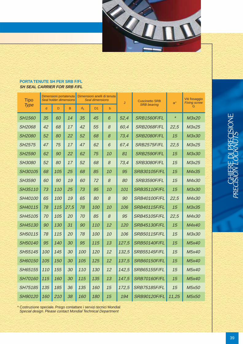
I portatenuta tipo SH, progettati per essere montatisui cuscinetti SRB F/FL, rappresentano la piùsemplice ed economica soluzione per la maggiorparte dei problemi di tenuta per applicazioni conlubrificazione a grasso. Il portatenuta viene fornitocompleto di anello di tenuta per albero rotante, vitiTCEI per il montaggio sull’anello esterno delcuscinetto SRB F/FL e guarnizione da interporre traSH e cuscinetto.
SH seal carrier, designed to be installed onto SRBF/FL bearings, are the simplest and cheapestsolution for the majority of the sealing problems ingrease lubrication applications. The seal carrier issupplied complete of rotary shaft seal, hexagonalsocket cap screws for mounting onto the SRB F/FLouter ring and a gasket to be used between SH andthe bearing.
38
Guarnizione
UNI 5931
G (N°4x90°)
N°4
x90°
J D
BGasket
d1D1
d
b
Sealing ring
Anello di tenuta °
39
GH
IERE
DI P
RECIS
ION
EPR
ECIS
ION
LO
CKN
UTS
SH1560 35 60 14 35 45 6 52,4 SRB1560F/FL * M3x20
SH2068 42 68 17 42 55 8 60,4 SRB2068F/FL 22,5 M3x25
SH2080 52 80 22 52 68 8 73,4 SRB2080F/FL 15 M3x30
SH2575 47 75 17 47 62 6 67,4 SRB2575F/FL 22,5 M3x25
SH2590 62 90 22 62 75 10 81 SRB2590F/FL 15 M3x30
SH3080 52 80 17 52 68 8 73,4 SRB3080F/FL 15 M3x25
SH30105 68 105 25 68 85 10 95 SRB30105F/FL 15 M4x35
SH3590 60 90 19 60 72 8 80 SRB3590F/FL 15 M4x30
SH35110 73 110 25 73 95 10 101 SRB35110F/FL 15 M3x30
SH40100 65 100 19 65 80 8 90 SRB40100F/FL 22,5 M4x30
SH40115 78 115 27,5 78 100 10 106 SRB40115F/FL 15 M3x35
SH45105 70 105 20 70 85 8 95 SRB45105F/FL 22,5 M4x30
SH45130 90 130 31 90 110 12 120 SRB45130F/FL 15 M4x40
SH50115 78 115 20 78 100 10 106 SRB50115F/FL 15 M3x30
SH50140 95 140 30 95 115 13 127,5 SRB50140F/FL 15 M5x40
SH55145 100 145 30 100 120 12 132,5 SRB55145F/FL 15 M5x40
SH60150 105 150 30 105 125 12 137,5 SRB60150F/FL 15 M5x40
SH65155 110 155 30 110 130 12 142,5 SRB65155F/FL 15 M5x40
SH70160 115 160 30 115 135 13 147,5 SRB70160F/FL 15 M5x40
SH75185 135 185 36 135 160 15 172,5 SRB75185F/FL 15 M5x50
SH90120 160 210 38 160 180 15 194 SRB90120F/FL 11,25 M5x50
TipoType
Dimensioni portatenutaSeal holder dimensions
Dimensioni anelli di tenutaSeal dimensions
d D B d1 D1
α°Viti fissaggioFixing screw
GJ Cuscinetto SRB
SRB bearing
* Costruzione speciale. Prego contattare i servizi tecnici MondialSpecial design. Please contact Mondial Technical Department
b
PORTA TENUTE SH PER SRB F/FLSH SEAL CARRIER FOR SRB F/FL

40
Quando si utilizzano ghiere tradizionali per bloccarecuscinetti su viti a ricircolo di sfere, si possono verifi-care problemi di precisione e di durata delle macchi-ne collegate, a causa della insufficiente precisionedella filettatura o dell’eccessiva eccentricità della su-perficie di contatto.
Le ghiere di precisione MONDIAL® sono prodotte ri-cavando filettatura interna e superficie di contattonella stessa fase produttiva e sono perciò in grado disoddisfare le esigenze di precisione più elevata.
When using conventional locknuts to fasten bearingson screw drives, precision and duration problems ofthe adjoining machines may arise due to the limitedprecision of the thread or because of the undue ru-nout of the contact surface.
MONDIAL® precision locknuts are manufactured bymachining internal thread and contact surface in thesame production stage, so that they can meet thehighest precision requirements.
HIA Bloccaggio assiale
• 3 punti di bloccaggio• sicurezza antiribaltamento per ridurre
coppie in eccedenza• materiale ghiera: SCM 440 con
trattamento termico• materiale vite: bronzo al fosforo• durezza: HRC 28-32• tolleranza filettatura: ISO H6• perpendicolarità della superficie =
0,005 mm serie precisa - suffisso: P -perpendicolarità = 0,002 mm
HIF Bloccaggio laterale
HIA Axial locking
• 3 locking points• anti-overturning safety to reduce
redundant torque• locknut material: SCM 440, hardened• screw drive material: phosphor-bronze• hardness: HRC 28-32• thread tolerance: ISO H6• lateral surface squareness =
0,005 mmprecision series - suffix: P -squareness = 0,002 mm
HIF Side locking
• 2 locking points (for smaller sizes) or 3locking points (for larger sizes)
• same thickness as for HIF series• axial locking is particularly suited if there
are operational constraints• locknut material: SCM 440, hardened• screw drive material: phosphor-bronze• hardness: HRC 28-32• thread tolerance: ISO H6• lateral surface squareness =
0,005 mm precision series - suffix: P - squareness = 0,002 mm
Ghiere di precisione MONDIAL
MONDIAL precision locknuts
• 2 punti di bloccaggio (per le misure piùpiccole) o 3 (per le misure più grandi)
• spessore identico a quello della serie HIF• il bloccaggio assiale è indicato in
presenza di particolari vincoli operativi• materiale ghiera: SCM 440 con
trattamento termico• materiale vite: bronzo al fosforo• durezza: HRC 28-32• tolleranza filettatura: ISO H6• perpendicolarità della superficie =
0,005 mm serie precisa - suffisso: P -perpendicolarità = 0,002 mm
41
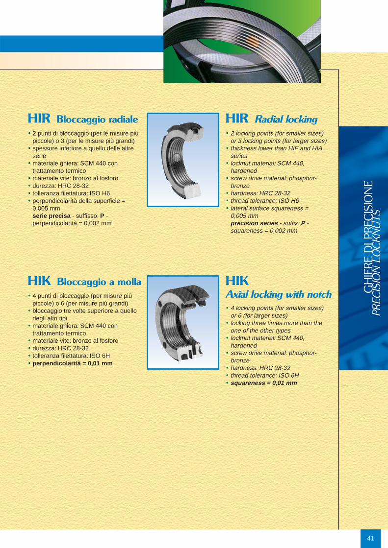
• 2 punti di bloccaggio (per le misure piùpiccole) o 3 (per le misure più grandi)
• spessore inferiore a quello delle altre serie
• materiale ghiera: SCM 440 con trattamento termico
• materiale vite: bronzo al fosforo• durezza: HRC 28-32• tolleranza filettatura: ISO H6• perpendicolarità della superficie =
0,005 mm serie precisa - suffisso: P -perpendicolarità = 0,002 mm
HIR Bloccaggio radiale• 2 locking points (for smaller sizes)
or 3 locking points (for larger sizes)• thickness lower than HIF and HIA
series• locknut material: SCM 440,
hardened• screw drive material: phosphor-
bronze• hardness: HRC 28-32• thread tolerance: ISO H6• lateral surface squareness =
0,005 mm precision series - suffix: P -squareness = 0,002 mm
HIR Radial locking
• 4 punti di bloccaggio (per misure piùpiccole) o 6 (per misure più grandi)
• bloccaggio tre volte superiore a quellodegli altri tipi
• materiale ghiera: SCM 440 contrattamento termico
• materiale vite: bronzo al fosforo• durezza: HRC 28-32• tolleranza filettatura: ISO 6H• perpendicolarità = 0,01 mm
HIK Bloccaggio a molla
• 4 locking points (for smaller sizes)or 6 (for larger sizes)
• locking three times more than theone of the other types
• locknut material: SCM 440,hardened
• screw drive material: phosphor-bronze
• hardness: HRC 28-32• thread tolerance: ISO 6H• squareness = 0,01 mm
HIKAxial locking with notch G
HIE
RE D
I PRE
CIS
ION
EPR
ECIS
ION
LO
CKN
UTS

42
SELEZIONATURA GHIERE DI PRECISIONE MONDIALMONDIAL PRECISION LOCKNUTS SELECTION
Diametroalbero
Bore diam.
(mm)
Versione base e versione L
Basis design and L design
Versione F/ FL/ T
F/ FL/ T design
Sigla
Designation
Cuscinetti SRB
SRB bearings
Ghiere Mondial raccomandate
Recommended MONDIAL locknuts
15
20
20
25
25
30
30
35
35
40
40
45
45
50
50
55
60
65
70
75
90
6,3
12,6
29,6
27,3
23,7
23,5
75,4
37,7
95,2
46,0
104,7
48,5
152,1
56,9
178,5
189,2
235,8
265,4
299,0
549,4
887,2
HIR M15 x 1
HIF/ HIA/ HIR/ HIK M20 x 1
HIF/ HIA/ HIR/ HIK M20 x 1
HIF/ HIA/ HIR/ HIK M25 x 1,5
HIF/ HIA/ HIR/ HIK M25 x 1,5
HIF/ HIA/ HIR/ HIK M30 x 1,5
HIF/ HIA/ HIR/ HIK M30 x 1,5
HIF/ HIA/ HIR/ HIK M35 x 1,5
HIF/ HIA/ HIR/ HIK M35 x 1,5
HIF/ HIA/ HIR/ HIK M40 x 1,5
HIF/ HIA/ HIR/ HIK M40 x 1,5
HIF/ HIA/ HIR/ HIK M45 x 1,5
HIF/ HIA/ HIR/ HIK M45 x 1,5
HIF/ HIA/ HIR/ HIK M50 x 1,5
HIF/ HIA/ HIR/ HIK M50 x 1,5
HIF/ HIA/ HIR/ HIK M55 x 2
HIF/ HIA/ HIR/ HIK M60 x 2
HIF/ HIA/ HIR/ HIK M65 x 2
HIF/ HIA/ HIR/ HIK M70 x 2
HIF/ HIA/ HIR/ HIK M75 x 2
HIF/ HIA/ HIR/ HIK M90 x 2
SRB 1545/ L
SRB 2052/ L
SRB 2062/ L
SRB 2557/ L
SRB 2572/ L
SRB 3062/ L
SRB 3080/ L
SRB 3570/ L
SRB 3585/ L
SRB 4075/ L
SRB 4090/ L
SRB 4580/ L
SRB 45105/ L
SRB 5090/ L
SRB 50110/ L
SRB 55115/ L
SRB 60120/ L
SRB 65125/ L
SRB 70130/ L
SRB 75155/ L
SRB 90180/ L
SRB 1560 F/ FL/ T
SRB 2068 F/ FL/ T
SRB 2080 F/ FL/ T
SRB 2575 F/ FL/ T
SRB 2590 F/ FL/ T
SRB 3080 F/ FL/ T
SRB 30105 F/ FL/ T
SRB 3590 F/ FL/ T
SRB 35110 F/ FL/ T
SRB 40110 F/ FL/ T
SRB 40115 F/ FL/ T
SRB 45105 F/ FL/ T
SRB 45130 F/ FL/ T
SRB 50115 F/ FL/ T
SRB 50140 F/ FL/ T
SRB 55145 F/ FL/ T
SRB 60150 F/ FL/ T
SRB 65155 F/ FL/ T
SRB 70160 F/ FL/ T
SRB 75185 F/ FL/ T
SRB 90210 F/ FL/ T
Coppia di serraggioMS
Tightening torqueMS
(Nm)
Tab. 6

Coppia di serraggioRelativamente al concetto di precarico, fare riferimento al paragraforelativo agli RTB, in particolare, il valore del precarico può esserestabilito, per ogni singolo caso di applicazione, in base alle forzeassiali gravanti sul cuscinetto.Nella Tab. 6 sono indicate le coppie di serraggio previste perottenere un valore d precarico assiale pari al 5% della capacità dicarico dinamica del cuscinetto, utilizzando le ghiere di precisioneMondial con superfici e filetti rettificati. Sono inoltre riportati i valoridelle rispettive coppie di rotolamento relativi ad una velocità dirotazione compresa tra 0 e 5 rpm.Sia i valori delle coppie di serraggio che quelle di rotolamento sonoda considerarsi indicativi e soggetti a variazioni statistiche.
Tightening torque As for the preload notion, please refer to the paragraph regardingbearings of RTB series. The preload value can be calculated foreach application according to the axial forces which burden thebearing. Tab. 6 refers to the tightening torques necessary to obtainan axial preload value equivalent to 5% of the dynamic load-carrying capacity of the bearing, by using the MONDIAL precisionlocknuts with ground surfaces and thread. This table also states thevalues of the friction torques according to an operating speedbetween 0 and 5 rpm. Both values (tightening torques as well asfriction torques) are statistical and therefore subject to variations.
43
GH
IERE
DI P
RECIS
ION
EPR
ECIS
ION
LO
CKN
UTS
44
TipoType
D h d g b t c mCoppia di serraggio grani
Setscrews tightening torque(Nm)
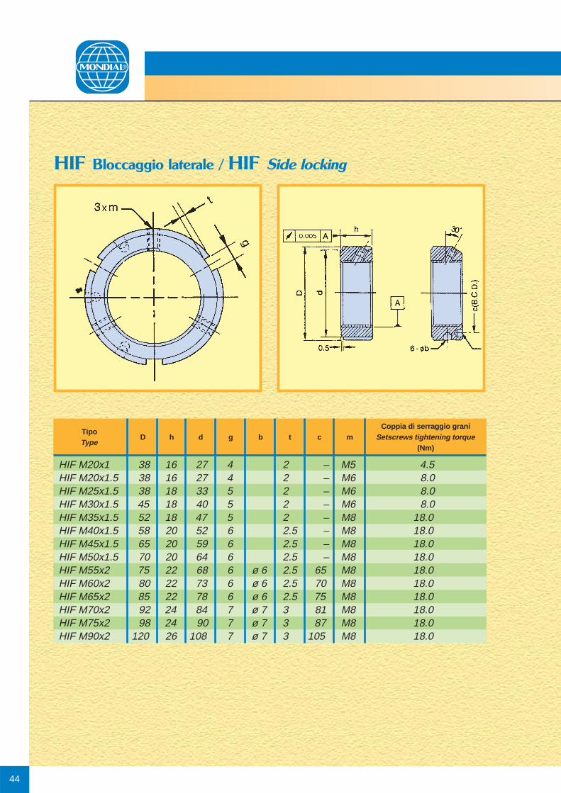
HIF Bloccaggio laterale / HIF Side locking
HIF M20x1 38 16 27 4 2 – M5 4.5HIF M20x1.5 38 16 27 4 2 – M6 8.0HIF M25x1.5 38 18 33 5 2 – M6 8.0HIF M30x1.5 45 18 40 5 2 – M6 8.0HIF M35x1.5 52 18 47 5 2 – M8 18.0HIF M40x1.5 58 20 52 6 2.5 – M8 18.0HIF M45x1.5 65 20 59 6 2.5 – M8 18.0HIF M50x1.5 70 20 64 6 2.5 – M8 18.0HIF M55x2 75 22 68 6 ø 6 2.5 65 M8 18.0HIF M60x2 80 22 73 6 ø 6 2.5 70 M8 18.0HIF M65x2 85 22 78 6 ø 6 2.5 75 M8 18.0HIF M70x2 92 24 84 7 ø 7 3 81 M8 18.0HIF M75x2 98 24 90 7 ø 7 3 87 M8 18.0HIF M90x2 120 26 108 7 ø 7 3 105 M8 18.0

45
GH
IERE
DI P
RECIS
ION
EPR
ECIS
ION
LO
CKN
UTS
HIA Bloccaggio assiale / HIA Axial locking
TipoType
D h g t d nxmCoppia di serraggio grani
Setscrews tightening torque(Nm)
HIA M20x1 38 16 4 2 27 2xM5 4.5HIA M20x1.5 38 16 4 2 27 2xM5 4.5HIA M25x1.5 38 18 5 2 33 2xM6 8.0HIA M30x1.5 45 18 5 2 40 2xM6 8.0HIA M35x1.5 52 18 5 2 47 2xM6 8.0HIA M40x1.5 58 20 6 2.5 52 3xM6 8.0HIA M45x1.5 65 20 6 2.5 59 3xM6 8.0HIA M50x1.5 70 20 6 2.5 64 3xM6 8.0HIA M55x2 75 22 7 3 68 3xM6 8.0HIA M60x2 80 22 7 3 73 3xM6 8.0HIA M65x2 85 22 7 3 78 3xM6 8.0HIA M70x2 92 24 8 3.5 84 3xM8 18.0HIA M75x2 98 24 8 3.5 90 3xM8 18.0HIA M90x2 120 26 10 4 108 3xM8 18.0

46
HIR Bloccaggio radiale / HIR Radial locking
TipoType
D h g t d nxmCoppia di serraggio grani
Setscrews tightening torque(Nm)
HIR M15x1 25 8 3 2 21 2xM4 3.5HIR M20x1 32 10 4 2 32 2xM5 8.0HIR M20x1.5 32 10 4 2 32 2xM5 8.0HIR M25x1.5 38 12 5 2 33 3xM6 8.0HIR M30x1.5 45 12 5 2 40 3xM6 8.0HIR M35x1.5 52 12 5 2 47 3xM6 8.0HIR M40x1.5 58 14 6 2.5 52 3xM6 8.0HIR M45x1.5 65 14 6 2.5 59 3xM6 8.0HIR M50x1.5 70 14 6 2.5 64 3xM6 8.0HIR M55x2 75 16 7 3 68 3xM6 8.0HIR M60x2 80 16 7 3 73 3xM6 8.0HIR M65x2 85 16 7 3 78 3xM6 8.0HIR M70x2 92 18 8 3.5 84 3xM8 18.0HIR M75x2 98 18 8 3.5 90 3xM8 18.0HIR M90x2 120 20 10 4 108 3xM8 18.0

47
GH
IERE
DI P
RECIS
ION
EPR
ECIS
ION
LO
CKN
UTS
HIK Bloccaggio a molla / HIK Axial locking with notch
TipoType
D h d n x Øb c
HIK M20x1.0 40 18 35 4xM4-12 4x ø 4 30HIK M20x1.5 40 18 35 4xM4-12 4x ø 4 30HIK M25x1.5 45 20 40 4xM4-14 4x ø 5 35HIK M30x1.5 48 20 45 4xM4-14 4x ø 5 39HIK M35x1.5 53 22 50 4xM4-16 4x ø 5 44HIK M40x1.5 58 22 55 4xM4-16 4x ø 5 49HIK M45x1.5 68 22 63 6xM4-16 6x ø 6 57HIK M50x1.5 70 25 66 6xM4-18 6x ø 6 60HIK M55x2.0 75 25 71 6xM4-18 6x ø 6 65HIK M60x2.0 84 26 79 6xM5-20 6x ø 6 72HIK M65x2.0 88 28 84 6xM5-20 6x ø 6 77HIK M70x2.0 95 28 89 6xM5-20 6x ø 7 82HIK M75x2.0 100 28 94 6xM5-20 6x ø 7 87HIK M90x2.0 120 32 113 6xM6-22 6x ø 8 105
n - m x L(Viti non comprese nella fornitura)
(Screws not included in the delivery)

Cuscinetti customizzati a rulli cilindrici incrociatiCustomized crossed roller bearingsXRB
48
Disegno compatto, capacità di sopportare carichi assialinei due sensi, carichi radiali oltre ad elevate coppie diribaltamento.
Il cuscinetto a rulli incrociati UNITEC serie XRB è lasoluzione ideale nel caso in cui lo spazio a disposizionesia limitato oppure quando si richiedano centri di gravitàdelle masse in rotazione ad altezza ridotta.
Tavole rotanti ad asse verticale, tavole di posizionamento,mandrini ad asse orizzontale e verticale ed articolazioni dirobot sono le applicazioni chiave per questo cuscinetto.Esecuzioni speciali con anelli provvisti di interfacce dimontaggio per motori diretti, consentono il raggiungimentodi prestazioni dinamiche superiori, elevate precisioniallineamento e riduzione dei tempi di assiemaggio.
I cuscinetti a rulli incrociati UNITEC XRB sono progettatie prodotti esclusivamente a richiesta del cliente
Compact design, capacity to carry high axial loads in bothdirections combined with radial loads and high tiltingmoments.
UNITEC crossed roller bearings XRB series are the idealsolution where space is limited or lower center of gravityof the rotating masses is requested.
The main applications for UNITEC crossed roller bearingsare indexing tables, rotating tables, spindles with horizontal and vertical axis and robot arms.
All UNITEC XRB cross roller bearings are designed andmanufactured, only according to customer requirements.
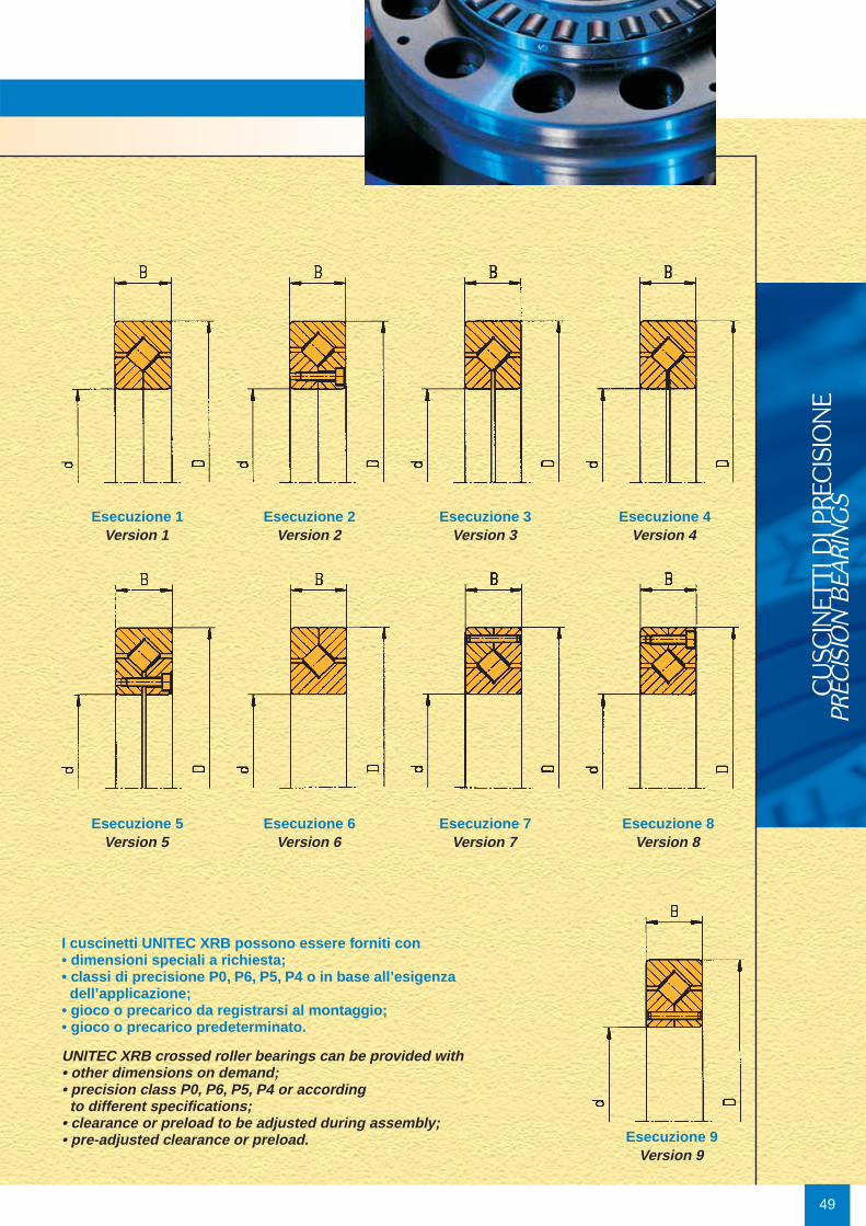
Esecuzione 9Version 9
I cuscinetti UNITEC XRB possono essere forniti con• dimensioni speciali a richiesta;• classi di precisione P0, P6, P5, P4 o in base all’esigenza dell’applicazione;
• gioco o precarico da registrarsi al montaggio;• gioco o precarico predeterminato.
UNITEC XRB crossed roller bearings can be provided with• other dimensions on demand;• precision class P0, P6, P5, P4 or according to different specifications;
• clearance or preload to be adjusted during assembly;• pre-adjusted clearance or preload.
Esecuzione 1Version 1
Esecuzione 2Version 2
Esecuzione 3Version 3
Esecuzione 4Version 4
Esecuzione 5Version 5
Esecuzione 6Version 6
Esecuzione 7Version 7
Esecuzione 8Version 8
49
CU
SCIN
ETTI
DI P
RECIS
ION
EPR
ECIS
ION
BEA
RIN
GS

50
Tab. 7
N° Dis. d D BPart number mm mm mm
Max difetto radialee assiale di rotazione
Axial and radial runout
Coeff. di carico ISOLoad ratings according to
RADIALE RADIAL ASSIALE AXIAL
din. Ca kNdyn. Ca
stat. Co kNstat. Co
din. C kNdyn.
stat. Co kNstat. Co
EsecuzioneVersionAn. interno
inner ringμm
An. esternoouter ring
μm
XRB50-6-0945 50 80 16 4 4 18,5 21,8 22,6 49,7 6XRB60-7-0946 60 90 13 10 17 19,7 28,1 22,7 64,1 7XRB70-7-0947 70 100 13 10 17 21,3 32,5 24,8 74,5 7XRB80-6-0742 80 110 16 4 4 23 30 25 70 6XRB90-8-0948 90 130 16 12 20 31,3 51,5 40,6 136 8XRB100-7-0949 100 125 13 12 20 21,8 39,7 25,4 91,4 7XRB110-7-0950 110 145 15 12 20 30,6 56 35,6 129 7XRB120-9-1000 120 155 18 5 5 23,3 40,4 24,7 94,2 9XRB120-2-0971 120 180 25 13 23 63 97 73 227 2XRB120-1-0951 120 180 28 5 5 81 118 99 259 1XRB130-1-0712 130 165 18 4 4 38,9 64 47 148 1XRB140-7-0953 140 175 18 15 22 34,5 70,5 40,1 163 7XRB140-6-0725 140 190 24 5 5 73,9 122 89 280 6XRB140-8-0952 140 200 25 15 25 82,1 141 95,2 322 8XRB144-2-0863 144 207 28,5 4 4 87 136 105 312 2XRB150-1-0298 150 207 28,5 4 4 87 136 105 312 1XRB150-6-0293 150 207 28,5 4 4 87 136 105 312 6XRB150-8-0942 150 210 25 8 11 69 108 80,5 253 8XRB150-1-0690 150 230 30 5 5 100 159 121 364 1XRB150-2-0966 150 230 30 8 8 100 159 121 364 2XRB160-6-0743 160 220 28 5 5 79,5 132 96 303 6XRB175-6-0294 175 240 32,5 5 5 107 180 130 412 6XRB175-3-0982 175 240 32,5 5 5 107 180 130 412 3XRB180-8-0958 180 225 22 15 25 60,3 127,6 70,4 297 8XRB180-8-0984 180 225 22 6 15 60,3 127,6 70,4 297 8XRB180-6-0723 180 250 33 5 5 120 199 145 455 6XRB200-1-0300 200 280 38 5 5 122 212 148 486 1XRB225-6-0296 225 320 47,5 7 7 232 381 281 869 6XRB240-1-0954 240 300 28 7 7 108 209 130 481 1XRB250-6-0297 250 360 47,5 7 7 249 435 302 994 6XRB260-1-0955 260 360 46 7 7 210 377 254 864 1XRB280-1-0956 280 380 46 7 7 216 399 261 916 1XRB300-6-0957 300 380 38 7 7 186 376 225 866 6XRB300-2-0980 300 395 35 50 70 153 323 172 823 2XRB310-5-0864 310 425 45 7 7 252 457 270 1067 5
XRB Alcuni esempi delle tipologie di cuscinetti XRB.
Soluzioni costumizzate sono disponibili a richiesta.
Some manufactured XRB bearings examples.
Custom solutions available upon request.

51
CU
SCIN
ETTI
DI P
RECIS
ION
EPR
ECIS
ION
BEA
RIN
GS
Designazione cuscinetti RTB / RTB-AMSBearings designation RTB / RTB-AMS
RTB 260 G C 0 6 7 8
TipoType
Diametro foro d (mm)Inner diameter d (mm)
G = cuscinetto ingrassatogreased bearing
P = super preciso (metà run cut assiale e radiale)*super precision (half axial & radial run out)*
C = con certificato dimensionalewith dimensional certificate
Codice disegno customizzatoCustomized drawing’s code
RTB 150 AMSAMS G P 0 5 2 1
TipoType
Diametro foro d (mm)Inner diameter d (mm)
Sistema di misura integratoIntegrated measuring system
G = cuscinetto ingrassatogreased bearing
P = super preciso (metà run cut assiale e radiale)super precision (half axial & radial run out)
Codice disegno customizzatoCustomized drawing’s code
* Con certificato dimensionaleWith dimensional certificate
Nota: i tipi RTB AMS, sono sempre forniti con certificato dimensionale.Note: the type RTB AMS, are always supplyed with dimensional certificate.

52
Designazione cuscinetti SRBBearings designation SRB
SRB 15 45 - F L
TipoType
Diametro foro d (mm)Inner diameter d (mm)
Diametro esterno D (mm)Outside diameter D (mm)
L = con ralla porta tenutawith extended waster
F = con flangia di fissaggiowith fixing flange
FL = con flangia di fissaggio e ralla porta tenutawith fixing flange and extended washer
T = con fori di fissaggiowith fixing holes

53
CU
SCIN
ETTI
DI P
RECIS
ION
EPR
ECIS
ION
BEA
RIN
GS
Disegni speciali customizzatiCustom special drawings
Massimo difetto radiale ed assialedi rotazione 0.007 mm
Maximum radial and axial run out 0.007 mm
Massimo difetto radiale ed assialedi rotazione 0.005 mm
Maximum radial and axial run out 0.005 mm
XRB customizzati per tavole d’indexaggio. Custom XRB for indexing table.
Soluzioni customizzate, progettate per la vostra applicazione, sono disponibili a richiesta.Custom solutions, specifically designed for your application, are available upon request.
Ø 3
27
Ø 2
80
Ø 3
95
Ø 1
32
Ø 1
70
Ø 2
28
38
35
48,5
28,5 20

54
XRB customizzati per tavola di indexaggio ad azionamento diretto, con alloggiamento scala di precisione per Encoder
Custom XRB for direct drive rotary table, with flange for encoder precision scale mounting
Cuscinetto speciale persupporto chiocciola.
Special bearings for rotatingnut support.
Ø 1
64
3 17
3 17
0.8
0.8
45 49 1212
Ø 9
5
Ø 1
70
Ø 2
63
17297 38

55
CU
SCIN
ETTI
DI P
RECIS
ION
EPR
ECIS
ION
BEA
RIN
GS
Cuscinetto speciale per testa fresatrice
Custom cross roller bearing for milling head application
Ø 5
00
Ø 6
20
35
Ø 3.5
70
Nr 6x60°

56
45
Ø 7
3,8
Ø 3
0
Ø 5
2
Classe di precisione P4
Precision class P4
Cuscinetti combinati speciali. Special combined bearings.
Cuscinetto per comando a vite senza fine. Worm drive bearing
Classe di precisione UP
Precision class UP
54
30
Ø 6
3
Ø 2
5
Ø 9
8 Ø 5
0
Ø 1
15
78
60
Ø 1
50
Ø 2
10
Cuscinetti supporto mandrino - foro conico
Spindle support bearings - tapered bore

CU
SCIN
ETTI
DI P
RECIS
ION
EPR
ECIS
ION
BEA
RIN
GS
Classe di precisione P5 / SP
Precision class P5 / SP
Cuscinetti supporto mandrino - foro conico
Spindle support bearings - tapered bore
57
160
160
Ø 4
90,2
Ø 4
40
Ø 4
53,3 Ø
600
Ø 4
90
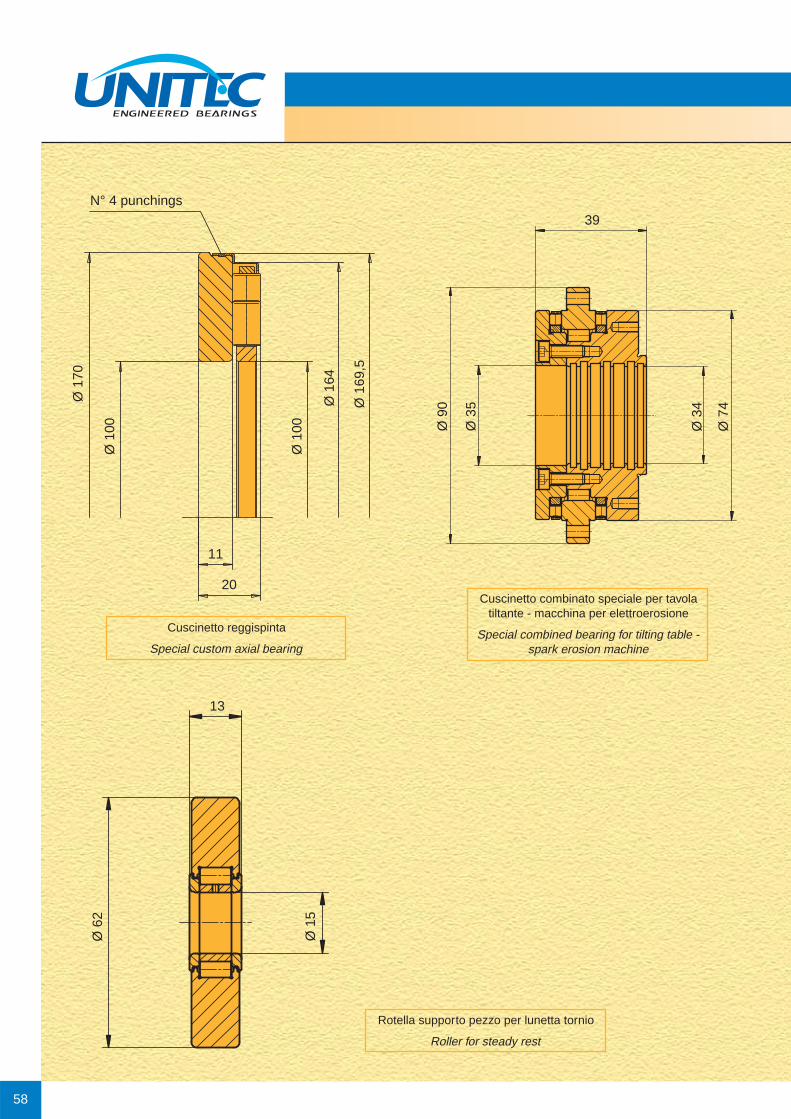
58
Cuscinetto reggispinta
Special custom axial bearing
Cuscinetto combinato speciale per tavolatiltante - macchina per elettroerosione
Special combined bearing for tilting table -spark erosion machine
Rotella supporto pezzo per lunetta tornio
Roller for steady rest
Ø 1
70Ø
62
Ø 1
5
13
Ø 1
00
Ø 1
00
Ø 1
64
Ø 1
69,5
11
20
N° 4 punchings39
Ø 9
0
Ø 3
5
Ø 3
4
Ø 7
4

CU
SCIN
ETTI
DI P
RECIS
ION
EPR
ECIS
ION
BEA
RIN
GS
59
Cuscinetti assiali per tornio verticale
Thrust bearings for vertical lathe
Ø 7
64.5
Ø 4
95Ø
420
Ø 4
20Ø
424
Ø 5
00
Ø 3
96
Ø 3
20
Ø 3
24 Ø 4
00
Ø 7
46Ø
630
Ø 6
35Ø
750
610.4624
95
65
63
25 1919
2520 20r 2.5 r 2
.5
r 2.5r 2.5

60
Cuscinetti assiali per tornio verticale
Thrust bearings for vertical lathe
Ø 7
05Ø
600
Ø 6
00Ø
605
Ø 7
10
Ø 5
95Ø
500
Ø 5
00Ø
505
Ø 6
00
8525.5 34 25.5
8024 32 24

Note:

Note:

Questo catalogo è stato redatto con la massima attenzione, i dati in esso contenuti sono stati controllati accuratamente.
Non possiamo pertanto accettare alcuna responsabilità per eventuali errori od omissioni.
Ci riserviamo di apportare modifiche anche parziali, dovute alla costante evoluzione tecnica dei nostri prodotti.
Tutti i diritti riservati. La produzione, anche parziale, non è ammessa senza nostra autorizzazione.
This catalogue has been produced with a great deal of care and attention and all data have been checked for their accuracy.
However, no liability can be assumed for any incorrect or incomplete data.
Due to constant development and expansion of the product range, we reserve the right to make modifications.
All rights reserved. Reproduction in whole or in part without our authorization is prohibited. 06
/10

MONDIAL S.p.A.20124 Milano - Italy - Via G. Keplero, 18Tel. +39 0266810.1 - Fax +39 0266810252 - +39 0266810333e-mail: [email protected] www.mondial.it
www.unitecbearings.com