customization and automation of engineering … · engineering simulation workflow . 2 ......
TRANSCRIPT

© 2011 ANSYS, Inc. June 21, 2012 1
Mai Doan, Application Engineer
Customization and Automation of Engineering Simulation Workflow

© 2011 ANSYS, Inc. June 21, 2012 2
Agenda
1. Need for customization
2. Different Customization Methods
3. Application Customization Toolkit (ACT) and Examples
4. Other Mechanical Customization possibilities
5. Other Fluid Customization possibilities
6. Other possibilities (Common)
© 2011 ANSYS, Inc. June 21, 2012 3
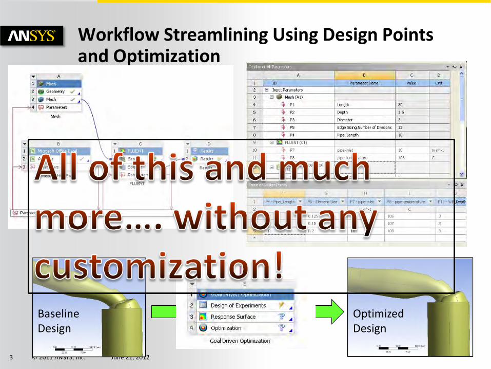
Workflow Streamlining Using Design Points and Optimization
Baseline Design
Optimized Design

© 2011 ANSYS, Inc. June 21, 2012 4
Need for Customization
Capture the existing simulation process
Make repetitive operations automatic
Integrate CAE with other (or in-house) tools
Make the technology available to a wider group (non CAE experts)
….
1

© 2011 ANSYS, Inc. June 21, 2012 5
Native and Data-Integrated Applications
Native applications • Built entirely on WB2 Framework • Embedded within the “Workbench” window • Project Schematic, Design Exploration, Engineering
Data • Fully supported by Workbench scripting • Scripting language: Python
Data-integrated applications – Share data and parameters with Workbench,
native applications, and other data-integrated applications
– Independent UI, window
– E.g., Mechanical, Mechanical APDL, CFX, FLUENT, DesignModeler
– Scripting Language: JScript, Scheme, APDL …

© 2011 ANSYS, Inc. June 21, 2012 6
Workbench Scripting Overview
Application-level Scripting
• For task automation at the application level
– Mechanical, DM, Meshing: JScript
– CFX: CCL
– FLUENT: Scheme
– MAPDL: APDL
Workbench Scripting • For task automation at project level
– Creating project, performing parameters simulations, optimization etc.
• Works “hand-in-hand” with scripting in DIAs
– Can embed JScript, CCL, Scheme, APDL

© 2011 ANSYS, Inc. June 21, 2012 7
Different Customization Methods Application Customization Toolkit (ACT) • Create new load/BC/results • Integrate an external solver in Mechanical
Jscript (for DM, Meshing, Mechanical etc.) • Task automation within the various applications • Jscript add-in to add functionality in the application
Wizards (for DM, Meshing, Mechanical etc.) • Creating a customized workflow within the DIA
Python Journaling • For task automation at WB level (applicable for all applications available on WB)
– Creating Project, Performing Parameters simulations etc. • Can use Jscript macros for DM, Meshing, Mechanical etc. • Can use Scheme (Fluent), CCL (CFX), VBScript (Maxwell etc.)
External Connection Add-in • Making external applications (not integrated with WB) to participate in workflow through
parameters • Python scripting can be integrated to add functionality to WB
C# Add-in using Software Development Kit (SDK) • Integrate external applications in workflow through custom systems • WB GUI customization (addition of buttons, menu etc.)

© 2011 ANSYS, Inc. June 21, 2012 8
An Introduction to Application Customization Toolkit (ACT) and Examples

© 2011 ANSYS, Inc. June 21, 2012 9
What is ACT
It is a Toolkit to customize Applications in Workbench
• In R14, ACT allows customization in the Mechanical application (Beta)
– Define customized boundary conditions and post-processing – Replace command snippets with interactive objects – Do much more than what the standard features in Mechanical • Access node/element information, material, solution, results data … • Perform: Crack propagation, Sub-modeling, MEMS, CMS (using ROM)
– Even replace the APDL solver with your custom solver!
• ACT would be available for more applications in future
• ACT provides an option to migrate APDL users to Mechanical – Allow reusing legacy APDL developments in user-friendly way – Gets the best of the two worlds!
• Developing ACT solutions is fast and efficient
– One doesn’t have to be a developer – Simple ACT solutions can be developed in minutes – ACT solutions are future ready!

© 2011 ANSYS, Inc. June 21, 2012 10
Examples – What can be done ?
Node coupling
Sub-modeling simulation in Mechanical
Acoustics simulation in Mechanical
Custom result – “Contact Force Vectors”
2D Convection Load extension
Clamp and Displace extension
Third party solver connection

© 2011 ANSYS, Inc. June 21, 2012 11
Node Coupling
New extension for specific load creation
The Coupling object

© 2011 ANSYS, Inc. June 21, 2012 12
Sub-modeling extension
Sub-modeling in Mechanical between 2 structural analysis
– Interpolation of displacement (CBDOF) and temperature (BFINT).
– Choose 2D-2D, 3D-3D or 2D axi-3D sub-modeling
– Choose Solid-solid & Shell-shell key or Solid-shell key
– Tabular data for multi-stepping
The sub-modeling extension was developed as an example just to show the possibility. Since, sub-modeling is scheduled to be released natively in Mechanical at R14.5, the extension is not being developed further or distributed.

© 2011 ANSYS, Inc. June 21, 2012 13
Acoustics simulation in Mechanical using ACT
Acoustics features in Mechanical without any command objects
– Define acoustics elements, real constants & material properties
– Apply acoustics boundary conditions & loads
– Plot Far/Near field & Time/Frequency results
– Postprocess Pressure & SPL

© 2011 ANSYS, Inc. June 21, 2012 14
Example simulations
Speaker
Underwater
© 2011 ANSYS, Inc. June 21, 2012 15
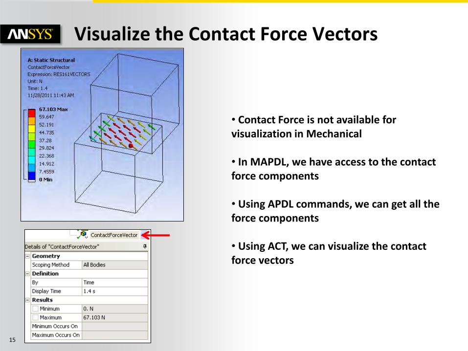
Visualize the Contact Force Vectors
• Contact Force is not available for visualization in Mechanical • In MAPDL, we have access to the contact force components • Using APDL commands, we can get all the force components • Using ACT, we can visualize the contact force vectors

© 2011 ANSYS, Inc. June 21, 2012 16
Visualize the Contact Force Vectors
The Minimum and Maximum values of the result can be defined as “parameter” to perform DP and DX analysis
!
© 2011 ANSYS, Inc. June 21, 2012 17
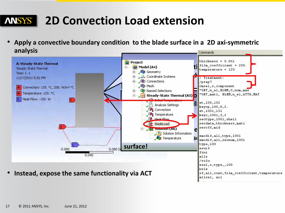
• Apply a convective boundary condition to the blade surface in a 2D axi-symmetric analysis
• Instead, expose the same functionality via ACT
2D Convection Load extension
Need to apply a convective boundary condition to this surface
Since the model is 2D, convective boundary condition is allowed only on edges! Using a command snippet we can apply the convection load to the surface!
© 2011 ANSYS, Inc. June 21, 2012 18
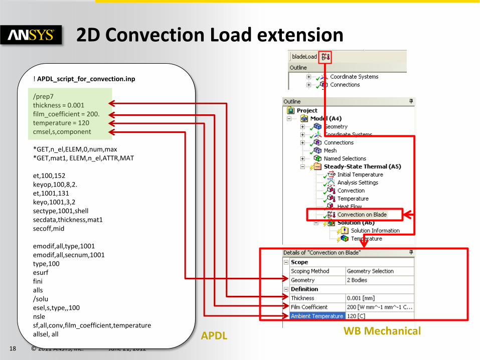
! APDL_script_for_convection.inp /prep7 thickness = 0.001 film_coefficient = 200. temperature = 120 cmsel,s,component *GET,n_el,ELEM,0,num,max *GET,mat1, ELEM,n_el,ATTR,MAT et,100,152 keyop,100,8,2. et,1001,131 keyo,1001,3,2 sectype,1001,shell secdata,thickness,mat1 secoff,mid emodif,all,type,1001 emodif,all,secnum,1001 type,100 esurf fini alls /solu esel,s,type,,100 nsle sf,all,conv,film_coefficient,temperature allsel, all APDL WB Mechanical
2D Convection Load extension

© 2011 ANSYS, Inc. June 21, 2012 19
Clamp and Displace extension
Load Step-1: Apply the pressure Allow the body to bend Load Step-2: Clamp the top surface in its deformed state Load Step-3: Apply a deformation to the clamped surface
LS-1
LS-3
LS-2

© 2011 ANSYS, Inc. June 21, 2012 20
Solution using Command Snippet
Definition based on named selection previously defined
LS 2
LS 3

© 2011 ANSYS, Inc. June 21, 2012 21
Solution using ACT
User inputs in the APDL command snippets are translated to ACT properties related to the newly integrated ACT load: • The location provided by the named selection is now defined based on a scoping method compatible with both named selection and direct geometry selection • The load step number for clamping is available from a drop-down menu initialized with the number of steps already defined in the Analysis Settings object • The X Displacement value for the next load step is defined by a new property declared as a length. This makes this property always consistent with the current unit system activated in Mechanical
© 2011 ANSYS, Inc. June 21, 2012 22
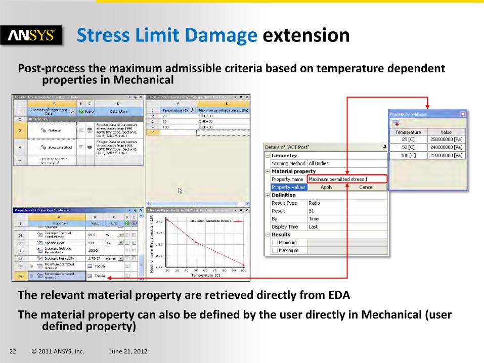
Post-process the maximum admissible criteria based on temperature dependent properties in Mechanical
The relevant material property are retrieved directly from EDA
The material property can also be defined by the user directly in Mechanical (user defined property)
Stress Limit Damage extension

© 2011 ANSYS, Inc. June 21, 2012 23
Stress Limit Damage extension

© 2011 ANSYS, Inc. June 21, 2012 24
FEInfo extension

© 2011 ANSYS, Inc. June 21, 2012 25
Tosca integration in Workbench
Tosca structure is an Non-parametric optimization solver (topological optimization)
Initial design
Optimal result
Optimal design
Verification

© 2011 ANSYS, Inc. June 21, 2012 26
Using ACT extensions

© 2011 ANSYS, Inc. June 21, 2012 27
Using the ACT extension for a Project
The “Extensions” option is available in the menu bar of the project page
View log file to review messages generated from the extensions
Extension Manager to Load / Unload available extensions

© 2011 ANSYS, Inc. June 21, 2012 28
Using ACT in Mechanical
Command line editor
Output window
Functions list
Refresh to reload the extensions
Info window
© 2011 ANSYS, Inc. June 21, 2012 29
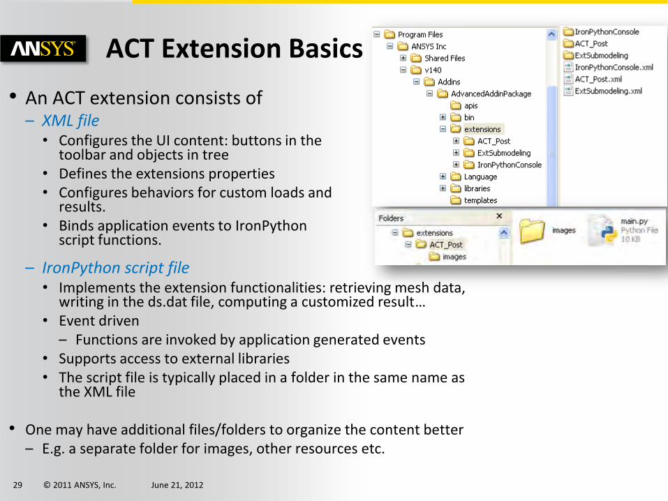
ACT Extension Basics
• An ACT extension consists of – XML file • Configures the UI content: buttons in the
toolbar and objects in tree • Defines the extensions properties • Configures behaviors for custom loads and
results. • Binds application events to IronPython
script functions.
– IronPython script file • Implements the extension functionalities: retrieving mesh data,
writing in the ds.dat file, computing a customized result… • Event driven
– Functions are invoked by application generated events • Supports access to external libraries • The script file is typically placed in a folder in the same name as
the XML file
• One may have additional files/folders to organize the content better – E.g. a separate folder for images, other resources etc.

© 2011 ANSYS, Inc. June 21, 2012 30
Extension structure
Pre-Processing object
Post-Processing object
Customization Toolkit
WB Project/Mechanical
Geometry
Mesh
Simulation data
Results
Materials
XML definition
Python scripts
UI
Mechanical toolbar
Events

© 2011 ANSYS, Inc. June 21, 2012 31
Other possibilities (Mechanical)

© 2011 ANSYS, Inc. June 21, 2012 32
• Objectives: Apply Transient Force & Moment Loads from Excel
– Transient Force and Moment load consists of thousands (30,000+) of data points
– Applying these loads manually with so many inputs is impossible
• Solution:
– A new script is written for this automation
– This solution works fine on all versions on Mechanical (R11 to R14)
Automation in Mechanical: Jscript macro

© 2011 ANSYS, Inc. June 21, 2012 33
• Objectives: Automate Contact Generation and Naming from Excel – Defining various contacts from Named Selections
– Rename the contacts appropriately : ContactType – sourceNS -to- targetNS
– Keep the generated contacts in a group for easy identification
– Have an Excel file for interactive and easy input
• Solution:
– A script is written for this automation
– A macro enabled Excel file helps user to provide correct inputs
– An additional script is also provided to rename contacts appropriately (not generated from Excel file)
Automation in Mechanical

© 2011 ANSYS, Inc. June 21, 2012 34
• WB simulations can be performed with user inputs in Excel
WB simulations from MS Excel
WB simulation is started in the background. Result from Study-1 Updating…
Provide the Parameters for the Design Point studies
Both the Design Points are solved, Project is saved. Max deformation values from those analysis are updated in Excel
• WB Python journal is used for getting inputs from MS Excel, performing the simulation and publishing results back to MS Excel • Similarly other simulations (FLUENT, HFSS etc.) can be done

© 2011 ANSYS, Inc. June 21, 2012 35
Customization possibilities (Fluids examples)
© 2011 ANSYS, Inc. June 21, 2012 36
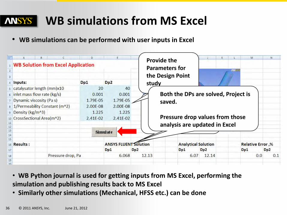
• WB simulations can be performed with user inputs in Excel
WB simulations from MS Excel
DP1 simulation is done. DP2 Updating…
WB simulation is started in the background. DP1 simulation is Updating…
Provide the Parameters for the Design Point study
Both the DPs are solved, Project is saved. Pressure drop values from those analysis are updated in Excel
• WB Python journal is used for getting inputs from MS Excel, performing the simulation and publishing results back to MS Excel • Similarly other simulations (Mechanical, HFSS etc.) can be done

© 2011 ANSYS, Inc. June 21, 2012 37
• Generate the Mixing Tank interactively
• Geometry Parameters are exposed in WB for design point studies
• Different analyses can be combined easily
• An unified customized report can be generated
Customizing Mixing Simulation in WB
© 2011 ANSYS, Inc. June 21, 2012 38
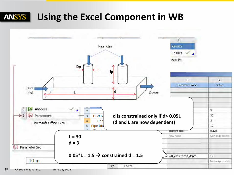
Using the Excel Component in WB
d and L are independent d is constrained only if d> 0.05L (d and L are now dependent)
L = 30 d = 3 0.05*L = 1.5 constrained d = 1.5

© 2011 ANSYS, Inc. June 21, 2012 39
Custom GUI on WB
A custom GUI opens that allows a Pipe Flow CFD Simulation
Provide the dimensions of the pipe
Provide the inputs
Provide the inputs Validate the flow condition
Provide the inputs Generate Mesh
A suitable mesh with appropriate Y+ is generated View Mesh
Provide solver controls
Provide some inputs for extracting results (radial profiles) Iterate
The residuals are displayed as the simulation is progressing
Some standard results are displayed for a quick check Plots generated are available for display
Open a standard report (with plots, contours, vectors etc.)
Open CFD Post for an interactive post-processing

© 2011 ANSYS, Inc. June 21, 2012 40
• Generate the Mixing Tank interactively
• Geometry Parameters are exposed in WB for design point studies
• Different analyses can be combined easily
• An unified customized report can be generated
Customizing Mixing Simulation in WB

© 2011 ANSYS, Inc. June 21, 2012 41
Other possibilities (Common)

© 2011 ANSYS, Inc. June 21, 2012 42
• External Connection
– Allow external applications to participate in the workflow defined through the project schematic
– Allow custom Toolbar button and menus
External Application Integration

© 2011 ANSYS, Inc. June 21, 2012 43
External Application Integration
Example:
• nCode is integrated in Workbench Project Schematic using C# add-in (SDK)
Typical Usage:
• Integrate in-house/third-party codes deep in WB workflow
• Create Customized GUI on WB

© 2011 ANSYS, Inc. June 21, 2012 44
• ANSYS provides multiple methods to extend and customize Workbench
• Power and complexity range from basic scripting to full programming
• Choose method that best fits your needs
Conclusion

© 2011 ANSYS, Inc. June 21, 2012 45
THANK YOU!