customized hmi via xml version 1.1 user manual · 6 initiation as of: 13/03/2018, version 1.3,...
TRANSCRIPT

OrangeApps
myHMI
Customized HMI via XML
Version 1.1
User Manual
Date: 13/03/2018, Version 1.3

2 Initiation
As of: 13/03/2018, Version 1.3, myHMI, User Manual
© Copyright 2018
OrangeApps GmbH Arnikaweg 1 87471 Durach Germany www.orangeapps.de This documentation may – even partially – be copied and reposted. In the excerpts reproduction a reference to the copyright owner and to this document must be noted. The contents of this document have been tested with the described software. Since deviations cannot be excluded, no guarantee for full compliance can be taken.

3 Initiation
As of: 13/03/2018, Version 1.3, myHMI, User Manual
History of document versions
Version Date Author Reason for change / Comment
1.0 22/09/2016 Christian Mayer First release
1.1 20/02/2018 Christian Mayer Implementation of the control “Picture”
1.2 06/03/2018 Christian Mayer Small changes in documentation
Contents
1 Initiation .............................................................................................. 6
1.1 Target group ....................................................................................................................... 6
1.2 Representation of information ......................................................................................... 6
1.3 Terminology used .............................................................................................................. 6
2 Overview ............................................................................................. 7
2.1 Product Description .......................................................................................................... 7
2.2 Characteristics................................................................................................................... 7
2.3 Scope of delivery ............................................................................................................... 8
2.4 Application area / environment ........................................................................................ 8
2.5 CPC ..................................................................................................................................... 8
3 Installation .......................................................................................... 9
3.1 System Requirements for running .................................................................................. 9
3.2 install myHMI or upgrade to new version ....................................................................... 9
3.3 Uninstall myHMI............................................................................................................... 10
3.4 Installed files .................................................................................................................... 10
4 Licensing .......................................................................................... 11
4.1 Types of licenses ............................................................................................................. 11 4.1.1 Robot License ............................................................................................................ 11 4.1.2 License for KUKA OfficePC/OfficeLite ....................................................................... 11
4.2 Installing a License ......................................................................................................... 11 4.2.1 myHMI is not installed yet .......................................................................................... 11 4.2.2 myHMI is already installed ......................................................................................... 11
5 Elements of an HMI .......................................................................... 12
5.1 Schematic representation of the functional principle ................................................. 14
5.2 Group controls on tab pages ......................................................................................... 15
5.3 Controls ............................................................................................................................ 15 5.3.1 Notation in the XML file .............................................................................................. 15 5.3.2 Overview available Controls ....................................................................................... 16 5.3.3 Display size of the controls ........................................................................................ 16 5.3.4 Control "Number" ....................................................................................................... 16 5.3.5 Control "LED" ............................................................................................................. 17 5.3.6 Control "switch" .......................................................................................................... 17 5.3.7 Control "checkbox" ..................................................................................................... 17 5.3.8 Control "button" .......................................................................................................... 18 5.3.9 Control "DropDown" ................................................................................................... 18

4 Initiation
As of: 13/03/2018, Version 1.3, myHMI, User Manual
5.3.10 Control "Text" ............................................................................................................. 19 5.3.11 Control "Label" ........................................................................................................... 19 5.3.12 Control "Progressbar" ................................................................................................ 19 5.3.13 Control "Slider" ........................................................................................................... 20 5.3.14 Control "Headline" ...................................................................................................... 20 5.3.15 Control “Picture” ......................................................................................................... 21
5.3.15.1 Supported graphic formats ............................................................................... 21 5.3.15.2 Display size of the graphics ............................................................................. 21 5.3.15.3 Arguments of the control “Picture” ................................................................... 21
5.3.15.3.1 Argument “Path” - Path to the graphic file ............................................... 21 5.3.15.3.2 Argument „KrlVar“ (optional) – KRL-variable for dynamic representation 22 5.3.15.3.3 Argument „Width“ (optional) – Display size of an graphic ....................... 22 5.3.15.3.4 Argument „Border“ (optional) – Frame pictures ....................................... 22 5.3.15.3.5 Argument „Alignment“ (optional) – Align graphics ................................... 22 5.3.15.3.6 Argument „Text“ (optional) – Display text ................................................. 22
5.3.15.4 Static representation ........................................................................................ 23 5.3.15.5 Dynamische representation ............................................................................. 23 5.3.15.6 Dynamic overlay of single graphics to an overall graphic ................................ 24
5.3.16 Overview of all available arguments .......................................................................... 28 5.3.16.1 Argument "Alignment" for control Headline...................................................... 31 5.3.16.2 Argument "AreYouSure" ................................................................................... 32 5.3.16.3 Argument "Border” ........................................................................................... 33 5.3.16.4 Argument "Color0 / Color1" .............................................................................. 33 5.3.16.5 Argument "ColSpan" ........................................................................................ 34 5.3.16.6 Argument "Description" .................................................................................... 35 5.3.16.7 Argument "Format" ........................................................................................... 36 5.3.16.8 Argument "KrlVar" ............................................................................................ 38
5.3.16.8.1 Indication of global and local variables .................................................... 38 5.3.16.8.2 Nested variables ...................................................................................... 39 5.3.16.8.3 Internal variables as placeholders for counter ......................................... 39
5.3.16.9 The arguments "Min" and "Max" ...................................................................... 40 5.3.16.9.1 Use in control "Number" ........................................................................... 40 5.3.16.9.2 Use in the controls "Slider" and "progress bar" ....................................... 40
5.3.16.10 Argument "Module" ........................................................................................ 41 5.3.16.11 Argument "Mode_OP" Operantion Mode .................................................. 42 5.3.16.12 Argument "NeedDrivesOk" Antriebe .......................................................... 43 5.3.16.13 Argument "Negate" ........................................................................................ 43 5.3.16.14 Argument "Path" ............................................................................................. 44 5.3.16.15 Argument "ProState0" Submit interpreter .................................................. 44 5.3.16.16 Argument "ProState1" Program interpreter ............................................... 45 5.3.16.17 Argument "Step" ............................................................................................. 45 5.3.16.18 Argument "Text" ............................................................................................. 46 5.3.16.19 Argument "Text0" and "Text1" ........................................................................ 46 5.3.16.20 Argument "TextButton" ................................................................................... 46 5.3.16.21 Argument "UserLevelEdit".............................................................................. 47 5.3.16.22 Argument "UserLevelVisible " ........................................................................ 47 5.3.16.23 User levels KRC4 ........................................................................................... 48 5.3.16.24 Element "DropDownItem" of the control "DropDown" .................................... 48
5.3.16.24.1 Argument "Value" ................................................................................... 48 5.3.16.24.2 Argument "Text" ..................................................................................... 48
5.3.16.25 Argument "Width” ........................................................................................... 50
5.4 Layout ............................................................................................................................... 50
5.5 Multilingualism ................................................................................................................ 52
6 Demo HMI ......................................................................................... 55
6.1 Screenshots ..................................................................................................................... 55
7 Create your own HMI ....................................................................... 58
7.1 Create XML....................................................................................................................... 58

5 Initiation
As of: 13/03/2018, Version 1.3, myHMI, User Manual
7.1.1 Create backbone ........................................................................................................ 58 7.1.1.1 Define Groups/Tabs ............................................................................................ 58
7.1.2 Definition of controls ................................................................................................... 59
7.2 Menu assistant – create menu entry in the KUKA main menu ................................... 59 7.2.1 Add or edit an entry .................................................................................................... 61
7.2.1.1 Multilingualism of the name of the menu item .................................................... 62
7.3 Example – Creating a HMI called „myFirstHmi“ ........................................................... 64 7.3.1 Xml-file for the HMI, "myFirstHMI.xml" ....................................................................... 64 7.3.2 Menu assistant ........................................................................................................... 65
8 Appendix .......................................................................................... 73
8.1 Messages from myHMI ................................................................................................... 73
8.2 License messages ........................................................................................................... 73

6 Initiation
As of: 13/03/2018, Version 1.3, myHMI, User Manual
1 Initiation
1.1 Target group
This documentation is intended for users with the following skills:
Knowledge of the software structure of the KUKA robot system
1.2 Representation of information
1.3 Terminology used
Term Description
HMI The Human-Machine Interface (HMI) is an interface that a person communicates via a machine.
KSS KUKA System Software
SmartPad Robot control terminal
SmartHMI User interface of KRC4 robot control
KOP KUKA Option Package
These Notes contain helpful tips or special information on the current topic.

7 Overview
As of: 13/03/2018, Version 1.3, myHMI, User Manual
2 Overview
2.1 Product Description
myHMI can be used as user-specific HMI to display and manipulate all in the robot system known KRL variables. The intention is to display BOOL, INT, REAL, ENUM and CHAR variables using graphical elements such as text boxes, switches, LEDs, dropdown and image controls.
Every HMI is specified by a xml-file which contains the specific entries. The xml-file can be edited with a standard text editor. A plugin interprets the entries in the XML file, and represents the elements in tabular form on a HMI. The user thus does not require any knowledge of programming of plugins and HMIs.
Any number of XML files and therefore any number of HMIs can be generated. Each HMI is called up via a menu entry in the main menu of the robot. You can choose between a half or full page display. The HMI fits seamlessly into the robot system. All standard menu and control elements remain fully operable. For easy creation of the menu entries, a comfortable menu assistant is available.
To enable a thematic separation within an HMI, the content can be distributed to a maximum of 5 tab pages. Each tab can display 32 items.
Each element can be dynamically linked to a user level.
The entire HMI supports multiple languages, so that a dynamic language switching is possible.
Changed values by the operator are recorded in the logbook KUKA. (Diagnosis/Logbook).
For the creation of the menu entries of each HMI there’s a menu assistant available. Thus, no knowledge of the menu creation is necessary.
2.2 Characteristics
HMI for display and manipulation of KRL variables
Displayed content is defined using XML
Content is thematically presented with tabs
The controls are displayed in tabular form with up to 3 columnss
Controls: switche, button, text box, number box, LED, drop-down list, Slider, Progress bar, Headline, Label and Image
Input fields can be enabled by specifying optional dependencies (user group, Submit u. Program status, drives enable, operating mode, etc.)
Dynamic display of images
Image files can be stored both locally and on a network driveContents can be presented in several languages using KXR files
User input is stored in the logbook
The number of displayed HMI's is theoretically unlimited
Up to 5 tabs can be defined on each HMI
Up to 32 units can be defined for each tab
Each HMI is opened from the main menu
The menu entries can be created with a menu assistant
the software can easily be installed using the KUKA standard installation procedure

8 Overview
As of: 13/03/2018, Version 1.3, myHMI, User Manual
2.3 Scope of delivery
The software is delivered as technology package for installation directly on the robot (additional software). This includes all the necessary components for installation and operation:
Plugin
- myHMI.dll
- SmartHMI.exe.myHMI.config
- myHMI.kxr
User documentation for the installation and operation of the software
Plugin menu assistant
- myHMIMenuConfigurator.dll
- SmartHMI.exe.myHMIMenuConfigurator.config
- myHMIMenuConfigurator.kxr
To help users get started, the setup package contains a sample HMI with the following files:
DemoMyHMI.xml contains examples of using tabs and controls
DemoMyHMI.kxr Example of creating a speech database for multilingualism
2.4 Application area / environment
The software runs on all KUKA robots with KSS8.2 or 8.3 without CPC protection.
2.5 CPC
If the software should be used on robots with CPC protection, a CPC certificate is required before installation. This can be created on demand.

9 Installation
As of: 13/03/2018, Version 1.3, myHMI, User Manual
3 Installation
The installation is done via the additional software option. This is located in the main menu under start-up.
3.1 System Requirements for running
Minimum Requirements Software
KUKA System Software 8.2, 8.3
3.2 install myHMI or upgrade to new version
Requirement
User group Expert
For installation on the three systems, Real Robot, Office Lite and Office PC follow these steps:
Method
1. Extract the .Zip file
2. Copy the installation folder OrangeApps.myHMI containing the setup files to a USB stick or directly to a drive on the target system (for example, d:\).
3. If you are already in possession of a valid license file, copy it to the files in the installation folder. The license file is automatically detected and installed during setup. Alternatively, you can manually install the license file after installation.
4. When installing from a USB stick, connect this to the controlling PC or the SmartPad.
5. Choose commissioning Additional software from the main menu.
6. Click the button New software.
7. You’ll get a list of available software for installation. If there’s no entry OrangeApps.myHMI in the list, click Refresh. If now the entry appears, go to step 10
8. If the entry does not appear, the drive from where to install must be configured first. To do this, choose Configuration. In the new window you now have the option to select the path where to find the folder OrangeApps.myHMI.
9. Select an empty cell in the installation paths for options and click path selection. The available drives are displayed. Select the drive on which the folder OrangeApps.myHMI is located and save your selection with. The window closes. OrangeApps.myHMI should now appear as an entry in the list. If this is not the case, press refresh and/or repeat steps 7 to 8
10. Highlight the entry OrangeApps.myHMI and press Install. Confirm the security prompt with Yes.
11. Read the license agreement carefully. Explain your agreement to the license terms by clicking I Accept and continue the installation by clicking Continue. If you do not agree with the license terms, please cancel the installation by clicking Cancel.
12. The installation will be prepared now. To perform the final installation the control PC has to be restarted. This can immediately be executed by clicking Reboot Control PC now or later by clicking later.
13. If you select later, the window is closed. In order finalize the installation proceed with step 14. If you select Reboot Control PC now, a restart of the control PC will be performed. Step 15 is then executed.
14. Perform a shutdown of the control PC by clicking shutdown in the main menu.
15. During reboot of the control PC myHMI will be installed on the computer.
16. Remove the USB stick from the PC.

10 Installation
As of: 13/03/2018, Version 1.3, myHMI, User Manual
3.3 Uninstall myHMI
Requirement
User group Expert
Method
1. Choose commissioning Additional software from the main menu.
2. Highlight the OrangeApps.myHMI and click Uninstall. Answer the security prompt with Yes. The uninstallation is prepared. After completion of the preparatory work, a message box appears. To perform the final installation the control PC has to be restarted. To perform the final installation the control PC has to be restarted. This can immediately be executed by clicking Reboot Control PC now or later by clicking later.
3. If you select later, the window is closed. In order finalize the uninstallation proceed with step 4. If you select Reboot Control PC now, a restart of the control PC will be performed. Step 5 is then executed.
4. Perform a shutdown of the control PC by clicking shutdown in the main menu.
5. During reboot of the control PC myHMI will be uninstalled from the computer.
3.4 Installed files
To operate the software, the following files are installed:
File Files Function
C:\KRC\SmartHMI
SmartHMI.exe.myHMI.config
myHMI.dll
OrangeApps.myHMIMenuConfigurator.dll
SmartHMI.exe.myHMIMenuConfigurator.config
Plugin myHMI
Plugin menu assistant
C:\KRC\DATA myHMI.kxr
myHMIMenuConfigurator.kxr
Language database for myHMI and menu assistant
These files are installed for the sample HMI:
File Files Function
C:\KRC\DATA DemoMyHMI.kxr language database for demo HMI
C:\KRC\USER\MYHMI DemoMyHMI.xml HMI
C:\KRC\USER\MYHMI Several Picture files
The sample HMI can fully operate and can be used as a basis for further HMI's.

11 Licensing
As of: 13/03/2018, Version 1.3, myHMI, User Manual
4 Licensing
myHMI is subject to licensing. Licensing is done by a license file. Visit our website www.orangeapps.de for more information on licensing.
Reference
A license is required for each robot
Trial licenses are free of charge and limited in time.
Date manipulations of the system are detected, myHMI automatically disables the license
4.1 Types of licenses
Trial licenses can be obtained directly at www.orangeapps.de. Runtime licenses are given after receipt of the license fee.
4.1.1 Robot License
To obtain a valid license, you will need the serial number of the robot. These can be found on the nameplate of the robot or in the control software in the Help menu Info Robot Serial number.
4.1.2 License for KUKA OfficePC/OfficeLite
After installing and starting the software, a product ID is displayed. These ID you will need to obtain a valid license.
4.2 Installing a License
4.2.1 myHMI is not installed yet
Before the installation of myHMI copy the license file into the installation folder of the software. During installation the license is copied automatically.
4.2.2 myHMI is already installed
Method 1
Plug a USB stick, containing the license file, to a USB port of the controller or SmartPad.
Alternatively, copy the license file to the d: drive of the robot
When opening an HMI the license will be copied automatically into the license folder and then be enabled. Note: A run-time license in the license folder will not be overwritten by a trial license
Remove the USB stick
Method 2
Copy the obtained license in the folder c:\KRC\TP\myHMI\Lic
12 Elements of an HMI
As of: 13/03/2018, Version 1.3, myHMI, User Manual
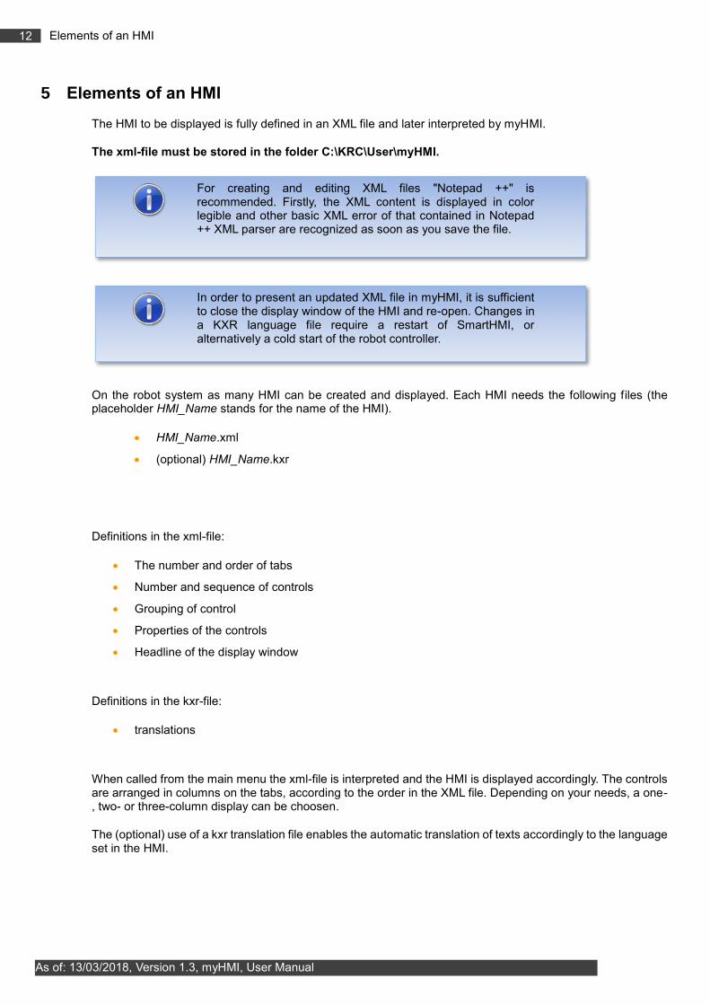
5 Elements of an HMI
The HMI to be displayed is fully defined in an XML file and later interpreted by myHMI.
The xml-file must be stored in the folder C:\KRC\User\myHMI.
On the robot system as many HMI can be created and displayed. Each HMI needs the following files (the placeholder HMI_Name stands for the name of the HMI).
HMI_Name.xml
(optional) HMI_Name.kxr
Definitions in the xml-file:
The number and order of tabs
Number and sequence of controls
Grouping of control
Properties of the controls
Headline of the display window
Definitions in the kxr-file:
translations
When called from the main menu the xml-file is interpreted and the HMI is displayed accordingly. The controls are arranged in columns on the tabs, according to the order in the XML file. Depending on your needs, a one-, two- or three-column display can be choosen.
The (optional) use of a kxr translation file enables the automatic translation of texts accordingly to the language set in the HMI.
For creating and editing XML files "Notepad ++" is recommended. Firstly, the XML content is displayed in color legible and other basic XML error of that contained in Notepad ++ XML parser are recognized as soon as you save the file.
In order to present an updated XML file in myHMI, it is sufficient to close the display window of the HMI and re-open. Changes in a KXR language file require a restart of SmartHMI, or alternatively a cold start of the robot controller.

13 Elements of an HMI
As of: 13/03/2018, Version 1.3, myHMI, User Manual
Tabulated summary
File Description Location
HMI_Name.xml Description of the displayed content through predefined tabs and controls
any location e.g .: C:\KRC\USER\myHMI
HMI_Name.kxr (Optional) for multilingual text and caption content
C:\KRC\Data
SmartHMI.exe.User.config
Menu call of the HMI from the KUKA main menu. Created by the menu assistant
C:\KRC\User
HMI_Name= Placeholder for the name of the HMI, freely selectable

14 Elements of an HMI
As of: 13/03/2018, Version 1.3, myHMI, User Manual
5.1 Schematic representation of the functional principle
After calling a HMI from the main menu the plugin interprets the corresponding XML file and creates the respective HMI.
Plugin MyHMI
myHMI_Demo.xml
myHMI_Example1.xml
myHMI_Example2.xml
created HMI
reads XML

15 Elements of an HMI
As of: 13/03/2018, Version 1.3, myHMI, User Manual
5.2 Group controls on tab pages
The groups are used for thematic separation of content and displayed in the HMI as tabs. You must specify at least one group. Up to five groups can be specified.
Example XML
<Configuration Text="MeinHmi_Titel" modules="MeinHmi">
<Group Text="first tab">
, , ,
</Group>
</Configuration>
Example Display
If only one tab is defined within an XML file in the HMI no tab is displayed.
5.3 Controls
Controls are definied by the node <Control …>.
To display and manipulate KRL variables different controls are available. These controls are linked in the XML file with the KRL variables. The appearance and behavior can be influenced by various arguments. In the simplest case, a control requires the arguments type, text and KrlVar. The following description of the controls shows the minimum necessary arguments. Further arguments for each control are discussed in Chapter 0.
To define controls within a tab page, the text must be within the node <Group ….> … </Group>
<Group Text="...">
<Control Type="Number" Text="Path Velocity" KrlVar="$Vel.CP"/>
, , ,
</Group>
5.3.1 Notation in the XML file
The notation in the XML file is based on the common formatting rules for XML files.
A control is normally specified within within the node < Control .../>. The type of control is indicated by the argument Type. The indication of allocation to the individual arguments is written within quotation marks (").
Example of a control of type "Number" to display INT or REAL variables
<Control type="Number" text="line speed" KrlVar="$Vel.CP"/>

16 Elements of an HMI
As of: 13/03/2018, Version 1.3, myHMI, User Manual
5.3.2 Overview available Controls
Following controls are available:
Number
LED
Switch
Checkbox
Button
DropDown
Text
Label
Progressbar
Slider
Headline
Picture
5.3.3 Display size of the controls
Except for the "Picture" control, all controls are displayed at a height of 40 pixels.
5.3.4 Control "Number"
Is used to represent INT or REAL variables. The control automatically determines the variable type (INT or REAL) and sets the appropriate keyboard type for input values.
Example 1
Entry in the XML file
<Control type="Number" text="Path velocity" KrlVar="$Vel.CP"
Example 2
Entry in the XML file
<Control type="Number" Text="Velocity" KrlVar="$OV_PRO" VisibleLevel="0" EditLevel="20"
Min="0" Max="100" Step="10"/>
The specification of the minimum and maximum value can also be made via a KRL variable.
<Control type="Number" Text="Velocity" KrlVar="$OV_PRO" VisibleLevel="0" EditLevel="20"
Min="iMinValue" Max="iMaxValue" Step="10"/>

17 Elements of an HMI
As of: 13/03/2018, Version 1.3, myHMI, User Manual
5.3.5 Control "LED"
Is used to represent Boolean variables.
Example
Example entry in the XML file
<Control type="Led" Text="Motor Drehtisch 1" KrlVar="$Flag[1]"
By specifying the argument "Negate", the LED display will be negated.
5.3.6 Control "switch"
Represents the state Boolean variables and toggles the value between TRUE and FALSE.
Function: Switch, Maintained
Example
Entry in the XML file
<Control type="Switch" Text="Flag 1" KrlVar="$FLAG[1]"
By specifying the argument "Negate" the function of the switch are negated.
5.3.7 Control "checkbox"
Represents the state Boolean variables and toggles the value between TRUE and FALSE.
Function: Switch, Maintained
Example
Entry in the XML file
<Control type="checkbox" Text="Checkbox Steuerelement" KrlVar="$Flag[1]"/>
By specifying the argument "Negate" the function of the switch are negated.

18 Elements of an HMI
As of: 13/03/2018, Version 1.3, myHMI, User Manual
5.3.8 Control "button"
Sets the value of a Boolean variable to TRUE or FALSE.
Function: Button, without detent
Default value when operating: TRUE
Example
Entry in the XML file
<Control type="button" Text="Button control" TextButton="Press" KrlVar="$Flag[1]"/>
By specifying the argument "Negate" the function of the button will be negated.
5.3.9 Control "DropDown"
Is used for displaying and manipulating variables of type ENUM.
Example
Entry in the XML file
<Control Type="dropdown" Text="Interpolations Mode" KrlVar "$IPO_MODE">
<DropDownItem text="Base" value="#Base"/>
<DropDownItem text="Tool" Value="#TCP"/>
</Control>
The entries in the drop-down menu are made via the element "DropDownItem" and its arguments "Value" and "Text"
(optional).
Arguments of the element "DropdownItem"
Argument Description
Text Text displayed in the drop down menu (optional)
Value Value is assigned to each of the connected KRL variable
In addition ENUM variables, also KRL variable of type CHAR, INT, REAL, BOOL can be linked with this control. It must be ensured then that the available values in the dropdown are compatible with the target KRL variable.

19 Elements of an HMI
As of: 13/03/2018, Version 1.3, myHMI, User Manual
5.3.10 Control "Text"
Is used to represent and manipulate CHAR variables.
Example
Entry in the XML file
<Control type="text" Text="Text control (Base_Name[1,])" KrlVar="base_name[1,]"/>
5.3.11 Control "Label"
Is used to represent any variable types.
Example
Entry in the XML file
<Control type="label" Text="Label Control ($OV_PRO)" KrlVar="$OV_PRO" Format="0 \%"/>
5.3.12 Control "Progressbar"
Is used to represent INT or REAL variables
Example
Entry in the XML file
<Control type="progressbar" Text="Progressbar control" KrlVar="$OV_PRO" min="0"
max="100"/>
The specification of the minimum and maximum value can also be made via a KRL variable.
<Control type="progressbar" Text="Progressbar control " KrlVar="$OV_PRO" Min="iMinValue"
Max="iMaxValue"/>

20 Elements of an HMI
As of: 13/03/2018, Version 1.3, myHMI, User Manual
5.3.13 Control "Slider"
Is used to display and manipulation of INT or REAL variables.
Example
Entry in the XML file
<Control type="Slider" Text="Slider control" KrlVar="$OV_PRO" min="0" max="100"/>
The relative position of the slider by means of supplying the arguments "Min" and "Max". These are default 0 and 100. The value of the KRL variable always Located within these limits, the disclosure of "Min" and "Max" is not necessary. Does the KRL variable values outside the range of values of "Min" and "Max", the background bar is shown in red.
The specification of the minimum and maximum value can also be made via a KRL variable.
<Control type=" Slider " Text=" Slider control" KrlVar="$OV_PRO" Min="iMinValue"
Max="iMaxValue"/>
5.3.14 Control "Headline"
Used to display captions and headings
Example
Entry in the XML file
<Control type="headline" Text="Example for the representation of Number variables
($OV_PRO)"/>

21 Elements of an HMI
As of: 13/03/2018, Version 1.3, myHMI, User Manual
5.3.15 Control “Picture”
The "Picture" control is used for the static and dynamic display of graphics. For dynamic representation, the specification of a KRL variable and a wildcard is required.
It is also possible to superimpose individual images into an overall image. To do this, the KRL variable must be a structure.
The location of image files can be both local and on a network drive (file sharing must be considered).
5.3.15.1 Supported graphic formats
Supported formats are:
BMP
GIF
JPEG
PNG
TIFF
If an incorrect graphic format is used, an error message will be displayed.
5.3.15.2 Display size of the graphics
The pictures are shown by default (without optionale size argument) in original size. The size can be scaled using the optional "Width" argument.
All other controls are displayed by default at a height of 40 pixels.
5.3.15.3 Arguments of the control “Picture”
Different arguments can affect the look and feel of the control.
5.3.15.3.1 Argument “Path” - Path to the graphic file
The argument "Path" specifies the name of the graphic files to be loaded. This path can be specified both absolutely and relative. If relative, the reference folder is c:\KRC\User\myHMI.
Absolute indication:
<Control Type="Picture" Text="myHMI is powered by OrangeApps"
Path="C:\KRC\User\myHMI\myPics\logo_orangeapps.png" Border="False"/>
relative indication:
<Control Type="Picture" Text="myHMI is powered by OrangeApps"
Path="myPics\logo_orangeapps.png" Border="False"/>

22 Elements of an HMI
As of: 13/03/2018, Version 1.3, myHMI, User Manual
5.3.15.3.2 Argument „KrlVar“ (optional) – KRL-variable for dynamic representation
By specifying a KRL variable and the wildcard {0}, the name of the graphic to be displayed can be dynamically generated.
<Control Type="Picture" Text="Power Laser enabled" Path="D:\IO_{0}.png" KrlVar="$IN[1]"/>
The value of the KRL variable is monitored, read out and converted into a string. The placeholder is replaced by the string and thus the file name is specified.
5.3.15.3.3 Argument „Width“ (optional) – Display size of an graphic
Without the specification of the element "Width", the graphic is displayed in its original size. The element "Width" scales the graphic in width. The height adjustment is done according to the original aspect ratio. The specification of "Width" is in pixels.
Example:
<Control Type="Picture" Text="Power Laser enabled" Path="D:\IO_{0}.png" KrlVar="$IN[1]"
Width="80"/>
Suppose the original size of an graphic is 50x80 pixels. Width is specified as 80
The scale factor is 1.6. The picture is displayed with 80x128 pixels.
5.3.15.3.4 Argument „Border“ (optional) – Frame pictures
The argument "Border" determines if a frame should be drawn around the graphic. Border = "True" draws a border, False does not draw the border. The default is "TRUE"
Example:
<Control Type="Picture" Path="D:\IO_{0}.png" KrlVar="$IN[1]" Width="80" Border="FALSE"/>
5.3.15.3.5 Argument „Alignment“ (optional) – Align graphics
The argument "Alignment" can be used to change the orientation of the graphic between left, center, and right. Without specifying "Alignment", the graphics are aligned on the right edge.
Example:
<Control Type="Picture" Path="C:\KRC\User\myHMI\myPics\logo_orangeapps.png"
Alignment="Left"/>
5.3.15.3.6 Argument „Text“ (optional) – Display text
With the argument "Text" additional text can be displayed. This text can also be displayed in multiple languages (see chapter "Multilingualism").
Example:
<Control Type="Picture" Text="Power Laser enabled" Path="D:\IO_{0}.png" KrlVar="$IN[1]"
Width="80" Border="FALSE"/>

23 Elements of an HMI
As of: 13/03/2018, Version 1.3, myHMI, User Manual
5.3.15.4 Static representation
For static display always the same picture displayed.
Example
Entry in the xml-file
<Control Type="Picture" Text="myHMI is powered by OrangeApps"
Path="Pics\logo_orangeapps.png" Border="False"/>
5.3.15.5 Dynamische representation
For the dynamic display of graphics, the path to the graphic file is assembled from the specification in the element "Path" and the value of a KRL variable. In the file name, the placeholder {0} must be used. The value of the variable is interpreted as a string and built into the file name in the place of the wildcard {0}. If the value of the KRL variable changes, the displayed graphic changes automatically.
Example dynamic representation
Entry in the xml-file
<Control Type="Picture" Text="Power Laser enabled" Path="D:\IO_{0}.png" KrlVar="$IN[1]"/>
Graphic to load::
Value of the variable $IN[1] Graphic to load
FALSE D:\IO_FALSE.PNG
TRUE D:\IO_TRUE.PNG

24 Elements of an HMI
As of: 13/03/2018, Version 1.3, myHMI, User Manual
5.3.15.6 Dynamic overlay of single graphics to an overall graphic
Similar to dynamic rendering, the placeholder {0} in the Path element is used to superimpose images. To display superimposed images in an overall image, a KRL variable of type "structure" is required. myHMI determines all structure elements and their values in succession, puts them together into a string and replaces the placeholder in the file name with the respective string according to the following principle:
First graphic: String from Path + Name of the 1st structure element + Value of the 1st structure element
Second graphic: String from Path + name of the 2nd structure element + value of the 2nd structure element etc. last graphic: String from Path + Name of the last structure element + Value of the nth structure element
There are as many graphics been displayed as there are structure elements. The order of the image overlay is determined by the order of the definition of the structure elements. The name of the structure variable and its elements can be freely selected. Not allowed is structure in structure. If the value of the KRL variable changes, the displayed overall graphic changes automatically.
Example with overlay, the structure variable is called "myHMIPicDemo" with the boolean elements Gate, Background, Door, Turntable and Robot
The overall graphic consists of five different graphics
.
Entry in the xml-file (Assumption: The graphics are stored in the folder D:\myHMI\Pics)
<Control Type="Picture" Path="D:\myHMI\Pics\myHMI_{0}.png" KrlVar="myHMIPicDemo"/>
The variable myHMIPicDemo is a structure with the following boolean elements:
GLOBAL STRUC strPicDemo BOOL Gate,BackGround,Door,TurnTable,Robot
DECL GLOBAL strPicDemo myHMIPicDemo={Gate TRUE,BackGround TRUE,Door TRUE,TurnTable
FALSE,Robot FALSE}

25 Elements of an HMI
As of: 13/03/2018, Version 1.3, myHMI, User Manual
How do the names of the graphics result? 1. myHMI searches for the elements of the variable myHMIDemo. These are Gate, Background, Door, TurnTable and Robot 2.myHMI determines the current values of the elements 3. myHMI composes the name of each element and its value into a string, e.g. GateTrue 4. The placeholder {0] in the path D:\myHMI\Pics\myHMI_ {0} .png is replaced by the determined string, eg. D: \ myHMI \ Pics \ myHMI_GateTrue.png 5. This image will now be displayed myHMI performs these steps for each structure element. The order of the elements in the definition of the structure determines the order of the image display. The folder D:\myHMI\Pics contains the following graphics:
myHMI_BackgroundTrue.png
myHMI_RobotTrue.png
myHMI_RobotFalse.png

26 Elements of an HMI
As of: 13/03/2018, Version 1.3, myHMI, User Manual
myHMI_DoorTrue.png myHMI_DoorFalse.png
myHMI_TurnTableTrue.png
myHMI_TurnTableFalse.png
myHMI_GateTrue.png
myHMI_GateFalse.png
Example
At the following values
DECL GLOBAL strPicDemo myHMIPicDemo={Gate TRUE,BackGround TRUE,Door FALSE,TurnTable
TRUE,Robot TRUE}
these graphics will be displayed:
Element Value Graphics to be loaded
Gate TRUE D:\myHMI\Pics\myHMI_GateTrue.png
Background TRUE D:\myHMI\Pics\myHMI_BackgroundTrue.png
Door FALSE D:\myHMI\Pics\myHMI_DoorFalse.png
TurnTable TRUE D:\myHMI\Pics\myHMI_TurnTableTrue.png
Robot TRUE D:\myHMI\Pics\myHMI_RobotTrue.png

27 Elements of an HMI
As of: 13/03/2018, Version 1.3, myHMI, User Manual
Result:
If more graphics are to be displayed, only the structure needs to be expanded accordingly and the respective graphics added to the folder D:\myHMI\Pics.
Beispiel mit Überlagerung, die Strukturvariable heißt „myCellView“ mit den Elementen Gate, Background, Door, Turntable und Robot vom Typ Integer,
Eintrag in der XML-Datei (Annahme: Die Bilder sind im Ordner C:\KRC\User\myHMI\Pics gespeichert)
<Control Type="Picture" Path="Pics\{0}.png" KrlVar="myCellView"/>
At the following values
DECL GLOBAL strCellView myCellView={Gate 0,BackGround 1,Door 2,TurnTable 1,Robot 3}
(The values of the variables were assumed as examples)
these graphics will be displayed:
Element Value Graphic tob e loaded
Gate 0 C:\KRC\User\myHMI\Pics\Gate0.png
Background 1 C:\KRC\User\myHMI\Pics\Background1.png
Door 2 C:\KRC\User\myHMI\Pics\Door2.png
TurnTable 1 C:\KRC\User\myHMI\Pics\TurnTable1.png
Robot 3 C:\KRC\User\myHMI\Pics\Robot3.png
We are happy to assist you in creating attractive graphics for your HMI. Just contact us at [email protected].

28 Elements of an HMI
As of: 13/03/2018, Version 1.3, myHMI, User Manual
5.3.16 Overview of all available arguments
For each control are further arguments are available. These arguments effect the appearance and behavior of each control.
Description of all possible arguments
Argument Description Optional Default value
Alignment
Control Label:
Sets the caption text left, center, right)
Control Picture:
Aligns the graphic (left,center,right)
Yes Label:left
Picture: right
AreYouSure True=Confirmation on value change (dialogue)
Yes False
Border Controls if a frame shall be drawn around a graphic (with frame=True)
Yes TRUE
Color0
Color of the LED in the control state False
Possible values: Grey, Green, Red, Yellow
Yes Gray
Color1
LED color of the control “Led” at the TRUE state
Possible values: Grey, Green, Red, Yellow
Yes Green
ColSpan Number of columns spanned by the element
Yes 1
Description When clicking on the control additional description text is displayed
Yes
Format Formatting of INT and REAL values Yes
KrlVar Linked KRL variable No
Max Maximum allowed value Yes
Min Minimum allowed value Yes
ModeOP Operation mode from which the element is editable
Yes 31
Module Module / KXR file for multilingual content Yes value from
group
NeedDrivesReady Editability of the element is dependent on the state of the drives
Yes False
NeedSafetySwitch Editability of the element is dependent of the state of the enabling switch
Yes False
Negate Invert a 28oolean variable Yes False
Path Specifies the name and path of a graphic
No

29 Elements of an HMI
As of: 13/03/2018, Version 1.3, myHMI, User Manual
ProState0 Editability of the element is dependent of the state of the submit interpreter
Yes 63
ProState1 Editability of the element is dependent of the state of the program interpreter dependent
yes 63
Step Increment for up / down button Yes
Text Label text or key for the element No
Text0 Labeling of the control button "checkbox" at state False
Yes From
Text1 Labeling of the control button "checkbox" state at True
Yes An
TextButton Labeling of the control "button" Yes
UserLevelEdit User level from which the element is editable
Yes 0
User Level Visible User level from which the element is visible
Yes 0
Value Value of an entry in control "DropDown". The selected value is given to the variable of the argument "KrlVar".
No
Width Specifies the width of a graphic (pixel).
The height is scaled proportial
Yes

30 Elements of an HMI
As of: 13/03/2018, Version 1.3, myHMI, User Manual
Arguments / element array
Argument
<C
onfigura
tion>
<G
roup>
Num
ber
Led
Sw
itch
Checkbox
Butt
on
Slid
er
Pro
gre
ssbar
Dro
p
Text
Labe
l
Head
line
Alignment n/a n/a n/a n/a n/a n/a n/a n/a n/a n/a n/a n/a O O
AreYouSure n/a n/a O n/a O O O O n/a O O n/a n/a n/a
Border n/a n/a n/a n/a n/a n/a n/a n/a n/a n/a n/a n/a n/a O
Color 0/1 n/a n/a n/a O n/a n/a n/a n/a n/a n/a n/a n/a n/a n/a
Columns n/a O n/a n/a n/a n/a n/a n/a n/a n/a n/a n/a n/a n/a
ColSpan n/a n/a O O O O O O O O O O O O
Description n/a n/a O O O O O O O O O O n/a n/a
Format n/a n/a O n/a n/a n/a n/a O O n/a n/a n/a n/a n/a
KrlVar n/a n/a X X X X X X X X X X n/a O
Max n/a n/a O n/a n/a n/a n/a O O n/a n/a n/a n/a n/a
Min n/a n/a O n/a n/a n/a n/a O O n/a n/a n/a n/a n/a
ModeOP n/a n/a O n/a O O O O n/a O O n/a n/a n/a
Module O O O O O O O O O O O O O O
NeedDrivesReady n/a n/a O n/a O O O O n/a O O n/a n/a n/a
NeedSafetySwitch n/a n/a O n/a O O O O n/a O O n/a n/a n/a
Negate n/a n/a n/a O O O O n/a n/a n/a n/a n/a n/a n/a
Path n/a n/a n/a n/a n/a n/a n/a n/a n/a n/a n/a n/a n/a X
ProState0 n/a n/a O n/a O O O O n/a O O n/a n/a n/a
ProState1 n/a n/a O n/a O O O O n/a O O n/a n/a n/a
Step n/a n/a O n/a n/a n/a n/a O n/a n/a n/a n/a n/a n/a
Text X X X X X X X X X X X X X O
Text0/1 n/a n/a n/a n/a n/a O n/a n/a n/a n/a n/a n/a n/a n/a
TextButton n/a n/a n/a n/a n/a n/a O n/a n/a n/a n/a n/a n/a n/a
UserLevelEdit n/a n/a O n/a O O O O n/a O O n/a n/a n/a
UserLevelVisible n/a n/a O O O O O O O O O O O O

31 Elements of an HMI
As of: 13/03/2018, Version 1.3, myHMI, User Manual
Value n/a n/a n/a n/a n/a n/a n/a n/a n/a X n/a n/a n/a n/a
Width n/a n/a n/a n/a n/a n/a n/a n/a n/a n/a n/a n/a n/a O
X: Specification mandatory | O: Optional specification | n/a:not available
5.3.16.1 Argument "Alignment" for control Headline
By specifying the argument "alignment" the text within the control "Headline" can be individually aligned.
Format: String
Allowed values
Value Orientation of the argument "Text" Default
Left left Control Headline
Center center -
Right right Control Picture
Example Headline without argument “Alignment”
Example Headline with Alignment="Center"
Example Graphic without argument „Alignment“

32 Elements of an HMI
As of: 13/03/2018, Version 1.3, myHMI, User Manual
5.3.16.2 Argument "AreYouSure"
If the argument is "AreYouSure" is TRUE, a message dialog is displayed with the question of whether the change is to be performed.
Format: BOOL
Allowed values:
Value Impact
TRUE Dialog message appears
FALSE Dialog message does not appear
Default value: False
Multi language support: yes
Example
<Control Type="Switch" Text="Switch Control" KrlVar "$Flag[1]" AreYouSure="True"/>
YES: value change is adopted No: value change is discarded

33 Elements of an HMI
As of: 13/03/2018, Version 1.3, myHMI, User Manual
5.3.16.3 Argument "Border”
Determines whether an image with or without a frame is displayed.
Format: BOOL
Allowed values:
Value Impact
TRUE Frame is displayed
FALSE Frame is not displayed
Default: TRUE
Example
<Control Type="Picture" Text="LasPowEnabled" Path="PicsDemo\led_{0}.png"
KrlVar="$Flag[1]" ColSpan="2" Border="FALSE"/>
<Control Type="Picture" Text="LasPowEnabled" Path="PicsDemo\IO_{0}.png" KrlVar="$Flag[1]"
Width="50" ColSpan="2" />
<Control Type="Picture" Text="LasPowEnabled" Path="PicsDemo\Smile{0}.png"
KrlVar="$Flag[1]" Width="50" ColSpan="2" Border="FALSE"/>
Only the second control draws a border.
5.3.16.4 Argument "Color0 / Color1"
The argument "Color0 / Color1" sets the color of the control "LED" in the states False and True.
Color0 sets the color of the state False. Color1 sets the color of the state True.
Allowed values:
Value Impact
Gray Control is shown in gray
Green Control is shown in green
Red Control is shown in red
Yellow Control is shown in yellow

34 Elements of an HMI
As of: 13/03/2018, Version 1.3, myHMI, User Manual
Defaults: Color0=gray, color=green 1
Example Color0="yellow" Color1="red"
<Control type="Led" Text="Led Steuerelement" KrlVar="$Flag[1]" Color0="Yellow"
Color1="Red"/>
State of the variable=False
State of the variable=TRUE
5.3.16.5 Argument "ColSpan"
The argument "ColSpan" specifies the number of columns to which a control extends. It interacts with the argument "Columns". "Columns" specifies the number of columns in a tab. The argument "ColSpan" is evaluated only if "Columns" has a value greater than 1. If "ColSpan" is not specified, a control extends on one column.
Format: INT
Allowed values
Value Impact
1 Control spans one column
2 Control spans two columns
3 Control spans three columns
Default value: 1
Example Columns="2"
<Group text="Controls" columns="2">
<Control type="headline" Text='Beispiel Columns="2"'
Alignment="MiddleCenter" ColSpan="2"/>
<Control type="Led" Text="Led Steuerelement " KrlVar="$Flag[1]" Color0="Yellow"
Color1="Red"/>
<= Control Type="Switch" Text="Switch Steuerelement" KrlVar "$Flag[1]"/>
<Control type="checkbox" Text="Checkbox Steuerelement " KrlVar="$Flag[1]"
ColSpan="2"/>
<Control type="button" Text="Button Steuerelement " TextButton="Drücken"
KrlVar="$Flag[1]" ColSpan="2"/>

35 Elements of an HMI
As of: 13/03/2018, Version 1.3, myHMI, User Manual
Explanation
<GROUP>: Column ="2" specifies the number of columns of the entire tab to 2.
HEADLINE: ColSpan ="2" spans the control over 2 columns
LED: ColSpan is not specified, the control is one column wide
SWITCH: ColSpan is not specified, the control is one column wide
CHECKBOX: ColSpan ="2" spans the control over 2 columns
BUTTON: ColSpan ="2" spans the control over 2 columns
5.3.16.6 Argument "Description"
Specifies an additional descriptive text for a control. Tap on the text of the control opens the control and the description text is visible. If a description is available text for a control an arrow down icon is displayed.
Format: string
Allowed characters: Key string or a speech database
Mulit language support: yes
For each string of the argument "Description" an entry in a speech database is searched. If no entry is found, the specified string is displayed.
Example 1
<Control Type="Checkbox" Text="Leds umschalten" Description="Mit dem optionalen Argument
"Text0" und "Text1" kann die Schaltfläche für den jeweiligen Zustand beschriftet werden"
KrlVar="$Flag[1]" Text0="Aus" Text1="Aktiv"/>
Control collapsed:
Control opened:

36 Elements of an HMI
As of: 13/03/2018, Version 1.3, myHMI, User Manual
Example 2 Database Key
XML:
<Control Type="Checkbox" Text="Leds umschalten" Description="DescCheckbox"
KrlVar="$Flag[1]" Text0="Aus" Text1="Aktiv"/>
Kxr file:
<uiText key="DescCheckBox">
<text xml:lang="de-DEV"> Mit dem optionalen Argument "Text0" und "Text1" kann die
Schaltfläche für den jeweiligen Zustand beschriftet werden </text>
<text xml:lang="en-DEV">By using the optional argument "Text0" and "Text1” it’s
possible to parametrize the caption of the button</text>
</uiText>
<text xml:lang="it-DEV">…</uiText>
For the HMI language "English", "German" and "Italian" the respective translation text from the kxr file is used. For all other languages, the English text is used.
5.3.16.7 Argument "Format"
By specifying a number format string, the displayed value is formatted accordingly to the schematic of the country.
Suitable for control: Label, Slider, Progressbar, Number (with restrictions)
Numeric Format Strings
Format-specifier
Name Description Examples
"0" Zero placeholder
Replaces the zero with the corresponding digit if one is present; otherwise, zero appears in the result string.
1234.5678 ("00000") -> 01235
0.45678 ("0.00", en-US) -> 0.46
0.45678 ("0.00", fr-FR) -> 0,46
"#" Digit placeholder
Replaces the "#" symbol with the corresponding digit if one is present; otherwise, no digit appears in the result string.
1234.5678 ("#####") -> 1235
0.45678 ("#.##", en-US) -> .46
0.45678 ("#.##", fr-FR) -> ,46
"." Decimal point Determines the location of the decimal separator in the result string.
0.45678 ("0.00", en-US) -> 0.46
0.45678 ("0.00", fr-FR) -> 0,46
"," Group separator and number scaling
Serves as both a group separator and a number scaling specifier. As a group separator, it inserts a localized group separator character between each group. As a number scaling specifier, it divides a
Group separator specifier:
2147483647 ("##,#", en-US) -> 2,147,483,647
2147483647 ("##,#", es-ES) -> 2.147.483.647

37 Elements of an HMI
As of: 13/03/2018, Version 1.3, myHMI, User Manual
number by 1000 for each comma specified. Scaling specifier:
2147483647 ("#,#,,", en-US) -> 2,147
2147483647 ("#,#,,", es-ES) -> 2.147
"%" Percentage placeholder
Multiplies a number by 100 and inserts a localized percentage symbol in the result string.
0.3697 ("%#0.00", en-US) -> %36.97
0.3697 ("%#0.00", el-GR) -> %36,97
0.3697 ("##.0 %", en-US) -> 37.0 %
0.3697 ("##.0 %", el-GR) -> 37,0 %
"‰" Per mille placeholder Multiplies a number by 1000 and inserts a localized per mille symbol in the result string.
0.03697 ("#0.00‰", en-US) -> 36.97‰
0.03697 ("#0.00‰", ru-RU) -> 36,97‰
"E0"
"E+0"
"E-0"
"e0"
"e+0"
"e-0"
Exponential notation
If followed by at least one 0 (zero), formats the result using exponential notation. The case of "E" or "e" indicates the case of the exponent symbol in the result string. The number of zeros following the "E" or "e" character determines the minimum number of digits in the exponent. A plus sign (+) indicates that a sign character always precedes the exponent. A minus sign (-) indicates that a sign character precedes only negative exponents.
987654 ("#0.0e0") -> 98.8e4
1503.92311 ("0.0##e+00") -> 1.504e+03
1.8901385E-16 ("0.0e+00") -> 1.9e-16
\ Escape character
Causes the next character to be interpreted as a literal rather than as a custom format specifier.
987654 ("\###00\#") -> #987654#
'string'
"string" Literal string delimiter
Indicates that the enclosed characters should be copied to the result string unchanged.
68 ("# ' degrees'") -> 68 degrees
68 ("#' degrees'") -> 68 degrees
; Section separator Defines sections with separate format strings for positive, negative, and zero numbers.
12.345 ("#0.0#;(#0.0#);-\0-") -> 12.35
0 ("#0.0#;(#0.0#);-\0-") -> -0-
-12.345 ("#0.0#;(#0.0#);-\0-") -> (12.35)
12.345 ("#0.0#;(#0.0#)") -> 12.35
0 ("#0.0#;(#0.0#)") -> 0.0

38 Elements of an HMI
As of: 13/03/2018, Version 1.3, myHMI, User Manual
-12.345 ("#0.0#;(#0.0#)") -> (12.35)
Examples
<Control Type="Label" Text="Label1" KrlVar="rPercentCurrent" Format="#.##%"/>
<Control Type="Number" Text="maxForce" KrlVar="rMaxForce" Format="#.00" Module="Gunkxr"/>
<Control Type="Progressbar" Text="nbrPoints" KrlVar="iNumPoints" Format="# 'pro Tag'"
Min="0" Max="3000" ColSpan="2"/>
<Control Type="Slider" Text="prgBarGunParam" KrlVar="$OV_PRO" Format="# 'mm'" Min="1"
Max="100" ColSpan="2"/>
Representation
Limitations of use in control "Number"
Within the control "Number" only the format strings "#" and "0" may be used.
5.3.16.8 Argument "KrlVar"
KRL variable whose value is to be displayed in the control. Permitted are local and global variables, nested values and use wildcards.
5.3.16.8.1 Indication of global and local variables
The controls can be bound to global or local variables.
Global variables
Global variables are specified without naming the module in which they declared.
Example
KrlVar="$OV_PRO"
Local variables
Local variables are specified with naming the module in which they declared.
Example, Variable "MyVariable" declared in R1\Program\User\MyDatFile.dat
KrlVar="/R1/MyDatFile.dat/MyVariable"

39 Elements of an HMI
As of: 13/03/2018, Version 1.3, myHMI, User Manual
The folder of the module must not be named.
5.3.16.8.2 Nested variables
Variables can be nested. When the HMI opens, the terms are completely dissolved from the inside and the value of all variables included is monitored. If there's a change of the value of an internal variable the complete expression is recalculated.
Example
<Control Text="Base Data" type="text" KrlVar "Base_Data[myArray
[/R1/MyDatFile.dat/MyVariable]].X"/>
First, the value of the local variable "/R1/MyDatFile.dat/MyVariable" is determined e.g. "5"
Now the value of the array "myArray [5]" is this determined e.g. "2"
Finally, the value of Base_Data[2] .X is determined and displayed
5.3.16.8.3 Internal variables as placeholders for counter
To create even more flexible HMI's, it is possible to represent the KRL-arrays with the help of two or more control elements. In this case, one control performs the function of a counter. This serves to select the array index and each further control is used to display the actual value. Per page 32 internal variables can be used.
Counters are indicated by a placeholder "%1", "%2", "%3" ... - %32" in the argument "KrlVar".
If the value of the counter changes, all associated controls are updated automatically.
Example
<Control Type="Headline" Text="Technologie Visualisierung"/>
<Control Type="Number" Text="Nummer" KrlVar="%1" Step="1" Min="1" Max="10"/>
<Control Type="Text" Text="Tech Visualisierung" KrlVar="Tech_Visu[%1].Techshortcut[]"/>
<Control Type="Text" Text="aktiv" KrlVar="Tech_Visu[%1].IsActive"/>
Declaration of the variable used in the example:
DECL Technologie Tech_Visu[10]
TechVisu[1]={TechShortcut[] "SWM_1", IsActive #Yes}
Display in HMI:

40 Elements of an HMI
As of: 13/03/2018, Version 1.3, myHMI, User Manual
5.3.16.9 The arguments "Min" and "Max"
The specification of the arguments "Min" and "Max" has different meanings depending on the control where it is used.
Format: INT
Allowed values: 10-31 to 10 + 31
The following controls support the specification of these arguments:
Control "Number"
Control "progressbar"
Control "Slider"
The values of Min and Max can be given by KRL-variables.
5.3.16.9.1 Use in control "Number"
The control "Number" supports a check of the value given by the operator when the arguments "Min" and "Max" specify the lower and upper bounds for the input value. If the input value is out of bounds, the number field is shown in red and the saving of the input value is not possible.
Example
<Control type="Number" text="Maximum Force (5-7kN)" KrlVar="max_Force" min="5" Max="7"
ColSpan="2"/>
In the message window, a message will appear:
5.3.16.9.2 Use in the controls "Slider" and "progress bar"
In both controls the arguments "Min" and "Max" is used to properly display the controls.
At the control "Slider" the background is shown in red if the value is out of bounds.
Example
<Control type="Slider" Text="Maximum Force (5-7kN)" KrlVar="max_Force" min="5" Max="7"
ColSpan="2"/>

41 Elements of an HMI
As of: 13/03/2018, Version 1.3, myHMI, User Manual
5.3.16.10 Argument "Module"
Specifies the name of the speech database for automatic language switching again.
Format: string
Allowable values: name of the language database (*.kxr)
The plugin supports the use of kxr files for multilingualism. For all the arguments of type "string" a key in a speech database can be specified. If a key is found for the actual language of the HMI, the translated text is shown. If no key is found in the database, the specified text is displayed.
Example:
<= Control Type="Number" text="maxForce" KrlVar "xHome1.a1" Module="Servogun"
ColSpan="2"/>
Entry in the file Servogun.kxr
<uiText key="maxForce">
<text xml:lang="de-DEV">maximale Zangenkraft (5-7 kN)</text>
<text xml:lang="en-DEV">maximum gun force (5-7 kN)</text>
</uiText>
HMI language is German:
HMI language is English:
The switching between the language is done automatically.
The argument "Module" can be used in the element:
<Configuration>
<Group>
<Control>
Usage and validity
Usage in Validity
<Control> Applies for that control
<Group> Applies to all elements within this group
<Configuration> Applies to all elements of all groups
If a key is found in the database, but no entry for the current HMI language is given, the text of the English language is shown (if given).

42 Elements of an HMI
As of: 13/03/2018, Version 1.3, myHMI, User Manual
Explanation for usage
If a database is specified for a control this will be used. If no database is specified, the database of the <Group> is used. Is there also no database is specified, the database of the element <Configuration> used. Is there also no database specified, the database "myHMI.kxr" is used by default.
Schematic representation
5.3.16.11 Argument "Mode_OP" Operantion Mode
Defines the state of the operation mode ($Mode_op") from which a control is editable.
Format: INT
Allowed values:
Designation
Valu
e
Examples
Invalid 16 Default value=31
Control is always active
Example value=3
Control active when operation mode is "T1" or "T2"
Example value=12
Control only active when operation mode is "Auto" or "Ext"
Ext 8
Aut 4
T1 2
T2 1
"Module" in <Control> is specified?
yes
no "Module" in <Group> specified?
yes
no "Module" in <configuration>
specified?
yes
no
"Module" of the <control> is used for translation
"Module" of the element <Group> is used for translation
"Module" of the element <Configuration> is used for translation
"MyHMI.kxr" is used for translation (Standard)

43 Elements of an HMI
As of: 13/03/2018, Version 1.3, myHMI, User Manual
5.3.16.12 Argument "NeedDrivesOk" Antriebe
Defines the state of the drives for the control being editable.
Value of the argument
Impact
True Control is only active when the drives are switched on
False or not specified
Control is active
5.3.16.13 Argument "Negate"
Negates the display of a Boolean variable.
Format: BOOL
Allowed values
Value Impact
True The indication of the state of the variable is negated
False The indication of the state of the variable is not negated
Example
<Control Type="Led" Text="Led Control" KrlVar="$FLAG[1]" Negate="TRUE" Color0="Yellow"
Color1="Red" Mode_OP="#EX"/>
<Control Type="Switch" Text="Switch Control" KrlVar="$Flag[1]"/>
<Control Type="Checkbox" Text="Checkbox Control" KrlVar="$Flag[1]" Negate="TRUE"
ColSpan="2"/>
Display at $Flag[1]=False

44 Elements of an HMI
As of: 13/03/2018, Version 1.3, myHMI, User Manual
5.3.16.14 Argument "Path"
Sets the filename and path to the graphic file to be loaded by the Picture control.
The file name can contain the placeholder {0}. This is then replaced by the value of a KRL variable to be specified.
Example
<Control Type="Picture" Text="Power Laser enabled" Path="D:\IO_{0}.png" KrlVar="$IN[1]"/>
The value of $IN[1] replaces as a string the placeholder {0} in the filename.
5.3.16.15 Argument "ProState0" Submit interpreter
Defines the state of the submit interpreter for the control being editable.
Designation
Valu
e
Examples
Active 32 Default=63
Control is always active
Example-value=32
Control is only active when the Submit is running
Sample Value=2
Control is only active if the submit is deselected
End 16
Reset 8
Stop 4
Free 2
Unknown 1
Example
<Control Type="Switch" Text="Switch Control" KrlVar="$FLAG[1]" Color0="Yellow"
Color1="Red" ProState="6"/>
Control editable when the submit interpreter is stopped or deselected.

45 Elements of an HMI
As of: 13/03/2018, Version 1.3, myHMI, User Manual
5.3.16.16 Argument "ProState1" Program interpreter
Defines the state of the program interpreter for the control being editable.
Designation
Valu
e
Examples
Active 32 Default=63
Control is always active
Example-value=30
Control is only active if the program pointer is at the end, or if the selected program has been reset or if the selected program has been stopped or select a program is
the control is inactive if a program is running
End 16
Reset 8
Stop 4
Free 2
Unknown 1
5.3.16.17 Argument "Step"
This sets the step size of the Up/Down buttons of the control "Number". Only if the argument "Step" is specified, the Up/Down buttons are displayed.
Format: REAL
Allowed values: 10-31 to 10 + 31
Example
<Control Type="Number" Text="Maximum Force (5-7 KN)" KrlVar=" max_Force" Min="5" Max="5"
Step="0.1" ColSpan="2"/>
Representation
Each time the Up/Down buttons are pressed, the value of the variable "max_Force" is in/decreased by 0.1
With integer variables, no real values for Step can be used!

46 Elements of an HMI
As of: 13/03/2018, Version 1.3, myHMI, User Manual
5.3.16.18 Argument "Text"
Is used for the label text of a control.
Format: string
Allowed characters: Key string or a speech database
Multi language support: yes
For each string in "text" an entry in the speech database is searched. If no entry is found, the specified string is displayed. The database used is specified with the argument "Module". See section 0.
5.3.16.19 Argument "Text0" and "Text1"
These arguments are used to label the button text of the control "checkbox" at state FALSE and TRUE.
Format: string
Allowed characters: Key string or a speech database
Multi language support: yes
For each string in "Text0" and "Text1" an entry in the speech database is searched. If no entry is found, the specified string is displayed. The database used is specified with the argument "Module". See section 0.
Usage
Argument Impact Default value if the
argument is not specified
Text0 Specifies the label of the button when the state of the associated variable is False
Off
Text1 Specifies the label of the button when the state of the associated variable is True
On
5.3.16.20 Argument "TextButton"
Used for the labeling of the button text of the control "button".
Format: string
Allowed characters: Key string or a speech database
Multi language support: yes
Default value: -
For each string in "TextButton" an entry in the speech database is searched. If no entry is found, the specified string is displayed. The database used is specified with the argument "Module". See section 5.3.16.10.
Example
<Control Type="Button" Text="Button Steuerelement" TextButton="Push" KrlVar="$Flag[1]"
ColSpan="2"/>

47 Elements of an HMI
As of: 13/03/2018, Version 1.3, myHMI, User Manual
5.3.16.21 Argument "UserLevelEdit"
Defines from which user level a tab or a control is editable.
Format: INT
Default value: 10
Usage and validity
Usage in Validity
<Control> Applies for that control
<Group> Applies to all elements within this group
Example
<Control Type="Switch" Text="Checkbox" KrlVar="$Flag[1]" UserLevelEdit="20"
AreYouSure="True" />
Representation for standard users
Representation for user 'expert'
5.3.16.22 Argument "UserLevelVisible "
Defines from which user level a tab or a control is visible.
Format: INT
Default value: 10

48 Elements of an HMI
As of: 13/03/2018, Version 1.3, myHMI, User Manual
5.3.16.23 User levels KRC4
On the KRC4 following user levels are used:
User Level
Operator 10
Expert 20
Safety maintenance 27
Sicherheitsinbetriebnehmer 29
Administrator 30
5.3.16.24 Element "DropDownItem" of the control "DropDown"
Used to add elements to a dropdown control. Within this argument the arguments "Value" and "Text" will be used.
5.3.16.24.1 Argument "Value"
Specifies the value which is given to the associated variable in the argument "KrlVar".
Format: depending on the type of the variable of the element "KrlVar"
Default value: -
Optional: no
5.3.16.24.2 Argument "Text"
Describes the entry in the drop-down control. If "text" is not specified, the entry is set according to the entry in the argument "Value".
Format: Key string or a speech database
Default value: -
Optional: yes
Multi language support: yes
Example 1 "Text" not specified
<Control Type="Dropdown" Text="Dropdown Steuerelement ($PRO_MODE1)" KrlVar="$PRO_MODE1">
<DropDownItem Value="#GO"/>
<DropDownItem Value="#MSTEP"/>
<DropDownItem Value="#ISTEP"/>
<DropDownItem Value="#BSTEP"/>
<DropDownItem Value="#PSTEP"/>
<DropDownItem Value="#CSTEP"/>
</Control>

49 Elements of an HMI
As of: 13/03/2018, Version 1.3, myHMI, User Manual
Example 2, "Text" specified
<Control Type="Dropdown" Text="Dropdown Control ($PRO_MODE1)" KrlVar="$PRO_MODE1">
<DropDownItem Value="#GO" Text="Go"/>
<DropDownItem Value="#MSTEP" Text="Motion"/>
<DropDownItem Value="#ISTEP" Text="Single Step"/>
<DropDownItem Value="#BSTEP" Text="Backward"/>
<DropDownItem Value="#PSTEP" Text="Program Step" />
<DropDownItem Value="#CSTEP" Text="Continuous Step"/>
</Control>
All text is defined as a "key" in the kxr file and is translated.

50 Elements of an HMI
As of: 13/03/2018, Version 1.3, myHMI, User Manual
5.3.16.25 Argument "Width”
Sets the width of the graphic for the Picture control. The height of the graphic is scaled according to the proportions of the original graphic.
Format: INT (Pixel)
Default: -
Example:
<Control Type="Picture" Text="Power Laser enabled" Path="D:\IO_{0}.png" KrlVar="$IN[1]"
Width="80"/>
The graphic is scaled to the width of 80 pixels.
5.4 Layout
The controls are arranged in columns and tabs accordingly to their order within the XML file.
The following restrictions apply:
A maximum of five tabs per HMI
A maximum of 32 controls with associated krl variables each tab
To improve the clarity and usability, the layout of each tab can be divided into up to three columns. For this purpose, in the element <Group> the argument "Columns" is used. Depending on the value of "Columns" the controls are arranged side by side in columns. By the argument "ColSpan" the controls can be stretched over multiple columns.
Example for three columns
<Group Text="3 Spalten" Columns="3">
<Control Type="Headline" Text="Eingaenge" ColSpan="3"/>
<Control Type="Led" Text="Eingang 1" KrlVar="$IN[1]"/>
<Control Type="Led" Text="Eingang 2" KrlVar="$IN[2]"/>
<Control Type="Led" Text="Eingang 3" KrlVar="$IN[3]"/>
<Control Type="Led" Text="Eingang 4" KrlVar="$IN[4]"/>
<Control Type="Led" Text="Eingang 5" KrlVar="$IN[5]"/>
<Control Type="Led" Text="Eingang 6" KrlVar="$IN[6]"/>
<Control Type="Label" Text="Ausgaenge" ColSpan="3"/>
<Control Type="Switch" Text="Ausgang 1" KrlVar="$OUT[1]" NeedSafetySwitch="TRUE"/>
<Control Type="Switch" Text="Ausgang 2" KrlVar="$OUT[2]" NeedSafetySwitch="TRUE"/>
<Control Type="Switch" Text="Ausgang 3" KrlVar="$OUT[3]" NeedSafetySwitch="TRUE"/>
<Control Type="Switch" Text="Ausgang 4" KrlVar="$OUT[4]" NeedSafetySwitch="TRUE"/>
<Control Type="Switch" Text="Ausgang 5" KrlVar="$OUT[5]" NeedSafetySwitch="TRUE"/>
<Control Type="Switch" Text="Ausgang 6" KrlVar="$OUT[6]" NeedSafetySwitch="TRUE"/>
<Control Type="Headline" Text="Flags" ColSpan="3"/>
<Control Type="Led" Text="Wert von $Flag[1]" KrlVar="$FLAG[1]" ColSpan="2"/>
<Control Type="Switch" Text="" KrlVar="$Flag[1]"/>
<Control Type="Headline" Text="Zeitgeber" ColSpan="3"/>
<Control Type="Switch" Text="Zeitgeber 1 Stop" KrlVar="$Timer_Stop[1]" ColSpan="2"/>
<Control Type="Number" Text="Wert Zeitgeber 1" KrlVar="$Timer[1]"/>
<Control Type="Headline" Text="Geschwindigkeiten" ColSpan="3"/>
<Control Type="Number" Text="Programm Override" KrlVar="$OV_PRO" Min="0" Max="100"
Step="10" ColSpan="3"/>
<Control Type="Number" Text="Hand Override" KrlVar="$OV_JOG" Min="0" Max="100" Step="10"
ColSpan="3"/>
</Group>

51 Elements of an HMI
As of: 13/03/2018, Version 1.3, myHMI, User Manual
HMI with 3 columns
Column 1 Column 2 Column 3

52 Elements of an HMI
As of: 13/03/2018, Version 1.3, myHMI, User Manual
5.5 Multilingualism
For the multilingual presentation of the texts a translation file (kxr) is necessary. The specification which translation file shall be used is made by the argument "Module".
If the name of the translation file is the same as the name of the xml file, you can do without the argument "Module". By default, myHMI tries to access the kxr file of the same name.
The following requirements must be met.:
There must be a translation file (* .kxr) with corresponding "Keys" be present in the folder C:\KRC \Data. The kxr-file must have the encoding “UTF-8”.
In the XML file the argument "Module" must refer to this kxr file (HINT: specify the name without extension)
The translatable text must be specified in the XML file as a "Key".
It is possible to specify different kxr-files in the argument "Module".
Example 1: All texts of the control "Button" shall be translated into the languages German and English.
Procedure:
1. Create a new KXR file or copy an existing. The name is arbitrary.
Here: DemoMyHMI.kxr
2. Within the control "Button" specify the name of the kxr-file in the argument "Module" (only the name without the extension ".kxr")
3. Specify a "key" in the argument "text"
4. Specify a key for the argument "ButtonText" and, if used, for the argument "Description"
5. Adjust the entries in the kxr-file
6. Restart the SmartHMI or the robot in order to introduce the kxr-file to the robot system
XML file:
<Control Type="Button" Text="txtTextBtn" TextButton="txtPushBtn" Description="descrBtn"
Module="DemoMyHMI" KrlVar="$Flag[1]" ColSpan="2"/>
KXR file:
<?XML version="1.0" encoding="utf-8"?>
<resources xmlns="http://www.kuka.com/schemas/kxr/2009">
<module name="DemoMyHMI">
<uiText key="txtTextBtn">
<text xml:lang="de-DEV">Greifer schliessen</text>
<text xml:lang="en-DEV">close gripper</text>
</uiText>
<uiText key="txtPushBtn">
<text xml:lang="de-DEV">Schliessen</text>
<text xml:lang="en-DEV">Close</text>
</uiText>
<uiText key="descrBtn">
<text xml:lang="de-DEV">Beispiel Mehrsprachigkeit</text>
<text xml:lang="en-DEV">Example multi lingualismn</text>
</uiText>
</module>
</resources>

53 Elements of an HMI
As of: 13/03/2018, Version 1.3, myHMI, User Manual
Example 2: All texts of the HMI should be translated into the languages German and English.
Method:
1. Create a new KXR file or copy an existing one. The name is freely selectable. Here: Demo.kxr
2. In the "Configuration" element, specify the name of the KXR file by the "Module" argument (only the name without the ".kxr" extension)
3. Specify a "key" for the controls in the "Text" argument (string)
XML-Datei:
<Configuration Text="Demotext" Module="Demo">
KXR-Datei:
<?XML version="1.0" encoding="utf-8"?>
<resources xmlns="http://www.kuka.com/schemas/kxr/2009">
<module name="Demo">
<uiText key="Demotext">
<text xml:lang="de-DEV">Text für Demo in deutsch</text>
<text xml:lang="en-DEV">text for demo in english</text>
</uiText>
<uiText key="txtTextBtn">
<text xml:lang="de-DEV">Greifer schliessen</text>
<text xml:lang="en-DEV">close gripper</text>
</uiText>
<uiText key="txtPushBtn">
<text xml:lang="de-DEV">Schliessen</text>
<text xml:lang="en-DEV">Close</text>
</uiText>
<uiText key="descrBtn">
<text xml:lang="de-DEV">Beispiel Mehrsprachigkeit</text>
<text xml:lang="en-DEV">Example multi lingualismn</text>
</uiText>
</module>
</resources>
Description of entries in the kxr file:
Element / argument Description
<Module name> Here, enter the name of KXR file. This entry must be identical to the item in the argument "Module" in the Button control
Key Corresponding with the entries of the arguments "Text", "Description" and "TextButton" in the control
<Text xml: lang="de-DEV"> German translation
<Text xml: lang="en-DEV"> English translation
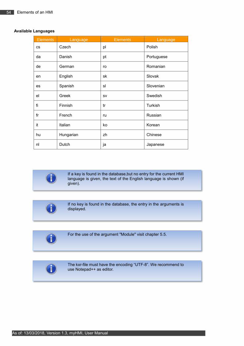
54 Elements of an HMI
As of: 13/03/2018, Version 1.3, myHMI, User Manual
Available Languages
Elements Language Elements Language
cs Czech pl Polish
da Danish pt Portuguese
de German ro Romanian
en English sk Slovak
es Spanish sl Slovenian
el Greek sv Swedish
fi Finnish tr Turkish
fr French ru Russian
it Italian ko Korean
hu Hungarian zh Chinese
nl Dutch ja Japanese
If a key is found in the database,but no entry for the current HMI language is given, the text of the English language is shown (if given).
If no key is found in the database, the entry in the arguments is displayed.
For the use of the argument "Module" visit chapter 5.5.
The kxr-file must have the encoding “UTF-8”. We recommend to use Notepad++ as editor.

55 Demo HMI
As of: 13/03/2018, Version 1.3, myHMI, User Manual
6 Demo HMI
An HMI is included in the setup, which explains the functionality of myHMI and can serve as a template for new HMIs. The HMI can be opened as a half or full size window from the main menu under "myHMI".
Call from the main menu
The underlying xml file myHMIDemo.xml is located in the folder C:\KRC\USER\myHMI.
6.1 Screenshots
Tab „Controls“

56 Demo HMI
As of: 13/03/2018, Version 1.3, myHMI, User Manual
Tab „Advanced“
Tab „Usage Counter variable“

57 Demo HMI
As of: 13/03/2018, Version 1.3, myHMI, User Manual
Tab „Picture Control“
Tab „3 Columns“
This tab demonstrates the dynamic representation of images and the superimposed rendering of images into an overall image, depending on the state of a KRL variable. As a result variable-controlled different states can be displayed.
The switches can be used to display different system states.
In the folder "Program" is an executable demo program "myHMIDemo" which illustrates this dynamic image representation from a robot program.

58 Create your own HMI
As of: 13/03/2018, Version 1.3, myHMI, User Manual
7 Create your own HMI
The following files are required:
Name_of_HMI.xml definition of the HMI
(optional) Name_of_KXR.kxr language database for translation
7.1 Create XML
To create an xml-file, it is advisable to copy an existing file, for example, Demo.xml. The created xml must be stored in C:\KRC\USER\myHMI.
To process the xml-file an appropriate editor such as should Notepad ++ should be used.
7.1.1 Create backbone
The basic structure of the XML file is the element <Configuration>. It describes the main node and includes all sub-nodes. By arguments a text for the heading of the HMI and a module for translations can be specified. If a translation file is specified, this file will be used for all items (if no other module is specified in the controls or groups).
<Configuration Text="myFirstHMI" Module="myFirstHMI">
. . .
</Configuration>
Arguments
Argument Description Optional Default value
Text Label text or key for the heading X
Module Module / KXR file for multilingual content X
7.1.1.1 Define Groups/Tabs
The groups are used for thematic separation of content and displayed on the surface as tabs. You must specify at least one group, and up to five groups can be specified.
Arguments
Argument Description Optional Default value
Text Label text or key for the tab
Modules Module / KXR file for multilingual content X Value from
<Configuration>
Columns Number of columns 1-3 X 1

59 Create your own HMI
As of: 13/03/2018, Version 1.3, myHMI, User Manual
Example XML
<Configuration Text="myFirstHMI" Module="myFirstHMI">
<Group Text="Erste Registerkarte" Columns=”2” >
. . .
</Group>
</Configuration>
Example Display
7.1.2 Definition of controls
The controls in the xml-file are defined as described in Section 5.3.
7.2 Menu assistant – create menu entry in the KUKA main menu
In order to open an HMI from the main menu an menu entry must be defined. This is done in the file SmartHMI.User.config. In order to ease the entry a menu assistant is available. The assistant can be started from Configuration myHMI menu assistant. The required user level to start the assistant is administrator.
Starting the assistant

60 Create your own HMI
As of: 13/03/2018, Version 1.3, myHMI, User Manual
In the main window of the assistant all available HMI are listed. New entries can be added, existing ones can be edited, duplicated or deleted.
Description of the buttons
Button Description
Add A new entry can be added
Edit An entry can be edited
Delete An entry will be deleted
Duplicate An entry can be duplicated

61 Create your own HMI
As of: 13/03/2018, Version 1.3, myHMI, User Manual
7.2.1 Add or edit an entry
In the following window an entry can be added or edited.
The placement in the main menu of an entry can be selected in the listing of the menu structure.

62 Create your own HMI
As of: 13/03/2018, Version 1.3, myHMI, User Manual
Description of the elements
Element Description
How shall be the name in the menu?
Name of the entry in the main menu
Which xml-file shall be called? Name of the xml-File. In the dropdown all in C:\KRC\USER\MYHMI available xml-files will be listed
How shall the HMI be displayed? The HMI can be displayed in full or half size window
Allow to open the HMI only as:
The opening of the HMI can be limited according to the user level. The levels are: User, Expert, Safety maintenance, Safety recovery and administrator.
If no level is selected the HMI can be opened by everyone.
Description of the buttons
Button Description
Create folder At any location in the main menu, a subfolder is created
Apply The settings will be saved
Cancel The settings will be discarded
7.2.1.1 Multilingualism of the name of the menu item
The menu entry can be translated by using a language database and a key. The syntax is:
Name of the database # Key
Example entry: FirstHMI#myFirstHMI
The name of the kxr-file in C:\KRC\Data is: FirstHMI.kxr The key for the translation in that file is: myFirstHMI
If the name oft he kxr-file is identical to the name of the xml-file, the indication of the name of the language base can be omitted. The menu assistant automatically creates the entry of the key in the database.
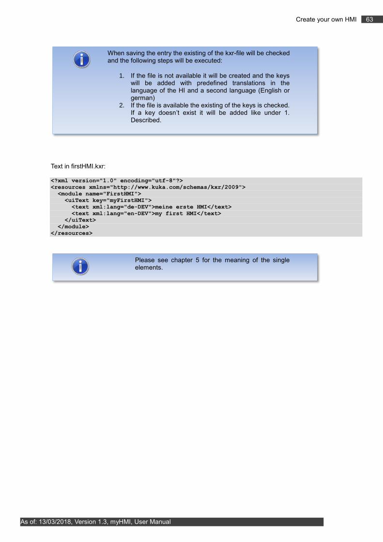
63 Create your own HMI
As of: 13/03/2018, Version 1.3, myHMI, User Manual
Text in firstHMI.kxr:
<?xml version="1.0" encoding="utf-8"?>
<resources xmlns="http://www.kuka.com/schemas/kxr/2009">
<module name="FirstHMI">
<uiText key="myFirstHMI">
<text xml:lang="de-DEV">meine erste HMI</text>
<text xml:lang="en-DEV">my first HMI</text>
</uiText>
</module>
</resources>
When saving the entry the existing of the kxr-file will be checked and the following steps will be executed:
1. If the file is not available it will be created and the keys will be added with predefined translations in the language of the HI and a second language (English or german)
2. If the file is available the existing of the keys is checked. If a key doesn’t exist it will be added like under 1. Described.
Please see chapter 5 for the meaning of the single elements.

64 Create your own HMI
As of: 13/03/2018, Version 1.3, myHMI, User Manual
7.3 Example – Creating a HMI called „myFirstHmi“
The following example shows the creation of a HMI with the following properties:
Name of the xml: myHMI_myFirstHMI.xml
Entry of the HMI in the main menu: Display Folder – my first HMI my first HMI
Userlevel to open the HMI: Expert
Window size: full size
Number of registers: 2
All text items and the menu entry shall be translated in English and German.
Method:
Copy DemoMyHMI.xml to myHMI_myFirstHMI.xml
Modify the xml-file to your needs according to chapterFehler! Verweisquelle konnte nicht efunden werden. 5
Open the menu assistant and add the entry when saving the language database will be created automatically (if not available) in C:\KRC\Data
Edit the language database
Restart the robot with cold start in order implement the language database to the robot
7.3.1 Xml-file for the HMI, "myFirstHMI.xml"
<?xml version="1.0" encoding="ISO-8859-1"?>
<Configuration Text="Headline">
<Group text="Steuerelemente">
<Control Type="Headline" Text="Headline1"/>
<Control Type="Led" Text="Led1" KrlVar="$Flag[1]"/>
<Control Type="Switch" Text="Switch1" KrlVar="$Flag[1]"/>
<Control Type="Checkbox" Text="Checkbox1" KrlVar="$Flag[1]"/>
<Control Type="Button" Text="Button1" TextButton="Press" KrlVar="$Flag[1]"/>
<Control Type="Headline" Text="Headline2"/>
<Control Type="Number" Text="Number1" KrlVar="$OV_PRO"/>
<Control Type="Progressbar" Text="Progressbar1" KrlVar="$OV_PRO" Format="0
\%" Min="0" Max="100"/>
<Control Type="Slider" Text="Slider1" KrlVar="$OV_PRO" Format="0 \%" Min="0"
Max="100"/>
<Control Type="Headline" Text="Headline3"/>
<Control Type="Label" Text="Label1" KrlVar="$OV_PRO" Format="0 \%"/>
<Control Type="Text" Text="Text1" KrlVar="BASE_NAME[1,]"/>
<Control Type="Dropdown" Text="Dropdown1" KrlVar="$PRO_MODE1">
<DropDownItem Value="#GO" Text="Go"/>
<DropDownItem Value="#MSTEP" Text="MStep"/>
<DropDownItem Value="#ISTEP" Text="IStep"/>
</Control>
</Group>
<Group Text="3Spalten" Columns="3">
<Control Type="Headline" Text="Headline4" ColSpan="3"/>
<Control Type="Led" Text="Eingang1" KrlVar="$FLAG[1]"/>
<Control Type="Led" Text="Eingang2" KrlVar="$FLAG[2]"/>
<Control Type="Led" Text="Eingang3" KrlVar="$FLAG[3]"/>
<Control Type="Led" Text="Eingang4" KrlVar="$FLAG[4]"/>
<Control Type="Led" Text="Eingang5" KrlVar="$FLAG[5]"/>
<Control Type="Led" Text="Eingang6" KrlVar="$FLAG[6]"/>
</Group>
</Configuration>

65 Create your own HMI
As of: 13/03/2018, Version 1.3, myHMI, User Manual
7.3.2 Menu assistant
Log in as administrator and open the menu assistant in the main menu by clicking Configuration myHMI menu assistant. Choose Add and create the entries.

66 Create your own HMI
As of: 13/03/2018, Version 1.3, myHMI, User Manual
1. Create the folder for the menu entry in the main menu
Open the folder Display and click Create folder.
Enter the key for the language database in the text field (e.g. “Foldername“):
2. Create all entries
Enter the key for the name of the HMI in the main menu in the text field (e.g. „Headline“).
Save the entry with Apply.

67 Create your own HMI
As of: 13/03/2018, Version 1.3, myHMI, User Manual
The specified language database “myFirstHMI.kxr” has been created automatically with the given keys Headline and Foldername and can now be edited.
3. Edit "myFirstHMI.kxr"
Before editing:
<?xml version="1.0" encoding="utf-8"?>
<resources xmlns="http://www.kuka.com/schemas/kxr/2009">
<module name="myFirstHMI">
<uiText key="Headline">
<text xml:lang="de-DEV">Headline_de</text>
<text xml:lang="en-DEV">Headline_en</text>
</uiText>
<uiText key="Foldername">
<text xml:lang="de-DEV">Foldername_de</text>
<text xml:lang="en-DEV">Foldername_de</text>
</uiText> </module>
</resources>

68 Create your own HMI
As of: 13/03/2018, Version 1.3, myHMI, User Manual
after editing:
<?xml version="1.0" encoding="utf-8"?>
<resources xmlns="http://www.kuka.com/schemas/kxr/2009">
<module name="myFirstHMI">
<uiText key="Headline">
<text xml:lang="de-DEV">meine erste HMI</text>
<text xml:lang="en-DEV">my first HMI</text>
</uiText>
<uiText key="Foldername">
<text xml:lang="de-DEV">Ordner meine erste HMI</text>
<text xml:lang="en-DEV">Folder my first HMI</text>
</uiText> </module>
</resources>
The translations for the HMI will also be added to this file.
<?xml version="1.0" encoding="utf-8"?>
<resources xmlns="http://www.kuka.com/schemas/kxr/2009">
<module name="myFirstHMI">
<uiText key="Headline">
<text xml:lang="de-DEV">meine erste HMI</text>
<text xml:lang="en-DEV">my first HMI</text>
</uiText>
<uiText key="Foldername">
<text xml:lang="de-DEV">Ordner - meine erste HMI</text>
<text xml:lang="en-DEV">Folder - my first HMI</text>
</uiText>
<uiText key="Headline1">
<text xml:lang="de-DEV">Beispiele für die Darstellung von BOOL Variablen
($FLAG[1])</text>
<text xml:lang="en-DEV">Examples for the representation of BOOL variables
($Flag[1])</text>
</uiText>
<uiText key="Steuerelemente">
<text xml:lang="de-DEV">Steuerelemente</text>
<text xml:lang="en-DEV">Controls</text>
</uiText>
<uiText key="LED1">
<text xml:lang="de-DEV">LED Steuerelement</text>
<text xml:lang="en-DEV">LED control</text>
</uiText>
<uiText key="Switch1">
<text xml:lang="de-DEV">Switch Steuerelement</text>
<text xml:lang="en-DEV">Switch control</text>
</uiText>
<uiText key="CheckBox1">
<text xml:lang="de-DEV">Checkbox Steuerelement</text>
<text xml:lang="en-DEV">Checkbox control</text>
</uiText>
<uiText key="Button1">
<text xml:lang="de-DEV">Button Steuerelement</text>
<text xml:lang="en-DEV">Button control</text>
</uiText>
<uiText key="Press">
<text xml:lang="de-DEV">Drücken</text>
<text xml:lang="en-DEV">Press</text>
</uiText>
<uiText key="Headline2">
<text xml:lang="de-DEV">Beispiele für die Darstellung von numerischen Variablen
($OV_PRO)</text>
<text xml:lang="en-DEV">Examples for the representation of Number variables
($OV_PRO)</text>
</uiText>
<uiText key="Number1">

69 Create your own HMI
As of: 13/03/2018, Version 1.3, myHMI, User Manual
<text xml:lang="de-DEV">Number Steuerelement</text>
<text xml:lang="en-DEV">Number control</text>
</uiText>
<uiText key="Progressbar1">
<text xml:lang="de-DEV">Progressbar Steuerelement</text>
<text xml:lang="en-DEV">Progressbar control</text>
</uiText>
<uiText key="Slider1">
<text xml:lang="de-DEV">Slider Steuerelement</text>
<text xml:lang="en-DEV">Slider control</text>
</uiText>
<uiText key="Headline3">
<text xml:lang="de-DEV">Beispiele für die Darstellung von diversen
Variablen</text>
<text xml:lang="en-DEV">Examples for the representation of miscellaneous
variables</text>
</uiText>
<uiText key="Label1">
<text xml:lang="de-DEV">Label Steuerelement ($OV_PRO)</text>
<text xml:lang="en-DEV">Label control ($OV_PRO)</text>
</uiText>
<uiText key="Text1">
<text xml:lang="de-DEV">Text Steuerelement (Base_Name[1,])</text>
<text xml:lang="en-DEV">Text control (Base_Name[1,])</text>
</uiText>
<uiText key="Dropdown1">
<text xml:lang="de-DEV">Dropdown Steuerelement ($PRO_MODE1</text>
<text xml:lang="en-DEV">Dropdown control ($PRO_MODE1)</text>
</uiText>
<uiText key="Go">
<text xml:lang="de-DEV">kontinuierlich</text>
<text xml:lang="en-DEV">continous</text>
</uiText>
<uiText key="MStep">
<text xml:lang="de-DEV">Bewegung</text>
<text xml:lang="en-DEV">motion</text>
</uiText>
<uiText key="IStep">
<text xml:lang="de-DEV">Einzelschritt</text>
<text xml:lang="en-DEV">single step</text>
</uiText>
<uiText key="3Spalten">
<text xml:lang="de-DEV">Darstellung in 3 Spalten</text>
<text xml:lang="en-DEV">Representation in 3 columns</text>
</uiText>
<uiText key="Headline4">
<text xml:lang="de-DEV">Eingänge 1-6</text>
<text xml:lang="en-DEV">Input 1-6</text>
</uiText>
<uiText key="Eingang1">
<text xml:lang="de-DEV">Eingang 1</text>
<text xml:lang="en-DEV">Input 1</text>
</uiText>
<uiText key="Eingang2">
<text xml:lang="de-DEV">Eingang 2</text>
<text xml:lang="en-DEV">Input 2</text>
</uiText>
<uiText key="Eingang3">
<text xml:lang="de-DEV">Eingang 3</text>
<text xml:lang="en-DEV">Input 3</text>
</uiText>
<uiText key="Eingang4">
<text xml:lang="de-DEV">Eingang 4</text>
<text xml:lang="en-DEV">Input 4</text>
</uiText>
<uiText key="Eingang5">
<text xml:lang="de-DEV">Eingang 5</text>
<text xml:lang="en-DEV">Input 5</text>
</uiText>
<uiText key="Eingang6">

70 Create your own HMI
As of: 13/03/2018, Version 1.3, myHMI, User Manual
<text xml:lang="de-DEV">Eingang 6</text>
<text xml:lang="en-DEV">Input 6</text>
</uiText>
</module>
</resources>
In order for the entries in the language database to take effect the robot has to be restarted with a Cold start.
Menu entry in the main menu

71 Create your own HMI
As of: 13/03/2018, Version 1.3, myHMI, User Manual
HMI – register 1

72 Create your own HMI
As of: 13/03/2018, Version 1.3, myHMI, User Manual
HMI – register 2

73 Appendix
As of: 13/03/2018, Version 1.3, myHMI, User Manual
8 Appendix
8.1 Messages from myHMI
Message Description
Error in XML file A general error occurred while reading the file
No Groups defined in XML file There are no groups in the XML file configures
Error in XML file, group x In the group x is a generic error in the XML description
Error in XML file control x When control x is a generic error in the XML description
Error XML file, a control has no title A control in the XML file has no "title" attribute
Defined error XML file for the control variable x is not KRL
The control element x in the XML file has no "KrlVar" attribute
Defined error XML file for control x is not a type (int, real)
The control element x in the XML file has a valid "Type" attribute
Control x, y variable does not exist The KRL variable y does not exist
Control x, general error The control x caused a general exception
Control x, value could not be set The value entered could not be written to the KRL variable
Error loading the image file. Format not supported.
The graphic file has a wrong file format.
Error loading image file During loading the graphic file an unknown error occurred.
8.2 License messages
Message Description
Dialog message:
License for the product myHMI invalid or expired. Contact your system integrator.
The license file is invalid, for example, wrong serial number, or a term expiring license has expired.
A new license file fixes the problem.
Dialog message:
No license for the product myHMI available. Contact your system integrator.
There is no license file on the system.
A new license file fixes the problem.
Status message:
X days left to expire license
Appears in time limited licenses if remaining period is <15 days.
Status message:
No license file for robot X available
No license file for the robot with the serial number X (X=serial number).

74 Appendix
As of: 13/03/2018, Version 1.3, myHMI, User Manual
A new license file fixes the problem.
Status message:
License for robot X invalid or expired
No valid license for the robot with the serial number X (X=serial number).
A new license file fixes the problem.
Info message:
Date has been manipulated license has been reset!
When using a run-length limited license is detected that the date of the robotic system was changed. The license is valid.
A new license file fixes the problem.