cutler-hammer i.b. ats-v004 - eatonpub/@electrical/documents/content/... · i.b. ats-v004 effective...
TRANSCRIPT
I.B. ATS-V004
Effective July 2001 Supersedes ATS-VOO3 dated June 1998
Cutler-Hammer
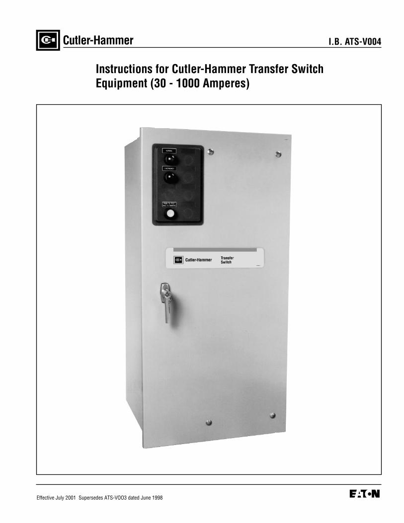
Instructions for Cutler-Hammer Transfer Switch Equipment (30 - 1000 Amperes)


I.B. ATS-V004 Page iii
Effective 7/01
All possible contingencies which may arise during installation, operation or maintenance, and all details andvariations of this equipment do no purport to be covered by these instructions. If further information isdesired by purchaser regarding his particular installation, operation or maintenance of particular equipment,contact a Cutler-Hammer representative.
READ AND UNDERSTAND THE INSTRUCTIONSCONTAINED HEREINAFTER BEFORE ATTEMPTINGTO UNPACK, ASSEMBLE, OPERATE OR MAINTAINTHIS EQUIPMENT.
HAZARDOUS VOLTAGES ARE PRESENT INSIDETRANSFER SWITCH ENCLOSURES THAT CANCAUSE DEATH OR SEVERE PERSONAL INJURY.FOLLOW PROPER INSTALLATION, OPERATIONAND MAINTENANCE PROCEDURES TO AVOIDTHESE VOLTAGES.
! WARNINGTRANSFER SWITCH EQUIPMENT COVERED BYTHIS INSTRUCTION BOOK IS DESIGNED AND TEST-ED TO OPERATE WITHIN ITS NAMEPLATE RAT-INGS. OPERATION OUTSIDE OF THESE RATINGSMAY CAUSE THE EQUIPMENT TO FAIL RESULTINGIN DEATH, SERIOUS BODILY INJURY AND/ORPROPERTY DAMAGE. ALL RESPONSIBLE PERSON-NEL SHOULD LOCATE THE DOOR MOUNTEDEQUIPMENT NAMEPLATE AND BE FAMILIAR WITHTHE INFORMATION PROVIDED ON THE NAME-PLATE. A TYPICAL EQUIPMENT NAMEPLATE ISSHOWN IN FIGURE 1.
Figure 1 Typical Automatic Transfer Switch Equipment Nameplate
Cutler-Hammer
Automatic Transfer Switch
ECat No: ATVIKDA30300XSU 10 / 96
GO No: 1 of 1
Item: 1
Poles: 3 Amps: 300 Volt: 480
Phase: 3 Hertz: 60 Wire: 4

TABLE OF CONTENTSPage
SECTION 1: INTRODUCTION
1.1 Preliminary Comments and Safety Precautions..................................................................................................11.1.1 Warranty and Liability Information..........................................................................................................11.1.2 Safety Precautions .................................................................................................................................1
1.2 General Information.............................................................................................................................................11.2.1 Transfer Switch Types............................................................................................................................21.2.2 Design Configuration..............................................................................................................................2
1.3 Transfer Switch Catalog Number Identification ...................................................................................................31.4 Environmental Conditions ...................................................................................................................................5
SECTION 2: RECEIVING, HANDLING AND STORAGE
2.1 Receiving.............................................................................................................................................................62.2 Handling ..............................................................................................................................................................62.3 Storage ...............................................................................................................................................................6
SECTION 3: EQUIPMENT DESCRIPTION
3.1 General ...............................................................................................................................................................73.2 Power Panel ........................................................................................................................................................7
3.2.1 Vertical Design Steel Base Plate............................................................................................................83.2.2 Main Contacts ........................................................................................................................................83.2.3 Vertical Design Transfer Mechanism .....................................................................................................83.2.4 Horizontal Design Transfer Mechanism .................................................................................................8
3.3 Voltage Selection Panel ......................................................................................................................................93.4 Logic Panel..........................................................................................................................................................93.5 Options (Non-Logic Panel) ..................................................................................................................................93.6 Enclosure ..........................................................................................................................................................113.7 Standards .........................................................................................................................................................12
SECTION 4: INSTALLATION AND WIRING
4.1 General .............................................................................................................................................................134.2 Mounting Location .............................................................................................................................................134.3 Mounting Procedure ..........................................................................................................................................134.4 Vertical Design Load Lug Location ...................................................................................................................154.5 Power Cable Connections ................................................................................................................................194.6 Wiring ................................................................................................................................................................204.7 Voltage Selection Adjustments..........................................................................................................................204.8 Terminal Block Wire Installation and Removal..................................................................................................21
SECTION 5: OPERATION
5.1 General .............................................................................................................................................................245.2 Vertical Design Operation .................................................................................................................................245.3 Horizontal Design Operation .............................................................................................................................255.4 Non-Automatic Operation (Manually Operated) ................................................................................................265.5 Non-Automatic Operation (Electrically Operated) .............................................................................................265.6 Automatic Transfer Switch ................................................................................................................................26
I.B. ATS-V004Page iv
Effective 7/01

I.B. ATS-V004 Page v
Effective 7/01
PageSECTION 6: TESTING AND PROBLEM SOLVING
6.1 Testing .............................................................................................................................................................286.2 Problem Solving ................................................................................................................................................28
6.2.1 Transfer Switch Appears Inoperative ...................................................................................................28
SECTION 7: MAINTENANCE
7.1 Introduction........................................................................................................................................................307.2 Procedures ........................................................................................................................................................30
I.B. ATS-V004Page vi
Effective 7/01
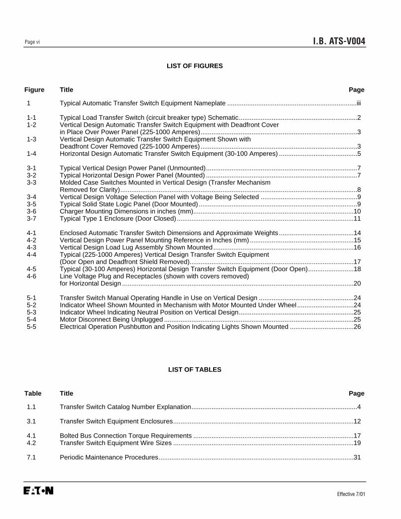
LIST OF FIGURES
Figure Title Page
1 Typical Automatic Transfer Switch Equipment Nameplate .......................................................................iii
1-1 Typical Load Transfer Switch (circuit breaker type) Schematic.................................................................21-2 Vertical Design Automatic Transfer Switch Equipment with Deadfront Cover
in Place Over Power Panel (225-1000 Amperes)......................................................................................31-3 Vertical Design Automatic Transfer Switch Equipment Shown with
Deadfront Cover Removed (225-1000 Amperes) ......................................................................................31-4 Horizontal Design Automatic Transfer Switch Equipment (30-100 Amperes) ...........................................5
3-1 Typical Vertical Design Power Panel (Unmounted)...................................................................................73-2 Typical Horizontal Design Power Panel (Mounted) ...................................................................................73-3 Molded Case Switches Mounted in Vertical Design (Transfer Mechanism
Removed for Clarity)..................................................................................................................................83-4 Vertical Design Voltage Selection Panel with Voltage Being Selected .....................................................93-5 Typical Solid State Logic Panel (Door Mounted) .......................................................................................93-6 Charger Mounting Dimensions in inches (mm)........................................................................................103-7 Typical Type 1 Enclosure (Door Closed) .................................................................................................11
4-1 Enclosed Automatic Transfer Switch Dimensions and Approximate Weights .........................................144-2 Vertical Design Power Panel Mounting Reference in Inches (mm).........................................................154-3 Vertical Design Load Lug Assembly Shown Mounted.............................................................................164-4 Typical (225-1000 Amperes) Vertical Design Transfer Switch Equipment
(Door Open and Deadfront Shield Removed)..........................................................................................174-5 Typical (30-100 Amperes) Horizontal Design Transfer Switch Equipment (Door Open).........................184-6 Line Voltage Plug and Receptacles (shown with covers removed)
for Horizontal Design ...............................................................................................................................20
5-1 Transfer Switch Manual Operating Handle in Use on Vertical Design ....................................................245-2 Indicator Wheel Shown Mounted in Mechanism with Motor Mounted Under Wheel ...............................245-3 Indicator Wheel Indicating Neutral Position on Vertical Design...............................................................255-4 Motor Disconnect Being Unplugged ........................................................................................................255-5 Electrical Operation Pushbutton and Position Indicating Lights Shown Mounted ...................................26
LIST OF TABLES
Table Title Page
1.1 Transfer Switch Catalog Number Explanation...........................................................................................4
3.1 Transfer Switch Equipment Enclosures...................................................................................................12
4.1 Bolted Bus Connection Torque Requirements ........................................................................................174.2 Transfer Switch Equipment Wire Sizes ...................................................................................................19
7.1 Periodic Maintenance Procedures...........................................................................................................31

I.B. ATS-V004 Page 1
Effective 7/01
SECTION 1: INTRODUCTION
1.1 PRELIMINARY COMMENTS AND SAFETYPRECAUTIONS
This technical document is intended to cover mostaspects associated with the installation, application,operation and maintenance of transfer switch equipmentwith ratings from 30 through 1000 amperes, except forthe specific logic used to control the equipment. It is pro-vided as a guide for authorized and qualified personnelonly. Please refer to the specific WARNING and CAU-TION in Section 1.1.2 before proceeding. If further infor-mation is required by the purchaser regarding a particu-lar installation, application or maintenance activity, aCutler-Hammer representative should be contacted. Forinformation associated with the control, refer to the sep-arate instruction book pertaining to the logic packageinstalled in the switch.
1.1.1 WARRANTY AND LIABILITY INFORMATION
No warranties, expressed or implied, including war-ranties of fitness for a particular purpose of merchant-ability, or warranties arising from course of dealing orusage of trade, are made regarding the information, rec-ommendations and descriptions contained herein. In noevent will Cutler-Hammer be responsible to the purchas-er or user in contract, in tort (including negligence), strictliability or otherwise for any special, indirect, incidentalor consequential damage or loss whatsoever, includingbut not limited to damage or loss of use of equipment,plant or power system, cost of capital, loss of power,additional expenses in the use of existing power facili-ties, or claims against the purchaser or user by its cus-tomers resulting from the use of the information anddescriptions contained herein.
1.1.2 SAFETY PRECAUTIONS
All safety codes, safety standards and/or regulationsmust be strictly observed in the installation, operationand maintenance of this device.
THE WARNINGS AND CAUTIONS INCLUDED ASPART OF THE PROCEDURAL STEPS IN THIS DOCU-MENT ARE FOR PERSONNEL SAFETY AND PRO-TECTION OF EQUIPMENT FROM DAMAGE. ANEXAMPLE OF A TYPICAL WARNING LABEL HEAD-ING IS SHOWN ABOVE TO FAMILIARIZE PERSON-
NEL WITH THE STYLE OF PRESENTATION. THISWILL HELP TO INSURE THAT PERSONNEL AREALERT TO WARNINGS, WHICH APPEAR THROUGH-OUT THE DOCUMENT. IN ADDITION, CAUTIONSARE ALL UPPER CASE AND BOLDFACE.
COMPLETELY READ AND UNDERSTAND THE MATE-RIAL PRESENTED IN THIS DOCUMENT BEFOREATTEMPTING INSTALLATION, OPERATION ORAPPLICATION OF THE EQUIPMENT. IN ADDITION,ONLY QUALIFIED PERSONS SHOULD BE PERMIT-TED TO PERFORM ANY WORK ASSOCIATED WITHTHE EQUIPMENT. ANY WIRING INSTRUCTIONS PRE-SENTED IN THIS DOCUMENT MUST BE FOLLOWEDPRECISELY. FAILURE TO DO SO COULD CAUSEPERMANENT EQUIPMENT DAMAGE.
1.2 GENERAL INFORMATION
Transfer switches are used to protect critical electricalloads against loss of power. The load’s normal powersource is backed up by a secondary (emergency) powersource. A transfer switch is connected to both the nor-mal and emergency power sources and supplies theload with power from one of these two sources. In theevent that power is lost from the normal power source,the transfer switch transfers the load to the secondary(emergency) power source. Transfer can be automaticor manual, depending upon the type of transfer switchequipment being used. Once normal power is restored,the load is automatically or manually transferred back tothe normal power source, again depending upon thetype of transfer equipment being used (Figure 1-1).
In automatic transfer switch equipment, the switch’sintelligence system initiates the transfer when normalpower fails or falls below a preset voltage. If the emer-gency power source is a standby generator, the transferswitch initiates generator starting and transfers to theemergency power source when sufficient generator volt-age is available. When normal power is restored, thetransfer switch automatically transfers back and initiatesengine shutdown. In the event the normal power sourcefails and the emergency power source does not appear,the automatic transfer switch remains connected to thenormal power source until the emergency power sourcedoes appear. Conversely, if connected to the emer-gency power source and the emergency power sourcefails while the normal power source is still unavailable,the automatic transfer switch remains connected to theemergency power source.
! WARNING
! CAUTION

I.B. ATS-V004Page 2
Effective 7/01
1.2.1 TRANSFER SWITCH TYPES
Four types of basic transfer switch equipment are avail-able:
Automatic Transfer SwitchAutomatic transfer switches automatically perform thetransfer function. They consist of three basic elements:
(1) Main contacts to connect and disconnect the loadto and from the source of power.
(2) Intelligence/supervisory circuits to constantly moni-tor the condition of the power sources and thus pro-vide the intelligence necessary for the switch andrelated circuit operation.
(3) A transfer mechanism to effect the transfer of themain contacts from source to source.
Basic Transfer SwitchThe basic transfer switch is designed for use with cus-tomer furnished controls. It is similar in design to theautomatic version except the intelligence circuit (logicpanel) and voltage selection panel are omitted. All auto-matic sensing devices, relays or solid state devices arethe customer’s responsibility.
Non-Automatic Transfer Switch (Manually Operated)Non-Automatic transfer switches provide the main con-tacts and the transfer mechanism to effect the transferof the main contacts from source to source. Transfer ofpower, however, is accomplished by true hand opera-tion (not power assisted) of the transfer switch. Thisswitch is similar to the basic switch in that an intelli-gence circuit and a motor driven mechanism are notpart of the design.
Non-Automatic Transfer Switch (ElectricallyOperated)This transfer switch is similar to the Non-AutomaticTransfer Switch (Manually Operated) just describedexcept that an electrical operation feature is added. Theswitch electrically transfers power when an appropriatepushbutton on the front of the enclosure is pushed. Ifnecessary, the switch can also be operated manually.
1.2.2 DESIGN CONFIGURATION
The Cutler-Hammer transfer switch is a rugged, compactdesign utilizing molded case switches to effect the trans-fer of essential loads from one power source to another(Figures 1-2, 1-3 and 1-4). Molded case switches areinterlocked to prevent both switches from being closed atthe same time. The versatile design, in addition to stan-dard transfer functions, offers an optional integral thermaland short circuit protection in either or both switchingdevices.
Molded case switches and the associated transfermechanism are usually mounted vertically in the assem-bly. The vertical configuration (225-1000 amperes) isaccomplished by utilizing a positive, metallic transferand interlocking system between the molded caseswitches. A horizontally mounted transfer mechanism isutilized with transfer switches 30 to 150 amperes.
The Cutler-Hammer automatic transfer switch wasdesigned with installation ease and simplified mainte-nance in mind. Three main panels comprise the auto-matic transfer switch design:
• Power Panel• Voltage Selection Panel• Logic Panel
Each panel is independently mounted with interconnect-ing wiring terminated in connector plugs to permit indi-vidual door or panel removal without disturbing criticalconnections. Enclosure mounting is simplified by utiliz-ing top and bottom mounting flanges with elongatedmounting holes. Figure 1-1 Typical Load Transfer Switch (circuit break-
er type) Schematic
NormalSource
EmergencySource
Load

I.B. ATS-V004 Page 3
Effective 7/01
For the vertical design, installed power panel positioningbolts, elongated mounting holes and pre-tapped insertsinsure proper power panel mounting after initial enclo-sure installation or when switching from top to bottomentry and vice versa. Refer to Section 4 for mountingand modification details.
1.3 TRANSFER SWITCH CATALOG NUMBERIDENTIFICATION
Transfer switch equipment catalog numbers provide asignificant amount of relevant information that pertainsto a particular piece of equipment. The Catalog NumberIdentification Table (Table 1.1) provides the requiredinterpretation information. An example is offered to ini-tially simplify the process.
➀ to ➁ ➂ ➃ ➄ to ➅ ➆ ➇ ➈ to ➉
AT V I KD A 3 0225 B S U
The catalog number ATVSKDA30225BSU describes anAutomatic Transfer Switch with the switching devicesmounted vertically in the enclosure. The intelligencerepresented by the control panel is IQ Transfer logic.The Cutler-Hammer Series C Type HKD is used as theswitching device and is in the form of a 3-pole moldedcase switch on each source. The continuous current rat-ing of this equipment is 225 amperes and applicable at208 VAC, 60Hz. The transfer switch equipment isenclosed in a NEMA 1 enclosure and is both UL andUL-C listed.
Figure 1-3 Vertical Design Automatic Transfer SwitchEquipment Shown with Deadfront Cover Removed (225-1000 Amperes)
Figure 1-2 Vertical Design Automatic Transfer SwitchEquipment with Deadfront Cover in Place Over PowerPanel (225-1000 Amperes)
Example: Catalog Number (circled numbers corre-spond to position headings in Table 1.1) –
12 13 14 15
Voltage Selection
Panel

I.B. ATS-V004Page 4
Effective 7/01
Positions 1-2 Position 3 Position 4 Positions 5-6
Basic Switching Device Control SwitchingDevice Orientation Panel Device
Automatic Transfer Switch AT Vertical V➀ IQ Transfer I HFD Cutler-Hammer Series C FD
Horizontal H➁ Microprocessor M HKD Cutler-Hammer Series C KD
Non-Automatic Transfer Switch NT Solid State Logic S HLD Cutler-Hammer Series C LD
(Electrically Operated) Not Applicable X MA Cutler-Hammer MA
HMDL Cutler-Hammer MD
Non-Automatic Transfer Switch MT NB Cutler-Hammer NB
(Manually Operated) HND Cutler-Hammer Series C ND➂
Basic Transfer Switch PP
(Power Panel Only)
Position 7 Position 8 Positions 9-12 Position 13 Position 14 Position 15
Switching Device Number Ampere Voltage/Arrangement of Poles Rating Frequency Enclosure Listing
Fixed Mount Molded Case A Two 2 30A – 0030 120VAC/60Hz A No Enclosure K UL Listed U
Switches Both Power Sources 70A – 0070 208VAC/60Hz B Type 1 S
Three 3 100A – 0100 600VAC/60Hz E Type 12 J UL Recognized R
Fixed Mount Molded Case B 150A – 0150 220VAC/50 or 60Hz G Type 3R R ComponentBreakers Both Power Sources Four 4 225A – 0225 380VAC/50Hz H Type 4➂ L
300A – 0300 600VAC/50Hz K Type 4X➂ D UL Listed and C
Fixed Mount Molded Case C 400A – 0400 230VAC/50Hz M Meets Canadian Breaker Normal Power 600A – 0600 401VAC/50Hz N Electrical CodeSource, Molded Case Switch 800A – 0800 415VAC/50Hz O
Emergency Power Source 1000A – 1000 240VAC/60Hz W No Listing X
480VAC/60Hz X
Fixed Mount Molded Case D 365VAC/50Hz Z
Switch Normal Power Source,Molded Case Breaker Emergency Power Source
Table 1.1 Transfer Switch Catalog Number Explanation➃
➀ Vertical orientation (225-1000 amperes)➁ Horizontal orientation (30-150 amperes)➂ Contact factory for availability➃ Not all combinations are possible

I.B. ATS-V004 Page 5
Effective 7/01
Figure 1-4 Horizontal Design Automatic Transfer SwitchEquipment (30-100 Amperes)
1.4 ENVIRONMENTAL CONDITIONS
SeismicWith proper installation and by including the appropriateoption which includes specially designed cleats, transferswitches have a seismic capability which exceeds theworst case Zone 4 required levels per both the UniformBuilding Code and the California Building Code.
Operational ConditionsNormally, a transfer switch is applied indoors in an elec-trical equipment room. In the appropriate enclosure, itcan be used for outdoor applications were the equip-ment is subject to falling rain, freezing temperatures and90% humidity (non condensing). The ambient tempera-ture range for operation is between -20 and +70°C.

I.B. ATS-V004Page 6
Effective 7/01
SECTION 2: RECEIVING, HANDLING ANDSTORAGE
2.1 RECEIVING
Every effort is made to insure that transfer switch equip-ment arrives at its destination undamaged and ready forinstallation. Crating and packing is designed to protectinternal components as well as the enclosure. Transferswitch enclosures are skid mounted and suited for forklift movement. Care should be exercised, however, toprotect the equipment from impact at all times. Do notremove protective packaging until the equipment isready for installation.
When transfer switch equipment reaches its destination,the customer should inspect the shipping container forany obvious signs of rough handling and/or externaldamage incurred during the transportation phase.Record any external and internal damage observed forreporting to the transportation carrier and Cutler-Hammer, once a thorough inspection is completed. Allclaims should be as specific as possible and includeshop order and general order numbers.
MAKE NOTE OF THE WARNING LABEL ATTACHEDTO THE TOP OF THE SHIPPING CONTAINER THATWARNS AGAINST DOUBLE STACKING TRANSFERSWITCH EQUIPMENT.
A shipping label is affixed to the top of the shipping con-tainer which includes a variety of equipment and cus-tomer information, such as General Order Number(GO#) and Catalog Number (Cat#). Make certain thatthis information matches other shipping paper informa-tion.
Each transfer switch enclosure is bolted through its topand bottom mounting flanges to a rigid wooden pallet.The pallet is open at two ends for movement by a forklift. Heavy duty cardboard sides surround the enclosureand are further supported with reinforced cardboard cor-
ner posts. An egg crate design cardboard protector cov-ers the entire top of the enclosure with additional card-board protectors over the indicating light panel andoperating handle. A heavy duty cardboard lid covers theentire opening. The shipment is secured and further pro-tected with shrink wrap. Do not discard the packingmaterial until the equipment is ready for installation.
Once the top packaging is removed from the shipment,the enclosure door can be opened. A plastic bag of doc-uments will be found within the enclosure, usuallyattached to the inside of the door. Important documents,such as test reports, wiring diagrams, appropriateinstruction leaflets and a warranty registration card, areenclosed within the bag and should be filed in a safeplace.
2.2 HANDLING
As previously mentioned, transfer switch equipment ispackaged for fork lift movement. Protect the equipmentfrom impact at all times and do not double stack. Oncethe equipment is in the installation location and ready tobe installed, packaging material can be removed. Oncethe enclosure is unbolted from the wooden pallet, it canbe hand moved to its installation position. Be careful notto damage the top or bottom enclosure mountingflanges. Refer to Section 4 of this manual for specificinstallation instructions.
2.3 STORAGE
Although well packaged, this equipment is not suitablefor storage outdoors. The equipment warranty will notbe applicable if there is evidence of outdoor storage. Ifthe equipment is to be stored indoors for any period oftime, it should be stored with its protective packagingmaterial in place. Protect the equipment at all times fromexcessive moisture, construction dirt, corrosive condi-tions and other contaminants. It is strongly suggestedthat the package protected equipment be stored in a cli-mate controlled environment of -20° to 85° with a rela-tive humidity of 80% or less. Do not, under any circum-stances, stack other equipment on top of a transferswitch equipment enclosure, whether packaged or not.
! CAUTION

I.B. ATS-V004 Page 7
Effective 7/01
SECTION 3: EQUIPMENT DESCRIPTION
3.1 GENERAL
Cutler-Hammer transfer switch equipment is available infour different configurations:• Automatic Transfer Switch • Basic Transfer Switch • Non-Automatic Transfer Switch (Manually Operated) • Non-Automatic Transfer Switch (Electrically Operated)
Refer to Section 1 for a discussion of the four types.Each transfer switch is usually supplied in an enclosure,although unmounted sub-assemblies can be supplied formounting by the customer. Since the enclosed automatictransfer switch encompasses all transfer switch equip-ment possibilities, it is the only specific type that will bediscussed in this section.
The enclosed automatic transfer switch consists of threebasic panels interconnected through connector plugsand mounted in an enclosure (Figures 1-3, 1-4, 4-4 and4-5):
• Power Panel • Voltage Selection Panel • Logic Panel
- IQ Transfer- Solid State- Micro-processor based
The components comprising the three panels are installedin accordance with the specific requirements of the circuitbeing controlled. Each transfer switch is, therefore, tailor-made to a specific application.
3.2 POWER PANEL
The power panel consists of a means for making load,power and neutral connections, the main contacts andthe transfer mechanism all on one steel base plate(Figures 3-1 and 3-2).
Figure 3-1 Typical Vertical Design Power Panel(Unmounted)
Figure 3-2 Typical Horizontal Design Power Panel(Mounted)
I.B. ATS-V004Page 8
Effective 7/01
3.2.1 VERTICAL DESIGN STEEL BASE PLATE
The steel base plate on the vertical design permits thepower panel to be moved vertically within the enclosureto accommodate top or bottom cable entry (Figure 4-2).Elongated holes on either side of the base plate insureproper positioning. The bottom set of elongated holesposition the power panel higher in the enclosure, thuspermitting bottom cable entry. The top set of elongatedholes position the power panel lower in the enclosure fortop cable entry. Section 4 discusses equipment mount-ing and load lug location in detail.
3.2.2 MAIN CONTACTS
The main contacts connect and disconnect the load toand from the different power sources. High withstandmolded case switches are the main contacts for theNormal and Emergency power sources in standard,unmodified automatic transfer switches. Optional integralthermal and short circuit protection in either or bothswitching devices is, however, available (Figure 3-3 andSection 3.5). These continuous duty switches are ratedfor all classes of loads, open or enclosed. In addition,they have high dielectric strength, heavy-duty switchingand withstand capabilities, and high interrupting capacity.The switches incorporate positive, quick-make, quick-break toggle mechanisms and De-ion arc chutes.
Vertically mounted switching devices are mechanicallyand electrically interlocked to prevent the two sets ofmain contacts from being closed simultaneously. Theload side contacts of each switching device are joinedwith a bus bar assembly to form a common load termi-nal location, either top or bottom (Figure 4-3).
Horizontally mounted switching devices are alsomechanically and electrically interlocked. The moldedcase switches are kept trip-free in the closed position.This permits thermal and short circuit protection to beincorporated in either or both interrupters.
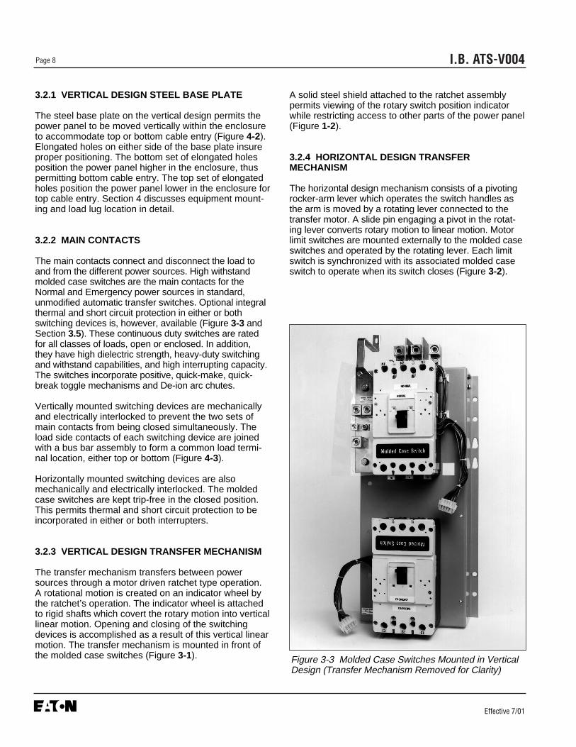
3.2.3 VERTICAL DESIGN TRANSFER MECHANISM
The transfer mechanism transfers between powersources through a motor driven ratchet type operation.A rotational motion is created on an indicator wheel bythe ratchet’s operation. The indicator wheel is attachedto rigid shafts which covert the rotary motion into verticallinear motion. Opening and closing of the switchingdevices is accomplished as a result of this vertical linearmotion. The transfer mechanism is mounted in front ofthe molded case switches (Figure 3-1).
A solid steel shield attached to the ratchet assemblypermits viewing of the rotary switch position indicatorwhile restricting access to other parts of the power panel(Figure 1-2).
3.2.4 HORIZONTAL DESIGN TRANSFERMECHANISM
The horizontal design mechanism consists of a pivotingrocker-arm lever which operates the switch handles asthe arm is moved by a rotating lever connected to thetransfer motor. A slide pin engaging a pivot in the rotat-ing lever converts rotary motion to linear motion. Motorlimit switches are mounted externally to the molded caseswitches and operated by the rotating lever. Each limitswitch is synchronized with its associated molded caseswitch to operate when its switch closes (Figure 3-2).
Figure 3-3 Molded Case Switches Mounted in VerticalDesign (Transfer Mechanism Removed for Clarity)

I.B. ATS-V004 Page 9
Effective 7/01
3.3 VOLTAGE SELECTION PANEL
The voltage selection panel is a multi-tap enclosedtransformer mounted in the enclosure (Figure 3-4).Seven front accessible voltages taps from 208 to 600volts AC satisfy any required application voltage. Aquick change capability from one voltage to another isprovided by a small disconnect plug.
3.4 LOGIC PANEL
The logic panel provides the intelligence and superviso-ry circuits which constantly monitor the condition of bothnormal and emergency power sources thus providingthe required intelligence for transfer operations (Figure3-5). Three different possibilities are available withdetailed information presented in separate documents:• IQ Transfer Instruction Book• Solid State Instruction Leaflet• Micro-processor Based Instruction Leaflet
3.5 OPTIONS (NON-LOGIC PANEL)
Switch options, which are not part of the logic scheme,are available to meet a variety of other applicationrequirements. Options are numbered with an associateddescription. More detailed selections that must be madewithin a specific option are lettered. For availableoptions associated with the logic scheme, refer to thespecific logic document associated with the type of logicselected.
Options are Underwriters Laboratories, Inc. listed,except as noted, when supplied on UL Listed Switches.If an option is selected that is Not UL Listed , the switchWill Not Have A UL Label .
Figure 3-4 Vertical Design Voltage Selection Panel withVoltage Being Selected
Figure 3-5 Typical Solid State Logic Panel (DoorMounted)
NOTICE

I.B. ATS-V004Page 10
Effective 7/01
Not all options are available for all transfer switch con-figurations. If in doubt, check Price List 29-920 for theavailability of options for a specific transfer switchdesign. The option numbers used here correspond tothe numbers used in the price list.
14. Relay Auxiliary Contact
The Normal power source relay is energized only whenthe switch is in the Normal position and Normal power ispresent. The Emergency power source relay is ener-gized whenever the Emergency power source is present.
C. Normal Power Source: Provides 2 NO and 2 NCcontacts
D. Emergency Power Source: Provides 2 NO and 2 NCcontacts
16. Power Switch with Integral OvercurrentProtection
Use of this option can, in many cases, eliminate the needfor separate upstream overcurrent/short circuit protec-tion, thus enabling code requirements to be met with adevice that takes up less space and requires less wiring.
B. Both Normal and Emergency Sides
E. Emergency side only
N. Normal side only
18. IQ Metering
I. IQ Generator - Normal Only
J. IQ Generator - Emergency Only
K. IQ Generator - Both N&E (Selectable)
O. IQ Analyzer - Normal Only
P. IQ Analyzer - Emergency Only
Q. IQ Analyzer - Both N&E (Selectable)
R. DP-4000 - Normal Only
S. DP-4000 - Emergency Only
T. DP-4000 - Both N&E (Selectable)
20A. Rear Bus Connections
Front connected solderless lugs are furnished as stan-dard on all enclosed and open units. Rear bus connec-tions are only available on open units.
21A. Non-Standard Terminals
(Refer to Cutler-Hammer)
24. Battery Charger
The trickle charge DC output is 12 or 24 volts. Units aresupplied in a separate wall mounted enclosure, andhave an automatic high-low charge rate.
C. 12 volt
D. 24 volt
When supplied, the battery charger is provided in a sep-arate wall mounted enclosure (Figure 3-6). Separateinstructions and wiring information are provided with thecharger for installation purposes.
A separate 120 VAC control power supply isrequired for the battery charger input. No connec-tions between the transfer switch and battery charg-er should be made.
6 1/8
9 1/2
7 1/2
7 3/8
Figure 3-6 Charger Mounting Dimensions in inches (mm)
NOTICE
NOTICE

I.B. ATS-V004 Page 11
Effective 7/01
33. Shunt Trip
The shunt trip is wired to terminal blocks for customerconnection. (120V coil supplied as standard.)
A. Supplied in Normal Breaker
B. Supplied in Emergency Breaker
34. Extender Cable
An extender cable provides a means for extending thedistance between the power switching panel and thelogic panel. This allows for remote mounting of the logicpanel.
A. 48 inch (1.2 m)
B. 72 inch (1.8 m)
C. 96 inch (2.4 m)
D. 120 inch (3.0 m)
E. 144 inch (3.7 m)
Special lengths are available. Contact Cutler-Hammer.
37. Service Entrance
A. Provides transfer switch as suitable for serviceequipment rating - A key operated selector switchpermits external, power operated service disconnec-tion with external pilot light for disconnect indication,also includes Option 16.
B. Same as A except includes ground fault protection.
41. Space Heater with Thermostat
A. 100 Watts
B. 200 Watts
C. 400 Watts
42. Seismic Withstand Capability
Provides transfer switch with seismic capability exceed-ing the worst case Zone 4 required levels per both theUniform Building Code and the California BuildingCode .
3.6 ENCLOSURE
The rugged steel switch enclosure is supplied with threedoor hinges, regardless of enclosure size, to insureproper support of the door and door mounted devices(Figures 3-6 and 4-1). The hinges have removable
hinge pins to facilitate door removal. Certain proce-dures, such as switch mounting, are simplified with thedoor removed. The doors are supplied as standard witha key lockable handle.
The door is used to mount a variety of lights, switchesand pushbuttons, depending upon the options requiredfor a particular switch. All switch doors are supplied witha heavy duty plastic accessory panel in place, whetheror not external devices are required. When lights, push-buttons or switches are required, they are normallymounted in the plastic door mounted panel.
The rear of the enclosure is supplied with elongatedholes in the top and bottom mounting flanges to facilitatemounting. The vertical design is also supplied with twopositioning bolts and various pre-tapped inserts to insureproper positioning of the power panel, anytime the powerpanel must be repositioned to accommodate a different
Figure 3-7 Typical Type 1 Enclosure (Door Closed)
I.B. ATS-V004Page 12
Effective 7/01
cable entry position. Cable entry holes are the responsi-bility of the customer.
Transfer switch enclosures and all internal steel mount-ing plates, such as the power panel mounting plate, gothrough a pre-treatment cleaning system prior to paint-ing to insure a durable finish.
The standard switch enclosure is NEMA Type 1 for gen-eral indoor use. A variety of enclosures are, however,available to address almost any environmental circum-stance (Table 3.1).
3.7 STANDARDS
Cutler-Hammer transfer switch equipment enclosed in aNEMA 1 enclosure is listed for application by UL. Inaddition, Cutler-Hammer Automatic Transfer Switchesare listed in File E38116 by Underwriters Laboratories,Inc. under Standard UL 1008. This standard coversrequirements for automatic transfer switches intendedfor use in ordinary locations to provide for lighting andpower as follows:
a. In emergency systems, in accordance with articles517 and 700 in the National Electrical Code,ANSI/NFPA 70 and the National Fire ProtectionAssociation No. 76A and/or
b. In stand-by systems, in accordance with article 702of the National Electrical Code and/or
c. In legally required stand-by systems in accordancewith article 701 of the National Electrical Code.
Cutler-Hammer Automatic Transfer Switches are avail-able to meet NFPA 110 for emergency and stand-bypower systems, and NFPA99 for health care facilitieswhen ordered with the appropriate options.
Since Cutler-Hammer Automatic Transfer Switches uti-lize specially designed molded case switches and/ormolded case circuit breakers as the main power switch-ing contacts, these devices must also be listed under theadditional UL Standards 489 and 1087. Underwriters lab-oratories utilize two basic types of listing programs: a)Label service b) Re-examination. UL489 and UL1087employ a label service listing program which requires anextensive follow-up testing program for listed devices.Standard UL1008 for automatic transfer switches listsdevices under the re-examination program which onlyrequires a continual physical re-examination of the com-ponents used in the product to insure consistency withthe originally submitted device. Follow-up testing is notrequired by UL1008.
Representative production samples of molded caseswitches and molded case circuit breakers used in Cutler-Hammer Automatic Transfer Switches are subjected to acomplete test program identical to the originally submitteddevices on an ongoing periodic basis per UL489 andUL1087. The frequency of such a re-submittal can be asoften as every quarter for a low ampere device.
NEMA Design ProtectionType
1 Indoor Enclosed Equipment
3R Outdoor Rain, Ice Formation
12 Indoor Dust, Dirt and Non-corrosive Liquids
4/4X Indoor/Outdoor Dust, Rain, Splashing Water, Corrosion Resistant
Table 3.1 Transfer Switch Equipment Enclosures
I.B. ATS-V004 Page 13
Effective 7/01
SECTION 4: INSTALLATION AND WIRING
4.1 GENERAL
Transfer switches are factory wired and tested. Installa-tion requires solidly mounting the enclosed unit and con-necting power cables and auxiliary pilot circuits.Physical mounting procedures and power cable connec-tions are covered in this section. All other requiredwiring or electrical connection references are covered ina separate Customer Wiring Booklet packed with thetransfer switch. Locate the wiring booklet, review it, andkeep it readily available for reference purposes duringinstallation and testing. Once a transfer switch is proper-ly installed and wired, it should be mechanically andelectrically checked for proper installation and operation.The procedures for these initial mechanical and electri-cal checks are outlined in Section 6 of this instructionmanual.
To facilitate the procedures described in this sec-tion for the vertical design, remove the solid steelshield over the power panel. The shield is attachedto the ratchet assembly with four screws. Removethe four screws and shield until the procedures arecompleted.
BE CERTAIN THAT THE SOLID STEEL POWERPANEL SHIELD USED WITH THE VERTICAL DESIGNIS PROPERLY INSTALLED BEFORE TRANSFERSWITCH EQUIPMENT IS PUT INTO SERVICE. THESHIELD PROVIDES PROTECTION FROM DANGER-OUS VOLTAGES AT THE LINE AND LOAD TERMI-NALS WHEN THE EQUIPMENT IS IN OPERATION.FAILURE TO DO SO COULD RESULT IN PERSONALINJURY OR DEATH.
4.2 MOUNTING LOCATION
Choose a location that offers a flat, rigid mounting sur-face capable of supporting the weight of the enclosedtransfer switch equipment (Figure 4-1). Avoid locationsthat are moist, hot and/or dusty. Enclosure designs are,however, available for special environments. If there areany doubts as to location suitability, discuss it with yourCutler-Hammer representative.
Check to make certain that there are no pipes, wires orother mounting hazards in the immediate mounting areathat could create a present or future problem.
Carefully remove all packing material from the transferswitch at the mounting location. Even though an equip-ment inspection was made when the equipment wasreceived, make another careful inspection of the enclo-sure and the enclosed transfer switch as packing materi-al is removed and the enclosure readied for mounting.Be especially alert for distorted metal, loose wires ordamaged components.
4.3 MOUNTING PROCEDURE
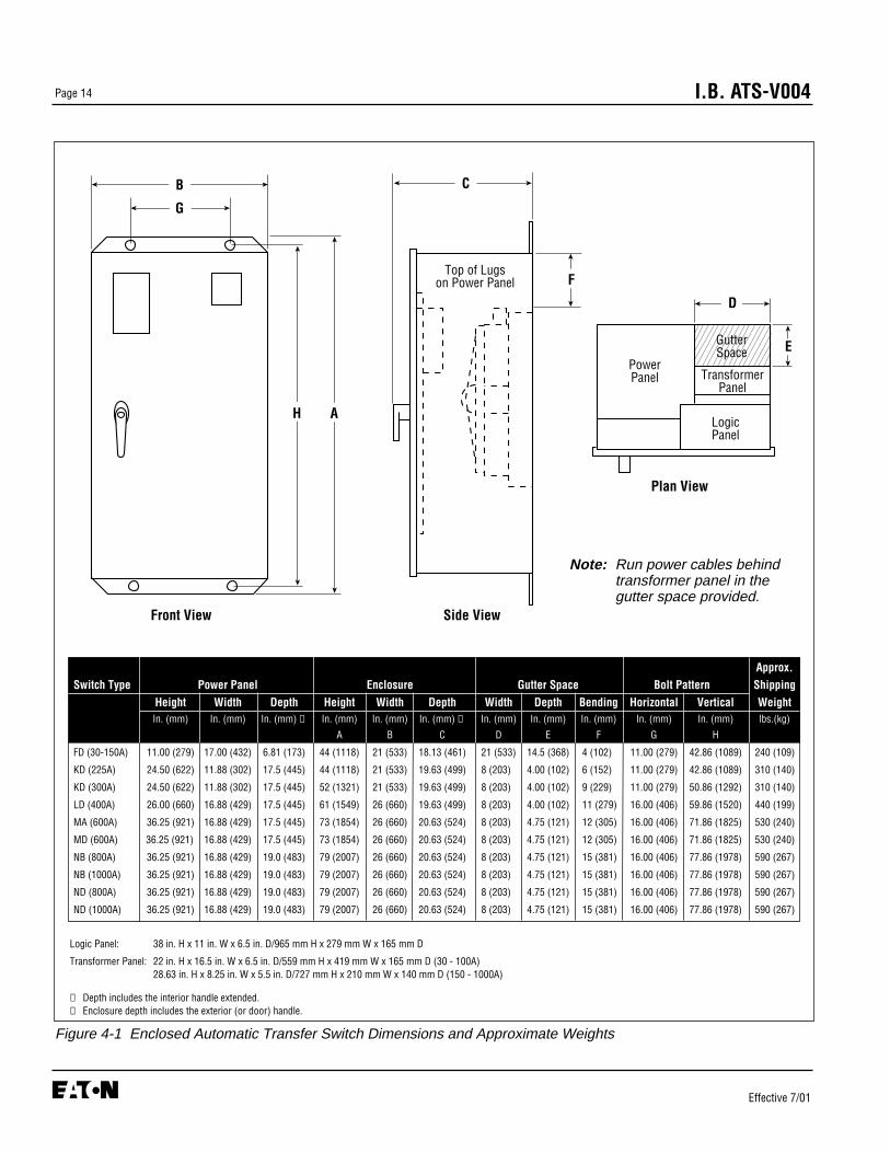
SINCE THE ENCLOSED TRANSFER SWITCH MUSTBE LIFTED INTO PLACE FOR MOUNTING, BE CER-TAIN THAT ADEQUATE RESOURCES ARE AVAIL-ABLE FOR LIFTING TO AVOID PERSONNELINJURIES OR EQUIPMENT DAMAGE.
Refer to Figure 4-1 for enclosure mounting dimensionreferences. All transfer switch equipment enclosures areof the same design. Only the overall physical dimen-sions change.The enclosure is provided with four elon-gated mounting holes, two in the top mounting flangeand two in the bottom.
If the transfer switch equipment is of the vertical design,the power panel is provided with two sets of mountingholes. One set positions the panel for top entry of cablesand one set for bottom entry (Figure 4-2). This will becovered in more detail later in this section under “LoadLug Location.”
Transfer switch equipment is assembled and suppliedas standard for top entry, although equally adaptable tobottom entry. Cable entry holes are not part of theenclosure when shipped from the factory and must beprovided in the field, either before or after mounting theenclosure.
EXTREME CARE SHOULD BE TAKEN TO PROTECTTHE TRANSFER SWITCH FROM DRILL CHIPS, FIL-INGS AND OTHER CONTAMINANTS WHEN MAKINGTHE CABLE ENTRY HOLES AND MOUNTING THEENCLOSURE TO PREVENT COMPONENT DAMAGEOR A FUTURE MALFUNCTION.
! WARNING
! CAUTION
! CAUTION
NOTICE
GutterSpace
TransformerPanel
LogicPanel
PowerPanel
Top of Lugson Power Panel
D
E
AH
B
G
C
F
Side ViewFront View
Plan View
I.B. ATS-V004Page 14
Effective 7/01
Figure 4-1 Enclosed Automatic Transfer Switch Dimensions and Approximate Weights
Note: Run power cables behindtransformer panel in thegutter space provided.
Logic Panel: 38 in. H x 11 in. W x 6.5 in. D/965 mm H x 279 mm W x 165 mm D
Transformer Panel: 22 in. H x 16.5 in. W x 6.5 in. D/559 mm H x 419 mm W x 165 mm D (30 - 100A)28.63 in. H x 8.25 in. W x 5.5 in. D/727 mm H x 210 mm W x 140 mm D (150 - 1000A)
➀ Depth includes the interior handle extended.➁ Enclosure depth includes the exterior (or door) handle.
Approx.
Switch Type Power Panel Enclosure Gutter Space Bolt Pattern Shipping
Height Width Depth Height Width Depth Width Depth Bending Horizontal Vertical Weight In. (mm) In. (mm) In. (mm) ➀ In. (mm) In. (mm) In. (mm) ➁ In. (mm) In. (mm) In. (mm) In. (mm) In. (mm) lbs.(kg)
A B C D E F G H
FD (30-150A) 11.00 (279) 17.00 (432) 6.81 (173) 44 (1118) 21 (533) 18.13 (461) 21 (533) 14.5 (368) 4 (102) 11.00 (279) 42.86 (1089) 240 (109)
KD (225A) 24.50 (622) 11.88 (302) 17.5 (445) 44 (1118) 21 (533) 19.63 (499) 8 (203) 4.00 (102) 6 (152) 11.00 (279) 42.86 (1089) 310 (140)
KD (300A) 24.50 (622) 11.88 (302) 17.5 (445) 52 (1321) 21 (533) 19.63 (499) 8 (203) 4.00 (102) 9 (229) 11.00 (279) 50.86 (1292) 310 (140)
LD (400A) 26.00 (660) 16.88 (429) 17.5 (445) 61 (1549) 26 (660) 19.63 (499) 8 (203) 4.00 (102) 11 (279) 16.00 (406) 59.86 (1520) 440 (199)
MA (600A) 36.25 (921) 16.88 (429) 17.5 (445) 73 (1854) 26 (660) 20.63 (524) 8 (203) 4.75 (121) 12 (305) 16.00 (406) 71.86 (1825) 530 (240)
MD (600A) 36.25 (921) 16.88 (429) 17.5 (445) 73 (1854) 26 (660) 20.63 (524) 8 (203) 4.75 (121) 12 (305) 16.00 (406) 71.86 (1825) 530 (240)
NB (800A) 36.25 (921) 16.88 (429) 19.0 (483) 79 (2007) 26 (660) 20.63 (524) 8 (203) 4.75 (121) 15 (381) 16.00 (406) 77.86 (1978) 590 (267)
NB (1000A) 36.25 (921) 16.88 (429) 19.0 (483) 79 (2007) 26 (660) 20.63 (524) 8 (203) 4.75 (121) 15 (381) 16.00 (406) 77.86 (1978) 590 (267)
ND (800A) 36.25 (921) 16.88 (429) 19.0 (483) 79 (2007) 26 (660) 20.63 (524) 8 (203) 4.75 (121) 15 (381) 16.00 (406) 77.86 (1978) 590 (267)
ND (1000A) 36.25 (921) 16.88 (429) 19.0 (483) 79 (2007) 26 (660) 20.63 (524) 8 (203) 4.75 (121) 15 (381) 16.00 (406) 77.86 (1978) 590 (267)

I.B. ATS-V004 Page 15
Effective 7/01
With the enclosed transfer switch equipment unpackedand ready for mounting, proceed with the following steps:
Step 1 : The transfer switch enclosure door is hingemounted with removable hinge pins. To simplifythe mounting procedure and avoid damagingthe door mounted logic panel, carefully removethe door and set aside in a safe place untilmounting is complete.
Step 2 : Install required mounting bolt anchors and thetwo upper mounting bolts in the mounting sur-face.
Step 3 : Gently lift the enclosure and guide the elongat-ed holes in the upper mounting flange over theupper mounting bolts, but do not completelytighten the bolts.
Step 4 : While still supporting the enclosure, install thetwo lower mounting bolts in the lower mountingflange, but do not completely tighten. Useshims, if required, to prevent deformation ofthe enclosure when the mounting surface isdistorted.
Step 5 : Tighten all four mounting bolts after anyrequired shimming is completed.
Step 6 : Double check to ensure that all packing andshipping material has been removed.
4.4 VERTICAL DESIGN LOAD LUG LOCATION
Transfer switch equipment is supplied as standard fromthe factory with its load terminal lugs at the top. If the
Location for Neutral Strap in Bottom Entry Position
Location for Neutral Strap in Top Entry Position
4.5 (114)
4.5 (114)
.88 (22)See Figure “1”
Location Holes forBottom Entry
Location Holes for Top Entry .17R
.88 (22)
.38R.25 (6)
.69 (18)
Figure 4-2 Vertical Design Power Panel Mounting Reference in Inches (mm)

I.B. ATS-V004Page 16
Effective 7/01
load lugs are to be repositioned to the bottom, do it atthis time before wiring the unit or making power cableconnections.
IF THE LOAD LUG LOCATION IS BEING CHANGEDON ALREADY INSTALLED TRANSFER SWITCHEQUIPMENT, MAKE SURE THAT THE NORMAL,EMERGENCY AND OTHER POWER SOURCES CON-NECTED TO THE EQUIPMENT ARE DE-ENERGIZED.HAZARDOUS VOLTAGES ARE PRESENT INSIDETRANSFER SWITCH EQUIPMENT AND CAN CAUSESEVERE PERSONAL INJURY OR DEATH.
With the solid steel shield removed, proceed with thefollowing steps (Figure 1-3):
Step 1 : Disconnect the power panel from the rest of thetransfer switch by unplugging the connectorplugs (S1, S2 and S3) (Figure 4-4).
Step 2 : Remove the bolt that bonds the neutral strap tothe rear of the enclosure, if it is in place
Step 3 : Remove the four bolts that secure the powerpanel in the enclosure. Depending upon thesize of the panel, it may be advisable to haveassistance with the removal. Once the powerpanel is free, carefully move it to a solid worksurface (Figure 3-1).
At this point, take the time to refer to Figure 4-2 andbecome familiar with the inside rear of the enclo-sure and the power panel mounting provisionsavailable for both top and bottom entry. It will facili-tate re-installation of the power panel.
Step 4 : Remove the operating mechanism from thefront of the power panel by removing the sixbolts holding the mechanism in position. Themolded case switches or optional circuit break-ers do not have to be removed (Figure 3-3).
The rear mounted load lugs, dip insulated bus bars,standoff insulators, glass polyester phase barriers,and metal mounting bracket are designed to beremoved as one load lug assembly (Figure 4-3).
Step 5 : The load lug assembly, just mentioned, isremoved by first removing the six or eight boltssecuring the pieces of insulated bus to the backof the power panel. The number of mountingbolts depends upon whether 3 or 4-poledevices are installed. Mounting bolts areaccessed through holes in the load end of themolded case switches or optional circuit break-ers.
Step 6 : Next, remove the 4 bolts holding the mountingbracket to the upper rear portion of the powerpanel. The load lug assembly can now beremoved as one unit. Note that there aregrooves in the back of the power panel and inthe mounting bracket that keep the polyesterphase barriers in their proper positions.
Figure 4-3 Vertical Design Load Lug Assembly ShownMounted
! WARNING
NOTICE
NOTICE

I.B. ATS-V004 Page 17
Effective 7/01
Step 7 : Turn the load lug assembly 180° with the lugsat the bottom and remount the assembly byreversing the procedures described in Steps 5and 6. The mounting bracket will now be boltedto the bottom of the power panel. Make certainthat all glass polyester phase barriers are inplace and positioned properly in the groovesprovided. When making any bolted connectionto the bus, comply with the torque require-ments as outlined in Table 4.1.
Power Panel TorqueSwitching Device ft-lb (Nm)
Type FD 10 (13)
Type KD 20 (27)
Type LD 25 (33.8)
Type MA/MD 25 (33.8)
Type ND/NB 25 (33.8)
Table 4.1 Bolted Bus Connection Torque Requirements
Figure 4-4 Typical (225-1000 Amperes) Vertical Design Transfer Switch Equipment (Door Open and DeadfrontShield Removed)
Door MountedLogic Panel
MotorDisconnect(S3)
VoltageSelectionPanel
VoltageSelectionConnectors
NeutralConnections
ManualOperating
Handle
IndicatorWheel
TransferMechanism
Load Lugs(Top Entry)
Normal Power SourceMolded Case Switch Power Panel
Emergency Power SourceMolded Case Switch
Door Disconnect Plugs (Disconnected)
Transformer Panel
Engine StartContacts(Red Terminals)

I.B. ATS-V004Page 18
Effective 7/01
Step 8 : Remount the operating mechanism to the frontof the power panel with the six bolts removedpreviously in Step 4.
Step 9 : Position the power panel in the enclosure suchthat the two upper elongated holes, one oneither side of the power panel, fit over the twopositioning bolts located in the rear of theenclosure. This will line up the four correctmounting holes in the power panel with thepre-tapped inserts in the rear of the enclosure.
Step 10 : With the power panel held securely against theback of the enclosure, replace and tighten thefour mounting bolts removed previously in Step 3.
Step 11 : Attach the neutral strap to the back of theenclosure through the upper bonding hole,which may or may not have been previouslyremoved in Step 2
Step 12 : Reconnect the connector plugs and the trans-fer switch equipment is now configured for bot-tom entry.
Figure 4-5 Typical (30-100 Amperes) Horizontal Design Transfer Switch Equipment (Door Open)
Manual OperatorKnob
Transfer Mechanism
Voltage SelectionConnectors
Voltage Selection Panel
DisconnectConnectors
Emergency LineConnections
Emergency Power Source
Switching Device
Normal Power Source SwitchingDevice
LoadConnections
NeutralAssembly
Engine StartContacts
(Red Terminals)
Normal LineConnections
Brake ReleaseLever

Step 5 : Carefully strip insulation from the power cables.Avoid nicking or ringing of the conductorstrands. Prepare the stripped conductor termi-nation end by cleaning it with a wire brush. Ifaluminum conductors are used, apply an appro-priate joint compound to the clean conductorsurface area. Refer to Figure 4-3 for approxi-mate locations of power connections.
Power cables are to be connected to solderless screwtype lugs located on the transfer switch switchingdevices. Verify that the lugs supplied will accommodatethe power cables being used. Also verify that the cablescomply with local electrical codes. Standard transferswitch equipment, as supplied from the factory, willaccommodate the wire sizes shown in Table 4.2.
IMPROPER POWER CABLE CONNECTIONS CANCAUSE EXCESSIVE HEAT AND SUBSEQUENTEQUIPMENT FAILURE.
Step 6 : Tighten cable lugs to the torque identified onthe label affixed to the unit immediately adja-cent to the lugs.
Step 7 : Make necessary connections of options usingwiring diagrams supplied with the unit.
Step 8 : Connect engine start wires to the red terminal blocks marked 51 and 52.
Transfer Switch Wire Size Number ofAmp Rating Range Cables per Phase
30-100 #14 - 3/0 1
150 #6 - 300 MCM 1
150-300 #3 - 350 MCM 1
400 250 - 350 MCM 2
600 (3P) #1 - 500 MCM 2
600 (4P) 3/0 - 400 MCM 3
800 3/0 - 400 MCM 3
1000 4/0 - 500 MCM 4
I.B. ATS-V004 Page 19
Effective 7/01
4.5 POWER CABLE CONNECTIONS
POWER CONDUCTORS MAY HAVE VOLTAGE PRE-SENT THAT CAN CAUSE SEVERE PERSONALINJURY OR DEATH. DE-ENERGIZE ALL POWER ORCONTROL CIRCUIT CONDUCTORS TO BE CON-NECTED TO THE TRANSFER SWITCH EQUIPMENTBEFORE BEGINNING TO WORK WITH THE CON-DUCTORS AND/OR TERMINATING THEM TO THEEQUIPMENT.
USE OF CABLE LUGS NOT DESIGNED FOR THETRANSFER SWITCH MAY CAUSE HEATING PROB-LEMS. BREAKER LUGS ONLY MOUNT TO THEBREAKER, WHILE TRANSFER SWITCH LUGSMOUNT TO BOTH THE BREAKER AND THE BUS-BAR BEHIND THE BREAKER. FOR INSTALLATIONINSTRUCTIONS, REFER TO THE INSTRUCTIONLEAFLET SUPPLIED FOR THE SPECIFIC LUGS.
TO HELP PREVENT COMPONENT DAMAGE ORFUTURE MALFUNCTIONS, USE EXTREME CARE TOKEEP CONTAMINANTS OUT OF THE TRANSFERSWITCH EQUIPMENT WHEN MAKING POWERCABLE CONNECTIONS.
Proceed with the following steps:
Step 1 : Verify that the line and load cables comply withapplicable electrical codes.
Step 2 : Verify that transfer switch rated current andvoltage (see identification plate on the intelli-gence panel of transfer switch) agree with sys-tem current and voltage.
Step 3 : After the transfer switch is mounted, provideconduit or cable openings as required. Ensurethat no metal filings contaminate the transferswitch components.
Step 4 : Test all power cables before connecting to theunit to insure that conductors or cable insulationhave not been damaged while being pulled intoposition.
Table 4.2 Transfer Switch Equipment Wire Sizes
! WARNING
! CAUTION
! CAUTION
! CAUTION

I.B. ATS-V004Page 20
Effective 7/01
DO NOT RUN POWER CABLES BEHIND OR TO THELEFT OF THE POWER PANEL. THE CABLESSHOULD BE RUN IN THE GUTTER SPACE PROVID-ED AS SHOWN IN FIGURE 4-1. RUNNING THECABLES IN PLACES NOT RECOMMENDED COULDINTERFERE WITH THE PROPER OPERATION OFTHE TRANSFER SWITCH.
Remember to re-attach the solid steel power paneldeadfront shield to the ratchet assembly on the ver-tical design after completing any of the proceduresdescribed in this section.
4.6 WIRING
POWER CONDUCTORS AND CONTROL WIRINGMAY HAVE VOLTAGE PRESENT THAT CAN CAUSESEVERE PERSONAL INJURY OR DEATH. DE-ENER-GIZE ALL POWER OR CONTROL CIRCUIT CONDUC-TORS BEFORE BEGINNING TO PERFORM ANYWIRING ACTIVITY TO OR WITHIN THE TRANSFERSWITCH EQUIPMENT.
Power sources, load conductors and control wiringshould be connected to locations as indicated in theCustomer Wiring Booklet supplied with the transferswitch equipment.
DO NOT RUN POWER CABLES BEHIND OR TO THELEFT OF THE POWER PANEL. THE CABLESSHOULD BE RUN IN THE GUTTER SPACE PROVID-ED AS SHOWN IN FIGURE 4-1. RUNNING THECABLES IN PLACES NOT RECOMMENDED COULDINTERFERE WITH THE PROPER OPERATION OFTHE TRANSFER SWITCH.
CHECK THE TRANSFER SWITCH EQUIPMENTNAMEPLATE FOR RATED VOLTAGE. IT SHOULDBE THE SAME AS THE NORMAL AND EMERGENCYLINE VOLTAGES. OPERATING THE EQUIPMENT ONIMPROPER VOLTAGE CAN CAUSE EQUIPMENTDAMAGE.
Once the transfer switch equipment has been installedand wired, perform initial mechanical and electrical pro-cedures as outlined in Section 6 to verify that the equip-ment is installed and operating properly.
Remember to re-attach the solid steel power paneldeadfront shield to the ratchet assembly on the ver-tical design after completing any of the proceduresdescribed in this section.
4.7 VOLTAGE SELECTION ADJUSTMENTS
Certain devices, such as the Voltage Selection Panel,sensing relays and timers, need to be set and/or cali-brated prior to placing the transfer switch equipment intoservice. Adjustments for logic devices are described inthe separate instructional document dedicated to thespecific logic being used. Voltage selection adjustmentsare described here.
Figure 4-6 Line Voltage Plug and Receptacles (shownwith covers removed) for Horizontal Design
! CAUTION
! CAUTION
NOTICE
! CAUTION
! CAUTION
NOTICE

I.B. ATS-V004 Page 21
Effective 7/01
BE SURE THAT THE CORRECT VOLTAGE ISSELECTED TO MATCH THE SYSTEM VOLTAGE. ANIMPROPER SELECTION AND/OR CONNECTIONCOULD RESULT IN EQUIPMENT DAMAGE.
Vertical Design Voltage SelectionThe vertical design transfer switch is furnished with amulti-tap Voltage Selection Panel to the right of thepower panel. Seven front accessible taps from 208 to600 volts AC are provided (Figure 3-4). A small discon-nect plug is provided to change from one voltage toanother.
Horizontal Design Voltage SelectionHorizontal design transfer switches are furnished with anadjustable line voltage plug and receptacles below thepower panel. To change the line voltage, remove thecovers and insert the plug in the desired receptacle(Figure 4-6).
4.8 TERMINAL BLOCK WIRE INSTALLATION ANDREMOVAL
Proceed with the following steps and associated pic-tures to install or remove terminal block wiring.
Step 1: Pictured above are two tension clamp terminalblocks. There is a large one and small one, but theoperation is the same for both. A small tool, such as ascrewdriver, will be pushed into the square hole next tothe wire hole and a wire will be inserted into the largercircular hole on the outer edge.
Step 2: Begin by inserting a small, flathead screwdriverinto the square (tool) hole with the flat surface of thescrewdriver against the back wall of the hole. With a lit-tle bit of force, push the screwdriver in on a slight angletoward the center of the clamp. Be sure to slide it in untilit clicks. You will then see the clamp open in the wirehole.
Step 3: Once the screwdriver is in place, obtain astripped wire (strip about 1/4 of an inch) and insert it intothe larger circular wire hole. Push the wire in until it cango no further.
! CAUTION
Tool Hole Wire Hole
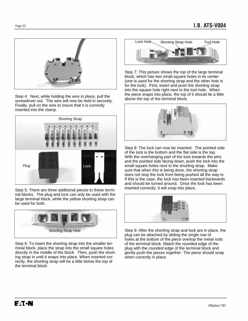
I.B. ATS-V004Page 22
Effective 7/01
Step 4: Next, while holding the wire in place, pull thescrewdriver out. The wire will now be held in securely.Finally, pull on the wire to insure that it is correctlyinserted into the clamp.
Step 5: There are three additional pieces to these termi-nal blocks. The plug and lock can only be used with thelarge terminal block, while the yellow shorting strap canbe used for both.
Step 6: To insert the shorting strap into the smaller ter-minal block, place the strap into the small square holesdirectly in the middle of the block. Then, push the short-ing strap in until it snaps into place. When inserted cor-rectly, the shorting strap will be a little below the top ofthe terminal block.
Step 7: This picture shows the top of the large terminalblock, which has two small square holes in its center(one is used for the shorting strap and the other hole isfor the lock). First, insert and push the shorting strapinto the square hole right next to the tool hole. Whenthe piece snaps into place, the top of it should lie a littleabove the top of the terminal block.
Step 8: The lock can now be inserted. The pointed sideof the lock is the bottom and the flat side is the top.With the overhanging part of the lock towards the pinsand the pointed side facing down, push the lock into thesmall square holes next to the shorting strap. Makesure that when this is being done, the shorting strapdoes not stop the lock from being pushed all the way in.If this is the case, the lock has been inserted backwardsand should be turned around. Once the lock has beeninserted correctly, it will snap into place.
Step 9: After the shorting strap and lock are in place, theplug can be attached by sliding the single row of holes at the bottom of the piece overtop the metal rodsof the terminal block. Match the rounded edge of theplug with the rounded edge of the terminal block andgently push the pieces together. The piece should snapwhen correctly in place.
Shorting Strap
Plug Lock
Shorting Strap Hole
Lock Hole Shorting Strap Hole Tool Hole

I.B. ATS-V004 Page 23
Effective 7/01
Step 10: Once the plug is snapped in place, the lock willneed to be pushed over it. In order to do this you caneither insert a flathead screwdriver into the small rectan-gular hole at the top of the lock or you could squeezethe lock and plug together using your fingers. Whenusing the screwdriver, insert it into the rectangular holeof the lock, from the side opposite to the plug. Nextpush the back of the screwdriver down (which will lift upthe top of the lock a little) and guide the lock overtop theplug by pushing the screwdriver towards the plug.When correctly together, it should now not be possibleto pull the plug out without removing the lock first.
Step 11: The picture above shows the exact position ofthe additional pieces on the large terminal block. Oncethey are in place, repeat steps 2) through 4) to correctlywire the tension clamp terminal block. Note that thesquare tool holes on the plug are facing the outside ofthe assembly.
Step12: If these additional pieces would need to beremoved, you should do the following:
1.Remove the lock by inserting a screwdriver from thesame side as the plug into the small rectangular hole atthe top of the lock.
2. Push the screwdriver down and push it away from theplug.
3. Pull the plug out.
Wire Holes
Tool Holes

I.B. ATS-V004Page 24
Effective 7/01
SECTION 5: OPERATION
5.1 GENERAL
A transfer switch provides main contacts to connect anddisconnect the load to and from the normal and emer-gency power sources (Paragraph 3.2.2). A transfer mech-anism provides the mechanical motion required to openand close the mechanically interlocked main contacts(Paragraphs 3.2.3, 3.2.4 and Figure 3-3).
Three distinct switch positions are provided:
• Normal - The contacts associated with the normalpower source are closed and the emergency powersource contacts are open.
• Neutral - The contacts associated with both the nor-mal power source and emergency power source areopen. This position allows for load circuit mainte-nance.
• Emergency - The contacts associated with the nor-mal power source are open and the emergency powersource contacts are closed.
5.2 VERTICAL DESIGN OPERATION
The vertical design transfer switch utilizes a mechanicalmechanism with a manual operating handle (Figure 4-4). The manual operating handle can be used to createthe rotational motion required to open and close themain contacts through a rigid mechanical interlockingsystem (Figure 5-1). An indicator wheel attached to theoperating handle and mechanical interlocking systemrotates with each movement of the handle to openand/or close the main contacts (Figure 5-2). The threeswitch positions (Normal, Neutral and Emergency) arevisually indicated on the indicator wheel (Figure 5-3).
To manually operate the transfer switch, the operatinghandle is ratcheted until the desired switch position isindicated on the indicator wheel. The operating handleis always electrically “dead,” and the indicator wheelfree-wheels should a particular switch be capable ofelectrical operation through the use of a motor. This fea-ture ensures no operator problems should the switchautomatically operate while the manual handle is beingused.
Figure 5-1 Transfer Switch Manual Operating Handle inUse on Vertical Design
Figure 5-2 Indicator Wheel Shown Mounted inMechanism with Motor Mounted Under Wheel

I.B. ATS-V004 Page 25
Effective 7/01
If a transfer switch with any kind of electrical operat-ing capabilities is to be operated manually utilizingthe manual operating handle, it is strongly recom-mended that the transfer motor circuit first be isolat-ed. This is accomplished by unplugging the (S3)plug marked motor disconnect (Figure 5-4). If, how-ever, a transfer switch is supplied with a four posi-tion selector switch (Option 6H), it can be turned tothe “OFF” position, making it unnecessary tounplug the plug. In the case of the automatic trans-fer switch design, any attempt to operate the manu-al handle without first isolating the motor circuitcauses an automatic transfer.
5.3 HORIZONTAL DESIGN OPERATION
The horizontal design transfer switch utilizes a pivotingrocker-arm lever which operates the circuit breaker han-dles as the arm is moved by a rotating lever usually con-nected to a transfer motor (Figure 4-5). A slide pinengaging a pivot in the rotating lever converts rotarymotion to linear motion. Motor limit switches, for motor
equipped transfer switches, are mounted external to themolded case switches and operated by the rotatinglever. Each limit switch is synchronized with its associat-ed switch to operate when the switch closes.
To operate breaker manually or if the breaker trips,unplug P3 from S3 to disconnect the motor circuit(Figure 5-4). Turn and hold the break release lever to“HOLD FOR MANUAL OPERATION” position, and thenrotate the manual operator knob in either direction tomove the ATS into the desired position. Let go of thebrake release lever for “AUTOMATIC OPERATION”.
If a transfer switch with any kind of electrical operat-ing capabilities is to be operated manually, it isstrongly recommended that the transfer motor cir-cuit first be isolated. This is accomplished byunplugging the disconnect link. In the case of theautomatic transfer switch design, any attempt tooperate the manual handle without first isolating themotor circuit causes an automatic transfer.
Figure 5-3 Indicator Wheel Indicating NeutralPosition on Vertical Design
Figure 5-4 Motor Disconnect Being Unplugged
NOTICE
NOTICE

I.B. ATS-V004Page 26
Effective 7/01
5.4 NON-AUTOMATIC OPERATION (MANUALLYOPERATED)
A non-automatic (manually operated) transfer switch(Paragraph 1.2.1) functions as described in Paragraphs5.1 through 5.3. All transfer operations are accom-plished by true hand operation, with no power assis-tance of any kind.
5.5 NON-AUTOMATIC OPERATION (ELECTRIC-ALLY OPERATED)
A non-automatic (electrically operated) transfer switch(Paragraph 1.2.1) functions similarly to the non-auto-matic (manually operated) transfer switch except for theaddition of an electrical operating feature. This featurepermits the main contacts to be opened or closed elec-trically. There is, however, no intelligence circuit associ-ated with this design.
Electrical operation is accomplished by adding a motorand required circuitry to the manual mechanism and wiringit to a pushbutton on the front of the enclosure (Figure 5-5). The pushbutton can be pushed to test the transferswitch or held to make an electrical transfer. The switch’soperating position can be visually indicated on the front ofthe enclosure by using optional indicating lights.
Pushing and holding the pushbutton causes the motorto operate and automatically transfer the load by open-ing and closing the main contacts. Since an intelligencecircuit is not part of the design, operation of the pushbut-ton is required each time an electrical transfer isrequired, whether it is from Normal to Emergency orvice versa.
5.6 AUTOMATIC TRANSFER SWITCH
The automatic transfer switch incorporates all the featuresand utilizes the same designs as the switches described inParagraphs 5.4 and 5.5, except that intelligence andsupervisory capabilities are added to the switch by theaddition of a logic panel in the enclosure or on the enclo-sure door (Figures 1-4 and 3-5). The logic panel can be assophisticated or simple as required, depending upon thenumber and types of options selected.
The operating sequence of an automatic transfer switchis dictated by the switch’s standard features and selectedoptions. Operation of an automatic transfer switch duringnormal source failure and normal source restoration willbe described here with only standard options included onthe switch. Additional options, as described in the sepa-rate instructional document dedicated to the specificlogic being used, can change sequences and timing,depending upon the options selected. Refer to para-graph 3.4. Become familiar with additional options select-ed and their effect on the normal operation of an auto-matic transfer switch.
Normal Power Source FailureStandard normal power source failure is defined as areduction or loss of voltage. If this occurs, the sequenceof operation is as follows:
• Failure of the normal power source is detected by thelogic.
• When the logic detects a failure, it will close a contactwhich starts the engine driven generator.
• When the emergency power source voltage and fre-quency reaches its operation range, the logic beginsthe transfer operation. This operating sequenceopens the Normal Power Source Switching Device(NB) and closes the Emergency Power SourceSwitching Device (EB).
• The load is now transferred to emergency powersource.
Figure 5-5 Electrical Operation Pushbutton andPosition Indicating Lights Shown Mounted

I.B. ATS-V004 Page 27
Effective 7/01
Normal Source Restoration• A return to the normal power source begins when the
voltage in all phases of a three phase sensing unit orline-to-line in a single phase sensing unit is restored toits operating range.
• At preset levels, the logic starts the return to the nor-mal power source and normal transfer switch opera-tion.
• During this sequence, the Emergency Power SourceSwitching Device is opened and the Normal PowerSource Switching Device is closed.
• Simultaneously, the logic initiates the shut down of theengine driven generator.
• Transfer of the load back to the normal power sourceis now completed.

I.B. ATS-V004Page 28
Effective 7/01
SECTION 6: TESTING AND PROBLEMSOLVING
6.1 TESTING
After transfer switch equipment is initially installed or dur-ing planned outages, the installation should be tested toinsure that all equipment operates properly. This attentionto detail will help to avoid unexpected malfunctions.Mechanical and/or electrical tests should be performed.
The frequency of subsequent testing should be basedon recommendations of the generator set manufacturer.Use the test pushbutton to check the electrical operationof the switch. IF A TEST SWITCH IS PROVIDED,ALWAYS RETURN THE SWITCH TO THE AUTOPOSITION AFTER THE TEST IS COMPLETE.
HIGH VOLTAGES ASSOCIATED WITH OPERA-TIONAL TRANSFER SWITCH EQUIPMENT PRESENTA SHOCK HAZARD THAT CAN CAUSE SEVEREPERSONAL INJURY OR DEATH. USE EXTREMECAUTION TO AVOID TOUCHING ELECTRICAL CON-NECTIONS WHENEVER INSPECTING OR TESTINGTHE EQUIPMENT.
IN ADDITION, IMPROPER OPERATION OF THE GEN-ERATOR SET PRESENTS A HAZARD THAT CANCAUSE SEVERE PERSONAL INJURY OR DEATH.OBSERVE ALL SAFETY PRECAUTIONS IN YOURGENERATOR SET OPERATIONS AND INSTALLA-TION MANUALS.
For mechanical operations, refer to Section 5 in thisinstruction book. Refer to the applicable logic instructionmanual for electrical testing. Refer to paragraph 3.4 forlogic instruction manuals.
6.2 PROBLEM SOLVING
HAZARDOUS VOLTAGES IN AND AROUND TRANS-FER SWITCH EQUIPMENT DURING THE PROBLEMSOLVING PROCESS CAN CAUSE PERSONALINJURY AND/OR DEATH. AVOID CONTACT WITHANY VOLTAGE SOURCE WHILE PROBLEM SOLV-ING.
ONLY PROPERLY TRAINED PERSONNEL FAMILIARWITH THE TRANSFER SWITCH EQUIPMENT ANDITS ASSOCIATED EQUIPMENT SHOULD BE PERMIT-TED TO PERFORM THE PROBLEM SOLVING FUNC-TION. IF AN INDIVIDUAL DOES NOT FEEL QUALI-FIED TO PERFORM THE PROBLEM SOLVING FUNC-TION, THE INDIVIDUAL SHOULD NOT ATTEMPT TOPERFORM ANY OF THESE PROCEDURES.
A basic problem solving effort is the first step to takeprior to calling for assistance. Frequently, the effort willsuccessfully address most problems encountered. Mostproblem solving procedures are outlined in the instruc-tion manual unique to the type of logic being used. Inaddition, several problem solving procedures are pre-sented here which are specific to the type of switches orcircuit breakers used in this equipment.
If a problem persists after having completed the problemsolving procedure, contact a Cutler-Hammer represen-tative for further assistance. When calling for assis-tance, the following is the minimum information requiredto properly address the need:
1. Shop Order Number (SO#) or General OrderNumber (GO#) of transfer switch, plus related ItemNumber
2. Catalog and/or Style Number of transfer switch
3. Actual location of transfer switch (type of facility,address, etc.)
4. Company name
5. Name and position of individual representing com-pany
6. Basic description of situation as it exists
7. Any results of problem solving steps taken and/orreadings taken
6.2.1 TRANSFER SWITCH APPEARS INOPERATIVE
Step 1: Verify that all plugs and sockets are properly interconnected.
Step 2: Verify that the correct system voltage appearsat NORMAL switch. Measure the voltage at thebreaker lugs.
! WARNING
! WARNING
! WARNING
I.B. ATS-V004 Page 29
Effective 7/01
Step 3: Verify that the voltage selection plug is in the proper position to match the system voltage.
Step 4: Look for any obviously overheated components.Determine the cause and rectify, if possible. Replace defective components after the cause is determined.
Step 5: Manually ratchet the mechanism to the NOR-MAL position. Verify whether or not the systemvoltage now appears on the load terminals.
If YES: Proceed to check logic for problems in respective logic instruction book.
If NO: Check all power connections andthe switching mechanism.

I.B. ATS-V004Page 30
Effective 7/01
SECTION 7: MAINTENANCE
7.1 INTRODUCTION
HIGH VOLTAGES ARE PRESENT IN AND AROUNDTRANSFER SWITCH EQUIPMENT. BEFOREINSPECTING OR MAINTAINING THIS EQUIPMENT,DISCONNECT LINE POWER FROM THE EQUIPMENTBEING SERVICED BY OPENING AND LOCKINGOUT, IF POSSIBLE, THE NEXT HIGHEST DISCON-NECT DEVICE. FAILURE TO FOLLOW THIS PROCE-DURE COULD CAUSE PERSONAL INJURY AND/ORDEATH.
In general, transfer switch equipment is designed to berelatively maintenance free under normal usage. How-ever, because of the variability of application conditions
and the importance placed on dependable operation bythis type of equipment, inspection and maintenancechecks should be made on a regularly scheduled basis.Since equipment maintenance will consist mainly ofkeeping the equipment clean, the frequency of mainte-nance will depend, to a large extent, on the cleanlinessof the surroundings. If a significant amount of dust orforeign matter is present, a more frequent maintenanceschedule should be followed.
It is suggested that visual inspections of the equipmentbe made on a regular basis, not just during regularlyscheduled periods. Always be alert for an accumulationof dirt in and around the structure, loose parts and/orhardware, cracks and/or discoloration to insulation, anddamaged or discolored components.
7-2 PROCEDURES
A suggested maintenance procedure to follow is out-lined in Table 7.1.
! WARNING
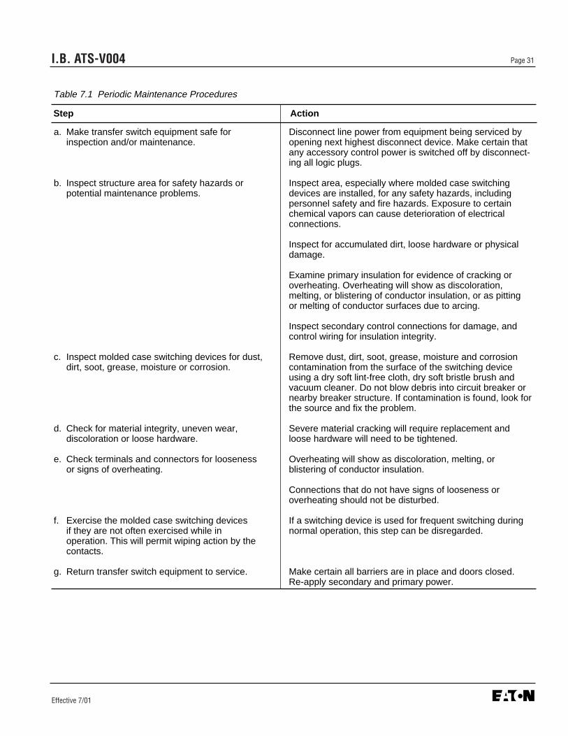
I.B. ATS-V004 Page 31
Effective 7/01
Table 7.1 Periodic Maintenance Procedures
a. Make transfer switch equipment safe for Disconnect line power from equipment being serviced by inspection and/or maintenance. opening next highest disconnect device. Make certain that
any accessory control power is switched off by disconnect-ing all logic plugs.
b. Inspect structure area for safety hazards or Inspect area, especially where molded case switching potential maintenance problems. devices are installed, for any safety hazards, including
personnel safety and fire hazards. Exposure to certain chemical vapors can cause deterioration of electrical connections.
Inspect for accumulated dirt, loose hardware or physical damage.
Examine primary insulation for evidence of cracking or overheating. Overheating will show as discoloration, melting, or blistering of conductor insulation, or as pitting or melting of conductor surfaces due to arcing.
Inspect secondary control connections for damage, and control wiring for insulation integrity.
c. Inspect molded case switching devices for dust, Remove dust, dirt, soot, grease, moisture and corrosion dirt, soot, grease, moisture or corrosion. contamination from the surface of the switching device
using a dry soft lint-free cloth, dry soft bristle brush and vacuum cleaner. Do not blow debris into circuit breaker or nearby breaker structure. If contamination is found, look for the source and fix the problem.
d. Check for material integrity, uneven wear, Severe material cracking will require replacement anddiscoloration or loose hardware. loose hardware will need to be tightened.
e. Check terminals and connectors for looseness Overheating will show as discoloration, melting, oror signs of overheating. blistering of conductor insulation.
Connections that do not have signs of looseness or overheating should not be disturbed.
f. Exercise the molded case switching devices If a switching device is used for frequent switching during if they are not often exercised while in normal operation, this step can be disregarded.operation. This will permit wiping action by the contacts.
g. Return transfer switch equipment to service. Make certain all barriers are in place and doors closed.Re-apply secondary and primary power.
Step Action

I.B. ATS-V004Page 32
Effective 7/01

I.B. ATS-V004
Cutler-HammerFive Parkway CenterPittsburgh, PA 15220
Effective 7/01 (ISI)Style 8165A03H04Printed in U.S.A.
This instruction booklet is published solely for informa-tion purposes and should not be considered all inclu-sive. If further information is required, you should con-sult Cutler-Hammer.
Sale of product shown in this literature is subject toterms and conditions outlined in appropriate Cutler-Hammer selling policies or other contractual agreementbetween the parties. This literature is not intended toand does not enlarge or add to any such contract. Thesole source governing the rights and remedies of anypurchaser of this equipment is the contract between thepurchaser and Cutler-Hammer.
NO WARRANTIES, EXPRESSED OR IMPLIED,INCLUDING WARRANTIES OF FITNESS FOR A PAR-TICULAR PURPOSE OR MERCHANTABILITY, ORWARRANTIES ARISING FROM COURSE OF DEAL-ING OR USAGE OF TRADE, ARE MADE REGARDINGTHE INFORMATION, RECOMMENDATIONS ANDDESCRIPTIONS CONTAINED HEREIN. In no eventwill Cutler-Hammer be responsible to the purchaser oruser in contract, in tort (including negligence), strict lia-bility or otherwise for any special, indirect, incidental orconsequential damage or loss whatsoever, including butnot limited to damage or loss of use of equipment, plantor power system, cost of capital, loss of power, addition-al expenses in the use of existing power facilities, orclaims against the purchaser or user by its customersresulting from the use of the information, recommenda-tions and description contained herein.