cutting force analysis to estimate the friction force in ... · pdf filecutting force analysis...
TRANSCRIPT

Measurement 85 (2016) 65–79
Contents lists available at ScienceDirect
Measurement
journal homepage: www.elsevier .com/ locate/measurement
Cutting force analysis to estimate the friction force in linearguideways of CNC machine
http://dx.doi.org/10.1016/j.measurement.2016.02.0170263-2241/� 2016 Elsevier Ltd. All rights reserved.
⇑ Corresponding author at: Centre of Advanced Manufacturing andMaterial Processing (AMMP), Department of Mechanical Engineering,Engineering Faculty, University of Malaya, 50603 Kuala Lumpur,Malaysia. Tel.: +60 3 7967 4593; fax: +60 3 7967 7669.
E-mail address: [email protected] (A.A.D. Sarhan).
Mahdi Sparham a, Ahmed A.D. Sarhan a,b,⇑, N.A. Mardi a, M. Dahari a, M. Hamdi a
aCentre of Advanced Manufacturing and Material Processing (AMMP), Department of Mechanical Engineering, Engineering Faculty, University of Malaya,50603 Kuala Lumpur, MalaysiabDepartment of Mechanical Engineering, Faculty of Engineering, Assiut University, Assiut 71516, Egypt
a r t i c l e i n f o a b s t r a c t
Article history:Received 20 May 2015Received in revised form 4 January 2016Accepted 16 February 2016Available online 23 February 2016
Keywords:Machine toolsMotionLinear guidewaysCutting forceFriction force
Linear guideways are widely applied in advanced machinery industries worldwide for dif-ferent types of CNC machine (e.g., turning, milling, grinding, and gantry). All of thesemachines require accuracy and precision in the machining operations to manufacture qual-ity products. The cutting operation in product manufacturing occurs with the displacementof machine tables on linear guideways. For this reason, linear guideways are significantparts and have sensitive locations in CNC machines to yield precision and accuracy.Friction is a major factor of deformation in guideways and non-smooth motion that pre-vents superior accuracy and precision in machine operations. Moreover, the frictionalbehavior in linear guideways is one of the most crucial challenges for CNC machining, suchthat between two parts of friction and temperature stimulus there will be stick-slipmotion, wear and corrosion of the parts. Thus, manufacturers are interested in thesemachines, particularly to facilitate this process with an actual lubrication system. Hence,friction force estimation and modeling in CNC machine guideways is used to overcomethese problems by controlling the lubrication operation.In this research work, the cutting force components including, longitudinal force (FL),
radial force (Fr) and tangential force (Ft) are measured during cutting process. These cuttingforce values are corresponding to different cutting conditions includes, spindle speed,depth of cut, and feed rate. The cutting force components and the weight of the movingparts are analyzed and transferred to the CNC machine guideways. The friction force on lin-ear guideways of machine tools is modeled based on the analyzed and transferred forcecomponents on the guideways during cutting. The static and kinetic coefficient of frictionare measured experimentally in dry lubrication condition hence the friction force compo-nents can be obtained. The friction force are estimated using the identified coefficient offriction.
� 2016 Elsevier Ltd. All rights reserved.
1. Introduction
Guideways are among the most critical elements inmachining tools, as they guide the tool or work piece alonga predetermined path [1], usually in a straight line or circle[2]. Guideway wear along with thermal and vibrationerrors are the largest contributors to positioning anddimensional workpiece errors in precision machining. For

Fig. 2. Schematic representation of the Stribeck diagram.
66 M. Sparham et al. /Measurement 85 (2016) 65–79
instance, machine tool carriages typically operate on slide-ways under high loads and slow speeds and thus must beable to get into motion quickly and smoothly and then con-tinue at a constant speed.
According to Fig. 1, friction between contact points inlinear guideways and carriages is problematic for achiev-ing machining precision and accuracy. Temperatureincreases due to friction; consequently, friction is usuallyconsidered in motion control design for the sake of simpleimplementation [3–10]. However, the slideways generallyused in the feed drive servomechanisms of CNC machinetools often induce significant static friction [11–13]. Staticfriction cannot be ignored in practical applications becauseit can significantly deteriorate the reversal motions of feeddrive servomechanisms.
The frictional behavior in linear guideways is one of themost crucial challenges with CNC machining, as higherfriction produces motion and accuracy problems. Lubrica-tion in CNC machine guideways is used to overcome suchproblems. According to Fig. 2 [14], lubricated sliding sur-faces exhibit frictional behavior. The oil viscosity (ɥ), slid-ing speed (v), and the average normal force on the planeof projection (N), cause the frictional coefficient (l). Inzone I, a solid-to-solid contact between guide surfaces isseen, since the oil film thickness is less than the surfaceroughness. Although the oil film prevents total seizure,partial seizure can occur as conditions approach boundaryzone I. This field is called boundary lubrication state. Inzone III, the oil film is much thicker than the surface rough-ness and prevents solid-to-solid contact. This is called thehydrodynamic lubrication state. Field II indicates a middlestage called the mixed lubrication state. Hence applyingcorrect lubrication condition is very essential for gettinghigher motion precision with lowest oil consumption.
Currently there are two lubrication techniques are used,including manual and automatic lubrication were used forlubrication of carriages in CNC machines to overcome thefrictional behavior in linear guideways. Manual lubricationwas based on the provided instructions of the CNCmachine maker company, and is performed by the opera-
Fig. 1. Contact points in linear guideways.
tor. This method does not guarantee correctness, amount,or controlled lubrication, as it depends on operator experi-ence. On the other hand, automatic lubrication processruns based on a fixed time and amount of oil injectionregardless of cutting force value, weight and size of theworkpiece, friction force on the guideways, and machiningprocess conditions. This leads to less protection of theguideways in case there is high friction force, or excessiveoil consumption at lessen the friction force in guideways.Manual and automatic lubrication methods can be usedindependently or together based on the design providedby the machine makers [15,16].
The most important matter in this research is the qual-ity of correct lubrication. This paper then emphasizes theeffects of cutting components [17] on friction modelingfor a systematic approach of lubrication after which thenew control technique with intelligent lubrication systemin a CNC machine will introduced in future.
Many researchers have analyzed the frictional behaviorof machine components, and some work has been carriedout on practical machine tools. To simplify the stick-slipprocedure, Kato et al. studied the characteristics of staticfriction during sticking and kinetic friction during slipping[18]. However, static friction is position-dependent [19]and the interplay of moving parts in a transmission systemcan considerably affect the position dependency of staticfriction [20].
Friction occurs in all machines possessing relativemotion and is salient in many servomechanisms and sim-ple pneumatic or hydraulic systems. Realistically speaking,friction can lead to tracking errors, limited cycles, andundesirable stick-slip motion [21]. Engineers have to dealwith the undesirable effects of friction, and the lack effec-tive tools make it all the more severe [22,23]. In order toovercome this problem and achieve a high performanceof servo control systems, an appropriate friction model[24] to describe the friction characteristics is required.The LuGre model [25] is representative of such model.Researchers have utilized this model for it possesses a sim-

Fig. 3. Solid modeling of the OKUMA LB15 II CNC machine.
Fig. 4. Outline of the moving table on slideways at a 25-degree slope(side view).
M. Sparham et al. /Measurement 85 (2016) 65–79 67
ple, implementable structure in the controller design, andit is capable of representing most friction characteristicswith the notable exception of pre-sliding characteristics[26].
Tarng and Cheng used a nonlinear model to simulateand analyze the dynamic behavior of stick-slip friction onthe contouring accuracy of CNC machine tools [27]. Houet al. investigated the tribological behavior of the thin-deep scraped and wide-shallow scraped surface topogra-phy of machine tool guideways [14].
In order to evaluate the cutting force and cutting torqueby the feed motor current, Stein et al. evaluated the DC andAC servo feed motor drives in the machine tool as force andtorque sensors, respectively [28]. However, current controlis necessary, as it is susceptible to increasing friction at thecontact points of dynamic parts. Therefore, servomotorcurrent was variably selected for measurement. Changesin current indicate that the mechanical movements arenot smooth [15]. The skip-slip motions of carriages and/or supporters cause the current in the servomotors toincrease. The feed motor current is measured by a HallEffect sensor to calculate the feed force indirectly [29].The current of the variable feed motor can provide useful
information about the stick-slip motion in carriages ofthe linear guideways since for turning operations themotor is aligned normally to the machine tables.
In this research, the friction force on linear guidewaysof machine tools is modeled based on the analyzed andtransferred the effective force components on the guide-ways during cutting. The static and kinetic coefficient offriction are measured experimentally in dry lubricationcondition hence the friction force components can beobtained. This friction force modeling can be used in theintelligent lubrication system.
2. Experimental setup
Experimental studies were done on a CNC lathemachine (OKUMA LB15-II) with maximum cutting lengthand diameters of 425 mm and 250 mm, respectively, andwith various workpieces weighing up to 500 kg (4905 N).The table traveled about 520 mm when undergoing anycutting. An OKUMA OSP7000L control was installed onthe CNC machine for this research. The operation frame-work of the Solid modeling of the OKUMA LB15 II CNCmachine used in the experiments are shown in Fig. 3.
The X and Z-axes have a 25-degree slope relative to thehorizontal line. The moving table includes a turret and toolchanger, and it moves on the axes at this angle in its owndirection. In other words, the side view of the machine toolshows that the slideways are at a 25-degree slope from thehorizontal line of the machine bed (Fig. 4).
A tool dynamometer (Model 9121, Kistler InstrumentAG, and Winterthur, Switzerland) was installed on the tur-ret of the LB15-II (Fig. 3). The dynamometer has severalquartz-based piezoelectric force transducers in steel hous-ings. When force is acting on the dynamometer, eachtransducer produces a charge proportional to the forcecomponent that is sensitive to that axis. The 9121 modelmeasures force on the X, Y, and Z-axes. The charge is thenconverted into voltage signal by a multi-channel chargeamplifier (Model 5019 B 141, Kistler). Force data signaland voltage signal input ranges were sampled at 1 kHzand ±10 V, respectively, with a DAQ (data acquisition)module (Model 9219, NI-C series, 24-Bit Universal AnalogInput).
Experimental studies were conducted on a two-axisCNC turning machine, comprising an industrial laptop, a

Fig. 5. Cutting force components and measuring method.
Fig. 6. A sample of measured cutting force in one cycle of cutting.
68 M. Sparham et al. /Measurement 85 (2016) 65–79
Compact DAQ USB chassis designed for use with C Series I/O modules, and a mechanical system equipped with a com-mercial servomotor. An industrial laptop with an Intel‘‘Pentium” processor T4400 2.2 GHz CPU was used to pro-vide functions and include an interface for human andmachine operation, implementing documentation meth-ods, and recording data values during the tests.
3. Cutting force components
Cutting force is a force that is created by the cutting toolon the work piece during the turning operation. Accordingto Fig. 5, the main cutting force (Ft) is tangential force andit is related to the force applied in the spindle direction. Fris the radial force in the X-direction, whereas FL (Longitudi-
nal force) is the force in the Z-direction performed on thework-piece. These cutting force components are measuredusing dynamometer tools, with specifications given inabove.
The cutting force components (FL, Fr, and Ft) in turningare measured for different cutting conditions. Fig. 6 showsthe sample of measured cutting force including longitudi-nal, radial, and tangential forces at 1000 (rpm) spindlespeed, 1.5 (mm) depth of cut, and 0.5 (mm/rev) feed rateconditions. According to Tables 1–3, variation in cuttingconditions have a direct impact on cutting forces. Mean-while, the contribution of feed rate and depth of cut is sig-nificant. Although, increasing the spindle speed isaccompanied with reduced cutting forces.
Estimation of resultant cutting forces (FC) is obtainedusing below equation:
FCðNÞ ¼ffiffiffiffiffiffiffiffiffiffiffiffiffiffiffiffiffiffiffiffiffiffiffiffiffiffiF2t þ F2
r þ F2L
qð1Þ
The values of cutting force based on cutting conditionsthat were measured, are shown in Tables 1–3 with differ-ent depth of cut, respectively.
4. Estimation of friction force in guideways usingmeasured cutting force
Friction between contact points in linear guideways andcarriages is problematic for achieving machining precisionand accuracy. Friction forces on machine tool linear guide-ways are mainly influenced by cutting force values wherethe cost of machining maintenance and amount of machin-
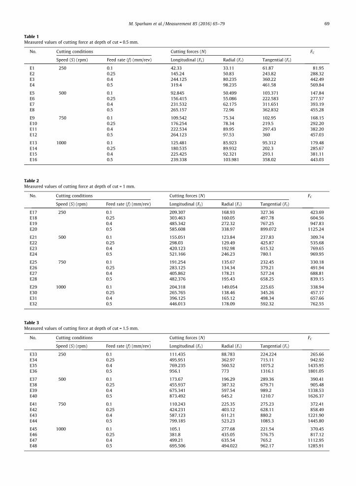
Table 1Measured values of cutting force at depth of cut = 0.5 mm.
No. Cutting conditions Cutting forces (N) FC
Speed (S) (rpm) Feed rate (f) (mm/rev) Longitudinal (FL) Radial (Fr) Tangential (Ft)
E1 250 0.1 42.33 33.11 61.87 81.95E2 0.25 145.24 50.83 243.82 288.32E3 0.4 244.125 80.235 360.22 442.49E4 0.5 319.4 98.235 461.58 569.84
E5 500 0.1 92.845 50.499 103.371 147.84E6 0.25 156.415 55.086 222.583 277.57E7 0.4 231.532 62.175 311.651 393.19E8 0.5 265.157 72.96 362.832 455.28
E9 750 0.1 109.542 75.34 102.95 168.15E10 0.25 176.254 78.34 219.5 292.20E11 0.4 222.534 89.95 297.43 382.20E12 0.5 264.123 97.53 360 457.03
E13 1000 0.1 125.481 85.923 95.312 179.48E14 0.25 180.535 89.932 202.3 285.67E15 0.4 225.425 92.321 293.1 381.11E16 0.5 239.338 103.981 358.02 443.03
Table 2Measured values of cutting force at depth of cut = 1 mm.
No. Cutting conditions Cutting forces (N) FC
Speed (S) (rpm) Feed rate (f) (mm/rev) Longitudinal (FL) Radial (Fr) Tangential (Ft)
E17 250 0.1 209.307 168.93 327.36 423.69E18 0.25 303.463 160.05 497.78 604.56E19 0.4 485.342 272.32 767.25 947.83E20 0.5 585.608 338.97 899.072 1125.24
E21 500 0.1 155.051 123.84 237.83 309.74E22 0.25 298.03 129.49 425.87 535.68E23 0.4 420.123 192.98 615.32 769.65E24 0.5 521.166 246.23 780.1 969.95
E25 750 0.1 191.254 135.67 232.45 330.18E26 0.25 283.125 134.34 379.21 491.94E27 0.4 405.862 178.21 527.24 688.81E28 0.5 482.376 195.43 658.25 839.15
E29 1000 0.1 204.318 149.054 225.65 338.94E30 0.25 265.765 138.46 345.26 457.17E31 0.4 396.125 165.12 498.34 657.66E32 0.5 446.013 178.09 592.32 762.55
Table 3Measured values of cutting force at depth of cut = 1.5 mm.
No. Cutting conditions Cutting forces (N) FC
Speed (S) (rpm) Feed rate (f) (mm/rev) Longitudinal (FL) Radial (Fr) Tangential (Ft)
E33 250 0.1 111.435 88.783 224.224 265.66E34 0.25 495.951 362.97 715.11 942.92E35 0.4 769.235 560.52 1075.2 1435.95E36 0.5 956.1 773 1316.1 1801.05
E37 500 0.1 173.67 196.29 289.36 390.41E38 0.25 455.937 387.32 679.71 905.48E39 0.4 675.341 597.54 989.2 1338.53E40 0.5 873.492 645.2 1210.7 1626.37
E41 750 0.1 110.243 225.35 275.23 372.41E42 0.25 424.231 403.12 628.11 858.49E43 0.4 587.123 611.21 880.2 1221.90E44 0.5 799.185 523.23 1085.3 1445.80
E45 1000 0.1 105.1 277.68 221.54 370.45E46 0.25 381.8 435.05 576.75 817.12E47 0.4 499.21 635.54 765.2 1112.95E48 0.5 695.506 494.022 962.17 1285.91
M. Sparham et al. /Measurement 85 (2016) 65–79 69

Fig. 7. Directions of force application and analysis them.
Fig. 9. Center gravity distance from linear guideways in X-axis.
70 M. Sparham et al. /Measurement 85 (2016) 65–79
ing accuracy are the most important factors to necessary ofthe friction force estimation.
Friction forces on the machine tool guideways, are cal-culated by the analysis of two set of forces, which are cut-ting force and normal force. The cutting forces componentshave some effects on a tip of cutting tool. The cutting forcewas divided to three vectors, Ft (tangential force), FL (longi-tudinal force), and Fr (radial force) as shown in Fig. 7.
As mentioned in Fig. 4, the moving table has a 25�degree slope, relative to horizontal line in side view ofCNC machine. The cutting force angle matching theinclined angle. However, the normal force is required todivide under a� angle as shown in Fig. 7. Normal force isobtained from weight of moving table with belongings,such as, turret, tool changer, cutting tools, and so on, willbe analyzed (projected) to F1 and F2 under a�.
F1 ¼ W � cosa ð2Þ
F2 ¼ W � sina ð3Þ
Fig. 8. Main parts of
where here; F1, F2 are, the components of the weight, andW, is weight of moving table.
4.1. Analysis of effective forces
Cutting force and normal force as effective forces wereexplained above and they are affected the linear guidewaysin both X, and Z-axes simultaneously. Analyzing them isrequired to estimate the friction force.
Another effective force is the weight of moving table(W1 and W2), that is composed of two main parts. Fig. 8shows the Turret body and belongings including housingbody, tool changer, cutting tool and installed dynamome-ter on the tool changer part B, which the weight of part Bis called, W1. The W1, is used to estimate the friction forcein X-axis. The other part is X-axis carriage, which is slides
moving table.

Fig. 10. Center gravity distance from linear guideways in Z-axis.
Fig. 11. Forces and their distances from cer
M. Sparham et al. /Measurement 85 (2016) 65–79 71
on Z-axis linear guideways. Whereas the turret can bereciprocating motion in the X-axis direction part C. Theassembly of part B, and part C, is represented as part A.The weight of part A is calledW2, that is used in calculationof friction force in Z-axis.
It should be mentioned, the weight of moving parts hasbeen calculated via density of the material in solid worksoftware with respect to the real dimensions, which hasbeen adapted from user manual of CNC lathe machine.
Figs. 9 and 10 show the force vectors on X, and Z-axesmoving tables, with accurate dimensions of design. For aprecise positioning of forces, first calculate the center ofgravity of moving table with belongings, which is acquiredvia mathematical methods using solid work software.Afterwards, that point to be considered as a load point inthe normal force. Secondly, it should be measured longitu-dinal and lateral distance of this point until the exact loca-tion of the cutting forces at the tip of cutting tool, anddistance from the machine bed according to real dimen-sions of the CNC machine. The X; Y values are distancesfrom center of gravity (G).
X ¼Pn
i¼1mixim
ð4Þ
tain load points on X-axis coordinate.
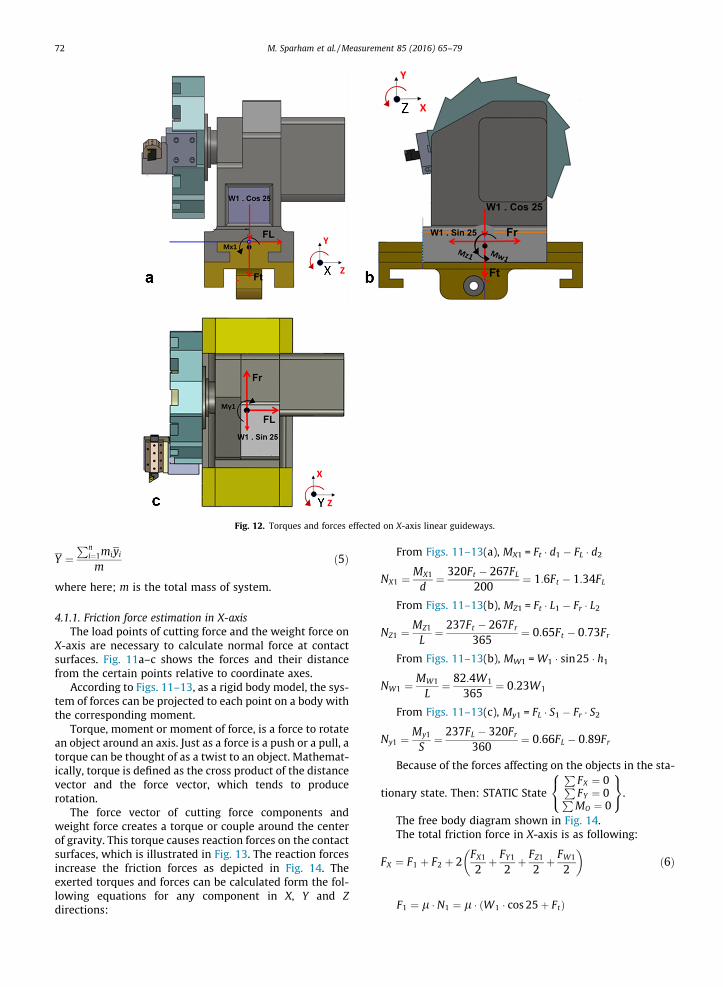
Fig. 12. Torques and forces effected on X-axis linear guideways.
72 M. Sparham et al. /Measurement 85 (2016) 65–79
Y ¼Pn
i¼1miyim
ð5Þ
where here; m is the total mass of system.
4.1.1. Friction force estimation in X-axisThe load points of cutting force and the weight force on
X-axis are necessary to calculate normal force at contactsurfaces. Fig. 11a–c shows the forces and their distancefrom the certain points relative to coordinate axes.
According to Figs. 11–13, as a rigid body model, the sys-tem of forces can be projected to each point on a body withthe corresponding moment.
Torque, moment or moment of force, is a force to rotatean object around an axis. Just as a force is a push or a pull, atorque can be thought of as a twist to an object. Mathemat-ically, torque is defined as the cross product of the distancevector and the force vector, which tends to producerotation.
The force vector of cutting force components andweight force creates a torque or couple around the centerof gravity. This torque causes reaction forces on the contactsurfaces, which is illustrated in Fig. 13. The reaction forcesincrease the friction forces as depicted in Fig. 14. Theexerted torques and forces can be calculated form the fol-lowing equations for any component in X, Y and Zdirections:
From Figs. 11–13(a), MX1 = Ft � d1 � FL � d2
NX1 ¼ MX1
d¼ 320Ft � 267FL
200¼ 1:6Ft � 1:34FL
From Figs. 11–13(b), MZ1 = Ft � L1 � Fr � L2
NZ1 ¼ MZ1
L¼ 237Ft � 267Fr
365¼ 0:65Ft � 0:73Fr
From Figs. 11–13(b), MW1 =W1 � sin25 � h1
NW1 ¼ MW1
L¼ 82:4W1
365¼ 0:23W1
From Figs. 11–13(c), My1 = FL � S1 � Fr � S2
Ny1 ¼ My1
S¼ 237FL � 320Fr
360¼ 0:66FL � 0:89Fr
Because of the forces affecting on the objects in the sta-
tionary state. Then: STATIC State
PFX ¼ 0PFY ¼ 0PMO ¼ 0
8<:
9=;.
The free body diagram shown in Fig. 14.The total friction force in X-axis is as following:
FX ¼ F1 þ F2 þ 2FX1
2þ FY1
2þ FZ1
2þ FW1
2
� �ð6Þ
F1 ¼ l � N1 ¼ l � ðW1 � cos 25þ FtÞ
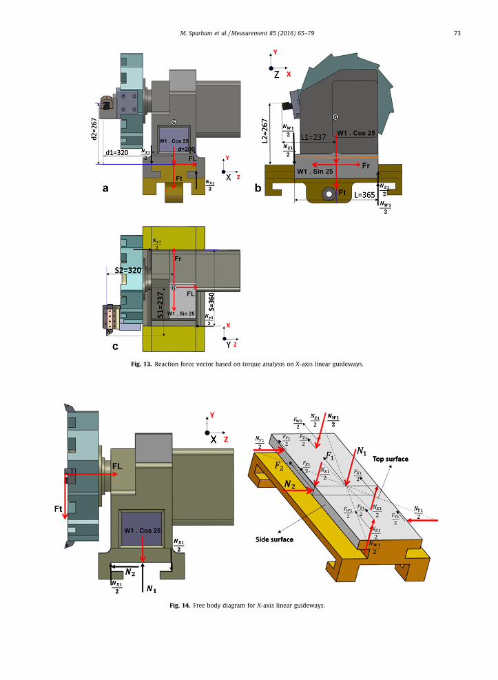
Fig. 13. Reaction force vector based on torque analysis on X-axis linear guideways.
Fig. 14. Free body diagram for X-axis linear guideways.
M. Sparham et al. /Measurement 85 (2016) 65–79 73

Fig. 15. Forces and distances from load points on Z-axis coordinate.
74 M. Sparham et al. /Measurement 85 (2016) 65–79
F2 ¼ l � N2 ¼ lðFLÞFX1 ¼ l � NX1 ¼ l � ð1:6Ft � 1:34FLÞFY1 ¼ l � NY1 ¼ l � ð0:66FL � 0:89FrÞFZ1 ¼ l � NZ1 ¼ l � ð0:65Ft � 0:73FrÞFW1 ¼ l � NW1 ¼ l � ð0:23W1ÞFX ¼ l½0:906W1þ Ft þ FL þ ð1:6Ft � 1:34FLÞ þ ð0:66FL�0:89FrÞ þ ð0:65Ft � 0:73FrÞ þ 0:23W1�FX ¼ lð1:14W1 þ 3:25Ft þ 0:32FL � 1:62FrÞ
where W1 is the weight of part B (refer to Fig. 8).The static and kinetic coefficient friction (lS and lK) are
considered to identify the friction force in X-axis in both ofstationary and moving table on the guideways.
FSX ¼ lS � ð1:14W1 þ 3:25Ft þ 0:32FL � 1:62FrÞ ð7Þ
FKX ¼ lK � ð1:14W1 þ 3:25Ft þ 0:32FL � 1:62FrÞ ð8Þ
where FSX is a total static friction force and FKX is totalkinetic friction forces in X-axis linear guideways.
4.1.2. Friction force estimation in Z-axisThe cutting force and normal force result in the friction
force on Z direction during cutting operations are shown inFig. 15.
Fig. 16 shows the force and torque affected on Z-axisdirection.
It is necessary to transfer the moment of the forces dueto cutting forces and normal force, to the individual center
of gravity in order to calculate the forces acting on the lin-ear guideways.
From Figs. 15–17(a),
MX2 ¼ Ft � d1 � FL � d2 ð9aÞ
RX2 ¼ MX2
d¼ 320Ft � 367FL
280¼ 1:14Ft � 1:31FL ð9bÞ
From Figs. 15–17(b),
MZ2 ¼ Ft � L1 � Fr � L2 ð9cÞ
RZ2 ¼ MZ2
L¼ 237Ft � 367Fr
538¼ 0:44Ft � 0:68Fr ð9dÞ
From Figs. 15–17(b),
MW2 ¼ W2 � sin 25 � h1 ð9eÞ
RW2 ¼ MW2
L¼ 70:15W2
538¼ 0:13W2 ð9fÞ
From Figs. 15–17(c),
MY2 ¼ FL � S1 � Fr � S2 ð9gÞ
Ry2 ¼ My2
S¼ 237FL � 320Fr
538¼ 0:44FL � 0:59Fr ð9hÞ
Free body diagram for Z-axis linear guide after analysisthe forces is shown in Fig. 18.

Fig. 16. Torques and forces effected on Z-axis linear guideways.
M. Sparham et al. /Measurement 85 (2016) 65–79 75
FZ ¼ F1 þ F2 þ 2FX2
2þ FY2
2þ FZ2
2þ FW2
2
� �
F1 ¼ l � ðW2 � cos 25þ FtÞF2 ¼ l � ðW2 � sin 25� FrÞFX2 ¼ l � RX2 ¼ l � ð1:14Ft � 1:31FLÞFY2 ¼ l � Ry2 ¼ l � ð0:44FL � 0:59FrÞFZ2 ¼ l � RZ2 ¼ l � ð0:44Ft � 0:68FrÞFW2 ¼ l � RW2 ¼ l � ð0:13W2Þ
FZ ¼l 0:906W2þ0:422W2þFt �Fr þð1:14Ft �1:31FLÞ½þð0:44FL�0:59FrÞþð0:44Ft �0:68Fr þ013W2Þ�
FZ ¼ l � ð1:46W2 þ 2:58Ft � 2:27FL � 0:87FrÞwhere W2 is the weight of part A (refer to Fig. 8).
The static and kinetic coefficient friction (lS and lK) willbe used to identify the friction force in Z-axis.
FSZ ¼ lS � ð1:46W2 þ 2:58Ft � 2:27FL � 0:87FrÞ ð10Þ
FKZ ¼ lK � ð1:46W2 þ 2:58Ft � 2:27FL � 0:87FrÞ ð11Þwhere FSZ is a static friction force on Z-axis, and FKZ iskinetic friction forces on Z-axis linear guideways.
Generally material of linear guideways that has beenused in moving table of CNC machines are from HardenedSteel. The mass density of them is q ¼ 7:85 gr
cm3
� �, and the
static coefficient of mixed (dry and greasy) mode of slidingfriction between contact points of moving table for staticand mixed kinetic will be identified according to measure-ments. The most commonly used classification for guide-ways is manufactured from AISI A4 tool steel.
4.2. Coefficient of friction measurement in dry lubricationcondition
Though in order to find the coefficients of friction canrefer to engineer’s Handbooks, and apply the values ofcoefficients of friction materials but for more, accuratewe decided to obtain the coefficient of friction experimen-tally in both static and kinetic mods. In friction coefficientmeasurement in CNC linear guideways, the mixed frictionzone (II) is considered (refer to Stribeck diagram in Fig. 2).The coefficient of frictions test method is ‘‘flat block slidingdown an inclined runway” (IS).
Fig. 19 shows a piece of test block with specificationsgiven in Table 4 is used for measuring coefficient offriction.

Fig. 17. Reaction force vector based on torque analysis on Z-axis linear guideways.
76 M. Sparham et al. /Measurement 85 (2016) 65–79
The coefficient value of static friction in dry lubricationcondition that achieved was equal to 0.095 (lS = 0.095).While this value for kinetic friction was 0.075 (lK = 0.075).
Where: Fapp1 and Fapp2, are static and kinetic appliedforce for measuring, respectively.
Coefficient of friction values in engineer’s handbook isaccording to the below table (Table 5) [30].
Finally, a functionmodel between cutting force and fric-tion force can help us to calculate the magnitude of thefriction forces during cutting in different cutting conditions(refer to Eqs. (7)–(11)).
This model is the following:The coefficient of friction between two materials during
same tribology conditions is constant in static and kineticmodes. According to friction formula (F = l � N), the frictionforce is depends on the load or cutting force, therefore,they are considered in Eqs. (12)–(15) [31].
FSX ¼ 0:095ð1:14W1 þ 3:25Ft þ 0:32FL � 1:62FrÞ ð12Þ
FKX ¼ 0:075ð1:14W1 þ 3:25Ft þ 0:32FL � 1:62FrÞ ð13Þ
FSZ ¼ 0:095ð1:46W2 þ 2:58Ft � 2:27FL � 0:87FrÞ ð14Þ
FKZ ¼ 0:075ð1:46W2 þ 2:58Ft � 2:27FL � 0:87FrÞ ð15ÞDuring machine cutting operations, there is only static
friction force on the X-axis (FSX), and only kinetic frictionforce on the Z axis (FKZ). According to Eq. (12), the static
friction force in X-axis depends on the tangential, longitu-dinal and radial forces. In accordance with Eq. (13), thekinetic friction force in X-axis is related to tangential, lon-gitudinal and radial forces. This model is used for frictionforce calculation based on different cutting conditions.While the Eqs. (14) and (15) are static and kinetic frictionforce calculated in Z-axis, respectively.
The friction forces are modeled by a set of two equa-tions as above Eqs. (12)–(15), as is the case of the linearmodel, depends on a state variable representing the cut-ting force components. The static friction force equationon X-axis guideways is obtained from the friction forcebased on the tangential force (Ft), longitudinal force (FL)and radial force (Fr) Plus the constant value. In addition,the kinetic friction force equation on Z-axis guideways isobtained from the friction force based on the tangentialforce (Ft), longitudinal force (FL) and radial force (Fr) plusthe constant value. Table 6 shows the values of frictionforce in dry lubrication condition based on cutting condi-tions in X, and Z-axis that was calculated from the equa-tions obtained from 48 experiments. According to Tables1–3, the cutting conditions, including depth of cut, feedrate and spindle speed, were applied in the 48 individualexperiments. The parameters were applied to achieve theeffective forces on the machine linear guideways. Conse-quently, the effective forces including cutting force andnormal force on linear guideways in both X, and Z-axis,were analyzed to estimate the friction force. The critical

Fig. 18. Free body diagram for Z-axis linear guideways.
Table 4Specification of test method for coefficient of frictions in dry condition.
Material of test block Hard steelDensity 7.60 kg/cm3
Size 100 ⁄ 100 ⁄ 50 mmSlope angle 25�Mass of test block 3.80 kgWeight of test block 37.28 N (W)Static force applied 18.98 N (Fapp1)Kinetic force applied 13.24 N (Fapp2)
Table 5Applied coefficient of friction.
Material1
Material2
Coefficient of friction
Dry Greasy
Static Sliding Static Sliding
Steel(hard)
Steel(hard)
0.78 0.42 0.05–0.11 0.29–0.12
M. Sparham et al. /Measurement 85 (2016) 65–79 77
cutting parameters value are including the spindle speed infour level (250, 500, 750 and 1000 rpm), the depth of cut inthree level (0.5, 1, and 1.5 mm), and finally the feed rate in
Fig. 19. Test method used to obta
four level (0.1, 0.25, 0.4, and 0.5 mm/rev), regarding toloaded data.
5. Conclusion
In this Paper, the friction force in CNC machine linearguideways in dry lubrication condition was estimatedusing cutting force values. For this purpose, the values ofthe cutting force components including tangential, longitu-dinal, and radial forces were measured based on the differ-ent cutting conditions. The cutting conditions, includingdepth of cut, feed rate and spindle speed, were applied in48 individual experiments. The parameters were appliedto achieve the effective forces on the machine linear guide-ways. Consequently, the effective forces including cutting
in the coefficient of friction.

Table 6The values of friction force based on cutting conditions.
48Seq.
Cutting conditions Cutting force (N) Friction force (N)
Speed (S)(rpm)
DOC (d)(mm)
Feed rate (f) (mm/rev)
Longitudinal(FL)
Radial(FR)
Tangential(Ft)
FSX FKX FSZ FKZ
E1 250 0.5 0.1 42.33 33.11 61.87 429.59 339.17 660.50 521.40E2 0.25 145.245 50.83 243.821 486.17 383.84 681.44 537.93E3 0.4 244.125 80.235 360.22 520.59 411.01 686.21 541.70E4 0.5 319.4 98.235 461.58 551.40 435.34 693.34 547.33
E5 500 0.5 0.1 92.845 50.499 103.371 441.27 348.39 658.34 519.70E6 0.25 156.415 55.086 222.583 479.30 378.42 673.47 531.65E7 0.4 231.532 62.175 311.651 507.99 401.07 678.52 535.63E8 0.5 265.157 72.96 362.832 523.16 413.04 682.92 539.10
E9 750 0.5 0.1 109.542 75.34 102.95 437.82 345.67 652.58 515.16E10 0.25 176.254 78.34 219.5 475.37 375.31 666.52 526.15E11 0.4 222.534 89.95 297.43 499.05 394.01 674.68 532.60E12 0.5 264.123 97.53 360 518.47 409.34 680.42 537.13
E13 1000 0.5 0.1 125.481 85.923 95.312 434.32 342.90 646.40 510.27E14 0.25 180.535 89.932 202.3 468.41 369.82 660.42 521.34E15 0.4 225.425 92.321 293.1 497.44 392.74 672.80 531.11E16 0.5 239.338 103.981 358.02 516.11 407.48 684.74 540.54
E17 250 1 0.1 209.307 168.93 327.36 495.74 391.39 678.34 535.49E18 0.25 303.463 160.05 497.78 552.58 436.27 700.54 553.01E19 0.4 485.342 272.32 767.25 624.03 492.68 718.08 566.86E20 0.5 585.608 338.97 899.072 657.52 519.12 723.26 570.95
E21 500 1 0.1 173.67 196.29 289.36 478.71 377.95 674.45 532.42E22 0.25 424.231 403.12 628.11 559.09 441.40 686.35 541.81E23 0.4 587.123 611.21 880.2 609.85 481.48 695.81 549.28E24 0.5 799.185 523.23 1085.3 693.16 547.25 707.62 558.60
E25 750 1 0.1 191.254 135.67 232.45 471.00 371.87 661.72 522.37E26 0.25 283.125 134.34 379.21 519.31 410.01 677.99 535.21E27 0.4 405.862 178.21 527.24 562.00 443.70 684.17 540.09E28 0.5 482.376 195.43 658.25 602.12 475.38 698.36 551.30
E29 1000 1 0.1 204.318 149.054 225.65 467.24 368.90 656.13 518.95E30 0.25 265.765 138.46 345.26 507.67 400.81 673.07 531.33E31 0.4 396.125 165.12 498.34 554.79 438.02 680.27 537.01E32 0.5 446.013 178.09 592.32 583.33 460.54 691.48 545.86
E33 250 1.5 0.1 111.435 88.783 224.224 473.25 373.64 680.79 537.42E34 0.25 495.951 362.97 715.11 594.31 469.21 695.52 549.05E35 0.4 769.235 560.52 1075.2 683.39 539.54 708.52 559.32E36 0.5 521.166 246.23 780.1 633.10 499.84 715.66 564.95
E37 500 1.5 0.1 110.243 225.35 275.23 467.95 369.45 682.26 538.58E38 0.25 455.937 387.32 679.71 578.41 456.66 693.46 547.43E39 0.4 675.341 597.54 989.2 648.28 511.82 704.63 556.24E40 0.5 873.492 645.2 1210.7 715.36 564.78 712.25 562.26
E41 750 1.5 0.1 155.051 123.84 237.83 467.95 369.45 682.26 538.58E42 0.25 298.03 129.49 425.87 534.92 422.33 686.61 542.02E43 0.4 420.123 192.98 615.32 587.35 463.72 701.47 553.75E44 0.5 956.1 773 1316.1 730.75 576.93 709.70 560.25
E45 1000 1.5 0.1 105.1 277.68 221.54 443.16 349.88 665.88 525.66E46 0.25 381.8 435.05 576.75 537.02 423.99 680.27 537.01E47 0.4 499.21 635.54 765.2 567.92 448.38 684.57 540.41E48 0.5 695.506 494.022 962.17 656.48 518.30 702.21 554.34
78 M. Sparham et al. /Measurement 85 (2016) 65–79
force and normal force on linear guideways in both X, andZ-axis, were analyzed to estimate the friction force.
The static and kinetic coefficient of friction (lS and lK)were considered to identify the friction force in X, and Z-axis in both of stationary and moving table on the guide-ways. Mathematical friction models were formulated asEqs. (12)–(15) for the static and kinetic friction force. Thesemodels were obtained based on the measured static andkinetic friction coefficients in dry condition. It wasobserved in this paper, that the friction force values on lin-ear guideways, on X-axis generally was less than Z-axis at
the same cutting conditions. For example, Table 6 demon-strated FSX, and FSZ were almost 656 N, and 702 N, respec-tively when the depth of cut was equal to 1.5 mm, feed rate0.5 mm/rev, and 1000 rpm for spindle speed. Among these,the tangential force was increased more than the other twolongitudinal and radial components.
Acknowledgments
This study has been supported by Malaysia Ministry ofHigher Education (MOHE) and the High Impact Research –
M. Sparham et al. /Measurement 85 (2016) 65–79 79
Grant number of ‘‘UM.C/HIR/MOHE/ENG/23” and theUniversity of Malaya Research Grant (UMRG) programno. RP039B-15AET.
References
[1] H. Schwenke, W. Knapp, H. Haitjema, A. Weckenmann, R. Schmitt, F.Delbressine, Geometric error measurement and compensation ofmachines—an update, CIRP Ann. – Manuf. Technol. 57 (2008) 660–675.
[2] K. Liu, S.N. Melkote, Finite element analysis of the influence of tooledge radius on size effect in orthogonal micro-cutting process, Int. J.Mech. Sci. 49 (2007) 650–660.
[3] S.-S. Yeh, Z.-H. Tsai, P.-L. Hsu, Applications of integrated motioncontrollers for precise CNC machines, Int. J. Adv. Manuf. Technol. 44(2009) 906–920.
[4] H. Lim, J.-W. Seo, C.-H. Choi, Torsional displacement compensation inposition control for machining centers, Contr. Eng. Pract. 9 (2001)79–87.
[5] B. Yao, M. Al-Majed, M. Tomizuka, High-performance robust motioncontrol of machine tools: an adaptive robust control approach andcomparative experiments, IEEE/ASME Trans. Mechatron. 2 (1997)63–76.
[6] Y. Altintas, K. Erkorkmaz, W.H. Zhu, Sliding mode controller designfor high speed feed drives, CIRP Ann. – Manuf. Technol. 49 (2000)265–270.
[7] M.T.E. Tung, Y. Urushisaki, High-speed end milling using afeedforward control architecture, J. Manuf. Sci. Eng. 118 (1996) 178.
[8] E. Tung, G. Anwar, M. Tomizuka, Low velocity friction compensationand feedforward solution based on repetitive control, Am. Contr.Conf. 1991 (1991) 2615–2620.
[9] M. Safaieh, A. Nassehi, S.T. Newman, A novel methodology for cross-technology interoperability in CNC machining, Robot. Comput.-Integr. Manuf. 29 (2013) 79–87.
[10] R. Mahmoodian, M.A. Hassan, R.G. Rahbari, R. Yahya, M. Hamdi, Anovel fabrication method for TiC–Al2O3–Fe functional materialunder centrifugal acceleration, Composites Part B 50 (2013) 187–192.
[11] S. Kumar, A. Nassehi, S.T. Newman, R.D. Allen, M.K. Tiwari, Processcontrol in CNC manufacturing for discrete components: a STEP-NCcompliant framework, Robot. Comput.-Integr. Manuf. 23 (2007)667–676.
[12] S. Kato, K. Yamaguchi, T. Matsubayashi, Stick-slip motion of machinetool slideway, J. Manuf. Sci. Eng. 96 (1974) 557–566.
[13] A.A. Sarhan, A. Matsubara, Investigation about the characterizationof machine tool spindle stiffness for intelligent CNC end milling,Robot. Comput.-Integr. Manuf. (2014).
[14] G.D. Kim, C.N. Chu, Indirect cutting force measurement consideringfrictional behaviour in a machining centre using feed motor current,Int. J. Adv. Manuf. Technol. 15 (1999) 478–484.
[15] M. Sparham, M. Hamdi, R. Rahbari, R. Mahmoodian, Smartlubrication via pump response interval (PRI) variation in themachining process, Int. J. Adv. Manuf. Technol. 67 (2013) 1755–1764.
[16] R. Mahmoodian, R.G. Rahbari, M. Hamdi, M. Sparham, A new attemptto adapt a machine for SHS lining ceramics inside pipes, High Temp.Mater. Process. (Int. Quart. High-Technol. Plasma Process.) 16 (2012)15–23.
[17] U. Zuperl, F. Cus, Optimization of cutting conditions during cuttingby using neural networks, Robot. Comput.-Integr. Manuf. 19 (2003)189–199.
[18] S. Kato, K. Yamaguchi, T. Matsubayashi, Stick-slip motion of machinetool slideway, ASME J. Eng. Ind. 96 (1974) 557–566.
[19] S.-S. Yeh, H.-C. Su, Development of friction identification methodsfor feed drives of CNC machine tools, Int. J. Adv. Manuf. Technol. 52(2011) 263–278.
[20] F. Huo, A.-N. Poo, Precision contouring control of machine tools, Int.J. Adv. Manuf. Technol. 64 (2013) 319–333.
[21] J.-H. Chin, Y.-M. Cheng, J.-H. Lin, Improving contour accuracy byfuzzy-logic enhanced cross-coupled precompensation method,Robot. Comput.-Integr. Manuf. 20 (2004) 65–76.
[22] J. Wang, S.S. Ge, T.H. Lee, Adaptive friction compensation for servomechanisms, in: G. Tao, F. Lewis (Eds.), Adaptive Control ofNonsmooth Dynamic Systems, Springer, London, 2001.
[23] L. Zhiping, C. Jie, Z. Guozhu, G. Minggang, Adaptive robust control ofservo mechanisms with compensation for nonlinearlyparameterized dynamic friction, IEEE Trans. Contr. Syst. Technol.21 (2013) 194–202.
[24] H. Olsson, K.J. Åström, C.C. De Wit, M. Gäfvert, P. Lischinsky, Frictionmodels and friction compensation, Eur. J. Contr. 4 (1998) 176–195.
[25] L. Freidovich, A. Robertsson, A. Shiriaev, R. Johansson, LuGre-model-based friction compensation, IEEE Trans. Contr. Syst. Technol. 18(2010) 194–200.
[26] H.M. Kim, S.I. Han, J.S. Kim, Precision position control of servosystems using adaptive back-stepping and recurrent fuzzy neuralnetworks, J. Mech. Sci. Technol. 23 (2009) 3059–3070.
[27] Y.S. Tarng, H.E. Cheng, An investigation of stick-slip friction on thecontouring accuracy of CNC machine tools, Int. J. Mach. Tools Manuf35 (1995) 565–576.
[28] J.L. Stein, C.H. Wang, Analysis of power monitoring on AC inductiondrive systems, Trans. ASME, J. Dyn. Syst., Meas., Contr. 112 (1990)239–248.
[29] M. Sparham, A.D. Sarhan, N.A. Mardi, M. Hamdi, Designing andmanufacturing an automated lubrication control system in CNCmachine tool guideways for more precise machining and less oilconsumption, Int. J. Adv. Manuf. Technol. (2013) 1–10.
[30] J.F. Shackelford, W. Alexander, CRC Materials Science andEngineering Handbook, CRC Press, 2010.
[31] S. Pytko, K. Wierzcholski, Elastohydrodynamic contact between tworollers under conditions of unsteady motion, Wear 55 (1979) 245–260.