cv-6slx user manual
TRANSCRIPT

0101-8242-0
CV-6SLX USER MANUAL
Revision C, April 2016
Temescal, a division of Ferrotec (USA) Corporation 4569-C Las Positas Road, Livermore, CA 94551
Tel: 1-800-522-1215; Fax: 925-449-4096

Revision History 0101-8242-0
Rev. Change Description Reason/Application Date Appvd.
A First published version of CV-6SLX User Manual, based on the CV-6SLX Technical Manual, Rev. L.
Applies to all CV-6SLX units, with HV power supplies with PNs 0620-1135-0 (for 208-volt units) and 0620-1135-1 (for 400-volt units)
March 2014
IA
B Corrections throughout to cross-references. Minor changes to technical data in Section 5. Deleted former section 5.6 (Suggested Spare Parts lists).
Pursuant to Field Service review of Rev. A
Sept. 2015
IA
C Replaced all occurrences of 0620-9654-0 with 0620-9654-1 and all occurrences of 6024-6112-1 with 0620-8684-1.
Pursuant to PN change ordered in ECN 12185.
April 2016
IA
© 2016 Ferrotec (USA) Corporation TemEBeam is a trademark of Ferrotec Corporation.

0101-8242-0, Rev. C i CV-6SLX User Manual
Table of Contents Page
Section Number and Title Number 1 Introduction to the CV-6SLX ........................................................................................1-1
1.1 Product Description ....................................................................................................... 1-1 1.2 CV-6SLX HVPS Description and Specifications ................................................................. 1-1 1.3 Filament Power Supply Description and Specifications ..................................................... 1-2 1.4 Miscellaneous Hardware and Interconnection Cables ....................................................... 1-3 1.5 TemEBeam EBC Integrated Controller ............................................................................ 1-3
2 Installation ...................................................................................................................2-1 2.1 Section Overview .......................................................................................................... 2-1 2.2 List of Components and Cables Supplied with the Unit ..................................................... 2-2 2.3 Rack Mounting the Power Module (HVPS) ....................................................................... 2-2 2.4 Mounting the Filament Power Supply Module(s) .............................................................. 2-3 2.5 Grounding Requirements ............................................................................................... 2-3 2.6 Cable Installation .......................................................................................................... 2-7
3 Power Supply Operation ..............................................................................................3-1 3.1 Section Overview .......................................................................................................... 3-1 3.2 HVPS Front Panel Controls and Indicators ....................................................................... 3-1 3.3 Switches and LEDs on the FPS Front Panel ..................................................................... 3-2 3.4 Power-Up Procedure ...................................................................................................... 3-3 3.5 Control of Power Supply from TemEBeam EBC Integrated Controller ................................ 3-3 3.6 Control of Power Supply by a PLC-Based System Controller ............................................. 3-8 3.7 Responding to Fault Conditions .................................................................................... 3-11
4 Theory of Operation .....................................................................................................4-1 4.1 Section Overview .......................................................................................................... 4-1 4.2 Power Module Theory of Operation ................................................................................ 4-1 4.3 FPS Theory of Operation ................................................................................................ 4-4
5 Troubleshooting ...........................................................................................................5-1 5.1 Section Overview .......................................................................................................... 5-1 5.2 HVPS Front Panel LEDs .................................................................................................. 5-1 5.3 Ishikawa Diagrams ........................................................................................................ 5-6 5.4 Troubleshooting Procedures ......................................................................................... 5-15 5.5 FPS Fuse Replacement Procedure ................................................................................ 5-29 5.6 Suggested Spare Parts ................................................................................................ 5-31
Appendix A: Pinout Table for Power Module Diagnostic Port (HVPS J3) ..................................... A-1

CV-6SLX User Manual ii 0101-8242-0, Rev. C
0101-8242-0, Rev. C iii CV-6SLX User Manual
List of Illustrations Figure Number and Title Page Figure 1-1 CV-6SLX HVPS Front Panel ......................................................................................................................... 1-1 Figure 1-2 Filament Power Supply Front Panel ............................................................................................................ 1-2 Figure 1-3 EBC Main Control Unit and Hand-Held Controller ......................................................................................... 1-3 Figure 2-1 Mounting Hole Pattern for FPS Module(s) .................................................................................................... 2-3 Figure 2-2 Facility Low Impedance Grounding Requirements ........................................................................................ 2-4 Figure 2-3 System Low Impedance Grounding Requirements ....................................................................................... 2-5 Figure 2-4 Rear Panel of CV-6SLX HVPS ...................................................................................................................... 2-6 Figure 2-5 Grounding Studs on FPS Front Panel .......................................................................................................... 2-7 Figure 2-6 Input Power Connections to 208-Volt HVPS Units ........................................................................................ 2-8 Figure 2-7 Input Power Connections to 400-Volt HVPS Units ........................................................................................ 2-8 Figure 2-8 Input Power and HV Connections on FPS Front Panel .................................................................................. 2-9 Figure 2-9 Removing the FPS Conduit Panel .............................................................................................................. 2-10 Figure 2-10 Conduit Properly Secured to FPS Conduit Panel ......................................................................................... 2-10 Figure 2-11 HV Output Cables Secured to Studs inside FPS .......................................................................................... 2-10 Figure 2-12 HV Conduit Bracket Properly Installed on HV Feedthrough ......................................................................... 2-11 Figure 2-13 HV Conduit Properly Secured to Bracket .................................................................................................... 2-11 Figure 2-14 Control/Data Cable Connections on FPS Front Panel .................................................................................. 2-12 Figure 2-15 System I/Os Exchanged via HVPS Rear Panel Connector J4 and the HVPS I/O Cable (PN 0620-6682-0) ....... 2-14 Figure 2-16 System I/Os Exchanged via FPS Front Panel Connector J101 and the FPS I/O Cable (PN 0620-6672-2) ....... 2-16 Figure 3-1 CV-6SLX HVPS Front Panel ......................................................................................................................... 3-1 Figure 3-2 Filament Power Supply Front Panel ............................................................................................................ 3-2 Figure 3-3 EBC’s Operations>E-Beam Screen when Beam Is Off .................................................................................. 3-4 Figure 3-4 Operations>E-Beam Screen, Beam On at 0.0 mA ........................................................................................ 3-4 Figure 3-5 Operations>E-Beam Screen when Gun is On and HV is Off .......................................................................... 3-5 Figure 3-6 Operations E-Beam Screen with Numeric Keypad Displayed ......................................................................... 3-5 Figure 3-7 Operations>E-Beam Screen, Beam on at 5% Power .................................................................................... 3-6 Figure 3-8 The EBC’s Diagnostics Screen .................................................................................................................... 3-6 Figure 3-9 Remote Controller’s LOCAL Screen, Menu 1 Selected, Beam and Sweep Off .................................................. 3-8 Figure 3-10 HVPS Front Panel LEDs: HVPS Powered Up in Nominal State, with HV and FPS Off ........................................ 3-9 Figure 3-11 HVPS Front Panel LEDs when Subthreshold Arcing is Occurring .................................................................. 3-12 Figure 3-12 HVPS Front Panel LEDs when a Latched OUTPUT ARCING Fault Has Occurred ............................................ 3-12 Figure 4-1 CV-6SLX HVPS Rear Panel.......................................................................................................................... 4-1 Figure 4-2 CV-6SLX HVPS Internal Components Referenced in Section 4.2 .................................................................... 4-2 Figure 4-3 Filament Power Supply (FPS) Module .......................................................................................................... 4-5 Figure 4-4 Component Location in Standard FPS Units (PN 0620-6604-0) ..................................................................... 4-6 Figure 4-5 Top Level Block Diagram for Standard FPS Units (PN 0620-6604-0) .............................................................. 4-6 Figure 4-6 Component Location in FPS Units with PN 0620-6604-2 ............................................................................... 4-7 Figure 4-7 Top Level Block Diagram for FPS Units with PN 0620-6604-2 ....................................................................... 4-7 Figure 4-8 Filament Supply PCB Overview Block Diagram ............................................................................................. 4-8 Figure 4-9 Block Diagram of Filament Supply PCB Control and Power Circuits ............................................................. 4-10 Figure 4-10 Emission Current Ramp Circuit ................................................................................................................. 4-11 Figure 4-11 Autobias Circuit Block Diagram ................................................................................................................. 4-11 Figure 5-1 HVPS Front Panel LEDs .............................................................................................................................. 5-2 Figure 5-2 Status Indicator LEDs ................................................................................................................................ 5-2 Figure 5-3 Sub-Threshold Arcing: Arc/Out Of Regulation and Output Arcing LEDs ......................................................... 5-3 Figure 5-4 Filament Load Fault and Filament Power LEDs ............................................................................................ 5-3 Figure 5-5 HVPS Front Panel LEDs with Latching Fault LEDs Outlined ........................................................................... 5-4 Figure 5-6 Interlocks OK and Rail Undervoltage LEDs .................................................................................................. 5-4 Figure 5-7 HV Overcurrent and HV Overvoltage LEDs .................................................................................................. 5-5 Figure 5-8 Setpoint Overvoltage and Output Arcing LEDs ............................................................................................. 5-5 Figure 5-9 Inverter Overload and Overtemperature LEDs ............................................................................................. 5-5 Figure 5-10 Aux Supply Low and External Control Fault LEDs ......................................................................................... 5-6

CV-6SLX User Manual iv 0101-8242-0, Rev. C
List of Illustrations (Continuted) Figure Number and Title Page Ishikawa Diagram #1: No Input Power ......................................................................................................................... 5-7 Ishikawa Diagram #2: Interlock Fault ........................................................................................................................... 5-7 Ishikawa Diagram #3: No Beam After HV and Gun Are Switched ON .............................................................................. 5-8 Ishikawa Diagram #4: HV Output Unstable .................................................................................................................... 5-8 Ishikawa Diagram #5: HV Out of Regulation LED Lights Frequently ................................................................................. 5-9 Ishikawa Diagram #6: Arc/Out of Regulation LED Lights Excessively for the Material/Application ...................................... 5-9 Ishikawa Diagram #7: Rail Undervoltage Fault ............................................................................................................. 5-10 Ishikawa Diagram #8: HV Overcurrent Fault ................................................................................................................ 5-10 Ishikawa Diagram #9: HV Overvoltage Fault ................................................................................................................ 5-11 Ishikawa Diagram #10: Setpoint Overvoltage Fault ...................................................................................................... 5-11 Ishikawa Diagram #11: Output Arcing Fault ................................................................................................................. 5-12 Ishikawa Diagram #12: Overtemperature Fault ............................................................................................................ 5-12 Ishikawa Diagram #13: Aux Power Supply Low Fault.................................................................................................... 5-13 Ishikawa Diagram #14: External Control Fault ............................................................................................................. 5-13 Ishikawa Diagram #15: Filament Load Fault ................................................................................................................ 5-14 Ishikawa Diagram #16: Simultaneous Filament Load Fault + Filament Power Fault ........................................................ 5-14 Ishikawa Diagram #17: Emission Current Unstable ....................................................................................................... 5-15 Figure 5-11 Prying Open the Fuse Block Cover on FPS Front Panel ............................................................................... 5-29 Figure 5-12 Extracting the Fuse Block from the FPS ..................................................................................................... 5-30 Figure 5-13 Fuse Block Removed from FPS ................................................................................................................. 5-30
List of Tables Table Number and Title Page Number Table 2-1 Descriptions of I/Os Exchanged via HVPS Rear Panel Connector J4 and HVPS I/O Cable (PN 0620-6682-0) ... 2-15 Table 2-2 Descriptions of I/Os Exchanged via FPS Rear Panel Connector J101 and FPS I/O Cable (PN 0620-6672-2) ... 2-17 Table 5-1 No Input Power Indicated ........................................................................................................................ 5-16 Table 5-2 One or More Interlocks Not Made .............................................................................................................. 5-17 Table 5-3 General Condition: HVPS Powered Up But Fails to Achieve HV Ready State .................................................. 5-17 Table 5-4 HVPS and FPS Are Powered Up but GUN READY State Not Achieved/Confirmed ........................................... 5-18 Table 5-5 HVPS Powered Up but HV Does Not Switch On When Commanded To Do So ............................................... 5-18 Table 5-6 FPS Powered Up but Gun Does Not Switch On When Commanded To Do So ............................................... 5-19 Table 5-7 No Filament Current After GUN ON State Is Achieved ................................................................................. 5-19 Table 5-8 No Beam Emitted After HV and Gun Are Switched On ................................................................................. 5-20 Table 5-9 HV Output Unstable ................................................................................................................................. 5-20 Table 5-10 Filament Current Out Of Regulation ........................................................................................................... 5-21 Table 5-11 HVPS ARC/OUT OF REGULATION LED Flashes Excessively .......................................................................... 5-21 Table 5-12 HVPS RAIL UNDERVOLTAGE LED Lights Red .............................................................................................. 5-22 Table 5-13 HVPS HV OVERCURRENT LED Lights Red ................................................................................................... 5-23 Table 5-14 HVPS HV OVERVOLTAGE LED Lights Red ................................................................................................... 5-24 Table 5-15 HVPS SETPOINT OVERVOLTAGE LED lights red .......................................................................................... 5-25 Table 5-16 HVPS OUTPUT ARCING LED lights red ....................................................................................................... 5-25 Table 5-17 HVPS INVERTER OVERLOAD LED lights red ................................................................................................ 5-26 Table 5-18 HVPS OVERTEMPERATURE LED lights red .................................................................................................. 5-27 Table 5-19 Fan fails to rotate when HVPS is powered up ............................................................................................. 5-27 Table 5-20 HVPS AUXILIARY SUPPLY LOW LED lights red ............................................................................................ 5-27 Table 5-21 HVPS EXTERNAL CONTROL FAULT LED lights red ....................................................................................... 5-28 Table 5-22 HVPS FILAMENT LOAD FAULT LED lights red ............................................................................................. 5-28 Table 5-23 HV Is Switched On but FPS Front Panel HIGH VOLTAGE ON LED Fails To Light ............................................ 5-28 Table 5-24 FPS Is Switched On but Its POWER ON LED Fails To Light .......................................................................... 5-29 Table 5-25 Suggested Spare Parts for 208-Volt Units .................................................................................................. 5-31 Table 5-26 Suggested Spare Parts for 400-Volt Units .................................................................................................. 5-31

0101-8242-0, Rev. C v CV-6SLX User Manual
Terms and Conditions 1. Delivery. Unless otherwise stated, shipments of Ferrotec Temescal Electron Beam Gun and Systems
products quoted and/or produced at the Livermore, CA factory site will be made Ex-Works, Livermore, CA Incoterms. Shipping date as are approximate and are based on conditions at the time of acceptance and prompt receipt of all necessary information from the Buyer. Pro- Rata payments shall become due as shipments are made. Items held of Buyer shall be at the risk and expense of the Buyer.
2. Title. A. This subsection applies in jurisdictions where the laws provides a purchase-money security interest, or
similar rights, in favor of the seller, including but not limited to the U.S., Canada, and Mexico: Title and risk of loss or damage passes to Buyer when the goods are put into possession of the freight carrier for delivery to Buyer. Seller retains a security interest in the goods to ensure payment in full. Buyer agrees not to take any action with respect to the goods that would interfere with Seller’s security interest until the goods are fully paid for.
B. This sub-section applies in all other jurisdictions: Risk of loss or damage passes to Buyer when the goods are put into possession of the freight carrier for delivery to Buyer. Seller retains sufficient title in the goods to ensure the goods are fully paid for. Buyer agrees not to take any action with respect to the goods that would interfere with Seller’s title until the goods are fully paid for.
3. Delays in Deliveries. Seller shall not be liable for failure to fill any order when due to: fires; riots; strikes; freight embargoes or transportation delays; shortage of labor; inability to secure fuel, material, supplies or power at current price or on account of shortages thereof; acts of God or of the public enemy; any existing or future laws or acts of the federal or of any state or local government (including specifically but not exclusively any orders, rules or regulations issued by an official or agency of any such government) affecting the conduct of Seller’s business with which Seller in its judgment and discretion deems it advisable to comply as a legal or patriotic duty; or to any cause beyond Seller’s reasonable control. Seller is not liable for damages attributed to delays in delivery.
4. Taxes. Prices quoted herein shall be subject to an additional charge to cover any existing or future Manufacturers, Sales, Use, Value Added or similar tax which may be applicable and any administrative costs for required governmental permits, inspections and the life.
5. Special Order Equipment. Where buyer shall furnish special order equipment, Buyer shall bear the cost of alterations made thereon, except such as Seller may make for its own convenience. Buyer shall furnish drawings and specific information as to variations permissible between equipment and drawings. Shipping and crating charges on said equipment to and from Seller’s facilities shall be borne by buyer. Seller shall have no responsibility for loss or damage to said equipment, except when due to careless handling or negligence on the part of Seller. Cost of insurance on special orders will be borne by buyer, and same are held at Buyer’s risk.
6. Seller’s Warranty. Seller’s standard published warranty in effect at the time of shipment for the particular product shall apply. THIS WARRANTY IS EXCLUSIVE AND IS IN LIEU OF ALL OTHER WARRANTIES, EXPRESS, IMPLIED OR STATUTORY, INCLUDING THE WARRANTIES OF MERCHANTABILITY OR FITNESS FOR A PARTICULAR PURPOSE. Seller’s liability shall not in any case exceed the cost of repair or replacement of any defective product as stated in the warranty and upon expiration of the warranty period all such liability shall terminate. Seller shall in no event be liable for consequential damages of any kind.
7. Changes and Acceptance. Any changes in drawings specifications or in their Terms and Conditions will require Seller’s written approval before they become binding.

CV-6SLX User Manual vi 0101-8242-0, Rev. C
8. Cancellations. The following schedule of cancellation charges shall apply: A. Cancellations:
i. For custom/modified products: When cancellation notice received: Charge is:
1-30 days prior to shipment 100% of product sales price 31-60 days prior to shipment 75% of product sales price 61-90 days prior to shipment 50% of product sales price 91 days or more prior to shipment 10% of product sales price
ii. For standard products: To be negotiated B. Reschedules:
i. For completed custom/modified product 1.5% per month x sales price of product rescheduled ii. Incomplete custom/modified product, parts 1.5% per month x sales price of rescheduled
. products which are stocked or ordered. iii. Restocking: Only standard products may be restocked. 25% of dollar value returned to Seller’s stock,
plus all freight charges. All restocking is subject to Seller’s approval and inspection.
9. Payment. The terms of payment of items quoted herein shall be: cash in advance or net 30 upon credit approval unless otherwise agreed in writing. If at any time, in the judgment of the Seller, Buyer’s credit shall be impaired, Seller shall have the right to demand immediate cash payment and to refuse to make delivery except against payment therefore in cash.
10. No implied License. The sale of any product or material quoted herein does not give or imply any right or license to buyer to analyze or manufacture such product or material or to claim Buyer is an authorized re-seller of such material.
11. Export Licenses. Items quoted herein may constitute a controlled commodity requiring export licenses from the U.S. Department of Commerce prior to transshipment. Buyer shall be responsible for obtaining any such licenses required.
12. Exclusive Statement. The terms and conditions contained in Seller’s Order Acknowledgement will be the complete and exclusive statement of the terms of agreement between the parties. If the terms of said Acknowledgement differ in any way from the terms of Buyer’s order, the provisions of said Acknowledgement shall prevail and be controlling.
13. State Laws. This contract shall be governed in all respects by the laws of the State of New Hampshire and the State of California.
14. This contract is governed by Incoterms 2010.
FERROTEC (USA) CORPORATION’S ACCEPTANCE OF THE REFERENCED PURCHASE ORDER IS EXPRESSLY MADE CONDITIONAL ON THE PARTY’S ASSENT (WHO SUBMITTED THE REFERENCED PURCHASE ORDER) TO FERROTEC’S ADDITIONAL OR DIFFERENT TERMS IN THIS ORDER ACKNOWLEDGEMENT. IF NO ANSWER IS RECEIVED FROM THE PARTY SUBMITTING THE REFERENCED PURCHASE ORDER WITHIN A REASONABLE TIME AFTER RECEIPT OF THIS ORDER ACKNOWLEDGEMENT, IT WILL BE ASSUMED THAT THEIR INCLUSION HAS BEEN ASSENTED TO.

0101-8242-0, Rev. C vii CV-6SLX User Manual
Limited Warranty 1. Parties Covered. This limited warranty is given by Ferrotec (USA) Corporation hereinafter called the
“Warrantor” to the buyer of the above described item(s) and extends to Buyer only and is not transferable to nor enforceable by any transferee, subsequent purchaser or successor of buyer.
2. Term of Limited Warranty. The term of this limited warranty shall be one year from the date of
shipment of the above items(s). Warrantor shall not have liability or responsibility under this limited warranty or under any warranties implied by law or otherwise, for defects ensuring or claims asserted after the expiration of the term of this Limited Warranty.
2. Limitations of warranties. The only express or implied warranties of Warrantor are those expressed
in this instrument. A. WITHOUT LIMITATION, WARRANTOR HEREBY DISCLAIMS ANY WARRANTY OF
MERCHANTABILITY OR FITNESS FOR A PARTICULAR PURPOSE. THERE ARE NO WARRANTIES WHICH EXTEND BEYOND THE EXPRESS WARRANTIES SET FORTH HERIN. THE TERM OF ANY WARRANTY OR WARRANTOR IMPLIED BY LAW SHALL END ON THE TERMINATION DATE OF THIS LIMITED WARRANTY SPECIFIED IN SECTION 2.
B. Warranty duration for out of warranty items repaired by Ferrotec shall be ninety (90) days from date of shipment post repair “Ex-works”.
4. Warranty Coverage. Subject to the exclusions set forth in Section 5, the item(s) described above
is/(are) warranted against defects in material or workmanship. Warrantor shall, at its option, repair or replace at its cost any defective item during the warranty period. Warrantor may repair the item at any of its worldwide service locations.
5. Exclusions from coverage. Warrantor expressly disclaims responsibility for any of the following,
each of which is expressly EXCLUDED from this limited warranty. A. Ordinary wear and tear, damage or defects due to abuse, misuse, failure to use according to
instruction, or exposure to temperatures and conditions in excess of those referred to in the Notes and instructions delivered herewith. If different operating temperatures or conditions are specified in documentation specific to your product, these supersede those on the enclosed Notes and instructions.
B. Damage or defects caused by Acts of God, the elements, natural disasters, or by the wrongful or negligent act or omission of anyone other than the Warrantor.
C. Damage or defects to any product disassembled, modified, repaired or replaced by any party other than the warrantor or its expressed authorized representative, whether or not damage was caused by said disassembly or modification.
D. Incidental, consequential or special damages of any kind.
6. Claims Procedure. Buyer shall promptly notify warrantor in writing of a claim under this Limited Warranty or any warranty implied by law. Buyer is responsible for freight charges for shipment of product to Warrantor. Warrantor will pay for the freight charges for shipment of product back to Buyer where the product is found to be defective.
7. Severability: No Waiver. In the event any of the provisions hereof shall be invalid, the remainder of
the provisions of this Limited Warranty shall remain in full force and effect. No waiver by Warrantor of the provisions hereof at any time shall constitute a waiver of any such provisions at any subsequent time or of any other provisions at any time.

CV-6SLX User Manual viii 0101-8242-0, Rev. C
Safety Instructions for Operating and Service Personnel Operators and service personnel should always wear safety glasses. Operators shall not enter areas intended for service access only. Only experienced service personnel should enter such areas, and only after taking the preliminary precautions described in paragraphs 1 through 6 below.
DANGER Potentially lethal voltages may exist within this unit, even with the line power switched off. Service should only be attempted by qualified personnel. Failure to observe all safety precautions may result in personal injury.
This component is designed to operate as part of a system containing high-voltage equipment. Observe the precautions described below when servicing this system, especially when servicing components where high voltages may be present.
1. Before servicing or operating this equipment, read all the component manuals supplied with the system, paying special attention to safety instructions.
2. Post HIGH VOLTAGE WARNING signs in conspicuous locations within the service area.
3. Remove rings, watches, bracelets, and any other metal jewelry before working around high voltage.
4. DO NOT WORK ALONE!
5. Be sure that all equipment is connected to a power receptacle having the correct polarity and grounding, as prescribed by the local electrical codes. Refer to the power supply portion of the documentation to determine the proper electrical ground for high-voltage components.
6. Before servicing any high-voltage component, switch off the electrical power at the component’s main power switch. This switch should have a lockout feature. Lock the power off and keep the key with you while you are working on the equipment.
7. Certain electrical parts (e.g., electrolytic capacitors) hold a lethal voltage even after the power is switched off. Before entering any service area, use a grounding hook to discharge such parts. Be sure that these parts are discharged before starting any repairs.
8. DO NOT touch high-voltage leads unless power is off and a grounding hook is connected to the parts to be serviced.
9. The high-voltage components of the system should be equipped with electrical interlocks to protect personnel from injury. DO NOT ATTEMPT TO DEFEAT, OVERRIDE, OR BYPASS THESE PROTECTIVE DEVICES!
10. Never leave loose ends on high-voltage connections.
11. Observe the following warning if the system employs Radio Frequency (RF) power.
DANGER RF radiation—even at modest power levels—can cause serious injury. If any of the RF components (e.g.,
the RF power supply, the RF matching network, or the RF electrodes or shielding inside the product chamber) are moved or changed in any way, the RF energy may be radiated outside the equipment. Monitor the equipment to assure that external RF radiation is below the levels prescribed by any and all applicable safety codes.
0101-8242-0, Rev. C ix CV-6SLX User Manual
Special Amendment for United Kingdom Users All Electrical Power Sources: Safety Precautions
This component is designed to be used in an extra-high-voltage system. Only authorized personnel should be permitted to carry out work on this system. Prior to any servicing, grounding hooks should be used to short out all high-voltage parts and conductors in both the vacuum system and the high-voltage power supply. Screens protecting extra-high-voltage conductors should be removed only if appropriate action has been taken to ensure that extra-high-voltage conductors are dead and cannot be reenergized inadvertently. In addition, all personnel should be aware of: 1. The Electricity (Factories Act) Special Regulations (1908 and 1944), in particular, Regulations 18(d) and 28 of the
1980 Regulations, as amended; and 2. The employer’s responsibility to set up suitable systems to safeguard the health and safety of employees, according
to the Health & Safety at Work etc. Act (1974).
User Responsibility This equipment will perform in accordance with the instructions and information contained in the user’s manual and its referenced documents when such equipment is installed, operated, and maintained in compliance with such instructions. The equipment must be checked periodically. Defective equipment shall not be used. Parts that are broken, missing, plainly worn, distorted, or contaminated, shall be replaced immediately. Should such repair or replacement become necessary, a telephone or written request for service should be made to Temescal, Livermore, CA, a division of Ferrotec (USA) Corp. The equipment, or any of its parts, shall not be altered without the prior written approval of Temescal. The user and/or purchaser of this equipment shall have the sole responsibility for any malfunction which results from improper use, faulty maintenance, damage, improper repair, or alteration by any party other than Temescal.

CV-6SLX User Manual x 0101-8242-0, Rev. C
Guidelines And Good Practices 1. Follow applicable clean room procedures (smocks, masks, gloves, etc.).
2. Do not expose the vent and purge valves to excessive pressures. The nitrogen line regulator is factory set at 15 psi and must not be adjusted above 20 psi.
3. Prevent oil, grease, water, sweat, etc. from getting into the vacuum chamber.
4. Replace the source tray shield correctly to ensure that the ceramic parts or the high voltage feedthroughs are protected from being coated.
5. Clean all mechanical parts and seals with lint-free paper/cloth soaked with isopropyl alcohol (IPA). Dispose all IPA-exposed cleaning paper/cloth in a fireproof container, while ensuring proper safety precautions are being followed.
6. Polish scratched surfaces with Scotch-Brite, taking care not to produce any cross scratches.
7. Shaft seals are all ferromagnetic. No lubrication is required.
8. Check the chamber door’s seal and sealing surfaces each time before closing it.
9. Check and clean with IPA the source tray seals and sealing surfaces each time before raising the source tray into place.
10. Train staff by competent personnel. DO NOT allow staff to operate or do maintenance and recovery work on the machine until they are trained by competent personnel.
11. Document all alarms, deviations, breakdowns, and servicings done on either a hardcopy or an electronic equipment-log system.
HEALTH HAZARD
The condensates deposited on the tank walls of a vacuum system are generally in the form of extremely fine particles. The nature, as well as the form, of the materials poses the following potential health hazards: a) Inhaling fine particles (powder) may cause damage to the lungs. To help prevent this, wear a protective
respirator mask with fine filter that has been approved by the National Institute for Occupational Safety and Health (NIOSH) and the federal Mine Safety and Health Administration (MSHA).
b) Some substances are toxic and inhaling them should be avoided. Take steps to ascertain whether or not the material being deposited is a known toxic substance. Refer to the Material Safety Data Sheet(s) covering the evaporant(s) in question.
c) Certain powders (titanium, for instance) can cause flash fires when exposed to oxygen or other oxidizers. Therefore, when opening the chamber door after a deposition cycle, exercise extreme caution and allow time for the coating surface to oxidize. Breakage of some of the more reactive condensates may be hazardous, even when the above precautions are observed. In this situation, fire-protective clothing should be worn.
d) Certain powders (platinum, for instance) are known to catalyze methyl alcohol vapors upon contact, generating heat in the process and possibly causing a fire to erupt. Therefore, never use methyl alcohol to wipe down or clean any internal tank surfaces of a vacuum system. Use isopropyl alcohol (IPA), instead. Dispose of all IPA-exposed lint-free paper/cloth into a fireproof container, while ensuring all proper safety procedures and precautions are being followed.

0101-8242-0, Rev. C 1-1 CV-6SLX User Manual
1 Introduction to the CV-6SLX 1.1 Product Description
The Temescal Model CV-6SLX is a 6-kW, constant voltage, high-frequency, switching electron beam power supply. The CV-6SLX is compatible with sources featuring either permanent-magnet or electromagnetic deflection. The power supply delivers up to 10 kV at 600 mA, making it possible to achieve substantial deposition rates in production environments. The CV-6SLX provides stable output at all voltage levels, rapid arc recovery, ease of integration, and safety and convenience for operating as well as service personnel.
The main components of CV-6SLX units are the HVPS (see Figure 1-1), the filament power supply (see Figure 1-2), and the control and high-voltage cables required to connect these components to each other and to the system’s control computer.
NOTE In systems without a PLC-based system controller, a TemEBeamTM Controller (see Figure 1-3 is a required accessory for the CV-6SLX. For additional information about the EBC, see section 1.5.
1.2 CV-6SLX HVPS Description and Specifications
Figure 1-1 shows the front panel of the CV-6SLX power module, or HVPS. For a description of its control and display features, see sections 3.2 and 5.2. For installation instructions, see section 2.3.
Figure 1-1 CV-6SLX HVPS Front Panel

1.3 Filament Power Supply Description and Specifications Section 1: Introduction to the CV-6SLX
CV-6SLX User Manual 0101-8242-0, Rev. C 1-2
HVPS Specifications Dimensions 8.75 in. H × 19 in. W × 23 in. D Weight: 61 lbs.
Input Power 208-V Model CV-6SLX 208 V ac +10% /–5%, 50/60 Hz, 27 A, 60 Hz 3-phase delta (4-wire)
400-V Model CV-6SLX 400 V ac +10% /–5%, 50/60 Hz, 15 A, 50 Hz 3-phase wye (5-wire, with neutral)
NOTE Current capacities listed above are for the facility breaker supplying power to the HVPS and include the AC power required for the FPS, whose power cable should always be connected to the HVPS rear panel, not to a separate power drop.
High Voltage Output 6 kW at 10 kV max. Fully adjustable 0–10 kV Regulated to within ±5%
Beam Current Fully adjustable, 0–600 mA dc Regulated to within ±5%
Environmental Requirements Must be free of corrosive vapors Ambient temperature: 104° F (40° C) maximum Humidity: 10%–90%, noncondensing
1.3 Filament Power Supply Description and Specifications
Figure 1-2 shows the filament power supply, a stand-alone assembly that must be installed near the vacuum chamber.
Figure 1-2 Filament Power Supply Front Panel

Section 1: Introduction to the CV-6SLX 1.5 Miscellaneous Hardware and Interconnection Cables
0101-8242-0, Rev. C 1-3 CV-6SLX User Manual
For FPS installation instructions, see section 2.4. For a description of the switches and LEDs on the FPS front panel, see section 3.3.
FPS Specifications
Dimensions: 6.5 in. H × 6.5 in. W × 11 in. D Weight: 14 lbs. Input Power: 208 V ac ±10%, 3.5 A, 50/60 Hz, single-phase Power Output: 10 V ac, 50 A, 28.5 kHz (max.), single-phase
1.4 Miscellaneous Hardware and Interconnection Cables
For a complete list of the components and cables included with the CV-6SLX, see section 2.2.
1.5 TemEBeam Controller (EBC)
In systems without a PLC-based system controller, the TemEBeam Controller (see Figure 1-3) provides the sole means of controlling the e-beam power supply. An EBC is therefore a required accessory for the CV-6SLX in such systems. For detailed information about controlling the CV-6SLX from the EBC, see section 3.5 of this manual. For complete information about installing and operating the EBC see the EBC manual (PN 101-9028-0).
Figure 1-3 EBC Main Control Unit and Hand-Held Controller

1.5 TemEBeam Controller (EBC) Section 1: Introduction to the CV-6SLX
CV-6SLX User Manual 0101-8242-0, Rev. C 1-4
0101-8242-0, Rev. C 2-1 CV-6SLX User Manual
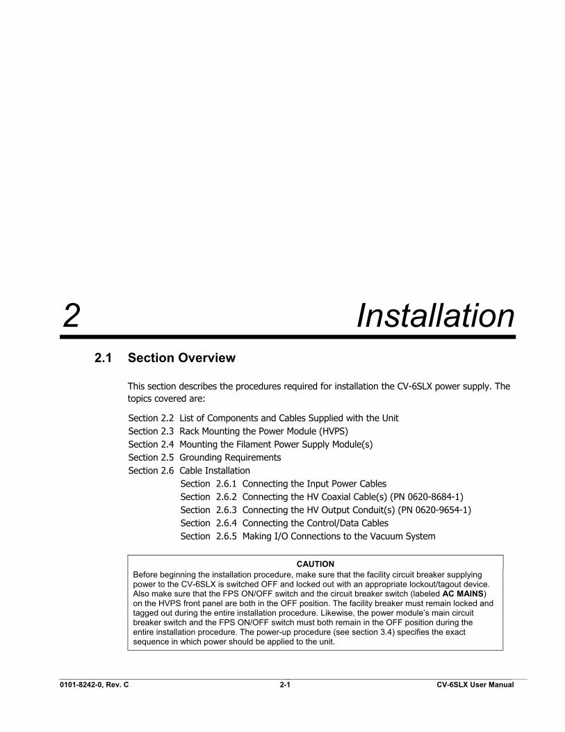
2 Installation 2.1 Section Overview
This section describes the procedures required for installation the CV-6SLX power supply. The topics covered are:
Section 2.2 List of Components and Cables Supplied with the Unit Section 2.3 Rack Mounting the Power Module (HVPS) Section 2.4 Mounting the Filament Power Supply Module(s) Section 2.5 Grounding Requirements Section 2.6 Cable Installation Section 2.6.1 Connecting the Input Power Cables Section 2.6.2 Connecting the HV Coaxial Cable(s) (PN 0620-8684-1) Section 2.6.3 Connecting the HV Output Conduit(s) (PN 0620-9654-1) Section 2.6.4 Connecting the Control/Data Cables Section 2.6.5 Making I/O Connections to the Vacuum System
CAUTION Before beginning the installation procedure, make sure that the facility circuit breaker supplying power to the CV-6SLX is switched OFF and locked out with an appropriate lockout/tagout device. Also make sure that the FPS ON/OFF switch and the circuit breaker switch (labeled AC MAINS) on the HVPS front panel are both in the OFF position. The facility breaker must remain locked and tagged out during the entire installation procedure. Likewise, the power module’s main circuit breaker switch and the FPS ON/OFF switch must both remain in the OFF position during the entire installation procedure. The power-up procedure (see section 3.4) specifies the exact sequence in which power should be applied to the unit.

2.2 List of Components and Cables Supplied with the Unit Section 2: Installation
CV-6SLX User Manual 0101-8242-0, Rev. C 2-2
2.2 List of Components and Cables Supplied with the Unit
Listed below are the components and cables supplied with CV-6SLX units.
• CV-6SLX HVPS, PN 0620-1135-0 (for 208-volt units) or 0620-1135-1 (for 400-volt units) • Filament power supply, PN 0620-6604-0 or 0620-6604-2 • FPS input power cable, PN 6622-0100-20 • Terminal connector (PN 6149-1967-485) for user-supplied HVPS input power cable • HVPS-FPS cable, PN 0620-6672-0 • HVPS I/O cable, PN 0620-6682-0 • FPS I/O cable, PN 0620-6672-2 • HV coaxial cable, PN 0620-8684-1 • HV cable/conduit assembly, PN 0620-9654-1 • Bracket (PN 0040-9982-0) for securing HV conduit to source tray • 16” grounding hook, PN 9900-4864-0 • 20’ coil of 3”-wide copper strap, PN 5621-0032-3 • Coil of ½”-wide copper strap, PN 5621-0032-0 • One copy of CV-6SLX Technical manual
2.3 Rack Mounting the Power Module (HVPS)
2.3.1 General Installation Guidelines
The CV-6SLX HVPS can be rack mounted in a standard 19" rack cabinet. It must be supported by two side shelf supports to hold the power supply weight. The rack vertical height required is 8-3/4 inches. The chassis depth is 23 inches. An additional 3" is required for clearance of terminals, plugs, and wiring. The panel should be secured to the rack cabinet by the four mounting holes provided.
DANGER: HIGH VOLTAGE Removal of the HVPS top cover can expose personnel to dangerous or lethal voltages. Particular care should be taken regarding high voltage, which can arc over a considerable distance. It is not necessary to be in physical contact with a live terminal in order for an arc to send a lethal high-voltage discharge through a person’s body.
The HVPS is designed to be installed in an indoor laboratory or clean room in which the immediate environment is controlled to maintain an ambient temperature of 40° C or lower and a noncondensing humidity level of 10%-90%. Together, the screen covering the front panel air vent plus the screen sandwiched between the exhaust fan and the rear panel provides IP40 ingress protection. These screens prevent solid foreign objects larger than 1 mm in diameter from penetrating the outside chassis but do not provide a barrier against liquids. Both screens must be removed and cleaned whenever the fan airflow drops more than 15% from its original value or every two years, whichever comes first. The power module does not require any routine maintenance, aside from the cleaning of the screens.
2.3.2 Air Flow Requirements
The inverters have a temperature sensor that will shut down and latch out further operation if an overtemperature condition should occur. The customer must ensure a free flow of air is

Section 2: Installation 2.4 Mounting the Filament Power Supply Module(s)
0101-8242-0, Rev. C 2-3 CV-6SLX User Manual
maintained through the cabinet and keep the ambient air temperature at the input to the power supply below 104° F (40° C). All air passages must be unobstructed. If air filters are used on the cabinet air input, they should be checked on a regular schedule for dirt and dust accumulation.
CAUTION Cabinet doors and panels must not block air vents located on the unit’s front and rear panels, providing at least 2” of clearance from these vents. A fan located on the rear panel pulls air in through the vents on the front panel, and exhausts warmer air through the rear vent.
2.4 Mounting the Filament Power Supply Module(s)
Install the FPS module(s) in the vacuum cubicle, within 6 feet of the high-voltage feedthoughs that supply power to the e-beam gun. To do so, first drill four holes at the installation location, in the pattern shown in Figure 2-1. Then place the holes in the bottom of the FPS module over the drilled holes and secure the FPS in place with the hardware provided.
DANGER: HIGH VOLTAGE Removal of any of the covers on the FPS module can expose personnel to dangerous or lethal voltages. Particular care should be taken regarding high voltage, which can arc over a considerable distance. It is not necessary to be in physical contact with a live terminal in order for an arc to send a lethal high-voltage discharge through a person’s body.
Figure 2-1 Mounting Hole Pattern for FPS Module(s)
2.5 Grounding Requirements
2.5.1 Facility Low-Impedance Grounding Requirements
Safe, dependable operation of the power supply cannot be ensured unless a good earth ground is provided for the system and the power supply. This ground must provide a low-impedance path for radio frequency (RF) as well as direct current (dc) electricity, and it must not be connected to that of any other system or equipment. Figure 2-2 shows two different methods of providing the required low-impedance ground on the facility side of the installation.

2.5 Grounding Requirements Section 2: Installation
CV-6SLX User Manual 0101-8242-0, Rev. C 2-4
Figure 2-2 Facility Low Impedance Grounding Requirements
The installation of twin rods of copper-clad steel is preferred. However, if the equipment is to be installed on the upper floors of a building, the system can be grounded by connecting the vacuum chamber to the steel structure of the building. Where copper straps are attached to frame members, the copper must be bolted to clean, bare patches of metal. The length of copper strap connected to the source tray must be securely bolted to a clean site on that part.
CAUTION Do not use braided wire for any ground connections.
CAUTION Do not rely on water pipes to establish the system ground connection. Multiple plumbing joints, each with tape and/or sealing compounds, make such a ground unreliable.

Section 2: Installation 2.5 Grounding Requirements
0101-8242-0, Rev. C 2-5 CV-6SLX User Manual
2.5.2 System Low-Impedance Grounding
Within the vacuum system, the low-impedance ground is provided by 3”-wide and 1/2”-wide copper straps. As Figure 2-3 shows, these straps must connect:
• the grounding stud labeled RF GND on the power module’s rear panel (see Figure 2-4) to a grounding point on the frame of the operator station
• the operator station’s grounding point to the vacuum cubicle’s central grounding point • the grounding stud labeled RF GND on the FPS front panel (see Figure 2-5) to the vacuum
cubicle’s main grounding point • the source tray to the vacuum cubicle’s main grounding point.
Figure 2-3 System Low Impedance Grounding Requirements
2.5.3 Power Module Grounding
Make connections to the power supply’s grounding lugs as shown in the CV-6SLX Quick Start Guide (PN 0101-8241-1), following the procedure described below.
Step Action 1 A roll of 1/2”-wide copper strap (PN 5621-0032-0) is supplied with
the unit. Cut off a length of this strap that will easily extend from the grounding lugs on the power module’s rear panel to the operator station’s frame.

2.5 Grounding Requirements Section 2: Installation
CV-6SLX User Manual 0101-8242-0, Rev. C 2-6
2 Secure one end of this strap to the grounding stud labeled RF GND on the power module’s rear panel (see Figure 2-4).
Figure 2-4 Rear Panel of CV-6SLX HVPS
3 Secure a length of #10 AWG wire to the grounding lug labeled GND on the power module rear panel.
4 Secure the loose end of the 1/2” copper strip and the loose end of the #10 AWG ground wire to a clear, bare patch of metal on the operator station’s frame. The same fastener that secures the above copper strip to the frame should also secure one end of a length of 3” copper strap that connects to the vacuum cubicle’s central grounding point, as shown in Figure 2-3.
2.5.4 Filament Power Supply Grounding
Make connections to the grounding lugs on the FPS front panel as shown in in the CV-6SLX Quick Start Guide (PN 0101-8241-1), following the procedure described below.
Step Action 1 Cut a length of 1/2”-wide copper strap (user-supplied) that will
easily extend from the filament power supply to the vacuum cubicle’s central grounding point.
2 Secure one end of this strap to the grounding stud labeled RF GND on the FPS front panel (see Figure 2-5).

Section 2: Installation 2.6 Cable Installation
0101-8242-0, Rev. C 2-7 CV-6SLX User Manual
Figure 2-5 Grounding Studs on FPS Front Panel
3 Secure a length of #10 AWG wire to the other grounding lug on the FPS front panel.
4 Secure the free ends of the 1/2” copper strip and the #10 AWG ground wire to the vacuum cubicle’s central grounding point.
2.5.5 Electron Beam Source Ground
To ensure a good ground between the electron beam source and the vacuum cubicle, the following conditions must be met:
• The base of the source and the surface on which it is mounted (usually the upper surface of the source tray) must be clean and free of evaporated material.
• The mounting surface must be made of nonmagnetic material. • The source must be securely bolted to the mounting surface.
2.5.6 Mounting the Grounding Hook
If your are installing the CV-SLX unit in a system that does not already have a properly mounted grounding hook, install the grounding hook provided with the power supply in the vacuum cubicle, attaching its pigtail to the vacuum cubicle’s central grounding point and the grounding hook’s storage bracket at a convenient location nearby.
2.6 Cable Installation
For an illustration of cabling details, refer to the CV-6SLX Quick Start Guide (0101-8241-1). For detailed instructions on connecting the cables shown in this diagram, see sections 2.6.1 through 2.6.5.
Chassis Ground. Connect to vacuum cubicle’s central gounding point, using #10 AWG wire.
RF Ground. Connect to vacuum cubicle’s central gounding point, using 1/2”-wide copper strap (PN 5621-0032-0).

2.6 Cable Installation Section 2: Installation
CV-6SLX User Manual 0101-8242-0, Rev. C 2-8
2.6.1 Connecting the Input Power Cables
Connecting the Power Module Input Power Cable
CAUTION Make sure that the main power breaker on the HVPS front panel is in the OFF position and remains in that position throughout the installation procedure.
The CV-6SLX is available for the following input voltages:
• 208-V Model CV-6SLX (PN 6024-7110-0), 50/60 Hz, 3-Phase delta, 4-wire Connect using AWG #10 stranded UL1015 wire
• 400-V Model CV-6SLX (PN 6024-7120-0), 50/60 Hz, 3-Phase wye, 5-Wire with neutral Connect using AWG #12 stranded UL1015 wire
The input power cable is user supplied and must conform to the specifications listed above. On 208-volt units, connect the input power cable as shown in Figure 2-6. On 400-volt units, connect the input power cable as shown in Figure 2-7. Then plug the input power terminal connector into the terminal strip on the HVPS rear panel and secure it with the screws provided for that purpose.
Figure 2-6 Input Power Connections to 208-Volt HVPS Units
Figure 2-7 Input Power Connections to 400-Volt HVPS Units
Section 2: Installation 2.6 Cable Installation
0101-8242-0, Rev. C 2-9 CV-6SLX User Manual
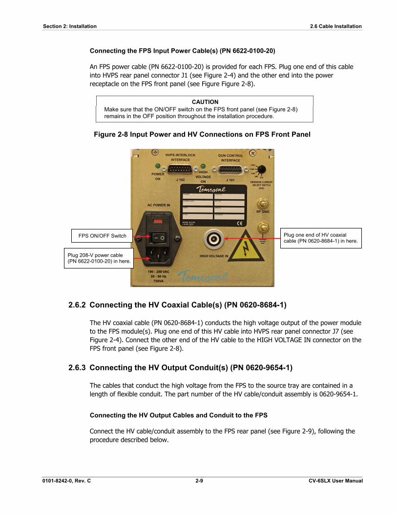
Connecting the FPS Input Power Cable(s) (PN 6622-0100-20)
An FPS power cable (PN 6622-0100-20) is provided for each FPS. Plug one end of this cable into HVPS rear panel connector J1 (see Figure 2-4) and the other end into the power receptacle on the FPS front panel (see Figure Figure 2-8).
CAUTION Make sure that the ON/OFF switch on the FPS front panel (see Figure 2-8) remains in the OFF position throughout the installation procedure.
Figure 2-8 Input Power and HV Connections on FPS Front Panel
2.6.2 Connecting the HV Coaxial Cable(s) (PN 0620-8684-1)
The HV coaxial cable (PN 0620-8684-1) conducts the high voltage output of the power module to the FPS module(s). Plug one end of this HV cable into HVPS rear panel connector J7 (see Figure 2-4). Connect the other end of the HV cable to the HIGH VOLTAGE IN connector on the FPS front panel (see Figure 2-8).
2.6.3 Connecting the HV Output Conduit(s) (PN 0620-9654-1)
The cables that conduct the high voltage from the FPS to the source tray are contained in a length of flexible conduit. The part number of the HV cable/conduit assembly is 0620-9654-1.
Connecting the HV Output Cables and Conduit to the FPS
Connect the HV cable/conduit assembly to the FPS rear panel (see Figure 2-9), following the procedure described below.
Plug 208-V power cable (PN 6622-0100-20) in here.
Plug one end of HV coaxial cable (PN 0620-8684-1) in here.
FPS ON/OFF Switch

2.6 Cable Installation Section 2: Installation
CV-6SLX User Manual 0101-8242-0, Rev. C 2-10
Step Action 1 Remove four screws that secure the conduit panel to the FPS rear
panel, as shown below.
Figure 2-9 Removing the FPS Conduit Panel
2 Insert the threaded end of the conduit elbow into the hole in the conduit panel and secure the elbow with the nut provided, as shown in Figure 2-10.
Figure 2-10 Conduit Properly Secured to FPS Conduit Panel
3 Figure 2-11 shows the FPS with its conduit panel removed and with the lugs on the ends of the HV cables properly secured to the studs inside the FPS unit.
Figure 2-11 HV Output Cables Secured to Studs inside FPS

Section 2: Installation 2.6 Cable Installation
0101-8242-0, Rev. C 2-11 CV-6SLX User Manual
4 Replace the conduit panel, taking care to secure it in place with all four screws.
Connecting the HV Ouput Cables and Conduit at the Source Tray
Connect the other end of the HV output cables to the HV feedthroughs in the source tray, following the instructions provided below.
CAUTION If the vacuum system has previously been in use with a high-voltage power supply, then before performing this procedure, touch the source tray and the terminals on both HV feedthroughs with a properly connected grounding hook.
Step Action 1 Remove the nut that secures one of the feedthroughs to the
underside of the source tray.
2 Install the HV conduit bracket (PN 0040-9982-0) supplied with the unit and secure it with the nut removed in Step 1, as shown in Figure 2-12.
Figure 2-12 HV Conduit Bracket Properly Installed on HV Feedthrough
3 Using the nut supplied with the conduit, secure the conduit to the bracket as shown in Figure 2-13.
Figure 2-13 HV Conduit Properly Secured to Bracket

2.6 Cable Installation Section 2: Installation
CV-6SLX User Manual 0101-8242-0, Rev. C 2-12
4 Secure the lugs on the ends of the HV cables to the feedthroughs, as shown in Figure 2-12. Either cable can be connected to either feedthrough, as polarity is not an issue.
2.6.4 Connecting the Control/Data Cables
This section provides detailed instructions for connecting the unit’s control/data cables:
• the HVPS-FPS cable, PN 0620-6672-0 • the HVPS I/O cable, PN 0620-6682-0 • the FPS I/O cable, PN 0620-6672-2
Step Action 1 Plug the male end of the HVPS-FPS cable (PN 0620-6672-0) into
connector J5 on the power module rear panel (see Figure 2-4).
2 Plug the female end of the HVPS-FPS cable for Gun #1 into connector J102 on the FPS front panel (see Figure 2-14).
Figure 2-14 Control/Data Cable Connections on FPS Front Panel
3 Plug the male end of the same HVPS I/O cable (PN 0620-6682-0) into HVPS rear panel connector J4 (see Figure 2-4).
4 Plug the male end of the FPS I/O cable (PN 0620-6672-2) into connector J101 on the FPS front panel (see Figure 2-14).
5 Make the I/O connections to the control system, as described in section 2.6.5.
Connect HVPS-FPS cable (PN 0620-6672-0) to J102.
Connect FPS I/O cable (PN 0620-6672-2) to J101.

Section 2: Installation 2.6 Cable Installation
0101-8242-0, Rev. C 2-13 CV-6SLX User Manual
2.6.5 Making I/O Connections to the Vacuum System
NOTE Before performing this portion of the installation, complete the mandatory baseline test described in Section III of document 0101-8241-1, the CV-6SLX Quick Start Guide.
The installer must make connections (1) between the vacuum system and the HVPS I/O cable (PN 0620-6682-0) and (2) between the vacuum system and the FPS I/O cable (PN 0620-6672-2). Control inputs and status outputs include both digital and analog signals. Digital inputs require a simple contact closure and carry 24 V dc at approximately 20 mA. All digital outputs are +24 V dc sourcing a maximum of 50 mA. For detailed information about I/Os exchanged via the HVPS I/O cable, see Figure 2-15 and Table 2-1. For details about I/Os exchanged via the FPS I/O cable, see Figure 2-16 and Table 2-2.
When making I/O connections to the HVPS I/O cable, use either the optional 25-pin interface module available from Temescal (PN 6149-2293-637) or a comparable interface module. When making I/O connections to the FPS I/O cable, use either the optional 15-pin interface module available from Temescal (PN 6149-2293-624) or a comparable interface module.

2.6 Cable Installation Section 2: Installation
CV-6SLX User Manual 0101-8242-0, Rev. C 2-14
Figure 2-15 System I/Os Exchanged via HVPS Rear Panel Connector J4 and the HVPS I/O Cable (PN 0620-6682-0)
NOTE Because the interlock string is internally supplied with 24 V dc, only contact closure must be supplied by the vacuum system. Care must be taken not to allow voltages from other sources to affect the external interlock loop, as safety could thereby be compromised. In addition, the application of additional voltage sources to the interlock circuit will damage it.

Section 2: Installation 2.6 Cable Installation
0101-8242-0, Rev. C 2-15 CV-6SLX User Manual
Table 2-1 Descriptions of I/Os Exchanged via HVPS Rear Panel Connector J4 and the HVPS I/O Cable (PN 0620-6682-0)
Signal Name Pin I/O Type Description
KV SET IN 1 Analog input
HV adjustment input, 0-10 V dc = 0-10 KV. Controls high voltage if Pin 5 is high, in which case the HVPS front panel OUTPUT kV ADJUST pot is disabled.
ANALOG COMMON 2 Analog common
Common for KV MONITOR OUT and mA MONITOR OUT outputs (see Pins 3 and 4), if used. Connect to vacuum system ground.
KV MONITOR OUT 3 Analog output
High voltage monitor output, linear (0-10 V dc = 0-10 kV).
mA MONITOR OUT 4 Analog output
Emission current monitor output., linear. Scaling is factory set (0-10 V dc = 0-1500 mA).
REMOTE/LOCAL IN 5 Digital input
Selects either remote or local HV control. If high, (i.e., if +24 V dc is supplied), then 0-10 dc input via Pin 1 controls HV exclusively. If low, then HVPS front panel OUTPUT kV ADJUST pot exclusively controls the high voltage.
I/O SWITCHES POWER 6 DC voltage + 24 V dc output, fused at 1 A. Can be used to supply Pin 5, if remote HV control via Pin 1 is desired. NOTE: To be used only for power supply control; do NOT use this voltage to drive any external device.
DIGITAL COMMON 7 Digital common
Common for digital indicator signals output via Pins 12, 13, 14, 15, and 16, if any of them are used.
HV ON IN + 8 Digital input
Controlled by a normally open external switch. If HV OFF IN + is high, then a momentary contact closure between Pins 8 and 9 switches the high voltage ON.
HV ON IN – 9 DC voltage + 15 dc output supplied to Pin 8 via a normally open switch.
RESET + 10 Digital input
Controlled by a normally open external switch. If the POWER SUPPLY FAULT INDICATOR output (Pin 13) is true, then a momentary contact closure between Pins 10 and 11 resets the HVPS.
RESET – 11 DC voltage + 24 dc output supplied Pin 10 via a normally open switch controlling.
HV IS ON INDICATOR 12 Digital output
When high (+24 V dc), this output indicates that the high voltage is ON.
POWER SUPPLY FAULT INDICATOR
13 Digital output
When high, this output indicates that a latching power supply fault has occurred. For additional details about latching PS faults, see section 5.2.
HV READY INDICATOR 14 Digital output
When high, this output indicates that the HV can be switched on. This indicator is high when the HV OFF IN+ input supplied via Pin 17 is high.
OUT OF REGULATION INDICATOR
15 Digital output
High whenever the HVPS front panel HV OUT OF REGULATION LED is lit. For additional details about that LED, see section 5.2.
INTERLOCK OK INDICATOR 16 Digital output
High when all interlocks are made, so that the REMOTE INTERLOCK IN input (Pin 24) is high.
HV OFF IN+ 17 Digital input
Controlled by a normally closed external switch. This input is high when the HV is OFF and when no latching power supply faults exist. When the HV is ON, then momentary opening of the external contact closure between Pins 17 and 18 switches off the HV.
HV OFF IN– 18 DC voltage + 15 dc output supplied to Pin 17 via a normally closed switch.
REMOTE INTERLOCKS IN 24 Digital input
High when the external interlock string is made; connect to Pin 24 via external interlock switches.
REMOTE INTERLOCKS OUT 25 DC voltage + 24 dc output, fused at 0.2 A and supplied to Pin 24 via external interlock switches. NOTE: Minimum external interlocks required are WATER (= e-beam gun’s water-flow switch is true), DOORS (= all vacuum cubicle doors are closed), and VACUUM (= vacuum system is pumped down to crossover point). If e-beam position is controlled by a beam sweep controller, a POSITION interlock signal from that component must also be true. NOTE: Within the HVPS, the external interlock string is connected in series with the internal interlocks for the HVPS and FPS covers.

2.6 Cable Installation Section 2: Installation
CV-6SLX User Manual 0101-8242-0, Rev. C 2-16
Figure 2-16 System I/Os Exchanged via FPS Front Panel Connector J101 and the FPS I/O Cable (PN 0620-6672-2)
NOTE: DEPOSITION CONTROLLER INPUT On the CV-6SLX power supply, the polarity of the emission current request input (J101 Pin 10) must be positive. Reversal of this input’s polarity may result in damage to the power supply.
Section 2: Installation 2.6 Cable Installation
0101-8242-0, Rev. C 2-17 CV-6SLX User Manual
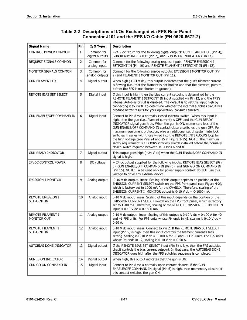
Table 2-2 Descriptions of I/Os Exchanged via FPS Rear Panel Connector J101 and the FPS I/O Cable (PN 0620-6672-2)
Signal Name Pin I/O Type Description
CONTROL POWER COMMON 1 Common for digital outputs
+24 V dc return for the following digital outputs: GUN FILAMENT OK (Pin 4), GUN READY INDICATOR (Pin 7), and GUN IS ON INDICATOR (Pin 14).
REQUEST SIGNALS COMMON 2 Common for analog inputs
Common for the following analog request inputs: REMOTE EMISSION I SETPOINT IN (Pin 10) and REMOTE FILAMENT I SETPOINT IN (Pin 12).
MONITOR SIGNALS COMMON 3 Common for analog outputs
Common for the following analog outputs: EMISSION I MONITOR OUT (Pin 9) and FILAMENT I MONITOR OUT (Pin 11).
GUN FILAMENT OK 4 Digital output When high (+ 24 V dc), this output indicates that the gun’s filament current is flowing (i.e., that the filament is not broken and that the electrical path to it from the FPS is not shorted to ground).
REMOTE BIAS SET SELECT 5 Digital input If this input is high, then the bias current setpoint is determined by the REMOTE FILAMENT I SETPOINT IN input supplied via Pin 12, and the FPS’s internal Autobias circuit is disabled. The default is to set this input high by connecting it to Pin 8. To determine whether the internal autobias circuit will produce better results for your application, consult Temescal.
GUN ENABLE/OFF COMMAND IN 6 Digital input Connect to Pin 8 via a normally closed external switch. When this input is high, then the gun (i.e., filament current) is OFF, and the GUN READY INDICATOR signal goes true. When the gun is ON, momentary loss of the GUN ENABLE/OFF COMMAND IN contact closure switches the gun OFF. For maximum equipment protection, wire an additional set of system interlock switches in series with those wired into the REMOTE INTERLOCKS loop for the high voltage (see Pins 24 and 25 in Figure 2-15). NOTE: The minimum safety requirement is a DOORS interlock switch installed before the normally closed switch required between J101 Pins 6 and 8.
GUN READY INDICATOR 7 Digital output This output goes high (+24 V dc) when the GUN ENABLE/OFF COMMAND IN signal is high.
24VDC CONTROL POWER 8 DC voltage + 24 dc output supplied for the following inputs: REMOTE BIAS SELECT (Pin 5), GUN ENABLE/OFF COMMAND IN (Pin 6), and GUN GO ON COMMAND IN (Pin 15). NOTE: To be used only for power supply control; do NOT use this voltage to drive any external device.
EMISSION I MONITOR 9 Analog output 0-10 V dc output, linear. Scaling of this output depends on position of the EMISSION CURRENT SELECT switch on the FPS front panel (see Figure 4-2), which is factory set to 1000 mA for the CV-6SLX. Therefore, scaling of the EMISSION CURRENT I MONITOR output is 0-10 V dc = 0-1000 mA.
REMOTE EMISSION I SETPOINT IN
10 Analog input 0-10 V dc input, linear. Scaling of this input depends on the position of the EMISSION CURRENT SELECT switch on the FPS front panel, which is factory set to 1500 mA. Therefore, scaling of the REMOTE EMISSION I SETPOINT IN input is 0-10 V dc = 0-1500 mA.
REMOTE FILAMENT I MONITOR OUT
11 Analog output 0-10 V dc output, linear. Scaling of this output is 0-10 V dc = 0-100 A for –0 and –1 FPS units. For FPS units whose PN ends in –2, scaling is 0-10 V dc = 0-50 A.
REMOTE FILAMENT I SETPOINT IN
12 Analog input 0-10 V dc input, linear. Connect to Pin 2. If the REMOTE BIAS SET SELECT input (Pin 5) is high, then this input controls the filament current’s bias setting. Scaling is 0-10 V dc = 0-100 A for –0 and –1 FPS units. For FPS units whose PN ends in –2, scaling is 0-10 V dc = 0-50 A.
AUTOBIAS DONE INDICATOR 13 Digital output If the REMOTE BIAS SET SELECT input (Pin 5) is low, then the FPS autobias circuit controls the bias current setpoint. In that case, the AUTOBIAS DONE INDICATOR goes high after the FPS autobias sequence is completed.
GUN IS ON INDICATOR 14 Digital output When high, this output indicates that the gun is ON.
GUN GO ON COMMAND IN 15 Digital input Connect to Pin 8 via a normally open contact closure. If the GUN ENABLE/OFF COMMAND IN signal (Pin 6) is high, then momentary closure of this contact switches the gun ON.

2.6 Cable Installation Section 2: Installation
CV-6SLX User Manual 0101-8242-0, Rev. C 2-18

0101-8242-0, Rev. C 3-1 CV-6SLX User Manual
3 Power Supply Operation 3.1 Section Overview
This section covers the following topics:
Section 3.2 HVPS Front Panel Controls and Indicators Section 3.3 Switches and LEDs on the FPS Front Panel Section 3.4 Power-Up Procedure Section 3.5 Control of Power Supply from TemEBeam EBC Integrated Controller Section 3.6 Control of Power Supply by a PLC-Based System Controller Section 3.7 Responding to Latching Power Supply Faults
3.2 HVPS Front Panel Controls and Indicators
Figure 3-1 shows the controls and indicators on the front panel of the CV-6SLX HVPS. Those features are described in detail below.
Figure 3-1 CV-6SLX HVPS Front Panel
3.2.1 HVPS Front Panel Controls
Main Circuit Breaker Switch (Labeled AC MAINS) High-Voltage Adjustment Pot (labeled ADJUST) HV OFF Button. This button is always active when the HVPS is powered up. Note that pushing it when the HV is on switches it off, and pushing it when the HV is off due to a latched fault condition resets the power supply.
Status and Fault Indicator LEDs
HV Adjustment Pot
Main Power Breaker
HV OFF Button
High Voltage Meter
Emission Current Meter

3.3 Switches and LEDs on the FPS Front Panel Section 3: Power Supply Operation
CV-6SLX User Manual 0101-8242-0, Rev. C 3-2
3.2.2 HVPS Front Panel Indicators
Display Meters
• Output Voltage meter (0–10 kV) • Emission Current meter (0–600 mA)
Status LEDs
• Power ON LED. Turns green to indicate that the HVPS is powered up. • HV ON LED. Lights yellow when HVPS is powered up but HV is OFF. Turns green when the
HV is switched on.
Fault Indicator LEDs
For detailed information about fault indicator LEDs, see sections 5.2.2 and 5.2.3.
3.3 Switches and LEDs on the FPS Front Panel
Figure 3-2 shows the switches and LEDs on the FPS front panel.
Figure 3-2 Filament Power Supply Front Panel
The switches and indicators on the FPS front panel are:
• Power ON/Off switch: Must be switched ON in order for unit to operate. • POWER ON LED: When lit, indicates that the HVPS and the FPS are both powered up.
Power ON/OFF Switch
HIGH VOLTAGE ON LED Emission Current Selection Switch
POWER ON LED

Section 3: Power Supply Operation 3.4 Power-Up Procedure
0101-8242-0, Rev. C 3-3 CV-6SLX User Manual
• HIGH VOLTAGE ON LED: Lights when the HV IS ON signal from the HVPS is high.
• EMISSION CURRENT SELECTION SWITCH: Position of this switch determines scaling of remote emission current request inputs and monitoring outputs. A black plastic cap normally covers this switch, which is factory set and should require no further attention. Figure 3-2 shows the switch set to the 300-mA position. However, for the CV-6SLX, its default setting is 1000, which means that scaling of the emission current request input and monitoring outputs is 0-10 V dc = 0-1000 mA.
3.4 Power-Up Procedure
Follow the procedure described below when powering up the unit when it has been powered down and lock/tagged out at the facility breaker (e.g., for maintenance).
Step Action 1 If you are powering up the power supply following a maintenance
procedure, remove the lockout/tagout device from the facility circuit breaker supplying power to the CV-6SLX. If not, proceed to Step 2.
1 Set the facility breaker switch to the ON position.
2 Set the circuit breaker switch (labeled AC MAINS) on the power module front panel to the ON position.
3 Set the FPS ON/OFF switch (see Figure 3-2) to the ON position.
Follow the operating instructions provided below to switch on and to adjust the HV, the filament bias current, and the emission current.
3.5 Control of Power Supply from TemEBeam EBC Integrated Controller
3.5.1 Overview of the EBC’s Operations>E-Beam Screen
If your system is equipped with a TemEBeam controller (EBC), you can use the E-BEAM button on its touch screen (see Figure 3-3) to switch the beam on and off. The HV ON and Gun ON buttons on the Operations>E-Beam screen allow you to switch the HV and gun on/off independently of each other. Note that if kV Control is set to Input Ctrl on the EBC’s Config>E-Beam screen, then the kV Set button on the Operations>E-Beam screen allows the user to change the HV operating level from the default setting (10.0 kV). If kV Control is set to Pot Ctrl, then the kV Set button becomes a flat display rectangle like those labeled Emission and Filament, which indicate emission and filament current, respectively.

3.5 Control of Power Supply from TemEBeam EBC Integrated Controller Section 3: Power Supply Operation
CV-6SLX User Manual 0101-8242-0, Rev. C 3-4
Figure 3-3 EBC’s Operations>E-Beam Screen when Beam Is Off
3.5.2 Using the E-BEAM ON/OFF Button to Switch the Beam On/Off
As noted above, when the beam is off you can switch it on by simply touching the E-BEAM button, assuming that you have already entered a nonzero percent-power setpoint. This applies when both HV and gun are off, when the HV alone is on, and when the gun alone is on. Touching the E-BEAM button when the beam is on switches the HV and the gun off. Figure 3-4 shows the Operations>E-Beam screen when the beam is on.
Figure 3-4 Operations>E-Beam Screen, Beam On at 0.0 mA
3.5.3 Switching on the HV and Gun Independently of Each Other
Figure 3-5 shows the Operations E-Beam screen when the gun is on but the HV is off. To switch the HV on/off independently of the gun, simply touch the HV ON button,. Likewise, to switch the gun on/off independently of the HV, touch the GUN ON button. You can also switch on the beam by touching the HV ON and GUN ON buttons in either order.

Section 3: Power Supply Operation 3.5 Control of Power Supply from TemEBeam EBC Integrated Controller
0101-8242-0, Rev. C 3-5 CV-6SLX User Manual
Figure 3-5 Operations>E-Beam Screen when Gun is On and HV is Off
3.5.4 Setting the Beam Power Level
To set the beam power level, first touch the Change button, then touch the E-Beam button. The EBC will then display a keypad screen, which you can use to enter a percent-power setpoint. After you do so and touch Enter to close the keypad, the power supply will ramp up to that power setpoint. In Figure 3-6, the user has used the keypad to enter 5. Figure 3-7 shows the Ops>E-Beam screen after the user has closed the numeric keypad, with the beam now operating at 5% power (= 75 mA). Note that the beam power level can be set or changed either with beam on or with it off.
Figure 3-6 Operations E-Beam Screen with Numeric Keypad Displayed

3.5 Control of Power Supply from TemEBeam EBC Integrated Controller Section 3: Power Supply Operation
CV-6SLX User Manual 0101-8242-0, Rev. C 3-6
Figure 3-7 Operations>E-Beam Screen, Beam on at 5% Power
3.5.5 Changing the HV Operating Level
If kV Control is set to Input Ctrl on the EBC’s Config>E-Beam screen, you can change the operating voltage of the HVPS at any time, regardless of whether the HV is on or off. To change the kV value:
Step Action 1 Touch the rectangle labeled kV Set to open a numeric keypad.
2 Use the keypad to enter the desired kV value.
3 Touch the keypad’s Enter button to close it.
If the HV is on when you perform this procedure, the HVPS will begin operating at the new kV value as soon as you touch the OK button. If the button is off, the HV will begin operating at the new value the next time it is switched on.
3.5.6 Using the EBC’s Diagnostics Screen
The EBC’s Diagnostics screen (see Figure 3-7) enables you to monitor the operating status of the power supply from the EBC screen. Functional definitions of this screen’s PS-related LED indicators appear below the screen illustration.
Figure 3-8 The EBC’s Diagnostics Screen

Section 3: Power Supply Operation 3.5 Control of Power Supply from TemEBeam EBC Integrated Controller
0101-8242-0, Rev. C 3-7 CV-6SLX User Manual
Functional Definitions of PS-Related LED Indicators on the Diagnostics Screen
Except where noted, the indicators on this screen are gray (off) when the signal in question is false and green when it is true.
High Voltage Section
• Interlock LED: Status of the HV interlock input from the HVPS
• HV Ready LED: Status of the HV READY input from the HVPS
• HV is ON LED: Status of the IS ON input from the HVPS
• Fault LED: On systems with CV6-SLX HV power supplies, this LED indicates the status of the HV FAULT input from the HVPS. It is green when that input is false and red when that signal is true, indicating that a latching power supply fault has occurred. For additional information about latching HVPS faults, see section 5.2.
Gun Section
• Is Ready LED: Status of the IS READY input from the FPS
• Is ON LED: Status of the IS ON input from the FPS
• Manual Bias LED: Off (gray) when autobias is selected via the Configuration>E-Beam screen and green when manual bias is selected.
• Auto Bias LED: Green when autobias is selected via the Configuration>E-Beam screen and off (gray) when manual bias is selected.
High Voltage/Gun Interlocks Section
The Tank, Vacuum, Auxiliary, Water, and Position LEDs indicate the state of the corresponding inputs from the HVPS and the FPS, which in turn reflect that state of the external interlock switches that must be made before the gun or HV can be enabled.
3.5.7 Switching the Beam On/Off and Setting Beam Power from the Remote Controller
Figure 3-9 shows how to switch the beam on/off and control beam power from the EBC’s hand-held remote controller.

3.6 Control of Power Supply by a PLC-Based System Controller Section 3: Power Supply Operation
CV-6SLX User Manual 0101-8242-0, Rev. C 3-8
Figure 3-9 Remote Controller’s LOCAL Screen, Menu 1 Selected, Beam and Sweep Off
3.6 Control of Power Supply by a PLC-Based System Controller
3.6.1 Switching Main Power On/Off
To switch on three-phase input power to the power supply, set the HVPS front-panel’s main power breaker to the ON position (i.e., all the way up). To switch off main input power, set the main power breaker to the OFF position (i.e., all the way down).
Press to switch beam On/Off
Joystick. When Pwr Adjust is selected, push up/down to increase/decrease beam power.
Press to select beam power control as the joystick’s function

Section 3: Power Supply Operation 3.6 Control of Power Supply by a PLC-Based System Controller
0101-8242-0, Rev. C 3-9 CV-6SLX User Manual
NOTE The main power breaker on the power module front panel controls power to the filament power supply (FPS) module.
Figure 3-10 shows the HVPS front panel LEDs when the unit is powered up and in its nominal state (i.e., no faults have occurred) but before the HV and the FPS have been switched on.
Figure 3-10 HVPS Front Panel LEDs: HVPS Powered Up in Nominal State, with HV and FPS Off
For additional information about HVPS front panel LEDs, see section 5.2.
3.6.2 High Voltage Control
Switching On the High Voltage Under Normal Operating Conditions
In order for the HV to be switched on, the LEDs on the HVPS front panel must be in the state shown in Figure 3-10. Then the external controller or control system must assert HV ON IN signal for two seconds at Pin 8 of HVPS rear panel connector J4 (see Table 2-1).
Switching On the High Voltage Following a Latching Fault Condition
Switching off the HV by pressing the HV OFF button on the power module front panel triggers a latching Power Supply Fault. In that event, or when any other latching fault has occurred, the following signals must supplied, in the order given below, to switch the HV back on.
NOTE If a Power Supply fault has occurred because of a latching fault condition—and not because the user has pressed the power module’s HV OFF button—the underlying fault that triggered the latching fault must be corrected before the HV can be reset. For detailed information about fault indicator LEDs, see section 5.2. For diagrams illustrating the troubleshooting logic that applies to various fault conditions, see section 5.3. For troubleshooting procedures, see section 5.4.
1. The RESET signal must be supplied via Pins 10 and 11 of HVPS rear panel connector J4 (see Table 2-1). If the RESET attempt is successful, all status and interlock LEDs on the power module should be green, except for HV ON and ARC/OUT OF REGULATION..

3.6 Control of Power Supply by a PLC-Based System Controller Section 3: Power Supply Operation
CV-6SLX User Manual 0101-8242-0, Rev. C 3-10
2. Assuming that the reset attempt is successful, the HV can then be switched on again. On units without a remote controller, the HV ON contact must be supplied via Pins 8 and 9 of HVPS rear panel connector J4 (see Table 2-1).
If this sequence of operations fails to restart the HV, refer to Table 5-5 for troubleshooting instructions.
Adjusting the High Voltage Level
If the REM/LOC IN signal supplied via J4 Pin 5 is low, the operator can adjust the HV by using a screwdriver to turn the OUTPUT KV ADJUST pot on the HVPS front panel (see Figure 3-1). If the REM/LOC IN signal is high, the external control system can adjust the HV by varying the HV SET IN input, which is supplied via Pin 1 of power module rear panel connector J4 (see Table 2-1).
Switching Off the High Voltage
The high voltage is automatically switched off if:
• any internal or external interlock is no longer made • the power supply goes into an HV Out Of Regulation state • a latching Power Supply Fault occurs.
If the REM/LOC IN signal supplied via J4 Pin 5 is low, the operator can switch off the HV by pressing the HV OFF button on the HVPS front panel (see (see Figure 3-1).
If the REM/LOC IN signal is high, the external control system can switch off the high voltage in either of two ways:
1. The control system can momentarily de-assert the HV ON contact supplied via Pins 8-9 of HVPS connector J4 (see Table 2-1).
2. The control system can assert the HV OFF contact supplied via Pin 17-18 of HVPS rear panel connector J3.
3.6.3 Switching the Filament Current On/Off
NOTE In order for the filament current to be switched on, the FPS module’s power cable must be properly connected to a source of 220-V ac power, and the module’s ON/OFF switch must be in the ON position.
Switching On the Filament Current
The gun (i.e., filament current) can be switched on only by an externally supplied GUN GO ON signal, which must be applied via Pin 15 of FPS front panel connector J101 (see Table 2-2). Once HV and gun are both switched on, the emission current will ramp up to requested level after a 10–15 second delay.
Switching Off the Filament Current
In order for the filament current to be switched off, the GUN GO ON IN signal supplied via Pin 15 of FPS front panel connector J101 (see Table 2-2) must be de-asserted.

Section 3: Power Supply Operation 3.7 Responding to Fault Conditions
0101-8242-0, Rev. C 3-11 CV-6SLX User Manual
3.6.4 Adjusting the Filament Bias Current and the Emission Current
Adjusting the Filament Bias Current
The bias current can be adjusted only by varying the FILAMENT CURRENT REQUEST signal, which is supplied Pin 12 on the FPS front panel connector J101 (see Table 2-2).
NOTE When the FIL BIAS SET SELECT signal (supplied via J101 Pin 5) is low, the Autobias circuit of the FPS controls the bias current. When the FIL BIAS SET SELECT signal is high, the operator can control the bias current from the control system’s user interface.
Adjusting the Emission Current
The emission current can be adjusted only by varying the EMISSION CURRENT REQUEST signal, which is supplied via Pin 10 FPS rear panel connector J101 (see Table 2-2).
3.7 Responding to Fault Conditions
3.7.1 Responding to Latching Power Supply Faults
The following signals must be supplied, in the order given below, in order for the HV to be switched back on after a latching Power Supply fault has occurred:
• a RESET signal, supplied either by the user pressing the front panel HV OFF button or by remote input, via Pins 10 and 11 on HVPS rear panel connector J4
• an HV ON input, supplied via HVPS J4 Pins 8 and 9.
The remote HV ON signal can be supplied either from an EBC (see section 3.5) or from a PLC-based system controller. In many cases, it will be necessary to trace and correct the cause of a latching fault before the HV can be switched back on. Then the RESET and HV ON signals must be supplied, as described above. Note that the gun is not automatically switched off when latching Power Supply (i.e., HVPS faults occur) and that FPS faults that cause the gun to be switched off do not cause the HV to be switched off. Section 3.7.2 describes this user-response sequence with respect to a specific latched-fault condition.
For detailed functional descriptions of the front panel LEDs that indicate latching faults, see section 5.2.3. For diagrams illustrating the troubleshooting logic that apply to a various fault conditions, see section 5.3. For detailed troubleshooting procedures, see section 5.4.
3.7.2 Special Note Regarding Arc-Related Fault Conditions
During normal operation, the ART/OUT OF REGULATION LED on the power module front panel will flash intermittently as arcs occur. The flashing will increase in frequency as arcs increase in frequency. Each time it does so, the HV OUT OF REGULATION LED will also turn amber for two seconds. For an illustration of this Subthreshold arcing state, see Figure 3-11.

3.7 Responding to Fault Conditions Section 3: Power Supply Operation
CV-6SLX User Manual 0101-8242-0, Rev. C 3-12
Figure 3-11 HVPS Front Panel LEDs when Subthreshold Arcing is Occurring
If arcing surpasses either a frequency or a time-duration threshold, a latching OUTPUT ARCING fault will occur. (These threshold values are detailed in Figure 5-8.) The OUTPUT ARCING and POWER SUPPLY FAULT LEDs will then light red, while the HV OUT OF REGULATION LED will turn green and the ART/OUT OF REGULATION LED will no longer flash. In addition, the HV ON LED is extinguished, as the fault condition causes the HV to be switched off. This latched-fault state is illustrated in Figure 3-12.
Figure 3-12 HVPS Front Panel LEDs when a Latched OUTPUT ARCING Fault Has Occurred
If the OUTPUT ARCING fault occurred solely because intermittent arcing passed one of the threshold conditions, the HV should come back on as soon as the RESET and HV ON signals are supplied. Out-of-regulation faults arising as a result of other conditions will likely require troubleshooting. To address such cases, see Ishikawa Diagram #11 and Table 5-16.

0101-8242-0, Rev. C 4-1 CV-6SLX User Manual
4 Theory of Operation 4.1 Section Overview
This section provides separate theories of operations for the major modules of the CV-6SLX power supply. Section 4.2 contains a theory of operation for the power module (i.e., HVPS) and section 4.3 covers the FPS in detail.
4.2 Power Module Theory of Operation
4.2.1 Input Power Filtering, Protection, and Distribution
AC line power is connected to the power module through the green connectors below AC Input on the unit’s rear-panel (see Figure 4-1). Line filter LF1 (see Figure 4-2) then performs high-frequency filtering to minimize conductive emissions from the unit and to protect against AC line transients at common levels. The load side of LF1 feeds three-phase circuit breaker CB1 (see Figure 4-2) as well as the J2, the filtered rear-panel IEC auxiliary outlet (see Figure 4-1). Circuit breaker CB1 is mounted to the front panel and shielded from inadvertent operation by a “kick” guard. CB1 provides overcurrent protection for the three AC line phases, and its load side feeds the Inverter board (see Figure 4-2). Rear panel AC outlet J2 is fused at 6.3A by F1 and F2, which are accessible via the rear panel through panel-mounted fuse holders (see Figure 4-1). On 208 VAC units, outlet J2 is connected between phases, while on 400 VAC units it is connected between one phase and neutral. The goal is to maintain the J2’s voltage between 187 VAC and 254 VAC, taking into account the ±10% tolerance range of the voltage supplied to TB1.
Figure 4-1 CV-6SLX HVPS Rear Panel

4.2 Power Module Theory of Operation Section 4: Theory of Operation
CV-6SLX User Manual 0101-8242-0, Rev. C 4-2
Figure 4-2 CV-6SLX HVPS Internal Components Referenced in Section 4.2
Step-Down Transformer T2
HV Output Transformer
HV Regulator Board
PS1: 24 V dc Power Supply
HV Inverter Board
HV Output Board
Line Filter LF1
Front Panel Board
Housing for Rear Panel AC Outlet J2
Terminal Block TB1
Circuit Breaker CB1
Interface Board

Section 4: Theory of Operation 4.2 Power Module Theory of Operation
0101-8242-0, Rev. C 4-3 CV-6SLX User Manual
Two AC line phases from the Inverter board feed the primary of step-down transformer T2 (see Figure 4-2). In 208 VAC units, T2 is wired with jumpers for a 1:1 ratio. In 400 VAC units, it is wired for a 2:1 ratio. T2 powers the AC input of PS1, the +24 VDC auxiliary power supply (see Figure 4-2). The +24 VDC output of PS1 connects back to the Inverter board and provides low-voltage power to the other board assemblies in the power module.
4.2.2 Power Module Grounding
Grounding is provided through two threaded studs mounted on the unit’s rear panel (see Figure 4-1). The grounding stud labeled GND must be connected to an earth ground for safety. The other threaded grounding stud, labeled RF GND, provides a ground return for the HV output and must be properly connected to provide a low-impedance ground (for instructions, see section 2.6). Internally, ground wires are connected together by a ground block mounted to the bottom panel.
4.2.3 Temperature Control
Temperature inputs come from two separate devices, thermostat S2 and IC sensor U1, which are connected to the Inverter board. Thermostat S2 opens when the Inverter board’s heat sink rises above a preset temperature, while U1 generates an analog voltage scaled to the temperature of the heat sink near the Inverter board’s IGBTs. Both sensors feed the over-temperature fault circuitry. Cooling of internal components is provided by +24 VDC fan B1 mounted on the rear panel. The fan draws air in through the front panel grille and exhausts it through the rear of the unit. The fan features an integral jammed-rotor sensor, which is designed to sense when the fan has stopped spinning and to trigger an over-temperature fault in that event.
4.2.4 PCB Functionality
Inverter Board
From the load side of circuit breaker CB1, the three AC line phases are fed to the Inverter board, which converts the 50/60Hz AC line power into high-frequency power. Part of that conversion process involves rectifying the AC input voltage through a three-phase bridge rectifier and employing a “DC link” choke (L1) to smooth the current. This inductor improves the power factor of the power module as seen by the AC power grid. High-speed IGBTs on the Inverter board switch the rectified bus voltage through HV transformer T1 at 25 kHz, thereby converting the intermediate DC power once again into AC power. Other functions performed by the Inverter board are rail capacitor charging, temperature sensing, and monitoring auxiliary power and rail voltage.
HV Rectifier Board
The HV Rectifier board converts the high-frequency, high-voltage output of HV transformer T1 into DC high-voltage power. The Rectifier board also scales the output voltage and current for feedback to the Regulator board’s control circuits.

4.3 FPS Theory of Operation Section 4: Theory of Operation
CV-6SLX User Manual 0101-8242-0, Rev. C 4-4
HV Output Board
The HV Output board provides secondary-tuning capacitance, HV rectification, and voltage and current feedback to the Regulator board. High frequency AC voltage driven on the primary of the HV transformer by the Inverter is transformed by a fixed ratio (15:225) and connected to the input of the HV Output board at J1 and J2.
Regulator Board
The Regulator board performs virtually all logic, control, and analog processing functions. However, its primary function is output voltage control. The board performs this function by comparing the output feedback to the references provided and then feeding the Inverter board’s IGBT gate drives to properly actuate them. DC output voltage is delivered from the Regulator board to the external load through the custom high-voltage “cablewell” connector J1 on the unit’s rear panel. A mating connector and cable for J1 are provided with each power supply.
Interface Board
The Interface board is mounted to the upper left-hand corner of the rear panel. Three D-subminiature connectors on the Interface board connect the remote I/O signals to the Regulator board. J1, a 14-pin D-sub connector (labeled J5 on rear panel), provides the interface to the filament power supply. J2, a 37-pin D-sub connector (labeled J3 on rear panel), provides diagnostic signals to the user’s system. Appendix B provides a pinout table for these signals. J3, a 24-pin D-sub connector (labeled J4 on rear panel), serves as the active control interface for user-supplied I/O signals.
Interface board connector J4 routes all signals on the Interface board to the Regulator board. Since the location of the unit’s top cover interlock switch (which opens its contacts when the top cover has been removed) is adjacent to the Interface PCB, board connector J5 provides the shortest path for the switch’s contacts to the interlock circuitry on the Regulator board.
Display and Control Board
The Display and Control board is sandwiched between the front panel and the Regulator board. The Display and Control board houses and handles signals to/from an HV OFF pushbutton, an output voltage adjustment potentiometer, voltage and current LCD displays, and the unit’s front panel LEDs.
4.3 FPS Theory of Operation
4.3.1 Overview of FPS Operation
The filament power supply module (see Figure 4-3) provides emission current control and measurement, filament power and control, and high-voltage switching. The filament circuit utilizes high-frequency switch mode technology similar to that of the high-voltage circuit. The filament circuit requires single-phase power of approximately 208–230 V.

Section 4: Theory of Operation 4.3 FPS Theory of Operation
0101-8242-0, Rev. C 4-5 CV-6SLX User Manual
Figure 4-3 Filament Power Supply (FPS) Module
Figures 4-4 and 4-6 show the locations of the major components in the standard FPS unit (i.e., with PN 0620-6604-0) and for FPS units with PN 0620-6604-2, respectively. Figures 4-5 and 4-7 are top-level block diagrams for the same units. Primary power enters the FPS via J302 and is routed to the Filament Supply PCB. The FPS consists of two major functional sections, the Filament Supply PCB and the Filament Output section. The Filament Supply Board supplies and controls the filament power. The filament output section combines the filament power with the negative HV from the power module and routes the combination to the filament. As Figure 4-5 shows, the Filament Output section on standard FPS units consists of an HV vacuum relay and a filament transformer. On FPS units with PN 0620-6604-2, the Filament Output section consists only of a filament transformer (see Figure 4-7). Section 4.3.4 describes the Filament output section in greater detail.
4.3.2 Safety Interlocks
The safety interlocks insure that circuits are safely connected and that the box is closed before operation can continue. Safety interlocks are provided by switches S101 and S102 in the filament output section of the FPS. These interlocks are routed to the Filament Supply PCB via J103 pins 3 and 4 and are connected in series with the cover interlocks on the CV-6SLX power module. Therefore, in order for FPS operation to take place, the FPS covers and the power module covers must be in place, closing the interlock switches, and the FPS cover interlock switches must be connected to the Filament Supply PCB.

4.3 FPS Theory of Operation Section 4: Theory of Operation
CV-6SLX User Manual 0101-8242-0, Rev. C 4-6
Figure 4-4 Component Location in Standard FPS Units (PN 0620-6604-0)
Figure 4-5 Top Level Block Diagram for Standard FPS Units (PN 0620-6604-0)

Section 4: Theory of Operation 4.3 FPS Theory of Operation
0101-8242-0, Rev. C 4-7 CV-6SLX User Manual
Figure 4-6 Component Location in FPS Units with PN 0620-6604-2
Figure 4-7 Top Level Block Diagram for FPS Units with PN 0620-6604-2

4.3 FPS Theory of Operation Section 4: Theory of Operation
CV-6SLX User Manual 0101-8242-0, Rev. C 4-8
4.3.3 Filament Supply PCB
Figure 4-8 is a top-level block diagram for the Filament Supply PCB, whose circuits are described in detail below.
Figure 4-8 Filament Supply PCB Overview Block Diagram
Filament DC Voltage Supply for Switch Mode Converter
A single-phase bridge rectifier circuit provides the raw dc power for the high-frequency switches. The DC voltage is filtered and a + (positive) rail voltage and a - (negative) rail voltage is established. The single-phase 220-V power for the filament and positions circuits enters on J104 Pin 1 and 4. The circuit is protected by fuses F-1 and F-2. The ac power is rectified by DB-10 and filtered by inductors L-10 and L-11 in combination with rail capacitors C-11 and C-12.
Low-Voltage DC Supplies
Low DC voltages of +24 V, +12 V, +5 V and –12V are supplied by T-102 via bridge rectifiers DB-14 and DB-14. +12 V and +5V are down-regulated from +24 V by VR-101 and VR-103. -12 V is down-regulated from –24 V by VR-102. These supplies provide power for the logic and control circuits on the board.
FilamentDC Voltage
Supply
FilamentCurrentControlCircuits
LowVoltage
DC Supplies
FilamentSwitch Mode
Supply
FILAMENT BIAS SET IN
EMISSION REQUESTIN
+ 24 V
208 -220VAC
GUN GOON IN
AUTO-BIAS ACTIVATE IN
AB IAS _RESET _IN
- 12 V+ 5 V
+ 12 V
CurrentSense
GunControlMonitorOutputs
FILAMENT CURRENT MONITOR
EMISSION MONITOR OUT
GUN IS READY OUT
GUN IS ON OUT
AUTO-BIAS INDICATOR HI
AUTO-BIAS INDICATOR LO
HVPSStatus
EM MON
FIL I MON
HV INTERLOCK OUT
FIL PWR OK
FIL OK /OPEN
H VIS ON IN
HV INTERLOCK IN
HV IN REGULATION IN
PRIMARY FILAMENT VOLTAGE

Section 4: Theory of Operation 4.3 FPS Theory of Operation
0101-8242-0, Rev. C 4-9 CV-6SLX User Manual
Filament Switch Mode Supply
The filament supply uses IGBT switches and operates at a frequency of approximately 28.5 kHz. The filament transformer steps down the voltage with a ratio of 10:1 to provide approximately 10 V rms at the filament. There are no rectifiers on the output of the transformer as the filament input is high frequency AC. The filament circuit is current-regulated. There are two modes of filament operation: One with HV OFF and one with HV ON.
A. HV OFF Filament Reference: Filament Bias Set Filament Feedback: Filament Primary Current
B. HV ON Filament Reference: Autobias (if active)/Emission Current Set Filament Feedback: High Voltage Current
The filament switch mode supply IGBT switches Q-10 and Q-11 switch the primary of the filament transformer between the voltage rails at a frequency of approximately 34 kHz. The filament transformer connects to the center point of the rail capacitors. Thus, half of the rail voltage is impressed alternately on the transformer by the IGBT inverters. Gate driver ICs U-10A and U-10B, in conjunction with transformer T-101, provide the gate drive for the IGBT switches. Inductor T-103 has a dual function of adding impedance in the primary and a sensing circuit for fault currents. Capacitors C-20 through C-24 are tuning capacitors for the output circuit.
The IGBT switches are driven from the PWM modulator chip U-101. This IC has two outputs. One output drives IGBT switch Q-10 and the other drives IGBT switch Q-11. The PWM is controlled by the filament current control circuits. The filament current feedback circuit utilizes transformer CT-10 to measure the filament transformer primary current. The signal is rectified by DB-11 and scaled by A-102. The feedback signal scaling is 4.0 V = 50 A.
Filament Current Control Circuits
Filament Current Control Loop
Figure 4-9 shows a block diagram of the control and power circuits. As that diagram shows, the filament current is regulated by filament current feedback or emission current feedback. The analog OR circuit (U-106B, along with D-13A and D-13B) selects emission-current regulation or filament-current regulation, depending on which request signal is greatest.
Assume that Filament Current Request (FCR) is asserted and Emission Current Request (ECR) is zero and that Auto Bias Enable is not asserted. The scaling for FCR is 0 to 4.0 volts = 0 to 50.0 amperes. FCR is buffered by A-103 and fed via analog switch A-104B and buffer inverter U-205B to the summing junction at the input to the filament current loop compensation amplifier U106A. The output of U106A feeds the PWM U101 via buffer U106B to drive the switch mode power inverter. The filament feedback signal from buffer A102 is fed to the summing junction at the input to the filament current loop compensation amplifier (U106A). Ideally, the FCR level will be just below the point where emission current takes place, therefore when zero emission current is called for FCR will dominate. An alternative to FCR to drive the filament current loop is auto bias. Analog switches A104A and U104B form an SPDT switch that selects either FCR or the Auto Bias signal as the input to the filament current summing junction. The Auto Bias circuit is described in greater detail below.

4.3 FPS Theory of Operation Section 4: Theory of Operation
CV-6SLX User Manual 0101-8242-0, Rev. C 4-10
Figure 4-9 Block Diagram of Filament Supply PCB Control and Power Circuits
Fil amentSwitch Mode
PowerCircuit
CurrentSensorAnalog
ORCircuit
FilamentCurrent
LoopCompensation
Em issionCurrent
LoopCompensation
10 SecEmissi on
Ramp
EmissionCurrentRequest
HV OFF +Gun OFF
To Fi lamentTransfo rm er
FilamentCurrentRequest
AutoBias
Enable
Auto BiasCircuit
Fil Curr/
Auto BiasSelect
Emissi onMonitorScaleSelect
EmissionCurrentMonitor
-+
+ -
Emission Current Control Loop
When emission current (ECR) is called for the emission current loop control comes into play and the filament current control loop is ignored. ECR is first buffered by A105 and then fed to the 10-sec ramp circuit to gradually increase the emission current to the desired level. The output of the ramp circuit U103-2 is fed to inverting buffer U205A to the summing junction of the emission current loop compensation circuit of U106A via R54. The emission current feedback signal, Emission Monitor (EM) comes from the HV current transducer in the Filament Output Section of the FPS and is scaled by a rotary switch selection of gain values for buffer A101. The output of A101 is also fed to the summing junction of the emission current loop compensation circuit of U106A via R52. As above, the output of U106A feeds the PWM U101-2 via buffer U106B to drive the switch mode power inverter.
Emission Current Request Ramp
Figure 4-10 is a block diagram for the emission current ramp circuit, which allows the gradual increase of emission current in 255 steps. When the Emission Request, Gun On, HV On, and HV In Reg signals are asserted, clock U104 begins clocking 8-bit counter U11 from its cleared state. When U11 counter reaches 255 the AND of its outputs stops the clock oscillator. The eight outputs of the counter drive the 8-bit digital to analog converter U103. The output of the D/A is the count times the Emission Current Request Signal divided by 256.

Section 4: Theory of Operation 4.3 FPS Theory of Operation
0101-8242-0, Rev. C 4-11 CV-6SLX User Manual
Figure 4-10 Emission Current Ramp Circuit
Auto Bias Circuit
Figure 4-11 shows the Auto Bias circuit, which is designed to maintain the filament current at a level just below the zero emission current point. To do so, the Auto Bias circuit gradually increases the filament until emission current begins to flow. When this is detected, the emission current is scaled back to a point just below emission threshold. The process begins with Gun ON and HV ON asserted and with Auto Bias invoked. As noted above, switches A104A and A104B form an SBDT switch that selects either the filament current request or the Auto Bias signal as the input to the filament current loop compensation summing point. Selection by this SBDT switch of the Auto Bias signal also removes the clear from counter U101 and clears the stop from clock oscillator U203, allowing it to clock the counter. The counter outputs drive the 8-bit D/A converter U202. The D/A output is Ref times the count divided by 256 volts. This count-up process continues until Emission Current is above the threshold, as determined by comparator U102C. The comparator output sets the latch U16B Auto Bias Set. The latch output stops clock U203 and slightly reduces the gain of scaling amplifier U105B via analog switch A104C, setting the autobias level just below the emission point.
Figure 4-11 Autobias Circuit Block Diagram
AutobiasON In
ClockOsc
HV OFF +Gun OFF
HVIs ON
GunON In
Latch
AND
8 BitD/A
Scal ingAmpli fier
8 BitUp
CounterOR
Comparator
Ref
RefThreshol d
IN V
AND
AnalogSwitch
AnalogSwitch
INV
Fi lamentCurrent
Request
To emission currentloop compensationsumming junction
Remove Clear
Clock
Remove Clear Autobias Set
Stop
EmissionMonitor In
ClockOsc
HVIn
Reg
EmissionRequest
HVIs
ON
GunONIn
Buffer
AND
8 BitD/A
ANDOR
INV
Buffer8 BitUp
Counter
To emission currentloop compensationsumming junction
Remove Clear
Stop
Clock
Emission Request Signal
Enable

4.3 FPS Theory of Operation Section 4: Theory of Operation
CV-6SLX User Manual 0101-8242-0, Rev. C 4-12
4.3.4 Filament Output Section
The filament output section of the FPS connects the filament power with the negative HV. The filament power and the HV are connected to the filament by a two-conductor cable. The high voltage (0–10 kV) from the HV Power Supply enters the FPS via J301. On standard FPS units (PN 0620-6604-0), the high voltage is routed to the vacuum relay (K101). On such units, K101 either connects the negative HV to the secondary of the filament transformer or applies a ground to the secondary of the filament transformer. The relay is driven from the Filament Supply PCB via J103 pins 5 and 6.
FPS units with PN 0620-6604-0 omit the vacuum relay. On those units, the high voltage is connected to the secondary of the filament transformer T1, which has a 10:1 ratio. The filament transformer connects the high-voltage, low-current output of the FPS to the filament with low-voltage, high-current filament current, superimposing the negative DC HV on the AC filament current.

0101-8242-0, Rev. C 5-1 CV-6SLX User Manual
5 Troubleshooting 5.1 Section Overview
This section provides a guide to basic troubleshooting procedures. The topics covered are:
Section 5.2 HVPS Front Panel LEDs Section 5.2.1 Status Indicator LEDs Section 5.2.2 LEDs That Indicate Nonlatching Faults Section 5.2.3 LEDs That Indicate Latching Faults
Section 5.3 Ishikawa Diagrams Section 5.4 Troubleshooting Procedures Section 5.4.1 Checkout of HV Circuit and Cable Connections Section 5.4.2 Troubleshooting Tables Section 5.5 FPS Fuse Replacement Procedure Section 5.6 Suggested Spare Parts
In some case, the user will be able to resolve a given problem by such simple measures as ensuring that cable connections are properly made or ensuring that the turret on multipocket sources can turn freely. In other cases, the information provided in this section will aid the user to narrow down the source of a problem to a small number of possible causes. In some cases, it will be necessary to contact Temescal Field Service for assistance in resolving the problem.
5.2 HVPS Front Panel LEDs
Except when power is lost, the LEDs on the HVPS front panel (see Figure 5-1) indicate the current operating status of the power supply. Section 5.2.1 describes the LEDs that a pure status indicators. Section 5.2.2 describes the LEDs that indicate nonlatching faults (i.e., faults that do not switch off the HV), and section 5.2.3 describes the LEDs that indicate latching faults.

5.2 HVPS Front Panel LEDs Section 5: Troubleshooting
CV-6SLX User Manual 5-2 0101-8242-0, Rev. C
Figure 5-1 HVPS Front Panel LEDs
5.2.1 Status Indicator LEDs
Figure 5-2 points out and describes the three status indicator LEDs.
Figure 5-2 Status Indicator LEDs
• When unit is powered up but HV is off, this LED is yellow
• Turns green when HV is on
• Turns green when the HVPS is powered up
• Normally green; turns red when a latching power supply fault has occurred
5.2.2 LEDs That Indicate Nonlatching Faults
Figures 5-3 and 5-4 point out and describe the front panel LEDs that indicate nonlatching faults (i.e., faults that do not cause the HV to be switched off). They are:
• Arc/Out of Regulation • HV Out of Regulation • Filament Power • Filament Load Fault
Power ON LED
HV ON LED
Power Supply Fault LED

Section 5: Troubleshooting 5.2 HVPS Front Panel LEDs
0101-8242-0, Rev. C 5-3 CV-6SLX User Manual
Figure 5-3 Sub-Threshold Arcing: Arc/Out Of Regulation and Output Arcing LEDs
• LED is normally off (i.e., clear)
• Flashes yellow when subthreshold arcing occurs and when the HV is out of regulation
• LED is normally green
• Turns amber for 2 seconds each time the Arc/Out of Regulation LED flashes amber
NOTE Figures 5-4 and 5-6 through 5-10 do not show HVPS LEDs as they would appear when the applicable faults have occurred. Instead, the LEDs described in these illustrations are shown as red merely to highlight them.
Figure 5-4 Filament Load Fault and Filament Power LEDs
• LED is normally green when FPS is powered up
• Turns red to indicate an ‘open’ on the filament circuit (i.e., filament broken or burned out; resistance across emitter is 2.5 Ohms or greater)
• LED is green when FPS is powered up, red when FPS is not powered up
NOTE The HV can remain on, even if the gun is switched off, either due to a fault or user action.
5.2.3 LEDs That Indicate Latching Faults
Figures 5-6 through 5-10 point out and describe the front panel LEDs that indicate latching
Filament Power LED
Filament Load Fault LED
Arc/Out of Regulation LED
HV Out of Regulation LED

5.2 HVPS Front Panel LEDs Section 5: Troubleshooting
CV-6SLX User Manual 5-4 0101-8242-0, Rev. C
faults. Those LEDs are outlined in Figure 5-5.
Figure 5-5 HVPS Front Panel LEDs with Latching Fault LEDs Outlined
Figure 5-6 Interlocks OK and Rail Undervoltage LEDs
• Turns red one or more interlocks (internal or external) are not met
• LED turns red if the rail voltage falls below the value specified below:
208-V units: 220 VDC (Nominal range is 264 to 323 VDC)
400-V units: 427 VDC (Nominal range is 509 to 622 VDC)
Rail Undervoltage LED
Interlocks OK LED
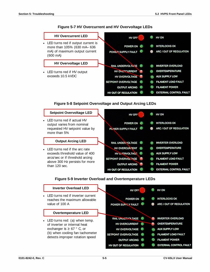
Section 5: Troubleshooting 5.2 HVPS Front Panel LEDs
0101-8242-0, Rev. C 5-5 CV-6SLX User Manual
Figure 5-7 HV Overcurrent and HV Overvoltage LEDs
• LED turns red if output current is more than 105% (630 mA– 636 mA) of maximum output current (600 mA)
• LED turns red if HV output exceeds 10.5 kVDC
Figure 5-8 Setpoint Overvoltage and Output Arcing LEDs
• LED turns red if actual HV output varies from nominal requested HV setpoint value by more than 5%
• LED turns red if the arc rate exceeds threshold value of 400 arcs/sec or if threshold arcing above 300 Hz persists for more than 120 sec.
Figure 5-9 Inverter Overload and Overtemperature LEDs
• LED turns red if inverter current reaches the maximum allowable value of 100 A
• LED turns red: (a) when temp. of inverter or internal heat exchanger is ≥ 67 ° C, or (b) when cooling fan tachometer detects improper rotation speed
HV Overvoltage LED
HV Overcurrent LED
Output Arcing LED
Setpoint Overvoltage LED
Overtemperature LED
Inverter Overload LED

5.3 Ishikawa Diagrams Section 5: Troubleshooting
CV-6SLX User Manual 5-6 0101-8242-0, Rev. C
Figure 5-10 Aux Supply Low and External Control Fault LEDs
• LED turns red when the nominal +24 VDC control voltage drops below +19.5 VDC
• LED lights red: (a) when fault occurs in internal I/O switch power, or (b) when fault occurs in the external control circuit powered by +24 VDC supplied via J4 pin 6
5.3 Ishikawa Diagrams
Each of the following diagrams illustrates the troubleshooting logic that applies in the case of a given fault condition. The diagrams, in order, are:
Ishikawa Diagram #1: No Input Power ......................................................................................... 5-7 Ishikawa Diagram #2: Interlock Fault ........................................................................................... 5-7 Ishikawa Diagram #3: No Beam After HV and Gun Are Switched ON ............................................... 5-8 Ishikawa Diagram #4: HV Output Unstable ................................................................................... 5-8 Ishikawa Diagram #5: HV Out of Regulation LED Lights Frequently ................................................. 5-9 Ishikawa Diagram #6: Arc/Out of Regulation LED Lights Excessively for the Material/Application ....... 5-9 Ishikawa Diagram #7: Rail Undervoltage Fault ............................................................................ 5-10 Ishikawa Diagram #8: HV Overcurrent Fault ............................................................................... 5-10 Ishikawa Diagram #9: HV Overvoltage Fault ............................................................................... 5-11 Ishikawa Diagram #10: Setpoint Overvoltage Fault ........................................................................ 5-11 Ishikawa Diagram #11: Output Arcing Fault .................................................................................. 5-12 Ishikawa Diagram #12: Overtemperature Fault ............................................................................. 5-12 Ishikawa Diagram #13: Aux Power Supply Low Fault ..................................................................... 5-13 Ishikawa Diagram #14: External Control Fault ............................................................................... 5-13 Ishikawa Diagram #15: Filament Load Fault .................................................................................. 5-14 Ishikawa Diagram #16: Simultaneous Filament Load Fault + Filament Power Fault ........................... 5-14 Ishikawa Diagram #17: Emission Current Unstable ........................................................................ 5-15
External Control Fault LED
Aux Supply Low LED

Section 5: Troubleshooting 5.3 Ishikawa Diagrams
0101-8242-0, Rev. C 5-7 CV-6SLX User Manual
Ishikawa Diagram #1: No Input Power
Ishikawa Diagram #2: Interlock Fault
Power Supply
Missing/loose internalcable connections
A3 HV RegulatorPCB defective
ConsequencePossible Causes
No input power(see Table 6-1)
Contactor defective,not pulling in
Mains
Phase missing
Incorrect mains supplyvoltage
Interface
I/O cables missing or notcorrectly plugged in/seated
Interlock signal to HVPSJ4 not correct –Pin 24 (Interlock IN)Pin 25 (Interlock OUT)
Power Supply
Covers interlock onHVPS not made
FPS
Cover interlock onFPS not made
ConsequencePossible Causes
Blown F1 fuse (0.2 A) onA3 HV Regulator PCB
External interlocks not made (Doors, Tank,Vacuum, Water, Positon, Auxillary)
Interlocks OK LED lightsred (see Table 6-2)
5-1)
5-2)

5.3 Ishikawa Diagrams Section 5: Troubleshooting
CV-6SLX User Manual 5-8 0101-8242-0, Rev. C
Ishikawa Diagram #3: No Beam After HV and Gun Are Switched ON
Ishikawa Diagram #4: HV Output Unstable
Emitter
FPS
Filament failure
Interface/External control
Filament bias setpointnot present
Nominal value setpoint inputfrom external input or guncontroller not correct
HV not present at emitterEmitter incorrectly assembled
HV relay defective
ConsequencePossible Causes
HV and gun switched ONbut no beam is emitted(see Table 6-8)
Loose or faulty connections
Loose or faulty connections in emitter assembly,feedthrough, or interconnection path
ConsequencePossible Causes
HV output unstable(see Table 6-9)
Mains
FPS
Problem with HV path, looseconnection, shorting
Power Supply
HV relay defective
Incorrect feedbackcommunication betweenA5 HV Output PCB andA3 HV Regulator PCB
Defective A5HV Output PCB HV output cable defective/
not connected
Improper grounding
Mains fluctuating
5-8)
5-9)

Section 5: Troubleshooting 5.3 Ishikawa Diagrams
0101-8242-0, Rev. C 5-9 CV-6SLX User Manual
Ishikawa Diagram #5: HV Out of Regulation LED Lights Frequently
Ishikawa Diagram #6: Arc/Out of Regulation LED Lights Excessively for the Material/Application
Emitter
HV Path
Dirty/loose connections
Emitter damaged
ConsequencePossible Causes
Shorts/loose connections on HVfeedthrough(s) or HV connection path
HV Out of RegulationLED lights frequently(see Table 6-11)
Other
Mains
Damaged emitter
Short in HV path
FPS
Faulty/loose cableconnections
Improper grounding
HV relay shorting
Incorrect linevoltage;or phasemissing
Faulty/loose cableConnections
Improper grounding
Short in HV path
ConsequencePossible Causes
Arc/Out of Regulation LEDflashes excessively for thematerial/application(see Table 6-11)
5-11)
5-11)

5.3 Ishikawa Diagrams Section 5: Troubleshooting
CV-6SLX User Manual 5-10 0101-8242-0, Rev. C
Ishikawa Diagram #7: Rail Undervoltage Fault
Ishikawa Diagram #8: HV Overcurrent Fault
Power Supply
Rail low: Min. for 208 VAC = 220 VDC Min. for 400 VAC = 427 VDC
Power Supply
Rail low – A1 HV Inverter PCBTP24/TP26 = actual rail voltage
ConsequencePossible Causes
Rail Undervoltage LEDlights red(see Table 6-12)
Blown IGBTs on A1HV Inverter PCB
Mains
AC phase missing
AC mains input not correct orlow (phase-to phase, phase-to-ground readings)
Rail to A3 HV Reg. PCB incorrect.A3 TP29 to ref: 10V = 1000 VDC foractual rail
Blown F3 fuse on A1HV Inverter PCB
R1 misadjusted on A3 HV Regulator PCB.TP85 to ref:208 V = 2.2 VDC400 V = 4.27 VDC
FPS
Mains
HV relay defective
HV relay control voltage missing.J103 pin 6 = +24VDC
Power Supply
HV output cabledefective
Loose cables
ConsequencePossible Causes
HV Overcurrent LEDlights red(see Table 6-13)
Fluctuating line voltage
Improper grounding
HV Ouptut PCBdefective
Incorrect mains input voltageor phase missing
5-12)
5-13)

Section 5: Troubleshooting 5.3 Ishikawa Diagrams
0101-8242-0, Rev. C 5-11 CV-6SLX User Manual
Ishikawa Diagram #9: HV Overvoltage Fault
Ishikawa Diagram #10: Setpoint Overvoltage Fault
FPS
Mains
HV relay defective
Fluctuating line voltage
Power Supply
Loose cables to FPS
Improper grounding
Defective feedback interconnectioncable from A2 HV Output PCB to A3HV Regulator PCB
Other
Emitter damaged
ConsequencePossible Causes
Loose cables
HV Overvoltage LEDlights red(see Table 6-14)
Defective HVOutput PCB
Incorrect mains input voltageor phase missing
HV relay control voltage missing.J103 pin 6 = +24 VDC
Interface
Power Supply
Incorrect nominal requestvoltage. 1V = 1kV
R7 on A3 HV RegulatorPCB misadjusted
ConsequencePossible Causes
Setpoint Overvoltage LEDlights red (see Table 6-15)
HV setpointabove 10.5 kV
5-14)
5-15)

5.3 Ishikawa Diagrams Section 5: Troubleshooting
CV-6SLX User Manual 5-12 0101-8242-0, Rev. C
Ishikawa Diagram #11: Output Arcing Fault
Ishikawa Diagram #12: Overtemperature Fault
Emitter/Chamber
FPS
Damaged emitter
Power Supply
Defective HV Relay
HV Output cable
ConsequencePossible Causes
Output Arcing LED lightsred (see Table 6-16)
Faulty/loose connections inHV path or output path
HV feedthroughshorted/damaged
Faulty/loose connections in FPSconnections or chamber feedthrough
Temp Sensors
Connection J6 on inverternot made or brokern
Power Supply
Ambient temperature too high
U1 damaged
Power supply blower‘sintake restricted
+24 VDC missing;PS1 or T2 defective
Connections between inverterand T2/PS1 missing or defective
Defective B1 blower fan
B1 blower fan obstructed
B1 Blower Fan
B1 blower fan power connectionmissing or damaged
ConsequencePossible Causes
Overtemperature LEDlights red(see Table 6-18)5-18)
5-16)

Section 5: Troubleshooting 5.3 Ishikawa Diagrams
0101-8242-0, Rev. C 5-13 CV-6SLX User Manual
Ishikawa Diagram #13: Aux Power Supply Low Fault
Ishikawa Diagram #14: External Control Fault
Mains
Power Supply
T2 AC transformerfaulty
PS1 (+24 VDC powersupply) defective
F1/F2 on A1 HVInverter PCB blown
ConsequencePossible Causes
Aux Power Supply LowLED lights red(see Table 6-20)
A3 HV RegulatorPCB defective
HV Inverter PCB defective
ConsequencePossible Causes
Power Supply
Power Supply
A3 HV Regulator PCBdefective
T2 AC transformer faulty
External Control FaultLED lights red(see Table 6-21)
Fuses F1/F2 on A1 HVInverter PCB blown
Self-resetting fuse F1 on A3HV Regulator PCB blown
PS1 (+24 VDC powersupply) faulty
5-21)
5-20)

5.3 Ishikawa Diagrams Section 5: Troubleshooting
CV-6SLX User Manual 5-14 0101-8242-0, Rev. C
Ishikawa Diagram #15: Filament Load Fault
Ishikawa Diagram #16: Simultaneous Filament Load Fault + Filament Power Fault
Emitter Assembly
FPS/CablesPower Supply
Cable not connected betweenJ102 on FPS and J5 on HVPS
A5 Interface PCB defective
ConsequencePossible Causes
Filament Load FaultLED lights red(see Table 6-22)
HV feedthroughdamaged or coated
Dirty/damagedemitter assembly
Broken/damaged filament
Incorrect filament status signal fromFPS. +24 VDC from J102 Pin 6
Filament Load Fault andFilament Power LEDsboth light red (seeTables 6-22 and 6-23)
Cables
FPS/Cables
No connection betweenHVPS J5 and FPS J102
Power Supply
Fuses F1/F2 on AC input J104switch blown
A5 Interface PCB defective
Fuses F1/F2 blown
FPS power switch in OFFposition
ConsequencePossible Causes
HVPS J2 to AC power cable defectiveor incorrrectly connected
HVPS to FPS interfacecable defective
5-22)
5-23) 5-22

Section 5: Troubleshooting 5.4 Troubleshooting Procedures
0101-8242-0, Rev. C 5-15 CV-6SLX User Manual
Ishikawa Diagram #17: Emission Current Unstable
5.4 Troubleshooting Procedures
5.4.1 Checkout of HV Circuit and Cable Connections
Before performing procedures described in Tables 5-5, 5-6, and 5-8 through 5-21, perform the following procedure to verify the integrity of the HV circuit and the power supply’s cable connections. Follow all safety procedures described in the e-beam gun manual.
Step Action 1 Vent the vacuum system to atmosphere and lower the source tray.
2 Touch a properly installed grounding hook to the e-beam gun’s emitter, to the HV feedthroughs, and to the source tray.
3 Check the emitter assembly, the HV leads, the HV feedthroughs, and the source tray for flakes and debris and clean as necessary.
4 Check the emitter’s filament for breaks and replace if necessary.
5 Check the emitter assembly, the HV leads, the HV feedthroughs, and the atmosphere side HV cables for possible shorts. Correct any shorts found.
6 Check all cable interconnections between components of the power supply and between the power supply and the vacuum system. Verify that all connections are correctly and securely made.
HVPS A3 HVRegulator PCB
HVPS A2 HVOutput PCB
Damaged emitter
HVPS mAFeedback
Defective A2 HVOutput PCB
Defective feedback cable or connectionA2J5 to A3J12 connection
ConsequencePossible Causes
Emission Current Unstable
Faulty/loose connections inHV path or output path
Defective A2 HV Output PCBR4/R5 100 Ohm resistors
HV feedthroughshorted/damaged

5.4 Troubleshooting Procedures Section 5: Troubleshooting
CV-6SLX User Manual 5-16 0101-8242-0, Rev. C
5.4.2 Troubleshooting Tables
This section contains the following troubleshooting tables:
Table Number and Title Page No.
Table 5-1 No Input Power Indicated ........................................................................................... 5-16 Table 5-2 One or More Interlocks Not Made ................................................................................ 5-17 Table 5-3 General Condition: HVPS Powered Up But Fails to Achieve HV Ready State ..................... 5-17 Table 5-4 HVPS and FPS Are Powered Up but GUN READY State Not Achieved/Confirmed .............. 5-18 Table 5-5 HVPS Powered Up but HV Does Not Switch On When Commanded To Do So .................. 5-18 Table 5-6 FPS Powered Up but Gun Does Not Switch On When Commanded To Do So ................... 5-19 Table 5-7 No Filament Current After GUN ON State Is Achieved .................................................... 5-19 Table 5-8 No Beam Emitted After HV and Gun Are Switched On ................................................... 5-20 Table 5-9 HV Output Unstable ................................................................................................... 5-20 Table 5-10 Filament Current Out Of Regulation ............................................................................. 5-21 Table 5-11 HVPS ARC/OUT OF REGULATION LED Flashes Excessively ............................................ 5-21 Table 5-12 HVPS RAIL UNDERVOLTAGE LED Lights Red ................................................................ 5-22 Table 5-13 HVPS HV OVERCURRENT LED Lights Red ..................................................................... 5-23 Table 5-14 HVPS HV OVERVOLTAGE LED Lights Red ..................................................................... 5-24 Table 5-15 HVPS SETPOINT OVERVOLTAGE LED lights red ............................................................ 5-25 Table 5-16 HVPS OUTPUT ARCING LED lights red ......................................................................... 5-25 Table 5-17 HVPS INVERTER OVERLOAD LED lights red ................................................................. 5-26 Table 5-18 HVPS OVERTEMPERATURE LED lights red .................................................................... 5-27 Table 5-19 Fan fails to rotate when HVPS is powered up ............................................................... 5-27 Table 5-20 HVPS AUXILIARY SUPPLY LOW LED lights red .............................................................. 5-28 Table 5-21 HVPS EXTERNAL CONTROL FAULT LED lights red ......................................................... 5-28 Table 5-22 HVPS FILAMENT LOAD FAULT LED lights red ............................................................... 5-28 Table 5-23 HV Is Switched On but FPS Front Panel HIGH VOLTAGE ON LED Fails To Light ............... 5-29 Table 5-24 FPS Is Switched On but Its POWER ON LED Fails To Light ............................................. 5-29
Each table is organized around a set of operational symptoms that should be easily identifiable to the operator. For functional descriptions of the HVPS front panel LEDs, see section 5.2. For descriptions of the LEDs on the FPS, see section 3.3. The Ishikawa diagrams in section 5.3 provide additional information about the faults covered in many of the troubleshooting tables.
Table 5-1 No Input Power Indicated
Symptoms • TCS displays PSU1_RDY_ALM ( = Power Supply Control Not Ready Timeout Alarm). • HVPS Front Panel: No LEDs are lit, and displays are dark. For additional information about this fault mode, see Ishikawa Diagram #1.
Possible Causes Procedure
1. Loss of main line power 1. Check to see whether input line voltages a HVPS rear panel terminals L1, L2, and L3 are within specifications for your facility. If so, proceed to next step. If not, check circuit protection devices (i.e., either circuit breakers or fuses) on the facility input power circuit to ensure they are not tripped or blown.
2. Power supply’s front breakers are tripped.
2. Reset front breakers and attempt to power up the unit. If breakers trip again, proceed to next step.
3. Loose or faulty line power connection 3. Check for secure connections on main three-phase line power connector on rear of unit.
4. Fault condition(s) whose investigation requires removal of HVPS top cover.
4. Contact Temescal Field Service.
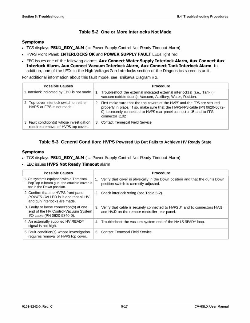
Section 5: Troubleshooting 5.4 Troubleshooting Procedures
0101-8242-0, Rev. C 5-17 CV-6SLX User Manual
Table 5-2 One or More Interlocks Not Made
Symptoms • TCS displays PSU1_RDY_ALM ( = Power Supply Control Not Ready Timeout Alarm)
• HVPS Front Panel: INTERLOCKS OK and POWER SUPPLY FAULT LEDs light red
• EBC issues one of the following alarms: Aux Connect Water Supply Interlock Alarm, Aux Connect Aux Interlock Alarm, Aux Connect Vacuum Interlock Alarm, Aux Connect Tank Interlock Alarm. In addition, one of the LEDs in the High Voltage/Gun Interlocks section of the Diagnostics screen is unlit.
For additional information about this fault mode, see Ishikawa Diagram #2.
Possible Causes Procedure 1. Interlock indicated by EBC is not made. 1. Troubleshoot the external indicated external interlock(s) (i.e., Tank (=
vacuum cubicle doors), Vacuum, Auxiliary, Water, Position.
2. Top-cover interlock switch on either HVPS or FPS is not made.
2. First make sure that the top covers of the HVPS and the FPS are secured properly in place. If so, make sure that the HVPS-FPS cable (PN 0620-6672-0) is securely connected to HVPS rear-panel connector J5 and to FPS connector J102
3. Fault condition(s) whose investigation requires removal of HVPS top cover..
3. Contact Temescal Field Service.
Table 5-3 General Condition: HVPS Powered Up But Fails to Achieve HV Ready State
Symptoms • TCS displays PSU1_RDY_ALM ( = Power Supply Control Not Ready Timeout Alarm)
• EBC issues HVPS Not Ready Timeout alarm
Possible Causes Procedure 1. On systems equipped with a Temescal
PopTop e-beam gun, the crucible cover is not in the Down position.
1. Verify that cover is physically in the Down position and that the gun’s Down position switch is correctly adjusted.
2. Confirm that the HVPS front-panel POWER ON LED is lit and that all HV and gun interlocks are made.
2. Check interlock string (see Table 5-2).
3. Faulty or loose connection(s) at one end of the HV Control-Vacuum System I/O cable (PN 0620-9840-0).
3. Verify that cable is securely connected to HVPS J4 and to connectors HVJ1 and HVJ2 on the remote controller rear panel.
4. An externally supplied HV READY signal is not high.
4. Troubleshoot the vacuum system end of the HV IS READY loop.
5. Fault condition(s) whose investigation requires removal of HVPS top cover..
5. Contact Temescal Field Service.

5.4 Troubleshooting Procedures Section 5: Troubleshooting
CV-6SLX User Manual 5-18 0101-8242-0, Rev. C
Table 5-4 HVPS and FPS Are Powered Up but GUN READY State Not Achieved/Confirmed
Symptoms • TCS displays SRC1_GON_ALM ( = Source 1 Gun Control GO ON Timeout Alarm)
• EBC issues FPS Gun Ctl Go On Timeout alarm
Possible Causes Procedure 1. Confirm that all interlocks are made. 1. See Table 5-2.
2. Faulty or loose cable connections. 2. Make sure that all power module and FPS cable connections are correctly and securely made.
3. GUN ENABLE input at Pin 6 on FPS connector J101 is high.
3. Check input at Pin 6. If high, proceed to Step 4. If low, investigate the GUN ENABLE loop upstream of the FPS.
4. Fault condition(s) whose investigation requires removal of FPS top cover.
4. Contact Temescal Field Service.
DANGER: HIGH VOLTAGE Before performing the following procedure, perform the procedure described in section 5.4.1.
Table 5-5 HVPS Powered Up but HV Does Not Switch On When Commanded To Do So
Symptoms:
• TCS displays PSU1_GON_ALM (= Power Supply Control Go On Timeout Alarm)
• HVPS Front Panel: HV ON LED fails to light Green
• EBC issues HVPS Go On Failure alarm
Possible Causes Procedure 1. HV READY signal is not present. 1. See Table 5-3.
2. After remote HV GO ON command is issued, HV ON signals are not supplied via Pins 8-9 of HVPS J4.
2. Verify that the remote HV GO ON signal is supplied by EBC or PLC-based system controller.
If the preceding steps have failed to correct the fault, perform the following procedure: 1. Switch off the power supply. 2. Disconnect HV output cable. 3. Switch on the power supply and the HV and leave them switched on for no more than 9 seconds, observing whether the
symptom persists during that interval.
CAUTION DO NOT leave the high voltage on for more than 9 seconds with the HV cable disconnected. Doing so will result in the emitter’s filament burning out.
4. If the symptom is not in evidence during Step 3, troubleshoot the HV path and emitter assembly, following the instructions in the e-gun manual. If the symptom persists during Step 3, reconnect the HV output cable to J101, switch the power supply back on, and proceed with the troubleshooting steps described below.
3. Fault condition(s) whose investigation requires removal of HVPS top cover.
3. Contact Temescal Field Service.

Section 5: Troubleshooting 5.4 Troubleshooting Procedures
0101-8242-0, Rev. C 5-19 CV-6SLX User Manual
DANGER: HIGH VOLTAGE Before performing any of the procedures described on this page, perform the procedure described in section 5.4.1.
Table 5-6 FPS Powered Up but Gun Does Not Switch On When Commanded To Do So
Symptoms
• TCS displays SRC1_GON_ALM (= Source 1 Control Go On Timeout Alarm)
• Remote Controller: Gun Ready light inside Gun Control panel’s OFF button fails to light
• EBC issues FPS Gun Ctl Go On Timeout alarm
Possible Causes Procedure 1. Faulty or loose cable connections. 1. Make sure that all power module and FPS cable connections are correctly
and securely made.
2. Confirm Gun Ready signal 2. See Table 5-4.
3. Emitter damaged 3. Follow instructions in gun manual to troubleshoot emitter issues.
If the preceding steps have failed to correct the fault, perform the following procedure: 1. Switch off the power supply. 2. Disconnect HV output cable. 3. Switch on the power supply and the HV and leave them switched on for no more than 9 seconds, observing whether the
symptom persists during that interval.
CAUTION DO NOT leave the high voltage on for more than 9 seconds with the HV cable disconnected. Doing so will result in the emitter’s filament burning out.
4. If the symptom is not in evidence during Step 3, troubleshoot the HV path and emitter assembly, following the instructions in the e-gun manual. If the symptom persists during Step 3, reconnect the HV output cable to J101, switch the power supply back on, and proceed with the troubleshooting steps described below.
4. Fault conditions whose investigation requires removal of FPS top cover.
4. Contact Temescal Field Service.
Table 5-7 No Filament Current After GUN ON State Is Achieved
Symptom: Gun switches on but has no filament current
Possible Causes Procedure 1. Faulty or loose cable connections. 1. Make sure that all power module and FPS cable connections are
correctly and securely made.
2. Emitter damaged 2. Follow instructions in gun manual to troubleshoot emitter issues.
3. Incorrect filament bias current 3. Adjust filament bias current
4. FPS fault 4. See Tables 5-23, 5-24, and 5-25.
5. Fault conditions whose investigation requires removal of FPS top cover.
5. Contact Temescal Field Service.

5.4 Troubleshooting Procedures Section 5: Troubleshooting
CV-6SLX User Manual 5-20 0101-8242-0, Rev. C
DANGER: HIGH VOLTAGE Before performing any of the procedures described on this page, perform the procedure described in section 5.4.1.
Table 5-8 No Beam Emitted After HV and Gun Are Switched On
Symptom: HV and gun are switched on, but no beam is emitted
For additional information about this fault mode, see Ishikawa Diagram #3.
Possible Causes Procedure 1. Faulty or loose connections. 1. Make sure that all HV and FPS connections are correctly and securely made.
2. Confirm HV Ready signal 2. See Table 5-3.
3. Confirm Gun Ready signal 3. See Table 5-4.
4. Emitter damaged 4. Follow instructions in gun manual to troubleshoot emitter issues.
5. Confirm HV IS ON signal 5. See Table 5-5.
6. Confirm GUN IS ON signal 6. See Table 5-6.
7. Fault conditions whose investigation requires removal of FPS top cover.
7. Contact Temescal Field Service.
DANGER: HIGH VOLTAGE Before performing the following procedure, perform the procedure described in section 5.4.1.
Table 5-9 HV Output Unstable
Symptom: HV fluctuates or sags from requested level
For additional information about this fault mode, see Ishikawa Diagram #4.
Possible Causes Procedure 1. Incorrect or fluctuating line voltage 1. Confirm input line voltage
2. Faulty or loose cable connections. 2. Make sure that all power module and FPS cable connections are correctly and securely made.
3. Emitter damaged 3. Follow instructions in gun manual to troubleshoot emitter issues.
4. System incorrectly grounded for HV 4. Make sure that grounding instructions in e-gun manual have been correctly implemented.
If the preceding steps have failed to correct the fault, perform the following procedure:
1. Switch off the power supply. 2. Disconnect HV output cable. 3. Switch on the power supply and the HV and leave them switched on for no more than 9 seconds, observing whether the
symptom persists during that interval.
CAUTION DO NOT leave the high voltage on for more than 9 seconds with the HV cable disconnected. Doing so will result in the emitter’s filament burning out.

Section 5: Troubleshooting 5.4 Troubleshooting Procedures
0101-8242-0, Rev. C 5-21 CV-6SLX User Manual
4. If the symptom is not in evidence during Step 3, troubleshoot the HV path and emitter assembly, following the instructions in the e-gun manual. If the symptom persists during Step 3, reconnect the HV output cable to J101, switch the power supply back on, and proceed with the troubleshooting steps described below.
5. Fault conditions whose investigation requires removal of HVPS top cover.
5. Contact Temescal Field Service.
DANGER: HIGH VOLTAGE Before performing any of the procedures described on this page, perform the procedure described in section 5.4.1.
Table 5-10 Filament Current Out Of Regulation
Symptom: When gun and HV are switched on, filament current ramps up and goes out of regulation
Possible Causes Procedure 1. Faulty or loose connections. 1. Make sure that all HV and FPS connections are correctly and securely made. 2. Short in HV path 2. Check emitter, feethroughs, and cables for signs of shorts. 3. Emitter damaged 3. Follow instructions in gun manual to troubleshoot emitter issues.
4. Fault conditions whose investigation requires removal of FPS top cover.
4. Contact Temescal Field Service.
Table 5-11 HVPS ARC/OUT OF REGULATION LED Flashes Excessively
Condition indicated: Subthreshold arcing is occurring and/or HV is intermittently out of regulation
NOTE: A problem exists only if arcing is excessive for the material or process in question
Symptoms:
• HVPS front panel: The ARC/OUT OF REGULATION LED flashes excessively. The HV OUT OF REGULATION LED turns yellow for 2 seconds each time the ARC/OUT OF REGULATION LED flashes
For additional information about this fault mode, see Ishikawa Diagram #6 in Appendix A.
Possible Cause Procedure 1. Emitter damaged 1. Follow instructions in gun manual to troubleshoot emitter issues. 2. Faulty or loose connections. 2. Make sure that all HV and FPS connections are correctly and securely made. 3. HV feedthrough shorted 3. Check copper bus bars and HV feedthroughs for shorts, coatings, cracks or
arc marks 4. Chamber Pressure too high 4. Chamber pressure should be less than 1 x 10⁻⁵ mTorr.
5. System improperly grounded for HV. 5. Follow grounding instructions provided in e-gun manual. 6. Incorrect or fluctuating line voltage 6. Confirm input line voltage
7. Fault conditions whose investigation requires removal of HVPS top cover.
7. Contact Temescal Field Service.

5.4 Troubleshooting Procedures Section 5: Troubleshooting
CV-6SLX User Manual 5-22 0101-8242-0, Rev. C
DANGER: HIGH VOLTAGE Before performing the following procedure, perform the procedure described in section 5.4.1.
Table 5-12 HVPS RAIL UNDERVOLTAGE LED Lights Red
Condition indicated: Rail voltage below 220 V dc (on 208-V units) or 427 V dc (on 400-V units)
NOTE: Nominal rail voltage ranges are 264-323 V dc (for 208-V units) and 509-622 V dc (for 400-V units)
Symptoms:
• TCS displays PSU1_FAIL_ALM (= Power Supply Control Is On failure alarm)
• HVPS Front Panel: RAIL UNDER VOLTAGE and POWER SUPPLY FAULT LEDs are lit
• EBC: Fault LED lit in High Voltage section of Diagnostics screen
For additional information about this fault mode, see Ishikawa Diagram #7.
Possible Cause Procedure 1. System improperly grounded for HV. 1. Follow grounding instructions provided in e-gun manual. 2. Incorrect line voltage. 2. Confirm line voltage as per manual. 3. Incorrect line phase. 3. Confirm line phase as per specifications.
4. Faulty or loose cable connections. 4. Make sure that all power module and FPS cable connections are correctly and securely made.
If preceding steps have failed to correct the fault, perform the following procedure: 1. Switch off the power supply. 2. Disconnect HV output cable from HVPS J1. 3. Switch on the power supply and the HV and leave them switched on for no more than 9 seconds, observing whether the
symptom persists during that interval.
CAUTION DO NOT leave the high voltage on for more than 9 seconds with the HV cable disconnected. Doing so will result in the emitter’s filament burning out.
4. If the symptom is not in evidence during Step 3, troubleshoot the emitter assembly, following the instructions in the e-gun manual. If the symptom persists during Step 3, reconnect the HV output cable to HVPS J1, switch the power supply back on, and proceed with the troubleshooting steps described below.
Possible Cause Procedure
5. Fault conditions whose investigation requires removal of HVPS top cover.
5. Contact Temescal Field Service.

Section 5: Troubleshooting 5.4 Troubleshooting Procedures
0101-8242-0, Rev. C 5-23 CV-6SLX User Manual
DANGER: HIGH VOLTAGE Before performing the following procedure, perform the procedure described in section 5.4.1.
Table 5-13 HVPS HV OVERCURRENT LED Lights Red
Condition indicated: HV Output current is above 636 mA
Symptoms
• TCS displays PSU1_FAIL_ALM (= Power Supply Control Is On failure alarm)
• HVPS Front Panel: HV OVERCURRENT and POWER SUPPLY FAULT LEDs are lit
• EBC: Fault LED lit in High Voltage section of Diagnostics screen
For additional information about this fault mode, see Ishikawa Diagram #8.
Possible Cause Procedure 1. Incorrect or fluctuating line
voltage 1. Confirm input line voltage
2. Faulty or loose cable connections.
2. Make sure that all power module and FPS cable connections are correctly and securely made.
3. Emitter damaged 3. Follow instructions in gun manual to troubleshoot emitter issues. 4. System improperly grounded for
HV 4. Make sure that grounding instructions in e-gun manual have been correctly
implemented.
If preceding steps have failed to correct the fault, perform the following procedure: 1. Switch off the power supply. 2. Disconnect HV output cable from HVPS J1. 3. Switch on the power supply and the HV and leave them switched on for no more than 9 seconds, observing whether the
symptom persists during that interval.
CAUTION DO NOT leave the high voltage on for more than 9 seconds with the HV cable disconnected. Doing so will result in the emitter’s filament burning out.
4. If the symptom is not in evidence during Step 3, troubleshoot the emitter assembly, following the instructions in the e-gun manual. If the symptom persists during Step 3, reconnect the HV output cable to HVPS J1, switch the power supply back on, and proceed with the troubleshooting steps described below.
Possible Cause Procedure 4. Broken or shorted emitter. 4. Check emitter for breaks and check emitter assembly and associated leads for
possible grounds.
5. Fault conditions whose investigation requires removal of HVPS top cover.
5. Contact Temescal Field Service.

5.4 Troubleshooting Procedures Section 5: Troubleshooting
CV-6SLX User Manual 5-24 0101-8242-0, Rev. C
DANGER: HIGH VOLTAGE Before performing the following procedure, perform the procedure described in section 5.4.1.
Table 5-14 HVPS HV OVERVOLTAGE LED Lights Red
Condition indicated: HV Output Voltage Is Above Maxiumum (i.e., 105% of Setpoint)
Symptoms
• TCS displays PSU1_FAIL_ALM (= Power Supply Control Is On failure alarm)
• HVPS Front Panel: HV OVERVOLTAGE and POWER SUPPLY FAULT LEDs are lit
• EBC: Fault LED lit in High Voltage section of Diagnostics screen
For additional information about this fault mode, see Ishikawa Diagram #9.
Possible Cause Procedure 1. Incorrect or fluctuating line voltage 1. Confirm input line voltage 2. Faulty or loose cable connections. 2. Make sure that all power module and FPS cable connections are correctly and
securely made. 3. Emitter damaged 3. Follow instructions in gun manual to troubleshoot emitter issues. 4. System improperly grounded for HV. 4. Make sure that grounding instructions in e-gun manual have been correctly
implemented.
If preceding steps have failed to correct the fault, perform the following procedure: 1. Switch off the power supply. 2. Disconnect HV output cable from HVPS J1. 3. Switch on the power supply and the HV and leave them switched on for no more than 9 seconds, observing whether the
symptom persists during that interval.
CAUTION DO NOT leave the high voltage on for more than 9 seconds with the HV cable disconnected. Doing so will result in the emitter’s filament burning out.
4. If the symptom is not in evidence during Step 3, troubleshoot the emitter assembly, following the instructions in the e-gun manual. If the symptom persists during Step 3, reconnect the HV output cable to HVPS J1, switch the power supply back on, and proceed with the troubleshooting steps described below.
Possible Cause Procedure 5. Broken or shorted emitter. 5. Check emitter for breaks and check emitter assembly and associated leads
for possible grounds.
6. Fault condition(s) whose investigation requires removal of HVPS top cover.
6. Contact Temescal Field Service.

Section 5: Troubleshooting 5.4 Troubleshooting Procedures
0101-8242-0, Rev. C 5-25 CV-6SLX User Manual
DANGER: HIGH VOLTAGE Before performing the following procedure, perform the procedure described in section 5.4.1.
Table 5-15 HVPS SETPOINT OVERVOLTAGE LED lights red
Condition indicated: HV output voltage is above 10.5 kV when setpoint is 10 kV
Symptoms
• TCS displays PSU1_FAIL_ALM (= Power Supply Control Is On failure alarm)
• HVPS Front Panel: SETPOINT OVERVOLTAGE and POWER SUPPLY FAULT LEDs are lit
• EBC: Fault LED lit in High Voltage section of Diagnostics screen
For additional information about this fault mode, see Ishikawa Diagram #10 in Appendix A.
Possible Cause Procedure
1. Fault condition(s) whose investigation requires removal of HVPS top cover
1. Contact Temescal Field Service.
Table 5-16 HVPS OUTPUT ARCING LED lights red
Condition indicated: Latched PS fault due to either an arc duration > 120 ms or arc rate > 200 Hz Symptoms
• TCS issues PSU1_FAIL_ALM (= Power Supply Control Is On failure alarm)
• HVPS Front Panel: OUTPUT ARCING and POWER SUPPLY FAULT LEDs are lit
• EBC: Fault LED lit in High Voltage section of Diagnostics screen
For additional information about this fault mode, see Ishikawa Diagram #11.
Possible Cause Procedure 1. Faulty or loose connections. 1. Make sure that all HV and FPS connections are correctly and securely made. 2. Emitter damaged 2. Follow instructions in gun manual to troubleshoot emitter issues. 3. System improperly grounded
for HV. 3. Make sure that grounding instructions in e-gun manual have been correctly
implemented. 4. Chamber Pressure too high 4. Chamber pressure should be less than 1 x 10⁻⁵ mTorr. 5. HV feedthrough shorted 5. Check copper bus bars and HV feedthroughs for shorts, coatings, cracks or arc
marks.
6. Fault condition(s) whose investigation requires checking HV output at FPS.
6. Contact Temescal Field Service.

5.4 Troubleshooting Procedures Section 5: Troubleshooting
CV-6SLX User Manual 5-26 0101-8242-0, Rev. C
DANGER: HIGH VOLTAGE Before performing the following procedure, perform the procedure described in section 5.4.1.
Table 5-17 HVPS INVERTER OVERLOAD LED lights red
Condition indicated: Inverter current > 150 A
Symptoms
• TCS displays PSU1_FAIL_ALM (= Power Supply Control Is On failure alarm)
• HVPS Front Panel: INVERTER OVERLOAD and POWER SUPPLY FAULT LEDs are lit
• EBC: Fault LED lit in High Voltage section of Diagnostics screen
Possible Cause Procedure 1. Incorrect or fluctuating line voltage 1. Confirm input line voltage 2. Faulty or loose connections. 2. Make sure that all HV and FPS connections are correctly and securely made.
If preceding steps have failed to correct the fault, perform the following procedure: 1. Switch off the power supply. 2. Disconnect HV output cable from HVPS J1. 3. Switch on the power supply and the HV and leave them switched on for no more than 9 seconds, observing whether the
symptom persists during that interval.
CAUTION DO NOT leave the high voltage on for more than 9 seconds with the HV cable disconnected. Doing so will result in the emitter’s filament burning out.
4. If the symptom is not in evidence during Step 3, troubleshoot the emitter assembly, following the instructions in the e-gun manual. If the symptom persists during Step 3, reconnect the HV output cable to HVPS J1, switch the power supply back on, and proceed with the troubleshooting steps described below.
Possible Cause Procedure 3. Rail voltage incorrect 3. See Table 5-12.
4. Fault condition(s) whose investigation requires removal of HVPS top cover
4. Contact Temescal Field Service.

Section 5: Troubleshooting 5.4 Troubleshooting Procedures
0101-8242-0, Rev. C 5-27 CV-6SLX User Manual
DANGER: HIGH VOLTAGE Before performing the following procedure, perform the procedure described in section 5.4.1.
Table 5-18 HVPS OVERTEMPERATURE LED lights red
Conditions indicated: One or more of the following: IGBT temp > 678 C, heat sink Temp >778 C, fan stopped, fan rotating too slowly Symptoms
• TCS displays PSU1_FAIL_ALM (= Power Supply Control Is On failure alarm)
• HVPS Front Panel: OVERTEMPERATURE and POWER SUPPLY FAULT LEDs are lit
• EBC: Fault LED lit in High Voltage section of Diagnostics screen
For additional information about this fault mode, see Ishikawa Diagram #12 in Appendix A. Possible Cause Procedure
1. Incorrect or fluctuating line voltage 1. Check input line voltage.
2. Fault condition(s) whose investigation requires removal of HVPS top cover
2. Contact Temescal Field Service.
DANGER: HIGH VOLTAGE
Before performing the following procedure, perform the procedure described in section 5.4.1.
Table 5-19 Fan fails to rotate when HVPS is powered up
Symptoms
• TCS displays PSU1_FAIL_ALM (= Power Supply Control Is On failure alarm)
• HVPS Front Panel: OVERTEMPERATURE and POWER SUPPLY FAULT LEDs light red
• EBC: Fault LED lit in High Voltage section of Diagnostics screen Possible Causes Procedure
1. Fan is mechanically stuck 1. Check to see whether fan is clogged with dust or dirt. Excessive dust build-up around edges of fan will prevent it from moving. Clean and blow out dust. Restart power supply.
2. Fault condition(s) whose investigation requires removal of HVPS top cover
2. Contact Temescal Field Service.

5.4 Troubleshooting Procedures Section 5: Troubleshooting
CV-6SLX User Manual 5-28 0101-8242-0, Rev. C
Table 5-20 HVPS AUXILIARY SUPPLY LOW LED lights red
Condition indicated: Control Supply voltage is below minimum value
Symptoms • TCS displays PSU1_FAIL_ALM (= Power Supply Control Is On failure alarm)
• HVPS Front Panel: AUXILIARY SUPPLY LOW and POWER SUPPLY FAULT LEDs light red
• EBC: Fault LED lit in High Voltage section of Diagnostics screen
For additional information about this fault mode, see Ishikawa Diagram #13.
Possible Cause Procedure
1. Fault condition(s) whose investigation requires removal of HVPS top cover
1. Contact Temescal Field Service.
DANGER: HIGH VOLTAGE Before performing the following procedure, perform the procedure described in section 5.4.1.
Table 5-21 HVPS EXTERNAL CONTROL FAULT LED lights red
Condition indicated: I/O SWITCH POWER output (+24 V dc) supplied via Pin 6 on HVPS J4 is below its minimum value (< 20 V dc)
Symptoms
• TCS displays PSU1_FAIL_ALM (= Power Supply Control Is On failure alarm)
• HVPS Front Panel: EXTERNAL CONTROL FAULT and POWER SUPPLY FAULT LEDs are lit
• EBC: Fault LED lit in High Voltage section of Diagnostics screen
For additional information about this fault mode, see Ishikawa Diagram #14.
Possible Cause Procedure
1. Fault condition(s) whose investigation requires removal of HVPS top cover
1. Contact Temescal Field Service.
Table 5-22 HVPS FILAMENT LOAD FAULT LED lights red
Condition indicated: Minimum filament load not present
Symptoms
• HVPS Front Panel: FILAMENT LOAD FAULT LED lights red; FILAMENT POWER LED remains green
• FPS Front Panel: POWER ON and HV ON LEDs are lit
• EBC issues FPS Gun Ctl Go On Timeout For additional information about this fault mode, see Ishikawa Diagram #15.
Possible Cause Procedure 1. Gun filament burnt out. 1. Check filament and replace if necessary. If OK, proceed to Step 2. 2. Other problems with emitter, gun,
HV feedthroughs, and connections to HV feedthroughs.
2. Follow troubleshooting procedures described in gun manual.

Section 5: Troubleshooting 5.5 FPS Fuse Replacement Procedure
0101-8242-0, Rev. C 5-29 CV-6SLX User Manual
Table 5-23 HV Is Switched On but FPS Front Panel HIGH VOLTAGE ON LED Fails To Light
Symptoms
• HVPS Front Panel: HV switched on, with LEDs indicating nominal HVPS state
• FPS Front Panel: HIGH VOLTAGE ON LED is unlit
Possible Cause Procedure 1. FPS is not powered up. 1. Make sure that FPS is switched on. If switch is on, POWER ON LED is lit,
and HV is switched on, proceed to Step 2. If FPS switch is in the ON position but the POWER ON LED is not lit, see Table 5-24.
2. HV IS ON signal is not present at FPSB connector J102.
2. Check pins J102 Pin 1 for the HV IS ON signal. If not present, proceed to Step 3.
3. Fault condition(s) whose investigation requires removal of HVPS top cover
3. Contact Temescal Field Service.
Table 5-24 FPS Is Switched On but Its POWER ON LED Fails To Light
Symptoms • HVPS front panel: FILAMENT POWER LED on turns red • FPS #1 front panel: POWER ON LED on fails to light when FPS is switched on • EBC displays FPS Gun Ctl Go On Timeout alarm message
For additional information about this fault mode, see Ishikawa Diagram #16.
Possible Cause Procedure 1. HVPS rear panel connector J1 not
supplying 208 V ac power 1. Disconnect FPS power cable from HVPS J1 and check J1 for 208 V ac output. If no
voltage or incorrect voltage is indicated, proceed to Step 2. If voltage is correct, skip to Step 4.
2. HVPS rear panel fuses F1 and/or F2 blown.
2. Check fuses and replace as necessary. After replacing either fuse, repeat Step 1 of this procedure. If correct voltage is then detected at J1, reconnect power cable between J1 and FPS #1.
3. Faulty FPS power cable. 3. Reconnect the FPS power cable to J1 and disconnect it from the FPS. Measure the female end of the cable for 208 V ac. Replace cable as necessary.
4. Blown fuses on FPS input power line. 4. Check and replace fuse(s) as necessary, as described in section 5.5.
5. Fault condition(s) whose investigation requires removal of HVPS top cover
5. Contact Temescal Field Service.
5.5 FPS Fuse Replacement Procedure
To check the input power fuses and replace them as necessary, follow the instructions provided below.
Step Action 1 Set the FPS ON/OFF switch to the OFF position.
7 Switch off the facility breaker providing AC power to the FPS.
8 Unplug the input power cable from its receptacle on the FPS front panel.

5.5 FPS Fuse Replacement Procedure Section 5: Troubleshooting
CV-6SLX User Manual 5-30 0101-8242-0, Rev. C
9 Using a flat-bladed screwdriver, pry open the fuse block’s cover as shown in Figure 5-11.
Figure 5-11 Prying Open the Fuse Block Cover on FPS Front Panel
10 Using the same screwdriver, pry the fuse block out of its holder, as shown in Figure 5-12. Figure 5-13 shows the fuse block extracted from its holder.
Figure 5-12 Extracting the Fuse Block from the FPS
Figure 5-13 Fuse Block Removed from FPS
11 Check the fuses and replace them as necessary.

Section 5: Troubleshooting 5.5 FPS Fuse Replacement Procedure
0101-8242-0, Rev. C 5-31 CV-6SLX User Manual
12 Push the fuse block all the way into its holder and snap its cover back into place.
13 Reconnect the FPS input power cable.
14 Switch on facility breaker supplying power to the FPS.
15 Set the FPS ON/OFF switch to the ON position.

5.5 FPS Fuse Replacement Procedure Section 5: Troubleshooting
CV-6SLX User Manual 5-32 0101-8242-0, Rev. C

0101-8242-0, Rev. C A-1 CV-6SLX User Manual
Appendix A: Pinout Table for HVPS Rear Panel Diagnostic Port (HVPS J3)
Signal Name/ Functional Component
Pin No.
Range Proportion Description
Cable Shield 1 N/A N/A
Analog Controls (0-10 V dc) HV Output Voltage 2 0-10 V dc 0-10 kV dc Fault at above 10.5 kV dc
HV Output Current 3 0-10 V dc 0-1,000 mA dc Fault at above 630 mA dc
HV Inverter IGBT Temperature 4 0-10 V dc 0-160° C Fault at above 67° C
HV Inverter Rail Voltage 5 0-10 V dc 0-1,000 V dc Fault at below 430 V dc
Arc Counter Integrator 6 0-10 V dc 0-480 S Fault at above 120 S continuous arcing at above allowable rate
HV Inverter PWM Duty Cycle 7 0-5 V dc 0-100%
EG Filament Current 8 0-10 V dc 0-50 A ac
EG Emission Current 9 0-10 V dc 0-2,000 mA dc
Analog Common 22 N/A
Digital Controls (0/24 V dc) 24 V dc Control Power 10 0-10 V dc 0-24 V dc Fault at below 19.5 V dc
Overtemp. Trip 11 0/24 V dc 0 V dc = Fault Inverter temperature overload (above 67° C) or cooling fan failure.
External Interlocks 12 0/24 V dc 0 V dc = Fault
HV Enable (ready) 13 0/24 V dc 0 V dc = Fault
HV Go ON 14 0/24 V dc 0 V dc = OFF
Overcurrent Trip 15 0/24 V dc 0 V dc = Fault HV output current above 105% of nominal (nominal = 600 mA).
Overvoltage Trip 16 0/24 V dc 0 V dc = Fault HV output voltage above 105% of maximum (maximum = 10 kV).
Arc Counter Active 17 0/24 V dc 0 V dc = Fault Arc rate or duration exceeds maximum programmed limits (200/second or continuous arcing for more than 120 seconds).
Out of Regulation 18 0/24 V dc 0 V dc = Fault HV output voltage out of "voltage regulation" mode for over 2 seconds duration.
EG Filament Status 19 0/24 V dc 0 V dc = Fault Fault = Open filament
EG Filament Power Status 20 0/24 V dc 0 V dc = Fault Fault = Filament Power Supply OFF
Digital Common 23 N/A N/A

Appendix A: Pinout Table for Rear Panel Diagnostic Port (J3)
CV-6SLX User Manual A-2 0101-8242-0, Rev. C