cvs-fx1 ime ver01 - si-tex · cvs-fx1 revision history 0092601112-01 i cvs-fx1 installation manual...
TRANSCRIPT

CVS-FX1 Revision History
0092601112-01 i
CVS-FX1 Installation Manual
Doc No. 0092601112
Document Revision History
No. Doc. – Rev. No. Date Revised
(Y/M/D) Revised content
0 0092601112-00 2011/11/09 First edition
1 0092601112-01 2011/12/19 Configuration of Equipment, Specifications, Chapter 1, Chapter 2
2
3
4
5
6
7
8
9
10
Document No. Revised Version Norm When part of the document needs to be revised, the document has advanced revised number. The document No. is indicated at the lower right side on the cover and at the left or right side of the footer region of each page.
© 2011 Koden Electronics Co., Ltd. All rights reserved. No part of this publication may be reproduced, transmitted, translated in any form by any means without the written permission of Koden Electronics Coo., Ltd. The technical descriptions contained in this publication are subject to change without notice. Koden assumes no responsibility for any errors, incidentals or consequential damages caused by misinterpretation of the descriptions contained in this publication.
Important Notice CVS-FX1
ii 0092601112-01
Important Notice For copy and transcription of this Installation Manual (hereinafter referred to as this manual),
permission from Koden is needed. Koden prohibits the un-authorized copy and transcription of this manual.
If this manual is lost or damaged, consult a dealer of Koden or Koden.
The specification of the products and the contents in this manual are subject to change without notice.
The contents displayed on the menu of product may be different from the expression of this manual. The fonts and shapes of the keys and menus in the illustration may differ from the actual ones, and some parts may be omitted.
Koden is not liable for damages and troubles arisen from misunderstanding of the contents in this manual.
Koden is not liable for any damages caused by earthquake, lightning, wind and flood damage and fire for which Koden is not responsible, and actions by third parties, other accidents, customer’s unintended error/abuse and the use under other abnormal conditions.
Koden is not liable for damages of accompaniment (change/loss of memorized content, loss of business profit, stop of business) arisen from use or failure of our products.
If the stored data are changed or lost, irrespective of causes of troubles and damages, Koden is not liable for them.
Koden is not liable for any damages arisen from malfunction caused by combination of software and connected equipment in which Koden is not engaged.

CVS-FX1 For Your Safe Operation
0092601112-01 iii
For Your Safe Operation
Symbol used in this Installation Manual
The following graphical symbols are used in this manual. The meaning of each symbols shall be well understood and apply at maintenance and inspection works.
Symbol Meaning
Mark for warning This symbol denotes that there is a risk of death or serious injury when not dealing with it correctly.
Mark for danger high voltage This symbol denotes that there is a risk of death or serious injury caused by electric shock when not dealing with it correctly.
Mark for caution This symbol denotes that there is a risk of slight injury or damage of device when not dealing with it correctly.
Mark for prohibition This symbol denotes prohibition of the specified conduct. Description of the prohibition is displayed near the mark.
Caution items on equipment
Be careful of a high voltage inside.
A high voltage, which may risk your life, is used. This high voltage remains in the circuit after you have powered off switch. To prevent touching the high voltage circuit inadvertently, the hard cover is provided to the high voltage circuit and the high voltage caution label is affixed. Ensure to power off switch for your safety and discharge the electricity remaining in the capacity before starting to check. An engineer authorized by our company should inspect and maintain
Be sure to power off in the boat.
If the power switch is inadvertently powered on during work, you will be electrified. To prevent such accident from occurring, ensure to power off in the boat and the power of equipment. Furthermore, it is safer to hang the caution tag described as [Under Work] near the power switch of equipment.
Be careful of dust
Inhaling dust may cause A respiratory disease. When cleaning the inside of equipment, be careful not to inhale dust. Wearing a safety mask is recommended.
Warning
Warning
Warning
For Your Safe Operation CVS-FX1
iv 0092601112-01
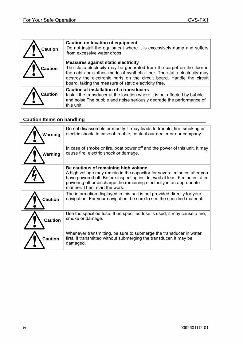
Caution on location of equipment Do not install the equipment where it is excessively damp and suffers from excessive water drops.
Measures against static electricity The static electricity may be generated from the carpet on the floor in the cabin or clothes made of synthetic fiber. The static electricity may destroy the electronic parts on the circuit board. Handle the circuit board, taking the measure of static electricity free.
Caution at installation of a transducers Install the transducer at the location where it is not affected by bubble and noise The bubble and noise seriously degrade the performance of this unit.
Caution Items on handling
Do not disassemble or modify. It may leads to trouble, fire, smoking or electric shock. In case of trouble, contact our dealer or our company.
In case of smoke or fire, boat power off and the power of this unit. It may cause fire, electric shock or damage.
Be cautious of remaining high voltage. A high voltage may remain in the capacitor for several minutes after you have powered off. Before inspecting inside, wait at least 5 minutes after powering off or discharge the remaining electricity in an appropriate manner. Then, start the work.
The information displayed in this unit is not provided directly for your navigation. For your navigation, be sure to see the specified material.
Use the specified fuse. If un-specified fuse is used, it may cause a fire, smoke or damage.
Whenever transmitting, be sure to submerge the transducer in water first. If transmitted without submerging the transducer, it may be damaged.
Caution
Caution
Caution
Warning
Warning
Caution
Caution
Caution

CVS-FX1 Contents
0092601112-01 v
Contents
Document Revision History .......................................................................................................................i Important Notice ....................................................................................................................................... ii For Your Safe Operation ......................................................................................................................... iii Contents ...................................................................................................................................................v System Configuration ............................................................................................................................. vii Configuration of Equipment................................................................................................................... viii Dimensions............................................................................................................................................. xii Specifications ........................................................................................................................................ xiii
Chapter 1 Installation..............................................................................................1-1
1.1 Installation precautions ............................................................................................................. 1-1 1.1.1 Unpacking of components ..................................................................................................... 1-1 1.1.2 Appearance verification of each unit and accessories .......................................................... 1-1 1.1.3 Selection of location for installation ....................................................................................... 1-1 1.1.4 Laying and connection of cables ........................................................................................... 1-2 1.1.5 Coordination after installation ................................................................................................ 1-2 1.2 Installation of CVS-FX1 Display unit ......................................................................................... 1-3 1.2.1 Desk-top installation............................................................................................................... 1-3 1.2.2 Flush-mount installation ......................................................................................................... 1-5 1.3 Installation of transducer........................................................................................................... 1-6 1.3.1 In the case of inner hull installation........................................................................................ 1-6 1.4 Wiring ...................................................................................................................................... 1-11 1.4.1 Connection of cables to Display unit.................................................................................... 1-11 1.5 List of input/output sentences ................................................................................................. 1-21 1.5.1 Input sentence ..................................................................................................................... 1-21 1.5.2 Output sentence................................................................................................................... 1-21
Chapter 2 Adjustment.............................................................................................2-1
2.1 Setup of transducer................................................................................................................... 2-1 2.1.1 Setup of type of high frequency transducer........................................................................... 2-1 2.1.2 Setup of type of low frequency transducer ............................................................................ 2-1 2.2 Setup of frequency of transducer.............................................................................................. 2-2 2.2.1 Setup of frequency for high frequency transducer................................................................. 2-2 2.2.2 Setup of frequency for low frequency transducer .................................................................. 2-2 2.3 Setup of Beam Angle of transducer .......................................................................................... 2-3 2.3.1 Setup of Beam Angle for high frequency transducer ............................................................. 2-3 2.3.2 Setup of Beam Angle for low frequency transducer .............................................................. 2-3 2.4 Setup of Bottom Limit................................................................................................................ 2-4 2.4.1 Setup of Bottom Limit HF....................................................................................................... 2-4 2.4.2 Setup of Bottom Limit LF ....................................................................................................... 2-4 2.5 Setup of Draft Set...................................................................................................................... 2-4 2.6 Setup of Gain (TD) for transducer............................................................................................. 2-5 2.7 Setup of Output Limit for transmitter......................................................................................... 2-6 2.7.1 Display of Output Limit Menu................................................................................................. 2-6 2.7.2 Setup of Output Limit HF ....................................................................................................... 2-6 2.7.3 Setup of Output Limit LF........................................................................................................ 2-6 2.7.4 Relation of the set value between [Output Limit] and [MENU] - [Echo Adjust] - [TX
Power] .................................................................................................................................... 2-7
Chapter 3 Maintenance...........................................................................................3-1
3.1 Inspection.................................................................................................................................. 3-1 3.2 Cleaning .................................................................................................................................... 3-1 3.2.1 Display unit ............................................................................................................................ 3-1 3.2.2 Transducer ............................................................................................................................. 3-2 3.3 Fuse Replacement.................................................................................................................... 3-2

Contents CVS-FX1
vi 0092601112-01
3.4 Diagnostics of troubles..............................................................................................................3-2 3.4.1 Necessary information for requesting repair ..........................................................................3-2 3.4.2 Diagnostics test ......................................................................................................................3-3 3.4.3 LCD Test.................................................................................................................................3-4 3.4.4 Initialize ..................................................................................................................................3-4 3.4.5 Update of program .................................................................................................................3-4 3.5 If you suspect a trouble .............................................................................................................3-6

CVS-FX1 System Configuration
0092601112-01 vii
System Configuration Connection diagram
Owner supplyOption Standard configuration
Legend
Display unit CVS-FX1
With mounting bracket and hard cover
J1 connector
J2 connector
J3 connector
External echo sounder(Owner supply)
CW-371-5MCW-372-5M
Speaker with amplifier(Owner supply)
CW-264A-2
NMEA2 circuit input output(12 V power output)
(Owner supply) CW-373-5MCW-374-5MCW-376-5M
GPS sensor
NMEA1 circuit input output (Owner supply)
J8 connector
Junction box
CW-836-3M
CW-270-2M
POWER connector White +
Black -
10.8 to 31.2 VDC
J4 connector
CC
D c
amer
a C
W-4
05-0
.3M
Ext
erna
l mo
nito
r
CW
-576
-0.5
M
TransducerTDM-052/062
J5 connector
J6 connector
J7 connector
CW-373-5MCW-374-5MCW-376-5M
Fuse
10 A
10 A
CW
-844
-3M
Configuration of Equipment CVS-FX1
viii 0092601112-01
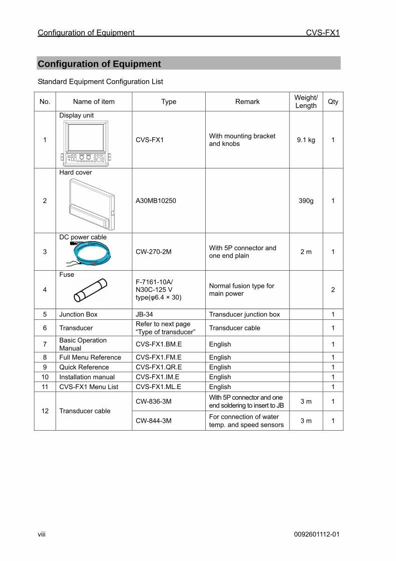
Configuration of Equipment Standard Equipment Configuration List
No. Name of item Type Remark Weight/ Length
Qty
1
Display unit
CVS-FX1 With mounting bracket and knobs
9.1 kg 1
2
Hard cover
A30MB10250 390g 1
3
DC power cable
CW-270-2M With 5P connector and one end plain
2 m 1
4
Fuse
F-7161-10A/ N30C-125 V type(φ6.4 × 30)
Normal fusion type for main power
2
5 Junction Box JB-34 Transducer junction box 1
6 Transducer Refer to next page “Type of transducer”
Transducer cable 1
7 Basic Operation Manual
CVS-FX1.BM.E English 1
8 Full Menu Reference CVS-FX1.FM.E English 1
9 Quick Reference CVS-FX1.QR.E English 1
10 Installation manual CVS-FX1.IM.E English 1
11 CVS-FX1 Menu List CVS-FX1.ML.E English 1
CW-836-3M With 5P connector and one end soldering to insert to JB
3 m 1
12 Transducer cable
CW-844-3M For connection of water temp. and speed sensors
3 m 1
CVS-FX1 Configuration of Equipment
0092601112-01 ix
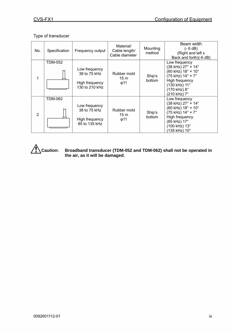
Type of transducer
Caution: Broadband transducer (TDM-052 and TDM-062) shall not be operated in the air, as it will be damaged.
No. Specification Frequency outputMaterial/
Cable length/ Cable diameter
Mounting method
Beam width (- 6 dB)
(Right and left x Back and forth)(-6 dB)
1
TDM-052
Low frequency 38 to 75 kHz
High frequency 130 to 210 kHz
Rubber mold 15 m φ11
Ship’s bottom
Low frequency (38 kHz) 27° × 14° (60 kHz) 18° × 10° (75 kHz) 14° × 7° High frequency (130 kHz) 11° (170 kHz) 8° (210 kHz) 7°
2
TDM-062
Low frequency 38 to 75 kHz
High frequency 85 to 135 kHz
Rubber mold 15 m φ11
Ship’s bottom
Low frequency (38 kHz) 27° × 14° (60 kHz) 18° × 10° (75 kHz) 14° × 7° High frequency (85 kHz) 17° (100 kHz) 13° (135 kHz) 10°
Configuration of Equipment CVS-FX1
x 0092601112-01
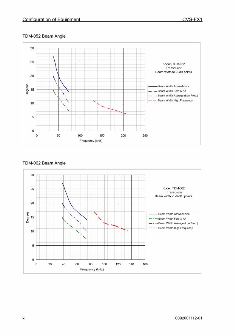
TDM-052 Beam Angle
TDM-062 Beam Angle
Koden TDM-062 Transducer
Beam width to -6 dB points
0
5
10
15
20
25
30
0 20 40 60 80 100 120 140 160
Freqency (kHz)
Deg
rees Beam Width Athwartships
Beam Width Fore & Aft
Beam Width Average (Low Freq.)
Beam Width High Frequency
Koden TDM-052Transducer
Beam width to -6 dB points
0
5
10
15
20
25
30
0 50 100 150 200 250
Frequency (kHz)
Deg
rees Beam Width Athwartships
Beam Width Fore & Aft
Beam Width Average (Low Freq.)
Beam Width High Frequency
Frequency (kHz)

CVS-FX1 Configuration of Equipment
0092601112-01 xi
Option List
No. Name of Item Specification Remark Weight/ Length
1 Power rectifier PS-010 Fuse (5A) 2 pcs. 2 AC power cable VV-2D8-3M Both ends plain. 3 m
3 Transducer extension cable
C44-01
Cable configuration is the same as TDM-052/TDM062. (Refer to “Connection of transducer”, page 1-14)
Specify length at
order
4 Grounding cable OW7/1.6S-3M 3 m
CW-371-5M With a 5-pin connector & a 5-pin water resistant connector
5 m
CW-372-5M With a 5-pin water resistant connector & one end plain
5 m
CW-373-5M With 6-pin water resistant connectors both ends
5 m
CW-374-5M With a 6-pin connector & a 6-pin water resistant connector
5 m
CW-376-5M With a 6-pin water resistant connector & one end plain
5 m
CW-560-2M With 15-pin water resistant D-Sub connectors both ends
2 m
CW-264A-2M 12P waterproof connector at one end / φ3.5 stereo jack at one end
2 m
5 Connecting cable
CW-405-0.3M Junction cable for CCD camera 0.3 m
6 Cable for external monitor
CW-576-0.5M Junction cable for external monitor With a 12-pin water resistant connector & a D-Sub connector
0.5 m
LTWBD-05BFFA- L180
5P water resistant connector
7 Connector LTWBD-06BFFA-
AL180 6P water resistant connector
8 CVS-841 transmission filter
Transmission C29EHB004A
Filter against leakage from wireless equipment
Dimensions CVS-FX1
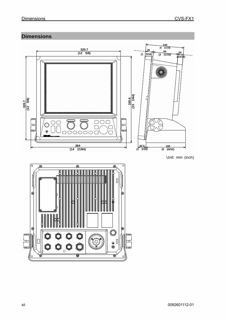
xii 0092601112-01
Dimensions
Unit: mm (inch)
20 320.7
(12 5/8)
364 (14 21/64)
30.5 (1 3/16)
150 (5 29/32)
320.
7 (1
2 5/
8)
144 (5 11/18)
30
330.
6 (1
3 1/
64)
94 (3 11/16) (1 3/16)
(13/16)
CVS-FX1 Specifications
0092601112-01 xiii
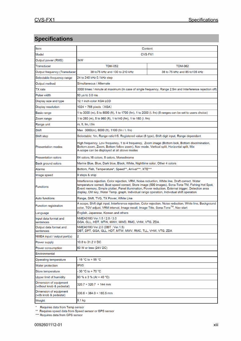
Specifications

CVS-FX1 Chapter 1 Installation
0092601112-01 1-1
Chapter 1 Installation
1.1 Installation precautions In order to obtain the maximum performance of the echo sounder, this echo sounder should be installed by a qualified engineer in charge of installation and maintenance. Installation procedures include the following:
(1) Unpacking of components
(2) Inspection of composition units, spare parts, accessories and installation materials.
(3) Checking of supply voltage and current capacity
(4) Selection of location for installation
(5) Installation of CVS-FX1 Display unit and transducer
(6) Attachment of accessories
(7) Planning and implementation of cable laying and connection
(8) Coordination after installation
1.1.1 Unpacking of components
Unpack components and check that all the items correspond with the description of the packing list. When a discrepancy or damage has been found, contact the dealer you purchased or our sales company.
1.1.2 Appearance verification of each unit and accessories
Inspect the appearance of each components and accessories and check that no dents or damages exist.
If any dents or damages exist and they are believed to be caused by accident during transportation, contact the transportation and insurance company and consult our sales company or our dealer nearest to you.
1.1.3 Selection of location for installation
In order to obtain the maximum performance of the unit, it is necessary to install in consideration of matters described below:
(1) Install the equipment at a location in a bridge so that its display can be easily seen.
(2) Keep enough space for maintenance. Especially, secure enough space at the rear panel where many cables are connected.
(3) Keep the equipment as far away from wireless transmitter/receivers as possible.

Chapter 1 Installation CVS-FX1
1-2 0092601112-01
1.1.4 Laying and connection of cables
(1) Keep the transducer and power cable as far away from the cables of other electronic equipment as possible.
(2) The cabinet of CVS-FX1 Display unit shall be securely grounded to the hull, using the grounding terminal on the rear panel.
Caution: The ground side of power input of this equipment is connected to the ground terminal. In case of + (positive) ground, it cannot be used. The power may short-circuit.
(3) If you connect the power cable directly to the battery, interference from the other electronic equipment is expected to be less. (See Fig. 1.1)
Fig. 1.1 Connection of Power line
1.1.5 Coordination after installation
Be sure to confirm the following points before starting up this equipment. The confirmation is mandatory to operate the equipment normally:
(1) Is the power voltage in the boat within the appropriate voltage range? Is the current capacity enough? (Voltage range: 10.8 VDC to 31.2 VDC measured at the power connector.)
(2) Is the electric current capacity sufficient? (Power consumption: 60 W)
(3) Is the wiring of transducer cable correct? Is the wiring shorted?
バッテリー
CVS-FX1 CVS-FX1
良い例送受信表示機 送受信表示機
バッテリー バッテリー
ノイズ ノイズ
悪い例
Noise
Battery
Display unit Good example Bad example Display unit
Battery
Noise
CVS-FX1 CVS-FX1
CVS-FX1 Chapter 1 Installation
0092601112-01 1-3
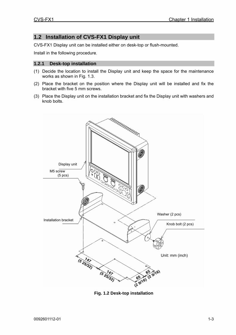
1.2 Installation of CVS-FX1 Display unit CVS-FX1 Display unit can be installed either on desk-top or flush-mounted.
Install in the following procedure.
1.2.1 Desk-top installation
(1) Decide the location to install the Display unit and keep the space for the maintenance works as shown in Fig. 1.3.
(2) Place the bracket on the position where the Display unit will be installed and fix the bracket with five 5 mm screws.
(3) Place the Display unit on the installation bracket and fix the Display unit with washers and knob bolts.
Fig. 1.2 Desk-top installation
Unit: mm (inch)
Display unit
M5 screw (5 pcs)
Installation bracket
Washer (2 pcs)
Knob bolt (2 pcs)

Chapter 1 Installation CVS-FX1
1-4 0092601112-01
Caution: At installing on desktop, keep the maintenance space is required as shown below.
Unit: mm (inch)
100
(3 15/16)
320.7
(12 5/8)
147
(5 25/32)
100
(3 15/16)
100
(3
15/1
6)
144
(5
11/1
6)
147
(5 25/32)
65
(2
9/16
)
65
(2
9/16
)
40.5
(1
5/8)
Fig. 1.3 Maintenance space
CVS-FX1 Chapter 1 Installation
0092601112-01 1-5
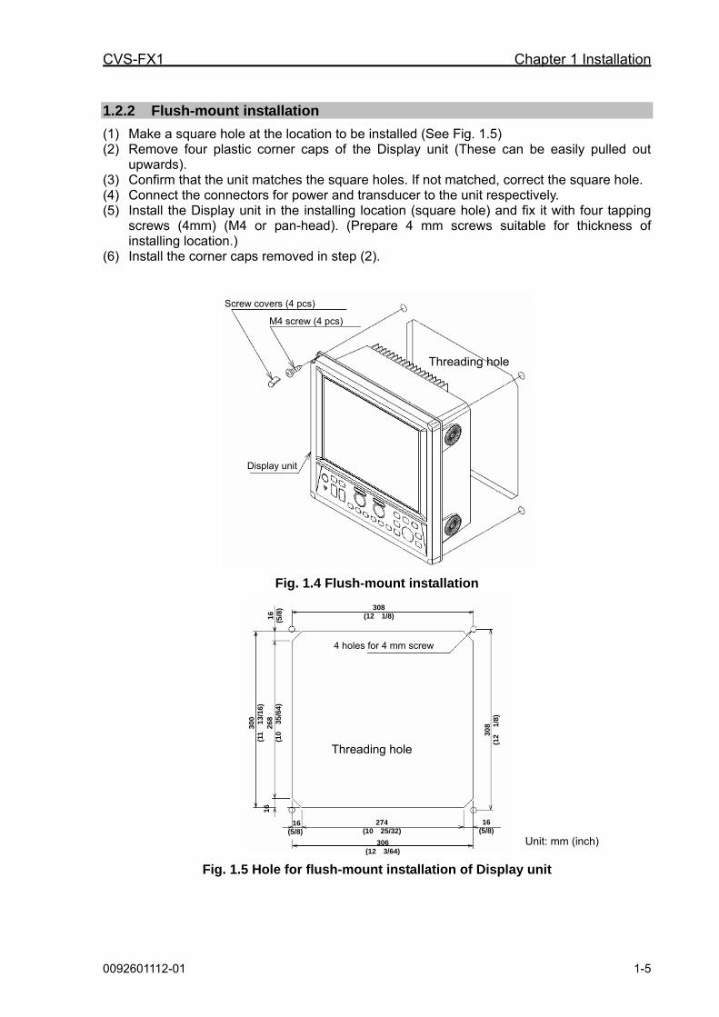
1.2.2 Flush-mount installation
(1) Make a square hole at the location to be installed (See Fig. 1.5) (2) Remove four plastic corner caps of the Display unit (These can be easily pulled out
upwards). (3) Confirm that the unit matches the square holes. If not matched, correct the square hole. (4) Connect the connectors for power and transducer to the unit respectively. (5) Install the Display unit in the installing location (square hole) and fix it with four tapping
screws (4mm) (M4 or pan-head). (Prepare 4 mm screws suitable for thickness of installing location.)
(6) Install the corner caps removed in step (2).
Fig. 1.4 Flush-mount installation
Fig. 1.5 Hole for flush-mount installation of Display unit
Screw covers (4 pcs)
Threading hole
M4 screw (4 pcs)
Display unit
306(12 3/64)
16 (5/8)
16
16(5/8)
Unit: mm (inch)
308(12 1/8)
4 holes for 4 mm screw
16
(5
/8)
30
0
(11
13/
16
) 2
68
(1
0
35/6
4)
274(10 25/32)
30
8
(12
1/8
)
Threading hole

Chapter 1 Installation CVS-FX1
1-6 0092601112-01
1.3 Installation of transducer
1.3.1 In the case of inner hull installation 1) In the case of steel boat
With reference to the figures below, install the transducer at a shipyard.
Fig. 1.6 Mounting of a transducer on steel boat
Mounting components of a transducer on steel boat
No. Name Material Qty Remarks 1 Transducer unit (with bottom plate) 1 2 Cable gland (CG-1) SS400B 1
By Koden
3 Tank SS400P 1 4 Mounting bolts SUS304 4
By shipyard
1
Unit: mm (inch)
Ship’s bottom and reinforcing plate
Weld plate or rod to protect knocking the net or ropes
Protruding amount; More than 300 mm (11 13/16)
φ60 (2 23/64)
110
(4 2
1/6
4)
713 (28 5/64)
140 (5 33/64)
2
4
Conduit pipe (SGP -1 1/2) This pipe should be extended to the draft line or to the junction box
Plumbing pipe (SGP-1 1/2) up to draft line or junction box
Cable gland Ship’s bottom and reinforcing plate
Weld plate or rod to protect knocking the net or ropes
Weld the position marked with
After tightening, apply putty to smooth the surface
Transducer unit
Tank
BOW
250
(9 2
7/3
2)
6
(15
/64
)
350
(13
25/
32
)
3
220 (8 11/16)
265 (10 7/16)
114 (4 31/64)
350 (13 25/32)
192
(7 9
/16
)
138
(5 7
/16
)

CVS-FX1 Chapter 1 Installation
0092601112-01 1-7
About installation:
Caution: 1. Plumbing pipe and welded plate or rod in dotted lines shall be provided by the shipyard after specifying the details.
2. Preferably larger amount of protruding could produce better performance.
Fig. 1.7 Outline view of a transducer unit on steel boat
Unit: mm (inch)
Transducer
Packing
60°
192
(7 9
/16)
235
(9 1
/4)
138
(5 7
/16)
19
(3/4
)
6 (1
5/64
)
10.5
(1
3/32
)
485 (19 3/32)
350 (13 25/32)
R16 (R5/8)
4-φ12
685 (26 31/32)
φ12 (15/32)
φ25 (63/64)
BOW

Chapter 1 Installation CVS-FX1
1-8 0092601112-01
2) In the case of wooden and FRP boat
With reference to the figures below, install the transducer at a shipyard.
Fig. 1.8 Installation of transducer
Parts list for installation of a transducer on FRP and wooden boat No. Name Qty Remarks 1 Transducer unit (With case, GE) 1 2 Cable gland (CG-16) 1
By Koden
3 Fixing bolts 4 4 Float 1 5 Pedestal 1
By shipyard
Unit: mm (inch)
Hull plate
Protruding amount More than 230mm
Fixing bolts
Cable gland
Pedestal
Hull plate
Float
Transducer
CVS-FX1 Chapter 1 Installation
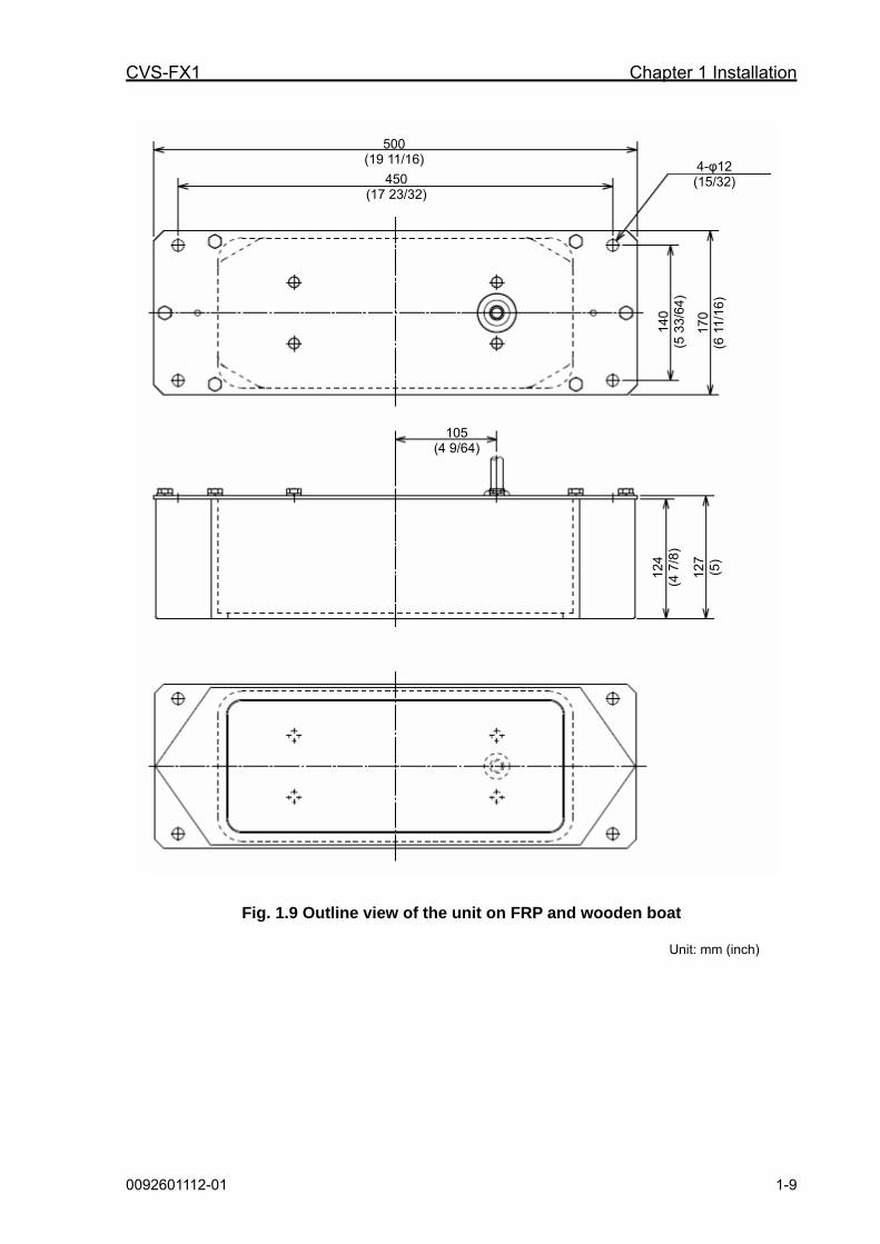
0092601112-01 1-9
Fig. 1.9 Outline view of the unit on FRP and wooden boat
Unit: mm (inch)
500 (19 11/16)
450 (17 23/32)
4-φ12 (15/32)
105 (4 9/64)
140
(5 3
3/64
)
124
(4 7
/8)
170
(6 1
1/16
)
127
(5)
Chapter 1 Installation CVS-FX1
1-10 0092601112-01
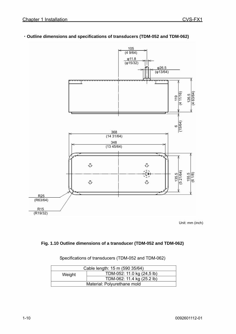
・Outline dimensions and specifications of transducers (TDM-052 and TDM-062)
Fig. 1.10 Outline dimensions of a transducer (TDM-052 and TDM-062)
Specifications of transducers (TDM-052 and TDM-062)
Cable length: 15 m (590 35/64) TDM-052: 11.0 kg (24,5 lb) Weight TDM-062: 11.4 kg (25.2 lb)
Material: Polyurethane mold
Unit: mm (inch)
105 (4 9/64)
φ11.8 (φ15/32)
φ26.5 (φ13/64)
348 (13 45/64)
368 (14 31/64)
119
(4 1
1/16
)
155.
5 (6
1/8
)
6 (1
5/64
)
126.
5 (4
63/
64)
135.
5 (5
21/
64)
R15 (R19/32)
R25 (R63/64)
CVS-FX1 Chapter 1 Installation
0092601112-01 1-11
1.4 Wiring
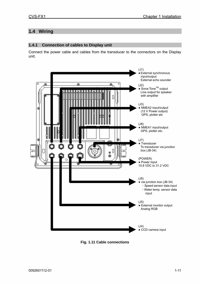
1.4.1 Connection of cables to Display unit
Connect the power cable and cables from the transducer to the connectors on the Display unit.
Fig. 1.11 Cable connections
(J1) ● External synchronous
input/output External echo sounder
(J2) ● Sona-ToneTM output
Line output for speaker with amplifier
(J3) ● NMEA2 input/output
(12 V Power output) GPS, plotter etc
(J8) ● NMEA1 input/output
GPS, plotter etc.
(J7) ● Transducer
To transducer via junction box (JB-34)
(POWER) ● Power input 10.8 VDC to 31.2 VDC (J6) ● via junction box (JB-34)
・Speed sensor data input・Water temp. sensor data
input
(J5) ● External monitor output
Analog RGB
(J4) ● CCD camera input

Chapter 1 Installation CVS-FX1
1-12 0092601112-01
Pin assignment of rear connectors
Pin assignment viewed from the rear of Display unit:
Fig. 1.12 Pins assignment of rear connector
1
3
4
5
2
POWER
1 : Power - 2 : Power + 3 : NC 4 : NC 5 : NC
J1
1
3
4
5
2
1 : External trigger input (+)
2 : External trigger input/output (-)
3 : External trigger output (+)
4 : NC 5 : NC
12
34 5
6
78
9
J5 1 : R 2 : R-GND 3 : G 4 : G-GND 5 : B 6 : B-GND 7 : H-SYNC 8 : V-SYNC 9 : BZCOM 10 : BZNO
1
2
34
5
6
7
8
J6 1 : Speed sensor input 2 : Speed sensor power (+) 3 : NC 4 : NC 5 : NC 6 : Water temp. sensor Power 7 : Water temp. sensor Input 8 : Speed sensor Power (-)
1 2
3 4 5
6
7 8
9
J2
1 : Sona-ToneTM R 2 : Sona-ToneTM L 3 : NC 4 : NC 5 : NC 6 : NC 7 : NC 8 : NC 9 : NC 10 : NC 11 : Sona-ToneTM COM 12 : NC
1
2 3
4
5
6
J3
1 : External power (-) 2 : NMEA2 TX+ 3 : NMEA2 TX- 4 : NMEA2 RX+ 5 : NMEA2 RX- 6 : External power (+)
1
2
3 4
5
6
7
J4 1 : CCD camera input 2 : CCD (-) 3 : NC 4 : NC 5 : NC 6 : NC 7 : NC
1
23
4
5
6
J8
1 : NMEA (-) 2 : NMEA1 TX + 3 : NMEA1 TX - 4 : NMEA1 RX + 5 : NMEA1 RX - 6 : NC
J7
1
3
4
5
2
1 : TD 1H (High frequency transducer) 2 : TD 1L (Low frequency transducer) 3 : Housing GND 4 : TD 2H (High frequency transducer 5 : TD 2L (Low frequency transducer)
Caution: Do not connect each wire to ship’s earth.
CVS-FX1 Chapter 1 Installation
0092601112-01 1-13
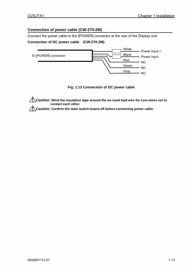
Connection of power cable (CW-270-2M)
Connect the power cable to the [POWER] connector at the rear of the Display unit.
Connection of DC power cable (CW-270-2M)
Fig. 1.13 Connection of DC power cable
Caution: Wind the insulation tape around the un-used lead wire for core-wires not to contact each other.
Caution: Confirm the main switch-board off before connecting power cable.
Power input +
Power input -
NC
NC
NC
To [POWER] connector
White
Black
Red
Green
Gray

Chapter 1 Installation CVS-FX1
1-14 0092601112-01
Connection of transducer
In the case of connection of CVS-FX1 and transducer (TDM-052/TDM-062):
1) Referring to the connection table of transducers (TDM-052/TDM-062), solder CW-836-3M and CW844-3M to the transducer (TDM-052/TDM-062). After soldering is completed, be sure to provide the connected part with water resistance and insulation using self adhesive tape, etc.
2) Connect CW-836-3M after the above processing to J7 connector of CVS-FX1. Connect CW844-3M after the above processing to J6 connector of CVS-FX1.
Fig. 1.14 Connection of transducer cable
Connection table of transducer (TDM-052/TDM-062)
Connectors to be connected Connectors to be connected from CW-836-3M J7
Connectors to be connected from CW-844-3M J6
Transducer cable
No. J6 Color of cable
Name of signal
Color of cable
Name of signal
Color of cable
Note
4 Shield - - Shield Shield Shield
6 Green/ Water temp. sensor power - - Green Water temp.
sensor White
7 Red/ Water temp. sensor input - - Red Water temp.
sensor Brown
Water temp. sensor
3 Orange/NC - - Orange - Orange NC 1 Blue/Speed sensor input - - Blue - -
2 White/ Speed sensor power (+) - - White - -
8 Black/ Speed sensor power (-) - - Black - -
Speed Sensor
No. J7
3 Shield Shield Housing GND - - Shield*
5 Black/TD2L (Low frequency transducer) Black TD2L - - Black
(Black/White)**
2 White/TD1L (Low frequency transducer) White TD1L - - Yellow
(Blue/White)**
Low
frequency
4 Green/TD2H (High frequency transducer) Green TD2H - - Black
1 Red/TD1H (High frequency transducer) Red TD1H - Blue
High frequency
Sol
dere
d
CW-836-3M Transducer cable
To J7 connector of CVS-FX1
CW-844-3M Sol
dere
d
To J6 connector of CVS-FX1
TDM-052 TDM-062
NC
To Speed sensor
Shield White
Brown
Orange
Shield* Black (Black/white)
Yellow (Blue/white)
Black Blue
Shield Green Red Orange Blue White Black Shield Black White Green Red

CVS-FX1 Chapter 1 Installation
0092601112-01 1-15
Caution: Wind the insulation tape around the un-used lead wire for core-wires not to contact each other.
* As for the shield of transducer to be connected with the shield of CW-836-3M, the 3 of outer shield, low frequency shield and high frequency shield shall be bundled and connected.
**For low frequency cable of transducer, there are two combinations of (Black : Yellow) and (Black/White : Blue/White). Connect them with the corresponding cable of CW836-3M and solder them.
Chapter 1 Installation CVS-FX1
1-16 0092601112-01
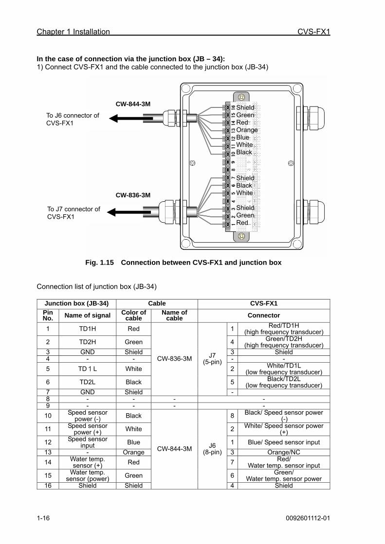
In the case of connection via the junction box (JB – 34): 1) Connect CVS-FX1 and the cable connected to the junction box (JB-34)
Fig. 1.15 Connection between CVS-FX1 and junction box
Connection list of junction box (JB-34)
Junction box (JB-34) Cable CVS-FX1
Pin No. Name of signal Color of
cable Name of
cable Connector
1 TD1H Red 1 Red/TD1H (high frequency transducer)
2 TD2H Green 4 Green/TD2H (high frequency transducer)
3 GND Shield 3 Shield 4 - - - -
5 TD1L White 2 White/TD1L (low frequency transducer)
6 TD2L Black 5 Black/TD2L (low frequency transducer)
7 GND Shield
CW-836-3M J7 (5-pin)
- 8 - - - - 9 - - - -
10 Speed sensor power (-) Black 8 Black/ Speed sensor power
(-)
11 Speed sensor power (+) White 2 White/ Speed sensor power
(+)
12 Speed sensor input Blue 1 Blue/ Speed sensor input
13 - Orange 3 Orange/NC
14 Water temp. sensor (+) Red 7 Red/
Water temp. sensor input
15 Water temp. sensor (power) Green 6 Green/
Water temp. sensor power 16 Shield Shield
CW-844-3M J6 (8-pin)
4 Shield
CW-844-3M
CW-836-3M
To J6 connector of CVS-FX1
To J7 connector of CVS-FX1
Shield Green Red OrangeBlue White Black
Shield Black White Shield Green Red
CVS-FX1 Chapter 1 Installation
0092601112-01 1-17
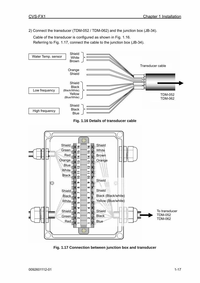
2) Connect the transducer (TDM-052 / TDM-062) and the junction box (JB-34).
Cable of the transducer is configured as shown in Fig. 1.16. Referring to Fig. 1.17, connect the cable to the junction box (JB-34).
Fig. 1.16 Details of transducer cable
Fig. 1.17 Connection between junction box and transducer
To transducer TDM-052 TDM-062
Shield
White
Brown
Orange
Shield
Shield
Black (Black/white)
Yellow (Blue/white)
Shield
Black
Blue
Shield
Green
Red
Orange
Blue
White
Black
Shield
Black
White
Shield
Green
Red
Water Temp. sensor
Low frequency
High frequency
Transducer cable
TDM-052TDM-062
Shield White Brown
Orange Shield
Shield Black
(Black/White) Yellow
(Blue/White)
Shield Black Blue

Chapter 1 Installation CVS-FX1
1-18 0092601112-01
Connection table of transducers (TDM-052/TDM-062)
*For low frequency, there are two combinations of cable colors, (yellow and black) and (blue/white and black/white). Connect the wires to the corresponding pin No.
CVS-FX1 Junction box
(JB-34) Transducer
(TDM-052/TDM-062)
No. Connection to: Pin No.
Signal name at connection to:
Color of cable Remarks
1 Red/TD1H
(high frequency transducer) 1 TD1H Blue
4 Green/TD2H
(high frequency transducer) 2 TD2H Black
3 Shield 3 GND Shield
High frequency
- - 4 - - -
2 White/TD1L
(low frequency transducer) 5 TD1L
Yellow (Blue/ white)*
5 Black/TD2L
(low frequency transducer) 6 TD2L
Black (Black/White)*
3 - 7 GND Shield
Low frequency
J7
- 8 - - - - - - 9 - Shield Shield
8 Black/Speed sensor power
(-) 10
Speed sensor power (-)
-
2 White/Speed sensor power
(+) 11
Speed sensor power (+)
-
1 Blue/Speed sensor input 12 Speed sensor
input -
Speed sensor
3 Orange/NC 13 - Orange -
7 Red/Water temp. sensor
input 14
Water temp. sensor (+)
Brown
6 Green/Water temp. sensor power
15 Water temp.
sensor power White
J6
4 Shield 16 Shield Shield
Water temp. sensor
CVS-FX1 Chapter 1 Installation
0092601112-01 1-19
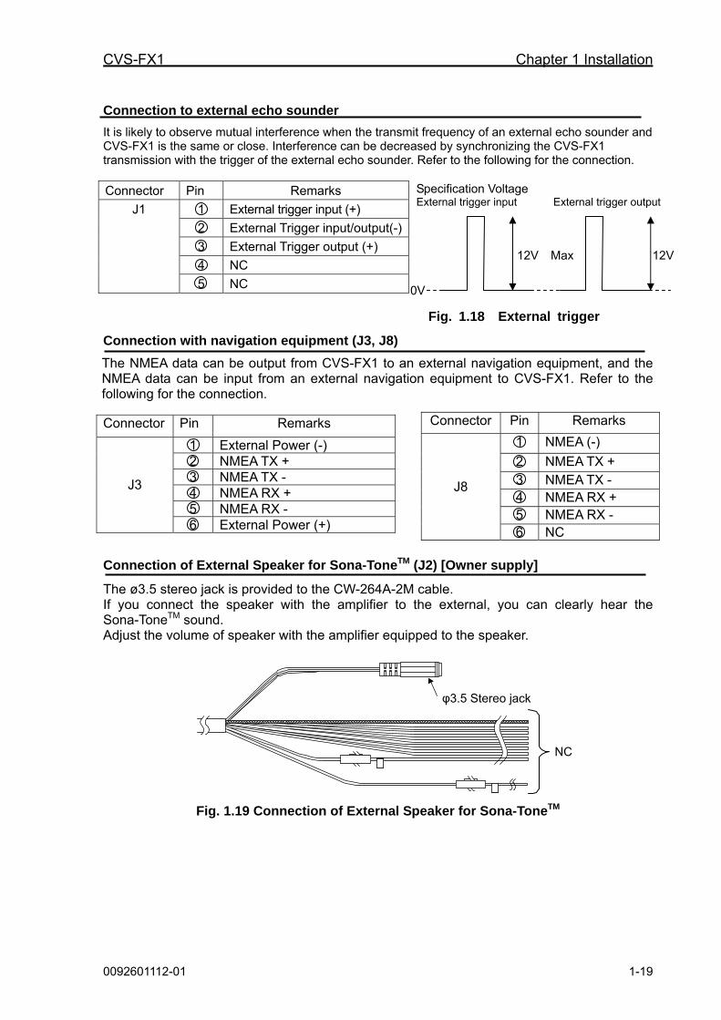
Connection to external echo sounder
It is likely to observe mutual interference when the transmit frequency of an external echo sounder and CVS-FX1 is the same or close. Interference can be decreased by synchronizing the CVS-FX1 transmission with the trigger of the external echo sounder. Refer to the following for the connection.
Connector Pin Remarks
1 External trigger input (+)
2 External Trigger input/output(-)
3 External Trigger output (+)
4 NC
J1
5 NC
Fig. 1.18 External trigger
Connection with navigation equipment (J3, J8)
The NMEA data can be output from CVS-FX1 to an external navigation equipment, and the NMEA data can be input from an external navigation equipment to CVS-FX1. Refer to the following for the connection.
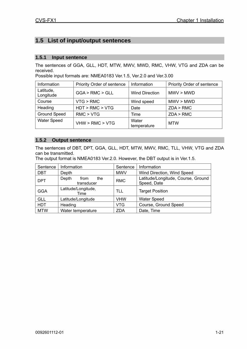
Connection of External Speaker for Sona-ToneTM (J2) [Owner supply]
The ø3.5 stereo jack is provided to the CW-264A-2M cable. If you connect the speaker with the amplifier to the external, you can clearly hear the Sona-ToneTM sound. Adjust the volume of speaker with the amplifier equipped to the speaker.
Fig. 1.19 Connection of External Speaker for Sona-ToneTM
Connector Pin Remarks
1 External Power (-) 2 NMEA TX + 3 NMEA TX - 4 NMEA RX + 5 NMEA RX -
J3
6 External Power (+)
Connector Pin Remarks
1 NMEA (-)
2 NMEA TX + 3 NMEA TX - 4 NMEA RX + 5 NMEA RX -
J8
6 NC
NC
φ3.5 Stereo jack
12V Max 12V
0V
Specification Voltage External trigger input External trigger output

Chapter 1 Installation CVS-FX1
1-20 0092601112-01
Connection of External Monitor (J5) [Owner supply]
When installing an external monitor (VGA monitor, analog RGB input), connect it via CW-576-0.5M. For its wiring, refer to the illustration below. After soldering, perform the waterproof and insulation treatment on the junction with a self-fusion tape.
Structure of CW-576-0.5M
Fig. 1.20 Connection of External Monitor
Connection of CCD camera (J4) [Owner supply]
CVS-FX1 and a CCD camera (NTSC/PAL/SECAM) can be connected via CW-405-0.3M (option). Connect the video output terminal (RCA plug (In most cases, yellow)) of your CCD camera. Perform the waterproof treatment on the junction of the RCA terminal with a self-fusion tape. Refer to the following for the connection.
Connector Pin Remarks 1 CCD camera input 2 CCD (-) 3 NC 4 NC 5 NC 6 NC
J4
7 NC
Fig. 1.21 Connection of CCD camera
RCA jack (Yellow)
(White)
To an external monitor via CW-560-2M or equivalent
(Black) NC
CVS-FX1 Chapter 1 Installation
0092601112-01 1-21
1.5 List of input/output sentences
1.5.1 Input sentence
The sentences of GGA, GLL, HDT, MTW, MWV, MWD, RMC, VHW, VTG and ZDA can be received. Possible input formats are: NMEA0183 Ver.1.5, Ver.2.0 and Ver.3.00
Information Priority Order of sentence Information Priority Order of sentence
Latitude, Longitude GGA > RMC > GLL Wind Direction MWV > MWD
Course VTG > RMC Wind speed MWV > MWD
Heading HDT > RMC > VTG Date ZDA > RMC
Ground Speed RMC > VTG Time ZDA > RMC
Water Speed VHW > RMC > VTG
Water temperature
MTW
1.5.2 Output sentence
The sentences of DBT, DPT, GGA, GLL, HDT, MTW, MWV, RMC, TLL, VHW, VTG and ZDA can be transmitted. The output format is NMEA0183 Ver.2.0. However, the DBT output is in Ver.1.5.
Sentence Information Sentence Information DBT Depth MWV Wind Direction, Wind Speed
DPT Depth from the
transducer RMC
Latitude/Longitude, Course, Ground Speed, Date
GGA Latitude/Longitude,
Time TLL Target Position
GLL Latitude/Longitude VHW Water Speed HDT Heading VTG Course, Ground Speed MTW Water temperature ZDA Date, Time

CVS-FX1 Chapter 2 Adjustment
0092601112-01 2-1
Chapter 2 Adjustment
2.1 Setup of transducer The frequency and beam angle etc. per transducer will be conformed to those of the transducer to be used, then, the correct information can be provided.
2.1.1 Setup of type of high frequency transducer
TD Setting – HF TD Type
Select the type of transducer to be actually used in high frequency. It has to be adjusted as it has influence on images.
1. Press .
2. Select [TD Setting] - [HF TD Type].
3. Press of [ ] of .
The setup box of [HF TD Type] will be displayed.
4. When a Broadband transducer is used, press [▲] and [▼] to select [Broadband Type]. When the other transducer is used, select [Others]. When a high frequency transducer is not used, select [OFF].
5. Press [ ]. When [Broadband Type] is selected, the setup box of [Broadband Type] will be displayed.
When [Others] is selected, the setup box of [Others] will be displayed.
6. Press [▲] or [▼] to select the type of transducer to use.
The transducer selected as a [Broadband Type] can be reflected to the [Broadband Type] of low frequency side.
7. Press to close the menu.
2.1.2 Setup of type of low frequency transducer
TD Setting – LF TD Type
Select the type of transducer to be actually used in low frequency. It has to be adjusted as it has effect on images.
1. Press .
2. Select [TD Setting] - [LF TD Type].
3. Press [ ] of .
The setup box of [LF TD Type] will be displayed.
4. When a Broadband transducer is used, press [▲] and [▼] to select [Broadband Type]. When a transducer other than that is used, select [Others]. When a low

Chapter 2 Adjustment CVS-FX1
2-2 0092601112-01
frequency transducer is not used, select [OFF].
5. Press [ ].
When [Broadband Type] is selected, the setup box of Broadband Type will be displayed.
When [Others] is selected, the setup box of others will be displayed.
6. Press [▲] or [▼] to select a transducer to use.
The TD selected as a [Broadband Type] is reflected to the [Broadband Type] of high frequency side.
7. Press to close the menu.
2.2 Setup of frequency of transducer
The high or low frequency can be setup for transducer frequency.
2.2.1 Setup of frequency for high frequency transducer
TD Setting – HF TD1 Setting
1. Press .
2. Select [TD Setting] – [HF TD1 Setting].
3. Press [ ] of .
The setup box of [HF TD1 Setting] will be displayed.
4. Press [▲] or [▼] to select [Frequency].
5. Press [ ].
The setup box of [Frequency] will be displayed.
6. Press [▲] or [▼] to select [Frequency].
7. Press to close the menu.
TD Setting – HF TD2 Setting
1. Press .
2. Select [TD Setting] – [HF TD2 Setting].
3. Press [ ] of .
The setup box of HF TD2 Setting will be displayed.
4. Set as the same way as HF TD1 Setting.
5. Press to close the menu.
2.2.2 Setup of frequency for low frequency transducer
TD Setting – LF TD1 Setting
1. Press .
2. Select [TD Setting] – [LF TD1 Setting].
3. Press [ ] of .
The setup box of [LF TD1 Setting] will be
displayed.
4. Set as the same way as [HF TD1 Setting].
5. Press to close the menu.
TD Setting – LF TD2 Setting
1. Press .
2. Select [TD Setting] – [LF TD2 Setting].

CVS-FX1 Chapter 2 Adjustment
0092601112-01 2-3
Caution: The setup of beam angle is reflected on the display of detecting range and will not change the actual beam angle.
3. Press [ ] of .
The setup box of [LF TD2 Setting] will be
displayed.
4. Set as the same way as [HF TD1 Setting].
5. Press to close the menu.
2.3 Setup of Beam Angle of transducer
The beam angle of the transducer of high and low frequencies can be set.
2.3.1 Setup of Beam Angle for high frequency transducer
TD Setting - HF TD1 Setting
1. Press .
2. Select [TD Setting] – [HF TD1 Setting].
3. Press [ ] of .
The setup box of [HF TD1 Setting] will be
displayed.
4. Press [▲] or [▼] to select [Beam Angle].
5. Press [ ].
The setup box of [Beam Angle] will be displayed.
6. Press [▲] or [▼] to set [Beam Angle].
When [Broadband Type] is selected at the selection of a transducer type, the
beam angle will be automatically set at setup of frequency.
7. Press to close the menu.
TD Setting - HF TD2 Setting
1. Press .
2. Select [TD Setting] – [HF TD2 Setting].
3. Press [ ] of .
The setup box of [HF TD2 Setting] will be displayed.
4. Set as the same way as [HF TD1 Setting].
5. Press to close the menu.
2.3.2 Setup of Beam Angle for low frequency transducer
TD Setting - LF TD1 Setting
1. Press .
2. Select [TD Setting] – [LF TD1 Setting].
3. Press [ ] of .
The setup box of [LF TD1 Setting] will be displayed.
4. Set as the same way as [HF TD1 Setting].
5. Press to close the menu.
Caution: The setup of beam angle is reflected on the display of detecting range and will not change the actual beam angle.
Chapter 2 Adjustment CVS-FX1
2-4 0092601112-01
Caution: The setup of beam angle is reflected on the display of detecting range and will not change the actual beam angle.
Caution: The setup of beam angle is reflected on the display of detecting range and will not change the actual beam angle.
TD Setting - LF TD2 Setting
1. Press .
2. Select [TD Setting] – [LF TD2 Setting].
3. Press [ ] of .
The setup box of [LF TD2 Setting] will be displayed.
4. Set as the same way as [HF TD1 Setting].
5. Press to close the menu.
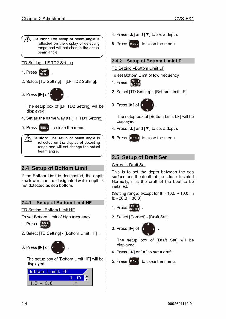
2.4 Setup of Bottom Limit If the Bottom Limit is designated, the depth shallower than the designated water depth is not detected as sea bottom.
2.4.1 Setup of Bottom Limit HF
TD Setting –Bottom Limit HF
To set Bottom Limit of high frequency.
1. Press .
2. Select [TD Setting] - [Bottom Limit HF] .
3. Press [ ] of .
The setup box of [Bottom Limit HF] will be displayed.
4. Press [▲] and [▼] to set a depth.
5. Press to close the menu.
2.4.2 Setup of Bottom Limit LF
TD Setting –Bottom Limit LF
To set Bottom Limit of low frequency.
1. Press .
2. Select [TD Setting] - [Bottom Limit LF]
3. Press [ ] of .
The setup box of [Bottom Limit LF] will be displayed.
4. Press [▲] and [▼] to set a depth.
5. Press to close the menu.
2.5 Setup of Draft Set Correct - Draft Set
This is to set the depth between the sea surface and the depth of transducer instated. Normally, it is the draft of the boat to be installed.
(Setting range: except for ft: - 10.0 ~ 10.0, in ft: - 30.0 ~ 30.0)
1. Press .
2. Select [Correct] - [Draft Set].
3. Press [ ] of .
The setup box of [Draft Set] will be displayed.
4. Press [▲] or [▼] to set a draft.
5. Press to close the menu.
CVS-FX1 Chapter 2 Adjustment
0092601112-01 2-5
Caution: In case of inner-hull installation, the set value of gain (TD) varies depending on the materials of bottom of the ship and the processing method. In some cases, low frequency side cannot be used due to too much attenuation of ultrasonic signal at ship’s bottom.
2.6 Setup of Gain (TD) for transducer
Correct – Gain (TD)
The insufficient gain due to ultrasonic signal attenuation can be corrected. Accuracy of bottom detection is adjusted. Such false recognition can be corrected that a deeper position is recognized as sea bottom than actual, or large fish school is recognized as sea bottom.
It is not necessary to do this gain correction for TDM-052, as the factory default setting is optimized for TDM-052.
1. Press .
2. Select [Correct] – [Gain (TD)].
3. Press [ ] of .
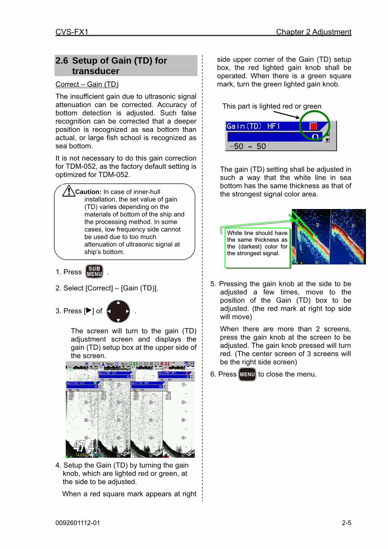
The screen will turn to the gain (TD) adjustment screen and displays the gain (TD) setup box at the upper side of the screen.
4. Setup the Gain (TD) by turning the gain knob, which are lighted red or green, at the side to be adjusted.
When a red square mark appears at right
side upper corner of the Gain (TD) setup box, the red lighted gain knob shall be operated. When there is a green square mark, turn the green lighted gain knob.
The gain (TD) setting shall be adjusted in such a way that the white line in sea bottom has the same thickness as that of the strongest signal color area.
5. Pressing the gain knob at the side to be adjusted a few times, move to the position of the Gain (TD) box to be adjusted. (the red mark at right top side will move)
When there are more than 2 screens, press the gain knob at the screen to be adjusted. The gain knob pressed will turn red. (The center screen of 3 screens will be the right side screen)
6. Press to close the menu.
WWhhiittee lliinnee sshhoouulldd hhaavvee tthhee ssaammee tthhiicckknneessss aass tthhee ((ddaarrkkeesstt)) ccoolloorr ffoorr tthhee ssttrroonnggeesstt ssiiggnnaall..
This part is lighted red or green

Chapter 2 Adjustment CVS-FX1
2-6 0092601112-01
2.7 Setup of Output Limit for transmitter
This is to set the output limit in the following cases:
1.When you examine standard TD (TDM-052/062) in the air
2. When you connect a non-standard low output power TD
2.7.1 Display of Output Limit Menu
1. If the power supply is ON, turn OFF the power supply by long press of the
key.
2. Press key, while keeping
key, and key at the same
time, to turn ON the power supply.
3. Press key after the normal image
is displayed.
4. [ Spc. Adj.] appears at the bottom of the submenu list.
2.7.2 Setup of Output Limit HF
1. Please display the [Spc. Adj.] at the bottom of the submenu list.(Refer to 2.7.1 Display of Output Limit Menu)
2. Press .
Select [Spc. Adj.] - [Output Limit HF].
3. Press [ ] of .
The setup box of [Output Limit HF] will be displayed.
4. Press [▲] or [▼] to set an output limit.
5. Press to close the menu.
2.7.3 Setup of Output Limit LF
1. Please display the [Spc. Adj.] at the bottom of the submenu list.(Refer to 2.7.1 Display of Output Limit Menu)
2. Press .
Select [Spc. Adj.] - [Output Limit LF].
3. Press [ ] of .
The setup box of [Output Limit LF] will be displayed.
Caution: Set the value at 20 for the examination of TDM-052/062 in the air. Set the value at 60 for the transducer of 1kW .

CVS-FX1 Chapter 2 Adjustment
0092601112-01 2-7
4. Press [▲] or [▼] to set an output limit.
5. Press to close the menu.
2.7.4 Relation of the set value between [Output Limit] and [MENU] - [Echo Adjust] - [TX Power]
[Output Limit] is a common setting regardless of CM key.
A set value of [TX Power] is applicable individually to each CM key.
[Output Limit] limits the output that becomes the source of [TX power].
The value of [TX Power] represents the percentage out of the value set by [Output Limit] as 100%.
For instance, when the value of [Output Limit] is 60, and the value of [TX Power] is 90, actual output is 90% of the output limited to 60% from the original output power.
[[OOuuttppuutt LLiimmiitt]] 6600 [[TTXX PPoowweerr]] 9900
Caution: Set the value at 20 for the examination of TDM-052/062 in the air. Set the value at 60 for the transducer of 1kW.
FFuullll PPoowweerr
Original power Source power Transmission

CVS-FX1 Chapter 3 Maintenance
0092601112-01 3-1
Chapter 3 Maintenance
3.1 Inspection The daily maintenance and inspection extend the life of equipment. To keep the equipment always in the best conditions, implement the periodical inspection shown in the table below.
Item Inspection item
Connectors at the rear of the Display unit
Check the looseness
Wiring of cables Check the wiring of cables connecting the equipment and the damage of cable
Grounding of Display unit Scrape the rust off the ground terminal and keep good contact .
3.2 Cleaning
3.2.1 Display unit
Contamination on the screen may cause faint images. For cleaning the screen, wipe it with soft and clean cloth dipped in diluted neutral detergent. Pay full attention as the screen gets scratched easily. No solvent such as thinner shall be used.
For cleaning the chassis, do not use solvent such as thinner or alcohol. Painting on the surface and characters at the operating unit may be dissolved. After wiping with soft and clean cloth dipped with diluted neutral detergent, wipe away with dry soft and clean cloth.
Caution The display screen has a special coating. Do not use a solvent such as paint thinner, acetone, alcohol, and benzene, etc. Strong rubbing may cause scratch.

Chapter 3 Maintenance CVS-FX1
3-2 0092601112-01
3.2.2 Transducer
In the case of the through-hull installation, check the surface of opening of transducer (portion from which the ultra-sonic is emitted). If shells or oil adhere, scrub the surface with a wooden or bamboo knife with caution not to damage the surface and remove stuck materials. If you scrub strongly, the surface will be damaged, resulting in deteriorated performance of transducer.
3.3 Fuse Replacement
Fuse blows out when such a trouble occurs inside at too high input voltage or over current. The fuse is located in the power cable. Please replace with the fuse listed in the list of standard components.
3.4 Diagnostics of troubles In this section, simple procedures to find out troubles are mentioned to locate the troubles on boat.
3.4.1 Necessary information for requesting repair
Please inform of the following points:
(1) Name of the ship, and telephone number, if a satellite communication system is equipped,
(2) Failed equipment name and type name
(3) Equipment serial number
(4) “Version number. of system software” displayed on “Title screen”
(5) Next calling port and name of sales agent, telephone number., Fax number., e-mail address, etc.
(6) Details of failure (as much as possible) and failure diagnostics results on board, as well as operation conducted, in particular, until the failure or when the failure occurred.
Use the specified fuse. If you use a fuse other than specified one, it may lead to a serious accident.
Warning
CVS-FX1 Chapter 3 Maintenance
0092601112-01 3-3
Caution: The LED on panel will turn the color from green to red if the gain knob is rotated to right or left, or one of CM1 ~ CM6 is pressed and one more pressing will turn the color to green. In addition, the internal buzzer will sound when the gain knob is rotated.
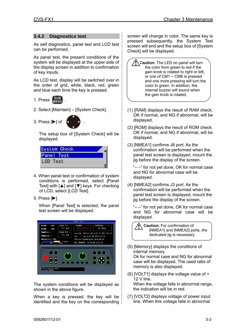
3.4.2 Diagnostics test
As self diagnostics, panel test and LCD test can be performed.
As panel test, the present conditions of the system will be displayed at the upper side of the display screen in addition to confirmation of key inputs.
As LCD test, display will be switched over in the order of grid, white, black, red, green and blue each time the key is pressed.
1. Press .
2. Select [Maintain] – [System Check].
3. Press [ ] of .
The setup box of [System Check] will be displayed.
4. When panel test or confirmation of system conditions is performed, select [Panel Test] with [▲] and [▼] keys. For checking of LCD, select [LCD Test].
5. Press [ ].
When [Panel Test] is selected, the panel test screen will be displayed.
The system conditions will be displayed as shown in the above figure.
When a key is pressed, the key will be identified and the key on the corresponding
screen will change in color. The same key is pressed subsequently, the System Test screen will end and the setup box of [System Check] will be displayed.
(1) [RAM] displays the result of RAM check. OK if normal, and NG if abnormal, will be displayed.
(2) [ROM] displays the result of ROM check. OK if normal, and NG if abnormal, will be displayed.
(3) [NMEA1] confirms J8 port. As the confirmation will be performed when the panel test screen is displayed, mount the jig before the display of the screen.
“– –” for not yet done, OK for normal case and NG for abnormal case will be displayed.
(4) [NMEA2] confirms J3 port. As the confirmation will be performed when the panel test screen is displayed, mount the jig before the display of the screen.
“– –” for not yet done, OK for normal case and NG for abnormal case will be displayed.
(5) [Memory] displays the conditions of internal memory. Ok for normal case and NG for abnormal case will be displayed. The used ratio of memory is also displayed.
(6) [VOLT1] displays the voltage value of + 12 V line. When the voltage falls in abnormal range, the indication will be in red.
(7) [VOLT2] displays voltage of power input line. When this voltage falls in abnormal
Caution: For confirmation of [NMEA1] and [NMEA2] ports, the dedicated jig is necessary.
Chapter 3 Maintenance CVS-FX1
3-4 0092601112-01
range, alarm will sound and an alarm message will be displayed.
When the voltage falls in abnormal range, the indication will be in red.
(8) [TEMP] displays water temperature of the water temperature sensor.
In the case of non connection, - 30.0 in red will be displayed.
(9) [SPEED] displays the speed of the boat’s speed sensor.
In the case of abnormality, display will be in red.
(10) [Version] displays the version No. of the system software.
(11) [IPL] displays the version No. of IPL version.
(12) [Top.ncd] will display the version No. of FPGA data.
(13) [MAC ADDRESS] displays MAC
address used in network..
3.4.3 LCD Test
Display the setup box for [System Check] in the same way as for [Panel Test], and select [LCD Test].When [ ] is pressed, the grid will be displayed.
Each time [ ] key is pressed, the color of display will change, and displays finally the setup box of [System Check].
3.4.4 Initialize
This is to return all setup of each CM or the whole system to the factory default settings. However, waypoint data and image stored data will remain as they are.
1. Press .
2. Select [Maintain] – [Initialize]
3. Press [ ] of .
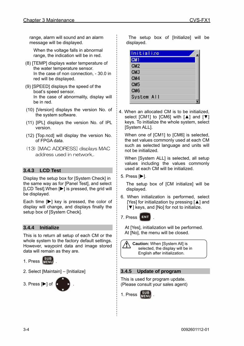
The setup box of [Initialize] will be displayed.
4. When an allocated CM is to be initialized, select [CM1] to [CM6] with [▲] and [▼] keys. To initialize the whole system, select [System ALL].
When one of [CM1] to [CM6] is selected, the set values commonly used at each CM such as selected language and units will not be initialized.
When [System ALL] is selected, all setup values including the values commonly used at each CM will be initialized.
5. Press [ ].
The setup box of [CM initialize] will be displayed.
6. When initialization is performed, select [Yes] for initialization by pressing [▲] and [▼] keys, and [No] for not to initialize.
7. Press .
At [Yes], initialization will be performed. At [No], the menu will be closed.
3.4.5 Update of program
This is used for program update. (Please consult your sales agent)
1. Press .
Caution: When [System All] is selected, the display will be in English after initialization.
CVS-FX1 Chapter 3 Maintenance
0092601112-01 3-5
2. Select [Maintain] – [System Program Load].
3. Press [ ] of .
The setup box of [System Program Load] will be displayed.
4. When [Yes] is selected, program will be in updating condition and a message “Updating Do not Power Off.” will be displayed.
When [No] is selected, returns to the menu.
5. Press .
When [Yes] is selected, the system turns into program updating and a message “Updating. Do not Power Off.” will be displayed.
When [No] is selected, the screen returns to the menu.
6. The program will be downloaded from USB ROM writer or PC.
When downloading has started, [CM] keys will blink red in the order of CM1 to CM6.
At completion of downloading, the both gain knobs will be lighted red.
7. Pressed for about 5 seconds to
switch off the power.
Caution: When program updating failed on the way, switch off the power once and switch on again. It will start up in the wait status of downloading. Try again the procedures from step 6 again.

Chapter 3 Maintenance CVS-FX1
3-6 0092601112-01
3.5 If you suspect a trouble
Symptom Possible cause of trouble Measure
Even with power on, nothing is displayed.
Fuse is blown. Power voltage is out of
specification (10.8 to 31.2 VDC)
Poor connection between power cable and battery
Replace the fuse (See “3.3 Fuse Replacement”, page 3-2.
Use a proper power as per specification.
Check the connection between power cable and battery.
After starting up, nothing is displayed
Poor connection between transducer and Display unit
Failure of LCD display panel
Check the connection between transducer and Display unit.
Consult a repair shop or sales agent.
Much interference noise Improper installation of transducer
Interference from the echo sounder on other boats.
Check the installed position of transducer (See “1.3 Installation of transducer”, page 1-6.
Implement interference rejection.
Display of water temperature / Speed is abnormal or not displayed.
Poor connection of sensors connectors
Input sources may be abnormal.
Check the connection at sensor connectors.
Check the input sources.
Display of present location/course is abnormal or not displayed.
Poor connection between this unit and navigation equipment
Check the connection between this unit and navigation equipment.
