cw keyer manual (1130).pdf - nue-psk.com
TRANSCRIPT

Page 1 of 26
CW Keyer Manual (and other functional enhancements)
NUE-PSK Modem
Version 5.00
David Collins – AD7JT
29 November 2011

Page 2 of 26
Table of Contents 1.0 Introduction ............................................................................................................... 4
2.0 General Description .................................................................................................. 4
2.1 Interface Connections ............................................................................................ 5
2.2 Transmit Operation ............................................................................................... 6
2.3 Receive Operation .................................................................................................. 7
3.0 Functional Description .............................................................................................. 8
3.1 External (Practice) Keyer Input Processing ......................................................... 8
3.2 Built-in Keyer Input Processing ............................................................................ 9
3.3 Keyer Side Tone ................................................................................................... 10
3.4 Keyer Escape Code ............................................................................................... 10
3.5 Keyed Common Functions ................................................................................... 11
3.6 Keyed Transmit Functions .................................................................................. 12
3.7 Keyed Receive Functions ..................................................................................... 13
3.8 Keyed Macro Functions ....................................................................................... 14
4.0 DLE Sequence Display ............................................................................................ 14
5.0 Keyer Speed Control ............................................................................................... 14
6.0 CW Practice Mode ................................................................................................... 15
7.0 Other Changes Incorporated in This Release ........................................................ 15
7.1 Vocabulary Additions ........................................................................................... 15
7.2 Direct Keying CW ................................................................................................ 15
7.3 Transmit Side Tone Tweak ................................................................................. 16
7.4 Enter File Name (Ctrl-N) Display Relocation .................................................... 16
7.5 Enter RTCC Date (Ctrl-D) Display Relocation ................................................... 17
7.6 Enter RTCC Time (Alt-D) Display Relocation .................................................... 17
7.7 Programmable Gain Amplifier (PGA) Gain Level Display ................................ 18
7.8 Automatic Frequency Control (AFC) indicator ................................................... 18
7.9 Save Text on Switch from Rx to Tx ..................................................................... 19
7.10 Configure Menu Terminology .............................................................................. 19
8.0 Keyer Configuration Menu Options ....................................................................... 19

Page 3 of 26
8.1 Keyer Mode Selection .......................................................................................... 19
8.2 CW Paddle Reverse .............................................................................................. 20
APPENDIX A. Morse Code Encoding with Prosigns and ASCII Equivalents. ............. 21
APPENDIX B. EEPROM Content Map .......................................................................... 23
APPENDIX C. Hot Key Assignments ............................................................................. 25

Page 4 of 26
1.0 Introduction
This document describes the functional enhancements in the NUE-PSK Digital Modem firmware version
5. A major part of these enhancements includes a built in keyer for using CW to enter Tx text and
modem commands that can process input from either iambic or single-lever paddles. The built-in keyer
implementation makes it possible to operate the modem without requiring a keyboard. This document
assumes that the reader is familiar with the CW Mode Operating Section of the NUE-PSK Digital
Modem Operating Manual (for firmware version 4).
The firmware will also process input from an external keyer or a straight key in a “practice mode”.
Since the firmware processes input from a straight key the same way it processes input from an external
keyer, this document will generally refer to either of these simply as an “external keyer”. In practice
mode, the external keyer drives the Morse code decoding logic in receive mode and displays the ASCII
decode of the Morse characters. This mode was introduced in previous firmware versions and is
completely independent of the full-function keyer implemented in this firmware version. In the
remainder of this document, the term “keyer” pertains only to the built-in keyer.
The keyer is a new user input device and may be used with or without a keyboard attached to the
modem. The keyer can provide all the control and text input functions normally provided by the
keyboard. This functionality is available in all operating modes, not just CW mode, thus enabling PSK
and RTTY operation without requiring a keyboard. Support for the external keyer and practice modes
are only available in CW mode.
To utilize keyer functions, a CW paddle must be interfaced to the modem assembly and wired to two
expansion pads on the main modem PCBA. This document recommends a method for adding a connector
to the modem assembly but the user may use other methods as long as the required interface
connections are provided. A minor modification to the modem chassis may be required to accommodate
the connector.
The keyer supports the following keyer operating modes:
Iambic type A
Iambic type B
Dot Preferred
Dash Preferred
Ultimatic
Note that semi-automatic (bug) mode is not supported. The keyer operating mode is a Configure Menu
selection.
Normally, the left paddle will generate dots and the right paddle will generate dashes. Some left-handed
operators prefer to reverse the paddle functions. CW paddle reversal is implemented as a Configuration
Menu option
2.0 General Description
Keyer functions make maximum use of existing CW support functions. Keyer input is always translated
to ASCII for processing by the modem firmware. This approach simplifies the keyer implementation and
results in a high level of consistency between keyer and keyboard input.

Page 5 of 26
2.1 Interface Connections
The major digital modem system components are shown in the following diagram:
A common interface of two signal lines plus ground is used to interface either a CW paddle or an
external keyer to the modem. The signal lines are labeled “DIT” and “DAH” and must be connected to
the dsPIC expansion pads ‘b’ (DIT) and ‘a’ (DAH) on the main modem PCBA. Note that there is a
conductor from the three-wire cable to the USB option card connected to expansion pad ‘a’. This signal is
no longer used so the wire can be disconnected and insulated so it does not cause a short to components
or etch on the main modem board. The signal attached to expansion pad ‘a’ also requires a 10 K ohm
pull up resistor to 3.3 volts. Expansion pad ‘b’ uses a weak pull up built into the dsPIC I/O pin. The
following schematic shows the keyer interface connection using a 3.5 MM stereo connector (Digi-Key P/N
SC1464-ND or equivalent).
2
3
4
5
1
DAHEXPANSION PAD ‘a’
(RD0)
+3.3 V
EXPANSION PAD ‘b’(RC13)
DIT
10 K
N.C.
RING
TIP0.1 uF
0.1 uF
When the modem is powered up, the signal level on expansion pad ‘a’ (DAH) is checked. If it is at ground
level, the firmware assumes a monaural phone plug is plugged into the connector, all keyer functions

Page 6 of 26
requiring a paddle will be disabled, and the CW practice mode will be enabled. (Note that this will also
be true if nothing is plugged into the keyer jack.) In this case, expansion pad ‘b’ (DIT) will be assumed to
be driven by an external keyer and expansion pad ‘a’ will be ignored. All other modem functions will
operate normally.
The interface connector can be mounted on a metal angle bracket attached to the modem PCBA with the
mounting screw located just below the keyboard connector. This mounting screw is also used to ground
the PCBA to the modem chassis so no separate ground connection will be required. When the connector
is installed in this position, the modem chassis must be modified to provide access to the connector.
The following picture illustrates this connector mounting method:
Note that the connector opening in the flange on the chassis has been widened to accommodate the
connector.
2.2 Transmit Operation
The following block diagram shows the major functional elements involved in transmit modes.
Emphasized (with shadows) elements and interconnections have been added to support keyer functions;
the other elements were included in previous firmware releases.

Page 7 of 26
After the firmware determines whether an external CW paddle or an external keyer is plugged into the
keyer connector, it sets up the appropriate routing through the functional firmware blocks. When an
external CW paddle is connected, inputs (DIT and DAH) from the interface connector are processed by
the built-in keyer logic to generate groups of MARKs (dots and dashes) comprising Morse characters.
Each group is then translated to ASCII and passed on to the standard firmware functions to display,
transmit, record, and/or interpret as hotkey functions.
To facilitate hot-key simulation, an escape character has been defined using a unique Morse code
character. This code is only recognized when generated by a CW paddle. It will be treated like an
undefined Morse character when decoded in received text. The escape character and its uses are
described in detail in later sections.
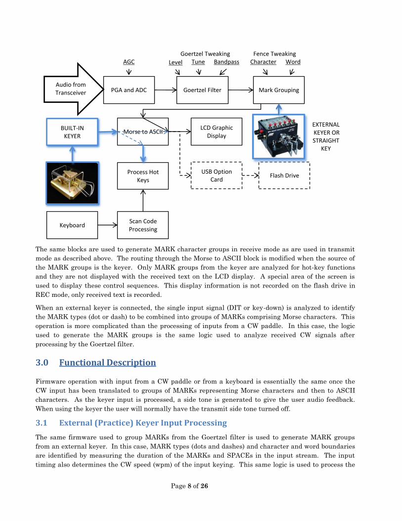
2.3 Receive Operation
The following block diagram shows the major functional elements involved in receive modes. Elements
and interconnections with shadows are added to support keyer functions; the non-shadowed elements
were included in previous firmware releases. The dashed routing paths through the Morse to ASCII
block represent special routing to facilitate keyer-initiated functions.
Keyboard Scan Code Processing
ASCII to Morse
LCD Graphic Display
EEPROM Macro
Playback
Phase Modulator
USB Option Card
Flash Drive
Audio to Transceiver
BUILT-IN KEYER
Morse to ASCII
Process Hot Keys
EXTERNAL CW
PADDLE
Page 8 of 26
The same blocks are used to generate MARK character groups in receive mode as are used in transmit
mode as described above. The routing through the Morse to ASCII block is modified when the source of
the MARK groups is the keyer. Only MARK groups from the keyer are analyzed for hot-key functions
and they are not displayed with the received text on the LCD display. A special area of the screen is
used to display these control sequences. This display information is not recorded on the flash drive in
REC mode, only received text is recorded.
When an external keyer is connected, the single input signal (DIT or key-down) is analyzed to identify
the MARK types (dot or dash) to be combined into groups of MARKs comprising Morse characters. This
operation is more complicated than the processing of inputs from a CW paddle. In this case, the logic
used to generate the MARK groups is the same logic used to analyze received CW signals after
processing by the Goertzel filter.
3.0 Functional Description
Firmware operation with input from a CW paddle or from a keyboard is essentially the same once the
CW input has been translated to groups of MARKs representing Morse characters and then to ASCII
characters. As the keyer input is processed, a side tone is generated to give the user audio feedback.
When using the keyer the user will normally have the transmit side tone turned off.
3.1 External (Practice) Keyer Input Processing
The same firmware used to group MARKs from the Goertzel filter is used to generate MARK groups
from an external keyer. In this case, MARK types (dots and dashes) and character and word boundaries
are identified by measuring the duration of the MARKs and SPACEs in the input stream. The input
timing also determines the CW speed (wpm) of the input keying. This same logic is used to process the
Audio from Transceiver
PGA and ADC Goertzel Filter Mark Grouping
Morse to ASCII LCD Graphic
Display
USB Option Card
Flash Drive
AGC Level Tune Bandpass Character Word
Fence Tweaking Goertzel Tweaking
BUILT-IN KEYER
Process Hot Keys
Keyboard Scan Code Processing
EXTERNAL
KEYER OR
STRAIGHT
KEY

Page 9 of 26
output from the Goertzel filter in receive mode which must be processed independently from the external
keyer input. This mode of operation is only intended for off-line practice and demonstrations, keyed data
is only displayed, and it is never transmitted.
3.2 Built-in Keyer Input Processing
Since the built-in keyer has separate inputs for dots and dashes, it can generate MARK groups without
having to determine Tcw from the paddle input. Instead, the operator sets the transmit keying rate
which determines Tcw. Training is not required to determine Tcw as is needed to accurately decode
received CW text. MARK groups are generated directly from the states of the DIT and DAH inputs at
specific time intervals that are multiples of Tcw.
For example, when the DIT input is active, the keyer logic buffers a dot in the current MARK group then
monitors the input for two Tcw. If the DIT input is still active, it buffers another dot and waits two more
Tcw. If, instead, the DAH input is active, a dash is buffered and the keyer logic waits four Tcw before
checking the inputs. If neither the DIT nor the DAH inputs are active, the current MARK group is
complete and passed on to be processed as a Morse character and the keyer logic waits two more Tcw
before checking the inputs again. If one of the inputs is active at that time, a new MARK group is
started otherwise a space (end of word) is inserted in the character stream. After an end of word, the
keyer logic goes idle until an input goes active signaling the start of the next MARK group.
When using an iambic (two-lever) paddle, the above sequence is modified to handle the case where both
inputs are active. In this case, keyer processing is governed by a Configure Menu option as follows:

Page 10 of 26
IAMBIC KEYER MODE PADDLE SQUEEZE ACTION
Iambic-A Alternate dots and dashes, immediate end
Iambic-B Alternate dots and dashes, one element added
Dot Preferred Repeated dots
Dash Preferred Repeated dashes
Ultimatic Repeat last selected
In iambic-A mode, the alternate dot - dash generation will terminate as soon as the keyer senses one or
both of the inputs are inactive. In iambic-B mode, one more complete element is generated after the
keyer senses one or both of the inputs are inactive. The additional element will be the opposite of the
last one generated while both inputs were active. Of course, none of these modes apply when a single-
lever paddle is used for input.
3.3 Keyer Side Tone
A 400 Hz side tone is generated when the keyer is used. The side tone is always enabled and the
frequency is fixed. The low frequency was selected to make it easy to distinguish between it and the Rx
and Tx side tones. It is recommended that the Tx and Rx side tones be disabled when using the keyer.
Multiple tones do not mix well in the modem’s piezo noise maker. The rig’s receive audio can be on for
tuning and signal monitoring.
3.4 Keyer Escape Code
In general, the generation of special hotkeys with the keyer requires a mechanism to identify the input
as a hot-key sequence. To satisfy this requirement, a special code has been defined for use as an escape
character. The code chosen for the escape character is not defined in standard and extended
(international) Morse code sets and is relatively easy to key. The chosen code is:
..-..- (prosign uU). This character cannot be generated by the keyboard. It will be represented by and
displayed as a backward slash character (‘\’). All keyed hotkey sequences must start and end with this
character which will be referred to as a “Data Link Escape” or “DLE” character.
When a DLE character is entered, it indicates the start or end of a hotkey sequence. Hotkey sequences
consist of the DLE character followed by one or two characters followed by another DLE character. Once
the first DLE character is recognized, all inter-word SPACEs are ignored. Hotkey sequences never
contain space characters. When the ending DLE character is entered, the hotkey sequence is validated
and, if valid for the current mode, it is processed and executed immediately. If a hotkey sequence is not
valid for the current mode, it is simply ignored; there is no explicit error indication. When entering
hotkey sequences, the prosign “hH” (eight or more dots) will be processed as a backspace. The preceding
character will be deleted. Note that the starting DLE character cannot be deleted. To cancel a hotkey
sequence after it is started, simply key in an illegal character sequence followed by the closing DLE
character.

Page 11 of 26
Wherever possible, the characters used for keyed hotkeys are the same as those used for keyboard
hotkeys. Leading letters ‘A’ and ‘C’ are used to indicate Alt- and Ctrl- prefixes. For example, to insert
THEIRCALL in transmit text from a keyboard enter Alt-T and from the keyer enter “\AT\”. Two
consecutive DLE characters perform the same function as the Esc key on the keyboard (i.e., toggle Rx or
Tx side tone on and off).
Function keys F1 through F10 are input as just the numbers 1 through 9 and 0. For example, ‘F1’ on the
keyboard is entered with the keyer as “\1\”, Ctrl-F5 is entered as “\C5\”, and Alt-F9 is entered as
“\A9\”. Function key F10 is entered as “\0\” or “\10\”.
In most cases, keyer input characters not preceded by a DLE character in Rx mode will be ignored. The
exceptions are single-letter hot keys used in Rx mode. Since keyboard input is not part of the receive
processes, keyboard inputs are always processed as hotkeys. Defined Rx hotkeys are processed,
unrecognized keyboard inputs are ignored. The same is true for keyed characters in Rx mode. For
example, tweak CW bandwidth may be initiated by keying either “\B\” or the single character “B”. This
is only possible for single-character hotkey sequences where the keyboard character is the same as the
keyed character. Keyer input characters not preceded by a DLE character in Tx mode will generate
ASCII characters to be encoded and transmitted.
3.5 Keyed Common Functions
The following hotkey functions are available in both Tx and Rx modes:
KEYBOARD KEYER HOTKEY FUNCTION
Ctrl-Tab \?\ Display current frequency
F1 – F7 \1\ – \7\ Play macro 1 - 7
F8 \8\ Toggle Tune mode ON/OFF
Shift-F9
or Ctrl-F9** \C9\ Turn Beacon mode ON
Alt-F9 \A9\ Turn beacon mode OFF
F11 \11\ Display My Call
F12 \12\ Display/Hide Config
Ctrl-U \CU\ Toggle RECord mode ON / OFF
Ctrl-I n/a Enter text to be RECorded
Ctrl-A \CA\ Enable AFC
Alt-A \AA\ Disable AFC
Ctrl-O \CO\ Toggle LCD display back light ON/OFF
Ctrl-L \CL\ Clear text display
Ctrl-F \CF\ Save current frequency in EEPROM
Alt-F \AF\ Set current frequency from EEPROM
Ctrl-N n/a Enter RECord file name
Ctrl-Z or F9 \CZ\ or \9\ End \CI\ and \CN\
** New Hotkey assignment
Note that the Ctrl-I hotkey function is not implemented for keyer input. This operation uses the
Buffered_Text_Capture function which is not capable of accepting keyer input. For more information see
Keyer Macro Functions below.

Page 12 of 26
3.6 Keyed Transmit Functions
The following hotkey functions are available in Tx mode:
KEYBOARD KEYER HOTKEY FUNCTION
Esc \\ Toggle Tx side tone ON/OFF *
Alt-K \AK\ Insert Beacon Count
Alt-M \AM\ or mc Insert My Call
Alt-S or Alt-X \AS\ or \AX\ Insert Serial Number
Alt-T \AT\ of tc Insert Their Call
F10 \10\ or \0\
or _K_*** or _K_
or _kn_ or _KN_ or _kn_ or _KN_
or _bk_ or _BK_ or _bk_ or _BK_
or _sk_ or _SK_ or _sk_ or _SK_ Toggle Tx mode OFF
*** ‘_’ represents a keyboard space character or a CW inter-word SPACE (5+ Tcw)
Note: Tx mode is toggled off by a “normal” end of transmission character sequence. These prosigns and
one and two character sequences must be preceded and followed by an inter-word SPACE followed by
nothing. The end of transmission sequence must be the last thing in the transmit buffer for it to be
acted on. The end of transmission characters will be transmitted before toggling Tx mode off.

Page 13 of 26
3.7 Keyed Receive Functions
The following hotkey functions are available in Rx mode:
KEYBOARD KEYER HOTKEY FUNCTION
Esc \\ Toggle Rx side tone ON/OFF *
B \B\ or B Tweak CW Bandwidth *
C \C\ or C Tweak Character space multiple *
G or T \G\ or G Tweak Goertzel Threshold *
S \S\ or S Tweak Serial Number
W \W\ or W Tweak Word space multiple *
Z \Z\ or Z Tweak MARK limit *
+ or U** \U\ or U****
\up\ or up Tweak Up (Locks \C\, \G\, or \W\)
- or D** \D\ or D****
\do\ or do Tweak Down (Locks \C\, \G\, or \W\)
Home \bk\ or bk Reset Serial Number to 001 (\S\ only)
Enter \ar\ or ar End Tweaking (Unlocks \C\, \G\, and \W\)
Alt-D \AD\ Enter Time
Ctrl-D \CD\ Enter Date
Ctrl-M \CM\ Enter/Edit My Call
Ctrl-T \CT\ Enter/Edit Their Call
X \X\ or X Tweak Serial Number and Enter/Edit Their Call
Home \bk\ or bk Clear Their Call (\CT\ and \X\) or clear My Call (\CM\)
Ctrl-Z or F9 \CZ\ or \9\ End \AD\, \CD\, \CM\, \CT\, and \X\
Enter \ar\ or ar End \AD\, \CD\, \CM\, \CT\, and \X\
(Unlocks \C\, \G\, and \W\)
Page Up \PU\ Increase PGA Gain
Page Down \PD\ Decrease PGA Gain
Left Arrow \LA\ Tune down x 1
Right Arrow \RA\ Tune up x 1
Down Arrow \DA\ Tune down x 2
Up Arrow \UA\ Tune up x 2
End \AQ\ Acquire (tune to nearby maximum signal level)
F10 \10\ or \0\
or ct Toggle Tx mode ON
* CW mode only
** New Hotkey assignment
**** U and D will not tweak Serial Number in \X\, use ‘up’ and ‘do’.

Page 14 of 26
Note: Prosigns in DLE sequences can be keyed as discrete characters. Therefore “\bk\” may be keyed
as “\BK\”, “\ar\” may be keyed as “\AR\”, and “\do\” may be keyed as “\DO\”. Prosigns not in DLE
sequences must be entered without the intra character SPACE.
3.8 Keyed Macro Functions
Entering and deleting macros with the keyer are not supported in this
release. It may be considered for a future release but, to do so, will require
major changes to basic parts of the firmware.
4.0 DLE Sequence Display
When a DLE character is keyed, the modem will display a backwards slash (‘\’) character in the first
column of the third line of the LCD display screen. The next one or two characters keyed will be
displayed after the DLE as they are keyed. When the ending DLE is keyed and the sequence is valid, it
will be acted on. If the sequence is not valid it will be ignored. In either case, the DLE display will be
cleared. The ending DLE is never displayed.
.
5.0 Keyer Speed Control
In CW mode, the keyer speed is the same as the CW transmit speed (keying rate). The keying rate can
be changed to any value between 5 wpm and 50 wpm when in Tx mode by turning the tune control.
Since the keyer can be used in any operating mode, the keying rate control has been included in the Tx
display for all modes. In operating modes other than CW, the keying rate can only be adjusted and the
rate will only be displayed when the keyer is enabled.

Page 15 of 26
An additional field has also been added to the Tx display to identify the current operating mode. The
operating mode is displayed as: “BPSK”, “QPSK”, “QPSK/R”, “RTTY”, “CW”, or “CWD”. When the keyer
is not enabled, the TX display line will be truncated immediately after the operating mode field.
6.0 CW Practice Mode
Since some of the operating procedures to perform all the modem functions from the keyer are new, a
practice mode is included in this firmware release to help the user get familiar with them. Practice
mode is selected from the CONFIGURE>MODE menu like any other operating mode. To activate
practice mode, select “CW Practice” from the menu. This will activate all the normal CW features and
keyer functions except the transceiver’s PTT line will not be keyed and received text will not be
displayed on the receive text area of the LCD. CW Practice mode will not be saved with a Save
Configuration nor will it be restored on power up. If a Save Configuration is performed in CW Practice
mode, the modem will restart in CW mode. The same is true of Upload Config and Download Config.
7.0 Other Changes Incorporated in This Release
The following subsections describe those functional changes made in this firmware version other than
the CW Keyer support.
7.1 Vocabulary Additions
The CW vocabulary has been expanded to include ‘@’ (.--.-.). This character was added to
International Morse Code in the 2004 version of Recommendation ITU-R M.1677.
The CW and PSK vocabularies have been expanded to include ‘é’ (..-..) . The ASCII code for this
character is 0xE9 (233) which exceeds the upper limit for a 7-bit code (0x7F or 127). Internally, the
firmware uses ASCII code 0x40 (64) to represent this character. The 0x40 ASCII code is normally
assigned to ‘`’ (grave accent) which has little or no use as a stand-alone character in normal text.
Some international keyboards use this key to apply the grave accent to the following character.
7.2 Direct Keying CW
CW support in previous versions of the modem firmware requires the transceiver be in SSB mode. Rigs
that do not support SSB operation could not be used with the modem. This includes many older rigs,
QRP rigs, kits, and homebrew rigs. This version of the firmware supports a direct keying CW mode
where the rig can be operated in CW mode and the modem keys its PTT interface line. This operating
mode is enabled by selecting the “CW DIRECT” mode from the modem configuration menu. CW DIRECT
requires a special cable to connect the modem PTT line (J3, pin 8) to the rig’s key-in jack and the modem

Page 16 of 26
audio input interface line to the rig’s audio-out jack. This cable will only work in CW DIRECT mode. In
some cases, an interface adapter may be required for, circuit isolation, voltage level translation, and/or
signal polarity conversion (e.g., for vacuum tube keying).
The following cable (or equivalent) is required for direct keying CW:
Keyer
Phones
DIT
DAH
Audio
N.C.
COMMON
COMMON
87654321 N.C.
N.C.
N.C.
N.C.
N.C.
J3 RADIO
N.C.
PTT
Audio In
GRD
This cable can be made as a stand-alone interface or incorporated into a standard modem-to-transceiver
cable or as an adaptor between the standard cable and the modem.
Note: Many commercial transceivers have an option that enables transmitter keying using the data
interface PTT line in CW mode. It those cases, the standard data mode interface cable can be used.
Check your transceiver operating manual.
7.3 Transmit Side Tone Tweak
Previous versions required the Ctrl key to be held down to adjust the Tx and Rx side tone frequency with
the tuning knob. This version allows the frequency adjustment when either the Ctrl key or the Select
button is pressed. Note that the side tone frequency applies to both Tx and Rx side tones but the
frequency can only be adjusted in Tx mode. This change allows the side tone frequency to be adjusted
without a keyboard attached to the modem.
7.4 Enter File Name (Ctrl-N) Display Relocation
The Enter File Name function display area has been moved to the upper right quadrant of the LCD.
This allows the function to be performed without interrupting an in-process Rx operation. It also allows
the file name to be entered/edited using either the keyboard or the keyer. Note there is no validation of
the input characters other than length.

Page 17 of 26
7.5 Enter RTCC Date (Ctrl-D) Display Relocation
The Enter RTCC Date function display area has been moved to the upper right quadrant of the LCD.
This allows the function to be performed without interrupting an in-process Rx operation. It also allows
the RTCC date to be entered/edited using either the keyboard or the keyer. Note that the date
separators (‘-’and ‘/’) are not verified as long as there is a character in the assigned position. The
forward slash may be input with a keyer but the dash cannot. Any character, such as a period or a
comma, can be used instead of the dash.
7.6 Enter RTCC Time (Alt-D) Display Relocation
The Enter RTCC Time function display area has been moved to the upper right quadrant of the LCD.
This allows the function to be performed without interrupting an in-process Rx operation. It also allows
the RTCC date to be entered/edited using either the keyboard or the keyer. Note that the time separator
(‘:’) is not verified as long as there is a character in the assigned position. Any character, such as a
period or a comma, can be used instead of the colon.

Page 18 of 26
7.7 Programmable Gain Amplifier (PGA) Gain Level Display
In receive mode the gain of the input amplifier may be programmed to one of four levels. The gain level
is changed using the Page Up (\PU\) hot key to increase gain and Page Down (\PD\) hotkey to decrease
gain. The four levels are as follows:
x1
x2
x16
x32
Repeatedly keying Page Up will raise the gain to x32 and hold it there. Similarly, repeatedly keying
Page Down will reduce the gain to x1 and hold it there. To know what the gain level was, the operator
had to increase or decrease the gain level to the limit then step the gain in the opposite direction
counting the steps. This release displays the current gain level on the top line of the LCD as shown
below:
7.8 Automatic Frequency Control (AFC) indicator
When the AFC is enabled (Ctrl-A) “AFC” will be displayed on the top line of the LCD. This display area
will be blank when AFC is disabled.

Page 19 of 26
7.9 Save Text on Switch from Rx to Tx
Previous firmware versions clear the text area of the LCD on any change between Rx and Tx modes.
This version preserves the last three lines of the Rx screen when changing from Rx mode to Tx mode.
Instead of clearing the text area of the screen, a marker (a right pointing triangle) is placed at the end of
the current line and the text is scrolled up one line. This allows to operator to see up to three lines of Rx
text as he/she starts to key a response. The text area is still cleared on a change from Tx mode to Rx
mode.
7.10 Configure Menu Terminology
The “Upload” and “Download” terminology formerly used to select reading and writing the CONFIG.TXT
file was confusing to some users. This terminology has been changed to “Export” and “Import” to be
more definitive.
8.0 Keyer Configuration Menu Options
This release adds the following selections to the configuration menu.
8.1 Keyer Mode Selection
The following keyer modes are supported:
CONFIGURE menu selection: Keyer Mode
Iambic A
Iambic B
Dot Preferred
Dash Preferred
Ultimatic

Page 20 of 26
A Save Config operation will save the current keyer mode in the EEPROM so it will be restored the
when modem power is turned on. The keyer mode is not saved in the config.txt file.
8.2 CW Paddle Reverse
The CW paddle dot-dash designations may be interchanged as follows:
CONFIGURE menu selection: CW Paddle Reverse
Normal (DOT: left paddle, DASH: right paddle)
Reverse (DOT: right paddle, DASH: left paddle)
A Save Config operation will save the current CW Paddle Reverse selection in the EEPROM so it will be
restored the when modem power is turned on. The CW Paddle Reverse selection is not saved in the
config.txt file.

Page 21 of 26
APPENDIX A. Morse Code Encoding with Prosigns and ASCII
Equivalents.
STANDARD MORSE ENCODING AND ASCII EQUIVALENTS
CHAR DEC HEX MORSE PROSIGN CHAR DEC HEX MORSE
32 0x20 W SPACE @ 64 0x40 .--.-.
! 33 0x21 A 65 0x41 .-
" 34 0x22 .-..-. B 66 0x42 -...
# 35 0x23 C 67 0x43 -.-.
$ 36 0x24 D 68 0x44 -..
% 37 0x25 E 69 0x45 .
& 38 0x26 F 70 0x46 ..-.
' 39 0x27 G 71 0x47 --.
( 40 0x28 -.--. kn H 72 0x48 ....
) 41 0x29 I 73 0x49 ..
* 42 0x2A ...-.- sk J 74 0x4A .---
+ 43 0x2B .-.-. ar K 75 0x4B -.-
, 44 0x2C --..-- L 76 0x4C .-..
- 45 0x2D -.--.- M 77 0x4D --
. 46 0x2E .-.-.- N 78 0x4E -.
/ 47 0x2F -..-. O 79 0x4F ---
0 48 0x30 ----- P 80 0x50 .--.
1 49 0x31 .---- Q 81 0x51 --.-
2 50 0x32 ..--- R 82 0x52 .-.
3 51 0x33 ...-- S 83 0x53 ...
4 52 0x34 ....- T 84 0x54 -
5 53 0x35 ..... U 85 0x55 ..-
6 54 0x36 -.... V 86 0x56 ...-
7 55 0x37 --... W 87 0x57 .--
8 56 0x38 ---.. X 88 0x58 -..-
9 57 0x39 ----. Y 89 0x59 -.--
: 58 0x3A ---... Z 90 0x5A --..
; 59 0x3B -.-.-. é 64 0x60 ..-..
< 60 0x3C
= 61 0x3D -...- bt
> 62 0x3E
? 63 0x3F ..--..

Page 22 of 26
APPENDIX A. Morse Code Encoding with Prosigns and ASCII
Equivalents (cont.)
STANDARD PROSIGNS
MORSE PROSIGN MEANING DESCRIPTION
.-.-.. al ???
.-.-. ar All Right end of message
.-... as wait A Sec stand by
-...-.- bk BacK-to-you BreaK
-...- bt Separator
-.-..-.. cl CLear CLosing down
-.-.--.- cq Calling
-.-.- ct Commence Transmission start of message
........ hh error HuH?
..--.- iq ???
-.--. kn oK, Named-station Kalled statioN only
...-.- sk Silent Key end of contact
...-. sn Sho' 'Nuff understood
NON-STANDARD PROSIGNS USED BY THE NUE-PSK DIGITAL MODEM
MORSE PROSIGN MEANING DESCRIPTION
..-..- uu Start/End DLE Sequence Keyed modem hot keys
..-.--. up UP Tweak up
-..--- do DOwn Tweak down
--.-. tc Their Call Insert TC in Tx text
---.-. mc My Call Insert MC in Tx text

Page 23 of 26
APPENDIX B. EEPROM Content Map
(HEX) CONTENT ENTER CHARS
00000 's' (indicates saved config is valid) - 1
00001 CFG1 (PGA + mMode) 1
00002 CFG2 (BL + SQTH + AFC + CWID) 1
00003 CFG3 (CW side tone enables and RTCC display enable flags) Esc 1
00004 CW TX Speed (05 – 50 WPM) CW Mode + Tuning 1
00005 CW Side-Tone Period (2 – 10, 400 – 2000 Hz) CW Mode + Ctrl-Tuning 1
00006 CW RX inter-char Tcw x 10 (20 – 40) 'C' +/- 1
00007 CW RX inter-word Tcw x10 (25 – 70) 'W' +/- 1
00008 CW RX skew limit (2 – 6) 'S' +/- 1
00009 Date Display Format (0: Y-M-D, 1: M-D-Y, 2:M/D/Y) Config option 1
0000A-0000B Serial Number (001 - 999) 'N'/'X' +/-/Home 2
0000C-0001F Reserved 20
00020 'd' - 1
00021 'e' - 1
00022 ' ' - 1
00023-0002F My Call Sign (11 char max, null terminated) Ctrl+M 13
00030-0003F Saved Frequency Ctrl+F 4
00040 - 0004F (unassigned) - 16
00050 ' ' - 1
00051-00059 Log File Name (8.3) Ctrl+N 12
0005A-0005F (unassigned) - 6
0005A-000FF (unassigned) - 166
00100-001FF Macro 1 Ctrl+F1 255
00200-002FF Macro 2 Ctrl+F2 255
00300-003FF Macro 3 Ctrl+F3 255
00400-004FF Macro 4 Ctrl+F4 255
00500-005FF Macro 5 Ctrl+F5 255
00600-006FF Macro 6 Ctrl+F6 255
00700-007FF Macro 7 Ctrl+F7 255
00800-03FFF (unassigned) - 14336
04000-040FF (unassigned) - 256
04100-041FF CW Macro 1 Ctrl+F1 255
04200-042FF CW Macro 2 Ctrl+F2 255
04300-043FF CW Macro 3 Ctrl+F3 255
04400-043FF CW Macro 4 Ctrl+F4 255
04500-045FF CW Macro 5 Ctrl+F5 255
04600-046FF CW Macro 6 Ctrl+F6 255
04700-047FF CW Macro 7 Ctrl+F7 255
04800-07FFF (unassigned) - 14336
Note: Address range is shown for 24AA256. Some modems use 24AA1025 which has four times the
capacity but the modem only uses the first quarter.

Page 24 of 26
APPENDIX B. EEPROM Content Map (cont.)
Configuration byte bit and field definitions:
ADRS BYTE Bit 7 Bit 6 Bit 5 Bit 4 Bit 3 Bit 2 Bit 1 Bit 0
00001 CFG1 X PGA OPERATING MODE
00002 CFG2 X X BL X SQTH
AFC CWID
00003 CFG3 X K Swap CW RX ST CW TX ST Keyer Mode RTCC
Keyer Mode
OPERATING MODE
VALUE MODE
VALUE MODE
0 Iambic A
0 BPSK_MODE
1 Iambic B
1 QPSKU_MODE
2 Dot Preferred
2 QPSKL_MODE
3 Dash Preferred
3 (TUNE_MODE)
4 Ultimatic
4 (TUNE_MODE_WID)
5
5 (CWID_MODE)
6
6 RTTY_MODE
7
7 CW_MODE
8 (PSK63_MODE)
9 CW_DIR_MODE
A (CW_PRACTICE)
Note: Modes shown in parentheses
are used internally and are not
entered in the EEPROM. They are
shown here for reference only.

Page 25 of 26
APPENDIX C. Hot Key Assignments
KEY - - - Ctrl- Alt- Shift-
A Enable AFC Disable AFC
B CW Goertzel Bandwidth Clear internal buffers
C CW Char SPACE fence Toggle RTTY FIGS
D Tweak Down Enter date Enter Time
E
F Save freq in EEPROM Retrieve saved freq
G CW Goertzel threshold
H Reset Entry (CANCEL, DLE only)
I Enter text to be RECed
J
K Toggle Tx mode ON Clear keyboard buffer Insert beacon count
L Clear text display
M Enter My Call Insert My Call
N Enter REC file name
O Toggle back light
P Keyboard to Tx buffer
Q Insert Tx OFF in macro
R Reverse RTTY Mark & Space
S Serial Number Insert Tx ON in macro Insert Serial No.
T CW Goertzel threshold Enter Their Call Insert Their Call
U Tweak Up Toggle REC mode
V
W CW Word SPACE fence
X Serial Number/Their Call Insert Serial No.
Y
Z CW Skew count Input string terminator
F1 Play macro 1 Record macro 1 Delete macro 1
F2 Play macro 2 Record macro 2 Delete macro 2
F3 Play macro 3 Record macro 3 Delete macro 3
F4 Play macro 4 Record macro 4 Delete macro 4
F5 Play macro 5 Record macro 5 Delete macro 5
F6 Play macro 6 Record macro 6 Delete macro 6
F7 Play macro 7 Record macro 7 Delete macro 7
F8 Toggle TUNE mode
F9 Save_Macro (0x1A) Beacon ON Beacon OFF Beacon ON
F10 Toggle Rx & Tx
F11 Display My Call

Page 26 of 26
KEY - - - Ctrl- Alt- Shift-
F12 Toggle settings display
Tab
Display current freq
Pg-Up Increase PGA gain
Pg-Dn Decrease PGA gain
End Acquire
Home Reset Entry (CANCEL)
L-Arrow Tune down x 1 Tune down x 5
R-Arrow Tune up x 1 Tune up x 5
D-Arrow Tune down x 2 Tune down x 10
U-Arrow Tune up x 2 Tune up x 10
ESC Toggle CW Side Tone (TX or RX)