cx-server opc user manual -...
TRANSCRIPT

OMRON Getting Started with CX-Server OPC
Page 1
CX-Server OPCUser Manual
Getting StartedVersion 1.0

OMRON Getting Started with CX-Server OPC
Page 2
NoticeOMRON products are manufactured for use according to proper procedures by a qualifiedoperator and only for the purposes described in this manual.
The following conventions are used to indicate and classify precautions in this manual. Alwaysheed the information provided in them. Failure to heed precautions can result in injury topeople or damage to the product.
DANGER! Indicates information that, if not heeded, is likely to result in loss of lifeor serious injury.
WARNING Indicates information that, if not heeded, could possibly result in lossof life or serious injury.
Caution Indicates information that, if not heeded, could result in relativelyserious or minor injury, damage to the product, or faulty operation.
OMRON Product ReferencesAll OMRON products are capitalised in this manual. The word “Unit” is also capitalised whenit refers to an OMRON product, regardless of whether or not it appears in the proper name ofthe product.
The abbreviation “PLC” means Programmable Logic Controller and is not used as anabbreviation for anything else.

OMRON Getting Started with CX-Server OPC
Page 3
Visual AidsThe following headings appear in the left column of the manual to help you locate differenttypes of information.
Note: Indicates information of particular interest for efficient and convenient operationof the product.
1, 2, 3… Indicates lists of one sort or another, such as procedures, checklists etc.Represents a shortcut on the Toolbar to one of the options available on the menu ofthe same window.Indicates a program must be started, usually by clicking the appropriate option underthe standard Windows ‘Start’ button.
Note: Indicates procedures that are specific to Visual Basic.
OMRON, 2000All rights reserved. No part of this publication may be reproduced, stored in a retrieval system,or transmitted, in any form, or by any means, mechanical, electronic, photocopying, recording,or otherwise, without the prior written permission of OMRON.
All copyright and trademarks acknowledged.
No patent liability is assumed with respect to the use of the information contained herein.Moreover, because OMRON is constantly striving to improve its high-quality products, theinformation contained in this manual is subject to change without notice. Every precaution hasbeen taken in the preparation of this manual. Nevertheless, OMRON assumes no responsibilityfor errors or omissions. Neither is any liability assumed for damages resulting from the use ofthe information contained in this publication.

OMRON Getting Started with CX-Server OPC
About this ManualThis manual describes the CX-Server OPC application and its ability to interface with OMRONCS, CV and C PLCs. It does not provide detailed information concerning the PLCs themselves,for this information the commercial manual for the device must be consulted.
This manual contains the following information:
• Getting Started with CX-Server OPC: This describes the CX-Server OPC software ingeneral terms.
• Using the OPC Server: This describes running and setting up the OPC Server for use byany OPC Client.
• Using Omron OPC Client Components: This describes using the supplied ActiveXcomponents to access PLC data and includes a tutorial for Excel and Visual Basic hostapplications.
• Appendix A Component Properties: This appendix summerises the available propertiesfor the ActiveX objects.
• Appendix B Script Interface: The Visual Basic script interface for the OPC Servercommunications control.
A Glossary of Terms and Index are also provided.
Warning: Failure to read and understand the information provided in thismanual may result in personal injury or death, damage to theproduct, or product failure. Please read each chapter in itsentirety and be sure you understand the information provided inthe chapter and related chapters before attempting any of theprocedures or operations given.
Page 4

OMRON Getting Started with CX-Server OPC
Page 5
Table of Contents
CX-Server OPC Page
Getting Started with CX-Server OPC ............................................... 6About this Manual ........................................................................................................................6System Requirements..................................................................................................................7Installing CX-Server Lite ..............................................................................................................8The Help System, and How to Access it ......................................................................................8Technical Support ........................................................................................................................9
Using the OPC Server ....................................................................... 10What is OPC? ............................................................................................................................10Starting CX OPC Server ............................................................................................................10Using with Third Party OPC Clients ...........................................................................................11Configuring the PC for remote connection .................................................................................12
Using the OPC Client Components.................................................. 14Objects Overview.......................................................................................................................14Using the OPC Server................................................................................................................15Step 1: Viewing PLC data using Omron Graphical Controls ......................................................15Step 2: Inserting PLC data in Cells ............................................................................................18Step 3: Adding Third Party Controls...........................................................................................18Other Features...........................................................................................................................19
Appendix A – Component Properties.............................................. 23Appendix B – Script Interface.......................................................... 26
Functions ...................................................................................................................................26
Glossary of Terms.............................................................................. 29Index.................................................................................................... 31

OMRON Getting Started with CX-Server OPC
Page 6
Getting Started with CX-Server OPCThis book introduces the CX-Server OPC application to a new user.
CX-Server OPC allows PLC data collected by CX-Server to be accessed by standard OPCclients. It allows existing process data to be collected and analysed, plus it includes graphicalcomponents allowing easy creation of simple SCADA applications.
Included with CX-Server OPC is the CX-Server Runtime, plus a range of ActiveX componentsthat can be dragged and dropped onto your Excel Workbook or Visual Basic Form.
About this ManualThis manual helps a new user get started with CX-Server OPC, by describing the softwareinstallation and computer configuration, and by leading the user through the basics of CX-Server OPC.
Separate OMRON manuals describe the related products; CX-Server, CX-Programmer andSYSMAC-SCS.
Small example applications are included to demonstrate the basic features of the product.These can be used to help with product familiarity.
CX-Server OPC comes with a comprehensive on-line help system, which is designed tocomplement this manual, and provide a quick reference at any point in the CX-Server OPCapplication when the manual is not to hand. This general help system uses a fast 'hypertext'system that allows progressively more information to be obtained about any topic by selectingkeywords within the descriptive text.
Throughout this manual, it is assumed that a working knowledge of Microsoft Windows isobtained, and that the user can:
♦ Use the keyboard and mouse.♦ Select options from Windows menus.♦ Operate dialog boxes.♦ Locate, open and save data files.♦ Edit, cut and paste text.♦ Drag and drop.♦ Use standard Help systems including Index and Find features.♦ Start programs from the “START” button.If Windows has not been used before, it is recommended that some time working with theMicrosoft documentation is spent before using CX-Server OPC.
This introductory section deals with several important aspects of installing CX-Server OPC andsetting it up for use. It is recommended that this entire section be read before installing thesoftware.

OMRON Getting Started with CX-Server OPC
Page 7
System RequirementsCX-Server OPC operates on IBM compatible personal computers with 200 MHz Pentiumcentral processor. It is designed to run in the Microsoft Windows 95 / 98 and Windows NT V4.0environment.
Note: CX-Server OPC is not guaranteed to be compatible with computers runningWindows emulation (e.g. Apple Macintosh).
Hardware RequirementsThe following configuration is the minimum system requirements for running CX-Server OPC
IBM PC compatible 200 MHz Pentium processor:
♦ 64 Mbytes of RAM,♦ 30 Mbytes available hard disk space,♦ 800 x 600 Super VGA display.The Recommended minimum is:
♦ IBM PC compatible 400 MHz Pentium II processor,♦ 64 Mbytes of RAM,♦ 50 Mbytes available hard disk space,♦ 1024 x 768 Super VGA display.
Operating Systems and EnvironmentsThe operating systems on which this software will run are:
♦ Microsoft Windows 95 / 98,♦ Microsoft Windows NT 4.0 (Service Pack 4 and later),Containers in which this software will run are:♦ Microsoft Excel 97 and later,♦ Microsoft Visual Basic version 5.0 and later.
Interfaces to Hardware - PLC CommunicationsInterfaces to PLC hardware are via the CX-Server runtime system. Note that TemperatureControllers are not supported in this version.
Interfaces to Network Service Boards (NSBs) are achieved using Fins Gateway, which issupplied and supported as part of the CX-Server product.
Interfaces to Hardware - PeripheralsInterfaces to PC hardware (printers, graphics, keyboard, mouse, Ethernet etc) are supportedby drivers installed and supported by Windows.

OMRON Getting Started with CX-Server OPC
Page 8
Installing/Uninstalling CX-Server OPCThe CX-Server OPC software is supplied on CD-ROM and is installed easily from withinWindows.
To install CX-Server OPC1, 2, 3… 1. Close all programs.
2. Insert the CD labelled CX-Server OPC into your CD-ROM drive. If Autorunis enabled on your system, the installation starts automatically, otherwisesee the README.TXT on the CD-ROM for instructions to launch manually
3. Follow the instructions on the screen.By default, CX-Server OPC is installed in C:\Program Files\Omron. AdditionalOmron applications will be installed in a subfolder under Omron. Commoncomponents are installed into C:\Program Files\CommonFiles\Omron\Components
To uninstall CX-Server OPCWhen you uninstall, your CX-Server OPC project data remains intact – uninstall only removesprogram files. It is recommended, however, that you copy and move any projects you savedin the CX-Server OPC folder. Save a copy of your projects in another location on your harddrive (such as your My Documents folder) before uninstalling CX-Server OPC.
1, 2, 3… 1. From the Start menu, select Settings – Control Panel.2. Double-click the Add/Remove Programs.3. Click the Install/Uninstall tab.4. From the list programs that you can remove, select CX-Server OPC.5. Click Add/Remove.6 At the prompt, select the Remove item and click Next and follow any further
prompts7 Wait until the uninstall program indicates that the process is complete.
The Help system, and How to Access itCX-Server OPC comes with a detailed help system. At any time while using the software, it ispossible to get help on a particular point that is currently being worked on, or on generalaspects of CX-Server OPC. This system is intended to complement the manual, by providingon-line reference to specific functions of the software and how to use them. The manual isdesigned to provide tutorial information and discuss the various facilities offered by CX-ServerOPC.

OMRON Getting Started with CX-Server OPC
Page 9
Help TopicsThe help can be launched in several ways. The Contents page can be launched byselecting Help from the CX-Server OPC folder on the Start button. Alternatively, if theserver is running right click the CX logo in the system tray and select Help… from the menu.
The help system provides a standard look-up dialog under the Contents tab showing thecontents of the CX-Server OPC Help file. Double-click on an item to read the associatedinformation.
Refer to Microsoft Windows documentation for further information on using the Index and Findfeatures.
About CX-Server OPCThe OPC Server menu includes an About dialog contains essential version number informationand includes details of the version of CX-Server installed that are required for obtainingtechnical support. The CX-Server ActiveX Components also include an About dialog containingessential version number information, which is accessible from their properties menu.
In addition, a brief description of CX-Server OPC and the CX-Automation Suite can beaccessed from the main help contents dialog.
Technical SupportIf the installation instructions for this application have been followed, no difficulties should beencountered.
If a problem occurs, check that it does not relate to a fault outside CX-Server OPC, for instance,with external components. Check the following:
♦ The PC is working correctly,♦ The external system or application is working correctly,♦ The communications system is set up correctly,♦ Any errors are cleared in the associated PLCs.When Customer Services need to be contacted, keep the following details to hand. A clear andconcise description of the problem is required, together with the exact text of any errormessages.
Note: Use the About dialog to obtain the version number of the application.

OMRON Getting Started with CX-Server OPC
Page 10
Using the OPC ServerThis section introduces the OPC Server application to a new user.
What is OPC?OPC stands for OLE for Process Control, and is a standard published by the OPCFoundation. The basic aim of the OPC standard is to allow hardware vendors to producesoftware drivers (called OPC Servers) and for software vendors to produce applications (calledOPC Clients) which use a standard method for data interchange. This allows software andhardware from different vendors to be used together.
The latest version of the OPC standard is version 2. This replaces the earlier version 1standard.
CX-Server OPC provides an OPC version 2 server by adding an OPC version 2 interface to theCX-Server runtime used for communication to Omron PLCs. Note that the OPC version 1interface has been superseded, and is not supported.
Users of CX-Server OPC, who have existing OPC clients or intend to use the OPC clientfunctionality included may need some basic understanding of OPC. OPC client developers willneed a complete understanding of OPC, and the interfaces defined. For more information onOPC, see the OPC Foundation web site at www.opcfoundation.org.
Starting CX OPC ServerTo launch the OPC Server:
1, 2, 3… 1. From the Start button, select OPC Server from the section Programs,Omron, CX-Server OPC.
2. The server will start. Note the CX logo in the system tray:
3. Configure the server namespace by clicking the CX logo with the rightmouse button and selecting Select CX-Server Project from the popupmenu.

OMRON Getting Started with CX-Server OPC
Page 11
i. To open an existing CX-Server Project (.CDM) file:♦ Click the Open… button and in the Open Project dialog
navigate to the file you wish to open.♦ When you click the Open button, the full path name of the
selected file will be entered into the Project field.Caution: When sharing a CDM file with other applications it is important
to realise that any changes that are made to the CDM file mayaffect the other applications.
ii. To create a new CX-Server Project (.CDM) file:♦ Click the New… button and in the Create Project dialog
navigate to the directory in which you wish to create the newfile.
♦ In the File Name field, enter the new file name. When you clickthe Save button, the full path name of the new file will beentered into the Project field.
Click the OK button.4. Projects can be edited by clicking the Edit Project… button and then
making the required changes from the Project Editor Dialog. This is aCX-Server runtime utility – invoke help from within it for details of how toadd and configure PLCs and Points.
5. Click the OK button to complete the configuration.The OPC Server is now ready for use by any OPC Client that is compliant with OPC DataAccess version 2.
The CX-Server project file cannot be changed while clients are connected. To select a differentCX-Server project file at a later date, either start the OPC Server manually from the Start buttonor if the server is running, select Disconnect Clients and then follow steps 3-5 of the aboveprocedure.
Tip: You can make the OPC Server start automatically when the PC starts, by copying theshortcut on the Start button in the CX-Server OPC folder to the Startup folder.
Using with Third Party OPC ClientsThe exact procedure for connecting Third Party OPC Clients to the OPC Server will depend onthe client being used. Consult your OPC Client documentation for full details. However, thefollowing is a basic overview:
1, 2, 3… 1. Start and configure the OPC Server as described above.
2. Start the OPC Client.
OMRON Getting Started with CX-Server OPC
Page 12
3. Depending on the client, either browse for local OPC servers and selectOMRON.OpenDataServer.1 or type the name directly.Note: If the client supports browsing for servers, but the server is notshown, the client may not be fully OPC version 2 compliant.
4. Create an OPC Group from the client.5. Create an OPC Item from the client. If the client supports OPC item
browsing facilities, browse the OPC Server to list the namespace groupsand items to create the OPC Item ID. Otherwise, type the CX-Serverlogical name as the OPC Item ID.
Configuring the PC for remote connectionThe OPC interface uses a Microsoft technology called DCOM. This allows the OPC client andOPC server to be seamlessly ‘Distributed’ over a PC network. The OPC Server should berunning on the PC with direct connection to the PLC or PLC network. However, the OPC Client,or indeed multiple OPC Clients, can be run on different networked PCs and will automaticallyread and write data over the PC network. To do this, the PC running the OPC Server must becorrectly configured. For full details of DCOM configuration and security issues see yourMicrosoft documentation. The following is a quick guide:
Configuring a machine running Windows NT1, 2, 3… 1. Start DCOMCNFG.EXE e.g. by selecting RUN from the Start button. The
default location is C:\WINDOWS\SYSTEM.2. View the Default Properties tab. Ensure that the Enable Distributed
COM on this computer is checked.3. From the Default Properties tab, configure the Default Authentication
Level to Connect and the Default Impersonation Level to Identify.Setup the access permissions by either:a) On the Default Security tab, adding the user to the Access, Launch
and Configuration lists by clicking the Edit Default… button in eachcase.
b) From the Applications tab, configure the properties forOpenDataServer and OpcEnum. On the Security tab, add therequired users to each of the Custom Permissions.
Configuring a machine running Windows 98 or Windows 951, 2, 3… 1. Ensure File and Printer sharing is enabled by selecting Network from the
Control Panel. Add a service and click either “File and print sharing forMicrosoft Networks” or “File and print sharing for Netware Networks” asappropriate.
2. Start DCOMCNFG.EXE e.g. by selecting RUN from the Start button. Thedefault location is C:\WINDOWS\SYSTEM.

OMRON Getting Started with CX-Server OPC
Page 13
3. View the Default Properties tab. Ensure that the Enable DistributedCOM on this computer is checked.
4. View the Default Security tab and check the Enable remote connectioncheck box.
5. From the Default Properties tab, configure the Default AuthenticationLevel to Connect and the Default Impersonation Level to Identify.Setup the access permissions by either:a) On the Default Security tab, adding the user to the Access list by
clicking the Edit Default… button.b) From the Applications tab, configure the properties for OPC Server
and OPC ServerList Class. On the Security tab, add the requiredusers to each of the Custom Permissions.
Third party servers and clients running on Windows 95 or Windows 98, also require theMicrosoft Remote Registry network service to be installed with the operating system andcorrectly configured on both the server and client machine. To check: start the Control Paneland view the Network settings. In the list of network components, look for Microsoft RemoteRegistry. If it does not exist, follow these steps to add it.
1, 2, 3… 1. In the Network settings, ensure User-level access control is selected onthe Access Control tab.
2. From the Configuration tab, click Add to add a Network component.Choose Service from the type list and click Add.
3. Click Have Disk… and browse your Windows CD. Select the path\Tools\ResKit\NetAdmin\RemotReg and select regsvr.inf.
4. Follow screen prompts to complete installation and reboot if necessary.5. On the server machine, select Passwords from the Control Panel.6. Ensure the Enable remote administration of this server option is
checked.7. Add all required user ids to the Administrators list by clicking Add….

OMRON Getting Started with CX-Server OPC
Page 14
Using the OPC Client ComponentsCX-Server OPC also includes an OPC Client, called Omron OPC CommunicationsComponent and graphical controls that link directly to the communications component. Theseare all ActiveX controls allowing data to easily be collected and displayed in either Excel orVisual Basic. The graphical controls and communication component can of course be usedwith any version 2 OPC Server.
Objects OverviewOPC Communications ControlThis control provides a seamless interface between the CX-Server OPC host application (Excel,Visual Basic) and any version 2 compliant OPC Server. Note that the control is only visiblewhen the host application is in the Design mode.
7 SegmentThe 7 segment displays a numerical value in Binary, Decimal or Hexadecimal formats. Leadingzeros and unused segments hidden. The colour of the segments and the display backgroundcan be set independently. The 7 Segment can not be used to set a value.
DisplayThe Display displays an analogue or text value. The Display only displays a value i.e. you cannot set a value using this display.
LED IndicatorThe LED functions as a coloured on/off indicator. The colour of the indicator and the displaybackground can be set independently while its shape can be round or square. In the off state,the chosen indicator colour is dimmed.
Linear GaugeThe Linear Gauge displays an analogue value by filling a rectangle to represent the actualvalue as a proportion of its expected maximum. The rectangle can be filled from bottom to top(like a thermometer) or from left to right (like a progress complete bar). There is also aconfigurable scale, enabling intermediate values to be estimated. The Linear gauge will onlydisplay a value, you can not set a value with this gauge.
Rotational GaugeThe Rotational Gauge displays an analogue value, similar to a speedometer. An indicatorneedle rotates according to the value. There is a configurable scale, enabling intermediatevalues to be estimated. The Rotational gauge will only displays a value, you can not set avalue with this gauge.

OMRON Getting Started with CX-Server OPC
Page 15
Rotary KnobThe Rotary Knob allows the you to set an analogue value, similar to a volume knob. You canrotate the knob, e.g. by clicking and dragging the mouse, to set the pointer to a new position.There is a configurable scale, enabling intermediate values to be estimated. The pointeralways reflects the current value e.g. on start-up, and will change position in response to anexternal influence.
ToggleThe Toggle allows you to toggle a Boolean bit between its ‘On’ and ‘Off’ state. This is as aswitch that can be clicked to change its state. The current state is shown by the position of theswitch. The switch position also reflects the current value e.g. on start-up, and will changeposition in response to an external influence.
TimerThe timer enables you to run a set of instructions repeatedly at regular intervals.
Using the OPC ServerThe following sections take you through the steps required to open your selected application,i.e. Excel or Visual Basic and create a working area. Using the short tutorial you can thencontinue and load a number of ActiveX objects, link them together and run a simulation.
As you became more practised in using CX-Server OPC you will find there is usually more thenone way to perform an operation. The following procedures may not always the quickest buthave been written to show how the application works using the basic features.
If the ActiveX objects are not visible in the Visual Basic Toolbox they can be added as follows:
1, 2, 3… 1. Right click in the Toolbox and select the Components… option. This willopen the Components dialog.
2. Find the CX-Server OPC controls in the list, all of which all start withOMRON CX, and tick each box.
3. Click the OK button. The objects are now displayed in the Toolbox.
Step 1: Viewing Data using Omron Graphical ControlsAdding the Communications Control
Before the Graphical Controls objects of CX-Server OPC can communicate with an OPCServer, the correct data source connections have to be set up for it. This is not necessary if theGraphical Control will be used stand alone and driven from script.

OMRON Getting Started with CX-Server OPC
Page 16
To add a Communications Control:
1, 2, 3… 1. Start the host application e.g. Microsoft Excel 97.Tip: If you intend having a large number of components on yourdesktop it is recommended you run Excel in full screen mode.
2. Ensure the Control Toolbox and CX-Server OPC toolbars are shownby selecting them from the View, Toolbar menu.Note: In Visual Basic, ensure the Toolbox is shown by selecting
Toolbox from the View menu.
3. Ensure the host application is in design mode for example, in Excel byclicking the Design Mode button in the Control Toolbox.
4. In the CX-Server OPC toolbar click the Add OPC CommunicationsControl button. The Communications Control object is drawn in thedefault position - top left hand corner of the work area.Note: In Visual Basic, select the required component from the
Toolbox and draw a rectangle at the desired position.Tip: Double clicking the toolbox button inserts the componentwith a default size.
5. Using Drag and Drop the object can now be repositioned in the workarea. Note that the object will not visible in run mode.
Connecting the Communications Control to an OPC ServerThe first step is to create a project file (.OPC file) or select one which has been previouslycreated. This file contains configuration data and symbolic definitions for the desired OPCitems
The following procedure takes you through the steps required to load an existing .OPC file orcreate a new one.
1, 2, 3… 1. Right click on the OPC communications control. In the popup menu, selectthe OMRON CX OPC Communications Control Object option.
Note: In Visual Basic, the menu option is called Properties.
2. In the Communication Control Properties dialog select the Project file:
i. To open an existing project (.OPC) file:♦ Click the Open… button and in the Open Project dialog navigate
to the file you wish to open.♦ When you click the Open button, the full path name of the
selected file will be entered into the Project field.

OMRON Getting Started with CX-Server OPC
Page 17
ii. To create a new project (.OPC) file:♦ Click the New… button and in the Create Project dialog navigate
to the directory in which you wish to create the new file.♦ In the File Name field, enter the desired file name. When you
click the Save button, the full path name of the new file will beentered into the Project field.
3. By default, the Computer Name field shows the name of the local computer.If the OPC Server is on a remote machine, click Show All. This may takea few moments, depending on your network and operating system. Whencomplete the Computer Name list now shows all computer names. Selectthe required computer, and wait while connection is tested.
4. The Server name list shows all the OPC version 2 compliant serversregistered on the computer listed in Computer Name field. For the serverincluded with CX-Server OPC select Omron.OpenDataServer.1 from thelist. The connection can be tested by clicking the Info… button that willdisplay standard OPC status information collected from the OPC server.
5. At least one OPC client Groups must now be defined using the Groups tab.Choose any meaningful name.
6. Add an Item for the data to display using the Items tab. Choose anymeaningful name e.g. OPCBoilerTemp. Type the Item ID of the item asdefined by the OPC Server or use the Browse… button if the serversupports the optional ‘Browse items’ interface. For the server included withCX-Server OPC the Item ID is same as the CX-Server Point Name e.g.“BoilerTemp”.
7. Click the OK button to complete the configuration.
The communications control is now ready to connect to the OPC Server, and retrieve data.This data can be accessed using script commands (see Appendix B), or by adding a GraphicalComponent.
Adding a 7 Segment Display1, 2, 3… 1. With the host application in design mode, add a 7 Segment control.
2. Right click on the graphical component and from the popup menu select theOMRON CX 7 Segment Control Object option.Note: In Visual Basic, the menu option is called Properties.
3. In the component properties dialog select the Data Source tab and enterthe following information:

OMRON Getting Started with CX-Server OPC
Page 18
♦ Server: - Select the name of the communications control to be used.If only one has been added, it is selected automatically. If the list isempty then you need to add one first.
♦ Group: - Select the required group. If the appropriate group is not inthe list click the > button and select Add Group….
♦ Item: - Select the point Item. If the appropriate Item is not in the listclick the > button and select Add Item….
4. Click OK to complete the connection.
Running the ApplicationClick the Mode button to change to ‘Run’ mode. The communications controlwill disappear and will connect to the server. Once connected, the 7 Segmentdisplay will show the current value.
Note: In Visual Basic, click to switch to run mode, and to returnto design mode.
Step 2: Inserting Data in CellsStep 1 shows data in a graphical control, but the data can also be inserted directly into cellswithin Excel. This could be useful for further numerical analysis, like averaging or statisticalcontrol.
Note:
In Visual Basic, there is no concept of cells, but the same technique could be usedto set a Visual Basic variable.
Assuming Step 1 above has been completed:
1, 2, 3… 1. Decide when the data should be updated:i. For the user to control the data update, add a standard Command
Button from the Control Toolbox.
ii. For the value to constantly update on a regular interval, add theOmron timer control.
2. Double click the added object to access the script and add the line:Cells(1, 1) = OPCComms1.Value(“GroupName”, "OPCBoilerTemp")
where OPCBoilerTemp is the name of the item to read.3. Close the Visual Basic editor, and run the application as shown in Step
1. The cell A1 (that is row 1, column 1) will show the required data.

OMRON Getting Started with CX-Server OPC
Page 19
Step 3: Adding Third Party ActiveX ControlsStep 1 shows data in an Omron graphical control, but the data can used by other ActiveXcontrols, like Graphical Control Libraries supplied by other manufacturers, or controls likeCharts or Scroll Bars supplied with Microsoft products.
Assuming Step 1 above has been completed, the following steps show connecting the data toa standard Scroll Bar:
1, 2, 3… 1. Add a standard Scroll Bar from the Control Toolbox.
2. Select and resize the buttons as required then drag and drop the buttonsin the desired position.
3. Double- click on the scroll bar buttons. This will reposition the cursor in thecode sheet at the following entry.
Private Sub Scrollbar1_Change()|End Sub
Note: In Visual Basic, the default name for scroll bars is HScroll1 orVScroll1.
4. Add the following syntax. The additional command instructs any new ScrollBar value to be written to the server.
Private Sub Scrollbar1_Change() OPCComms1.Value(“GroupName”, “OPCBoilerTemp”) =
Scrollbar1.ValueEnd Sub
Run the application as shown in Step 1. The communications control willdisappear and the 7 Segment display will show the current value. When youclick on the scroll bar buttons the value is sent to the server. This new valueis then shown on the 7 segment display. Note that the maximum value islimited to 100. This is the default value of the scroll bar buttons.
This example shows a control setting a value. Third Party controls can also display values. Forthis, the syntax would be (depending on actual control):
ControlName.Value = OPCComms1.Value(“GroupName”, “OPCBoilerTemp”)
This script could also be added to a button or Timer control, as explained in Step 2. Scriptfunctions are described further in Appendix B.
Other FeaturesThe following sections provide a brief overview of some of the more advanced featuresavailable in CX-Server OPC.

OMRON Getting Started with CX-Server OPC
Page 20
Event Driven RoutinesMany of the script examples in this manual use asynchronous communications, that iscommunications are carried out on demand without synchronisation with the rest of the system.Asynchronous communications can be easily used to quickly create solutions that are easy tounderstand. As a solution grows however, asynchronous communications can prove inefficientand produce unpredictable updating, which is difficult to debug because multiple scripts maybe demanding the same data at the same time.
The OPC Communications Control provides facilities for synchronous communications, that iscommunications and data updating are synchronised. The GetData and StopData scriptcommands (see Appendix B for full details) control the generation of OnData events on regularintervals, which can be used to efficiently drive multiple controls, and is easier to debug.
Example:
1, 2, 3… 1. Add an OMRON CX OPC Communications Control and two standardCommand Buttons.
2. Double click the communications control to add the following script.Note the script is in the Event OnData:
Private Sub OPCComms1_OnData(ByVal Group As String,ByVal Item As String, ByVal Value As Variant, ByValBadQuality As Boolean)
If (Item = "OPCBoilerTemp") Then 'Data is from this point Cells(1, 1) = Value
End IfEnd Sub
Every time OnData is called with data from the point OPCBoilerTempthe value is written to the cell A1.
3. Double click the Command Buttons to add the following script:Private Sub CommandButton1_Click() OPCComms1.GetData "MyGroup", "OPCBoilerTemp"End Sub
Private Sub CommandButton2_Click() OPCComms1.StopData "MyGroup", "OPCBoilerTemp”End Sub
Run the application. Click CommandButton1 to start creating OnData events every second.Note the cell A1 updating. Click CommandButton2 to stop the updating.

OMRON Getting Started with CX-Server OPC
Page 21
Advanced PropertiesWhen working with Visual Basic the advanced properties dialog is normally displayed on theright of the work form, although it can be docked in any position. In Excel it is opened by rightclicking on an object and selecting the Properties option from the pop up menu. The dialogallows you to scan through all the available options. Some options require you to enter specificinformation, others provide a choice of entries from a drop down menu.
From the drop down menu at the top of the dialog select the objet to be edited. This will displaythe full range of options available for that object, which can then be viewed either Alphabeticallyor Categorised. A full list of the options and their settings and ranges for the CX-Server OPCobjects can be found in Appendix A – Component Properties.

OMRON Getting Started with CX-Server OPC
Page 22
Project TreeLike Explorer the Project Tree provides a graphical representation of you application. In VisualBasic it is displayed to the right of the work form while in Excel it is shown on the left of the codesheet.
By expanding the tree you can see all your associated files and work sheets. It is possible toopen any number of work sheets by simply double- clicking on them. Having multiple worksheets open in this way enables you to copy and paste between them saving you valuable timerewriting sections of code that already exist, and more importantly are known to work.
Controlling ActiveX ObjectsA number of objects can be grouped together such as the 7 segment display and the spinbuttons by selecting the objects you want to group while holding down the ‘Shift’ key as youselect each object. When you have selected all the objects, right click on an object and selectthe ‘Group’ option from the drop down menu. Note however that objects must be ungroupedbefore their parameters can be edited.
Other drawing commands such as Bring to Front, Send to Back, Cut, Copy, Past etc. follow thestandard windows conventions and are selected from the toolbar and/or drop down menus.

OMRON Getting Started with CX-Server OPC
Page 23
Appendix AComponent Properties
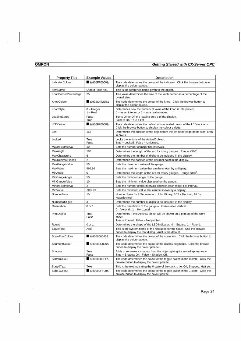
This appendix gives a list of the available properties. Each component supports a selection ofthese properties which can be set in design mode by using the properties dialog, or in the runtime by using a Visual Basic script command – for example: - Object1.Value = 10
Property Title Example Values DescriptionAbout None Description of the object.(Custom) None Opens the properties dialog for the object.(Name) Object Name This is the system generated name for the object.Autoload True
FalseSwitches the Autoload function On or Off. When set to On the ActiveXcomponent value will autoload.True = On, False = Off.
AutoSize 0 to 1 Switches the fonts auto size option on or off.0 = Off, 1 = On.
BackColour &H00E0E0E0& The code determines the background colour of the object. Click the browsebutton to display the colour palette.
BorderStyle 0 to 3 The value determines the visual appearance of the border that surrounds theobject.0 = None, 1 = Raised, 2 = Sunken, 3 = Single_Line
ButtonStyle 0 to 6 The value determines the button style.0 = Toggle Switch, 1 = Colour Button, 2 = In/Out Button, 3 – Rotary Switch4 = Rocker Switch, 5 = Indicator Button, 6 = Blank Button.
CommsServerName Comms1 to n This is the name of associated communications control.DecimalPlaces 2 Number of decimal places for 7 Segment. Only applies when NumberBase =
10DisplayFont Arial This is the system name of the font used for the display. Use the browse
button to display the font dialog. Arial is the default.DisplayFontColour &H00000000& The code determines the colour of the display font. Click the browse button
to display the colour palette.DisplayFormat 0 – Dec
1 – Hex2 – Scientific
Determines the format used to display the analogue display information.0 = Decimal, 1 = Hexadecimal, 2 = Scientific.
DisplayMajorTicks FalseTrue
Shows or hides the major tick marks of the scale.True = Show, - False = Hide.
DisplayMajorUnits FalseTrue
Shows or hides the major units markers of the scale.True = Show, False = Hide.
DisplayMinorTicks FalseTrue
Shows or hides the minor tick marks of the scale.True = Show, False = Hide.
DisplayMinorUnits FalseTrue
Shows or hides the minor units markers of the scale.True = Show, False = Hide.
DisplayType 0 – Analogue1 – Digital2 – Text
Determines the type of display.0 – Analogue: as a numeric value, 1 – Digital: as textual value,2 – Text: as text.
Enabled TrueFalse
Switches the object on or off.True = On, False = Off.
Font Arial This is the system name of the font used for the object title. Use the browsebutton to display the font dialog. Arial is the default.
FontColour &H00000000& The code determines the colour of the title font. Click the browse button todisplay the colour palette.
Height 141 Sets the overall height of the object in pixels.
OMRON Getting Started with CX-Server OPC
Page 24
Property Title Example Values DescriptionIndicatorColour &H00FF0000& The code determines the colour of the indicator. Click the browse button to
display the colour palette.ItemName Output Flow No1 This is the reference name given to the object.KnobBorderPercentage 25 This value determines the size of the knob border as a percentage of the
overall size.KnobColour &H02C4723E& The code determines the colour of the knob. Click the browse button to
display the colour palette.KnobStyle 0 – Integer
1 – RealDetermines how the numerical value of the knob is interpreted0 = as an integer or 1 = as a real number.
LeadingZeros FalseTrue
Turns On or Off the leading zero’s of the display.False = On, True = Off.
LEDColour &H00FF0000& The code determines the default or inactivated colour of the LED indicator.Click the browse button to display the colour palette.
Left 153 Determines the position of the object from the left hand edge of the work areain pixels.
Locked TrueFalse
Locks the actions of the ActiveX object.True = Locked, False = Unlocked.
MajorTickInterval 10 Sets the number of major tick intervals.MaxAngle 180 Determines the length of the arc for rotary gauges. Range ±3600.MaxCharacters 6 Determines the number of digits to be included in the display.MaxDecimalPlaces 2 Determines the position of the decimal point in the display.MaxGaugeValue 50 Sets the maximum value of the gauge.MaxValue 999.99 Sets the maximum value that can be shown by a display.MinAngle 0 Determines the length of the arc for rotary gauges. Range ±3600.MinGaugeAngle 50 Sets the minimum angle of the gauge.MinGaugeValue 10 Sets the minimum value displayed on the gauge.MinorTickInterval 2 Sets the number of tick intervals between each major tick interval.MinValue -999.99 Sets the minimum value that can be shown by a display.NumberBase 10 Number Base for 7 Segment e.g. 2 for Binary, 10 for Decimal, 16 for
HexadecimalNumberOfDigits 3 Determines the number of digits to be included in the display.Orientation 0 or 1 Sets the orientation of the gauge – Horizontal or Vertical.
0 = Vertical, 1 = Horizontal.PrintObject True
FalseDetermines if this ActiveX object will be shown on a printout of the worksheet.True = Printed, False = Not printed.
Round 0 or 1 Determines the shape of the LED indicator. 0 = Square, 1 = Round.ScaleFont Arial This is the system name of the font used for the scale. Use the browse
button to display the font dialog. Arial is the default.ScaleFontColour &H00000040& The code determines the colour of the scale font. Click the browse button to
display the colour palette.SegmentColour &H0000C000& The code determines the colour of the display segments. Click the browse
button to display the colour palette.Shadow True
FalseAdds or removes a shadow from the object giving it a raised appearance.True = Shadow On, False = Shadow Off.
State0Colour &H000000FF& The code determines the colour of the toggle switch in the 0 state. Click thebrowse button to display the colour palette.
State0Text Text This is the text indicating the 0 state of the switch, i.e. Off, Stopped, Halt etc.State1Colour &H0000FF00& The code determines the colour of the toggle switch in the 1 state. Click the
browse button to display the colour palette.

OMRON Getting Started with CX-Server OPC
Page 25
Property Title Example Values DescriptionState1Text Text This is the text indicating the 1 state of the switch, i.e. On, Running, Start etc.StateFont Arial This is the system name of the font used to display the sate of the switch ro
button. Use the browse button to display the font dialog. Arial is the default.StateFontColour &H00000000& The code determines the colour of the title font. Click the browse button to
display the colour palette.Title Text This is the title that appears in the object.TitlePosition 0 – Top
1 – BottomDetermines where title will be placed in the object. Above or below the scale.
Top 230 Determines the position of the object from the top of the work area in pixels.UnitPostion 0 – Inside
1 – OutsidePositions the dial units inside or outside the scale.
UpdateRate 10 The value sets the frequency, in seconds, at which the data passing to orfrom the object is updated.
Value 0 Determines the default value of the ActiveX object.Visible True
FalseSwitches the object between visible and invisible in run mode.True = Visible, False = Invisible.
Width 98.25 Determines the overall width of the object in pixels.

OMRON Getting Started with CX-Server OPC
Page 26
Appendix BScript Interface
The Script Interface defines the Visual Basic script interface for the OPC communicationscontrol.
FunctionsValue Function for getting and setting an OPC item value.Read Function to read the value of an OPC item.Write Function to write the value of an OPC item.GetData Function for starting OnData events.StopData Function for stopping OnData events.OnData Event for receiving notification of a change in data.
ValueReads or writes the value of an OPC item.
Example 1 – Reading a value:intVal = OPCComms1.Value(“MyGroup”, “BoilerTemp”)
In this example, the OPC item ‘BoilerTemp’ in the OPC group called “MyGroup” will be readfrom the OPC Server and will be stored in ‘intVal’.
Example 2 – Writing a value:OPCComms1.Value(“MyGroup”, “BoilerTemp”) = 50
In this example, the value 50 will be written to the OPC item ‘BoilerTemp’.
Note: ‘Value’ is the default property for all objects, so is assumed if omitted. Therefore, thefollowing examples are the same:
intVal = OPCComms1.Value(“MyGroup”, “BoilerTemp”)andintVal = OPCComms1(“MyGroup”, “BoilerTemp”)
ReadReads the value of an OPC item.
Example of synchronous read:intVal = OPCComms1.Read(“MyGroup”, “BoilerTemp”, WaitUntilComplete)
In this example, the OPC item ‘BoilerTemp’ in the OPC group called “MyGroup” will be readfrom the OPC Server and will be stored in ‘intVal’. The script will wait for the read operation to

OMRON Getting Started with CX-Server OPC
Page 27
complete before continuing to execute the next line. This is identical to the operation of the‘Value’ method.
Example of asynchronous read:OPCComms1.Read “MyGroup”, “BoilerTemp”, NoWaiting
In this example, the OPC item ‘BoilerTemp’ in the OPC group called “MyGroup” will be readfrom the OPC Server. The script will continue to execute the next line immediately, and whenthe data is read, it generates an OnData event.
WriteWrites the value of an OPC item.
Example of synchronous write:OPCComms1.Write “MyGroup”, “BoilerTemp”, NewValue, WaitUntilComplete
In this example, ‘NewValue’ will be written to the OPC item ‘BoilerTemp’ in the OPC groupcalled “MyGroup”. The script will wait for the write operation to complete before continuing toexecute the next line. This is identical to the operation of the ‘Value’ method.
Example of asynchronous write:OPCComms1.Write “MyGroup”, “BoilerTemp”, NewValue, NoWaiting
In this example, ‘NewValue’ will be written to the OPC item ‘BoilerTemp’ in the OPC groupcalled “MyGroup”. The script will continue to execute the next line immediately.
GetDataStarts asynchronous data reading of the specified OPC item at the group update rate
ExampleOPCComms1.GetData “MyGroup”, “MyItem”
In this example, MyItem in MyGroup would be read at the group update rate. Data is then sentto the OnData routine.
StopDataStops asynchronous data reading of the specified OPC item
Example
OPCComms1.StopData “MyGroup”, “MyItem”
In this example, the asynchronous reading of MyItem in MyGroup would be stopped.

OMRON Getting Started with CX-Server OPC
Page 28
OnDataThis event is sent back to the container (e.g. Excel) when data has changed. This is either datastarted by calling GetData, or by calling Read or Write in asynchronous mode.
ExamplePrivate Sub OPCComms1_OnData(ByVal Group As String, ByVal
Item As String, ByVal Value As Variant,ByVal BadQuality as Boolean)
TextBox1 = ItemSegment1 = Value
End Sub
In this example, the CX-Server 7 Segment component is set to the value of the point and a textbox is set to display the name of the item.
If BadQuality is set to True then the value may be inaccurate e.g. from a device which has beendisconnected.
The OnData routine can be enhanced to include logical expressions on the incoming Itemname and then update the correct graphical object etc. for example:
Private Sub OPCComms1_OnData(ByVal Group As String,ByVal Item As String, ByVal Value AsVariant, ByVal BadQuality as Boolean)
If Item = “MyItem” thenSegment1 = Value
Else if Item = “MyOtherItem” thenCells(1,1) = Value
End ifEnd Sub

OMRON Getting Started with CX-Server OPC
Page 29
Glossary of Term sActiveX A component technology developed by Microsoft allowing components
to communicate with applications.Application A software program that accomplishes a specific task. Examples of
applications are SYSMAC-SCS, SYSMAC-CDM, Microsoft Word andMicrosoft Excel
Bitmap The representation of an image stored in a computer’s memory. Eachpicture element (pixel) is represented by bits stored in the memory.
Communications Driver The relevant communications management system for OMRON PLCsin conjunction with Microsoft Windows, providing facilities for otherSYSMAC software to maintain PLC device and address informationand to communicate with OMRON PLCs and their supported networktypes.
GUI Graphical User Interface. Part of a program that interacts with the userand takes full advantage of the graphics displays of computers. A GUIemploys pull-down menus and dialog boxes for ease of use.
I/O type Input / Output type. An attribute of a point that defines the origin anddestination of the data for that point. The data for a point canoriginate (be input from) and is destined (is output to) to the internalcomputer memory, a PLC or a target application
Icon Pictorial representations of computer resources and functionsMicrosoft Excel A spread sheet application.Microsoft Windows A windowing environment for MS-DOS computers, that is noted for its
GUI, and for features such as multiple typefaces, desk accessories(such as a clock, calculator, calendar and notepad), and the capabilityof moving text and graphics from one application to another via aclipboard.CX-Server OPC will run only under Microsoft Windows.
Microsoft Word A word processing application.OLE Object Linking and Embedding. Used to transfer and share information
between Microsoft Windows based applications and accessories.OPC Abbreviation for OLE for Process Control. Open standard for the
exchange of data between OPC Servers and OPC Clients used withinthe process control industry.
OPC Client A software application which uses an OPC interface to exchange datawith an OPC Server.
OPC Group A collection of OPC Items.OPC Item A single piece of data e.g. a PLC memory area stored with an OPC
Server.

OMRON Getting Started with CX-Server OPC
Page 30
OPC Server A software application which uses an OPC interface to provide datato OPC Clients.
PC Abbreviation for Personal Computer.Pixel A single displayable point on the screen from which a displayed image
is constructed. The screen resolution of the computer’s Visual DisplayUnit (VDU) is defined by the number of pixels across and the numberof pixels down (e.g. 1024 x 768).
PLC Abbreviation for Programmable Logic Controller.Point A point is used to hold a value of a predefined type - Boolean, Integer,
Text, etc. The contents of a point may be controlled by an object orI/O mechanism such as DDE. The contents of a point may control theaction or appearance of an object, or be used for output via an I/Omechanism.
SVGA mode A mode of video display that provides 800 × 600 pixel resolution (orhigher) with 16 or more colours and is supported on Super VideoGraphics Adapter systems.
Windows Desktop An integral part of Microsoft Windows which allows MicrosoftWindows based applications to be started from icons and for allapplications to be organised.

OMRON Getting Started with CX-Server OPC
Page 31
Index
AAbout CX-Server OPC · 9About this Manual · 6ActiveX Objects
7 Segment · 14Display · 14LED Indicator · 14Linear Gauge · 14OPC Communications · 14Rotary Knob · 15Rotational Gauge · 14Timer · 15Toggle · 15
Adding a 7 Segment Display · 17Adding the Communication Control · 15Adding Third Party ActiveX Controls · 19Advanced Properties · 21
CComponent Properties · 23Configuring server for remote connection · 12Connecting to an OPC Server · 16Controlling ActiveX Objects · 22
EEvent Driven Routines · 20
GGetting Started with CX-Server OPC · 6Glossary of Terms · 29
HHardware Requirements · 7
Operating Systems · 7Help Topics · 9
IInserting Data in Cells · 18Installing/Uninstalling CX-Server OPC · 8
OObjects Overview · 14OPC
Foundation web site · 10What is it? · 10
OPC ServerConfiguring for remote connection · 12Starting · 10Using Third Party OPC Clients · 11
Operating Systems · 7Other Features · 19
Advanced Properties · 21Controlling ActiveX Objects · 22Event Driven Routines · 20The Project Tree · 22
PProject Tree · 22
RRunning an Application · 18
SScript Interface · 26
Functions · 26Script Interface Functions
GetData · 27OnData · 28StopData · 27
Starting CX OPC Server · 10System Requirements · 7
Hardware Requirements · 7

OMRON Getting Started with CX-Server OPC
Page 32
TTechnical Support · 9The Help System, and How to access it · 8Tutorial Step 1 Viewing Data using Omron
Graphical Control · 15Tutorial Step 2 Inserting Data in Cells · 18Tutorial Step 3 Adding Third Party ActiveX
Controls · 19
UUsing the OPC Client components · 14Using the OPC Server · 10Using Third Party OPC Clients · 11
VViewing Data using Omron Graphical Control · 15
WWhat is OPC? · 10