cx-simulator introduction guide - etitudela.com · chapter 1 overview of cx-simulator overview of...
TRANSCRIPT
- Please be sure to read and understand Precautions and Introductions in CX-Simulator Operation Manual and
CX-Programmer Operation Manual before using the product.
- This guide describes the basic operation procedure of CX-Simulator. Refer to the Help or the Operation Manual of
the PDF file for detailed descriptions.
- Acrobat Reader 5.0 or later is required to read the PDF files.
- You can display the PDF files from the [Start] menu on your desktop after installing the CX-Simulator.
- The screen views used in this guide may be different from the actual view, and be subject to change without notice.
- The product names, service names, function names, and logos described in this guide are trademarks or
registered trademarks of their respective companies.
- The symbols (R) and TM are not marked with trademarks and registered trademarks in this guide respectively
- The product names of the other companies may be abbreviated in this guide.
Introduction
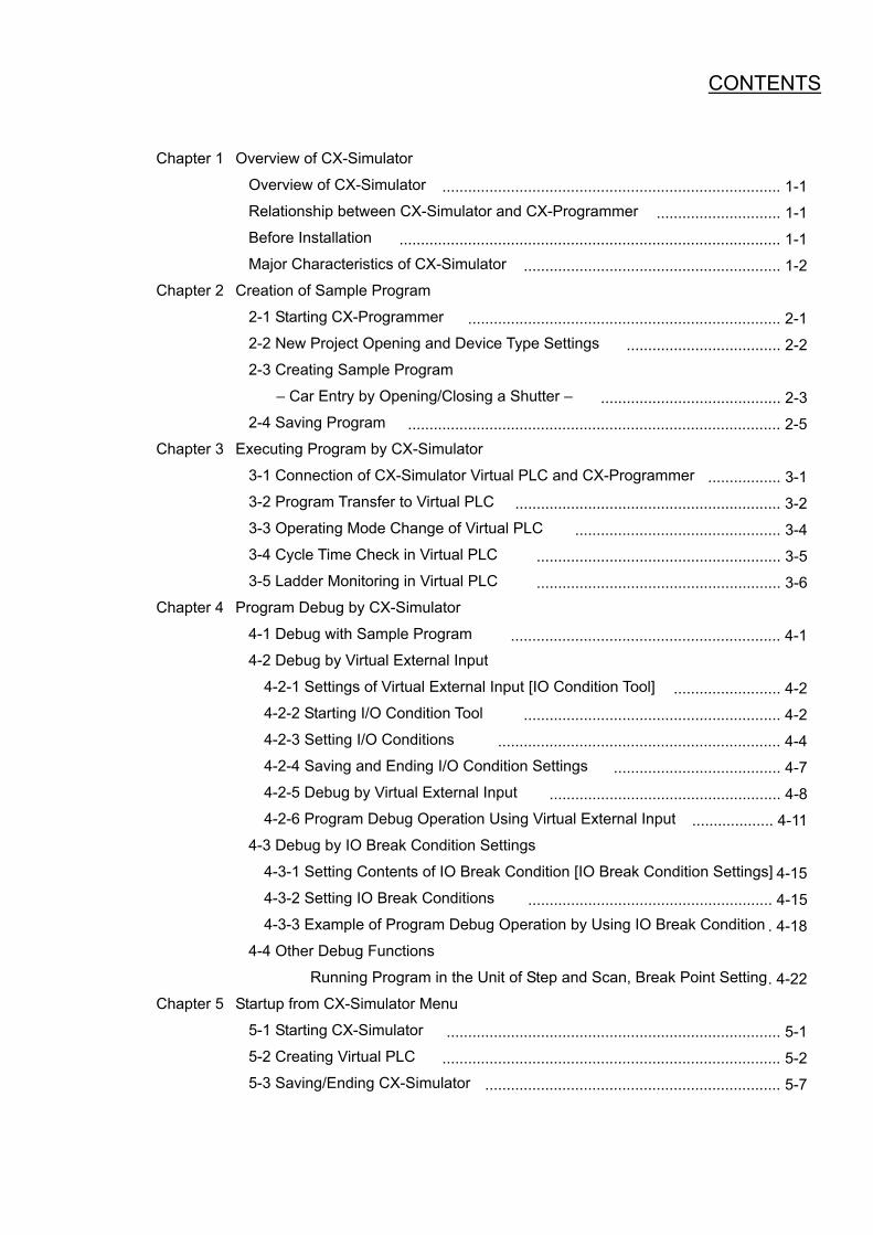
Chapter 1 Overview of CX-Simulator
Overview of CX-Simulator
Relationship between CX-Simulator and CX-Programmer
Before Installation
Major Characteristics of CX-Simulator
Chapter 2 Creation of Sample Program
2-1 Starting CX-Programmer
2-2 New Project Opening and Device Type Settings
2-3 Creating Sample Program
– Car Entry by Opening/Closing a Shutter –
2-4 Saving Program
Chapter 3 Executing Program by CX-Simulator
3-1 Connection of CX-Simulator Virtual PLC and CX-Programmer
3-2 Program Transfer to Virtual PLC
3-3 Operating Mode Change of Virtual PLC
3-4 Cycle Time Check in Virtual PLC
3-5 Ladder Monitoring in Virtual PLC
Chapter 4 Program Debug by CX-Simulator
4-1 Debug with Sample Program
4-2 Debug by Virtual External Input
4-2-1 Settings of Virtual External Input [IO Condition Tool]
4-2-2 Starting I/O Condition Tool
4-2-3 Setting I/O Conditions
4-2-4 Saving and Ending I/O Condition Settings
4-2-5 Debug by Virtual External Input
4-2-6 Program Debug Operation Using Virtual External Input
4-3 Debug by IO Break Condition Settings
4-3-1 Setting Contents of IO Break Condition [IO Break Condition Settings]
4-3-2 Setting IO Break Conditions
4-3-3 Example of Program Debug Operation by Using IO Break Condition
4-4 Other Debug Functions
Running Program in the Unit of Step and Scan, Break Point Setting
Chapter 5 Startup from CX-Simulator Menu
5-1 Starting CX-Simulator
5-2 Creating Virtual PLC
5-3 Saving/Ending CX-Simulator
............................................................................... 1-1
............................. 1-1
......................................................................................... 1-1
............................................................ 1-2
......................................................................... 2-1
.................................... 2-2
.......................................... 2-3
....................................................................................... 2-5
................. 3-1
.............................................................. 3-2
................................................ 3-4
......................................................... 3-5
......................................................... 3-6
............................................................... 4-1
......................... 4-2
............................................................ 4-2
.................................................................. 4-4
....................................... 4-7
...................................................... 4-8
................... 4-11
4-15
......................................................... 4-15
. 4-18
. 4-22
.............................................................................. 5-1
............................................................................... 5-2
..................................................................... 5-7
CONTENTS

CChhaapptteerr 11 OOvveerrvviieeww ooff CCXX--SSiimmuullaattoorr
Overview of CX-Simulator CX-Simulator enables you to realize SYSMAC CS/CJ series CPU Units in your computer as a virtual
PLC and operate (simulate) it equally as actual CPU Units. Combination use of CX-Simulator and
CX-Programmer enables you to verify ladder program operation and cycle time in advance on a PC
without an actual PLC.
Moreover, various debug functions of CX-Simulator make it possible to debug ladders, which used to
be impossible by using an actual PLC only.
Relationship between CX-Simulator and CX-Programmer CX-Simulator creates a virtual PLC on a virtual network in your PC. If you use the “Work Online
Simulator“ function of CX-Programmer Ver.3.0 or greater versions, CX-Simulator automatically starts
up a virtual PLC of the current project’s device type to open connection between CX-Programmer and
the virtual PLC.
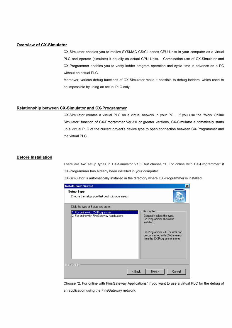
Before Installation There are two setup types in CX-Simulator V1.3, but choose “1. For online with CX-Programmer” if
CX-Programmer has already been installed in your computer.
CX-Simulator is automatically installed in the directory where CX-Programmer is installed.
Choose “2. For online with FinsGateway Applications” if you want to use a virtual PLC for the debug of
an application using the FinsGateway network.
Major Characteristics of CX-Simulator Program execution, monitoring, debug without actual PLC Monitoring of programs and IO memory present values is enabled. Moreover, normal debugs such as
force on/off, differential monitoring, data trace and online edit are enabled from CX-Programmer. Also,
any cyclic task can be started/stopped and interrupt tasks can be started in simulation.
Cycle time check without actual PLC It is possible to check estimated cycle time (current, minimum, maximum, and mean values, servicing
time *1) when the program is executed in an actual PLC in advance.
Program execution per step or scan, I/O brake condition settings Debugs that cannot be realized in actual PLCs are provided.
• Step Run: Executes a program per instruction
• Scan Run: Executes a program per scan (cycle)
• I/O Break Condition Settings: Aborts execution when the conditions set in I/O memory are
satisfied.
• Designation of the start and break points
Debugs in connection with display devices and serial communications devices *1 Regarding the serial communications port of a PC as the communications port of a PLC, it is possible
to debug a program in combination with display devices or serial communications devices (barcode
reader, ID sensor, etc.).
Display of the send messages of serial communications and network communications *1 It is possible to check the send messages issued by TXD instruction (communications port output),
SEND instruction (network send), and CMND instruction (command send). It is useful for the debugs
of serial communications and network communications.
*1: You need to start CX-Simulator from the Windows [Start] menu and set a virtual PLC. See
Chapter 5 and the CX-Simulator Operation Manual for the detailed operations.

CChhaapptteerr 22 CCrreeaattiioonn ooff SSaammppllee PPrrooggrraamm
This chapter explains basic functions such as programming and comment entry of a simple ladder by using CX-Programmer. Here, a sample program “a program of car entry control by opening/closing shutters” is created as an example. This program is used to explain how to use the debug functions of CX-Simulator, which are mentioned after Chapter 3.
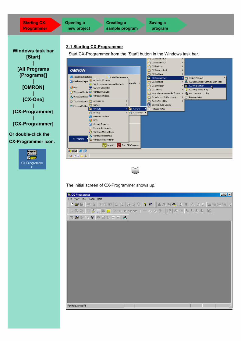
2-1 Starting CX-Programmer Start CX-Programmer from the [Start] button in the Windows task bar.
The initial screen of CX-Programmer shows up.
Windows task bar [Start]
| [All Programs (Programs)]
| [OMRON]
| [CX-One]
| [CX-Programmer]
| [CX-Programmer]
Or double-click the CX-Programmer icon.
Starting CX- Programmer
Opening a new project
Saving a program
Creating a sample program
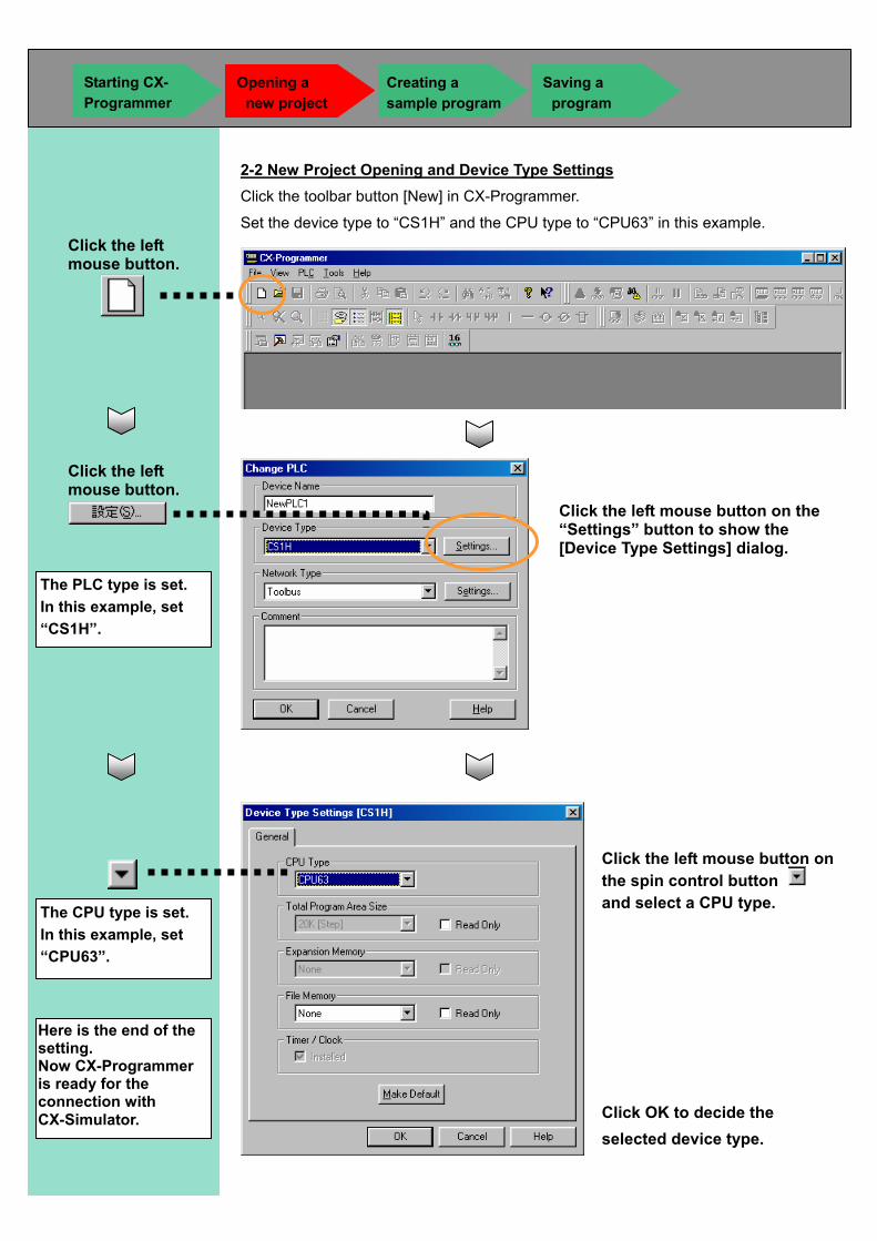
2-2 New Project Opening and Device Type Settings Click the toolbar button [New] in CX-Programmer.
Set the device type to “CS1H” and the CPU type to “CPU63” in this example.
Click the left mouse button.
Click the left mouse button.
Click the left mouse button on the “Settings” button to show the [Device Type Settings] dialog.
Click the left mouse button on the spin control button and select a CPU type.
Click OK to decide the selected device type.
The PLC type is set. In this example, set “CS1H”.
The CPU type is set. In this example, set “CPU63”.
Starting CX- Programmer
Opening a new project
Saving a program
Here is the end of the setting. Now CX-Programmer is ready for the connection with CX-Simulator.
Creating a sample program
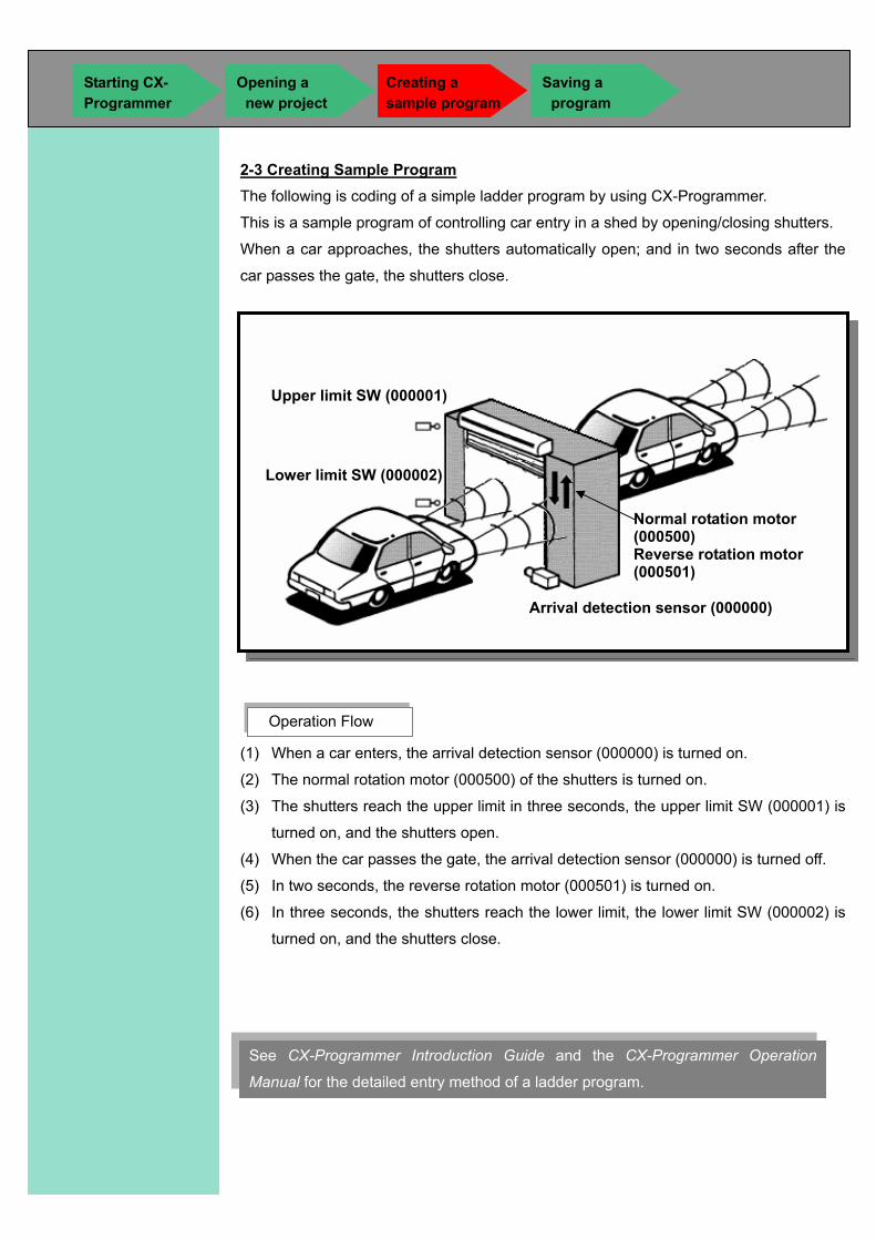
2-3 Creating Sample Program
The following is coding of a simple ladder program by using CX-Programmer.
This is a sample program of controlling car entry in a shed by opening/closing shutters.
When a car approaches, the shutters automatically open; and in two seconds after the
car passes the gate, the shutters close.
(1) When a car enters, the arrival detection sensor (000000) is turned on.
(2) The normal rotation motor (000500) of the shutters is turned on.
(3) The shutters reach the upper limit in three seconds, the upper limit SW (000001) is
turned on, and the shutters open.
(4) When the car passes the gate, the arrival detection sensor (000000) is turned off.
(5) In two seconds, the reverse rotation motor (000501) is turned on.
(6) In three seconds, the shutters reach the lower limit, the lower limit SW (000002) is
turned on, and the shutters close.
Operation Flow
Arrival detection sensor (000000)
Normal rotation motor (000500) Reverse rotation motor (000501)
Upper limit SW (000001)
Lower limit SW (000002)
See CX-Programmer Introduction Guide and the CX-Programmer Operation
Manual for the detailed entry method of a ladder program.
Starting CX- Programmer
Opening a new project
Creating a sample program
Saving a program
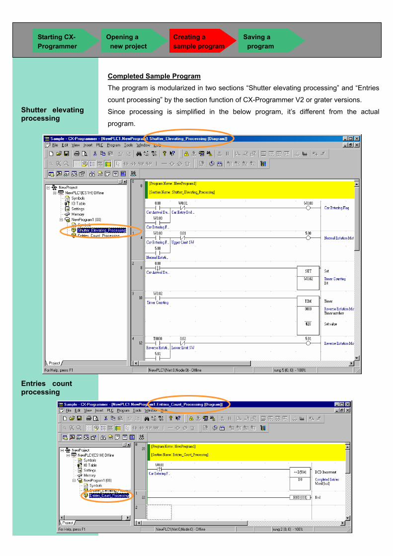
Completed Sample Program
The program is modularized in two sections “Shutter elevating processing” and “Entries
count processing” by the section function of CX-Programmer V2 or grater versions.
Since processing is simplified in the below program, it’s different from the actual
program.
Shutter elevating processing
Entries count processing
Starting CX- Programmer
Opening a new project
Creating a sample program
Saving a program
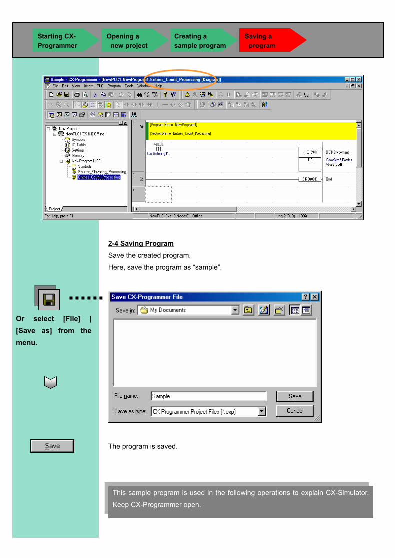
2-4 Saving Program Save the created program.
Here, save the program as “sample”.
The program is saved.
Or select [File] | [Save as] from the menu.
This sample program is used in the following operations to explain CX-Simulator.
Keep CX-Programmer open.
Starting CX- Programmer
Creating a sample program
Saving a program
Opening a new project
This chapter explains how to operate CX-Programmer functions such as program transfer, PLC mode change, cycle time check, and ladder program monitoring, when CX-Programmer is connected to a CX-Simulator virtual PLC. In addition, you can use CX-Programmer when connecting to a virtual PLC by the exactly same operation as when connecting to an actual PLC. For detailed operations, see the operation manual of CX-Programmer.
CChhaapptteerr 33 EExxeeccuuttiinngg PPrrooggrraamm bbyy CCXX--SSiimmuullaattoorr

3-1 Connection of CX-Simulator Virtual PLC and CX-Programmer Connect CX-Programmer with a CX-Simulator virtual PLC.
The sample program created in Chapter 2 is used for the explanation here.
Starting CX-Programmer Click the [Open] button from the toolbar of CX-Programmer.
Select the sample program created in Chapter 2.
Select “Sample”.
Connecting to a virtual PLC
Program transfer to a virtual PLC
Operation mode change of a virtual PLC
Cycle time check in a virtual PLC
Ladder monitoring in a virtula PLC
The sample program is loaded.
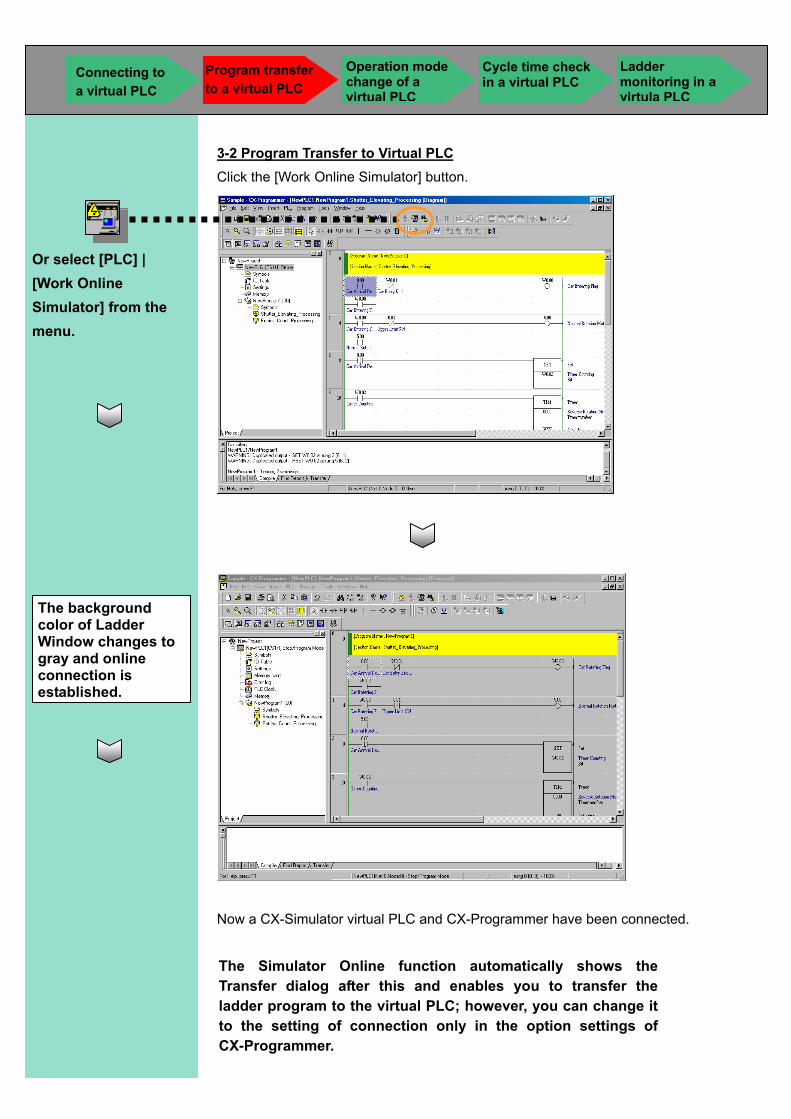
3-2 Program Transfer to Virtual PLC Click the [Work Online Simulator] button.
Now a CX-Simulator virtual PLC and CX-Programmer have been connected.
The background color of Ladder Window changes to gray and online connection is established.
Or select [PLC] | [Work Online Simulator] from the menu.
The Simulator Online function automatically shows the Transfer dialog after this and enables you to transfer the ladder program to the virtual PLC; however, you can change it to the setting of connection only in the option settings of CX-Programmer.
Connecting to a virtual PLC
Program transfer to a virtual PLC
Operation mode change of a virtual PLC
Cycle time check in a virtual PLC
Ladder monitoring in a virtula PLC
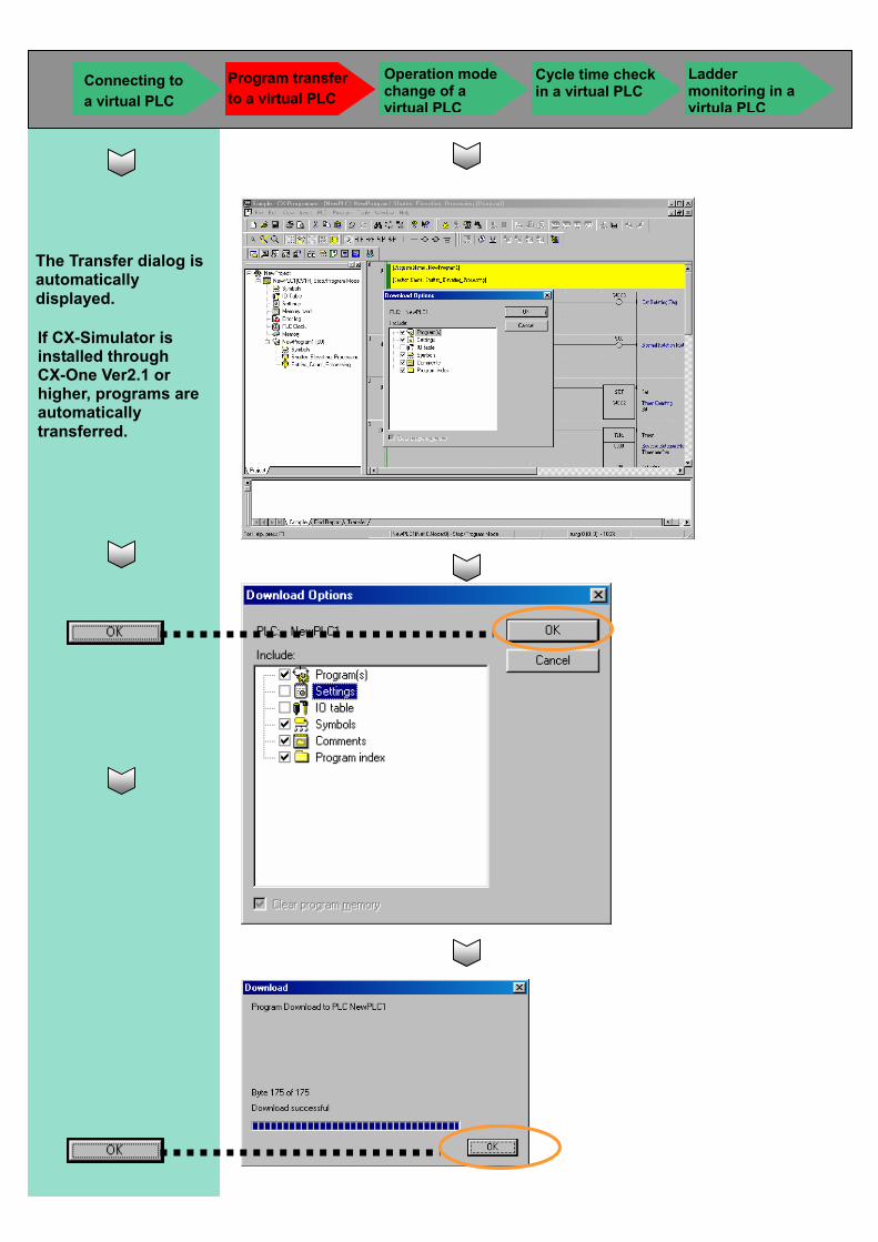
The Transfer dialog is automatically displayed.
Connecting to a virtual PLC
Program transfer to a virtual PLC
Operation mode change of a virtual PLC
Cycle time check in a virtual PLC
Ladder monitoring in a virtula PLC
If CX-Simulator is installed through CX-One Ver2.1 or higher, programs are automatically transferred.
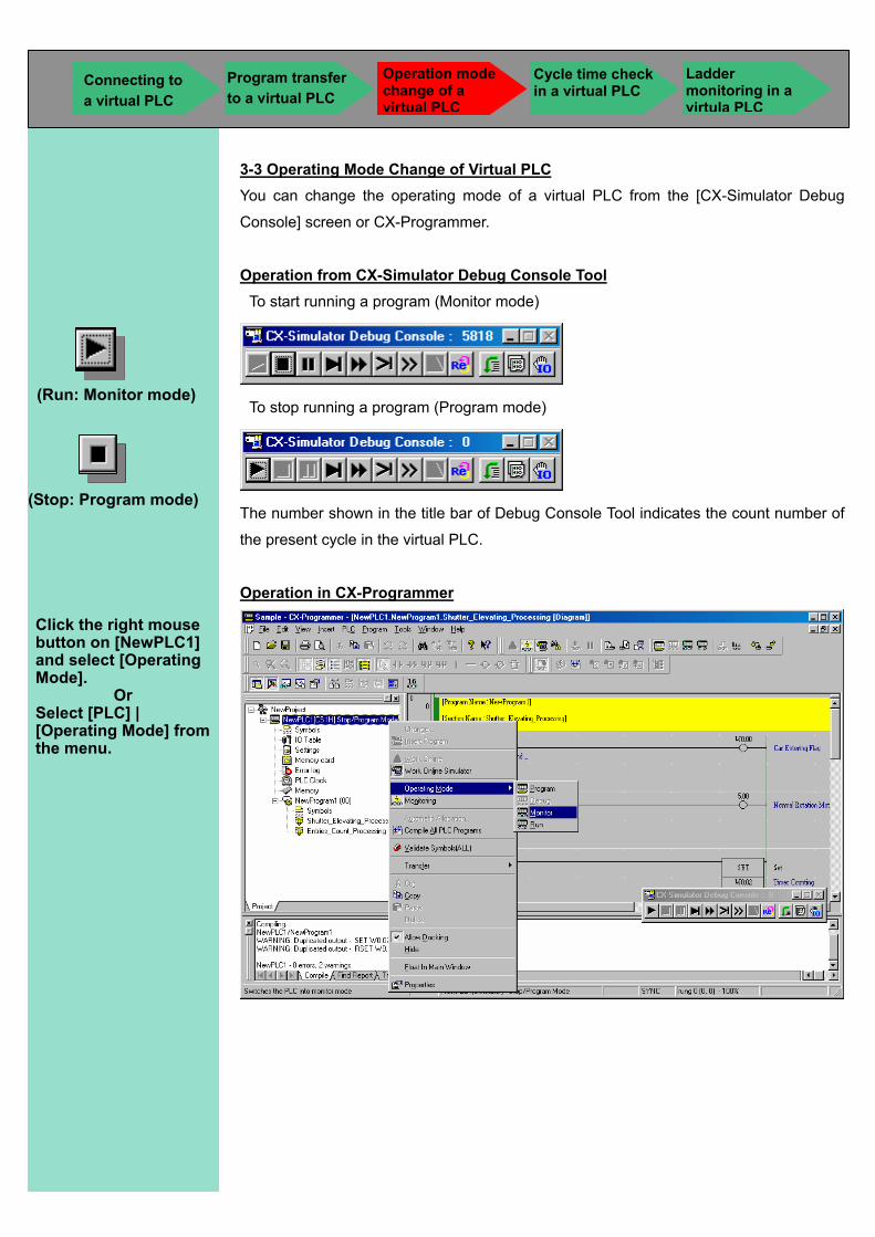
3-3 Operating Mode Change of Virtual PLC You can change the operating mode of a virtual PLC from the [CX-Simulator Debug
Console] screen or CX-Programmer.
Operation from CX-Simulator Debug Console Tool To start running a program (Monitor mode)
To stop running a program (Program mode)
The number shown in the title bar of Debug Console Tool indicates the count number of
the present cycle in the virtual PLC.
Operation in CX-Programmer
(Run: Monitor mode)
(Stop: Program mode)
Click the right mouse button on [NewPLC1] and select [Operating Mode].
Or Select [PLC] | [Operating Mode] from the menu.
Connecting to a virtual PLC
Program transfer to a virtual PLC
Operation mode change of a virtual PLC
Cycle time check in a virtual PLC
Ladder monitoring in a virtula PLC
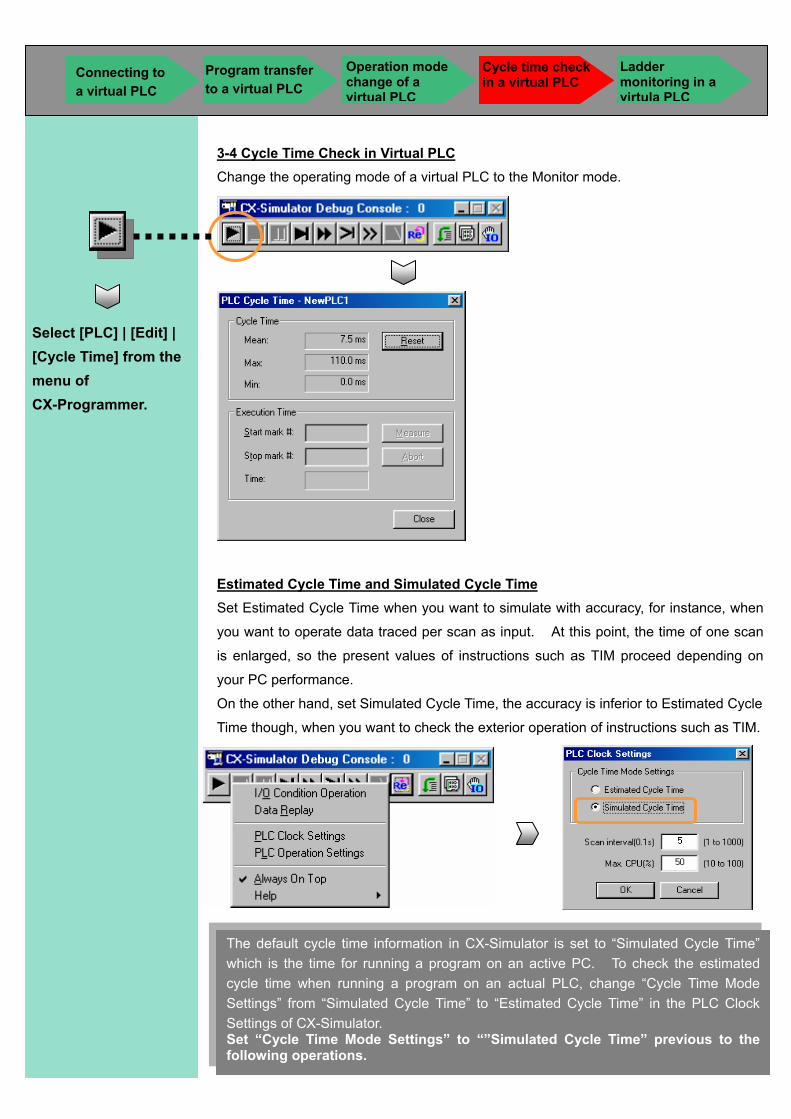
3-4 Cycle Time Check in Virtual PLC Change the operating mode of a virtual PLC to the Monitor mode.
Estimated Cycle Time and Simulated Cycle Time Set Estimated Cycle Time when you want to simulate with accuracy, for instance, when
you want to operate data traced per scan as input. At this point, the time of one scan
is enlarged, so the present values of instructions such as TIM proceed depending on
your PC performance.
On the other hand, set Simulated Cycle Time, the accuracy is inferior to Estimated Cycle
Time though, when you want to check the exterior operation of instructions such as TIM.
Select [PLC] | [Edit] | [Cycle Time] from the menu of CX-Programmer.
The default cycle time information in CX-Simulator is set to “Simulated Cycle Time” which is the time for running a program on an active PC. To check the estimated cycle time when running a program on an actual PLC, change “Cycle Time Mode Settings” from “Simulated Cycle Time” to “Estimated Cycle Time” in the PLC Clock Settings of CX-Simulator. Set “Cycle Time Mode Settings” to “”Simulated Cycle Time” previous to the following operations.
Connecting to a virtual PLC
Program transfer to a virtual PLC
Operation mode change of a virtual PLC
Cycle time check in a virtual PLC
Ladder monitoring in a virtula PLC
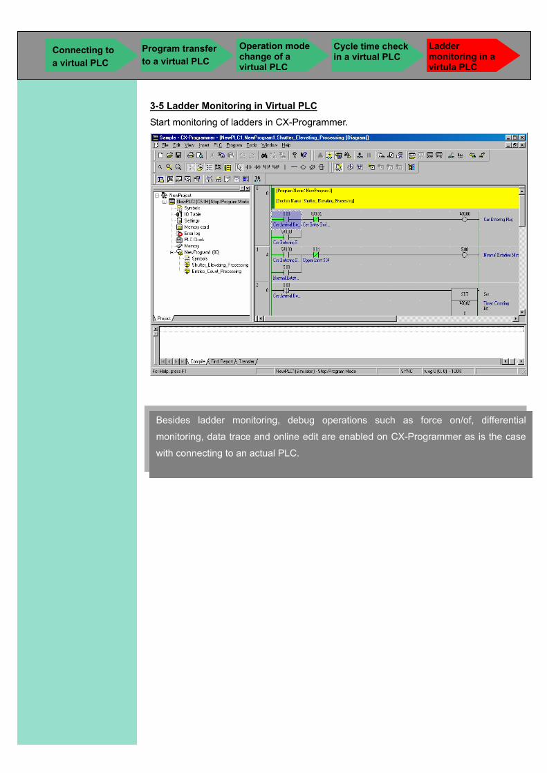
3-5 Ladder Monitoring in Virtual PLC Start monitoring of ladders in CX-Programmer.
Besides ladder monitoring, debug operations such as force on/of, differential
monitoring, data trace and online edit are enabled on CX-Programmer as is the case
with connecting to an actual PLC.
Connecting to a virtual PLC
Program transfer to a virtual PLC
Operation mode change of a virtual PLC
Cycle time check in a virtual PLC
Ladder monitoring in a virtula PLC

CChhaapptteerr 44 PPrrooggrraamm DDeebbuugg bbyy CCXX--SSiimmuullaattoorr
The debug operations of a ladder program by using the original functions of CX-Simulator, which are unavailable by actual PLCs, are explained in this chapter.
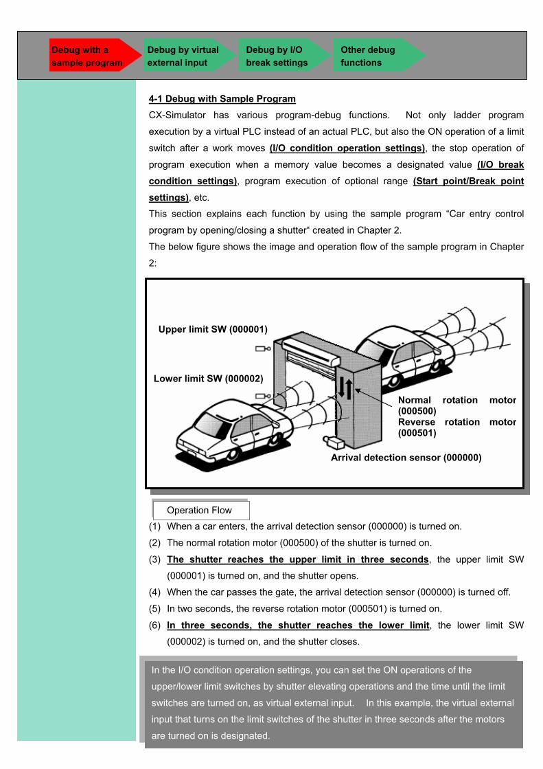
4-1 Debug with Sample Program CX-Simulator has various program-debug functions. Not only ladder program
execution by a virtual PLC instead of an actual PLC, but also the ON operation of a limit
switch after a work moves (I/O condition operation settings), the stop operation of
program execution when a memory value becomes a designated value (I/O break condition settings), program execution of optional range (Start point/Break point settings), etc.
This section explains each function by using the sample program “Car entry control
program by opening/closing a shutter“ created in Chapter 2.
The below figure shows the image and operation flow of the sample program in Chapter
2:
(1) When a car enters, the arrival detection sensor (000000) is turned on.
(2) The normal rotation motor (000500) of the shutter is turned on.
(3) The shutter reaches the upper limit in three seconds, the upper limit SW
(000001) is turned on, and the shutter opens.
(4) When the car passes the gate, the arrival detection sensor (000000) is turned off.
(5) In two seconds, the reverse rotation motor (000501) is turned on.
(6) In three seconds, the shutter reaches the lower limit, the lower limit SW
(000002) is turned on, and the shutter closes.
Operation Flow
Arrival detection sensor (000000)
Normal rotation motor(000500) Reverse rotation motor(000501)
Upper limit SW (000001)
Lower limit SW (000002)
In the I/O condition operation settings, you can set the ON operations of the
upper/lower limit switches by shutter elevating operations and the time until the limit
switches are turned on, as virtual external input. In this example, the virtual external
input that turns on the limit switches of the shutter in three seconds after the motors
are turned on is designated.
Debug with a sample program
Debug by I/O break settings
Other debug functions
Debug by virtual external input
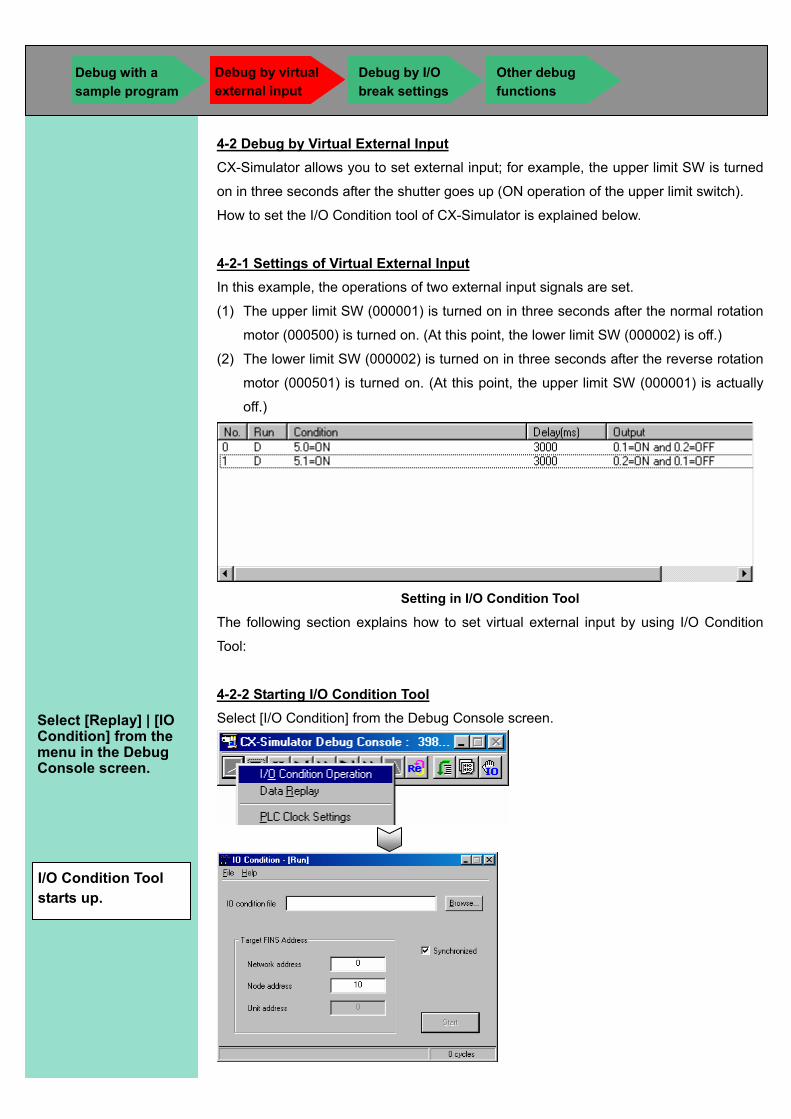
4-2 Debug by Virtual External Input CX-Simulator allows you to set external input; for example, the upper limit SW is turned
on in three seconds after the shutter goes up (ON operation of the upper limit switch).
How to set the I/O Condition tool of CX-Simulator is explained below.
4-2-1 Settings of Virtual External Input In this example, the operations of two external input signals are set.
(1) The upper limit SW (000001) is turned on in three seconds after the normal rotation
motor (000500) is turned on. (At this point, the lower limit SW (000002) is off.)
(2) The lower limit SW (000002) is turned on in three seconds after the reverse rotation
motor (000501) is turned on. (At this point, the upper limit SW (000001) is actually
off.)
Setting in I/O Condition Tool
The following section explains how to set virtual external input by using I/O Condition
Tool:
4-2-2 Starting I/O Condition Tool Select [I/O Condition] from the Debug Console screen.
Select [Replay] | [IO Condition] from the menu in the Debug Console screen.
I/O Condition Tool starts up.
Debug with a sample program
Debug by I/O break settings
Other debug functions
Debug by virtual external input
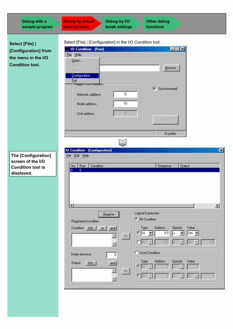
Select [File] | [Configuration] in the I/O Condition tool.
Select [File] | [Configuration] from the menu in the I/O Condition tool.
The [Configuration] screen of the I/O Condition tool is displayed.
Debug with a sample program
Debug by I/O break settings
Other debug functions
Debug by virtual external input
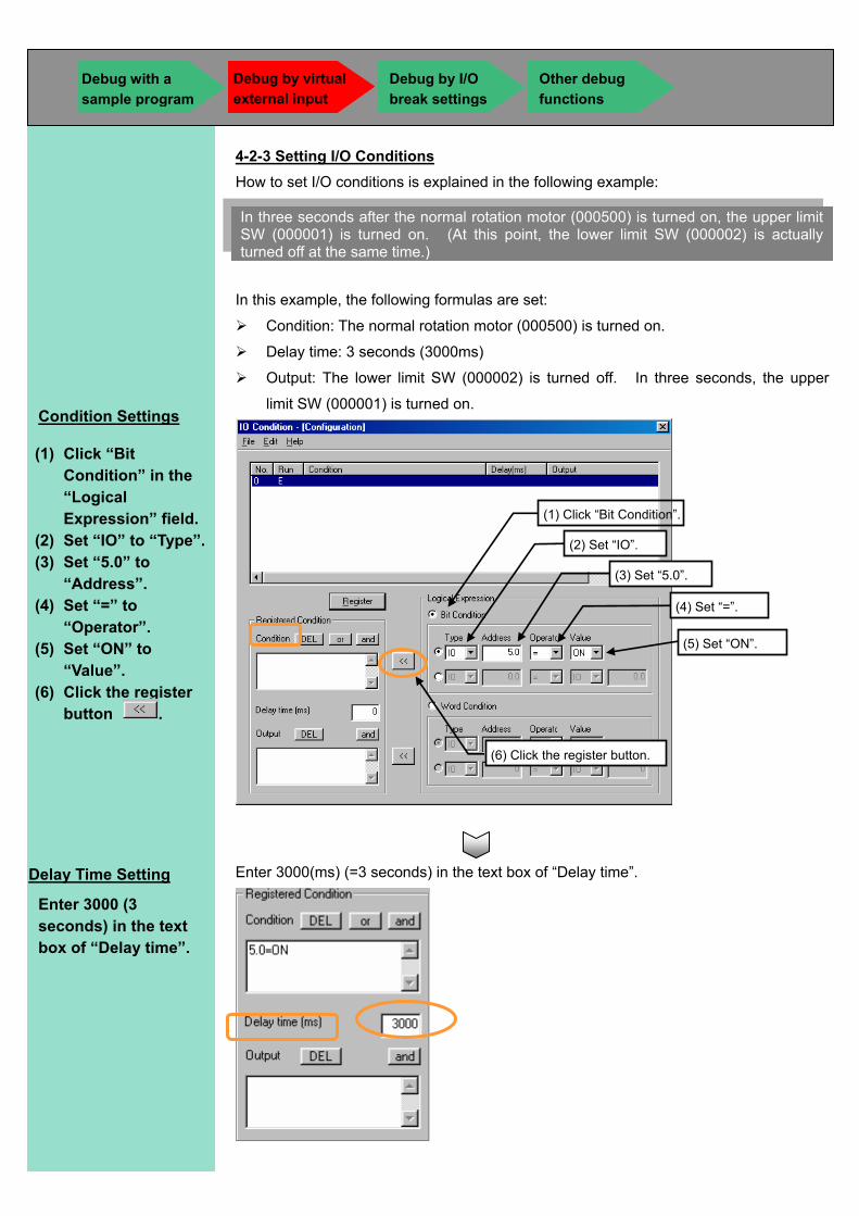
4-2-3 Setting I/O Conditions How to set I/O conditions is explained in the following example:
In this example, the following formulas are set:
Condition: The normal rotation motor (000500) is turned on.
Delay time: 3 seconds (3000ms)
Output: The lower limit SW (000002) is turned off. In three seconds, the upper
limit SW (000001) is turned on.
Enter 3000(ms) (=3 seconds) in the text box of “Delay time”.
In three seconds after the normal rotation motor (000500) is turned on, the upper limit SW (000001) is turned on. (At this point, the lower limit SW (000002) is actually turned off at the same time.)
Condition Settings
(1) Click “Bit Condition” in the “Logical Expression” field.
(2) Set “IO” to “Type”. (3) Set “5.0” to
“Address”. (4) Set “=” to
“Operator”. (5) Set “ON” to
“Value”. (6) Click the register
button .
Delay Time Setting
Enter 3000 (3 seconds) in the text box of “Delay time”.
(1) Click “Bit Condition”.
(2) Set “IO”.
(3) Set “5.0”.
(4) Set “=”.
(5) Set “ON”.
(6) Click the register button.
Debug with a sample program
Debug by I/O break settings
Other debug functions
Debug by virtual external input
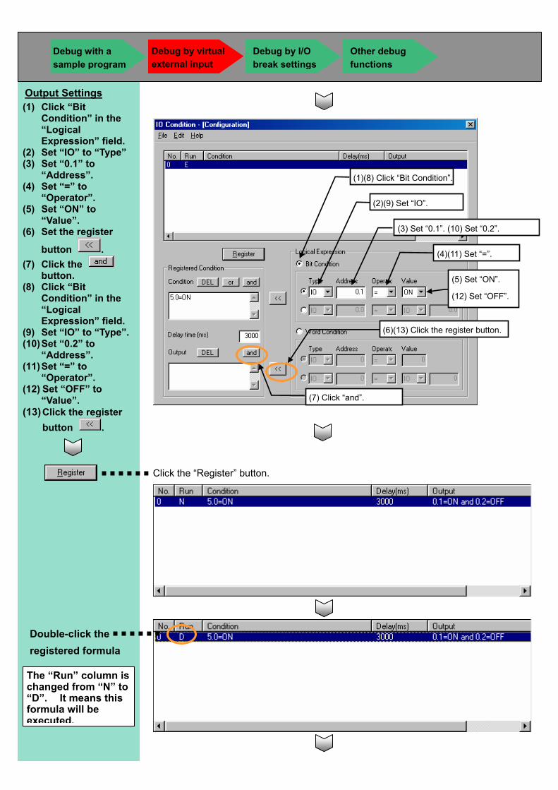
Click the “Register” button.
Output Settings (1) Click “Bit
Condition” in the “Logical Expression” field.
(2) Set “IO” to “Type” (3) Set “0.1” to
“Address”. (4) Set “=” to
“Operator”. (5) Set “ON” to
“Value”. (6) Set the register
button . (7) Click the
button. (8) Click “Bit
Condition” in the “Logical Expression” field.
(9) Set “IO” to “Type”. (10) Set “0.2” to
“Address”. (11) Set “=” to
“Operator”. (12) Set “OFF” to
“Value”. (13) Click the register
button .
Double-click the registered formula
The “Run” column is changed from “N” to “D”. It means this formula will be executed.
(1)(8) Click “Bit Condition”.
(2)(9) Set “IO”.
(3) Set “0.1”. (10) Set “0.2”.
(4)(11) Set “=”.
(5) Set “ON”.
(12) Set “OFF”.
(6)(13) Click the register button.
(7) Click “and”.
Debug with a sample program
Debug by I/O break settings
Other debug functions
Debug by virtual external input
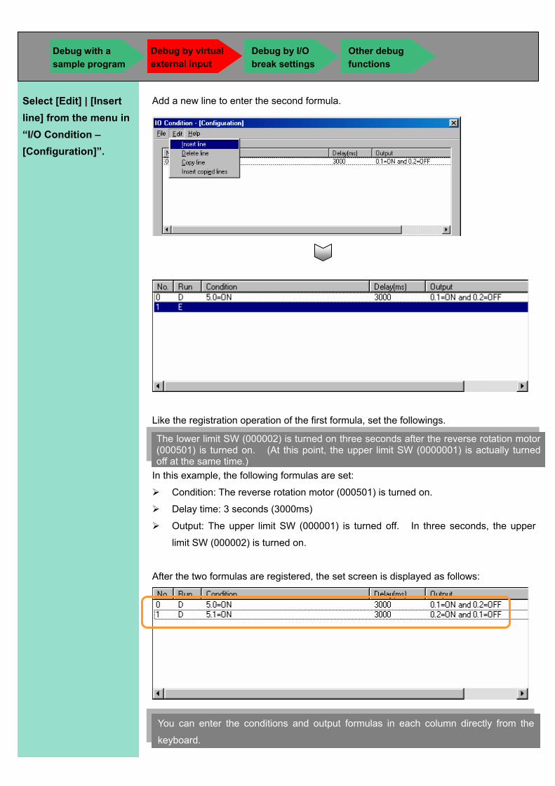
Add a new line to enter the second formula.
Like the registration operation of the first formula, set the followings.
In this example, the following formulas are set:
Condition: The reverse rotation motor (000501) is turned on.
Delay time: 3 seconds (3000ms)
Output: The upper limit SW (000001) is turned off. In three seconds, the upper
limit SW (000002) is turned on.
After the two formulas are registered, the set screen is displayed as follows:
Select [Edit] | [Insert line] from the menu in “I/O Condition – [Configuration]”.
The lower limit SW (000002) is turned on three seconds after the reverse rotation motor (000501) is turned on. (At this point, the upper limit SW (0000001) is actually turned off at the same time.)
You can enter the conditions and output formulas in each column directly from the
keyboard.
Debug with a sample program
Debug by I/O break settings
Other debug functions
Debug by virtual external input
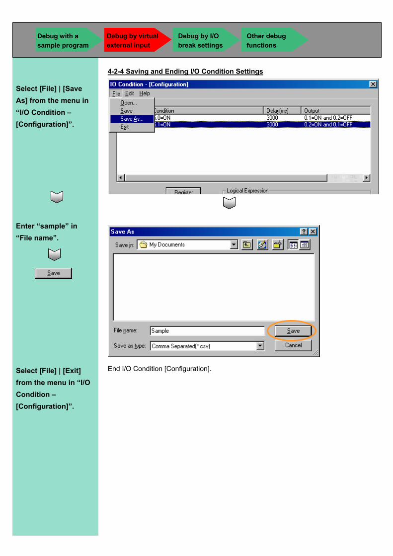
4-2-4 Saving and Ending I/O Condition Settings
End I/O Condition [Configuration].
Select [File] | [Save As] from the menu in “I/O Condition – [Configuration]”.
Enter “sample” in “File name”.
Select [File] | [Exit] from the menu in “I/O Condition – [Configuration]”.
Debug with a sample program
Debug by I/O break settings
Other debug functions
Debug by virtual external input
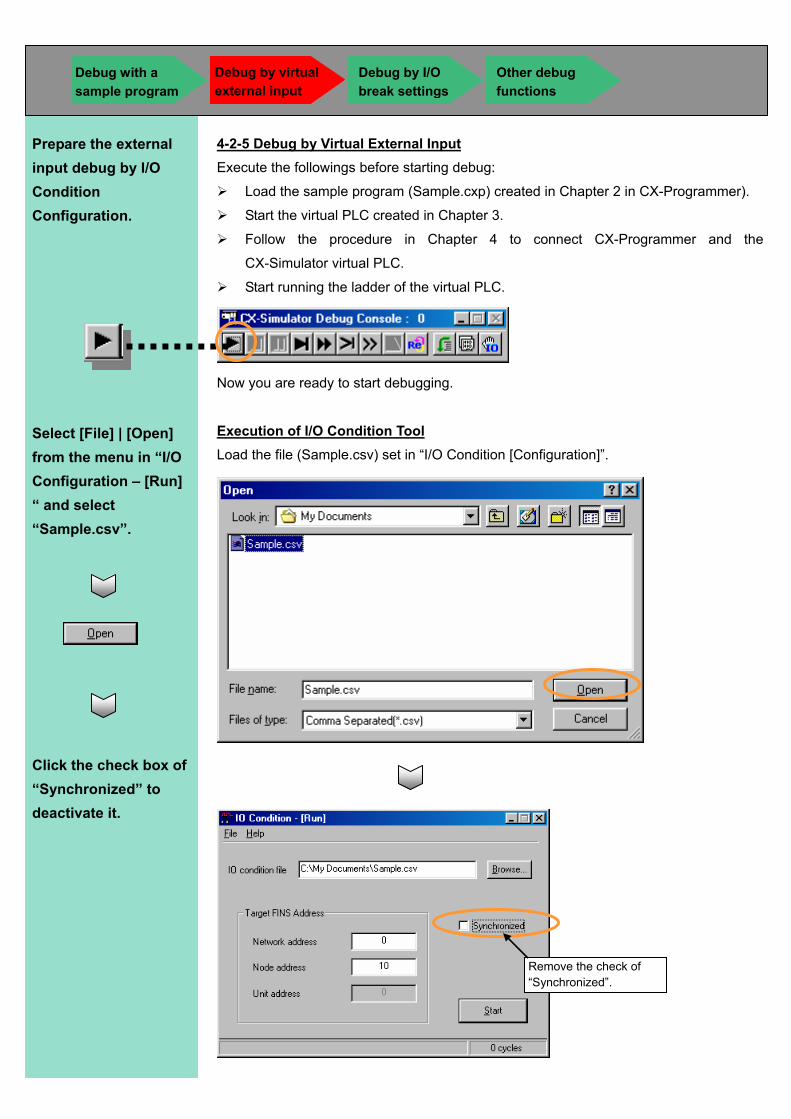
4-2-5 Debug by Virtual External Input Execute the followings before starting debug:
Load the sample program (Sample.cxp) created in Chapter 2 in CX-Programmer).
Start the virtual PLC created in Chapter 3.
Follow the procedure in Chapter 4 to connect CX-Programmer and the
CX-Simulator virtual PLC.
Start running the ladder of the virtual PLC.
Now you are ready to start debugging.
Execution of I/O Condition Tool Load the file (Sample.csv) set in “I/O Condition [Configuration]”.
Remove the check of “Synchronized”.
Select [File] | [Open] from the menu in “I/O Configuration – [Run] “ and select “Sample.csv”.
Click the check box of “Synchronized” to deactivate it.
Prepare the external input debug by I/O Condition Configuration.
Debug with a sample program
Debug by I/O break settings
Other debug functions
Debug by virtual external input
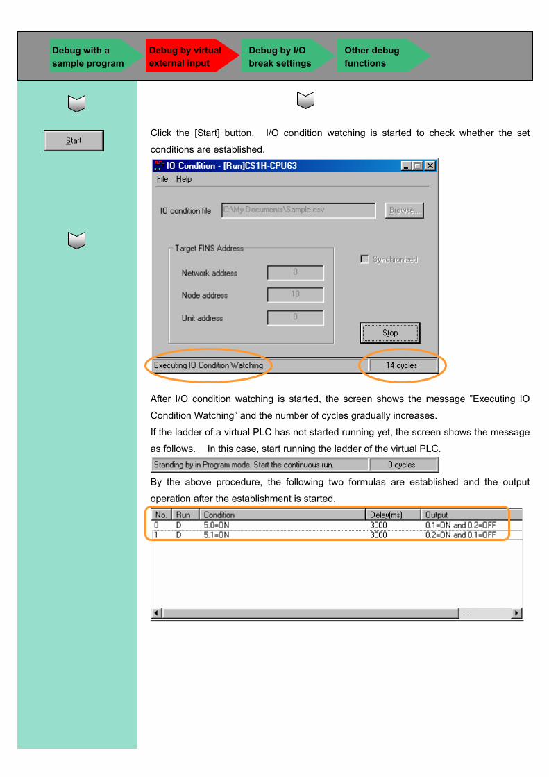
Click the [Start] button. I/O condition watching is started to check whether the set
conditions are established.
After I/O condition watching is started, the screen shows the message ”Executing IO
Condition Watching” and the number of cycles gradually increases.
If the ladder of a virtual PLC has not started running yet, the screen shows the message
as follows. In this case, start running the ladder of the virtual PLC.
By the above procedure, the following two formulas are established and the output
operation after the establishment is started.
Debug with a sample program
Debug by I/O break settings
Other debug functions
Debug by virtual external input
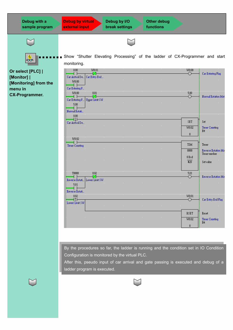
Show “Shutter Elevating Processing” of the ladder of CX-Programmer and start
monitoring.
Or select [PLC] | [Monitor] | [Monitoring] from the menu in CX-Programmer.
By the procedures so far, the ladder is running and the condition set in IO Condition
Configuration is monitored by the virtual PLC.
After this, pseudo input of car arrival and gate passing is executed and debug of a
ladder program is executed.
Debug with a sample program
Debug by I/O break settings
Other debug functions
Debug by virtual external input
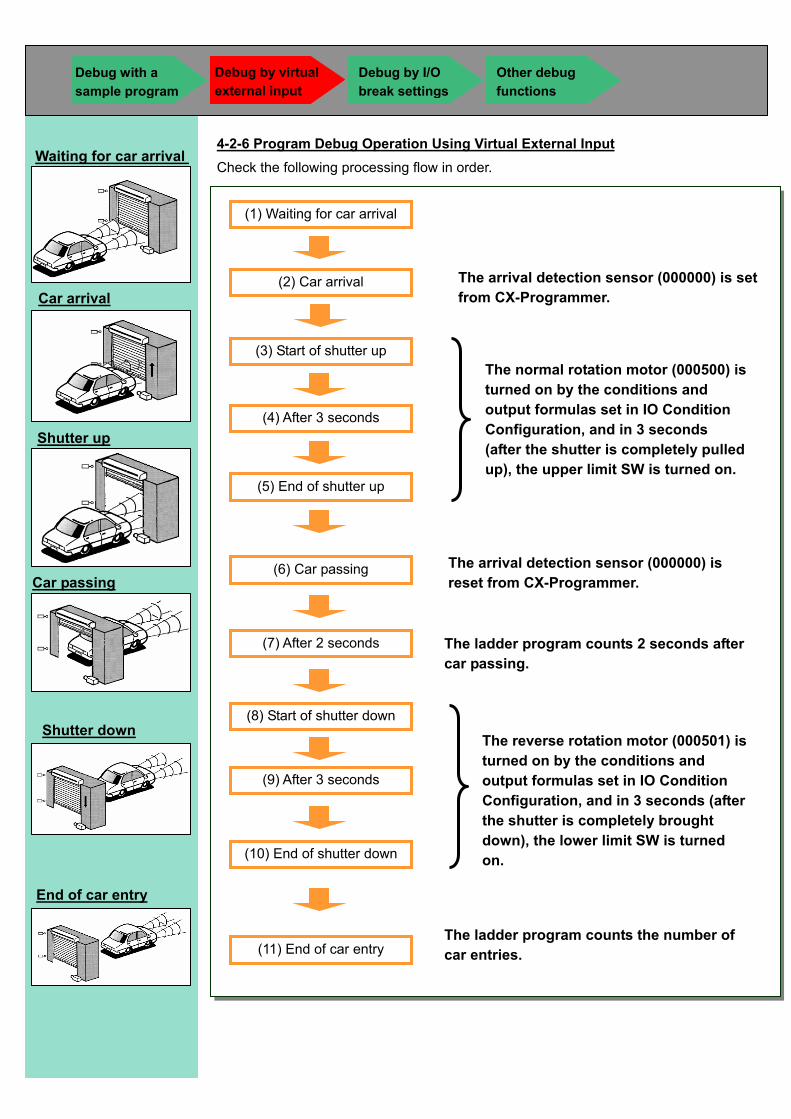
4-2-6 Program Debug Operation Using Virtual External Input Check the following processing flow in order.
Waiting for car arrival
Car passing
Car arrival
Shutter up
Shutter down
End of car entry
Debug with a sample program
Debug by I/O break settings
Other debug functions
Debug by virtual external input
The arrival detection sensor (000000) is set from CX-Programmer.
The normal rotation motor (000500) is turned on by the conditions and output formulas set in IO Condition Configuration, and in 3 seconds (after the shutter is completely pulled up), the upper limit SW is turned on.
The arrival detection sensor (000000) is reset from CX-Programmer.
The ladder program counts 2 seconds after car passing.
The reverse rotation motor (000501) is turned on by the conditions and output formulas set in IO Condition Configuration, and in 3 seconds (after the shutter is completely brought down), the lower limit SW is turned on.
The ladder program counts the number of car entries.
(11) End of car entry
(1) Waiting for car arrival
(2) Car arrival
(3) Start of shutter up
(6) Car passing
(7) After 2 seconds
(8) Start of shutter down
(9) After 3 seconds
(10) End of shutter down
(5) End of shutter up
(4) After 3 seconds
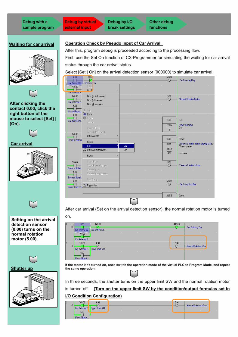
Operation Check by Pseudo Input of Car Arrival After this, program debug is proceeded according to the processing flow.
First, use the Set On function of CX-Programmer for simulating the waiting for car arrival
status through the car arrival status.
Select [Set | On] on the arrival detection sensor (000000) to simulate car arrival.
After car arrival (Set on the arrival detection sensor), the normal rotation motor is turned
on.
If the motor isn’t turned on, once switch the operation mode of the virtual PLC to Program Mode, and repeat the same operation.
In three seconds, the shutter turns on the upper limit SW and the normal rotation motor
is turned off. (Turn on the upper limit SW by the condition/output formulas set in I/O Condition Configuration)
After clicking the contact 0.00, click the right button of the mouse to select [Set] | [On].
Waiting for car arrival
Car arrival
Setting on the arrival detection sensor (0.00) turns on the normal rotation motor (5.00).
Shutter up
Debug with a sample program
Debug by I/O break settings
Other debug functions
Debug by virtual external input

Operation Check by Pseudo Input of Car Arrival Next, use the Set Off function of CX-Programmer for simulating the car passing status.
Set off the arrival detection sensor (000000) to simulate the car passing status.
After car passing (Set off the arrival detection sensor), the Timer Calculating flag is
turned on.
After click the bit 0.00, click the right-mouse button and select [Set] | [Off].
Car passing
Setting off the arrival detection sensor (0.00) turns on the timer calculating flag (W0.02).
Timer starts calculating.
Debug with a sample program
Debug by I/O break settings
Other debug functions
Debug by virtual external input
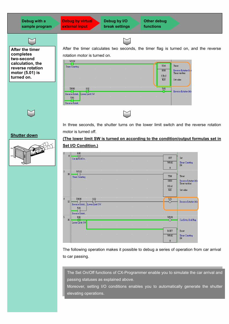
After the timer calculates two seconds, the timer flag is turned on, and the reverse
rotation motor is turned on.
In three seconds, the shutter turns on the lower limit switch and the reverse rotation
motor is turned off.
(The lower limit SW is turned on according to the condition/output formulas set in Set I/O Condition.)
The following operation makes it possible to debug a series of operation from car arrival
to car passing.
Shutter down
After the timer completes two-second calculation, the reverse rotation motor (5.01) is turned on.
The Set On/Off functions of CX-Programmer enable you to simulate the car arrival and
passing statuses as explained above.
Moreover, setting I/O conditions enables you to automatically generate the shutter
elevating operations.
Debug with a sample program
Debug by I/O break settings
Other debug functions
Debug by virtual external input
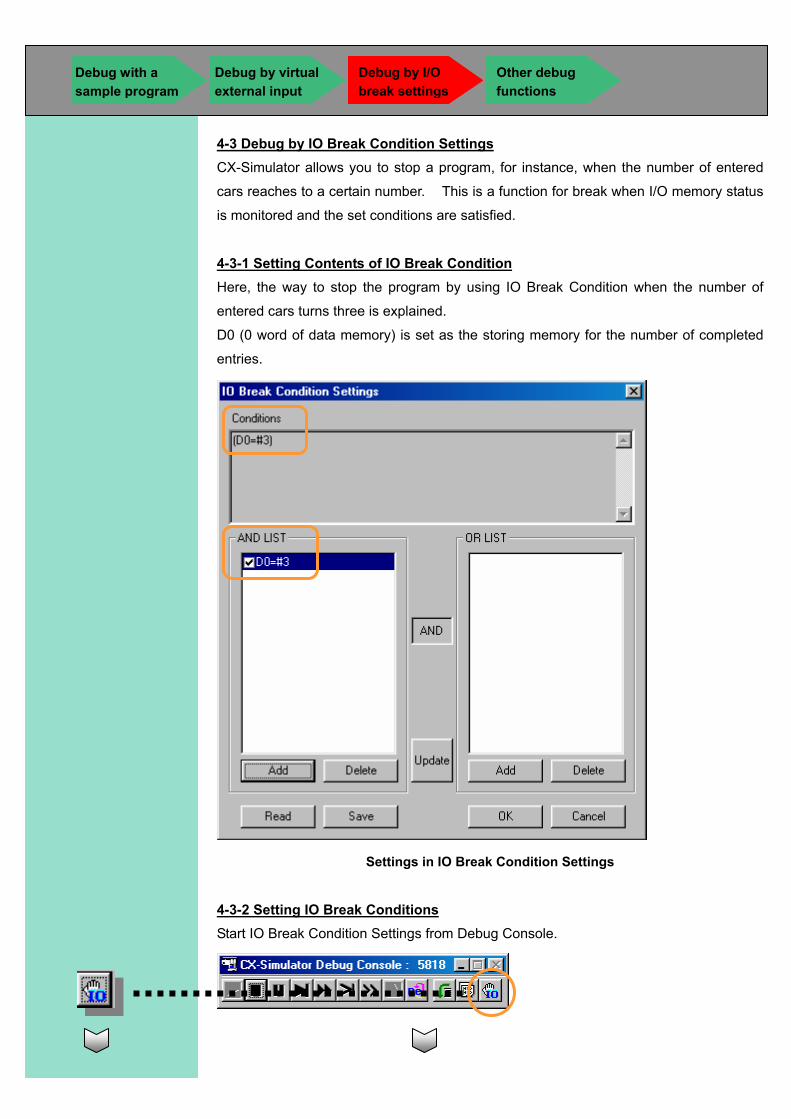
4-3 Debug by IO Break Condition Settings CX-Simulator allows you to stop a program, for instance, when the number of entered
cars reaches to a certain number. This is a function for break when I/O memory status
is monitored and the set conditions are satisfied.
4-3-1 Setting Contents of IO Break Condition Here, the way to stop the program by using IO Break Condition when the number of
entered cars turns three is explained.
D0 (0 word of data memory) is set as the storing memory for the number of completed
entries.
Settings in IO Break Condition Settings
4-3-2 Setting IO Break Conditions Start IO Break Condition Settings from Debug Console.
Debug with a sample program
Debug by I/O break settings
Other debug functions
Debug by virtual external input
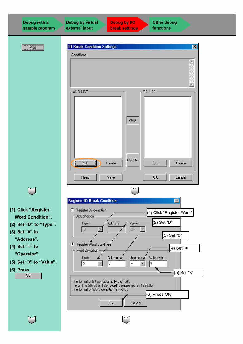
(1) Click “Register Word Condition”.
(2) Set “D” to “Type”. (3) Set “0” to
“Address”. (4) Set “=” to
“Operator”.
(5) Set “3” to “Value”. (6) Press
.
(1) Click “Register Word”
(2) Set “D”
(3) Set “0”
(4) Set “=”
(6) Press OK
(5) Set “3”
Debug with a sample program
Debug by I/O break settings
Other debug functions
Debug by virtual external input
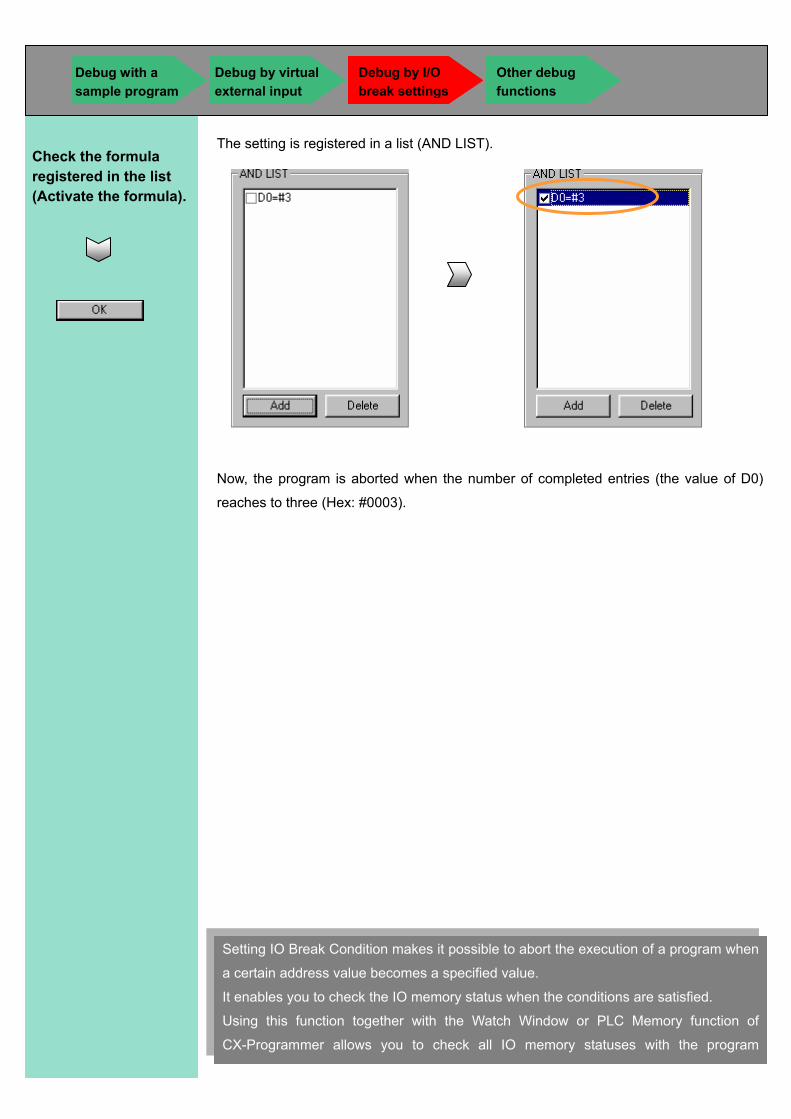
The setting is registered in a list (AND LIST).
Now, the program is aborted when the number of completed entries (the value of D0)
reaches to three (Hex: #0003).
Check the formula registered in the list (Activate the formula).
Setting IO Break Condition makes it possible to abort the execution of a program when
a certain address value becomes a specified value.
It enables you to check the IO memory status when the conditions are satisfied.
Using this function together with the Watch Window or PLC Memory function of
CX-Programmer allows you to check all IO memory statuses with the program
Debug with a sample program
Debug by I/O break settings
Other debug functions
Debug by virtual external input
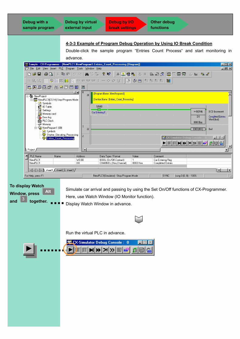
4-3-3 Example of Program Debug Operation by Using IO Break Condition Double-click the sample program “Entries Count Process“ and start monitoring in
advance.
Simulate car arrival and passing by using the Set On/Off functions of CX-Programmer.
Here, use Watch Window (IO Monitor function).
Display Watch Window in advance.
Run the virtual PLC in advance.
To display Watch
Window, press Alt
and 3 together.
Debug with a sample program
Debug by I/O break settings
Other debug functions
Debug by virtual external input
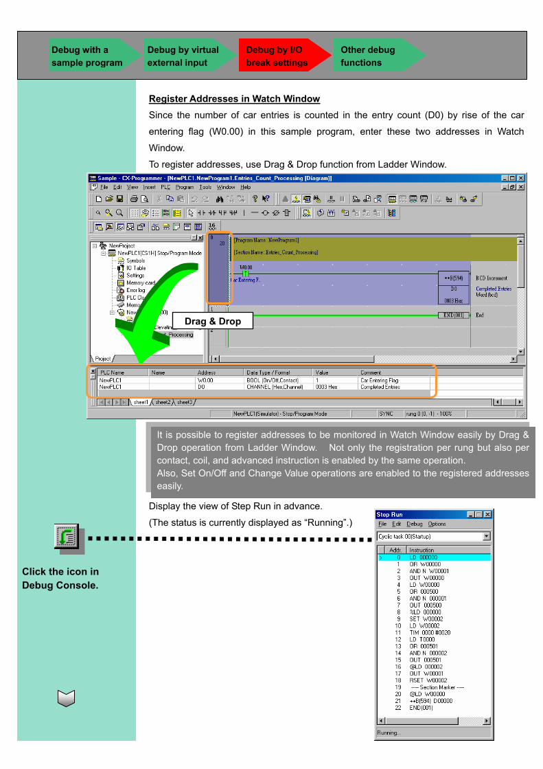
Register Addresses in Watch Window Since the number of car entries is counted in the entry count (D0) by rise of the car
entering flag (W0.00) in this sample program, enter these two addresses in Watch
Window.
To register addresses, use Drag & Drop function from Ladder Window.
Display the view of Step Run in advance.
(The status is currently displayed as “Running”.)
It is possible to register addresses to be monitored in Watch Window easily by Drag & Drop operation from Ladder Window. Not only the registration per rung but also per contact, coil, and advanced instruction is enabled by the same operation. Also, Set On/Off and Change Value operations are enabled to the registered addresses easily.
Click the icon in Debug Console.
Drag & Drop
Debug with a sample program
Debug by I/O break settings
Other debug functions
Debug by virtual external input
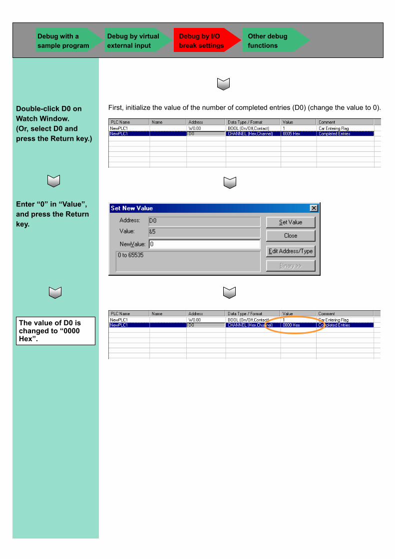
First, initialize the value of the number of completed entries (D0) (change the value to 0).
Double-click D0 on Watch Window. (Or, select D0 and press the Return key.)
Enter “0” in “Value”, and press the Return key.
The value of D0 is changed to “0000 Hex”.
Debug with a sample program
Debug by I/O break settings
Other debug functions
Debug by virtual external input
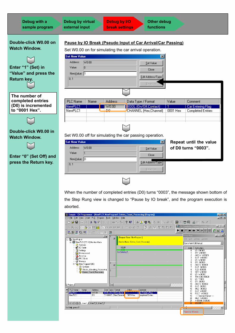
Pause by IO Break (Pseudo Input of Car Arrival/Car Passing) Set W0.00 on for simulating the car arrival operation.
Set W0.00 off for simulating the car passing operation.
When the number of completed entries (D0) turns “0003”, the message shown bottom of
the Step Rung view is changed to “Pause by IO break”, and the program execution is
aborted.
Double-click W0.00 on Watch Window.
Enter “1” (Set) in “Value” and press the Return key.
The number of completed entries (D0) is incremented to “0001 Hex”.
Double-click W0.00 in Watch Window.
Enter “0” (Set Off) and press the Return key.
Repeat until the value of D0 turns “0003”.
Debug with a sample program
Debug by I/O break settings
Other debug functions
Debug by virtual external input
4-4 Other Debug Functions This section describes the function for simple debugging. A case in a ladder program is shown
below as an example.
Step Run Function You can execute a program per instruction, which enables you to
monitor the processing in the middle of program execution.
Break point setting You can pause the programs temporarily at any point and under the
specified conditions by setting multiple break points and break conditions
according to I/O memory status.
Scan Replay Function You can execute the program in the same state
repertedly.
Break point setting, Continuous Run and Step Run operations As an example of Break Point Setting, Continuous Run
and Step Run operations, how to check the memory state
at a specified timing during program execution is
described below.
Debug with a sample program
Debug by I/O break settings
Other debug functions
Debug by virtual external input
Debug with a sample program
Debug by I/O break settings
Other debug functions
Debug by virtual external input
Run
Stpe Run
Clear All Break Points
Set/Clear Break Point
CX-Programmer Tool Bar
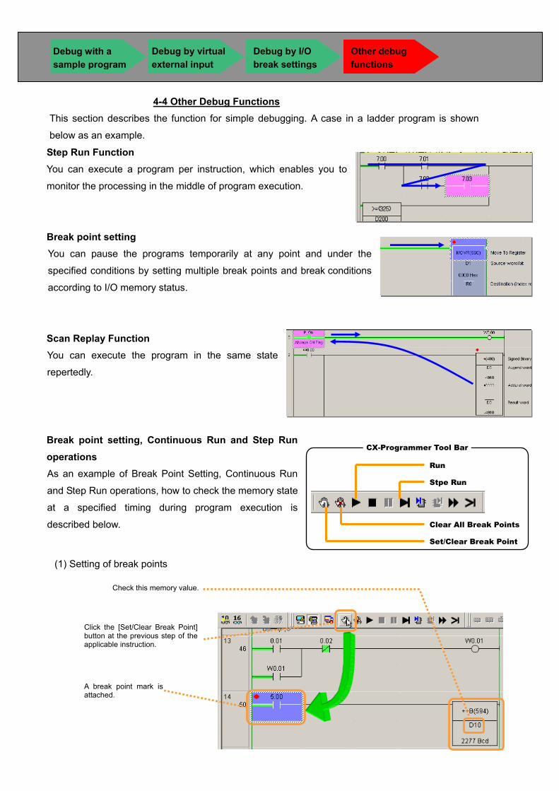
(1) Setting of break points
Check this memory value.
Click the [Set/Clear Break Point]button at the previous step of theapplicable instruction.
A break point mark is attached.
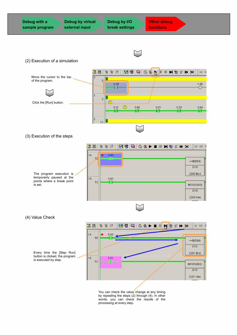
(2) Execution of a simulation
(4) Value Check
(3) Execution of the steps
Move the cursor to the topof the program.
Click the [Run] button.
The program execution istemporarily paused at thepoints where a break pointis set.
Every time the [Step Run]button is clicked, the programis executed by step.
You can check the value change at any timing by repeating the steps (2) through (4). In other words, you can check the results of the processing at every step.
Debug with a sample program
Debug by I/O break settings
Other debug functions
Debug by virtual external input
CChhaapptteerr 55 SSttaarrttuupp ffrroomm CCXX--SSiimmuullaattoorr MMeennuu
This chapter explains how to start and end CX-Simulator and how to set CX-Simulator for creating a virtual PLC in your PC. Creating a virtual PLC from the CX-Simulator menu enables you to use the following functions. See the CX-Simulator Operation Manual for the detailed operations. • Serial communications for connecting with PT • Network communications by network communications instructions • Measurement of I/O refresh time with an I/O unit registered • Display of message instructions or network communications instructions on your PC screen • Record of the communications log of FINS Commands sent/received by a virtual PLC
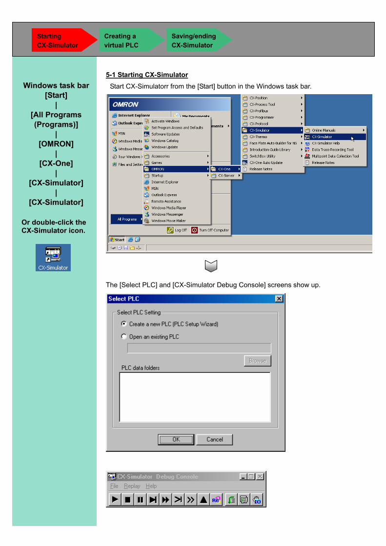
5-1 Starting CX-Simulator Start CX-Simulatorr from the [Start] button in the Windows task bar.
The [Select PLC] and [CX-Simulator Debug Console] screens show up.
Starting CX-Simulator
Creating a virtual PLC
Saving/ending CX-Simulator
Or double-click the CX-Simulator icon.
Windows task bar [Start]
| [All Programs (Programs)]
| [OMRON]
| [CX-One]
| [CX-Simulator]
| [CX-Simulator]
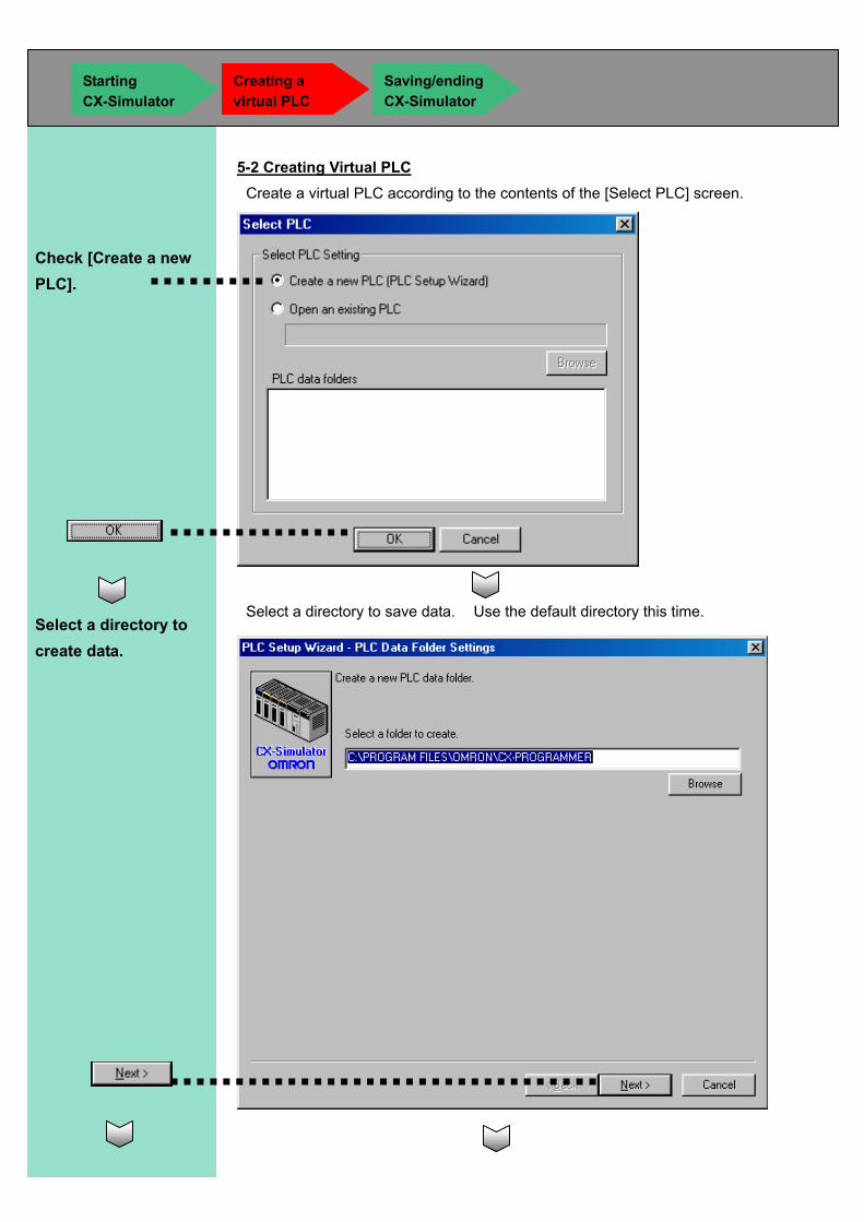
5-2 Creating Virtual PLC Create a virtual PLC according to the contents of the [Select PLC] screen.
Select a directory to save data. Use the default directory this time.
Check [Create a new PLC].
Select a directory to create data.
Starting CX-Simulator
Creating a virtual PLC
Saving/ending CX-Simulator
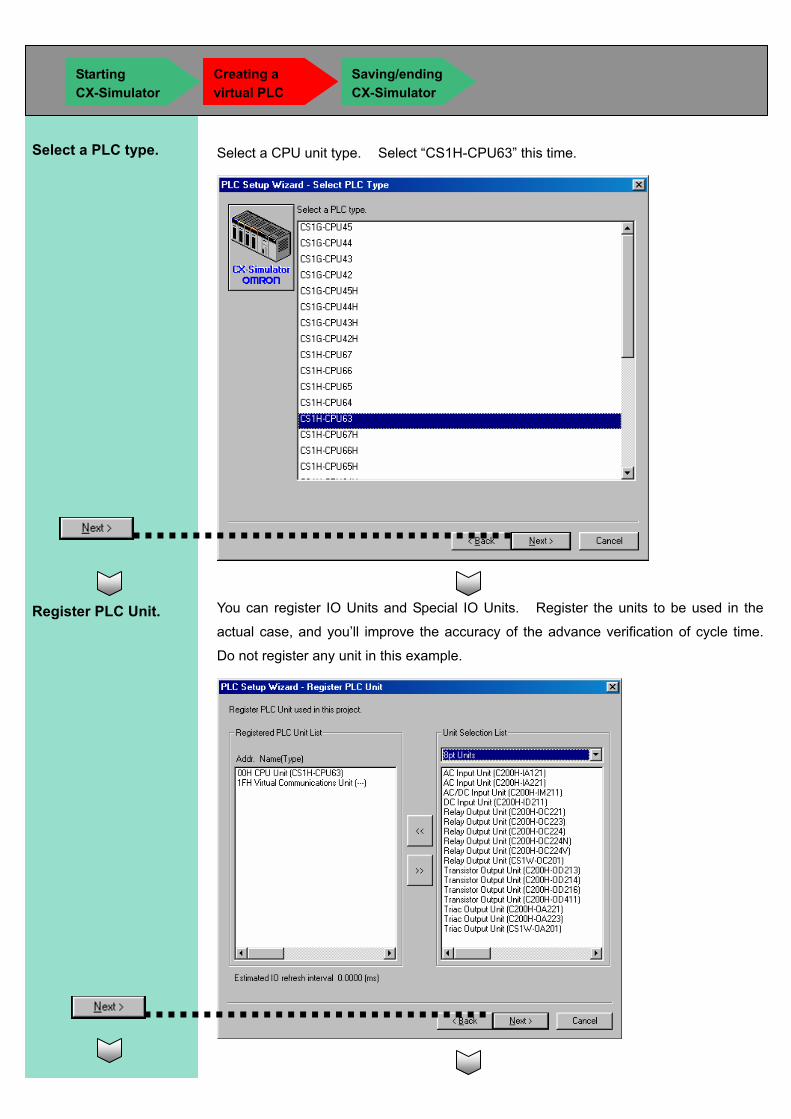
Select a CPU unit type. Select “CS1H-CPU63” this time.
You can register IO Units and Special IO Units. Register the units to be used in the
actual case, and you’ll improve the accuracy of the advance verification of cycle time.
Do not register any unit in this example.
Register PLC Unit.
Select a PLC type.
Starting CX-Simulator
Creating a virtual PLC
Saving/ending CX-Simulator
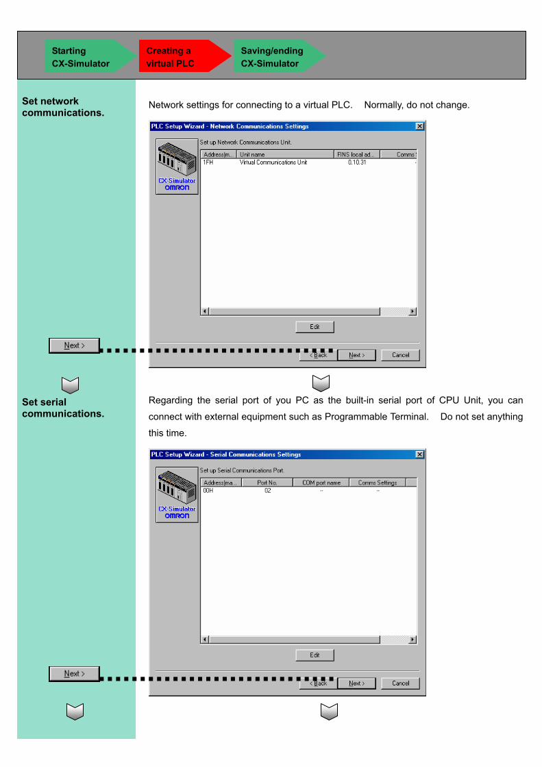
Network settings for connecting to a virtual PLC. Normally, do not change.
Regarding the serial port of you PC as the built-in serial port of CPU Unit, you can
connect with external equipment such as Programmable Terminal. Do not set anything
this time.
Set network communications.
Set serial communications.
Starting CX-Simulator
Creating a virtual PLC
Saving/ending CX-Simulator
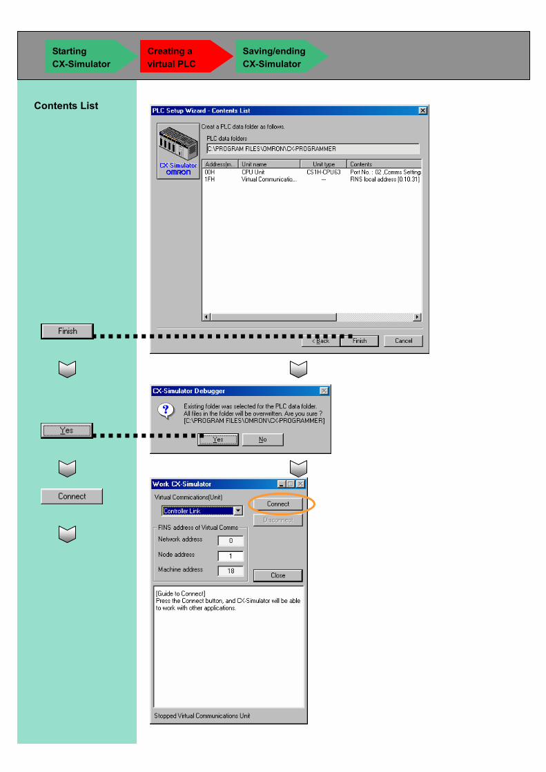
Contents List
Starting CX-Simulator
Creating a virtual PLC
Saving/ending CX-Simulator
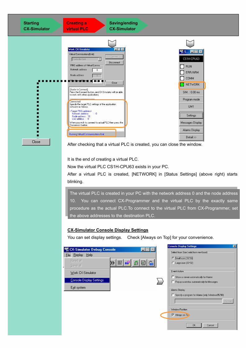
After checking that a virtual PLC is created, you can close the window.
It is the end of creating a virtual PLC.
Now the virtual PLC CS1H-CPU63 exists in your PC.
After a virtual PLC is created, [NETWORK] in [Status Settings] (above right) starts
blinking.
CX-Simulator Console Display Settings You can set display settings. Check [Always on Top] for your convenience.
The virtual PLC is created in your PC with the network address 0 and the node address
10. You can connect CX-Programmer and the virtual PLC by the exactly same
procedure as the actual PLC.To connect to the virtual PLC from CX-Programmer, set
the above addresses to the destination PLC.
Starting CX-Simulator
Creating a virtual PLC
Saving/ending CX-Simulator
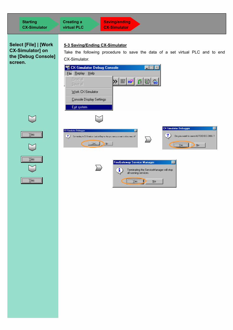
5-3 Saving/Ending CX-Simulator Take the following procedure to save the data of a set virtual PLC and to end
CX-Simulator.
Select [File] | [Work CX-Simulator] on the [Debug Console] screen.
Starting CX-Simulator
Creating a virtual PLC
Saving/ending CX-Simulator

Memo

OMRON Industrial Automation Global: www.ia.omron.com
Authorized Distributor:
In the interest of product improvement, specifications are subject to change without notice.
Cat. No. R151-E1-01
OMRON CorporationIndustrial Automation Company
Regional HeadquartersOMRON EUROPE B.V.Wegalaan 67-69-2132 JD HoofddorpThe NetherlandsTel: (31)2356-81-300/Fax: (31)2356-81-388
OMRON ELECTRONICS LLCOne Commerce Drive Schaumburg,IL 60173-5302 U.S.A.Tel: (1) 847-843-7900/Fax: (1) 847-843-7787
OMRON ASIA PACIFIC PTE. LTD.No. 438A Alexandra Road # 05-05/08 (Lobby 2), Alexandra Technopark, Singapore 119967Tel: (65) 6835-3011/Fax: (65) 6835-2711
OMRON (CHINA) CO., LTD.Room 2211, Bank of China Tower, 200 Yin Cheng Zhong Road, PuDong New Area, Shanghai, 200120, ChinaTel: (86) 21-5037-2222/Fax: (86) 21-5037-2200
OMRON Industrial Automation Global: www.ia.omron.com
Control Devices Division H.Q.PLC DivisionShiokoji Horikawa, Shimogyo-ku,Kyoto, 600-8530 JapanTel: (81) 75-344-7084/Fax: (81) 75-344-7149