cx506a .a 10.. 4
TRANSCRIPT

CX506aMULTITESTER
INSTRUCTION MANUAL

CONTENTS
[1] SAFETY PRECAUTIONS:Before use, read the following safety precautions ……025
1-1 Warning Instruction for safe use …………………………025
1-2 Explanation of Warning Symbols…………………………026
1-3 Overload Protections ………………………………………026
1-4 Influence of the electromagnetic field ……………………026
[2] APPLICATION AND FEATURES……………………………027
2-1 Application …………………………………………………027
2-2 Features ……………………………………………………027
[3] NAME OF FUNCTIONS………………………………………027
[4] SCALE READING ……………………………………………028
[5] DESCRIPTION OF FUNCTIONS ……………………………029
5-1 Selections, adjusters and switches ………………………029
5-2 How to Use the Stand ……………………………………029
[6] MEASUREMENT PROCEDURE ……………………………030
6-1 Start -up Inspection…………………………………………030
6-2 How to select an appropriate range………………………030
(Selection of an appropriate range)
6-3 Preparation for Measurement ……………………………030
6-4 Voltage Measurement ……………………………………032
6-4-1 DCV Measurement ( ) ………………………………032
6-4-2 ACV Measurement ( ) ………………………………033
6-5 DCA Measurement ( ) …………………………………034
6-6 Resistance Measurement …………………………………035
6-6-1 Resistance Measurement ( Ω ) ………………………035
6-6-2 Terminal to Terminal Current ( LI )……………………036
6-7 Capacitance Measurement ( ) …………………………037
6-7-1 C1,C2 Range……………………………………………037
6-7-2 C3 Range ………………………………………………039
6-8 Transistor Measurement …………………………………040
6-8-1 ICEO Measurement ……………………………………040

6-8-2 hFE Measurement …………………………………………041
6-9 DC High Voltage measurement …………………………042
6-10 End of Measurement………………………………………042
[7] MAINTENANCE ………………………………………………043
7-1 Maintenance and Inspection………………………………043
7-2 Calibration …………………………………………………043
7-3 How to Replace Battery and Fuse ………………………043
7-4 Cleaning and Storage………………………………………045
[8] AFTER-SALE SERVICE………………………………………045
8-1 Warranty and Provision ……………………………………045
8-2 Repair ………………………………………………………046
8-3 SANWA web site……………………………………………046
[9] SPECIFICATIONS ……………………………………………047
9-1 General Specification………………………………………047
9-2 Optional Accessories ………………………………………048
9-3 Measurement Range and Accuracy………………………048

To ensure that the meter is used safely, be sure to observe theinstruction when using the instrument.Please be careful that the protection circuit may be undermined byunjustifiable usage that does not follow the guidelines in theinstruction manual.
11. Never use the meter on the electric circuits that exceed 6kVA.12. Pay special attention when measuring the voltage of AC 33
Vrms (46.7V peak) or DC 70V or more to avoid injury.13. Never apply an input signals exceeding the maximum rating
input value.14. Never use the meter for measuring the line connected with
equipment (i.e. motors) that generates induced or surgevoltage since it may exceed the maximum allowable voltage.
15. Never use the meter if the meter or test leads are damaged orbroken.
16. Never use uncased meter.17. Be sure to use a fuse of the specified rating or type. Never use a
substitute of the fuse or never make a short circuit of the fuse.18. Always keep your fingers behind the finger guards on the
probe when making measurements.19. Be sure to disconnect the test pins from the circuit when
changing the function or range.10. Before starting measurement, make sure that the function and
range are properly set in accordance with the measurement.11. Never use the meter with wet hands or in a damp environment.12. Never open rear case except when replacing batteries or fuse.
Do not attempt any alteration of original specifications.13. To ensure safety and maintain accuracy, calibrate and check
the tester at least once a year.14. Indoor use.
— 25 —
[1] SAFETY PRECAUTIONS:Before use, read the following safety precautions
This instruction manual explains how to use your multitesterCX506a, safely.Before use, please read this manual thoroughly. After reading it,keep it together with the product for reference to it when necessary.The instruction given under the heading“ WARNING”“ CAUTION”must be followed to prevent accidental burn or electrical shock.
1-1 Warning Instruction for Safe Use
WARNING

— 26 —
1-3 Overload Protections
1-2 Explanation of Warning SymbolsThe meanings of the symbols used in this manual and attached tothe product are as follows.
: Very important instruction for safe use.・The warning messages are intended to prevent accidents to
operating personnel such as burn and electrical shock.・The caution messages are intended to prevent damage to the
instrument.: DC : Diode: AC : Ground: Resistance : Plus: Capacitance : Minus: DC Current Amplification Factor : Fuse: Fuse & Diode Protection : Double insulation
hFE
+-
Ω
+,-
DCVFunctions Input terminals Maximum overload protection input (within 5s)
DC・AC 1000V or peak max 1400VACVDCVACVDCV
DCA
hFE
1000750120/3003/12/30120mV30µ/0.3m3m30m/0.3X1~X10kC1/C2/C3
-
Ω
・EMITTER・COLLECTOR・BASE
DC・AC 750V or peak max 1100VDC・AC 200V or peak max 280V
DC・AC 1mA
DC・AC 10mA DC・AC 0.5A
DC・AC 100V orpeak max 140V
DC・AC 50V or peak max 75V
DC・AC 50V or peak max 75V
1-4 Influence of the electromagnetic fieldACV and Capacitance measurement functions may not workproperly in the electromagnetic field over 10kHz.

[2] APPLICATION AND FEATURES
2-1 ApplicationsThis instrument is portable multimeter designated formeasurement of weak current circuit.
2-2 FeaturesHigh-Sensitivity(DC50kΩ /V)meterCapacitance measurement by built-in transistor oscillatorIEC61010-1 MEASUREMENT CAT- MAX. 600VWide measurement functions 26-ch switchTransistor check functionPolarity reversal switch for DCV and DCA
[3] NAME OF FUNCTIONS
— 27 —
Ⅲ
Clip lead (CL-506a)
Scale
Pointer
Meter zero positionadjuster
Function/Rangeselector
- input terminal(collector connectingterminal)Base connectingterminal
0Ω・C∞adjuster
power indicator
Polarity reversal switch
function powerswitch(capacitance switch)
Stand
+ input terminal (emitter connectingterminal)
Plug
Clip
Rear casePanel
Test pins
Plugs
Finger guards
Test probe (red)
Test probe (black)TL-21a
Removabletest pin covers
When notcovered
・When the removable test pin covers are mounted : CAT.III 600V・When the removable test pin covers are not mounted: CAT.II 1000V

[4] SCALE READING
— 28 —
C1
C2
hFE
C3
80mA
8mA
800µA
80µA
ACV 3
X 1
X 1
X 1
X 1
X 10
X 1
X 100
X 10
X 1
Range Multiplier
Ω X 10k
Ω X 1k
Ω X 100
Ω X 10
Ω X 1
DCV 1000
DCV 120
DCV 12
DCV 120m
ACV 750
ACV 120
ACV 12
X 10k
X 1k
X 100
X 10
X 1
X 10
X 1
X 0.1
X 1
X 10
X 1
X 0.1
DCV 300
DCV 30
DCV 3
ACV 300
ACV 30
DCmA 30µ
DCmA 0.3
DCmA 3
DCmA 30
DCmA 0.3A
X 10
X 1
X 0.1
X 10
X 1
X 1
X 0.01
X 0.1
X 1
X 0.01
*Please read the indication from the right overthe pointer.
How to read the scale value:
Function Range scale No. Conversion Reading
Ω
DCV
ACV
DCmA
X 100
120V
3V
3mA
89 X 100
36 X 100
1.17 X 100...
.9 X 0.1
8900[Ω]=8.9[kΩ]
36 [V]
1.17 [V]
0.9 [mA]
Range Multiplier Range Multiplier

[5] DESCRIPTION OF FUNCTIONS
5-1 Selectors, adjusters and switchesFunction/Range selector
Turn the instrument on by selecting any measurement range.Meter zero position adjuster
Turn the adjuster to have the pointer align with the zero line.(scale left edge)
0Ω・C∞AdjusterFor resistance or hFE measurement, turn the adjuster to havethe pointer align with the zero line (0Ω) while test leads areshorted.For capacitance measurement, turn the adjuster to have thepointer align with ∞ of each C scale while test leads areshorted, with pressing (locking) the capacitance switch.
Capacitance SwitchPress the switch to measure capacitance at C1 or C2 range. Tolock the switch at ON position, press and turn it to right approx45 degree.
Power IndicatorThe indicator (LED) is blinked when power is on, for capacitancemeasurement.
Polarity reversal switchShift the switch to minus (-) to reverse polarity for -DCV or -DCA measurement.
5-2 How to Use the StandPlease use the stand that thereis on the side of rear case like afigure.
— 29 —
How to Use the Stand

— 30 —
[6] MEASUREMENT PROCEDURE
6-1 Start-Up Inspection
1. Never use meter if the meter or test leads are damaged orbroken.
2. Make sure that the test leads are not cut or otherwise damaged.
WARNING
6-2 How to select an appropriate range (Selection of a appropriate range)For voltage or current measurements, select a function/range
selector is higher than the value to be measured. For example,whenmeasuring 9V, select 12V range. If the value to be measured isuncertain, select maximum range.
For Ω measurement, select a range that the pointer can beread by the center of scale.
6-3 Preparation for measurementsZero position adjustment.Shift the polarity reversal switch to + position.Select a proper range and set the switch for measurements.
Zero position adjustment
Zero position

— 31 —
Check continuity of test leads and fuse.
Stop using it and have it repaired.
Short the red and black test pins.
Replace the battery and fuse, and starting to once more.Set the switch to
+ position.
START
Main unitand test leads
damaged ?
Did thepointer move to
right side ?
Stop using it and have it repaired.
No problem.Start measurement.
Damaged
No damaged
YES
NO
Connect the black plug of the test lead to the - terminal.
Connect the red plug of the test lead to the + terminal.
Set the function range switch at Ω x 1 range.

— 32 —
6-4-1 DCV Measurement ( ) Max. measurement value 1000VDC1) Application
Measuring batteries or DC circuits.2) Measuring range: 120m/3/12/30/120/300/1000 (7ranges)
6-4 Voltage Measurement
1.Never apply an input signals exceeding the maximumrating input value.
2.Be sure to disconnect the test pins from the circuit whenchanging the function / range.
3.Select the maximum range and measure, if the value to bemeasured is uncertain.
4.Always keep your fingers behind the finger guards on theprobe when making measurements.
WARNING
3) Measurement procedureShift the polarity reversal switch to + position.Connect the black plug of the test lead to the - input
terminal and the red plug to the + input terminal.Set the function/range selector to an appropriate DCV
range.Apply the black test pin to the negative potential side of the
circuit to measure and the red test pin to the positivepotential side.
Read the pointer on V・A scale.After measurement, remove the red and black test pins from
the circuit measured.
When the pointer moves to the“-”side, shift the polarityreversal switch to the“-”position.
Battery

— 33 —
6-4-2 ACV Measurement ( ): Max.measurement value 750VAC1) Application
Measures sine-wave AC voltages such as lighting voltages.2) Measuring range: 3/12/30/120/300/750 (6ranges)
3) Measurement procedureShift the polarity reversal switch to + side.Connect the black plug of the test lead to the - input
terminal and the red plug to the + input terminal.Set the function/range selector to an appropriate ACV
range.Apply the black and red test pin to measuring circuit.Read the pointer on V・A scale.
The AC3V range only uses the“AC3V”scale.After measurement, remove the red and black test pins
from the circuit measured.
When measuring non-sine wave ACV, measuring valuesmay have errors according to the contortion of the wave.Band width.40Hz-30kHz at 3,12V range40Hz-10kHz at 30V or above rangesValues measured at 750V shall be read by decupling (X10)the scale of 0-120. But for the safety, do not measure anycircuits that exceed 6kVA.
Outlet

At current measurement, according to the size of internalresistance of the current range, measuring value will besmaller than actual current.
1) ApplicationCurrent in batteries or DC circuit is measured.
2) Measuring range: 30µ/0.3m/3m/30m/0.3A (5ranges)3) Measurement procedure
Shift the polarity reversal switch to + position.Connect the black plug of the test lead to the - input
terminal and the red plug to the + input terminal.Set the function/range selector to an appropriate DCA
range.Apply the black test pin to the negative potential side of the
circuit to measure and the red test pin to the positivepotential side.
Read the pointer on V・A scale.After measurement, remove the red and black test pins from
the circuit measured.
— 34 —
6-5 DCA Measurement ( ): Max. measuremet value 0.3ADC
1. Never apply voltage tothe input terminals.
2. Be sure to make a seriesconnection via load.
3. Do not apply an inputexceeding the maximumrated current to the inputterminals.
WARNING
Correct × Incorrect
PowerLoad
PowerLoad
Battery
Resistor

— 35 —
6-6-1 Resistance Measurement ( Ω )1) Application
Resistance of resistors or circuits are measured.2) Measuring range: X1/X10/X100/X1k/X10k (5ranges)3) Measurement procedure
Shift the polarity reversal switch to + side.Connect the black plug of the test lead to the - input
terminal and the red plug to the + input terminal.Set the function/range selector to an appropriate Ω range.Short the test pins, and adjust 0Ω・C ∞ by turning adjuster
to have the pointer align with 0 line.Apply the black and red test pin to the measured resistance.Read the pointer on Ω scale.After measurement, remove the red and black test pins from
the resistor measured.
6-6 Resistance Measurement Max. measurement value 50MΩ
Never apply voltage to the input terminals.WARNING
and/or circuit protection is become unable.Operating voltage for Ω range of this multitester is 3V, solighting test of LED can be performed. Appropriate range isΩ x 10 range.If the pointer does not move to 0 line even when the 0 Ωadjuster is turned fully, replace the internal batteries to newones.
Resistor
At Ω range, thepolarity of +/- isreverse from thatmarked on the bodypanel.Be sure to use therated fuse for theinstrument. In casea fuse other thanthe rated one isused, indicationerrors may occur,

— 36 —
6-6-2 Terminal to Terminal Current (LI)Terminal-to-Terminal Current is the current that runs between- and + terminals when measuring resistance. There may besome cases that the impedance of measured object varies,especially when measuring semi-conductors, due to self-heating caused by current running while measuring resistance.The maximum LI values are printed on the body panel, at rightside of each range. Readings at each range shall be convertedby multiplying the values (shown below).x1k (80µA) Range : LI scale x10, and read as µA.x100 (800µA) Range : LI scale x100, and read as µA.x10 (8mA) Range : Simply read as mA.x1 (80mA) Range : LI scale x10, and read as mA.

— 37 —
6-7-1 C1,C2 ranges1) Application
Measurement of capacitance2) Measuring range
C1 range : 50pF~0.2µFC2 range : 0.01~20µF
3) Measurement procedureShift the polarity reversal switch to + position.Connect the black plug of the test lead to the - input
terminal and the red plug to the + input terminal.Set the function/range selector to an appropriate C1 or C2
range.Push the function power switch. (See 5-1)
Then, the power indicator blinks.Short the test pins and turn the 0 Ω・C ∞ adjuster to have
the pointer align exactly with ∞ of C1or C2 scale.Apply the black and red test pin to the measured capacitor.
6-7 Capacitance Measurement ( )
1.Never apply voltage to the input terminals.2.Discharge the capacitance before measuring it.
WARNING
Read the pointer on C1or C2 scale.After measurement, remove the red and black test pins from
the object measured.Turn off the function power switch. (See 5-1)
Capacitor

— 38 —
NoteMeasuring frequency
C1range : approx. 900Hz C2range : approx. 800HzMeasuring voltage
C1range : approx.8.0V (peak)/When 200pF is measuredC1range : approx.0.5V (peak)/When 0.05µF is measuredC2range : approx.4.0V (peak)/When 0.1µF is measuredC2range : approx.0.7V (peak)/When 5.0µF is measured
Application・Test of the cord (Use the C1 range)
Wire breaking point
Cx 1
Cx 2
Cx 1>Cx 2
Continuity or open-wire check of parallel cords, as shown in Fig,can be done by measuring capacitance between the core wires(conductors) as a comparison test.Longer cords are easier to check the detection of the open-wirebecause the capacity value lost by leakage between the wires isproportioned to the length of the wires.
— 39 —
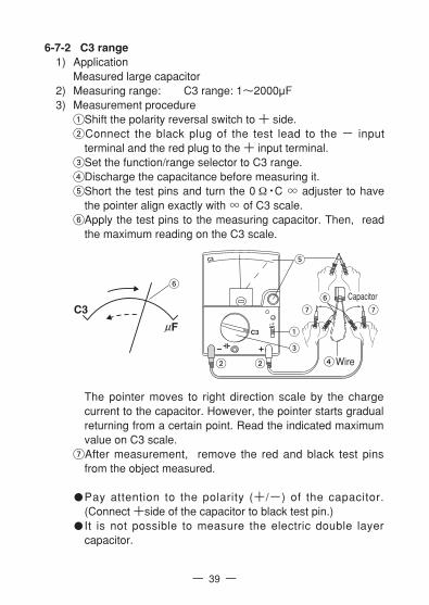
6-7-2 C3 range1) Application
Measured large capacitor2) Measuring range: C3 range: 1~2000µF3) Measurement procedure
Shift the polarity reversal switch to + side.Connect the black plug of the test lead to the - input
terminal and the red plug to the + input terminal.Set the function/range selector to C3 range.Discharge the capacitance before measuring it.Short the test pins and turn the 0 Ω・C ∞ adjuster to have
the pointer align exactly with ∞ of C3 scale.Apply the test pins to the measuring capacitor. Then, read
the maximum reading on the C3 scale.
The pointer moves to right direction scale by the chargecurrent to the capacitor. However, the pointer starts gradualreturning from a certain point. Read the indicated maximumvalue on C3 scale.
After measurement, remove the red and black test pinsfrom the object measured.
Pay attention to the polarity (+/-) of the capacitor.(Connect +side of the capacitor to black test pin.)It is not possible to measure the electric double layercapacitor.
C3
C3
Wire
Capacitor

— 40 —
6-8-1 ICEO Measurement1) Application
Measuring Iceo of transistor2) Measuring range: hFE range3) Measurement procedure
Connect the black plug of the test lead to the - inputterminal and the red plug to the + input terminal.
Set the function/range selector to hFE function.Set the polarity reversal switch to either NPN or PNP
position according to the transistor (hereinafter simply called“TR.”) to be measured. (NPN-TR: NPN position PNP-TR:PNP position)
Short the test pins and turn the 0 Ω・C ∞ adjuster to havethe pointer align exactly with 0 line of Ω scale.
Connect the emitter of TR and the collector of TR to eachmeasuring terminal (pin of test lead).
Read the pointer on LI scale. (X10mA)After measurement, remove the red and black test pins from
the TR.
Good or Bad shall be determined by comparison tostandard TR.Except large power TR, reading of the ICEO of normal siliconTR is almost 0mA.
6-8 Transistor Measurement
Never apply voltage to the input terminals.WARNING
transistor
Case of NPN-TR
E: emitterB: baseC: collector

— 41 —
6-8-2 hFE Measurement1) Application
Measuring hFE of transistor2) Measuring range: hFE range3) Measurement procedure
Connect the black plug of the test lead to the COLLECTOR(-input) terminal and the red plug to the EMITTER (+input) terminal.
Connect the black plug of the clip lead to the BASE terminal.Set the function/range selector to hFE function.Set the polarity reversal switch to either NPN or PNP
position according to the transistor (hereinafter simply called“TR.”) to be measured. (NPN-TR: NPN position PNP-TR:PNP position)
Short the test pins and turn the 0 Ω・C ∞ adjuster to havethe pointer align exactly with 0 line of Ω scale.
Connect the base of TR to the base terminal (clip lead).Connect the emitter of TR and the collector of TR to each
measuring terminal (pin of test lead).Read the pointer on hFE scale.After measurement, remove the test pins and the clip lead
from the TR.
transistor
Case of NPN-TR
E: emitterB: baseC: collector

— 42 —
1) ApplicationThe probe is suitable for measuring voltage of high impedancecircuits, such as CRT anode voltage of TV sets.
6-9 DC High Voltage measurement (HV) (Optional HV Probe)Max. measurement value 30kV DC
1.The probe is designed for the measurement of very smalldirect current circuit. Never use the probe to measurehigh voltage in power lines, such as transmission anddistribution lines; it is very dangerous.
2. Never apply input signals that exceed 30kV.3. Be sure to disconnect the test pins from the circuit when
changing the function.4. Always keep your fingers behind the finger guards on the
probe when making measurements.
WARNING
selector to HV PROBE position.First, connect the clip (black) of the probe to the earth line (-) in
the circuit to be measured, and then apply the measuring pin onthe probe body to your measuring point.
Read the pointer on V・A (0~30) scale as kV.After measurement, remove the measuring pin from the
measured circuit, and then remove the clip.
6-10 End of MeasurementWhen measurement is end, be sure to return the function/rangeselector to the OFF position.
2) Measuring range: HV PROBE (DC120mV)
3) Measurement procedureShift the polarity
reversal switch to +position.
Connect the black plugof the HV Probe to the- input terminal andthe red plug to the +input terminal.
Set the function/range
Anode
CRT
Earth line

— 43 —
[7] MAINTENANCE
1.This section is very important for safety. Read and understandthe following instruction fully and maintain your instrumentproperly.
2. The instrument must be calibrated and inspected at least once ayear to maintain the safety and accuracy.
WARNING
7-1 Maintenance and inspection1) Appearance
Is the appearance not damaged by falling ?2) Test leads and fuse
Are the test leads not damaged ?Are the core wire not exposed at any place of the test leads ?Make sure that the test leads are not cut, referring to thesection 6-1.
If your instrument fails any of above check, do not use it, and have itrepaired or replace it to new one.
7-2 CalibrationThe manufacturer may conduct calibration and inspection. Formore information, please contact the dealer or manufacturer.
7-3 How to Replace Battery and Fuse
1. If the rear case is removed with input applied to the inputterminals, you may get electrical shock. Before starting thework, always make sure that no inputs is applied.
2. Be sure to use a fuse that has the same rating so as toensure safety and performance of tester.
3. When removing the rear case do not touch the internal partsor wire with hand.
WARNING

— 44 —
<How to replace the battery or fuse>Remove the rear case screw with a screwdriver.Remove the rear case.Take out the battery or fuse and replace it with a new one.Attach the rear case and fix it with the screw.
Check and see whether or not indications of respective rangesare normal.
Fuse of the specified rating and type(Parts No. F1176)500mA/250V φ5 X 20mm Ceramic tube Fast acting fuse.Blowout capacity : 1500A
Fuse
Battery (6F22)9V X1
Spare fuse
Battery (R6)1.5V X2
9V1.5V

7-4 Cleaning and Storage
1. For cleaning, wipe lightly with a soft, and either dry or slightlywater-dampended cloth. Do not use volatile solvent such asthinner or alcohol for panel, case, and meter cover.
2. The panel and the case are not resistant to heat. Do not placethe instrument near heat-generating devices (such as asoldering iron).
3. Do not store the instrument in a place where it may be subjectedto vibration or from where it may fall.
4. For storing the instrument, avoid hot, cold or humid places orplaces under direct sunlight or where condensation isanticipated.
CAUTION
— 45 —
Following the above instructions, store the instrument in goodenvironment. (See 9-1)
[8] AFTER-SALE SERVICE
8-1 Warranty and Provision Sanwa offers comprehensive warranty services to its end-users andto its product resellers. Under Sanwa's general warranty policy, eachinstrument is warranted to be free from defects in workmanship ormaterial under normal use for the period of one (1) year from the dateof purchase.This warranty policy is valid within the country of purchase only, andapplied only to the product purchased from Sanwa authorized agentor distributor.Sanwa reserves the right to inspect all warranty claims to determinethe extent to which the warranty policy shall apply. This warranty shallnot apply to fuses, test leads, disposables batteries, or any product orparts, which have been subject to one of the following causes:
1. A failure due to improper handling or use that deviates from theinstruction manual.
2. A failure due to inadequate repair or modification by peopleother than Sanwa service personnel.
3. A failure due to causes not attributable to this product such asfire, flood and other natural disaster.

4. Non-operation due to a discharged battery. 5. A failure or damage due to transportation, relocation or
dropping after the purchase.

— 47 —
[9] SPECIFICATIONS
9-1 General SpecificationAC Rectifier form
:Half-wave rectifier formMeter type :Internal magnet, Taut band meter (15µA)Accuracy assurance Temperature/Humidity range
:23±2 75%RH max. No condensationOperating temperature and humidity
:5~31,80%RH max.31<~40, 80~50%RH (decreasing linearly)
Storage temperature/Humidity range:-10~50 70%RH max. No condensation
Built-in battery :R6 (IEC) or UM-3 1.5V X2, 6F22 9V X1
* Factory-preinstalled built-in battery A battery for monitoring is preinstalled before shipping, therefore it mayrun down sooner than the battery life specified in the instruction manual.The ”battery for monitoring” is a battery to inspect the functions andspecifications of the product.
Built-in fuse :F500mAH/250V φ5 X 20mm Ceramic tubeFast acting fuse. Blowout capacity : 1500A
Dimension and Weight:165(H) X 106(W) X 46(D) mm・approx. 370g
Accessories :Instruction manual 1 Spare fuse 1Test leads TL-21a 1 Crip lead CL-506a 1
Safety :IEC 61010-1 (EN61010-1) 2nd : 2001Measurement CATⅢ*. AC, DC600V max.Pollution degree 2
EMC :IEC 61326 : 1997+A1 : 1998+A2 : 2001Environmental conditions: Indoor use Altitude up to 2000mWorking circuit voltage: 600 VAC max.
MEASUREMENT CATEGORY・CATⅠ:Secondary electrical circuits connected to an AC
electrical outlet through a transformer or similar device.・CATⅡ:Primary electrical circuits in equipment connected to
an AC electrical outlet by a power cord.・CATⅢ:Primary electrical circuits of heavy equipment
connected directly to the distribution panel, andfeeders from the distribution panel to outlets.
*

9-3 Measurement Range and AccuracyAccuracy assurance range :23±2 75%RH max.
No condensationAttitude :Horizontal (±5°)ACV accuracy in the case of sine wave AC.
Function Full scale value Accuracy Remarks
DCV( )
120m
ACV( )
DCA( )
Ω
( µF )
LI(µA/mA)
hFE
3/12/30/120/300/750
30µ/0.3m/3m30m/0.3
5k(X1)/50k(X10)/500k(X100)/5M(X1k)/50M(X10k)
3/12/30/120/300/1000
C1range : 50p~0.2µC2range : 0.01~20µ
C3range : 1~2000µ
0~80µA (Ω X1k range)0~800µA (Ω X100 range)0~8mA (Ω X10 range)0~80mA (Ω X1 range)
0~1000
±4% Against full scale
±2.5% Against full scale
±3% Against full scale
(up to 12V range ±4% against full scale)
±2.5% Against full scale
(30µ and 0.3A range ±3% against full scale)
±3% of arc
±6% of arc
Approximate value
Approximate value
Approximate value
Input resistance : 4kΩ
Input resistance : 50kΩ/V(1000V range : 15kΩ/V)
Input resistance : 8kΩ/V
Voltage drop : 120mV(0.3A range : 300mV)
Center value 38Ω (X1 range)Max. value 5kΩ (X1 range)Release voltage : 3V
(X10k range : 12V)
Use the internaloscillator
Use the Ω X 1k range
Terminal to terminalcurrent
hFE=Ic/Ib
Band width3V and 12V range : 40Hz~30kHz 30V range : 40Hz~10kHz
— 48 —
9-2 Optional Accessories・Clip adapter CL-11 (Red, Black 1set)・HV probe HV-60 (DC 0~30kV Internal resistance:1000MΩ)・Carrying case C-CA

SANWA ELECTRIC INSTRUMENT CO., LTD.Dempa Bldg, 4-4 Sotokanda2-Chome Chiyoda-ku, Tokyo, Japan
10-1106 2040 2040