cyberlogic opc server help
TRANSCRIPT
Cyberlogic OPC Server Help
OPC Server for MBX, DHX and OPC DA Server Devices
Version 9
Cyberlogic OPC Server Help
Cyberlogic Technologies Inc. - 2 -
CYBERLOGIC OPC SERVER HELP
Version 9
Copyright © 1994-2017, Cyberlogic® Technologies Inc. All rights reserved.
This document and its contents are protected by all applicable copyright, trademark and patent laws and international treaties. No part of this document may be copied, reproduced, stored in a retrieval system or transmitted by any means, electronic, mechanical, photocopying, recording or otherwise, without the express written permission of Cyberlogic Technologies Inc. This document is subject to change without notice, and does not necessarily reflect all aspects of the mentioned products or services, their performance or applications. Cyberlogic Technologies Inc. is not responsible for any errors or omissions in this presentation. Cyberlogic Technologies Inc. makes no express or implied warranties or representations with respect to the contents of this document. No copyright, trademark or patent liability or other liability for any damages is assumed by Cyberlogic Technologies Inc. with respect to the use of the information contained herein by any other party.
Cyberlogic®, DHX®, MBX®, WinConX® and Intelligent • Powerful • Reliable® are registered trademarks and DirectAccess™, OPC Crosslink™, OPC Datacenter™, DevNet™ and C-logic™ are trademarks of Cyberlogic Technologies Inc. All other trademarks and registered trademarks belong to their respective owners.
Document last revision date May 14, 2019
Cyberlogic OPC Server Help
Cyberlogic Technologies Inc. - 3 -
TABLE OF CONTENTS
Introduction ........................................................................................................ 5 Compatibility and Compliance ................................................................................... 5
What Should I Do Next?...................................................................................... 7 Learn How the OPC Server Works ............................................................................. 7 Read a Quick-Start Guide ......................................................................................... 7 Get Detailed Information on the Configuration Editors ............................................... 7 Verify That It’s Working or Troubleshoot a Problem ................................................... 7 Print a Copy of This Document ................................................................................. 7 Contact Technical Support ........................................................................................ 7
Theory of Operation ............................................................................................ 8 OPC Server Basics ................................................................................................... 8 Main Server Features ............................................................................................. 10 Network Connections Tree ..................................................................................... 11
Network Auto-Configuration ................................................................................ 12 Health Watchdog................................................................................................ 12
Address Space Tree ............................................................................................... 13 Device Folders and Devices ................................................................................. 13 Folders and Data Items ...................................................................................... 17
Conversions Tree ................................................................................................... 20 Simulation Signals Tree .......................................................................................... 20 Alarm Definitions Tree ........................................................................................... 20 Database Operations Tree ...................................................................................... 21 OPC Crosslinks Tree ............................................................................................... 21
Quick-Start Guide ..............................................................................................23 Configuring the Driver ............................................................................................ 25 Configuring the Network Connections Tree Automatically ......................................... 27 Configuring the Network Connections Tree Manually ................................................ 29 Selecting a Computer in the Network Connections Tree ........................................... 34 Selecting an OPC Server ......................................................................................... 39 Creating Address Space Device Folders and Devices ................................................ 42 Configuring the Access Paths .................................................................................. 45 Configuring Unsolicited Message Filters ................................................................... 48 Using DirectImport ................................................................................................ 51 Configuring Folders and Data Items Manually .......................................................... 54 Using the Data Item Duplication Wizard .................................................................. 59 Saving the Configuration and Updating the Server ................................................... 66 Verifying Your Configuration ................................................................................... 67
Configuration Editor Reference ........................................................................69 Network Connections ............................................................................................. 70 Address Space ....................................................................................................... 74 Conversions .......................................................................................................... 75
Conversion Types ............................................................................................... 75 Creating and Deleting Conversions ...................................................................... 77 Editing a Conversion ........................................................................................... 78
Simulation Signals ................................................................................................. 81 Simulation Signal Types ...................................................................................... 81 Creating and Deleting Simulation Signals ............................................................. 85 Editing Simulation Signals ................................................................................... 86
Cyberlogic OPC Server Help
Cyberlogic Technologies Inc. - 4 -
Alarm Definitions ................................................................................................... 89 Alarm Definition Types........................................................................................ 89 Creating and Deleting Alarm Definitions ............................................................... 89 Editing Limit Alarm Definitions............................................................................. 90 Editing Digital Alarm Definitions .......................................................................... 93
Database Operations ............................................................................................. 96 OPC Crosslinks ...................................................................................................... 96 Saving and Undoing Configuration Changes ............................................................ 96 Configuration Import/Export ................................................................................... 97
Exporting a Server Configuration ......................................................................... 97 Importing a Cyberlogic Server Configuration ........................................................ 99 Importing Configurations from Other Server Brands ........................................... 101 Selective Import of a Server Configuration ......................................................... 103
Compacting the Configuration File ........................................................................ 114 Editor Options ..................................................................................................... 114 Server Status Block .............................................................................................. 122 Connecting OPC Client Software ........................................................................... 122
Validation & Troubleshooting ........................................................................ 125 Data Monitor ....................................................................................................... 125 Cyberlogic OPC Client .......................................................................................... 126
Typical Client Session ....................................................................................... 127 Main View Window ........................................................................................... 132 Server Status ................................................................................................... 134 Group State ..................................................................................................... 135 Saving/Reloading Data Items ............................................................................ 137 Shortcuts and Command Line Parameters .......................................................... 138 Client Options .................................................................................................. 139
Performance Monitor ........................................................................................... 142 DirectAccess ........................................................................................................ 146 Status Items........................................................................................................ 148
Cyberlogic OPC Server Status Application ........................................................... 149 Status Item Definitions ..................................................................................... 150
Event Viewer ....................................................................................................... 164 Cyberlogic OPC Server Messages .......................................................................... 165 Frequently Asked Questions ................................................................................. 168
Appendix A: Item Properties .......................................................................... 170 Standard Properties ............................................................................................. 171 Vendor-Defined Properties ................................................................................... 172
Appendix B: Quality Codes ............................................................................. 174
Appendix C: Data Access Automation Support .............................................. 176
Appendix D: OPC XML Data Access Support .................................................. 177 Install Windows Internet Information Services ....................................................... 177 Install the Cyberlogic OPC Server XML Data Access Support ................................... 180 Adding a User Account to the Cyberlogic OPC Users Group .................................... 181 Connecting an XML DA Client ............................................................................... 184
Cyberlogic OPC Server Help
Cyberlogic Technologies Inc. - 5 -
INTRODUCTION
The Cyberlogic OPC Server provides OPC Data Access, Alarms & Events and XML Data
Access functions for various networks, controllers and compatible devices. It supports
major industrial brands, such as Allen-Bradley and Modicon.
The server has a modular structure that supports a variety of industrial devices and
communication networks. The various communication subsystems, which we call driver agents, are plug-ins that you can easily add as required. As a result, the server maintains
a set of common features, but has the flexibility to allow additional features as required
by the specific driver agent.
This document describes only the common features of the Cyberlogic OPC Server. For
information related to a particular driver agent, refer to the help file specific for that agent.
The Cyberlogic OPC Server is part of these products:
• DHX OPC Server Suite
• DHX OPC Premier Suite
• DHX OPC Enterprise Suite
• MBX OPC Server Suite
• MBX OPC Premier Suite
• MBX OPC Enterprise Suite
• OPC Crosslink Suite
• OPC Crosslink Premier Suite
• OPC Crosslink Enterprise Suite
• OPC Datacenter Suite
• OPC Datacenter Premier Suite
Compatibility and Compliance
The Cyberlogic OPC Server is compatible with all local and remote OPC Data Access and
Alarms & Events clients, including HMI, SCADA, ActiveX Controls and custom VB and C/C++ applications. It provides full compliance with the OPC Foundation specifications
for:
• Data Access 3.0, 2.05a and 1.0a
• Alarms & Events 1.1
• XML Data Access 1.0
• Data Access Automation 2.02
These products are tested for compliance to the OPC specifications using the latest test
software from the OPC Foundation. All Cyberlogic OPC products are certified for
compliance by the OPC Foundation's Independent Testing Laboratory. In addition, they

Cyberlogic OPC Server Help
Cyberlogic Technologies Inc. - 6 -
are tested annually for interoperability with other OPC products at the OPC Foundation’s Interoperability Workshops.
Cyberlogic OPC Server Help
Cyberlogic Technologies Inc. - 7 -
WHAT SHOULD I DO NEXT?
The links below will take you directly to the section of this manual that contains the
information you need to configure, use and troubleshoot the Cyberlogic OPC Server.
This document describes only the common features of the Cyberlogic OPC Server. For information related to a particular driver agent, refer to the help file specific for that
Agent.
Learn How the OPC Server Works
If you are not familiar with the way that OPC Servers provide data, you should begin by
reading the Theory of Operation.
Read a Quick-Start Guide
First-time users of the Cyberlogic OPC Server will want to read the Quick-Start Guide,
which walks through a typical configuration session, step-by-step.
Get Detailed Information on the Configuration Editors
Experienced users who want specific information on features of the configuration editors
will find it in the Configuration Editor Reference section.
Verify That It’s Working or Troubleshoot a Problem
If you have already configured the server, you should verify that it operates as expected.
Refer to the Validation & Troubleshooting section for assistance. In case of communication problems, this section also provides problem-solving hints.
Print a Copy of This Document
The content of this document is also provided in PDF format. PDF files can be viewed
using the Adobe Reader program, and can also be used to print the entire document.
Contact Technical Support
To obtain support information, open the Windows Start menu and go to Cyberlogic Suites, and then select Product Information.
Cyberlogic OPC Server Help
Cyberlogic Technologies Inc. - 8 -
THEORY OF OPERATION
In this section, you will learn the details about all major architectural features of the
Cyberlogic OPC Server. If you are new to OPC or the Cyberlogic OPC Server, you should
first read the OPC Tutorial. You will find it in the Help section of your product installation.
Let’s start with a brief review of what you have already read in the tutorial.
OPC Server Basics
The server is the “hidden” part of an OPC-based system. It sits behind the scenes, passing data between your PLCs or other field components, and the operator interface
software you see on the screen. Although its operation is critical to the functioning of the system, it is typically the least understood component. Let’s take a look at what the
Cyberlogic OPC Server does and some of its key features.
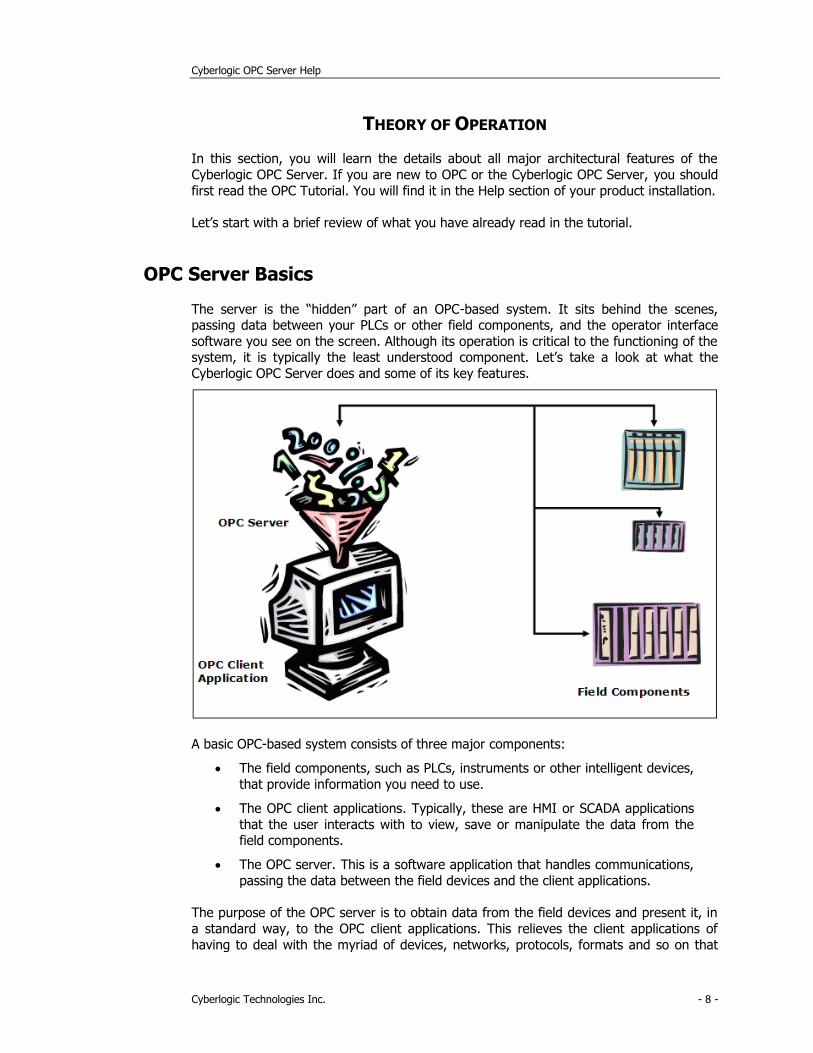
A basic OPC-based system consists of three major components:
• The field components, such as PLCs, instruments or other intelligent devices,
that provide information you need to use.
• The OPC client applications. Typically, these are HMI or SCADA applications
that the user interacts with to view, save or manipulate the data from the field components.
• The OPC server. This is a software application that handles communications,
passing the data between the field devices and the client applications.
The purpose of the OPC server is to obtain data from the field devices and present it, in
a standard way, to the OPC client applications. This relieves the client applications of
having to deal with the myriad of devices, networks, protocols, formats and so on that
Cyberlogic OPC Server Help
Cyberlogic Technologies Inc. - 9 -
exist among the various control device vendors. The client software need only concern itself with the graphics, logic, storage and other operations that it provides to the user.
In short, the server deals with acquiring the data, while the client deals with manipulating and displaying the data. Critically important are the OPC specifications,
which describe how the clients and servers exchange data. Compliance with the OPC
specifications means that any server will work with any client, even if they are from different suppliers.
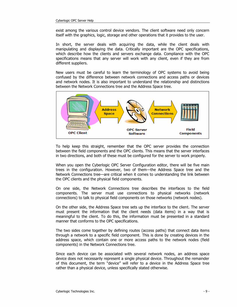
New users must be careful to learn the terminology of OPC systems to avoid being confused by the difference between network connections and access paths or devices
and network nodes. It is also important to understand the relationship and distinctions between the Network Connections tree and the Address Space tree.
To help keep this straight, remember that the OPC server provides the connection between the field components and the OPC clients. This means that the server interfaces
in two directions, and both of these must be configured for the server to work properly.
When you open the Cyberlogic OPC Server Configuration editor, there will be five main trees in the configuration. However, two of them—the Address Space tree and the
Network Connections tree—are critical when it comes to understanding the link between the OPC clients and the physical field components.
On one side, the Network Connections tree describes the interfaces to the field
components. The server must use connections to physical networks (network connections) to talk to physical field components on those networks (network nodes).
On the other side, the Address Space tree sets up the interface to the client. The server must present the information that the client needs (data items) in a way that is
meaningful to the client. To do this, the information must be presented in a standard manner that conforms to the OPC specifications.
The two sides come together by defining routes (access paths) that connect data items
through a network to a specific field component. This is done by creating devices in the address space, which contain one or more access paths to the network nodes (field
components) in the Network Connections tree.
Since each device can be associated with several network nodes, an address space
device does not necessarily represent a single physical device. Throughout the remainder
of this document, the term “device” will refer to a device in the Address Space tree rather than a physical device, unless specifically stated otherwise.
Cyberlogic OPC Server Help
Cyberlogic Technologies Inc. - 10 -
If you are still unclear about some of the terms mentioned here, go back and re-read the OPC Tutorial.
Main Server Features
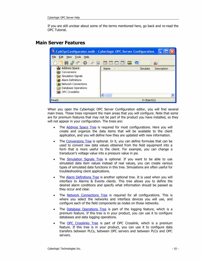
When you open the Cyberlogic OPC Server Configuration editor, you will find several main trees. These trees represent the main areas that you will configure. Note that some
are for premium features that may not be part of the product you have installed, so they
will not appear in your configuration. The trees are:
• The Address Space Tree is required for most configurations. Here you will create and organize the data items that will be available to the client
application, and you will define how they are updated with new information.
• The Conversions Tree is optional. In it, you can define formulas that can be used to convert raw data values obtained from the field equipment into a
form that is more useful to the client. For example, you can change a
transducer’s voltage value into a pressure value in psi.
• The Simulation Signals Tree is optional. If you want to be able to use
simulated data item values instead of real values, you can create various
types of simulated data functions in this tree. Simulations are often useful for troubleshooting client applications.
• The Alarm Definitions Tree is another optional tree. It is used when you will
interface to Alarms & Events clients. This tree allows you to define the desired alarm conditions and specify what information should be passed as
they occur and clear.
• The Network Connections Tree is required for all configurations. This is
where you select the networks and interface devices you will use, and configure each of the field components as nodes on those networks.
• The Database Operations Tree is part of the logging feature, which is a
premium feature. If this tree is in your product, you can use it to configure databases and data logging operations.
• The OPC Crosslinks Tree is part of OPC Crosslink, which is a premium
feature. If this tree is in your product, you can use it to configure data transfers between PLCs, between OPC servers and between PLCs and OPC
servers.
Cyberlogic OPC Server Help
Cyberlogic Technologies Inc. - 11 -
The following sections describe these operational features of the server. Because the Network Connections Tree is normally configured first, we will start there.
Network Connections Tree
The Network Connections tree is used to describe the physical connections to the field components. This is where you select the communication driver agents, networks and
interface devices you will use, and configure each of the field components as nodes on those networks. The following describes each branch in this tree.
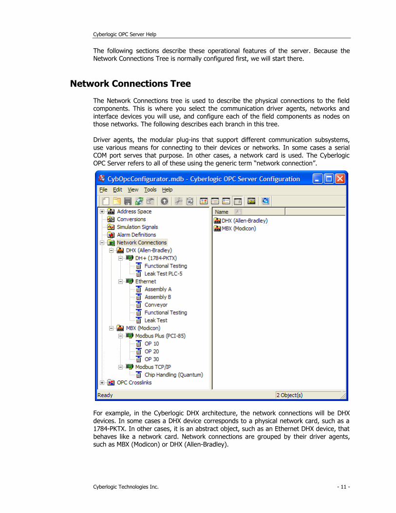
Driver agents, the modular plug-ins that support different communication subsystems,
use various means for connecting to their devices or networks. In some cases a serial COM port serves that purpose. In other cases, a network card is used. The Cyberlogic
OPC Server refers to all of these using the generic term “network connection”.
For example, in the Cyberlogic DHX architecture, the network connections will be DHX devices. In some cases a DHX device corresponds to a physical network card, such as a
1784-PKTX. In other cases, it is an abstract object, such as an Ethernet DHX device, that
behaves like a network card. Network connections are grouped by their driver agents, such as MBX (Modicon) or DHX (Allen-Bradley).
Cyberlogic OPC Server Help
Cyberlogic Technologies Inc. - 12 -
Each network connection allows access to a network of one or more physical devices. The server refers to each of these physical devices on the network as a network node. A
typical network node might be a PLC-5 on a Data Highway Plus network or a Quantum controller on a Modbus TCP/IP network. The server accesses the network nodes through
their corresponding network connection. The network node configuration contains the
communication parameters for the physical node device.
A user can define many network connections, each having many network nodes. These
network connections and network nodes will be used in defining access paths for devices in the address space. This greatly simplifies the configuration process, because multiple
access paths can refer to the same network node, and the network parameters for each node need to be entered only once. Any changes subsequently made to a network node
are automatically reflected in all the access paths that reference that node.
Notice also, that each network connection and network node can be given any name that best describes its function. For example, rather than calling a node “PLC-5”, you could
call it “Assembly A” or “OP10” instead.
Refer to the Configuration Editor section for information on how to configure Network
Connections.
Network Auto-Configuration
For most driver agents, the Cyberlogic OPC Server Configuration Editor can automatically
detect the physical devices attached to the network connections and create corresponding network nodes in the server configuration file.
Health Watchdog
This feature allows you to configure redundant networks with automatic failover and recovery. The server monitors the health of the connection to each physical device. If
there is no network activity for a specified amount of time, the server sends a communication request to the device to verify that it can still communicate. If the device
becomes inaccessible, the server rechecks it at a specified polling rate to see if it
becomes accessible again.
Once a failed network connection is reestablished, the server continues to exercise the
connection for a specified time to ensure that the connection is reliable. After these tests complete successfully, the node is marked as healthy again.
When the health watchdog identifies that a network node has failed, you can configure
the server to switch to a backup network node. When communication to the failed network node is restored, the server can then switch communication back to the primary
network node. For more information on this capability, refer to the Address Space Tree section.
Cyberlogic OPC Server Help
Cyberlogic Technologies Inc. - 13 -
Address Space Tree
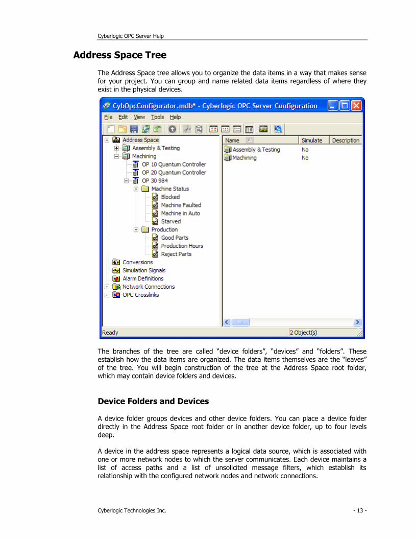
The Address Space tree allows you to organize the data items in a way that makes sense
for your project. You can group and name related data items regardless of where they
exist in the physical devices.
The branches of the tree are called “device folders”, “devices” and “folders”. These establish how the data items are organized. The data items themselves are the “leaves”
of the tree. You will begin construction of the tree at the Address Space root folder, which may contain device folders and devices.
Device Folders and Devices
A device folder groups devices and other device folders. You can place a device folder directly in the Address Space root folder or in another device folder, up to four levels
deep.
A device in the address space represents a logical data source, which is associated with
one or more network nodes to which the server communicates. Each device maintains a
list of access paths and a list of unsolicited message filters, which establish its relationship with the configured network nodes and network connections.
Cyberlogic OPC Server Help
Cyberlogic Technologies Inc. - 14 -
Note A device in the address space is not the same thing as a network node. Each network node represents a single physical device, while an address space device may be
associated with many physical devices.
The main function of a device is to define valid sources of data for all of its data items.
Multiple devices can use the same network node as a data source, allowing greater flexibility in the logical grouping of data items.
You may place a device directly in the Address Space root folder or in a device folder. In
addition to its device-specific functionality, a device operates as a folder. It can contain folders and data items.
Math & Logic Devices
Math & Logic devices don’t get data from a network node, but instead contain data items
with C-Logic programs that perform mathematical and logical functions on data. For
more information, refer to the Math & Logic Help.
Access Paths
An access path is a logical connection to a network node. These connections link the data items in an address space device with their values in a physical device. They tell the
server where and how to obtain these values during solicited data reads and writes.
Note Access paths are required only for solicited communications. If you plan to use
unsolicited data updates instead, you do not have to configure any access paths. Refer
to the Unsolicited Message Filters section for more information.
Cyberlogic OPC Server Help
Cyberlogic Technologies Inc. - 15 -
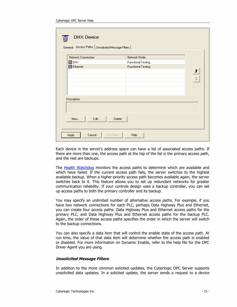
Each device in the server’s address space can have a list of associated access paths. If
there are more than one, the access path at the top of the list is the primary access path, and the rest are backups.
The Health Watchdog monitors the access paths to determine which are available and which have failed. If the current access path fails, the server switches to the highest
available backup. When a higher-priority access path becomes available again, the server switches back to it. This feature allows you to set up redundant networks for greater
communication reliability. If your controls design uses a backup controller, you can set
up access paths to both the primary controller and its backup.
You may specify an unlimited number of alternative access paths. For example, if you
have two network connections for each PLC, perhaps Data Highway Plus and Ethernet, you can create four access paths: Data Highway Plus and Ethernet access paths for the
primary PLC, and Data Highway Plus and Ethernet access paths for the backup PLC.
Again, the order of these access paths specifies the order in which the server will switch to the backup connections.
You can also specify a data item that will control the enable state of the access path. At run time, the value of that data item will determine whether the access path is enabled
or disabled. For more information on Dynamic Enable, refer to the help file for the OPC Driver Agent you are using.
Unsolicited Message Filters
In addition to the more common solicited updates, the Cyberlogic OPC Server supports unsolicited data updates. In a solicited update, the server sends a request to a device
Cyberlogic OPC Server Help
Cyberlogic Technologies Inc. - 16 -
asking it for data, and the device replies. In an unsolicited update, the device decides when to send data to the server. This helps to minimize the amount of traffic on the
network. For example, instead of having the server poll a device every 500 milliseconds to see if some data has changed, you can configure the device to update the server only
when the data changes.
The disadvantage of unsolicited updates is the fact that the server has no control over who may attempt to send data to it. Data written from unintended sources could corrupt
the server-maintained data, resulting in potentially catastrophic events.
Although unrestricted unsolicited updates are possible, the Cyberlogic OPC Server
supports a mechanism of unsolicited message filters to prevent data corruption. Unsolicited messages must first pass through the user-defined filters before the server
accepts them. These filters guarantee that unsolicited messages are accepted only from
trusted sources.
Note Unsolicited message filters are used only for unsolicited communications. Only the
driver agents that support unsolicited communications will support the use of
unsolicited message filters.
Unsolicited Message Filter Groups
The unsolicited message filters are organized into groups. Each group is a list of trusted
network nodes and trusted network connections. A message may pass through any one of these groups to be accepted by the server. In addition, the Configuration Editor allows
you to disable and enable entire groups of filters. This can be very convenient during startup and debugging.
Cyberlogic OPC Server Help
Cyberlogic Technologies Inc. - 17 -
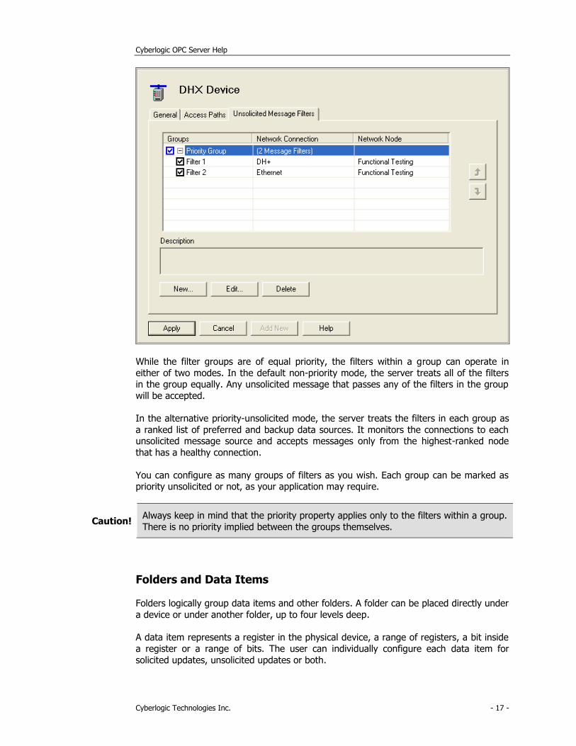
While the filter groups are of equal priority, the filters within a group can operate in
either of two modes. In the default non-priority mode, the server treats all of the filters in the group equally. Any unsolicited message that passes any of the filters in the group
will be accepted.
In the alternative priority-unsolicited mode, the server treats the filters in each group as
a ranked list of preferred and backup data sources. It monitors the connections to each unsolicited message source and accepts messages only from the highest-ranked node
that has a healthy connection.
You can configure as many groups of filters as you wish. Each group can be marked as priority unsolicited or not, as your application may require.
Caution! Always keep in mind that the priority property applies only to the filters within a group.
There is no priority implied between the groups themselves.
Folders and Data Items
Folders logically group data items and other folders. A folder can be placed directly under
a device or under another folder, up to four levels deep.
A data item represents a register in the physical device, a range of registers, a bit inside
a register or a range of bits. The user can individually configure each data item for
solicited updates, unsolicited updates or both.
Cyberlogic OPC Server Help
Cyberlogic Technologies Inc. - 18 -
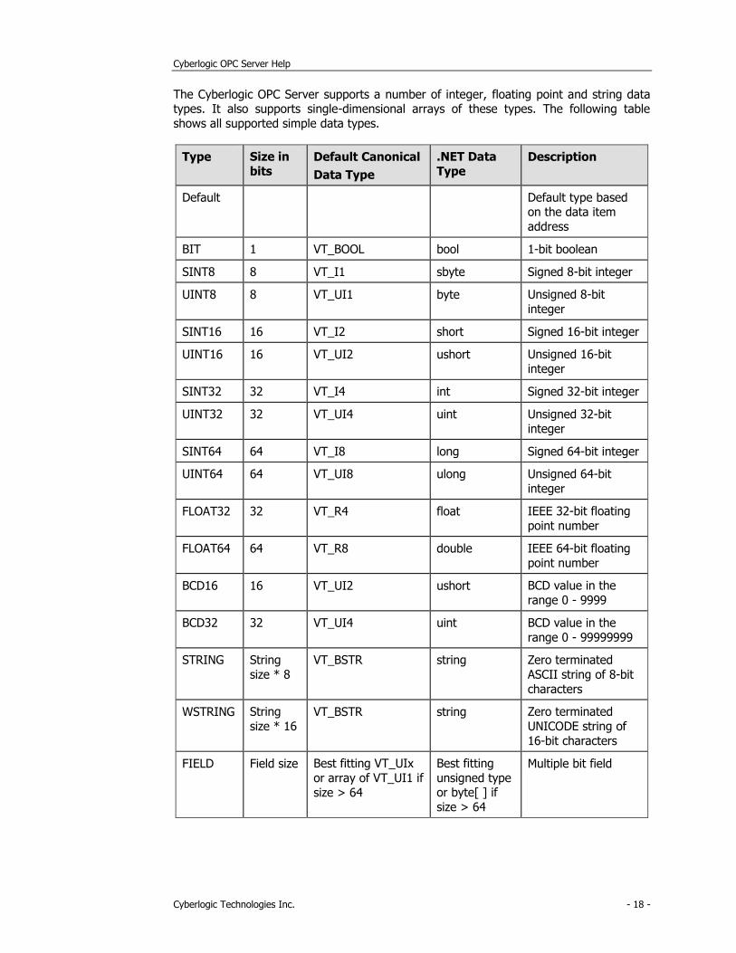
The Cyberlogic OPC Server supports a number of integer, floating point and string data types. It also supports single-dimensional arrays of these types. The following table
shows all supported simple data types.
Type Size in
bits Default Canonical
Data Type
.NET Data
Type Description
Default Default type based on the data item
address
BIT 1 VT_BOOL bool 1-bit boolean
SINT8 8 VT_I1 sbyte Signed 8-bit integer
UINT8 8 VT_UI1 byte Unsigned 8-bit
integer
SINT16 16 VT_I2 short Signed 16-bit integer
UINT16 16 VT_UI2 ushort Unsigned 16-bit
integer
SINT32 32 VT_I4 int Signed 32-bit integer
UINT32 32 VT_UI4 uint Unsigned 32-bit
integer
SINT64 64 VT_I8 long Signed 64-bit integer
UINT64 64 VT_UI8 ulong Unsigned 64-bit
integer
FLOAT32 32 VT_R4 float IEEE 32-bit floating
point number
FLOAT64 64 VT_R8 double IEEE 64-bit floating
point number
BCD16 16 VT_UI2 ushort BCD value in the
range 0 - 9999
BCD32 32 VT_UI4 uint BCD value in the
range 0 - 99999999
STRING String
size * 8
VT_BSTR string Zero terminated
ASCII string of 8-bit
characters
WSTRING String
size * 16 VT_BSTR string Zero terminated
UNICODE string of
16-bit characters
FIELD Field size Best fitting VT_UIx
or array of VT_UI1 if
size > 64
Best fitting
unsigned type or byte[ ] if
size > 64
Multiple bit field
Cyberlogic OPC Server Help
Cyberlogic Technologies Inc. - 19 -
For each simple data type, a user can specify a canonical data type (a variant data type in the form of VT_XXX) or choose the default type. When the default is selected, the
server selects the canonical data type that can best store the selected data type.
Data Write Protection
In general, the Cyberlogic OPC Server supports both read and write operations to its data
items. However, writing to some data items may create a safety hazard. Some registers, such as PLC-5 inputs, are read-only and require no additional protection. For read/write
registers, you can disable the write capability at any level. That is, you can disable writes for a:
• Data item
• Folder
• Device
• Device folder
• Network node
• Network connection
• Driver agent
You can also disable DirectAccess writes at each network node, network connection or driver agent.
DirectAccess
At run time, in addition to the user-configured address space branches, the Cyberlogic OPC Server dynamically creates a branch called DirectAccess at the root of the address
space. OPC clients can use this branch to access any register in any configured network node or device by directly specifying the register address.
The DirectAccess branch acts like a device folder that contains all configured driver agents. Each driver agent branch contains its configured network connections, and each
network connection branch contains its configured network nodes. However, only driver
agents, network connections and network nodes that enable DirectAccess are present.
DirectAccess can benefit users in two ways. First, you can quickly deploy minimally-
configured servers, giving clients access to data in the shortest possible time. By configuring just the network connection and network nodes, a user would have access to
all the registers in each network node.
Second, DirectAccess can help you to work around configuration errors. Suppose a user forgets to configure a needed data register in the server. DirectAccess allows an OPC
client to access the forgotten register until the server configuration can be modified.
Note DirectAccess is available for OPC DA servers, if the OPC DA Driver Agent is installed. It
is also available for crosslinks, if OPC Crosslink is installed.
Cyberlogic OPC Server Help
Cyberlogic Technologies Inc. - 20 -
Conversions Tree
The raw data associated with a data item may represent a signal value from some
instrument. Typically, this value is not expressed in the engineering units of the
measured signal. To simplify working with the data from these instruments, the Cyberlogic OPC Server can associate a conversion with each data item.
A user can define a number of different types of conversions, and the server can then apply each conversion to a number of data items. As a result, each conversion type
needs to be defined only once, regardless of how many data items will use it.
The server supports both linear and square root conversions. Each has a range of engineering units that corresponds to the specified instrument range. The conversions
then keep a linear or square root relation between the engineering units range and the instrument range.
In addition, the server supports data range clamping, which prevents the server from reporting a value that is outside of a specified range. The clamping can be based on
either the engineering units range or a custom range.
Refer to the Configuration Editor section for information on how to configure Conversions.
Simulation Signals Tree
To facilitate client-side testing without the need for a physical device, a predefined formula can simulate the data for each data item. A user can define several different
types of simulation signals. Each signal can then simulate a number of data items. As a result, each simulation signal type needs to be defined only once, regardless of how
many data items will use it.
The simulation signals available are: read count, write count, random, ramp, sine, square, triangle and step. The signals other than read count and write count have
parameters that define properties such as amplitude, signal phase and number of steps.
Data can be simulated at any level in the server’s address space. Enabling data
simulation at one level automatically enables it at all levels below. For example, if you enable simulation on a device folder, all of the data items in all of the devices in that
device folder will be simulated. This allows you to switch quickly between simulated and
real data for a large number of data items.
Refer to the Configuration Editor section for information on how to configure Simulation
Signals.
Alarm Definitions Tree
The Cyberlogic OPC Server supports the OPC Alarms & Events specification. It allows a
user to define a number of alarm conditions, each of which can then be used by a number of data items. As a result, each alarm condition needs to be defined only once,
regardless of how many data items will use it.
Cyberlogic OPC Server Help
Cyberlogic Technologies Inc. - 21 -
Note To receive the alarms and events reported by the server, the client application must
also support the OPC Alarms and Events specification.
Alarms cannot be used with string data items, arrays or bit fields greater than 64 bits.
There are two categories of alarms: digital and limit (analog).
Digital Alarms
Digital alarms are normally used with Boolean data. A user can request an alarm when
the item’s value equals either TRUE or FALSE.
Each alarm has an associated alarm message and a severity level. The alarm message
describes the alarm condition. The severity value indicates the importance of the alarm on a scale of 1 to 1000, where 1000 is the most severe. Optionally, an alarm can be
generated when the item’s data returns to its normal value. A user can also specify that
each alarm condition requires an acknowledgment from the client.
Limit Alarms
Limit alarms are normally used with numeric data. These alarm definitions divide the data item range into five alarm states: LoLo, Lo, Normal, Hi and HiHi.
Every alarm state includes an alarm message and a severity level. In addition, you may indicate whether the alarm requires an acknowledgment from the client. An optional
deadband value prevents the server from generating a large number of alarm messages
when the signal oscillates around one of the limits. When the deadband value is set properly, the server will send only one alarm even if the signal oscillates.
Refer to the Configuration Editor section for information on how to configure Alarm Definitions.
Database Operations Tree
In addition to providing data to OPC clients in real time, the Cyberlogic OPC Server can store it in a database. The feature that does this is called Data Logger. Once the data is
logged, it is available to any application that can access that database. It need not be an
OPC client application.
Refer to the Data Logger Help for a full discussion.
OPC Crosslinks Tree
This is where you can set up data transfers between PLCs and OPC servers. Before you can configure crosslinks, you must first configure the network connections to the desired
PLCs or OPC servers. You must also configure address space data items to serve as the crosslink inputs and outputs.

Cyberlogic OPC Server Help
Cyberlogic Technologies Inc. - 22 -
Refer to the OPC Crosslink Help for a full discussion.
Cyberlogic OPC Server Help
Cyberlogic Technologies Inc. - 23 -
QUICK-START GUIDE
Before you can use the OPC server, you must configure it by using the OPC Server
Configuration Editor. Every server requires configuration of the Network Connections
branch, and most users will want to configure the Address Space branch. The remaining branches (Conversions, Simulation Signals, Alarm Definitions, Database Operations and
OPC Crosslinks) are optional features used by some systems.
Sample Configuration Files
The default installation of all Cyberlogic OPC Server Suites includes a set of sample
configuration files. These samples will help you to understand how to configure the OPC server for your project. In addition, the OPC Math & Logic sample provides you with
numerous sample programs that you can modify and use in your system.
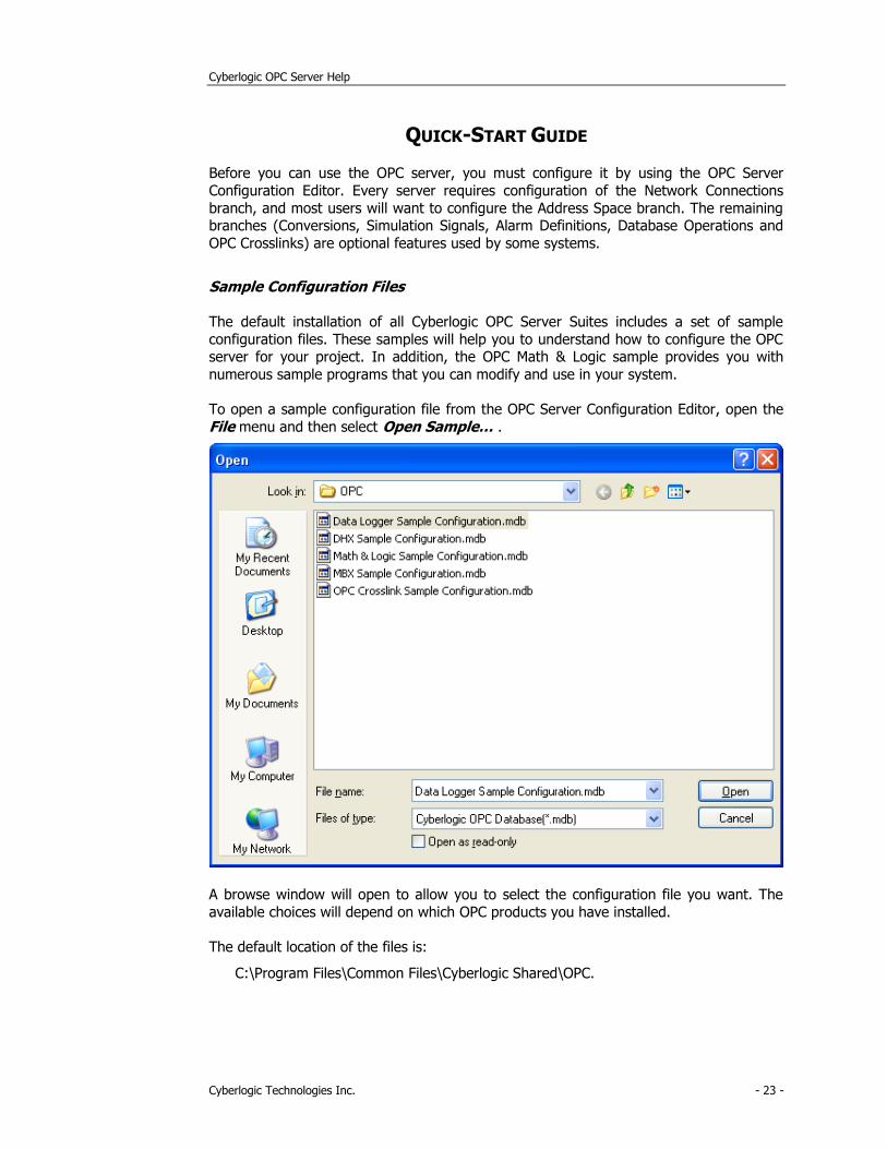
To open a sample configuration file from the OPC Server Configuration Editor, open the
File menu and then select Open Sample… .
A browse window will open to allow you to select the configuration file you want. The
available choices will depend on which OPC products you have installed.
The default location of the files is:
C:\Program Files\Common Files\Cyberlogic Shared\OPC.
Cyberlogic OPC Server Help
Cyberlogic Technologies Inc. - 24 -
Step-By-Step Example
The following steps show a typical configuration session using the DHX OPC Enterprise
Suite. This allows us to illustrate the configuration of all of the major features: communication to Allen-Bradley controllers and OPC DA servers, use of auto-
configuration and DirectImport, and the configuration of unsolicited messaging.
Configurations using the other driver agents, such as MBX, would be very similar.
Not all of the features shown are available on all of Cyberlogic's OPC suites, so some
sections my not apply to your software. You should use this description only as a guideline of how to configure the most common features. For detailed information on all
of the server’s features, refer to the Configuration Editor Reference and to the help file for the driver agent you are using.
This example assumes that you have a single 1784-KTX card connected to the Data
Highway Plus (DH+) network, so this example requires the DHX Driver. Because the 1784-KTX is not Plug-and-Play, you must create the device manually. If you had used a
Plug-and-Play PCI card, such as the 1784-PKTX/A, a DHX device would have been created when you booted up the system. If you use a different adapter card or different
network, refer to the driver-specific help file for more information on configuring the DHX
devices.
Another assumption is that you have two Allen-Bradley PLC-5/20s connected to the Data
Highway Plus network. One is the primary PLC at node address 2 while the other is the backup PLC at node address 50.
Finally, we assume that you are connected over Ethernet to another OPC server.
The procedure is divided into several sections:
• Configuring the Driver
• Configuring the Network Connections Tree Automatically
• Configuring the Network Connections Tree Manually
• Selecting a Computer in the Network Connections Tree
• Selecting an OPC Server
• Creating Address Space Device Folders and Devices
• Configuring the Access Paths
• Configuring Unsolicited Message Filters
• Using DirectImport
• Configuring Folders and Data Items Manually
• Using the Data Item Duplication Wizard
• Saving the Configuration and Updating the Server
• Verifying Your Configuration
We will start with Configuring the Driver.
Cyberlogic OPC Server Help
Cyberlogic Technologies Inc. - 25 -
Configuring the Driver
Manual driver configuration is needed only if you want to communicate to a PLC through
a legacy non-Plug-and-Play adapter card, such as 1784-KTX. For Plug-and-Play (PnP)
adapters, such as 1784-PKTX, Windows will automatically detect and configure the adapter card. If you are using a PnP adapter, or you are interested only in
communicating with OPC DA servers, you can skip this part of the configuration and start with Selecting a Computer in the Network Connections Tree.
The first step is to use the DHX Driver Configuration Editor to create a DHX device.
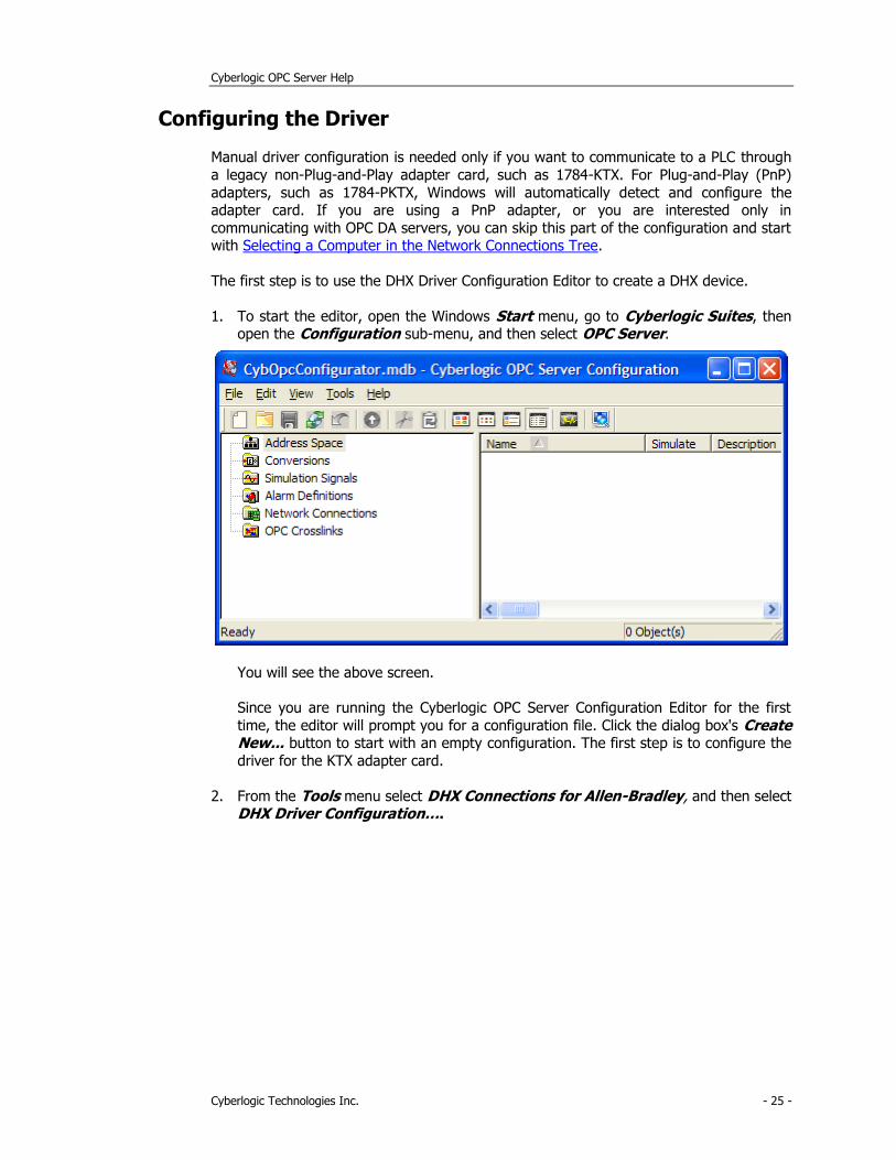
1. To start the editor, open the Windows Start menu, go to Cyberlogic Suites, then open the Configuration sub-menu, and then select OPC Server.
You will see the above screen.
Since you are running the Cyberlogic OPC Server Configuration Editor for the first
time, the editor will prompt you for a configuration file. Click the dialog box's Create New... button to start with an empty configuration. The first step is to configure the
driver for the KTX adapter card.
2. From the Tools menu select DHX Connections for Allen-Bradley, and then select DHX Driver Configuration….
Cyberlogic OPC Server Help
Cyberlogic Technologies Inc. - 26 -
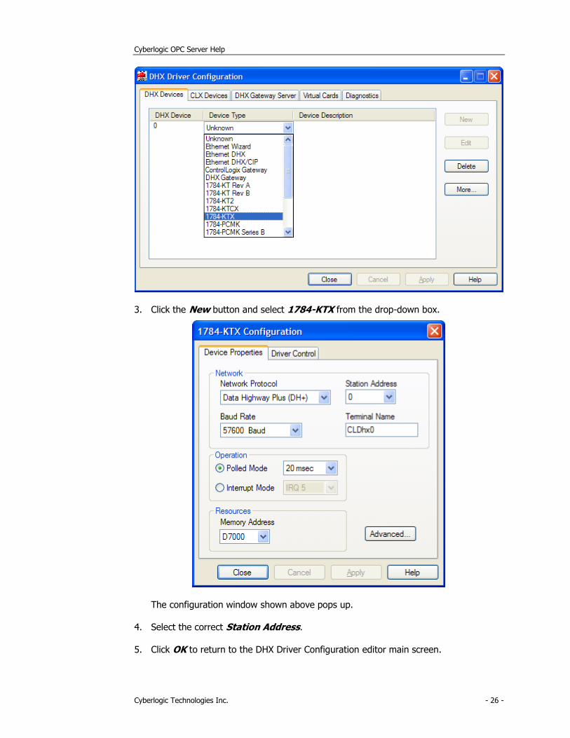
3. Click the New button and select 1784-KTX from the drop-down box.
The configuration window shown above pops up.
4. Select the correct Station Address.
5. Click OK to return to the DHX Driver Configuration editor main screen.
Cyberlogic OPC Server Help
Cyberlogic Technologies Inc. - 27 -
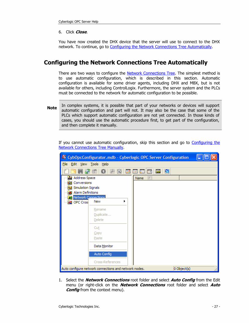
6. Click Close.
You have now created the DHX device that the server will use to connect to the DHX
network. To continue, go to Configuring the Network Connections Tree Automatically.
Configuring the Network Connections Tree Automatically
There are two ways to configure the Network Connections Tree. The simplest method is
to use automatic configuration, which is described in this section. Automatic configuration is available for some driver agents, including DHX and MBX, but is not
available for others, including ControlLogix. Furthermore, the server system and the PLCs
must be connected to the network for automatic configuration to be possible.
Note In complex systems, it is possible that part of your networks or devices will support automatic configuration and part will not. It may also be the case that some of the
PLCs which support automatic configuration are not yet connected. In those kinds of
cases, you should use the automatic procedure first, to get part of the configuration,
and then complete it manually.
If you cannot use automatic configuration, skip this section and go to Configuring the Network Connections Tree Manually.
1. Select the Network Connections root folder and select Auto Config from the Edit
menu (or right-click on the Network Connections root folder and select Auto Config from the context menu).
Cyberlogic OPC Server Help
Cyberlogic Technologies Inc. - 28 -
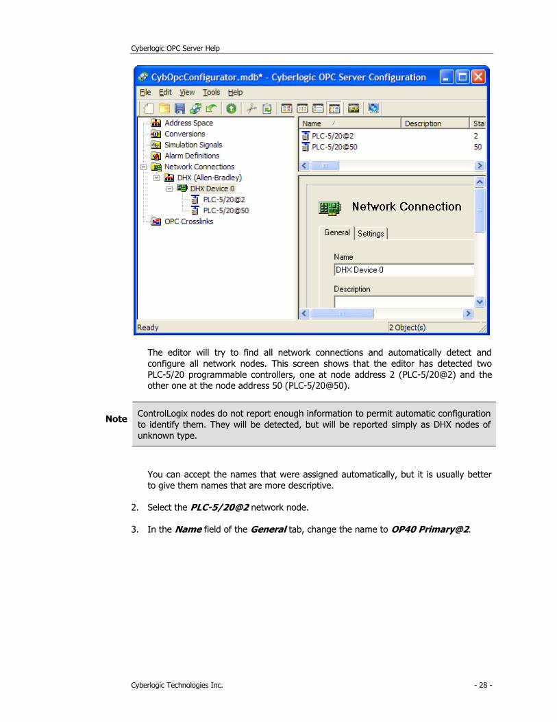
The editor will try to find all network connections and automatically detect and
configure all network nodes. This screen shows that the editor has detected two
PLC-5/20 programmable controllers, one at node address 2 (PLC-5/20@2) and the other one at the node address 50 (PLC-5/20@50).
Note ControlLogix nodes do not report enough information to permit automatic configuration
to identify them. They will be detected, but will be reported simply as DHX nodes of
unknown type.
You can accept the names that were assigned automatically, but it is usually better
to give them names that are more descriptive.
2. Select the PLC-5/20@2 network node.
3. In the Name field of the General tab, change the name to OP40 Primary@2.

Cyberlogic OPC Server Help
Cyberlogic Technologies Inc. - 29 -
4. Repeat this for the PLC-5/20@50 network node, changing the name to OP40 Backup@50.
The next step is Configuring the Network Connections Tree Manually.
Configuring the Network Connections Tree Manually
When you use networks and devices that cannot be configured automatically or if they
are not connected to the server system when you are doing the editing, you must
configure them manually.
If automatic configuration was able to configure all of your network connections and
nodes, then you can skip this section and go to Selecting a Computer in the Network Connections Tree.
Cyberlogic OPC Server Help
Cyberlogic Technologies Inc. - 30 -
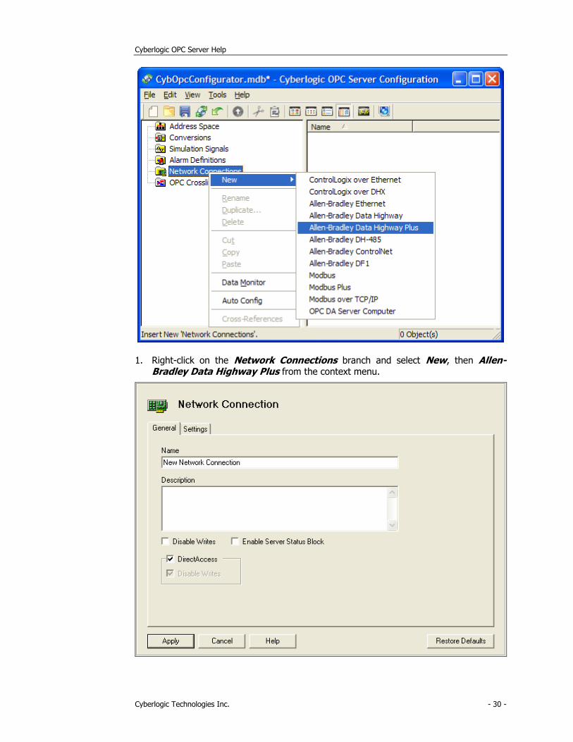
1. Right-click on the Network Connections branch and select New, then Allen-Bradley Data Highway Plus from the context menu.
Cyberlogic OPC Server Help
Cyberlogic Technologies Inc. - 31 -
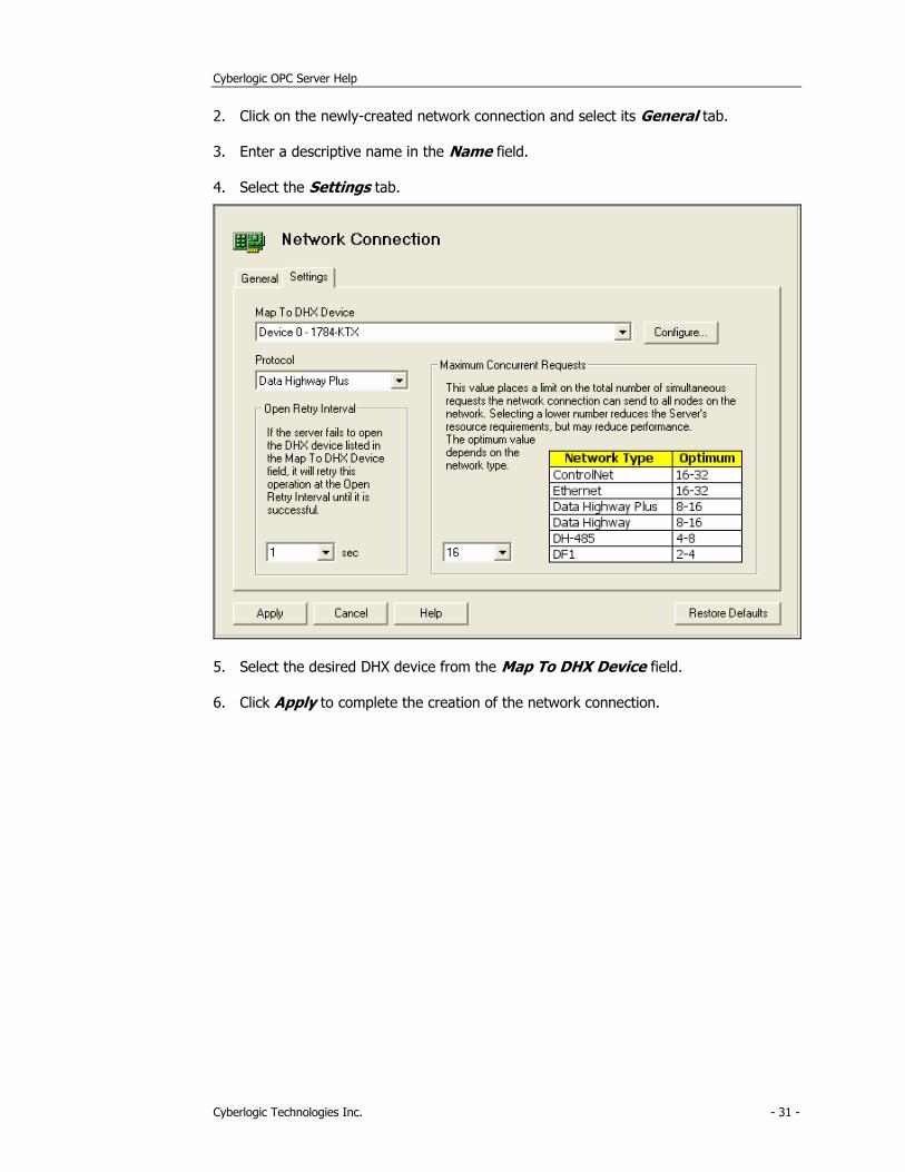
2. Click on the newly-created network connection and select its General tab.
3. Enter a descriptive name in the Name field.
4. Select the Settings tab.
5. Select the desired DHX device from the Map To DHX Device field.
6. Click Apply to complete the creation of the network connection.
Cyberlogic OPC Server Help
Cyberlogic Technologies Inc. - 32 -
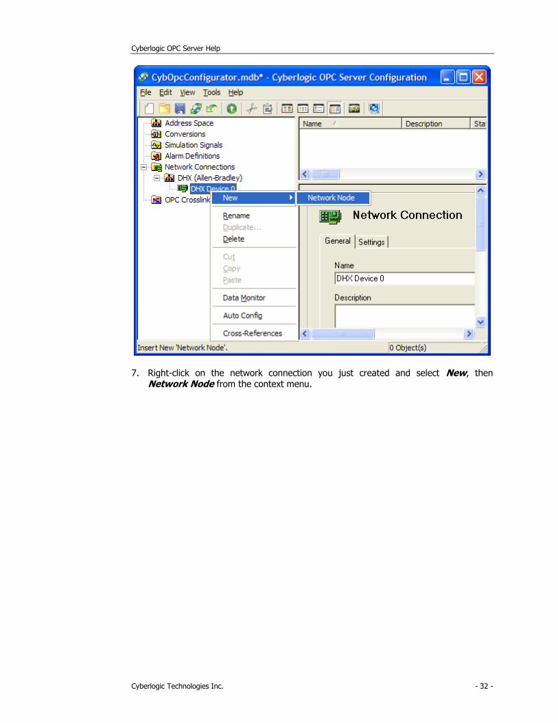
7. Right-click on the network connection you just created and select New, then Network Node from the context menu.
Cyberlogic OPC Server Help
Cyberlogic Technologies Inc. - 33 -
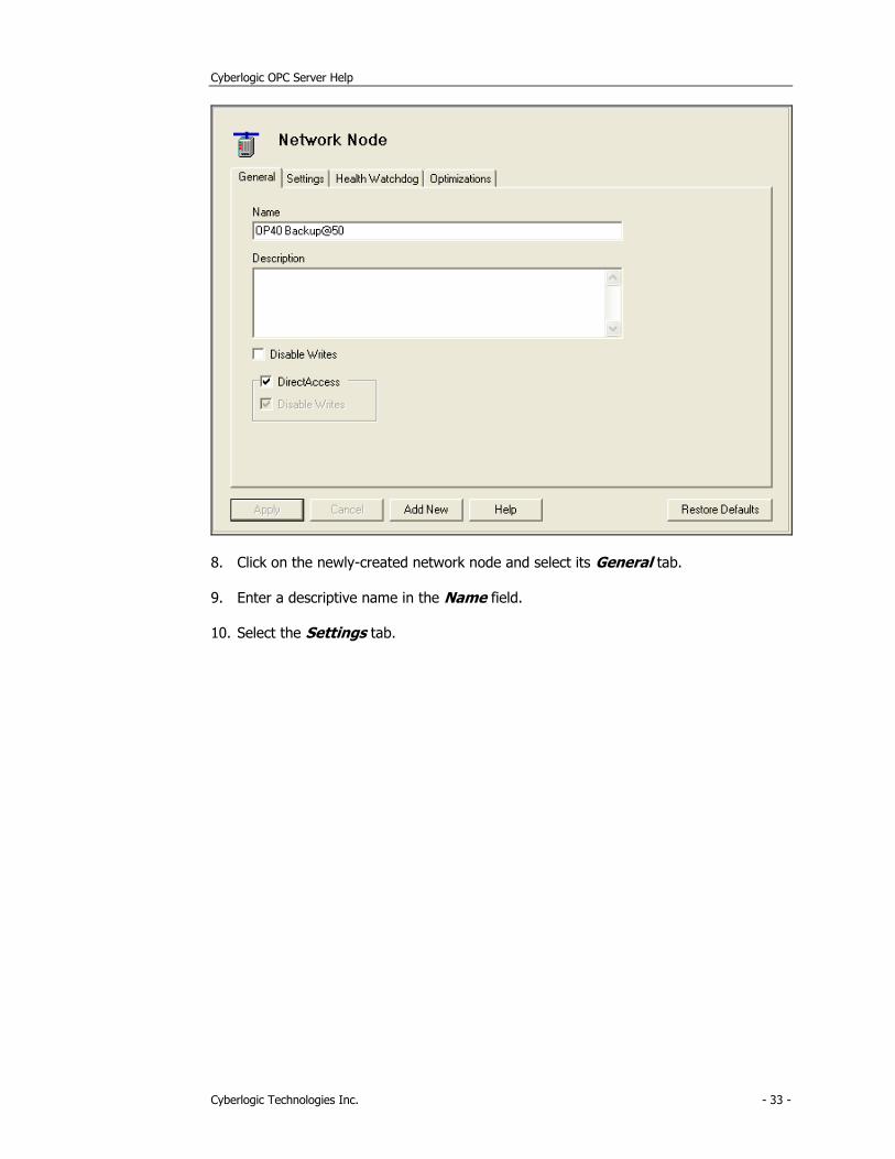
8. Click on the newly-created network node and select its General tab.
9. Enter a descriptive name in the Name field.
10. Select the Settings tab.
Cyberlogic OPC Server Help
Cyberlogic Technologies Inc. - 34 -
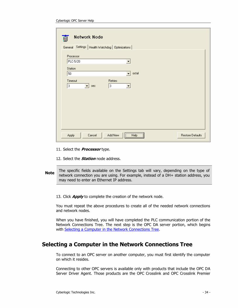
11. Select the Processor type.
12. Select the Station node address.
Note The specific fields available on the Settings tab will vary, depending on the type of
network connection you are using. For example, instead of a DH+ station address, you
may need to enter an Ethernet IP address.
13. Click Apply to complete the creation of the network node.
You must repeat the above procedures to create all of the needed network connections
and network nodes.
When you have finished, you will have completed the PLC communication portion of the
Network Connections Tree. The next step is the OPC DA server portion, which begins with Selecting a Computer in the Network Connections Tree.
Selecting a Computer in the Network Connections Tree
To connect to an OPC server on another computer, you must first identify the computer on which it resides.
Connecting to other OPC servers is available only with products that include the OPC DA
Server Driver Agent. Those products are the OPC Crosslink and OPC Crosslink Premier
Cyberlogic OPC Server Help
Cyberlogic Technologies Inc. - 35 -
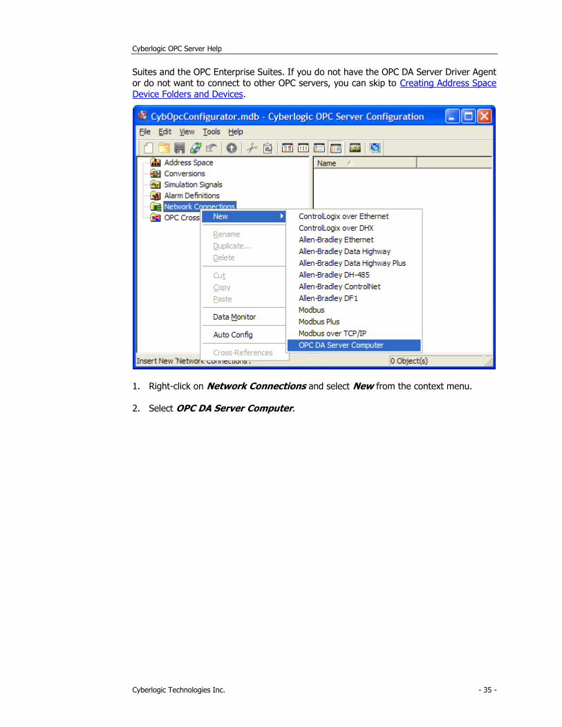
Suites and the OPC Enterprise Suites. If you do not have the OPC DA Server Driver Agent or do not want to connect to other OPC servers, you can skip to Creating Address Space
Device Folders and Devices.
1. Right-click on Network Connections and select New from the context menu.
2. Select OPC DA Server Computer.

Cyberlogic OPC Server Help
Cyberlogic Technologies Inc. - 36 -
The editor will create a new folder called OPC DA Servers, containing a computer called New OPC DA Server Computer
3. Enter Assy OPC Server in the Name field.
You may, of course, use any name you wish for the computer.
4. Select the Settings tab.
Cyberlogic OPC Server Help
Cyberlogic Technologies Inc. - 37 -
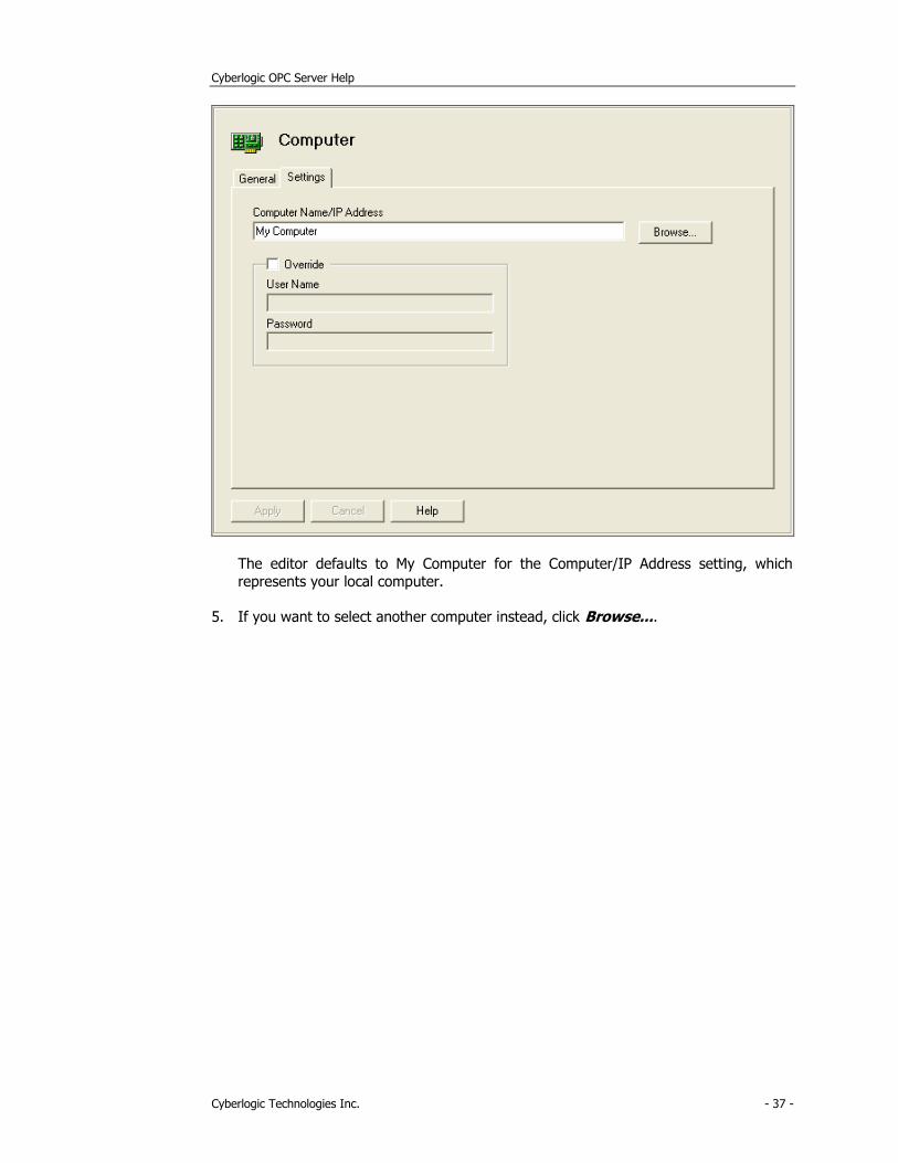
The editor defaults to My Computer for the Computer/IP Address setting, which
represents your local computer.
5. If you want to select another computer instead, click Browse....
Cyberlogic OPC Server Help
Cyberlogic Technologies Inc. - 38 -
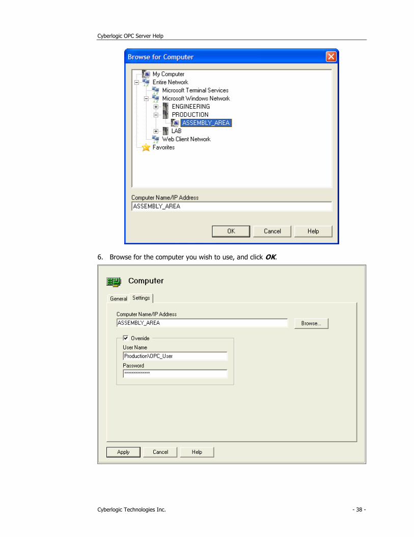
6. Browse for the computer you wish to use, and click OK.

Cyberlogic OPC Server Help
Cyberlogic Technologies Inc. - 39 -
Caution! If the selected computer is not your local computer, you may need to provide a computer or domain name, user name, and password, so the OPC server can access
that computer.
To simplify configuration, you should enter this information on the Settings Tab of the OPC DA Servers folder. This becomes the default computer/domain, user name and
password for all computers and OPC servers. However, you can override this default setting by selecting Override and entering the computer or domain name, user name,
and password information for this computer only.
7. If you want to override the default User Name and Password, check the Override
box, and then enter the User Name and Password that you wish to use when accessing this computer.
The User Name field entry must be in the form:
[<DomainNameOrWorkgroupComputerName>\]<UserName>
If the computer you wish to connect to is the local computer or is in the same
domain as the local computer, the domain name or workgroup computer name specification is optional.
8. Click Apply.
Go to the Selecting an OPC Server section to continue.
Selecting an OPC Server
You must now select the specific OPC DA server you will connect to. Once connected, you can read data from it, write to it, or use it as the source or destination for an OPC
Crosslink data transfer.
Cyberlogic OPC Server Help
Cyberlogic Technologies Inc. - 40 -
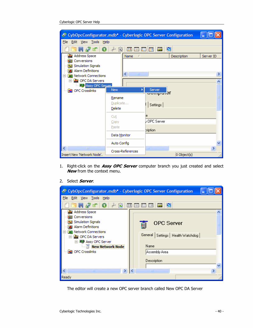
1. Right-click on the Assy OPC Server computer branch you just created and select
New from the context menu.
2. Select Server.
The editor will create a new OPC server branch called New OPC DA Server
Cyberlogic OPC Server Help
Cyberlogic Technologies Inc. - 41 -
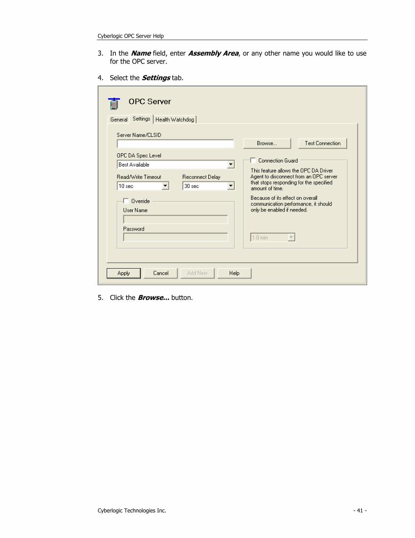
3. In the Name field, enter Assembly Area, or any other name you would like to use for the OPC server.
4. Select the Settings tab.
5. Click the Browse... button.
Cyberlogic OPC Server Help
Cyberlogic Technologies Inc. - 42 -
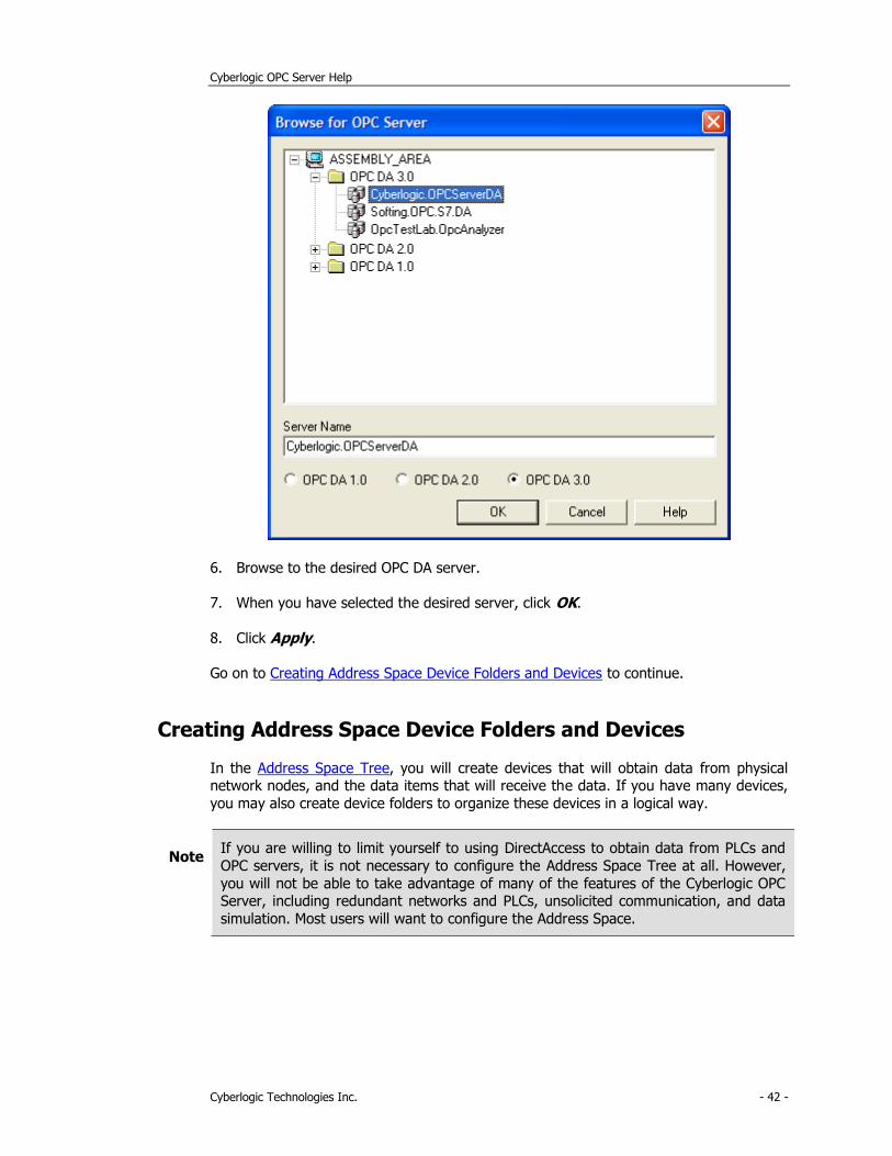
6. Browse to the desired OPC DA server.
7. When you have selected the desired server, click OK.
8. Click Apply.
Go on to Creating Address Space Device Folders and Devices to continue.
Creating Address Space Device Folders and Devices
In the Address Space Tree, you will create devices that will obtain data from physical network nodes, and the data items that will receive the data. If you have many devices,
you may also create device folders to organize these devices in a logical way.
Note If you are willing to limit yourself to using DirectAccess to obtain data from PLCs and
OPC servers, it is not necessary to configure the Address Space Tree at all. However,
you will not be able to take advantage of many of the features of the Cyberlogic OPC Server, including redundant networks and PLCs, unsolicited communication, and data
simulation. Most users will want to configure the Address Space.
Cyberlogic OPC Server Help
Cyberlogic Technologies Inc. - 43 -
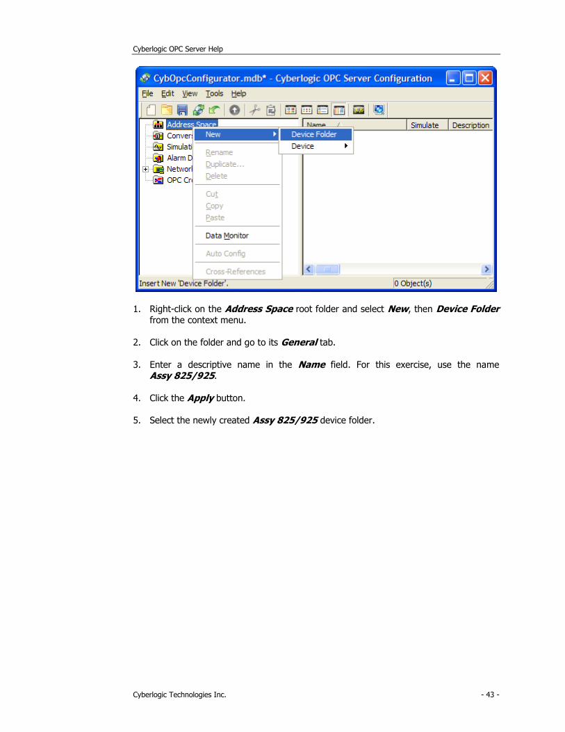
1. Right-click on the Address Space root folder and select New, then Device Folder from the context menu.
2. Click on the folder and go to its General tab.
3. Enter a descriptive name in the Name field. For this exercise, use the name Assy 825/925.
4. Click the Apply button.
5. Select the newly created Assy 825/925 device folder.
Cyberlogic OPC Server Help
Cyberlogic Technologies Inc. - 44 -
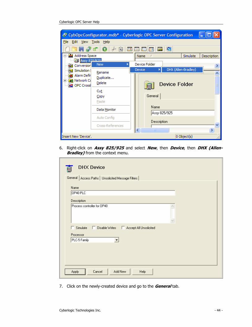
6. Right-click on Assy 825/925 and select New, then Device, then DHX (Allen-Bradley) from the context menu.
7. Click on the newly-created device and go to the General tab.
Cyberlogic OPC Server Help
Cyberlogic Technologies Inc. - 45 -
8. Enter a descriptive name in the Name field. For this exercise, use the name OP40 PLC.
9. Enter an optional description, in this example, use Process controller for OP40.
10. From the Processor drop-down box, select PLC-5 Family.
11. Click Apply.
You have just created a device for the OP40 PLC, and you can repeat this process to create devices to be associated with the other controllers you will communicate with. If
you also want to obtain data from OPC servers, you can create devices for them as well, in a similar manner.
An address space device represents a logical data source associated with one or more physical devices to which the server communicates. In the next section, Configuring the
Access Paths, you will make this association.
Configuring the Access Paths
Access paths specify the network and PLC you want the device to use for obtaining its
data. In the case of OPC server devices, access paths specify the computer and OPC DA
server. If you want to use backup networks, controllers or OPC servers, you can specify more than one access path for a device to create the desired redundancy.
Note Access paths are needed only for solicited communication. If your driver agent supports unsolicited communication and you want to use only that type, you can skip
this section and go to Configuring Unsolicited Message Filters.
The newly-created OP40 PLC device has not been associated with the physical network
nodes yet. In this section, you will set OP40 Primary@2 as the primary controller and OP40 Backup@50 as the secondary controller.
Cyberlogic OPC Server Help
Cyberlogic Technologies Inc. - 46 -
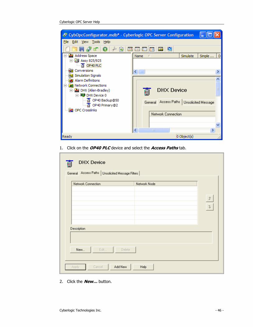
1. Click on the OP40 PLC device and select the Access Paths tab.
2. Click the New… button.
Cyberlogic OPC Server Help
Cyberlogic Technologies Inc. - 47 -
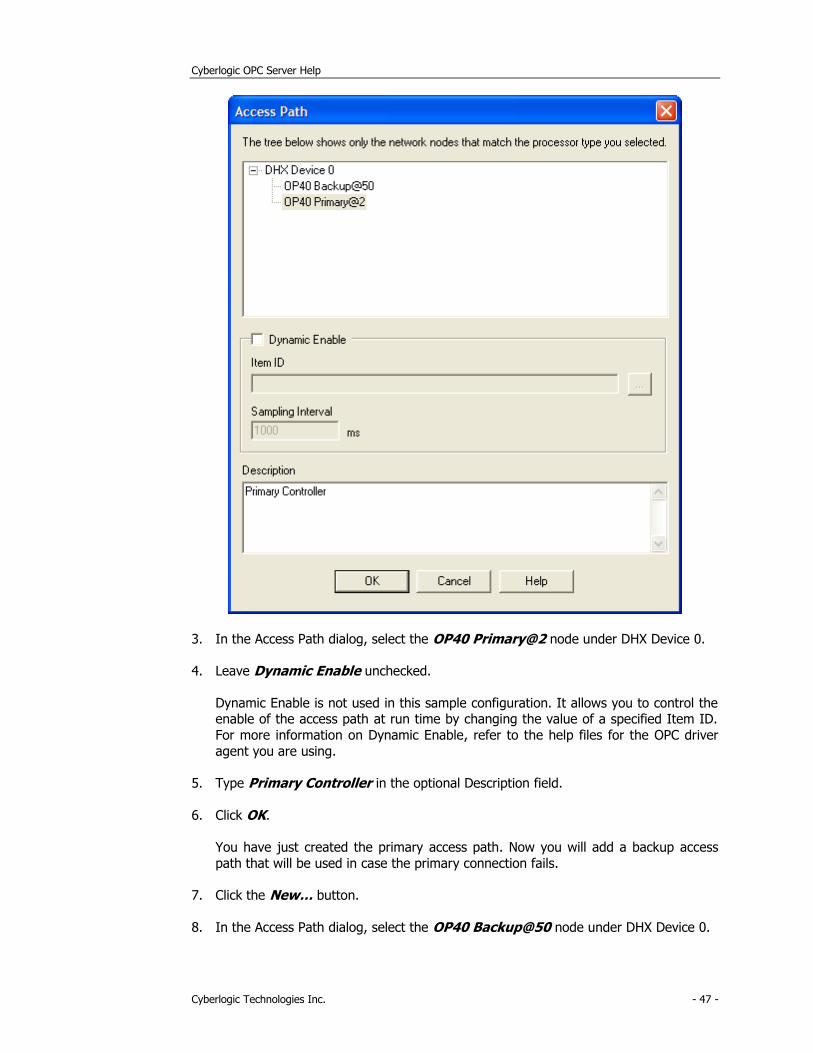
3. In the Access Path dialog, select the OP40 Primary@2 node under DHX Device 0.
4. Leave Dynamic Enable unchecked.
Dynamic Enable is not used in this sample configuration. It allows you to control the enable of the access path at run time by changing the value of a specified Item ID.
For more information on Dynamic Enable, refer to the help files for the OPC driver
agent you are using.
5. Type Primary Controller in the optional Description field.
6. Click OK.
You have just created the primary access path. Now you will add a backup access
path that will be used in case the primary connection fails.
7. Click the New… button.
8. In the Access Path dialog, select the OP40 Backup@50 node under DHX Device 0.
Cyberlogic OPC Server Help
Cyberlogic Technologies Inc. - 48 -
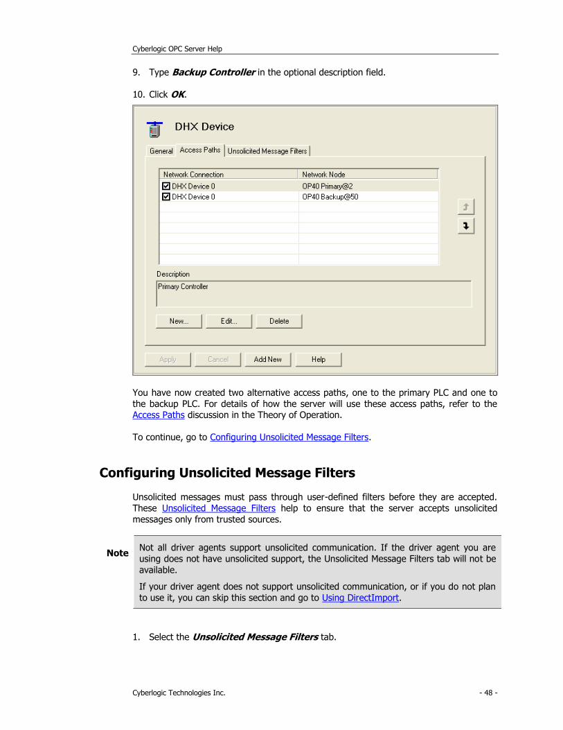
9. Type Backup Controller in the optional description field.
10. Click OK.
You have now created two alternative access paths, one to the primary PLC and one to
the backup PLC. For details of how the server will use these access paths, refer to the Access Paths discussion in the Theory of Operation.
To continue, go to Configuring Unsolicited Message Filters.
Configuring Unsolicited Message Filters
Unsolicited messages must pass through user-defined filters before they are accepted.
These Unsolicited Message Filters help to ensure that the server accepts unsolicited
messages only from trusted sources.
Note Not all driver agents support unsolicited communication. If the driver agent you are
using does not have unsolicited support, the Unsolicited Message Filters tab will not be
available.
If your driver agent does not support unsolicited communication, or if you do not plan
to use it, you can skip this section and go to Using DirectImport.
1. Select the Unsolicited Message Filters tab.
Cyberlogic OPC Server Help
Cyberlogic Technologies Inc. - 49 -
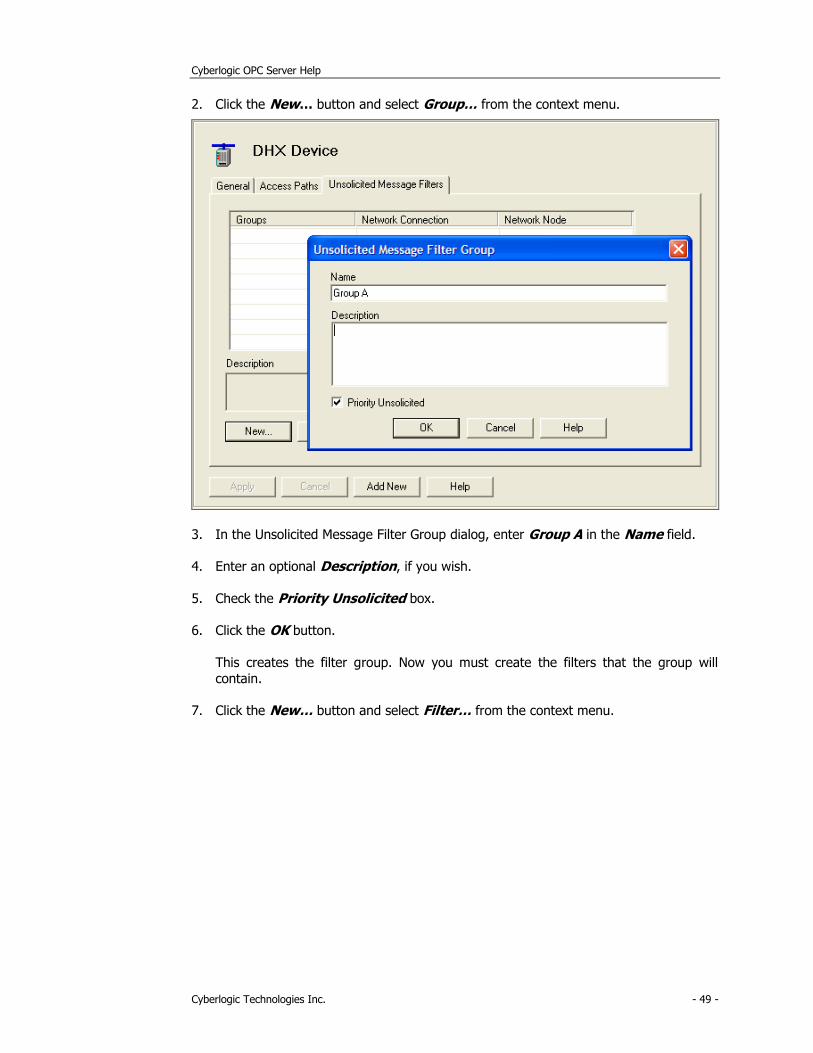
2. Click the New… button and select Group… from the context menu.
3. In the Unsolicited Message Filter Group dialog, enter Group A in the Name field.
4. Enter an optional Description, if you wish.
5. Check the Priority Unsolicited box.
6. Click the OK button.
This creates the filter group. Now you must create the filters that the group will
contain.
7. Click the New… button and select Filter… from the context menu.
Cyberlogic OPC Server Help
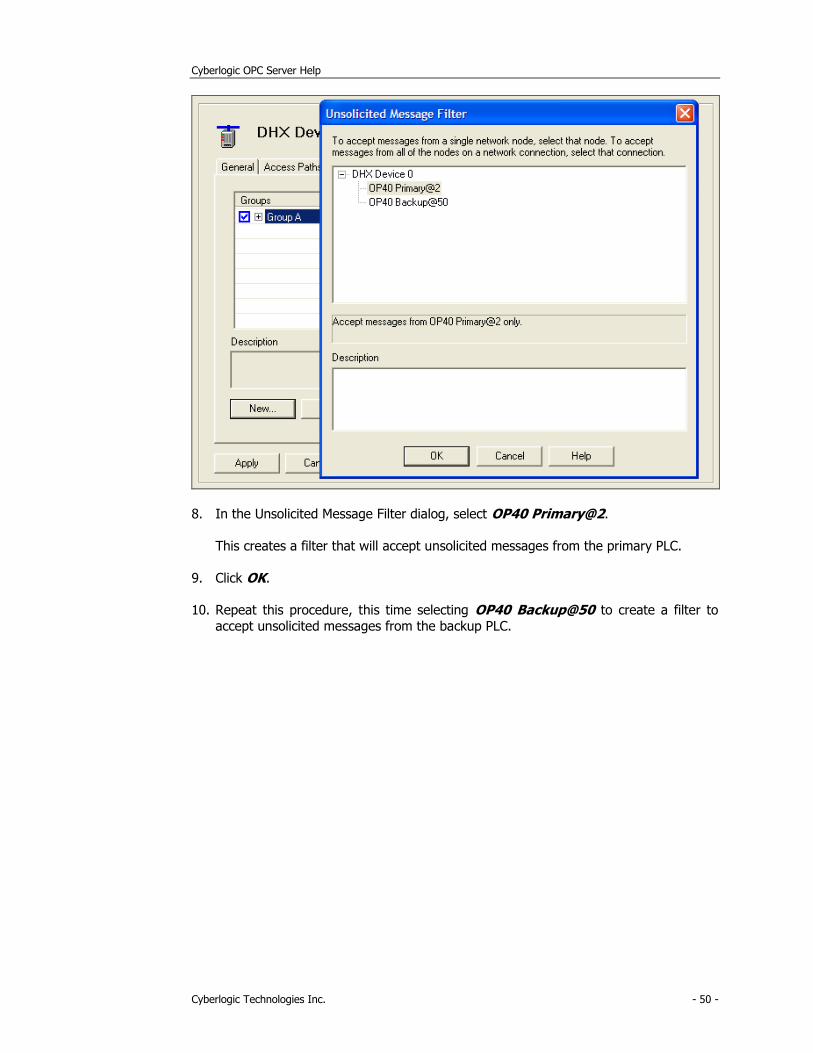
Cyberlogic Technologies Inc. - 50 -
8. In the Unsolicited Message Filter dialog, select OP40 Primary@2.
This creates a filter that will accept unsolicited messages from the primary PLC.
9. Click OK.
10. Repeat this procedure, this time selecting OP40 Backup@50 to create a filter to
accept unsolicited messages from the backup PLC.
Cyberlogic OPC Server Help
Cyberlogic Technologies Inc. - 51 -
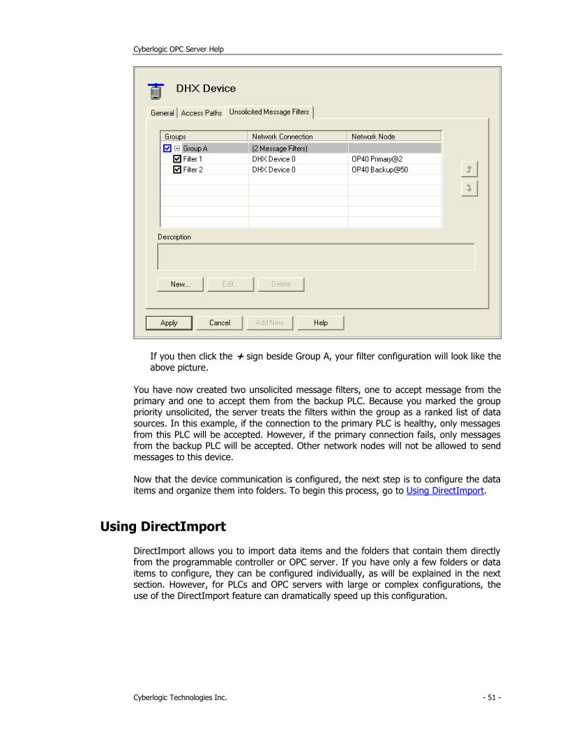
If you then click the + sign beside Group A, your filter configuration will look like the
above picture.
You have now created two unsolicited message filters, one to accept message from the
primary and one to accept them from the backup PLC. Because you marked the group priority unsolicited, the server treats the filters within the group as a ranked list of data
sources. In this example, if the connection to the primary PLC is healthy, only messages
from this PLC will be accepted. However, if the primary connection fails, only messages from the backup PLC will be accepted. Other network nodes will not be allowed to send
messages to this device.
Now that the device communication is configured, the next step is to configure the data
items and organize them into folders. To begin this process, go to Using DirectImport.
Using DirectImport
DirectImport allows you to import data items and the folders that contain them directly
from the programmable controller or OPC server. If you have only a few folders or data
items to configure, they can be configured individually, as will be explained in the next section. However, for PLCs and OPC servers with large or complex configurations, the
use of the DirectImport feature can dramatically speed up this configuration.
Cyberlogic OPC Server Help
Cyberlogic Technologies Inc. - 52 -
Note DirectImport is available only for the ControlLogix and OPC Server DA Driver Agents,
and requires communication with the controller or server you are importing from.
If the driver agent you are using does not have DirectImport or if communication is not
available, you can skip this section and go to Configuring Folders and Data Items
Manually.
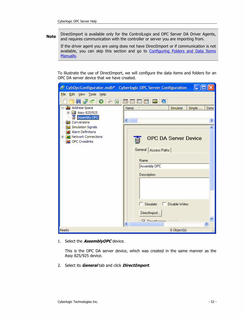
To illustrate the use of DirectImport, we will configure the data items and folders for an
OPC DA server device that we have created.
1. Select the AssemblyOPC device.
This is the OPC DA server device, which was created in the same manner as the Assy 825/925 device.
2. Select its General tab and click DirectImport.
Cyberlogic OPC Server Help
Cyberlogic Technologies Inc. - 53 -
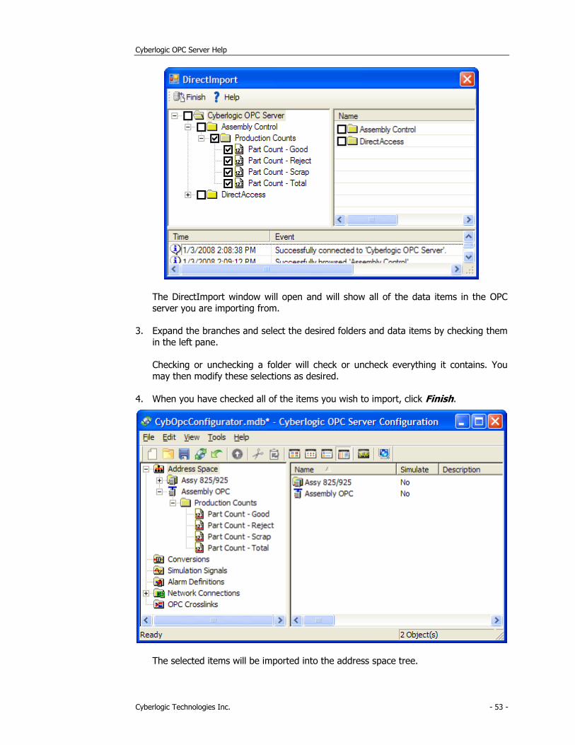
The DirectImport window will open and will show all of the data items in the OPC
server you are importing from.
3. Expand the branches and select the desired folders and data items by checking them
in the left pane.
Checking or unchecking a folder will check or uncheck everything it contains. You
may then modify these selections as desired.
4. When you have checked all of the items you wish to import, click Finish.
The selected items will be imported into the address space tree.
Cyberlogic OPC Server Help
Cyberlogic Technologies Inc. - 54 -
5. You may then edit these folders and data items, if you wish to use different names or arrange them differently.
To learn how to edit the items you've imported or to create folders and data items that you could not import, go to Configuring Folders and Data Items Manually.
Configuring Folders and Data Items Manually
In the Address Space Tree, data items are used to receive data from the network nodes through the device’s access paths or unsolicited filters. The OPC client software will
access these data items to obtain the values they hold. Folders may be used to organize
the data items into logical groups.
Note If you are willing to limit yourself to using DirectAccess at the device level to obtain data from PLCs and OPC servers, it is not necessary to configure the data items at all.
However, you will not be able to take advantage of many of the features of the
Cyberlogic OPC Server, including logical organization of data, and data simulation. Most
users will want to configure the data items.
If DirectImport was able to import all of the folders and data items you need, and you do not want to make any changes to them, you can skip to Saving the Configuration and
Updating the Server.
1. Right-click on the OP40 PLC device and select New, then Folder from the context
menu.
Cyberlogic OPC Server Help
Cyberlogic Technologies Inc. - 55 -
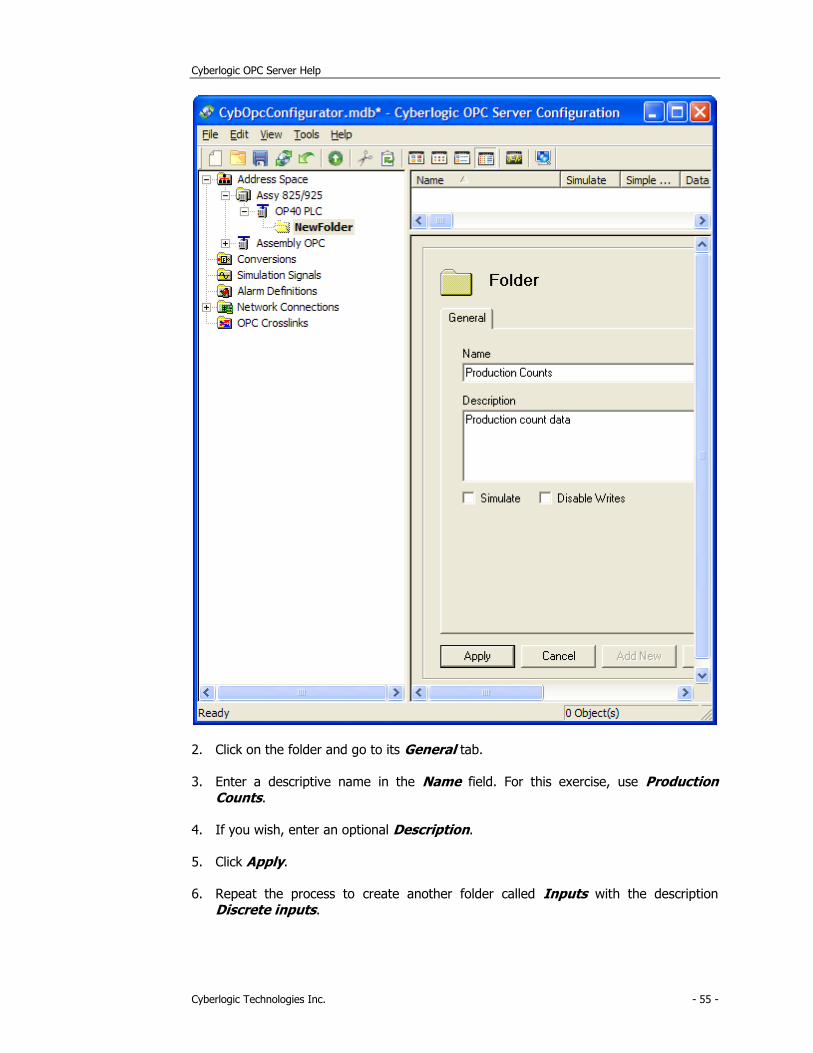
2. Click on the folder and go to its General tab.
3. Enter a descriptive name in the Name field. For this exercise, use Production Counts.
4. If you wish, enter an optional Description.
5. Click Apply.
6. Repeat the process to create another folder called Inputs with the description
Discrete inputs.

Cyberlogic OPC Server Help
Cyberlogic Technologies Inc. - 56 -
7. Right-click on the Production Counts folder and select New, then Data Item from the context menu.
8. Click on the data item and select its General tab.
9. Enter a descriptive name in the Name field. For this exercise, use GoodParts.
10. If you wish, enter an optional Description.
11. Verify that the Solicited Update box is checked.
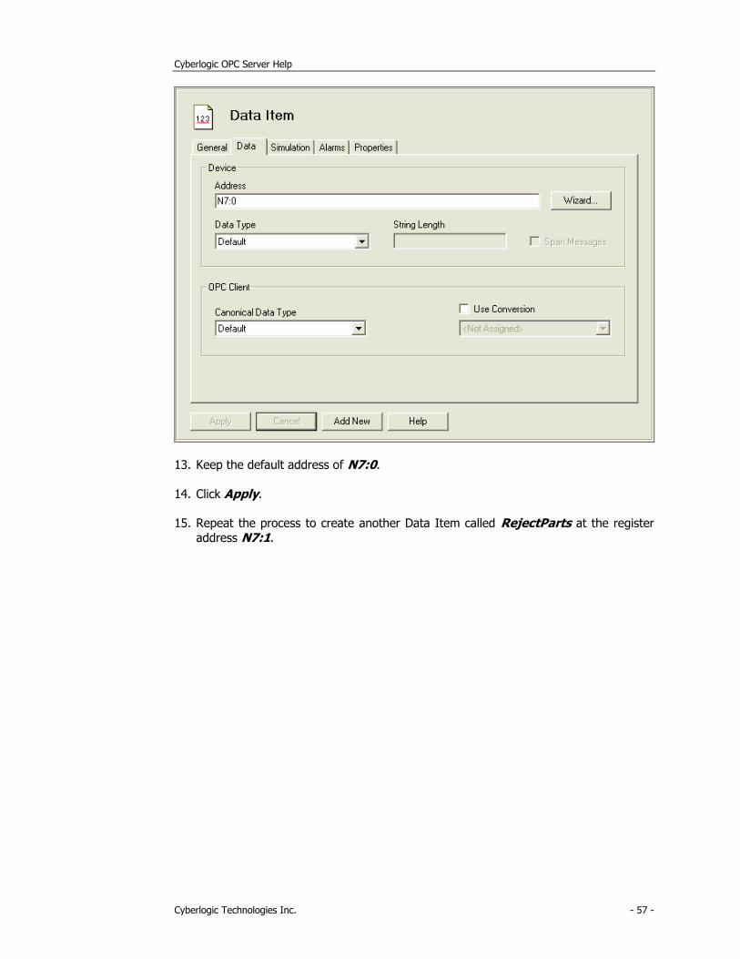
12. Select the Data tab.
Cyberlogic OPC Server Help
Cyberlogic Technologies Inc. - 57 -
13. Keep the default address of N7:0.
14. Click Apply.
15. Repeat the process to create another Data Item called RejectParts at the register
address N7:1.
Cyberlogic OPC Server Help
Cyberlogic Technologies Inc. - 58 -
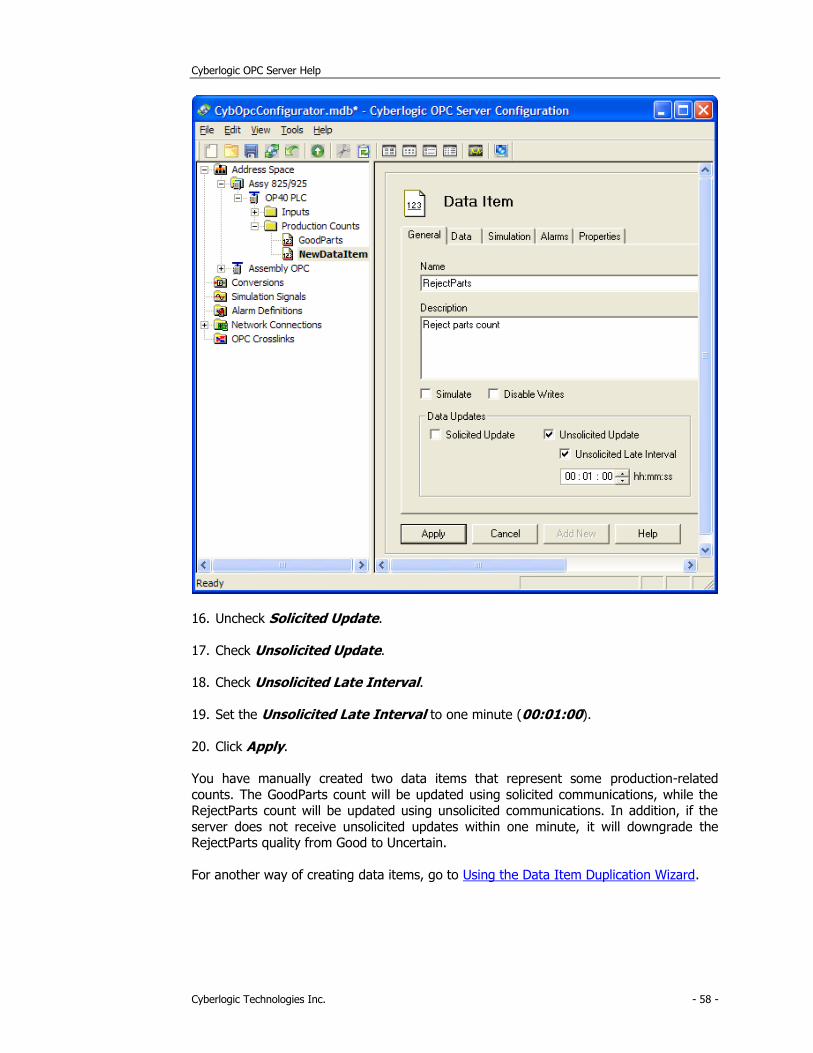
16. Uncheck Solicited Update.
17. Check Unsolicited Update.
18. Check Unsolicited Late Interval.
19. Set the Unsolicited Late Interval to one minute (00:01:00).
20. Click Apply.
You have manually created two data items that represent some production-related
counts. The GoodParts count will be updated using solicited communications, while the RejectParts count will be updated using unsolicited communications. In addition, if the
server does not receive unsolicited updates within one minute, it will downgrade the RejectParts quality from Good to Uncertain.
For another way of creating data items, go to Using the Data Item Duplication Wizard.
Cyberlogic OPC Server Help
Cyberlogic Technologies Inc. - 59 -
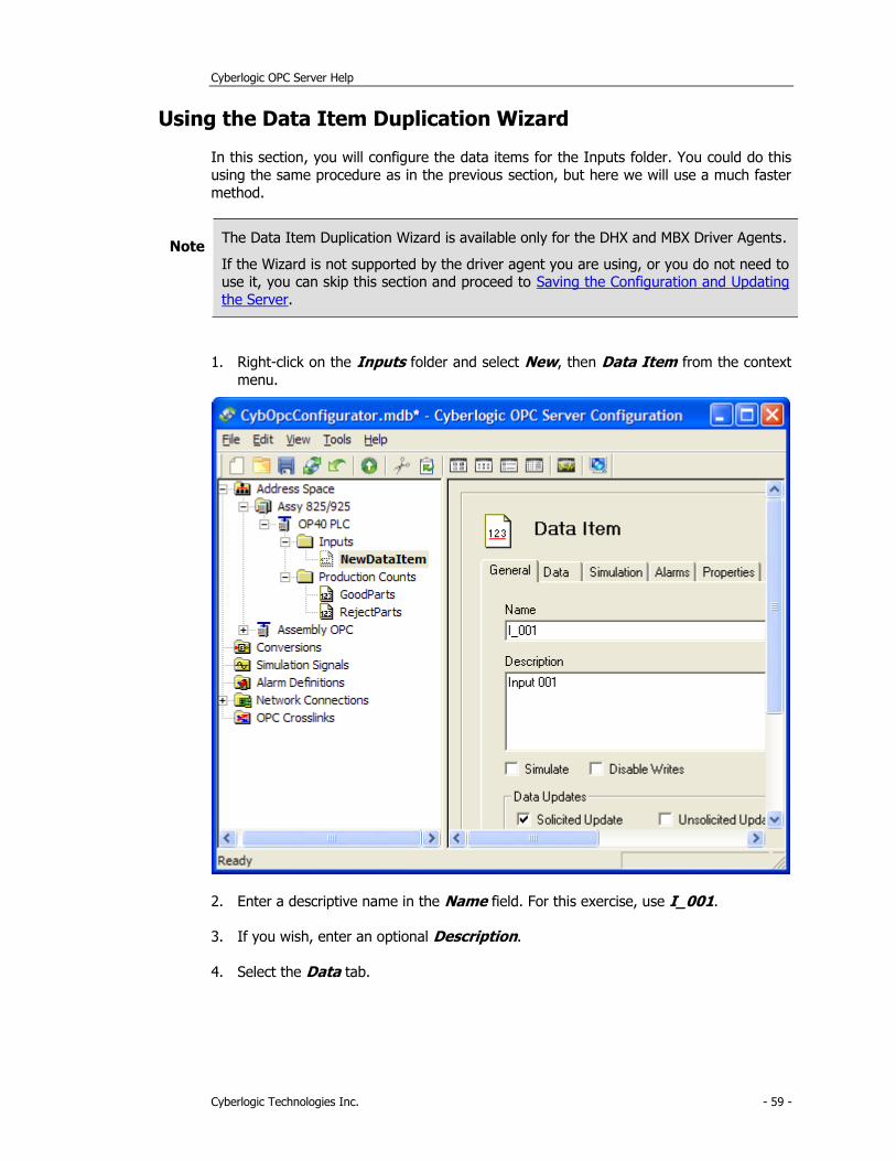
Using the Data Item Duplication Wizard
In this section, you will configure the data items for the Inputs folder. You could do this
using the same procedure as in the previous section, but here we will use a much faster
method.
Note The Data Item Duplication Wizard is available only for the DHX and MBX Driver Agents.
If the Wizard is not supported by the driver agent you are using, or you do not need to use it, you can skip this section and proceed to Saving the Configuration and Updating
the Server.
1. Right-click on the Inputs folder and select New, then Data Item from the context
menu.
2. Enter a descriptive name in the Name field. For this exercise, use I_001.
3. If you wish, enter an optional Description.
4. Select the Data tab.
Cyberlogic OPC Server Help
Cyberlogic Technologies Inc. - 60 -
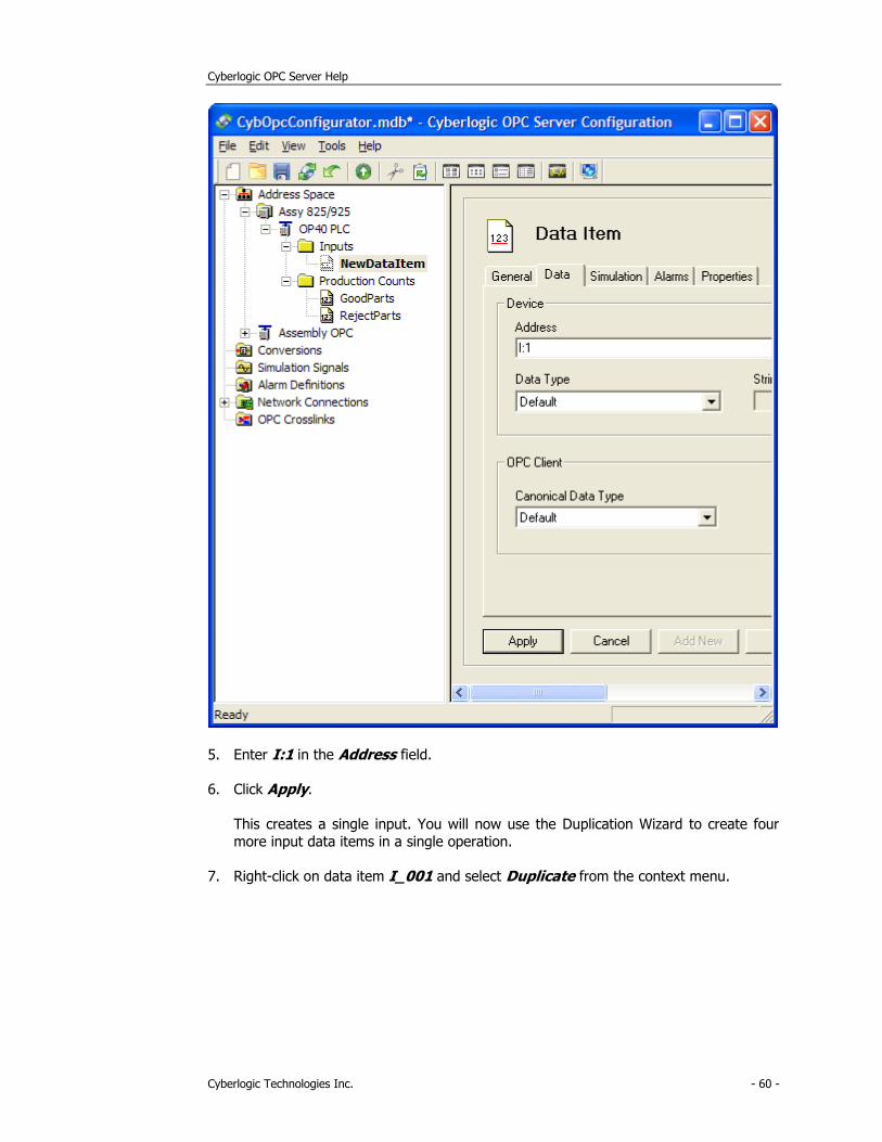
5. Enter I:1 in the Address field.
6. Click Apply.
This creates a single input. You will now use the Duplication Wizard to create four
more input data items in a single operation.
7. Right-click on data item I_001 and select Duplicate from the context menu.
Cyberlogic OPC Server Help
Cyberlogic Technologies Inc. - 61 -
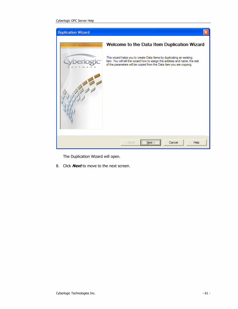
The Duplication Wizard will open.
8. Click Next to move to the next screen.
Cyberlogic OPC Server Help
Cyberlogic Technologies Inc. - 62 -
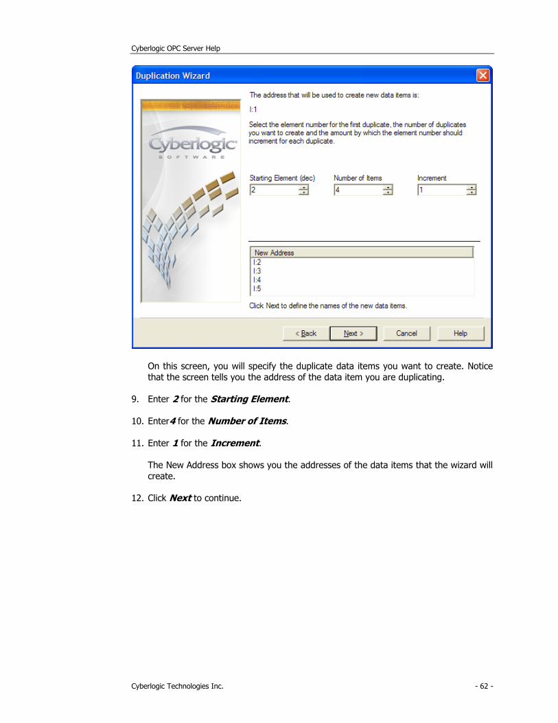
On this screen, you will specify the duplicate data items you want to create. Notice
that the screen tells you the address of the data item you are duplicating.
9. Enter 2 for the Starting Element.
10. Enter4 for the Number of Items.
11. Enter 1 for the Increment.
The New Address box shows you the addresses of the data items that the wizard will
create.
12. Click Next to continue.
Cyberlogic OPC Server Help
Cyberlogic Technologies Inc. - 63 -
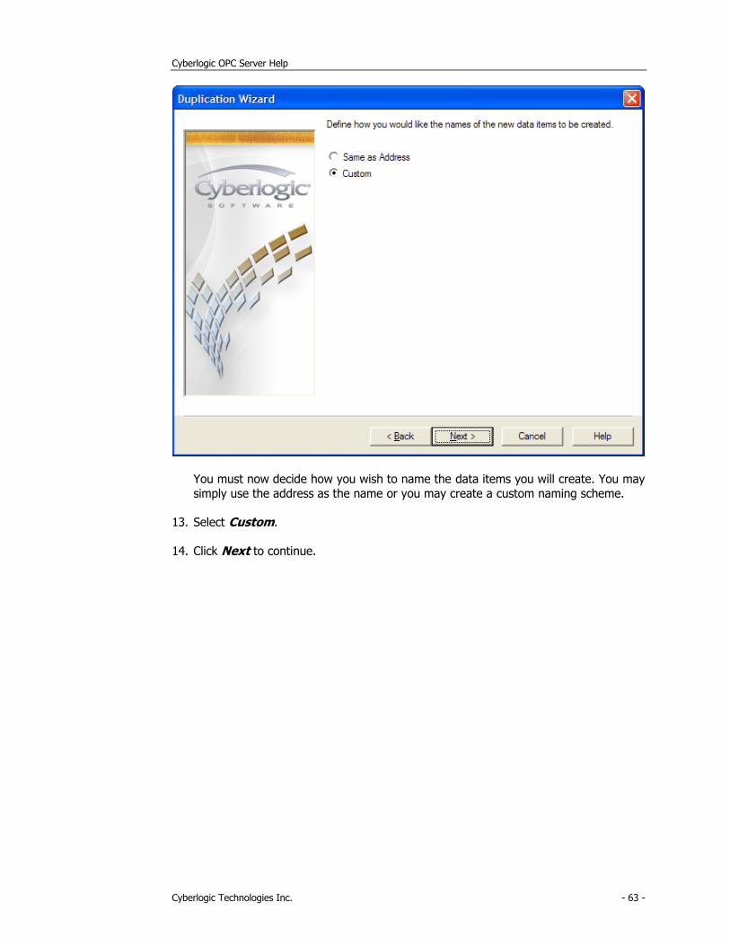
You must now decide how you wish to name the data items you will create. You may
simply use the address as the name or you may create a custom naming scheme.
13. Select Custom.
14. Click Next to continue.
Cyberlogic OPC Server Help
Cyberlogic Technologies Inc. - 64 -
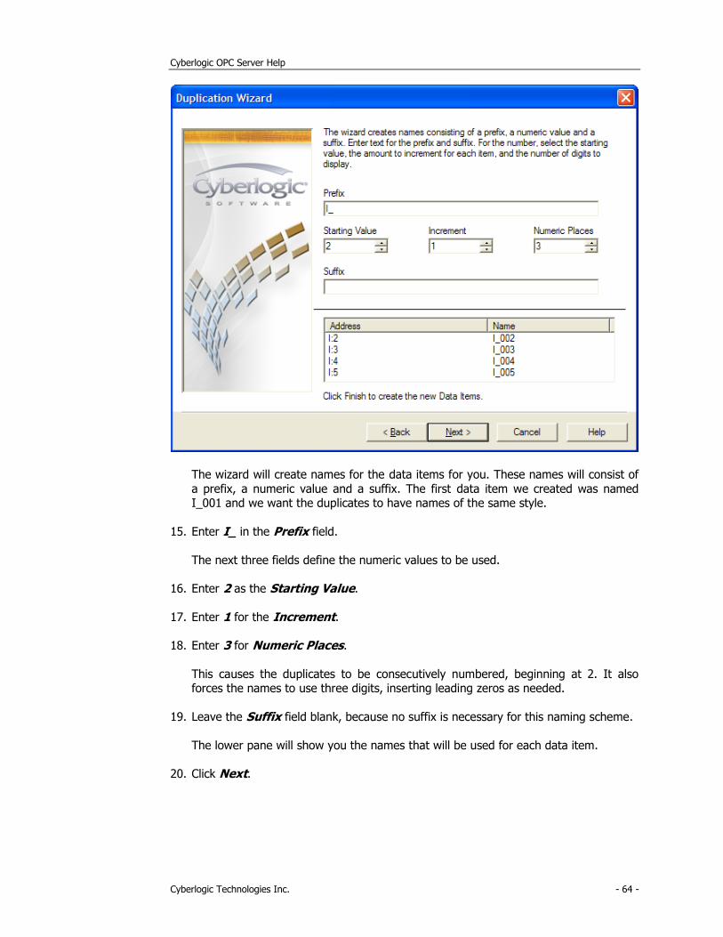
The wizard will create names for the data items for you. These names will consist of
a prefix, a numeric value and a suffix. The first data item we created was named I_001 and we want the duplicates to have names of the same style.
15. Enter I_ in the Prefix field.
The next three fields define the numeric values to be used.
16. Enter 2 as the Starting Value.
17. Enter 1 for the Increment.
18. Enter 3 for Numeric Places.
This causes the duplicates to be consecutively numbered, beginning at 2. It also forces the names to use three digits, inserting leading zeros as needed.
19. Leave the Suffix field blank, because no suffix is necessary for this naming scheme.
The lower pane will show you the names that will be used for each data item.
20. Click Next.
Cyberlogic OPC Server Help
Cyberlogic Technologies Inc. - 65 -
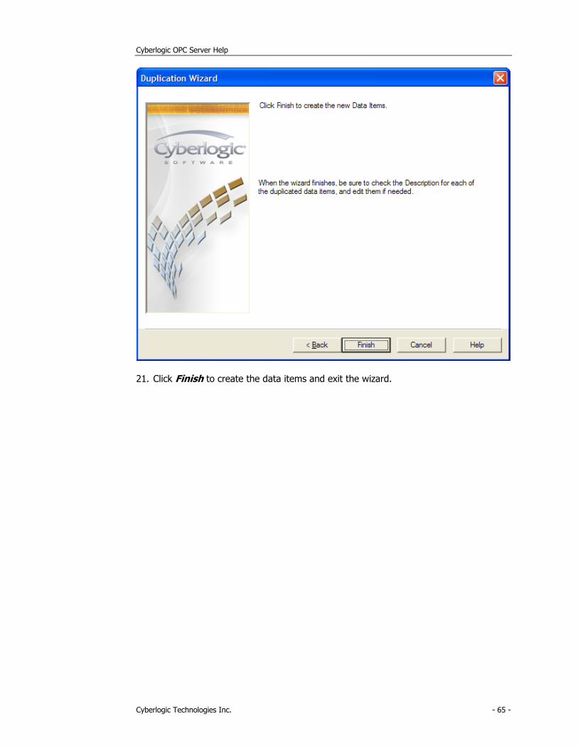
21. Click Finish to create the data items and exit the wizard.
Cyberlogic OPC Server Help
Cyberlogic Technologies Inc. - 66 -
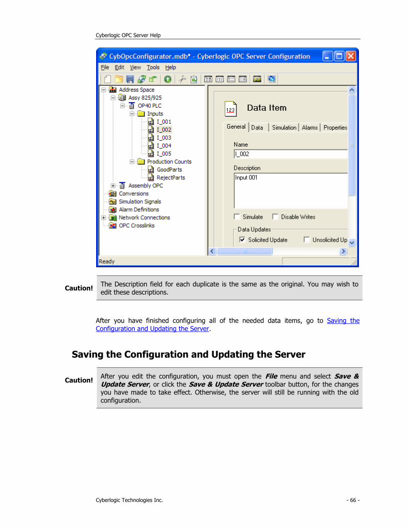
Caution! The Description field for each duplicate is the same as the original. You may wish to
edit these descriptions.
After you have finished configuring all of the needed data items, go to Saving the
Configuration and Updating the Server.
Saving the Configuration and Updating the Server
Caution! After you edit the configuration, you must open the File menu and select Save & Update Server, or click the Save & Update Server toolbar button, for the changes you have made to take effect. Otherwise, the server will still be running with the old
configuration.
Cyberlogic OPC Server Help
Cyberlogic Technologies Inc. - 67 -
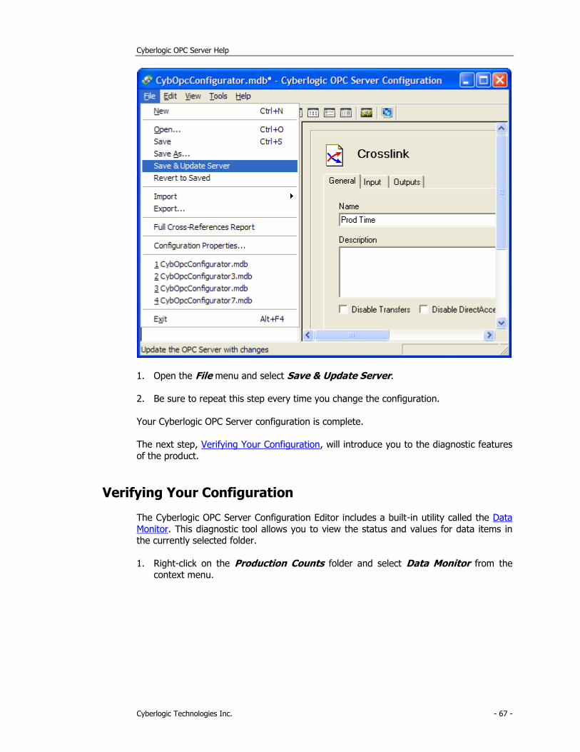
1. Open the File menu and select Save & Update Server.
2. Be sure to repeat this step every time you change the configuration.
Your Cyberlogic OPC Server configuration is complete.
The next step, Verifying Your Configuration, will introduce you to the diagnostic features
of the product.
Verifying Your Configuration
The Cyberlogic OPC Server Configuration Editor includes a built-in utility called the Data
Monitor. This diagnostic tool allows you to view the status and values for data items in the currently selected folder.
1. Right-click on the Production Counts folder and select Data Monitor from the context menu.
Cyberlogic OPC Server Help
Cyberlogic Technologies Inc. - 68 -
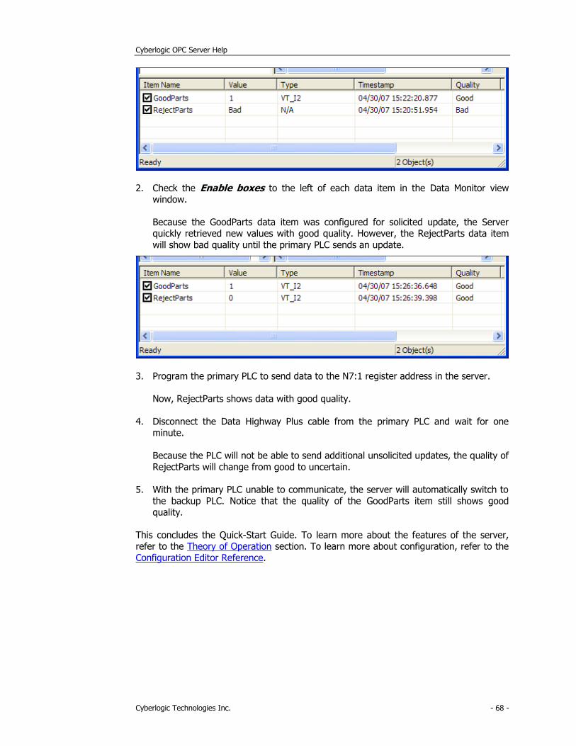
2. Check the Enable boxes to the left of each data item in the Data Monitor view window.
Because the GoodParts data item was configured for solicited update, the Server quickly retrieved new values with good quality. However, the RejectParts data item
will show bad quality until the primary PLC sends an update.
3. Program the primary PLC to send data to the N7:1 register address in the server.
Now, RejectParts shows data with good quality.
4. Disconnect the Data Highway Plus cable from the primary PLC and wait for one minute.
Because the PLC will not be able to send additional unsolicited updates, the quality of
RejectParts will change from good to uncertain.
5. With the primary PLC unable to communicate, the server will automatically switch to
the backup PLC. Notice that the quality of the GoodParts item still shows good quality.
This concludes the Quick-Start Guide. To learn more about the features of the server, refer to the Theory of Operation section. To learn more about configuration, refer to the
Configuration Editor Reference.
Cyberlogic OPC Server Help
Cyberlogic Technologies Inc. - 69 -
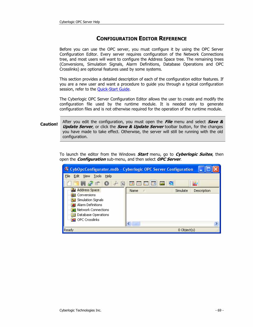
CONFIGURATION EDITOR REFERENCE
Before you can use the OPC server, you must configure it by using the OPC Server
Configuration Editor. Every server requires configuration of the Network Connections
tree, and most users will want to configure the Address Space tree. The remaining trees (Conversions, Simulation Signals, Alarm Definitions, Database Operations and OPC
Crosslinks) are optional features used by some systems.
This section provides a detailed description of each of the configuration editor features. If
you are a new user and want a procedure to guide you through a typical configuration
session, refer to the Quick-Start Guide.
The Cyberlogic OPC Server Configuration Editor allows the user to create and modify the
configuration file used by the runtime module. It is needed only to generate configuration files and is not otherwise required for the operation of the runtime module.
Caution! After you edit the configuration, you must open the File menu and select Save & Update Server, or click the Save & Update Server toolbar button, for the changes
you have made to take effect. Otherwise, the server will still be running with the old
configuration.
To launch the editor from the Windows Start menu, go to Cyberlogic Suites, then open the Configuration sub-menu, and then select OPC Server.
Cyberlogic OPC Server Help
Cyberlogic Technologies Inc. - 70 -
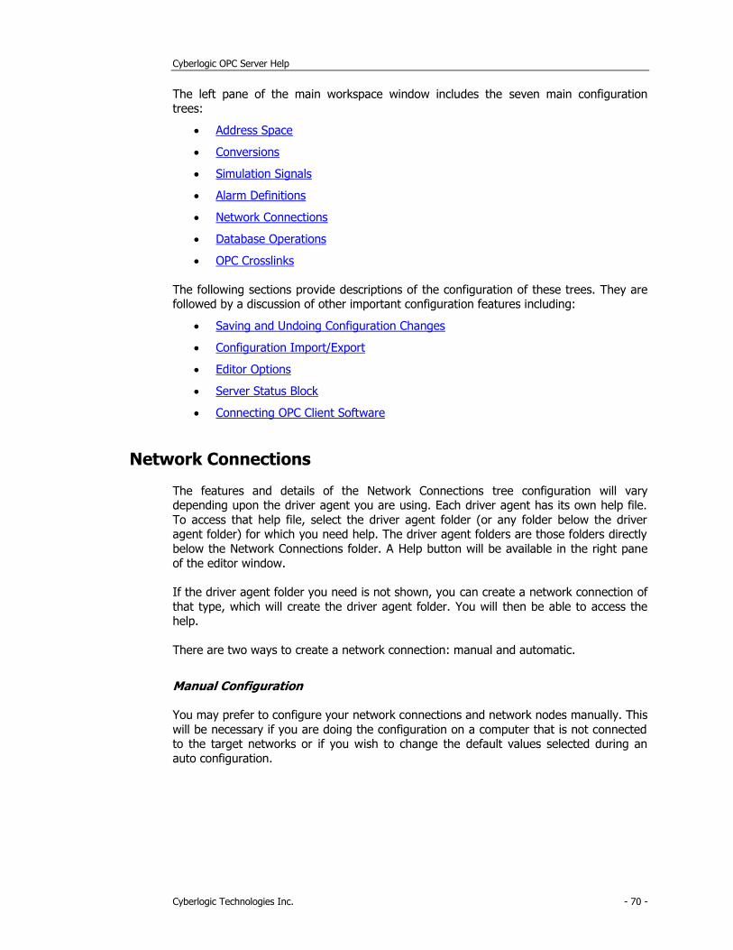
The left pane of the main workspace window includes the seven main configuration trees:
• Address Space
• Conversions
• Simulation Signals
• Alarm Definitions
• Network Connections
• Database Operations
• OPC Crosslinks
The following sections provide descriptions of the configuration of these trees. They are followed by a discussion of other important configuration features including:
• Saving and Undoing Configuration Changes
• Configuration Import/Export
• Editor Options
• Server Status Block
• Connecting OPC Client Software
Network Connections
The features and details of the Network Connections tree configuration will vary depending upon the driver agent you are using. Each driver agent has its own help file.
To access that help file, select the driver agent folder (or any folder below the driver agent folder) for which you need help. The driver agent folders are those folders directly
below the Network Connections folder. A Help button will be available in the right pane
of the editor window.
If the driver agent folder you need is not shown, you can create a network connection of
that type, which will create the driver agent folder. You will then be able to access the help.
There are two ways to create a network connection: manual and automatic.
Manual Configuration
You may prefer to configure your network connections and network nodes manually. This
will be necessary if you are doing the configuration on a computer that is not connected to the target networks or if you wish to change the default values selected during an
auto configuration.
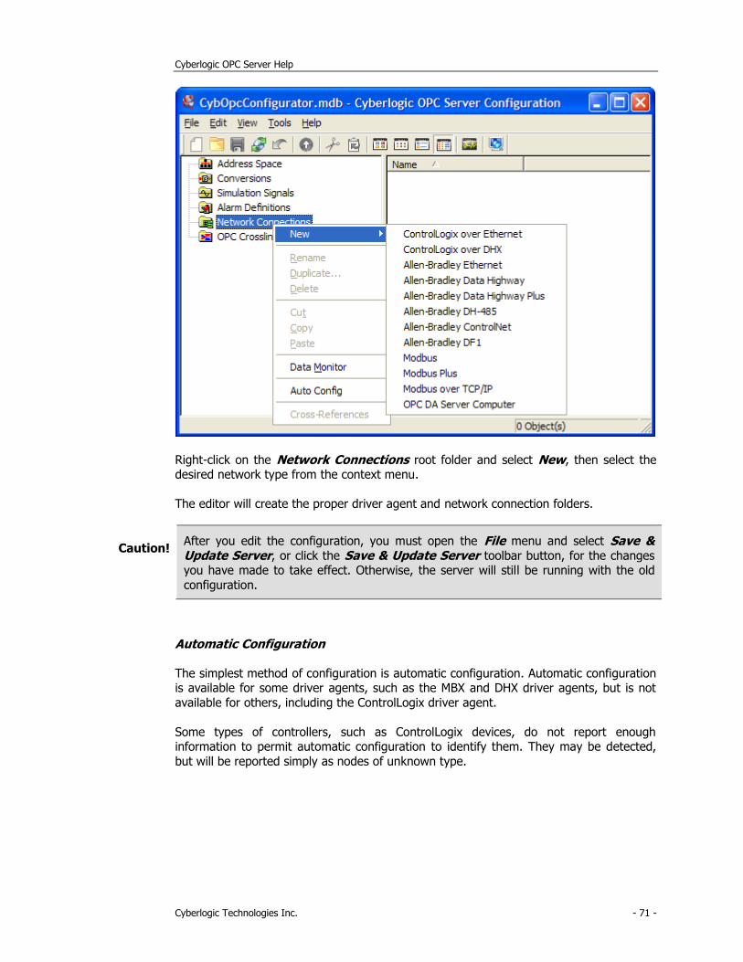
Cyberlogic OPC Server Help
Cyberlogic Technologies Inc. - 71 -
Right-click on the Network Connections root folder and select New, then select the desired network type from the context menu.
The editor will create the proper driver agent and network connection folders.
Caution! After you edit the configuration, you must open the File menu and select Save & Update Server, or click the Save & Update Server toolbar button, for the changes you have made to take effect. Otherwise, the server will still be running with the old
configuration.
Automatic Configuration
The simplest method of configuration is automatic configuration. Automatic configuration is available for some driver agents, such as the MBX and DHX driver agents, but is not
available for others, including the ControlLogix driver agent.
Some types of controllers, such as ControlLogix devices, do not report enough information to permit automatic configuration to identify them. They may be detected,
but will be reported simply as nodes of unknown type.
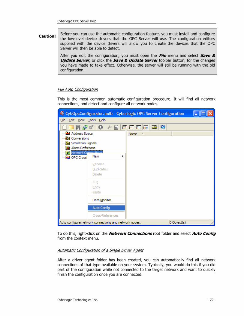
Cyberlogic OPC Server Help
Cyberlogic Technologies Inc. - 72 -
Caution! Before you can use the automatic configuration feature, you must install and configure the low-level device drivers that the OPC Server will use. The configuration editors
supplied with the device drivers will allow you to create the devices that the OPC
Server will then be able to detect.
After you edit the configuration, you must open the File menu and select Save & Update Server, or click the Save & Update Server toolbar button, for the changes you have made to take effect. Otherwise, the server will still be running with the old
configuration.
Full Auto Configuration
This is the most common automatic configuration procedure. It will find all network connections, and detect and configure all network nodes.
To do this, right-click on the Network Connections root folder and select Auto Config from the context menu.
Automatic Configuration of a Single Driver Agent
After a driver agent folder has been created, you can automatically find all network
connections of that type available on your system. Typically, you would do this if you did part of the configuration while not connected to the target network and want to quickly
finish the configuration once you are connected.
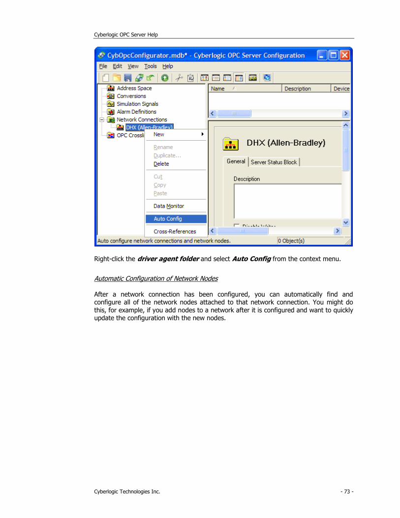
Cyberlogic OPC Server Help
Cyberlogic Technologies Inc. - 73 -
Right-click the driver agent folder and select Auto Config from the context menu.
Automatic Configuration of Network Nodes
After a network connection has been configured, you can automatically find and configure all of the network nodes attached to that network connection. You might do
this, for example, if you add nodes to a network after it is configured and want to quickly update the configuration with the new nodes.
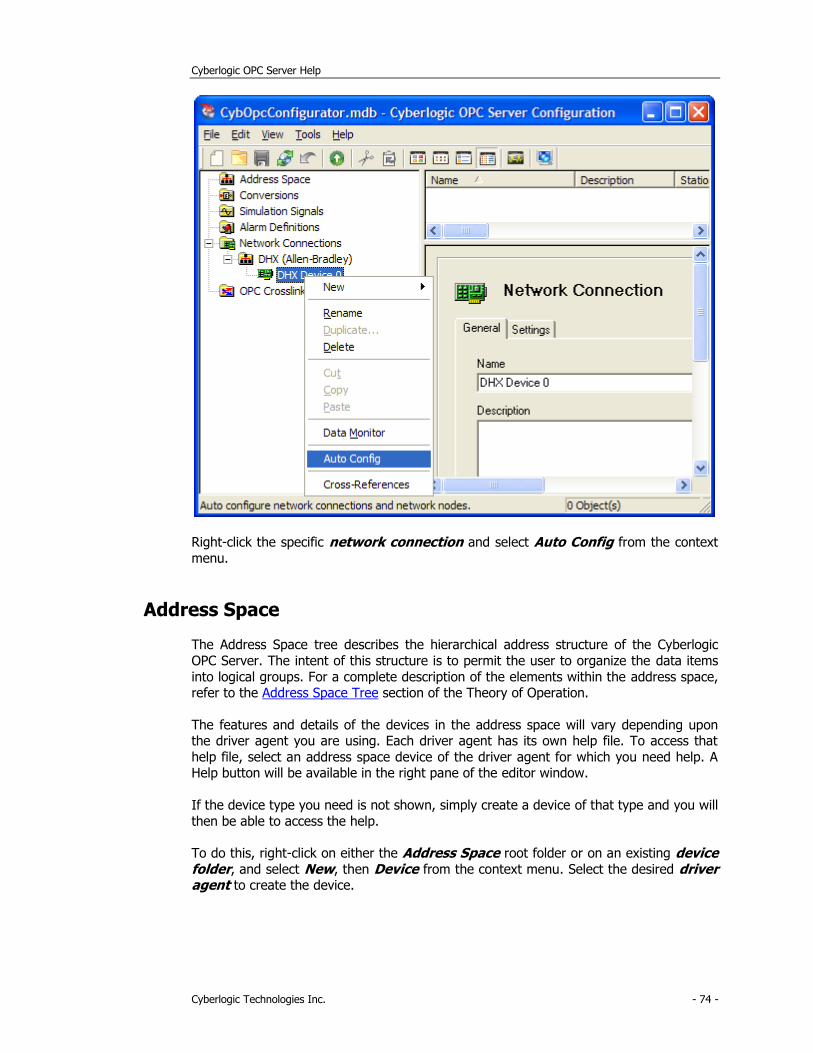
Cyberlogic OPC Server Help
Cyberlogic Technologies Inc. - 74 -
Right-click the specific network connection and select Auto Config from the context
menu.
Address Space
The Address Space tree describes the hierarchical address structure of the Cyberlogic
OPC Server. The intent of this structure is to permit the user to organize the data items
into logical groups. For a complete description of the elements within the address space, refer to the Address Space Tree section of the Theory of Operation.
The features and details of the devices in the address space will vary depending upon the driver agent you are using. Each driver agent has its own help file. To access that
help file, select an address space device of the driver agent for which you need help. A Help button will be available in the right pane of the editor window.
If the device type you need is not shown, simply create a device of that type and you will
then be able to access the help.
To do this, right-click on either the Address Space root folder or on an existing device folder, and select New, then Device from the context menu. Select the desired driver agent to create the device.
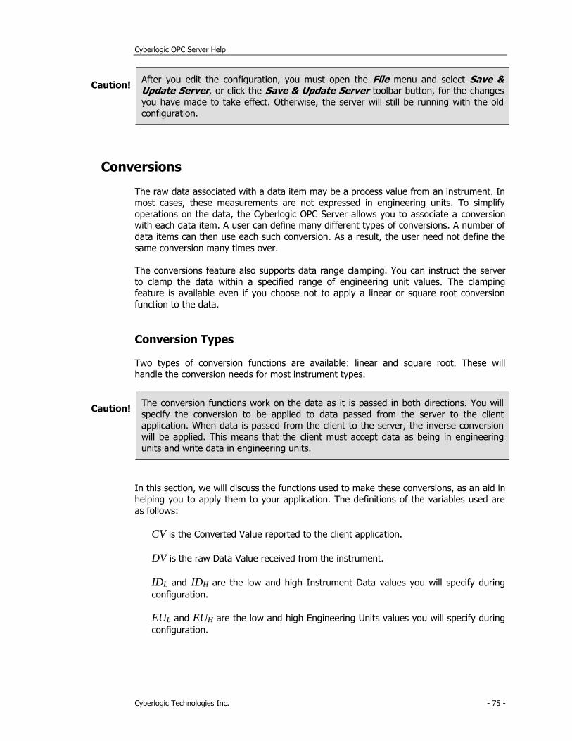
Cyberlogic OPC Server Help
Cyberlogic Technologies Inc. - 75 -
Caution! After you edit the configuration, you must open the File menu and select Save & Update Server, or click the Save & Update Server toolbar button, for the changes
you have made to take effect. Otherwise, the server will still be running with the old
configuration.
Conversions
The raw data associated with a data item may be a process value from an instrument. In most cases, these measurements are not expressed in engineering units. To simplify
operations on the data, the Cyberlogic OPC Server allows you to associate a conversion with each data item. A user can define many different types of conversions. A number of
data items can then use each such conversion. As a result, the user need not define the
same conversion many times over.
The conversions feature also supports data range clamping. You can instruct the server
to clamp the data within a specified range of engineering unit values. The clamping feature is available even if you choose not to apply a linear or square root conversion
function to the data.
Conversion Types
Two types of conversion functions are available: linear and square root. These will
handle the conversion needs for most instrument types.
Caution! The conversion functions work on the data as it is passed in both directions. You will
specify the conversion to be applied to data passed from the server to the client application. When data is passed from the client to the server, the inverse conversion
will be applied. This means that the client must accept data as being in engineering
units and write data in engineering units.
In this section, we will discuss the functions used to make these conversions, as an aid in helping you to apply them to your application. The definitions of the variables used are
as follows:
CV is the Converted Value reported to the client application.
DV is the raw Data Value received from the instrument.
IDL and IDH are the low and high Instrument Data values you will specify during
configuration.
EUL and EUH are the low and high Engineering Units values you will specify during
configuration.
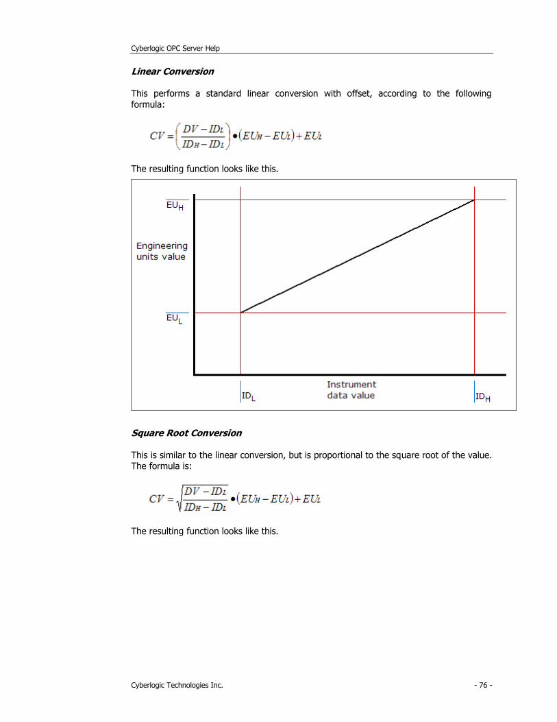
Cyberlogic OPC Server Help
Cyberlogic Technologies Inc. - 76 -
Linear Conversion
This performs a standard linear conversion with offset, according to the following
formula:
The resulting function looks like this.
Square Root Conversion
This is similar to the linear conversion, but is proportional to the square root of the value. The formula is:
The resulting function looks like this.
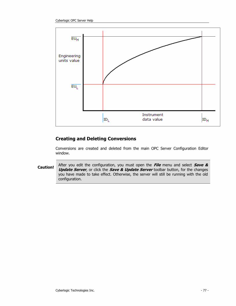
Cyberlogic OPC Server Help
Cyberlogic Technologies Inc. - 77 -
Creating and Deleting Conversions
Conversions are created and deleted from the main OPC Server Configuration Editor
window.
Caution! After you edit the configuration, you must open the File menu and select Save & Update Server, or click the Save & Update Server toolbar button, for the changes you have made to take effect. Otherwise, the server will still be running with the old
configuration.

Cyberlogic OPC Server Help
Cyberlogic Technologies Inc. - 78 -
Creating a Conversion
1. Right-click on the Conversions root folder and select New, and then Conversion from the context menu.
2. Enter the information required in the Conversion dialog box, as described in Editing a Conversion.
3. Click Apply.
Deleting a Conversion
To delete an existing conversion, select it and press the Delete key, or right-click on the
conversion and select Delete from the context menu.
Editing a Conversion
The Conversion dialog box consists of two tabs, General and Settings.
Caution! After you edit the configuration, you must open the File menu and select Save & Update Server, or click the Save & Update Server toolbar button, for the changes you have made to take effect. Otherwise, the server will still be running with the old
configuration.
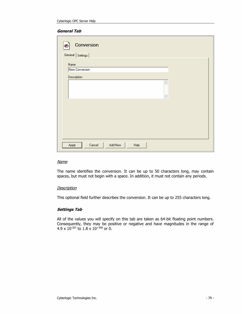
Cyberlogic OPC Server Help
Cyberlogic Technologies Inc. - 79 -
General Tab
Name
The name identifies the conversion. It can be up to 50 characters long, may contain
spaces, but must not begin with a space. In addition, it must not contain any periods.
Description
This optional field further describes the conversion. It can be up to 255 characters long.
Settings Tab
All of the values you will specify on this tab are taken as 64-bit floating point numbers.
Consequently, they may be positive or negative and have magnitudes in the range of 4.9 x 10-307 to 1.8 x 10+308 or 0.
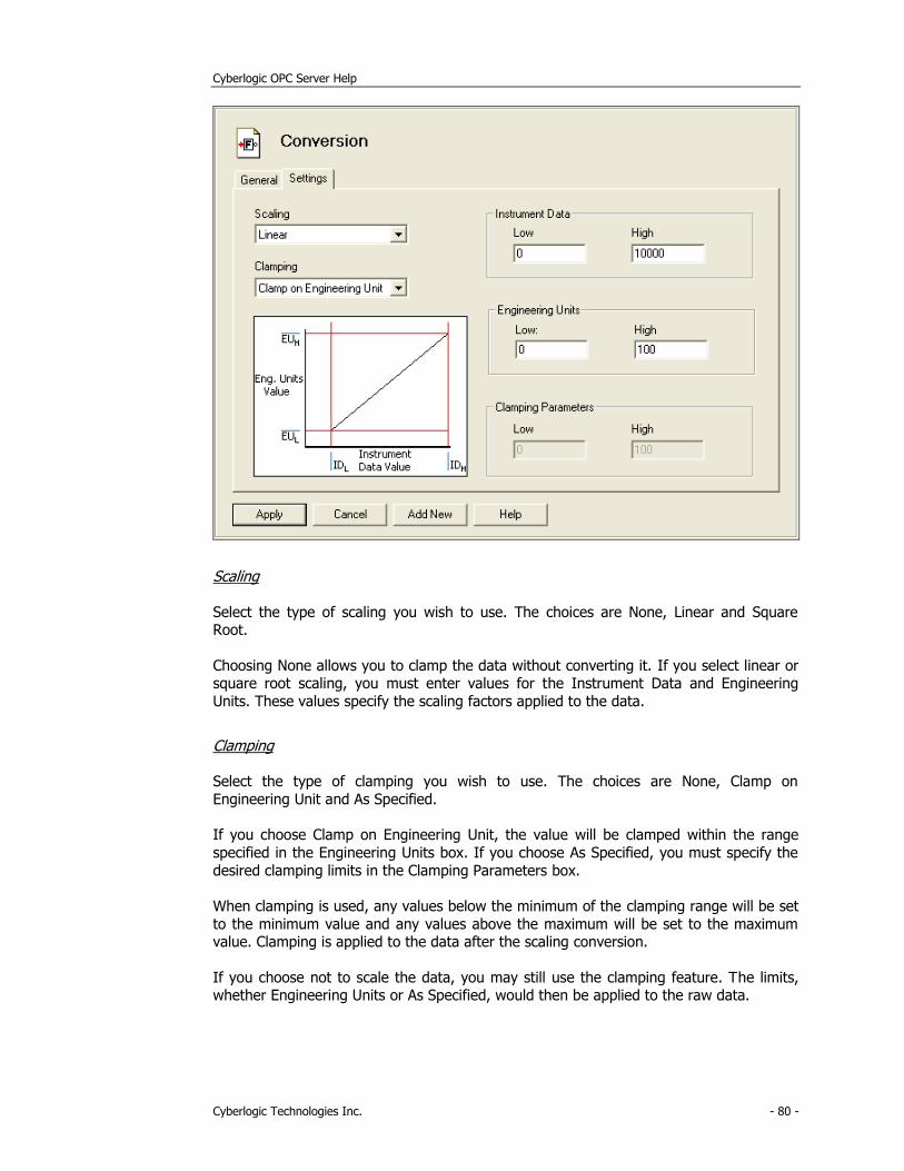
Cyberlogic OPC Server Help
Cyberlogic Technologies Inc. - 80 -
Scaling
Select the type of scaling you wish to use. The choices are None, Linear and Square Root.
Choosing None allows you to clamp the data without converting it. If you select linear or square root scaling, you must enter values for the Instrument Data and Engineering
Units. These values specify the scaling factors applied to the data.
Clamping
Select the type of clamping you wish to use. The choices are None, Clamp on
Engineering Unit and As Specified.
If you choose Clamp on Engineering Unit, the value will be clamped within the range
specified in the Engineering Units box. If you choose As Specified, you must specify the
desired clamping limits in the Clamping Parameters box.
When clamping is used, any values below the minimum of the clamping range will be set
to the minimum value and any values above the maximum will be set to the maximum value. Clamping is applied to the data after the scaling conversion.
If you choose not to scale the data, you may still use the clamping feature. The limits, whether Engineering Units or As Specified, would then be applied to the raw data.
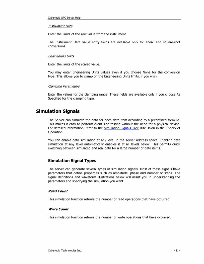
Cyberlogic OPC Server Help
Cyberlogic Technologies Inc. - 81 -
Instrument Data
Enter the limits of the raw value from the instrument.
The Instrument Data value entry fields are available only for linear and square-root conversions.
Engineering Units
Enter the limits of the scaled value.
You may enter Engineering Units values even if you choose None for the conversion
type. This allows you to clamp on the Engineering Units limits, if you wish.
Clamping Parameters
Enter the values for the clamping range. These fields are available only if you choose As Specified for the clamping type.
Simulation Signals
The Server can simulate the data for each data item according to a predefined formula. This makes it easy to perform client-side testing without the need for a physical device.
For detailed information, refer to the Simulation Signals Tree discussion in the Theory of
Operation.
You can enable data simulation at any level in the server address space. Enabling data
simulation at any level automatically enables it at all levels below. This permits quick switching between simulated and real data for a large number of data items.
Simulation Signal Types
The server can generate several types of simulation signals. Most of these signals have parameters that define properties such as amplitude, phase and number of steps. The
signal definitions and waveform illustrations below will assist you in understanding the parameters and specifying the simulation you want.
Read Count
This simulation function returns the number of read operations that have occurred.
Write Count
This simulation function returns the number of write operations that have occurred.
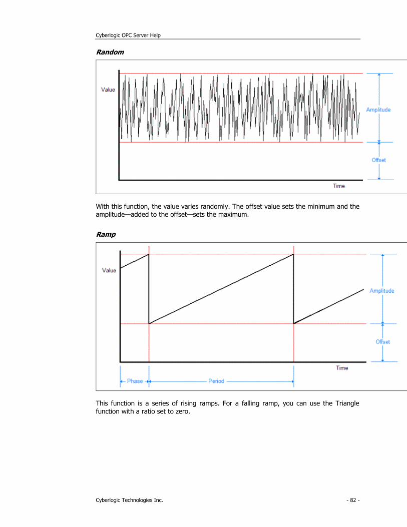
Cyberlogic OPC Server Help
Cyberlogic Technologies Inc. - 82 -
Random
With this function, the value varies randomly. The offset value sets the minimum and the amplitude—added to the offset—sets the maximum.
Ramp
This function is a series of rising ramps. For a falling ramp, you can use the Triangle
function with a ratio set to zero.
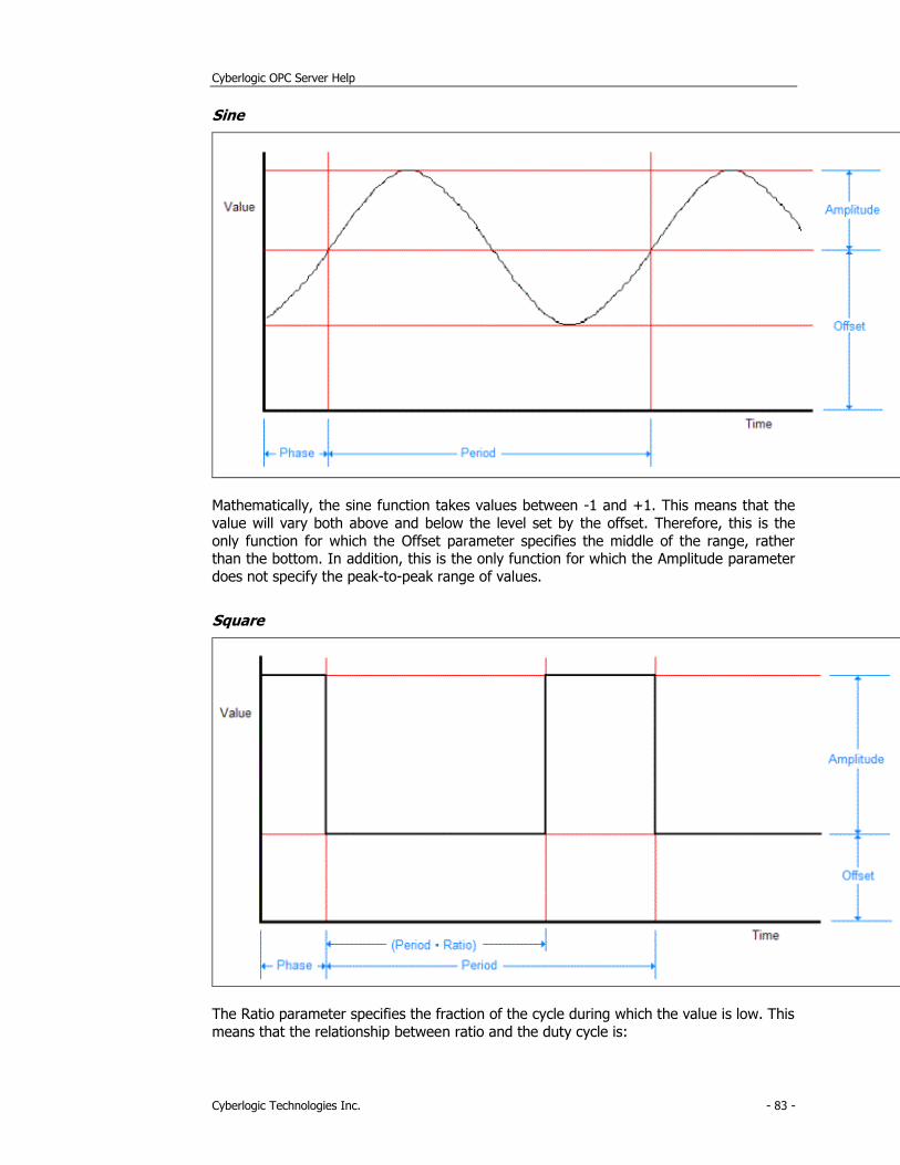
Cyberlogic OPC Server Help
Cyberlogic Technologies Inc. - 83 -
Sine
Mathematically, the sine function takes values between -1 and +1. This means that the
value will vary both above and below the level set by the offset. Therefore, this is the
only function for which the Offset parameter specifies the middle of the range, rather than the bottom. In addition, this is the only function for which the Amplitude parameter
does not specify the peak-to-peak range of values.
Square
The Ratio parameter specifies the fraction of the cycle during which the value is low. This
means that the relationship between ratio and the duty cycle is:
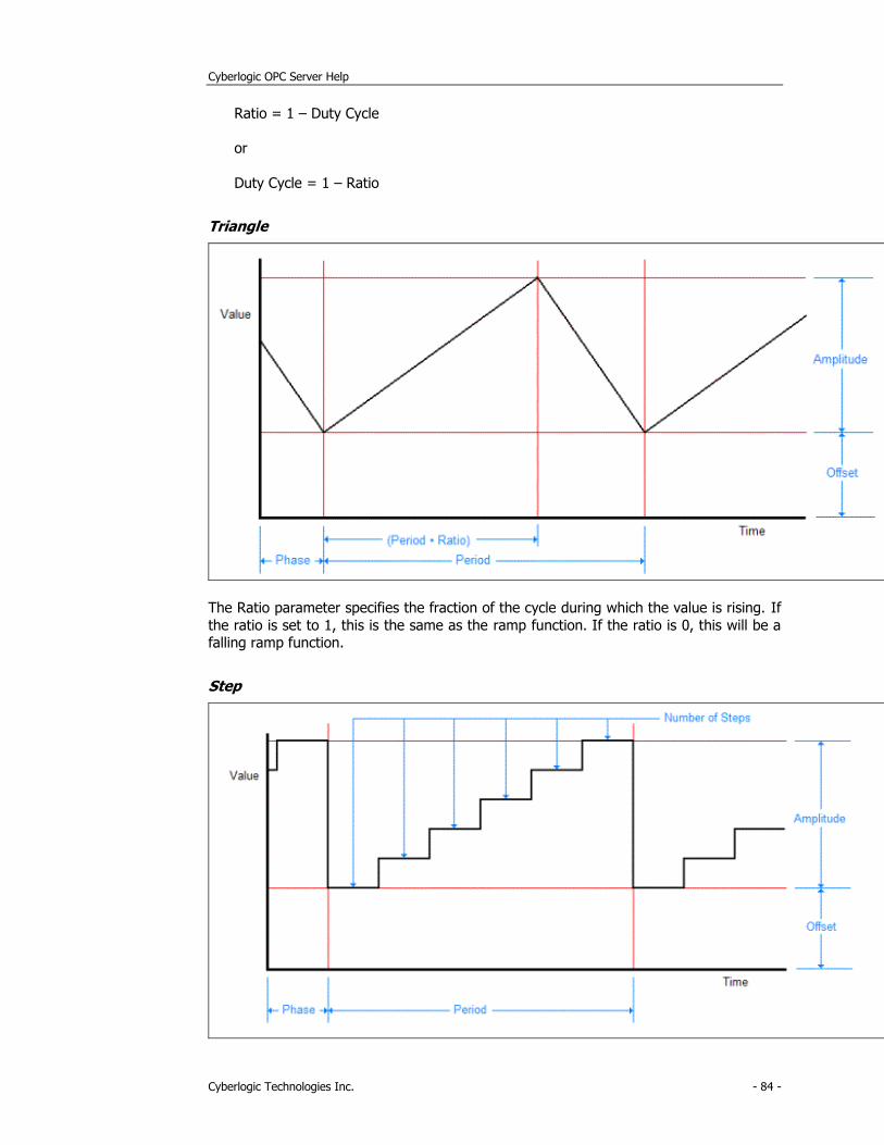
Cyberlogic OPC Server Help
Cyberlogic Technologies Inc. - 84 -
Ratio = 1 – Duty Cycle
or
Duty Cycle = 1 – Ratio
Triangle
The Ratio parameter specifies the fraction of the cycle during which the value is rising. If
the ratio is set to 1, this is the same as the ramp function. If the ratio is 0, this will be a falling ramp function.
Step
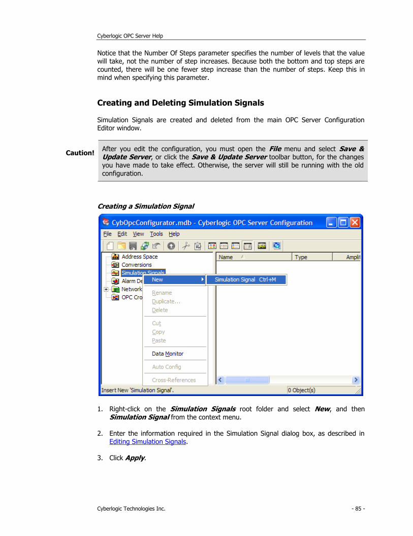
Cyberlogic OPC Server Help
Cyberlogic Technologies Inc. - 85 -
Notice that the Number Of Steps parameter specifies the number of levels that the value will take, not the number of step increases. Because both the bottom and top steps are
counted, there will be one fewer step increase than the number of steps. Keep this in mind when specifying this parameter.
Creating and Deleting Simulation Signals
Simulation Signals are created and deleted from the main OPC Server Configuration Editor window.
Caution! After you edit the configuration, you must open the File menu and select Save & Update Server, or click the Save & Update Server toolbar button, for the changes
you have made to take effect. Otherwise, the server will still be running with the old
configuration.
Creating a Simulation Signal
1. Right-click on the Simulation Signals root folder and select New, and then
Simulation Signal from the context menu.
2. Enter the information required in the Simulation Signal dialog box, as described in
Editing Simulation Signals.
3. Click Apply.
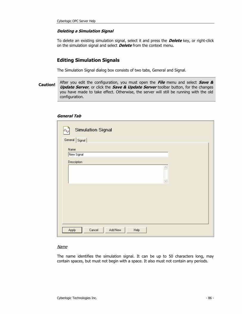
Cyberlogic OPC Server Help
Cyberlogic Technologies Inc. - 86 -
Deleting a Simulation Signal
To delete an existing simulation signal, select it and press the Delete key, or right-click
on the simulation signal and select Delete from the context menu.
Editing Simulation Signals
The Simulation Signal dialog box consists of two tabs, General and Signal.
Caution! After you edit the configuration, you must open the File menu and select Save & Update Server, or click the Save & Update Server toolbar button, for the changes
you have made to take effect. Otherwise, the server will still be running with the old
configuration.
General Tab
Name
The name identifies the simulation signal. It can be up to 50 characters long, may
contain spaces, but must not begin with a space. It also must not contain any periods.
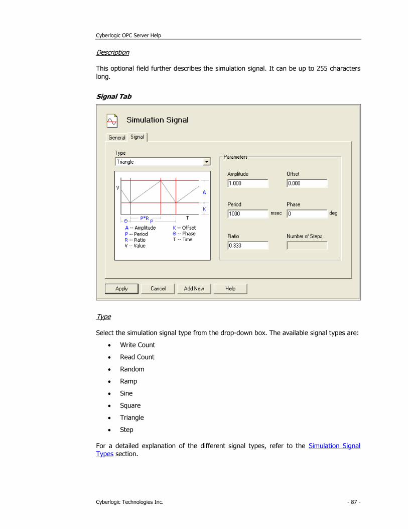
Cyberlogic OPC Server Help
Cyberlogic Technologies Inc. - 87 -
Description
This optional field further describes the simulation signal. It can be up to 255 characters
long.
Signal Tab
Type
Select the simulation signal type from the drop-down box. The available signal types are:
• Write Count
• Read Count
• Random
• Ramp
• Sine
• Square
• Triangle
• Step
For a detailed explanation of the different signal types, refer to the Simulation Signal Types section.
Cyberlogic OPC Server Help
Cyberlogic Technologies Inc. - 88 -
The signal type selection will enable the needed parameter fields, if any. You must enter the values for the parameter fields that are not dimmed.
Amplitude
This is the peak value of the signal, measured from the offset level.
All signal types except Write Count and Read Count use this parameter.
Offset
This is a fixed offset for the value of the data item. The generated waveform varies
around this value.
All signal types except Write Count and Read Count use this parameter.
Period
This is the period of one cycle of the waveform, specified in milliseconds.
The Ramp, Sine, Square, Triangle and Step functions use this parameter.
Phase
This is a phase offset for the waveform, specified in degrees. The value you specify will
be taken as a leading phase shift and cannot be a negative number. To create a lagging phase shift, subtract the desired shift from 360. For example, if you want a leading shift
of 20 degrees, you would enter 20. If you want a lagging shift of 20 degrees, you would
enter 340.
The Ramp, Sine, Square, Triangle and Step functions use this parameter.
Ratio
This is a decimal fraction between 0 and 1.
For the Square function, it specifies the fraction of the cycle during which the value is at the low level. A Square function with a period of 1000 ms and a ratio of 0.4 would be low
for 400 ms and high for 600 ms.
For the Triangle function, it specifies the fraction of the cycle during which the signal is rising. A Triangle function with a period of 1000 ms and a ratio of 0.4 would rise for
400 ms and fall for 600 ms.
Only the Square and Triangle functions use this parameter.
Number of Steps
Only the Step function uses this parameter. It specifies the number of value levels in each signal period. The steps are of equal height and width.
Cyberlogic OPC Server Help
Cyberlogic Technologies Inc. - 89 -
Alarm Definitions
The Cyberlogic OPC Server supports the OPC Alarms and Events specification. If your
client application is also OPC AE compliant, it will then be able to receive the alarms and
events reported by the server. The user may define many different alarm conditions. A number of data items can then use each such condition. As a result, the user need not
define the same alarm condition many times over.
Alarm Definition Types
There are two categories of alarms: limit and digital. Limit alarms are normally used for
numeric data, and digital alarms are normally used for Boolean data, but either alarm type may be used with either data type. Alarms may not be used with string data, arrays
or bit fields greater than 64 bits.
Limit Alarms
Limit alarms divide the range of values for the data item into five alarm states: LoLo, Lo,
Normal, Hi and HiHi. These are normally used for numeric data items.
If you use a limit alarm with a Boolean data item, the software will convert its state to a
numeric value before checking for alarm conditions. A value of false will be converted to 0 and a value of true will be converted to -1.
Each alarm state allows you to designate a message and a severity level. You may also indicate whether the alarm requires a client-side acknowledgment. If you wish, you can
specify a deadband value. The deadband prevents the server from generating a large
number of alarm messages when the signal jitters around one of the limits.
Digital Alarms
Digital alarms specify an alarm that must occur when a value is either true or false, and so they are normally used with Boolean data items.
If you use a Digital Alarm with a numeric data item, a value of 0 is treated as false and
any other value is treated as true.
Each alarm state allows you to designate a message and a severity level. You may also
indicate whether the alarm requires a client-side acknowledgment. If desired, you can have the server generate an alarm when the data item returns to its normal value.
Creating and Deleting Alarm Definitions
Alarms are created and deleted from the main OPC Server Configuration Editor window.
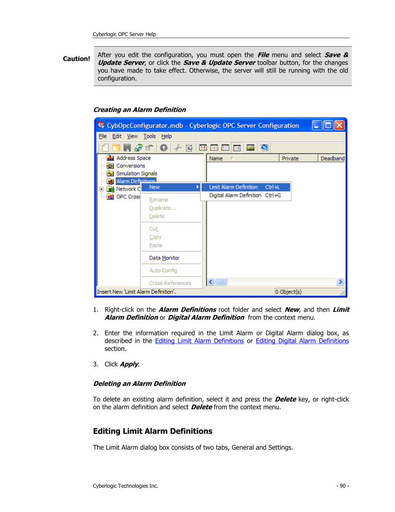
Cyberlogic OPC Server Help
Cyberlogic Technologies Inc. - 90 -
Caution! After you edit the configuration, you must open the File menu and select Save & Update Server, or click the Save & Update Server toolbar button, for the changes
you have made to take effect. Otherwise, the server will still be running with the old
configuration.
Creating an Alarm Definition
1. Right-click on the Alarm Definitions root folder and select New, and then Limit Alarm Definition or Digital Alarm Definition from the context menu.
2. Enter the information required in the Limit Alarm or Digital Alarm dialog box, as described in the Editing Limit Alarm Definitions or Editing Digital Alarm Definitions
section.
3. Click Apply.
Deleting an Alarm Definition
To delete an existing alarm definition, select it and press the Delete key, or right-click on the alarm definition and select Delete from the context menu.
Editing Limit Alarm Definitions
The Limit Alarm dialog box consists of two tabs, General and Settings.
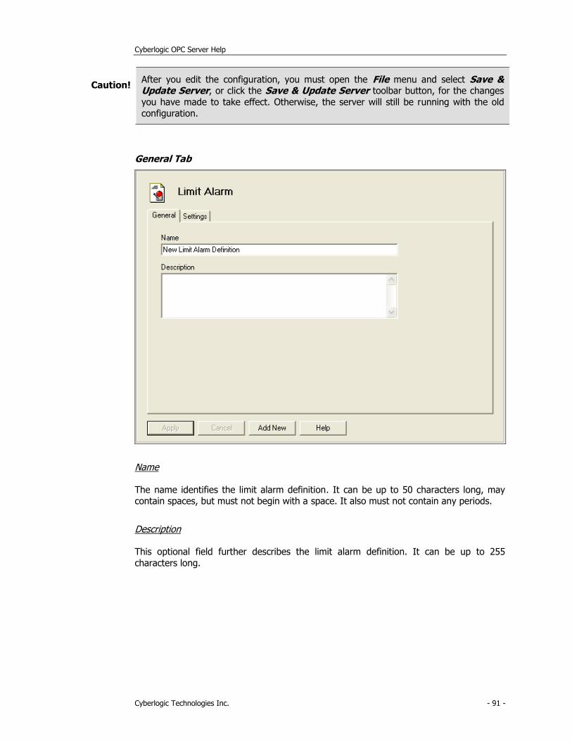
Cyberlogic OPC Server Help
Cyberlogic Technologies Inc. - 91 -
Caution! After you edit the configuration, you must open the File menu and select Save & Update Server, or click the Save & Update Server toolbar button, for the changes
you have made to take effect. Otherwise, the server will still be running with the old
configuration.
General Tab
Name
The name identifies the limit alarm definition. It can be up to 50 characters long, may contain spaces, but must not begin with a space. It also must not contain any periods.
Description
This optional field further describes the limit alarm definition. It can be up to 255
characters long.
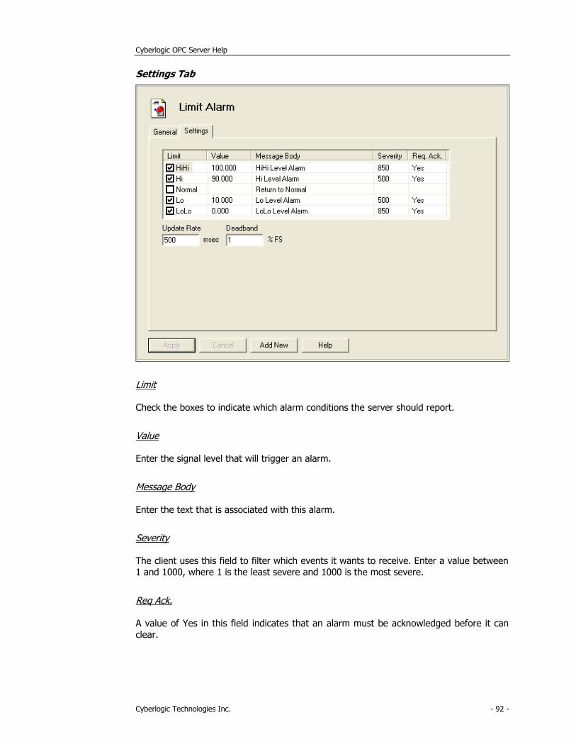
Cyberlogic OPC Server Help
Cyberlogic Technologies Inc. - 92 -
Settings Tab
Limit
Check the boxes to indicate which alarm conditions the server should report.
Value
Enter the signal level that will trigger an alarm.
Message Body
Enter the text that is associated with this alarm.
Severity
The client uses this field to filter which events it wants to receive. Enter a value between 1 and 1000, where 1 is the least severe and 1000 is the most severe.
Req Ack.
A value of Yes in this field indicates that an alarm must be acknowledged before it can clear.
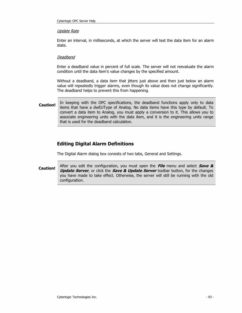
Cyberlogic OPC Server Help
Cyberlogic Technologies Inc. - 93 -
Update Rate
Enter an interval, in milliseconds, at which the server will test the data item for an alarm
state.
Deadband
Enter a deadband value in percent of full scale. The server will not reevaluate the alarm
condition until the data item’s value changes by the specified amount.
Without a deadband, a data item that jitters just above and then just below an alarm
value will repeatedly trigger alarms, even though its value does not change significantly. The deadband helps to prevent this from happening.
Caution! In keeping with the OPC specifications, the deadband functions apply only to data items that have a dwEUType of Analog. No data items have this type by default. To
convert a data item to Analog, you must apply a conversion to it. This allows you to associate engineering units with the data item, and it is the engineering units range
that is used for the deadband calculation.
Editing Digital Alarm Definitions
The Digital Alarm dialog box consists of two tabs, General and Settings.
Caution! After you edit the configuration, you must open the File menu and select Save & Update Server, or click the Save & Update Server toolbar button, for the changes
you have made to take effect. Otherwise, the server will still be running with the old
configuration.
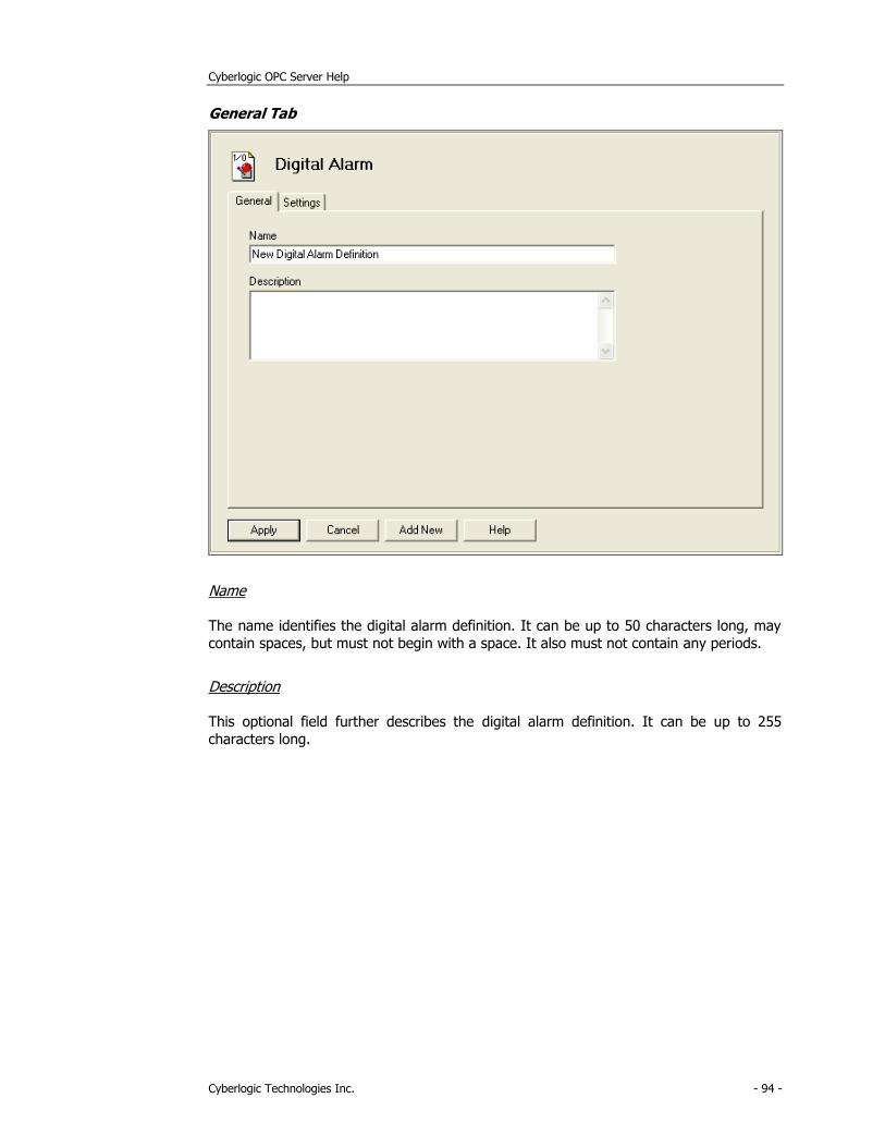
Cyberlogic OPC Server Help
Cyberlogic Technologies Inc. - 94 -
General Tab
Name
The name identifies the digital alarm definition. It can be up to 50 characters long, may
contain spaces, but must not begin with a space. It also must not contain any periods.
Description
This optional field further describes the digital alarm definition. It can be up to 255
characters long.
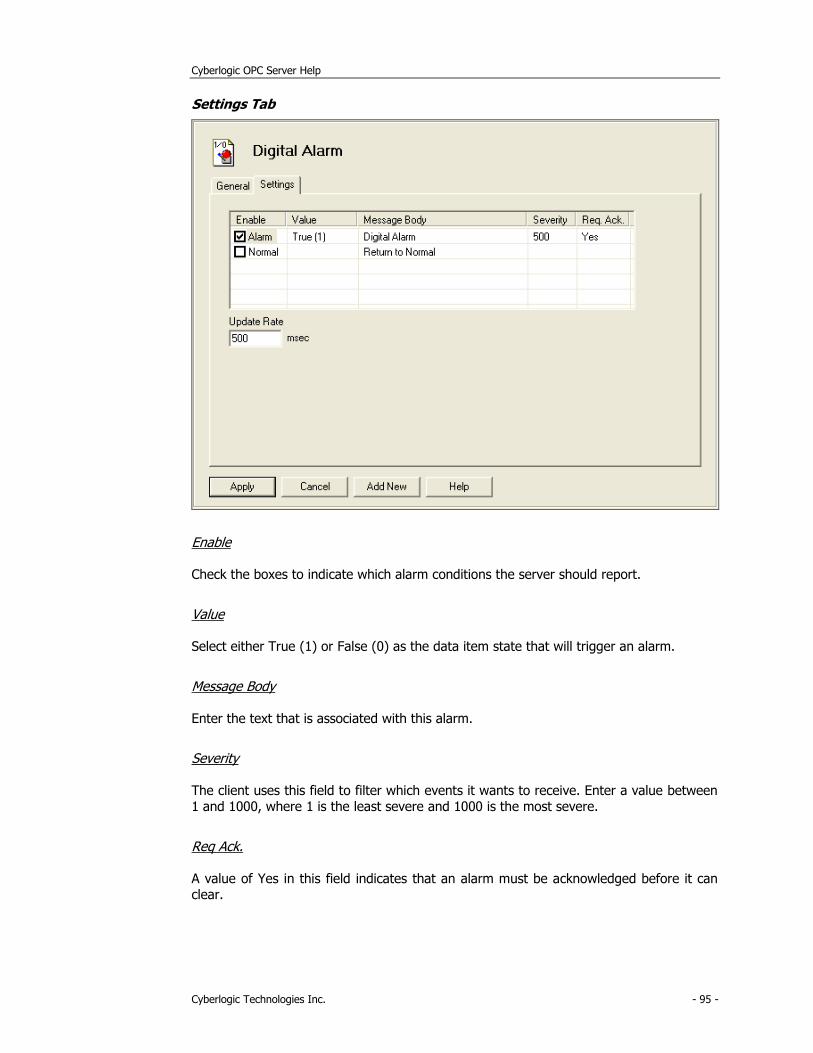
Cyberlogic OPC Server Help
Cyberlogic Technologies Inc. - 95 -
Settings Tab
Enable
Check the boxes to indicate which alarm conditions the server should report.
Value
Select either True (1) or False (0) as the data item state that will trigger an alarm.
Message Body
Enter the text that is associated with this alarm.
Severity
The client uses this field to filter which events it wants to receive. Enter a value between 1 and 1000, where 1 is the least severe and 1000 is the most severe.
Req Ack.
A value of Yes in this field indicates that an alarm must be acknowledged before it can clear.
Cyberlogic OPC Server Help
Cyberlogic Technologies Inc. - 96 -
Update Rate
Enter an interval, in milliseconds, at which the server will test the data item for an alarm
state.
Database Operations
In addition to providing data to OPC clients in real time, the Cyberlogic OPC Server can
store it in a database. The feature that does this is called Data Logger. Once the data is logged, it is available to any application that can access that database. It need not be an
OPC client application.
Refer to the Data Logger Help for a full discussion.
OPC Crosslinks
This is where you can set up data transfers between PLCs and OPC servers. Before you
can configure crosslinks, you must first configure the network connections to the desired PLCs or OPC servers. You must also configure address space data items to serve as the
crosslink inputs and outputs.
Refer to the OPC Crosslink Help for a full discussion.
Saving and Undoing Configuration Changes
The Cyberlogic OPC Server Configuration Editor keeps track of recent configuration
changes. Until you save these changes, you can revert to the previously saved configuration. The editor supports two types of save operations. The standard Save
operation saves the changes without updating the server or the connected clients. The
Save & Update Server operation saves the changes and also updates the server and all connected clients.
Caution! After you edit the configuration, you must open the File menu and select Save & Update Server, or click the Save & Update Server toolbar button, for the changes
you have made to take effect. Otherwise, the server will still be running with the old
configuration.
Saving Configuration Changes Without Updating the Server
To save the configuration without updating the server, open the File menu and select
Save, or click the Save button on the toolbar. The changes will be saved but the server will still be running with the old configuration.
Cyberlogic OPC Server Help
Cyberlogic Technologies Inc. - 97 -
Saving Configuration Changes and Updating Server
To save the configuration and update the server, open the File menu and select Save & Update Server, or click the Save & Update Server button on the toolbar.
Undoing Configuration Changes
To undo configuration changes and revert to the previously saved configuration, open
the File menu and select Undo Changes, or click the Undo Changes button on the toolbar.
Configuration Import/Export
The Cyberlogic OPC Server normally stores its configuration information in a binary file. The Cyberlogic OPC Server Configuration Editor and the runtime server module can easily
read and operate on this file. However, a different file format may be preferred for quick viewing or processing by other applications.
The Export feature allows the entire server configuration to be saved in three text formats: comma delimited (.csv), tab delimited (.tab) and XML.
The Import feature allows you to import these exported files or selected portions of
them. You may also import configurations from other vendors’ OPC servers.
The import/export capability of the Cyberlogic OPC Server Configuration Editor reduces
the time and effort required to configure the server. In addition, it can speed up the configuration of similar Cyberlogic OPC Servers and is useful for backing up and restoring
server configurations. Furthermore, because it can import configurations from other OPC
server brands, it can greatly reduce the effort needed to migrate from those servers to Cyberlogic’s OPC Server.
Note To provide better results, the import process performs verification tests on the
imported data. On slower systems, those with relatively low memory or those that are
running other tasks concurrently, importing a configuration can take a significant length of time. You should take this into consideration when choosing the system to
use for running the import operation.
Exporting a Server Configuration
This feature exports an entire server configuration to one of the supported file formats.
1. Open the File menu and select Export… .
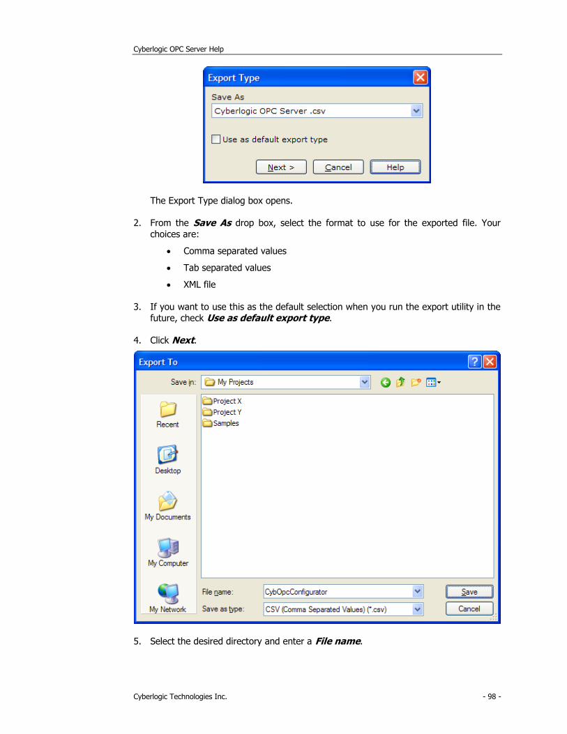
Cyberlogic OPC Server Help
Cyberlogic Technologies Inc. - 98 -
The Export Type dialog box opens.
2. From the Save As drop box, select the format to use for the exported file. Your
choices are:
• Comma separated values
• Tab separated values
• XML file
3. If you want to use this as the default selection when you run the export utility in the
future, check Use as default export type.
4. Click Next.
5. Select the desired directory and enter a File name.
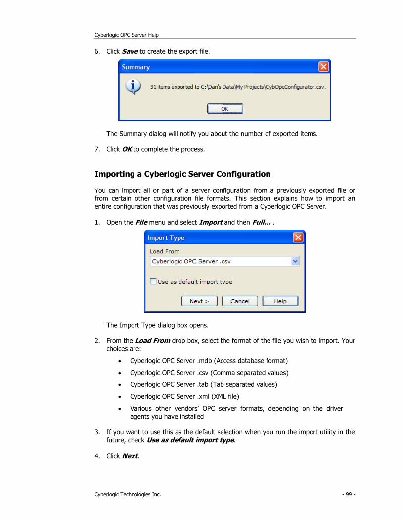
Cyberlogic OPC Server Help
Cyberlogic Technologies Inc. - 99 -
6. Click Save to create the export file.
The Summary dialog will notify you about the number of exported items.
7. Click OK to complete the process.
Importing a Cyberlogic Server Configuration
You can import all or part of a server configuration from a previously exported file or from certain other configuration file formats. This section explains how to import an
entire configuration that was previously exported from a Cyberlogic OPC Server.
1. Open the File menu and select Import and then Full… .
The Import Type dialog box opens.
2. From the Load From drop box, select the format of the file you wish to import. Your
choices are:
• Cyberlogic OPC Server .mdb (Access database format)
• Cyberlogic OPC Server .csv (Comma separated values)
• Cyberlogic OPC Server .tab (Tab separated values)
• Cyberlogic OPC Server .xml (XML file)
• Various other vendors’ OPC server formats, depending on the driver
agents you have installed
3. If you want to use this as the default selection when you run the import utility in the
future, check Use as default import type.
4. Click Next.
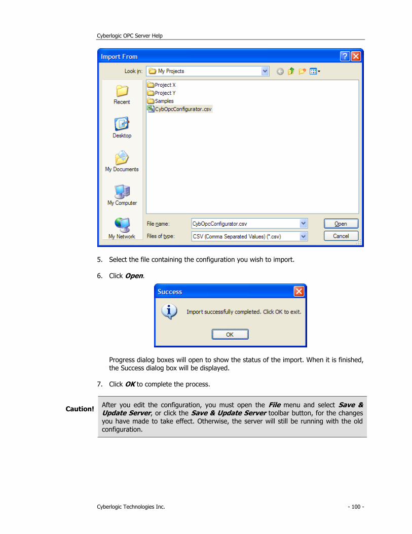
Cyberlogic OPC Server Help
Cyberlogic Technologies Inc. - 100 -
5. Select the file containing the configuration you wish to import.
6. Click Open.
Progress dialog boxes will open to show the status of the import. When it is finished,
the Success dialog box will be displayed.
7. Click OK to complete the process.
Caution! After you edit the configuration, you must open the File menu and select Save & Update Server, or click the Save & Update Server toolbar button, for the changes
you have made to take effect. Otherwise, the server will still be running with the old
configuration.
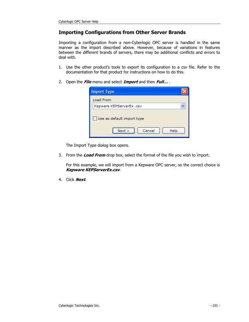
Cyberlogic OPC Server Help
Cyberlogic Technologies Inc. - 101 -
Importing Configurations from Other Server Brands
Importing a configuration from a non-Cyberlogic OPC server is handled in the same
manner as the import described above. However, because of variations in features between the different brands of servers, there may be additional conflicts and errors to
deal with.
1. Use the other product’s tools to export its configuration to a csv file. Refer to the documentation for that product for instructions on how to do this.
2. Open the File menu and select Import and then Full… .
The Import Type dialog box opens.
3. From the Load From drop box, select the format of the file you wish to import.
For this example, we will import from a Kepware OPC server, so the correct choice is Kepware KEPServerEx.csv.
4. Click Next.
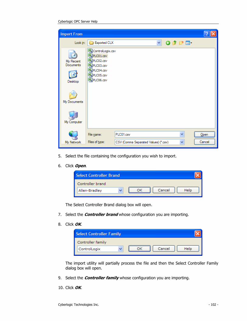
Cyberlogic OPC Server Help
Cyberlogic Technologies Inc. - 102 -
5. Select the file containing the configuration you wish to import.
6. Click Open.
The Select Controller Brand dialog box will open.
7. Select the Controller brand whose configuration you are importing.
8. Click OK.
The import utility will partially process the file and then the Select Controller Family
dialog box will open.
9. Select the Controller family whose configuration you are importing.
10. Click OK.
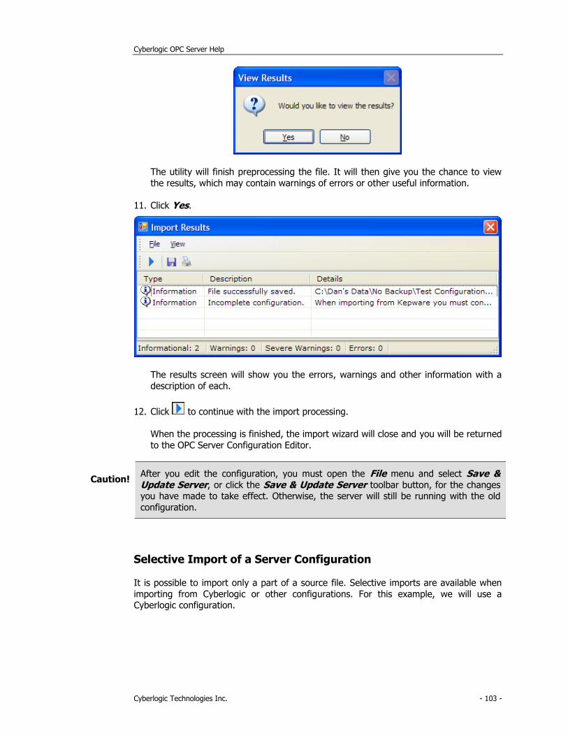
Cyberlogic OPC Server Help
Cyberlogic Technologies Inc. - 103 -
The utility will finish preprocessing the file. It will then give you the chance to view
the results, which may contain warnings of errors or other useful information.
11. Click Yes.
The results screen will show you the errors, warnings and other information with a
description of each.
12. Click to continue with the import processing.
When the processing is finished, the import wizard will close and you will be returned
to the OPC Server Configuration Editor.
Caution! After you edit the configuration, you must open the File menu and select Save & Update Server, or click the Save & Update Server toolbar button, for the changes you have made to take effect. Otherwise, the server will still be running with the old
configuration.
Selective Import of a Server Configuration
It is possible to import only a part of a source file. Selective imports are available when
importing from Cyberlogic or other configurations. For this example, we will use a Cyberlogic configuration.
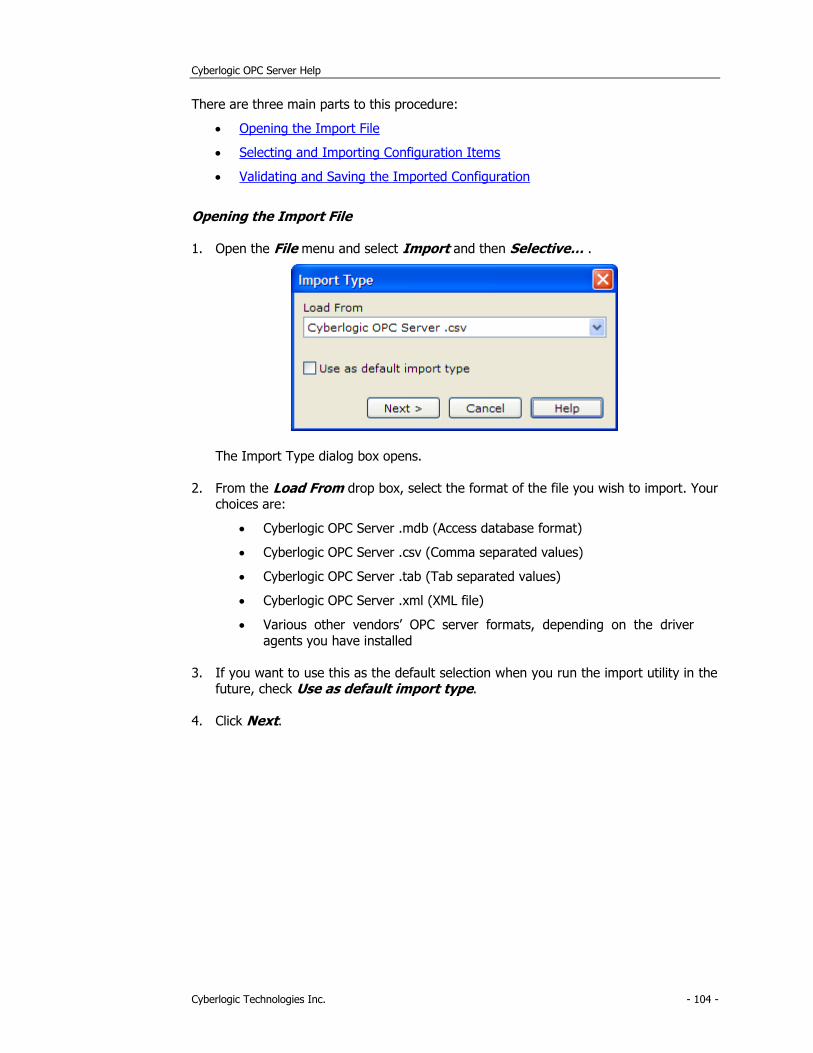
Cyberlogic OPC Server Help
Cyberlogic Technologies Inc. - 104 -
There are three main parts to this procedure:
• Opening the Import File
• Selecting and Importing Configuration Items
• Validating and Saving the Imported Configuration
Opening the Import File
1. Open the File menu and select Import and then Selective… .
The Import Type dialog box opens.
2. From the Load From drop box, select the format of the file you wish to import. Your choices are:
• Cyberlogic OPC Server .mdb (Access database format)
• Cyberlogic OPC Server .csv (Comma separated values)
• Cyberlogic OPC Server .tab (Tab separated values)
• Cyberlogic OPC Server .xml (XML file)
• Various other vendors’ OPC server formats, depending on the driver
agents you have installed
3. If you want to use this as the default selection when you run the import utility in the future, check Use as default import type.
4. Click Next.
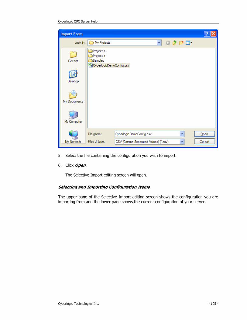
Cyberlogic OPC Server Help
Cyberlogic Technologies Inc. - 105 -
5. Select the file containing the configuration you wish to import.
6. Click Open.
The Selective Import editing screen will open.
Selecting and Importing Configuration Items
The upper pane of the Selective Import editing screen shows the configuration you are importing from and the lower pane shows the current configuration of your server.
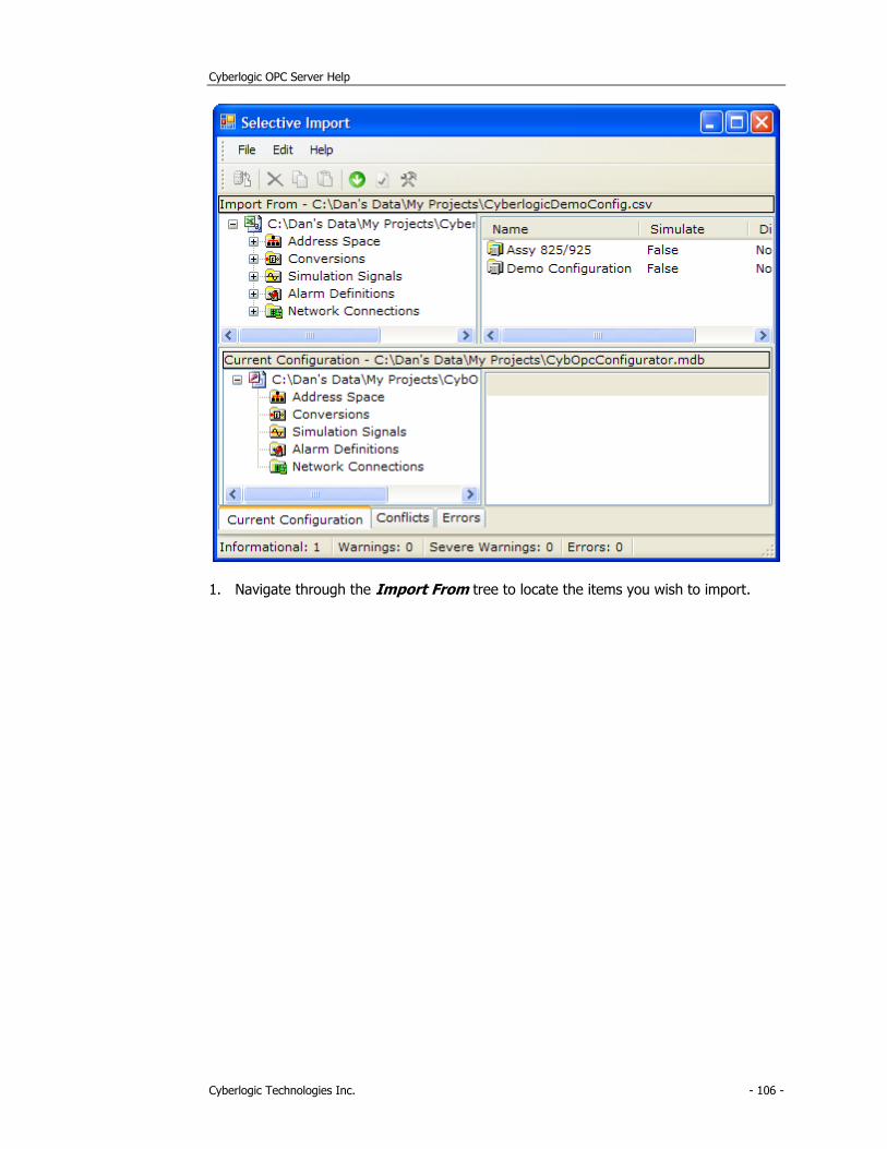
Cyberlogic OPC Server Help
Cyberlogic Technologies Inc. - 106 -
1. Navigate through the Import From tree to locate the items you wish to import.
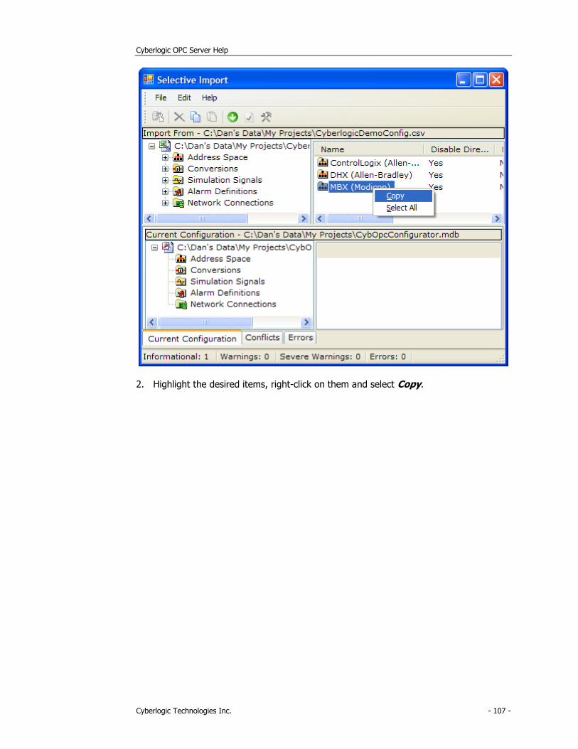
Cyberlogic OPC Server Help
Cyberlogic Technologies Inc. - 107 -
2. Highlight the desired items, right-click on them and select Copy.
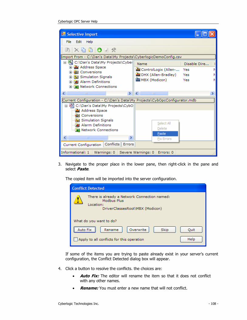
Cyberlogic OPC Server Help
Cyberlogic Technologies Inc. - 108 -
3. Navigate to the proper place in the lower pane, then right-click in the pane and select Paste.
The copied item will be imported into the server configuration.
If some of the items you are trying to paste already exist in your server’s current configuration, the Conflict Detected dialog box will appear.
4. Click a button to resolve the conflicts. the choices are:
• Auto Fix: The editor will rename the item so that it does not conflict with any other names.
• Rename: You must enter a new name that will not conflict.
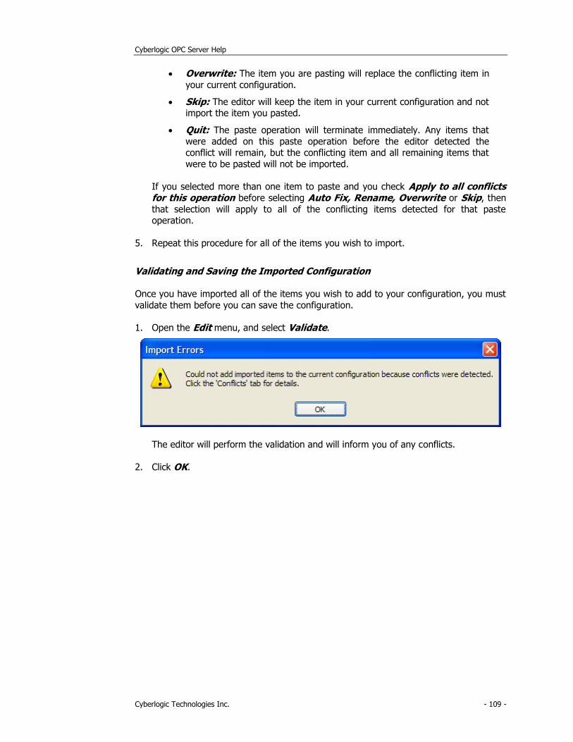
Cyberlogic OPC Server Help
Cyberlogic Technologies Inc. - 109 -
• Overwrite: The item you are pasting will replace the conflicting item in
your current configuration.
• Skip: The editor will keep the item in your current configuration and not import the item you pasted.
• Quit: The paste operation will terminate immediately. Any items that
were added on this paste operation before the editor detected the conflict will remain, but the conflicting item and all remaining items that
were to be pasted will not be imported.
If you selected more than one item to paste and you check Apply to all conflicts for this operation before selecting Auto Fix, Rename, Overwrite or Skip, then
that selection will apply to all of the conflicting items detected for that paste operation.
5. Repeat this procedure for all of the items you wish to import.
Validating and Saving the Imported Configuration
Once you have imported all of the items you wish to add to your configuration, you must
validate them before you can save the configuration.
1. Open the Edit menu, and select Validate.
The editor will perform the validation and will inform you of any conflicts.
2. Click OK.
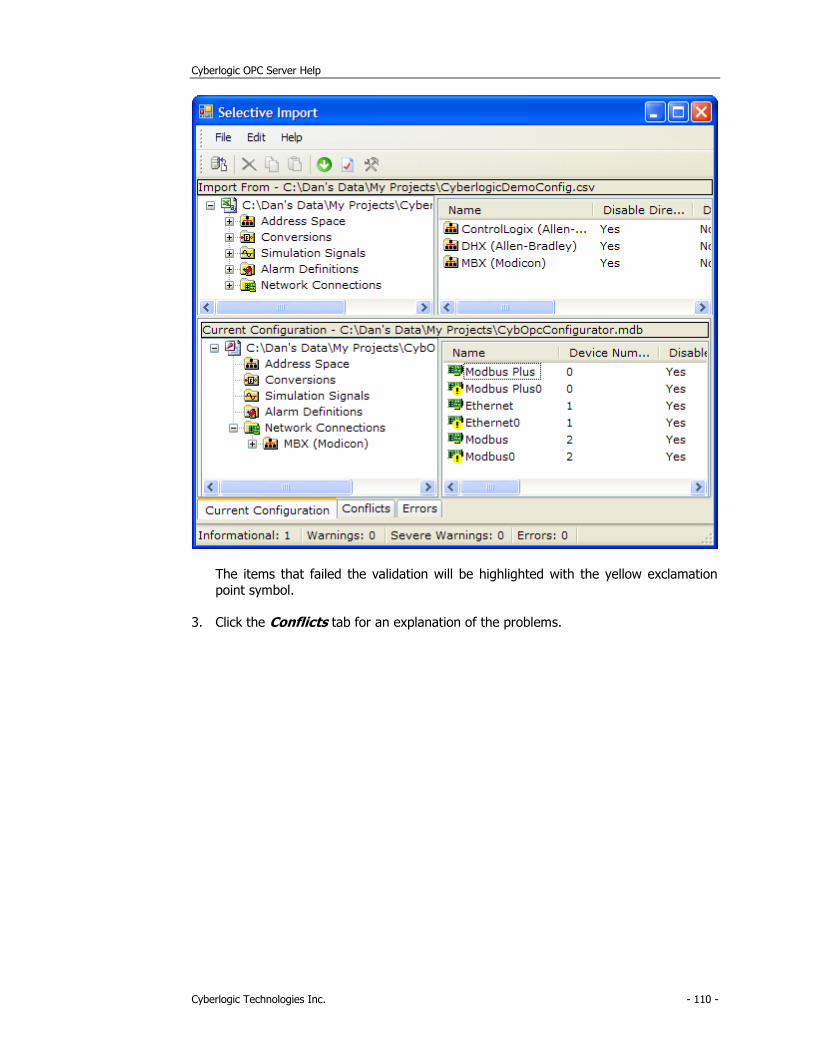
Cyberlogic OPC Server Help
Cyberlogic Technologies Inc. - 110 -
The items that failed the validation will be highlighted with the yellow exclamation
point symbol.
3. Click the Conflicts tab for an explanation of the problems.
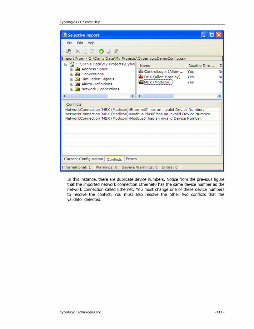
Cyberlogic OPC Server Help
Cyberlogic Technologies Inc. - 111 -
In this instance, there are duplicate device numbers. Notice from the previous figure
that the imported network connection Ethernet0 has the same device number as the
network connection called Ethernet. You must change one of these device numbers to resolve the conflict. You must also resolve the other two conflicts that the
validator detected.
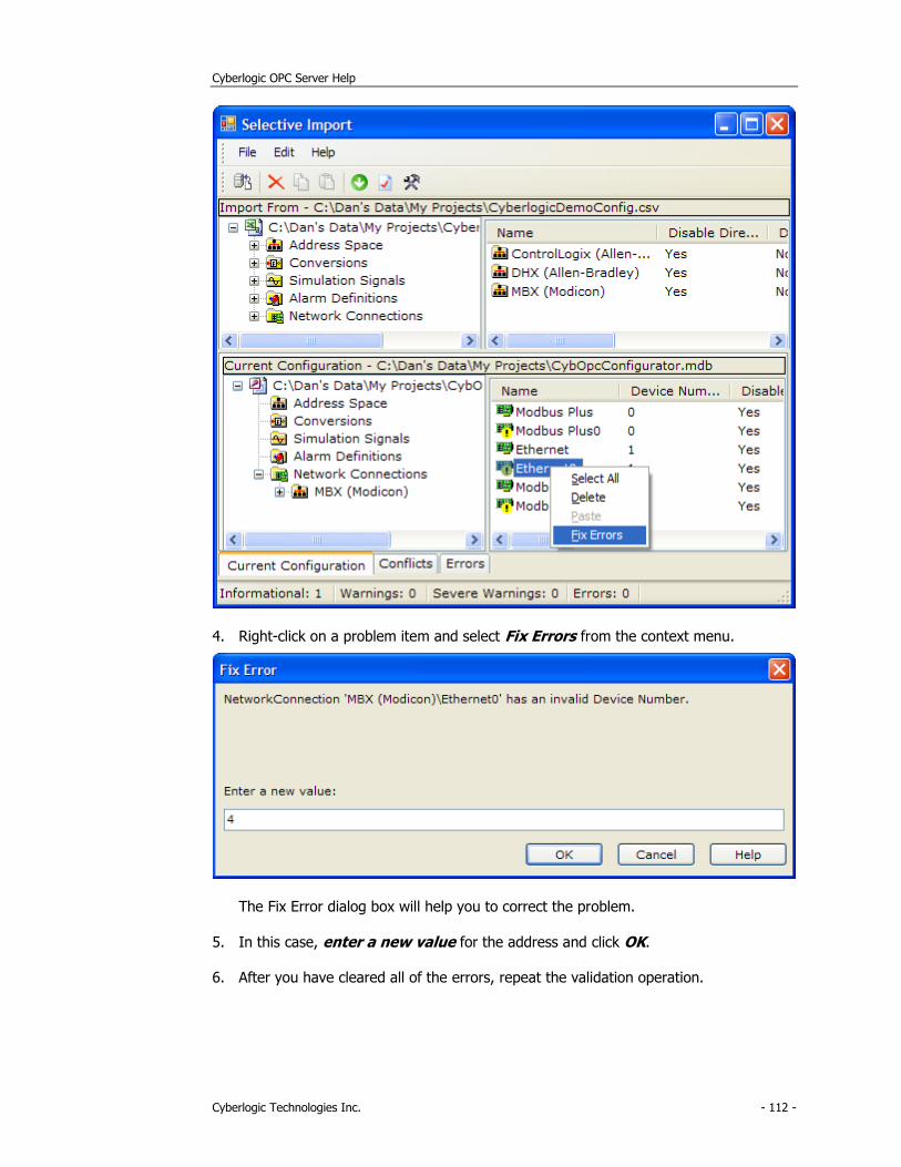
Cyberlogic OPC Server Help
Cyberlogic Technologies Inc. - 112 -
4. Right-click on a problem item and select Fix Errors from the context menu.
The Fix Error dialog box will help you to correct the problem.
5. In this case, enter a new value for the address and click OK.
6. After you have cleared all of the errors, repeat the validation operation.
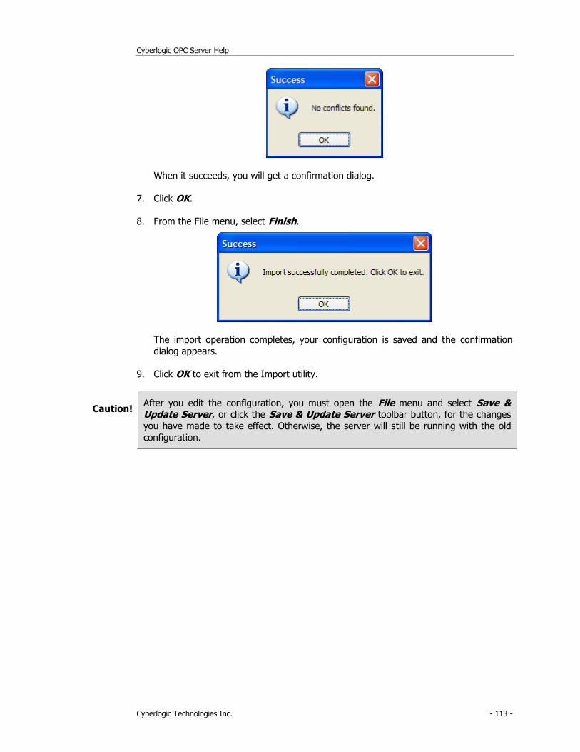
Cyberlogic OPC Server Help
Cyberlogic Technologies Inc. - 113 -
When it succeeds, you will get a confirmation dialog.
7. Click OK.
8. From the File menu, select Finish.
The import operation completes, your configuration is saved and the confirmation
dialog appears.
9. Click OK to exit from the Import utility.
Caution! After you edit the configuration, you must open the File menu and select Save & Update Server, or click the Save & Update Server toolbar button, for the changes
you have made to take effect. Otherwise, the server will still be running with the old
configuration.
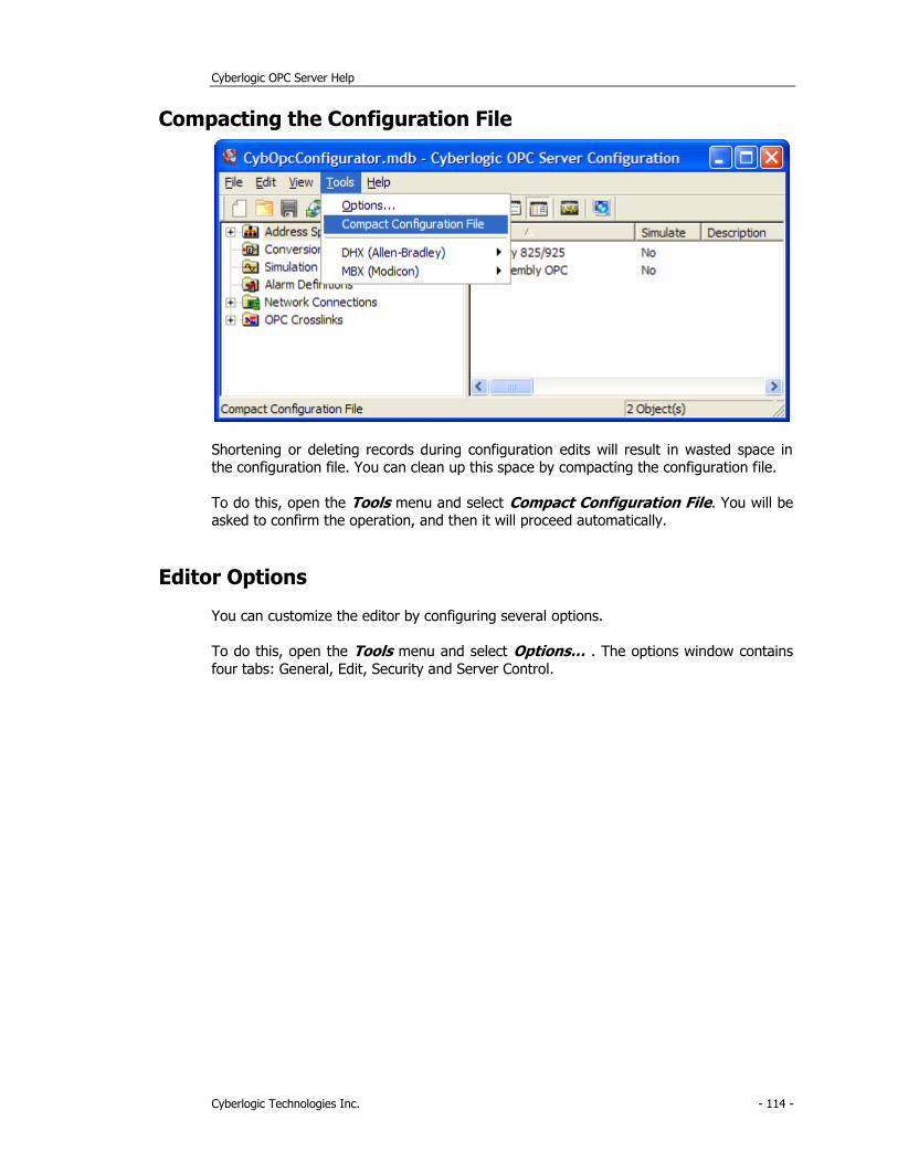
Cyberlogic OPC Server Help
Cyberlogic Technologies Inc. - 114 -
Compacting the Configuration File
Shortening or deleting records during configuration edits will result in wasted space in the configuration file. You can clean up this space by compacting the configuration file.
To do this, open the Tools menu and select Compact Configuration File. You will be asked to confirm the operation, and then it will proceed automatically.
Editor Options
You can customize the editor by configuring several options.
To do this, open the Tools menu and select Options… . The options window contains
four tabs: General, Edit, Security and Server Control.
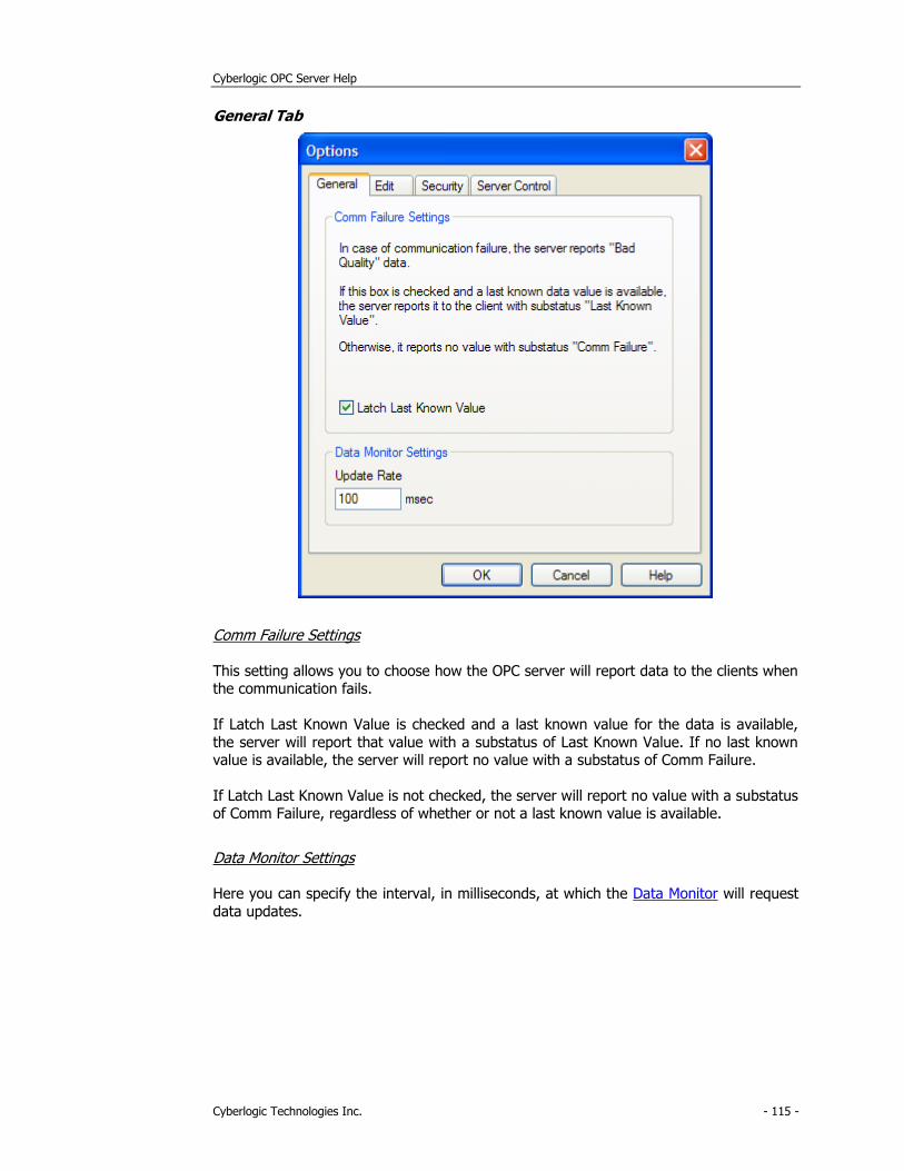
Cyberlogic OPC Server Help
Cyberlogic Technologies Inc. - 115 -
General Tab
Comm Failure Settings
This setting allows you to choose how the OPC server will report data to the clients when the communication fails.
If Latch Last Known Value is checked and a last known value for the data is available,
the server will report that value with a substatus of Last Known Value. If no last known value is available, the server will report no value with a substatus of Comm Failure.
If Latch Last Known Value is not checked, the server will report no value with a substatus of Comm Failure, regardless of whether or not a last known value is available.
Data Monitor Settings
Here you can specify the interval, in milliseconds, at which the Data Monitor will request
data updates.
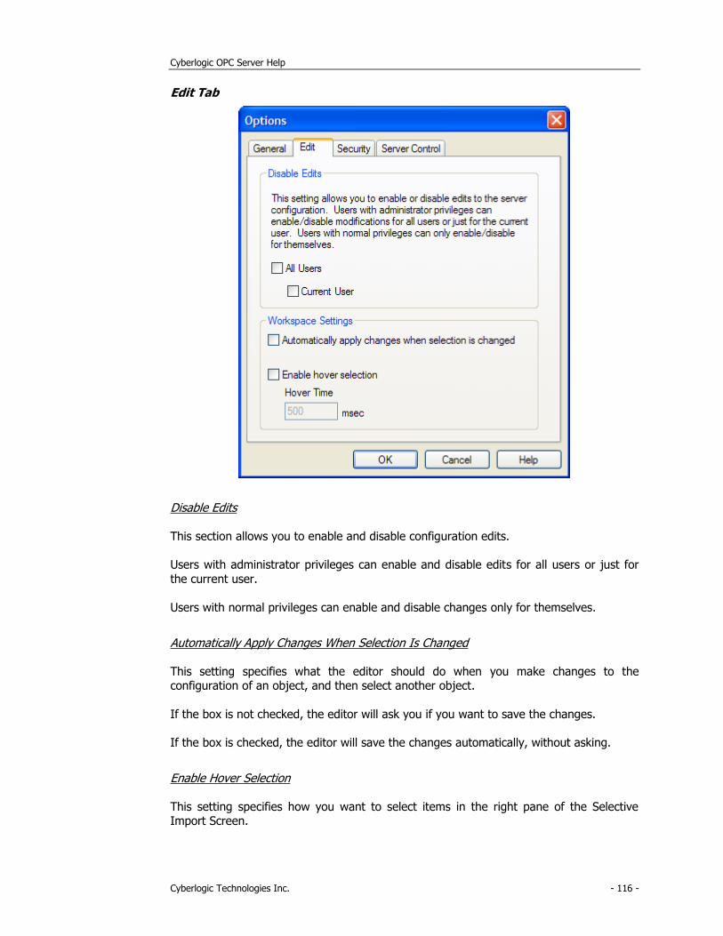
Cyberlogic OPC Server Help
Cyberlogic Technologies Inc. - 116 -
Edit Tab
Disable Edits
This section allows you to enable and disable configuration edits.
Users with administrator privileges can enable and disable edits for all users or just for
the current user.
Users with normal privileges can enable and disable changes only for themselves.
Automatically Apply Changes When Selection Is Changed
This setting specifies what the editor should do when you make changes to the configuration of an object, and then select another object.
If the box is not checked, the editor will ask you if you want to save the changes.
If the box is checked, the editor will save the changes automatically, without asking.
Enable Hover Selection
This setting specifies how you want to select items in the right pane of the Selective Import Screen.
Cyberlogic OPC Server Help
Cyberlogic Technologies Inc. - 117 -
If this box is not checked, you must click on the items to select them.
If this box is checked, you can select an item by just pointing to it with the mouse.
Hover Time
When hover selection is enabled, this is the amount of time, in milliseconds, that the
mouse pointer must hover before the item is selected.
Security Tab
For an OPC client and server to communicate, both systems must have proper DCOM
security settings. There is no standard setting for OPC applications because each installation’s security needs are unique. Therefore, you must decide how to configure
security for your systems.
Caution! If you change the selection on this tab, you must restart the Cyberlogic OPC Server for
the new settings to take effect.
To restart the Server, open the Windows Control Panel, go to Administrative Tools
and then Services. Right-click on Cyberlogic OPC Server and select Restart.
For help in making these decisions and a detailed discussion of how to do the
configuration, refer to the document OPC & DCOM: A Guide to Using the Cyberlogic OPC Server via DCOM. A copy of this document was installed on your system along with the
software. To access it, open the Windows Start menu and go to Cyberlogic Suites. Next, open the Help sub-menu, then open OPC, and then click on DCOM Help.
For information about additional Windows security settings, including user accounts and
the Windows firewall, refer to the Cyberlogic Control Panel Help.
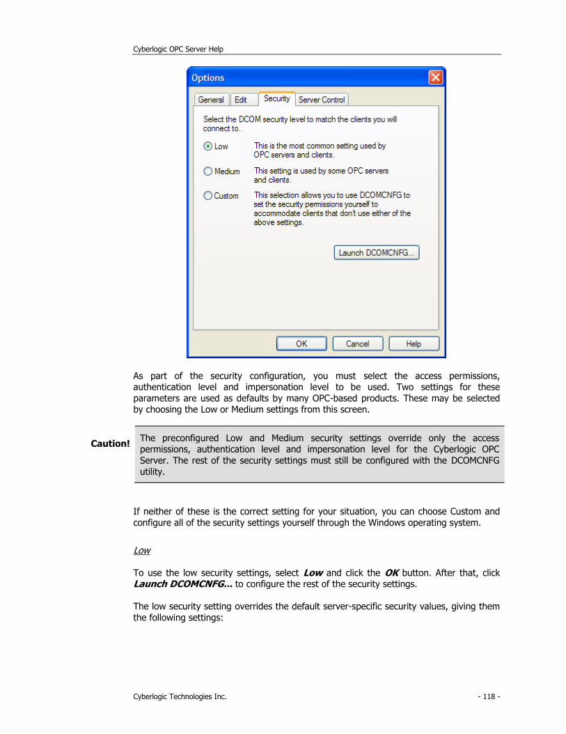
Cyberlogic OPC Server Help
Cyberlogic Technologies Inc. - 118 -
As part of the security configuration, you must select the access permissions, authentication level and impersonation level to be used. Two settings for these
parameters are used as defaults by many OPC-based products. These may be selected by choosing the Low or Medium settings from this screen.
Caution! The preconfigured Low and Medium security settings override only the access permissions, authentication level and impersonation level for the Cyberlogic OPC
Server. The rest of the security settings must still be configured with the DCOMCNFG
utility.
If neither of these is the correct setting for your situation, you can choose Custom and
configure all of the security settings yourself through the Windows operating system.
Low
To use the low security settings, select Low and click the OK button. After that, click Launch DCOMCNFG... to configure the rest of the security settings.
The low security setting overrides the default server-specific security values, giving them
the following settings:
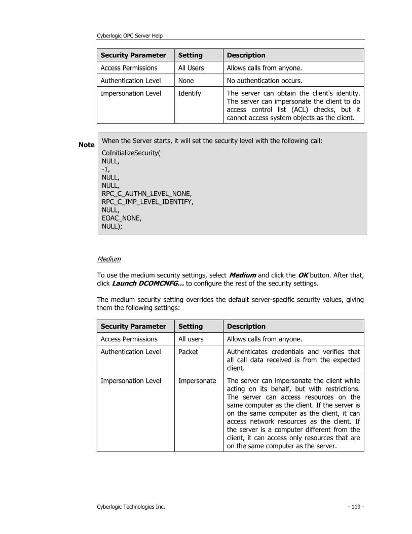
Cyberlogic OPC Server Help
Cyberlogic Technologies Inc. - 119 -
Security Parameter Setting Description
Access Permissions All Users Allows calls from anyone.
Authentication Level None No authentication occurs.
Impersonation Level Identify The server can obtain the client's identity.
The server can impersonate the client to do access control list (ACL) checks, but it
cannot access system objects as the client.
Note When the Server starts, it will set the security level with the following call:
CoInitializeSecurity(
NULL, -1,
NULL, NULL,
RPC_C_AUTHN_LEVEL_NONE,
RPC_C_IMP_LEVEL_IDENTIFY, NULL,
EOAC_NONE,
NULL);
Medium
To use the medium security settings, select Medium and click the OK button. After that,
click Launch DCOMCNFG... to configure the rest of the security settings.
The medium security setting overrides the default server-specific security values, giving
them the following settings:
Security Parameter Setting Description
Access Permissions All users Allows calls from anyone.
Authentication Level Packet Authenticates credentials and verifies that
all call data received is from the expected
client.
Impersonation Level Impersonate The server can impersonate the client while
acting on its behalf, but with restrictions.
The server can access resources on the same computer as the client. If the server is
on the same computer as the client, it can access network resources as the client. If
the server is a computer different from the
client, it can access only resources that are
on the same computer as the server.
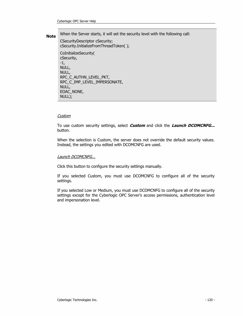
Cyberlogic OPC Server Help
Cyberlogic Technologies Inc. - 120 -
Note When the Server starts, it will set the security level with the following call:
CSecurityDescriptor cSecurity;
cSecurity.InitializeFromThreadToken( );
CoInitializeSecurity( cSecurity,
-1, NULL,
NULL, RPC_C_AUTHN_LEVEL_PKT,
RPC_C_IMP_LEVEL_IMPERSONATE,
NULL, EOAC_NONE,
NULL);
Custom
To use custom security settings, select Custom and click the Launch DCOMCNFG... button.
When the selection is Custom, the server does not override the default security values. Instead, the settings you edited with DCOMCNFG are used.
Launch DCOMCNFG...
Click this button to configure the security settings manually.
If you selected Custom, you must use DCOMCNFG to configure all of the security
settings.
If you selected Low or Medium, you must use DCOMCNFG to configure all of the security
settings except for the Cyberlogic OPC Server’s access permissions, authentication level
and impersonation level.
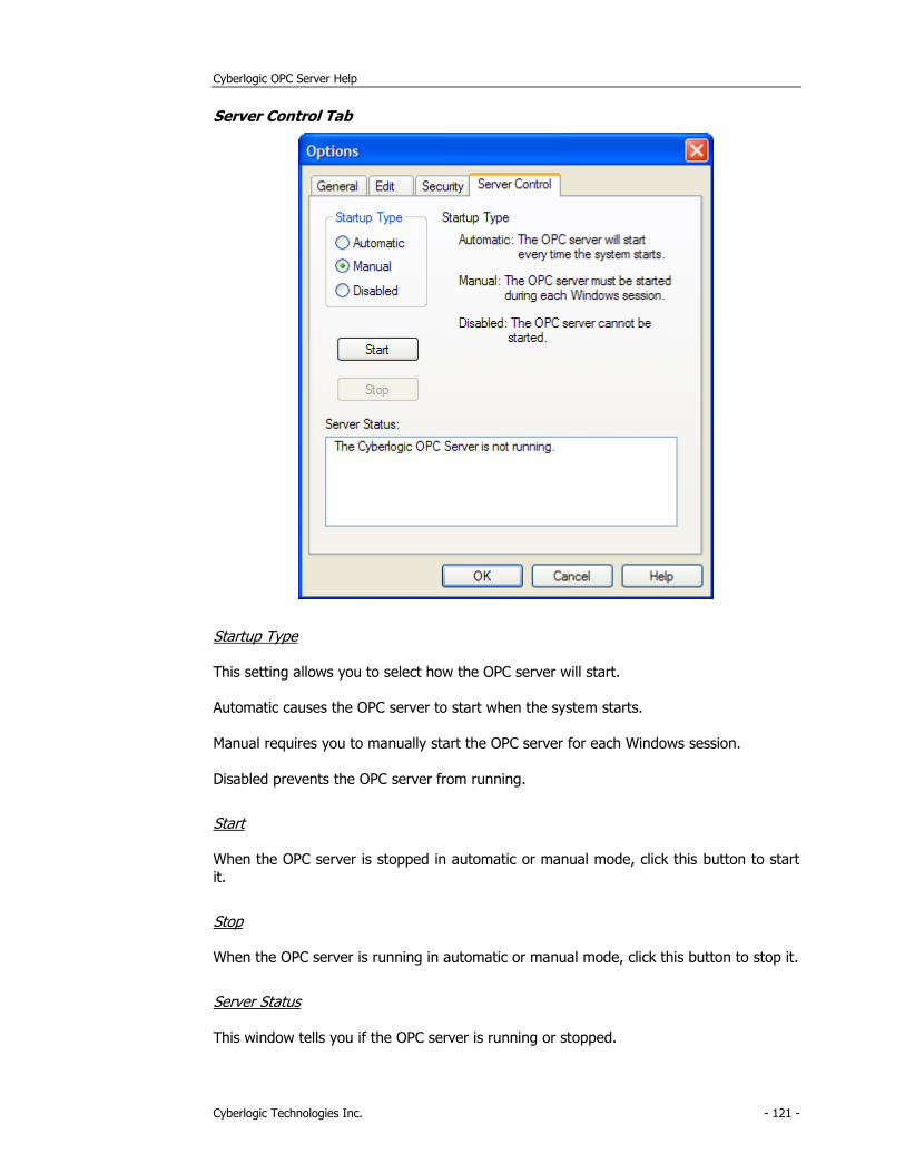
Cyberlogic OPC Server Help
Cyberlogic Technologies Inc. - 121 -
Server Control Tab
Startup Type
This setting allows you to select how the OPC server will start.
Automatic causes the OPC server to start when the system starts.
Manual requires you to manually start the OPC server for each Windows session.
Disabled prevents the OPC server from running.
Start
When the OPC server is stopped in automatic or manual mode, click this button to start it.
Stop
When the OPC server is running in automatic or manual mode, click this button to stop it.
Server Status
This window tells you if the OPC server is running or stopped.

Cyberlogic OPC Server Help
Cyberlogic Technologies Inc. - 122 -
Server Status Block
The Cyberlogic OPC Server has a set of 16-bit registers called the server status block.
Physical devices on the network, such as PLCs, can read these registers to determine the
current health and status of the server.
The location of the server status block depends upon the network type. For example, in
the DHX OPC Server, the server status block is laid out as follows:
PLC-2 Other PLCs Description
200 N7:0 Server version – Major (e.g. 5)
201 N7:1 Server version – Minor (e.g. 0)
202 N7:2 Server version – Build (e.g. 3)
203 N7:3 User configured server signature
204 N7:4 Server alive millisecond counter (Low word)
205 N7:5 Server alive millisecond counter (High word)
For information about location of the server status block for a particular driver agent,
refer to the help file specific for that agent.
Connecting OPC Client Software
After completing your configuration, you will use an OPC client application to access the
data from the Cyberlogic OPC Server. To do this, you must connect the client to the
server. The exact method for doing this will vary somewhat from one client to another, but typically will be done by browsing a tree for available servers.
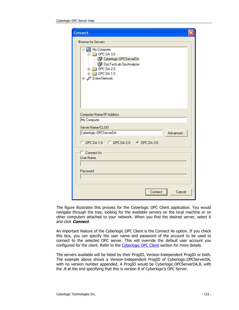
Cyberlogic OPC Server Help
Cyberlogic Technologies Inc. - 123 -
The figure illustrates this process for the Cyberlogic OPC Client application. You would navigate through the tree, looking for the available servers on the local machine or on
other computers attached to your network. When you find the desired server, select it and click Connect.
An important feature of the Cyberlogic OPC Client is the Connect As option. If you check
this box, you can specify the user name and password of the account to be used to connect to the selected OPC server. This will override the default user account you
configured for the client. Refer to the Cyberlogic OPC Client section for more details.
The servers available will be listed by their ProgID, Version-Independent ProgID or both.
The example above shows a Version-Independent ProgID of Cyberlogic.OPCServerDA,
with no version number appended. A ProgID would be Cyberlogic.OPCServerDA.8, with the .8 at the end specifying that this is version 8 of Cyberlogic’s OPC Server.

Cyberlogic OPC Server Help
Cyberlogic Technologies Inc. - 124 -
In general, it is preferable to use the Version-Independent ProgID to avoid the need to change the selection if you install a newer version of the server software. Some servers
may allow you to have multiple versions installed at the same time. In such a case, you would use the ProgID to specify the exact version to connect to.
To connect an OPC Alarms and Events client, you would proceed in the same manner,
selecting among the available AE servers. In the case of the Cyberlogic Alarms and Events server, the Version-Independent ProgID would be Cyberlogic.OPCServerAE.
The procedure for connecting an XML Data Access client application is explained in Appendix D: OPC XML Data Access Support.
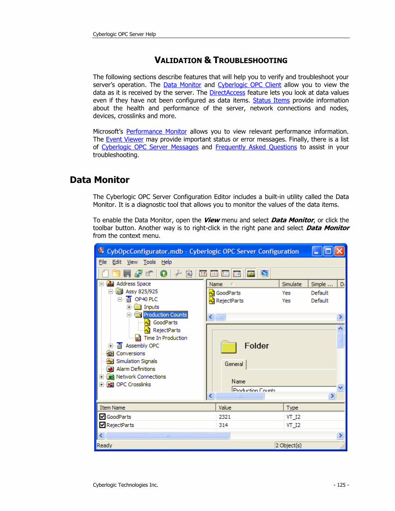
Cyberlogic OPC Server Help
Cyberlogic Technologies Inc. - 125 -
VALIDATION & TROUBLESHOOTING
The following sections describe features that will help you to verify and troubleshoot your
server’s operation. The Data Monitor and Cyberlogic OPC Client allow you to view the
data as it is received by the server. The DirectAccess feature lets you look at data values even if they have not been configured as data items. Status Items provide information
about the health and performance of the server, network connections and nodes, devices, crosslinks and more.
Microsoft’s Performance Monitor allows you to view relevant performance information.
The Event Viewer may provide important status or error messages. Finally, there is a list of Cyberlogic OPC Server Messages and Frequently Asked Questions to assist in your
troubleshooting.
Data Monitor
The Cyberlogic OPC Server Configuration Editor includes a built-in utility called the Data
Monitor. It is a diagnostic tool that allows you to monitor the values of the data items.
To enable the Data Monitor, open the View menu and select Data Monitor, or click the
toolbar button. Another way is to right-click in the right pane and select Data Monitor from the context menu.
Cyberlogic OPC Server Help
Cyberlogic Technologies Inc. - 126 -
With the Data Monitor enabled, the Cyberlogic OPC Server Configuration Editor acts as an OPC client to the Cyberlogic OPC Server. It creates an output display pane at the
bottom of the main workspace window.
To choose the data items to view, select a device or folder in the Address Space tree.
Each row in the Data Monitor corresponds to a data item in the selected folder or device.
Enable Checkbox
At the left end of each data item row is a checkbox that, when checked, enables
monitoring of its data item. By default, this checkbox is not checked. To minimize unnecessary communications, enable only data items that you are interested in.
Item Name
Shows the name of the monitored data item.
Value
The data item’s current value.
Type
The Data Monitor always requests data in the canonical (native) format. Therefore, the Type column shows the canonical data type of the requested data.
Timestamp
The timestamp for the data item’s current value.
Quality, Substatus and Limit Status
Each data value returned by an OPC server has a 16-bit quality flag word associated with it. The low eight bits are currently defined in the form of three bit fields: Quality,
Substatus and Limit Status. The Data Monitor displays the current value of each of these fields for the data item value. For more information, refer to the OPC Quality Flags
section in the OPC Data Access specification.
Cyberlogic OPC Client
The Cyberlogic OPC Client is a stand-alone OPC DA client that you can use to test the
operation of the Cyberlogic OPC Server and other OPC servers. Although its appearance
resembles the Cyberlogic OPC Server Data Monitor, it contains many additional features. An important feature is its ability to view real-time values of data items from more than
one device simultaneously. Running multiple instances of the client can also be useful when testing the server’s response to various loads.
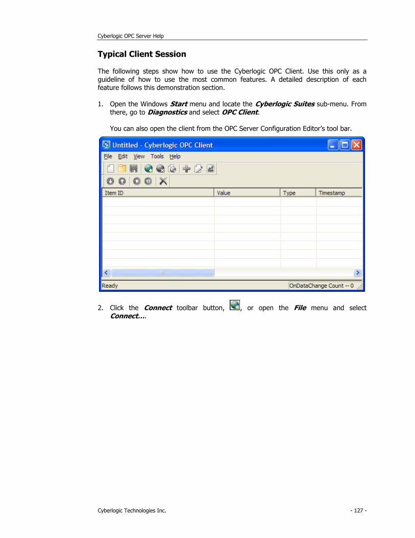
Cyberlogic OPC Server Help
Cyberlogic Technologies Inc. - 127 -
Typical Client Session
The following steps show how to use the Cyberlogic OPC Client. Use this only as a
guideline of how to use the most common features. A detailed description of each feature follows this demonstration section.
1. Open the Windows Start menu and locate the Cyberlogic Suites sub-menu. From
there, go to Diagnostics and select OPC Client.
You can also open the client from the OPC Server Configuration Editor’s tool bar.
2. Click the Connect toolbar button, , or open the File menu and select
Connect….
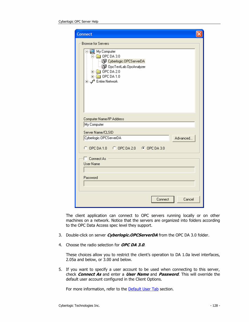
Cyberlogic OPC Server Help
Cyberlogic Technologies Inc. - 128 -
The client application can connect to OPC servers running locally or on other machines on a network. Notice that the servers are organized into folders according
to the OPC Data Access spec level they support.
3. Double-click on server Cyberlogic.OPCServerDA from the OPC DA 3.0 folder.
4. Choose the radio selection for OPC DA 3.0.
These choices allow you to restrict the client’s operation to DA 1.0a level interfaces, 2.05a and below, or 3.00 and below.
5. If you want to specify a user account to be used when connecting to this server, check Connect As and enter a User Name and Password. This will override the
default user account configured in the Client Options.
For more information, refer to the Default User Tab section.
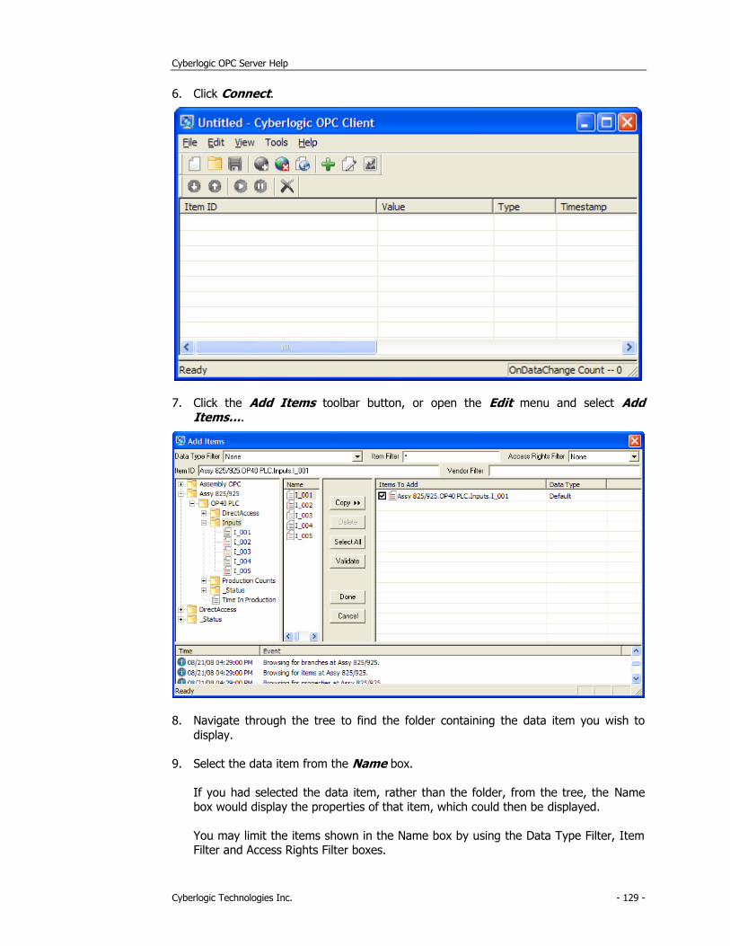
Cyberlogic OPC Server Help
Cyberlogic Technologies Inc. - 129 -
6. Click Connect.
7. Click the Add Items toolbar button, or open the Edit menu and select Add Items….
8. Navigate through the tree to find the folder containing the data item you wish to
display.
9. Select the data item from the Name box.
If you had selected the data item, rather than the folder, from the tree, the Name box would display the properties of that item, which could then be displayed.
You may limit the items shown in the Name box by using the Data Type Filter, Item Filter and Access Rights Filter boxes.
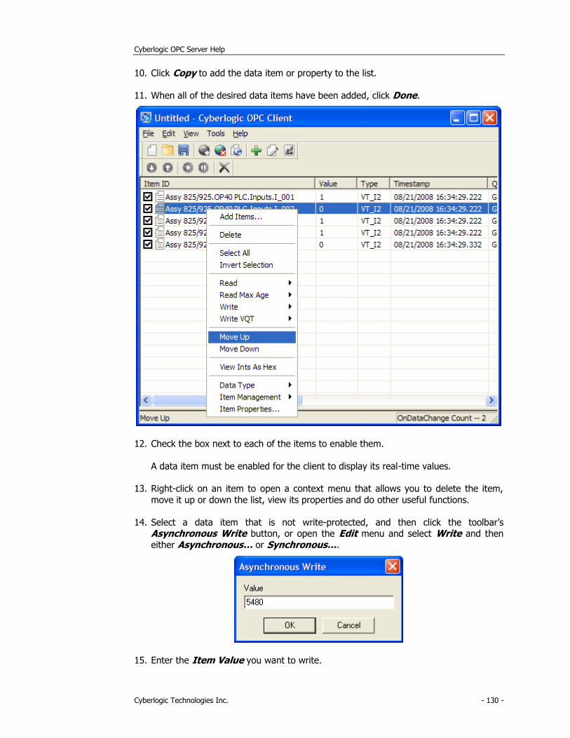
Cyberlogic OPC Server Help
Cyberlogic Technologies Inc. - 130 -
10. Click Copy to add the data item or property to the list.
11. When all of the desired data items have been added, click Done.
12. Check the box next to each of the items to enable them.
A data item must be enabled for the client to display its real-time values.
13. Right-click on an item to open a context menu that allows you to delete the item,
move it up or down the list, view its properties and do other useful functions.
14. Select a data item that is not write-protected, and then click the toolbar’s Asynchronous Write button, or open the Edit menu and select Write and then
either Asynchronous… or Synchronous….
15. Enter the Item Value you want to write.
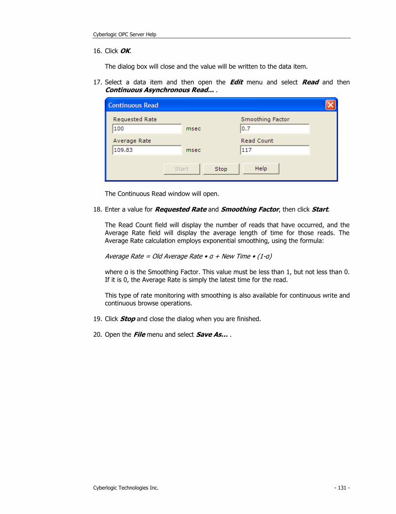
Cyberlogic OPC Server Help
Cyberlogic Technologies Inc. - 131 -
16. Click OK.
The dialog box will close and the value will be written to the data item.
17. Select a data item and then open the Edit menu and select Read and then Continuous Asynchronous Read... .
The Continuous Read window will open.
18. Enter a value for Requested Rate and Smoothing Factor, then click Start.
The Read Count field will display the number of reads that have occurred, and the
Average Rate field will display the average length of time for those reads. The
Average Rate calculation employs exponential smoothing, using the formula:
Average Rate = Old Average Rate • α + New Time • (1-α)
where α is the Smoothing Factor. This value must be less than 1, but not less than 0. If it is 0, the Average Rate is simply the latest time for the read.
This type of rate monitoring with smoothing is also available for continuous write and continuous browse operations.
19. Click Stop and close the dialog when you are finished.
20. Open the File menu and select Save As… .
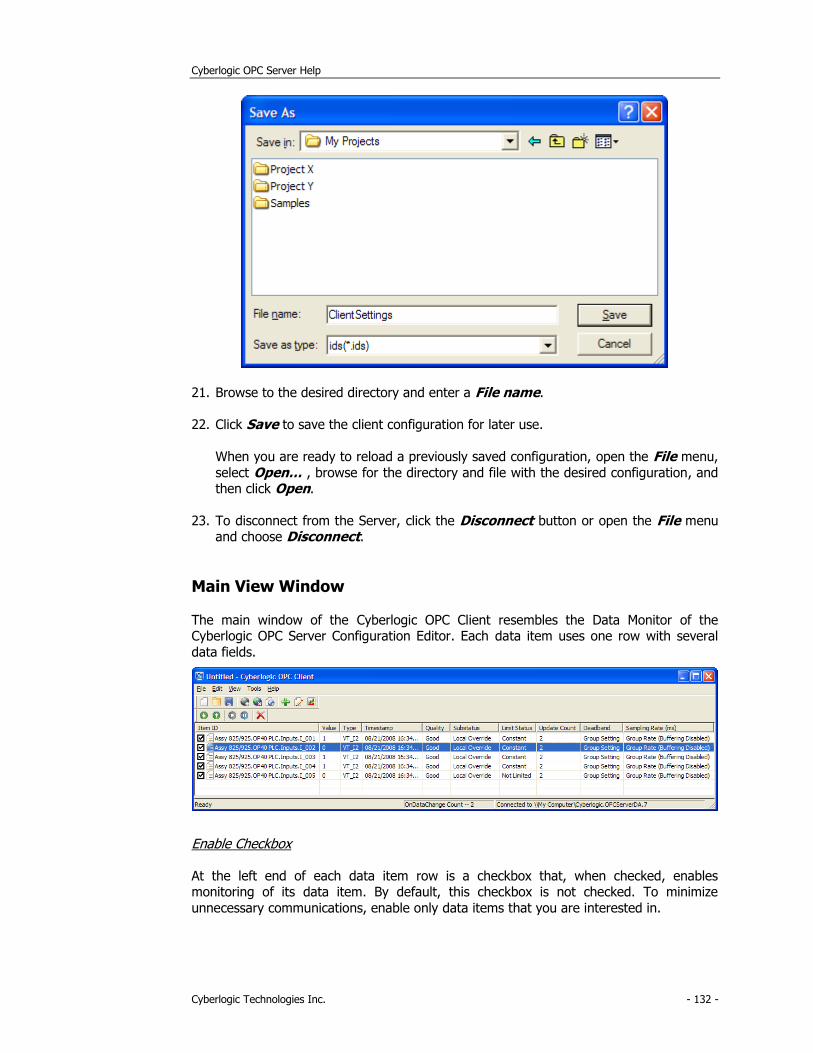
Cyberlogic OPC Server Help
Cyberlogic Technologies Inc. - 132 -
21. Browse to the desired directory and enter a File name.
22. Click Save to save the client configuration for later use.
When you are ready to reload a previously saved configuration, open the File menu,
select Open… , browse for the directory and file with the desired configuration, and then click Open.
23. To disconnect from the Server, click the Disconnect button or open the File menu and choose Disconnect.
Main View Window
The main window of the Cyberlogic OPC Client resembles the Data Monitor of the Cyberlogic OPC Server Configuration Editor. Each data item uses one row with several
data fields.
Enable Checkbox
At the left end of each data item row is a checkbox that, when checked, enables monitoring of its data item. By default, this checkbox is not checked. To minimize
unnecessary communications, enable only data items that you are interested in.
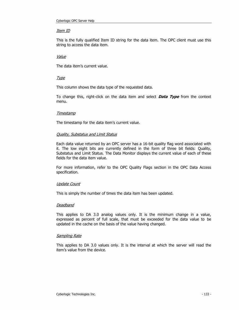
Cyberlogic OPC Server Help
Cyberlogic Technologies Inc. - 133 -
Item ID
This is the fully qualified Item ID string for the data item. The OPC client must use this
string to access the data item.
Value
The data item’s current value.
Type
This column shows the data type of the requested data.
To change this, right-click on the data item and select Data Type from the context menu.
Timestamp
The timestamp for the data item’s current value.
Quality, Substatus and Limit Status
Each data value returned by an OPC server has a 16-bit quality flag word associated with it. The low eight bits are currently defined in the form of three bit fields: Quality,
Substatus and Limit Status. The Data Monitor displays the current value of each of these fields for the data item value.
For more information, refer to the OPC Quality Flags section in the OPC Data Access
specification.
Update Count
This is simply the number of times the data item has been updated.
Deadband
This applies to DA 3.0 analog values only. It is the minimum change in a value, expressed as percent of full scale, that must be exceeded for the data value to be
updated in the cache on the basis of the value having changed.
Sampling Rate
This applies to DA 3.0 values only. It is the interval at which the server will read the
item’s value from the device.
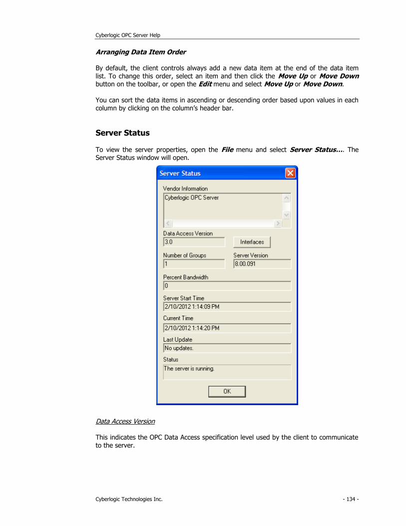
Cyberlogic OPC Server Help
Cyberlogic Technologies Inc. - 134 -
Arranging Data Item Order
By default, the client controls always add a new data item at the end of the data item
list. To change this order, select an item and then click the Move Up or Move Down button on the toolbar, or open the Edit menu and select Move Up or Move Down.
You can sort the data items in ascending or descending order based upon values in each
column by clicking on the column’s header bar.
Server Status
To view the server properties, open the File menu and select Server Status…. The Server Status window will open.
Data Access Version
This indicates the OPC Data Access specification level used by the client to communicate
to the server.
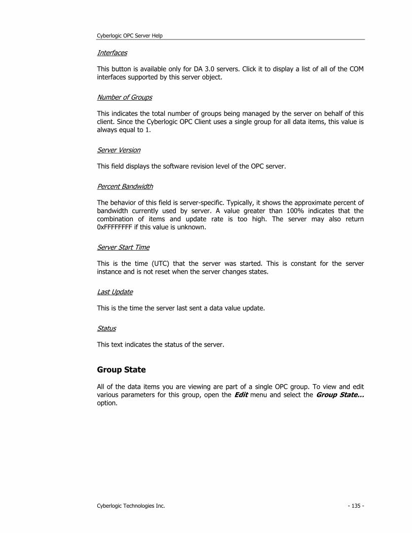
Cyberlogic OPC Server Help
Cyberlogic Technologies Inc. - 135 -
Interfaces
This button is available only for DA 3.0 servers. Click it to display a list of all of the COM
interfaces supported by this server object.
Number of Groups
This indicates the total number of groups being managed by the server on behalf of this
client. Since the Cyberlogic OPC Client uses a single group for all data items, this value is always equal to 1.
Server Version
This field displays the software revision level of the OPC server.
Percent Bandwidth
The behavior of this field is server-specific. Typically, it shows the approximate percent of
bandwidth currently used by server. A value greater than 100% indicates that the
combination of items and update rate is too high. The server may also return 0xFFFFFFFF if this value is unknown.
Server Start Time
This is the time (UTC) that the server was started. This is constant for the server
instance and is not reset when the server changes states.
Last Update
This is the time the server last sent a data value update.
Status
This text indicates the status of the server.
Group State
All of the data items you are viewing are part of a single OPC group. To view and edit various parameters for this group, open the Edit menu and select the Group State…
option.
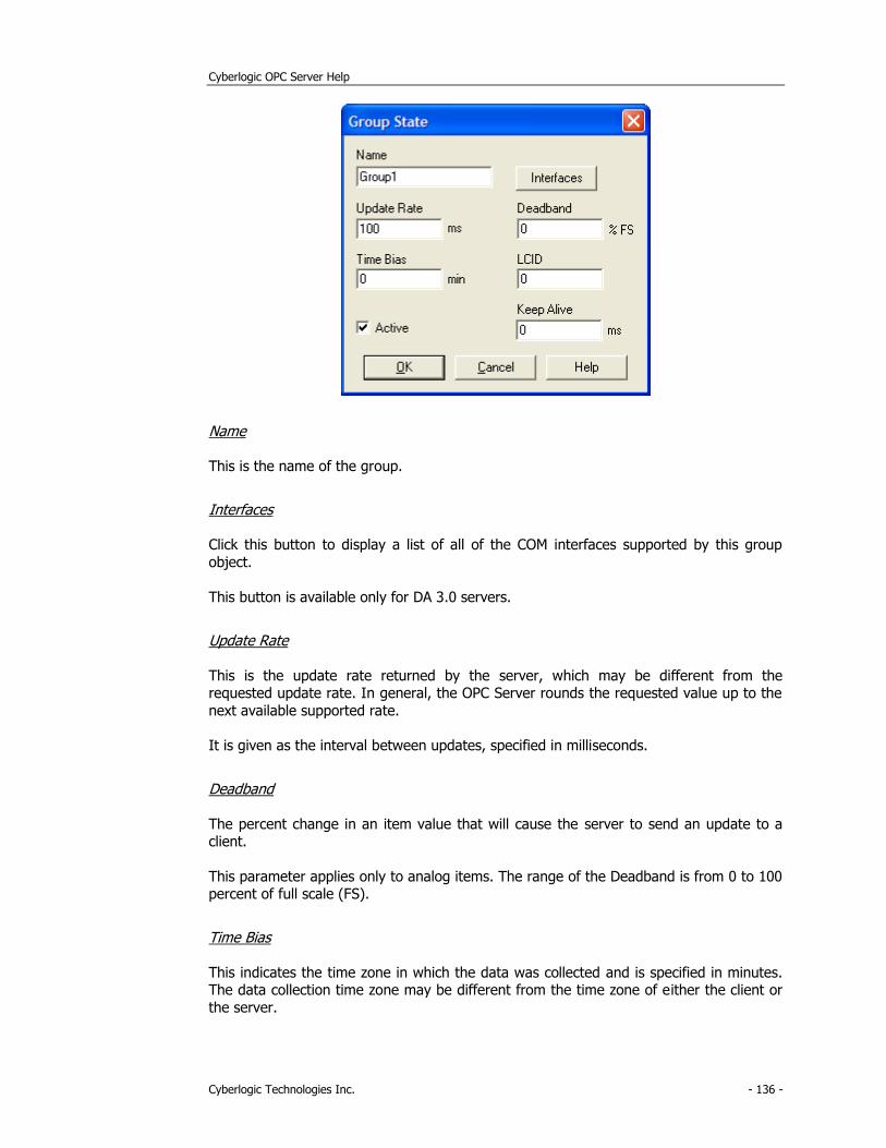
Cyberlogic OPC Server Help
Cyberlogic Technologies Inc. - 136 -
Name
This is the name of the group.
Interfaces
Click this button to display a list of all of the COM interfaces supported by this group
object.
This button is available only for DA 3.0 servers.
Update Rate
This is the update rate returned by the server, which may be different from the requested update rate. In general, the OPC Server rounds the requested value up to the
next available supported rate.
It is given as the interval between updates, specified in milliseconds.
Deadband
The percent change in an item value that will cause the server to send an update to a client.
This parameter applies only to analog items. The range of the Deadband is from 0 to 100 percent of full scale (FS).
Time Bias
This indicates the time zone in which the data was collected and is specified in minutes. The data collection time zone may be different from the time zone of either the client or
the server.
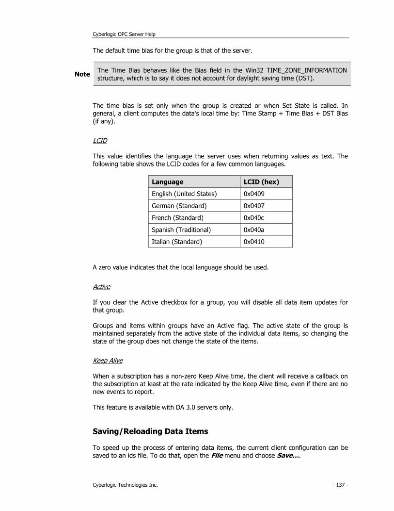
Cyberlogic OPC Server Help
Cyberlogic Technologies Inc. - 137 -
The default time bias for the group is that of the server.
Note The Time Bias behaves like the Bias field in the Win32 TIME_ZONE_INFORMATION
structure, which is to say it does not account for daylight saving time (DST).
The time bias is set only when the group is created or when Set State is called. In general, a client computes the data's local time by: Time Stamp + Time Bias + DST Bias
(if any).
LCID
This value identifies the language the server uses when returning values as text. The
following table shows the LCID codes for a few common languages.
Language LCID (hex)
English (United States) 0x0409
German (Standard) 0x0407
French (Standard) 0x040c
Spanish (Traditional) 0x040a
Italian (Standard) 0x0410
A zero value indicates that the local language should be used.
Active
If you clear the Active checkbox for a group, you will disable all data item updates for
that group.
Groups and items within groups have an Active flag. The active state of the group is maintained separately from the active state of the individual data items, so changing the
state of the group does not change the state of the items.
Keep Alive
When a subscription has a non-zero Keep Alive time, the client will receive a callback on the subscription at least at the rate indicated by the Keep Alive time, even if there are no
new events to report.
This feature is available with DA 3.0 servers only.
Saving/Reloading Data Items
To speed up the process of entering data items, the current client configuration can be
saved to an ids file. To do that, open the File menu and choose Save….
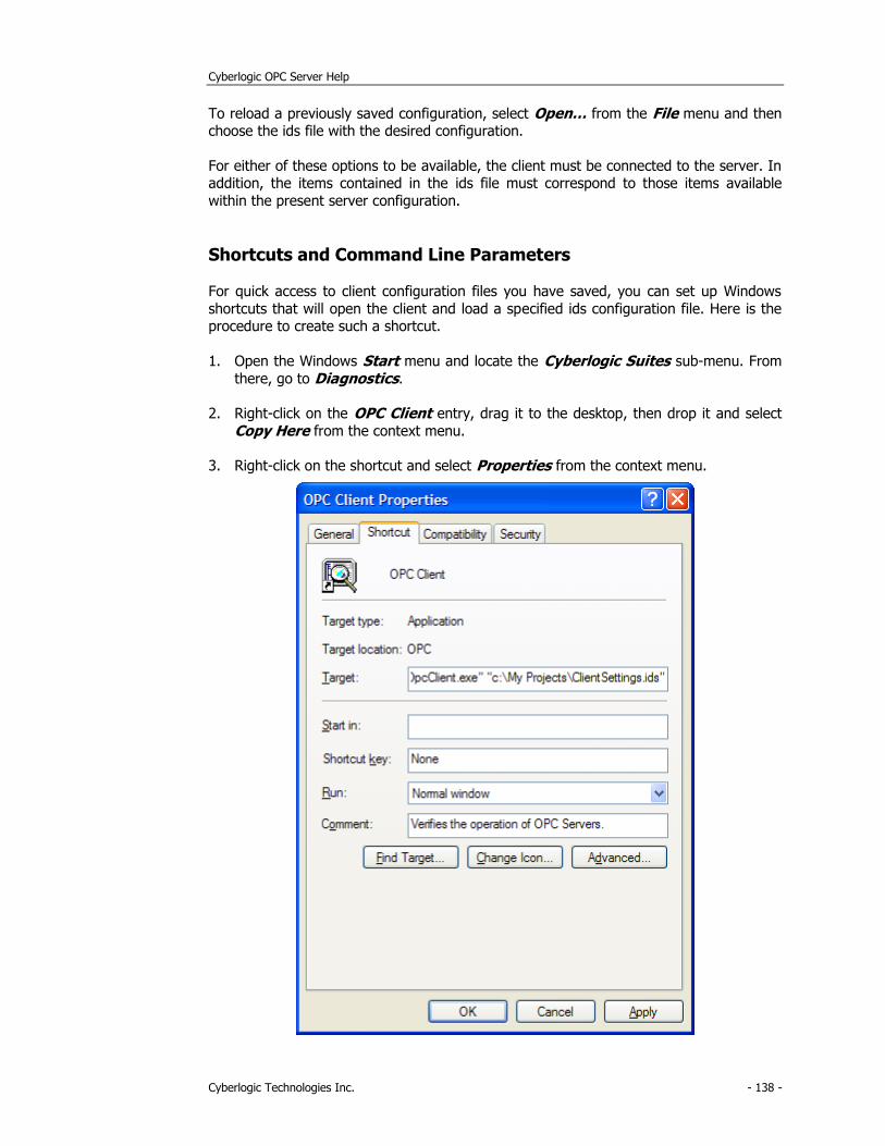
Cyberlogic OPC Server Help
Cyberlogic Technologies Inc. - 138 -
To reload a previously saved configuration, select Open… from the File menu and then choose the ids file with the desired configuration.
For either of these options to be available, the client must be connected to the server. In addition, the items contained in the ids file must correspond to those items available
within the present server configuration.
Shortcuts and Command Line Parameters
For quick access to client configuration files you have saved, you can set up Windows
shortcuts that will open the client and load a specified ids configuration file. Here is the procedure to create such a shortcut.
1. Open the Windows Start menu and locate the Cyberlogic Suites sub-menu. From
there, go to Diagnostics.
2. Right-click on the OPC Client entry, drag it to the desktop, then drop it and select
Copy Here from the context menu.
3. Right-click on the shortcut and select Properties from the context menu.
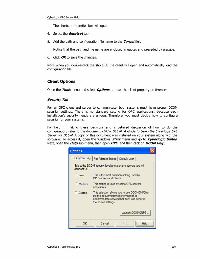
Cyberlogic OPC Server Help
Cyberlogic Technologies Inc. - 139 -
The shortcut properties box will open.
4. Select the Shortcut tab.
5. Add the path and configuration file name to the Target field.
Notice that the path and file name are enclosed in quotes and preceded by a space.
6. Click OK to save the changes.
Now, when you double-click the shortcut, the client will open and automatically load the configuration file.
Client Options
Open the Tools menu and select Options… to set the client property preferences.
Security Tab
For an OPC client and server to communicate, both systems must have proper DCOM security settings. There is no standard setting for OPC applications, because each
installation’s security needs are unique. Therefore, you must decide how to configure security for your systems.
For help in making these decisions and a detailed discussion of how to do the configuration, refer to the document OPC & DCOM: A Guide to Using the Cyberlogic OPC Server via DCOM. A copy of this document was installed on your system along with the
software. To access it, open the Windows Start menu and go to Cyberlogic Suites. Next, open the Help sub-menu, then open OPC, and then click on DCOM Help.
Cyberlogic OPC Server Help
Cyberlogic Technologies Inc. - 140 -
As part of the security configuration, you must select the access permissions, authentication level and impersonation level to be used. Two settings for these
parameters are used as defaults by many OPC-based products. These may be selected by choosing the Low or Medium settings from this screen.
If neither of these is the correct setting for your situation, you must choose Custom and
click Launch DCOMCNFG... to configure all of the security settings yourself through the Windows operating system.
Caution! The preconfigured Low and Medium security settings override only the access
permissions, authentication level and impersonation level for the Cyberlogic OPC Client.
The rest of the security settings configured with the DCOMCNFG utility still apply.
Low and Medium
For details of these settings, refer to the discussion of the Server Options Security Tab.
Custom
If neither of the preconfigured settings are suitable for your installation, you must choose Custom. When the selection is Custom, the client does not override the default security
values. Instead, the settings you edited with DCOMCNFG are used.
Launch DCOMCNFG...
Click this button to configure the security settings manually.
If you selected Custom, you must use DCOMCNFG to configure all of the security settings. If you selected Low or Medium, you must use DCOMCNFG to configure all of the
security settings except for the Cyberlogic OPC Client’s access permissions, authentication level and impersonation level.
Caution! If you change the selection on this tab, you must close the client and reopen it before
the new settings will take effect.
Flat Address Space Browsing Tab
The OPC Server address space is normally shown with a multi-level tree structure. When
browsing for elements, you may prefer to see the address space as a flat structure with all of the elements at a single level. This is supported in Data Access 1.x and 2.x
compliant servers, but not in 3.x compliant servers.
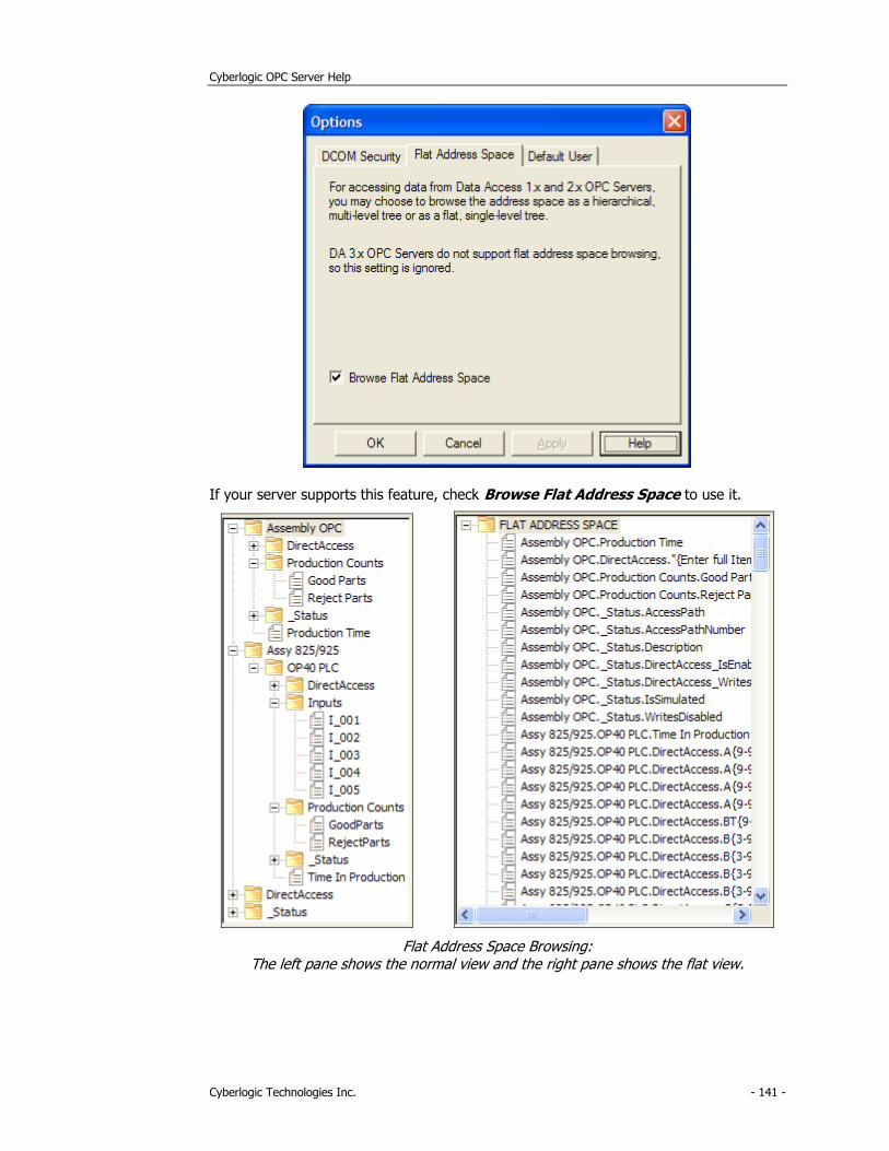
Cyberlogic OPC Server Help
Cyberlogic Technologies Inc. - 141 -
If your server supports this feature, check Browse Flat Address Space to use it.
Flat Address Space Browsing: The left pane shows the normal view and the right pane shows the flat view.
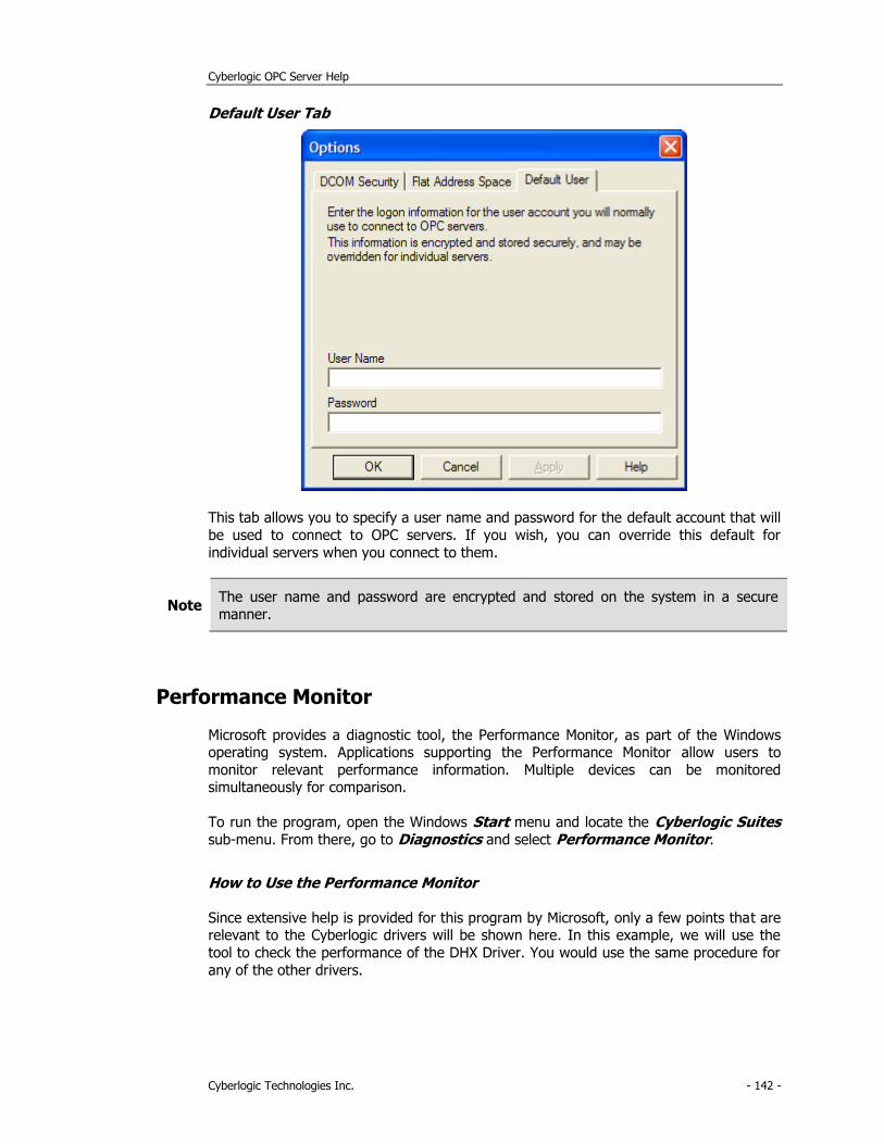
Cyberlogic OPC Server Help
Cyberlogic Technologies Inc. - 142 -
Default User Tab
This tab allows you to specify a user name and password for the default account that will
be used to connect to OPC servers. If you wish, you can override this default for
individual servers when you connect to them.
Note The user name and password are encrypted and stored on the system in a secure
manner.
Performance Monitor
Microsoft provides a diagnostic tool, the Performance Monitor, as part of the Windows operating system. Applications supporting the Performance Monitor allow users to
monitor relevant performance information. Multiple devices can be monitored simultaneously for comparison.
To run the program, open the Windows Start menu and locate the Cyberlogic Suites
sub-menu. From there, go to Diagnostics and select Performance Monitor.
How to Use the Performance Monitor
Since extensive help is provided for this program by Microsoft, only a few points that are relevant to the Cyberlogic drivers will be shown here. In this example, we will use the
tool to check the performance of the DHX Driver. You would use the same procedure for
any of the other drivers.
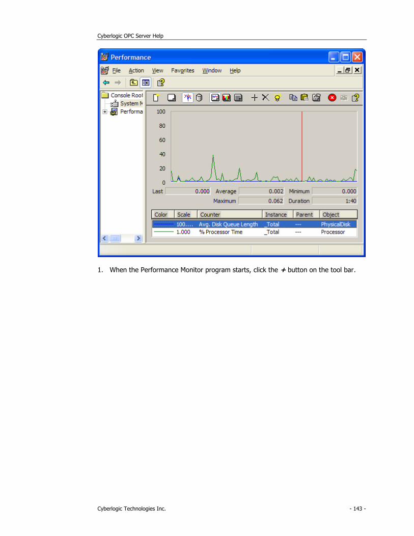
Cyberlogic OPC Server Help
Cyberlogic Technologies Inc. - 143 -
1. When the Performance Monitor program starts, click the + button on the tool bar.
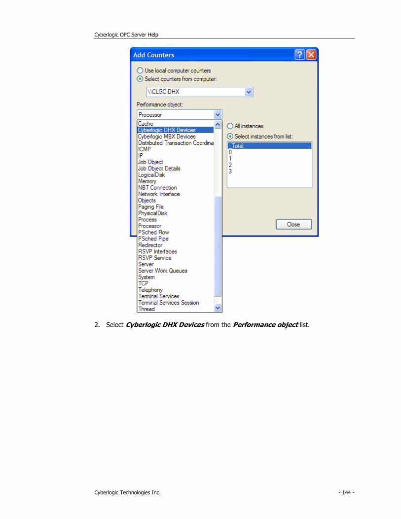
Cyberlogic OPC Server Help
Cyberlogic Technologies Inc. - 144 -
2. Select Cyberlogic DHX Devices from the Performance object list.
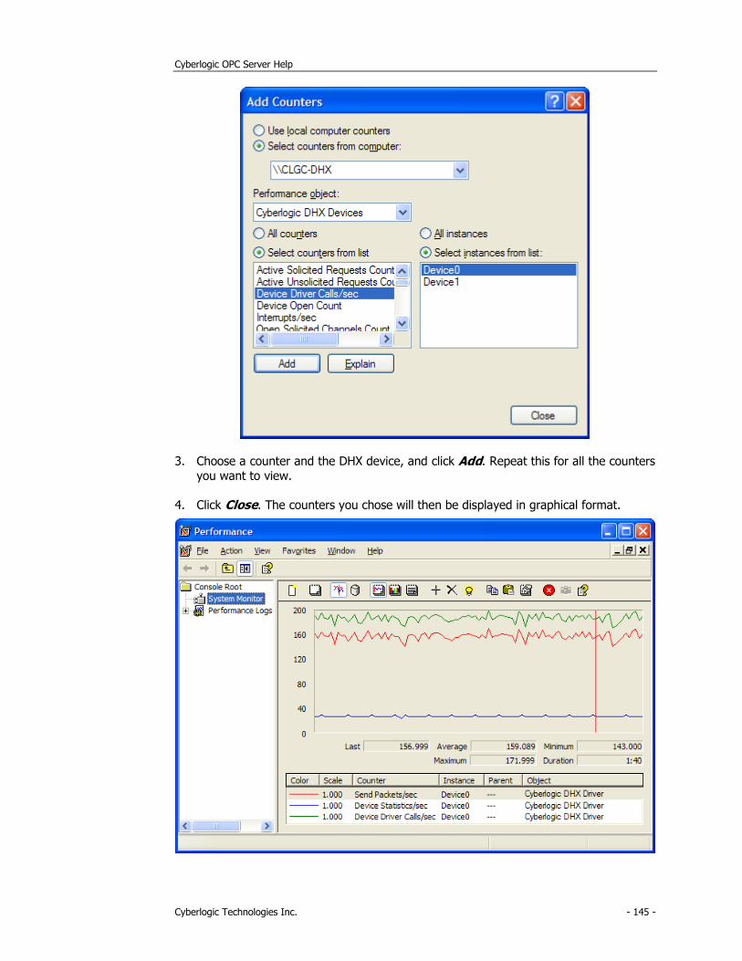
Cyberlogic OPC Server Help
Cyberlogic Technologies Inc. - 145 -
3. Choose a counter and the DHX device, and click Add. Repeat this for all the counters
you want to view.
4. Click Close. The counters you chose will then be displayed in graphical format.
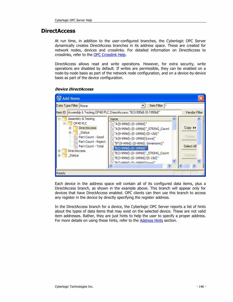
Cyberlogic OPC Server Help
Cyberlogic Technologies Inc. - 146 -
DirectAccess
At run time, in addition to the user-configured branches, the Cyberlogic OPC Server
dynamically creates DirectAccess branches in its address space. These are created for
network nodes, devices and crosslinks. For detailed information on DirectAccess to crosslinks, refer to the OPC Crosslink Help.
DirectAccess allows read and write operations. However, for extra security, write operations are disabled by default. If writes are permissible, they can be enabled on a
node-by-node basis as part of the network node configuration, and on a device-by-device
basis as part of the device configuration.
Device DirectAccess
Each device in the address space will contain all of its configured data items, plus a
DirectAccess branch, as shown in the example above. This branch will appear only for devices that have DirectAccess enabled. OPC clients can then use this branch to access
any register in the device by directly specifying the register address.
In the DirectAccess branch for a device, the Cyberlogic OPC Server reports a list of hints about the types of data items that may exist on the selected device. These are not valid
item addresses. Rather, they are just hints to help the user to specify a proper address. For more details on using these hints, refer to the Address Hints section.
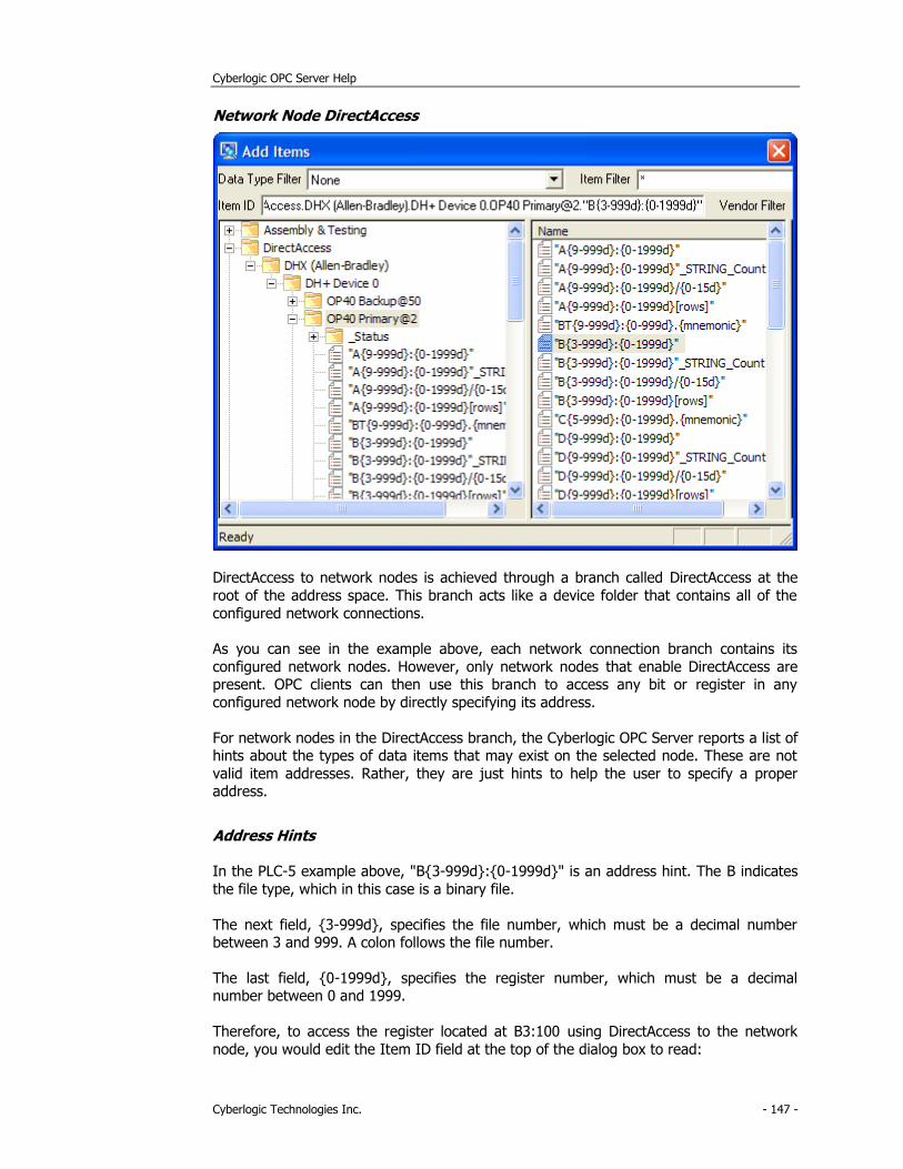
Cyberlogic OPC Server Help
Cyberlogic Technologies Inc. - 147 -
Network Node DirectAccess
DirectAccess to network nodes is achieved through a branch called DirectAccess at the
root of the address space. This branch acts like a device folder that contains all of the
configured network connections.
As you can see in the example above, each network connection branch contains its
configured network nodes. However, only network nodes that enable DirectAccess are present. OPC clients can then use this branch to access any bit or register in any
configured network node by directly specifying its address.
For network nodes in the DirectAccess branch, the Cyberlogic OPC Server reports a list of hints about the types of data items that may exist on the selected node. These are not
valid item addresses. Rather, they are just hints to help the user to specify a proper address.
Address Hints
In the PLC-5 example above, "B{3-999d}:{0-1999d}" is an address hint. The B indicates
the file type, which in this case is a binary file.
The next field, {3-999d}, specifies the file number, which must be a decimal number between 3 and 999. A colon follows the file number.
The last field, {0-1999d}, specifies the register number, which must be a decimal number between 0 and 1999.
Therefore, to access the register located at B3:100 using DirectAccess to the network
node, you would edit the Item ID field at the top of the dialog box to read:
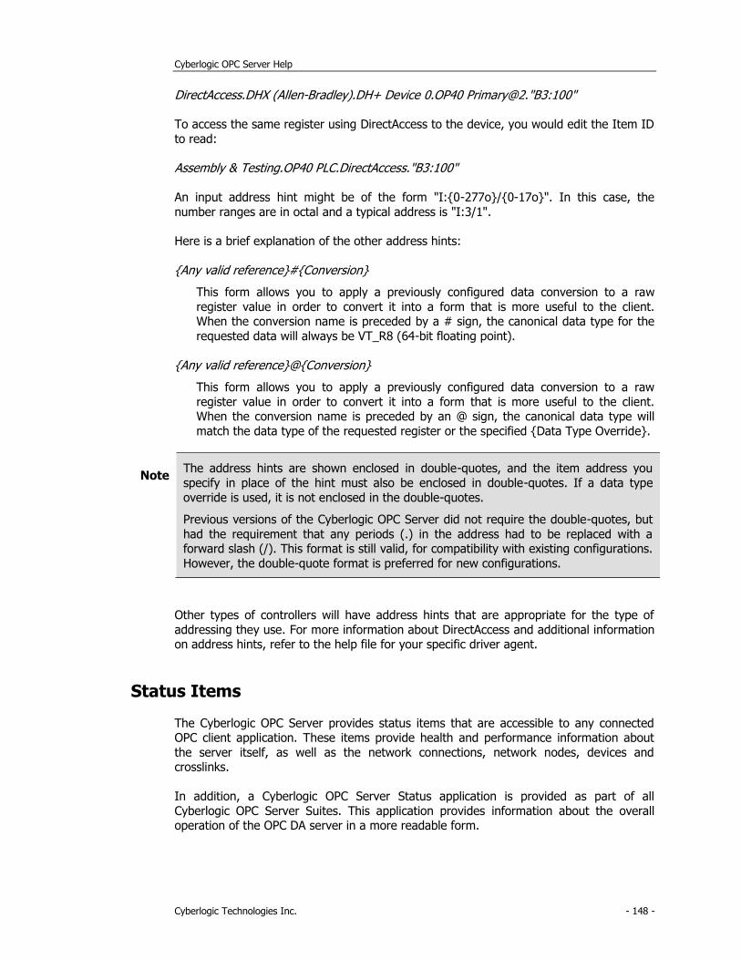
Cyberlogic OPC Server Help
Cyberlogic Technologies Inc. - 148 -
DirectAccess.DHX (Allen-Bradley).DH+ Device 0.OP40 Primary@2."B3:100"
To access the same register using DirectAccess to the device, you would edit the Item ID
to read:
Assembly & Testing.OP40 PLC.DirectAccess."B3:100"
An input address hint might be of the form "I:{0-277o}/{0-17o}". In this case, the
number ranges are in octal and a typical address is "I:3/1".
Here is a brief explanation of the other address hints:
{Any valid reference}#{Conversion}
This form allows you to apply a previously configured data conversion to a raw
register value in order to convert it into a form that is more useful to the client. When the conversion name is preceded by a # sign, the canonical data type for the
requested data will always be VT_R8 (64-bit floating point).
{Any valid reference}@{Conversion}
This form allows you to apply a previously configured data conversion to a raw
register value in order to convert it into a form that is more useful to the client. When the conversion name is preceded by an @ sign, the canonical data type will
match the data type of the requested register or the specified {Data Type Override}.
Note The address hints are shown enclosed in double-quotes, and the item address you
specify in place of the hint must also be enclosed in double-quotes. If a data type
override is used, it is not enclosed in the double-quotes.
Previous versions of the Cyberlogic OPC Server did not require the double-quotes, but
had the requirement that any periods (.) in the address had to be replaced with a forward slash (/). This format is still valid, for compatibility with existing configurations.
However, the double-quote format is preferred for new configurations.
Other types of controllers will have address hints that are appropriate for the type of
addressing they use. For more information about DirectAccess and additional information on address hints, refer to the help file for your specific driver agent.
Status Items
The Cyberlogic OPC Server provides status items that are accessible to any connected OPC client application. These items provide health and performance information about
the server itself, as well as the network connections, network nodes, devices and crosslinks.
In addition, a Cyberlogic OPC Server Status application is provided as part of all
Cyberlogic OPC Server Suites. This application provides information about the overall operation of the OPC DA server in a more readable form.
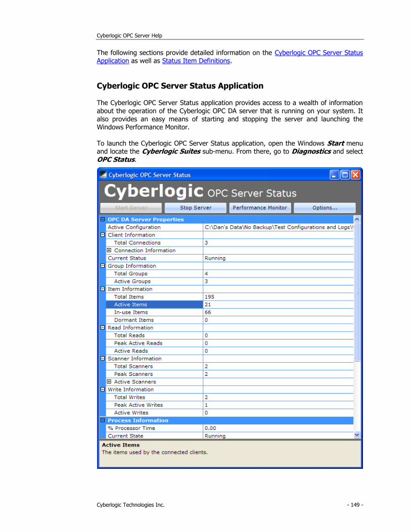
Cyberlogic OPC Server Help
Cyberlogic Technologies Inc. - 149 -
The following sections provide detailed information on the Cyberlogic OPC Server Status Application as well as Status Item Definitions.
Cyberlogic OPC Server Status Application
The Cyberlogic OPC Server Status application provides access to a wealth of information
about the operation of the Cyberlogic OPC DA server that is running on your system. It
also provides an easy means of starting and stopping the server and launching the Windows Performance Monitor.
To launch the Cyberlogic OPC Server Status application, open the Windows Start menu and locate the Cyberlogic Suites sub-menu. From there, go to Diagnostics and select
OPC Status.
Cyberlogic OPC Server Help
Cyberlogic Technologies Inc. - 150 -
The application will open, showing you the available status information. For an explanation of the displayed items, refer to the Status Item Definitions section.
When the application is running, an icon will appear in the Windows System Tray.
Start Server
Click this button to start the Cyberlogic OPC server.
Stop Server
Click this button to stop the Cyberlogic OPC server.
Performance Monitor
Click this button to launch the Windows Performance Monitor.
Options...
Click this button to open a selection that allows you to indicate if you want the
application to start when Windows starts.
Status Item Definitions
When you connect to the Cyberlogic OPC Server with a client application and browse for
items to display, the status items are shown in folders called _Status.
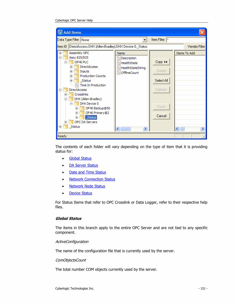
Cyberlogic OPC Server Help
Cyberlogic Technologies Inc. - 151 -
The contents of each folder will vary depending on the type of item that it is providing status for:
• Global Status
• DA Server Status
• Date and Time Status
• Network Connection Status
• Network Node Status
• Device Status
For Status Items that refer to OPC Crosslink or Data Logger, refer to their respective help
files.
Global Status
The items in this branch apply to the entire OPC Server and are not tied to any specific component.
ActiveConfiguration
The name of the configuration file that is currently used by the server.
ComObjectsCount
The total number COM objects currently used by the server.
Cyberlogic OPC Server Help
Cyberlogic Technologies Inc. - 152 -
The OPC DA specification is based on an object-oriented model called COM (Component Object Model). In this model, the data is provided by the so-called COM objects. An OPC
group or a data item are examples of this type of object.
ServerMemory_Max_KB
The maximum amount of virtual memory (in kilobytes) that Windows can allot to the
OPC Server.
Virtual memory is a combination of both RAM and temporary hard disk space. On 64-bit
systems, this value will be approximately 4,000,000 KB. On 32-bit systems, it defaults to approximately 2,000,000 KB. On 32-bit systems with the 4-Gigabyte Tuning (4GT)
enabled—up to approximately 3,000,000 KB.
For more information on this subject, search microsoft.com for “4-Gigabyte Tuning”.
ServerMemory_Used_KB
The amount of virtual memory (in kilobytes) used by the OPC Server.
ServerMemory_PercentUsed
The percentage of ServerMemory_Max_KB actually used by the OPC Server.
Percentages between 50% and 80% should serve as a warning. Values greater than
80% indicate that server performance is likely impacted by the lack of resources. In this
case, stopping and restarting the OPC Server is recommended. If the issue continues, consider adding more memory to the system or reducing the size of the active
configuration. On 32-bit systems, you may also consider enabling the 4-Gigabyte Tuning (4GT).
For more information on this subject, search microsoft.com for “4-Gigabyte Tuning”.
ServerMemory_OutOfMemoryCount
The number of times the OPC Server has experienced out-of-memory errors since it
started.
A value other than zero indicates that the OPC Server may be running in an inconsistent
state. Stopping and restarting the OPC Server is recommended. If the issue continues, consider adding more memory to the system or reducing the size of the active
configuration. On 32-bit systems, you may also consider enabling the 4-Gigabyte Tuning
(4GT).
For more information on this subject, search microsoft.com for “4-Gigabyte Tuning”.
SystemPhysicalMemory_Total_KB
The total amount of RAM (in kilobytes) in the entire system.
SystemPhysicalMemory_Used_KB
The amount of RAM (in kilobytes) in the system that is in use.

Cyberlogic OPC Server Help
Cyberlogic Technologies Inc. - 153 -
SystemPhysicalMemory_PercentUsed
The amount of RAM in the system that is in use expressed as a percentage of total RAM.
DA Server Status
This branch is located directly under the _Status branch at the root of the address space
(_Status.DA_Server). The items in this branch provide global status information about
the overall operation of the OPC Data Access (DA) component of the Cyberlogic OPC server. Most of the items can also be viewed through the Cyberlogic OPC Server Status
Application, which presents the data in a more readable form.
Clients_Count
The current number of client connections to the OPC DA server.
Most client applications use a single server connection for all of their I/O requests, so this
number typically represents the number of connected OPC clients.
Clients_Info
This item provides status information for all current OPC DA server connections.
This information includes:
• Connection sequence number
• Domain/Computer name
• User name
• Client application name
• Total number of OPC groups
• Number of active OPC groups
• Number of OPC groups that established an advise channel for callbacks
• Number of OPC groups that enabled the OnDataChange callbacks
Clients_UpdateInfo
This item provides data update status for all current OPC DA server connections.
This information includes:
• Connection sequence number
• Total number of data updates (in hex)
• Last data update time (FILETIME in hex)
Groups_ActiveCount
The number of OPC groups set to an active state.
Cyberlogic OPC Server Help
Cyberlogic Technologies Inc. - 154 -
Active data items, which are part of these groups, are being updated by the server’s data acquisition engine. The updates can be either solicited or unsolicited.
Groups_TotalCount
The total number of OPC groups created by all OPC clients connected to the server.
Items_ActiveCount
Number of data items whose data value or other property has been set to an active state by some OPC client.
Active data items are updated by the server’s data acquisition engine. The updates can be either solicited or unsolicited.
Items_DormantCount
The number of data items that recently participated in the data acquisition (were active),
but that are currently dormant (not in use).
While dormant, the server maintains the last data value for these items, which allows quicker re-activation. The maximum dormant time for a data item defaults to 10 minutes.
If a dormant data item does not become active within that time, its data cache is removed, reducing the amount of memory used by the server.
Items_InUseCount
The number of data items that are either set active by an OPC client or that are used internally, such as status items.
The in-use data items are updated by the server’s data acquisition engine.
Items_TotalCount
This number includes all configured data items, status items, and the items dynamically created through the DirectAccess branches.
Scanner_Count
The number of scanner modules currently used by the server.
The Cyberlogic OPC Server uses so-called scanner modules to handle all of its solicited
data updates. Each scanner runs at a different scan interval. The number of scanners depends on the current requirements of the connected OPC clients.
Scanner_HighCount
The greatest number of scanners that operated simultaneously at some point in time.
The server operates most efficiently when there are fewer scanners being used. If this
number is high, you may want to review the requested update/sampling rates from your OPC clients. Try to combine scan/sampling rates that are close to each other.
Cyberlogic OPC Server Help
Cyberlogic Technologies Inc. - 155 -
Scanner_ItemCounts
This item provides the status information for all scanner modules currently in use.
This information includes:
• Total data item reference count for the scanner
• Number of data items requiring device reads
• Number of data items operating on internal data
• Scan interval in milliseconds
It is not unusual for only the reference count and the scan interval to have a non-zero
values, that is, no device or internal reads are performed. The server’s data acquisition component optimizes communications, so, for a given data item, only the highest-rate
scanner acquires the data, while the lower-rate scanners only distribute the data to the
appropriate requesters.
Read_ActiveCount
This is the number of synchronous and asynchronous read requests being currently serviced by the server.
Read_HighActiveCount
This is the highest number of simultaneous read requests at some point in time.
Read_TotalCount
This is the total number of synchronous and asynchronous reads serviced by the server.
Write_ActiveCount
The number of synchronous and asynchronous write requests currently being serviced by
the server.
Write_HighActiveCount
The highest number of simultaneous write requests at some point in time.
Write_TotalCount
The total number of synchronous and asynchronous writes serviced by the server.
Date and Time Status
This branch is located directly under the _Status branch at the root of the address space
(_Status.CurrentTime). The items in this branch provide the current date, time, and time-zone information. The date and time is provided in both the Coordinated Universal Time
(UTC) and local time.

Cyberlogic OPC Server Help
Cyberlogic Technologies Inc. - 156 -
Local_Year
The year part of the current local date (e.g. 2011).
Local_Month
The month part of the current local date:
January = 1
February = 2 March = 3
April = 4 May = 5
June = 6 July = 7
August = 8
September = 9 October = 10
November = 11 December = 12
Local_DayOfWeek
The day of the week of the current local date:
Sunday = 0
Monday = 1 Tuesday = 2
Wednesday = 3 Thursday = 4
Friday = 5
Saturday = 6
Local_Day
The day of the month of the current local date (1-31).
Local_Hour
The hour part of the current local time (0-23).
Local_Minute
The minute part of the current local time (0-59).
Local_Second
The seconds part of the current local time (0-59).
Local_TimeChangeCount
This counter increments each time the system time changes. Typically, this will happen when the time changes from standard time to daylight saving time, and vice versa. Also,
Cyberlogic OPC Server Help
Cyberlogic Technologies Inc. - 157 -
manual changes to the system clock will increment this count. However, small changes to the system time by the operating system, which are the result of synchronizations to an
external time server, will not change this counter.
Local_DateString
Current local date as a string. The string is formatted according to the current locale
(e.g. 12/22/2011 in the US).
Local_TimeString
Current local time as a string. The string is formatted according to the current locale (e.g. 2:10:47 PM in the US).
Local_DateTimeString
Current local date and time as a string. The string is formatted according to the current
locale (e.g. 12/22/2011 2:12:09 PM in the US).
Local_Bias
Current bias for local time translation on this computer, in minutes. The bias is the
difference, in minutes, between Coordinated Universal Time (UTC) and local time. All translations between UTC and local time are based on the following formula:
UTC = local time + bias
When the standard time is in effect, the bias is calculated using this formula:
bias = Local_Bias + Local_StandardBias
When the daylight saving time is in effect, the bias is calculated using this formula:
bias = Local_Bias + Local_DaylightBias
Local_StandardName
String associated with the standard time name. For example, "Eastern Standard Time"
indicates Eastern Standard Time in the US. This string can be empty.
Local_StandardDate
A local date and time when the transition from daylight saving time to standard time
occurs on this system (e.g. 11/6/2011 2:00:00 AM).
Local_StandardBias
Bias value to be used during local time translations that occur during standard time.
This value is added to the value of the Local_Bias to form the bias used during standard time. In most time zones, the value of this member is zero.

Cyberlogic OPC Server Help
Cyberlogic Technologies Inc. - 158 -
Local_DaylightName
String associated with the daylight saving time name. For example, " Eastern Daylight
Time" indicates Eastern Daylight Time in the US. This string can be empty.
Local_DaylightDate
A local date and time when the transition from standard time to daylight saving time
occurs on this system (e.g. 3/13/2011 2:00:00 AM).
Local_DaylightBias
Bias value to be used during local time translations that occur during daylight saving time.
This value is added to the value of the Local_Bias to form the bias used during daylight saving time. In most time zones, the value of this member is –60.
Local_InDaylightSavings
A boolean flag. When set true, the system is operating in the daylight saving time. Else, the system is operating in the standard time.
UTC_Year
The year part of the current UTC date (e.g. 2011).
UTC_Month
The month part of the current UTC date:
January = 1
February = 2 March = 3
April = 4 May = 5
June = 6
July = 7 August = 8
September = 9 October = 10
November = 11
December = 12
UTC_DayOfWeek
The day of the week of the current UTC date:
Sunday = 0
Monday = 1
Tuesday = 2 Wednesday = 3
Thursday = 4
Cyberlogic OPC Server Help
Cyberlogic Technologies Inc. - 159 -
Friday = 5 Saturday = 6
UTC_Day
The day of the month of the current UTC date (1-31).
UTC_Hour
The hour part of the current UTC time (0-23).
UTC_Minute
The minute part of the current UTC time (0-59).
UTC_Second
The seconds part of the current UTC time (0-59).
UTC_DateString
Current UTC date as a string. The string is formatted according to the current locale (e.g.
12/22/2011 in the US).
UTC_TimeString
Current UTC time as a string. The string is formatted according to the current locale (e.g. 2:10:47 PM in the US).
UTC_DateTimeString
Current UTC date and time as a string. The string is formatted according to the current locale (e.g. 12/22/2011 2:12:09 PM in the US).
Network Connection Status
The following items are shown in folders called _Status located directly under the
network connection branches in the DirectAccess tree of the address space root. These branches are present only when DirectAccess at a given network connection is enabled.
For information on how to enable DirectAccess for a network connection, refer to the
help file for the driver agent you are configuring.
Description
This is the description text as configured in the Description field.
HealthState
Indicates the current health state of the network connection in numeric form.
The valid values are:
• 0 = Online

Cyberlogic OPC Server Help
Cyberlogic Technologies Inc. - 160 -
• 2 = Offline
HealthStateString
Indicates the current health state of the network connection in text form.
The valid values are:
• Online
• Offline
OfflineCount
The number of times this network connection transitioned from the Online state to the Offline state.
Network Node Status
The following items are shown in folders called _Status located directly under the network node branches in the DirectAccess tree of the address space root. These
branches are present only when DirectAccess at a given network node is enabled. For information on how to enable DirectAccess for a network node, refer to the help file for
the driver agent you are configuring.
Description
This is the description text as configured in the Description field.
HealthState
Indicates the current health state of the network node in numeric form.
The valid values are:
• 0 = Online
• 1 = Online Delay
• 2 = Offline
The network node enters the Online Delay state after it re-establishes connection to the associated physical device, but is still running diagnostic tests before transitioning to the
Online state.
HealthStateString
Indicates the current health state of the network node in text form.
The valid values are:
• Online
• Online Delay
• Offline
Cyberlogic OPC Server Help
Cyberlogic Technologies Inc. - 161 -
The network node enters the Online Delay state after it re-establishes connection to the associated physical device, but is still running diagnostic tests before transitioning to the
Online state.
OfflineCount
The number of times this network node transitioned from the Online state to the Offline
state.
Device Status
The following items are shown in folders called _Status located directly under the device branches in the address space. These branches are present only when the DirectAccess
at a given device is enabled. For information on how to enable DirectAccess for a device, refer to the help file for the driver agent you are configuring.
Caution! If you want to view the status items that relate to unsolicited communication, that is, those that begin with Unsolicited_, you must create at least one unsolicited message
filter group for the device. This is required even if you have configured the device to
accept all unsolicited messages. You can leave the filter group empty; it is not
necessary to create any filters within it.
AccessPath
This item shows the currently used access path in text form.
AccessPathNumber
This item shows the currently used access path in numeric form.
Description
This is the description text as configured in the Description field.
DirectAccess_IsEnabled
Indicates whether or not DirectAccess is enabled.
The valid values are:
• 0 = Disabled
• 1 = Enabled
DirectAccess_WritesDisabled
Indicates whether or not DirectAccess writes are enabled.
The valid values are:
• 0 = Disabled
• 1 = Enabled
Cyberlogic OPC Server Help
Cyberlogic Technologies Inc. - 162 -
IsSimulated
This indicates whether or not the data items under this device are simulated.
The valid values are:
• 0 = Simulation is not forced
• 1 = Simulated
ResetAllErrorCounts
An Off to On transition of this item resets all access path dynamic enable error counts to
zero.
This resets only the counts; the last error information is not cleared. This item can be
written to by any OPC client.
ResetAllErrorInfo
Set this item to the ON state to reset all data logger error information. This includes the error counts and the last error information. It is automatically reset to the OFF state
following the reset operation.
Unsolicited_AcceptAll
This item reflects the state of the Accept All Unsolicited checkbox.
Unsolicited_DataAcceptedMsgCount
The number of unsolicited messages that delivered data to at least one data item under
this device.
Unsolicited_DataRejectedMsgCount
The number of unsolicited messages that passed through the unsolicited filter, but could
deliver data to no data items under this device.
Unsolicited_PassedFilterMsgCount
The number of unsolicited messages that passed through the unsolicited filter associated with this device.
Unsolicited_ReceivedMsgCount
The number of unsolicited messages that were received by this device.
WritesDisabled
Indicates whether or not writes are enabled for data items under this device.
The valid values are:
• 0 = Disabled
Cyberlogic OPC Server Help
Cyberlogic Technologies Inc. - 163 -
• 1 = Enabled
In addition, the following status items are available for each defined access path.
Description
This is the description text as configured in the Description field.
IsEnabled
Indicates whether or not the access path is enabled.
The valid values are:
• 0 = Disabled
• 1 = Enabled
DynamicEnable_ErrorCount
This is the error count for the dynamic enable item ID. It is incremented each time bad quality data is received for that item ID.
This item is present only if the path’s enable check box is checked and dynamic enable is configured.
DynamicEnable_ItemID
This is the item ID string associated with the dynamic enable.
This item is present only if the path’s enable check box is checked and dynamic enable is
configured.
DynamicEnable_UpdateCount
The number of times the access path has changed from enabled to disabled or disabled
to enabled. This count is incremented each time IsEnabled changes state.
This item is present only if the path’s enable check box is checked and dynamic enable is
configured.
DynamicEnable_LastError
The last error code associated with the dynamic enable item ID.
This item is present only if the path’s enable check box is checked and dynamic enable is
configured.
DynamicEnable_LastErrorQuality
The last error quality associated with the dynamic enable item ID.
This item is present only if the path’s enable check box is checked and dynamic enable is configured.
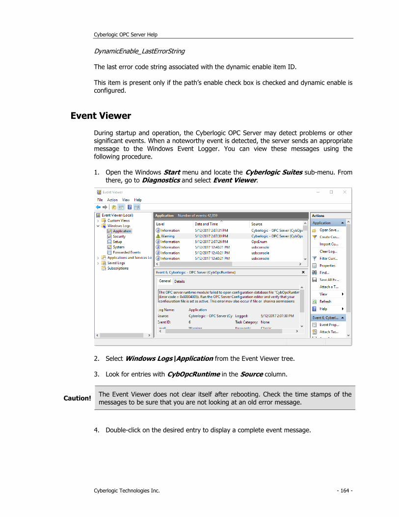
Cyberlogic OPC Server Help
Cyberlogic Technologies Inc. - 164 -
DynamicEnable_LastErrorString
The last error code string associated with the dynamic enable item ID.
This item is present only if the path’s enable check box is checked and dynamic enable is configured.
Event Viewer
During startup and operation, the Cyberlogic OPC Server may detect problems or other significant events. When a noteworthy event is detected, the server sends an appropriate
message to the Windows Event Logger. You can view these messages using the
following procedure.
1. Open the Windows Start menu and locate the Cyberlogic Suites sub-menu. From
there, go to Diagnostics and select Event Viewer.
2. Select Windows Logs\Application from the Event Viewer tree.
3. Look for entries with CybOpcRuntime in the Source column.
Caution! The Event Viewer does not clear itself after rebooting. Check the time stamps of the
messages to be sure that you are not looking at an old error message.
4. Double-click on the desired entry to display a complete event message.
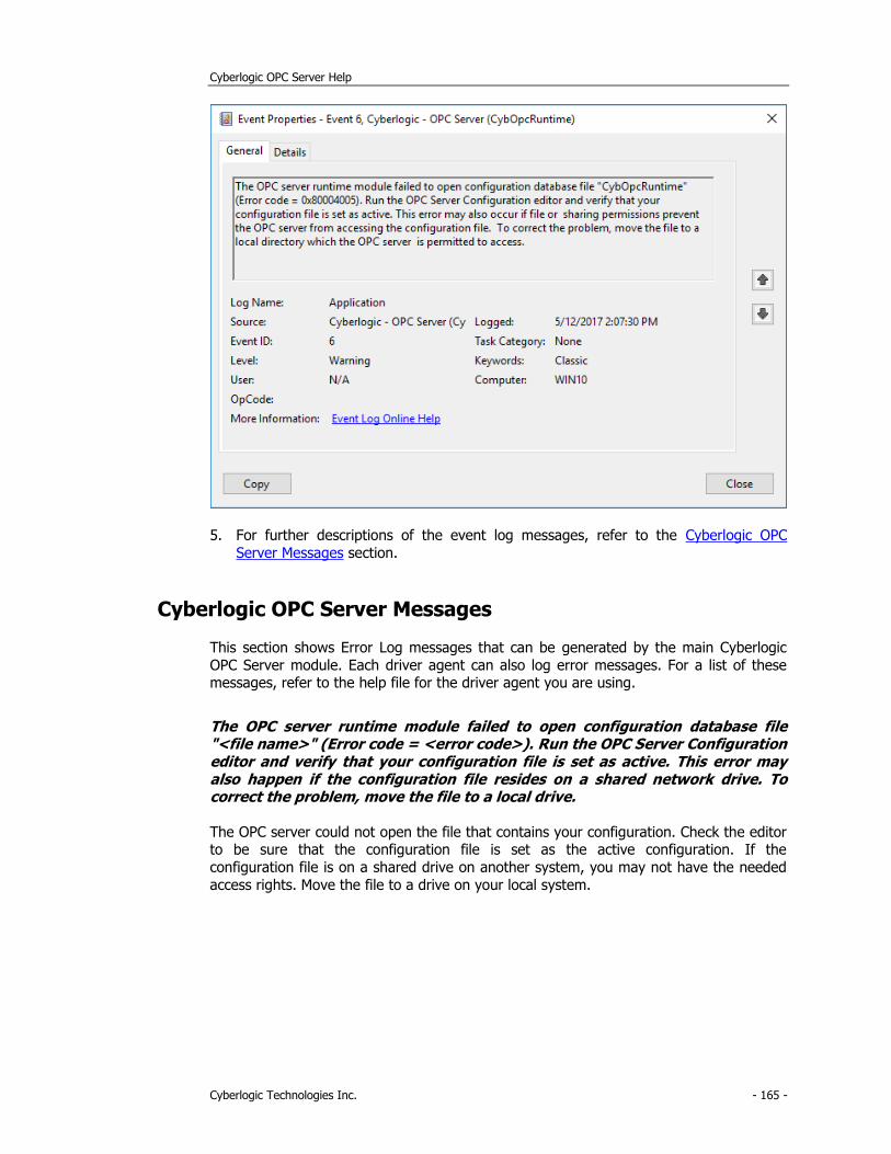
Cyberlogic OPC Server Help
Cyberlogic Technologies Inc. - 165 -
5. For further descriptions of the event log messages, refer to the Cyberlogic OPC
Server Messages section.
Cyberlogic OPC Server Messages
This section shows Error Log messages that can be generated by the main Cyberlogic
OPC Server module. Each driver agent can also log error messages. For a list of these messages, refer to the help file for the driver agent you are using.
The OPC server runtime module failed to open configuration database file "<file name>" (Error code = <error code>). Run the OPC Server Configuration editor and verify that your configuration file is set as active. This error may also happen if the configuration file resides on a shared network drive. To correct the problem, move the file to a local drive.
The OPC server could not open the file that contains your configuration. Check the editor to be sure that the configuration file is set as the active configuration. If the
configuration file is on a shared drive on another system, you may not have the needed
access rights. Move the file to a drive on your local system.
Cyberlogic OPC Server Help
Cyberlogic Technologies Inc. - 166 -
The OPC server runtime module failed to load configuration database file "<file name>" (Error code = <error code>). Your configuration file may be corrupt. Run the OPC Server Configuration editor and verify that you have a valid configuration file. If the editor is also unable to load the configuration data, create a new configuration file.
The OPC server detected that the file that contains your configuration information may be corrupted. Try to open the file with the configuration editor. If you cannot open the
file, and no backup is available, you will have to create a new configuration.
Registration DLL failed to load. The OPC Crosslink has been disabled. Reinstall the product.
A necessary registration DLL could not be loaded. This may indicate a corrupted
installation. Repair the existing installation, or remove and reinstall the software.
The OPC Crosslink has not been activated. The feature has been disabled.
Run the Activation Wizard to activate the OPC Crosslink, Crosslink Premier or Crosslink
Enterprise Suite, or the DHX or MBX OPC Enterprise Suite. You will need the activation codes that came with your license. If you have not purchased a license for any of these
products, contact Cyberlogic's Sales Department.
This is a <hours>-hour promotional copy of the OPC Crosslink. The server started at <start time> and the OPC Crosslink will stop at <stop time>.
This is a time-limited installation of the software. After the stop time, the driver agent will not allow any further I/O operations.
This is a promotional copy of the OPC Crosslink. The allowed operation time has expired. The I/O operations of Crosslink have been disabled.
This is a time-limited installation of the software. The stop time has been reached or
exceeded, so the driver agent will not allow any further I/O operations.
The Cyberlogic License Server failed to respond with valid license information. The I/O operations of the OPC Crosslink have been disabled. Contact the manufacturer's technical support.
The driver agent experienced a problem when it tried to contact the Cyberlogic License
Server. If the license server is not running, start it and then try restarting the driver. If the license server is already running, contact Cyberlogic Tech Support.
Memory allocation error in <function name>. Close some applications. Add more memory to your system. Contact the manufacturer's technical support.
The specified function failed to allocate the needed memory. This is a fatal error. If you
are running low on memory, close some applications or add more memory to your system. If the problem continues, contact technical support for more information on a
possible solution.
Cyberlogic OPC Server Help
Cyberlogic Technologies Inc. - 167 -
Unexpected error in <function name>. Please contact the manufacturer's technical support.
Indicates a possible programming bug in the server. Contact technical support for more information on a possible solution.
Unexpected error in <function name> (Error code = <error code>). Please contact the manufacturer's technical support.
Indicates a possible programming bug in the server. Contact technical support for more
information on a possible solution.
Handler not installed.
During startup, the Cyberlogic OPC Server failed to register the Service Control Handler. Contact technical support for more information on a possible solution.
Bad service request.
The Cyberlogic OPC Server detected an unsupported service request. Contact technical support for more information on a possible solution.
Memory allocation error in <function name>. The server may not operate correctly. Close some applications. Add more memory to your system. Contact the manufacturer's technical support.
The specified function failed to allocate the needed memory. The server will continue to operate, but some functions may not work. If you are running low on memory, close
some applications or add more memory to your system. If the problem continues, contact technical support for more information on a possible solution.
Communication module for driver class <driver agent name> failed to load (Error code = <error code>). All configuration related to this driver class will be ignored. To resolve this problem, please contact the manufacturer's technical support.
This error will be generated if your configuration file was generated on a system with the
listed driver agent installed, but the driver agent is not installed on your system. Install the listed driver agent to correct the problem.
If you believe that the indicated driver agent is installed, this message may indicate that
you have a corrupted installation.
Service started.
The Cyberlogic OPC Server started successfully.
Service stopped.
The Cyberlogic OPC Server has stopped.
Cyberlogic OPC Server Help
Cyberlogic Technologies Inc. - 168 -
Frequently Asked Questions
I am not connected to the network, but my data items are being updated. What’s going on?
Simulation Signals are generating data for the items. Verify that the Simulate check box is cleared for the data item and for each parent up the chain from the data item.
I created a new data item in the Address Space. When I try to look at it with the Data Monitor, the item is shown as Not Available. The entire configuration appears correct. What do I do?
You may not have updated the runtime module of the Cyberlogic OPC Server with your recent configuration changes. To save current configuration and update the server, select
Save & Update Server from the File menu of the OPC Server Configuration Editor, or click the Save & Update Server button on the standard buttons toolbar.
I can’t find any information specific to my communication network in your help file.
This help file describes only the common features of the Cyberlogic OPC Server. For
information related to a particular driver agent, refer to the help file specific for that agent.
I cannot update the server with my new or changed configuration. It always returns a message that the update failed.
On some systems, Windows will spontaneously unregister the server application. You
must manually re-register it. To do this, locate the file CybOpcRuntimeService.exe. In most installations, it will be in the directory C:\Program Files\Common Files\Cyberlogic Shared\OPC.
From the Accessories group of the Windows Start menu, run Command Prompt. (In
the following commands, <Enter> indicates that you should press the Enter key.)
You must change to the drive and directory you just located. To change the drive to C:,
for example, type:
C: <Enter>
Once you are at the correct drive, change the directory by typing this command. (There
is a space after the cd.)
cd \Program Files\Common Files\Cyberlogic Shared\OPC <Enter>
Now type the following. (Note that there is a space before the slash.)
CybOpcRuntimeService.exe /unregserver <Enter>
Finally, type the following. (Again, there is a space before the slash.)
Cyberlogic OPC Server Help
Cyberlogic Technologies Inc. - 169 -
CybOpcRuntimeService.exe /service <Enter>
Close the command prompt window.
I cannot get XML Data Access to work. The Event Viewer shows an error for a User called ASPNET, with the description: “Access denied attempting to launch a DCOM Server using DefaultLaunchPermission”.
You must add the User account ASPNET to the DCOM security settings for the OPC server software, giving it launch and access rights.
To do this, you will use the DCOM configuration editor, dcomcnfg.exe. For details on how to use this editor, refer to the document OPC & DCOM: A Guide to Using the Cyberlogic OPC Server via DCOM. A copy of this document was installed on your system along with the software. To access it, open the Windows Start menu and go to Cyberlogic Suites. Next, open the Help sub-menu, then open OPC, and then click on DCOM Help.
Note that on some systems, you may not get the Event Viewer error message.
Cyberlogic OPC Server Help
Cyberlogic Technologies Inc. - 170 -
APPENDIX A: ITEM PROPERTIES
In the Cyberlogic OPC Server, all data items have properties, or attributes, associated
with them. These attributes are values related to the data item. The OPC Data Access
specification defines several standard properties and allows vendors to define custom properties.
Properties with IDs from 1 – 4999 are defined by the OPC Data Access specification. Refer to the OPC Data Access specification for more information about these properties.
IDs 5000 and above are custom properties defined by each server vendor.
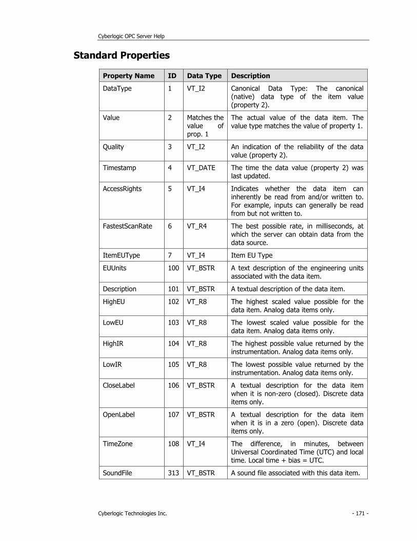
Cyberlogic OPC Server Help
Cyberlogic Technologies Inc. - 171 -
Standard Properties
Property Name ID Data Type Description
DataType 1 VT_I2 Canonical Data Type: The canonical (native) data type of the item value
(property 2).
Value 2 Matches the value of
prop. 1
The actual value of the data item. The
value type matches the value of property 1.
Quality 3 VT_I2 An indication of the reliability of the data
value (property 2).
Timestamp 4 VT_DATE The time the data value (property 2) was
last updated.
AccessRights 5 VT_I4 Indicates whether the data item can
inherently be read from and/or written to.
For example, inputs can generally be read
from but not written to.
FastestScanRate 6 VT_R4 The best possible rate, in milliseconds, at
which the server can obtain data from the
data source.
ItemEUType 7 VT_I4 Item EU Type
EUUnits 100 VT_BSTR A text description of the engineering units
associated with the data item.
Description 101 VT_BSTR A textual description of the data item.
HighEU 102 VT_R8 The highest scaled value possible for the
data item. Analog data items only.
LowEU 103 VT_R8 The lowest scaled value possible for the
data item. Analog data items only.
HighIR 104 VT_R8 The highest possible value returned by the
instrumentation. Analog data items only.
LowIR 105 VT_R8 The lowest possible value returned by the
instrumentation. Analog data items only.
CloseLabel 106 VT_BSTR A textual description for the data item
when it is non-zero (closed). Discrete data
items only.
OpenLabel 107 VT_BSTR A textual description for the data item
when it is in a zero (open). Discrete data
items only.
TimeZone 108 VT_I4 The difference, in minutes, between
Universal Coordinated Time (UTC) and local
time. Local time + bias = UTC.
SoundFile 313 VT_BSTR A sound file associated with this data item.
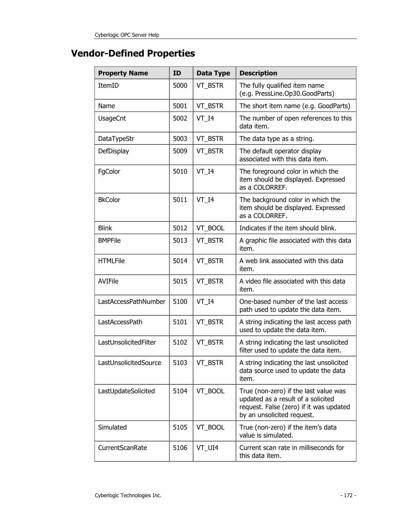
Cyberlogic OPC Server Help
Cyberlogic Technologies Inc. - 172 -
Vendor-Defined Properties
Property Name ID Data Type Description
ItemID 5000 VT_BSTR The fully qualified item name
(e.g. PressLine.Op30.GoodParts)
Name 5001 VT_BSTR The short item name (e.g. GoodParts)
UsageCnt 5002 VT_I4 The number of open references to this
data item.
DataTypeStr 5003 VT_BSTR The data type as a string.
DefDisplay 5009 VT_BSTR The default operator display
associated with this data item.
FgColor 5010 VT_I4 The foreground color in which the
item should be displayed. Expressed
as a COLORREF.
BkColor 5011 VT_I4 The background color in which the
item should be displayed. Expressed
as a COLORREF.
Blink 5012 VT_BOOL Indicates if the item should blink.
BMPFile 5013 VT_BSTR A graphic file associated with this data
item.
HTMLFile 5014 VT_BSTR A web link associated with this data
item.
AVIFile 5015 VT_BSTR A video file associated with this data
item.
LastAccessPathNumber 5100 VT_I4 One-based number of the last access
path used to update the data item.
LastAccessPath 5101 VT_BSTR A string indicating the last access path
used to update the data item.
LastUnsolicitedFilter 5102 VT_BSTR A string indicating the last unsolicited
filter used to update the data item.
LastUnsolicitedSource 5103 VT_BSTR A string indicating the last unsolicited
data source used to update the data
item.
LastUpdateSolicited 5104 VT_BOOL True (non-zero) if the last value was
updated as a result of a solicited request. False (zero) if it was updated
by an unsolicited request.
Simulated 5105 VT_BOOL True (non-zero) if the item’s data
value is simulated.
CurrentScanRate 5106 VT_UI4 Current scan rate in milliseconds for
this data item.

Cyberlogic OPC Server Help
Cyberlogic Technologies Inc. - 173 -
ActualScanRate 5107 VT_UI4 Actual scan rate in milliseconds for
this data item.

Cyberlogic OPC Server Help
Cyberlogic Technologies Inc. - 174 -
APPENDIX B: QUALITY CODES
The OPC specification requires that each data item value must have an associated quality
code. These codes fall into three main categories: good, bad and uncertain. This
appendix describes all of the quality codes used by the Cyberlogic OPC Server. Because the low two bits in the quality code indicate the limit conditions, they are shown here as
LL.
Good Quality Codes
110000LL - Non-specific
The value is good. There are no special conditions.
110110LL - Local Override
The value has been overridden. The Cyberlogic OPC Server returns this code when a simulated signal is used.
Bad Quality Codes
000000LL - Non-specific
The value is bad but the reason is unknown. This is the default quality code used by each
data item.
000001LL - Configuration Error
At runtime, the server may detect that the physical device does not support the requested register type. For example, some devices do not support 6xxxxx registers, so
you would get this code if you attempt to access, for example, register 600102 in such a
device.
000010LL – Not Connected
This code usually indicates an invalid register address.
000011LL – Device Failure
The server could not complete the requested operation due to an internal failure, such as insufficient memory.
000101LL - Last Known Value
Communication has failed, but the last known value is available. Note that the age of the value may be determined from the time stamp.

Cyberlogic OPC Server Help
Cyberlogic Technologies Inc. - 175 -
000110LL - Communication Failure
Communication has failed and there is no last known value available.
Uncertain Quality Codes
010001LL - Last Usable Value
This code is used only with unsolicited communications. The data item was not updated
within the Unsolicited Late Interval. The returned value should be regarded as stale.
Cyberlogic OPC Server Help
Cyberlogic Technologies Inc. - 176 -
APPENDIX C: DATA ACCESS AUTOMATION SUPPORT
The purpose of OPC Data Access Automation is to allow applications which have an OLE
Automation Interface, such as Visual Basic and Visual Basic for Applications, to access
process data from OPC Data Access servers. This is done through a DLL that functions as a wrapper, translating between the OPC interface provided by the server and the
automation interface needed by the client. The wrapper does not support VB Script or Java Script, however.
Compatibility Considerations
The DLL implementing the Data Access Automation layer was developed by the OPC Foundation and made available to OPC software vendors.
Caution! Some providers made custom changes to the DLL, but did not change its name or
ProgID. Consequently, all of the different versions appear to be the same, so you
cannot install more than one version in a single system without causing conflicts.
The DLL provided with Cyberlogic’s software, OPCDAAuto.dll, is the standard OPC
Foundation file with no modifications. To avoid conflicts with other, altered versions that may be on your system, Cyberlogic’s software installation program copies the file onto
your hard drive but does not register it. If you wish to use our version, you must register it. Doing so will change the registration from any other version that may be on your
system to the Cyberlogic version. This, in turn, may affect the operation of software that uses the other version.
Registering the DLL
It is not necessary to copy the DLL to the System 32 directory. You can leave it in the directory where the installation program placed it and simply register it.
1. From the Windows Start menu, open Command Prompt.
2. Change to the directory in which the DLL resides. The default installation directory is:
C:\Program Files\Common Files\Cyberlogic Shared\OPC
3. Type the command: regsvr32 opcdaauto.dll
4. Press the Enter key.
The DLL will be registered.
5. Close the command prompt window.
Cyberlogic OPC Server Help
Cyberlogic Technologies Inc. - 177 -
APPENDIX D: OPC XML DATA ACCESS SUPPORT
Cyberlogic’s OPC servers include support for OPC XML Data Access 1.0 (XML DA), but
this is an optional feature that is not part of the default installation. In addition, the
installation and operation of XML DA requires certain Windows components that may not already be installed on your system. Furthermore, in some systems, the necessary
configuration may be incompatible with other software running on the system. In this case, the user must choose which will run and which will be disabled.
This appendix will assist you in determining what features and settings are required for
your system.
Overview of the Procedure
You will first install Windows Internet Information Services (IIS), with certain required components. After that, you will install the OPC XML DA component of the Cyberlogic
OPC server and verify its security settings. Depending on your operating system, you may then need to select an operating mode for ASP.NET. Finally, you will connect an
OPC XML DA client to the server.
Some of the procedures will vary, depending on the specific Windows operating system you are installing under. These variations will be identified so you can follow the
procedure that applies to your system.
To get started, go to Install Windows Internet Information Services.
Install Windows Internet Information Services
This is a Windows component, and therefore may require your Windows installation CD.
There are two procedures for installing IIS, depending on your operating system:
• Windows
• Windows Server
Windows
1. Open the Start menu and navigate to Control Panel.
2. Open Programs and Features, and then Turn Windows features on or off.
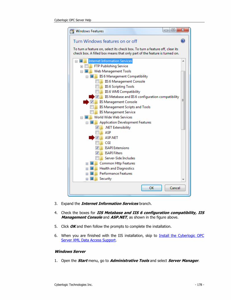
Cyberlogic OPC Server Help
Cyberlogic Technologies Inc. - 178 -
3. Expand the Internet Information Services branch.
4. Check the boxes for IIS Metabase and IIS 6 configuration compatibility, IIS Management Console and ASP.NET, as shown in the figure above.
5. Click OK and then follow the prompts to complete the installation.
6. When you are finished with the IIS installation, skip to Install the Cyberlogic OPC Server XML Data Access Support.
Windows Server
1. Open the Start menu, go to Administrative Tools and select Server Manager.
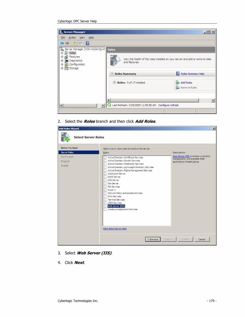
Cyberlogic OPC Server Help
Cyberlogic Technologies Inc. - 179 -
2. Select the Roles branch and then click Add Roles.
3. Select Web Server (IIS).
4. Click Next.
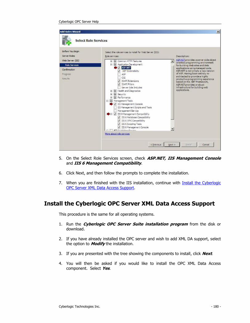
Cyberlogic OPC Server Help
Cyberlogic Technologies Inc. - 180 -
5. On the Select Role Services screen, check ASP.NET, IIS Management Console
and IIS 6 Management Compatibility.
6. Click Next, and then follow the prompts to complete the installation.
7. When you are finished with the IIS installation, continue with Install the Cyberlogic
OPC Server XML Data Access Support.
Install the Cyberlogic OPC Server XML Data Access Support
This procedure is the same for all operating systems.
1. Run the Cyberlogic OPC Server Suite installation program from the disk or download.
2. If you have already installed the OPC server and wish to add XML DA support, select the option to Modify the installation.
3. If you are presented with the tree showing the components to install, click Next.
4. You will then be asked if you would like to install the OPC XML Data Access component. Select Yes.
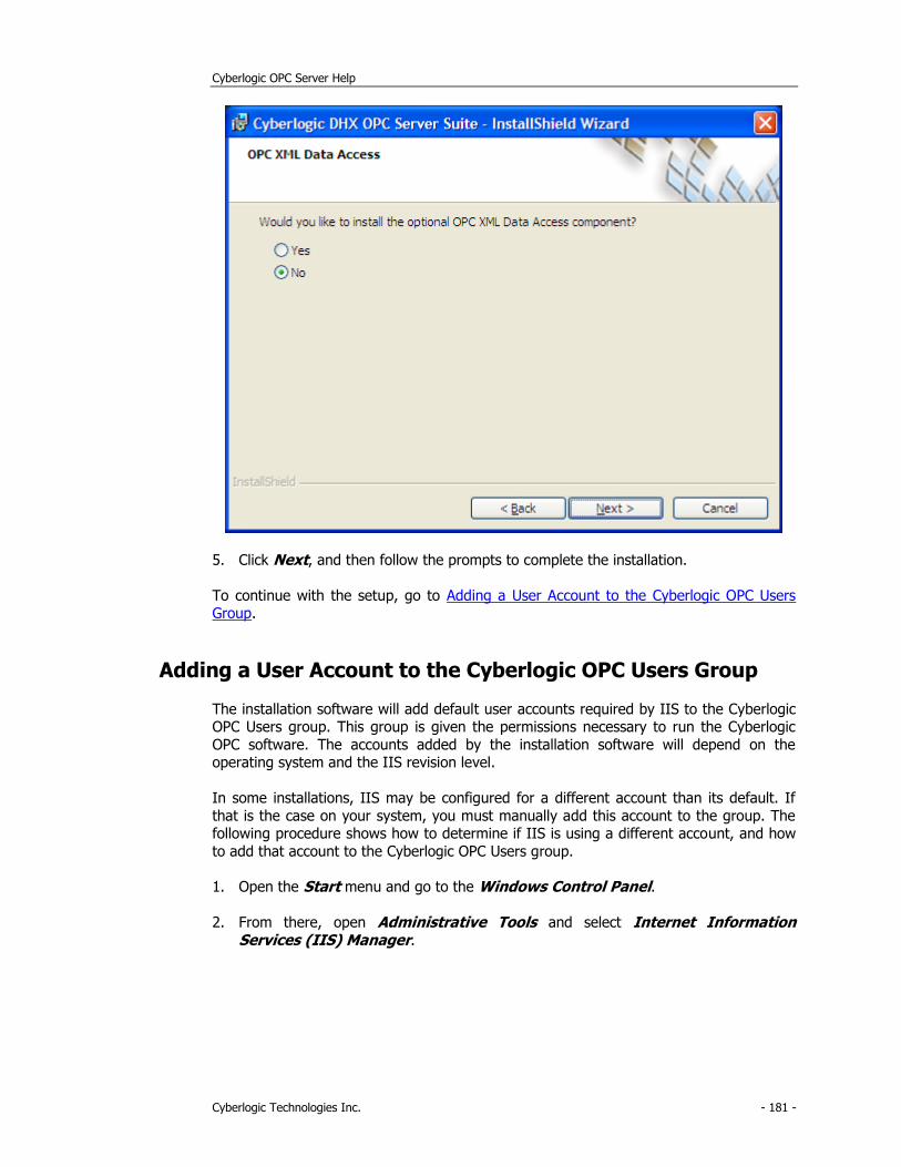
Cyberlogic OPC Server Help
Cyberlogic Technologies Inc. - 181 -
5. Click Next, and then follow the prompts to complete the installation.
To continue with the setup, go to Adding a User Account to the Cyberlogic OPC Users Group.
Adding a User Account to the Cyberlogic OPC Users Group
The installation software will add default user accounts required by IIS to the Cyberlogic OPC Users group. This group is given the permissions necessary to run the Cyberlogic
OPC software. The accounts added by the installation software will depend on the operating system and the IIS revision level.
In some installations, IIS may be configured for a different account than its default. If
that is the case on your system, you must manually add this account to the group. The following procedure shows how to determine if IIS is using a different account, and how
to add that account to the Cyberlogic OPC Users group.
1. Open the Start menu and go to the Windows Control Panel.
2. From there, open Administrative Tools and select Internet Information Services (IIS) Manager.
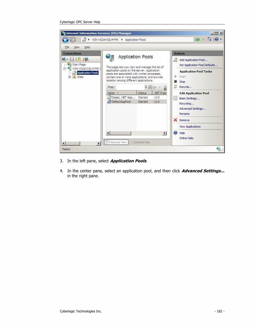
Cyberlogic OPC Server Help
Cyberlogic Technologies Inc. - 182 -
3. In the left pane, select Application Pools.
4. In the center pane, select an application pool, and then click Advanced Settings... in the right pane.
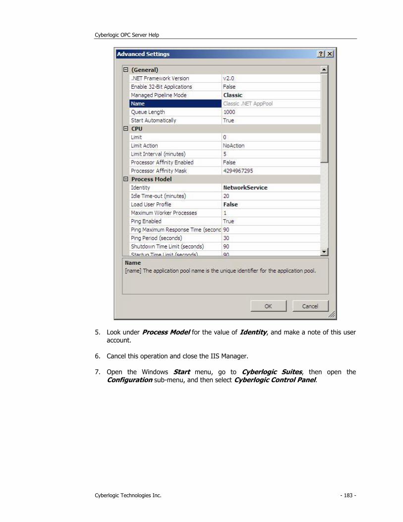
Cyberlogic OPC Server Help
Cyberlogic Technologies Inc. - 183 -
5. Look under Process Model for the value of Identity, and make a note of this user
account.
6. Cancel this operation and close the IIS Manager.
7. Open the Windows Start menu, go to Cyberlogic Suites, then open the
Configuration sub-menu, and then select Cyberlogic Control Panel.
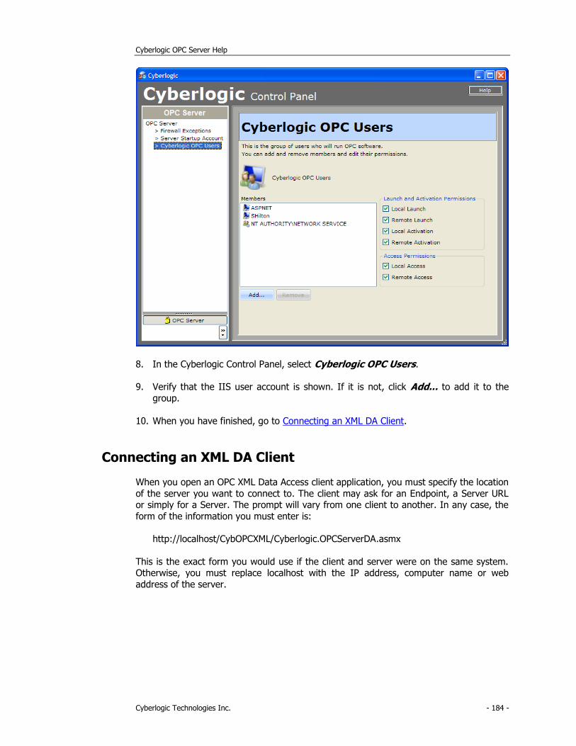
Cyberlogic OPC Server Help
Cyberlogic Technologies Inc. - 184 -
8. In the Cyberlogic Control Panel, select Cyberlogic OPC Users.
9. Verify that the IIS user account is shown. If it is not, click Add... to add it to the
group.
10. When you have finished, go to Connecting an XML DA Client.
Connecting an XML DA Client
When you open an OPC XML Data Access client application, you must specify the location
of the server you want to connect to. The client may ask for an Endpoint, a Server URL or simply for a Server. The prompt will vary from one client to another. In any case, the
form of the information you must enter is:
http://localhost/CybOPCXML/Cyberlogic.OPCServerDA.asmx
This is the exact form you would use if the client and server were on the same system. Otherwise, you must replace localhost with the IP address, computer name or web
address of the server.