cyclic behavior of steel i-beams modified by a welded
TRANSCRIPT

Steel and Composite Structures, Vol. 9, No. 5 (2009) 419-444 419
Cyclic behavior of steel I-beams modified by a welded haunch and reinforced with GFRP
O. Ozgur Egilmez*, Deniz Alkan and Timur Ozdemir
Dept. of Civil Engineering, Izmir Inst. of Technology, Izmir, 35430, Turkey
(Received July 25, 2009, Accepted August 7, 2009)
Abstract. Flange and web local buckling in beam plastic hinge regions of steel moment frames canprevent beam-column connections from achieving adequate plastic rotations under earthquake-inducedforces. Reducing the flange-web slenderness ratios (FSR/WSR) of beams is the most effective way inmitigating local member buckling as stipulated in the latest seismic design specifications. However, existingsteel moment frame buildings with beams that lack the adequate slenderness ratios set forth for new buildingsare vulnerable to local member buckling and thereby system-wise instability prior to reaching the requiredplastic rotation capacities specified for new buildings. This paper presents results from a research studyinvestigating the cyclic behavior of steel I-beams modified by a welded haunch at the bottom flange andreinforced with glass fiber reinforced polymers at the plastic hinge region. Cantilever I-sections with atriangular haunch at the bottom flange and flange slenderness ratios higher then those stipulated in currentdesign specifications were analyzed under reversed cyclic loading. Beam sections with different depth/widthand flange/web slenderness ratios (FSR/WSR) were considered. The effect of GFRP thickness, width, andlength on stabilizing plastic local buckling was investigated. The FEA results revealed that the contribution ofGFRP strips to mitigation of local buckling increases with increasing depth/width ratio and decreasing FSRand WSR. Provided that the interfacial shear strength of the steel/GFRP bond surface is at least 15 MPa,GFRP reinforcement can enable deep beams with FSR of 8-9 and WSR below 55 to maintain plastic rotationsin the order of 0.02 radians without experiencing any local buckling.
Keywords : existing steel buildings; plastic local buckling; glass fiber reinforced polymers; stability.
1. Introduction
Seismic design of welded steel moment frames is generally based on the strong column-weak beam
concept, in which the majority of energy dissipation is anticipated to occur by inelastic deformations in
beams through the formation of plastic hinges near column faces. Seismic provisions, such as Eurocode-8
(2003) and AISC (2005a), require beam-column connections to sustain interstory drift angles of at least
0.02 and 0.035-0.04 radians for intermediate and special moment frames (IMF and SMF), respectively,
without any significant strength degradation; targeting a ductile behavior under earthquake induced forces.
The ductility of welded beam-column connections depends primarily on three failure modes: a- fracture
of beam flange to column groove welds; b- lateral torsional buckling (LTB) of beams; c- flange/web
local buckling (FLB/WLB) at the plastic hinge region of beams. Most of the research conducted after
* Assistant Professor, Corresponding Author, Email: [email protected]
DOI: http://dx.doi.org/10.12989/scs.2009.9.5.419

420 O. Ozgur Egilmez, Deniz Alkan and Timur Ozdemir
the 1994 Northridge (US) and 1995 Kobe (Japan) earthquakes focused on stress reduction methodologies
and improvement of welding procedures to overcome the brittle weld fractures widely observed in
welded SMFs in the aftermath of these earthquakes (ex: Nakashima, et al. 1998, SAC 1996, Uang, et
al. 2000). Based on the findings from these researches new design guidelines and modification methods
have been developed for new and existing steel moment frames, respectively, in order to overcome the
brittle weld fractures and improve the plastic rotation capacity of welded connections (FEMA 2000a,
FEMA 2000b, AISC 1999). Some typical recommendations include providing a reduced beam, welded
haunch, or bolted bracket modification; as well as replacing the beam flange to column groove welds
with a weld metal with higher Charpy V-Notch toughness. Fig. 1 depicts a pre-Northridge bolted web -
welded flange connection modified by a welded haunch at the bottom flange.
Although brittle weld fractures can now be satisfactorily mitigated for new and existing welded steel
moment frame connections with post-Northridge design guidelines and modification methods, inelastic
local buckling of beam flanges and webs is still a threat for the ductility and stability of structural members.
In current seismic design codes (AISC 2005a, Eurocode-8 2003) local instabilities are controlled by
limiting flange-web slenderness ratios. However, the rotation capacities expected from beam-column
connections have increased as a result of post-Northridge and post-Kobe research. Hence, especially
older structures that lack adequate slenderness ratios are vulnerable to local member buckling and thereby
system-wise instability due to overloads such as earthquakes or other extreme events prior to reaching
the required plastic rotation capacities specified for new buildings. Okazaki, et al. (2006) and Nakashima,
et al. (2002 and 2003) have investigated the stability requirements for beams in steel SMF under
earthquake induced forces and proposed even more stringent limits for unbraced length and width-
thickness ratios to control instabilities during large plastic rotations. Furthermore, even higher levels of
Fig. 1 Typical pre-Northridge bolted web - welded flange connection modified by a welded haunch at bottom flange

Cyclic behavior of steel I-beams modified by a welded haunch and reinforced with GFRP 421
plastic rotations than those stipulated in provisions may also be needed for buildings in soft soils,
irregular buildings, and important structures. In addition, the repair of local buckles is an expensive and
challenging application. Hence, mitigation of local inelastic instabilities especially in older steel moment
frame connections is an important task, which will not only improve the ductility of the structure, but
will also minimize cumbersome repair works in the aftermath of extreme events.
As the use of fiber reinforced polymers (FRP) has increased in strengthening and repair of steel
members in recent years, using FRPs in stabilizing local instabilities has also attracted attention (ex:
Accord and Earls 2006). A research study was conducted at Izmir Institute of Technology to investigate
the cyclic behavior of existing welded steel moment frame connections rehabilitated by a triangular
haunch welded to the beam bottom flange and reinforced with glass FRP (GFRP) laminates. The
research consisted of laboratory investigations and finite element analytical (FEA) studies. This paper
presents results from the FEA studies. Cantilever I-sections with a triangular haunch at the bottom flange
and flange slenderness ratios (FSR) higher then those stipulated in current design specifications were
analyzed under reversed cyclic loading. Both bare beam and GFRP reinforced sections were investigated.
The behavior of bare steel sections were then compared with those of steel sections reinforced with
GFRP strips. The effects of GFRP thickness, width, and length on stabilizing local buckling were investigated.
The flexural resistance of the beams at column face, together with interlaminar shear stresses in GFRP
strips, and shear stresses at the beam-GFRP binding surface were also examined.
Background information will be presented first, followed by the description and verification of the
finite element model, as well as an overview of the study. Results from the FEA studies and recommendations
on the use of GFRP laminates for different slenderness ratios will then be presented. The paper is
concluded by a brief summary and conclusions.
2. Background and previous work
The high stiffness/strength to weight ratios of FRP materials, combined with their resistance to
corrosion have increased their use in repair and strengthening of steel members. Generally, high
modulus carbon FRP (CFRP) laminates with elastic modulus similar to that of steel are preferred in
strengthening applications. On the other hand, GFRP has a much smaller modulus than that of steel,
which limits its use in strengthening applications. However, this modulus mismatch is an asset when the
primary goal is to stabilize inelastic local buckling with the least possible strength increase in the
section. A strength increase in the beam section is not desired in steel moment frame connections because
such an increase will result in higher forces in beam-column welds, which may exceed the design
moment capacity of the connection. In a study by Accord and Earls (2006) it was observed that in a
steel-GFRP composite system, while the low modulus of GFRP as compared to that of steel will not
allow a significant strength increase in the steel section, its compressive strength can enable GFRP
strips to maintain their flexural strength to provide bracing to the underlying steel in the plastic hinge
region. This type of a composite action will enhance the plastic rotation capacity of the plastic hinge
region; provided that an early debonding or GFRP fracture do not control the behavior.
The most significant work on stability of local buckling utilizing FRP composites is a finite element
based study conducted by Accord and Earls (2006). In this study, Accord and Earls performed finite
element analyses on cantilever steel beams with GFRP strips under monotonic loading and investigated
the contribution of GFRP strips to the plastic rotation capacity and flexural strength of different sections.
The plastic rotation capacity of the beam sections was shown to increase significantly, whereas the

422 O. Ozgur Egilmez, Deniz Alkan and Timur Ozdemir
flexural strength increase in the sections was in the order of 20 to 25%. However, the study did not focus
on the response of the bond surface between steel and GFRP. Sayed-Ahmed (2004) also performed a
finite element study in which CFRP strips were used on the compression region of the webs of I-beams
and investigated the contribution of CFRP strips in delaying local web buckling. The results of the
parametrical study showed that through the use of CFRP strips the local buckling of the web could be
delayed resulting in critical load and strength increase. Ekiz, et al. (2004) conducted an experimental
study investigating the energy dissipating capacity of double channel truss members under reversed
cycling loading, which were wrapped by CFRP around the plastic hinge region. The test results showed
that CFRP wrapping could increase the size of the yielded plastic hinge region and inhibit occurrence of
local buckling.
3. Finite element model and overview of study
The three dimensional finite element program ANSYS (2007) was used to conduct FEA studies on
the cyclic behavior of beams modified by a triangular haunch welded to the beam bottom flange and
reinforced with GFRP strips. A half span steel frame model was adopted in the study as shown in Fig. 2.
The column was modeled as a rigid bar; whereas the beam, triangular haunch, and the stiffener at the
end of the haunch were modeled using eight-node quadrilateral shell elements with six degrees of
freedom per node. This element possesses plasticity, large deflection, and large strain capabilities. The
flange and web nodes of the beam and the triangular haunch at the end adjacent to the column face were
coupled to the coinciding column nodes of the rigid column elements in all directions (3 displacements:
UX, UY, UX, and 3 rotations: ROTX, ROTY, ROTZ) to form a fixed end connection. The nodes at the
Fig. 2 Half span steel frame model

Cyclic behavior of steel I-beams modified by a welded haunch and reinforced with GFRP 423
bottom flange face of the web and flange of the triangular haunch were coupled to the coinciding
bottom flange nodes of the beam in all directions to simulate the weld between the beam bottom flange
and triangular haunch. The other end of the beam was supported by a roller; unconstrained in the
longitudinal direction and constrained in the vertical direction. The beam was laterally restrained (both
twist and out-of-plane motion) at mid-span and at the end with the roller support in order to ensure
lateral torsional buckling did not control the failure mode. The column was simply supported at the
bottom and supported by a roller at the top; unconstrained in the vertical direction and constrained in
the longitudinal direction. Both top and bottom of the column were constrained against out of plane motion.
The length of the column and the beam were taken as 4,000 mm and 3,500 mm, respectively. In the
initial 1/3 length of the beam from the fixed end the mesh sizes for the beam flanges and web were
16.5 × 20 mm and 47 × 20 mm, respectively. The mesh sizes for the remainder of the beam was
16.5 × 58 mm in the flanges and 47 × 58 mm in the web. Both geometric and material non-linearity
was considered. The yield strength (Fy) and elastic modulus (E) of steel were taken as 345 MPa and 200
GPa, respectively. A bilinear kinematic hardening rule was adopted for the stress-strain behavior of
steel, with a secondary stiffness equal to 1/100 of the elastic modulus. The effects of initial imperfections
were also considered in the model, similar to the procedure followed by Accord and Earls (2006). A
linear eigenvalue buckling analyses was performed for each beam section prior to non-linear analyses
in which the cantilever beam was displaced towards the top flange. The displacement field obtained
from the first eigenmode was then scaled by a factor of L/1000 and applied to the model geometry to
create the initial imperfections. The factor of L/1000 is selected based on the permissible out of
straightness specified in AISC (2005b).
GFRP laminates and epoxy resin used to attach GFRP to the steel surface were jointly modeled using
layered eight-node solid elements with three degrees of freedom per node (translations in the nodal X,
Y, and Z directions). The initial layer of the element adjacent to the flange shell elements was treated as
the epoxy resin and the other layers were treated as GFRP laminates. The thickness of each GFRP layer
and epoxy resin were taken as 0.9 mm and 0.5 mm, respectively. The mechanical properties of GFRP
and interfacial surface between steel and GFRP were determined through laboratory tests confirming to
ASTM standards performed by Guven at Izmir Institute of Technology (Guven 2009). Guven used 0o/
+45o/90o/−45o oriented glass fibers provided by METIX Co. and epoxy resin DTE/1000/1001 provided
by DURATEK Co. Guven’s test results indicated that the compression modulus of GFRP material in 0o
was 10 GPa. The elastic modulus of the epoxy resin was taken from the manufacturer’s brochures as
2.6 GPa. Poisson’s ratio was assumed as 0.3 for all materials. The finite element model of the cantilever
beam with the triangular haunch and GFRP strips is shown in Fig. 3.
Cyclic loading was applied to the beams as drifts to the tip of the rigid column element, according to
the loading sequence shown in Fig. 4. The rotation, θ, shown in Fig. 4 represents the rotation of the
beam at the fixed end; which is also equal to the rotation of the rigid column element. The sequence is
identical to the loading sequence defined in AISC (2005a) for cyclic tests of beam-to-column moment
connections in SMF and IMF; except that the initial elastic cycles were omitted.
The validity of the FEA simulation was verified by comparing the cyclic behavior of a wide flange I-
section with that of the FEA simulation. The test used in the verification study was a full-scale cantilever
beam test conducted at the structural engineering laboratory of Izmir Institute of Technology. The beam
was a European wide flange beam, HE400AA, with a depth of 378 mm, web thickness of 9.5 mm,
flange thickness of 13 mm, and width of 300 mm. The fixed end of the beam was modified by a welded
haunch at the bottom flange. The cantilever beam was loaded cyclically similar to the loading protocol
defined in AISC (2005a) for cyclic tests of beam-to-column moment connections in SMF and IMF. A

424 O. Ozgur Egilmez, Deniz Alkan and Timur Ozdemir
photograph of the HE400AA beam in the test setup and the loading sequence followed in the test are
shown in Figs. 5 and 6, respectively. Due to the fact that the laboratory facilities did not have a strong
wall, a strong steel frame was constructed and the test beam was bolted to it as seen in Fig. 5. Since the
small displacements in the steel frame that would occur in the test could not be predicted prior to the
actual test, slight deviations from the AISC (2005a) loading protocol were inevitable during testing.
Fig. 7 shows the load-fixed end rotation behavior of the HE400AA test beam and FEA simulation.
The test was stopped at the second cycle of 0.03 radians of rotation when the load started to drop. As
can be seen from the figure the FEA model predicted the behavior of the test beam very well. The only
slight deviation occurred at the second cycle of 0.03 rad of rotation, where the FEA model reached only
up to about 94% of the moment capacity of the test beam at positive rotation. This was probably due to
Fig. 3 Finite element model of cantilever beam with triangular haunch and GFRP strips
Fig. 4 Loading protocol followed in FEA studies

Cyclic behavior of steel I-beams modified by a welded haunch and reinforced with GFRP 425
the fact that the connection between the welded haunch stiffener and the flanges was not exactly
simulated in the model. In the test beam the 25 mm thick stiffeners were fillet welded to the flanges on
both sides. This type of a connection provided a 45-50 mm wide and 130 mm long rigid area on the
flanges where the stiffeners were welded. In the FEA model however, the coinciding nodes of the top
and bottom elements of the stiffeners were coupled to the flange elements’ coinciding nodes along a single
line. Although all six degrees of freedoms were coupled, the connection that was simulated in the
model was more flexible than the connection provided in the actual beam. Hence, the flanges of the
FEA model were more vulnerable to local buckling than the flanges of the actual beam.
The steel I-sections considered in the study consisted of beam sections with flange slenderness ratios
exceeding the flange slenderness limits set forth in current seismic design specifications. In AISC (2005a)
Fig. 5 Photograph of HE400AA test specimen in the test setup
Fig. 6 Loading sequence followed in the cyclic test

426 O. Ozgur Egilmez, Deniz Alkan and Timur Ozdemir
limiting slenderness ratios for flanges and webs of rolled or built-up I shaped sections in flexural
compression are 7.2 and 59, respectively, for SMF with Fy = 345 MPa and E = 200 GPa. Fig. 8 shows
the European and US wide-flange beams with FSR greater than 7.2. It can be seen in Fig. 8 that the
flange and web slenderness ratios (FSR and WSR) of deep beams (2 < depth/width < 3) range between
7.5-9.5 and 43-57, respectively, and for shallow beams (1 < depth/width < 2) FSR and WSR range
between 7.5-13.5 and 20-48, respectively. Three different beam depth/width (d/bf) ratios were selected:
2.79, 2.1, and 1.38. The flange width was taken as 265 mm for all sections and the desired d/bf ratios
were obtained by changing the beam depth. Beam depths were 740, 556.5, and 365 mm for d/bf ratios
of 2.79, 2.1, and 1.38, respectively. It can be seen in Fig. 8 that the flange slenderness ratios of the
majority of the sections are between 8 and 10. Therefore, for all d/bf ratios FSR of 8, 9, and 10 were
Fig. 7 Load-Rotation behavior of HE400AA beam and finite element simulation
Fig. 8 US and European wide flange beams with FSR greater than 7.2

Cyclic behavior of steel I-beams modified by a welded haunch and reinforced with GFRP 427
investigated. Since flange and web local buckling are not independent from each other, different WSR
were examined for each flange slenderness ratio. It was observed in Fig. 8 that as the d/bf ratio of the
wide flange sections decreased, the WSR of the sections also decreased. Therefore, for sections with d/bf
= 2.79, 2.1, and 1.38 WSR of 40-45-50-55-60, 40-45-50, and 30-35-40 were selected, respectively. The
desired FSR and WSR values were obtained by changing the flange and web thicknesses of the beams.
The geometric properties of the beams modeled in this study are presented in Table 1. The depth and
length of the triangular haunches were taken as 228/380, 167/278 and 114/190 mm for d/bf = 2.79, 2.10,
and 1.38, respectively. The triangular haunch dimensions were obtained following the guidelines presented
in AISC (1999).
Table 1 Geometric properties of beam sections used in the FEA study
SectionDesignation
Beam Length(mm)
Beam Depth(mm)
Flange Width(mm)
FlangeThickness (mm)
WebThickness (mm)
Depth/WidthRatio
D740-F8W40 3500 740 265 16.56 18.50 2.79
D740-F8W45 3500 740 265 16.56 16.44 2.79
D740-F8W50 3500 740 265 16.56 14.80 2.79
D740-F8W55 3500 740 265 16.56 13.45 2.79
D740-F8W60 3500 740 265 16.56 12.33 2.79
D740-F9W40 3500 740 265 14.72 18.50 2.79
D740-F9W45 3500 740 265 14.72 16.44 2.79
D740-F9W50 3500 740 265 14.72 14.80 2.79
D740-F9W55 3500 740 265 14.72 13.45 2.79
D740-F9W60 3500 740 265 14.72 12.33 2.79
D740-F10W40 3500 740 265 13.25 18.50 2.79
D740-F10W45 3500 740 265 13.25 16.44 2.79
D740-F10W50 3500 740 265 13.25 14.80 2.79
D740-F10W55 3500 740 265 13.25 13.45 2.79
D740-F10W60 3500 740 265 13.25 12.33 2.79
D556-F8W40 3500 556 265 16.56 13.90 2.10
D556-F8W45 3500 556 265 16.56 12.36 2.10
D556-F8W50 3500 556 265 16.56 11.12 2.10
D556-F9W40 3500 556 265 14.72 13.90 2.10
D556-F9W45 3500 556 265 14.72 12.36 2.10
D556-F9W50 3500 556 265 14.72 11.12 2.10
D556-F10W40 3500 556 265 13.25 13.90 2.10
D556-F10W45 3500 556 265 13.25 12.36 2.10
D556-F10W50 3500 556 265 13.25 11.12 2.10
D365-F8W30 3500 380 265 16.56 12.66 1.38
D365-F8W35 3500 380 265 16.56 10.86 1.38
D365-F8W40 3500 380 265 16.56 9.50 1.38
D365-F9W30 3500 380 265 14.72 12.66 1.38
D365-F9W35 3500 380 265 14.72 10.86 1.38
D365-F9W40 3500 380 265 14.72 9.50 1.38
D365-F10W30 3500 380 265 13.25 12.66 1.38
D365-F10W35 3500 380 265 13.25 10.86 1.38
D365-F10W40 3500 380 265 13.25 9.50 1.38

428 O. Ozgur Egilmez, Deniz Alkan and Timur Ozdemir
4. FEA results
The sections listed in Table 1 were analyzed both with and without GFRP strips in order to observe
the effects of GFRP strips to the cyclic behavior of each beam section. In evaluating the cyclic behavior
of sections reinforced with GFRP strips the moment at the column face, shear stress of the interface
between steel and GFRP, and interlaminar shear stress of GFRP strips were checked at every load step
prior to local buckling to make sure the design moment of the connection, shear strength of the interface,
and interlaminar shear strength of the GFRP strips were not exceeded. The maximum design moment
of the connection was taken as 1.2Mp, which is in correlation with AISC (2005c).
There are many potential failure modes of a steel-FRP composite system under flexure. The major
ones that involve the FRP material and the adhesive layer are tensile rupture or compressive failure of
the FRP material and debonding of the steel-FRP bond surface. Among these failure modes, debonding
is often the weakest link (Cadei, et al. 2004). The most significant stresses in a bond layer between steel
and FRP are the longitudinal shear stresses and through the thickness normal stresses, which is also
known as peeling stress. These stresses are generally the highest at the ends of the FRP laminates or in
the regions of large local deformations such as buckling. A tensile normal stress at the adhesive layer
may lead to peeling of the FRP away from the steel surface and accelerate debonding. However, the
negative effects of the peeling stresses are neglected in this study and focus is mainly given to the longitudinal
shear stresses.
Recently, many studies have been conducted that investigated potential ways to mitigate peeling
stresses and premature debonding. Some of the recommended applications of these research investigations
include reverse tapering the edges of the FRP laminates (Schnerch, et al. 2007) and providing cross-
wraps (Chen and Das 2009). In addition, Cadei, et al. (2004) showed that for system with FRP laminates
of small thickness, which is the case in this study, the peeling stresses were negligible compared with
shear stresses. Nevertheless, it is assumed in this study that the ends of the FRP material are anchored to
the steel surface in some way and that peeling stresses do not affect debonding. Furthermore, the increase
in peeling stresses in the buckled regions is not of interest in this research, because the longitudinal
shear stresses in the adhesive layer are always checked against the shear strength of the adhesive layer
prior to local buckling. It is further assumed that the steel-GFRP composite action ends when either of
the following takes place: a- local buckling initiates; b- interfacial shear strength of the steel-GFRP
bond layer is exceeded prior to local buckling; or c- interlaminar shear strength of the GFRP laminates
is exceeded prior to local buckling. The tensile and compressive stresses that developed on the GFRP
strips were much lower than the measured tensile and compressive strengths of the GFRP material and
therefore were not discussed in the results.
In order to determine the interfacial and interlaminar shear strength values that would be used in the
study, a literature review was conducted. It was seen that the interfacial shear strength of steel-GFRP
surfaces bonded with commonly used epoxies could reach up to 20-25 MPa (El Damatty and Abushagur
2003, Boone 2002) and the interlaminar shear strength of commonly used GFRP materials could reach
up to 20 MPa (Lili, et al. 2008). A resistance factor of 0.75 was applied to the lower limit of the above
interfacial shear strengths and a resistance factor of 0.90 was applied to the above interlaminar shear
strength. Hence, shear strength of the interface and interlaminar shear strength of the GFRP strips were
taken as 15.0 MPa and 18.0 MPa, respectively. A lower resistance factor was accepted for the interfacial
shear strength as compared to that for the interlaminar shear strength. This was due to the fact that
bonding GFRP strips to steel surfaces involves many steps that need to be performed carefully and
could be difficult to control out in the field.

Cyclic behavior of steel I-beams modified by a welded haunch and reinforced with GFRP 429
5. Optimum location, length, and width of GFRP strips
In order to determine the optimum location, length, and width of GFRP strips a series of analyses were
conducted with a beam section having a depth/width ratio of 2.79, depth of 740 mm, width of 265 mm,
FSR of 10, and WSR of 65. Although this section (D740-F10W65) is not among the sections listed in
Table 1, the response of the sections listed in Table 1 to different GFRP length, width, thickness, and
placement configurations were similar to that of section D740-F10W65. Three different configurations
were considered for GFRP placement: 1- Bottom of the top flange and top of the bottom flange outside
the welded haunch region (Fig. 9), 2- Both sides of the top and bottom flanges outside the welded haunch
region (Fig. 10), and 3- Both sides of the top flange outside and inside the welded haunch region and
both sides of the bottom flange only outside of the welded haunch region (Fig. 11). As seen in these
figures the length, width, and thickness of GFRP strips are identified as ratios of beam depth, beam
width, and flange thickness, respectively. The length of GFRP strips denotes the length beyond the
welded haunch stiffener in the plastic hinge region of the beam. The results obtained from several analyses
with different GFRP widths, lengths, and locations are presented in Table 2.
Prior to discussion of the results in Table 2, the M/Mp-θ (normalized moment at column face –
rotation at fixed end) behavior of a beam with and without GFRP will be explained to clarify how the
values presented in Table 2 were obtained. Fig. 12 shows the M/Mp-θ behaviors of a bare beam and
beam with GFRP. The beam depth, width, d/bf ratio, FSR, and WSR were 740 mm, 265 mm, 2.79, 9, and
55, respectively. The GFRP configuration was identical to the one shown in Fig. 11. The GFRP length,
thickness, and width were db, where db is equal to depth of the beam, 0.37tf (3 layers at top and 3 layers
at bottom of each flange = 3 + 3 layers), where tf is equal to thickness of the flange, and 0.45bf, where
bf is equal to the flange width. Positive rotation (bending) corresponds to compression at the top flange
and negative rotation (bending) corresponds to compression at the bottom flange. In the figure a drop in
capacity indicates the occurrence of local buckling. It can be observed from the figure that for the bare
beam the last cycles prior to local buckling were the 1st cycle of 0.015 rad of rotation and the 1st cycle of
0.017 rad of rotation at the bottom and top flanges, respectively. In other words, local flange buckling
occurred at the 2nd cycle of 0.015 rad of rotation and the 1st cycle of 0.02 rad of rotation at bottom and
Fig. 9 GFRP placement: Configuration 1

430 O. Ozgur Egilmez, Deniz Alkan and Timur Ozdemir
top flanges, respectively. The fact that local buckling initiates at the bottom flange prior to the top
flange is consistent with the applied initial imperfections.
For the GFRP reinforced beam the last cycles prior to local buckling were the 2nd cycle of 0.015 rad
of rotation and the 1st cycle of 0.02 rad of rotations at the bottom and top flanges, respectively. The
maximum shear stress at the interface and interlaminar shear stress at these cycles were 13.4 and 15.0
MPa, respectively. The maximum interfacial shear stress was very close to the accepted interfacial
shear strength of the bond surface between steel and GFRP. The maximum M/Mp values were 0.99 and
1.08 for the beam with GFRP for negative and positive bending, respectively; which were lower than
the design moment of the connection. The addition of GFRP to the steel section enabled the rotation capacities
in positive and negative bending to increase by 1 cycle, whereas the increase in the moment capacity
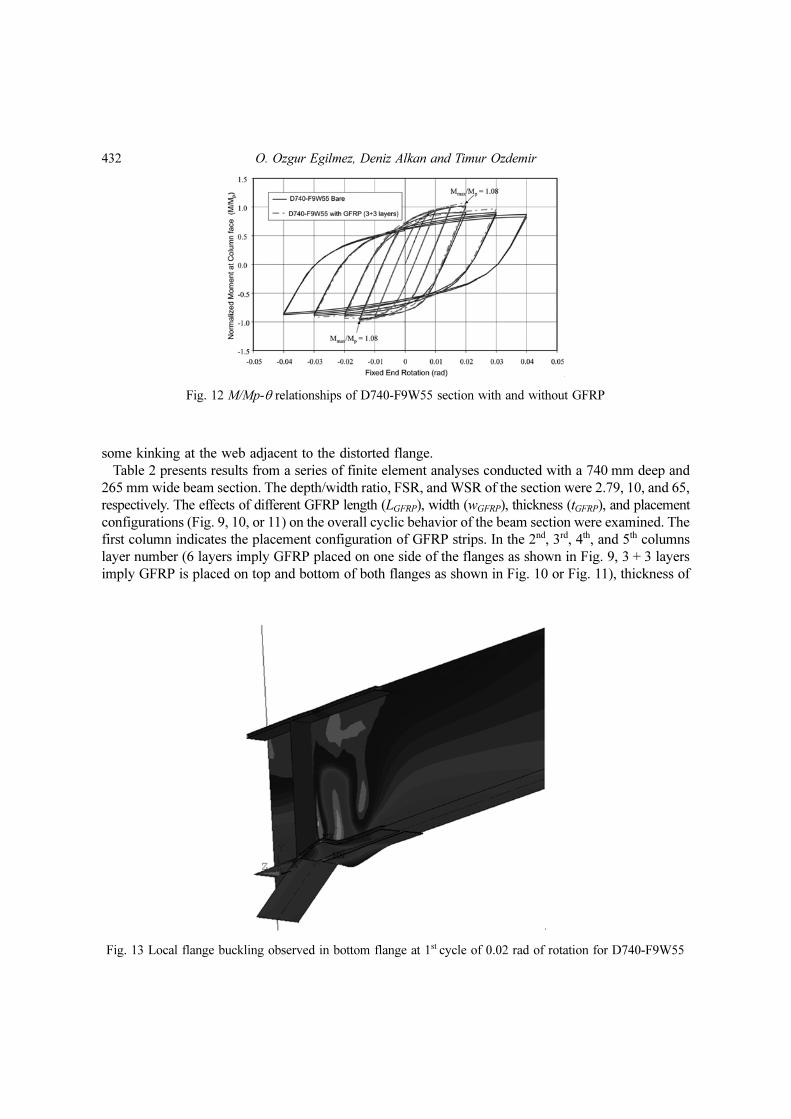
was minimal. Local distortions in the bottom flange observed in the model with GFRP at a rotation of
0.02 rad are shown in Fig. 13. As can be seen from the figure major distortions occur in the flanges with
Fig. 10 GFRP placement: Configuration 2
Fig. 11 GFRP placement: Configuration 3

Cyclic b
ehavio
r of steel I-b
eam
s modified
by a
weld
ed h
aunch
and rein
forced
with
GF
RP
431
Table 2 Analyses results for section D740-F10W65
1 2 3 4 5 6 7 8 9 10 11 12 13 14 15
GF
RP
Pla
cem
ent
# ofLayers (Total thickness of
GFRP)
tGFRP LGFRP bGFRP
Negative Bending Positive Bending@ 0.01 rad of Rota-
tion
@ Last Rotation/Cycle Prior to Local
Buckling
Mmax/Mp
Last Rot./Cycle
Prior toLocal
Buckling
Location of Local Buckling (outside or inside of WH region)
Mmax/Mp
Last Rot./Cycle
Prior to Local
Buckling
Location of Local Buckling (outside or inside of WH region)
Max Inter-facialShearStress(MPa)
Max Inter-laminarShearStress(MPa)
Max Inter-facialShearStress(MPa)
Max Inter-laminarShearStress(MPa)
1 Bare - - - - 0.89 0.010/2nd Outside 0.95 0.015/1st Outside - - - -
2
Conf
igura
tion 1
(F
ig. 9) 6
(5.4 mm)0.41tf
Lb 0.20bf 0.90 0.010/2nd Outside 0.96 0.015/2nd Outside 11.5 12.5 19.7 19.3
3 2db 0.20bf 0.90 0.010/2nd Outside 0.96 0.015/2nd Outside 11.5 12.5 19.7 19.3
4 2db 0.45bf 0.93 0.015/1st Outside 0.97 0.015/2nd Outside 9.7 11.4 16.5 17.6
5
Con
figura
tion
2(F
ig. 10)
3+3 0.41tf 2db 0.45bf 0.94 0.015/1st Outside 0.97 0.015/2nd Outside 5.4 8.1 8.7 12.4
63+3
(5.4 mm)0.41tf db 0.45bf 0.94 0.015/1st Outside 0.97 0.015/2nd Outside 5.4 8.1 8.7 12.4
74+4
(7.2 mm)0.54tf db 0.45bf 0.94 0.015/1st Outside 0.97 0.015/2nd Inside 6.9 9.2 11.6 14.3
85+5
(9.0 mm)0.68tf db 0.45bf 0.94 0.015/2nd Outside 0.98 0.015/2nd Inside 8.3 10.2 14.3 16.2
9
Con
figura
tion
3 (F
ig. 11
)
4+4(7.2 mm)
0.41tf db 0.45bf 0.94 0.015/1st Outside 0.98 0.015/2nd Outside 6.8 9.2 12.6 14.1
432 O. Ozgur Egilmez, Deniz Alkan and Timur Ozdemir
some kinking at the web adjacent to the distorted flange.
Table 2 presents results from a series of finite element analyses conducted with a 740 mm deep and
265 mm wide beam section. The depth/width ratio, FSR, and WSR of the section were 2.79, 10, and 65,
respectively. The effects of different GFRP length (LGFRP), width (wGFRP), thickness (tGFRP), and placement
configurations (Fig. 9, 10, or 11) on the overall cyclic behavior of the beam section were examined. The
first column indicates the placement configuration of GFRP strips. In the 2nd, 3rd, 4th, and 5th columns
layer number (6 layers imply GFRP placed on one side of the flanges as shown in Fig. 9, 3 + 3 layers
imply GFRP is placed on top and bottom of both flanges as shown in Fig. 10 or Fig. 11), thickness of
Fig. 12 M/Mp-θ relationships of D740-F9W55 section with and without GFRP
Fig. 13 Local flange buckling observed in bottom flange at 1st cycle of 0.02 rad of rotation for D740-F9W55

Cyclic behavior of steel I-beams modified by a welded haunch and reinforced with GFRP 433
GFRP (as a ratio of flange thickness, tf), length of GFRP (as a ratio of beam depth db beyond the haunch
stiffener), and width of GFRP (as a ratio of flange width, bf, for each side of a flange) are presented,
respectively. The 6th and 9th columns present Mmax/Mp values for negative and positive bending, respectively.
The 7th and 10th columns present the last rotation/cycle number achieved prior to local buckling for
negative and positive bending, respectively. The 8th and 11th columns indicate whether buckling occurs
inside or outside of the welded haunch region at the flanges.
The interfacial and interlaminar shear stresses were also examined at different load steps and results
are presented in columns 12 through 15. The maximum interfacial shear stress at the surface between
steel and GFRP and interlaminar shear stress in GFRP at the 2nd cycle of 0.01 rad of rotation are presented
in column 12 and 13, respectively. These are the largest stress values that develop at the top and bottom
flanges at this rotation. The purpose of presenting these values is to compare the shear stresses of
different GFRP systems at a fixed rotation prior to local buckling. In the 14th and 15th columns the maximum
interfacial and interlaminar shear stresses are presented at the last rotation/cycle prior to local buckling
for negative and positive bending, respectively. The maximum interfacial and interlaminar shear stresses
occurred around the welded haunch stiffener. The values presented in columns 14 and 15 are the shear
stress values that develop at the last rotation/cycle of the bottom flange. Due to the implemented imperfections
the top flange buckled at a later rotation/cycle than the bottom flange. However, the maximum interfacial
and interlaminar shear stress values for the top flange at the corresponding last rotation/cycle prior to
local buckling were similar to the values given in columns 14 and 15.
The first row of Table 2 contains information about the bare steel model. The 2nd, 3rd, and 4th rows are
for steel-GFRP systems with 6 layers of GFRP (Fig. 9 with tGFRP = 0.40tf). The 5th and 6th rows are for
systems with 3 layers of GFRP (Fig. 10 with tGFRP = 0.20tf + 0.20tf = 0.40tf) on each side of the flanges
(3 + 3 layers). The total thickness of the GFRP strips in one flange for 6 layers and 3 + 3 layers are
identical. However, in 6 layer systems a thicker GFRP is placed on one side of the flanges, whereas in
3+3 layer systems a thinner GFRP is placed on both sides of the flanges. Comparison of rows 2 and 3
shows that keeping the length of GFRP laminates at twice the beam depth beyond the welded haunch
stiffener is identical to using full length GFRP laminates. For both of the systems maximum moments
at column face, last rotation/cycle numbers, location of local buckling, maximum interfacial and
interlaminar shear stresses at 0.01 rad of rotation, and maximum interfacial and interlaminar shear
stresses at last cycle prior to local buckling were identical.
In row 4 results from a steel-GFRP system with a GFRP length, thickness, and width of 2db, 0.40tf,
and 0.45bf, respectively, are presented. Increasing the width of the GFRP strips to 0.45bf from 0.20bf
decreased the maximum interfacial and interlaminar shear stresses at 0.01 rad of rotation to 9.7 and 11.4
MPa from 11.5 and 12.5 MPa, respectively. An increase in the last rotation/cycle number prior to local
buckling was observed only in negative bending. The last rotation/cycle number prior to local buckling
at negative bending for the system with a GFRP width of 0.20bf was 2nd cycle of 0.01 rad of rotation;
whereas for the system with GFRP width of 0.45bf this value increased to 1st cycle of 0.015 rad of
rotation.
In order to further decrease the interfacial and interlaminar shear stresses, a system with GFRP placed
on both sides of flanges were analyzed (rows 5 and 6), keeping the total thickness of GFRP the same. It
was seen that using GFRP strips on both sides of flanges (Fig. 10) decreased the maximum interfacial
and interlaminar shear stresses at 0.01 rad of rotation to 5.4 and 8.1 MPa from 9.7 and 11.4 MPa (row
4), respectively. Another analysis was conducted to determine whether the length of the GFRP strips
could further be decreased. Row 6 presents results from a system identical to the system in row 5,
except the length of the GFRP strips. Comparison of the results presented in rows 6 and 5 shows that

434 O. Ozgur Egilmez, Deniz Alkan and Timur Ozdemir
decreasing the length of GFRP strips to db from 2db does not weaken the contribution of GFRP strips.
For the system presented in row 6 the maximum interfacial and interlaminar shear stresses at last cycle
prior to local buckling were 8.7 and 12.4 MPa, respectively. Since these values were smaller than the
accepted interfacial and interlaminar shear stresses (15.0 and 18 MPa), the analyses were continued by
increasing the layer number of GFRP.
Rows 7 and 8 present results from steel-GFRP systems with 4+4 and 5+5 layers of GFRP, respectively.
The major difference in behavior observed in systems with 4+4 and 5+5 layers of GFRP was a shift in
the location of initial local buckling at the top flange. In the system with 3+3 layers of GFRP initial top
flange local buckling was observed just outside the welded haunch (WH) region. However, in the
systems with 4+4 and 5+5 layers of GFRP initial top flange local buckling was observed inside the WH
region adjacent to the column face. Increasing the bracing provided to the top flange outside the WH
region inevitably forced local buckling to shift to other locations under high strains, such as the portion
of the top flange adjacent to the column face. The presence of the welded haunch at the bottom flange
prevented bottom flange local buckling to shift adjacent to the column face inside the WH region. As
can be seen in columns 14 and 15 the maximum interfacial and interlaminar shear stresses increased as
the thickness of the GFRP increased. The shear strength of the interfacial layer was exceeded in the
system with 5+5 layers of GFRP.
Since local flange buckling adjacent to the column face is not desirable, another analysis was conducted
by providing GFRP at both outside and inside of the WH region (as shown in Fig. 11). The purpose of
such an addition was to shift the top flange buckling back to the plastic hinge region just outside the
welded haunch region. Row 9 presents results from a system with 4+4 layers of GFRP and GFRP
configuration identical to the one shown in Fig. 11. The addition of the GFRP inside the welded haunch
region did not have an effect on the rotation capacities prior to local buckling as compared to the behavior
obtained from the system presented in row 7. However, the initiation of local buckling at the top flange
was moved back to the plastic hinge region adjacent to the WH stiffener.
The results presented in Table 2 revealed that the contribution of GFRP strips to the cyclic behavior
of steel beams modified by a welded haunch at the bottom flange was limited by the interfacial shear
strength of the bonded layer between steel and GFRP. The optimum length and width of GFRP strips,
which lead to the smallest interfacial and interlaminar shear stresses, were db and 0.45bf, respectively,
and the optimum GFRP configuration was configuration 3 (Fig. 11).
Prior to conducting finite element analyses with the sections listed in Table 1, the writers also
investigated the effects of modulus of elasticity of GFRP and placing GFRP also on the web to the
cyclic behavior of beams. Table 3 presents results from analyses conducted on steel-GFRP systems with
higher GFRP elastic modulus and different GFRP configurations. Rows 1 and 2 of Table 3 present results
from bare beam and GFRP reinforced sections, respectively. The steel-GFRP system had 4+4 number
of GFRP layers placed according to configuration 3 (Fig. 11). The system in row 2 is the same system
presented in row 9 of Table 2. The systems in rows 3 and 4 are identical to the system in row 2, except
the elastic modulus of GFRP. The elastic modulus of GFRP was taken as 20000 and 200000 MPa for
the systems in rows 3 and 4, respectively. For the system presented in row 2 the elastic modulus of
GFRP was taken as 10000 MPa. Finally in rows 5 and 6, results from a steel-GFRP steel system with
GFRP (elastic modulus of 10000 MPa) placed also in the web are presented. The system in row 5 is
reinforced with GFRP in the web outside the WH region for a distance db, in addition to the GFRP
configuration shown in Fig. 11. The system in row 6 is reinforced with GFRP in the web both inside
and outside the WH region.
Comparison of the results presented in rows 2, 3, and 4 shows that increasing the elastic modulus of

Cyclic b
ehavio
r of steel I-b
eam
s modified
by a
weld
ed h
aunch
and rein
forced
with
GF
RP
435
Table 3 Analyses results for section D740-F10W65 with different GFRP modulus and placement
1 2 3 4 5 6 7 8 9 10 11 12 13 14
GF
RP
Pla
cem
ent
# of Layers (Total thick-
ness of GFRP)
GFRP Place-
ment on Web
E of GFRP (MPa)
tGFRP LGFRP bGFRP
Negative Bending Positive Bending@ Last Rotation/
Cycle Prior to Local Buckling
Mmax/Mp
Last Rot./Cycle
Prior to Local
Buckling
Location of Local Buckling (outside or inside of WH region)
Mmax/Mp
Last Rot./Cycle
Prior to Local
Buckling
Location of Local Buckling (outside or inside of WH region)
Max Interfa-
cial Shear Stress (MPa)
Max Inter-
laminar Shear Stress (MPa)
1 Bare - - - - - - 0.89 0.010/2nd Outside 0.95 0.015/1st Outside - -
2
Confi
gura
tion 3
(F
ig.
11)
4+4(7.2 mm)
N/A 10000 0.54tf db 0.45bf 0.94 0.015/1st Outside 0.98 0.015/2nd Outside 12.6 14.1
3 N/A 20000 0.54tf db 0.45bf 0.99 0.017/1st Outside 1.01 0.018/1st Outside 19.6 24.2
4 N/A 200000 0.54tf db 0.45bf 1.18 0.017/1st Outside 1.22 0.018/1st Outside 59.9 78.4
5
Confi
gura
tion 3
(F
ig.
11)
4+4(7.2 mm)
Out of theWH
region10000 0.54tf db 0.45bf 0.96 0.015/1st Outside 1.00 0.015/2nd Inside 12.9 14.5
6Inside andoutside ofthe WH
10000 0.54tf db 0.45bf 0.97 0.015/1st Outside 1.00 0.015/2nd Outside 12.8 14.3

436 O. Ozgur Egilmez, Deniz Alkan and Timur Ozdemir
GFRP had a minor effect on the rotation capacities prior to local buckling for both the top and bottom
flanges. However, the maximum interfacial and interlaminar shear stresses for both systems prior to
local flange buckling increased beyond the accepted shear strengths. The interfacial and interlaminar
shear stresses prior to local flange buckling jumped to 19.6/24.2 MPa and 59.9/78.4 MPa at the end of
the 2nd cycle of 0.015 rad of rotation for the systems with GFRP modulus of 20000 and 200000 MPa,
respectively. For the system with GFRP modulus of 200000 MPa, not only the maximum shear stresses
but also the maximum moment at the column face increased considerably. The maximum normalized
column moments (Mmax/Mp) for this system were 1.18 and 1.22 for negative and positive bendings,
respectively. The design moment capacity of the connection in positive bending was exceeded.
The addition of GFRP on the web also did not have a major effect on the behavior (rows 5 and 6). The
maximum column face moments and shear stresses at the last rotation prior to local buckling increased
slightly for both configurations. The addition of GFRP on the web only at the outside of the welded
haunch region (row 5) forced the location of initial local buckling to shift to the top flange inside the
welded haunch region. The reason for such behavior is probably due to the fact that the addition of the
GFRP on the web prevents the initiation of local buckling outside the welded haunch region and forces
it to initiate inside the welded haunch region where the web is free of GFRP. Addition of GFRP to the
web inside the welded haunch region shifted local buckling back to the plastic hinge region beyond the
welded haunch stiffener at the flanges (row 6).
6. Sections with depth/width ratio of 2.79
The sections presented in Table 1 were analyzed with the GFRP configuration shown in Fig. 11. The
width of GFRP was taken as 0.45bf and the length as db beyond the haunch stiffener for all sections.
Results from analyses conducted on sections with a depth/width ratio of 2.79 will be presented in this
section. Prior to looking at the results in a table format the M/Mp-θ behavior of one of the sections will
be presented. The normalized moment at the column face – rotation at fixed end (M/Mp-θ) behavior of
section D740-F8W40 with and without GFRP is shown in Fig. 14. Three layers of GFRP on each side
of the flanges were used. In the figure positive and negative rotations indicate compression on the top
and bottom flanges, respectively. It can be observed from the figure that in the bare section strength
degradation initiates at the end of the 2nd cycle of 0.02 rad of rotation and the 1st cycle of 0.02 rad of
rotation for positive and negative bending, respectively. The strength degradations continue in the
following rotations as the severity of local buckling increases and the normalized column moments at
the column face at the end of the 2nd cycle of 0.04 rad of rotation drop to 0.90 and 0.94 for positive and
negative bendings, respectively. These values are higher than the minimum required flexural resistance
at the column face (0.80 M/Mp) at an interstory drift angle of 0.04 rad for special moment frames as
stated in AISC (2005a).
The addition of 3+3 layers of GFRP to the steel section increases the rotation/cycle values prior to
local buckling. For positive and negative bendings these values increase to the 1st cycle of 0.025 rad of
rotation and the 2nd cycle of 0.02 rad of rotation, respectively. Although there seems to be no strength
degradation until the end of the 1st cycle of 0.03 rad of rotation for both positive and negative bending,
investigating the stress fields available in ANSYS (2007) revealed that local flange buckling initiated at
the end of the above-mentioned rotations/cycles. The analysis of the section with GFRP was stopped at
the end of 0.03 rad of rotation since the maximum interfacial and interlaminar shear strengths were
previously exceeded.

Cyclic behavior of steel I-beams modified by a welded haunch and reinforced with GFRP 437
The maximum normalized moments at the column face (Mmax/Mp) were 1.09 and 1.20 for negative
and positive bending, respectively, which were smaller or equal to the design moment of the connection. It
can be observed in Fig. 14 that these values were actually achieved at the end of the 1st cycle of 0.03 rad
of rotation, at which maximum interfacial shear strength was already exceeded. However, the
assumption that steel-GFRP interaction and therefore the ability of GFRP strips to brace local buckles
ends when the shear strength of the interface is exceeded can be unconservative when the aim is to determine
the maximum moment that can be achieved in a real system. If the steel-GFRP interaction is still partly
active even after the shear strength of the interface is exceeded at one or more locations throughout the
GFRP strips, the maximum achieved moment can be higher than the moment achieved at the time when
the shear strength was first exceeded. Hence, the Mmax/Mp values presented in rows 8 and 9 in Table 4
are the maximum values observed in the M/Mp-θ graphs of GFRP reinforced sections.
The normalized moment at the column face - rotation at fixed end (M/Mp-θ) behavior of sections with
depth/width ratio of 2.79 listed in Table 1 was examined. Table 4 presents the key results obtained from
the M/Mp-θ behaviors of these sections. Columns 1, 2, and 3 indicate the section designation, number of layers
together with the total thickness of GFRP in mm, and thickness of GFRP as a ratio of the thickness of
the flange, respectively. The GFRP layer number and thickness presented in columns 2 and 3 are the
thickest GFRP that could be used without exceeding the interfacial shear strength of the bond surface
between steel and GFRP or interlaminar shear strength of GFRP laminates prior to local flange buckling.
Interfacial and interlaminar shear stresses increased significantly once flange local buckling initiated.
The 4th and 6th columns present last rotation/cycle of bare sections prior to local buckling for negative
and positive bending, respectively. The 5th and 7th columns present the last rotation/cycle number of
GFRP reinforced sections prior to local buckling for negative and positive bending, respectively. The 8th
and 9th columns present Mmax/Mp values of GFRP reinforced sections for negative and positive bending,
respectively. The 10th and 11th columns present M/Mp values of bare sections at the end of the 2nd cycle
of 0.04 rad of rotation for negative and positive bending, respectively. The maximum interfacial and
interlaminar shear stresses of sections with GFRP at the last rotation/cycle prior to local buckling are
presented in columns 12 and 13 for negative and positive bending, respectively. Maximum shear
stresses generally occurred around the welded haunch stiffener for both flanges.
It can be seen from columns 2 and 3 that for all of the sections 3+3 number of GFRP layers were the
most that could be used without exceeding the interfacial shear strength of the bond surface between
Fig. 14 M/Mp-θ relationships of D740-F8W40 section with and without GFRP

438
O. O
zgur E
gilm
ez, Den
iz Alka
n a
nd T
imur O
zdem
ir
Table 4 FEA results for sections with depth/width ratio of 2.79
1 2 3 4 5 6 7 8 9 10 11 12 13
SectionDesignation
# of Layers (Total
thickness of GFRP)
tGFRP
Last Rotation/Cycle Prior to Local Buck-ling Mmax/Mp for Sec-
tions with GFRP
M/Mp @ the end of 2nd Cycle of 0.04
rad of Rotation for Bare Sections
Max Shear Stresses @ Last Rotation/
Cycle Prior to Local Buckling
Negative Bending Positive Bending
BareSection
Sectionw/ GFRP
BareSection
Sectionw/ GFRP
NegativeBending
PositiveBending
NegativeBending
PositiveBending
InterfacialInterlami-
nar
1 D740-F8W403+3
(5.4 mm)0.33tf 0.020/1st 0.020/2nd 0.020/2nd 0.025/1st 1.09 1.20 0.94 0.90 13.0 13.1
2 D740-F8W453+3
(5.4 mm)0.33tf 0.020/1st 0.020/2nd 0.020/2nd 0.025/1st 1.06 1.12 0.91 0.87 13.4 14.6
3 D740-F8W503+3
(5.4 mm)0.33tf 0.015/2nd 0.020/1st 0.020/1st 0.020/2nd 1.05 1.10 0.89 0.88 13.3 14.1
4 D740-F8W553+3
(5.4 mm)0.33tf 0.015/2nd 0.018/1st 0.020/1st 0.020/2nd 1.00 1.09 0.88 0.86 13.3 14.3
5 D740-F8W603+3
(5.4 mm)0.33tf 0.015/1st 0.015/2nd 0.015/2nd 0.020/1st 0.99 1.07 0.86 0.84 14.3 14.6
6 D740-F9W403+3
(5.4 mm)0.37tf 0.015/1st 0.015/2nd 0.020/2nd 0.023/1st 1.04 1.18 0.91 0.84 12.4 13.9
7 D740-F9W453+3
(5.4 mm)0.37tf 0.015/1st 0.015/2nd 0.020/2nd 0.023/1st 1.03 1.09 0.88 0.84 12.7 13.9
8 D740-F9W503+3
(5.4 mm)0.37tf 0.015/1st 0.015/2nd 0.020/1st 0.020/2nd 0.99 1.08 0.86 0.84 13.1 14.1
9 D740-F9W553+3
(5.4 mm)0.37tf 0.015/1st 0.015/2nd 0.017/1st 0.020/1st 0.99 1.08 0.85 0.82 13.4 15.0
10 D740-F9W603+3
(5.4 mm)0.37tf 0.015/1st 0.015/2nd 0.015/2nd 0.017/1st 0.99 1.05 0.84 0.79 13.3 13.6
11 D740-F10W403+3
(5.4 mm)0.41tf 0.015/2nd 0.015/2nd 0.020/1st 0.020/1st 1.01 1.09 0.87 0.83 11.9 13.9
12 D740-F10W453+3
(5.4 mm)0.41tf 0.015/2nd 0.015/2nd 0.020/1st 0.020/1st 0.99 1.08 0.85 0.78 12.3 13.8
13 D740-F10W503+3
(5.4 mm)0.41tf 0.015/1st 0.015/2nd 0.018/1st 0.020/1st 0.99 1.08 0.81 0.78 12.6 13.8
14 D740-F10W553+3
(5.4 mm)0.41tf 0.015/1st 0.015/2nd 0.015/2nd 0.020/1st 0.98 1.07 0.81 0.77 12.9 13.8
15 D740-F10W603+3
(5.4 mm)0.41tf 0.014/1st 0.015/2nd 0.015/2nd 0.016/1st 0.97 1.02 0.81 0.76 13.3 13.8

Cyclic behavior of steel I-beams modified by a welded haunch and reinforced with GFRP 439
steel and GFRP prior to local buckling. The interfacial shear stresses achieved for the sections prior to
local flange buckling ranged between 11.9 to 13.4 MPa, which were somewhat close to the accepted
interfacial shear strength (15.0 MPa) of the bond surface. The interlaminar shear stresses of the sections
ranged between 13.1 and 15.0 MPa. The interfacial shear strength of GFRP strips was taken as 18 MPa.
Results presented in columns 8 and 9 show that the design moment capacity of the connection (1.2Mp)
was not exceeded neither in negative nor positive bending in any of the sections. The largest normalized
column face moment occurred in section D740-F8W40 at positive bending with 1.20. The results
presented in columns 10 and 11 show that strength degradation in most of the sections was below 20%
at the end of the 2nd cycle of 0.04 rad of rotation. Sections D740-F9W60/F10W45/F10W50/F10W55/
F10W60 experienced strength degradations in excess of 20% at the end of the 2nd cycle of 0.04 rad of
rotation, especially in positive bending.
For bare sections initial local flange buckling occurred at a lower rotation/cycle at the bottom flange
than the top flange, which was consistent with the implemented imperfections in the models. In
negative bending almost none of the bare sections reached 0.02 rad of rotation without local buckling.
Only sections D740-F8W40 and D740-F8W45 reached the first cycle of 0.02 rad of rotation without
any local buckling. However, in positive bending bare sections D740-F8W40/F8W45/F9W40/F9W45
completed the two cycles of 0.02 rad of rotation and sections D740-F8W50/F8W55/F9W50/F10W40/
F10W45 completed the first cycle of 0.02 rad of rotation without any local buckling.
Comparison of the rotation values of bare sections with sections with GFRP strips reveals that the
addition of 3+3 layers of GFRP increased the rotation capacity of bare sections prior to local buckling
by at least one cycle in both negative and positive bendings. The only exception to this was section
D740-F10W60 in positive bending, which was the most slender section among all sections with a
depth/width ratio of 2.79. The addition of 3+3 layers of GFRP enabled almost all of the sections to
reach to 0.02 rad of rotation in positive bending. Sections D740-F9W60 and D740-F10W60 reached
only 0.017 and 0.016 rad of rotations in positive bending, respectively, with the addition of the GFRP
strips. In negative bending the addition of 3+3 layers of GFRP strips enabled all of the sections to
complete 2 cycles at 0.015 rad of rotation or higher without any local buckling. Sections D740-F8W40
and D740-F8W45 completed the full 2 cycles of 0.02 rad of rotation, section D740-F8W50 completed
the first cycle of 0.02 rad of rotation, and section D740-F8W55 completed the first cycle of 0.018 rad of
rotation. The rest of the sections completed the second cycle of 0.015 rad of rotation in negative bending
without any local buckling.
Examining the rotations in positive bending of sections D740-F8W40/F8W45 and D740-F9W40/
F9W45 indicates that the contribution of the GFRP strips to the rotation capacity of the sections decreases
with increasing FSR. While the rotation capacities in positive bending of bare sections D740-F8W40/
F8W45 and D740-F9W40/F9W45 with no local buckling were the same (second cycle of 0.02 rad of
rotation), the rotation capacities with no local buckling differed with the addition of GFRP strips to
these sections. While sections D740-F8W40/F8W45 with an FSR of 8 were capable of reaching the end
of the 1st cycle of 0.025 rad of rotation with the addition of the GFRP strips, sections D740-F9W40/
F9W45 with an FSR of 9 reached the end of the 1st cycle of 0.023 rad of rotation with the addition of
the GFRP strips without any local buckling. The same comment could be made for the relationship
between WSR and contribution of GFRP reinforcement. Comparison of the rotation values prior to
local buckling of section D740-F8W50 and D740-F8W55 in negative bending shows that the contribution
of GFRP strips decreases as the WSR of the sections increase. The addition of 3+3 layers of GFRP
strips to section D740-F8W50 with WSR of 50 increased the rotation capacity of the section to 0.02 rad
of rotation from 0.015 rad of rotation. However, for section D740-F8W55 with WSR of 55 the addition

440 O. Ozgur Egilmez, Deniz Alkan and Timur Ozdemir
of 3+3 layers of GFRP strips increased the rotation capacity of the section to 0.018 rad of rotation from
0.015 rad of rotation.
7. Sections with depth/width ratio of 2.10
Table 5 presents results from the M/Mp-θ behaviors of sections with depth/width ratio of 2.10. For
bare sections the rotation capacities that were achieved without any local buckling or strength
degradation were around 0.030 rad and 0.020 rad for positive and negative bending, respectively. The
results presented in columns 10 and 11 shows that the strength degradations at the end of 2nd cycle of
0.04 rad of rotation were more than 20% for almost all of the sections. Only section D556-F8W40
experienced degradations below 20%. All of the other sections suffered strength degradations in excess
of 20% either only at negative bending or at both negative and positive bending. Using 3+3 layers of
GFRP strips for sections with FSR of 8 and 9 caused the interlaminar shear strength of GFRP strips to
be exceeded. Therefore, 2+2 layers of GFRP strips were the thickest layer that could be used for these
sections without the interlaminar shear strength being exceeded. For sections with an FSR of 10 3+3
layers of GFRP strips could be used.
Comparison of the rotation values prior to local buckling of bare sections with sections with GFRP
(columns 4, 5, 6, and 7) shows that in negative bending the addition of GFRP strips did not increase the
rotation capacity of the sections. Only sections D556-F10W40 and D-556-F10W45 showed a slight
increase, which was not significant to consider. In positive bending only four out of the nine sections
showed an increase in the rotation capacity. The rotation capacities in positive bending of sections
D556-F8W45/F8W50/F9W50/F10W40 increased to the 2nd cycle of 0.03 rad, 2nd cycle of 0.03 rad, 1st
cycle of 0.03 rad, and 1st cycle of 0.025 rad from the 1st cycle of 0.03 rad, 1st cycle of 0.03 rad, 2nd cycle
of 0.020 rad, and 2nd cycle of 0.020 rad, respectively. The maximum normalized column face moment
of sections with GFRP was 1.15, which was achieved by section D556-F8W40 in positive bending.
8. Sections with depth/width ratio of 1.38
Table 6 presents results from the M/Mp-θ behaviors of sections with depth/width ratio of 1.38. The
results presented in column 4 and 6 reveal that the rotation capacities of the bare sections prior to local
flange buckling were around 0.04 rad and 0.03 rad for positive and negative bending, respectively. In
addition, the strength degradations of the bare sections at the end of 2nd cycle of 0.04 rad of rotation
were below 20%. For sections D365-F8W30/F8W35/F8W40/F9W35/F9W40 the addition of even 1+1
layers of GFRP strips caused the interfacial shear strength of the bond surface between steel and GFRP
to be exceeded prior to local buckling of the flanges. For sections D365-F9W35/F10W30/F10W35/
F10W40 interfacial shear stresses developed at the bond surface between steel and 1+1 layers of GFRP
remained below the accepted interfacial shear strength. Although the interfacial shear strength was not
exceeded for these sections with 1+1 layers of GFRP strips, the GFRP reinforcement did not improve
the rotation capacities of these three sections, as can be observed by comparing the rotation values
presented in columns 4-5 and 6-7.
The reason behind the incapability of GFRP strips to brace local buckles in shallow sections probably
lies in the shorter depths of these sections. Since the flange widths of all the sections (shallow or deep)
that were analyzed are the same, as the depth of the sections gets shorter, the coupling forces in the

Cyclic b
ehavio
r of steel I-b
eam
s modified
by a
weld
ed h
aunch
and rein
forced
with
GF
RP
441
Table 5 FEA results for sections with depth/width ratio of 2.10
1 2 3 4 5 6 7 8 9 10 11 12 13
SectionDesignation
# of Layers (Total
thickness of GFRP)
tGFRP
Last Rotation/Cycle Prior toLocal Buckling Mmax/Mp for Sec-
tions with GFRP
M/Mp @ the end of 2nd Cycle of 0.04
rad of Rotation for Bare Sections
Max Shear Stresses @ Last Rotation/
Cycle Prior to Local BucklingNegative Bending Positive Bending
BareSection
Sectionw/ GFRP
BareSection
Sectionw/ GFRP
NegativeBending
PositiveBending
NegativeBending
PositiveBending
InterfacialInterlami-
nar
1 D556-F8W402+2
(3.6 mm)0.22tf 0.020/2nd 0.020/2nd 0.035/1st 0.035/1st 1.01 1.15 0.84 1.01 10.5 16.4
2 D556-F8W452+2
(3.6 mm)0.22tf 0.020/2nd 0.020/2nd 0.030/1st 0.030/2nd 0.97 1.06 0.79 0.86 10.9 16.3
3 D556-F8W502+2
(3.6 mm)0.22tf 0.020/2nd 0.020/2nd 0.030/1st 0.030/2nd 0.96 1.07 0.76 0.82 10.8 15.9
4 D556-F9W402+2
(3.6 mm)0.22tf 0.020/1st 0.020/1st 0.030/1st 0.030/1st 0.93 1.05 0.72 0.86 10.4 16.5
5 D556-F9W452+2
(3.6 mm)0.22tf 0.020/1st 0.020/1st 0.030/1st 0.030/1st 0.91 1.04 0.69 0.80 10.6 16.2
6 D556-F9W502+2
(3.6 mm)0.22tf 0.020/1st 0.020/1st 0.020/2nd 0.030/1st 0.9 1.03 0.66 0.77 10.7 15.8
7 D556-F10W403+3
(5.4 mm)0.41tf 0.015/2nd 0.018/1st 0.020/2nd 0.025/1st 0.91 1.04 0.67 0.80 10.1 13.5
8 D556-F10W453+3
(5.4 mm)0.41tf 0.015/2nd 0.018/1st 0.020/2nd 0.020/2nd 0.89 0.99 0.62 0.76 10.4 13.6
9 D556-F10W503+3
(5.4 mm)0.41tf 0.015/2nd 0.015/2nd 0.020/2nd 0.020/2nd 0.87 0.96 0.60 0.71 10.8 13.3

442
O. O
zgur E
gilm
ez, Den
iz Alka
n a
nd T
imur O
zdem
ir
Table 6 FEA results for sections with depth/width ratio of 1.38
1 2 3 4 5 6 7 8 9 10 11 12 13
SectionDesignation
# of Layers (Total
thickness of GFRP)
tGFRP
Last Rotation/Cycle Prior to Local Buckling
Mmax/Mp for Sec-tions with GFRP
M/Mp @ the end of 2nd Cycle of
0.04 rad of Rota-tion for Bare Sec-
tions
Max Shear Stresses @ Last Rotation/Cycle Prior to Local
BucklingNegative Bending Positive Bending
Bare Sec-tion
Section w/ GFRP
Bare Sec-tion
Section w/ GFRP
Nega-tive
Bending
Positive Bending
Nega-tive
Bending
Positive Bending
Interfa-cial
Interlam-inar
1 D365-F8W301+1
(1.8 mm)0.11tf 0.030/2nd 0.030/2nd 0.040/2nd 0.040/2nd N/A N/A 0.98 1.06 15.5 N/A
2 D365-F8W351+1
(1.8 mm)0.11tf 0.030/2nd 0.030/2nd 0.040/2nd 0.040/2nd N/A N/A 0.94 1.05 15.7 N/A
3 D365-F8W401+1
(1.8 mm)0.11tf 0.030/2nd 0.030/2nd 0.040/1st 0.040/1st N/A N/A 0.92 1.05 16.0 N/A
4 D365-F9W301+1
(1.8 mm)0.11tf 0.030/1st 0.030/1st 0.040/1st 0.040/1st N/A N/A 0.92 1.00 14.8 N/A
5 D365-F9W351+1
(1.8 mm)0.11tf 0.030/1st 0.030/1st 0.040/1st 0.040/1st N/A N/A 0.90 0.98 15.2 N/A
6 D365-F9W401+1
(1.8 mm)0.11tf 0.030/1st 0.030/1st 0.040/1st 0.040/1st N/A N/A 0.87 0.95 15.4 N/A
7 D365-F10W301+1
(1.8 mm)0.11tf 0.030/1st 0.030/1st 0.030/2nd 0.030/2nd N/A N/A 0.88 0.94 14.3 N/A
8 D365-F10W351+1
(1.8 mm)0.11tf 0.020/2nd 0.020/2nd 0.030/2nd 0.030/2nd 0.86 0.97 0.85 0.92 10.6 N/A
9 D365-F10W401+1
(1.8 mm)0.11tf 0.020/2nd 0.020/2nd 0.030/2nd 0.030/2nd 0.86 0.97 0.84 0.90 11.0 N/A

Cyclic behavior of steel I-beams modified by a welded haunch and reinforced with GFRP 443
flanges get higher under high moments. Higher forces in the flanges will result in higher shear forces to
be transferred to the GFRP strips, which could exceed the interfacial shear strength of the adhesive
layer between steel and GFRP. This type of an action could limit the bracing effect of GFRP strips.
9. Conclusions
This paper presents results from an analytical study targeted at improving the understanding of the
cyclic behavior of steel I-beams modified by a welded haunch at the bottom flange and reinforced with
GFRP strips at the plastic hinge region. Modified steel sections with flange slenderness ratios exceeding
the slenderness limits set forth in current seismic design codes were the main focus of the study. The
results from finite element analyses demonstrate that the GFRP strips may provide bracing to the
flanges against the occurrence of plastic local buckling and the rotation capacities of deep beams
modified by a WH can be moderately improved by reinforcing the plastic hinge region with GFRP. The
weakest link in a steel-GFRP composite action under high cyclic flexure appears to be the interfacial
shear strength of the adhesive layer between the steel and GFRP. The negative effects of peeling
stresses on debonding were neglected.
Results from the present work also indicate that it does not seem possible to rely on GFRP
reinforcement to increase the flexural resistance of modified beam-column connections at a rotation of
0.04 radians, which is the target rotation for SMF. It appears that the adhesive layer between steel and
GFRP fails in rotations much lower than 0.04 radians. However, if the bottom flange welded haunch
modification is applied in an effort to moderately improve the seismic performance of the structure,
then GFRP reinforcement can help the connections to maintain rotations in the order of 0.02 radians,
which is required for intermediate moment frames, and may eliminate cumbersome repair works of
buckled flanges and webs. It should also be noted that in order to rely on such a contribution, the design
moment of the existing connection needs to be checked to make sure that it is not exceeded prior to
debonding of the adhesive layer.
This analytical study is part of research program that also includes testing of full-scale cantilever
beams under cyclic loading. Results from the experimental phase of the program will be combined with
the results from this study to develop a better understanding on the cyclic behavior of beams reinforced
with GFRP strips.
Acknowledgements
The writers gratefully acknowledge the funding provided by The Scientific and Technological Research
Council of Turkey (TUBITAK). Partial funding from a reintegration grant provided by the European
Commission and Izmir Institute of Technology is also acknowledged.
References
Accord, N.B. and Earls, C.J. (2006), “Use of fiber-reinforced polymer composite elements to enhance structuralsteel member ductility”, J. Compos. Constr., ASCE, 10(4), 337-344.
American Institute of Steel Construction (AISC) (2005a), Seismic provisions for structural steel buildings, ANSI/

444 O. Ozgur Egilmez, Deniz Alkan and Timur Ozdemir
AISC 341-05, AISC, Chicago, IL.American Institute of Steel Construction (AISC) (2005b), Code of standard practice for steel buildings and
bridges, AISC, Chicago, IL.American Institute of Steel Construction (AISC) (2005c), Prequalified connections for special and intermediate
steel moment frames for seismic applications, ANSI/AISC 358-05, AISC, Chicago, IL.American Institute of Steel Construction (AISC) (1999), Modification of existing welded steel moment
connections for seismic resistance, Steel Design Guide Series 12, AISC, Chicago, IL.ANSYS Inc. (2007), Finite element model users manual, Version 11.0, Canonsburg, Pa.Boone, M.J. (2002), “Mechanical Testing of Epoxy Adhesives for Naval Applications”, Master of Science
Thesis, The Graduate School of The University of Maine, December.Cadei, J.M.D., Stratford, T.J., Hollaway, L.C. and Duckett, W.G. (2004), Strengthening metallic structures using
externally bonded fiber-reinforced polymers, CIRIA, Publication C595, London.Chen, M. and Das, S. (2009), “Experimental study on repair of corroded steel beam using CFRP”, Steel Compos.
Struct., 9(2), 103-118.Ekiz, E., El-Tawil, S., Parra-Montesinos, G. and Goel, S. (2004), “Enhancing plastic hinge behavior in steel
flexural members using CFRP wraps”, Proc. of the 13th World Conf. on Earthquake Engineering, Paper No.2496, Vancouver.
El Damatty, A.A. and Abushagur, M. (2003), “Testing and modeling of shear and peel behavior for bonded steel/FRP connections”, Thin-Wall. Struct., 41, 987-1003.
Eurocode-8, Part 1, European Standard (2003), Design of structures for earthquake resistance- Part 1: Generalrules, seismic actions, and rules for buildings, prEN 1998-1: 2003 (E).
Federal Emergency Management Agency (FEMA) (2000a), Recommended seismic design criteria for new steelmoment-frame buildings, FEMA 350, Washington, D.C.
Federal Emergency Management Agency (FEMA) (2000b), Recommended seismic evaluation and upgrade forexisting welded steel moment-frame buildings, FEMA 351, Washington, D.C.
Guven, C.A. (2009), “Experimental study on improving local buckling behavior of steel plates with glass fiberreinforced polymers”, MS Thesis, Izmir Institute of Technology, March.
Lili, S., Yan, Z., Yuexin, D. and Zuoguang, Z. (2008), “Interlaminar Shear Property of Modified Glass FiberReinforced Polymer with Different MWCNTs”, Chinese Journal of Aeronautics, 21, 361-369.
Nakashima, M., Suita, K., Morisako, K. and Maruoka, Y. (1998), “Tests of welded beam-column subassembliesI: Global behavior”, J. Struct. Eng. ASCE, 124(11), 1236-1244.
Nakashima, M., Kanao, I. and Liu, D. (2002), “Lateral instability and lateral bracing of steel beams subjected tocyclic loading”, J. Struct. Eng. ASCE, 128(10), 1308-1316.
Nakashima, M., Liu, D. and Kanao, I. (2003), “Lateral-torsional and local instability of steel beams subjected tolarge cyclic loading”, J. Steel Struct., 3(3), 179-189.
Okazaki, T., Liu, D., Nakashima, M. and Engelhardt, M.D. (2006), “Stability requirements for beams in seismicsteel moment frames”, J. Struct. Eng. ASCE, 132(9), 1334-1342.
SAC (1996), “Technical report: Experimental investigations of beam-column subassemblies”, Report No. SAC-96-01, SAC Joint Venture, Sacramento, California.
Sayed-Ahmet, E.Y. (2004), “Strengthening of thin-walled steel I-section beams using CFRP strips”, Proc. of the4th Advanced Composites for Bridges and Structures Conf., Calgary, Canada.
Schnerch, D., Dawood, M., Rizkalla, S. and Sumner, E. (2007), “Proposed design guidelines for strengthening ofsteel bridges with FRP materials”, Constr. Build. Mater., 21(5), 1001-1010.
Uang, C., Yu, Q.K., Noel, S. and Gross, J. (2000), “Cyclic testing of steel moment connections rehabilitated withRBS or welded haunch”, J. Struct. Eng. ASCE, 126(1), 57-68.
CE