cyclic boolean circuits - university of minnesota
TRANSCRIPT

This article appeared in a journal published by Elsevier. The attachedcopy is furnished to the author for internal non-commercial researchand education use, including for instruction at the authors institution
and sharing with colleagues.
Other uses, including reproduction and distribution, or selling orlicensing copies, or posting to personal, institutional or third party
websites are prohibited.
In most cases authors are permitted to post their version of thearticle (e.g. in Word or Tex form) to their personal website orinstitutional repository. Authors requiring further information
regarding Elsevier’s archiving and manuscript policies areencouraged to visit:
http://www.elsevier.com/copyright

Author's personal copy
Discrete Applied Mathematics 160 (2012) 1877–1900
Contents lists available at SciVerse ScienceDirect
Discrete Applied Mathematics
journal homepage: www.elsevier.com/locate/dam
Cyclic Boolean circuits✩
Marc D. Riedel a,∗, Jehoshua Bruck b
a Electrical and Computer Engineering, University of Minnesota, Minneapolis, MN 55455, USAb Electrical Engineering, California Institute of Technology, Pasadena, CA 91125, USA
a r t i c l e i n f o
Article history:Received 15 January 2010Received in revised form 26 August 2011Accepted 31 March 2012Available online 14 May 2012
Keywords:Boolean circuitsBoolean functionsCombinational circuitsCyclic circuitsDAGCyclesLoopsFeedback
a b s t r a c t
A Boolean circuit is a collection of gates and wires that performs a mapping from Booleaninputs to Boolean outputs. The accepted wisdom is that such circuits must have acyclic(i.e., loop-free or feed-forward) topologies. In fact, the model is often defined this way –as a directed acyclic graph (DAG). And yet simple examples suggest that this is incorrect.We advocate that Boolean circuits should have cyclic topologies (i.e., loops or feedbackpaths). In other work, we demonstrated the practical implications of this view: digitalcircuits can be designed with fewer gates if they contain cycles. In this paper, we explorethe theoretical underpinnings of the idea. We show that the complexity of implementingBoolean functions can be lower with cyclic topologies than with acyclic topologies. Withexamples, we show that certain Boolean functions can be implemented by cyclic circuitswith as little as one-half the number of gates that are required by equivalent acyclic circuits.We also show a quadratic upper bound: given a cyclic Boolean circuit with m gates, thereexists an equivalent acyclic Boolean circuit withm2 gates.
© 2012 Elsevier B.V. All rights reserved.
1. Introduction
This paper presents circuit constructs that are counter-intuitive and run against the accepted practice. Accordingly,throughout the paper, we adopt a discursive tone and elucidate the ideas with many examples.
1.1. Boolean circuit model
The Boolean circuit model is a fundamental one in complexity theory. It is also the core model underpinning practicaldigital circuit design. In general terms, a Boolean circuit consists of gates and wires. Each gate corresponds to a Booleanfunction that performs a mapping from several input bits to an output bit. The gates are connected by wires, with theoutputs of some being the inputs of others. Accordingly, the topology of the circuit may be described as a directed graphG = (V , E), with the nodes V representing logic gates and the edges E representing wires.
Central to the definition of the Boolean circuit model is the idea that such circuits perform mappings from designatedinputs to designated outputs. So each output of a Boolean circuit computes a specific Boolean function:
f : {0, 1}n → {0, 1}. (1)
✩ This work is partially supported by an NSF CAREER Award (grant CCF0845650), by the NSF Expeditions in Computing Program (grant CCF-0832824), bya grant from theMARCO Focus Center Research Program on Functional Engineered Nano-Architectonics (FENA), and by the Caltech Lee Center for AdvancedNetworking.∗ Corresponding author. Tel.: +1 612 625 6086; fax: +1 612 625 4583.
E-mail addresses:[email protected] (M.D. Riedel), [email protected] (J. Bruck).
0166-218X/$ – see front matter© 2012 Elsevier B.V. All rights reserved.doi:10.1016/j.dam.2012.03.039

Author's personal copy
1878 M.D. Riedel, J. Bruck / Discrete Applied Mathematics 160 (2012) 1877–1900
Fig. 1. An acyclic circuit.
Fig. 2. A cyclic circuit.
Of course, a collection of gates and wires can produce outputs that are not Boolean functions. Such circuits can exhibitmemory. We will use the term ‘‘Boolean circuit’’ to refer to a circuit that produces outputs that depend only on the currentinputs; digital circuit designers call these combinational circuits. We will use the term ‘‘not a Boolean circuit’’ to refer to acircuit that produces outputs that depend not only on the current inputs, but also on the previous inputs; digital circuitdesigners call these sequential circuits.
The common way to categorize circuits is that Boolean circuits have acyclic topologies, while circuits with cyclictopologies have non-Boolean behavior. This conforms to intuition. In an acyclic circuit, such as that shown in Fig. 1, theinput values propagate forward and determine the values of the outputs. The outcome can be asserted regardless of theprior values on the wires and so independently of the past sequence of inputs. The circuit is clearly Boolean (it implementsthe exclusive-OR of x and y).
In a cyclic circuit, such as that shown in Fig. 2, the behavior is more intricate. A common approach is to characterize theoutput values and the next state in terms of the input values and the current state. The current state, in turn, depends onthe prior sequence of inputs (starting from some known initial state). The circuit in Fig. 2 is not a Boolean circuit: giveninput values s = 0 and r = 0, we cannot determine the output without knowing the value of z3 or z4. (In fact, the circuitimplements a one-bit memory element, called a latch.)
Clearly:
• An acyclic topology is sufficient for a circuit to be Boolean.• Conversely, a cyclic topology is necessary for a circuit not to be Boolean.
But we ask:
• Is an acyclic topology necessary for a circuit to be Boolean?
Accepted wisdom is that, yes, Boolean circuits must have acyclic topologies. In fact, Boolean circuits are often definedas directed acyclic graphs (DAGs): e.g., [19, p. 80] and [29, p. 8]. Circuit practitioners design combinational circuits withoutcycles: e.g., [10, p. 14] and [30, p. 193]. Design automation tools enforce this constraint [26].
1.2. Cyclic Boolean circuits
Accepted wisdom and theoretical practice are wrong: a circuit with a cyclic topology can be Boolean. A trivial circuit,shown in Fig. 3, demonstrates this. It consists of an AND gate and an OR gate connected in a cycle, both with input x. Recallthat the output of an AND gate is 0 iff either input is 0; the output of an OR gate is 1 iff either input is 1. Consider the twopossible values of x.
• On the one hand, if x = 0, the output of the AND gate is fixed at 0, and so the input from the OR gate has no influence, asshown in Fig. 4(a).
• On the other hand, if x = 1, the output of the OR gate is fixed at 1, and so the input from the AND gate has no influence,as shown in Fig. 4(b).
Although useless, this circuit qualifies as Boolean: the value of the output f is completely determined by the current inputvalue x (actually f = x).

Author's personal copy
M.D. Riedel, J. Bruck / Discrete Applied Mathematics 160 (2012) 1877–1900 1879
Fig. 3. A (useless) cyclic Boolean circuit.
Fig. 4. The circuit of Fig. 3 with (a) x = 0 and (b) x = 1.
Fig. 5. A cyclic Boolean circuit due to Rivest [24].
Fig. 6. Analyzing the circuit of Fig. 5.
Onemight argue that, while Boolean circuits can be cyclic, such examples are contrived or inconsequential. A convincingexample suggesting otherwise is shown in Fig. 5. It consists of six alternating AND and OR gates, with inputs x1, x2 and x3repeated.To show that the circuit is Boolean, we label the feedback path with an unknown value y, as shown in Fig. 6.1Applyingstandard Boolean identities, such as distribution and absorption, we obtain:
f1 = x1yf2 = x2 + f1 = x2 + x1yf3 = x3f2 = x3(x2 + x1y)f4 = x1 + f3 = x1 + x3(x2 + x1y) = x1 + x2x3f5 = x2f4 = x2(x1 + x2x3) = x2(x1 + x3)f6 = x3 + f5 = x3 + x2(x1 + x3) = x3 + x1x2.
We see that f4, f5 and f6 do not depend upon the unknown value. Thus, we compute
f1 = x1f6 = x1(x3 + x1x2) = x1(x2 + x3)f2 = x2 + f1 = x2 + x1(x2 + x3) = x2 + x1x3f3 = x3f2 = x3(x2 + x1x3) = x3(x1 + x2).
Each output depends on the current input values, not on the prior values, and so the circuit is Boolean. Unlike the circuit inFig. 3, the one in Fig. 5 computes something useful. The six output functions are distinct, and each depends on all three inputvariables. Moreover, we can show that this cyclic circuit has fewer gates than any equivalent acyclic circuit. To see this, notethat any acyclic circuit contains at least one output gate that does not depend on the value of any other output gate. (If thiswere not the case, then the circuit would be cyclic.)
With fan-in two gates, it takes two gates to compute any one of the six functions by itself. This is illustrated in Fig. 7. Weconclude that an acyclic implementation of the six functions requires seven gates, compared to the six in the cyclic circuit.
1 We use the standard arithmetical convention that addition represents disjunction (OR) and multiplication represents conjunction (AND). Also, whenwriting arithmetical expressions, we assume that multiplication has precedence over addition, so x + yz represents x + (yz).
Author's personal copy
1880 M.D. Riedel, J. Bruck / Discrete Applied Mathematics 160 (2012) 1877–1900
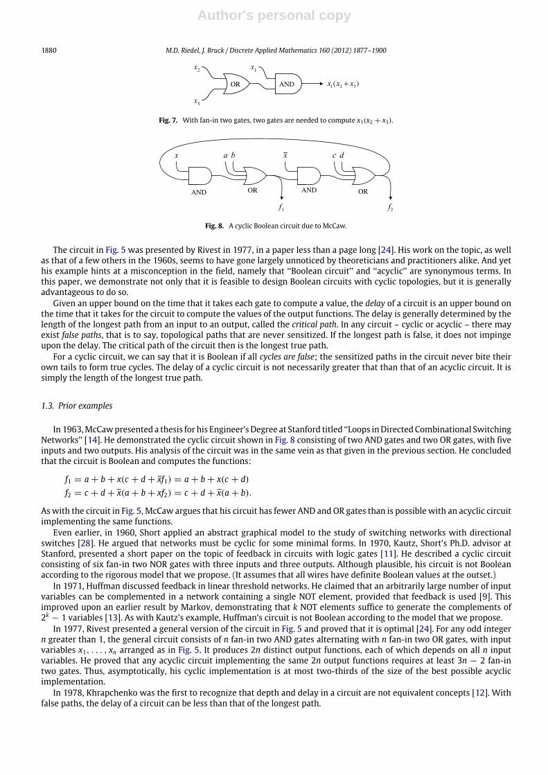
Fig. 7. With fan-in two gates, two gates are needed to compute x1(x2 + x3).
Fig. 8. A cyclic Boolean circuit due to McCaw.
The circuit in Fig. 5 was presented by Rivest in 1977, in a paper less than a page long [24]. His work on the topic, as wellas that of a few others in the 1960s, seems to have gone largely unnoticed by theoreticians and practitioners alike. And yethis example hints at a misconception in the field, namely that ‘‘Boolean circuit’’ and ‘‘acyclic’’ are synonymous terms. Inthis paper, we demonstrate not only that it is feasible to design Boolean circuits with cyclic topologies, but it is generallyadvantageous to do so.
Given an upper bound on the time that it takes each gate to compute a value, the delay of a circuit is an upper bound onthe time that it takes for the circuit to compute the values of the output functions. The delay is generally determined by thelength of the longest path from an input to an output, called the critical path. In any circuit – cyclic or acyclic – there mayexist false paths, that is to say, topological paths that are never sensitized. If the longest path is false, it does not impingeupon the delay. The critical path of the circuit then is the longest true path.
For a cyclic circuit, we can say that it is Boolean if all cycles are false; the sensitized paths in the circuit never bite theirown tails to form true cycles. The delay of a cyclic circuit is not necessarily greater that than that of an acyclic circuit. It issimply the length of the longest true path.
1.3. Prior examples
In 1963,McCawpresented a thesis for his Engineer’sDegree at Stanford titled ‘‘Loops inDirectedCombinational SwitchingNetworks’’ [14]. He demonstrated the cyclic circuit shown in Fig. 8 consisting of two AND gates and two OR gates, with fiveinputs and two outputs. His analysis of the circuit was in the same vein as that given in the previous section. He concludedthat the circuit is Boolean and computes the functions:
f1 = a + b + x(c + d + xf1) = a + b + x(c + d)f2 = c + d + x(a + b + xf2) = c + d + x(a + b).
Aswith the circuit in Fig. 5, McCaw argues that his circuit has fewer AND andOR gates than is possible with an acyclic circuitimplementing the same functions.
Even earlier, in 1960, Short applied an abstract graphical model to the study of switching networks with directionalswitches [28]. He argued that networks must be cyclic for some minimal forms. In 1970, Kautz, Short’s Ph.D. advisor atStanford, presented a short paper on the topic of feedback in circuits with logic gates [11]. He described a cyclic circuitconsisting of six fan-in two NOR gates with three inputs and three outputs. Although plausible, his circuit is not Booleanaccording to the rigorous model that we propose. (It assumes that all wires have definite Boolean values at the outset.)
In 1971, Huffman discussed feedback in linear threshold networks. He claimed that an arbitrarily large number of inputvariables can be complemented in a network containing a single NOT element, provided that feedback is used [9]. Thisimproved upon an earlier result by Markov, demonstrating that k NOT elements suffice to generate the complements of2k
− 1 variables [13]. As with Kautz’s example, Huffman’s circuit is not Boolean according to the model that we propose.In 1977, Rivest presented a general version of the circuit in Fig. 5 and proved that it is optimal [24]. For any odd integer
n greater than 1, the general circuit consists of n fan-in two AND gates alternating with n fan-in two OR gates, with inputvariables x1, . . . , xn arranged as in Fig. 5. It produces 2n distinct output functions, each of which depends on all n inputvariables. He proved that any acyclic circuit implementing the same 2n output functions requires at least 3n − 2 fan-intwo gates. Thus, asymptotically, his cyclic implementation is at most two-thirds of the size of the best possible acyclicimplementation.
In 1978, Khrapchenko was the first to recognize that depth and delay in a circuit are not equivalent concepts [12]. Withfalse paths, the delay of a circuit can be less than that of the longest path.

Author's personal copy
M.D. Riedel, J. Bruck / Discrete Applied Mathematics 160 (2012) 1877–1900 1881
Fig. 9. An exclusive-OR (XOR) gate in a feedback loop.
1.4. Related models
Theorists have studied the distinction between cyclic and acyclic circuits from the perspective of computationalcomplexity. Dymond and Cook proposed a model called Boolean ‘‘aggregates’’ [6,7]. This model is discussed in detail in [8].As is the case for Boolean circuits, Boolean aggregates consist of gates connected by wires. The topology is a directed graphG = (V , E), with the nodes V representing gates and the edges E representing wires. However, unlike the conventionaldefinition of Boolean circuits, the definition of aggregates explicitly allows the graph topology to be cyclic. Also, unlike thedefinition for Boolean circuits, the model of aggregates prescribes synchronous behavior. At the outset, the values on all thewires are 0. Then, at each time step, all the gates update their outputs synchronously, based on their inputs. As we explainbelow, these assumptions are an inherent difference from our model; they are also unrealistic in terms of actual circuitimplementations.
Dymond and Cook prove a surprising result: there is a gap between the computational power of polynomial-sized circuitsand polynomial-sized aggregates [6,7]. They show that a family of logspace-uniformpolynomial-sized aggregates can decideany language in PSPACE, that is to say, any language that can be decided by a Turingmachine that uses a polynomial amountof space. This, of course, is not true for polynomial-sized circuits.
Their proof hinges on the synchronous aspect of the aggregate model. They construct a Turing machine that simulatesan aggregate. The Turing machine requires storage for an encoding of the aggregate as well as storage for the values of thegates. It simulates the computation performed by the aggregate, step by step, as the values of the gates are updated. So,crucially, the proof assumes that the aggregates have memory. Indeed, this conforms to the conventional view of circuitmodels: feedback is generally introduced specifically to create memory.
Nickelsen et al. [18] present amore precise result. These authors show that polynomial-sized aggregateswith very limitedfeedback topologies can decide any language in PSPACE. Aggregates that have connected components of size at most one aresufficient. The aggregates used in their argument contain components consisting of loops on exclusive-OR gates, as shownin Fig. 9. Other than such components of size one, there are no feedback paths. The argument on the computational powerof these aggregates hinges on the storage that the exclusive-OR loops provide. Each loop provides one bit of memory: if theinput x = 0, then the gate retains its previous value, XOR(0, y) = y; if the input x = 1, then the gate complements itsprevious value, XOR(1, y) = y.
With respect to memory and synchronous behavior, our Boolean circuit model is inherently different from Dymond andCook’s Boolean aggregate model. We allow for feedback, but we stipulate that Boolean circuits must performmappings fromthe inputs to the outputs. Each output f is a function
f : {0, 1}n → {0, 1}. (2)
The results of the computation cannot depend on the initial or the prior values on the wires. Also, we insist that the circuitscompute the same values regardless of the delays of the gates and the delays of the wires, so our model is asynchronous.
Why permit feedback but disallow memory and insist on delay-independent computation? Our assumptions result incircuits thatwillwork in practice. (Indeed, the exclusive-OR feedback loops proposed in [18] are quite unrealistic; one cannotcreate a single bit of memory with such a simple configuration.) Circuits that conform to our model can be substituted forexisting combinational circuit designs.
1.5. Practical validation
Based upon our model, we show a linear improvement in complexity, which is small to theorists. However, theimprovements that we have demonstrated on actual circuits are significant in practice. For instance, we reduced the area ofthe arithmetic logic unit (ALU) decoder of an 8051microprocessor design by 20%. In trials with benchmark circuits, wewereable to optimize nearly all of them significantly, with improvements of up to 30% in the area and up to 25% in the delay.
We discuss techniques for validating cyclic circuits in [21,23,1,4]. We discuss practical strategies for synthesizing cycliccircuits with computer-aided design tools in [22,2,3]. Our synthesis tool, CYCLIFY, optimizes the designs of circuits byintroducing cycles in the restructuring and minimization phases of logic synthesis. It reduces the number of gates neededby overlapping the computation of multiple functions, as Rivest’s example hinted at, and reduces the delay of circuits bymoving computation off of critical paths, as Khrapchenko’s work hinted at.

Author's personal copy
1882 M.D. Riedel, J. Bruck / Discrete Applied Mathematics 160 (2012) 1877–1900
1.6. Overview
In this paper, we compare the size of cyclic Boolean circuits to that of acyclic Boolean circuits.We exhibit families of cycliccircuits that are optimal in the number of gates andwe prove lower bounds on the size of equivalent acyclic circuits. First, wepresent a cyclic circuit with only two gates and argue that an equivalent acyclic circuit requires three gates. Next, we presenta cyclic circuit with three gates and argue that an equivalent acyclic circuit requires five gates. Next, we present a family ofcyclic circuits with n gates and prove that an equivalent family of acyclic circuits requires at least 2n gates. Accordingly, weconclude that the cyclic complexity of functions can be as little as one-half of the acyclic complexity. Our lower bound isbased on a fan-in argument: in order to compute a function that depends on a certain number of variables using gates witha certain fan-in, we require a tree of at least a certain size. We show that this is the largest gap that can be obtained withthis fan-in lower bound technique. Finally, we show a quadratic upper bound: given a cyclic Boolean circuit with m gates,there exists an equivalent acyclic Boolean circuit withm2 gates.
2. Framework
2.1. Notation
Algebraically, we use the standard notation: addition (+) denotes disjunction (OR),multiplication (·), denotes conjunction(AND), and an overbar (x) denotes negation (NOT). The restriction operation (also known as the cofactor) of a function f withrespect to a variable x refers to the assignment of a constant value to x in the expression for f . We use the notation f |x todenote the restriction of x to 1 and f |x to denote the restriction of x to 0. A function f depends upon a variable x iff f |x is notidentically equal to f |x. Call the variables that a function depends upon its support set.
We will often represent functions with algebraic expressions consisting of exclusive-OR (XOR) and conjunction (AND)operations. (We denote XOR with the symbol ⊕.) As early as 1929, Zhegalkin showed that such a representation iscanonical [32]: if we multiply out all parentheses, perform the simplifications x ⊕ x = 0 and x · x = x, and sort the productterms, the resulting expression is unique. The representation is sometimes called the Reed–Muller normal form [17,20]. Forinstance, the function
f = x1(x2 + x3)
is represented as
f = 1 ⊕ x1 ⊕ x2x3 ⊕ x1x2x3.
Note that 1⊕x = x. Whenwriting expressions, we assume that AND has precedence over XOR, so x⊕yz represents x⊕(yz).The Reed–Muller form has a distinct advantage over others when it comes to algebraic manipulations: the dependence of afunction on its variables is explicit; if a variable appears in the expression, then the function depends on it.
2.2. Circuit model
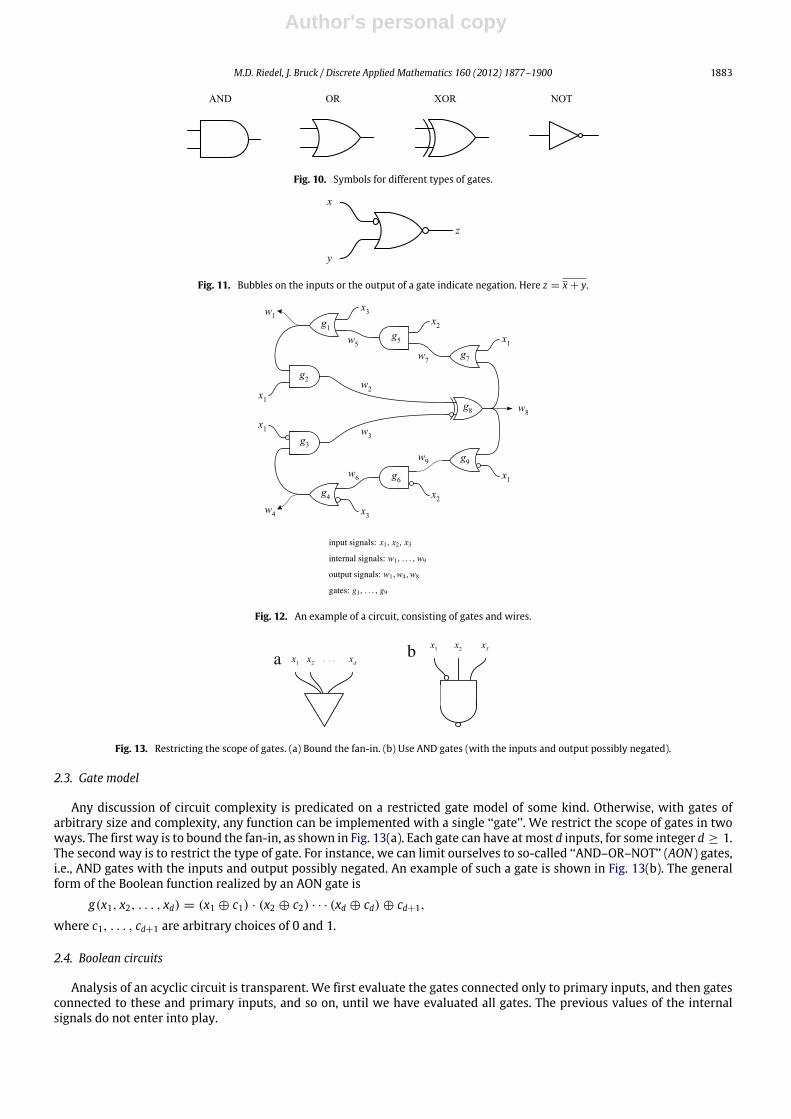
Graphically, a circuit consists of gates connected by wires. Each gate has one or more inputs and a single output. Thesymbols for common gates are shown in Fig. 10. A bubble is used to indicate that an input or output is negated, as illustratedin Fig. 11.
An example of a circuit is shown in Fig. 12. Even though a wire may split in our diagrams, as is the case with wire w8 inFig. 12, conceptually there is a single instance of it. In general,
• A circuit accepts signals x1, . . . , xm, ranging over {0, 1}, called the primary inputs. Each primary input is fed into one ormore gate inputs. Even though the symbol for a primary input may appear in several places, as is the case with x1, x2 andx3 in Fig. 12, conceptually there is a single instance of it.
• The gates in the circuit produce internal signals, w1, . . . , wn ranging over {0, 1, ⊥}. (We discuss the third value, ⊥, inSection 2.4.)
• A subset of the set of internal signals is designated as the set of primary outputs.
A gate implements a Boolean function, i.e., a mapping from Boolean inputs to a Boolean output value,
g: {0, 1}d → {0, 1}.
The set of inputs to a gate is called its fan-in set. When we say a ‘‘fan-in d’’ gate, wemean a gate with fan-in set of cardinalityd. The set of gates that are attached to a gate output are called its fan-out set.
Author's personal copy
M.D. Riedel, J. Bruck / Discrete Applied Mathematics 160 (2012) 1877–1900 1883
Fig. 10. Symbols for different types of gates.
Fig. 11. Bubbles on the inputs or the output of a gate indicate negation. Here z = x + y.
Fig. 12. An example of a circuit, consisting of gates and wires.
...
Fig. 13. Restricting the scope of gates. (a) Bound the fan-in. (b) Use AND gates (with the inputs and output possibly negated).
2.3. Gate model
Any discussion of circuit complexity is predicated on a restricted gate model of some kind. Otherwise, with gates ofarbitrary size and complexity, any function can be implemented with a single ‘‘gate’’. We restrict the scope of gates in twoways. The first way is to bound the fan-in, as shown in Fig. 13(a). Each gate can have atmost d inputs, for some integer d ≥ 1.The second way is to restrict the type of gate. For instance, we can limit ourselves to so-called ‘‘AND–OR–NOT’’ (AON) gates,i.e., AND gates with the inputs and output possibly negated. An example of such a gate is shown in Fig. 13(b). The generalform of the Boolean function realized by an AON gate is
g(x1, x2, . . . , xd) = (x1 ⊕ c1) · (x2 ⊕ c2) · · · (xd ⊕ cd) ⊕ cd+1,
where c1, . . . , cd+1 are arbitrary choices of 0 and 1.
2.4. Boolean circuits
Analysis of an acyclic circuit is transparent. We first evaluate the gates connected only to primary inputs, and then gatesconnected to these and primary inputs, and so on, until we have evaluated all gates. The previous values of the internalsignals do not enter into play.
Author's personal copy
1884 M.D. Riedel, J. Bruck / Discrete Applied Mathematics 160 (2012) 1877–1900
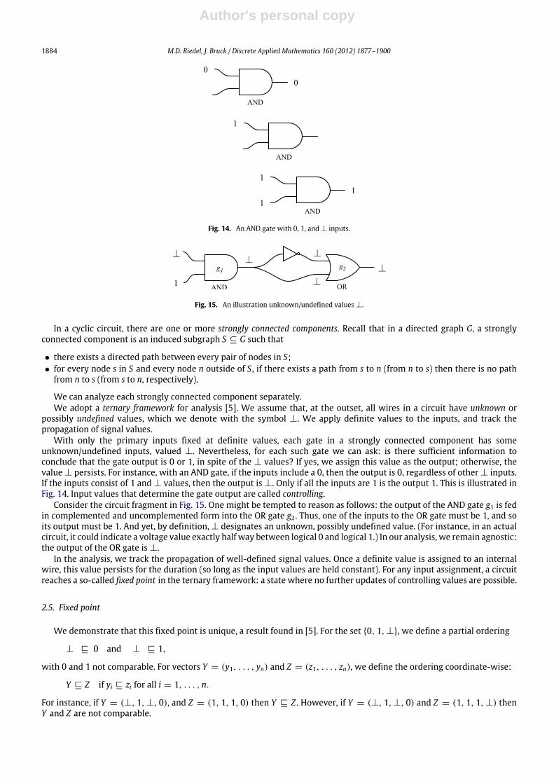
Fig. 14. An AND gate with 0, 1, and ⊥ inputs.
g2g1
Fig. 15. An illustration unknown/undefined values ⊥.
In a cyclic circuit, there are one or more strongly connected components. Recall that in a directed graph G, a stronglyconnected component is an induced subgraph S ⊆ G such that
• there exists a directed path between every pair of nodes in S;• for every node s in S and every node n outside of S, if there exists a path from s to n (from n to s) then there is no path
from n to s (from s to n, respectively).
We can analyze each strongly connected component separately.We adopt a ternary framework for analysis [5]. We assume that, at the outset, all wires in a circuit have unknown or
possibly undefined values, which we denote with the symbol ⊥. We apply definite values to the inputs, and track thepropagation of signal values.
With only the primary inputs fixed at definite values, each gate in a strongly connected component has someunknown/undefined inputs, valued ⊥. Nevertheless, for each such gate we can ask: is there sufficient information toconclude that the gate output is 0 or 1, in spite of the ⊥ values? If yes, we assign this value as the output; otherwise, thevalue ⊥ persists. For instance, with an AND gate, if the inputs include a 0, then the output is 0, regardless of other ⊥ inputs.If the inputs consist of 1 and ⊥ values, then the output is ⊥. Only if all the inputs are 1 is the output 1. This is illustrated inFig. 14. Input values that determine the gate output are called controlling.
Consider the circuit fragment in Fig. 15. One might be tempted to reason as follows: the output of the AND gate g1 is fedin complemented and uncomplemented form into the OR gate g2. Thus, one of the inputs to the OR gate must be 1, and soits output must be 1. And yet, by definition, ⊥ designates an unknown, possibly undefined value. (For instance, in an actualcircuit, it could indicate a voltage value exactly half way between logical 0 and logical 1.) In our analysis, we remain agnostic:the output of the OR gate is ⊥.
In the analysis, we track the propagation of well-defined signal values. Once a definite value is assigned to an internalwire, this value persists for the duration (so long as the input values are held constant). For any input assignment, a circuitreaches a so-called fixed point in the ternary framework: a state where no further updates of controlling values are possible.
2.5. Fixed point
We demonstrate that this fixed point is unique, a result found in [5]. For the set {0, 1, ⊥}, we define a partial ordering
⊥ ⊑ 0 and ⊥ ⊑ 1,
with 0 and 1 not comparable. For vectors Y = (y1, . . . , yn) and Z = (z1, . . . , zn), we define the ordering coordinate-wise:
Y ⊑ Z if yi ⊑ zi for all i = 1, . . . , n.
For instance, if Y = (⊥, 1, ⊥, 0), and Z = (1, 1, 1, 0) then Y ⊑ Z . However, if Y = (⊥, 1, ⊥, 0) and Z = (1, 1, 1, ⊥) thenY and Z are not comparable.

Author's personal copy
M.D. Riedel, J. Bruck / Discrete Applied Mathematics 160 (2012) 1877–1900 1885
Fig. 16. Ternary extensions for common gates.
We define the partial join V = (v1, . . . , vn) = Y ⊔ Z as:
vi =
a if yi = zi = a for some a ∈ {0, 1},b if {yi, zi} = {b, ⊥} for some b ∈ {0, 1},⊥ else
for all i = 1, . . . , n. For instance, if Y = (⊥, 1, ⊥, 0), and Z = (1, 1, 1, ⊥) then Y ⊔ Z = (1, 1, 1, 0).Within the ternary framework, a gate performs a mapping from ternary values to ternary values,
g ′: {0, 1, ⊥}k→ {0, 1, ⊥}.
Given a Boolean mapping g , the ternary extension g ′ is defined as follows. For a vector of ternary values Y ∈ {0, 1, ⊥}k,
g ′(Y ) =
0 if g(Z) = 0 for each Z ∈ {0, 1}k, where Y ⊑ Z,
1 if g(Z) = 1 for each Z ∈ {0, 1}k, where Y ⊑ Z,⊥ else.
A similar definition of the ternary extension is found in [5]. The truth-tables for the ternary extensions of fan-in two AND,OR and XOR gates, as well as a fan-in one NOT gate, are shown in Fig. 16.
The following theorem shows that once a definite value is assigned to an internal wire, this value persists for the durationof the interval (so long as the input values are held constant). Furthermore, the order of gate evaluations is irrelevant; thefinal outcome – which internal wires are assigned definite values, and what these values are – is the same regardless. Theanalysis terminates at a fixed point: in this state, every gate evaluation agrees with the value on its output wire, so thereare no further changes. Of course, the term ‘‘fixed point’’ is somewhat paradoxical: with ⊥ values, the state includes signalsthat are potentially unstable.
Theorem 1. With all the internal signals assigned an initial value ⊥, for a given set of Boolean values applied to the inputs andheld constant, the analysis terminates at a unique fixed point.
Proof. Call the values assumed by the internal variables W = (w1, . . . , wn) the state. Beginning from the initial stateW0 = (⊥, . . . ,⊥), the circuit evolves through a sequence,
W0,W1,W2, . . . .
Since each gate update consists of a change ⊥→ {0, 1}, the sequence of states is ordered,
W0 ⊑ W1 ⊑ W2 ⊑ . . . .
Since the number of states is finite, clearly the computation terminates at some fixed point. This is illustrated in Fig. 17.It remains to show that this fixed point is unique. To do so, we argue that the order of updates is irrelevant. Indeed, from
a given stateW , if we have a choice of immediate successor statesWi andWj, then the partial joinWk = Wi ⊔Wj exists andis an immediate successor state to bothWi andWj. This is illustrated in Fig. 18. With the initial state (⊥, . . . ,⊥) as the basecase, a simple inductive argument suffices to show that all states have a common successor. This common successor mustbe a fixed point. �
We adopt the following definition.
A circuit is Boolean iff, for every assignment of input values, with all the wires initially set to ⊥, the circuit reaches afixed point that does not contain any ⊥ values on the outputs.
We illustrate the analysis with two cyclic examples: one that is not Boolean and one that is.

Author's personal copy
1886 M.D. Riedel, J. Bruck / Discrete Applied Mathematics 160 (2012) 1877–1900
Fig. 17. The computation terminates at a fixed point.
Fig. 18. The order of updates is irrelevant.
Fig. 19. A cyclic circuit that is not Boolean.
Fig. 20. The circuit of Fig. 19 with x1 = 1, x2 = 0 and x3 = 1.
Table 1Analysis of the circuit in Fig. 19.
x1 x2 x3 f1 f2 f3
0 0 0 0 0 00 0 1 0 0 00 1 0 0 1 00 1 1 0 1 11 0 0 0 0 01 0 1 ⊥ ⊥ ⊥
1 1 0 0 1 01 1 1 1 1 1
Example 1. Consider the circuit shown in Fig. 19, consisting of an AND gate g1, an OR gate g2, and an AND gate g3, in a cycle.By inspection, note that if x1 = 0 then f1 assumes value 0; if x2 = 1 then f2 assumes value 1; and if x3 = 0 then f3 assumesvalue 0. But what happens if x1 = 1, x2 = 0 and x3 = 1? In this case, all the outputs equal ⊥, as illustrated in Fig. 20. Theoutcome for all eight cases is shown in Table 1. We conclude that the circuit is not Boolean.
Example 2. Consider the circuit in Fig. 12. Suppose that we apply inputs x1 = 1, x2 = 0, x3 = 1. Gates g1, g3, g5 and g7produce outputs of 1, 0, 0, and 1, respectively. Gate g2 produces an output of 1. Gate g8 produces an output of 0. Gate g9produces an output of 0. Gate g6 produces an output of 0. Finally, gate g4 produces an output of 0. The analysis for all eightinput combinations is summarized in Fig. 21. We conclude that the circuit is Boolean.

Author's personal copy
M.D. Riedel, J. Bruck / Discrete Applied Mathematics 160 (2012) 1877–1900 1887
Fig. 21. Analysis summary for the circuit of Fig. 12.
3. Optimality and lower bounds
Our general strategy in the following constructions is to present a cyclic circuit that is optimal in the number of gates, andthen prove a lower bound on the size of any acyclic circuit implementing the same functions. (For what follows, when wesay circuit size, we mean the number of gates.) The argument for the optimality of the cyclic circuit rests on two properties:
Property 1. Each of the output functions depends on all the variables.
Property 2. The output functions are pairwise distinct.
The cyclic circuit is shown to be optimal according to the following trivial claim (true regardless of the gate model):
Claim 1. A circuit implementing m distinct functions consists of at least m gates.
Lower bounds on circuit size are notoriously difficult to establish. In fact, such proofs are related to fundamental questionsin computer science, such as the separation of the complexity classes P andNP . (To prove that P = NP it would suffice to finda problem in NP that cannot be computed by a polynomially sized circuit.) Much of the recent work in circuit complexityhas been spurred by these open problems.
All existing lower bounds on circuit size are linear in the number of variables [29]. In 1949, Shannon showed by astraightforward counting argument that nearly all functions require circuits with an exponential number of gates [27]. Yetthere is no known explicit example [31].
We prove that some cyclic Boolean circuits are smaller than equivalent acyclic circuits based on a fan-in lower bound.We show that this is the largest gap that we can prove using the fan-in lower bound technique.
3.1. Fan-in lower bound
Our lower bound on the size of an acyclic circuit is formulated as a fan-in argument. The essence of the argument waspresented by Rivest [24], although we present it in a more general form.
A circuit can only compute a function of a given set of input variables if it ‘‘sees’’ all of them. For example, in Fig. 22, gate g2can compute a function of x1, x2 and x3; gate g1 cannot compute a function of x3 since it does not see x3. In an acyclic circuit,there is a partial ordering among the gates: if a gate gi depends on a gate gj, directly or indirectly, then gj cannot depend ongi, directly or indirectly. With a partial ordering on the output functions, there must be at least one output function at thetop which depends upon no other. If this function depends on v input variables, the gate producing it must be the root of atree that sees all these v variables as leaves. The lower bound is based on a calculation of the minimum number of gates inthis tree.
Claim 2. An acyclic circuit implementing m distinct output functions, each depending on v input variables, consisting of gateswith fan-in at most d has at least
v − 1d − 1
+ m − 1
gates. This is true for any fan-in value d ≥ 2.
Proof. Consider a connected directed acyclic graph (DAG). Call nodes with no in-coming edges leaves, and all other nodesinternal nodes. We show, by a simple inductive argument, that a connected DAG with k internal nodes, each with in-degreeat most d, has at most k(d − 1) + 1 leaves. Obviously, a graph consisting of a single such internal node has at most d leaves.Suppose an internal node with in-degree at most d is added to a connected DAG. If the resulting graph is to be a connectedDAG, the newnode can replace an existing leaf or it can be attached to an existing internal node. The former case is illustrated

Author's personal copy
1888 M.D. Riedel, J. Bruck / Discrete Applied Mathematics 160 (2012) 1877–1900
Fig. 22. A gate can only compute functions of variables that it ‘‘sees’’.
...
...
Fig. 23. Adding a node with in-degree d to a connected DAG results in net gain of at most d − 1 leaves.
with node g1 in Fig. 23, and the latter with node g2. In both cases there is a net gain of at most d − 1 leaves. We concludethat connected DAG with k internal nodes has at most
d + (k − 1)(d − 1) = k(d − 1) + 1
leaves, as expected. Suppose that a connected DAG has v leaves. Since
v ≤ k(d − 1) + 1,
the number of internal nodes k is bounded by
k ≥
v − 1d − 1
.
Now, in an acyclic circuit implementingm output functions, at least one of the output functions depends on no other. By theargument above, this output function requires at least
v − 1d − 1
gates. With distinct output functions, each output function must emanate from a different gate, so at least m − 1 gates arerequired to implement the remainingm − 1 functions. �
3.2. Improvement factor
Suppose that we have a cyclic circuit withm gates, eachwith fan-in at most d, that implementsm distinct functions, eachof which depends on all v input variables.

Author's personal copy
M.D. Riedel, J. Bruck / Discrete Applied Mathematics 160 (2012) 1877–1900 1889
Fig. 24. A cyclic Boolean circuit with three inputs, due to Rivest [24].
Call the improvement factor the ratio of size of the cyclic circuit to the lower bound on the size of the acyclic circuit:
size of cyclicsize of acyclic
=m
v−1d−1
+ m − 1
.
With an improvement factor of C , we can say that our cyclic circuit is C times the size of any equivalent acyclic circuit.
Claim 3. The improvement factor is bounded below by 12 .
Proof. For a given d, the improvement factor is minimized if the term
v − 1d − 1
in the denominator is maximized. Now, the number of variables v in a cyclic circuit is at mostm(d− 1), and this is achievedif all the gates have fan-in d. For such a circuit, the improvement factor is
mm −
1d−1
+ m − 1
=m
2m − 1≥
12
if d ≥ 3 and
m2m − 2
≥12
if d = 2. �
3.3. Rivest’s circuit
Consider the circuit shown in Fig. 24, due to Rivest [24]. This is the same circuit as in Fig. 5, shown again for the reader’sconvenience; however, here we provide a slightly different analysis of it, based on controlling values. We first verify thatthis circuit is Boolean. For gate g1, an AND gate, x1 = 0 is a controlling value. Setting x1 = 0 we have
f1 |x1 = 0,
f2 |x1 =f1 |x1
+ x2 = x2,
f3 |x1 =f2 |x1
x3 = x2x3,
f4 |x1 =f3 |x1
+ 0 = x2x3,
f5 |x1 =f4 |x1
x2 = x2x3,
f6 |x1 =f5 |x1
+ x3 = x3.
All outputs assume definite Boolean values. For gate g4, an OR gate, x1 = 1 is a controlling value. Setting x1 = 1, we have
f4 |x1 = 1,
f5 |x1 =f4 |x1
x2 = x2,
f6 |x1 =f5 |x1
+ x3 = x2 + x3,
f1 |x1 =f6 |x1
1 = x2 + x3,
f2 |x1 =f1 |x1
+ x2 = x2 + x3,
f3 |x1 =f2 |x1
x3 = x3.

Author's personal copy
1890 M.D. Riedel, J. Bruck / Discrete Applied Mathematics 160 (2012) 1877–1900
... ...
Fig. 25. A cyclic Boolean circuit with n inputs (for any odd n ≥ 3) due to Rivest.
Again, all outputs assume definite Boolean values. Since x1 must either have value 0 or value 1, we conclude that the networkis Boolean. We assemble the output functions from these two cases. Applying distributivity and absorption, we obtain
f1 = x1 · f1 |x1 +x1 · f1 |x1 = x1 · 0 + x1 · (x2 + x3) = x1(x2 + x3)f2 = x1 · f2 |x1 +x1 · f2 |x1 = x1 · x2 + x1 · (x2 + x3) = x2 + x1x3f3 = x1 · f3 |x1 +x1 · f3 |x1 = x1 · x2x3 + x1 · x3 = x3(x1 + x2)f4 = x1 · f4 |x1 +x1 · f4 |x1 = x1 · x2x3 + x1 · 1 = x1 + x2x3f5 = x1 · f5 |x1 +x1 · f5 |x1 = x1 · x2x3 + x1 · x2 = x2(x1 + x3)f6 = x1 · f6 |x1 +x1 · f6 |x1 = x1 · x3 + x1 · (x2 + x3) = x3 + x1x2.
Rivest presented a more general version of this circuit. For any odd integer n greater than 1, the general circuit consists of ntwo-input AND gates alternating with n two-input OR gates in a single cycle, with inputs x1, . . . , xn repeated, as shown inFig. 25. Analyzing the general circuit in the same manner as above, we find that it implements the functions
f1 = x1(xn + xn−1(· · · (x3 + x2) · · ·))
f2 = x2 + x1(xn + · · · (x4x3) · · ·)
...
f2n = xn + xn−1(xn−2 + · · · (x2x1) · · ·).
Note that the functions are symmetrical with respect to a cyclic permutation of the variables. More precisely, the functionsf3, f5, . . . , f2n−1 are obtained from f1 by the cyclic permutation of the variables x1, x2, . . . , xn:
f3(x1, x2, . . . , xn) = f1(x2, x3, . . . , x1),f5(x1, x2, . . . , xn) = f1(x3, x4, . . . , x2),......
f2n−1(x1, x2, . . . , xn) = f1(xn, x1, . . . , xn−1).
Similarly, the functions f4, f6, . . . , f2n are obtained from f2 through a cyclic permutation of the variables.
3.3.1. OptimalityTo show that Rivest’s circuit is optimal, we must show that it satisfies Properties 1 and 2. (This argument of optimality
was presented by Rivest in [24].)
1. To show that each function depends on all n input variables, we note that in the parenthesized expression, each variableappears exactly once. Without loss of generality, consider the i-th function fi in the list, for an odd i, and consider the j-thvariable appearing in its expression, from the left-hand side. To show the dependence on this variable, set each variablepreceding a product to 1, and each variable preceding a sum to zero, beginning on the left-hand side, until we arrive atxj. Set the variable following xj to 1 and all variables following that to 0. The result is
fi = 1(0 + 1(0 + · · · + xj(1 + 0(0 + 0(· · ·))))) = xj.
2. To show that all the functions are distinct, we exhibit an assignment that sets any chosen function to 0 if it is oddnumbered (to 1 if it is even numbered), while setting all the other functions to 1 (to 0, respectively). Without loss ofgenerality, consider function fi, for an odd i ≤ n. This function is the output of an AND gate with input xi. Set xi to 0 andset all the other variables to 1. Clearly, fi has value 0 while all the other functions have value 1 in this case.
3.3.2. Acyclic lower boundNote that the Rivest circuit has n input variables and implements 2n distinct output functions with 2n fan-in two gates.
According to Claim 2, an acyclic circuit implementing the same functions requires at leastn − 12 − 1
+ 2n − 1 = 3n − 2

Author's personal copy
M.D. Riedel, J. Bruck / Discrete Applied Mathematics 160 (2012) 1877–1900 1891
Fig. 26. An acyclic circuit implementing the same functions as the circuit in Fig. 24.
fan-in two gates. For large n, the improvement factor is
size of cyclicsize of acyclic
=2n
3n − 2≈
23.
Rivest’s cyclic circuit is two-thirds the size of any acyclic circuit implementing the same functions.The bound of 3n−2 is, in fact, tight. To obtain an acyclic circuit with 3n−2 gates, we break the cycle and prepend a copy
of the last n − 2 gates. For n = 3, we simply prepend an OR gate with inputs x2 and x3, as shown in Fig. 26.Rivest’s circuit is also optimal seen from a different perspective. The circuit consists of AON gates, and yet none of the
output functions are implementable with a single AON gate, regardless of the fan-in. Thus, any acyclic circuit implementingthe functions requires at least one more gate.
3.3.3. A generalizationWe note that Rivest’s circuit can be generalized to AND and OR gates with arbitrary fan-in. The circuit shown in Fig. 27
consists of 2n fan-in d AND and OR gates, with n(d − 1) inputs repeated, for n ≥ 3, n odd, and d ≥ 2. This circuit producesoutputs
f1 = y1(yn + yn−1(· · · (y3 + y2) · · ·))
f2 = y2 + y1(yn + · · · (y4y3) · · ·)
...
f2n = yn + yn−1(yn−2 + · · · (y2y1) · · ·),
where
y1 = x1 · · · xd−1
y2 = xd + · · · + x2d−2
...
yn = x(n−1)(d−1)+1 + · · · + xn(d−1).
It may be shown that all 2n functions are distinct, and that each depends on all n(d − 1) input variables.
3.3.4. VariantsWe note that many different circuits of the same general form as Rivest’s example exist. In Fig. 28, we show a circuit with
four variables and eight gates in a single cycle. As with Rivest’s circuit, this one produces distinct output functions each ofwhich depends on all four variables.
A more intriguing example is shown in Fig. 29. It consists of two copies of Rivest’s circuit with the outputs of the first fedas inputs into the second. Although not shown here, we assert that this circuits produces 20 functions that are distinct, andeach depends on all five variables.

Author's personal copy
1892 M.D. Riedel, J. Bruck / Discrete Applied Mathematics 160 (2012) 1877–1900
Fig. 27. A generalization of Rivest’s circuit to gates with fan-in greater than 2.
Fig. 28. A circuit with the same properties as Rivest’s example.
Fig. 29. A pair of Rivest circuits, n = 5, stacked.
3.4. A minimal cyclic circuit with two gates
We provide an example of a circuit with the same property as Rivest’s circuit, but with only two gates. The circuit shownin Fig. 30 consists of two fan-in four gates of the form
g(w, x, y, z) = wx ⊕ yz
connected in a cycle with five inputs, a, b, c, d, e. The circuit computes f and g:
f = ab ⊕ gcg = f c ⊕ de.

Author's personal copy
M.D. Riedel, J. Bruck / Discrete Applied Mathematics 160 (2012) 1877–1900 1893
Fig. 30. A cyclic circuit with two gates.
To verify that the circuit is Boolean, note that if c = 0, then f and g assume definite values. We have
f |c = ab ⊕g |c
0 = ab
g |c = (f |c) 1 ⊕ de = ab ⊕ de.
Similarly, if c = 1, then f and g also assume definite values. We have
g |c = (f |c) 0 ⊕ de = def |c = ab ⊕ (g|c) 1 = ab ⊕ de.
Assembling the output functions, we obtain
f = c ·f |c
+ c ·
f |c
= cab ⊕ c(ab ⊕ de)= cab ⊕ abc ⊕ cde= ab ⊕ cde,
g = c ·g |c
+ c ·
g |c
= c(ab + ⊕de) ⊕ cde= cab + cdee + cde= abc ⊕ de.
With the functions thus written in Reed–Muller form, we can readily assert that f and g are distinct and that each dependson all five variables. Now, consider an acyclic circuit, also with fan-in four gates, that computes the same functions. Since asingle fan-in four gate cannot possibly compute a function of five variables, we conclude that the acyclic circuit must haveat least three gates.
3.5. A cyclic circuit with two cycles
We continue the exposition of examples of cyclic Boolean circuits. We present an example with two cycles. This will begeneralized to examples with multiple cycles, culminating with the main result of the paper: a cyclic circuit that is one-halfthe size of any equivalent acyclic circuit.
Consider the circuit shown in Fig. 31, written in a general form. The inputs are x1, . . . , xn, grouped together in thefigure as X . (A diagonal line across a wire indicates that it represents multiple wires.) There are three gates, connectedin a configuration consisting of two cycles:
f1 = α1 ⊕ β1f3f2 = α2 ⊕ β2f3f3 = α3 ⊕ β3f1 ⊕ γ3f2 ⊕ δ3f1f2
where the α’s, β ’s, γ ’s, and δ’s are arbitrary functions of the input variables.We analyze this circuit with the goal of obtaining a sufficient condition for it to be Boolean, as well as expressions for
the gate outputs in terms of the inputs when that condition holds. We proceed on a case-by-case basis. For what follows,αi, βi, γi and δi, for i = 1, 2, 3, are arbitrary functions of the input variables.Case I
Suppose that for some X , we have that β1 = 0. In this case f1 assumes the definite value α1. This situation is shown inFig. 32. Now suppose further that γ3 ⊕ δ3α1 = 0. In this case, f3 assumes a definite value of α3 ⊕ β3α1. Given this value forf3, it follows that f2 assumes the definite value of α2 ⊕ β2α3 ⊕ β2β3α1. This situation is shown in Fig. 33. We conclude thatthe functions assume definite values if β1 = 0 and γ3 ⊕ δ3α1 = 0.

Author's personal copy
1894 M.D. Riedel, J. Bruck / Discrete Applied Mathematics 160 (2012) 1877–1900
Fig. 31. A cyclic circuit with two cycles.
Fig. 32. The circuit of Fig. 31 if β1 = 0.
Fig. 33. The circuit of Fig. 31 if β1 = 0 and γ3 ⊕ δ3α1 = 0.
Fig. 34. The circuit of Fig. 31 if β1 = 0 and β2 = 0.
Case IISimilarly, it can be shown that the functions f1, f2 and f3 assume definite values if β2 = 0 and β3 ⊕ δ3α2 = 0.
Case IIISuppose that for some X , we have β1 = 0 and β2 = 0. In this case f1 and f2 assume definite values of α1 and α2,
respectively. Given these values for f1 and f2, it follows that f3 assumes the definite value of α3 ⊕ β3α1 ⊕ γ3α2 ⊕ δ3α1α2.This situation is shown in Fig. 34.

Author's personal copy
M.D. Riedel, J. Bruck / Discrete Applied Mathematics 160 (2012) 1877–1900 1895
Fig. 35. The circuit of Fig. 31 if β3 = γ3 = δ3 = 0.
Case IVSuppose that β3 = γ3 = δ3 = 0. In this case f3 assumes the definite value α3. Given this value for f3, it follows that f1 and
f2 assume the definite values α1 ⊕ β1α3 and α2 ⊕ β2α3, respectively. This situation is shown in Fig. 35. �The characteristic functions for the four cases are:
c1(X) = β1 · (γ3 ⊕ δ3α1), (3)
c2(X) = β2 · (β3 ⊕ δ3α2), (4)
c3(X) = β1 · β2, (5)
c4(X) = β3 · γ3 · δ3. (6)
We conclude that the circuit is Boolean if
c1(X) + c2(X) + c3(X) + c4(X) ≡ 1.
If this condition holds, then the functions have values
f1(X) = c1α1 + c2(α1 ⊕ β1α3 ⊕ β1γ3α2) + c3α1 + c4(α1 ⊕ β1α3) (7)
f2(X) = c1(α2 ⊕ β2α3 ⊕ β1β3α1) + c2α2 + c3α2 + c4(α2 ⊕ β2α3) (8)
f3(X) = c1(α3 ⊕ β3α1) + c2(α3 ⊕ γ3α2) + c3(α3 ⊕ β3α1 ⊕ γ3α2δ3α1α2) + c4α3. (9)
3.6. A circuit three-fifths the size
Let us make the circuit of Fig. 31 somewhat more concrete. Suppose that the inputs are a, b, x1, x2, . . . , xn, y1, y2, . . . ,yn, z1, z2, . . . , zn. Suppose that the gates are defined by
α1 = aX, α2 = bY , α3 = Z,
where
X = x1x2, . . . , xn, Y = y1y2, . . . , yn, Z = z1z2, . . . , znand
β1 = a, β2 = b, β3 = a,
γ3 = b, δ3 = ab.
The resulting circuit is shown in Fig. 36. For this circuit, the conditions defined in Eqs. (3)–(6) evaluate to:
c1 = a(b + X),
c2 = b(a + Y ),
c3 = ab,c4 = ab.
It may easily be verified that for every combination of values assigned to a and b, one of c1, c2, c3, c4 is true. The functionsdefined in Eqs. (7)–(9) are
f1(a, b, X, Y , Z) = X ⊕ a(X ⊕ Y ⊕ Z) ⊕ abY ,
f2(a, b, X, Y , Z) = Y ⊕ b(X ⊕ Y ⊕ Z) ⊕ abX,
f3(a, b, X, Y , Z) = X ⊕ Y ⊕ Z ⊕ XY ⊕ a(X ⊕ XY ) ⊕ b(Y ⊕ XY ) ⊕ abXY .

Author's personal copy
1896 M.D. Riedel, J. Bruck / Discrete Applied Mathematics 160 (2012) 1877–1900
Fig. 36. Variant of the circuit of Fig. 31.
Fig. 37. Circuit of Fig. 36 with 12 variables.
With the functions expressed in Reed–Muller form, we can assert that they are distinct and that each depends on all thevariables. To make the situation more concrete, suppose that
X = c e g i, Y = d f h j, Z = k l.
There are a total of 12 variables (a through l). Each gate has fan-in six. This situation is shown in Fig. 37. According to Claim 2,an acyclic circuit implementing the same functions requires at least
v − 1d − 1
+ m − 1
gates, where v = 12 (the number of variables), d = 6 (the fan-in) andm = 3 (the number of functions). Thusv − 1d − 1
+ m − 1 =
12 − 16 − 1
+ 3 − 1 = 5.
We conclude that the circuit in Fig. 37 is at most 35 the size of any equivalent acyclic circuit.
3.7. A circuit one-half the size
Consider the circuit shown in Fig. 38, a generalization of the circuit in Fig. 31 to k gates.We argue the validity of this circuitinformally. On the one hand, for each variable xi, if xi = 0 then fi does not depend on fk+1. On the other hand, if xi = 1, thenfk+1 does not depend on fi.We conclude that none of the k cycles can be sensitized, and so the circuit is Boolean. Now considerthe function fi implemented by each gate. With xi = 0, we see that fi depends on the variables y1,1, . . . , y1,d−1. Since fk+1depends on fi, it also depends on these variables. Thus fk+1 depends all the variables yi,j for i = 1, . . . , k and j = 1, . . . , d−1.With xi = 1, we see that fi depends on fk+1; hence it also depends on all these variables. We conclude that each functiondepends on all the variables.With the fan-in of the gates set to d, the number of variables is
v = k(d − 1) + d − 2k = (k + 1)d − 3k
and the number of gates is
m = k + 1.

Author's personal copy
M.D. Riedel, J. Bruck / Discrete Applied Mathematics 160 (2012) 1877–1900 1897
Fig. 38. A generalization of the circuit of Fig. 31.
Fig. 39. Obtaining an equivalent acyclic circuit from a cyclic circuit.
According to Claim 2, an acyclic circuit implementing the same functions requires at leastv − 1d − 1
+ m − 1
gates. The improvement factor is,
mv−1d−1
+ m − 1
=k + 1
(k+1)d−3k−1d−1
+ k
=k + 1
k + 1 −2kd−1
+ k
gates. Suppose that d = 2k + 1 and that k is large. Then the ratio is
k + 12k
≈12.
We conclude that the circuit of Fig. 38 is at most one-half the size of any equivalent acyclic circuit. According to Claim 3, thisis the best possible improvement factor that we can obtain with the fan-in lower bound of Section 3.1.
4. Upper bound
In the previous section, we proved a lower bound: given a cyclic Boolean circuit described by a graph with m nodes, insome cases the smallest acyclic circuit computing the same functions is described by a graph consisting of 2m nodes. In thissection, we prove some simple upper bounds.
Given a Boolean circuit with a single cycle, we can always obtain a corresponding acyclic circuit by breaking the feedbackand doubling the length of the chain, as shown in Fig. 39. (The input ⊥ indicates any constant value.)
So, if the circuit consists of a single cycle with m nodes, we have a linear upper bound of 2m on the number of nodes inan equivalent acyclic circuit. If the cyclic circuit has multiple cycles, we can prove a quadratic upper bound.
Theorem 2. Given a cyclic Boolean circuit described by a graph with m nodes computing functions f1, f2, . . . , fm, there exists anacyclic Boolean circuit described by a graph with m2 nodes implementing the same functions f1, f2, . . . , fm.

Author's personal copy
1898 M.D. Riedel, J. Bruck / Discrete Applied Mathematics 160 (2012) 1877–1900
Fig. 40. A cyclic topology.
Proof. Suppose that we are given a cyclic circuit described by a graph withm nodes. In order to obtain an equivalent acycliccircuit, we produce m copies. In the first copy, we assign a value of 0 (arbitrarily) to all the incoming edges. Then in eachcopy except the last, we redirect all the edges to the corresponding destination nodes in the next copy. The output functionsf1, f2, . . . , fm are obtained from the last copy.
The resulting circuit is described by a graph withm2 nodes. It is clearly acyclic, since every node is connected to nodes insuccessive copies of the original circuit, and there is a total ordering among the copies. The resulting circuit computes thesame functions as the original circuit. To see this, note that if we follow directed paths from the outputs back to the inputs,there is a direct correspondence in the logical functions computed by the gates in both circuits.
We conclude that there is an acyclic Boolean circuit described by a graphwithm2 nodes implementing the same functionsas any cyclic Boolean circuit described by a graph withm nodes. �
Example 3. Consider a cyclic Boolean circuit with the topology shown in Fig. 40. Suppose that it computes the followingfunctions at the corresponding nodes:
e = f (a h + c) + d h + b (10)
f = a d g + a(b d + bc) (11)
g = a b c + h(a e + a d + b c) (12)
h = f (a(c + d) + c d). (13)
We produce the acyclic circuit shown in Fig. 41. This circuit computes the following functions at the corresponding nodes:
e1 = 1(a 1 + c) + d 1 + b (14)
f1 = a d 1 + a(bd + bc) (15)
g1 = abc + 1(a 1 + ad + bc) (16)h1 = 1(a(c + d) + cd) (17)
e2 = f 1(a h1 + c) + d h1 + b (18)
f2 = a d g1 + a(b d + bc) (19)
g2 = a b c + h1(a e1 + a d + b c) (20)
h2 = f 1(a(c + d) + c d) (21)
e3 = f 2(a h2 + c) + d h2 + b (22)
f3 = a d g2 + a(b d + bc) (23)
g3 = a b c + h2(a e2 + a d + b c) (24)
h3 = f 2(a(c + d) + c d) (25)
e4 = f 3(a h3 + c) + d h3 + b (26)
f4 = a d g3 + a(b d + bc) (27)
g4 = a b c + h3(a e3 + a d + b c) (28)
h4 = f 3(a(c + d) + c d). (29)
We can verify that e4 = e, f4 = f , g4 = g , and h4 = h. The original cyclic circuit consisted of four nodes. The acyclic circuitconsists of 42
= 16 nodes.

Author's personal copy
M.D. Riedel, J. Bruck / Discrete Applied Mathematics 160 (2012) 1877–1900 1899
e4
f4h3h4f3h2
f2h1f1
g4
e3e2
g3g2
e1
g1
Fig. 41. A cyclic topology equivalent to the cyclic topology in Fig. 40.
5. Discussion
In related work, we have explored the practical implications of cyclic Boolean circuits. We have described an efficientapproach for analyzing cyclic circuits, andwehave provided a general framework for synthesizing such circuits. Our synthesistool, called CYCLIFY, is built within the Berkeley SIS and ABC environments [26,16]. Timing analysis is performed withbinary decision diagrams (BDDs) and Boolean satisfiability (SAT)-based techniques [21,23,1]. Synthesis is performed byintroducing cycles through the incremental application of restructuring andminimization operations [22].Wehave exploredthe technique of Craig interpolation for synthesizing cyclic functional dependencies [15,2]. Perhaps themost salient result toreport is that cyclic solutions are not a rarity. On trials with industry-accepted benchmark circuits, we improved the designof many circuits significantly in terms of area and delay by introducing cycles.
In theoretical computer science, one of the main goals is to prove lower bounds on the resources, such as time and space,required for computation. The Boolean circuit model is often postulated as a representative model for computation withdigital circuits. Unlike more abstract models of computation, such as Turing machines, Boolean circuits can be viewed asbit-level implementation of a computational procedure—in a sense, the most basic way that one can compute something.A lower bound on the circuit size is taken as a true measure of the computational requirements of a problem. For instance,lower bounds on circuit size have been used to justify the security of cryptographic algorithms [25]. Complexity theoristsinvariably define a Boolean circuit as a directed acyclic graph (DAG) [19, p. 80] and [29, p. 8]. It is conceivable that some ofthe proofs of lower bounds on circuit size depend on this definition.
We hope that this paper will help promulgate the view that a Boolean circuit is not necessarily a DAG; rather it is adirected graph that may have cycles. This distinction is a fundamental one. We have demonstrated that, both in theory andin practice, it is not only feasible to design Boolean circuits with cyclic topologies, but thismaywell be the best way to designthem.
References
[1] J. Backes, B. Fett, M.D. Riedel, The analysis of cyclic circuits with Boolean satisfiability, in: International Conference on Computer-Aided Design, 2008,pp. 143–148.
[2] J. Backes, M.D. Riedel, The synthesis of cyclic dependencies with Craig interpolation, in: International Workshop on Logic and Synthesis, 2009,pp. 24–30.
[3] J. Backes, M.D. Riedel, Reduction of interpolants for logic synthesis, in: International Conference on Computer-Aided Design, 2010, pp. 602–609.[4] J. Backes, M.D. Riedel, The analysis and mapping of cyclic circuits with boolean satisfiability, Journal on Satisfiability, Boolean Modeling and
Computation (2012) (in press).[5] J. Brzozowski, C.-J. Seger, Asynchronous Circuits, Springer-Verlag, 1995.[6] P.W. Dymond, S.A. Cook, Hardware complexity and parallel computation, in: Symposium on Foundations of Computer Science, 1980, pp. 360–372.[7] P.W. Dymond, S.A. Cook, Complexity theory of parallel time and hardware, Information and Computation 80 (3) (1989) 205–226.[8] J.W. Hong, Computation; Computability, Similarity and Duality, John Wiley and Sons, 1986.[9] D.A. Huffman, Combinational circuits with feedback, in: A. Mukhopadhyay (Ed.), Recent Developments in Switching Theory, Academic Press, 1971,
pp. 27–55.[10] R. Katz, Contemporary Logic Design, Benjamin/Cummings, 1992.[11] W.H. Kautz, The necessity of closed circuit loops in minimal combinational circuits, IEEE Transactions on Computers C-19 (2) (1970) 162–164.[12] V. Khrapchenko, Depth and delay in a network, Soviet Mathematics—Doklady 19 (1978) 1006–1009 (in Russian).[13] A. Markov, On the inversion complexity of a system of functions, Journal of the ACM 5 (1958) 331–334.[14] C. McCaw, Loops in directed combinational switching networks. Ph.D. Thesis, Stanford University, 1963.[15] K.L. McMillan, Interpolation and SAT-based model checking, in: International Conference on Computer Aided Verification, 2003, pp. 1–13.[16] A. Mishchenko, et al., ABC: a system for sequential synthesis and verification. URL http://www.eecs.berkeley.edu/~alanmi/abc/, 2007.[17] D.E.Muller, Application of Boolean algebra to switching circuit design and to error detection, IEEE Transactions on Electronic Computation EC-3 (1954)
6–12.[18] A. Nickelsen, T. Tantau, L. Weizsäcker, Aggregates with components size one characterize polynomial space, Electronic Colloquium on Computational
Complexity 028 (2004).[19] C.H. Papadimitriou, Computational Complexity, Addison-Wesley, 1995.[20] I.S. Reed, A class of multiple-error-correcting codes and the decoding scheme, IRE Transactions, Information Theory PGIT-4 (1954) 38–40.[21] M.D. Riedel, J. Bruck, Cyclic combinational circuits: analysis for synthesis, in: International Workshop on Logic and Synthesis, 2003, pp. 105–112.[22] M.D. Riedel, J. Bruck, The synthesis of cyclic combinational circuits, in: Design Automation Conference, 2003, pp. 163–168.[23] M.D. Riedel, J. Bruck, Timing analysis of cyclic combinational circuits, in: International Workshop on Logic and Synthesis, 2004, pp. 69–77.[24] R.L. Rivest, The necessity of feedback in minimal monotone combinational circuits, IEEE Transactions on Computers 26 (6) (1977) 606–607.[25] J. Rothe, Some facets of complexity theory and cryptography, ACM Computing Surveys 34 (4) (2002) 504–549.

Author's personal copy
1900 M.D. Riedel, J. Bruck / Discrete Applied Mathematics 160 (2012) 1877–1900
[26] E.M. Sentovich, et al. SIS: a system for sequential circuit synthesis, Tech. Rep., University of California, Berkeley, 1992.[27] C.E. Shannon, The synthesis of two terminal switching circuits, Bell System Technical Journal 28 (1949) 59–98.[28] R. Short, A theory of relations between sequential and combinational realizations of switching functions, Ph.D. Thesis, Stanford University, 1961.[29] H. Vollmer, Introduction to Circuit Complexity, Springer, 1999.[30] J.F. Wakerly, Digital Design: Principles and Practices, Prentice-Hall, 2000.[31] I. Wegener, The Complexity of Boolean Functions, John Wiley & Sons, 1987.[32] I. Zhegalkin, The arithmetization of symbolic logic, Matematicheskii Sbornik 36 (1929) 205–338 (in Russian).