cyclic scheduling for ethylene cracking furnace system with consideration of secondary ethane...
TRANSCRIPT

Cyclic Scheduling for Ethylene Cracking Furnace System with Consideration ofSecondary Ethane Cracking
Chuanyu Zhao, Chaowei Liu, and Qiang Xu*
Dan F. Smith Department of Chemical Engineering, Lamar UniVersity, Beaumont, Texas 77710
Cracking furnaces of ethylene plants are capable of processing multiple feeds to produce smaller hydrocarbonmolecules, such as ethylene, propylene, and ethane. The best practice for handling the produced ethane is torecycle it as an internal feed and conduct the secondary cracking in a specific furnace. As cracking furnaceshave to be periodically shut down for decoking, when multiple furnaces processing different feeds undervarious product values and manufacturing costs are considered, the operational scheduling for the entire furnacesystem should be optimized to achieve the best economic performance. In this paper, a new MINLP (mixed-integer nonlinear programming) model has been developed to optimize the operation of cracking furnacesystems with the consideration of secondary ethane cracking. This model is more practical than the previousstudy and can simultaneously identify the allocation of feeds with their quantity, time, and sequence informationfor each cracking furnace. A case study has demonstrated the efficacy of the developed scheduling model.
1. Introduction
Ethylene is the most widely produced organic compound inthe world and is essential for daily life. Because of the rapidgrowth of the worldwide economy and population, globalethylene production in 2007 reached about 115 million metrictons and is expected to increase by 4.4% per year from 2007 to2012.1 To meet the ever increasing global demand for ethylene,continuous advancements in manufacturing technology arepursued by ethylene plants. Among these advancements, thetechnological innovation for the cracking furnace operation isone of the most important aspects. The cracking furnace is usedto convert hydrocarbon feeds to smaller hydrocarbon moleculesthrough complex pyrolysis reactions, resulting in mostly ethyleneand propylene. The cracked gas also contains an amount ofethane. The best practice for handling the produced ethane isto recycle it as an internal feed and conduct the secondarycracking in a specific furnace. Thermal cracking is crucial forethylene production because the major product yields of anethylene plant are mainly determined in this operation. Thedownstream operations after cracking, such as quenching,compressing, chilling, and separating sections, are actually usedto recover products from the cracked gas.
Thermal cracking is also a semicontinuous dynamic operation.The reason for this is that the pyrolysis byproduct of coke duringthe operation is gradually generated and deposited on thereaction coils, which increases the heat transfer resistance andthe reactor pressure drop and results in the decay of both reactionselectivity and productivity. Thus, a cracking furnace must beperiodically shut down for decoking (cleanup). Meanwhile,multiple cracking furnaces are needed in an ethylene plant tosustain the continuity of the cracking operation. Normally,ethylene plants will not allow two or more cracking furnacesto simultaneously shut down for decoking for two major reasons:(i) many ethylene plants have only one decoking facility, whichcan only clean up one furnace at a time and (ii) simultaneouslyshutting down two or more cracking furnaces will causesignificant disturbances to downstream processes, jeopardizingthe plant’s operability and productivity.2
Increasing economic competition and volatile raw-materialand product markets have forced ethylene plants to be able toprocess different types of feeds to enhance their manufacturingflexibility. When multiple cracking furnaces processing differentfeeds under various product values and manufacturing costs areconsidered, the scheduling for the entire furnace system impliessignificant economic opportunities. The scheduling of thecracking furnace system will provide the quantitative answersto the following questions: (i) how are the different feedsallocated to different furnaces for cracking; (ii) what is theprocessing sequence if two or more feeds are allocated to thesame furnace; (iii) how long should each cracking operationtake before its cleanup; (iv) what is the best decoking sequenceamong multiple furnaces if nonsimultaneous cleanups arerequired? Informed answers to these questions need to optimallycoordinate the information elements of feed, furnace, time,quantity, and sequence. Their optimality is extremely importantto the ethylene plant profitability, which needs in-depth studies.
By far, studies for improving cracking furnace operationsmainly focus on the areas of process simulation, control, andoperational optimization.3-8 Production scheduling for a crack-ing furnace system is not well studied because the thermalcracking process involves highly complex reactions. For in-stance, the well-recognized commercial software package,SPYRO, has over 3000 radical reactions in the kinetic network.9
It is very hard for researchers to consider such complexities inreactions while scheduling the cracking furnace system. Edwinand Balchen have conducted dynamic optimization to determinethe optimal batch processing time and time-dependent operationtrajectories of a single cracking furnace.10
For multifurnace scheduling, Jain and Grossmann developedan MINLP (mixed-integer nonlinear programming) model forthe cyclic scheduling of multiple feeds cracked on parallelethylene furnaces with exponential decay performance.11 Thesolving algorithm for global optimality is also exploited anddemonstrated. However, the MINLP model does not considersecondary ethane cracking and nonsimultaneous cleanups.Schulz et al. proposed an extension for ethane-fed ethyleneplants with the consideration of recycled ethane.12 Theyestimated the recycling mean value through the addition of asimplified plant model. On the basis of that, a discrete-time-
* To whom correspondence should be addressed. Tel.: 409-880-7818.Fax: 409-880-2197. E-mail: [email protected].
Ind. Eng. Chem. Res. 2010, 49, 5765–5774 5765
10.1021/ie1001235 2010 American Chemical SocietyPublished on Web 05/06/2010

based MINLP model was developed to study cyclic optimalfurnace shutdowns and downstream separation systems.13 Itemploys a time-dependent empirical variable of coil internalroughness as the indicator for furnace shutdown operation. Thesemodels capture the decaying performance throughout furnaceoperations and are proposed to increase overall plant net profit.However, they still allow simultaneous cleanup scenarios andonly address cracking of one kind of feed.
In 2006, Lim et al. scheduled a neural-network-based crackingsimulation, which employed dynamic data on ethylene andpropylene yields, coil skin temperature, and pressure dropinformation to support the scheduling decisions.14 To tackle thecomputational complexity of the developed large-scale MINLPmodel, they also developed three alternative solution strategies.This study did not consider cracking multiple feeds. To furtherconsider the unexpected uncertainties, they developed a proac-tive scheduling for the naphtha cracking furnace systemdecoking.15 In this MINLP model, scheduling is not in a cyclicscheme but in a dynamic scheme, and the rescheduling istriggered when the gap between the model prediction and themeasurement exceeds a chosen threshold value. The model candetermine appropriate rescheduling points before actual opera-tional problems arise. Because the profit in an ethylene plantcomes from multiple products, Gao et al. addressed theoptimization problem for periodic operations of the naphthapyrolysis.16 Their work highlights the important fact that theevaluation of ethylene furnace performance needs to considermultiple products simultaneously, such as the productivity ofpropylene and ethylene. Very recently, Liu et al. developed acyclic scheduling model by considering multiple feeds, multiplecracking furnaces, and nonsimultaneous cleanup constraints.2
However, the model did not consider the issue of secondaryethane cracking, which still has some deficiency in application.
In this paper, a new MINLP model has been developed toobtain cyclic scheduling strategies for a cracking furnace systemwith the consideration of secondary ethane cracking. It cansimultaneously identify the allocation of feeds with theirquantity, time, and sequence information for each crackingfurnace. A case study has demonstrated the efficacy of thedeveloped scheduling model.
2. Problem Clarification
Furnace system scheduling addresses multiple cracking furnacesprocessing multiple feeds. Among the furnaces, there is one furnacespecifically designated for cracking ethane feed (either from freshfeedstock or from the recycled ethane product), namely the ethanefurnace; while the other furnaces process all the leftover feeds. Asshown in Figure 1, the recycled ethane is from down streamseparations. Meanwhile, a fresh ethane feedstock is employed tomakeup the possible deficiency of the recycled ethane. Note thatif the ethane furnace is in decoking operation, the recycled ethanefrom other furnaces will be accumulated temporarily until theethane furnace cleanup is completed.
For easy understanding of the developed scheduling model,Figure 2 shows the concepts of a batch processing time, cleanuptime, total cycle time, and nonsimultaneous cleanup. Batchprocessing time is the time duration for a furnace starting tocrack a feed to the shutdown for decoking. It usually takes20-90 days, depending on furnace types, feed characteristics,and the cracking severity. Cleanup time is the time durationfor decoking a furnace, which is also the down time intervalbetween two adjacent processing batches. Total cycle time isthe time span of a schedule for each of the cracking furnaces.Note that a furnace during the cycle time may perform multiple
batches with their associated cleanups (e.g., furnaces 1 and 2have three and two batches, respectively, in Figure 2). For allthe cracking furnaces, nonsimultaneous shutdown means everysingle cleanup cannot be overlapped. Also note that during thebatch processing time, the production yields of the products willchange dynamically because of the coking and pyrolysis reactionkinetics.8,14 As shown in Figure 2, the ethylene yield duringthe batch processing time decays with respect to time.
It should be emphasized that the developed model has severalassumptions: (i) sufficient feedstock supply and steady feed flowrate; (ii) one batch slot in any furnace processing only one typeof feed; (iii) ethane contained in the cracked gas will be fullyrecovered and reused for the secondary cracking; and (iv)product yield models used for the scheduling are reliable. Thefirst three assumptions are generally acceptable in reality. Thefourth assumption will be secure if sufficient plant data isregressed to generate the yield models. In this study, all theproduct yield models are assumed to be already obtained.
3. Cyclic Scheduling Model
In this section, a model describing the scheduling of ordinarycracking furnaces and one ethane furnace is introduced, includ-ing the objective function, mass balance constraints, recycledflow rate constraint, integrality constraints, feed allocationconstraints, timing constraints, nonsimultaneous cleanup con-
Figure 1. Illustration for cracking furnace system with secondary ethanecracking.
Figure 2. An illustrative example for a cyclic schedule.
5766 Ind. Eng. Chem. Res., Vol. 49, No. 12, 2010

straints, additional logic constraints, and variable bounds. Allthe parameters are explained both in this section and in thenomenclature section. For illustrations, some auxiliary figuresare also presented.
3.1. Objective Function. The objective of the schedulingmodel is to maximize the average net profit per day over onecycle, which is shown in eq 1.
where ci,j,l + ai,j,lebi,j,lt describes the dynamic change of product l’syield with respect to time, when the feed i is cracked in the furnacej during a batch operation. Generally, the dynamic changes of theproduct yields with respect to time are nonlinear. Thus, using theexponential formulas to describe dynamic product yield will bemore acceptable than using linear functions. Di,j is the batch feedflow rate. Pl is the unit price of product l. Then, it can be seen that∑l ) 1
NP Pl(∫ 0ti,j,kDi,j(ci,j,l + ai,j,lebi,j,l t) dt) is the total sale income for all
products during one batch operation. To calculate the net profit ofone batch operation, the material and operational costs representedby (Cri + Cvi,j)Di,j ti,j,k and the cleanup cost represented by Csi,j yi,j,k
should be accounted. Note that the feed flow rate of ethane to theethane furnace DNF,NC comes from two parts: ethane produced byall the furnaces and the fresh ethane from the offsite. Only themakeup ethane accounts for the raw material cost. On the otherhand, ethane is not a final product for sale. It is just an intermediateproduct for secondary cracking in the ethane furnace. Thus, eq 1contains both recycled ethane profit and the equivalent amount offresh ethane cost. Such a mathematical processing does notinfluence the optimization results but will make the objectivefunction easy for presentation.
Also note that the cleanup cost is controlled by the binaryvariable of yi,j,k, which is designated as 1 if the feed i is processedin the kth batch in furnace j; otherwise, it is 0. Also note thatthat the batch processing time, ti,j,k, is subject to yi,j,k (if yi,j,k is0, ti,j,k will be 0), which will be presented in the modelconstraints. Overall, the numerator of eq 1 is the total net profitfor the furnace system during one cycle operation. It is dividedby the total cycle time, suggesting that J represents the averagenet profit per day of the furnace system.
3.2. Mass Balance Constraints. For each feed, the totalamount used by all cracking furnaces should be under the supplycapability. Equations 2 and 3 are directly borrowed from Jainand Grossmann.11 In the formulas, Gi is the amount of feedflow rate above the lower bound of Floi. Equation 2 calculatesthe total average flow rate of the feed i during one cycle.Equation 3 gives the bound of Gi.
3.3. Recycled Flow Rate Constraint. Because the recycledethane has to be reprocessed, the total amount of ethane producedby all the furnaces during one recycle time should be less than theprocessing capacity of the ethane furnace; otherwise, the excessethane would accumulate within the system. As shown in eq 4,the left-hand side represents the total ethane amount produced fromall the feeds (including ethane) cracked in all the furnaces (includingethane furnace) during one cycle operation. The right-hand siderepresents the consumed ethane amount in the ethane furnace
during one cycle. Note that the fresh ethane feed will makeup tomaintain a steady flow rate to the ethane furnace. Also note thatthe NPth product represents the recycled ethane, the NFth feedrepresents the feed of ethane, and the NCth cracking furnacerepresents the ethane furnace.
3.4. Integrality Constraints. Prior to the solution identifica-tion, it is unknown how many batches will be needed for eachfurnace during one cycle time. Thus, the total number of batches,NB, is just a heuristic integer. Some batch slots may not beutilized for cracking. Some logic constraints borrowed from Liuet al. may help reduce the solution searching space, as shownin eqs 5-7.2 Equation 5 suggests all the feeds should beprocessed during one cycle operation. Equation 6 indicates that,for each furnace, the first-batch slot should always be used forcracking a feed. Equation 7 means one batch slot could onlybe utilized for cracking one feed at most.
3.5. Feed Allocation Constraints. Because only one crack-ing furnace is used to process ethane, and all the other furnaceswill process all the feeds except ethane, these feed allocationconstraints can be modeled as shown in eqs 8 and 9.
3.6. Timing Constraints. Timing constraints restrict the timevariables of ti,j,k, Sj,k, and Ej,k. Equation 10 suggests the batchprocessing time ti,j,k should be within some time window. Thetime window may be designated by furnace operational char-acteristics or industrial experience.
Equations 11 through 14 are used to characterize the starting-time (Sj,k) and ending-time (Ej,k) instants of every batchprocessing at each furnace. Because the cyclic schedulingproblem is a round-table problem, the first batch may start fromthe previous cycle or from current cycle (Figures 3a and b).Thus, a binary variable zj is introduced. zj is 1 if the startingtime of the first batch in the jth furnace is larger than its endingtime (as the scenario shown Figure 3a); otherwise, it is 0 (asthe scenario shown in Figure 3b). These logic constraints aredescribed by eqs 15 and 16. Equation 17 means the total cycletime at each furnace is the same, which is equal to thesummation of all the batch processing time and their cleanuptime. Equation 18 suggests the starting time of the first batchshould be less than or equal to the total cycle time. Note that
max J ) [ ∑i)1
NF
∑j)1
NC
∑k)1
NB
{ ∑l)1
NP
Pl(∫0
ti,j,kDi,j(ci,j,l + ai,j,le
bi,j,lt) dt) -
(Cri + Cvi,j)Di,jti,j,k - Csi,jyi,j,k}]/T (1)
FloiT + Gi ) ∑j
NC
(Di,j ∑k
NB
ti,j,k), ∀i ) 1, ..., NF (2)
Gi e (Fupi - Floi)T, ∀i ) 1, ..., NF (3)
∑i)1
NF
∑j)1
NC
∑k)1
NB
[∫0
ti,j,kDi,j(ci,j,NP + ai,j,NPebi,j,NPt) dt] e
DNF,NC ∑k)1
NB
tNF,NC,k (4)
∑j)1
NC
∑k)1
NB
yi,j,k g 1, ∀i ) 1, ..., NF (5)
∑i)1
NF
yi,j,1 ) 1, ∀j ) 1, ..., NC (6)
∑i)1
NF
yi,j,k e 1, ∀j ) 1, ..., NC, ∀k ) 2, ..., NB (7)
yi,NC,k ) 0, ∀i ) 1, ..., NF - 1, ∀k ) 1, ..., NB (8)
yNF,j,k ) 0, ∀j ) 1, ..., NC - 1, ∀k ) 1, ..., NB (9)
tloi,jyi,j,k e ti,j,k e tupi,jyi,j,k, ∀i ) 1, ..., NF, ∀j )1, ..., NC, ∀k ) 1, ..., NB (10)
Ind. Eng. Chem. Res., Vol. 49, No. 12, 2010 5767
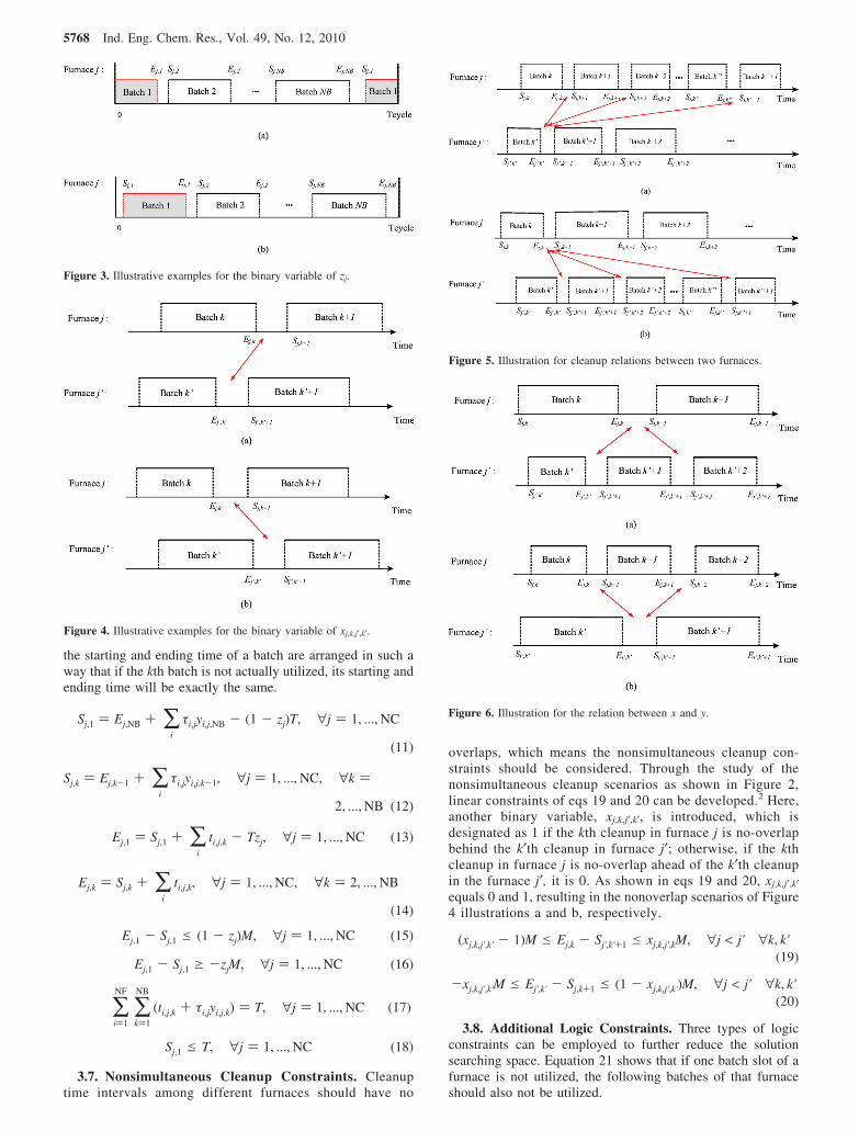
the starting and ending time of a batch are arranged in such away that if the kth batch is not actually utilized, its starting andending time will be exactly the same.
3.7. Nonsimultaneous Cleanup Constraints. Cleanuptime intervals among different furnaces should have no
overlaps, which means the nonsimultaneous cleanup con-straints should be considered. Through the study of thenonsimultaneous cleanup scenarios as shown in Figure 2,linear constraints of eqs 19 and 20 can be developed.2 Here,another binary variable, xj,k,j′,k′, is introduced, which isdesignated as 1 if the kth cleanup in furnace j is no-overlapbehind the k′th cleanup in furnace j′; otherwise, if the kthcleanup in furnace j is no-overlap ahead of the k′th cleanupin the furnace j′, it is 0. As shown in eqs 19 and 20, xj,k,j′,k′equals 0 and 1, resulting in the nonoverlap scenarios of Figure4 illustrations a and b, respectively.
3.8. Additional Logic Constraints. Three types of logicconstraints can be employed to further reduce the solutionsearching space. Equation 21 shows that if one batch slot of afurnace is not utilized, the following batches of that furnaceshould also not be utilized.
Figure 3. Illustrative examples for the binary variable of zj.
Figure 4. Illustrative examples for the binary variable of xj,k,j′,k′.
Figure 5. Illustration for cleanup relations between two furnaces.
Figure 6. Illustration for the relation between x and y.Sj,1 ) Ej,NB + ∑i
τi,jyi,j,NB - (1 - zj)T, ∀j ) 1, ..., NC
(11)
Sj,k ) Ej,k-1 + ∑i
τi,jyi,j,k-1, ∀j ) 1, ..., NC, ∀k )
2, ..., NB (12)
Ej,1 ) Sj,1 + ∑i
ti,j,k - Tzj, ∀j ) 1, ..., NC (13)
Ej,k ) Sj,k + ∑i
ti,j,k, ∀j ) 1, ..., NC, ∀k ) 2, ..., NB
(14)
Ej,1 - Sj,1 e (1 - zj)M, ∀j ) 1, ..., NC (15)
Ej,1 - Sj,1 g -zjM, ∀j ) 1, ..., NC (16)
∑i)1
NF
∑k)1
NB
(ti,j,k + τi,jyi,j,k) ) T, ∀j ) 1, ..., NC (17)
Sj,1 e T, ∀j ) 1, ..., NC (18)
(xj,k,j',k' - 1)M e Ej,k - Sj',k'+1 e xj,k,j',kM, ∀j < j' ∀k, k'(19)
-xj,k,j',k'M e Ej',k' - Sj,k+1 e (1 - xj,k,j',k')M, ∀j < j' ∀k, k'(20)
5768 Ind. Eng. Chem. Res., Vol. 49, No. 12, 2010

Equations 22 and 23 show that if the kth cleanup in thefurnace j is after the k′th cleanup in the furnace j′, then the k′′thcleanup in the furnace j should also be after the k′th cleanup inthe furnace j′ (k′′ > k), and vice versa. Figure 5 gives anillustration.
Equations 24 and 25 represent logic relations characterizedby binary variables of x and y: if two consecutive x’s has therelation of xj,k,j′,k′ - xj,k,j′,k′+1 ) 1, then there must be a batchslot being used between these two cleanups, i.e., ∑iyi,j′,k′+1 ) 1;and vice versa.2 Figure 6 gives the illustration.
Table 1. Cracking Furnace System Related Parameter Values
furnace j
parameter feed i 1 2 3 4 5 6
τi,j (day) Fa 2 2 2 2 2 0Fb 2 2 3 2 2 0Fc 3 2 3 3 2 0Fpd 0 0 0 0 0 3
Di,j (ton/day) Fa 204.4 214.9 188.2 202.3 212.7 0Fb 202.2 213.7 187.2 199.6 210.6 0Fc 201.0 211.1 185.8 197.6 209.8 0Fpd 0 0 0 0 0 210.1
tloi,j (day) Fa 20 23 18 20 23 0Fb 19 21 17 18 22 0Fc 18 19 16 17 20 0Fpd 0 0 0 0 0 59
tupi,j (day) Fa 70 72 65 69 73 0Fb 53 54 49 52 56 0Fc 41 43 39 43 45 0Fpd 0 0 0 0 0 101
ai,j,Pa Fa -0.0539 -0.0500 -0.0574 -0.0510 -0.0585 0Fb -0.0539 -0.0560 -0.0534 -0.0528 -0.0584 0Fc -0.0129 -0.0140 -0.0139 -0.0125 -0.0134 0Fpd 0 0 0 0 0 -0.0542
ai,j,Pb Fa -0.0267 -0.0243 -0.0288 -0.0242 -0.0278 0Fb -0.0267 -0.0287 -0.0269 -0.0244 -0.0257 0Fc -0.0149 -0.0149 -0.0143 -0.0146 -0.0148 0Fpd 0 0 0 0 0 -0.0264
ai,j,Pd Fa -0.2445 -0.1675 -0.3466 -0.2318 -0.2901 0Fb -0.0783 -0.0855 -0.0940 -0.0723 -0.0671 0Fc -0.0436 -0.0485 -0.0525 -0.0420 -0.0394 0Fpd 0 0 0 0 0 -0.1659
bi,j,Pa (1/day) Fa 0.0050 0.0054 0.0053 0.0049 0.0050 0.0010Fb 0.0060 0.0062 0.0054 0.0058 0.0057 0.0010Fc 0.0070 0.0070 0.0069 0.0073 0.0068 0.0010Fpd 0.0010 0.0010 0.0010 0.0010 0.0010 0.0051
bi,j,Pb (1/day) Fa -0.0041 -0.0043 -0.0038 -0.0037 -0.0038 -0.0040Fb -0.0041 -0.0042 -0.0038 -0.0038 -0.0043 -0.0040Fc -0.0105 -0.0100 -0.0115 -0.0112 -0.0100 -0.0040Fpd -0.0040 -0.0040 -0.0040 -0.0040 -0.0040 -0.0039
bi,j,Pd (1/day) Fa -0.0007 -0.0010 -0.0006 -0.0007 -0.0006 -0.0010Fb -0.0012 -0.0011 -0.0010 -0.0013 -0.0014 -0.0010Fc -0.0014 -0.0013 -0.0012 -0.0015 -0.0016 -0.0010Fpd -0.0010 -0.0010 -0.0010 -0.0010 -0.0010 -0.0010
ci,j,Pa Fa 0.5900 0.6378 0.5637 0.5987 0.6432 0Fb 0.3600 0.3698 0.3548 0.3626 0.3628 0Fc 0.3000 0.3109 0.2979 0.3011 0.2985 0Fpd 0 0 0 0 0 0.6067
ci,j,Pb Fa 0.0650 0.0610 0.0747 0.0724 0.0599 0Fb 0.1600 0.1581 0.1663 0.1620 0.1524 0Fc 0.1600 0.1523 0.1631 0.1572 0.1513 0Fpd 0 0 0 0 0 0.0666
ci,j,Pd Fa 0.5701 0.4430 0.6944 0.5359 0.5733 0Fb 0.1136 0.1208 0.1293 0.1076 0.1024 0Fc 0.0686 0.0735 0.0775 0.0670 0.0644 0Fpd 0 0 0 0 0 0.4732
∑i
yi,j,k g ∑i
yi,j,k'', k < k'' e NB, ∀j (21) xj,k,j',k' e xj,k'',j',k', j < j', k < k'' e NB (22)
xj,k,j',k' g xj,k,j',k'', j < j', k' < k'' e NB (23)
Ind. Eng. Chem. Res., Vol. 49, No. 12, 2010 5769

3.9. Variable Bounds. All the continuous variables have alower bound of zero, and all the starting times, ending times,batch times, and the total cycle time should be less than theupper bound. Variables x, y, and z are defined as binaryvariables.
The solution scheduling is searched in the pool which obeysthe above constraints and variable bounds, and is shown andanalyzed in a case study.
4. Case Study
A case study with real ethylene plant data is presented inthis paper. It is a cyclic scheduling problem for a crackingfurnace system with six furnaces processing four types of feeds.The feeds include gas, naphtha, light diesel, and ethanerepresented by Fa, Fb, Fc, and Fpd, respectively. After cracking,each feed would generate four types of products (NP is 4), whichare ethylene, propylene, ethane, and the left products representedby Pa, Pb, Pd, and Pc, respectively. The cracking furnace systemincludes one specific ethane furnace for processing recycled andfresh ethane and five ordinary furnaces for processing the otherfeeds.
Table 1 shows the product yield data, which comes fromthe regression of the industrial data. Note that when theproduct yields of ethylene, propylene, and ethane for a feedcracked at a furnace are obtained, the yield of the remainingproducts will be identified according to the mass balance.Generally, it can be seen that the ethylene yield is decayingwith time, while the propylene and ethane yields areincreasing with time. Among the four feeds, ethane feed hasthe highest ethylene yield, but lowest propylene yield.Conversely, the light diesel has the lowest ethylene yield but
highest propylene yield. The production yields are alsorelevant to the design of a furnace. Although furnaces 1-5are similarly designed; the performance of each is still a littlebit different. All the information is shown in Table 1.
As mentioned before, the scheduling objective is to maximizethe average net profit per day, which comes from product profitssubtracting raw material cost, operational cost, and cleanup cost.The related cost data is listed in Tables 2 and 3. The uppertime limit of M in the model is set as 365 days. The schedulingmodel is implemented in GAMS v23.3.17 The developed MINLPmodel has 1746 binary variables, 2112 continuous variables,and 12247 constraints. The MINLP model is solved by the
Table 2. Operational Cost and Cleanup Cost Values
furnace j
parameter feed i 1 2 3 4 5 6
Cvi,j ($/ton) Fa 16.55 17.74 15.55 18.18 16.66 0Fb 16.80 17.61 18.27 17.91 18.25 0Fc 17.20 15.50 16.06 17.29 16.18 0Fpd 0 0 0 0 0 16.94
Csi,j ($) Fa 86700.0 92758.3 81960.6 94973.8 86733.3 0Fb 87361.0 90964.4 79695.6 80087.9 82357.1 0Fc 89154.0 87879.6 84239.9 81375.3 92398.7 0Fpd 0 0 0 0 0 88625.2
Table 3. Additional Parameter Values of Feeds and Products
feed iCri
($/ton)Floi
(ton/day)Fupi
(ton/day) product lPl
($/ton)
Fa (gas) 444.13 70 210 Pa (ethylene) 866.67Fb (naphtha) 415.49 420 1260 Pb (propylene) 718.53Fc (light diesel) 411.01 80 240 Pc (others) 356.67Fpd (ethane) 444.13 110 410 Pd (ethane) 444.13
Figure 7. Heuristic scheduling results.
∑i
yi,j',k'+1gxj,k,j',k' - xj,k,j',k'+1, j < j', k' < NB (24)
∑i
yi,j,k+1gxj,k+1,j',k' - xj,k,j',k', j < j', k < NB (25)
Ej,k, Gi, Sj,k, ti,j,k, T g 0, ∀i, j, k (26)
Ej,k, Sj,k, ti,j,k, T e M (27)
zj, yi,j,k, xi,k,j',k' ∈ {0, 1} ∀i, j, k, j', k' (28)
5770 Ind. Eng. Chem. Res., Vol. 49, No. 12, 2010
solver DICOPT, and the sub solvers CPLEX and CONOPT areadopted to handle the MIP and NLP problems respectively.18-20
For comparison, a heuristic solution based on industrialexpertise is shown in Figure 7. This scheduling follows all the
same constraints, and variables are all within their bounds. Theidea behind this heuristic solution is that a feed should beallocated to the furnace that could generate higher product yields.For instance, Fb is cracked in furnaces 3 and 4 because it hashigher ethylene yield from these two furnaces than that of the
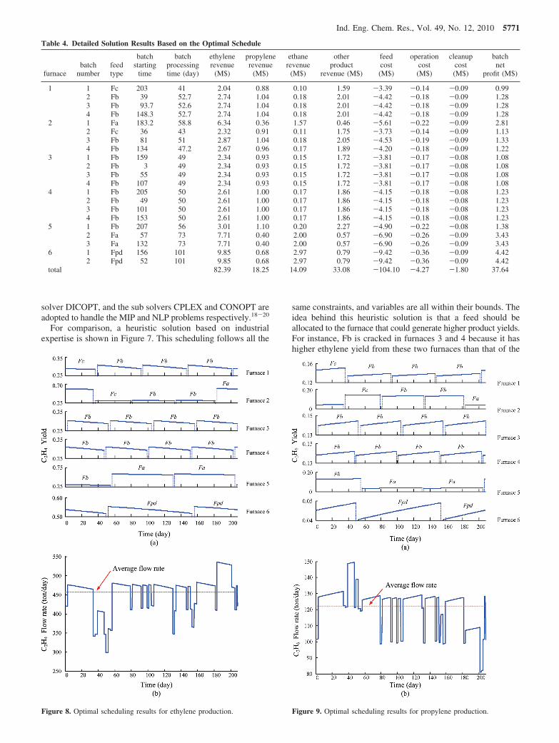
Figure 8. Optimal scheduling results for ethylene production. Figure 9. Optimal scheduling results for propylene production.
Table 4. Detailed Solution Results Based on the Optimal Schedule
furnacebatch
numberfeedtype
batchstarting
time
batchprocessingtime (day)
ethylenerevenue
(M$)
propylenerevenue
(M$)
ethanerevenue
(M$)
otherproduct
revenue (M$)
feedcost(M$)
operationcost(M$)
cleanupcost(M$)
batchnet
profit (M$)
1 1 Fc 203 41 2.04 0.88 0.10 1.59 -3.39 -0.14 -0.09 0.992 Fb 39 52.7 2.74 1.04 0.18 2.01 -4.42 -0.18 -0.09 1.283 Fb 93.7 52.6 2.74 1.04 0.18 2.01 -4.42 -0.18 -0.09 1.284 Fb 148.3 52.7 2.74 1.04 0.18 2.01 -4.42 -0.18 -0.09 1.28
2 1 Fa 183.2 58.8 6.34 0.36 1.57 0.46 -5.61 -0.22 -0.09 2.812 Fc 36 43 2.32 0.91 0.11 1.75 -3.73 -0.14 -0.09 1.133 Fb 81 51 2.87 1.04 0.18 2.05 -4.53 -0.19 -0.09 1.334 Fb 134 47.2 2.67 0.96 0.17 1.89 -4.20 -0.18 -0.09 1.22
3 1 Fb 159 49 2.34 0.93 0.15 1.72 -3.81 -0.17 -0.08 1.082 Fb 3 49 2.34 0.93 0.15 1.72 -3.81 -0.17 -0.08 1.083 Fb 55 49 2.34 0.93 0.15 1.72 -3.81 -0.17 -0.08 1.084 Fb 107 49 2.34 0.93 0.15 1.72 -3.81 -0.17 -0.08 1.08
4 1 Fb 205 50 2.61 1.00 0.17 1.86 -4.15 -0.18 -0.08 1.232 Fb 49 50 2.61 1.00 0.17 1.86 -4.15 -0.18 -0.08 1.233 Fb 101 50 2.61 1.00 0.17 1.86 -4.15 -0.18 -0.08 1.234 Fb 153 50 2.61 1.00 0.17 1.86 -4.15 -0.18 -0.08 1.23
5 1 Fb 207 56 3.01 1.10 0.20 2.27 -4.90 -0.22 -0.08 1.382 Fa 57 73 7.71 0.40 2.00 0.57 -6.90 -0.26 -0.09 3.433 Fa 132 73 7.71 0.40 2.00 0.57 -6.90 -0.26 -0.09 3.43
6 1 Fpd 156 101 9.85 0.68 2.97 0.79 -9.42 -0.36 -0.09 4.422 Fpd 52 101 9.85 0.68 2.97 0.79 -9.42 -0.36 -0.09 4.42
total 82.39 18.25 14.09 33.08 -104.10 -4.27 -1.80 37.64
Ind. Eng. Chem. Res., Vol. 49, No. 12, 2010 5771

other furnaces. Similarly, Fc is only processed in furnace 2 andFa is processed in furnace 5 for higher ethylene yield consid-eration. Because Fb has the largest supply rate, furnace 1 canbe used to handle Fb. As a result, the heuristic solution gives150 days of the total cycle time, during which the allocationsfor different feeds and furnaces are shown in Figure 7. Theindustrial-experience-based heuristic solution is an effectiveschedule. The net profit per day for the cracking process is$178,769, which is equivalent to a total profit of $65.25 millionper year.
Based on the developed scheduling model, the solution givesa total cycle time of 208 days and an average net profit of$180,744/day, about $65.97 million/year. A detailed solutionis attached in Table 4. There are four batches in furnaces 1-4,three batches in furnace 5, and two batches in furnace 6 duringone cycle. As shown in Figure 8, the first batch of furnace 1processes Fc (light diesel) followed by three batches of Fb(naphtha); in furnace 2, the first batch processes Fa (gas)followed by an Fc batch and two Fb batches; furnaces 3 and 4are only cracking the single feed of Fb, because Fb accountsfor the majority of the total feed supply and it has higherethylene yield in these two furnaces; in furnace 5, three batchesare arranged as Fb, Fa, and Fa; and for furnace 6 (ethanefurnace), it contains only two batches of recycled ethane. Figure8 illustrations a and b show the ethylene yield curve for eachbatch and the flow rate fluctuation of the total ethylene productin a cycle, respectively. Similarly, Figures 9and 10 provide yield
and flow rate fluctuation information for products of propyleneand ethane, respectively.
The overall performance of the cracking furnace system forproducing major products is shown in Figure 11, where thedecaying and increasing trends of different product yields areconsistent with the regressed formulas. Since a furnace decokingwill influence the mass throughput of the furnace system, it isvaluable to obtain the information of the total flow rate changeduring the manufacturing. Figure 12 gives the mass flow rateload to the cracking furnace system based on the optimizedschedule. It shows the total flow rate drops because of furnaceshutdowns for decoking. The fluctuation characterized by thestandard deviation of the total flow rate is 86.2, which is betterthan that of the heuristic solution (90.6 from Table 5). Thatmeans the cracking furnace system has inherently unstablefeatures due to the decoking operation. How to mitigate theinfluence from decoking to downstream manufacturing systemis a topic worthy of future study. Note that because simultaneousfurnace cleanups are avoided in the developed scheduling model,the inherently unstable situation has been addressed to someextent.
The comparison results between the optimal solution and theheuristic solution are summarized in Table 5. It shows that,although the heuristic schedule is acceptable, the solutionoptimal schedule can obtain nearly $2,000/day more, which isabout $0.72 million per year. Since the average product yieldsare almost the same, the profit increment actually comes fromthe increase of the average mass flow rate to the cracking furnacesystem. Meanwhile, the total flow rate fluctuation is alsoreduced, which is another benefit. Overall, the case studymanifests the superiority of the developed furnace schedulingmodel.
Finally, it should be clarified that it would be unnecessaryto designate specific ethane cracking furnace(s) if secondaryethane cracking was not considered. Under this situation, thefeed allocation constraints (see, eqs 8 and 9) should beremoved from the scheduling model, which means theupdated optimization model will have less stringent con-straints. Thus, the optimization results without consideringsecondary ethane cracking would supposedly be better thanthose with considering secondary ethane cracking. However,since the industrial practice is that every ethylene plant hasspecific ethane cracking furnace(s) to handle the secondaryethane cracking and employs nonsimultaneous furnace clean-ups, there would be no practical meaning to study on thedifference with/without secondary ethane cracking and non-simultaneous furnace cleanups.
5. Concluding Remarks
For multiple cracking furnaces processing different feedsunder various product values and manufacturing costs, theoperational scheduling for the entire furnace system shouldbe optimized to achieve the best economic performance. Inthis paper, a new MINLP model has been developed to obtaincyclic scheduling strategies for cracking furnace systems withthe consideration of secondary ethane cracking. It is morepractical than previous studies and can simultaneouslyidentify the allocation of feeds with their quantity, time, andsequence information for each cracking furnace. The casestudy has demonstrated the economic potential of thedeveloped methodology. It also shows that the furnace systemscheduling has the capability to mitigate the decoking-inducedunstable situations from the very beginning of crackingoperations.
Figure 10. Optimal scheduling results for ethane production.
5772 Ind. Eng. Chem. Res., Vol. 49, No. 12, 2010

Acknowledgment
This work was supported in part by Texas Air ResearchCenter (TARC) and the Research Enhancement Grant fromLamar University.
Nomenclature
Sets and Indicesi ) 1, ..., NF ) number of different feeds for crackingj, j′ ) 1, ..., NC ) number of cracking furnacesk, k′, k′′ ) 1, ..., NB ) number of batches assigned for each furnace
during one cycle timel ) 1, ..., NP ) number of considered productsParametersai,j,l ) pre-exponential factor of product l’s yield formula for the
feed i cracked in the furnace jbi,j,l ) power factor of product l’s yield formula for the feed i
cracked in the furnace jci,j,l ) constant coefficient of product l’s yield formula for the feed
i cracked in the furnace jCri ) raw material cost for the feed iCsi,j ) one cleanup cost for the feed i cracked in the furnace jCvi,j ) batch operation cost for the feed i cracked in the furnace jDi,j ) flow rate of the feed i cracked in the furnace jFloi ) lower bound of the total average flow rate for the feed iFupi ) upper bound of the total average flow rate for the feed iM ) upper bound of total cycle timePl ) market price for the product ltloi,j ) lower bound of batch processing time for the feed i cracked
in the furnace jtupi,j ) upper bound of batch processing time for the feed i cracked
in the furnace jτi,j ) cleanup time used after the feed i cracked in the furnace j
Figure 11. Product yield curves for six furnaces based on the optimized schedule.
Figure 12. Mass flow rate load to the cracking furnace system based onthe optimized schedule.
Table 5. Comparison between Optimal and Heuristic ScheduleResults
optimalsolution
heuristicsolution
profit ($/day) 180,744 178,769total cycle time (day) 208 150average ethylene yield 0.388 0.388average ethane yield 0.130 0.130average propylene yield 0.104 0.104average flow rate (ton/day) 1,177 1,167total flow rate fluctuation (standard deviation) 86.2 90.6
Ind. Eng. Chem. Res., Vol. 49, No. 12, 2010 5773

VariablesEj,k ) ending time point of the kth batch in the furnace jGi ) extra amount of flow rate for feed i that is processed above
Floi
Sj,k ) starting time point of the kth batch in the furnace jti,j,k ) processing time for the feed i cracked in the kth batch of the
furnace jT ) total cycle time of the scheduling problemxj,k,j′,k′ ) binary variable which is 1 if the kth cleanup in the furnace
j is no-overlap behind the k′th cleanup in the furnace j′; otherwise,if the kth cleanup in the furnace j is no-overlap ahead of the k′thcleanup in the furnace j′, it is 0.
yi,j,k ) binary variable which is 1 if the feed i is processed in thekth batch of the furnace j; otherwise, it is 0.
zj ) binary variable which is 1 if the starting time of the first batchin the furnace j is larger than its ending time; otherwise, it is 0.
Literature Cited
(1) SRI Consulting. World Petrochemical Report on Ethylene, MenloPark, CA. 2008. Available online at http://www.sriconsulting.com/WP/Public/Reports/ethylene/ (accessed February 2, 2009).
(2) Liu, C.; Zhang, J.; Xu, Q.; Li, K. Cyclic Scheduling for BestProfitability of Industrial Cracking Furnace System. Comput. Chem. Eng.2010, 34 (4), 544–554.
(3) Heynderickx, G. J.; Froment, G. F. Simulation and Comparison ofthe Run Length of an Ethane Cracking Furnace with Reactor Tubes ofCircular and Elliptical Cross Sections. Ind. Eng. Chem. Res. 1998, 37 (3),914–922.
(4) Heynderickx, G. J.; Oprins, A. J. M.; Marin, G. B.; et al. Three-Dimensional Flow Patterns in Cracking Furnaces with Long-Flame Burners.AIChE J. 2001, 47 (2), 388–400.
(5) Joo, E.; Lee, K.; Lee, M.; Park, S. CRACKER- A PC based Simulatorfor Industrial Cracking Furnaces. Comput. Chem. Eng. 2000, 24, 1523–1528.
(6) Li, C. F.; Zhu, Q. X.; Geng, Z. Q. Multiobjective Particle SwarmOptimization Hybrid Algorithm: An Application on Industrial CrackingFurnace. Ind. Eng. Chem. Res. 2007, 46 (11), 3602–3609.
(7) Wang, J.; Xu, Q.; Chen, B. Z.; He, X. R. Parallel OptimizationScheme for Industrial Steam Cracking Process. J. Chem. Eng. Jpn. 2003,36 (1), 14–19.
(8) Xu, Q.; Chen, B. Z.; He, X. R. A Fast Simulation Algorithm forIndustrial Cracking Furnaces. Hydrocarbon Process. 2002, 81 (12), 65–68.
(9) Goethem, M. W. M.; Kleinendorst, F. I.; Leeuwen, C. V.; Velzen,N. V. Equation-Based SPYRO Model and Solver for the Simulation of theSteam Cracking Process. Comput. Chem. Eng. 2001, 25, 905–911.
(10) Edwin, E. H.; Balchen, J. G. Dynamic Optimization and ProductionPlanning of Thermal Cracking Operation. Chem. Eng. Sci. 2001, 56 (3),989–997.
(11) Jain, V.; Grossmann, I. E. Cyclic Scheduling of Continuous Parallel-Process Units with Decaying Performance. AIChE J. 1998, 44 (7), 1623–1636.
(12) Schulz, E. P.; Bandoni, J. A.; Diaz, M. S. Optimal Shutdown Policyfor Maintenance of Cracking Furnaces in Ethylene Plants. Ind. Eng. Chem.Res. 2006, 45 (8), 2748–2757.
(13) Schulz, E. P.; Diaz, M. S.; Bandoni, J. A. Interaction betweenProcess Plant Operation and Cracking Furnaces Maintenance Policy in anEthylene Plant. Comput.-Aided Process Eng. 2008, 8, 487–492.
(14) Lim, H.; Choi, J.; Realff, M. J.; Lee, J. H.; Park, S. Developmentof Optimal Decoking Scheduling Strategies for an Industrial NaphthaCracking Furnace System. Ind. Eng. Chem. Res. 2006, 45 (16), 5738–5747.
(15) Lim, H.; Choi, J.; Realff, M. J.; Lee, J. H.; Park, S. ProactiveScheduling Strategy Applied to Decoking Operations of an IndustrialNaphtha Cracking Furnace System. Ind. Eng. Chem. Res. 2009, 48, 3024–3032.
(16) Gao, X. D.; Chen, B. Z.; He, X. R.; et al. MultiobjectiveOptimization for the Periodic Operation of the Naphtha Pyrolysis ProcessUsing a New Parallel Hybrid Algorithm Combining NSGA-II with SQP.Comput. Chem. Eng. 2008, 32 (11), 2801–2811.
(17) GAMS; GAMS Development Corporation: Washington, DC, 1992.(18) CPLEX. Using the CPLEX Callable Library; CPLEX Optimization,
Inc.: Incline Village, NV, 1995.(19) Drud, A. S. CONOPTs: A Large Scale GRG Code. ORSA
J. Comput. 1994, 6, 207.(20) Viswanathan, J.; Grossmann, I. E. A Combined Penalty Function
and Outer-Approximation Method for MINLP Optimization. Comput. Chem.Eng. 1990, 14 (7), 769–782.
ReceiVed for reView January 19, 2010ReVised manuscript receiVed April 14, 2010
Accepted April 21, 2010
IE1001235
5774 Ind. Eng. Chem. Res., Vol. 49, No. 12, 2010