cyclohexane production unit presented by brian clifton
TRANSCRIPT

Cyclohexane Production Unit
Presented by Brian Clifton

Executive Summary
The cyclohexane production plant is not economically feasible unless the price of cyclohexane is more than double the price of benzene.
Yellow does not recommend IRI to proceed with the plans to build and operate this facility.

Outline
Process Overview Economic and Risk Analysis Pipe Network Pump System Heat Exchanger Distillation Column
Process Overview
Benzene is hydrogenated in a Gibbs reactor at high temperature and pressure to form cyclohexane

MIXER E1
C1
SPLITTER
E2
E3
R1FLASH
P1
V1
SO1
PI1
PI2
PI3
1
30T1
BENZENE
HYDROGEN
RECYCLE
S4S5
S6
S7
S9
S1
S11
PURGEGAS
S13
PRODUCT
1PRODUCT
S3 1S3S10
1S10
S2
S8S12
S14
Process Overview

Economic AnalysisEquipment Cost
Distillation column $53,200
Heat Exchanger E1 $14,800
Heat Exchanger E2 $1,230
Heat Exchanger E3 $6,610
Reactor $5,040
Mixer $2,500
Splitter $2,500
Compressor $150,000
Flash $42,600
Total Equipment Cost (2005) $344,200

Economic Analysis
Production Cost: $7.14/gal Revenue: $3.60/gal TCI: $2.5 million NPW: negative $1 billion Accuracy: ±10% Required ROI: 8%

Strauss Plots/Propagation of Error
Strauss plots for FCI, product cost, and product cost
Propagation of error method
NPW vs. Product Cost
y = -3E+08x + 1E+09
($1,500,000,000.00)
($1,000,000,000.00)
($500,000,000.00)
$0.00
$500,000,000.00
$1,000,000,000.00
$1,500,000,000.00
$0.00 $1.00 $2.00 $3.00 $4.00 $5.00 $6.00 $7.00 $8.00
Product Cost ($/gal)
NPW
($)
Product Cost
Linear (Product Cost)
2Cost
2
)Cost(
)(2Price
2
)Price(
)(22
)(
)(2
NPWNPWFCIFCI
NPWNPW

Monte Carlo SimulationMonte Carlo Simulation for NPW
500 data points
0
20
40
60
80
Net Present Worth(millions of dollars)
Fre
qu
en
cy

Piping System
Piping materials made of stainless steel
Insulation thickness of 1 inch Schedule 40 pipes increased to
schedule 80 to operate under bursting strength
FCI of $900,000 for piping system

Piping SpecificationsStream Type Length (ft) Elbows (90o) Valves (globe) Pressure Drop (psia)
Hydrogen 8'' Sch 80 700 3 3 0.1623535
Benzene 4'' Sch 80 500 5 3 0.0568027
Recycle 8'' Sch 80 350 4 1 0.1724243
Feed 6'' Sch 80 150 6 2 0.1095886
Top 8'' Sch 80 500 2 2 0.0748854
Bottom 6'' Sch 80 500 2 2 0.1420422
Purge 6'' Sch 80 300 2 1 0.0448303
S1 10'' Sch 80 150 2 1 0.5344238
S2 10'' Sch 80 100 2 1 0.643341
S3 10'' Sch 80 150 4 2 0.9095154
S4 10'' Sch 80 150 4 2 0.7703857
S5 10'' Sch 80 100 2 1 0.4255066
S6 10'' Sch 80 150 4 2 0.6598205
S7 10'' Sch 80 150 4 0 0.0444946
S8 10'' Sch 80 100 2 1 0.039032

Pumping Section
Cyclohexane is pumped from the process to a storage tank at 555 psia which is 35 feet above the flash tank

Pumping Section
Pump Section
Piping All pipe are stainless steel schedule
40 ability to resist corrosion
Pump Section
Pump Positive displacement pump
9 hp required 415 ft head available
All components are stainless steel

NPSHA
1240
1260
1280
1300
1320
1340
1360
1380
0 200 400 600 800 1000 1200 1400 1600
flow rate, ft^3/hr
NP
SH
A

System Head
0
100
200
300
400
500
600
700
800
900
1000
0 200 400 600 800 1000 1200 1400 1600
flow rate, ft^3/hr
hea
d, f
t

Pumping Section
Cost for installation of the pumping section, including the pump, pipes, and valves, was determined to be $105,000
Total fixed capital investment for the cyclohexane plant up to $2.4 million.
Heat Exchanger Network
There are three heat exchangers in the cylcohexane plant
The heating utility required by the plant is minimized by using the hot product stream to pre-heat the incoming reactant stream.

Heat Exchanger Network
Heat exchanger 1 was designed rigorously
A temperature – heat diagram was created

Heat Exchanger: Design
Duty, x 10^6 BTU/hr0 2.0 4.0 6.0 8.0 10.0
Tem
per
atu
re, F
100.0
140.0
180.0
220.0
260.0
300.0
Heat Exchanger E1 Zones Analysis
Shell Side
Tube Side

Heat Exchanger: Design
The single pass, countercurrent design was selected
No baffles were
used, in order to
maintain the
shell-side pressure
drop under 5 psi
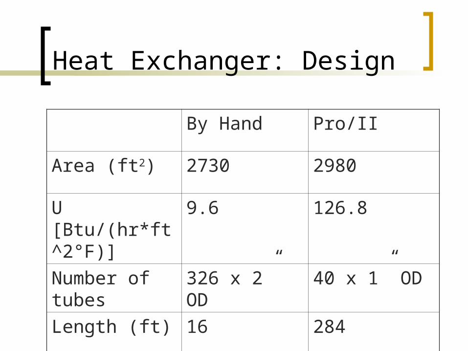
Heat Exchanger: Design
By Hand Pro/II
Area (ft2) 2730 2980
U [Btu/(hr*ft^2°F)]
9.6 126.8
Number of tubes
326 x 2” OD 40 x 1” OD
Length (ft) 16 284

Heat Exchanger Design
Triangular pitch Stainless steel heat exchangers Hot streams were maintained tube
side in all heat exchangers Heat exchanger 2 uses steam to heat
the reactant stream Heat exchanger 3 uses cooling water
to cool the product stream
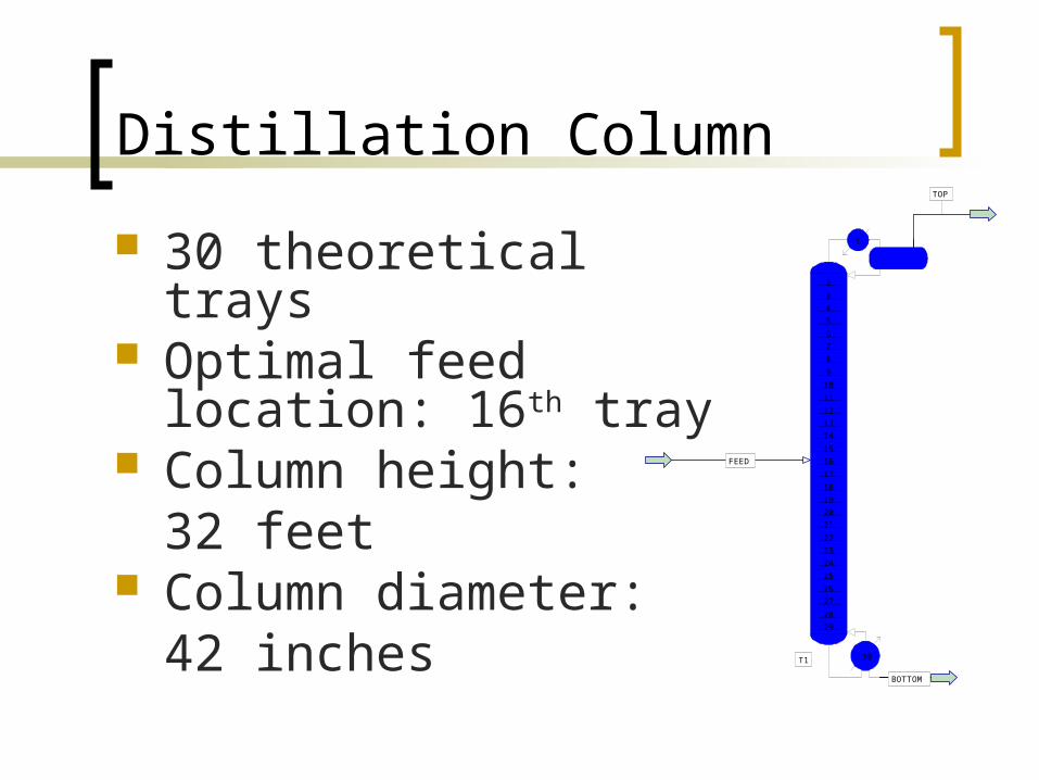
Distillation Column
30 theoretical trays Optimal feed location:
16th tray Column height:
32 feet Column diameter:
42 inches
234567891011121314151617181920212223242526272829
1
30T1
TOP
BOTTOM
FEED

Distillation Column
Valve trays 94 valves / tray Tray spacing:
24 inches Condenser heat duty:
-1.9 MM Btu/hr Reboiler heat duty:
3.01 MM Btu/hr

Summary
After the detailed designs were conducted, the cyclohexane plant was shown to not meet IRI’s criteria for profitablity.
Yellow does not recommend IRI building and operating this facility.

Questions
??