cyclotrons: magnetic design and beam dynamics · 2017-07-05 · kleeven/zaremba cas-2015:...
TRANSCRIPT

Cyclotrons: magnetic design and beam dynamics
Wiel Kleeven and Simon Zaremba (Ion Beam Applications s.a.)CERN Accelerator School: Accelerators for Medical
ApplicationsVösendorf, Austria 26 May-5 June, 2015
1Kleeven/Zaremba CAS-2015: Cyclotrons -
magnetic design and beam dynamics

Outline• Part I: A short introduction
• Part II: A little bit about focusing and isochronism
• Part III: ….. about injection
• Part IV: ….. about extraction
• Part V: …… about magnetic design
Kleeven/Zaremba CAS-2015: Cyclotrons -magnetic design and beam dynamics
2
First lecture: parts 1-3Second lecture: parts 3-5

Kleeven/Zaremba CAS-2015: Cyclotrons -magnetic design and beam dynamics
3
Part I: A short introduction

Kleeven/Zaremba CAS-2015: Cyclotrons -magnetic design and beam dynamics
4
The most basic equation of the cyclotron
H+
Bz
V
Fc
Bz
V
Fc
A charged particle in a uniform magnetic fieldmoves on a circle
The centripetal force is equal to the Lorentz force acting on the particle
𝑚𝑣2
𝑟= 𝑞𝑣𝐵 𝜔 =
𝑣
𝑟=𝑞𝐵
𝑚
Thus the rotation frequency of the particle isconstant => independent on radius ,velocity , energy or time (in the non-relativistic limit)

Kleeven/Zaremba CAS-2015: Cyclotrons -magnetic design and beam dynamics
5
Consequences of constant cyclotron frequency Particles can be accelerated with an
RF-system operating at constant frequency:
The orbit starts in the center (injection) and spirals outwardtowards the pole radius (extraction)
The magnet field is constant in time RF and magnetic stucture are
completely integrated => Same RF structure accelerates many times =>compact and cost-effective
CW-operation (continuous wave)
FRF(MHz) = 15.2 h(Z/A) B (Tesla)
Classical cyclotron: Lawrence and Livingston, Phys. Rev. 40 (1932) 9
DEE

Classical cyclotron: where is the problem?
i. In a uniform magnetic field there is no vertical focusing (metastable)
ii. During acceleration, due to the relativistic mass increase, the revolution frequency decreases in a uniform magnetic field => loss of resonancebetween RF and the beam => loss of isochronism
iii. just increasing the magnetic field with radius is not possible => vertically unstable
Kleeven/Zaremba CAS-2015: Cyclotrons -magnetic design and beam dynamics
𝜔 =𝑞𝐵
𝑚01 −
𝑣
𝑐
2

Can we still use the classical cyclotron?a small side-step
Just accept the problem and see how far you get
The classical cyclotron with a smallnegative field-gradient is verticallyfocusing.
During acceleration the particles willgradually run out of phase withrespect to the RF system.
How high energy can we obtain beforedeceleration sets in?
Kleeven/Zaremba CAS-2015: Cyclotrons -magnetic design and beam dynamics
7
Courtesy Frédéric Chautard

Kleeven/Zaremba CAS-2015: Cyclotrons -magnetic design and beam dynamics
8
2.93
2.94
2.95
2.96
2.97
2.98
2.99
3.00
3.01
3.02
-60
-40
-20
0
20
40
60
80
0 20 40 60 80 100 120 140 160
mag
net
ic f
ield
(Te
sla)
inte
grat
ed p
has
e sl
ip (
deg
)
Radius (mm)
classical cyclotron: B-field and integrated phase slip
phase-slipBisoB
magnetic focusing: n=0.01; nz=0.1
Small SC cyclo for PET?Could it be competitive?
Make a simple calculation in Excel
CIEMAT Madrid
E 10 MeV
B 3 Tesla
Vdee 50 kVolt
Ngaps 2
Rextr 156 mm
Nturns 59
DFRF-max 45 deg
classical cyclotron
calculation example
RF system: 2 dees of
180° in push-pull first
harmonic mode

Another solution: the synchro-cyclotron
• Let the magnetic field gradually decrease with radius in orderto obtain weak vertical focusing =>
• Let the RF frequency gradually decrease with time in order to compensate for the drop of the magnetic field and for the increase of the mass
Kleeven/Zaremba CAS-2015: Cyclotrons -magnetic design and beam dynamics
𝜐𝑧 = 𝑘 ⇒ 𝑘 = −𝑟
𝐵
𝑑𝐵
𝑑𝑟
𝜔 =𝑞𝐵
𝑚
Veksler, J. Phys. USSR 9 (1945)153McMillan, Phys. Rev. 68 (1945)143L
Note: synchrotron wasinvented at the same time

Some consequences1. The RF is pulsed but the magnetic field is still constant (in time)2. The beam is no longer CW but modulated in time3. The mean beam intensity is much lower => OK for proton therapy4. There is a longitudinal beam dynamics similar to that of the synchrotron5. Only during a short time-window, beam can be captured in the cyclo-center6. The timing between RF frequency, RF voltage and ion source need to be well
defined and controlled7. A more complicated RF system because of the required frequency variation8. The RF frequency can not be varied very fast (rotating capacitor) and therefore
the acceleration must be slow => low energy gain per turn => many turns up to extraction => little RF power needed
9. There is only a very small turn-separation. Therefore a special extraction method is needed to get the beam out of the machine (regenerative extraction)
Kleeven/Zaremba CAS-2015: Cyclotrons -magnetic design and beam dynamics
10

Example: the IBA S2C2 for proton therapy
Kleeven/Zaremba CAS-2015: Cyclotrons -magnetic design and beam dynamics
11
Repition rate = 1 kHz Duty cycle about 100
Superconducting synchro-cyclotronExtraction energy 230 MeV
0.0
0.1
0.2
0.3
0.4
0.5
0.6
0.7
0.8
0.9
1.0
4.0
4.2
4.4
4.6
4.8
5.0
5.2
5.4
5.6
5.8
6.0
0 100 200 300 400 500
vert
ical
tu
ne
Mag
net
ic f
ield
(Te
sla)
Radius (mm)
IBA S2C2 synchrocyclotron for proton therapy
B
nu_z
extraction

Longitudinal dynamics in a synchro-cyclotron
• There is a definition of a synchronous particle: everywherein the synchro-cyclotron, at any moment in time, the revolution frequency of the synchronous particle is equal to RF frequency
• There are oscillations (in energy and phase) of real particlesaround the synchronous particle
• There is a stability zone for these oscillations defined by a separatrix in the longitudinal phase space
• This separatrix is filled during the beam capture in the synchro-cyclotron center
Kleeven/Zaremba CAS-2015: Cyclotrons -magnetic design and beam dynamics
12

13
-6
-4
-2
0
2
4
6
-200 -100 0 100 200 300 400
Del
ta E
(M
eV)
Phase (degrees)
Separatrix and flowlines in longitudinal phase space
separatrix
synchronousparticle
stable motion
unstable motion
Illustration of the longitudinal dynamics
John L. Livingood, Principles of cyclicParticle Accelerators (1961) Chapter 6 Kleeven/Zaremba CAS-2015: Cyclotrons -
magnetic design and beam dynamics

Yet another solution: the isochronous cyclotron
• Two contributions to vertical focusing:
– vqBr => obtained in the radially decreasing rotationallysymmetric magnetic fields as in the classical cyclotron and the synchro-cyclotron
– vrBq => requires an azimuthal modulation of the magneticfield => introduce sectors (hills) with high field and valleyswith low field => azimuthally varying field cyclotron=> the field variation creates the non-circular orbit
Kleeven/Zaremba CAS-2015: Cyclotrons -magnetic design and beam dynamics
14
𝐹𝑧 = 𝑞( 𝑣 × 𝐵)𝑧 = −𝑞(𝑣𝜃𝐵𝑟 − 𝑣𝑟𝐵𝜃)

Kleeven/Zaremba CAS-2015: Cyclotrons -magnetic design and beam dynamics
15
Part II: A little bit about
vertical focusing and isochronism

The Azimuthally Varying Field (AVF) cyclotron
Kleeven/Zaremba CAS-2015: Cyclotrons -magnetic design and beam dynamics
16Upper+return yoke
Hill sector+pole
Magnetic field on hills and valleys
high field low fieldvalley

Vertical focusing => scaloping of the orbit
Kleeven/Zaremba CAS-2015: Cyclotrons -magnetic design and beam dynamics
17
0.5 Tesla
-0.5 Tesla
0° 90°
vr/vmod in the median plane
Bq 10 mm abovemedian plane
𝐹𝑧 ∞ 𝑣𝑟𝐵𝜃
entrance exit
Bq
vr
q

Cyclotron sector focusing edge focusing
Kleeven/Zaremba CAS-2015: Cyclotrons -magnetic design and beam dynamics
18
Look how the magnetic fieldchanges when moving outward
perpendicular to the orbit:
B z-focusB z-defocus
Increasing => vertically defocusing
Decreasing => vertically focusing

More vertical focusing => pole spiraling
Kleeven/Zaremba CAS-2015: Cyclotrons -magnetic design and beam dynamics
19
B z-focusB z-defocus For straight sectors: equal vertical focusingat entrance and exit of sector
Spiraling of the pole changes the focusingstrength at the entrance and exit of the sector:
Entrance: strong B-decrease => strong z-focusing
Exit: strong B-increase => strong z-defocus
ALTERNATING FOCUSINGThis may give a very large contribution

Distributed focusing in a real cyclotron field
• In a real cyclotron geometry the focusing isdistributed along the orbit:
• At pole entrance/exit => edge focusing• Spiral sectors => alternating (strong) focusing• In the middle of the hill: often a positive field
gradient => vertically defocusing• In the middle of a valley: often a negative field
gradient => vertically focusingKleeven/Zaremba CAS-2015: Cyclotrons -
magnetic design and beam dynamics20

X
Y
Flutter: a measure for the azimuthal field variation
Average of the field modulation
21
𝐹 𝑟 =𝐵2 − 𝐵2
𝐵2
N=number of sectorsa=‘filling factor’

Formulas for focusing in an AVF cyclotron
Kleeven/Zaremba CAS-2015: Cyclotrons -magnetic design and beam dynamics
22
𝜐𝑧2 = 𝑘 +
𝑁2
𝑁2 − 1𝐹 1 + 2tan2𝜉
k = field index = −𝑟
𝐵
𝑑 𝐵
𝑑𝑟
F = flutterN = number of sectors = spiral angle
Definition of spiral angle
This is an approximation: There is
also some dependency on radial
gradients of the flutter. See:
Hagedoorn and Verster, NIM 18,19
(1962) 201-228
NOTE: for an iscochronous cyclotron:𝑘 = 1 − 𝛾rel
2
𝜐𝑟 ≅ 𝛾rel
𝜐𝑟2 = 1 − 𝑘 +
3𝑁2
(𝑁2 − 1)(𝑁2 − 4)𝐹 1 + tan2𝜉

The deep-valley cyclotron design (IBA-1986)
Kleeven/Zaremba CAS-2015: Cyclotrons -magnetic design and beam dynamics
23
deep valley
large flutter
strong focusing
small beam size
small vertical gap
little resistive coil losses
Place RF cavities in the valleysAcceleration of H-
An industrial cyclotron

Kleeven/Zaremba CAS-2015: Cyclotrons -magnetic design and beam dynamics
24
Isochronism => the revolution frequency of the particle is constant everywhere in the cyclotron
independent of the energy of the particle
Isochronous cyclotrons have to be isochronizedby correct shaping of the average magnetic field
as a function of radius

All cyclotron magnetic fields are mapped in the median plane
Precise mapping and iron pole shimming is needed in order to isochronize the magnetic field
Move Hall-probe or a search coil (S2C2) on a 2D polar grid to obtain a full field-map => automized and computer controlled system
It is not possible to obtain isochronismjust from the design => requiredprecission of <B> =>10-4 to 10-5
Analyse the magnetic field on equilibriumorbits in order to evaluate isochronism
Shim the hill sectors of the iron in order to improve the isochronism (reduce the RF phase slip)

Essential information of a cyclotron field map
1. The level of isochronism => integrated RF phase slip2. The transverse optical stability => tune functions3. Crossing of dangerous resonances => operating
diagram4. Magnetic field errors
First and second harmonic errors => resonance drivers Median plane errors => very difficult to measure
5. …Kleeven/Zaremba CAS-2015: Cyclotrons -
magnetic design and beam dynamics26

Analysis of a cyclotron field map
1. Static analysis => Acceleration is turned off Computation of the closed orbits and their
properties
2. Accelerated orbits => for special problems Central region studies
Extraction studies
Study of resonance crossings
…Kleeven/Zaremba CAS-2015: Cyclotrons -
magnetic design and beam dynamics27

Closed orbit analysis in a cyclotron
• Closed orbits are obtained by solving the non-accelerated motion. Two types:– Equilibrium orbits: have the same N-fold symmetry as the cyclotron.
They are obtained in the ideal magnetic field map where errors have been removed
– Periodic orbits: have a periodicity of 2p and are obtained in a real (measured) field map with errors
• Different dedicated programs are available such as CYCLOPS, EOMSU. At IBA we use a home-made program.
• They solve the equations of motion and determine the properinitial conditions such that the orbit closes in itself.
Kleeven/Zaremba CAS-2015: Cyclotrons -magnetic design and beam dynamics
28
Closed orbit computation, see:
Verster and Hagedoorn, NIM 18,19 (1962) 201-228
Gordon, Particle Accelerators 16 (1984) 39-62

Information obtained from a closed-orbit analysis
• A family of closed orbits is computed for a full range of energies, covering the full region of acceleration in the cyclotron
• For each orbit the horizontal and vertical tune-functions (nr and nz) and the corresponding resonance diagram of nz versus nr
• The particle revolution frequency for each energy: from this the isochronism of the field can be evaluated
• The optical functions (Twiss parameters) on each orbit can alsobe obtained. This may be useful for study of beam extraction.
Kleeven/Zaremba CAS-2015: Cyclotrons -magnetic design and beam dynamics
29
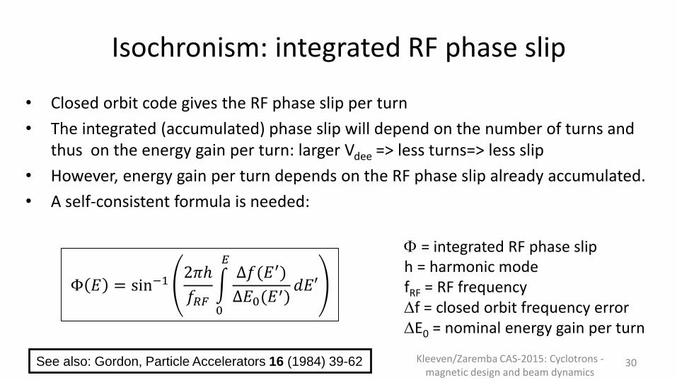
Isochronism: integrated RF phase slip
• Closed orbit code gives the RF phase slip per turn
• The integrated (accumulated) phase slip will depend on the number of turns and thus on the energy gain per turn: larger Vdee => less turns=> less slip
• However, energy gain per turn depends on the RF phase slip already accumulated.
• A self-consistent formula is needed:
30
Φ 𝐸 = sin−12𝜋ℎ
𝑓𝑅𝐹
0
𝐸Δ𝑓(𝐸′)
Δ𝐸0(𝐸′)𝑑𝐸′
F = integrated RF phase sliph = harmonic modefRF = RF frequencyDf = closed orbit frequency errorDE0 = nominal energy gain per turn
See also: Gordon, Particle Accelerators 16 (1984) 39-62 Kleeven/Zaremba CAS-2015: Cyclotrons -magnetic design and beam dynamics

Isochronization by pole shimming
Kleeven/Zaremba CAS-2015: Cyclotrons -magnetic design and beam dynamics
31
Removable pole-edge
Shimming
Calculate shim effect with OPERA3Dshimming matrix: shim(r1) => DB(r2)
Simple => hard edge modelMore advanced => shimming matrix
For more saturatedpoles

Removable pole edges in the C235 cyclotron
Kleeven/Zaremba CAS-2015: Cyclotrons -magnetic design and beam dynamics
32
123
In this isochronous PT cyclotron, there are 3 removable pole edges
(per pole) for shimming the averagefield as needed for isochronism

Isochronization for two different particlesExample: a proton/deuteron isotope production cyclotron
Kleeven/Zaremba CAS-2015: Cyclotrons -magnetic design and beam dynamics
33flaps
By placing iron shims (flaps) in the valleys which can be moved vertically close to the median plane (protons) or further away from the median plane (deuterons)
1.295
1.300
1.305
1.310
1.315
1.320
1.325
1.330
0 10 20 30 40 50 60 70
mag
net
ic f
ield
(Te
sla)
radius (cm)
Isochronous fields for a proton/deutron cyclotron
0.53%
2.1%
20 MeV protons10 MeV deutrons

Movable inserts (flaps) effect
Kleeven/Zaremba CAS-2015: Cyclotrons -magnetic design and beam dynamics
34
H measured magnetic fieldD measured magnetic field

Isochronization by flaps that do not move
Kleeven/Zaremba CAS-2015: Cyclotrons -magnetic design and beam dynamics
35
• For higher energies not enoughcorrection can be generated with the flaps
• Flaps are magneticly connected to the yoke by the iron pillar, ‘pumping’ flux into the flaps
• With the solenoid around the pillar, the amount of flux can be adjusted
• A lot of flux can be ‘pumped-up’. Therefore, this method can appliedfor higher energy cyclotrons
• For example: 70 MeV protons vs 35 MeV deutronsflap pillar solenoid
Based on a study for a 70 MeV cyclotron for INFN

Isochronization of multi-particle C70 cyclotron
Kleeven/Zaremba CAS-2015: Cyclotrons -magnetic design and beam dynamics
36
Coils around the pole produce a ‘quadrupole-like’ field distribution. Field is pushed from low radius to high radius or vice-versa, by changing the sign of the coil current
upper pole
lower pole
cyclo center extraction
Panofsky quadrupole

The similar method is applied in the AGOR superconducting cyclotron
Kleeven/Zaremba CAS-2015: Cyclotrons -magnetic design and beam dynamics
37
Many independent coilsallow to create a wide
range of differentisochronous field maps

Circular trim coils on the poles
Kleeven/Zaremba CAS-2015: Cyclotrons -magnetic design and beam dynamics
38
Trim coils of the Berkeley 88-inch cyclotron on a test-bench
Also here several independent but circular coils
For the multi-particle variable energy research-cyclotrons this is
probably the most commonmethod

Example C70: industrial cyclotron for medicalisotope production
• Currently under commisioning
• 70 MeV H-, Intensity 750 mA
• N=4, axial injection
• Stripping extraction, dual beam
Kleeven/Zaremba CAS-2015: Cyclotrons -magnetic design and beam dynamics
39
Little bit of pole spiral for fine-tuning of nz
Isochronization by pole shimming
Slight spiraling of poles => fine-tuning of the nz curve

Example C70: average field and flutter
• Average field increases withroughly 1% per 10 MeV
Kleeven/Zaremba CAS-2015: Cyclotrons -magnetic design and beam dynamics 40
Ab
ou
t 7
% in
crea
se
No flutter in the centerField bump
• Sharp field drop in the center due the axial hole for injection
– Local field bump provides someweak focusing
– RF electric field will provide somevertical focusing
• No flutter in the cyclotron center; what about focusing in the center?

Example C70: isochronism
Kleeven/Zaremba CAS-2015: Cyclotrons -magnetic design and beam dynamics
41
-30.0
-20.0
-10.0
0.0
10.0
20.0
30.0
-0.3%
-0.2%
-0.1%
0.0%
0.1%
0.2%
0.3%
0 25 50 75 100 125
inte
grat
ed p
has
e R
F p
has
e sl
ip (
deg
)
ph
ase
slip
(tu
rn/t
urn
)
Average radius (cm)
C70 RF phase slip
phase slip per turn
RF integrated phase slip
Vdee = 50 kVolt
-1.0
0.0
1.0
2.0
3.0
4.0
5.0
6.0
7.0
0 25 50 75 100 125
req
uir
ed s
him
min
g o
f th
e p
ole
(m
m)
Average radius (cm)
C70 required pole shimming
required pole shimming
Closed orbits are found up to 71.4 MeV. The most outer orbits enter into the radial fringe area of the pole. These orbits can no longer be corrected. The maximum phase slip of 30° is considered acceptable. The actual shift will be smaller becauseparticles are extracted up to 70 MeV
Fringefield

Example C70: tune functions and operating diagram
0.8
0.9
1.0
1.1
1.2
1.3
1.4
0.8
0.9
1.0
1.1
1.2
1.3
1.4
0 25 50 75 100 125
vert
ical
tu
ne
2*n
z
ho
rizo
nta
l tu
ne
nr
Average radius (cm)
C70 tune functions
nr
2*nz
avoid Walkinshaw resonance nr=2nz
add some pole spiral
nr=2nz => a structural resonance; may be dangerous, better to avoid
42nr+3nz=3 => non-structural, driven by harmonic 3; considered as non-dangerous

Harmonic field errors in the map (1)• A first harmonic field error will de-center the closed orbit. This effect becomes big
when nr 1. This happens in the cyclotron center and in the radial fringe region of the pole. An off-centered orbit may become more sensitive to other resonances. Too high harmonic errors must be avoided.
• The gradient of the first harmonic can drive the 2nz=1 resonance. In the stop band of this resonance, the motion becomes vertically unstable. This may lead to amplitude growth and emittance growth. The stop-band of this resonance is given by:
4𝜐𝑧 𝜐𝑧 −1
2< 𝑟
𝑑𝐶1𝑑𝑟
𝐶𝑛 = 𝐴𝑛2 + 𝐵𝑛
2
• A localised first harmonic field bump may be used to create a coherent beamoscillation giving extraction of the beam from the cyclotron => precessional extraction
Kleeven/Zaremba CAS-2015: Cyclotrons -magnetic design and beam dynamics
43

Harmonic field errors in the map (2)
44
• The gradient of the second harmonic can drive the 2nr=2 resonance. In the stop band of thisresonance, the horizontal motion becomesunstable. This problem may occur whenmovable 2nd harmonic iron shims are used to isochronize a dual-particle (proton/deuteron) cyclotron. The stop-band of this resonance isgiven by:
4 𝜐𝑟 − 1 < |2𝐶2 + 𝑟𝑑𝐶2𝑑𝑟|
Measured field errors in the C70
See also: Kleeven, Hagedoorn et.al., Cyclotron Conference Vancouver (1992) 380-383
5 to 10 Gauss is accepted
• The same 2nr=2 resonance is used in the synchro-cyclotron for extraction of the beam
mapping system alignment errors

The notion of orbit centre in a cyclotron Betatron oscillations in a cyclotron can
be represented by amplitude and phase,but also by the coordinates of the orbitcentre.
The latter can be more convenientbecause the orbit centre oscillatesslowly (frequency nr-1) as compared tothe betatron oscillation itself (nr)
In the orbit centre representation, theequations of motion can be simplifiedusing approximations that make use ofthe slowly varying character of thismotion and the integration can be donemuch faster
This may be especially useful in asynchro-cyclotron where the particlemakes many turns (50000) and full orbitintegration from source to extraction isalmost impossible
particle orbit
orbit centerf
xc
yc
equilibrium orbit
x
y
q
cyclotron center
Radial betatron oscillation around the equilibrium orbit in termsof the coordinates of the orbit center. The real orbit can be re-constructed from the orbit center coordinates and theequilibrium orbit radius r(q). A Hamiltonian description is usedfor the dynamics of the orbit center. In this illustration anequilibrium orbit with circular shape (synchro-cyclotron) isshown. For AVF cyclotrons this will be a scalloped orbit.
particle
45

The notion of magnetic centre in a cyclotronParticles execute a betatron-oscillationaround the magnetic center. A first harmonicfield error displaces the magnetic center ofthe cyclotron relative to the geometricalcenter. When there is acceleration, themagnetic center itself is also moving and thetotal motion is a superposition of the twoseparate motions. Beam quality degradeswhen the beam centroid is not following themagnetic center. This may occur in two ways:
i. a beam centering error at injection
ii. accelerating through a region wherethe gradient of the 1st harmonic is large(non-adiabatic effect synchro-cyclo).
Aosc is the amplitude of the betatronoscillation and is a good measure for theharmful effect of the centering. Numbers
indicate subsequent turns.
magnetic center
beam centroid
geometrical center
Orbit center phase space
Xcenter
Y cen
ter
XmagnXbeam
Ymagn
Ybeam
unwanted oscillation
initial beamemittance
0
12
4
3
5 Δ𝑥 = −𝑟𝐴1
2 𝜐𝑟 − 1
Δ𝑦 = −𝑟𝐵1
2 𝜐𝑟 − 1
Hagedoorn and Verster (NIM 18,19 (1962) 201-228) havederived the Hamiltonian for the orbit center motion. Thetheory includes the linear motion, nonlinear motion(separatrix) and the influence of field errors
46

Kleeven/Zaremba CAS-2015: Cyclotrons -magnetic design and beam dynamics
47
Part III: A little bit about
injection

Injection into a cyclotron
Transfer of the beam from the ion source onto the equilibrium orbit in the center of the cyclotron, two appoaches:1. Internal Ion Source:
– Ion source placed in the center of the cyclotron– Source is ‘integrated part’ of the accelerating stucture– Is used in proton therapy cyclotrons as well as isotope production
cyclotrons2. External Ion Source:
– Ion source placed oustside of the machine– An injection line with magnets and electrostatic inflector is needed– Is used in high intensity isotope production cyclotrons (and in IBA C400)
48Kleeven/Zaremba CAS-2015: Cyclotrons -
magnetic design and beam dynamics

Injection: some important design goals
1. Centering of the beam with respect to the cyclotron magneticcenter. Equivalent to placing of the beam on the correct equilibriumorbit given by the injection energy
2. Vertical centering with respect to the median plane
3. Longitudinal matching =>bunching => compressing the DC beamfrom the ion source into shorter packages at the frequency of the RF
4. Matching of the beam phase space into the cyclotron acceptance or eigenellipse (if possible)
5. Preserve as well as possible the beam quality with minimum lossesbetween the ion source and the cyclotron center
49Kleeven/Zaremba CAS-2015: Cyclotrons -
magnetic design and beam dynamics

There are many constraints in the design of a new central region
1. Magnetic structure Magnetic field value and shape
in the center
Geometrical space available for the central region, inflector, ion source etc
2. Accelerating structure The number of accelerating
dees (one, two, three or four)
The dee-voltage
The RF harmonic mode50
Kleeven/Zaremba CAS-2015: Cyclotrons -magnetic design and beam dynamics
3. Injected particle
Charge and mass of the particle(s)
Number of ion sources to beplaced (one or two)
Injection energy
4. ………

Injection: internal ion source
Some advantages Simple and cost-effective: simple ion source; no injection line needed Compact:
two ion sources can be placed simultaneously Can be used in the high-field (6 to 9 Tesla) superconducting cyclotrons
Some disavantages/limitation
Low to moderate beam intensities
Simple ion species (H+,H-,deuterons,He-3, He-4)
Beam matching/bunching/manipulation not possible
Gas-leak directly into the cyclotron (bad for negative ions)
Machine has to be stopped for ion source maintenance
51Kleeven/Zaremba CAS-2015: Cyclotrons -
magnetic design and beam dynamics

Injection: cold cathode PIG ion source
Electron emission due to electrical potential on the cathodes
Electron confinement due to the magnetic field along the anode axis
Electrons produced by thermionic emission and ionic bombardment
- Start-up: 3 kV to strike an arc -At the operating point : 100 V
cathodes heated by the plasma (100 V isenough to pull an outer e- off the gas atoms)
Hot cathode PIG => heated with filamentAnode
Cathode
Discharge
Power
Supply
B
Extraction
Aperture
e-
e-H2 B
H+
PL
AS
MA
Cathode
52Kleeven/Zaremba CAS-2015: Cyclotrons -
magnetic design and beam dynamics

Chimney, cathodes and puller
Chimney: copper-tungsten good heat properies; machinable
Cathodes: tantallum high electron emission; shaped to reduce heat conduction53
chimney
cathode
puller
Kleeven/Zaremba CAS-2015: Cyclotrons -magnetic design and beam dynamics

Example: central region of a compact cyclotron
Central plug to adjustfield in the center
54Kleeven/Zaremba CAS-2015: Cyclotrons -
magnetic design and beam dynamics
2 Dees at Vdee
dummy dees at ground
4 acceleratinggaps
4 poles
2 ion sources (H- and D-)
Puller at Vdee
4 removable pole edges for shimming of
isochronismSmall gap (1.5 mm) betweenchimney and puller

OPERA3D finite element model of a central region
Fine meshing where needed source puller gap Modeling of complete accelerating structure Orbit tracking from source to extraction Parametrize for easy modification and optimization
55
Goal: compute an 3D electric potential map thatserves as input for an orbittracking code.
Electrostatic => 𝜆𝑅𝐹 ≫structure size
Optimize beam centering, focusing, transmission etc.
Dee
D- source
H- sourcepuller
Kleeven/Zaremba CAS-2015: Cyclotrons -magnetic design and beam dynamics

Orbit tracking (C18/9 isotope production cyclotron)
Red dots: position of particle when Vdee =0
Green dots: position of particle when Vdee =Vmax
D- source is placed furtherout because of larger orbit
Cut D-
chimney for H-
passage
56Kleeven/Zaremba CAS-2015: Cyclotrons - magnetic design and beam dynamics
H- sourceh=2
D- source; h=4
Note compactness5 cm
E-fields => from OperaB-fields => measured or Opera

Kleeven/Zaremba CAS-2015: Cyclotrons -magnetic design and beam dynamics
57
Δ𝐸𝑘 = 𝑞𝑉𝑑𝑒𝑒𝑁 sinℎ𝛼
2cosΦ𝑅𝐹
a=45°
-150 -100 -50 0 50 100 150
h=2
h=2
h=4
h=4
Energy gain per turn
Dee in
Dee out
Dee in
Dee out
h=2 => 71%h=4 => 100 %
dee-angle

Vertical focusing in the center• Azimuthal Field Variation (AVF) goes to zero in the
cyclotron center magnetic vertical focusing disappears
• Two remedies Add a magnetic field bump in the center negative field
gradient creates vertical focusing: field bump of a few hundredGauss central plug
The first few accelerating gaps provide electrical focusing proper positioning of accelerating gaps during the design to getsome phase focusing
58Kleeven/Zaremba CAS-2015: Cyclotrons -
magnetic design and beam dynamics

Vertical Electrical Focusing in accelerating gap: two contributions
1st half => focusing 2nd half => defocusing
Falling slope of RF wave net focusing (phase focusing)
59Kleeven/Zaremba CAS-2015: Cyclotrons -
magnetic design and beam dynamics
i. Due to the shape of electric field lines in the gap: first half is focusing and second half is defocusing => total effect isfocusing => comparable to Einzel lens
DEE, Vdee < 0
DEE, Vdee < 0
DUMMY-
DEE, V=0
DUMMY-
DEE, V=0
t
VRF
FRF
ii. Due to RF effect: If E-field is decreasingin time at moment of acceleration => falling slope of RF sine wave => second defocusing half is less important => net focusing (phase focusing)
Vertical cross section

Vertical electrical focusingforces
Particle tracking (5 turns)2-dee system (4 gaps)Minus sign focusingFocusing quickly weakens after a few turns
60Kleeven/Zaremba CAS-2015: Cyclotrons -
magnetic design and beam dynamics
DEE 1DEE 2

Finding the beam in the cyclotron center
Burning paper with the beam in order to find its position in the cyclotron center.
Gives also a rough idea of beamheight, beam width and turn-separation
61Kleeven/Zaremba CAS-2015: Cyclotrons -
magnetic design and beam dynamics

Axial Injection
Axial injection most relevant for compact cyclotrons
Along the vertical symmetry axis of the cyclotron
In the center, the beam is bent by 90° into the medianplane
For this an electrostatic inflector device is used
62Kleeven/Zaremba CAS-2015: Cyclotrons -
magnetic design and beam dynamics

Spiral inflector for Axial Injection
63Kleeven/Zaremba CAS-2015: Cyclotrons -
magnetic design and beam dynamics
The E-field between 2 electrodes bends the beam 90° from vertical to horizontal. The presence the cyclotron B-field creates a 3D orbit
The spiral inflector basicly a cylindrical capacitor which is gradually twisted in order to take into account the spiraling of the trajectory induced by the vertical magnetic field
E-field always perpendicular to velocity orbit on equipotential this allows for lowelectrode voltage
Two free design parameters available to obtain orbit centering1. Electric radius A (equivalent to height of inflector)2. Tilt parameter k’ (equivalent to a change of magnetic field)
Very compact geometry Complicated electrode structure needs a 5 axis milling machine
𝑞𝑉
𝐸=2𝑑
𝐴

spiral inflectorscale 1:1 model
upper electrode
lower electrode
Left dee tip
right dee tip
Gap 1 Gap 2
Gap 3Gap 4
housing
64

Inflector simulations
Kleeven/Zaremba CAS-2015: Cyclotrons -magnetic design and beam dynamics 65
Spiral inflector is a complex 3D problem 3D fields (B,E) are needed => Opera3d In house developed tracking code Calculated orbits are imported in Opera3d
post-processor Tilt is seen as the electrode-rotation at the
exitC70-example
An additional horizontal deflector isneeded for multi-particle cyclotron
Calculated orbits imported in Opera3D

66Kleeven/Zaremba CAS-2015: Cyclotrons -
magnetic design and beam dynamics
Injection line
Beam envelopesinflectorsource
More than 2mA injected (30 MeV cyclotron)

Due to the high magnetic field (5,74T) and the low deevoltage (11kV), the source has to be extremely compact:
Ion source and central region of the S2C2Central region size with a very compact cold cathode PIG source
Puller
cm
cm
Chimney
ChimneyPuller
1. Source diameter < 5 mm2. Vertical gap in the center 6 mm3. First 100 turns within a radius of 3 cm

The Ion Source and the central region, can be extracted as one assembly for easy maintenance and precise repositioning, without turning down the magnetic field.
Ion source and central region of the S2C2
Insulator
PullerChimney
Part of deePolarized counter dee
Source shaft
Dee and counter dee are biased at 1 kV DC, to supress multi-pactor

By the way: why a SC synchrocyclotron for PT
• An isochronous cyclotron needs flutter
• Flutter can only be created by the iron (not by the coil)
• Maximum achievable field modulation about 2 Tesla
• If average field is pushed too far up (using a SC coil) than no longer enough flutter => not enough vertical focusing
• In a synchro-cyclotron this problem does not occur
Kleeven/Zaremba CAS-2015: Cyclotrons -magnetic design and beam dynamics
69
In a synchrocyclotron you can fully exploit the potential offered by superconductivity

Simulation of beam capture in the S2C2
Kleeven/Zaremba CAS-2015: Cyclotrons -magnetic design and beam dynamics
70
-6
-4
-2
0
2
4
6
0 50 100 150 200 250 300 350
tim
e_d
elay
wrt
syn
chro
no
us
par
ticl
e (m
sec)
phase (deg)
case 1; df/dt=-68.3 MHz/msecseparatrix
separatrix
dt=-0.9 micro-sec
dt=-0.5 micro-sec
dt=0.0 micro-sec
dt=+0.5 microsec
dt=+1.0 micro-sec
dt=+1.5 micro-sec
dt=+2.0 micro-sec
dt=+2.5 micro-sec
dt=+3.0 micro-sec
dt=+3.5 micro-sec
dt=+4.0 micro-sec
dt=+4.5 micro-sec
dt=+5.0 microsec
dt=+5.5 micro-sec
verticallosses
CR collisions
A combined study of cyclotron central region and subsequent
acceleration
Particles are started at the ion source at different time-
moments and at different RF phases.
Only a subset is captured
In the central region there are additional transverse
(horizontal/vertical) losses due to collisions with the geometry
Bohm and Foldy, The Physical Review 72 (1947) 649-661

Kleeven/Zaremba CAS-2015: Cyclotrons -magnetic design and beam dynamics
71
Part IV: A little bit about
extraction

Extraction from a cyclotron
Extraction: transfer of the beam from an internal orbit to the application outside of the magnetic field
72Kleeven/Zaremba CAS-2015: Cyclotrons -
magnetic design and beam dynamics
Often a difficult process. Why?1. The magnetic field is a trap: When the particle enters into the radial fringe
field of the pole, it runs out of RF phase and will be decelerated particleis « reflected » inwards (if nothing is done to prevent this)
2. The orbits pile up at high radii smaller and smaller turn-separation
𝑅∞ 𝐸
3. The beam quality is quickly destroyed in the non-linear fringe field

Different ways of extraction
1. No extraction at all => place an internal target Can be done for isotope production (a little bit dirty)
2. Stripping extraction (H- cyclotrons; or H2+)
Isotope production cyclotrons
3. Extraction with an electrostatic deflector (ESD) Proton therapy cyclotrons (Varian, IBA, SHI)
4. Regenerative extraction => synchrocyclotron Proton therapy cyclotrons (Mevion, IBA)
5. Self-extraction => suitable shaping of the magnetic field One IBA prototype cyclotron but needs further
improvement
Kleeven/Zaremba CAS-2015: Cyclotrons -magnetic design and beam dynamics
73
Cases 3 and 4 require some
way to increasethe turn
separationbefore extraction

Stripping Extraction (1)Beam passes through a thin foil to remove electrons and suddenlychange of the orbit curvature
74Kleeven/Zaremba CAS-2015: Cyclotrons -
magnetic design and beam dynamics
𝜌𝑓 =𝑍𝑖𝑍𝑓
𝑀𝑓
𝑀𝑖𝜌𝑖
Example H-minus, H- H+ +2 e- (IBA C18/9, C30, ACS TR30, GE) => Radius of curvature changes sign 𝜌𝑓 = −𝜌𝑖
Example H2+ 2 H+ + e-
Requires a much larger machine, because the extracted energy reduces witha factor 4 compared to protons
Only works when there is enough flutter𝜌𝑓 =
𝜌𝑖2

H- stripping extraction (2)
Kleeven/Zaremba CAS-2015: Cyclotrons -magnetic design and beam dynamics
75
Stripper foil removes the two electrons of the H- ion and orbit curvature changes sign
Energy variation by moving stripper position
All energies go to one crossoverpoint by proper foil azimuthalposition
Place combination magnet at crossover
Ideal solution for industrialcyclotrons
Stripper foilCross-over

Stripping Extraction (3)
Other advantages Simple and 100 % extraction efficiency
Multiple targets around the machine
Dual beam extraction
Good extracted beam optics
Limitations due to stripping losses Low B-field large magnet (Triumf
500 MeV/3 kG)
Good vacuum required (expensive)
OK for isotope production but not for proton therapy
76Kleeven/Zaremba CAS-2015: Cyclotrons -
magnetic design and beam dynamics

A side step: why cyclotrons for isotope production?
• Cost-effective machines for achieving:– required energies (<100 MeV) and – high currents (upto 1 to 2 mA)
• Efficient use of RF power => same accelerating structure used multiple times• Compact =>
– magnet and RF integrated into one system– Single stage => no injector accelerator needed
• Moderate magnetic fields: 1 to 2 Tesla • Simple RF system:
– Constant RF-frequency (10-100 MHz) => CW operation– Moderate voltages (10-100 kVolt)
• Relative easy injection (internal ion source or axial injection)• Simple extraction (stripping for H-- ions)
77Kleeven/Zaremba CAS-2015: Cyclotrons -
magnetic design and beam dynamics
IBA was founded in 1986. Since then more than 300
isotope production cyclotrons have been sold by IBA
Many more by competitors
IBA isotope production cyclotrons: some general features
78
Deep-valley magnetic structure• Strong azimuthal variation of B Strong focussing• Small gap requiring low power dissipation
Acceleration of negative ions (H or D) • Stripping =>very easy using thin carbon foil• 100% extraction efficiency
4-fold symmetry• Two accelerating structures (dees) in two valleys • Very compact; two other valleys for pumping, ESD….
Injection from internal PIG-source (PET-isotopes) or witha spiral inflector (SPECT => cyclone 30)

Compact Deep-valley Cyclotron Design
Central region
DeesIon Source
flaps
Vacuum chamber
hill
valley stripper
yoke
targets
Main coil

Some commercial cyclotron vendors/manufacturers
GE, USA (RP)
Japan (RP+PT)
USA (PT)
Germany (RP)
Canada (RP)
Canada (RP) Belgium (RP+PT)
USA (PT)
80Kleeven/Zaremba CAS-2015: Cyclotrons -
magnetic design and beam dynamics
C235

3-fold symmetry cyclotron for proton therapy?
The simple formula nr=g is not valid when approaching the structural resonance 2nr=3. This resonance may occur when N=3.
A compact H2+ cyclotron (N=3)
previously studied at IBA to seeabout variable energy extraction
1
1.1
1.2
1.3
1.4
1.5
1.6
0 10 20 30 40 50 60
nr
and
g(-
)
Radius (cm)
Final model isochronized: nr and gversus radius
Nur-numerical
Nur-analytical
gamma
E=185 MeV
2nr=3
another small side-step
Consider PT-cyclotron of 230 MeV => g=1.25 far from resonance nr=1.5?
N=3 =>NO !
=> Not far enough !

Stability diagram for N=3 cyclotron
Kleeven/Zaremba CAS-2015: Cyclotrons -magnetic design and beam dynamics
Look at full parameter spaceof flutter and spiral angleTaking into account:i. Vertical stabiltyii. Stay away from 2nr=3
stop band
Maximum grel alwaysbelow 1.2 => 185 MeV
Analytical model for 2nr=3 resonance

Extraction continued: turn-separation in a cyclotron
Kleeven/Zaremba CAS-2015: Cyclotrons -magnetic design and beam dynamics
A Coherent beam oscillation is an oscillation
around the equilibrium orbit
EO betatron oscilation
amplitude phase
acceleration resonance
precession
𝑟 𝜃 = 𝑟0 𝜃 + 𝑥 𝜃 sin 𝜐𝑟𝜃 + 𝜃0
∆𝑟 𝜃𝑖 = ∆𝑟0 𝜃𝑖 + ∆𝑥 sin 2𝜋𝑛 𝜐𝑟 − 1 + 𝜃0
+2𝜋 𝜐𝑟 − 1 𝑥 cos 2𝜋𝑛 𝜐𝑟 − 1 + 𝜃0
There are three differentmechanisms to create turn
separation

How can turn-separation be used for extraction
84Kleeven/Zaremba CAS-2015: Cyclotrons -
magnetic design and beam dynamics
IBA/SHI C235
Varian SC cyclotron
(IBA S2C2, Mevion Monarch)
I. By acceleration high dee-voltage
II. By resonances (coherent beam oscillations)
Precessional extraction (more subtle)
Create oscillation amplitude with 1st harmonic or beam off-centering
Accelerate into fringe field where nr~0.7
Turn separation obtained from betatron phase advance
Regenerative extraction (even more subtle)
Second harmonic gradient bump: 2nr=2; nr is locked to 1 in the stopband
Exponential growth of betatron amplitude

Deflecting and guiding the beam out
i. Create an oscillation amplitude by harmonic coils, trimrods or initial beam off-centering (at the ion source) Obtain turn-separation by precession
ii. Provide an initial radial kick Electostatic deflector ESD (peel off last turn)
iii. Reduce B-field and minimize optical damage whenpassing the fringe field Gradient corrector channels
iv. Re-focus the beam as quickly as possible to handle beamdivergencies created in the fringe field First quadrupole doublet (in return yoke)
A generic method of precessional extraction in a few steps
85
Example of a harmonic coil
Kleeven/Zaremba CAS-2015: Cyclotrons -magnetic design and beam dynamics
Non-adiabatic effect needed =>

Electrostatic Deflector DC radial E-field creates initial angular kick to
deflect beam Inner electrode (septum) on ground potential
No disturbance on inner orbits Knife thin (0.1 mm) and V-shape at entrance (distribute heat) Water cooled limitation for maximum
beam intensity Outer electrode on negative potential Electrode shape = orbit shape
86
ESD for IBA C235
last inner orbit
extracted orbit
septum
electrode

C235 Electrostatic deflector
Kleeven/Zaremba CAS-2015: Cyclotrons -magnetic design and beam dynamics
87
electrode
septum

Gradient Corrector focusing Channel
Goal: Guide the beam through the fringe field Lower magnetic field on extraction path reduce vertical/increase radial focusing
through fringe field Different types
Passive: soft iron magnetized by the main field Active:
Using permanent magnets Using coils
Designed in such a way as to minimize adverse effects on internal orbits
88Kleeven/Zaremba CAS-2015: Cyclotrons -
magnetic design and beam dynamics
𝐵 𝐵

Extraction in the IBA C235
The pole gap in the C235 has an elliptical form.This allows to obtain a good field region very close to the radius of the poleTherefore particles can be accelerated very close to the radius of the pole
Only a small kick is needed to extract the beam => orbit is extracted in ¼ of a turn89
a=1120 mmb=48 mm
A very sharp transition from stable to unstable

C235 Extraction Scheme
deflector
Gradient corrector
SmCo doublet
90Kleeven/Zaremba CAS-2015: Cyclotrons -
magnetic design and beam dynamics

C235 Gradient Corrector
91Kleeven/Zaremba CAS-2015: Cyclotrons -
magnetic design and beam dynamics
A passif channel, magnetized by the cyclotron magnetic field
Placed between the main coils, against(almost touching) the hill sector.
A descending ‘slider’ of graduallydecreasing magnetic field that guides the beam gently through the fringe field

C235 Permanent Magnet DoubletPlaced in the return yoke
92Kleeven/Zaremba CAS-2015: Cyclotrons -
magnetic design and beam dynamics
Permanent magnetsIron shield

Two extraction systems in one cyclotron
Kleeven/Zaremba CAS-2015: Cyclotrons -magnetic design and beam dynamics
93
• Stripping extraction for negative particles
• ESD for a-particle• Two opposite exit ports• Simultaneous dual beam
capability for H- and D-• Variable energy for H- and D-• External switching magnet to
direct different energies and particle into the beam lines
C70 multiple particle cyclotron for Arronax in NantesH-,D-,a,H2
+

The C70 electrostatic deflector (ESD)
Kleeven/Zaremba CAS-2015: Cyclotrons -magnetic design and beam dynamics
94
Septum 2nd part (copper)
Septum first part (tungsten)allowing heat expension
Water-cooled pre-septum,adjustable with V-shape
High intensity isotope production cyclotron

Y. Jongen et.al., NIM A624 (2010) 47-53
The IBA C400 cyclotron
• Full detailed design study was done in collaboration with JINR• Possibly/hopefully to be industrialized by the French company
Normandy Hadrontherapy in which IBA is minority shareholder
particles 12C6+ ; H2+ ; 4He2+
Final energy
ions 400 MeV/A
protons 265 MeV
Bending limit K=1600
Weight 700 t
Diameter 6.6 m
Hill field 4.5 Tesla
Valley field 2.45 Tesla
Number of cavities 2
RF frquency 75 MHz; h=4
Vdee 80-160 kV
Number of turns 2000
SC coil NbTi; Helium cooled
Ischronism of H2+
Coil in 2 parts

Kleeven/Zaremba CAS-2015: Cyclotrons -magnetic design and beam dynamics
96
Extraction from the C400Protons => stripping of H2
+
12C6+ => Electrostatic deflector
H2+ two-turn extraction
after strippingCombining both beams into one beam line

The IBA S2C2 extraction system
97
Fully passive system => only soft iron Use resonant extraction based on 2Qh=2 resonance. Strong local field bump produced by regenerator increases horizontal betatron
frequency and locks it to unity. Unstable orbit is pushed towards the extraction channel by the first harmonic
Horizontal focusing by gradient corrector and permanent magnet quadrupole (PMQ) in strongly decreasing field.
Correction bars are needed to reduce strong first harmonic errorduring acceleration.
Kleeven/Zaremba CAS-2015: Cyclotrons -magnetic design and beam dynamics

Regenerative extraction based on 2nr=2 resonance
Kleeven/Zaremba CAS-2015: Cyclotrons -magnetic design and beam dynamics
98
A strong regenerator bump increases nr
and locks it to 1 A steady shift of the beam towards the
extraction channel builts up
Avoid Walkinshaw resonance (nr=2nz)

Kleeven/Zaremba CAS-2015: Cyclotrons -magnetic design and beam dynamics
99
Part V: A little bit about magnetic design

Main design choices are made before anycalculation starts
i. What is the application=> particle-type(s) and energyii. Choice of cyclotron type: isochronous or synchrocyclotroniii. Coil technology => super-conducting or normal-conductingiv. Extraction => stripping, ESD, regenerativev. Maximum rigidity => max <B>-field => pole radiusvi. For example for an isochronous cyclotron
a. Number of sectors, pole gap, pole angle, valley depth, pole spiral etcb. Number of dees, dee-voltage, harmonic mode, RF-frequencyc. Injection: internal or external ion source
Kleeven/Zaremba CAS-2015: Cyclotrons -magnetic design and beam dynamics
100

Back of the envelope => a few examples
Kleeven/Zaremba CAS-2015: Cyclotrons -magnetic design and beam dynamics
101
Maximum energy determines magnetic rigidity
Average field vs hill/valley field
Total produced magnetic flux Φ = 2𝜋𝑅𝑝𝑜𝑙𝑒2 𝐵 ≅ 𝐵𝑟𝑒𝑡𝐴𝑟𝑒𝑡
𝐵 = 𝛼𝐵ℎ𝑖𝑙𝑙 + (1 − 𝛼)𝐵𝑣𝑎𝑙
𝐵𝜌 = 𝑇2 + 2 𝑇 𝐸0 /(300 𝑍)
Relation between field and coil Amp-turns nILBgapBldH ironiron
iron
hill mmm 00
11
Estimation of the flutter……
Estimation of betatron frequencies….. => required spiral angle
Relativistic mass increase 𝐵 = 𝐵0𝛾𝑟𝑒𝑙
Etc.
Estimation of hill and valley field

Tools for magnetic modeling in OPERA
Kleeven/Zaremba CAS-2015: Cyclotrons -magnetic design and beam dynamics
102
• OPERA2D => – Perfect for a synchro-cyclotron– use stacking factors for modeling of AVF cyclotron (<B>, return yoke)
• OPERA3D => modeler interface– Easy to use and easy to include fine geometrical details– 3D FE-mesh automatically generated;
• Tetrahedal mesh => less regular => magnetic fields may be more noisy
• OPERA3D => pre-processor interface– More difficult to use and to include geometrical details – 3D FE-mesh fully created by the user and more regular
• Hexahedral mesh => less noisy magnetic fields => more precise prediction of magnetic forces

OPERA2D - example
Kleeven/Zaremba CAS-2015: Cyclotrons -magnetic design and beam dynamics
103
Initial design of a synchro-cyclotron can very well be done in OPERA2D => rotational symmetry
Fast optimization of dimensions Pole profile => magnetic field maps => tune functions Yoke dimensions => stray-fields Coil dimensions => Maximum field on the coils
Yoke-penetrations + feet =>include by stacking factors Extraction-elements => assume fully saturated iron Study of special features
Vertical asymmetry Median plane errors Forces on the cold-mass
Compensation of vertical asymmetry

Compensation of median plane error due to cyclotron feet calculated with OPERA2D
-30000
-20000
-10000
0
10000
20000
0 0.2 0.4 0.6 0.8 1 1.2
Ver
tica
l fo
rce
on
co
ldm
ass
(N)
Main coil setting (1 <=> 654 Amps <=> 230 MeV)
OPERA2D =>Effects of feet and ring (coil well-centered)
FEET ONLY
RING ONLY
FEET+RING
RingRmin = 850 mmRmax = 950 mmHeight=14 mmWeight= 62 kg
-8
-6
-4
-2
0
2
4
6
8
0 100 200 300 400 500 600
Rad
ial f
ield
in m
edia
n p
lan
e B
r(g
auss
)
Radius (mm)
Median plane error before and after correction
FEET ONLY
RING ONLY
FEET+RING
Force on cold mass compensated by iron ring on
top of yoke
Median plane magnetic field error also compensated

Coil forces in the S2C2 calculated with the pre-processor
A pre-processor model with the typical hexahedral mesh
Differential forces on the cold-mass due totranslations or rotation can be calculated withbetter precision in the pre-processor
•All forces vary linear with displacement or rotation•All coil movements are unstable => forces want to increase their cause

Full parameterization of 3D models
Automatic generation of models using macro-structures
One common macro-structure for all different types of IBA cyclotrons:
S2C2, C230, C30-family, C3, …..
Verify iron BH-curves with in-house permeability meter
OPERA3D model design approach

All dimensional parameters and pole profiles
Main coil settings
Material properties (different BH-curves for different subsystems)
Finite element mesh sizes
Solver tolerances
Switches for (de-) selection of separate subsystems
Switches for filling separate subsystems with air or iron
…….
OPERA3DDifferent types of parameters

General macro structure for a cyclotron model in OPERA3D
Main(create model)
Read parameters
Make sub-systems
yoke
Pole ……etc
Make full cyclotron
geometry
Materials
Mesh propertiesLoad all subsystems
Assign BH-curves
Boundary conditions
symmetries
Create database
Save subsystem
Surface mesh
Create database
Add main coil currents
save
Solve
Post-process
Volume mesh
Advantages:•Easy to modify subsystems•Easy to add new subsystems

Elements included in S2C2 OPERA3D model
i. Yoke+poles+coils
ii. Yoke penetrations
iii. Extraction system (regenerator, channels, first harmonic correctors)
iv. External systems
a) Cyclotron feet
b) Yoke lifting system
c) Shields (cryo-coolers + rotco)
d) External quadrupoles
Due to saturation of yoke iron:•external systems have to be included inthe magnetic design studies•Cryo-coolers and rotco must be shielded

Major milestones in cyclotron development (1)
1. Classical cyclotron (Lawrence)• Uniform magnetic field => loss of isochronism due to relativistic mass increase =>
energy limited• CW but weak focusing => low currents
2. Synchro-cyclotron (McMillan-Veksler)• B(r) decreasing but time varying RF frequency => high energies achievable• Pulsed operation and weak focusing => very low currents
3. The isochronous AVF cyclotron (Thomas focusing)• Azimuthally varying magnetic fields with hills and valleys• Allows both isochronism and vertical stability• CW-operation, high energies and high currents• Radial sectors => edge-focusing• Spiral sectors => alternating focusing
110Kleeven/Zaremba CAS-2015: Cyclotrons -
magnetic design and beam dynamics

Major milestones in cyclotron development (2)4. The separate sector cyclotron (Willax)
• No more valleys=> hills constructed from separate dipole magnets• More space for accelerating cavities and injection elements• Example PSI-cyclotron at Villingen-Switserland• Very high energy (590 MeV) and very high current (2.5 mA) => 1.5 MWatt
5. H– cyclotron (Triumf)• Easy extraction of H-- by stripping• Low magnetic field (center 3 kG) because of electromagnetic stripping • Triumf is largest cyclotron in the world (17 m pole diameter)
6. Superconducting cyclotron: Fraser/Chalk River/Blosser/MSU• High magnetic field (up to 5 Tesla) => high energies at compact design
7. Superconducting synchrocyclotrons (Wu-Blosser-Antaya)• Very high average magnetic fields (9 Tesla (Mevion) and almost 6 Tesla (IBA)) • Very compact => cost reduction => future proton therapy machines?
111Kleeven/Zaremba CAS-2015: Cyclotrons -
magnetic design and beam dynamics

Kleeven/Zaremba CAS-2015: Cyclotrons -magnetic design and beam dynamics
112
THANK YOU FOR YOUR ATTENTION