cylinder with turntable - smc pneumatics · cylinder with turntable mgt stroke (mm) table position...
TRANSCRIPT

Flat cylinder with guide (Series MGP) and manual turntable combination
Series MGT
Cylinder with Turntable
ø63, ø80, ø100
449
MGJ
MGP
MGQ
MGG
MGC
MGF
MGZ
MGT
Individual-X�
D-�
-X�

Side piping
Front m
ounting
Front p
iping
Bottom
mountin
g
Side mountin
g
90° 180°
Rotation position is detected by
provision of an auto switch sensor
Cylinder with Turntable Series MGT
ø63, ø80, ø100
Flat cylinder with guide (Series MGP) and manual turntable combination
High precision bearings for smooth turning return movement
Table unit has positioning mechanisms for each 90° and 180° of rotation
Assembly lines, inspection lines etc.with turning operations
Application Example
Model
MGTM
MGTL
Bearing type
Slide bearing
Ball bushingbearing
Bore size(mm) Standard stroke (mm)
63
80
100
25, 50, 75, 100, 125, 150, 175, 200
Series Variations
Can be mounted 3 ways
Bottom mounting
Front mounting Side mounting
450

Cylinder Unit/Applicable Auto Switch/Refer to pages 1719 to 1827 for detailed specifications of auto switches.
∗ Lead wire length symbols:0.5 m ··········· Nil (Example) M9NW
1 m ··········· M (Example) M9NWM3 m ··········· L (Example) M9NWL5 m ··········· Z (Example) M9NWZ
∗ Refer to page 457 for applicable auto switches other than listed above.
∗ Refer to pages 1784 and 1785 for details of auto switches with a pre-wired connector.
∗ Auto switches are shipped together (not assembled).
∗ Solid state auto switches marked “” are produced upon receipt of order.
Table Unit/Applicable Auto Switch/Refer to pages 1719 to 1827 for detailed specifications of auto switches.
∗ Solid state auto switches marked “” are produced upon receipt of order.∗ The in-line electrical entry type cannot be mounted.
∗ Lead wire length symbols:0.5 m ··········· Nil (Example) M9NW
1 m ··········· M (Example) M9NWM3 m ··········· L (Example) M9NWL5 m ··········· Z (Example) M9NWZ
∗ Refer to pages 1784 and 1785 for details of auto switches with a pre-wired connector.
∗ Auto switches are shipped together (not assembled).
—
Diagnosticindication
(2-colorindication)
Grommet Yes
3-wire(NPN)
3-wire(NPN)3-wire(PNP)
24V —
5 V,12 V
12 V
5 V,12 V
12 V
M9N
M9B
M9NW
M9PW
M9BW
�
�
�
�
�
�
�
�
�
�
—
ICcircuit
—
Relay,PLC
2-wire
2-wire
ICcircuit3-wire
(PNP)
M9NV
M9BV
M9NWV
M9PWV
M9BWV
M9PV M9P � �
�
�
�
�
�
�
Specialfunction
Electricalentry
Wiring(Output)
Load voltage
DC AC
Auto switch model
Perpendicular In-line
Lead wire length (m) Pre-wiredconnector0.5
(Nil)3
(L)5
(Z)
Applicableload
Type 1(M)
— GrommetYes
No
3-wire(NPN equiv.)
2-wire
5 V—
24V 12 V
—
100 V
100 Vor less
A96
A93
A90
�
�
�
�
�
�
—
—
—
ICcircuit
ICcircuit
—
—
Relay,PLC
—A96V
A93V
A90V
—
—
—
—
—
—
3-wire (NPN)3-wire (PNP)
2-wire3-wire (NPN)3-wire (PNP)
2-wire
������
������
������
ICcircuit
ICcircuit
M9N
M9P
M9B
M9NW
M9PW
M9BW
Relay,PLC
—12 V24VYesGrommetDiagnosticindication
(2-colorindication)
—
GrommetNo
2-wire— 100 V Relay,
PLC
——
12 V
5 VYes
—
24V
3-wire (NPN equiv.) ���
———
���
———
IC circuit—
IC circuit
A96
A93
A90
Pre-wiredconnector
Specialfunction
Type Electricalentry
Wiring(Output)
Load voltage
ACDC
Auto switch model Lead wire length (m)0.5(Nil)
1(M)
3(L)
———
5(Z)
ApplicableloadIn-line
100 V or less
Reed
sw
itch
So
lid
sta
te s
wit
ch
Reed
sw
itch
So
lid
sta
te
sw
itch
Indic
ato
rlig
ht
Indic
ato
rlig
ht
How to Order
Table unit/Number ofauto switches
Cylinder with Turntable
MGT
Stroke (mm)
Table position detector hardware
Guide rod bearing type
M
L
Slide bearing
Ball bushing bearing
Bore size
63
80
100
63 mm
80 mm
100 mm
NilWithout auto switch
(Built-in magnet)
Table unit/Auto switch
Cylinder unit/Auto switch
M 63 50 11 M9BW 4M9BW
a
Table positiondetector arm
Auto switch mounting bracket
d
c
b
S
2
3
4
1 pc.
2 pcs.
3 pcs.
4 pcs.
Cylinder unit/Number ofauto switches
Nil
S
2 pcs.
1 pc.
Port thread type
Nil
TN
TF
Rc
NPT
Ga b c d
10
11
12
13
14
15
20
23
25
180°
90°
Position detector armsSwitchbracket
Positioningangle
Symbol
NilWithout auto switch
(Built-in magnet)
Refer to “Standard Stroke” on page 452.
∗ For the applicable auto switch model, refer to the table below.
∗ For the applicable auto switch model, refer to the table below.
Cylinder with Turntable
ø63, ø80, ø100 Series MGT
451
MGJ
MGP
MGQ
MGG
MGC
MGF
MGZ
MGT
Individual-X�
D-�
-X�

Specifications
Theoretical Output
Mass
Standard Stroke
Additional Bracket Mass
Action
Fluid
Proof pressure
Maximum operating pressure
Minimum operating pressure
Ambient & fluid temperatures
Piston speed
Cushion
Lubrication
Stroke length tolerance
Table rotation system
Table rotation direction
Table angle of rotation
Double acting
Air
1.5 MPa
1.0 MPa
0.1 MPa
–10 to 60°C (No freezing)
50 to 400 mm/s
Rubber bumper on both ends
Non-lube
Manual type
Right, left, free repetetive rotation
Quarter circle 90°, half circle 180°,with positioning mechanism
Intermediate strokes
Intermediate strokes (in 5 mm increments) other than the standard stokes are made by installing spacers of 5, 10, 15 and 20 mm widths.
(Ex.) 1.MGTM63-35st is made by installing a 15 mm spacer inside a MGTM63-50st, however the overall length will be the same as the 50st.
63
80
100
25, 50, 75, 100, 125,
150, 175, 200
Symbols for table unit position detector bracket
Standard strokes (mm)Bore size (mm)
10
20
0
0
0
11
—
0.21
0.24
0.25
12
—
0.16
0.19
0.19
13
23
0.12
0.14
0.14
14
—
0.12
0.13
0.14
15
25
0.08
0.08
0.09
Bore size(mm)
63
80
100
OUT (N) IN (N)
(N)
Bore size(mm)
Rod size(mm)
Pistonarea
(mm2)
Actuationdirection
623
561
1005
907
1571
1429
3117
2803
5027
4536
7854
7147
OUT
IN
OUT
IN
OUT
IN
935
841
1508
1361
2356
2144
1247
1121
2011
1814
3142
2859
1559
1402
2514
2268
3927
3574
1870
1682
3016
2722
4712
4288
2182
1962
3519
3175
5498
5003
2494
2242
4022
3629
6283
5718
2805
2523
4524
4082
7069
6432
3117
2803
5027
4536
7854
7147
0.2 0.3 0.4 0.5 0.6
Operating pressure (MPa)
0.7 0.8 0.9 1.0
20
25
30
63
80
100
Note) Theoretical output (N) = Pressure (MPa) x Piston area (mm2)
MGTM63 to 100 (Slide bearing)
63
80
100
MGTM63
MGTM80
MGTM100
Bore size(mm)
Model
(kg)
Standard stroke (mm)
25 50 75 100 125 150 175 2006.96
(4.78)12.07(9.29)(17.83)(13.51)
7.81(5.12)13.31(9.96)(19.56)(14.45)
8.57(5.38)14.25
(10.33)20.89
(14.99)
9.32(5.63)15.18
(10.71)22.22
(15.53)
10.08(5.88)16.12
(11.08)23.55
(16.07)
10.83(6.14)17.06
(11.46)24.88
(16.60)
11.59(6.39)18.00
(11.83)26.21
(17.14)
13.10(6.90)19.87
(12.58)28.87
(18.22)
MGTL63 to 100 (Ball bushing bearing)
63
80
100
MGTL63
MGTL80
MGTL100
Bore size(mm)
Model
(kg)
Standard stroke (mm)
25 50 75 100 125 150 175 2006.62
(4.33)12.03(8.92)17.53
(12.84)
7.49(4.61)13.33(9.44)19.33
(13.62)
8.15(4.80)14.15(9.73)20.51
(14.04)
8.91(5.08)14.97
(10.02)21.69
(14.46)
9.57(5.27)15.79
(10.31)22.87
(14.87)
10.24(5.45)16.61
(10.60)24.04
(15.29)
10.90(5.64)17.43
(10.89)25.22
(15.70)
12.23(6.01)19.07
(11.46)27.58
(16.54)
Numbers inside ( ) indicate the mass of moving parts.
(kg)
Bore size (mm) 63 80 100
+1.50 mm
452
Series MGT

Allowable eccentric load mass
Operating Conditions
Allowable side load
l
m
l
m
F
F
Bore size(mm)
Model
F (N)
Stroke (mm)
25 50 75 100 125 150 175 200
63
80
100
MGTM
MGTL
MGTM
MGTL
MGTM
MGTL
204
143
250
62
356
114
178
127
221
154
321
153
212
186
291
255
382
335
193
170
267
237
353
313
176
243
246
220
328
292
162
226
228
205
307
274
151
212
213
192
288
257
140
199
199
180
271
242
100
543
2
1
Load
mas
s m
(kg
)
Eccentric distance l (mm)
200
300
1 2 3 4 5 10 20 30 40 50 100 200 300 400
10
30
20
40
P = 0.5 MPa
75, 100st
MGTL63
50100
200
50
40
30
20
10
10 20 30 40 50 100 200 300
Load
mas
s m
(kg
)
Eccentric distance l (mm)
P = 0.5 MPa
25, 50st
MGTM63
100
543
2
1
Load
mas
s m
(kg
)
Eccentric distance l (mm)
200
300
1 2 3 4 5 10 20 30 40 50 100 200 300 400
10
30
20
4050
P = 0.5 MPa
25st 50st
MGTL80
100
50
40
30
20
10
20 30 40 50 100 200 300
Load
mas
s m
(kg
)
Eccentric distance l (mm)10
P = 0.5 MPa
25, 50st
MGTM80
400
200
300
100
543
2
1
Load
mas
s m
(kg
)
Eccentric distance l (mm)
200
300
1 2 3 4 5 10 20 30 40 50 100 200 300 400
10
30
20
4050
P = 0.5 MPa
MGTL100
25st 50st100
50
40
30
20
10
20 30 40 50 100 200 300
Load
mas
s m
(kg
)
Eccentric distance l (mm)10 400
200
300
P = 0.5 MPa
25, 50st
MGTM100
Largerthan 100st
Larger than 50st
Largerthan 75st
Larger than 50st
Largerthan 75stLarger than 50st
50st or smaller
453
Cylinder with Turntable Series MGT
MGJ
MGP
MGQ
MGG
MGC
MGF
MGZ
MGT
Individual-X�
D-�
-X�

Construction
No.
1
2
3
4
5
6
7
8
9
10
11
12
Description Material Note
Component Parts
Flat cylinder
w/turntable
Guide plate
Bearing guide A
Bearing guide B
Bearing guide C
Bearing guide D
Notch table
Bearing
Notch ring
Steel ball
Ball cap
Return spring
—
Aluminum alloyAluminum alloyAluminum alloyAluminum alloyAluminum alloyCarbon steel
—Carbon steel
High carbon chromium bearing steelStainless steel
Piano wire
MGPM63 to 100- -MGPL63 to 100- -
White anodizedWhite anodizedWhite anodized
ChromatedChromated
Nickel plated
Hard zinc chromated
Zinc chromated
No.13
14
15
16
17
18
19
20
21
22
23
24
25
Description Material Note
Component Parts
Spring guide
Parallel pin
Parallel pin
Hexagon socket head cap screw
Hexagon socket head cap screw
Hexagon socket head cap screw
Hexagon socket head cap screw
Hexagon socket head cap screw
Hexagon bolt
Hexagon nut
Spring washer
Plain washer
Helical insert
Carbon steelHigh carbon chromium bearing steelHigh carbon chromium bearing steelChrome molybdenum steelChrome molybdenum steelChrome molybdenum steelChrome molybdenum steelChrome molybdenum steelChrome molybdenum steel
Carbon steelSteel wire
Carbon wireStainless steel
Nickel platedNickel platedNickel platedNickel platedNickel platedNickel platedNickel platedNickel platedNickel plated
No.26
27
28
29
30
31
32
33
34
Description Material Note
Component Parts (Position detector bracket)
Magnet base A
Magnet base B
Switch holder
Magnet holder
Magnet
Retaining ring
Auto switch
Hexagon socket head cap screw
Hexagon socket head cap screw
Aluminum alloyAluminum alloyAluminum alloyAluminum alloy
—Carbon tool steel
—Chrome molybdenum steelChrome molybdenum steel
White anodizedWhite anodizedWhite anodizedWhite anodized
Nickel platedNickel plated
A
A’
Section A–A’
!3 @2 @1@5!1!0
@0 u @8 r y !6 @3 @4 e !7 w i t q
@7 #3 @9 #0# 1#2 !8 !9 #4 @8 @6 !4 !5
MGTM
MGTL
Note) Please refer to page 284 for details on components and replaceable parts for flat cylinders with guides (MGPM, MGPL).
o !2
454
Series MGT

75st, 100st
Dimensions
XAH7
XC
XL
XB
øX
AH
7
WB
Z WA
XX section
X
X±0
.02
4 x YY depth YL
øXAH7 depth XL
ab
c d
e
T groove dimensions
XX section detail drawing
QQ section detail drawing
22.5°
45°
30
S
QQ section
8 x NN depth NL
øQ
øRA
Notch spring force adjustment bolt
Turntable angledetection switch
Z WA
UX
PW
øD
B
2 x P
2 x PGBGAGC
PA + StrokeC + StrokeFA FB
SB
SA
FC B + Stroke
A + StrokeAA + Stroke
E
60
NL
HB
T
ø
RB
ø
RC
4 x øOA through4 x øOB counterbore depth OL L
4 x MM depth ML
XX section
VA HVB
HA
: T g
roov
e fo
r he
x. b
olt
PB
KJ
G
(Plug)
øXAH7 depth XL
X±0
.02
6
8
2 x R3
a
11
13.3
15.3
b
17.8
20.3
23.3
c
10
12
13.5
d
7
8
10
e
18.5
22.5
30
Bore size (mm)
63
80
100
Boresize(mm)
Boresize(mm)
63
80
100
63
80
100
25, 50, 75, 100, 125, 150,175, 200
Standard stroke (mm)
7796.5116
4956.566
202530
162225
121825
151520
7891.5111.5
16.51923
13.515.519
16.514.518
162202240
M10M12M14
103121.5145
3945.555.5
394656
585462
222632
101215
8.610.612.5
188225272
117128168
242435
100125150
545671
394151
148198236
124156188
142180210
110140166
1417.520
988
Rc 1/4Rc 3/8Rc 3/8
Nil TN TF
NPT 1/4NPT 3/8NPT 3/8
G 1/4G 3/8G 3/8
1414.517.5
2825.532.5
587489
7080100
M6 x 1.0M8 x 1.25M10 x 1.5
M10 x 1.5M12 x 1.75M14 x 2.0
(mm)
(mm)
AA A EDB
165.5192
186218
147 168 188
216251
25st Larger than 100st
114 134
160180
75st, 100st Larger than 100st
37 57
63.5
64
75st, 100st Larger than 100st50st
109.5121
130147
9325st 50st
135
33.531
16
25st 50st
202530
160.5171208
172198233
106.5115137
118142162
253036
29.518.521
4145.546
25, 50st Larger than 50st25, 50stLarger than 50st 25, 50st Larger than 50st
(mm)MGTM (Slide bearing) MGTL (Ball bushing bearing)
(mm)
B C DA FA
OB OL P PA PB PW Q RA RB RC S SA SB T U VA VB
FB FC G GA GB GC H HA HB J K L MM ML NN NL OA
282848
525272
128128148
384235
505447
889285
25st 50, 75, 100st Larger than 100st 25st 50, 75, 100st Larger than 100st
WA WBBoresize(mm)
63
80
100
242811
80100124
566
677
81010
M10 x 1.5M12 x 1.75M14 x 2.0
202428
(mm)
X XA XB
455
XC XL YY YL Z
Boresize(mm)
63
80
100
Boresize(mm)
63
80
100
(mm)
AA A EBD
For intermediate strokes other than standard strokes, refer to the Manufacture of Intermediate Stroke on page 452.
6+0.050
ø6 depth 6+0.050
455
Cylinder with Turntable Series MGT
MGJ
MGP
MGQ
MGG
MGC
MGF
MGZ
MGT
Individual-X�
D-�
-X�

Proper auto switch mounting position for
cylinder (stroke end)
Mounting of auto switches for cylinder
Proper auto switch mounting position for
table position detection
Mounting of auto switch for
table position detection
Auto Switch Proper Mounting Position (Detection at Stroke End)
Auto Switch Mounting
A B Auto switchAuto switch
d c b a
When mounting an auto switch, insert it into the cylinder’s auto switch groove from the direction shown in the figure below. After setting it in the mounting position, use a flat head watchmaker’s screwdriver to secure it with the auto switch mounting screw which is included.
Note) When fastening the auto switch mounting screw, use a watchmaker’s screwdriver with a grip diameter of 5 to 6 mm.The fastening torque should be 0.05 to 0.1 N·m.As a rule, it should be turned about 90° past the position at which tightening can be felt.
Auto switch mounting screw (M2.5 x 4 l)
(Included)
Flat head watchmaker’s screwdriver
Auto switch mounting screw (M2.5 x 4 l)
(Included)
Flat head watchmaker’s screwdriver
Autoswitchmodel
Bore size63
80
100
Proper Mounting Position (mm)
D-M9�D-M9�VD-M9�WD-M9�WV
D-Z7�/Z80D-Y59�/Y7PD-Y69�/Y7PVD-Y7�WD-Y7�WV
D-A9�D-A9�V
15 18 22.5
A
11 14 18.5
A
15 19.524.5
B
10 13 17.5
A
14 18.523.5
B
19 23.528.5
B
Note) Adjust the auto switch after confirming the operating conditions in the actual setting.
Auto switch modelD-A9�D-M9�D-M9�W
265
81211
Proper Mounting Position (mm)
a b
141817
c
202423
d
∗ In order that adjacent auto switches do not misoperate, they should be set within ± 1 mm of the proper mounting positions indicated in the table above.
456
Series MGT

Minimum Stroke for Mounting
Auto switch model
D-A9�D-A9�V
D-M9�D-M9�V
D-Z7�D-Z80
D-Y59�D-Y7P
D-M9�W
D-M9�WV
D-Y69�D-Y7PV
D-Y7�W
D-Y7�WV
1 pc.
2 pcs.
1 pc.2 pcs.1 pc.2 pcs.1 pc.2 pcs.
5
10
1010 5 51015
(mm)
No. ofauto switches
ø100ø80ø63
Operating Range
(mm)
Auto switch modelBore size
D-A9�/A9�V
D-Z7�/Z80
D-Y59�/Y69�D-Y7P/Y7PV
D-Y7�W/Y7�WV
11
7.5
11.5
8
10.5
7.5
11.5
9.5
10.5
8.5
12
10
63 80 100
∗ Hysteresis specifications are given as a guide, it is not a guaranteed range. (Tolerance �30%)Hysteresis may fluctuate due to the operating environment.
Auto Switch Mounting Bracket/Part No.
D-A9�(V)/M9�(V)/M9�W(V)
Auto switch modelBore size (mm)
D-A9�/A9�V
D-M9�/M9�W
D-M9�W/M9�WV
BMG2-012
ø63 to ø100
∗ For solid state auto switches, auto switches with a pre-wired connector are also available. Refer to pages 1784 and 1785 for details.∗ Normally closed (NC = b contact) solid state auto switches (D-F9G/F9H/Y7G/Y7H types) are also available. Refer to pages 1746 and 1748 for details.
Auto switch type Model FeaturesElectrical entry (Fetching direction)
D-Z73, Z76
D-Z80
D-Y69A, Y69B, Y7PV
D-Y7NWV, Y7PWV, Y7BWV
D-Y59A, Y59B, Y7P
D-Y7NW, Y7PW, Y7BW
Grommet (In-line)
Grommet (Perpendicular)
Grommet (In-line)
Besides the models listed in How to Order, the following auto switches can be mounted on cylinder units.Refer to pages 1719 to 1827 for the detailed specifications.
Solid state
Reed—
Without indicator light
—
Diagnostic indication (2-color indication)
—
Diagnostic indication (2-color indication)
BMG2-012
D-M9�/M9�V
D-M9�W/M9�WV
457
Cylinder with Turntable Series MGT
MGJ
MGP
MGQ
MGG
MGC
MGF
MGZ
MGT
Individual-X�
D-�
-X�
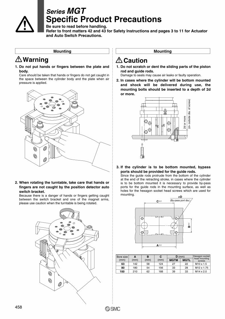
1. Do not scratch or dent the sliding parts of the piston
rod and guide rods.Damage to seals may cause air leaks or faulty operation.
2. In cases where the cylinder will be bottom mounted
and shock will be delivered during use, the
mounting bolts should be inserted to a depth of 2d
or more.
3. If the cylinder is to be bottom mounted, bypass
ports should be provided for the guide rods.Since the guide rods protrude from the bottom of the cylinder at the end of the retracting stroke, in cases where the cylinder is to be bottom mounted it is necessary to provide by-pass ports for the guide rods in the mounting surface, as well as holes for the hexagon socket head screws which are used for mounting.
Mounting
Caution1. Do not put hands or fingers between the plate and
body. Care should be taken that hands or fingers do not get caught in the space between the cylinder body and the plate when air pressure is applied.
2. When rotating the turntable, take care that hands or
fingers are not caught by the position detector auto
switch bracket.Because there is a danger of hands or fingers getting caught between the switch bracket and one of the magnet arms, please use caution when the turntable is being rotated.
Mounting
Warning
2d o
r m
ore
(d=
out
side
dia
. of s
crew
)
(By-pass port dia.)øD
C±0.2
A±0.2
B±0
.2
Bore size(mm)
Hexagon sockethead mounting
screws
A(mm)
B(mm)
C(mm)
D (mm)MGTM MGTL
63
80
100
142180210
585462
124156188
273339
222833
M10 x 1.5M12 x 1.75M14 x 2.0
Series MGTSpecific Product PrecautionsBe sure to read before handling.
Refer to front matters 42 and 43 for Safety Instructions and pages 3 to 11 for Actuator
and Auto Switch Precautions.
458

Prior to UseAuto Switches Common Specifications 1
Auto Switches Common Specifications
Leakage current
Operating time
Impact resistance
Insulation resistance
Withstand voltage
Ambient temperature
Enclosure
Type Reed auto switch
None
1.2 ms
300 m/s2
1500 VAC for 1 minute (1)
(Between lead wire and case)
Solid state auto switch
3-wire: 100 μA or less, 2-wire: 0.8 mA or less
1 ms or less (3)
1000 m/s2 (4)
1000 VAC for 1 minute(Between lead wire and case)
50 MΩ or more at 500 VDC Mega (Between lead wire and case)
–10 to 60°C
IEC60529 Standard IP67 (2)
Specific Product Precautions
Refer to the Auto Switch Precautions on pages 8 to 11 before using auto switches.
∗ 1) Electrical entry: Connector type (A73C/A80C/C73C/C80C): 1000 VAC/min. (Between lead wire and the case)
∗ 2) The terminal conduit type (D-A3/A3�A/A3�C/G39/G39A/G39C/K39/K39A/K39C), DIN terminal type (D-A44/A44A/A44C) and heat resistant auto switch (D-F7NJL) conform to IEC60529 Standard IP63. The trimmer type amplifier section (D-R�K) conforms to IP40.
∗ 3) Excluding the solid state auto switches with a timer (D-M5�TL/G5NTL/F7NTL/F5NTL types) and magnetic field resistant 2-color indication solid state auto switch (D-P4DWL). The operating time for D-J51 is 2 ms or less and for D-P4DWL is 40 ms or less.
∗ 4) 980 m/s2 for the trimmer type sensor section, 98 m/s2 for the amplifier section.
Lead Wire
Lead wire length indication Solid state auto switch oil resistant flexible cabtire cord indication
Lead wires with a connector indication∗ Applicable for the connector type (D-��C) only.
Note 1) Lead wire length Z: 5 mApplicable auto switchesReed auto switch: D-B53/B54, D-C73(C)/C80C, D-A73(C)(H)/A80C,
D-A53/A54, D-Z73, D-90/97/90A/93A Solid state auto switch: Manufactured upon receipt of order as standard.
Note 2) The standard lead wire length for solid state auto switches with a timer, water resistant 2-color indication solid state auto switches, wide range detection type solid state auto switches, heat resistant 2-color indication solid state auto switches and trimmer auto switches is 3 m. (0.5 m is not available.)
Note 3) The standard lead wire length for magnetic field resistant 2-color indication solid state auto switches is 3 m or 5 m. (0.5 m is not available.)
Note 4) 1 m (M): D-M9�(W)(V) only
Add a -61 at the end of the part number for the solid state auto switch flexible cord except D-Y59�, D-Y69�, D-Y7�, D-M9�/M9�V, and D-M9�W/M9�WV.
Lead wire length
Nil
M
L
Z
N∗
0.5 m1 m3 m5 m
None
(Example)
Lead wire length
0.5 m
1 m
3 m
5 m
Tolerance
±15 mm
±30 mm
±90 mm
±150 mm
(D-Y59, D-Y69, D-Y7 and D-M9 series use flexible lead wire as standard. )
(Example)
D-F7PL-
Flexible specification
61
Model
D-LC05
D-LC30
D-LC50
Lead wire length
0.5 m
3 m
5 m
Part No. of Lead Wires with Connectors(Applicable only for connector type)
LD-M9BW
1728
P1719-P1732-E.qxd 08.11.17 4:07 PM Page 1728

Solid State Auto SwitchDirect Mounting Style
D-M9N(V)/D-M9P(V)/D-M9B(V)
Auto Switch Internal Circuit
D-M9N, D-M9NV
D-M9B, D-M9BV
D-M9P, D-M9PV
Auto Switch Specifications
Mass
Auto switch model
0.5
1
3
5
D-M9N(V)
8
14
41
68
D-M9P(V)
8
14
41
68
D-M9B(V)
7
13
38
63
(g)
Lead wire length(m)
Grommet
Auto switch model
Electrical entry direction
Wiring type
Output type
Applicable load
Power supply voltage
Current consumption
Load voltage
Load current
Internal voltage drop
Leakage current
Indicator light
Standard
D-M9NVD-M9N D-M9B D-M9BV
2-wire
—
24 VDC relay, PLC
—
—
24 VDC (10 to 28 VDC)
2.5 to 40 mA
4 V or less
0.8 mA or less
D-M9PVD-M9P
Red LED illuminates when turned ON.
CE marking
3-wire
IC circuit, Relay, PLC
5, 12, 24 VDC (4.5 to 28 V)
10 mA or less
40 mA or less
0.8 V or less at 10 mA (2 V or less at 40 mA)
100 μA or less at 24 VDC
In-line Perpendicular In-line Perpendicular In-line Perpendicular
NPN PNP
28 VDC or less —
D-M9�, D-M9�V (With indicator light)
� Lead wires — Oilproof flexible heavy-duty vinyl cord: ø2.7 x 3.2 ellipse, 0.15 mm2, 2 cores (D-M9B(V)), 3 cores (D-M9N(V), D-M9P(V))
Note 1) Refer to page 1728 for solid state auto switch common specifications.Note 2) Refer to page 1728 for lead wire lengths.
Dimensions
D-M9�
D-M9�V
M2.5 x 4l
2.7
22
2.6
4
2.8
3.2
6
4
2.6
9.5
2.7
4.62
20
M2.5 x 4l
2.8
83.2
4
Indicator lightSlotted set screw
6 Most sensitive position
� 2-wire load current is reduced (2.5 to 40 mA).
� Flexibility is 1.5 times greater than the conventional model (SMC comparison).
� Using flexible cable as standard spec.
Precautions
Caution
(mm)
Do not fix the auto switch with the existing screw installed on the auto switch body. The auto switch may be damaged if a screw other than the one supplied is used.
Refer to SMC website for the details of the products conforming to the international standards.
PLC: Programmable Logic Controller
DC (+)Brown
OUTBlack
DC (–)Blue
DC (+)Brown
OUTBlack
DC (–)Blue
OUT (+)Brown
OUT (–)Blue
Mai
n ci
rcui
tof
sw
itch
Mai
n ci
rcui
tof
sw
itch
Mai
n ci
rcui
tof
sw
itch
Slotted set screw
Indicator light
Most sensitive position
1744
P1733-P1828-E.qxd 08.11.17 4:16 PM Page 1744

Auto Switch Specifications
Dimensions
Mass
Auto switch model
0.5
3
5
D-Y59B D-Y69B
9
50
83
D-Y59A D-Y69A
10
53
87
D-Y7P(V)
10
53
87
(g)
(mm)
Lead wire length(m)
AB
AB
Auto Switch Internal Circuit
D-Y59A, D-Y69A
D-Y59B, D-Y69B
D-Y7P, D-Y7PV
D-Y59A/D-Y7P/D-Y59B D-Y69A/D-Y7PV/D-Y69B
D-Y5�, D-Y6�, D-Y7P, D-Y7PV (With indicator light)
Auto switch model
Electrical entry direction
Wiring type
Output type
Applicable load
Power supply voltage
Current consumption
Load voltage
Load current
Internal voltage drop
Leakage current
Indicator light
Standard
D-Y59A
In-line
3-wire
NPN
IC circuit, Relay, PLC
5, 12, 24 VDC (4.5 to 28 VDC)
28 VDC or less
40 mA or less
Red LED illuminates when turned ON.
CE marking
D-Y69A
Perpendicular
D-Y69B
Perpendicular
D-Y7PV
Perpendicular
D-Y59B
In-line
2-wire
—
24 VDC relay, PLC
—
—
24 VDC (10 to 28 VDC)
5 to 40 mA
4 V or less
0.8 mA or less at 24 VDC
D-Y7P
In-line
PNP
10 mA or less
—
80 mA or less
0.8 V or less
SM
C
SM
C
6.2
5
2.5
29
ø3.
4
12.5
27.3
6.2
5
12.5
8.5
2.5
ø3.4
Most sensitive position
M2.5 x 4l
Slotted set screw
Slotted set screw
Indicator light
Indicator light
Most sensitive position
M2.5 x 4l
Grommet
Using flexible cable as standard
spec.
Refer to SMC website for the details of the products conforming to the international standards.
PLC: Programmable Logic Controller
Solid State Auto SwitchDirect Mounting Style
D-Y59 /D-Y69 /D-Y7P(V)
1.5 V or less(0.8 V or less
at 10 mA load current)
• Lead wires — Oilproof flexible heavy-duty vinyl cord, ø3.4, 0.15 mm2, 3 cores (Brown, Black, Blue), 2 cores (Brown, Blue), 0.5 m
Note 1) Refer to page 1728 for solid state auto switch common specifications.Note 2) Refer to page 1728 for lead wire lengths.
Mai
n ci
rcui
t of
sw
itch
Mai
n ci
rcui
t of
sw
itch
Mai
n ci
rcui
t of
sw
itch
OUT (+)Brown
OUT (–)Blue
OUTBlack
DC (+)Brown
DC (–)Blue
OUTBlack
DC (+)Brown
DC (–)Blue
100 μA or less at 24 VDC
1747
D-�
P1733-P1828-E.qxd 08.11.17 4:16 PM Page 1747

Mass (g)
(mm)Dimensions
Auto switch model
0.5
1
3
5
D-M9NW(V)
8
14
41
68
D-M9PW(V)
8
14
41
68
D-M9BW(V)
7
13
38
63
Lead wire length(m)
Grommet
Auto switch model
Electrical entry direction
Wiring type
Output type
Applicable load
Power supply voltage
Current consumption
Load voltage
Load current
Internal voltage drop
Leakage current
Indicator light
Standard
D-M9NWVD-M9NW D-M9BW D-M9BWV
2-wire
—
24 VDC relay, PLC
—
—
24 VDC (10 to 28 VDC)
2.5 to 40 mA
4 V or less
0.8 mA or less
D-M9PWVD-M9PW
Operating position .......... Red LED illuminates.Optimum operating position .......... Green LED illuminates.
3-wire
IC circuit, Relay, PLC
5, 12, 24 VDC (4.5 to 28 V)
10 mA or less
40 mA or less
0.8 V or less at 10 mA (2 V or less at 40 mA)
100 μA or less at 24 VDC
CE marking
In-line Perpendicular In-line Perpendicular In-line Perpendicular
NPN PNP
28 VDC or less —
D-M9�W, D-M9�WV (With indicator light)
� Lead wires — Oilproof flexible heavy-duty vinyl cord: ø2.7 x 3.2 ellipse, 0.15 mm2, 2 cores(D-M9BW(V)), 3 cores (D-M9NW(V), D-M9PW(V))
Note 1) Refer to page 1728 for solid state auto switch common specifications.Note 2) Refer to page 1728 for lead wire lengths.
� 2-wire load current is reduced (2.5 to 40 mA).
� Flexibility is 1.5 times greater than the conventional model (SMC comparison).
� Using flexible cable as standard spec.� The optimum operating position can
be determined by the color of the light. (Red → Green ← Red)
D-M9NW, D-M9NWV
D-M9BW, D-M9BWV
D-M9PW, D-M9PWV
Indicator light / Display method
Auto Switch Internal Circuit
D-M9�W
D-M9�WV
M2.5 x 4l
Slotted set screw
Indicator light
2.7
22
2.6
4
2.8
3.2
6 Most sensitive position
4
2.6
9.5
M2.5 x 4l
Indicator light
Slotted set screw
2.8
4.6
4
20
28
3.2
6 Most sensitive position
2.7
Precautions
Caution
Do not fix the auto switch with the existing screw installed on the auto switch body. The auto switch may be damaged if a screw other than the one supplied is used.
Auto Switch Specifications
Refer to SMC website for the details of the products conforming to the international standards.
PLC: Programmable Logic Controller
2-Color Indication Type Solid State Auto SwitchDirect Mounting Style
D-M9NW(V)/D-M9PW(V)/D-M9BW(V)
OUTBlack
DC (+)Brown
DC (–)Blue
DC (+)Brown
OUTBlack
DC (–)Blue
OUT (+)Brown
OUT (–)Blue
ON
OFF
Mai
n ci
rcui
tof
sw
itch
Mai
n ci
rcui
tof
sw
itch
Mai
n ci
rcui
tof
sw
itch
DisplayRed Green Red
Operating range
Optimum operating position
1755
D-�
P1733-P1828-E.qxd 08.11.17 4:16 PM Page 1755

Auto Switch Internal Circuit
D-Y7NW, Y7NWV
D-Y7BW, Y7BWV
D-Y7PW, Y7PWV
Dimensions
Grommet
Indicator light/Display method
D-Y7�W, D-Y7�WV (With indicator light)
Auto switch model
Electrical entry direction
Wiring type
Output type
Applicable load
Power supply voltage
Current consumption
Load voltage
Load current
Internal voltage drop
Leakage current
Indicator light
Standard
D-Y7NW
In-line
3-wire
NPN
IC circuit, Relay, PLC
5, 12, 24 VDC (4.5 to 28 VDC)
10 mA or less
28 VDC or less
40 mA or less
100 μA or less at 24 VDC
D-Y7NWV
Perpendicular
D-Y7BWV
Perpendicular
D-Y7PWV
Perpendicular
D-Y7BW
In-line
2-wire
—
24 VDC relay, PLC
—
—
24 VDC (10 to 28 VDC)
5 to 40 mA
4 V or less
0.8 mA or less at 24 VDC
D-Y7PW
In-line
PNP
—
80 mA or less
0.8 V or less1.5 V or less(0.8 V or less
at 10 mA load current)
Mass
Auto switch model
0.5
3
5
D-Y7NW(V) D-Y7PW(V) D-Y7BW(V)
11
54
88
11
54
88
11
54
88
(g)
(mm)
Lead wire length(m)
D-Y7�W
D-Y7�WV
M2.5 x 4l
Slotted set screw
Indicator light
Most sensitive position
M2.5 x 4l
Slotted set screw
Indicator light
SM
CS
MC
6.2
5
2.5
29
ø3.
4
12.5
27.3
6.2
5
12.5
8.5
2.5
ø3.4
Most sensitive position
CE marking
Auto Switch Specifications
Refer to SMC website for the details of the products conforming to the international standards.
PLC: Programmable Logic Controller
2-Color Indication Type Solid State Auto SwitchDirect Mounting Style
D-Y7NW(V)/D-Y7PW(V)/D-Y7BW(V)
Operating range
IndicationGreenRed Red
Optimum operating position
Mai
n ci
rcui
t of
sw
itch
Mai
n ci
rcui
t of
sw
itch
Mai
n ci
rcui
t of
sw
itch OUT
Black
DC (+)Brown
DC (–)Blue
OUTBlack
DC (+)Brown
DC (–)Blue
OUT (+)Brown
OUT (–)Blue
• Lead wires — Oilproof flexible heavy-duty vinyl cord, ø3.4, 0.15 mm2, 3 cores (Brown, Black, Blue), 2 cores (Brown, Blue), 0.5 m
Note 1) Refer to page 1728 for solid state auto switch common specifications.Note 2) Refer to page 1728 for lead wire lengths.
� The optimum operating position can be determined by the color of the light. (Red → Green ← Red)
� Using flexible cable as standard spec.
Operating position .......... Red LED illuminates.Optimum operating position .......... Green LED illuminates.
1756
P1733-P1828-E.qxd 08.11.17 4:16 PM Page 1756

ø2.
72
22(24.5)
2.8 4.5
4
10 ( ): dimensions for D-A93.
D-A90 without indicator light
Indicator light
Most sensitive position
Slotted set screwM2.5 x 4L
4
9.1
5.1
ø2.7
10
4.5
Most sensitive position
2
22
6
D-A90V without indicator light
Indicator light
Slotted set screw
M2.5 x 4L
Grommet
Auto Switch Specifications
D-A90, D-A90V (Without indicator light)
Auto switch model
Applicable load
Load voltage
Maximum load current
Contact protection circuit
Internal resistance
Standard
D-A93, D-A93V, D-A96, D-A96V (With indicator light)
Auto switch model
Applicable load
Load voltage
Load current range and
Maximum load current (3)
Contact protection circuit
Internal voltage drop
Indicator light
Standard
D-A90, D-A90V
IC circuit, Relay, PLC
24 V or less
50 mA
None
1 Ω or less (Including lead wire length of 3 m)
CE marking
48 V or less
40 mA
100 V or less
20 mA
D-A93, D-A93V
Relay, PLC
24 VDC
5 to 40 mA
None
D-A93: 2.4 V or less (up to 20 mA)/3 V or less (up to 40 mA)D-A93V: 2.7 V or less
Red LED illuminates when turned ON.
CE marking
100 VAC
5 to 20 mA
D-A96, D-A96V
IC circuit
4 to 8 VDC
20 mA
0.8 V or less
Note 1) Operating load is an induction load.Note 2) Wiring to the load is 5 m or longer.Note 3) Load voltage is 100 VAC.Use the contact protection box in any of the above listed situations. The contact point life may decrease. (Refer to page 1729 for contact protection box.)
Do not fix the auto switch with the existing screw installed on the auto switch body. The auto switch may be damaged if a screw other than the one supplied is used.
Precautions
Caution
Model
0.5
3Lead wire length
(m)
D-A90
6
30
D-A90V
6
30
D-A93
6
30
D-A93V
6
30
D-A96
8
41
D-A96V
8
41
(g)
Mass
Auto Switch Internal Circuit
D-A90, A90V
D-A93, A93V
D-A96, A96V
Dimensions
D-A90/D-A93/D-A96
D-A90V/D-A93V/D-A96V
(mm)
PLC: Programmable Logic Controller
Refer to SMC website for the details of the products conforming to the international standards.
Reed Auto SwitchDirect Mounting Style
D-A90(V)/D-A93(V)/D-A96(V)
• Lead wires D-A90(V)/D-A93(V)—Oilproof heavy-duty vinyl cord, ø2.7, 0.18 mm2 x 2 cores (Brown, Blue), 0.5 mD-A96(V)—Oilproof heavy-duty vinyl cord, ø2.7, 0.15 mm2 x 3 cores (Brown, Black, Blue), 0.5 m
Note 1) Refer to page 1728 for reed auto switch common specifications.Note 2) Refer to page 1728 for lead wire lengths.Note 3) Under 5 mA, the strength of the indicator light is poor. In some cases, visibility of the indicator
light will not be possible where the output signal is less than 2.5 mA. However, there is no problem in terms of contact output, when an output signal exceeds 1 mA or more.
ACDC
ACDC
ACDC
Reed s
witc
h OUT(±)Brown
�
OUT (±) Blue
Contact protection boxCD-P11CD-P12
Blue (Black)
LED
Ree
d sw
itch
Resistor
Zener diode
Brown (Red)OUT (+)Brown
�
OUT (–)Blue
Contact protection boxCD-P11CD-P12
LED
Ree
d sw
itch
Resistor
Reverse current prevention diode
OUTBlack
DC (+) Brown
DC (–)Blue
Load
(+)
(–)
DC power supply
1798
P1733-P1828-E.qxd 08.11.17 4:17 PM Page 1798

12.5 ø2.
7
5.5
30.52.3
6.2
12.5
5.7
1.5
2.5
6.2
27.6
Auto Switch Internal Circuit
D-Z73
D-Z80
Grommet
D-Z76
Auto switch model
0.5
3
5
7
31
50
10
55
—
9
49
—
D-Z73 D-Z76 D-Z80
Lead wire length(m)
D-Z7 (With indicator light)
Auto switch model
Applicable load
Load voltage
Max. load current and load current range(3)
Contact protection circuit
Internal voltage drop
Indicator light
Standard
D-Z73
Relay, PLC
2.4 V or less (to 20 mA)/3 V or less (to 40 mA)
24 VDC
5 to 40 mA
100 VAC
5 to 20 mA
None
Red LED illuminates when turned ON.
CE marking
D-Z76
IC circuit
4 to 8 VDC
20 mA
0.8 V or less
D-Z80
Relay, PLC, IC circuit
40 mA
None
1 Ω or less (Including 3 m lead wire)
CE marking
D-Z8 (Without indicator light)
Auto switch model
Applicable load
Load voltage
Maximum load current
Contact protection circuit
Internal resistance
Standard
50 mA 20 mA
D-Z73 D-Z76,Z80
Reed Auto SwitchDirect Mounting Style
D-Z73/D-Z76/D-Z80
Auto Switch Specifications
PLC: Programmable Logic Controller
Refer to SMC website for the details of the products conforming to the international standards.
Mass (g)
Dimensions (mm)
Slotted set screw
Slotted set screw
Indicator light Indicator light
D-Z80 without indicator light
Most sensitive position
Most sensitive position
M2.5 x 4L
M2.5 x 4L
24 V or lessACDC 100 VAC
DC48 VACDC
• Lead wires — Oilproof heavy-duty vinyl cord, ø3.4, 0.2 mm2, 2 cores (Brown, Blue), 3 cores (Brown, Black, Blue), 0.5 m (For only D-Z73, ø2.7, 0.18 mm2, 2 cores)
Note 1) Refer to page 1728 for reed auto switch common specifications.Note 2) Refer to page 1728 for lead wire lengths.Note 3) Under 5 mA, the strength of the indicator light is poor. In some cases, visibility of the
indicator light will not be possible where the output signal is less than 2.5 mA. However, there is no problem in terms of contact output, when an output signal exceeds 1 mA or more.
LED
Ree
d sw
itch
Resistor
Zener diode
Brown
Blue
OUT (+)Brown
�
OUT (–)Blue
LED
Ree
d sw
itch
Resistor
OUTBlack
DC (+) Brown
DC (–)Blue
Load
(+)
(–)
DC power supply
Reed s
witc
h
Contact protection boxCD-P11CD-P12
Contact protection boxCD-P11CD-P12
Reverse current prevention diode
Note 1) Operating load is an induction load.Note 2) Wiring to the load is 5 m or longer.Note 3) Load voltage is 100 VAC.Use the contact protection box in any of the above listed situations. The contact point life may decrease. (Refer to page 1729 for contact protection box.)
OUT(±)Brown
�
OUT ( ) Blue
±
1799
D-�
P1733-P1828-E.qxd 08.11.17 4:17 PM Page 1799

<Applicable auto switch>
Solid state ······D-M9N(V), D-M9P(V), D-M9B(V),
D-M9NW(V), D-M9PW(V), D-M9BW(V),
D-M9NA(V)L, D-M9PA(V)L, D-M9BA(V)L
Reed ···············D-A90(V), D-A93(V), D-A96(V)
<Applicable auto switch>
Solid state ······D-M9N(V), D-M9P(V), D-M9B(V),
D-M9NW(V), D-M9PW(V), D-M9BW(V),
D-M9NA(V), D-M9PA(V), D-M9BA(V)
Reed ···············D-A90(V), D-A93(V), D-A96(V)
w
e
q
Auto Switch Mounting Bracket Part No.
MY1B
MY1M, MY1MW
MY1C, MY1CW
MY1H
CY3R
REAR
REBR
MGPS
MGP, MGPAMGQ, MVGQ
MGP�-�A
MLGP
MGF
MGT
RSH
RS1H
12
—
———
—
———
BMG2-012———
—
—
—
16
—
———
—
———
BMG2-012
——
—
—
—
20
—
———
—
———
BMG2-012
—
—
BMG2-012
—
25
BMG2-012—
BMG2-012
—
BMG2-012
—
—
—
—
32
BMG2-012
—
BMG2-012
—
—
BMG2-012
—
40
—
——
BMG2-012
——
BMG2-012
—
—
—
50
BMG2-012
—BMG2-012——
BMG2-012
—
—
—
BMG2-012
80
BMG2-012———
—
——
BMG2-012
—BMG2-012
—
BMG2-012
100
BMG2-012———
—
———
BMG2-012
—
—
63
BMG2-012
—BMG2-012———
BMG2-012
—
BMG2-012
CDQ2 (Large bore)
125
BMG2-012140
BMG2-012160
BMG2-012180
BMG2-012200
BMG2-012
1. Insert the auto switch mounting bracket into the auto switch mounting groove to set it roughly to the auto switch mounting position.
2. Insert the auto switch into the attachment part of the auto switch mounting bracket.
3. After confirming the detecting position, secure the auto switch by tightening the set screw (M2.5) attached to the auto switch.
4. When changing the detecting position, carry out in the state of 2.
Note 1) When tightening a set screw (M2.5), use a watchmaker’s screwdriver with a grip diameter of 5 to 6 mm. Also set the tightening torque to be 0.1 to 0.15 N·m. As a guide, turn 90° from the position where it comes to feel tight.
Series MY2
ø5 to ø6
When mounting auto switches, insert them into the
cylinder’s switch groove from the direction shown in the
drawing. After setting in the mounting position, use a flat
head watchmaker's screwdriver to tighten the provided
set screw.
D-A9�(V)
D-M9�(V)
D-M9�W(V)
Tightening torque0.10 to 0.20
0.05 to 0.15
(N·m)
Mounting Bracket Direct Mounting Style
How to Mount and Move the Auto Switch How to Mount and Move the Auto Switch
Auto switch mounting screw
• When tightening an auto switch mounting screw, use a watchmaker’s screwdriver with a grip diameter of 5 to 6 mm.
Auto switch
Auto Switch Mounting Screw Tightening Torque
Auto switch model
(Note) When tightening an auto switch mounting screw, use a watchmaker’s screwdriver with a grip diameter of 5 to 6 mm. The tightening torque should be about 0.05 to 0.1 N·m.
Auto switch
(Attached to the auto switch)Auto switch mounting screw
Watchmakers’ screwdriver
Auto switch
Cylinder tube
Watchmaker’s (precision) screwdriver
Set screwM2.5 x 0.45 x 4 l
Auto switchmounting bracket
Cylinder seriesApplicable bore size (mm)
Cylinder seriesApplicable bore size (mm)
Note 2) Color or gloss differences in the metal surfaces have no effect on metal performance.The special properties of the chromate (trivalent) applied to the main body of the auto switch mounting bracket for BMG2-012 result in differ-ences in coloration depending on the production lot, but these have no adverse impact on corrosion resistance.
1824
How to Mount and Move the Auto Switch
P1733-P1828-E.qxd 08.11.17 4:17 PM Page 1824

<Applicable auto switch>
Solid state ······D-Y59 , D-Y69 , D-Y7P(V),
D-Y7NW(V), D-Y7PW(V), D-Y7BW(V),
D-Y7BAL
Reed ···············D-Z73, D-Z76, D-Z80
<Applicable auto switch>
Solid state ······D-Y59 , D-Y69 , D-Y7P(V),
D-Y7NW(V), D-Y7PW(V), D-Y7BW(V),
D-Y7BAL
Reed ···············D-Z73, D-Z76, D-Z80
MDB1
Applicable bore size (mm)
BMP1-032
32 40 50 63 80 100
ø5 to ø6
AB
AB
Mounting Bracket Direct Mounting Style
AB
AB
How to Mount and Move the Auto SwitchHow to Mount and Move the Auto Switch
Auto switch mounting nutM2.5 x 4 l
Note) When tightening an auto switch mounting screw, use a watchmaker’s screwdriver with a grip diameter of 5 to 6 mm. Also, set the tightening torque to be 0.05 to 0.1 N·m. As a guide, turn 90° from the position where it comes to feel tight.
1. Insert the auto switch into the mounting groove and set it at the auto switch mounting position.
2. After reconfirming the detecting position, tighten the mounting screw to secure the auto switch.
3. Modification of the detecting position should be made in the condition of 1.
Note) When tightening an auto switch mounting screw, use a watchmaker’s screwdriver with a grip diameter of 5 to 6 mm. Also, tighten with a torque of about 0.05 to 0.1 N·mAs a guide, it should be turned about 90° past the point at which tightening can be felt.
When attaching an auto switch, first take a switch spacer between your fingers and press it into a switch mounting groove. When doing this, confirm that it is set in the correct mounting orientation, or reattach if necessary. Next, insert an auto switch into the groove and slide it until it is positioned under the switch spacer.After establishing the mounting position, use a watchmakers flat head screwdriver to tighten the auto switch mounting screw which is included.
Switch Spacer No.
Cylinder series
Correct Incorrect
Flat head watchmaker’s screwdriver
Switch spacer
Auto switch mounting screw (M2.5 x 4 l )Accessory
1826
How to Mount and Move the Auto Switch
P1733-P1828-E.qxd 08.11.17 4:17 PM Page 1826

Prior to UseAuto Switches Common Specifications 2
Refer to the Auto Switch Precautions on pages 8 to 11 before using auto switches.
Contact Protection Box: CD-P11, CD-P12
Contact Protection Box Specifications
Load voltage
Max. load current
Part no. CD-P11 CD-P12
� Lead wire length — Auto switch connection side 0.5 mLoad connection side 0.5 m
100 VAC or less
25 mA
200 VAC
12.5 mA
24 VDC
50 mA
To connect a switch unit to a contact protection box, connect the lead wire from the side of the contact protection box marked SWITCH to the lead wire coming out of the switch unit. Keep the switch as close as possible to the contact protection box, with a lead wire length of no more than 1 meter.
Contact Protection Box Connection
Hysteresis is the distance between the position at which piston movement operates an auto switch to the position at which reverse movement turns the switch off. This hysteresis is included in part of the operating range (one side).
Auto Switch Hysteresis
Contact Protection Box/Dimensions
Contact Protection Box Internal Circuit
CD-P11
CD-P12
<Applicable switch models>
D-A7/A8, D-A7�H/A80H, D-A73C/A80C, D-C7/C8, D-C73C/C80C, D-E7�A, E80A, D-Z7/Z8, D-9/9�A, D-A9/A9�V, and D-A79W typeThe auto switches above do not have a built-in contact protection circuit. A contact protection box is not required for solid state auto switches due to their construction.q Where the operation load is an inductive load.
w Where the wiring length to load is greater than 5 m.
e Where the load voltage is 100/200 VAC.
Therefore, use a contact protection box with the switch for any of
the above cases:
The contact life may be shortened (due to permanent energizing conditions.)D-A72(H) must be used with the contact protection box regardless
of load types and lead wire length since it is greatly affected by
loads.
(Where the load voltage is 110 VAC)
When the load voltage is increased by more than 10% to the rating of applicable auto switches (except D-A73C/A80C/C73C/C80C/90/97/A79W) above, use a contact protection box (CD-P11) to reduce the upper limit of the load current by 10% so that it can be set within the range of the load current range, 110 VAC.
Even for the built-in contact protection circuit type (D-A34[A][C], D-A44[A][C], D-A54/A64, D-A59W, D-B59W), use the contact protection
box when the wiring length to load is very long (over 30 m) and PLC
(Programmable Logic Controller) with a large inrush current is used.
Specific Product Precautions
Note) Hysteresis may fluctuate due to the operating environment.Please contact SMC if hysteresis causes an operational problem.
Auto switch
Switch operating position(ON) Hysteresis Reed auto switch: 2 mm or less
Solid state auto switch: 1 mm or less
Switch operating position(OFF)
Note)
Surge absorber
Zener diode
Chokecoil
OUT Brown
OUT Blue
OUT (+) Brown
OUT (–) Blue
~
Chokecoil
1729
D-�
P1719-P1732-E.qxd 08.11.17 4:07 PM Page 1729

Basic Wiring
Solid state 3-wire, NPN
• Sink input specifications
3-wire, NPN
• 3-wire
• 2-wire
2-wire (Solid state)
• Source input specifications
3-wire, PNP
OR connection for NPN output
2-wire with 2-switch AND connection 2-wire with 2-switch OR connection
2-wire 2-wire
Solid state 3-wire, PNP
Load voltage at ON = Power supply voltage – Residual voltage x 2 pcs.= 24 V – 4 V x 2 pcs.= 16 V
Example: Power supply is 24 VDCInternal voltage drop in auto switch is 4 V.
Load voltage at OFF = Leakage current x 2 pcs. x Load impedance= 1 mA x 2 pcs. x 3 kΩ= 6 V
Example: Load impedance is 3 kΩ.Leakage current from auto switch is 1 mA.
Auto switch 1
Auto switch 2
Load
BrownBlackBlue
BrownBlackBlue
Auto switch 1
Auto switch 2
Brown
Blue
Brown
Blue
LoadAuto switch 1
Auto switch 2
Brown
Blue
Brown
Blue
Load
Auto switch
Auto switch
Auto switch
Example of AND (Series) and OR (Parallel) Connection
Example of Connection with PLC (Programmable Logic Controller)
2-wire (Reed switch)
AND connection for NPN output(Using relays)
Auto switch 1
Brown
Auto switch 2
BlackBlue
Load
BrownBlackBlue
AND connection for NPN output(Performed with auto switches only)
The indicator lights will light up whenboth auto switches are turned ON.
When two auto switches are connected in series, a load may malfunction because the load voltage will decline when in the ON state.The indicator lights will light up when both of the auto switches are in the ON state.
Prior to UseAuto Switches Connection and Example
Main curcuitof switch
Brown
Black
Blue
Load
Brown
Black
Blue
Main curcuitof switch
Load
Brown
Black
Blue
Main curcuitof switch
(Power supply for switch and load are separate)
Load
Brown
Blue
Brown
Blue
Main curcuitof switch
Main curcuitof switch
Load
Load
Indicatorprotectioncircuit,etc.
Brown
Blue
~
~
Brown
Blue
Indicatorprotectioncircuit,etc.
Load
Load
Auto switch
InputBlack
COM
Brown
Blue
PLC internal circuit
InputBlack
COM
Brown
Blue
PLC internal circuit
Input
Blue COM
Brown
PLC internal circuit PLC internal circuit
InputBlue
COMBrown
Connect according to the applicable PLC input specifications, as the connection method will vary depending on the PLC input specifications.
Auto switch 1
Brown
Auto switch 2
BlackBlue
Relay
Relay
BrownBlackBlue
Load
Relay contact
(Solid state auto switch)When two auto switches are connected in parallel, malfunction may occur because the load voltage will increase when in the OFF state.
(Reed auto switch)Because there is no current leakage, the load voltage will not increase when turned OFF. However, depending on the number of auto switches in the ON state, the indicator lights may sometimes grow dim or not light up, due to the dispersion and reduction of the current flowing to the auto switches.
1730
P1719-P1732-E.qxd 08.11.17 4:07 PM Page 1730

• Eliminates the harnessing work by cable with connector specifications
• Adopts global standardized connector (IEC947-5-2)
• IP67 construction
How to Order
Cable length
0.5 m1.0 m3.0 m
S
M
L
Connector model
Applicable Auto Switch
D M9N S A PC
Note) L is available for the D-P4DW type only.
A
B
D
Note) Type D is available for the D-P4DW type only.
M8-3 pinM8-4 pinM12-4 pin
Grommet (In-line)
—
—
—
—
—
—
—
—
�
—
—
—
—
—
—
—
—
—
—
—
—
—
�
�
�
�
�
�
�
�
�
�
�
�
�
�
�
�
�
�
�
�
�
�
�
�
�
�
�
�
�
�
�
�
�
�
�
�
�
�
�
�
�
�
�
�
3.0
Lead wire length (m)
1.00.5Applicable modelFunctionMounting
F79, F7P, J79
F7NV, F7PV, F7BV
F79W, F7PW, J79W
F7NWV, F7BWV
F79F
F7BA
F7BAV
F7NT
P4DW
H7A1, H7A2, H7B
G59, G5P, K59
H7NW, H7PW, H7BW
G59W, G5PW, K59W
H7NF, G59F
H7BA, G5BA
G5NT
G5NB
F59, F5P, J59
F59W, F5PW, J59W
F59F
F5BA
F5NT
Electrical entry
Grommet (In-line)Grommet
(Perpendicular)
Grommet (In-line)Grommet
(Perpendicular)
Grommet (In-line)
Grommet (Perpendicular)
—
2-colorindication
With diagnostic output
Water resistant
With timer
Magnetic field resistant
—
2-colorindication
Diagnostic output
Water resistant
With timer
Wide detection
—
2-color indication
Diagnostic output
Water resistant
With timer
Rail mounting style
Band mounting style
Tie-rod mounting style
—
—
—
—
—
—
—
—
—
—
—
—
—
—
—
—
—
—
�
�
�
�
�
�
�
�
�
�
�
�
�
�
�
�
�
�
�
�
�
�
�
�
�
�
�
�
�
�
�
�
�
�
�
�
3.01.00.5
Y59A, Y7P, Y59B
Y69A, Y7PV, Y69B
M9N, M9P, M9B
M9NV, M9PV, M9BV
F8N, F8P, F8B
F6N, F6P, F6B
Y7G, Y7H
F9G, F9H
Y7NW, Y7PW, Y7BW
Y7NWV, Y7PWV, Y7BWV
M9NW, M9PW, M9BW
M9NWV, M9PWV, M9BWV
Y7BA
M9NA, M9PA, M9BA
M9NAV, M9PAV, M9BAV
S791/2, S7P1/2, T791/2
S991/2, S9P1/2, T991/2
S99V1/2, T99V1/2
Grommet (In-line)Grommet
(Perpendicular)
Grommet (In-line)
Grommet (Perpendicular)
Grommet (In-line)
Grommet (In-line)
Grommet (In-line)Grommet
(Perpendicular)
Grommet (In-line)Grommet
(Perpendicular)
Grommet (In-line)
Grommet (Perpendicular)
Grommet (In-line)
Grommet (Perpendicular)
—
—
2-colorindication
Normally closed
Water resistant
Direct mounting style
Rotaryactuator
Connector Specifications
12
1 2
43
Connector model
Pin arrangement
Conformed standard
Impact resistance
Enclosure
Insulation resistance
Withstand voltage
M8-3 pin M8-4 pin M12-4 pin
JIS C 4524, JIS C 4525, IEC 947-5-2, NECA 0402
300 m/s2
IP-67 (IEC60529 standard)
100 MΩ or more at 500 VDC Mega
1500 VAC 1 minute (between contacts), Leak current 1 mA or less
1
3
4
3 4
Made to Order Specifications:
Solid State Auto Switch
With Pre-wired Connector1
Refer to SMC website for the details of the products conforming to the international standards.
Solid state auto switch
Standard part no.∗ For the applicable auto switch
model, refer to the table below.
Lead wire length (m)Applicable modelFunctionMounting
Electrical entry
1784
P1733-P1828-E.qxd 08.11.17 4:17 PM Page 1784

ø14
44
ø10
31.4
12
3 4
1 4
3
1 2
43
Mass for Connector Type
Connector Pin Arrangement
Sensor type
DC 2-wire type
DC 2-wire, Non-polar type
DC 3-wire type
DC 4-wire type
Brown
—
Brown
Brown
1 pin 2 pin 3 pin 4 pin
Color distinction of lead wire Meaning of contact number
1 pin 2 pin 3 pin 4 pin
Connector Specifications
Connector model
Pin arrangement
Conformed standard
Impact resistance
Enclosure
Insulation resistance
Withstand voltage
JIS C 4524, JIS C 4525, IEC 947-5-2, NECA 0402
300 m/s2
IP67 (IEC60529 standard)
100 MΩ or more at 500 VDC Mega
1500 VAC 1 minute (between contacts), Leak current 1 mA or less
M8-3 pin M8-4 pin M12-4 pin
—
—
—
Orange
—
Brown
Blue
Blue
Blue
Blue
Black
Black
OUT (+)
—
DC (+)
DC (+)
—
—
—Diagnostic
output
—
OUT (±)
DC (–)
DC (–)
OUT (–)
OUT ( )
OUT
OUT
±
M8-4 pin
M12-4 pin
M8-3 pin
Dimensions
Connector model
M8-3 pin
4 pin
M12-4 pin
Sensor section
Sensor section
Connection (Female side) Connector Cable
As the parts are not supplied from SMC, refer to the application examples listed in the below.(For detail such as catalog availability, etc., please contact each manufacturer.)
Connector size
M8
M12
SAC-3P
M8-3D
M8-4D
XS3
SAC-4P
VA-4D
XS2
PA5-4I
HR24
CM01-8DP4S
Manufacturer
Phoenix Contact
Corrence Corporation
OMROM Corporation
Phoenix Contact
Corrence Corporation
OMROM Corporation
Yamatake Corporation
Hirose Electric Co., Ltd.
DKK Ltd.
4
3
Number of pins Applicable series example
Part no. Connector type
M8-3
M8-4
M12-4
4 g
4 g
About 11 g
Mass
D-���APC
D-���BPC
D-���DPC
1785
With Pre-wired Connector
D-�
P1733-P1828-E.qxd 08.11.17 4:17 PM Page 1785