cytoscape user manual · 2020-03-02 · with lar ge databases of protein-protein, protein-dn a, and...
TRANSCRIPT

Cytoscape User Manual
Table of ContentsCytoscape 2.4.1 User Manual ................................................................................................. 2Introduction ........................................................................................................................ 2Launching Cytoscape ........................................................................................................... 4
(1) If necessary, install Java ........................................................................................... 4(2) Install Cytoscape .................................................................................................... 4(3) Launch the application ............................................................................................. 5
Quick Tour of Cytoscape ....................................................................................................... 7The Menus ................................................................................................................. 9Network Management ................................................................................................. 11The Network Overview Window ................................................................................... 13
Command Line Arguments .................................................................................................. 13Cytoscape Preferences ........................................................................................................ 15
Managing Properties ................................................................................................... 15Managing Bookmarks ................................................................................................. 17Managing Proxy Servers ............................................................................................. 18
Creating Networks ............................................................................................................. 18Import Fixed-Format Network Files ............................................................................... 18Import Free-Format Table Files ..................................................................................... 19Edit a New Network ................................................................................................... 23
Supported Network File Formats ........................................................................................... 23SIF Format ............................................................................................................... 24GML Format ............................................................................................................. 25XGMML Format ....................................................................................................... 25SBML (Systems Biology Markup Language) Format ........................................................ 26BioPAX (Biological PAthways eXchange) Format ............................................................ 26PSI-MI Format .......................................................................................................... 26Delimited Text Table and Excel Workbook ...................................................................... 26
Node and Edge Attributes .................................................................................................... 27Cytoscape Attribute File Format .................................................................................... 27Import Attribute Table Files ......................................................................................... 30
Loading Gene Expression (Attribute Matrix) Data .................................................................... 33Data File Format ........................................................................................................ 33Example ................................................................................................................... 34
Navigation and Layout ........................................................................................................ 36Basic Network Navigation ........................................................................................... 36Automatic Layout Algorithms ...................................................................................... 36Manual Layout .......................................................................................................... 38
Visual Styles ..................................................................................................................... 43Introduction to Visual Styles ........................................................................................ 43Visual Attributes, Graph Attributes and Visual Mappers ..................................................... 46Visual Styles Tutorials ................................................................................................ 48Managing Visual Styles ............................................................................................... 52Bypassing Visual Styles .............................................................................................. 53
Finding and Filtering Nodes and Edges .................................................................................. 54QuickFind ................................................................................................................ 54Filters ...................................................................................................................... 58
1
Select Menu .............................................................................................................. 62Editing Networks ............................................................................................................... 63CytoPanels ....................................................................................................................... 65Rendering Engine .............................................................................................................. 67Annotation ........................................................................................................................ 67
Ontology and Annotation File Format ............................................................................ 68Import Ontology and Annotation ................................................................................... 71Custom Annotation Files for Ontologies Other than GO (for Advanced Users) ....................... 73
Linkout ............................................................................................................................ 76Acknowledgements ............................................................................................................ 77Appendix A: Old Annotation Server Format ............................................................................ 77
Building your own annotation files ................................................................................ 78Load Data into Cytoscape ............................................................................................ 79Getting and Reformatting GO Data ............................................................................... 79
Appendix B: GNU Lesser General Public License .................................................................... 83
Cytoscape 2.4.1 User Manual
This document is licensed under the Creative Commons license, 2006
Authors: The Cytoscape Collaboration
The Cytoscape project is an ongoing collaboration between:
Table 1.
University of California at San Diego
Institute for Systems Biology
Memorial Sloan-Kettering Cancer Center
Institut Pasteur
Agilent Technologies
University of California at San Francisco
Funding for Cytoscape is provided by a federal grant from the U.S. National Institute of General MedicalSciences (NIGMS) of the National Institutes of Health (NIH) under award number GM070743-01. Corporatefunding is provided through a contract from Unilever PLC.
IntroductionCytoscape is a project dedicated to building open-source network visualization and analysis software. Asoftware “Core” provides basic functionality to layout and query the network and to visually integrate thenetwork with state data. The Core is extensible through a plug-in architecture, allowing rapid developmentof additional computational analyses and features.
2
Cytoscape User Manual

Cytoscape's roots are in Systems Biology where it is used for integrating biomolecular interaction networkswith high-throughput expression data and other molecular state information. Although applicable to anysystem of molecular components and interactions, Cytoscape is most powerful when used in conjunctionwith large databases of protein-protein, protein-DNA, and genetic interactions that are increasingly availablefor humans and model organisms. Cytoscape allows the visual integration of the network with expressionprofiles, phenotypes, and other molecular state information and to link the network to databases of func-tional annotations. The central organizing metaphor of Cytoscape is a network (graph), with genes,proteins, and molecules represented as nodes and interactions represented as links, i.e. edges, betweennodes.
Development Cytoscape is a collaborative project between the Institute for Systems Biology (Leroy Hoodlab), the University of California San Diego (Trey Ideker lab), Memorial Sloan-Kettering Cancer Center(Chris Sander lab), the Institut Pasteur (Benno Schwikowski lab), Agilent Technologies (Annette Adlerlab) and the University of California, San Francisco (Bruce Conklin lab).
Visit http://www.cytoscape.org for more information.
License Cytoscape is protected under the GNU LGPL (Lesser General Public License). The License isincluded as an appendix to this manual, but can also be found online: http://www.gnu.org/copyleft/lesser.txtCytoscape also includes a number of other open source libraries, which are detailed in Acknowledgementsbelow.
What’s New in 2.4
Cytoscape version 2.4 contains several new features, plus improvements to the performance and usabilityof the software. These include:
• Publication quality image generation. This includes:
• Node label position adjustment.
• Automatic Visual Legend generator.
• Node position fine-tuning by arrow keys.
• The ability to override selected VizMap settings.
• Quick Find plugin.
• New Cytoscape icons for a cleaner user interface.
• Consolidated network import capabilities.
• Import network from remote data sources (through http or ftp).
• Default support for the following file formats:
• Systems Biology Markup Language (SBML)
• BioPAX Level 1 and 2
• PSI-MI (Level 1 and 2.5)
• Delimited text table (TAB delimited text file, CSV, etc.)
• Excel (.xls) format file.
3
Cytoscape User Manual

• New Ontology Server. This will eventually replace the BioDataServer. New Ontology Server featuresinclude:
• Native support for OBO format ontology files. Users can import many different ontologies in theOBO format.
• Ability to visualize the ontology tree as a network (DAG).
• Full support for Gene Association files.
• Support for Java SE 5.
• Many, many bug fixes!
Launching CytoscapeCytoscape is a Java application that runs on Linux, Windows, and Mac OS X.
System requirements: The system requirements for Cytoscape depend on the size of the networks theuser wants to load, view and manipulate. We recommend a recent computer (1GHz CPU or higher) witha high-end graphics card and at least 512MB of free physical RAM. Cytoscape expects a minimum screenresolution of 1024x768.
(1) If necessary, install JavaIf not already installed on your computer, download and install Java SE 5 or 6. Cytoscape 2.4 will nolonger run with Java version 1.4.x or lower. You must install Java SE 5 or 6!!!
These can be found at:
Java SE 5
Java SE 6
(2) Install CytoscapeThere are a number of options for downloading and installing Cytoscape. All options can be downloadedfrom the http://cytoscape.org website.
• Automatic installation packages exist for Windows, Mac OS X, and Linux platforms.
• You can install cytoscape from a compressed archive distribution.
• You can build cytoscape from source.
• You can check out the latest and greatest software from our Subversion repository.
Cytoscape installations (regardless of platform) containing the following files and directories:
4
Cytoscape User Manual
Table 2.
DescriptionFile
Main Cytoscape application (Java archive)cytoscape.jar
Script to run Cytoscape from command line (Linux, Mac OS X)cytoscape.sh
Script to run Cytoscape (Windows)cytoscape.bat
Cytoscape GNU LGPL LicenseLICENSE.txt/html
library jar files needed to run Cytoscape.lib/
Manuals in different formats. What you are reading now.docs/
Licence files for the various libraries distributed with Cytoscape.licenses/
Directory containing cytoscape PlugIns, in .jar format.plugins/
sampleData/
galFiltered.gml -- Sample molecular interaction network file *
galFiltered.sif -- Identical network in Simple Interaction Format *
galExpData.pvals -- Sample gene expression matrix file *
galFiltered.nodeAttrTable.xls -- Sample node attribute file in Microsoft Excel format
galFiltered.cys -- Sample session file created from datasets above plus GO Annotations*
BINDyeast.sif -- Network of all yeast protein-protein interactions in the BIND databaseas of Dec, 2006 **
BINDhuman.sif -- Network of all human protein-protein interactions in the BINDdatabase as of Dec, 2006 **
yeastHighQuality.sif -- Sample molecular interaction network file ***
interactome_merged.networkTable.gz -- Human interactome network file in tab-de-limited format ****
* From Ideker et al., Science 292:929 (2001)
** Obtained from data hosted at http://www.blueprint.org/bind/bind_downloads.html
** From von Mering et al., Nature, 417:399 (2002) and Lee et al, Science 298:799 (2002)
**** Created from Cytoscape tutorial web page. Original data sets are available at: http://www.cyto-scape.orghttp://cytoscape.org/cgi-bin/moin.cgi/Data_Sets/ A merged human interactome by Andrew Garrow,Yeyejide Adeleye and Guy Warner Unilever, Safety and Environmental Assurance Center
(3) Launch the applicationDouble-click on the icon created by the installer or by running cytoscape.sh from the command line (Linuxor Mac OS X) or double-clicking cytoscape.bat (Windows). Alternatively, you can pass the .jar file to Javadirectly using the command java -Xmx512M -jar cytoscape.jar -p plugins. The -Xmx512M flag tells java toallocate more memory for Cytoscape and the -p plugins option tells cytoscape to load all of the plugins inthe plugins directory. Loading the plugins is important because many key features like layouts, filters andthe attribute browser are included with Cytoscape as plugins in the plugins directory. See the [Cyto-scape_User_Manual/Command_Line_Arguments Command Line] chapter for more detail. In Windows,it is also possible to directly double-click the .jar file to launch it. However, this does not allow specificationof command-line arguments (such as the location of the plugin directory).
5
Cytoscape User Manual

Cytoscape Window When you succeed in launching Cytoscape, a window will appear that looks like this(captured on Linux):
Note on Memory Consumption
For users interested in loading large networks, the amount of memory needed by Cytoscape will increase.Memory usage depends on both number of network objects (nodes+edges) and the number of attributes.Here are some rough suggestions for memory allocation:
Suggested Memory Size Without View
Table 3.
Suggested Memory SizeNumber of Objects (nodes + edges)
512M (default)0 - 70,000
800M70,000 - 150,000
Suggested Memory Size With View
6
Cytoscape User Manual
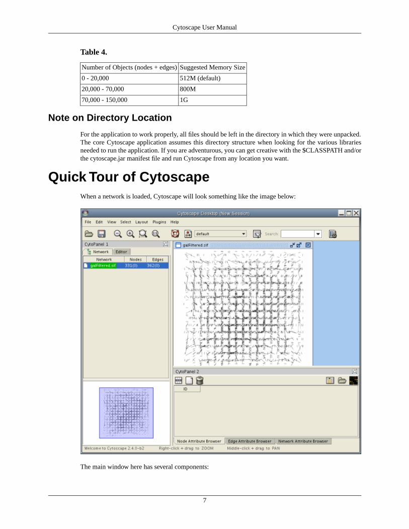
Table 4.
Suggested Memory SizeNumber of Objects (nodes + edges)
512M (default)0 - 20,000
800M20,000 - 70,000
1G70,000 - 150,000
Note on Directory Location
For the application to work properly, all files should be left in the directory in which they were unpacked.The core Cytoscape application assumes this directory structure when looking for the various librariesneeded to run the application. If you are adventurous, you can get creative with the $CLASSPATH and/orthe cytoscape.jar manifest file and run Cytoscape from any location you want.
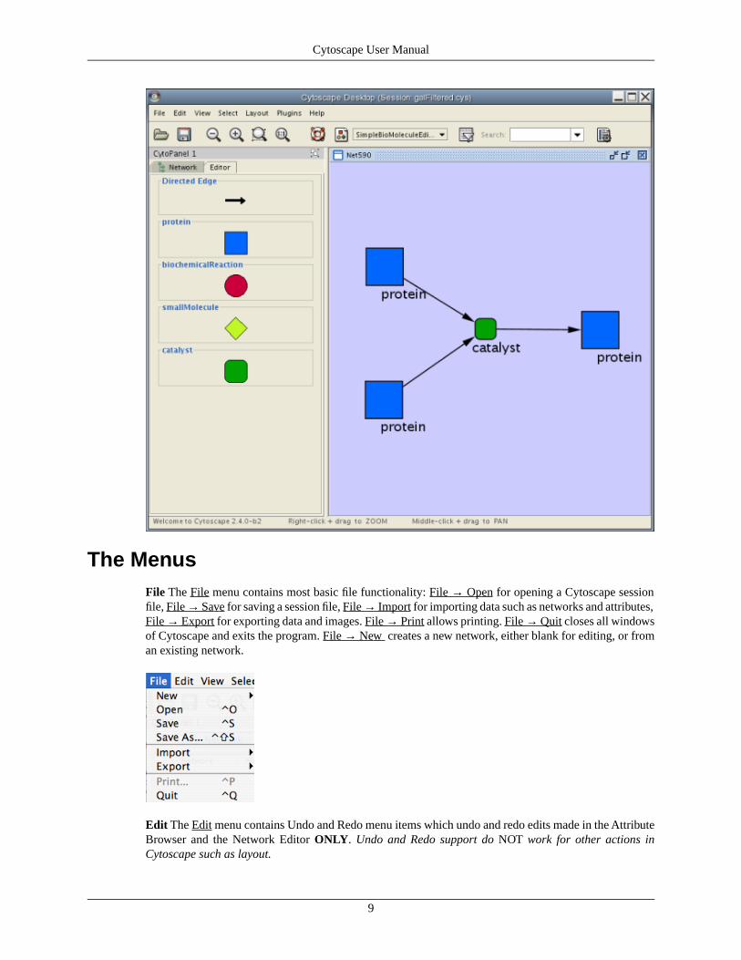
Quick Tour of CytoscapeWhen a network is loaded, Cytoscape will look something like the image below:
The main window here has several components:
7
Cytoscape User Manual
1. The menu bar at the top (See below for more information about each menu).
2. The toolbar, which contains icons for commonly used functions. These functions are also available viathe menus. Hover the mouse pointer over an icon and wait momentarily for a description to appear asa tooltip.
3. The network management panel (top-left ). This contains an optional network overview pane (bottom-left overview of the network).
4. The main network view window, which displays the network.
5. The attribute browser panel (bottom panel), which displays attributes of selected nodes and edges andenables you to modify the values of attributes.
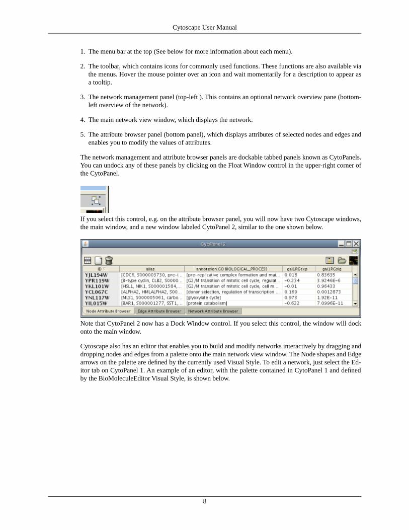
The network management and attribute browser panels are dockable tabbed panels known as CytoPanels.You can undock any of these panels by clicking on the Float Window control in the upper-right corner ofthe CytoPanel.
If you select this control, e.g. on the attribute browser panel, you will now have two Cytoscape windows,the main window, and a new window labeled CytoPanel 2, similar to the one shown below.
Note that CytoPanel 2 now has a Dock Window control. If you select this control, the window will dockonto the main window.
Cytoscape also has an editor that enables you to build and modify networks interactively by dragging anddropping nodes and edges from a palette onto the main network view window. The Node shapes and Edgearrows on the palette are defined by the currently used Visual Style. To edit a network, just select the Ed-itor tab on CytoPanel 1. An example of an editor, with the palette contained in CytoPanel 1 and definedby the BioMoleculeEditor Visual Style, is shown below.
8
Cytoscape User Manual
The MenusFile The File menu contains most basic file functionality: File → Open for opening a Cytoscape sessionfile, File → Save for saving a session file, File → Import for importing data such as networks and attributes,File → Export for exporting data and images. File → Print allows printing. File → Quit closes all windowsof Cytoscape and exits the program. File → New creates a new network, either blank for editing, or froman existing network.
Edit The Edit menu contains Undo and Redo menu items which undo and redo edits made in the AttributeBrowser and the Network Editor ONLY. Undo and Redo support do NOT work for other actions inCytoscape such as layout.
9
Cytoscape User Manual

There are also options for creating and destroying views (graphical representations of a network) and net-works (the network data – not yet visualized), as well as an option for deleting selected nodes and edgesfrom the current network. All deleted nodes and edges can be restored to the network via the Edit → Undomenu item. The Edit Menu also supports Preferences editing for properties and plug-ins via a PreferencesDialog.
View The View menu allows you to display or hide the network management panel (CytoPanel 1), the at-tribute browser (CytoPanel 2), the Network Overview (in CytoPanel 1), and the Advanced window. TheView menu also allows you to open the VizMapper and lock the VizMapper. The View → Desktop providefurther control over the various CytoPanels.
Select The Select menu contains different options selecting nodes and edges. It also contains the Select→ Use Filters option which allows filters to be created which can be used to automatically select portionsof a network whose node or edge attributes meet a filtering criterion.
Layout The Layout menu has an array of features for organizing the network visually. The top of the menucontains tools for manipulating sections of networks. These tools include scale, rotate, distribute, and align.The bottom section of the menu lists a variety of layout algorithms which automatically lay a network out.
10
Cytoscape User Manual
Plugins The Plugins menu has menu items or choices added by plugins that have been loaded, such as"Import BioPAX Document from file". Depending on which plugins are loaded, the plugins that you seemay be different than what appear here.
Table 5.
Note: A list of available Cytoscape Plugins with descriptions is available online at: http://cytoscape.org/plu-gins2.php
Help The Help menu allows you to launch the online help viewer and browse the table of contents (Con-tents…). The “About…” menu item displays information about the running version of Cytoscape.
Network ManagementCytoscape 2.3 allows multiple networks to be loaded at a time, either with or without a view. A networkstores all the nodes and edges that are loaded by the user and a view displays them. You can have manyviews of the same network. Networks (and their optionally associated views) can be organized hierarchically.
An example where a number of networks have been loaded and arranged hierarchically is shown below:
11
Cytoscape User Manual
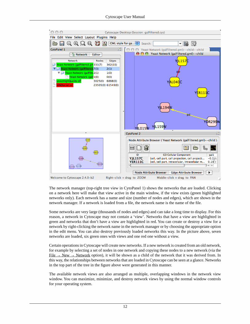
The network manager (top-right tree view in CytoPanel 1) shows the networks that are loaded. Clickingon a network here will make that view active in the main window, if the view exists (green highlightednetworks only). Each network has a name and size (number of nodes and edges), which are shown in thenetwork manager. If a network is loaded from a file, the network name is the name of the file.
Some networks are very large (thousands of nodes and edges) and can take a long time to display. For thisreason, a network in Cytoscape may not contain a ‘view’. Networks that have a view are highlighted ingreen and networks that don’t have a view are highlighted in red. You can create or destroy a view for anetwork by right-clicking the network name in the network manager or by choosing the appropriate optionin the edit menu. You can also destroy previously loaded networks this way. In the picture above, sevennetworks are loaded, six green ones with views and one red one without a view.
Certain operations in Cytoscape will create new networks. If a new network is created from an old network,for example by selecting a set of nodes in one network and copying these nodes to a new network (via theFile → New → Network option), it will be shown as a child of the network that it was derived from. Inthis way, the relationships between networks that are loaded in Cytoscape can be seen at a glance. Networksin the top part of the tree in the figure above were generated in this manner.
The available network views are also arranged as multiple, overlapping windows in the network viewwindow. You can maximize, minimize, and destroy network views by using the normal window controlsfor your operating system.
12
Cytoscape User Manual

The Network Overview WindowThe network overview window shows an overview (or ‘bird’s eye view’) of the network. It can be usedto navigate around a large network view. This feature can be turned on or off via the View → Show/HideNetwork Overview menu. The blue rectangle in the overview window shown below can be dragged withthe mouse to navigate to a part of the network. The size of the navigation rectangle depends on the size ofthe active view and the zoom level of the view. The rectangle is smaller if the view is zoomed in and largerif zoomed out.
•
Command Line ArgumentsTable 6.
Important! The command line arguments have changed since version 2.2, so please read this sectioncarefully.
Cytoscape recognizes a number of optional command line arguments, including run-time specification ofnetwork files, attribute files, and session files. This is the output generated when the cytoscape is executedwith the "-h" or "--help" flag.
usage: java -Xmx512M -jar cytoscape.jar [OPTIONS] -h,--help Print this message. -v,--version Print the version number. -s,--session <file> Load a cytoscape session (.cys) file. -N,--network <file> Load a network file (any format). -e,--edge-attrs <file> Load an edge attributes file (edge attribute format). -n,--node-attrs <file> Load a node attributes file (node attribute format). -m,--matrix <file> Load a node attribute matrix file (table). -p,--plugin <file> Load a plugin jar file, directory of jar files, plugin class name, or plugin jar URL. -P,--props <file> Load cytoscape properties file (Java properties format) or individual property: -P name=value. -V,--vizmap <file> Load vizmap properties file (Java properties format).
Any file specified for an option may be specified as either a path or as a URL. For example you can specifya network as a file (assuming that myNet.sif exists in the current working directory): cytoscape.sh -NmyNet.sif. Or you can specify a network as a URL: cytoscape.sh -N http://example.com/myNet.sif.
13
Cytoscape User Manual
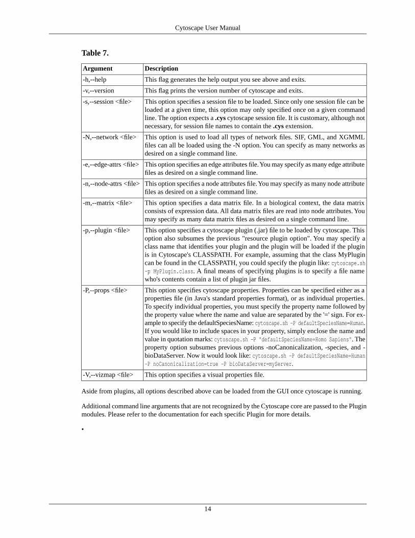
Table 7.
DescriptionArgument
This flag generates the help output you see above and exits.-h,--help
This flag prints the version number of cytoscape and exits.-v,--version
This option specifies a session file to be loaded. Since only one session file can beloaded at a given time, this option may only specified once on a given commandline. The option expects a .cys cytoscape session file. It is customary, although notnecessary, for session file names to contain the .cys extension.
-s,--session <file>
This option is used to load all types of network files. SIF, GML, and XGMMLfiles can all be loaded using the -N option. You can specify as many networks asdesired on a single command line.
-N,--network <file>
This option specifies an edge attributes file. You may specify as many edge attributefiles as desired on a single command line.
-e,--edge-attrs <file>
This option specifies a node attributes file. You may specify as many node attributefiles as desired on a single command line.
-n,--node-attrs <file>
This option specifies a data matrix file. In a biological context, the data matrixconsists of expression data. All data matrix files are read into node attributes. Youmay specify as many data matrix files as desired on a single command line.
-m,--matrix <file>
This option specifies a cytoscape plugin (.jar) file to be loaded by cytoscape. Thisoption also subsumes the previous "resource plugin option". You may specify aclass name that identifies your plugin and the plugin will be loaded if the pluginis in Cytoscape's CLASSPATH. For example, assuming that the class MyPlugincan be found in the CLASSPATH, you could specify the plugin like: cytoscape.sh-p MyPlugin.class. A final means of specifying plugins is to specify a file namewho's contents contain a list of plugin jar files.
-p,--plugin <file>
This option specifies cytoscape properties. Properties can be specified either as aproperties file (in Java's standard properties format), or as individual properties.To specify individual properties, you must specify the property name followed bythe property value where the name and value are separated by the '=' sign. For ex-ample to specify the defaultSpeciesName: cytoscape.sh -P defaultSpeciesName=Human.If you would like to include spaces in your property, simply enclose the name andvalue in quotation marks: cytoscape.sh -P "defaultSpeciesName=Homo Sapiens". Theproperty option subsumes previous options -noCanonicalization, -species, and -bioDataServer. Now it would look like: cytoscape.sh -P defaultSpeciesName=Human-P noCanonicalization=true -P bioDataServer=myServer.
-P,--props <file>
This option specifies a visual properties file.-V,--vizmap <file>
Aside from plugins, all options described above can be loaded from the GUI once cytoscape is running.
Additional command line arguments that are not recognized by the Cytoscape core are passed to the Pluginmodules. Please refer to the documentation for each specific Plugin for more details.
•
14
Cytoscape User Manual
Cytoscape Preferences
Managing Properties
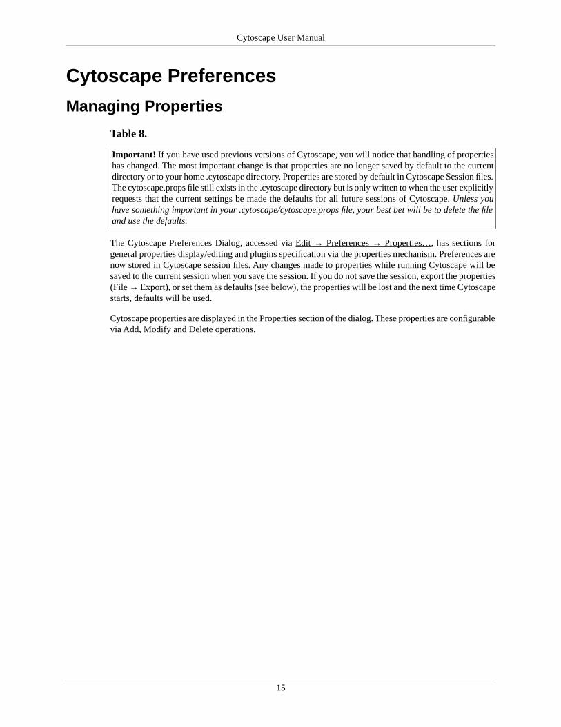
Table 8.
Important! If you have used previous versions of Cytoscape, you will notice that handling of propertieshas changed. The most important change is that properties are no longer saved by default to the currentdirectory or to your home .cytoscape directory. Properties are stored by default in Cytoscape Session files.The cytoscape.props file still exists in the .cytoscape directory but is only written to when the user explicitlyrequests that the current settings be made the defaults for all future sessions of Cytoscape. Unless youhave something important in your .cytoscape/cytoscape.props file, your best bet will be to delete the fileand use the defaults.
The Cytoscape Preferences Dialog, accessed via Edit → Preferences → Properties…, has sections forgeneral properties display/editing and plugins specification via the properties mechanism. Preferences arenow stored in Cytoscape session files. Any changes made to properties while running Cytoscape will besaved to the current session when you save the session. If you do not save the session, export the properties(File → Export), or set them as defaults (see below), the properties will be lost and the next time Cytoscapestarts, defaults will be used.
Cytoscape properties are displayed in the Properties section of the dialog. These properties are configurablevia Add, Modify and Delete operations.
15
Cytoscape User Manual

Some common properties are described below.
16
Cytoscape User Manual
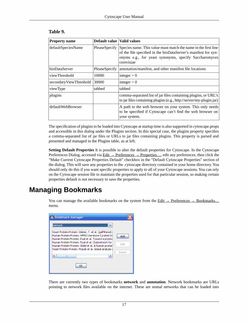
Table 9.
Valid valuesDefault valueProperty name
Species name. This value must match the name in the first lineof the file specified in the bioDataServer’s manifest for syn-onyms e.g., for yeast synonyms, specify Saccharomycescerevisiae
PleaseSpecifydefaultSpeciesName
annotation/manifest, and other manifest file locationsPleaseSpecifybioDataServer
integer > 010000viewThreshold
integer > 030000secondaryViewThreshold
tabbedtabbedviewType
comma-separated list of jar files containing plugins, or URL’sto jar files containing plugins (e.g., http://server/my-plugin.jar)
plugins
A path to the web browser on your system. This only needsto be specified if Cytoscape can’t find the web browser onyour system.
defaultWebBrowser
The specification of plugins to be loaded into Cytoscape at startup time is also supported in cytoscape.propsand accessible in this dialog under the Plugins section. In this special case, the plugins property specifiesa comma-separated list of jar files or URLs to jar files containing plugins. This property is parsed andpresented and managed in the Plugins table, as at left.
Setting Default Properties It is possible to alter the default properties for Cytoscape. In the CytoscapePreferences Dialog, accessed via Edit → Preferences → Properties…, edit any preferences, then click the"Make Current Cytoscape Properties Default" checkbox in the "Default Cytoscape Properties" section ofthe dialog. This will save any properties to the .cytoscape directory contained in your home directory. Youshould only do this if you want specific properties to apply to all of your Cytoscape sessions. You can relyon the Cytoscape session file to maintain the properties used for that particular session, so making certainproperties default is not necessary to save the properties.
Managing BookmarksYou can manage the available bookmarks on the system from the Edit → Preferences → Bookmarks…menu.
There are currently two types of bookmarks network and annotation. Network bookmarks are URLspointing to network files available on the internet. These are nomal networks that can be loaded into
17
Cytoscape User Manual

Cytoscape. The annotation bookmarks are URLs pointing to ontology annotation files. The annotationbookmarks are only used when importing an ontology.
Managing Proxy ServersYou can define and configure a proxy server for Cytoscape to use from the Edit → Preferences → Proxies…menu.
After the proxy server is set, all network traffic related to loading a network from URL will pass throughthe proxy server. Other plugins use this capability as well.
Creating NetworksThere are 3 different ways of creating networks in Cytoscape:
1. Importing pre-existing, formatted network files.
2. Importing pre-existing unformatted text or excel files.
3. Creating an empty network and adding nodes and edges using the Editor.
Import Fixed-Format Network FilesNetwork files can be specified in any of the formats described in the [Cytoscape_User_Manual/Net-work_Formats Network Formats] chapter. Networks are imported into Cytoscape through the ImportNetwork dialog, which can be activated through Menu File → Import → Network. The network file caneither be located on the local computer, or it can also be located in a remote computer and referenced witha URL.
Load Networks from Local Computer
By default, Cytoscape load network from the local computer. When the import network dialog is initialized,the data source type “Local” will be selected. To import a network, first click on the “Select” button, whichwill pop-up a file chooser and let user browse the local disk to choose a network file. User is allowed onlyto choose Cytoscape recognized network types. After the file is selected, a click on the Import button willimport the network. For example, The following steps will load a sample molecular interaction networkin SIF format. Use the menu File → Import → Network. select the file “galFiltered.sif” in “sampleData”directory. After a few seconds, a small network of 331 nodes should appear in the main window. Theprocedure to load network in other format is very similar. To load the same interaction network as a GML,use the menu: File → Import → Network again. In the resulting file dialog box, select the file“sampleData/galFiltered.gml”. Node and edge attribute files as well as expression data and extra annotationcan be loaded as well.
18
Cytoscape User Manual
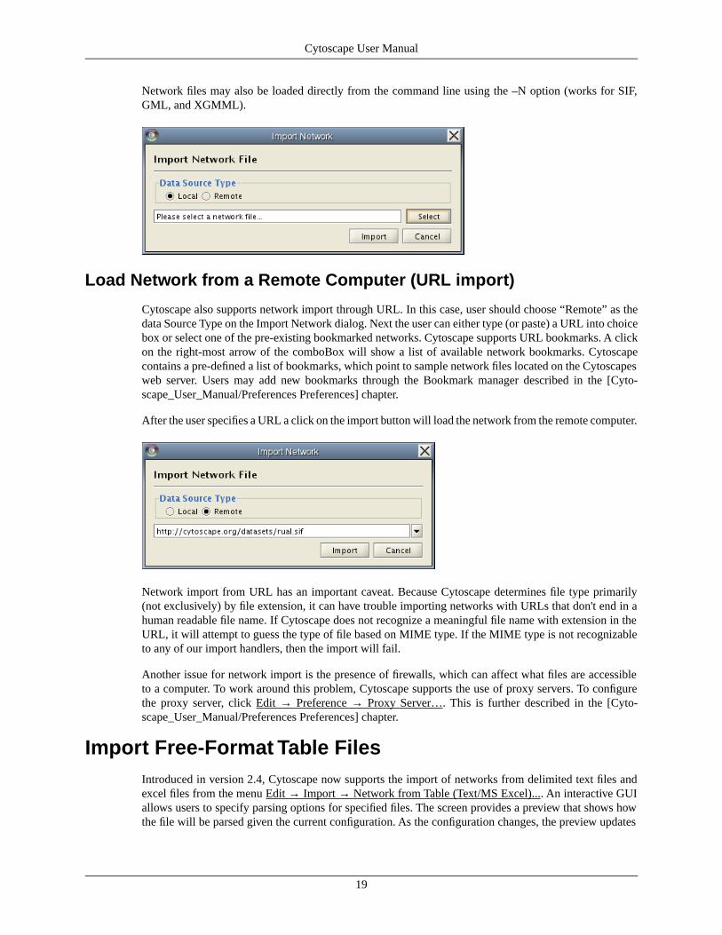
Network files may also be loaded directly from the command line using the –N option (works for SIF,GML, and XGMML).
Load Network from a Remote Computer (URL import)
Cytoscape also supports network import through URL. In this case, user should choose “Remote” as thedata Source Type on the Import Network dialog. Next the user can either type (or paste) a URL into choicebox or select one of the pre-existing bookmarked networks. Cytoscape supports URL bookmarks. A clickon the right-most arrow of the comboBox will show a list of available network bookmarks. Cytoscapecontains a pre-defined a list of bookmarks, which point to sample network files located on the Cytoscapesweb server. Users may add new bookmarks through the Bookmark manager described in the [Cyto-scape_User_Manual/Preferences Preferences] chapter.
After the user specifies a URL a click on the import button will load the network from the remote computer.
Network import from URL has an important caveat. Because Cytoscape determines file type primarily(not exclusively) by file extension, it can have trouble importing networks with URLs that don't end in ahuman readable file name. If Cytoscape does not recognize a meaningful file name with extension in theURL, it will attempt to guess the type of file based on MIME type. If the MIME type is not recognizableto any of our import handlers, then the import will fail.
Another issue for network import is the presence of firewalls, which can affect what files are accessibleto a computer. To work around this problem, Cytoscape supports the use of proxy servers. To configurethe proxy server, click Edit → Preference → Proxy Server…. This is further described in the [Cyto-scape_User_Manual/Preferences Preferences] chapter.
Import Free-Format Table FilesIntroduced in version 2.4, Cytoscape now supports the import of networks from delimited text files andexcel files from the menu Edit → Import → Network from Table (Text/MS Excel).... An interactive GUIallows users to specify parsing options for specified files. The screen provides a preview that shows howthe file will be parsed given the current configuration. As the configuration changes, the preview updates
19
Cytoscape User Manual
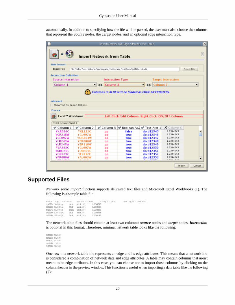
automatically. In addition to specifying how the file will be parsed, the user must also choose the columnsthat represent the Source nodes, the Target nodes, and an optional edge interaction type.
Supported Files
Network Table Import function supports delimited text files and Microsoft Excel Workbooks (1). Thefollowing is a sample table file:
source target interaction boolean attribute string attribute floating point attributeYJR022W YNR053C pp TRUE abcd12371 1.2344543YER116C YDL013W pp TRUE abcd12372 1.2344543YNL307C YAL038W pp FALSE abcd12373 1.2344543YNL216W YCR012W pd TRUE abcd12374 1.2344543YNL216W YGR254W pd TRUE abcd12375 1.2344543
The network table files should contain at least two columns: source nodes and target nodes. Interactionis optional in this format. Therefore, minimal network table looks like the following:
YJR022W YNR053CYER116C YDL013WYNL307C YAL038WYNL216W YCR012WYNL216W YGR254W
One row in a network table file represents an edge and its edge attributes. This means that a network fileis considered a combination of network data and edge attributes. A table may contain columns that aren'tmeant to be edge attributes. In this case, you can choose not to import those columns by clicking on thecolumn header in the preview window. This function is useful when importing a data table like the following(2):
20
Cytoscape User Manual
Unique ID A Unique ID B Alternative ID A Alternative ID B Aliases A Aliases B Interaction detection methods First author surnames Pubmed IDs species A species B Interactor types Source database Interaction ID Interaction labels Cross-references Associated Files Experiment files Experiment labels Different techniques Different Pubmed articles Different sources Weight
7205 5747 TRIP6 PTK2 Q15654 Q05397-1 vv|HPRD Currently not available 14688263|15892868(Marcotte) Mammalia Homo sapiens protein|protein HPRD|Marcotte 0 Thyroid hormone receptor interactor 6-FAK-|PTK2-TRIP6 NA(HPRD)|NA(Marcotte) HPRD/02859_psimi.xml|other/ORIGINAL_DATA_MARCOTTE.txt vv(HPRD/02859_psimi.xml)|HPRD(other/ORIGINAL_DATA_MARCOTTE.txt) 17651(ExptRef)|Marcotte 2 2 2 2
4174 7311 MCM5 UBA52 P33992 P62987 neighbouring_reaction Currently not available 15608231(Reactome) Homo sapiens Homo sapiens protein|protein Reactome 1 P33992-P62988 Reaction:68944<->Reaction:68946(Reactome)|Reaction:68946<->Reaction:68944(Reactome) other/ORIGINAL_DATA_MARCOTTE.txt neighbouring_reaction(other/REACTOMEhomo_sapiens.interactions.txt) Reactome 1 1 1 1
7040 7040 TGFB1 TGFB1 P01137 P01137 nmr: nuclear magnetic resonance Currently not available 8679613 Homo sapiens Homo sapiens protein|protein BIND 2 TGFB1-TGFB1- 72085(BIND) BIND/bind_taxid9606.1.psi.xml nmr: nuclear magnetic resonance(BIND/bind_taxid9606.1.psi.xml) NotAvailable 1 1 1 1
This data file is a tab-delimited text and contains network data (interactions), edge attributes, and node at-tributes. To import network and edge attributes from this table, you need to choose Unique ID A as source,Unique ID B as target, and Interactor types as interaction type. Then you need to turn off columns usedfor node attributes (Alternative ID A, species B, etc.). Other columns can be imported as edge attributes.
The network import dialog cannot import node attributes - only edge attributes. To import node attributesfrom this table, please see the Attributes section of this manual.
Note (1): in version 2.4, Cytoscape supports Excel Workbooks with single sheet (table) only. Multiplesheet Workbooks are not supported.
Note (2): from A merged human interactome datasets by Andrew Garrow, Yeyejide Adeleye and GuyWarner (Unilever, Safety and Environmental Assurance Center, 12 October 2006). Actual data files areavailable at:
http://www.cytoscape.orghttp://cytoscape.org/cgi-bin/moin.cgi/Data_Sets/
Basic Operations
To import network text/Excel tables, please follow these steps:
1. Select File → Import → Network from Table (Text/MS Excel)...
2. Select a table file by clicking on Select File button.
3. Set Interaction Definition. You need to specify Source Interaction, Target Interaction, and InteractionType. For Interaction Type, if you select Default Interaction the default interaction value will be usedfor all edges. The default value is pp. This value can be modified in Advanced Options.
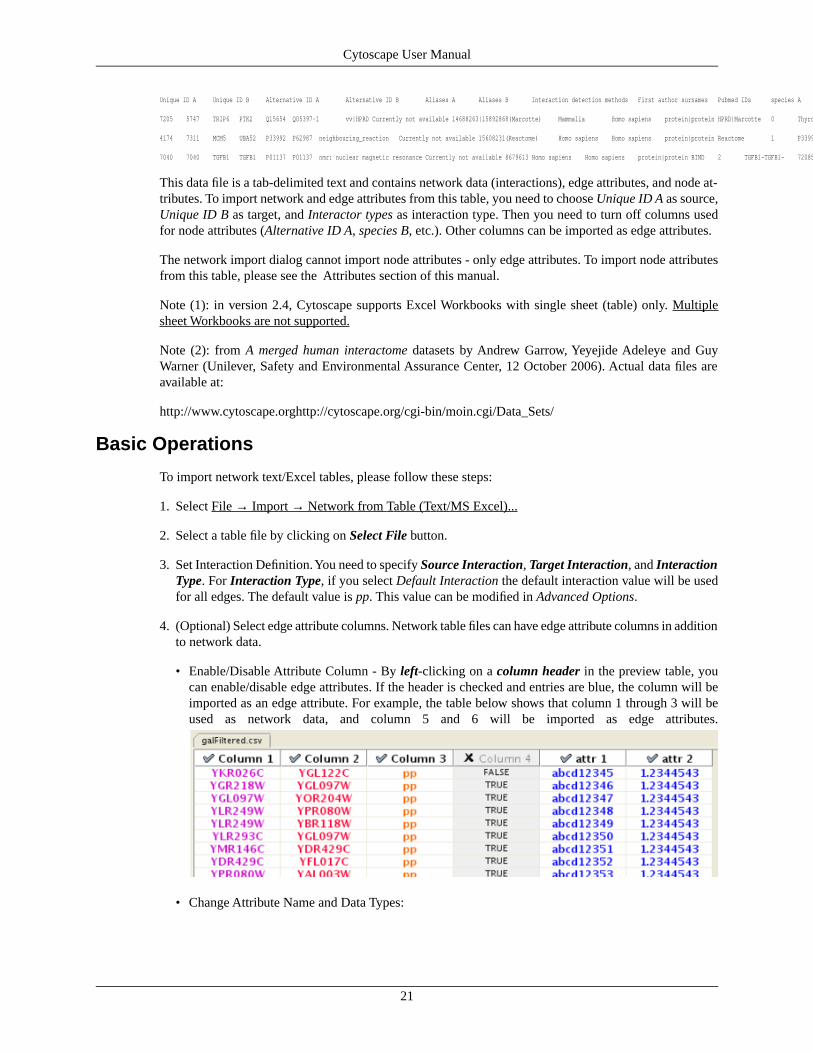
4. (Optional) Select edge attribute columns. Network table files can have edge attribute columns in additionto network data.
• Enable/Disable Attribute Column - By left-clicking on a column header in the preview table, youcan enable/disable edge attributes. If the header is checked and entries are blue, the column will beimported as an edge attribute. For example, the table below shows that column 1 through 3 will beused as network data, and column 5 and 6 will be imported as edge attributes.
• Change Attribute Name and Data Types:
21
Cytoscape User Manual

• If you right-click on a column header in the preview table, the dialog above will be displayed. Youcan modify attribute name and data type from this dialog. For more detail, see Modify AttributeName/Type.
5. Click Import button.
Advanced Options
You can select several options by checking Show Text File Import Options.
• Delimiter: You can select multiple delimiters for text tables. By default, Tab and Space are selected asdelimiters.
• Preview Options: When you select a network table file, first 100 entries will be displayed in the Previewpanel. To display more entries, change the value for this option. If you want to show all entries in thefile, select Show all entries in the file. You need to click Reload button to update the Preview panel.
• Attribute Names
• Transfer first line as attribute names: By choosing this option, first entry in the file will be used asedge attribute names.
• Start Import Row: Change the start row for import. For example, if you want to skip first 3 rows inthe file, set 4 for this option.
• Comment Line: Rows start with this character will be ignored. This option will be used to skip commentlines in text files.
• Network Import Options: If Interaction Type is set to Default Interaction, the value here will be usedas interaction for all edges.
Modify Attribute Name/Type
22
Cytoscape User Manual
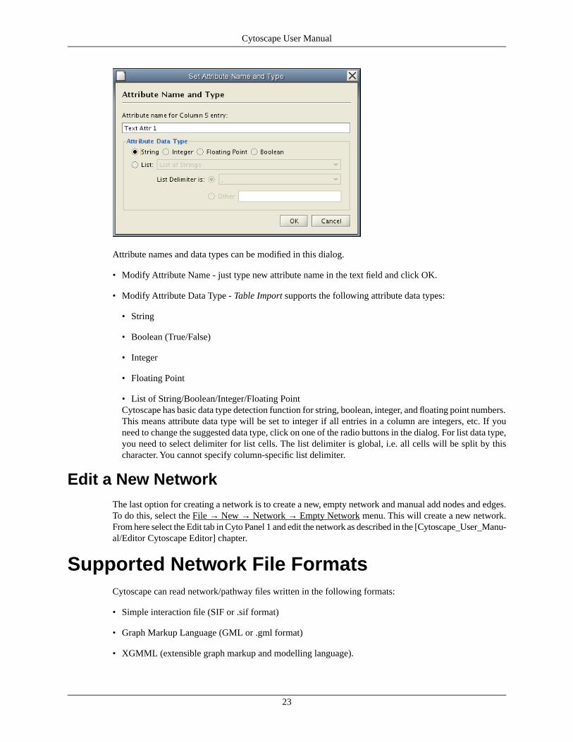
Attribute names and data types can be modified in this dialog.
• Modify Attribute Name - just type new attribute name in the text field and click OK.
• Modify Attribute Data Type - Table Import supports the following attribute data types:
• String
• Boolean (True/False)
• Integer
• Floating Point
• List of String/Boolean/Integer/Floating PointCytoscape has basic data type detection function for string, boolean, integer, and floating point numbers.This means attribute data type will be set to integer if all entries in a column are integers, etc. If youneed to change the suggested data type, click on one of the radio buttons in the dialog. For list data type,you need to select delimiter for list cells. The list delimiter is global, i.e. all cells will be split by thischaracter. You cannot specify column-specific list delimiter.
Edit a New NetworkThe last option for creating a network is to create a new, empty network and manual add nodes and edges.To do this, select the File → New → Network → Empty Network menu. This will create a new network.From here select the Edit tab in Cyto Panel 1 and edit the network as described in the [Cytoscape_User_Manu-al/Editor Cytoscape Editor] chapter.
Supported Network File FormatsCytoscape can read network/pathway files written in the following formats:
• Simple interaction file (SIF or .sif format)
• Graph Markup Language (GML or .gml format)
• XGMML (extensible graph markup and modelling language).
23
Cytoscape User Manual
• SBML
• BioPAX
• PSI-MI Level 1 and 2.5
• Delimited text
• Excel Workbook (.xls)
SIF specifies nodes and interactions only, while others store additional information about network layoutand allows network data exchange with a variety of other network programs and data sources. Typically,SIF is used to import interactions when building a network for the first time, since it is easy to create in atext editor or spreadsheet. Once the interactions have been loaded and layout has been performed, thenetwork may be saved to GML or XGMML format for interaction with other systems. All file types listed(except Excel) are text files and you can edit and view them in a regular text editor.
SIF FormatThe simple interaction format is convenient for building a graph from a list of interactions. It also makesit easy to combine different interaction sets into a larger network, or add new interactions to an existingdata set. The main disadvantage is that this format does not include any layout information, forcing Cyto-scape to re-compute a new layout of the network each time it is loaded.
Lines in the SIF file specify a source node, a relationship type (or edge type), and one or more target nodes:
nodeA <relationship type> nodeBnodeC <relationship type> nodeAnodeD <relationship type> nodeE nodeF nodeBnodeG...nodeY <relationship type> nodeZ
A more specific example is:
node1 typeA node2node2 typeB node3 node4 node5node0
The first line identifies two nodes, called node1 and node2, and a single relationship between node1 andnode2 of type typeA. The second line specifies three new nodes, node3, node4, and node5; here "node2"refers to the same node as in the first line. The second line also specifies three relationships, all of typetypeB and with node2 as the source, with node3, node4, and node5 as the targets, respectively. This secondform is simply shorthand for specifying multiple relationships of the same type with the same source node.The third line indicates how to specify a node that has no relationships with other nodes. This form is notneeded for nodes that do have relationships, since the specification of the relationship implicitly identifiesthe nodes as well.
Duplicate entries are ignored. Multiple edges between the same nodes must have different edge types. Forexample, the following specifies two edges between the same pair of nodes, one of type xx and one of typeyy:
node1 xx node2node1 xx node2node1 yy node2
Edges connecting a node to itself (self-edges) are also allowed:
node1 xx node1
24
Cytoscape User Manual
Every node and edge in Cytoscape has an identifying name, most commonly used with the node and edgedata attribute structures. Node names must be unique as identically named nodes will be treated asidentical nodes. The name of each node will be the name in this file by default (unless another string ismapped to display on the node using the visual mapper). This is discussed in the section on [Cyto-scape_User_Manual/Visual_Styles visual styles]. The name of each edge will be formed from the nameof the source and target nodes plus the interaction type: for example, sourceName (edgeType) targetName.
The tag <interaction type> can be any string. Whole words or concatenated words may be used to definetypes of relationships e.g. geneFusion, cogInference, pullsDown, activates, degrades, inactivates, inhibits,phosphorylates, upRegulates, etc.
Some common interaction types used in the Systems Biology community are as follows:
pp .................. protein – protein interaction pd .................. protein -> DNA (e.g. transcription factor binding upstream of a regulating gene.)
Some less common interaction types used are:
pr .................. protein -> reaction rc .................. reaction -> compound cr .................. compound -> reaction gl .................. genetic lethal relationship pm .................. protein-metabolite interaction mp .................. metabolite-protein interaction
Delimiters Whitespace (space or tab) is used to delimit the names in the simple interaction file format.However, in some cases spaces are desired in a node name or edge type. The standard is that, if the filecontains any tab characters, then tabs are used to delimit the fields and spaces are considered part of thename. If the file contains no tabs, then any spaces are delimiters that separate names (and names cannotcontain spaces).
If your network unexpectedly contains no edges and node names that look like edge names, it probablymeans your file contains a stray tab that's fooling the parser. On the other hand, if your network has nodeswhose names are half of a full name, then you probably meant to use tabs to separate node names withspaces.
Networks in simple interactions format are often stored in files with a ".sif" extension, and Cytoscape re-cognizes this extension when browsing a directory for files of this type.
GML FormatIn contrast to SIF, GML is a rich graph format language supported by many other network visualizationpackages. The GML file format specification is available at:
http://www.infosun.fmi.uni-passau.de/Graphlet/GML/
It is generally not necessary to modify the content of a GML file directly. Once a network is built in SIFformat and then laid out, the layout is preserved by saving to and loading from GML. Visual attributesspecified in a GML file will result in a new visual style named “Filename.style” when that GML file isloaded.
XGMML FormatXGMML is the XML evolution of GML and is based on the GML definition. In addition to network data,XGMML contains node/edge/network attributes. The XGMML file format specification is available at:
http://www.cs.rpi.edu/~puninj/XGMML/
25
Cytoscape User Manual

XGMML is now preferred to GML because it offers the flexibility associated with all XML documenttypes. If you're unsure about which to use, choose XGMML.
SBML (Systems Biology Markup Language) FormatThe Systems Biology Markup Language (SBML) is an XML format to describe biochemical networks.SBML file format specification is available at:
http://sbml.org/documents/
BioPAX (Biological PAthways eXchange) FormatBioPAX is an OWL (Web Ontology Language) document designed to exchange biological pathways data.Complete set of documents for this format is available at:
http://www.biopax.org/index.html
PSI-MI FormatThe PSI-MI format is a data exchange format for protein-protein interactions. It is an XML document todescribe PPI and associated data. PSI-MI XML format specification is available at:
http://psidev.sourceforge.net/mi/xml/doc/user/
Delimited Text Table and Excel WorkbookCytoscape has native support for Microsoft Excel files (.xls) and delimited text files. The table in thosefile can have network data and edge attributes. Users can specify columns for source node, target node,interaction type, and edge attributes from GUI. For more detail, please read Import Free-Format Tablessection.
NODE NAMING ISSUES IN CYTOSCAPE
Typically, genes are represented by nodes, and interactions (or other biological relationships) are representedby edges between nodes. For compactness, a gene also represents its corresponding protein. Nodes mayalso be used to represent compounds and reactions (or anything else) instead of genes.
If a network of genes or proteins is to be integrated with Gene Ontology (GO) annotation or gene expressiondata, the gene names must exactly match the names specified in the other data files. We strongly encouragenaming genes and proteins by their systematic ORF name or standard accession number; common namesmay be displayed on the screen for ease of interpretation, so long as these are available to the program inthe annotation directory or in a node attribute file. Cytoscape ships with all yeast ORF-to-common namemappings in a synonym table within the annotation/ directory. Other organisms will be supported in thefuture.
Why do we recommend using standard gene names? All of the external data formats recognized by Cyto-scape provide data associated with particular names of particular objects. For example, a network of protein-protein interactions would list the names of the proteins, and the attribute and expression data would likewisebe indexed by the name of the object.
The problem is in connecting data from different data sources that don't necessarily use the same name forthe same object. For example, genes are commonly referred to by different names, including a formal"location on the chromosome" identifier and one or more common names that are used by ordinary research-
26
Cytoscape User Manual

ers when talking about that gene. Additionally, database identifiers from every database where the geneis stored may be used to refer to a gene (e.g. protein accession numbers from Swiss-Prot). If one data sourceuses the formal name while a different data source used a common name or identifier, then Cytoscape mustfigure out that these two different names really refer to the same biological entity.
Cytoscape has two strategies for dealing with this naming issue, one simple and one more complex. Thesimple strategy is to assume that every data source uses the same set of names for every object. If this isthe case, then Cytoscape can easily connect all of the different data sources.
To handle data sources with different sets of names, as is usually the case when manually integrating geneinformation from different sources, Cytoscape needs a data server that provides synonym information(See12. Annotation.). A synonym table gives a canonical name for each object in a given organism andone or more recognized synonyms for that object. Note that the synonym table itself defines what set ofnames are the "canonical" names. For example, in budding yeast the ORF names are commonly used asthe canonical names.
If a synonym server is available, then by default Cytoscape will convert every name that appears in a datafile to the associated canonical name. Unrecognized names will not be changed. This conversion of namesto a common set allows Cytoscape to connect the genes present in different data sources, even if they havedifferent names – as long as those names are recognized by the synonym server.
For this to work, Cytoscape must also be provided with the species to which the objects belong, since thedata server requires the species in order to uniquely identify the object referred to by a particular name.This is usually done in Cytoscape by specifying the species name on the command line with the –P option(cytoscape.sh -P "defaultSpeciesName=Saccharomyces cerevisiae") or by editing the properties in the Prefer-ences Dialog (Edit → Preference...).
The automatic canonicalization of names can be turned off using the -P option (cytoscape.sh -P canonic-alizeName=false") or by editing the properties in the Preferences Dialog (Edit → Preferences...). This ca-nonicalization of names currently does not apply to expression data. Expression data should use the samenames as the other data sources or use the canonical names as defined by the synonym table.
Node and Edge AttributesInteraction networks are useful as stand-alone models. However, they are most powerful for answeringscientific questions when integrated with additional information. Cytoscape allows the user to add arbitrarynode, edge and network information to Cytoscape as node/edge/network(1) attributes. Attributes couldbe, for example, annotation data on a gene or confidence values in a protein-protein interaction. These at-tributes can then be visualized in a user-defined way by setting up a mapping from data attributes to visualattributes (colors, shapes, etc.) See the section on visual styles for a discussion of this.
Cytoscape Attribute File FormatNode and edge attribute files are simply formatted: A node attribute file begins with the name of the attributeon the first line, and on each following line, has the name of the node, followed by an equals sign, followedby the value of that attribute. Numbers and text strings are the most common attribute types. All valuesfor a given attribute must have the same type. For example:
FunctionalCategoryYAL001C = metabolismYAR002W = apoptosisYBL007C = ribosome
An edge attribute file has much the same structure, except that the name of the edge is the source nodename, followed by the interaction type in parentheses, followed by the target node name. Directionality
27
Cytoscape User Manual

counts, so switching the source and target will refer to a different (or perhaps non-existent) edge. The fol-lowing is an example edge attributes file:
InteractionStrengthYAL001C (pp) YBR043W = 0.82YMR022W (pd) YDL112C = 0.441YDL112C (pd) YMR022W = 0.9013
Cytoscape treats edge attributes as directional, so note that the second and third edge attribute values referto two different edges (source and target are reversed, though the nodes involved are the same).
Each attribute is stored in a separate file. Node and edge attribute files use the same format. Node attributefile names often use the suffix ".noa", while edge attribute file names use the suffix ".eda". Cytoscape re-cognizes these suffixes when browsing for attribute files.
Node and edge attributes may be loaded at the command line using the –n and –e options or via the File→ Import menu.
When expression data is loaded using an expression matrix, it is automatically copied into the Node Attrib-utes data structure unless explicitly specified not to.
Node and edge attributes are attached to nodes and edges, NOT to networks. If two different networkshave the same nodes, then those nodes will have the same attributes. Even if a network is loaded after at-tributes have been loaded, if the nodes or edges found in the new network already exist, then any existingattributes will be applied to those nodes.
Note (1): Network attributes are supported in Cytoscape, but network attribute file reader is not yet imple-mented in Cytoscape 2.4. If you need to import network attributes, please use attribute table import functionor write network attributes directly in XGMML file.
Detailed file format (Advanced users)
Every attribute file has one header line that gives the name of the attribute, and optionally some additionalmeta-information about that attribute. The format is as follows:
attributeName (class=formal.class.of.value)
The first field is always the attribute name: it cannot contain spaces. If present, the class field defines theformal (package qualified) name of the class of the attribute values. For example, java.lang.String forStrings, java.lang.Double for floating point values, java.lang.Integer for integer values, etc. If the value isactually a list of values, the class should be the type of the objects in the list. If no class is specified in theheader line, Cytoscape will attempt to guess the type from the first value. If the first value contains numbersin a floating point format, Cytoscape will assume java.lang.Double; if the first value contains only numberswith no decimal point, Cytoscape will assume java.lang.Integer; otherwise Cytoscape will assumejava.lang.String. Note that the first value can lead Cytoscape astray: for example,
floatingPointAttributefirstName = 1secondName = 2.5
In this case, the first value will make Cytoscape think the values should be integers, when in fact theyshould be floating point numbers. It's safest to explicitly specify the value type to prevent confusion. Abetter format would be:
floatingPointAttribute (class=Double)firstName = 1secondName = 2.5
or
28
Cytoscape User Manual
floatingPointAttribute firstName = 1.0secondName = 2.5
Every line past the first line identifies the name of an object (node in a node attribute file and an edge ina edge attribute file) along with the String representation of the attribute value. The delimiter is always anequals sign; whitespace (spaces and/or tabs) before and after the equals sign is ignored. This means thatyour names and values can contain whitespace, but object names cannot contain an equals sign and noguarantees are made concerning leading or trailing whitespace. Object names must be the Node ID or EdgeID as seen in the left-most column of the attribute browser if the attribute is to map to anything. Thesenames must be reproduced exactly, including case, or they will not match.
Edge names are all of the form:
sourceName (edgeType) targetName
Specifically, that is
Table 10.
sourceName space openParen edgeType closeParen space targetName
Note that tabs are not allowed in edge names. Tabs can be used to separate the edge name from the "="delimiter, but not within the edge name itself. Also note that this format is different from the specificationof interactions in the SIF file format. To be explicit: a SIF entry for the previous interaction would looklike
sourceName edgeType targetName
or
Table 11.
sourceName whiteSpace edgeType whiteSpace targetName
To specify lists of values, use the following syntax:
listAttributeName (class=java.lang.String)firstObjectName = (firstValue::secondValue::thirdValue)secondObjectName = (onlyOneValue)
This defines an attribute which is a list of Strings. The first object has three strings, and thus three elementsin its list, while the second object has a list with only one member. In the case of a list every attribute valueshould be specified as a list, and every member of the list should be of the same class. Again, the class willbe inferred if it is not specified in the header line. Lists are not supported by the visual mapper, so can’tbe mapped to visual attributes.
Newline Feature
Sometimes it is desirable to for attributes to include linebreaks, for example node labels that extend overtwo lines. You can acomplish by inserting the characters into the attribute value. For example:
newlineAttrYJL157C = This is a long\nline for a label.
29
Cytoscape User Manual

Import Attribute Table FilesIntroduced in version 2.4, Cytoscape now supports importing delimited text and MS Excel attribute datatables. Using this functionality, users can now easily import data that isn't formatted into Cytoscape nodeor edge attribute file formats (as described above).
Sample Attribute Table 1
Table 12.
SGD IDAliasObject Key
S000000289YBR085W|ANC3AAC3
S000004017YLR027C|ASP5AAT2
S000000534YCL029C|ARM5|PAC14BIK1
Attribute table file should contain a primary key column and at least one attribute column. Number of at-tribute columns is unlimited. Alias column is optional. First row can be used as attribute names, but it isoptional. You can specify each attribute name from Attribute Table Import user interface.
30
Cytoscape User Manual
Basic Operation
User interface of Attribute Table Import is similar to Network Table Import.
1. Select File → Import → Attribute from Table (text/MS Excel)
2. Select one of the attribute types from Attributes radio buttons. Cytoscape can import node, edge, andnetwork attributes.
3. Select a data file. To load a local file, click on Select File button and choose a data file. Input file canbe text or Excel (.xls) file. To load a remote file, type source URL directly in the text box. To showpreview for the remote file, click Reload button on Advanced panel.
4. (Optional) If the table is not properly delimited, change delimiter from Text File Import Options panel.Default delimiter is TAB. This is not necessary for Excel Workbooks.
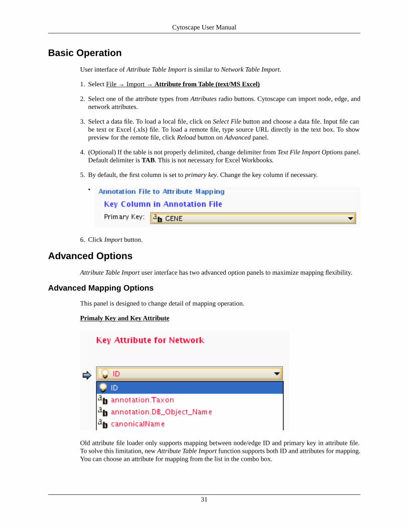
5. By default, the first column is set to primary key. Change the key column if necessary.
•
6. Click Import button.
Advanced Options
Attribute Table Import user interface has two advanced option panels to maximize mapping flexibility.
Advanced Mapping Options
This panel is designed to change detail of mapping operation.
Primaly Key and Key Attribute
Old attribute file loader only supports mapping between node/edge ID and primary key in attribute file.To solve this limitation, new Attribute Table Import function supports both ID and attributes for mapping.You can choose an attribute for mapping from the list in the combo box.
31
Cytoscape User Manual

Note: currently, only primitive data types (string, boolean, floating point, and integer) are supported formapping, i.e. you cannot use list, map, or complex attribute as Key Attribute.
Aliases
Cytoscape uses simple mechanism to manage aliases of objects. Both nodes and edges can have alias. Ifattributes are loaded as alias, they are treated as special attribute called alias. This will be used whenmapping attributes. If primary key and key attribute for an object does not match, Cytoscape searches amatch between aliases and key attribute. To use columns in attribute table as alias, just click on checkboxes in the alias table.
Text File Import Options
• This is mostly same as Network Table Import. For detail, please read Import Free-Format Table Filessection in this manual.
Attribute Browser
When Cytoscape is started, the Attribute Browser appears in the bottom Cytopanel. This browser can behidden and restored using the F5 key or the View → Show/Hide attribute browser menu option. Like otherCytopanels, the browser can be undocked by pressing the little icon in the browser’s top right corner.
To swap between displaying node, edge, and network attributes use the tabs on the bottom of the panel:Node Attribute Browser, Edge Attribute Browser, and Network Attribute Browser. The attribute browserdisplays attributes belonging to selected nodes and/or edges and the currently selected network. To populatethe browser with rows (as pictured above), simply select nodes and/or edges in a loaded network. By default,only the ID of nodes and edges is shown. To display more than just the ID, click the Select Attributes
button and choose the attributes that are to be displayed. Each attribute chosen will result in one columnin the attribute browser (in the screenshot above there are 5 columns total including the ID). Most attributevalues can be edited by double-clicking an attribute cell; list values cannot be edited, and neither can theID. Attribute rows in the browser can be sorted alphabetically by specific attribute by clicking on a column
32
Cytoscape User Manual

heading. A new attribute can be created using the Create New Attribute
button. Attributes created using the attribute browser must be one of four types – integer, string, realnumber (floating point), or boolean. Attributes can be deleted using the Delete Attributes...
button. NOTE: Deleting attributes removes them from Cytoscape, not just the attribute browser! To removeattributes only from the browser simply unselect the attribute using the Select Attributes
button. The right-click menu on the Attribute Browser has several functions. This menu is useful for ex-porting attribute information to spreadsheet applications. For example, choose Select All and then Copyfrom the right-click and then paste into a spreadsheet application. Each attribute browser panel has a buttonf o r i m p o r t i n g n e w a t t r i b u t e s :
.
The Node Attribute Browser panel has additional buttons for loading Gene Expression attribute matrices
( ) as node attributes.
Loading Gene Expression (Attribute Matrix) DataIn addition to normal node and edge attribute data, Cytoscape also supports importing gene expressiondata. Gene expression data are imported using a different file format than normal attributes, however theresulting attributes are no different from other attributes from Cytoscape's perspective. Gene expressiondata (like attribute data) can be loaded at any time, but are (generally) only relevant once a network hasbeen loaded.
Data File FormatGene expression ratios or values are specified over one or more experiments using a text file. Ratios resultfrom a comparison of two expression measurements (experiment vs. control). Some expression platforms,such as Affymetrix, directly measure expression values, without a comparison. The file consists of aheader and a number of space- or tab-delimited fields, one line per gene, with the following format:
Identifier [CommonName] value1 value2 ... valueN [pval1 pval2 ... pvalN]
Brackets [ ] indicate fields that are optional.
The first field identifies which Cytoscape node the data refers to. In the simplest case, this is the gene name- exactly as it appears on the Cytoscape canvas (case sensitive!). Alternatively, this can be some node at-tribute that identifies the node uniquely, such as a probeset identifier for commercial microarrays.
The next field is an optional common name. It is not used by Cytoscape, and is provided strictly for theuser's convenience. With this common name field, the input format is the same as for commonly-used ex-pression data anaysis packages such as SAM (http://www-stat.stanford.edu/~tibs/SAM/).
The next set of columns represent expression values, one per experiment. These can be either absoluteexpression values or fold change ratios. Each experiment is identified by its experiment name, given inthe first line.
33
Cytoscape User Manual

Optionally, significance measures such as P values may be provided. These values, generated by manymicroarray data analysis packages, indicate where the level of gene expression or the fold change appearsto be greater than random chance. If you are using significance measures, then your expression file shouldcontain them in a second set of columns after the expression values. The column names for the expressionsignificance measures should match those of the expression values exactly.
For example, here is an excerpt from the file galExpData.pvals in the Cytoscape sampleData directory::
GENE COMMON gal1RG gal4RG gal80R gal1RG gal4RG gal80RYHR051W COX6 -0.034 0.111 -0.304 3.75720e-01 1.56240e-02 7.91340e-06YHR124W NDT80 -0.090 0.007 -0.348 2.71460e-01 9.64330e-01 3.44760e-01YKL181W PRS1 -0.167 -0.233 0.112 6.27120e-03 7.89400e-04 1.44060e-01YGR072W UPF3 0.245 -0.471 0.787 4.10450e-04 7.51780e-04 1.37130e-05
This indicates that there is data for three experiments: gal1RG, gal4RG, and gal80R. These names appeartwo times: the first time gives the expression values, and the second gives the significance measures. Forinstance, the second line tells us that in Experiment gal1RG, the gene YHR051W has an expression valueof -0.034 with significance measure 3.75720e-01.
Some variations on this basic format are recognized: see the formal file format specification below formore information. Expression data files commonly have the file extensions ".mrna" or ".pvals", and thesefile extensions are recognized by Cytoscape when browsing for data files.
COMMANDS: Load an expression attribute matrix file using the Cytoscape menu options File → Import→ Attribute/Expression Matrix to bring up the import dialog box, or by specifying the filename using the-m option at the command line. If you use the command line input, you must enter your expression databy node ID. If you use the dialog box, then you can either load expression data by node ID (the defaultoption), or can optionally select a node attribute to use in assigning your expression data to your Cytoscapenodes. If you do use a node attribute, then (1) the attribute should already be loaded, and (2) the node at-tribute value must match the first column in your matrix file.
ExampleFor the sample network file sampleData/galFiltered.sif:
1. Load a sample gene expression data set using the menu: File → Import → Attribute/Expression Matrix.In the resulting file dialog box, in the field labeled "Please select an attribute or expression matrix file...",select sampleData/galExpData.pvals. The identifiers used in this file are the same ones used in the networkfile sampleData/galFiltered.sif, so you do not need to touch the field labeled "Assign values to nodesusing...". A few lines of this file are shown below:
GENE COMMON gal1RG gal4RG gal80R gal1RG gal4RG gal80RYHR051W COX6 -0.034 0.111 -0.304 3.75720e-01 1.56240e-02 7.91340e-06YHR124W NDT80 -0.090 0.007 -0.348 2.71460e-01 9.64330e-01 3.44760e-01YKL181W PRS1 -0.167 -0.233 0.112 6.27120e-03 7.89400e-04 1.44060e-01
- or -
2a. After loading the network, load the node attribute file sampleData/gal.probeset.na, using the menuoptions File → Import → Node attributes.... This file is shown in part below:
ProbesetYHR051W = probeset2YHR124W = probeset3YKL181W = probeset4
2b. After loading the node attribute file, select the expression data file sampleData.galExpPvals.probe-set.pvals, shown in part below:
GENE COMMON gal1RG gal4RG gal80R gal1RG gal4RG gal80Rprobeset2 COX6 -0.034 0.111 -0.304 3.75720e-01 1.56240e-02 7.91340e-06
34
Cytoscape User Manual

probeset3 NDT80 -0.090 0.007 -0.348 2.71460e-01 9.64330e-01 3.44760e-01probeset4 PRS1 -0.167 -0.233 0.112 6.27120e-03 7.89400e-04 1.44060e-01
After selecting this file, in the field labeled Assign values to nodes using..., select Probeset. You will seethat this loads exactly the same expression data as in Case 1, but provides extra flexibility in case the nodename cannot be used as an identifier.
Detailed file format (Advanced users) In all expression data files, any whitespace (spaces and/or tabs)is considered a delimiter between adjacent fields. Every line of text is either the header line or contains allthe measurements for a particular gene. No name conversion is applied to expression data files.
The names given in the first column of the expression data file should match exactly the names used else-where (i.e. in SIF or GML files).
The first line is a header line with one of the following three formats:
<text> <text> cond1 cond2 ... cond1 cond2 ... [NumSigConds]<text> <text> cond1 cond2 ...<tab><tab>RATIOS<tab><tab>...LAMBDAS
The first format specifies that both expression ratios and significance values are included in the file. Thefirst two text tokens contain names for each gene. The next token set specifies the names of the experimentalconditions; these columns will contain ratio values. This list of condition names must then be duplicatedexactly, each spelled the same way and in the same order. Optionally, a final column with the title Num-SigConds may be present. If present, this column will contain integer values indicating the number ofconditions in which each gene had a statistically significant change according to some threshold.
The second format is similar to the first except that the duplicate column names are omitted, and there isno NumSigConds fields. This format specifies data with ratios but no significance values.
The third format specifies an MTX header, which is a commonly used format. Two tab characters precedethe RATIOS token. This token is followed by a number of tabs equal to the number of conditions, followedby the LAMBDAS token. This format specifies both ratios and significance values.
Each line after the first is a data line with the following format:
FormalGeneName CommonGeneName ratio1 ratio2 ... [lambda1 lambda2 ...] [numSigConds]
The first two tokens are gene names. The names in the first column are the keys used for node namelookup; these names should be the same as the names used elsewhere in Cytoscape (i.e. in the SIF, GML,or XGMML files). Traditionally in the gene expression microarray community, who defined these fileformats, the first token is expected to be the formal name of the gene (in systems where there is a formalnaming scheme for genes), while the second is expected to be a synonym for the gene commonly used bybiologists, although Cytoscape does not make use of the common name column. The next columns containfloating point values for the ratios, followed by columns with the significance values if specified by theheader line. The final column, if specified by the header line, should contain an integer giving the numberof significant conditions for that gene. Missing values are not allowed and will confuse the parser. Forexample, using two consecutive tabs to indicate a missing value will not work; the parser will regard bothtabs as a single delimiter and be unable to parse the line correctly.
Optionally, the last line of the file may be a special footer line with the following format:
NumSigGenes int1 int2 ...
This line specified the number of genes that were significantly differentially expressed in each condition.The first text token must be spelled exactly as shown; the rest of the line should contain one integer valuefor each experimental condition.
35
Cytoscape User Manual
Navigation and Layout
Basic Network NavigationCytoscape uses a Zoomable User Interface for navigating and viewing networks. ZUIs use two mechanismsfor navigation: zooming and panning. Zooming increases or decreases the magnification of a view basedon how much or how little a user wants to see. Panning allows users to move the focus of a screen to dif-ferent parts of a view.
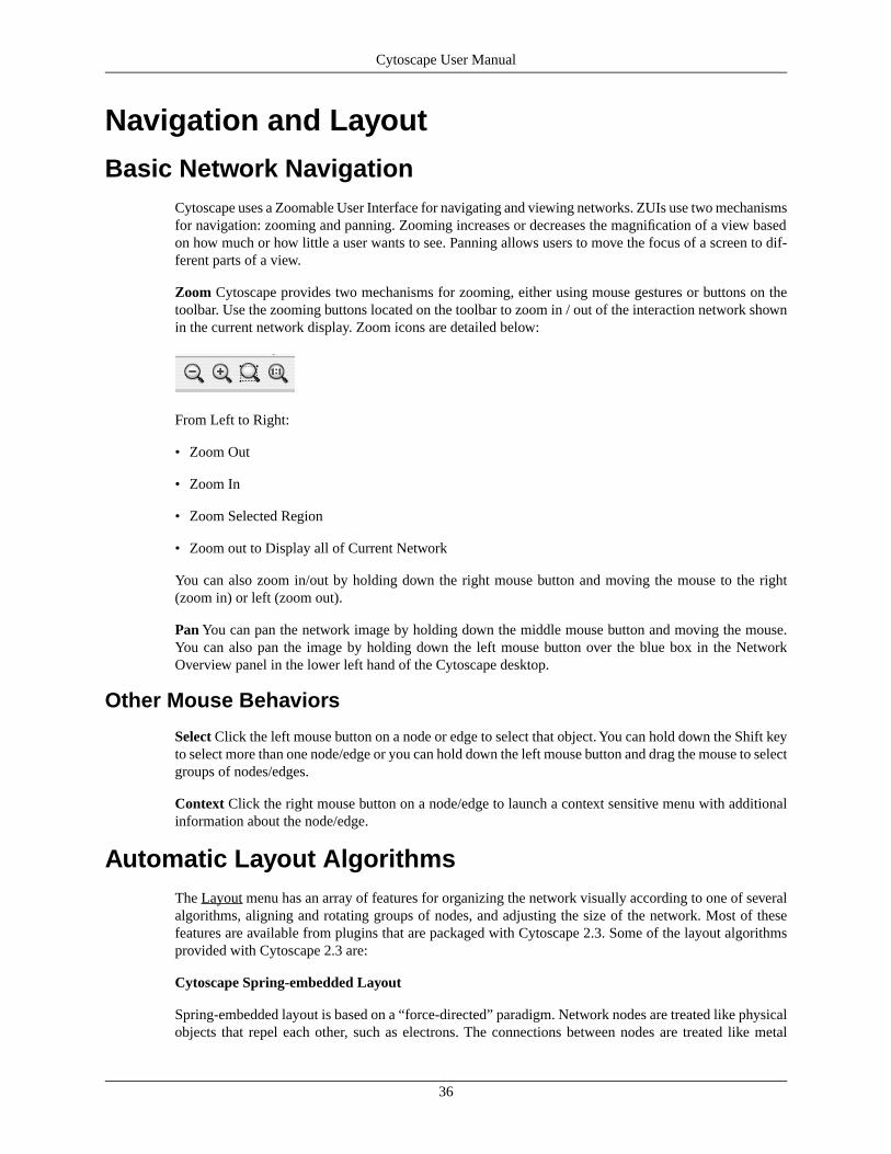
Zoom Cytoscape provides two mechanisms for zooming, either using mouse gestures or buttons on thetoolbar. Use the zooming buttons located on the toolbar to zoom in / out of the interaction network shownin the current network display. Zoom icons are detailed below:
From Left to Right:
• Zoom Out
• Zoom In
• Zoom Selected Region
• Zoom out to Display all of Current Network
You can also zoom in/out by holding down the right mouse button and moving the mouse to the right(zoom in) or left (zoom out).
Pan You can pan the network image by holding down the middle mouse button and moving the mouse.You can also pan the image by holding down the left mouse button over the blue box in the NetworkOverview panel in the lower left hand of the Cytoscape desktop.
Other Mouse Behaviors
Select Click the left mouse button on a node or edge to select that object. You can hold down the Shift keyto select more than one node/edge or you can hold down the left mouse button and drag the mouse to selectgroups of nodes/edges.
Context Click the right mouse button on a node/edge to launch a context sensitive menu with additionalinformation about the node/edge.
Automatic Layout AlgorithmsThe Layout menu has an array of features for organizing the network visually according to one of severalalgorithms, aligning and rotating groups of nodes, and adjusting the size of the network. Most of thesefeatures are available from plugins that are packaged with Cytoscape 2.3. Some of the layout algorithmsprovided with Cytoscape 2.3 are:
Cytoscape Spring-embedded Layout
Spring-embedded layout is based on a “force-directed” paradigm. Network nodes are treated like physicalobjects that repel each other, such as electrons. The connections between nodes are treated like metal
36
Cytoscape User Manual

springs attached to the pair of nodes. These springs repel or attract their end points according to a forcefunction. The layout algorithm sets the positions of the nodes in a way that minimizes the sum of forcesin the network. This algorithm is available from the Layout → Cytoscape Layouts → Spring Embeddedmenu item. A sample screen shot is provided below:
yFiles Circular Layout
This algorithm produces layouts that emphasize group and tree structures within a network. It partitionsthe network by analyzing its connectivity structure, and arranges the partitions as separate circles. Thecircles themselves are arranged in a radial tree layout fashion. This algorithm is available from the Layout→ yFiles → Circular menu item.
yFiles Hierarchical Layout
The hierarchical layout algorithm is good for representing main direction or flow within a network. Nodesare placed in hierarchically arranged layers and the ordering of the nodes within each layer is chosen in
37
Cytoscape User Manual
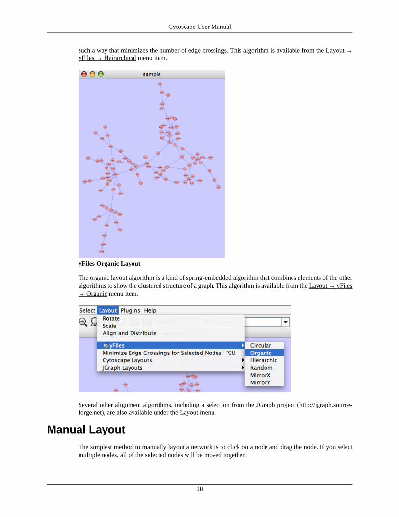
such a way that minimizes the number of edge crossings. This algorithm is available from the Layout →yFiles → Heirarchical menu item.
yFiles Organic Layout
The organic layout algorithm is a kind of spring-embedded algorithm that combines elements of the otheralgorithms to show the clustered structure of a graph. This algorithm is available from the Layout → yFiles→ Organic menu item.
Several other alignment algorithms, including a selection from the JGraph project (http://jgraph.source-forge.net), are also available under the Layout menu.
Manual LayoutThe simplest method to manually layout a network is to click on a node and drag the node. If you selectmultiple nodes, all of the selected nodes will be moved together.
38
Cytoscape User Manual

Edge Handles
A little known feature! If you select an edge and then Ctrl-left-click on the edge, an edge "handle" willappear. This handle can be used to change the shape of the line. To remove a handle, simply Ctrl-left-clickon the handle again.
The Select → Edges menu has two menu items that provide further control: "Smooth Selected Edges"turns an edge consisting of line segments into a smoothed bezier curve, and "Straighen Selected Edges"turns a curved edge back into line segments.
Rotate
The Layout → Rotate menu opens the Rotate dialog. Rotate will either rotate the entire network or a selectedportion of the network. The image below shows a network with selected nodes rotated.
Before
39
Cytoscape User Manual

After
Scale
The Layout → Scale menu opens the Scale dialog. Scale will scale the position of the entire network orof the selected portion of the network. Note that only the position of the nodes scale, not the node sizes.Node size can be adjusted using the VizMapper. The image below shows selected nodes scaled.
Before
40
Cytoscape User Manual
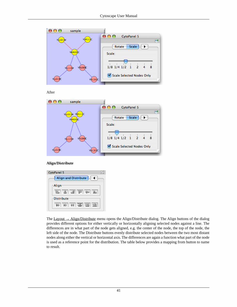
After
Align/Distribute
The Layout → Align/Distribute menu opens the Align/Distribute dialog. The Align buttons of the dialogprovides different options for either vertically or horizontally aligning selected nodes against a line. Thedifferences are in what part of the node gets aligned, e.g. the center of the node, the top of the node, theleft side of the node. The Distribute buttons evenly distribute selected nodes between the two most distantnodes along either the vertical or horizontal axis. The differences are again a function what part of the nodeis used as a reference point for the distribution. The table below provides a mapping from button to nameto result.
41
Cytoscape User Manual

Table 13.
Description of Align OptionsAfterBeforeButton
Vertical Align Top - The tops of the selected nodes are aligned with the top-mostnode.
Vertical Align Center - The centers of selected nodes are aligned along a linedefined by the midpoint between the top and bottom-most nodes.
Vertical Align Bottom - The bottoms of the nodes are aligned with the bottom-most node.
Horizontal Align Left - The left hand sides of the selected nodes are aligned withthe left-most node.
Horizontal Align Center - The centers of selected nodes are aligned along a linedefined by the midpoint between the left and right-most nodes.
Horizontal Align Right - The right hand sides of the selected nodes are alignedwith the right-most node.
Table 14.
Description of Distribute OptionsAfterB e -fore
Button
Vertical Distribute Top - The tops of the selected nodes are distributed evenlybetween the top-most and bottom-most nodes, which should stay stationary.
Vertical Distribute Center - The centers of the selected nodes are distributed evenlybetween the top-most and bottom-most nodes, which should stay stationary.
Vertical Distribute Bottom - The bottoms of the selected nodes are distributedevenly between the top-most and bottom-most nodes, which should stay stationary.
Horizontal Distribute Left - The left hand sides of the selected nodes are distributedevenly between the left-most and rigth-most nodes, which should stay stationary.
Horizontal Distribute Center - The centers of the selected nodes are distributedevenly between the left-most and rigth-most nodes, which should stay stationary.
Horizontal Distribute Right - The right hand sides of the selected nodes are distrib-uted evenly between the left-most and rigth-most nodes, which should stay station-ary.
Node Movement and Placement
In addition to the ability to click on a node and drag it to a new position, Cytoscape now has the abilitymove nodes using the arrow keys on the keyboard. By selecting one or more nodes using the mouse andclicking one of the arrow keys (←, →, ↑, ↓) the selected nodes will move one pixel in the chosen direction.If an arrow key is pressed while holding the shift key down, the selected nodes will 10 pixels in the chosendirection.
Mouse movement has also been enhanced. If the shift key is held down while dragging a node, the nodewill only move horizontally, vertically, or along a 45 degree diagonal.
42
Cytoscape User Manual

Visual StylesWith the Cytoscape Visual Style feature, you can easily customize the visual appearance of your network.For example, you can:
• specify a default color and shape for all nodes.
• use specific line types to indicate different types of interactions, or
• visualize gene expression data along a color gradient.
All these features are available by selecting the View → Open Viz Mapper menu item or clicking on theV i z M a p p e r i c o n
button on the main button bar.
Introduction to Visual StylesThe Cytoscape distribution includes several predefined visual styles to get you started. To demonstratethese styles, try out the following example:
• Load a sample network: From the main menu, select File → Import → Network, and selectsampleData/galFiltered.sif.
• Layout the network: select Layout → yFiles → Organic.
• Load a sample set of expression data: From the main menu, select File → Import → Attribute Matrixand select sampleData/galExpData.pvals.
By default, the Visual Style labeled “default” will be automatically applied to your network. This defaultstyle has a blue background, circular pink nodes, and blue edges (see sample screenshot below).
43
Cytoscape User Manual

Figure: Using the default Visual Style.
You can change visual styles by making a selection from the Visual Style pull down menu (available directlyt o t h e r i g h t o f t h e
icon).
For example, if you select “Sample1”, a new visual style will be applied to your network, and you will seea white background and round blue nodes. Additionally, if you zoom in closer, you can see that protein-DNA interactions (specified with the label: pd) are drawn with dashed red edges, whereas protein-proteininteractions (specified with the label: pp) are drawn with a light blue color (see sample screenshot below).
44
Cytoscape User Manual

Figure: Using the Sample1 Visual Style. Protein-Protein interactions (solid blue lines) are now dis-tinguishable from Protein-DNA interactions (dashed red lines).
Finally, if you select “Sample2”, gene expression values for each node will be colored along a colorgradient between red and green (where red represents a low expression ratio, and green represents a highexpression ratio - with thresholds set for the gal1RGexp experiment bundled with Cytoscape in thesampleData/galExpData.pvals file). See sample screenshot below:
45
Cytoscape User Manual
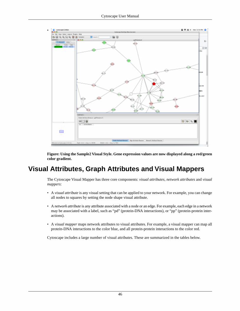
•
Figure: Using the Sample2 Visual Style. Gene expression values are now displayed along a red/greencolor gradient.
Visual Attributes, Graph Attributes and Visual MappersThe Cytoscape Visual Mapper has three core components: visual attributes, network attributes and visualmappers:
• A visual attribute is any visual setting that can be applied to your network. For example, you can changeall nodes to squares by setting the node shape visual attribute.
• A network attribute is any attribute associated with a node or an edge. For example, each edge in a networkmay be associated with a label, such as “pd” (protein-DNA interactions), or “pp” (protein-protein inter-actions).
• A visual mapper maps network attributes to visual attributes. For example, a visual mapper can map allprotein-DNA interactions to the color blue, and all protein-protein interactions to the color red.
Cytoscape includes a large number of visual attributes. These are summarized in the tables below.
46
Cytoscape User Manual
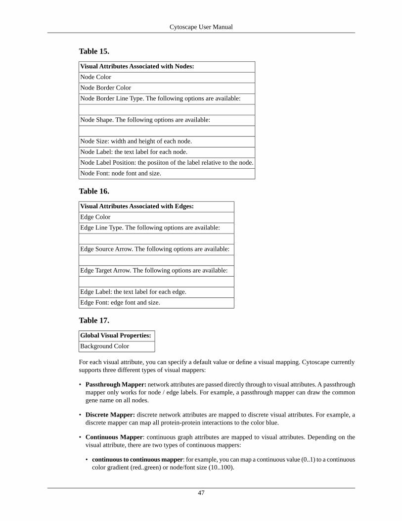
Table 15.
Visual Attributes Associated with Nodes:
Node Color
Node Border Color
Node Border Line Type. The following options are available:
Node Shape. The following options are available:
Node Size: width and height of each node.
Node Label: the text label for each node.
Node Label Position: the posiiton of the label relative to the node.
Node Font: node font and size.
Table 16.
Visual Attributes Associated with Edges:
Edge Color
Edge Line Type. The following options are available:
Edge Source Arrow. The following options are available:
Edge Target Arrow. The following options are available:
Edge Label: the text label for each edge.
Edge Font: edge font and size.
Table 17.
Global Visual Properties:
Background Color
For each visual attribute, you can specify a default value or define a visual mapping. Cytoscape currentlysupports three different types of visual mappers:
• Passthrough Mapper: network attributes are passed directly through to visual attributes. A passthroughmapper only works for node / edge labels. For example, a passthrough mapper can draw the commongene name on all nodes.
• Discrete Mapper: discrete network attributes are mapped to discrete visual attributes. For example, adiscrete mapper can map all protein-protein interactions to the color blue.
• Continuous Mapper: continuous graph attributes are mapped to visual attributes. Depending on thevisual attribute, there are two types of continuous mappers:
• continuous to continuous mapper: for example, you can map a continuous value (0..1) to a continuouscolor gradient (red..green) or node/font size (10..100).
47
Cytoscape User Manual

• continuous to discrete mapper: for example, all values below 0 are mapped to square nodes, andall values above 0 are mapped to circular nodes. However, there is no way to smoothly morph betweencircular nodes and square nodes.
The matrix below shows visual mapper support for each visual property.
Table 18.
Continuous MapperDiscrete MapperPassthrough MapperNode Properties
XX-Node Color
XX-Node Border Color
oX-Node Border Type
oX-Node Shape
XX-Node Size
oXXNode Label
oX-Node Font Family
XX-Node Font Size
Continuous MapperDiscrete MapperPassthrough MapperEdge Properties
XX-Edge Color
oX-Edge Line Type
oX-Edge Source Arrow
oX-Edge Target Arrow
oXXEdge Label
oX-Edge Font Family
XX-Edge Font Size
Legend
Table 19.
DescriptionSymbol
Mapping is not supported for specified visual property.-
Mapping is fully supported for specified visual property.X
Mapping is partially supported for specified visual property. Support for “continuous to continuous”mapping is not supported.
o
Visual Styles Tutorials
Tutorial 1: Creating a Basic Visual Style
To create a new visual style, select the View → Open Viz Mapper menu item, or select the VizMap iconin the main button bar. You will now see a new Visual Styles dialog box (shown below.)
48
Cytoscape User Manual

Click the New button, and enter a name for your new visual style when prompted. Then click the Definebutton. You will now see the main Visual Styles Properties dialog box (shown below.)
From this dialog box, you can flip between Node Attributes, Edge Attributes, and Global Defaults. Youcan also specify default values for any visual property, or define a new custom mapping.
For example, to set the default node shape to triangles, select Node Attributes → Node Shape. Then, clickthe Change Default button, and select the Triangle icon from the selection list.
To apply your visual style to your network, hit the Apply to Network button, available in the bottom ofthe dialog panel.
Tutorial 2: Creating a New Visual Style with a Discrete Mapper
The following tutorial demonstrates how to create a new visual style with a discrete mapper. The goal isto draw Protein-DNA interactions with blue edges, and Protein-Protein interactions with red edges.
49
Cytoscape User Manual
• Load a sample network: From the main menu, select File → Import → Network, and selectsampleData/galFiltered.sif.
• C l i c k t h e V i z M a p
button on the tool bar.
• Select New to create a new Visual Style. Name your new style: “Sample3”.
• Click the Define button to define the newly created Visual Style.
• In the “Set Visual Properties” Dialog box, select Edge Attributes → Edge Color.
• Click the New button in the mapping panel.
• You will be prompted to select a mapping type: passthrough mapper, discrete mapper or continuousmapper (for an overview of the differences between these mappers, please refer to the text above) Select“discrete mapper”, and enter a descriptive name. For example, enter: Interaction_Type_Color.
• From the “Map Attribute” pull-down menu, select “interaction.” You should now see two buttons, onefor pd (Protein-DNA interactions), and one for pp (Protein-Protein interactions).
• Click the “pd” button and select a blue color.
• Click the “pp” button and select a red color.
• Click the “Apply to Network" button.
You network should now show “pd” interactions in blue, and “pp” interactions in red. Sample screenshotis below
50
Cytoscape User Manual

Tutorial 3: Visualizing Expression Data on a Network
The following tutorial demonstrates how to create a new continuous mapper. The goal is to superimposegene expression data onto a network, and to display gene expression values along a color gradient.
• Load a sample network: From the main menu, select File → Import → Network, and selectsampleData/galFiltered.sif.
• Load a sample set of expression data: From the main menu, select File → Import → Attribute Matrixand select sampleData/galExpData.pvals.
• C l i c k t h e V i z M a p
button on the tool bar.
• Select “New” to create a new Visual Style. Name your new style: “Sample4”.
• Click the “Define” button to define the newly created Visual Style.
• In the “Set Visual Properties” Dialog box, select Node Attributes → Node Color.
• Click the New button in the mapping panel.
• You will be prompted to select a mapping type: passthrough mapper, discrete mapper or continuousmapper (for an overview of the differences between these mappers, please refer to the section above)Select “continuous mapper”, and enter a descriptive name. For example, enter: Color_Gradient.
51
Cytoscape User Manual
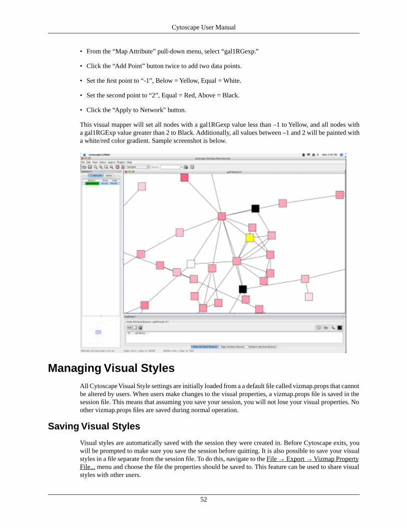
• From the “Map Attribute” pull-down menu, select “gal1RGexp.”
• Click the “Add Point” button twice to add two data points.
• Set the first point to “-1”, Below = Yellow, Equal = White.
• Set the second point to “2”, Equal = Red, Above = Black.
• Click the “Apply to Network" button.
This visual mapper will set all nodes with a gal1RGexp value less than –1 to Yellow, and all nodes witha gal1RGExp value greater than 2 to Black. Additionally, all values between –1 and 2 will be painted witha white/red color gradient. Sample screenshot is below.
Managing Visual StylesAll Cytoscape Visual Style settings are initially loaded from a a default file called vizmap.props that cannotbe altered by users. When users make changes to the visual properties, a vizmap.props file is saved in thesession file. This means that assuming you save your session, you will not lose your visual properties. Noother vizmap.props files are saved during normal operation.
Saving Visual Styles
Visual styles are automatically saved with the session they were created in. Before Cytoscape exits, youwill be prompted to make sure you save the session before quitting. It is also possible to save your visualstyles in a file separate from the session file. To do this, navigate to the File → Export → Vizmap PropertyFile... menu and choose the file the properties should be saved to. This feature can be used to share visualstyles with other users.
52
Cytoscape User Manual
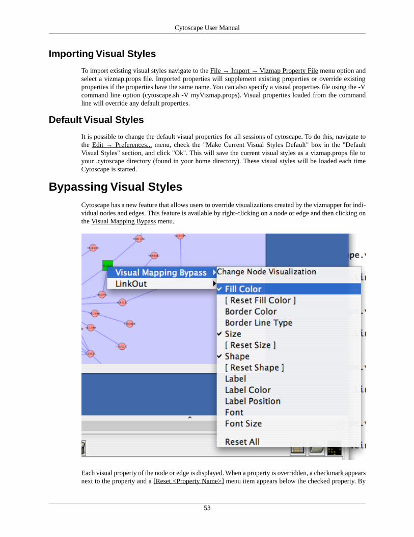
Importing Visual Styles
To import existing visual styles navigate to the File → Import → Vizmap Property File menu option andselect a vizmap.props file. Imported properties will supplement existing properties or override existingproperties if the properties have the same name. You can also specify a visual properties file using the -Vcommand line option (cytoscape.sh -V myVizmap.props). Visual properties loaded from the commandline will override any default properties.
Default Visual Styles
It is possible to change the default visual properties for all sessions of cytoscape. To do this, navigate tothe Edit → Preferences... menu, check the "Make Current Visual Styles Default" box in the "DefaultVisual Styles" section, and click "Ok". This will save the current visual styles as a vizmap.props file toyour .cytoscape directory (found in your home directory). These visual styles will be loaded each timeCytoscape is started.
Bypassing Visual StylesCytoscape has a new feature that allows users to override visualizations created by the vizmapper for indi-vidual nodes and edges. This feature is available by right-clicking on a node or edge and then clicking onthe Visual Mapping Bypass menu.
Each visual property of the node or edge is displayed. When a property is overridden, a checkmark appearsnext to the property and a [Reset <Property Name>] menu item appears below the checked property. By
53
Cytoscape User Manual

clicking the [Reset <Property Name>] option the bypass will be removed and the attribute will be displayedas defined by the VizMapper. At the bottom of the menu a Reset All option appears. When clicked, thiswill be remove all bypasses for the specified node or edge. In the example above you can see the the selectednode size, color, and shape have been overridden. This is apparent in the appearance of the node itself andby the check marks in the popup menu.
It is important to realize that the the Visual Mapping Bypass only works for individual nodes and edgesand not for all nodes or edges of a specific type. Using bypass is not particularly resource intensive,meaning you can use it as much as you like. However, if you ever find yourself repeating the same bypasses,then you should consider using the VizMapper instead.
Bypass is accomplished using special attributes with names like node.fillColor and node.shape. These arenormal Cytoscape attributes and can be seen an editted in the Attribute Browser. The value of the attributeis a string representation of a property. For example, color is represented by 3 integers representing theRGB (red, green, blue) value of the color. Different types of properties have different string representations.When in doubt, just use the right click menu to create valid attribute values.
Because bypass values are specified using normal attributes, these attributes will persist between sessionsas long as you save your session! If you don't save your session, you will lose whatever bypass values youset.
Finding and Filtering Nodes and Edges
QuickFindCytoscape now includes a new Quick Find feature, which enables you to quickly find nodes and edges.
Using Quick Find is very simple. Here is how it works:
• Import up a network. For example, load up sampleData/galFiltered.sif
• Start typing in the text box. For example, enter "yd". The search box will automatically display a list ofall matching nodes.
54
Cytoscape User Manual
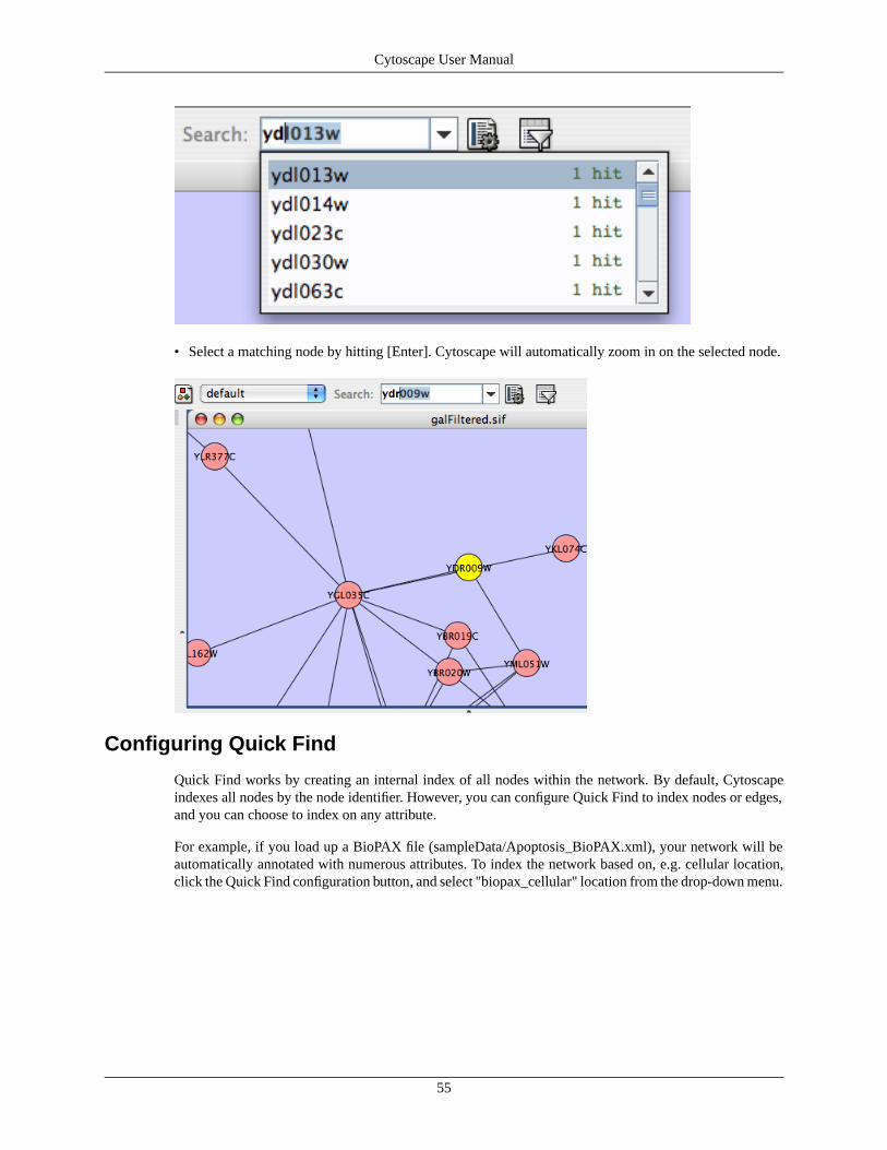
• Select a matching node by hitting [Enter]. Cytoscape will automatically zoom in on the selected node.
Configuring Quick Find
Quick Find works by creating an internal index of all nodes within the network. By default, Cytoscapeindexes all nodes by the node identifier. However, you can configure Quick Find to index nodes or edges,and you can choose to index on any attribute.
For example, if you load up a BioPAX file (sampleData/Apoptosis_BioPAX.xml), your network will beautomatically annotated with numerous attributes. To index the network based on, e.g. cellular location,click the Quick Find configuration button, and select "biopax_cellular" location from the drop-down menu.
55
Cytoscape User Manual

You can then quickly find all proteins located in the "plasma membrane" by just typing "p".
Tip: If you don't know what to search for, just leave the search box empty, and click on the down arrowdirectly next to the search box. Cytoscape will provide you with an initial list of matches. In the case below,we get a list of all distinct cellular locations in the network.
56
Cytoscape User Manual

Dynamic Filtering via Quick Find
If you choose to index on a numerical attribute, the Cytoscape search box changes to a dynamic slider forquick filtering.
For example:
• Import a network: sampleData/galFiltered.sif. File → Import → Network.
• Import an expression data file: sampleData/galExpData.pvals. File → Import → Attribute / ExpressionMatrix
• Index Quick Find on the gal1RGExp attribute
• Use the slider widget to automatically filter the entire network
57
Cytoscape User Manual
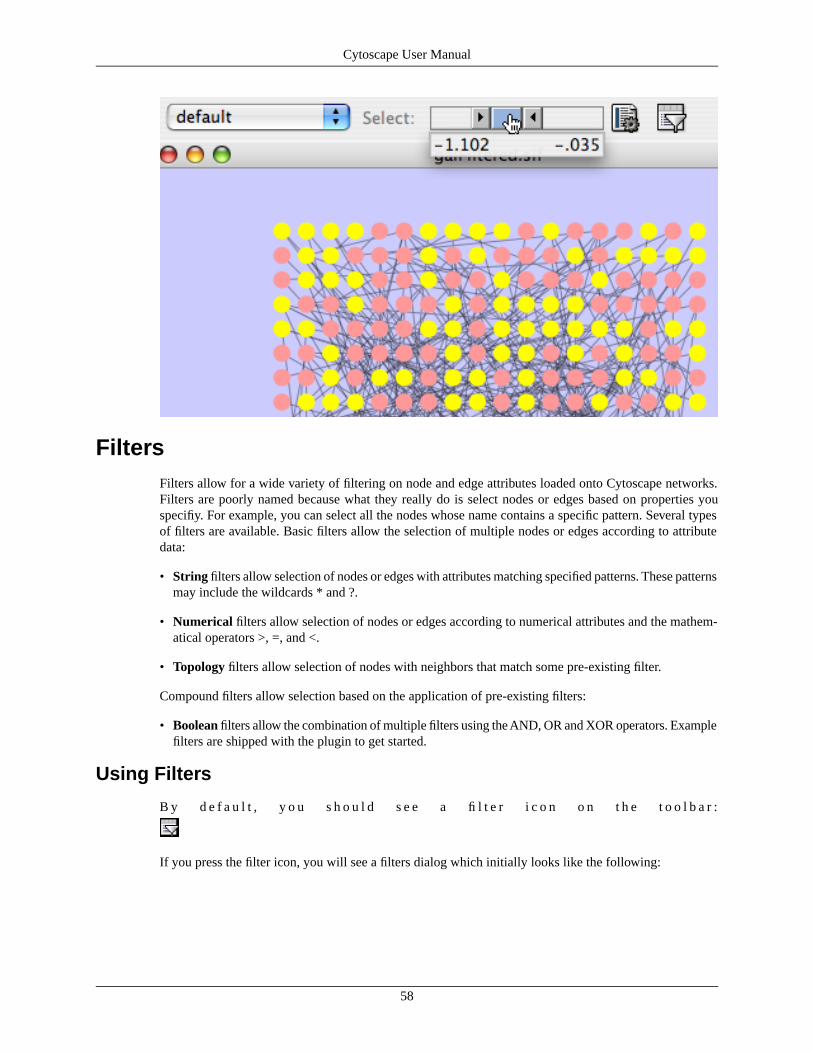
FiltersFilters allow for a wide variety of filtering on node and edge attributes loaded onto Cytoscape networks.Filters are poorly named because what they really do is select nodes or edges based on properties youspecifiy. For example, you can select all the nodes whose name contains a specific pattern. Several typesof filters are available. Basic filters allow the selection of multiple nodes or edges according to attributedata:
• String filters allow selection of nodes or edges with attributes matching specified patterns. These patternsmay include the wildcards * and ?.
• Numerical filters allow selection of nodes or edges according to numerical attributes and the mathem-atical operators >, =, and <.
• Topology filters allow selection of nodes with neighbors that match some pre-existing filter.
Compound filters allow selection based on the application of pre-existing filters:
• Boolean filters allow the combination of multiple filters using the AND, OR and XOR operators. Examplefilters are shipped with the plugin to get started.
Using Filters
B y d e f a u l t , y o u s h o u l d s e e a fi l t e r i c o n o n t h e t o o l b a r :
If you press the filter icon, you will see a filters dialog which initially looks like the following:
58
Cytoscape User Manual

If the first filter is selected, then the dialog looks as shown:
Filter Panels:
The right panel: An existing or newly created filter can be edited in this area. Each filter type has its ownuser interface for editing.
The low left panel: All available filters are shown in this list. Initially, this list will contain sample filters,but as you create more, they will be added here.
The up left panel: Pressing “Create new filter” adds a filter to the “Available Filters” box, and “Removeselected filter” deletes the currently selected filter.
Creating Filters
The “Create new filter” button brings up the Filter creation dialog box, shown below.
59
Cytoscape User Manual

The important thing to realize when creating a filter is that the filter does not do anything by itself. Oncecreated, the filter must be run.
String Filter:
The String Filter allows you to filter nodes or edges by a given string node or edge attribute. Attributesthat are loaded on the network are available for filtering against. Search terms are entered in the text boxat the bottom. For example to match any Node whose canonicalName starts with “YDL” you would select“Node”, “canonicalName” and type “YDL*”. The * is important as it matches any number of charactersafter YDL. If you want to be more specific and only select nodes whose canonicalName starts with YDL00followed by any other two characters, you would type “YDL00??”. The “?” denotes any single character,while the “*” represents zero or more characters. Full regular expression searching is supported, althoughis not covered here. Once the filter is defined, it will be assigned a default descriptive name.
60
Cytoscape User Manual
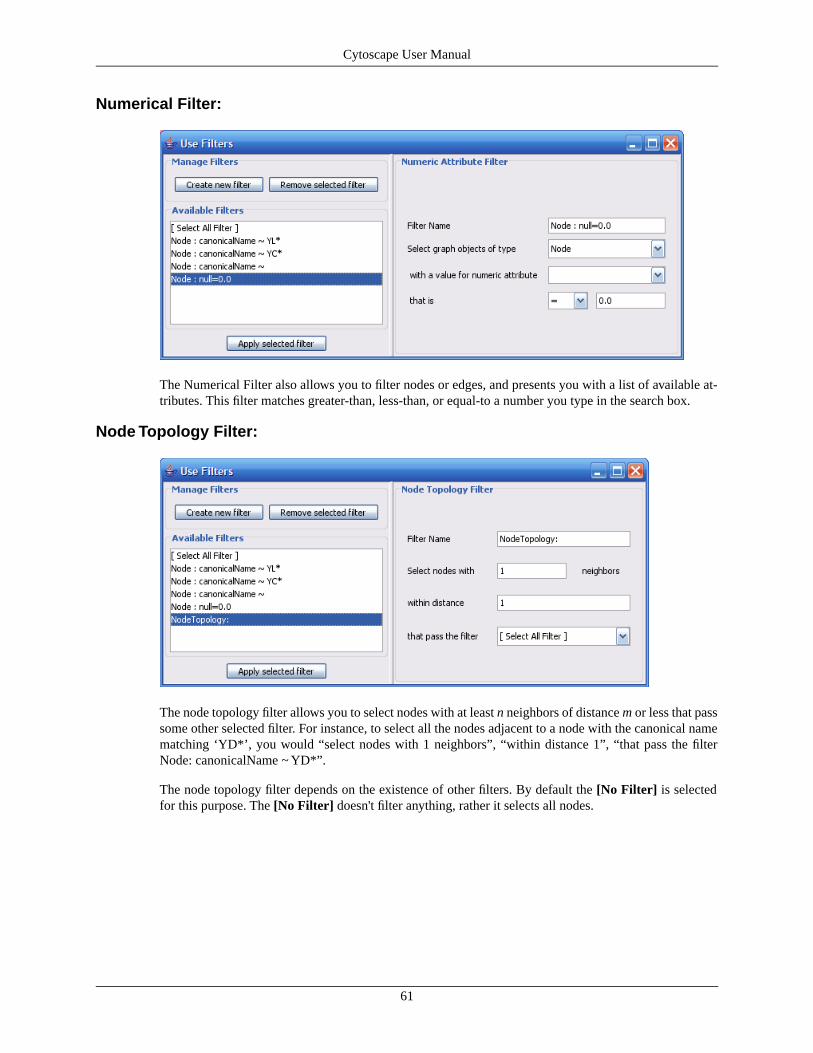
Numerical Filter:
The Numerical Filter also allows you to filter nodes or edges, and presents you with a list of available at-tributes. This filter matches greater-than, less-than, or equal-to a number you type in the search box.
Node Topology Filter:
The node topology filter allows you to select nodes with at least n neighbors of distance m or less that passsome other selected filter. For instance, to select all the nodes adjacent to a node with the canonical namematching ‘YD*’, you would “select nodes with 1 neighbors”, “within distance 1”, “that pass the filterNode: canonicalName ~ YD*”.
The node topology filter depends on the existence of other filters. By default the [No Filter] is selectedfor this purpose. The [No Filter] doesn't filter anything, rather it selects all nodes.
61
Cytoscape User Manual

Boolean Filter:
The Boolean Meta-Filter allows you to define a new filter that is a logical combination of existing filters.Available filters are displayed. By selecting one or more filters, you can then choose whether Nodes orEdges pass “ALL” (AND), “AT LEAST ONE” (OR), or “ONLY ONE” (XOR) of the selected filters.Once created Boolean filters can then themselves be combined using the Boolean filter to create arbitrarilycomplex logical combinations of filters. Note that unlike the String and Numerical Filters, Boolean Filterswill need to be assigned a name manually.
Saving Filters
Filters are currently saved automatically in the filters.props file found in the .cytoscape directory, foundin each user's home directory. Once created, filters are saved for future sessions, as long as you exit Cyto-scape normally via the exit command in the File menu (i.e. not via ctrl-c on Linux).
Running filters
Any available filter can be run by pressing the ‘Apply selected filter’ button. When a filter is applied andmultiple nodes or edges are selected, all of the normal selection-related operations may be performed, suchas Delete Selected Node/Edges, Copy To New Network, and Invert Selection.
Select MenuThe Select → Nodes and Select → Edges menus provide several mechanisms for selecting nodes andedges. Most options are fairly straightforward, however some need extra explanation.
Select → Nodes → By Name... selects nodes by the node identifier (ID). This is the value seen in the left-most column of the attribute browser. This does not change if the node label changes!
Select → Nodes → From File... selects nodes based on node identifiers found in a specified file. The fileformat is simply one node id per line:
Node1Node2Node3...
62
Cytoscape User Manual

Editing NetworksUsing Cytoscape's Editor, you can build and modify networks interactively by dragging and droppingnodes and edges from a palette onto the main network view window. The palette contains a set of shapes(for nodes) and arrows (for edges). The shapes on the palette are defined by the current Visual Style, withNode Shape and Node Color mapping into the shape and color of a node, and Edge Target Arrow mappinginto the target arrow of an edge. An example of an editor, with the palette contained in CytoPanel 1, isshown below.
To edit an existing network, just select the Editor tab in CytoPanel 1. To start editing a new network, usethe File → New → Network → Empty Network menu item.
The figure below shows the editor with palette defined by "Default" visual style.
63
Cytoscape User Manual
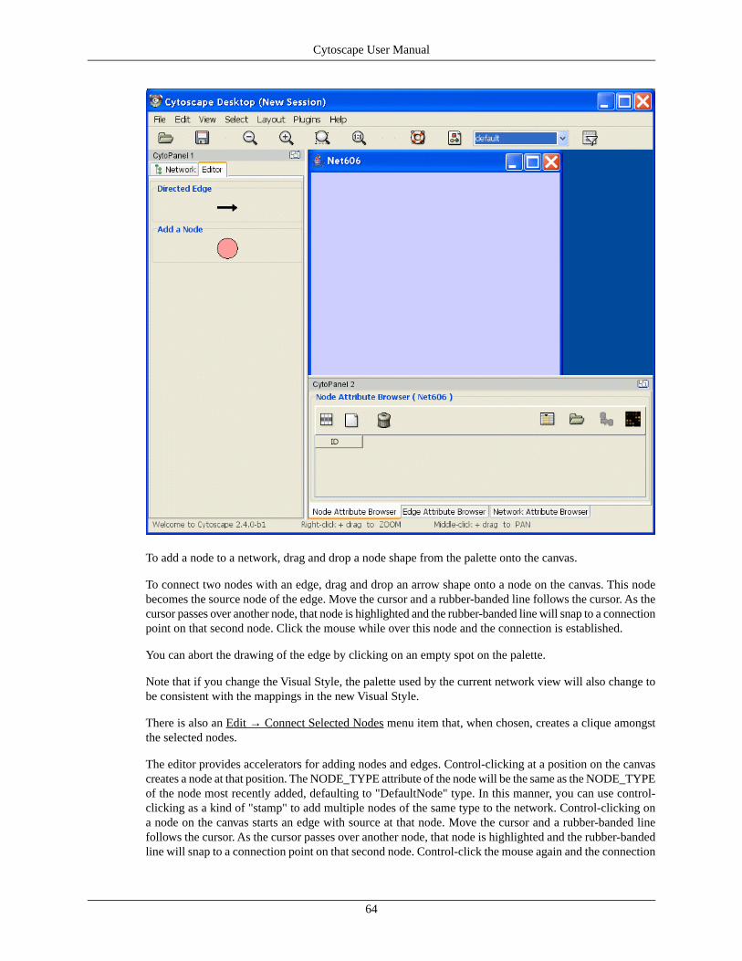
To add a node to a network, drag and drop a node shape from the palette onto the canvas.
To connect two nodes with an edge, drag and drop an arrow shape onto a node on the canvas. This nodebecomes the source node of the edge. Move the cursor and a rubber-banded line follows the cursor. As thecursor passes over another node, that node is highlighted and the rubber-banded line will snap to a connectionpoint on that second node. Click the mouse while over this node and the connection is established.
You can abort the drawing of the edge by clicking on an empty spot on the palette.
Note that if you change the Visual Style, the palette used by the current network view will also change tobe consistent with the mappings in the new Visual Style.
There is also an Edit → Connect Selected Nodes menu item that, when chosen, creates a clique amongstthe selected nodes.
The editor provides accelerators for adding nodes and edges. Control-clicking at a position on the canvascreates a node at that position. The NODE_TYPE attribute of the node will be the same as the NODE_TYPEof the node most recently added, defaulting to "DefaultNode" type. In this manner, you can use control-clicking as a kind of "stamp" to add multiple nodes of the same type to the network. Control-clicking ona node on the canvas starts an edge with source at that node. Move the cursor and a rubber-banded linefollows the cursor. As the cursor passes over another node, that node is highlighted and the rubber-bandedline will snap to a connection point on that second node. Control-click the mouse again and the connection
64
Cytoscape User Manual

is established. The EDGE_TYPE attribute of the edge will be the same as the EDGE_TYPE of the edgemost recently added, defaulting to "DefaultEdge" type. You can abort the drawing of the edge by control-clicking on an empty spot on the palette.
You can delete nodes and edges by selecting a number of nodes and edges, then selecting the Edit → DeleteSelected Nodes and Edges menu item. You can recover any nodes and edges deleted from a network byselecting the Edit → Undo menu item. Note that this will restore all nodes and edges that were previouslydeleted from the network, not just those deleted by the most recent delete operation.
CytoPanelsWhat are CytoPanels?
CytoPanels are floatable / dockable panels designed to cut down on the number of pop-up windows withinCytoscape and to create a more unified user experience. The following screenshot shows the galFiltered.siffile loaded into Cytoscape. In CytoPanel 1, the CytoPanel on the left-hand side of the screen, the NetworkManager, Network Overview, and Cytoscape Editor have been loaded. In addition, in CytoPanel 2, theNode Attribute Browser has been loaded.
The user can then chose to resize, hide or float the left CytoPanel. For example, in the screenshot below,the user has chosen to float CytoPanel 1:
65
Cytoscape User Manual

Basic Usage
Cytoscape 2.2 includes three CytoPanels: CytoPanel 1 (appears on the left), CytoPanel 2 (appears on thebottom), and CytoPanel 3 (appears on the right). By default, CytoPanel 1 and CytoPanel 2 will appear.CytoPanel 3 may appear depending on the mix of PlugIns currently installed in your Cytoscape distribution.
CytoPanels can be shown or hidden by selecting the desired menu item within the CytoPanels menu.
In addition, CytoPanels can be floated or docked by selected the icon at the top-right corner of eachCytoPanel. The icon and tooltip will change based on the CytoPanel state. If the CytoPanel is docked,clicking on the icon will float the CytoPanel, as indicated by the “Float Window” tooltip. Alternatively, ifthe CytoPanel is floating, clicking on the icon will dock the CytoPanel, as indicated by the “Dock Window”tooltip.
•
66
Cytoscape User Manual
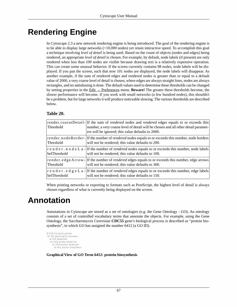
Rendering EngineIn Cytoscape 2.3 a new network rendering engine is being introduced. The goal of the rendering engine isto be able to display large networks (>10,000 nodes) yet retain interactive speed. To accomplish this goala technique involving level of detail is being used. Based on the count of objects (nodes and edges) beingrendered, an appropriate level of detail is chosen. For example, by default, node labels (if present) are onlyrendered when less than 100 nodes are visible because drawing text is a relatively expensive operation.This can create some unusual behavior. If the screen currently contains 98 nodes, node labels will be dis-played. If you pan the screen, such that now 101 nodes are displayed, the node labels will disappear. Asanother example, if the sum of rendered edges and rendered nodes is greater than or equal to a defaultvalue of 2000, a very coarse level of detail is chosen, where edges are always straight lines, nodes are alwaysrectangles, and no antialiasing is done. The default values used to determine these thresholds can be changedby setting properties in the Edit → Preferences menu. Beware! The greater these thresholds become, theslower performance will become. If you work with small networks (a few hundred nodes), this shouldn'tbe a problem, but for large networks it will produce noticeable slowing. The various thresholds are describedbelow.
Table 20.
If the sum of rendered nodes and rendered edges equals to or exceeds thisnumber, a very coarse level of detail will be chosen and all other detail paramet-ers will be ignored; this value defaults to 2000.
render.coarseDetail-Threshold
If the number of rendered nodes equals to or exceeds this number, node borderswill not be rendered; this value defaults to 200.
r ende r.nodeBorde r-Threshold
If the number of rendered nodes equals to or exceeds this number, node labelswill not be rendered; this value defaults to 100.
r e n d e r . n o d e L a -belThreshold
If the number of rendered edges equals to or exceeds this number, edge arrowswill not be rendered; this value defaults to 300.
r e n d e r. e d g e A r r ow -Threshold
If the number of rendered edges equals to or exceeds this number, edge labelswill not be rendered; this value defaults to 150.
r e n d e r . e d g e L a -belThreshold
When printing networks or exporting to formats such as PostScript, the highest level of detail is alwayschosen regardless of what is currently being displayed on the screen.
AnnotationAnnotations in Cytoscape are stored as a set of ontologies (e.g. the Gene Ontology - GO). An ontologyconsists of a set of controlled vocabulary terms that annotate the objects. For example, using the GeneOntology, the Saccharomyces Cerevisiae CDC55 gene’s biological process is described as “protein bio-synthesis”, to which GO has assigned the number 6412 (a GO ID).
GO 8150 biological_process GO 7582 physiological processes GO 8152 metabolism GO 44238 primary metabolism GO 19538 protein metabolism GO 6412 protein biosynthesis
Graphical View of GO Term 6412: protein biosynthesis
67
Cytoscape User Manual

Cytoscape can use this ontology DAG (Directed Acyclic Graph) to annotate objects in networks. TheOntology Server (originally called Bio Data Server) is a Cytoscape feature which allows you to load,navigate, and assign annotation terms to nodes and edges in a network. In version 2.4, Cytoscape has en-hanced GUI for loading ontology and associated annotation, which enables you to load both local and remotefiles.
Ontology and Annotation File FormatThe standard file formats used in Cytoscape Ontology Server are OBO and Gene Association. The GOwebsite details these file formats:
• Ontologies and Definitions: http://www.geneontology.org/GO.downloads.shtml#ont
• Current Annotations: http://www.geneontology.org/GO.current.annotations.shtml
OBO File
OBO file is the ontology DAG itself. This file defines relationships of ontology terms. Since version 2.4,Cytoscape can load all ontology files written in OBO format. The full listing of ontology files are availablefrom Open Biomedical Ontologies (OBO) website:
• OBO Ontology Browser: http://obo.sourceforge.net/browse.html
Sample OBO File - gene_ontology.obo: http://www.geneontology.org/ontology/gene_ontology_edit.obo
format-version: 1.2date: 27:11:2006 17:12saved-by: midoriauto-generated-by: OBO-Edit 1.002subsetdef: goslim_generic "Generic GO slim"subsetdef: goslim_goa "GOA and proteome slim"subsetdef: goslim_plant "Plant GO slim"subsetdef: goslim_yeast "Yeast GO slim"subsetdef: gosubset_prok "Prokaryotic GO subset"default-namespace: gene_ontologyremark: cvs version: $Revision: 5.49 $
[Term]id: GO:0000001name: mitochondrion inheritancenamespace: biological_processdef: "The distribution of mitochondria, including the mitochondrial genome, into daughter cells after mitosis or meiosis, mediated by interactions between mitochondria and the cytoskeleton." [GOC:mcc, PMID:10873824, PMID:11389764]synonym: "mitochondrial inheritance" EXACT []is_a: GO:0048308 ! organelle inheritanceis_a: GO:0048311 ! mitochondrion distribution
[Term]id: GO:0000002name: mitochondrial genome maintenancenamespace: biological_process
68
Cytoscape User Manual

def: "The maintenance of the structure and integrity of the mitochondrial genome." [GOC:ai]is_a: GO:0007005 ! mitochondrion organization and biogenesis
Default List of Ontologies
Cytoscape provides a list of ontologies available in OBO format. If Internet connection is available,Cytoscape imports ontology and annotation file directly from the remote source. The table below is thelist of default ontoligies.
Table 21.
DescriptionOntology Name
This data source contains full size GO dag, which contains all GO terms. ThisOBO file is written in version 1.2 format.
Gene Ontology Full
Subset of general GO Terms. Includes higer-level terms only.Generic GO slim
Subset of GO Terms for annotating Yeast data sets. Maintained by SGD.Yeast GO slim
A structured controlled vocabulary of concrete protein names and generic(abstract) protein names. This ontology is a INOH pathway annotation onto-logy, one of a set of ontologies intended to be used in pathway data annotationto ease data integration. This ontology is used to annotate protein names,protein family names, generic/concrete protein names in the INOH pathwaydata. INOH is part of the BioPAX working group.
Molecule role (INOH Pro-tein name/family name on-tology)
A structured controlled vocabulary of pathway centric biological processes.This ontology is a INOH pathway annotation ontology, one of a set of onto-logies intended to be used in pathway data annotation to ease data integration.This ontology is used to annotate biological processes, pathways, sub-pathwaysin the INOH pathway data. INOH is part of the BioPAX working group.
Event (INOH pathway onto-logy)
A structured controlled vocabulary for the annotation of experiments concernedwith protein-protein interactions.
Protein-protein interaction
The Pathway Ontology is a controlled vocabulary for pathways that providesstandard terms for the annotation of geneproducts.
Pathway Ontology
PATO is an ontology of phenotypic qualities, intended for use in a numberof applications, primarily phenotype annotation. For more information, pleasevisit PATO wiki (http://www.bioontology.org/wiki/in-dex.php/PATO:Main_Page).
PATO
Mouse Pathology Ontology (MPATH) is an ontology for mutant mousepathology. This is Version 1.
Mouse pathology
This ontology is a comprehensive hierarchical controlled vocabulary for humandisease representation. For more information, please visit Disease Ontologywebsite (http://diseaseontology.sourceforge.net/).
Human disease
Although Cytoscape can import all kinds of ontologies in OBO format, you need to provide ontology-specific annotation file to annotate node/edge/network in Cytoscape. For example, while you can an-notate human network data with GO Full and Gene Association file for human, you cannot annotate it withthe combination of the Human disease ontology file and Gene Association file because the Gene Associationfile is annotation data only for GO.
• Mapping Ontology - Annotation files are associated with a specific ontology. This means, you can mapGO terms onto human network using Gene Association file for human, but cannot map Human Diseaseontology terms with Gene Association file. In that case, you need an annotation file for Human diseaseontology(see the diagram below):
69
Cytoscape User Manual

Visualize and Browse Ontology DAG (for Advanced Users)
Relationships between ontology terms are usually represented as Directed Acyclic Graph (DAG). This isa special case of a network (or graph), where nodes are ontology terms and edges are relationships betweenterms. Originally, Cytoscape used special data structure called BioDataServer to store ontology DAGs.Since version 2.4, ontology data is stored in the same data structure as normal networks. This enables usersand plugin writers to visualize, browse and manipulate ontology DAGs just like other networks. The fol-lowing is an example of visualization of an ontology DAG (Generic GO Slim):
Every ontology term and relationship can have attributes. In the OBO files, ontology terms have optionalfields such as definition, synonyms, comments, or cross-references. These fields will be imported as nodeattributes. To browse those attributes, please use attribute browser (see the example below):
70
Cytoscape User Manual
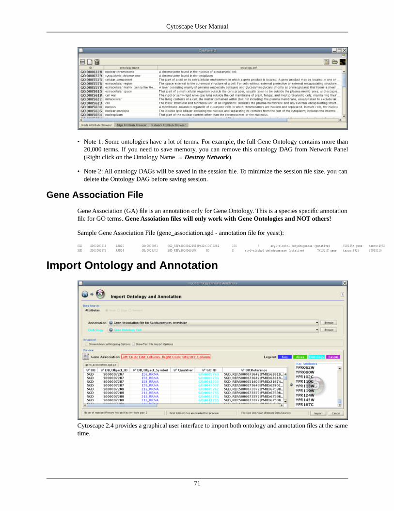
• Note 1: Some ontologies have a lot of terms. For example, the full Gene Ontology contains more than20,000 terms. If you need to save memory, you can remove this ontology DAG from Network Panel(Right click on the Ontology Name → Destroy Network).
• Note 2: All ontology DAGs will be saved in the session file. To minimize the session file size, you candelete the Ontology DAG before saving session.
Gene Association File
Gene Association (GA) file is an annotation only for Gene Ontology. This is a species specific annotationfile for GO terms. Gene Assoiation files will only work with Gene Ontologies and NOT others!
Sample Gene Association File (gene_association.sgd - annotation file for yeast):
SGD S000003916 AAD10 GO:0006081 SGD_REF:S000042151|PMID:10572264 ISS P aryl-alcohol dehydrogenase (putative) YJR155W gene taxon:4932 20020902 SGDSGD S000005275 AAD14 GO:0008372 SGD_REF:S000069584 ND C aryl-alcohol dehydrogenase (putative) YNL331C gene taxon:4932 20010119 SGD
Import Ontology and Annotation
Cytoscape 2.4 provides a graphical user interface to import both ontology and annotation files at the sametime.
71
Cytoscape User Manual

Import Gene Ontology and Gene Association Files
For user's convenience, Cytoscape has a list of URLs for commonly used ontology data and a completeset of Gene Association files. To import Gene Ontology and Gene Association files for the loaded networks,please follow these steps:
Important: All data sources in the preset list are remote URLs, meaning a network connection is required!
Step 1. Select Annotation File
Select File → Import → Ontology and Annotation... to open the Import Ontology and Annotation dialog.From the Annotation combo box, select a gene association file for your network. For example, if you wantto annotate yeast network, select Gene Association file for Saccharomyces cerevisiae.
Step 2. Select Ontology File
Select an Ontology data (OBO file) from Ontology combo box. If the file is not loaded yet, they are shownin red. The first three files are Gene Ontology files. You can load other ontologies, but you need your ownannotation file to annotate networks.
Step 3. Start Import
Once you click Import button, Cytoscape start loading OBO and Gene Association files from the remotesources. If you choose GO Full it may take a while since it is a large data file.
Step 4.
When Cytoscape finishes to import files, the window will be automatically closed. All attributes mappedby this function have prefix annotation and looks like this: annotation.[attribute_name]. All ontologieswill be added to the end of branch Ontology DAGs.
72
Cytoscape User Manual

Ontology DAGs have some attributes associated with the terms. All attributes associated with ontologyterms have prefix ontology. They have at least one attribute, ontology.name. For more informations aboutdetail of attributes for ontology DAGs, please read OBO specification document.
• Note: Cytoscape supports both OBO format version 1.0 and 1.2.
Custom Annotation Files for Ontologies Other than GO(for Advanced Users)
Ontology and Annotation Import function is designed to import general ontology and annotation files. In-ternally, mapping ontology terms onto existing networks is same as joining three data tables in Cytoscape.An Ontology DAG, an annotation file, and networks are used in this process (see the example below).
Network Data
Ontology Data
73
Cytoscape User Manual

Annotation Data
Mapping Result
If you want to map ontology terms onto network objects, you need to create a custom annotation file. Theannotation file should contain at least 2 columns: aprimary key and an ontology term ID. Primary key isthe value for mapping between annotation file and network. Usually, node/edge ID is used as primary key,but you may choose any of the available attributes. Ontology term ID is the key for mapping between theontology DAG and the annotation file. Using these data sources, you can annotate network objects inCytoscape.
Suppose you have a small network:
74
Cytoscape User Manual

node_1 pp node_2node_3 pp node_1node_2 pp node_3
and you want to annotate this network with Ontology A, which is an ontology DAG available in OBOformat. In this case, you need an annotation table file looks like this:
node_1 OA_0000232node_2 OA_0000441node_3 OA_0000702
where OA_*** represents an ontology term ID. This example is a file with the minimum necessary numberof columns, however you can include additional columns that will appear as additional node attributes.
Some ontologies will be used to annotate edges or networks. For example, Protein-protein interaction on-tology is a controlled set of terms for annotating interactions between proteins, so ontology terms shouldbe mapped onto edges (see example below).
node_1 (pp) node_2 MI:0445node_3 (pp) node_1 MI:0046node_2 (pp) node_3 MI:0346
The basic operation of Ontology and Annotation Import is the same as Attribute Table Import. The maindifference is that you need to specify an additional key for mapping:
75
Cytoscape User Manual

By selecting a column from Key Column in Annotation File combo box, you can specify the key formapping between ontology terms and annotation file.
• Note: When you load Gene Association files, Cytoscape uses a special loader program designed onlyfor Gene Association files. Because of this program, all attributes will be named automatically. Also,ontology IDs will be converted into term names and NCBI taxsonomy ID will be converted into actualspecies name. However, for custom annotation files, those processes will not be applied. All ontologyterms will be mapped as term IDs.
LinkoutLinkOut provides a mechanism to link nodes and edges to external web resources within Cytoscape. Right-clicking on a node or edge in Cytoscape view opens a popup menu with a list of web links.
The external links are specified in a linkout.props file which is included in the cytoscape.jar file. The defaultsinclude a number of links such as Entrez, SGD, iHOP, Google, as well as a number of species-specificlinks. In addition to the default links, users can customize the LinkOut menu by adding (or removing) linksby editing the linkout properties that can be found in the Edit → Preferences → Properties... dialog.
External links are listed as ‘key’-‘value’ pairs in the linkout.props file where key specifies the name of thelink and value is the search URL. The LinkOut menus are organized in a hierarchical structure that isspecified in the key. All key terms start with the keyword linkouturl.
For example, the following entry: linkouturl.yeast.SGD=http://db.yeastgenome.org/cgi-bin/locus.pl?locus\=%ID%
places the SGD link under the yeast submenu. This link will appear in Cytoscape as:
In a similar fashion one can added new submenus.
The %ID% string in the URL is a place-holder for the node label. When the popup menu is generated thismarker is substituted with the node label. In the above example the generated SGD link for YIM proteinis: http://db.yeastgenome.org/cgi-bin/locus.pl?locus\=YIM1. If you want to query based on a different at-tribute you currently need to specify a different Node Label using the VizMapper.
Currently there is no mechanism to check whether the constructed URL query is correct and if the nodelabel is meaningful. Similarly there is no ID mapping between various identifiers. For example, a link toNCBI Entrez from a network that uses ensembl gene identifiers as node label will produce a link to Entrez
76
Cytoscape User Manual

using ensembl ID, which results in an incorrect link. It is the users responsibility to ensure that the nodelabel that is used as the search term in the URL link will result in a meaningful link.
Adding or Removing links The default links are defined in a linkout.props file contained in the linkout.jar.These links are normal java properties and can be editited while running in the Edit → Preferences →Properties... dialog. New links can be defined this way as well. New links can be defined at startup in aseparate file and loaded from the command line, either by specifying a file containing the links cytoscape.sh-P new_linout.props or as individual properties cytoscape.sh -P linkouturl.yeast.SGD=http://db.yeastgen-ome.org/cgi-bin/locus.pl?locus\=%ID%. Any links defined on the command line will supersede the defaultlinks.
To remove a link from the menu simply delete the property from the Edit → Preferences → Properties...dialog.
•
AcknowledgementsCytoscape is built with a number of open source 3rd party Java libraries. The Cytoscape team gratefullyacknowledges the following libraries:
• The Colt Distribution: Open Source Libraries for High Performance Scientific and Technical Computingin Java. Information is available at: http://hoschek.home.cern.ch/hoschek/colt/.
• Graph INterface librarY a.k.a. GINY. Information is available at: http://csbi.sourceforge.net/.
• JDOM. Information is available at: http://www.jdom.org.
• JUnit. Information is available at: http://junit.org.
• JGoodies Looks. Information is available at: http://www.jgoodies.com/freeware/looks/index.html.
• Piccolo. Information is available at: http://www.cs.umd.edu/hcil/jazz/.
• Type-Specific Collections Library, from Sosnoski Software Solutions, Inc. Information is available at:http://www.sosnoski.com/opensrc/tclib/.
• Xerces Java XML parser. Information is available at: http://xml.apache.org/xerces-j/.
• CLI command line parser. Information is available at: http://jakarta.apache.org/commons/cli/.
• FreeHEP library. Information is available at: http://java.freehep.org.
This product includes software developed by the Apache Software Foundation (http://www.apache.org/).
This product includes software developed by the JDOM Project (http://www.jdom.org/).
One-step Installation of the Cytoscape software is accomplished using the InstallAnywhere product fromZeroG Software, Inc. (http://zerog.com)
Appendix A: Old Annotation Server FormatHandler for the following format still exist in Cytoscape as a legacy code, however we strongly recommendusing the new formats (OBO + Gene Association) described in the previous section, since they are easier
77
Cytoscape User Manual

to download directly from the Gene Ontology project and use directly. Currently, users have no access toimport UI for this old format.
Building your own annotation filesThe annotation server requires that the gene annotations, and associated ontology on controlled vocabularyterms, follow a simple format. This simple format was chosen because it is efficient to parse and easy touse.
The flat file formats are explained below:
The Ontology Format
By example (the Gene Ontology - GO):
(curator=GO) (type=all)0003673 = Gene_Ontology0003674 = molecular_function [partof: 0003673 ]0008435 = anticoagulant [isa: 0003674 ]0016172 = antifreeze [isa: 0003674 ]0016173 = ice nucleation inhibitor [isa: 0016172 ]0016209 = antioxidant [isa: 0003674 ]0045174 = glutathione dehydrogenase (ascorbate) [isa: 0009491 0015038 0016209 0016672 ]0004362 = glutathione reductase (NADPH) [isa: 0015038 0015933 0016209 0016654 ]0017019 = myosin phosphatase catalyst [partof: 0017018 ]...
A second example (KEGG pathway ontology):
(curator=KEGG) (type=Metabolic Pathways)90001 = Metabolism80001 = Carbohydrate Metabolism [isa: 90001 ]80003 = Lipid Metabolism [isa: 90001 ]80002 = Energy Metabolism [isa: 90001 ]80004 = Nucleotide Metabolism [isa: 90001 ]80005 = Amino Acid Metabolism [isa: 90001 ]80006 = Metabolism of Other Amino Acids [isa: 90001 ]80007 = Metabolism of Complex Carbohydrates [isa: 90001 ]...
The format has three required features:
1. The first line contains two parenthesized assignments, for curator and type. In the GO example above,the ontology file (which is created from the XML GO provides) nests all three specific ontologies(molecular function, biological process, cellular component) below the 'root' ontology, named'Gene_Ontology'.
(type=all)
tells you that all three ontologies are included in that file.
1. Following the mandatory title line, there are one or more category lines, each with the form:
number0 = name [isa:|partof: number1 number2 ...]
'isa' and 'partof' are terms used in GO; they describe the relation between parent and child terms in theontology hierarchy.
1. The trailing blank before each left square bracket is not required; it is an artifact of the python scriptthat creates these files.
The Annotation Format
By example (from the GO biological process annotation file):
78
Cytoscape User Manual

(species=Saccharomyces cerevisiae) (type=Biological Process) (curator=GO)YMR056C = 0006854YBR085W = 0006854YJR155W = 0006081...
and from KEGG:
(species=Mycobacterium tuberculosis) (type=Metabolic Pathways) (curator=KEGG)RV0761C = 10RV0761C = 71RV0761C = 120RV0761C = 350RV0761C = 561RV1862 = 10...
The format has these required features:
1. The first line contains three parenthesized assignments, for species, type and curator. In the examplejust above, the annotation file (which we create for budding yeast from the flat text file maintained bySGD for the Gene Ontology project, and available both at their web site and at GO's) shows three yeastORFs annotated for biological process, with respect to GO, described (further above).
2. Following the mandatory title line, there are one or more annotation lines, each with the form:
canonicalName = ontologyTermID
1. Once loaded, this annotation (along with the accompanying ontology) can be assigned to nodes in aCytoscape network. For this to work, the species type of the node must exactly match the speciesnamed on the first line of the annotation file. The canonicalName of your node must exactly matchthe canonicalName present in the annotation file. If you don’t see the expected results when usingthis feature of Cytoscape, check this again, as getting either of these wrong is a common mistake.
Load Data into CytoscapeThe easiest way to make annotations available to Cytoscape is by loading annotations into the Cytoscapeannotation server. This is the default behavior for the official release of Cytoscape.
The Annotation Manifest
You must first create a text file to specify the files you want Cytoscape to load. Here is an example, froma file which (for convenience) we usually call “manifest”
ontology=goOntology.txtannotation=yeastBiologicalProcess.txtannotation=yeastMolecularFunction.txtannotation=yeastCellularComponent.txt
Use the Cytoscape -b command line argument to specify the annotation manifest file to read (e.g. -bmanifest). Please note that the -s switch, which sets the default species for your data is required to exactlymatch the species named in any annotation file you wish to use.
Getting and Reformatting GO DataThe Gene Ontology (GO) project is a valuable source of annotation for the genes of many organisms. Inthis section we will explain how to:
1. Obtain the GO ontology file
2. Reformat it into the simpler flat file Cytoscape uses
79
Cytoscape User Manual
3. Obtain an annotation file (we illustrate with yeast and human annotation)
4. Reformat the annotation files into the simple Cytoscape format
Obtain the GO ontology file Go to the GO XML FTP (ftp://ftp.geneontology.org/pub/go/xml/) page.Download the latest go-YYYYMM-termdb.xml.gz file.
Reformat GO XML ontology file into a flat file
gunzip go-YYYYMM-termdb.xml.gz python parseGoTermsToFlatFile.py go-YYYYMM-termdb.xml > goOntology.txt
(See below for Python script listing)
Obtain the 'association' file for your organism GO maintains a list of association files for many organisms;these files associate genes with GO terms. The next step is to get the file for the organism/s you are interestedin, and parse it into the form Cytoscape needs. A list of files may be seen at http://www.geneonto-logy.org/GO.current.annotations.shtml. The rightmost column contains links to tab-delimited files of geneassociations, by species. Choose the species you are interested in, and click 'Download'.
Let's use 'GO Annotations @ EBI Human' as an example. After you have downloaded and saved the file,look at the first few lines:
SPTR O00115 DRN2_HUMAN GO:0003677 PUBMED:9714827 TAS F Deoxyribonuclease II precursor IPI00010348 protein taxon:9606 SPTRSPTR O00115 DRN2_HUMAN GO:0004519 GOA:spkw IEA F Deoxyribonuclease II precursor IPI00010348 protein taxon:9606 20020425 SPTRSPTR O00115 DRN2_HUMAN GO:0004531 PUBMED:9714827 TAS F Deoxyribonuclease II precursor IPI00010348 protein taxon:9606 SPTR...
Note that line wrapping has occurred here, so each line of the actual file is wrapped to two lines. The goalis to create from these lines the following lines:
(species=Homo sapiens) (type=Molecular Function) (curator=GO)IPI00010348 = 0003677IPI00010348 = 0004519IPI00010348 = 0004531...
or
(species=Homo sapiens) (type=Biological Process) (curator=GO)NP_001366 = 0006259NP_001366 = 0006915NP_005289 = 0007186NP_647593 = 0006899...
The first sample contains molecular function annotation for proteins, and each protein is identified by itsIPI number. IPI is the International Protein Index, which maintains cross references to the main databasesfor human, mouse and rat proteomes. The second sample contains biological process annotation, and eachprotein is identified by its NP (RefSeq) number. These two naming systems, IPI and RefSeq, are two ofmany that you can use for canonical names when you run Cytoscape. For budding yeast, it is much easier:the yeast community always uses standard ORF names, and so Cytoscape uses these as canonical names.For human proteins and genes, there is no such single simple standard. See section 5. Building and StoringInteraction Networks for more information.
The solution (for those working with human genes or proteins) is, once you have downloaded the annotationsfile, to:
1. Decide which naming system you want to use.
2. Download ftp://ftp.ebi.ac.uk/pub/databases/GO/goa/HUMAN/xrefs.goa. This cross-reference file, whenused strategically, allows you to create Cytoscape-compatible annotation files in which the canonicalname is the one most meaningful to you.
80
Cytoscape User Manual

3. Examine xrefs.goa to figure out which column contains the names you wish to use.
4. Make a very slight modification to the python script described below, and then
5. Run that script, supplying both xrefs.goa and that annotation file as arguments.
Here are a few sample lines from xrefs.goa:
SP O00115 IPI00010348 ENSP00000222219; NP_001366; BAA28623;AAC77366;AAC35751;AAC39852;BAB55598;AAB51172;AAH10419; 2960,DNASE2 1777,DNASE2SP O00116 IPI00010349 ENSP00000324567;ENSP00000264167; NP_003650; CAA70591; 327,AGPS 8540,AGPSSP O00124 IPI00010353 ENSP00000265616;ENSP00000322580; NP_005662; BAA18958;BAA18959;AAH20694; 7993,D8S2298E...
Note that line wrapping has occurred here – each line in this example starts with the letters SP. See theREADME file for more information (ftp://ftp.ebi.ac.uk/pub/databases/GO/goa/HUMAN/README)
Finally, run the script to create your three annotation files for human proteins:
• bioproc.anno (GO biological process annotation)
• molfunc.anno (GO molecular function annotation)
• cellcomp.anno (GO cellular component annotation)
using the supplied python script. It may be necessary to modify this script slightly if RefSeq identifiers arenot used as canonical names or if you are using a more recent version of Python.
python parseAssignmentsToFlatFileFromGoaProject.py gene_association.goa_human xrefs.goa
(See below for Python script listing)
Python script examples: These scripts, described above require Python version 2.2 or later.
Script 1 - parseGoTermsToFlatFile.py
# parseGoTermToFlatFile.py: translate a GO XML ontology file into a simpler# Cytoscape flat file#-----------------------------------------------------------------------------------# RCS: $Revision: 1.3 $ $Date: 2003/05/18 00:38:43 $#-----------------------------------------------------------------------------------import re, pre, sys#-----------------------------------------------------------------------------------def flatFilePrint (id, name, isaIDs, partofIDs): isa = '' if (len (isaIDs) > 0): isa = '[isa: ' for isaID in isaIDs: isa += isaID isa += ' ' isa += ']' partof = '' if (len (partofIDs) > 0): partof = '[partof: ' for partofID in partofIDs: partof += partofID partof += ' ' partof += ']' result = '~np~%~/np~s = ~np~%~/np~s ~np~%~/np~s ~np~%~/np~s' ~np~%~/np~ (id, name, isa, partof) result = result.strip () if (result == 'isa = isa' or result == 'partof = partof'): print >> sys.stderr, 'meaningless term: ~np~%~/np~s' ~np~%~/np~ result else: print result#-----------------------------------------------------------------------------------if (len (sys.argv) != 2): print 'usage: ~np~%~/np~s <someFile.xml>' ~np~%~/np~ sys.argv [0] sys.exit ();inputFilename = sys.argv [1];print >> sys.stderr, 'reading ~np~%~/np~s...' ~np~%~/np~ inputFilenametext = open (inputFilename).read ()print >> sys.stderr, 'read ~np~%~/np~d characters' ~np~%~/np~ len (text)regex = '<go:term .*?>(.*?)</go:term>';cregex = pre.compile (regex, re.DOTALL) # . matches newlines
81
Cytoscape User Manual

m = pre.findall (cregex, text)print >> sys.stderr, 'number of go terms: ~np~%~/np~d' ~np~%~/np~ len (m)regex2 = '<go:accession>GO:(.*?)</go:accession>.*?<go:name>(.*?)</go:name>'cregex2 = re.compile (regex2, re.DOTALL)regex3 = '<go:isa\s*rdf:resource="http://www.geneontology.org/go#GO:(.*?)"\s*/>'cregex3 = re.compile (regex3, re.DOTALL)regex4 = '<go:part-of\s*rdf:resource="http://www.geneontology.org/go#GO:(.*?)"\s*/>'cregex4 = re.compile (regex4, re.DOTALL)goodElements = 0badElements = 0print '(curator=GO) (type=all)'for term in m: m2 = re.search (cregex2, term) if (m2): goodElements += 1; id = m2.group (1) name = m2.group (2) isaIDs = [] m3 = re.findall (cregex3, term); for ref in m3: isaIDs.append (ref) m4 = re.findall (cregex4, term); partofIDs = [] for ref in m4: partofIDs.append (ref) flatFilePrint (id, name, isaIDs, partofIDs) else: badElements += 1; print >> sys.stderr, 'no match to m2...' print >> sys.stderr, "---------------\n~np~%~/np~s\n------------------" ~np~%~/np~ termprint >> sys.stderr, 'goodElements ~np~%~/np~d' ~np~%~/np~ goodElementsprint >> sys.stderr, 'badElements ~np~%~/np~d' ~np~%~/np~ badElements#--------------------------------------
Script 1 - parseAssignmentsToFlatFileFromGoaProject.py
import sys#-----------------------------------------------------------------------------------def fixCanonicalName (rawName):# for instance, trim 'YBR085W|ANC3' to 'YBR085W' bar = rawName.find ('|') if (bar < 0): return rawName return rawName [:bar]#-----------------------------------------------------------------------------------def fixGoID (rawID): bar = rawID.find (':') + 1 return rawID [bar:]#-----------------------------------------------------------------------------------def readGoaXrefFile (filename): lines = open (filename).read().split ('\n') result = {} for line in lines: if (len (line) < 10): continue tokens = line.split ('\t') ipi = tokens [2] np = tokens [5] semicolon = np.find (';') if (semicolon >= 0): np = np [:semicolon] if (len (ipi) > 0 and len (np) > 0): result [ipi] = np return result#-----------------------------------------------------------------------------------if (len (sys.argv) != 3): print 'error! parse <gene_associations file from GO> <goa xrefs file> ' sys.exit ()associationFilename = sys.argv [1];xrefsFilename = sys.argv [2]species = 'Homo sapiens'ipiToNPHash = readGoaXrefFile (xrefsFilename)tester = 'IPI00099416'print 'hash size: ~np~%~/np~d' ~np~%~/np~ len (ipiToNPHash)print 'test map: ~np~%~/np~s -> NP_054861: ~np~%~/np~s ' ~np~%~/np~ (tester, ipiToNPHash [tester])bioproc = open ('bioproc.txt', 'w')molfunc = open ('molfunc.txt', 'w')cellcomp = open ('cellcomp.txt', 'w')bioproc.write ('(species=~np~%~/np~s) (type=Biological Process) (curator=GO)\n' ~np~%~/np~ species)molfunc.write ('(species=~np~%~/np~s) (type=Molecular Function) (curator=GO)\n' ~np~%~/np~ species);cellcomp.write ('(species=~np~%~/np~s) (type=Cellular Component) (curator=GO)\n' ~np~%~/np~ species);lines=open(associationFilename).read().split('\n')sys.stderr.write ('found ~np~%~/np~d lines\n' ~np~%~/np~ len (lines))
for line in lines: if (line.find ('!') == 0 or len (line) < 2): continue
82
Cytoscape User Manual

tokens = line.split ('\t') goOntology = tokens [8] goIDraw = tokens [4] goID = goIDraw.split (':')[1] ipiName = fixCanonicalName (tokens [10]) if (len (ipiName) < 1): continue
if (not ipiToNPHash.has_key (ipiName)): continue refseqName = ipiToNPHash [ipiName] printName = refseqName #printName = ipiName if (ipiName == tester): print '~np~%~/np~s (~np~%~/np~s) has go term ~np~%~/np~s' ~np~%~/np~ (tester, printName, goID) if (goOntology == 'C'): cellcomp.write ('~np~%~/np~s = ~np~%~/np~s\n' ~np~%~/np~ (printName, goID)) elif (goOntology == 'P'): bioproc.write ('~np~%~/np~s = ~np~%~/np~s\n' ~np~%~/np~ (printName, goID)) elif (goOntology == 'F'): molfunc.write ('~np~%~/np~s = ~np~%~/np~s\n' ~np~%~/np~ (printName, goID))#-----------------------------------------------------------------------------------
Appendix B: GNU Lesser General Public LicenseGNU LESSER GENERAL PUBLIC LICENSE
• Version 2.1, February 1999 Copyright (C) 1991, 1999 Free Software Foundation, Inc. 59 Temple Place,Suite 330, Boston, MA 02111-1307 USA Everyone is permitted to copy and distribute verbatim copiesof this license document, but changing it is not allowed. [This is the first released version of the LesserGPL. It also counts as the successor of the GNU Library Public License, version 2, hence the versionnumber 2.1.]
Preamble
The licenses for most software are designed to take away your freedom to share and change it. By contrast,the GNU General Public Licenses are intended to guarantee your freedom to share and change free software--to make sure the software is free for all its users.
This license, the Lesser General Public License, applies to some specially designated software packages--typically libraries--of the Free Software Foundation and other authors who decide to use it. You can useit too, but we suggest you first think carefully about whether this license or the ordinary General PublicLicense is the better strategy to use in any particular case, based on the explanations below.
When we speak of free software, we are referring to freedom of use, not price. Our General Public Licensesare designed to make sure that you have the freedom to distribute copies of free software (and charge forthis service if you wish); that you receive source code or can get it if you want it; that you can change thesoftware and use pieces of it in new free programs; and that you are informed that you can do these things.
To protect your rights, we need to make restrictions that forbid distributors to deny you these rights or toask you to surrender these rights. These restrictions translate to certain responsibilities for you if you dis-tribute copies of the library or if you modify it.
For example, if you distribute copies of the library, whether gratis or for a fee, you must give the recipientsall the rights that we gave you. You must make sure that they, too, receive or can get the source code. Ifyou link other code with the library, you must provide complete object files to the recipients, so that theycan relink them with the library after making changes to the library and recompiling it. And you must showthem these terms so they know their rights.
We protect your rights with a two-step method: (1) we copyright the library, and (2) we offer you this license,which gives you legal permission to copy, distribute and/or modify the library.
83
Cytoscape User Manual

To protect each distributor, we want to make it very clear that there is no warranty for the free library.Also, if the library is modified by someone else and passed on, the recipients should know that what theyhave is not the original version, so that the original author's reputation will not be affected by problemsthat might be introduced by others.
Finally, software patents pose a constant threat to the existence of any free program. We wish to make surethat a company cannot effectively restrict the users of a free program by obtaining a restrictive licensefrom a patent holder. Therefore, we insist that any patent license obtained for a version of the library mustbe consistent with the full freedom of use specified in this license.
Most GNU software, including some libraries, is covered by the ordinary GNU General Public License.This license, the GNU Lesser General Public License, applies to certain designated libraries, and is quitedifferent from the ordinary General Public License. We use this license for certain libraries in order topermit linking those libraries into non-free programs.
When a program is linked with a library, whether statically or using a shared library, the combination ofthe two is legally speaking a combined work, a derivative of the original library. The ordinary GeneralPublic License therefore permits such linking only if the entire combination fits its criteria of freedom.The Lesser General Public License permits more lax criteria for linking other code with the library. Wecall this license the "Lesser" General Public License because it does Less to protect the user's freedom thanthe ordinary General Public License. It also provides other free software developers Less of an advantageover competing non-free programs. These disadvantages are the reason we use the ordinary General PublicLicense for many libraries. However, the Lesser license provides advantages in certain special circumstances.For example, on rare occasions, there may be a special need to encourage the widest possible use of acertain library, so that it becomes a de-facto standard. To achieve this, non-free programs must be allowedto use the library. A more frequent case is that a free library does the same job as widely used non-freelibraries. In this case, there is little to gain by limiting the free library to free software only, so we use theLesser General Public License. In other cases, permission to use a particular library in non-free programsenables a greater number of people to use a large body of free software. For example, permission to usethe GNU C Library in non-free programs enables many more people to use the whole GNU operatingsystem, as well as its variant, the GNU/Linux operating system. Although the Lesser General Public Licenseis Less protective of the users' freedom, it does ensure that the user of a program that is linked with theLibrary has the freedom and the wherewithal to run that program using a modified version of the Library.The precise terms and conditions for copying, distribution and modification follow. Pay close attention tothe difference between a "work based on the library" and a "work that uses the library". The former containscode derived from the library, whereas the latter must be combined with the library in order to run.
GNU LESSER GENERAL PUBLIC LICENSE TERMS AND CONDITIONS FOR COPYING, DISTRI-BUTION AND MODIFICATION
0. This License Agreement applies to any software library or other program which contains a notice placedby the copyright holder or other authorized party saying it may be distributed under the terms of thisLesser General Public License (also called "this License"). Each licensee is addressed as "you". A "library"means a collection of software functions and/or data prepared so as to be conveniently linked with applic-ation programs (which use some of those functions and data) to form executables. The "Library", below,refers to any such software library or work which has been distributed under these terms. A "work basedon the Library" means either the Library or any derivative work under copyright law: that is to say, a workcontaining the Library or a portion of it, either verbatim or with modifications and/or translated straightfor-wardly into another language. (Hereinafter, translation is included without limitation in the term "modific-ation".) "Source code" for a work means the preferred form of the work for making modifications to it.For a library, complete source code means all the source code for all modules it contains, plus any associatedinterface definition files, plus the scripts used to control compilation and installation of the library. Activ-ities other than copying, distribution and modification are not covered by this License; they are outside itsscope. The act of running a program using the Library is not restricted, and output from such a program
84
Cytoscape User Manual

is covered only if its contents constitute a work based on the Library (independent of the use of the Libraryin a tool for writing it). Whether that is true depends on what the Library does and what the program thatuses the Library does.
1. You may copy and distribute verbatim copies of the Library's complete source code as you receive it,in any medium, provided that you conspicuously and appropriately publish on each copy an appropriatecopyright notice and disclaimer of warranty; keep intact all the notices that refer to this License and to theabsence of any warranty; and distribute a copy of this License along with the Library.
You may charge a fee for the physical act of transferring a copy, and you may at your option offer warrantyprotection in exchange for a fee.
2. You may modify your copy or copies of the Library or any portion of it, thus forming a work based onthe Library, and copy and distribute such modifications or work under the terms of Section 1 above,provided that you also meet all of these conditions:
a) The modified work must itself be a software library.
b) You must cause the files modified to carry prominent notices stating that you changed the files and thedate of any change.
c) You must cause the whole of the work to be licensed at no charge to all third parties under the terms ofthis License.
d) If a facility in the modified Library refers to a function or a table of data to be supplied by an applicationprogram that uses the facility, other than as an argument passed when the facility is invoked, then you mustmake a good faith effort to ensure that, in the event an application does not supply such function or table,the facility still operates, and performs whatever part of its purpose remains meaningful. (For example, afunction in a library to compute square roots has a purpose that is entirely well-defined independent of theapplication. Therefore, Subsection 2d requires that any application-supplied function or table used by thisfunction must be optional: if the application does not supply it, the square root function must still computesquare roots.)
These requirements apply to the modified work as a whole. If identifiable sections of that work are notderived from the Library, and can be reasonably considered independent and separate works in themselves,then this License, and its terms, do not apply to those sections when you distribute them as separate works.But when you distribute the same sections as part of a whole which is a work based on the Library, thedistribution of the whole must be on the terms of this License, whose permissions for other licensees extendto the entire whole, and thus to each and every part regardless of who wrote it.
Thus, it is not the intent of this section to claim rights or contest your rights to work written entirely byyou; rather, the intent is to exercise the right to control the distribution of derivative or collective worksbased on the Library. In addition, mere aggregation of another work not based on the Library with theLibrary (or with a work based on the Library) on a volume of a storage or distribution medium does notbring the other work under the scope of this License.
3. You may opt to apply the terms of the ordinary GNU General Public License instead of this License toa given copy of the Library. To do this, you must alter all the notices that refer to this License, so that theyrefer to the ordinary GNU General Public License, version 2, instead of to this License. (If a newer versionthan version 2 of the ordinary GNU General Public License has appeared, then you can specify that versioninstead if you wish.) Do not make any other change in these notices.
Once this change is made in a given copy, it is irreversible for that copy, so the ordinary GNU GeneralPublic License applies to all subsequent copies and derivative works made from that copy.
85
Cytoscape User Manual

This option is useful when you wish to copy part of the code of the Library into a program that is not alibrary.
4. You may copy and distribute the Library (or a portion or derivative of it, under Section 2) in object codeor executable form under the terms of Sections 1 and 2 above provided that you accompany it with thecomplete corresponding machine-readable source code, which must be distributed under the terms ofSections 1 and 2 above on a medium customarily used for software interchange.
If distribution of object code is made by offering access to copy from a designated place, then offeringequivalent access to copy the source code from the same place satisfies the requirement to distribute thesource code, even though third parties are not compelled to copy the source along with the object code.
5. A program that contains no derivative of any portion of the Library, but is designed to work with theLibrary by being compiled or linked with it, is called a "work that uses the Library". Such a work, in isol-ation, is not a derivative work of the Library, and therefore falls outside the scope of this License.
However, linking a "work that uses the Library" with the Library creates an executable that is a derivativeof the Library (because it contains portions of the Library), rather than a "work that uses the library". Theexecutable is therefore covered by this License. Section 6 states terms for distribution of such executables.
When a "work that uses the Library" uses material from a header file that is part of the Library, the objectcode for the work may be a derivative work of the Library even though the source code is not. Whetherthis is true is especially significant if the work can be linked without the Library, or if the work is itself alibrary. The threshold for this to be true is not precisely defined by law.
If such an object file uses only numerical parameters, data structure layouts and accessors, and smallmacros and small inline functions (ten lines or less in length), then the use of the object file is unrestricted,regardless of whether it is legally a derivative work. (Executables containing this object code plus portionsof the Library will still fall under Section 6.)
Otherwise, if the work is a derivative of the Library, you may distribute the object code for the work underthe terms of Section 6. Any executables containing that work also fall under Section 6, whether or not theyare linked directly with the Library itself.
6. As an exception to the Sections above, you may also combine or link a "work that uses the Library"with the Library to produce a work containing portions of the Library, and distribute that work under termsof your choice, provided that the terms permit modification of the work for the customer's own use andreverse engineering for debugging such modifications.
You must give prominent notice with each copy of the work that the Library is used in it and that the Libraryand its use are covered by this License. You must supply a copy of this License. If the work during executiondisplays copyright notices, you must include the copyright notice for the Library among them, as well asa reference directing the user to the copy of this License. Also, you must do one of these things:
a) Accompany the work with the complete corresponding machine-readable source code for the Libraryincluding whatever changes were used in the work (which must be distributed under Sections 1 and 2above); and, if the work is an executable linked with the Library, with the complete machine-readable"work that uses the Library", as object code and/or source code, so that the user can modify the Libraryand then relink to produce a modified executable containing the modified Library. (It is understood thatthe user who changes the contents of definitions files in the Library will not necessarily be able to recompilethe application to use the modified definitions.)
b) Use a suitable shared library mechanism for linking with the Library. A suitable mechanism is one that(1) uses at run time a copy of the library already present on the user's computer system, rather than copyinglibrary functions into the executable, and (2) will operate properly with a modified version of the library,
86
Cytoscape User Manual
if the user installs one, as long as the modified version is interface-compatible with the version that thework was made with.
c) Accompany the work with a written offer, valid for at least three years, to give the same user the mater-ials specified in Subsection 6a, above, for a charge no more than the cost of performing this distribution.
d) If distribution of the work is made by offering access to copy from a designated place, offer equivalentaccess to copy the above specified materials from the same place.
e) Verify that the user has already received a copy of these materials or that you have already sent this usera copy.
For an executable, the required form of the "work that uses the Library" must include any data and utilityprograms needed for reproducing the executable from it. However, as a special exception, the materials tobe distributed need not include anything that is normally distributed (in either source or binary form) withthe major components (compiler, kernel, and so on) of the operating system on which the executable runs,unless that component itself accompanies the executable.
It may happen that this requirement contradicts the license restrictions of other proprietary libraries thatdo not normally accompany the operating system. Such a contradiction means you cannot use both themand the Library together in an executable that you distribute.
7. You may place library facilities that are a work based on the Library side-by-side in a single library to-gether with other library facilities not covered by this License, and distribute such a combined library,provided that the separate distribution of the work based on the Library and of the other library facilitiesis otherwise permitted, and provided that you do these two things:
a) Accompany the combined library with a copy of the same work based on the Library, uncombined withany other library facilities. This must be distributed under the terms of the Sections above.
b) Give prominent notice with the combined library of the fact that part of it is a work based on the Library,and explaining where to find the accompanying uncombined form of the same work.
8. You may not copy, modify, sublicense, link with, or distribute the Library except as expressly providedunder this License. Any attempt otherwise to copy, modify, sublicense, link with, or distribute the Libraryis void, and will automatically terminate your rights under this License. However, parties who have receivedcopies, or rights, from you under this License will not have their licenses terminated so long as such partiesremain in full compliance.
9. You are not required to accept this License, since you have not signed it. However, nothing else grantsyou permission to modify or distribute the Library or its derivative works. These actions are prohibited bylaw if you do not accept this License. Therefore, by modifying or distributing the Library (or any workbased on the Library), you indicate your acceptance of this License to do so, and all its terms and conditionsfor copying, distributing or modifying the Library or works based on it.
10. Each time you redistribute the Library (or any work based on the Library), the recipient automaticallyreceives a license from the original licensor to copy, distribute, link with or modify the Library subject tothese terms and conditions. You may not impose any further restrictions on the recipients' exercise of therights granted herein. You are not responsible for enforcing compliance by third parties with this License.
11. If, as a consequence of a court judgment or allegation of patent infringement or for any other reason(not limited to patent issues), conditions are imposed on you (whether by court order, agreement or other-wise) that contradict the conditions of this License, they do not excuse you from the conditions of this Li-cense. If you cannot distribute so as to satisfy simultaneously your obligations under this License and anyother pertinent obligations, then as a consequence you may not distribute the Library at all. For example,if a patent license would not permit royalty-free redistribution of the Library by all those who receive
87
Cytoscape User Manual

copies directly or indirectly through you, then the only way you could satisfy both it and this License wouldbe to refrain entirely from distribution of the Library. If any portion of this section is held invalid or unen-forceable under any particular circumstance, the balance of the section is intended to apply, and the sectionas a whole is intended to apply in other circumstances. It is not the purpose of this section to induce youto infringe any patents or other property right claims or to contest validity of any such claims; this sectionhas the sole purpose of protecting the integrity of the free software distribution system which is implementedby public license practices. Many people have made generous contributions to the wide range of softwaredistributed through that system in reliance on consistent application of that system; it is up to the author/donorto decide if he or she is willing to distribute software through any other system and a licensee cannot imposethat choice.
This section is intended to make thoroughly clear what is believed to be a consequence of the rest of thisLicense.
12. If the distribution and/or use of the Library is restricted in certain countries either by patents or bycopyrighted interfaces, the original copyright holder who places the Library under this License may addan explicit geographical distribution limitation excluding those countries, so that distribution is permittedonly in or among countries not thus excluded. In such case, this License incorporates the limitation as ifwritten in the body of this License.
13. The Free Software Foundation may publish revised and/or new versions of the Lesser General PublicLicense from time to time. Such new versions will be similar in spirit to the present version, but may differin detail to address new problems or concerns. Each version is given a distinguishing version number. Ifthe Library specifies a version number of this License which applies to it and "any later version", you havethe option of following the terms and conditions either of that version or of any later version published bythe Free Software Foundation. If the Library does not specify a license version number, you may chooseany version ever published by the Free Software Foundation.
14. If you wish to incorporate parts of the Library into other free programs whose distribution conditionsare incompatible with these, write to the author to ask for permission. For software which is copyrightedby the Free Software Foundation, write to the Free Software Foundation; we sometimes make exceptionsfor this. Our decision will be guided by the two goals of preserving the free status of all derivatives of ourfree software and of promoting the sharing and reuse of software generally.
NO WARRANTY
15. BECAUSE THE LIBRARY IS LICENSED FREE OF CHARGE, THERE IS NO WARRANTY FORTHE LIBRARY, TO THE EXTENT PERMITTED BY APPLICABLE LAW. EXCEPT WHEN OTHER-WISE STATED IN WRITING THE COPYRIGHT HOLDERS AND/OR OTHER PARTIES PROVIDETHE LIBRARY "AS IS" WITHOUT WARRANTY OF ANY KIND, EITHER EXPRESSED OR IMPLIED,INCLUDING, BUT NOT LIMITED TO, THE IMPLIED WARRANTIES OF MERCHANTABILITYAND FITNESS FOR A PARTICULAR PURPOSE. THE ENTIRE RISK AS TO THE QUALITY ANDPERFORMANCE OF THE LIBRARY IS WITH YOU. SHOULD THE LIBRARY PROVE DEFECTIVE,YOU ASSUME THE COST OF ALL NECESSARY SERVICING, REPAIR OR CORRECTION.
16. IN NO EVENT UNLESS REQUIRED BY APPLICABLE LAW OR AGREED TO IN WRITINGWILL ANY COPYRIGHT HOLDER, OR ANY OTHER PARTY WHO MAY MODIFY AND/OR RE-DISTRIBUTE THE LIBRARY AS PERMITTED ABOVE, BE LIABLE TO YOU FOR DAMAGES,INCLUDING ANY GENERAL, SPECIAL, INCIDENTAL OR CONSEQUENTIAL DAMAGES ARISINGOUT OF THE USE OR INABILITY TO USE THE LIBRARY (INCLUDING BUT NOT LIMITED TOLOSS OF DATA OR DATA BEING RENDERED INACCURATE OR LOSSES SUSTAINED BY YOUOR THIRD PARTIES OR A FAILURE OF THE LIBRARY TO OPERATE WITH ANY OTHERSOFTWARE), EVEN IF SUCH HOLDER OR OTHER PARTY HAS BEEN ADVISED OF THE POS-SIBILITY OF SUCH DAMAGES.
88
Cytoscape User Manual
END OF TERMS AND CONDITIONS
89
Cytoscape User Manual