d ion e x technical note 29 - thermo fisher...
TRANSCRIPT
. D ION E X Technical Note 29
I
I INTRODUCTION. . . Any Thenno Jarrell Ash (TJA) simultaneou.s ICAPI Ion exchange IS a technique that has long been used mstrument (Model 61, 61E, 1100,9000) can be mterfaced
for concentration and separation of trace metals. The docu- to the Dionex IC as long as the simultaneous spectrometermentation of ion exchange is extensive and its application is used with an ffiM or ffiM-compatible computer withfor sample pretreatment prior to spectroscopic analysis is TJA ThennoSpec software. For system automation, awell known. Ion exchange offers a solution to detection ThennoSpec-supported autosampler is required. A TJAlimits commonly experienced when analyzing ultratrace type 22 or TJA 300 autosampler can be used. The auto-concentration of metals in high purity water or drinking sampler should use the large sample racks (type 24) towater by inductively coupled argon plasma (ICAP) ensure sufficient sample volume.spectroscopy. Using a simple fonn of mixed bed ion Questions concerning the compatibility of interfacing aexchange resin, the analytes of interest, both anions and particular TJA simultaneous ICAP instrument to a Dionexcations, can be concentrated from a relatively clean matrix. IC should be directed to your TJA sales or service represen-
In this technical note, we describe a technique based on tative.
direct coupling of a sample preconcentration system (anion chrOmatograph) to a simultaneous ICAP for trace REAGENTSmetals in drinking water. This sample preconcentration 2.0 M Ultrapure Nitric Acid (IL, PIN 33442; 6 L,method lowers the ICAP detection limits at least 50-fold PIN 33443)for most metals. . .AtOffilC Absorption Standard (1000 ppm) for each metal
of interestEQUIPMENT
A sample preconcentration system comprising: ELUENTS AND STANDARD PREPARATIONAdvanced Gradient Pump (AGP, PIN 42144/115V; .
PIN 42145/220V) Before preparIng the eluent and standard, thoroughlyclean the eluent containers as directed in "System Prepara-
Sample Concentration Module (SCM, PIN 42134/115V, tion", later in this technical note. Be sure that the eluent
PIN 42135/220V) bottle caps have a white TFE seal, NOT a black rubber
IC/ICAP Installation Kit (PIN 43169; contains seal. The 2.0 M nitric acid is available in a ready-to-useeluent containers, air regulator, tubing, power cords fonn. If you wish to prepare your own solution, Optima
and fittings for installation) grade reagents (Fisher Scientific), SeaStar UltrapureIonPac@CG5 (PIN 37029), 2 required Reagents (SeaStar Chemical), and Ultrex reagents (VanIonPac CG2 (PIN 35370),3 required Waters and Rogers Scientific) can be used. For ultratrace
level determination (sub-ppb), it is necessary to useultrapure grade. Any metal impurity in the reagents will beconcentrated with your sample constituting a system blank.
Eluent 1: Ultrapure Water with the sample. Care must be taken to minimize reagentand sample contamination during preparation and handling.
Eluent 2: 2.0 M Nitric Acid Reagent purity will usually dictate the detection limits.If Dionex ultrapure reagent is used, no further prepara-
tion is required. Otherwise, place 200 mL of ultrapure SYSTEM CONFIGURA nON AND SET-UPwater into a clean 1-L glass eluent container. Add 179 g Figure 2 shows a detailed pneumatic and hydraulic(126 mL) of ultrapure nitric acid. Add water to bring the schematic of the sample preconcentration system. Thefinal volume to 1.0 L and mix thoroughly. SCM is factory-configured for chelation concentration
sample pretreatment. The following set-up procedure isCarrier Solution: Ultrapure Water required for this application.
Working standards can be prepared from 1000-ppmatomic absorption standard solutions. Since the analytes of Pneumatic Connectionsinterest are concentrated, the concentration of the high Locate the four colored air tubings at the rear panelstandard used should not exceed 1 ppm. It is convenient to of the AGP and SCM. Using the small barbed couplersfirst prepare a lOX concentrate or stock solution of the (PIN 42241), couple the air tubing together by matchingstandard, and then prepare the high standard by dilution of the color (orange-orange, yellow-yellow, green-green andthe stock solution. blue-blue). Next, connect about 2 ft (60 cm) of air tubing
(PIN 30091) to the small barbed fitting on the back of theDISCUSSION OF THE METHOD AGP. Insert a barbed tee (PIN 30538) into the end of this
The method described in this technical note was fitting. One arm of the tee will go to the nitrogen or argondeveloped to improve the ICAP detection limit of common source (regulator) and the other arm will go to the inlet ofmetals present in relatively clean matrix samples (e.g. the eluent bottle regulator (PIN 38201). Using the required
ultrapure water, drinking water). For complex matrices length of tubing, connect the tee to the gas source and tosuch as high ionic strength or high salt matrices, the the eluent pressure regulator. Use the 1/4-in.-to-10/32 brasschelation concentration sample pretreatment is strongly reducer (PIN 30087) and the 10/32 x 1/16-in. barbed fittingrecommended (see Dionex Technical Note 28). (PIN 30071) to connect the air tubing to the source
The column used for sample preconcentration, the regulator.IonPac CG5, which has both anion and cation exchangesites, contains a l3-~ latex agglomerated surface sulfon-ated polystyrene/divinylbenzene copolymer. The anionexchange latex is low crosslinked, aminated with a hydro-phillic amine and has a diameter of 0.2 ~. The cation and Cu-1 Cu-2
anion exchange capacities are 30 microequivalents and14 microequivalents per column, respectively. The resincan be used with acid or base up to 6 M without degradation. .::i(j;
£:=
The sample preconcentration process consists of two .::§
steps. First, the sample is passed through the column.Metal ions are concentrated in a tight band. Then, theconcentrated metals are eluted off the column with 1.5 Mnitric acid and the column is ready for the next run.
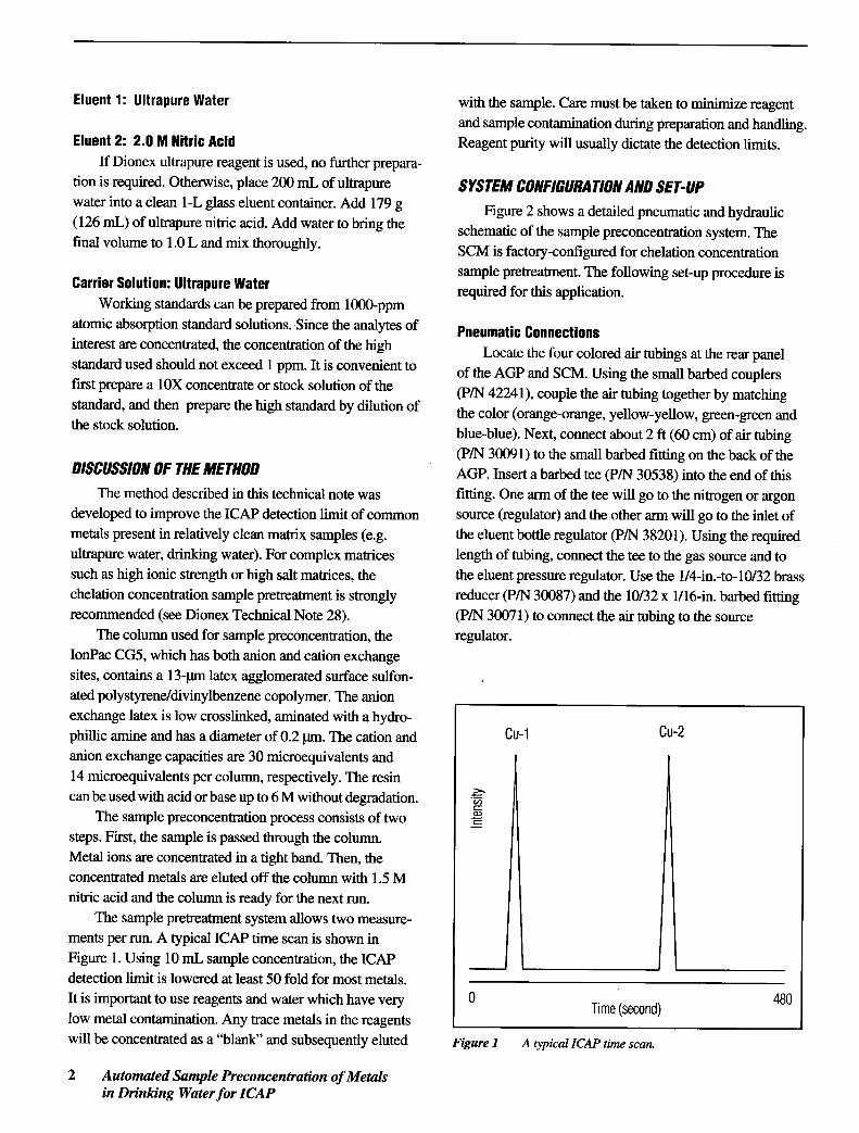
The sample pretreatment system allows two measure-ments per run. A typical ICAP time scan is shown in
! Figure 1. Using 10 mL sample concentration, the ICAPdetection limit is lowered at least 50 fold for most metals.It is important to use reagents and water which have very 0 Time (second) 480low metal contamination. Any trace metals in the reagentswill be concentrated as a "blank" and subsequently eluted Figure 1 A typical [CAP time scan.
2 Automated Sample Preconcentration of Metalsin Drinking Water for [CAP

Next, connect the air tubing to the eluent container tubings (blue tubings) are used for all connections exceptcaps (PIN 41004). Start by cutting one of the two l/8-in. for the sample loop. The two 10-rnL sample loops can beTeflon@ lines flush with the bottom of the cap. Repeat this made from 1/8- in. I.D. tubing.for the other eluent container cap. Next, cut the same Next, connect the eluent line from the 4-liter plastictubing about 2 in. (5 cm) above the eluent container cap. eluent container (pIN 39164) to the CARRIER IN port ofThis line will be used to connect the argon or nitrogen for the SCM rear panel. Next, connect the three blue wastepressurizing the eluent bottles. Insert a barbed coupler lines (PIN 39441) to the ports of the SCM rear panel(PIN 42241) into the trimmed Teflon line of cap El.lnsert labeled CARRIER OUT, AGP OUT, and SAMPLE OUTa barbed tee (PIN 30538) into the trimmed Teflon line of and place them in a waste container. For the sample inletcap E2. Connect the eluent caps using the air tubing (PIN line, connect the 0.037-in. I.D. x 36-in. (92 cm) length of30091 or equivalent). pink tubing to valve B, port 7, in the SCM. Locate the
This completes the pneumatic set-up. SAMPLE IN port of the rear panel and use the l/8-in. I.D.tubing to connect this port to the peristaltic pump inlet.
Hydraulic Connections Finally, remove the end fitting from the 0.020-in. I.D. xRefer to the AGP and SCM Operator's Manuals for 36-in. (92 cm) tubing connected to valve C, port 8, of the
details pertaining to the installation and operation of the SCM. Using a pair of pliers, stretch the end of this tubingrespective modules. Begin the hydraulic connections by to taper the tubing to about two-thirds of its originalconnecting the two eluent lines from the three eluent outside diameter. Using about 3/8-in. (1 cm) of 0.03-in.container caps to the front panel eluent ports of the AGP. !.D. Tygon tubing as a coupler, connect the tapered tubingEnsure that the eluent lines are connected to the appropri- to 6-in. (15 cm) of the nebulizer tubing. This is the actualate eluent port of the AGP. liquid interface between the IC and the ICAP. Place the
Locate the four valves in the SCM. Remove all the tubing in a waste container for the system test.tubings connected to the four valves. The fIrSt valve on the This completes the hydraulic connections.
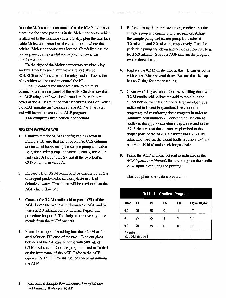
far left will not be used for this configuration. Designateeach valve by starting from the second valve to your right Electrical Connectionsas A, B, and C. Confirm that valves A and B are controlled Verify that the front PUMP 1 and PUMP 2 Powerby E5 and valve C is controlled by E6 of the AGP. Plumb switches of the SCM are off. Using the power cordsthe system as indicated in Figure 2. The 0.020-in. !.D. provided (pIN 96078), connect the ac receptacles on the
rear panels of the SCM and AGP to the white outlets of thepower strip located on the rear upper section of the systemenclosure. Next, connect the ac receptacle of the power
AGP Sample Carrier strip enclosure to an ac (110V) power outlet.Sample I Pump Peristaltic Pump Next install the interface cable (pIN 43044). One endOut JJCG2 ~CG2 Pump' '
~ Pulse of the interface cable connects to the rear panel of the AGP~Damper .~CG2 and the other end connects to a connector 10 the ICAP
main power board. Start by turning off the line voltage tol . the ICAP intelligent controller. The circuit breaker to be
CarrierOut turned off is located on the rear power panel of the ICAP
instrument. Next, loosen (or remove) the screws on the. rear power panel and carefully open the power panel toI reveal the electronics. On the left side of the electronics
panel is a printed circuit board containing three 12-pin- Off Sample To ICAP Molex nylon connects in a row. Carefully remove the- - - - On In center Molex connector (J3-N) by gripping the sides of the
A & B Controlled by E5 connector and pulling straight up. Note the positions of theC Controlled by E6
wires in the connector. Using the Molex pin extractor tool,remove the wire(s) at the 1 and 10 or 4 and 7 positions
Figure 2 Pneumatic and hydraulic schematic of the sample
preconcentration systemTechnical Note 29 3
from the Molex connector attached to the ICAP and insert 5. Before turning the pump switch on, confinn that thethem into the same positions in the Molex connector which sample pump and carrier pump are primed. Adjustis attached to the interface cable. Finally, plug the interface the sample pump and carrier pump flow rates atcable Molex connector into the circuit board where the 5.0 mUmin and 2.0 mUmin, respectively. Turn theoriginal Molex connector was located. Carefully close the peristaltic pump switch on and adjust its flow rate to atpower panel, being careful not to pinch or sever the least 5.0 mUmin. Start the AGP and run the programinterface cable. two or three times.
To the right of the Molex connectors are nine relaysockets. Check to see that there is a relay (labeled 6. Replace the 0.2 M oxalic acid in the 4-L carrier bottleSOURCE or Kl) installed in the relay socket. This is the with water. Rinse several times. Be sure that the caprelay which will be used to control the IC. has an O-ring for proper sealing.
Finally, connect the interface cable to the relayconnector on the rear panel of the AGP. Check to see that 7. Clean two l-L glass eluent bottles by filling them withthe AGP relay "dip" switches located on the right top 0.2 M oxalic acid. Allow the acid to remain in thecover of the AGP are in the "off" (forward) position. When eluent bottles for at least 4 hours. Prepare eluents asthe ICAP initiates an "exposure," the AGP will be reset indicated in Eluent Preparation. Use caution inand will begin to execute the AGP program. preparing and transferring these reagents in order to
This completes the electrical connections. minimize contamination. Connect the filled eluentbottles to the appropriate eluent cap connected to the
SYSTEM PREPARA nON AGP. Be sure that the eluents are plumbed to the1. Confinn that the SCM is configured as shown in proper ports of the AGP (El: water and E2: 2.0 M
Figure 2. Be sure that the three IonPac CG2 columns nitric acid). Adjust the eluent bottle regulator to 4 to 6are installed between: 1) the sample pump and valve psi (30 to 40 kPa) and check for gas leaks.
B; 2) the carrier pump and valve C; and 3) the AGPand valve A (see Figure 2). Install the two IonPac 8. Prime the AGP with each eluent as indicated in theCG5 columns in valve A. AGP Operator's Manual. Be sure to tighten the needle
valve upon completing the priming.
2. Prepare 1 L of 0.2 M oxalic acid by dissolving 25.2 g. .of reagent grade oxalic acid dihydrate in 1 L of This completes the system preparation.
deionized water. This eluent will be used to clean theAGP eluent flow path.
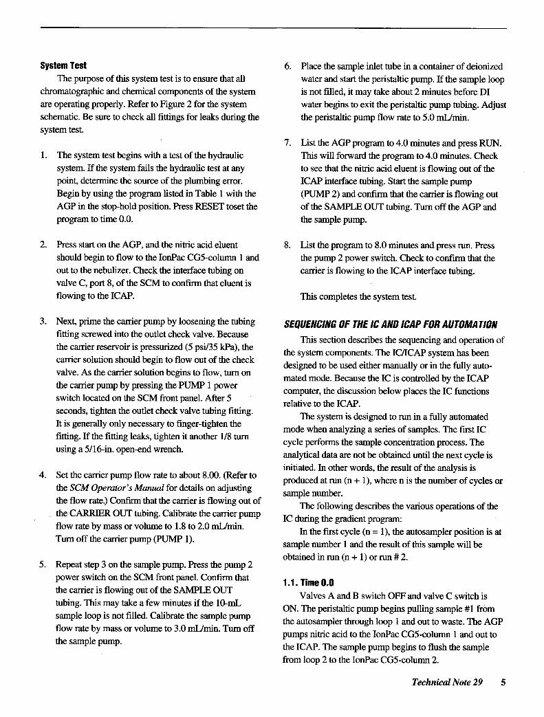
3. Connect the 0.2 M oxalic acid to port 1 (El) of theAGP. Pump the oxalic acid through the AGP and to Time E1 E2 E5 E6 Flow (ml/min)
waste at 2.0 mUmin for 10 minutes. Repeat this 0.0 25 75 0 1 1.7procedure for port 2. This helps to remove any trace 4.0 25 75 1 1 1.7metals from the AGP flow path.
9.0 25 75 0 0 1.7
4. Place the sample inlet tubing into the 0.20 M oxalic E1: wateracid solution. Fill each of the two l-L eluent glass E2: 2.0 M nitric acid
bottles and the 4-L carrier bottle with 500 mL of0.2 M oxalic acid. Enter the program listed in Table 1on the front panel of the AGP. Refer to the AGPOperator's Manual for instructions on programmingthe AGP.
4 Automated Sample Preconcentration of Metalsin Drinking Water for [CAP
System Test 6.. Place the sample inlet tube in a container of deionizedThe purpose of .this system test is to ensure that all water and start the peristaltic pump, If the sample loop
chromatographic and chemical components of the system is not filled, it may take about 2 minutes before DIare operating properly. Refer to Figure 2 for the system water begins to exit the peristaltic pump tubing. Adjustschematic. Be sure to check all fittings for leaks during the the peristaltic pump flow rate to 5.0 mUmin.system test.
7, List the AGP program to 4,0 minutes and press RUN.1. The system test begins with a test of the hydraulic This will forward the program to 4.0 minutes. Check
system. If the system fails the hydraulic test at any to see that the nitric acid eluent is flowing out of thepoint, determine the source of the plumbing error. ICAP interface tubing. Start the sample pumpBegin by using the program listed in Table 1 with the (PUMP 2) and confirm that the carrier is flowing outAGP in the stop-hold position. Press RESET toset the of the SAMPLE OUT tubing. Turn off the AGP andprogram to time 0.0. the sample pump.
2. Press start on the AGP, and the nitric acid eluent 8. List the program to 8.0 minutes and press run, Pressshould begin to flow to the IonPac CG5-column 1 and the pump 2 power switch. Check to confirm that theout to the nebulizer. Check the interface tubing on carrier is flowing to the ICAP interface tubing.valve C, port 8, of the SCM to confmn that eluent isflowing to the ICAP. This completes the system test.
3. Next, prime the carrier pump by loosening the tubing SEQUENCING OF THE IC AND ICAP FOR AUTOMA nONfitting screwed into the outlet check valve. Because Thi ' d .b th ' d . fs section escn es e sequencmg an operanon 0
the carrier reservoir is pressurized (5 psi/35 kPa), theth t Th IC/ICAP h beee sys em components. e system as n
carrier solution should begin to flow out of the check d . ed be d ' th all , th fulleslgn to use el er manu y or m e y auto-valve, As the carrier solution begins to flow, .turn on d d B th IC .
lIed b th ICAPmate mo e. ecause e IS contro y ethe carrier pump by pressing the PUMP 1 power , . .
computer, the diScussIon below places the IC functionsswitch located on the SCM front panel. After 5 relative to the ICAP.seconds, tighten the outlet check valve tubing fitting. Th . d . ed . full ted. . e system IS eslgn to run may automaIt IS generally only necessary to fmger-nghten the d h al . . f 1 Th firs ICmo e w en an yzmg a senes 0 samp es. e tfitting. If the fitting leaks, tighten it another 1/8 .turn 1 r£ th 1 .
Th. . cyc e pe orms e samp e concentration process. eusmg a 5/16-m. open-end wrench. al . alda be b . d .1th 1 ' an ytic.ta are not 0 t:aine unn e next cyc e IS
initiated, In other words, the result of the analysis is4. Set the carrier pump flow rate to about 8.00. (Refer to d d t ( 1) h ' th be f 1pro uce a run n + , were n IS e num r 0 cyc es or
the SCM Operator's Manual for details on adjusting1 besamp e num r.
the flow rate.) Confirm that the carrier is flowing out of Th Ii 11 . d 'b th . ~f the 0 oWIng escn es e vanous operauons 0 e
the CARRIER OUT tubing. Calibrate the carrier pump IC d . th di tunng e gra en program:flow rate by mass or volume to 1.8 to 2.0 mUmin. In th fir t 1 ( 1) th t 1 .ti..
e s cyc e n = , e au osamp er pOSl on IS atTurn off the carrier pump (pUMP 1). , .
sample number 1 and the result of .this sample will beobtained in run (n + 1) or run # 2.
5, Repeat step 3 on the sample pump, Press the pump 2power switch on the SCM front panel. Confirm that 1 1 T"
0 0" " Ime "the carrier is flowing out of the SAMPLE OUT Val A d B . h OFF d al C . h .
ves an swl.tc an v ve swltC IStubing. This may take a few minutes if the 10-mL ON Th . tal . b ' lli 1 #1 fr.. . e pens tic pump egtns pu ng samp e om
sample loop IS not filled. Calibrate the sample pumpth t 1 thr h 1 1 d Th AGPe au osamp er oug oop an out to waste. e
flow rate by mass or volume to 3.0 mUmin. Turn off .. .d th I nP CG5 1 1 dpumps m1nc aCl to e 0 ac -co umn an out to
the sample pump. .the ICAP. The sample pump begms to flush the samplefrom loop 2 to the IonPac CG5-column 2.
Technical Note 29 5

2.1. Time 4.0 either begins in a flush mode or in an exposure mode. AtValves A, B, and C switch ON. The sample pump the initiation of an exposure, a signal is sent to the AGP.1f
begins to flush the sample from loop 1 to the IonPac CG5- the AGP is in the "start" mode, the signal from the IC~column 1. The AGP pumps nitric acid to the IonPac CG5- controller to the AGP will reset the AGP program to tlmecolumn 2 and out to the ICAP. The peristaltic pump begins 0.0 and the program will begin to run.pulling sample #1 from the autosampler through loop 2and out to waste. IC/ICAP OPERA TION
The second cycle is initiated at time 8.0 minutes. This section describes the integrated operation of the
IC/ICAP system. For details on ThermoSpec software,In the second cycle, the autosampler position is at refer to the appropriate TJA manual.
sample number 2. The first sample has been concentratedin the IonPac CG5 column. The result of the second Methods Developmentsample will be obtained in run #3. 1. Begin by writing a ThermoSpec method titled
"IC/ICAP". Under Methods Development, Set-up,2.1. Time 0.0 select the elements of interest (PI) and also select the
Valves A and B switch OFF and valve C switch is duplicate (F3) function for each element. Select theON. The peristaltic pump begins pulling sample #2 from elements and the duplicate of each element in thethe autosampler through loop 1 and out to waste. The order in which you want them printed in the report.concentrated metals of sample #1 from the IonPac CG5- Add an additional element, such as Na, which can becolumn 1 are eluted to the ICAP with nitric acid delivered duplicated using the F3 function key. This elementby the AGP. The sample pump begins to flush sample #1 (assigned as Na-3) will be used to extend the gradientfrom loop 2 to the IonPac CG5-column 2. program to 8.0 minutes in the automated mode (see
step 3 below for more details). Press F9 to save the2.2. Time 4.0 element selection.
Valves A, B, and C switch ON. The sample pumpbegins to flush the sample #2 from loop 1 to the IonPac Note: The order in which the elements are printed inCG5-column 1. The concentrated metals of sample #1 the analysis report can be selected under Options, F8,from the IonPac CG5-column 2 are eluted to the ICAP from the Main Menu under Methods Development.with nitric acid delivered by the AGP. The peristaltic pumpbegins pulling sample #2 from the autosampler through 2. Next, press F3, Output. Change the number of repeatsloop 2 and out to waste. to 1 and the concentration to ppm or ppb. Select print
Remember to include the blank sample (water) at the limits as desired. Press F9 to save.end of the analysis since the last sample requires an addi-tional cycle to complete the analysis. In the automated 3. For F5, Element Info, the element heading will bemode, the gradient program is reset by the ICAP control at changed and the standard(s) concentrations entered.8.0 minutes and never reaches the last step, time 9.0 Start by changing the element heading. For theminutes, of the gradient program. However, in the last run elements in timing group 1 (first measurement), enterwhen the gradient is not reset, the AGP continues to run to the element symbol followed by "-I." For example,9.0 minutes where the IC is put in "standby" mode. If the "Cu-I," "Fe-I," "Na-I ", etc. For the elements in thesystem operates in manual mode, make sure that the new timing group 2 (second measurement), enter theexposure starts at time 8.0 minutes. element symbol followed by "-2." Assign Na-3 in
The IC is controlled by a relay from the ICAP system timing group 3.controller. When an ICAPrun is initiated, the computersends a signal to the intelligent controller. The controller
6 Automated Sample Preconcentration of Metalsin Drinking Water for ICAP
Enter the appropriate concentration for each element. 8. Press F5, Overlay, to overlay several time scans.Generally, a two-point calibration routine is used, a Notice that all the concentrated metals elute withblank "BLANK" and a high standard "HIGH Sill." nearly the same retention times.Be sure that the correct concentration is entered foreach element and that only a high standard and a blank The time scan can be stored if required.appear in the method. Press F9 to save. Be sure to save
the entire method. 9. Repeat the time scan. The retention time of the peakshould not vary by more than 3 seconds. Continue
4. At this point, it is necessary to run a time scan. Press repeating the time scan until the retention time isF6 for Scan and F7 for Time Scan. Remember that the :t 3 seconds. Return to the Main Menu for methodstime scan will be obtained in the second cycle after the development.sample is introduced into the IC. The Time Scanfeature will be used to determine the retention times of 10. Press F2, Internal Standards, to enter the timingthe first and second bands. Place the sample inlet tube groups. For timing group 1, enter a preintegration timeinto the high standard and turn on the peristaltic pump (in seconds), determined from the first concentrationwhen initiating the fIrst run cycle. band of the time scan. This preintegration time is the
time from the beginning of the exposure to when a5. In the Time Scan mode, the spectrophotometer peak begins to elute. To allow for minor shifts in
monitors the plasma for a user-specified time (much retention times, it is advisable to enter a preintegrationlike a chromatographic detector). Enter an integration time about 1 to 2 seconds less than the measured times."slice" of 4.8 and press ENTER. Enter 100 for the For the integration time, add about 5 seconds to thenumber of time slice. This will result in a time scan of measured base width and enter this value (typically480 s. After the fIrst cycle, press Fl, run at time 8.0 30 to 40 seconds).minutes. The controller will go to an exposure mode(The "EXP" LED will light), and a signal sent to the For timing group 2, enter a preintegration time and anAGP resets the program to time 0 and starts the AGP integration time for the second concentration region.program. The exposure will end in 480 seconds. Calculate the values the same as you did for the fIrst
concentration region.7. The results of the time scan displayed on the screen Since an 8-minute cycle is required for each run, a
should look like Figure 1. For concentrated elements, "dummy" timing group 3 is used to keep the programtwo discrete regions are present in the time scan. The running until 8.0 minutes. Otherwise the exposure will endfirst region is the first concentration band. This at the second preintegration time (timing group 2) and therepresents the concentrated sample from the IonPac next cycle will be initiated. For timing group 3, ~nter aCG5-column 1. The second region represents the preintegration time of 475 seconds for 5 seconds.second band and is subsequently eluted off the IonPac Press F9, Save, to complete the methods development.CG5-column 2. Press Fl, Expand, and move the Be sure to save the entire method.cursor to determine the time at which the peak begins The system is ready for standardization. Standardiza-to elute. Note this time for comparison to the next run. tion of the ICAP system with the IC is performed in theDetermine the width of the peak at the base using the same manner as normal ICAP standardization. Standardiza-cursor. Typical base width is 20 to 30 seconds. tion can be performed manually or with the autosampler.
Technical Note 29 7
Teflon is a registered trademark of E.I. du Pontde Nemours & Co. 10nPac is a trademark ofDionex Corporation.
* Ptinted on recycled and recyclable paper
Dionex Corporation Dionex Corporation Dionex U.S. Regional Offices Dionex Canada Ltd. Dionex (UK) Ltd Dionex GmbH Dionex S.rl. Dionex S.A Dionex B V Nippon Dionex K.K.1228 Titan Way Salt Lake City Technical Ctr Sunnyvale, CA (408) 737-8522 Mississauga, Ontario Carnberley, Surrey Idsteiu Rome lollY en losas Breda Yodogawa-ku, OsakaP.O Box 3603 1515 W. 2200 South, Ste. A Westmout, JL (708) 789-3660 Canada United Kingdom Germany Italy France The Netherlands lapanSunnyvale, CA Salt Lake City, UT Houstun, TX (713) 847-5652 (416) 855-2551 (0276) 691722 (06126) 991-0 (06) 30895454 (I) 39 46 08 40 (076) 714800 (06) 885-121394088-3603 84119-1484 Smyrna, GA (404) 432-8100(408) 737-0700 (801) 972-9292 Marltou, NI (609) 596-0600 LPN 034838 5M 12/92
@ 1992 Diunex Corporation