d reference guide for - iscar cutting tools s quick die and mold making reference guide for die and...
TRANSCRIPT

Third
Edition
Metric Version
www.iscar.com www.iscar.com
ISCAR’s QuickReference Guide forDie and Mold MakingISCAR’s Quick
Reference Guide forDie and Mold Making
ISCA
R’s
Quic
k Re
fere
nce
Guid
e fo
r Di
e an
d M
old
Mak
ing
Met
ric V
ersi
on

ISCAR LTD.HeadquartersTefen 24959, IsraelTel + 972 (0)4 997 0311Fax + 972 (0)4 987 [email protected]
Argentina ISCAR TOOLS ARGENTINA SAMonteagudo 222 1437 Buenos AiresTel + 54 114 912 2200Fax + 54 114 912 [email protected]
AustraliaHeadquarters and Technical Centre Norwest Business Park 30 Brookhollow AvenueBaulkham Hills NSW 2153 Australian Technical Training CentreBell Street, Preston, Victoria, 3072Tel + 61 (0) 2 8848 3500 Fax + 61 (0) 2 8848 [email protected]
Austria ISCAR AUSTRIA GmbH Im Stadtgut C 2A-4407 Steyr-GleinkTel + 43 7252 71200-0Fax + 43 7252 [email protected]
BelarusJV ALC “TWING-M” Slutskaya str. 3,223056 v. SennitsaMinsk districtTel +375 17 506-32-38 +375 17 506-33-31/65Tel/Fax +375 17 [email protected], www.iscar.by
Belgium n.v. ISCAR BENELUX s.a.Roekhout 13B 1702 Dilbeek (Groot-Bijgaarden)Tel + 32 (0) 2 464 2020Fax + 32 (0) 2 522 [email protected]
Bosnia(Representative Office) Kralja Tvrtka I br. 17 BIH- 72000 ZenicaTel +387 32 201 100Fax +387 32 201 [email protected]
Brazil ISCAR DO BRASIL COML. LTDA. Rodovia Miguel Melhado Campos, Km 79, Bairro MoinhoCEP: 13280-000 - Vinhedo - SPTel + 55 19 3826-7100Fax + 55 19 3826-7171DDG 0800 701 [email protected]
BulgariaISCAR BULGARIA Starozagorska 1, Str.Floor 1, Office G,6100 Kazanlak Tel/Fax +359 431 [email protected]
CanadaISCAR TOOLS INC.2100 Bristol CircleOakville, Ontario L6H 5R3Tel + 1 905 829 9000Fax + 1 905 829 [email protected]
ChinaISCAR CHINA7B21, Hanwei Plaza, 7 Guanghua RoadChaoyang DistrictBejiing 100004Tel + 86 10 6561 0261/2/3Fax + 86 10 6561 [email protected] www.iscar.com.cn
CroatiaISCAR ALATI d.o.o.J. Jelačiča 134CRO-10430 SamoborTel +385 (0) 1 33 23 301Fax +385 (0) 1 33 76 145 [email protected]
Czech Republic ISCAR CR s.r.o.Mánesova 73, 301 00 PlzenTel + 420 377 420 625Fax + 420 377 420 [email protected]
FinlandISCAR FINLAND OYAhertajantie 6 02100 Espoo Tel +358-(0)9-439 1420Fax +358-(0)9-466 [email protected]
FranceISCAR FRANCE SAS8, Rue Georges Guynemer78286 GUYANCOURT CedexTel + 33 (0)1 30 12 92 92Fax + 33 (0)1 30 43 88 [email protected]
GermanyISCAR GERMANY GmbH Eisenstockstrasse 14D 76275 EttlingenTel + 49 (0) 72 43 9908-0Fax + 49 (0) 72 43 [email protected]
HungaryISCAR HUNGARY kft Kassai u 151H 1142 BudapestTel + 36 1 251 5688Fax + 36 1 251 [email protected]
ItalyISCAR ITALIA srlVia Mattei 49 / 5120020 Arese [MI]Tel + 39 02 93 528 1Fax + 39 02 93 528 [email protected]
JapanISCAR JAPAN LTD.Head Office 15th Floor, Senri Asahi Hankyu Building1-5-3, Shinsenri-Higashimachi Toyonaka-Shi, Osaka 560-0082Tel + 81 6 6835 5471Fax + 81 6 6835 [email protected]
Macedonia(Representative Office) Londonska 19/4MK-1000 Skopje Tel +389 2 309 02 52Fax +389 2 309 02 54 [email protected]
MexicoISCAR DE MÉXICO, S.A de C.V.Fray Pedro de Gante 15Col. CimatarioQuerétaro, Qro.C.P. 76030Tel + 52 (442) 214 5505Fax + 52 (442) 214 [email protected] www.iscar.com.mx
The Netherlands ISCAR NEDERLAND B.V.Postbus 704, 2800 AS GoudaTel + 31 (0) 182 535523Fax + 31 (0) 182 [email protected]
New ZealandISCAR PACIFIC LTD.1/501 Mt. Wellington Hwy.Mt. Wellington AucklandTel + 64 9 5731280Fax + 64 9 [email protected]
Poland ISCAR POLAND Sp. z o.o.ul. Gospodarcza 1440-432 KatowiceTel + 48 32 735 7700Fax + 48 32 735 [email protected]
PortugalISCAR PORTUGAL, SAAvd.Dr.Domingos Caetano de Sousa Fracção B, Nº 5414520-165 Santa Maria da FeiraTel + 351 256 579950Fax + 351 256 [email protected] www.iscarportugal.pt
RomaniaISCAR TOOLS SRLStr. Maramures nr. 38, Corp 2, Otopeni, jud. Ilfov, cod 010832Tel + 40 (0)312 286 614Fax + 40 (0)312 286 [email protected]
RussiaMoscowISCAR RUSSIA CISGodovikova str. 9, build. 10129085 Moscow Tel/fax +7 495 660 91 25/31 [email protected]
ChelyabinskISCAR RF EAST LTDMalogruzovaya str., 1 - office 605 454007, ChelyabinskTel/fax +7 351 [email protected] www.iscar.ru
SerbiaISCAR TOOLS d.o.o.Autoput 22SRB-11080 Zemun Tel +381 11 314 90 38Fax +381 11 314 91 [email protected]
SlovakiaISCAR SR, s.r.o.K múzeu 3010 03 ZilinaTel +421 (0) 41 5074301Fax +421 (0) 41 [email protected]
SloveniaISCAR SLOVENIJA d.o.o.IOC, Motnica 14SI-1236 TrzinTel + 386 1 580 92 30Fax + 386 1 562 21 [email protected]
South Africa ISCAR SOUTH AFRICA (PTY) LTD. 47 Lake RoadLongmeadow Business Estate - NorthExtension 7, Modderfontein,Edenvale, GautengP.O. Box 392Longmeadow Business Estate - North 1609ShareCall 08600-47227Tel +27 11 997 2700Fax +27 11 388 [email protected]
South Korea ISCAR KOREA304 Youggye-Ri, Gachang-myeonDalsung-gun, Daegu 711-860Tel + 82 53 760 7590Fax + 82 53 767 [email protected]
Spain ISCAR IBERICA SA Parc Tecnològic del VallèsAvda. Universitat Autònoma 19-2108290 Cerdanyola-BarcelonaTel +34 93 594 6484Fax +34 93 582 [email protected]
SwedenISCAR SVERIGE ABKungsangsvagen 17BBox 845751 08 UppsalaTel + 46 (0) 18 66 90 60Fax + 46 (0) 18 122 [email protected]
Switzerland ISCAR HARTMETALL AGWespenstrasse 14CH 8500 FrauenfeldTel + 41 (0) 52 728 0850Fax + 41 (0) 52 728 [email protected]
TaiwanISCAR TAIWAN LTD.395, Da Duen South Road, Taichung 408Tel +886 (0)4-24731573Fax +886 (0)[email protected] www.iscar.org.tw
Thailand ISCAR THAILAND LTD. 57, 59, 61, 63 Soi Samanchan-Babos Sukhumvit Rd. Phra Khanong, Khlong Toey Bangkok 10110 Tel + 66 (2) 7136633-8 Fax + 66 (2) 7136632 [email protected]
TurkeyISCAR KESICI TAKIM TIC. VE IML. LTD. STI.Gebze Organize Sanayi Bölgesi (GOSB)Ihsan Dede Cad. No: 105Gebze / KocaeliTel + 90 (262) 751 04 84 (Pbx)Fax + 90 (262) 751 04 [email protected]
UkraineISCAR UKRAINE LLCVolgodonska str., 6602099 KievTel/fax +38 (044) [email protected] www.iscar.ru
United KingdomISCAR TOOLS LTD. Woodgate Business ParkBartley Green Birmingham B32 3DE Tel + 44 (0) 121 422 8585Fax + 44 (0) 121 423 [email protected]
United States ISCAR METALS INC. 300 Westway PlaceArlington, TX 76018-1021Tel + 1 817 258 3200Tech Tel 1-877-BY-ISCAR Fax + 1 817 258 [email protected]
VietnamISCAR VIETNAM (Representative Office)Room D 2.8, Etown Building,364 Cong Hoa, Tan Binh Dist.,Ho Chi Minh CityTel +84 38 123 519/20Fax +84 38 123 [email protected]
7861458
© ISCAR LTD.All rights reserved 02/2017
Dear Die and Mold Maker,
our Distinguished Customer and Colleague,
Our primary concern, as a tool manufacturer, is to provide you with the most progressive and most high-efficiency cutting tools that will meet your requirements and answer the purpose ofmodern technology.
Cutting metal faster and more accurate means cutting machining time and cost per part. In many cases the cutting tool, which is sometimes seen as the more insignificant link in the chain of production costs, presents a barrier to achieving productivity. We, at ISCAR, are aware of that fact; and our ongoing research and development intends to develop those cutting tools that will increase your manufacturing productivity, improve the performance of your workshop and lead your die-making process to be more profitable.
The research and development result in various innovative solutions that we offer to our customers. The variety of ISCAR tools is very rich, and sometimes, it is not so simple to be well oriented in it. Therefore, we hope that this guide will help you in right tool selection and will be a good supplement to our catalogs, reference forms and leaflets because it takes into account specific features of die and mold making. First of all the guide emphasizes the latest solutions in order to give you the opportunity of becoming familiar with them.
Also, we included here some more general information, tips and even historical issues related to the discussed material and hope that you will find them useful.
We will be thankful for your every remark or suggestion regarding the guide.
We consider ourselves as your true colleague in the die and mold making process at your location and will be proud and sincerely pleased if you will feel the same.

Die and Mold
3
Contents
Foreword ......................................................................................................
Die and Mold Materials ...............................................................................
Typical Examples of Dies and Molds ..........................................................
Cutting Tools in the Die and Mold Industry .................................................
Milling Tools ..................................................................................................
1. 90˚ Shoulder Milling ....................................................................
2. Milling Plane Surfaces ................................................................
3. Milling Contoured Surfaces (Profiling) .........................................
Hole Making Tools ........................................................................................
In Summation ................................................................................................
Technical Information ...................................................................................
3
4
8
9
10
13
36
44
119
121
122

4
ISCAR Tool FamiliesReferenced in this Guide
1. Milling Tools
2. Hole Making Tools
Fore
wor
d
Die and Mold
5
Foreword A lot of things around us, parts or even fully completed products, are produced in dies and molds: an internal cylinder block or a toy, a plastic container or a crankshaft, a bottle or a jet turbine blade, a tin soldier or a boat. These objects differ in their form, material, sizes, mechanical properties, and are manufactured by different technological methods of metal forming or processing of plastics.
Broadly speaking a die or a mold, being an assembly unit, comprises various elements, and many of them are standard or unified. A form of a part that is produced in the die or the mold is determined by several main components (cavities, rams, etc.). Shaping the components is a central operation in die and mold manufacturing that demands from die and mold makers rich knowledge, skills and experience. A die and mold maker is rightfully considered as one of the most professionally skilled workers in manufacturing. Modern CNC technology and CAD/CAM systems substantially change die and mold making, turning it from craft into a whole branch of trade.
A part intended to be produced in a die or mold dictates shape and sizes of the die or mold and accuracy requirements; and a forming technology and the part run size – the die or mold material. The part shape and the die or mold material are a source data for die and mold making.
Automotive Industry is a major consumer of dies and molds. Approximately 60% of stamping dies and 40% of plastic molds produce automotive parts.
There are different kinds of dies and molds, which can be grouped in the following principal types: forging dies, stamping (pressing) dies, die casting dies and molds for plastics.
In manufacturing a die or mold, the shape and the sizes are the main factors of the degree of difficulty for machining:• Low degree in case of plane areas, simple shapes, shallow cavities etc.• Medium, when the shape becomes more complicated, the sizes bigger and the cavities deeper; rams have steep walls, etc.• High degree in the context of very complex shape, narrow and deep cavities, considerable difference between heights, etc. Also, difficulty in machining is a function of machinability of the die or mold material.
The key to productive and effective die and mold making is the process planning – the choice of technology of the die or mold manufacturing that, in general, includes machining operations, assembly and finishing works. Today’s CAD/CAM software enables analyzing the die or mold design, defining machining strategy, developing CNC programs and machining simulation in order to find the most efficient solution that allows full use of advantages of modern machine tools. The right machining strategy is directly related to correctly chosen cutting tools that perform material removal during operation. A tool, which seems to be a secondary element of the die and mold process, is a substantial factor of productivity and profitability. We, at ISCAR, distinctly understand the role of cutting tools in the die and mold industry and try to provide the die and mold maker with reliable and efficient tooling that meets every requirement of the branch. The right tool selection depends on different factors. We will discuss them here briefly, explain the tools’ features and thus build a base for the correct tool choice.

Die
and
Mol
d M
ater
ials
6
Die and Mold Materials We have already noticed that a die or mold has different movable and stationary parts (clamping elements, springs, pins, bolts, bushings, support pillars, etc.) generally made from different engineering materials, from plastics to cemented carbides.
However, key die or mold parts that act on specific requirements of the die and mold industry usually are from particular materials, which should be emphasized.
Tool Steels Tool steels relate to a type of steels that, as indicated in its name, is intended first of all for making tools for cutting and forming metals and other materials. There are many national and international standards for specified tool steels. Moreover, in order to answer to the particular requirements of industry, steel manufacturers produce different steels in accordance with their own specification. These steels often have no standard designation and are identified by their trade names. In this guide we use the standards of the American Iron and Steel Institute (AISI) and the Society of Automotive Engineers (SAE). The parallel designation in conformity with other acting standards is sometimes given in the text; and the information section at the end of this guide contains a cross-reference table with comparative designation of tool steels in keeping with the different national standards.
Die and mold makers deal with steel in wide ranges of hardness, from low (HB 200 and less) to high (HRC 63).
In line with the main field of application there are six general and two special-purpose classes of tool steels, from which the following are the most popular in the die and mold industry:
• Cold-work tool steels including A series (air-hardening medium-alloy), D series (high-carbon high-chromium) and O series (oil hardening)• Hot-work H series• Water hardening W series • Plastic mold P series• Shock resistant S series• Special-purpose L series (low-alloy)
In die and mold design, the main properties of tool steels are strength, wear resistance, corrosion resistance, etc. However, while for a die and tool maker dealing with the material, which has already been specified by designers, more important properties are: hardness, machinability, polishability and dimensional stability.
The steel manufacturers supply steels in different delivery conditions: annealed, pre-hardened and hardened. Consequently, in die and mold making process, hardness of tool steel (even the same grade) can vary within a wide range from HB 200 and less (soft steel) to HRC 63 (hard steel). Normally, high stock removal rate characterizes rough machining of a soft material while closed allowances are usual for finish cuts when material hardness is high. The term “pre-hardened steel” is not well-defined. It means that steel is hardened and tempered to relatively not high hardness but different steel producers use different limits for its specification. Generally, it is less than HRC 45, however, in technical literature and references the steels with that hardness often relate to hard steel. The term and its hardness limit are allied to cutting tool development and their ability to cut material. Therefore, steels can be divided into the following conditional groups depending on their hardness:

Die
and
Mol
d M
ater
ials
Die and Mold
7
• Soft annealed to hardness up to HB 250• Pre-hardened to two ranges: - HRC 30-37 - HRC 38-44• Hardened to two ranges: - HRC 45-49 - HRC 50-55 - HRC 56-63 and more
Table 1 shows some features of the most typical tool steels that are common in the die and mold industry.
Not relating directly to tool steels, so called maraging steels (the term includes the words martensitic and aging) became be more and more usable in die and mold making, particularly, in manufacturing plastic molds. They have relatively high Ni and Co percentage, can be supplied in pre-hardened state (HRC 30-36, Maraging 250 and Maraging 300, for instance) and are hardened to HRC 58. Nevertheless, despite their dimensional stability and good polishability, they are still considerably expensive comparing with mold steels, and therefore their application in the die and mold industry is limited.
Category Designation Delivery
Hardening Application examplesAISI/SAE DIN W.-Nr. Annealed to Prehardened
Cold-worktool steels
A2 1.2363 HB 220 HRC 56-60Cold blanking, extrusion,
coining dies, molds
D2
1.2379
HB 210
HRC 56-62
Cold stamping and extrusion diesand punches,
forging dies, master hobs
D3 1.2080 HB 240 HRC 56-62 Cold stamping dies and punches
O1 1.2510 HB 200 HRC 58-62Forming dies and parts,
cold stamping dies
Hot-work tool steels
H11 1.2343 HB 180 HRC 46-52 Hot extrusion dies, plastic molds
H13 1.2344 HB 190 HRC 44-54Die-casting dies, punches,
plastic molds
Plastic mold steels
P20 1.2330 HB 280 HRC 32-36 HRC 48-52 Plastic molds
Shock-resistant steels
S7 HB 200 HRC 50-58Hot forging dies, punches, master
hobs, cold extrusion diesSpecial-purpose steels L6 1.2713 HB 230 HRC 36-44 HRC 50-60
Drop forging dies, die-casting dies, plastic molds
Table 1 Typical Tool Steels for Die and Mold Making

Die
and
Mol
d M
ater
ials
8
Stainless SteelsMartensitic stainless steels (AISI 420, 420F) are widely used for producing plastic molds, especially, for cavities of small to medium sizes with complicated shapes and substantial differences in cross-sections. They are supplied as annealed to HB 200, and their heat treatment after machining is simple.
Alloy Steels and Plain Carbon SteelsAlloy and even plain carbon steels are used for various general parts such as holders, pillars, pins, rings, etc. Moreover, in many cases (low-run production dies, some kinds of molds) AISI/SAE 4130, 4140 and 4150 steels are main materials for forming parts. These three steels are usually supplied in an annealed state or pre-hardened to HRC 32-35 and can be hardened to HRC 44-52.
The die and mold industry handles practically all types of engineering materials, but the most typical for the branch are tool steels.
Cast IronCast iron (especially grey) is also considered as a die and mold material for manufacturing large-sized parts, plates, spacers, bushings and other components where wear is not expected. In addition, nodular cast iron sometimes is used for dies, punches, jigs and pads and even for molds.
Nonferrous MetalsAluminum is not the most popular material in the die and mold industry, but it often used for prototype dies and molds, for multiplied identical molds, short life molds and various extrusion molds because it is easy to machine and low cost. Today aluminum starts to penetrate into resin mold manufacturing due to its much better thermal conductivity, machinability and polishability compared to mold steels. The following aluminum alloys: 2024, 6061 and 7075 (in accordance with the Aluminum Association Alloy and Temper Designation System) are more and morecommon in mold making practice.
Beryllium-copper alloys and zinc alloy are materials for blow molds, injection mold components and cavity inserts. Modern metal producers offer beryllium-copper alloys that have enough strength and good wear and corrosion resistance properties. In machining, they are cut 2-3 times faster than tool steels. The alloys’ hardness is HRC 30-42, depending on the hardness grade. For this reason the beryllium-copper alloys can replace traditional tool steels and stainless steels as a mold material in some cases.
Electrical discharge machining (EDM) is another important field of nonferrous metals applicationin die and mold making. Electrodes for EDM are produced from brass, copper, copper tungsten(60-70% of tungsten) and graphite.

Die
and
Mol
d M
ater
ials
Die and Mold
9
Machinability of Die and Mold MaterialsThe following data can be useful for estimating machinability of common die and mold materials in regular delivery conditions. Machinability rating is based on AISI/SAE 1212 free cutting steel as 100%.
¹ ASTM is the American Society for Testing and Materials
Carbon steels1020 72% 1030 72% 1045 57%1060 51% 1212 100% 1215 136%
Alloy steels4130 72% 4140 66% 4340 57%5015 78% 8620 68% 8720 68%
Tool steelsA2 42% D2 27% D3 28%D7 25% H11 49 H12 46%H13 46% H19 43% H21 36%L6 39% O1 42% O6 57% P2 42% P5 42% P20 38%P21 38% S1 36% S5 31% S7 45% W1 48% W2 45%
Martensitic stainless steels403 55% 420 45% 430 45%
Grey cast iron (ASTM A48-76 classes¹)20 (DIN GG 10) 73% 40 (DIN GG 25) 48%
Nodular cast iron (ASTM A 536-80 classes)65-45-12 (DIN GGG 50) 61% 80-55-06 (DIN GGG 60) 39%
Aluminum alloys6061-T 200% 7075-T 140%
Copper and copper alloys 80%-120%
Maraging 300 33%
Typi
cal E
xam
ples
of D
ies
and
Mol
ds
10
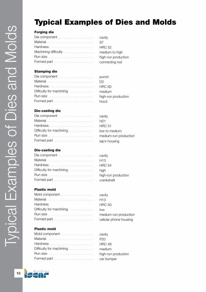
Typical Examples of Dies and MoldsForging dieDie component…………….................... cavityMaterial…………….……….................... S7Hardness……………...............………... HRC 52Machining difficulty................................. medium to highRun size………………..............……..... high-run productionFormed part………………..................... connecting rod
Stamping dieDie component…………….................... punchMaterial……………………..................... D2Hardness…………………….................. HRC 60Difficulty for machining……................... mediumRun size……………………................... high-run productionFormed part………………..................... hood
Die-casting dieDie component…………….................... cavityMaterial……………………..................... H21Hardness…………………….................. HRC 51Difficulty for machining……................... low to mediumRun size……………………................... medium-run productionFormed part………………..................... tap's housing
Die-casting dieDie component…………….................... cavityMaterial……………………..................... H13Hardness…………………….................. HRC 54Difficulty for machining……................... highRun size……………………................... high-run productionFormed part………………..................... crankshaft
Plastic moldMold component………….................... cavityMaterial……………………..................... H13Hardness HRC 50Difficulty for machining……................... lowRun size……………………................... medium-run productionFormed part………………..................... cellular phone housing
Plastic moldMold component……………................. cavityMaterial……………………..................... P20Hardness…………………….................. HRC 48Difficulty for machining……................... mediumRun size……………..............………..... high-run productionFormed part………………..................... car bumper

Die and Mold
11
Cutting Tools inDie and Mold IndustryIn die and mold manufacturing, there are different machining operations: cutting (milling, drilling, reaming, etc.), abrasive machining (grinding, polishing, honing, etc.) and EDM. Even water jet cutting is used by die and mold makers. However, metal cutting remains to be the predominant method of die and mold production.
Dies and molds have different shapes and sizes, varying from small to large. In many cases machining dies and molds requires removing a large amount of material. A typical machining process contains rough and finish cutting operations. The main parameter for rough machining with a large stock allowance is metal removal rate, while for finishing, the most important factors are accuracy and surface finish.
For the development of machine tools, CNC control and CAD/CAM systems cardinally changed the die and mold industry by giving the die and mold maker new methods of multi-axis machining and introducing advanced computer techniques of machining simulation and verification. Modern cutting strategies, such as high speed machining (HSM), high feed milling (HFM) and trochoidal milling have penetrated into die and mold production. Machining hard materials, long tool life, stability, reliability and high performance intended for reducing or even full elimination EDM and manual polishing – only the tool that meets these requirements can be considered a passport to success in productive and effective die and mold making.

Milli
ng T
ools
12
Milling Tools
Milling plays a key role in machining dies and molds. Indeed, milling tools remove the most share of material, shaping a workpiece to a die or mold part. A conventional process planning comprises rough, semi-finish and finish milling operations. The traditional approach to rough milling is based on cutting with large depth and width of cut. Correspondingly, it demands high-power machine tools with low spindle speeds for large milling tools. This way of machining provides maximum productivity when cutting a soft material. Due to a die or mold has appropriate hardness requirements and in addition, heavy-duty rough milling leads to significant residual stresses, further heat treatment is necessary. The mentioned approach usually characterizes production of large-sized die and mold parts that have considerable differences in depth or height. However, some producers are still supporters of this method due to limitations of available machine tools, CNC programs or traditional thinking in process planning. Over time, and as industrial innovations developed, HFM became a relevant technique in roughing. It allows machining soft to pre-hardened steels with small depth of cut and extremely high feed per tooth and leads to increased productivity.
HSM, another modern way of metal cutting, is intended first of all for finish milling of hard steels. Nevertheless, it can be effective also for rough and semi-finish machining, particularly for small to medium parts or in cases with slight differences in depth or height because it enables cutting hard material directly. Further HSM development has resulted in trochoidal milling.
Yet one method of rough milling growing in popularity in the die and mold industry is plunge milling (or plunging) with a tool feed direction towards the tool axis. It gives the opportunity for efficient roughing of cavities and external surfaces with a complex shape (so called sculpturing operations).
The modern milling techniques, their advantages and problematic points and requirements of cutting tools will be discussed on the following pages of the guide. All typical milling operations are involved in die and mold manufacturing: 90˚ shoulder milling, face milling, milling slots, contours and chamfers; and profile milling (the parallel definition of the operations: shouldering, facing, slotting, countering, chamfering and profiling, also are often used by professionals). The latter, including machining shaped 3D surfaces, is the pivot of die and mold making. Milling tools are available in different configurations: indexable, that has replaceable cutting inserts or whole cutting heads, and solid.
Milli
ng T
ools
Die and Mold
13
Selection Guideline: How to Choose the Right Milling ToolPutting the question of tool selection into broad perspective, the main side of the issue shall be emphasized: cost per unit (CPU) for a part that is machined by the tool. In spite of the fact that the tooling cost share in CPU is minor, the tool’s indirect influence on CPU reduction can be considerable. Namely the tool, this small part of a manufacturing process, sometimes is a single obstacle for a machine tool to run faster and thus to cut machining time.Hence, for better productivity and as a result for lower CPU the most high-efficiency tool should be used.Another important aspect is versatility of the cutting tool, its ability to perform various milling operations effectively. For example: shoulder milling, ramping and plunge milling. Such combinations allow for using one tool for different applications and, when machining a part, shortening time needed for tool change during machining.An additional way of increasing versatility is using the tools with interchangeable precise cutting heads, which render a possible head change when the tool or its holder is clamped into a machine spindle and does not require time for setup procedures.
Taking these so obvious, but often left out points into consideration and speaking about the tool selection more specifically, the analysis by chain: Application-Geometry-Grade (AGG) shall be applied. In brief, AGG means the following commonly known checkpoints - questions, answer on which allows for the tool choice:
Application What is the type of machining operation? Workpiece: its material, hardness before the operation Required accuracy and surface finish Machining allowance Machining strategy Type of machining (light, medium, heavy) What type of tool, in accordance to adaptation (a mill with shank, shell mill)? Operation stability (good, bad) Machine tool (sufficient/limited power, condition, spindle speed) Coolant (coolant type: dry, wet; possibility of coolant throw spindle)Geometry Which cutting geometry is recommended for machining the workpiece for the above requirements? Both types of tools should be checked: indexable and solid.Grade Which grade of a cutting tool material is more suitable for machining the workpiece for the above requirements?
Carbide Grades for Indexable Milling InsertsThe indexable inserts for milling the die and mold materials are produced from different tungsten carbide grades, mostly coated by methods of physical or chemical vapor deposition (PVD and CVD respectively).PVD coatings have a wide distribution in milling inserts and solid carbide endmills because they leave the cutting edges sharp. PVD coatings are applied at relatively low temperature(about 500 ˚C).CVD coatings are much thicker and that contributes to wear resistance. The CVD coatings are applied at high temperature (approximately 1000 ˚C). Current technology enables improving CVD process by moderate-temperature CVD (MT CVD) with its lower deposition temperatures. Further steps in technology development include combinations of both coating methods: CVD and PVD.ISCAR offers a rich program of the carbide grades for the milling inserts. We observe briefly the more recent of them intended primarily for machining the popular die and mold materials. Except for grade DT7150, the preferred grades, which are produced by SUMO TEC method, have

Milli
ng T
ools
14
ISO Class
DIN/ISO 513Carbide Grades
IC808 IC5100 IC810 DT7150 IC830 IC330
P P15-P30 P10-P25 P15-P30 P20-P50 P25-P50
M M20-M30 M20-M40 M30-M40
K K20-K40 K05-K20 K05-K25 K05-K25 K15-K40
H H20-H30
Coating PVD MT CVD PVD Combination PVD PVD
Table 2 Selected Carbide Grades for Indexable Inserts Intended for Milling Die and Mold Materials
For more detailed information about the carbide grades and coating technology refer to ISCAR catalogs, guides and technical leaflets.
- First choiceFerritic and martensitic s.s. (ISCAR material groups 12;13)
TougherHarder
a special post-coating treatment with extra advantages. Table 2 contains the comparative data for general characteristics of the grades.IC808 is a grade with tough submicron substrate and titanium aluminum nitride (TiAlN) PVD coating, designed for milling die and mold materials such as hard alloy and carbon steels at medium-to-high cutting speed. They are noted for excellent notch wear and built-up edge resistance.IC5100 – a tough substrate with a MT CVD and alpha aluminum oxide (Al2O3) coating that is recommended for milling grey cast iron at high cutting speeds, providing excellent tool life.IC810 – a PVD grade coated with aluminum titanium nitride (AlTiN) that produces high oxidation resistance, enabling machining at high speed. A good choice for miling nodular and grey cast iron at low to medium cutting speed under unstable conditions.DT7150 – a carbide grade with a tough substrate that has a dual MT CVD and TiAlN PVD coating. Features high wear and chipping resistance. Recommended for medium to high cutting speeds for machining of cast iron and cast steel, especially with siliceous skin.IC830 – a PVD TiAlN coated tough grade for milling alloy steel and stainless steel. Shows good results for interrupted cut and heavy duty operations.IC330 – a multi-purpose tough grade with titanium nitride (TiN)/titanium carbonitride (TiCN) coating. Used for milling a wide range of die and mold materials, at low to mediumcutting speed.
SUMO TEC carbide grades
The SUMO TEC grades feature a special post-coating treatment which provides substantially improved life and better reliability. The new process enhances toughness and chipping resistance, reduces friction and built-up edge, thus increasing tool life. The golden-colored flank facilitates wear detection. The post-coating treatment has the effect of making the rake face even and uniform, minimizing inner stresses and droplets in coating, which lead to smooth chip flow and extended tool life. Yet at the same time the untreated flank continues to be rough enough for good contact with base surfaces of tool pockets.

Milli
ng T
ools
Die and Mold
15
90˚ Shoulder Milling ISCAR endmills that are intended mostly for 90˚ (square) shoulder milling but used also for milling slots and grooves, are being developed in the following directions:• Endmills with indexable inserts of diameter range 8-50 mm• Solid carbide endmills with diameters to 25 mm• Replaceable milling heads with MULTI-MASTER adaptation (or simply MULTI-MASTER heads) of 6-25 mm diameters• Extended flute endmill cutters of diameter range 12-100 mm The extended flute endmill cutters are for roughing, while the other kinds of endmills are used in all kinds of operations: roughing, semi-finishing and finishing.
Insert with helical cutting edge
In the 1990’s ISCAR introduced new milling cutters which carried indexable sintered carbide inserts APKT 1003 PDR-HM. It was the first insert with a helical cutting edge. Now an insert cutting edge as a part of a helix that is built on a cutting cylinder seems apparent, and many tool manufacturers use this approach for producing their milling inserts. But in the 1990’s it was a real innovative solution. A helical edge ensured constant cutting geometry, smooth cutting and considerably improved insert life. Ground HSS and solid carbide tools, which were known long before, already had helical edges; however, the edge was made by grinding. Nonetheless, producing a replaceable carbide insert with a helical edge by means of pressing technology only was a serious problem at that time, and its solution by ISCAR brought about revolutionary changes in the cutting tools industry. HELIMILL – a line of new milling tools was born.
Endmills with Indexable Inserts The main functional features of the most popular ISCAR endmills with indexable inserts are summarized in Tables 3 and 4. Table 3 shows the number of teeth of the tools as a function of the tool diameter and its maximal depth of cut; and Table 4 is intended for estimating the rampdown ability of the tools.
Machining cavities is a typical feature of die and mold making. Hence, the ability to drill with subsequent milling is an important attribute of a milling tool. Another significant factor is a tool capability to ramp milling when the tool is simultaneously fed in radial and axial directions. If the tool moves axially upward, it is ramp up milling (ramping up); and if it moves axially down – ramp down milling. Maximal rampdown angle characterizing tool possibilities in ramping is a valued feature for tool selection. The angle depends on cutting geometry and the nominal diameter of a tool. For tools with high overhang from a toolholder (long and extra long series of the tool overall length) the rampdown angle should be additionally diminished. Three axes milling by helical interpolation is a widely used method for machining holes especially with a large diameter. A cutter, which travels simultaneously along three coordinate axes of a machine tool, moves planetary about an internal hole diameter and creates the summarized cutting helical movement. The helix angle is dependent of the maximal rampdown angle of the tool performed interpolation. The helical tool path maintains smooth entry in the material and uniform loading of the tool. The particular case of helical interpolation is two axes milling by circular interpolation when only the planetary movement is made. The depth of a machined hole depends on the maximal allowed depth of cut of the tool. Chip evacuation and chip re-cutting are factors that affect a milling tool machined cavities by a different technique.
1

Milli
ng T
ools
16
T290 ELN -05 HP E90ANT490 ELN -08T490 E90LN -08 H490 E90AX -09 HM90 E90A T290 ELN -10
ap 5 7.7 8 8 10 10Tool D Number of Teeth (Effective)
8 110 2 1 112 2; 3 2 114 3 116 4; 5 3; 4 2 2 217 218 220 4; 5 2; 3 3 2; 3 2; 321 322 325 5; 7 3; 4 4 2; 3; 4 3; 428 430 432 6; 8 3; 5 5 3; 4; 5 4; 540 8; 10 4; 6 3; 5; 6 650 7
Inserts T290 LNMT 05 HP ANKT T490 LN..T 08 H490 ANKX 09HM90 AP…10AP…10 T290 LNMT 10
Table 3 Quick Selector for 90˚ Indexable Endmills
Table 3 Quick Selector for 90˚ Indexable Endmills (cont.)
H490 E90AX -12 T490 ELN -13 HM90 E90AD T490 ELN -16 H490 E90AX -17ap 12 12.5 14.3 16 16
Tool D Number of Teeth (Effective)810121416171820 1212225 2 2283032 3 3 2; 3 2 240 4 3; 4 2; 3; 4 3 350 5 4; 5 5 4 4
Inserts H490 AN..X 12 T490 LN..T 13HM90 AD..15AD..15 T490 LN..T 16 H490 AN..X 17

Milli
ng T
ools
Die and Mold
17
Table 4 Rampdown Angle for 90˚ Indexable Endmills
Table 4 Rampdown Angle for 90˚ Indexable Endmills (cont.)
* Lower values for tools with long overall length
** Valid only when H490 ANKX 1706R15T-FF is used.
T290 ELN -05 HP E90AN
T490 ELN -08T490 E90LN -08 H490 E90AX -09 HM90 E90A T290 ELN -10
ap 5 7.7 8 8 10 10Tool D Rampdown angle, ˚
8 2.5 10 2.3 2.5 5 12 2 2.7 32 14 1.5 Ramp Ramp 7 16 1 3.2 15 17 down down 15/4.5* 18 7.5 20 2.4 prohibited prohibited 7.5 421 7.5/2.8* 22 7.5 25 2 5 2.228 2 30 2 32 1.4 3 1.640 1 2.7 1.250 2.7
Inserts T290 LNMT 05 HP ANKT T490 LN..T 08 H490 ANKX 09HM90 AP…10AP…10 T290 LNMT 10
H490 E90AX -12 T490 ELN -13 HM90 E90AD T490 ELN -16 H490 E90AX -17
ap 12 12.5 14.3 16 16Tool D Rampdown angle, ˚
8 10 12 14 Ramp Ramp Ramp 16 17 down down down 18 20 prohibited prohibited 3 prohibited 21 22 25 11.5 28 30 32 5. 3 6.5**40 4 4.4**50 5 3.8**
Inserts H490 AN..X 12 T490 LN..T 13HM90 AD..15AD..15 T490 LN..T 16 H490 AN..X 17

Milli
ng T
ools
18
General Characteristics of the Latest ISCAR Lines ofIndexable Tools for 90˚ Milling
No mismatch
In machining square shoulders by indexable milling tools, the shoulder height can be more than a tool depth of cut (D.O.C.) that is determined by the length of cutting edge of an insert clamped in the tool. In this case the shoulder machining needs two or more continuous passes. Ensuring true 90˚ shoulder profile without a detectible border, steps, marks or burrs between the passes – no mismatch – is an essential feature of modern precise indexable milling tools intended for milling square shoulders. Use of such tools substantially improves productivity by eliminating additional finish cuts and ensures the high-accuracy profile with good surface finish. Perpendicularity of the shoulder wall to its base of no more than 0.02 mm is today a normal requirement to the “no mismatch” milling tools.
HELITANG T490 is a family of milling tools that uses tangentially clamped inserts with four right-hand helical cutting edges. The T490 inserts are available in 8, 12.5 and 16 mm long cutting edges. The smallest tool diameter is 16 mm, with 2 teeth. The line offers the tools in different configuration: end and face mills, replaceable milling heads for ISCAR MULTI-MASTER and FLEXFIT systems; and the tools are available with coarse or fine pitch. Most of the tools are provided with holes for internal coolant supply. The tools are intended for milling square shoulders at high rates, with no mismatch and they are capable of plunging as well.The family features high durability and outstanding tool life, due to the tangentially oriented pocket, the most advanced insert production technology and excellent grade combination.It is interesting to note that none of ISCAR competitors can offer such a small tangential insert as the T490 LN.. 0804PN-R with four cutting edges.
HELIDO H490, a family of tools for 90˚ milling, is an evolution of the original ISCAR HELIMILL line. The H490 AN.. X laydown (radial) insert has 4 right-hand cutting edges. There are 3 standard sizes of the insert with cutting edge lengths 8, 12 and 16 mm.Insert construction is very thick and strong. It is clamped into a dovetail inclined pocket, which provides a very rigid clamping, and has a wiper that leaves an excellent surface finish. Due to its strong construction, unique chip deflector with positive rake angles and good grade combinations, the family stands out high durability, low cutting forces and long tool life. The tools, which are produced with coolant holes, can machine 90˚ shoulders with no mismatch, plunge with large stepover and can perform milling slots and faces. This family combines the most advantageous features of both the HELIMILL – helical cutting edge and positive rake angles; and the MILL2000 – strong construction, most suited for heavy milling applications.
3P ISCAR Premium Productivity Products
Since 2007 this symbol started coming into view on packages of various ISCAR products and on pages of leaflets. The symbol stands for new tools, inserts and toolholders, which are manufactured in accordance with the advanced designed principles and the latest technology, and allow to the customer substantial productivity increase. In addition to the progressive cutting geometry, the key features of the 3P cutting inserts are the new SUMO TEC carbide grades with their special post-coating treatment.

Milli
ng T
ools
Die and Mold
19
SUMOMILL T290 is a family of milling tools with coolant holes that uses tangentially clamped inserts with two cutting edges. The T290 inserts are available in 5 and 10 mm long cutting edges. The inserts are the next evolution of the most popular HELIMILL inserts. As a result of their tangential orientation in the pocket, the inserts allow tool design with larger core diameter, providing a much stronger tool construction, which sustains a higher impact load and reduces the risk of fracture to a minimum. When compared to the current HELIMILL and HELIPLUS tools of similar sizes, the tools of the line feature high long-term strength and remarkable tool life, due to the tangential orientation of the inserts in the pockets and higher tooth density.The tools runs at higher feed speeds (table feeds), producing excellent surface finish and no mismatch; and are suitable for plunging and rampdown applications. Their increased radial and axial rake angles lead to a major reduction in cutting forces, improve tool stability and prolong life of the cutting edge.The T290 unique convex shaped insert enabled the development of small diameter cutting tools of even 8 mm diameter.
Tangential or radial? The question: what is more effective – tangential or radial clamping, often can lead the user to hesitate when selecting the right cutting tool when there are both milling cutters with laydown (radial) inserts and with inserts clamped tangentially. As in many practical cases, the question has no strictly unambiguous answer. The academic studies of the question are beyond the scope of the guide. Therefore, a brief review of advantages and disadvantages of each clamping principle can be useful for the right choice. In general, the tangential configuration allows increasing feed per tooth because the tangential component of a cutting force acts against an insert with more rational orientation of its cross-section. The well-designed tangential insert contributes to optimal loading of a clamping screw while the resultant cutting force is transmitted directly to the cutter body. The tangential clamping enables cutter design with larger core diameter than tools with radial inserts. It is much easier to provide an indexable double-sided insert with helical cutting edges if a tangential configuration is applied. And finally, the tangential clamping configuration also offers a higher insert density. Typically, the milling cutters with tangentially clamped inserts run at high feed rates especially when machining cast iron. However, relative to milling tools with the laydown (radial) inserts, the cutters with the tangential clamping normally have lesser ramping abilities, and their resources for shaping rake face and high positive axial rake, which can significantly reduce cutting forces, are limited. Greater chip gullets in case of the radial inserts go a long way towards better chip evacuation when milling materials such as steel with high metal removal rate, particularly in machining deep cavities. The latest ISCAR design provides the customers with the milling tools with tangential and radial inserts for which in many cases the disadvantages related to tangential and radial clamping correspondingly were overcome. For example, the H490 line with double-sided radial H490 AN…X inserts, real workhorses, are intended for heavy milling operations with high feed per tooth; and T290 line that is based on tangential T290 LN…T inserts is notable by excellent rampdown performance. In either event the question of using the cutters with tangentially or radially clamping inserts should be solved specifically. The ISCAR application specialists will be glad to advise you the best choice.

Milli
ng T
ools
20
How to Start: Cutting Data
General Principles Cutting speed Vc and feed per tooth fz, the first key parameters in milling, depend on different factors. Before everything else, a carbide grade. The harder grade has higher wear resistance and enables higher cutting speed. The tougher grade with its better impact strength is intended for the lesser speed, but allows greater feed per tooth. Machinability of engineering materials is different, and even the same material can be substantially different by its machinability (for example, milling a tool steel in different conditions: annealed, pre-hardened and hardened). Therefore, a specific force needed for removal of a unit of a chip section, and load acting on an insert differ too. It is evident; the machinability factor should be taken into consideration. Insert geometry is also important. A sharp cutting edge, which is brittle and can not stand up against a serious load, sets the upper limit to the feed. The T-land, a negative land protecting the cutting edge, conversely, binds the feed below because too small a feed causes in this case, considerably increased cutting force. Another factor - the milling tool body. A durable design of the body and a reliable method of securing the insert ensure machining under high cutting data. Further, the application. What is the aim of tool use? In rough milling, when a relatively large volume of material is removed, the feed is high and the cutting speed is moderate. At the same time, finish milling operations performing with small allowances demands maximal speeds and small to medium feeds for high machining accuracy and good surface finish. Different limitations such as large overhang (in milling deep cavities, for example), improper clamping, workpiece with a thin wall and others lead to decreasing the speed, the feed or even both. Lastly, the machine tool and toolholding. Poor machine conditions and not rigid toolholders create an additional barrier for increased cutting data.
The mentioned arguments are very general; and no doubt everyone who is involved in metal cutting is familiar with them. They are a good illustration of complex dependence or the cutting data on different attributes. How to go from the generalities to the particulars and specify the starting cutting data? We can take into account the application factor and the machine tool conditions by introducing operation estimation: light, medium and heavy. Then we can prepare the tables with the recommended cutting speed and feed for every milling line and thus provide the user with the cutting data. It is a correct approach; and the cutting data recommendations in full application guides, tool advice software and specific guidelines use it in full.
In the U.S.A., instead of the term “feed per tooth” (“fpt”), “chip load” is often used; “advance per revolution” means “feed per revolution” (“fpr” or “feed”) and “advance per minute” or “feed rate” – “feed speed” (“feed per minute”, “fpm”, or “table feed”).

Milli
ng T
ools
Die and Mold
21
Starting Feed Table 5 contains data for estimating starting feed per tooth. Smaller values more suitable for finish operations and greater feeds usually characterize rough milling. In case of high tool overhang and unstable technological system (poor clamping, cutting thin wall workpieces and so on), the feed should be reduced by 20-30%.
Starting Speed
Vc = Vo x Ks x Kt (1)
Where: Vc – starting cutting speed Vo – basic cutting speed Ks – stability factor Kt – tool life factor
a) Basic cutting speed Vo
Table 9 determines the basic cutting speed depending on carbide grade, workpiece material and type of machining. The basic cutting speed relates to a 20 minute tool-life period. In order to define what is known as light duty, moderate duty and heavy duty machining more rigorous, we introduce the following two-step procedure.
Tooth Loading In shoulder milling, tooth loading is a function of the ratios:• Cutting depth h to a length of cutting edge ap• Width of cut b to the nominal diameter of a milling tool D The tooth loading reflects a fraction of the cutting edge involved in cutting and a cycling path of the tooth in the workpiece material from the tooth entering to the tooth exit. While remaining in the material too long, the tooth experiences more intensive heat loads that affect the tool life. The diagram shown in Fig. 1 allows defining the tooth load, but for a quick rough estimate, Table 6 may be enough.
Type of Machining The tooth load in combination with the feed per tooth defines the type of machining (Table 7). The feed interval from fz min to fz max relate to a field of the estimated starting feeds as above. Do not take literally “minimum”, “maximum” and “moderate” feeds: the feeds closed to the lower border of the field relate to fz min, the average values – to fz moderate, and the feeds closed to the upper border – to fz max.

Milli
ng T
ools
22
ISO ClassDIN/ISO 513
Workpiece material Starting feed fz, mm/tooth, for grades
TypeMat.
Group*σT
N/mm2
Hard-ness, HB
IC808 IC5100 IC810 DT7150 IC830 IC330
P
Plain carbonsteel
1-4 <850 <250 0.1-0.25 0.1-0.25 0.1-0.25 0.1-0.35 0.1-0.4
5>850 <1000
>250 <300
0.1-0.25 0.1-0.25 0.1-0.25 0.1-0.3 0.1-0.4
Alloy steeland
tool steel
6, 7 <1000 <300 0.1-0.25 0.1-0.2 0.1-0.25 0.1-0.3 0.1-0.4
8, 9>1000 <1200
>300 <350
0.1-0.2 0.1-0.18 0.1-0.2 0.1-0.25 0.1-0.3
10 <850 <250 0.08-0.18 0.08-0.15 0.08-0.18 0.1-0.25 0.1-0.25
11>1100 <1450
>325 0.08-0.15 0.08-0.12 0.08-0.15 0.08-0.2 0.08-0.25
M Martensitic s.s.
12, 13 <850 <250 0.08-0.12 0.08-0.15 0.08-0.2
KGrey cast iron 15-16 <1000 <300 0.2-0.35 0.2-0.4 0.2-0.4 0.2-0.3Nodular cast
iron17-18 <1000 <300 0.2-0.35 0.2-0.4 0.2-0.4 0.2-0.3
H Hardened steel
38.1>1480 <1700
HRC 45-49
0.07-0.12 0.07-0.1
38.2>1700 <2000
HRC 50-55
0.06-0.09
39>2000 <2500
HRC 56-63
0.05-0.08
Table 5 Estimated Starting Feed fz
* ISCAR material group in accordance with VDI 3323 standard - First choice for grades For T290 milling tools the table values should be reduced by 30%. For the face mills with inserts HP ANKX…07 and T490 LN..T…08 the table values should be reduced by 20%. For milling hardened steel, see the appropriate chapter for further discussion.
Harder Tougher
hap
34
34
12
12
14
14
1
1bD
Heavy
Moderate
Light
hap
3
4
1
2
1
4
1
4
1
1
Heavy
Moderate
Light
1
2
3
4
bD
b
h ap
D
Fig. 1. Tooth load areas

Milli
ng T
ools
Die and Mold
23
b/Dh/ap
1/4 1/2 3/4 11/4 light moderate moderate moderate1/2 moderate moderate moderate heavy3/4 moderate heavy heavy heavy
1 moderate heavy heavy heavy
Table 6 Tooth Load
Tooth loading Type of Machining for Feed per Tooth fz
fz min fz moderate fz maxLight tooth loading Light-duty (L) Light-duty (L) Medium-duty (M)Moderate tooth loading Light-duty (L) Medium-duty (M) Heavy-duty (H)
Heavy tooth loading Medium-duty (M) Heavy-duty (H) Heavy-duty (H)
Table 7 Type of Machining
b) Stability Factor Ks
The factor is defined by the below estimate of milling operation stability:• for normal stability Ks = 1,• for unstable operations (high overhang, poor clamping, milling thin walls, etc.) Ks = 0.7
c) Tool Life Factor Kt
The factor that relies on the relationship cutting speed-tool life is shown in Table 8
Table 8 Tool life factor KtTool life, min. 10 20 40 60Kt 1.15 1 0.85 0.8
ExampleThe workpiece from AISI P20 steel with hardness HRC 32 is machined by ISCAR indexable endmill cutter H490 E90AX D25-4-C25-09. The cutter carries inserts H490 ANKX 090408PNTR IC830.The application – rough to semi-finish milling of a square shoulder with 4 mm depth and 16 mm width. The workpiece is properly clamped; and the stiffness of the whole technological system (machine tool + fixture) is estimated as sufficient.
The machined material relates to the ninth material group (No.9).In accordance with Table 5 starting feed fz =0.2 mm/tooth (the value that is close tothe upper border).The length of the cutting edge for the insert above is 8 mm (from the catalog or Table 3).Hence, h/ap=4/8=0.5 and b/D=16/25≈0.6.From Table 6 the tooth load is moderate; and from Table 7 the type of machining takes "medium-duty" definition. Ks is accepted as 1 (paragraph b).Therefore, as per Table 9 starting cutting speed for 20 min. tool life Vc=135 m/min.For 60 minute tool life, tool life factor Kt=0.8 (Table 8); and the starting cutting speed in this case will be 108 m/min.

Milli
ng T
ools
24
Tabl
e 9
Bas
ic S
pee
d V
o f
or
Sel
ecte
d G
rad
es in
Rel
atio
n to
Typ
e o
f M
achi
ning
*
ISO
Cla
ssD
IN/I
SO
513
Wo
rkp
iece
Mat
eria
lB
asic
sp
eed
Vo
, m/m
in, f
or
gra
des
and
typ
e o
f m
achi
ning
Typ
eM
ater
ial
grou
p**
σT ,
N/ m
m2
Har
dne
ssH
B
IC80
8IC
5100
IC81
0D
T71
50IC
830
IC33
0
LM
HL
MH
LM
HL
MH
LM
HL
MH
P
Pla
inca
rbon
stee
l
1<
850
<25
030
024
022
026
023
020
020
017
015
018
516
013
5
2-4
<85
0<
250
280
220
200
240
200
180
180
150
135
170
140
125
5>
850
<10
00>
250
<30
024
020
018
021
519
017
015
013
512
013
512
011
5
Allo
y st
eel
and
tool
ste
el
6, 7
<10
00<
300
230
200
170
200
180
160
170
140
125
150
135
120
8, 9
>10
00 <
1200
>30
0 <
350
215
185
165
180
150
125
150
135
120
140
125
115
10<
850
<25
021
019
017
016
513
511
014
012
511
513
012
011
0
11>
1100
<14
50>
325
165
135
115
150
125
105
135
120
115
125
110
100
MM
arte
nsiti
c s.
s.12
, 13
<85
0<
250
200
170
140
170
140
125
150
130
120
KG
rey
cast
iron
15-1
6<
1000
<30
026
022
020
030
025
022
030
025
022
030
025
022
026
022
019
0
Nod
ular
cas
t iro
n17
-18
<10
00<
300
240
200
180
250
220
200
250
220
200
250
220
200
200
185
160
HH
arde
ned
stee
l***
38.1
>14
80 <
1700
HR
C 4
5-49
120
100
8010
080
70
38.2
>17
00 <
2000
HR
C 5
0-55
7555
39>
2000
<25
00H
RC
56-
6365
45
*
For
20 m
in. t
ool l
ife.
**
ISC
AR
mat
eria
l gro
up in
acc
orda
nce
with
VD
I 332
3 st
anda
rd**
* M
illing
har
dene
d st
eel s
ee u
nder
the
app
ropr
iate
cha
pter
for
furt
her
disc
ussi
on.
-
Firs
t ch
oice
for
grad
es
Milli
ng T
ools
Die and Mold
25
Solid Carbide EndmillsISCAR offers the die and mold makers a rich line of solid carbide endmills with 90˚ lead angle for machining square shoulders. These tools with nominal diameters from 0.4 mm to 25 mm and varied in form are intended for machining all types of materials used in the die and mold industry such as tool and alloy steels, martensitic stainless steel, cast iron, etc. The tools differ in cutting geometry, helix angle, number of flutes and length series (short to extra long) and perform all kinds of milling: rough, semi-finish and finish operations.
ISCAR catalogs and leaflets contain detailed guidelines for using the solid carbide endmills in shoulder milling. In general, recommended practice says that if the endmills with two flutes, which have largest chip gullet characteristics, are intended mostly for rough shoulder machining, milling slots and plunging; the multi-flute mills are usually used in finish applications with high requirements of accuracy and surface quality.Commonly, a tool choice and a cutting data depend on application requirements and workpiece material. However, when speaking about feed limitations, it should be emphasized that the main factors are not only tooth strength and tool rigidity, but also the ability of chip handling that is defined by a chip gullet (a form of flute and its depth). Hence, due to the mentioned factors the feed is limited by the nominal diameter and the number of flutes of a solid carbide endmill.
Endless cutting tool manufacturers from small shops to world-known companies produce solid carbide endmills of the same sizes that often seem like copies of each other. However, in spite of a formal resemblance, occasionally simply amazing, there is a great difference in performance and tool life of the mills. The reason lies in carbide grades, grinding technology and of course, unique features of cutting geometry.
Dry or wet
Dry machining (or using air as a coolant) is preferable for solid carbide endmills. In machining steels and hard steels (ISO classes P and H correspondingly) by mills of IC900 and IC903 carbide grades, a wet coolant is not recommended. If, however, an application requires wet cooling (machining austenitic stainless steel, for instance), grade IC300 should be a first choice.
There are several carbide grades for ISCAR solid endmills.
The majority of the solid mills is produced from IC900 – a tough submicron substrate with PVD TiAlN coating, which has wide-spectrum rough to finish applications at medium to high cutting speeds in milling carbon, alloy, tool and stainless steel. Also, the grade is suitable for milling hardened steel with hardness to HRC 55.IC903 with an ultra-fine grain substrate with 12% cobalt content and PVD TiAlN coating can be recommended for milling hardened steel, especially if its hardness is HRC 56-63 and even more. The grade should not be used for heavy-duty machining.IC300 is a tough submicron TiCN PVD coated grade that is suitable for machining steel and stainless steel workpieces, specifically under unfavorable conditions, at low to medium cutting speeds.Uncoated fine-grain grade IC08 is aimed mainly at milling nonferrous materials.

Milli
ng T
ools
26
Table 10 Grade Selector for Solid Carbide Mills
- First choice - Optional
ISO class IC900 IC903 IC300
P :
M
K
HUp to HRC 55
Above HRC 55
Within the rich and diversified family of ISCAR solid carbide square endmills (with 90˚ lead angle), the following three lines have exceptional geometry.
The FINISHRED endmills feature 4 flutes with a 45˚ helix, two serrated teeth and two continuous teeth, combine two geometries: rough (serrated teeth with chip splitting effect) and finish (continuous teeth) and therefore sometimes are called “Two in One”. They enable running at rough machining parameters, resulting in semi-finish or even finish surface quality. Such a single tool (“One”) can replace the rough and finish endmills (“Two”), dramatically reducing cycle time and power consumption, and increasing productivity. The unique tool design reduces vibrations at heavy-duty applications; and the chip mixture from long and split short chips is evacuated more easily, which is a good solution for machining cavities of dies and molds.
The CHATTERFREE endmills have 4 or 5 flutes and unequal tooth spacing. Due to the uneven arrangement of the teeth these tools feature excellent dampening ability. They provide an effective solution for low power machine tools with ISO40 or BT40 adaptations, which are popular in small works involved in die and mold making. The mills are able machine full slots with 2xD depth.
The FINISHRED VARIABLE PITCH combines all the remarkable features of the two lines above. Combining the lines together delivers a powerful hybrid solid carbide mill with extraordinary performance. The user gets a “Three in One” rather than just a “Two in One” version of the FINISHRED.
Regrinding solid carbide endmills
The progress in technology of grinding machine tools led to impressive achievements in regrinding (resharpening) solid carbide endmills, allowing accurate restoration of cutting geometries of worn-out tools. Reground mills still have shorter tool life due uncoated areas or problematic recoating. However, the main reason of the efficiency losses is a reduction of a tool diameter as a result of regrinding the tool relief surfaces. Regrinding the relief surfaces causes decreasing rake angles and flute depth. Therefore, the tool cuts harder; its chip handling properties become worse. On average, every 1% decrease of the tool diameter results in a decline of the tool performance by 2%-3%, and from the definite reduction value the tool performance drops dramatically. In order to avoid negative sides of regrinding it is very important to follow ISCAR’s instructions regarding this operation.
Milli
ng T
ools
Die and Mold
27
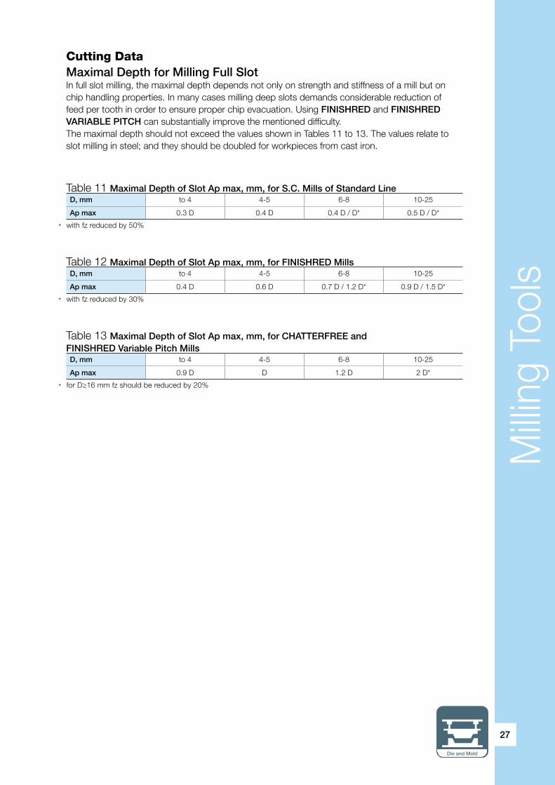
Table 11 Maximal Depth of Slot Ap max, mm, for S.C. Mills of Standard LineD, mm to 4 4-5 6-8 10-25
Ap max 0.3 D 0.4 D 0.4 D / D* 0.5 D / D*
* with fz reduced by 50%
Table 12 Maximal Depth of Slot Ap max, mm, for FINISHRED MillsD, mm to 4 4-5 6-8 10-25
Ap max 0.4 D 0.6 D 0.7 D / 1.2 D* 0.9 D / 1.5 D*
* with fz reduced by 30%
Table 13 Maximal Depth of Slot Ap max, mm, for CHATTERFREE andFINISHRED Variable Pitch MillsD, mm to 4 4-5 6-8 10-25
Ap max 0.9 D D 1.2 D 2 D*
* for D≥16 mm fz should be reduced by 20%
Cutting DataMaximal Depth for Milling Full SlotIn full slot milling, the maximal depth depends not only on strength and stiffness of a mill but on chip handling properties. In many cases milling deep slots demands considerable reduction of feed per tooth in order to ensure proper chip evacuation. Using FINISHRED and FINISHRED VARIABLE PITCH can substantially improve the mentioned difficulty.The maximal depth should not exceed the values shown in Tables 11 to 13. The values relate to slot milling in steel; and they should be doubled for workpieces from cast iron.

Milli
ng T
ools
28
Milling Square Shoulder: Dimensional LimitationsIn rough to finish shoulder milling, depth of cut ap and width of cut ae can be estimatedin accordance with Table 14.
Starting Feeds and SpeedsThe following tables specify estimated values for feed per tooth and cutting speeds referring to FINISHRED, CHATTERFREE and FINISHRED Variable Pitch endmills.The tables relate to rough and semi-finish milling. The recommendations regarding finish operations are discussed on the next pages separately.In case of unfavorable conditions (poor clamping, milling thin walls, high overhang), the table values should be reduced by 20-30%.
ae
ap max
D ≤ 16 mm D > 16 mm
< 0.3 D 2 D 1.8 D
( 0.3…0.5) D 2 D 1.8 D
0.5 D < ae < 0.75 D 1.25 D 0.8 D
≥ 0.75 D Ap max*
Table 14 Shoulder Milling: Shoulder Size
- Recommended operational mode* Ap max as it specified in Tables 11-13
* ISCAR material group in accordance with VDI 3323 standard** HRC 45-49
ISO ClassDIN/ISO 513
D, mm
Mat. Group* 1 2 3 4 5 6 8 10 12 16 20 25
P
1-4 0.008 0.020 0.030 0.040 0.055 0.065 0.080 0.085 0.092 0.138 0.145 0.155
5 0.008 0.020 0.028 0.038 0.055 0.065 0.077 0.082 0.090 0.130 0.137 0.148
6, 7 0.008 0.020 0.028 0.038 0.055 0.065 0.077 0.082 0.090 0.130 0.137 0.142
8, 9 0.008 0.019 0.028 0.038 0.050 0.060 0.072 0.077 0.085 0.130 0.137 0.142
10 0.008 0.017 0.025 0.036 0.048 0.058 0.070 0.072 0.082 0.125 0.130 0.137
11 0.008 0.012 0.022 0.032 0.045 0.055 0.065 0.065 0.077 0.110 0.120 0.132
M 12, 13 0.008 0.015 0.028 0.038 0.048 0.058 0.070 0.077 0.082 0.125 0.130 0.137
K15-16 0.009 0.022 0.032 0.043 0.060 0.070 0.083 0.088 0.095 0.142 0.150 0.163
17-18 0.009 0.022 0.032 0.043 0.060 0.070 0.083 0.088 0.095 0.142 0.150 0.163
H
38.1** 0.022 0.028 0.032 0.038 0.040 0.045 0.055 0.060 0.065
38.2
39
Table 15 FINISHRED: Starting Feed fz, mm/tooth, for Mill Diameters D
Slot drills
Endmills that can cut straight down are also called “slot drills”. They have at least one center cutting tooth, and their primary use is for milling key slots (“slot drilling”). Normally, the slot drills are two-flute mills, but often they have three and sometimes even four flutes.
Milli
ng T
ools
Die and Mold
29
* ISCAR material group in accordance with VDI 3323 standard** HRC 45-49
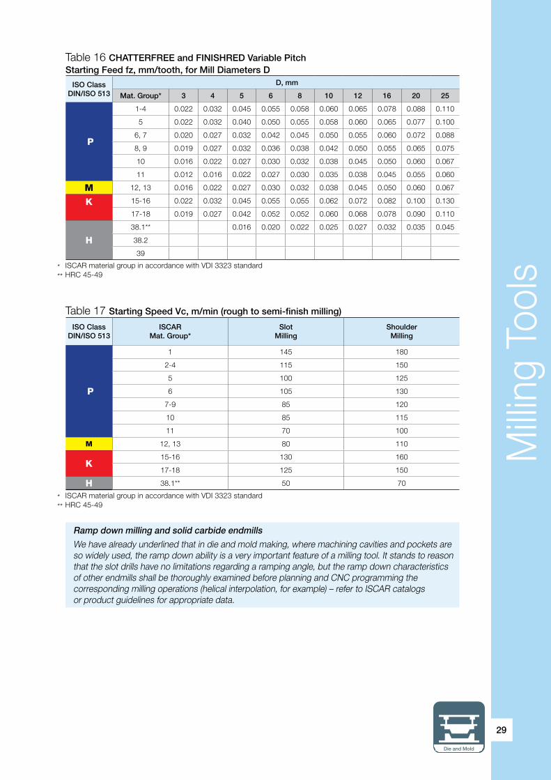
Table 16 CHATTERFREE and FINISHRED Variable Pitch Starting Feed fz, mm/tooth, for Mill Diameters D
ISO ClassDIN/ISO 513
D, mm
Mat. Group* 3 4 5 6 8 10 12 16 20 25
P
1-4 0.022 0.032 0.045 0.055 0.058 0.060 0.065 0.078 0.088 0.110
5 0.022 0.032 0.040 0.050 0.055 0.058 0.060 0.065 0.077 0.100
6, 7 0.020 0.027 0.032 0.042 0.045 0.050 0.055 0.060 0.072 0.088
8, 9 0.019 0.027 0.032 0.036 0.038 0.042 0.050 0.055 0.065 0.075
10 0.016 0.022 0.027 0.030 0.032 0.038 0.045 0.050 0.060 0.067
11 0.012 0.016 0.022 0.027 0.030 0.035 0.038 0.045 0.055 0.060
M 12, 13 0.016 0.022 0.027 0.030 0.032 0.038 0.045 0.050 0.060 0.067
K
15-16 0.022 0.032 0.045 0.055 0.055 0.062 0.072 0.082 0.100 0.130
17-18 0.019 0.027 0.042 0.052 0.052 0.060 0.068 0.078 0.090 0.110
H
38.1** 0.016 0.020 0.022 0.025 0.027 0.032 0.035 0.045
38.2
39
* ISCAR material group in accordance with VDI 3323 standard** HRC 45-49
Table 17 Starting Speed Vc, m/min (rough to semi-finish milling)
ISO ClassDIN/ISO 513
ISCARMat. Group*
SlotMilling
ShoulderMilling
P
1 145 180
2-4 115 150
5 100 125
6 105 130
7-9 85 120
10 85 115
11 70 100
M 12, 13 80 110
K15-16 130 160
17-18 125 150
H 38.1** 50 70
Ramp down milling and solid carbide endmills
We have already underlined that in die and mold making, where machining cavities and pockets are so widely used, the ramp down ability is a very important feature of a milling tool. It stands to reason that the slot drills have no limitations regarding a ramping angle, but the ramp down characteristics of other endmills shall be thoroughly examined before planning and CNC programming the corresponding milling operations (helical interpolation, for example) – refer to ISCAR catalogs or product guidelines for appropriate data.

Milli
ng T
ools
30
* ISCAR material group in accordance with VDI 3323 standard** HRC 45-49
Table 18 Starting Speed Vc, m/min (finish milling)
ISO ClassDIN/ISO 513
ISCARMat. Group*
Vc,m/min
P
1 280
2-4 200
5 170
6 190
7-9 170
10 165
11 120
M 12, 13 150
K15-16 220
17-18 200
H38.1 100
38.2 90
39 60

Milli
ng T
ools
Die and Mold
31
Finishing
Solid endmills as integral, monolith tools ensure high dimensional and form accuracy (tolerance limits for a tool diameter, runout of teeth relative to the tool shank, etc.). Therefore, they fully meet the requirements for finish milling (or finishing) of die and mold parts. The typical features of finishing operations are high accuracy and surface quality of machined surface, and small allowances (to 5% of a mill diameter and 0.1-0.2 mm for hardened steels). In finishing, the cutting speed is high and the feed per tooth is low relative to rough and semi-finish operations. The tool strength allows cutting with feeds greater than in Table 15 and 16, but due to insufficient surface finish it is recommended to start cutting under the table values and then try to increase until the surface roughness is enough.
Short or Extra-Long Reach? Solid carbide endmills of the same type and nominal diameter vary in flute lengths and overall lengths. The mills of short length ensure highest strength and rigidity whereas the extra long reach mills are designed for deep cavities and high shoulders. As a rule, a series of standard endmills comprise short, medium, long reach and extra long reach tools.
ExampleIt is required to mill a square shoulder of 3 mm width (ae) and 5 mm height (ap) in a mold block from AISI/SAE 4340 steel with hardness HRC 34. The required roughness is Ra 2.5, the accuracy requirements to straightness and flatness of the shoulder walls in accordance with ISO 2768-m (medium). The available tool: solid carbide endmill EC-E4L 08-18/26W08CF63.
The machined material relates to the eighth material group (No.8).The nominal diameter of the above mill is 8 mm (D), its cut length 18 mm (Ap).The mill relates to the CHATTERFREE solid mill line.The specified requirements to the milled surface are not high; ae/D = 3/8, ap<Ap, ap<2D (5<16); hence the shoulder can be machined by one pass (Table 14).From Table 16 starting feed fz =0.038 mm/tooth and from Table 17 starting cuttingspeed Vc=120 m/min.
Feed per tooth or depth of cut?
In milling, metal removal rate, the litmus test of productivity, depends both on feed per tooth and on depth of cut. The question: “What is more effective for effective productivity control – varying the feed or the depth within the acceptable limits?” has no unambiguous answer. But in general, under the same metal removal rate, increasing the feed coupled with reduced depth of cut is more favorable than the opposite combination (the lesser feed with the deeper cut) because it normally results in greater tool life. By the way, high feed milling (HFM), one of the progressive rough milling techniques that are also taken into consideration in this guide, rests in particular on this principle.
No. of flutes Strength Rigidity Chip handling
Roughing Finishing Slot milling Plunge milling
2 * * **** **** * **** ****
3 ** ** *** *** ** *** **
4 *** *** ** ** *** *
5 and more **** **** * ****
For more detailed information regarding 90˚ solid carbide endmills, refer to ISCAR catalogs, guides and technical leaflets.
Table 19 General Characteristics of Solid Carbide Endmills
Milli
ng T
ools
32
MULTI-MASTER Endmill Heads
General NotesMULTI-MASTER is a family of tools with shanks and interchangeable cutting heads for a variety of machining applications: milling, countersinking, spot and center drilling, and slitting.The MULTI-MASTER design approach bases upon a thread system of the unique profile, centering by a short precise taper and a face contact. A MULTI-MASTER head has a cutting part and a back connection with the external thread and the taper, which screws into a shank with the corresponding internal thread and the taper until final securing when the back face of the head cutting part will contact the face of the shank.This principle of coupling ensures strength and rigid clamping of a wide range of the interchangeable heads. The MULTI-MASTER tools meet the requirements of high accuracy because the head geometry is finished by precise grinding and the connection guarantees high concentricity within very close limits. In addition, the tools are simple-to-operate, because the heads are quickly replaced by easy rotation of an applied key. Moreover, they answer to strict requirements of repeatability, and thus, replacement of the heads does not require additional adjustment.
The MULTI-MASTER family features a large variety of heads, shanks and extensions. The basic concept is, when a shank can carry heads of different shapes and accuracy, this allows dramatic increase of tool versatility and will diminish needs for special tools. A huge stock of tools is not necessary. Resharpening of tools is no longer needed, because a worn-out cutting head is simply replaced. The family renders a possibility of numerous tools by an unlimited combination of the heads and the shanks and therefore, excellently answers the demands of die and mold making and reduces procurement cost.
No setup time advantages
Repeatability of an assembled mechanical system with interchangeable elements means that a key parameter of the system remains in agreed limits in case of replacing an interchangeable element of the same type. For the standard MULTI-MASTER tools, repeatability in tool length is about 0.04 mm for the milling heads of normal accuracy and about 0.02 mm for the precise milling heads. That is why there is no need for additional adjustment in tool length after replacing a head; and the head can be replaced when a shank remains clamped in a machine tool spindle without new presetting. No setup time for replacement considerably cuts cycle time and is a good source for increasing productivity.

Milli
ng T
ools
Die and Mold
33
90˚ Endmill Cutting Heads
There are two kinds of the relatively small-diameter (8-25 mm) MULTI-MASTER heads for square shoulder milling.
The first, which is designated MM EC…, has exactly the same cutting geometry (number of flutes, helix angle, etc.) as the solid carbide endmills. The only difference is a smaller cutting length: normally, it does not exceed a head diameter. It goes without saying that every type of solid carbide endmill has also been produced as a MULTI-MASTER head. Naturally, the cutting data for MM EC… heads is the same as for the 90˚ solid carbide endmills considered in the previous pages.
The second, “economy” type, designated MM HC… features only two flutes and a lesser helix angle. Being pressed and sintered to shape and size, the cutting geometry of the heads of this type is merely finished by grinding. Due to the high-impact structure of a pressed tooth the heads run at feeds per tooth that are significantly greater than in case of solid carbide endmills or MM EC… heads, so despite only two teeth, the feed speed is the same as for multi-flute mills or heads. The mentioned strength property allows even a slight increase of cutting speed relative to the solid carbide tools/heads for the same tool life period. This property makes MM HC… heads to be an attractive economical solution especially in rough milling and slot drilling. In milling slot or square shoulder with the use of MM HC… heads, the natural geometrical limitation is cutting length Ap of a head. At any rate it is not recommended to exceed 0.8Ap for depth of cut while milling shoulders with widths more than a half of the head diameter or milling slots. Tables 20 and 21 show data for estimated starting feeds and speeds for MM HC… heads.
Indexable solid carbide tools
The endmills that are assembled from the MULTI-MASTER heads and shanks open new doors to saving money and improving productivity. MULTI-MASTER modular tools, which are neither solid carbide nor indexable tools in a popular sense, lay in the intermediate field between them. Having a replaceable solid carbide cutting part they relate to a new type of cutting tools: indexable solid tools, unlikely as it may seem with the combination of the words “indexable” and “solid”.
ISO ClassDIN/ISO 513
fz,mm/tooth, for D, mm
Mat. Group* 8 10 12 16
P
1-4 0.11 0.13 0.13 0.15
5 0.1 0.12 0.13 0.13
6, 7 0.09 0.1 0.1 0.12
8, 9 0.08 0.09 0.1 0.12
10 0.07 0.08 0.09 0.1
11 0.06 0.07 0.08 0.09
M 12, 13 0.07 0.08 0.09 0.1
K15-16 0.1 0.13 0.14 0.16
17-18 0.09 0.12 0.13 0.15
H 38.1** 0.04 0.05 0.06 0.06
Table 20 MM HC… Heads: Starting Feed fz, mm/tooth
* ISCAR material group in accordance with VDI 3323 standard** HRC 45-49

Milli
ng T
ools
34
MULTI-MASTER shanks
The MULTI-MASTER shanks are produced from various materials: steel (for general applications), tungsten carbide (has high stiffness) and heavy metal (an alloy with great tungsten percentage with small alloying additions of other metals; the alloy features excellent vibration damping properties but not recommended for heavy-duty applications due to its limited impact fatigue strength). The shanks differ in configuration: without neck and with straight or tapered neck. The taper angle for standard shanks varies from 5˚ on side to 1 .̊ Of course, overall lengths and neck lengths vary also. Combining the above shank characteristics provides the die maker with the tool that is exactly needed in his specific operation, whether it be roughing or finishing, machining deep cavities or shoulders, milling under poor clamping or with high overhang. Modularity converts the MULTI-MASTER tools into a powerful means for choosing the right tool.
Table 21 MM HC… Heads: Starting Speed Vc, m/min (rough to semi-finish milling)
* ISCAR material group in accordance with VDI 3323 standard** HRC 45-49
ISO ClassDIN/ISO 513
ISCARMat. Group*
SlotMilling
ShoulderMilling
P
1 160 190
2-4 125 160
5 110 135
6 115 140
7-9 95 130
10 95 125
11 80 110
M 12, 13 90 120
K15-16 145 175
17-18 135 165
H 38.1** 55 75
In case of unfavorable conditions (poor clamping, milling thin walls, high overhang) the values in Tables 20 and 21 should be reduced by 20-30%.
Generally, the MULTI-MASTER endmill heads are produced from grade IC908 that has tough submicron substrate and PVD TiAlN coating. This universal grade is suitable for wide-range milling applications, including interrupted cut and unfavorable conditions, with medium to high cutting speeds; and feature excellent notch wear and built-up edge resistance.Additionally, some heads intended for milling hardened steel are manufactured from grade IC903. The previous section is devoted to solid carbide endmills and contains a brief description.
ExampleRough milling a square shoulder of 4 mm width (ae) and 6 mm height (ap) is need during machining a bushing of a die set. The bushing material – steel AISI S1 with hardness HB 190. A planner specified for milling a MULTI-MASTER tool comprising short steel shank MM S-A-L070-W20-T10 and economy head MM HC160C16R0.4-2T10 908. The bushing is properly clamped into the clamping fixture of the machine tool.
The machined material relates to the sixth material group (No.6).The nominal diameter of the above head is 16 mm (D), its cutting length 15 mm (Ap).
Under these tool dimensions and machining requirements one pass is enough for milling the shoulder (ae/D = 6/16=3/8, ap<Ap); so the shoulder can be machined by one pass (p. 31).From Table 20, starting feed fz =0.12 mm/tooth and from Table 21, starting cuttingspeed Vc=140 m/min.

Milli
ng T
ools
Die and Mold
35
For more detail information regarding MULTI-MASTER endmill cutting heads, shanks and extensions, refer to ISCAR catalogs, guides and technical leaflets.
90˚ Extended Flute Mill Cutters
Cutting blades of extended flute mill cutters consist of sets of indexable inserts. The inserts, which are placed gradually and with mutual offset of one another, produce continuous helical cutting blades and engage the material during machining and results in a smooth cut. As against an ordinary indexable mill with length of cut that is limited by the cutting edge of the insert mounted on the mill, the cutting length of the extended flute cutter is significantly larger – it is “extended” due to the whole set of the insert. Correspondingly, a chip gullet of the ordinary mill transformsin a full flute for proper chip handling.
For fully effective extended flute cutters the number of face teeth is equal to the number of flutes; and for half effective cutters with staggered order of the inserts, the number of the face teeth is twice as small as the flute number. Understandably, the fully effective cutters run twice as fast as the half effective ones under the same cutting speed and feed per tooth.
The extended flute cutters can be with integral body or modular tools assembled from different sections. In accordance to sizes and adaptation the cutters are produced with shanks or like shell mills.
The extended flute cutters perform heavy roughing operations such as heavy-duty milling deep slots, grooves and shoulders. They are used also as edging mill.
ISCAR offers the broad-range line of the fully effective extended flute mill cutters. Although this type of the milling tools is not the most common in the die and mold making process, within the scope of the reference guide we consider briefly the assignment of cutting data for the extended flute cutters with the latest inserts. The detailed method of defining speeds and feeds in this case demands taking into account different combinations of the main machining parameters, which can adversely affect performance and tool life. Therefore, for initial estimation it is quite sufficient to use the data of Tables 22-24 that relate to the extended flute cutters carrying the inserts of SUMO TEC carbide grades.
ap in the tables is depth of cut, ae means width of cut correspondingly, and D – nominal cutter diameter.The speeds for milling full slot take values of milling shoulder with ap/D>0.5; and if in this caseap/D>1.25, the values should be reduced by 20%.
Cutting porcupine
In the technical literature the extended flute mill cutters are called also long-edge, porcupine-type or porcupine cutters and even, as it is sometimes called in shoptalk, “porkies”.

Milli
ng T
ools
36
ISOClass
DIN/ISO 513
ISCARMaterialGroup*
fo, mm/toothT290 LNK… T490 LNK (LNM)… T490 SM… H490 SM…
12-16 20 20-32 40-50 40-50 63 63 80-100
P
1 0.13 0.14 0.16 0.2 0.2 0.22 0.22 0.252-4 0.11 0.12 0.14 0.17 0.17 0.18 0.18 0.195 0.09 0.1 0.12 0.15 0.15 0.16 0.16 0.176 0.09 0.1 0.12 0.15 0.15 0.16 0.16 0.177 0.09 0.1 0.12 0.15 0.15 0.16 0.16 0.178 0.09 0.1 0.12 0.15 0.15 0.16 0.16 0.179 0.08 0.09 0.1 0.12 0.12 0.13 0.13 0.1410 0.08 0.09 0.1 0.12 0.12 0.13 0.13 0.1411 0.06 0.07 0.08 0.1 0.1 0.1 0.1 0.12
M 12, 13 0.12 0.1 0.12 0.15 0.15 0.16 0.16 0.16
K15-16 0.14 0.12 0.14 0.17 0.17 0.19 0.19 0.217-18 0.12 0.1 0.12 0.15 0.15 0.16 0.16 0.17
H 38.1** 0.05 0.06 0.07 0.08 0.08 0.09 0.09 0.1
ISO ClassDIN/ISO
513
ISCARMat.
Group*
ae/D for grades IC808 IC810 IC830 IC330
<0.3 0.3…0.5 >0.5 <0.3 0.3…0.5 >0.5 <0.3 0.3…0.5 >0.5 <0.3 0.3…0.5 >0.5
P
1 225 200 170 200 180 160 160 140 125 150 130 1152-4 200 175 160 180 160 150 140 125 115 125 115 1105 170 155 140 155 140 130 120 110 100 110 100 1006 180 165 130 165 150 120 130 115 95 120 110 957 170 150 130 155 135 120 125 110 95 115 105 858 170 140 125 155 130 115 120 105 90 115 100 859 140 125 120 130 115 110 105 90 85 100 85 8010 140 120 115 130 110 105 105 90 85 100 85 8011 120 105 95 110 100 90 85 80 75 80 75 70
M 12, 13 125 110 100 110 100 90 110 100 90
K15-16 175 160 135 200 170 150 170 150 130 17-18 165 140 125 170 150 135 160 135 120
H 38.1** 70
Table 22 Starting Speed Vc, m/min (average data for extended flute cutters)
Table 23 Basic Feed fo, mm/tooth, for Extended Flute Cutters
Table 24 Loading Factor KL for Extended Flute Cutters
– First choice for grades* ISCAR material group in accordance with VDI 3323 standard** HRC 45-49
* ISCAR material group in accordance with VDI 3323 standard** HRC 45-49
* For T290 LNK… cutters ae/D shall not exceed 1/4
ap/D ae/D1/10 1/4* 1/2 3/4 1
1/20 1.2 1 0.9 0.8 0.751/4 1.2 1 0.9 0.8 0.71/2 1.2 1 0.8 0.7 0.653/4 1 0.8 0.7 0.6 0.551 0.9 0.7 0.6 0.55 0.5>1.25 0.7 0.6 0.5 0.45 0.4

Milli
ng T
ools
Die and Mold
37
Starting feed per tooth fz for the extended flute cutters can be estimated in accordance with the following equation:
fz = fo x kL (2)
Where: fo – basic feed (Table 23) kL –loading factor (Table 24) that takes into consideration tool loading.
ExampleExtended flute shell mill cutter H490 SM D100-64-5-40-17C carrying inserts H490 ANKX 170608PNTR IC830 performs rough milling of a deep shoulder of a large-size die structural component made from AISI/SAE 4130 alloy steel, which has hardness HB 270. The shoulder dimensions are as follows: 60 mm depth and 40 mm width.The machine tool power is sufficient, the clamping conditions are good.
The machined material relates to the seventh material group (No.7).The nominal diameter of the cutter is 100 mm (D), its maximal cutting length 61.5 mm (Ap) - the catalog data. The inserts’ carbide grade – IC830.
ae/D = 40/100=0.4; ap/D = 60/100=0.6.Hence, from Table 22, starting cutting speed Vc can be estimated as 110 m/min; and from Table 23, basic feed fo=0.17 mm/tooth. Table 24 specifies loading factor kL as 0.75 (approximation).Thus the starting feed fz = 0.17x0.75≈0.13 mm/tooth.
Important NoteHeavy-duty rough milling with the extended flute cutters, especially of shell mill type, often demands high machine power. Check power consumption and compare it with the main drive specification of your machine tool!
Tangential or radial? (2)
Further to our discussion regarding tangential and radial (laydown) insert clamping in the context of the extended flute cutters, it can be noted that under otherwise equal conditions the extended flute cutters with radial clamping have certain advantages in chip handling and can show better results while milling full deep slots. The cutters with tangential clamping, however, provide an advantage when machining deep shoulders due to their more rigid body structure. Of course, these remarks should not be considered as absolute guidelines for choosing a cutter or as a final solution of the question of the header, but is a good illustration of a reason for different principles of tool configurations.

Milli
ng T
ools
38
Milling Plane Surfaces The first choice for milling plane surfaces is face mills. The face mills are intended for machining surfaces that are parallel to the mill face. Obviously, the endmill examined in the previous section, also belongs to such general definition. Moreover, the face mill and likewise the endmills machine square shoulders. But the definition of mill types relates to main distinctive features and underlines them in specification.
Due to main application the face mills have additional design features in comparison with the endmills. The cutting diameter of a face mill is considerably larger than its maximal depth of cut; and the ratio between the mentioned key dimensions far exceeds the corresponding ratio in endmills. Generally, the face mills are designed as shell mills with a stepped bore for mounting directly upon an adapter, an arbor or a machine tool spindle; and have a key slot on its non-cutting face for torque transfer. The endmills, on the contrary, belong to shank-type tools for which mounting and activation is performed by shank.
One of the main design characteristics of a milling tool is the position of the cutting edge of the tool with respect to machine surfaces. The position defines the cutting edge angle (entering angle). So as to meet various shape requirements of machined parts, cutting tool manufacturers produce the face mills with different cutting edge angles. The most common types of the face mills have the following cutting edge angles:• 90˚ (0˚ lead angle correspondingly)• 75˚ (15˚ lead)• 60˚ (30˚ lead)• 45˚ (45˚ lead)
Classically, if there is no limitation regarding the shape of machined surface, the face mill with the smallest cutting edge angle is recommended. The point is that the maximal chip thickness, which characterizes the mill loading, is equal to full feed per tooth for 90˚ mills and, for cutting edge angles differing 90˚, to the product of the feed to sine of the cutting edge angle. Therefore, the smaller angles allow higher feed per tooth under the same mill loading (maximal chip thickness) – a good source for increasing productivity*. See tables 25, 26.
2
Table 25 Chip Thickness for the Same Feed per ToothCutting edge angle 90˚ 75˚ 60˚ 45˚
Chip thickness 100% 97% 87% 71%
Table 26 Feed Increasing for the Same Chip ThicknessCutting edge angle 90˚ 75˚ 60˚ 45˚
Feed per tooth 100% 103% 115% 141%
* This approach resides in high-feed machining (HFM).

Milli
ng T
ools
Die and Mold
39
Cutting edge angle or approach angle?
There a well-defined strict specification for the angles’ defined cutting geometry of the milling tools. However, national standard sometimes defines the same parameters in a different manner that causes misunderstandings even in technical literature and between experienced metal cutting specialists. The angle between the plane of the main cutting plane (the plane that the edge machines) and the machined plane surface (which the mill machined) is called the tool cutting edge angle or the cutting edge angle. Some technical sources call it also the entering angle, the cut-entering angle, the entry angle or the entrance angle. Its value is often indicated before a general type or header of milling tool families. For example: “90˚ milling tool” means that the mill has a 90˚ cutting edge angle.
In the U.S.A. and U.K., it is common practice to specify the angle that is complimentary to the cutting edge angle: so-called the lead angle (USA) and the approach angle (UK) – the angle formed by the main cutting edge and a line parallel to the axis of the cutter rotation.
Being the complimentary angles, the cutting edge angle and the lead angle produce together 90˚; and they are equal only in case of 45˚ mills. For our example above the lead angle is 0˚ (“zero lead”).
As it is not always clear what angle is specified, please pay attention to prevent confusion.
In addition, the smaller cutting edge angles lead possibly render a smoother engagment into the material and exit during milling operations. The radial component of a cutting force is reduced, and the radial pressure, correspondingly, too. That is very important for materials that have a tendency of break-out edges (cast iron, for instance). Heat dissipation is better; insert life is longer.
However, many applications demand 90˚ shoulder shapes. Decreasing the cutting edge angle reduces the radial component of the cutting force but leads to increasing its axial component*, which can cause deflected machined surfaces, especially if a workpiece has thin walls. Moreover, other insert dimensions being more or less equal, 90˚ mills have greater maximal depth of cut – an important feature of the mill.
It stands to reason that milling operations need a different type of mill; and only correctly understanding operation requirements coupled with the main properties of the different mill types will bring the proper choice of mill.
ISCAR has a rich line of face mills with various cutting edge angles for broad spectrum applications. Among the latest 90˚ face mills are the tools of the HELITANG T490, SUMOMILL T290 and HELIDO H490 families. The main features of these tools have already been discussed in brief in the section of the endmills in this guide. As before, HELI2000 HM90 family with the classically designed 2 cutting edged insert is in great request.
The 45˚ face mills grew in the newest HELIDO S845 family with an innovative solution that enables using either square or octagonal double-sided inserts on the same tool. The mills of the family offer an effective solution of inserts with 8 or 16 cutting edges. If the square right-hand inserts feature durable structure, positive geometry of the rake face and 8 cutting edges; the octagonal high-strength inserts have 16 cutting edges, either right-hand or left-hand and are very economical per edge inserts.
Summary tables 27 and 28 show main general data of some advanced ISCAR 90˚ and 45˚ face mills.
* This approach resides in high-feed machining (HFM).

Milli
ng T
ools
40
HPF90AN
T490FLN -08
H490E90AX -09
HM90F90AP
H490E90AX -12
T490FLN -13
HM90F90A
T290FLN -15
T490FLN -16
H490E90AX -17
HPF90AT -19
ap 7.7 8 8 10 12 12.5 14.3 15 16 16 16Tool D Number of Teeth (Effective)32 6; 8 3; 5 5 3; 540 8; 10 4; 6 6 5;6 4 4; 5 3; 4 4 3 350 9; 12 5; 7 7 6; 7 3; 5 5; 6 3; 5 5 3; 4 3; 4 3; 463 12; 16 6; 9 9 7; 9 4; 6 6; 8 4; 6 6 4; 6 4; 6 4; 580 8; 11 5; 7 7; 10 5; 7 7 5; 7 5; 7 4; 6100 9; 13 6; 9 8; 13 6; 8 5; 8 5; 8 5; 7125 10; 16 9;17 7; 9 7; 10 7; 10160 8; 10 8; 12200 9; 12 10250 10 12315 12
InsertsHPANKT 07
T490LN..T 08
H490ANKX 09
HM90AP…10
H490AN..X 12
T490LN..T 13
HM90AD..15
T290LN..T 15
T490LN..T 16
H490AN..X 17
HP90AD.. 1906
Table 27 Quick Selector for Certain 90˚ Indexable Face Mills
Wiper insert
Normally, the ordinary inserts for face milling are provided today with a wiper flat for improving quality of a machined plane surface. This is a small secondary cutting edge, which in spite of the definition "flat", sometimes has a complex geometry but can be considered to be parallel to the machined surface. For this, although the wiper flat improves the surface roughness, it is not always enough, particularly for the face mills with a relatively large nominal diameter.
The situation becomes much better if in addition to the ordinary inserts, a face mill carries a specially designed insert (or more rarely two for large-sized tools), for which the wiper flat is significantly larger than for the ordinary one. This wiper insert is mounted in the same pocket but it protrudes 0.05…0.07 mm relative to the ordinary inserts towards to the machined plane. Due to the wide wiper flat the wiper insert applies additional force to the workpiece that needs special emphasis for milling brittle materials.
Table 28 Quick Selector for HELIDO 45˚ Indexable Face Mills
SOF45 8/16 SOF45 8/16 S845 F45SX ap 3.5 6 7.1
Tool D Number of Teeth (Effective)40 4 4 450 4; 6 4; 6 4; 563 6; 8 6; 8 5; 780 7; 10 7; 10 6; 9100 8; 12 8; 12 7; 11125 10; 16 10; 16 8; 14160 10; 18200 12250 15315 19
Inserts ON…U 0505 S845 SN…U 1305 S845 SXMU

Milli
ng T
ools
Die and Mold
41
Pitch of milling tool
The pitch is the distance between two nearest-neighbor teeth of a milling tool measured between the same points of the cutting edges of the teeth. The pitch shows density of tooth of a milling tool in accordance to which the tools differ from the tools with coarse, fine and extra fine pitch. Choosing the proper right tooth density depends on two main things. On the one hand, at least one tooth should always cut material. On the other hand, the space of a chip gullet should be enough for chip handling. Hence, the machined material and type of machining are the principal factors for choosing. General-duty coarse pitch with maximum chip gullet space and a few teeth are the first choice for rough and finish milling of steel. Also, in many cases the coarse pitch is a way to reduce vibration. Fine pitch, which provides less space for the chip gullet but more teeth, allows increased feed speed. It is recommended for milling cast iron and for applications requiring limited feed per tooth. Extra fine pitch generally is suitable for milling steel with shallow depth of cut, milling cast iron and high-efficiency machining with considerable feed speed.
Sometimes, in order to overcome vibrations during operations, the teeth are produced with unequal spacing, which is to say, the tool has differential pitch.
In technical literature parallel with the coarse-fine-extra fine pitch, grading also exists: coarse-medium (or regular)-fine, normal-close-extra close and other definitions. In addition, tools with extra-fine pitch can be called high-density cutters.
HPF90AN
T490FLN -08
H490E90AX -09
HM90F90AP
H490E90AX -12
T490FLN -13
HM90F90A
T290FLN -15
T490FLN -16
H490E90AX -17
HPF90AT -19
ap 7.7 8 8 10 12 12.5 14.3 15 16 16 16Tool D Number of Teeth (Effective)32 6; 8 3; 5 5 3; 540 8; 10 4; 6 6 5;6 4 4; 5 3; 4 4 3 350 9; 12 5; 7 7 6; 7 3; 5 5; 6 3; 5 5 3; 4 3; 4 3; 463 12; 16 6; 9 9 7; 9 4; 6 6; 8 4; 6 6 4; 6 4; 6 4; 580 8; 11 5; 7 7; 10 5; 7 7 5; 7 5; 7 4; 6100 9; 13 6; 9 8; 13 6; 8 5; 8 5; 8 5; 7125 10; 16 9;17 7; 9 7; 10 7; 10160 8; 10 8; 12200 9; 12 10250 10 12315 12
InsertsHPANKT 07
T490LN..T 08
H490ANKX 09
HM90AP…10
H490AN..X 12
T490LN..T 13
HM90AD..15
T290LN..T 15
T490LN..T 16
H490AN..X 17
HP90AD.. 1906
Table 28 Quick Selector for HELIDO 45˚ Indexable Face Mills (cont.)

Milli
ng T
ools
42
Cutting diameter and width of cut
Normally, peak efficiency in face milling can be achieved if a width of cut will be 60-80% of a mill cutting diameter. Of course, the real situation often dictates other proportions even when milling a full slot, but the above ratio is always preferable.
The meaning of the cutting diameter for the face milling tool with indexable inserts needs clarification. In accordance with ISO standard 6462 it shall be taken from point P as defined inFig. 2 (diameter D). Point P is the theoretical point produced by intersection of the main cutting edge and the plane machined by the mill. The cutting diameter is one of the main dimensions of the mill, and it often is called the nominal diameter.
For 90˚ face mills the cutting diameter is consistent along the cutting edge and does not change for different depths of cut (ap).
At the same time, if the cutting edge angle (χr) differs from 90˚, the real cutting diameter will be D+2×ap×tan χr. One would think that the right calculation should take this point into consideration. But the fact that in the face mills the maximal depth of cut of a tool far less cutting diameter D, allows neglecting the above correction; and it is conventional to specify the cutting speed, the spindle speed, etc. with respect to cutting diameter D as defined in ISO 6462.*
* The guide also uses this specification.
ØD ØDP P
Xr
Fig. 2. Cutting diameter D and cutting edge angle (in accordance with ISO 6462)

Milli
ng T
ools
Die and Mold
43
Initial Cutting Data
Basically, the way of defining the initial cutting data is the same as for the endmills with indexable inserts, already examined.
a) Starting feed per tooth fz
fz = fz0 x kχ (3)
Where: fz0 – the basic starting feed kχ – the factor of the cutting edge angle
The basic starting feed can be chosen in accordance with Table 5, that specifies the feed limits for the more popular ISCAR carbide grades. Optionally, as the case may be, the satisfactory estimation of the basic feed is achieved with the use of Table 29, which contains the average values for the face mills.
The factor of the cutting edge angle kχ (Table 30) reflects possible increasing of feed for the same chip thickness due to position of the main cutting edge relative to the machined plane surface (compare with Table 26).
ISO ClassDIN/ISO
513Workpiece material Basic feed fz0, mm/tooth, for gradesType Mat. Group* IC808 IC5100 IC810 DT7150 IC830 IC330
P
Plain carbonsteel
1-4 0.2 0.2 0.2 0.22 0.255 0.18 0.18 0.18 0.2 0.22
Alloy steeland
tool steel
6, 7 0.15 0.15 0.18 0.2 0.228, 9 0.12 0.12 0.15 0.18 0.210 0.12 0.12 0.12 0.15 0.1511 0.1 0.1 0.12 0.12 0.15
M Martensitic s.s. 12, 13 0.1 0.12 0.15
KGrey cast iron 15-16 0.22 0.25 0.25 0.22
Nodular cast iron 17-18 0.2 0.22 0.22 0.2 H
Hardened steel38.1 0.08 0.08 38.2 0.07 39 0.05
Table 29 Basic Starting Feed fzo for Face Mills
* ISCAR material group in accordance with VDI 3323 standard – First choice for grades For T290 face mills the table values should be reduced by 30%. For the face mills with inserts HP ANKX…07 and T490 LN..T…08 the table values should be reduced by 20%. For milling hardened steel, see the appropriate chapter for further discussion
Table 30 Factor of the Cutting Edge Angle kχ Cutting edge angle 90˚ 75˚ 60˚ 45˚
kχ 1 1 1.1 1.4

Milli
ng T
ools
44
b) Starting cutting speed Vc Exactly as for the indexable endmills, calculation of starting cutting speed Vc for the face mills rests on equation (1):
Vc = Vo x Ks x Kt Where: Vc – starting cutting speed Vo – basic cutting speed Ks – stability factor (1 if stability is enough and 0.7 for unstable operations) Kt – tool life factor (Table 8)
Table 9 specifies basic cutting speed Vo as dictated by the workpiece material, the carbide grade and the type of machining, whilst defining the latter can be done through Tables 6 and 7. If desired, upon condition that the starting feed was calculated from equation (3) and Table 29, the type of machining for a face mill more suitable for the operation (when the width of cut is 60-80% of the mill diameter) or for milling a full slot (100% diameter engagement), can be taken from Table 31.
Shoptalk: facing and shouldering
In the art of metal cutting, face milling is often called simply facing, slot milling – slotting, and shoulder milling, correspondingly - shouldering.
h/apb/D
60% 70% 80% 100%**
1/8 Light-duty (L) Light-duty (L) Light-duty (L) Medium-duty (M)
1/4 Light-duty (L) Medium-duty (M) Medium-duty (M) Medium-duty (M)
1/2 Medium-duty (M) Medium-duty (M) Heavy-duty (H) Heavy-duty (H)
3/4 Heavy-duty (H) Heavy-duty (H) Heavy-duty (H) Heavy-duty (H)
Table 31 Type of Machining: Face Milling*
* For starting feed fz in accordance with equation (3)** Milling full slot Be aware: milling with a width of cut that is 60%-80% of a mill diameter ensures peak efficiency in face milling

Milli
ng T
ools
Die and Mold
45
ExampleA face of a plate 90 mm × 406 mm from nodular cast iron DIN GGG 50(ASTM 65-45-12) with hardness HB 180 is machined by face mill cutter SOF 8/16-D125-16-40R that carries inserts ONMU 050505-TN IC810. The depth of cut is 3 mm. Power of the machine tool main drive is sufficient; the plate is secure mounted in the clamping device of the machine tool.
The machined material relates to the seventeenth material group (No.17).The nominal diameter of the cutter is 125 mm (D), its maximal cutting length 3.5 mm (ap) - the catalog data. The inserts’ carbide grade – IC810.The cutting edge angle of the face mill cutter is 44˚ (it can be rounded off to 45˚).
h/ap = 3/3.5=0.86; b/D = 90/125=0.72.So, basic starting feed fzo=0.22 mm/tooth (Table 29), factor of the cutting edge angle kχ=1.4 (Table 30) and starting feed fz = 0.22x1.4≈0.3 mm/tooth.The type of machining is heavy-duty (Table 31), and starting cutting speed Vc= 200 m/min(Table 9).
ExampleCutter H490 F90AX D063-6-27-17 with inserts H490 ANKX 170608PNTR IC330 performs face milling of a large-scale block by several passes, for which the depth of cut is 6 mm and the width of cut is 50 mm. The block material is carbon steel AISI/SAE 1030, HB 200…220. The operation stability can be estimated as sufficient.
The machined material relates to the second material group (No. 2).The nominal diameter of the cutter is 63 mm (D), its maximal cutting length 16 mm (ap) - the catalog data. The inserts’ carbide grade – IC330.The cutting edge angle of the face mill cutter is 90˚.
h/ap = 6/16=0.38; b/D = 50/63=0.8.Then basic starting feed fzo=0.2 mm/tooth (Table 29), factor of the cutting edge angle kχ=1(Table 30) and starting feed fz = 0.2 mm/tooth.The type of machining according to Table 31 lays between medium- to heavy-duty, for whichTable 9 recommends the starting speeds 140 and 125 m/min correspondingly. As it stands we can accept a more or less average value between these limits as the starting cutting speed, thus Vc = 130 m/min.
Clamping screws with adjustable protrusion nozzle for shell-type face m ills
Most conventionally designed shell-type face mills are equipped with coolant holes for the spindle-through coolant supply. The holes are usually located in the chip gullets and are directed towards the cutting edges. This design ensures coolant supply at the cutting zone, but in many cases does not facilitate chip evacuation, as the coolant flow tends to push the chips back towards the inserts. Several cutting tool manufacturers produce clamping screws with internal ports. The screws secure the face mills on the adapter and ensure flow through the axis of a tool to its periphery and thus facilitate improved chip evacuation. However, as shell mills have central countersink with different depths, effective application of such screws is limited. The ISCAR clamping screws with movable nozzle eliminate the above disadvantage. The protrusion of the nozzle of the screw can be easily adjusted according to countersink depth, insert size or any other application requirements. The nozzle screw position can be secured by a locking-nut. The adjustable protrusion nozzle effectively directs the coolant supply to the cutting zone, thus improving chip evacuation substantially.

Milli
ng T
ools
46
Milling Contoured Surfaces (profiling) The outstanding characteristics of the die and mold industry show through a large proportion of contoured surfaces, especially in the production of plastic molds and die-casting dies. Therefore, while speaking about the specific tools for die and mold, one often means the tools, and first of all milling cutters, for machining the very same contoured surfaces. These kinds of tools represent the majority of metal cutting tools required by die and mold makers.
Contoured surfaces
In the technical literature the contoured surfaces are also called formed surfaces, profiled surfaces, 3-D shaped surfaces, and etc.
3.1. Milling tools with toroidal cutting profile A milling tool with toroidal cutting profile being rotated around the tool axis produces a torus – a geometrical form, which is generated by revolving a circle about an axis that does not touch the circle and is coplanar with it – a ring-shaped bagel (Fig. 3).
Structurally, this profile is realized in the following designs:• Milling tools with indexable round inserts• Solid carbide toroidal milling tools• Interchangeable solid carbide toroidal milling heads The solid carbide tools and heads are more suitable for small nominal diameters. Due to some limitations they often look like a bull-nose or back-draft mills (Fig. 4)
3
Fig. 3.
Fig. 4.
rα°

Milli
ng T
ools
Die and Mold
47
Fig. 5.
3.1.1. Milling tools with indexable round inserts
By all accounts, the milling tools with round (or as it also called button) inserts are the most popular roughing and semi-finishing mills in machining dies and molds, especially complex male-female main parts such as cavities and projections. In roughing, when the primary target is the highest metal removal rate, the round inserts have two significant advantages that contribute greatly to their successful use. Whether or not, both of the advantages relate to the round shape of the inserts.
Firstly, strength of the cutting edge. If the cutting corner is the Achilles heel for an insert of any polygonal shape, the round insert without a cutting corner is much stronger. The higher strength allows more heavy tool load or in other words, stronger cutting data: more feed and speed that cause the improved metal removal rate.
All around … a round!
A tool intended for milling countered surfaces should have a cutting geometry that not only contacts the surface but also ensures correct generation of a needed shape in every direction. Generally speaking, for rough milling any cutting geometry can be suitable; but in finish operations, only the cutting edge, which lays on a spherical portion, meets the above requirements. Therefore the milling tools with complex cutting form: toroidal or ball nose, are very popular in the die and mold industry. One way or another, but look about – a round!
Secondly, a varying cutting edge angle. The cutting edge angle, which is consistant in case of the polygonal insert, varies along the cutting edge of the round insert from zero to the value measured at the highest point of the cutting edge that is involved in cutting. The latter defines the maximal cutting edge angle (χmax, Fig. 5). When the tool runs at its maximum depth of cut that is equal to the insert radius, the maximal cutting edge angle will be 90˚.
1
2345
6
8
1234
567
8
1
2345
6
8
1234
567
8
D
Deff
Xeff
Xmax
Xmax
d=2r
ap
D1=D+d
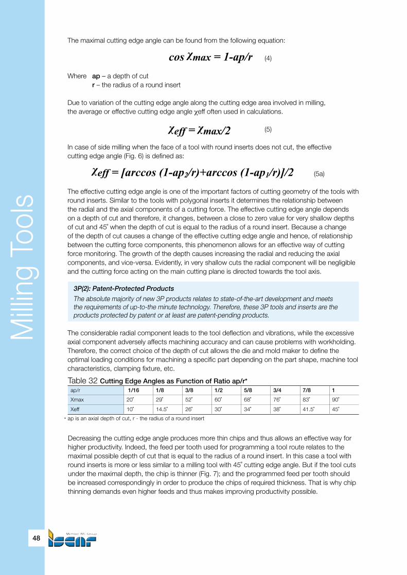
Milli
ng T
ools
48
ap/r 1/16 1/8 3/8 1/2 5/8 3/4 7/8 1
Xmax 20˚ 29˚ 52˚ 60˚ 68˚ 76˚ 83˚ 90˚
Xeff 10˚ 14.5˚ 26˚ 30˚ 34˚ 38˚ 41.5˚ 45˚
Decreasing the cutting edge angle produces more thin chips and thus allows an effective way for higher productivity. Indeed, the feed per tooth used for programming a tool route relates to the maximal possible depth of cut that is equal to the radius of a round insert. In this case a tool with round inserts is more or less similar to a milling tool with 45˚ cutting edge angle. But if the tool cuts under the maximal depth, the chip is thinner (Fig. 7); and the programmed feed per tooth should be increased correspondingly in order to produce the chips of required thickness. That is why chip thinning demands even higher feeds and thus makes improving productivity possible.
Table 32 Cutting Edge Angles as Function of Ratio ap/r*
* ap is an axial depth of cut, r - the radius of a round insert
The maximal cutting edge angle can be found from the following equation:
cos χmax = 1-ap/r (4)
Where ap – a depth of cut r – the radius of a round insert
Due to variation of the cutting edge angle along the cutting edge area involved in milling, the average or effective cutting edge angle χeff often used in calculations.
χeff =χmax/2 (5)
In case of side milling when the face of a tool with round inserts does not cut, the effectivecutting edge angle (Fig. 6) is defined as: χeff = [arccos (1-ap2/r)+arccos (1-ap1/r)]/2 (5a)
The effective cutting edge angle is one of the important factors of cutting geometry of the tools with round inserts. Similar to the tools with polygonal inserts it determines the relationship betweenthe radial and the axial components of a cutting force. The effective cutting edge angle depends on a depth of cut and therefore, it changes, between a close to zero value for very shallow depths of cut and 45˚ when the depth of cut is equal to the radius of a round insert. Because a change of the depth of cut causes a change of the effective cutting edge angle and hence, of relationship between the cutting force components, this phenomenon allows for an effective way of cutting force monitoring. The growth of the depth causes increasing the radial and reducing the axial components, and vice-versa. Evidently, in very shallow cuts the radial component will be negligible and the cutting force acting on the main cutting plane is directed towards the tool axis.
3P(2): Patent-Protected Products
The absolute majority of new 3P products relates to state-of-the-art development and meets the requirements of up-to-the minute technology. Therefore, these 3P tools and inserts are the products protected by patent or at least are patent-pending products.
The considerable radial component leads to the tool deflection and vibrations, while the excessive axial component adversely affects machining accuracy and can cause problems with workholding. Therefore, the correct choice of the depth of cut allows the die and mold maker to define the optimal loading conditions for machining a specific part depending on the part shape, machine tool characteristics, clamping fixture, etc.
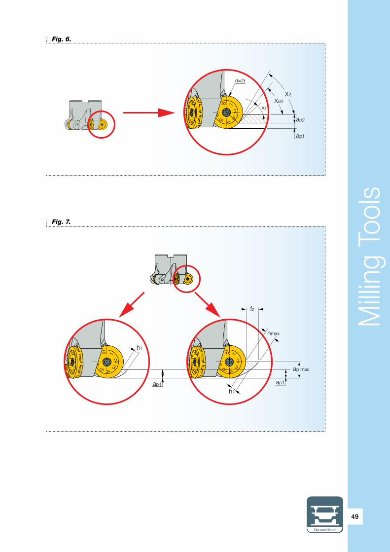
Milli
ng T
ools
Die and Mold
49
Fig. 6.
Fig. 7.
1
2345
6
8
1234
567
8
1
2345
6
8
1234
567
8
d=2r
X1
XeffX2
ap2
ap1
1
2345
6
8
1234
567
8
1
2345
6
8
1234567
8
1
2345
6
8
1234
567
8
hmax
fz
ap1 ap1
ap max
h1
h1

Milli
ng T
ools
50
Insert size
The size of a round insert is its diameter. For example, “insert size 12” means “a 12 mm diameter
round insert”.
Although milling at the full possible depth (the radius of a round insert) leads to maximum engagement between a tool and a workpiece, considerable increase of the radial component of the cutting force, extraneous vibrations, and as a result, excessive wear, - the shape of a machined contoured surface sometimes demands coming into cutting contact exactly at this area. On the other hand, maximum effect is at the highest if the depth of cut ensures that the maximal cutting edge angle 25˚…45˚, that is approximately 0.1…0.3 of the insert radius (or in other words, 0.05…0.15 of the insert diameter). For that reason the ISCAR regular round inserts have 8 indexed working positions for 45˚ or 90˚ indexing. The rake face of some of them is indicated in the corresponding numbers: 1, 2, 3, … for better usability. The specially shaped side faces on the relief surfaces or the bottom protrusions of the inserts keep an insert from drifting during cutting.
High overhang dramatically reduces vibration stability of milling cutters and the mills with round inserts are no exception. As a rule, milling with the overhang already twice as large the mill diameter requires decreasing cutting data for stable machining. The same situation is observed while milling near thin walls and in poor workholding: both of these cases also result in reduced cutting data. ISCAR MILLSHRED line offers a good solution for the problem. In addition, it provides the users with another operating benefit of efficient milling at the full possible depth.
The main principle of the MILLSHRED insert is a combination of the round cutting profile with the chip splitting effect. It is achieved by the serrated cutting edge of the insert. The insert has 4 indexed working positions for 90˚ indexing; and the serrations on the cutting edge were designed so they overlap, providing a fully effective tool configuration. The MILLSHRED milling tools can carry either the round inserts with serrated cutting edge (designated as RCMT…) or regular round inserts (RCC… MO).
Serrate around
The serrated cutting edge that splits chips into small pieces significantly upgrades the round insert. First of all, reducing the cutting force (and especially its radial component) accrued from the chip splitting, substantially improves the dynamic behavior and less bending of a tool, that ensures stable cutting with normal feeds if the tool overhang is high. Therefore the overhang range can be considerably extended. Normally the upper border of the range comes close to the ten tool diameters. In many cases such a simple and cheap solution renders unnecessary use of complex and expensive toolholding devices with vibration-dampening properties. It is very important to note that the serrated cutting edge provides a means of depth equal to the insert radius. Also, the lower the cutting force the lower the machining power. Secondly, the small chip pieces simplify chip evacuation, specifically in deep cavities of dies and molds. And thirdly, the small pieces have fewer tendencies to be re-cut and that greatly improves rough milling of the deep cavities and increases tool life.
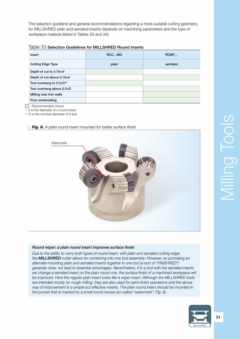
Milli
ng T
ools
Die and Mold
51
The selection guideline and general recommendations regarding a more suitable cutting geometry for MILLSHRED plain and serrated inserts depends on machining parameters and the type of workpiece material (listed in Tables 33 and 34).
Round wiper: a plain round insert improves surface finish
Due to the ability to carry both types of round insert, with plain and serrated cutting edge, the MILLSHRED cutter allows for combining into one tool assembly. However, so promising an alternate mounting plain and serrated inserts together in one tool (a sort of “FINISHRED”) generally does not lead to essential advantages. Nevertheless, if in a tool with the serrated inserts we change a serrated insert on the plain round one, the surface finish of a machined workpiece will be improved. Here the regular plain insert looks like a wiper insert. Although the MILLSHRED tools are intended mostly for rough milling, they are also used for semi-finish operations and the above way of improvement is a simple but effective means. The plain round insert should be mounted in the pocket that is marked by a small round recess (so-called “watermark”, Fig. 8).
Insert RCC…MO RCMT…
Cutting Edge Type plain serrated
Depth of cut to 0.15×d*
Depth of cut above 0.15×d
Tool overhang to 2.5×D**
Tool overhang above 2.5×D
Milling near thin walls
Poor workholding
Table 33 Selection Guidelines for MILLSHRED Round Inserts
- Recommended choice * d is the diameter of a round insert** D is the nominal diameter of a tool
Watermark
Fig. 8. A plain round insert mounted for better surface finish

Milli
ng T
ools
52
Type of Milling Roughing Roughing and Semi-Finishing
Insert Designation
RCMT...FW RCMT...FW-T20 RCMT...FW-F20 RCCT...MO RCCW..MO
Mat.group
GeometryPositive rake face Positive rake face
with T-landPositive rake face
sharp edgePositive rake face Flat top face
with a t-land
Workpiece
1-5
P
Plain carbonsteel
√√√ √ √ √√√ √√
6-9 Low-alloy steel √√√ √ √ √ √√√
10-11High-alloy steel and tool steel
√√√ √ √ √ √√√
12-14 M Stainless steel √√√ (1) √√√ (2) √√√
15-20 K Cast iron √√ √√√
38.1 H
Hardened steel(HRC 45 max)
√ √
Application
Helicalinterpolation
ShoulderingContourMilling
RampingDown
Plunging ProfilingPocketMilling
Table 34 Selection of MILLSHRED Inserts for Machining Die and Mold Materials
(1) Recommended for martensitic stainless steel(2) Recommended for austenitic stainless steel√ Last recommended√√ Second option√√√ Most recommended
12º20º
20º
0.15
20º 12º 15º
Mainly, the MILLSHRED inserts are produced from grades IC908, which has already been mentioned in the previous sections, and IC928 – a PVD TiAlN coated tough grade that is especially recommended for heavy-duty operations. Additionally, the inserts intended for machining cast iron are made from PVD AlTiN coated carbide grade IC910.
Starting Cutting Data
a) Starting feed per tooth fz
i. MILLSHRED plain round inserts
Generally, the starting cutting feed per tooth that should be use for CNC programming can be found from the following equation:
fz = fz0 x KTH x Ks (6)
Where: fz0 – the basic starting feed KTH – the chip thinning factor Ks – the stability factor
The basic starting feed (Table 35) is a recommended feed for milling with depth of cut that is equal to the radius of a round insert. It corresponds to a maximal chip thickness, which is planned to be carried out during machining.

Milli
ng T
ools
Die and Mold
53
Table 35 MILLSHRED Plain Round Inserts. Basic Starting Feed fzo, mm/tooth
The chip thinning factor, as the function of a depth of cut and hence of a cutting edge angle, reflects the necessity for increasing the basic starting feed; while CNC programming for obtaining the planned maximal chip thickness at a time when machining is performed with a depth of cut less than the radius of the insert.
KTH = 1/sin (0.75 xχmax) (7)
or, that is the same,
KTH = 1/sin (1.5 xχeff) (7a) The stability factor that takes into account the effect of cutting stability is taken to be 1 for normal conditions and to 0.7 if the estimated cutting stability is insufficient (milling thin walls, high overhang, poor toolholding, non-rigid workholding, etc.).
ExampleThe face of a plate from AISI H13 tool steel annealed to HB 170…190 is machined by shell mill cutter FRW D068A080-07-27-12 carrying inserts RCCW 1206MO IC908 with 1.5 mm depth of cut. The plate is properly clamped into a workholding device and the cutter has light overhang. What is the feed per tooth necessary for CNC programming of the operation?
From Table 35 the basing starting feed for the material group No.10, related to the specified steel, is 0.15 mm. Using equation (4), χmax=41˚; and equation (7), KTH=1.95.Hence, fz = 0.15×1.95×1=0.29 (mm/tooth); and the programmed feed should be 0.29 mm/tooth.
Alternatively, the feed can be determined by applying Tables 36 and 37 following.
The tables contain feeds per tooth as a function of the diameter of an insert and a depth of cut. The data in the tables relates to machining a group of materials that is chosen as basic; and for the other material groups the table values should be multiplied by corresponding coefficients.
Table 36, for instance, reflects milling workpiece material groups 5-9 (low alloy steel and quenched plain carbon steel) and 15-16 (grey cast iron) with the use of inserts RC..W…MO. For machining groups 10-11 (high alloy and tool steels), the table values should be multiplied by 0.7, for machining groups 17-18 (nodular cast iron) - by 0.85 and for machining group 38.1 (hardened steels, HRC 45 max) – by 0.55.
The feeds in Table 37 correspond to milling plain carbon and low alloy steels (groups 1-9) by inserts RC..T…MO. In case of milling material groups 10-11, the table feeds should be multiplied by 0.7; and for milling material groups 12-13 (ferritic and martensitic stainless steels) – by 0.85.
ISO Class(DIN/ISO
513)
MaterialGroup*
Basic starting feed fzo, mm/tooth, for inserts
RC..W…MO RC..T…MO
Ø12 Ø16 Ø20 Ø12 Ø16 Ø20
P
1-4 0.21 0.28 0.34 0.14 0.19 0.235-9 0.21 0.28 0.34 0.14 0.19 0.23
10-11 0.15 0.2 0.24 0.1 0.13 0.16
M 12 ,13 0.18 0.24 0.29 0.12 0.16 0.2
K15-16 0.21 0.28 0.3417-18 0.18 0.24 0.29
H 38.1 0.12 0.15 0.19
- recommended choice * ISCAR material group in accordance with VDI 3323 standard

Milli
ng T
ools
54
In either case, machining under unstable operational conditions will also demand reducingthe feed by 30%. Using Table 36, the programmed starting feed for the previous example should be as follows: 0.4 (the table value) × 0.7 (coefficient for material group No.10) = 0.28 (mm/tooth).
ExampleA workshop plans to perform a semi-finish machining of a deep mold cavity by using endmill cutter ERW D028A040-A-4-C32-12 with inserts RCCW 1206MO IC908. The cutter is clamped into a spring collet with overhang 150 mm. The workpiece material is unhardened AISI A2 tool steel. The programmed feed per tooth needs to be found if the cavity planned to be machined is with 0.6 mm depth of cut.
The machined material relates to group No.10.d (the insert diameter) = 12 mm; and the ratio “depth of cut to insert radius”: ap/r=2×ap/d=0.1. From Table 36 fzo=0.54 mm/tooth (for groups 5-9).After correcting by the material coefficient (0.7) and the stability factor (0.7), the programmed feed will be: 0.54×0.7×0.7=0.26 (mm/tooth).
ap/r
Basic starting feed fzo, mm/tooth, for inserts
Ø12 Ø16 Ø20
ap fzo ap fzo ap fzo
– 0.15 0.8 0.15 1 0.15 1.3
1/16 0.37 0.7 0.5 0.9 0.62 1.2
1/10 0.6 0.54 0.8 0.7 1 0.9
1/8 0.75 0.5 1 0.6 1.25 0.8
1/4 1.5 0.4 2 0.54 2.5 0.67
3/10 1.8 0.36 2.4 0.45 3 0.54
1/2 3 0.27 4 0.36 5 0.45
5/8 3.75 0.21 5 0.28 6.25 0.34
3/4 4.5 0.21 6 0.28 7.5 0.34
7/8 5.25 0.21 7 0.28 8.75 0.34
1 6 0.21 8 0.28 10 0.34
Table 36 MILLSHRED Plain Round Inserts RC..W…MO. Basic Feeds, mm/tooth
The feeds relate to workpiece material groups 5-9 (low alloy and quenched carbon steels) and 15-16 (grey cast iron).For machining groups 10-11 (high alloy and tool steels), the table values should be multiplied by 0.7, for machining groups 17-18 (nodular cast iron) - by 0.85 andfor machining group 38.1 (hardened steel, HRC 45 max) - by 0.55. - Recommended depths of cut

Milli
ng T
ools
Die and Mold
55
ap/r
Basic starting feed fzo, mm/tooth, for inserts
Ø12 Ø16 Ø20
ap fzo ap fzo ap fzo
– 0.15 0.56 0.15 0.75 0.15 0.9
1/16 0.37 0.5 0.5 0.68 0.62 0.83
1/10 0.6 0.41 0.8 0.55 1 0.67
1/8 0.75 0.36 1 0.47 1.25 0.57
1/4 1.5 0.26 2 0.34 2.5 0.42
3/10 1.8 0.24 2.4 0.32 3 0.39
1/2 3 0.18 4 0.25 5 0.3
5/8 3.75 0.14 5 0.19 6.25 0.23
3/4 4.5 0.14 6 0.19 7.5 0.23
7/8 5.25 0.14 7 0.19 8.75 0.23
1 6 0.14 8 0.19 10 0.23
Table 37 MILLSHRED Plain Round Inserts RC..T…MO. Basic Feeds, mm/tooth
The feeds relate to workpiece material groups 1-9 (plain carbon and low alloy steels).For machining groups 10-11 (high alloy and tool steels) the table values should bemultiplied by 0.7, for machining groups 12-13 (ferritic and martensitic stainless steels) – by 0.85. - Recommended depths of cut
Tool overhang
The overhang (or the projection) of a milling tool is an important factor of the tool stiffness and machining stability. The tool overhang being 5% less reduces the tool deflection by 15%, 10% less –by 27% and 20% less – already by 50%. Minimizing the overhang substantially improves operational efficiency, allowing for increased cutting conditions and good surface finish. But, what can we do - manufacturing real parts often demands long tools. How to determine the cutting data for such tools? And what is a high overhang, for which various techniques of cutting data determination recommend correction factors? This not simple question is directly connected with the dynamic behavior of a tool. It relates to the sphere of serious research and needs a separate discussion. We are sure that the reader on the basis of his own knowledge and experience knows exactly if the overhang of a tool that he uses is high. For a rough estimate, the following rule of thumb often can be helpful: the overhang is high being 4-5 and more times as much as the nominal diameter of the tool. However, one thing needs clarification: from which point should the overhang be measured? Generally, in case of the shell mills mounted on arbors, the correct way is to measure the overhang for the whole assembly, which is to say from the gauge line (datum) of the arbor shank (Fig. 9). For the endmills that are clamped into holders with spring collets or adapter-style holders with side screws, the overhang is measured from the holder (Fig. 10).
ii. MILLSHRED serrated round inserts As previously noted (Table 33), the serrated round inserts are intended first of all for the following cases:• High depth of cut (above 15% of the insert diameter)• Considerable tool projection (the overhang more than 2.5 of the tool diameter)• Milling near thin walls• Poor workholding Additionally, the serrated inserts are sometimes applied in milling with usual depth of cut (to 15% of the insert diameter) when the main drive power of a machine tool is limited.
A programmed starting feed per tooth fz is defined by equation (8):
fz = fzo x KH (8)
Where: fzo – the basic starting feed (Tables 39-41) KH – the overhang coefficient (Table 38)

Milli
ng T
ools
56
ExampleA die part made from AISI D2 tool steel, HB 210, is milled by cutter FRW D034A050-04-22-16 with inserts RCMT 1607-FW IC908 mounted on it. The cutter overhang is 120 mm, the depth of cut – 6 mm. What is a programmed feed to start milling?
The workpiece material relates to the tenth material group (No.10). Table 39 specifies the basic feed for a 16 mm diameter insert with 6 mm depth of cut as 0.2, which should be multiplied by 0.9 for material group No.10. The cutter diameter is 50 mm; and for overhang 120 mm the overhang coefficient is equal to 1 (Table 38).
Therefore we have fz = 0.2×0.9×1=0.18 (mm/tooth).
Table 38 Overhang Coefficient KH for the MILLSHRED Serrated Round Insertsas the Function of Ratio of an Overhang H to a Tool Diameter D1H/D1 to 4 over 4 to 6 over 6 to 8 over 8 to 10
KH 1 0.85 0.7 0.65
Fig. 9 Fig. 10
h
1
2345
6
8
1234
567
8
h
Datum

Milli
ng T
ools
Die and Mold
57
ap/r
Basic starting feed fzo, mm/tooth, for inserts
Ø12 Ø16 Ø20
ap fzo ap fzo ap fzo
ap min 0.9 0.26 1.2 0.35 1.2 0.4
1/4 1.5 0.23 2 0.3 2.5 0.35
3/10 1.8 0.21 2.4 0.28 3 0.3
1/2 3 0.18 4 0.25 5 0.28
5/8 3.75 0.13 5 0.18 6.25 0.21
3/4 4.5 0.13 6 0.18 7.5 0.21
7/8 5.25 0.13 7 0.18 8.75 0.21
1 6 0.13 8 0.18 10 0.21
Table 39 MILLSHRED General-purpose Serrated Round Inserts RCMT…FW.Basic Feeds, mm/tooth
Table 40 MILLSHRED Serrated Round Inserts RCMT…FW-T20.First choice for machining martensitic stainless steel can also be used for machining carbon and low alloy steels
The feeds relate to workpiece material groups 1-9 (plain carbon and low alloy steels).For machining groups 10-11 (high alloy and tool steels) the table values should bemultiplied by 0.9, for machining groups 15-18 (cast iron) – by 1.3 and for machining group 38.1 (hardened steel, HRC 45 max) – by 0.6. - Recommended depths of cut
The feeds relate to workpiece material groups 12-13 (ferritic and martensitic stainless steels).For machining groups 1-9 (carbon and low alloy steels) the table values should be multiplied by 1.1. - Recommended depths of cut
ap/r
Basic starting feed fzo, mm/tooth, for inserts
Ø12 Ø16 Ø20
ap fzo ap fzo ap fzo
ap min 0.9 0.3 1.2 0.4 1.2 0.52
1/4 1.5 0.28 2 0.35 2.5 0.46
3/10 1.8 0.25 2.4 0.32 3 0.42
1/2 3 0.22 4 0.28 5 0.35
5/8 3.75 0.15 5 0.2 6.25 0.25
3/4 4.5 0.15 6 0.2 7.5 0.25
7/8 5.25 0.15 7 0.2 8.75 0.25
1 6 0.15 8 0.2 10 0.25
ExampleA mold part from AISI 420 stainless steel with a thin-walled complicated shape and non-uniform machining allowance is milled by tool ERW D020A032-B-3-C32-12 carrying inserts RCMT 1206-FW-T20 IC928. Due to the unsteady allowance the depth of cut varies from 3 to 4 mm. The tool performs cutting with 220 mm overhang from a collet. Find feed per tooth needed for programming the tool path.
The material represents group No.14; ratio “overhang/diameter” is 220/32=6.9. Although Table 40 does not contain the basic feed for 12 mm diameter inserts with 4 mm depth of cut (worst case of loading) directly, it is easily seen that it is 0.13 mm.Consequently, the starting programmed feed is: 0.13×0.7=0.09 (mm/tooth).

Milli
ng T
ools
58
Table 41 MILLSHRED Serrated Round Inserts RCMT…FW-F20.First choice for machining austenitic stainless steel and aluminum alloys; can be used also for machining low carbon steel. ap/r
Basic starting feed fzo, mm/tooth, for inserts
Ø12 Ø16 Ø20
ap fzo ap fzo ap fzo
ap min 0.9 0.13 1.2 0.17 1.2 0.2
1/4 1.5 0.12 2 0.16 2.5 0.18
3/10 1.8 0.1 2.4 0.14 3 0.16
1/2 3 0.09 4 0.12 5 0.14
5/8 3.75 0.07 5 0.09 6.25 0.1
3/4 4.5 0.07 6 0.09 7.5 0.1
7/8 5.25 0.07 7 0.09 8.75 0.1
1 6 0.07 8 0.09 10 0.1
The feeds relate to workpiece material group 14 (austenitic stainless steel).For machining group 1 (low carbon steel) the table values should be multiplied by 1.5.For machining groups 21-25 (aluminum alloys) the table values should be multiplied by 3. - Recommended depths of cut
b) Starting cutting speed Vc
The starting cutting speed should be determined by the following steps:• Find the recommended cutting speed with the use of the averaged data in the tables• Calculate the effective diameter• Calculate the programmed spindle speed relative to the nominal diameter of a tool in such a way that the cutting speed relative to the effective diameter will be equal to the found value
Recommended cutting speed
Vc = Vo x KF x KH x Kt (9)
Where: Vo – The basic cutting speed (Table 43) KF – The factor of a cutting edge form: KF=1 for the plain round inserts and KF=0.75 for the serrated round inserts KH – The overhang coefficient: For the serrated round inserts KH can be found from Table 38 For the plain round inserts KH is specified in Table 42 Kt– The tool life factor (Table 8)
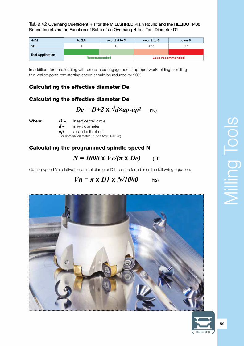
Milli
ng T
ools
Die and Mold
59
Table 42 Overhang Coefficient KH for the MILLSHRED Plain Round and the HELIDO H400 Round Inserts as the Function of Ratio of an Overhang H to a Tool Diameter D1
In addition, for hard loading with broad-area engagement, improper workholding or milling thin-walled parts, the starting speed should be reduced by 20%.
Calculating the effective diameter De
Calculating the effective diameter De
De = D+2 x√d×ap-ap2 (10)
Where: D – insert center circle d – insert diameter ap – axial depth of cut (For nominal diameter D1 of a tool D=D1-d)
Calculating the programmed spindle speed N
N = 1000 x Vc/(πx De) (11)
Cutting speed Vn relative to nominal diameter D1, can be found from the following equation:
Vn=πx D1 x N/1000 (12)
H/D1 to 2.5 over 2.5 to 3 over 3 to 5 over 5
KH 1 0.9 0.65 0.5
Tool Application
Recommended Less recommended

Milli
ng T
ools
60
Effective diameter
The correct approach to finding the cutting speed of a profiling milling tool is to calculate the speed with respect to the effective diameter of the tool. In profiling, due to the shaped, non-straight form of the tool, a cutting diameter is a function of a depth of cut; and it is not the same for different areas of the tool cutting edge that is involved in milling. The effective diameter is the largest true cutting diameter: maximum of the cutting diameters of the mentioned areas (Fig. 11). Generally, it corresponds to the diameter measured at the axial depth of cut.
Ignoring the cutting diameter in calculating spindle speeds can cause essential errors in cutting data and incorrect tool operation. In the milling cutters with round inserts, specifically, this is particularly significant for relatively small tool diameters. For example, for a 25 mm diameter tool with 12 mm diameter round inserts, the cutting diameter varies from the value closed to 13 mm (the axial depth of cut is nothing more than tenths of mm) to 25 mm (at maximum depth of cut that equal to the insert radius – 6 mm). If the effective diameter is, for instance, 19 mm, and the spindle speed was calculated with reference to 25 mm, the real cutting speed relative to 19 mm diameter will be 24% less! The error grows for shallow depths of cut: for effective diameter 14 mm it is already 44%. Of course, for large-sized tools such error grows substantially smaller and can even be ignored. Moreover, machining slots, milling near straight walls, etc. with even shallow depth of cut but with several passes, when after each pass the tool embeds deeper and deeper into the workpiece, and its nominal diameter in some or other way cuts the material (Fig. 12), the calculations shall relate only to the nominal diameter! In any other case we always recommend to take the effective diameter into consideration and make corresponding necessary corrections during programming the spindle speed. Remember, the cutting speed relates to the effective diameter, while the spindle speed refers to the nominal diameter!
1
2345
6
8
1234
567
8
1
2345
6
8
1234
567
8
ap
Area involved in cutting
fzDeff
1
2345
6
8
1234
567
8
ap
Di
Deff=Di max
1
2345
6
8
1234
567
8
1
2345
6
8
1234
567
8VF
n
Deff1
VF
n
Deff = Dnom
Fig. 11
Fig. 12
1st pass N pass
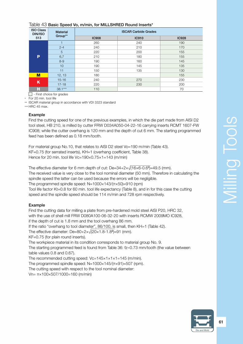
Milli
ng T
ools
Die and Mold
61
ExampleFind the cutting speed for one of the previous examples, in which the die part made from AISI D2 tool steel, HB 210, is milled by cutter FRW D034A050-04-22-16 carrying inserts RCMT 1607-FW IC908; while the cutter overhang is 120 mm and the depth of cut 6 mm. The starting programmed feed has been defined as 0.18 mm/tooth.
For material group No.10, that relates to AISI D2 steel Vo=190 m/min (Table 43).KF=0.75 (for serrated inserts), KH=1 (overhang coefficient, Table 38).Hence for 20 min. tool life Vc=190×0.75×1=143 (m/min)
The effective diameter for 6 mm depth of cut: De=34+2×√(16×6-0.62)=49.5 (mm).The received value is very close to the tool nominal diameter (50 mm). Therefore in calculating the spindle speed the latter can be used because the errors will be negligible.The programmed spindle speed: N=1000×143/(π×50)=910 (rpm)Tool life factor Kt=0.8 for 60 min. tool life expectancy (Table 8), and in for this case the cuttingspeed and the spindle speed should be 114 m/min and 728 rpm respectively.
ExampleFind the cutting data for milling a plate from pre-hardened mold steel AISI P20, HRC 32, with the use of shell mill FRW D080A100-06-32-20 with inserts RCMW 2009MO IC928,if the depth of cut is 1.8 mm and the tool overhang 86 mm.If the ratio “overhang to tool diameter”, 86/100, is small, then KH=1 (Table 42).The effective diameter: De=80+2×√(20×1.8-1.82)=91 (mm).KF=0.75 (for plain round inserts).The workpiece material in its condition corresponds to material group No. 9.The starting programmed feed is found from Table 36: fz≈0.73 mm/tooth (the value betweentable values 0.8 and 0.67).The recommended cutting speed: Vc=145×1×1×1=145 (m/min).The programmed spindle speed: N=1000×145/(π×91)=507 (rpm).The cutting speed with respect to the tool nominal diameter:Vn= π×100×507/1000=160 (m/min)
Table 43 Basic Speed Vo, m/min, for MILLSHRED Round Inserts*ISO ClassDIN/ISO
513
MaterialGroup**
ISCAR Carbide Grades
IC908 IC910 IC928
P
1 260 240 1902-4 240 210 1705 220 200 155
6,7 210 180 1558-9 190 160 14510 190 145 13511 150 135 130
M 12, 13 180 155
K15-16 240 270 23017-18 220 230 200
H 38.1*** 110 70
- First choice for grades* For 20 min. tool life** ISCAR material group in accordance with VDI 3323 standard*** HRC 45 max.

Milli
ng T
ools
62
Example A customer complains of poor tool life with inserts RCCW 1206MO IC908, that are used in milling a deep and narrow cavity with almost vertical walls from a solid block of SAE/AISI 4340 steel. During operation, tool ERW D020A032-A-3-C25-12, with the inserts clamped into its pockets, machines the cavity by the required contour with shallow cuts (0.7 mm depth of cut) by stepped passes and thus removes material layer by layer. The customer defined the cutting data in accordance with the ISCAR recommendations and took into account the high overhang and the effective diameter. What is a reason for the problem? In the first pass only a small part of the insert cutting edge cuts the material. But every next pass brings a new portion of the edge in engagement. After already the 8th pass, almost all cutting portions will be involved in milling near the cavity wall: 8×0.7 mm =5.6 mm, and the maximal depth of cut is 6 mm – the insert radius. The calculated effective diameter is 20+2×√(12×0.7-0.72)=25.6 (mm); and with respect to this value the customer defined the spindle speed. As a result, the cutting speed referred to the nominal diameter (that began cutting after 8 passes) is 1.25 (32/25.6=1.25) greater than required. In all appearances, it is the reason for the customer’s problem. Even though the depth of cut is small, the tool nominal diameter cuts also and therefore the calculation should be relative to it.
In summation, the above-mentioned advantages: high strength of cutting edge and benefits of the round shape, made the round insert the real workhorse of rough and semi-finish milling in die and mold making. Marking the end of the section, underlined again are some points of using MILLSHRED round inserts:• For shallow depths of cut and small tool overhang, the plain round inserts are the best solution. Their highest efficiency will be when the depth of cut is 10-30% of the insert radius (or 5-15% of the insert diameter). Remember that machining with deeper cuts in this case is a source of serious vibrations, intensive wear and misoperation.• Machining with greater depths of cut, high overhang, insufficient stiffness of the technological system (poor workholding, thin-walled part, etc.) will be more effective with the serrated round inserts.• The serrated inserts due to chip splitting effect can solve the problem of chip evacuation.• The serrated inserts need less cutting power and therefore are suitable for low-power machine tools.• Cutting data must be correctly defined with respect to properly chosen effective diameter and depth of cut, because the wrong definition can lead to substantially reduced tool life.

Milli
ng T
ools
Die and Mold
63
3.1.1.1. HELIDO H400 Round Line A Conceptually New Solution for Efficient Profiling
The HELIDO H400 family, one of the latest ISCAR developments, was designed in order to fulfill the industry requirement for an effective milling tool for multiaxis profiling. The family is based on a double-sided insert H400 RNHU 1205… that looks like a round insert, but properly speaking is not round in the sense of the word.The H400 RNHU 1205… insert (Fig. 13) has four major cutting edges and each of them is the 120° arc of 6 mm radius. By comparison, a round insert of traditional design ensures four 90° arcs. Inaddition, the insert has four minor cutting edges, acting mostly during ramp down. The four full 120° major cutting edges in combination with the four “ramping” edges significantly expand the family possibilities in milling complicated 3-D shapes, especially in 5-axis machining, (Fig. 14) that makes it promising for die and mold applications.The H400… insert is smaller in size, that enables a cutter design with more insert at the periphery – a more closed angular pitch of teeth.The HELIDO H400 cutters are available in arbor-type face mill, shank-type endmill configuration; and also as interchangeable milling heads with FLEXFIT threaded connection. The range of diameters for the cutters of the standard line is 32…80 mm.There are three different types of the insert: ML, HP and AX, which are designed for machining various materials and applications. The inserts of ML- and HP- types have straight major edges, the inserts of AX-type – helical (Fig. 15). The inserts are made from the latest SUMO TEC carbide grades, featuring advanced coating and post treatment technology. Table 44 shows general data regarding the inserts and their application in the die and mold industry. As seen, the inserts of ML- and AX-types are more suitable for milling the die and mold materials. At the same time the inserts of HP-type having so-called “high positive” cutting geometry and basically intended for high temperature alloys, can also be used in die and mold practice, so far as milling soft carbon steel or some kinds of martensitic stainless steel.
a b c
Fig. 13
Fig. 14
R6
Centerof circle with6 mm radius
120º
˜11
2
1

Milli
ng T
ools
64
InsertCuttingedge T-land
Intended for Grades
First priority Second priority IC808 IC830 IC330
H400 RNHU...-ML straight negative steel stainless steel
H400 RNHU...-AX helical neutral stainless steel steel
H400 RNHU...-HP straight positive high temp. alloys stainless and soft steels
Table 44 HELIDO H400 Inserts
The way of defining starting cutting data for the H400 milling tools is similar to the already described method relative to the cutters with indexable round inserts. Equation (6) specifies a starting feed, equation (7) – a chip thinning factor and (9) – a starting cutting speed. Cutting edge angles can be calculated by equations (4)-(5a) or estimated using Table 32 (in this case r will be the radius of a H400 insert: namely, 6 mm for inserts H400 RNHU 1205). The tables below show values of the basic starting feed fzo and speed Vo (Tables 45 and 46 correspondingly) and allow estimation of the basic feed directly (Table 47).
Neutral, positive and high positive
In milling, unlike turning, there is no standard classification for combinations of geometrical parameters of indexable inserts, but words “neutral”, “positive”, etc. are commonly used. In order to be familiar with the terms they need clarification. An insert with a flat rake surface parallel to the insert base is called “neutral”. Typical examples of such a geometry are inserts for milling hardened steel and cast iron. But what is “positive”? The progress in powder metallurgy and pressing technology brought about the possibility of shaping the rake face, and the possibility became more and more impressive. The shaping resulted in an effective way of increasing positive normal rake and axial rake for indexable milling tools, which led to substantially decreased cutting forces, improving chip formation and making cutting smoother and more stable. This is the reason why that sort of milling inserts is called “positive”. Further development of technology gave rise to an additional increase of difference in height for two cutting corners along the insert cutting edge. Thus the axial rake can be more positive. It is accepted to call the inserts with the considerable height differences “high positive”. Of course, the pressing technology does not exhaust its potential, and maybe, today’s high positive milling inserts will be classified only as positive tomorrow.
Fig. 15
a b
Straight Edge ML, HP Helical Edge AX

Milli
ng T
ools
Die and Mold
65
Table 45 HELIDO H400 RNHU 1205 Round Inserts. Basic Starting Feed fzo, mm/tooth
Table 46 Milling Tools with HELIDO H400 RNHU 1205 Inserts. Basic Speed Vo, m/min
ISO Class(DIN/ISO
513)
MaterialGroup*
fzo for insert type
ML AX HP
P1-4 0.21 0.14 0.145-9 0.21 0.14
10-11 0.15 0.1
M 12-13 0.18 0.12 0.12
K15-16 0.2117-18 0.18
H 38.1 0.12
* ISCAR material group in accordance with VDI 3323 standard - Recommended application
ISO ClassDIN/ISO
513
MaterialGroup**
Vo for carbide grades
IC808 IC830 IC330
P
1 260 180 1602-4 240 160 1455 220 145 130
6,7 210 145 1308-9 190 140 12510 190 135 12511 150 125 120
M 12, 13 180 150 140
K15-16 240 240 17-18 220 220
H 38.1*** 110 90
- First choice for grades* For 20 min. tool life** ISCAR material group in accordance with VDI 3323 standard*** HRC 45 max
Table 47 HELIDO H400 RNHU 1205 Round Inserts. Basic Feeds fzo, mm/tooth, as a Function of Depth of Cut ap
ap,mm
fzo for types
ML*¹ AX*² HP*³
0.15 0.8 0.56 0.56
0.37 0.7 0.5 0.5
0.6 0.54 0.41 0.41
0.75 0.5 0.36 0.36
1.5 0.4 0.26 0.26
1.8 0.36 0.24 0.24
3 0.27 0.18 0.18
3.75 0.21 0.14 0.14
4.5 0.21 0.14 0.14
5.25 0.21 0.14 0.14
6 0.21 0.14 0.14
*¹ ML-type: The feeds relate to workpiece material groups 1-9 (plain carbon and low alloy steels) and 15-16 (grey cast iron). For machining groups 10-11 (high alloy and tool steels) the table values should be multiplied by 0.7, for machining groups 12-13 (martensitic stainless steel) and 17-18 (nodular cast iron) - by 0.85 and for machining group 38.1 (hardened steel, HRC 45 max) - by 0.55.*² AX-type: The feeds relate to workpiece material groups 1-9 (plain carbon and low alloy steels). For machining groups 10-11 (high alloy and tool steels) the table values should be multiplied by 0.7, for machining groups 12-13 (ferritic and martensitic stainless steels) - by 0.85.*³ HP-type: The feeds relate to workpiece material groups 1-4 (plain carbon steel). For machining groups 12-13 (ferritic and martensitic stainless steels) the table values should be multiplied by 0.85.

Milli
ng T
ools
66
Concerning correction caused by a tool overhang, Table 42 gives necessary data.
ExampleA die and mold manufacturer decided to use endmill cutter H400 ER D32-4-060-C32-12 with inserts H400 RNHU 1205-HP IC830 for 5-axis machining a complex-shaped mold component made from AISI 420 stainless steel with hardness HB 300…310. The depth of cut during machining varies from 1 to 4.5 mm. Machining stability is estimated as good. The manufacturer approached a local ISCAR representative on recommendations regarding starting cutting data.
The component material relates to ISCAR material group No.13. Due to variable depth of cut the calculation should refer to the depth maximum (4.5 mm).
The effective diameter: De=(32-12)+2×√(12×4.5-4.52)=31.6 (mm)≈32 mm (the most part of the cutting edge performs cutting).
The basic feed per tooth (Table 45): fzo=0.18 mm/tooth (alternatively, fzo can be defined from Table 47 with reducing the table value by 15% - see remark to the table).The basic cutting speed (Table 46): Vo=150 m/min
The programmed starting spindle speed: N=1000×150/(π×32)=1492 (rpm).The starting feed speed: VF=0.18×4×1492=1074 (mm/min).
3.1.2. MULTI-MASTER Toroidal Milling Heads andSolid Carbide Toroidal Milling Tools
As for other forms of the MULTI-MASTER heads, the toroidal cutting profile if this tool family is also represented by two design versions: two-flute pressed to shape and size MM HT… heads and multiflute MM ETR… heads fully ground from solid.Table 48 shows nominal diameters D and corner radii R of the standard line of the MULTI-MASTER toroidal heads.
Tool diam. D, mm 8 10 12 16 20
Corner radius R, mm 2 0.5 1 2 3 1.6 2 2.5 3 4 2 3 4 5 3 4 5 6 8
2 flute MM HT…
6 flute MM ETR…
Table 48 MULTI-MASTER Toroidal Milling Heads

Milli
ng T
ools
Die and Mold
67
Back draft of toroidal cutting bull
If the diameter of a toroidal milling tool with round inserts decreases it causes reduction of a screw that secures the insert. The tool becomes weaker, less productive; and at one point producing such tools is practically impossible. The same situation occurs when the insert radius decreases. However, the die and mold industry demands toroidal cutters to be able to effectively mill light-size parts and small radii. In addition, increased requirements of machining accuracy set a limit to using the tool with round inserts in some operations.
Solid carbide tools and interchangeable heads with a toroidal cutting profile overcome these problems and thus extend the application boundaries of toroidal milling tools.
There are some technical terms, which specify the solid tools and the heads. Because the tool manufacturers and industrial workers often use different terms for the same things, the matter requires short consideration.
Speaking about the 90˚ solid endmill, they are traditionally divided between the square endmills with sharp corners, the radiused (or radius) endmill with rounded corners and the chamfered end mill with chamfered corners. The cutting end of a tool (on the tool face) is made with concavity or without it (in flat bottom endmills); and the peripheral cutting end may or may not have a back taper. The back taper allows for minimization of the area of contact between the tool and a machined wall if this contact is undesirable (the tool deflection due the radial cutting force, high overhang, vibrations, etc.). If truth be told, even the flat bottom endmills are produced with small concavity, the straight peripheral cutting edge often have slight, and the sharp corners upon closer view are not so sharp but gently rounded or chamfered; but we do not take these conventional design features into consideration under current discussion.
So, the radiused, also called the bull nose, mills, especially with the concave end cutting edge, can perform as the toroidal cutters. A back draft of the peripheral cutting edge, produced by the back taper, improves efficiency of the cutter.
Today solid carbide toroidal endmills and interchangeable toroidal milling heads feature the design configuration of the back draft radiused (bull nose) cutters. The most popular diameters of the tools and heads lay within 10…25 mm. Normally they have 5 .̊..7˚ concavity and back draft; and the number of teeth is generally 2 or 3. Being ground peripherally and mostly with ground rake face, the tool and heads combine the advantages of the round inserts with the precise radiused endmills and are suitable for rich applications from productive milling of small die and mold components to finish fillets with high accuracy. In some cases these tools and heads are provided with bottom or peripheral wiper flats and even chip splitting grooves.
Properly speaking, the toroidal solid tools and heads present the milling cutters with precise round inserts, where the insert is an integral part of the cutter body (Fig. 16).

Milli
ng T
ools
68
Fig. 16
D
Concavity
R
Back draft
The main design features particular to MM HT… heads are: high-strength structure that allowed heavy tooth loading and neutral ground rake face (zero radial rake). These characteristic properties make the heads very effective in milling steel, hardened steel and cast iron. The heads are successfully applied to high feed milling, machining cavities and pockets by helical interpolation and ramping, side plunging, and also drills small depth.
Multiflute MM ETR… heads with 30˚ helix and zero radial rake are intended first of all for high-production finish milling of hardened steel and precise fillet finishing. The heads do not have center cutting teeth and therefore are not suitable for drilling operations. However, their geometry enables high-performance ramping down by straight line and by helix (interpolation).
In addition, both types of the heads are sometimes used for milling undercuts.
IC908 is a main carbide grade for the MULTI-MASTER toroidal milling heads. In addition, some heads that are intended mostly for milling steels of high hardness (HRC 56-63) are produced from grade IC903.
STARTING CUTTING DATA
a) Starting feed per tooth fz
Programmed feed per tooth fz, which relates to the nominal diameter of a head is defined by the above equation (8):
fz = fzo x KHTable 49 shows basic starting feed fzo for different groups of engineering materials.If the overhang of a tool does not exceed 3D (three diameters of the tool), KH=1; in case of the greater overhangs KH=0.7.
In milling with the toroidal heads, the machining allowance is normally 0.01D…0.2D. If the heads are used, for example, for face milling, an axial depth of cut defines the allowance; and for heads with relatively large corner radius, the chip thinning effect may play an important role. The “relatively large corner radius” has no precise definition, but a rule of thumb says that it is the radius from3 mm (2 mm for 8 mm dia. heads) and more. Table 50 contains values of chip thinning factor KTH that should be taken into account in such cases, for which
fz = fzo x KH x KTH (13)

Milli
ng T
ools
Die and Mold
69
b) Starting cutting speed Vc
Table 51 gives averaged starting cutting speeds. If the cutting conditions can be estimated as unfavorable (poor workholding, high tool overhang, milling thin walls) the table values should be reduced by 20-30%.
ISO ClassDIN/ISO 513
Material Group*2 fzo for D
8 10 12 16 20
P
1-4 0.13 0.14 0.16 0.18 0.2
5 0.12 0.13 0.15 0.16 0.18
6, 7 0.1 0.11 0.12 0.13 0.15
8, 9 0.09 0.1 0.12 0.13 0.15
10 0.08 0.09 0.1 0.11 0.13
11 0.07 0.08 0.09 0.1 0.11
M 12, 13 0.08 0.09 0.1 0.11 0.13
K15-16 0.13 0.14 0.16 0.18 0.2
17-18 0.12 0.13 0.15 0.17 0.18
H
38.1*3 0.06 0.06 0.07 0.07 0.08
38.2*4 0.05 0.05 0.06 0.06 0.07
39*5 0.03 0.03 0.04 0.04 0.05
*1 Machining allowance (0.01…0.2) D for MM HT… heads and (0.01…0.06) D for MM ETR… heads*2 ISCAR material group in accordance with VDI 3323 standard*3 HRC 45-49*4 HRC 50-55*5 HRC 56-63 – Most recommended applications
Toroid for improved surface quality in milling die and mold cavities
For better surface finish, ISCAR offers the customer toroidal heads with chip splitting grooves and side wiper flats (Fig. 17 and 18). The splitting grooves allow producing smaller chips and thus reduce scratching the walls of a machined wall cavity. In addition, the smaller chip, swarf, makes chip evacuation easier. The side wiper flat intended for better surface finish of the cavity walls. In order to achieve the best results in this case a stepdown should not exceed the length of the wiper flat
Table 49 MULTI-MASTER Toroidal Heads: Basic Feed fzo, mm/tooth, for Head Diameter D, mm*1
Wiper flat
Fig. 17 Fig. 18
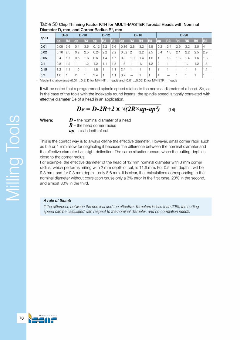
Milli
ng T
ools
70
Table 50 Chip Thinning Factor KTH for MULTI-MASTER Toroidal Heads with Nominal Diameter D, mm, and Corner Radius R*, mm
ap/DD=8 D=10 D=12 D=16 D=20
ap R2 ap R3 ap R3 R4 ap R3 R4 R5 ap R3 R4 R5 R6 R8
0.01 0.08 3.6 0.1 3.5 0.12 3.2 3.6 0.16 2.8 3.2 3.5 0.2 2.4 2.9 3.2 3.5 4
0.02 0.16 2.5 0.2 2.5 0.24 2.2 2.2 0.32 2 2.2 2.5 0.4 1.8 2.1 2.2 2.5 2.9
0.05 0.4 1.7 0.5 1.6 0.6 1.4 1.7 0.8 1.3 1.4 1.6 1 1.2 1.3 1.4 1.6 1.8
0.1 0.8 1.2 1 1.2 1.2 1.1 1.3 1.6 1 1.1 1.2 2 1 1 1.1 1.2 1.3
0.15 1.2 1.1 1.5 1 1.8 1 1.1 2.4 1 1 1 3 1 1 1 1 1.1
0.2 1.6 1 2 1 2.4 1 1.1 3.2 — 1 1 4 — 1 1 1 1
* Machining allowance (0.01…0.2) D for MM HT… heads and (0.01…0.06) D for MM ETR… heads
It will be noted that a programmed spindle speed relates to the nominal diameter of a head. So, as in the case of the tools with the indexable round inserts, the spindle speed is tightly correlated with effective diameter De of a head in an application.
De = D-2R+2 x√(2R×ap-ap²)(14)
Where: D – the nominal diameter of a head R – the head corner radius ap – axial depth of cut
This is the correct way is to always define the effective diameter. However, small corner radii, such as 0.5 or 1 mm allow for neglecting it because the difference between the nominal diameter and the effective diameter has slight deflection. The same situation occurs when the cutting depth is close to the corner radius.For example, the effective diameter of the head of 12 mm nominal diameter with 3 mm corner radius, which performs milling with 2 mm depth of cut, is 11.6 mm. For 0.5 mm depth it will be9.3 mm, and for 0.3 mm depth – only 8.6 mm. It is clear, that calculations corresponding to the nominal diameter without correlation cause only a 3% error in the first case, 23% in the second, and almost 30% in the third.
A rule of thumb
If the difference between the nominal and the effective diameters is less than 20%, the cutting speed can be calculated with respect to the nominal diameter, and no correlation needs.

Milli
ng T
ools
Die and Mold
71
ISO Class DIN/ISO 513
MaterialGroup*
Vc,m/min
P
1 180
2-4 160
5-6 150
7-9 140
10 130
11 120
M 12, 13 120
K15-16 200
17-18 180
H
38.1 120
38.2 100
39** 80
* ISCAR material group in accordance with VDI 3323 standard** In this case HSM recommended – Most recommended applications
Table 51 MM HT… Heads and HTR… Inserts: Starting Speed Vc, m/min
ExampleA planner decided to use endmill cutter MM S-A-L065-W16-T08 with toroidal headMM HT120N06R3.0-2T08 908 for milling a part made from grey cast iron. The depth of cut was defined as 0.6 mm and the stepover as 10 mm. What is the programmed cutting data for proper workholding and stiffened tool clamping?
Cutting speed Vc=200 m/min (Table 51), basic feed fzo=0.16 mm/tooth (Table 49). Chip thinning factor KTH=1.4 (Table 50) and the programmed feed per tooth should be 0.22 mm/tooth(equation (13)).Effective diameter De=12-2×3+2×√(2×3×0.6-0.6²)=9.6 (mm); hence the programmed spindle speed should be 1000×200/(π×9.6)=6630 (rpm).Compare: if we relate directly to the nominal diameter 12 mm, the result might be 5305 rpm,and the real cutting speed transforms to 160 m/min – 20% less.
Feed speed VF=0.22×2×6630=2917 (mm/min).
As previously stated, multiflute heads MM ETR… (and also the solid carbide endmills of similar cutting geometry) are most advantageous for finish milling hardened steel, more exactly with hardness to HRC 55. Machining allowance in this case does not exceed 0.06 D (normally even 0.03 D). Under such conditions the starting feed per tooth, the thinning factor and the starting cutting speed are the same as for MM HT… heads and therefore can be chosen from Tables 49-51. In finish milling with small allowance the cutting speed is actually 10-15% more than the table data.
ExampleAn insert of a plastic mold cavity is finished by endmill cutter MM S-A-L090-C12-T08 withhead MM ETR080A04R2.0-6T05 908 clamped into it. The depth of cut is 1…1.3 mm, the stepover– 0.3 mm. Find the starting cutting data if the insert material is AISI P20 steel, and its hardnessas of the operation is HRC 50…52.

Milli
ng T
ools
72
The basic feed (Table 49) is 0.05 mm/tooth, the chip thinning factor (Table 50) – 1.1. Without any information regarding stability of machining we can, however, assume that it is sufficient (the short shank of type A, small allowance) and the programmed starting feed will be 0.05×1.1=0.055 (mm/tooth).
The starting cutting speed 100 m/min, which is taken from Table 51, can be even increased by 10-15%, as above, and is set 110 m/min. Effective diameter De=8-2×2+2×√(2×2×1.3-1.3²)=7.7 (mm). The effective diameter is very close to the nominal diameter of the head (96%); and corrections for a programmed spindle speed are not needed. The spindle speed 1000×110/(π×8)=4377 (rpm), the feed speed 0.055×6×4377=1444 (mm/min).
3.1.3. BALLPLUS one-insert toroidal milling tools
BALLPLUS (Fig. 19) is a multifunction system comprising straight and tapered cylindrical shank options and inserts of various types. A one-insert tool is a combination of an insert, which has cutting teeth and a shank. The shank has the ability to carry every type of insert. The insert rear (non cutting) V-shaped part is positioned against two contact surfaces within the corresponding V-formed slot of the shank; and a clamping screw being tightened pulls the insert towards the contact surfaces - that guarantees high accuracy and firm and secure insert mounting, even under considerable cutting forces. Replacing the inserts is very simple. The BALLPLUS system offers the following insert shapes:• Spherical and ball nose (hemispherical)• Toroidal• Square• V-shaped (for chamfering and countersinking)
Fig. 19
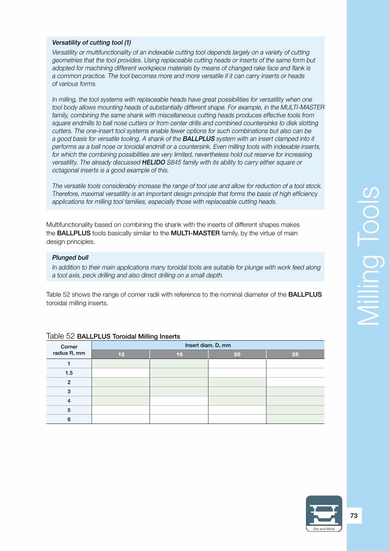
Milli
ng T
ools
Die and Mold
73
Table 52 shows the range of corner radii with reference to the nominal diameter of the BALLPLUS toroidal milling inserts.
Multifunctionality based on combining the shank with the inserts of different shapes makesthe BALLPLUS tools basically similar to the MULTI-MASTER family, by the virtue of maindesign principles.
Versatility of cutting tool (1)
Versatility or multifunctionality of an indexable cutting tool depends largely on a variety of cutting geometries that the tool provides. Using replaceable cutting heads or inserts of the same form but adopted for machining different workpiece materials by means of changed rake face and flank is a common practice. The tool becomes more and more versatile if it can carry inserts or heads of various forms.
In milling, the tool systems with replaceable heads have great possibilities for versatility when one tool body allows mounting heads of substantially different shape. For example, in the MULTI-MASTER family, combining the same shank with miscellaneous cutting heads produces effective tools from square endmills to ball nose cutters or from center drills and combined countersinks to disk slotting cutters. The one-insert tool systems enable fewer options for such combinations but also can be a good basis for versatile tooling. A shank of the BALLPLUS system with an insert clamped into it performs as a ball nose or toroidal endmill or a countersink. Even milling tools with indexable inserts, for which the combining possibilities are very limited, nevertheless hold out reserve for increasing versatility. The already discussed HELIDO S845 family with its ability to carry either square or octagonal inserts is a good example of this.
The versatile tools considerably increase the range of tool use and allow for reduction of a tool stock. Therefore, maximal versatility is an important design principle that forms the basis of high efficiency applications for milling tool families, especially those with replaceable cutting heads.
Plunged bull
In addition to their main applications many toroidal tools are suitable for plunge with work feed along a tool axis, peck drilling and also direct drilling on a small depth.
Corner radius R, mm
Insert diam. D, mm
12 16 20 25
1
1.5
2
3
4
5
6
Table 52 BALLPLUS Toroidal Milling Inserts
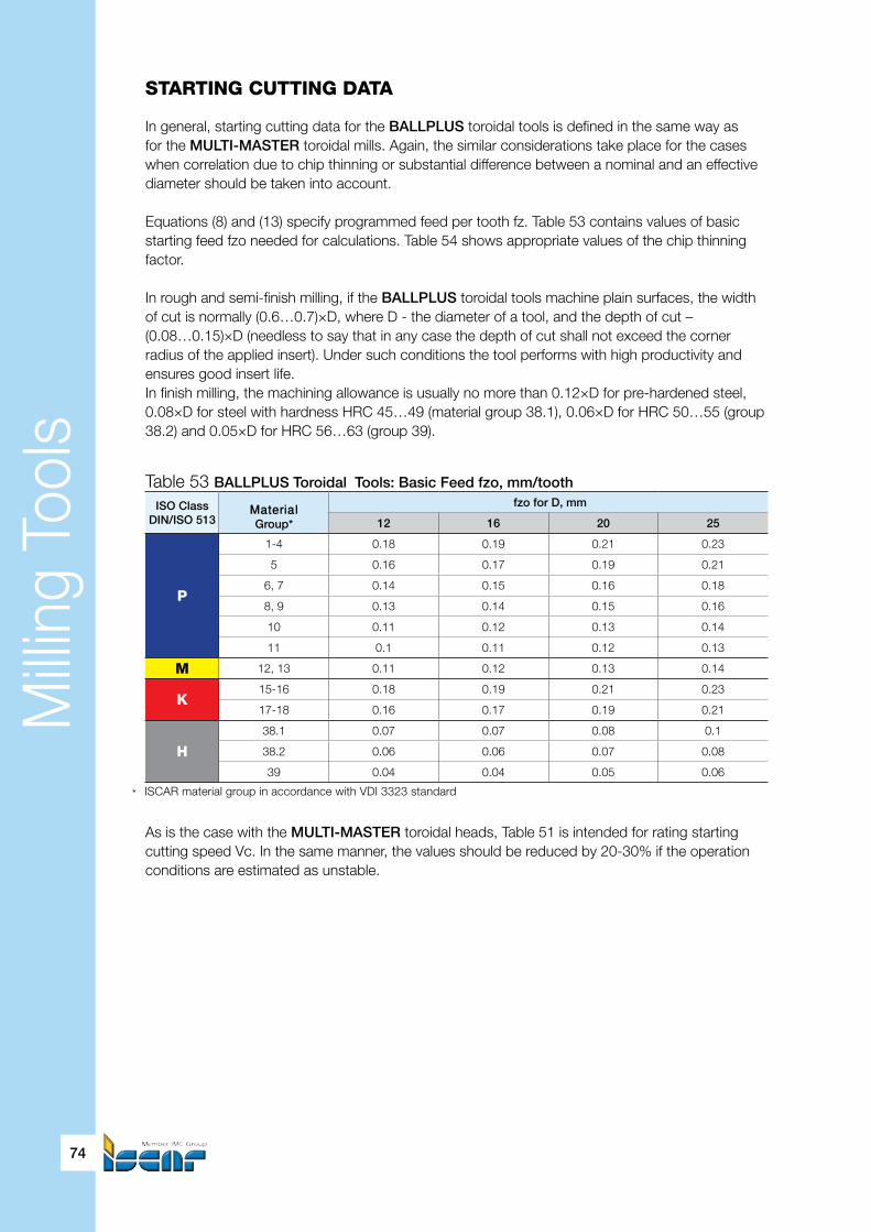
Milli
ng T
ools
74
STARTING CUTTING DATA
In general, starting cutting data for the BALLPLUS toroidal tools is defined in the same way as for the MULTI-MASTER toroidal mills. Again, the similar considerations take place for the cases when correlation due to chip thinning or substantial difference between a nominal and an effective diameter should be taken into account.
Equations (8) and (13) specify programmed feed per tooth fz. Table 53 contains values of basic starting feed fzo needed for calculations. Table 54 shows appropriate values of the chip thinning factor.
In rough and semi-finish milling, if the BALLPLUS toroidal tools machine plain surfaces, the widthof cut is normally (0.6…0.7)×D, where D - the diameter of a tool, and the depth of cut – (0.08…0.15)×D (needless to say that in any case the depth of cut shall not exceed the corner radius of the applied insert). Under such conditions the tool performs with high productivity and ensures good insert life.In finish milling, the machining allowance is usually no more than 0.12×D for pre-hardened steel, 0.08×D for steel with hardness HRC 45…49 (material group 38.1), 0.06×D for HRC 50…55 (group 38.2) and 0.05×D for HRC 56…63 (group 39).
As is the case with the MULTI-MASTER toroidal heads, Table 51 is intended for rating starting cutting speed Vc. In the same manner, the values should be reduced by 20-30% if the operation conditions are estimated as unstable.
ISO ClassDIN/ISO 513
MaterialGroup*
fzo for D, mm
12 16 20 25
P
1-4 0.18 0.19 0.21 0.23
5 0.16 0.17 0.19 0.21
6, 7 0.14 0.15 0.16 0.18
8, 9 0.13 0.14 0.15 0.16
10 0.11 0.12 0.13 0.14
11 0.1 0.11 0.12 0.13
M 12, 13 0.11 0.12 0.13 0.14
K15-16 0.18 0.19 0.21 0.23
17-18 0.16 0.17 0.19 0.21
H
38.1 0.07 0.07 0.08 0.1
38.2 0.06 0.06 0.07 0.08
39 0.04 0.04 0.05 0.06
Table 53 BALLPLUS Toroidal Tools: Basic Feed fzo, mm/tooth
* ISCAR material group in accordance with VDI 3323 standard

Milli
ng T
ools
Die and Mold
75
ExampleIn a die-making shop mill HCE D25-A-L170-C25 with insert HTR D250-R5.0-QF IC908 planned to be applied for rough milling of a mold insert cavity. The cavity material is stainless steel AISI 420F. The proposed cutting parameters are as below: the depth of cut – 2.5 mm, the width of cut – 17 mm. A rigid machine tool performs milling; and the cavity is properly secured in the workholding fixture of the machine tool. Find the programmed spindle speed and feed.
Basic feed for tooth fzo for groups 12-13 is equal to 0.14 mm/tooth (Table 53), chip thinning factor KTH for 25 mm dia. insert, 5 mm corner radius and 2.5 mm depth of cut (Table 54) – 1. Hence, the programmed feed will be 0.14 mm per tooth.In accordance with Table 51 the recommended starting speed is 120 m/min. Effective diameter De=25-2×5+2×√(2×2.5×5-2.5²)=23.7 (mm) that contains ~95% of the insert nominal diameter (25 mm). Therefore, the spindle speed can be calculated with the reference to the nominal diameter and it will be 1000×120/(π×25)=1528 (rpm). Correspondingly, the feed speed becomes 0.14×2×1528=427.8 (mm/min).
Table 54 Chip Thinning Factor KTH for BALLPLUS Toroidal Inserts withNominal Diameter D and Corner Radius R
ap/D D=12 D=16 D=20 D=25
ap R3 R4 ap R3 ap R3 R4 ap R3 R4 R5 R6
0.01 0.12 3.2 3.6 0.16 2.8 0.2 2.4 2.9 0.25 2.2 2.6 2.9 3.1
0.02 0.24 2.2 2.2 0.32 2 0.4 1.8 2.1 0.5 1.6 1.9 2.1 2.2
0.05 0.6 1.4 1.7 0.8 1.3 1 1.2 1.3 1.25 1.1 1.2 1.3 1.5
0.1 1.2 .1 1.3 1.6 1 2 1 1 2.5 1 1 1 1.1
0.15 1.8 1 1.1 2.4 1 3 1 1 3.75 1 1 1 1
0.2 2.4 1 1.1 3.2 — 4 — 1 5 — 1 1 1
Fig. 20
α°
FvAp ≤ RR

Milli
ng T
ools
76
Fv
R
Ap ≤ R
Profile afteroperation
Allowanceincrease
∆Machiningallowance
Pre-shapedprofile
Fillet
Fillet
Fig. 21
Fig. 22 Fig. 23
Toroidal cutting profile and rampdown milling
Toroidal milling tools can be used in rampdown milling applications whether linear ramping or ramping by helix (helical interpolation). For each of these ramping techniques a depth of cut should be no more that the corner radius of a head, an insert or a solid tool (Fig. 20, 21). Obviously, such is true also for milling by circular interpolation.
Marking the end of the chapter devoted to the toroidal tools, we can emphasize the following points:• Toroidal tools are suitable for milling plane and contoured surfaces.• Toroidal tools feature successful performance in face milling, helical and circular interpolation and plunging. Within certain limits they operate in linear ramping and peck drilling.• Toroidal tools allow for substantial improvement in feed speed due to chip thinning effect and thus considerably reduces cycle time.• The cutting profile of the toroidal tools has no point where the cutting speed will be zero during machining that gives convincing advantages - in comparison with ball nose cutters, for instance, and ensures smooth face milling with large width of cut.• Such versatility and the sources of improving productivity determine the toroidal tools as exceptionally widespread in die and mold making for various applications from rough to finish milling, especially in machining cavities and faces.
Unexpectedly too large machining allowance
One of the most popular applications of toroidal tools is machining cavities by helical interpolation. A cavity may already be pre-shaped by casting or pre-machined. In this case the bottom of a cavity is connected with its walls by a fillet; and a machining allowance (material stock to be removed) for the filleted area increases. That may be problematic or even fatal for the tool (Fig. 22). Therefore, in spite of impressive self-tuning possibilities of modern CNC machine tools with adaptive control always take the above into consideration and check thoroughly the machined shape and corresponding cutting data. In addition, the same picture may occur when machining outer surfaces (a punch, for instance) (Fig. 23).
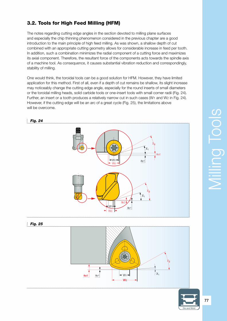
Milli
ng T
ools
Die and Mold
77
3.2. Tools for High Feed Milling (HFM)
The notes regarding cutting edge angles in the section devoted to milling plane surfaces and especially the chip thinning phenomenon considered in the previous chapter are a good introduction to the main principle of high feed milling. As was shown, a shallow depth of cut combined with an appropriate cutting geometry allows for considerable increase in feed per tooth. In addition, such a combination minimizes the radial component of a cutting force and maximizes its axial component. Therefore, the resultant force of the components acts towards the spindle axis of a machine tool. As consequence, it causes substantial vibration reduction and correspondingly, stability of milling.
One would think, the toroidal tools can be a good solution for HFM. However, they have limited application for this method. First of all, even if a depth of cut remains be shallow, its slight increase may noticeably change the cutting edge angle, especially for the round inserts of small diameters or the toroidal milling heads, solid carbide tools or one-insert tools with small corner radii (Fig. 24). Further, an insert or a tooth produces a relatively narrow cut in such cases (W1 and W2 in Fig. 24). However, if the cutting edge will be an arc of a great cycle (Fig. 25), the limitations abovewill be overcome.
χ2
ap2
χ1
W1W2
ap1
W1
ap2
W2ap1
χ2
χ1
ap2 W1
W2
ap1
χ2
χ1
Fig. 24
Fig. 25

Milli
ng T
ools
78
In the past, the classical approach for rough milling dictated using as large-sized cutter as possible and required corresponding powerful machine tools. Today HFM leads to the same result that is reached by much smaller sized tools. No wonder many machine tools for HFM have spindles with a #40 taper, which can be enough for properly securing HFM tools and good operational performance.
Generally HFM relates to rough milling operations, but it can substantially reduce overall machining-cycle time. First of all, it allows for fast material removal, due to considerably increased feed rates. Second, the cutting force acting mainly towards to the spindle axis minimizes vibrations and enables stable rough milling at high overhangs – the property of the utmost importance for machining die cavities, punches and rams. Third, shallow depth of cut makes it possible to produce the contour that will be very close to the final shape and thus diminish or even eliminate semi finishing. All these features make HFM a significant time saver.
HFM is especially effective for machining die cavities or recesses by helical interpolation, principally if they have sufficiently large sizes. Naturally, HFM technique is successfully applied to rapid production of large-diameter holes directly from solid, or enlarging a previously made hole.In the case of a blind hole, the hole bottom will be flat. Moreover, the same HFM tool can produce holes of different diameters. In addition to the mentioned advantages, a HFM tool has far less contact with a cavity wall in contrast with a toroidal tool. In milling cavities by helical interpolation, the toroidal tool, working even at shallow depth of cut, comes in contact with the cavity material at increased area after some passes (Fig. 26), that caused vibrations and instable cutting.
However, the feed drive of a machine tool used for HFM should correspond to the required feed rates and be equipped by appropriate CNC devices. Further, rapid acceleration and slowing down combined with quickly changed working trajectories cause more intensive wear of the machine’s moving parts such as guideways, feed screws, bearings, etc. Therefore, the concept of today’s machining centers takes these factors into consideration; and machine tool builders produce the machine tools intended especially for HFM die and mold parts.
Fig. 26: 1st pass
Fig. 26: 3 rd pass Fig. 26: 4th pass
Fig. 26: 2nd pass

Milli
ng T
ools
Die and Mold
79
HFM and “old-type” CNC machine tools
Is the HFM method suitable for “old-type” CNC machine tools with spindle speeds
normally 6000-7000 rpm? These machines are still common in many die and mold shops. The answer is generally “yes” because the typical feed drive of the machine ensures necessary feed rates; and the mentioned values of the spindle speed are enough for rough milling of most die and mold materials. In HFM, the key for high material removal is incresed feed per tooth, combined with normal cutting speed at shallow depth of cut.
Originally the HFM tools were indexable milling cutters of relatively large nominal diameters. The replaceable inserts carried by the tools traditionally had trigon or quadrihedral shapes (Fig. 27).A cutting edge of the insert basically was an arc or two arc chords (correspondingly profiles 1 and 2 in Fig. 28). The progress in multiaxis CNC grinding and sharpening machines allowed for production of very complicated cutting geometries in tools of different, even small sizes. Eventually the HFM tools not only improved the shape of their inserts but were replenished by solid tools and interchangeable heads of less nominal diameters. Such a second birth of the HFM tools was very important for the die and mold industry; and since that moment the HFM technique is applied to roughing face surfaces or relatively large-sized shapes, as well as to various profiles of medium to small dimensions.
ISCAR’s HFM line comprises families of indexable milling tools, solid carbide endmills and interchangeable MULTI-MASTER heads (the latter are intended for mounting in theMULTI-MASTER shanks)
Fig. 27
Fig. 28
Fig. 30
1 2
Fig. 29

Milli
ng T
ools
Table 55 Main Tool Families for HFM
80
* Number of flutes for solid carbide mills and MULTI-MASTER heads
Family TypeToolconfiguration
Range ofdiameters,mm
No. of insert cutting edges
Tool (shank)designation
Insert (head)designation
HELIDO UPFEED Indexable
Shell mills 40-125
6
FF FWX…
H600 WXCU…Shank-type mills 16-40 FF EWX…FLEXFIT adaptation 20-40 FF EWX…M…MULTI-MASTERadaptation 16-20 FF EWX…MMT…
FEEDMILL Indexable
Shell mills 40-125
3
FF FW…
FF WO…Shank-type mills 25-40 FF EW…CLICKFIT adaptation 25-40 FF EW…CF…FLEXFIT adaptation 25-40 FF EW…M…
16FEEDMILL Indexable Shell mills 80 16 FF NM… ONMU…FEEDMILL Solid Solid carbide endmills 6-20 4* EFF S4…
MULTI-MASTERSolidheads
Assembly: shanks 10-25 2*MM…
MM FF…with replaceable heads 8-25 4* MM EFF…
In accordance with the cutting geometry, there are two types of the HELIDO UPFEED inserts: T and HP. The T-type is designed for milling steel and cast iron, while the HP-type relates mostly to machining austenitic stainless steel and high temperature alloys. The T-type inserts have “I” marks on their top surfaces for visual identification (Fig. 30).
Referring to HFM, the die and mold industry is generally concerned with steel workpieces. Hence, the T-type inserts are more common there; however, the HP-type inserts are also used for manufacturing parts from corresponding materials.
Run faster
Two letters FF in the designation of ISCAR tools, inserts or heads for HFM means “Fast Feed”. Run faster at fast feed for high productivity in rough milling operations!
3.2.1. Indexable Tools for HFM
FEEDMILL, the first-ever family of indexable tools, produced by ISCAR, feature the trigon inserts clamped in the tool body. The inserts have a cylindrical protrusion at their bottom, which when mounted into the corresponding hole of the insert pocket provides very rigid clamping, absorbing most of the forces usually exerted on the clamping screw (Fig. 29).
The quest for excellence of the HFM tools led to combining the HELIDO’s strength and FEEDMILL’s geometry, creating the HELIDO UPFEED family with the trigon double-sided inserts that feature 6 cutting edges (Fig. 30). The insert is secured into a dovetail inclined pocket, which provides very firm clamping. A cutting edge of the insert comprises two sections: the major (main or external) cutting edge and the minor (internal) cutting edge. This configuration improves a tool performance especially in rampdown milling, when the minor cutting edge plays a key role (Fig. 31). For better chip formation, the insert rake face portion adjacent to the major edge is convex; and the portion adjoining the minor edge – concave.
The mentioned advantages of the HELIDO UPFEED family allows effective rough milling at very high feeds for high metal removal. Tools of the family have a 17° cutting edge angle and are available in different configurations: shell mills, mills with shanks and milling heads for various adaptations.

Milli
ng T
ools
Die and Mold
81
Radius for programming
In CNC programming, an HFM tool is often specified as a milling cutter with a corner radius. The radius that is called as “radius for programming (R in Fig.32), relates to reference data and can be found in ISCAR catalogs and technical leaflets. The radius defines the maximal thickness of a cusp – a mismatch produced by such specification (correspondingly t in the same figure).
∝
A
A
A-A
Minor cutting edge Major cutting edge
Rotated and enlarged
Fig. 31
Starting Cutting Data
a) Depth of Cut ApTable 56 shows the depth of cut ranges, depending on the sizes of H600 WXCU…T inserts for HELIDO UPFEED FF… milling tools.
Insertsize
Insertdesignation
Ap, mmmin. max.
04 H600 WXCU 04…T 0.2 0.805 H600 WXCU 05…T 0.25 108 H600 WXCU 08…T 0.4 2
D1
R
t
Fig. 32
Table 56 Depth of Cut Ap for FF… Tools with H600 WXCU…T Inserts

Milli
ng T
ools
82
Stepdown
Cusp
D1
Ae>D1 ae>Ap
Fig. 33
b) Width of Cut AeIt is strongly recommended that a width of cut be no more than diameter D1 in order to prevent tooth overloading, because of excess machining allowance in cusps produced on the further passes after stepdown (Fig. 33).
c) Starting Feed Per Tooth fzNormally, feeds per tooth for the majority of die and mold materials lay within the values shown in Table 57.The values are enough for quick estimation of a feed per tooth and give satisfactory results when applied. More precisely, the feed fz can be defined with Table 58. For poor workholding, high overhang, milling near thin walls and in other cases of non-sufficient operational stability, the table data should be reduced by 30%.
Insertsize
Insertdesignation
Feed Fz,mm/tooth
04 H600 WXCU 04…T 0.4…105 H600 WXCU 05…T 0.5…1.508 H600 WXCU 08…T 0.6…2
Table 57 Commonly Occurring Feeds for FF… Tools with H600 WXCU…T Inserts
Table 58 Average Starting Feed fzo for FF… Tools with H600 WXCU…T Inserts
ISO Class
DIN/ISO 513
Workpiece material Feed fzo, mm/tooth for FF…tools
TypeMaterialGroup*
with H600 WXCU…T… Inserts**
H600 WXCU 04 H600 WXCU 05 H600 WXCU 08
P
Plain carbonsteel
1-4 1 1.3 1.7
5 1 1.3 1.6
Alloy steeland
tool steel
6, 7 1 1.2 1.5
8, 9 0.9 1.2 1.4
10 0.8 1.1 1.3
11 0.7 1 1.2
M Martensitic s.s. 12, 13 0.9 1.2 1.4
KGrey cast iron 15-16 1 1.3 1.6
Nodular cast iron 17-18 0.8 1.1 1.3
H Hardened steel38.1 0.4 0.5 0.6
38.2 0.3 0.3 0.4
* ISCAR material group in accordance with VDI 3323 standard** In case of machining in unstable conditions, the starting feed should be reduced by 30%

Milli
ng T
ools
Die and Mold
83
* ISCAR material group in accordance with VDI 3323 standard – Recommended carbide grade
d) Starting cutting speed VcTable 59 comprises the averaged values of starting cutting speed Vc in relation to the insert carbide grades. If the cutting conditions are estimated as unfavorable (high overhang, poor work- or toolholding, etc.) the values should be reduced by 20-30%.
ExampleIn order to cut cycle time for forging die manufacturing, a process planner decided to apply face mill tool FF FWX D080-06-32-08 with inserts H600 WXCU 080612T IC830 for rough milling a plane surface of a large-size block. The block material is AISI/SAE D2 tool steel, HB 190…210. The machining conditions can be estimated as stable: a machine tool with powerful main and feed drives, proper workholding, and short overhang of the tool.
Table 59 FF… Tools with H600 WXCU…T Inserts: Starting Cutting Speed Vc
Particular care: ramping down directly to solid
Starting high feed milling of cavities and pockets, an HFM tool performs the first cut by ramping down to a solid workpiece and then starts profile milling by helical interpolation. Keep in mind that in case, when the tool cuts downward, ramps to material, demands reduced feed per tooth; and the values shown in Table 58 should be decreased by 30-40%. Additionally, it is recommended to reduce the maximal depth of cut that is specified in Table 57 by 20%.
Depth of cut: work for maximum
The cutting edge angle of a FF tool with H600 inserts is practically consistant (17°) along the main cutting edge of an insert mounted in the tool. Therefore, reducing a depth of cut does not cause the chip thinning effect and does not allow for inscreasing feed per tooth and then run faster. If your machine has enough power and workholding is rigid, work for maximal depth of cut – you gain cycle time and reach higher productivity.
ISO ClassDIN/ISO 513
Workpiece material Vc, m/min for Grades
Type Mat. group* IC808 IC810 IC830 IC330
P
Plain carbonsteel
1-4 150 150 150 135
5 150 140 135 125
Alloy steeland
tool steel
6, 7 150 135 125 120
8, 9 150 130 120 115
10 130 125 115 110
11 120 120 115 100
M Martensitic s.s. 12, 13 120 120 120
KGrey cast iron 15-16 200 220 220
Nodular cast iron 17-18 180 200 200
H Hardened steel38.1 80 70
38.2 60 50

Milli
ng T
ools
84
Assuming that calculations show that the machine has enough power, the current manufacturing conditions allow the proposed maximal depth of cut (refer to remark “Depth of cut: work for maximum”) 2 mm (Table 56).The material relates to material group No.10. Starting feed fz=1.3 mm/tooth (Table 58), starting cutting speed Vc=115 m/min (Table 59).Width of cut Ae=62 mm - refer to above paragraph b) “Width of cut Ae” and catalog data of the chosen tool (D1=64 mm).
Spindle speed N=1000×115/(π×80)=458 (rpm).Feed speed VF=1.3×6×458=3572 (mm/min).Metal removal rate Q≈1.3×62×3572=287.9 (cm3/min).
3.2.2. MULTI-MASTER milling heads and solid carbide endmills for HFM
There are two groups of the MULTI-MASTER heads for HFM: two-flute MM FF… heads of the “economy” type and multiflute MM EFF… heads with cutting geometry similar to the FEEDMILL solid carbide endmills. General data regarding these heads and solid endmills is shown in Tables 60 and 61.
Particular care: milling full slot
If the HFM technique is applied for rough milling a full slot, starting feeds and cutting speeds recommended in Tables 58 and 59 should be reduced by 30%.
Table 60 Number of Flutes Z and Maximal Depth of Cut Apmax for MULTI-MASTER Heads and Solid Carbide Endmills Intended for HFM
Type DesignationNumberof flutes Z
Apmax, mm, for nom. diam. D, mm6 8 10 12 16 20 25
MULTI-MASTER MM FF… 2 0.6 1 1.1 1.5 MULTI-MASTER MM EFF… 4 0.4 0.5 0.6 0.8 1 1.2S.C. Endmills EFF… 4 0.3 0.4 0.5 0.6 0.8 1
Versatility of cutting tool (2) and …cutting insert
ISCAR offers the customer inserts that when mounted into the existing tools, they turn these tools into HFM cutters. Inserts OFMW…FF that are intended for the HELIOCTO family and inserts ADKT… FF, ADCT … FF and APKT …FF, which are designed for the HELIMILL family, expand the application ranges of the mentioned lines for high-efficiency rough milling using the HFM method. The inserts do not require any new tools and are secured into pockets of the standard tools of the families. Further, face mill FF NM D080-06-27-R08 with 80 mm nominal diameter carries standard 16-edged insert ONMU 0806…. The insert orientation features similar capabilities to HFM tools. By using the tool in rough face milling, the material removal rate can be increased by 1.5 to 2 times, when compared with the standard tool with this insert. By the way, due to its 16 cutting edge insert ONMU 0806…is a winning economical solution for high feed milling of large-sized plane surfaces. The ISCAR main catalog and technical leaflets contain necessary information regarding these solutions based on the principle of versatility, where the right combination of indexable tools and inserts result in new positive results.
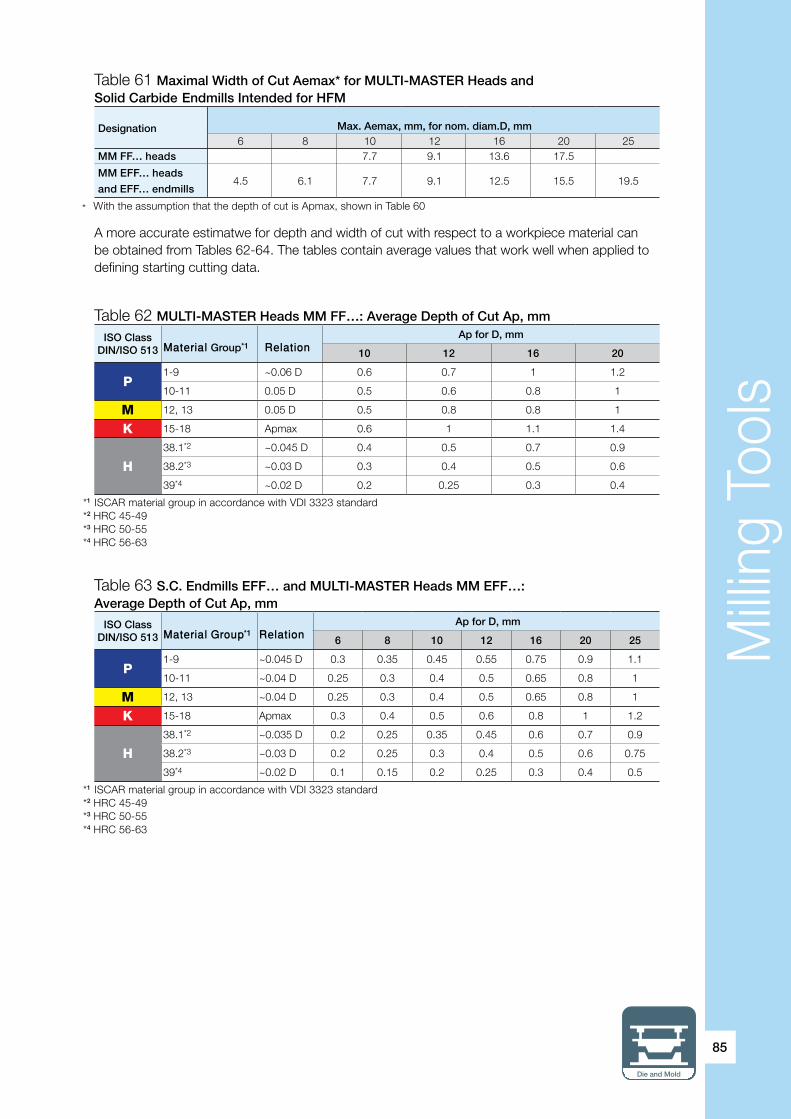
Milli
ng T
ools
Die and Mold
85
Designation
Max. Aemax, mm, for nom. diam.D, mm6 8 10 12 16 20 25
MM FF… heads 7.7 9.1 13.6 17.5
MM EFF… heads
and EFF… endmills4.5 6.1 7.7 9.1 12.5 15.5 19.5
A more accurate estimatwe for depth and width of cut with respect to a workpiece material can be obtained from Tables 62-64. The tables contain average values that work well when applied to defining starting cutting data.
Table 61 Maximal Width of Cut Aemax* for MULTI-MASTER Heads and Solid Carbide Endmills Intended for HFM
Table 62 MULTI-MASTER Heads MM FF…: Average Depth of Cut Ap, mm
Table 63 S.C. Endmills EFF… and MULTI-MASTER Heads MM EFF…: Average Depth of Cut Ap, mm
* With the assumption that the depth of cut is Apmax, shown in Table 60
ISO ClassDIN/ISO 513 Material Group*1 Relation
Ap for D, mm
10 12 16 20
P1-9 ~0.06 D 0.6 0.7 1 1.2
10-11 0.05 D 0.5 0.6 0.8 1
M 12, 13 0.05 D 0.5 0.8 0.8 1
K 15-18 Apmax 0.6 1 1.1 1.4
H
38.1*2 ~0.045 D 0.4 0.5 0.7 0.9
38.2*3 ~0.03 D 0.3 0.4 0.5 0.6
39*4 ~0.02 D 0.2 0.25 0.3 0.4
*1 ISCAR material group in accordance with VDI 3323 standard*2 HRC 45-49*3 HRC 50-55*4 HRC 56-63
*1 ISCAR material group in accordance with VDI 3323 standard*2 HRC 45-49*3 HRC 50-55*4 HRC 56-63
ISO ClassDIN/ISO 513 Material Group*1 Relation
Ap for D, mm
6 8 10 12 16 20 25
P1-9 ~0.045 D 0.3 0.35 0.45 0.55 0.75 0.9 1.1
10-11 ~0.04 D 0.25 0.3 0.4 0.5 0.65 0.8 1
M 12, 13 ~0.04 D 0.25 0.3 0.4 0.5 0.65 0.8 1
K 15-18 Apmax 0.3 0.4 0.5 0.6 0.8 1 1.2
H
38.1*2 ~0.035 D 0.2 0.25 0.35 0.45 0.6 0.7 0.9
38.2*3 ~0.03 D 0.2 0.25 0.3 0.4 0.5 0.6 0.75
39*4 ~0.02 D 0.1 0.15 0.2 0.25 0.3 0.4 0.5

Milli
ng T
ools
86
ISO ClassDIN/ISO 513 Material Group*2 Relation
Ae for D
6 8 10 12 16 20 25
P1-9 ~0.7 D 4 5.5 7 8.5 11.5 14 17.5
10-11 ~0.6 D 3.5 4.5 6 7 9.5 12 15
M 12, 13 ~0.6 D 3.5 4.5 6 7 9.5 12 15
K 15-18 ~0.7 D 4 5.5 7 8.5 11.5 14 17.5
H
38.1*3 ~0.45 D 2.5 3.5 4.5 5.5 7 9 11
38.2*4 ~0.3 D 2 2.5 3 3.5 4.5 6 7.5
39*5 ~0.25 D 1.5 2 2.5 3 4 5 6
Particular care: milling full slot
Speaking about application of the solid carbide endmills and the MULTI-MASTER heads intended for HFM, it should be noted that all additional limitations regarding table values of starting cutting data considered for HELIDO UPFEED cutters are also valid here:• Reduce feed by 30% in case of poor stability• Decrease feed by 30-40% and maximal depth of cut by 20% for ramping down to solid• Reduce feed and cutting speed by 30% when milling full slot
Table 64 MULTI-MASTER Heads MM FF…/MM EFF… andS.C. Endmills EFF…: Average Width of Cut Ae, mm*1
Table 65 MULTI-MASTER Heads MM FF…/MM EFF… and S.C. Endmills EFF…: Starting Speed Vc, m/min
*1 With reference to depth of cut, Ap shown in Table 63*2 ISCAR material group in accordance with VDI 3323 standard*3 HRC 45-49*4 HRC 50-55*5 HRC 56-63
* ISCAR material group in accordance with VDI 3323 standard
ISO ClassDIN/ISO 513 Material Group* Vc, m/min
P
1 180
2-4 160
5-6 150
7-9 140
10 130
11 120
M 12, 13 120
K
15-16 180
17-18 160
H
38.1 100
38.2 80
39** 60
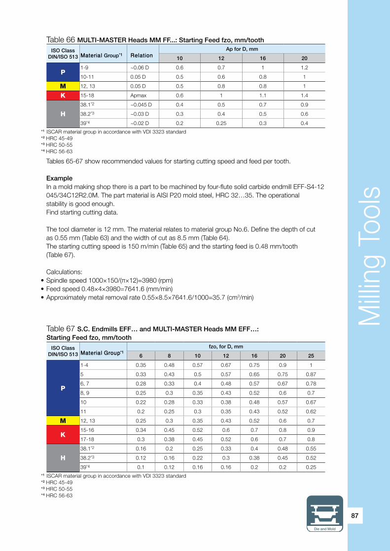
Milli
ng T
ools
Die and Mold
87
Table 67 S.C. Endmills EFF… and MULTI-MASTER Heads MM EFF…:Starting Feed fzo, mm/tooth
Table 66 MULTI-MASTER Heads MM FF...: Starting Feed fzo, mm/tooth
ISO ClassDIN/ISO 513 Material Group*1 Relation
Ap for D, mm
10 12 16 20
P1-9 ~0.06 D 0.6 0.7 1 1.2
10-11 0.05 D 0.5 0.6 0.8 1
M 12, 13 0.05 D 0.5 0.8 0.8 1
K 15-18 Apmax 0.6 1 1.1 1.4
H
38.1*2 ~0.045 D 0.4 0.5 0.7 0.9
38.2*3 ~0.03 D 0.3 0.4 0.5 0.6
39*4 ~0.02 D 0.2 0.25 0.3 0.4
*1 ISCAR material group in accordance with VDI 3323 standard*2 HRC 45-49*3 HRC 50-55*4 HRC 56-63
Tables 65-67 show recommended values for starting cutting speed and feed per tooth.
Example In a mold making shop there is a part to be machined by four-flute solid carbide endmill EFF-S4-12 045/34C12R2.0M. The part material is AISI P20 mold steel, HRC 32…35. The operational stability is good enough. Find starting cutting data.
The tool diameter is 12 mm. The material relates to material group No.6. Define the depth of cut as 0.55 mm (Table 63) and the width of cut as 8.5 mm (Table 64). The starting cutting speed is 150 m/min (Table 65) and the starting feed is 0.48 mm/tooth (Table 67).
Calculations:• Spindle speed 1000×150/(π×12)=3980 (rpm)• Feed speed 0.48×4×3980=7641.6 (mm/min)• Approximately metal removal rate 0.55×8.5×7641.6/1000=35.7 (cm3/min)
ISO ClassDIN/ISO 513 Material Group*1
fzo, for D, mm
6 8 10 12 16 20 25
P
1-4 0.35 0.48 0.57 0.67 0.75 0.9 1
5 0.33 0.43 0.5 0.57 0.65 0.75 0.87
6, 7 0.28 0.33 0.4 0.48 0.57 0.67 0.78
8, 9 0.25 0.3 0.35 0.43 0.52 0.6 0.7
10 0.22 0.28 0.33 0.38 0.48 0.57 0.67
11 0.2 0.25 0.3 0.35 0.43 0.52 0.62
M 12, 13 0.25 0.3 0.35 0.43 0.52 0.6 0.7
K15-16 0.34 0.45 0.52 0.6 0.7 0.8 0.9
17-18 0.3 0.38 0.45 0.52 0.6 0.7 0.8
H
38.1*2 0.16 0.2 0.25 0.33 0.4 0.48 0.55
38.2*3 0.12 0.16 0.22 0.3 0.38 0.45 0.52
39*4 0.1 0.12 0.16 0.16 0.2 0.2 0.25
*1 ISCAR material group in accordance with VDI 3323 standard*2 HRC 45-49*3 HRC 50-55*4 HRC 56-63

Milli
ng T
ools
88
t
apmax
Stepover max
Stepover ≤ t
Fig. 34
apmax
Stepover 1
Stepover 2
h1 apmax
h2
Fig. 35
Depth of cut and stepover (pick feed) In HFM with stepover passes, the depth of cut and the stepover are interrelated quantities. Because the cutting edge of a EFF solid carbide endmill or a MM FF/EFF milling head actually is an arc of large-diameter circle, the maximal stepover is limited by chord length t defined by depth of cut ap (Fig. 34). Therefore, the width of cut in Tables 61 and 64 specifies the values that are not recommended to exceed when the depth of cut is defined by corresponding data in Tables 60, 62 and 63. If not, the produced cusp shape can lead to the tool (head) overloading in further milling with stepdown. It is clear that decreasing the stepover reduces the cusps (Fig. 35) and improve surface condition. Generally, in machining large-sized, mostly plane, surfaces with an allowance no more than the recommended depth of cut, HFM with maximal corresponding width of cut will be the most productive. In case when the allowance is divided between stepdown passes, the stepover definition requires more careful examination, in order to avoid overload after stepdown.

Milli
ng T
ools
Die and Mold
89
SR... SR... SR...
Fig. 36
3.3. Ball nose milling tools
A ball nose milling tool has a ball-shaped (spherical) cutting edge. This means that the cutting edge is a part of a sphere (Fig. 36). Nothing other than a ball has the common normal to a surface; and actually only a spherical cutting tool can ensure theoretical pinpoint contact with a required 3-D surface. Thus the tool does not cause deformation of the needed shape while milling (Fig. 37).
The die and mold industry feature no lack of complex shaped parts - the ball nose milling tools excellently meet the requirements for machining these parts. It is little wonder when speaking about specific features of the cutting tools in die and mold making, the reference is to the ball nose and the toroidal cutting profiles.
In the ball nose cutters, one of the important engineering factors is the angular value of a ball-shaped cutting edge. Usually it is 180° (hemisphere, Fig. 38); but tools with the edge more than hemisphere (bulb-type cutters, Fig. 39), typically 220°-250°, and the edge less than hemisphere (taper or tapered ball nose cutters, Fig. 40), basically 80°-89°, are common in die and mold making.
The ball nose milling tools with the ball-shaped cutting edge as a hemisphere often have also a cylindrical cutting portion. The portion allows for better surface finish, while machining near straight walls and enables for increasing step down for milling passes (compare cases a and b in Fig. 41).
Ball mill
From time to time (especially in shoptalk of the die and mold professional environment) the ball nose cutters are said to be “ball mills”. Such a definition should be avoided because ball mills refer to grinding devices of the specific design principle and relate to grinding materials into powder, but not to material removal by milling.
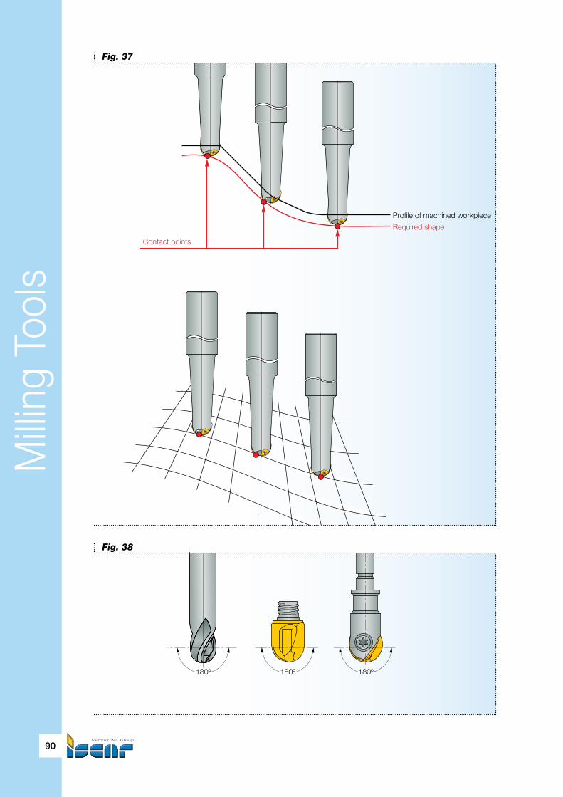
Milli
ng T
ools
90
Contact points
Required shape
Profile of machined workpiece
Fig. 37
180º 180º 180º
Fig. 38
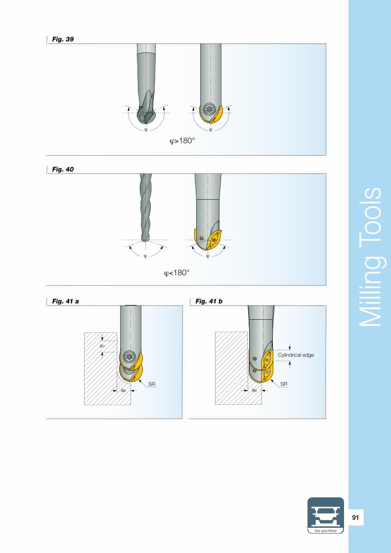
Milli
ng T
ools
Die and Mold
91
ϕ>180°
ϕ ϕ
Fig. 39
ϕ<180°
ϕ ϕ
Fig. 40
a1
aeSR
aeSR
Cylindrical edge
Fig. 41 a Fig. 41 b

Milli
ng T
ools
92
Historical background: copy mill In many cases the ball nose milling tools are called “copy milling cutters”, “copying style mills” or plainly “copy mills”. These terms trace their history to not so long-ago when the contoured surfaces were produced on conventional milling machines of a copying arrangement – the copy milling machines. The machines, operated manually or having a follow-up drive of hydraulic, electric, etc. type, feature the ability to follow a master model (template) and thus to generate the contoured surfaces by cutting. As a matter of course, the copy milling machines use mainly the cutters of ball-shaped or toroidal cutting profile that were called “copy mills” accordingly. Introduction of the CNC machines dramatically changed the technology of generating the contoured surfaces by cutting. In contrast to the traditional copy milling that allowed machining for the most part 2-D profiles, modern CNC technology is capable of producing very complicated 3-D shapes by metal cutting; and today “template”, which defines tool paths, is a computer solid model. The model built with the use of CAD/CAM software is intended for generating corresponding CNC programs. Therefore sometimes used terms “copy milling” and correspondingly “copy mills”, now substantially differ from their original meanings.
The ability to generate exact, true to form surfaces is the prime advantage of the ball nose milling tools. However, the ball-shaped cutting edge, which predetermines this important feature, has one serious weak point: the zero velocity (and hence the zero cutting speed) of a cutter tip. That phenomenon makes cutting near to the tip difficult. Further, the points of a ball-shaped cutting edge lay on unequal distance from a tool axis varying from zero (the tip) to the radius of the corresponding sphere. Such a variation means that the points cut were with different cutting speeds. The chip thinning effect considered in the previous sections of the guide also takes place here. The combination of unequal cutting speeds and dissimilar chip thickness leads to a substantial difference in loading the points of the cutting edge along its profile, which makes cutting harder and intensifies wear in the certain areas of the cutting edge.
Cutting tool engineers take into account the mentioned negative effect when designing the cutting geometry of a ball nose tool. Additionally, machining practice advances different methods that improve the performance of the ball nose tools and makes them more effective. For instance, milling with a tool when its axis is not perpendicular to a machined surface (“tilting”, Fig. 42) makes loading on the cutting edge more uniform. Another example: replacing rampdown milling (case a, Fig. 43) on rampup milling (case b, the same figure) in a machining process at once changes the cutting conditions for the better. Under the same programmed spindle speed and feed in case a), the most stressed portion of the cutting edge is the area near the cutter tip that features low cutting speeds; while in case b), the cutting edge area, which carries the main load, is in a much better situation when a more acceptable cutting speed corresponds to this area. Of course, machining specific parts can demand various milling strategies; and the examples only illustrate some particular properties associated with the ball nose cutting geometry. The correct process planning requires taking the properties into consideration.
ISCAR carries a wide range of ball nose milling cutters of diverse types: indexable and solid, single-insert and with interchangeable solid cutting heads. Normally these are endmills with shank and they vary in dimensions and obtainable accuracy. In addition, the cutters of the single-insert and indexable types are available not only as tools with integral body but in most cases as replaceable cutting heads with a FLEXFIT or MULTI-MASTER adaptation. For the tools with integral body (Fig.44), there are different design configurations with straight (type A) and tapered (conical) neck (types B and D). Usually type B features an operating angle α equal to 5°, and type D –2°. Table 68 shows the most popular ISCAR families of the ball nose endmill cutters.

Milli
ng T
ools
Die and Mold
93
RR
n
A B
δ
∝
α°
Fig. 42
Fig. 44
Type A Type B and D
VF
a
∝ VF
a
∝
Fig. 43 a Fig. 43 b

Milli
ng T
ools
94
Family Type Diameter Range, mm*
BALLPLUS Single-insert 12…25
DROPMILL Indexable 12…50
HELIBALL Single-insert 8…10
MULTI-MASTER Interchangeable solid heads 6…25
SOLIDMILL Solid carbide tools 0.4…25
Table 68 Ball Nose Endmill Cutters: Main Families
* For production of the standard line
Tilting action: case study
When milling with a ball nose cutter, tilting the cutter axis prevents the non-cutting effect of the cutter tip due to its zero cutting speed. Turn to Fig. 42. Section AB of the cutting edge performs milling operation, removing machining allowance δ. The cutting speed within the section is directly proportional to a distance from a point of the section to the cutter axis and it is minimal in point A. The cutting speed has a maximum in the point spaced on distance R from the axis, where R – the radius of the cutter sphere. The distance from point A to the axis can be found as R∙sinα, where α – a tilting angle. It is not difficult to see that if the angle is 5°, the cutting speed in point A is approximately 9% of the maximum, if 10° - 17%; and for the angle 15° the speed is already 26% of the maximum.
Starting Cutting Data and Tool SelectionAs already stated, the cutting speed varies along the section of a ball-shaped cutting edge that engages directly in milling. Due to the chip thinning effect the chip thickness also varies within the section. A correctly selected milling method demands removing most of a machining allowance by the area with the possibly maximal cutting speed. Compare, for example, the mentioned cases a) and b) in Fig. 43. The latter is the correct choice, while the first case shows cutting in unfavorable conditions and should be avoided.
For a ball nose milling tool the effective cutting diameter (see the marginal note on page 58) De, which relates to the point of the cutting edge with maximal cutting speed, can be defined from the following equation:
De = 2 x √(D×ap-ap²)(15)
Where D – tool diameter ap – axial depth of cut
However, the equation will not work for ramping and milling near straight walls (cases b) and c) in Fig. 45) where the areas of the cutting edge having diameters more than De determined from equation 15. Table 69 shows how to define the effective diameter, depending on a cutting path.

Milli
ng T
ools
Die and Mold
95
ap
De
+ VF
n
De
VF
n
a
α
VF
n
De
Stepdown (ap)
ae
Fig. 45 a Fig. 45 b Fig. 45 c
Cutting Path Case in Fig. 45 Effective Diameter De Notes
The cutter axis is normal to a machined surface a) 2×√(D×ap-ap²)
Ramping, milling inclined surfaces b) (D-2×a)×sinα+2×√(D×a-a²) ×cosα* ≈D×sinα**
Milling straight walls c) D * α - ramping angle, a - machining allowance (stock to be removed) per pass.** The simplified equation is often used for estimating effective diameter. In many cases it gives a more or less suitable result. Nevertheless, this equation should be applied for rough calculation only due to the truncation error that can be a source of serious inaccuracy.
Be accurate with effective diameter
In milling with ball nose cutters, especially in ramping operations, it is very important to be accurate in computation of the effective diameter. Precise calculation leads to correct cutting action and better performance.
Table 69 Effective Diameter for Ball Nose Milling Cutters
ExampleCalculate the effective diameter for a ball nose cutter of 10 mm diameter, which is applied to ramp up milling with a ramping angle of 30°. The machining allowance 0.4 mm should be removed by one pass.
In accordance with Table 69 (case b) in Fig. 45):De=(10-2×0.4)×sin30°+2×√(10×0.4-0.4²) ×cos30°=7.99 (mm) ≈8 mm.By comparison, the simplified equation will give 10×sin30°=5 (mm) - the truncation error is 37.5%.
If for the same cutter the ramping angle will be 10° and the allowance 2 mm, calculated effective diameter De=(10-2×2)×sin10°+2×√(10×2-2²) ×cos10°=8.9 (mm), while the simplified equation gives only 1.7 mm! The truncation error in this case reaches 80%!
On the contrary, for 70° ramping with a 25 mm diameter ball nose cutter with a 1 mm allowance De=(25-2×1)×sin70°+2×√(25-1) ×cos70°=24.96 (mm) ≈25 mm; and in accordance with the simplified equation - 25×sin70°=23.5 (mm).The truncation error here is only 6% and that is totally acceptable.One can easily see that equation (15) is nothing but a particular case of the formula for the effective diameter of a ball nose milling cutter in ramping applications and is simply obtained from the latter by substitution zero value for angle α.

Milli
ng T
ools
96
ap
fz
hm
Fig. 46
The ball-shaped (spheric) cutting edge is the cause of chip thinning (Fig. 46). Just as the milling tools with toroidal cutting profile, for a ball nose cutter the variation of the depth of cut changes the maximal cutting angle. The chip thinning effect has been already considered in reasonable detail in the section related to the toroidal tools; and it is not necessary to repeat it again. However it is very important to re-emphasize that the chip thinning factor increases the programmed feed per tooth in order to obtain the planned maximal chip thickness, shall be taken into account. The chip thinning factor is a function of the cutter spheric diameter D and the axial depth of cut ap (Fig. 47).
Normally, chip thinning factor KTH can be found from the following equation:
KTH = 1/sin χmax (16)
Maximal cutting edge angle χmax, as it follows from equation (4), is determined by
χmax = arccos (1-(2 x ap/D)) (4a)
ExampleWhat feed and spindle speed should be programmed for a milling operation performed by 16 mm diameter two-flute ball nose cutter, if the required cutting speed is 100 m/min and the expected maximal chip thickness 0.12 mm? The axial depth of cut is 3.5 mm.
Effective diameter De=2×√(16×3.5-3.5²)= 13.2 (mm)Correspondingly, programmed spindle n=1000×100/(π×13.2)= 2411 (rpm)Maximal cutting edge angle χmax = arccos (1-(2×3.5/16))= 55.8°Chip thinning factor KTH = 1/sin χmax=1/sin55.8°= 1.2Thus feed per tooth fz=0.12×1.2= 0.14 (mm/tooth) and programmed feed speed VF=0.14×2×2411= 675 (mm/min)
As a comparison, ignoring such factors as effective diameter and chip thinning results inspindle speed n=1000×100/(π×16)= 1990 (rpm) and programmed feed speedVF= 0.12×2×1990= 477.6 (mm/min). Under this programmed data, productivity of theoperation will be approximately 30% less!

Milli
ng T
ools
Die and Mold
97
apap
VF a
∝
VF
Fig. 47
In addition to equations (15) and (16), effective cutting diameter De and chip thinning factor KTH can also be found from Table 70. Just as well, the table data is very useful for quickly estimating cutting data.
In milling with ball nose cutters, correct feed and speed calculations should be based on the corresponding effective diameter of a cutter and the chip thinning factor defined by application. Leaving them out can lead to to poor operational performance and less productivity.
ap,mm
D, mm
SØ4 SØ5 SØ6 SØ7 SØ8 SØ10 SØ12 SØ16
De KTH De KTH De KTH De KTH De KTH De KTH De KTH De KTH
0.2 1.7 2.3 1.9 2.5 2.1 2.8 2.3 3 2.5 3.2 2.8 3.6 3.1 3.9 3.5 4.5
0.3 2.1 1.9 2.4 2.1 2.6 2.3 2.8 2.5 3 2.6 3.4 2.9 3.7 3.2 4.3 3.7
0.5 2.6 1.5 3 1.7 3.3 1.8 3.6 1.9 3.9 2.1 4.3 2.3 4.8 2.5 5.6 2.9
0.7 3 1.3 3.5 1.4 3.8 1.5 4.2 1.7 4.5 1.8 5.1 1.9 5.6 2.1 6.5 2.4
1 3.5 1.1 4 1.2 4.5 1.3 4.9 1.4 5.3 1.5 6 1.7 6.6 1.8 7.7 2.1
2 4 1 4.9 1 5.6 1.1 6.3 1.1 6.9 1.1 8 1.2 8.9 1.3 10.6 1.5
3 — — — — 6 1 6.9 1 7.7 1 9.1 1.1 10.4 1.1 12.5 1.3
4 — — — — — — — — 8 1 9.8 1 11.3 1.1 13.8 1.1
5 — — — — — — — — — — 10 1 11.8 1 14.8 1.1
6 — — — — — — — — — — — — 12 1 15.5 1
7 — — — — — — — — — — — — — — 15.9 1
8 — — — — — — — — — — — — — — 16 1
Table 70 Effective Cutting Diameter De, mm, and Chip Thinning Factor KTH forBall Nose Milling Cutters

Milli
ng T
ools
98
Table 70 (cont.) Effective Cutting Diameter De, mm, and Chip Thinning Factor KTH for Ball Nose Milling Cutters
ap,mm
D, mm
SØ20 SØ25 SØ32 SØ40 SØ50
De KTH De KTH De KTH De KTH De KTH
0.3 4.9 4.1 5.4 4.6 6.2 5.2 6.9 5.8 7.7 6.5
0.5 6.2 3.2 7 3.6 7.9 4 8.9 4.5 9.9 5
1 8.7 2.3 9.8 2.5 11.1 2.9 12.5 3.2 14 3.6
3 14.3 1.4 16.2 1.5 18.6 1.7 21 1.9 23.7 2.1
5 17.3 1.1 20 1.2 23.2 1.4 26.4 1.5 30 1.7
8 19.6 1 23.3 1.1 27.7 1.1 32 1.2 36.7 1.4
10 20 1 24.5 1 29.7 1.1 34.6 1.1 40 1.2
12 — — 25 1 30.1 1 36.7 1.1 42.7 1.2
16 — — — — 32 1 39.2 1 46.6 1.1
20 — — — — — — 40 1 49 1
25 — — — — — — — — 50 1
Apart from everything else, defining cutting data depends on the type of the ball nose cutters. Normally, the ball nose cutters feature semi-finish to finish milling of the 3-D surfaces without a large machining allowance. The machined die and mold parts are not equal in their size and accuracy; they differ in processing chain and specification of rough and finish passes. Therefore the part manufacture makes different demands for the required tools in general and for the ball nose milling cutters specifically.
The chart in Fig. 48 shows in simplified form the type of a ball nose cutter as a function of the cutter accuracy and its nominal diameter. In some measures the chart can help in choosing the cutter: basing on the indexable-type principle the cutter can reach large diameters but its accuracy will be limited; at the same time a solid carbide endmill usually is the most suitable solution for high accuracy requirements; however the diameter of such a mill rarely exceeds 20 mm. The ball nose cutters of the single-insert type and the milling tools with the interchangeable solid carbide heads of the MULTI-MASTER family are typically found in-between the indexable and solid tools either in their accuracy or dimensional sizes. It is worthy to note that there are high-precisionMULTI-MASTER ball nose heads with accuracy requirements more strict than for the solid mills, but it is more exception than the rule that says: the monolithic integral tool can be more precise than the assembled one.
Nom. diameter
Indexable
SolidCarbide
One InsertB.N. Cutters
InterchangeableSolid Heads
Accuracy
Fig. 48

Milli
ng T
ools
Die and Mold
99
The starting cutting speed Vc and feed per tooth fz used for CNC programming can be found from the already known equations (1) and (6):
Vc = Vo x Ks x Kt (1)
fz = fz0 x KTH x Ks (6)
Where: Vo – basic cutting speed Kt – tool life factor fz0 – basic starting feed KTH – chip thinning factor Ks – stability factor
The tool life factor is shown in Table 8.
The chip thinning factor is defined by equation (16) or in Table 70.
The stability factor, as already noted, is taken to be 1 for normal conditions and to 0.7 if the estimated cutting stability is insufficient (milling thin walls, high overhang, poor toolholding, non-rigid workholding, etc.).
Defining the basic starting speed and feed depends on the type of a ball nose cutter and is connected with design features of the cutter family.
The subsections below emphasize the characteristic properties of the families of the ball nose cutter and contain the tables with the basic speeds and feeds necessary for cutting data calculation.
BALLPLUS and HELIBALL: families of single-insert ballnose milling cutters
A BALLPLUS milling cutter carries one ball nose insert with the V-shaped rear part that is mounted against two contact surfaces within the slot of the cutter body (Fig. 19). The cutter has two cutting edges which are the edges of the insert. The range of diameters for the BALLPLUS cutters is12-25 mm.
The HELIBALL family, the immediate predecessor of the BALLPLUS and now almost completely replaced by it, is represented today only by the cutters of smaller diameters: 8-10 mm. Inserts for the cutters are shaped by sintering only without any grinding operation. A cutter has only one cutting edge in this case and is intended mostly for rough milling operations. The 10 mm insert, however, is indexable and there are two cutting edges on it; but the 8 mm insert, a typical throwaway, is provided with only one cutting edge.
The BALLPLUS inserts differ in angular values of their cutting edge, cutting geometry and accuracy (Table 71).

Milli
ng T
ools
100
Table 71 Ball Nose Inserts of the BALLPLUS Family
InsertCutting Edge Accuracy
GradeRakeFace
FlankApplication
Spheric Cylindrical Material type Operation
HBR... ~220°(bulb-type)
nonormal sintered
ground
widerange
rough to finish
HBF… high ground finish
HCR…-QF 180°(hemisphere)
yes normal sintered rough to finishHCR…-QP soft
Basic starting feed fzo and basic cutting speed Vo are shown in Tables 72 and 73.
Table 72 BALLPLUS and HELIBALL Ball Nose Milling Cutters: Basic Feed fzo, mm/tooth
* ISCAR material group in accordance with VDI 3323 standard
ISO classDIN/ISO 513
MaterialGroup*
fzo, for D, mm
8 10 12 16 20 25
P
1-4 0.09 0.1 0.12 0.13 0.15 0.17
5 0.08 0.09 0.11 0.12 0.14 0.16
6, 7 0.08 0.09 0.1 0.12 0.13 0.15
8, 9 0.07 0.08 0.1 0.11 0.12 0.13
10 0.07 0.08 0.09 0.1 0.11 0.12
11 0.06 0.07 0.09 0.1 0.1 0.11
M 12, 13 0.07 0.08 0.09 0.1 0.11 0.12
K15-16 0.09 0.1 0.12 0.13 0.15 0.17
17-18 0.08 0.09 0.11 0.12 0.14 0.16
H
38.1 0.05 0.06 0.07 0.07 0.08 0.1
38.2 0.04 0.05 0.06 0.06 0.07 0.08
39 0.03 0.03 0.04 0.04 0.05 0.06
A rule of thumb
As mentioned earlier, in milling with ball nose cutters, the machining tolerance (stock) typically is not so large. For quick estimation of the depth of cut/width of cut relation, a rule of thumb may be used. The rule, named as “the rule of 12”, gives quite acceptable results for milling soft and pre-hardened steel and martensitic stainless steel by ball nose cutters of one-insert type or with interchangeable solid heads. In accordance with the rule, if a depth of cut is the half of a cutter diameter (D/2), a width of cut should be no more than D/6; for the depth of cut D/3 the maximal width of cut should be D/4, etc. It is not difficult to see that 2×6=3×4=12.

Milli
ng T
ools
Die and Mold
101
Three carbide grades are available for the BALLPLUS/HELIBALL inserts of the standard line: IC908, IC928 and IC328. From these three grades, IC928 is conceptually the most general-duty and should be the first choice for milling soft and pre-hardened steel. However, due to the fact that the main part of the application of the one-insert ball nose cutters relates to semi-finish and finish milling, grade IC908, the hardest one, has become increasingly more popular, and can be considered to be the preferred option. In many cases it is the unique solution for profiling workpieces from hardened steels and nodular cast iron. The tougher grade IC328 is suitable for milling in unstable conditions and for cases with considerable impact loading. The fully shaped by sintering non-ground CR… inserts for 8 and 10 mm dia. HELIBALL tools are produced just from this grade.
ExampleA part made from carbon steel AISI/SAE 1020 is machined by ball nose endmill cutterHCM D20-A-L150-C20, with insert HCR D200-QF IC908. The axial depth of cut is 5 mm,the width of cut (stepover) – 3.5 mm. Operational stability is sufficient.
Effective diameter De and chip thinning factor KTH can be calculated or found directly fromTable 70: 17.3 mm and 1.1 respectively.The workpiece material relates to the material group No.1.Basic feed fzo=0.15 mm/tooth (Table 72).Basic cutting speed Vo=210 m/min (Table 73).Programmed feed per tooth fz=0.15×1.1= 0.16 (mm/tooth).Cutting speed for estimated tool life 60 min.Vc=210×1×0.8=168 (m/min).Spindle speed 1000×Vc/(π×De)=1000×168/(π ×17.3)=3090 (rpm).Programmed feed speed VF= 0.16×2×3090=988.8 (mm/min) ≈990 mm/min.
Table 73 Ball Nose Cutters with BALLPLUS HCR…/HBR…, HELIBALL CR… and DROPMILL BCR… Inserts: Basic Cutting Speed Vo, m/min
* ISCAR material group in accordance with VDI 3323 standard** In this case HSM recommended
ISO ClassDIN/ISO 513
MaterialGroup*
Vc, for Grade
IC908 IC928 IC328
P
1 210 180 160
2-4 200 170 140
5-6 190 150 130
7-9 180 140 125
10 160 125 120
11 140 120 110
M 12, 13 155 130 125
K15-16 220 200
17-18 200 180
H
38.1 100 80
38.2 70
39** 55

Milli
ng T
ools
102
Ramping mathematics and one working rule
Chip thinning factor KTH, as a function of cutter diameter D and axial depth of cut ap, is defined by equations (16) and (4a). In ramping with ball nose cutters, ap often is not specified directly but it is defined implicitly via ramping angle α and machining allowance (stock to be removed) per part a. Of course, CAD/CAM systems allows very quick finding ap in such case. In addition, the axial depth of cut can be calculated from the following equation: ap=D/2+[(a-D/2)×cosα+√(D×a-a²) ×sinα] (17) If the phrase in the square brackets is positive, ap should be taken equal to the cutter radius or D/2.
In shop practice the result of calculation according to equation (17) is often increased by 10-20% (clearly, in any case the final value shall not exceed D/2). This working rule provides a sort of safety factor, making the programmed feed a little bit smaller. The safety factor takes into account non-uniform loading of a ball-shaped cutting edge during ramping.
Example 12 mm diameter ball nose endmill cutter HCM D12-D-L160-C16 with insert HBF D120-QF IC908 is applied to finishing an inclined bottom surface of a plastic mold part made from AISI P20 mold steel hardened to HRC 50-52. The operation is ramp up milling with a ramping angle of 5° and machining allowance of 0.2 mm. The cutter works with reasonably high overhang.
Find cutting data if the required tool life period is 20 minutes:
Effective diameter in accordance with Table 69, case b): De=(12-2×0.2)×sin5°+2×√(12×0.2-0.2²) ×cos5°=4.1 (mm). Axial depth of cut (equation 17) ap=12/2+[(0.2-12/2) ×cos5°+√(12×0.2-0.2²) ×sin5°]=0.36 (mm). Maximal cutting edge angle χmax = arccos (1-(2×0.2/12))= 14.8°. Chip thinning factor KTH = 1/sin χmax=1/sin14.8°= 3.9.
The high tool overhang requires defining stability as poor and using stability factor Ks=0.7.
The machined material relates to material group No.38.2, hence:• Basic feed fzo=0.06 mm/tooth (Table 72)• Basic cutting speed Vo=70 m/min (Table 73)
Programmed feed per tooth fz=0.06×3.9×0.7= 0.16 (mm/tooth) Cutting speed for 20 min. tool life Vc=70×0.7×1=49 (m/min) Spindle speed 1000×Vc/(π×De)=1000×49/(π ×4.1)=3804 (rpm) Programmed feed speed VF= 0.16×2×3804=1217 (mm/min)
Comparison of the cutting speed with respect to the nominal diameter will be as follows: π×12×3804/1000=143 (m/min), while the real cutting speed is no better than 49 m/min.

Milli
ng T
ools
Die and Mold
103
QT CS
Ap
R
StraightArea
Fig. 49
DROPMILL: a Family of Indexable Ball Nose Milling Cutters
A DROPMILL cutter carries two indexable inserts of a teardrop shape, ensuring two fully effective teeth for the cutter (Fig. 49). The insert features two cutting edges and each of them combines a round corner with a straight side area tangent to the corner. The area has a relatively large length: 60-70% of a spherical radius generated by the corner, which enables machining a straight wall and a shoulder with a round corner. A protrusion from the insert bottom that fits into a matching slot in the insert pocket, allows the insert to withstand the high forces resulting from considerable loading.
The main application of the family is for milling 3-D surfaces using various techniques, machining die and mold cavities by ramping by line or helix (helical interpolation), etc. The DROPMILL cutters are especially advantageous for semi-finishing the contoured surfaces; allowing for productive removal of significant machining stock. In addition, they are suitable for drilling operations with relatively small depth. The cutters are produced as integral tools and also as milling heads for modular tools with FLEXFIT or MULTI-MASTER connections.
There are two types of the DROPMILL inserts: the peripherally ground QT and fully sintered CS with chip splitting grooves. The latter is principally intended for heavy duty rough milling with large depths of cut, due to its chip slitting cutting effect that prevents the formation of long chips, reduces acting cutting forces and improves chip evacuation.
Table 74 Ball Nose Inserts of DROPMILL Family
InsertRakeFace
FlankChip
SplitterMain
Application
Tool Ø ,mm
12 16 20 25 30 32 40 50
BCR D…-QTsintered
ground no semi-finishing
BCR D…-CS sintered yes roughing

Milli
ng T
ools
104
Similar to the families of the one-insert ball nose cutters, the DROPMILL inserts are produced from the same carbide grades: IC908, IC928 and IC328.
Table 73 contains data for basic cutting speeds. In milling with the DROPMILL cutters, a width of cut usually does not exceed 30% of the cutter diameter in rough operations and it is considerably less in semi-finish to finish passes. Therefore, in case of heavy-duty applications with a sizable width of cut or milling a full slot with a depth of cut more than a quarter of the diameter for theQT-type inserts and more than the third part of the diameter for the CS-type inserts, the table values should be reduced by 10-20%.
Basic feed per tooth is shown in Table 75. For milling a full slot with a depth of cut more than a quarter of the diameter for the QT-type inserts and more than the third part of the diameter for the CS-type inserts and for heavy-duty shoulder milling, the specified values should be reduced by 20-30%.
ExampleA slot with a rounded bottom of 50 mm width and 43 mm depth is planned to be machined by ball nose endmill cutter BCM D50-A-W50-C with inserts BCR D500-CS IC908. The workpiece material is alloy steel AISI/SAE 6150, HB 250…260. The technological system has sufficient stiffness.A process planner decided to mill the slot by three step passes: the first – with 25 mm depth of cut, the second – with 10 mm, and the third – with 8 mm depth of cut. Find cutting data:
The cutter radius is 25 mm. Hence, the effective diameter on the first pass will already be 50 mm; and chip thinning factor KTH = 1.
Table 75 DROPMILL Ball Nose Milling Cutters: Basic Feed fzo, mm/tooth
* ISCAR material group in accordance with VDI 3323 standard
ISO ClassDIN/ISO 513
MaterialGroup*
fzo, for D, mm
12 16 20 25 30/32 40 50
P
1-4 0.11 0.13 0.15 0.17 0.18 0.21 0.25
5 0.11 0.12 0.14 0.16 0.17 0.18 0.21
6, 7 0.1 0.11 0.13 0.15 0.16 0.17 0.19
8, 9 0.1 0.11 0.13 0.14 0.15 0.16 0.18
10 0.09 0.1 0.12 0.13 0.14 0.15 0.17
11 0.08 0.09 0.1 0.11 0.12 0.13 0.15
M 12, 13 0.09 0.1 0.12 0.13 0.14 0.15 0.17
K15-16 0.11 0.13 0.15 0.17 0.18 0.21 0.25
17-18 0.11 0.12 0.14 0.16 0.17 0.18 0.2
H
38.1 0.07 0.08 0.09 0.1 0.11 0.12 0.13
38.2 0.05 0.06 0.07 0.08 0.09 0.09 0.1
39 0.04 0.04 0.05 0.06 0.07 0.07 0.08
Chip splitting drop
Milling slots or grooves (especially the deep ones by step passes), milling shoulders with large allowance, rough milling cavities and pockets with high stock removal rate – all these operations performed by the DROPMILL cutters feature heavy tool loading and chip re-cutting. For such operations, using the CS-type inserts is the preferred way. The CS-type geometry should be considered as a first choice in any case when it comes to heavy-duty milling and problems with chip evacuation.

Milli
ng T
ools
Die and Mold
105
Solid Carbide Ball Nose Endmill Cutters
SOLIDMILL, the ISCAR line of solid carbide endmills, contains ball nose cutters varying in cutting geometry and number of flutes. The cutters are produced from various carbide grades (Table 10) in short, medium, long and extra long length versions (Fig. 50), with straight or tapered neck and intended for all types of the die and mold materials. Generally, the range of cutting diameters for the solid carbide ball nose endmill tools is 1 …25 mm (0.4…2 mm for miniature cutters); and the helix angle is 30°. The diameter has accuracy tolerance e8 (h10 for the economical SOLIDECO family, Table 76).
The machined material relates to material group No.8, therefore:• Basic feed fzo=0.18 mm/tooth (Table 75)• Basic cutting speed Vo=180 m/min (Table 73)
Taking into account the above remarks regarding milling a full slot we should reduce these values by 10-20% for the speed and by 20-30% for the feed. It means that on average the programmed feed per tooth will be 0.18×0.75=0.13 (mm/tooth); the cutting speed for 60 min. tool life - 180×0.85×0.8=122 (m/min).
Spindle speed 1000×Vc/(π×De)=1000×122/(π ×50)=776 (rpm) ≈ 770 rpm Programmed feed speed VF= 0.13×2×776=202 (mm/min) ≈ 200 mm/min
Remark We took the average factor for reducing the speed and feed. A more correct approach demands less decrease for the first pass and greater reduction for the third, the last one because the chip evacuation becomes problematic. Let say, 135 m/min with 0.14 mm/tooth for the first pass and 115 m/min with 0.12 mm/tooth for the third pass.
Overhang
Fig. 50
Short Medium Long Extra Long

Milli
ng T
ools
106
Table 76 Solid Carbide Ball Nose Milling Cutters
Table 77 Solid Carbide Ball Nose Cutters and MULTI-MASTER MM EB… Ball Nose Heads: Type of Machining and Approximate Machining Allowance
Cutter
CuttingEdge Z*
Diam. Range,
mm
ECOLine
CarbideGrades Main Milling
ApplicationWorkpieceHardness
Spherical Cylindr. Standard ECO
EBRF 180° yes 3; 4 6…20 no IC903 – roughing up to HRC 55
EB 180° yes 2; 3; 4 0.4…25 yesIC903 – hard materials up to HRC 65**
IC900; IC300; IC08 IC900; IC08 general-duty up to HRC 45
ESB ~220° no 2; 4 3…16 no IC903 – hard materials up to HRC 65
* Number of flutes** A subgroup of 2 flute EB …A…cutters is intended for materials with HRC 55…70
* ISCAR material group in accordance with VDI 3323 standard** D - the diameter of a ball nose cutter (head)
ISO ClassDIN/ISO 513
ISCARMat. Group*
Machined materialType of machining
Roughing Semi-finishing Finishing
P
1, 2, 4, 6, 10soft steel
HB<250 0.12×D** 0.07×D 0.02×D
3, 7 HB 250…300 0.1×D 0.05×D 0.015×D
5, 8, 9, 11 pre-hardened steel
HRC 30-37 0.1×D 0.05×D 0.01×D
9-11 HRC 38-44 0.08×D 0.04×D 0.01×D
M 12, 13 martensitic s.s. HB<250 0.1×D 0.05×D 0.01×D
K 15-18 cast iron HB< 300 0.15×D 0.08×D 0.03×D
H
38.1hardened
steel
HRC 45-49 0.08×D 0.04×D 0.01×D
38.2 HRC 50-55 0.06×D 0.04×D 0.01×D
39 HRC 56-63 0.05×D 0.03×D 0.01×D
Basic cutting speeds and feeds can be defined from Tables 78 and 79. As already stated, the only carbide grade should be chosen from Table 10.
Two or four?
Classically the ISCAR solid carbide ball nose milling cutters have 2 or 4 flutes, that is - 2 or 4 cutting teeth. How to choose the number of flutes for a tool? The all-purpose 4 flute ball nose cutters give a universal robust and productive solution for various applications, especially for semi-finish and finish milling. Oppositely, the 2 flute cutters with greater chip gullet are more suitable for rough milling, ensuring better chip evacuation. In addition, using the 2 flute cutters is a workable method for fine finishing due to less accumulated error, which depends on the number of teeth. Concerning the 4 flute cutters, traditionally only two teeth produce the central cutting area near the cutter tip and not four. Then in finish milling with shallow depth of cut, calculation of the feed per tooth should take into consideration only two effective teeth; and the advantages of a multi-flute cutter are diminished. The 2 flute tool is a more preferable means for such a case. Also, it prevents cutting action by a “conversion zone” between 2 and 4 teeth, specific for the 4 flute tools that is marked by intensive wear of the non-central teeth and accuracy errors.
Obviously, an integral solid cutter provides a more accurate machining solution relative to an indexable mill. Therefore, the main application of the solid carbide ball nose cutters relates to finish and semi-finish milling of the 3-D surfaces; and they primarily operate under small machining allowance or stock (Fig. 45), but the cutters are used successfully in roughing applications too. In machining with low allowances, even a rough stock is small enough; and the borders between different types of machining are not so clear. Table 77 can help in estimation of the type of machining for main die and mold materials and corresponding machining allowance.

Milli
ng T
ools
Die and Mold
107
ExampleIt is suggested to mill a master hob, which is made from AISI A6 tool steel hardened to HRC 55, on a vertical machine center, using a 12 mm diameter solid carbide ball nose cutterEB-A2 12-12/24C12H110 903. The hob walls are inclined 3°.Machining stock to be removed during this milling operation is 0.1…0.15 mm on side.The machine is in a good condition; the hob is properly clamped into a fixture on the machine table.Find starting cutting data.
According to Table 69, case b) effective diameter De:De=(12-2×0.15)×sin3°+2×√(12×0.15-0.15²) ×cos3°=3.3 (mm)Axial depth of cut ap can be readily calculated (Fig. 47) as:ap=D/2-0.5×√(D²-De²)=12/2-0.5××√(12²-3.3²)=0.23 (mm)From Table 70 chip thinning factor KTH≈3.5.
Consequently, for material group No. 38.2, to which relates the machined steel, the basic cutting speed is 50 m/min (Table 78); the basic feed per tooth is 0.011 mm/tooth (0.013×0.85 – refer to Table 79 and remarks to it).
Programmed feed per tooth fz=0.011×3.5×1= 0.038 (mm/tooth).Cutting speed for 20 min. tool life Vc=Vo=50 m/min.Spindle speed 1000×Vo/(π×De)=1000×50/(π ×3.3)=4822 (rpm).Programmed feed speed VF= 0.038×2×4822=366 (mm/min).
It is interesting that the cutting speed calculated relative to the nominal diameter of the cutter (12 mm) will be: VcD =π×12×4822/1000=182 (m/min)
Table 78 Solid Carbide Ball Nose Cutters and MULTI-MASTERBall Nose Heads: Basic Cutting Speed Vo*
* Carbide grade selector for solid cutters – refer to Table 10** ISCAR material group in accordance with VDI 3323 standard
ISO ClassDIN/ISO 513
ISCARMat. Group**
Vo, m/min, for Type of Machining
Roughing Semi-finishing Finishing
P
1 180 220 280
2-4 150 170 200
5 125 140 170
6 130 150 190
7-9 120 135 170
10 115 130 165
11 100 110 120
M 12, 13 110 110 150
K15-16 160 180 220
17-18 150 170 200
H
38.1 70 80 100
38.2 40 50
39 30 40
Reminder
Always check how a report, technical paper or guide specifiies a cutting speed, with respect to effective or nominal diameter (Fig. 51)!
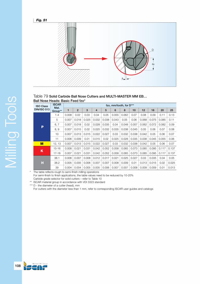
Milli
ng T
ools
108
ISO ClassDIN/ISO 513
ISCARMat.
Group**
fzo, mm/tooth, for D***
1 2 3 4 5 6 8 10 12 16 20 25
P
1-4 0.008 0.02 0.03 0.04 0.05 0.055 0.062 0.07 0.08 0.09 0.11 0.13
5 0.007 0.018 0.025 0.032 0.038 0.043 0.05 0.06 0.068 0.075 0.085 0.11
6, 7 0.007 0.018 0.02 0.028 0.035 0.04 0.048 0.057 0.062 0.072 0.082 0.09
8, 9 0.007 0.015 0.02 0.025 0.032 0.035 0.038 0.045 0.05 0.06 0.07 0.08
10 0.007 0.013 0.015 0.022 0.027 0.03 0.032 0.038 0.042 0.05 0.06 0.07
11 0.006 0.009 0.01 0.015 0.02 0.025 0.028 0.035 0.038 0.045 0.055 0.06
M 12, 13 0.007 0.013 0.015 0.022 0.027 0.03 0.032 0.038 0.042 0.05 0.06 0.07
K15-16 0.008 0.021 0.031 0.042 0.052 0.058 0.065 0.073 0.085 0.095 0.117 0.137
17-18 0.007 0.021 0.031 0.042 0.052 0.058 0.065 0.073 0.085 0.095 0.117 0.137
H
38.1 0.006 0.007 0.008 0.012 0.017 0.021 0.025 0.027 0.03 0.035 0.04 0.05
38.2 0.005 0.005 0.006 0.007 0.007 0.008 0.009 0.01 0.013 0.015 0.02 0.025
39 0.004 0.004 0.005 0.005 0.006 0.007 0.007 0.008 0.009 0.009 0.01 0.013
a
ap
D
Fig. 51
Table 79 Solid Carbide Ball Nose Cutters and MULTI-MASTER MM EB… Ball Nose Heads: Basic Feed fzo*
* The table reflects rough to semi-finish milling operations For semi-finish to finish applications, the table values need to be reduced by 10-20% Carbide grade selector for solid cutters – refer to Table 10** ISCAR material group in accordance with VDI 3323 standard*** D - the diameter of a cutter (head), mm For cutters with the diameter less than 1 mm, refer to corresponding ISCAR user guides and catalogs

Milli
ng T
ools
Die and Mold
109
Table 80 Ball Nose Heads of MULTI-MASTER Family
* Number of flutes
MULTI-MASTER: Interchangeable Ball Nose Milling Heads
The MULTI-MASTER family offers a rich choice of ball nose milling heads with various dimensions, shapes and accuracy. The heads combined with shanks, extensions and reducers allow for assembly of numerous ball nose endmill cutters that meet the requirements of the die and mold maker.
Similar to the MULTI-MASTER head shapes (square, toroidal, etc.), there are two main types of the ball nose heads: multi-flute MM EB… heads and two flute “economy” MM H… heads (Table 80).
The cutting geometry of MM EB… heads is not different from the solid carbide ball nose cutters; however the heads usually have smaller cutting lengths. The approach to finding cutting data for MM EB… heads is the same as the method for the solid cutters.
MM H… ball nose heads are called “economy”, but not due to lesser accuracy. On the contrary, high-precision MM HBR… and MM HRF… heads have very closed diameter tolerances (h7). The heads, as other pressed and sintered “to shape and size” heads of this type, require minimum grinding operation during their manufacturing. Such technology allows for unique features: the combination of negative rake angles near the head tip with positive rake angles along the most part of the spheric cutting edge in MM HCR… heads, increased area of the spheric edge in bulb-type MM HBR… heads and others. A tooth of the head is extremely strong and successfully stands up against considerable loading; which is important for rough profiling and milling hardened steel. However, the helix angle of the heads is much less when compared with the solid carbide ball nose cutters and MM EB… heads.
The MULTI-MASTER ball nose heads are made from carbide grade IC908, except for the heads MM HRF… intended for precise finishing hardened steel, for which carbide grade IC903 is used.
Concerning cutting data, Table 81 shows average machining allowance for different types of milling with the use of MULTI-MASTER ball nose tools carrying MM H… heads. The basic cutting speed can be found from Table 78 and the basic feed per tooth – from Table 82.
ExampleWithin a planned process for manufacturing a die casting die, a ball nose cutter, which comprises shank MM S-B-L125-C16-T06 assembled with ball nose head MM HCR100-2T06 IC908, is the subject of restmilling the corners of a part of the die. The part material is tool steel AISI H11 with hardness HRC 40…42. The restmilling cycle consists of several passes with machining allowance 0.2 mm max. Operational stability is good. Cutting data must be found.
Assume that all cutting edges perform cutting and the effective diameter De is equal to the nominal diameter (10 mm) – the worst case. Then chip thinning factor KTH = 1.
The machined material represents material group No.10.
Head TypeCutting Edge Rake
FaceFlank Z*
Øtol.
CarbideGrade
Head Ø, mm Main Milling Application
Spherical Cylindr. 6 8 10 12 16 20
MM HCR economy(pressedto size)
180° yessintered
ground 2
h9 IC908 rough to finish
MM HRF
ground
h7 IC903 finish + millinghard steelMM HBR ~240° no h7 IC908
MM EB ground 180° yes ground 2; 4 e8 IC908 rough to finish

Milli
ng T
ools
110
Table 81 MULTI-MASTER MM H… Ball Nose Heads:Type of Machining and Approximate Machining Allowance
ISO ClassDIN/ISO 513
ISCARMat. Group*
Machined MaterialType of Machining
Roughing Semi-finishing Finishing
P
1, 2, 4, 6, 10Soft steel
HB<250 0.14×D** 0.08×D 0.02×D
3, 7 HB 250…300 0.12×D 0.06×D 0.015×D
5, 8, 9, 11 Pre-hardened steel
HRC 30-37 0.11×D 0.05×D 0.01×D
9-11 HRC 38-44 0.09×D 0.04×D 0.01×D
M 12, 13 Martensitic s.s. HB<250 0.11×D 0.05×D 0.01×D
K 15-18 Cast iron HB< 300 0.17×D 0.08×D 0.03×D
H
38.1Hardened
steel***
HRC 45-49 0.09×D 0.04×D 0.01×D
38.2 HRC 50-55 0.06×D 0.04×D 0.01×D
39 HRC 56-63 0.05×D 0.03×D 0.01×D
* ISCAR material group in accordance with VDI 3323 standard** D - the diameter of a head*** Recommended carbide grade - IC903
Restmilling
As a rule, productive milling passes, especially rough, propose applying more durable and rigid tools for high metal removal rate. In many cases the form and dimensions of the tool do not allow for a cut in some areas; for example, the corners of a die cavity (Fig. 52). The remainder of the material in the areas is removed by restmilling – a method under a technological process where a tool of smaller diameter cuts the areas with residual stock. In speaking about restmilling, this is a finishing operation that is a part of the whole finish milling cycle. Making use of the solid carbide ball nose cutters and the MULTI-MASTER ball nose heads is the excellent choice for restmilling tools.
Fig. 52
r<D2
R≥D2
∅D
A
Material to be removedby restmilling (residual stock)
Final shape
Rough milling cutter with diameter D
aR
ax - Finising allowanceaR - Rough allowance
aX
A

Milli
ng T
ools
Die and Mold
111
Table 81 MULTI-MASTER MM H… Ball Nose Heads: Basic Feed fzo*
* The table reflects rough to semi-finish milling operations For semi-finish to finish applications the table values need to be reduced by 10-20% For roughing by a cutter with MM HBR…head, the table values need to be reduced by 10% For machining hardened steel - carbide grade IC903 is recommended** ISCAR material group in accordance with VDI 3323 standard*** D - the diameter of a head
ISO classDIN/ISO 513
ISCARMat. Group**
fzo, mm/tooth, forD***
8 10 12 16 20
P
1-4 0.08 0.09 0.11 0.12 0.13
5 0.07 0.08 0.1 0.11 0.12
6, 7 0.07 0.08 0.09 0.1 0.11
8, 9 0.06 0.07 0.08 0.09 0.1
10 0.06 0.07 0.08 0.09 0.1
11 0.05 0.06 0.07 0.08 0.09
M 12, 13 0.06 0.07 0.08 0.09 0.1
K15-16 0.08 0.09 0.1 0.12 0.13
17-18 0.08 0.09 0.1 0.11 0.12
H
38.1 0.04 0.05 0.06 0.07 0.08
38.2 0.03 0.037 0.045 0.055 0.065
39 0.02 0.025 0.03 0.035 0.04
Comparing the machining allowance with the values of Table 81, the operation fits into finish milling.So the basic cutting speed for 20 min. tool life is 165 m/min (Table 78); the basic feed per tooth is0.06 mm/tooth (Table 82: table value 0.07 mm/tooth with reducing by 10% in accordancewith the remark).Spindle speed 1000×Vo/(π×De)=1000×165/(π ×10)=5252 (rpm)Programmed feed speed VF = 0.06×2×5252=630 (mm/min)

Milli
ng T
ools
112
3.4. Special Methods: High Speed Machining (HSM) and Milling of Hardened Steel
The term “High Speed Machining” and the abbreviation “HSM” are well-known in industry, and in particular, in die and mold making. High speed machining, what is it? Why is HSM so relevant for up-to-date die and mold manufacturing?
Even up to now a generally accepted definition of high speed machining does not exist. Obviously, HSM can mean:• High cutting speed machining• High spindle speed machining• High feed speed machining HSM is often emphasized that it is “…a high-efficiency method of modern machining with high spindle and feed speeds…” that allows for various advantages. It is clear that cutting, spindle and feed speeds are interrelated. More spindle speed = more feed speed, etc. How to define the cutting speed?
In the example of machining steel with hardness HRC 55 to the section “Solid carbide ball nose cutters” the real cutting speed related to the effective diameter was 50 m/min, and the speed with respect to the nominal diameter – 182 m/min. More illustrative is a case of milling with 0.1 mm depth of cut by ball nose cutters of different diameters (Table 83). The table shows distinctly that in profile milling with shallow depths of cut, even small cutting speeds can require considerable spindle speed, which in turn causes a cutter to run fast. Assume that 4 mm diameter ball nose cutter in Table 83 has 2 teeth and it cuts with feed 0.04 mm/tooth. The feed speed will be 815 mm/min, 1222 mm/min and 1630 mm/min for cutting speed 40 m/min, 60 m/min and 80 m/min correspondingly! Shallow, light cuts combined with high spindle speeds are classical attributes of high speed machining. HSM, as a metalcutting method, demands very specific cutting techniques and dedicated machine tools, toolholding devices and of course, cutting tools, that will ensure acceptable tool life. Being applied to manufacturing process HSM can dramatically cut cycle time. It is worthy of note that HSM not always a process with high spindle speed; and many HSM operations do not need high rotational velocity.
History: HSM
In the twenties-thirties Dr.-Ing. Carl Salomon, a German researcher, did a series of experiments for measuring cutting temperatures against the corresponding cutting speeds during machining of some engineering materials. The results, which have been represented graphically, allowed the researcher to assume that the cutting temperature rises with increasing the cutting speed, until the speed reaches some specific critical value, and then comes down, in spite of further the speed growth (Fig. 53). Hence, Salomon concluded, there is an area of cutting speeds much more than usual for which the cutting temperature is similar to those that are observed in conventional cutting. By hypothesis the area related to speeds is 5-10 times as much as common values.

Milli
ng T
ools
Die and Mold
113
Conventional Cutting
Vcr Vh
High SpeedMachining
CuttingSpeed
Tcr
Tc
CuttingTemperature
Critical Point
Fig. 53
Table 83 Comparative Example: Milling by Ball Nose Cuttersof Different Diameters with 0.1 mm Depth of Cut
Vc,m/min
D, mm
SØ 20 SØ 10 SØ 8 SØ 6 SØ 4 SØ 2
De= 2.8 De= 2 De= 1.77 De= 1.5 De= 1.25 De= 0.87
rpm VcD rpm VcD rpm VcD rpm VcD rpm VcD rpm VcD
40 4547 286 6366 200 7193 181 8488 160 10186 128 14635 92
60 6820 429 9549 300 10789 271 12732 240 15279 192 21952 138
80 9094 572 12732 400 14386 362 16976 320 20372 256 29270 184
D - the diameter of a ball nose cutterDe, mm, - the effective diameter for 0.1 mm depth of cutVc - the cutting speed with respect to effective diameter Derpm - spindle speedVcD, m/min, - the cutting speed with respect to diameter of a cutter D
Today, HSM has penetrated deeply enough mainly into the following processes: machining of aluminum in aerospace or automotive industries and steel in die and mold making. Exactly in the die and mold branch, HSM advantages led to drastic changes in the entire manufacturing approach.
Traditionally, die and mold making expected a considerable share of cutting operations on soft steel, electro discharge machining (EDM) and finishing on hardened steel; and then manual smooth finish and polishing. EDM and manual finish and polish are very time-consuming processes. Repeatability of manual work is a very low likelihood, which presents additional problems for production. Intense competition on the die and mold markets dictates that manufacturers cut cycle time as much as possible and eliminate manual finish and polish. Success in CNC control, high-speed spindle technology, drives, bearings and other components of machine tool, balanced high-precision toolholders and of course, new cutting tool materials and geometries opened to HSM a road to the die and mold maker. The HSM method was very successful. It changed die and mold making processes, allowing for starting machining of already hardened workpieces, and left manual finish and polishing out; cutting the cycle time by 40-50%. Therefore HSM high speed machining in die and mold practice, connected first of all with high speed milling of hardened steel and especially by tools with small nominal diameters.

Milli
ng T
ools
114
Hard steel
Hardened steel is at the same time hard-to-machine steel. Not so long ago a workpiece of hardness HRC 45 was considered to be the limit for metal cutting; and for more hard materials grinding operations should be applied. Progress in cutting tool technology seriously shook the understanding of the hardness limits. Today “hard steels” often refers to steel hardened to HRC 60 and more. In the context of such steels HSM is an effective instrument that makes their cutting possible.
A rule of thumb
In HSM of hardened steel, starting feed per tooth feed per tooth is often estimated as 0.5-1% of a cutter diameter. The lower feed values correspond to more hard steel.
In machining hardened steels - which are difficult-to-cut materials - intensive heat generation and vibration take place. It is a source of poor tool life, reduction of accuracy, loss of stability, etc. that makes machining operations unpredictable. Such vagueness is simply unacceptable for die and mold manufacturing, especially for large-sized die and molds that sometimes need to be cut during several days’ time. The HSM technique gave the die and mold maker a good tool for overcoming this problem. Of course, HSM is not only cutting tools but also dedicated machine tools, control systems and toolholding devices – the combination of all the means together results in real advantages.
Conceptually, HSM of hardened steel is an integrated technological method for which every one of the involved components: the machine tool, the CNC hardware and software, the toolholder and of course the cutting tool, is a mandatory participant and a critical part of the whole process. It differs essentially from milling hardened steel under conventional conditions and from HSM of soft steel. Therefore, defining a more suitable tool and starting cutting data require more deep examination; and we recommend contacting ISCAR specialists in this field. For initial estimation and a general knowledge of the matter, Table 84 below contains typical average data referring to the square end solid carbide and MULTI-MASTER cutters with diameter 4…25 mm.
Table 84 Average Starting Cutting Data for HSM of Steel Parts
* ISCAR material group in accordance with VDI 3323 standard D - cutter diameter ae - width of cut (stepover) ap - depth of cut (stepdown) Vc - cutting speed with respect to effective diameter De
Steel Conditional Group Pre-hardened Hardened
Material Group* 11 38.1 38.2 39.1 39.2
Hardness, HRC 38-44 45-49 50-55 56-60 >60
RoughMilling
ae (0.40-0.70)D (0.40-0.60)D (0.40-0.60)D (0.35-0.55)D (0.30-0.50)D
ap (0.07-0.15)D (0.06-0.12)D (0.05-0.08)D (0.04-0.07)D (0.03-0.07)D
Vc, m/min 120-190 100-170 90-150 70-100 60-80
fz, mm/tooth 0.03-0.24 0.03-0.22 0.03-0.2 0.03-0.17 0.02-0.14
Semi-finishMilling
ae (0.40-0.70)D (0.40-0.60)D (0.35-0.55)D (0.35-0.45)D (0.30-0.45)D
ap (0.05-0.12)D (0.04-0.09)D (0.03-0.07)D (0.03-0.05)D (0.02-0.05)D
Vc, m/min 140-200 130-180 120-170 90-150 70-130
fz, mm/tooth 0.03-0.22 0.03-0.2 0.03-0.17 0.03-0.14 0.02-0.12
FinishMilling
ae (0.40-0.70)D (0.40-0.55)D (0.35-0.50)D (0.35-0.45)D (0.30-0.40)D
ap (0.04-0.1)D (0.03-0.08)D (0.02-0.06)D 0.1-0.4 mm 0.1-0.3 mm
Vc, m/min 150-230 180-220 170-190 130-200 110-160
fz, mm/tooth 0.03-0.2 0.03-0.18 0.02-0.15 0.02-0.13 0.015-0.11

Milli
ng T
ools
Die and Mold
115
Reminder
Some technical papers and advertising leaflets related to HSM and in particular to HSM of hardened steel, use cutting speed data which is not actual. Please check thorougly which diameters, effective or nominal these values refer to.
Keep in mind
Various research shows that for HSM with the use of a ball nose cutter, the best surface finish can be reached when the stepover will be equal to the feed per revolution..
ExampleIn a die and mold shop a technologist plans to change the process of manufacturing a cavity plate by introducing HSM in the final machining steps. The technologist checks a proposed process by test milling. In accordance with the process, the plate, which is made from AISI O1 tool steel, will be machined in hardened condition (HRC 58…60) by solid carbide endmill EC-A4 060-13C06-50 IC903 on a recently acquired new high speed machining center. Find the starting cutting data fortest milling passes. We have a good basis to assume that machining conditions are stable. Taking into account that Table 84 relates mostly to typical data for cutters within diameter range 4…25 mm and the mill diameter is 6 mm, we can extract from the table the following starting data referring to finish milling for ISCAR material group No. 39.1:Width of cut = 0.4×6=2.4 mmDepth of cut = 0.15 mmCutting speed = 130 m/minFeed = 0.03 mm/tooth
Spindle speed = 1000×130/(π×6)=6896 (rpm)≈7000 rpmFeed speed = 0.03×4×7000=840 (mm/min)
RemarkThe spindle speed lays within boundaries of “conventional” values. However, do not forget that the above case refers to machining tool steel with high hardness, for which “normal” cutting speed (and correspondingly, spindle speed) is twice as little!

Milli
ng T
ools
116
3.5. Special Methods: Sculpturing by Plunge Milling
Plunge milling or simply “plunging”, is a productive rough milling method during which a tool moves directly downward into a workpiece with feed directed along the tool axis (Fig. 54). It looks like drilling: the tool plunges into the workpiece. But despite the fact that some plunge milling tools (usually called plungers) are able to produce holes, their main function is to machine straight walls or slots.
In plunging, the tool classically plunges in, lifts out, moves stepwise linearly and then continues this cycle again. It is clear that this machining technique produces a serrated surface with cusps that can be reduced by decreasing a linear stepover; but nevertheless the surface usually requires additional milling for better finish.
Plunging had spurted into popularity among die and mold makers due to one important feature: the main advantage of plunging is the ability to machine at high overhang with minimal bending forces. When high overhang is applied on a conventional milling cutter, which removes material layer-by-layer in passes, the cutter and its adapter quite often can not withstand the great bending moments because of the considerable radial component of cutting forces. Furthermore, the spindle of a machine tool takes up the most part of the radial forces. The result is vibration, noise and the cutter deviation, which causes inaccurate machining and damage of the tool, the adapter and the machine tool. Vibration and noise automatically lead to reducing cutting data and decreasing productivity.
In plunging, the main component of the cutting force acts axially – exactly in the direction of the highest rigidity of a machine tool – allowing productive milling and excellent straightness of machined surfaces.
In addition to plunging ability, the main intended purpose of the plunge milling cutters (also called plunge-in cutters or plungers), is often to perform face milling with limited depth of cut for obtaining a flat surface at bottoms and HFM at high overhang, boring operation, etc.
ISCAR offers a great variety of the plunge milling cutters. Table 85 shows general characteristics of the more popular representatives.
Plunge-in cutting options
Plunge-in capacity is not a feature incidental to plungers. Some other milling cutters (for example, MULTI-MASTER tools with toroidal heads MM HT…) can also perform this milling technique. However, their use as plunging tools has some limitations and should be considered as only optional.
Fig. 54
Stepover
Lifting out
Plunging in
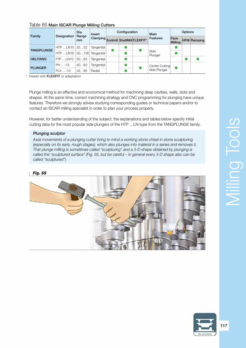
Milli
ng T
ools
Die and Mold
117
Family DesignationDia. Rangemm
Insert Clamping
ConfigurationMainFeatures
Options
Endmill ShellMill FLEXFIT*Face Milling
HFM Ramping
TANGPLUNGEHTP …LN10 25…52 Tangential
SidePlunger
HTP …LN16 50…100 Tangential
HELITANG FTP …LN10 50…63 Tangential
PLUNGER PH …-13 40…63 Tangential
Center Cutting Side Plunger
PLX …-12 32…80 Radial
Table 85 Main ISCAR Plunge Milling Cutters
* Heads with FLEXFIT or adaptation
Plunge milling is an effective and economical method for machining deep cavities, walls, slots and shapes. At the same time, correct machining strategy and CNC programming for plunging have unique features. Therefore we strongly advise studying corresponding guides or technical papers and/or to contact an ISCAR milling specialist in order to plan your process properly.
However, for better understanding of the subject, the explanations and tables below specify initial cutting data for the most popular side plungers of the HTP …LN-type from the TANGPLUNGE family.
Plunging sculptor
Axial movements of a plunging cutter bring to mind a working stone chisel in stone sculpturing (especially on its early, rough stages), which also plunges into material in a series and removes it. That plunge milling is sometimes called “sculpturing” and a 3-D shape obtained by plunging is called the “sculptured surface” (Fig. 55, but be careful – in general every 3-D shape also can be called “sculptured”).
Fig. 55

Milli
ng T
ools
118
∆ae
L1
Fig. 56
Starting cutting speed Vc and feed per tooth fz can be found from the following equations (17) and (18):
Vc = Vo x KH x Kt (17)
fz = fzo x KH (18)
Where: Vo – basic cutting speed for 20 min. tool life (Table 88) KH – overhang coefficient (Table 86) Kt – tool life factor (Table 8) fzo – basic starting feed (Table 89)
Table 86 Overhang Coefficient KH for the TANGPLUNGE Cuttersas the Function of Ratio of Overhang H to Cutter Diameter D
Table 87 TANGPLUNGE HTP…LN Plungers:Maximal Stepover L1max and Width of Plunge ae for Cutter Diameter D* (Fig. 56)
H/D to 4 over 4 to 6 over 6 to 8 over 8 to 10
KH 1 0.9 0.8 0.7
ae, mm
D, mm
HTP… 06 HTP…10 HTP…16
16 20 25 25 32 35 40 42 50 52 50 52 63 66 80 100
L1max, mm
1 7.7 8.7 9.8 9.8 11.1 11.7 12.5 12.8 14 14.3 14 14.3 15.7 16.1 17.8 19.9
2 10.5 12 13.5 13.5 15.4 16.2 17.4 17.8 19.5 20 19.5 20 22 22.6 24.9 28
3 12.4 14.2 16.2 16.2 18.7 19.6 21 21.6 23.8 24.3 23.8 24.3 26.8 27.5 30.4 34.1
4 13.8 16 18.3 18.3 21.2 22.3 24 24.6 27.1 27.7 27.1 27.7 30.7 31.4 34.8 39.1
4.5 14.3 16.7 19.2 19.2 22.2 23.4 25.2 25.9 28.6 29.2 28.6 29.2 32.4 33.2 36.8 41.4
5 17.3 20 20 23.3 24.5 26.5 27.2 30 30.7 30 30.7 34 34.9 38.7 43.6
6 21.3 25 26.4 28.6 29.4 32.5 33.2 32.5 33.2 37 37.9 42.1 47.5
7 22.4 26.4 28 30.3 31.3 34.7 35.5 34.7 35.5 39.6 40.6 45.2 51
7.5 22.9 27.1 28.7 31.2 32.2 35.7 36.5 35.7 36.5 40.8 41.8 46.6 52.6
8 27.7 29.4 32 33 36.7 37.5 36.6 37.5 41.9 43 48 54.3
9 38.5 39.3 43.1 45.3 50.5 57.2
10 40 41 46 47.3 52.9 60
11 41.4 42.5 47.8 49.2 55.1 62.6
12 42.7 43.8 49.5 50.9 57.1 65
13 43.8 45 51 52.5 59 67.3
14 52.4 53.9 60.8 69.4
* The relationship between L1max and ae is given by the following formula: L1max = 2×√D× ae -ae²

Milli
ng T
ools
Die and Mold
119
Table 88 TANGPLUNGE HTP …LN Plungers: Basic Cutting Speed Vo, m/min*
ISO ClassDIN/ISO 513
ISCARMat. Group**
Vo for Grades
IC808 IC810 IC830 IC928 IC330 IC328
P
1 190 175 165 155 150 145
2-4 175 155 150 140 135 135
5 155 145 140 135 130 130
6, 7 150 140 135 130 125 120
8, 9 150 140 135 130 125 120
10 140 140 135 130 125 120
11 130 125 125 120 115 110
M 12, 13 145 135 130 125 120
K15-16 210 230 210 200
17-18 175 180 170 165
H 38.1 105 95 90
* For 20 min. tool life** ISCAR material group in accordance with VDI 3323 standard - More suitable grade
Table 89 TANGPLUNGE HTP …LN Plungers: Basic Starting Feed fzo, mm/tooth
* ISCAR material group in accordance with VDI 3323 standard
ISO Class
DIN/ISO 513
ISCARMaterialGroup*
fzo for Grades
IC808
IC810
IC830IC928
IC330IC328
P
1 0.12 0.13 0.14 0.15
2-4 0.11 0.11 0.12 0.13
5 0.1 0.11 0.12 0.12
6, 7 0.1 0.11 0.12 0.12
8, 9 0.09 0.1 0.11 0.12
10 0.08 0.09 0.1 0.11
11 0.08 0.09 0.1 0.1
M 12, 13 0.08 0.1 0.1
K15-16 0.13 0.15 0.16
17-18 0.11 0.12 0.13
H 38.1 0.07 0.08
Plunge in chips
In plunge milling pockets and cavities, especially those with considerable depth, chip evacuation is highly important. Horizontal machines have good conditions for removing chips, however the situation with vertical machines is worse. For the latter it is very important to use the machining strategy with a tool route that ensures collecting the chips away from the tool cutting movement (at the bottom of a cavity, for example) in order to prevent compressing and re-cutting the chips, which can cause serious problems and thus significantly reduce tool life.
Please note
Plunging can be a good solution for unstable and low-power milling machine tools.

Milli
ng T
ools
120
There two kinds of inserts intended for the HTP plungers: general-duty HTP LNHT…ER and HTP LNHT…ETR – that are recommended for machining hardened and hard-to-cut steel and for heavy cutting conditions.
ExampleSide plunging by shell milling cutter HTP D040-4-16-R-LN10 with inserts HTP LNHT 1006 ER IC830 is proposed for machining a die cavity on a new machine tool. The cavity material is pre-hardened steel AISI P20, HRC 30…35. For necessary plunging depth 100 mm the cutter will be mounted in shell endmill holder DIN69871 40 SEMC 16X100; and this tool assembly will have an overhang of 140 mm. The width of plunge and the stepover are 5 mm and 20 mm, respectively. Estimate starting cutting data for 60 min. tool life.
The material in the mentioned conditions represents ISCAR material group No.9.Basic cutting speed Vo = 135 m/min (Table 88).Basic starting feed fzo = 0.11 mm/tooth (Table 89).Overhang/cutter diameter = 140/40 < 4, then overhang coefficient KH = 1 (Table 86).
Therefore:Starting speed for estimated tool life 60 min. (Kt=0.8, Table 8) Vc = 135×1×0.8=108 (m/min) (may be accepted as 110 m/min)Starting feed = 0.11×1=0.11 (mm/tooth)
Spindle speed = 1000×108/(π×40)≈860 (rpm)Feed speed fz= 0.11×4×860≈378 (mm/min)
ITA – Your helper for finding the most efficient cutting tool
ITA, Iscar Tool Advisor, is a parametric search engine that takes computer-aided tool and process selection to an entirely new level. It “thinks” like a process engineer and allows finding the right tool resting on a huge knowledge base of best practice worldwide. Three key features separate ITA from the other available tooling search engines:• Quick Search/Advanced Search Option – With just three application facts, the Quick Search provides the best starting ideas and processing strategies, with priority by productivity. The Advanced Search Option takes more comprehensive application input, helps the user narrow choices down and delivers a fully developed optimum solution.• Accommodates Shop Preferences and Variables – The user can stipulate such preferences as solid vs. indexable tooling, tool brand/family as well as productivity/tool cost and power management priorities. Variables include machine power and condition, type of cut, available spindle speed, part shape/rigidity, setup stability, overhang, secondary operations and many more. The Variables feature makes ITA valuable for job shops as well as dedicated applications. ISCAR recognizes that most shops want to be able to use a tool for more than one job.• Processing Solutions, Not Just Tooling Solutions – With Advanced Search, the user can get recommended machining parameters for a given shop environment, as well as a short list of tooling solutions.
Visit www.iscar.com/ITA and see the ITA’s true value!

Hol
e M
akin
g To
ols
Die and Mold
121
Hole Making ToolsWhen speaking about cutting tools for die and mold making, we first of all mean milling tools. Indeed, the milling tools are so specific for die and mold manufacturing and most machining operations during this process relate to milling. However, it is hard to imagine die and mold production without hole making. Hence, we consider it necessary to add a short profile of some popular ISCAR toolsfor hole making.
ISCAR’s broad hole making line includes a rich variety of drills, reamers, counterbores and countersinks of various kinds: solid, indexable or with interchangeable heads.
One of the most effective products for short-to-medium depth of drilling is SUMOCHAM – a relatively new family of drills with interchangeable carbide heads (Fig. 57). The heads are available in four cutting geometries intended for main types of engineering materials. Being clamped into steel shanks of different lengths produces efficient tools for drilling holes of various depths: from one and a half to eight hole diameters. The unique clamping mechanism allows for machining with exceptionally high cutting parameters. The shanks are designed with twisted nozzles for coolant and exhibit durable and stably constructed bodies with excellent chip evacuation properties.
SUMODRILL is a family of relatively large diameter drills (more than 60 mm). It features a drill body that carries cartridges with square indexable inserts. Each drill is supplied with a set of a shim plates for adjusting the drill’s diameter within a corresponding range if it will be necessary (Fig. 58).
CHAMGUN, a family of deep hole drills with replaceable heads (Fig. 59), is intended for productive high-precision machining with good surface quality. A single drill body can carry different types of drill head profiles designed for various workpiece materials. There is no need to remove the drill for head replacement – it can be done inside the machine.
In comparison with conventional reaming methods, BAYO T-REAM, a family of high speed reamers with interchangeable carbide heads, allows for considerable increase of productivity. The reamers with their unique quick-change bayonet mechanism for securing the heads are suitable for reaming applications of H7 hole tolerance range. Internal coolant channels provide coolant supply directly to cutting edges.
Table 90 contains general data regarding the most often used drilling families
Fig. 57

Hol
e M
akin
g To
ols
122
Fig. 58
Fig. 59
Set of Shim Plates
Cartridge ClampingScrew and Washer
Drill Body
Internal Cartridge
Shim Plate Screw
External Cartridge
Shim Plate
Modularity and versatility
One body that carries various heads and one head suitable for different bodies – similar to the milling cutters – such a principle is successfully applied to the hole making line. Versatile robust drills and reamers with interchangeable cutting heads designed in accordance with this principle, such as SUMOCHAM, CHAMGUN and BAYO T-REAM, give the die and mold maker effective tools with no setup time for increasing productivity and profitability in die and mold manufacturing.
Family Designation TypeDiam. Range,
mmMax. Drilling
DepthRemarks
SOLIDDRILL
SCD…
Solid
carbide
0.8…20 5×D*
two-flute3…10 8×D
5…10 20×D
SCCD… 3…20 5×D three-flute
SUMOCHAM DCN… With interchangeable heads 6…25.9 12×D
DR-TWIST DR… With indexable inserts 12…60 5×D
ISCAR DR-DH DR-DH… With indexable inserts 25.4…69.5 5×D and up semi-standard
SUMODRILL DR…CA-N With indexable inserts in cartridges 61…80 ~2.5×D adjustable
CHAMGUN STGT… With interchangeable heads 10…16 deep hole drilling semi-standard
Table 90 Selected ISCAR Drilling Families
* D - drill nominal diameter

Die and Mold
123
3P (3): Productivity, performance, and profitability
Triple P not only emphasizes the newest products, but reflects 3 main principles, “3 pillars” of ISCAR’s philosophy regarding the aim of cutting tools for the customer. By advanced tools to higher productivity for improving the work performance and to increase profitability – this is the real way for fruitful collaboration and partnership between ISCAR and the customer.
In SummationWe hope that ISCAR’s reference guide will provide you with brief but necessary information, that will help you to select the most suitable cutting tool and define relevant initial cutting data.
We consider the guide to be a practical supplement to our catalogs and technical papers, and will be pleased if you will find it useful for solving real tooling problems.
The scope of the guide has allowed us only to touch upon some themes related to the cutting tools used for die and mold making. Therefore we are waiting for your response. Do you find the guide to be useful? What do you want to add? Delete? What is you own experience with ISCAR tools in die and mold manufacturing?
We are waiting for your comments in order to improve the guide and change it in cooperation with you, in order to become more effective.

Tech
nica
l Inf
orm
atio
n
124
Values for Motor Power PmMotor Power Pm has a value of approximately 7 to 12% Maximum Machine Power
Max. Machine Power (kW) Motor Power Pm (kW)
5.5 0.4
7.5 0.4-0.6
11.0 1.0
15.0 1.5
18.0 2.2
22.0 2.5
P = Pc + Pm
P - Total Machining PowerPc - Net Power=Cutting PowerPm - Motor Power (while not cutting)
κ
ap
fzD
Vf
Nfz
b
hm
N
Vf
Vc [m/min] Cutting speed D [mm] Tool diameterN [RPM] Spindle speedVf [mm/min] Feed speedfz [mm/tooth] Feed per toothZ Number of cutting edgesfN [mm/rev] Feed per revolutionQ [cm3/min] Metal removal rateap [mm] Depth of cutb [mm] Width of cutTh [min] Machining timeLw [mm] Machining lengthKc [N/mm2] Specific cutting forceKc1(1) [N/mm2] Specific cutting force for 1 mm2 chip sectionHm [mm] Average chip thicknessmc Chip thickness factork [degrees] Cutting edge angleP [kW] Machining powerh Machine efficiency
Calculations
Cutting speed
Spindle speed
Feed speed
Feed per tooth
Feed per revolution
Metal removal rate
Machining time
Specific cutting force
Average chip thickness in shoulder milling for b/D≤0.1
Average chip thickness in shoulder milling for b/D>0.1
Machining power
Vc = π*D*N [m/min] 1000min
N = Vc*1000 [rev/min] π*D
Vf = fz*Z*N [mm/min]
fz = Vf
[mm/tooth] N*Z
fN = fz*Z [mm/rev]
Q = ap*b*Vf [cm3/min] 1000
Th = Lw [min] Vf
Kc = Kc1*hm
-mc
hm ≈fz* b [mm]
D
hm = ( sink*180*b*f Z ) [mm] π*D*arcsin ( b/D)
P = ( ap*b*Vf*kc ) [kW]
6*107*h
√

Tech
nica
l Inf
orm
atio
n
125
Die and Mold
l
d
l
d
d
l
l
l
Cylindrical
Weldon
Combined Shank(Clarkson)
Morse
Bridgeport
Shank Diameter (d)
101620253240
12162025324050
1620253240
CM 2CM 3CM 4
Recommended Min. l Value
1.5xd1.5xd1.5xd1.5xd1.5xd1.5xd
45485056607080
39—535475
64 81102.5
101.6
Endmill Shank Styles

Tech
nica
l Inf
orm
atio
n
126
da
Eb
d1
da
Eb
d1
a
d
b
E
b
E
a
d
d1
Style A
Style B
Style C
Style D
16
22
27
19
20
23
13.5
18
38
8.4
10.4
12.4
5.6
6.5
7.0
22
27
32
40
20
25
25
33
31
38
46
56
10.9
12.4
14.4
16.4
6.5
7.0
8.0
9.0
d E d1 a b
40
60
60
d
33
38
38
E
65
—
—
d1
66.7
—
101.6
d2
—
—
177.8
d3
16.4
25.7
25.7
a
9.0
14.0
14.0
b
Face Mills Arbor Hole Styles

Tech
nica
l Inf
orm
atio
n
127
Die and Mold
According to DIN / ISO 513 and VDI 3323
Steel Stainless Steel Cast Iron
Hardened SteelHigh Temp. AlloysNonferrous
MATERIAL GROUPS
ISO Material Condition
Tensile Strength [N/mm2]
Kc [N/mm2] mc
Hardness
HB
Material
No.
P
Non-alloy steel
and cast steel,
free cutting steel
< 0.25 %C Annealed 420 1350 0.21 125 1>= 0.25 %C Annealed 650 1500 0.22 190 2
< 0.55 %C Quenched and tempered 850 1675 0.24 250 3>= 0.55 %C Annealed 750 1700 0.24 220 4
Quenched and tempered 1000 1900 0.24 300 5
Low alloy steel and cast steel (less than 5% of alloying elements
Annealed 600 1775 0.24 200 6930 1675 0.24 275 7
Quenched and tempered 1000 1725 0.24 300 81200 1800 0.24 350 9
High alloy steel, cast steel, and tool steel
Annealed 680 2450 0.23 200 10Quenched and tempered 1100 2500 0.23 325 11
M Stainless steel and cast steel
Ferritic/martensitic 680 1875 0.21 200 12Martensitic 820 1875 0.21 240 13Austenitic 600 2150 0.20 180 14
K
Grey cast iron (GG)Ferritic 1150 0.20 180 15Pearlitic 1350 0.28 260 16
Cast ironnodular (GGG)
Pearlitic/ferritic 1225 0.25 160 17Pearlitic/martensitic 1350 0.28 250 18
Malleable cast ironFerritic 1225 0.25 130 19Pearlitic 1420 0.3 230 20
N
Aluminum-
wrought alloyNot cureable 700 0.25 60 21Cured 800 0.25 100 22
Aluminum-cast, alloyed
<=12% Si Not cureable 700 0.25 75 23Cured 700 0.25 90 24
>12% Si High temperature 750 0.25 130 25
Copper alloys>1% Pb Free cutting 700 0.27 110 26
Brass 700 0.27 90 27Electrolyitic copper 700 0.27 100 28
Non-metallicDuroplastics, fiber plastics 29Hard rubber 30
SHigh temp. alloys
Fe basedAnnealed 2600 0.24 200 31Cured 3100 0.24 280 32
Ni or Co based
Annealed 3300 0.24 250 33Cured 3300 0.24 350 34Cast 3300 0.24 320 35
Titanium and
Ti alloysRM 400 1700 0.23 36
Alpha+beta alloys cured RM 1050 2110 0.22 37
HHardened steel
Hardened 4600 55 HRC 38Hardened 4700 60 HRC 39
Chilled cast iron Cast 4600 400 40Cast iron Hardened 4500 55 HRC 41
Specific cutting force for 1 mm2 chip section.Chip thickness factor.

Tech
nica
l Inf
orm
atio
n
128
ISCAR MATERIAL GROUPS
According to VDI 3323 Standard
MaterialGroup
AISI/SAE Material No. DIN BS EN AFNOR
1 A 366 (1012) 0.0030 C10 040 A 10 AF 34 C 10 1008 045 M 10 XC 10 1449 10 CS 1 1.0028 Ust 34-2 (S250G1T) A 34-21 1.0034 RSt 34-2 (S250G2T) 1449 34/20 HR, HS,CR,CS A 34-2 NE1 1.0035 St185 (Fe 310-0) Fe 310-0 A 33 St 33 1449 15 HR,HS1 A 570 Gr. 33,36 1.0036 S235JRG1 (Fe 360 B) Fe 360 B Ust 37-2 4360-40 B 1 1.0037 S235JR (Fe 360 B) Fe 360 B St 37-2 4360-40 B E 24-21 1115 1.0038 GS-CK16 030A04 1A 1 A 570 Gr. 40 1.0044 S275JR (Fe 430 B) Fe 430 B FN St44-2 1449 43/25 HR, HS 4360-43 B E 28-21 1.0045 S355JR 4360-50 B E 36-21 A 570 Gr.50 1.0050 E295 (Fe 490-2) Fe 490-2 FN A572 Gr.50 St 50-2 4360-50 B A 50-21 A 572 Gr. 65 1.0060 E335 (Fe 590-2) Fe 60-2 St 60-2 4360-55 E; 55 C A 60-21 1.0060 St60-2 1 1.0070 E360 (Fe 690-2) Fe 690-2 FN A 70-2 St 70-2 1 1.0112 P235S 1501-164-360B LT20 A37AP1 1.0114 S235JU;St 37-3 U 4360-40C E 24-31 A 284 Gr.D 1.0116 S235J2G3 (Fe 360 D 1) Fe 360 D1 FF E 24-3 A 573 Gr.58 St 37-3 1449 37/23 CR E 24-4 A 570 Gr 36;C 4360-40 D A 611 Gr. C 1 1.0130 P265S 1501-164-400B LT 20 A 42 AP1 1.0143 S275J0; St 44-3 U 4360-43C E 28-31 A 573 Gr. 70 1.0144 S275J2G3 (Fe 430 D 1) Fe 430 D1 FF E 28-3 A 611 Gr.D St 44-3 4360-43 C; 43 D E 28-41 1.0149 S275JOH; RoSt 44-2 4360-43C 1 1.0226 DX51D; St 02 Z Z2 GC1 M 1010 1.0301 C10 040 A 10 AF 34 C 10 045 M 10 XC 10 1449 10 CS 1 A 621 (1008) 1.0330 DC 01 1449 4 CR St 2; St 12 1449 3 CS TC1 A 619 (1008) 1.0333 Ust 3 (DC03G1) 1449 2 CR;3 CR E Ust 13 1 A 621 (1008) 1.0334 UStW 23 (DD12G1) S C
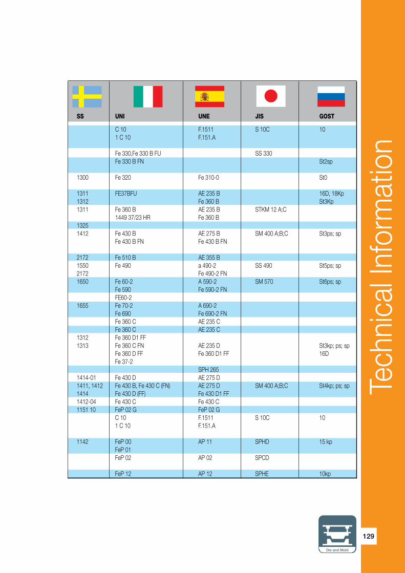
Tech
nica
l Inf
orm
atio
n
129
Die and Mold
SS UNI UNE JIS GOST
C 10 F.1511 S 10C 10 1 C 10 F.151.A
Fe 330,Fe 330 B FU SS 330 Fe 330 B FN St2sp
1300 Fe 320 Fe 310-0 St0
1311 FE37BFU AE 235 B 16D, 18Kp 1312 Fe 360 B St3Kp 1311 Fe 360 B AE 235 B STKM 12 A;C 1449 37/23 HR Fe 360 B 1325 1412 Fe 430 B AE 275 B SM 400 A;B;C St3ps; sp Fe 430 B FN Fe 430 B FN 2172 Fe 510 B AE 355 B 1550 Fe 490 a 490-2 SS 490 St5ps; sp 2172 Fe 490-2 FN 1650 Fe 60-2 A 590-2 SM 570 St6ps; sp Fe 590 Fe 590-2 FN FE60-2 1655 Fe 70-2 A 690-2 Fe 690 Fe 690-2 FN Fe 360 C AE 235 C Fe 360 C AE 235 C 1312 Fe 360 D1 FF 1313 Fe 360 C FN AE 235 D St3kp; ps; sp Fe 360 D FF Fe 360 D1 FF 16D Fe 37-2 SPH 265 1414-01 Fe 430 D AE 275 D 1411, 1412 Fe 430 B, Fe 430 C (FN) AE 275 D SM 400 A;B;C St4kp; ps; sp 1414 Fe 430 D (FF) Fe 430 D1 FF 1412-04 Fe 430 C Fe 430 C 1151 10 FeP 02 G FeP 02 G C 10 F.1511 S 10C 10 1 C 10 F.151.A
1142 FeP 00 AP 11 SPHD 15 kp FeP 01 FeP 02 AP 02 SPCD FeP 12 AP 12 SPHE 10kp

Tech
nica
l Inf
orm
atio
n
130
ISCAR MATERIAL GROUPS
According to VDI 3323 Standard
MaterialGroup
AISI/SAE Material No. DIN BS EN AFNOR
1 A 622 (1008) 1.0335 DD13; StW 24 1449 1 HR 3 C1 A 620 (1008) 1.0338 DC04 1449 1 CR;2 CR ES St4; St 14 1 A 516 Gr. 65; 55 1.0345 P235GH 1501 Gr. 141-360 A 37 CP;AP A 515 Gr. 65;55 H I 1501 Gr. 161-360; 151-360 A 414 Gr. C 1501 Gr. 161-400; 154-360 A 442 Gr.55 1501 Gr. 164-360; 161-3601 (M) 1020 1.0402 C22 055 M 15, 070 M 20 2C/2D AF 42 C 20; M 1023 1499 22 HS, CS XC 25;1 C 221 1020 1.0402 C22 050A20 2C/2D CC201 1020;1023 1.0402 C22 055 M 15;070 M 20 2C AF 42 C 20; XC 25;1 C 221 1.0425 P265GH H ll 1501 Gr. 161-400;151-400 A 42 CP; AP 1501 Gr. 164-360; 161-400 1501 Gr. 164-400;154-400 1 A27 65-35 1.0443 GS-45 A1 E 23-45 M1 1.0539 S355NH;StE 335 TSE 355-41 1.0545 S355N; StE 355 4360-50E E 355 R1 1.0546 S355NL;TStE 355 4360-50EE E 355 FP1 1.0547 S355JOH 4360-50C TSE 355-31 1.0549 S355 NLH;TStE 355 1 1.0553 S355JO;St 52-3U 4360-50C E 36-31 A 633 Gr.C 1.0562 P355N 1501 Gr.225-490A LT 20 FeE 355 KG N A 588 StE 355 E 355 R/FP; A 510 AP1 1.0565 P355NH; WStE 355 1501-225-490B LT 20 A 510 AP1 1.0566 P355NL1; TStE 355 1501-225-490A LT 50 A 510 FP1 1 1.0570 S355J2G3 Fe 510 D1 FF E 36-3 St 52-3 1449 50/35 HR>HS E 36-4 4360-50 D 1 1213 1.0715 9 SMn 28 (1SMn30) 230 M 07 S 2501 1213 1.0715 9 SMn 28 230 M 07 S 2501 12 L 13 1.0718 9 SMnPb 28 S 250 Pb (11SMnPb30) 1 1108 1.0721 10 S 20 (210 M 15) 10S20 1109 10F 21 11 L 08 1.0722 10 SPb 20 10PbF 21 11 L 08 1.0722 10 SPb 20 10 PbF 21 1215 1.0736 9 SMn 36 11SMn37) S 3001 12 L 14 1.0737 9 SMnPb 36 S 300 Pb (11SMnPb37) 1 1.0972 S315MC; QStE 300 TM 1501-40F30 E 315 D1 1.0976 S355MC; QStE 360 TM 1501-43F35 E 355 D1 1.0982 S460MC; QStE 460 TM 1501-50F45

Tech
nica
l Inf
orm
atio
n
131
Die and Mold
SS UNI UNE JIS GOST
FeP 13 AP 13 SPHE 08kp 1147 FeP 04 AP 04 SPCE 08Ju; JuA
1331 FeE235, Fe 360 1 KW;KG A 37 RC I SGV 410, SGV 450 1330 Fe 360 2 KW;KG RA II SGV 48, SPV 450; SPV 480
1450 C 20 1 C 22 F.112 S20C 20 C 21, C 25 1450 C20C21 F.112 S22 C 20 1450 C 20; 1 C 22F.112 S 20 C;S 22 C C 21;C 25 1431 Fe 410 1 KW; KG; A 42 RC I SPV 315; SPV 355 16K 1430 KT Fe 410 2 KW; KG A 42 RC II SG 295; SGV 410 20K 1432 SGV 450; SGV 480 1305 2134-04 Fe 510 B Fe 355 KGN 2334-01 FeE 355 KG AE 355 KG 2135-01 FeE 355 KT AE 355 KT 2172-04 Fe 510 C Fe 510 C 2135 Fe 510 D FeE 355 KTM Fe 510 C 2106 FeE 355 KG;KW AEE 355 KG;DD SM 490 A;B;C; YA;YB 15GF
2106 FeE 355-2 2107-01 FeE 355-3 2132, 2133 17GS AE 355 D SM 490 A;B;C;YA;YB 17GS 2134, 17G1S Fe 510, D1 FF 17G1S 2174 1912 CF SMn 28 F.2111 - 11 SMn 28 SUM 22 1912 CF 9 SMn 28 11 SMn 28 SUM 22 1914 CF 9 SMnPb 28 F.2112-11 SMnPb 28 SUM 22 L SUM 23 L, SUM 24 L CF 10 S 20 F. 2121 - 10 S 20 CF 10 SPb 20 F.2122-10 SPb 20 CF 10 SPb 20 10 SPb 20 CF 9 Mn 36 F.2113 - 12 SMn 35 SUM 25 1926 CF 9 SMnPb 36 F.2114- 12 SMnPb 35
2642 FeE 355TM

Tech
nica
l Inf
orm
atio
n
132
MaterialGroup
AISI/SAE Material No. DIN BS EN AFNOR
1 1.0984 S500MC; QStE 500 TM E 490 D1 1.0986 S500MC; QStE 500 TM 1501 - 60F55 E 560 D1 1010 1.1121 CK 10 040 A 10 XC 10 (C10E) 1 1.1121 St 37-1 4360 40 A 1 1015 1.1141 CK 15 040 A 15 32C XC 12 XC 15 (C15E) 080 M 15 XC 181 1020 1.1151 C22E 055 M 15 2 C 22 XC 18 1023 CK 22 (070 M 20) XC 251 D 3 1.2080 X 210 Cr 12 BD 3 Z 200 C 121 A36 St 44-2 4360 43 A NFA 35-501 E 281 StE 320-3Z 1 501 160 1 A572-60 1.8900 StE 380 4360 55 E 2 (M) 1025 1.0406 C 25 070 M 26 1 C 252 1.0416 GS-38 20-400 M2 A 537 CI.1 1.0473 P355GH 19 Mn 6 A 52 CP A 414 Gr. G A 612 2 1035 1.0501 C35 080 A 32, 080 A 35 1 C 35 080 M 36, AF 55 C 35 1449 40 CS XC 382 1045 1.0503 CF 45 060 A 47 XC 42 H 1 TS (C45G) 080 M 46 2 1040 1.0511 C40 080 M 40 1 C 40 AF 60 C 402 1.0540 C 50 2 A27 70-36 1.0551 GS-52 A2 280-480 M2 A148 80-40 1.0553 GS-60 A3 320-560 M2 A738 1.0577 S355J2G4 (Fe 510 D 2) Fe 510 D2 FF A 52 FP 1501 Gr.224-460 1501 Gr. 224-490 2 1140 1.0726 35 S 20 212 M 36 8M 35MF 62 1146 1.0727 45 S 20 (46S20) 45 MF 42 1035 1.1157 40Mn4 150 M 36 15 35 M 5 1041 40 M 52 1025 1.1158 C25E (070 M 25) 2 C 25 CK 25 XC 252 1536 1.1166 34Mn5 2 1330 1.1170 28Mn6 (150 M 28), (150 M 18) 20 M 5, 28 Mn 62 1330 1.1170 28 Mn 6 150 M 5 20 M 52 1330 1.1170 28Mn6 14A 20M52 1.1178 C30E; CK 30 080M30 XC 322 1035 1.1180 C35R 080 A 35 3 C 35 Cm 35 XC 32
ISCAR MATERIAL GROUPS
According to VDI 3323 Standard

Tech
nica
l Inf
orm
atio
n
133
Die and Mold
SS UNI UNE JIS GOST
2662 FeE 490 TM FeE 560 TM 1265 C 10, 2 C 10 F-1510-C 10 K S 9 CK 2 C 15 S 10 C 08;10 1300 1370 C 15 C 16 F.1110-C 15 K S 15 15 F.1511-C 16 K S 15 CK 1450 C 20 C 25 F.1120-C 25 K S 20 C, S 20 CK 20 S 22 C Ch12 1411 1421 2145 FeE390KG S25C C 25 1 C 25 1306 2101 Fe E 355-2 A 52 RC I RA II SGV 410 2102 SGV 450 SGV 480 1572 C 35 F.113 S 35 C 35 1550 1 C 35
1672 C 43 S 45 C 45 C 46 C40 1 C 40 F.114.A
1674 C 50 1 C 50 1505 1606 2107 A 52 RB II AE 355 D 1957 F.210.G 1973 40G C25 F.1120 - C 25 K S 25 C 25 S 28 C TO.B SMn 433 H C 28 Mn 28 Mn 6 SCMn 1 30G C28Mn SCMn1 C 30 2 C 30 1572 F.1135-C 35 K-1

Tech
nica
l Inf
orm
atio
n
134
MaterialGroup
AISI/SAE Material No. DIN BS EN AFNOR
2 1035 1.1181 C35E 080 A 35 2 C 35, XC 32 1038 CK 35 (080 M 36) XC 38 H 1 2 1035 1.1181 C35E 080 A 35 XC 38 CK 35 (080 M 36 2 1042 1.1191 GS- Ck 45 080 A 46 XC 452 1049 1.1206 C50E 080 M 50 2 C 50 1050 CK 50 XC 48 H 1; XC 50 H12 1050 1.1213 Cf 53 070 M 55 XC 48 H TS 1055 (C53G) 2 4520 1.5423 22Mo4 1503-245-420 3 1.0050 St50-2 3 A 516 Gr.70 1.0481 P295GH 1501 Gr. 224 a 48 Cp;AP A 515 Gr. 70 17 Mn 4 A 414 Gr.F; G 3 1043 1.0503 C35 060 A 47 1 C 45 080 M 46 AF 65 C 45 1449 50 HS, CS 3 1074 1.0614 C 76 D; D 75-2 XC 753 1086 1.0616 C 86 D; D 85-2 XC 803 1095 1.0618 C 92 D;D 95-2 XC 903 1036 1.1165 30Mn5 120 M 36 35 M 5 1330 (150 M 28) 3 1335 1.1167 36Mn5 150 M 36 40 M 5
3 1040 1.1186 C40E 060 A 40, 080 A 40 2 C 40 CK 40 080 M 40 XC 42 H 13 1045 1.1191 C45E 080 M 46 2 C 45 CK 45 060 A 47 XC 42 H 1 XC 45 XC 48 H 13 1049 1.1201 C45R 080 M 46 3 C 45 Cm 45 XC 42 H 1 XC 48 H 13 1.7242 18 CrMo 4 3 A 387 Gr. 12 CI 1.7337 16 CrMo 4 4 3 A 387 Gr. 12 CI. 1.7337 16 CrMo 4 4 3 1.7362 12 CrMo 19 5 3606-625 Z 10 CD 5.053 A572-60 17 MnV 6 436055 E NFA 35-501 E 364 1055 1.0535 C55 070 M 55 1 C 55 AF 70 C 554 1060 1.0601 C60 060 A 62 43D 1 C 60 1449 HS,CS AF 70 C 554 107 1.0603 C67 080 A 67 1449 70 HS XC 65
ISCAR MATERIAL GROUPS
According to VDI 3323 Standard

Tech
nica
l Inf
orm
atio
n
135
Die and Mold
SS UNI UNE JIS GOST
1550 C 35 F.1130-C 35 K S 35 C 35 1572 1572 C36 S35C 1660 C45 F-1140 45 1674 C 50 50
1674 C 53 S 50 C 50
16 Mo 5 KG; KW F.2602- 16 Mo 5 SB 450 M; SB 480 M FE50 Fe 510 KG;KT;KW A 47 RC I RA II SG 365, SGV 410 14G2 Fe 510-2 KG;KT;KW SGV 450 FeE 295 SGV 480 1672 C 45 F.114 S 45 C 45 1650 1 C 45 75 C 85 85 F.8211-30 Mn 5 SMn 433 H 27ChGSNMDTL f.8311-AM 30 Mn 5 SCMn 2 30GSL 2120 F. 1203-36 Mn 6 ssmN 438 (H) 35G2 F. 8212-36 Mn 5 SCMn 3 35GL C 40 S 40 C 40 1672 C 45 F.1140-C 45 K S 45 C 45 C 46 F.1142-C48 K S 48 C
1660 C 45 F.1145-C 45K-1 S 50 C F.1147C 48 K-1 18 CrMo 4 A 18 CrMo 4 5 KW 15ChM A 18 CrMo 4 5 KW 16 CrMo 20 5 2142 1655 C 55 S 55 C 55 1 C 55 C 60 1 C 60 S 58 C 60(G) C 67

Tech
nica
l Inf
orm
atio
n
136
MaterialGroup
AISI/SAE Material No. DIN BS EN AFNOR
4 1074 1.0605 C75 1449 80 HS 1075 4 1055 1.1203 C55E 060 A 57 2 C 55 CK 55 070 M 55 XC 55 H 14 1055 1.1209 C55R 070 M 55 3 C 55 Cm 55 XC 55 H 14 1060 1.1221 C60E 060 A 62 43D 2 C 60 1064 CK 60 XC 60 H 14 1070 1.1231 Ck 67 060 A 67 XC 68 (C67E) 4 1074 1.1248 CK 75 1075 (C75E) 060 A 78 XC 75 1078 4 1086 1.1269 CK 85 (C85E) XC 904 1095 1.1274 Ck 101 (C101E) XC 1004 W 112 1.1663 C 125 W Y2 1204 5 1.0070 St70-2 5 1.7238 49 CrMo 45 1.7701 51 CrMoV 4 6 A573-81 65 1.0116 St 37-3 4360 40 B E 24-U6 A515 65 1.0345 H1 1 501 161 A 37 CP6 5120 1.0841 St 52-3 150 M 19 20 MC 56 9255 1.0904 55 Si 7 250A53 45 55S76 9254 1.0904 55 Si 7 250 A 53 55 S 76 9262 1.0961 60SiCr7 60SC66 L3 1.2067 100Cr6 BL3 Y100C66 L1 1.2108 90 CrSi 5 6 L2 1.2210 115CrV3 100C36 1.2241 51CrV4 6 1.2311 40 CrMnMo 7 6 4135 1.2330 35 CrMo 4 708 A 37 34 CD 46 1.2419 105WCr6 105WC136 0 1 1.2510 100 MnCrW 4 BO1 8 MO 86 S1 1.2542 45 WCrV7 BS1 6 S1 1.2550 60WCrV7 55WC206 L6 1.2713 55NiCrMoV6 55NCDV76 L6 1.2721 50NiCr13 55 NCV 6 6 O2 1.2842 90MnCrV8 BO2 90 MV86 E 50100 1.3501 100 Cr 2 6 52100 1.3505 100Cr6 2 S 135 31 100 C 6 535 A 99 6 1.5024 46Si7 45 S 7; Y 46 7;46 SI 7
ISCAR MATERIAL GROUPS
According to VDI 3323 Standard

Tech
nica
l Inf
orm
atio
n
137
Die and Mold
SS UNI UNE JIS GOST
C 75 75
1655 C 55 F.1150-C 55 K S 55 C 55 C 55 F.1155-C 55K-1 1665 C 60 S 58 C 60 1678 60G, 60GA 1770 C70 65GA 68GA , 70 774 C 75 75(A)
C 90 85(A) 1870 C 100 F-5117 SUP 4 2223 FE70-2 51 CrMoV 4 1312 Fe37-3 1330 2172 Fe 52 F-431 2085 55Si8 56Si7 2090 60SiCr8 60SiCr8 100Cr6 Ch 2092 105WCR 5 107CrV3KU 35 cRmO 8 KU 2234 35CrMo4 34CrMo4 SCM435TK 2140 10WCr6 105WCr5 ChWG 2140 10WCr6 105WCr5 SKS31 2710 45 WCrV8 KU 45WCrSi8 5ChW25F 2710 58WCr9KU F.520.S SKT4 5ChNM 2550 f-528 2258 100Cr6 F.1310 - 100 Cr 6 SUJ2 SchCh 15 F. 1451 - 46 SI 7

Tech
nica
l Inf
orm
atio
n
138
MaterialGroup
AISI/SAE Material No. DIN BS EN AFNOR
6 9255 1.5025 51Si7 51 S 7 51 Si 76 9255 1.5026 55Si7 251 a 58 55 S 76 9260 1.5027 60Si7 251 A 60 60 S 7 251 H 60 6 9260 H 1.5028 65Si7 60 S 76 1.5120 38 MnSi 4 6 A 204 Gr.A 1.5415 16Mo3 1503-243 B 15 D 3 4017 15 Mo 3 6 4419 1.5419 20Mo4 1503-243-430 6 A 350-LF 5 1.5622 14Ni6 16N66 3415 1.5732 1 NiICr10 14 NC 116 3310; 3314 1.5752 14NiICr14 655M13 36A 12NC156 1.6587 17CrNiMo6 820A16 18NCD66 1.6657 14NiCrMo134 6 5015 1.7015 15Cr3 523 M 15 12 C 36 5132 1.7033 34Cr4 530A32 18B 32C46 5140 1.7035 41Cr4 530M40 18 42C46 5140 1.7045 42Cr41 530 A 40 42 C 4 TS6 5115 1.7131 16MnCr5 527 M 17 16 MC 56 1.7139 16MnCr5 6 5155 1.7176 55Cr3 527 A 60 48 55 C 36 4135; 4137 1.7220 34CrMo4 708 Aa 37 35 CD 46 4142 1.7223 41CrMo4 6 4140 1.7225 42CrMo4 708 M 0 42 CD 46 1.7228 55NiCrMoV6G 823M30 33 6 1.7262 15CrMo5 12 CD 46 1.7321 20 mOcR 4 6 ASTM A182 F-12 1.7335 13CrMo4 4 1501-620Gr27 6 A 182-F11;12 1.7335 13 CrMo 4 4 1 501 620 Gr. 27 15 CD 4.56 ASTM A 182 F.22 1.7380 10CrMo9 10 1501-622gR31; 45 6 A182 F-22 1.7380 10 CrMo 9 10 1501-622 12 CD 9.106 1.7715 14MoV6 3 1503-660-440 6 A355A 1.8509 41CrAlMo 7 905 M 39 41B 40 CAD 6.127 A570.36 1.0038 S235JRG2 (Fe 360 B) Fe 360 B FU E 24-2NE RSt 37-2 1449 27/23 CR 4360-40 B 7 3135 1.5710 36NiCr6 640A35 35NC67 1.5755 31 NiCr 14 653 M 31 18 NC 137 8620 1.6523 2 NiCrMo2 805M20 362 20 NCD 27 8740 1.6546 40 NiCrMo 22 311-Tyre 7 7 4130 1.7218 25CrMo4 CDS 110 25 CD 47 1.7733 24 CrMoV 5 5 20 CDV 67 1.7755 GS-45 CrMOV 10 4
ISCAR MATERIAL GROUPS
According to VDI 3323 Standard

Tech
nica
l Inf
orm
atio
n
139
Die and Mold
SS UNI UNE JIS GOST
2090 48 Si 7 F.1450-50 Si 7 50 Si 7 2085 2090 55 Si 7 F.1440 - 56 Si 7 55S2 60 Si 7 F. 1441 - 60 Si 7 60S2 50 P 7 SUP 6 2912 16Mo3(KG;KW) F. 2601 - 16 Mo 3 -2512 G 20 Mo 5 G 22 Mo5 SCPH 11 14 Ni 6 KG;KT F.2641 - 15 Ni 6 16NiCr11 15NiCr11 SNC415(H) SNC815(H) 14NiCrMo13 14NiCrMo131 SCr415(H) 15Ch 34Cr4(KB) 35Cr4 SCr430(H) 35Ch 41Cr4 42Cr4 SCr440(H) 2245 41Cr4 42Cr4 SCr440 2511 16MnCr5 16MnCr5 2127 2253 SUP9(A) 50ChGA 2234 35ChM 41CrMo4 42CrMo4 SNB 22-1 40ChFA 2244 2512 653M31 2216 12CrMo4 2625 14CrMo4 5 14CrMo45 2216 12CrMo4 SCM415(H) 12ChM; 15ChM 2218 12CrMo9,10 TU.H 13MoCrV6 2940 41CrAlMo7 41CrAlMo7 1312 Fe 360 B FN AE 235 B FN;FU Fe 360 B FN; FU St3ps; sp
2506 20NiCrMo2 20NiCrMo2 SNCM220(H) 20ChGNM 40NiCrMo2(KB) 40NiCrMo2 SNCM240 38ChGNM 2225 25CrMo4(KB) 55Cr3 SCM420/430 20ChM; 30ChM 21 CrMoV 5 11

Tech
nica
l Inf
orm
atio
n
140
MaterialGroup
AISI/SAE Material No. DIN BS EN AFNOR
7 1.8070 21 CrMoV 5 11 8 4142 1.2332 47 CrMo 4 708 M 40 19A 42 CD 48 A128 (A) 1.3401 G-X120 Mn 12 Z 120 M 128 3435 1.5736 36 NiCr 10 30 NC 118 9840 1.6511 36CrNiMo4 816M40 110 40NCD38 4340 1.6582 35CrNiM 6 817 M 40 24 35 NCD 68 1.7361 32 CeMo12 722 M 24 40B 30 CD 128 6150 1.8159 50 CrV 4 735 A 50 47 50CrV48 1.8161 58 CrV 4 8 1.8515 32 CrMo 12 722 M 24 40B 30 CD 128 1.8523 39CrMoV13 9 897M39 40C 9 1.4882 X 50 CrMnNiNbN 21 9 Z 50 CMNNb 21.099 3135 1.5710 36NiCr6 640A35 111A 35NC69 1.5864 35 niCr 18 9 31 NiCrMo 13 4 830 m 31 10 A573-81 1.0144 ST 44-3 4360 43 C E 28-310 A 619 1.0347 DCO3 1449 3 CR E RSt;RRSt 13 1449 2 CR 10 M 1015 1.0401 C15 080 M 15 AF 37 C12 M 1016 080 M 15 XC 18 M 1017 1449 17 CS 10 1.0570 ST 52-3 4360 50 B E 36-310 12L13 1.0718 9SMnPb28 S250Pb10 (12L13) 1.0718 9 SMnPb 28 S 250 Pb10 1.0723 15 S22 210 A 15 15 S 20 210 M 15 10 1.2083 10 H 11 1.2343 x 38 CrMoV 5 1 BH 11 Z 38 CDV 510 H 13 1.2344 X 40 CrMoV 5 1 BH 13 Z 40 CDV 510 A 2 1.2363 X100 CrMoV 5 1 BA 2 Z 100 CDV 510 D 2 1.2379 X 155 CrVMo 12 1 BD2 Z 160 CDV 1210 HNV3 1.2379 X210Cr12G BD2 Z160CDV1210 D 4 (D 6) 1.2436 X 210 CrW 12 BD6 Z 200 CD 1210 H 21 1.2581 X 30 WCrV 9 3 BH 21 Z 30 WCV 910 1.2601 X 165 CrMoV 12 10 H 12 1.2606 X 37 CrMoW 5 1 BH 12 Z 35 CWDV 510 D3 1.3343 S 6-5-2 BM2 Z200C1210 N08028 1.4563 Z1NCDU31-27-0310 ASTM A353 1.5662 X8Ni9 1501-509;510 10 ASM A353 1.5662 X8Ni9 502-650 9 Ni10 2517 1.5680 12Ni19 12Ni19 Z18N510 2515 1.5680 12 Ni 19 Z 18 N 511 1.3202 S 12-1-4-5 BT 15
ISCAR MATERIAL GROUPS
According to VDI 3323 Standard

Tech
nica
l Inf
orm
atio
n
141
Die and Mold
SS UNI UNE JIS GOST
35 NiCr 9 2244 42CrMo4 42CrMo4 SCM (440) 2183 GX120Mn12 F. 8251-AM-X120Mn12 SCMnH 1, SCMn H 11 110G13L 36nIcRmO4(KB) 35NiCrMo4 SUP10 40ChN2MA 2541 35NiCrMo6(KB) SNCM 447 38Ch2N2MA 2240 30CrMo12 F.124.A 2230 50CrV4 51CrV4 50ChGFA 2240 32CrMo12 F.124.A 36CrMoV12 SNC236 2534 f-1270 1412 SM 400A;B;C St4KP; ps; sp Fep 02 AP 02 08JU 1350 C15 C16 F.111 S 15 C 1 C 15 2132 Fe52BFN/Fe52CFN SM490A;B;C;YA;YB 17G5 1914 CF9SMnPb28 11SMnPb28 1914 CF 9 SMnPb 28 11 SMnPb 28 12 L 13 1922 F.210.F SUM 32
2314 X 37 CrMoV 5 1 KU 4Ch5MFS 2242 X40CrMoV511KU F-5318 SKD61 4Ch5MF1S 2260 X100CrMoV51KU F-5227 SKD12 2310 X165CrMoW12KU X160CrMoW12KU 2736 2312 X215CrW 12 1 KU F-5213 X30WCrV 9 3 KU F-526 SKD5 3Ch2W8F 2310 X 35 CrMoW 05 KU F.537 5ChNM 2715 X210Cr13KU X210Cr12 SUH3 R6M5 2584 14 Ni 6 KG;KT XBNiO9 X10Ni9 F-2645 SL9N60(53) HS 12-1-5-5 12-1-5-5

Tech
nica
l Inf
orm
atio
n
142
MaterialGroup
AISI/SAE Material No. DIN BS EN AFNOR
11 1.3207 S 10-4-3-10 BT42 Z130WKCDV11 T 15 1.3243 S 6-5-2-5 KCV 06-05-05-04-0211 1.3246 S 7-4-2-5 Z110 WKCDV 07-05-0411 1.3247 S 2-10-1-8 BM 42 Z110 DKCWV 09-08-0411 M 42 1.3249 S 2-9-2-8 BM 34 11 T 4 1.3255 S 18-1-2-5 BT 4 Z 80 WKCV 18-05-04-011 M 2 1.3343 S6-5-2 BM2 Z 85 WDCV11 M 7 1.3348 S2-9-2 Z 100 DCWV 09-04-02-11 T 1 1.3355 S 18-0-1 BT 1 Z 80 WCV 18-4-0111 630 1.4548 Z7CNU17-0411 HNV 3 1.4718 X45CrSi 9 3 401S45 52 Z45CS911 422 1.4935 x20 CrMoWV 12 1 12 403 1.4000 X6Cr13 403 S 17 Z 6 C 1312 1.4001 X6Cr14 12 (410S) 1.4001 X7 Cr 13 (403 S 7) Z 8 C 1312 405 1.4002 X6CrA12 405S17 Z8CA1212 405 1.4002 X6 CrAl 13 405 S 17 Z6CA1312 416 1.4005 X12CrS 13 416 S 21 Z11 CF 1312 410; CA-15 1.4006 (G-)X10 Cr 13 410S21 56A Z10 C 13 12 430 1.4016 X8Cr17 Z8C17 430S1512 430 1.4016 X6 Cr 17 430 S 15 60 Z 8 C 1712 1.4027 G-X20Cr14 420C29 Z20C13M12 1.4027 G-X 20 Cr 14 420 C 29 Z 20 C 13 M12 420 1.4028 X30 Cr 13 420 S 45 Z 30 C 1312 1.4086 G-X120Cr29 452C11 12 430 F 1.4104 X12CrMoS17 420 S 37 Z 10 CF 1712 440B 1.4112 X90 CrMoV 18 12 434 1.4113 X6CrMo 17 434 S 17 Z 8 CD 17.0112 1.4340 G-X40CrNi27 4 12 S31500 1.4417 X2CrNiM0Si19 5 12 S31500 1.4417 X2 CrNoMoSi 18 5 3 12 1.4418 X4 CrNiMo16 5 Z6CND16-04-0112 XM 8 1.4510 Z 4 CT 17 430 Ti 439 12 430tI 1.4510 X6 CrTi 17 Z 4 CT 1712 1.4511 X 6 CrNb 17(X 6 CrNb 17 Z 4 CNb 1712 409 1.4512 X 6 CrTi 12 LW 19 Z 3 CT 12 (X2CrTi12) 409 S 19
ISCAR MATERIAL GROUPS
According to VDI 3323 Standard

Tech
nica
l Inf
orm
atio
n
143
Die and Mold
SS UNI UNE JIS GOST
2723 HS 6-5-2-5 6-5-2-5 SKH55 R6M5K5
7-4-2-5 HS 7-4-2-5 M 35
2-10-1-8 HS 2-9-1-8 M 41 2-9-2-8 R6M5 2722 HS 6 5 2 F-5604 SKH 51 2782 HS 2 9 2 F-5607 R18 X45CrSi8 F322 SUH1 40Ch9S2
2301 X6Cr13 F.3110 SUS403 08Ch13 F8401 08Ch13 2301 08Ch13 X6CrAI13 2302 X6CrAI13 2380 X12 CrSC13 F-3411 SUS 416 2302 X12Cr13 F.3401 SUS410 12Ch13 2320 X8Cr17 F.3113 12Ch17 2320 X8Cr17 F3113 SUS430 12Ch17 20Ch13L 20Ch13L 2304 20Ch13 2383 X10CrS17 F.3117 SUS430F 2325 X8CrMo17 SUS434 2376 2376 2387 X 6 CrTi 17 F.3115 -X 5 CrTi 17 SUS 430 LX 08Ch17T 08Ch17T X 6 CrNb 17 F.3122-X 5 CrNb 17 SUS 430 LK X 6 CrTi 12 SUH 409
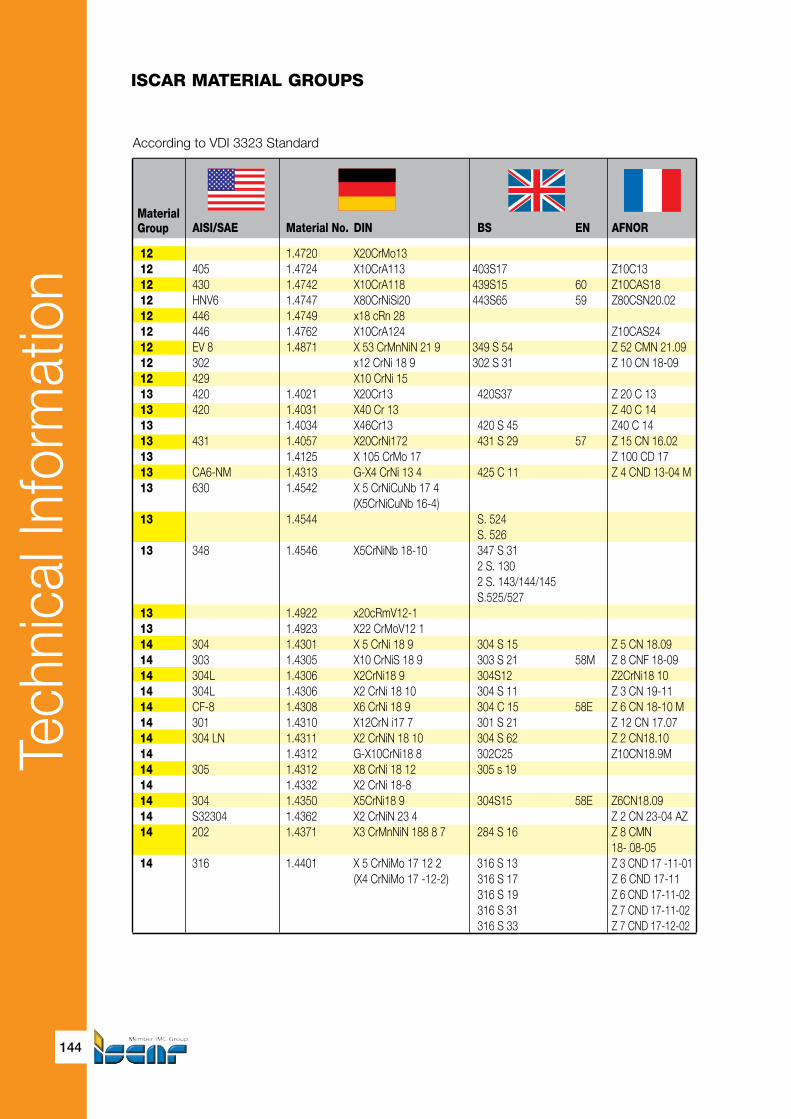
Tech
nica
l Inf
orm
atio
n
144
MaterialGroup
AISI/SAE Material No. DIN BS EN AFNOR
12 1.4720 X20CrMo13 12 405 1.4724 X10CrA113 403S17 Z10C1312 430 1.4742 X10CrA118 439S15 60 Z10CAS1812 HNV6 1.4747 X80CrNiSi20 443S65 59 Z80CSN20.0212 446 1.4749 x18 cRn 28 12 446 1.4762 X10CrA124 Z10CAS2412 EV 8 1.4871 X 53 CrMnNiN 21 9 349 S 54 Z 52 CMN 21.0912 302 x12 CrNi 18 9 302 S 31 Z 10 CN 18-0912 429 X10 CrNi 15 13 420 1.4021 X20Cr13 420S37 Z 20 C 13 13 420 1.4031 X40 Cr 13 Z 40 C 1413 1.4034 X46Cr13 420 S 45 Z40 C 1413 431 1.4057 X20CrNi172 431 S 29 57 Z 15 CN 16.0213 1.4125 X 10⁵ CrMo 17 Z 100 CD 1713 CA6-NM 1.4313 G-X4 CrNi 13 4 425 C 11 Z 4 CND 13-04 M 13 630 1.4542 X 5 CrNiCuNb 17 4 (X5CrNiCuNb 16-4) 13 1.4544 S. 524 S. 526 13 348 1.4546 X5CrNiNb 18-10 347 S 31 2 S. 130 2 S. 143/144/145 S.525/527 13 1.4922 x20cRmV12-113 1.4923 X22 CrMoV12 1 14 304 1.4301 X 5 CrNi 18 9 304 S 15 Z 5 CN 18.0914 303 1.4305 X10 CrNiS 18 9 303 S 21 58M Z 8 CNF 18-0914 304L 1.4306 X2CrNi18 9 304S12 Z2CrNi18 1014 304L 1.4306 X2 CrNi 18 10 304 S 11 Z 3 CN 19-1114 CF-8 1.4308 X6 CrNi 18 9 304 C 15 58E Z 6 CN 18-10 M14 301 1.4310 X12CrN i17 7 301 S 21 Z 12 CN 17.0714 304 LN 1.4311 X2 CrNiN 18 10 304 S 62 Z 2 CN18.10 14 1.4312 G-X10CrNi18 8 302C25 Z10CN18.9M14 305 1.4312 X8 CrNi 18 12 305 s 19 14 1.4332 X2 CrNi 18-8 14 304 1.4350 X5CrNi18 9 304S15 58E Z6CN18.0914 S32304 1.4362 X2 CrNiN 23 4 Z 2 CN 23-04 AZ 14 202 1.4371 X3 CrMnNiN 188 8 7 284 S 16 Z 8 CMN 18- 08-0514 316 1.4401 X 5 CrNiMo 17 12 2 316 S 13 Z 3 CND 17 -11-01 (X4 CrNiMo 17 -12-2) 316 S 17 Z 6 CND 17-11 316 S 19 Z 6 CND 17-11-02 316 S 31 Z 7 CND 17-11-02 316 S 33 Z 7 CND 17-12-02
ISCAR MATERIAL GROUPS
According to VDI 3323 Standard

Tech
nica
l Inf
orm
atio
n
145
Die and Mold
SS UNI UNE JIS GOST
X10CrA112 F.311 10Ch13SJu X8Cr17 F.3113 SUS430 15Ch18SJu X80CrSiNi20 F.320B SUH4 2322 X16Cr26 SUH446 X53CrMnNiN21 9 SUH35,SUH36 55Ch20G9AN4 2330 2303 14210 20Ch13 -2304 40Ch13 X40Cr14 F.3405 SUS420J2 2321 X16CrNi16 F.3427 SUS431 20Ch17N2 X 105 CrMo 17 95Ch18 2385 (G)X6CrNi304 SCS5 X 6 CrNiTi 18 11 08Ch 18N12T X 6 CrNiNb 18 11
2317 x20cRmOnI 12 01 2332;2333 08Ch18N10 2346 X10CrNiS18.09 F.3508 SUS303 30Ch18N11 2352 x2cRnI18 11 F.3503 SCS19 2352 X2CrNi18 11 2333 SUS304L 2331 X2CrNi18 07 F.3517 2371 X2CrNiN18 10 SUS304LN 10Ch18N9L 10Ch18N9L 2332 X5CrNi18 10 F.3551 SUS304 2327 2347 X 5 CrNiMo 17 12 F.3534-X 5 CrNiMo 17 12 2 SUS 316
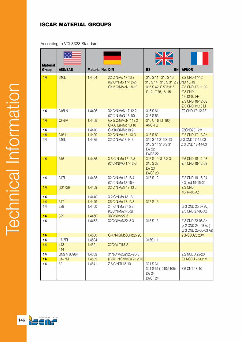
Tech
nica
l Inf
orm
atio
n
146
MaterialGroup
AISI/SAE Material No. DIN BS EN AFNOR
14 316L 1.4404 X2 CrNiMo 17 13 2 316 S 11, 316 S 13 Z 2 CND 17-12 (X2 CrNiMo 17-12-2) 316 S 14, 316 S 31; Z 2 CND 18-13 GX 2 CrNiMoN 18-10 316 S 42, S.537;316 Z 3 CND 17-11-02 C 12, T.75, S. 161 Z 3 CND 17-12-02 FF Z 3 CND 18-12-03 Z 3 CND 19.10 M14 316LN 1.4406 X2 CrNiMoN 17 12 2 316 S 61 Z2 CND 17-12 AZ (X2CrNiMoN 18-10) 316 S 63 14 CF-8M 1.4408 GX 5 CrNiMoN 7 12 2 316 C 16 (LT 196) G-X 6 CrNiMo 18 10 ANC 4 B 14 1.4410 G-X10CrNiMo18 9 Z5CND20.12M14 316 Ln 1.4429 X2 CrNiMo 17 -13-3 316 S 62 Z 2 CND 17-13 Az14 316L 1.4435 X2 CrNiMo18 14 3 316 S 11;316 S 13 Z 3 CND 17-12-03 316 S 14;316 S 31 Z 3 CND 18-14-03 LW 22 LWCF 22 14 316 1.4436 X 5 CrNiMo 17 13 3 316 S 19; 316 S 31 Z 6 CND 18-12-03 (X4CRNIMO 17-13-3 316 S 33 Z 7 CND 18-12-03 LW 23 LWCF 23 14 317L 1.4438 X2 CrNiMo 18 16 4 317 S 12 Z 2 CND 19-15-04 (X2CrNiMo 18-15-4) z 3 cnd 19-15-0414 (s31726) 1.4439 X2 CrNiMoN 17 13 5 Z 3 CND 18-14-06 AZ14 1.4440 X 2 CrNiMo 18 13 14 317 1.4449 X5 CrNiMo 17 13 3 317 S 16 14 329 1.4460 X 4 CrNiMo 27 5 2 (Z 3 CND 25-07 Az) (X3CrNiMo27-5-2) Z 5 CND 27-05 Az14 329 1.4460 X8CrNiMo27 5 14 1.4462 X2CrNiMoN22 5 3 318 S 13 Z 3 CND 22-05 Az (Z 2 CND 24 -08 Az ) (Z 3 CND 25-06-03 Az)14 1.4500 G-X7NiCrMoCuNb25 20 23NCDU25.20M14 17-7PH 1.4504 316S11114 443 1.4521 X2CrMoTi18-2 444 14 UNS N 08904 1.4539 X1NiCrMoCuN25-20-5 Z 2 NCDU 25-2014 CN-7M 1.4539 (G-)X1 NiCrMoCu 25 20 5 Z1 NCDU 25-02 M14 321 1.4541 Z 6 CrNiTi 18-10 321 S 31 321 S 51 (1010;1105) Z 6 CNT 18-10 LW 24 LWCF 24
ISCAR MATERIAL GROUPS
According to VDI 3323 Standard

Tech
nica
l Inf
orm
atio
n
147
Die and Mold
SS UNI UNE JIS GOST
2348 X 2 CrNiMo 17 12 F.3533 - X 2 CrNiMo 17 13 2 G-X 2 CrNiMo 19 11 F.3537 - X 2 CrNiMo 17 13 3 SUS 316 L
X 2 CrNiMoN 17 12 F.3542-X 2 CrNiMoN 17 12 2 SUS316LN 07Ch18N; 18N10G2S2MSL 2343 F.8414-AM-X 7 CrNiMo 20 10 SCS 14 2328 2375 X 2 CrNiMoN 17 13 F.3543-X 2 CrNiMoN 17 13 3 (SUS 316 LN 2375 X2CrNiMoN 17 13 F.3533-X 2 CrNiMo 17 13 2 SUS 316 L O3Ch17N14M3
2343 X 5 CrNiMo 117 13 F.3543-X 5 CrNiMo 17 12 2 3 SUS 316 X 8 cRnImO 17 13 F.3538-X 5 CrNiMo 17 13
2367 X2CrNiMo18 16 f.3539-x 2 cRnImO 18 16 4 SUS317L X 5 CrNiMo 18 15 SUS 317 2324 F.3309-X 8 CrNiMo 17 12 2 F.3552-X 8 CrNiMo 18 16 4 SUS 329 J 1 2324 2377 SUS 329 J3L Z8CNA17-07 X2CrNiMo1712 2326 F.3123-X 2 CrMoTiNb 18 2 SUS 444 2562 2564 2337 X 6 CrNiTi 18 11 F.3523 - X 6 CrNiTi 06Ch18N10T 18 10 SUS 321 08Ch18N10T 09Ch18N10T 12Ch18N10T
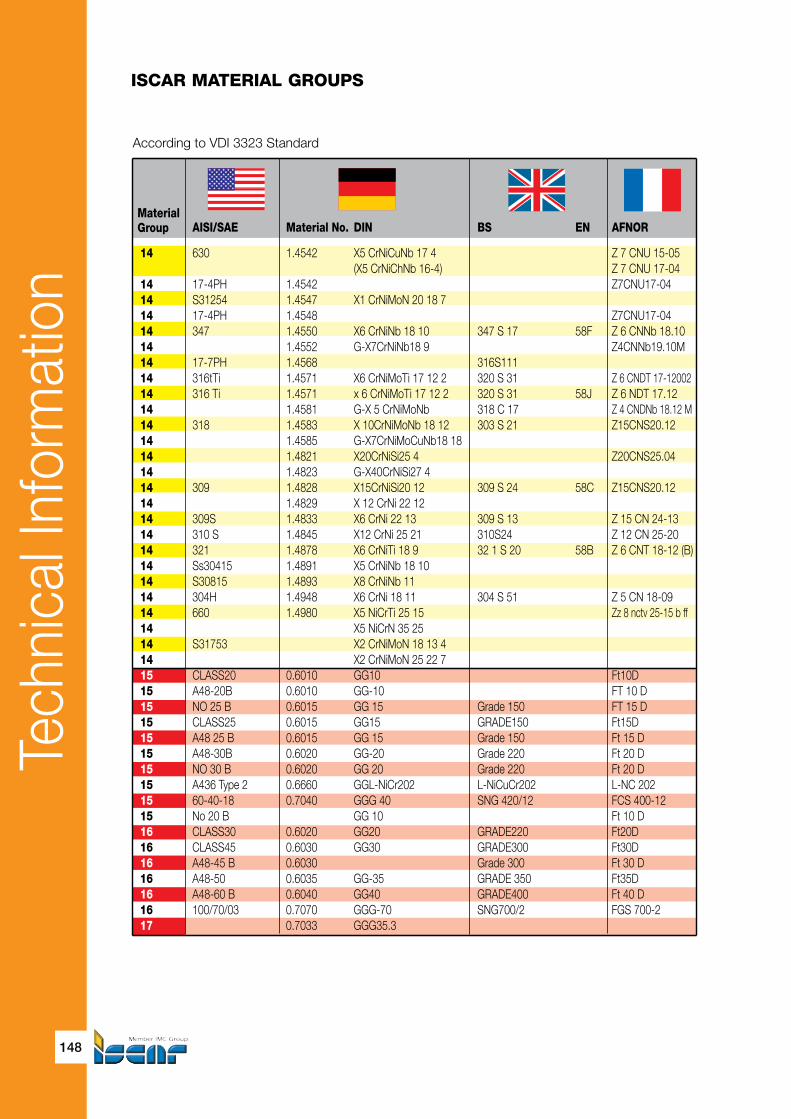
Tech
nica
l Inf
orm
atio
n
148
MaterialGroup
AISI/SAE Material No. DIN BS EN AFNOR
14 630 1.4542 X5 CrNiCuNb 17 4 Z 7 CNU 15-05 (X5 CrNiChNb 16-4) Z 7 CNU 17-0414 17-4PH 1.4542 Z7CNU17-0414 S31254 1.4547 X1 CrNiMoN 20 18 7 14 17-4PH 1.4548 Z7CNU17-0414 347 1.4550 X6 CrNiNb 18 10 347 S 17 58F Z 6 CNNb 18.10 14 1.4552 G-X7CrNiNb18 9 Z4CNNb19.10M14 17-7PH 1.4568 316S111 14 316tTi 1.4571 X6 CrNiMoTi 17 12 2 320 S 31 Z 6 CNDT 17-1200214 316 Ti 1.4571 x 6 CrNiMoTi 17 12 2 320 S 31 58J Z 6 NDT 17.1214 1.4581 G-X 5 CrNiMoNb 318 C 17 Z 4 CNDNb 18.12 M14 318 1.4583 X 10CrNiMoNb 18 12 303 S 21 Z15CNS20.1214 1.4585 G-X7CrNiMoCuNb18 18 14 1.4821 X20CrNiSi25 4 Z20CNS25.0414 1.4823 G-X40CrNiSi27 4 14 309 1.4828 X15CrNiSi20 12 309 S 24 58C Z15CNS20.1214 1.4829 X 12 CrNi 22 1214 309S 1.4833 X6 CrNi 22 13 309 S 13 Z 15 CN 24-1314 310 S 1.4845 X12 CrNi 25 21 310S24 Z 12 CN 25-2014 321 1.4878 X6 CrNiTi 18 9 32 1 S 20 58B Z 6 CNT 18-12 (B)14 Ss30415 1.4891 X5 CrNiNb 18 10 14 S30815 1.4893 X8 CrNiNb 11 14 304H 1.4948 X6 CrNi 18 11 304 S 51 Z 5 CN 18-0914 660 1.4980 X5 NiCrTi 25 15 Zz 8 nctv 25-15 b ff14 X5 NiCrN 35 25 14 S31753 X2 CrNiMoN 18 13 4 14 X2 CrNiMoN 25 22 715 CLASS20 0.6010 GG10 Ft10D15 A48-20B 0.6010 GG-10 FT 10 D15 NO 25 B 0.6015 GG 15 Grade 150 FT 15 D15 CLASS25 0.6015 GG15 GRADE150 Ft15D15 A48 25 B 0.6015 GG 15 Grade 150 Ft 15 D15 A48-30B 0.6020 GG-20 Grade 220 Ft 20 D15 NO 30 B 0.6020 GG 20 Grade 220 Ft 20 D15 A436 Type 2 0.6660 GGL-NiCr202 L-NiCuCr202 L-NC 20215 60-40-18 0.7040 GGG 40 SNG 420/12 FCS 400-1215 No 20 B GG 10 Ft 10 D16 CLASS30 0.6020 GG20 GRADE220 Ft20D16 CLASS45 0.6030 GG30 GRADE300 Ft30D16 A48-45 B 0.6030 Grade 300 Ft 30 D16 A48-50 0.6035 GG-35 GRADE 350 Ft35D16 A48-60 B 0.6040 GG40 GRADE400 Ft 40 D16 100/70/03 0.7070 GGG-70 SNG700/2 FGS 700-217 0.7033 GGG35.3
ISCAR MATERIAL GROUPS
According to VDI 3323 Standard
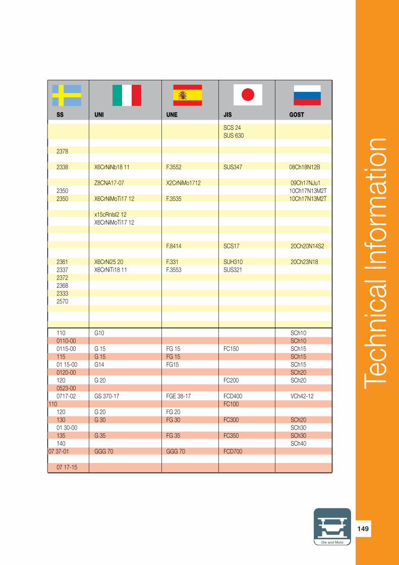
Tech
nica
l Inf
orm
atio
n
149
Die and Mold
SS UNI UNE JIS GOST
SCS 24 SUS 630 2378 2338 X6CrNiNb18 11 F.3552 SUS347 08Ch18N12B Z8CNA17-07 X2CrNiMo1712 09Ch17NJu1 2350 10Ch17N13M2T 2350 X6CrNiMoTi17 12 F.3535 10Ch17N13M2T x15cRnIsI2 12 X6CrNiMoTi17 12 F.8414 SCS17 20Ch20N14S2 2361 X6CrNi25 20 F.331 SUH310 20Ch23N18 2337 X6CrNiTi18 11 F.3553 SUS321 2372 2368 2333 2570 110 G10 SCh10 0110-00 SCh10 0115-00 G 15 FG 15 FC150 SCh15 115 G 15 FG 15 SCh15 01 15-00 G14 FG15 SCh15 0120-00 SCh20 120 G 20 FC200 SCh20 0523-00 0717-02 GS 370-17 FGE 38-17 FCD400 VCh42-12 110 FC100 120 G 20 FG 20 130 G 30 FG 30 FC300 SCh20 01 30-00 SCh30 135 G 35 FG 35 FC350 SCh30 140 SCh40 07 37-01 GGG 70 GGG 70 FCD700 07 17-15

Tech
nica
l Inf
orm
atio
n
150
MaterialGroup
AISI/SAE Material No. DIN BS EN AFNOR
17 0.7033 GGG-35.3 350/22 L 40 FGS 370/1717 60-40-18 0.7040 GGG-40 SNG 420/12 FGS 400-1217 60/40/18 0.7043 GGG-40.3 370/7 FGS 370/1717 80-55-06 0.7050 GGG50 SNG500/7 FGS 500/717 65-45-12 0.7050 GGG-50 SNG 500/7 FGS 500-717 0.7652 GGG-NiMn 13 7 S-NiMn 137 S-Mn 13717 A43D2 0.7660 GGG-NiCr 20 2 Grade S6 S-NC 20217 GGG 40.3 SNG 370/17 FGS 370-1718 A48-40 B 0.6025 GG25 Grade260 Ft 25 D18 0.7060 GGG60 SNG600/3 FGS600-318 80/55/06 0.7060 GGG-60 600/3 FGS 600/318 A48 40 B 19 0.8055 GTW55 19 32510 0.8135 GTS-35-10 B 340/12 MN35-1019 A47-32510 0.8135 GTS-35-10 B 340/2 Mn 35-1019 A220-40010 0.8145 GTS-45-06 P 440/7 Mn 450-619 GTS-35 B 340/12 19 8 290/6 MN 32-819 32510 GTS-35 B340/12 MN 35-1020 0.8035 GTM-35 W340/3 MB35-720 0.8040 GTW-40 W410/4 MB40-1020 0.8045 20 0.8065 GTMW-65 20 A220-50005 0.8155 GTS-55-04 P 510/4 Mn 550-420 50005 0.8155 GTS-55-04 P510/4 MP 50-520 70003 0.8165 GTS-65-02 P 570/3 Mn 650-320 90001 0.8170 GTS-70-02 P 690/2 Mn 700-220 A220-90001 0.8170 GTS-70-02 Mn 700-220 0.817 GTS-70-02 IP 70-2 20 1022 1518 1.1133 20Mn5 120 M 19 20 M 520 1035 1.1183 Cf 35 (C35G) 080 A 35 XC 38 H 1 TS20 400 10 GTS-45 P440/7 20 70003 GTS-65 P 570/3 MP 60-321 Al99 3.0205 21 1000 3.0255 AI99.5 L31/34/36 A59050C21 3.3315 AIMg1 22 3.1325 AlCuMg 1 22 3.1655 AICuSiPb 22 3.2315 AlMgSi1 22 7050 3.4345 AIZnMgCuO,5 L 86 AZ 4 GU/905123 3.2381 G-AISi10Mg 23 3.2382 GD-AISi10Mg 23 3.2581 G-AISi12
ISCAR MATERIAL GROUPS
According to VDI 3323 Standard

Tech
nica
l Inf
orm
atio
n
151
Die and Mold
SS UNI UNE JIS GOST
0717-15 0717-02 VCh42-12 0717-15 VCh42-12 0727-02 GGG 50 VCh50-2 0727-02 FCD 500 VCh50-2 0772-00 0776-00 0717-12 SCh25 125 G 25 FG 25 FC250 VCh60-2 07 32-03 GGG 60 GGG 60 0727-03 FCD600 GTW 55 810 GTS 35 KCh35-10 0815-00 KCh35-10 0852-00 GMN 45 FCMW370 0810-00 814 AC4A 08 15 FCMW330 852 GTM 35 GMB40 GTM 40 GMB45 GTM 45 KCh55-4 GTW 65 KCh55-4 0854-00 KCh60-3 0854-00 GMN 55 FCMP490 KCh70-2 0856-00 GMN 65 FCMP590 KCh70-2 0862-00 GMN 70 FCMP690 KCh70-2 0864-00 20G 2132 G 22 Mn 3 35 20 Mn 7 F.1515-20 Mn 6 SMnC 420 1572 C 36; C 38 S 35 C 35 08 52 858 FCMP540 AD0 D1 AD35 AK9 811-04 AK12

Tech
nica
l Inf
orm
atio
n
152
MaterialGroup
AISI/SAE Material No. DIN BS EN AFNOR
23 3.3561 G-AIMg 5 23 ZE 41 3.5101 G-MgZn4sE1Zr1 MAG 5 23 EZ 33 3.5103 MgSE3Zn27r1 MAG 6 G-TR3Z223 AZ 81 3.5812 G-MgAI8Zn1 NMAG 1 23 AZ 91 3.5912 G-MgAI9Zn1 MAG 7 24 2.1871 G-AICu 4 TiMg 24 3.1754 G-AICu5Ni1,5 24 3.2163 G-AISi9Cu3 24 4218 B 3.2371 G-AISi 7 Mg 24 SC64D 3.2373 G-AISI9MGWA A-S7G24 3.2373 G-AISi 9 Mg 24 QE 22 3.5106 G-MgAg3SE2Zr1 MAG 12 24 GD-AISI12 G-ALMG5 LM5 A-SU1223-24 A360.2 3.2383 G-AISi0Mg(Cu) LM9 23-24 A356-72 2789;1973 NF A32-20123-24 356.1 LM25 23-24 A413.2 G-AlSi12 LM 6 23-24 A413.1 G-AlSi 12 (Cu) LM 20 23-24 A413.0 GD-AlSi12 23-24 A380.1 GD-AlSi8Cu3 LM24 26 C 93200 2.1090 G-CuSn 7 5 pb U-E 7 Z 5 pb 426 C 83600 2.1096 G-CuSn5ZnPb LG 2 26 C 83600 2.1098 G-CuSn 2 Znpb 26 C 23000 2.1182 G-CuPb15Sn LB1 U-pb 15 E 826 C 93800 2.1182 G-CuPb15Sn Uu-PB 15e 827 2.0240 CuZn 15 27 C 27200 2.0321 CuZn 37 CZ 108 CuZn 36, CuZn 3727 C 27700 2.0321 CuZn 37 CZ 108 CuZn 36, CuZn 3727 2.0590 G-CuZn40Fe 27 C 86500 2.0592 G-CuZn 35 AI 1 U-Z 36 N 3 HTB 127 C 86200 2.0596 G-CuZn 34 AI 2 HTB 1 U-Z 36 N 327 C 18200 2.1293 CuCrZr CC 102 U-Cr 0.8 Zr28 2.0060 E-Cu57 28 2.0375 CuZn36Pb3 28 C 94100 2.0596 G-CuZn 34 AI 2 HTB 1 U-Z 36 N 328 C 63000 2.0966 CuAI 10 Ni 5 Fe 4 Ca 104 U-A 10 N28 B-148-52 2.0975 G-CuAI 10 Ni 28 C 90700 2.1050 G-CuSn 10 CT1 28 C 90800 2.1052 G-CuSn 12 pb 2 UE 12 P28 C 81500 2.1292 G-CuCrF 35 CC1-FF 28 2.4764 CoCr20W15Ni 31 N 08800 1.4558 X 2 NiCrAITi 32 20 NA 15 31 N 08031 1.4562 X 1 NiCrMoCu 32 28 7 31 N 08028 1.4563 X 1 NiCrMoCuN 31 27 4
ISCAR MATERIAL GROUPS
According to VDI 3323 Standard

Tech
nica
l Inf
orm
atio
n
153
Die and Mold
SS UNI UNE JIS GOST
VAL8 AK8 4251 C4BS AK9 4252 4253 4244 A5052 AK7 4261 4260 ADC12 AK12 4247 A6061 4250 A7075 C 2700 L63 C2720 L63 LTs23AD; ZMts LS60-2 BrAD; N10-4-4 2584 EK77

Tech
nica
l Inf
orm
atio
n
154
MaterialGroup
AISI/SAE Material No. DIN BS EN AFNOR
31 N 08330 1.4864 X 12 NiCrSi 36 16 NA 17 Z 12 NCS 35.1631 330 1.4864 X12 NiCrSi 36 16 NA 17 Z 12 NCS 37.1831 1.4865 G-X40NiCrSi38 18 330 C 40 31 1.4958 X 5 NiCrAITi 31 20 31 AMS 5544 LW2.4668 NiCr19NbMo NC20K1432 1.4977 X 40 CoCrNi 20 20 Z 42 CNKDWNb33 Monel 400 2.4360 NiCu30Fe NA 13 NU 3033 5390A 2.4603 NC22FeD33 Hastelloy C-4 2.4610 NiMo16cR16Ti 33 Nimonic 75 2.4630 NiCr20Ti HR 5,203-4 NC 20 T33 2.4630 NiCr20Ti HR5,203-4 NC20T33 lnconel 690 2.4642 NiC29Fe Nnc 30 Fe33 lnconel 625 2.4856 NiCr22Mo9Nb NA 21 NC 22 FeDNb33 5666 2.4856 NiCr22Mo9Nb Inconel 62533 lncoloy 825 2.4858 NiCr21Mo NA 16 NC 21 Fe DU34 Monel k-500 2.4375 NiCu30 Al NA 18 NU 30 AT34 4676 2.4375 NiCu30Al 3072-76 34 2.4631 NiCr20TiAI Hr40;601 NC20TA34 lnconel 718 2.4668 NiCr19FeNbMo NC 19 Fe Nb34 lnconel 2.4694 NiCr16fE7TiAl 34 2.4955 NiFe25Cr20NbTi 34 5383 LM2.4668 NiCr19Fe19NbMo HR8 NC19eNB34 5391 LW2 4670 S-NiCr13A16MoNb 3146-3 NC12AD34 5660 LW2.4662 NiFe35Cr14MoTi ZSNCDT4234 5537C LW2.4964 CoCr20W15Ni KC20WN34 AMS 5772 C0Cr22W14Ni KC22WN35 lnconel X-750 2.4669 NiCr15Fe7TiAl NC 15 TNb A35 Hastelloy B 2.4685 G-NiMo28 35 Hastelloy C 2.4810 G-NiMo30 35 AMS 5399 2.4973 NiCr19Co11MoTi NC19KDT35 3.7115 TiAl5Sn2 36 R 50250 3.7025 Ti 1 2 TA 1 36 R 52250 3.7225 Ti 1 pd TP 1 36 AMS 5397 LW2 4674 NiCo15Cr10MoAITi 37 3.7124 TiCu2 2 TA 21-24 37 R 54620 3.7145 TiAl6Sn2Zr4Mo2Si 37 3.7165 TiAl6V4 TA 10-13;TA 28 T-A 6 V37 3.7185 TiAl4Mo4Sn2 TA 45-51; TA 57 37 3.7195 TiAl 3 V 2.5 37 TiAl4Mo4Sn4Si0.5 37 AMS R54520 TiAl5Sn2.5 TA14/17 T-A5E37 AMS R56400 TiAl6V4 TA10-13/TA28 T-A6V37 AMS R56401 TiAl6V4ELI TA11
ISCAR MATERIAL GROUPS
According to VDI 3323 Standard

Tech
nica
l Inf
orm
atio
n
155
Die and Mold
SS UNI UNE JIS GOST
SUH330 XG50NiCr39 19 SCH15 KhN38VT KhN77TYuR VT5-1 VT1-00 VT6

Tech
nica
l Inf
orm
atio
n
156
MaterialGroup
AISI/SAE Material No. DIN BS EN AFNOR
38 W 1 1.1545 C 105 W1 BW 1A Y1 10538 W210 1.1545 C105W1 BW2 Y12038 1.2762 75 CrMoNiW 6 7 38 440C 1.4125 X10⁵ CrMo 17 Z 100 CD 1738 1.6746 32 nIcRmO 14 5 832 M 31 35 NCD 1440 Ni- Hard 2 0.9620 G-X 260 NiCr 4 2 Grade 2 A 40 Ni- Hard 1 0.9625 G-X 330 Ni Cr 4 2 Grade 2 B 40 Ni-Hard 4 0.9630 G-X 300 CrNiSi 9 5 2 40 0.9640 G-X 300 CrMoNi 15 2 1 40 A 532 lll A 25% Cr 0.9650 G-X 260 Cr 27 Grade 3 D 40 A 532 lll A 25% Cr 0.9655 G-X 300 CrNMo 27 1 Grade 3 E 40 1.2419 105 WCr 6 105WC 13 40 310 1.4841 X15 CrNiSi 25 20 314 S31 Z 15 CNS 25-2041 0.9635 G-X 300 CrMo 15 3 41 0.9645 G-X 260 CrMoNi 20 2 1 41 0.9655 G-X 300 CrNMo 27 1
ISCAR MATERIAL GROUPS
According to VDI 3323 Standard

Tech
nica
l Inf
orm
atio
n
157
Die and Mold
SS UNI UNE JIS GOST
1880 C 100 KU F-5118 SK 3 U10A 2900 C120KU CF.515 SUP4 U10A 95Ch18 0512-00 0513-00 0466-00 ChWG 20Ch25N20S2 107 WCr 5 KU

Tech
nica
l Inf
orm
atio
n
158

ISCAR LTD.HeadquartersTefen 24959, IsraelTel + 972 (0)4 997 0311Fax + 972 (0)4 987 [email protected]
Argentina ISCAR TOOLS ARGENTINA SAMonteagudo 222 1437 Buenos AiresTel + 54 114 912 2200Fax + 54 114 912 [email protected]
AustraliaHeadquarters and Technical Centre Norwest Business Park 30 Brookhollow AvenueBaulkham Hills NSW 2153 Australian Technical Training CentreBell Street, Preston, Victoria, 3072Tel + 61 (0) 2 8848 3500 Fax + 61 (0) 2 8848 [email protected]
Austria ISCAR AUSTRIA GmbH Im Stadtgut C 2A-4407 Steyr-GleinkTel + 43 7252 71200-0Fax + 43 7252 [email protected]
BelarusJV ALC “TWING-M” Slutskaya str. 3,223056 v. SennitsaMinsk districtTel +375 17 506-32-38 +375 17 506-33-31/65Tel/Fax +375 17 [email protected], www.iscar.by
Belgium n.v. ISCAR BENELUX s.a.Roekhout 13B 1702 Dilbeek (Groot-Bijgaarden)Tel + 32 (0) 2 464 2020Fax + 32 (0) 2 522 [email protected]
Bosnia(Representative Office) Kralja Tvrtka I br. 17 BIH- 72000 ZenicaTel +387 32 201 100Fax +387 32 201 [email protected]
Brazil ISCAR DO BRASIL COML. LTDA. Rodovia Miguel Melhado Campos, Km 79, Bairro MoinhoCEP: 13280-000 - Vinhedo - SPTel + 55 19 3826-7100Fax + 55 19 3826-7171DDG 0800 701 [email protected]
BulgariaISCAR BULGARIA Starozagorska 1, Str.Floor 1, Office G,6100 Kazanlak Tel/Fax +359 431 [email protected]
CanadaISCAR TOOLS INC.2100 Bristol CircleOakville, Ontario L6H 5R3Tel + 1 905 829 9000Fax + 1 905 829 [email protected]
ChinaISCAR CHINA7B21, Hanwei Plaza, 7 Guanghua RoadChaoyang DistrictBejiing 100004Tel + 86 10 6561 0261/2/3Fax + 86 10 6561 [email protected] www.iscar.com.cn
CroatiaISCAR ALATI d.o.o.J. Jelačiča 134CRO-10430 SamoborTel +385 (0) 1 33 23 301Fax +385 (0) 1 33 76 145 [email protected]
Czech Republic ISCAR CR s.r.o.Mánesova 73, 301 00 PlzenTel + 420 377 420 625Fax + 420 377 420 [email protected]
FinlandISCAR FINLAND OYAhertajantie 6 02100 Espoo Tel +358-(0)9-439 1420Fax +358-(0)9-466 [email protected]
FranceISCAR FRANCE SAS8, Rue Georges Guynemer78286 GUYANCOURT CedexTel + 33 (0)1 30 12 92 92Fax + 33 (0)1 30 43 88 [email protected]
GermanyISCAR GERMANY GmbH Eisenstockstrasse 14D 76275 EttlingenTel + 49 (0) 72 43 9908-0Fax + 49 (0) 72 43 [email protected]
HungaryISCAR HUNGARY kft Kassai u 151H 1142 BudapestTel + 36 1 251 5688Fax + 36 1 251 [email protected]
ItalyISCAR ITALIA srlVia Mattei 49 / 5120020 Arese [MI]Tel + 39 02 93 528 1Fax + 39 02 93 528 [email protected]
JapanISCAR JAPAN LTD.Head Office 15th Floor, Senri Asahi Hankyu Building1-5-3, Shinsenri-Higashimachi Toyonaka-Shi, Osaka 560-0082Tel + 81 6 6835 5471Fax + 81 6 6835 [email protected]
Macedonia(Representative Office) Londonska 19/4MK-1000 Skopje Tel +389 2 309 02 52Fax +389 2 309 02 54 [email protected]
MexicoISCAR DE MÉXICO, S.A de C.V.Fray Pedro de Gante 15Col. CimatarioQuerétaro, Qro.C.P. 76030Tel + 52 (442) 214 5505Fax + 52 (442) 214 [email protected] www.iscar.com.mx
The Netherlands ISCAR NEDERLAND B.V.Postbus 704, 2800 AS GoudaTel + 31 (0) 182 535523Fax + 31 (0) 182 [email protected]
New ZealandISCAR PACIFIC LTD.1/501 Mt. Wellington Hwy.Mt. Wellington AucklandTel + 64 9 5731280Fax + 64 9 [email protected]
Poland ISCAR POLAND Sp. z o.o.ul. Gospodarcza 1440-432 KatowiceTel + 48 32 735 7700Fax + 48 32 735 [email protected]
PortugalISCAR PORTUGAL, SAAvd.Dr.Domingos Caetano de Sousa Fracção B, Nº 5414520-165 Santa Maria da FeiraTel + 351 256 579950Fax + 351 256 [email protected] www.iscarportugal.pt
RomaniaISCAR TOOLS SRLStr. Maramures nr. 38, Corp 2, Otopeni, jud. Ilfov, cod 010832Tel + 40 (0)312 286 614Fax + 40 (0)312 286 [email protected]
RussiaMoscowISCAR RUSSIA CISGodovikova str. 9, build. 10129085 Moscow Tel/fax +7 495 660 91 25/31 [email protected]
ChelyabinskISCAR RF EAST LTDMalogruzovaya str., 1 - office 605 454007, ChelyabinskTel/fax +7 351 [email protected] www.iscar.ru
SerbiaISCAR TOOLS d.o.o.Autoput 22SRB-11080 Zemun Tel +381 11 314 90 38Fax +381 11 314 91 [email protected]
SlovakiaISCAR SR, s.r.o.K múzeu 3010 03 ZilinaTel +421 (0) 41 5074301Fax +421 (0) 41 [email protected]
SloveniaISCAR SLOVENIJA d.o.o.IOC, Motnica 14SI-1236 TrzinTel + 386 1 580 92 30Fax + 386 1 562 21 [email protected]
South Africa ISCAR SOUTH AFRICA (PTY) LTD. 47 Lake RoadLongmeadow Business Estate - NorthExtension 7, Modderfontein,Edenvale, GautengP.O. Box 392Longmeadow Business Estate - North 1609ShareCall 08600-47227Tel +27 11 997 2700Fax +27 11 388 [email protected]
South Korea ISCAR KOREA304 Youggye-Ri, Gachang-myeonDalsung-gun, Daegu 711-860Tel + 82 53 760 7590Fax + 82 53 767 [email protected]
Spain ISCAR IBERICA SA Parc Tecnològic del VallèsAvda. Universitat Autònoma 19-2108290 Cerdanyola-BarcelonaTel +34 93 594 6484Fax +34 93 582 [email protected]
SwedenISCAR SVERIGE ABKungsangsvagen 17BBox 845751 08 UppsalaTel + 46 (0) 18 66 90 60Fax + 46 (0) 18 122 [email protected]
Switzerland ISCAR HARTMETALL AGWespenstrasse 14CH 8500 FrauenfeldTel + 41 (0) 52 728 0850Fax + 41 (0) 52 728 [email protected]
TaiwanISCAR TAIWAN LTD.395, Da Duen South Road, Taichung 408Tel +886 (0)4-24731573Fax +886 (0)[email protected] www.iscar.org.tw
Thailand ISCAR THAILAND LTD. 57, 59, 61, 63 Soi Samanchan-Babos Sukhumvit Rd. Phra Khanong, Khlong Toey Bangkok 10110 Tel + 66 (2) 7136633-8 Fax + 66 (2) 7136632 [email protected]
TurkeyISCAR KESICI TAKIM TIC. VE IML. LTD. STI.Gebze Organize Sanayi Bölgesi (GOSB)Ihsan Dede Cad. No: 105Gebze / KocaeliTel + 90 (262) 751 04 84 (Pbx)Fax + 90 (262) 751 04 [email protected]
UkraineISCAR UKRAINE LLCVolgodonska str., 6602099 KievTel/fax +38 (044) [email protected] www.iscar.ru
United KingdomISCAR TOOLS LTD. Woodgate Business ParkBartley Green Birmingham B32 3DE Tel + 44 (0) 121 422 8585Fax + 44 (0) 121 423 [email protected]
United States ISCAR METALS INC. 300 Westway PlaceArlington, TX 76018-1021Tel + 1 817 258 3200Tech Tel 1-877-BY-ISCAR Fax + 1 817 258 [email protected]
VietnamISCAR VIETNAM (Representative Office)Room D 2.8, Etown Building,364 Cong Hoa, Tan Binh Dist.,Ho Chi Minh CityTel +84 38 123 519/20Fax +84 38 123 [email protected]
7861458
© ISCAR LTD.All rights reserved 02/2017
Third
Edition
Metric Version
www.iscar.com www.iscar.com
ISCAR’s QuickReference Guide forDie and Mold MakingISCAR’s Quick
Reference Guide forDie and Mold Making
ISCA
R’s
Quic
k Re
fere
nce
Guid
e fo
r Di
e an
d M
old
Mak
ing
Met
ric V
ersi
on