d000044352 e230 zxr100xc and zmr100xr user manual … · electricity meters bs/iec/mid residential...
TRANSCRIPT

Electricity Meters BS/IEC/MID
Residential
ZxR100xC/ZMR100xR
E230 Residential Electricity Meter User Manual
Date: 14.01.2015 Filename: D000044352 E230 ZxR100xC and ZMR100xR User Manual en g.docx © Landis+Gyr D000044352 en g

2/84 Revision history
© Landis+Gyr D000044352 en g – E230 Residential Electricity Meter – ZxR100xC/ZMR100xR – User Manual
Revision history
Version Date Comments
a 30.06.2012 Combined User Manuals D000028872 E230 ZxR100xC (version e, issue 1.32) and D000030166 E230 ZMR100xR (version e, issue 1.32). Section 2.4.7 Temperature values: Corrected maximum storage temperature (+70°C). Section 4.1.1 Meter construction: Added extra extended terminal cover. Section 6.6.1 Tariff control (ZMR100xR only): Deleted Status signal. Section 6.9.1 Manual setting of date/time/ID: Added Id2.1 and Id2.2. Section 6.15 IEC formatted commands: Updated command list. Figure 13. Drilling diagram for fixing screws: Added 180 mm short fixing. Changed company name from “Landis+Gyr (Europe AG) to “Landis+Gyr AG”. Other minor formatting and wording changes.
b 30.6.2012 Minor formatting changes.
c 25.07.2012 Corrected pulse output standard (IEC 62053-31).
d 17.08.2012 Section 2.4.10 Output values: Deleted “no measurement of load curve” from the description of pulse output r53.
e 11.02.2013 Section 1 About this document: second restriction added. Section 2.1 Functional overview: measuring technology updated and RS485 interface added. Section 2.3.2 E230 ZMR1x0AR/CR: RS485 interface added. Section 2.4.6 Power consumption: power consumption data corrected.Section 2.4.10 Output values: RS485 interface added. Section 3.1 Safety information: safety concept updated and all notes, cautions and warnings reformatted. Section 4.2.5 Multi-tariff version with one pulse input, one relay output and RS485 interface: new diagram added. Section 4.2.6 Multi-tariff version with four pulse inputs and RS485 interface: new diagram added. Section 6.1 Customer display: figures redrawn and rate indication triangles added to list. Section 6.1.1 Display cycle options: previous billing added. Section 6.1.2 Example displays: RST replaced by L1, L2 and L3. OBIS codes for summation, DC field, terminal tamper and meter case tamper added. Section 6.1.4 Meter powered with zero energy being consumed (anti-creep mode): expanded information about energy direction and phase indicators. Section 6.1.6 Rate registers: advanced Rate and Relay indication mode added. Section 6.3 Push button operation: using the MD button to reset alarms added. Section 6.4.6 Alert notification: alert notification lists added. Section 6.5 No power read (optional fitting): inductive loop deleted. Section 6.7.4 Reset of maximum demand: MD register reset procedure updated. Section 6.8 Billing (stored values) (ZMR100xR only): new section added. Section 6.8.1 Unit suppression: new section added.

Revision history 3/84
D000044352 en g – E230 Residential Electricity Meter – ZxR100xC/ZMR100xR – User Manual © Landis+Gyr
Section 6.9 MDTP (Manual Date Time Programming) (ZMR100xR only): MDTP information updated. Section 6.9.1 Manual setting of date/time/ID: figures redrawn and reprogramming date and counts added. Section 6.13 Communication interfaces: RS485 interface added. Section 6.14.2 Last configuration change identifier: last configuration change identifier added. Section 6.15 IEC formatted commands: IEC formatted commands updated. Section 7.2.1 Measurement Times: new section added.
f 02.08.2013 Release 2 updates: New photographs. Disclaimer updated. Section 2.4.2 RTC (Real Time Clock) accuracy (ZMR100xR only) updated. Section Starting values deleted. Section 2.4.6 Power consumption updated. Section 2.5 Data readout updated. Section 4.1.1 Meter construction updated. Section 4.1.5 Field of application updated. Section 5.6.1 Installation mode updated. Section 6.1 Customer display updated. Section 6.1.1 Display cycle options updated. Section 6.1.2 Example displays updated. Section 6.1.3 Energy efficiency meter displays (ZMR100xC only) updated. Section Import and export energy (ZMR100xC only) deleted. Section 1-day and 7-day consumption registers (ZMR100xC only) deleted. Section 6.1.6 Rate registers updated. Section 6.3 Push button operation updated. Section 6.4.1 Reverse energy detection (RED) updated. Section 6.4.2 Tamper event log (ZMR100xR only) updated. Section 6.4.5 DC magnetic field intrusion updated. Section 6.4.6 Alert notification updated. Section 6.6 ToU (Time-of-Use) tables (ZMR100xR only) updated. Section 6.6.1 Tariff control (ZMR100xR only) updated. Section 6.6.2 Load control (ZMR100xR only) updated. Section 6.7 Maximum demand updated. Section 6.7.4 Reset of maximum demand updated. Section 6.8 Billing (stored values) (ZMR100xR only) updated. Section 6.9.1 Manual setting of date/time/ID updated. Section 6.11.1 Relay control (ZMR100xR only) updated. Section 6.13 Communication interfaces updated. Section 6.15 IEC formatted commands updated.
g 14.01.2015 Section 6.4.2 Tamper event log (ZMR100xR only) updated. Section 8 Error handling added.
Although the information contained within this document are presented in good faith and believed to be correct, Landis+Gyr (including its affiliates, agents and employees) disclaim any and all liability for any errors, inaccuracies or incompleteness relating to the product. Landis+Gyr makes no warranty, representation or guarantee regarding the performance, quality, durability or suitability of the products for any particular purpose. To the fullest extent permitted by law Landis+Gyr disclaims (1) any and all liability arising out of the use of the product, (2) any and all liability, including, but without limitation to, special, consequential and indirect damages and losses, and (3) any and all implied warranties, including, but without limitation to, fitness for purpose and merchantability.
The information contained in this document is strictly confidential and is intended for the addressee only. The unauthorised use, disclosure, copying, alteration or distribution of this document or the contents thereof is strictly prohibited and may be unlawful.
All product information are subject to change without notice.

4/84 Table of contents
© Landis+Gyr D000044352 en g – E230 Residential Electricity Meter – ZxR100xC/ZMR100xR – User Manual
Table of contents
1 About this document ............................................................................................................... 7
2 Introduction .............................................................................................................................. 9 2.1 Functional overview ............................................................................................................ 9 2.2 Intended use and installation .............................................................................................. 9 2.3 Type designation .............................................................................................................. 11
2.3.1 E230 ZxR1x0AC/CC ................................................................................................. 11 2.3.2 E230 ZMR1x0AR/CR ................................................................................................ 12
2.4 Technical details ............................................................................................................... 13 2.4.1 Measuring accuracy .................................................................................................. 13 2.4.2 RTC (Real Time Clock) accuracy (ZMR100xR only) ................................................. 13 2.4.3 Voltage values ........................................................................................................... 13 2.4.4 Current values ........................................................................................................... 13 2.4.5 Frequency values ...................................................................................................... 14 2.4.6 Power consumption ................................................................................................... 14 2.4.7 Temperature values .................................................................................................. 14 2.4.8 External influences .................................................................................................... 14 2.4.9 Voltage interruption and restoration .......................................................................... 15 2.4.10 Output values ............................................................................................................ 15 2.4.11 Control inputs ............................................................................................................ 17
2.5 Data readout ..................................................................................................................... 17
3 Safety ...................................................................................................................................... 19 3.1 Safety information ............................................................................................................. 19 3.2 Responsibilities ................................................................................................................. 19 3.3 Safety regulations ............................................................................................................. 20
4 Mechanical description ......................................................................................................... 21 4.1 Meter description .............................................................................................................. 21
4.1.1 Meter construction ..................................................................................................... 23 4.1.2 Weight and dimensions ............................................................................................. 23 4.1.3 Faceplate details ....................................................................................................... 24 4.1.4 Purpose of use .......................................................................................................... 25 4.1.5 Field of application .................................................................................................... 25
4.2 External connection diagrams (ECD) ............................................................................... 26 4.2.1 Single-tariff version .................................................................................................... 26 4.2.2 Single-tariff version with twin pulse outputs .............................................................. 26 4.2.3 Multi-tariff version with pulse input, pulse output and CS interface ........................... 27 4.2.4 Multi-tariff version with two pulse inputs, two pulse outputs and CS interface .......... 27 4.2.5 Multi-tariff version with one pulse input, one relay output and RS485 interface ........ 28 4.2.6 Multi-tariff version with four pulse inputs and RS485 interface.................................. 28
5 Installation and commissioning ........................................................................................... 29 5.1 Introduction ....................................................................................................................... 29 5.2 Materials and tools required ............................................................................................. 29 5.3 Mounting the meter ........................................................................................................... 30 5.4 Connecting the meter ....................................................................................................... 31 5.5 Final checks before applying power ................................................................................. 32

Table of contents 5/84
D000044352 en g – E230 Residential Electricity Meter – ZxR100xC/ZMR100xR – User Manual © Landis+Gyr
5.6 Commissioning and functional check ............................................................................... 32 5.6.1 Installation mode ....................................................................................................... 33
6 Operation ................................................................................................................................ 34 6.1 Customer display .............................................................................................................. 34
6.1.1 Display cycle options ................................................................................................. 34 6.1.2 Example displays ...................................................................................................... 35 6.1.3 Energy efficiency meter displays (ZMR100xC only) .................................................. 38 6.1.4 Meter powered with zero energy being consumed (anti-creep mode) ...................... 38 6.1.5 Total registers ............................................................................................................ 41 6.1.6 Rate registers ............................................................................................................ 42 6.1.7 Instantaneous values ................................................................................................ 43 6.1.8 Maximum demand displays ....................................................................................... 45 6.1.9 Alert / report and test displays ................................................................................... 46
6.2 Energy registers ............................................................................................................... 47 6.3 Push button operation ...................................................................................................... 48 6.4 Tamper detection .............................................................................................................. 49
6.4.1 Reverse energy detection (RED) .............................................................................. 49 6.4.2 Tamper event log (ZMR100xR only) ......................................................................... 49 6.4.3 Meter cover opening (optional fitting) ........................................................................ 52 6.4.4 Terminal cover opening (optional fitting) ................................................................... 52 6.4.5 DC magnetic field intrusion ....................................................................................... 52 6.4.6 Alert notification ......................................................................................................... 52
6.5 No power read (optional fitting) ........................................................................................ 53 6.6 ToU (Time-of-Use) tables (ZMR100xR only) .................................................................... 53
6.6.1 Tariff control (ZMR100xR only) ................................................................................. 55 6.6.2 Load control (ZMR100xR only) ................................................................................. 56
6.7 Maximum demand ............................................................................................................ 56 6.7.1 ‘Slab’ maximum demand ........................................................................................... 56 6.7.2 ‘Rolling’ maximum demand ....................................................................................... 57 6.7.3 Maximum demand at power fail ................................................................................ 57 6.7.4 Reset of maximum demand ...................................................................................... 57
6.8 Billing (stored values) (ZMR100xR only) .......................................................................... 58 6.8.1 Unit suppression ........................................................................................................ 59
6.9 MDTP (Manual Date Time Programming) (ZMR100xR only) ........................................... 60 6.9.1 Manual setting of date/time/ID ................................................................................... 60
6.10 Front panel optical port ..................................................................................................... 63 6.11 Relays (ZMR100xR only) ................................................................................................. 63
6.11.1 Relay control (ZMR100xR only) ................................................................................ 63 6.12 Energy measurement modes ........................................................................................... 63
6.12.1 Vectorial sum ............................................................................................................. 63 6.12.2 Complete four-quadrant system ................................................................................ 64 6.12.3 v1- or always positive registration, absolute value (SUM [ALi]) ................................. 64 6.12.4 Import and export values ........................................................................................... 65 6.12.5 Energy consumption plus green energy generation .................................................. 65
6.13 Communication interfaces ................................................................................................ 66 6.14 Security system ................................................................................................................ 67
6.14.1 Access level 3 (ZMR100xR only) .............................................................................. 68

6/84 Table of contents
© Landis+Gyr D000044352 en g – E230 Residential Electricity Meter – ZxR100xC/ZMR100xR – User Manual
6.14.2 Last configuration change identifier ........................................................................... 68 6.15 IEC formatted commands ................................................................................................. 68
7 Maintenance ........................................................................................................................... 70 7.1 Meter check ...................................................................................................................... 70 7.2 Meter testing ..................................................................................................................... 70
7.2.1 Measurement Times .................................................................................................. 70 7.2.2 Post-installation configuration changes ..................................................................... 71
7.3 Operating faults ................................................................................................................ 71 7.4 Disconnecting the meter ................................................................................................... 72 7.5 Repairing the meter .......................................................................................................... 72
8 Error handling ........................................................................................................................ 73 8.1 Error codes ....................................................................................................................... 73 8.2 Formatted commands and error codes ............................................................................ 78
9 Decommissioning and disposal ........................................................................................... 79
10 Terms and abbreviations ................................................................................................... 80 10.1 Acronyms .......................................................................................................................... 80 10.2 Units ................................................................................................................................. 81 10.3 Standards ......................................................................................................................... 82

About this document 7/84
D000044352 en g – E230 Residential Electricity Meter – ZxR100xC/ZMR100xR – User Manual © Landis+Gyr
1 About this document
Range of validity
This user manual applies to the E230 ZxR100xC and ZMR100xR polyphase residential electricity meters.
The meter conforms to standards:
IEC 62052-11 IEC 62053-21 IEC 62053-23 IEC 62053-31 EN 50470-1 EN 50470-3
Purpose
Restriction for meters with software version up to and including v21.x.x (ZxR100xC) and v51.x.x (ZMR100xR): The meters may not be used in networks with significant disturbances in the frequency range of 2 kHz to 150 kHz since the intended operating conditions of the meters according to the harmonised standards EN50470-1 and EN50470-3 assume no significant noise currents and voltages in this frequency range. Such significant disturbances occur, for instance, in large photovoltaic systems (influence of the inverters with high emissions of extreme harmonics) and can cause additional errors in the meters, even though the meters meet all applicable standards and directions.
Restriction for meters with software version up to and including K75 (ZxR100xC) and K52 (ZMR100xR): Follow the measurement times for meter constant and dial tests specified in section 7.2.1. When switching a load (< 0.5 A to > 1A) on and off at regular intervals of about 20 minutes, an additional error of about 0.1% can occur. The deviation may be higher, if the load is switched on and off more often. The meter meets all specifications and applicable standards and regulations.
Contained in the user manual is all information required for the application of the meter for the intended purpose. This includes:
Characteristics and functionality of the meter. Information about possible dangers, their consequences and
measures to prevent them. A detailed description of the tasks to be performed during the entire
life-cycle of the meter (configuration, installation, commissioning, operation, maintenance and disposal).

8/84 About this document
© Landis+Gyr D000044352 en g – E230 Residential Electricity Meter – ZxR100xC/ZMR100xR – User Manual
Target group
The contents of this user manual are intended for technically qualified personnel of energy supply companies responsible for system planning, installation and commissioning, operation, maintenance, decommissioning and disposal of the meter.
Reference documents
This document is available in the following languages:
Language Document number
English D000044352
German D000044354
The following documents provide more information related to the subject of this document:
D000028923 E230 ZxR100xC Technical Data en D000030167 E230 ZMR100xR Technical Data en D000042744 E230 Functional Description en
Typographical conventions
The following typographical conventions are used in this document:
Font Description
Courier Font for file names, paths and code examples.
Bold Font style used for menu items and buttons in the user interface and for keyboard keys.
Italics
Font style for new terminology and references to other documents or other parts of this document. For example: “For more information on safety issues, see section 3 Safety.”
Terms and abbreviations
A list of terms and abbreviations used in this document is available at the end of this document.

Introduction 9/84
D000044352 en g – E230 Residential Electricity Meter – ZxR100xC/ZMR100xR – User Manual © Landis+Gyr
2 Introduction
2.1 Functional overview
The meters have the following basic characteristics:
Recording of active/reactive energy in one or more tariffs External tariff control via control input terminals Display of data with a liquid crystal display (LCD) Landis+Gyr’s proprietary application-specific integrated circuit
(ASIC) measurement technology using one shunt measuring element per phase
Compliance with accuracy classes 1 and 2 according to IEC Compliance with accuracy classes A and B according to MID Flexible measuring system through the definition of different
variables by software (single parameterisation by manufacturer) Correct measurement even with the failure of individual phases or
when used in two- or single-phase networks Wide range of measurement from starting current to maximum
current Serial interface with optical input/output
For direct readout of meter data For communication with an extension
CS and RS485 interface for remote communication of data Pulse output for transmission of constant pulses Relay output for switching external circuits (ZMR100xR only) Installation aids
Indication of the presence of phase voltages, rotating field and direction of energy
Power indicator
Storage of additional information, such as operating times (readable via optical interface or, if present, the CS or RS485 interface).
2.2 Intended use and installation
The E230 ZxR100xC and E230 ZMR100xR meters record active and reactive energy consumption primarily in three-phase four-wire networks. The meter can operate on one phase (any phase and neutral), two phases (any two phases and neutral) and three phases with or without neutral. In addition, E230 ZxR100xC can also operate on three-phase delta configuration (F-Circuit). For this purpose, the meters are directly installed in the supply line by the energy supply company and are read regularly for energy charging purposes. They are used according to the technical specifications stated in the respective data sheets and in conjunction with this document.

10/84 Introduction
© Landis+Gyr D000044352 en g – E230 Residential Electricity Meter – ZxR100xC/ZMR100xR – User Manual
The meter may solely be installed in a residential environment by qualified personnel. The meter conforms to IEC 62053, EN 50470 (MID) in its mechanical specification and is suitable for installation in any situation that also meets these standards. The meter must be installed away from powerful sources of electromagnetic interference.
There are no user serviceable parts within the meter and the meter must be returned to the manufacturer or an authorised partner for repair and/or maintenance. See sections 7 and 9. There are no permissible adjustments to meter installation procedure or meter operation outside those covered by the detailed operational instructions contained within this document
Any other application of these meters is not considered use for the intended purpose.

Introduction 11/84
D000044352 en g – E230 Residential Electricity Meter – ZxR100xC/ZMR100xR – User Manual © Landis+Gyr
2.3 Type designation
2.3.1 E230 ZxR1x0AC/CC
The exact configuration of E230 products is expressed in a type code printed on the device face plate.
ZMR 1 10 C C d S1 f CS
Network Type
ZMR 3-phase 4-wire network (M-circuit) ZFR 3-phase 3-wire network (F-circuit)
Connection Type
1 Direct connection
Accuracy Class
10 20
Active energy class 1 (IEC), B (MID) Active energy class 2 (IEC), A (MID)
Measured Energy
A C
Active energy Active and reactive energy
Tariffication
C No RTC
Tariff Control Inputs
e d t
None (single rate) 1 (two rates) 2 (up to 4 rates)
Pulse Outputs
- S1 S2
None 1 pulse contact 2 pulse contacts
Tampering Detection
- f
None Yes
Interfaces
- CS
None CS
In this user manual, the extensions found in the type designation for the tariff functions and pulse transmissions are not mentioned unless they provide a better understanding.

12/84 Introduction
© Landis+Gyr D000044352 en g – E230 Residential Electricity Meter – ZxR100xC/ZMR100xR – User Manual
2.3.2 E230 ZMR1x0AR/CR
The exact configuration of E230 products is expressed in a type code printed on the device face plate.
ZMR 1 10 A R d S1 R1 s f CS
Network Type
ZMR 3-phase 4-wire network (M-circuit)
Connection Type
1 Direct connection
Accuracy Class
10 20
Active energy class 1 (IEC), B (MID) Active energy class 2 (IEC), A (MID)
Measured Energy
A C
Active energy Active and reactive energy
Tariffication
R Internal RTC
Tariff Control Inputs
e d t m
None (up to 6 rates) 1 (up to 6 rates) 2 (up to 6 rates) 4 (up to 6 rates)
Pulse Outputs
- S1 S2
None 1 pulse contact 2 pulse contacts
Relay Outputs
- R1 R2
None 1 relay output 2 relay outputs
Supercapacitor
- s
None Supercapacitor
Tampering Detection
- f
None Yes
Interfaces
- CS RS
None CS RS485
In this user manual, the extensions found in the type designation for the tariff functions and pulse transmissions are not mentioned unless they provide a better understanding.

Introduction 13/84
D000044352 en g – E230 Residential Electricity Meter – ZxR100xC/ZMR100xR – User Manual © Landis+Gyr
2.4 Technical details
2.4.1 Measuring accuracy
Active Energy Class B or A MID/IEC class 1 or 2
Reactive Energy (Optional) Class 2 or 3 IEC
Active Power (Instantaneous) ± 10%
Reactive Power (Instantaneous) ± 10%
VRMS (Instantaneous) ± 2%
IRMS (Instantaneous) at 0.25 A ± 2.5%
IRMS (Instantaneous) at 8.0 A ± 0.8%
IRMS (Instantaneous) at 100.0 A ± 1.0%
Frequency ± 2.0% at a resolution of 0.1 Hz
Power Factor ± 2.5%
2.4.2 RTC (Real Time Clock) accuracy (ZMR100xR only)
Crystal (internal to RTC) 32768 Hz ± 8 ppm max
Accuracy after calibration ± 3 ppm at 25°C
Temperature Drift
± 5 ppm / °C (-40°C…-15°C)
± 3 ppm / °C (-15°C…+60°C)
± 5 ppm / °C (+60°C…+70°C)
2.4.3 Voltage values
Rated Voltage (Un)
Nominal Value 3 x 230/400 V (3 x 120/200 V) 3 x 230 V
Operating Range3 x 220/380 V to 3 x 240/415 V (3 x 110/190 V to 3 x 240/415 V)
Tolerance 0.8 to 1.15 Un
2.4.4 Current values
MID Reference Current (Iref) Configurable: 5, 10, 15 or 20 A
Maximum Current (Imax) 125 A (Brass Terminals) 100 A (Steel Terminals)
Starting Current
In accordance with MID Class B 0.4% Iref
In accordance with MID Class A 0.5% Iref
Maximum Measuring Range Approx. 15 mA to 125 A
Load Capacity
Measurements 125 A
Short Circuit < 10mS 10,000 A (standard 30 x Imax)

14/84 Introduction
© Landis+Gyr D000044352 en g – E230 Residential Electricity Meter – ZxR100xC/ZMR100xR – User Manual
2.4.5 Frequency values
Rated Supply Frequency 50 Hz ±5%, 60 Hz ±5%
2.4.6 Power consumption
In Voltage Path (ZxR1x0xR only) Un 110 V Un 230 V
Active at Un (typ.) 1.0 W (per phase)
1.1 W (per phase)
Apparent at Un (typ.) 1.0 VA (per phase)
1.1 VA (per phase)
In Voltage Path (ZxR1x0xC only) Un 110 V Un 230 V
Active at Un (typ.) 0.6 W (per phase)
0.8 W (per phase)
Apparent at Un (typ.) 0.6 VA (per phase)
0.8 VA (per phase)
In Current Path (ZxR1x0xC and ZxR1x0xR)
Apparent at 5A (typ.) 0.015 VA (per phase)
2.4.7 Temperature values
Operating Temperature Range -40°C to +70°C
Power Measurement Range -40°C to +70°C
Storage Temperature Range -40°C to +70°C
LCD Operating Temperature From -25°C; will recover from temperatures below
2.4.8 External influences
Electromagnetic Compatibility
Electrostatic Discharges IEC 61000-4-2
Contact Discharge – Conductive Surfaces
8 kV
Air Gap Discharge – Non-Conductive Surfaces
15 kV
Electromagnetic High Frequency Fields
IEC 61000-4-3
80 MHz to 2 GHz 10 V/m & 30 V/m
Dwell Time 2 s
Line Transients (burst) IEC 61000-4-4
Current and Voltage Circuits 4 kV
Auxiliary Circuits > 40V 2 kV
Rise Time 5 ns

Introduction 15/84
D000044352 en g – E230 Residential Electricity Meter – ZxR100xC/ZMR100xR – User Manual © Landis+Gyr
Electromagnetic Compatibility
Width 50 ns
Repetition Rate 5 kHz
Burst Duration 15 ms
Burst Period 300 ms
Surge Immunity IEC 61000-4-5
Current and Voltage Circuits 4 kV
Auxiliary Circuits 1 kV
Rise Time 5 ns
Width 50 ns
Repetition Rate 5 kHz
Burst Duration 15 ms
Burst Period 300 ms
Radio Interference Suppression IEC/CISPR 22 Class B
2.4.9 Voltage interruption and restoration
Voltage Interruption
Blocking of Inputs and Outputs Immediate
Standby Operation Approx. 0.5 s
Data Storage Immediate
Disconnection Approx. 1 s
Voltage Restoration
Ready for Service after <5 s
Recognition of Energy Direction and Voltage after
<5 s
2.4.10 Output values
Display
Type Liquid Crystal Display (LCD), high performance Super-Twisted Nematic (STN) technology
Character Size (main digits) 10 mm

16/84 Introduction
© Landis+Gyr D000044352 en g – E230 Residential Electricity Meter – ZxR100xC/ZMR100xR – User Manual
CS Interface
Type Serial bi-directional
Standard IEC 61107 / DIN 66258
Rated Voltage 24V DC
Max. Voltage 30V DC
Transmitter Current – On state Min.11 mA Typ. 20 mA Max. 30 mA
Off State Max. 2.5 mA
Receiver Current – On state Min. 9 mA Typ. 20 mA Max. 30 mA
Off State 3 mA Max.
Communication Speed 300 to 4800 Baud
RS485 Interface (ZMR100xR only)
Type Half-duplex
Standard ANSI TIA/EIA-485-A and ISO 8482:1993
Nominal Voltage Range -7 V to +12 V DC
Binary 1 State Difference voltage > 0.2 V
Binary 0 State Difference voltage < -0.2 V
Communication Speed 300 to 9600 Baud
Maximum Number of Nodes 31
Maximum Length 1000 m cable (daisy chain)
Insulation 4 kV AC/50 Hz, 1 min
Creepage Distance 6.2 mm
Impulse Voltage Withstand 6 kV peak 1.2/50 μs
Protocols IEC62056-21 C
Pulse Output r53
Type S0 Interface (or data stream)
Standard IEC 62053-31
Configurable Imp/Wh or imp/VArh
Pulse Constant Configurable (1 – 1000)
Supply Voltage (typ.) 24 V
Supply Voltage (max.) 50 V
Current 10 mA DC
Pulse Length Configurable (10 ms – 1000 ms)
Maximum Line Length 1000 m

Introduction 17/84
D000044352 en g – E230 Residential Electricity Meter – ZxR100xC/ZMR100xR – User Manual © Landis+Gyr
Relay Output (ZMR100xR only)
Type Single-pole, single-throw, normally open
Maximum Contact Voltage 276 VRMS
Maximum Contact Current 5 A (30 V DC), 10 A (250 V AC)
Contact/Coil Insulation Basic
Coil Maximum Power 200 mW
Coil Voltage 12 VDC
Limited suitability of r53 for testing purposes: The pulse output r53 is only suitable to a limited extent for meter testing due to its special method of operation (refer also to 5.4 Connecting the meter).
On status
Off statust T <_ 5 ms tT
tOn t
Off> 30 ms_ > 30 ms_
0.9 i
0.5 i
0.1 i
Figure 1. Pulse shape according to DIN 43 864
2.4.11 Control inputs
External Switching Voltage Values
Control Voltage (UT) 120-240 V
Range 0.8 – 1.15 (UT)
2.5 Data readout
The Utility Company can take readings from the meter at any time in the field. .MAP110 tool can be used for detailed local readings. There are three possible ways to perform local readings, they are:
Take readings directly from the LCD display. The registers will either scroll through a configurable loop or the Cycle Display button can be pressed to move through the available registers.
With the aid of a suitable laptop computer or PDA, more detailed readings can be taken using the optical port. This method of communication is also utilised for the reconfiguration of certain meter functions, for example, reset registers and change tariff details. For the necessary hardware and software, please contact the Landis+Gyr Metering Sales Team who will be happy to assist.

18/84 Introduction
© Landis+Gyr D000044352 en g – E230 Residential Electricity Meter – ZxR100xC/ZMR100xR – User Manual
Below is an example of a typical data readout using .MAP110:
Code Main Value Auxiliary Value
F.F.0 00000000
0.0.0 12345678
0.0.1 87654321
C.2.0 22
0.9.2 13-06-25
0.9.1 11:26:42
1.8.1 008362.44 kWh
1.8.2 002633.20 kWh
1.8.3 001145.14 kWh
1.8.4 000856.08 kWh
1.6.0.01 0047.62 kW
14.7.0 50.2 Hz
32.7.0 239 V
52.7.0 234 V
72.7.0 240 V
0.2.2 122
0.1.0 12
C.61.0 0000
C.61.2 00000000 min
Figure 2. Data readout example

Safety 19/84
D000044352 en g – E230 Residential Electricity Meter – ZxR100xC/ZMR100xR – User Manual © Landis+Gyr
3 Safety
3.1 Safety information
The following symbols are used to draw your attention to the relevant danger level, i.e. the severity and probability of any danger, in the individual sections of this document.
Warning Used to indicate a dangerous situation that could cause bodily injury or death.
Caution Used to indicate a situation/ action that could result in material damage or loss of data.
Note Used to indicate general guidelines and other useful information.
In addition to the danger level, safety information also describes the type and source of the danger, its possible consequences and measures for avoiding the danger.
3.2 Responsibilities
The owner of the meters – usually the utility company – is responsible for assuring that all persons engaged in working with meters:
Have read and understood the relevant sections of the user manual. Are appropriately qualified for the work to be performed. Strictly observe the safety regulations (laid down in section 3.3) and
the operating instructions as specified in the individual sections.
In particular, the owner of the meters bears responsibility for the protection of persons, prevention of material damage and the training of personnel.
For this purpose, Landis+Gyr provides training on a variety of products and solutions. Please contact your local Landis+Gyr representative if interested.

20/84 Safety
© Landis+Gyr D000044352 en g – E230 Residential Electricity Meter – ZxR100xC/ZMR100xR – User Manual
3.3 Safety regulations
The following safety regulations must be observed at all times:
This equipment does not contain a disconnection device. Means for disconnection from the electricity supply must be provided as part of the building installation. Do not work on the equipment unless the supply is disconnected. If disconnection is done by removal of fuses or other cut-outs, the removed disconnection devices must be kept secure from replacement while work is performed. If disconnection is provided by a switch, the switch shall conform to the requirements of IEC 947-1 and IEC 947-3 or equivalent.
This equipment does not contain an over-current protection device. Over-current protection must be provided as part of the building installation. Maximum over-current device rating is 125 A at 415 V, conforming to the requirements of BS1361 or equivalent. The meter connections must not be under voltage during installation or when opening. Contact with live parts is dangerous to life. The relevant main fuses should therefore be removed and kept in a safe place until the work is completed, so that other persons cannot replace them unnoticed.
Only suitably trained and qualified personnel shall be allowed to work on the equipment. Local safety standards shall be observed and shall take precedence over these regulations in points of conflict.
The meter must be held securely during installation. They can cause injuries if dropped.
Any meter that has fallen must not be installed, even if no damage is apparent, but must be returned for testing to the service and repair department responsible (or the manufacturer). Internal damage can result in functional disorders or short-circuits.
The meter must on no account be cleaned with running water or with high-pressure devices. Water penetration can cause short-circuits.
The meter terminal cover should be secured in place before any load is applied.
To avoid overheating, the meter must be connected using appropriate cable sizes:
Currents up to 60 A: a cable with a minimum 16 mm2 cross-sectional area.
Currents up to 100 A: a cable with a minimum 25 mm2 cross-sectional area.
Currents up to 125 A: a cable with a minimum 35 mm2 cross-sectional area.

Mechanical description 21/84
D000044352 en g – E230 Residential Electricity Meter – ZxR100xC/ZMR100xR – User Manual © Landis+Gyr
4 Mechanical description
4.1 Meter description
Figure 3. View of the E230 ZxR110CC meter
1. Reactive test output
2. Display
3. Display button
4. Active test output
5. Alert LED
6. Optical interface
1
2 3
4
5
6

22/84 Mechanical description
© Landis+Gyr D000044352 en g – E230 Residential Electricity Meter – ZxR100xC/ZMR100xR – User Manual
Figure 4. View of the E230 ZMR120CR meter
1. Reactive test output
2. Display
3. Display button
4. MD (Maximum Demand) button
5. Active test output
6. Alert LED
7. Optical interface

Mechanical description 23/84
D000044352 en g – E230 Residential Electricity Meter – ZxR100xC/ZMR100xR – User Manual © Landis+Gyr
4.1.1 Meter construction
The meter base, terminal shroud, long hanging bracket and calibration link seal are 10% glass-filled UV stabilised polycarbonate material with a flame retardant (V0) rating. All available terminal covers, the meter cover (top) and short hanging bracket are non-glass filled UV stabilised polycarbonate material with a flame retardant (V0) rating.
4.1.2 Weight and dimensions
65.
5
182.
4
Figure 5. Meter with standard terminal cover and extended fixing bracket
Weight Approx. 1 kg
External Dimensions Comply with DIN 43857
Width 170 mm
Height (with standard terminal cover) 182.4 mm
Height (with extended terminal cover) 239.1 mm
Height (with extra extended terminal cover) 346.1 mm
Depth 65.5 mm

24/84 Mechanical description
© Landis+Gyr D000044352 en g – E230 Residential Electricity Meter – ZxR100xC/ZMR100xR – User Manual
Figure 6. Terminal layout and phase connections
External Connections
Type Screw terminals
Diameter 9.5 mm (Brass), 8.5 mm (Steel)
Torque Max. 3 Nm
Conductor Cross-section
Maximum with Brass Terminals 35 mm2
Maximum with Steel Terminals 25 mm2
Minimum Conductor Cross-section 1.5 mm2
Screw Dimensions M6 x 14
Head Diameter 6 mm
Slot 1.2 mm
4.1.3 Faceplate details
The meter shows type and metrological markings in accordance with MID requirements. The Display button (upper front panel green button) allows the user to scroll through displays as defined in the pre-installed configuration file. The orange MD button (if fitted) is used to reset the Maximum Demand feature (if configured), and can be tamper sealed.
The meters serial number and barcode will be laser marked onto the front of the meter case. Serial numbers are allowed with up to 16 characters.

Mechanical description 25/84
D000044352 en g – E230 Residential Electricity Meter – ZxR100xC/ZMR100xR – User Manual © Landis+Gyr
4.1.4 Purpose of use
The E230 ZxR100AC and ZMR100AR meters record active (ZxR100CC and ZMR100CR also reactive) energy consumption in three-phase four-wire networks. For this purpose, they are directly installed in the supply line by the energy supply company and are read regularly for energy charging purposes. They are particularly suitable for residential metering.
The meter is designed to operate in the following configurations:
Single-Phase Two-Wire Any phase and neutral
Two-Phase Three-Wire Any two phases and neutral
Three-Phase No Neutral Anti-fraud configuration
Three-Phase and Neutral to One Phase (ZFR100xC only)
Delta configuration
Any other application of these meters is not considered use for the intended purpose.
4.1.5 Field of application
The meters can be used for currents up to 125 A (brass terminals) (100 A with steel terminals).
The type designation informs you about the meter’s functionality. The extensions define the features/functions of the meter, some of which are optional.

26/84 Mechanical description
© Landis+Gyr D000044352 en g – E230 Residential Electricity Meter – ZxR100xC/ZMR100xR – User Manual
4.2 External connection diagrams (ECD)
The following connection diagrams are examples. The connection diagram relevant for a particular installation is located on the reverse side of the terminal cover.
4.2.1 Single-tariff version
Figure 7. E230 3-phase 4-wire network
4.2.2 Single-tariff version with twin pulse outputs
Figure 8. E230 3-phase 4-wire network, 2 pulse outputs

Mechanical description 27/84
D000044352 en g – E230 Residential Electricity Meter – ZxR100xC/ZMR100xR – User Manual © Landis+Gyr
4.2.3 Multi-tariff version with pulse input, pulse output and CS interface
Figure 9. E230 3-phase 4-wire network, 1 pulse input, 2 pulse outputs and CS
4.2.4 Multi-tariff version with two pulse inputs, two pulse outputs and CS interface
Figure 10. E230 3-phase 4-wire network, 2 pulse inputs, 2 pulse outputs and CS

28/84 Mechanical description
© Landis+Gyr D000044352 en g – E230 Residential Electricity Meter – ZxR100xC/ZMR100xR – User Manual
4.2.5 Multi-tariff version with one pulse input, one relay output and RS485 interface
Figure 11. E230 3-phase 4-wire network, 1 pulse input, 1 relay output and RS485
4.2.6 Multi-tariff version with four pulse inputs and RS485 interface
Figure 12. E230 3-phase 4-wire network, 4 pulse inputs and RS485

Installation and commissioning 29/84
D000044352 en g – E230 Residential Electricity Meter – ZxR100xC/ZMR100xR – User Manual © Landis+Gyr
5 Installation and commissioning
5.1 Introduction
Do not touch live parts Dangers exist in live electrical installations the meter is connected to. As a general rule, touching live components is dangerous to life and should be avoided. All local, national and company safety procedures must be observed. This may involve attending suitable training seminars.
The following is a list of the minimum requirements which should be met before any installation is carried out. The observation of local national and company procedures takes a priority over the following and should be observed without fail.
The procedures described below should only be performed by suitably qualified registered and trained personnel.
All local national and company safety regulations must be familiar to these persons and strictly adhered to.
A review of section 3 Safety is recommended before commencement.
Ensure that all tools equipment and materials that maybe required in accordance with section 5.2 are present and in serviceable condition.
Ensure that the meter type matches to any paperwork supplied and is of the correct type for the installation.
Confirm all calibration seals are in place and secure.
5.2 Materials and tools required
An accurate connection diagram (see reverse of terminal cover). Correct fixing screws to secure the meter to the meter board or
similar. Suitable-sized screwdriver. Sealing pliers (if required) to affix company seal. Suitable drilling machine, if required. Test equipment as supplied and as required.

30/84 Installation and commissioning
© Landis+Gyr D000044352 en g – E230 Residential Electricity Meter – ZxR100xC/ZMR100xR – User Manual
5.3 Mounting the meter
The connecting conductors should not be live during installation of the meter. Electrically live parts are a life threatening hazard. Preliminary fuses should be removed and kept in a safe place, where they cannot be replaced by anyone unnoticed, until all work is complete.
Mount the meter as follows:
1. Find the correct and suitable position to mount the meter.
2. With suitable test equipment, check that the proposed conductors are live. If they are live, remove the preliminary fuses and keep in a safe place where no-one can replace unnoticed until after the work is complete.
3. Mark the fixing points in accordance with the diagram below.
150 mm
75 mm
130
mm
Sta
nd
ard
Fix
ing
180
mm
Sh
ort
Fix
ing
230
mm
Ext
end
ed F
ixin
g
Figure 13. Drilling diagram for fixing screws
4. Drill the holes for the fixing screws
5. Unscrew and remove the meter terminal cover
6. Fix the meter to the meter board or other supplied surface with the fixing screws

Installation and commissioning 31/84
D000044352 en g – E230 Residential Electricity Meter – ZxR100xC/ZMR100xR – User Manual © Landis+Gyr
5.4 Connecting the meter
Remove preliminary fuses before continuing The connecting conductors should not be live during the installation of the meter. Electrically live parts are a life threatening hazard. Preliminary fuses should be removed and kept in a safe place, where they cannot be replaced by anyone unnoticed, until all work is complete.
With suitable test equipment, check if the proposed conductors are live. If they are live, remove the preliminary fuses and keep in a safe place where no-one can replace unnoticed until after the work is complete.
Connecting the phase conductors
1. Offer the phase conductors up to the meter, measure to desired length, shorten if necessary and strip back the insulator.
2. Following the External Connection Diagram (ECD), found on the inside of the terminal cover, connect the conductors to the relevant phase connections and tighten the terminal screws firmly (maximum torque 3.0 Nm)
Figure 14. Phase connection diagram
Insufficiently tightened terminal screws at the phase connections can lead to increased power loss at the terminals and therefore undesirable heating. A contact resistance of 1 mΩ causes a power loss of 10 W at 100 A.
Connecting the auxiliary inputs and outputs
1. Offer the phase conductors up to the meter, measure to desired length, shorten if necessary and strip back the insulator.
2. Wires and strands up to 4 mm2 can be used.
3. If a stranded conductor is used, it is recommended to terminate the end before inserting into the auxiliary connections.
4. Follow the numbering system as shown on the ECD, which is located on the inside of the terminal cover.
32/84 Installation and commissioning
© Landis+Gyr D000044352 en g – E230 Residential Electricity Meter – ZxR100xC/ZMR100xR – User Manual
5.5 Final checks before applying power
Only a properly connected meter can operate correctly. Installation errors will result in a financial loss for the utility company.
Ensure the following points are satisfied before powering the meter and correct as necessary.
1. Cross-reference the meter type number and serial number to confirm that the correct meter has been used for the installation.
2. Check the factory fitted calibration seal is in place and secure.
3. Check all phase terminal screws are tightened to the correct torque (max. 3 Nm).
4. Fit terminal cover and seal with company seal if applicable.
5.6 Commissioning and functional check
Do not touch live parts It is necessary, in order to put the meter into service and perform a functional check, to replace the preliminary fuses. The connecting conductors will therefore become live. Electrically live parts are a life threatening hazard. If any modifications to the installation are required, preliminary fuses should be removed and kept in a safe place, where they cannot be replaced by anyone unnoticed, until all work is complete.
Once satisfied that it is safe to do so, replace the preliminary fuses, and the meter will power on.
The installed meter should be put into service and checked as follows:
1. Insert the preliminary fuses removed for installation. The meter is switched on.
2. Check whether the operating display appears correctly (no error message).
3. Check on the display whether all three phases L1, L2 and L3 are indicated and show the phase sequence.
If one phase is not present, the relevant symbol is absent. This is also the case if the voltage is less than 25% Un.
With the normal phase sequence L1-L2-L3 the symbols are displayed continuously.
If the meter is connected with a reversed phase sequence (e.g. L2-L1-L3) the symbols flash. The direction of field rotation (clockwise or anticlockwise) is determined by parameterisation. This has no influence, however, on the measuring behaviour of the meter.
Caution Some of the aids described here are not available depending on the version for a specific country.

Installation and commissioning 33/84
D000044352 en g – E230 Residential Electricity Meter – ZxR100xC/ZMR100xR – User Manual © Landis+Gyr
4. Connect a load and check the power indicator and energy direction display on the meter.
The power indicator provides a rough idea of the power applied (for values, see section 6.1 Customer display). With a smaller load, particularly close to starting or no load, the meter requires a little time (up to 10 s) before indicating the relevant value. This also applies to the display of energy direction.
5. Switch off the load again.
If no load is present, the energy direction arrow disappears and the power indicator only shows the upper bar.
6. Check the tariff display and switch the control voltage on and off at the tariff input. The arrow symbol of the tariff display must change.
7. If the meter is operating correctly, screw on the terminal cover. Otherwise first locate and eliminate the error.
8. Seal the terminal cover with two company seals.
5.6.1 Installation mode
This is an optional feature. During a configurable period of up to 240 minutes, the meter will display all energy registers to three decimal places irrespective of the configuration. If the meter is configured this way, every power up occurrence of the meter in the installation mode is triggered for the defined duration of time. However, it is more common and also possible to manually enable and disable the installation mode by formatted command using the .MAP110 meter support tool (see formatted commands “Enable Test Mode” and “Disable Test Mode”).

34/84 Operation
© Landis+Gyr D000044352 en g – E230 Residential Electricity Meter – ZxR100xC/ZMR100xR – User Manual
6 Operation
6.1 Customer display
The meter is fitted with a custom LCD display. A ‘display test’ is illustrated below showing all segments lit.
Figure 15. E230 ZMR100xR customer display
1. Reactive creep indicator
2. Energy direction indicator
3. Active creep indicator
4. Tamper alert indicator
5. Phase indicator
6. Battery level
7. Register indicator
8. Register value (8 digits)
9. Current register text or OBIS code (5 digits)
o Rate and/or Relay and/or tamper status indication (triangles)
6.1.1 Display cycle options
Custom configuration options control which registers and parameters that are shown on the display. The meters are factory configured to the utility company’s specification. The display sequence and the on screen duration are also dependent on the meter’s factory setup. Below is a brief indication of what can be displayed. (Please see the configuration options document for complete options.)
Channels 1-6 (ZxR100xC) or 1-8 (ZMR100xR) Rates 1-4 (ZxR100xC) or 1-6 (ZMR100xR), active rate and total IRMS and VRMS per phase Power Factor per phase and for all phases kW, kVAr and kVA per phase, summed and total
1
2
6
3
4
9
8
5
7

Operation 35/84
D000044352 en g – E230 Residential Electricity Meter – ZxR100xC/ZMR100xR – User Manual © Landis+Gyr
Maximum Demand (2 channel in ZxR100xC or 4 channel in ZMR100xR), Previous MD and Cumulative MD
Maximum Demand per rate, current MD and total MD Previous billing (stored values) (ZMR100xR only)
6.1.2 Example displays
To further clarify what information can be obtained from the meter’s display, the following are examples of what can appear on the display and a description of what is being represented. As per above, the meter display is subject to factory configuration and therefore all options below may not appear on every meter installation.
For the purpose of this document, a flashing LCD segment will be shown in red colour and illustrated using this symbol:
.
Energy register indicators can be configured in production to show either text or OBIS codes to identify the current register.
Table 1. Display text and OBIS code correspondence
Register Display text OBIS code
Energy Registers Configurable See Table 2
VRMS Phase L1 L1 32.7.0
VRMS Phase L2 L2 52.7.0
VRMS Phase L3 L3 72.7.0
IRMS Phase L1 L1 31.7.0
IRMS Phase L2 L2 51.7.0
IRMS Phase L3 L3 71.7.0
Power Factor Phase L1 PF1 33.7.0
Power Factor Phase L2 PF2 53.7.0
Power Factor Phase L3 PF3 73.7.0
Power Factor Phase Summation PFT 13.7.0
Mains Frequency FR 14.7.0
ID1.1 Meter ID (8 characters) ID1.1 0.0.0
ID1.2 Customer ID_1 (characters 1-8) ID1.2 0.0.1
ID1.3 Customer ID_2 (characters 9-16) ID1.3 0.0.2
ID1.4 Manufacturing ID (8 characters) ID1.4 0.0.3
ID 2.1 Identification Number 2.1 ID2.1 C.1.0
ID 2.2 Identification Number 2.2 ID2.2 C.1.1
IEC Device Address IEC C.90.1

36/84 Operation
© Landis+Gyr D000044352 en g – E230 Residential Electricity Meter – ZxR100xC/ZMR100xR – User Manual
Register Display text OBIS code
Software ID VER 0.2.0
Config ID C OPT C.90
Last Configuration Change ID C.128.0 C.128.0
Parameter ID P ID 0.2.1
Parameter Count (ZMR100xR only) NUM P C.2.0
Date (ZMR100xR only) DATE 0.9.2
Time (ZMR100xR only) TIME 0.9.1
Billing Period Reset Count RST 0.1.0
Blank Display No Legend
All Segments On All Seg. On
Phase L1 kW L1 36.7.0
Phase L2 kW L2 56.7.0
Phase L3 kW L3 76.7.0
Summation kW LT 16.7.0
Total (L1+L2+L3) kW (magnitude) TOT 16.7.0
Phase L1 kVAr L1 151.7.0
Phase L2 kVAr L2 171.7.0
Phase L3 kVAr L3 191.7.0
Summation kVAr LT 131.7.0
Total (L1+L2+L3) kVAr (magnitude) TOT 131.7.0
Phase L1 kVA L1 29.7.0
Phase L2 kVA L2 49.7.0
Phase L3 kVA L3 69.7.0
Summation kVA LT 9.7.0
Total (L1+L2+L3) kVA (magnitude) TOT 9.7.0
Error ERROR F.F.0
Alert Status C.10.1 C.10.1
DC Field Count DC D C.60.0
DC Field Running Time DC RT C.60.1
DC Field Cumulative Time DC CT C.60.2
Terminal Tamper Count TT R C.61.0
Terminal Tamper Running Time TT RT C.61.1
Terminal Tamper Cumulative Time TT CT C.61.2
Meter Case Tamper Count TC R C.62.0
Meter Case Tamper Running Time TC RT C.62.1

Operation 37/84
D000044352 en g – E230 Residential Electricity Meter – ZxR100xC/ZMR100xR – User Manual © Landis+Gyr
Register Display text OBIS code
Meter Case Tamper Cumulative Time TC CT C.62.2
Operating Status S OP C.5.0
I / O Status S IO C.3.0
Control Status S CTL C.4.0
Power Fail Count (all phases) POC C.7.0
Phase L1 Fail Count PFC1 C.7.1
Phase L2 Fail Count PFC2 C.7.2
Phase L3 Fail Count PFC3 C.7.3
Total Operating Time OPT C.8.0
Rate 1 Operating Time OP1 C.8.1
Rate 2 Operating Time OP2 C.8.2
Rate 3 Operating Time OP3 C.8.3
Rate 4 Operating Time OP4 C.8.4
Rate 5 Operating Time (ZMR100xR only) OP5 C.8.5
Rate 6 Operating Time (ZMR100xR only) OP6 C.8.6
Billing Period Average Power Factor AV PF 13.0.0
Reverse Current Counter REV C C.64.0
EDL21 Total Active Power (summation) P P
EDL21 (Consumption Start 1) Import 1 (ZxR100xC only)
E E
EDL21 (Consumption Start 2) Export 2 (ZxR100xC only)
E-E E-E
EDL21 (Consumption Day) Import (ZxR100xC only)
1 d 1 d
EDL21 (Consumption Week) Import (ZxR100xC only)
7 d 7 d
EDL21 (Consumption Month) Import (ZxR100xC only)
30 d 30 d
Active TOU Activation Date (ZMR100xR only) AT AD C.2.2
Active TOU ID (ZMR100xR only) AT ID 0.2.2
Passive TOU Activation Date (ZMR100xR only) PT AD C.2.7
Passive TOU ID (ZMR100xR only) PT ID 0.2.7

38/84 Operation
© Landis+Gyr D000044352 en g – E230 Residential Electricity Meter – ZxR100xC/ZMR100xR – User Manual
Table 2. Determining OBIS code for energy registers
1st digit Significance 2nd digit Significance 3rd digit Significance
1 A+ 2 Max demand 1 Tariff 1
2 A- 8 Cumulative energy
2 Tariff 2
3 R+ 9 Periodic 3 Tariff 3
4 R- 4 Tariff 4
5 Tariff 5
6 Tariff 6
For example: OBIS code 2.8.1 means A-, cumulative energy, tariff 1.
6.1.3 Energy efficiency meter displays (ZMR100xC only)
If configured appropriately, the display can list 6 new (Software ≥ K76) items intended to allow the consumer to easily monitor energy consumption:
Item Display Content Remarks
EDL21 Total Active Power (Summation)
P Total Active Power (Summation)
None
Import Energy Meter E Import Energy 1.8.0 Resettable
Export Energy Meter E-E Export Energy 2.8.0 Resettable
24 Hour Energy
Consumption 1 d
Import Energy 1.8.0
over last 24 h
Refresh
every 5 min
1 Week Energy Consumption
7 d Import Energy 1.8.0
over last week
Refresh
every 1 hour
1 Month Energy Consumption
30 d Import Energy 1.8.0
over last month
Refresh
every 1 hour
The resolution of these 6 displays is 1 W.
30 d and P registers are available in firmware version K76 or newer.
As a built-in privacy feature, if any EDL21 display is shown in conjunction with no display button activity (presses) for 120 seconds, the meter exits the EDL displays and returns to the Main Display list.
6.1.4 Meter powered with zero energy being consumed (anti-creep mode)
Example A shows that the meter is powered on all 3 phases (L1-L2-L3), the internal battery is in maximum charge state (4 bars) (optional feature) and that the current register being displayed is a kWh register. In a reverse phase situation (e.g. L1-L3-L2), the phase power segments will flash.

Operation 39/84
D000044352 en g – E230 Residential Electricity Meter – ZxR100xC/ZMR100xR – User Manual © Landis+Gyr
The phase voltage indications are switched on, if the respective phase voltages are present. It can be selected by parameterisation whether all the phase voltage indications are flashing, if the rotating field goes in the wrong direction, and/or whether they are flashing, if the energy flow is reversed in the corresponding phase. The meter can also be configured so that it will flash in service mode only.
The significance of the two segments A and B (a diamond and a circle) is to show that both the kVArh (diamond) (reactive measurement is an option) and the kWh (circle) registers have entered anti-creep mode. Zero energy is flowing through the meter, which is further illustrated by the lack of any energy direction indicator.
Example A (OBIS code 1.8.1)
To introduce the function of the direction indicators, we move to the display below (example B). The Reactive Register is still in anti-creep mode (diamond symbol and lack of reactive direction indicators).
The Active Register is, however, now measuring energy. The circle symbol is no longer lit and we have direction indicators +P and –P. The +P indicator is solid ‘on’, which indicates that the instantaneous active energy is predominantly in a positive direction (phases summed). The –P indicator is flashing, which indicates that there is an amount of reverse energy being measured, but it is less than the forward energy.
Example B (OBIS code 1.8.1)
B A

40/84 Operation
© Landis+Gyr D000044352 en g – E230 Residential Electricity Meter – ZxR100xC/ZMR100xR – User Manual
Possible states for the +/-P indicators are:
Both off No Active Energy is being consumed.
+P ‘on’ –P ‘off’ All energy being consumed is in a positive direction.
-P ‘on’ +P ‘off’ All energy being consumed is in a negative direction.
+P ‘on’ –P flashing Majority of the energy is Positive with some negative (only in three-phase four-wire circuit; only with magnitude summation).
-P ‘on’ +P flashing Majority of the energy is Negative with some positive (only in three-phase four-wire circuit; only with magnitude summation).
Example C below is the reciprocal of the previous. Active energy is now zero (circle symbol and no direction indicators (anti-creep mode), but Reactive energy is now being recorded. Again the arrow and +Q symbols are flashing.
Also notice that the displayed register is now a positive total kVArh register.
Example C (OBIS code 3.8.1)
Possible states for the +/-Q indicators are:
Both off No Reactive Energy is being consumed.
+Q ‘on’ –Q ‘off’ All energy being consumed is in a positive direction.
-Q ‘on’ +Q ‘off’ All energy being consumed is in a negative direction.
+Q ‘on’ –Q flashing Majority of the energy is Positive with some negative (only in three-phase four-wire circuit; only with magnitude summation).
-Q ‘on’ +Q flashing Majority of the energy is Negative with some positive (only in three-phase four-wire circuit; only with magnitude summation).
The Energy Direction Indicators (or anti creep indicators) will always be displayed. These indicators, along with the phase powered indicators (L1, L2, L3), battery monitor and rate indicators (see below) provide the user with a quick overall status of the meter.

Operation 41/84
D000044352 en g – E230 Residential Electricity Meter – ZxR100xC/ZMR100xR – User Manual © Landis+Gyr
6.1.5 Total registers
The display is now showing the Active Reverse Total register (example D). Notice that the meter is also recording Majority Positive Active and Majority Positive Reactive Energy and that the battery level indicator has changed to 2 bars.
Example D (OBIS code 2.8.1)
Reactive positive total display
Example E (OBIS code 3.8.1)
Active forward total display
Example F (OBIS code 1.8.1)
Reactive negative total display
Example G (OBIS code 4.8.1)

42/84 Operation
© Landis+Gyr D000044352 en g – E230 Residential Electricity Meter – ZxR100xC/ZMR100xR – User Manual
Apparent energy total display
Example H (OBIS code 3.8.1)
L3L2L1 k V a h+P
+Q
-Q
-P
6.1.6 Rate registers
There are six inverted triangles at the bottom left of the display, indicated as A B C, D, E and F in the display examples (example I) below. When configured to be used, these segments can be used to indicate current active rate, relay status, case and terminal cover tamper indication or a combination of these conditions where applicable. More details are provided in the Functional Description document. As with the energy direction indicators, these segments are independent of the remainder of the display, and provide a quick indication of the rate, relay and tamper status that the meter is currently in (configuration option).
Example I (OBIS code 1.8.3)
To represent the Rate registers, the display will appear as in example J. Here we have Rate 3 Forward Active Energy register.
The energy direction indicators are incidental to this (and any other) display mode, and are showing current energy consumption (Reactive in anti-creep mode, Majority Forward with some Reverse Active energy in this example).

Operation 43/84
D000044352 en g – E230 Residential Electricity Meter – ZxR100xC/ZMR100xR – User Manual © Landis+Gyr
Example J (OBIS code1.8.3)
Rate 1 reactive negative
Example K (OBIS code 4.8.1)
6.1.7 Instantaneous values
If configured to do so, the meter can display various instantaneous values. Examples of these are shown below:
T-phase (L3) reactive power (+/- summed)
Example L (OBIS code 191.7.3)
R-phase (L1) active power (forward / reverse summed)
Example M (OBIS code 36.7.0)

44/84 Operation
© Landis+Gyr D000044352 en g – E230 Residential Electricity Meter – ZxR100xC/ZMR100xR – User Manual
Instantaneous apparent power (phase summed)
Example N (OBIS code 131.7.0)
Instantaneous phase voltage (L2 in this example)
Example O (OBIS code 52.7.0)
Instantaneous average current (across all 3 phases)
Example P (OBIS code 12.7.1)
Instantaneous power factor (individual phase; phase T (L3) in this example)
Example Q (OBIS code 73.7.0)

Operation 45/84
D000044352 en g – E230 Residential Electricity Meter – ZxR100xC/ZMR100xR – User Manual © Landis+Gyr
Instantaneous supply frequency average
Example R (OBIS code 14.7.0)
6.1.8 Maximum demand displays
Maximum Demand (MD) is a hardware and software option, and is factory fitted. The following will demonstrate how various MD displays will appear. In all the examples, kW has been measured. The meter can be configured to measure kVAr.
Maximum demand rate 2
Example S
Maximum demand total
Example T

46/84 Operation
© Landis+Gyr D000044352 en g – E230 Residential Electricity Meter – ZxR100xC/ZMR100xR – User Manual
Previous maximum total
Example U
Cumulative maximum demand
Example V
6.1.9 Alert / report and test displays
The following displays are examples of miscellaneous counters that the meter stores. They can all be factory configured to be part of the meter’s display cycle. Some of the following options will also require the relevant hardware, which must be factory fitted.
Terminal cover tamper count
Example W (OBIS code 82.8.1)

Operation 47/84
D000044352 en g – E230 Residential Electricity Meter – ZxR100xC/ZMR100xR – User Manual © Landis+Gyr
Total meter operating time
Example X (OBIS code C.8.0)
All segments on – test display
Example Y
6.2 Energy registers
The display of energy registers is configurable to show 5 or 6 whole numbers and between 0 and 3 decimal places with a maximum of 8 digits. All energy registers are displayed with leading zeros and will roll over from 999 999.99 to 000 000.00. These can be reconfigured by using the formatted commands made available in .MAP110.
All energy registers are incremented for every 1 Wh, VArh or VAh of energy consumed.
The meter has up to six (in E230 ZxR100xC) or eight (in E230 ZxR100xC) user-defined energy registers (or channels), each of which can be configured to measure for example:
Energy Type kWh, kVAr or kVAh
Direction Forward, Reverse, +/-Reactive
Source Individual Phase, Summed, etc.
Instantaneous Values
Voltage, Current, Frequency, Phase Angle, etc.
The meter also has four externally switched Rate registers.
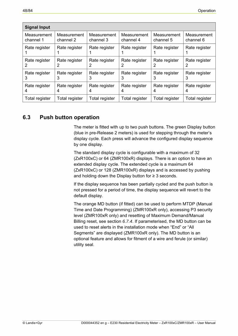
The following table shows the arrangement of the total and rate registers. In all cases, only one rate register is active for each measurement channel.
48/84 Operation
© Landis+Gyr D000044352 en g – E230 Residential Electricity Meter – ZxR100xC/ZMR100xR – User Manual
Signal Input
Measurement channel 1
Measurement channel 2
Measurement channel 3
Measurement channel 4
Measurement channel 5
Measurement channel 6
Rate register 1
Rate register 1
Rate register 1
Rate register 1
Rate register 1
Rate register 1
Rate register 2
Rate register 2
Rate register 2
Rate register 2
Rate register 2
Rate register 2
Rate register 3
Rate register 3
Rate register 3
Rate register 3
Rate register 3
Rate register 3
Rate register 4
Rate register 4
Rate register 4
Rate register 4
Rate register 4
Rate register 4
Total register Total register Total register Total register Total register Total register
6.3 Push button operation
The meter is fitted with up to two push buttons. The green Display button (blue in pre-Release 2 meters) is used for stepping through the meter’s display cycle. Each press will advance the configured display sequence by one display.
The standard display cycle is configurable with a maximum of 32 (ZxR100xC) or 64 (ZMR100xR) displays. There is an option to have an extended display cycle. The extended cycle is a maximum 64 (ZxR100xC) or 128 (ZMR100xR) displays and is accessed by pushing and holding down the Display button for ≥ 3 seconds.
If the display sequence has been partially cycled and the push button is not pressed for a period of time, the display sequence will revert to the default display.
The orange MD button (if fitted) can be used to perform MTDP (Manual Time and Date Programming) (ZMR100xR only), accessing P3 security level (ZMR100xR only) and resetting of Maximum Demand/Manual Billing reset, see section 6.7.4. If parameterised, the MD button can be used to reset alerts in the installation mode when “End” or “All Segments” are displayed (ZMR100xR only). The MD button is an optional feature and allows for fitment of a wire and ferule (or similar) utility seal.

Operation 49/84
D000044352 en g – E230 Residential Electricity Meter – ZxR100xC/ZMR100xR – User Manual © Landis+Gyr
6.4 Tamper detection
6.4.1 Reverse energy detection (RED)
If the meter is configured to operate in Reverse Energy fraud detection mode, the meter will alternate a warning message on the display if a fraud attempt is made by running current backwards through the meter. The reverse energy warning message is triggered when the reverse power exceeds a programmable threshold level of between 1-10 Amps for a period of 10 seconds. The meter will store the number of RED (Reverse Energy Detected) tamper events.
Once triggered, the reverse energy-warning message can only be reset by a formatted command.
6.4.2 Tamper event log (ZMR100xR only)
All meters with an internal RTC have a tamper event log, where the date/time, status and number of events are stored. The maximum capacity of the log is 200 events. The event log can be read and cleared through the communication interfaces with appropriate rights, but it is not displayed on the LCD.
The following events can be recorded in the log depending on the device settings and configuration. The events trigger a log event either when they begin or both when they begin and end.
Event no.
Name Description Trigger Event Anti-fraud
Perma-nent trigger (confi-gurable)
1 Voltage imbalance
Indicates that any phase voltage is below the % threshold of Max Voltage.
X X
2 Energy registers cleared
Indicates that tariff energy registers were cleared (but not the total energy registers).
X
3 Load profile and/or stored value profile cleared
Indicates that the load profile and/or the stored value profile was cleared.
X
4 Event log cleared
Indicates that the event log was cleared. This is always the first entry in the event log.
X
5 Battery low Indicates that the battery voltage fell below a set threshold.
X
6 Current imbalance
Indicates that any phase current is below the % threshold of Max Current.
X X

50/84 Operation
© Landis+Gyr D000044352 en g – E230 Residential Electricity Meter – ZxR100xC/ZMR100xR – User Manual
Event no.
Name Description Trigger Event Anti-fraud
Perma-nent trigger (confi-gurable)
8 Billing period reset
Indicates that a billing period reset has occurred.
X
9 Daylight saving time enabled or disabled
Indicates a change from and to daylight saving time. The time stamp shows the time before the change.
X
10 Clock adjusted (old date/time)
Indicates that the date/time has been adjusted. The time that is stored in the event log is the old time before the adjustment was made.
X
11 Clock adjusted (new date/time)
Indicates that the date/time has been adjusted. The time that is stored in the event log is the new time after the adjustment was made.
X
17, 18, 19
Under-voltage L1, L2, L3
Indicates that an undervoltage has occurred on the corresponding phase.
X
20, 21, 22
Overvoltage L1, L2, L3
Indicates that an overvoltage has occurred on the corresponding phase.
X
23 Power down Indicates that a power failure has occurred.
X
24 Power up Indicates that a power up has occurred.
X
25, 26, 27
Overcurrent L1, L2, L3
Indicates that an overcurrent has occurred on the corresponding phase.
X
28, 29, 30
Voltage without current L1, L2, L3
Indicates a possible shorting of the current coil.
X X
31 Power factor monitor 1
Indicates that the power factor is below a set limit.
X
33, 34, 35, 36
Demand monitors 1, 2, 3 and 4
Indicates that the demand is above a set limit.
X
37, 38, 39
Phase reversal L1, L2, L3
Indicates a reversal of polarity of the current coil.
X X

Operation 51/84
D000044352 en g – E230 Residential Electricity Meter – ZxR100xC/ZMR100xR – User Manual © Landis+Gyr
Event no.
Name Description Trigger Event Anti-fraud
Perma-nent trigger (confi-gurable)
40 Parameter changed
Indicates that one or more parameters have been changed by an external tool. The event is triggered by the tool.
X
45 Error Register Cleared
Indicates that the error register (F.F.0) has been cleared.
X
49, 50, 51
Missing voltage L1, L2, L3
Indicates that the corresponding voltage dropped below 20 V and remained below 20 V for a period of time defined by parameterisation.
X X
55 Magnet detection
Indicates that the meter has been influenced by a strong magnet (>0.5T). If event 55 is recorded without event 134, a tamper/fraud attempt has been made, but energy measurement has not been affected.
X X
66 Date/time invalid
Error X
76 Time base error
Error X
89 Start-up sequence invalid
Error X
133 Terminal cover removal
Indicates that the terminal cover has been removed.
X X
134 Strong DC field
Indicates that the energy measurement ICs have been affected by the presence of a strong DC magnet. Energy measurement must be treated as though it has been tampered with, which may result in inaccurate energy measurements from the point of detection.
X X
135 Front cover removal
Indicates that the front cover has been removed.
X X

52/84 Operation
© Landis+Gyr D000044352 en g – E230 Residential Electricity Meter – ZxR100xC/ZMR100xR – User Manual
With the occurrence of event 66 (Date/time invalid) RTC failure, all events except events 9, 10, 11 and 33-36 continue to be logged, but do not necessarily have valid date and time stamps. Tamper persistence times will also not be logged. To prevent the event log from filling as a result of event 66, events 66, 76 and 89 are only recorded once, until the clear event log is performed.
6.4.3 Meter cover opening (optional fitting)
A switch can be fitted to the meter, which will open when the top cover is removed. The meter will record the number of times the switch is activated. This feature is incorporated into the battery back-up circuit and is therefore operational even with no mains supply to the meter. If the tamper is triggered during a power fail situation, the meter will only detect one alert. For example, if the cover is removed and then replaced and then removed again, only one tamper count will be recorded. The tamper register will need to be reset when power has been restored in order for it to begin registering any further no power alerts.
6.4.4 Terminal cover opening (optional fitting)
A similar circuit to the above applied to the Terminal Cover.
6.4.5 DC magnetic field intrusion
The meter will detect the presence of a strong DC magnetic field and can be used to activate the tamper Alert. There are two separate detection methods, each having a separate event number: Magnet detection (event 55) and Strong DC Field (event 134). Event 55 is the first indication of a potential tamper attempt. Event 134 indicates that the energy measurement ICs have been affected by the presence of a strong DC magnet. Energy measurement must be treated as though it has been tampered with, which may result in inaccurate energy measurement from the point of detection.
6.4.6 Alert notification
The meter can be configured to activate the front panel Alert LED, when an alert is detected, and/or illuminate the Bell alert icon on the meter display. Any combination of the following alerts can be configured:
Meter Cover Tamper Terminal Cover Tamper DC Field (Magnetic fraud) Voltage Missing (ZMR100xR only) Phase Reversal (ZMR100xR only) Voltage Without Current (ZMR100xR only) Voltage Imbalance (ZMR100xR only) Current Imbalance (ZMR100xR only)
With the exception of meter cover tamper, terminal cover tamper and DC field, all alerts/events have separate definable thresholds and include:

Operation 53/84
D000044352 en g – E230 Residential Electricity Meter – ZxR100xC/ZMR100xR – User Manual © Landis+Gyr
Missing voltage persistence time Voltage without current persistence time Under voltage persistence time Current threshold for voltage without current Over voltage persistence time Phase reversal persistence time Under voltage threshold voltage KVA threshold for PF monitor Over voltage threshold voltage Threshold for PF monitor Over current persistence time Voltage imbalance persistence time Over current threshold current Lower power factor persistence time Current balance persistence time Power On/Off persistence time Magnet sensor persistence time Voltage unbalance threshold (Vmax) Current imbalance threshold (Imax) Threshold for demand monitor Ch1 Threshold for demand monitor Ch2 Threshold for demand monitor Ch3 Threshold for demand monitor Ch4
6.5 No power read (optional fitting)
The No Power Read (NPR) feature allows readings to be taken from the meter for data collection purposes either via the optical port or from the LCD display, when there is no mains supply. This function is activated by pressing and holding the display cycle button or by using the front panel optical port.
The battery circuitry locks on after about 2 or 3 seconds and provides about 60 seconds of power in which to read the meter or perform a flag download. In No Power Read mode, the display sign-on is removed to conserve power. After this, the display uses the NPR default display and NPR display cycle. Some functions of the meter are disabled in this mode (e.g. LEDs and Relays).
After using the battery, a repeat operation cannot be performed for approximately 60 seconds. To prolong battery life, the number of times NPR can be activated is restricted to 2 per month.
6.6 ToU (Time-of-Use) tables (ZMR100xR only) The E230 ZMR100xR’s ToU functionality provides a maximum of 16 output signals to switch:
Energy Demand tariffs Control loads

54/84 Operation
© Landis+Gyr D000044352 en g – E230 Residential Electricity Meter – ZxR100xC/ZMR100xR – User Manual
A maximum of 6 day tables can be used, e.g. for weekdays, Saturday, Sunday and holidays. In each day table, it is possible to define up to 24 switching times. During one year, it is possible to define up to 12 different seasons, where for each day (Monday to Sunday) a day table is chosen. An exception day table with up to 200 entry days (e.g. national holidays, Easter Monday, New Year’s Day, etc.) can be defined and it overrules the season and day tables.
There are two complete sets of switching tables:
Active switching tables: Active switching tables are the ones that are currently being used.
Passive switching tables: Passive switching tables are not yet used. They can be prepared in the background for later use.
Each set of switching tables bears an ID code with which it is clearly identified. The ID code consists of a maximum of 7 characters and can be set by a tool.
The passive switching tables will be activated, if the current date becomes newer than the activation date. An activation date set in the past or today will therefore immediately activate the passive switching tables.
There are no passive special day settings. Therefore, a special day setting becomes active immediately after you have completed its definition.
The time resolution in a day table is 15 minutes. Each line in the day table represents one switching state with its start time and the activated signals in that period of time. The first entry starts at 00:00 hours and the last entry ends at 24:00 hours.
Day Table n
Valid from
TOU-T1
TOU-T2
TOU-T3
TOU-T…
TOU-T…
TOU-T…
TOU-T15
TOU-T16
00:00
06:00 x
11:00 x
13:00
The day tables are controlled by the exception days and season tables. The exception day table has priority over the season day table.
The exception day table is used to define a tariff to be used on a particular day, e.g. national holiday, Easter Monday, etc. If the date includes the year, the special day is valid for the specified year only (e.g. Easter). If the date does not include the year, the special day is valid every year thereafter (e.g. New Year).
At each change of the date, the time switch checks whether or not the following day is a special day and selects the day table accordingly.

Operation 55/84
D000044352 en g – E230 Residential Electricity Meter – ZxR100xC/ZMR100xR – User Manual © Landis+Gyr
Date Day Table
01.01. 2
25.12. 2
25.3.2007 3
15.3.2008 1
A maximum of 200 exception days can be programmed.
The season table defines the weekly and the seasonal on/off pattern of the control signals.
Week: To define the weekly on/off pattern, the user enters the number of the day table which is applicable on a particular day of the week. As soon as all days of the week are allocated with a day table, the week table is completed.
Season: In the season column, the user defines the period of the year the week table applies to. A maximum of 12 seasons can be defined.
Season Table
Season Mon Tue Wed Thu Fri Sat Sun
01.01. – 31.03.
1 1 1 1 1 2 2
01.04. – 30.09.
3 3 3 3 3 2 2
01.10. – 31.12.
1 1 1 1 1 2 2
If the meter’s internal clock fails, an emergency table is used. These settings remain active until the clock has been adjusted.
Emergency Settings
TOU-T1
TOU-T2
TOU-T3
TOU-T4
TOU-T5
TOU-T6
TOU-T7
TOU-T8
x x x
6.6.1 Tariff control (ZMR100xR only)
E230 ZMR100xR can have up to six different tariff rates for energy depending on the type. The meter has built in ToU tables that can control tariffs, but tariffs can also be controlled by signals from other sources. The meter also has external control inputs for tariff switching.
The control sources for tariff control are:
Time of use signals Voltage monitors Anti-fraud inputs Demand monitor Power factor monitor
Time-of-Use has up to 16 Time switch signals for controlling tariffs.

56/84 Operation
© Landis+Gyr D000044352 en g – E230 Residential Electricity Meter – ZxR100xC/ZMR100xR – User Manual
Voltage monitors produce Events signals due to over- and under- voltage, missing voltages (phase losses) and total phase failure (total power loss).
Tampering inputs produce Events signals due to strong DC fields, as well as meter and terminal cover or meter box opening.
Demand monitors produce Event signals indicating a high demand value (two demand excess monitors based on the average demand).
Power factor monitor produces Event signals indicating too low power factor value. The various control sources or a combination of them can be used to enable and disable registers, to control arrows on the LCD and the Alert LED, and to control outputs.
6.6.2 Load control (ZMR100xR only)
The meter’s external outputs can be controlled by:
TOU signals Control input signals Combination of tariff signals Event signals
Time/date not valid Demand monitor Power factor monitor Voltage monitoring Tamper monitoring Alert occurred
6.7 Maximum demand
Maximum Demand (MD) can be measured in kW, kVAr or kVA. MD functionality is available in two different ways either ‘Slab’ or ‘Rolling’. Both of these, however, use the same registers and settings.
Registers (matching the number of rates available, plus total) in E2 are made available for up to four rates and total (ZxR100xC) or up to six rates (ZMR100xR). Current, Previous and Summation MD values are recorded and are available for display and readout.
6.7.1 ‘Slab’ maximum demand
This MD method works by calculating the maximum demand over fixed periods. The Maximum Demand Period is set to the period (in minutes) over which to calculate the MD. This value must be a factor of 60 (i.e. 1, 2, 3, 4, 5, 6, 10, 12, 15, 20, 30 or 60).
The demand is then calculated at this interval in such a way that one of the calculations is done on the hour boundary (e.g. if the period is 12 then the demand is calculated at 0, 12, 24, 36 and 48 minutes past the hour).

Operation 57/84
D000044352 en g – E230 Residential Electricity Meter – ZxR100xC/ZMR100xR – User Manual © Landis+Gyr
For total maximum demand, the recording can either start on power up or not until the first one of these boundaries occurs. In the former case, the demand is calculated by integrating the recorded value over the full period (assuming the rest of the period to be 0).
During each integration period, a rising demand is calculated. This rising demand is what the demand will be if there is no further energy consumption within the current MD period.
Each time the demand is calculated the value is compared to the respective current largest demand, and if it is larger, the new value is written to the register.
6.7.2 ‘Rolling’ maximum demand
Rolling Maximum Demand is always calculated over a period of 15 minutes. The demand is calculated every minute using readings from the last 15 minutes. The first calculation occurs 15 minutes after power up.
Each time the demand is calculated, the value is compared to the respective current largest demand, and if it is larger, the new value is written to the register.
When Rolling Maximum Demand is used, it is not possible to trigger rate switching from an MD activity.
6.7.3 Maximum demand at power fail
If ‘slab’ MD and partial MD periods are enabled when the power is removed from the meter and then restored, the meter restores the values from the partial period and integrates that as if it were the total energy used over the complete period.
6.7.4 Reset of maximum demand
There are two available methods of resetting maximum demand: Formatted Command via optical port and MD Push Button.
Optical port formatted command
The Maximum Demand registers can be reset via the optical port by formatted command using .MAP110.
MD push button
If the meter is fitted with a Maximum Demand push button, pressing the button for > 3 seconds will reset the MD registers. Once the button is pressed, the button is not active (for further MD resets) until a new MD period has elapsed.
Resetting the maximum demand registers causes the following:
MD reset count is incremented by one Display shows ‘rSt PASS’ to indicate successful acknowledgement
of a manual reset. (If manual reset is not successful, the display will show ‘rSt FAIL’).

58/84 Operation
© Landis+Gyr D000044352 en g – E230 Residential Electricity Meter – ZxR100xC/ZMR100xR – User Manual
Old maximum demand values are added to the cumulative registers Continual demand register is stored in the Previous MD register Current MD registers are then cleared
6.8 Billing (stored values) (ZMR100xR only)
A total of 15 billing (stored values) are available via IEC readout and in the LCD. Billing periods can be closed/reset automatically by means of a configured date and time each month or at a specific time on the last calendar day of the month. Manual closure/reset is also possible by formatted command and use of the orange MD button (where fitted).
Each billing capture will always contain a date and time stamp and a billing reset count number. In addition, they may be defined with any combination of the following parameters (maximum 10):
Energy register channel 1-8, for up to six rates each, plus total registers
MD register channel 1-4, for up to six rates each, plus total registers Operating time registers for up to six rates, plus total register Average power factor Battery operating time Terminal cover removal event (special Bulgarian parameter)
Since there are a limited number of segments available in the OBIS legend, implementation of a 2 second toggle between parts of the OBIS designation in both auto cycle and manual cycle modes of the displays for all previous billing parameters, is made (excluding the mandatory date/time and reset counter parameters). The last completed billing period is always first in previous billing display list. A worked example is provided below:
Readout
0.1.0 10 (12-12-01;00:00)
0.1.0 10 (10)
1.8.0 10 (000010.55*kWh)
2.8.0 10 (000002.22*kWh)
15.8.0 10 (000002.16*kvarh)
5.8.0 10 (000002.70*kvarh)
6.8.0 10 (000017.69*kVAh)
7.8.0 10 (000010.55*kWh)
8.8.0 10 (000002.22*kWh)
130.8.0 10 (000002.16*kvarh)
C.8.0 10 (00000033)
C.8.1 10 (00000000)
Example Readout

Operation 59/84
D000044352 en g – E230 Residential Electricity Meter – ZxR100xC/ZMR100xR – User Manual © Landis+Gyr
Display Behaviour
0.1.0 10 (12-12-01;00:00) No toggle
0.1.0 10 (10) No toggle
1.8.0 (000010.55*kWh) 2 sec toggle
2.8.0 (000002.22*kWh) 2 sec toggle
15.8.0 (000002.16*kvarh) 2 sec toggle
5.8.0 (000002.70*kvarh) 2 sec toggle
6.8.0 (000017.69*kVAh) 2 sec toggle
7.8.0 (000010.55*kWh) 2 sec toggle
8.8.0 (000002.22*kWh) 2 sec toggle
130.8.0 (000002.16*kvarh) 2 sec toggle
C.8.0 (00000033) 2 sec toggle
C.8.1 (00000000) 2 sec toggle
How the stored values are displayed to the LCD
OBIS Legend
0 1 0 1 0
0 1 0 1 0
1 8 0 2 sec
1 0 2 sec
1 8 0 2 sec
OBIS legend behaviour (toggling)
All OBIS codes are to be forced left aligned. Billing count/reset count number is to be forced right aligned to make reading clearer.
Manual and Automatic resets are not distinguishable via the display (i.e. it is not possible to display “*” and/or “&” symbols.
Only closed previous billing periods are made visible in the display and IEC readout.
6.8.1 Unit suppression
IEC billing readout may be parameterised to suppress values to suit reading preference or simplify data capture for utility acquisition.

60/84 Operation
© Landis+Gyr D000044352 en g – E230 Residential Electricity Meter – ZxR100xC/ZMR100xR – User Manual
Example billing readout Comments/remarks
1.6.0(02.250*kW)(11-12-28 12:00) 1.6.0*21(02.160*kW) (11-11-28 12:00) 1.6.0*20(02.015*kW) (11-10-28 12:00)
Units of stored values included (Suppress Units In Billing disabled). Current value must always contain unit, e.g. kW. Stored value with units. Stored value with units.
1.6.0(02.250*kW)(11-12-28 12:00) 1.6.0*21(02.160) (11-11-28 12:00) 1.6.0*20(02.015) (11-10-28 12:00)
Units of stored values not included (Suppress Units In Billing enabled). Current value must always contain unit, e.g. kW. Stored value without units. Stored value without units.
6.9 MDTP (Manual Date Time Programming) (ZMR100xR only)
The Date, Time and IDs can be programmed using the meter’s push buttons. The meter must feature a Maximum Demand button to perform this operation. Configuration is required to enable/disable this feature. A log records the number of times the Date and/or Time is reprogrammed. This is displayed with the first and second displays during MDTP. “rdt” is the date when the last date or time parameter has been changed by MDTP. “rct” is the count/number of changes made to date or time since reset. The count goes up to 99 before rolling over to 00.
6.9.1 Manual setting of date/time/ID
The procedure is as follows (assuming feature is enabled):
After one short press (< 3 seconds) of the Maximum Demand push button, the meter enters a separate display cycle. The display list shows all of the parameters that can be programmed through the MDTP mode.
Subsequent short presses (< 3 seconds) of the Maximum Demand push button will advance the display to the next parameter. The parameter list is sequenced as follows:
“rdt” - Reprogramming date: date of last programming (read only) “rct” - Reprogramming counts: the number of times the Date or Time
has been programmed via the push button (read only) Date* (0.9.2) Time* (0.9.1) ID1.1 (0.0.0) ID1.2 (0.0.1) ID1.3 (0.0.2) ID1.4 (0.0.3) ID2.1 (C.1.0) ID2.2 (C.1.1)
* ZMR100xR only.
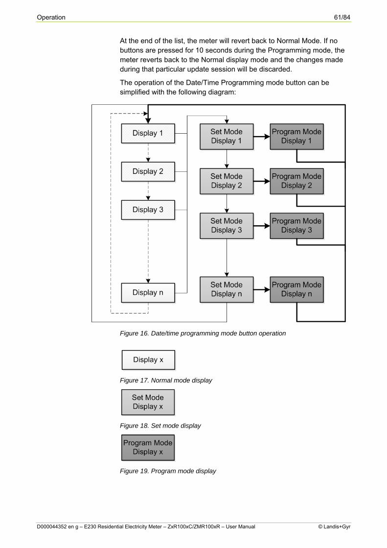
Operation 61/84
D000044352 en g – E230 Residential Electricity Meter – ZxR100xC/ZMR100xR – User Manual © Landis+Gyr
At the end of the list, the meter will revert back to Normal Mode. If no buttons are pressed for 10 seconds during the Programming mode, the meter reverts back to the Normal display mode and the changes made during that particular update session will be discarded.
The operation of the Date/Time Programming mode button can be simplified with the following diagram:
Figure 16. Date/time programming mode button operation
Figure 17. Normal mode display
Figure 18. Set mode display
Figure 19. Program mode display

62/84 Operation
© Landis+Gyr D000044352 en g – E230 Residential Electricity Meter – ZxR100xC/ZMR100xR – User Manual
Dashed arrows represent a press of the green Display button.
Solid arrows represent a press of the orange Maximum Demand button.
Thin arrows represent a short button press (<3s).
Thick arrows represent a long button press (>3s).
Figure 20. Date/time programming success/fail sequence
The Success/Fail message confirms the validity of the programmed data. A fail message will revert the display back to Display 1 in 5 seconds. Successful timeout is 10 seconds.

Operation 63/84
D000044352 en g – E230 Residential Electricity Meter – ZxR100xC/ZMR100xR – User Manual © Landis+Gyr
6.10 Front panel optical port
Type LED / PTR optical port
Standard IEC1107
Communication protocol Asynchronous serial
Communication speed Configurable – 9600 baud max.
16 byte device address Configurable
6.11 Relays (ZMR100xR only)
The meter can have up to two relays for switching, e.g. load control.
6.11.1 Relay control (ZMR100xR only)
The relay is controlled through six relay sources. These are:
Rate Switching Patterns (RS) Clock Invalid (CI) Alert (AL) MD Period (MD) Energy Direction (ED) TOU Switching (TS)
The relay Open/Closed state is decided by the source that controls a particular relay and can optionally be indicated using the triangular indicators detailed in section 6.1.6. This source is freely configurable. The duration of the open and closed times of the relay can be configured (Clock Invalid (CI), Alert (AL) and MD Period (MD) sources only).
6.12 Energy measurement modes
6.12.1 Vectorial sum
Quadrants Direction Value Phase Unit
Channel 1 Import, Q1+Q4 + A Sum kWh
Channel 2 Export, Q2+Q3 - A Sum kWh
Channels 3 to 6
(can be configured)
-
Q2 Q1
Q3 Q4
Q2 Q1
Q3 Q4
Q2 Q1
Q3 Q4

64/84 Operation
© Landis+Gyr D000044352 en g – E230 Residential Electricity Meter – ZxR100xC/ZMR100xR – User Manual
6.12.2 Complete four-quadrant system
Quadrants Direction Value Phase Unit
Channel 1 Import, Q1+Q4 + A Sum kWh
Channel 2 Export, Q2+Q3 A Sum kWh
Channel 3 Import, Q1 + R Sum kVAr
Channel 4 Import, Q2 + R Sum kVAr
Channel 5 Export, Q3 R Sum kVAr
Channel 6 Export, Q4 - R Sum kVAr
6.12.3 v1- or always positive registration, absolute value (SUM [ALi])
Quadrants Direction Value Phase Unit
Channel 1
Import, Q1-Q4 + A L1,L2,L3
kWh
Channels 2 to 6
(can be configured)
-
Q2 Q1
Q3 Q4
Q2 Q1
Q3 Q4
Q2 Q1
Q3 Q4
Q2 Q1
Q3 Q4
Q2 Q1
Q3 Q4
Q2 Q1
Q3 Q4
Q2 Q1
Q3 Q4
Q2 Q1
Q3 Q4

Operation 65/84
D000044352 en g – E230 Residential Electricity Meter – ZxR100xC/ZMR100xR – User Manual © Landis+Gyr
6.12.4 Import and export values
Quadrants Direction Value Phase Unit
Channel 1 Import, Q1+Q4 + A Sum kWh
Channel 2 Export, Q2+Q3 A Sum kWh
Channel 3 Import, Q1+Q2 + R Sum kVAr
Channel 4 Export, Q3+Q4 + R Sum kVAr
Channel 5 Import, Q1+Q4 + S Sum kVA
Channel 6 Export, Q2+Q4 - S Sum kVA
6.12.5 Energy consumption plus green energy generation
Quadrants Direction Value Phase Unit
Channel 1 Import, Q1+Q4 + A L2+L3 kWh
Channel 2 Export, Q2+Q3 A L1 kWh
Channel 3 Import, Q1+Q2 + R L2+L2 kVAr
Channel 4 Import, Q1+Q2 + R L1 kVAr
Channel 5 Export, Q3+Q4 - R L2+L3 kVAr
Channel 6 Export, Q3+Q4 - R L1 kVAr
Q2 Q1
Q3 Q4
Q2 Q1
Q3 Q4
Q2 Q1
Q3 Q4
Q2 Q1
Q3 Q4
Q2 Q1
Q3 Q4
Q2 Q1
Q3 Q4
Q2 Q1
Q3 Q4
Q2 Q1
Q3 Q4
Q2 Q1
Q3 Q4
Q2 Q1
Q3 Q4
Q2 Q1
Q3 Q4
Q2 Q1
Q3 Q4

66/84 Operation
© Landis+Gyr D000044352 en g – E230 Residential Electricity Meter – ZxR100xC/ZMR100xR – User Manual
6.13 Communication interfaces
The E230 meter has several different communication interfaces:
Optical test output Optical interface CS interface (optional) RS485 interface (optional) S0 interface (optional)
The optical test output is for verifying the meter operation. The LED flashes at 1000 imp/kWh.
The optical interface can be used for gathering the meter data in the field. It is also commonly used for making re-parameterisations and for the input of formatted commands. The readout protocol is according to IEC 62056-21 with speeds of up to 9600 bps.
The CS and RS485 interfaces are both optional and can be used for gathering the meter data in the field. The readout protocol is according to IEC 62056-21 with speeds of up to 9600 bps (4800 bps), but, of course, are highly influenced and dependent on the given installation conditions, cable lengths, etc.
The S0 interface is also optional and can be individually parameterised for a range of pulse frequencies and pulse durations. In addition, pulse output 1 S0 interface may also be used for periodical data output, i.e. the retransmission of data protocol every 30 seconds at 300 bps. This replicates a proprietary communication data stream as found in the obsolete ZME meter.
CS connections
Connection type: screwless terminals.
Designation Connection
40 +ve
41 -ve
RS485 connections
Connection type: screwless terminals. Terminals are doubled up in order to facilitate the ability to connect in and out (loop) of the meter without compromising the connection quality.
Designation Connection
27 -ve
28 Ground
29 +ve
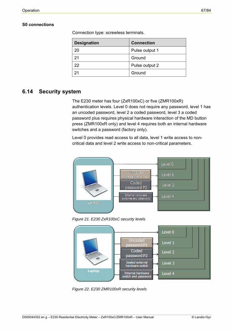
Operation 67/84
D000044352 en g – E230 Residential Electricity Meter – ZxR100xC/ZMR100xR – User Manual © Landis+Gyr
S0 connections
Connection type: screwless terminals.
Designation Connection
20 Pulse output 1
21 Ground
22 Pulse output 2
21 Ground
6.14 Security system
The E230 meter has four (ZxR100xC) or five (ZMR100xR) authentication levels. Level 0 does not require any password, level 1 has an uncoded password, level 2 a coded password, level 3 a coded password plus requires physical hardware interaction of the MD button press (ZMR100xR only) and level 4 requires both an internal hardware switches and a password (factory only).
Level 0 provides read access to all data, level 1 write access to non-critical data and level 2 write access to non-critical parameters.
Figure 21. E230 ZxR100xC security levels
Figure 22. E230 ZMR100xR security levels

68/84 Operation
© Landis+Gyr D000044352 en g – E230 Residential Electricity Meter – ZxR100xC/ZMR100xR – User Manual
6.14.1 Access level 3 (ZMR100xR only)
Level 3 access can be utilised if: (a) level 3 is enabled in the configuration, (b) “Auto Restart” display option is set and (c) the meter is fitted with the orange MD button.
First, press the display button to obtain all display segments (‘display test’) and then press the MD button (MD seal must be removed).
Note: The duration of press for both buttons is not of any significance here as long as they are pressed in the correct sequence (MD reset button press after pressing display button at all segments on).
The sequence of button presses should be done after the sign on for obtaining the level 3 access. Flag read/write signing on to the meter at P0 access will allow all P3 access permissions to be parameterised.
6.14.2 Last configuration change identifier
A special register C.128.0 is defined (for the use of a 3rd party) to read and write an identifier relating to the user who made the last change to the configuration of the meter. 8 bytes (suitable for 8 alphanumeric characters) are permitted at address 0x269F. Subject to the setting of the security parameter “LastChangeIdent”, register C.128.0 can be enabled for viewing in the IEC readout or left for reading directly by formatted command. The adjacent address 0x0BFA will contain the date and time stamp in the format: yy-mm-dd; hh:mm.
6.15 IEC formatted commands
Available commands are (but not limited to):
Perform IEC data readout Read and set ID1s and ID2s Read parameterisation ID Read and set IEC device address Read and set optical interface baud rate Read and set electrical interface baud rate Read and set pulse output settings Read and set LCD Recall List Read and set LCD Service List Read and set Readout List Read and set No Power Display List Set rate switching Set passwords Set register resolution Reset Billing/MD period Enable/Disable test mode Reset Energy and Demand registers Reset Error register Reset Tamper Flags Reset Fraud Detection

Operation 69/84
D000044352 en g – E230 Residential Electricity Meter – ZxR100xC/ZMR100xR – User Manual © Landis+Gyr
Reset Magnetic Fraud Detection Reset Terminal Cover Fraud Detection Reset Meter Cover Fraud Detection
ZxR100xC only
Read and set EDL21 registers Reset EDL specific registers
ZMR100xR only
Read and set date/time and DST Perform Load Profile readout Perform Event log readout Read last parameterisation change ID Read and set Time of Use (TOU) Read and set Billing (Stored Values) settings and parameters Reset Alert indicator Reset Billing period counter Reset Operating Time registers Reset Billing (Stored Values) Reset Load Profile

70/84 Maintenance
© Landis+Gyr D000044352 en g – E230 Residential Electricity Meter – ZxR100xC/ZMR100xR – User Manual
7 Maintenance
7.1 Meter check
While it is not necessary, under normal circumstances, to perform any maintenance on the installed meter, the following are check points that should be observed during scheduled periodic meter visits.
Is the meter dry and clean, particularly the LCD display and the optical interface?
Does the meter display a legible and sensible display? I.e. does the meter appear to be in a serviceable condition?
Check that all factory- and company-fitted seals are secure and intact.
Observe display for any error messages or notifications Confirm that the energy registers have changed to a reasonable
degree since the last visit. If irregularities are found, continue as described in section7.3.
7.2 Meter testing
The testing of meters, either random sample or on all meters, should be carried out periodically according to national regulations. The meter must be removed as described in section 7.4 and replaced with a meter of similar type for the duration of the tests.
7.2.1 Measurement Times
For technical reasons, higher measurement deviations can occur during short-term measurements. It is therefore recommended to use sufficiently long measurement times in order to achieve the required accuracy.
Table of required measurement times:
ZMR
Un=230V
Measurement Uncertainty 0.2%
Measurement Uncertainty 0.1%
3 ph 1 ph 3 ph 3 ph 1 ph 3 ph
Current [A]
cosφ=1 cosφ=1 cosφ=0.5 cosφ=1 cosφ=1 cosφ=0.5
0.2 25 s 70 s 90 s 90 s 4.5 min 6 min
0.5 20 s 20 s 20 s 20 s 45 s 60 s
≥ 1 20 s 20 s 20 s 20 s 20 s 20 s
3 ph = balanced load 1 ph = single-phase load

Maintenance 71/84
D000044352 en g – E230 Residential Electricity Meter – ZxR100xC/ZMR100xR – User Manual © Landis+Gyr
ZFR
Un=230V
Measurement Uncertainty 0.2%
Measurement Uncertainty 0.1%
3 ph 1 ph 3 ph 3 ph 1 ph 3 ph
Current [A]
cosφ=1 cosφ=1 cosφ=0.5 cosφ=1 cosφ=1 cosφ=0.5
0.2 45 s 3 min 3 min 3 min 12 min 11 min
0.5 20 s 30 s 27 s 30 s 2 min 2 min
≥ 1 20 s 20 s 20 s 20 s 30 s 30 s
≥ 2 20 s 20 s 20 s 20 s 20 s 20 s
3 ph = balanced load 1 ph = single-phase load
For meters with software ≤K75 or ≤K52:
If the so-called register test (meter constant or gear transmission error test) is not carried out at a constant load point, but with a constant injected amount of energy, a test time of 15 minutes is recommended (minimum 10 minutes).
7.2.2 Post-installation configuration changes
With the aid of a laptop computer or a suitable PDA together with a flag probe and Landis+Gyr-specific software, it is possible to amend some of the factory configured options of the meter. However, it is beyond the scope of this manual to describe the procedure in any further detail. Landis+Gyr Metering sales team would be happy to discuss specific requirements, if they arise.
7.3 Operating faults
If the LCD window is illegible or the data readout does not function, the following points should be checked.
Is mains voltage present? Are the preliminary fuses intact? Has the minimum or maximum recommended ambient temperature
been exceeded? Is the LCD window clear of all debris? – Not misted over, painted
over or soiled in any way.
If none of the above are causing the fault, the meter should be disconnected as described in section 7.4, replaced if required as detailed in section 5, and returned to Landis+Gyr as described in section 7.5.

72/84 Maintenance
© Landis+Gyr D000044352 en g – E230 Residential Electricity Meter – ZxR100xC/ZMR100xR – User Manual
7.4 Disconnecting the meter
Remove preliminary fuses before continuing The connecting conductors should not be live when removing the meter. Electrically live parts are a life threatening hazard. Preliminary fuses should be removed and kept in a safe place, where they cannot be replaced by anyone unnoticed, until all work is complete.
Proceed as follows:
1. Remove the company seal on the terminal cover (if fitted).
2. Release the two terminal cover screws and remove terminal cover.
3. Check with a suitable voltage testing device that the phase connections are not live. If they are live, remove the preliminary fuses and keep in a safe place, where they cannot be replaced by anyone unnoticed, until all work is complete.
4. Remove the signal inputs and outputs by releasing the auxiliary terminal screws.
5. Remove the phase connections by releasing the main terminal screws.
6. If required, fit a suitable replacement meter as described in section 5.
7.5 Repairing the meter
There are no user serviceable parts inside the meter. Breaking factory calibration seals will invalidate the calibration status of the meter. In the event of a meter requiring repair, proceed as follows.
1. Remove the meter from the installation as detailed in section 7.4.
2. Attach a label, which describes the fault as accurately as possible, to the meter and include the name and contact details of the person responsible in case of inquiries.
3. Package the meter to ensure no further damage can occur during transit.
4. Send the meter back to Landis+Gyr.

Error handling 73/84
D000044352 en g – E230 Residential Electricity Meter – ZxR100xC/ZMR100xR – User Manual © Landis+Gyr
8 Error handling
8.1 Error codes This error display is added to the end of the current display, if it is not already parameterised to display in the main display sequence.
On the display of E230 meters, an error is shown as an eight digit hexadecimal value, i.e. the single digits may show values between 0 (no error code set) and F (all four error codes set). The index field shows “F.F.0”.
There are two kinds of errors: persistent and transient errors. Transient error codes are automatically reset at the next readout. The errors can also be cleared either using the formatted write command “Reset Error Register” (W2 C150) command in .MAP110 tool or by power cycling the meter.
Note The formatted write command “Reset Error Register” (W2 C150) command using .MAP110 only clears the error flags, it does not eliminate the error.
Persistent error codes cannot be reset in the field. If the reason for the error persists, for example in the case of a component failure, power cycling will not clear the error. A meter showing a persistent error code must be considered unsafe/unsuitable for further use. Contact a Landis+Gyr Service Centre for support.
If more than one error is detected, the error codes are added. If e.g. the two errors "00002000" and "00008000" occur simultaneously, the error code would be the sum of these error codes = "0000A000" (note that the error code is a hex value).
The error message in the readout does not correspond to the displayed error. The value of this error is bitmapped:
Display Description If error is persistent If error is transitional Related event log #
80000000 RTC has drifted too far. This error only gets set, if using MLC option is enabled.
Billing based on energy registers after the error occurrence is not reliable and may be subject to discrepancies and incorrect time-based tariff switching.
Clear Error Register F.F.0 on display and readout by “Reset Error Register” (W2 C150) command using .MAP110, power-cycle or wait for the error to be cleared automatically after RTC correction. It gets cleared at 03:20:30 hours.
N/A

74/84 Error handling
© Landis+Gyr D000044352 en g – E230 Residential Electricity Meter – ZxR100xC/ZMR100xR – User Manual
Display Description If error is persistent If error is transitional Related event log #
40000000 UNUSED
20000000 UNUSED
10000000 UNUSED
08000000 UNUSED
04000000 UNUSED
02000000 Battery power reserve exhausted.
Meter may not operate under NPR conditions. RTC may become incorrect or reset when mains supply is removed. If the supercapacitor option is fitted, it will support the RTC for a limited time without battery.
Cleared by leaving on mains power for a minimum of 3 days or by power-cycle, since battery health is checked during the power-up sequence.
N/A
01000000 UNUSED
00800000 Error saving energy registers.
Energy registers may be missing up to 60 minutes worth of energy consumption per power- down.
A retry after 60 minutes is made from RAM to EEPROM in order to save the energy registration. If successful, the meter will show correct energy consumption. Clear Error Register F.F.0 on display and readout by “Reset Error Register” (W2 C150) command using .MAP110 or by power-cycle.
N/A
00400000 Error restoring energy registers. (Unable to read from EEPROM.)
Meter operation may be compromised. Billing based on energy registers after the error occurrence is not reliable. This error will only occur during the power-up sequence.
Clear Error Register F.F.0 on display and readout by “Reset Error Register” (W2 C150) command using .MAP110 or by power-cycle.
N/A

Error handling 75/84
D000044352 en g – E230 Residential Electricity Meter – ZxR100xC/ZMR100xR – User Manual © Landis+Gyr
Display Description If error is persistent If error is transitional Related event log #
00200000 Error Reading/ Writing tamper microcontroller.
Tamper functionality in NPR mode may be affected. Meter operations are not compromised, i.e. only tampers that occurred in NPR mode may not be recorded and logged by the meter.
Clear Error Register F.F.0 on display and readout by “Reset Error Register” (W2 C150) command using .MAP110, power-cycle or wait for the error to be cleared automatically once communication is re-established.
N/A
00100000 UNUSED
00080000 RTC Error. (TOU meters only).
Billing based on energy registers after the error occurrence is not reliable and may be subject to discrepancies and incorrect time-based tariff switching. Billing Profile (stored values) will not be created following this event type and therefore Load Profile data may also be compromised. Maximum Demand will be calculated at configured intervals. Caused by the meter’s inability to read/write to RTC.
Clear Error Register F.F.0 on display and readout by “Reset Error Register” (W2 C150) command using .MAP110 or wait for the error to be cleared automatically after RTC correction.
76

76/84 Error handling
© Landis+Gyr D000044352 en g – E230 Residential Electricity Meter – ZxR100xC/ZMR100xR – User Manual
Display Description If error is persistent If error is transitional Related event log #
00040000 Date Time invalid (TOU meters only).
Billing based on energy registers after the error occurrence is not reliable and may be subject to discrepancies and incorrect time-based tariff switching. Billing Profile (stored values) will not be created following this event type and therefore Load Profile data may also be compromised. Maximum Demand functions independently of this error type and is not affected. Battery Operating Time functionality will no longer be reliable once this error bit is set.
Clear Error Register F.F.0 on display and readout by “Reset Error Register” (W2 C150) command using .MAP110 or wait for the error to be cleared automatically after RTC correction.
66
00020000 Error accessing EEPROM.
Meter operation may be compromised. Billing based on energy registers after the error occurrence is not reliable.
Clear Error Register F.F.0 on display and readout by “Reset Error Register” (W2 C150) command using .MAP110 or by power-cycle.
N/A
00010000 UNUSED
00008000 Failed checksum when restoring registers from EEPROM. (No backup of registers available.)
Meter operation may be compromised. Billing based on energy registers after the error occurrence is not reliable. Error will only occur during the power-up sequence.
Clear Error Register F.F.0 on display and readout by “Reset Error Register” (W2 C150) command using .MAP110 or by power-cycle.
N/A

Error handling 77/84
D000044352 en g – E230 Residential Electricity Meter – ZxR100xC/ZMR100xR – User Manual © Landis+Gyr
Display Description If error is persistent If error is transitional Related event log #
00004000 Power-fail data failed checksum.
Meter operation may be compromised. Billing based on energy registers after the error occurrence is not reliable. Error will only occur during the power-up sequence. This error is set, if the checksum of the power-fail data is incorrect during power-up.
Clear Error Register F.F.0 on display and readout by “Reset Error Register” (W2 C150) command using .MAP110 or by power-cycle.
N/A
00002000 Calibration value failed checksum.
Meter operation may be compromised. Billing based on energy registers after the error occurrence is not reliable. Error will only occur during the power-up sequence. This error is set, if the checksum of the calibration data is incorrect during power-up.
Clear Error Register F.F.0 on display and readout by “Reset Error Register” (W2 C150) command using .MAP110 or by power-cycle.
N/A
00001000 UNUSED
00000800 UNUSED
00000400 UNUSED
00000200 UNUSED
00000100 UNUSED
00000008 Error in Parameter Data.
Meter operation may be compromised due to incorrect or corrupt parameterisation.
Clear Error Register F.F.0 on display and readout by “Reset Error Register” (W2 C150) command using .MAP110 or by power-cycle.
N/A
00000040 UNUSED

78/84 Error handling
© Landis+Gyr D000044352 en g – E230 Residential Electricity Meter – ZxR100xC/ZMR100xR – User Manual
Display Description If error is persistent If error is transitional Related event log #
00000002 More than 32 consecutive attempts to communicate with or initialise the MMI devices have failed.
Energy measurement is compromised. Communication with measurement device(s) has failed and some or all energy is not measured.
Only by power-cycle. N/A
00000010 UNUSED
00000004 UNUSED
00000001 Insufficient time to complete power failure routine.
Energy registers may be missing up to 60 minutes worth of energy consumption and power-fail data per power-down.
Clear Error Register F.F.0 on display and readout by “Reset Error Register” (W2 C150) command using .MAP110 or by power- cycle.
89
8.2 Formatted commands and error codes If a formatted command is not properly executed, one of the following error codes is sent in response to any R1/R2/W1/W2/E2 command:
ER20: If the user does not have read or write permissions to that section.
ER23: If an unsupported command is sent to the meter.
ER26: If there is an error in reading from or writing to EEPROM.
ER30: If the user has read or write permissions, but command data is not valid (e.g. the IEC device address must be numeric only: if the user tries to write 999A0999 in the address, the response will be ER30).
If none of the above cases are true and there are still problems with communication, “NAK” (not acknowledged) is sent in response.
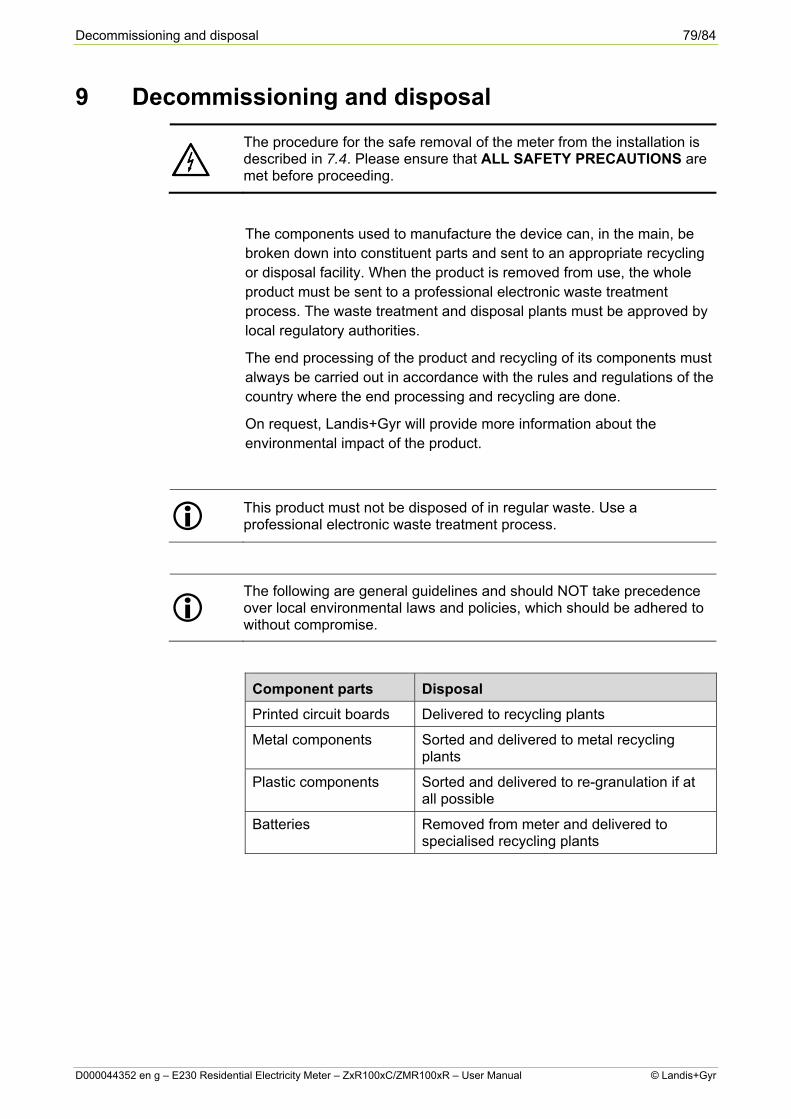
Decommissioning and disposal 79/84
D000044352 en g – E230 Residential Electricity Meter – ZxR100xC/ZMR100xR – User Manual © Landis+Gyr
9 Decommissioning and disposal
The procedure for the safe removal of the meter from the installation is described in 7.4. Please ensure that ALL SAFETY PRECAUTIONS are met before proceeding.
The components used to manufacture the device can, in the main, be broken down into constituent parts and sent to an appropriate recycling or disposal facility. When the product is removed from use, the whole product must be sent to a professional electronic waste treatment process. The waste treatment and disposal plants must be approved by local regulatory authorities.
The end processing of the product and recycling of its components must always be carried out in accordance with the rules and regulations of the country where the end processing and recycling are done.
On request, Landis+Gyr will provide more information about the environmental impact of the product.
This product must not be disposed of in regular waste. Use a professional electronic waste treatment process.
The following are general guidelines and should NOT take precedence over local environmental laws and policies, which should be adhered to without compromise.
Component parts Disposal
Printed circuit boards Delivered to recycling plants
Metal components Sorted and delivered to metal recycling plants
Plastic components Sorted and delivered to re-granulation if at all possible
Batteries Removed from meter and delivered to specialised recycling plants

80/84 Terms and abbreviations
© Landis+Gyr D000044352 en g – E230 Residential Electricity Meter – ZxR100xC/ZMR100xR – User Manual
10 Terms and abbreviations
10.1 Acronyms
The following terms and abbreviations are used in this document.
Term Description
BS British Standard
DFS Direct Field Sensor
DIN Deutsches Institut für Normung (German Institute for Standardisation)
ECD External Connection Diagram
EEPROM Electrically Erasable Programmable Read Only Memory (E2)
IEC International Electrotechnical Commission
ISO International Standards Organisation
LCD Liquid Crystal Display
LED Light Emitting Diode
MD Maximum Demand
MID Metering Industry Directive
NPR No Power Read
OFGEM The Office of Gas and Electricity Markets
PTR Photo-transistor
RED Reverse Energy Detected

Terms and abbreviations 81/84
D000044352 en g – E230 Residential Electricity Meter – ZxR100xC/ZMR100xR – User Manual © Landis+Gyr
10.2 Units
Unit Description
A Ampere (unit of current)
Hz Hertz (unit of frequency)
Iref MID reference current
Kg Kilogramme (unit of weight)
kVAh Kilo Volt Ampere hour
kVArh kilo Volt Amps reactive hour
kWh kilo Watt-hour
mm millimetre (unit of distance)
mΩ milliohm (unit of resistance)
ms millisecond
Nm Newton meter (unit of torque)
°C Degree Celsius (unit of temperature)
UN Rated supply voltage of meter
UT Rated external switch voltage
V Volt

82/84 Terms and abbreviations
© Landis+Gyr D000044352 en g – E230 Residential Electricity Meter – ZxR100xC/ZMR100xR – User Manual
10.3 Standards
Standard Brief definition
BS 1361 Specification for fuse links
DIN 43857 Specification for meter design details (dimensions, etc.)
IEC 1107 Optical Interface standard, now known as IEC 62056-21:2002
IEC 61000-4-2 Electrostatic discharge immunity tests
IEC 61000-4-3 Radiated, radio-frequency, electromagnetic field immunity test
IEC 61000-4-4 Electrical fast transient/burst immunity test
IEC 61107 / DIN 66258
See IEC 1107
IEC 947-1 Standard for low voltage switchgear and control gear
IEC 947-3 Standard for low voltage switchgear and control gear
IEC/CISPR 22 Radio interference suppression limits
ISO 14001 Environmental Management Standard
MID Measuring Instruments Directive, directive 2004/22/EC of the European Parliament and of The Council
IEC 62052-11 Electricity metering equipment (a.c.) - General requirements, tests and test conditions - Part 11: Metering equipment
IEC 62053-21 Electricity metering equipment (a.c.) - Particular requirements - Part 21: Static meters for active energy (classes 1 and 2)
IEC 62053-23 Electricity metering equipment (a.c.) - Particular requirements - Part 23: Static meters for reactive energy (classes 2 and 3)
IEC 62053-31 Electricity metering equipment (a.c.) - Particular requirements - Part 31: Pulse output devices for electromechanical and electronic meters (two wires only)
EN 50470-1 Electricity metering equipment (a.c.). General requirements, tests and test conditions. Metering equipment (class indexes A, B and C)
EN 50470-3 Electricity metering equipment (a.c.). Particular requirements. Static meters for active energy (class indexes A, B and C)

Terms and abbreviations 83/84
D000044352 en g – E230 Residential Electricity Meter – ZxR100xC/ZMR100xR – User Manual © Landis+Gyr

Contact:
Landis+Gyr AG
Theilerstrasse 1
CH-6301 Zug
Switzerland
Phone: +41 41 935 6000
www.landisgyr.com