d1.2: 5g-transformer initial system...
TRANSCRIPT

H2020 5G-TRANSFORMER Project
Grant No. 761536
5G-TRANSFORMER Initial System Design
Abstract
This deliverable reports the set of defined vertical service use cases and their
requirements on the architecture. The main content of this deliverable is a detailed
description of the initial system design of the 5G-TRANSFORMER architecture,
including the design of the main building blocks and the interfaces among them, as well
as the interface towards the verticals. Additionally, it defines the high level workflows
among the building blocks for a set of basic service operations, showing the required
interactions among the different builliding blocks on the related interfaces.

5G-TRANSFORMER Initial System Design 2
H2020-761536
Document properties
Document number D1.2
Document title 5G-TRANSFORMER initial system design
Document responsible Xi Li (NEC) Document editor Xi Li (NEC)
Editorial team Xi Li (NEC), Josep Mangues (CTTC), Thomas Deiß (NOK-N), Juan Brenes Baranzano (ATOS), Barbara Martini (SSSA), Kiril Antevski (UC3M), Giuseppe Imbarlina (TEI)
Target dissemination level Public
Status of the document Final
Version 1.0
Production properties
Reviewers Giada Landi (NXW), Carlos J. Bernardos (UC3M), Thomas Deiß (NOK-N), Philippe Bertin (Orange), Céline Merlet (BCOM), Kiril Antevski (UC3M), Xi Li (NEC), Giuseppe Imbarlina (TEI), Iñaki Pascual (CTTC), Juan Brenes Baranzano (ATOS), Nicolas Angel Serrano Linares (TID)
Disclaimer
This document has been produced in the context of the 5G-TRANSFORMER Project.
The research leading to these results has received funding from the European
Community's H2020 Programme under grant agreement Nº H2020-761536.
All information in this document is provided “as is" and no guarantee or warranty is
given that the information is fit for any particular purpose. The user thereof uses the
information at its sole risk and liability.
For the avoidance of all doubts, the European Commission has no liability in respect of
this document, which is merely representing the authors view.
5G-TRANSFORMER Initial System Design 3
H2020-761536
Table of Contents List of Contributors ........................................................................................................ 6
List of Figures ............................................................................................................... 7
List of Tables ................................................................................................................ 9
List of Acronyms ......................................................................................................... 10
Executive Summary and Key Contributions ................................................................ 13
1 Introduction .......................................................................................................... 16
2 5G-TRANSFORMER Overview ........................................................................... 18
2.1 5G-TRANSFORMER Stakeholders .............................................................. 18
2.2 5G-TRANSFOMER Services ........................................................................ 19
2.3 Vertical Services ........................................................................................... 20
2.3.1 Automotive ............................................................................................ 20
2.3.2 Entertainment ........................................................................................ 22
2.3.3 eHealth .................................................................................................. 23
2.3.4 eIndustry ................................................................................................ 24
2.3.5 MNO/MVNO .......................................................................................... 26
3 5G-TRANSFORMER Architecture Requirements ................................................ 28
3.1 Business Requirements ................................................................................ 28
3.2 Functional Requirements .............................................................................. 30
3.2.1 Discovery ............................................................................................... 30
3.2.2 Fulfillment .............................................................................................. 31
3.2.3 Assurance ............................................................................................. 32
3.2.4 Decommisioning .................................................................................... 33
4 5G-TRANSFORMER System Architecture ........................................................... 34
4.1 Baseline architecture design ......................................................................... 34
4.1.1 Vertical Slicer (5GT-VS) ........................................................................ 35
4.1.2 Service Orchestrator (5GT-SO) ............................................................. 36
4.1.3 Mobile Transport and Computing Platform (5GT-MTP) .......................... 37
4.1.4 Monitoring Architecture .......................................................................... 38
4.1.5 Interfaces and reference points .............................................................. 39
4.1.6 Services mapping to network slices and NFV network services ............. 46
4.1.7 Network slice and network slice management ....................................... 48
4.1.8 Federation across multiple administrative domains ................................ 49
4.1.9 Integration of MEC ................................................................................. 52

5G-TRANSFORMER Initial System Design 4
H2020-761536
4.2 Architecture challenges for service orchestration over multi-technology
domains .................................................................................................................. 58
4.2.1 End-to-End infrastructure graph ............................................................. 59
4.2.2 E2E path calculation and resource allocation ......................................... 60
4.2.3 Network to Network Interface (NNI) specification ................................... 61
5 Vertical Slicer Design ........................................................................................... 64
5.1 Vertical Slicer Overview ................................................................................ 64
5.2 The VSD/NSD Translator Module ................................................................. 66
5.3 The Arbitrator Module ................................................................................... 66
5.3.1 Sharing of network slices among vertical services ................................. 67
5.3.2 Computation of deployment flavors ........................................................ 68
5.4 The Monitoring Service ................................................................................. 69
5.5 VSI/NSI Coordinator & LC Manager .............................................................. 69
5.5.1 VSI Group Coordinator .......................................................................... 70
5.5.2 VSI LC Manager .................................................................................... 70
5.5.3 NSMF and NSSMF ................................................................................ 70
6 Service Orchestrator Design ................................................................................ 72
6.1 Key functionalities of 5GT-SO ....................................................................... 72
6.2 5GT-SO architecture ..................................................................................... 73
6.3 Service Orchestration and Federation ........................................................... 75
6.3.1 Service Orchestration ............................................................................ 76
6.3.2 Federation ............................................................................................. 79
7 Mobile Transport and Computing Platform Design ............................................... 81
7.1 Key functionalities of 5GT-MTP .................................................................... 81
7.2 5GT-MTP architecture .................................................................................. 82
7.3 MTP Abstraction ........................................................................................... 84
8 Common Workflows ............................................................................................. 89
8.1 NFV Network Service Service On-boarding .................................................. 89
8.2 Vertical Service Instantiation ......................................................................... 91
8.3 Vertical Service Termination ......................................................................... 94
9 Conclusions ......................................................................................................... 96
10 References ....................................................................................................... 97
11 Annex I: Notation for Requirements ................................................................ 100
12 Annex II: Glossary .......................................................................................... 101
12.1 General Terms ............................................................................................ 101
12.2 Network function virtualization related......................................................... 101

5G-TRANSFORMER Initial System Design 5
H2020-761536
12.3 Network slice related .................................................................................. 103
12.4 Vertical service related ............................................................................... 104
12.5 Multi-access edge computing related .......................................................... 105
12.6 Business logic/stakeholder related .............................................................. 105
12.7 5G-TRANSFORMER specific terms ............................................................ 107
13 Annex III: Reference open-source and industry-driven projects ...................... 109
13.1 State of the Art Solutions for 5GT-VS.......................................................... 109
13.1.1 ETSI Network Service Descriptor (NSD) .............................................. 109
13.1.2 TOSCA Network Function Virtualization (NFV) .................................... 109
13.1.3 Descriptors in H2020 SONATA project ................................................ 110
13.2 State of the Art Solutions for 5GT-SO ......................................................... 110
13.3 State of the Art Solutions for 5GT-MTP ....................................................... 110
14 Annex IV: Vertical Service Modification and Monitoring Workflows ................. 111
14.1 Vertical Service Modification ....................................................................... 111
14.2 Vertical Service Monitoring ......................................................................... 113
15 Annex V: Composed Services ........................................................................ 120
15.1 Vertical Service Blueprints for Composed Services .................................... 120
15.2 Vertical Service Descriptors for Composed Services .................................. 124
15.3 Translation of Composed Services ............................................................. 125
15.4 Instantiation of Composed Services ............................................................ 126
15.4.1 Single Slice, Same Lifecycle ................................................................ 126
15.4.2 Multiple Slice, Different Lifecycle ......................................................... 128
15.5 5GT-SO support for Composed Services .................................................... 129
15.5.1 Application-level Service Registry ........................................................ 129
15.5.2 Connecting Network Slices .................................................................. 129
16 Annex VI: See-Through for Safety .................................................................. 130
16.1 UC Diagram ................................................................................................ 131
16.2 Sequence Diagram ..................................................................................... 132
16.3 Logical Architecture .................................................................................... 132
16.4 Detailed Requirements ............................................................................... 133
17 Annex VII: Federation across 5G-TRANSFORMER systems ......................... 137
17.1 Resource Federation (NFVI-aaS) ............................................................... 137
17.1.1 MLPOC: Multiple Logical Point of Contact ........................................... 137
17.1.2 SLPOC: Single Logical Point of Contact .............................................. 139
17.2 Service Federation (NSaaS) ....................................................................... 142
5G-TRANSFORMER Initial System Design 6
H2020-761536
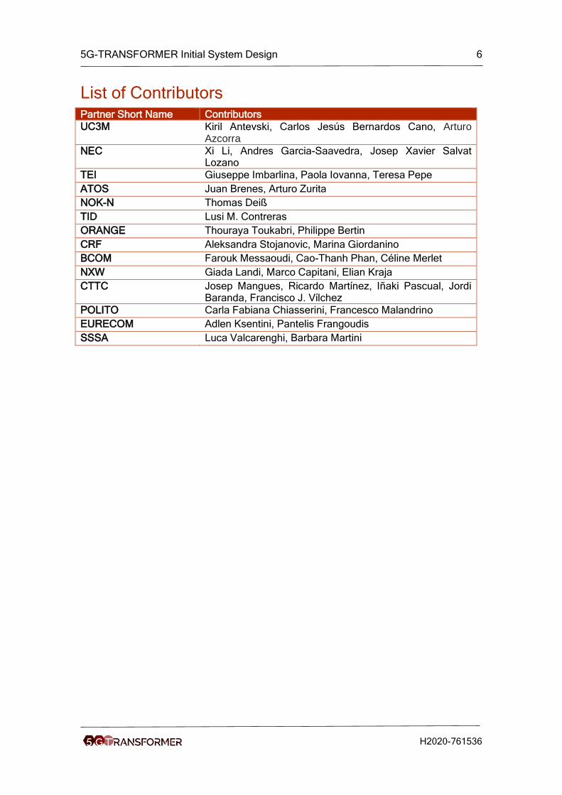
List of Contributors Partner Short Name Contributors
UC3M Kiril Antevski, Carlos Jesús Bernardos Cano, Arturo Azcorra
NEC Xi Li, Andres Garcia-Saavedra, Josep Xavier Salvat Lozano
TEI Giuseppe Imbarlina, Paola Iovanna, Teresa Pepe
ATOS Juan Brenes, Arturo Zurita
NOK-N Thomas Deiß
TID Lusi M. Contreras
ORANGE Thouraya Toukabri, Philippe Bertin
CRF Aleksandra Stojanovic, Marina Giordanino
BCOM Farouk Messaoudi, Cao-Thanh Phan, Céline Merlet
NXW Giada Landi, Marco Capitani, Elian Kraja
CTTC Josep Mangues, Ricardo Martínez, Iñaki Pascual, Jordi Baranda, Francisco J. Vílchez
POLITO Carla Fabiana Chiasserini, Francesco Malandrino
EURECOM Adlen Ksentini, Pantelis Frangoudis
SSSA Luca Valcarenghi, Barbara Martini

5G-TRANSFORMER Initial System Design 7
H2020-761536
List of Figures Figure 1: 5G-TRANSFORMER stakeholders mapping with the system architecture ... 18
Figure 2: 5G-Transformer system architecture ............................................................ 35
Figure 3: Hierarchy of monitoring services in 5G-TRANSFORMER architecture ......... 39
Figure 4: Reference points on the northbound of the 5GT-VS ..................................... 40
Figure 5: Reference points between 5GT-VS and 5GT-SO ......................................... 41
Figure 6: Reference points for 5GT-SO SBI (i.e., So-Mtp Interface) ............................ 43
Figure 7: Reference points for 5GT-SO E/WBI (i.e.,So-So Interface) .......................... 44
Figure 8: From Vertical Service to Network Slice to NFV Network Service .................. 47
Figure 9: Examples of Service Mapping ...................................................................... 48
Figure 10: Federation as a domain unified by mutual trust .......................................... 49
Figure 11: Federation with non-5GT administrative domain (5G-TRANSFORMER AD
as consumer) .............................................................................................................. 51
Figure 12: Federation with non-5GT administrative domain (5G-TRANSFORMER AD
as provider) ................................................................................................................. 52
Figure 13: MEC in NFV ............................................................................................... 53
Figure 14: Integration of AppD into a NSD .................................................................. 54
Figure 15: Integration of AppD into a NSD .................................................................. 55
Figure 16: Deployment of Scenario 1 .......................................................................... 56
Figure 17: Deployment of Scenario 2 .......................................................................... 56
Figure 18: Workflow of deploying an instance of a NSD including an AppD ................ 57
Figure 19: Multi Domain use case presentation........................................................... 59
Figure 20: End to end infrastructure graph .................................................................. 60
Figure 21: Presentation of the technology domain connectivity ................................... 61
Figure 22: Network to Network infrastructure specification .......................................... 62
Figure 23: The Vertical Slicer architecture .................................................................. 65
Figure 24: The 5GT-SO architecture .......................................................................... 73
Figure 25: Example of Virtual Infrastracture Graph ..................................................... 76
Figure 26: Decoupled VNF placement heuristic .......................................................... 78
Figure 27: Slpoc Function ........................................................................................... 81
Figure 28: 5GT-MTP ARCHITECTURE ...................................................................... 83
Figure 29: 5GT-SO view for abstraction alternative 1 .................................................. 85
Figure 30: 5GT-SO view for abstraction alternative 2 .................................................. 85
Figure 31: 5GT-SO view for abstraction alternative 3 .................................................. 86
Figure 32: YANG tree representation of logical links ................................................... 87
Figure 33: YANG tree representation of computational resources ............................... 87
Figure 34: YANG tree representation of storage resources ......................................... 88
Figure 35: Service on-boarding workflow .................................................................... 91
Figure 36: Vertical service instantiation workflow ........................................................ 93
Figure 37: Vertical Service Termination Workflow ....................................................... 94
Figure 38: Vertical service modification workflow ...................................................... 112
Figure 39: Vertical service monitoring workflow by 5GT-SO (1) ................................ 115
Figure 40: Vertical service monitoring workflow by 5GT-SO (2) ................................ 116
Figure 41: Vertical service monitoring workflow by 5GT-MTP (1) .............................. 118
Figure 42: Vertical service monitoring workflow by 5GT-MTP (2) .............................. 119
Figure 43: Example of composed vertical service ..................................................... 120
Figure 44: Workflow service instantiation of composed service, part 1 ...................... 127
5G-TRANSFORMER Initial System Design 8
H2020-761536
Figure 45: Workflow service instantiation of composed service, part 2 ...................... 128
Figure 46: See-Through Overview ............................................................................ 130
Figure 47: See-Through UC Diagram ........................................................................ 131
Figure 48: See-Trough Sequence Diagram ............................................................... 132
Figure 49: Vehicle Equipment ................................................................................... 132
Figure 50: NFVIaaS Federation (MLPOC)................................................................. 138
Figure 51: NFVIaaS Federation (SLPOC) ................................................................. 140
Figure 52: NSaaS Use Case ..................................................................................... 142
5G-TRANSFORMER Initial System Design 9
H2020-761536
List of Tables Table 1: Automotive Use Cases .................................................................................. 21
Table 2: Entertainment Use Cases ............................................................................. 23
Table 3: eHealth Use Cases ....................................................................................... 24
Table 4: eIndustry Use Cases ..................................................................................... 25
Table 5: MNO/MVNO Use Cases ................................................................................ 26
Table 6: Business requirements .................................................................................. 28
Table 7: Requirements on the discovery phase........................................................... 30
Table 8: Requirements on the fulfillment phase .......................................................... 31
Table 9: Requirements on the assurance phase ......................................................... 32
Table 10: Requirements on the decommissioning phase ............................................ 33
Table 11: Query VS blueprints messages ................................................................... 41
Table 12: Assumed Logical Link Parameters To Be Exchanged with The 5GT-SO ..... 86
Table 13: Information Modelling To Define A Computational Resource ....................... 86
Table 14: Information Modelling To Define A Storage Resource ................................. 87
Table 15: VSB of vertical service A ........................................................................... 122
Table 16: VSB of vertical service B ........................................................................... 123
Table 17: VSB of vertical service C ........................................................................... 123
Table 18: VSD for vertical service A1 ........................................................................ 125
Table 19: Description of CT Use Case ...................................................................... 130
Table 20: Detailed UC Requirements for Automotive ................................................ 133
Table 21: Detailed UC Requirements for Automotive the CT use case ...................... 134
Table 22: NFVIaaS architecture with (Direct versus Indirect) VNF management for
MLPOC access ......................................................................................................... 138
Table 23: NFVIaaS architecture with (direct versus indirect) VNF management for
SLPOC access ......................................................................................................... 140

5G-TRANSFORMER Initial System Design 10
H2020-761536
List of Acronyms Acronym Description
5GT-MTP Mobile Transport and Computing Platform
5GT-SO Service Orchestrator 5GT-VS Vertical Slicer
ABNO Applications-Based Network Operations
AD Administrative Domain
AM Abstraction Manager
API Application Programming Interface
AppD Application Descriptor
AS/PCE Active Stateful Path Computation Element
BSS Business Support System
CIM Cooperative Information Manager
CN Core Network
COP Control Orchestration Protocol
CQI Channel Quality Indicator CSAR Cloud Service Archive
CSMF Communication Service Management Function
DCSP Data Centre Service Provider
EM Element Manager
E/WBI Eastbound/Westbound Interface
E2E End-to-end
GMPLS Generalized Multi-Protocol Label Switching
GTP GPRS Tunneling Protocol
HMI Human Machine Interface
HSS Home Subscriber Server
HTTP HyperText Transfer Protocol
IM Information Model JSON JavaScript Object Notation
LCM LifeCycle Management
MANO Management and Orchestration
MEA Multi-access edge application
MEAO Multi-access edge application orchestrator
MEC Multi-access edge computing
MEO Multi-access edge orchestrator
MEP Multi-access edge platform
MEPM Multi-access edge platform manager
MEPM-V Multi-access edge platform manager - NFV
MES Multi-access edge service
MLPOC Multiple Logical Point of Contact
MME Mobility Management Element MVNO Mobile Virtual Network Operator
NBI Northbound Interface
NBI Northbound Interface
NF Network Function
NF FG NF Forwarding Graph
NFP Network Forwarding Path
NFV Network Function Virtualization
NFVIaaS NFVI as a Service
NFV-NS Network Service

5G-TRANSFORMER Initial System Design 11
H2020-761536
NFV-NSI Network Service Instance
NFV-NSO Network Service Orchestrator
NFVI Network functions virtualisation infrastructure
NFVIaaS NFVI as a Service
NFVO NFV Orchestrator
NFVO-RO Resource Orchestrator NNI Network to Network Interface
NS Network Slice
NSaaS Network Slice as a Service
NSD Network Service Descriptor
NSD Network Service Descriptor
NSI Network Slice Instance
NSMF Network Slice Management Function
NSSI Network Slice Subnet Instance
NSSMF Network Slice Subnet Management Function
NST Network Slice Template
OEM Original Equipment Manufacturer
OF OpenFlow OSS Operating Support System
PA Physical Application
PGW-C Packet Gateway Control Plan
PGW-U Packet Gateway User Plan
PNF Physical Network Function
PNFD Physical Network Function Descriptor
QoS Quality of Service
RAN Radio Access Network
REST Representational State Transfer
RMA Resource Management Application
RNIS Radio Network Information
SBI Southbound Interface SBI Southbound Interface
SDK Software Development Kit
SDN Software-Defined Networking
SGW-C Serving Gateway Control Plan
SGW-U Serving Gateway User Plan
SLA Service Level Agreement
SLO Service Level Objective
SLPOC Single Logical Point of Contact
TMOP 5G-TRANSFORMER Mobile Transport and Computing Platform Operator
TMVS 5G-TRANSFORMER Managed Vertical Service
TOSCA Topology and Orchestration Specification for Cloud Applications
TOR Top of the Rack
TS 5G-TRANSFORMER Service
TSC 5G-TRANSFORMER Service consumer
TSP 5G-TRANSFORMER Service Provider
TUVS 5G-TRANSFORMER Unmanaged Vertical Service
VA Virtual Application
VA FG VA Forwarding Graph
VIM Virtual Infrastructure Manager
5G-TRANSFORMER Initial System Design 12
H2020-761536
VISP Virtualization Infrastructure Service Provider
VL Virtual Link
VNF Virtualised Network Function
VNF FG VNF Forwarding Graph
VNFC Virtualised Network Function Component
VNFD Virtualised Network Function Descriptor VNFM Virtual Network Functions Manager
VS Vertical Service
VSaaS Vertical Service as a Service
VSB Vertical Service Blueprint
VSD Vertical Service Descriptor
VSI Vertical Service Instance
VXLAN Virtual Extensible LAN
WAN Wide Area Network
WIM Wide area network Infrastructure Manager
XCI 5G-Crosshaul Control Infrastructure
XFE 5G-Crosshaul Forwarding Element
YAML YAML Ain't Markup Language YANG Yet Another Next Generation
5G-TRANSFORMER Initial System Design 13
H2020-761536
Executive Summary and Key Contributions This deliverable dives into the initial system design of the 5G-TRANSFORMER system.
The scope of the 5G-TRANSFORMER project is to simultaneously support the needs
of various vertical industries hence enriching the telecom network ecosystem. A wide
range of vertical industries, such as eHealth, automotive, media, or cloud robotics, act
as drivers to construct this ecosystem. The support of the diverse service requirements
of different vertical industries is not only a question of providing broadband capacity,
but also a matter of “ultra-reliable low-latency communications” and “massive density
connections”. The key architectural concept we take to support the needs of vertical
industries with diverse range of networking and computing requirements is network
slicing, to provide slices tailored to the needs of different vertical industries and allow
per-slice management of virtualized resources.
5G-TRANSFORMER architecture defines three novel building blocks, namely:
• The Vertical Slicer (5GT-VS), as the common entry point for all verticals into the
system. It dynamically creates and maps the vertical services onto network
slices according to their requirements, and manages their lifecycle.
• The Service Orchestrator (5GT-SO) offers service or resource orchestration and
federation of transport, networking and computing resources from one or
multiple administrative domains.
• The Mobile Transport and Computing Platform (5GT-MTP), as the underlying
unified transport stratum for integrated fronthaul and backhaul networks. It is
responsible for providing the virtual resources including their instantiation over
the underlying physical transport network, computing and storage infrastructure.
It also provides the abstraction of virtual resources offered to the 5GT-SO.
Our architecture approach is twofold: (i) it enables vertical industries to meet their
service requirements within customized slices; and (ii) it aggregates and federates
transport networking and computing fabric, from the edge up to the core and cloud, to
create and manage slices throughout a federated virtualized infrastructure.
The main contribution in this deliverable is the presentation of our initial system
architecture design, with the definition of the three main building blocks mentioned
above and the specification of the interfaces among them as well as the interfaces
towards the verticals and towards other administrative domains in support of federation.
The system design have been driven by the final set of vertical service use cases
selected as target for the implementation in the project and their functional and
business requirements on the architecture, which are presented at the beginning of the
document to provide the whole context of the 5G-TRANSFORMER ecosystem. The
system arechitecture deisgn is also complemented by a summary of each building
block on their key functionalities and the internal architecture design, based on D2.1[2]
(5GT-MTP)[2], D3.1[3] (5GT-VS) and D4.1[4] (5GT-SO). It shows that the internal
design of the building blocks and their functional roles are exactly according to the
initial system architecture design. Such summary helps to present a complete view of
the whole 5G-TRANSFORMER architecture design and provides a better
understanding of the key architecture components. Finally, the document presents the
high-level workflows among the architectural building blocks for a set of basic service
operations.

5G-TRANSFORMER Initial System Design 14
H2020-761536
In more details, the main contributions in this deliverable are the following:
• 5G-TRANSFORMER business ecosystem, its stakeholders model and the
offered services (Section 2), inspired by the definitions provided by 3GPP and
NGMN. In particular, we identify the different 5G-TRANSFORMER
stakeholders, the basic relationships established among them and the services
offered or consumed by each of them.
• Selection of the final set of vertical services and use cases to be implemented in
the project, motivating these selection choices (Section 2).
• The requirements (Section 3) on the 5G-TRANSFORMER architecture, which
are split into two major groups related to business and functional requirements.
The functional requirements are grouped along the different phases of a vertical
service instance: discovery, fulfillment, assurance, and decommissioning.
• The 5G-TRANSFORMER baseline architecture design (Section 4), with the
three main functional blocks of our system (i.e., 5GT-VS, 5GT-SO and 5GT-
MTP) and the interfaces among them. The network slicing concept is
introducted, and we explain how to map vertical services to network slices and
how to manage them. We also provide a detailed discussion on the different
architecture options for federation and Multi-access Edge Computing (MEC)
integration. A glossary on the relevant terminology is also provided in Annex II
in Section 12. In addition to the baseline architecture design, we also discuss
the architecture challenges for service deployment in environments composed
of multiple technology domains.
• Summary of the internal architecture design of the 5GT-VS (Section 6) based
on D3.1 [3], defining the components to manage vertical services and network
slices and the corresponding catalogues. Two key components of the 5GT-VS
are 1) the service translator component, which takes a vertical service
descriptor and maps it to a network service descriptor, and 2) the arbitrator
component, which ensures that resources assigned to a vertical are made
available to high-priority vertical services.
• Summary of the internal architecture design of the 5GT-SO (Section 7) based
on D4.1 [4]. The design includes the different functional blocks comprising the
service orchestrator, the northbound interface towards the 5GT-VS, the
southbound interface towards the 5GT-MTP, and the eastbound/westbound
interface towards federated 5GT-SOs.
• Summary of the internal architecture design of the 5GT-MTP (Section 8) based
on D2.1 [2]. The design includes Physical Network Functions (PNFs), Virtual
Network Functions (VNFs), Virtual Infrastructure Manager (VIM), Wide area
network Infrastructure Manager (WIM), and 5GT-MTP Single Logical Point of
Contact for resource orchestration (5GT-MTP NFVO-RO SLPOC).
• The workflows among a vertical and the three main components of the system
(Section 5), indicating the ordered sequence of information and messages
passed among the architectural components. Here we focus – among others –
on the most important workflows. For a simple, non-nested vertical service, we
present the workflows for on-boarding, instantiating, and terminating it. We
describe as well its modification and monitoring while being in operation status.
Moreover, we also describe the workflow for instantiating a composite vertical
service, embedding multiple nested services.

5G-TRANSFORMER Initial System Design 15
H2020-761536
• Dissemination of the 5G-TRANSFORMER architecture design and steering
related standardization activities (activities collected by WP6), are of paramount
interest of the project and has resulted in a number of contributions to academic
journals and conferences [32][33][34][35] and standardization bodies
[59][60][61][62]. The initial system architecture design has been also presented
to the 5GPP Architecture WG in May, 2018.
5G-TRANSFORMER Initial System Design 16
H2020-761536
1 Introduction 5G-TRANSFORMER is designing a flexible SDN/NFV-based platform to support next-
generation mobile transport networks and novel vertical-oriented use cases. Namely,
eHealth, automotive, media or cloud robotics use cases drive the design of 5G-
TRANSFORMER’s architecture to provision such heterogeneous service requirements.
Consequently, 5G-TRANSFORMER defines three main functional blocks: Vertical
Slicer (5GT-VS), Service Orchestrator (5GT-SO) and Mobile Transport and Computing
Platform (5GT-MTP).
The Vertical Slicer (5GT-VS) is the entry point for vertical industries, which are the
consumer of 5G-TRANSFORMER services. The main goal of 5GT-VS is three-fold.
First, to provide an interface that let vertical players compose (exploiting an exposed
catalogue of blueprints), instantiate, update, terminate and monitor their vertical service
instances (VSI). The second main goal is to arbitrate resources among contending
VSIs in case of resource shortage. Finally, the last main goal is to create and manage
network slices (NS). An NS is modeled as an extended ETSI NFV Network Service
(NFV-NS) and described by extended ETSI NFV Network Service Descriptors (NSD),
which 5GT-SO can orchestrate when requested by 5GT-VS.
The Service Orchestrator (5GT-SO) is responsible for the management and
orchestration of NFV-NSs. In this quest, the 5GT-SO can exploit resources from local
domains or federate resources or services from domains that belong to different
administrations. In short, the 5GT-SO main function is to process NFV-NS orchestration
requests from 5GT-VS via (i) service orchestration (NFV-NSO), and ultimately (ii)
resource orchestration (NFVO-RO). The former function, NFVO-NSO, shall manage the
deployment of NFV-NSs requested by the 5GT-VS (also possibly across different
domains), including their lifecycle management (on-boarding, instantiation, scaling,
termination) and the management of the VNF forwarding graphs associated to the
network service. The latter, NFVO-RO, is in charge of aggregating resources spanning
multiple domains, multiple technologies and/or multiple administrations (via federation).
Clearly, both NFVO-NSO and NFVO-RO coordinate to provision sufficient resources to
each deployed VNF and (virtual) links.
The Mobile Transport and Computing Platform (5GT-MTP) of 5G-TRANSFORMER has
the goal of replacing traditional rigid “one-size-fits-all” deployments with a customizable
SDN/NFV-based transport and computing platform capable of simultaneously
supporting a diverse range of networking and computing requirements specific to the
vertical industries. The 5GT-MTP hosts the physical and/or virtual mobile transport
network and computing infrastructure within which vertical services are deployed.
This deliverable introduces the up-to-date design of the 5G-TRANSFORMER
architecture. An overall description of the stakeholders and (vertical) services
supported by 5G-TRANSFORMER is presented in Section 2. Section 3 analyizes the
business and functional requirements that services and stakeholders impose onto the
design of the platform’s architecture. As a result of this analysis, Section 4 depicts the
baseline architecture, including not only the main functional blocks aforementioned, but
also the interfaces and reference points among them and particular guidelides to map
services into network slices and NFV network services, their management, how to
achieve federation and how to integrate with MEC platforms. Sections 5, 6 and 7
provide the most important insights from the design of 5GT-VS, 5GT-SO and 5GT-

5G-TRANSFORMER Initial System Design 17
H2020-761536
MTP, summarizing the key functionalities and results presented in D3.1[3], D4.1[4] and
D2.1[2], respectively. The summary shows that the design of the three building blocks
and their functional roles are exactly aligned with the proposed high level system
architecture design. Moreover, the summary of designed components complements the
system architecture design providing a complete view of the whole 5G-
TRANSFORMER architecture and thereby offers a better understanding for the
architecture components. In order to illustrate our design, Section 8 depicts a set of
example workflows that are common to all of the services and provides details on the
different interactions between the 5G-TRANSFORMER functional blocks and their
internal operations. Finally, Section 9 includes some concluding remarks.
For the reader’s interest, we have included additional details in annexed sections,
omitted from the main body in an effort to maximize the readability of the document.
Namely, Annex I introduces the notation employed to describe the system
requirements; Annex II presents a glossary of terms and concepts used all throughout
the document (and the project); Annex III lists a series of open-source and industry-
driven projects related to 5G-TRANSFORMER; Annex IV presents additional workflows
specific to service monitoring and modification operations; Annex V discusses how
composed vertical services can be handled within the 5G-TRANSFORMER system
architecture; Annex VI presents an additional vehicular use case, namely see-through
for vehicular safety; and finally, Annex VII summarizes how federation is addressed in
5GT-SO.
As a final comment on notation, sometimes we refer to the project as 5G-T instead of
using its full acronym 5G-TRANSFORMER. In general, the former notation is used to
shorten references to entities or building blocks throughout the text (e.g., 5G-T Service
Provider instead of 5G-TRANSFORMER Service Provider).

5G-TRANSFORMER Initial System Design 18
H2020-761536
2 5G-TRANSFORMER Overview This section presents the high-level overview of 5G-TRANSFORMER scope, including
the stakeholders and the services offered by the system. Finally the selected vertical
services and use cases to be implemented in the project are presented.
2.1 5G-TRANSFORMER Stakeholders
An initial analysis of the 5G-TRANSFORMER business ecosystem has been presented
in [1]. Based on the definitions provided by 3GPP [6] and NGMN ([48],[49],[50]), this
analysis identifies the different stakeholders and the basic relationships established
among them in the next generation of network services. After the gap analysis
presented in [1], 5G-TRANSFORMER business ecosystem and stakeholders modelling
is closer to the treatment provided by NGMN because of its support of a multi-domain
scenario and its more flexible approach to reflect the various possible customer-
provider relationships between verticals and operators. Based on these considerations,
Figure 1 presents the different stakeholders defined in 5G-TRANSFORMER and their
relationship with the system architecture, which will be further described in Section 4.
FIGURE 1: 5G-TRANSFORMER STAKEHOLDERS MAPPING WITH THE SYSTEM
ARCHITECTURE
The different stakeholders for the 5G- TRANSFORMER system are defined in a top-
down approach as follows:
• 5G-TRANSFORMER Service Consumer (TSC): uses 5G-TRANSFORMER
services (see Section 2.2 below for a definition) that are offered by a 5G-T Service
Provider. Note that a 5G-TRANSFORMER Service Provider can also be a TSC of
another service provider through federation. In the context of 5G-TRANSFORMER,
the main role considered as consumer of services is the vertical industry.
• 5G-TRANSFORMER Service Provider (TSP): provides 5G-TRANSFORMER
services (described in Section 2.2). Designs, builds and operates its 5G-T services.
• 5G-TRANSFORMER Mobile Transport and Computing Platform Operator (TMOP):
in charge of orchestrating resources, potentially from multiple virtual infrastructure
providers (VISP) and offered to the TSP. In that sense, it acts as an aggregator of

5G-TRANSFORMER Initial System Design 19
H2020-761536
resources. The virtual infrastructure features transport and computing resources,
potentially including those of datacentre service providers with which the TMOP has
an agreement. The TMOP designs, builds, and operates the computing and
network aggregated virtual infrastructure services and it has agreements 1 with
Virtualization Infrastructure Service Providers (VISPs) (see below for a definition).
• Virtualization Infrastructure Service Provider (VISP): Provides virtualized
infrastructure services and it designs, builds and operates its virtualization
infrastructure(s) [6] . A VISP can be further specialized depending on the kind of
infrastructure it manages: a VISP-T provides virtual transport infrastructures while a
VISP-C provides virtual computing infrastructures.
• Data Centre Service Provider (DCSP): Provides data centre services and it
designs, builds and operates its data centres [6] . The difference between DCSP
and VISP-C is that the former is closer to the raw resources (host servers) offering
simple services of raw resource consumption. Additionally, these resources are
located in a centralized location (datacentre). The latter offers access to a variety of
virtual infrastructure resources created by aggregating multiple technology domains
and by making them accessible through a single API for all of them. For instance,
VISP-C may offer not only centralized datacentre resources, but also distributed
computing resources available throughout the network.
2.2 5G-TRANSFOMER Services
From a business perspective, 5G-TRANSFORMER Services (TS) are services focused
on a specific industry or group of customers with specialized needs (e.g., automotive
services, entertainment services, e-health services, industry 4.0). From a technical
point of view, it is a composition of general functions, denoted as Virtual Applications
(VA), as well as network functions and defined by its functional and behavioural
specification. Hence, a TS provides more general functionalities than just network
functionalities.
TS are offered by a 5G-TRANSFORMER Service Provider (TSP) to 5G-
TRANSFORMER Service Consumers such as verticals through its northbound
interface or to other TSPs through the east-west interface (E/WBI). Such services can
include a bundle of the different types of services, as explained in the following.
If service requests come through the northbound interfaces requested by the verticals
or the Mobile Virtual Network Operators (MVNOs) (to ask for services such as the ones
described in Section 2.3), the following four types of TSs can be distinguished:
• 5G-TRANSFORMER Managed Vertical Service (TMVS): These vertical services
are fully deployed and managed by the TSP and consumed as such by the vertical
(i.e., without any interface available to modify the service logic, but only for getting
operational information, at most).
• 5G-TRANSFORMER Unmanaged Vertical Service (TUVS): Vertical services are
deployed by the TSP (i.e., VNFs and their connectivity), but their logic is partly or
fully managed by the vertical. This includes the configuration of VNF internals to
control the logic of the vertical services at service level, e.g., the algorithms for ICA
(Intersection Collision Avoidance) for the automotive use case. In this case, the
1 Initially, it is assumed that TMOPs and VISPs belong to the same administrative domain. This might be different in a general scenario

5G-TRANSFORMER Initial System Design 20
H2020-761536
lifecycle management of the NFV network service and its VNFs is still retained by
the TSP.
• Network Slice as a Service (NSaaS): to provide a network along with the services
that it may support. For instance, a TSP may provide a mIoT network slice as a
service, which may support several services, including sensor monitoring, collision
avoidance as well as traffic management, and warehouse automation. The TSC (i.e.
the NSaaS customer) can, in turn, play the role of a provider itself, and offer to its
own consumers its vertical services built on top of the services of the network slice
(B2B2X). Based on a mutual agreement, the relevant network slice characteristics
and some limited network slice management capability need to be exposed.
• NFVI as a Service (NFVIaaS): The tenant (e.g., a vertical or an MVNO) is offered a
virtual infrastructure including associated resources (networking/computing/storage)
under its full control, in which it can deploy and manage its own NFV network
services on top of it. It is assumed that the vertical will deploy its own MANO stack.
This is probably the most usual service consumed by M(V)NOs, since they have the
knowledge and the need to customize their communication service offering for their
own customers. Resources could be virtual cores, storage, virtual nodes and links,
etc.
o NOTE: The tenant can deploy and connect under its own control VMs on
these resources.
Additionally, TSPs can also consume TSs offered by peering TSPs. This interaction is
done through the east-west interface (E/WBI) of 5GT-SOs. There are two types of
service federation:
• 5G-TRANSFORMER Service federation (TSF): The consumer TSP uses NFV
network services offered by the peer TSP. This may be the case when an end-to-
end service is split into constituent services that are deployed in multiple TSP
administrative domains.
• 5G-TRANSFORMER Resource federation (TRF): The consumer TSP uses NFV
(abstracted) virtual network resources offered by the peer TSP. This may be the
case when an end-to-end NFVIaaS service is built by combining virtual resources
belonging to multiple TSP administrative domains.
2.3 Vertical Services
The 5G-TRANSFORMER consortium includes verticals from different industries. In this
section we summarize the use cases (UC) selected for demonstration within the project
and reasons behind this selection. They are mapped to the service types classified in
Section 2.2. Further details about all the use cases considered can be found in D1.1[1].
2.3.1 Automotive
The automotive industry is currently undergoing key technological transformations, as
more and more vehicles are connected to the Internet and to each other, and advances
towards higher automation levels. In order to deal with increasingly complex road
situations, automated vehicles will have to rely not only on their own sensors, but also
on those of other vehicles, and will need to cooperate with each other, rather than make
decisions on their own.

5G-TRANSFORMER Initial System Design 21
H2020-761536
These trends pose significant challenges to the underlying communication system, as
information must reach its destination reliably within an exceedingly short time frame –
beyond what current wireless technologies can provide. 5G, the next generation of
mobile communication technology, holds promise of improved performance in terms of
reduced latency, increased reliability and higher throughput under higher mobility and
connectivity density.
Vehicle domain features differ across the target operative scenarios, which are strongly
characterized by their own peculiarities. In order to better analyse the needs of the
automotive domain versus the incoming communication technology, we considered
four main scenarios (urban, rural, highway and transversal) and several use cases
quite different for their peculiar features outlining the key aspects that mostly impacts
on 5G.
Typical automotive UCs are various and can address heterogeneous domains. In
D1.1[1] more than 25 UCs from those most popular in the literature have been
described; the identified UCs are grouped in 6 domains: safety, mobility, entertainment,
e-road, digitalized vehicles and automated vehicle.
In the 5G-TRANSFORMER project, we focus on the safety domain where, thanks to 5G
capabilities, the vehicle can outline/foresee dangerous situations and properly react on
time. In particular, two use cases have been initially selected and proposed for
implementation:
TABLE 1: AUTOMOTIVE USE CASES
ID Name Goal in context General description
UC A.01, UC A.02
Intersection Collision Avoidance (ICA)
Avoid possible collision crossing intersection.
The purpose of the ICA system is to alert drivers about the existence of any possible obstacles and eventually activate the emergency braking system. The communication infrastructure facilitates a real-time exchange of data between the involved entities.
UC A.04 See-Trough Vehicles are able to see through obstacles, thanks to cooperation among them achieving bilateral awareness of road conditions.
Thanks to the cooperation between vehicles, streaming information is provided to all the vehicles that want/need to access to it. This information can be used to identify potential obstacles that cannot be detected through on-board sensors.
An initial analysis of the ICA is reported in the Section 5.1 of D1.1 [1] where a more
detailed description of the use case including goals, involved actors, flow, UML UC and

5G-TRANSFORMER Initial System Design 22
H2020-761536
sequence diagrams are provided. The analysis of the See-through UC is reported in
this document, in the Annex VI: See-Through for Safety in Section 16.
The two use cases have been analyzed providing a common draft architecture able to
cope both.
Afterward, although both use cases are of interest for FCA, since the architecture is
common to both use cases and thus it was decided to focus the Proof of Concept (PoC)
on the implementation of the ICA, as representative of the whole scenario.
The selection of this application for the reference PoC has been done considering:
• the potential benefit that the application could provide to the Road Safety;
• the Governments C-ITS application roadmaps;
• the maturity of the application from an implementation point of view;
• challenges for 5G-TRANSFORMER.
The crash avoidance effectiveness of the ICA has been evaluated, on average, in the
order of 50% [10]. This is indeed one of the main reasons why it is listed as prioritary
application of European and North America Market [11]. Moreover the See-Through
application appears to be less mature, due to the difficulty and complexity regarding the
effective video real-time proccessing. Finally the ICA has requirements particularly
challenging for the project, especially in terms of latency and MEC functionalities
required for realizing the deployment of the applications and the related components in
a cost-efficient way, satisfying the QoS requirements set by the vertical.
For the aforementioned reasons, the ICA application is the candidate application to
assess the 5G infrastructure and architecture provided within the project. According to
the TSs types, introduced in Section 2.2, ICA is classified as TUVS.
2.3.2 Entertainment
The Media and Entertainment (M&E) industry is one of the industries most affected by
the deep changes in terms of user habits and expectations that the society has been
experiencing with the explosion of Internet. The amount of users grows daily and the
users demand progressively media-rich contents and a better quality of experience,
imposing great challenges to the network infrastructures (in terms of data rates, number
of connections, quality of experience, etc.) not present before.
For the last years, the entertainment industry has been working on improving fan
engagement solutions on sport venues. In particular, the ability to setup smart venues
where ultra-high definition interactive media can be delivered massively to mobile
devices with minimum latency has been challenging because current wireless
communication technologies do not allow to cost-efficiently support a dense
concentration of connected devices with intensive data traffic consumption.
The planned demonstrations will focus on the On-site live experience (OLE) and Ultra-
high fidelity media use cases, which aim to provide an immersive experience together
with an ultra-high definition content. The selection of these two use cases is due to the
increasing demand from the customers for this kind of solutions. This makes them
particularly interesting for sport event organizers, since they provide promising
opportunities for new revenues. At the same time, these use cases are aligned to state
of the art expectations from sport fans regarding quality and features of interactive
media.

5G-TRANSFORMER Initial System Design 23
H2020-761536
From the technological perspective, the two use cases are also the most challenging
ones, presenting the higher impact over the project platform and over the services
themselves. First, because the goal of the demonstrations is to expand the network
slices to be as close as possible to the sport fans (i.e., using federation, expanding the
slice over multiple data centres, etc.) and integrate the services with the MEC. Second,
because the OLE UC requires a seamless composition of vertical services, and finally
because the services involved require to be scaled automatically and be capable of
serving a high amount of users. We refer to D1.1 [1] for further details about both UCs,
and to D5.1 [5] for further details abouth the demonstrations.
In terms of service classification UC.E01 and UCE02 are both classified as TUVS, as
established in Section 2.2, since the TSP in this case aims to keep certain control over
the service logic and rely on the platform for the service management.
TABLE 2: ENTERTAINMENT USE CASES
ID Name Goal in context General description
UC.E01 On-site live event experience (OLE)
To provide a better fan experience to users attending (on-site) an event
Large scale event sites, such as stadiums are more and more being connected in order to give better experience to their customers (replay, choose a specific camera, language, augmented reality to bring additional information, etc.)
UC.E02 Ultra-high fidelity media
To guarantee a high-quality of content experience for Ultra High Fidelity Media in both closed and open venues.
The next generation of media consumption will be driven by the high definition. Consumers (fans) will demand 4k and 8k quality in their media consumption through their user devices. Both linear (e.g. live programming, streaming) and non-linear (e.g. on-demand) content will be used for providing this Ultra High Fidelity Media experience.
2.3.3 eHealth
The eHealth use case is one of the most critical verticals we have in the 5G-
TRANSFORMER project. This industry can effectively take advantage of the future 5G
networks to improve the quality of life and medical assistance of people in emergency
situations. Hence, we consider two main targets: e-Infrastructure and eHealth
application. Both are considered as TUVS type of vertical services.
On one hand, the e-Infrastructure use case focuses on how the current municipality
infrastructure based on TETRA can be replaced exploiting the novel 5G features. This
will allow not only emergency alarms to be received in smaller delay and thus be
processed in a small amount of time, but also to access in real time the clinical history
of the patient from the place of the incident to give the patient a better medical
attention. In addition, the eHealth use case will need a high-priority and low latency

5G-TRANSFORMER Initial System Design 24
H2020-761536
service in the 5G-TRANSFORMER system. To address that, the 5G-TRANSFORMER
system will allow to have access to the resources of the emergency system in extreme
cases where the network is overloaded by users like in big events.
On the other hand, the eHealth application aims to study how new technologies such
as MEC can help improving the speed and the quality of response. This application
tries to reduce the response time and automate the processes of communicating
between the patient and the medical personnel and among the medical personnel.
TABLE 3: EHEALTH USE CASES
ID Name Goal in context General description
UC.H.01 Heart attack emergency
To provide a better medical assistance in emergency cases
Emergencies that requires real time communication between the ambulances and doctors. Improvement of the current infrastructure to guarantee the real time exchange of information to detect early the emergencies.
This use case has been selected as it poses the key challenges for eHealth and
provides inmmediate advantages from the use of 5G. It covers the main requirements
from the eHealth partner of the project, SAMUR, summarized next: (i) voice
communications substituting TETRA system, (ii) improved location of the ambulances,
and, (iii) ambulance activation and tracking system, capable of exchanging with the
ambulance service commands, patient's medical history, information about
recommended navigation routes , information about accident site, enviromental risks,
and receiving remote monitoring information from the ambulance activity (e.g., speed,
use of acoustic signals and priority warning lights, breakdowns).
2.3.4 eIndustry
The production and manufacturing industry is currently undergoing important changes
mainly driven by the ongoing introduction of new emerging technologies, including
mobile network, cloud computing, robotics, machine intelligence and big data.
Nowadays we are facing a new industrial revolution, commonly referred to as Industry
4.0, whose aim is to provide mass customization with costs comparable to those of
mass production. This can be achieved leveraging on full digitalization and automation
of industrial processes.
The major ingredient to ensure full digitalization and automation is the virtualization of
control, allowing to centralize all the intelligence of the operations in order to increase
flexibility and facilitate the changes of the manufacturing plants.
In such ever-changing environment, wired connectivity would mean complex cabling
and high operational expenditure for upgrading that cabling. Thus, a new wireless
connectivity that allows to reduce costs and infrastructures and meets the tight
requirements in terms of bandwidth and latency becomes fundamental. In particular,
5G wireless connectivity, with its standardized networking capabilities, built-in security,
guaranteed grades of service as well as network slicing concepts, is therefore a perfect
tool for advanced industries that want to take advantage of digital transformation.

5G-TRANSFORMER Initial System Design 25
H2020-761536
Data rates, latency, reliability and positioning accuracy requirements on industrial
wireless communications are escalating continuously. The upcoming 5G mobile
network will be able to meet enhanced requirements as it targets data rates of up to ten
gigabits per second, latencies under one millisecond, extremely high communication
reliability, and elevated accuracy in positioning.
For the maximum flexibility in a production plant, new kinds of cloud driven robots and a
massive number of connected sensors will be deployed. The manufacturing processes
will be continuously monitored through wireless connectivity and information processing
(including big data and analytics technologies).
These enhanced functionalities introduce strict requirements on data rates, latency,
reliability, etc., all of which are addressed in the 5G mobile transport and computing
platform (5G-MTP).
In D1.1 [1] several use cases have been identified for the e-Industry vertical, namely
monitoring in production line, cloud robotics, automated logistics, electric power
generation, electric power transmission and electric power distribution.
Among all the identified eIndustry use cases, Table 4 presents the cloud robotics as
candidate for implementation in 5G-TRANSFORMER project.
The main reason behind this decision is that this use case is the most challenging from
a communication network point of view. Indeed, the Cloud Robotics use case poses
severe requirements on the underlying communication network, making it essential for
the industrial environment to be equipped with 5G solutions. The increasing need for
customization of manufacturing process will require more flexible production plant and,
as a consequence, centralised control functionalities in the cloud will be required to
optimize processes and implement lean manufacturing.
Moving the control into the cloud, it is possible to utilize its massive computing power,
but at the same times very low latency and high bandwidth will be required to transfer
instantaneously a huge amount of information.
According to the TSs types introduced in Section 2.2, Cloud Robotics is classified as
TUVS.
TABLE 4: EINDUSTRY USE CASES
ID Name Goal in context General description
UC I.02 Cloud Robotics
Highly automation of the factory plant is provided moving the control of the production processes and of the robots functionalities in cloud, exploiting wireless connectivity to minimize infrastructure, optimize processes, implement lean manufacturing.
The controlling functionality of the robots is moved to the cloud, in order to utilize its massive computing power. Huge amounts of information will have to be transferred instantaneously. With lower latency and higher bandwidth than other forms of wireless connectivity, 5G is the optimal choice.

5G-TRANSFORMER Initial System Design 26
H2020-761536
2.3.5 MNO/MVNO
Increasing the capacity and the elasticity of mobile network operators’ networks is one
of the most important challenges foreseen in 5G networks, as it will allow opening
Mobile Network Operator’s (MNO) business toward new markets and a large variety of
tailored services. This evolution is especially brought through the convergence of
mobile networks and cloud infrastructures, which provides the capability for mobile
operators to use network function virtualization (NFV) concepts and cloud-based
infrastructures in order to virtualize and decentralize their network entities. Hence, the
Mobile Virtual Network Operator (MVNO) business model emerges from this evolution
through the creation of a new business model with new players that disrupts the
traditional mobile value chain, capturing the interest of 5G-TRANSFORMER. The vEPC
use case reflects perfectly the concept of network slicing as defined in 3GPP TS 28.530
[9] in terms of business service types. Actually, a Virtual Service Provider (VSP), i.e., a
MNO, can offer to its customers (MVNOs) LTE services in the form of a Network Slice
as a Service (NSaaS), exposing also a set of specific management functions. MVNOs
can in turn provide their own services on top of the vEPC services: this use case
matches with the B2B2X business service type. In addition, it highlights the difference
between the two types of clients interacting with the 5GT-VS: MVNO vs Vertical. Unlike
the MVNO, a Vertical customer has no knowledge of the underlying network
characteristics that is being deployed to support its business services, which makes the
vEPC an essential use case to demonstrate the 5G-TRANSFORMER features.
In D1.1 [1], several use cases have been identified as relevant for the MNO/MVNO
domain in 5G-TRANSFORMER. We chose to focus here on the vEPCaaS use case
presented in Table 5. However it is anticipated that 5G will cover several telco and
vertical use cases, not targeting pure mobile services only but also fixed, IoT, and
convergent ones’. This requires flexibility to provision, deploy and manage core
networks adapted the specific target services. For example a vEPC tailored to support
fixed/mobile broadband access requires specific functions and dimensioning, different
from another one supporting only IoT data, and than a third one dedicated to
emergency services. Even when the three network instances are supported on the
same / virtualized infrastructure. This motivates the choice of focusing on the vEPC use
case to experiment how it can be instantiated on demand in a dedicated network slide,
to serve different types of MNO/MVNO and relevant services.
TABLE 5: MNO/MVNO USE CASES
ID Name Goal in context General description
UC M.01 vEPCaaS Creation of an MVNO service through the deployment and operation of a network slice with a vEPC in “as a Service” mode.
The vEPC can be instantiated as a virtualized Control plane only or as a complete virtualized Control and User planes core network. Based on mutual agreement, limited relevant management are also exposed.

5G-TRANSFORMER Initial System Design 27
H2020-761536
5G-TRANSFORMER Initial System Design 28
H2020-761536
3 5G-TRANSFORMER Architecture Requirements Technical requirements on the 5G-TRANSFORMER system and the vertical services
have been defined already in [1]. These requirements have focused on properties of
the vertical services and the corresponding network slices. More general requirements
on the 5G-TRANSFORMER system are described in this deliverable. In Section 3.1 we
present requirements from the business perspective point of view, in Section 3.2 we
present functional requirements corresponding to the different phases of the lifecycle of
vertical services. The definition of the requirements follows the methodology described
in Annex I in Section 11.
3.1 Business Requirements
The 5GT-VS forms part of the business front-end of the 5G-TRANSFORMER system. It
is a component that directly interacts with the customer through the service request,
which is internally transformed into a network slice instantiation.
The following business related requirements are identified:
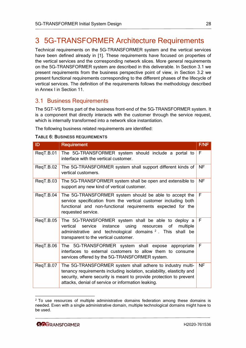
TABLE 6: BUSINESS REQUIREMENTS
ID Requirement F/NF
ReqT.B.01 The 5G-TRANSFORMER system should include a portal to
interface with the vertical customer.
F
ReqT.B.02 The 5G-TRANSFORMER system shall support different kinds of
vertical customers.
NF
ReqT.B.03 The 5G-TRANSFORMER system shall be open and extensible to
support any new kind of vertical customer.
NF
ReqT.B.04 The 5G-TRANSFORMER system should be able to accept the
service specification from the vertical customer including both
functional and non-functional requirements expected for the
requested service.
F
ReqT.B.05 The 5G-TRANSFORMER system shall be able to deploy a
vertical service instance using resources of multiple
administrative and technological domains 2 . This shall be
transparent to the vertical customer.
F
ReqT.B.06 The 5G-TRANSFORMER system shall expose appropriate
interfaces to external customers to allow them to consume
services offered by the 5G-TRANSFORMER system.
F
ReqT.B.07 The 5G-TRANSFORMER system shall adhere to industry multi-
tenancy requirements including isolation, scalability, elasticity and
security, where security is meant to provide protection to prevent
attacks, denial of service or information leaking.
NF
2 To use resources of multiple administrative domains federation among these domains is needed. Even with a single administrative domain, multiple technological domains might have to be used.

5G-TRANSFORMER Initial System Design 29
H2020-761536
ReqT.B.08 The 5G-TRANSFORMER system shall allow to negotiate and
monitor service SLAs, with appropriate granularity according to
the final service characteristics.
F
ReqT.B.09 The 5G-TRANSFORMER system shall provide vertical customers
with service catalogue information about available service offers
and capabilities, in order to facilitate the automated provision of
services.
F
ReqT.B.10 The 5G-TRANSFORMER system shall provide a mechanism to
perform vertical service accounting and charging. This information
should be available internally and externally (for the vertical
customer).
F
ReqT.B.11 The 5G-TRANSFORMER system should be able to support long-
live and short-lived services.
F
ReqT.B.12 The 5G-TRANSFORMER system should be reliable. NF
ReqT.B.13 The 5G-TRANSFORMER system should be available (as carrier
class component providing 5 nines availability).
NF
ReqT.B.14 The 5G-TRANSFORMER system should keep responsiveness for
vertical customer requests. The 5GT-TRANSFORMER system
should provide response times as an interactive system.
NF
ReqT.B.15 The 5G-TRANSFORMER system shall allow blueprints
composed of other blueprints.
F
ReqT.B.16 The 5G-TRANSFORMER system shall allow VSDs composed of
other VSDs.
F
ReqT.B.17 The 5G-TRANSFORMER system shall allow a vertical to specify
which vertical service instance to use in a composed vertical
service.
F
ReqT.B.18 The 5G-TRANSFORMER system shall support the specification
of preferred, non-preferred, and prohibited virtual infrastructure
providers.
F
ReqT.B.19 The 5G-TRANSFORMER system shall allow a vertical to define
whether a child service of a composed service instance has the
same lifecycle as the parent service instance or whether it has a
lifecycle of its own.
F
ReqT.B.20 The 5G-TRANSFORMER system shall allow a vertical to define
whether a vertical service instance can be a child service of
several composed services, i.e., whether it can be shared among
other vertical services.
F
ReqT.B.21 The 5G-TRANSFORMER system shall support to specify the
deployment area based on KPIs3 of another service.
F
3 As an example, intersection collision avoidance should cover critical intersections, where ‘critical’ is defined in terms of occurrence of abrupt braking manouvers in the past.
5G-TRANSFORMER Initial System Design 30
H2020-761536
3.2 Functional Requirements
The 5G-TRANSFORMER system is involved in the service lifecycle at different phases,
each having different requirements. The phases are discovery, fulfilment, assurance,
and decommissioning. All requirements in this section are functional requirements.
3.2.1 Discovery
The discovery phase facilitates the 5G-TRANSFORMER system to understand what
are the capabilities and services supported. That information will be exposed to the
vertical customers for 5G-TRANSFORMER service offering.
The following requirements are identified:
TABLE 7: REQUIREMENTS ON THE DISCOVERY PHASE
ID Requirement
ReqT.Di.01 The 5G-TRANSFORMER system must provide vertical customers with
the means to submit detailed requests including information regarding
the location of resources and service points, QoS, charging options.
ReqT.Di.02 Service catalogue entries may contain a service manifest and a price tag
(or an indicative price range from which the exact price can be extracted
at run-time).
ReqT.Di.03 The 5G-TRANSFORMER system shall provide the customer with the
ability to request a service from the catalogue along with the expected
SLA.
ReqT.Di.04 Service catalogue entries and satisfied service requests should result in
an SLA commitment for the respective service.
ReqT.Di.05 The service request (and associated SLA) must contain a parameter
describing the service aging or Time To Live (TTL).
ReqT.Di.06 The 5G-TRANSFORMER system must support both private (i.e.,
towards specific vertical customer(s)) and public dissemination of
service offers.
ReqT.Di.07 The 5GT-TRANSFORMER system should provide a mechanism to set-
up, re-size and terminate services.
ReqT.Di.08 The 5G-TRANSFORMER system shall support a vertical to create
several instances of the same vertical service.
ReqT.Di.09 The 5G-TRANSFORMER system shall allow a vertical to store its
service descriptions persistently, and to create, retrieve, update, and
delete vertical service descriptions4.
ReqT.Di.10 The 5G-TRANSFORMER system shall allow the 5G-TRANSFORMER
service provider to define vertical service blueprints.
4 A vertical may provide the location of virtual machine images of its virtual applications as part of its service descriptions. These images may have to be certified by the 5G-TRANSFORMER system provider before actually onboarding them to the 5G-TRANSFORMER system.

5G-TRANSFORMER Initial System Design 31
H2020-761536
ReqT.Di.11 The 5G-TRANSFORMER system shall store and keep up-to-date a
catalogue of NFVI-PoPs available within its administrative domain and of
related resources (computing, storage, networking) in addition to
available PNFs/VNFs.
ReqT.Di.12 The 5G-TRANSFORMER system shall monitor the (current) state of
available PNFs and keep track of the history of states of available PNFs.
ReqT.Di.13 The 5G-TRANSFORMER system shall certify the credentials of entities
accessing its NFVI catalogue.
ReqT.Di.14 The 5G-TRANSFORMER system shall allow to create/delete different
instances of VNF(s) and update/retrieve VNFDs
3.2.2 Fulfillment
During the service fulfilment phase, the 5G-TRANSFORMER system produces the
necessary mapping from the customer request to the network slice templates, i.e.,
network service descriptors, to properly instruct the 5GT-SO.
The following requirements are identified:
TABLE 8: REQUIREMENTS ON THE FULFILLMENT PHASE
ID Requirement
ReqT.Fu.01 Depending on the modality 5 of the contracted service, the 5G-
TRANSFORMER system could be required to offer proper configuration
and management interfaces to the slice capabilities honoring the
service request, in order to manage them similarly as if they were
owned and dedicated resources (tenant-managed slices).
ReqT.Fu.02 Depending on the modality of the contracted service, the 5G-
TRANSFORMER system could accommodate a vertical customer
service request in some existing slice (provider-managed slices).
ReqT.Fu.03 The 5G-TRANSFORMER system shall support the vertical to express
policies6. The 5G-TRANSFORMER system shall enforce such policies.
ReqT.Fu.04 The 5G-TRANSFORMER system could allow the vertical customer to
specify7 policies associated to the service to describe e.g. elasticity
rules to be enforced when the service requires re-deployment/re-
configuration.
ReqT.Fu.05 The 5G-TRANSFORMER system shall support a vertical to manage the
lifecycle of each of its vertical service instances separately.
ReqT.Fu.06 The 5G-TRANSFORMER system shall provide configuration and
5 Modality refers to the possibility of requesting tenant-managed network slices (i.e., request of control and management capabilities of the allocated resources functions) or provider-managed network slices (i.e. the control and management is retained by the provider and the tenant simply uses the network slice). 6 QoS policies, charging policies, security policies, and regulatory policies where needed. 7 As an example of such policies, it could be possible to specify the concentration of resources by night for an efficient management of energy consumption during low workloads.
5G-TRANSFORMER Initial System Design 32
H2020-761536
management interfaces to instantiated VNFs or available PNFs.
ReqT.Fu.07 The 5G-TRANSFORMER system shall allow VNF scaling
(up/down/in/out).
ReqT.Fu.08 The 5G-TRANSFORMER system shall allow resource scaling
(up/down/in/out).
ReqT.Fu.09 The 5G-TRANSFORMER system shall provide appropriate isolation
and access guarantees to available PNFs.
ReqT.Fu.10 The 5G-TRANSFORMER system shall certify the credentials of entities
accessing its NFVI.
ReqT.Fu.11 The 5G-TRANSFORMER system shall maintain information regarding
the mapping between NSD, VNFs/PNFs and allocated resources, along
with the state of PNFs and VNFs.
3.2.3 Assurance
The 5G-TRANSFORMER system informs the vertical customer about events and
performance of the vertical service instances. As a consequence, the 5G-
TRANSFORMER system should gather monitoring information and expose it to the
vertical, who could take different actions accordingly. In addition, the monitoring
information can be also consumed internally by the 5G-TRANSFORMER system to
trigger events like arbitration.
The following requirements are identified:
TABLE 9: REQUIREMENTS ON THE ASSURANCE PHASE
ID Requirement
ReqT.As.01 The 5G-TRANSFORMER system must provide the vertical customer
with tools to monitor the QoS attained for the requested service.
ReqT.As.02 The 5G-TRANSFORMER system should provide a mechanism for the
vertical for reward/penalty in service provisioning in case of SLA
conformance/failure.
ReqT.As.03 This 5G-TRANSFORMER system should be able to map the associated
SLA into KPIs8 to be monitored during the slice execution lifecycle.
ReqT.As.04 The 5G-TRANSFORMER system should be able to support lawful
interception mechanisms.
ReqT.As.05 The 5GT-TRANSFORMER system should prevent DoS attacks from a
malicious behavior from vertical customers.
ReqT.As.06 The 5G-TRANSFORMER system should provide isolation among
vertical customers’ procedures and requests.
ReqT.As.07 The 5G-TRANSFORMER system shall allow dynamically set-up a traffic
8 The SLA will be expressed in terms of service parameters, while the KPIs represent technical parameters. For example, service latency (as part of the SLA) could require to monitor transport network latency but also VM execution latency (as two different KPIs to monitor).

5G-TRANSFORMER Initial System Design 33
H2020-761536
monitoring service in any given 5G network slice.
ReqT.As.08 The 5G-TRANSFORMER system shall arbitrate resources among
vertical service instances of one vertical based on priorities and SLA
requirements.
ReqT.As.09 The 5G-TRANSFORMER system shall be able to collect performance
information and manage fault information, even when vertical services
are deployed across multiple administrative and technological domains.
ReqT.As.10 The 5G-TRANSFORMER system shall monitor the QoS attained to
instantiated VNFs,allocated PNFs, and related resources.
ReqT.As.11 The 5G-TRANSFORMER system shall provide isolation and
performance guarantees among tenants, even when sharing PNFs.
ReqT.As.12 The 5G-TRANSFORMER system shall be tolerant to failures and report
failure events whenever issues cannot be solved.
3.2.4 Decommisioning
The 5G-TRANSFORMER system also participates in the proper release of resources
and services to the vertical once a service instance is no longer required.
The following requirements are identified:
TABLE 10: REQUIREMENTS ON THE DECOMMISSIONING PHASE
ID Requirement
ReqT.De.01 The 5G-TRANSFORMER system should be able to identify the slice(s)
to be decommissioned as result of service termination.
ReqT.De.02 The 5G-TRANSFORMER system should be able to identify the
monitoring mechanisms to be deactivated as result of service
termination.
ReqT.De.03 The 5G-TRANSFORMER system should have means for receiving
acknowledgement of releasing resources.
ReqT.De.04 The 5G-TRANSFORMER system should be able to notify the vertical
customer about service instance termination.
ReqT.De.05 The 5G-TRANSFORMER system should be able to keep track of
charging and accounting information even after service termination for
periods of time according to local laws.
ReqT.De.06 The 5G-TRANSFORMER system shall be able to identify and
deallocate resources allocated to VNFs upon a VNF termination
procedure.
ReqT.De.07 The 5G-TRANSFORMER system shall be able to identify the
monitoring mechanisms to be deactivated as a result of a VNF
termination procedure or resource deallocation procedure

5G-TRANSFORMER Initial System Design 34
H2020-761536
4 5G-TRANSFORMER System Architecture This chapter introduces the proposed 5G-TRANSFORMER system architecture.
Section 4.1 presents a high level design of the main components and introduce their
key functional roles as well as the interfaces among them. Section 4.2 addresses the
architecture challenges to provide service orchestration over multi-technology domains.
The details for the design of individual components have been reported in the 5G-
TRANSFORMER D2.1[2], D3.1[3] and D4.1[4] deliverables. They are summarized at
the architecture level in this deliverable in the following chapter 5, 6, and 7, in order to
give a complete view of the whole system architecture design. Besides, the reference
architectures from 3GPP, ETSI NFV and ETSI MEC have been studied in D2.1, D3.1
and D4.1. A glossary on the relevant terminologies is provided in Annex II in 12.
4.1 Baseline architecture design
The 5G-TRANSFORMER project explores how the network can better serve the needs
of 5G-TRANSFORMER customers (i.e., vertical industries and M(V)NOs) by offering
the abstraction, flexibility, and dynamic management capabilities they require. In terms
of notation, it is important to differentiate between (vertical) service, i.e., the service that
is requested by the customer of the 5G-TRANSFORMER system, from the underlying
network service deployed to fulfill the requirements of the vertical. An example of the
former is a car manufacturer requesting the deployment of an automotive intersection
collision avoidance service. The latter will be deployed in the form of an NFV network
service, in general.
The key architectural concept to support such adaptation to the needs of verticals and
M(V)NOs is network slicing. The term network slice aligns network functionality to
business needs [12], since it allows customers to request not just functions, but also
business objectives (e.g., quality of service, security, etc.), as a sort of intent. The
scope of a slice may be a single customer facing service (using TM Forum terminology
[13]) or a group of such services. The system will also allow infrastructure providers to
share the 5G mobile transport and computing infrastructure efficiently among verticals
and M(V)NOs, hence enhancing 5G-TRANSFORMER provider network usage
efficiency. In terms of deployment, network slices can be implemented by means of
ETSI NFV network services.
The architecture is conceived to support multiple combinations of stakeholders (see
Section 2.1) by introducing open Application Programming Interfaces (API) among
components. Through these APIs, the system hides unnecessary details from the
verticals, allowing them to focus on the definition of the services and the required
Service Level Agreements (SLAs). As for interfaces, particularly relevant for the goals
of the project are east-westbound interfaces (E/WBI), which enable service and
resource federation across different administrative domains, allowing 5G-
TRANSFORMER service providers (TSP) to enhance their service offerings to their
customers by peering with other providers.
We envision a system of three major components: vertical slicer (5GT-VS), service
orchestrator (5GT-SO) and mobile transport and computing platform (5GT-MTP), see
Figure 2. The 5GT-VS is the entry point for the vertical requesting a service and it
handles the association of these services with slices as well as network slice

5G-TRANSFORMER Initial System Design 35
H2020-761536
management. The 5GT-SO is responsible for end-to-end orchestration of services
across multiple domains and for aggregating local and federated (i.e., from peer
domains) resources and services and exposing them to the 5GT-VS in a unified way.
Finally, the 5GT-MTP provides and manages the virtual and physical IT and network
resources on which service components are eventually deployed. It also decides on the
abstraction level offered to the 5GT-SO.
FIGURE 2: 5G-TRANSFORMER SYSTEM ARCHITECTURE
4.1.1 Vertical Slicer (5GT-VS)
The 5GT-VS is the common entry point for all verticals into the 5G-TRANSFORMER
system. It is part of the operating and business support systems (OSS/BSS) of the 5G-
TSP [1]. Vertical services are offered through a high-level interface at the 5GT-VS
northbound, which is designed to allow verticals to focus on the service logic and
requirements, without caring about how their services are eventually deployed at the
resource level. This latter issue would be up to the TSP. Therefore, vertical services will
use those services offered by the TSP. In fact, the 5GT-VS offers a catalogue of vertical
service blueprints (VSB), based on which the vertical service requests are generated by
the vertical. The role of the 5GT-VS is to trigger the actions allowing the 5G-
TRANSFORMER system to fulfil the requirements of a given incoming service request.
After the appropriate translation between service requirements and slice-related
requirements by the VSD/NSD Translator and Arbitrator, corresponding to the
Communication Service Management Function (CSMF) as defined in [6], a decision is
taken on whether the service can be provided through an already existing slice or a
new one needs to be created.
The vertical slicer is the component of the system that is aware of the business needs
of the vertical, their SLA requirements, and how they are satisfied by mapping them to
given slices. Intra-vertical arbitration is also part of the vertical slicer, by which intra-

5G-TRANSFORMER Initial System Design 36
H2020-761536
vertical contention is resolved to prioritize those services that are more critical,
according to the agreed SLA.
The VSI/NSI Coordinator and LC Manager is the central component of the 5GT-VS. It
contains functionality that can be mapped to that of the Network Slice Management
Function (NSMF) and Network Slice Subnet Management Function (NSSMF), as
defined in [6]. More specifically, the NSMF is in charge of lifecycle management of
network slice instances. All possible relations between vertical services and network
slices exist; that is, a network slice can be shared by different vertical services, but a
given vertical service may be mapped to multiple network slices as well. In turn,
network slices may be composed by network slice subnets, which may offer part of the
functionality required by a given network slice. And network slice subnets may be
shared by multiple network slices.
The final result of this slice-related process is a request sent by the 5GT-VS towards
the 5GT-SO to create or update the NFV network services (NFV-NS) that implement
the slices.
In summary, through this process, the 5GT-VS maps vertical service descriptions and
instantiation parameters at the vertical application (VA) level into an NFV-NS (existing
or new) implementing the network slice. In turn, such NFV-NS will be updated or
created through a network service descriptor (NSD), which is a service graph
composed of a set of virtual network functions (VNF) chained with each other, and the
corresponding fine-grained instantiation parameters (e.g., deployment flavor) that are
sent to the 5GT-SO. Given the operations carried out through it, the Vs-So interface
(see Figure 2) takes ETSI GS NFV-IFA 013 [23] as basis.
4.1.2 Service Orchestrator (5GT-SO)
The NFV-NS from the 5GT-VS is received by the 5GT-SO through the Vs-So interface.
The main duty of the 5GT-SO [34] is to provide end-to-end orchestration of the NFV-NS
across multiple administrative domains by interacting with the local 5GT-MTP (So-Mtp
reference point) and with the 5GT-SOs of other administrative domains (So-So
reference point). If needed (e.g., in case of not enough local resources), the 5GT-SO
interacts with peer 5GT-SOs located in other administrative domains (federation) to
take decisions on the end-to-end (de)composition of virtual services and their most
suitable execution environment. Even if a service is deployed across several
administrative domains, e.g., if roaming is required, a vertical still uses one single 5GT-
VS to access the system. The 5GT-SO hides this federation from the 5GT-VS and thus
from the the verticals.
The 5GT-SO embeds the network service orchestrator (NFVO-NSO) and the resource
orchestrator (NFVO-RO) with functionalities equivalent to those of a regular NFV
orchestrator and it may be used for single and multi-domains [14].
Since the network slices handled at the 5GT-VS will in general serve complex end-to-
end services, in the general case, the corresponding network service will be a
composition of nested NFV-NSs. The lifecycle management of this complex NFV-NS is
the role of the NFVO-NSO.
5G-TRANSFORMER Initial System Design 37
H2020-761536
In case the NFVO-NSO decides to deploy a network service across multiple
administrative domains (requiring service and/or resoruce federation), the 5GT-SO
receiving the request becomes the parent NFVO-NSO and sends ETSI GS NFV-IFA
013 [23] requests for each of the constituent NFV-NSs to other NFVO-NSOs.
Therefore, a hierarchy of NFVO-NSOs is established. The child NFVO-NSOs may
belong to the same 5GT-SO that received the request from the 5GT-VS or to a peer
5GT-SO, which, in turn, may establish an additional hierarchy, which is transparent for
the parent NFVO-NSO. The child NFVO-NSO belonging to the same 5GT-SO would be
in charge of the lifecycle management of the constituent service that is eventually
deployed over the local 5GT-MTP, i.e., the 5G-MTP with which the 5GT-SO has a
direct relationship through the So-Mtp interface. When a child NFVO-NSO belongs to a
different domain, there is service federation.
Eventually, a resource-related request is generated towards the underlying NFVO-RO
to assign virtual resources towards the deployment of the (constituent) NFV-NS. The
NFVO-RO functionality of the 5GT-SO handles resources coming from the local 5GT-
MTP (real or abstracted) and from the peer 5GT-SOs of other administrative domains
(abstracted). The NFVO-RO will decide on the placement of the VNFs of the NFV-NS
based on the information available in the NFVI resources repository and the NFV-NS
instances repository. The NFVI repository will include information about the
infrastructure controlled by the local 5GT-MTP as well as resources offered by peer
domains. Most likely, the information available in this repository will be more detailed
when coming from the local 5GT-MTP rather than from a federated domain. The
interaction between NFVO-ROs is based on ETSI GS NFV-IFA 005 [16]. This also
includes the interface with the 5GT-MTP, where an additional NFVO-RO in the lower
hierarchy layer is embedded, as explained below.
Notice that the NFVI resources handled by the NFVO-RO of the 5GT-SO based on
which decisions are taken will have a higher or lower abstraction level depending on
the policies applied by the 5GT-MTP and the peering 5GT-SO. In general, the NFVO-
RO of the local 5GT-SO will take coarse-grained decisions and the 5GT-MTP and peer
5GT-SO will take finer-grained ones, as they are closer to the actual resources.
The 5GT-SO also includes the Virtual Network Function Managers (VNFM) to manage
the lifecycle of the VNFs composing the NFV-NS. ETSI GS NFV-IFA 006-based
interfaces [17] will be used to allow the VNFM interacting with the NFVO-RO Single
Logical Point of Contact (SLPOC) entity in the 5GT-MTP, as well as peer 5GT-SOs for
resource allocation requests involving the VNFs under its control.
4.1.3 Mobile Transport and Computing Platform (5GT-MTP)
The 5GT-MTP [35] is responsible for orchestration of resources and the instantiation of
VNFs over the infrastructure under its control, as well as managing the underlying
physical mobile transport network, computing and storage infrastructure. In general,
there will be multiple technology domains (TD) inside a 5GT-MTP (e.g., data centres,
mobile network, wide area network). The 5GT-MTP NFVO-RO acts as end-to-end
resource orchestrator across the various technology domains of the 5GT-MTP. The
computing and storage infrastructure may be deployed in central data centres as well
as distributed ones placed closer to the network edge, as in MEC. Therefore, the 5GT-
MTP is in charge of managing the virtual resources on which the NFV-NSs are
deployed.

5G-TRANSFORMER Initial System Design 38
H2020-761536
The NFVO-RO acts as single entry point, i.e., single logical point of contact (SLPOC) in
ETSI GS NFV-IFA 028 [26] terminology, for any resource allocation request coming
from the 5GT-SO. The So-Mtp interface is based on ETSI GS NFV-IFA 005 [16] and
ETSI GS NFV-IFA 006 [17]. The former allows the NFVO-RO of the 5GT-SO to request
resource allocations to the NFVO-RO of the 5GT-MTP, whilst the latter allows the
VNFM of the 5GT-SO to request resource allocations for the VNFs under its control.
In terms of managing VNF instances, the So-Mtp interface also consists of ETSI GS
NFV-IFA 008-based interfaces (i.e., the Ve-Vnfm-vnf reference point) [19] to allow the
VNFM of the 5GT-SO to directly configure the VNF instances running in the 5GT-MTP.
Depending on the use case, the 5GT-MTP may offer different levels of resource
abstraction to the 5GT-SO. However, the 5GT-MTP NFVO-RO has full visibility of the
resources under the control of the Virtual Infrastructure Managers (VIM) managing
each technology domain, since they belong to the same administrative domain. ETSI
GS NFV-IFA 005-based interfaces [16] are deployed between the 5GT-MTP NFVO-RO
and the 5GT-MTP VIMs. Therefore, when receiving a resource allocation request from
the 5GT-SO, the 5GT-MTP NFVO-RO generates the corresponding request to the
relevant entities (e.g., VIM or WAN Infrastructure Manager (WIM)), each of them
providing part of the virtual resources needed to deploy the VNFs, interconnect them,
and/or configure the relevant parameters of the PNFs that form the NFV-NS. As a
special case, a resource request for a virtual link may be mapped from the 5GT-MTP
NFVO-RO into an ETSI GS NFV-IFA 013-based NFV-NS request [23] addressed to a
mobile network technology domain [14]. This option is offered to hide the complexity of
both transport and mobile network to the rest of the system whilst keeping the required
flexibility inside the mobile domain (e.g., to let the specific domain decide on the most
appropriate functional split of the base station functions). Therefore, a full ETSI MANO
stack is represented in technology domain 1-2 (see Figure 2) even if the focus of the
5GT-MTP is handling virtual resources and not NFV-NSs. In any case, this NFV-NS is
hidden to the 5GT-SO, since it is abstracted as an abstract link.
4.1.4 Monitoring Architecture
In the 5G-TRANSFORMER framework, each architectural component (i.e., 5GT-VS,
5GT-SO, 5GT-MTP) includes a monitoring service able to provide performance metrics
and failure reports targeting the logical entities managed by each component. Following
this approach, the 5GT-MTP monitoring service will produce monitoring data about the
local physical and virtual resources, the 5GT-SO monitoring service will produce
monitoring data about the managed VNFs and NFV-NSs, while the 5GT-VS monitoring
service will produce monitoring data about network slices and vertical services. This
hierarchy of monitoring services is shown in Figure 3, where the arrows indicate a
consumer-provider interaction. In particular, the 5GT-SO monitoring service can be a
consumer of the monitoring service provided by the underlying 5GT-MTP or by a
federated 5GT-SO, while the 5GT-VS can be a consumer of the monitoring service
provided by the local 5GT-SO.
The monitoring data generated at each layer can be used to feed internal decisions
within each architectural component or to serve external consumers of monitoring data.
For example, the 5GT-SO monitoring service can elaborate performance metrics about
an NFV-NS, and these metrics can be used by the 5GT-SO to take scaling decisions
for the involved VNFs. On the other hand, the performance metrics computed at the
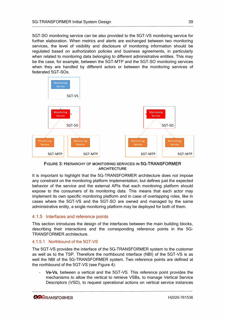
5G-TRANSFORMER Initial System Design 39
H2020-761536
5GT-SO monitoring service can be also provided to the 5GT-VS monitoring service for
further elaboration. When metrics and alerts are exchanged between two monitoring
services, the level of visibility and disclosure of monitoring information should be
regulated based on authorization policies and business agreements, in particularly
when related to monitoring data belonging to different administrative entities. This may
be the case, for example, between the 5GT-MTP and the 5GT-SO monitoring services
when they are handled by different actors or between the monitoring services of
federated 5GT-SOs.
FIGURE 3: HIERARCHY OF MONITORING SERVICES IN 5G-TRANSFORMER
ARCHITECTURE
It is important to highlight that the 5G-TRANSFORMER architecture does not impose
any constraint on the monitoring platform implementation, but defines just the expected
behavior of the service and the external APIs that each monitoring platform should
expose to the consumers of its monitoring data. This means that each actor may
implement its own specific monitoring platform and in case of overlapping roles, like in
cases where the 5GT-VS and the 5GT-SO are owned and managed by the same
administrative entity, a single monitoring platform may be deployed for both of them.
4.1.5 Interfaces and reference points
This section introduces the design of the interfaces between the main building blocks,
describing their interactions and the corresponding reference points in the 5G-
TRANSFORMER architecture.
4.1.5.1 Northbound of the 5GT-VS
The 5GT-VS provides the interface of the 5G-TRANSFORMER system to the customer
as well as to the TSP. Therefore the northbound interface (NBI) of the 5GT-VS is as
well the NBI of the 5G-TRANSFORMER system. Two reference points are defined at
the northbound of the 5GT-VS (see Figure 4):
- Ve-Vs, between a vertical and the 5GT-VS. This reference point provides the
mechanisms to allow the vertical to retrieve VSBs, to manage Vertical Service
Descriptors (VSD), to request operational actions on vertical service instances

5G-TRANSFORMER Initial System Design 40
H2020-761536
(VSI), like instantiation, termination, modification, and to monitor performance
and failures of instantiated vertical services.
- Mgt-Vs, between the TSP’s OSS/BSS Management Platform and the 5GT-VS.
This reference point provides primitives to manage tenants, SLAs and VSBs. It
is used mainly for management and administrative issues and it is handled
internally within the 5G-TRANSFORMER service provider.
FIGURE 4: REFERENCE POINTS ON THE NORTHBOUND OF THE 5GT-VS
The 5GT-VS NBI implementing both reference points is a REST API based on HTTP
and JSON messages, where the 5GT-VS acts as REST server and the verticals and
the OSS/BSS Management Platform act as REST clients. The interface should also
support asynchronous notifications from the 5GT-VS, for example based on web
sockets. Suitable mechanisms for authentication and authorization of the entities
issuing the requests should also be supported. However, this section focuses only on
the main functionalities supported at each reference points, while the full specification
of the primitives and their abstract messages is documented in D3.1[3] and the protocol
messages enconding will be specified during the software design and implementation
phase.
Note, the 5GT-VS NBI specified in this section focuses on the provisioning of Vertical
Services. For NSaaS we consider network slices of 5G access and core networks.
Management of these slices can be done by the vertical or MVNO through a dedicated
management service access point. For NFVIaaS we consider 5G core networks, where
specific functionality such as Home Subscriber Server (HSS) is provided by the MVNO.
These subsets of the more generic NSaaS and NFVIaaS can be described by vertical
service blueprints and descriptors and handled within the 5GT-VS as described below.
The Ve-Vs reference point identifies the following operations:
• Query VSBs.
• Create, query, update, and delete VSDs.
• Instantiate, query, terminate, modify Vertical Service Instances (VSI).
• Notifications about vertical service lifecycle events.
• Query monitoring parameters for VSIs.
• Subscriptions/notifications about vertical service monitoring parameters.
• Notifications about vertical service failures.
As an example we provide the definition of the Query VS blueprints operation. All
operations at the reference point are specified in D3.1 [3]. The Query VS blueprints
operation allows a vertical to retrieve one or more VSBs from the 5GT-VS catalogue.

5G-TRANSFORMER Initial System Design 41
H2020-761536
The blueprints are then used by the vertical to create the VSDs for the vertical services
to be instantiated.
The Query VS blueprints messages are specified in Table 11.
TABLE 11: QUERY VS BLUEPRINTS MESSAGES
Message Direction Description Parameters
Query VS blueprint request
Vertical → 5GT-VS Request to retrieve one or more VSBs matching the given filter.
• Filter (e.g. VSB ID, …) Vertical ID.
Query VS blueprint response
5GT-VS → Vertical Response including the details of the requested VSBs.
• List<VSB>
The Mgt-Vs reference point between the OSS/BSS Management Platform (Mgt in the
following) and the 5GT-VS identifies the following operations:
• Create, query and delete tenants.
• Create, query, modify and delete SLAs.
• Create, query and delete VSBs.
As for the Ve-Vs reference point, all the operations at this reference point are specified
in D3.1 [3].
Beyond these operations, the OSS/BSS Management Platform has also access in read
mode to the information related to all the entities managed by the 5GT-VS, i.e., VSDs,
VSIs, NSIs and NSSIs, which can be retrieved from the related catalogues and records.
4.1.5.2 Vs-So Interface
The 5GT-SO NBI refers to the interface between the 5GT-VS and the 5GT-SO, based
on the ETSI NFV IFA 013 interface (reference point Os-Ma-nfvo between the OSS/BSS
and the NFVO in the NFV MANO architecture) [23]. This interface is used for: (i)
network service lifecycle management and forwarding of information related to the
status of the NFV network services; (ii) management of NFV NS Descriptors, VNF
packages and PNF Descriptors (PNFDs); and (iii) monitoring of Network Service
Instances (NFV-NSI).
FIGURE 5: REFERENCE POINTS BETWEEN 5GT-VS AND 5GT-SO
The interactions between the 5GT-VS and 5GT-SO implement the three reference
points shown in Figure 5 and described below:
5G-TRANSFORMER Initial System Design 42
H2020-761536
• Vs-So (-LCM – LifeCycle Management) is used for operations on NFV-NSs. It
offers primitives to instantiate, terminate, query, and reconfigure NFV network
service instances or receive notifications about their lifecycle.
• Vs-So (-MON - MONitoring) is used for the monitoring of NFV-NS and VNF
instances through queries or subscriptions and notifications about performance
metrics. Additionally, this interface provides APIs for the fault management.
• Vs-So (-CAT - CATalogue) is used for the management of NFV NSD, PNFDs,
VNF and MEC Application package descriptors, including the onboarding,
removal, updates and queries.
The mapping between the three Vs-So reference points and the specific interfaces
defined in the ETSI NFV IFA 013 is reported in deliverable D3.1[3], together with the
required extensions in terms of descriptors’ information model (e.g. in support of MEC
applications integrated in NFV-NSs) and interfaces’ information elements (e.g. in
support of geographical or latency constraints specification).
4.1.5.3 So-Mtp Interface
The So-Mtp Interface (5GT-SO southbound interface (SBI) as seen by the 5GT-SO and
5GT-MTP northbound interface (NBI) as seen by the 5GT-MTP) addresses the
interworking between the 5GT-SO and the 5GT-MTP building blocks of the 5G-
TRANSFORMER architecture. A single 5GT-SO may interact via multiple SBI
instances towards N 5GT-MTPs, which handle the configuration and programmability of
a number of domains including heterogeneous virtualized resources for compute,
storage and networking, whereas a 5GT-MTP is managed by a single 5GT-SO.
Besides managing the utilization (i.e., de/allocation) of the virtualized resources, the
So-Mtp interface provides the required functionalities for deploying (updating and
terminating) demanded VNFs by a given NFV-NS.
As depicted in Figure 6, the So-Mtp interface can be split into different subsets of
interfaces taking care of different functions. However, the So-Mtp interface enables
communicating to the specific entities of the 5GT-SO (VNFM and NFVO-RO) with a
single logical point of contact (SLPOC) at each 5GT-MTP entity. The So-Mtp interface
is based on a set of standard documents being produced within the ETSI NFV
framework, namely ETSI GS NFV-IFA 005 [16], ETSI GS NFV-IFA 006 [17] and ETSI
GS NFV-IFA 008 [19]. In a nutshell, the So-Mtp interface provides the operations and
functions, supported by a well-defined set of messages and workflows, for: (i), providing
abstracted information (e.g., capacities, availability, connectivity, etc.) of the virtualized
resources managed by each 5GT-MTP; (ii) managing (i.e., instantiation, reservation,
allocation, scaling up/down and release) of the virtualized resources required to support
an NFV-NS; (iii) enabling the fault management and performance monitoring aiming at
recovering interrupted services or ensuring the targeted SLAs demanded by each NFV-
NS; and (iv) supporting the lifecycle management (i.e., creation, configuration,
modification and termination) along with related performance and fault management of
the VNFs instantiated over the virtualized (compute and storage) resources.

5G-TRANSFORMER Initial System Design 43
H2020-761536
FIGURE 6: REFERENCE POINTS FOR 5GT-SO SBI (I.E., SO-MTP INTERFACE)
In particular the following functions are provided by the interfaces subset: So-Mtp(-
RAM) provides the Resource Advertisement Management functions; So-Mtp(-RM)
encompasses the Resource Management operations over the virtualized resources;
So-Mtp(-RMM) provides the Resource Management and Monitoring operations; So-
Mtp(-VNF) takes over the general VNF lifecycle management (e.g., scaling up/down a
particular VNF instance, fixing VNF malfunctions, etc.) commanded by the 5GT-SO
VNFM. For more details, please, refer to D2.1 [2].
Current interfaces defined by ETSI in IFA 005 are sufficient for a first implementation of
the So-Mtp interface. However a thorough analysis for their applicability to inter NFVI-
PoP connectivity is necessary and such analysis will be reported in future deliverables.
4.1.5.4 So-So Interface
The 5GT-SO provides the interface of the 5G-TRANSFORMER system to another
external 5G-TRANSFORMER system. Therefore the eastbound/westbound interface
(E/WBI) of the 5GT-SO is as well the E/WBI of the 5G-TRANSFORMER system. Six
reference points are defined at the E/WBI of the 5GT-SO (see Figure 7):
- So-So(-Life Cycle Management), between consumer 5GT-SO NFVO-NSO and
provider 5GT-SO NFVO-NSO. This reference point provides the mechanisms to
instantiate, terminate, query or re-configure NFV-NS or receive notifications for
federated NFV-NS.
- So-So(-MONitoring), between consumer 5GT-SO NFVO-NSO and provider
5GT-SO NFVO-NSO. This reference point provides monitoring of NFV-NS
through queries or subscribtion/notification of performance metrics, VNF
indicatiors and NFV-NS failures.
- So-So(-Catalogue), between consumer 5GT-SO NFVO-NSO and provider 5GT-
SO NFVO-NSO. This reference point provides primitives to subscribe/notify for
changes, queries of descriptors (NSDs and AppDs) and packages (MEC
Application Packages).
- So-So(-Resource Management), between consumer 5GT-SO NFVO-RO and
provider 5GT-SO NFVO-RO. This reference point provides the operations for
configuration of the resources, configuration of the network paths for
5GT-MTPSLPOC
5GT-MTPSLPOC
5GT-SONFVO-NSO NFVO-RO
VNFM
So-Mtp-(VNF) So-Mtp-(RM); So-Mtp-(RMM); So-Mtp-(RAM)
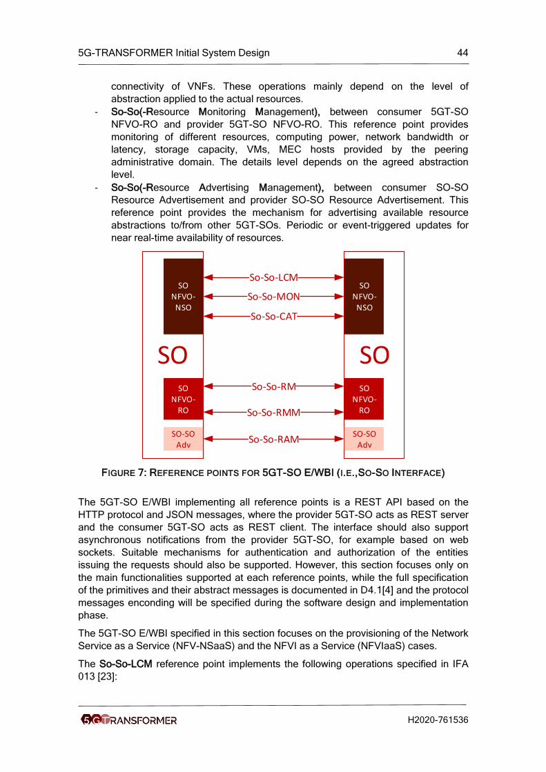
5G-TRANSFORMER Initial System Design 44
H2020-761536
connectivity of VNFs. These operations mainly depend on the level of
abstraction applied to the actual resources.
- So-So(-Resource Monitoring Management), between consumer 5GT-SO
NFVO-RO and provider 5GT-SO NFVO-RO. This reference point provides
monitoring of different resources, computing power, network bandwidth or
latency, storage capacity, VMs, MEC hosts provided by the peering
administrative domain. The details level depends on the agreed abstraction
level.
- So-So(-Resource Advertising Management), between consumer SO-SO
Resource Advertisement and provider SO-SO Resource Advertisement. This
reference point provides the mechanism for advertising available resource
abstractions to/from other 5GT-SOs. Periodic or event-triggered updates for
near real-time availability of resources.
SO SO
So-So-LCM
So-So-MON
So-So-RM
So-So-RMM
So-So-RAM
SO NFVO-NSO
SO NFVO-NSO
SO NFVO-
RO
SO NFVO-
RO
So-So-CAT
SO-SOAdv
SO-SOAdv
FIGURE 7: REFERENCE POINTS FOR 5GT-SO E/WBI (I.E.,SO-SO INTERFACE)
The 5GT-SO E/WBI implementing all reference points is a REST API based on the
HTTP protocol and JSON messages, where the provider 5GT-SO acts as REST server
and the consumer 5GT-SO acts as REST client. The interface should also support
asynchronous notifications from the provider 5GT-SO, for example based on web
sockets. Suitable mechanisms for authentication and authorization of the entities
issuing the requests should also be supported. However, this section focuses only on
the main functionalities supported at each reference points, while the full specification
of the primitives and their abstract messages is documented in D4.1[4] and the protocol
messages enconding will be specified during the software design and implementation
phase.
The 5GT-SO E/WBI specified in this section focuses on the provisioning of the Network
Service as a Service (NFV-NSaaS) and the NFVI as a Service (NFVIaaS) cases.
The So-So-LCM reference point implements the following operations specified in IFA
013 [23]:

5G-TRANSFORMER Initial System Design 45
H2020-761536
• Instantiate, query, terminate, modify NFV-NSs.
• Subscribe/Notify about NFV-NSs lifecycle change notification.
The So-So-MON reference point implements the following operations specified in IFA
013 [23]:
• Subscribe/notify, query about NFV-NSs performance information.
• Create, delete, query NFV-NSs threshold operation.
• Subscribe/notify about NFV-NSs fault alarms.
The So-So-CAT reference point implements the following operations specified in IFA
013 [23]:
• Query, update, subscribe/notify changes on NSDs.
• Query, update, subscribe/notify changes of MEC Application Package
The So-So-RM reference point implements the following operations specified in IFA
005/006/008 [16][17][19]:
• Add, query, update, delete software image operations.
• Allocate, query, update, terminate, operate on compute/network/storage
resources. Due to abstraction of the resources, operations and information are
limited to the abstraced level.
• Create, instantiate, scale, scale to level, change, terminate, delete, query,
operate, modify, get operation status of VNFs. Due to abstraction of the
resources, operations and information are limited to the abstraced level.
The So-So-RMM reference point implements the following operations specified in IFA
005/006/008 [16][17][19]:
• Query, subscribe/notify, create/delete/query threshold operation for
performance information on compute/network/storage resources. Due to
abstraction of resources, operations and information are limited to the abstraced
level.
• Subscribe/notify for lifecycle change of VNFs.
• Subscribe/notify, query, create/delete/query threshold performance operation of
VNFs.
• Subscribe/notify for fault alarms of VNFs.
The So-So-RAM reference point implements the following operations specified in IFA
005/006 [16][17]:
• Query quota information for compute/network/storage resources. Due to
abstraction of resources, information is limited to the abstract level.
• Subscribe/notify for change of compute/network/storage resources. Due to
abstraction of resources, information is limited to the abstract level.
The reference points on the E/WBI are based on operations defined in the ETSI NFV
IFA documents, however there are some gaps not covered there. ETSI NFV-EVE 012
[27] addresses the lack of support for service availability levels, priority handling for
virtual resource assignment as well as service continuity during healing procedures of a
service. Most of them have to be covered by the E/WBI, which is work in progress.
Additional, the So-So-RAM reference point should be extended to enable dynamic

5G-TRANSFORMER Initial System Design 46
H2020-761536
exchange of resource abstractions (available for federation) either by implementing
APIs for connection to a central point or mechanisms to establish peer-to-peer network.
An extension of the existing or even a new reference point may be needed to
implement operations that support the negotiation operations regarding the service and
resource federation procedure. The pricing models should be implemented on the
E/WBI and covered by extending several reference points, in particular the So-So-CAT
and So-So-RAM.
4.1.6 Services mapping to network slices and NFV network services
This section presents the process of instantiating a vertical service in the 5G-
TRANSFORMER system through the different building blocks.
Figure 8 shows the high-level workflow for instantiation of a vertical service through
these modules, more detailed workflows are shown in Section 8.2. During service
onboarding phase, the TSP defines a set of vertical service blueprints in a vertical
service catalog offered to the tenants (verticals or MVNOs) through service
advertisement. To instantiate a vertical service, the tenant selects a VSB from the
catalog of the 5GT-VS via its NBI (i.e., Ve-Vs as described in Section 4.1.5.1).
Thereafter, the tenant completes the VSB to a high-level service description of the
vertical service, the VSD. To instantiate this vertical service, the 5GT-VS translates the
high-level requirements to network slice level requirements and maps the vertical
service instance to (existing or new) network slice instance(s). In the 5G-
TRANSFORMER system, a network slice would be directly mapped to a NFV network
service instance (NFV-NSI), and the network slice characteristics will be described by a
NFV Network Service Descriptor. In this context, creating a network slice instance will
involve defining a NFV network service descriptor including its deployment flavors. This
is performed through the VSD/NSD translator inside the 5GT-VS. In turn, the process
for instantiating the requested NFV-NS is initiated from the 5GT-VS by sending a
request to the 5GT-SO via the Vs-So interface (see Section 4.1.5.2), requesting the
5GT-SO to instantiate the NFV-NS according to the contents of the NSD. This request
typically contains the pointer to the NSD and the deployment flavors as well as
additional input parameters (e.g. IP addresses to be assigned to some of the network
functions) and constraints (e.g. location where to deploy all or some of the network
functions). The 5GT-SO will determine the actual flavor and parameters to be deployed
(e.g. the selection of VNFs and VLs to be instantiated) based on the available
resources.
The 5GT-SO is the main entity to provision and manage the NFV NSI via the NFVO
component, which includes the tasks of network service orchestration (NFVO-NSO)
and resource orchestration (NFVO-RO). The NFVO-NSO component takes care of the
de-composition of NFV NSs to multiple segments, deployed in different technical or
administrative domains and Life Cycle Management (LCM) of the NFV NSs. The
NFVO-RO component decides the optimal VNF(s) placement and the resources to be
allocated for the requested NFV-NS. The orchestration decision is based on the
abstraction provided by the local and federated 5GT-MTPs (whenever federation is
needed). Whenever the 5GT-SO detects that the local administrative domain has not
enough resources to orchestrate the required NFV-NS, it interacts with other 5GT-SOs
via the So-So interface (see Section 4.1.5.4) to request resource federation across
multiple administrative domains. In this case, the 5GT-SO will dynamically discover the

5G-TRANSFORMER Initial System Design 47
H2020-761536
available administrative domains by exchanging the view with the 5GT-SOs of the peer
administrative domains, and negotiate with them which administrative domains can be
federated to provide an end-to-end service orchestration ensuring the desired SLAs.
Thereafter, the 5GT-SO will request the 5GT-MTP to perform the actual resource
allocation and instantiation. The 5GT-MTP is mainly responsible for the actual
allocation/instantiation/control/configuration of virtual resources (including networking,
computing and storage resources) over the underlying infrastructure.
FIGURE 8: FROM VERTICAL SERVICE TO NETWORK SLICE TO NFV NETWORK SERVICE
Figure 9 shows examples of mapping the vertical services to NFV network services in
the 5G-TRANSFORMER system. Different VSIs compose one or multiple vertical
services, which are mapped to different network slices (existing or new) and in turn
mapped to different NFV network service instances. Different VSIs (e.g., VSI 2 and VSI
3) can map to instances of the same type of NFV-NS with different deployment flavors
(VSI 2 -> NFV-NSI 3 and VSI 3 ->NFV-NSI 4 respectively) or of instances of different
types of NFV-NSs. Scenarios where a VSI is mapped to a set of concatenated or
nested NFV-NSs can also be envisioned (VSI 1 -> NFV-NSI 1 connecting to NFV-NSI
2). The scenario of composed services is studied in the Annex V in Section 15.

5G-TRANSFORMER Initial System Design 48
H2020-761536
FIGURE 9: EXAMPLES OF SERVICE MAPPING
4.1.7 Network slice and network slice management
This section summarizes the definition of network slice by the 3GPP. A Network Slice is
considered a complete logical network including Radio Access Network (RAN) and
Core Network (CN). It enables the operator to create customized networks to provide
optimized solutions for different scenarios that demand different requirements,
especially about the functions, performance and isolation. A network slice describes a
system behavior implemented by a network slice instance (NSI), built from a network
slice template (NST), which represents the network functions and resources to provide
telecommunication services. Within 5G-TRANSFORMER we use NFV NSDs to define
NSTs.
[6] describes a network slice as a set of one or more network slice subnets where each
of these subnet may include network functions (PNFs and/or VNFs) and other network
slice subnets.
A network slice has to verify several requirements, namely 1) completeness of a NSI in
the sense that it should include all functionalities and resources necessary to support
some set of communication services; 2) a NSI contains network functions (VNFs and/or
PNFs) and all the connections information between NF (e.g. topology connections,
individual link requirements (e.g. QoS attributes)); 3) resources used by a NSI, a NSI is
realized via the required physical and logical resources; 4) instance-specific policies
and configuration are required when creating a NSI. Ultra-low latency and ultra-
reliability are examples of network characteristics; and 5) a NSI can be fully or partially
isolated from another NSI. The isolation can be logical and/or physical.
The 5GT-VS implements the Network Slice Management Function (NSMF) and
Network Slice Subnet Management Function (NSSMF) and performs the mapping
between VS instances and network slice instances, as well as the coordination
between their lifecycles. . The NSMF and the NSSMF respectively manage the
lifecycle of instances of network slice and network slice subnet. It consists of several
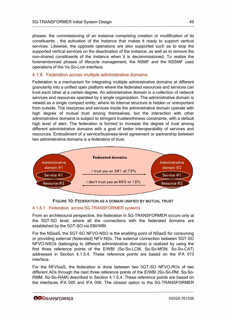
5G-TRANSFORMER Initial System Design 49
H2020-761536
phases: the commissioning of an instance comprising creation or modification of its
constituents , the activation of the instance that makes it ready to support vertical
services. Likewise, the opposite operations are also supported such as to stop the
supported vertical services on the deactivation of the instance, as well as to remove the
non-shared constituents of the instance when it is decommissioned. To realize the
forementionned phases of lifecycle management, the NSMF and the NSSMF uses
operations of the Vs-So-Lcm interface.
4.1.8 Federation across multiple administrative domains
Federation is a mechanism for integrating multiple administrative domains at different
granularity into a unified open platform where the federated resources and services can
trust each other at a certain degree. An administrative domain is a collection of network
services and resources operated by a single organization. The administrative domain is
viewed as a single compact entity, where its internal structure is hidden or unimportant
from outside. The resources and services inside the administrative domain operate with
high degree of mutual trust among themselves, but the interaction with other
administrative domains is subject to stringent trustworthiness constraints, with a default
high level of alert. The federation is formed to increase the degree of trust among
different administrative domains with a goal of better interoperability of services and
resources. Embodiment of a service/business-level agreement or partnership between
two administrative domains is a federation of trust.
FIGURE 10: FEDERATION AS A DOMAIN UNIFIED BY MUTUAL TRUST
4.1.8.1 Federation across 5G-TRANSFORMER systems
From an architectural perspective, the federation in 5G-TRANSFORMER occurs only at
the 5GT-SO level, where all the connections with the federated domains are
established by the 5GT-SO via EBI/WBI.
For the NSaaS, the 5GT-SO NFVO-NSO is the enabling point of NSaaS for consuming
or providing external (federated) NFV-NSs. The external connection between 5GT-SO
NFVO-NSOs (belonging to different administrative domains) is realized by using the
first three reference points of the E/WBI (So-So-LCM, So-So-MON, So-So-CAT)
addressed in Section 4.1.5.4. These reference points are based on the IFA 013
interface.
For the NFVIaaS, the federation is done between two 5GT-SO NFVO-ROs of two
different ADs through the next three reference points of the E/WBI (So-So-RM, So-So-
RMM, So-So-RAM) described in Section 4.1.5.4. These reference points are based on
the interfaces IFA 005 and IFA 006. The closest option to the 5G-TRANSFORMER

5G-TRANSFORMER Initial System Design 50
H2020-761536
approach is the SLPOC approach refered as SLPOC-F. The 5GT-SO NFVO-RO of the
provider AD has the role of the SLPOC of the provider AD. The consumer 5GT-SO
NFVO-RO can request NFVI resources to the provider 5GT-SO NFVO-RO via the three
mentioned interfaces (So-So-RM, So-So-RMM, So-So-RAM), dedicated to resource
federation operations. Both approaches, direct and indirect (described in Annex VII
Section 17.1), are feasible for implementation. In direct mode the consumer 5GT-SO
NFVO-RO and the consumer VNFM will use the reference points of the E/WBI to
communicate with the provider SLPOC-F or specifically the provider 5GT-SO NFVO-
RO. In the indirect case, the consumer 5GT-SO NFVO-RO would act as a proxy to the
consumer VNFM using IFA 007 interface (as described in Annex VII section 17.1). In
that case the communication between different ADs for resource federation procedures
is only done between the consumer 5GT-SO NFVO-RO and the provider 5GT-SO
NFVO-RO (which is the provider SLPOC-F) on the E/WBI.
Compared to the MLPOC case (as described in Annex VII Section 17.1), the SLPOC-F
functionality of the provider 5GT-SO NFVO-RO allows to act as a proxy point to the
underlying provider MTP (which can be referred as the VIM in the use case described
in Annex VII Section 17.1) both in direct and indirect mode.
The choice of the VNF management mode is a trade-off between architectural
complexity and overall performance of the VNFM. In direct mode, the connection from
the consumer VNFM to the provider 5GT-SO is implemented using IFA 006 based
interface. This interface is independent of the IFA 005 based interface between the
consumer 5GT-SO NFVO-RO and provider 5GT-SO NFVO-RO. In the indirect case, as
described above, the consumer 5GT-SO NFVO-RO has the proxy role. IFA 007 based
internal interface is implemented between the consumer VNFM and the consumer 5GT-
SO NFVO-RO. The consumer 5GT-SO NFVO-RO processes the VNFM requests
received on the IFA 007 based internal interface and adapts them on the existing (IFA
005 based) interface to the provider 5GT-SO NFVO-RO. The direct mode solution
increases the interface complexity and implementation of the E/WBI APIs. The
consumer VNFM is exposed to the external administrative domains that demands
application of higher security(e.g., MTP proxy to ensure VNFM protection). In indirect
mode, high computational overhead is introduced in the consumer 5GT-SO NFVO-RO.
This overhead would increase linearly with the number of consumed federated services
which threats the 5GT-SO NFVO-RO of being a bottleneck in the 5G-TRANSFORMER
system. Outlined, for low number of consumed federated services the indirect mode
seems like a good solution, however for higher number of consumed federated services
the direct mode increases the performances (e.g., with lower delays) at a cost of higher
security and higher interface complexity. It needs further evaluation in the development
phase to decide which mode to implement for federation in the 5GT-SO.
4.1.8.2 Federation with non 5G-TRANSFORMER systems
To cover a large set of clients, the 5G-TRANSFORMER system should be able to
interact with different systems to provide a wide range of services. In the federation
case, we distinguish the 5G-TRANSFORMER system as a provider or a consumer of
services.
4.1.8.2.1 5G-TRANSFORMER system as a consumer
Figure 11 depicts the case of federation between a 5G-TRANSFORMER Administrative
Domain (AD) and a non 5G-TRANSFORMER AD, with the 5G-TRANSFORMER AD

5G-TRANSFORMER Initial System Design 51
H2020-761536
acting as a consumer that requests NFV-NS services or virtualized resources from the
non 5G-TRANSFORMER AD.
According to the conclusions stated in Section 4.1.8.1, the 5G-TRANSFORMER AD is
able to federate with a non 5G-TRANSFORMER AD through the 5GT-SO. This later
can interact with an NFV Orchestrator (NFVO) and/or VIM via an SLPOC functionality.
In case of NSaaS, the federation is done between the NFVO-NSO of the 5GT-SO and
the NFVO of the provider via the reference point Or-Or using the IFA 013 interface.
Regarding the NFVIaaS case, we distinguish the two cases of VNF management. In
the direct mode, the VNFM inside the 5T-SO may interact either with the NFVO or the
VIM/WIM (according to the location of the SLPOC functionality) through the reference
point Vi-Vnfm using the interface IFA 006. Whilst, for the indirect mode, the VNFM
invokes virtualized resource management operations on the NFVO (inside the 5GT-
SO) through IFA 007 interface, which in turn invokes them towards the SLPOC on the
provider side via the reference point Or-Or using IFA 005 interface. Concerning the
resource orchestration, this is done between the NFVO-RO on the 5G-
TRANSFORMER AD and the NFVO of the provider, through the reference point Or-Or
via the IFA 005 interface.
FIGURE 11: FEDERATION WITH NON-5GT ADMINISTRATIVE DOMAIN (5G-TRANSFORMER AD AS CONSUMER)
4.1.8.2.2 5G-TRANSFORMER system as a provider
We highlight the possible cases of federation between a 5G-TRANSFORMER system
and a non 5G-TRANSFORMER system on Figure 12, in which the 5G-Transformer AD

5G-TRANSFORMER Initial System Design 52
H2020-761536
is considered as a provider for the non 5G-TRANSFORMER AD. We categorize these
possibilities of federation into three classes:
• OSS/BSS – 5GT-SO federation: This case of federation is done between the
network slice management functions (NS(S)MF) in one hand and the 5GT-SO
on the other hand. This kind of federation could be requested for instance, in
case of roaming for M(V)NOs or to maximize the availability for critical
communications. The NS(S)MF interacts with the 5GT-SO, which exposes a
set of network services, through Os-Ma-Nfvo IFA 013 interface to instantiate a
network service or to update its deployment flavor.
• NSaaS: The federation is done between the NFVO on the consumer AD and
the NFVO-NSO on the 5GT-SO through the reference point Or-Or using the
IFA 013 interface.
• NFVIaaS: the resource federation is done between the NFVO of the consumer
AD and the NFVO-RO on the 5GT-SO via IFA 005 interface. For the VNFs
management in the direct mode, it is done via Vi-Vnfm reference point using
IFA 006 interface. Whilst for the indirect mode, this is done through IFA 005
interface (i.e., VNFM on the consumer interacts with the NFVO on the same AD
using IFA 007 interface, and the NFVO forwards the requests to the 5GT-MTP
through the SLPOC on the 5GT-SO using the IFA 005 interface).
FIGURE 12: FEDERATION WITH NON-5GT ADMINISTRATIVE DOMAIN (5G-TRANSFORMER AD AS PROVIDER)
4.1.9 Integration of MEC
To integrate Multi-access Edge Computing (MEC) in 5G-TRANSFORMER, we follow
the MECinNFV [31] document, which defines a new reference architecture of MEC.
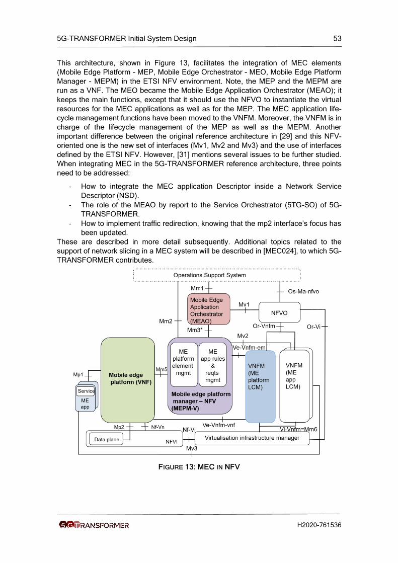
5G-TRANSFORMER Initial System Design 53
H2020-761536
This architecture, shown in Figure 13, facilitates the integration of MEC elements
(Mobile Edge Platform – MEP, Mobile Edge Orchestrator – MEO, Mobile Edge Platform
Manager - MEPM) in the ETSI NFV environment. Note, the MEP and the MEPM are
run as a VNF. The MEO became the Mobile Edge Application Orchestrator (MEAO); it
keeps the main functions, except that it should use the NFVO to instantiate the virtual
resources for the MEC applications as well as for the MEP. The MEC application life-
cycle management functions have been moved to the VNFM. Moreover, the VNFM is in
charge of the lifecycle management of the MEP as well as the MEPM. Another
important difference between the original reference architecture in [29] and this NFV-
oriented one is the new set of interfaces (Mv1, Mv2 and Mv3) and the use of interfaces
defined by the ETSI NFV. However, [31] mentions several issues to be further studied.
When integrating MEC in the 5G-TRANSFORMER reference architecture, three points
need to be addressed:
- How to integrate the MEC application Descriptor inside a Network Service
Descriptor (NSD).
- The role of the MEAO by report to the Service Orchestrator (5TG-SO) of 5G-
TRANSFORMER.
- How to implement traffic redirection, knowing that the mp2 interface’s focus has
been updated.
These are described in more detail subsequently. Additional topics related to the
support of network slicing in a MEC system will be described in [MEC024], to which 5G-
TRANSFORMER contributes.
FIGURE 13: MEC IN NFV

5G-TRANSFORMER Initial System Design 54
H2020-761536
4.1.9.1 Integration of MEC application in the NSD
We identified two solutions to integrate a MEC application descriptor inside the Network
Service Descriptor (NSD). The first solution involves in the extension of the NSD to
integrate AppD (see Figure 14). Similar to a Virtual Network Function Descriptor
(VNFD), the AppD has been defined in [30] to specifically describe a MEC application.
It contains several fields that represent the requirements of the MEC application;
particularly appTrafficRule and appDNSRule that concern the traffic redirection
requirement of an application, appRequiredService that indicates the required MEC
service to run the MEC application, and appLatency that indicates the latency
requirement of a MEC application.
FIGURE 14: INTEGRATION OF APPD INTO A NSD
Unlike a classical VNF, a MEC application is not allowed to scale resources (scale
up/down); therefore, the AppD does not include information on scalability. Instead, a
migration of a MEC application between two hosts is allowed.
The second solution consists in extending the VNFD, by integrating MEC-specific
fields, like appTrafficRule and appLatency. In this case, VNFs will leave these fields
empty, while MEC applications use these fields to indicate specific constraints, such as
latency, MEC services to consume, and traffic redirection. This solution avoids
modifying the NSD, but requires changing the VNFD.
Both solutions need a modification of a well-standardized component; hence changing
one of these components makes 5G-TRANSFORMER non-compliant to the NFV
standard. However, the integration of MEC in NFV is still under investigation, so
choosing between the two solutions will constitute one of 5G-TRANSFORMER’s
contribution to MECinNFV. At this point, we propose to use Solution 1, which assumes
the extension of the NSD with AppDs. Figure 15 illustrates the relationship between the
NSD and AppD. It should be noted that the choice of one solution has no impact on the
other components described later in this document. Therefore, the choice might change
in the future, if it is considered more appropriate to use Solution 2 during the project’s
progress.

5G-TRANSFORMER Initial System Design 55
H2020-761536
FIGURE 15: INTEGRATION OF APPD INTO A NSD
4.1.9.2 The role of MEAO
To recall, the MEAO is in charge of the placement of MEC applications, and their
instantiation using the NFVO function. In 5G-TRANSFORMER we propose to integrate
the MEAO within the 5GT-SO. To guarantee that MEC applications will be hosted at the
edge, the placement algorithm used by the 5GT-SO needs to consider the appLatency
information included in the NSD as an input when placing the AppD. According to the
abstraction information provided by the 5GT-MTP layer, particularly the latency access
to the radio networks from the different NFVIs used by the 5GT-MTP, the placement
algorithm of the 5GT-SO will place the MEC application by satisfying the latency
constraint indicated in the appLatency field. Indeed, we envision that the 5GT-MTP will
provide information on the available NFVIs, and their access latency to the different
radio access elements (eNB), typically organized by geographical location.
4.1.9.3 Traffic redirection
According to [31], traffic redirection using the mp2 interface should be adapted to the
new architecture, where the NFVO is supposed to control traffic redirection. Before
detailing how we envision traffic redirection in 5G-TRANSFORMER, we will detail first
the different scenarios to deploy a MEC application in 5G-TRANSFORMER. Three
scenarios are assumed:
(i) MEC applications that require traffic redirection and consume MEC services,
which are indicated in the AppD via the appTrafficRule and appServiceRequired
fields. An example of this type of application is video transcoding at the edge,
which relies on the Radio Network Information Service (RNIS) API to receive
Channel Quality Indicators (CQI) per UE and transcode the video stream
appropriately according to them. First, this type of application requires not only
the deployment of MEP, but also all the core network elements (vMME, vS/P-
GW, and vHSS) as the application requires to have access to a MEC service
that relies on a mobile network (including eNBs). To ensure traffic redirection, in
this scenario, the S/PGW needs to be split in two new entities [8], i.e. the
S/PGW-C and S/PGW-U. The S/PGW-C integrates all the control plane
functions (such as signaling and tunnel creation), while S/PGW-U contains only
forwarding functions. The S/PGW-C will control the S/PGW-U to forward the UE

5G-TRANSFORMER Initial System Design 56
H2020-761536
traffic to the appropriate destinations by enforcing rules using a southbound
API, e.g. OpenFlow. While the vMME, vHSS, vS/PGW can be run in a central
cloud, the S/PGW-U shall be run at the edge close to the MEP. This will allow
breaking the GTP tunnel and implementing the traffic redirection as indicated in
the appTrafficRule. Figure 16 indicates the different elements and their
interfaces to deploy this scenario. It should be noted that we propose to
integrate the MEPM within the MEP. The MEPM is considered as the Element
Manager (EM) of the MEP.
FIGURE 16: DEPLOYMENT OF SCENARIO 1
(ii) MEC applications requiring only MEC services; the appServiceRequired field is
used to indicate the type of MEC service needed by the application. Example of
such applications is a monitoring application using the RNIS API. In this
scenario, only the MEP needs to be deployed in addition to the MEC
application. Figure 17 Illustrates this case.
FIGURE 17: DEPLOYMENT OF SCENARIO 2
(iii) MEC applications requiring low latency access to the user plane, and traffic
redirection; the appTrafficRule field is used to indicate the required traffic by the
MEC application and appLatency indicates the latency constraint. An example
of this type of application is car collision avoidance. For this scenario, the MEC
application can be deployed without the need of other components. The only

5G-TRANSFORMER Initial System Design 57
H2020-761536
requirement is that the MEC application has access to the user plane traffic.
Therefore, the data plane can come from any underlying networks (WiFi, LTE,
5G, or fixed network). As an example, in LTE this can be achieved with S/PGW-
U as shown in Figure 16, but does not require the deployment of a MEP.
FIGURE 18: WORKFLOW OF DEPLOYING AN INSTANCE OF A NSD INCLUDING AN APPD
Having described the three considered scenarios and how they can be instantiated, we
will discuss our propositions to ensure traffic redirection for MEC applications. For
Scenario 2, there is no need to do traffic redirection. Therefore, the Virtual Network
Function Forwarding Graph (VNFFG) is sufficient to ensure the interconnection
between the MEP, eNodeB and MEC applications. For Scenario 3, a Network
Forwarding Path (NFP) must be present in the VNFFG, to specify a traffic classifier in
order to forward traffic to the MEC application. Here, there is no need to break the GTP
tunnel, as we assume that the VIM is redirecting the appropriate traffic to the MEC
application via the traffic classifier described in the NFP.
However, Scenario 1 requires the interaction with the S/PGW-U to install rules to break
the GTP tunnel and redirect the appropriate traffic to the MEC application, as requested
by the latter. To this end, we propose that the 5GT-SO, when the resources are
instantiated, configures the S/PGW-U via the VNFM, to install rules aiming at enforcing
the appTrafficRule specified by the MEC application. Figure 18 shows the necessary
workflow to enforce the traffic redirection for Scenario 1. This workflow relies on the 5G-
TRANSFORMER reference architecture.
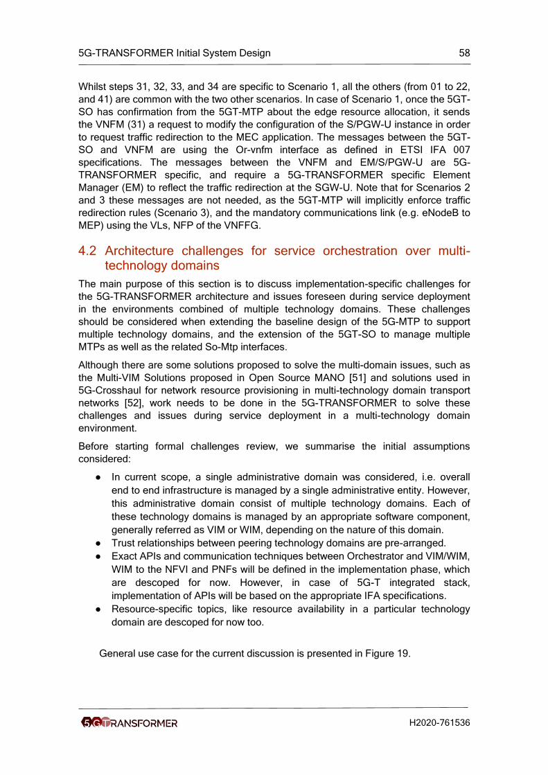
5G-TRANSFORMER Initial System Design 58
H2020-761536
Whilst steps 31, 32, 33, and 34 are specific to Scenario 1, all the others (from 01 to 22,
and 41) are common with the two other scenarios. In case of Scenario 1, once the 5GT-
SO has confirmation from the 5GT-MTP about the edge resource allocation, it sends
the VNFM (31) a request to modify the configuration of the S/PGW-U instance in order
to request traffic redirection to the MEC application. The messages between the 5GT-
SO and VNFM are using the Or-vnfm interface as defined in ETSI IFA 007
specifications. The messages between the VNFM and EM/S/PGW-U are 5G-
TRANSFORMER specific, and require a 5G-TRANSFORMER specific Element
Manager (EM) to reflect the traffic redirection at the SGW-U. Note that for Scenarios 2
and 3 these messages are not needed, as the 5GT-MTP will implicitly enforce traffic
redirection rules (Scenario 3), and the mandatory communications link (e.g. eNodeB to
MEP) using the VLs, NFP of the VNFFG.
4.2 Architecture challenges for service orchestration over multi-technology domains
The main purpose of this section is to discuss implementation-specific challenges for
the 5G-TRANSFORMER architecture and issues foreseen during service deployment
in the environments combined of multiple technology domains. These challenges
should be considered when extending the baseline design of the 5G-MTP to support
multiple technology domains, and the extension of the 5GT-SO to manage multiple
MTPs as well as the related So-Mtp interfaces.
Although there are some solutions proposed to solve the multi-domain issues, such as
the Multi-VIM Solutions proposed in Open Source MANO [51] and solutions used in
5G-Crosshaul for network resource provisioning in multi-technology domain transport
networks [52], work needs to be done in the 5G-TRANSFORMER to solve these
challenges and issues during service deployment in a multi-technology domain
environment.
Before starting formal challenges review, we summarise the initial assumptions
considered:
● In current scope, a single administrative domain was considered, i.e. overall
end to end infrastructure is managed by a single administrative entity. However,
this administrative domain consist of multiple technology domains. Each of
these technology domains is managed by an appropriate software component,
generally referred as VIM or WIM, depending on the nature of this domain.
● Trust relationships between peering technology domains are pre-arranged.
● Exact APIs and communication techniques between Orchestrator and VIM/WIM,
WIM to the NFVI and PNFs will be defined in the implementation phase, which
are descoped for now. However, in case of 5G-T integrated stack,
implementation of APIs will be based on the appropriate IFA specifications.
● Resource-specific topics, like resource availability in a particular technology
domain are descoped for now too.
General use case for the current discussion is presented in Figure 19.
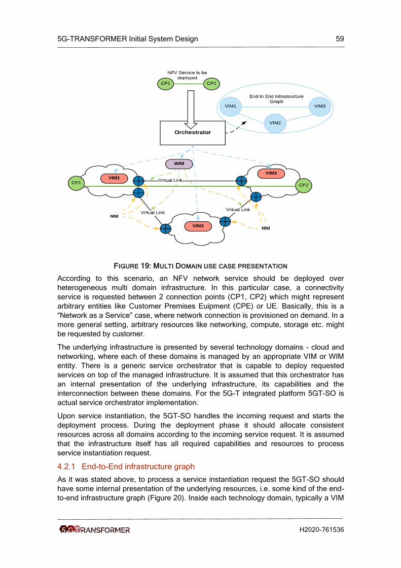
5G-TRANSFORMER Initial System Design 59
H2020-761536
FIGURE 19: MULTI DOMAIN USE CASE PRESENTATION
According to this scenario, an NFV network service should be deployed over
heterogeneous multi domain infrastructure. In this particular case, a connectivity
service is requested between 2 connection points (CP1, CP2) which might represent
arbitrary entities like Customer Premises Euipment (CPE) or UE. Basically, this is a
“Network as a Service” case, where network connection is provisioned on demand. In a
more general setting, arbitrary resources like networking, compute, storage etc. might
be requested by customer.
The underlying infrastructure is presented by several technology domains - cloud and
networking, where each of these domains is managed by an appropriate VIM or WIM
entity. There is a generic service orchestrator that is capable to deploy requested
services on top of the managed infrastructure. It is assumed that this orchestrator has
an internal presentation of the underlying infrastructure, its capabilities and the
interconnection between these domains. For the 5G-T integrated platform 5GT-SO is
actual service orchestrator implementation.
Upon service instantiation, the 5GT-SO handles the incoming request and starts the
deployment process. During the deployment phase it should allocate consistent
resources across all domains according to the incoming service request. It is assumed
that the infrastructure itself has all required capabilities and resources to process
service instantiation request.
4.2.1 End-to-End infrastructure graph
As it was stated above, to process a service instantiation request the 5GT-SO should
have some internal presentation of the underlying resources, i.e. some kind of the end-
to-end infrastructure graph (Figure 20). Inside each technology domain, typically a VIM
5G-TRANSFORMER Initial System Design 60
H2020-761536
or a WIM have an internal representation of the managed infrastructure and relevant
capabilities for automatic topology discovery. For example, OpenFlow SDN controllers
have capabilities to generate the topology automatically for all managed switches using
specialized discovery mechanisms based on appropriate protocols. However, topology
discovery in the multidomain environment is challenging. Additionally, it should be
stated that besides just networking connectivity it is required to present other types of
the resources, like compute, storage or their combination.
FIGURE 20: END TO END INFRASTRUCTURE GRAPH
In general, two options are possible to generate such topology information for the 5GT-
SO:
● Dynamic infrastructure and capabilities discovery, followed then by inventory or
graph generation;
● Statically specified inventory or graph along with appropriate infrastructure
capabilities.
From the operations perspective, dynamic topology discovery is the preferred
option. However, it might be challenging to implement consistent technology which will
be feasible for multi domain environments, considering the variety of the possible VIM
and WIM implementations. Thus, for 5G-TRANSFORMER the static definition of the
underlying infrastructure topology combined with appropriate inventory will be preferred
option initially. Later, the project plans to adopt some approaches for dynamic topology
and capabilities discovery, based for example on outputs of the 5GEx [53] and 5G-
Crosshaul [36] projects.
4.2.2 E2E path calculation and resource allocation
Assuming the infrastructure graph was generated and appropriate capabilities are
available in the inventory, the 5GT-SO should be capable to calculate, according to
some criterias/constraints, and optimal end-to-end path and request resource

5G-TRANSFORMER Initial System Design 61
H2020-761536
allocations. While connectivity details between VIMs/WIMs might be already provided,
a representation of the internal structure of each technology domain, combined with
inter-domain connectivity options, is required. This challenge is presented in Figure 21.
FIGURE 21: PRESENTATION OF THE TECHNOLOGY DOMAIN CONNECTIVITY
Inside of each technology domain, typically there is a complex infrastructure managed
by its own control plane. Thus, in case the 5GT-SO has just a global view of the
underlying infrastructure (which is effectively a set of interconnections among VIM and
WIM islands) the end-to-end path calculation and resource allocation might be
suboptimal. This suboptimal allocation might emerge due to the fact that the internal
structure and individual domain features are opaque for the calculation logic.
To deal with this issue the end-to-end path calculation logic should consider both the
global infrastructure view combined with specific features of the individual technology
domain. For example, if VIM is capable to provide certain features, like advanced QoS,
these capabilities should be exposed in the appropriate abstractions. Additionally, in
case of sophisticated services deployment like multidomain NFV services or low-
latency MEC application deployment, calculation logic should be combined with the
placement algorithm, which is aware of resources and capabilities available in a
particular technology domain.
4.2.3 Network to Network Interface (NNI) specification
Interconnected technology domains typically have logical or physical points where one
domain ends and another starts. For example, a transport network managed by a WIM
is connected to the Telco cloud, managed by a particular VIM. We refer to this point
between technology domains as usual as the Network to Network Interface (NNI).
However, it should be noted, that in our case this definition is broader than used in the
typical Telco environment as NNI might referred not just as “network to network”
interconnection, but “network to cloud” or “cloud to cloud” connections (Figure 22).
While deploying virtual links across multiple technology domains configuration and
consistent setting of these NNIs has to be ensured. Particularly, several interconnection
scenarios are possible, such as:

5G-TRANSFORMER Initial System Design 62
H2020-761536
● There is a border device (router, switch, VPN concentrator, etc.), which explicitly
splits domains and has interfaces connected to both technology domain. Thus,
consistency between the domains should be managed at the border device via
appropriate configuration.
● There is no explicit device interconnecting two technology domains. This can be
case, for example, when alink from the transport network attached directly to the
Top of the Rack (TOR) switch in the Telco cloud. In this case it is required to
apply consistent configuration to the VIM/WIM which are managing particular
entities at each domain.
FIGURE 22: NETWORK TO NETWORK INFRASTRUCTURE SPECIFICATION
An additional challenge is presented in Figure 22. In genera,l each technology domain
might have its own transport (networking) technology. For example, in the WAN domain
MPLS L2/L3 VPNs are the dominant transport technology. To attach MPLS VPN link to
the Telco cloud this VPN should be either terminated at border device or there should
be some entity capable to do VPN termination at the given compute node. On the other
hand, inside the Telco cloud a completely different networking technology, like VXLAN
5G-TRANSFORMER Initial System Design 63
H2020-761536
[55], might be used. Thus, orchestrator, i.e., the 5GT-SO should be supplied with
information to ensure consistent resource allocation and NNI configuration.
To summarise this challenge, some approach should be developed to specify and
express borders of the technology domains (NNIs) while constructing E2E topology and
relevant inventories. Using these details as an input, the 5GT-SO should be capable to
allocate consistent resources for these NNIs to ensure valid configuration of the virtual
links. To simplify this in some cases, it might be assumed that IP connectivity is
already available among all infrastructure elements. Thus, the NNI configuration might
be descoped and the focus is shifted towards service provisioning aspects, like Service
Function Chaining and VNF forwarding graphs configuration.
A separate item to be considered is the handling of the virtual or logical links which
span over multiple technology domains. Effectively, such end to end logical link is a
combination of the individual virtual links deployed at the particular technology domain
and managed by specific VIMs/WIMs. Thus, the 5GT-SO should be capable to track
the end to end logical link status, generate appropriate statistics, and provide relevant
management information.

5G-TRANSFORMER Initial System Design 64
H2020-761536
5 Vertical Slicer Design This chapter summarizes the design of the Vertical Slicer (5GT-VS), as well as its main
functional blocks and the algorithms therein. The summary is provided in a high level in
this deliverable, in order to give a complete view and offer a better understanding of the
whole system design. The details on the design of individual componets and their
internal workflows and interfaces can be found in D3.1 [3]. In this chapter, we describe
its architecture in Section 5.1 and its main components in subsequent sections. A
summary of the current state of the art soultions for the 5GT-VS in terms of descriptions
of network descriptors is given in Annex III Section 13.1.
5.1 Vertical Slicer Overview
The 5GT-VS is the common entry point for all verticals into the 5G-TRANSFORMER
system, being part of the OSS/BSS of the administrative domain of a 5G-
TRANSFORMER service provider (TSP). The 5GT-VS coordinates and arbitrates the
requests for vertical services. The vertical services are offered through a high-level
interface focusing on specifying the logic and the needs of the vertical services.
Specifically, the 5GT-VS allows defining vertical services from a set of vertical-oriented
service blueprints, which, along with instantiation parameters, will result in Vertical
Service Descriptors (VSD). Then, the 5GT-VS maps the vertical service descriptions
and requirements defined in the VSD onto a network slice, which we describe with
extended ETSI NFV Network Service Descriptors (NSD) [24]. NSDs define forwarding
graphs composed of a set of VNFs or Virtual Applications (VAs) connected with Virtual
Links (VLs), where some of the VAs have specific characteristics and constraints of
MEC applications. Importantly, the 5GT-VS allows mapping several vertical service
instances (VSI) onto one network slice, handling vertical-dependent sharing criteria or
strategies and taking care of the necessary capacity changes in existing slices. In
conclusion, the most fundamental tasks of the 5GT-VS are to provide the functionality
for creating the vertical service descriptions, and to manage the lifecycle and the
monitoring of VSIs and of the corresponding network slice instances (NSI) to which
they were mapped.
In addition to such tasks, the 5GT-VS provides arbitration among several vertical
service instances in case of resource shortage in the underlying infrastructure and
based on global budgets for resource utilization, as defined in the SLAs between the
verticals and the TSP. The arbitration component in the 5GT-VS maps priorities of
vertical services and SLA requirements to ranges of cardinalities of resources. These
cardinalities are used by the 5GT-SO while deploying the NFV network services (NFV-
NS) and, in case of actual resource shortage, to assign resources to the most important
vertical service instances.
The architecture of the 5GT-VS is shown in Figure 23. As mentioned, the 5GT-VS is
part of the provider’s OSS/BSS, and interacts with the vertical (including the M(V)NO)
through its northbound interface (NBI), and with the service orchestrator through its
southbound interface (SBI). The 5GT-VS interacts also with the OSS/BSS Management
Platform of the TSP. This in turn interacts with the TSP, but this interaction between
management platform and TSP is out of the scope of the 5GT-VS. Here, the TSP can

5G-TRANSFORMER Initial System Design 65
H2020-761536
manage tenants (tenant management), manage the resource budgets of tenants (SLA
management), and onboard Vertical Service Blueprints (VSB) (VS Blueprints catalog).
The Vertical Front-end is the entry point to receive requests from the verticals/MVNO
on vertical service provisioning, management and monitoring. Importantly, the Vertical
Front-end presents the vertical with Vertical Service Blueprints (VSB), stored and
handled through the related catalogue (VS Blueprints catalog), and supports the
vertical in providing the parameters therein to obtain the corresponding Vertical Service
Descriptor (VSD). VSBs and VSDs are described in D3.1 [3].
FIGURE 23: THE VERTICAL SLICER ARCHITECTURE
The lifecycle (LC) of Vertical Service Instances (VSIs) and the corresponding Network
Slice Instances (NSIs) are handled through the component called “VSI/NSI Coordinator
& LC Manager”. This component, described in Section 5.5, is the central engine of the
5GT-VS: it manages the association between VSIs and NSIs, regulating the sharing of
network slices among different vertical services and their decomposition into network
slice subnet instances (NSSIs). Moreover, it handles the finite state machines for VSIs’
and NSIs’ lifecycle, coordinating commands and events associated with them. The
network slice management is handled through requests for instantiation, modification
and termination of the corresponding NFV-NSs, interacting with the 5GT-SO. The
status and the current characteristics of VSIs and NSIs/NSSIs are stored persistently in
the VSI/NSI/NSSI records.
While the “VSI/NSI Coordinator & LC Manager” manages the lifecycle of slices and
vertical services, the complete 5GT-VS decision logic is implemented in the VSD/NSD
Translator and in the Arbitrator. The VSD/NSD Translator, described in Section 5.2,
selects the descriptors of the NFV network services that are able to support the
requested vertical services. The VSD/NSD Translator also identifies the network
service deployment flavor (DF) (e.g., number of VNF instances, amount of vCPU or
RAM for VNFs, bandwidth of VLs) to guarantee the performance and the characteristics

5G-TRANSFORMER Initial System Design 66
H2020-761536
defined in the VSD. The Arbitrator, described in Section 5.3, decides about the sharing
of network slices among different vertical services and the scaling of vertical services
based on service priority and resource budget in verticals’ SLAs.
The 5GT-VS Monitoring Service, described in Section 5.4, interacts with the 5GT-SO to
collect monitoring data about the established NFV network services and aggregates
these data to produce metrics and KPIs for the corresponding network slices and
vertical services. These metrics can be used for SLA verification, or to make decisions
about the lifecycle of a network slice, e.g. to trigger a scale-up action in case of
decreasing performance.
5.2 The VSD/NSD Translator Module
The VSD/NSD Translator module is an entity within the 5GT-VS that maps the vertical’s
requirements into technical specifications needed by the 5GT-SO to perform a NFV-NS
deployment. To define a vertical service or prepare it for deployment, the vertical first
selects a VSB, which contains parts that have to be filled in with the requirements it
demands. Once the vertical provides actual values for the missing parts in the VSB, the
latter becomes a Vertical Service Descriptor (VSD): a high-level specification of a
network service, based on a service logic perspective rather than a resource-based
perspective.
The VSD is then mapped onto a Network Service Descriptor (NSD) through the
following steps: (1) the Translator queries the Virtual Network Function Descriptor
(VNFD) catalogue within the 5GT-SO for the VNFs referenced in the VSD; (2) the
Translator queries the NSD catalogue within the 5GT-SO for the NSDs referenced in
the VSD; (3) the Translator fills the fields present in the deployment flavor of each
VNFD and of each Virtual Link Descriptor (VLD), using the QoS restrictions of the VSD
(such fields will be finalized by the Arbitrator later on).
5.3 The Arbitrator Module
SLA management is a key aspect in service provisioning to a vertical. Any degradation
of the SLA can impact not only on the technical behaviour of the vertical service but
also on the reputation or business leadership of the vertical itself. The vertical, as 5G-
TRANSFORMER service consumer, will specify Service Level Objectives (SLOs)
adapted to its service needs. An example of SLOs can be a maximum end-to-end
latency of 20ms for a vertical service in the automotive domain. Vice versa, the TSP’s
OSS/BSS can state different service level classes, representing distinct guarantees on
resource and/or service availability. The matching between the SLOs desired by the
vertical and the service level classes offered by a provider defines an SLA. The
contents and terms of an SLA are used as directives for the configuration and
orchestration of services and resources in network slices, where the orchestration is
done by the 5GT-SO.
The Arbitrator within the 5GT-VS implements these mechanisms and provides the 5GT-
SO with support for service deployment. It operates based on the SLA, as well as the
information on each service provided by the vertical, namely: (1) the service priority
level, (2) the VNFFG representing the service, (3) bandwidth requirements of the VLs
and the relative CPU requirements of the VNFs in the VNFFG, as well as their
memory/storage requirements, and (4) the vertical’s quality of service (QoS)

5G-TRANSFORMER Initial System Design 67
H2020-761536
requirements (e.g., end-to-end latency, service availability or reliability level). Note that
such information is described in the NSD created by the VSD/NSD Translator for the
received VSD.
The Arbitrator’s tasks are twofold:
1. Decide how to map new VSIs in NSIs/NSSIs, allowing multiple vertical services
to share one or more NSIs or NSSIs;
2. Determine the deployment flavors associated with each service, thereby
meeting the vertical’s QoS requirements and accounting for the priority level.
When instantiating a new vertical service and performing the second of these tasks, the
Arbitrator may detect there are insufficient resources in a resource budget for all VSI of
this vertical. This situation is reported to the vertical, which may then decide to a)
cancel the instantiation request, b) negotiate additional resources with the TSP, i.e.
increase the resource budget, and retry the instantiation, or c) confirm the instantiation
request. In the last case, the new VSI would be instantiated at the expense of lower-
priority VSIs.
5.3.1 Sharing of network slices among vertical services
During the instantiation of a vertical service, the Arbitrator is responsible for making
decisions about the sharing of NSIs and NSSIs among different vertical service
instances. A typical example could be the sharing of the same vEPC among different
vertical service instances with similar requirements in terms of mobile access, or the
sharing of a service component for the collection of vehicle messages among multiple
automotive services that make use of the same information. At present we focus on
arbitration among vertical services of one vertical, arbitration among several verticals
will be considered in future releases of the Arbitrator.
The decision about slice sharing is made by the Arbitrator analysing the pair <NSD;
DF> initially computed by the VSD/NSD Translator, which describes the structure, the
characteristics and the cardinalities of a potential NSI able to support the requested
VSI. Starting from the NSD, the Arbitrator verifies if one or more existing NSIs can be
re-used to accommodate the new VSI or at least part of it, e.g. one or more nested
NFV-NSs that may be included in the NSD. This decision is affected by the constraints
specified by the vertical in the VSD, in particular by the constraints about isolation.
If no suitable NSI is available, the Arbitrator decides to create a new NSI, based on the
NSD originally computed by the VSD/NSD Translator. It will proceed with the update of
the deployment flavor initially set by the VSD/NSD Translator (see Section 5.3.2). The
“VSI/NSI Coordinator & LC Manager” manages the instantiation of the new network
slice and its slice subnets, triggering the 5GT-SO to deploy the required NFV-NSIs.
On the other hand, if the Arbitrator finds existing NSIs that can be used, it determines if
and how they should be modified to accommodate the additional service. For this, it
interacts with the VSD/NSD Translator, providing as input the VSDs of all the VSIs that
will share resources from the given set of network slices. The VSD/NSD Translator
combines the requirements of the various VSDs and returns a suitable set of pairs
<NSD; DF> defining the characteristics and the size of the target NSIs. Assuming that
the elaborated solution is compliant with the vertical’s SLAs, the Arbitrator identifies the
NSIs to be modified and new ones to be created, according to the result provided by

5G-TRANSFORMER Initial System Design 68
H2020-761536
the VSD/NSD Translator. As in the previous case, the “VSI/NSI Coordinator & LC
Manager” manages the procedures to execute the required actions.
5.3.2 Computation of deployment flavors
Regarding deployment flavors, we consider firstly the case where a new NSI is
deployed for a requested vertical service. The Arbitrator assigns resources according to
the priority level of the VSIs of a vertical, starting from the highest-priority VSI. The
Arbitrator assigns memory and storage resources to this VSI, whereas for CPU and
bandwidth allocation a more complicated procedure is needed, as this allocation can be
adjusted and affects placement decisions as well. Here, service latency is the main
performance metric, i.e. the maximum latency that a VSI is allowed to experience. Two
components contribute to the service latency: (i) the processing time, due to the
execution of the VNFs in the VNFFG, and (ii) the network travel time, which is due to
the time needed to transfer data from one VNF to the next in the VNFFG, when
adjacent VNFs are deployed on different servers. While the former depends on the
CPU allocated to the VNFs execution, the latter depends on the deployment decisions
made by the 5GT-SO and on the bandwidth associated with the VLs connecting the
servers when the 5GT-SO places VNFs on different servers.
The Arbitrator considers the best and worst possible cases that may occur depending
on the 5GT-SO later decisions. The best case happens when all VNFs in the VNFFG,
are deployed within the same server. In this case, the bandwidth required for data
transfers over VLs for this VSI can be set to zero, while the allocated CPU can be
computed such that its processing latency is small enough without exceeding the
amount of CPUs available to the vertical.
In the worst case, each VNF is deployed in a different server, requiring the allocation of
network connections between the servers. The CPU allocation is computed as in the
best case, but shorter processing times have to be achieved to keep the sum of
processing and network travel time within limits.
The Arbitrator will update the deployment flavor in the VLDs and the VNFDs of the NSD
created by the VSD/NSD Translator with the information for these two cases.
Specifically, the Arbitrator sets the instantiation-level information element in the
VNFDFs by using the worst-case values as default deployment flavor and the best-
case values as optional. The updated NSD is then returned to the VSI/NSI Coordinator
& LC Manager, which will send it to the 5GT-SO. After the 5GT-SO has made its
deployment decisions, it will notify the 5GT-VS about the current resource allocation
(e.g., in terms of characteristics of the instantiated VNFs) so that the Arbitrator can
compute the new amount of resources that are available to the vertical.
Let us now consider the case where the vertical service to be processed can be
provisioned on an existing NSI or using an existing NSSI. In this case, the Arbitrator
adds the traffic load due to the newly requested vertical service to the load of the
existing VNFs/VLs, and re-computes the necessary CPU and bandwidth, as described
above. Again, the Arbitrator will use the CPU and bandwidth values obtained for the
worst and the best case, to update the deployment flavor of the involved VLDs and
VNFDs.
5G-TRANSFORMER Initial System Design 69
H2020-761536
In case of resource shortage, some lower-priority services may not be accommodated,
or may be terminated due to the need to re-allocate resources to higher priority
services.
To summarize, the Arbitrator module allows the 5GT-SO to make deployment decisions
meeting the vertical’s indications even if (i) the 5GT-SO is unaware of higher-layer
information like the SLA between the vertical and OSS/BSS, and (ii) the total amount of
available resources is not sufficient to adequately deploy all requested services.
5.4 The Monitoring Service
The 5GT-VS Monitoring Service is responsible for producing monitoring data about
network slices and vertical services and for elaborating more elementary monitoring
data about VNFs and NFV network services, as retrieved from the underlying 5GT-SO
Monitoring Service. It provides monitoring data about the VSIs as input for internal
decisions related to resource arbitration at the Arbitrator. The 5GT-VS provides also
monitoring data about the deployed VSIs to the verticals, to feed the internal processing
of vertical applications, where needed. The 5GT-VS monitoring service should be able
to expose the monitoring information it receives from the 5GT-SO Monitoring Service to
the VS Front-end. Actually, this exposure can be part of the SLA.
The 5GT-VS Monitoring Service receives and shares monitoring data from the 5GT-SO
via the Vs-So-Mon reference point, or generated internally. The VSI LC Manager and/or
NS(S)MF send a request to the 5GT-VS Monitoring Service indicating the monitoring
metrics to subscribe to. The 5GT-VS Monitoring Service relays the request to the 5GT-
SO Monitoring Service. During service runtime, the 5GT-SO indicates the availability of
monitoring data to the 5GT-VS Monitoring Service. The 5GT-VS Monitoring Service
retrieves the data and informs the VSI LC Manager and NS(S)MF. It can also send this
information directly to the 5GT-VS Front-end to provide the vertical with it, depending
on the SLA and what was defined in the VSD.
The 5GT-VS Monitoring Service can supervise alarms related to an NSI and/or VSI
only if it has subscribed to them. The NS(S)MF sends a corresponding request for
subscription to NSI alarm notifications towards the 5GT-VS Monitoring Service to
receive the alarm notifications related to the NSI. As a result of this operation,
whenever an alarm is raised, a notification will be sent to the 5GT-VS Monitoring
Service, which will transmit it to the NS(S)MF. The NS(S)MF can request the 5GT-VS
Monitoring Service to create, modify, and delete a threshold on a specified performance
metric (for NFV-NSI(s)) for which notifications will be generated when crossed. The VSI
LC Manager can do the same for vertical service(s).
5.5 VSI/NSI Coordinator & LC Manager
This component coordinates the activities of the other 5GT-VS components. To do so,
it uses several subcomponents and interacts with the other components and databases
of the 5GT-VS. The subcomponents are the VSI Group Coordinator to handle the VSIs
of one vertical, the VSI LC Manager to handle the lifecycle of single VSIs, and the
Network Slice (Subnet) Management Functions (NSMF, NSSMF) to handle the lifecycle
of NSIs and NSSIs.

5G-TRANSFORMER Initial System Design 70
H2020-761536
5.5.1 VSI Group Coordinator
One or several resource budgets may be defined for the VSIs of a vertical. These
resource budgets define the maximum amount of e.g. storage, vCPU, memory, and
bandwidth. The resource consumption of a specific VSI is checked against one such
resource budget. The VSI Group Coordinator component maintains the relation
between resource budgets and VSIs for each individual vertical. The actual checking
and arbitration among different VSIs is done by the Arbitrator (see Section 5.3).
5.5.2 VSI LC Manager
The VSI LC Manager proposes vertical services to customers via the catalogue of
VSBs, which may include also information on the services’ cost. Internally, the VSI LC
Manager keeps a record of the requested VSIs and maintains their references to the
associated supporting NSIs. It also performs accounting of vertical service resource
consumption per NSI.
The 5GT-VS SBI is used to link the NSMF in the 5GT-VS with the 5GT-SO, e.g. for
network slice management: discovery, allocation and LCM of NSIs, performance
monitoring, fault management and accounting. Due to the monitoring and the fault
management of NSIs, the VSI LC Manager is aware of the running state of each NSI
and able to verify whether it matches the expected SLAs of the corresponding VSIs. If
the outcome indicates that a vertical service SLA has not been fulfilled, remediation is
required.
In addition, the VSI LC Manager supports LCM operations, pricing and charging,
performance monitoring and fault reporting of VSIs. If a customer changes the
requirements of a VSI, the VSI LC Manager triggers the Arbitrator to update the
network slice requirements via recalculation of the NSD deployment flavor. Eventually,
the VSI LC Manager asks the NSMF for a modification of the NSI capacities.
As mentioned, the VSB catalogue includes information on the SLA costs. To enable the
charging of the verticals for the VSIs, the VSI LC Manager traces their resource
consumption according to information (e.g., monitoring data, events) reported by the
5GT-SO to the 5GT-VS Monitoring Service. Thus, the VSI LC Manager subscribes to
alarm notifications, using the 5GT-VS Monitoring Service. Some service related alarm
data may be provided, if required, to the verticals. Also, the VSI LC Manager
subscribes to performance measurement notifications. Again, some service related
performance measurement data may be provided to the verticals.
5.5.3 NSMF and NSSMF
The NSMF manages NSIs; correspondingly the NSSMF manages NSSIs, see also
Section 4.1.7. As mentioned, the VSI LC Manager relies on the NSMF and NSSMF to
assess the feasibility of providing NSIs and NSSIs, respectively. As the functionalities
of NSMF and NSSMF are rather similar, we describe in the following the NSMF
functionality only. The NSMF and NSSMF are based on [6].
Specifically, the NSMF checks which PNFs and/or VNFs are referenced in the NSDs
(the NSDs are exposed by the the NSD catalogue inside the 5GT-SO to the 5GT-VS),
then the NSMF provides the VSI LC Manager with the NSIs, through which a VSI could
be deployed. The NSMF also keeps record of all the network slice requirements (e.g.
number of CPU, storage) per NSI. This information can be used by the Arbitrator to

5G-TRANSFORMER Initial System Design 71
H2020-761536
recalculate the deployment flavors of the NFV-NSs when new VSIs are instantiated or
existing ones are updated or terminated. However, the NSMF is not aware of the VSIs
but only of the requirements received from the Arbitrator. Due to the monitoring and the
fault management of NFV-NS instances, the NSMF is aware of the running state of the
latter and able to verify the expected functionalities and whether its SLAs are met or
not. In case of SLA violations, the NSMF can trigger corresponding alarms.

5G-TRANSFORMER Initial System Design 72
H2020-761536
6 Service Orchestrator Design This chapter summaries the design of the Service Orchstrator (5GT-SO), as well as its
main functional blocks and orchestration algorithm framework. A detailed description of
5GT-SO architecture as well as the review of the state of the art solutions for the 5G-
SO platform is provided in the 5G-TRANSFORMER deliverable D4.1[4]. Similar to
Chapter 5, the aim is to provide an overview of the 5GT-SO, presenting a general
insight of the proposed 5GT-SO approach and architecture solutions, which
completmente the whole 5G-TRANSFORMER system architecture design.
6.1 Key functionalities of 5GT-SO
The 5GT-SO is in charge of end-to-end (E2E) orchestration of the NFV-NS across one
or multiple administrative domains by interacting with the local 5GT-MTP and/or with
other 5GT-SOs, respectively, while addressing and managing the allocation of different
vertical slices. 5GT-SO receives the service requirements from 5GT-VS via the Vs-So
interface (see Figure 2 in Section 3) in the shape of a Network Service Descriptors
(NSD). A NSD describes a Network Service (NFV-NS) that 5GT-SO is able to provide
(either by its own or by leveraging neighboring SOs); it is expressed in terms of
chaining of VNF components (i.e., constituent VNFs) described by VNF Descriptors
(VNFD). A VNFD describes a VNF in terms of its deployment and operational behavior
as well as connectivity (i.e., virtual links) requirements.
The 5GT-SO processes the NSD in order to assign virtual networking, computing and
storage resources across one or multiple local/remote 5GT-MTP domains while
addressing service requirements specified in the NSD. To this purpose, the 5GT-SO
embeds the Network Service Orchestrator (NFV-NSO) and the Resource Orchestrator
(NFV-RO) with functionalities equivalent to those of ETSI NFV Orchestrator [14]. The
NFV-NSO has the responsibility of coordinating the deployment of NFV-NSs along with
their lifecycle management. The NFV-RO is in charge of orchestrating virtual resources
across multiple domains. Moreover, both may be used for single and multi-domain
service orchestration. Indeed, if local resources are not enough to address the NFV-NS
requirements, the 5GT-SO interacts with 5GT-SOs of other administrative domains
through So-So interface (federation) to take decisions on the end-to-end
(de)composition of network services and their most suitable execution environment,
i.e., service federation.
In addition to a complete E2E NFV-NS deployment and orchestration, the 5GT-SO may
take care of NFV infrastructure as a service (NFVIaaS) operations. In case of NFVIaaS,
the request from the 5GT-VS is processed by the NFVO-RO, which is in charge of
allocating resources either from the local 5GT-MTP or from federated domain(s). The
latter case corresponds to the resource federation where the request from the local
NFVO-RO reaches the NFVO-RO of the federated domain to accomplish the required
virtual resource allocations.
Service orchestration involves the management, instantiation, and migration of VNFs
and/or VAs at local, edge and cloud NFVIs. The problem of mapping VNFs to (virtual)
computing entities (nodes, NFVI-PoPs) and the mapping of virtual links between VNFs
into (virtual) paths, depending on the granularity of abstraction offered by the 5GT-
MTPs, can be tackled by different optimization strategies, namely heuristics or mixed-
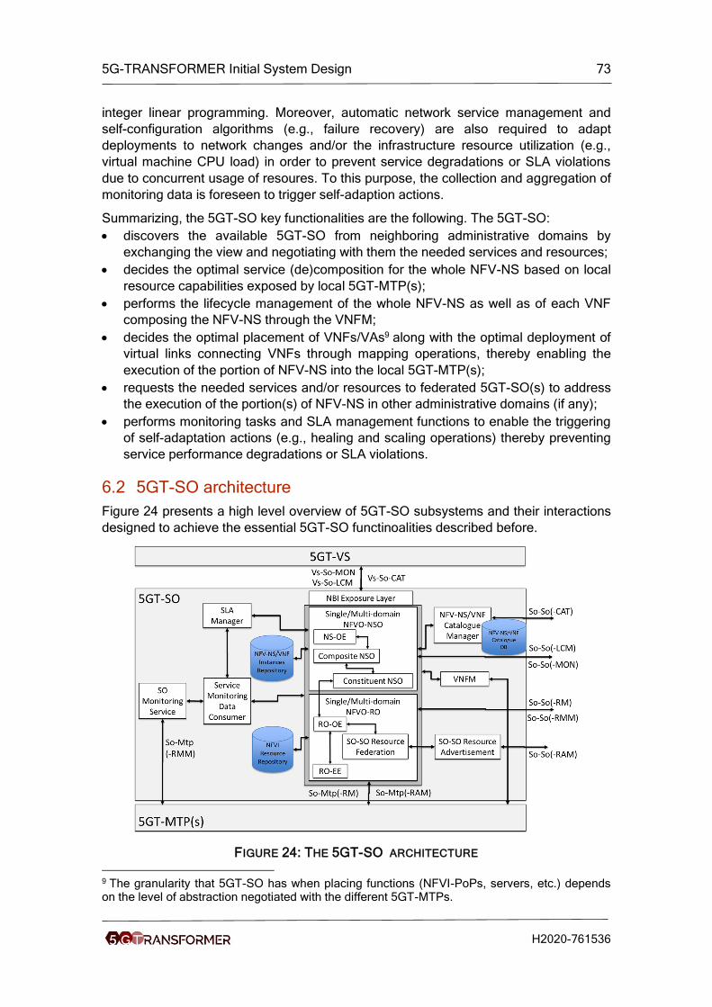
5G-TRANSFORMER Initial System Design 73
H2020-761536
integer linear programming. Moreover, automatic network service management and
self-configuration algorithms (e.g., failure recovery) are also required to adapt
deployments to network changes and/or the infrastructure resource utilization (e.g.,
virtual machine CPU load) in order to prevent service degradations or SLA violations
due to concurrent usage of resoures. To this purpose, the collection and aggregation of
monitoring data is foreseen to trigger self-adaption actions.
Summarizing, the 5GT-SO key functionalities are the following. The 5GT-SO:
• discovers the available 5GT-SO from neighboring administrative domains by
exchanging the view and negotiating with them the needed services and resources;
• decides the optimal service (de)composition for the whole NFV-NS based on local
resource capabilities exposed by local 5GT-MTP(s);
• performs the lifecycle management of the whole NFV-NS as well as of each VNF
composing the NFV-NS through the VNFM;
• decides the optimal placement of VNFs/VAs9 along with the optimal deployment of
virtual links connecting VNFs through mapping operations, thereby enabling the
execution of the portion of NFV-NS into the local 5GT-MTP(s);
• requests the needed services and/or resources to federated 5GT-SO(s) to address
the execution of the portion(s) of NFV-NS in other administrative domains (if any);
• performs monitoring tasks and SLA management functions to enable the triggering
of self-adaptation actions (e.g., healing and scaling operations) thereby preventing
service performance degradations or SLA violations.
6.2 5GT-SO architecture
Figure 24 presents a high level overview of 5GT-SO subsystems and their interactions
designed to achieve the essential 5GT-SO functinoalities described before.
FIGURE 24: THE 5GT-SO ARCHITECTURE
9 The granularity that 5GT-SO has when placing functions (NFVI-PoPs, servers, etc.) depends on the level of abstraction negotiated with the different 5GT-MTPs.

5G-TRANSFORMER Initial System Design 74
H2020-761536
The main building blocks comprising 5GT-SO are the following:
– NBI Exposure Layer acts as a Front-End functionality offering a Northbound API
towards the 5GT-VS to process requests for NSD on-boarding, NFV-NS creation,
instantiation, modification, and termination. The details on the NBI interface are
described in section 4.1.5.2.
– NFV-NS/VNF Catalogue DB/Manager is a composite building block in charge of
repository and management functions of the offered catalogue. More specifically,
the Catalogue DB is the repository of all usable Network Service Descriptors
(NSDs) and VNF Descriptors (VNFDs) as well as AppDs for MEC applications (see
Section 4.1.9.1) that can be accessed through the Catalogue Manager. The
NSD/VNFD is used by the 5GT-SO in the process of NFV-NS/VNF instantiation and
its lifecycle management to obtain relevant information, e.g., deployment flavors or
out-scaling rules. The Catalogue Manager also takes care of the advertising of
NFV-NSs for federation purpose.
– NFV Orchestrator (NFVO): has the responsibility of coordinating the deployment of
NFV-NSs along with their lifecycle management, thus fulfilling the Network Service
Orchestration (NFVO-NSO) functions. The NFVO is also in charge of orchestrating
virtual resources across multiple domains, thus fulfilling the Resource Orchestration
(NFVO-RO) functions. More specifically, the NFVO-NSO coordinates all the NFV-
NS deployment operations including Authentication, Authorization and Accounting
(AAA) as well as formal checks of service requests based on attributes retrieved
from NSDs and VNFDs. In particular, the Composite NSO, using the algorithms
implemented in the NFV-NS Orchestration Engine (NS-OE), decomposes the NSDs
into several segments and decides where to deploy them, i.e., whether using a local
5GT-MTP or leveraging neighbor SOs. Correspondently, the Composite NSO
requests (i) the Constituent NSO and then the local NFVO-RO to deploy the NFV-
NS segment into its administrative domain; and/or (ii) the federated NFVO-NSO to
deploy the NFV-NS segment(s) into their administrative domains. Finally, the
NFVO-NSO is responsible for the network service lifecycle management including
operations such as service instantiation, scaling, termination, and management of
the VNF forwarding graphs associated to the network services. Moreover, the
NFVO-RO maps the NFV-NS segment into a set of virtual resources through the
RO Orchestration Engine (RO-OE) by deciding the placement of each VNFs within
the virtual infrastructure, based on specified computational, storage and networking
(e.g., bandwidth) requirements. The decision is based on available virtual resources
that are exposed by the 5GT-MTP via the 5GT-SO Southbound Interface (SBI) or
by other domains through the So-So Eastbound/Westbound Interface (E/WBI). In
the latter case, the sharing of abstract views is needed to build-up a comprehensive
view of all the resources available from different domains and it is carried out by the
SO-SO Resource Federation element. Then, the RO Execution Entity (RO-EE)
takes care of resource provisioning by managing the coordination of correlated
actions to execute/forward the allocation requests to either 5GT-MTP or to the 5GT-
SO NFVO-RO of other domains.
– VNF Manager (VNFM): is in charge of the lifecycle management of the VNFs
deployed by the 5GT-SO using either local or remote resources (or a combination
of them). It receives relevant VNF lifecycle events from the local NFVO and
provides reconfiguration according to specified counteractions decided by the
NFVO based on VNFDs (e.g., auto-scaling).

5G-TRANSFORMER Initial System Design 75
H2020-761536
– SO-SO Resource Advertisement: is in charge of exchanging abstract resource
views (e.g., abstract topologies, computing and storage capabilities) with other
domains while feeding the 5GT-SO Resource Federation entity that consolidates
inputs and stores federated resources into the NFVI Resource Repository.
– NFVI Resource Repository stores consolidated abstract resource views received
from the underlying 5GT-MTPs, either from the SBI or from the SO-SO Resource
Federation block in case of abstract resource views received from other
SOs/domains through the So-So E/WBI.
– NS/VNF Instance Repository stores the instances of VNFs and NFV-NSs that have
been instantiated.
– SO Monitoring Service provides the measurement reports for the 5GT-SO to carry
out lifecycle management of NFV-NSs and, if needed, to trigger self-configuration
and recovery actions (e.g., self-healing, fault recovery, auto-scaling). The aim is to
adapt deployed services or provisioned resources while preventing service
degradations and/or SLA violations due to the concurrent usage of resources from
different services.
– Service Monitoring Data Consumer supports the lifecycle management of
instantiated VNFs/NFV-NSs by collecting measurement reports from the 5GT-SO
Monitoring Service and reporting data to the NFVO (e.g., to trigger auto-scaling
actions based on scaling rules in the NSD) and/or to the SLA Manager (e.g., to
enable SLA on-line verification). Performance reports can be also used to trigger
healing actions to recover from failures or service degradations.
– SLA Manager elaborates performance reports from the Service Monitoring Data
Consumer during the service lifecycle and assures that the agreed SLAs are
continuously satisfied through on-line SLA verification. In the event a requested
SLA is not met, the SLA Manager may trigger scaling actions to prevent or recover
from SLA violations.
6.3 Service Orchestration and Federation
Decisions for service orchestration and/or federation are triggered when 5GT-VS
requests the instantiation of a network service or modifications of an existing network
service. In both cases, the 5GT-SO NFVO has two main decisions to make, namely:
1. How to decompose the network service graph (i.e., NSDs) into several network
service segments and, consequently, where to implement each segment,
whether in the local 5GT-MTP domain or by leveraging neighbor 5GT-SOs
(using service federation).
2. How to map a service segment into a set of virtual resources, i.e., where to run
the component VNFs in the virtual infrastructure based on specified resource
demand.
The first decision includes service decomposition and the possible use of service
federation, where the second step consists of resource orchestration and possible use
of resource federation.

5G-TRANSFORMER Initial System Design 76
H2020-761536
6.3.1 Service Orchestration
6.3.1.1 Information provided to 5GT-SO
The 5GT-SO interacts with the 5GT-VS and the 5G-MTP, where both provide
information that is used to make orchestration decisions. The 5GT-VS is using NSD to
define information about the set of VNFs and their interconnection for all the NFV-NS
instances that will be requested for that NSD. At the service instatiation time, the 5GT-
VS provides information about the needed resources for each VNF in the specific NFV-
NS instance in the form of an NSD deployment flavor.
The input data from 5GT-MTP consists of a set of available resources that are stored in
the 5GT-SO’s NFVI resource repository. In general, the 5GT-VS asks the 5GT-SO to
instantiate a certain network service, and it is the 5GT-SO’s task to decide how to
provide it, i.e., which of the virtual resources exposed by the 5GT-MTP or offered by
federated 5GT-SOs shall be used.
6.3.1.2 Service orchestration decision steps
Service orchestration decisions consist of a preliminary step and three major steps.
The preliminary step of the 5GT-SO is when all input data is translated into an instance-
level system model, synthetically representing all the elements to account for,
categorized in two categories: 1) VNF-related – VNFs to place, capabilities they require,
amount of data they exchange; 2) infrastructure-related – hosts able to run VNFs and
their capabilities, logical links10 and their capacity/delay.
Both the VNF-related and the infrastructure-related elements of the system model can
be represented as graphs, namely the VNFFG and a virtual infrastructure graph.
An example of the virtual infrastructure graph is shown on the Figure 25. The graphs
consists of the hosts hx with capabilities (h) and the logical links connecting the hosts
with the capacity C(h1,h2) and delay (h1,h2).
FIGURE 25: EXAMPLE OF VIRTUAL INFRASTRACTURE GRAPH
10 In this context, logical links are the links exposed by the 5GT-MTP to the 5GT-SO. A logical link is a path at the infrastructure level connecting two physical interfaces. As such, they are distinct from IFA013 virtual links.

5G-TRANSFORMER Initial System Design 77
H2020-761536
The three major decision steps that result in three decision variables are:
• VNF11 placement, i.e., location where in the virtual infrastructure exposed by the
5GT-MTP each VNF shall be hosted. VNF placement decisions are represented
through binary variables A(h,v), each expressing whether a given VNF v is
assigned to a certain host h. Using a binary variable here reflects the fact that
VNFs cannot be split across multiple hosts. If we extend the model to consider a
VNF composed of multiple VNFCs, then, it could be that a VNF can be split
across multiple hosts;
• Resource assignment, i.e., how much of virtual resources (computational
power, memory, storage…) each VNF shall be assigned. For resources such as
memory, storage, bandwidth, etc., VNFs shall get the exact amount they need,
while for other resources (e.g., CPU) can be allocated in a more flexible fashion
using minimum and maximum thresholds;
• Traffic routing, i.e., which logical links at the infrastructure level should be used
to implement the virtual link instances for transferring data between different
VNFs, and their bandwidth assignment. The traffic and the delays on the logical
links must not exceed the capacity of the logical links and the service time
requirements expressed in the virtual link descriptors.
The three decision variables above impact one another. The entities in charge of these
decisions are the NFVO-NSO and the NFVO-RO. However, owing to the
interdependence between decisions, a convenient approach is therefore to make joint
placement, assignment and routing decisions, thus accounting for all the aspects of the
orchestration problem.
6.3.1.3 Constraints
Along with the decisions that have to be made, there are four major constraints that the
5GT-SO has to honor. The first one, host capabilities, is the total amount of resources
assigned to VNFs must not exceed the capabilities of the host that is running the VNFs.
The second is the minimum VNF resources or that for each VNF must be assigned at
least the minimum amount of resources required. The third constraint, the link capacity,
meaning that the total amount of traffic produced between VNFs placed at host h1 and
VNFs placed at h2 must not exceed the logical link capacity between h1 and h2. The
forth constraint is the service time which mainly depends on the processing time (in the
VNFs) and the network delays (sum of the delays on the traveling logical links).
Additional constraint is added for each service-specific KPI.
6.3.1.4 Objective
The objective is to make placement (of VNF), assignment (of resources) and network
routing that satisfies the described constraints while maintaining the service KPIs with
optimized network usage, power consumption, or cost.
6.3.1.5 Service Orchestration Algorithms
The task of the 5GT-SO can be viewed as setting the decision variables (the three
major steps) in order to optimize the objective in 6.3.1.4, subject to the constraints in
11 For simplicity, we refer to VNFs only in the description of our algorithms. Notice however that they can be easily extended to VNFCs.

5G-TRANSFORMER Initial System Design 78
H2020-761536
6.3.1.3. Directly solving the orchestration problem through optimization is not a viable
approach.
The proposed orchestration algorithm is based on a decoupling strategy based on three
pillars:
• Decoupling VNF placement decisions from resource assignment and traffic
routing ones.
• Making placement decisions sequentially, one VNF per iteration, without
deciding a priori the order in which VNFs are placed.
• Within each iteration, solve a relaxed (convex) problem to obtain guidance
about the placement decisions, rather than to directly set all decision variables.
The idea of decoupling VNF placement decisions from the others comes from the
observation that, if placement decisions were given, then the problem of resource
assignment and traffic routing would become much simpler, namely, convex. The
relaxation is a solution strategy used when dealing with binary optimization problems,
based on replacing binary variables with continuous (real) ones.
The proposed solution for VNF placement is heuristic, summarized in Figure 26. At the
first iteration, it solves a convex problem where all placement variables A(h,v) are
replaced with their relaxed counterparts a(h,v). Then, the VNF v* and the host h* are
identified with the highest value of such variable, and VNF v* is placed at host h*. If
there are more VNFs to be placed, the heuristic continues with a new iteration, solving
a new relaxed problem where:
• The a-variables, corresponding to VNFs that have not been placed, are relaxed.
• The a-variables, corresponding to VNFs that have been placed, are fixed, either
to one (for the host the VNF is placed at) or to zero (for all other hosts).
After all VNFs are placed, the heuristic terminates.
FIGURE 26: DECOUPLED VNF PLACEMENT HEURISTIC
The usage of relaxed problems and how decisions are made across iterations are the
two aspects of placement heuristics that make it especially effective. The order in which
VNFs should be placed is not decided a priori, which allows us to place first the VNFs
for which the relaxed problem provides the strongest indications. This results in
decisions that are guaranteed to be feasible.
As far as complexity is concerned, our placement heuristic runs for as many iterations
as there are VNFs to place, and during each iteration exactly one convex optimization
problem is solved. Considering that convex optimization problems have polynomial
(namely, cubic) time complexity in the number of variables, we can conclude that our
placement heuristic – and our decoupled solution strategy as a whole – have the
potential to be used in real-world 5GT-SO implementations.

5G-TRANSFORMER Initial System Design 79
H2020-761536
6.3.2 Federation
In 5G-TRANFORMER there are two types of federation: federation of services and
federation of resources. Both federation procedures occur in the 5GT-SO. To enable
federation, the administrative domains (implementing the 5G-TRANSFORMER system)
need to define mutual business/service agreements among each other (federation
level), initial catalogue of services and the network connections between administrative
domains (So-So interface, see Section 4.1.5.4).
6.3.2.1 Federation levels
The federation relationships among administrative domains are ranked on different
federation levels, depending of the business/service agreements. The federation levels
indicate the mutual degree of trust among administrative domains and they can be from
lower to higher, defined as bronze, silver, gold, platinum, etc. For higher federation
levels (e.g., platinum), significantly broader options and specific information parameters
about resources and/or services are exchanged between the administrative domains.
For the lower levels(e.g., bronze), the offering of resources and/or services is limited
and information for parameters is more abstract and descriptive. How these levels
should be achieved and to what extent is for further study.
6.3.2.2 Service federation
The decision for service federation occurs upon service decomposition. The 5GT-VS
issues a request for instantiation of new NFV-NS or modification of existing NFV-NS
(using NSD). The requested NFV-NS is decomposed into one or more segments.
Some of these segments could be nested services that can be instantiated on another
administrative domain. The decomposition procedure is for further study.
The 5GT-SO NFVO-NSO is in charge of performing the service federation procedure.
Pre-requirements for service federation is the service catalogue and the network
connections between different administrative domains. We assume that network
connections are established upon business/service agreements are made. The
catalogue of services is used to collect all the federation capabilities of the other
domains. The catalogue of services can be formed dynamically or in a static manner. In
the dynamic manner the 5GT-SOs exchange their capabilities to provide service
federation among themselves, while the 5G-TRANSFORMER system is running. Each
5GT-SO broadcasts (periodically or event-triggered) the capabilities to the different
groups of peers, grouped according to the federation levels. In the static manner, the
catalogue of services is defined during the business/service agreements among the
administrative domains and contains more generic and pre-defined services.
When the 5GT-SO NFVO-NSO decides to consume federated NFV-NS from external
domain, first it checks the catalogue of services for available NFV-NS. Based on certain
criteria (e.g., federation level, footprint of the service, closest peer), which is still not
defined, the 5GT-SO NFVO-NSO would send a request for instantiation of the NFV-NS
(segment or nested service) to the provider 5GT-SO NFVO-NSO. If the NFV-NS is
available, the provider 5GT-SO NFVO-NSO instantiates and provides the NFV-NS to
the consumer 5GT-SO NFVO-NSO. All the details (e.g., VNFs, VLs, monitoring
parameters, etc.) are hidden away from the consumer 5GT-SO NFVO-NSO, depending
on the federation level between both administrative domains. The consumer 5GT-SO

5G-TRANSFORMER Initial System Design 80
H2020-761536
NFVO-NSO would use the So-So-LCM of the E/WBI to send requests for lifecycle
operations of the provided NFV-NS.
6.3.2.3 Resource federation
The federation of resources occurs in the 5GT-SO NFVO-RO. The federation of
resource is split in two phases: 1) advertisement phase and 2) allocation and
management phase. As in the federation of services, pre-requirements would be:
business/service agreements (federation levels) and setup of network connections.
The advertisement phase of the federation of resources has the objective for providing
each 5GT-SO NFVO-RO with an updated view of the available resources in the other
administrative domains. This phase contains calculation of resource abstractions and
broadcasting of the resource abstractions towards peering 5GT-SOs. The abstraction
of resources is applied twice. First, the 5G-MTP applies resource abstraction on the
underlying NFVI infrastructure to hide some details of NFVI resources from the local
5GT-SO. The second abstraction is applied by the 5GT-SO NFVO-RO to hide away
more parameters of the underlying resources (e.g., number of CPU cores, type of
storage, etc.). The outcomes of the calculations are categorized in federation levels.
The categorized information is then broadcast by the SO-SO Advertisement block to
the peering 5GT-SOs according to the established federation level. On the receiving
end, the categorized information is stored in the NFVI database, as an updated view of
peering 5GT-SOs resources.
The second phase, allocation and management of resources, is triggered in the 5GT-
SO NFVO-RO upon decision to use federated resources. Once the decision is made,
the request for resources is sent from the consumer 5GT-SO NFVO-RO to the chosen
provider 5GT-SO NFVO-RO. The algorithm for choosing the available resource
abstractions of an external provider 5GT-SO NFVO-RO is a work in progress, satisfying
certain criteria (e.g., resource capacity, delay, federation level, location, etc.). Once the
provider 5GT-SO NFVO-RO processes the request and allocates the resources on its
constituent 5GT-MTP, it provides positive response to the consumer 5GT-SO NFVO-
RO, with details of the allocated federated resources. The consumer 5GT-SO NFVO-
RO includes the allocated federated resources as its own, managing and monitoring
their performance through the monitoring primitives of the So-So interface. The
limitations on the management operations and monitoring parameters directly depend
on the federation level between the two 5GT-SOs. The provider 5GT-SO NFVO-RO is
a forwarding point between the consumer 5GT-SO NFVO-RO and the provider 5GT-
MTP.
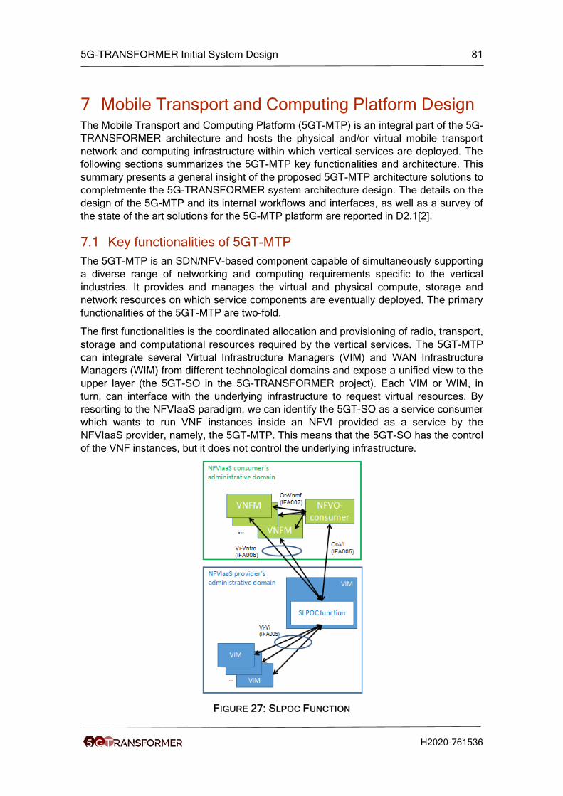
5G-TRANSFORMER Initial System Design 81
H2020-761536
7 Mobile Transport and Computing Platform Design The Mobile Transport and Computing Platform (5GT-MTP) is an integral part of the 5G-
TRANSFORMER architecture and hosts the physical and/or virtual mobile transport
network and computing infrastructure within which vertical services are deployed. The
following sections summarizes the 5GT-MTP key functionalities and architecture. This
summary presents a general insight of the proposed 5GT-MTP architecture solutions to
completmente the 5G-TRANSFORMER system architecture design. The details on the
design of the 5G-MTP and its internal workflows and interfaces, as well as a survey of
the state of the art solutions for the 5G-MTP platform are reported in D2.1[2].
7.1 Key functionalities of 5GT-MTP
The 5GT-MTP is an SDN/NFV-based component capable of simultaneously supporting
a diverse range of networking and computing requirements specific to the vertical
industries. It provides and manages the virtual and physical compute, storage and
network resources on which service components are eventually deployed. The primary
functionalities of the 5GT-MTP are two-fold.
The first functionalities is the coordinated allocation and provisioning of radio, transport,
storage and computational resources required by the vertical services. The 5GT-MTP
can integrate several Virtual Infrastructure Managers (VIM) and WAN Infrastructure
Managers (WIM) from different technological domains and expose a unified view to the
upper layer (the 5GT-SO in the 5G-TRANSFORMER project). Each VIM or WIM, in
turn, can interface with the underlying infrastructure to request virtual resources. By
resorting to the NFVIaaS paradigm, we can identify the 5GT-SO as a service consumer
which wants to run VNF instances inside an NFVI provided as a service by the
NFVIaaS provider, namely, the 5GT-MTP. This means that the 5GT-SO has the control
of the VNF instances, but it does not control the underlying infrastructure.
FIGURE 27: SLPOC FUNCTION

5G-TRANSFORMER Initial System Design 82
H2020-761536
In particular, since the 5GT-MTP is structured in several VIMs/WIMs, it acts as a single
entry point (see Figure 27), i.e., single logical point of contact (SLPOC) in ETSI GS
NFV-IFA 028 [26] terminology, for any resource allocation request coming from the
5GT-SO. In this case the NFVIaaS provider's VIMs/WIMs are hidden from the NFVIaaS
consumer and unified interfaces are exposed by the SLPOC and offered to the
NFVIaaS consumer.
The second functionality is providing an abstracted view of the resources to the 5GT-
SO, thus hiding the complexity of the specific underlying technologies. In the context of
5G-TRANSFORMER, the 5GT-MTP resources consists of the RAN and core network,
transport network, MEC infrastructure, compute, and storage resources. Thus, the
5GT-MTP will provide a scalable and efficient abstraction that takes into account all
these aspects. In particular, to allow a correct selection of the resources for a specific
service, the 5GT-MTP will expose (with the suitable level of abstraction) information
about:
• availability of NFVI-PoP resources, identifying also the geographical location of
the servers for a correct placement of the VNFs,
• type and characteristic of available connectivity provided in the form of logical
links.
Depending on the use case, the 5GT-MTP may offer different levels of resource
abstraction to the 5GT-SO. However, the 5GT-MTP has full visibility of the resources
under the control of the VIMs or WIMs managing each technology domain, since they
belong to the same administrative domain. Depending on the level of details exposed to
the upper layer, the 5GT-MTP may take autonomous decisions about resource
orchestration (also considering radio network related constraints) or these decisions
may be taken directly by the 5GT-SO.
7.2 5GT-MTP architecture
The design of the 5GT-MTP architecture leveraged the works carried out in the 5GPP
Phase 1 projects, 5G-Crosshaul [36] in particular, and standard development
organizations such as ETSI NFV. The architecture (see Figure 28) of the 5GT-MTP
aims at providing a set of functionalities and operations to support the 5GT-SO to
achieve efficient utilization of resource allocations for the VNFs under its control.
The main building block of the 5GT-MTP is the Single Logical Point of Contact for
resource orchestration (5GT-MTP NFVO-RO SLPOC) that acts as a single point of
contact towards the 5GT-SO providing the suitable abstract view of the resources
managed by the 5GT-MTP and receiving the resource requests (see Figure 27).
Moreover, the NFVO-RO SLPOC acts as resource orchestrator to select and configure
the transport, radio and compute/storage resources compliant with the requests from
the 5GT-SO. The computing and storage infrastructure may be deployed in central data
centres as well as distributed ones placed closer to the network edge, as in MEC [56].
In particular, when receiving a resource allocation request from the 5GT-SO, the 5GT-
MTP NFVO-RO SLPOC generates the corresponding request to the relevant entities
(e.g., VIM or WIM), each of them providing part of the needed virtual resources.

5G-TRANSFORMER Initial System Design 83
H2020-761536
FIGURE 28: 5GT-MTP ARCHITECTURE
The 5GT-MTP northbound interface (NBI) addresses the interworking between the
5GT-SO and the 5GT-MTP building blocks of the 5G-TRANSFORMER architecture.
The 5GT-MTP NBI is mostly based on a set of standard documents being produced
within the ETSI NFV framework, namely ETSI GS NFV-IFA 005 [16] and ETSI GS NFV-
IFA 006 [17]. The former allows the NFVO-RO of the 5GT-SO to request resource
allocations to the 5GT-MTP, whilst the latter allows the VNFM of the 5GT-SO to request
resource allocations for the VNFs under its control. In terms of managing VNF
instances, the So-Mtp interface also consists of ETSI GS NFV-IFA 008-based
interfaces [19] to allow the VNFM of the 5GT-SO to directly configure the VNF
instances running in the 5GT-MTP.
At the internal southbound interface between the 5GT-MTP NFVO-RO SLPOC and the
technological domains (TDs), the SLPOC might request resources to each TD. For
example, it might interact with VIM through ETSI GS NFV-IFA 006 or with PNFs and
WIM. Moreover, as a special case, a resource request may be translated at the SLPOC
into an ETSI GS NFV-IFA 013-based NFV-NS request [23] towards a mobile network
technology domain. This option is offered to hide the complexity of the mobile network
to the rest of the system whilst keeping the required flexibility inside the mobile domain
(e.g., to decide on the most appropriate functional split). Therefore, a full ETSI MANO
stack is represented in technology domain 1-2 (see Figure 28) even if the focus of the
5GT-MTP is handling virtual resources and not NFV-NSs. In any case, this NFV-NS is
hidden to the 5GT-SO, since it is abstracted as a logical link. A logical link is a path
connecting two physical interfaces. It is different from the virtual links defined in IFA 013
as an abstracted representation of the connection between the VNFs (characterized by
a given bandwidth and latency), independent of the physical interfaces.

5G-TRANSFORMER Initial System Design 84
H2020-761536
Other main building blocks of the 5GT-MTP are the VIMs, WIMs, Network Function
Virtualization Infrastructure (NFVI) and Monitoring component.
VIMs
VIMs are in charge of managing storage, networking and computational resources in its
respective NFVI-PoP administrative domain. The VIM is typically handled by a cloud
platform, like e.g. OpenStack. In addition, each NFVI-PoP under the VIM’s
responsibility may include one or more SDN Controllers (e.g. OpenDaylight) in charge
of establishing the transport connectivity between VNFs deployed within an NFVI-PoP.
In case of multi-layer or multi-technology network infrastructures, SDN controllers can
also be deployed in a hierarchical model to handle the heterogeneity of the
technological domains through dedicated child controllers.
WIMs
WIMs are in charge of providing inter-domain links, which will be translated into
configurations of the transport network between NFVI-PoPs gateways through the
proper SDN controller.
Network Function Virtualization Infrastructure (NFVI)
NFVI provides all the hardware (e.g. compute, storage and networking) and software
(e.g. hypervisor) components that constitute the infrastructure where VNFs are
deployed. Eventually, also sharing PNFs among different NFV-NSs can be taken into
consideration for the virtualization infrastructure.
Monitoring component
The monitoring block is responsible for collecting data from the different domains
(transport, radio and cloud), monitoring the physical infrastructure and virtual
resources, and providing the needed monitoring information to the 5GT-SO.
7.3 MTP Abstraction
As highlighted in Section 7.1, an important and exclusive function of the 5GT-MTP is to
decide the abstraction (i.e., the level of details) related to the resources exposed to the
5GT-SO. The abstraction includes the definition of an information model and the
related data model. According to the general architecture defined in 5G-
TRANSFORMER, abstraction of logical links (i.e., a physical path connecting two
physical node interfaces), computation and storage capabilities is required to enable
5GT-SO for orchestration.
Three different alternatives of 5GT-MTP abstraction with different levels of details are
considered.
Alternative 1
5GT-MTP exposes all physical resources (mobile, transport, storage, and compute) to
the 5GT-SO. An example is provided in Figure 29 where the 5GT-SO has a full view of
all physical resources and takes decisions on how to orchestrate the NFV-NS based on
a full view of physical resources. Clearly, this alternative has severe scalability as well
as resources ownership issues as data centers may belong to different providers.

5G-TRANSFORMER Initial System Design 85
H2020-761536
FIGURE 29: 5GT-SO VIEW FOR ABSTRACTION ALTERNATIVE 1
Alternative 2
In this abstraction model the MTP exposes cloud resources availability and an abstract
view of transport and mobile resources. The 5GT-SO is not fully aware of the physical
network topology. As shown in Figure 30, the 5GT-MTP presents an abstract network
topology of the transport network, which is composed by a set of logical links
interconnecting some service access points (connection point identifying a specific
eNB) with telco data centers (NVFI_PoP_telco_a and NVFI_PoP_telco_b) as well as a
set of logical links interconnecting telco data centers with cloud data centers
(NVFI_PoP_cloud_a and NVFI_PoP_cloud_b).
FIGURE 30: 5GT-SO VIEW FOR ABSTRACTION ALTERNATIVE 2
Alternative 3
In this abstraction model the 5GT-MTP exposes cloud data center resources availability, an abstract view of transport and mobile resources, and completely hides telco data center resources. The 5GT-SO is not fully aware of the physical network topology. As shown in Figure 31, the 5GT-MTP presents an abstract network topology of the transport network, which is composed by a set of logical links interconnecting some service access points (connection points identifying a specific eNB) with cloud data centers (NVFI_PoP_cloud_a and NVFI_PoP_cloud_b).

5G-TRANSFORMER Initial System Design 86
H2020-761536
FIGURE 31: 5GT-SO VIEW FOR ABSTRACTION ALTERNATIVE 3
The following part defines the information model for the aforementioned resources, i.e.
the list of parameters describing such resources exposed to the 5GT-SO, which is thus
enabled for orchestration. Such information is communicated by the 5GT-MTP to the
5GT-SO through the 5GT-SO SBI/5GT-MTP NBI defined in [2] and [4].
In the 5GT-MTP network resources are represented by Logical Links (LL) defined as
the link interconnecting two IP endpoints. Table 12 shows the information model for a
logical link, including the IP address of terminating nodes and information related to the
bandwidth and the latency induced by such connectivity. Table 13 shows the
information model of computational resources including info about CPU, RAM, and
address. Table 14 shows the information model of storage resources including info
about memory and address.
TABLE 12: ASSUMED LOGICAL LINK PARAMETERS TO BE EXCHANGED WITH THE 5GT-SO
Identifier
Source node
Destination node
Available bit rate
Max bit rate
Latency
TABLE 13: INFORMATION MODELLING TO DEFINE A COMPUTATIONAL RESOURCE
Identifier
Max CPU
Used CPU
Max RAM
Used RAM
IP address

5G-TRANSFORMER Initial System Design 87
H2020-761536
TABLE 14: INFORMATION MODELLING TO DEFINE A STORAGE RESOURCE
Identifier
Max Memory
Available Memory
IP address
Finally, based on the information model, a data model has to be defined to express
relevant information parameters, thus enabling the exchange of this information
through the adoption of proper protocol. YANG is one candidate language for data
modeling [2]. Recently, an IETF informational draft provides a technology independent
information model for transport network slicing based on YANG [40]. Figure 32 - Figure
34 show the tree representation of YANG models for logical links, computational
resources, and storage resources, respectively. The tree representations reflect the
information models of Table 12-Table 14. Data modeling, for each resource type,
presents a list: e.g., a list, thus a set, of logical links, each one identified by an identifier.
For each information parameter, then, the data model expresses the “type” of
parameter. As an example, in Figure 34, the parameter “ip” (which refers to the IP
address of the resource) is expressed with the “ip-address” type. For more details on
information and data models, the reader can refer to the 5GT D2.1 [2].
FIGURE 32: YANG TREE REPRESENTATION OF LOGICAL LINKS
FIGURE 33: YANG TREE REPRESENTATION OF COMPUTATIONAL RESOURCES

5G-TRANSFORMER Initial System Design 88
H2020-761536
FIGURE 34: YANG TREE REPRESENTATION OF STORAGE RESOURCES

5G-TRANSFORMER Initial System Design 89
H2020-761536
8 Common Workflows In this section we describe workflows among a vertical or the 5G-TRANFORMER
service provider (TSP) with the three main components of the system; more detailed
workflows including the subcomponents of 5GT-VS, 5GT-SO, and 5GT-MTP are
described in [3], [4], and [2], respectively. For a simple, non-nested vertical service in a
single-domain scenario, we describe the workflows for onboarding (see Section 8.1),
instantiating (see Section 8.2), and terminating it (see Section 8.3). We describe as well
its modification and monitoring while being in operation in Annex IV (Section 14).
8.1 NFV Network Service Service On-boarding
Description: The workflow describes the on-boarding of VNFs (initiated by the 5GT-SO
admin), VAs (initiated by the vertical) and NFV-NS (initiated by the 5GT-VS). The same
procedure applies for on-boarding MEC applications.12
Prerequisites: The mapping between vertical service and the NSD has been already
performed.
Assumptions: None.
Workflow: This workflow, see Figure 35, includes three parts that are initiated at
separate times by different actors, as set forth below.
The first part of the workflow describes the on-boarding of VNFs. The process is
triggered by the 5GT-SO administrator or operator, requesting the on-board to the 5GT-
SO (1) and providing the VNF package – including the VNFD as well as additional
configuration files – as an input. The 5GT-SO requests the VNF package (2) from the
software provider13 , which replies (3) by sending the VNF package. The 5GT-SO
extracts the VNFD from the VNF package and stores it in its VNFD/AppD catalogue (4).
The 5GT-SO can confirm the successful on-boarding to the 5GT-SO service provider14
(5).
The second part of the workflow describes the on-boarding of VAs.
The vertical sends the 5GT-VS an on-board request (6), including the VA package (see
D3.1 [3] for more details). The 5GT-VS sends the 5GT-SO a request to on-board the
VA package, including the VNFD (7), to which the 5GT-SO replies with a request for the
VA package itself (8). The 5GT-VS replies (9) by sending the VA package, including the
VNFD/AppD as well as additional configuration files. The 5GT-SO extracts the AppD
from the VA package and then stores the AppD into its VNFD/AppD catalogue (10).
The 5GT-SO NFVO-NSO confirms (11) the successful uploading to the 5GT-VS. Then
the 5GT-VS sends a response (12) to the original on-board request from the vertical.
12 MEC applications are described using the AppD as specified by ETSI MEC [56]. The AppD has similar information as the VNFD, but with specific fields reflecting the MEC applications requirements (e.g., traffic redirection, latency requirement, required MEC service, etc.). In 5G-TRANSFORMER we assume that the NSD is extended to integrate AppD(s). 13 A software provider is an entity that develops the VNFs’ software for the 5G-TRANSFORMER’s service provider. 14 The 5GT-SO service provider is the entity in charge of the management of 5G-TRANSFORMER service orchestrator.

5G-TRANSFORMER Initial System Design 90
H2020-761536
The third part of the workflow describes the on-boarding of network services:
The 5GT-VS sends an on-boarding request to the 5GT-SO (13), including the NSD info.
The 5GT-SO checks that all the VNFs referenced in the NSD are already stored in its
VNFD/AppD catalogue (14). The 5GT-SO stores the NSD in its NSD catalogue (15).
The 5GT-SO replies with a success message (16) to the original request from the 5GT-
VS.

5G-TRANSFORMER Initial System Design 91
H2020-761536
FIGURE 35: SERVICE ON-BOARDING WORKFLOW
8.2 Vertical Service Instantiation
Description: The workflow describes the instantiation of a vertical service, triggered by
the vertical.

5G-TRANSFORMER Initial System Design 92
H2020-761536
Prerequisites: The vertical has selected a blueprint and prepared a vertical service
description from it.
Assumptions: The vertical service is a simple one, meaning it can be deployed in a
single network slice. We also assume that this service is deployed in a new network
slice instance. We assume that the NSD to which the vertical service is mapped and
which describes the network slice has been onboarded to the 5GT-SO before and the
same for the VSD on the 5GT-VS.
Workflow: The vertical triggers the workflow, see Figure 36, by requesting the
instantiation of a vertical service, providing the identifier for the VSD that describes the
service itself (01). Before the workflow proceeds further, the vertical is authenticated
and its authorization checked (02). Assuming this is successful, the 5GT-VS creates
and stores an entry for the instance of this vertical service in its repositories (03). Note,
this is internal bookkeeping of the 5GT-VS, the vertical service instance is not deployed
yet. The vertical is informed about the ID of this vertical service instance (04).
Next, the 5GT-VS maps the VSD to an NSD15 and checks whether a new instance of
vertical service would be possible according to the resource budget of the vertical (05).
If the resource budget has not been exhausted already, the 5GT-VS requests a new
network service identifier from the 5GT-SO (06, 07). Note, we assume that the vertical
service instance (VSI) is mapped to a network slice instance (NSI), which is further
mapped to an NFV network service instance (NFV-NSI) described by a network service
descriptor known or on-boarded already to the 5GT-SO16.
Now, the 5GT-VS requests the actual instantiation of NFV-NS from the 5GT-SO (08). It
is described by a specific deployment flavor17 of the NFV network service instance. The
5GT-SO makes the orchestration decisions on NFV-NS, VNF placement and
resource allocation (09) and informs the 5GT-VS that the instantiation has started (10).
Based on the resource decisions made by the 5GT-SO, for each VNF the 5GT-SO
sends a “resource allocation request” to the 5GT-MTP to ask for the actual allocation of
virtual resources inside the 5GT-MTP (11, 12, 13). The resource allocation requests
include the information for the resources (storage, compute and virtual network
resources) to be allocated. After successful instantiation and allocation of resources for
all VNFs, the 5GT-MTP will notify the 5GT-SO with a response, containing information
of the allocated resources with their IDs. Afterwards the 5GT-SO updates its NFVI
resource repository with the information provided by the 5GT-MTP (14). Alternatively,
the 5GT-SO may also request an update of the resource abstraction from the 5GT-MTP
with certain mechanisms, e.g., via periodical polling.
Afterwards, the 5GT-SO instantiates all VNFs included in this NSD. Once all VNFs are
instantiated (15), the NFV-NSI is instantiated.
Once the NFV network service instance has been instantiated on the actual
infrastructure, the 5GT-SO updates its records of instantiated NFV network service
15 We assume a 1:1 relationship in this example though 5G-TRANSFORMER will support different relationships. 16 In more complex cases, a new network service descriptor could be created and would have to be onboarded to the 5GT-SO first, or an existing network service descriptor would have to be modified and the 5GT-SO would have to be updated at the 5GT-SO. 17 Deployment flavor as defined in ETSI NFV IFA014, Section 5.3.

5G-TRANSFORMER Initial System Design 93
H2020-761536
instances in the internal repository (16). Then, the 5GT-SO informs the 5GT-VS (17),
which in turn updates its record of instantiated vertical service and network slice
instances (18). Eventually, the vertical is notified18 about the instantiation of the vertical
service (19).
FIGURE 36: VERTICAL SERVICE INSTANTIATION WORKFLOW
18 It will be decided in the implementation phase whether notification is an operation initiated by 5GT-VS and consumed by the vertical or whether the vertical periodically polls the 5GT-VS. In case the interface between vertical and 5GT-VS is implemented as a GUI, this notification might just be a graphical indication in the GUI.

5G-TRANSFORMER Initial System Design 94
H2020-761536
8.3 Vertical Service Termination
Description: The workflow describes the termination of a vertical service, triggered by
the vertical.
Prerequisites: The vertical service instance has been instantiated.
Assumptions: Single vertical service instance is mapped to a single network slice
instance, which is mapped to a single NFV-NS.
Workflow:
FIGURE 37: VERTICAL SERVICE TERMINATION WORKFLOW

5G-TRANSFORMER Initial System Design 95
H2020-761536
In this workflow (see Figure 37), the Vertical decides to terminate the vertical service
instance by sending the Terminate request including the vsInstanceId (1). The 5GT–VS
authenticates the Vertical, maps the vsInstanceId by querying the database for the
nsInstanceId of corresponding vsInstanceId (2). The 5GT-VS checks the status of the
obtained nsInstanceId, maps the nsInstanceId to the corresponding nfv_nsInstanceId
(3). The vertical is informed that the termination has started, but is still ongoing (4).
The 5GT-VS sends the 5GT-SO a termination request for the corresponding
nfv_nsInstanceId with specific timeout (according to ETSI NFVI IFA 013 [23]) (5). The
5GT-SO initiates VNFs termination, Virtual Links (VLs) and VNFFG deletions and
release of orchestrated resources (6). The 5GT-SO responds to the termination of the
lifecyle for the nfv_nsInstanceId including the LCid or lifecycleOperationOccuranceId
(according to ETSI NFV IFA 013 [23]) (7).
The 5GT-SO sends a Termination request to the 5GT-MTP for resources that were held
by the NFV Network Service instance in the 5GT-SO (nsi_id) and the VNFs (vnf_id) (8).
The 5GT-MTP performs release of resources and decoupling of the resources with the
corresponding nsi_id and vnf_id (9). The 5GT-MTP responds with successful release of
the corresponding nsi_id and vnf_id (10).
The 5GT-SO updates the NFVI Resource Repository affected with the recently
released resource (11). The 5GT-SO sends a notification message with the terminated
status of the nfv_nsInstanceId (12). The 5GT-VS concludes termination of the
nsInstanceId that corresponds with the terminated nfv_nsInstanceId (13). The 5GT-VS
notifies the vertical that the VSI has terminated (14).

5G-TRANSFORMER Initial System Design 96
H2020-761536
9 Conclusions This document introduced an overview of the stakeholders and target (vertical) services
of 5G-TRANSFORMER and a series of business and functional requirements that have
ultimately driven the architectural design.
Motivated by the above, Section 4 introduced the main result of this deliveralble,
namely the overall architecture of 5G-TRANSFORMER, conveniently supported by a
summary of he three main building blocks of 5G-TRANSFOMER, namely, the Vertical
Slicer (5GT-VS), the Service Orchestrator (5GT-SO) and the Mobile Transport and
Computing Platform (5GT-MTP), which are described in detail in D2.1, D3.1 and D4.1,
respectively. The design of the overall architecture presented in this document included
the definition of the interfaces that interconnect the different functional blocks of the
system, in addition to a discussion on how to map network slices into NFV network
sevices, management of network slices, federation and 5G-TRANSFORMER’s
monitoring platform.
In order to illustrate the operational behaviour of 5G-TRANSFORMER’s platform as a
whole, we presented in Section 8 a series of workflows that demonstrate the
interactions between the different functional blocks of the architecture with three basic
use cases: NFV network service on-boarding, vertical service instantiation and vertical
service termination.
In summary, this document shall serve as a baseline for upcoming implementation
activities within the project. We note, however, that the design presented here is
subject to future extensions and modifications depending on feedback obtained during
the development phase.

5G-TRANSFORMER Initial System Design 97
H2020-761536
10 References [1] 5G-TRANSFORMER, D1.1, Report on vertical requirements and use cases,
November 2017. [2] 5G-TRANSFORMER, D2.1, Definition of the Mobile Transport and Computing
Platform, March 2018. [3] 5G-TRANSFORMER, D3.1, Definition of vertical service descriptors and SO
NBI, March 2018. [4] 5G-TRANSFORMER, D4.1, Definition of service orchestration and federation
algorithms, service monitoring algorithms, March 2018. [5] 5G-TRANSFORMER, D5.1, Definition of vertical testbeds and initial
integration plans, May 2018. [6] 3GPP TR28.801, V15.0.0, Telecommunication management; Study on
management and orchestration of network slicing for next generation network, 2017.
[7] 3GPP TS23.501, V15.0.0, System Architecture for the 5G System; Stage 2, 2017.
[8] 3GPP TR 23.714, V14.0.0, Study on control and user plane separation of EPC nodes, 2016.
[9] 3GPP TS28.530, V0.4.0, Telecommunication management; Management of 5G networks and network slicing; Concepts, use cases and requirements, 2017.
[10] NHTSA, “Preliminary regulatory impact analysis - FMVSS No. 150 Vehicle-to-Vehicle Communication Technology for Light Vehicles,” December 2016.
[11] G. Avino, M. Malinverno, C. Casetti, C. F. Chiasserini, F. Malandrino, M. Rapelli, G. Zennaro “Support of Safety Services through Vehicular Communications: The Intersection Collision Avoidance Use Case”.
[12] B. Chatras, U. S. Tsang Kwong and N. Bihannic, "NFV enabling network slicing for 5G," 2017 20th Conference on Innovations in Clouds, Internet and Networks (ICIN), Paris, 2017, pp. 219-225.
[13] TeleManagement Forum. “TeleManagement Forum Information Framework (SID): GB922_Addendum_4SO_Service_Overview_R9-5_v9-7”.
[14] ETSI GS NFV-MAN 001, “Network Functions Virtualisation (NFV); Management and Orchestration”, v1.1.1, 2014.
[15] ETSI GS NFV 003, “Network Functions Virtualisation (NFV); Terminology for Main Concepts in NFV”, v1.2.1, Dec. 2014.
[16] ETSI GS NFV-IFA 005, “Network Function Virtualisation (NFV); Management and Orchestration; Or-Vi reference point – Interface and Information Model Specification”, v2.1.1, 2016.
[17] ETSI GS NFV-IFA 006, “Network Function Virtualisation (NFV); Management and Orchestration; Vi-Vnfm reference point – Interface and Information Model Specification”, v2.1.1, 2016.
[18] ETSI GS NFV-IFA 007, “Network Function Virtualisation (NFV); Management and Orchestration; Or-Vnfm reference point – Interface and Information Model Specification” v2.1.1, 2016.
[19] ETSI GS NFV-IFA 008, “Network Functions Virtualisation (NFV); Management and Orchestration; Ve-Vnfm reference point - Interface and Information Model Specification”, v2.1.1, 2016.
[20] ETSI GS NFV-IFA 010, Management and Orchestration; Functional requirements specification”, v2.4.1, 2018.

5G-TRANSFORMER Initial System Design 98
H2020-761536
[21] ETSI GS NFV-IFA 011, “Network Functions Virtualisation (NFV) Release 2; Management and Orchestration; VNF Packaging Specification” v2.3.1, August 2017.
[22] ETSI GS NFV-IFA 012, draft, Management and Orchestration Os-Ma-Nfvo reference point – Application and Service Management Interface and Information Model Specification, v0.11.0, 2017.
[23] ETSI GS NFV-IFA 013, “Network Functions Virtualisation (NFV) Release 2; Management and Orchestration; Os-Ma-Nfvo reference point – Interface and Information Model Specification” v2.3.1, August 2017.
[24] ETSI GS NFV-IFA 014, V2.4.1, Management and Orchestration; Network Service Templates Specification, 2018.
[25] ETSI GR NFV-IFA 022, Management and Orchestration; Report on Management and Connectivity for Multi-Site Services”, v0.8.2, 2018.
[26] ETSI GS NFV-IFA 028, Management and Orchestration; Report on architecture options to support multiple administrative domains”, v3.1.1, 2018.
[27] ETSI GR NFV-EVE 012 V3.1.1, Evolution and Ecosystem; Report on Network Slicing Support with ETSI NFV Architecture Framework, 2017.
[28] ETSI GS MEC 001 V1.1.1, Mobile Edge Computing (MEC): Terminology, March 2016.
[29] ETSI GS MEC 003, “Mobile Edge Computing (MEC); Framework and Reference Architecture”, v1.1.1, March 2016.
[30] ETSI GS MEC 010-2, “Mobile Edge Computing (MEC); Mobile Edge Management; Part 2: Application lifecycle, rules and requirements management”, v1.1.1, July 2017.
[31] ETSI GR MEC 017, “Mobile Edge Computing (MEC); Deployment of Mobile Edge Computing in an NFV Environment”, v1.1.1, February 2018.
[32] Antonio de la Oliva et.al., “5G-TRANSFORMER: Slicing and Orchestrating Transport Networks for Industry Verticals", accepted by IEEE Communications Magazine, 2018.
[33] C. Casetti et.al, Network Slices for Vertical Industries, 1st Workshop on Control and management of Vertical slicing including the Edge and Fog Systems (COMPASS), Barcelona, IEEE, 2018.
[34] Xi Li et.al., “Service Orchestration and Federation for Verticals”, 1st Workshop on Control and management of Vertical slicing including the Edge and Fog Systems (COMPASS), Barcelona, IEEE, 2018.
[35] P. Iovanna et.al., “5G Mobile Transport and Computing Platform for verticals”, 1st Workshop on Control and management of Vertical slicing including the Edge and Fog Systems (COMPASS), Barcelona, IEEE, 2018.
[36] Horizon 2020, 5GPPP: 5G-Crosshaul project, Available at: http://5g-crosshaul.eu/
[37] D. King and A. Farrell, “A PCE-Based Architecture for Application-Based Network Operations”, IETF RFC 7491, March 2015.
[38] M. Björklund, Martin, “YANG - A Data Modeling Language for the Network Configuration Protocol (NETCONF)”, IETF RFC6020, October 2010.
[39] A. Bierman et al, “Restconf Protocol”, IETF RFC 8040, January 2017. [40] L. Qiang et al., “Technology Independent Information Model for Network
Slicing”, draft-qiang-coms-netslicing-information-model-02, Work in progress, Expires July 30, 2018.
[41] RFC 2119, “Key words for use in RFCs to Indicate Requirement Levels”, IETF, 1997.
[42] Topology and Orchestration Specification for Cloud Applications Version 1.0. 25 November 2013. OASIS Standard. [Online] http://docs.oasis-open.org/tosca/TOSCA/v1.0/os/TOSCA-v1.0-os.html
5G-TRANSFORMER Initial System Design 99
H2020-761536
[43] TOSCA Simple Profile for Network Functions Virtualization (NFV) Version 1.0, Edited by Shitao Li and John Crandall. 11 May 2017. OASIS Committee Specification Draft 04, [Online] http://docs.oasis-open.org/tosca/tosca-nfv/v1.0/tosca-nfv-v1.0.pdf
[44] The TOSCA Cloud Service Archive (CSAR), [Online] https://www.oasis-open.org/committees/download.php/46057/CSAR%20V0-1.docx
[45] YAML, [Online], http://yaml.org/ [46] SONATA NFV, http://www.sonata-nfv.eu/ [47] SONATA D2.2. Architecture Design, [Online] http://www.sonata-
nfv.eu/content/d22-architecture-design-0 [48] Description of Network Slicing Concept by NGMN Alliance, NGMN 5G P1
Requirements & Architecture Work Stream End-to-End Architecture, version 1.0, January 2016.
[49] NGMN Alliance, “Description of Network Slicing Concept”, v.1.0.8, September 2016.
[50] NGMN Alliance, NGMN 5G White Paper, February 2015. [51] Open Source MANO. https://osm.etsi.org/ [52] J. Baranda et.al., “Resource Management in a Hierarchically Controlled
Multidomain Wireless/Optical Integrated Fronthaul and Backhaul Network”, IEEE NFV-SDN conference, November 2017.
[53] 5GEx, https://5g-ppp.eu/5gex/ [54] 3GPP TS 29.060 V15.1.0 (2017-12), General Packet Radio Service (GPRS);
GPRS Tunnelling Protocol (GTP) across the Gn and Gp interface. [55] IETF, RFC7348, Virtual eXtensible Local Area Network (VXLAN): A
Framework for Overlaying Virtualized Layer 2 Networks over Layer 3 Networks, August 2014.
[56] Multi-access Edge Computing, http://www.etsi.org/technologies-clusters/technologies/multi-access-edge-computing
[57] IETF RFC3198, Terminology for Policy-Based Management, November 2001. [58] L. Cominardi, "Multi-domain federation: scope, challenges, and opportunities,"
Workshop in 3rd IEEE Conference on Network Softwarization, Bologna, Italy, July 2017.
[59] C. J. Bernardos, A. De La Oliva, F. Giust, JC. Zuniga, A. Mourad, “Proxy Mobile IPv6 extensions for Distributed Mobility Management”, September 2018, IETF draft (work-in-progress), draft-bernardos-dmm-pmipv6-dlif-01.
[60] C. J. Bernardos, et al., “Multi-domain Network Virtualization”, September 2018, IETF draft (work-in-progress), draft-bernardos-nfvrg-multidomain-04.
[61] L. Geng, et al., “COMS Architecture”, September 2018, IETF draft (work-in-progress), draft-geng-coms-architecture-02.
[62] L. Geng, et al., “Problem Statement of Common Operation and Management of Network Slicing”, September 2018, IETF draft (work-in-progress), draft-geng-coms-problem-statement-03.
5G-TRANSFORMER Initial System Design 100
H2020-761536
11 Annex I: Notation for Requirements In this deliverable we follow – with slight adaptions – the notation for requirements used
already in D1.1. For each requirement, the following fields should be provided:
ID Requirement F/NF
ReqX.XX e.g. The vehicle shall be connected to a 5G router F/NF
The meanings of the fields are as follows:
➢ ID: is the identifier of the requirement (written in the form ReqX.XX).
➢ Requirement: a complete sentence explaining the requirement.
➢ Ref: Reference to the source of the requirement, e.g. a use case, a statement in
a standard, etc.
➢ F/NF: if the requirement is Functional (F) or Non Functional (NF).
NOTE: The Requirement field is written following the approach followed by IETF
documents, included next. The key words “must”, “must not”, “required”, “shall”, “shall
not”, “should”, “should not”, “recommended”, “may” and “optional” in this document are
to be interpreted as described in [41].
1. MUST This word, or the terms “REQUIRED” or “SHALL”, mean that the
definition is an absolute requirement of the specification.
2. MUST NOT This phrase, or the phrase “SHALL NOT”, mean that the
definition is an absolute prohibition of the specification.
3. SHOULD This word, or the adjective “RECOMMENDED”, mean that there
may exist valid reasons in particular circumstances to ignore a particular item,
but the full implications must be understood and carefully weighted before
choosing a different course.
4. SHOULD NOT This phrase, or the phrase “NOT RECOMMENDED”
mean that there may exist valid reasons in particular circumstances when the
particular behavior is acceptable or even useful, but the full implications should
be understood and the case carefully weighed before implementing any
behavior described with this label.
5. MAY This word, or the adjective “OPTIONAL”, mean that an item is truly
optional. One vendor may choose to include the item because a particular
marketplace requires it or because the vendor feels that it enhances the product
while another vendor may omit the same item. An implementation which does
not include a particular option MUST be prepared to interoperate with another
implementation which does include the option, though perhaps with reduced
functionality. In the same vein, an implementation which does include a
particular option MUST be prepared to interoperate with another implementation
which does not include the option (except, of course, for the feature the option
provides.).
5G-TRANSFORMER Initial System Design 101
H2020-761536
12 Annex II: Glossary This section defines the key terminology used in 5G-TRANSFORMER. The definitions
of terms are structured according to their area, such as virtualization related or
business related. The terms defined here are the most relevant ones, especially those
that have different definitions by various standardization developing organizations.
12.1 General Terms
Data model: [57] A mapping of the contents of an information model into a form that is
specific to a particular type of data store or repository. A "data model" is basically the
rendering of an information model according to a specific set of mechanisms for
representing, organizing, storing and handling data. It has three parts:
- A collection of data structures such as lists, tables, relations, etc.
- A collection of operations that can be applied to the structures such as retrieval,
update, summation, etc.
- A collection of integrity rules that define the legal states (set of values) or
changes of state (operations on values).
Information model (IM): An abstraction and representation of the entities in a managed
environment, their properties, attributes and operations, and the way that they relate to
each other. It is independent of any specific repository, software usage, protocol, or
platform. [57]
Policy: [1] Policy can be defined from two perspectives:
- A definite goal, course or method of action to guide and determine present and
future decisions. "Policies" are implemented or executed within a particular
context (such as policies defined within a business unit).
- Policies as a set of rules to administer, manage, and control access to network
resources.
NOTE: [57] These two views are not contradictory since individual rules may be
defined in support of business goals.
Service: The behavior or functionality provided by a network, network element or host.
To completely specify a "service", one must define the "functions to be performed ...,
the information required ... to perform these functions, and the information made
available by the element to other elements of the system". Policy can be used to
configure a "service" in a network or on a network element/host, invoke its functionality,
and/or coordinate services in an interdomain or end-to-end environment. [57]
12.2 Network function virtualization related
The central concepts around network function virtualization and network services are
based on the definitions of ETSI NFV.
Network Function (NF): functional block within a network infrastructure that has well-
defined external interfaces and well-defined functional behaviour. [15]
Network Service (NFV-NS): composition of Network Functions and defined by its
functional and behavioural specification. [15]
5G-TRANSFORMER Initial System Design 102
H2020-761536
NOTE: “The Network Service contributes to the behaviour of the higher layer
service, which is characterized by at least performance, dependability, and
security specifications. The end-to-end network service behaviour is the result of
the combination of the individual network function behaviours as well as the
behaviours of the network infrastructure composition mechanism.” [15]
NOTE: A network service can be seen as a set of VNFs or PNFs, connected by
VLs as defined in a VNFFG.
Network Service Descriptor (NSD): template that describes the deployment of a
Network Service including service topology (constituent VNFs and the relationships
between them, Virtual Links, VNF Forwarding Graphs) as well as Network Service
characteristics such as SLAs and any other artefacts necessary for the Network
Service on-boarding and lifecycle management of its instances. [15]
NOTE: The NSD includes a number of deployment flavors, each referencing
deployment flavors of all or a subset of the NFV-NS’s constituent VNFs and
Virtual Links. The NSD also provides a list of pointers to the descriptors of its
constituent VNFs (i.e. VNFDs) and additional information on the connectivity
between them together with the traffic forwarding rules.
Network Service Instance (NFV-NSI): refers to an instance of a network service (NFV-
NS).
NOTE: In our case the process for instantiating a Network Service instance is
initiated from 5GT-VS by sending a request to the 5GT-SO. This request typically
contains a pointer to a NSD, a flavor selector and additional input parameters
(e.g., IP addresses to be assigned to some of the network functions) and
constraints (e.g. location where to deploy all or some of the network functions).
The flavor mechanism not only enables selecting a subset of VNFs and virtual
links to be instantiated but also the actual flavor for each of the selected objects
and the number of instances to be created for each selected VNF.
NFVI as a Service (NFVIaaS): The tenant (e.g., a vertical or an MVNO) is offered a
virtual infrastructure including associated resources (networking/computing/storage)
under its full control in which it can deploy and manage its own NFV network services
on top of it. It is assumed that the vertical will deploy its own MANO stack. This is
probably the most usual service consumed by M(V)NOs, given that they have the
knowledge and need to customize their communication service offering to their own
customers. Resources could be virtual cores, storage, virtual nodes and links, etc.
NOTE: The tenant can deploy and connect VMs on these resources under its
own control.
NOTE: NFVIaaS includes the provision of network slices or network slice subnets
as a service.
Network Service as a Service (NSaaS): Provide to a tenant the possibility to define and
instantiate a network service.
NF forwarding graph (NF FG): graph of logical links connecting NF nodes for the
purpose of describing traffic flow between these network functions. [15]
5G-TRANSFORMER Initial System Design 103
H2020-761536
Physical Application (PA): implementation of a VA via a tightly coupled software and
hardware system.
NOTE: analogous to PNF.
NOTE: may include devices such as cameras, smart city sensors, etc.
Physical Network Function (PNF): implementation of a NF via a tightly coupled
software and hardware system. [15]
VA Forwarding Graph (VA FG): Forwarding graph among VA, VNF, PA, PNF nodes.
Virtual Application (VA): more general term for a piece of software which can be loaded
into a Virtual Machine. [15]
Virtual link (VL): set of connection points along with the connectivity relationship
between them and any associated target performance metrics (e.g. bandwidth, latency,
QoS). [15]
Virtualised Network Function (VNF): implementation of an NF that can be deployed on
a Network Function Virtualisation Infrastructure. [15]
Virtualised Network Function Component (VNFC): internal component of a VNF
providing a defined sub-set of that VNF's functionality, with the main characteristic that
a single instance of this component maps 1:1 against a single Virtualisation Container.
[15]
Virtualised Network Function Descriptor (VNFD): configuration template that describes
a VNF in terms of its deployment and operational behaviour, and is used in the process
of VNF on-boarding and managing the lifecycle of a VNF instance. [15]
VNF Forwarding Graph (VNF FG): NF forwarding graph where at least one node is a
VNF. [15]
VS as a Service (VSaaS): Provide to a vertical the possibility to define and instantiate a
vertical service.
NOTE: similar to NSaaS, with vertical instead of network service.
12.3 Network slice related
Network slice (NS): A network slice is a complete logical network with specific services
offered to customers over a shared compute, storage and network infrastructure. E.g. a
network operator can build a network slice including an Access Network (AN) and a
Core Network (CN) to enable communication services.
Network slice instance (NSI): a set of network functions and the resources for these
network functions which are arranged and configured, forming a complete logical
network to meet certain network characteristics [6].
NOTE: A Network slice instance is the realization of a network slice.
NOTE: In ETSI NFV parlance a network slice instance would typically be
deployed as a NFV Network Service instance (NFV-NSI). Different slices can
map to instances of the same type of NFV-NS with different deployment flavors
or instances of different types of NFV-NS. In an NFV framework, creating a
network slice will typically involve filling a NSD and requesting the NFV

5G-TRANSFORMER Initial System Design 104
H2020-761536
Orchestrator to instantiate a NFV-NS according to the contents of its NSD and
selected deployment flavor.
Network slice subnet instance (NSSI): a set of network functions and the resources for
these network functions which are arranged and configured to form a logical network
(sub-network) [6].
NOTE:
• A NSI may include one or more NSSIs, which can include one or more VNFs
or PNFs.
• A NSSI can be shared by multiple NSIs.
• Both NSI and NSSI can be mapped to a nested NFV Network Service.
12.4 Vertical service related
Vertical: 5G-TRANSFORMER stakeholder belonging to a specific industry or group of
customers and consuming 5G-TRANSFORMER services (defined in Section 12.6).
MVNOs are considered a special type of vertical in 5G-TRANSFORMER.
NOTE: The existence of network slices is transparent to the vertical and it is fully
under the control of the 5G-TRANSFORMER Service Provider how to handle
them, including, for instance, mapping services into network slices.
Vertical Service (VS): From a business perspective, it is a service focused on a specific
industry or group of customers with specialized needs (e.g., automotive services,
entertainment services, e-health services, industry 4.0). The 5G-TRANSFORMER
system is designed to fulfil the requirements of vertical services coming from the 5G-
TRANSFORMER Service consumers (Section 12.6). M(V)NO requests are also
handled as a special kind of vertical service.
From a technical point of view, it is a composition of general functions as well as
network functions and defined by its functional and behavioural specification.
NOTE: The vertical service behaviour is the result of the combination of the
individual VA behaviours as well as the behaviours of the network infrastructure
composition mechanism.
NOTE: A vertical service is similar to a network service, but provides more
general functionality than network functionality.
Vertical Service Blueprint (VSB): A parameterized version of a VSD, where parameters
have to be provided to provide a complete VSD, which is ready to be instantiated.
NOTE: There can be a wide range of parameters. The parameters can be used to
express requirements of the vertical service, but also management related
parameters such as file locations of virtual machine images or the priority of a
service. A subset of parameters to express requirements are: Bitrate of VAs and
the connecting links, round-trip time among two VAs, geographical area to be
covered by the vertical service.
Vertical Service Descriptor (VSD): A description of the deployment of a vertical service
including service topology (constituent VAs and the relationships between them, Virtual
Links, VNF Forwarding Graphs) as well as vertical service characteristics such as SLAs

5G-TRANSFORMER Initial System Design 105
H2020-761536
and any other artefacts necessary for the vertical service on-boarding and lifecycle
management of its instances.
NOTE: A VSD may still contain instance specific parameters to be provided at
instantiation time. This is similar to parameters provided at instantiation time of
VNFs.
12.5 Multi-access edge computing related
The central concepts around multi-access edge computing are based on the definitions
of ETSI MEC [28] and recent draft integrating NFV and MEC [31]. Following the
renaming of mobile edge computing to multi-access edge computing, the definitions
have been changed accordingly.
Multi-access edge application (MEA): application that can be instantiated on a multi-
access edge host within the multi-access edge system and can potentially provide or
consume multi-access edge services. [28]
Multiple-access Edge Application Orchestrator (MEAO): It has the same functions as
MEO, excepting that it should use the NFVO to instantiate the virtual resources for the
MEA as well as for the MEP.
Multiple-access Edge Host (MEC Host): It provides the virtualization environment to run
MEC applications, while it interacts with the mobile network entities, via the MEP
platform, to provide MES and offload data to MEA.
Multiple-access Edge Orchestrator (MEO): The MEO is in charge of the orchestration
and the instantiation of MEA.
Multiple-access Edge Platform Manager (MEPM): It is in charge of the life-cycle
management of the deployed MEA. The MEPM is in charge of the MEP configuration,
such as the MEC application authorization, the traffic type need to be offloaded to the
MEC application, DNS redirection, etc.
Multiple-access Edge Platform Manager – NFV (MEPM-V): The virtualized version of
the MEPM delegates the LCM of MEA to one or more VNFMs, and keeps the MEP
configuration.
Multi-access edge platform (MEP): collection of functionality that is required to run
multi-access edge applications on a specific multi-access edge host virtualisation
infrastructure and to enable them to provide and consume multi-access edge services,
and that can provide itself a number of multi-access edge services. [28]
Multi-access edge service (MES): service provided via the multi-access edge platform
either by the multi-access edge platform itself or by a multi-access edge application.
[28]
12.6 Business logic/stakeholder related
5G-TRANSFORMER Service (TS): Services offered by a 5G-TRANSFORMER Service
Provider (TSP) to 5G-TRANSFORMER Service Consumers, such as verticals, through
the 5GT-VS northbound interface or to other TSPs through the east-west interface
(E/WBI). As for the former, it includes the following four types of services: 5G-
TRANSFORMER Managed Vertical Service (TMVS), 5G-TRANSFORMER

5G-TRANSFORMER Initial System Design 106
H2020-761536
Unmanaged Vertical Service (TUVS), NSaaS (sect. 12.212.4), and NFVIaaS (sect.
12.2). Additionally, TSPs can also consume TSs offered by peering TSPs. This
interaction is done through the east-west interface (E/WBI) of 5GT-SOs, and so, it is
not a slice-related interaction but an NFV network service-related one. There are two
types of services offered in this way: federated services and federated resources (sect.
12.7). A service offered by a 5G-TRANSFORMER Service Provider can include a
bundle of such services.
5G-TRANSFORMER Managed Vertical Service (TMVS): Vertical services that are fully
deployed and managed by the TSP and consumed as such by the vertical (i.e., without
any interface available to modify the service logic, but only for getting operational
information, at most).
5G-TRANSFORMER Unmanaged Vertical Service (TUVS): Vertical services that are
deployed by the TSP (i.e., instantiating VNFs and their connectivity), but their logic is
partly or fully managed by the vertical. This includes the configuration of VNF internals
to control the logic of the vertical services at service level, e.g., the algorithms for ICA
(Intersection Collision Avoidance) for the automotive use case. In this case, the
lifecycle management of the NFV-NS and its VNFs are still retained by the TSP.
5G-TRANSFORMER Service Consumer (TSC): Uses 5G-TRANSFORMER services
that are offered by a 5G-TRANSFORMER Service Provider. Note that a 5G-
TRANSFORMER Service Provider can also be a TSC of another service provider.
5G-TRANSFORMER Service Provider (TSP): Provides 5G-TRANSFORMER services.
Designs, builds and operates its 5G-TRANSFORMER services.
5G-TRANSFORMER Mobile Transport and Computing Platform Operator (TMOP): In
charge of orchestrating resources, potentially from multiple virtual infrastructure
providers (VISP) and offered to the TSP. In that sense, it acts as an aggregator of
resources. The virtual infrastructure features transport and computing resources,
potentially including those of datacentre service providers with which the TMOP has an
agreement. Designs, builds, and operates the computing and network aggregated
virtual infrastructure services. It has agreements 19 with Virtualization Infrastructure
Service Providers (VISPs) (see below for a definition).
Virtualization Infrastructure Service Provider (VISP): Provides virtualized infrastructure
services. Designs, builds and operates its virtualization infrastructure(s) [6]. VISP-T
provides virtual transport infrastructure and VISP-C virtual computing infrastructure.
Data Centre Service Provider (DCSP)20: Provides data centre services. Designs, builds
and operates its data centres. [6]
19 Initially, it is assumed that TMOPs and VISPs belong to the same administrative domain. This might be different in a general scenario. 20 The difference between DCSP and VISP-C is that the former is closer to the raw resources (host servers) offering simple services of raw resource consumption. Additionally, these resources are located in a centralized location (datacentre). The latter offers access to a variety of virtual infrastructure resources created by aggregating multiple technology domains and by making them accessible through a single API for all of them. For instance, VISP-C may offer not only centralized datacentre resources, but also distributed computing resources available throughout the network.

5G-TRANSFORMER Initial System Design 107
H2020-761536
12.7 5G-TRANSFORMER specific terms
Abstracted Resource/ Resource abstraction: Limited description of a resource with
intention to hide certain parameters (such as quantity, vendors, location of the
resource, etc.) and secure enough to be shared with other administrative domains.
Abstracted Service/ Service abstraction: Limited description of a service with intention
to hide certain parameters (such as used resources, virtual links, interconnections etc.)
and secure enough to be shared with other administrative domains.
Administrative domain: is a collection of resources operated by a single organization.
The internal structure (collection of resources) operates with significant degree of
mutual trust among them. The domain’s resources interoperate with other
administrative domains in a mutually suspicious manner and they are viewed as a
cohesive entity from the outside.
Available Resources for Federation: Set of resources offered by a provider domain
under pre-agreed terms and conditions; available resources potentially to be used by a
consumer domain, with certain pre-agreed terms and conditions.
Available Services for Federation: Available services offered by a provider domain to
other potential consumer domains, under pre-agreed terms and conditions.
Consumer domain: Administrative domain that demands resources or services from
other administrative domains.
Federated Resources: Resources managed by a consumer domain, but owned by a
provider domain (operator). The consumer domain is allowed (by the provider domain)
to manage and use the resources based on pre-agreed terms and conditions (SLAs). In
this case, the consumer TSP uses NFV (abstracted) virtual resources offered by the
peer TSP. This may be the case when an end-to-end NFVIaaS service is built by
combining virtual resources belonging to multiple TSP administrative domains.
Federated Services: Services managed by a consumer domain, but owned by a
provider domain. The consumer domain is allowed (by the provider domain) to manage
and use the services based on pre-agreed terms and conditions (SLAs). In this case,
the consumer TSP uses NFV network services offered by the peer TSP. This may be
the case when an end-to-end service is split into constituent services that are deployed
in multiple TSP administrative domains.
Federation is a mechanism for integrating multiple administrative domains at different
granularity into a unified open platform where the federated resources and/or services
can trust each other at a certain degree [58].
Mobile transport and computing platform (5GT-MTP): A component of the 5G-
TRANSFORMER system, see Section 4.1.3.
Local Repository: Database (in an administrative domain) that holds information for
available resources for federation, catalogue of services/abstracted services, provided
by other provider domains.
Provider domain: Administrative domain that offers resources or services to other
administrative domains.
5G-TRANSFORMER Initial System Design 108
H2020-761536
Service catalogue: Composed set of services and/or service abstractions offered by a
provider domain to other potential consumer domains using mutual taxonomy and
agreed usage terms (SLAs). The composed service catalogue is shared among pre-
agreed peering administrative domains.
Service Orchestrator (5GT-SO): A component of the 5G-TRANSFORMER system, see
section 4.1.2 .
Technology domain: is a collection of resources that are part of a single technology
(system) and belong to a single administrative domain. The internal structure is defined
and operated according to the technology definitions and standards. One or more
technology domains can be part of an administrative domain.
Vertical Slicer (5GT-VS): A component of the 5G-TRANSFORMER system, see
Section 4.1.1.
NOTE: The prefix ‘5GT’ of the acronym is used to avoid a clash with ‘VS’
standing for vertical service.

5G-TRANSFORMER Initial System Design 109
H2020-761536
13 Annex III: Reference open-source and industry-driven projects
This section analyses the mapping to the open source and industry-driven project
platforms for the 5GT-VS, 5GT-SO and 5GT-MTP, and provides the analysis on the
possible gaps.
13.1 State of the Art Solutions for 5GT-VS
This section presents a summary of the current notations to describe the information a
network descriptor should contain.
13.1.1 ETSI Network Service Descriptor (NSD)
ETSI has defined descriptors for NFV technologies in ETSI NFV MAN 001 [14]and IFA
013 [23]. Both documents provide a detailed description of the information elements
present in the description of a NFV Network Service (NFV-NS). The specifications
describe the different requirements that every NFV-NS can have as well as the
properties that the Virtual Links (VL) and network functions have to meet. To satisfy
variations in deployments of several services, deployment flavors can specify the
number of instances, parameters to meet QoS, and monitoring parameters that can be
related to the services deployed.
There is still a gap in how to deal with scenarios such as failure recovery, healing and
scaling according to events that might be triggered during the Life Cycle
Management (LCM).
13.1.2 TOSCA Network Function Virtualization (NFV)
Topology and Orchestration Specification for Cloud Applications (TOSCA) [42] is a data
model standard used to orchestrate NFV services and applications. It helps to define
topologies, dependencies and relationships between virtual applications (VA).
With the growing ecosystem for NFV and the need to model the relationships among
VNFs, several organizations proposed languages to model these relationships. ETSI
NFV defined an information model for VNFD and NSD. Correspondingly, the TOSCA
community created the TOSCA NFV simple profile [43] to adapt these features and
follow the standard version of ETSI. Work on this profile is still ongoing. Several
contributing companies are trying to extend the existing standards according their own
needs and TOSCA is trying to introduce the extensions in the standard. The TOSCA
NFV profile specifies a NFV specific data model using TOSCA language and following
the standardized fields required by the information model of ETSI NFV.
The deployment and operational behavior requirements of each NFV-NS in NFV will be
captured in a deployment template, stored during the NSD on-boarding process in a
catalogue, for future selection for instantiation. TOSCA deals properly with the gap
mentioned in ETSI NSD in the previous section and specifies the type of events that
can trigger the life cycle management operations.
Two other relevant characteristics of TOSCA that are worth mentioning, due to the
implication of the implementation of the 5GT-VS, are the packaging and the notation
used. For the packaging, the TOSCA standard defines the Cloud Service Archive
(CSAR) [44], which is a compressed file with a specific structure of files and folders.

5G-TRANSFORMER Initial System Design 110
H2020-761536
This file contains all the information required to describe the network service, and the
scripts required by the lifecycle of the service. This standard is important as it is
becoming one of the de-facto standards for service specification.
The notation used in most of the files within a CSAR package follows the YAML [45]
syntax. This notation has been widely adopted due to its simplicity and its capability to
model complex relationships. In the 5G-TRANSFORMER project we aim to adopt both,
the CSAR packaging and the YAML notations, to aid the on-boarding of new services.
13.1.3 Descriptors in H2020 SONATA project
The SONATA project [46] provides a tightly integrated Network Service SDK to design
and debug network services and a Service Platform (SP) which manages the execution
of NFV-NSs. The information exchanged between the SDK and the SP relies in
descriptors that convey all the information required for deploying and instantiating NFV-
NSs and their VNFs and setting up the virtual networks. One of the key outcomes of the
project is, therefore, the information model of these descriptors. In this sense the
SONATA project proposes a new information model based on the functional model
proposed in ETSI NFV IFA 007[18]. [47] describes the information model and proposed
extensions of the following items:
• NFV specific entities: VNFD, NSD, etc.
• NFV hosting relationships
• NFV composition relationships
13.2 State of the Art Solutions for 5GT-SO
Service orchestration and automated lifecycle management are mandatory
components of the 5G network sotwarisation. Multiple software implementations of the
orchestration platform for NFV domain are already available both as open source and
proprietary solutions. A detailded review of the state of the art solutions for the service
orchestrator platforms has been reported in Deliverable 4.1 [4].
13.3 State of the Art Solutions for 5GT-MTP
A detailded review of the state of the art solutions for the 5G-MTP platform has been
reported in Deliverable 2.1 [2].

5G-TRANSFORMER Initial System Design 111
H2020-761536
14 Annex IV: Vertical Service Modification and Monitoring Workflows
14.1 Vertical Service Modification
Description: The workflow describes the modification of a vertical service, triggered by
the vertical. The modification is a simple one, changing e.g. the amount of supported
devices.
Prerequisites: The vertical service instance has been instantiated.
Assumptions: The vertical service is a simple one, meaning it can be deployed in one
network slice. We also assume that this service is deployed in its own network slice, the
service does not share the slice with another service.
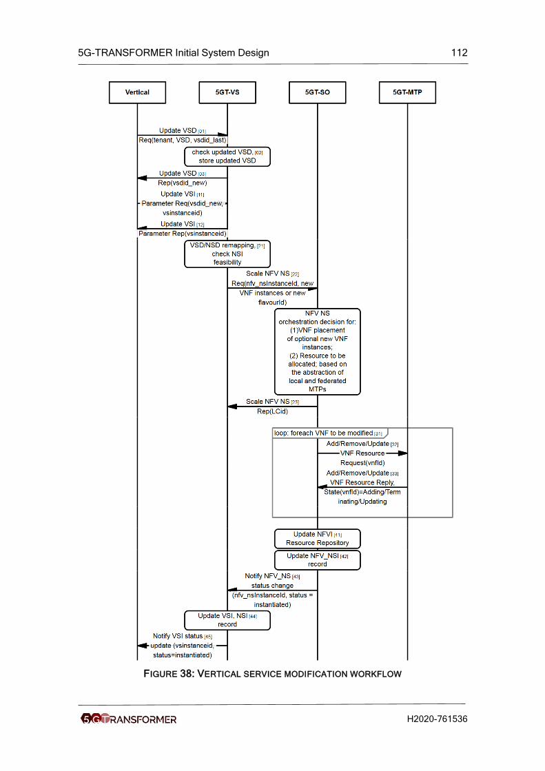
5G-TRANSFORMER Initial System Design 112
H2020-761536
FIGURE 38: VERTICAL SERVICE MODIFICATION WORKFLOW

5G-TRANSFORMER Initial System Design 113
H2020-761536
Workflow: The workflow, see Figure 38, consists of two separate steps. Firstly, the
vertical service description is changed, secondly, the vertical service description of a
specific vertical service instance is changed. Note, that several instances of the same
vertical service could be instantiated and only some of them are modified.
In the first step, the vertical provides the modified vertical service description. The
relation to the other versions is kept by providing the identifier of the last version of this
service descriptor as well (01). The new VSD is checked for correctness and stored in
the corresponding databases (02). An identifier for the new VSD is determined and
provided to the vertical (03).
In the second step, the vertical applies the new VSD to a vertical service instance. The
5GT-VS can relate the vsinstanceid to the used version of the VSD (11). The operation
returns immediately, while the actual processing continues.
Based on the last VSD the 5GT-VS can determine the necessary changes to the NSD
and check whether the modified version is feasible within the resource budget of this
vertical (21). Thereafter the 5GT-VS triggers the changes to the network slice by
scaling its defining NSD. In our simple example this could be a change of the cardinality
of VNFs or a change of the deployment flavor. Note that depending on the severity of
change of the VSD, the changes to the NSDs could be also more severe and might
trigger more complex interaction among 5GT-VS and 5GT-SO. The 5GT-SO makes the
placement decisions corresponding to the change (23). The NFV_NS Scale operation
is terminated (24), but the activities continue with applying the changes to the 5GT-
MTP.
Depending on the change, the 5GT-SO triggers add/remove/update requests for VNFs,
identified by its vnfId, at the 5GT-MTP (31, 32, 33).
The 5GT-SO updates its record of used resources and of instantiated network slices
(41, 42) and notifies the 5GT-VS that the modification has finished (43). In turn, the 5G-
VS updates the VSI/NSI record (44) and notifies the vertical that the modification is
finished (45).
14.2 Vertical Service Monitoring
Use case 1: The 5GT-SO monitors the NFV-NS instance in order to take internal
decisions (e.g., scaling).
Description: The workflow describes procedures to collect monitoring data related to an
NFV-NS at the 5GT-SO level.
Prerequisites: All the descriptors have been on-boarded, the vertical has requested the
instantiation of a new Vertical Service and the 5GT-VS has already created an nsi_Id.
Assumptions: Single-domain scenario. The MonitoredData in the NSD includes only
MonitoringParameters, not VnfIndicatorInfo. Moreover:
• The 5GT-SO Monitoring Service exposes IFA 013 - NS Performance
Management Interface [23].
• The 5GT-MTP Monitoring Service exposes IFA 006 - Virtualised Resource
Performance Management Interface [17].
• The 5GT-SO is a consumer of the 5GT-SO Monitoring Service and the 5GT-SO
Monitoring Service is a consumer of the 5GT-MTP Monitoring Service.

5G-TRANSFORMER Initial System Design 114
H2020-761536
Workflow description:
At the instantiation phase (steps 1-17 represented in Figure 39) the 5GT-SO creates
the Performance Monitoring jobs (PM jobs) to enable the 5GT-SO Monitoring Service to
collect the required performance metrics specified in the NSD. These metrics can be
computed starting from monitoring data that can be collected from the 5GT-MTP
Monitoring Service. Therefore, the 5GT-SO Monitoring Service creates the PM jobs to
enable the 5GT-MTP Monitoring Service to collect the required data. The specific
mechanisms used by the 5GT-MTP Monitoring Service to actually collect these data
are out of scope for this workflow, since they are VIM/WIM dependent.
The actual exchange of monitoring data between a generic Monitoring Service and its
consumer is based on subscriptions and notifications that notify the availability of new
monitoring data. The actual mechanisms to retrieve the monitoring data are not
specified in IFA 013 and IFA 006; in this workflow we assume that the consumer sends
an explicit request when it receives a notification about a new monitoring value it is
interested in and the Monitoring Service provides back the requested monitoring report.
In detail, at the instantiation phase, the 5GT-VS requests the instantiation of a Network
Service instance (step 1) and receives a synchronous response with the lifecycle
operation ID (step 2). The instantiation procedure proceeds at the 5GT-SO following an
asynchronous approach (step 3) and all the data related to the NFV-NS instance are
stored in the related 5GT-NFVO repository (step 4). For details about the instantiation
workflow see Section 8.2.
Once the resource allocation phase is concluded and the 5GT-SO is aware of all the
virtual resources created at the 5GT-MTP, the 5GT-SO can start the procedure to
create the PM jobs and subscribe with the local Monitoring Service in order to receive
the performance metrics. The monitoring parameters to be collected for a given
Network Service are specified in its NSD, encoded in the monitoredInfo field. For each
of them, the 5GT-SO requests the 5GT-SO Monitoring Service to create a PM job (step
5). Each monitoring parameter is a performance metric to be monitored on a NFV-NS
or on a VNF level. We define this performance metric as “5GT-SO performance metric”,
since it is the responsibility of the 5GT-SO Monitoring Service to provide it.
When creating a PM job for a given 5GT-SO performance metric, the 5GT-SO
Monitoring Service needs to register with the 5GT-MTP Monitoring Service for receiving
all the required “elementary” monitoring data (defined as “5GT-MTP performance
metrics”), which can be furtherly aggregated and elaborated to obtain the target metric.
The first step is therefore the identification of all the elementary monitoring data
required to elaborate the target 5GT-SO performance metric, translating the 5GT-SO
performance metric into one or more 5GT-MTP performance metrics (step 6). For each
of the required 5GT-MTP performance metric, the 5GT-SO Monitoring Service requests
the 5GT-MTP Monitoring Service to create a PM job (step 7-8), which is then stored in
the internal repository (step 9). Moreover, in order to actually receive the monitoring
notifications, it subscribes with a specific filter that identifies the requested 5GT-MTP
performance metric (step 10-11) and stores the subscription information (step 12).
Once all the subscriptions are completed, the 5GT-SO Monitoring Service is able to
receive all the required monitoring data from the 5GT-MTP Monitoring Service and it
can instantiate a new internal job to process and elaborate these data to generate the
target 5GT-SO performance metrics (step 13). This step concludes the creation of the
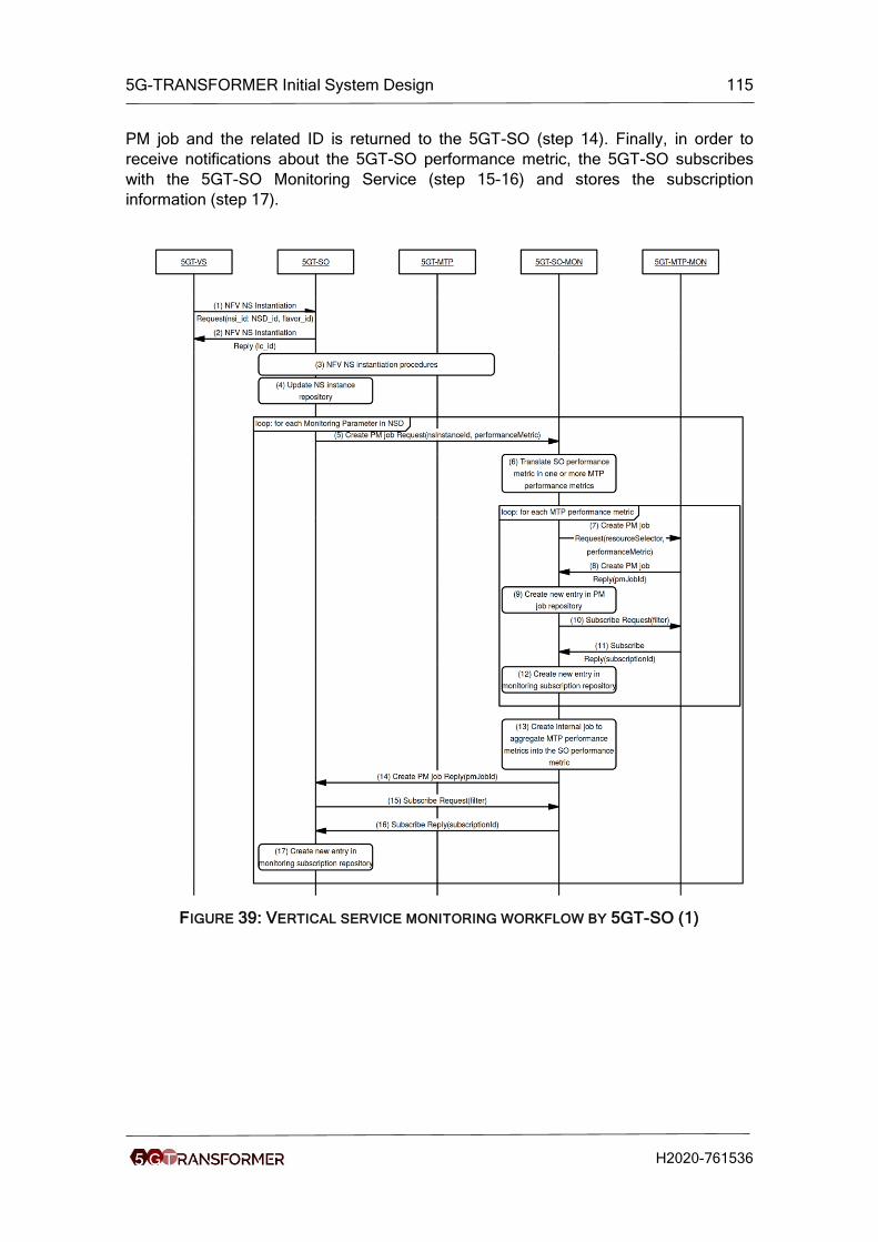
5G-TRANSFORMER Initial System Design 115
H2020-761536
PM job and the related ID is returned to the 5GT-SO (step 14). Finally, in order to
receive notifications about the 5GT-SO performance metric, the 5GT-SO subscribes
with the 5GT-SO Monitoring Service (step 15-16) and stores the subscription
information (step 17).
FIGURE 39: VERTICAL SERVICE MONITORING WORKFLOW BY 5GT-SO (1)

5G-TRANSFORMER Initial System Design 116
H2020-761536
FIGURE 40: VERTICAL SERVICE MONITORING WORKFLOW BY 5GT-SO (2)
The collection of monitoring data at the service runtime is shown in Figure 40.
Following the subscription/notification and report queries approach, when the 5GT-MTP
Monitoring Service produces new monitoring data for which the 5GT-SO Monitoring
Service has an active subscription, it sends a notification (step 18) and the 5GT-SO
Monitoring Service sends a request to retrieve the data (step 19-20). If needed, the
5GT-SO Monitoring Service aggregates the data (step 21) and stores the result as a
new performance metric value in its repository (step 22). Then the 5GT-SO (i.e. the
5GT-SO Monitoring Service’s consumer) is in turn notified about the availability of a
new performance report related to the given NFV-NS instance (step 23) and the 5GT-
SO retrieves the new report (steps 24-25). This may trigger a new action at the 5GT-SO
(e.g. a scaling procedure – step 26).
Use case 2: The 5GT-VS monitors a Vertical Service instance.
Description: The workflow describes procedures to allow the 5GT-VS to collect
monitoring data related to a NFV-NS.
Prerequisites: All the descriptors have been on-boarded, the vertical has requested the
instantiation of a new Vertical Service and the 5GT-VS has already created an nsi_Id.
Assumptions: Single-domain scenario. The MonitoredData in the NSD includes only
MonitoringParameters, not VnfIndicatorInfo. 1:1 relationship between Vertical Service
instance and Network Service instance (no sharing or nesting). Moreover:
• The 5GT-SO Monitoring Service exposes IFA 013 [23] - NS Performance
Management Interface

5G-TRANSFORMER Initial System Design 117
H2020-761536
• The 5GT-MTP Monitoring Service exposes IFA 006 [17] - Virtualised Resource
Performance Management Interface
• The 5GT-SO and the 5GT-VS are consumers of the 5GT-SO Monitoring Service
and the 5GT-SO Monitoring Service is a consumer of the 5GT-MTP Monitoring
Service.
Workflow: This use case is a small variance of the previous use case, where the main
difference is that the entity that wants to retrieve monitoring parameters about a NFV-
NS instance is the Vertical Slicer, instead of the 5GT-SO. As shown in Figure 41, the
procedures to request the Network Service instantiation (steps 1-4) and the creation of
the PM jobs at the 5GT-SO Monitoring Service (steps 5-14) are exactly the same as
before. However, now the entity that subscribes with the 5GT-SO Monitoring Service to
receive the 5GT-SO performance metrics is the 5GT-VS (step 16-17). Obviously, this
can be done only after the 5GT-VS has been notified by the 5GT-SO about the
successful instantiation of the NFV-NS (step 15).
At runtime (Figure 42), the procedure to collect 5GT-MTP performance metrics and
aggregate them into 5GT-SO performance metrics at the 5GT-SO Monitoring Service is
again the same as in the previous case (steps 19-23). However, since the subscription
has been performed by the 5GT-VS, the notification about the availability of a new
performance information is sent to the 5GT-VS itself (step 24), which in turn sends a
request to retrieve the monitoring report (step 25-26).
This workflow can be extended to any kind of 5GT-SO Monitoring Service’s consumer,
with suitable authorization rights (e.g. a federated 5GT-SO).

5G-TRANSFORMER Initial System Design 118
H2020-761536
FIGURE 41: VERTICAL SERVICE MONITORING WORKFLOW BY 5GT-MTP (1)

5G-TRANSFORMER Initial System Design 119
H2020-761536
FIGURE 42: VERTICAL SERVICE MONITORING WORKFLOW BY 5GT-MTP (2)

5G-TRANSFORMER Initial System Design 120
H2020-761536
15 Annex V: Composed Services The complexity of vertical services ranges from one or a few VNFs deployed in the
same network slice to vertical services composed of several other vertical services
(called “child” services), deployed in multiple network slices, where in some cases
some of service components are even shared with other vertical services. Such
composed services occur in the automotive, entertainment, and eHealth use cases, see
Sections 2.3.1, 2.3.2, and 2.3.3. In the entertainment use case the child services may
have quite different characteristics and lifetimes, whereas in the automotive use case
the child services may have different owners. In this annex we describe how composed
vertical services can be handled within the 5G-TRANSFORMER system architecture,
starting from Vertical Service Blueprints (VSB) of composed vertical services to support
at execution time.
As an abstract example we consider a composed service consisting of a parent
service A and two child services B and C. In Figure 43 two instances of this parent
vertical service are depicted (A1 and A2). Each of them uses dedicated instances B1
and B2, resp., of the child service B and a shared instance C12 of the child service C.
FIGURE 43: EXAMPLE OF COMPOSED VERTICAL SERVICE
The vertical service instances (VSI) are deployed to three network slice instances
(NSI), one for the shared VSI C12, one for A1 and B1, and one for A2 and B2. Note,
use of a dedicated NSI for the shared VSI C12 is just for illustration purposes, a shared
VSI may as well be deployed in an NSSI of a parent VSI. This abstract example fits to
the entertainment use cases, e.g. A could be the overall service for sports events, B
could be a video distribution service, and C could be a general ticketing service.
Similarly, in the automotive case, C could be a car manufacturer independent model of
vehicle movements, whereas A could be a manufacturer specific collision avoidance
service and B could be another car manufacture specific service analysing the outcome
of the collision avoidance algorithm.
15.1 Vertical Service Blueprints for Composed Services
As defined in D3.1 [3], a Vertical Service Blueprint (VSB) has fields for its atomic
functional components, service sequence, connectivity service, external, and internal
interconnections. We generalize the atomic functional components to a hierarchy of
functional components, where each level includes a list of lower level or of atomic
components, and a description of how to connect them consisting again of service
sequence, connectivity service, external, and internal connections. The functional

5G-TRANSFORMER Initial System Design 121
H2020-761536
components and the forwarding graph among them can thus be described in a VSB
similar to nested NFVI-NSs defined in ETSI NFV IFA 014 [24].
Additionally, a functional component may also be a reference to another VSB. This
allows to compose a vertical service from several other vertical services.
Note, both the child VSBs and the parent VSB are defined and offered by the 5G-
TRANSFORMER service provider (TSP) to the verticals. This is a first step towards
service composition by verticals themselves; this topic is left for further study
throughout the project.
Exemplary VSBs for the abstract services A, B, and C are shown in Table 15,

5G-TRANSFORMER Initial System Design 122
H2020-761536
Table 16, and Table 17, resp., focusing on the information for service composition.
Additional details on the service sequence and on the service itself would be provided
in the blueprint, but have been omitted here for the sake of brevity. Note, for vertical
services B and C different requirements on isolation and lifecycle dependencies have
been provided.
TABLE 15: VSB OF VERTICAL SERVICE A
Field Description
Name A
Description Abstract service a
Version 1.0
Identity 0123_vsbA
Parameters n/a
Atomic functional
components
involved
VNF: Vnf_a
Used VSB: B, C
Service sequence
Connectivity
service
n/a
External
interconnection
Ext_a
Internal
interconnection
Int_b, Int_c

5G-TRANSFORMER Initial System Design 123
H2020-761536
TABLE 16: VSB OF VERTICAL SERVICE B
Field Description
Name B
Description Abstract service B
Version 1.0
Identity 0123_vsbB
Parameters n/a
Atomic functional
components
involved
VNF: Vnf_b
Service sequence
Connectivity
service
n/a
External
interconnection
Ext_b
Internal
interconnection
n/a
Service
constraints • Security: Sharable21
• Lifecycle independence: same lifecycle as parent
• Etc.
TABLE 17: VSB OF VERTICAL SERVICE C
Field Description
Name C
Description Abstract service C
Version 1.0
Identity 0123_vsbC
Parameters n/a
Atomic functional
components
involved
VNF: Vnf_c
21 An instance of this vertical service can be in the same network slice as ist parent.

5G-TRANSFORMER Initial System Design 124
H2020-761536
Service sequence
Connectivity
service
n/a
External
interconnection
Ext_c
Internal
interconnection
n/a
Service
constraints • Security: Isolated22
• Lifecycle independence: independent
• Etc.
15.2 Vertical Service Descriptors for Composed Services
In a VSD, a reference to a child VSB is not sufficient. Additionally, it should be possible
to refer to another VSD or even a specific VSI. E.g., there could be several instances of
a vertical service to support sports event, in this case the corresponding child VSIs for
each sports event have to be composed. It has to be possible to refer specific VSIs
either by the identifier given by the 5G-TRANSFORMER system, as well as a name
provided by a vertical. Using a name allows to refer to a VSI before even an identifier is
requested and assigned: this is relevant in cases where parent and child service have
different lifecycles. We allow to use the following specific references in a VSD:
• VSB_name:VSI_name, VSB_Id:VSI_name: These named VSIs are instances of
some VSD derived from the given VSB. This kind of references is inherited from
VSBs.
• VSD_name:VSI_name/VSI_Id, VSD_Id:VSI_name/VSI_Id: A specific VSI of a
specific VSD, both VSI and VSD can be identified either by name or identifier.
• VSD_name:*, VSD_ID:*: an arbitrary VSI of a specific VSD. Depending on the
requirements on sharing or isolation, a shared VSI may be used or a new VSI
has to be created.
In the example, VSB A refers to VSBs B and C, the VSDs refer to specific VSIs already.
From the VSB A two VSDs a1 and a2 are derived, referring to specific child vertical
services, named VSIs B1, B2, and C12. The relevant fields for a1 are shown in Table
18, here the specific instances are used in the list of functional components and in the
service sequence. Additional details on the service sequence and on the service itself
would be provided in the blueprint, but have been omitted here for the sake of brevity.
22 An instance of this vertical service has to be deployed in its own network slice.

5G-TRANSFORMER Initial System Design 125
H2020-761536
TABLE 18: VSD FOR VERTICAL SERVICE A1
Field Description
Name A1
Description Abstract service a1
Version 1.0
Identity 0123_vsda1
Parameters n/a
Atomic functional
components
involved
VNF: Vnf_a
Uses: B:B1, C:C12
Service sequence
Connectivity
service
n/a
External
interconnection
Ext_a
Internal
interconnection
Int_b, Int_c
15.3 Translation of Composed Services
When translating VSDs of composed vertical services to NSDs, the VSD/NSD
Translator module (see Section 5.2) will translate such a composed VSD to
corresponding nested NSDs. This is the most straightforward approach and there is no
benefit in either flattening the structuring or even adding additional levels of nesting in
the NSDs by the 5GT-VS. If a VSD contains references to VSIs of other VSDs, then the
Arbitrator also will make the decisions on mapping several VSIs to one network slice
instance or to multiple ones, by adding their translated VSDs to the same NSD or by
creating separate NSDs for them.
When a composed VSI is mapped to several NSIs, described by nested NSDs, some
child NSDs can be mapped to the same NSI as the parent NSD, whereas others have
to be mapped to a separate NSD. These separate NSDs are not referred from the
parent NSD, they are NSDs on their own.
An additional NSD has to be created to describe how these NSDs are concatenated,
see ETSI NFV IFA 012 [22]. This additional NSD describes communication among
VSIs mapped to different network slices.

5G-TRANSFORMER Initial System Design 126
H2020-761536
15.4 Instantiation of Composed Services
For the instantiation of composed services we consider two separate cases. In the first
case, the service composition is merely a means to structure the service description, all
child services are in the same NSI as its parent and have the same lifetime. The
second case is the more generic one with child services in separate NSIs and with
different lifetimes.
15.4.1 Single Slice, Same Lifecycle
In the most simple case of a composed VSD, the structural information (VNFs and their
connections) are provided as a kind of nested NSD. Parent and child NFV-NSs have
the same lifecycle and are deployed in the same network slice instance. The VSD/NSD
Translator has translated the VSD to a composite NSD including one or more nested
NSDs.
Description: Instantiation of a vertical service with a composite service description.
Prerequisites: The vertical has selected a blueprint and prepared a vertical service
description from it.
Assumptions: Although the vertical service has a composite description, it can be
deployed in one network slice. We also assume that this service is deployed in a new
network slice instance. We assume that the NSDs, to which the vertical service is
mapped and which describe the network slice have been onboarded to the 5GT-SO
before.
Workflow: In general, the instantiation of NFV-NS consists of two steps, firstly to get an
identifier for the instance to be created and secondly to create the instance. In the first
step, the 5GT-VS requests identifiers for the parent and all child NSDs. These requests
can be made in arbitrary order or even in parallel, as an NSD according ETSI NFV IFA
014 [24] references other NSDs in the nestedNsdId field, but not specific instances.
In the second step, the 5GT-VS requests instantiation of the NFV-NSs in a top-down
manner. In case location constraints are provided as part of instantiation parameters of
the NFV-NSI, constraints on parent level can be considered already for placement
decisions. The identifiers of the child NFV-NSIs can be provided as part of the
Instantiate NS Operation according to ETSI NFV IFA 013 [23]. These child NFV-NSIs
will be deployed to the same NSI as its parent. Siblings can be instantiated in arbitrary
order or even in parallel.
This behaviour is described in more detail in the workflow in Figure 44 and Figure 45.
The workflow is similar to the instantiation of a non-nested service as described in
Section 8.2. The workflow is triggered by the vertical, which is authenticated and its
authorization checked (01, 02).
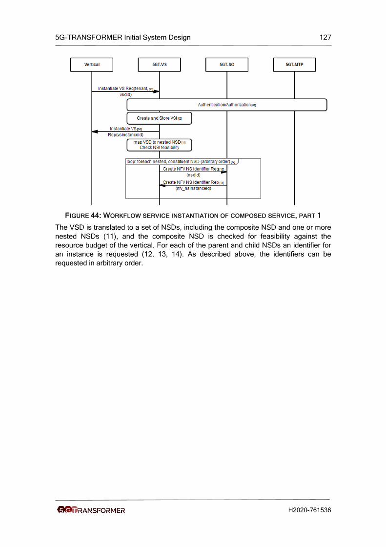
5G-TRANSFORMER Initial System Design 127
H2020-761536
FIGURE 44: WORKFLOW SERVICE INSTANTIATION OF COMPOSED SERVICE, PART 1
The VSD is translated to a set of NSDs, including the composite NSD and one or more
nested NSDs (11), and the composite NSD is checked for feasibility against the
resource budget of the vertical. For each of the parent and child NSDs an identifier for
an instance is requested (12, 13, 14). As described above, the identifiers can be
requested in arbitrary order.

5G-TRANSFORMER Initial System Design 128
H2020-761536
FIGURE 45: WORKFLOW SERVICE INSTANTIATION OF COMPOSED SERVICE, PART 2
Thereafter, the actual instances are created. Here, a top-down order is used to
consider high-level placement constraints first. Identifiers of (yet to be instantieated)
child NFV NSIs are available from the previous step and can be provided at the
instantiation time of the parent. To ensure that all placement decisions can be done, the
5G-VS waits for the notification of the status change before triggering the instantiation
of a child NFV NSI. Note, siblings can be instantiated in parallel to reduce the duration
of the workflow.
15.4.2 Multiple Slice, Different Lifecycle
For this generic case, we consider in our example that VSIs A1, B1, and C12 have
been created already and that VSIs A2 and B2 are to be created. A2 and B2 have been
mapped to the same network slice, therefore this can be handled as the case described
in Section 15.4.1. It remains to connect the corresponding new NSI with the NSI of C12.
This is done by the 5GT-VS updating the NSD describing how different NSIs are
concatenated and triggering the corresponding modification at the 5GT-SO.

5G-TRANSFORMER Initial System Design 129
H2020-761536
15.5 5GT-SO support for Composed Services
The support of composed services requires corresponding support at runtime such that
VNFs deployed to different NSIs can communicate with each other at all and that they
can find their communication peers.
15.5.1 Application-level Service Registry
Each VA or VNF provides an application service and may require other application
services. Therefore, a VA or VNF instance needs to find another VA or VNF instance
providing the requested services. MEC already allows an application to register a
service, see ETSI MEC 003 [29]. This service registry was intended for infrastructural
services such as the radio network information service. But this service registry can be
extended to application services. Already the VSB should contain a MEP with such a
service registry as a VNF. This service registry can be used by the vertical services
mapped to different NSIs to discover each other at runtime.
15.5.2 Connecting Network Slices
Different child VSIs of a composed VSIs may be deployed to different NSIs.
Nevertheless, traffic is flowing among child VSIs and the corresponding NSIs. When
tunnelling techniques, e.g. GTP [54] or VXLAN [55], are used to separate NSIs, then
the tunnel header of the source NSI has to be replaced with a tunnel header of the
target NSI when a packet is flowing from the source to the target NSI. Such header
operations require computational resources and may impact transmission latency,
therefore it is recommended that high-bandwidth or low-latency traffic flows are kept
within one NSI as much as possible. These header operations could be performed by
dedicated VNFs, in this case these VNFs belong to the NSD used to described
connectivity among NSIs, see Section 15.3.

5G-TRANSFORMER Initial System Design 130
H2020-761536
16 Annex VI: See-Through for Safety
This use case foresees the implementation of a service that, thanks to a
communication among vehicles, makes possible to see through an obstacle. For
example, with reference to Figure 46, Vehicle C1 sends information about the mobility
scenario in front of the obstacle and Vehicle C2 sends information about the mobility
scenario behind it.
FIGURE 46: SEE-THROUGH OVERVIEW
The main actors involved in the See-Through UC and the respective functions are
following:
1. The host vehicle (also called user vehicle) is the vehicle that uses the See-
Through (CT) services (indicated with 1 in the picture).
2. The other vehicles (indicated with “Ci” in the picture) are provider vehicles,
when they have subscribed the service, and are able to provide video streaming
to the user vehicle.
3. The intelligence of the application (CT Module) is placed in the MEC/cloud and
calculates for each user vehicle (having CT service activated) if provider
vehicles are available.
4. CIM (Cooperative Information Manager) manages common vehicle data.
5. OEM (Original Equipment Manufacturer) Vehicle DB (Vertical DB) manages
sensible car data (number, type and state of cameras, etc.).
TABLE 19: DESCRIPTION OF CT USE CASE
CT Bi-Lateral See-Through (safety)
Goal Vehicles are able to see through the obstacles, thanks to the cooperation among them, thus achieving bilateral awareness of road conditions.
Triggering Event Any time the service is active, the application retrieves available relevant provider.
Brief Description Exchanging the information among vehicles (or among Vehicle and Infrastructure), it is possible to see through an obstacle. Streaming information should be provided to all the vehicles that want/need to access to it. This information can be used to identify eventual obstacles that cannot be detected through on-board sensors.
Actors Driver, (user and provider – front and/or behind) Vehicles, See-Through Module (CT Module), Cooperative Information Manager.
Preconditions The host vehicle is connected and See-Through is available,
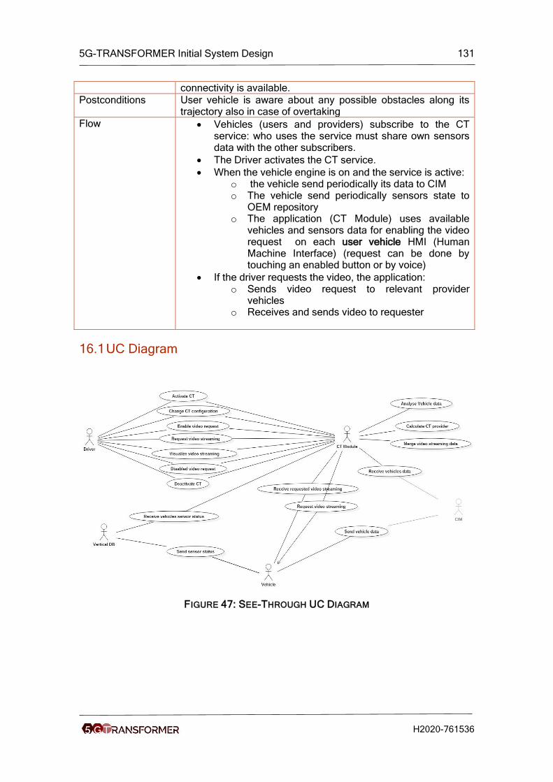
5G-TRANSFORMER Initial System Design 131
H2020-761536
connectivity is available.
Postconditions User vehicle is aware about any possible obstacles along its trajectory also in case of overtaking
Flow • Vehicles (users and providers) subscribe to the CT service: who uses the service must share own sensors data with the other subscribers.
• The Driver activates the CT service.
• When the vehicle engine is on and the service is active: o the vehicle send periodically its data to CIM o The vehicle send periodically sensors state to
OEM repository o The application (CT Module) uses available
vehicles and sensors data for enabling the video request on each user vehicle HMI (Human Machine Interface) (request can be done by touching an enabled button or by voice)
• If the driver requests the video, the application: o Sends video request to relevant provider
vehicles o Receives and sends video to requester
16.1 UC Diagram
FIGURE 47: SEE-THROUGH UC DIAGRAM

5G-TRANSFORMER Initial System Design 132
H2020-761536
16.2 Sequence Diagram
FIGURE 48: SEE-TROUGH SEQUENCE DIAGRAM
16.3 Logical Architecture
FIGURE 49: VEHICLE EQUIPMENT

5G-TRANSFORMER Initial System Design 133
H2020-761536
16.4 Detailed Requirements
The Most Relevant KPIs for the UC are the following:
• High Bandwidth
• High Reliability & availability (99%).
• Low Latency.
• High Security.
• High Priority.
• Enhanced data rate.
TABLE 20: DETAILED UC REQUIREMENTS FOR AUTOMOTIVE
ID Requirement # UC F/NF
ReqA.201 Road Segment where CT can be used shall be equipped with 5G.
CT F
ReqA.202 CT application shall work regardless the Telco Operator serving the involved connected vehicles.
CT F
ReqA.203 The QoS of CT application shall be ensured, despite other services running on board.
CT F
ReqA.204 Host vehicle shall be able to use CT application, only if the driver authorizes to share own vehicle data.
CT F
ReqA.205 The driver shall be able to activate/deactivate the CT application.
CT F
ReqA.206 The latest state of the CT application (activated/deactivated) shall be remembered for the subsequent uses.
CT F
ReqA.207 The CT application, when activated, shall be able to periodically receive information from the vehicle (position, sensors state).
CT F
ReqA.208 CT application shall be able to process vehicles data, detecting all vehicles (in previously determined range) that are able to transmit video streaming, and notify the host vehicle of CT video availability.
CT F
ReqA.209 When CT is activated, the driver shall be notified by the application if video streaming is available via on-screen CT button.
CT F
ReqA.210 The driver shall be able to request CT video streaming when provider vehicles are available.
CT F
ReqA.211 CT application shall be able to request video streaming from provider vehicles, process it and send video to the requester.
CT F
ReqA.211 Security level shall be elevated. CT NF

5G-TRANSFORMER Initial System Design 134
H2020-761536
UC Detailed Requirements are described in the above Table. For completeness, the
following table lists the general automotive requirements in D1.1 [1] that applies to the
CT use case is also reported below, adding the CT Id in the # UC field:
TABLE 21: DETAILED UC REQUIREMENTS FOR AUTOMOTIVE THE CT USE CASE
ID Requirement # UC F/NF
ReqA.01 All vehicles shall be equipped with 5G router. A.all, CT F
ReqA.02 All connected vehicles shall be able to exchange agreed information (those linked to context awareness), regardless the connectivity Provider.
A.01, A.02, A.04, A.06, A.07, A.08, A.09, A.10, A.11, A.12, A.13, A.14, A.23, A.24, A.25, CT
F
ReqA.04 All vehicles shall be able to transmit information in roaming.
A.all, CT F
ReqA.06 Infrastructure shall be able to communicate with connected vehicles and provide additional information.
A.02, A.09, A.11, A.12, A.13, A.14, A.07, A.19, CT
F
ReqA.05 Cloud shall be able to receive, process, and send all information to connected vehicles.
A.11, A.12, A.13, A.10, A.08 A.04, A.15, A.16, A.17, A.18, A.19, A.20, A.21, A.22, CT
F
ReqA.07 On-board system shall be able to monitor, recognize, control and transmit vehicle information.
A.all , CT F
ReqA.08 Service Provider shall be able to receive information from the vehicle and provide appropriate feedback.
A.19, A.20, A.21, A.22, CT
F
ReqA.10 Smart electronic consumer devices shall be able to transmit (stream) all received video information.
A.04, A.10, A.13, A.14, A.15, A.16, A.17, A.18, CT
F
ReqA.15 Reliability shall be more than 99%. A.01, A.02, A.03, A.04, A.05, A.06, A.07, A.09, A.10, A.11, A.12, A.13, A.14, A.23, A.24, A.25, CT
NF
ReqA.16 User data rate shall be higher than 100 Mb/s. A.18, CT NF
ReqA.17 Mobility shall be higher than 50 km/h. A.all, CT NF
ReqA.18 Availability (related to coverage) shall be higher than 99%.
A.01, A.02, A.03, A.04, A.05, A.06,
NF

5G-TRANSFORMER Initial System Design 135
H2020-761536
A.07, A.08, A.09, A.10, A.11, A.12, A.13, A.14, CT
ReqA.19 Positioning accuracy shall be less than 30 cm. A.01, A.02, A.04, A.05, A.06, A.07, A.09, A.10, A.11, A.12, A.13, A.14, A.23, A.24, A.25, CT
NF
ReqA.21 Integrity shall be elevated. A.01, A.02, A.03, A.04, A.05, A.06, A.07, A.08, A.10, A.11, A.12, A.13, A.14, A.19, A.20, A.21, A.23, A.24, A.25, CT
NF
ReqA.22 Availability (related to resilience) shall be elevated.
A.01, A.02, A.03, A.04, A.05, A.07, A.11, A.12, A.13, A.14, A.15, A.20, A.22, A.23, A.24, A.25, CT
NF
ReqA.22 In urban scenarios , the system shall operate in density higher than 10000/km2.
A.01, A.02, A.03, A.04, A.05, A.06, A.07, A.08, A.09, A.10, A.11, A.12, A.13, A.14, A.15, A.16, A.17, A.18, A.19, A.20, A.21, A.22, A.24, CT
NF
ReqA.24 Traffic shall be bursty. A.01, A.02, A.03, A.04, A.05, A.06, A.07, A.08, A.09, A.10, A.11, A.12, A.13, A.14, A.15, A.19, A.20, A.21, A.22, A.23, A.24, A.25, CT
NF

5G-TRANSFORMER Initial System Design 136
H2020-761536
ReqA.25 Traffic shall be event driven. A.01, A.02, A.03, A.05, A.06, A.07, A.08, A.09, A.11, A.12, A.13, A.14, A.15, A.18, A.19, A.20, A.21, A.22, A.23, A.24, A.25, CT
NF
ReqA.26 Traffic shall be periodic. A.01, A.02, A.03, A.05, A.06, A.07, A.08, A.09, A.10, A.13, A.14, A.24, A.25, CT
NF
ReqA.27 Traffic shall be all types. A.01, A.02, A.03, A.04, A.05, A.06, A.07, A.08, A.09, A.10, A.11, A.12, A.13, A.14, A.15, A.16, A.17, A.18, A.19, A.20, A.21, A.22, A.23, A.24, A.25, CT
NF
ReqA.29 Infrastructure shall be highly available. A.02, A.04, A.06, A.08, A.09, A.13, A.14, A.15, A.16, A.17, A.18, A.19, A.20, A.21, A.22, CT
NF
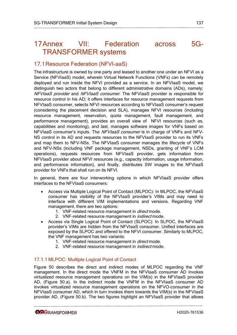
5G-TRANSFORMER Initial System Design 137
H2020-761536
17 Annex VII: Federation across 5G-TRANSFORMER systems
17.1 Resource Federation (NFVI-aaS)
The infrastructure is owned by one party and leased to another one under an NFVI as a
Service (NFVIaaS) model, wherein Virtual Network Functions (VNFs) can be remotely
deployed and run inside the NFVI provided as a service. In an NFVIaaS model, we
distinguish two actors that belong to different administrative domains (ADs), namely;
NFVIaaS provider and NFVIaaS consumer. The NFVIaaS provider is responsible for
resource control in his AD; it offers interfaces for resource management requests from
NFVIaaS consumer, selects NFVI resources according to NFVIaaS consumer’s request
(considering the placement decision and SLA), manages NFVI resources (including
resource management, reservation, quota management, fault management, and
performance management), provides an overall view of NFVI resources (such as,
capabilities and monitoring), and last, manages software images for VNFs based on
NFVIaaS consumer’s inputs. The NFVIaaS consumer is in charge of VNFs and NFV-
NS control in its AD and requests resources to the NFVIaaS provider to run its VNFs
and map them to NFV-NSs. The NFVIaaS consumer manages the lifecycle of VNFs
and NFV-NSs (including VNF package management, NSDs, granting of VNF’s LCM
operations), requests resources from NFVIaaS provider, gets information from
NFVIaaS provider about NFVI resources (e.g., capacity information, usage information,
and performance information), and finally, distributes SW images to the NFVIaaS
provider for VNFs that shall run on its NFVI.
In general, there are four interworking options in which NFVIaaS provider offers
interfaces to the NFVIaaS consumers:
• Access via Multiple Logical Point of Contact (MLPOC): In MLPOC, the NFVIaaS consumer has visibility of the NFVIaaS provider’s VIMs and may need to interface with different VIM implementations and versions. Regarding VNF management, there are two options:
1. VNF-related resource management in direct mode. 2. VNF-related resource management in indirect mode.
• Access via Single Logical Point of Contact (SLPOC): In SLPOC, the NFVIaaS provider’s VIMs are hidden from the NFVIaaS consumer. Unified interfaces are exposed by the SLPOC and offered to the NFVI consumer. Similarly to MLPOC, the VNF management has two variants:
1. VNF-related resource management in direct mode. 2. VNF-related resource management in indirect mode.
17.1.1 MLPOC: Multiple Logical Point of Contact
Figure 50 describes the direct and indirect modes of MLPOC regarding the VNF management. In the direct mode the VNFM in the NFVIaaS consumer AD invokes virtualized resource management operations on the VIM(s) in the NFVIaaS provider AD, (Figure 50.a). In the indirect mode the VNFM in the NFVIaaS consumer AD invokes virtualized resource management operations on the NFVO-consumer in the NFVIaaS consumer AD, which in turn invokes them towards the VIM(s) in the NFVIaaS provider AD, (Figure 50.b). The two figures highlight an NFVIaaS provider that allows

5G-TRANSFORMER Initial System Design 138
H2020-761536
access to MLPOC in its AD, while the NFVIaaS consumer issues NFVIaaS service requests using interfaces provided by the VIMs. It is assumed that VIMs provide logical points of contact for the virtualized resource management requests through existing interfaces (Or-VI [NFV IFA005] and Vi-Vnfm [NFV IFA006]), and both the NFVIaaS provider and NFVIaaS consumer have a business relationship, and exchange information about infrastructure tenants, resource groups, and access to VIMs.
FIGURE 50: NFVIAAS FEDERATION (MLPOC)
Table 22 compares the two variants of NFVIaaS architecture with MLPOC access. A
discussion of the options preferred for the 5G-TRANSFORMER architecture is given in
Section 4.1.8.1.
TABLE 22: NFVIAAS ARCHITECTURE WITH (DIRECT VERSUS INDIRECT) VNF
MANAGEMENT FOR MLPOC ACCESS
Direct mode Indirect mode
NFV NS management
- NFVO-consumer is responsible for the NFV NS’s LCM (including, NSD management, and VNF packages).
- NFVO-consumer manages VNF-FGs and VLs for NFV NSs. - NFVO-consumer issues network resource management operations towards respective VIMs.
VNF management
- VNFM requests resource management needed for VNF’s LCM from the identified VIM(s).
- VNFM requests resource management needed for VNF LCM from the NFVO-consumer, which issues the requests towards the VIM(s).
- VNFMs are responsible for VNF’s LCM. - Before computing VNF lifecycle operation, VNFM requests an operation granting from NFVO-consumer.
- NFVO-consumer collects information on consumable resource and virtualized resources capacity from VIMs.
- It uses such information to identify and select target VIM(s) from which virtualized resources will be provided for VNF.
- NFVO-consumer maintains and enforces permitted allowance at various granularity levels (VNFM, VNF, NS, etc.) to control resource consumption by VNFMs in relation with VNF lifecycle operation granting.
NS(s)
VNF(s)NFVO-
Consumer
NFVI(s) VIM
NFVIaaS consumer’s AD
NFVIaaS provider’s AD
VNFMVNFMVNFM
VIMVIM
NFVO-
Provider
Or-Vi [IFA005]Vi-Vnfm [IFA006]
a. Direct mode
NS(s)
VNF(s)NFVO-
Consumer
NFVI(s) VIM
NFVIaaS consumer’s AD
NFVIaaS provider’s AD
VNFMVNFMVNFM
VIMVIM
NFVO-
Provider
Or-Vi [IFA005]
Or-Vnfm [IFA007]
b. Indirect mode

5G-TRANSFORMER Initial System Design 139
H2020-761536
- NFVO-consumer cannot guarantee resource availability during the granting of a VNF lifecycle request if the resource needed to accommodate such lifecycle operation have not been reserved in the VIM.
- NFVO-consumer performs VNF package management and distributes the SW images of VNFs to the VIM(s) on which they will be deployed.
Virtualized resource
management
- VIMs are responsible for the virtualized resource management and providing interfaces to VNFMs and NFVO-consumer.
- VIMs are responsible for the virtualized resource management and providing interfaces to NFVO-consumer.
- VIMs manage infrastructure tenants and infrastructure resource groups, and limit the scope of operations to the requesting infrastructure tenant to: ▪ Get only information related to infrastructure resource groups
assigned to the tenant. ▪ May only initiate virtualized resource management related to
infrastructure resource groups assigned to the tenant. ▪ May only request quota related to infrastructure resource groups
assigned to this tenant. ▪ May only reserve virtualized resource belonging to infrastructure
resource groups assigned to the tenant.
17.1.2 SLPOC: Single Logical Point of Contact
Figure 44 describes the NFVIaaS architecture with via SLPOC. Figure 44.a describes
the architecture in which the VNF related-resource management is done in direct mode,
that is, the VNFM invokes virtualized resource management operations on the SLPOC,
while Figure 44.b depicts the indirect management mode of VNFs, wherein the VNFM
invokes virtualized resource management operations on the NFVO-consumer, which in
turn invokes them towards the SLPOC. The two figures depict the NFVIaaS consumer
which is allowed to issue NFVIaaS service requests and access to the NFVIaaS
provider’s AD through the SLPOC, which provides interfaces (Vi-Vnfm[IFA 006] and Or-
Vi[IFA 005]). The NFVIaaS provider hides its VIMs from the NFVIaaS consumer.
However, unified interfaces are exposed by the SLPOC and offered to the NFVIaaS
consumer. It is assumed that the NFVIaaS provider and the NFVIaaS consumer have a
business relationship to exchange information regarding the infrastructure, tenants,
resource groups, and access to the SLPOC.
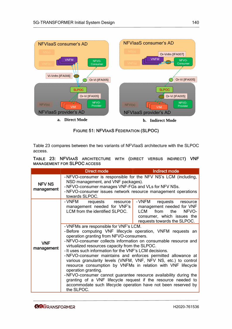
5G-TRANSFORMER Initial System Design 140
H2020-761536
FIGURE 51: NFVIAAS FEDERATION (SLPOC)
Table 23 compares between the two variants of NFVIaaS architecture with the SLPOC
access.
TABLE 23: NFVIAAS ARCHITECTURE WITH (DIRECT VERSUS INDIRECT) VNF
MANAGEMENT FOR SLPOC ACCESS
Direct mode Indirect mode
NFV NS management
- NFVO-consumer is responsible for the NFV NS’s LCM (including, NSD management, and VNF packages).
- NFVO-consumer manages VNF-FGs and VLs for NFV NSs. - NFVO-consumer issues network resource management operations towards SLPOC.
VNF management
- VNFM requests resource management needed for VNF’s LCM from the identified SLPOC.
- VNFM requests resource management needed for VNF LCM from the NFVO-consumer, which issues the requests towards the SLPOC.
- VNFMs are responsible for VNF’s LCM. - Before computing VNF lifecycle operation, VNFM requests an operation granting from NFVO-consumers.
- NFVO-consumer collects information on consumable resource and virtualized resources capacity from the SLPOC.
- It uses such information for the VNF’s LCM decisions. - NFVO-consumer maintains and enforces permitted allowance at various granularity levels (VNFM, VNF, NFV NS, etc.) to control resource consumption by VNFMs in relation with VNF lifecycle operation granting.
- NFVO-consumer cannot guarantee resource availability during the granting of a VNF lifecycle request if the resource needed to accommodate such lifecycle operation have not been reserved by the SLPOC.
NS(s)
VNF(s)NFVO-
Consumer
NFVI(s) VIM
NFVIaaS consumer’s AD
NFVIaaS provider’s AD
VNFMVNFMVNFM
VIMVIM
NFVO-
Provider
Or-Vi [IFA005]
Vi-Vnfm [IFA006]
SLPOC
Or-Vi [IFA005]
a. Direct Mode
NS(s)
VNF(s)NFVO-
Consumer
NFVI(s) VIM
NFVIaaS consumer’s AD
NFVIaaS provider’s AD
VNFMVNFMVNFM
VIMVIM
NFVO-
Provider
Or-Vi [IFA005]
Or-Vnfm [IFA007]
SLPOC
Or-Vi [IFA005]
b. Indirect Mode

5G-TRANSFORMER Initial System Design 141
H2020-761536
- NFVO-consumer performs VNF package management and distributes the SW images of VNFs to the SLPOC, which forwards them to the VIMs.
Virtualized resource
management
- VIMs are responsible for the virtualized resource management and providing interfaces to VNFMs and SLPOC, which interfaces with the VNFM and NFVO-consumer.
- VIMs are responsible for the virtualized resource management and providing interfaces to VNFMs and SLPOC, which interfaces only with the NFVO-consumer.
- SLPOC hides the VIM interfaces. - SLPOC maintains information about the infrastructure resource organization, availability, and utilization from various VIMs in the infrastructure domain.
- All virtualized resource management requests from the NFVIaaS consumer go to the SLPOC, which forwards them to the VIM(s).
- Existing interfaces Or-Vi [IFA 005] reference point can be reused for interfaces between SLPOC and VIMs.
- SLPOC manages infrastructure tenants and infrastructure resource groups, and limit the scope of operations to the requesting infrastructure tenant to: ▪ Gets only information related to infrastructure resource groups
assigned to the tenant. ▪ May only initiate virtualized resource management related to
infra. Resource groups assigned to the tenant. ▪ May only request quota related to infra resource groups
assigned to this tenant. May only reserve virtualized resource belonging to infra resource groups assigned to the tenant.
To sum up, the MLPOC and SLPOC look like VIM(s) from the NFVIaaS Consumer’s
NFVO and VNFMs view. For the architecture option using NFVIaaS provider’s VIMs
with MLPOC access, no new reference point is needed to integrate it into MANO
functional blocks. Regarding the architecture options using SLPOC functionality, two
options are possible: the SLPOC may be integrated into a VIM or into the NFVO of the
NFVIaaS provider, which introduces new reference points and reuses the
IFA005/IFA006 interfaces. When the SLPOC is integrated into a VIM, this latter needs
to support the SLPOC functionality and interfaces to: (i) forward requests from
NFVIaaS consumer’s NFVO and VNFM(s) to the respective VIMs; (ii) maintain an
overall view over virtualized resources, quotas, reservations, and capacity per
infrastructure resource group; (iii) connect between different VIMs, SLPOC, NFVO, and
VNFMs in the NFVIaaS Provider’s AD using IFA005 and IFA006 interfaces. If the
SLPOC is integrated into the NFVO inside the NFVIaaS provider’s AD, the NFVO
needs to support the SLPOC functionality and interfaces to: (i) manage the
infrastructure resource groups and tenants; (ii) provide IFA005 interfaces towards the
NFVIaaS consumer’s NFVO and forward the requests to the respective VIM(s); (iii)
provide IFA006 interfaces towards the NFVIaaS consumer’s VNFM(s) and forward the
requests to the respective VIM(s); (iv) limit the scope of operations to the infrastructure
resource groups assigned to the requesting infrastructure tenants; (v) finally, maintain
an overview of the virtualized resources, quotas, reservations, and capacity per
infrastructure resource group.
5G-TRANSFORMER Initial System Design 142
H2020-761536
17.2 Service Federation (NSaaS)
The NSaaS describes the use case of network services (NFV NS) provided by a
network operator to different departments within the same operator, as well as to other
network operators. Each administrative domain is seen as one or more NFVI-PoPs,
VIMs, and VNFMs together with their related VNFs. The NFVO in each Administrative
Domain (AD) allows distinct specific set of NFV NSs, which are hosted and offered by
each AD.
To better understand this use case, we rely on an example of composite NFV NS and
nested NFV NSs depicted in Figure 52.a. In this example, the composite NFV NS C is
build from the two nested NFV NS A and B. The nested NFV NSs A and B, and the
composite NFV NS C are provided by distinct ADs A, B, and C, respectively. For the
management of these NFV NSs, a hierarchical architecture is shown in Figure 52.b,
which provides an example of multiple ADs, each one offering a set of NFV NSs. The
NFVO-1 in the AD C is managing the composite NFV NS C, while the NFVO-2 (NFVO-
3, respectively) in the AD A (B, respectively) manages the nested NFV NSs A (B,
respectively) and exposes the nested NFV NSs to the NFVO-1. An SLA between the
providers of the nested NFVs NS A or B and the provider of the composite NFV NS C
should be negotiated, and to check if this SLA is met, monitoring resource usage by the
nested NSs is needed. Each NFVO is responsible for a set of actions according to the
NFV NS that is provided by its AD.
The NFVO-1 (for AD C) has to perform the instantiation of the composite NFV NS, and
if needed, to trigger the instantiation of the nested NFV NSs A and B corresponding to
NFVO-2 and NFVO-3. The NFVO-1 is also responsible for the LCM of other operations,
including scaling and healing of the nested NFV NSs, in collaboration with NFVO-2 and
NFVO-3. Note that the NFVO-1 is not aware of the virtualized resources in the ADs A
and B. NFVO-2 and NFVO-3 provide NFVO functionalities for the nested NFV NSs.
They receive the NFV NS LCM request from NFVO-1 and provide NFV NSs LCM for
the nested NFV NSs. Besides managing NFV NS tenants and service groups and their
association for the nested NFV NSs, NFVO-2 and NFVO-3 provide the NFVO-1 with
information about the nested NSs (including, fault information, performance, and
capacity information) belonging to service resource resource groups assigned to the
related NS tenants, in order to limit the scope of operations to the requesting NS
tenant.
FIGURE 52: NSAAS USE CASE
Composite NS C
Nested NS A
Nested
NS B
a. Composite NS and nested NSs b. Composite NS and nested NSs

5G-TRANSFORMER Initial System Design 143
H2020-761536
To support this use case of NSaaS in the NFV-MANO architecture framework, a new
reference point between NFVO-2 and NFVO-1, and between NFVO-3 and NFVO-1
called Or-Or based on IFA013 is added to the NFV-MANO framework to support the
NFV NS LCM actions provided through several ADs. In each AD, VNFMs interact with
the NFVO on the same AD. Therefore, the reference point Or-Vnfm keeps unchanged
in each AD. None of the NFVO-1, NFVO-2, and NFVO-3 is aware of the constituent
VNF instances of the NS outside its AD. Therefore, none of these NFVOs interact with
a VNFM from another AD