d15 - frame architecture part 6 -...
TRANSCRIPT
E-FRAME Extend FRAMEwork architecture for cooperative systems
WP300
D15 – FRAME Architecture – Part 6: Function, Data
Flow, Data Store and Terminator Descriptions
Version 4.1
Dissemination Level
Public
E-FRAME is a Support Action funded by the
European Commission, DG Information Society and Media
in the 7th Framework Programme
E-FRAME
support action
D15 – FRAME Architecture – Part 6, version V1.0
Page 2 of 568
Contract Number:
FP7-ICT-2007.6.2 Nr. 224383
Acronym:
E-FRAME
Title:
Extend FRAMEwork architecture for cooperative systems
Contractual date of delivery:
August 2011
Actual date of delivery:
September 2011
Main author(s) or editor(s):
Richard Bossom (Siemens)
Other author(s):
Angela Spence (MIZAR), Alexander Frötscher and Robert Ebner (ATE), Peter Jesty (PJCL)
List of Beneficiaries of the E-FRAME Project:
Beneficiary No.
Short Name
Participant name Country
1 PJCL Peter Jesty Consulting Limited UK
2 Siemens Siemens plc – Traffic Solutions Division UK
3 ATE AustriaTech - Federal Agency for technological Measures
AT
4 RWS-DVS Rijkswaterstaat - Dienst Verkeer en Scheepvaart NL
5 CTU Czech Technical University in Prague CZ
6 CERTU Centre for Studies on Urban Planning Transport Utilities and Public Construction
FR
7 MIZAR MIZAR Automazione IT

E-FRAME
support action
D15 – FRAME Architecture – Part 6, version V1.0
Page 3 of 568
Version History:
Version Date Main author(s) Summary of changes
0.1 10.03.2011 Richard Bossom First draft version
0.2 28.04.2011 Richard Bossom Function and other descriptions added
0.3 31.08.2011 Richard Bossom Updated for Version 4.1 and for internal review
1.0 08.09.2011 Richard Bossom Final Version for publication after internal review
Approval History:
Date Name of author/reviewer Version
Draft 31.08.2011 Richard Bossom 0.7
Internal reviewed 07.09.2011 Alexander Frötscher 0.7
Draft II
External reviewed
Reviewed Version 08.09.2011 Richard Bossom 1.0
Approved Version 11.09.2011 Peter Jesty 1.0
E-FRAME
support action
D15 – FRAME Architecture – Part 6, version V1.0
Page 4 of 568
Table of Contents
1 Introduction 7
1.1 The Aim of this Document 7
1.2 Assumptions behind this Document 7
1.3 Document Plan 7
1.4 Why is D15 in separate parts? 7
1.5 Abbreviations 8
2 Actual Descriptions 9
2.1 Introduction 9
2.2 General Remarks 9
3 Why Terminators and Actors? 563
3.1 Introduction 563
3.2 Why are Terminators and Actors? 563
3.3 What is a Terminator? 563
3.4 What is an Actor? 563
Appendix A: Alphabetical List of Terminators and Actors 564
E-FRAME
support action
D15 – FRAME Architecture – Part 6, version V1.0
Page 5 of 568
List of Tables
Table 1 - Descriptions of Actors......................................................................................... 10
Table 2 - Descriptions of Data Flows ................................................................................. 21
Table 3 - Descriptions of Data Stores .............................................................................. 316
Table 4 - Descriptions of Functions ................................................................................. 352
Table 5 - Descriptions of Functional Areas ...................................................................... 545
Table 6 - Descriptions of Functional Sub-Areas............................................................... 547
Table 7 - Descriptions of Terminators.............................................................................. 555
E-FRAME
support action
D15 – FRAME Architecture – Part 6, version V1.0
Page 6 of 568
Executive Summary
This document forms part of the FRAME Architecture deliverable (D15) that has been
produced by the E-FRAME project. The deliverable consists of the following parts:
Part 1: Overview – a brief description of what is in the FRAME Architecture, its history and
a snapshot of its current use;
Part 2: FRAME Browsing Tool – enables the contents of the FRAME Architecture to be
viewed and is only available for downloading from the FRAME website at
www.frame-online.net, in the Folder named The Architecture;
Part 3: FRAME Selection Tool Database – enables sub-set ITS architectures to be
created through the use of the FRAME Selection Tool and is only available for
downloading from the FRAME website at www.frame-online.net, in the Folder
named The Architecture;
Part 4: FRAME Architecture Changes Document – describes the changes made to the
FRAME Architecture since its previous version.
Part 5: The FRAME Methodology – describes how ITS architectures can be created using
the FRAME Architecture as a starting point.
Part 6: Function, Data Flow, Data Store and Terminator Descriptions – this document.
Parts 1, 2, 3 and 6 will be updated every time a new version of the FRAME Architecture is
produced. Part 5 should remain constant with each version of the Architecture and
therefore not be updated.. Part 4 will be replaced with each new version of the Architecture
Part 6 (this document) provides the descriptions of the Functions, Data Flows, Data Stores,
plus Terminators and Actors that are used within the FRAME Architecture. The reason for
creating this document is that these descriptions have been requested by at least one user
of the FRAME Architecture and it was thought that other users might find them useful. The
descriptions are taken from the Microsoft® Access® Database used by the FRAME
Selection Tool and are identical to those displayed by the FRAME Browsing Tool.
E-FRAME
support action
D15 – FRAME Architecture – Part 6, version V1.0
Page 7 of 568
1 Introduction
1.1 The Aim of this Document
The aim of this deliverable document is to provide in a readily accessible form the
descriptions of the Functions, Data Flows, Data Stores, plus Terminators and Actors
present within the FRAME Architecture and used by the FRAME Selection Tool. It is
intended that this deliverable document will provide easy access to the descriptions if they
require to be copied into other documents as part of creating the requirements for systems,
sub-systems and modules produced using the FRAME Selection Tool.
1.2 Assumptions behind this Document
It is assumed that readers will have some knowledge of the methodology behind the
FRAME Architecture and its use. A more detailed description of this methodology is
available in Part 5 of this deliverable.
Readers who want to explore the functionality within the FRAME Architecture in more detail
should use the FRAME Browsing Tool, which is available from the FRAME website at:
http://www.frame-online.net/. To actually use the FRAME Architecture, a copy of the
FRAME Selection Tool and its database are needed. Both of these together with
instructions for their use are again available from the FRAME website.
1.3 Document Plan
This document has been organised into 4 chapters including this one. Each of the
subsequent chapters contains the following:
Chapter 2: provides the actual descriptions of the Functions, Data Flows, Data Stores, plus
Terminators and Actors.
Chapter 3: provides some background information about why Terminators and Actors have
been used.
Appendix A: contains an alphabetical list of Actors and Terminators.
1.4 Why is D15 in separate parts?
This E-FRAME project deliverable document (D15) has been divided into six parts, which
are as follows:
Part 1: Overview – a brief description of what is in the FRAME Architecture, its history and
a snapshot of its current use;
Part 2: FRAME Browsing Tool – enables the contents of the FRAME Architecture to be
viewed and is only available for downloading from the FRAME website;
E-FRAME
support action
D15 – FRAME Architecture – Part 6, version V1.0
Page 8 of 568
Part 3: FRAME Selection Tool Database – enables sub-set ITS architectures to be
created through the use of the FRAME Selection Tool and is only available for
downloading from the FRAME website;
Part 4: FRAME Architecture Changes Document – describes the changes made to the
FRAME Architecture since its previous version.
Part 5: The FRAME Methodology – describes how ITS architectures can be created using
the FRAME Architecture as a starting point.
Part 6: Function, Data Flow, Data Store and Terminator Descriptions – this document.
Parts 2, 3, 4 and 6 will be updated every time a new version of the FRAME Architecture is
produced. Part 5 should remain constant with each version of the Architecture and
therefore not be updated.
The alternative of providing completely separate deliverable documents was rejected
because of the close linkage between what is in the Architecture and the methodology
behind its use.
1.5 Abbreviations
The following abbreviations may be unfamiliar to some users of the FRAME Architecture:
ID Identity – this may be a number (Data Stores, Functions and Functional Sub-Areas)
or a mnemonic (Actors, Functional Areas and Terminators)
HGV Heavy Goods Vehicle
msg message – used here to refer to what is in a Data Flow
VRU Vulnerable Road User, e.g. pedestrian, cyclist, person with some form of disability
E-FRAME
support action
D15 – FRAME Architecture – Part 6, version V1.0
Page 9 of 568
2 Actual Descriptions
2.1 Introduction
This is the main part of this document and consists of a number of tables. Each table
provide the descriptions for a particular type of entity within the FRAME Architecture that is
used by the FRAME Selection Tool. They are arranged in alphabetical order as follows:
Table 1: Actors
Table 2: Data Flows
Table 3: Data Stores
Table 4: Functions
Table 5: Functional Areas
Table 6: Functional Sub-Areas
Table 7: Terminators
A table of User Needs is not included as these can be found in deliverable D13, which is
available from the FRAME website.
2.2 General Remarks
The contents of all the tables should be self explanatory but the following general remarks
may be helpful.
1. With the exception of Tables 3 and 4, all of the other tables are arranged so that the
contents of each cell are contained on a single page.
2. Tables 3 and 4 are different in that the contents of their cells may run across a page
boundary. So care should be taken to ensure that all of the contents are selected
when copying material from any of their cells.
3. Tables 2 and 7 show the Actors and Terminators in alphabetical order according to
their mnemonics. An alphabetical list of Actors and Terminators is provided in
Appendix A.
4. In Table 3, the term "Origin" refers to the entity from which the Data Flow starts and
"Destination" refers to the entity at which the Data Flow terminates.
E-FRAME
support action
D15 – FRAME Architecture – Part 6, version V1.0
Page 10 of 568
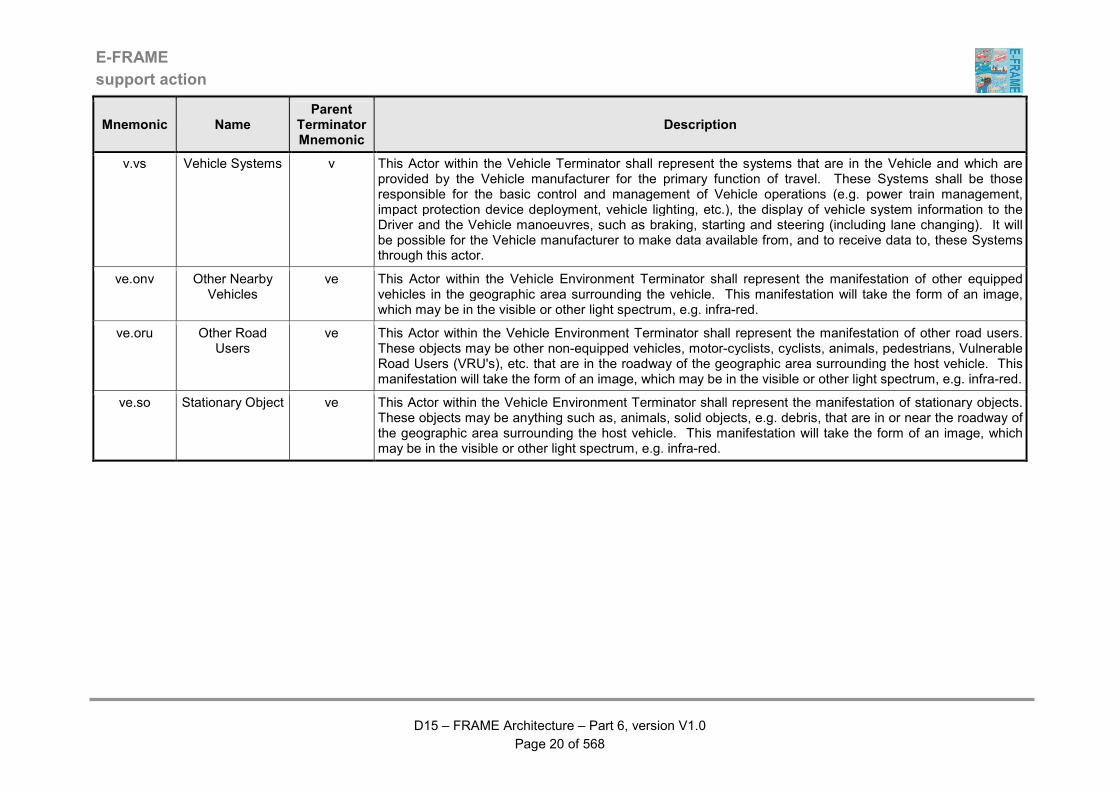
Table 1 - Descriptions of Actors
Mnemonic Name Parent
Terminator Mnemonic
Description
bti.bs Bridge Structures bti This Actor within the Bridge / Tunnel Infrastructure Terminator shall represent the structure of a bridge from which analogue data can be obtained about its status. This data will be analysed by sensors within the system to monitor changes in status and in particular if that status reaches a point where it becomes dangerous for Vehicle to continue to use the bridge.
bti.tms Tunnel Management
System
bti This Actor within the Bridge/Tunnel Infrastructure Terminator shall represent tunnel management systems that monitor the operation of equipment in a tunnel. The equipment shall comprise things such as ventilation fans and fire suppressant equipment, etc. Inputs shall be provided by this actor to show that the equipment has either not operated because it has not needed to, it has operated because an exceptional condition has occurred, or it has not operated due to a fault.
cc.fs Freight Shipper cc This Actor within the Consigner/Consignee Terminator shall represent a human entity or organisation that is a sender and/or recipient of goods and the owner of the details regarding the goods. It shall interface with the System so that good may be prepared and accepted for transport.
cc.p Principal cc This Actor within the Consigner/Consignee Terminator shall represent a human entity or organisation that is the originator of a freight request. The actor may, after a period of negotiation, establish a contract for a freight service with a freight haulage company. After successful delivery of the Consignment the actor pays the company.
d.e Emergency Vehicle Driver
d This Actor within the Driver Terminator shall represent a human entity that drives a vehicle belonging to one of the Emergency Services, i.e. an Emergency Services Vehicle. The vehicle type is defined in the description of the Emergency Vehicle actor.
d.fvd Freight Vehicle Driver
d This Actor within the Driver Terminator shall represent a human entity that drives a vehicle which is designed and licensed for the purpose of carrying freight of any kind. It is possible for this type of driver to plan their own routes using an in-vehicle trip planning service, if available and supported. The vehicle type for this driver is defined in the description of the Freight Vehicle actor.
d.hgvd Hazardous Goods Vehicle
Driver
d This Actor within the Driver Terminator shall represent a human entity that drives a vehicle that is carrying hazardous goods, i.e. a Hazardous Goods Vehicle. It is possible for Drivers of this type of Vehicle to plan their own routes using an in-Vehicle trip planning service, if available and supported. The Vehicle type for this Driver is defined in the description of the Hazardous Goods Vehicle actor.

E-FRAME
support action
D15 – FRAME Architecture – Part 6, version V1.0
Page 11 of 568
Mnemonic Name Parent
Terminator Mnemonic
Description
d.odsd On-Demand Service Driver
d This Actor within the Driver Terminator shall represent a human entity that drives Vehicles used to provide On-Demand Services for Travellers.
d.pr Private Driver d This Actor within the Driver Terminator shall represent a human entity that drives a car, or light van. It is possible for this type of driver to plan their own routes using an in-vehicle trip planning service, if available and supported. The vehicle type for this driver is defined in the description of the Private Vehicle actor.
d.ptd Public Transport Driver
d This Actor within the Driver Terminator shall represent a human entity that drives a vehicle that is licensed to carry passengers who pay for their transportation and which uses fixed or pre-defined routes. The exact vehicle types that can be operated by this driver are defined in the description of the Public Transport Vehicle actor.
d.pttvd Public Transport Touring Vehicle
Driver
d This Actor within the Driver Terminator shall represent a human entity that drives a vehicle that is licensed to carry passengers who pay for their transportation and which does not use fixed or pre-defined route. Thus this type of driver is able to plan their own routes using an in-vehicle trip planning service, if available and supported. The exact vehicle types that can be operated by this driver are defined in the description of the Public Transport Touring Vehicle actor.
d.tpd Trip Planning Driver
d This Actor within the Driver Terminator shall represent a group of human entities that as drivers are able to plan their own routes using an in-vehicle trip planning service, if available and supported. This actor is used when the inputs/outputs from/to this type of driver are common for the whole group and not particular to one member of that group. The definitions of each of the other actors in this group are provided separately and for each one the vehicle type that they are able to drive is defined in the description of the actors in the Vehicle terminator.
esp.b Broadcaster esp This Actor within the External Service Provider Terminator shall represent a provider of traffic and travel information to travellers. It shall be possible for the broadcast mechanism to be through “live” radio (interrupting other programmes) or through other means, such as the Internet and wireless technologies. The information shall be freely available either as a public service or through sponsorship.
esp.bsp Bookable Service Provider
esp This Actor within the External Service Provider Terminator shall represent a provider of information about such services as accommodation, leisure and sport.
esp.ccp Cellular Communications
Provider
esp This Actor within the External Service Provider Terminator shall represent a provider of cellular communications that has agreed to extract data from users, from which travel times can be determined. It will be assumed that the data that is provided will have had all personal identification removed and that it will show the journey times between defined locations.
E-FRAME
support action
D15 – FRAME Architecture – Part 6, version V1.0
Page 12 of 568
Mnemonic Name Parent
Terminator Mnemonic
Description
esp.dvip Driver and Vehicle
Information Provider
esp This Actor within the External Service Provider Terminator shall represent a provider of information about drivers and vehicles. The information shall enable contact to be made with drivers and with vehicle owners, who may not always be the vehicle drivers.
esp.fsra Freight Storage Renting Agency
esp This Actor within the External Service Provider Terminator shall represent an organisation from which is shall be possible to rent a freight storage area for individual cargo units. Rental shall be performed by a freight operator during the process of synchronising multi-mode transport or of providing the transport service to the consignor in case there is no storage area available at the destination.
esp.g Geographic Information Provider
esp This Actor within the External Service Provider Terminator shall represent a provider of digitised map data that shall be for use in vehicles and where ever information or data output is to be shown against the background of a map.
esp.gip General Information Provider
esp This Actor within the External Service Provider Terminator shall represent a provider of information about such services as garages, shops, banks, post offices, places of interest, tourist sites, town and city plans, etc.
esp.mmtip Multi-Modal Travel
Information Provider
esp This Actor within the External Service Provider Terminator shall represent a human entity or organisation that is a provider of travel information for non-road transport modes (rail, waterborne and air), including details of multi-modal exchange facilities.
esp.peo Planned Event Organiser
esp This Actor within the External Service Provider Terminator shall represent an organiser of external events that may have an impact on the travel conditions on the road network, such as football matches, parades, etc.
esp.ttip Traffic and Travel Information Provider
esp This Actor within the External Service Provider Terminator shall represent a provider of a subscription service through which travellers can obtain traffic and travel information.
esp.vra Vehicle Renting Agency
esp This Actor within the External Service Provider Terminator shall represent an organisation from which it shall be possible to hire a vehicle for part of a trip. The definition of a vehicle shall comprise but not be limited to a car, coach (for parties), bicycle, taxi, aeroplane, train, or boat.
E-FRAME
support action
D15 – FRAME Architecture – Part 6, version V1.0
Page 13 of 568
Mnemonic Name Parent
Terminator Mnemonic
Description
mms.mmc Multi-Modal Crossing
mms This Actor within the Multi-modal System Terminator shall represent an entity that provides the input from a non-road based transportation system that has a physical interference with a road-crossing. This input shall enable the System to generate traffic control strategies that can grant temporary priority to the non-road traffic. Examples of actors that are included in this terminator are heavy rail systems, river bridges, etc. The System shall be able to send data requesting that the physical interfaces remain open to road traffic to enable the passage of emergency vehicles, or vehicles with hazardous goods. This may cause interruption to the other mode, e.g. a train may have to stop and wait for a road crossing to open.
mms.mmms Multi-Modal Management
System
mms This Actor within the Multi-modal System Terminator shall represent an entity that shall provide the link to other non-road information or control systems that may need to exchange information with the System. Access to these systems shall be used to enable trip planning, or to exchange information about incidents that have occurred. It shall be possible for these incidents may be in the network controlled by either the System or the Related Multi-modal Systems
mms.omfs Other Mode Freight System
mms This Actor within the Multi-modal System Terminator shall represent an entity that shall provide the link to systems that are responsible for the conveyance of freight using modes of transport other than road, e.g. water, air, and rail. These systems shall exchange data with the System to enable the synchronisation between the use of the different modes in order to maximise the efficiency of freight transport, e.g. to reduce the waiting time at modal interchanges.
mo.ptmo Public Transport Maintenance Organisation
mo This Actor within the Maintenance Organisation Terminator shall represent human entities or Systems that are part of organisations able to carry out maintenance on Public Transport related equipment that is part of the System. It shall be possible for the actor to exchange data with the System so that it is provided with information about faulty equipment and/or vehicles, or to report that the equipment and/or vehicles have been repaired.
mo.rmo Road Maintenance Organisation
mo This Actor within the Maintenance Organisation Terminator shall represent human entities or Systems that are part of organisations able to carry out work to build and/or maintain the road network and/or can carry out maintenance on equipment that is used to manage traffic using the road network. It shall be possible for the actor to exchange data with the System in two ways. Firstly by providing information to the System about the time, place and duration of planned road works. The second way of exchanging data shall be when the actor receives requests from the System for maintenance work to be performed. Maintenance activities shall include any repairs required to roadside sensors and actuators that form part of the System, plus the management of de-icing and snow clearing equipment. It shall also be possible for the status and completion of maintenance activities to be reported by the actor to the System.
E-FRAME
support action
D15 – FRAME Architecture – Part 6, version V1.0
Page 14 of 568
Mnemonic Name Parent
Terminator Mnemonic
Description
o.bo Bridge Operator o This Actor within the Operator Terminator shall represent the human entity that is responsible for the management of road bridges that form part of the road network managed by the System.
o.eo Emergency Operator
o This Actor within the Operator Terminator shall represent a human entity that uses the facilities of the system to manage some of the activities carried out by the Emergency Services in response to incidents. The scope of the activities shall be limited to the management of vehicles belonging to the Emergency Services, plus the provision and receipt of information about incidents. The system may be in communication with more than one human entity that is an Emergency Operator. Each entity may belong to the same Emergency Service, or to different Services.
o.flo Fleet Operator o This Actor within the Operator Terminator shall represent a human entity that uses the facilities of the system to manage a fleet of freight carrying vehicles that are licensed to operate on the road network. It shall be possible for the human entity that is the Fleet Operator to also fulfil the role of a Freight Operator. The system may be in communication with more than one human entity that is a Fleet and/or Freight Operator. Each entity may belong to the same fleet and/or freight management organisation, or to different organisations.
o.fro Freight Management Operator
o This Actor within the Operator Terminator shall represent a human entity that uses the facilities of the system to manage the transportation of freight. It shall be possible for the human entity that is the Freight Operator to also fulfil the role of a Fleet Operator. The system may be in communication with more than one human entity that is a Freight and/or Fleet Operator. Each entity may belong to the same freight and/or fleet management organisation, or to different organisations.
o.odso On-Demand Service Operator
o This Actor within the Operator Terminator shall represent a human entity that manages the provision of On-Demand Transport Services to Travellers. It shall be possible for these Services to be provided by a passenger carrying Vehicle that covers a route and to a schedule that is dictated by the requests from the Travellers using it. The route shall be able to different for each Vehicle and for each time that Vehicle is used for a Service.
o.po Parking Operator o This Actor within the Operator Terminator shall represent a human entity that uses the facilities of the system to manage the use of car parks. The system may be in communication with more than one human entity that is a Parking Operator. Each entity may belong to the same car park owning/operating organisation, or to different organisations.
E-FRAME
support action
D15 – FRAME Architecture – Part 6, version V1.0
Page 15 of 568
Mnemonic Name Parent
Terminator Mnemonic
Description
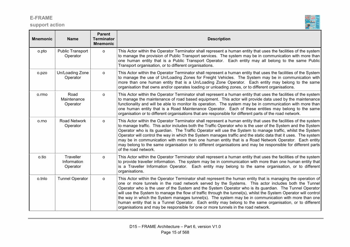
o.pto Public Transport Operator
o This Actor within the Operator Terminator shall represent a human entity that uses the facilities of the system to manage the provision of Public Transport services. The system may be in communication with more than one human entity that is a Public Transport Operator. Each entity may all belong to the same Public Transport organisation, or to different organisations.
o.pzo Un/Loading Zone Operator
o This Actor within the Operator Terminator shall represent a human entity that uses the facilities of the System to manage the use of Un/Loading Zones for Freight Vehicles. The System may be in communication with more than one human entity that is a Un/Loading Zone Operator. Each entity may belong to the same organisation that owns and/or operates loading or unloading zones, or to different organisations.
o.rmo Road Maintenance Operator
o This Actor within the Operator Terminator shall represent a human entity that uses the facilities of the system to manage the maintenance of road based equipment. This actor will provide data used by the maintenance functionality and will be able to monitor its operation. The system may be in communication with more than one human entity that is a Road Maintenance Operator. Each of these entities may belong to the same organisation or to different organisations that are responsible for different parts of the road network.
o.rno Road Network Operator
o This Actor within the Operator Terminator shall represent a human entity that uses the facilities of the system to manage traffic. This actor includes both the Traffic Operator who is the user of the System and the System Operator who is its guardian. The Traffic Operator will use the System to manage traffic, whilst the System Operator will control the way in which the System manages traffic and the static data that it uses. The system may be in communication with more than one human entity that is a Road Network Operator. Each entity may belong to the same organisation or to different organisations and may be responsible for different parts of the road network.
o.tio Traveller Information Operator
o This Actor within the Operator Terminator shall represent a human entity that uses the facilities of the system to provide traveller information. The system may be in communication with more than one human entity that is a Traveller Information Operator. Each entity may belong to the same organisation, or to different organisations.
o.tnlo Tunnel Operator o This Actor within the Operator Terminator shall represent the human entity that is managing the operation of one or more tunnels in the road network served by the Systems. This actor includes both the Tunnel Operator who is the user of the System and the System Operator who is its guardian. The Tunnel Operator will use the System to manage the flow of traffic through the tunnel(s), whilst the System Operator will control the way in which the System manages tunnel(s). The system may be in communication with more than one human entity that is a Tunnel Operator. Each entity may belong to the same organisation, or to different organisations and may be responsible for one or more tunnels in the road network.
E-FRAME
support action
D15 – FRAME Architecture – Part 6, version V1.0
Page 16 of 568
Mnemonic Name Parent
Terminator Mnemonic
Description
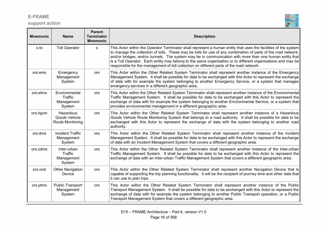
o.to Toll Operator o This Actor within the Operator Terminator shall represent a human entity that uses the facilities of the system to manage the collection of tolls. These may be tolls for use of any combination of parts of the road network, and/or bridges, and/or tunnels. The system may be in communication with more than one human entity that is a Toll Operator. Each entity may belong to the same organisation or to different organisations and may be responsible for the management of toll collection on different parts of the road network.
ors.ems Emergency Management
System
ors This Actor within the Other Related System Terminator shall represent another instance of the Emergency Management System. It shall be possible for data to be exchanged with this Actor to represent the exchange of data with for example the system belonging to another Emergency Service, or a system that manages emergency services in a different geographic area.
ors.etms Environmental Traffic
Management System
ors This Actor within the Other Related System Terminator shall represent another instance of the Environmental Traffic Management System. It shall be possible for data to be exchanged with this Actor to represent the exchange of data with for example the system belonging to another Environmental Service, or a system that provides environmental management in a different geographic area.
ors.hgvm Hazardous Goods Vehicle
Route Monitoring
ors This Actor within the Other Related System Terminator shall represent another instance of a Hazardous Goods Vehicle Route Monitoring System that belongs to a road authority. It shall be possible for data to be exchanged with this Actor to represent the exchange of data with the system belonging to another road authority.
ors.itms Incident Traffic Management
System
ors This Actor within the Other Related System Terminator shall represent another instance of the Incident Management System. It shall be possible for data to be exchanged with this Actor to represent the exchange of data with an Incident Management System that covers a different geographic area.
ors.iutms Inter-urban Traffic
Management System
ors This Actor within the Other Related System Terminator shall represent another instance of the Inter-urban Traffic Management System. It shall be possible for data to be exchanged with this Actor to represent the exchange of data with an Inter-urban Traffic Management System that covers a different geographic area.
ors.ond Other Navigation Device
ors This Actor within the Other Related System Terminator shall represent another Navigation Device that is capable of supporting the trip planning functionality. It will be the recipient of journey time and other data that it can use to plan trips.
ors.ptms Public Transport Management
System
ors This Actor within the Other Related System Terminator shall represent another instance of the Public Transport Management System. It shall be possible for data to be exchanged with this Actor to represent the exchange of data with for example the system belonging to another Public Transport operation, or a Public Transport Management System that covers a different geographic area.
E-FRAME
support action
D15 – FRAME Architecture – Part 6, version V1.0
Page 17 of 568
Mnemonic Name Parent
Terminator Mnemonic
Description
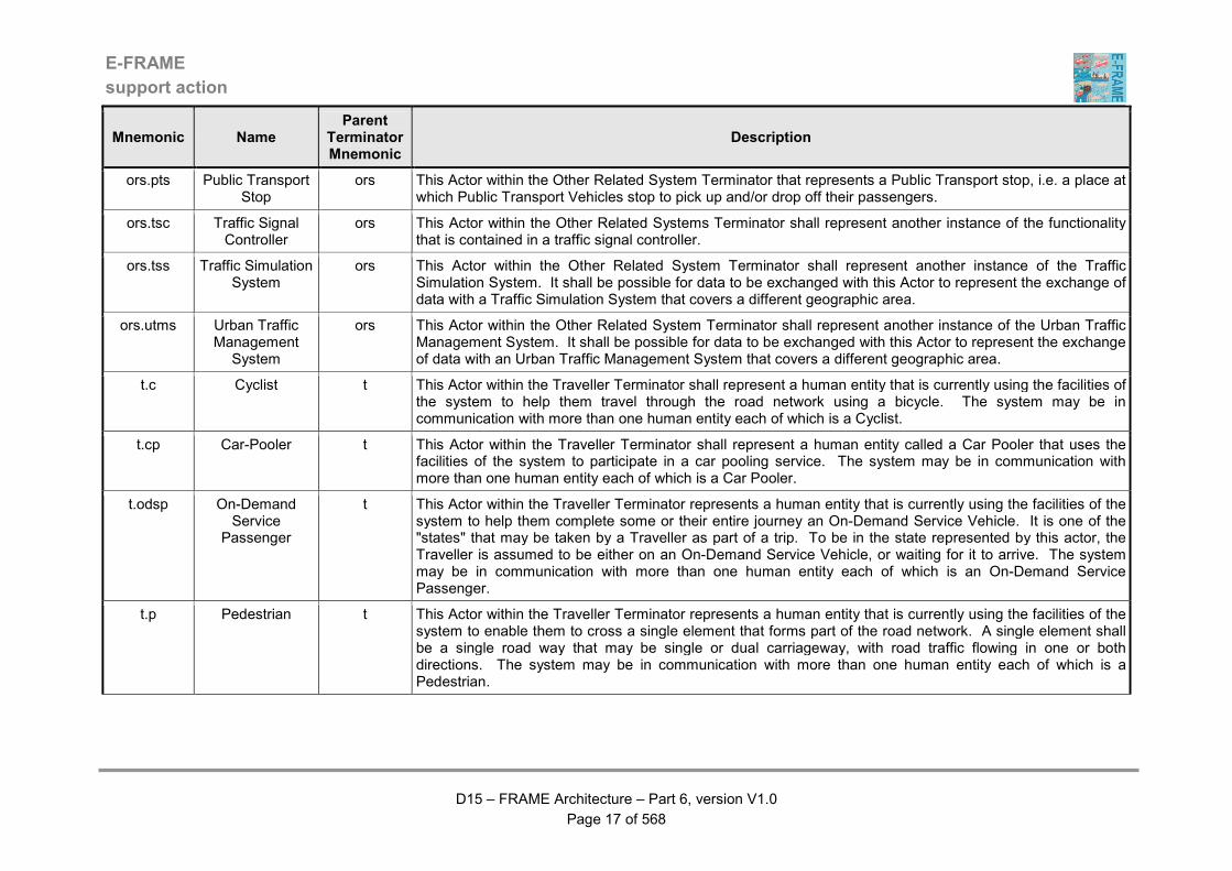
ors.pts Public Transport Stop
ors This Actor within the Other Related System Terminator that represents a Public Transport stop, i.e. a place at which Public Transport Vehicles stop to pick up and/or drop off their passengers.
ors.tsc Traffic Signal Controller
ors This Actor within the Other Related Systems Terminator shall represent another instance of the functionality that is contained in a traffic signal controller.
ors.tss Traffic Simulation System
ors This Actor within the Other Related System Terminator shall represent another instance of the Traffic Simulation System. It shall be possible for data to be exchanged with this Actor to represent the exchange of data with a Traffic Simulation System that covers a different geographic area.
ors.utms Urban Traffic Management
System
ors This Actor within the Other Related System Terminator shall represent another instance of the Urban Traffic Management System. It shall be possible for data to be exchanged with this Actor to represent the exchange of data with an Urban Traffic Management System that covers a different geographic area.
t.c Cyclist t This Actor within the Traveller Terminator shall represent a human entity that is currently using the facilities of the system to help them travel through the road network using a bicycle. The system may be in communication with more than one human entity each of which is a Cyclist.
t.cp Car-Pooler t This Actor within the Traveller Terminator shall represent a human entity called a Car Pooler that uses the facilities of the system to participate in a car pooling service. The system may be in communication with more than one human entity each of which is a Car Pooler.
t.odsp On-Demand Service
Passenger
t This Actor within the Traveller Terminator represents a human entity that is currently using the facilities of the system to help them complete some or their entire journey an On-Demand Service Vehicle. It is one of the "states" that may be taken by a Traveller as part of a trip. To be in the state represented by this actor, the Traveller is assumed to be either on an On-Demand Service Vehicle, or waiting for it to arrive. The system may be in communication with more than one human entity each of which is an On-Demand Service Passenger.
t.p Pedestrian t This Actor within the Traveller Terminator represents a human entity that is currently using the facilities of the system to enable them to cross a single element that forms part of the road network. A single element shall be a single road way that may be single or dual carriageway, with road traffic flowing in one or both directions. The system may be in communication with more than one human entity each of which is a Pedestrian.
E-FRAME
support action
D15 – FRAME Architecture – Part 6, version V1.0
Page 18 of 568
Mnemonic Name Parent
Terminator Mnemonic
Description
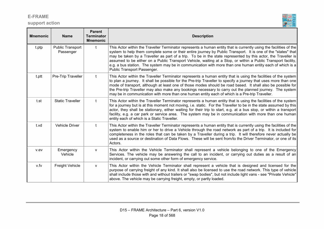
t.ptp Public Transport Passenger
t This Actor within the Traveller Terminator represents a human entity that is currently using the facilities of the system to help them complete some or their entire journey by Public Transport. It is one of the "states" that may be taken by a Traveller as part of a trip. To be in the state represented by this actor, the Traveller is assumed to be either on a Public Transport Vehicle, waiting at a Stop, or within a Public Transport facility, e.g. a bus station. The system may be in communication with more than one human entity each of which is a Public Transport Passenger.
t.ptt Pre-Trip Traveller t This Actor within the Traveller Terminator represents a human entity that is using the facilities of the system to plan a journey. It shall be possible for the Pre-trip Traveller to specify a journey that uses more than one mode of transport, although at least one of those modes should be road based. It shall also be possible for the Pre-trip Traveller may also make any bookings necessary to carry out the planned journey. The system may be in communication with more than one human entity each of which is a Pre-trip Traveller.
t.st Static Traveller t This Actor within the Traveller Terminator represents a human entity that is using the facilities of the system for a journey but is at this moment not moving, i.e. static. For the Traveller to be in the state assumed by this actor, they shall be stationary, either waiting for their trip to start, e.g. at a bus stop, or within a transport facility, e.g. a car park or service area. The system may be in communication with more than one human entity each of which is a Static Traveller.
t.vd Vehicle Driver t This Actor within the Traveller Terminator represents a human entity that is currently using the facilities of the system to enable him or her to drive a Vehicle through the road network as part of a trip. It is included for completeness in the roles that can be taken by a Traveller during a trip. It will therefore never actually be used as a source or destination of Data Flows. These will be sent from/to the Driver Terminator, or one of its Actors.
v.ev Emergency Vehicle
v This Actor within the Vehicle Terminator shall represent a vehicle belonging to one of the Emergency Services. The vehicle may be answering the call to an incident, or carrying out duties as a result of an incident, or carrying out some other form of emergency service.
v.fv Freight Vehicle v This Actor within the Vehicle Terminator shall represent a vehicle that is designed and licensed for the purpose of carrying freight of any kind. It shall also be licensed to use the road network. This type of vehicle shall include those with and without trailers or "swap bodies", but not include light vans - see "Private Vehicle" above. The vehicle may be carrying freight, empty, or partly loaded.

E-FRAME
support action
D15 – FRAME Architecture – Part 6, version V1.0
Page 19 of 568
Mnemonic Name Parent
Terminator Mnemonic
Description
v.hgv Hazardous Goods Vehicle
v This Actor within the Vehicle Terminator shall represent a vehicle that is carrying hazardous goods. The Vehicle must be designed and licensed for the purpose of carrying a particular type of hazardous goods. The "hazard" may relate to the type of goods, such as chemicals, combustible or nuclear materials, etc, or to its physical characteristics, e.g. size, weight.
v.hmi Human Machine Interface
v This Actor within the Vehicle Terminator shall represent devices within the Vehicle that will interact directly with the driver, or other occupants, for reasons not connected with the primary operation of the vehicle systems. In particular this actor will provide alertness warnings, or alertness enhancement.
v.odsv On-Demand Service Vehicle
v This Actor within the Vehicle Terminator shall represent a Vehicle that delivers Public Transport services on-demand. It can be any type of Vehicle that is licensed to carry any number of passengers. However the number of passengers is expected to be greater that 7, which is the usual maximum for a taxi. The service does not follow a regular route or regular timings, but instead follows a route dictated by where the passengers require to be picked up and dropped off at times that are also dictated by the passengers. A Traveller can only use this service by making a booking in advance.
v.ov Other Vehicle v This Actor within the Vehicle Terminator shall represent an Other Vehicle. It may be part of the normal traffic flow, in either direction, or part of a platoon. Data is exchanged between a host Vehicle and an Other Vehicle for a number of reasons, e.g. to prevent collisions, to perform platooning, to reduce headlamp glare.
v.pttv Public Transport Touring Vehicle
v This Actor within the Vehicle Terminator shall represent a vehicle that is licensed to carry passengers who pay for their transportation but for whom there is no requirement to adhere to a fixed or pre-defined route. It shall also be licensed to use the road network. This type of vehicle shall represent a "coach" that is used by tour operators and other organisations whose sole purpose is not to carry travellers through the road network and do not operate scheduled services.
v.ptv Public Transport Vehicle
v This Actor within the Vehicle Terminator shall represent a vehicle that is licensed to carry passengers who pay for their transportation and who expect it to follow a fixed or predicted route. It shall also be licensed to use the road network. The types of vehicle shall include buses, trolley buses and trams, i.e. any vehicle that carries its passengers on a pre-defined route, which can only be changed by the Public Transport Service Provider. It shall include both vehicles that operate routes in the urban road network, i.e. with an urban conurbation, and those that operate routes in the inter-urban road network, e.g. between towns and cities.
v.pv Private Vehicle v This Actor within the Vehicle Terminator shall represent a car, or light van that is licensed to use the road network. It is owned by a person and does not belong to any type of organisation.
E-FRAME
support action
D15 – FRAME Architecture – Part 6, version V1.0
Page 20 of 568
Mnemonic Name Parent
Terminator Mnemonic
Description
v.vs Vehicle Systems v This Actor within the Vehicle Terminator shall represent the systems that are in the Vehicle and which are provided by the Vehicle manufacturer for the primary function of travel. These Systems shall be those responsible for the basic control and management of Vehicle operations (e.g. power train management, impact protection device deployment, vehicle lighting, etc.), the display of vehicle system information to the Driver and the Vehicle manoeuvres, such as braking, starting and steering (including lane changing). It will be possible for the Vehicle manufacturer to make data available from, and to receive data to, these Systems through this actor.
ve.onv Other Nearby Vehicles
ve This Actor within the Vehicle Environment Terminator shall represent the manifestation of other equipped vehicles in the geographic area surrounding the vehicle. This manifestation will take the form of an image, which may be in the visible or other light spectrum, e.g. infra-red.
ve.oru Other Road Users
ve This Actor within the Vehicle Environment Terminator shall represent the manifestation of other road users. These objects may be other non-equipped vehicles, motor-cyclists, cyclists, animals, pedestrians, Vulnerable Road Users (VRU's), etc. that are in the roadway of the geographic area surrounding the host vehicle. This manifestation will take the form of an image, which may be in the visible or other light spectrum, e.g. infra-red.
ve.so Stationary Object ve This Actor within the Vehicle Environment Terminator shall represent the manifestation of stationary objects. These objects may be anything such as, animals, solid objects, e.g. debris, that are in or near the roadway of the geographic area surrounding the host vehicle. This manifestation will take the form of an image, which may be in the visible or other light spectrum, e.g. infra-red.
E-FRAME
support action
D15 – FRAME Architecture – Part 6, version V1.0
Page 21 of 568
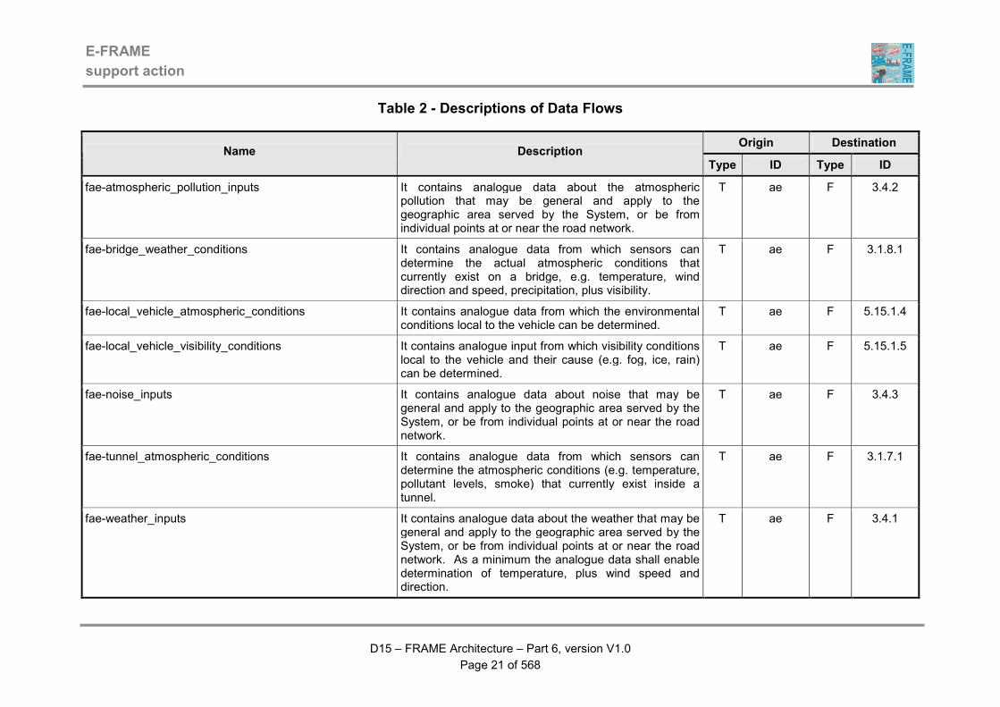
Table 2 - Descriptions of Data Flows
Origin Destination Name Description
Type ID Type ID
fae-atmospheric_pollution_inputs It contains analogue data about the atmospheric pollution that may be general and apply to the geographic area served by the System, or be from individual points at or near the road network.
T ae F 3.4.2
fae-bridge_weather_conditions It contains analogue data from which sensors can determine the actual atmospheric conditions that currently exist on a bridge, e.g. temperature, wind direction and speed, precipitation, plus visibility.
T ae F 3.1.8.1
fae-local_vehicle_atmospheric_conditions It contains analogue data from which the environmental conditions local to the vehicle can be determined.
T ae F 5.15.1.4
fae-local_vehicle_visibility_conditions It contains analogue input from which visibility conditions local to the vehicle and their cause (e.g. fog, ice, rain) can be determined.
T ae F 5.15.1.5
fae-noise_inputs It contains analogue data about noise that may be general and apply to the geographic area served by the System, or be from individual points at or near the road network.
T ae F 3.4.3
fae-tunnel_atmospheric_conditions It contains analogue data from which sensors can determine the atmospheric conditions (e.g. temperature, pollutant levels, smoke) that currently exist inside a tunnel.
T ae F 3.1.7.1
fae-weather_inputs It contains analogue data about the weather that may be general and apply to the geographic area served by the System, or be from individual points at or near the road network. As a minimum the analogue data shall enable determination of temperature, plus wind speed and direction.
T ae F 3.4.1
E-FRAME
support action
D15 – FRAME Architecture – Part 6, version V1.0
Page 22 of 568
Origin Destination Name Description
Type ID Type ID
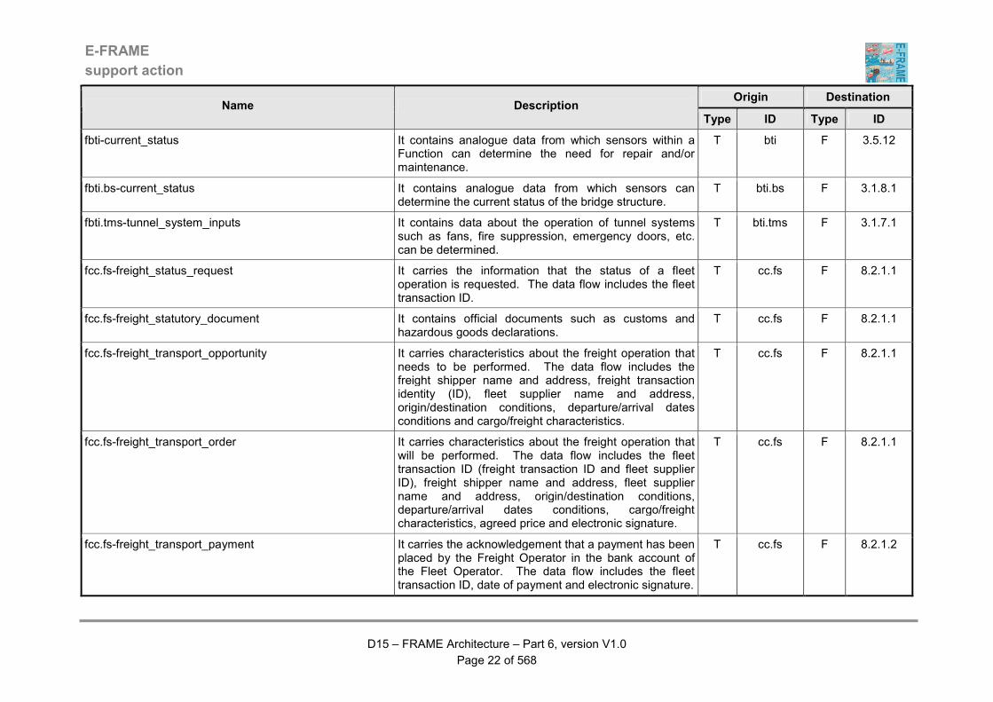
fbti-current_status It contains analogue data from which sensors within a Function can determine the need for repair and/or maintenance.
T bti F 3.5.12
fbti.bs-current_status It contains analogue data from which sensors can determine the current status of the bridge structure.
T bti.bs F 3.1.8.1
fbti.tms-tunnel_system_inputs It contains data about the operation of tunnel systems such as fans, fire suppression, emergency doors, etc. can be determined.
T bti.tms F 3.1.7.1
fcc.fs-freight_status_request It carries the information that the status of a fleet operation is requested. The data flow includes the fleet transaction ID.
T cc.fs F 8.2.1.1
fcc.fs-freight_statutory_document It contains official documents such as customs and hazardous goods declarations.
T cc.fs F 8.2.1.1
fcc.fs-freight_transport_opportunity It carries characteristics about the freight operation that needs to be performed. The data flow includes the freight shipper name and address, freight transaction identity (ID), fleet supplier name and address, origin/destination conditions, departure/arrival dates conditions and cargo/freight characteristics.
T cc.fs F 8.2.1.1
fcc.fs-freight_transport_order It carries characteristics about the freight operation that will be performed. The data flow includes the fleet transaction ID (freight transaction ID and fleet supplier ID), freight shipper name and address, fleet supplier name and address, origin/destination conditions, departure/arrival dates conditions, cargo/freight characteristics, agreed price and electronic signature.
T cc.fs F 8.2.1.1
fcc.fs-freight_transport_payment It carries the acknowledgement that a payment has been placed by the Freight Operator in the bank account of the Fleet Operator. The data flow includes the fleet transaction ID, date of payment and electronic signature.
T cc.fs F 8.2.1.2

E-FRAME
support action
D15 – FRAME Architecture – Part 6, version V1.0
Page 23 of 568
Origin Destination Name Description
Type ID Type ID
fcc.p-order_from_principal_for_goods_transport It contains the order from the principal for conveying an item of freight and includes freight transaction ID (principal order ID and freight operator proposal ID), principal name and address, origin/destination conditions, departure/arrival dates conditions, cargo/freight characteristics, agreed price and electronic signature.
T cc.p F 8.1.1.8
fcc.p-payment_acknowledgement It carries the acknowledgement that a payment has been placed in the bank account of the freight operator by the principal. This data flow includes freight transaction ID (principal order ID and freight operator proposal ID), date of payment and electronic signature.
T cc.p F 8.1.1.8
fcc.p-status_request It contains the request from the Principal Actor in the Consignor/Consignee Terminator to get information on the status of a freight operation and includes freight transaction ID (Principal order ID and Freight Operator proposal ID), cargo status ID
T cc.p F 8.1.3
fcc.p-transport_opportunity It contains the request from the principal for conveying an item of freight, including principal need ID, principal name and address, origin/destination conditions, departure/arrival dates conditions, cargo/freight characteristics and electronic signature.
T cc.p F 8.1.1.8
fd-carpark_space_payment It contains a payment for the use of a car park space. This will be in the form of a debit/credit card transaction.
T d F 3.1.4.6
fd-desitnation_for_bus_lane_use It contains the destination and any "way points" so that the route and hence the Bus Lanes that need to be used can be determined.
T d F 9.2.1
fd-driver_details It contains all data necessary to identify the Driver (including any pre-existing medical data) for use in recording operational data.
T d F 5.11.9
E-FRAME
support action
D15 – FRAME Architecture – Part 6, version V1.0
Page 24 of 568
Origin Destination Name Description
Type ID Type ID
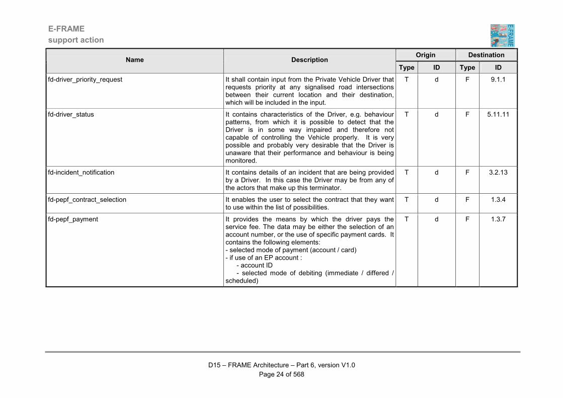
fd-driver_priority_request It shall contain input from the Private Vehicle Driver that requests priority at any signalised road intersections between their current location and their destination, which will be included in the input.
T d F 9.1.1
fd-driver_status It contains characteristics of the Driver, e.g. behaviour patterns, from which it is possible to detect that the Driver is in some way impaired and therefore not capable of controlling the Vehicle properly. It is very possible and probably very desirable that the Driver is unaware that their performance and behaviour is being monitored.
T d F 5.11.11
fd-incident_notification It contains details of an incident that are being provided by a Driver. In this case the Driver may be from any of the actors that make up this terminator.
T d F 3.2.13
fd-pepf_contract_selection It enables the user to select the contract that they want to use within the list of possibilities.
T d F 1.3.4
fd-pepf_payment It provides the means by which the driver pays the service fee. The data may be either the selection of an account number, or the use of specific payment cards. It contains the following elements: - selected mode of payment (account / card) - if use of an EP account : - account ID - selected mode of debiting (immediate / differed / scheduled)
T d F 1.3.7
E-FRAME
support action
D15 – FRAME Architecture – Part 6, version V1.0
Page 25 of 568
Origin Destination Name Description
Type ID Type ID
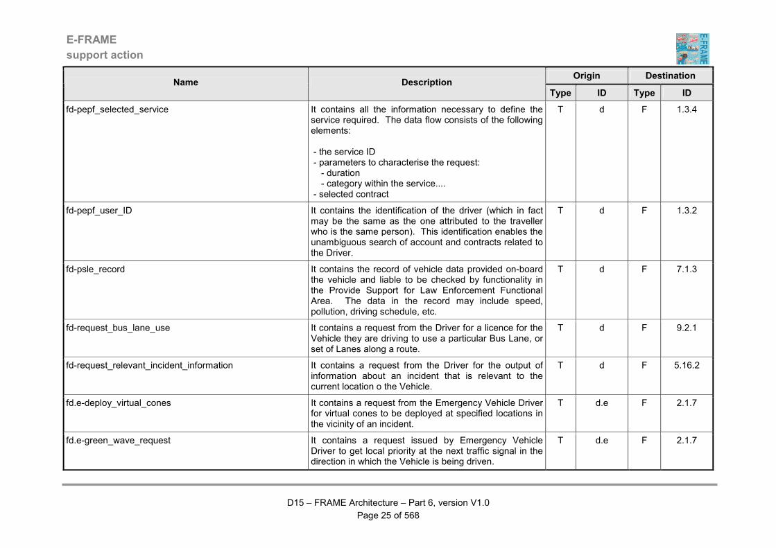
fd-pepf_selected_service It contains all the information necessary to define the service required. The data flow consists of the following elements: - the service ID - parameters to characterise the request: - duration - category within the service.... - selected contract
T d F 1.3.4
fd-pepf_user_ID It contains the identification of the driver (which in fact may be the same as the one attributed to the traveller who is the same person). This identification enables the unambiguous search of account and contracts related to the Driver.
T d F 1.3.2
fd-psle_record It contains the record of vehicle data provided on-board the vehicle and liable to be checked by functionality in the Provide Support for Law Enforcement Functional Area. The data in the record may include speed, pollution, driving schedule, etc.
T d F 7.1.3
fd-request_bus_lane_use It contains a request from the Driver for a licence for the Vehicle they are driving to use a particular Bus Lane, or set of Lanes along a route.
T d F 9.2.1
fd-request_relevant_incident_information It contains a request from the Driver for the output of information about an incident that is relevant to the current location o the Vehicle.
T d F 5.16.2
fd.e-deploy_virtual_cones It contains a request from the Emergency Vehicle Driver for virtual cones to be deployed at specified locations in the vicinity of an incident.
T d.e F 2.1.7
fd.e-green_wave_request It contains a request issued by Emergency Vehicle Driver to get local priority at the next traffic signal in the direction in which the Vehicle is being driven.
T d.e F 2.1.7

E-FRAME
support action
D15 – FRAME Architecture – Part 6, version V1.0
Page 26 of 568
Origin Destination Name Description
Type ID Type ID
fd.e-individual_emergency_progress_report It contains information about the status/progress of the green wave that is currently being followed by the Emergency Vehicle being driven by the Emergency Vehicle Driver.
T d.e F 2.1.7
fd.fvd-payment_receipt It contains proof of payment that has been completed by the Driver during a trip.
T d.fvd F 8.2.2.2.3
fd.fvd-rest_area_parking_request It contains a request for the reservation of a parking place at a rest area, which is assumed to be part of a service area. Details of planned route, Estimated Time of Arrival (ETA) and Vehicle type will be provided from the Vehicle Trip Plan information. The Driver will provide the other information needed for the booking such as the required duration, potential flexibility and any hazardous goods that will be carried by the Freight Vehicle.
T d.fvd F 5.14.10
fd.fvd-rest_area_parking_request_response It contains either acceptance of the previously requested booking of a parking space at a rest zone in a service area, or suggested alternatives if there was no space available at the originally requested time.
T d.fvd F 5.14.10
fd.fvd-revised_rest_area_parking_request It contains a revised request for the reservation of a parking place at a rest zone, which is assumed to be part of a service area. This request will have been generated either because the original request was rejected, or the Estimated Time of Arrival (ETA) of the Freight Vehicle has changed.
T d.fvd F 5.14.10
fd.fvd-revised_un/loading_zone_use_request It contains a revised request for the reservation for the use of a un/loading zone. This request will have been generated either because the original request was rejected, or the Estimated Time of Arrival (ETA) of the Freight Vehicle has changed.
T d.fvd F 5.14.11
E-FRAME
support action
D15 – FRAME Architecture – Part 6, version V1.0
Page 27 of 568
Origin Destination Name Description
Type ID Type ID
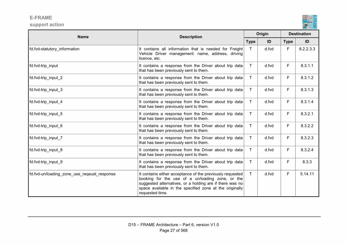
fd.fvd-statutory_information It contains all information that is needed for Freight Vehicle Driver management: name, address, driving licence, etc.
T d.fvd F 8.2.2.3.3
fd.fvd-trip_input It contains a response from the Driver about trip data that has been previously sent to them.
T d.fvd F 8.3.1.1
fd.fvd-trip_input_2 It contains a response from the Driver about trip data that has been previously sent to them.
T d.fvd F 8.3.1.2
fd.fvd-trip_input_3 It contains a response from the Driver about trip data that has been previously sent to them.
T d.fvd F 8.3.1.3
fd.fvd-trip_input_4 It contains a response from the Driver about trip data that has been previously sent to them.
T d.fvd F 8.3.1.4
fd.fvd-trip_input_5 It contains a response from the Driver about trip data that has been previously sent to them.
T d.fvd F 8.3.2.1
fd.fvd-trip_input_6 It contains a response from the Driver about trip data that has been previously sent to them.
T d.fvd F 8.3.2.2
fd.fvd-trip_input_7 It contains a response from the Driver about trip data that has been previously sent to them.
T d.fvd F 8.3.2.3
fd.fvd-trip_input_8 It contains a response from the Driver about trip data that has been previously sent to them.
T d.fvd F 8.3.2.4
fd.fvd-trip_input_9 It contains a response from the Driver about trip data that has been previously sent to them.
T d.fvd F 8.3.3
fd.fvd-un/loading_zone_use_reqeust_response It contains either acceptance of the previously requested booking for the use of a un/loading zone, or the suggested alternatives, or a holding are if there was no space available in the specified zone at the originally requested time.
T d.fvd F 5.14.11
E-FRAME
support action
D15 – FRAME Architecture – Part 6, version V1.0
Page 28 of 568
Origin Destination Name Description
Type ID Type ID
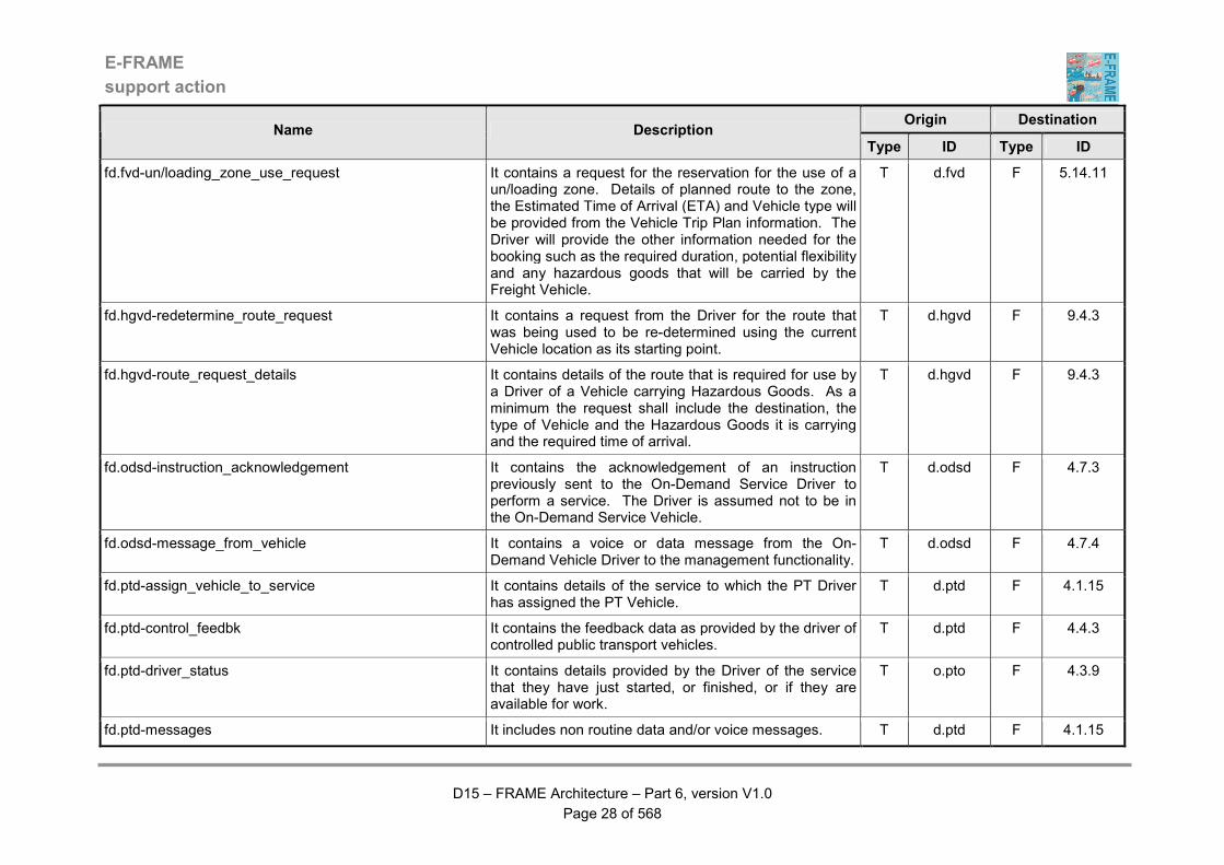
fd.fvd-un/loading_zone_use_request It contains a request for the reservation for the use of a un/loading zone. Details of planned route to the zone, the Estimated Time of Arrival (ETA) and Vehicle type will be provided from the Vehicle Trip Plan information. The Driver will provide the other information needed for the booking such as the required duration, potential flexibility and any hazardous goods that will be carried by the Freight Vehicle.
T d.fvd F 5.14.11
fd.hgvd-redetermine_route_request It contains a request from the Driver for the route that was being used to be re-determined using the current Vehicle location as its starting point.
T d.hgvd F 9.4.3
fd.hgvd-route_request_details It contains details of the route that is required for use by a Driver of a Vehicle carrying Hazardous Goods. As a minimum the request shall include the destination, the type of Vehicle and the Hazardous Goods it is carrying and the required time of arrival.
T d.hgvd F 9.4.3
fd.odsd-instruction_acknowledgement It contains the acknowledgement of an instruction previously sent to the On-Demand Service Driver to perform a service. The Driver is assumed not to be in the On-Demand Service Vehicle.
T d.odsd F 4.7.3
fd.odsd-message_from_vehicle It contains a voice or data message from the On-Demand Vehicle Driver to the management functionality.
T d.odsd F 4.7.4
fd.ptd-assign_vehicle_to_service It contains details of the service to which the PT Driver has assigned the PT Vehicle.
T d.ptd F 4.1.15
fd.ptd-control_feedbk It contains the feedback data as provided by the driver of controlled public transport vehicles.
T d.ptd F 4.4.3
fd.ptd-driver_status It contains details provided by the Driver of the service that they have just started, or finished, or if they are available for work.
T o.pto F 4.3.9
fd.ptd-messages It includes non routine data and/or voice messages. T d.ptd F 4.1.15

E-FRAME
support action
D15 – FRAME Architecture – Part 6, version V1.0
Page 29 of 568
Origin Destination Name Description
Type ID Type ID
fd.ptv-request_fares It contains a request for details of the fares for the route/service that the PT Driver is currently operating.
T d.ptd F 4.5.1
fd.tpd-accept_revised_vehicle_trip_plan It contains the acceptance from the Driver of the modified Vehicle Trip Plan, details of which have previously been provided.
T d.tpd F 5.14.1
fd.tpd-implement_vehicle_trip_plan It contains a request from the Driver to implement a specified previously prepared Vehicle Trip Plan.
T d.tpd F 5.14.1
fd.tpd-modified_vehicle_trip_plan_data It contains some modifications to the original parameters that the Driver provided for a trip. These modifications are being input because the original parameters did not produce a trip plan that was acceptable to the Driver.
T d.tpd F 5.14.1
fd.tpd-modify_current_vehicle_trip_plan It contains a request from the Driver to modify the Vehicle Trip Plan that is currently being implemented, even though it has not yet been completed.
T d.tpd F 5.14.1
fd.tpd-revised_vehicle_trip_plan_booking_choices It contains revisions that the Driver is making to previously made choices for advanced payments needed as part of a trip plan. These revisions are usually needed because payment for the previous choices has failed.
T d.tpd F 5.14.3
fd.tpd-vehicle_trip_planning_payment It contains details of how the payment that the Driver is making for the use of trip planning services is to be made.
T d.tpd F 5.14.3
fd.tpd-vehicle_trip_plan_accepted It contains the acceptance of the trip plan that has been produced using the parameters that have been provided by the Driver.
T d.tpd F 5.14.1
fd.tpd-vehicle_trip_plan_booking_approval It contains confirmation from the Driver that bookings are to be made for other services needed as part of a trip and includes details of how the payments are to be made.
T d.tpd F 5.14.3
E-FRAME
support action
D15 – FRAME Architecture – Part 6, version V1.0
Page 30 of 568
Origin Destination Name Description
Type ID Type ID
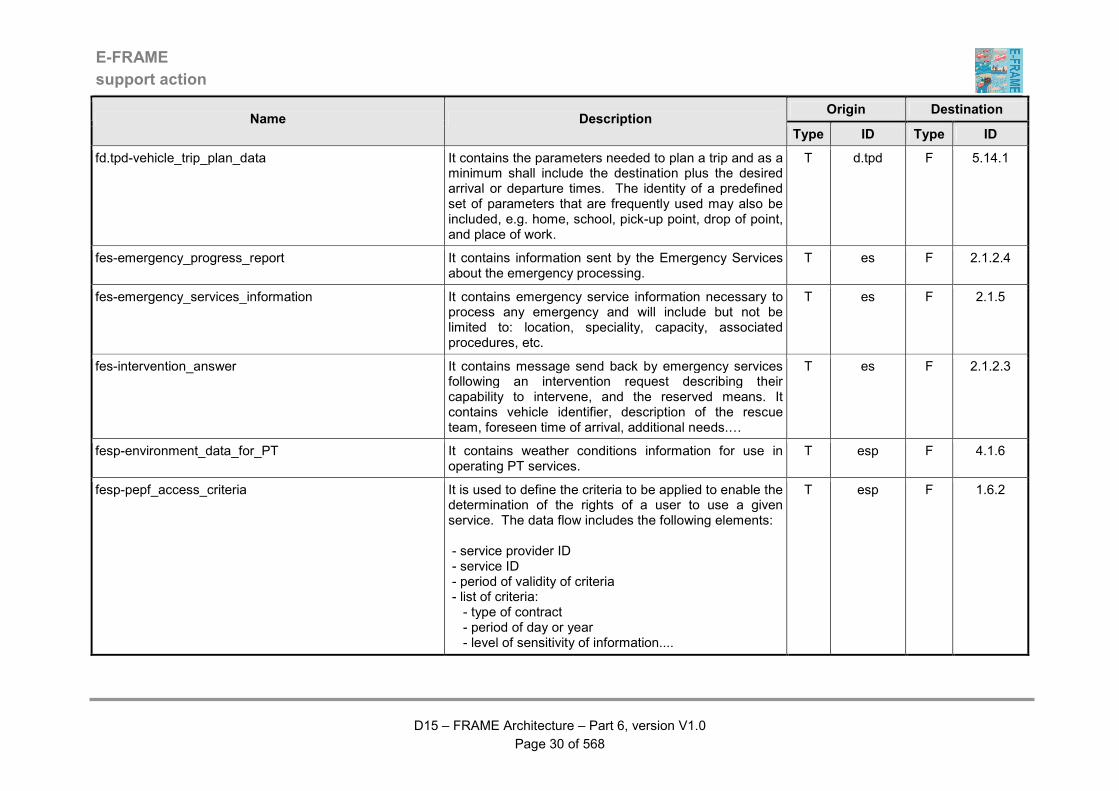
fd.tpd-vehicle_trip_plan_data It contains the parameters needed to plan a trip and as a minimum shall include the destination plus the desired arrival or departure times. The identity of a predefined set of parameters that are frequently used may also be included, e.g. home, school, pick-up point, drop of point, and place of work.
T d.tpd F 5.14.1
fes-emergency_progress_report It contains information sent by the Emergency Services about the emergency processing.
T es F 2.1.2.4
fes-emergency_services_information It contains emergency service information necessary to process any emergency and will include but not be limited to: location, speciality, capacity, associated procedures, etc.
T es F 2.1.5
fes-intervention_answer It contains message send back by emergency services following an intervention request describing their capability to intervene, and the reserved means. It contains vehicle identifier, description of the rescue team, foreseen time of arrival, additional needs.…
T es F 2.1.2.3
fesp-environment_data_for_PT It contains weather conditions information for use in operating PT services.
T esp F 4.1.6
fesp-pepf_access_criteria It is used to define the criteria to be applied to enable the determination of the rights of a user to use a given service. The data flow includes the following elements: - service provider ID - service ID - period of validity of criteria - list of criteria: - type of contract - period of day or year - level of sensitivity of information....
T esp F 1.6.2
E-FRAME
support action
D15 – FRAME Architecture – Part 6, version V1.0
Page 31 of 568
Origin Destination Name Description
Type ID Type ID
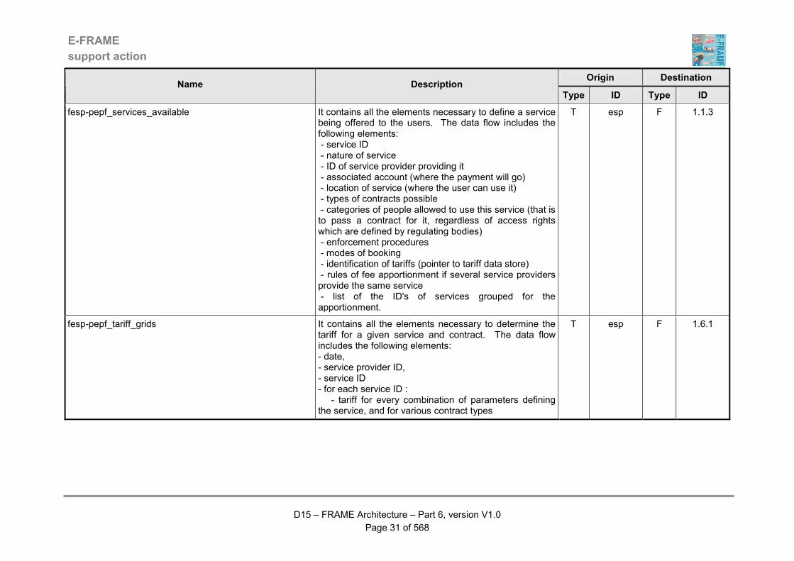
fesp-pepf_services_available It contains all the elements necessary to define a service being offered to the users. The data flow includes the following elements: - service ID - nature of service - ID of service provider providing it - associated account (where the payment will go) - location of service (where the user can use it) - types of contracts possible - categories of people allowed to use this service (that is to pass a contract for it, regardless of access rights which are defined by regulating bodies) - enforcement procedures - modes of booking - identification of tariffs (pointer to tariff data store) - rules of fee apportionment if several service providers provide the same service - list of the ID's of services grouped for the apportionment.
T esp F 1.1.3
fesp-pepf_tariff_grids It contains all the elements necessary to determine the tariff for a given service and contract. The data flow includes the following elements: - date, - service provider ID, - service ID - for each service ID : - tariff for every combination of parameters defining the service, and for various contract types
T esp F 1.6.1
E-FRAME
support action
D15 – FRAME Architecture – Part 6, version V1.0
Page 32 of 568
Origin Destination Name Description
Type ID Type ID
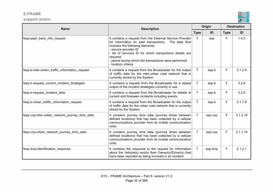
fesp-pepf_trans_info_request It contains a request from the External Service Provider for information on past transactions. The data flow includes the following elements: - service provider ID - list of services ID for which transactions details are required - period during which the transactions were performed - location criteria
T esp F 1.4.3
fesp.b-inter-urban_traffic_information_request It contains a request from the Broadcaster for the output of traffic data for the inter-urban road network that is currently stored by the System.
T esp.b F 3.1.2.9
fesp.b-request_current_incident_strategies It contains a request from the Broadcaster for a repeat output of the incident strategies currently in use.
T esp.b F 3.2.9
fesp.b-request_incident_data It contains a request from the Broadcaster for details of current and foreseen incidents including events.
T esp.b F 3.2.9
fesp.b-urban_traffic_information_request It contains a request from the Broadcaster for the output of traffic data for the urban road network that is currently stored by the System.
T esp.b F 3.1.1.9
fesp.ccp-inter-urban_network_journey_time_data It contains journey time data (journey times between defined locations) that has been collected by a cellular communications provider from its mobile communication units.
T esp.ccp F 3.1.2.16
fesp.ccp-urban_network_journey_time_data It contains journey time data (journey times between defined locations) that has been collected by a cellular communications provider from its mobile communication units.
T esp.ccp F 3.1.1.14
fesp.dvip-identification_response It contains the response to the request for information about the Vehicle(s) and/or their Owner(s)/Driver(s) that have been reported as being involved in an incident.
T esp.dvip F 2.1.2.1
E-FRAME
support action
D15 – FRAME Architecture – Part 6, version V1.0
Page 33 of 568
Origin Destination Name Description
Type ID Type ID
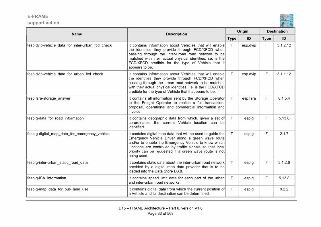
fesp.dvip-vehicle_data_for_inter-urban_fcd_check It contains information about Vehicles that will enable the identities they provide through FCD/XFCD when passing through the inter-urban road network to be matched with their actual physical identities, i.e. is the FCD/XFCD credible for the type of Vehicle that it appears to be.
T esp.dvip F 3.1.2.12
fesp.dvip-vehicle_data_for_urban_fcd_check It contains information about Vehicles that will enable the identities they provide through FCD/XFCD when passing through the urban road network to be matched with their actual physical identities, i.e. is the FCD/XFCD credible for the type of Vehicle that it appears to be.
T esp.dvip F 3.1.1.12
fesp.fsra-storage_answer It contains all information sent by the Storage Operator to the Freight Operator to realise a full transaction: proposal, operational and commercial information and invoice.
T esp.fsra F 8.1.5.4
fesp.g-data_for_road_information It contains geographic data from which, given a set of co-ordinates, the current Vehicle location can be identified.
T esp.g F 5.13.6
fesp.g-digital_map_data_for_emergency_vehicle It contains digital map data that will be used to guide the Emergency Vehicle Driver along a green wave route and/or to enable the Emergency Vehicle to know which junctions are controlled by traffic signals so that local priority can be requested if a green wave route is not being used.
T esp.g F 2.1.7
fesp.g-inter-urban_static_road_data It contains static data about the inter-urban road network provided by a digital map data provider that is to be loaded into the Data Store D3.8.
T esp.g F 3.1.2.6
fesp.g-ISA_information It contains speed limit data for each part of the urban and inter-urban road networks.
T esp.g F 5.13.8
fesp.g-map_data_for_bus_lane_use It contains digital data from which the current position of a Vehicle and its destination can be determined.
T esp.g F 9.2.2
E-FRAME
support action
D15 – FRAME Architecture – Part 6, version V1.0
Page 34 of 568
Origin Destination Name Description
Type ID Type ID
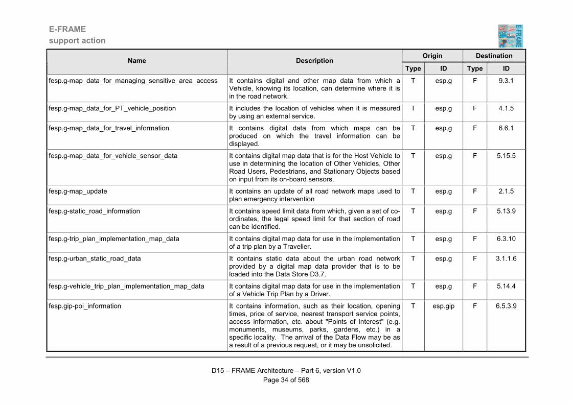
fesp.g-map_data_for_managing_sensitive_area_access It contains digital and other map data from which a Vehicle, knowing its location, can determine where it is in the road network.
T esp.g F 9.3.1
fesp.g-map_data_for_PT_vehicle_position It includes the location of vehicles when it is measured by using an external service.
T esp.g F 4.1.5
fesp.g-map_data_for_travel_information It contains digital data from which maps can be produced on which the travel information can be displayed.
T esp.g F 6.6.1
fesp.g-map_data_for_vehicle_sensor_data It contains digital map data that is for the Host Vehicle to use in determining the location of Other Vehicles, Other Road Users, Pedestrians, and Stationary Objects based on input from its on-board sensors.
T esp.g F 5.15.5
fesp.g-map_update It contains an update of all road network maps used to plan emergency intervention
T esp.g F 2.1.5
fesp.g-static_road_information It contains speed limit data from which, given a set of co-ordinates, the legal speed limit for that section of road can be identified.
T esp.g F 5.13.9
fesp.g-trip_plan_implementation_map_data It contains digital map data for use in the implementation of a trip plan by a Traveller.
T esp.g F 6.3.10
fesp.g-urban_static_road_data It contains static data about the urban road network provided by a digital map data provider that is to be loaded into the Data Store D3.7.
T esp.g F 3.1.1.6
fesp.g-vehicle_trip_plan_implementation_map_data It contains digital map data for use in the implementation of a Vehicle Trip Plan by a Driver.
T esp.g F 5.14.4
fesp.gip-poi_information It contains information, such as their location, opening times, price of service, nearest transport service points, access information, etc. about "Points of Interest" (e.g. monuments, museums, parks, gardens, etc.) in a specific locality. The arrival of the Data Flow may be as a result of a previous request, or it may be unsolicited.
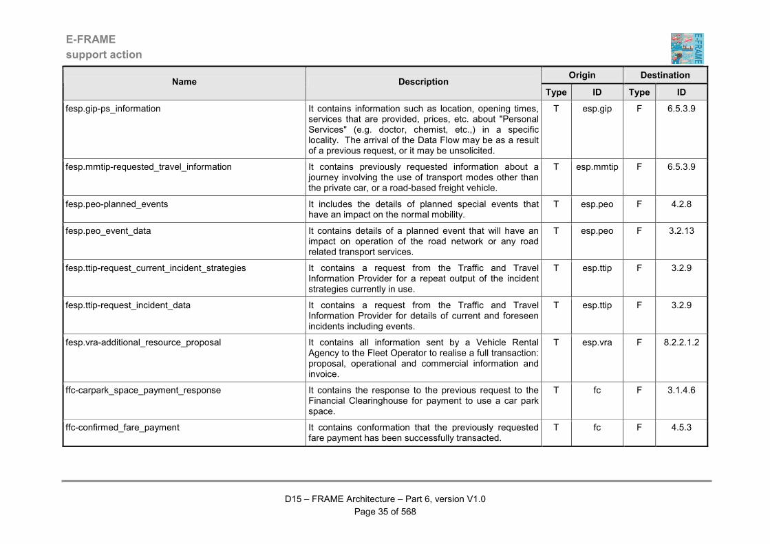
T esp.gip F 6.5.3.9
E-FRAME
support action
D15 – FRAME Architecture – Part 6, version V1.0
Page 35 of 568
Origin Destination Name Description
Type ID Type ID
fesp.gip-ps_information It contains information such as location, opening times, services that are provided, prices, etc. about "Personal Services" (e.g. doctor, chemist, etc.,) in a specific locality. The arrival of the Data Flow may be as a result of a previous request, or it may be unsolicited.
T esp.gip F 6.5.3.9
fesp.mmtip-requested_travel_information It contains previously requested information about a journey involving the use of transport modes other than the private car, or a road-based freight vehicle.
T esp.mmtip F 6.5.3.9
fesp.peo-planned_events It includes the details of planned special events that have an impact on the normal mobility.
T esp.peo F 4.2.8
fesp.peo_event_data It contains details of a planned event that will have an impact on operation of the road network or any road related transport services.
T esp.peo F 3.2.13
fesp.ttip-request_current_incident_strategies It contains a request from the Traffic and Travel Information Provider for a repeat output of the incident strategies currently in use.
T esp.ttip F 3.2.9
fesp.ttip-request_incident_data It contains a request from the Traffic and Travel Information Provider for details of current and foreseen incidents including events.
T esp.ttip F 3.2.9
fesp.vra-additional_resource_proposal It contains all information sent by a Vehicle Rental Agency to the Fleet Operator to realise a full transaction: proposal, operational and commercial information and invoice.
T esp.vra F 8.2.2.1.2
ffc-carpark_space_payment_response It contains the response to the previous request to the Financial Clearinghouse for payment to use a car park space.
T fc F 3.1.4.6
ffc-confirmed_fare_payment It contains conformation that the previously requested fare payment has been successfully transacted.
T fc F 4.5.3
E-FRAME
support action
D15 – FRAME Architecture – Part 6, version V1.0
Page 36 of 568
Origin Destination Name Description
Type ID Type ID
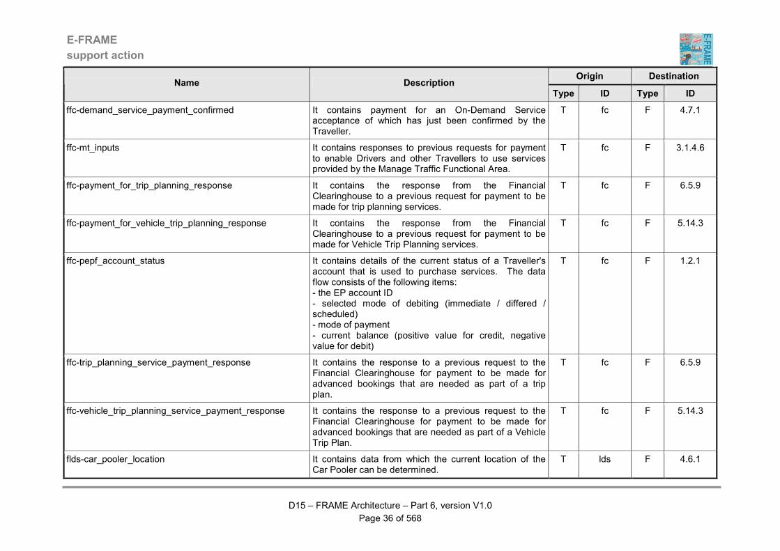
ffc-demand_service_payment_confirmed It contains payment for an On-Demand Service acceptance of which has just been confirmed by the Traveller.
T fc F 4.7.1
ffc-mt_inputs It contains responses to previous requests for payment to enable Drivers and other Travellers to use services provided by the Manage Traffic Functional Area.
T fc F 3.1.4.6
ffc-payment_for_trip_planning_response It contains the response from the Financial Clearinghouse to a previous request for payment to be made for trip planning services.
T fc F 6.5.9
ffc-payment_for_vehicle_trip_planning_response It contains the response from the Financial Clearinghouse to a previous request for payment to be made for Vehicle Trip Planning services.
T fc F 5.14.3
ffc-pepf_account_status It contains details of the current status of a Traveller's account that is used to purchase services. The data flow consists of the following items: - the EP account ID - selected mode of debiting (immediate / differed / scheduled) - mode of payment - current balance (positive value for credit, negative value for debit)
T fc F 1.2.1
ffc-trip_planning_service_payment_response It contains the response to a previous request to the Financial Clearinghouse for payment to be made for advanced bookings that are needed as part of a trip plan.
T fc F 6.5.9
ffc-vehicle_trip_planning_service_payment_response It contains the response to a previous request to the Financial Clearinghouse for payment to be made for advanced bookings that are needed as part of a Vehicle Trip Plan.
T fc F 5.14.3
flds-car_pooler_location It contains data from which the current location of the Car Pooler can be determined.
T lds F 4.6.1
E-FRAME
support action
D15 – FRAME Architecture – Part 6, version V1.0
Page 37 of 568
Origin Destination Name Description
Type ID Type ID
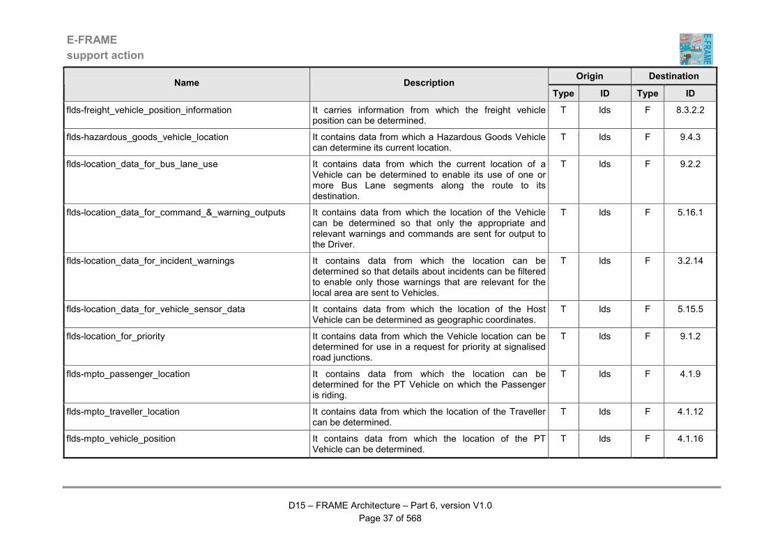
flds-freight_vehicle_position_information It carries information from which the freight vehicle position can be determined.
T lds F 8.3.2.2
flds-hazardous_goods_vehicle_location It contains data from which a Hazardous Goods Vehicle can determine its current location.
T lds F 9.4.3
flds-location_data_for_bus_lane_use It contains data from which the current location of a Vehicle can be determined to enable its use of one or more Bus Lane segments along the route to its destination.
T lds F 9.2.2
flds-location_data_for_command_&_warning_outputs It contains data from which the location of the Vehicle can be determined so that only the appropriate and relevant warnings and commands are sent for output to the Driver.
T lds F 5.16.1
flds-location_data_for_incident_warnings It contains data from which the location can be determined so that details about incidents can be filtered to enable only those warnings that are relevant for the local area are sent to Vehicles.
T lds F 3.2.14
flds-location_data_for_vehicle_sensor_data It contains data from which the location of the Host Vehicle can be determined as geographic coordinates.
T lds F 5.15.5
flds-location_for_priority It contains data from which the Vehicle location can be determined for use in a request for priority at signalised road junctions.
T lds F 9.1.2
flds-mpto_passenger_location It contains data from which the location can be determined for the PT Vehicle on which the Passenger is riding.
T lds F 4.1.9
flds-mpto_traveller_location It contains data from which the location of the Traveller can be determined.
T lds F 4.1.12
flds-mpto_vehicle_position It contains data from which the location of the PT Vehicle can be determined.
T lds F 4.1.16
E-FRAME
support action
D15 – FRAME Architecture – Part 6, version V1.0
Page 38 of 568
Origin Destination Name Description
Type ID Type ID
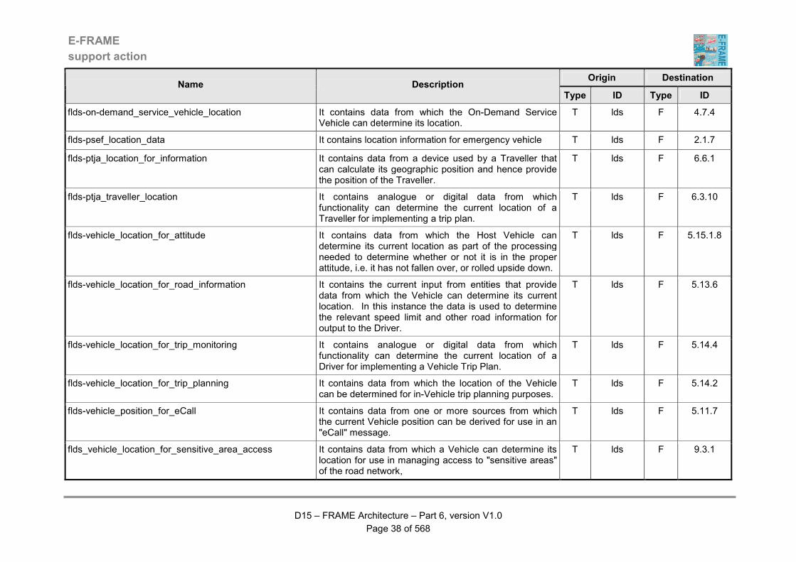
flds-on-demand_service_vehicle_location It contains data from which the On-Demand Service Vehicle can determine its location.
T lds F 4.7.4
flds-psef_location_data It contains location information for emergency vehicle T lds F 2.1.7
flds-ptja_location_for_information It contains data from a device used by a Traveller that can calculate its geographic position and hence provide the position of the Traveller.
T lds F 6.6.1
flds-ptja_traveller_location It contains analogue or digital data from which functionality can determine the current location of a Traveller for implementing a trip plan.
T lds F 6.3.10
flds-vehicle_location_for_attitude It contains data from which the Host Vehicle can determine its current location as part of the processing needed to determine whether or not it is in the proper attitude, i.e. it has not fallen over, or rolled upside down.
T lds F 5.15.1.8
flds-vehicle_location_for_road_information It contains the current input from entities that provide data from which the Vehicle can determine its current location. In this instance the data is used to determine the relevant speed limit and other road information for output to the Driver.
T lds F 5.13.6
flds-vehicle_location_for_trip_monitoring It contains analogue or digital data from which functionality can determine the current location of a Driver for implementing a Vehicle Trip Plan.
T lds F 5.14.4
flds-vehicle_location_for_trip_planning It contains data from which the location of the Vehicle can be determined for in-Vehicle trip planning purposes.
T lds F 5.14.2
flds-vehicle_position_for_eCall It contains data from one or more sources from which the current Vehicle position can be derived for use in an "eCall" message.
T lds F 5.11.7
flds_vehicle_location_for_sensitive_area_access It contains data from which a Vehicle can determine its location for use in managing access to "sensitive areas" of the road network,
T lds F 9.3.1
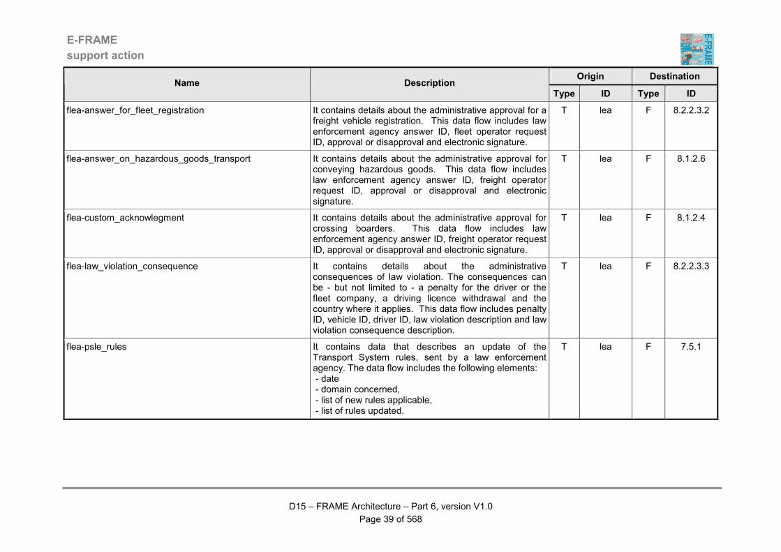
E-FRAME
support action
D15 – FRAME Architecture – Part 6, version V1.0
Page 39 of 568
Origin Destination Name Description
Type ID Type ID
flea-answer_for_fleet_registration It contains details about the administrative approval for a freight vehicle registration. This data flow includes law enforcement agency answer ID, fleet operator request ID, approval or disapproval and electronic signature.
T lea F 8.2.2.3.2
flea-answer_on_hazardous_goods_transport It contains details about the administrative approval for conveying hazardous goods. This data flow includes law enforcement agency answer ID, freight operator request ID, approval or disapproval and electronic signature.
T lea F 8.1.2.6
flea-custom_acknowlegment It contains details about the administrative approval for crossing boarders. This data flow includes law enforcement agency answer ID, freight operator request ID, approval or disapproval and electronic signature.
T lea F 8.1.2.4
flea-law_violation_consequence It contains details about the administrative consequences of law violation. The consequences can be - but not limited to - a penalty for the driver or the fleet company, a driving licence withdrawal and the country where it applies. This data flow includes penalty ID, vehicle ID, driver ID, law violation description and law violation consequence description.
T lea F 8.2.2.3.3
flea-psle_rules It contains data that describes an update of the Transport System rules, sent by a law enforcement agency. The data flow includes the following elements: - date - domain concerned, - list of new rules applicable, - list of rules updated.
T lea F 7.5.1

E-FRAME
support action
D15 – FRAME Architecture – Part 6, version V1.0
Page 40 of 568
Origin Destination Name Description
Type ID Type ID
flea-psle_user_clearance It contains data that is sent by a law enforcement agency and includes parameters describing what the vehicle or user is allowed to do. The data includes the following elements: - user ID - vehicle ID - max speed according to environment conditions - max weight (total and per axle) - max pollution level - type of cargo / types of forbidden zones - max duration of continuous drive.
T lea F 7.5.2
flea-psle_user_registration It contains the registration of a user or operator using the road network. The data flow includes the following elements: - law enforcement agency identification - date and place of registration - user or operator ID - list of vehicles for which the user or operator is responsible, - nature of link between the vehicles and the user (owner, driver, …) - nature of operations registered for these vehicles - period of validity of registration.
T lea F 7.5.2
flea-request_for_incident_data It contains a request from an authorised person for data that has been recorded during an incident. It includes a means of validating the request.
T lea F 5.11.6
fmms.mmc-inter-urban_crossing_request It contains requests for the opening of a multi-modal crossing that will stop or restrict the normal flow of road traffic through out the inter-urban road network.
T mms.mmc F 3.1.2.14.2
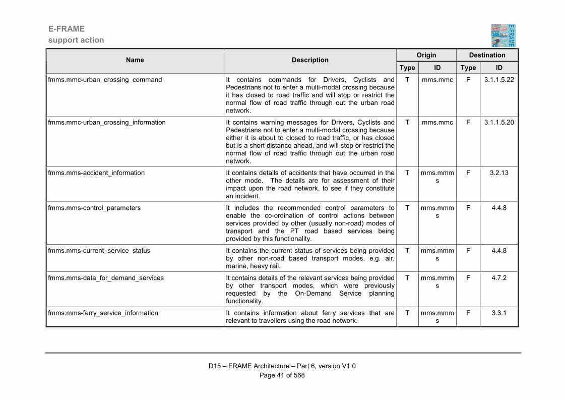
E-FRAME
support action
D15 – FRAME Architecture – Part 6, version V1.0
Page 41 of 568
Origin Destination Name Description
Type ID Type ID
fmms.mmc-urban_crossing_command It contains commands for Drivers, Cyclists and Pedestrians not to enter a multi-modal crossing because it has closed to road traffic and will stop or restrict the normal flow of road traffic through out the urban road network.
T mms.mmc F 3.1.1.5.22
fmms.mmc-urban_crossing_information It contains warning messages for Drivers, Cyclists and Pedestrians not to enter a multi-modal crossing because either it is about to closed to road traffic, or has closed but is a short distance ahead, and will stop or restrict the normal flow of road traffic through out the urban road network.
T mms.mmc F 3.1.1.5.20
fmms.mms-accident_information It contains details of accidents that have occurred in the other mode. The details are for assessment of their impact upon the road network, to see if they constitute an incident.
T mms.mmms
F 3.2.13
fmms.mms-control_parameters It includes the recommended control parameters to enable the co-ordination of control actions between services provided by other (usually non-road) modes of transport and the PT road based services being provided by this functionality.
T mms.mmms
F 4.4.8
fmms.mms-current_service_status It contains the current status of services being provided by other non-road based transport modes, e.g. air, marine, heavy rail.
T mms.mmms
F 4.4.8
fmms.mms-data_for_demand_services It contains details of the relevant services being provided by other transport modes, which were previously requested by the On-Demand Service planning functionality.
T mms.mmms
F 4.7.2
fmms.mms-ferry_service_information It contains information about ferry services that are relevant to travellers using the road network.
T mms.mmms
F 3.3.1
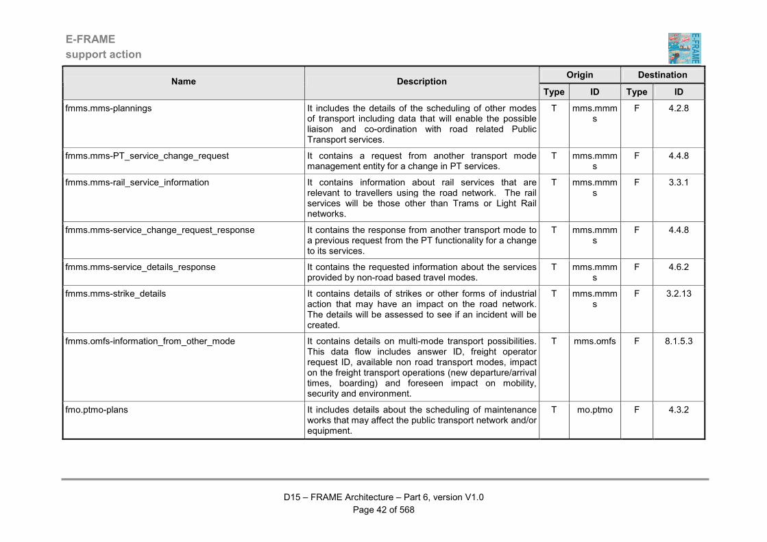
E-FRAME
support action
D15 – FRAME Architecture – Part 6, version V1.0
Page 42 of 568
Origin Destination Name Description
Type ID Type ID
fmms.mms-plannings It includes the details of the scheduling of other modes of transport including data that will enable the possible liaison and co-ordination with road related Public Transport services.
T mms.mmms
F 4.2.8
fmms.mms-PT_service_change_request It contains a request from another transport mode management entity for a change in PT services.
T mms.mmms
F 4.4.8
fmms.mms-rail_service_information It contains information about rail services that are relevant to travellers using the road network. The rail services will be those other than Trams or Light Rail networks.
T mms.mmms
F 3.3.1
fmms.mms-service_change_request_response It contains the response from another transport mode to a previous request from the PT functionality for a change to its services.
T mms.mmms
F 4.4.8
fmms.mms-service_details_response It contains the requested information about the services provided by non-road based travel modes.
T mms.mmms
F 4.6.2
fmms.mms-strike_details It contains details of strikes or other forms of industrial action that may have an impact on the road network. The details will be assessed to see if an incident will be created.
T mms.mmms
F 3.2.13
fmms.omfs-information_from_other_mode It contains details on multi-mode transport possibilities. This data flow includes answer ID, freight operator request ID, available non road transport modes, impact on the freight transport operations (new departure/arrival times, boarding) and foreseen impact on mobility, security and environment.
T mms.omfs F 8.1.5.3
fmo.ptmo-plans It includes details about the scheduling of maintenance works that may affect the public transport network and/or equipment.
T mo.ptmo F 4.3.2
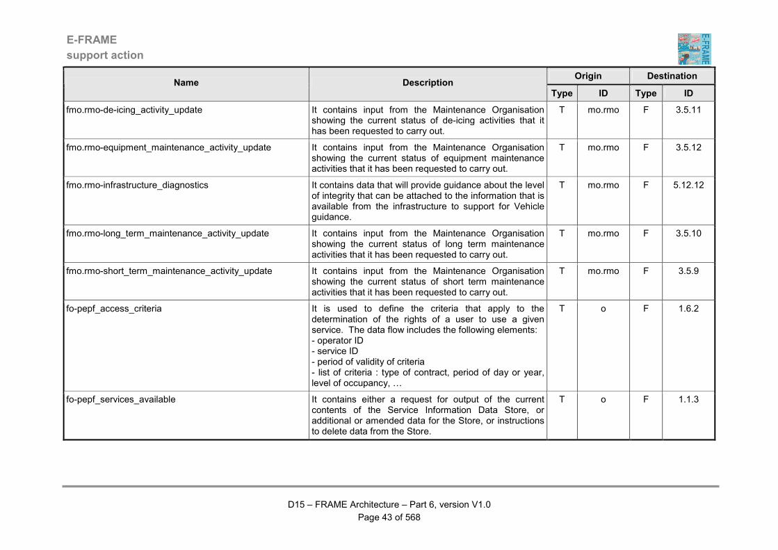
E-FRAME
support action
D15 – FRAME Architecture – Part 6, version V1.0
Page 43 of 568
Origin Destination Name Description
Type ID Type ID
fmo.rmo-de-icing_activity_update It contains input from the Maintenance Organisation showing the current status of de-icing activities that it has been requested to carry out.
T mo.rmo F 3.5.11
fmo.rmo-equipment_maintenance_activity_update It contains input from the Maintenance Organisation showing the current status of equipment maintenance activities that it has been requested to carry out.
T mo.rmo F 3.5.12
fmo.rmo-infrastructure_diagnostics It contains data that will provide guidance about the level of integrity that can be attached to the information that is available from the infrastructure to support for Vehicle guidance.
T mo.rmo F 5.12.12
fmo.rmo-long_term_maintenance_activity_update It contains input from the Maintenance Organisation showing the current status of long term maintenance activities that it has been requested to carry out.
T mo.rmo F 3.5.10
fmo.rmo-short_term_maintenance_activity_update It contains input from the Maintenance Organisation showing the current status of short term maintenance activities that it has been requested to carry out.
T mo.rmo F 3.5.9
fo-pepf_access_criteria It is used to define the criteria that apply to the determination of the rights of a user to use a given service. The data flow includes the following elements: - operator ID - service ID - period of validity of criteria - list of criteria : type of contract, period of day or year, level of occupancy, …
T o F 1.6.2
fo-pepf_services_available It contains either a request for output of the current contents of the Service Information Data Store, or additional or amended data for the Store, or instructions to delete data from the Store.
T o F 1.1.3

E-FRAME
support action
D15 – FRAME Architecture – Part 6, version V1.0
Page 44 of 568
Origin Destination Name Description
Type ID Type ID
fo-pepf_tariff_grids It contains all the elements necessary to determine the tariff for a given service and contract. The data flow includes the following elements: - date, - operator ID, - service ID - for each service ID : - tariff for every combination of parameters defining the service, and for various contract types
T o F 1.6.1
fo-pepf_trans_info_request It is used to by the operator to ask for information on past transactions. The data flow includes the following elements: - operator ID - list of services ID for which transactions details are required - period during which the transactions were performed - location criteria
T o F 1.4.3
fo.bo-bridge_action_definitions It contains input from the Bridge Operator that defines actions that are to be automatically taken when weather conditions are detected that are dangerous to traffic using a bridge.
T o.bo F 3.1.8.3
fo.bo-weather_condition_action_request_response It contains the response from the Bridge Operator of to a previous request to provide actions for dangerous conditions that have been detected for traffic using a bridge.
T o.bo F 3.1.8.3
fo.eo-commands It contains commands to the system by the emergency operator in order to manage emergency process
T o.eo F 2.1.9
fo.eo-request_statistical_report It contains the request from the Emergency Operator for the preparation and output of a report showing statistics about incidents, their occurrences and the responses that have been made to them by the Emergency Services.
T o.eo F 2.1.9
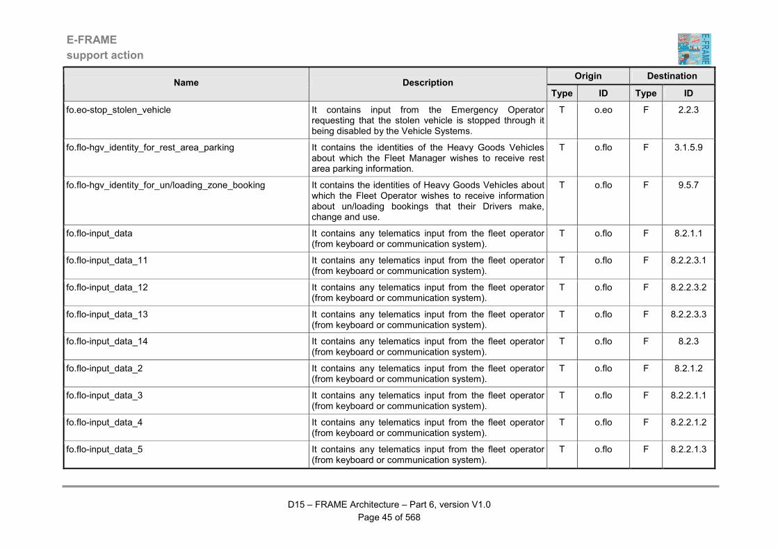
E-FRAME
support action
D15 – FRAME Architecture – Part 6, version V1.0
Page 45 of 568
Origin Destination Name Description
Type ID Type ID
fo.eo-stop_stolen_vehicle It contains input from the Emergency Operator requesting that the stolen vehicle is stopped through it being disabled by the Vehicle Systems.
T o.eo F 2.2.3
fo.flo-hgv_identity_for_rest_area_parking It contains the identities of the Heavy Goods Vehicles about which the Fleet Manager wishes to receive rest area parking information.
T o.flo F 3.1.5.9
fo.flo-hgv_identity_for_un/loading_zone_booking It contains the identities of Heavy Goods Vehicles about which the Fleet Operator wishes to receive information about un/loading bookings that their Drivers make, change and use.
T o.flo F 9.5.7
fo.flo-input_data It contains any telematics input from the fleet operator (from keyboard or communication system).
T o.flo F 8.2.1.1
fo.flo-input_data_11 It contains any telematics input from the fleet operator (from keyboard or communication system).
T o.flo F 8.2.2.3.1
fo.flo-input_data_12 It contains any telematics input from the fleet operator (from keyboard or communication system).
T o.flo F 8.2.2.3.2
fo.flo-input_data_13 It contains any telematics input from the fleet operator (from keyboard or communication system).
T o.flo F 8.2.2.3.3
fo.flo-input_data_14 It contains any telematics input from the fleet operator (from keyboard or communication system).
T o.flo F 8.2.3
fo.flo-input_data_2 It contains any telematics input from the fleet operator (from keyboard or communication system).
T o.flo F 8.2.1.2
fo.flo-input_data_3 It contains any telematics input from the fleet operator (from keyboard or communication system).
T o.flo F 8.2.2.1.1
fo.flo-input_data_4 It contains any telematics input from the fleet operator (from keyboard or communication system).
T o.flo F 8.2.2.1.2
fo.flo-input_data_5 It contains any telematics input from the fleet operator (from keyboard or communication system).
T o.flo F 8.2.2.1.3

E-FRAME
support action
D15 – FRAME Architecture – Part 6, version V1.0
Page 46 of 568
Origin Destination Name Description
Type ID Type ID
fo.flo-input_data_6 It contains any telematics input from the fleet operator (from keyboard or communication system).
T o.flo F 8.2.2.2.1
fo.flo-input_data_7 It contains any telematics input from the fleet operator (from keyboard or communication system).
T o.flo F 8.2.2.2.2
fo.flo-input_data_8 It contains any telematics input from the fleet operator (from keyboard or communication system).
T o.flo F 8.2.2.2.3
fo.flo-input_data_9 It contains any telematics input from the fleet operator (from keyboard or communication system).
T o.flo F 8.2.2.2.6
fo.flo-rest_area_booking_details It contains details of a rest area booking that has been made and passed to the Fleet Operator so that it can be given to the Freight Vehicle Driver.
T o.flo F 5.14.10
fo.flo-un/loading_zone_booking_details It contains details of the un/loading zone bookings that have been made or amended by the Driver of a Heavy Goods Vehicle.
T o.flo F 5.14.11
fo.fro-additional_evaluation_data It contains additional data for the freight operation evaluation that the Freight Management Operator has been requested to provide.
T o.fro F 8.1.6
fo.fro-cargo_status_request It contains a request from the Freight Management Operator for the output of the current status of the freight being moved at the request of the Principal.
T o.fro F 8.1.3
fo.fro-customs_declaration_request_proceed It contains the input from the Freight Management Operator that gives permission for the customs declaration to be processed and sent to the Law Enforcement Agency for approval.
T o.fro F 8.1.2.7
fo.fro-data_for_fleet_operator_selection It contains data from the Freight Management Operator that is concerned with the selection of a Fleet Operator to perform the requested transport of freight.
T o.fro F 8.1.1.7
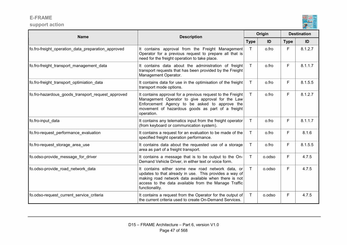
E-FRAME
support action
D15 – FRAME Architecture – Part 6, version V1.0
Page 47 of 568
Origin Destination Name Description
Type ID Type ID
fo.fro-freight_operation_data_preparation_approved It contains approval from the Freight Management Operator for a previous request to prepare all that is need for the freight operation to take place.
T o.fro F 8.1.2.7
fo.fro-freight_transport_management_data It contains data about the administration of freight transport requests that has been provided by the Freight Management Operator.
T o.fro F 8.1.1.7
fo.fro-freight_transport_optimiation_data It contains data for use in the optimisation of the freight transport mode options.
T o.fro F 8.1.5.5
fo.fro-hazardous_goods_transport_request_approved It contains approval for a previous request to the Freight Management Operator to give approval for the Law Enforcement Agency to be asked to approve the movement of hazardous goods as part of a freight operation.
T o.fro F 8.1.2.7
fo.fro-input_data It contains any telematics input from the freight operator (from keyboard or communication system).
T o.fro F 8.1.1.7
fo.fro-request_performance_evaluation It contains a request for an evaluation to be made of the specified freight operation performance.
T o.fro F 8.1.6
fo.fro-request_storage_area_use It contains data about the requested use of a storage area as part of a freight transport.
T o.fro F 8.1.5.5
fo.odso-provide_message_for_driver It contains a message that is to be output to the On-Demand Vehicle Driver, in either text or voice form.
T o.odso F 4.7.5
fo.odso-provide_road_network_data It contains either some new road network data, or updates to that already in use. This provides a way of making road network data available when there is not access to the data available from the Manage Traffic functionality.
T o.odso F 4.7.5
fo.odso-request_current_service_criteria It contains a request from the Operator for the output of the current criteria used to create On-Demand Services.
T o.odso F 4.7.5
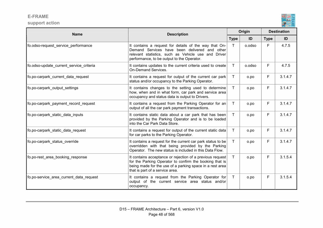
E-FRAME
support action
D15 – FRAME Architecture – Part 6, version V1.0
Page 48 of 568
Origin Destination Name Description
Type ID Type ID
fo.odso-request_service_performance It contains a request for details of the way that On-Demand Services have been delivered and other relevant statistics, such as Vehicle use and Driver performance, to be output to the Operator.
T o.odso F 4.7.5
fo.odso-update_current_service_criteria It contains updates to the current criteria used to create On-Demand Services.
T o.odso F 4.7.5
fo.po-carpark_current_data_request It contains a request for output of the current car park status and/or occupancy to the Parking Operator.
T o.po F 3.1.4.7
fo.po-carpark_output_settings It contains changes to the setting used to determine how, when and in what form, car park and service area occupancy and status data is output to Drivers.
T o.po F 3.1.4.7
fo.po-carpark_payment_record_request It contains a request from the Parking Operator for an output of all the car park payment transactions.
T o.po F 3.1.4.7
fo.po-carpark_static_data_inputs It contains static data about a car park that has been provided by the Parking Operator and is to be loaded into the Car Park Data Store.
T o.po F 3.1.4.7
fo.po-carpark_static_data_request It contains a request for output of the current static data for car parks to the Parking Operator.
T o.po F 3.1.4.7
fo.po-carpark_status_override It contains a request for the current car park status to be overridden with that being provided by the Parking Operator. The new status is included in this Data Flow.
T o.po F 3.1.4.7
fo.po-rest_area_booking_response It contains acceptance or rejection of a previous request for the Parking Operator to confirm the booking that is being made for the use of a parking space in a rest area that is part of a service area.
T o.po F 3.1.5.4
fo.po-service_area_current_data_request It contains a request from the Parking Operator for output of the current service area status and/or occupancy.
T o.po F 3.1.5.4
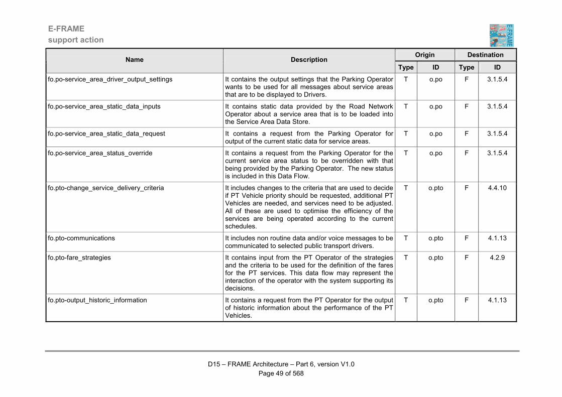
E-FRAME
support action
D15 – FRAME Architecture – Part 6, version V1.0
Page 49 of 568
Origin Destination Name Description
Type ID Type ID
fo.po-service_area_driver_output_settings It contains the output settings that the Parking Operator wants to be used for all messages about service areas that are to be displayed to Drivers.
T o.po F 3.1.5.4
fo.po-service_area_static_data_inputs It contains static data provided by the Road Network Operator about a service area that is to be loaded into the Service Area Data Store.
T o.po F 3.1.5.4
fo.po-service_area_static_data_request It contains a request from the Parking Operator for output of the current static data for service areas.
T o.po F 3.1.5.4
fo.po-service_area_status_override It contains a request from the Parking Operator for the current service area status to be overridden with that being provided by the Parking Operator. The new status is included in this Data Flow.
T o.po F 3.1.5.4
fo.pto-change_service_delivery_criteria It includes changes to the criteria that are used to decide if PT Vehicle priority should be requested, additional PT Vehicles are needed, and services need to be adjusted. All of these are used to optimise the efficiency of the services are being operated according to the current schedules.
T o.pto F 4.4.10
fo.pto-communications It includes non routine data and/or voice messages to be communicated to selected public transport drivers.
T o.pto F 4.1.13
fo.pto-fare_strategies It contains input from the PT Operator of the strategies and the criteria to be used for the definition of the fares for the PT services. This data flow may represent the interaction of the operator with the system supporting its decisions.
T o.pto F 4.2.9
fo.pto-output_historic_information It contains a request from the PT Operator for the output of historic information about the performance of the PT Vehicles.
T o.pto F 4.1.13

E-FRAME
support action
D15 – FRAME Architecture – Part 6, version V1.0
Page 50 of 568
Origin Destination Name Description
Type ID Type ID
fo.pto-output_predicted_PT_data It contains a request from the PT Operator for the output of the predicted performance of the PT Vehicles in the delivery of the PT Services.
T o.pto F 4.1.13
fo.pto-output_real_time_information It contains a request from the PT Operator for output of real-time information about the performance of the PT Vehicles.
T o.pto F 4.1.13
fo.pto-performance_criteria It includes the description of the performance indicators to be used to evaluate the quality of the Public Transport services.
T o.pto F 4.1.13
fo.pto-planning_strategies It contains input from the PT Operator of the strategies and the criteria to be used for the definition of the routes and schedules for the PT services. This data flow may represent the interaction of the operator with the system supporting its decisions.
T o.pto F 4.2.9
fo.pto-PT_vehicle_static_data It contains the PT Vehicle type, ID and number of allowed passengers data that is being provided by the PT Operator for use in the Data Stores of real-time and historic PT Vehicle data.
T o.pto F 4.4.10
fo.pto-requests_and_updates It contains requests for updates of the planning data. T o.pto F 4.2.9
fo.pto-request_actions_report It contains a request from the PT Operator for a report on the actions that have been taken by the control functionality.
T o.pto F 4.4.10
fo.pto-request_driver_statistics It contains a request from the PT Operator for the output of the statistics about the work done (and currently being done) by all PT Drivers.
T o.pto F 4.3.8
fo.pto-request_route_static_data It contains a request from the PT Operator for output of the current static data for PT routes. For each route this may include such things as origin, destination, location of intermediate stops, etc.
T o.pto F 4.2.9

E-FRAME
support action
D15 – FRAME Architecture – Part 6, version V1.0
Page 51 of 568
Origin Destination Name Description
Type ID Type ID
fo.pto-request_travel_plan_criteria It contains a request for details of the current criteria used to produce travel plans for Car Poolers.
T o.pto F 4.6.4
fo.pto-route_static_data_update It contains updates and additions to the current static data for PT routes that are being provided by the PT services. For each route the static data may include such things as origin, destination, location of intermediate stops, etc.
T o.pto F 4.2.9
fo.pto-service_change_response It contains the response from the PT Operator for a change to PT services that has been requested by another transport mode management entity. There is no restriction on the content of the changes that can be requested.
T o.pto F 4.4.10
fo.pto-updated_travel_plan_criteria It contains updates to the criteria currently used to produce travel plans for Car Poolers.
T o.pto F 4.6.4
fo.pto-update_driver_details It contains information provided by the PT Operator about each Driver that is available to drive a PT Vehicle on a scheduled PT Service. The information may include details such as proficiency, route knowledge.
T o.pto F 4.3.8
fo.rmo-confirmed_de-icing_activities It contains either confirmation from the Road Maintenance Operator that the proposed de-icing activities are to proceed, or alternative activities that are to be implemented instead.
T o.rmo F 3.5.7
fo.rmo-confirm_maintenance_activities It contains either confirmation from the Road Maintenance Operator that the long or short term maintenance activity and/or equipment maintenance previously proposed by the System the can proceed, or an alternative set of maintenance activities that are to be implemented.
T o.rmo F 3.5.7
fo.rmo-output_current_equipment_faults It contains a request from the Road Maintenance Operator for the output of the list of roadside equipment that is currently faulty.
T o.rmo F 3.5.7
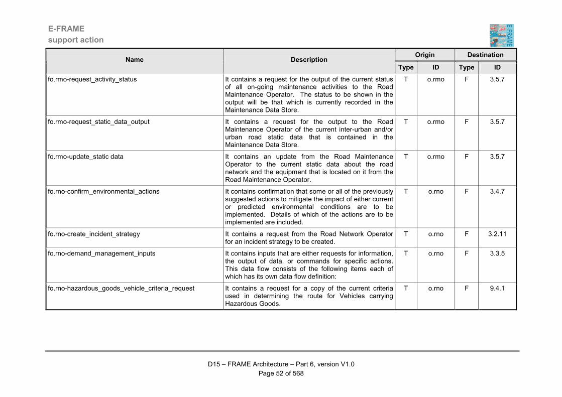
E-FRAME
support action
D15 – FRAME Architecture – Part 6, version V1.0
Page 52 of 568
Origin Destination Name Description
Type ID Type ID
fo.rmo-request_activity_status It contains a request for the output of the current status of all on-going maintenance activities to the Road Maintenance Operator. The status to be shown in the output will be that which is currently recorded in the Maintenance Data Store.
T o.rmo F 3.5.7
fo.rmo-request_static_data_output It contains a request for the output to the Road Maintenance Operator of the current inter-urban and/or urban road static data that is contained in the Maintenance Data Store.
T o.rmo F 3.5.7
fo.rmo-update_static data It contains an update from the Road Maintenance Operator to the current static data about the road network and the equipment that is located on it from the Road Maintenance Operator.
T o.rmo F 3.5.7
fo.rno-confirm_environmental_actions It contains confirmation that some or all of the previously suggested actions to mitigate the impact of either current or predicted environmental conditions are to be implemented. Details of which of the actions are to be implemented are included.
T o.rno F 3.4.7
fo.rno-create_incident_strategy It contains a request from the Road Network Operator for an incident strategy to be created.
T o.rno F 3.2.11
fo.rno-demand_management_inputs It contains inputs that are either requests for information, the output of data, or commands for specific actions. This data flow consists of the following items each of which has its own data flow definition:
T o.rno F 3.3.5
fo.rno-hazardous_goods_vehicle_criteria_request It contains a request for a copy of the current criteria used in determining the route for Vehicles carrying Hazardous Goods.
T o.rno F 9.4.1
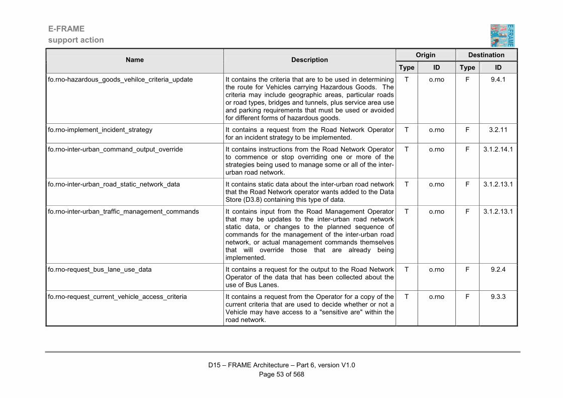
E-FRAME
support action
D15 – FRAME Architecture – Part 6, version V1.0
Page 53 of 568
Origin Destination Name Description
Type ID Type ID
fo.rno-hazardous_goods_vehilce_criteria_update It contains the criteria that are to be used in determining the route for Vehicles carrying Hazardous Goods. The criteria may include geographic areas, particular roads or road types, bridges and tunnels, plus service area use and parking requirements that must be used or avoided for different forms of hazardous goods.
T o.rno F 9.4.1
fo.rno-implement_incident_strategy It contains a request from the Road Network Operator for an incident strategy to be implemented.
T o.rno F 3.2.11
fo.rno-inter-urban_command_output_override It contains instructions from the Road Network Operator to commence or stop overriding one or more of the strategies being used to manage some or all of the inter-urban road network.
T o.rno F 3.1.2.14.1
fo.rno-inter-urban_road_static_network_data It contains static data about the inter-urban road network that the Road Network operator wants added to the Data Store (D3.8) containing this type of data.
T o.rno F 3.1.2.13.1
fo.rno-inter-urban_traffic_management_commands It contains input from the Road Management Operator that may be updates to the inter-urban road network static data, or changes to the planned sequence of commands for the management of the inter-urban road network, or actual management commands themselves that will override those that are already being implemented.
T o.rno F 3.1.2.13.1
fo.rno-request_bus_lane_use_data It contains a request for the output to the Road Network Operator of the data that has been collected about the use of Bus Lanes.
T o.rno F 9.2.4
fo.rno-request_current_vehicle_access_criteria It contains a request from the Operator for a copy of the current criteria that are used to decide whether or not a Vehicle may have access to a "sensitive are" within the road network.
T o.rno F 9.3.3
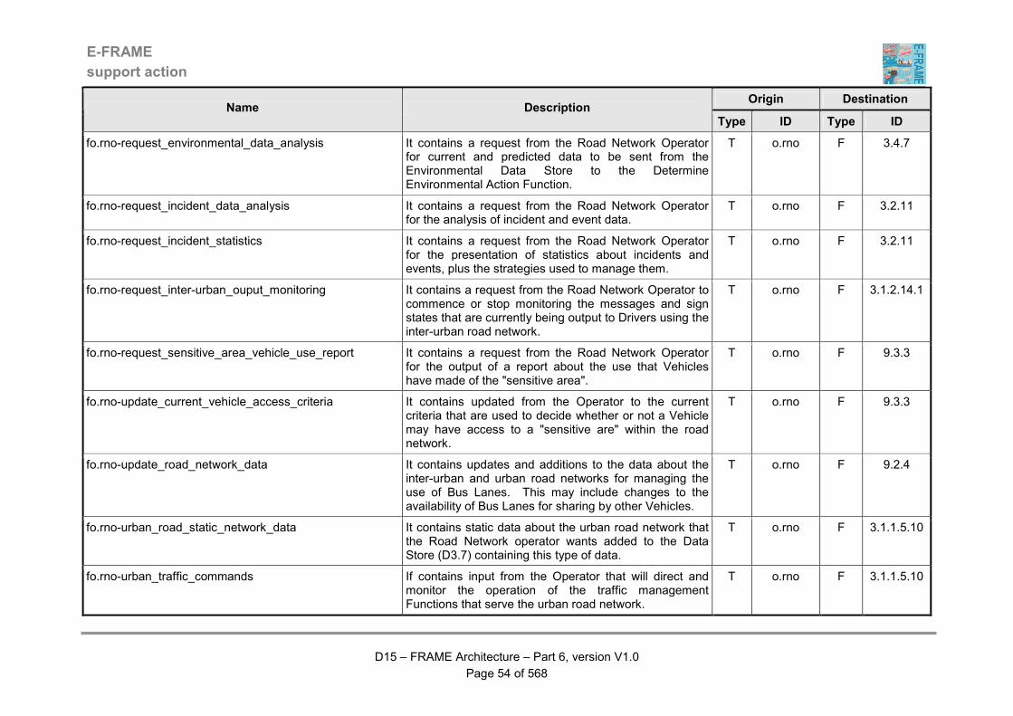
E-FRAME
support action
D15 – FRAME Architecture – Part 6, version V1.0
Page 54 of 568
Origin Destination Name Description
Type ID Type ID
fo.rno-request_environmental_data_analysis It contains a request from the Road Network Operator for current and predicted data to be sent from the Environmental Data Store to the Determine Environmental Action Function.
T o.rno F 3.4.7
fo.rno-request_incident_data_analysis It contains a request from the Road Network Operator for the analysis of incident and event data.
T o.rno F 3.2.11
fo.rno-request_incident_statistics It contains a request from the Road Network Operator for the presentation of statistics about incidents and events, plus the strategies used to manage them.
T o.rno F 3.2.11
fo.rno-request_inter-urban_ouput_monitoring It contains a request from the Road Network Operator to commence or stop monitoring the messages and sign states that are currently being output to Drivers using the inter-urban road network.
T o.rno F 3.1.2.14.1
fo.rno-request_sensitive_area_vehicle_use_report It contains a request from the Road Network Operator for the output of a report about the use that Vehicles have made of the "sensitive area".
T o.rno F 9.3.3
fo.rno-update_current_vehicle_access_criteria It contains updated from the Operator to the current criteria that are used to decide whether or not a Vehicle may have access to a "sensitive are" within the road network.
T o.rno F 9.3.3
fo.rno-update_road_network_data It contains updates and additions to the data about the inter-urban and urban road networks for managing the use of Bus Lanes. This may include changes to the availability of Bus Lanes for sharing by other Vehicles.
T o.rno F 9.2.4
fo.rno-urban_road_static_network_data It contains static data about the urban road network that the Road Network operator wants added to the Data Store (D3.7) containing this type of data.
T o.rno F 3.1.1.5.10
fo.rno-urban_traffic_commands If contains input from the Operator that will direct and monitor the operation of the traffic management Functions that serve the urban road network.
T o.rno F 3.1.1.5.10
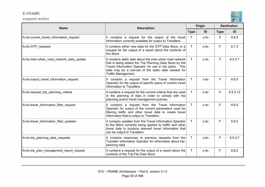
E-FRAME
support action
D15 – FRAME Architecture – Part 6, version V1.0
Page 55 of 568
Origin Destination Name Description
Type ID Type ID
fo.tio-current_travel_information_request It contains a request for the output of the travel information currently available for output to Travellers.
T o.tio F 6.6.5
fo.tio-GTP_requests It contains either new data for the GTP Data Store, or a request for the output of a report about the contents of the Store.
T o.tio F 6.7.3
fo.tio-inter-urban_road_network_data_update It contains static data about the inter-urban road network that is being added the Trip Planning Data Store by the Travel Information Operator for use in trip plans. This data may be a sub-set of the static data needed for Traffic Management.
T o.tio F 6.5.3.7
fo.tio-output_travel_information_request It contains a request from the Travel Information Operator for the output of specific piece of current travel information to Travellers.
T o.tio F 6.6.5
fo.tio-request_trip_planning_criteria It contains a request for the current criteria that are used in the planning of trips in order to comply with trip planning and/or travel management policies.
T o.tio F 6.5.3.12
fo.tio-travel_information_filter_request It contains a request from the Travel Information Operator for output of the current parameters used for filtering traffic and other travel data to create travel information that is output to Travellers.
T o.tio F 6.6.5
fo.tio-travel_information_filter_updates It contains updates from the Travel Information Operator to the filters currently being applied to traffic and other travel data to produce relevant travel information that can be output to Travellers.
T o.tio F 6.6.5
fo.tio-trip_planning_data_requests It contains responses to previous requests from the Traveller Information Operator for information about trip-planning data.
T o.tio F 6.5.3.7
fo.tio-trip_plan_management_report_request It contains a request for the output of a report about the contents of the Trip File Data Store.
T o.tio F 6.8.2
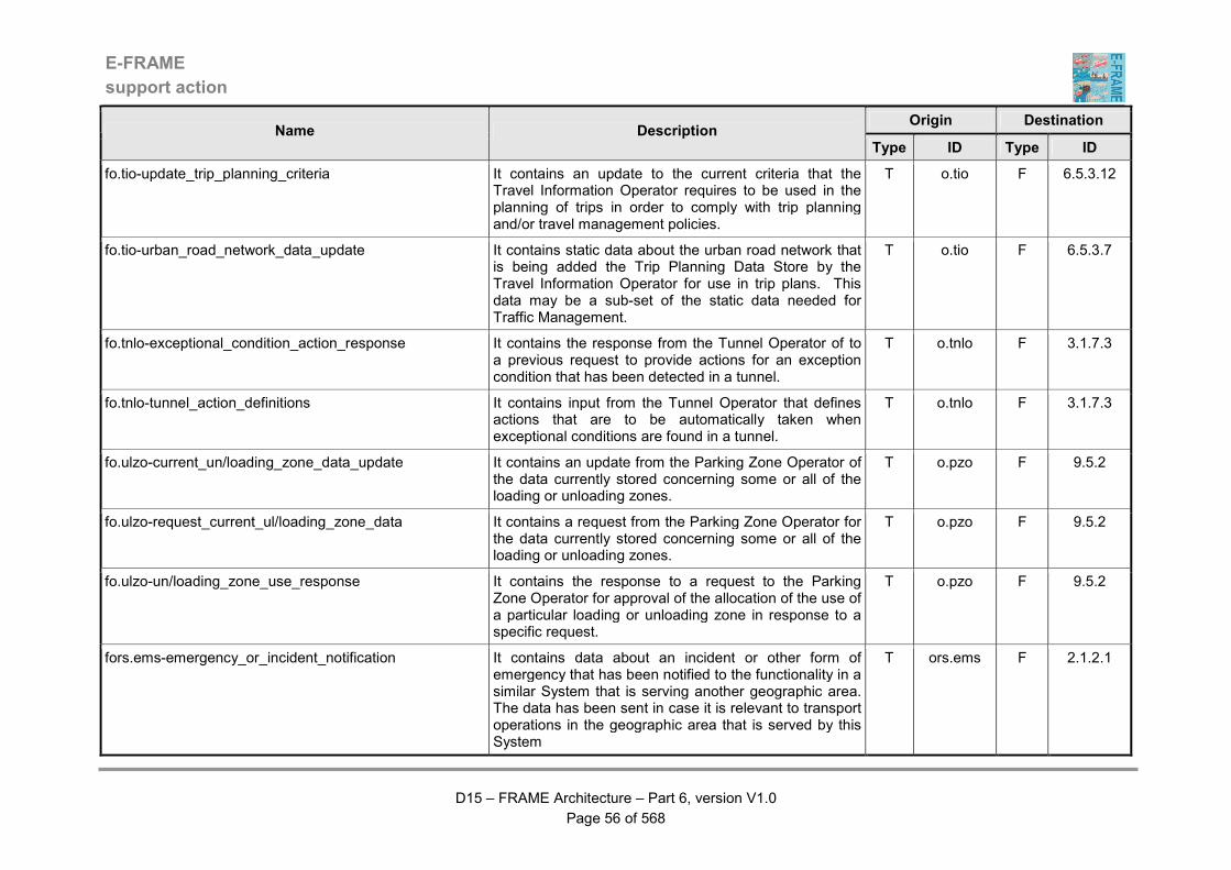
E-FRAME
support action
D15 – FRAME Architecture – Part 6, version V1.0
Page 56 of 568
Origin Destination Name Description
Type ID Type ID
fo.tio-update_trip_planning_criteria It contains an update to the current criteria that the Travel Information Operator requires to be used in the planning of trips in order to comply with trip planning and/or travel management policies.
T o.tio F 6.5.3.12
fo.tio-urban_road_network_data_update It contains static data about the urban road network that is being added the Trip Planning Data Store by the Travel Information Operator for use in trip plans. This data may be a sub-set of the static data needed for Traffic Management.
T o.tio F 6.5.3.7
fo.tnlo-exceptional_condition_action_response It contains the response from the Tunnel Operator of to a previous request to provide actions for an exception condition that has been detected in a tunnel.
T o.tnlo F 3.1.7.3
fo.tnlo-tunnel_action_definitions It contains input from the Tunnel Operator that defines actions that are to be automatically taken when exceptional conditions are found in a tunnel.
T o.tnlo F 3.1.7.3
fo.ulzo-current_un/loading_zone_data_update It contains an update from the Parking Zone Operator of the data currently stored concerning some or all of the loading or unloading zones.
T o.pzo F 9.5.2
fo.ulzo-request_current_ul/loading_zone_data It contains a request from the Parking Zone Operator for the data currently stored concerning some or all of the loading or unloading zones.
T o.pzo F 9.5.2
fo.ulzo-un/loading_zone_use_response It contains the response to a request to the Parking Zone Operator for approval of the allocation of the use of a particular loading or unloading zone in response to a specific request.
T o.pzo F 9.5.2
fors.ems-emergency_or_incident_notification It contains data about an incident or other form of emergency that has been notified to the functionality in a similar System that is serving another geographic area. The data has been sent in case it is relevant to transport operations in the geographic area that is served by this System
T ors.ems F 2.1.2.1
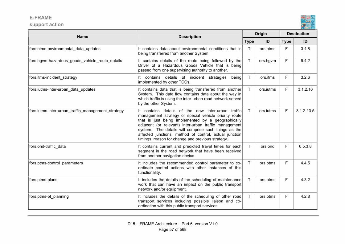
E-FRAME
support action
D15 – FRAME Architecture – Part 6, version V1.0
Page 57 of 568
Origin Destination Name Description
Type ID Type ID
fors.etms-environmental_data_updates It contains data about environmental conditions that is being transferred from another System.
T ors.etms F 3.4.8
fors.hgvm-hazardous_goods_vehicle_route_details It contains details of the route being followed by the Driver of a Hazardous Goods Vehicle that is being passed from one supervising authority to another.
T ors.hgvm F 9.4.2
fors.itms-incident_strategy It contains details of incident strategies being implemented by other TCCs.
T ors.itms F 3.2.6
fors.iutms-inter-urban_data_updates It contains data that is being transferred from another System. This data flow contains data about the way in which traffic is using the inter-urban road network served by the other System.
T ors.iutms F 3.1.2.16
fors.iutms-inter-urban_traffic_management_strategy It contains details of the new inter-urban traffic management strategy or special vehicle priority route that is just being implemented by a geographically adjacent (or relevant) inter-urban traffic management system. The details will comprise such things as the affected junctions, method of control, actual junction timings, reason for change and previous strategy.
T ors.iutms F 3.1.2.13.5
fors.ond-traffic_data It contains current and predicted travel times for each segment in the road network that have been received from another navigation device.
T ors.ond F 6.5.3.8
fors.ptms-control_parameters It includes the recommended control parameter to co-ordinate control actions with other instances of this functionality.
T ors.ptms F 4.4.5
fors.ptms-plans It includes the details of the scheduling of maintenance work that can have an impact on the public transport network and/or equipment.
T ors.ptms F 4.3.2
fors.ptms-pt_planning It includes the details of the scheduling of other road transport services including possible liaison and co-ordination with this public transport services.
T ors.ptms F 4.2.8

E-FRAME
support action
D15 – FRAME Architecture – Part 6, version V1.0
Page 58 of 568
Origin Destination Name Description
Type ID Type ID
fors.pts-arrival_prediction_data It contains predictions of the arrival time for services using the stop and is for use by other stops at which the service is expected to call.
T ors.pts F 4.1.11
fors.tsc-local_priority_request_details It contains details of the local priority requests that have been received from Other Vehicles.
T ors.tsc F 3.1.1.5.22
fors.tss-traffic_prediction_results It contains the results produced by traffic simulations that have been produced by similar functionality in other Systems.
T ors.tss F 3.1.6.4
fors.utms-urban_data_updates It contains data that is being transferred from another System. This data flow contains data about the way in which traffic is using the urban road network served by the other System.
T ors.utms F 3.1.1.14
fors.utms-urban_traffic_management_strategies It contains details of the new urban traffic management strategy or special vehicle priority route that is just being implemented by a geographically adjacent (or relevant) urban traffic management system. The details will comprise such things as the affected junctions, method of control, actual junction timings, reason for change and previous strategy.
T ors.utms F 3.1.1.5.24
fre-dynamic_commands_&_warnings_details It contains a representation of the dynamic commands and warnings that are being displayed to Drivers from outside of the Vehicle, i.e. from devices that are not in any way connected to the Vehicle.
T re F 5.16.3
fre-roadside_speed_indication_details It contains a representation of the dynamic speed commands that are being displayed to Drivers from outside of the Vehicle, i.e. from devices that are not in any way connected to the Vehicle.
T re F 5.13.10
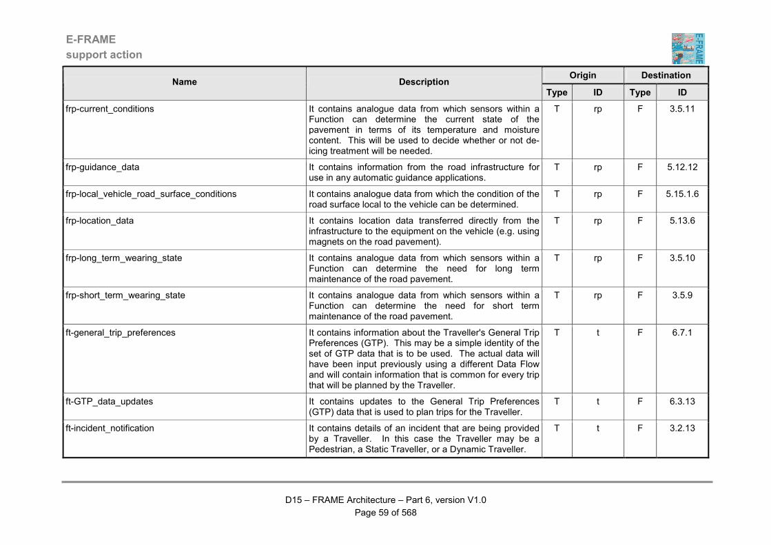
E-FRAME
support action
D15 – FRAME Architecture – Part 6, version V1.0
Page 59 of 568
Origin Destination Name Description
Type ID Type ID
frp-current_conditions It contains analogue data from which sensors within a Function can determine the current state of the pavement in terms of its temperature and moisture content. This will be used to decide whether or not de-icing treatment will be needed.
T rp F 3.5.11
frp-guidance_data It contains information from the road infrastructure for use in any automatic guidance applications.
T rp F 5.12.12
frp-local_vehicle_road_surface_conditions It contains analogue data from which the condition of the road surface local to the vehicle can be determined.
T rp F 5.15.1.6
frp-location_data It contains location data transferred directly from the infrastructure to the equipment on the vehicle (e.g. using magnets on the road pavement).
T rp F 5.13.6
frp-long_term_wearing_state It contains analogue data from which sensors within a Function can determine the need for long term maintenance of the road pavement.
T rp F 3.5.10
frp-short_term_wearing_state It contains analogue data from which sensors within a Function can determine the need for short term maintenance of the road pavement.
T rp F 3.5.9
ft-general_trip_preferences It contains information about the Traveller's General Trip Preferences (GTP). This may be a simple identity of the set of GTP data that is to be used. The actual data will have been input previously using a different Data Flow and will contain information that is common for every trip that will be planned by the Traveller.
T t F 6.7.1
ft-GTP_data_updates It contains updates to the General Trip Preferences (GTP) data that is used to plan trips for the Traveller.
T t F 6.3.13
ft-incident_notification It contains details of an incident that are being provided by a Traveller. In this case the Traveller may be a Pedestrian, a Static Traveller, or a Dynamic Traveller.
T t F 3.2.13
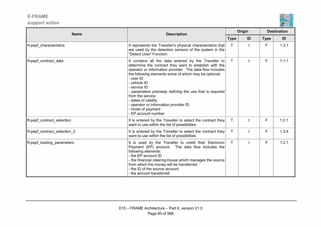
E-FRAME
support action
D15 – FRAME Architecture – Part 6, version V1.0
Page 60 of 568
Origin Destination Name Description
Type ID Type ID
ft-pepf_characteristics It represents the Traveller's physical characteristics that are used by the detection sensors of the system in the "Detect User" Function.
T t F 1.3.1
ft-pepf_contract_data It contains all the data entered by the Traveller to determine the contract they want to establish with the operator or information provider. The data flow includes the following elements some of which may be optional: - user ID - vehicle ID - service ID - parameters precisely defining the use that is required from the service - dates of validity - operator or information provider ID - mode of payment - EP account number
T t F 1.1.1
ft-pepf_contract_selection It is entered by the Traveller to select the contract they want to use within the list of possibilities.
T t F 1.2.1
ft-pepf_contract_selection_2 It is entered by the Traveller to select the contract they want to use within the list of possibilities.
T t F 1.3.4
ft-pepf_loading_parameters It is used by the Traveller to credit their Electronic Payment (EP) account. The data flow includes the following elements: - the EP account ID - the financial clearing-house which manages the source from which the money will be transferred - the ID of the source account - the amount transferred
T t F 1.2.1

E-FRAME
support action
D15 – FRAME Architecture – Part 6, version V1.0
Page 61 of 568
Origin Destination Name Description
Type ID Type ID
ft-pepf_payment It constitutes the means by which the Traveller pays the service fee. The means of payment may be either the selection of an account number, or that a specific payment card will be used. The data flow includes the following elements: - selected mode of payment (account / card) - if use of an EP account : - account ID - selected mode of debiting (immediate / differed / scheduled)
T t F 1.3.7
ft-pepf_selected_service It contains all the information necessary to define the service required by the Traveller. The data flow includes the following elements: - the service ID - parameters to characterise the request : duration, category within the service, ... - selected contract
T t F 1.3.4
ft-pepf_transaction_info_request It is used to ask for the list of transactions (including account loading) performed by a Traveller. The data flow includes the following elements: - user ID - vehicle ID (optional) - contract ID (optional) - period concerned - service ID (optional) - EP account ID - location of service used (optional) - operators or information providers ID (optional)
T t F 1.2.3
ft-pepf_user_ID It contains all the elements necessary to unambiguously identify the Traveller. The Traveller identification may be achieved using a personal code, a number of social security, etc.
T t F 1.2.1
E-FRAME
support action
D15 – FRAME Architecture – Part 6, version V1.0
Page 62 of 568
Origin Destination Name Description
Type ID Type ID
ft-pepf_user_ID_2 It contains all the elements necessary to unambiguously identify the Traveller. The Traveller identification may be achieved using a personal code, a number of social security, etc.
T t F 1.3.2
ft-post_trip_preferences It contains updates to the current set of Traveller's General Trip Preferences (GTP) for use in future trip planning. The data is generated as a result the success of a trip that the Traveller has just completed. Its use and availability removes from the Traveller the need for the repeated input of the same data every time a trip is planned.
T t F 6.7.1
ft-requested_implementing_trip_plan_change It contains a request from the Traveller for changes to be made to the trip plan that is currently being implemented. The actual required changes will be included in the request and may be for such things as destination, way points, and modes of travel.
T t F 6.3.13
ft-request_general_trip_preferences It contains a request from the Traveller for the output of all of the General Trip Preferences that they have provided.
T t F 6.7.1
ft-request_trip_plan_implementation It contains a request from the Traveller for the implementation of a previously prepared trip plan.
T t F 6.3.13
ft-traveller_information_request It contains a request from the Traveller for the output of some specified travel information.
T t F 6.6.1
ft-trip_plan_change_approval It contains confirmation from the Traveller that the previously described changes can be made to the trip plan that is currently being implemented. These changes will occur whilst the trip is in progress and be caused by either changes in the conditions within the travel network of a request from the Traveller.
T t F 6.3.13
E-FRAME
support action
D15 – FRAME Architecture – Part 6, version V1.0
Page 63 of 568
Origin Destination Name Description
Type ID Type ID
ft.cp-accept_travel_plan It contains the acceptance of the proposed new travel plan by the Car Poolers who will be an active participant in it.
T t.cp F 4.6.1
ft.cp-deregistration It contains a request from the Car Pooler to de-register from participation in travel plans.
T t.cp F 4.6.1
ft.cp-personal_details It contains the personal details of the Car Pooler that will be needed for their registration to participate in travel plans involving vehicle sharing. Thus it is effectively a request for registration.
T t.cp F 4.6.1
ft.cp-request_current_travel_plan It contains a request from the Car Pooler for details of the travel plans in which they are actively involved.
T t.cp F 4.6.1
ft.cp-travel_needs It contains details of the journey that a Car Pooler wishes to make with the participation of other Car Poolers.
T t.cp F 4.6.1
ft.p-presence_indication It contains the manifestation of the presence of a pedestrian. The manifestation can take a variety of forms such as a visual image, or an image in some other light form, e.g. infra-red.
T t.p F 5.15.1.3
ft.p-urban_data It contains analogue data from which the presence of a pedestrian can be determined. The definition of a "pedestrian" will include walkers, those in wheelchairs, those on horses, and any other form of Traveller that is not using a type of wheeled vehicle for their journey.
T t.p F 3.1.1.5.22
ft.ppt-confirm_demand_service It contains confirmation that the Service details that have just been sent to the Traveller are acceptable for implementation. The Traveller must include information that will enable any required payment to be made.
T t.ptt F 4.7.1
E-FRAME
support action
D15 – FRAME Architecture – Part 6, version V1.0
Page 64 of 568
Origin Destination Name Description
Type ID Type ID
ft.ppt-request_demand_service It contains a request from a Pre-Trip Traveller for an On-Demand Service to be created. The Traveller shall provide details of the origin, destination, time/date Service needed, arrival time, plus any other relevant information, e.g. disabled, elderly, luggage and young children.
T t.ptt F 4.7.1
ft.ptp-current_fare_credit_request It contains a request from the PT Passenger for the current level of credit available from the fare card to be provided for them to see.
T t.ptp F 4.5.3
ft.ptp-passenger_emergency It contains a request from a Passenger on a PT vehicle for assistance from the Emergency Services.
T t.ptp F 4.1.14
ft.ptp-pay_for_journey It contains a request for the cost of the journey to be deducted from the credit available on the PT Passenger's fare card.
T t.ptp F 4.5.2
ft.ptp-request_fare_credit_update It contains a request from the PT Passenger for an update of the current credit available from their fare card. It will include the amount of the actual update plus any other data needed by the Financial Clearinghouse.
T t.ptp F 4.5.3
ft.ptp-request_journey_fare_cost It contains a request from the PT Passenger for the output of the cost of the proposed journey.
T t.ptp F 4.5.2
ft.ptt-additional_trip_parameters It contains trip parameters provided by the Traveller that are in addition to, or modifications of, those available from as General Trip Preferences (GTP).
T t.ptt F 6.5.10
E-FRAME
support action
D15 – FRAME Architecture – Part 6, version V1.0
Page 65 of 568
Origin Destination Name Description
Type ID Type ID
ft.ptt-basic_trip_parameters It contains basic data about the trip that is to be planned and may include data such as, the date on which the trip will be made (or start), the locations of the origin and destination of the trip, the departure and arrival times, places to be visited (or passed through, i.e. way points) for the trip, places to be avoided, travel modes to be used and/or avoided, the type of road Vehicle that will be used for all of part of the trip, the identity of the Traveller preparing the trip (enables their General Trip Preferences (GTP) to be used, if available), the number of Travellers and information about any goods that are being carried.
T t.ptt F 6.5.10
ft.ptt-booking_approval It contains confirmation from the Traveller that bookings are to be made for other services needed as part of a trip and includes details of how the payments are to be made.
T t.ptt F 6.5.10
ft.ptt-final_approval It contains confirmation that the schedule for a trip is now acceptable to the Traveller.
T t.ptt F 6.5.10
ft.ptt-make_demand_service_payment It contains data from the Traveller that will enable payment to be made for the proposed On-Demand Service.
T t.ptt F 4.7.1
ft.ptt-modified_trip_parameters It contains modifications to the original trip plan data that the Traveller provides after the initial trip plan has been provided, and will consist of items such as alternative modes of travel and alternative places to be passed through between the origin and the destination.
T t.ptt F 6.5.10
ft.ptt-request_PT_service_information It contains a request from the Traveller for information about PT services. (Note at this point the Traveller is not a Passenger, or even a potential passenger and is thus a Pre-Trip Traveller.)
T t.st F 4.1.12
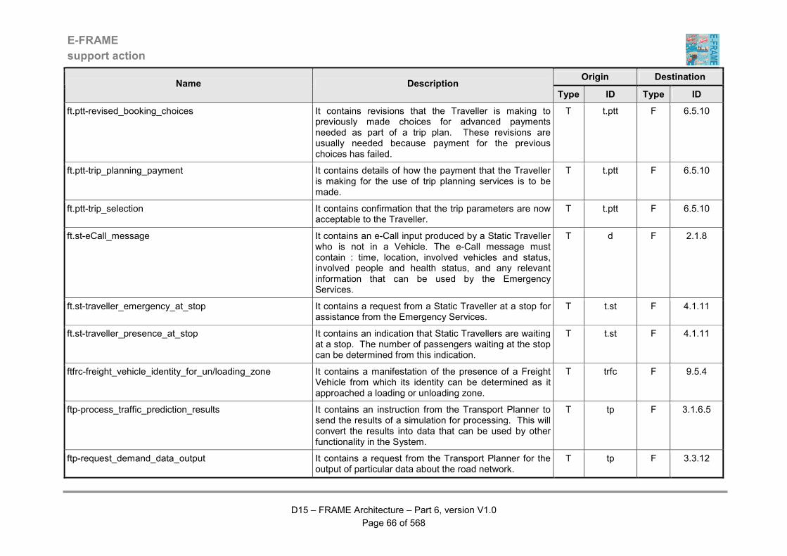
E-FRAME
support action
D15 – FRAME Architecture – Part 6, version V1.0
Page 66 of 568
Origin Destination Name Description
Type ID Type ID
ft.ptt-revised_booking_choices It contains revisions that the Traveller is making to previously made choices for advanced payments needed as part of a trip plan. These revisions are usually needed because payment for the previous choices has failed.
T t.ptt F 6.5.10
ft.ptt-trip_planning_payment It contains details of how the payment that the Traveller is making for the use of trip planning services is to be made.
T t.ptt F 6.5.10
ft.ptt-trip_selection It contains confirmation that the trip parameters are now acceptable to the Traveller.
T t.ptt F 6.5.10
ft.st-eCall_message It contains an e-Call input produced by a Static Traveller who is not in a Vehicle. The e-Call message must contain : time, location, involved vehicles and status, involved people and health status, and any relevant information that can be used by the Emergency Services.
T d F 2.1.8
ft.st-traveller_emergency_at_stop It contains a request from a Static Traveller at a stop for assistance from the Emergency Services.
T t.st F 4.1.11
ft.st-traveller_presence_at_stop It contains an indication that Static Travellers are waiting at a stop. The number of passengers waiting at the stop can be determined from this indication.
T t.st F 4.1.11
ftfrc-freight_vehicle_identity_for_un/loading_zone It contains a manifestation of the presence of a Freight Vehicle from which its identity can be determined as it approached a loading or unloading zone.
T trfc F 9.5.4
ftp-process_traffic_prediction_results It contains an instruction from the Transport Planner to send the results of a simulation for processing. This will convert the results into data that can be used by other functionality in the System.
T tp F 3.1.6.5
ftp-request_demand_data_output It contains a request from the Transport Planner for the output of particular data about the road network.
T tp F 3.3.12
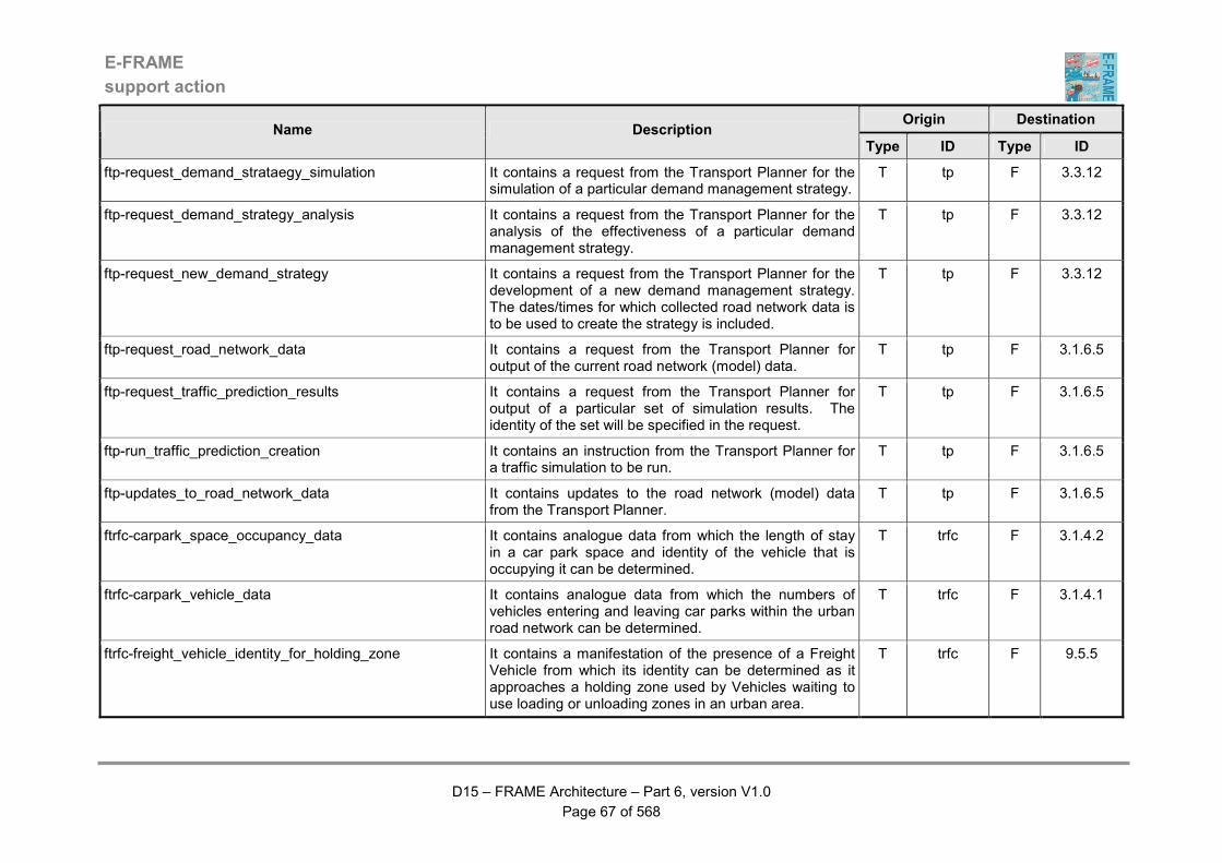
E-FRAME
support action
D15 – FRAME Architecture – Part 6, version V1.0
Page 67 of 568
Origin Destination Name Description
Type ID Type ID
ftp-request_demand_strataegy_simulation It contains a request from the Transport Planner for the simulation of a particular demand management strategy.
T tp F 3.3.12
ftp-request_demand_strategy_analysis It contains a request from the Transport Planner for the analysis of the effectiveness of a particular demand management strategy.
T tp F 3.3.12
ftp-request_new_demand_strategy It contains a request from the Transport Planner for the development of a new demand management strategy. The dates/times for which collected road network data is to be used to create the strategy is included.
T tp F 3.3.12
ftp-request_road_network_data It contains a request from the Transport Planner for output of the current road network (model) data.
T tp F 3.1.6.5
ftp-request_traffic_prediction_results It contains a request from the Transport Planner for output of a particular set of simulation results. The identity of the set will be specified in the request.
T tp F 3.1.6.5
ftp-run_traffic_prediction_creation It contains an instruction from the Transport Planner for a traffic simulation to be run.
T tp F 3.1.6.5
ftp-updates_to_road_network_data It contains updates to the road network (model) data from the Transport Planner.
T tp F 3.1.6.5
ftrfc-carpark_space_occupancy_data It contains analogue data from which the length of stay in a car park space and identity of the vehicle that is occupying it can be determined.
T trfc F 3.1.4.2
ftrfc-carpark_vehicle_data It contains analogue data from which the numbers of vehicles entering and leaving car parks within the urban road network can be determined.
T trfc F 3.1.4.1
ftrfc-freight_vehicle_identity_for_holding_zone It contains a manifestation of the presence of a Freight Vehicle from which its identity can be determined as it approaches a holding zone used by Vehicles waiting to use loading or unloading zones in an urban area.
T trfc F 9.5.5

E-FRAME
support action
D15 – FRAME Architecture – Part 6, version V1.0
Page 68 of 568
Origin Destination Name Description
Type ID Type ID
ftrfc-freight_vehicle_identity_for_rest_area It contains a manifestation of the presence of a Freight Vehicle from which its identity can be determined as it approached a rest area within a service area.
T v F 3.1.5.7
ftrfc-inter-urban_fcd_source_vehicle_image It contains an image of each Vehicle using the inter-urban road network from which its identity can be determined.
T trfc F 3.1.2.12
ftrfc-inter-urban_local_data_for_ramp_metering It contains Vehicle presence data that is collected solely for use in the management of ramp metering at entrances to on-ramps for all of part of the inter-urban road network managed by the system.
T trfc F 3.1.2.13.8
ftrfc-inter-urban_traffic_flow_data It contains analogue data from which the way in which traffic is flowing around the inter-urban road network can be determined.
T trfc F 3.1.2.10
ftrfc-inter-urban_vehicle_identity_for_violations It contains analogue data from which can be determined the identity of a Vehicle that has committed a violation in the way it is using the inter-urban road network.
T trfc F 3.1.2.14.5
ftrfc-inter-urban_vehicle_presence_for_messages It contains data indicating the presence of an approaching Vehicle using the inter-urban road network.
T trfc F 3.1.2.14.6
ftrfc-local_traffic_presence_data It contains analogue data that will be used to detect the presence of a vehicle for use in the local operation of urban output actuation Functions.
T trfc F 3.1.1.5.22
ftrfc-presence_indication It contains analogue data that will be analysed to see if it shows the presence of a possible incident on the road network.
T trfc F 3.2.12
ftrfc-service_area_vehicle_data It contains analogue data from which the numbers of vehicles entering and leaving service areas within the inter-urban road network can be determined.
T trfc F 3.1.5.1

E-FRAME
support action
D15 – FRAME Architecture – Part 6, version V1.0
Page 69 of 568
Origin Destination Name Description
Type ID Type ID
ftrfc-traffic_conditions_in_tunnel It contains analogue data from which the way in which traffic is flowing through each lane of the carriageway a tunnel can be determined, including such data as Vehicle flow rate, type(s) of Vehicles, etc.
T trfc F 3.1.7.1
ftrfc-traffic_data It contains analogue data about actual traffic in the area of interest of the Host Vehicle.
T trfc F 5.11.8
ftrfc-urban_fcd_source_vehicle_image It contains an image of each Vehicle using the urban road network from which its identity can be determined.
T trfc F 3.1.1.12
ftrfc-urban_traffic_flow_data It contains analogue data from which the way in which traffic is flowing around the urban road network can be determined.
T trfc F 3.1.1.10
ftrfc-urban_vehicle_identity_for_violations It contains analogue data from which can be determined the identity of a vehicle that has committed a violation in the way it is using the urban road network.
T trfc F 3.1.1.5.8
ftrfc-urban_vehicle_presence_for_messages It contains data indicating the presence of an approaching Vehicle using the urban road network.
T trfc F 3.1.1.5.21
ftrfc-vehicle_approaching_inter-urban_zone It contains the manifestation of the presence of a Vehicle approaching a part of the inter-urban road network (zone or "sensitive area") to which access is controlled.
T trfc F 3.1.2.13.2
ftrfc-vehicle_approaching_urban_zone It contains the manifestation of the presence of a Vehicle approaching a part of the urban road network (zone or "sensitive area") to which access is controlled.
T trfc F 3.1.1.5.11
ftrfc-vehicle_entering_inter-urban_zone It contains the manifestation of the presence of a Vehicle entering a part of the inter-urban road network (zone or "sensitive area") to which access is controlled.
T trfc F 3.1.2.13.3
ftrfc-vehicle_entering_urban_zone It contains the manifestation of the presence of a Vehicle entering a part of the urban road network (zone or "sensitive area") to which access is controlled.
T trfc F 3.1.1.5.12
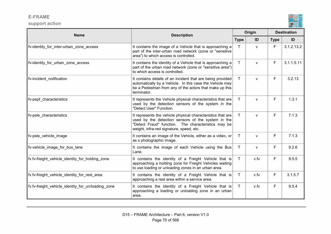
E-FRAME
support action
D15 – FRAME Architecture – Part 6, version V1.0
Page 70 of 568
Origin Destination Name Description
Type ID Type ID
fv-identity_for_inter-urban_zone_access It contains the image of a Vehicle that is approaching a part of the inter-urban road network (zone or "sensitive area") to which access is controlled.
T v F 3.1.2.13.2
fv-identity_for_urban_zone_access It contains the identity of a Vehicle that is approaching a part of the urban road network (zone or "sensitive area") to which access is controlled.
T v F 3.1.1.5.11
fv-incident_notification It contains details of an incident that are being provided automatically by a Vehicle. In this case the Vehicle may be a Pedestrian from any of the actors that make up this terminator.
T v F 3.2.13
fv-pepf_characteristics It represents the Vehicle physical characteristics that are used by the detection sensors of the system in the "Detect User" Function.
T v F 1.3.1
fv-psle_characteristics It represents the vehicle physical characteristics that are used by the detection sensors of the system in the "Detect Fraud" function. The characteristics may be weight, infra-red signature, speed, etc.
T v F 7.1.3
fv-psle_vehicle_image It contains an image of the Vehicle, either as a video, or as s photographic image.
T v F 7.1.3
fv-vehicle_image_for_bus_lane It contains the image of each Vehicle using the Bus Lane.
T v F 9.2.6
fv.fv-freight_vehicle_identity_for_holding_zone It contains the identity of a Freight Vehicle that is approaching a holding zone for Freight Vehicles waiting to use loading or unloading zones in an urban area.
T v.fv F 9.5.5
fv.fv-freight_vehicle_identity_for_rest_area It contains the identity of a Freight Vehicle that is approaching a rest area within a service area.
T v.fv F 3.1.5.7
fv.fv-freight_vehicle_identity_for_un/loading_zone It contains the identity of a Freight Vehicle that is approaching a loading or unloading zone in an urban area.
T v.fv F 9.5.4
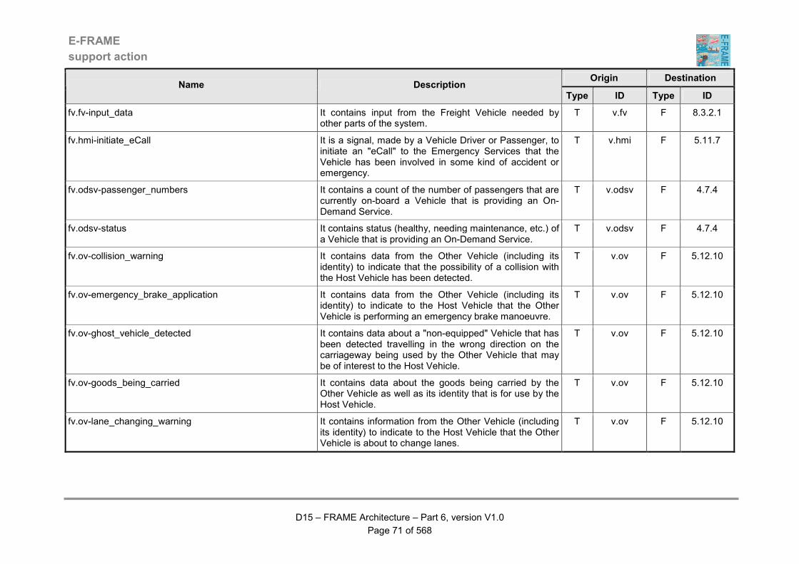
E-FRAME
support action
D15 – FRAME Architecture – Part 6, version V1.0
Page 71 of 568
Origin Destination Name Description
Type ID Type ID
fv.fv-input_data It contains input from the Freight Vehicle needed by other parts of the system.
T v.fv F 8.3.2.1
fv.hmi-initiate_eCall It is a signal, made by a Vehicle Driver or Passenger, to initiate an "eCall" to the Emergency Services that the Vehicle has been involved in some kind of accident or emergency.
T v.hmi F 5.11.7
fv.odsv-passenger_numbers It contains a count of the number of passengers that are currently on-board a Vehicle that is providing an On-Demand Service.
T v.odsv F 4.7.4
fv.odsv-status It contains status (healthy, needing maintenance, etc.) of a Vehicle that is providing an On-Demand Service.
T v.odsv F 4.7.4
fv.ov-collision_warning It contains data from the Other Vehicle (including its identity) to indicate that the possibility of a collision with the Host Vehicle has been detected.
T v.ov F 5.12.10
fv.ov-emergency_brake_application It contains data from the Other Vehicle (including its identity) to indicate to the Host Vehicle that the Other Vehicle is performing an emergency brake manoeuvre.
T v.ov F 5.12.10
fv.ov-ghost_vehicle_detected It contains data about a "non-equipped" Vehicle that has been detected travelling in the wrong direction on the carriageway being used by the Other Vehicle that may be of interest to the Host Vehicle.
T v.ov F 5.12.10
fv.ov-goods_being_carried It contains data about the goods being carried by the Other Vehicle as well as its identity that is for use by the Host Vehicle.
T v.ov F 5.12.10
fv.ov-lane_changing_warning It contains information from the Other Vehicle (including its identity) to indicate to the Host Vehicle that the Other Vehicle is about to change lanes.
T v.ov F 5.12.10

E-FRAME
support action
D15 – FRAME Architecture – Part 6, version V1.0
Page 72 of 568
Origin Destination Name Description
Type ID Type ID
fv.ov-lane_use_commands It contains information from the Other Vehicle concerning lane use commands it has received that may be of relevance to the Host Vehicle. The identity of the Other Vehicle will be included in the commands so that the Host Vehicle knows from which Vehicle they were sent.
T v.ov F 5.12.10
fv.ov-lights_anti-glare_request It contains a request from the Other Vehicle that the beam from the headlights of the Host Vehicle which is approaching it should be lowered because they are too high and causing glare. The request will include the identity of the Other Vehicle so that the Host Vehicle can determine which Vehicle is suffering from glare from its headlights.
T v.ov F 5.12.10
fv.ov-other_platooning_data It contains data concerned with performing platooning with one or more Vehicles that has been sent from the Other Vehicle to the Host Vehicle. The identity of the Other Vehicle will be included in the data so that the Host Vehicle knows from which Vehicle in the platoon the data was sent.
T v.ov F 5.12.10
fv.ov-other_vehicle_attitude_for_host_service It contains data showing the attitude of the Host Vehicle, i.e. on its wheels, on its side, upside down, etc.
T v.ov F 5.12.10
fv.ov-other_vehicle_location_for_host_vehicle It contains the location of the Other Vehicle that has been received by the Host Vehicle.
T v.ov F 5.12.10
fv.ov-overtaking_vehicle_warning It contains data from the Other Vehicle (including its identity) about an overtaking manoeuvre that it is about to make that is for use by the Host Vehicle.
T v.ov F 5.12.10
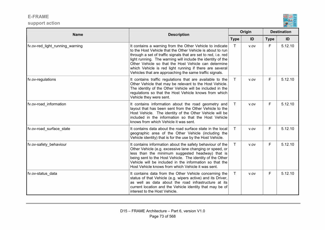
E-FRAME
support action
D15 – FRAME Architecture – Part 6, version V1.0
Page 73 of 568
Origin Destination Name Description
Type ID Type ID
fv.ov-red_light_running_warning It contains a warning from the Other Vehicle to indicate to the Host Vehicle that the Other Vehicle is about to run through a set of traffic signals that are set to red, i.e. red light running. The warning will include the identity of the Other Vehicle so that the Host Vehicle can determine which Vehicle is red light running if there are several Vehicles that are approaching the same traffic signals.
T v.ov F 5.12.10
fv.ov-regulations It contains traffic regulations that are available to the Other Vehicle that may be relevant to the Host Vehicle. The identity of the Other Vehicle will be included in the regulations so that the Host Vehicle knows from which Vehicle they were sent.
T v.ov F 5.12.10
fv.ov-road_information It contains information about the road geometry and layout that has been sent from the Other Vehicle to the Host Vehicle. The identity of the Other Vehicle will be included in the information so that the Host Vehicle knows from which Vehicle it was sent.
T v.ov F 5.12.10
fv.ov-road_surface_state It contains data about the road surface state in the local geographic area of the Other Vehicle (including the Vehicle identity) that is for the use by the Host Vehicle.
T v.ov F 5.12.10
fv.ov-safety_behaviour It contains information about the safety behaviour of the Other Vehicle (e.g. excessive lane changing or speed, or less than the minimum suggested headway) that is being sent to the Host Vehicle. The identity of the Other Vehicle will be included in the information so that the Host Vehicle knows from which Vehicle it was sent.
T v.ov F 5.12.10
fv.ov-status_data It contains data from the Other Vehicle concerning the status of that Vehicle (e.g. wipers active) and its Driver, as well as data about the road infrastructure at its current location and the Vehicle identity that may be of interest to the Host Vehicle.
T v.ov F 5.12.10
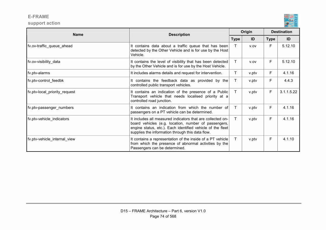
E-FRAME
support action
D15 – FRAME Architecture – Part 6, version V1.0
Page 74 of 568
Origin Destination Name Description
Type ID Type ID
fv.ov-traffic_queue_ahead It contains data about a traffic queue that has been detected by the Other Vehicle and is for use by the Host Vehicle.
T v.ov F 5.12.10
fv.ov-visibility_data It contains the level of visibility that has been detected by the Other Vehicle and is for use by the Host Vehicle.
T v.ov F 5.12.10
fv.ptv-alarms It includes alarms details and request for intervention. T v.ptv F 4.1.16
fv.ptv-control_feedbk It contains the feedback data as provided by the controlled public transport vehicles.
T v.ptv F 4.4.3
fv.ptv-local_priority_request It contains an indication of the presence of a Public Transport vehicle that needs localised priority at a controlled road junction.
T v.ptv F 3.1.1.5.22
fv.ptv-passenger_numbers It contains an indication from which the number of passengers on a PT vehicle can be determined.
T v.ptv F 4.1.16
fv.ptv-vehicle_indicators It includes all measured indicators that are collected on-board vehicles (e.g. location, number of passengers, engine status, etc.). Each identified vehicle of the fleet supplies the information through this data flow.
T v.ptv F 4.1.16
fv.ptv-vehicle_internal_view It contains a representation of the inside of a PT vehicle from which the presence of abnormal activities by the Passengers can be determined.
T v.ptv F 4.1.10
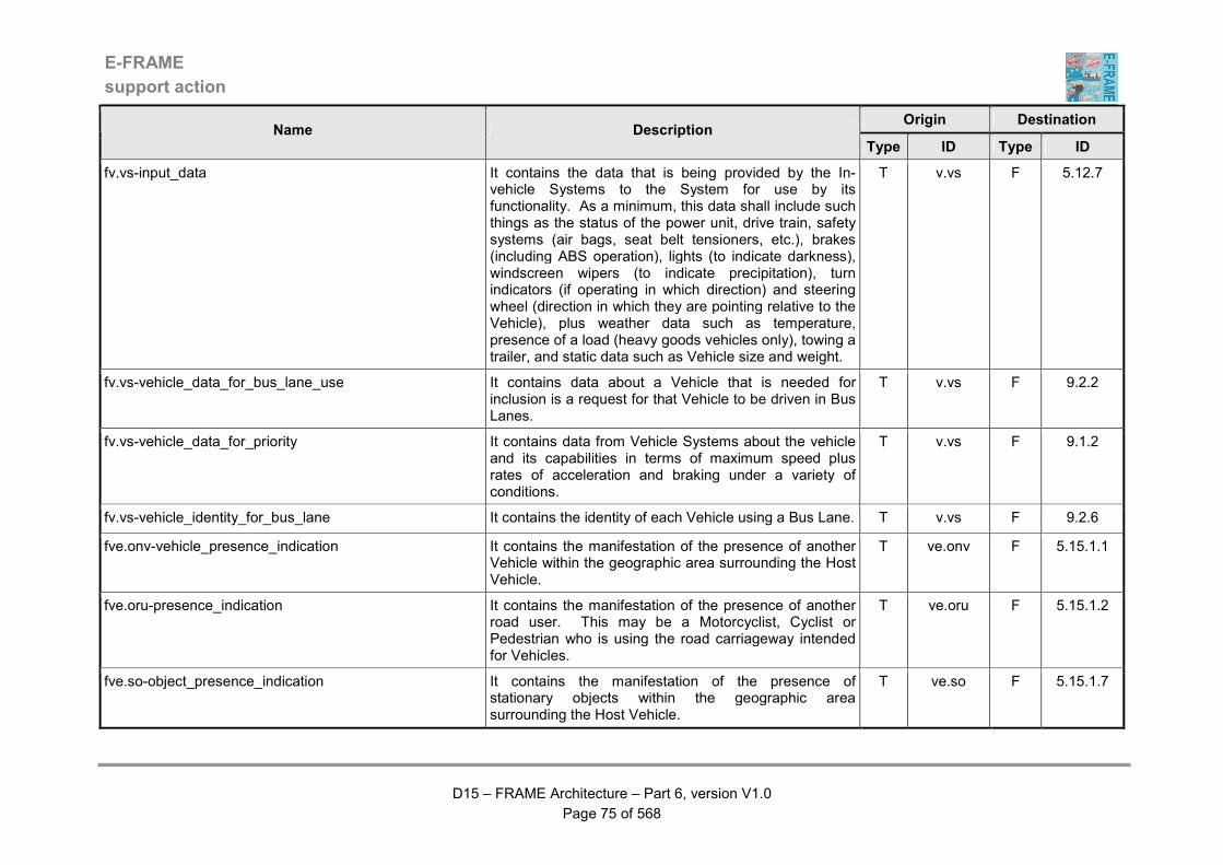
E-FRAME
support action
D15 – FRAME Architecture – Part 6, version V1.0
Page 75 of 568
Origin Destination Name Description
Type ID Type ID
fv.vs-input_data It contains the data that is being provided by the In-vehicle Systems to the System for use by its functionality. As a minimum, this data shall include such things as the status of the power unit, drive train, safety systems (air bags, seat belt tensioners, etc.), brakes (including ABS operation), lights (to indicate darkness), windscreen wipers (to indicate precipitation), turn indicators (if operating in which direction) and steering wheel (direction in which they are pointing relative to the Vehicle), plus weather data such as temperature, presence of a load (heavy goods vehicles only), towing a trailer, and static data such as Vehicle size and weight.
T v.vs F 5.12.7
fv.vs-vehicle_data_for_bus_lane_use It contains data about a Vehicle that is needed for inclusion is a request for that Vehicle to be driven in Bus Lanes.
T v.vs F 9.2.2
fv.vs-vehicle_data_for_priority It contains data from Vehicle Systems about the vehicle and its capabilities in terms of maximum speed plus rates of acceleration and braking under a variety of conditions.
T v.vs F 9.1.2
fv.vs-vehicle_identity_for_bus_lane It contains the identity of each Vehicle using a Bus Lane. T v.vs F 9.2.6
fve.onv-vehicle_presence_indication It contains the manifestation of the presence of another Vehicle within the geographic area surrounding the Host Vehicle.
T ve.onv F 5.15.1.1
fve.oru-presence_indication It contains the manifestation of the presence of another road user. This may be a Motorcyclist, Cyclist or Pedestrian who is using the road carriageway intended for Vehicles.
T ve.oru F 5.15.1.2
fve.so-object_presence_indication It contains the manifestation of the presence of stationary objects within the geographic area surrounding the Host Vehicle.
T ve.so F 5.15.1.7
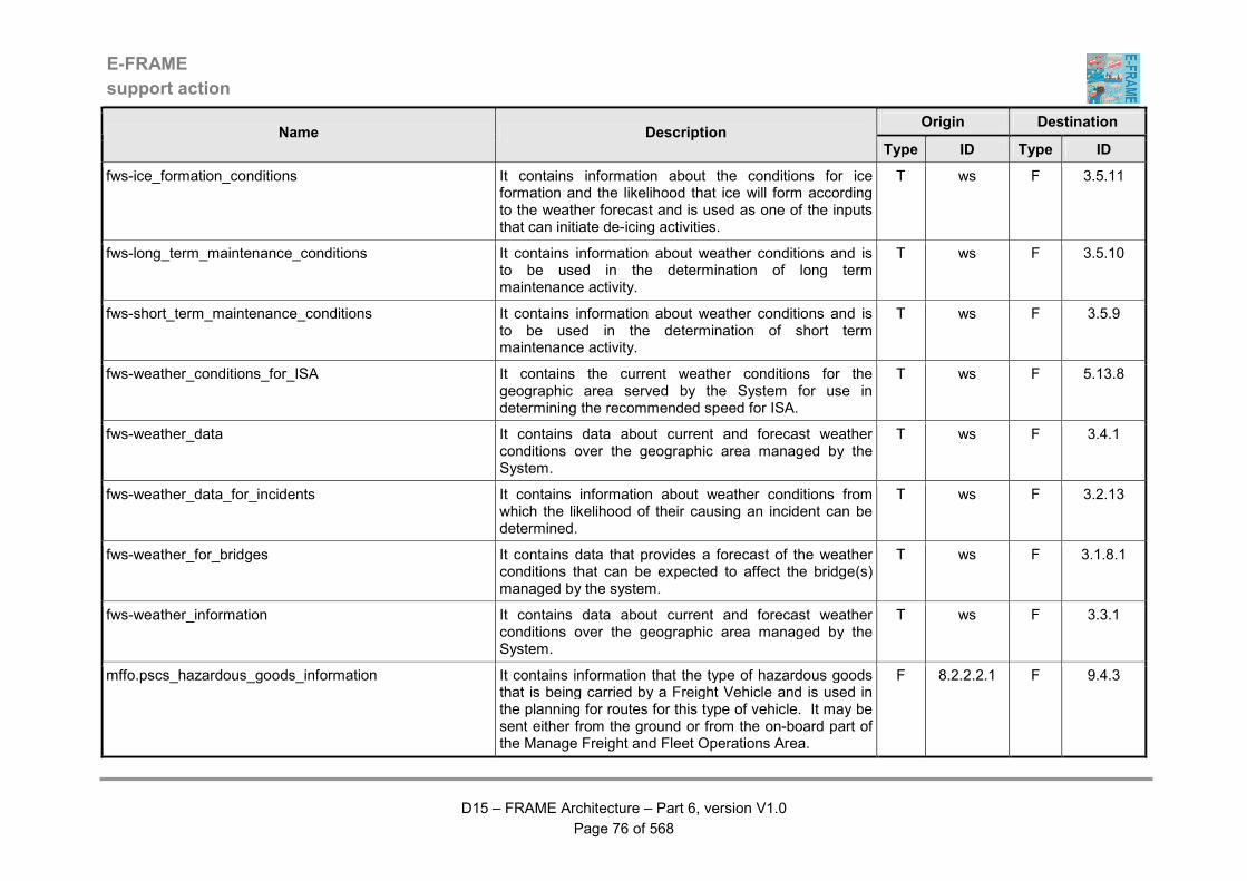
E-FRAME
support action
D15 – FRAME Architecture – Part 6, version V1.0
Page 76 of 568
Origin Destination Name Description
Type ID Type ID
fws-ice_formation_conditions It contains information about the conditions for ice formation and the likelihood that ice will form according to the weather forecast and is used as one of the inputs that can initiate de-icing activities.
T ws F 3.5.11
fws-long_term_maintenance_conditions It contains information about weather conditions and is to be used in the determination of long term maintenance activity.
T ws F 3.5.10
fws-short_term_maintenance_conditions It contains information about weather conditions and is to be used in the determination of short term maintenance activity.
T ws F 3.5.9
fws-weather_conditions_for_ISA It contains the current weather conditions for the geographic area served by the System for use in determining the recommended speed for ISA.
T ws F 5.13.8
fws-weather_data It contains data about current and forecast weather conditions over the geographic area managed by the System.
T ws F 3.4.1
fws-weather_data_for_incidents It contains information about weather conditions from which the likelihood of their causing an incident can be determined.
T ws F 3.2.13
fws-weather_for_bridges It contains data that provides a forecast of the weather conditions that can be expected to affect the bridge(s) managed by the system.
T ws F 3.1.8.1
fws-weather_information It contains data about current and forecast weather conditions over the geographic area managed by the System.
T ws F 3.3.1
mffo.pscs_hazardous_goods_information It contains information that the type of hazardous goods that is being carried by a Freight Vehicle and is used in the planning for routes for this type of vehicle. It may be sent either from the ground or from the on-board part of the Manage Freight and Fleet Operations Area.
F 8.2.2.2.1 F 9.4.3
E-FRAME
support action
D15 – FRAME Architecture – Part 6, version V1.0
Page 77 of 568
Origin Destination Name Description
Type ID Type ID
mffo.psef_incident_notification It carries information that enables Freight and Fleet Management to inform the Emergency Services about an incident together with its location as well as the type of vehicle and cargo concerned.
F 8.2.2.2.2 F 2.1.2.1
mffo.psle_cargo_characteristics It contains the on-board cargo characteristics that allow the evaluation of whether or not the cargo conforms to the local law.
F 8.3.3 F 7.1.2
mffo.psle_freight_vehicle_characteristics It contains the Freight Vehicle characteristics that allow the evaluation of whether or not the Vehicle conforms to the local law.
F 8.3.3 F 7.1.2
mffo.psle_violation_notification It contains all the elements gathered by Functions in the Manage Freight and Fleet Operations Area about a violation affecting its operations. It is composed of several data flows: date, image of violation (if available), involved driver / operator ID (if available), involved vehicle ID (if relevant and available), location of violation, other data according to the type of violation, reference, result of violation and type of violation.
F 8.2.2.2.6 F 7.3.5
mffo.ptja_freight_and_hazardous_goods_information It contains the origin/destination points, departure/arrival time constraints and in case of hazardous good transport the vehicle and cargo characteristics - all information - required to determine the route. It may be sent either from the ground or from the on-board part of the functional Area. It is composed of several different bits of information: departure/arrival time constraints, origin/destination points, plus vehicle and cargo characteristics.
F 8.2.2.1.1 F 6.5.3.13
mffo.ptja_hazardous_goods_monitoring_information It contains information that allows the monitoring of hazardous goods movements. The data flow relates to vehicle position, vehicle and cargo characteristics. It may be sent either from the ground or from the on-board part of the Manage Freight and Fleet Operations Area.
F 8.2.2.2.1 F 6.3.11
E-FRAME
support action
D15 – FRAME Architecture – Part 6, version V1.0
Page 78 of 568
Origin Destination Name Description
Type ID Type ID
mffo.ptja_on_board_informations_and_requests It contains all information and requests that can be useful for on-board use. Details of the contents of this Data Flow will be provided in the Documents produced by the COMETA Project.
F 8.3.1.4 F 6.5.3.13
mffo.ptja_request_on_pollution_situation It contains a request for information about the current pollution situation. The data flow may be sent either from the ground or from the on-board part of the Manage Freight and Fleet Operations Area.
F 8.2.2.1.1 F 6.5.3.13
mffo.ptja_request_on_traffic_situation It contains information about the current traffic situation. The data flow may be sent either from the ground or from the on-board part of the Manage Freight and Fleet Operations Area.
F 8.2.2.1.1 F 6.5.3.13
mffo.ptja_request_on_weather_situation It contains a request for information about the current weather situation. The data flow may be sent either from the ground or from the on-board part of the Manage Freight and Fleet Operations Area.
F 8.2.2.1.1 F 6.5.3.13
mffo.ptja_route_optimisation_request It contains all criteria that are useful for route optimisation for a trip. It includes start time and location, end time and location, intermediate location(s) and time(s), cargo description, vehicle description, location time, etc.
F 8.2.2.1.1 F 6.5.3.13
mffo_ack_on_area_booking It carries the information that a storage area booking action has been made. The action can be successful or not. The data flow includes the freight transaction ID (consignor order ID and freight operator proposal ID), booking result (positive or not) and booking ID.
F 8.1.5.4 F 8.1.1.4
mffo_administrative_data_for_operator It contains administrative data about a freight transport that is being made at the request of the Principal that is for output to the Freight Management Operator.
F 8.1.1.6 F 8.1.1.7
E-FRAME
support action
D15 – FRAME Architecture – Part 6, version V1.0
Page 79 of 568
Origin Destination Name Description
Type ID Type ID
mffo_administrative_data_from_operator It contains administrative data about a freight transport that is being made at the request of the Principal that has been input by the Freight Management Operator.
F 8.1.1.7 F 8.1.1.6
mffo_answer_on_custom_declaration It contains an indication that a custom declaration is completed and includes the freight transaction ID.
F 8.1.2.4 F 8.1.2.5
mffo_answer_on_fleet_choice It is used within the Manage Freight and Fleet Operations Area. The data flow carries the information that a fleet operator has been looked for. The action can be successful or not. The data flow includes the freight transaction ID (consignor order ID and freight operator proposal ID), fleet research result (positive or not) and fleet transaction ID.
F 8.1.1.5 F 8.1.1.4
mffo_answer_on_fleet_ressources_availability It carries the information that the best suitable transport resources for a given road freight transport operation have been looked for. The action can be successful or not. The data flow includes the fleet transaction ID, resources research result (positive or not) and analysis ID.
F 8.2.2.1.2 F 8.2.1.1
mffo_answer_on_freight_optimization It carries the information that a study to determine whether or not a road freight transport operation can be optimised with respect to inter-urban and multi-modal transport has been done and is available. The data flow includes the freight transaction ID (consignor order ID and freight operator proposal ID) and study ID.
F 8.1.5.3 F 8.1.1.4
mffo_answer_on_hazardous_goods_declaration It contains an indication that a hazardous goods declaration is completed and includes the freight transaction ID.
F 8.1.2.6 F 8.1.2.5
mffo_approve_hazardous_goods_transport_request It contains a data that is to be sent in a request to the Freight Management Operator to give approval for the Law Enforcement Agency to be asked to approve the movement of hazardous goods as part of a freight operation.
F 8.1.2.6 F 8.1.2.7
E-FRAME
support action
D15 – FRAME Architecture – Part 6, version V1.0
Page 80 of 568
Origin Destination Name Description
Type ID Type ID
mffo_board_incident_information It contains all information received relative to a trip that is already managed by the Manage Incident Function. Included in this data flow are data items such as, trip ID and information description.
F 8.2.2.2.1 F 8.2.2.2.2
mffo_commercial_event It contains data that informs Manage Fleet Business transaction function that a foreseen event happens on a trip that may need processing at commercial level. It contains trip ID, event (among a pre-defined list of relevant events).
F 8.2.2.2.1 F 8.2.1.1
mffo_commercial_incident It informs the function Manage fleet business transactions that an unforeseen event happens that may have consequences on freight management so that function can take all necessary decisions. It contents the trip ID with a brief description of the incident and of foreseen consequences on trip and load.
F 8.2.2.2.2 F 8.2.1.1
mffo_commercial_request It contains data that is a specific request from Manage fleet business transaction. The request can be a commercial instruction or an additional information answer (i.e. a request on information that cannot be find on the resource data store). The data comprises trip ID, nature of the request and the request.
F 8.2.1.1 F 8.2.2.2.1
mffo_customs_declaration_requested It contains data that will tell the Freight Management Operator that a request has been received to prepare and submit a customs declaration.
F 8.1.2.4 F 8.1.2.7
mffo_customs_declaration_submittal_approved It contains the approval from the Freight Management Operator for the previously requested customs declaration to be prepared and submitted to the Law Enforcement Agency.
F 8.1.2.7 F 8.1.2.4
mffo_data_for_freight_optimisation It contains data provided by the Freight Management Operator for use in the optimisation of the freight transport mode options.
F 8.1.5.5 F 8.1.5.3

E-FRAME
support action
D15 – FRAME Architecture – Part 6, version V1.0
Page 81 of 568
Origin Destination Name Description
Type ID Type ID
mffo_driver_booking_conflict It contains all information about a driver that is needed for a trip and that is already booked for other activities (holiday, training session...): driver ID, trip ID, date of the need.
F 8.2.2.1.2 F 8.2.2.3.3
mffo_driver_booking_notification It contains all information about a driver for a trip. The reservation can be preliminary or confirmed. trip Id, driver ID, reservation dates, reservation status and additional information.
F 8.2.2.1.2 F 8.2.2.3.3
mffo_driver_conflict_booking_solution It contains the solution to a conflict between the bookings of a Freight Vehicle Driver to do two or more activities simultaneously. This includes items such as, trip ID, driver ID, date of need, etc.
F 8.2.2.3.3 F 8.2.2.1.2
mffo_driver_event It carries details of an event that has occurred to the Driver. This will be used in the assessment of the future employment for the Driver.
F 8.2.2.2.1 F 8.2.2.3.3
mffo_driver_incident It carries details of an incident that has occurred to the Driver. This will be used in the assessment of the future employment for the Driver.
F 8.2.2.2.2 F 8.2.2.3.3
mffo_driver_request It carries a specific request from Manage fleet resources function. The request can be an instruction or an answer for additional information (i.e. a request on information that cannot be found on the resource data store) to the driver. Included in this data flow are data items such as, trip ID, driver ID, nature of the request and request.
F 8.2.2.3.3 F 8.2.2.2.1
mffo_driver_statutory_document It contains all actual documents that are legally needed for a trip and for a driver.
F 8.2.2.3.3 F 8.2.2.1.3
mffo_end_of_incident_handling It contains data that provides the information that the incident management of a trip is over. The data flow includes the trip ID.
F 8.2.2.2.2 F 8.2.2.2.1
E-FRAME
support action
D15 – FRAME Architecture – Part 6, version V1.0
Page 82 of 568
Origin Destination Name Description
Type ID Type ID
mffo_fleet_commercial_information It carries all commercial information that is provided by fleet supplier to the freight shipper for the performed freight transport. The data flow includes the fleet transaction ID (fleet supplier proposal ID and freight transaction ID), fleet supplier name and address, origin/destination conditions, departure/arrival dates, proof of delivery, delay and penalties.
F 8.2.1.1 F 8.1.1.4
mffo_fleet_global_availability_status It contains the current status of all Freight Vehicles in the Fleet and is for use in the management of the Fleet.
F 8.2.3 F 8.2.1.1
mffo_fleet_operational_information It carries all operational information that is provided by fleet supplier to the freight shipper for the performed freight transport. The data flow includes the fleet transaction ID (fleet supplier proposal ID and freight transaction ID), fleet supplier name and address, origin/destination conditions, departure/arrival dates, current operation (pick-up, conveying, delivering), position, intermediate time and location of the freight with freight status, delivery time with freight status, with or without incident and incident description
F 8.2.1.1 F 8.1.3
mffo_fleet_operator_data_for_freight_operator It contains data about a selected Fleet Operator that is for use by the Freight Management Operator in setting up a contract to move some freight.
F 8.1.1.5 F 8.1.1.7
mffo_fleet_operator_data_from_freight_operator It contains information about a contract for the movement of some freight that has just been awarded to a particular Fleet Operator and will be used to assess the availability of the Operator for further freight movement contracts.
F 8.1.1.7 F 8.1.1.5
E-FRAME
support action
D15 – FRAME Architecture – Part 6, version V1.0
Page 83 of 568
Origin Destination Name Description
Type ID Type ID
mffo_fleet_transport_capacity_availability It indicates to freight shipper that the fleet supplier is available to carry freight and so to study transport opportunity. The data flow includes fleet supplier name and address, start time of availability, end time of availability, description of capability during availability period.
F 8.2.1.1 F 8.1.1.5
mffo_fleet_transport_invoice It is the formal invoice from the fleet supplier to the freight management centre. The data flow includes the fleet transaction ID, price and electronic signature.
F 8.2.1.2 F 8.1.1.6
mffo_fleet_transport_offer It carries characteristics about the conditions under which the freight operation could be performed. The data flow includes the fleet transaction ID (fleet supplier proposal ID and freight transaction ID), fleet supplier name and address, departure/arrival dates proposal, proposed price and electronic signature.
F 8.2.1.1 F 8.1.1.5
mffo_fleet_transport_opportunity_request It is a request from the fleet supplier to freight system to get information about current freight opportunity. The data flow includes fleet supplier name and address, criteria for transport opportunity selection: start time, end-time, start location, end location, cargo type.
F 8.2.1.1 F 8.1.1.5
mffo_fleet_transport_order_confirmation It carries characteristics about the conditions under which the freight operation will be performed. It is the contract established between the freight and fleet centres. The data flow includes the fleet transaction ID (fleet supplier proposal ID and freight transaction ID), fleet supplier name and address, origin/destination conditions, departure/arrival dates engagement, agreed price and electronic signature.
F 8.2.1.1 F 8.1.1.4
mffo_freight_contractual_statutory_documents It includes all documents relative to freight status and declaration issued from all freight contracts and needed to build trip statutory documents.
F 8.2.1.2 F 8.2.2.1.3

E-FRAME
support action
D15 – FRAME Architecture – Part 6, version V1.0
Page 84 of 568
Origin Destination Name Description
Type ID Type ID
mffo_freight_status_request It carries the information that the status of a fleet operation is requested. The data flow includes the fleet transaction ID.
F 8.1.3 F 8.2.1.1
mffo_freight_statutory_document It contains official documents such as customs and hazardous goods declarations.
F 8.1.1.4 F 8.2.1.1
mffo_freight_transport_opportunity It carries characteristics about the freight operation that needs to be performed. The data flow includes the freight shipper name and address, freight transaction ID, fleet supplier name and address, origin/destination conditions, departure/arrival dates conditions, cargo/freight characteristics.
F 8.1.1.5 F 8.2.1.1
mffo_freight_transport_optimisation_results It contains the results of the freight transport mode optimisation for output to the Freight Management Operator.
F 8.1.5.3 F 8.1.5.5
mffo_freight_transport_order It carries characteristics about the freight operation that will be performed. The data flow includes the fleet transaction ID (freight transaction ID and fleet supplier ID), freight shipper name and address, fleet supplier name and address, origin/destination conditions, departure/arrival dates conditions, cargo/freight characteristics, agreed price and electronic signature.
F 8.1.1.4 F 8.2.1.1
mffo_freight_transport_payment It carries the acknowledgement that a payment has been placed by the freight operator on the bank account of the fleet operator. The data flow includes the fleet transaction ID, date of payment and electronic signature.
F 8.1.1.6 F 8.2.1.2
mffo_hazardous_goods_transport_request_approved It contains data from the approval for a previous request to the Freight Management Operator to give approval for the Law Enforcement Agency to be asked to approve the movement of hazardous goods as part of a freight operation.
F 8.1.2.7 F 8.1.2.6
E-FRAME
support action
D15 – FRAME Architecture – Part 6, version V1.0
Page 85 of 568
Origin Destination Name Description
Type ID Type ID
mffo_incident_handling It carries the information that an incident has occurred and that the incident management function needs to be activated. The data flow includes the trip ID.
F 8.2.2.2.1 F 8.2.2.2.2
mffo_incident_instruction It contains all instruction from incident management to be sent to a vehicle in incident: may be driver instructions, vehicle commands, cargo commands, etc. Included in the data flow are data items such as, trip ID and commands or texts.
F 8.2.2.2.2 F 8.2.2.2.1
mffo_input_from_principal It contains data about the request for the transport of freight that has been received from the Principal and is being sent for processing.
F 8.1.1.8 F 8.1.1.4
mffo_load_consignment_evaluation_data It contains data produced after an evaluation of the performance of the freight operations.
F 8.1.6 D D8.1
mffo_load_consignment_fleet_supplier_transact_data It contains fleet supplier characteristics assembled from the transactions concerning an order on a supplier to move some freight.
F 8.1.1.5 D D8.1
mffo_load_consignment_freight-cargo_data It contains data about the freight that is to be shipped by a fleet supplier.
F 8.1.3 D D8.1
mffo_load_consignment_freight_admin_transact_data It contains administrative data about the transactions that have been made to arrange the shipment of some freight by a fleet supplier.
F 8.1.1.6 D D8.1
mffo_load_consignment_freight_ops_customs_data It contains data for customs authorities about some freight that is to be shipped.
F 8.1.2.4 D D8.1
mffo_load_consignment_freight_ops_documents_data It contains electronic versions of the documentation concerning some freight that is to be shipped.
F 8.1.2.5 D D8.1
mffo_load_consignment_freight_ops_hazmat_data It contains data about any hazardous materials in some freight that is about to be shipped.
F 8.1.2.6 D D8.1
mffo_load_consignment_intermodal_ops_data It contains data about the arrangements for moving a shipment of freight by different modes of transport.
F 8.1.5.3 D D8.1
E-FRAME
support action
D15 – FRAME Architecture – Part 6, version V1.0
Page 86 of 568
Origin Destination Name Description
Type ID Type ID
mffo_load_consignment_intermodal_storage_data It contains data about the arrangements and need for storage of some freight. The storage is specifically needed during the transfer between the different transport modes that will be involved in the shipment.
F 8.1.5.4 D D8.1
mffo_load_consignment_principal_transaction_data It contains the main transaction data for a shipment of freight that is about to be made.
F 8.1.1.4 D D8.1
mffo_load_on_board_monitor_cargo_data It contains data collected by monitoring the state of the cargo and to be stored on-board a vehicle.
F 8.3.2.3 D D8.3
mffo_load_on_board_monitor_driver_data It contains data to be stored on-board the vehicle that has been collected by monitoring the driver.
F 8.3.2.1 D D8.3
mffo_load_on_board_monitor_equipment_data It contains data obtained from monitoring the freight equipment that is to be stored on-board a vehicle.
F 8.3.2.4 D D8.3
mffo_load_on_board_monitor_order_data It contains data about the freight order that is to be stored on-board the vehicle.
F 8.3.1.3 D D8.3
mffo_load_on_board_monitor_task_data It contains data about the shipment task that is being carried out by the vehicle that is to be stored on-board.
F 8.3.1.4 D D8.3
mffo_load_on_board_monitor_vehicle_data It contains data to be stored on-board the vehicle obtained from monitoring a freight it is carrying.
F 8.3.2.2 D D8.3
mffo_load_on_board_new_transport_unit_data It contains data to be stored on-board the vehicle about a new transport unit that has become part of it.
F 8.3.1.2 D D8.3
mffo_load_on_board_regulation_compliance_data It contains data to be stored on-board the vehicle about its compliance with the relevant regulations.
F 8.3.3 D D8.3
mffo_load_on_board_transport_order_check_data It contains data to be stored on-board the vehicle about the transport order.
F 8.3.1.1 D D8.3
mffo_load_resources_on_board_payments_data It contains data to be stored on-board the Freight Vehicle about payments already made for its movement.
F 8.2.2.2.3 D D8.2
E-FRAME
support action
D15 – FRAME Architecture – Part 6, version V1.0
Page 87 of 568
Origin Destination Name Description
Type ID Type ID
mffo_mgm_cargo_raw_data_request It contains fleet management request about data on cargo: cargo description, container ID, content, time period, type of requested data, periodicity.
F 8.2.2.2.1 F 8.3.2.3
mffo_mgm_commercial_information It contains data that provides all of the commercial information that will be re-loaded by the fleet management centre and sent to any fleet resources for any trip. The data includes the following: transport orders and confirmation, transport offers, pick-up and delivery documents (notices, reports, proofs) c.f. Transport order definition produced by the COMETA Project.
F 8.2.2.2.1 F 8.3.1.3
mffo_mgm_driver_raw_data_request It contains fleet management request about data on driver: driver ID, time period, type of requested data, frequency.
F 8.2.2.2.1 F 8.3.2.1
mffo_mgm_equipment_raw_data_request It contains fleet management request about data on equipment: equipment ID, time period, type of requested data, frequency.
F 8.2.2.2.1 F 8.3.2.4
mffo_mgm_incident_information_MOT It contains data that provides all of the incident information that is sent from the fleet management centre to fleet resources to help them. The data includes the following: driver ID, vehicle ID, cargo, location, incident management instruction, ID of impacted (modified, cancelled, delayed, etc.) transport orders and operational tasks.
F 8.2.2.2.1 F 8.3.1.4
mffo_mgm_incident_information_MTO It contains data that provides all of the incident information that is sent from the fleet management centre to the fleet resources to help them. The data includes the following: driver ID, vehicle ID, cargo, location, incident management instruction, ID of impacted (modified, cancelled, delayed, etc.) transport orders and operational tasks.
F 8.2.2.2.1 F 8.3.1.3

E-FRAME
support action
D15 – FRAME Architecture – Part 6, version V1.0
Page 88 of 568
Origin Destination Name Description
Type ID Type ID
mffo_mgm_operational_information It contains data that provides all of the operational information that is sent from the fleet management centre to any fleet resources for any trip. The data includes the following: mainly task descriptions with trip/route/load plan, transport order status information, vehicle positions, miscellaneous instructions, driver information, vehicle information, cargo information and trip information.
F 8.2.2.2.1 F 8.3.1.4
mffo_mgm_statutory_information_MOT It contains data that provides all of the commercial information that is sent by fleet management centre to any fleet resources for any trip. The data includes the following: driver, vehicle, cargo: customs documents and hazardous goods documents - c.f. the statutory document definition by the COMETA Project.
F 8.2.2.2.1 F 8.3.1.4
mffo_mgm_statutory_information_MTO It contains data that provides all of the commercial information that is sent by fleet management centre to any fleet resources for any trip. The data flow includes the following: driver, vehicle, cargo: customs documents and hazardous goods documents - c.f. the statutory document definition by the COMETA Project.
F 8.2.2.2.1 F 8.3.1.3
mffo_mgm_task_status_request It contains a request from fleet manager for information about a task processing. The request includes the following: date, task ID and type of requested information.
F 8.2.2.2.1 F 8.3.1.4
mffo_mgm_transport_order_status_request It contains a request from fleet manager for information about a transport order processing. The request includes the following: date, transport order ID and type of requested information.
F 8.2.2.2.1 F 8.3.1.3
mffo_mgm_vehicle_raw_data_request It contains fleet management request about data on vehicle: vehicle ID, time period, type of requested data, frequency.
F 8.2.2.2.1 F 8.3.2.2
E-FRAME
support action
D15 – FRAME Architecture – Part 6, version V1.0
Page 89 of 568
Origin Destination Name Description
Type ID Type ID
mffo_negotiation_data_for_freight_operator It contains data for the Freight Management Operator about the negotiations to find a Fleet Operator to respond to the freight transport request from the Principal.
F 8.1.1.4 F 8.1.1.7
mffo_negotiation_data_from_freight_operator It contains data from the Freight Management Operator sent in response to other data received about the negotiations to find a Fleet Operator to respond to the freight transport request from the Principal.
F 8.1.1.7 F 8.1.1.4
mffo_new_transport_order It contains ID of a new transport order to insert in the list of managed transport order: date, transport order ID.
F 8.3.1.2 F 8.3.1.3
mffo_outputs_to_principal It contains data about the request for the transport of freight that needs to be output to the Principal.
F 8.1.1.4 F 8.1.1.8
mffo_payment_acknowledgement_from_principal It contains an acknowledgement that the Principal has successfully made the required payment for the previously requested transport of freight.
F 8.1.1.8 F 8.1.1.6
mffo_prepare_freight_operations_data_appoved It contains the approval from the Freight Management Operator of a previous request for the preparation of the information required to enable the freight operation to take place.
F 8.1.2.7 F 8.1.2.5
mffo_prepare_freight_operations_data_request It contains a request for the Freight Management Operator to give permission for the preparation of the information required to enable the freight operation to take place.
F 8.1.2.5 F 8.1.2.7
mffo_read_consignment_evaluation_data It contains data previously produced after the evaluation of the freight operations performance.
D D8.1 F 8.1.6
mffo_read_consignment_fleet_supplier_transact_data It contains fleet supplier characteristics that were assembled from the transactions concerning an order on a supplier to move some freight.
D D8.1 F 8.1.1.5
mffo_read_consignment_freight-cargo_data It contains data about some freight that has been shipped by a fleet supplier.
D D8.1 F 8.1.3

E-FRAME
support action
D15 – FRAME Architecture – Part 6, version V1.0
Page 90 of 568
Origin Destination Name Description
Type ID Type ID
mffo_read_consignment_freight_admin_transact_data It contains administrative data about the transactions that were made to arrange the shipment of some freight by a fleet supplier.
D D8.1 F 8.1.1.6
mffo_read_consignment_freight_ops_customs_data It contains data previously stored that is for customs authorities and is about some freight that is to be shipped.
D D8.1 F 8.1.2.4
mffo_read_consignment_freight_ops_documents_data It contains previously stored electronic versions of the documentation concerning some freight that is to be shipped.
D D8.1 F 8.1.2.5
mffo_read_consignment_freight_ops_hazmat_data It contains previously stored data about any hazardous materials in some freight that is about to be shipped.
D D8.1 F 8.1.2.6
mffo_read_consignment_intermodal_ops_data It contains previously stored data about the arrangements for moving a shipment of freight by different modes of transport.
D D8.1 F 8.1.5.3
mffo_read_consignment_intermodal_storage_data It contains previously stored data about the arrangements and need for storage of some freight. The storage is specifically needed during the transfer between the different transport modes that will be involved in the shipment.
D D8.1 F 8.1.5.4
mffo_read_consignment_principal_transaction_data It contains previously stored data about the main transactions for a shipment of freight that is about to be made.
D D8.1 F 8.1.1.4
mffo_read_on_board_monitor_cargo_data It contains data that was previously stored after being collected by monitoring the state of the cargo and to be stored on-board a vehicle.
D D8.3 F 8.3.2.3
mffo_read_on_board_monitor_driver_data It contains data previously stored on-board the vehicle that was collected by monitoring the driver.
D D8.3 F 8.3.2.1
mffo_read_on_board_monitor_equipment_data It contains data previously stored after monitoring the freight equipment that is to be stored on-board a vehicle.
D D8.3 F 8.3.2.4
E-FRAME
support action
D15 – FRAME Architecture – Part 6, version V1.0
Page 91 of 568
Origin Destination Name Description
Type ID Type ID
mffo_read_on_board_monitor_order_data It contains data about the freight order that has been stored on-board the vehicle.
D D8.3 F 8.3.1.3
mffo_read_on_board_monitor_task_data It contains data about the shipment task that is being carried out by the vehicle that has been stored on-board.
D D8.3 F 8.3.1.4
mffo_read_on_board_monitor_vehicle_data It contains data previously stored on-board the vehicle that was obtained from monitoring a freight it is carrying.
D D8.3 F 8.3.2.2
mffo_read_on_board_new_transport_unit_data It contains data that was previously stored on-board the vehicle about a new transport unit that became part of it.
D D8.3 F 8.3.1.2
mffo_read_on_board_regulation_compliance_data It contains data previously stored on-board the vehicle about its compliance with the relevant regulations.
D D8.3 F 8.3.3
mffo_read_on_board_transport_order_check_data It contains data previously stored on-board the vehicle about the transport order.
D D8.3 F 8.3.1.1
mffo_read_resources_admin_fleet_transactions_data It contains previously stored resources administration data for a vehicle fleet.
D D8.2 F 8.2.1.2
mffo_read_resources_conditions_evaluation_data It contains data about the evaluation of the resource conditions under which a fleet of vehicles is operating.
D D8.2 F 8.2.2.2.6
mffo_read_resources_details_data It contains detailed data about resources that has been previously stored.
D D8.2 F 8.2.2.1.2
mffo_read_resources_driver_employment_data It contains previously stored data about the resources concerned with driver employment.
D D8.2 F 8.2.2.3.3
mffo_read_resources_fleet_performance_data It contains previously stored data about the performance of a vehicle fleet.
D D8.2 F 8.2.3
mffo_read_resources_incident_management_data It contains previously stored data that has been used for the management of incidents concerning the vehicle and/or the goods it is carrying.
D D8.2 F 8.2.2.2.2
mffo_read_resources_info_from_on_board_data It contains previously stored data that has been stored on-board the Freight Vehicle.
D D8.2 F 8.2.2.2.1

E-FRAME
support action
D15 – FRAME Architecture – Part 6, version V1.0
Page 92 of 568
Origin Destination Name Description
Type ID Type ID
mffo_read_resources_maintenance_data It contains previously stored maintenance data about the vehicle.
D D8.2 F 8.2.2.3.1
mffo_read_resources_on_board_payments_data It contains data previously stored on-board the Freight Vehicle about payments already made for its movement.
D D8.2 F 8.2.2.2.3
mffo_read_resources_op_document_data It contains previously stored electronic versions of operational documents.
D D8.2 F 8.2.2.1.3
mffo_read_resources_request_data It contains previously stored data about requests for freight shipments by the vehicle fleet.
D D8.2 F 8.2.1.1
mffo_read_resources_trip_and_load_plan_data It contains previously stored data about trips and plans for loading and un-loading freight.
D D8.2 F 8.2.2.1.1
mffo_read_resources_vehicle_equipment_data It contains previously stored data about the equipment on-board the vehicle.
D D8.2 F 8.2.2.3.2
mffo_regulation_event It contains the description of a regulation violation detected by the Comply Monitoring function, including the date of violation, transgressed rules and associated data.
F 8.3.3 F 8.3.1.4
mffo_regulation_rules It contains description a regulation rules to be verified for the next phase of the trip: list of rules ID.
F 8.3.1.4 F 8.3.3
mffo_request_for_area_booking It carries the information that a storage area booking action must be made. The data flow includes the freight transaction ID (consignor order ID and freight operator proposal ID).
F 8.1.1.4 F 8.1.5.4
mffo_request_for_conditions_evaluation It carries the information that the transport conditions need to be evaluated. The data flow includes the fleet transaction ID.
F 8.2.2.2.1 F 8.2.2.2.6
mffo_request_for_custom_declaration It contains information about the need for a custom declaration and includes the freight transaction ID.
F 8.1.2.5 F 8.1.2.4
E-FRAME
support action
D15 – FRAME Architecture – Part 6, version V1.0
Page 93 of 568
Origin Destination Name Description
Type ID Type ID
mffo_request_for_document_preparation It indicates that a trip has been planned and that statutory documents are needed. The data flow includes the trip ID.
F 8.2.2.1.1 F 8.2.2.1.3
mffo_request_for_fleet_administrative_closure It carries the information that the fleet administrative closure - invoice and payment - must start. The data flow includes the fleet transaction ID.
F 8.2.1.1 F 8.2.1.2
mffo_request_for_fleet_choice It carries the information that a fleet operator must be looked for. It also carries the information that a registered freight transport operation must have its transport conditions changed. There are two steps in the transaction: initial where a best offer is looked for ; final where the final choice is made. The data flow includes the transaction step (initial or final), transaction type (new or change), freight transaction ID (consignor order ID and freight operator proposal ID) and cancelled freight transaction ID.
F 8.1.1.4 F 8.1.1.5
mffo_request_for_fleet_control It carries the information that a fleet operation has been prepared and needs to be traced/controlled. The data flow includes the fleet transaction ID. The data flow includes the fleet transaction ID.
F 8.2.2.1.3 F 8.2.2.2.1
mffo_request_for_fleet_resources_availability It carries the information that an analysis must be made to determine what are the best suitable transport resources for a given road freight transport operation. It also carries the information that a registered fleet transport operation must have its transport conditions changed. There are two steps in the transaction: initial where the best suitable resources are looked for ; final where the final choice is made. The data flow includes the transaction step (initial or final), transaction type (new or change), fleet transaction ID and cancelled fleet transaction ID.
F 8.2.1.1 F 8.2.2.1.2
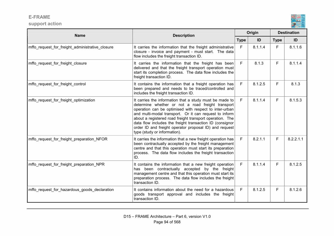
E-FRAME
support action
D15 – FRAME Architecture – Part 6, version V1.0
Page 94 of 568
Origin Destination Name Description
Type ID Type ID
mffo_request_for_freight_administrative_closure It carries the information that the freight administrative closure - invoice and payment - must start. The data flow includes the freight transaction ID.
F 8.1.1.4 F 8.1.1.6
mffo_request_for_freight_closure It carries the information that the freight has been delivered and that the freight transport operation must start its completion process. The data flow includes the freight transaction ID.
F 8.1.3 F 8.1.1.4
mffo_request_for_freight_control It contains the information that a freight operation has been prepared and needs to be traced/controlled and includes the freight transaction ID.
F 8.1.2.5 F 8.1.3
mffo_request_for_freight_optimization It carries the information that a study must be made to determine whether or not a road freight transport operation can be optimised with respect to inter-urban and multi-modal transport. Or it can request to inform about a registered road freight transport operation. The data flow includes the freight transaction ID (consignor order ID and freight operator proposal ID) and request type (study or information).
F 8.1.1.4 F 8.1.5.3
mffo_request_for_freight_preparation_NFOR It carries the information that a new freight operation has been contractually accepted by the freight management centre and that this operation must start its preparation process. The data flow includes the freight transaction ID.
F 8.2.1.1 F 8.2.2.1.1
mffo_request_for_freight_preparation_NPR It contains the information that a new freight operation has been contractually accepted by the freight management centre and that this operation must start its preparation process. The data flow includes the freight transaction ID.
F 8.1.1.4 F 8.1.2.5
mffo_request_for_hazardous_goods_declaration It contains information about the need for a hazardous goods transport approval and includes the freight transaction ID.
F 8.1.2.5 F 8.1.2.6

E-FRAME
support action
D15 – FRAME Architecture – Part 6, version V1.0
Page 95 of 568
Origin Destination Name Description
Type ID Type ID
mffo_request_for_resource_allocation It contains a request to allocate resources on a planned trip. The request only includes the trip ID as all correlative information is stored in the Resources Data Store (D 8.2).
F 8.2.2.1.1 F 8.2.2.1.2
mffo_request_for_safety_evaluation It carries the information that the transport safety needs to be evaluated. The data flow includes the fleet transaction ID.
F 8.2.2.2.1 F 8.2.2.2.6
mffo_request_payment_from_principal It contains a request for the Principal to make the required payment for the previously requested transport of freight and to inform when this has been successfully completed.
F 8.1.1.6 F 8.1.1.8
mffo_resource_allocation_confirmation It informs the Trip and Load Planning Function that all the required resources have been booked for a trip. The data flow contains the trip ID as all correlative information is stored in the Resources Data Store (D 8.2).
F 8.2.2.1.2 F 8.2.2.1.1
mffo_rsc_cargo_event It contains description about an event that occurred on cargo in order to manage impact on transport order and/or task management: date, cargo ID, event, parameters of the event.
F 8.3.2.3 F 8.3.1.4
mffo_rsc_cargo_raw_operational_data It contains information about cargo either requested by fleet manager either sent automatically by cargo monitoring function on a specific event: current date, current location, cargo ID, in case of an answer required data with associated date, location and events, in case of a non-solicited sending: event and associated data.
F 8.3.2.3 F 8.2.2.2.1
mffo_rsc_commercial_incident_information It contains all incident information about a problem encountered in the process of a transport order. This includes items such as ID of transport order, type of problem, date of problem occurrence, location, additional information about problem, etc.
F 8.3.1.3 F 8.2.2.2.1

E-FRAME
support action
D15 – FRAME Architecture – Part 6, version V1.0
Page 96 of 568
Origin Destination Name Description
Type ID Type ID
mffo_rsc_commercial_information It contains information about transport order processing. This message is either an answer to a Fleet Manager request, or an automatic sending of information about a specific event. The information includes items such as current date and location, transport order ID, etc. In the case of an answer, it includes a requested value with associated date, location and events. In case of a non-solicited sending of the information, it includes items such as origin event and associated data.
F 8.3.1.3 F 8.2.2.2.1
mffo_rsc_driver_event It contains description about an event that occurred on driver in order to manage impact on transport order and/or task management: date, driver ID, event, parameters of the event.
F 8.3.2.1 F 8.3.1.4
mffo_rsc_driver_raw_operational_data It contains information about driver either requested by fleet manager either sent automatically by driver monitoring function on a specific event: current date, current location, driver ID, in case of an answer required data with associated date, location and events, in case of a non-solicited sending: event and associated data.
F 8.3.2.1 F 8.2.2.2.1
mffo_rsc_equipment_event It contains description about an event that occurred on equipment in order to manage impact on transport order and/or task management: date, equipment ID, event, parameters of the event.
F 8.3.2.4 F 8.3.1.4
mffo_rsc_equipment_raw_operational_data It contains information about equipment either requested by fleet manager either sent automatically by equipment monitoring function on a specific event: current date, current location, equipment ID, in case of an answer required data with associated date, location and events, in case of a non-solicited sending: event and associated data.
F 8.3.2.4 F 8.2.2.2.1
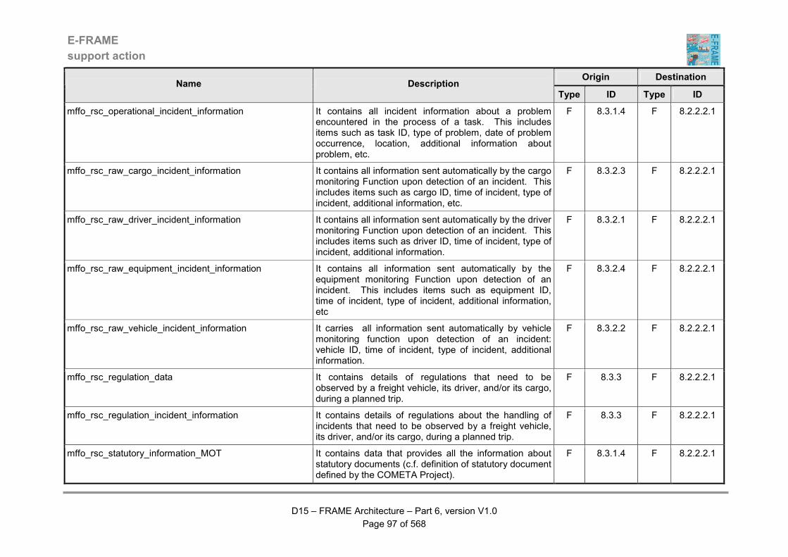
E-FRAME
support action
D15 – FRAME Architecture – Part 6, version V1.0
Page 97 of 568
Origin Destination Name Description
Type ID Type ID
mffo_rsc_operational_incident_information It contains all incident information about a problem encountered in the process of a task. This includes items such as task ID, type of problem, date of problem occurrence, location, additional information about problem, etc.
F 8.3.1.4 F 8.2.2.2.1
mffo_rsc_raw_cargo_incident_information It contains all information sent automatically by the cargo monitoring Function upon detection of an incident. This includes items such as cargo ID, time of incident, type of incident, additional information, etc.
F 8.3.2.3 F 8.2.2.2.1
mffo_rsc_raw_driver_incident_information It contains all information sent automatically by the driver monitoring Function upon detection of an incident. This includes items such as driver ID, time of incident, type of incident, additional information.
F 8.3.2.1 F 8.2.2.2.1
mffo_rsc_raw_equipment_incident_information It contains all information sent automatically by the equipment monitoring Function upon detection of an incident. This includes items such as equipment ID, time of incident, type of incident, additional information, etc
F 8.3.2.4 F 8.2.2.2.1
mffo_rsc_raw_vehicle_incident_information It carries all information sent automatically by vehicle monitoring function upon detection of an incident: vehicle ID, time of incident, type of incident, additional information.
F 8.3.2.2 F 8.2.2.2.1
mffo_rsc_regulation_data It contains details of regulations that need to be observed by a freight vehicle, its driver, and/or its cargo, during a planned trip.
F 8.3.3 F 8.2.2.2.1
mffo_rsc_regulation_incident_information It contains details of regulations about the handling of incidents that need to be observed by a freight vehicle, its driver, and/or its cargo, during a planned trip.
F 8.3.3 F 8.2.2.2.1
mffo_rsc_statutory_information_MOT It contains data that provides all the information about statutory documents (c.f. definition of statutory document defined by the COMETA Project).
F 8.3.1.4 F 8.2.2.2.1
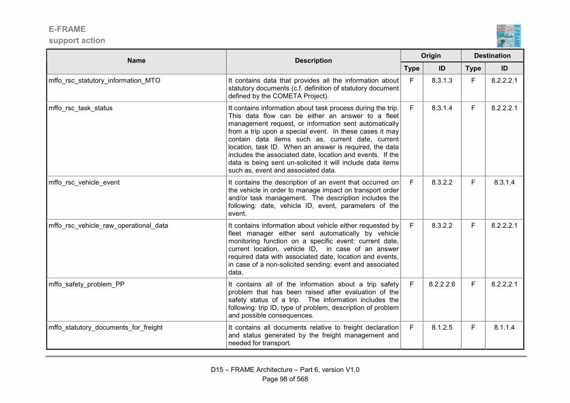
E-FRAME
support action
D15 – FRAME Architecture – Part 6, version V1.0
Page 98 of 568
Origin Destination Name Description
Type ID Type ID
mffo_rsc_statutory_information_MTO It contains data that provides all the information about statutory documents (c.f. definition of statutory document defined by the COMETA Project).
F 8.3.1.3 F 8.2.2.2.1
mffo_rsc_task_status It contains information about task process during the trip. This data flow can be either an answer to a fleet management request, or information sent automatically from a trip upon a special event. In these cases it may contain data items such as, current date, current location, task ID. When an answer is required, the data includes the associated date, location and events. If the data is being sent un-solicited it will include data items such as, event and associated data.
F 8.3.1.4 F 8.2.2.2.1
mffo_rsc_vehicle_event It contains the description of an event that occurred on the vehicle in order to manage impact on transport order and/or task management. The description includes the following: date, vehicle ID, event, parameters of the event.
F 8.3.2.2 F 8.3.1.4
mffo_rsc_vehicle_raw_operational_data It contains information about vehicle either requested by fleet manager either sent automatically by vehicle monitoring function on a specific event: current date, current location, vehicle ID, in case of an answer required data with associated date, location and events, in case of a non-solicited sending: event and associated data.
F 8.3.2.2 F 8.2.2.2.1
mffo_safety_problem_PP It contains all of the information about a trip safety problem that has been raised after evaluation of the safety status of a trip. The information includes the following: trip ID, type of problem, description of problem and possible consequences.
F 8.2.2.2.6 F 8.2.2.2.1
mffo_statutory_documents_for_freight It contains all documents relative to freight declaration and status generated by the freight management and needed for transport.
F 8.1.2.5 F 8.1.1.4
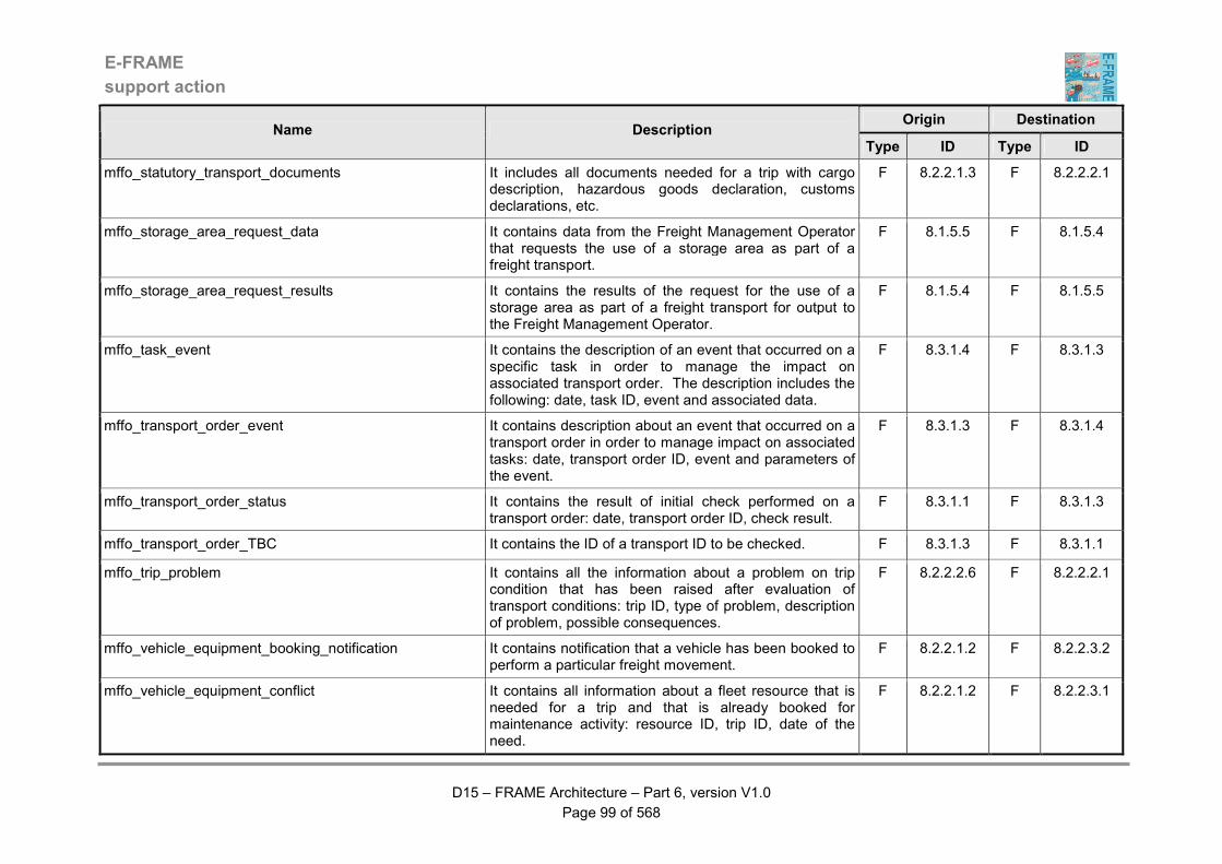
E-FRAME
support action
D15 – FRAME Architecture – Part 6, version V1.0
Page 99 of 568
Origin Destination Name Description
Type ID Type ID
mffo_statutory_transport_documents It includes all documents needed for a trip with cargo description, hazardous goods declaration, customs declarations, etc.
F 8.2.2.1.3 F 8.2.2.2.1
mffo_storage_area_request_data It contains data from the Freight Management Operator that requests the use of a storage area as part of a freight transport.
F 8.1.5.5 F 8.1.5.4
mffo_storage_area_request_results It contains the results of the request for the use of a storage area as part of a freight transport for output to the Freight Management Operator.
F 8.1.5.4 F 8.1.5.5
mffo_task_event It contains the description of an event that occurred on a specific task in order to manage the impact on associated transport order. The description includes the following: date, task ID, event and associated data.
F 8.3.1.4 F 8.3.1.3
mffo_transport_order_event It contains description about an event that occurred on a transport order in order to manage impact on associated tasks: date, transport order ID, event and parameters of the event.
F 8.3.1.3 F 8.3.1.4
mffo_transport_order_status It contains the result of initial check performed on a transport order: date, transport order ID, check result.
F 8.3.1.1 F 8.3.1.3
mffo_transport_order_TBC It contains the ID of a transport ID to be checked. F 8.3.1.3 F 8.3.1.1
mffo_trip_problem It contains all the information about a problem on trip condition that has been raised after evaluation of transport conditions: trip ID, type of problem, description of problem, possible consequences.
F 8.2.2.2.6 F 8.2.2.2.1
mffo_vehicle_equipment_booking_notification It contains notification that a vehicle has been booked to perform a particular freight movement.
F 8.2.2.1.2 F 8.2.2.3.2
mffo_vehicle_equipment_conflict It contains all information about a fleet resource that is needed for a trip and that is already booked for maintenance activity: resource ID, trip ID, date of the need.
F 8.2.2.1.2 F 8.2.2.3.1
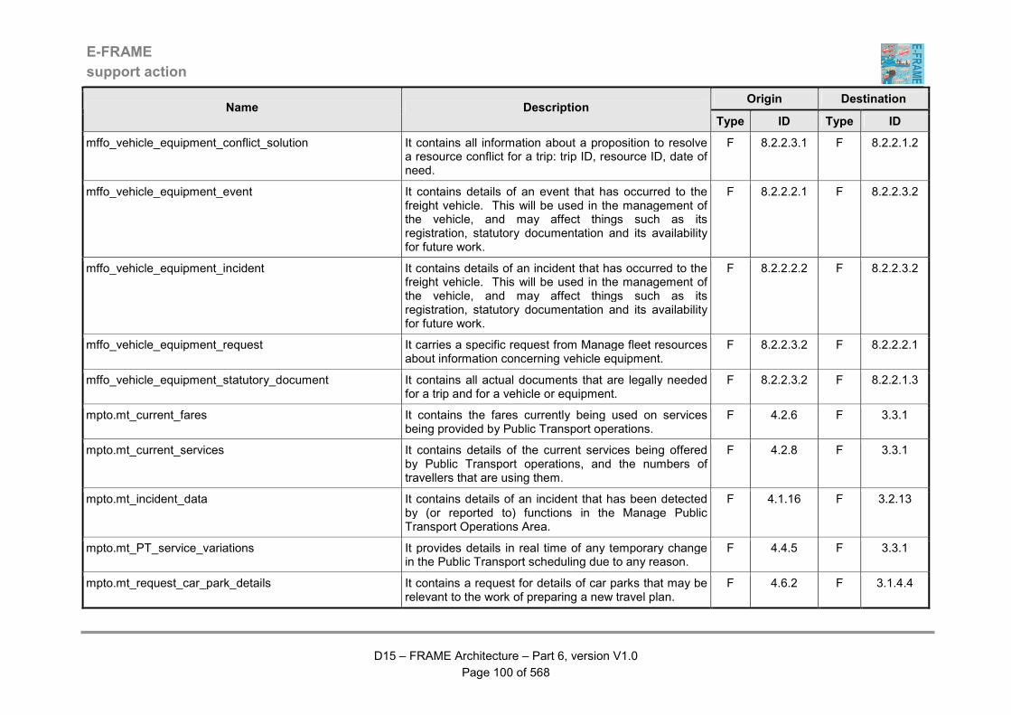
E-FRAME
support action
D15 – FRAME Architecture – Part 6, version V1.0
Page 100 of 568
Origin Destination Name Description
Type ID Type ID
mffo_vehicle_equipment_conflict_solution It contains all information about a proposition to resolve a resource conflict for a trip: trip ID, resource ID, date of need.
F 8.2.2.3.1 F 8.2.2.1.2
mffo_vehicle_equipment_event It contains details of an event that has occurred to the freight vehicle. This will be used in the management of the vehicle, and may affect things such as its registration, statutory documentation and its availability for future work.
F 8.2.2.2.1 F 8.2.2.3.2
mffo_vehicle_equipment_incident It contains details of an incident that has occurred to the freight vehicle. This will be used in the management of the vehicle, and may affect things such as its registration, statutory documentation and its availability for future work.
F 8.2.2.2.2 F 8.2.2.3.2
mffo_vehicle_equipment_request It carries a specific request from Manage fleet resources about information concerning vehicle equipment.
F 8.2.2.3.2 F 8.2.2.2.1
mffo_vehicle_equipment_statutory_document It contains all actual documents that are legally needed for a trip and for a vehicle or equipment.
F 8.2.2.3.2 F 8.2.2.1.3
mpto.mt_current_fares It contains the fares currently being used on services being provided by Public Transport operations.
F 4.2.6 F 3.3.1
mpto.mt_current_services It contains details of the current services being offered by Public Transport operations, and the numbers of travellers that are using them.
F 4.2.8 F 3.3.1
mpto.mt_incident_data It contains details of an incident that has been detected by (or reported to) functions in the Manage Public Transport Operations Area.
F 4.1.16 F 3.2.13
mpto.mt_PT_service_variations It provides details in real time of any temporary change in the Public Transport scheduling due to any reason.
F 4.4.5 F 3.3.1
mpto.mt_request_car_park_details It contains a request for details of car parks that may be relevant to the work of preparing a new travel plan.
F 4.6.2 F 3.1.4.4

E-FRAME
support action
D15 – FRAME Architecture – Part 6, version V1.0
Page 101 of 568
Origin Destination Name Description
Type ID Type ID
mpto.mt_request_demand_vehicle_priority It contains a request for a Vehicle that is currently providing an On-Demand Service to be given priority at a signalised junction.
F 4.7.3 F 3.1.1.5.24
mpto.mt_request_service_area_details It contains a request for details of service areas that may be relevant to the work of preparing a new travel plan.
F 4.6.2 F 3.1.5.2
mpto.mt_vehicle_priority_request It contains a request for priority to be given to a Public Transport vehicle at a particular junction in the road network, using the central traffic management facilities.
F 4.4.6 F 3.1.1.5.24
mpto.pepf_fare_schemes It provides up-to-date details for the complete fare scheme currently used for the whole set of services provide by the Public Transport operation.
F 4.2.5 F 1.6.1
mpto.pscs_predicted_PT_vehicle_arrival_times It contains the predicted arrival times of PT Vehicles at their next stops for us in Bus Lane management.
F 4.1.6 F 9.2.3
mpto.pscs_PT_services_and_schedules It contains details of the current PT services and schedules and is for use in Bus Lane management.
F 4.2.8 F 9.2.3
mpto.psef_alarm_notification It provides details of an alarm related to a Public Transport Vehicle requiring the Emergency Service to intervene.
F 4.1.16 F 2.1.2.1
mpto.psef_PT_stop_alarm_notification It contains a request for assistance to be provided by the Emergency Services to a Traveller at a PT stop.
F 4.1.11 F 2.1.2.1
mpto.ptja_available_pt_services It provides up-to-date details of the services currently being offered to travellers by the Public Transport providers that can be of use in trip planning or as part of information that is provided to Travellers.
F 4.2.8 F 6.5.3.3
mpto.ptja_current_fares It contains information about fares for Public Transport services that can be of use in trip planning or as part of information that is provided to Travellers.
F 4.2.5 F 6.5.3.3
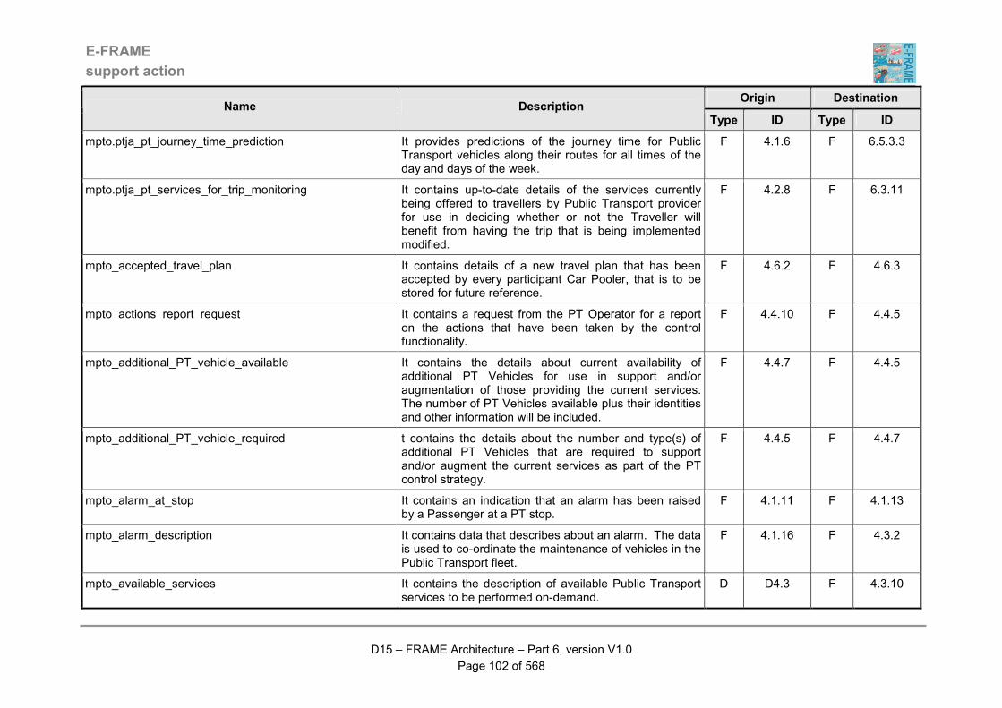
E-FRAME
support action
D15 – FRAME Architecture – Part 6, version V1.0
Page 102 of 568
Origin Destination Name Description
Type ID Type ID
mpto.ptja_pt_journey_time_prediction It provides predictions of the journey time for Public Transport vehicles along their routes for all times of the day and days of the week.
F 4.1.6 F 6.5.3.3
mpto.ptja_pt_services_for_trip_monitoring It contains up-to-date details of the services currently being offered to travellers by Public Transport provider for use in deciding whether or not the Traveller will benefit from having the trip that is being implemented modified.
F 4.2.8 F 6.3.11
mpto_accepted_travel_plan It contains details of a new travel plan that has been accepted by every participant Car Pooler, that is to be stored for future reference.
F 4.6.2 F 4.6.3
mpto_actions_report_request It contains a request from the PT Operator for a report on the actions that have been taken by the control functionality.
F 4.4.10 F 4.4.5
mpto_additional_PT_vehicle_available It contains the details about current availability of additional PT Vehicles for use in support and/or augmentation of those providing the current services. The number of PT Vehicles available plus their identities and other information will be included.
F 4.4.7 F 4.4.5
mpto_additional_PT_vehicle_required t contains the details about the number and type(s) of additional PT Vehicles that are required to support and/or augment the current services as part of the PT control strategy.
F 4.4.5 F 4.4.7
mpto_alarm_at_stop It contains an indication that an alarm has been raised by a Passenger at a PT stop.
F 4.1.11 F 4.1.13
mpto_alarm_description It contains data that describes about an alarm. The data is used to co-ordinate the maintenance of vehicles in the Public Transport fleet.
F 4.1.16 F 4.3.2
mpto_available_services It contains the description of available Public Transport services to be performed on-demand.
D D4.3 F 4.3.10

E-FRAME
support action
D15 – FRAME Architecture – Part 6, version V1.0
Page 103 of 568
Origin Destination Name Description
Type ID Type ID
mpto_calculated_service_performance It contains the calculated PT service performance in response to a previous request.
F 4.1.8 F 4.1.13
mpto_calculate_service_performance It contains a request for the performance of the PT services to be calculated.
F 4.1.13 F 4.1.8
mpto_car_pooler_details It contains details about a Car Pooler that wants to be involved in vehicle sharing and as such it represents their registration information.
F 4.6.1 F 4.6.3
mpto_car_pooler_travel_needs It contains details of the journey that a Car Poolers wants to have included in a new travel plan.
F 4.6.1 F 4.6.2
mpto_communications_from_driver It contains a message that has been provided by the PT Driver in the PT Vehicle.
F 4.1.5 F 4.1.13
mpto_communications_to_driver It contains a message that is to be sent to the PT Driver in the PT Vehicle.
F 4.1.13 F 4.1.5
mpto_complete_scheduling It contains the description of planned Public Transport services.
D D4.3 F 4.3.2
mpto_confirmed_demand_service It contains the identity of the On-Demand Service that is to be implemented.
F 4.7.2 F 4.7.3
mpto_confirmed_PT_service_change It contains conformation of a request for the PT Operator to confirm the changes to the PT services that have been requested by the management entity for another transport mode.
F 4.4.10 F 4.4.5
mpto_confirm_PT_service_change It contains a request for the PT Operator to confirm the changes to the PT services that have been requested by the management entity for another transport mode.
F 4.4.5 F 4.4.10
mpto_consolidated_vehicle_data It contains the averaged vehicle indicators to be stored in the historical archive.
F 4.1.5 D D4.2
mpto_control_actions It contains the details of the currently adopted control strategy for archiving.
F 4.4.5 D D4.2

E-FRAME
support action
D15 – FRAME Architecture – Part 6, version V1.0
Page 104 of 568
Origin Destination Name Description
Type ID Type ID
mpto_control_strategy It contains the details of the currently adopted control strategy related to the actions to undertaken on vehicles.
F 4.4.5 F 4.4.3
mpto_current_demand_criteria It contains the current criteria that are used to create routes for On-Demand Services.
F 4.7.2 F 4.7.5
mpto_current_driver_availability It contains information about the current availability of PT Drivers and is used in the process of deciding whether or not to add extra PT Vehicles to a service.
F 4.3.10 F 4.4.7
mpto_current_driver_statistics It contains the response to a previous request for the current details about a PT Driver and their current work schedule.
F 4.3.10 F 4.3.8
mpto_current_fare_credit It contains the value of credit currently available on the fare card for display to the PT Passenger.
D D4.6 F 4.5.3
mpto_current_fare_scheme It contains details of the current fare scheme(s) that are available for use by PT services.
F 4.2.6 F 4.2.5
mpto_current_PT_vehicle_data It contains the currently estimated vehicle indicators. D D4.1 F 4.4.5
mpto_deduct_fare_credit_for_journey It contains the amount of credit to be deducted from the PT Passenger's fare card for the journey that they want to make.
F 4.5.2 D D4.6
mpto_demand_service_arrival_prediction It contains the prediction of the arrival time of the On-Demand Service Vehicle at the next stop in the service schedule.
F 4.7.3 F 4.7.4
mpto_demand_service_confirmed It contains confirmation that the previously proposed On-Demand Service has been accepted by the Traveller and that any required payment has been successfully completed.
F 4.7.2 F 4.7.1
mpto_demand_service_payment_successful It contains confirmation that payment for the proposed On-Demand Service has successfully been made by the Traveller.
F 4.7.1 F 4.7.2
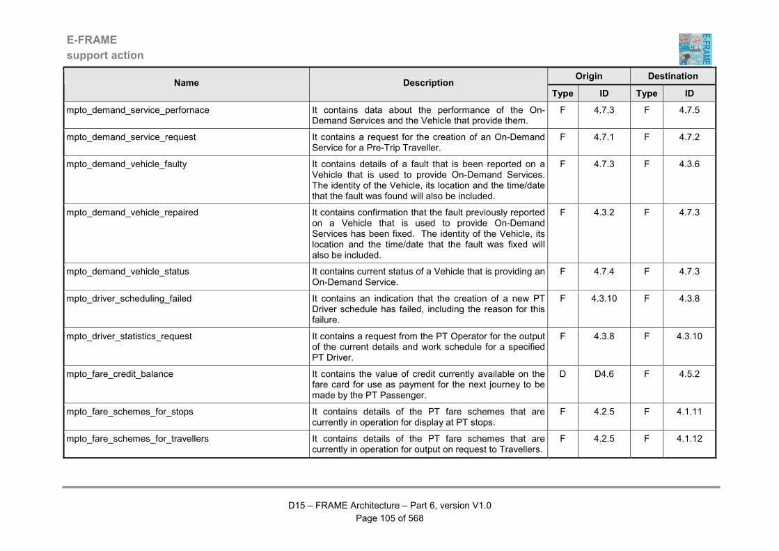
E-FRAME
support action
D15 – FRAME Architecture – Part 6, version V1.0
Page 105 of 568
Origin Destination Name Description
Type ID Type ID
mpto_demand_service_perfornace It contains data about the performance of the On-Demand Services and the Vehicle that provide them.
F 4.7.3 F 4.7.5
mpto_demand_service_request It contains a request for the creation of an On-Demand Service for a Pre-Trip Traveller.
F 4.7.1 F 4.7.2
mpto_demand_vehicle_faulty It contains details of a fault that is been reported on a Vehicle that is used to provide On-Demand Services. The identity of the Vehicle, its location and the time/date that the fault was found will also be included.
F 4.7.3 F 4.3.6
mpto_demand_vehicle_repaired It contains confirmation that the fault previously reported on a Vehicle that is used to provide On-Demand Services has been fixed. The identity of the Vehicle, its location and the time/date that the fault was fixed will also be included.
F 4.3.2 F 4.7.3
mpto_demand_vehicle_status It contains current status of a Vehicle that is providing an On-Demand Service.
F 4.7.4 F 4.7.3
mpto_driver_scheduling_failed It contains an indication that the creation of a new PT Driver schedule has failed, including the reason for this failure.
F 4.3.10 F 4.3.8
mpto_driver_statistics_request It contains a request from the PT Operator for the output of the current details and work schedule for a specified PT Driver.
F 4.3.8 F 4.3.10
mpto_fare_credit_balance It contains the value of credit currently available on the fare card for use as payment for the next journey to be made by the PT Passenger.
D D4.6 F 4.5.2
mpto_fare_schemes_for_stops It contains details of the PT fare schemes that are currently in operation for display at PT stops.
F 4.2.5 F 4.1.11
mpto_fare_schemes_for_travellers It contains details of the PT fare schemes that are currently in operation for output on request to Travellers.
F 4.2.5 F 4.1.12

E-FRAME
support action
D15 – FRAME Architecture – Part 6, version V1.0
Page 106 of 568
Origin Destination Name Description
Type ID Type ID
mpto_fare_scheme_for_PT_driver It contains details of the current fare scheme for the service that the PT Vehicle is operating that has been requested for output to the PT Driver.
F 4.2.6 F 4.5.1
mpto_fare_scheme_for_service It contains the current fare scheme for the PT service currently being performed by the PT Vehicle against which the fare card will be charged for a particular journey.
F 4.2.6 F 4.5.2
mpto_fare_scheme_planning_strategies It contains the strategies that are to be used for the preparations of new fare schemes.
F 4.2.9 F 4.2.5
mpto_fare_strategies It contains the description of the fare strategies connected to the current scheduling for Public Transport service.
F 4.2.8 F 4.2.5
mpto_faulty_equipment It contains the description of the kind of faults for the monitored equipment.
F 4.3.6 F 4.3.2
mpto_faulty_PT_stop It contains an indication that there is a fault with the operation at a PT stop.
F 4.1.11 F 4.3.6
mpto_faulty_PT_vehicle_display It contains an indication that there is a fault with the operation at a PT in-vehicle display.
F 4.1.9 F 4.3.6
mpto_historical_vehicle_data It contains the stored historical vehicle indicators. D D4.2 F 4.1.6
mpto_historical_vehicle_information It contains historical information about the performance of PT Vehicles.
F 4.1.5 F 4.1.13
mpto_load_demand_service It contains details of the On-Demand Service that is to be implemented at some point in the future and which is being stored for future reference.
F 4.7.2 D D4.8
mpto_load_demand_service_performance It contains details about how an On-Demand Service (and the Vehicles providing it) performed when it was implemented.
F 4.7.3 D D4.9
mpto_load_fare_scheme It contains a new or revised fare scheme that is to be loaded into the Fare Scheme Data Store.
F 4.2.6 D D4.5
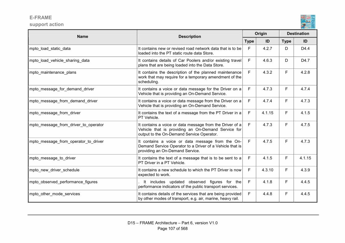
E-FRAME
support action
D15 – FRAME Architecture – Part 6, version V1.0
Page 107 of 568
Origin Destination Name Description
Type ID Type ID
mpto_load_static_data It contains new or revised road network data that is to be loaded into the PT static route data Store.
F 4.2.7 D D4.4
mpto_load_vehicle_sharing_data It contains details of Car Poolers and/or existing travel plans that are being loaded into the Data Store.
F 4.6.3 D D4.7
mpto_maintenance_plans It contains the description of the planned maintenance work that may require for a temporary amendment of the scheduling.
F 4.3.2 F 4.2.8
mpto_message_for_demand_driver It contains a voice or data message for the Driver on a Vehicle that is providing an On-Demand Service.
F 4.7.3 F 4.7.4
mpto_message_from_demand_driver It contains a voice or data message from the Driver on a Vehicle that is providing an On-Demand Service.
F 4.7.4 F 4.7.3
mpto_message_from_driver It contains the text of a message from the PT Driver in a PT Vehicle.
F 4.1.15 F 4.1.5
mpto_message_from_driver_to_operator It contains a voice or data message from the Driver of a Vehicle that is providing an On-Demand Service for output to the On-Demand Service Operator.
F 4.7.3 F 4.7.5
mpto_message_from_operator_to_driver It contains a voice or data message from the On-Demand Service Operator to a Driver of a Vehicle that is providing an On-Demand Service.
F 4.7.5 F 4.7.3
mpto_message_to_driver It contains the text of a message that is to be sent to a PT Driver in a PT Vehicle.
F 4.1.5 F 4.1.15
mpto_new_driver_schedule It contains a new schedule to which the PT Driver is now expected to work.
F 4.3.10 F 4.3.9
mpto_observed_performance_figures . It includes updated observed figures for the performance indicators of the public transport services.
F 4.1.8 F 4.4.5
mpto_other_mode_services It contains details of the services that are being provided by other modes of transport, e.g. air, marine, heavy rail.
F 4.4.8 F 4.4.5
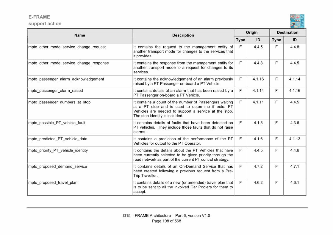
E-FRAME
support action
D15 – FRAME Architecture – Part 6, version V1.0
Page 108 of 568
Origin Destination Name Description
Type ID Type ID
mpto_other_mode_service_change_request It contains the request to the management entity of another transport mode for changes to the services that it provides.
F 4.4.5 F 4.4.8
mpto_other_mode_service_change_response It contains the response from the management entity for another transport mode to a request for changes to its services.
F 4.4.8 F 4.4.5
mpto_passenger_alarm_acknowledgement It contains the acknowledgement of an alarm previously raised by a PT Passenger on-board a PT Vehicle.
F 4.1.16 F 4.1.14
mpto_passenger_alarm_raised It contains details of an alarm that has been raised by a PT Passenger on-board a PT Vehicle.
F 4.1.14 F 4.1.16
mpto_passenger_numbers_at_stop It contains a count of the number of Passengers waiting at a PT stop and is used to determine if extra PT Vehicles are needed to support a service at the stop. The stop identity is included.
F 4.1.11 F 4.4.5
mpto_possible_PT_vehicle_fault It contains details of faults that have been detected on PT vehicles. They include those faults that do not raise alarms.
F 4.1.5 F 4.3.6
mpto_predicted_PT_vehicle_data It contains a prediction of the performance of the PT Vehicles for output to the PT Operator.
F 4.1.6 F 4.1.13
mpto_priority_PT_vehicle_identity It contains the details about the PT Vehicles that have been currently selected to be given priority through the road network as part of the current PT control strategy,.
F 4.4.5 F 4.4.6
mpto_proposed_demand_service It contains details of an On-Demand Service that has been created following a previous request from a Pre-Trip Traveller.
F 4.7.2 F 4.7.1
mpto_proposed_travel_plan It contains details of a new (or amended) travel plan that is to be sent to all the involved Car Poolers for them to accept.
F 4.6.2 F 4.6.1
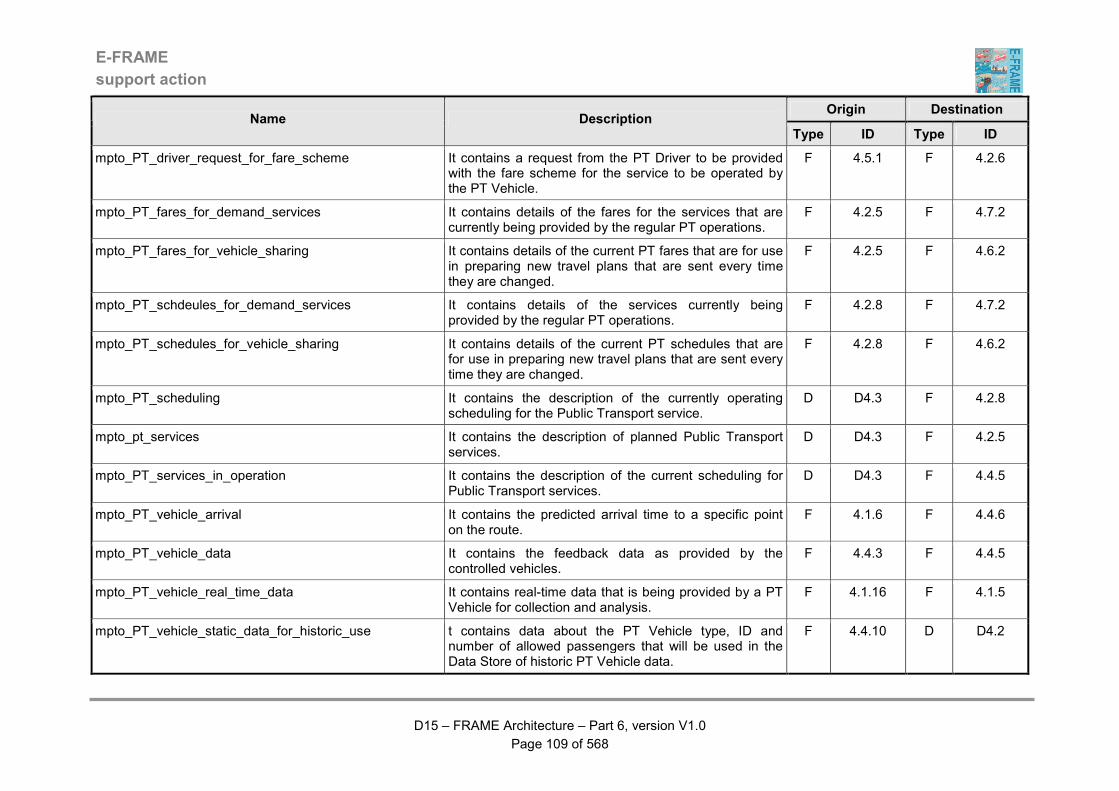
E-FRAME
support action
D15 – FRAME Architecture – Part 6, version V1.0
Page 109 of 568
Origin Destination Name Description
Type ID Type ID
mpto_PT_driver_request_for_fare_scheme It contains a request from the PT Driver to be provided with the fare scheme for the service to be operated by the PT Vehicle.
F 4.5.1 F 4.2.6
mpto_PT_fares_for_demand_services It contains details of the fares for the services that are currently being provided by the regular PT operations.
F 4.2.5 F 4.7.2
mpto_PT_fares_for_vehicle_sharing It contains details of the current PT fares that are for use in preparing new travel plans that are sent every time they are changed.
F 4.2.5 F 4.6.2
mpto_PT_schdeules_for_demand_services It contains details of the services currently being provided by the regular PT operations.
F 4.2.8 F 4.7.2
mpto_PT_schedules_for_vehicle_sharing It contains details of the current PT schedules that are for use in preparing new travel plans that are sent every time they are changed.
F 4.2.8 F 4.6.2
mpto_PT_scheduling It contains the description of the currently operating scheduling for the Public Transport service.
D D4.3 F 4.2.8
mpto_pt_services It contains the description of planned Public Transport services.
D D4.3 F 4.2.5
mpto_PT_services_in_operation It contains the description of the current scheduling for Public Transport services.
D D4.3 F 4.4.5
mpto_PT_vehicle_arrival It contains the predicted arrival time to a specific point on the route.
F 4.1.6 F 4.4.6
mpto_PT_vehicle_data It contains the feedback data as provided by the controlled vehicles.
F 4.4.3 F 4.4.5
mpto_PT_vehicle_real_time_data It contains real-time data that is being provided by a PT Vehicle for collection and analysis.
F 4.1.16 F 4.1.5
mpto_PT_vehicle_static_data_for_historic_use t contains data about the PT Vehicle type, ID and number of allowed passengers that will be used in the Data Store of historic PT Vehicle data.
F 4.4.10 D D4.2
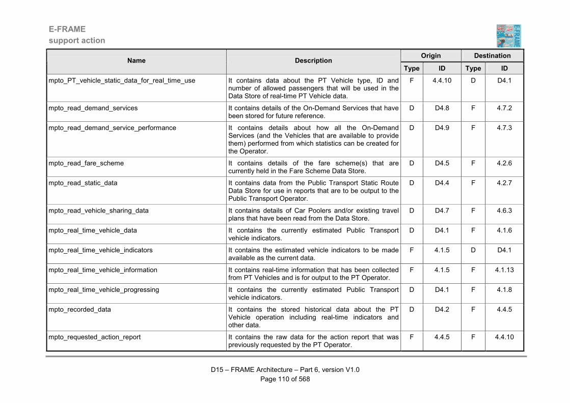
E-FRAME
support action
D15 – FRAME Architecture – Part 6, version V1.0
Page 110 of 568
Origin Destination Name Description
Type ID Type ID
mpto_PT_vehicle_static_data_for_real_time_use It contains data about the PT Vehicle type, ID and number of allowed passengers that will be used in the Data Store of real-time PT Vehicle data.
F 4.4.10 D D4.1
mpto_read_demand_services It contains details of the On-Demand Services that have been stored for future reference.
D D4.8 F 4.7.2
mpto_read_demand_service_performance It contains details about how all the On-Demand Services (and the Vehicles that are available to provide them) performed from which statistics can be created for the Operator.
D D4.9 F 4.7.3
mpto_read_fare_scheme It contains details of the fare scheme(s) that are currently held in the Fare Scheme Data Store.
D D4.5 F 4.2.6
mpto_read_static_data It contains data from the Public Transport Static Route Data Store for use in reports that are to be output to the Public Transport Operator.
D D4.4 F 4.2.7
mpto_read_vehicle_sharing_data It contains details of Car Poolers and/or existing travel plans that have been read from the Data Store.
D D4.7 F 4.6.3
mpto_real_time_vehicle_data It contains the currently estimated Public Transport vehicle indicators.
D D4.1 F 4.1.6
mpto_real_time_vehicle_indicators It contains the estimated vehicle indicators to be made available as the current data.
F 4.1.5 D D4.1
mpto_real_time_vehicle_information It contains real-time information that has been collected from PT Vehicles and is for output to the PT Operator.
F 4.1.5 F 4.1.13
mpto_real_time_vehicle_progressing It contains the currently estimated Public Transport vehicle indicators.
D D4.1 F 4.1.8
mpto_recorded_data It contains the stored historical data about the PT Vehicle operation including real-time indicators and other data.
D D4.2 F 4.4.5
mpto_requested_action_report It contains the raw data for the action report that was previously requested by the PT Operator.
F 4.4.5 F 4.4.10

E-FRAME
support action
D15 – FRAME Architecture – Part 6, version V1.0
Page 111 of 568
Origin Destination Name Description
Type ID Type ID
mpto_requested_current_travel_plan It contains details of the travel plans that were previously requested by a Car Pooler.
F 4.6.3 F 4.6.1
mpto_requested_fares_for_vehicle It contains the previously requested details of the fares for the service that the PT Vehicle is about to perform.
F 4.2.6 F 4.1.15
mpto_requested_schedule_for_vehicle It contains the previously requested details of the service that the PT Vehicle is about to perform.
F 4.2.8 F 4.1.15
mpto_requested_travel_plans It contains details of the travel plans that were previously requested as part of the work to prepare a new travel plan. Included with each of their contents will be details of all their participating Car Poolers.
F 4.6.3 F 4.6.2
mpto_requested_travel_plan_criteria It contains the previously requested criteria that are currently used to prepare new travel plans.
F 4.6.2 F 4.6.4
mpto_request_current_static_data It contains a request for a copy of the current static data that is used in the preparation of PT routes for services.
F 4.2.9 F 4.2.7
mpto_request_current_travel_plan It contains a request by a Car Pooler for details of the travel plans in which they are involved.
F 4.6.1 F 4.6.3
mpto_request_demand_criteria It contains a request for the criteria that are used to create routes for On-Demand Services.
F 4.7.5 F 4.7.2
mpto_request_demand_service_performance It contains a request for the current data about the performance of the On-Demand Services and the Vehicle that provide them.
F 4.7.5 F 4.7.3
mpto_request_existing_travel_plans It contains a request for existing travel plans that are relevant to work of creating a new travel plan.
F 4.6.2 F 4.6.3
mpto_request_fares_for_vehicle It contains a request for details of the fares that apply to the specified service to be sent to the PT Vehicle that is about to perform the service.
F 4.1.15 F 4.2.6
mpto_request_other_mode_service_details It contains a request for details of the services currently being provided by one or more other transport modes, e.g. air, marine, heavy rail.
F 4.4.5 F 4.4.8
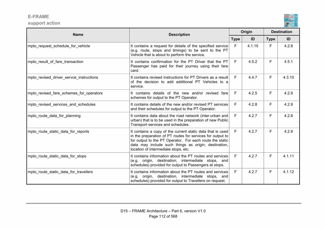
E-FRAME
support action
D15 – FRAME Architecture – Part 6, version V1.0
Page 112 of 568
Origin Destination Name Description
Type ID Type ID
mpto_request_schedule_for_vehicle It contains a request for details of the specified service (e.g. route, stops and timings) to be sent to the PT Vehicle that is about to perform the service.
F 4.1.15 F 4.2.8
mpto_result_of_fare_transaction It contains confirmation for the PT Driver that the PT Passenger has paid for their journey using their fare card.
F 4.5.2 F 4.5.1
mpto_revised_driver_servce_instructions It contains revised instructions for PT Drivers as a result of the decision to add additional PT Vehicles to a service.
F 4.4.7 F 4.3.10
mpto_revised_fare_schemes_for_operators It contains details of the new and/or revised fare schemes for output to the PT Operator.
F 4.2.5 F 4.2.9
mpto_revised_services_and_schedules It contains details of the new and/or revised PT services and their schedules for output to the PT Operator.
F 4.2.8 F 4.2.9
mpto_route_data_for_planning It contains data about the road network (inter-urban and urban) that is to be used in the preparation of new Public Transport services and schedules.
F 4.2.7 F 4.2.8
mpto_route_static_data_for_reports It contains a copy of the current static data that is used in the preparation of PT routes for services for output to for output to the PT Operator. For each route the static data may include such things as origin, destination, location of intermediate stops, etc.
F 4.2.7 F 4.2.9
mpto_route_static_data_for_stops It contains information about the PT routes and services (e.g. origin, destination, intermediate stops, and schedules) provided for output to Passengers at stops.
F 4.2.7 F 4.1.11
mpto_route_static_data_for_travellers It contains information about the PT routes and services (e.g. origin, destination, intermediate stops, and schedules) provided for output to Travellers on request.
F 4.2.7 F 4.1.12

E-FRAME
support action
D15 – FRAME Architecture – Part 6, version V1.0
Page 113 of 568
Origin Destination Name Description
Type ID Type ID
mpto_route_static_data_updates It contains updates to the current static data that is used in the preparation of PT routes for services. They will have been provided by the PT Operator and for each route may include such things as origin, destination, location of intermediate stops, etc.
F 4.2.9 F 4.2.7
mpto_service_change_information_for_stops It contains information about changes to a service that are to be output to Passengers at the relevant PT stops.
F 4.4.5 F 4.1.11
mpto_service_change_information_for_vehicles It contains information about changes to a service that are to be output to Passengers on-board PT Vehicles.
F 4.4.5 F 4.1.9
mpto_service_change_request_from_other_mode It contains a request from the management entity of another transport mode for changes to the services that are currently being provided by the PT functionality.
F 4.4.8 F 4.4.5
mpto_service_change_response_to_other_mode It contains the response from the management entity of another mode to a previous request for a change to its services.
F 4.4.5 F 4.4.8
mpto_service_data_for_reports It contains data from the Public Transport Service Plan Data Store for use in reports that are to be output to the Public Transport Operator.
D D4.3 F 4.2.9
mpto_service_information_for_passengers It contains information about the service being provided by a PT Vehicle for output to its Passengers. This information will include the predicted arrival time at the next PT stop.
F 4.1.6 F 4.1.9
mpto_service_information_for_stops It contains information about the service being provided at a PT stop for output to Passengers waiting there. This information will include the predicted arrival time of PT Vehicles at the stop.
F 4.1.6 F 4.1.11
mpto_service_information_for_travellers It contains information about PT services for output to Travellers on request. This information will include the predicted arrival time of PT Vehicles at PT stops.
F 4.1.6 F 4.1.12

E-FRAME
support action
D15 – FRAME Architecture – Part 6, version V1.0
Page 114 of 568
Origin Destination Name Description
Type ID Type ID
mpto_service_instructions_for_demand_driver It contains instructions for the On-Demand Service Driver that revise the current service so that one or more extra passengers can be included.
F 4.7.3 F 4.7.4
mpto_service_number_for_priority It contains the number of the service for which its PT Vehicles are to be requested priority.
F 4.4.5 F 4.4.6
mpto_service_planning_strategies It contains the strategies that are to be used for the preparations of new service plans.
F 4.2.9 F 4.2.8
mpto_travel_plan_accepted It contains the acceptance from a Car Pooler of a proposed new travel plan.
F 4.6.1 F 4.6.2
mpto_travel_plan_criteria_request It contains a request for the current criteria that are used to prepare new travel plans.
F 4.6.4 F 4.6.2
mpto_travel_plan_criteria_update It contains updates to the current criteria that are used to prepare new travel plans.
F 4.6.4 F 4.6.2
mpto_travel_plan_rejected It contains the rejection of a proposed travel plan by a Car Pooler.
F 4.6.1 F 4.6.2
mpto_typical_travel_times It contains the historically recorded travel time for Public Transport vehicle along the selected routes and for selected operational scenarios.
D D4.2 F 4.2.8
mpto_unused_PT_vehicle_status It contains the current status of selected PT Vehicles that are available for use to support and/or augment the current PT services because they are not currently being used.
F 4.1.16 F 4.4.7
mpto_updated_driver_details It contains updates to the current details about a PT Driver.
F 4.3.8 F 4.3.10
mpto_updated_driver_status It contains an update to the current PT Driver status, collected as a result of input from the PT Driver.
F 4.3.9 F 4.3.10
mpto_updated_fare_scheme It contains a new or revised fare scheme that has just been created.
F 4.2.5 F 4.2.6
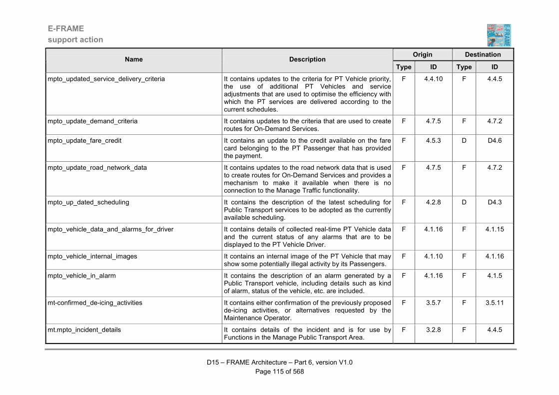
E-FRAME
support action
D15 – FRAME Architecture – Part 6, version V1.0
Page 115 of 568
Origin Destination Name Description
Type ID Type ID
mpto_updated_service_delivery_criteria It contains updates to the criteria for PT Vehicle priority, the use of additional PT Vehicles and service adjustments that are used to optimise the efficiency with which the PT services are delivered according to the current schedules.
F 4.4.10 F 4.4.5
mpto_update_demand_criteria It contains updates to the criteria that are used to create routes for On-Demand Services.
F 4.7.5 F 4.7.2
mpto_update_fare_credit It contains an update to the credit available on the fare card belonging to the PT Passenger that has provided the payment.
F 4.5.3 D D4.6
mpto_update_road_network_data It contains updates to the road network data that is used to create routes for On-Demand Services and provides a mechanism to make it available when there is no connection to the Manage Traffic functionality.
F 4.7.5 F 4.7.2
mpto_up_dated_scheduling It contains the description of the latest scheduling for Public Transport services to be adopted as the currently available scheduling.
F 4.2.8 D D4.3
mpto_vehicle_data_and_alarms_for_driver It contains details of collected real-time PT Vehicle data and the current status of any alarms that are to be displayed to the PT Vehicle Driver.
F 4.1.16 F 4.1.15
mpto_vehicle_internal_images It contains an internal image of the PT Vehicle that may show some potentially illegal activity by its Passengers.
F 4.1.10 F 4.1.16
mpto_vehicle_in_alarm It contains the description of an alarm generated by a Public Transport vehicle, including details such as kind of alarm, status of the vehicle, etc. are included.
F 4.1.16 F 4.1.5
mt-confirmed_de-icing_activities It contains either confirmation of the previously proposed de-icing activities, or alternatives requested by the Maintenance Operator.
F 3.5.7 F 3.5.11
mt.mpto_incident_details It contains details of the incident and is for use by Functions in the Manage Public Transport Area.
F 3.2.8 F 4.4.5

E-FRAME
support action
D15 – FRAME Architecture – Part 6, version V1.0
Page 116 of 568
Origin Destination Name Description
Type ID Type ID
mt.mpto_inter-urban_road_data It contains information about the inter-urban road network for use by functionality in the Manage Public Transport Area in their planning and generation of Public Transport schedules.
F 3.1.2.6 F 4.2.7
mt.mpto_inter-urban_road_data_for_demand It contains details of the inter-urban road network for the geographic area over which the On-Demand Services can be provided.
F 3.1.2.6 F 4.7.2
mt.mpto_inter-urban_road_network_details It contains details about the inter-urban road network for use in the work to prepare new travel plans.
F 3.1.2.6 F 4.6.2
mt.mpto_predicted_road_conditions_for_demand It contains details of the predicted conditions for the road network over which the On-Demand Services can be provided.
F 3.1.6.6 F 4.7.2
mt.mpto_requested_car_park_details It contains details of car parks that may be relevant to the work of preparing a new travel plan.
F 3.1.4.4 F 4.6.2
mt.mpto_requested_service_area_details It contains details of service areas that may be relevant to the work of preparing a new travel plan.
F 3.1.5.2 F 4.6.2
mt.mpto_request_demand_service_change It contains a request for a change to Public Transport services as part of a Demand Management strategy
F 3.3.7 F 4.2.8
mt.mpto_request_fares It requests a change to the current Public Transport fares and is issued as part of a Demand Management strategy has been accepted and implemented.
F 3.3.7 F 4.2.6
mt.mpto_request_incident_service_change It contains a request for a revision to the current Public Transport services to mitigate the impact of an incident.
F 3.2.8 F 4.2.8
mt.mpto_road_network_traffic_predictions It contains predictions of the future traffic conditions based on the results of a particular traffic simulation.
F 3.1.6.6 F 4.2.8
mt.mpto_traffic_management_strategies It contains new and/or updates to the current traffic management strategies that are available for use, together with the criteria for their use.
F 3.1.6.6 F 4.2.8
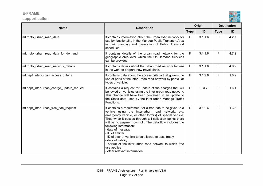
E-FRAME
support action
D15 – FRAME Architecture – Part 6, version V1.0
Page 117 of 568
Origin Destination Name Description
Type ID Type ID
mt.mpto_urban_road_data It contains information about the urban road network for use by functionality in the Manage Public Transport Area in their planning and generation of Public Transport schedules.
F 3.1.1.6 F 4.2.7
mt.mpto_urban_road_data_for_demand It contains details of the urban road network for the geographic area over which the On-Demand Services can be provided.
F 3.1.1.6 F 4.7.2
mt.mpto_urban_road_network_details It contains details about the urban road network for use in the work to prepare new travel plans.
F 3.1.1.6 F 4.6.2
mt.pepf_inter-urban_access_criteria It contains data about the access criteria that govern the use of parts of the inter-urban road network by particular types of vehicle.
F 3.1.2.6 F 1.6.2
mt.pepf_inter-urban_charge_update_request It contains a request for update of the charges that will be levied on vehicles using the inter-urban road network. This change will have been contained in an update to the Static data used by the inter-urban Manage Traffic Functions.
F 3.3.7 F 1.6.1
mt.pepf_inter-urban_free_ride_request It contains a requirement for a free ride to be given to a vehicle using the inter-urban road network, e.g. emergency vehicle, or other form(s) of special vehicle. Thus when it passes through toll collection points there will be no payment control . The data flow includes the following information: - date of message - ID of emitter - ID of user or vehicle to be allowed to pass freely - date of validity - part(s) of the inter-urban road network to which free use applies - other relevant information
F 3.1.2.6 F 1.3.3
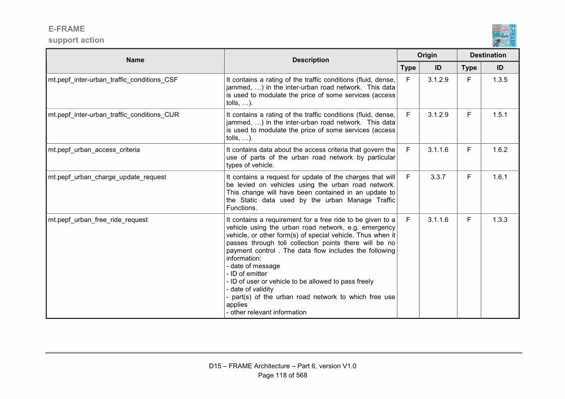
E-FRAME
support action
D15 – FRAME Architecture – Part 6, version V1.0
Page 118 of 568
Origin Destination Name Description
Type ID Type ID
mt.pepf_inter-urban_traffic_conditions_CSF It contains a rating of the traffic conditions (fluid, dense, jammed, …) in the inter-urban road network. This data is used to modulate the price of some services (access tolls, …).
F 3.1.2.9 F 1.3.5
mt.pepf_inter-urban_traffic_conditions_CUR It contains a rating of the traffic conditions (fluid, dense, jammed, …) in the inter-urban road network. This data is used to modulate the price of some services (access tolls, …).
F 3.1.2.9 F 1.5.1
mt.pepf_urban_access_criteria It contains data about the access criteria that govern the use of parts of the urban road network by particular types of vehicle.
F 3.1.1.6 F 1.6.2
mt.pepf_urban_charge_update_request It contains a request for update of the charges that will be levied on vehicles using the urban road network. This change will have been contained in an update to the Static data used by the urban Manage Traffic Functions.
F 3.3.7 F 1.6.1
mt.pepf_urban_free_ride_request It contains a requirement for a free ride to be given to a vehicle using the urban road network, e.g. emergency vehicle, or other form(s) of special vehicle. Thus when it passes through toll collection points there will be no payment control . The data flow includes the following information: - date of message - ID of emitter - ID of user or vehicle to be allowed to pass freely - date of validity - part(s) of the urban road network to which free use applies - other relevant information
F 3.1.1.6 F 1.3.3

E-FRAME
support action
D15 – FRAME Architecture – Part 6, version V1.0
Page 119 of 568
Origin Destination Name Description
Type ID Type ID
mt.pepf_urban_traffic_conditions_CSF It contains a rating of the traffic conditions (fluid, dense, jammed, …) in the urban road network. This data is used to modulate the price of some services (access tolls, …).
F 3.1.1.9 F 1.3.5
mt.pepf_urban_traffic_conditions_CUR It contains a rating of the traffic conditions (fluid, dense, jammed, …) in the urban road network. This data is used to modulate the price of some services (access tolls, …).
F 3.1.1.9 F 1.5.1
mt.pscs_current_inter-urban_traffic_conditions It contains data providing details of the current traffic conditions in the inter-urban road network.
F 3.1.2.9 F 9.2.3
mt.pscs_current_urban_traffic_conditions It contains data providing details of the current traffic conditions in the urban road network.
F 3.1.1.9 F 9.2.3
mt.pscs_green_wave_result It contains a response indicating that the result of the previous request for a green wave. The response may be success, or failure, and a recommended speed may be included in the success response.
F 3.1.1.5.24 F 9.1.2
mt.pscs_hazardous_goods_vehicle_demand_strategy It contains details of any restrictions that have been placed on the use of parts of the road network as part of a demand management strategy.
F 3.3.7 F 9.4.2
mt.pscs_hazardous_goods_vehicle_incedent_strategy It contains details of geographic areas and/or parts of the road network that a Vehicle carrying Hazardous Goods must avoid because an incident has occurred.
F 3.2.8 F 9.4.2
mt.pscs_inter-urban_road_network_data It contains data about the inter-urban road network that is used in the management of Bus Lane use.
F 3.1.2.6 F 9.2.3
mt.pscs_local_priority_request_result It contains a response indicating the result of the previous request for local priority at the next signalised road junction. The result may be success, or failure, and a recommended speed may be included in the success response.
F 3.1.1.5.22 F 9.1.2
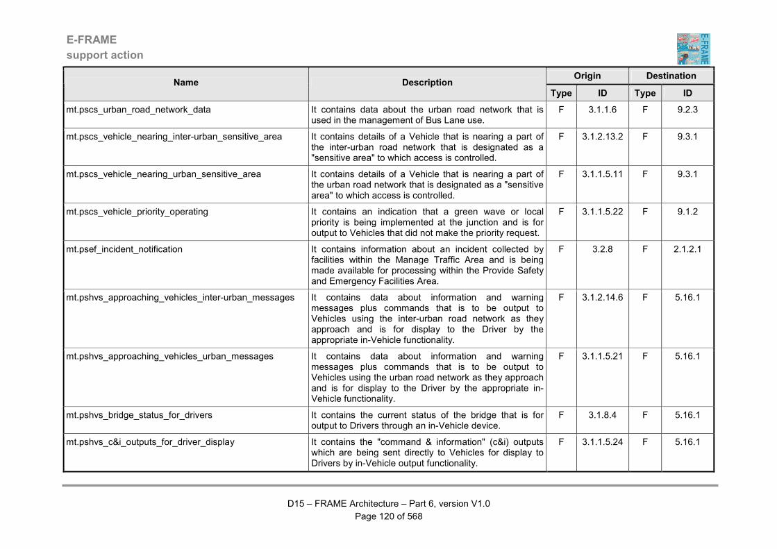
E-FRAME
support action
D15 – FRAME Architecture – Part 6, version V1.0
Page 120 of 568
Origin Destination Name Description
Type ID Type ID
mt.pscs_urban_road_network_data It contains data about the urban road network that is used in the management of Bus Lane use.
F 3.1.1.6 F 9.2.3
mt.pscs_vehicle_nearing_inter-urban_sensitive_area It contains details of a Vehicle that is nearing a part of the inter-urban road network that is designated as a "sensitive area" to which access is controlled.
F 3.1.2.13.2 F 9.3.1
mt.pscs_vehicle_nearing_urban_sensitive_area It contains details of a Vehicle that is nearing a part of the urban road network that is designated as a "sensitive area" to which access is controlled.
F 3.1.1.5.11 F 9.3.1
mt.pscs_vehicle_priority_operating It contains an indication that a green wave or local priority is being implemented at the junction and is for output to Vehicles that did not make the priority request.
F 3.1.1.5.22 F 9.1.2
mt.psef_incident_notification It contains information about an incident collected by facilities within the Manage Traffic Area and is being made available for processing within the Provide Safety and Emergency Facilities Area.
F 3.2.8 F 2.1.2.1
mt.pshvs_approaching_vehicles_inter-urban_messages It contains data about information and warning messages plus commands that is to be output to Vehicles using the inter-urban road network as they approach and is for display to the Driver by the appropriate in-Vehicle functionality.
F 3.1.2.14.6 F 5.16.1
mt.pshvs_approaching_vehicles_urban_messages It contains data about information and warning messages plus commands that is to be output to Vehicles using the urban road network as they approach and is for display to the Driver by the appropriate in-Vehicle functionality.
F 3.1.1.5.21 F 5.16.1
mt.pshvs_bridge_status_for_drivers It contains the current status of the bridge that is for output to Drivers through an in-Vehicle device.
F 3.1.8.4 F 5.16.1
mt.pshvs_c&i_outputs_for_driver_display It contains the "command & information" (c&i) outputs which are being sent directly to Vehicles for display to Drivers by in-Vehicle output functionality.
F 3.1.1.5.24 F 5.16.1
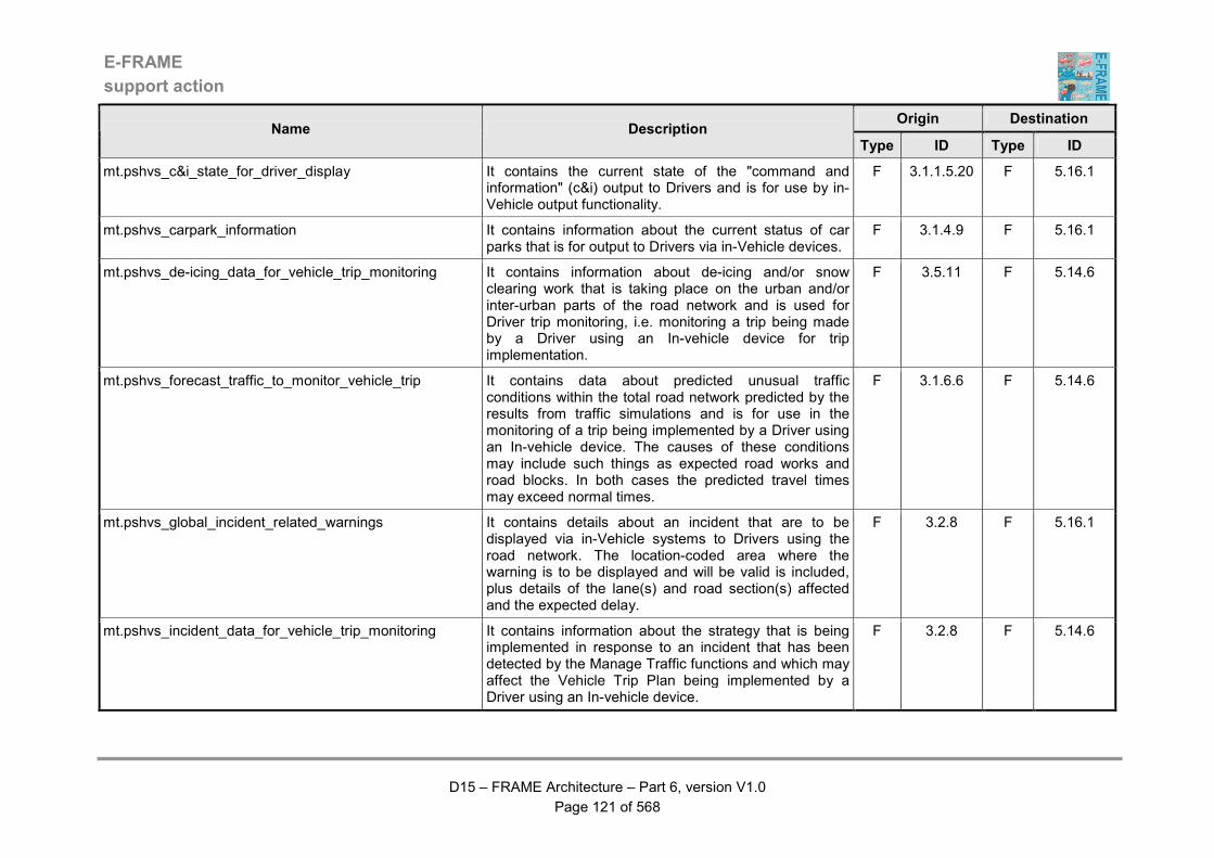
E-FRAME
support action
D15 – FRAME Architecture – Part 6, version V1.0
Page 121 of 568
Origin Destination Name Description
Type ID Type ID
mt.pshvs_c&i_state_for_driver_display It contains the current state of the "command and information" (c&i) output to Drivers and is for use by in-Vehicle output functionality.
F 3.1.1.5.20 F 5.16.1
mt.pshvs_carpark_information It contains information about the current status of car parks that is for output to Drivers via in-Vehicle devices.
F 3.1.4.9 F 5.16.1
mt.pshvs_de-icing_data_for_vehicle_trip_monitoring It contains information about de-icing and/or snow clearing work that is taking place on the urban and/or inter-urban parts of the road network and is used for Driver trip monitoring, i.e. monitoring a trip being made by a Driver using an In-vehicle device for trip implementation.
F 3.5.11 F 5.14.6
mt.pshvs_forecast_traffic_to_monitor_vehicle_trip It contains data about predicted unusual traffic conditions within the total road network predicted by the results from traffic simulations and is for use in the monitoring of a trip being implemented by a Driver using an In-vehicle device. The causes of these conditions may include such things as expected road works and road blocks. In both cases the predicted travel times may exceed normal times.
F 3.1.6.6 F 5.14.6
mt.pshvs_global_incident_related_warnings It contains details about an incident that are to be displayed via in-Vehicle systems to Drivers using the road network. The location-coded area where the warning is to be displayed and will be valid is included, plus details of the lane(s) and road section(s) affected and the expected delay.
F 3.2.8 F 5.16.1
mt.pshvs_incident_data_for_vehicle_trip_monitoring It contains information about the strategy that is being implemented in response to an incident that has been detected by the Manage Traffic functions and which may affect the Vehicle Trip Plan being implemented by a Driver using an In-vehicle device.
F 3.2.8 F 5.14.6
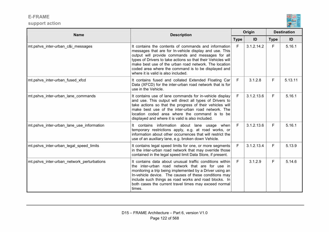
E-FRAME
support action
D15 – FRAME Architecture – Part 6, version V1.0
Page 122 of 568
Origin Destination Name Description
Type ID Type ID
mt.pshvs_inter-urban_c&i_messages It contains the contents of commands and information messages that are for In-vehicle display and use. This output will provide commands and messages for all types of Drivers to take actions so that their Vehicles will make best use of the urban road network. The location coded area where the command is to be displayed and where it is valid is also included.
F 3.1.2.14.2 F 5.16.1
mt.pshvs_inter-urban_fused_xfcd It contains fused and collated Extended Floating Car Data (XFCD) for the inter-urban road network that is for use in the Vehicle.
F 3.1.2.8 F 5.13.11
mt.pshvs_inter-urban_lane_commands It contains use of lane commands for in-vehicle display and use. This output will direct all types of Drivers to take actions so that the progress of their vehicles will make best use of the inter-urban road network. The location coded area where the command is to be displayed and where it is valid is also included.
F 3.1.2.13.6 F 5.16.1
mt.pshvs_inter-urban_lane_use_information It contains information about lane usage when temporary restrictions apply, e.g. at road works, or information about other occurrences that will restrict the use of an auxiliary lane, e.g. broken down Vehicle.
F 3.1.2.13.6 F 5.16.1
mt.pshvs_inter-urban_legal_speed_limits It contains legal speed limits for one, or more segments in the inter-urban road network that may override those contained in the legal speed limit Data Store, if present.
F 3.1.2.13.4 F 5.13.9
mt.pshvs_inter-urban_network_perturbations It contains data about unusual traffic conditions within the inter-urban road network that are for use in monitoring a trip being implemented by a Driver using an In-vehicle device. The causes of these conditions may include such things as road works and road blocks. In both cases the current travel times may exceed normal times.
F 3.1.2.9 F 5.14.6
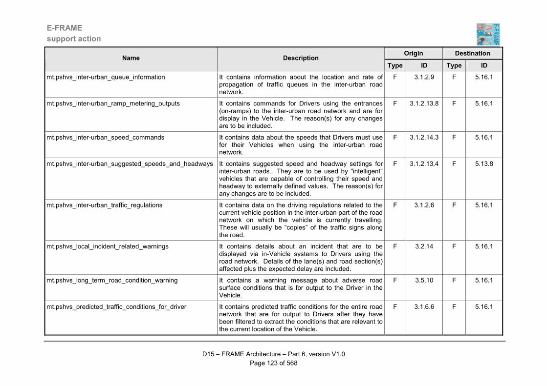
E-FRAME
support action
D15 – FRAME Architecture – Part 6, version V1.0
Page 123 of 568
Origin Destination Name Description
Type ID Type ID
mt.pshvs_inter-urban_queue_information It contains information about the location and rate of propagation of traffic queues in the inter-urban road network.
F 3.1.2.9 F 5.16.1
mt.pshvs_inter-urban_ramp_metering_outputs It contains commands for Drivers using the entrances (on-ramps) to the inter-urban road network and are for display in the Vehicle. The reason(s) for any changes are to be included.
F 3.1.2.13.8 F 5.16.1
mt.pshvs_inter-urban_speed_commands It contains data about the speeds that Drivers must use for their Vehicles when using the inter-urban road network.
F 3.1.2.14.3 F 5.16.1
mt.pshvs_inter-urban_suggested_speeds_and_headways It contains suggested speed and headway settings for inter-urban roads. They are to be used by "intelligent" vehicles that are capable of controlling their speed and headway to externally defined values. The reason(s) for any changes are to be included.
F 3.1.2.13.4 F 5.13.8
mt.pshvs_inter-urban_traffic_regulations It contains data on the driving regulations related to the current vehicle position in the inter-urban part of the road network on which the vehicle is currently travelling. These will usually be “copies” of the traffic signs along the road.
F 3.1.2.6 F 5.16.1
mt.pshvs_local_incident_related_warnings It contains details about an incident that are to be displayed via in-Vehicle systems to Drivers using the road network. Details of the lane(s) and road section(s) affected plus the expected delay are included.
F 3.2.14 F 5.16.1
mt.pshvs_long_term_road_condition_warning It contains a warning message about adverse road surface conditions that is for output to the Driver in the Vehicle.
F 3.5.10 F 5.16.1
mt.pshvs_predicted_traffic_conditions_for_driver It contains predicted traffic conditions for the entire road network that are for output to Drivers after they have been filtered to extract the conditions that are relevant to the current location of the Vehicle.
F 3.1.6.6 F 5.16.1
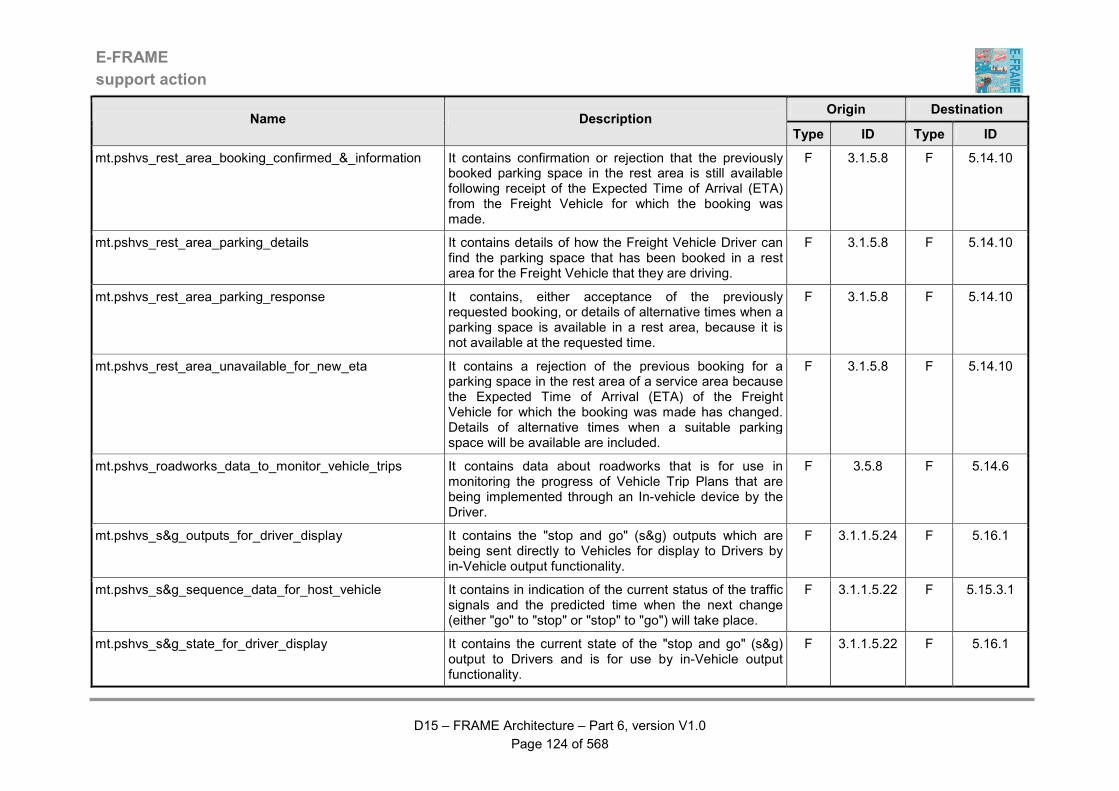
E-FRAME
support action
D15 – FRAME Architecture – Part 6, version V1.0
Page 124 of 568
Origin Destination Name Description
Type ID Type ID
mt.pshvs_rest_area_booking_confirmed_&_information It contains confirmation or rejection that the previously booked parking space in the rest area is still available following receipt of the Expected Time of Arrival (ETA) from the Freight Vehicle for which the booking was made.
F 3.1.5.8 F 5.14.10
mt.pshvs_rest_area_parking_details It contains details of how the Freight Vehicle Driver can find the parking space that has been booked in a rest area for the Freight Vehicle that they are driving.
F 3.1.5.8 F 5.14.10
mt.pshvs_rest_area_parking_response It contains, either acceptance of the previously requested booking, or details of alternative times when a parking space is available in a rest area, because it is not available at the requested time.
F 3.1.5.8 F 5.14.10
mt.pshvs_rest_area_unavailable_for_new_eta It contains a rejection of the previous booking for a parking space in the rest area of a service area because the Expected Time of Arrival (ETA) of the Freight Vehicle for which the booking was made has changed. Details of alternative times when a suitable parking space will be available are included.
F 3.1.5.8 F 5.14.10
mt.pshvs_roadworks_data_to_monitor_vehicle_trips It contains data about roadworks that is for use in monitoring the progress of Vehicle Trip Plans that are being implemented through an In-vehicle device by the Driver.
F 3.5.8 F 5.14.6
mt.pshvs_s&g_outputs_for_driver_display It contains the "stop and go" (s&g) outputs which are being sent directly to Vehicles for display to Drivers by in-Vehicle output functionality.
F 3.1.1.5.24 F 5.16.1
mt.pshvs_s&g_sequence_data_for_host_vehicle It contains in indication of the current status of the traffic signals and the predicted time when the next change (either "go" to "stop" or "stop" to "go") will take place.
F 3.1.1.5.22 F 5.15.3.1
mt.pshvs_s&g_state_for_driver_display It contains the current state of the "stop and go" (s&g) output to Drivers and is for use by in-Vehicle output functionality.
F 3.1.1.5.22 F 5.16.1
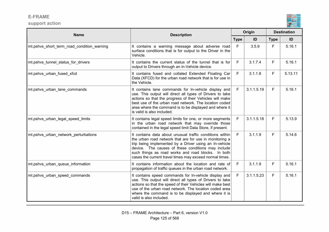
E-FRAME
support action
D15 – FRAME Architecture – Part 6, version V1.0
Page 125 of 568
Origin Destination Name Description
Type ID Type ID
mt.pshvs_short_term_road_condition_warning It contains a warning message about adverse road surface conditions that is for output to the Driver in the Vehicle.
F 3.5.9 F 5.16.1
mt.pshvs_tunnel_status_for_drivers It contains the current status of the tunnel that is for output to Drivers through an in-Vehicle device.
F 3.1.7.4 F 5.16.1
mt.pshvs_urban_fused_xfcd It contains fused and collated Extended Floating Car Data (XFCD) for the urban road network that is for use in the Vehicle.
F 3.1.1.8 F 5.13.11
mt.pshvs_urban_lane_commands It contains lane commands for In-vehicle display and use. This output will direct all types of Drivers to take actions so that the progress of their Vehicles will make best use of the urban road network. The location coded area where the command is to be displayed and where it is valid is also included.
F 3.1.1.5.19 F 5.16.1
mt.pshvs_urban_legal_speed_limits It contains legal speed limits for one, or more segments in the urban road network that may override those contained in the legal speed limit Data Store, if present.
F 3.1.1.5.18 F 5.13.9
mt.pshvs_urban_network_perturbations It contains data about unusual traffic conditions within the urban road network that are for use in monitoring a trip being implemented by a Driver using an In-vehicle device. The causes of these conditions may include such things as road works and road blocks. In both cases the current travel times may exceed normal times.
F 3.1.1.9 F 5.14.6
mt.pshvs_urban_queue_information It contains information about the location and rate of propagation of traffic queues in the urban road network.
F 3.1.1.9 F 5.16.1
mt.pshvs_urban_speed_commands It contains speed commands for In-vehicle display and use. This output will direct all types of Drivers to take actions so that the speed of their Vehicles will make best use of the urban road network. The location coded area where the command is to be displayed and where it is valid is also included.
F 3.1.1.5.23 F 5.16.1

E-FRAME
support action
D15 – FRAME Architecture – Part 6, version V1.0
Page 126 of 568
Origin Destination Name Description
Type ID Type ID
mt.pshvs_urban_suggested_speeds_and_headways It contains suggested speed and headway settings for urban roads. They are to be used by "intelligent" vehicles that are capable of controlling their speed and headway to an externally defined value. The reason(s) for any changes are to be included.
F 3.1.1.5.18 F 5.13.8
mt.pshvs_urban_traffic_regulations It contains data on the driving regulations related to the current vehicle position in the urban part of the road network on which the vehicle is currently travelling. These will usually be “copies” of the traffic signs along the road.
F 3.1.1.6 F 5.16.1
mt.pshvs_vehicle_s&g_input It contains data about the length of time that the Driver of the Vehicle will see a red (stop) signal at a junction and shall enable the Vehicle System to decide whether or not it wants to shut down the Vehicle's engine for this period of time.
F 3.1.1.5.22 F 5.12.7
mt.pshvs_weather_data_for_vehicle_trip_monitoring It contains general weather information that is used to monitor the implementation of a Vehicle Trip Plan by a Driver using an In-vehicle device.
F 3.4.11 F 5.14.6
mt.psle_illegal_carpark_space_occupancy It contains all the elements gathered by the Manage Traffic Area on a fraud affecting the use of a car park space. It includes the following elements: - reference - date - length of time in excess of limit - image of fraud (if available) - involved user ID (if available) - involved vehicle ID (if available) - car park identity and location
F 3.1.4.3 F 7.3.5

E-FRAME
support action
D15 – FRAME Architecture – Part 6, version V1.0
Page 127 of 568
Origin Destination Name Description
Type ID Type ID
mt.psle_inter-urban_enforcement_guidelines_CC It contains the recommendations established by the Manage Traffic area for the enforcement of rules in the inter-urban road network. The data flow includes the following elements: - date - period of validity of guidelines - area concerned - types of fraud concerned - for each type of fraud : level of fraud over which notification and / or prosecution is required, according to environmental conditions (weather, traffic conditions, …)
F 3.1.2.6 F 7.1.2
mt.psle_inter-urban_enforcement_guidelines_PF It contains the recommendations established by the Manage Traffic area for the enforcement of rules in the inter-urban road network. The data flow includes the following elements: - date - period of validity of guidelines - area concerned - types of fraud concerned - for each type of fraud : level of fraud over which notification and / or prosecution is required, according to environmental conditions (weather, traffic conditions, …)
F 3.1.2.6 F 7.1.3
mt.psle_inter-urban_vehicle_identity_error It contains an indication that a lack of correspondence has been found between the image of a Vehicle using the inter-urban road network, its registration data, or the identity in has included in any FCD/XFCD that it has provided. All of the relevant data is included, such as the Vehicle image, the registration data and if available the FCD/XFCD identity.
F 3.1.2.12 F 7.3.5
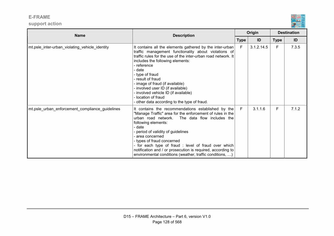
E-FRAME
support action
D15 – FRAME Architecture – Part 6, version V1.0
Page 128 of 568
Origin Destination Name Description
Type ID Type ID
mt.psle_inter-urban_violating_vehicle_identity It contains all the elements gathered by the inter-urban traffic management functionality about violations of traffic rules for the use of the inter-urban road network. It includes the following elements: - reference - date - type of fraud - result of fraud - image of fraud (if available) - involved user ID (if available) - involved vehicle ID (if available) - location of fraud - other data according to the type of fraud.
F 3.1.2.14.5 F 7.3.5
mt.psle_urban_enforcement_compliance_guidelines It contains the recommendations established by the "Manage Traffic" area for the enforcement of rules in the urban road network. The data flow includes the following elements: - date - period of validity of guidelines - area concerned - types of fraud concerned - for each type of fraud : level of fraud over which notification and / or prosecution is required, according to environmental conditions (weather, traffic conditions, …)
F 3.1.1.6 F 7.1.2
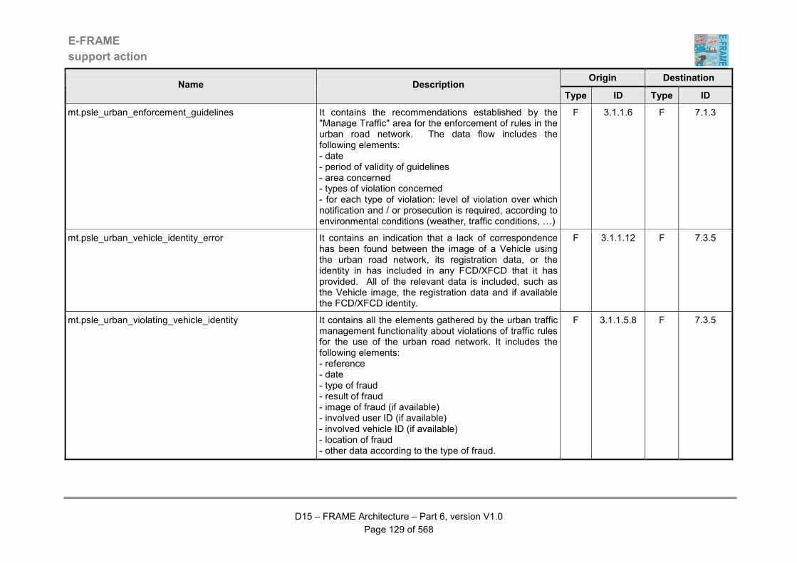
E-FRAME
support action
D15 – FRAME Architecture – Part 6, version V1.0
Page 129 of 568
Origin Destination Name Description
Type ID Type ID
mt.psle_urban_enforcement_guidelines It contains the recommendations established by the "Manage Traffic" area for the enforcement of rules in the urban road network. The data flow includes the following elements: - date - period of validity of guidelines - area concerned - types of violation concerned - for each type of violation: level of violation over which notification and / or prosecution is required, according to environmental conditions (weather, traffic conditions, …)
F 3.1.1.6 F 7.1.3
mt.psle_urban_vehicle_identity_error It contains an indication that a lack of correspondence has been found between the image of a Vehicle using the urban road network, its registration data, or the identity in has included in any FCD/XFCD that it has provided. All of the relevant data is included, such as the Vehicle image, the registration data and if available the FCD/XFCD identity.
F 3.1.1.12 F 7.3.5
mt.psle_urban_violating_vehicle_identity It contains all the elements gathered by the urban traffic management functionality about violations of traffic rules for the use of the urban road network. It includes the following elements: - reference - date - type of fraud - result of fraud - image of fraud (if available) - involved user ID (if available) - involved vehicle ID (if available) - location of fraud - other data according to the type of fraud.
F 3.1.1.5.8 F 7.3.5
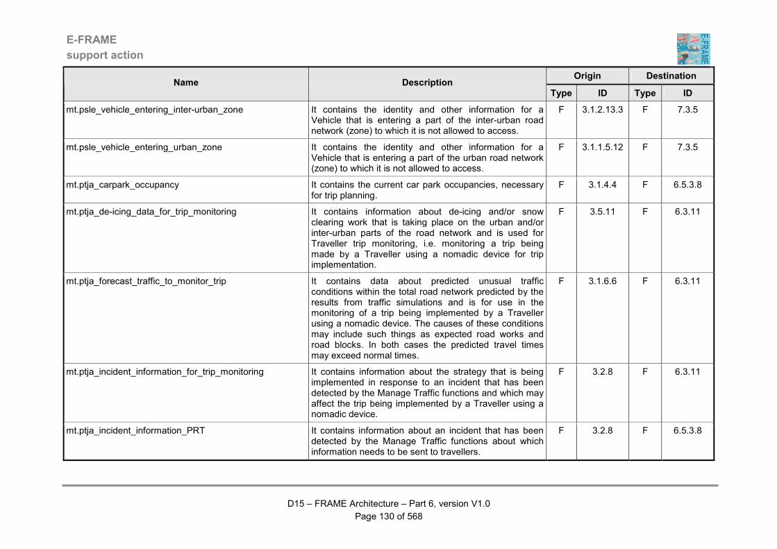
E-FRAME
support action
D15 – FRAME Architecture – Part 6, version V1.0
Page 130 of 568
Origin Destination Name Description
Type ID Type ID
mt.psle_vehicle_entering_inter-urban_zone It contains the identity and other information for a Vehicle that is entering a part of the inter-urban road network (zone) to which it is not allowed to access.
F 3.1.2.13.3 F 7.3.5
mt.psle_vehicle_entering_urban_zone It contains the identity and other information for a Vehicle that is entering a part of the urban road network (zone) to which it is not allowed to access.
F 3.1.1.5.12 F 7.3.5
mt.ptja_carpark_occupancy It contains the current car park occupancies, necessary for trip planning.
F 3.1.4.4 F 6.5.3.8
mt.ptja_de-icing_data_for_trip_monitoring It contains information about de-icing and/or snow clearing work that is taking place on the urban and/or inter-urban parts of the road network and is used for Traveller trip monitoring, i.e. monitoring a trip being made by a Traveller using a nomadic device for trip implementation.
F 3.5.11 F 6.3.11
mt.ptja_forecast_traffic_to_monitor_trip It contains data about predicted unusual traffic conditions within the total road network predicted by the results from traffic simulations and is for use in the monitoring of a trip being implemented by a Traveller using a nomadic device. The causes of these conditions may include such things as expected road works and road blocks. In both cases the predicted travel times may exceed normal times.
F 3.1.6.6 F 6.3.11
mt.ptja_incident_information_for_trip_monitoring It contains information about the strategy that is being implemented in response to an incident that has been detected by the Manage Traffic functions and which may affect the trip being implemented by a Traveller using a nomadic device.
F 3.2.8 F 6.3.11
mt.ptja_incident_information_PRT It contains information about an incident that has been detected by the Manage Traffic functions about which information needs to be sent to travellers.
F 3.2.8 F 6.5.3.8
E-FRAME
support action
D15 – FRAME Architecture – Part 6, version V1.0
Page 131 of 568
Origin Destination Name Description
Type ID Type ID
mt.ptja_inter-urban_network_conditions It contains data about current traffic conditions within the inter-urban road network. These conditions will include actual traffic flows and journey times for each segment of the inter-urban road network.
F 3.1.2.9 F 6.5.3.8
mt.ptja_inter-urban_network_perturbations It contains data about unusual traffic conditions within the inter-urban road network that are for use in monitoring a trip being implemented by a Traveller using a nomadic device. The causes of these conditions may include such things as road works and road blocks. In both cases the current travel times may exceed normal times.
F 3.1.2.9 F 6.3.11
mt.ptja_inter-urban_recommended_routes It contains routes through the inter-urban road network that are being recommended by the TCC, either as a result of Operator input, or as part of a traffic management strategy. The recommended routes may apply to all Vehicles or to specific type(s) of Vehicle.
F 3.1.2.13.5 F 6.5.3.9
mt.ptja_inter-urban_road_network_data It contains static data about the inter-urban road network for use in trip plan preparation.
F 3.1.2.6 F 6.5.3.8
mt.ptja_pollution It contains ambient conditions information about air pollution levels in a certain areas to support freight route planning. In case of severe pollution some kinds of transport may be forbidden. So such an area has to be circumvented.
F 3.4.11 F 6.5.3.8
mt.ptja_roadworks_information_for_trip_monitoring It contains information about roadworks that are taking place within the road network and is for use in trip planning for Travellers.
F 3.5.8 F 6.3.11
mt.ptja_road_network_traffic_predictions It contains predictions of the future traffic conditions within the total road network based on the results from traffic simulations.
F 3.1.6.6 F 6.5.3.8
E-FRAME
support action
D15 – FRAME Architecture – Part 6, version V1.0
Page 132 of 568
Origin Destination Name Description
Type ID Type ID
mt.ptja_service_area_occupancy It contains details of the occupancy of the service area for different types of vehicles. These are heavy goods vehicles, coaches/buses and cars.
F 3.1.5.2 F 6.5.3.8
mt.ptja_urban_network_conditions It contains data about current traffic conditions within the urban road network. These conditions will include actual traffic flows and journey times for each segment of the urban road network.
F 3.1.1.9 F 6.5.3.8
mt.ptja_urban_network_perturbations It contains data about unusual traffic conditions within the urban road network that are for use in monitoring a trip being implemented by a Traveller using a nomadic device. The causes of these conditions may include such things as road works and road blocks. In both cases the current travel times may exceed normal times.
F 3.1.1.9 F 6.3.11
mt.ptja_urban_recommended_routes It contains routes through the urban road network that are being recommended by the TCC, either as a result of Operator input, or as part of a traffic management strategy. The recommended routes may apply to all Vehicles or to specific type(s) of Vehicle.
F 3.1.1.5.24 F 6.5.3.9
mt.ptja_urban_road_network_data It contains static data about the urban road network for use in trip plan preparation.
F 3.1.1.6 F 6.5.3.8
mt.ptja_walking_and_cycling_info It contains data that can be used to create information promoting walking and cycling that is to be made available to travellers. This data will be issued as part of a demand management strategy that is designed to promote the use of these modes of travel.
F 3.3.7 F 6.5.3.8
mt.ptja_weather_information_for_trip_monitoring It contains general weather information that is used to monitor the implementation of a trip plan by a Traveller using a nomadic device.
F 3.4.11 F 6.3.11
mt.ptja_weather_information_PRT It contains general weather information to produce an appropriate route.
F 3.4.11 F 6.5.3.8
E-FRAME
support action
D15 – FRAME Architecture – Part 6, version V1.0
Page 133 of 568
Origin Destination Name Description
Type ID Type ID
mt_actions_for_bridge_operator It contains information about actions that have been taken automatically as the result of the detection of dangerous weather conditions on a bridge, or a request for actions to be defined because none were found that were suitable for automatic execution.
F 3.1.8.1 F 3.1.8.3
mt_actions_for_tunnel_operator It contains information about actions that have been taken automatically as the result of the detection of an exceptional condition within a tunnel, or a request for actions to be defined because none were found that were suitable for automatic execution.
F 3.1.7.1 F 3.1.7.3
mt_atmospheric_pollution_data_inputs It contains data about atmospheric pollution in the geographic area managed by the System. Sensors that are part of another Function in the Manage Traffic Area will have collected this data.
F 3.4.2 F 3.4.8
mt_bridge_action_definitions It contains the definition of actions that are to be taken either immediately or in the future to manage the use of a bridge by particular types of Vehicle during certain weather conditions.
F 3.1.8.3 F 3.1.8.1
mt_bridge_action_responses It contains responses from the Bridge Operator to the list of automatically executed actions which have been implemented to counter current and forecast weather conditions that have been detected for a bridge that will endanger its use by particular types of Vehicles.
F 3.1.8.3 F 3.1.8.1
mt_bridge_dangerous_conditions It contains data about what is believed to be an incident that has been detected for a bridge and will include such things as high winds, temperatures and/or visibility that are causing problems, or and traffic congestion.
F 3.1.8.1 F 3.2.13

E-FRAME
support action
D15 – FRAME Architecture – Part 6, version V1.0
Page 134 of 568
Origin Destination Name Description
Type ID Type ID
mt_bridge_equipment_status It contains data that is being transferred from the bridge management functions to those for maintenance management. The data flow contains the current status of bridge monitoring equipment and the bridge infrastructure. This data shows whether or not the status is faulty, or that the equipment or bridge infrastructure requires maintenance.
F 3.1.8.1 F 3.5.12
mt_bridge_information_outputs It contains data that is to be output as information to Drivers and other Travellers who are on or about to cross a bridge.
F 3.1.8.1 F 3.1.8.4
mt_bridge_inter-urban_inputs It contains details of the actions that have been taken to manage the flow of traffic using one or more of the bridges within the inter-urban road network.
F 3.1.8.1 F 3.1.2.13.5
mt_bridge_urban_inputs It contains the contents of messages that have been output to Drivers concerning weather conditions that are creating a danger to Vehicles that are currently affecting, or are forecast to affect bridges within the urban road network.
F 3.1.8.1 F 3.1.1.5.24
mt_carkpark_space_occuppied It contains a count of the current number of spaces that are occupied where the detection is made for each individual parking space.
F 3.1.4.3 F 3.1.4.4
mt_carpark_entrance_exit_vehicle_detection It contains an indication that a vehicle has entered into or exited from a car park.
F 3.1.4.1 F 3.1.4.4
mt_carpark_occupancy It contains the current car park occupancy for loading into the Car Park Data Store.
F 3.1.4.4 F 3.1.4.8
mt_carpark_occupancy_data It contains data about the occupancy of car parks within the urban road network that is to be included in the store of traffic data that is available for use by other Functions serving the urban road network.
F 3.1.4.4 F 3.1.1.14
E-FRAME
support action
D15 – FRAME Architecture – Part 6, version V1.0
Page 135 of 568
Origin Destination Name Description
Type ID Type ID
mt_carpark_occupancy_for_demand_management It contains data about the occupancy of car parks within the urban road network that is to be used by the demand management group of Functions.
F 3.1.4.4 F 3.3.1
mt_carpark_occupancy_for_inter-urban It contains the identities and details of the current number of spaces (or occupancy) and/or the status of some of the car parks in the urban road network. The identities of the car parks whose data is included will be set by the source functionality.
F 3.1.4.4 F 3.1.5.3
mt_carpark_occupancy_for_output It contains the current car park occupancy for output to Drivers.
F 3.1.4.4 F 3.1.4.9
mt_carpark_output_settings It contains the settings that are used to control the output of car park and service area related messages to Drivers.
F 3.1.4.7 F 3.1.4.9
mt_carpark_space_occupancy It contains an indication that a vehicle is occupying a space in a car park that is being monitored.
F 3.1.4.2 F 3.1.4.3
mt_carpark_space_payment_result It contains a report that the payment by the Driver for the car park space their Vehicle is using has been refused.
F 3.1.4.6 F 3.1.4.3
mt_carpark_space_time_costs It contains the costs for different durations of stay in a car park space. This can be one figure, or several values, depending on length of stay, plus time and/or day when parking takes place.
F 3.1.4.8 F 3.1.4.6
mt_carpark_static_data It contains the current static data for all car parks. F 3.1.4.8 F 3.1.4.4
mt_carpark_status It contains the current car park status for loading into the Car Park Data Store.
F 3.1.4.4 F 3.1.4.8
mt_carpark_status_change It contains information about the latest change to the status of a car park, either as a result of changes in occupancy, or because of a change request as part of a demand management strategy.
F 3.1.4.4 F 3.1.4.7

E-FRAME
support action
D15 – FRAME Architecture – Part 6, version V1.0
Page 136 of 568
Origin Destination Name Description
Type ID Type ID
mt_carpark_status_for_output It contains the current car park status for output to Drivers.
F 3.1.4.4 F 3.1.4.9
mt_carpark_status_for_store It contains the current car park status that is to be included in the store of traffic data that is available for use by other Functions serving the urban road network. The identities of the car parks whose data is included will be set by the source functionality.
F 3.1.4.4 F 3.1.1.14
mt_collected_inter-urban_traffic_data It contains data about the way traffic is flowing in the inter-urban road network that is to be included in the store of traffic data that is available to other Functions serving the inter-urban road network.
F 3.1.2.10 F 3.1.2.16
mt_collected_inter-urban_vehicle_data It contains processed XFCD about the way traffic is flowing in the inter-urban road network plus data about the use that Vehicles are making and will make of each segment in the inter-urban road network (from Vehicle Trip Plans) that is to be included in the store of Inter-urban Traffic Data that is available to other Functions serving the inter-urban road network.
F 3.1.2.8 F 3.1.2.16
mt_collected_urban_traffic_data It contains data about the way traffic is flowing in the urban road network that is to be included in the store of traffic data that is available to other Functions serving the urban road network.
F 3.1.1.10 F 3.1.1.14
mt_collected_urban_vehicle_data It contains processed XFCD about the way traffic is flowing in the urban road network plus data about the use that Vehicles are making and will make of each segment in the urban road network (from Vehicle Trip Plans) that is to be included in the store of Urban Traffic Data that is available to other Functions serving the urban road network.
F 3.1.1.8 F 3.1.1.14
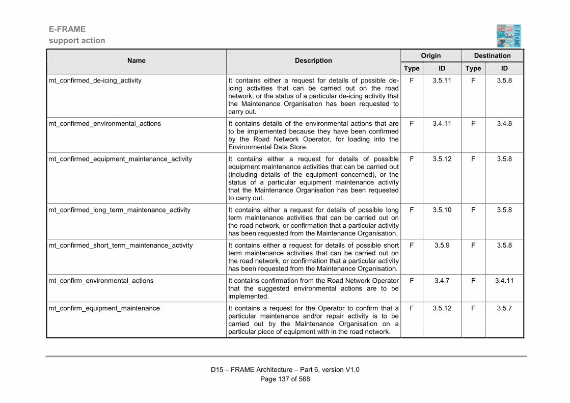
E-FRAME
support action
D15 – FRAME Architecture – Part 6, version V1.0
Page 137 of 568
Origin Destination Name Description
Type ID Type ID
mt_confirmed_de-icing_activity It contains either a request for details of possible de-icing activities that can be carried out on the road network, or the status of a particular de-icing activity that the Maintenance Organisation has been requested to carry out.
F 3.5.11 F 3.5.8
mt_confirmed_environmental_actions It contains details of the environmental actions that are to be implemented because they have been confirmed by the Road Network Operator, for loading into the Environmental Data Store.
F 3.4.11 F 3.4.8
mt_confirmed_equipment_maintenance_activity It contains either a request for details of possible equipment maintenance activities that can be carried out (including details of the equipment concerned), or the status of a particular equipment maintenance activity that the Maintenance Organisation has been requested to carry out.
F 3.5.12 F 3.5.8
mt_confirmed_long_term_maintenance_activity It contains either a request for details of possible long term maintenance activities that can be carried out on the road network, or confirmation that a particular activity has been requested from the Maintenance Organisation.
F 3.5.10 F 3.5.8
mt_confirmed_short_term_maintenance_activity It contains either a request for details of possible short term maintenance activities that can be carried out on the road network, or confirmation that a particular activity has been requested from the Maintenance Organisation.
F 3.5.9 F 3.5.8
mt_confirm_environmental_actions It contains confirmation from the Road Network Operator that the suggested environmental actions are to be implemented.
F 3.4.7 F 3.4.11
mt_confirm_equipment_maintenance It contains a request for the Operator to confirm that a particular maintenance and/or repair activity is to be carried out by the Maintenance Organisation on a particular piece of equipment with in the road network.
F 3.5.12 F 3.5.7

E-FRAME
support action
D15 – FRAME Architecture – Part 6, version V1.0
Page 138 of 568
Origin Destination Name Description
Type ID Type ID
mt_confirm_incident_strategy_implementation It contains a request for the Road Network Operator to confirm the implementation of a particular incident strategy. The location and identification of the incident or event and the strategy must be included.
F 3.2.6 F 3.2.11
mt_confirm_long_term_maintenance It contains a request for the Operator to confirm that a particular long term maintenance activity is to be carried out by the Maintenance Organisation.
F 3.5.10 F 3.5.7
mt_confirm_rest_area_request It contains a request for the Parking Operator to confirm that the request for use of a parking space at a rest zone within a service area can be accepted.
F 3.1.5.8 F 3.1.5.4
mt_confirm_short_term_maintenance It contains a request for the Operator to confirm that a particular short term maintenance activity is to be carried out by the Maintenance Organisation.
F 3.5.9 F 3.5.7
mt_created_new_demand_strategy It contains details of the demand management strategy created by a previous request.
F 3.3.8 F 3.3.12
mt_create_new_demend_strategy It contains a request for a new demand management strategy to be created. The dates/times when the data on which this strategy is to be based was collected is included.
F 3.3.12 F 3.3.8
mt_current_demand_strategy_for_simulation It contains details of the existing demand management strategy that is to be simulated.
F 3.3.9 F 3.3.11
mt_current_inter-urban_traffic_conditions It contains data that shows the current traffic conditions for the inter-urban road network.
F 3.1.2.16 F 3.1.2.14.4
mt_current_roadside_equipment_faults It contains a list of roadside equipment that is currently faulty.
F 3.5.12 F 3.5.7
mt_current_service_area_status_and_occupancy It contains the current service area status and occupancy for output to the Operator when requested.
F 3.1.5.2 F 3.1.5.4
mt_current_urban_traffic_conditions It contains data that shows the current traffic conditions for the urban road network.
F 3.1.1.14 F 3.1.1.5.24
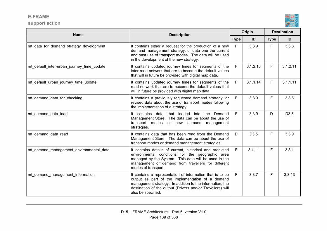
E-FRAME
support action
D15 – FRAME Architecture – Part 6, version V1.0
Page 139 of 568
Origin Destination Name Description
Type ID Type ID
mt_data_for_demand_strategy_development It contains either a request for the production of a new demand management strategy, or data one the current and past use of transport modes. The data will be used in the development of the new strategy.
F 3.3.9 F 3.3.8
mt_default_inter-urban_journey_time_update It contains updated journey times for segments of the inter-road network that are to become the default values that will in future be provided with digital map data.
F 3.1.2.16 F 3.1.2.11
mt_default_urban_journey_time_update It contains updated journey times for segments of the road network that are to become the default values that will in future be provided with digital map data.
F 3.1.1.14 F 3.1.1.11
mt_demand_data_for_checking It contains a previously requested demand strategy, or revised data about the use of transport modes following the implementation of a strategy.
F 3.3.9 F 3.3.6
mt_demand_data_load It contains data that loaded into the Demand Management Store. The data can be about the use of transport modes or new demand management strategies.
F 3.3.9 D D3.5
mt_demand_data_read It contains data that has been read from the Demand Management Store. The data can be about the use of transport modes or demand management strategies.
D D3.5 F 3.3.9
mt_demand_management_environmental_data It contains details of current, historical and predicted environmental conditions for the geographic area managed by the System. This data will be used in the management of demand from travellers for different modes of transport.
F 3.4.11 F 3.3.1
mt_demand_management_information It contains a representation of information that is to be output as part of the implementation of a demand management strategy. In addition to the information, the destination of the output (Drivers and/or Travellers) will also be specified.
F 3.3.7 F 3.3.13

E-FRAME
support action
D15 – FRAME Architecture – Part 6, version V1.0
Page 140 of 568
Origin Destination Name Description
Type ID Type ID
mt_demand_management_operator_commands It contains requests from the Operator. These requests may be for reports on the use of transport modes or for the development of demand management strategies.
F 3.3.5 F 3.3.8
mt_demand_management_operator_responses It contains responses to the Operator from requests that have been previously input. These responses may be reports on the use of transport modes, or confirmation that a new demand management strategy has been developed.
F 3.3.8 F 3.3.5
mt_demand_management_strategy_commands It contains a request for the implementation of a demand management strategy.
F 3.3.5 F 3.3.9
mt_demand_management_strategy_responses It contains the response to a request for the implementation of a demand management strategy. Alternatively it can contain an analysis of the results of implementing a previously requested strategy.
F 3.3.7 F 3.3.5
mt_demand_strataegy_for_implementation It contains details of the demand management strategy that is to be implemented.
F 3.3.9 F 3.3.7
mt_demand_strategy_data_update It contains updates to the static data used to develop demand management strategies. This data will provide "rules" for the strategy development. The "rules" may include but not be limited to such things as the criteria for switching modes, and the priority to be given to particular modes.
F 3.3.5 F 3.3.9
mt_demand_strategy_simulation_results It contains the results of the simulation of a demand management strategy from a previous request.
F 3.3.11 F 3.3.12
mt_developed_demand_strategy It contains either a request for data on the use of transport modes, or a new demand management strategy.
F 3.3.8 F 3.3.9
mt_environmental_conditions_data_for_predictions It contains current and historical environmental data that is to be used in predicting environmental conditions.
F 3.4.8 F 3.4.4

E-FRAME
support action
D15 – FRAME Architecture – Part 6, version V1.0
Page 141 of 568
Origin Destination Name Description
Type ID Type ID
mt_environmental_conditions_operator_requests It contains requests that have been input by the Road Network Operator. These requests may be for all or part of the Environmental Data Store to be output (optionally including, data analysis), data to be sent to other Functions in the Manage Traffic Area, or to other Areas and Systems, or to the environmental conditions prediction Function. Other requests can be received that contain data or that affect the management of the Data Store itself.
F 3.4.7 F 3.4.8
mt_environmental_conditions_operator_responses It contains the responses to requests previously input by the Operator. As a minimum, these responses will contain data from the Environmental Data Store, but they may also contain indications that a particular action has been performed.
F 3.4.8 F 3.4.7
mt_environmental_conditions_prediction_store_data It contains predictions of environmental conditions that are to be loaded into the Environmental Data Store. This data will then be sent to other Functions, and Areas of the System to assist with their operations.
F 3.4.4 F 3.4.8
mt_environmental_conditions_static_data_update It contains data for use by the forecasting algorithm in the environmental conditions prediction Function. This data will comprise but not be limited to such things as details of the terrain and the period for which predictions must be made.
F 3.4.7 F 3.4.8
mt_environmental_data_for_analysis It contains current and predicted environmental data from the Environmental Data Store that is to be analysed by the Determine Environmental Actions Function.
F 3.4.8 F 3.4.11
mt_environmental_incident_inputs It contains details of an environmental condition that constitutes an incident. Examples would be a particular type of pollution that would be dangerous to Travellers, and for which traffic and travel management action must be taken.
F 3.4.11 F 3.2.13
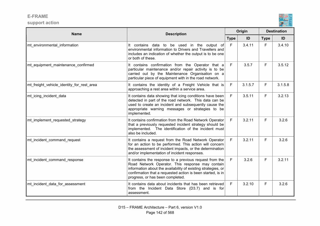
E-FRAME
support action
D15 – FRAME Architecture – Part 6, version V1.0
Page 142 of 568
Origin Destination Name Description
Type ID Type ID
mt_environmental_information It contains data to be used in the output of environmental information to Drivers and Travellers and includes an indication of whether the output is to be one or both of these.
F 3.4.11 F 3.4.10
mt_equipment_maintenance_confirmed It contains confirmation from the Operator that a particular maintenance and/or repair activity is to be carried out by the Maintenance Organisation on a particular piece of equipment with in the road network.
F 3.5.7 F 3.5.12
mt_freight_vehicle_identity_for_rest_area It contains the identity of a Freight Vehicle that is approaching a rest area within a service area.
F 3.1.5.7 F 3.1.5.8
mt_icing_incident_data It contains data showing that icing conditions have been detected in part of the road network. This data can be used to create an incident and subsequently cause the appropriate warning messages or strategies to be implemented.
F 3.5.11 F 3.2.13
mt_implement_requested_strategy It contains confirmation from the Road Network Operator that a previously requested incident strategy should be implemented. The identification of the incident must also be included.
F 3.2.11 F 3.2.6
mt_incident_command_request It contains a request from the Road Network Operator for an action to be performed. This action will concern the assessment of incident impacts, or the determination and/or implementation of incident responses.
F 3.2.11 F 3.2.6
mt_incident_command_response It contains the response to a previous request from the Road Network Operator. This response may contain information about the availability of existing strategies, or confirmation that a requested action is been started, is in progress, or has been completed.
F 3.2.6 F 3.2.11
mt_incident_data_for_assessment It contains data about incidents that has been retrieved from the Incident Data Store (D3.7) and is for assessment.
F 3.2.10 F 3.2.6
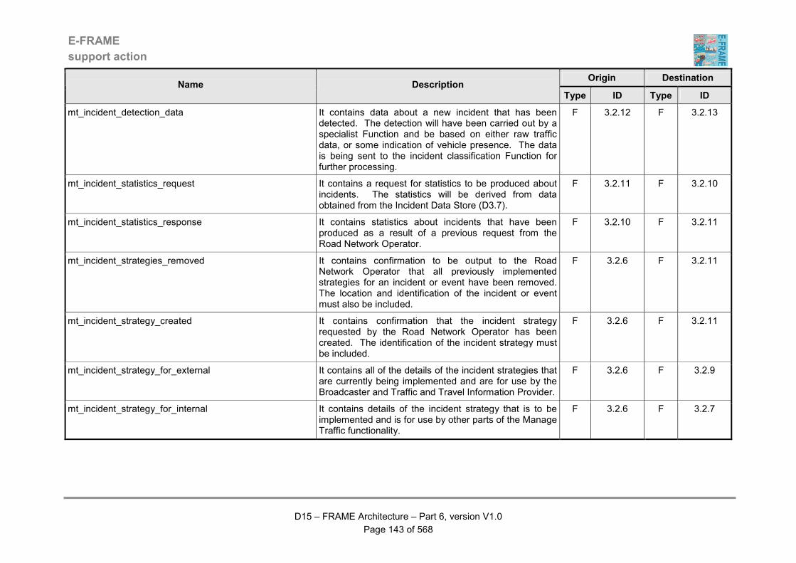
E-FRAME
support action
D15 – FRAME Architecture – Part 6, version V1.0
Page 143 of 568
Origin Destination Name Description
Type ID Type ID
mt_incident_detection_data It contains data about a new incident that has been detected. The detection will have been carried out by a specialist Function and be based on either raw traffic data, or some indication of vehicle presence. The data is being sent to the incident classification Function for further processing.
F 3.2.12 F 3.2.13
mt_incident_statistics_request It contains a request for statistics to be produced about incidents. The statistics will be derived from data obtained from the Incident Data Store (D3.7).
F 3.2.11 F 3.2.10
mt_incident_statistics_response It contains statistics about incidents that have been produced as a result of a previous request from the Road Network Operator.
F 3.2.10 F 3.2.11
mt_incident_strategies_removed It contains confirmation to be output to the Road Network Operator that all previously implemented strategies for an incident or event have been removed. The location and identification of the incident or event must also be included.
F 3.2.6 F 3.2.11
mt_incident_strategy_created It contains confirmation that the incident strategy requested by the Road Network Operator has been created. The identification of the incident strategy must be included.
F 3.2.6 F 3.2.11
mt_incident_strategy_for_external It contains all of the details of the incident strategies that are currently being implemented and are for use by the Broadcaster and Traffic and Travel Information Provider.
F 3.2.6 F 3.2.9
mt_incident_strategy_for_internal It contains details of the incident strategy that is to be implemented and is for use by other parts of the Manage Traffic functionality.
F 3.2.6 F 3.2.7

E-FRAME
support action
D15 – FRAME Architecture – Part 6, version V1.0
Page 144 of 568
Origin Destination Name Description
Type ID Type ID
mt_incident_strategy_for_others It contains details from the incident strategy that is to be implemented and is for use by functionality in the system that provides other services, e.g. Manage Public Transport and Provide Traveller Journey Assistance as well as directly to Vehicles.
F 3.2.6 F 3.2.8
mt_incident_strategy_for_vehicles It contains details from the incident strategy that is to be implemented and is for use by functionality in the Vehicle.
F 3.2.6 F 3.2.14
mt_incident_strategy_implementation_confirmed It contains the result of the input from the Road Network Operator confirming the implementation of an incident strategy can take place.
F 3.2.11 F 3.2.6
mt_incident_strategy_implemented It contains confirmation that the incident strategy previously requested by the Road Network Operator has been implemented. The identification of the incident strategy must be included.
F 3.2.6 F 3.2.11
mt_inter-urban_bridge_inputs It contains data about traffic management strategies that are currently being implemented in the inter-urban road network that must be considered for their impact on the traffic conditions on the management of traffic using bridges
F 3.1.2.13.5 F 3.1.8.1
mt_inter-urban_c&i_device_status It contains details of the current status of the command and information (c&i) output devices being used within the inter-urban road network. These details may include but not be limited to the indications that are currently being displayed to drivers. They will be used to determine when and whether any violations take place.
F 3.1.2.14.2 F 3.1.2.14.5
mt_inter-urban_command_monitoring_data It contains details of some or all of the messages and sign states that are currently being output to Drivers using all or parts of the inter-urban road network managed by the system. These details will be updated in real time as they change.
F 3.1.2.14.4 F 3.1.2.14.1

E-FRAME
support action
D15 – FRAME Architecture – Part 6, version V1.0
Page 145 of 568
Origin Destination Name Description
Type ID Type ID
mt_inter-urban_command_monitoring_state It contains a request to start or stop monitoring some or all of the current messages and sign states being output to Drivers using all or parts of the inter-urban road network managed by the system,
F 3.1.2.14.1 F 3.1.2.14.4
mt_inter-urban_command_override_response It contains the response to a previous request from the Road Network Operator to override some or all of the messages and/or sign states that are currently being output to all or parts of the inter-urban road network managed by the system.
F 3.1.2.14.4 F 3.1.2.14.1
mt_inter-urban_command_override_status It contains instructions to commence or stop the override some or all of the messages and sign states currently being output to Drivers using all or parts of the inter-urban road network managed by the system.
F 3.1.2.14.1 F 3.1.2.14.4
mt_inter-urban_current_traffic_data_for_demand It contains data about traffic that is flowing through the inter-urban road network. This data may include, but not be limited to traffic flow, occupancy, queues, speeds, etc.
F 3.1.2.10 F 3.3.1
mt_inter-urban_data_for_approaching_vehicles It contains the data for information and warning messages plus commands that are being sent to approaching Vehicles using the inter-urban road network, which is for output to their Drivers using in-Vehicle devices.
F 3.1.2.14.2 F 3.1.2.14.6
mt_inter-urban_data_for_traffic_predictions It contains traffic data for use in the prediction of traffic conditions in the inter-urban road network.
F 3.1.2.16 F 3.1.6.2
mt_inter-urban_demand_management_strategy It contains the portion of a demand management strategy that affects the way in which traffic using the inter-urban road network managed by the System. As an alternative it can contain the request to cancel a strategy implementation command sent previously.
F 3.3.7 F 3.1.2.13.5
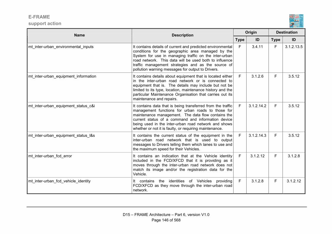
E-FRAME
support action
D15 – FRAME Architecture – Part 6, version V1.0
Page 146 of 568
Origin Destination Name Description
Type ID Type ID
mt_inter-urban_environmental_inputs It contains details of current and predicted environmental conditions for the geographic area managed by the System for use in managing traffic on the inter-urban road network. This data will be used both to influence traffic management strategies and as the source of pollution warning messages for output to Drivers.
F 3.4.11 F 3.1.2.13.5
mt_inter-urban_equipment_information It contains details about equipment that is located either in the inter-urban road network or is connected to equipment that is. The details may include but not be limited to its type, location, maintenance history and the particular Maintenance Organisation that carries out its maintenance and repairs.
F 3.1.2.6 F 3.5.12
mt_inter-urban_equipment_status_c&i It contains data that is being transferred from the traffic management functions for urban roads to those for maintenance management. The data flow contains the current status of a command and information device being used in the inter-urban road network and shows whether or not it is faulty, or requiring maintenance.
F 3.1.2.14.2 F 3.5.12
mt_inter-urban_equipment_status_l&s It contains the current status of the equipment in the inter-urban road network that is used to output messages to Drivers telling them which lanes to use and the maximum speed for their Vehicles.
F 3.1.2.14.3 F 3.5.12
mt_inter-urban_fcd_error It contains an indication that at the Vehicle identity included in the FCD/XFCD that it is providing as it moves through the inter-urban road network does not match its image and/or the registration data for the Vehicle.
F 3.1.2.12 F 3.1.2.8
mt_inter-urban_fcd_vehicle_identity It contains the identities of Vehicles providing FCD/XFCD as they move through the inter-urban road network.
F 3.1.2.8 F 3.1.2.12
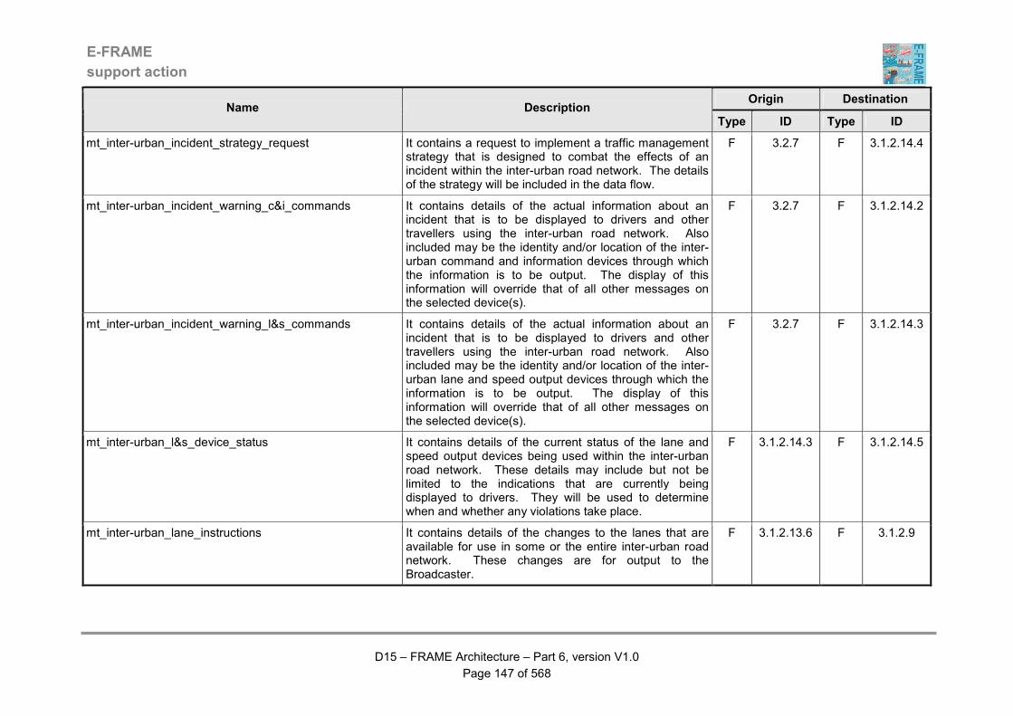
E-FRAME
support action
D15 – FRAME Architecture – Part 6, version V1.0
Page 147 of 568
Origin Destination Name Description
Type ID Type ID
mt_inter-urban_incident_strategy_request It contains a request to implement a traffic management strategy that is designed to combat the effects of an incident within the inter-urban road network. The details of the strategy will be included in the data flow.
F 3.2.7 F 3.1.2.14.4
mt_inter-urban_incident_warning_c&i_commands It contains details of the actual information about an incident that is to be displayed to drivers and other travellers using the inter-urban road network. Also included may be the identity and/or location of the inter-urban command and information devices through which the information is to be output. The display of this information will override that of all other messages on the selected device(s).
F 3.2.7 F 3.1.2.14.2
mt_inter-urban_incident_warning_l&s_commands It contains details of the actual information about an incident that is to be displayed to drivers and other travellers using the inter-urban road network. Also included may be the identity and/or location of the inter-urban lane and speed output devices through which the information is to be output. The display of this information will override that of all other messages on the selected device(s).
F 3.2.7 F 3.1.2.14.3
mt_inter-urban_l&s_device_status It contains details of the current status of the lane and speed output devices being used within the inter-urban road network. These details may include but not be limited to the indications that are currently being displayed to drivers. They will be used to determine when and whether any violations take place.
F 3.1.2.14.3 F 3.1.2.14.5
mt_inter-urban_lane_instructions It contains details of the changes to the lanes that are available for use in some or the entire inter-urban road network. These changes are for output to the Broadcaster.
F 3.1.2.13.6 F 3.1.2.9
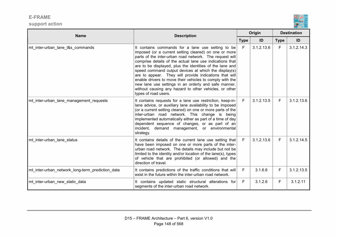
E-FRAME
support action
D15 – FRAME Architecture – Part 6, version V1.0
Page 148 of 568
Origin Destination Name Description
Type ID Type ID
mt_inter-urban_lane_l&s_commands It contains commands for a lane use setting to be imposed (or a current setting cleared) on one or more parts of the inter-urban road network. The request will comprise details of the actual lane use indications that are to be displayed, plus the identities of the lane and speed command output devices at which the display(s) are to appear. They will provide indications that will enable drivers to move their vehicles to comply with the new lane use settings in an orderly and safe manner, without causing any hazard to other vehicles, or other types of road users.
F 3.1.2.13.6 F 3.1.2.14.3
mt_inter-urban_lane_management_requests It contains requests for a lane use restriction, keep-in-lane advice, or auxiliary lane availability to be imposed (or a current setting cleared) on one or more parts of the inter-urban road network. This change is being implemented automatically either as part of a time of day dependent sequence of changes, or as part of an incident, demand management, or environmental strategy.
F 3.1.2.13.5 F 3.1.2.13.6
mt_inter-urban_lane_status It contains details of the current lane use setting that have been imposed on one or more parts of the inter-urban road network. The details may include but not be limited to the identity and/or location of the lane(s), types of vehicle that are prohibited (or allowed) and the direction of travel.
F 3.1.2.13.6 F 3.1.2.14.5
mt_inter-urban_network_long-term_prediction_data It contains predictions of the traffic conditions that will exist in the future within the inter-urban road network.
F 3.1.6.6 F 3.1.2.13.5
mt_inter-urban_new_static_data It contains updated static structural alterations for segments of the inter-urban road network.
F 3.1.2.6 F 3.1.2.11
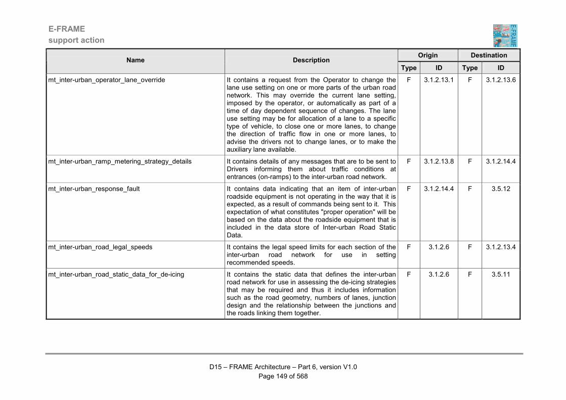
E-FRAME
support action
D15 – FRAME Architecture – Part 6, version V1.0
Page 149 of 568
Origin Destination Name Description
Type ID Type ID
mt_inter-urban_operator_lane_override It contains a request from the Operator to change the lane use setting on one or more parts of the urban road network. This may override the current lane setting, imposed by the operator, or automatically as part of a time of day dependent sequence of changes. The lane use setting may be for allocation of a lane to a specific type of vehicle, to close one or more lanes, to change the direction of traffic flow in one or more lanes, to advise the drivers not to change lanes, or to make the auxiliary lane available.
F 3.1.2.13.1 F 3.1.2.13.6
mt_inter-urban_ramp_metering_strategy_details It contains details of any messages that are to be sent to Drivers informing them about traffic conditions at entrances (on-ramps) to the inter-urban road network.
F 3.1.2.13.8 F 3.1.2.14.4
mt_inter-urban_response_fault It contains data indicating that an item of inter-urban roadside equipment is not operating in the way that it is expected, as a result of commands being sent to it. This expectation of what constitutes "proper operation" will be based on the data about the roadside equipment that is included in the data store of Inter-urban Road Static Data.
F 3.1.2.14.4 F 3.5.12
mt_inter-urban_road_legal_speeds It contains the legal speed limits for each section of the inter-urban road network for use in setting recommended speeds.
F 3.1.2.6 F 3.1.2.13.4
mt_inter-urban_road_static_data_for_de-icing It contains the static data that defines the inter-urban road network for use in assessing the de-icing strategies that may be required and thus it includes information such as the road geometry, numbers of lanes, junction design and the relationship between the junctions and the roads linking them together.
F 3.1.2.6 F 3.5.11

E-FRAME
support action
D15 – FRAME Architecture – Part 6, version V1.0
Page 150 of 568
Origin Destination Name Description
Type ID Type ID
mt_inter-urban_road_static_data_for_long_term_work It contains the static data for the inter-urban road network that has been provided by the Function managing the inter-urban road static Data Store and is for use in evaluating the need for long term maintenance work.
F 3.1.2.6 F 3.5.10
mt_inter-urban_road_static_data_for_prediction It contains the static data that defines the inter-urban road network. Thus it includes information such as the road geometry, numbers of lanes, junction design and the relationship between the junctions and the roads linking them together.
F 3.1.2.6 F 3.1.6.1
mt_inter-urban_road_static_data_for_short_term_wrk It contains the static data for the inter-urban road network that has been provided by the Function managing the inter-urban road static Data Store and is for use in evaluating the need for short term maintenance work.
F 3.1.2.6 F 3.5.9
mt_inter-urban_road_use_data It contains data that is being transferred from the traffic management functions for urban roads to those for maintenance management. The data flow contains the current use being made of the inter-urban road network by forms of road vehicles.
F 3.1.2.16 F 3.5.10
mt_inter-urban_speed_and_headway_settings It contains requests for a speed and/or headway setting to be imposed (or a current setting cleared) on one or more parts of the inter-urban road network. This is being implemented automatically either as part of a time of day dependent sequence of changes, or as part of an incident, demand management, or environmental strategy. The reason for the setting being applied will be included.
F 3.1.2.13.5 F 3.1.2.13.4
E-FRAME
support action
D15 – FRAME Architecture – Part 6, version V1.0
Page 151 of 568
Origin Destination Name Description
Type ID Type ID
mt_inter-urban_speed_l&s_commands It contains commands for a legal speed setting to be imposed (or a current setting cleared) on one or more parts of the inter-urban road network. The request will comprise details of the actual speed indications that are to be displayed, plus the identity of the lane and speed output devices at which the display(s) are to appear. They will provide indications that will enable drivers to change the speed of their vehicles in an orderly and safe manner, without causing any hazard to other vehicles, or other types of road users.
F 3.1.2.13.4 F 3.1.2.14.3
mt_inter-urban_speed_limit_changes It contains changes to the speed limits for inter-urban roads that are to be output to the Broadcaster and other functionality within the System.
F 3.1.2.13.4 F 3.1.2.9
mt_inter-urban_speed_value It contains a speed value that is to check for violations by vehicles in a part of the inter-urban road network. This is being implemented automatically as part of a time of day dependent sequence of changes, or at the request of the Operator, or as a result of the implementation of an incident management strategy.
F 3.1.2.14.4 F 3.1.2.14.5
mt_inter-urban_static_data It contains inter-urban traffic static data that is to be used by the inter-urban traffic management Function. It includes data about speed limits, numbers of lanes, etc. for each part of the inter-urban road network. This data will be part of that used to determine and implement the most appropriate method of traffic management and monitor that instructions being sent to roadside equipment are being obeyed.
F 3.1.2.6 F 3.1.2.13.5
mt_inter-urban_static_data_changes It contains updated and/or additional inter-urban static road data that is to be loaded into the Data Store D3.8.
F 3.1.2.13.1 F 3.1.2.6
mt_inter-urban_static_data_for_traffic_conditions It contains the static data about the inter-urban road network that is for use in the storage and output of inter-urban traffic conditions data.
F 3.1.2.6 F 3.1.2.16

E-FRAME
support action
D15 – FRAME Architecture – Part 6, version V1.0
Page 152 of 568
Origin Destination Name Description
Type ID Type ID
mt_inter-urban_static_data_read It contains data that has been read from the Inter-urban Traffic Static Data Store.
D D3.8 F 3.1.2.6
mt_inter-urban_static_data_update It contains data that loaded into the Inter-urban Traffic Static Data Store.
F 3.1.2.6 D D3.8
mt_inter-urban_strategies_for_long-term It contains details of one or more traffic management strategies that are to be made available for use by the Functions that control the traffic within the inter-urban road network.
F 3.1.6.6 F 3.1.2.13.7
mt_inter-urban_strategies_in_use It contains details of the traffic management strategies that are currently in use in the inter-urban road network. This data is for association with collected traffic flow data so that the impact of implementing particular strategies can be assessed.
F 3.1.2.13.5 F 3.1.6.4
mt_inter-urban_strategy_command_output_failure It contains details of an inter-urban strategy command output failure that is for use by the Maintenance Organisation.
F 3.1.2.14.4 F 3.5.12
mt_inter-urban_strategy_command_response_failure It contains details of the failure of an inter-urban traffic management strategy to be implemented.
F 3.1.2.14.4 F 3.1.2.13.5
mt_inter-urban_strategy_details_for_ramp_metering It contains details of the strategy to be used for ramp metering that is to be applied to some or all of the entrances to the all or part of the inter-urban road network managed by the system.
F 3.1.2.13.5 F 3.1.2.13.8
mt_inter-urban_to_urban_traffic_commands It contains traffic management commands that Functions serving the inter-urban road network want to be implemented by those managing the urban road network.
F 3.1.2.13.5 F 3.1.1.5.24
mt_inter-urban_to_urban_traffic_data_transfers It contains data about traffic using the inter-urban road network that is being sent for inclusion in the store of data available the Functions serving the urban road network.
F 3.1.2.16 F 3.1.1.14

E-FRAME
support action
D15 – FRAME Architecture – Part 6, version V1.0
Page 153 of 568
Origin Destination Name Description
Type ID Type ID
mt_inter-urban_traffic_data_for_demand It contains data about the current and predicted traffic conditions in the inter-urban road network. This data will be used in the selection of the appropriate demand management strategy to optimise the use of the inter-urban road network.
F 3.1.2.16 F 3.3.1
mt_inter-urban_traffic_data_for_incidents It contains data about the current traffic conditions in the inter-urban road network that will be used in the decision process for the selection of the appropriate management strategy to mitigate an incident.
F 3.1.2.16 F 3.2.6
mt_inter-urban_traffic_data_for_incident_detection It contains raw traffic data from points in the inter-urban road network that can be analysed to see if an incident has occurred.
F 3.1.2.10 F 3.2.12
mt_inter-urban_traffic_data_for_output It contains data about traffic flows, queues and queue propagation rates in the inter-urban road network plus service area occupancy data that are for output to a variety of functionality in other Functional Areas and entities outside the System.
F 3.1.2.16 F 3.1.2.9
mt_inter-urban_traffic_data_for_ramp_metering It contains traffic flow data that is to be used in the ramp metering that is to be applied to some or all of the entrances to the all or part of the inter-urban road network managed by the system.
F 3.1.2.13.5 F 3.1.2.13.8
mt_inter-urban_traffic_flow_management_data It contains data about the way traffic is flowing in the inter-urban road network that is to be used by Functions managing traffic in the inter-urban road network.
F 3.1.2.10 F 3.1.2.13.5
mt_inter-urban_traffic_long-term_prediction_data It contains data that provides predictions of traffic in the inter-urban road network, and is for loading into the Inter-urban Traffic Data Store (D3.2).
F 3.1.6.6 F 3.1.2.16
E-FRAME
support action
D15 – FRAME Architecture – Part 6, version V1.0
Page 154 of 568
Origin Destination Name Description
Type ID Type ID
mt_inter-urban_traffic_maintenance_conditions It contains data that is being transferred from the traffic management functions for urban roads to those for maintenance management. The data flow contains the current traffic conditions within the inter-urban road network.
F 3.1.2.16 F 3.5.9
mt_inter-urban_traffic_management_c&i_request It contains details of the outputs that are to be displayed by command and information devices to drivers using the inter-urban road network. These details may include but not be limited to the identity and/or location of the device and the actual output to be displayed.
F 3.1.2.14.4 F 3.1.2.14.2
mt_inter-urban_traffic_management_c&i_response It contains details of the response to the previous request for displays to be shown by command and information output devices to drivers using the inter-urban road network. These details may include but not be limited to the identity and/or location of the device and the actual response to the previous display command.
F 3.1.2.14.2 F 3.1.2.14.4
mt_inter-urban_traffic_management_l&s_request It contains details of the outputs that are to be displayed by lane and speed devices to drivers using the inter-urban road network. These details may include but not be limited to the identity and/or location of the device and the actual output to be displayed.
F 3.1.2.14.4 F 3.1.2.14.3
mt_inter-urban_traffic_management_l&s_response It contains details of the response to the previous request for displays to be shown by lane and speed output devices to drivers using the inter-urban road network. These details may include but not be limited to the identity and/or location of the device and the actual response to the previous display command.
F 3.1.2.14.3 F 3.1.2.14.4
mt_inter-urban_tunnel_inputs It contains data about traffic management strategies that are currently being implemented in the inter-urban road network that must be considered for their impact on the traffic conditions on the management of traffic in tunnels
F 3.1.2.13.5 F 3.1.7.1
E-FRAME
support action
D15 – FRAME Architecture – Part 6, version V1.0
Page 155 of 568
Origin Destination Name Description
Type ID Type ID
mt_inter-urban_xfcd_for_incident_detection It contains vehicle status data for improved incident detection collected from those Vehicles using the inter-urban road network.
F 3.1.2.8 F 3.2.12
mt_inter-urban_zone_access_vehicle_list It contains a list of the identities (and other data from which Vehicles can be recognised) of Vehicles that are permitted to enter a part of the inter-urban road network (zone) to which access is controlled.
F 3.1.2.13.5 F 3.1.2.13.2
mt_inter-urban_zone_vehicle_identity It contains the identity of a Vehicle that has approached a part of the inter-urban road network (zone) that it is not permitted to use.
F 3.1.2.13.2 F 3.1.2.13.3
mt_inter-urban_zoning_strategy It contains the portion of a demand management strategy that affects the way in which zoning is applied to traffic using the inter-urban road network managed by the System. As an alternative it can contain the request to cancel a strategy implementation command sent previously.
F 3.3.7 F 3.1.2.13.5
mt_load_carpark_static_data It contains new or updated car park static data that is to be loaded into the Car Park Data Store.
F 3.1.4.7 F 3.1.4.8
mt_load_car_park_data It contains static data about car parks, plus real-time data about their levels of occupancy that is being loaded in the store of car park data.
F 3.1.4.8 D D3.9
mt_load_environmental_conditions_data It contains requests for data to be read from the Environmental Data Store (D3.3). It may also contain requests for data to be deleted or in some way managed, e.g. compressed.
F 3.4.8 D D3.3
mt_load_incident_data It contains data that is to be loaded into the Incident Data Store (D3.4). This data will contain details of incidents, both current and planned.
F 3.2.10 D D3.4
mt_load_incident_strategies It contains an incident strategy that is to be loaded into the Data Store.
F 3.2.6 D D3.12
E-FRAME
support action
D15 – FRAME Architecture – Part 6, version V1.0
Page 156 of 568
Origin Destination Name Description
Type ID Type ID
mt_load_inter-urban_traffic_data It contains data that is being loaded into the Inter-urban Traffic Data Store (D3.2).
F 3.1.2.16 D D3.14
mt_load_maintenance_data It contains data that is being loaded into the Maintenance Data Store (D3.6). This data flow may contain either details of maintenance and repair operations that can be carried out on the road network or equipment, details of de-icing activities, confirmation that activities have been requested from the Maintenance Organisation, or the current status of the activities.
F 3.5.8 D D3.6
mt_load_prediction_data It contains new or updated data that is to be loaded into the Road Traffic Simulation Data Store.
F 3.1.6.4 D D3.11
mt_load_service_area_data It contains data being loaded into the Inter-urban Service Area Data Store.
F 3.1.5.5 D D3.10
mt_load_service_area_static_data It contains new or updated service area static data that is to be loaded into the Service Area Data Store.
F 3.1.5.4 F 3.1.5.5
mt_load_urban_traffic_data It contains data that is being loaded into the Urban Traffic Data Store (D3.1).
F 3.1.1.14 D D3.13
mt_long_term_maintenance_confirmed It contains confirmation from the Operator that a particular long term maintenance activity is to be carried out by the Maintenance Organisation.
F 3.5.7 F 3.5.10
mt_maintenance_data_updates It contains either new or changed data that is to be loaded into the Store of maintenance data, or a request for the output of some or all of this data. The data may relate to current maintenance activities, or static data for the road network.
F 3.5.7 F 3.5.8
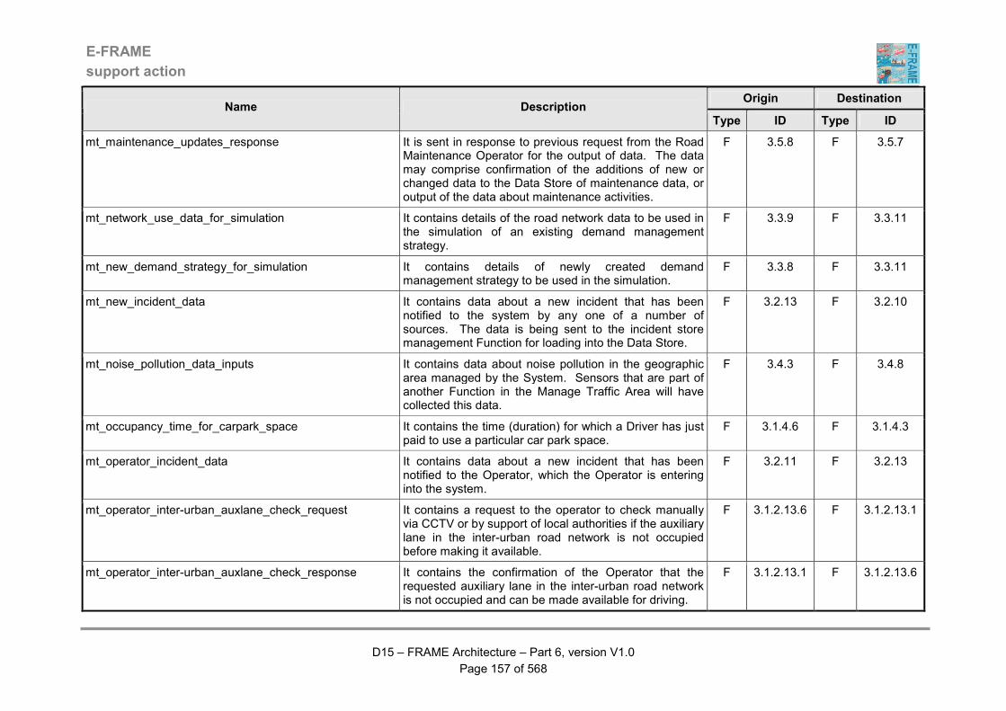
E-FRAME
support action
D15 – FRAME Architecture – Part 6, version V1.0
Page 157 of 568
Origin Destination Name Description
Type ID Type ID
mt_maintenance_updates_response It is sent in response to previous request from the Road Maintenance Operator for the output of data. The data may comprise confirmation of the additions of new or changed data to the Data Store of maintenance data, or output of the data about maintenance activities.
F 3.5.8 F 3.5.7
mt_network_use_data_for_simulation It contains details of the road network data to be used in the simulation of an existing demand management strategy.
F 3.3.9 F 3.3.11
mt_new_demand_strategy_for_simulation It contains details of newly created demand management strategy to be used in the simulation.
F 3.3.8 F 3.3.11
mt_new_incident_data It contains data about a new incident that has been notified to the system by any one of a number of sources. The data is being sent to the incident store management Function for loading into the Data Store.
F 3.2.13 F 3.2.10
mt_noise_pollution_data_inputs It contains data about noise pollution in the geographic area managed by the System. Sensors that are part of another Function in the Manage Traffic Area will have collected this data.
F 3.4.3 F 3.4.8
mt_occupancy_time_for_carpark_space It contains the time (duration) for which a Driver has just paid to use a particular car park space.
F 3.1.4.6 F 3.1.4.3
mt_operator_incident_data It contains data about a new incident that has been notified to the Operator, which the Operator is entering into the system.
F 3.2.11 F 3.2.13
mt_operator_inter-urban_auxlane_check_request It contains a request to the operator to check manually via CCTV or by support of local authorities if the auxiliary lane in the inter-urban road network is not occupied before making it available.
F 3.1.2.13.6 F 3.1.2.13.1
mt_operator_inter-urban_auxlane_check_response It contains the confirmation of the Operator that the requested auxiliary lane in the inter-urban road network is not occupied and can be made available for driving.
F 3.1.2.13.1 F 3.1.2.13.6
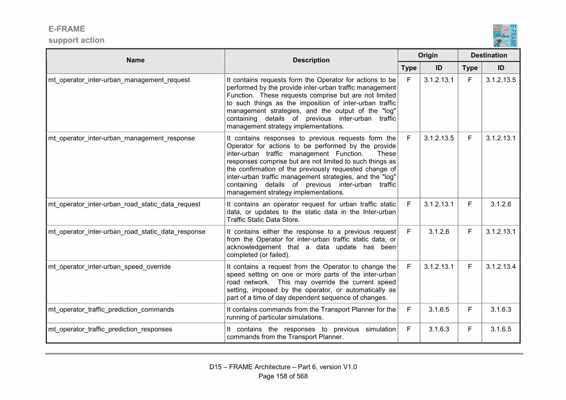
E-FRAME
support action
D15 – FRAME Architecture – Part 6, version V1.0
Page 158 of 568
Origin Destination Name Description
Type ID Type ID
mt_operator_inter-urban_management_request It contains requests form the Operator for actions to be performed by the provide inter-urban traffic management Function. These requests comprise but are not limited to such things as the imposition of inter-urban traffic management strategies, and the output of the "log" containing details of previous inter-urban traffic management strategy implementations.
F 3.1.2.13.1 F 3.1.2.13.5
mt_operator_inter-urban_management_response It contains responses to previous requests form the Operator for actions to be performed by the provide inter-urban traffic management Function. These responses comprise but are not limited to such things as the confirmation of the previously requested change of inter-urban traffic management strategies, and the "log" containing details of previous inter-urban traffic management strategy implementations.
F 3.1.2.13.5 F 3.1.2.13.1
mt_operator_inter-urban_road_static_data_request It contains an operator request for urban traffic static data, or updates to the static data in the Inter-urban Traffic Static Data Store.
F 3.1.2.13.1 F 3.1.2.6
mt_operator_inter-urban_road_static_data_response It contains either the response to a previous request from the Operator for inter-urban traffic static data, or acknowledgement that a data update has been completed (or failed).
F 3.1.2.6 F 3.1.2.13.1
mt_operator_inter-urban_speed_override It contains a request from the Operator to change the speed setting on one or more parts of the inter-urban road network. This may override the current speed setting, imposed by the operator, or automatically as part of a time of day dependent sequence of changes.
F 3.1.2.13.1 F 3.1.2.13.4
mt_operator_traffic_prediction_commands It contains commands from the Transport Planner for the running of particular simulations.
F 3.1.6.5 F 3.1.6.3
mt_operator_traffic_prediction_responses It contains the responses to previous simulation commands from the Transport Planner.
F 3.1.6.3 F 3.1.6.5
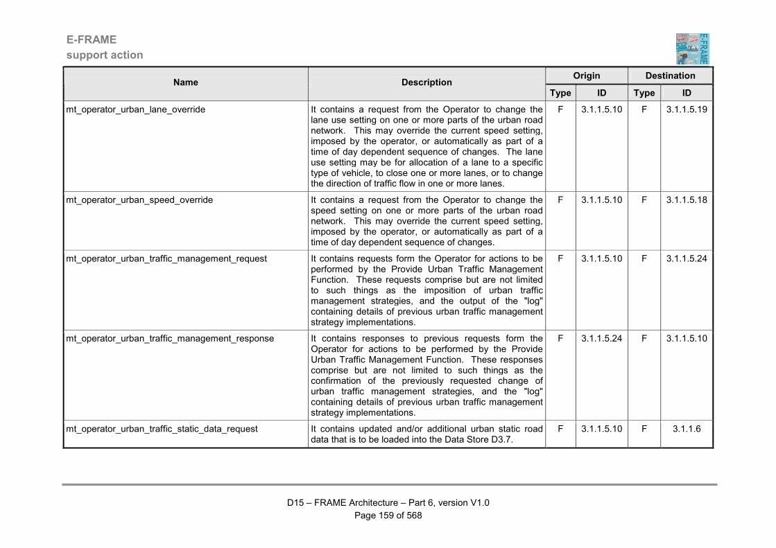
E-FRAME
support action
D15 – FRAME Architecture – Part 6, version V1.0
Page 159 of 568
Origin Destination Name Description
Type ID Type ID
mt_operator_urban_lane_override It contains a request from the Operator to change the lane use setting on one or more parts of the urban road network. This may override the current speed setting, imposed by the operator, or automatically as part of a time of day dependent sequence of changes. The lane use setting may be for allocation of a lane to a specific type of vehicle, to close one or more lanes, or to change the direction of traffic flow in one or more lanes.
F 3.1.1.5.10 F 3.1.1.5.19
mt_operator_urban_speed_override It contains a request from the Operator to change the speed setting on one or more parts of the urban road network. This may override the current speed setting, imposed by the operator, or automatically as part of a time of day dependent sequence of changes.
F 3.1.1.5.10 F 3.1.1.5.18
mt_operator_urban_traffic_management_request It contains requests form the Operator for actions to be performed by the Provide Urban Traffic Management Function. These requests comprise but are not limited to such things as the imposition of urban traffic management strategies, and the output of the "log" containing details of previous urban traffic management strategy implementations.
F 3.1.1.5.10 F 3.1.1.5.24
mt_operator_urban_traffic_management_response It contains responses to previous requests form the Operator for actions to be performed by the Provide Urban Traffic Management Function. These responses comprise but are not limited to such things as the confirmation of the previously requested change of urban traffic management strategies, and the "log" containing details of previous urban traffic management strategy implementations.
F 3.1.1.5.24 F 3.1.1.5.10
mt_operator_urban_traffic_static_data_request It contains updated and/or additional urban static road data that is to be loaded into the Data Store D3.7.
F 3.1.1.5.10 F 3.1.1.6
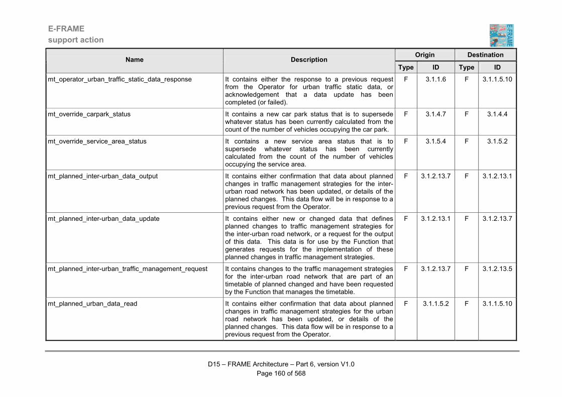
E-FRAME
support action
D15 – FRAME Architecture – Part 6, version V1.0
Page 160 of 568
Origin Destination Name Description
Type ID Type ID
mt_operator_urban_traffic_static_data_response It contains either the response to a previous request from the Operator for urban traffic static data, or acknowledgement that a data update has been completed (or failed).
F 3.1.1.6 F 3.1.1.5.10
mt_override_carpark_status It contains a new car park status that is to supersede whatever status has been currently calculated from the count of the number of vehicles occupying the car park.
F 3.1.4.7 F 3.1.4.4
mt_override_service_area_status It contains a new service area status that is to supersede whatever status has been currently calculated from the count of the number of vehicles occupying the service area.
F 3.1.5.4 F 3.1.5.2
mt_planned_inter-urban_data_output It contains either confirmation that data about planned changes in traffic management strategies for the inter-urban road network has been updated, or details of the planned changes. This data flow will be in response to a previous request from the Operator.
F 3.1.2.13.7 F 3.1.2.13.1
mt_planned_inter-urban_data_update It contains either new or changed data that defines planned changes to traffic management strategies for the inter-urban road network, or a request for the output of this data. This data is for use by the Function that generates requests for the implementation of these planned changes in traffic management strategies.
F 3.1.2.13.1 F 3.1.2.13.7
mt_planned_inter-urban_traffic_management_request It contains changes to the traffic management strategies for the inter-urban road network that are part of an timetable of planned changed and have been requested by the Function that manages the timetable.
F 3.1.2.13.7 F 3.1.2.13.5
mt_planned_urban_data_read It contains either confirmation that data about planned changes in traffic management strategies for the urban road network has been updated, or details of the planned changes. This data flow will be in response to a previous request from the Operator.
F 3.1.1.5.2 F 3.1.1.5.10
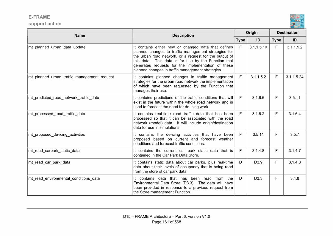
E-FRAME
support action
D15 – FRAME Architecture – Part 6, version V1.0
Page 161 of 568
Origin Destination Name Description
Type ID Type ID
mt_planned_urban_data_update It contains either new or changed data that defines planned changes to traffic management strategies for the urban road network, or a request for the output of this data. This data is for use by the Function that generates requests for the implementation of these planned changes in traffic management strategies.
F 3.1.1.5.10 F 3.1.1.5.2
mt_planned_urban_traffic_management_request It contains planned changes in traffic management strategies for the urban road network the implementation of which have been requested by the Function that manages their use.
F 3.1.1.5.2 F 3.1.1.5.24
mt_predicted_road_network_traffic_data It contains predictions of the traffic conditions that will exist in the future within the whole road network and is used to forecast the need for de-icing work.
F 3.1.6.6 F 3.5.11
mt_processed_road_traffic_data It contains real-time road traffic data that has been processed so that it can be associated with the road network (model) data. It will include origin/destination data for use in simulations.
F 3.1.6.2 F 3.1.6.4
mt_proposed_de-icing_activities It contains the de-icing activities that have been proposed based on current and forecast weather conditions and forecast traffic conditions.
F 3.5.11 F 3.5.7
mt_read_carpark_static_data It contains the current car park static data that is contained in the Car Park Data Store.
F 3.1.4.8 F 3.1.4.7
mt_read_car_park_data It contains static data about car parks, plus real-time data about their levels of occupancy that is being read from the store of car park data.
D D3.9 F 3.1.4.8
mt_read_environmental_conditions_data It contains data that has been read from the Environmental Data Store (D3.3). The data will have been provided in response to a previous request from the Store management Function.
D D3.3 F 3.4.8
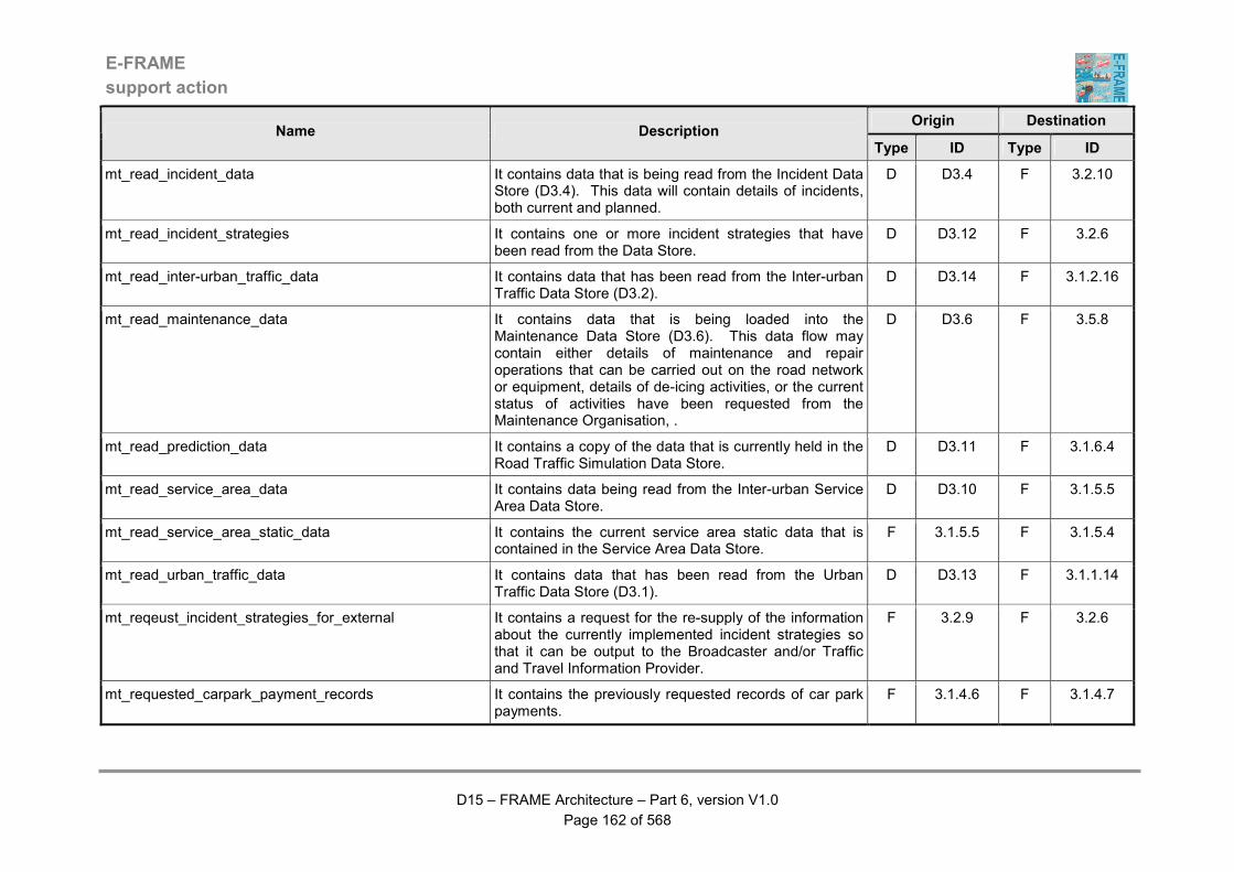
E-FRAME
support action
D15 – FRAME Architecture – Part 6, version V1.0
Page 162 of 568
Origin Destination Name Description
Type ID Type ID
mt_read_incident_data It contains data that is being read from the Incident Data Store (D3.4). This data will contain details of incidents, both current and planned.
D D3.4 F 3.2.10
mt_read_incident_strategies It contains one or more incident strategies that have been read from the Data Store.
D D3.12 F 3.2.6
mt_read_inter-urban_traffic_data It contains data that has been read from the Inter-urban Traffic Data Store (D3.2).
D D3.14 F 3.1.2.16
mt_read_maintenance_data It contains data that is being loaded into the Maintenance Data Store (D3.6). This data flow may contain either details of maintenance and repair operations that can be carried out on the road network or equipment, details of de-icing activities, or the current status of activities have been requested from the Maintenance Organisation, .
D D3.6 F 3.5.8
mt_read_prediction_data It contains a copy of the data that is currently held in the Road Traffic Simulation Data Store.
D D3.11 F 3.1.6.4
mt_read_service_area_data It contains data being read from the Inter-urban Service Area Data Store.
D D3.10 F 3.1.5.5
mt_read_service_area_static_data It contains the current service area static data that is contained in the Service Area Data Store.
F 3.1.5.5 F 3.1.5.4
mt_read_urban_traffic_data It contains data that has been read from the Urban Traffic Data Store (D3.1).
D D3.13 F 3.1.1.14
mt_reqeust_incident_strategies_for_external It contains a request for the re-supply of the information about the currently implemented incident strategies so that it can be output to the Broadcaster and/or Traffic and Travel Information Provider.
F 3.2.9 F 3.2.6
mt_requested_carpark_payment_records It contains the previously requested records of car park payments.
F 3.1.4.6 F 3.1.4.7
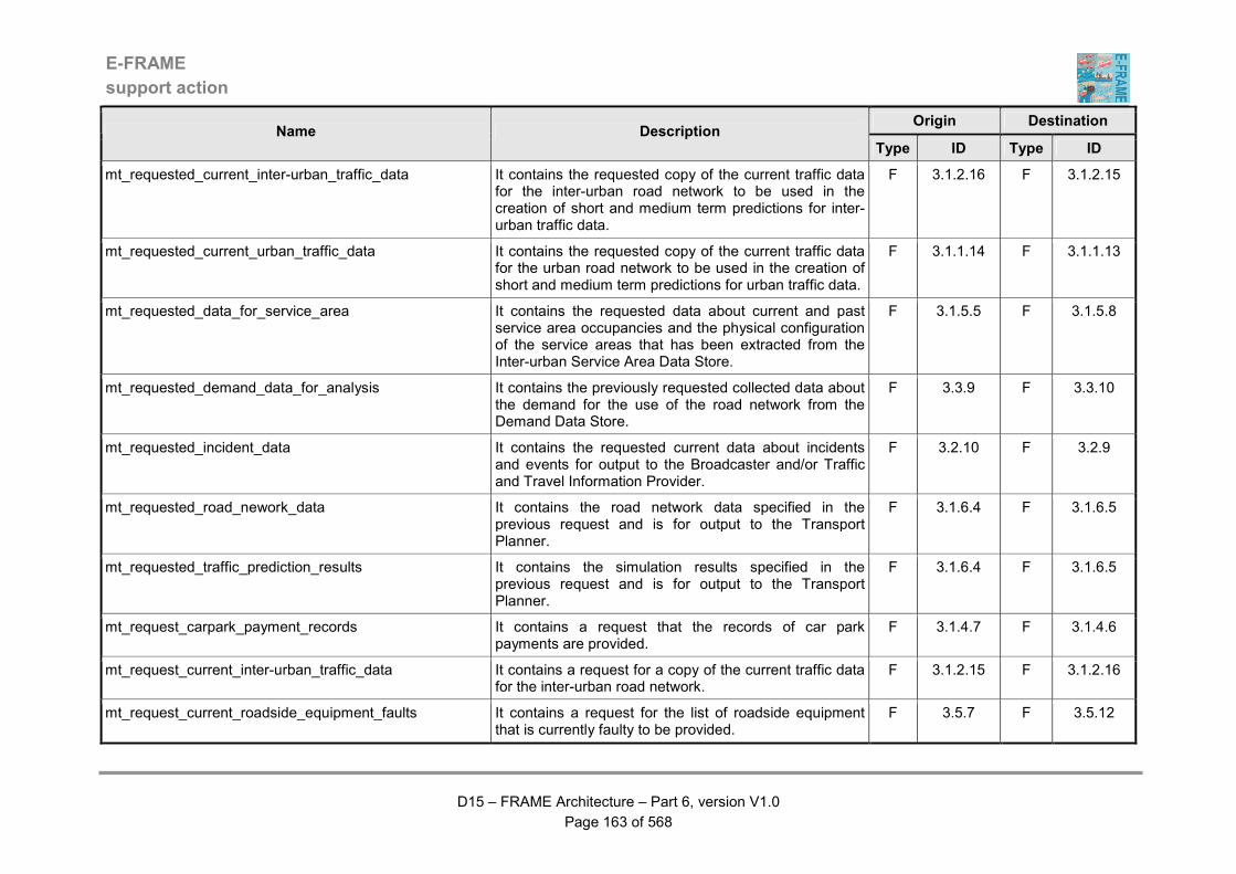
E-FRAME
support action
D15 – FRAME Architecture – Part 6, version V1.0
Page 163 of 568
Origin Destination Name Description
Type ID Type ID
mt_requested_current_inter-urban_traffic_data It contains the requested copy of the current traffic data for the inter-urban road network to be used in the creation of short and medium term predictions for inter-urban traffic data.
F 3.1.2.16 F 3.1.2.15
mt_requested_current_urban_traffic_data It contains the requested copy of the current traffic data for the urban road network to be used in the creation of short and medium term predictions for urban traffic data.
F 3.1.1.14 F 3.1.1.13
mt_requested_data_for_service_area It contains the requested data about current and past service area occupancies and the physical configuration of the service areas that has been extracted from the Inter-urban Service Area Data Store.
F 3.1.5.5 F 3.1.5.8
mt_requested_demand_data_for_analysis It contains the previously requested collected data about the demand for the use of the road network from the Demand Data Store.
F 3.3.9 F 3.3.10
mt_requested_incident_data It contains the requested current data about incidents and events for output to the Broadcaster and/or Traffic and Travel Information Provider.
F 3.2.10 F 3.2.9
mt_requested_road_nework_data It contains the road network data specified in the previous request and is for output to the Transport Planner.
F 3.1.6.4 F 3.1.6.5
mt_requested_traffic_prediction_results It contains the simulation results specified in the previous request and is for output to the Transport Planner.
F 3.1.6.4 F 3.1.6.5
mt_request_carpark_payment_records It contains a request that the records of car park payments are provided.
F 3.1.4.7 F 3.1.4.6
mt_request_current_inter-urban_traffic_data It contains a request for a copy of the current traffic data for the inter-urban road network.
F 3.1.2.15 F 3.1.2.16
mt_request_current_roadside_equipment_faults It contains a request for the list of roadside equipment that is currently faulty to be provided.
F 3.5.7 F 3.5.12
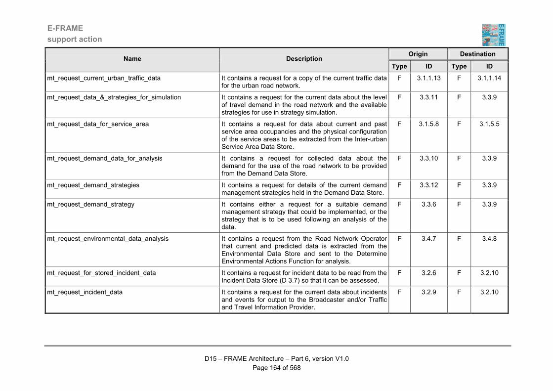
E-FRAME
support action
D15 – FRAME Architecture – Part 6, version V1.0
Page 164 of 568
Origin Destination Name Description
Type ID Type ID
mt_request_current_urban_traffic_data It contains a request for a copy of the current traffic data for the urban road network.
F 3.1.1.13 F 3.1.1.14
mt_request_data_&_strategies_for_simulation It contains a request for the current data about the level of travel demand in the road network and the available strategies for use in strategy simulation.
F 3.3.11 F 3.3.9
mt_request_data_for_service_area It contains a request for data about current and past service area occupancies and the physical configuration of the service areas to be extracted from the Inter-urban Service Area Data Store.
F 3.1.5.8 F 3.1.5.5
mt_request_demand_data_for_analysis It contains a request for collected data about the demand for the use of the road network to be provided from the Demand Data Store.
F 3.3.10 F 3.3.9
mt_request_demand_strategies It contains a request for details of the current demand management strategies held in the Demand Data Store.
F 3.3.12 F 3.3.9
mt_request_demand_strategy It contains either a request for a suitable demand management strategy that could be implemented, or the strategy that is to be used following an analysis of the data.
F 3.3.6 F 3.3.9
mt_request_environmental_data_analysis It contains a request from the Road Network Operator that current and predicted data is extracted from the Environmental Data Store and sent to the Determine Environmental Actions Function for analysis.
F 3.4.7 F 3.4.8
mt_request_for_stored_incident_data It contains a request for incident data to be read from the Incident Data Store (D 3.7) so that it can be assessed.
F 3.2.6 F 3.2.10
mt_request_incident_data It contains a request for the current data about incidents and events for output to the Broadcaster and/or Traffic and Travel Information Provider.
F 3.2.9 F 3.2.10
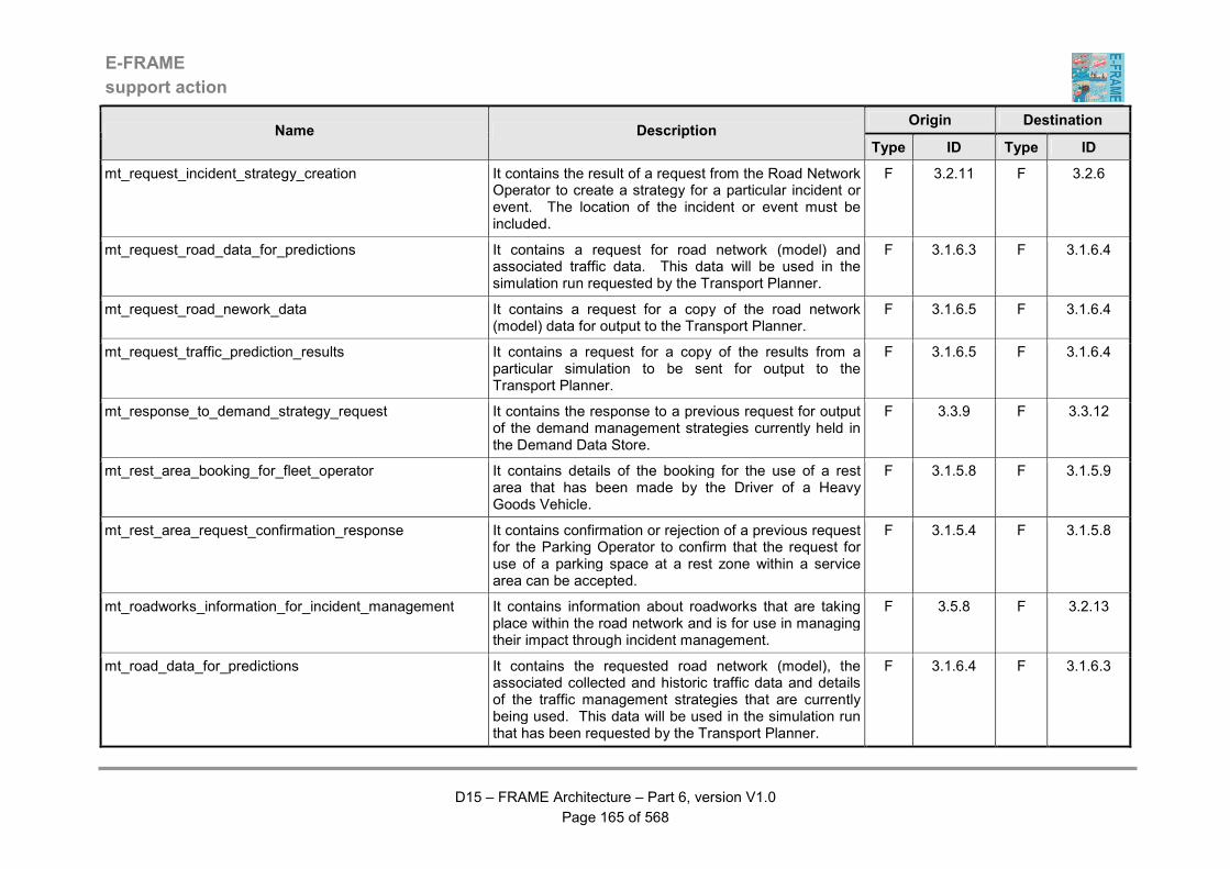
E-FRAME
support action
D15 – FRAME Architecture – Part 6, version V1.0
Page 165 of 568
Origin Destination Name Description
Type ID Type ID
mt_request_incident_strategy_creation It contains the result of a request from the Road Network Operator to create a strategy for a particular incident or event. The location of the incident or event must be included.
F 3.2.11 F 3.2.6
mt_request_road_data_for_predictions It contains a request for road network (model) and associated traffic data. This data will be used in the simulation run requested by the Transport Planner.
F 3.1.6.3 F 3.1.6.4
mt_request_road_nework_data It contains a request for a copy of the road network (model) data for output to the Transport Planner.
F 3.1.6.5 F 3.1.6.4
mt_request_traffic_prediction_results It contains a request for a copy of the results from a particular simulation to be sent for output to the Transport Planner.
F 3.1.6.5 F 3.1.6.4
mt_response_to_demand_strategy_request It contains the response to a previous request for output of the demand management strategies currently held in the Demand Data Store.
F 3.3.9 F 3.3.12
mt_rest_area_booking_for_fleet_operator It contains details of the booking for the use of a rest area that has been made by the Driver of a Heavy Goods Vehicle.
F 3.1.5.8 F 3.1.5.9
mt_rest_area_request_confirmation_response It contains confirmation or rejection of a previous request for the Parking Operator to confirm that the request for use of a parking space at a rest zone within a service area can be accepted.
F 3.1.5.4 F 3.1.5.8
mt_roadworks_information_for_incident_management It contains information about roadworks that are taking place within the road network and is for use in managing their impact through incident management.
F 3.5.8 F 3.2.13
mt_road_data_for_predictions It contains the requested road network (model), the associated collected and historic traffic data and details of the traffic management strategies that are currently being used. This data will be used in the simulation run that has been requested by the Transport Planner.
F 3.1.6.4 F 3.1.6.3

E-FRAME
support action
D15 – FRAME Architecture – Part 6, version V1.0
Page 166 of 568
Origin Destination Name Description
Type ID Type ID
mt_road_network_data_for_collection It contains details of the road network (model) plus current and historic traffic data so that real-time traffic data can be processed. The processing will enable the data to be allocated to the correct part(s) of the road network.
F 3.1.6.4 F 3.1.6.2
mt_road_network_data_for_predictions It contains a consolidated set of road static data that has been processed to produce the road network (model) data.
F 3.1.6.1 F 3.1.6.4
mt_run_demand_strategy_simulation It contains a request to run the simulation of a particular demand management strategy.
F 3.3.12 F 3.3.11
mt_run_strategy_effectiveness_analysis It contains the request for an analysis of the effectiveness of a demand strategy. The dates/times for the period and part(s) of the road network for which the stored data is to be analysed is provided.
F 3.3.12 F 3.3.10
mt_selected_inter-urban_strategy_details It contains details of the inter-urban traffic management strategy that has been selected for implementation in order to manage the traffic using the inter-urban road network,
F 3.1.2.13.5 F 3.1.2.14.4
mt_send_traffic_prediction_results_for_output It contains a processed request from the Transport Planner for the results from a particular simulation to be sent for processing so that they can be output to other functionality.
F 3.1.6.5 F 3.1.6.4
mt_service_area_entrance_exit_vehicle_detection It contains an indication that a vehicle has entered has entered or left a service area.
F 3.1.5.1 F 3.1.5.2
mt_service_area_occupancies_for_demand_management It contains data about the current occupancies of service areas in the inter-urban road network that are to be used by the demand management group of Functions. The term "service area" is generic in that it may also include locations where only freight and/or Public Transport vehicles are parked whilst in transit through the inter-urban road network.
F 3.1.5.2 F 3.3.1
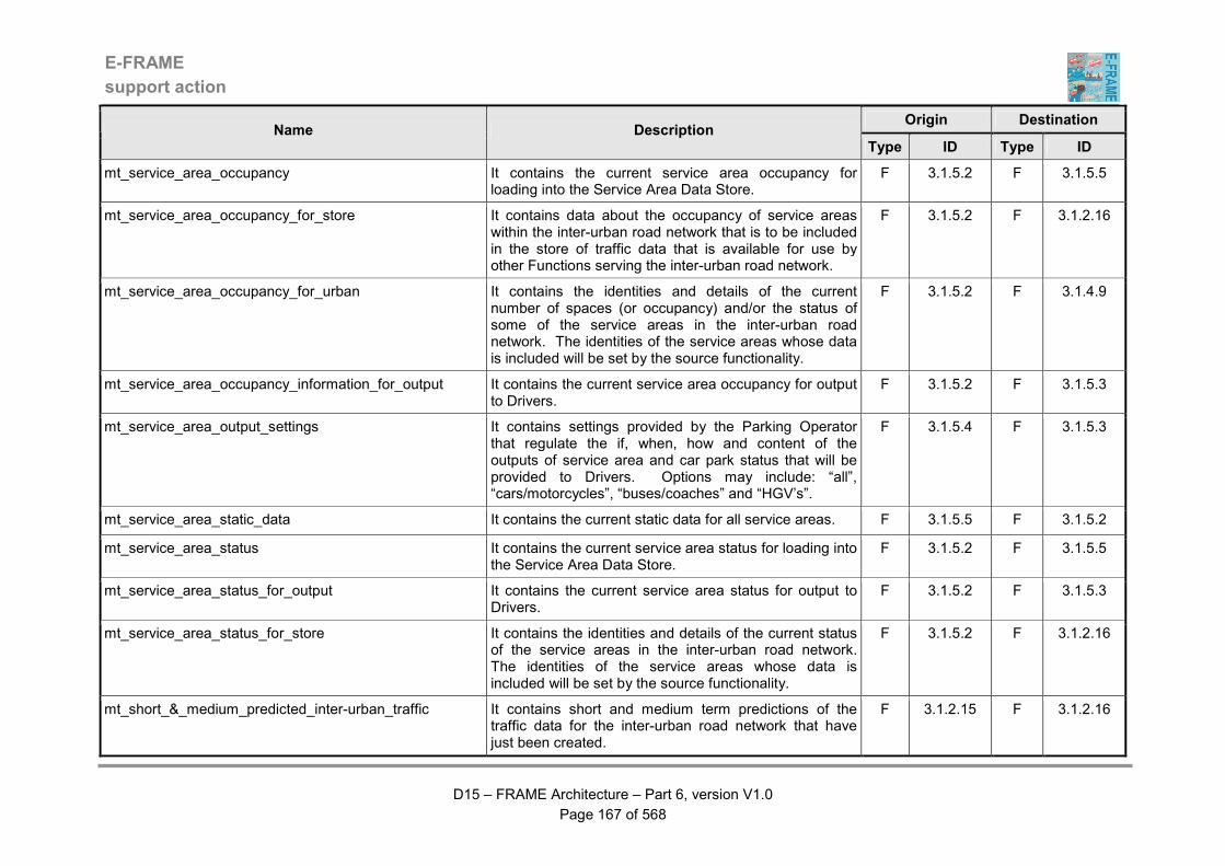
E-FRAME
support action
D15 – FRAME Architecture – Part 6, version V1.0
Page 167 of 568
Origin Destination Name Description
Type ID Type ID
mt_service_area_occupancy It contains the current service area occupancy for loading into the Service Area Data Store.
F 3.1.5.2 F 3.1.5.5
mt_service_area_occupancy_for_store It contains data about the occupancy of service areas within the inter-urban road network that is to be included in the store of traffic data that is available for use by other Functions serving the inter-urban road network.
F 3.1.5.2 F 3.1.2.16
mt_service_area_occupancy_for_urban It contains the identities and details of the current number of spaces (or occupancy) and/or the status of some of the service areas in the inter-urban road network. The identities of the service areas whose data is included will be set by the source functionality.
F 3.1.5.2 F 3.1.4.9
mt_service_area_occupancy_information_for_output It contains the current service area occupancy for output to Drivers.
F 3.1.5.2 F 3.1.5.3
mt_service_area_output_settings It contains settings provided by the Parking Operator that regulate the if, when, how and content of the outputs of service area and car park status that will be provided to Drivers. Options may include: “all”, “cars/motorcycles”, “buses/coaches” and “HGV’s”.
F 3.1.5.4 F 3.1.5.3
mt_service_area_static_data It contains the current static data for all service areas. F 3.1.5.5 F 3.1.5.2
mt_service_area_status It contains the current service area status for loading into the Service Area Data Store.
F 3.1.5.2 F 3.1.5.5
mt_service_area_status_for_output It contains the current service area status for output to Drivers.
F 3.1.5.2 F 3.1.5.3
mt_service_area_status_for_store It contains the identities and details of the current status of the service areas in the inter-urban road network. The identities of the service areas whose data is included will be set by the source functionality.
F 3.1.5.2 F 3.1.2.16
mt_short_&_medium_predicted_inter-urban_traffic It contains short and medium term predictions of the traffic data for the inter-urban road network that have just been created.
F 3.1.2.15 F 3.1.2.16
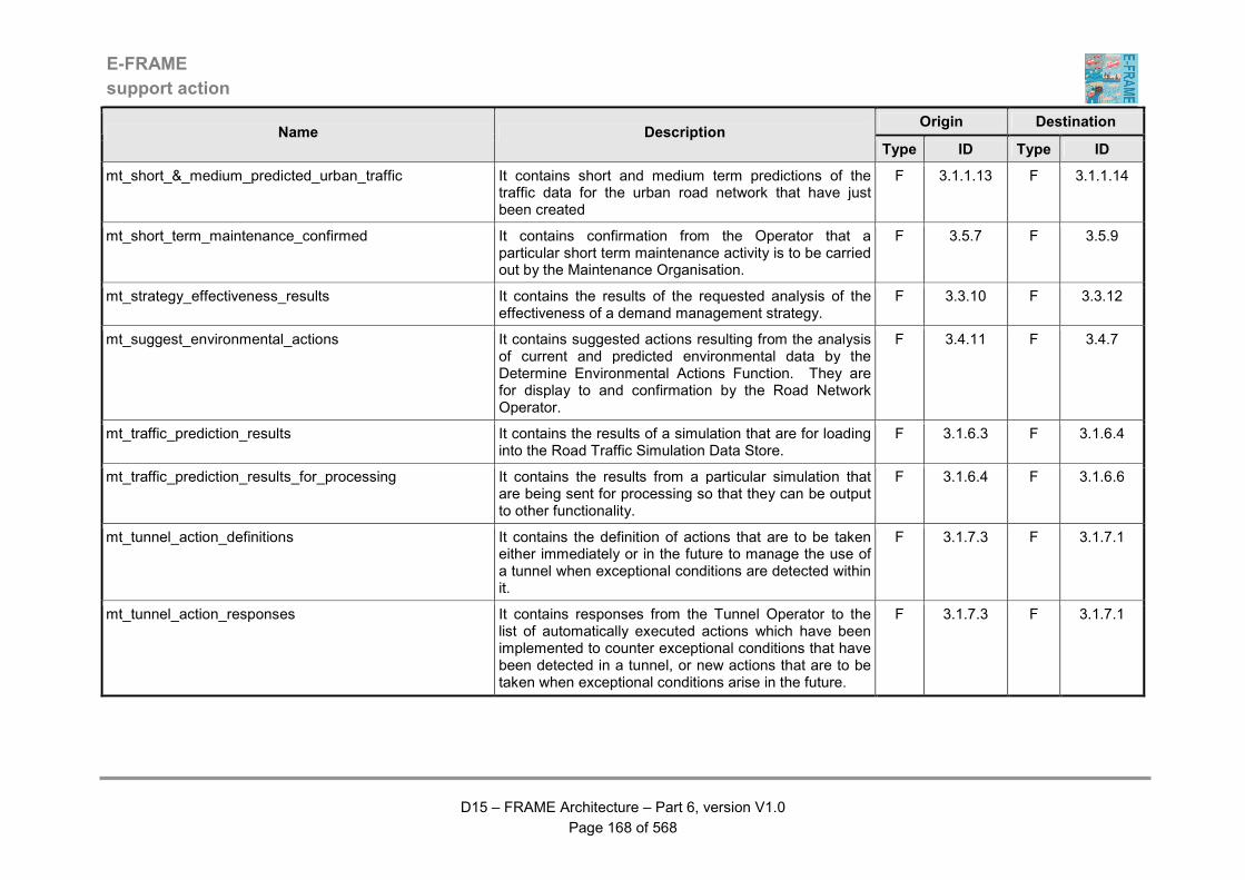
E-FRAME
support action
D15 – FRAME Architecture – Part 6, version V1.0
Page 168 of 568
Origin Destination Name Description
Type ID Type ID
mt_short_&_medium_predicted_urban_traffic It contains short and medium term predictions of the traffic data for the urban road network that have just been created
F 3.1.1.13 F 3.1.1.14
mt_short_term_maintenance_confirmed It contains confirmation from the Operator that a particular short term maintenance activity is to be carried out by the Maintenance Organisation.
F 3.5.7 F 3.5.9
mt_strategy_effectiveness_results It contains the results of the requested analysis of the effectiveness of a demand management strategy.
F 3.3.10 F 3.3.12
mt_suggest_environmental_actions It contains suggested actions resulting from the analysis of current and predicted environmental data by the Determine Environmental Actions Function. They are for display to and confirmation by the Road Network Operator.
F 3.4.11 F 3.4.7
mt_traffic_prediction_results It contains the results of a simulation that are for loading into the Road Traffic Simulation Data Store.
F 3.1.6.3 F 3.1.6.4
mt_traffic_prediction_results_for_processing It contains the results from a particular simulation that are being sent for processing so that they can be output to other functionality.
F 3.1.6.4 F 3.1.6.6
mt_tunnel_action_definitions It contains the definition of actions that are to be taken either immediately or in the future to manage the use of a tunnel when exceptional conditions are detected within it.
F 3.1.7.3 F 3.1.7.1
mt_tunnel_action_responses It contains responses from the Tunnel Operator to the list of automatically executed actions which have been implemented to counter exceptional conditions that have been detected in a tunnel, or new actions that are to be taken when exceptional conditions arise in the future.
F 3.1.7.3 F 3.1.7.1
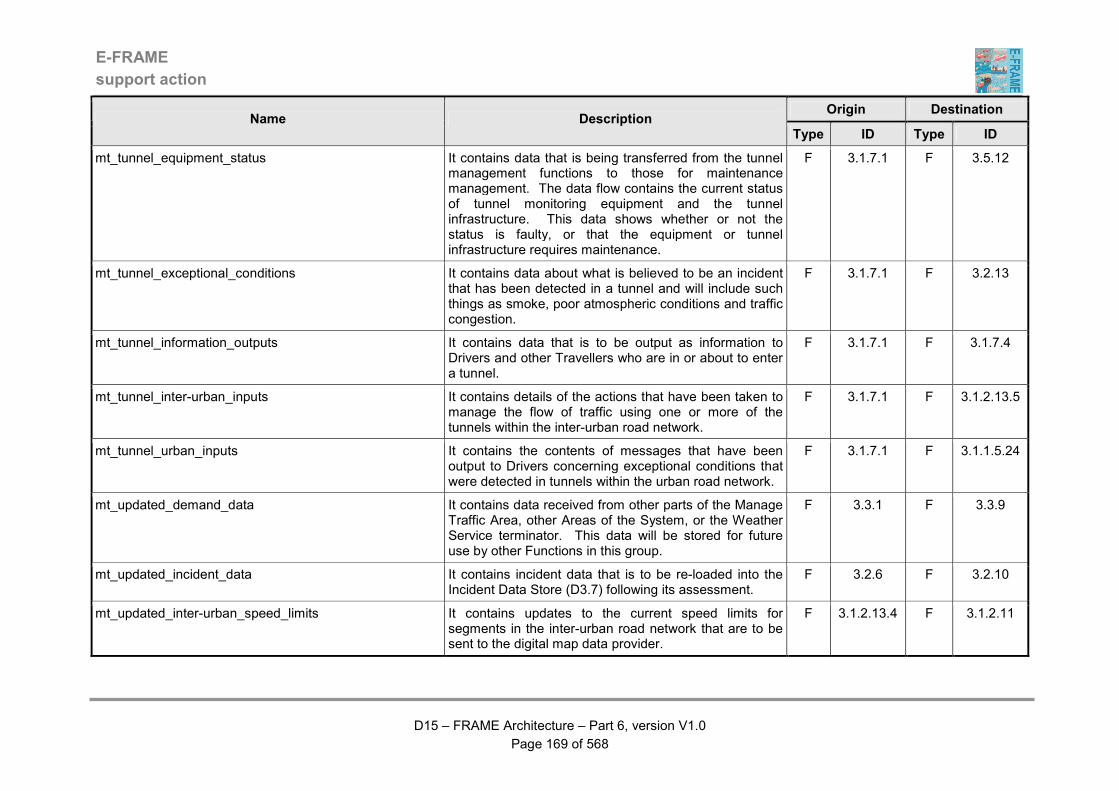
E-FRAME
support action
D15 – FRAME Architecture – Part 6, version V1.0
Page 169 of 568
Origin Destination Name Description
Type ID Type ID
mt_tunnel_equipment_status It contains data that is being transferred from the tunnel management functions to those for maintenance management. The data flow contains the current status of tunnel monitoring equipment and the tunnel infrastructure. This data shows whether or not the status is faulty, or that the equipment or tunnel infrastructure requires maintenance.
F 3.1.7.1 F 3.5.12
mt_tunnel_exceptional_conditions It contains data about what is believed to be an incident that has been detected in a tunnel and will include such things as smoke, poor atmospheric conditions and traffic congestion.
F 3.1.7.1 F 3.2.13
mt_tunnel_information_outputs It contains data that is to be output as information to Drivers and other Travellers who are in or about to enter a tunnel.
F 3.1.7.1 F 3.1.7.4
mt_tunnel_inter-urban_inputs It contains details of the actions that have been taken to manage the flow of traffic using one or more of the tunnels within the inter-urban road network.
F 3.1.7.1 F 3.1.2.13.5
mt_tunnel_urban_inputs It contains the contents of messages that have been output to Drivers concerning exceptional conditions that were detected in tunnels within the urban road network.
F 3.1.7.1 F 3.1.1.5.24
mt_updated_demand_data It contains data received from other parts of the Manage Traffic Area, other Areas of the System, or the Weather Service terminator. This data will be stored for future use by other Functions in this group.
F 3.3.1 F 3.3.9
mt_updated_incident_data It contains incident data that is to be re-loaded into the Incident Data Store (D3.7) following its assessment.
F 3.2.6 F 3.2.10
mt_updated_inter-urban_speed_limits It contains updates to the current speed limits for segments in the inter-urban road network that are to be sent to the digital map data provider.
F 3.1.2.13.4 F 3.1.2.11
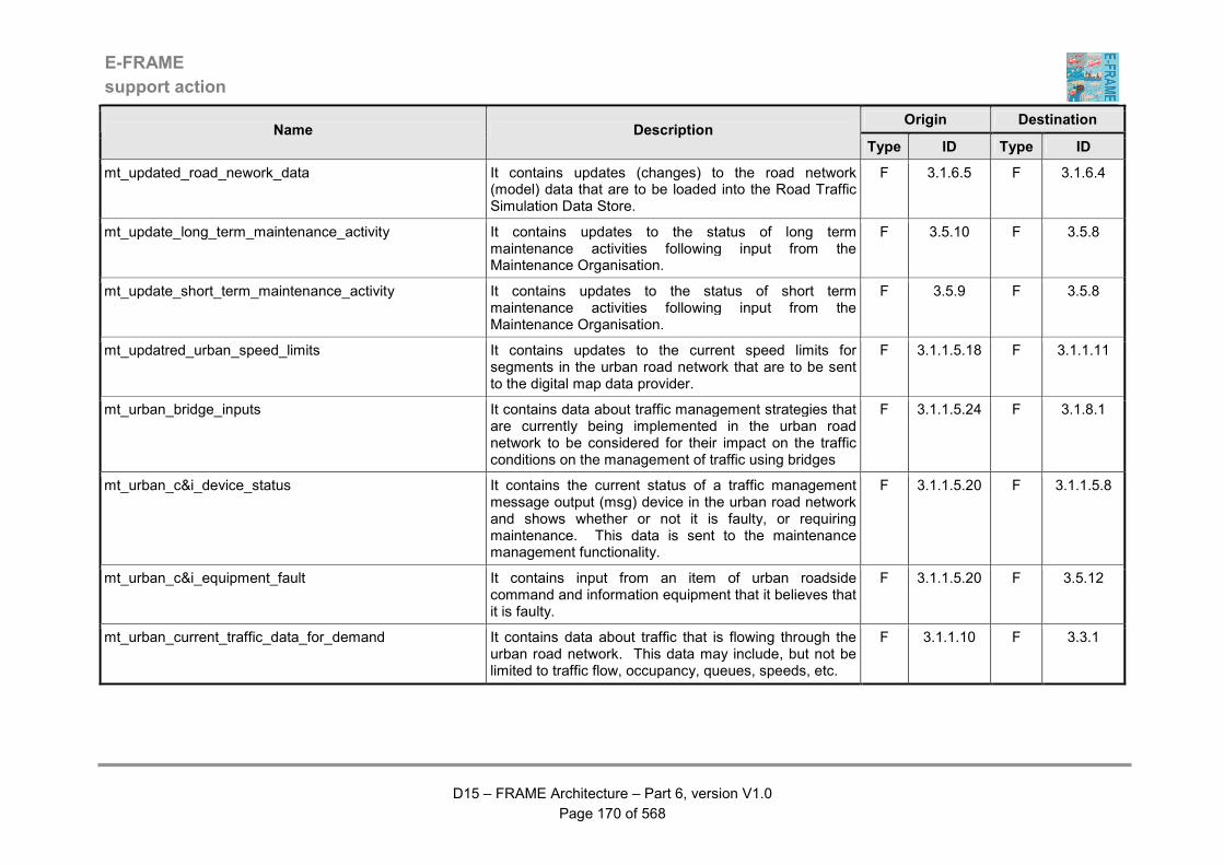
E-FRAME
support action
D15 – FRAME Architecture – Part 6, version V1.0
Page 170 of 568
Origin Destination Name Description
Type ID Type ID
mt_updated_road_nework_data It contains updates (changes) to the road network (model) data that are to be loaded into the Road Traffic Simulation Data Store.
F 3.1.6.5 F 3.1.6.4
mt_update_long_term_maintenance_activity It contains updates to the status of long term maintenance activities following input from the Maintenance Organisation.
F 3.5.10 F 3.5.8
mt_update_short_term_maintenance_activity It contains updates to the status of short term maintenance activities following input from the Maintenance Organisation.
F 3.5.9 F 3.5.8
mt_updatred_urban_speed_limits It contains updates to the current speed limits for segments in the urban road network that are to be sent to the digital map data provider.
F 3.1.1.5.18 F 3.1.1.11
mt_urban_bridge_inputs It contains data about traffic management strategies that are currently being implemented in the urban road network to be considered for their impact on the traffic conditions on the management of traffic using bridges
F 3.1.1.5.24 F 3.1.8.1
mt_urban_c&i_device_status It contains the current status of a traffic management message output (msg) device in the urban road network and shows whether or not it is faulty, or requiring maintenance. This data is sent to the maintenance management functionality.
F 3.1.1.5.20 F 3.1.1.5.8
mt_urban_c&i_equipment_fault It contains input from an item of urban roadside command and information equipment that it believes that it is faulty.
F 3.1.1.5.20 F 3.5.12
mt_urban_current_traffic_data_for_demand It contains data about traffic that is flowing through the urban road network. This data may include, but not be limited to traffic flow, occupancy, queues, speeds, etc.
F 3.1.1.10 F 3.3.1

E-FRAME
support action
D15 – FRAME Architecture – Part 6, version V1.0
Page 171 of 568
Origin Destination Name Description
Type ID Type ID
mt_urban_data_for_approaching_vehicles It contains the data for information and warning messages plus commands that are being sent to approaching Vehicles using the urban road network, which is for output to their Drivers using in-Vehicle devices.
F 3.1.1.5.20 F 3.1.1.5.21
mt_urban_data_for_traffic_predictions It contains current and historic traffic data for use in the calculation of predicted traffic data.
F 3.1.1.14 F 3.1.6.2
mt_urban_demand_management_strategy It contains the portion of a demand management strategy that affects the way in which traffic using the urban road network managed by the System. As an alternative it can contain the request to cancel a strategy implementation command sent previously.
F 3.3.7 F 3.1.1.5.24
mt_urban_device_s&g_status It contains the current status of a traffic management stop and go (s&g) device in the urban road network and shows whether or not it is faulty, or requiring maintenance. This data is sent to the maintenance management functionality.
F 3.1.1.5.22 F 3.1.1.5.8
mt_urban_environmental_inputs It contains details of current and predicted environmental conditions for the geographic area managed by the System for use in managing traffic on the urban road network. This data will be used both to influence traffic management strategies and as the source of pollution warning messages for output to Drivers and Travellers.
F 3.4.11 F 3.1.1.5.24
mt_urban_equipment_information It contains details about equipment that is located either in the urban road network or is connected to equipment that is. The details may include but not be limited to its type, location, maintenance history and the particular Maintenance Organisation that carries out its maintenance and repairs.
F 3.1.1.6 F 3.5.12
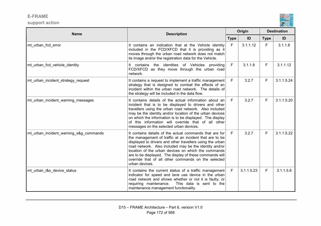
E-FRAME
support action
D15 – FRAME Architecture – Part 6, version V1.0
Page 172 of 568
Origin Destination Name Description
Type ID Type ID
mt_urban_fcd_error It contains an indication that at the Vehicle identity included in the FCD/XFCD that it is providing as it moves through the urban road network does not match its image and/or the registration data for the Vehicle.
F 3.1.1.12 F 3.1.1.8
mt_urban_fcd_vehicle_identity It contains the identities of Vehicles providing FCD/XFCD as they move through the urban road network.
F 3.1.1.8 F 3.1.1.12
mt_urban_incident_strategy_request It contains a request to implement a traffic management strategy that is designed to combat the effects of an incident within the urban road network. The details of the strategy will be included in the data flow.
F 3.2.7 F 3.1.1.5.24
mt_urban_incident_warning_messages It contains details of the actual information about an incident that is to be displayed to drivers and other travellers using the urban road network. Also included may be the identity and/or location of the urban devices on which the information is to be displayed. The display of this information will override that of all other messages on the selected urban devices.
F 3.2.7 F 3.1.1.5.20
mt_urban_incident_warning_s&g_commands It contains details of the actual commands that are for the management of traffic at an incident that are to be displayed to drivers and other travellers using the urban road network. Also included may be the identity and/or location of the urban devices on which the commands are to be displayed. The display of these commands will override that of all other commands on the selected urban devices.
F 3.2.7 F 3.1.1.5.22
mt_urban_l&s_device_status It contains the current status of a traffic management indicator for speed and lane use device in the urban road network and shows whether or not it is faulty, or requiring maintenance. This data is sent to the maintenance management functionality.
F 3.1.1.5.23 F 3.1.1.5.8
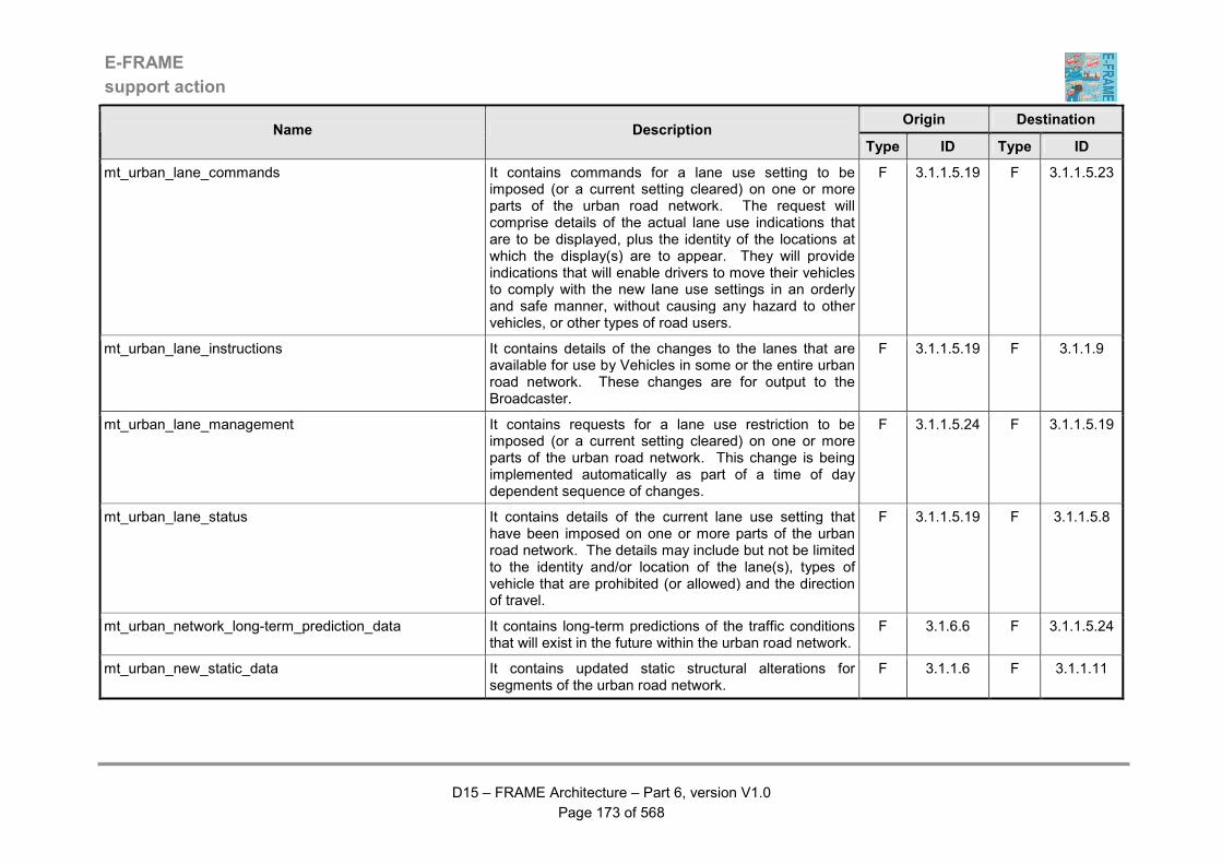
E-FRAME
support action
D15 – FRAME Architecture – Part 6, version V1.0
Page 173 of 568
Origin Destination Name Description
Type ID Type ID
mt_urban_lane_commands It contains commands for a lane use setting to be imposed (or a current setting cleared) on one or more parts of the urban road network. The request will comprise details of the actual lane use indications that are to be displayed, plus the identity of the locations at which the display(s) are to appear. They will provide indications that will enable drivers to move their vehicles to comply with the new lane use settings in an orderly and safe manner, without causing any hazard to other vehicles, or other types of road users.
F 3.1.1.5.19 F 3.1.1.5.23
mt_urban_lane_instructions It contains details of the changes to the lanes that are available for use by Vehicles in some or the entire urban road network. These changes are for output to the Broadcaster.
F 3.1.1.5.19 F 3.1.1.9
mt_urban_lane_management It contains requests for a lane use restriction to be imposed (or a current setting cleared) on one or more parts of the urban road network. This change is being implemented automatically as part of a time of day dependent sequence of changes.
F 3.1.1.5.24 F 3.1.1.5.19
mt_urban_lane_status It contains details of the current lane use setting that have been imposed on one or more parts of the urban road network. The details may include but not be limited to the identity and/or location of the lane(s), types of vehicle that are prohibited (or allowed) and the direction of travel.
F 3.1.1.5.19 F 3.1.1.5.8
mt_urban_network_long-term_prediction_data It contains long-term predictions of the traffic conditions that will exist in the future within the urban road network.
F 3.1.6.6 F 3.1.1.5.24
mt_urban_new_static_data It contains updated static structural alterations for segments of the urban road network.
F 3.1.1.6 F 3.1.1.11
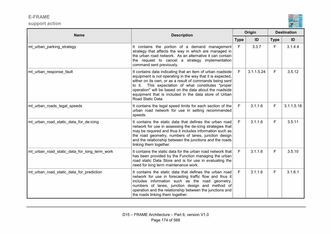
E-FRAME
support action
D15 – FRAME Architecture – Part 6, version V1.0
Page 174 of 568
Origin Destination Name Description
Type ID Type ID
mt_urban_parking_strategy It contains the portion of a demand management strategy that affects the way in which are managed in the urban road network. As an alternative it can contain the request to cancel a strategy implementation command sent previously.
F 3.3.7 F 3.1.4.4
mt_urban_response_fault It contains data indicating that an item of urban roadside equipment is not operating in the way that it is expected, either on its own, or as a result of commands being sent to it. This expectation of what constitutes "proper operation" will be based on the data about the roadside equipment that is included in the data store of Urban Road Static Data.
F 3.1.1.5.24 F 3.5.12
mt_urban_roads_legal_speeds It contains the legal speed limits for each section of the urban road network for use in setting recommended speeds.
F 3.1.1.6 F 3.1.1.5.18
mt_urban_road_static_data_for_de-icing It contains the static data that defines the urban road network for use in assessing the de-icing strategies that may be required and thus it includes information such as the road geometry, numbers of lanes, junction design and the relationship between the junctions and the roads linking them together.
F 3.1.1.6 F 3.5.11
mt_urban_road_static_data_for_long_term_work It contains the static data for the urban road network that has been provided by the Function managing the urban road static Data Store and is for use in evaluating the need for long term maintenance work.
F 3.1.1.6 F 3.5.10
mt_urban_road_static_data_for_prediction It contains the static data that defines the urban road network for use in forecasting traffic flow and thus it includes information such as the road geometry, numbers of lanes, junction design and method of operation and the relationship between the junctions and the roads linking them together.
F 3.1.1.6 F 3.1.6.1
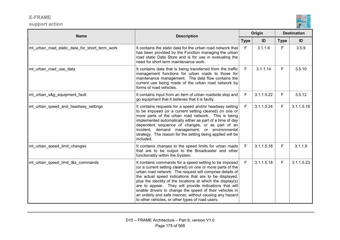
E-FRAME
support action
D15 – FRAME Architecture – Part 6, version V1.0
Page 175 of 568
Origin Destination Name Description
Type ID Type ID
mt_urban_road_static_data_for_short_term_work It contains the static data for the urban road network that has been provided by the Function managing the urban road static Data Store and is for use in evaluating the need for short term maintenance work.
F 3.1.1.6 F 3.5.9
mt_urban_road_use_data It contains data that is being transferred from the traffic management functions for urban roads to those for maintenance management. The data flow contains the current use being made of the urban road network by forms of road vehicles.
F 3.1.1.14 F 3.5.10
mt_urban_s&g_equipment_fault It contains input from an item of urban roadside stop and go equipment that it believes that it is faulty.
F 3.1.1.5.22 F 3.5.12
mt_urban_speed_and_headway_settings It contains requests for a speed and/or headway setting to be imposed (or a current setting cleared) on one or more parts of the urban road network. This is being implemented automatically either as part of a time of day dependent sequence of changes, or as part of an incident, demand management, or environmental strategy. The reason for the setting being applied will be included.
F 3.1.1.5.24 F 3.1.1.5.18
mt_urban_speed_limit_changes It contains changes to the speed limits for urban roads that are to be output to the Broadcaster and other functionality within the System.
F 3.1.1.5.18 F 3.1.1.9
mt_urban_speed_limit_l&s_commands It contains commands for a speed setting to be imposed (or a current setting cleared) on one or more parts of the urban road network. The request will comprise details of the actual speed indications that are to be displayed, plus the identity of the locations at which the display(s) are to appear. They will provide indications that will enable drivers to change the speed of their vehicles in an orderly and safe manner, without causing any hazard to other vehicles, or other types of road users.
F 3.1.1.5.18 F 3.1.1.5.23

E-FRAME
support action
D15 – FRAME Architecture – Part 6, version V1.0
Page 176 of 568
Origin Destination Name Description
Type ID Type ID
mt_urban_speed_value It contains a speed value that is to check for violations by vehicles in a part of the urban road network. This is being implemented automatically as part of a time of day dependent sequence of changes, or at the request of the Operator, or as a result of the implementation of an incident management strategy.
F 3.1.1.5.24 F 3.1.1.5.8
mt_urban_static_data It contains urban traffic static data that is to be used by the urban traffic management Function. It includes data about the operation of junctions, speed limits, numbers of lanes, etc. for each part of the urban road network. This data will be part of that used to determine and implement the most appropriate method of traffic management and monitor that instructions being sent to roadside equipment are being obeyed.
F 3.1.1.6 F 3.1.1.5.24
mt_urban_static_data_changes It contains updated and/or additional urban static road data that is to be loaded into the Data Store D3.7.
F 3.1.1.5.10 F 3.1.1.6
mt_urban_static_data_for_traffic_conditions It contains the static data about the urban road network that is for use in the storage and output of urban traffic conditions data.
F 3.1.1.6 F 3.1.1.14
mt_urban_static_data_read It contains data that has been read from the Urban Traffic Static Data Store.
D D3.7 F 3.1.1.6
mt_urban_static_data_update It contains data that is being loaded into the Urban Traffic Static Data Store.
F 3.1.1.6 D D3.7
mt_urban_strategies_for_long-term It contains details of one or more traffic management strategies that are to be made available for long-term future use by the functionality that manages the traffic within the urban road network.
F 3.1.6.6 F 3.1.1.5.2
mt_urban_strategies_in_use It contains details of the traffic management strategies that are currently in use in the urban road network. This data can be associated with traffic data so that the impact of particular strategies can be assessed.
F 3.1.1.5.24 F 3.1.6.4
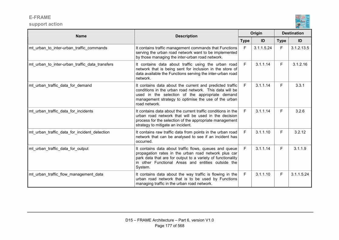
E-FRAME
support action
D15 – FRAME Architecture – Part 6, version V1.0
Page 177 of 568
Origin Destination Name Description
Type ID Type ID
mt_urban_to_inter-urban_traffic_commands It contains traffic management commands that Functions serving the urban road network want to be implemented by those managing the inter-urban road network.
F 3.1.1.5.24 F 3.1.2.13.5
mt_urban_to_inter-urban_traffic_data_transfers It contains data about traffic using the urban road network that is being sent for inclusion in the store of data available the Functions serving the inter-urban road network.
F 3.1.1.14 F 3.1.2.16
mt_urban_traffic_data_for_demand It contains data about the current and predicted traffic conditions in the urban road network. This data will be used in the selection of the appropriate demand management strategy to optimise the use of the urban road network.
F 3.1.1.14 F 3.3.1
mt_urban_traffic_data_for_incidents It contains data about the current traffic conditions in the urban road network that will be used in the decision process for the selection of the appropriate management strategy to mitigate an incident.
F 3.1.1.14 F 3.2.6
mt_urban_traffic_data_for_incident_detection It contains raw traffic data from points in the urban road network that can be analysed to see if an incident has occurred.
F 3.1.1.10 F 3.2.12
mt_urban_traffic_data_for_output It contains data about traffic flows, queues and queue propagation rates in the urban road network plus car park data that are for output to a variety of functionality in other Functional Areas and entities outside the System.
F 3.1.1.14 F 3.1.1.9
mt_urban_traffic_flow_management_data It contains data about the way traffic is flowing in the urban road network that is to be used by Functions managing traffic in the urban road network.
F 3.1.1.10 F 3.1.1.5.24

E-FRAME
support action
D15 – FRAME Architecture – Part 6, version V1.0
Page 178 of 568
Origin Destination Name Description
Type ID Type ID
mt_urban_traffic_long-term_prediction_data It contains predictions of the traffic conditions based on the results of a simulation model. This data is to be loaded into the traffic data Store and shall comprise long-term predicts of vehicle flow, vehicle speed, vehicle headway and road occupancy.
F 3.1.6.6 F 3.1.1.14
mt_urban_traffic_maintenance_conditions It contains data that is being transferred from the traffic management functions for urban roads to those for maintenance management. The data flow contains the current traffic conditions within the urban road network.
F 3.1.1.14 F 3.5.9
mt_urban_traffic_management_c&i_request It contains details of the outputs that are to be displayed by as a message to drivers and other travellers using the urban road network. These details may include but not be limited to the identity and/or location of the actuator and the actual output to be displayed.
F 3.1.1.5.24 F 3.1.1.5.20
mt_urban_traffic_management_c&i_response It contains details of the response to the previous request for output of a message to drivers, cyclists and pedestrians using the urban road network. These details may include but not be limited to the identity and/or location of the device from which the command was output and if the output was made, i.e. did the device appear to work, or was it faulty?
F 3.1.1.5.20 F 3.1.1.5.24
mt_urban_traffic_management_l&s_response It contains details of the response to the previous request for lane use and maximum speeds to be assessed and resulting commands output to drivers using the urban road network. These details may include but not be limited to the identity and/or location of the device from which the command was output and if the output was made, i.e. did it the device appear to work, or was it faulty?
F 3.1.1.5.23 F 3.1.1.5.24
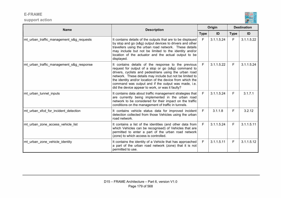
E-FRAME
support action
D15 – FRAME Architecture – Part 6, version V1.0
Page 179 of 568
Origin Destination Name Description
Type ID Type ID
mt_urban_traffic_management_s&g_requests It contains details of the outputs that are to be displayed by stop and go (s&g) output devices to drivers and other travellers using the urban road network. These details may include but not be limited to the identity and/or location of the actuator and the actual output to be displayed.
F 3.1.1.5.24 F 3.1.1.5.22
mt_urban_traffic_management_s&g_response It contains details of the response to the previous request for output of a stop or go (s&g) command to drivers, cyclists and pedestrians using the urban road network. These details may include but not be limited to the identity and/or location of the device from which the command was output and if the output was made, i.e. did the device appear to work, or was it faulty?
F 3.1.1.5.22 F 3.1.1.5.24
mt_urban_tunnel_inputs It contains data about traffic management strategies that are currently being implemented in the urban road network to be considered for their impact on the traffic conditions on the management of traffic in tunnels.
F 3.1.1.5.24 F 3.1.7.1
mt_urban_xfcd_for_incident_detection It contains vehicle status data for improved incident detection collected from those Vehicles using the urban road network.
F 3.1.1.8 F 3.2.12
mt_urban_zone_access_vehicle_list It contains a list of the identities (and other data from which Vehicles can be recognised) of Vehicles that are permitted to enter a part of the urban road network (zone) to which access is controlled.
F 3.1.1.5.24 F 3.1.1.5.11
mt_urban_zone_vehicle_identity It contains the identity of a Vehicle that has approached a part of the urban road network (zone) that it is not permitted to use.
F 3.1.1.5.11 F 3.1.1.5.12

E-FRAME
support action
D15 – FRAME Architecture – Part 6, version V1.0
Page 180 of 568
Origin Destination Name Description
Type ID Type ID
mt_urban_zoning_strategy It contains the portion of a demand management strategy that affects the way in which zoning is applied to traffic using the urban road network managed by the System. As an alternative it can contain the request to cancel a strategy implementation command sent previously.
F 3.3.7 F 3.1.1.5.24
mt_vehicle_in_carpark_space It contains indication that a vehicle has just arrived in car park space.
F 3.1.4.3 F 3.1.4.6
mt_weather_condition_data_inputs It contains data about weather conditions in the geographic area managed by the System. This data will be in two parts, one for current data and the other for forecast data. Sensors that are part of another Function in the Manage Traffic Area will have collected the current data. The forecast data will have been obtained from a specialist system through a terminator.
F 3.4.1 F 3.4.8
pepf-load_account_order_transactions It is used to credit an EP account from an account located in a financial clearing-house. The data flow contains the following elements: - date - user ID - EP account ID - financial clearing-house ID - source account ID - amount transferred
F 1.2.1 D D1.4
pepf.mffo_payment_receipt_MOT It contains the payment receipts provided that are being returned to the Manage Freight and Fleet Operations Area by the electronic payment system upon reception of the payment of the transaction. It is composed of several data flows: amount of the transaction, date / time, location, mode of payment, other parameters necessary to define precisely the service provider, service ID and user ID.
F 1.3.7 F 8.3.1.4
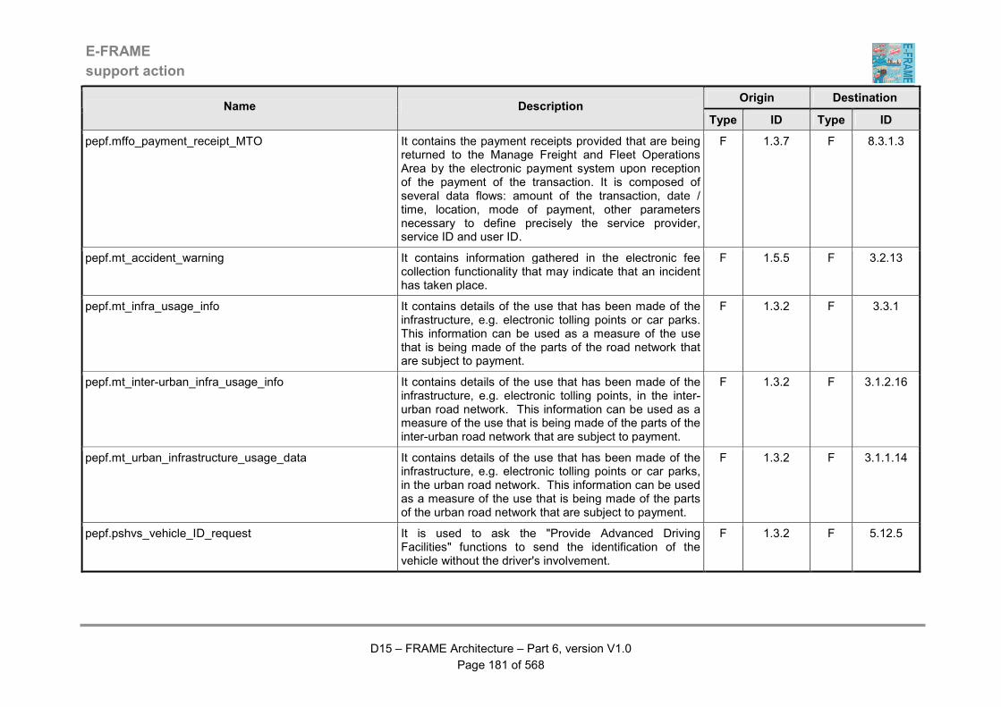
E-FRAME
support action
D15 – FRAME Architecture – Part 6, version V1.0
Page 181 of 568
Origin Destination Name Description
Type ID Type ID
pepf.mffo_payment_receipt_MTO It contains the payment receipts provided that are being returned to the Manage Freight and Fleet Operations Area by the electronic payment system upon reception of the payment of the transaction. It is composed of several data flows: amount of the transaction, date / time, location, mode of payment, other parameters necessary to define precisely the service provider, service ID and user ID.
F 1.3.7 F 8.3.1.3
pepf.mt_accident_warning It contains information gathered in the electronic fee collection functionality that may indicate that an incident has taken place.
F 1.5.5 F 3.2.13
pepf.mt_infra_usage_info It contains details of the use that has been made of the infrastructure, e.g. electronic tolling points or car parks. This information can be used as a measure of the use that is being made of the parts of the road network that are subject to payment.
F 1.3.2 F 3.3.1
pepf.mt_inter-urban_infra_usage_info It contains details of the use that has been made of the infrastructure, e.g. electronic tolling points, in the inter-urban road network. This information can be used as a measure of the use that is being made of the parts of the inter-urban road network that are subject to payment.
F 1.3.2 F 3.1.2.16
pepf.mt_urban_infrastructure_usage_data It contains details of the use that has been made of the infrastructure, e.g. electronic tolling points or car parks, in the urban road network. This information can be used as a measure of the use that is being made of the parts of the urban road network that are subject to payment.
F 1.3.2 F 3.1.1.14
pepf.pshvs_vehicle_ID_request It is used to ask the "Provide Advanced Driving Facilities" functions to send the identification of the vehicle without the driver's involvement.
F 1.3.2 F 5.12.5

E-FRAME
support action
D15 – FRAME Architecture – Part 6, version V1.0
Page 182 of 568
Origin Destination Name Description
Type ID Type ID
pepf.psle_fraud_notification_DAV It is used to send details of a fraud to functionality in the Law Enforcement Area where is can be processed before being sent to the Law Enforcement Agency terminator.
F 1.5.3 F 7.3.5
pepf.psle_fraud_notification_DPV It is used to send details of a fraud to functionality in the Law Enforcement Area where is can be processed before being sent to the Law Enforcement Agency terminator.
F 1.5.2 F 7.3.5
pepf.ptja_service_price It is used to provide the tariff associated with a service. The data flow includes the following elements: - operator or external service provider ID, - service ID- other parameters allowing a definition of the service (level of quality, duration, period of day or year, etc.) - tariff, possibly modulated according to the kind of contract, and the mode of payment.
F 1.3.4 F 6.5.3.9
pepf_access_criteria_L It contains the access rights criteria for the services provided.
F 1.6.2 D D1.7
pepf_access_criteria_R It is an extract from the ''access Rights'' store, and contains the access rights criteria for the service required.
D D1.7 F 1.5.1
pepf_access_refused It is emitted by the "Detect Payment Violation" function when a user's account used for a transaction is on the black list. The data flow contains the following elements: - user ID - account ID - reason of access refusal
F 1.5.2 F 1.3.7
pepf_account_status_for_debiting It contains information about the current account status and is for in debiting the account.
D D1.2 F 1.2.2
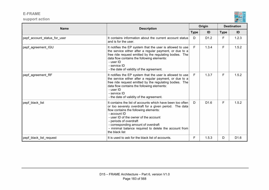
E-FRAME
support action
D15 – FRAME Architecture – Part 6, version V1.0
Page 183 of 568
Origin Destination Name Description
Type ID Type ID
pepf_account_status_for_user It contains information about the current account status and is for the user.
D D1.2 F 1.2.3
pepf_agreement_IGU It notifies the EP system that the user is allowed to use the service either after a regular payment, or due to a free ride request emitted by the regulating bodies. The data flow contains the following elements: - user ID - service ID - the date of validity of the agreement.
F 1.3.4 F 1.5.2
pepf_agreement_RF It notifies the EP system that the user is allowed to use the service either after a regular payment, or due to a free ride request emitted by the regulating bodies. The data flow contains the following elements: - user ID - service ID - the date of validity of the agreement.
F 1.3.7 F 1.5.2
pepf_black_list It contains the list of accounts which have been too often or too severely overdraft for a given period. The data flow contains the following elements: - account ID - user ID of the owner of the account - periods of overdraft - corresponding amount of overdraft - minimal balance required to delete the account from the black list
D D1.6 F 1.5.2
pepf_black_list_request It is used to ask for the black list of accounts. F 1.5.3 D D1.6

E-FRAME
support action
D15 – FRAME Architecture – Part 6, version V1.0
Page 184 of 568
Origin Destination Name Description
Type ID Type ID
pepf_black_list_update It is used to modify the black list, by adding or deleting some records. The data flow contains the following elements: - date: and for each modification: - addition or suppression indicator - account ID - user ID - if deletion, balance of the account - if addition, history of overdraft, minimum balanced required to suppress it from the list
F 1.5.2 D D1.6
pepf_block_free_command_DAV It is sent to the ''Block Access'' function to ask for a change of state of the access blocking systems
F 1.5.3 F 1.5.5
pepf_block_free_command_DPV It is sent to the "Block Access" function to ask for a change of state of the access blocking systems
F 1.5.2 F 1.5.5
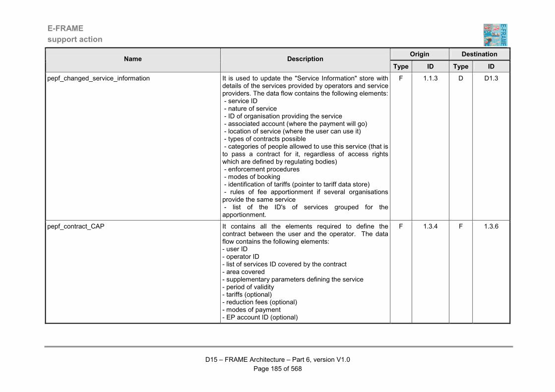
E-FRAME
support action
D15 – FRAME Architecture – Part 6, version V1.0
Page 185 of 568
Origin Destination Name Description
Type ID Type ID
pepf_changed_service_information It is used to update the "Service Information" store with details of the services provided by operators and service providers. The data flow contains the following elements: - service ID - nature of service - ID of organisation providing the service - associated account (where the payment will go) - location of service (where the user can use it) - types of contracts possible - categories of people allowed to use this service (that is to pass a contract for it, regardless of access rights which are defined by regulating bodies) - enforcement procedures - modes of booking - identification of tariffs (pointer to tariff data store) - rules of fee apportionment if several organisations provide the same service - list of the ID's of services grouped for the apportionment.
F 1.1.3 D D1.3
pepf_contract_CAP It contains all the elements required to define the contract between the user and the operator. The data flow contains the following elements: - user ID - operator ID - list of services ID covered by the contract - area covered - supplementary parameters defining the service - period of validity - tariffs (optional) - reduction fees (optional) - modes of payment - EP account ID (optional)
F 1.3.4 F 1.3.6

E-FRAME
support action
D15 – FRAME Architecture – Part 6, version V1.0
Page 186 of 568
Origin Destination Name Description
Type ID Type ID
pepf_contract_CSF It contains all the elements required to define the contract between the user and the operator. The data flow contains the following elements: - user ID - operator ID - list of services ID covered by the contract - area covered - supplementary parameters defining the service - period of validity - tariffs (optional) - reduction fees (optional) - modes of payment - EP account ID (optional)
F 1.3.4 F 1.3.5
pepf_contract_CUC It contains all the elements required to define the contract between the user and the operator. The data flow contains the following elements: - user ID - operator ID - list of services ID covered by the contract - area covered - supplementary parameters defining the service - period of validity - tariffs (optional) - reduction fees (optional) - modes of payment - EP account ID (optional)
D D1.1 F 1.3.3
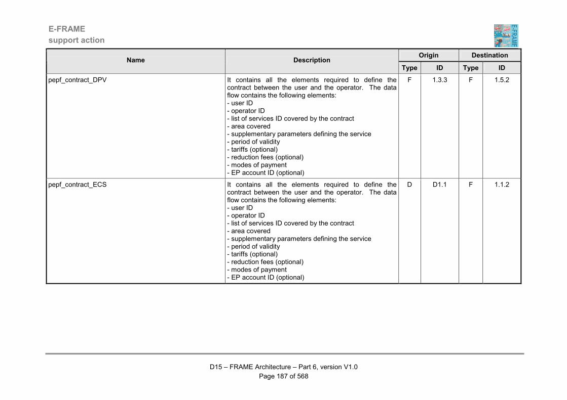
E-FRAME
support action
D15 – FRAME Architecture – Part 6, version V1.0
Page 187 of 568
Origin Destination Name Description
Type ID Type ID
pepf_contract_DPV It contains all the elements required to define the contract between the user and the operator. The data flow contains the following elements: - user ID - operator ID - list of services ID covered by the contract - area covered - supplementary parameters defining the service - period of validity - tariffs (optional) - reduction fees (optional) - modes of payment - EP account ID (optional)
F 1.3.3 F 1.5.2
pepf_contract_ECS It contains all the elements required to define the contract between the user and the operator. The data flow contains the following elements: - user ID - operator ID - list of services ID covered by the contract - area covered - supplementary parameters defining the service - period of validity - tariffs (optional) - reduction fees (optional) - modes of payment - EP account ID (optional)
D D1.1 F 1.1.2

E-FRAME
support action
D15 – FRAME Architecture – Part 6, version V1.0
Page 188 of 568
Origin Destination Name Description
Type ID Type ID
pepf_contract_IGU It contains all the elements required to define the contract between the user and the operator. The data flow contains the following elements: - user ID - operator ID - list of services ID covered by the contract - area covered - supplementary parameters defining the service - period of validity - tariffs (optional) - reduction fees (optional) - modes of payment - EP account ID (optional)
F 1.3.3 F 1.3.4
pepf_contract_LUA It contains all the elements required to define the contract between the user and the operator. The data flow contains the following elements: - user ID - operator ID - list of services ID covered by the contract - area covered - supplementary parameters defining the service - period of validity - tariffs (optional) - reduction fees (optional) - modes of payment - EP account ID (optional)
D D1.1 F 1.2.1
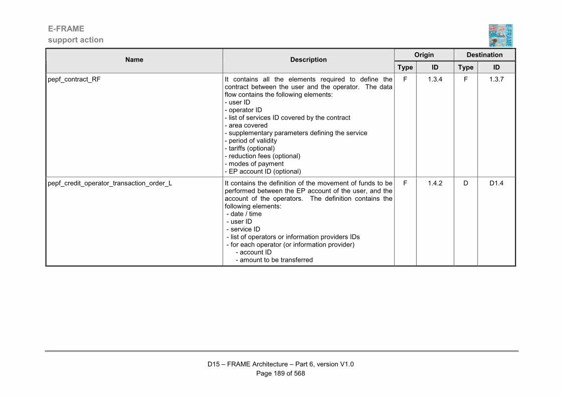
E-FRAME
support action
D15 – FRAME Architecture – Part 6, version V1.0
Page 189 of 568
Origin Destination Name Description
Type ID Type ID
pepf_contract_RF It contains all the elements required to define the contract between the user and the operator. The data flow contains the following elements: - user ID - operator ID - list of services ID covered by the contract - area covered - supplementary parameters defining the service - period of validity - tariffs (optional) - reduction fees (optional) - modes of payment - EP account ID (optional)
F 1.3.4 F 1.3.7
pepf_credit_operator_transaction_order_L It contains the definition of the movement of funds to be performed between the EP account of the user, and the account of the operators. The definition contains the following elements: - date / time - user ID - service ID - list of operators or information providers IDs - for each operator (or information provider) - account ID - amount to be transferred
F 1.4.2 D D1.4
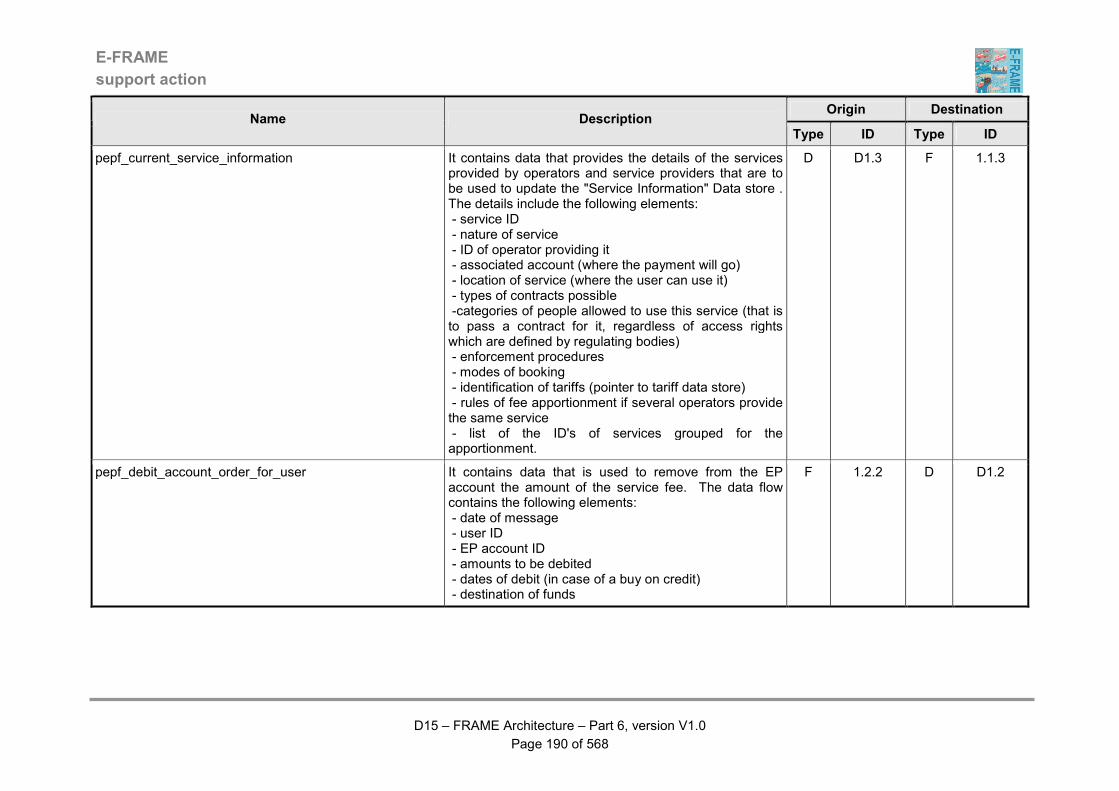
E-FRAME
support action
D15 – FRAME Architecture – Part 6, version V1.0
Page 190 of 568
Origin Destination Name Description
Type ID Type ID
pepf_current_service_information It contains data that provides the details of the services provided by operators and service providers that are to be used to update the "Service Information" Data store . The details include the following elements: - service ID - nature of service - ID of operator providing it - associated account (where the payment will go) - location of service (where the user can use it) - types of contracts possible -categories of people allowed to use this service (that is to pass a contract for it, regardless of access rights which are defined by regulating bodies) - enforcement procedures - modes of booking - identification of tariffs (pointer to tariff data store) - rules of fee apportionment if several operators provide the same service - list of the ID's of services grouped for the apportionment.
D D1.3 F 1.1.3
pepf_debit_account_order_for_user It contains data that is used to remove from the EP account the amount of the service fee. The data flow contains the following elements: - date of message - user ID - EP account ID - amounts to be debited - dates of debit (in case of a buy on credit) - destination of funds
F 1.2.2 D D1.2
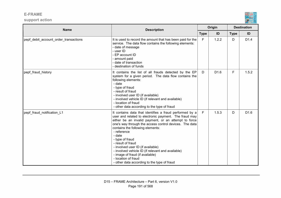
E-FRAME
support action
D15 – FRAME Architecture – Part 6, version V1.0
Page 191 of 568
Origin Destination Name Description
Type ID Type ID
pepf_debit_account_order_transactions It is used to record the amount that has been paid for the service. The data flow contains the following elements: - date of message - user ID - EP account ID - amount paid - date of transaction - destination of funds
F 1.2.2 D D1.4
pepf_fraud_history It contains the list of all frauds detected by the EP system for a given period. The data flow contains the following elements: - date - type of fraud - result of fraud - involved user ID (if available) - involved vehicle ID (if relevant and available) - location of fraud - other data according to the type of fraud
D D1.6 F 1.5.2
pepf_fraud_notification_L1 It contains data that identifies a fraud performed by a user and related to electronic payment. The fraud may either be an invalid payment, or an attempt to force one's way through the access control devices. The data contains the following elements: - reference - date - type of fraud - result of fraud - involved user ID (if available) - involved vehicle ID (if relevant and available) - image of fraud (if available) - location of fraud - other data according to the type of fraud
F 1.5.3 D D1.6
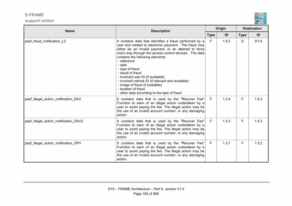
E-FRAME
support action
D15 – FRAME Architecture – Part 6, version V1.0
Page 192 of 568
Origin Destination Name Description
Type ID Type ID
pepf_fraud_notification_L2 It contains data that identifies a fraud performed by a user and related to electronic payment. The fraud may either be an invalid payment, or an attempt to force one's way through the access control devices. The data contains the following elements: - reference - date - type of fraud - result of fraud - involved user ID (if available) - involved vehicle ID (if relevant and available) - image of fraud (if available) - location of fraud - other data according to the type of fraud
F 1.5.2 D D1.6
pepf_illegal_action_notification_DAV It contains data that is used by the "Recover Fee" Function to warn of an illegal action undertaken by a user to avoid paying the fee. The illegal action may be the use of an invalid account number, or any damaging action.
F 1.3.4 F 1.5.3
pepf_illegal_action_notification_DAV2 It contains data that is used by the "Recover Fee" Function to warn of an illegal action undertaken by a user to avoid paying the fee. The illegal action may be the use of an invalid account number, or any damaging action.
F 1.3.3 F 1.5.3
pepf_illegal_action_notification_DPV It contains data that is used by the "Recover Fee" Function to warn of an illegal action undertaken by a user to avoid paying the fee. The illegal action may be the use of an invalid account number, or any damaging action.
F 1.3.7 F 1.5.2
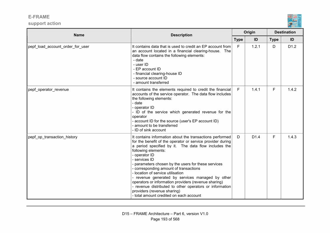
E-FRAME
support action
D15 – FRAME Architecture – Part 6, version V1.0
Page 193 of 568
Origin Destination Name Description
Type ID Type ID
pepf_load_account_order_for_user It contains data that is used to credit an EP account from an account located in a financial clearing-house. The data flow contains the following elements: - date - user ID - EP account ID - financial clearing-house ID - source account ID - amount transferred
F 1.2.1 D D1.2
pepf_operator_revenue It contains the elements required to credit the financial accounts of the service operator. The data flow includes the following elements: - date - operator ID - ID of the service which generated revenue for the operator - account ID for the source (user's EP account ID) - amount to be transferred - ID of sink account
F 1.4.1 F 1.4.2
pepf_op_transaction_history It contains information about the transactions performed for the benefit of the operator or service provider during a period specified by it. The data flow includes the following elements: - operator ID - services ID - parameters chosen by the users for these services - corresponding amount of transactions - location of service utilisation - revenue generated by services managed by other operators or information providers (revenue sharing) - revenue distributed to other operators or information providers (revenue sharing) - total amount credited on each account
D D1.4 F 1.4.3
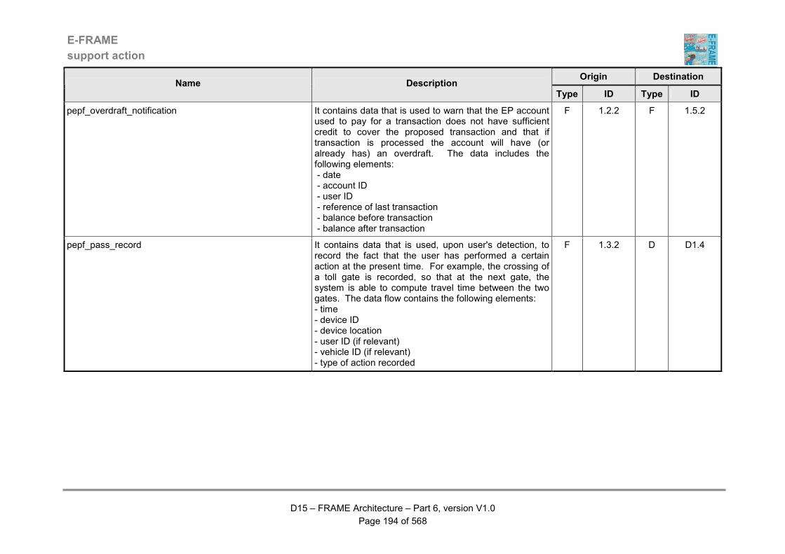
E-FRAME
support action
D15 – FRAME Architecture – Part 6, version V1.0
Page 194 of 568
Origin Destination Name Description
Type ID Type ID
pepf_overdraft_notification It contains data that is used to warn that the EP account used to pay for a transaction does not have sufficient credit to cover the proposed transaction and that if transaction is processed the account will have (or already has) an overdraft. The data includes the following elements: - date - account ID - user ID - reference of last transaction - balance before transaction - balance after transaction
F 1.2.2 F 1.5.2
pepf_pass_record It contains data that is used, upon user's detection, to record the fact that the user has performed a certain action at the present time. For example, the crossing of a toll gate is recorded, so that at the next gate, the system is able to compute travel time between the two gates. The data flow contains the following elements: - time - device ID - device location - user ID (if relevant) - vehicle ID (if relevant) - type of action recorded
F 1.3.2 D D1.4
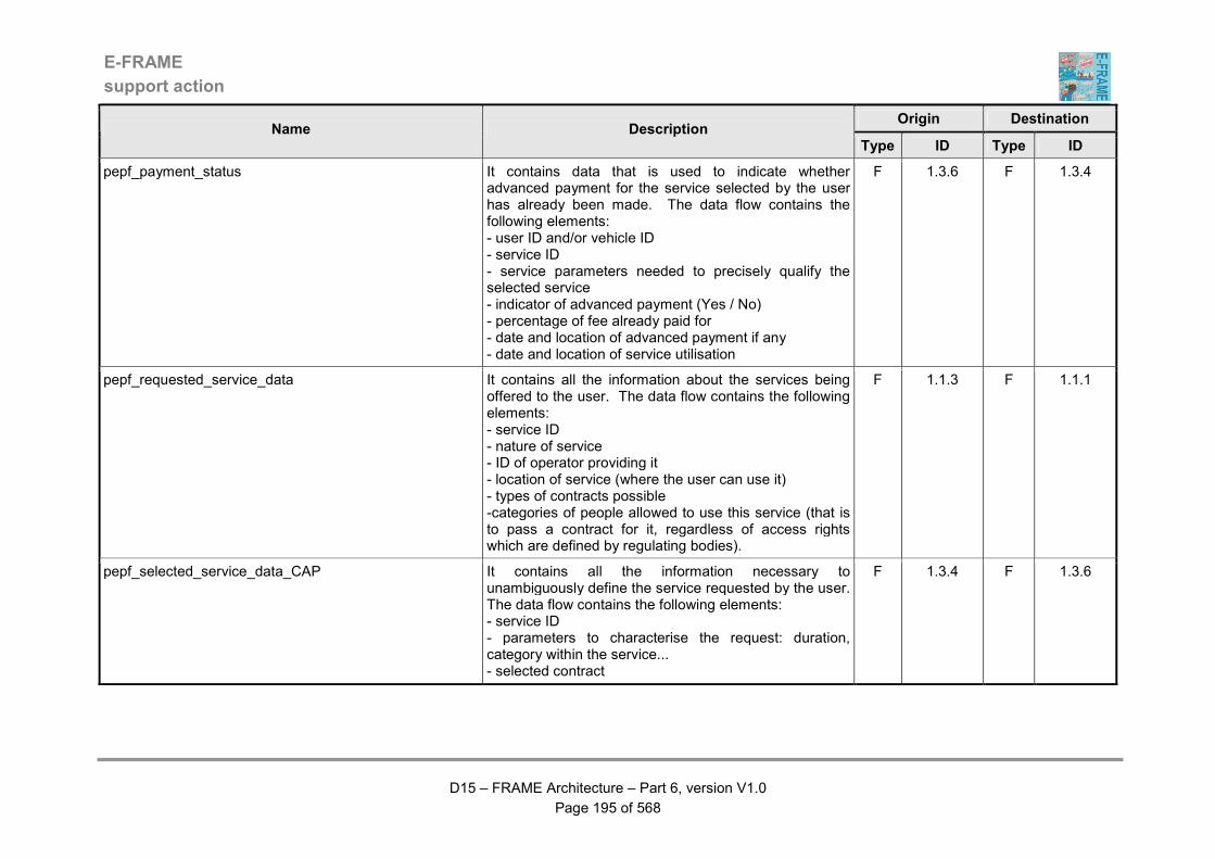
E-FRAME
support action
D15 – FRAME Architecture – Part 6, version V1.0
Page 195 of 568
Origin Destination Name Description
Type ID Type ID
pepf_payment_status It contains data that is used to indicate whether advanced payment for the service selected by the user has already been made. The data flow contains the following elements: - user ID and/or vehicle ID - service ID - service parameters needed to precisely qualify the selected service - indicator of advanced payment (Yes / No) - percentage of fee already paid for - date and location of advanced payment if any - date and location of service utilisation
F 1.3.6 F 1.3.4
pepf_requested_service_data It contains all the information about the services being offered to the user. The data flow contains the following elements: - service ID - nature of service - ID of operator providing it - location of service (where the user can use it) - types of contracts possible -categories of people allowed to use this service (that is to pass a contract for it, regardless of access rights which are defined by regulating bodies).
F 1.1.3 F 1.1.1
pepf_selected_service_data_CAP It contains all the information necessary to unambiguously define the service requested by the user. The data flow contains the following elements: - service ID - parameters to characterise the request: duration, category within the service... - selected contract
F 1.3.4 F 1.3.6
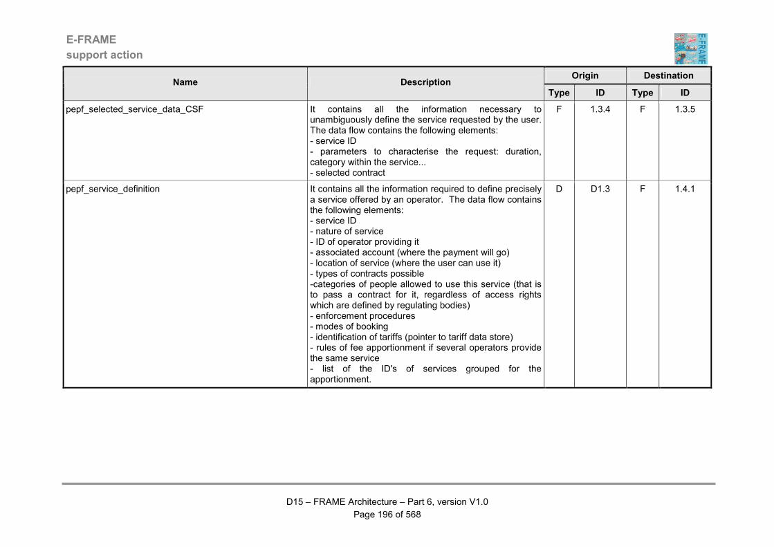
E-FRAME
support action
D15 – FRAME Architecture – Part 6, version V1.0
Page 196 of 568
Origin Destination Name Description
Type ID Type ID
pepf_selected_service_data_CSF It contains all the information necessary to unambiguously define the service requested by the user. The data flow contains the following elements: - service ID - parameters to characterise the request: duration, category within the service... - selected contract
F 1.3.4 F 1.3.5
pepf_service_definition It contains all the information required to define precisely a service offered by an operator. The data flow contains the following elements: - service ID - nature of service - ID of operator providing it - associated account (where the payment will go) - location of service (where the user can use it) - types of contracts possible -categories of people allowed to use this service (that is to pass a contract for it, regardless of access rights which are defined by regulating bodies) - enforcement procedures - modes of booking - identification of tariffs (pointer to tariff data store) - rules of fee apportionment if several operators provide the same service - list of the ID's of services grouped for the apportionment.
D D1.3 F 1.4.1
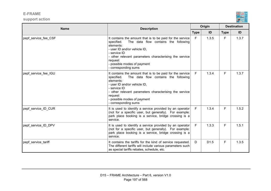
E-FRAME
support action
D15 – FRAME Architecture – Part 6, version V1.0
Page 197 of 568
Origin Destination Name Description
Type ID Type ID
pepf_service_fee_CSF It contains the amount that is to be paid for the service specified. The data flow contains the following elements: - user ID and/or vehicle ID, - service ID - other relevant parameters characterising the service request - possible modes of payment - corresponding sums
F 1.3.5 F 1.3.7
pepf_service_fee_IGU It contains the amount that is to be paid for the service specified. The data flow contains the following elements: - user ID and/or vehicle ID, - service ID - other relevant parameters characterising the service request - possible modes of payment - corresponding sums
F 1.3.4 F 1.3.7
pepf_service_ID_CUR It is used to identify a service provided by an operator (not for a specific user, but generally). For example: park place booking is a service, bridge crossing is a service.
F 1.3.4 F 1.5.2
pepf_service_ID_DPV It is used to identify a service provided by an operator (not for a specific user, but generally). For example: park place booking is a service, bridge crossing is a service.
F 1.3.3 F 1.5.1
pepf_service_tariff It contains the tariffs for the kind of service requested. The different tariffs will include various parameters such as special tariffs rebates, schedule, etc.
D D1.5 F 1.3.5

E-FRAME
support action
D15 – FRAME Architecture – Part 6, version V1.0
Page 198 of 568
Origin Destination Name Description
Type ID Type ID
pepf_supplied_account It is used to state that a previously overdraft EP account is now balanced again due to a new loading made by the owner. The data flow contains the following elements: - date - user ID - account ID - old balance (before loading) - new balance (after loading)
F 1.2.1 F 1.5.2
pepf_tariff_grids This data flow is used within the Provide Electronic Payment Facilities Area. It contains details of tariffs that can be used for charging Vehicles and/or Travellers for the use of roads and/or other services. The details are provided as a "grid" so that different tariffs can be shown for such things as parts of the road network, names of services, periods of the day, days of the week, types of vehicle, numbers of Travellers in a party, etc.
F 1.6.1 D D1.5
pepf_transaction_information It contains all the elements related to a transaction between a user and an operator (or information provider). The data flow contains the following elements: - date / time of payment - date / time of service utilisation - user ID and/or vehicle ID - operator ID or IP ID - location of transaction - service ID - other parameters defining precisely the service - mode of payment - amount - user's EP account ID
F 1.3.7 F 1.4.1
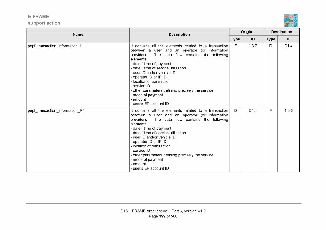
E-FRAME
support action
D15 – FRAME Architecture – Part 6, version V1.0
Page 199 of 568
Origin Destination Name Description
Type ID Type ID
pepf_transaction_information_L It contains all the elements related to a transaction between a user and an operator (or information provider). The data flow contains the following elements: - date / time of payment - date / time of service utilisation - user ID and/or vehicle ID - operator ID or IP ID - location of transaction - service ID - other parameters defining precisely the service - mode of payment - amount - user's EP account ID
F 1.3.7 D D1.4
pepf_transaction_information_R1 It contains all the elements related to a transaction between a user and an operator (or information provider). The data flow contains the following elements: - date / time of payment - date / time of service utilisation - user ID and/or vehicle ID - operator ID or IP ID - location of transaction - service ID - other parameters defining precisely the service - mode of payment - amount - user's EP account ID
D D1.4 F 1.3.6
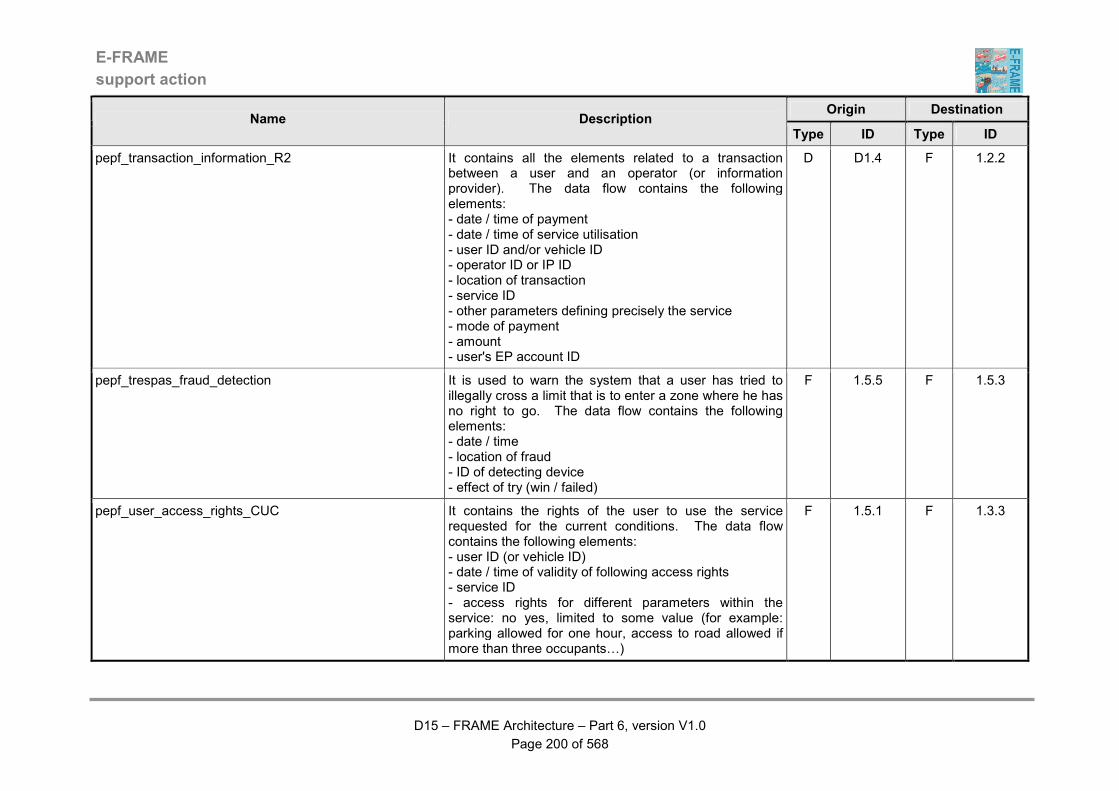
E-FRAME
support action
D15 – FRAME Architecture – Part 6, version V1.0
Page 200 of 568
Origin Destination Name Description
Type ID Type ID
pepf_transaction_information_R2 It contains all the elements related to a transaction between a user and an operator (or information provider). The data flow contains the following elements: - date / time of payment - date / time of service utilisation - user ID and/or vehicle ID - operator ID or IP ID - location of transaction - service ID - other parameters defining precisely the service - mode of payment - amount - user's EP account ID
D D1.4 F 1.2.2
pepf_trespas_fraud_detection It is used to warn the system that a user has tried to illegally cross a limit that is to enter a zone where he has no right to go. The data flow contains the following elements: - date / time - location of fraud - ID of detecting device - effect of try (win / failed)
F 1.5.5 F 1.5.3
pepf_user_access_rights_CUC It contains the rights of the user to use the service requested for the current conditions. The data flow contains the following elements: - user ID (or vehicle ID) - date / time of validity of following access rights - service ID - access rights for different parameters within the service: no yes, limited to some value (for example: parking allowed for one hour, access to road allowed if more than three occupants…)
F 1.5.1 F 1.3.3
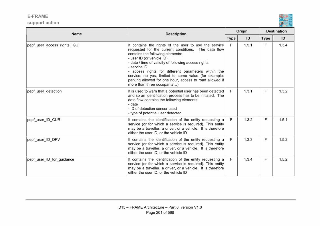
E-FRAME
support action
D15 – FRAME Architecture – Part 6, version V1.0
Page 201 of 568
Origin Destination Name Description
Type ID Type ID
pepf_user_access_rights_IGU It contains the rights of the user to use the service requested for the current conditions. The data flow contains the following elements: - user ID (or vehicle ID) - date / time of validity of following access rights - service ID - access rights for different parameters within the service: no yes, limited to some value (for example: parking allowed for one hour, access to road allowed if more than three occupants…)
F 1.5.1 F 1.3.4
pepf_user_detection It is used to warn that a potential user has been detected and so an identification process has to be initiated. The data flow contains the following elements: - date - ID of detection sensor used - type of potential user detected
F 1.3.1 F 1.3.2
pepf_user_ID_CUR It contains the identification of the entity requesting a service (or for which a service is required). This entity may be a traveller, a driver, or a vehicle. It is therefore either the user ID, or the vehicle ID
F 1.3.2 F 1.5.1
pepf_user_ID_DPV It contains the identification of the entity requesting a service (or for which a service is required). This entity may be a traveller, a driver, or a vehicle. It is therefore either the user ID, or the vehicle ID
F 1.3.3 F 1.5.2
pepf_user_ID_for_guidance It contains the identification of the entity requesting a service (or for which a service is required). This entity may be a traveller, a driver, or a vehicle. It is therefore either the user ID, or the vehicle ID
F 1.3.4 F 1.5.2
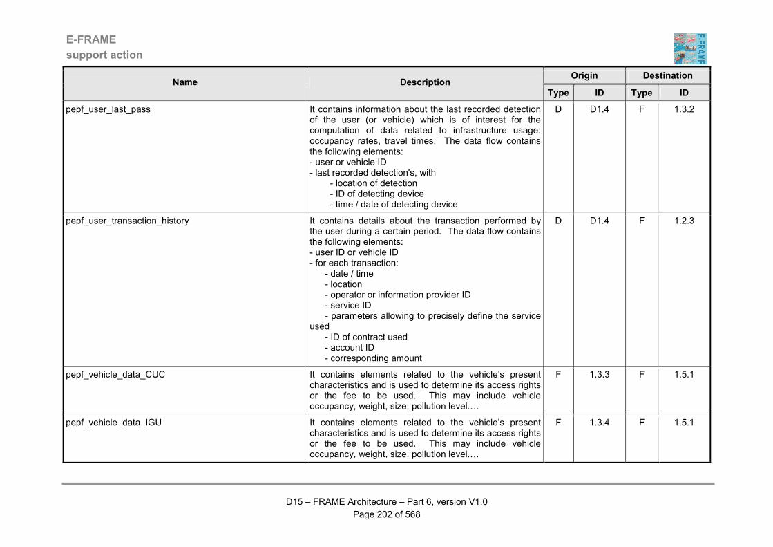
E-FRAME
support action
D15 – FRAME Architecture – Part 6, version V1.0
Page 202 of 568
Origin Destination Name Description
Type ID Type ID
pepf_user_last_pass It contains information about the last recorded detection of the user (or vehicle) which is of interest for the computation of data related to infrastructure usage: occupancy rates, travel times. The data flow contains the following elements: - user or vehicle ID - last recorded detection's, with - location of detection - ID of detecting device - time / date of detecting device
D D1.4 F 1.3.2
pepf_user_transaction_history It contains details about the transaction performed by the user during a certain period. The data flow contains the following elements: - user ID or vehicle ID - for each transaction: - date / time - location - operator or information provider ID - service ID - parameters allowing to precisely define the service used - ID of contract used - account ID - corresponding amount
D D1.4 F 1.2.3
pepf_vehicle_data_CUC It contains elements related to the vehicle’s present characteristics and is used to determine its access rights or the fee to be used. This may include vehicle occupancy, weight, size, pollution level.…
F 1.3.3 F 1.5.1
pepf_vehicle_data_IGU It contains elements related to the vehicle’s present characteristics and is used to determine its access rights or the fee to be used. This may include vehicle occupancy, weight, size, pollution level.…
F 1.3.4 F 1.5.1

E-FRAME
support action
D15 – FRAME Architecture – Part 6, version V1.0
Page 203 of 568
Origin Destination Name Description
Type ID Type ID
pepf_vehicle_data_IU It contains elements related to the vehicle’s present characteristics and is used to determine its access rights or the fee to be used. This may include vehicle occupancy, weight, size, pollution level.…
F 1.3.2 F 1.5.1
pepf_vehicle_detection It is used to warn that a potential vehicle user of a service has been detected and so an identification process has to be initiated. The data flow contains the following elements: - date - ID of detection sensor used - type of potential vehicle user detected - other parameters detected (weight, size, pollution level.…)
F 1.3.1 F 1.3.2
pscs.mt_green_wave_request It contains a request for priority to be given to the identified Vehicle at all signalised road junctions between two specified locations.
F 9.1.2 F 3.1.1.5.24
pscs.mt_inter-urban_sensitive_area_access_refused It contains the identity of the Vehicle for which access to the inter-urban "sensitive area" has not been granted and is to be used for enforcement purposes.
F 9.3.1 F 3.1.2.13.3
pscs.mt_local_priority_request It contains a request for local priority for the Vehicle at a particular signalised road junction.
F 9.1.2 F 3.1.1.5.22
pscs.mt_urban_sensitive_area_access_refused It contains the identity of the Vehicle for which access to the urban "sensitive area" has not been granted and is to be used for enforcement purposes.
F 9.3.1 F 3.1.1.5.12
pscs.pshvs_driver_instructions_for_sensitive_areas It contains instructions for the Driver of the Vehicle that must be observed whilst the Vehicle is within the "sensitive area".
F 9.3.1 F 5.16.2
pscs.pshvs_driver_report_from_sensitive_area It contains a report for the Driver of the use that has been made by the Vehicle of the "sensitive area" now that it has left the "area".
F 9.3.1 F 5.16.2
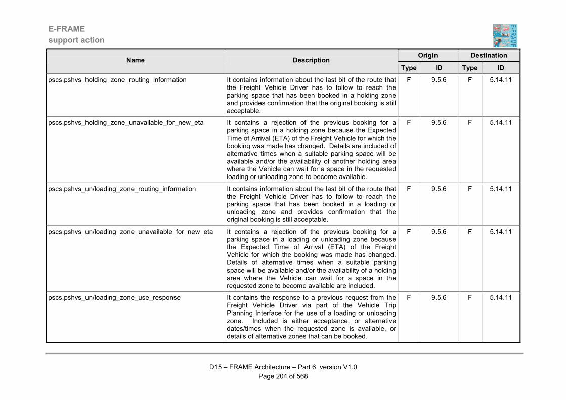
E-FRAME
support action
D15 – FRAME Architecture – Part 6, version V1.0
Page 204 of 568
Origin Destination Name Description
Type ID Type ID
pscs.pshvs_holding_zone_routing_information It contains information about the last bit of the route that the Freight Vehicle Driver has to follow to reach the parking space that has been booked in a holding zone and provides confirmation that the original booking is still acceptable.
F 9.5.6 F 5.14.11
pscs.pshvs_holding_zone_unavailable_for_new_eta It contains a rejection of the previous booking for a parking space in a holding zone because the Expected Time of Arrival (ETA) of the Freight Vehicle for which the booking was made has changed. Details are included of alternative times when a suitable parking space will be available and/or the availability of another holding area where the Vehicle can wait for a space in the requested loading or unloading zone to become available.
F 9.5.6 F 5.14.11
pscs.pshvs_un/loading_zone_routing_information It contains information about the last bit of the route that the Freight Vehicle Driver has to follow to reach the parking space that has been booked in a loading or unloading zone and provides confirmation that the original booking is still acceptable.
F 9.5.6 F 5.14.11
pscs.pshvs_un/loading_zone_unavailable_for_new_eta It contains a rejection of the previous booking for a parking space in a loading or unloading zone because the Expected Time of Arrival (ETA) of the Freight Vehicle for which the booking was made has changed. Details of alternative times when a suitable parking space will be available and/or the availability of a holding area where the Vehicle can wait for a space in the requested zone to become available are included.
F 9.5.6 F 5.14.11
pscs.pshvs_un/loading_zone_use_response It contains the response to a previous request from the Freight Vehicle Driver via part of the Vehicle Trip Planning Interface for the use of a loading or unloading zone. Included is either acceptance, or alternative dates/times when the requested zone is available, or details of alternative zones that can be booked.
F 9.5.6 F 5.14.11

E-FRAME
support action
D15 – FRAME Architecture – Part 6, version V1.0
Page 205 of 568
Origin Destination Name Description
Type ID Type ID
pscs.psle_bus_lane_violation It contains details of a non-PT Vehicle that is incorrectly using a Bus Lane and is for use in further action by the Law Enforcement Agency.
F 9.2.6 F 7.3.5
pscs.ptja_hazardous_goods_vehicle_route_request It contains the request for a route to be produced for a hazardous goods vehicle from its current location to a specified destination, using a set of specific criteria.
F 9.4.2 F 6.5.3.13
pscs_bus_lane_licence_revoked It contains details of the previously granted licences that have been revoked, specifying the Bus Lanes that are affected.
F 9.2.5 F 9.2.2
pscs_bus_lane_use_licence It contains a licence for a particular non-PT Vehicle to use one or more defined Bus Lane(s) for the specified time period. The location of each bus lane is included in the licence.
F 9.2.5 F 9.2.2
pscs_bus_lane_use_licence_details It contains details of the licences given/revoked to other Vehicles to use Bus Lanes.
F 9.2.5 F 9.2.3
pscs_bus_lane_use_request It contains a request to use Bus Lanes. Included in the request are current Vehicle location, destination, "way points" and route, plus the Vehicle identity.
F 9.2.2 F 9.2.5
pscs_bus_lane_use_request_result It contains the result of a request to use a Bus Lane during the current journey. If successful, the licence identity, time of expiry of permission to use the Bus Lane will be included, as will the identities of the Bus Lane segment(s) to which the licence applies.
F 9.2.2 F 9.2.1
pscs_current_data_about_bus_lanes It contains the current road network traffic flow and PT Vehicle predicted arrival times for all the Bus Lanes and their associated road links in the road network.
F 9.2.3 F 9.2.5
pscs_current_vehicle_access_data It contains a copy of the current criteria that are being used to grant or deny Vehicles access to a "sensitive area" within the road network.
F 9.3.2 F 9.3.3
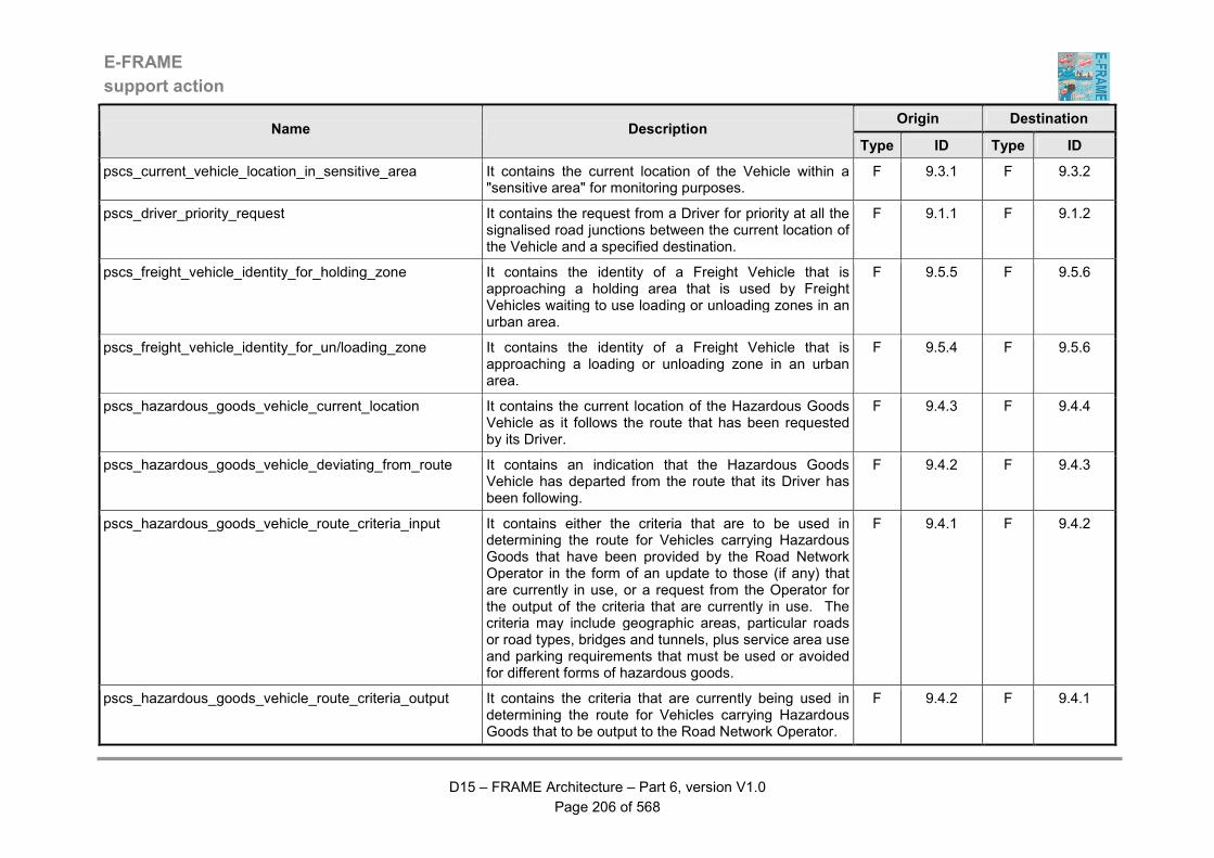
E-FRAME
support action
D15 – FRAME Architecture – Part 6, version V1.0
Page 206 of 568
Origin Destination Name Description
Type ID Type ID
pscs_current_vehicle_location_in_sensitive_area It contains the current location of the Vehicle within a "sensitive area" for monitoring purposes.
F 9.3.1 F 9.3.2
pscs_driver_priority_request It contains the request from a Driver for priority at all the signalised road junctions between the current location of the Vehicle and a specified destination.
F 9.1.1 F 9.1.2
pscs_freight_vehicle_identity_for_holding_zone It contains the identity of a Freight Vehicle that is approaching a holding area that is used by Freight Vehicles waiting to use loading or unloading zones in an urban area.
F 9.5.5 F 9.5.6
pscs_freight_vehicle_identity_for_un/loading_zone It contains the identity of a Freight Vehicle that is approaching a loading or unloading zone in an urban area.
F 9.5.4 F 9.5.6
pscs_hazardous_goods_vehicle_current_location It contains the current location of the Hazardous Goods Vehicle as it follows the route that has been requested by its Driver.
F 9.4.3 F 9.4.4
pscs_hazardous_goods_vehicle_deviating_from_route It contains an indication that the Hazardous Goods Vehicle has departed from the route that its Driver has been following.
F 9.4.2 F 9.4.3
pscs_hazardous_goods_vehicle_route_criteria_input It contains either the criteria that are to be used in determining the route for Vehicles carrying Hazardous Goods that have been provided by the Road Network Operator in the form of an update to those (if any) that are currently in use, or a request from the Operator for the output of the criteria that are currently in use. The criteria may include geographic areas, particular roads or road types, bridges and tunnels, plus service area use and parking requirements that must be used or avoided for different forms of hazardous goods.
F 9.4.1 F 9.4.2
pscs_hazardous_goods_vehicle_route_criteria_output It contains the criteria that are currently being used in determining the route for Vehicles carrying Hazardous Goods that to be output to the Road Network Operator.
F 9.4.2 F 9.4.1

E-FRAME
support action
D15 – FRAME Architecture – Part 6, version V1.0
Page 207 of 568
Origin Destination Name Description
Type ID Type ID
pscs_hazardous_goods_vehicle_route_details It contains details of the route for a Hazardous Goods Vehicle that has been prepared in response to a previous request from its Driver.
F 9.4.2 F 9.4.4
pscs_hazardous_goods_vehicle_route_guidance It contains guidance instructions for the Driver of a Hazardous Goods Vehicle in order that the previously requested route can be followed.
F 9.4.4 F 9.4.3
pscs_hazardous_goods_vehicle_route_location It contains the current location of the Freight Vehicle in which a Freight Vehicle Driver is implementing a Vehicle Trip Plan and is used to monitor progress with the Trip implementation.
F 9.4.3 F 9.4.2
pscs_hazardous_goods_vehicle_route_request It contains a request from the Driver of a Hazardous Goods Vehicle for a route. Included in the request is the current location of the Vehicle, plus other parameters provided by the Driver.
F 9.4.3 F 9.4.2
pscs_hazardous_goods_vehicle_route_status It contains an indication that the route previously requested by a Driver for a Vehicle carrying Hazardous Goods is now ready.
F 9.4.4 F 9.4.3
pscs_hazardous_routes_data_load It contains data being loaded into the data store of Hazardous Vehicle Routes. This data may include the criteria used for selecting routes and/or the actual routes that have been determined for particular Vehicles that are carrying Hazardous Goods.
F 9.4.2 D D9.3
pscs_hazardous_routes_data_read It contains data being read from the data store of Hazardous Vehicle Routes. This data may include the criteria used for selecting routes and/or the actual routes that have been determined for particular Vehicles that are carrying Hazardous Goods.
D D9.3 F 9.4.2
pscs_incorrect_bus_lane_use_data It contains data about non-PT Vehicles that have been found to be incorrectly using a Bus Lane. Details of the Bus Lane and the non-PT Vehicle are included.
F 9.2.6 F 9.2.3

E-FRAME
support action
D15 – FRAME Architecture – Part 6, version V1.0
Page 208 of 568
Origin Destination Name Description
Type ID Type ID
pscs_incorrect_vehicle_in_un/loading_zone It contains the identity of a Vehicle that should not be parked in a loading or unloading zone.
F 9.5.6 F 9.5.2
pscs_licence_details_for_vehicle_identification It contains details of the licences given/revoked to other Vehicles to use Bus Lanes including the identities of the Vehicles to which the licences have been granted.
F 9.2.5 F 9.2.6
pscs_load_bus_lane_data It contains data that is to be loaded in the Bus Lane Data store.
F 9.2.3 D D9.1
pscs_load_sensitive_area_data It contains either data about the use by Vehicles of a "sensitive area" that is being loaded in the Sensitive Area Monitoring data store, details about the Vehicle that is entering the "sensitive area", or updates to the criteria used to grant Vehicles access to the "sensitive area".
F 9.3.2 D D9.2
pscs_load_zone_use_data It contains data about the status, plus Vehicle capability and other static details of a loading or unloading zone that is being loaded into the Loading or Unloading Zone Use data store..
F 9.5.3 D D9.4
pscs_other_bus_lane_information It contains other information relevant to the presence of a non-PT Vehicle in a Bus Lane, such as licence revoked, no licence applied for.
F 9.2.2 F 9.2.1
pscs_read_bus_lane_data It contains data read from the Bus Lane Data Store. D D9.1 F 9.2.3
pscs_read_sensitive_area_data It contains the current criteria used to grant Vehicles access to the "sensitive area".
D D9.2 F 9.3.2
pscs_read_zone_use_data It contains data about the status, plus Vehicle capability and other static details of a loading or unloading zone that is being read from the Loading or Unloading Zone Use data store..
D D9.4 F 9.5.3
pscs_requested_bus_lane_data It contains the data about the location within the road network and use of Bus Lanes.
F 9.2.3 F 9.2.4
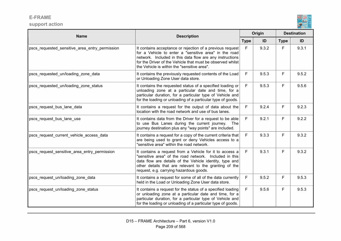
E-FRAME
support action
D15 – FRAME Architecture – Part 6, version V1.0
Page 209 of 568
Origin Destination Name Description
Type ID Type ID
pscs_requested_sensitive_area_entry_permission It contains acceptance or rejection of a previous request for a Vehicle to enter a "sensitive area" in the road network. Included in this data flow are any instructions for the Driver of the Vehicle that must be observed whilst the Vehicle is within the "sensitive area".
F 9.3.2 F 9.3.1
pscs_requested_un/loading_zone_data It contains the previously requested contents of the Load or Unloading Zone User data store.
F 9.5.3 F 9.5.2
pscs_requested_un/loading_zone_status It contains the requested status of a specified loading or unloading zone at a particular date and time, for a particular duration, for a particular type of Vehicle and for the loading or unloading of a particular type of goods.
F 9.5.3 F 9.5.6
pscs_request_bus_lane_data It contains a request for the output of data about the location with the road network and use of bus lanes.
F 9.2.4 F 9.2.3
pscs_request_bus_lane_use It contains data from the Driver for a request to be able to use Bus Lanes during the current journey. The journey destination plus any "way points" are included.
F 9.2.1 F 9.2.2
pscs_request_current_vehicle_access_data It contains a request for a copy of the current criteria that are being used to grant or deny Vehicles access to a "sensitive area" within the road network.
F 9.3.3 F 9.3.2
pscs_request_sensitive_area_entry_permission It contains a request from a Vehicle for it to access a "sensitive area" of the road network. Included in this data flow are details of the Vehicle identity, type and other details that are relevant to the granting of the request, e.g. carrying hazardous goods.
F 9.3.1 F 9.3.2
pscs_request_un/loading_zone_data It contains a request for some of all of the data currently held in the Load or Unloading Zone User data store.
F 9.5.2 F 9.5.3
pscs_request_un/loading_zone_status It contains a request for the status of a specified loading or unloading zone at a particular date and time, for a particular duration, for a particular type of Vehicle and for the loading or unloading of a particular type of goods.
F 9.5.6 F 9.5.3
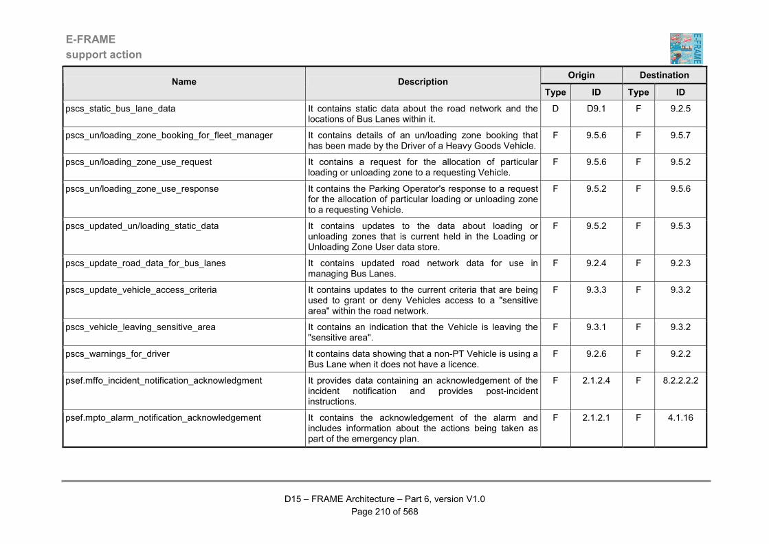
E-FRAME
support action
D15 – FRAME Architecture – Part 6, version V1.0
Page 210 of 568
Origin Destination Name Description
Type ID Type ID
pscs_static_bus_lane_data It contains static data about the road network and the locations of Bus Lanes within it.
D D9.1 F 9.2.5
pscs_un/loading_zone_booking_for_fleet_manager It contains details of an un/loading zone booking that has been made by the Driver of a Heavy Goods Vehicle.
F 9.5.6 F 9.5.7
pscs_un/loading_zone_use_request It contains a request for the allocation of particular loading or unloading zone to a requesting Vehicle.
F 9.5.6 F 9.5.2
pscs_un/loading_zone_use_response It contains the Parking Operator's response to a request for the allocation of particular loading or unloading zone to a requesting Vehicle.
F 9.5.2 F 9.5.6
pscs_updated_un/loading_static_data It contains updates to the data about loading or unloading zones that is current held in the Loading or Unloading Zone User data store.
F 9.5.2 F 9.5.3
pscs_update_road_data_for_bus_lanes It contains updated road network data for use in managing Bus Lanes.
F 9.2.4 F 9.2.3
pscs_update_vehicle_access_criteria It contains updates to the current criteria that are being used to grant or deny Vehicles access to a "sensitive area" within the road network.
F 9.3.3 F 9.3.2
pscs_vehicle_leaving_sensitive_area It contains an indication that the Vehicle is leaving the "sensitive area".
F 9.3.1 F 9.3.2
pscs_warnings_for_driver It contains data showing that a non-PT Vehicle is using a Bus Lane when it does not have a licence.
F 9.2.6 F 9.2.2
psef.mffo_incident_notification_acknowledgment It provides data containing an acknowledgement of the incident notification and provides post-incident instructions.
F 2.1.2.4 F 8.2.2.2.2
psef.mpto_alarm_notification_acknowledgement It contains the acknowledgement of the alarm and includes information about the actions being taken as part of the emergency plan.
F 2.1.2.1 F 4.1.16
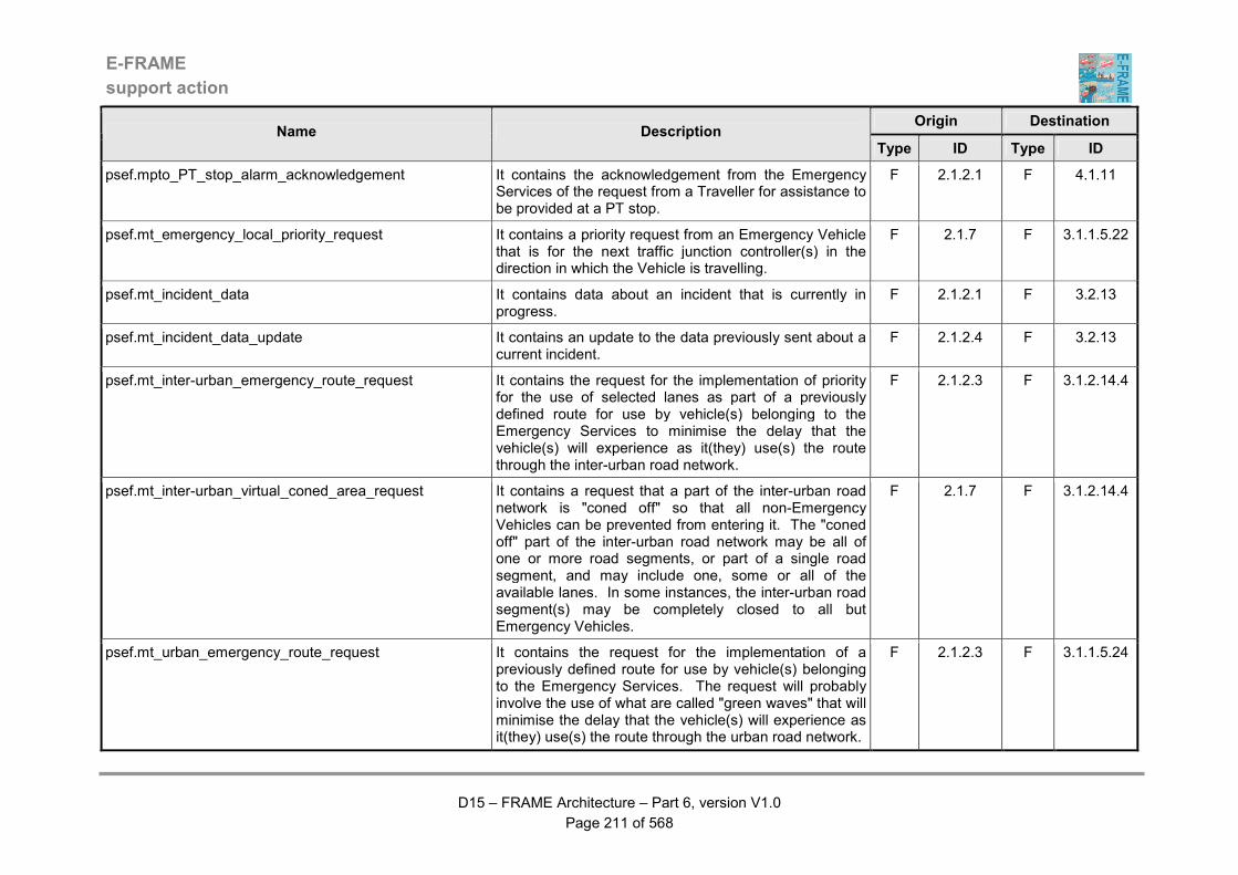
E-FRAME
support action
D15 – FRAME Architecture – Part 6, version V1.0
Page 211 of 568
Origin Destination Name Description
Type ID Type ID
psef.mpto_PT_stop_alarm_acknowledgement It contains the acknowledgement from the Emergency Services of the request from a Traveller for assistance to be provided at a PT stop.
F 2.1.2.1 F 4.1.11
psef.mt_emergency_local_priority_request It contains a priority request from an Emergency Vehicle that is for the next traffic junction controller(s) in the direction in which the Vehicle is travelling.
F 2.1.7 F 3.1.1.5.22
psef.mt_incident_data It contains data about an incident that is currently in progress.
F 2.1.2.1 F 3.2.13
psef.mt_incident_data_update It contains an update to the data previously sent about a current incident.
F 2.1.2.4 F 3.2.13
psef.mt_inter-urban_emergency_route_request It contains the request for the implementation of priority for the use of selected lanes as part of a previously defined route for use by vehicle(s) belonging to the Emergency Services to minimise the delay that the vehicle(s) will experience as it(they) use(s) the route through the inter-urban road network.
F 2.1.2.3 F 3.1.2.14.4
psef.mt_inter-urban_virtual_coned_area_request It contains a request that a part of the inter-urban road network is "coned off" so that all non-Emergency Vehicles can be prevented from entering it. The "coned off" part of the inter-urban road network may be all of one or more road segments, or part of a single road segment, and may include one, some or all of the available lanes. In some instances, the inter-urban road segment(s) may be completely closed to all but Emergency Vehicles.
F 2.1.7 F 3.1.2.14.4
psef.mt_urban_emergency_route_request It contains the request for the implementation of a previously defined route for use by vehicle(s) belonging to the Emergency Services. The request will probably involve the use of what are called "green waves" that will minimise the delay that the vehicle(s) will experience as it(they) use(s) the route through the urban road network.
F 2.1.2.3 F 3.1.1.5.24
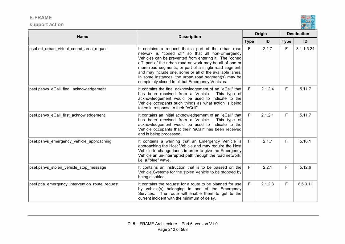
E-FRAME
support action
D15 – FRAME Architecture – Part 6, version V1.0
Page 212 of 568
Origin Destination Name Description
Type ID Type ID
psef.mt_urban_virtual_coned_area_request It contains a request that a part of the urban road network is "coned off" so that all non-Emergency Vehicles can be prevented from entering it. The "coned off" part of the urban road network may be all of one or more road segments, or part of a single road segment, and may include one, some or all of the available lanes. In some instances, the urban road segment(s) may be completely closed to all but Emergency Vehicles.
F 2.1.7 F 3.1.1.5.24
psef.pshvs_eCall_final_acknowledgement It contains the final acknowledgement of an "eCall" that has been received from a Vehicle. This type of acknowledgement would be used to indicate to the Vehicle occupants such things as what action is being taken in response to their "eCall".
F 2.1.2.4 F 5.11.7
psef.pshvs_eCall_first_acknowledgement It contains an initial acknowledgement of an "eCall" that has been received from a Vehicle. This type of acknowledgement would be used to indicate to the Vehicle occupants that their "eCall" has been received and is being processed.
F 2.1.2.1 F 5.11.7
psef.pshvs_emergency_vehicle_approaching It contains a warning that an Emergency Vehicle is approaching the Host Vehicle and may require the Host Vehicle to change lanes in order to give the Emergency Vehicle an un-interrupted path through the road network, i.e. a "blue" wave.
F 2.1.7 F 5.16.1
psef.pshvs_stolen_vehicle_stop_message It contains an instruction that is to be passed on the Vehicle Systems for the stolen Vehicle to be stopped by being disabled.
F 2.2.1 F 5.12.6
psef.ptja_emergency_intervention_route_request It contains the request for a route to be planned for use by vehicle(s) belonging to one of the Emergency Services. The route will enable them to get to the current incident with the minimum of delay.
F 2.1.2.3 F 6.5.3.11
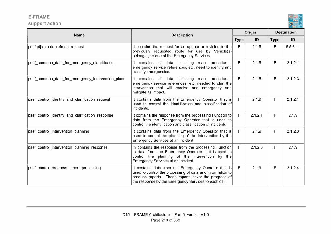
E-FRAME
support action
D15 – FRAME Architecture – Part 6, version V1.0
Page 213 of 568
Origin Destination Name Description
Type ID Type ID
psef.ptja_route_refresh_request It contains the request for an update or revision to the previously requested route for use by Vehicle(s) belonging to one of the Emergency Services.
F 2.1.5 F 6.5.3.11
psef_common_data_for_emergency_classification It contains all data, including map, procedures, emergency service references, etc. need to identify and classify emergencies.
F 2.1.5 F 2.1.2.1
psef_common_data_for_emergency_intervention_plans It contains all data, including map, procedures, emergency service references, etc. needed to plan the intervention that will resolve and emergency and mitigate its impact.
F 2.1.5 F 2.1.2.3
psef_control_identity_and_clarification_request It contains data from the Emergency Operator that is used to control the identification and classification of incidents.
F 2.1.9 F 2.1.2.1
psef_control_identity_and_clarification_response It contains the response from the processing Function to data from the Emergency Operator that is used to control the identification and classification of incidents
F 2.1.2.1 F 2.1.9
psef_control_intervention_planning It contains data from the Emergency Operator that is used to control the planning of the intervention by the Emergency Services at an incident
F 2.1.9 F 2.1.2.3
psef_control_intervention_planning_response In contains the response from the processing Function to data from the Emergency Operator that is used to control the planning of the intervention by the Emergency Services at an incident.
F 2.1.2.3 F 2.1.9
psef_control_progress_report_processing It contains data from the Emergency Operator that is used to control the processing of data and information to produce reports. These reports cover the progress of the response by the Emergency Services to each call
F 2.1.9 F 2.1.2.4
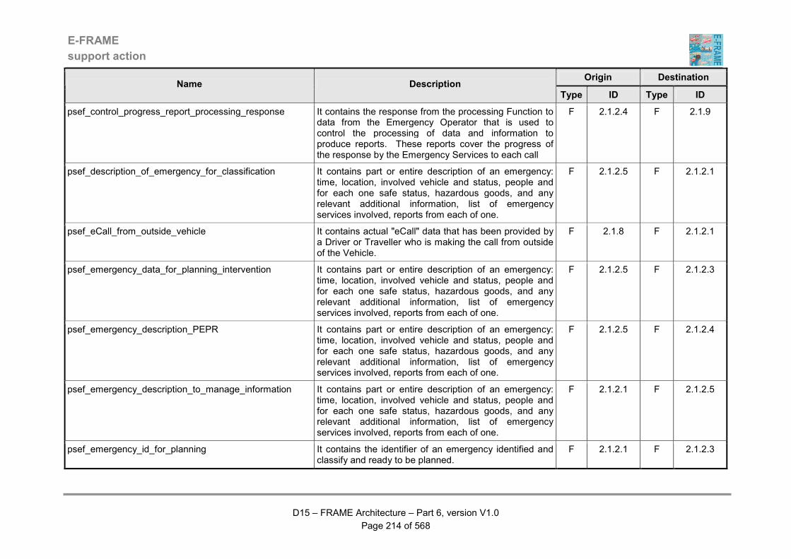
E-FRAME
support action
D15 – FRAME Architecture – Part 6, version V1.0
Page 214 of 568
Origin Destination Name Description
Type ID Type ID
psef_control_progress_report_processing_response It contains the response from the processing Function to data from the Emergency Operator that is used to control the processing of data and information to produce reports. These reports cover the progress of the response by the Emergency Services to each call
F 2.1.2.4 F 2.1.9
psef_description_of_emergency_for_classification It contains part or entire description of an emergency: time, location, involved vehicle and status, people and for each one safe status, hazardous goods, and any relevant additional information, list of emergency services involved, reports from each of one.
F 2.1.2.5 F 2.1.2.1
psef_eCall_from_outside_vehicle It contains actual "eCall" data that has been provided by a Driver or Traveller who is making the call from outside of the Vehicle.
F 2.1.8 F 2.1.2.1
psef_emergency_data_for_planning_intervention It contains part or entire description of an emergency: time, location, involved vehicle and status, people and for each one safe status, hazardous goods, and any relevant additional information, list of emergency services involved, reports from each of one.
F 2.1.2.5 F 2.1.2.3
psef_emergency_description_PEPR It contains part or entire description of an emergency: time, location, involved vehicle and status, people and for each one safe status, hazardous goods, and any relevant additional information, list of emergency services involved, reports from each of one.
F 2.1.2.5 F 2.1.2.4
psef_emergency_description_to_manage_information It contains part or entire description of an emergency: time, location, involved vehicle and status, people and for each one safe status, hazardous goods, and any relevant additional information, list of emergency services involved, reports from each of one.
F 2.1.2.1 F 2.1.2.5
psef_emergency_id_for_planning It contains the identifier of an emergency identified and classify and ready to be planned.
F 2.1.2.1 F 2.1.2.3
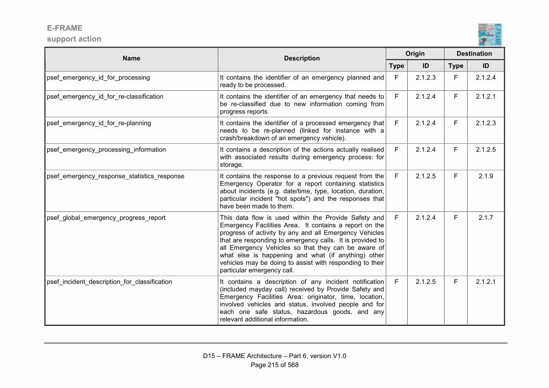
E-FRAME
support action
D15 – FRAME Architecture – Part 6, version V1.0
Page 215 of 568
Origin Destination Name Description
Type ID Type ID
psef_emergency_id_for_processing It contains the identifier of an emergency planned and ready to be processed.
F 2.1.2.3 F 2.1.2.4
psef_emergency_id_for_re-classification It contains the identifier of an emergency that needs to be re-classified due to new information coming from progress reports.
F 2.1.2.4 F 2.1.2.1
psef_emergency_id_for_re-planning It contains the identifier of a processed emergency that needs to be re-planned (linked for instance with a crash/breakdown of an emergency vehicle).
F 2.1.2.4 F 2.1.2.3
psef_emergency_processing_information It contains a description of the actions actually realised with associated results during emergency process: for storage.
F 2.1.2.4 F 2.1.2.5
psef_emergency_response_statistics_response It contains the response to a previous request from the Emergency Operator for a report containing statistics about incidents (e.g. date/time, type, location, duration, particular incident "hot spots") and the responses that have been made to them.
F 2.1.2.5 F 2.1.9
psef_global_emergency_progress_report This data flow is used within the Provide Safety and Emergency Facilities Area. It contains a report on the progress of activity by any and all Emergency Vehicles that are responding to emergency calls. It is provided to all Emergency Vehicles so that they can be aware of what else is happening and what (if anything) other vehicles may be doing to assist with responding to their particular emergency call.
F 2.1.2.4 F 2.1.7
psef_incident_description_for_classification It contains a description of any incident notification (included mayday call) received by Provide Safety and Emergency Facilities Area: originator, time, location, involved vehicles and status, involved people and for each one safe status, hazardous goods, and any relevant additional information.
F 2.1.2.5 F 2.1.2.1
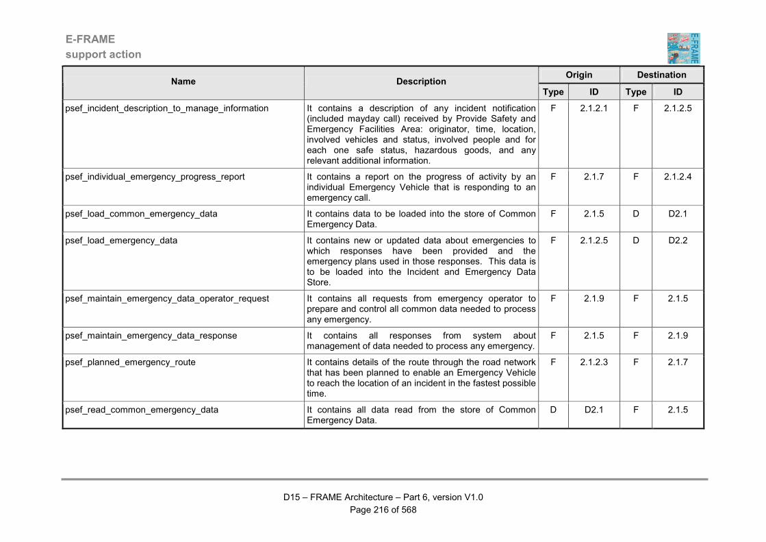
E-FRAME
support action
D15 – FRAME Architecture – Part 6, version V1.0
Page 216 of 568
Origin Destination Name Description
Type ID Type ID
psef_incident_description_to_manage_information It contains a description of any incident notification (included mayday call) received by Provide Safety and Emergency Facilities Area: originator, time, location, involved vehicles and status, involved people and for each one safe status, hazardous goods, and any relevant additional information.
F 2.1.2.1 F 2.1.2.5
psef_individual_emergency_progress_report It contains a report on the progress of activity by an individual Emergency Vehicle that is responding to an emergency call.
F 2.1.7 F 2.1.2.4
psef_load_common_emergency_data It contains data to be loaded into the store of Common Emergency Data.
F 2.1.5 D D2.1
psef_load_emergency_data It contains new or updated data about emergencies to which responses have been provided and the emergency plans used in those responses. This data is to be loaded into the Incident and Emergency Data Store.
F 2.1.2.5 D D2.2
psef_maintain_emergency_data_operator_request It contains all requests from emergency operator to prepare and control all common data needed to process any emergency.
F 2.1.9 F 2.1.5
psef_maintain_emergency_data_response It contains all responses from system about management of data needed to process any emergency.
F 2.1.5 F 2.1.9
psef_planned_emergency_route It contains details of the route through the road network that has been planned to enable an Emergency Vehicle to reach the location of an incident in the fastest possible time.
F 2.1.2.3 F 2.1.7
psef_read_common_emergency_data It contains all data read from the store of Common Emergency Data.
D D2.1 F 2.1.5
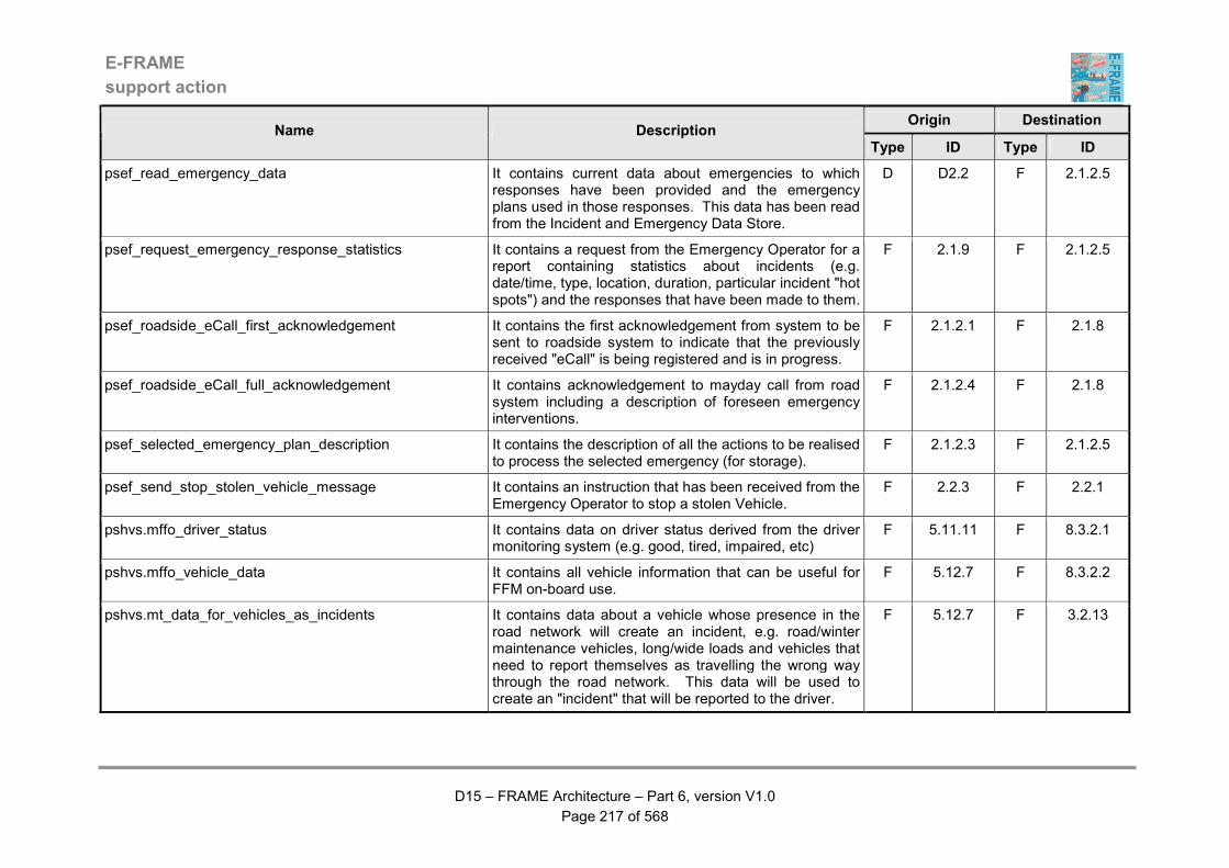
E-FRAME
support action
D15 – FRAME Architecture – Part 6, version V1.0
Page 217 of 568
Origin Destination Name Description
Type ID Type ID
psef_read_emergency_data It contains current data about emergencies to which responses have been provided and the emergency plans used in those responses. This data has been read from the Incident and Emergency Data Store.
D D2.2 F 2.1.2.5
psef_request_emergency_response_statistics It contains a request from the Emergency Operator for a report containing statistics about incidents (e.g. date/time, type, location, duration, particular incident "hot spots") and the responses that have been made to them.
F 2.1.9 F 2.1.2.5
psef_roadside_eCall_first_acknowledgement It contains the first acknowledgement from system to be sent to roadside system to indicate that the previously received "eCall" is being registered and is in progress.
F 2.1.2.1 F 2.1.8
psef_roadside_eCall_full_acknowledgement It contains acknowledgement to mayday call from road system including a description of foreseen emergency interventions.
F 2.1.2.4 F 2.1.8
psef_selected_emergency_plan_description It contains the description of all the actions to be realised to process the selected emergency (for storage).
F 2.1.2.3 F 2.1.2.5
psef_send_stop_stolen_vehicle_message It contains an instruction that has been received from the Emergency Operator to stop a stolen Vehicle.
F 2.2.3 F 2.2.1
pshvs.mffo_driver_status It contains data on driver status derived from the driver monitoring system (e.g. good, tired, impaired, etc)
F 5.11.11 F 8.3.2.1
pshvs.mffo_vehicle_data It contains all vehicle information that can be useful for FFM on-board use.
F 5.12.7 F 8.3.2.2
pshvs.mt_data_for_vehicles_as_incidents It contains data about a vehicle whose presence in the road network will create an incident, e.g. road/winter maintenance vehicles, long/wide loads and vehicles that need to report themselves as travelling the wrong way through the road network. This data will be used to create an "incident" that will be reported to the driver.
F 5.12.7 F 3.2.13
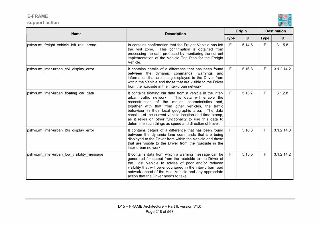
E-FRAME
support action
D15 – FRAME Architecture – Part 6, version V1.0
Page 218 of 568
Origin Destination Name Description
Type ID Type ID
pshvs.mt_freight_vehicle_left_rest_areae In contains confirmation that the Freight Vehicle has left the rest zone. This confirmation is obtained from processing the data produced by monitoring the current implementation of the Vehicle Trip Plan for the Freight Vehicle.
F 5.14.6 F 3.1.5.8
pshvs.mt_inter-urban_c&i_display_error It contains details of a difference that has been found between the dynamic commands, warnings and information that are being displayed to the Driver from within the Vehicle and those that are visible to the Driver from the roadside in the inter-urban network.
F 5.16.3 F 3.1.2.14.2
pshvs.mt_inter-urban_floating_car_data It contains floating car data from a vehicle in the inter-urban traffic network. This data will enable the reconstruction of the motion characteristics and, together with that from other vehicles, the traffic behaviour in their local geographic area. The data consists of the current vehicle location and time stamp, as it relies on other functionality to use this data to determine such things as speed and direction of travel.
F 5.13.7 F 3.1.2.8
pshvs.mt_inter-urban_l&s_display_error It contains details of a difference that has been found between the dynamic lane commands that are being displayed to the Driver from within the Vehicle and those that are visible to the Driver from the roadside in the inter-urban network.
F 5.16.3 F 3.1.2.14.3
pshvs.mt_inter-urban_low_visibility_message It contains data from which a warning message can be generated for output from the roadside to the Driver of the Host Vehicle to advise of poor and/or reduced visibility that will be encountered in the inter-urban road network ahead of the Host Vehicle and any appropriate action that the Driver needs to take.
F 5.15.5 F 3.1.2.14.2
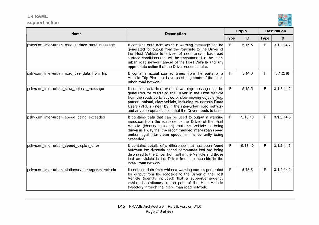
E-FRAME
support action
D15 – FRAME Architecture – Part 6, version V1.0
Page 219 of 568
Origin Destination Name Description
Type ID Type ID
pshvs.mt_inter-urban_road_surface_state_message It contains data from which a warning message can be generated for output from the roadside to the Driver of the Host Vehicle to advise of poor and/or bad road surface conditions that will be encountered in the inter-urban road network ahead of the Host Vehicle and any appropriate action that the Driver needs to take.
F 5.15.5 F 3.1.2.14.2
pshvs.mt_inter-urban_road_use_data_from_trip It contains actual journey times from the parts of a Vehicle Trip Plan that have used segments of the inter-urban road network.
F 5.14.6 F 3.1.2.16
pshvs.mt_inter-urban_slow_objects_message It contains data from which a warning message can be generated for output to the Driver in the Host Vehicle from the roadside to advise of slow moving objects (e.g. person, animal, slow vehicle, including Vulnerable Road Users (VRU's)) near by in the inter-urban road network and any appropriate action that the Driver needs to take.
F 5.15.5 F 3.1.2.14.2
pshvs.mt_inter-urban_speed_being_exceeded It contains data that can be used to output a warning message from the roadside to the Driver of the Host Vehicle (identity included) that the Vehicle is being driven in a way that the recommended inter-urban speed and/or legal inter-urban speed limit is currently being exceeded.
F 5.13.10 F 3.1.2.14.3
pshvs.mt_inter-urban_speed_display_error It contains details of a difference that has been found between the dynamic speed commands that are being displayed to the Driver from within the Vehicle and those that are visible to the Driver from the roadside in the inter-urban network.
F 5.13.10 F 3.1.2.14.3
pshvs.mt_inter-urban_stationary_emergency_vehicle It contains data from which a warning can be generated for output from the roadside to the Driver of the Host Vehicle (identity included) that a support/emergency vehicle is stationary in the path of the Host Vehicle trajectory through the inter-urban road network.
F 5.15.5 F 3.1.2.14.2
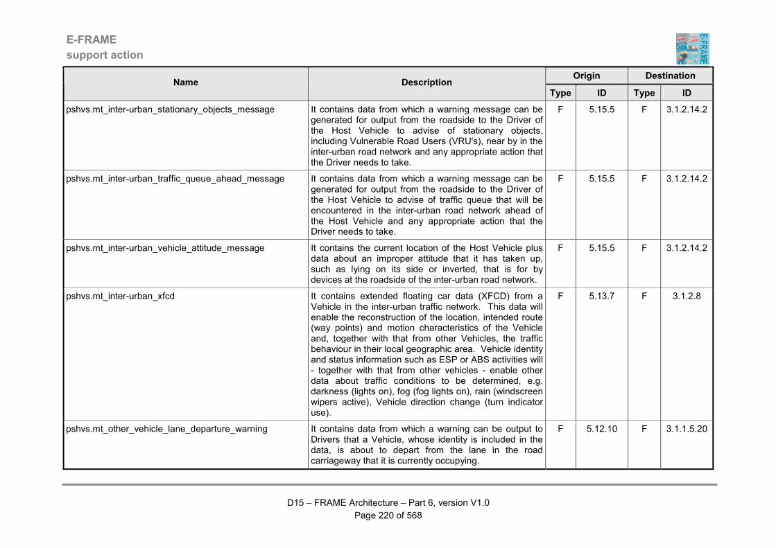
E-FRAME
support action
D15 – FRAME Architecture – Part 6, version V1.0
Page 220 of 568
Origin Destination Name Description
Type ID Type ID
pshvs.mt_inter-urban_stationary_objects_message It contains data from which a warning message can be generated for output from the roadside to the Driver of the Host Vehicle to advise of stationary objects, including Vulnerable Road Users (VRU's), near by in the inter-urban road network and any appropriate action that the Driver needs to take.
F 5.15.5 F 3.1.2.14.2
pshvs.mt_inter-urban_traffic_queue_ahead_message It contains data from which a warning message can be generated for output from the roadside to the Driver of the Host Vehicle to advise of traffic queue that will be encountered in the inter-urban road network ahead of the Host Vehicle and any appropriate action that the Driver needs to take.
F 5.15.5 F 3.1.2.14.2
pshvs.mt_inter-urban_vehicle_attitude_message It contains the current location of the Host Vehicle plus data about an improper attitude that it has taken up, such as lying on its side or inverted, that is for by devices at the roadside of the inter-urban road network.
F 5.15.5 F 3.1.2.14.2
pshvs.mt_inter-urban_xfcd It contains extended floating car data (XFCD) from a Vehicle in the inter-urban traffic network. This data will enable the reconstruction of the location, intended route (way points) and motion characteristics of the Vehicle and, together with that from other Vehicles, the traffic behaviour in their local geographic area. Vehicle identity and status information such as ESP or ABS activities will - together with that from other vehicles - enable other data about traffic conditions to be determined, e.g. darkness (lights on), fog (fog lights on), rain (windscreen wipers active), Vehicle direction change (turn indicator use).
F 5.13.7 F 3.1.2.8
pshvs.mt_other_vehicle_lane_departure_warning It contains data from which a warning can be output to Drivers that a Vehicle, whose identity is included in the data, is about to depart from the lane in the road carriageway that it is currently occupying.
F 5.12.10 F 3.1.1.5.20
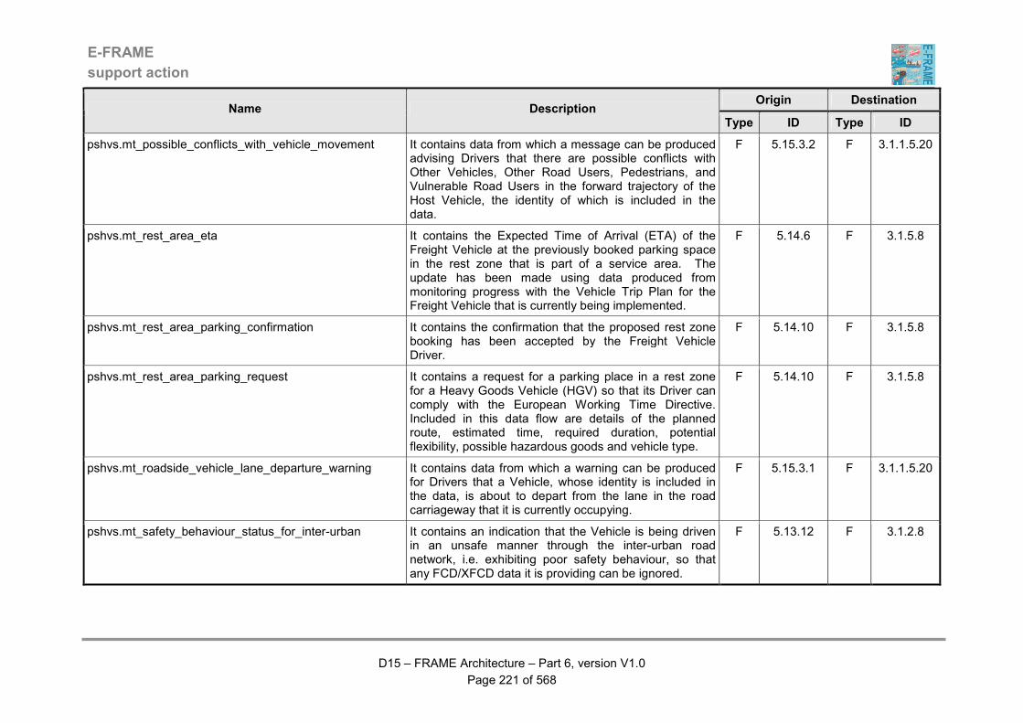
E-FRAME
support action
D15 – FRAME Architecture – Part 6, version V1.0
Page 221 of 568
Origin Destination Name Description
Type ID Type ID
pshvs.mt_possible_conflicts_with_vehicle_movement It contains data from which a message can be produced advising Drivers that there are possible conflicts with Other Vehicles, Other Road Users, Pedestrians, and Vulnerable Road Users in the forward trajectory of the Host Vehicle, the identity of which is included in the data.
F 5.15.3.2 F 3.1.1.5.20
pshvs.mt_rest_area_eta It contains the Expected Time of Arrival (ETA) of the Freight Vehicle at the previously booked parking space in the rest zone that is part of a service area. The update has been made using data produced from monitoring progress with the Vehicle Trip Plan for the Freight Vehicle that is currently being implemented.
F 5.14.6 F 3.1.5.8
pshvs.mt_rest_area_parking_confirmation It contains the confirmation that the proposed rest zone booking has been accepted by the Freight Vehicle Driver.
F 5.14.10 F 3.1.5.8
pshvs.mt_rest_area_parking_request It contains a request for a parking place in a rest zone for a Heavy Goods Vehicle (HGV) so that its Driver can comply with the European Working Time Directive. Included in this data flow are details of the planned route, estimated time, required duration, potential flexibility, possible hazardous goods and vehicle type.
F 5.14.10 F 3.1.5.8
pshvs.mt_roadside_vehicle_lane_departure_warning It contains data from which a warning can be produced for Drivers that a Vehicle, whose identity is included in the data, is about to depart from the lane in the road carriageway that it is currently occupying.
F 5.15.3.1 F 3.1.1.5.20
pshvs.mt_safety_behaviour_status_for_inter-urban It contains an indication that the Vehicle is being driven in an unsafe manner through the inter-urban road network, i.e. exhibiting poor safety behaviour, so that any FCD/XFCD data it is providing can be ignored.
F 5.13.12 F 3.1.2.8
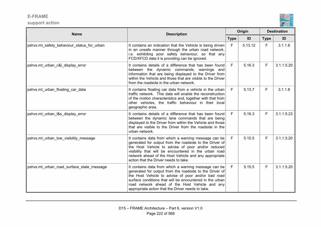
E-FRAME
support action
D15 – FRAME Architecture – Part 6, version V1.0
Page 222 of 568
Origin Destination Name Description
Type ID Type ID
pshvs.mt_safety_behaviour_status_for_urban It contains an indication that the Vehicle is being driven in an unsafe manner through the urban road network, i.e. exhibiting poor safety behaviour, so that any FCD/XFCD data it is providing can be ignored.
F 5.13.12 F 3.1.1.8
pshvs.mt_urban_c&i_display_error It contains details of a difference that has been found between the dynamic commands, warnings and information that are being displayed to the Driver from within the Vehicle and those that are visible to the Driver from the roadside in the urban network.
F 5.16.3 F 3.1.1.5.20
pshvs.mt_urban_floating_car_data It contains floating car data from a vehicle in the urban traffic network. This data will enable the reconstruction of the motion characteristics and, together with that from other vehicles, the traffic behaviour in their local geographic area.
F 5.13.7 F 3.1.1.8
pshvs.mt_urban_l&s_display_error It contains details of a difference that has been found between the dynamic lane commands that are being displayed to the Driver from within the Vehicle and those that are visible to the Driver from the roadside in the urban network.
F 5.16.3 F 3.1.1.5.23
pshvs.mt_urban_low_visibility_message It contains data from which a warning message can be generated for output from the roadside to the Driver of the Host Vehicle to advise of poor and/or reduced visibility that will be encountered in the urban road network ahead of the Host Vehicle and any appropriate action that the Driver needs to take.
F 5.15.5 F 3.1.1.5.20
pshvs.mt_urban_road_surface_state_message It contains data from which a warning message can be generated for output from the roadside to the Driver of the Host Vehicle to advise of poor and/or bad road surface conditions that will be encountered in the urban road network ahead of the Host Vehicle and any appropriate action that the Driver needs to take.
F 5.15.5 F 3.1.1.5.20
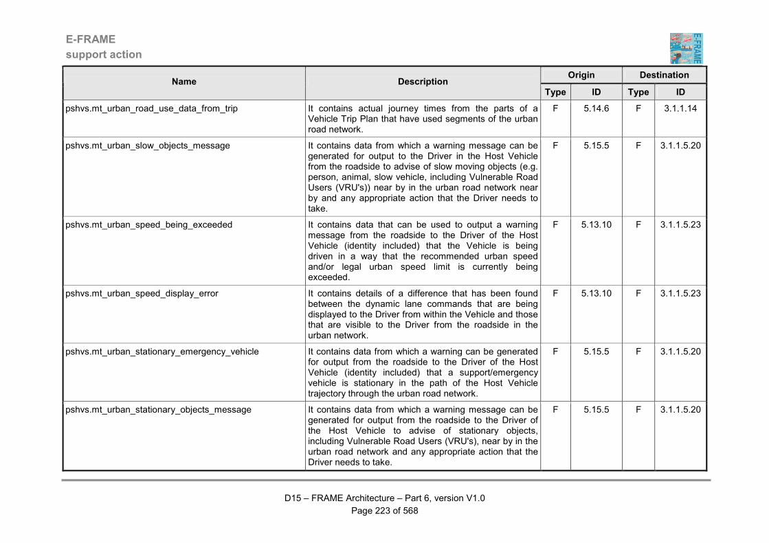
E-FRAME
support action
D15 – FRAME Architecture – Part 6, version V1.0
Page 223 of 568
Origin Destination Name Description
Type ID Type ID
pshvs.mt_urban_road_use_data_from_trip It contains actual journey times from the parts of a Vehicle Trip Plan that have used segments of the urban road network.
F 5.14.6 F 3.1.1.14
pshvs.mt_urban_slow_objects_message It contains data from which a warning message can be generated for output to the Driver in the Host Vehicle from the roadside to advise of slow moving objects (e.g. person, animal, slow vehicle, including Vulnerable Road Users (VRU's)) near by in the urban road network near by and any appropriate action that the Driver needs to take.
F 5.15.5 F 3.1.1.5.20
pshvs.mt_urban_speed_being_exceeded It contains data that can be used to output a warning message from the roadside to the Driver of the Host Vehicle (identity included) that the Vehicle is being driven in a way that the recommended urban speed and/or legal urban speed limit is currently being exceeded.
F 5.13.10 F 3.1.1.5.23
pshvs.mt_urban_speed_display_error It contains details of a difference that has been found between the dynamic lane commands that are being displayed to the Driver from within the Vehicle and those that are visible to the Driver from the roadside in the urban network.
F 5.13.10 F 3.1.1.5.23
pshvs.mt_urban_stationary_emergency_vehicle It contains data from which a warning can be generated for output from the roadside to the Driver of the Host Vehicle (identity included) that a support/emergency vehicle is stationary in the path of the Host Vehicle trajectory through the urban road network.
F 5.15.5 F 3.1.1.5.20
pshvs.mt_urban_stationary_objects_message It contains data from which a warning message can be generated for output from the roadside to the Driver of the Host Vehicle to advise of stationary objects, including Vulnerable Road Users (VRU's), near by in the urban road network and any appropriate action that the Driver needs to take.
F 5.15.5 F 3.1.1.5.20
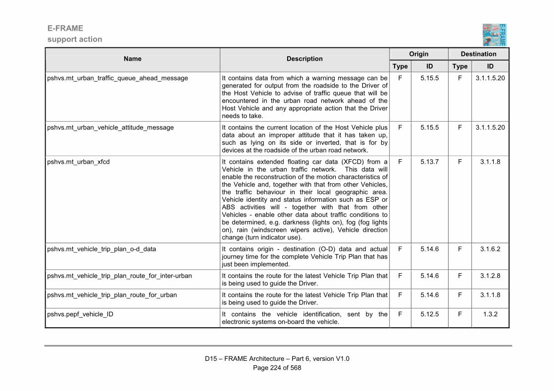
E-FRAME
support action
D15 – FRAME Architecture – Part 6, version V1.0
Page 224 of 568
Origin Destination Name Description
Type ID Type ID
pshvs.mt_urban_traffic_queue_ahead_message It contains data from which a warning message can be generated for output from the roadside to the Driver of the Host Vehicle to advise of traffic queue that will be encountered in the urban road network ahead of the Host Vehicle and any appropriate action that the Driver needs to take.
F 5.15.5 F 3.1.1.5.20
pshvs.mt_urban_vehicle_attitude_message It contains the current location of the Host Vehicle plus data about an improper attitude that it has taken up, such as lying on its side or inverted, that is for by devices at the roadside of the urban road network.
F 5.15.5 F 3.1.1.5.20
pshvs.mt_urban_xfcd It contains extended floating car data (XFCD) from a Vehicle in the urban traffic network. This data will enable the reconstruction of the motion characteristics of the Vehicle and, together with that from other Vehicles, the traffic behaviour in their local geographic area. Vehicle identity and status information such as ESP or ABS activities will - together with that from other Vehicles - enable other data about traffic conditions to be determined, e.g. darkness (lights on), fog (fog lights on), rain (windscreen wipers active), Vehicle direction change (turn indicator use).
F 5.13.7 F 3.1.1.8
pshvs.mt_vehicle_trip_plan_o-d_data It contains origin - destination (O-D) data and actual journey time for the complete Vehicle Trip Plan that has just been implemented.
F 5.14.6 F 3.1.6.2
pshvs.mt_vehicle_trip_plan_route_for_inter-urban It contains the route for the latest Vehicle Trip Plan that is being used to guide the Driver.
F 5.14.6 F 3.1.2.8
pshvs.mt_vehicle_trip_plan_route_for_urban It contains the route for the latest Vehicle Trip Plan that is being used to guide the Driver.
F 5.14.6 F 3.1.1.8
pshvs.pepf_vehicle_ID It contains the vehicle identification, sent by the electronic systems on-board the vehicle.
F 5.12.5 F 1.3.2

E-FRAME
support action
D15 – FRAME Architecture – Part 6, version V1.0
Page 225 of 568
Origin Destination Name Description
Type ID Type ID
pshvs.pepf_vehicle_position It contains the data on the vehicle current position to allow the charge of service based on the road occupation in time and space and other relevant data.
F 5.13.6 F 1.3.5
pshvs.pscs_destination_for_bus_lane_use It contains the destination of the Vehicle according to the Vehicle Trip Plan that it is using.
F 5.14.4 F 9.2.2
pshvs.pscs_freight_vehicle_left_un/loading_zone In contains confirmation that the Freight Vehicle has left the loading or unloading zone. This confirmation is obtained from processing the data produced by monitoring the current implementation of the Vehicle Trip Plan for the Freight Vehicle.
F 5.14.6 F 9.5.6
pshvs.pscs_hazarduous_goods_vehicle_data_for_route It contains data about the Vehicle that is carrying Hazardous Goods that is for use in the request from its Driver for a route.
F 5.12.7 F 9.4.3
pshvs.pscs_holding_zone_eta It contains the Expected Time of Arrival (ETA) of the Freight Vehicle at the previously booked holding zone. The update has been made using data produced from monitoring progress with the Vehicle Trip Plan for the Freight Vehicle that is currently being implemented.
F 5.14.6 F 9.5.6
pshvs.pscs_un/loading_zone_eta It contains the Expected Time of Arrival (ETA) of the Freight Vehicle at the previously booked loading or unloading zone. The update has been made using data produced from monitoring progress with the Vehicle Trip Plan for the Freight Vehicle that is currently being implemented.
F 5.14.6 F 9.5.6
pshvs.pscs_un/loading_zone_use_confirmation It contains the confirmation that the proposed loading or unloading area booking has been accepted by the Freight Vehicle Driver.
F 5.14.11 F 9.5.6
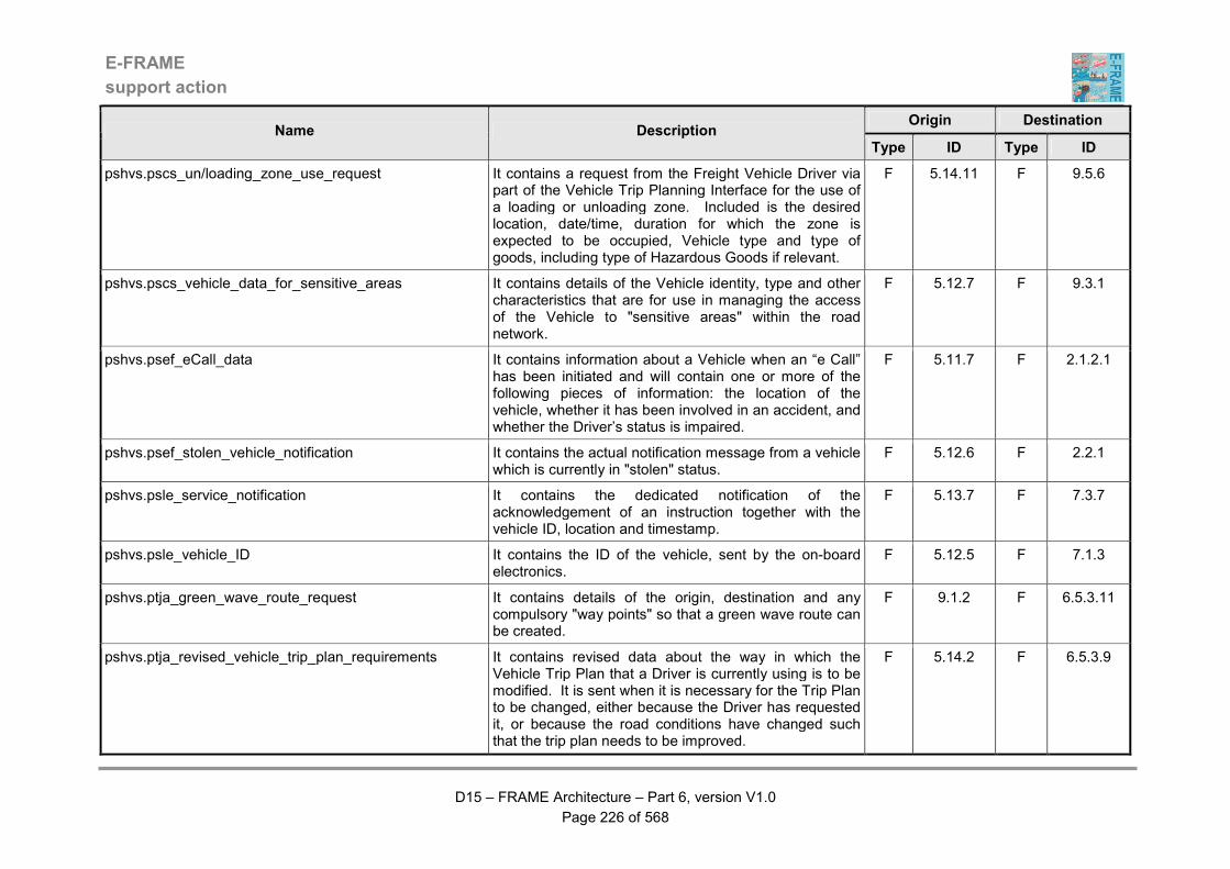
E-FRAME
support action
D15 – FRAME Architecture – Part 6, version V1.0
Page 226 of 568
Origin Destination Name Description
Type ID Type ID
pshvs.pscs_un/loading_zone_use_request It contains a request from the Freight Vehicle Driver via part of the Vehicle Trip Planning Interface for the use of a loading or unloading zone. Included is the desired location, date/time, duration for which the zone is expected to be occupied, Vehicle type and type of goods, including type of Hazardous Goods if relevant.
F 5.14.11 F 9.5.6
pshvs.pscs_vehicle_data_for_sensitive_areas It contains details of the Vehicle identity, type and other characteristics that are for use in managing the access of the Vehicle to "sensitive areas" within the road network.
F 5.12.7 F 9.3.1
pshvs.psef_eCall_data It contains information about a Vehicle when an “e Call” has been initiated and will contain one or more of the following pieces of information: the location of the vehicle, whether it has been involved in an accident, and whether the Driver’s status is impaired.
F 5.11.7 F 2.1.2.1
pshvs.psef_stolen_vehicle_notification It contains the actual notification message from a vehicle which is currently in "stolen" status.
F 5.12.6 F 2.2.1
pshvs.psle_service_notification It contains the dedicated notification of the acknowledgement of an instruction together with the vehicle ID, location and timestamp.
F 5.13.7 F 7.3.7
pshvs.psle_vehicle_ID It contains the ID of the vehicle, sent by the on-board electronics.
F 5.12.5 F 7.1.3
pshvs.ptja_green_wave_route_request It contains details of the origin, destination and any compulsory "way points" so that a green wave route can be created.
F 9.1.2 F 6.5.3.11
pshvs.ptja_revised_vehicle_trip_plan_requirements It contains revised data about the way in which the Vehicle Trip Plan that a Driver is currently using is to be modified. It is sent when it is necessary for the Trip Plan to be changed, either because the Driver has requested it, or because the road conditions have changed such that the trip plan needs to be improved.
F 5.14.2 F 6.5.3.9
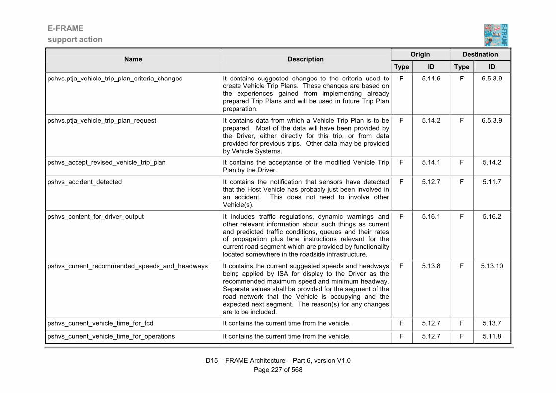
E-FRAME
support action
D15 – FRAME Architecture – Part 6, version V1.0
Page 227 of 568
Origin Destination Name Description
Type ID Type ID
pshvs.ptja_vehicle_trip_plan_criteria_changes It contains suggested changes to the criteria used to create Vehicle Trip Plans. These changes are based on the experiences gained from implementing already prepared Trip Plans and will be used in future Trip Plan preparation.
F 5.14.6 F 6.5.3.9
pshvs.ptja_vehicle_trip_plan_request It contains data from which a Vehicle Trip Plan is to be prepared. Most of the data will have been provided by the Driver, either directly for this trip, or from data provided for previous trips. Other data may be provided by Vehicle Systems.
F 5.14.2 F 6.5.3.9
pshvs_accept_revised_vehicle_trip_plan It contains the acceptance of the modified Vehicle Trip Plan by the Driver.
F 5.14.1 F 5.14.2
pshvs_accident_detected It contains the notification that sensors have detected that the Host Vehicle has probably just been involved in an accident. This does not need to involve other Vehicle(s).
F 5.12.7 F 5.11.7
pshvs_content_for_driver_output It includes traffic regulations, dynamic warnings and other relevant information about such things as current and predicted traffic conditions, queues and their rates of propagation plus lane instructions relevant for the current road segment which are provided by functionality located somewhere in the roadside infrastructure.
F 5.16.1 F 5.16.2
pshvs_current_recommended_speeds_and_headways It contains the current suggested speeds and headways being applied by ISA for display to the Driver as the recommended maximum speed and minimum headway. Separate values shall be provided for the segment of the road network that the Vehicle is occupying and the expected next segment. The reason(s) for any changes are to be included.
F 5.13.8 F 5.13.10
pshvs_current_vehicle_time_for_fcd It contains the current time from the vehicle. F 5.12.7 F 5.13.7
pshvs_current_vehicle_time_for_operations It contains the current time from the vehicle. F 5.12.7 F 5.11.8
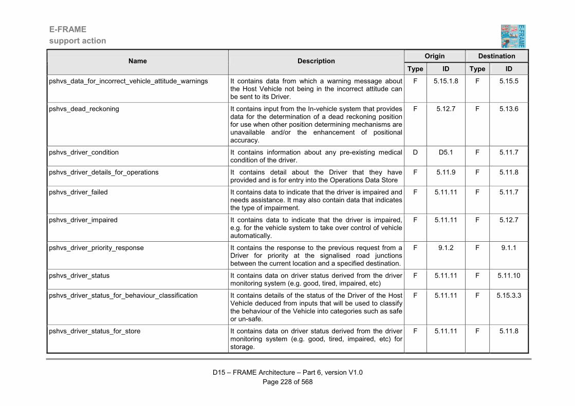
E-FRAME
support action
D15 – FRAME Architecture – Part 6, version V1.0
Page 228 of 568
Origin Destination Name Description
Type ID Type ID
pshvs_data_for_incorrect_vehicle_attitude_warnings It contains data from which a warning message about the Host Vehicle not being in the incorrect attitude can be sent to its Driver.
F 5.15.1.8 F 5.15.5
pshvs_dead_reckoning It contains input from the In-vehicle system that provides data for the determination of a dead reckoning position for use when other position determining mechanisms are unavailable and/or the enhancement of positional accuracy.
F 5.12.7 F 5.13.6
pshvs_driver_condition It contains information about any pre-existing medical condition of the driver.
D D5.1 F 5.11.7
pshvs_driver_details_for_operations It contains detail about the Driver that they have provided and is for entry into the Operations Data Store
F 5.11.9 F 5.11.8
pshvs_driver_failed It contains data to indicate that the driver is impaired and needs assistance. It may also contain data that indicates the type of impairment.
F 5.11.11 F 5.11.7
pshvs_driver_impaired It contains data to indicate that the driver is impaired, e.g. for the vehicle system to take over control of vehicle automatically.
F 5.11.11 F 5.12.7
pshvs_driver_priority_response It contains the response to the previous request from a Driver for priority at the signalised road junctions between the current location and a specified destination.
F 9.1.2 F 9.1.1
pshvs_driver_status It contains data on driver status derived from the driver monitoring system (e.g. good, tired, impaired, etc)
F 5.11.11 F 5.11.10
pshvs_driver_status_for_behaviour_classification It contains details of the status of the Driver of the Host Vehicle deduced from inputs that will be used to classify the behaviour of the Vehicle into categories such as safe or un-safe.
F 5.11.11 F 5.15.3.3
pshvs_driver_status_for_store It contains data on driver status derived from the driver monitoring system (e.g. good, tired, impaired, etc) for storage.
F 5.11.11 F 5.11.8

E-FRAME
support action
D15 – FRAME Architecture – Part 6, version V1.0
Page 229 of 568
Origin Destination Name Description
Type ID Type ID
pshvs_driver_stored_data It contains reference stored data useful to detect discrepancies between the current driver behaviour and the standard (or historical) one, or discrepancies between vehicle data to detect impending malfunctions.
D D5.1 F 5.11.11
pshvs_eCall_information It contains the data to indicate that a mayday call has been initiated so that the vehicle systems can perform an appropriate action if necessary.
F 5.11.7 F 5.12.7
pshvs_emergency_vehicle_stationary_ahead It contains data from which a warning can be generated for output to the Driver of the Host Vehicle that a support/emergency vehicle is stationary in the path of the Host Vehicle trajectory.
F 5.15.5 F 5.15.4
pshvs_fused_road_and_traffic_conditions It contains the fused road and traffic data from the host Vehicle and any Other Vehicle in the area, and is for display to the Driver.
F 5.13.11 F 5.13.10
pshvs_ghost_driver_detected_warning It contains data from which a warning can be output to the Driver of the Host Vehicle that a "non-equipped" Vehicle (ghost driver) has been detected travelling towards the Host Vehicle.
F 5.15.5 F 5.15.4
pshvs_ghost_driver_warning_for_other_vehicle It contains data about a "non-equipped" Vehicle travelling the wrong way along the carriageway (host driver) that has been detected by the Host Vehicle that is to be sent to the Other Vehicle for its use.
F 5.15.5 F 5.12.10
pshvs_ghost_driver_warning_from_other_vehicle It contains data about a "non-equipped" Vehicle travelling the wrong way along the carriageway (host driver) that has been detected by the Other Vehicle that has been sent to the Host Vehicle for its use.
F 5.12.10 F 5.15.5
pshvs_goods_being_carried_by_host_vehicle It contains details of the goods being carried by the Host Vehicle that is to be sent to the Other Vehicle.
F 5.12.7 F 5.12.10
pshvs_guidance_data It contains data, provided by the Infrastructure Support System, useful for any automatic guidance applications.
F 5.12.12 F 5.12.7
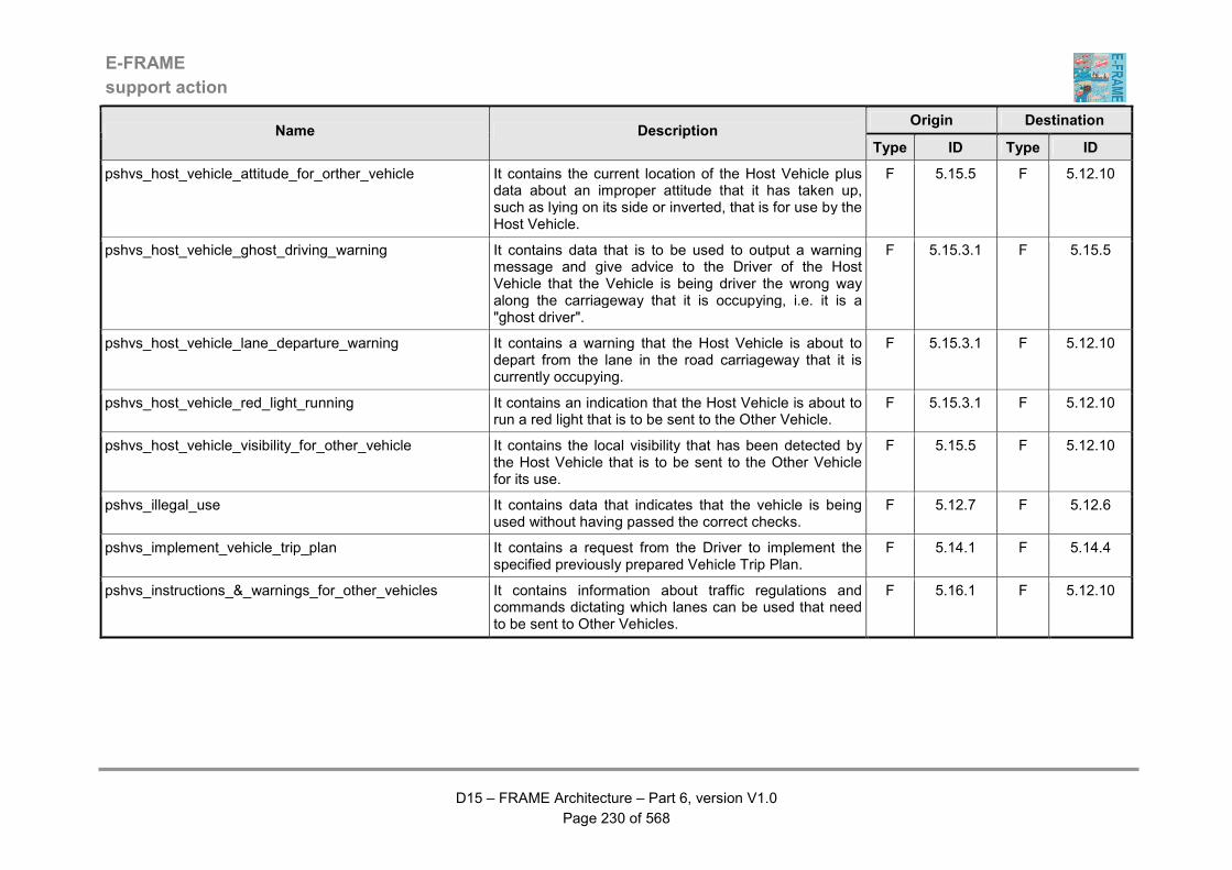
E-FRAME
support action
D15 – FRAME Architecture – Part 6, version V1.0
Page 230 of 568
Origin Destination Name Description
Type ID Type ID
pshvs_host_vehicle_attitude_for_orther_vehicle It contains the current location of the Host Vehicle plus data about an improper attitude that it has taken up, such as lying on its side or inverted, that is for use by the Host Vehicle.
F 5.15.5 F 5.12.10
pshvs_host_vehicle_ghost_driving_warning It contains data that is to be used to output a warning message and give advice to the Driver of the Host Vehicle that the Vehicle is being driver the wrong way along the carriageway that it is occupying, i.e. it is a "ghost driver".
F 5.15.3.1 F 5.15.5
pshvs_host_vehicle_lane_departure_warning It contains a warning that the Host Vehicle is about to depart from the lane in the road carriageway that it is currently occupying.
F 5.15.3.1 F 5.12.10
pshvs_host_vehicle_red_light_running It contains an indication that the Host Vehicle is about to run a red light that is to be sent to the Other Vehicle.
F 5.15.3.1 F 5.12.10
pshvs_host_vehicle_visibility_for_other_vehicle It contains the local visibility that has been detected by the Host Vehicle that is to be sent to the Other Vehicle for its use.
F 5.15.5 F 5.12.10
pshvs_illegal_use It contains data that indicates that the vehicle is being used without having passed the correct checks.
F 5.12.7 F 5.12.6
pshvs_implement_vehicle_trip_plan It contains a request from the Driver to implement the specified previously prepared Vehicle Trip Plan.
F 5.14.1 F 5.14.4
pshvs_instructions_&_warnings_for_other_vehicles It contains information about traffic regulations and commands dictating which lanes can be used that need to be sent to Other Vehicles.
F 5.16.1 F 5.12.10

E-FRAME
support action
D15 – FRAME Architecture – Part 6, version V1.0
Page 231 of 568
Origin Destination Name Description
Type ID Type ID
pshvs_instructions_&_warnings_from_other_vehicles It contains information that has been received from the Other Vehicle that can be displayed to the Driver of the host Vehicle. The information includes platooning, safety behaviour and other vehicle data, regulations, speed limits, lane commands, road signs and general road information, plus warnings of the need to dip headlights, lane changing, collision and emergency brake manoeuvres.
F 5.12.10 F 5.16.1
pshvs_ISA_acknowledgement It contains the dedicated acknowledgement that an intelligent speed adoption has been received and handled correctly.
F 5.13.8 F 5.13.7
pshvs_lane_command_response It contains the dedicated acknowledgement that a lane banning instruction has been received and handled correctly by the Vehicle HMI to output it to the Driver.
F 5.16.2 F 5.13.7
pshvs_legal_speed_acknowledgement It contains the dedicated acknowledgement that a legal speed instruction has been received and handled correctly.
F 5.13.9 F 5.13.7
pshvs_legal_speed_for_safety_behaviour It contains the current legal speed limit for the road segment which the Vehicle is currently using for use in monitoring the way that it is being driven so that reports are provided when it becomes unsafe, i.e. poor safety behaviour.
F 5.13.9 F 5.13.12
pshvs_legal_speed_limit_for_ISA It contains the legal speed limit for use by the ISA functionality.
F 5.13.9 F 5.13.8
pshvs_load_ISA_data It contains speed limits for use by the ISA facility for various parts of the road network that are to be loaded into the ISA Data Store.
F 5.13.8 D D5.2
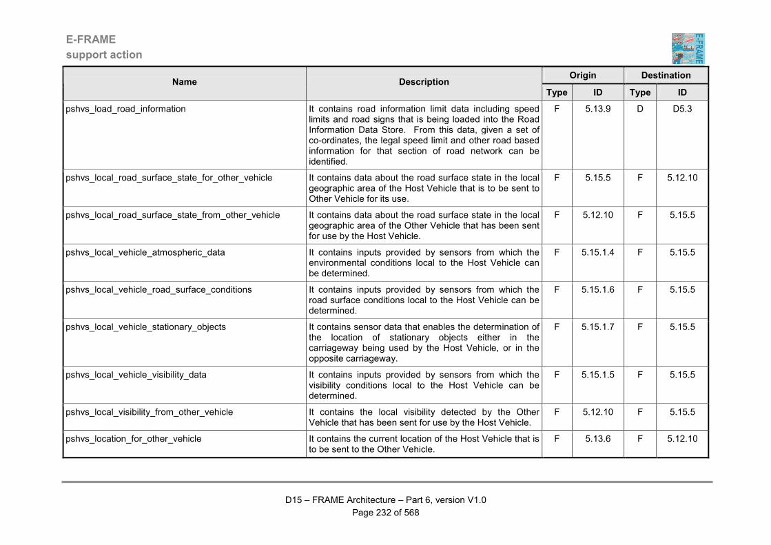
E-FRAME
support action
D15 – FRAME Architecture – Part 6, version V1.0
Page 232 of 568
Origin Destination Name Description
Type ID Type ID
pshvs_load_road_information It contains road information limit data including speed limits and road signs that is being loaded into the Road Information Data Store. From this data, given a set of co-ordinates, the legal speed limit and other road based information for that section of road network can be identified.
F 5.13.9 D D5.3
pshvs_local_road_surface_state_for_other_vehicle It contains data about the road surface state in the local geographic area of the Host Vehicle that is to be sent to Other Vehicle for its use.
F 5.15.5 F 5.12.10
pshvs_local_road_surface_state_from_other_vehicle It contains data about the road surface state in the local geographic area of the Other Vehicle that has been sent for use by the Host Vehicle.
F 5.12.10 F 5.15.5
pshvs_local_vehicle_atmospheric_data It contains inputs provided by sensors from which the environmental conditions local to the Host Vehicle can be determined.
F 5.15.1.4 F 5.15.5
pshvs_local_vehicle_road_surface_conditions It contains inputs provided by sensors from which the road surface conditions local to the Host Vehicle can be determined.
F 5.15.1.6 F 5.15.5
pshvs_local_vehicle_stationary_objects It contains sensor data that enables the determination of the location of stationary objects either in the carriageway being used by the Host Vehicle, or in the opposite carriageway.
F 5.15.1.7 F 5.15.5
pshvs_local_vehicle_visibility_data It contains inputs provided by sensors from which the visibility conditions local to the Host Vehicle can be determined.
F 5.15.1.5 F 5.15.5
pshvs_local_visibility_from_other_vehicle It contains the local visibility detected by the Other Vehicle that has been sent for use by the Host Vehicle.
F 5.12.10 F 5.15.5
pshvs_location_for_other_vehicle It contains the current location of the Host Vehicle that is to be sent to the Other Vehicle.
F 5.13.6 F 5.12.10

E-FRAME
support action
D15 – FRAME Architecture – Part 6, version V1.0
Page 233 of 568
Origin Destination Name Description
Type ID Type ID
pshvs_location_from_other_vehicle It contains the current location of the Other Vehicle that has been received by the Host Vehicle.
F 5.12.10 F 5.13.6
pshvs_location_of_other_vehicles_nearby It contains details of the locations of Other Vehicles that are nearby the Host Vehicle and includes the digital map data that shows the type of road on which the Host Vehicle is travelling.
F 5.15.5 F 5.15.3.2
pshvs_low_visibility_warning_and_advice It contains data from which a warning message for output to the Driver in the Host Vehicle can be generated to advise of poor and/or reduced visibility that will be encountered in the road network ahead of the Host Vehicle and any appropriate action that the Driver needs to take.
F 5.15.5 F 5.15.4
pshvs_nearby_vehicles_and_road_user_information It contains information about Other Vehicles and/or Other Road Users that are nearby the Host Vehicle, including those approaching the same set of traffic signals being approached by the Host Vehicle and those approaching the front or rear of the Host Vehicle that are partially in the lane occupied by the Host Vehicle.
F 5.15.3.2 F 5.15.4
pshvs_other_road_users_nearby It contains the position and detected details of any Other Road Users such as a cyclist, motorcyclist, Vulnerable Road User (VRU), "non-equipped" Vehicle, slow Vehicle, or other slow moving object, e.g. animal (pedestrians are detected separately), that has been detected in the geographic area surrounding the Host Vehicle.
F 5.15.1.2 F 5.15.5
pshvs_other_vehicle_receiving_priority It contains an indication that other vehicle(s) are receiving priority at a junction that is being approached by the Vehicle.
F 9.1.2 F 9.1.1
pshvs_other_vehicle_relative_position It contains the relative positions of other equipped Vehicles for use in determining the position of the Host Vehicle.
F 5.15.5 F 5.13.6
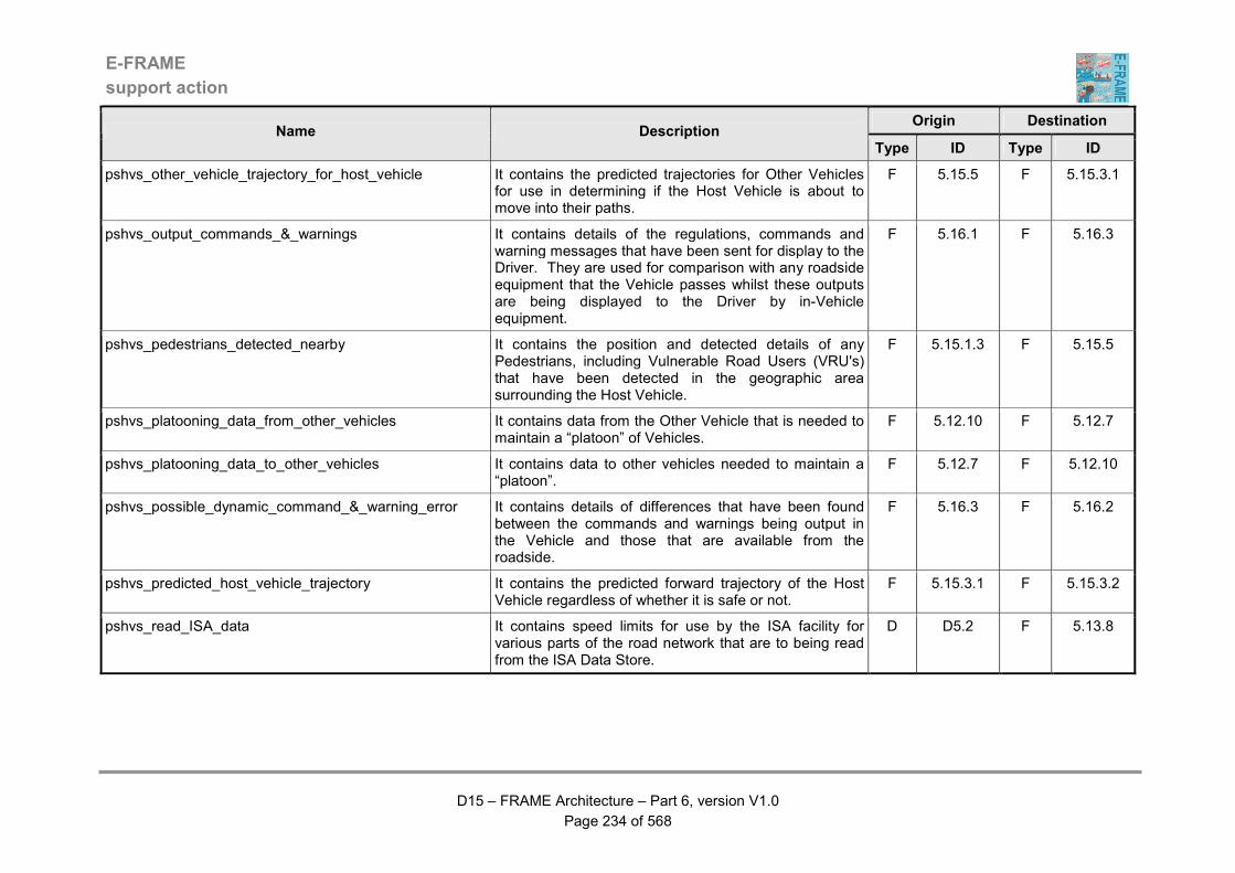
E-FRAME
support action
D15 – FRAME Architecture – Part 6, version V1.0
Page 234 of 568
Origin Destination Name Description
Type ID Type ID
pshvs_other_vehicle_trajectory_for_host_vehicle It contains the predicted trajectories for Other Vehicles for use in determining if the Host Vehicle is about to move into their paths.
F 5.15.5 F 5.15.3.1
pshvs_output_commands_&_warnings It contains details of the regulations, commands and warning messages that have been sent for display to the Driver. They are used for comparison with any roadside equipment that the Vehicle passes whilst these outputs are being displayed to the Driver by in-Vehicle equipment.
F 5.16.1 F 5.16.3
pshvs_pedestrians_detected_nearby It contains the position and detected details of any Pedestrians, including Vulnerable Road Users (VRU's) that have been detected in the geographic area surrounding the Host Vehicle.
F 5.15.1.3 F 5.15.5
pshvs_platooning_data_from_other_vehicles It contains data from the Other Vehicle that is needed to maintain a “platoon” of Vehicles.
F 5.12.10 F 5.12.7
pshvs_platooning_data_to_other_vehicles It contains data to other vehicles needed to maintain a “platoon”.
F 5.12.7 F 5.12.10
pshvs_possible_dynamic_command_&_warning_error It contains details of differences that have been found between the commands and warnings being output in the Vehicle and those that are available from the roadside.
F 5.16.3 F 5.16.2
pshvs_predicted_host_vehicle_trajectory It contains the predicted forward trajectory of the Host Vehicle regardless of whether it is safe or not.
F 5.15.3.1 F 5.15.3.2
pshvs_read_ISA_data It contains speed limits for use by the ISA facility for various parts of the road network that are to being read from the ISA Data Store.
D D5.2 F 5.13.8

E-FRAME
support action
D15 – FRAME Architecture – Part 6, version V1.0
Page 235 of 568
Origin Destination Name Description
Type ID Type ID
pshvs_read_road_information It contains road information limit data including speed limits and road signs that is being read from the Road Information Data Store. From this data, given a set of co-ordinates, the legal speed limit and other road based information for that section of road network can be identified.
D D5.3 F 5.13.9
pshvs_red_light_running_warnng It contains a warning for output to the Driver that the Vehicle it is about to run through a red light.
F 5.15.3.1 F 5.15.4
pshvs_reqeust_data_from_stored_vehicle_trip_plans It contains a request for details of the specified stored Vehicle Trip Plans for use as part of the data for a new Vehicle Trip Plan request.
F 5.14.2 F 5.14.7
pshvs_requested_data_from_stored_vehicle_trip_plan It contains the response to a previous request for details of the specified stored Vehicle Trip Plans for use as part of the data for a new Vehicle Trip Plan request.
F 5.14.7 F 5.14.2
pshvs_request_vehicle_trip_plan_for_implementation It contains a request for a specific Vehicle Trip Plan to be provided from the Store and used by the Driver for their journey.
F 5.14.4 F 5.14.7
pshvs_revised_vehicle_trip_plan_for_driver It contains details for the Driver of the changes to a Vehicle Trip Plan that have been created by changes to the travel conditions during the course of the trip, plus details of the consequent expected arrival times at the trip destination and any way points.
F 5.14.2 F 5.14.1
pshvs_revise_vehicle_trip_plan_request It contains a request for a change to the Vehicle Trip Plan that is currently being implemented as a result of the monitoring of the progress of the Vehicle. It includes all of the data about the current Trip Plan.
F 5.14.6 F 5.14.2
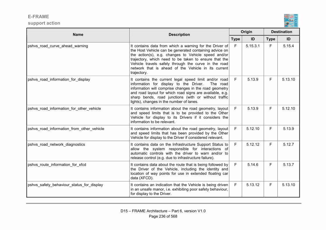
E-FRAME
support action
D15 – FRAME Architecture – Part 6, version V1.0
Page 236 of 568
Origin Destination Name Description
Type ID Type ID
pshvs_road_curve_ahead_warning It contains data from which a warning for the Driver of the Host Vehicle can be generated containing advice on the action(s), e.g. changes to Vehicle speed and/or trajectory, which need to be taken to ensure that the Vehicle travels safely through the curve in the road network that is ahead of the Vehicle in its current trajectory.
F 5.15.3.1 F 5.15.4
pshvs_road_information_for_display It contains the current legal speed limit and/or road information for display to the Driver. The road information will comprise changes in the road geometry and road layout for which road signs are available, e.g. sharp bends, road junctions (with or without traffic lights), changes in the number of lanes.
F 5.13.9 F 5.13.10
pshvs_road_information_for_other_vehicle It contains information about the road geometry, layout and speed limits that is to be provided to the Other Vehicle for display to its Drivers if it considers the information to be relevant.
F 5.13.9 F 5.12.10
pshvs_road_information_from_other_vehicle It contains information about the road geometry, layout and speed limits that has been provided by the Other Vehicle for display to the Driver if considered relevant.
F 5.12.10 F 5.13.9
pshvs_road_network_diagnostics It contains data on the Infrastructure Support Status to allow the system responsible for interactions of automatic controls with the driver to warn and/or to release control (e.g. due to infrastructure failure).
F 5.12.12 F 5.12.7
pshvs_route_information_for_xfcd It contains data about the route that is being followed by the Driver of the Vehicle, including the identity and location of way points for use in extended floating car data (XFCD).
F 5.14.6 F 5.13.7
pshvs_safety_behaviour_status_for_display It contains an indication that the Vehicle is being driven in an unsafe manor, i.e. exhibiting poor safety behaviour, for display to the Driver.
F 5.13.12 F 5.13.10

E-FRAME
support action
D15 – FRAME Architecture – Part 6, version V1.0
Page 237 of 568
Origin Destination Name Description
Type ID Type ID
pshvs_safety_behaviour_status_for_other_vehicle It contains an indication that the Vehicle is being driven in an unsafe manner, i.e. exhibiting poor safety behaviour, and is to be sent to the Other Vehicle.
F 5.13.12 F 5.12.10
pshvs_slippery_road_surface_warning It contains data that can be used to output a message to the Driver of the Host Vehicle warning that there is a slippery road surface ahead.
F 5.15.5 F 5.15.4
pshvs_slow_objects_warning_and_advice It contains data from which a warning message for output to the Driver in the Host Vehicle can be generated to advise of slow moving objects (e.g. person, animal, slow vehicle, including Vulnerable Road Users (VRU's)) near by and any appropriate action that the Driver needs to take.
F 5.15.5 F 5.15.4
pshvs_stationary_objects_warning_and_advice It contains data from which a warning message for output to the Driver in the Host Vehicle can be generated to advise of stationary objects, including Vulnerable Road Users (VRU's), near by and any appropriate action that the Driver needs to take.
F 5.15.5 F 5.15.4
pshvs_status_data_for_fcd It contains data relating to the current status of the Vehicle, and its environment, such as speed, plus use of Vehicle equipment such as windscreen wipers, fog lamps, lights, turn indicators and any failure indications, plus outside temperature.
F 5.12.7 F 5.13.7
pshvs_status_data_from_other_vehicles It contains data from the Other Vehicle relating to the current status of that Vehicle and its Driver.
F 5.12.10 F 5.12.7
pshvs_status_data_to_other_vehicles It contains data to the Other Vehicle relating to the current status of the host Vehicle and its Driver.
F 5.12.7 F 5.12.10
pshvs_stolen_vehicle_data_for_emergency_operator It contains data about a stolen Vehicle that has been formatted for sending to the Emergency Operator.
F 2.2.1 F 2.2.3
pshvs_stolen_vehicle_data_for_emergency_services It contains data about a stolen Vehicle that has been formatted for sending to the Emergency Services.
F 2.2.1 F 2.2.2
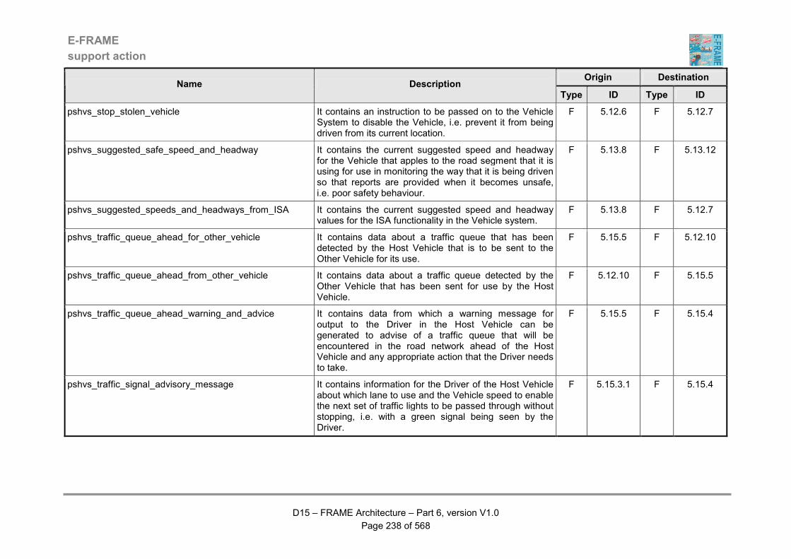
E-FRAME
support action
D15 – FRAME Architecture – Part 6, version V1.0
Page 238 of 568
Origin Destination Name Description
Type ID Type ID
pshvs_stop_stolen_vehicle It contains an instruction to be passed on to the Vehicle System to disable the Vehicle, i.e. prevent it from being driven from its current location.
F 5.12.6 F 5.12.7
pshvs_suggested_safe_speed_and_headway It contains the current suggested speed and headway for the Vehicle that apples to the road segment that it is using for use in monitoring the way that it is being driven so that reports are provided when it becomes unsafe, i.e. poor safety behaviour.
F 5.13.8 F 5.13.12
pshvs_suggested_speeds_and_headways_from_ISA It contains the current suggested speed and headway values for the ISA functionality in the Vehicle system.
F 5.13.8 F 5.12.7
pshvs_traffic_queue_ahead_for_other_vehicle It contains data about a traffic queue that has been detected by the Host Vehicle that is to be sent to the Other Vehicle for its use.
F 5.15.5 F 5.12.10
pshvs_traffic_queue_ahead_from_other_vehicle It contains data about a traffic queue detected by the Other Vehicle that has been sent for use by the Host Vehicle.
F 5.12.10 F 5.15.5
pshvs_traffic_queue_ahead_warning_and_advice It contains data from which a warning message for output to the Driver in the Host Vehicle can be generated to advise of a traffic queue that will be encountered in the road network ahead of the Host Vehicle and any appropriate action that the Driver needs to take.
F 5.15.5 F 5.15.4
pshvs_traffic_signal_advisory_message It contains information for the Driver of the Host Vehicle about which lane to use and the Vehicle speed to enable the next set of traffic lights to be passed through without stopping, i.e. with a green signal being seen by the Driver.
F 5.15.3.1 F 5.15.4
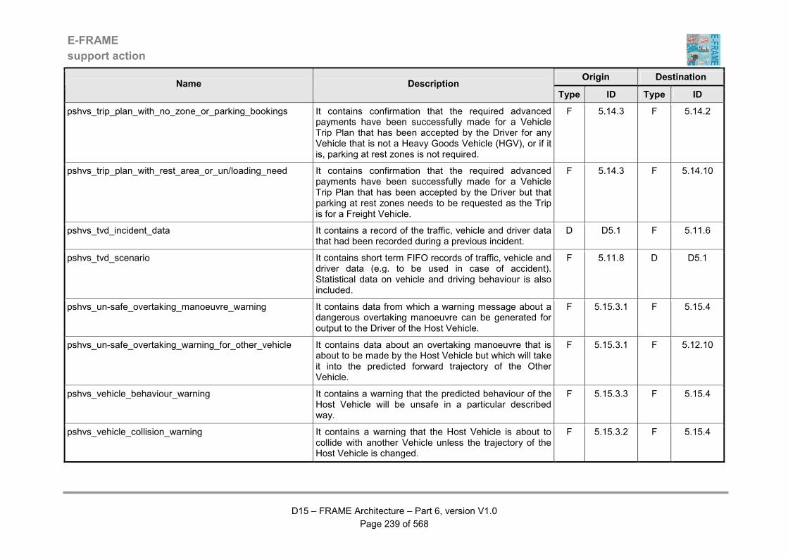
E-FRAME
support action
D15 – FRAME Architecture – Part 6, version V1.0
Page 239 of 568
Origin Destination Name Description
Type ID Type ID
pshvs_trip_plan_with_no_zone_or_parking_bookings It contains confirmation that the required advanced payments have been successfully made for a Vehicle Trip Plan that has been accepted by the Driver for any Vehicle that is not a Heavy Goods Vehicle (HGV), or if it is, parking at rest zones is not required.
F 5.14.3 F 5.14.2
pshvs_trip_plan_with_rest_area_or_un/loading_need It contains confirmation that the required advanced payments have been successfully made for a Vehicle Trip Plan that has been accepted by the Driver but that parking at rest zones needs to be requested as the Trip is for a Freight Vehicle.
F 5.14.3 F 5.14.10
pshvs_tvd_incident_data It contains a record of the traffic, vehicle and driver data that had been recorded during a previous incident.
D D5.1 F 5.11.6
pshvs_tvd_scenario It contains short term FIFO records of traffic, vehicle and driver data (e.g. to be used in case of accident). Statistical data on vehicle and driving behaviour is also included.
F 5.11.8 D D5.1
pshvs_un-safe_overtaking_manoeuvre_warning It contains data from which a warning message about a dangerous overtaking manoeuvre can be generated for output to the Driver of the Host Vehicle.
F 5.15.3.1 F 5.15.4
pshvs_un-safe_overtaking_warning_for_other_vehicle It contains data about an overtaking manoeuvre that is about to be made by the Host Vehicle but which will take it into the predicted forward trajectory of the Other Vehicle.
F 5.15.3.1 F 5.12.10
pshvs_vehicle_behaviour_warning It contains a warning that the predicted behaviour of the Host Vehicle will be unsafe in a particular described way.
F 5.15.3.3 F 5.15.4
pshvs_vehicle_collision_warning It contains a warning that the Host Vehicle is about to collide with another Vehicle unless the trajectory of the Host Vehicle is changed.
F 5.15.3.2 F 5.15.4

E-FRAME
support action
D15 – FRAME Architecture – Part 6, version V1.0
Page 240 of 568
Origin Destination Name Description
Type ID Type ID
pshvs_vehicle_data It contains data on the current status of selected Vehicle parameters for storage in case they need to be read by an authorised authority.
F 5.12.7 F 5.11.8
pshvs_vehicle_data_for_attitude_determination It contains data such as speed and trajectory from the Vehicle System in the Host Vehicle that is for use in determining that the Host Vehicle is in the proper attitude, i.e. it has not fallen over, or rolled upside down.
F 5.12.7 F 5.15.1.8
pshvs_vehicle_data_for_determining_speed_&_headway It contains data about the Vehicle such as identity, acceleration and braking characteristics, plus the weight when it is empty, the weight of goods being carried (if any), or the weight of any passengers (PT Vehicles only), or the weight of occupants and belongings (Private Car only), that will be used in determining the speed and headway that the Driver should use.
F 5.12.7 F 5.13.8
pshvs_vehicle_data_for_trajectory It contains data provided by In-vehicle Systems of the Host Vehicle that is used to calculate the forward trajectory of the Vehicle. It therefore includes such items as the status of the power unit, driver train, front wheels, steering wheel, turn indicator and brakes, plus the Host Vehicle identity.
F 5.12.7 F 5.15.3.1
pshvs_vehicle_data_for_trip_planning It contains data about the Host Vehicle from its Vehicle Systems. This data may include such things as Vehicle type, identity, size, weight, towing a trailer, fuel range, condition and capabilities, plus if appropriate, type of cargo and carrying capacity, data about hazardous cargo.
F 5.12.7 F 5.14.2
pshvs_vehicle_departed_from_route It contains a warning that the Vehicle has departed from the route in the Vehicle Trip Plan and that a revised route is being determined from the current location of the Vehicle to the original destination in the Trip Plan.
F 5.14.6 F 5.14.5

E-FRAME
support action
D15 – FRAME Architecture – Part 6, version V1.0
Page 241 of 568
Origin Destination Name Description
Type ID Type ID
pshvs_vehicle_detected_nearby It contains the position and available details of any Vehicles that have been detected in the geographic area surrounding the Host Vehicle.
F 5.15.1.1 F 5.15.5
pshvs_vehicle_eta_for_driver It contains the Estimated Time of Arrival (ETA) at the next way point or destination in the Vehicle Trip Plan and is updated at regular intervals.
F 5.14.6 F 5.14.5
pshvs_vehicle_ID It contains the ID of the vehicle. F 5.12.7 F 5.12.5
pshvs_vehicle_ID_for_fcd It contains the vehicle ID. F 5.12.5 F 5.13.7
pshvs_vehicle_ID_for_illegal_use It contains the vehicle ID. F 5.12.5 F 5.12.6
pshvs_vehicle_lane_departure_warning It contains a warning that the Host Vehicle is about to depart from the lane in the road carriageway that it is currently occupying.
F 5.15.3.1 F 5.15.4
pshvs_vehicle_location_for_safety_behaviour It contains the location of the Vehicle that will be used to monitor the way that it is being driven so that reports are provided when it becomes unsafe, i.e. poor safety behaviour.
F 5.13.6 F 5.13.12
pshvs_vehicle_location_for_trajectory It contains the location of the Host Vehicle within the carriageway and the road network, expressed in the form of digital map data, including data for the surrounding geographic area, and is for use in a variety of processes that are connected with the trajectory of the Host Vehicle.
F 5.15.5 F 5.15.3.1
pshvs_vehicle_location_for_trip_plan_monitoring It contains the current location of the Driver during the course of the implementation of a Vehicle Trip Plan and is used to monitor the progress of the Driver.
F 5.14.4 F 5.14.6
pshvs_vehicle_position_for_fcd It contains data on the current vehicle position derived from one or more means.
F 5.13.6 F 5.13.7
pshvs_vehicle_position_for_illegal_use It contains data on the current vehicle position derived from one or more means.
F 5.13.6 F 5.12.6

E-FRAME
support action
D15 – FRAME Architecture – Part 6, version V1.0
Page 242 of 568
Origin Destination Name Description
Type ID Type ID
pshvs_vehicle_position_for_ISA It contains data on the current vehicle position derived from one or more means.
F 5.13.6 F 5.13.8
pshvs_vehicle_position_for_road_information It contains data on the current Vehicle position derived from one or more means that is used to determine the applicable speed limit and other road information that is to be output to the Driver.
F 5.13.6 F 5.13.9
pshvs_vehicle_speed It contains the current speed of the Host Vehicle as measured by the on-board Vehicle systems plus the identity of the Vehicle.
F 5.12.7 F 5.13.10
pshvs_vehicle_speed_for_safety_behaviour It contains the current speed of the Vehicle that will be used to monitor the way that it is being driven so that reports are provided when it becomes unsafe, i.e. poor safety behaviour.
F 5.13.7 F 5.13.12
pshvs_vehicle_trajectory_for_driver_behaviour It contains details of the predicted forward trajectory of the Host Vehicle together with its location within the carriageway and the road network for use in classifying the behaviour of its Driver.
F 5.15.3.1 F 5.15.3.3
pshvs_vehicle_trip_plan_acceptance It contains data indicating that the Driver has accepted the Vehicle Trip Plan that has just been prepared.
F 5.14.1 F 5.14.2
pshvs_vehicle_trip_plan_change_data_for_driver It contains the reason (e.g. congestion or incident) that a change to the current Vehicle Trip Plan has been requested and is for output to the Driver.
F 5.14.6 F 5.14.5
pshvs_vehicle_trip_plan_data It contains parameters provided by the Driver from which a Vehicle Trip Plan will be prepared. The parameters may be original, or modifications of those previously provided that have produced a trip that has not been accepted by the Driver.
F 5.14.1 F 5.14.2
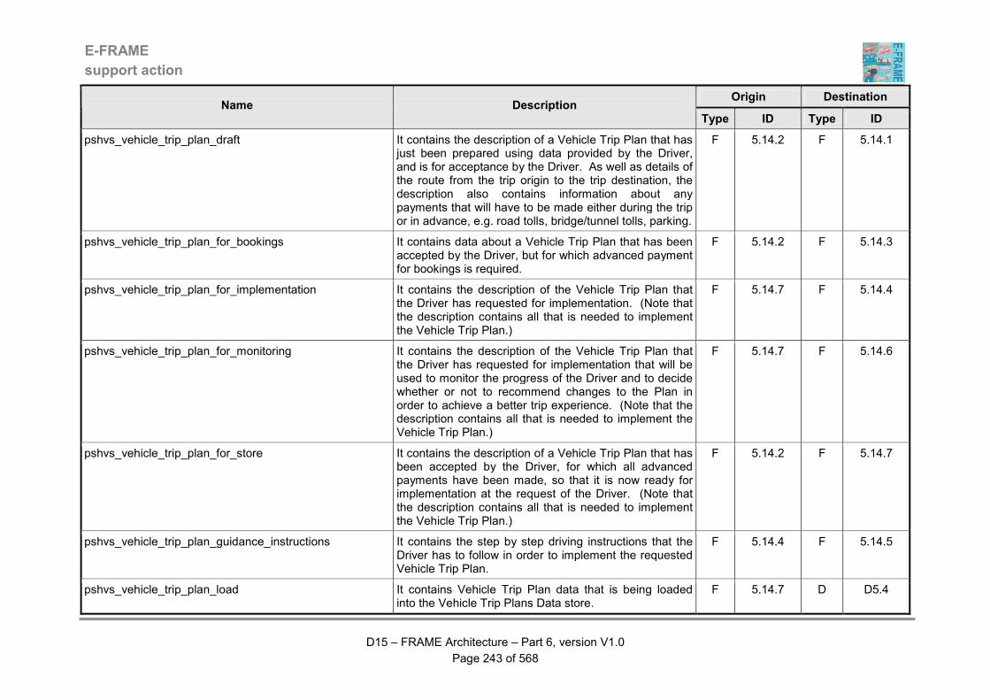
E-FRAME
support action
D15 – FRAME Architecture – Part 6, version V1.0
Page 243 of 568
Origin Destination Name Description
Type ID Type ID
pshvs_vehicle_trip_plan_draft It contains the description of a Vehicle Trip Plan that has just been prepared using data provided by the Driver, and is for acceptance by the Driver. As well as details of the route from the trip origin to the trip destination, the description also contains information about any payments that will have to be made either during the trip or in advance, e.g. road tolls, bridge/tunnel tolls, parking.
F 5.14.2 F 5.14.1
pshvs_vehicle_trip_plan_for_bookings It contains data about a Vehicle Trip Plan that has been accepted by the Driver, but for which advanced payment for bookings is required.
F 5.14.2 F 5.14.3
pshvs_vehicle_trip_plan_for_implementation It contains the description of the Vehicle Trip Plan that the Driver has requested for implementation. (Note that the description contains all that is needed to implement the Vehicle Trip Plan.)
F 5.14.7 F 5.14.4
pshvs_vehicle_trip_plan_for_monitoring It contains the description of the Vehicle Trip Plan that the Driver has requested for implementation that will be used to monitor the progress of the Driver and to decide whether or not to recommend changes to the Plan in order to achieve a better trip experience. (Note that the description contains all that is needed to implement the Vehicle Trip Plan.)
F 5.14.7 F 5.14.6
pshvs_vehicle_trip_plan_for_store It contains the description of a Vehicle Trip Plan that has been accepted by the Driver, for which all advanced payments have been made, so that it is now ready for implementation at the request of the Driver. (Note that the description contains all that is needed to implement the Vehicle Trip Plan.)
F 5.14.2 F 5.14.7
pshvs_vehicle_trip_plan_guidance_instructions It contains the step by step driving instructions that the Driver has to follow in order to implement the requested Vehicle Trip Plan.
F 5.14.4 F 5.14.5
pshvs_vehicle_trip_plan_load It contains Vehicle Trip Plan data that is being loaded into the Vehicle Trip Plans Data store.
F 5.14.7 D D5.4
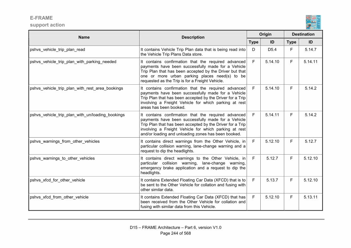
E-FRAME
support action
D15 – FRAME Architecture – Part 6, version V1.0
Page 244 of 568
Origin Destination Name Description
Type ID Type ID
pshvs_vehicle_trip_plan_read It contains Vehicle Trip Plan data that is being read into the Vehicle Trip Plans Data store.
D D5.4 F 5.14.7
pshvs_vehicle_trip_plan_with_parking_needed It contains confirmation that the required advanced payments have been successfully made for a Vehicle Trip Plan that has been accepted by the Driver but that one or more urban parking places need(s) to be requested as the Trip is for a Freight Vehicle.
F 5.14.10 F 5.14.11
pshvs_vehicle_trip_plan_with_rest_area_bookings It contains confirmation that the required advanced payments have been successfully made for a Vehicle Trip Plan that has been accepted by the Driver for a Trip involving a Freight Vehicle for which parking at rest areas has been booked.
F 5.14.10 F 5.14.2
pshvs_vehicle_trip_plan_with_un/loading_bookings It contains confirmation that the required advanced payments have been successfully made for a Vehicle Trip Plan that has been accepted by the Driver for a Trip involving a Freight Vehicle for which parking at rest and/or loading and unloading zones has been booked.
F 5.14.11 F 5.14.2
pshvs_warnings_from_other_vehicles It contains direct warnings from the Other Vehicle, in particular collision warning, lane-change warning and a request to dip the headlights.
F 5.12.10 F 5.12.7
pshvs_warnings_to_other_vehicles It contains direct warnings to the Other Vehicle, in particular collision warning, lane-change warning, emergency brake application and a request to dip the headlights.
F 5.12.7 F 5.12.10
pshvs_xfcd_for_other_vehicle It contains Extended Floating Car Data (XFCD) that is to be sent to the Other Vehicle for collation and fusing with other similar data.
F 5.13.7 F 5.12.10
pshvs_xfcd_from_other_vehicle It contains Extended Floating Car Data (XFCD) that has been received from the Other Vehicle for collation and fusing with similar data from this Vehicle.
F 5.12.10 F 5.13.11
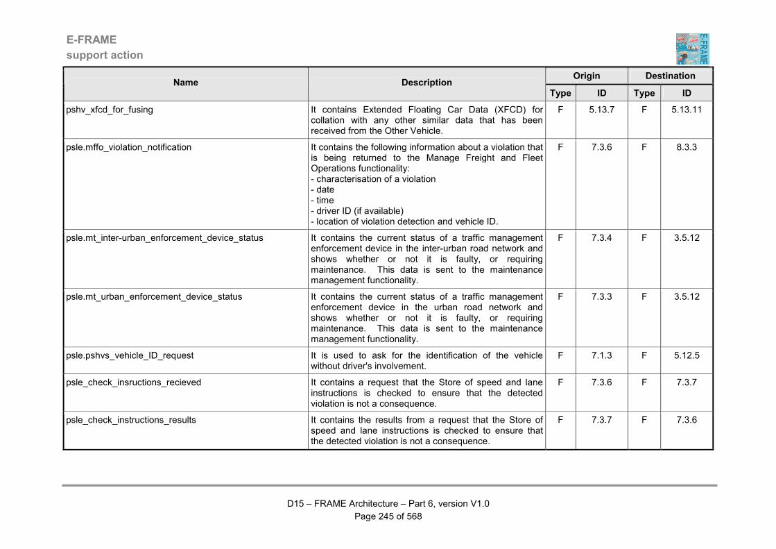
E-FRAME
support action
D15 – FRAME Architecture – Part 6, version V1.0
Page 245 of 568
Origin Destination Name Description
Type ID Type ID
pshv_xfcd_for_fusing It contains Extended Floating Car Data (XFCD) for collation with any other similar data that has been received from the Other Vehicle.
F 5.13.7 F 5.13.11
psle.mffo_violation_notification It contains the following information about a violation that is being returned to the Manage Freight and Fleet Operations functionality: - characterisation of a violation - date - time - driver ID (if available) - location of violation detection and vehicle ID.
F 7.3.6 F 8.3.3
psle.mt_inter-urban_enforcement_device_status It contains the current status of a traffic management enforcement device in the inter-urban road network and shows whether or not it is faulty, or requiring maintenance. This data is sent to the maintenance management functionality.
F 7.3.4 F 3.5.12
psle.mt_urban_enforcement_device_status It contains the current status of a traffic management enforcement device in the urban road network and shows whether or not it is faulty, or requiring maintenance. This data is sent to the maintenance management functionality.
F 7.3.3 F 3.5.12
psle.pshvs_vehicle_ID_request It is used to ask for the identification of the vehicle without driver's involvement.
F 7.1.3 F 5.12.5
psle_check_insructions_recieved It contains a request that the Store of speed and lane instructions is checked to ensure that the detected violation is not a consequence.
F 7.3.6 F 7.3.7
psle_check_instructions_results It contains the results from a request that the Store of speed and lane instructions is checked to ensure that the detected violation is not a consequence.
F 7.3.7 F 7.3.6
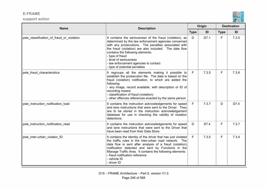
E-FRAME
support action
D15 – FRAME Architecture – Part 6, version V1.0
Page 246 of 568
Origin Destination Name Description
Type ID Type ID
psle_classification_of_fraud_or_violation It contains the seriousness of the fraud (violation), as determined by the law enforcement agencies concerned with any prosecutions. The penalties associated with the fraud (violation) are also included. The data flow contains the following elements: - type of fraud - level of seriousness - law enforcement agencies to contact - type of potential penalties
D D7.1 F 7.3.5
psle_fraud_characteristics It regroups all the elements making it possible to establish the prosecution file. The data is based on the fraud (violation) notification, to which are added the following: - any image, record available, with description or ID of recording means - classification of fraud (violation) - other offences references enacted by the same person
F 7.3.5 F 7.3.6
psle_instruction_notification_load It contains the instruction acknowledgements for speed and lane instructions that were sent to the Driver. They are to be stored in the instruction acknowledgement database for use in checking the validity of violation detections.
F 7.3.7 D D7.4
psle_instruction_notification_read It contains the instruction acknowledgements for speed and lane instructions that were sent to the Driver that have been read from their Data Store.
D D7.4 F 7.3.7
psle_inter-urban_violator_ID It contains the identity of the driver that has just violated the traffic rules in the inter-urban road network. The data flow is sent after analysis of a fraud (violation) notification detected and sent by Functions in the Manage Traffic Area. It contains the following elements: - fraud notification reference - vehicle ID - driver ID
F 7.3.5 F 7.3.4

E-FRAME
support action
D15 – FRAME Architecture – Part 6, version V1.0
Page 247 of 568
Origin Destination Name Description
Type ID Type ID
psle_measure It contains a measure carried out by the System (either directly or through the roadside actuators) to detect a fraud (violation). The measure can consist of a video record, a photograph, a measurement of speed, etc.
F 7.1.3 F 7.1.2
psle_prosecution_file It is a completed version of the fraud notification data flow. Therefore the data flow will contain a complete set of the following data elements: - reference - date - type of fraud (violation) - result of fraud (violation) - involved user ID (if available) - involved vehicle ID (if relevant and available) - image of fraud (if available) - location of fraud (violation) - other data according to the type of fraud (violation)
F 7.3.6 F 7.6
psle_rules_load It describes the part of the Transport System rules that are relevant to road surface transportation. The data flow contains the following elements: - domain concerned, - list of rules applicable
F 7.5.1 D D7.1
psle_rules_read It describes the part of the Transport System rules that are relevant to road surface transportation. The data flow contains the following elements: - domain concerned, - list of rules applicable
D D7.1 F 7.1.2
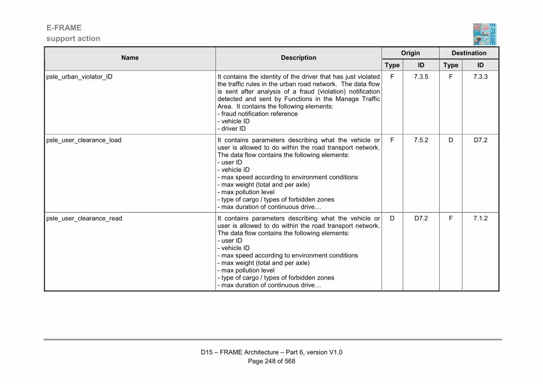
E-FRAME
support action
D15 – FRAME Architecture – Part 6, version V1.0
Page 248 of 568
Origin Destination Name Description
Type ID Type ID
psle_urban_violator_ID It contains the identity of the driver that has just violated the traffic rules in the urban road network. The data flow is sent after analysis of a fraud (violation) notification detected and sent by Functions in the Manage Traffic Area. It contains the following elements: - fraud notification reference - vehicle ID - driver ID
F 7.3.5 F 7.3.3
psle_user_clearance_load It contains parameters describing what the vehicle or user is allowed to do within the road transport network. The data flow contains the following elements: - user ID - vehicle ID - max speed according to environment conditions - max weight (total and per axle) - max pollution level - type of cargo / types of forbidden zones - max duration of continuous drive…
F 7.5.2 D D7.2
psle_user_clearance_read It contains parameters describing what the vehicle or user is allowed to do within the road transport network. The data flow contains the following elements: - user ID - vehicle ID - max speed according to environment conditions - max weight (total and per axle) - max pollution level - type of cargo / types of forbidden zones - max duration of continuous drive…
D D7.2 F 7.1.2

E-FRAME
support action
D15 – FRAME Architecture – Part 6, version V1.0
Page 249 of 568
Origin Destination Name Description
Type ID Type ID
psle_user_data_load It contains data about the owner or person responsible for a vehicle. The data flow contains the following elements: - vehicle ID - user ID - ID of other vehicles used by the user - operations allowed for the vehicle - period of validity of registration
F 7.5.2 D D7.2
psle_user_data_read It contains data about the owner or person responsible for a vehicle. The data flow contains the following elements: - vehicle ID - user ID - ID of other vehicles used by the user - operations allowed for the vehicle - period of validity of registration
D D7.2 F 7.2.2
psle_user_data_request It contains a request for data about the owner or person responsible for a vehicle to be searched for and retrieved from a Data Store.
F 7.2.2 D D7.2
psle_user_image It is an extract from recorded images used to identify a violator, i.e. the person who has carried out a fraud (violation). The user image can be provided using a photograph, a video picture, an electronic signature, etc.
F 7.1.2 F 7.2.1
psle_vehicle_ID_CC It allows the identification without ambiguity the vehicle involved in an illegal action that constitutes a fraud (violation). The data flow contains the following elements: - vehicle type - mineralogical late number
F 7.2.1 F 7.1.2
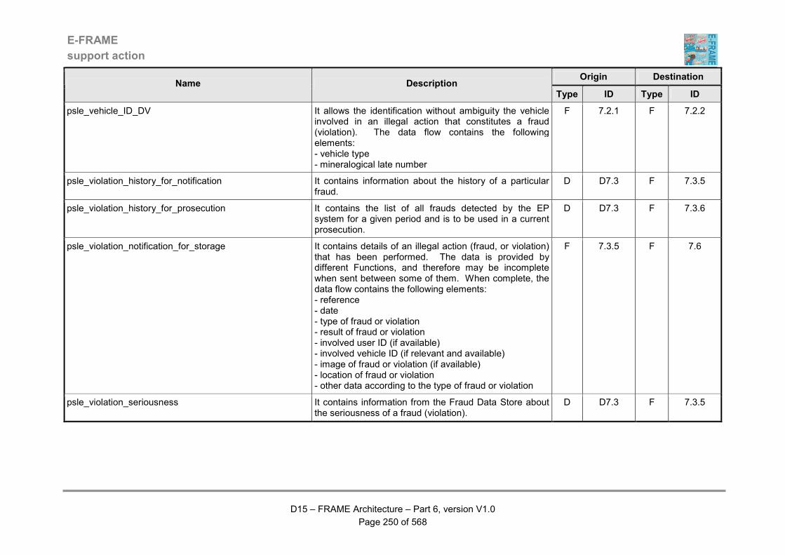
E-FRAME
support action
D15 – FRAME Architecture – Part 6, version V1.0
Page 250 of 568
Origin Destination Name Description
Type ID Type ID
psle_vehicle_ID_DV It allows the identification without ambiguity the vehicle involved in an illegal action that constitutes a fraud (violation). The data flow contains the following elements: - vehicle type - mineralogical late number
F 7.2.1 F 7.2.2
psle_violation_history_for_notification It contains information about the history of a particular fraud.
D D7.3 F 7.3.5
psle_violation_history_for_prosecution It contains the list of all frauds detected by the EP system for a given period and is to be used in a current prosecution.
D D7.3 F 7.3.6
psle_violation_notification_for_storage It contains details of an illegal action (fraud, or violation) that has been performed. The data is provided by different Functions, and therefore may be incomplete when sent between some of them. When complete, the data flow contains the following elements: - reference - date - type of fraud or violation - result of fraud or violation - involved user ID (if available) - involved vehicle ID (if relevant and available) - image of fraud or violation (if available) - location of fraud or violation - other data according to the type of fraud or violation
F 7.3.5 F 7.6
psle_violation_seriousness It contains information from the Fraud Data Store about the seriousness of a fraud (violation).
D D7.3 F 7.3.5
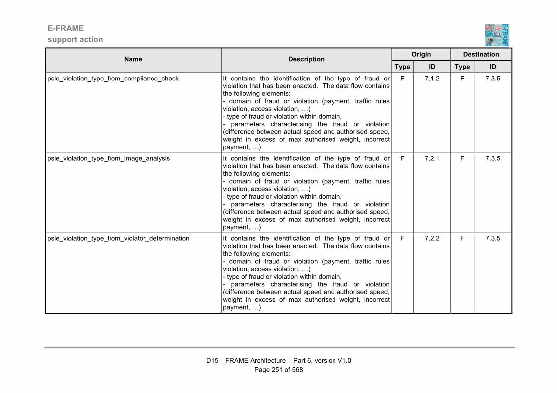
E-FRAME
support action
D15 – FRAME Architecture – Part 6, version V1.0
Page 251 of 568
Origin Destination Name Description
Type ID Type ID
psle_violation_type_from_compliance_check It contains the identification of the type of fraud or violation that has been enacted. The data flow contains the following elements: - domain of fraud or violation (payment, traffic rules violation, access violation, …) - type of fraud or violation within domain, - parameters characterising the fraud or violation (difference between actual speed and authorised speed, weight in excess of max authorised weight, incorrect payment, …)
F 7.1.2 F 7.3.5
psle_violation_type_from_image_analysis It contains the identification of the type of fraud or violation that has been enacted. The data flow contains the following elements: - domain of fraud or violation (payment, traffic rules violation, access violation, …) - type of fraud or violation within domain, - parameters characterising the fraud or violation (difference between actual speed and authorised speed, weight in excess of max authorised weight, incorrect payment, …)
F 7.2.1 F 7.3.5
psle_violation_type_from_violator_determination It contains the identification of the type of fraud or violation that has been enacted. The data flow contains the following elements: - domain of fraud or violation (payment, traffic rules violation, access violation, …) - type of fraud or violation within domain, - parameters characterising the fraud or violation (difference between actual speed and authorised speed, weight in excess of max authorised weight, incorrect payment, …)
F 7.2.2 F 7.3.5
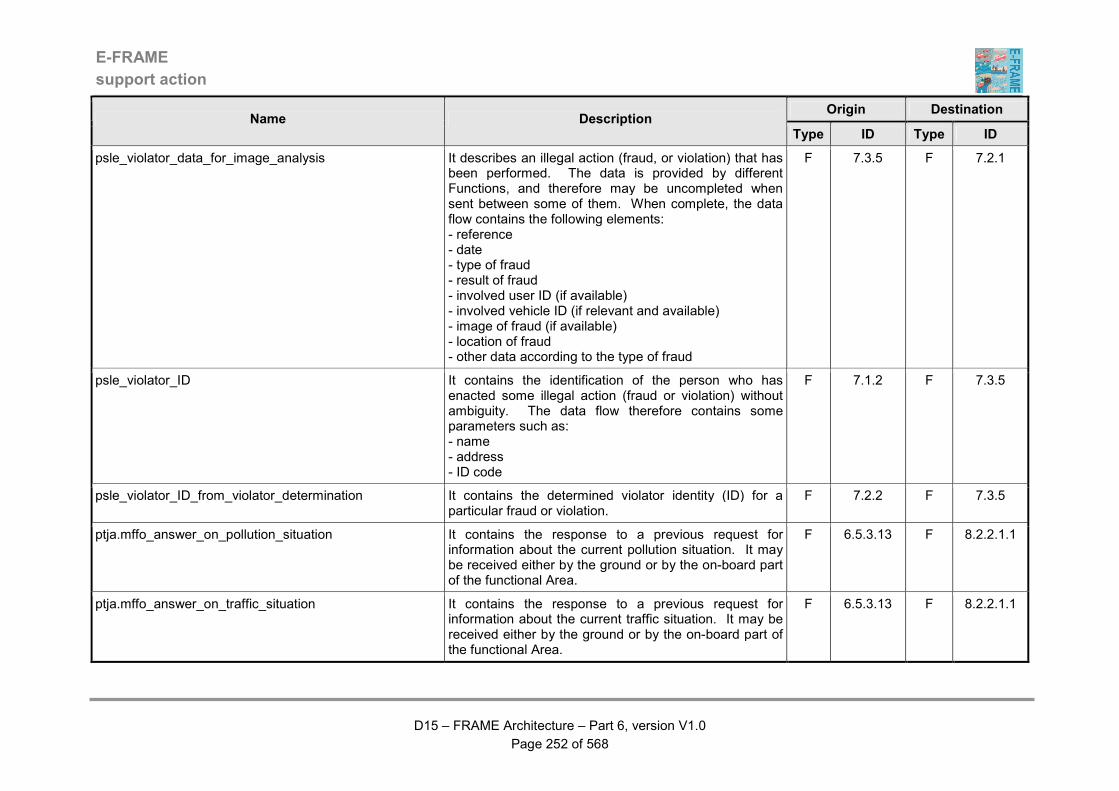
E-FRAME
support action
D15 – FRAME Architecture – Part 6, version V1.0
Page 252 of 568
Origin Destination Name Description
Type ID Type ID
psle_violator_data_for_image_analysis It describes an illegal action (fraud, or violation) that has been performed. The data is provided by different Functions, and therefore may be uncompleted when sent between some of them. When complete, the data flow contains the following elements: - reference - date - type of fraud - result of fraud - involved user ID (if available) - involved vehicle ID (if relevant and available) - image of fraud (if available) - location of fraud - other data according to the type of fraud
F 7.3.5 F 7.2.1
psle_violator_ID It contains the identification of the person who has enacted some illegal action (fraud or violation) without ambiguity. The data flow therefore contains some parameters such as: - name - address - ID code
F 7.1.2 F 7.3.5
psle_violator_ID_from_violator_determination It contains the determined violator identity (ID) for a particular fraud or violation.
F 7.2.2 F 7.3.5
ptja.mffo_answer_on_pollution_situation It contains the response to a previous request for information about the current pollution situation. It may be received either by the ground or by the on-board part of the functional Area.
F 6.5.3.13 F 8.2.2.1.1
ptja.mffo_answer_on_traffic_situation It contains the response to a previous request for information about the current traffic situation. It may be received either by the ground or by the on-board part of the functional Area.
F 6.5.3.13 F 8.2.2.1.1

E-FRAME
support action
D15 – FRAME Architecture – Part 6, version V1.0
Page 253 of 568
Origin Destination Name Description
Type ID Type ID
ptja.mffo_answer_on_weather_situation It contains the response to a previous request for information about the current weather situation. It may be received either by the ground or by the on-board part of the functional Area.
F 6.5.3.13 F 8.2.2.1.1
ptja.mffo_route No route could be provided in case of unauthorised hazardous goods transport. It may be received either by the ground or by the on-board part of the functional Area.
F 6.5.3.13 F 8.2.2.1.1
ptja.mt_inter-urban_road_use_data_from_trip It contains origin - destination (O-D) data and actual journey times from the parts of a trip that use segments of the inter-urban road network.
F 6.3.11 F 3.1.2.16
ptja.mt_trip_plan_o-d_data It contains origin - destination (O-D) data and actual journey time for the road network based parts of a complete trip plan that has just been implemented.
F 6.3.11 F 3.1.6.2
ptja.mt_urban_road_use_data_from_trip It contains origin - destination (O-D) data and actual journey times from the parts of a trip that use segments of the urban road network.
F 6.3.11 F 3.1.1.14
ptja.pepf_service_contract_info It contains all the information necessary to define the different types of contract that a user can place with an operator. The data flow includes the following elements : - operator ID - list of all potential contracts, for each one (some parameters being optional) : - service ID - other parameters defining the service (level of quality, ...) - geographical area covered - period covered - quantity of service purchased - tariff - mode of payment
F 6.5.3.9 F 1.1.1
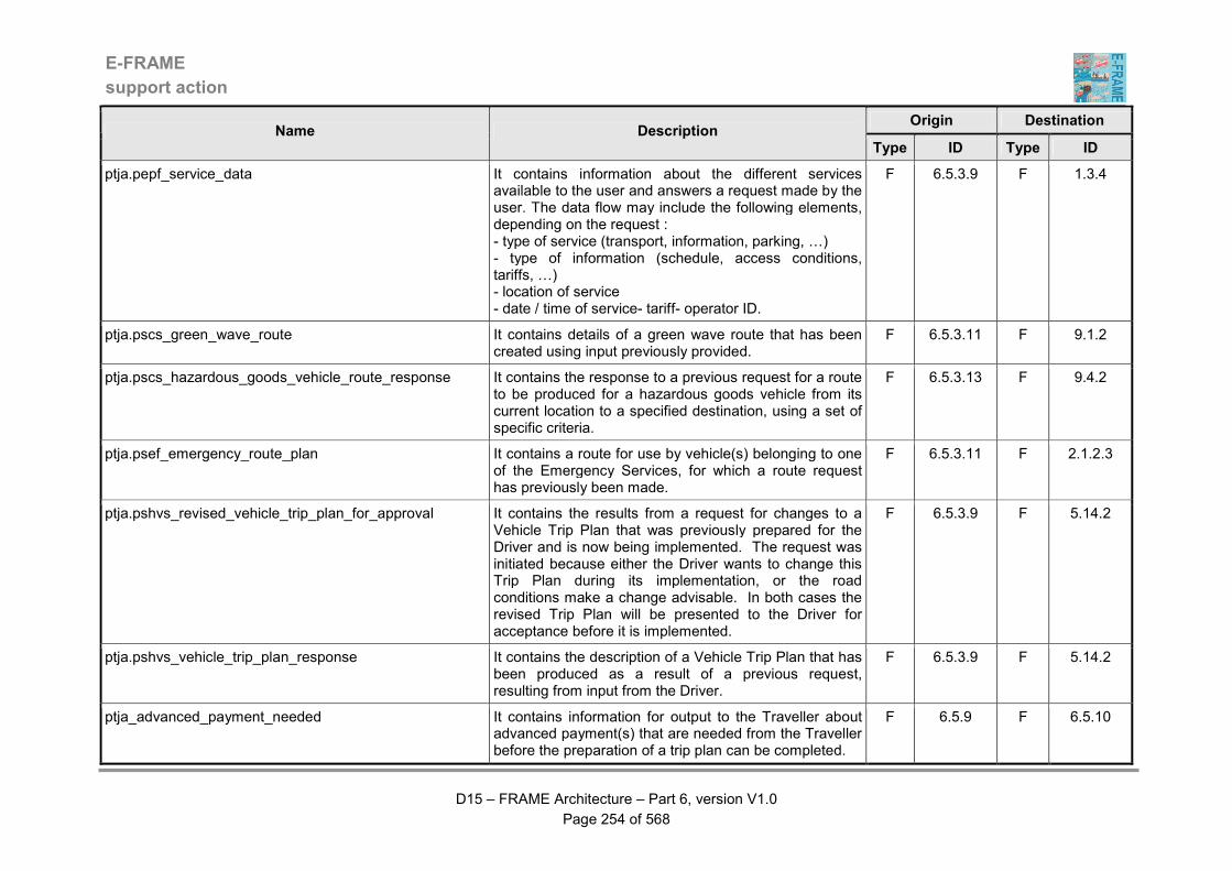
E-FRAME
support action
D15 – FRAME Architecture – Part 6, version V1.0
Page 254 of 568
Origin Destination Name Description
Type ID Type ID
ptja.pepf_service_data It contains information about the different services available to the user and answers a request made by the user. The data flow may include the following elements, depending on the request : - type of service (transport, information, parking, …) - type of information (schedule, access conditions, tariffs, …) - location of service - date / time of service- tariff- operator ID.
F 6.5.3.9 F 1.3.4
ptja.pscs_green_wave_route It contains details of a green wave route that has been created using input previously provided.
F 6.5.3.11 F 9.1.2
ptja.pscs_hazardous_goods_vehicle_route_response It contains the response to a previous request for a route to be produced for a hazardous goods vehicle from its current location to a specified destination, using a set of specific criteria.
F 6.5.3.13 F 9.4.2
ptja.psef_emergency_route_plan It contains a route for use by vehicle(s) belonging to one of the Emergency Services, for which a route request has previously been made.
F 6.5.3.11 F 2.1.2.3
ptja.pshvs_revised_vehicle_trip_plan_for_approval It contains the results from a request for changes to a Vehicle Trip Plan that was previously prepared for the Driver and is now being implemented. The request was initiated because either the Driver wants to change this Trip Plan during its implementation, or the road conditions make a change advisable. In both cases the revised Trip Plan will be presented to the Driver for acceptance before it is implemented.
F 6.5.3.9 F 5.14.2
ptja.pshvs_vehicle_trip_plan_response It contains the description of a Vehicle Trip Plan that has been produced as a result of a previous request, resulting from input from the Driver.
F 6.5.3.9 F 5.14.2
ptja_advanced_payment_needed It contains information for output to the Traveller about advanced payment(s) that are needed from the Traveller before the preparation of a trip plan can be completed.
F 6.5.9 F 6.5.10

E-FRAME
support action
D15 – FRAME Architecture – Part 6, version V1.0
Page 255 of 568
Origin Destination Name Description
Type ID Type ID
ptja_booking_approved It contains confirmation from the Traveller that bookings made as part of the creation of a trip plan are approved.
F 6.5.10 F 6.5.9
ptja_booking_mishap It contains information for output to the Traveller about the failure of the process to make bookings that are needed for the creation of a trip plan.
F 6.5.9 F 6.5.10
ptja_cancel_bookings_for_trip It contains a request to "cancel bookings" for a previously prepared trip plan, the identity of which is included with the request.
F 6.5.10 F 6.5.9
ptja_full_trip_description_for_bookings It contains the full description of a trip including portions covering all the modes agreed with the Traveller.
F 6.5.10 F 6.5.9
ptja_full_trip_description_with_bookings It contains the description of a planned trip that does include bookings for one or more services for which payment has successfully been made and which now requires final approval from the Traveller.
F 6.5.9 F 6.5.10
ptja_GTP_data It contains information as provided by a Traveller to personalise assistance during information retrieval, trip planning and trip performance. The identity of the Traveller providing the data must be included.
F 6.7.1 F 6.7.4
ptja_GTP_update It contains GTP data from a post trip evaluation that is to be used to update the Traveller's General Trip Preferences. The identity of the Traveller providing the data must be included
F 6.7.1 F 6.7.4
ptja_imlpement_updated_trip_plan It contains a command to implement the updated version of the current trip plan, which will be automatically sent by the trip plan data store management Function.
F 6.3.12 F 6.3.10
ptja_implement_trip_plan It contains an instruction from the Traveller to implement a particular trip plan.
F 6.3.13 F 6.8.1
ptja_load_GTP_data It contains data that is being sent to the General Trip Preferences (GTP) Data Store, or a request for output of the contents of the Store.
F 6.7.4 D D6.1
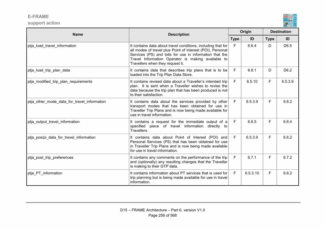
E-FRAME
support action
D15 – FRAME Architecture – Part 6, version V1.0
Page 256 of 568
Origin Destination Name Description
Type ID Type ID
ptja_load_travel_information It contains data about travel conditions, including that for all modes of travel plus Point of Interest (POI), Personal Services (PS) and tolls for use in information that the Travel Information Operator is making available to Travellers when they request it.
F 6.6.4 D D6.5
ptja_load_trip_plan_data It contains data that describes trip plans that is to be loaded into the Trip Plan Data Store.
F 6.8.1 D D6.2
ptja_modified_trip_plan_requirements It contains revised data about a Traveller’s intended trip plan. It is sent when a Traveller wishes to revise the data because the trip plan that has been produced is not to their satisfaction.
F 6.5.10 F 6.5.3.9
ptja_other_mode_data_for_travel_information It contains data about the services provided by other transport modes that has been obtained for use in Traveller Trip Plans and is now being made available for use in travel information.
F 6.5.3.9 F 6.6.2
ptja_output_travel_information It contains a request for the immediate output of a specified piece of travel information directly to Travellers.
F 6.6.5 F 6.6.4
ptja_pos/pi_data_for_travel_information It contains data about Point of Interest (POI) and Personal Services (PS) that has been obtained for use in Traveller Trip Plans and is now being made available for use in travel information.
F 6.5.3.9 F 6.6.2
ptja_post_trip_preferences It contains any comments on the performance of the trip and (optionally) any resulting changes that the Traveller is making to their GTP data.
F 6.7.1 F 6.7.2
ptja_PT_information It contains information about PT services that is used for trip planning but is being made available for use in travel information.
F 6.5.3.10 F 6.6.2
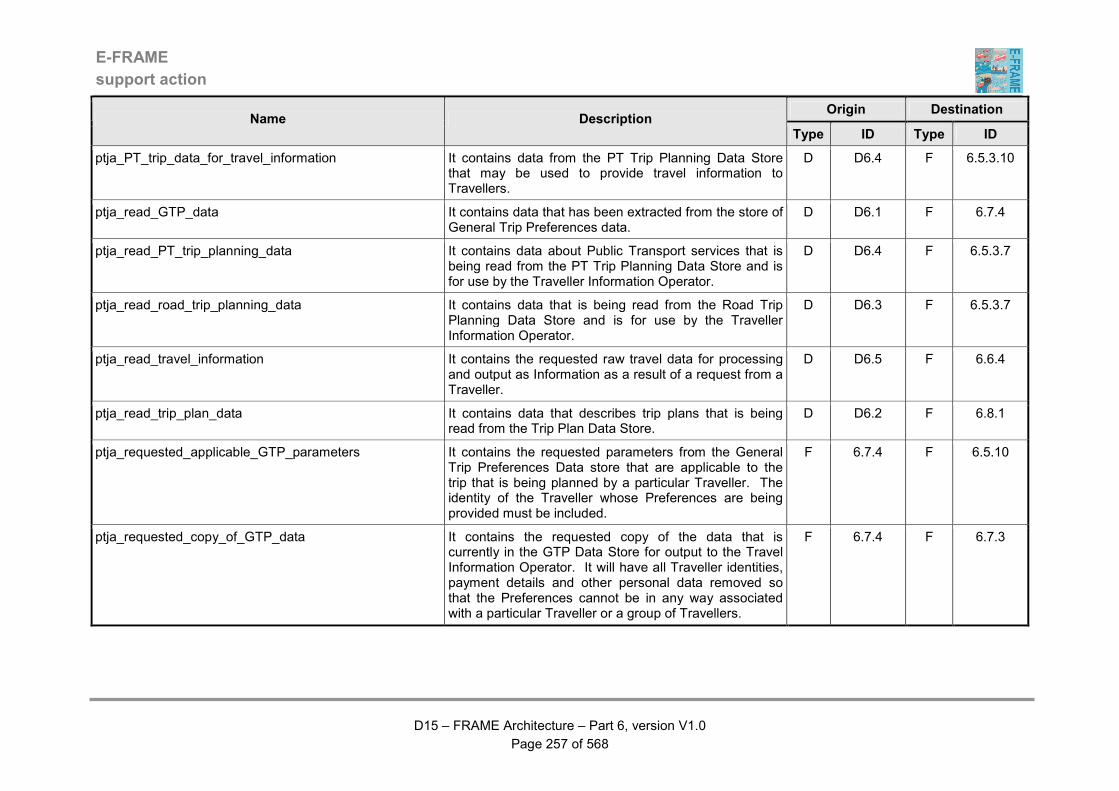
E-FRAME
support action
D15 – FRAME Architecture – Part 6, version V1.0
Page 257 of 568
Origin Destination Name Description
Type ID Type ID
ptja_PT_trip_data_for_travel_information It contains data from the PT Trip Planning Data Store that may be used to provide travel information to Travellers.
D D6.4 F 6.5.3.10
ptja_read_GTP_data It contains data that has been extracted from the store of General Trip Preferences data.
D D6.1 F 6.7.4
ptja_read_PT_trip_planning_data It contains data about Public Transport services that is being read from the PT Trip Planning Data Store and is for use by the Traveller Information Operator.
D D6.4 F 6.5.3.7
ptja_read_road_trip_planning_data It contains data that is being read from the Road Trip Planning Data Store and is for use by the Traveller Information Operator.
D D6.3 F 6.5.3.7
ptja_read_travel_information It contains the requested raw travel data for processing and output as Information as a result of a request from a Traveller.
D D6.5 F 6.6.4
ptja_read_trip_plan_data It contains data that describes trip plans that is being read from the Trip Plan Data Store.
D D6.2 F 6.8.1
ptja_requested_applicable_GTP_parameters It contains the requested parameters from the General Trip Preferences Data store that are applicable to the trip that is being planned by a particular Traveller. The identity of the Traveller whose Preferences are being provided must be included.
F 6.7.4 F 6.5.10
ptja_requested_copy_of_GTP_data It contains the requested copy of the data that is currently in the GTP Data Store for output to the Travel Information Operator. It will have all Traveller identities, payment details and other personal data removed so that the Preferences cannot be in any way associated with a particular Traveller or a group of Travellers.
F 6.7.4 F 6.7.3
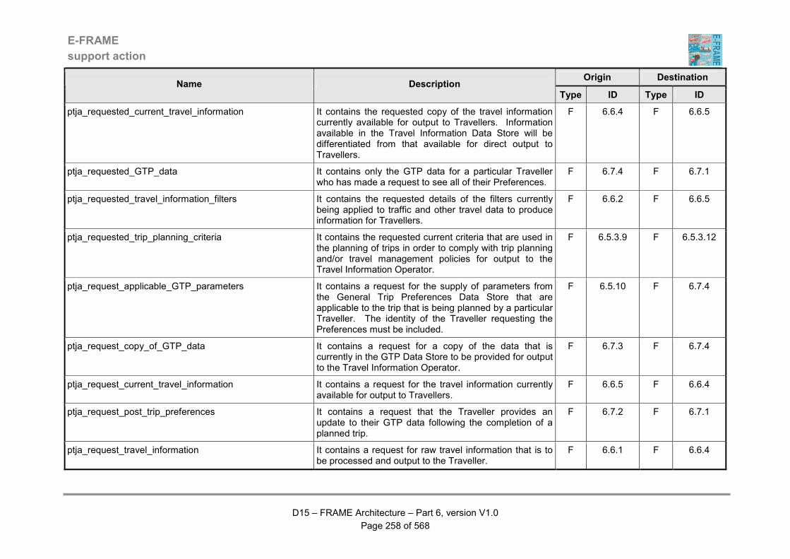
E-FRAME
support action
D15 – FRAME Architecture – Part 6, version V1.0
Page 258 of 568
Origin Destination Name Description
Type ID Type ID
ptja_requested_current_travel_information It contains the requested copy of the travel information currently available for output to Travellers. Information available in the Travel Information Data Store will be differentiated from that available for direct output to Travellers.
F 6.6.4 F 6.6.5
ptja_requested_GTP_data It contains only the GTP data for a particular Traveller who has made a request to see all of their Preferences.
F 6.7.4 F 6.7.1
ptja_requested_travel_information_filters It contains the requested details of the filters currently being applied to traffic and other travel data to produce information for Travellers.
F 6.6.2 F 6.6.5
ptja_requested_trip_planning_criteria It contains the requested current criteria that are used in the planning of trips in order to comply with trip planning and/or travel management policies for output to the Travel Information Operator.
F 6.5.3.9 F 6.5.3.12
ptja_request_applicable_GTP_parameters It contains a request for the supply of parameters from the General Trip Preferences Data Store that are applicable to the trip that is being planned by a particular Traveller. The identity of the Traveller requesting the Preferences must be included.
F 6.5.10 F 6.7.4
ptja_request_copy_of_GTP_data It contains a request for a copy of the data that is currently in the GTP Data Store to be provided for output to the Travel Information Operator.
F 6.7.3 F 6.7.4
ptja_request_current_travel_information It contains a request for the travel information currently available for output to Travellers.
F 6.6.5 F 6.6.4
ptja_request_post_trip_preferences It contains a request that the Traveller provides an update to their GTP data following the completion of a planned trip.
F 6.7.2 F 6.7.1
ptja_request_travel_information It contains a request for raw travel information that is to be processed and output to the Traveller.
F 6.6.1 F 6.6.4
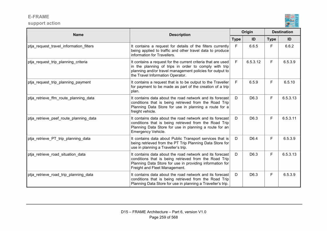
E-FRAME
support action
D15 – FRAME Architecture – Part 6, version V1.0
Page 259 of 568
Origin Destination Name Description
Type ID Type ID
ptja_request_travel_information_filters It contains a request for details of the filters currently being applied to traffic and other travel data to produce information for Travellers.
F 6.6.5 F 6.6.2
ptja_request_trip_planning_criteria It contains a request for the current criteria that are used in the planning of trips in order to comply with trip planning and/or travel management policies for output to the Travel Information Operator.
F 6.5.3.12 F 6.5.3.9
ptja_request_trip_planning_payment It contains a request that is to be output to the Traveller for payment to be made as part of the creation of a trip plan.
F 6.5.9 F 6.5.10
ptja_retrieve_ffm_route_planning_data It contains data about the road network and its forecast conditions that is being retrieved from the Road Trip Planning Data Store for use in planning a route for a freight vehicle.
D D6.3 F 6.5.3.13
ptja_retrieve_psef_route_planning_data It contains data about the road network and its forecast conditions that is being retrieved from the Road Trip Planning Data Store for use in planning a route for an Emergency Vehicle.
D D6.3 F 6.5.3.11
ptja_retrieve_PT_trip_planning_data It contains data about Public Transport services that is being retrieved from the PT Trip Planning Data Store for use in planning a Traveller’s trip.
D D6.4 F 6.5.3.9
ptja_retrieve_road_situation_data It contains data about the road network and its forecast conditions that is being retrieved from the Road Trip Planning Data Store for use in providing information for Freight and Fleet Management.
D D6.3 F 6.5.3.13
ptja_retrieve_road_trip_planning_data It contains data about the road network and its forecast conditions that is being retrieved from the Road Trip Planning Data Store for use in planning a Traveller’s trip.
D D6.3 F 6.5.3.9

E-FRAME
support action
D15 – FRAME Architecture – Part 6, version V1.0
Page 260 of 568
Origin Destination Name Description
Type ID Type ID
ptja_revised_trip_plan_after_traveller_approval It contains changes to the trip plan data following approval by the Traveller that is implementing the trip. The changes may reflect updates to the time schedule, route, transport mode, costs, bookings, but may also result in a premature end of the journey covered by the trip plan. The data will only be generated if during the trip the Support Trip functionality has detected a deviation from the situation under which the trip was defined and the Traveller has agreed to the proposed change.
F 6.3.12 F 6.8.1
ptja_revised_trip_plan_for_approval It contains the results from a request for changes to a trip plan that was previously prepared for the Traveller and is now being implemented. The request was initiated because either the Traveller wanted to change this trip plan during its implementation, or the travel conditions make a change advisable. In both cases, the revised trip plan will be presented to the Traveller for acceptance before it is implemented.
F 6.5.3.9 F 6.3.12
ptja_revised_trip_plan_requirements It contains revised data about the way in which the trip plan that a Traveller is currently using is to be modified. It is sent when it is necessary for the trip plan to be changed, either because the Traveller has requested it, or because the travel conditions have changed such that the trip plan needs to be improved.
F 6.3.12 F 6.5.3.9
ptja_revise_trip_plan_request It contains a request for a change to the trip plan that is currently being implemented as a result of the monitoring of the progress of the Traveller. It includes all of the data about the current trip plan.
F 6.3.11 F 6.3.12
ptja_road_data_for_travel_information It contains data from the Road Trip Planning Data Store that may be used to provide travel information to Travellers.
D D6.3 F 6.5.3.10
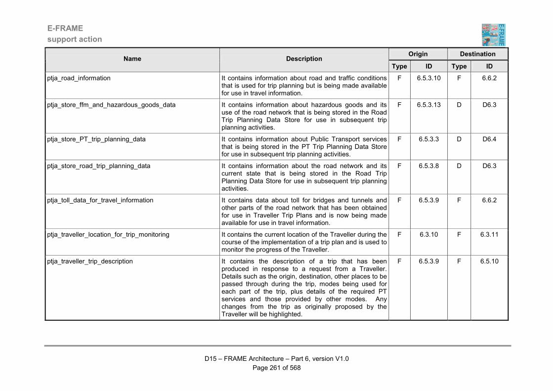
E-FRAME
support action
D15 – FRAME Architecture – Part 6, version V1.0
Page 261 of 568
Origin Destination Name Description
Type ID Type ID
ptja_road_information It contains information about road and traffic conditions that is used for trip planning but is being made available for use in travel information.
F 6.5.3.10 F 6.6.2
ptja_store_ffm_and_hazardous_goods_data It contains information about hazardous goods and its use of the road network that is being stored in the Road Trip Planning Data Store for use in subsequent trip planning activities.
F 6.5.3.13 D D6.3
ptja_store_PT_trip_planning_data It contains information about Public Transport services that is being stored in the PT Trip Planning Data Store for use in subsequent trip planning activities.
F 6.5.3.3 D D6.4
ptja_store_road_trip_planning_data It contains information about the road network and its current state that is being stored in the Road Trip Planning Data Store for use in subsequent trip planning activities.
F 6.5.3.8 D D6.3
ptja_toll_data_for_travel_information It contains data about toll for bridges and tunnels and other parts of the road network that has been obtained for use in Traveller Trip Plans and is now being made available for use in travel information.
F 6.5.3.9 F 6.6.2
ptja_traveller_location_for_trip_monitoring It contains the current location of the Traveller during the course of the implementation of a trip plan and is used to monitor the progress of the Traveller.
F 6.3.10 F 6.3.11
ptja_traveller_trip_description It contains the description of a trip that has been produced in response to a request from a Traveller. Details such as the origin, destination, other places to be passed through during the trip, modes being used for each part of the trip, plus details of the required PT services and those provided by other modes. Any changes from the trip as originally proposed by the Traveller will be highlighted.
F 6.5.3.9 F 6.5.10

E-FRAME
support action
D15 – FRAME Architecture – Part 6, version V1.0
Page 262 of 568
Origin Destination Name Description
Type ID Type ID
ptja_traveller_trip_requirement It contains the description of a trip that a Traveller is planning, including origin, destination, places to be included in the trip, modes for each part of the trip, plus details of required PT services and those provided by other modes and information from the GTP Data Store.
F 6.5.10 F 6.5.3.9
ptja_travel_information_for_output It contains data about both road and non-road travel conditions, plus Point of Information (POI), Personal Services (PS) and toll information that are to be output to Travellers.
F 6.6.4 F 6.6.3
ptja_travel_information_response It contains the information requested by the Traveller. Note that this may not be all of the information that the Traveller requested, in which case the missing "bits" will have to be requested by the receiving function.
F 6.6.4 F 6.6.1
ptja_trip_completion_report_for_evaluation It contains details of how the trip was implemented for evaluation purposes. The identity and other personal information about the Traveller who implemented the trip is not included.
F 6.3.11 F 6.7.2
ptja_trip_evaluation_report_for_output It contains data from which a post trip evaluation report can be produced for the Travel Information Operator.
F 6.7.2 F 6.7.3
ptja_trip_guidance_instructions It contains the step by step instructions that the Traveller has to follow in order to implement the requested trip plan and applies for all modes of travel that are included in the plan.
F 6.3.10 F 6.3.13
ptja_trip_planning_payment It contains the details provided by the Traveller that need to be sent to the Financial Clearinghouse so that payment can be made as part of the creation of a trip plan
F 6.5.10 F 6.5.9
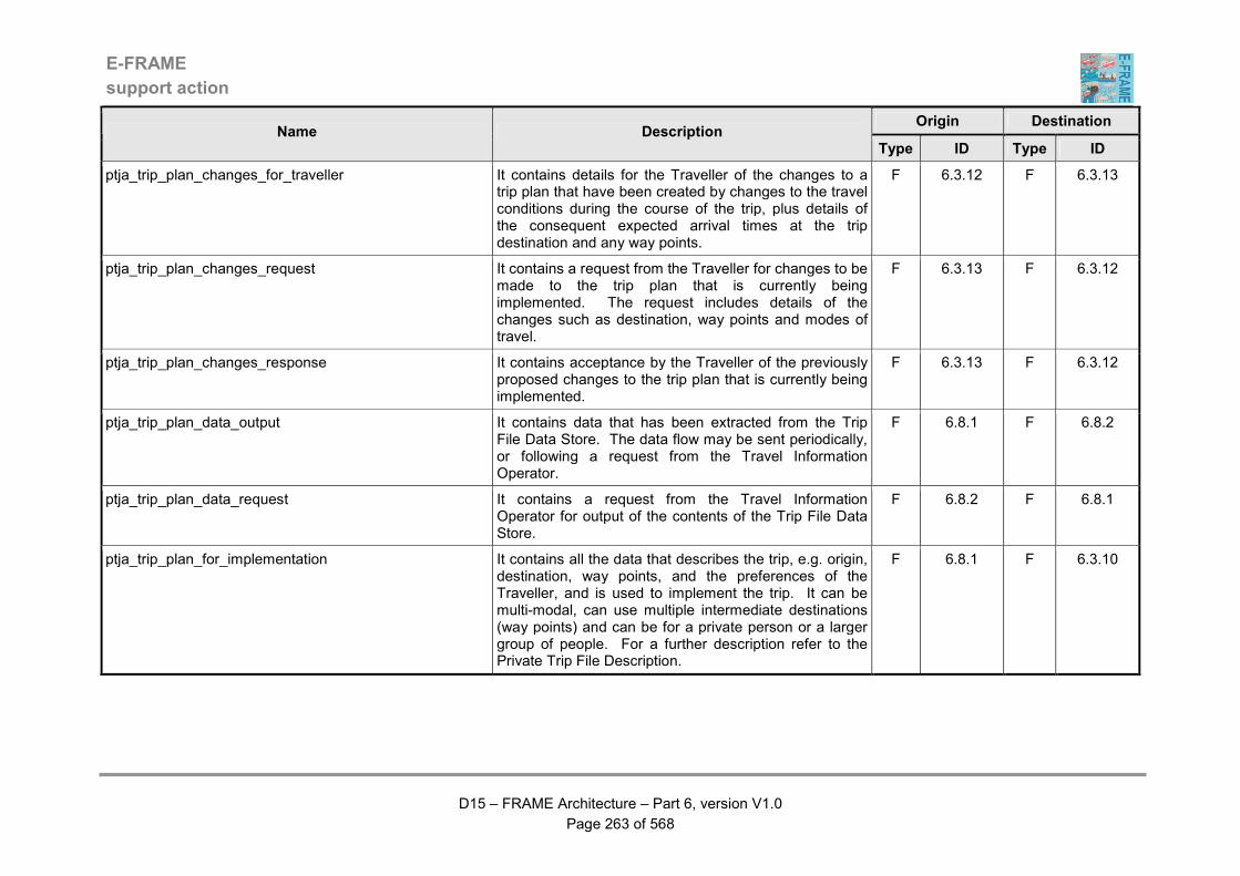
E-FRAME
support action
D15 – FRAME Architecture – Part 6, version V1.0
Page 263 of 568
Origin Destination Name Description
Type ID Type ID
ptja_trip_plan_changes_for_traveller It contains details for the Traveller of the changes to a trip plan that have been created by changes to the travel conditions during the course of the trip, plus details of the consequent expected arrival times at the trip destination and any way points.
F 6.3.12 F 6.3.13
ptja_trip_plan_changes_request It contains a request from the Traveller for changes to be made to the trip plan that is currently being implemented. The request includes details of the changes such as destination, way points and modes of travel.
F 6.3.13 F 6.3.12
ptja_trip_plan_changes_response It contains acceptance by the Traveller of the previously proposed changes to the trip plan that is currently being implemented.
F 6.3.13 F 6.3.12
ptja_trip_plan_data_output It contains data that has been extracted from the Trip File Data Store. The data flow may be sent periodically, or following a request from the Travel Information Operator.
F 6.8.1 F 6.8.2
ptja_trip_plan_data_request It contains a request from the Travel Information Operator for output of the contents of the Trip File Data Store.
F 6.8.2 F 6.8.1
ptja_trip_plan_for_implementation It contains all the data that describes the trip, e.g. origin, destination, way points, and the preferences of the Traveller, and is used to implement the trip. It can be multi-modal, can use multiple intermediate destinations (way points) and can be for a private person or a larger group of people. For a further description refer to the Private Trip File Description.
F 6.8.1 F 6.3.10
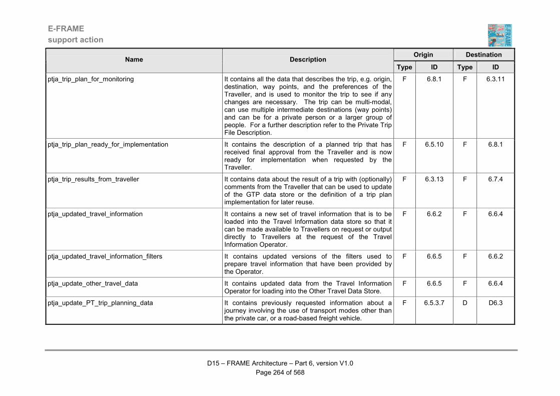
E-FRAME
support action
D15 – FRAME Architecture – Part 6, version V1.0
Page 264 of 568
Origin Destination Name Description
Type ID Type ID
ptja_trip_plan_for_monitoring It contains all the data that describes the trip, e.g. origin, destination, way points, and the preferences of the Traveller, and is used to monitor the trip to see if any changes are necessary. The trip can be multi-modal, can use multiple intermediate destinations (way points) and can be for a private person or a larger group of people. For a further description refer to the Private Trip File Description.
F 6.8.1 F 6.3.11
ptja_trip_plan_ready_for_implementation It contains the description of a planned trip that has received final approval from the Traveller and is now ready for implementation when requested by the Traveller.
F 6.5.10 F 6.8.1
ptja_trip_results_from_traveller It contains data about the result of a trip with (optionally) comments from the Traveller that can be used to update of the GTP data store or the definition of a trip plan implementation for later reuse.
F 6.3.13 F 6.7.4
ptja_updated_travel_information It contains a new set of travel information that is to be loaded into the Travel Information data store so that it can be made available to Travellers on request or output directly to Travellers at the request of the Travel Information Operator.
F 6.6.2 F 6.6.4
ptja_updated_travel_information_filters It contains updated versions of the filters used to prepare travel information that have been provided by the Operator.
F 6.6.5 F 6.6.2
ptja_update_other_travel_data It contains updated data from the Travel Information Operator for loading into the Other Travel Data Store.
F 6.6.5 F 6.6.4
ptja_update_PT_trip_planning_data It contains previously requested information about a journey involving the use of transport modes other than the private car, or a road-based freight vehicle.
F 6.5.3.7 D D6.3
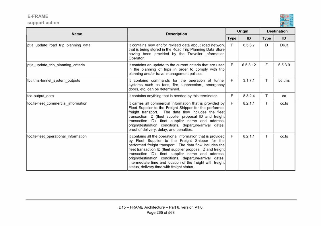
E-FRAME
support action
D15 – FRAME Architecture – Part 6, version V1.0
Page 265 of 568
Origin Destination Name Description
Type ID Type ID
ptja_update_road_trip_planning_data It contains new and/or revised data about road network that is being stored in the Road Trip Planning Data Store having been provided by the Traveller Information Operator.
F 6.5.3.7 D D6.3
ptja_update_trip_planning_criteria It contains an update to the current criteria that are used in the planning of trips in order to comply with trip planning and/or travel management policies.
F 6.5.3.12 F 6.5.3.9
tbti.tms-tunnel_system_outputs It contains commands for the operation of tunnel systems such as fans, fire suppression., emergency doors, etc. can be determined.
F 3.1.7.1 T bti.tms
tca-output_data It contains anything that is needed by this terminator. F 8.3.2.4 T ca
tcc.fs-fleet_commercial_information It carries all commercial information that is provided by Fleet Supplier to the Freight Shipper for the performed freight transport. The data flow includes the fleet transaction ID (fleet supplier proposal ID and freight transaction ID), fleet supplier name and address, origin/destination conditions, departure/arrival dates, proof of delivery, delay, and penalties.
F 8.2.1.1 T cc.fs
tcc.fs-fleet_operational_information It contains all the operational information that is provided by Fleet Supplier to the Freight Shipper for the performed freight transport. The data flow includes the fleet transaction ID (fleet supplier proposal ID and freight transaction ID), fleet supplier name and address, origin/destination conditions, departure/arrival dates, intermediate time and location of the freight with freight status, delivery time with freight status.
F 8.2.1.1 T cc.fs

E-FRAME
support action
D15 – FRAME Architecture – Part 6, version V1.0
Page 266 of 568
Origin Destination Name Description
Type ID Type ID
tcc.fs-fleet_transport_capacity_availability It indicates to freight shipper that the Fleet Supplier is available to carry freight and so to study transport opportunity. The data flow includes Fleet Supplier name and address, start time of availability, end time of availability, description of capability during availability period.
F 8.2.1.1 T cc.fs
tcc.fs-fleet_transport_invoice It is the formal invoice from the fleet supplier to the freight shipper. The data flow includes the fleet transaction ID, price and electronic signature.
F 8.2.1.2 T cc.fs
tcc.fs-fleet_transport_offer It carries characteristics about the conditions under which the freight operation could be performed. The data flow includes the fleet transaction ID (fleet supplier proposal ID and freight transaction ID), fleet supplier name and address, departure/arrival dates proposal, proposed price and electronic signature.
F 8.2.1.1 T cc.fs
tcc.fs-fleet_transport_opportunity_request It is a request from the fleet supplier to Freight Shipper to get information about current freight opportunity. The data flow includes Fleet Supplier name and address, plus criteria for transport opportunity selection, i.e. start time, end-time, start location, end location and cargo type.
F 8.2.1.1 T cc.fs
tcc.fs-fleet_transport_order_confirmation It carries characteristics about the conditions under which the freight operation will be performed. It is the contract established between the freight shipper and fleet centre. The data flow includes the fleet transaction ID (fleet supplier proposal ID and freight transaction ID), fleet supplier name and address, origin/destination conditions, departure/arrival dates engagement, agreed price and electronic signature.
F 8.2.1.1 T cc.fs
E-FRAME
support action
D15 – FRAME Architecture – Part 6, version V1.0
Page 267 of 568
Origin Destination Name Description
Type ID Type ID
tcc.p-cargo_status It contains details about the cargo status that are being sent to the Principal Actor within the Consignor/Consignee Terminator and include freight transaction ID (Principal order ID and freight operator proposal ID), cargo status ID, current operation (pick-up, conveying, delivering), position, expected time of arrival, with or without incident and incident description.
F 8.1.3 T cc.p
tcc.p-cargo_status_2 It carries details about the cargo status. The details include freight transaction ID (principal order ID and freight operator proposal ID), cargo status ID, current operation (pick-up, conveying, delivering), position, expected time of arrival, with or without incident and incident description.
F 8.3.2.3 T cc.p
tcc.p-constraints_change_request It contains elements of information that relate to a proposal from the freight operator to change the road transport conditions in order to ease an inter-modal transport mode and includes principal order ID, departure/arrival dates proposal, inter-modal transport conditions and electronic signature.
F 8.1.1.8 T cc.p
tcc.p-contract_for_principal It contains the formal answer from the freight operator for conveying an item of freight. The data is initially a proposal then it becomes a contract established between both parties - the Principal and the Freight Operator. It carries the expected time of arrival as predicted by the Freight Operator. This data flow includes freight transaction ID (principal order ID and freight operator proposal ID), principal name and address, origin/destination conditions, departure/arrival dates proposal, cargo/freight characteristics, agreed price and electronic signature.
F 8.1.1.8 T cc.p
E-FRAME
support action
D15 – FRAME Architecture – Part 6, version V1.0
Page 268 of 568
Origin Destination Name Description
Type ID Type ID
tcc.p-invoice_for_principal It is the formal invoice from the freight operator to the principal. This data flow includes freight transaction ID (principal order ID and freight operator proposal ID), price and electronic signature.
F 8.1.1.8 T cc.p
tcc.p-principal_notice_of_delivery It contains formal information from the Freight Operator to the Principal that indicates that the freight has been delivered and includes freight transaction ID (principal order ID and freight operator proposal ID), time of arrival and electronic signature.
F 8.1.1.8 T cc.p
td-alert_warning This data is used to active an alertness warning or alertness enhancement.
F 5.11.10 T d
td-approaching_inter-urban_zone It contains a warning message for Drivers that they are approaching a part of the inter-urban road network (zone) to which they do not have access.
F 3.1.2.13.2 T d
td-approaching_urban_zone It contains a warning message for Drivers that they are approaching a part of the urban road network (zone) to which they do not have access.
F 3.1.1.5.11 T d
td-bridge_status It contains information for a vehicle driver about the current status of bridge(s) in the road network served by the system, e.g. open, closed, lane closures, restrictions for large vehicles, etc.
F 3.1.8.4 T d
td-bus_lane_request_result It contains the result from the request made by the Driver for their non-PT Vehicle to use a Bus Lane.
F 9.2.1 T d
td-bus_lane_warning_message It contains messages for the Driver warning that either the non-PT Vehicle should not be using a Bus Lane, or the previously granted licence has been revoked.
F 9.2.1 T d
td-carpark_occupancy It contains the current car park occupancy (number of spaces) that is being output to Drivers.
F 3.1.4.9 T d
E-FRAME
support action
D15 – FRAME Architecture – Part 6, version V1.0
Page 269 of 568
Origin Destination Name Description
Type ID Type ID
td-carpark_space_payment_confirmed It contains an indication that the credit/debit payment for using a car park space requested by the Driver has been accepted.
F 3.1.4.6 T d
td-carpark_space_payment_refused It contains an indication that the previous credit/debit payment for using a car park space requested by the Driver has been refused.
F 3.1.4.6 T d
td-carpark_space_payment_required It contains an indication that payment is required for using a car park space. The current charges for using the space are included in the output.
F 3.1.4.6 T d
td-carpark_status It contains the current car park status that is being output to Drivers.
F 3.1.4.9 T d
td-current_commands_&_warnings It contains dynamic warnings for display to the Driver. They may be about such things as traffic conditions, queues and their rates of propagation, speed limits, lane commands, road signs and general road information, plus warnings of the need to dip headlights, lane changing, safety behaviour, collision and emergency brake manoeuvres.
F 5.16.2 T d
td-current_road_and_traffic_conditions It contains information that is being output to the Driver of the Host Vehicle about road and traffic conditions in the immediate surroundings of the Vehicle.
F 5.13.10 T d
td-current_road_information It contains static information that is being output to the Driver of the Host Vehicle about the road segment in which the Vehicle is currently travelling. This information may include road signs showing changes to the road geometry and/or layout, including road junctions.
F 5.13.10 T d
E-FRAME
support action
D15 – FRAME Architecture – Part 6, version V1.0
Page 270 of 568
Origin Destination Name Description
Type ID Type ID
td-current_speed_limits_and_headways It contains the output to the Driver of the Host Vehicle of the current legal limit or suggested dynamic speed, plus the suggested headway for the Vehicle. Two values shall be included, one for the road segment currently being occupied by the Vehicle and the other for the expected next segment. The reason(s) for any change(s) in speed indication will be included.
F 5.13.10 T d
td-demand_management_information It contains information that is being output to Drivers as part of a demand management strategy implementation.
F 3.3.13 T d
td-eCall_acknowledgement It contains the response that is being sent to a Driver as a result of a Traveller making an "eCall" from outside of the Vehicle. Typically each time it is sent it may contain one of the following : "OK we received your call and we process it" (first acknowledgement) or "ambulance will be there in 'X' minutes and police in 'Y' minutes" (full acknowledgement).
F 2.1.8 T d
td-enterring_inter-urban_zone It contains a warning message for Drivers that a physical barrier is in place because they are entering a part of the inter-urban road network (zone) to which they do not have access.
F 3.1.2.13.3 T d
td-enterring_urban_zone It contains a warning message for Drivers that a physical barrier is in place because they are entering a part of the urban road network (zone) to which they do not have access.
F 3.1.1.5.12 T d
td-environmental_information It contains information about either current or predicted environmental conditions that is being sent to Drivers as part of one or more actions that have been confirmed by the Road Network Operator.
F 3.4.10 T d
td-expected_time_of_arrival It contains output of the expected time of arrival at the next way point or the destination of the Vehicle Trip Plan to the Driver in the Vehicle.
F 5.14.5 T d
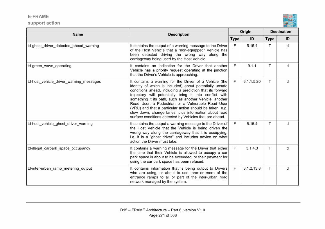
E-FRAME
support action
D15 – FRAME Architecture – Part 6, version V1.0
Page 271 of 568
Origin Destination Name Description
Type ID Type ID
td-ghost_driver_detected_ahead_warning It contains the output of a warning message to the Driver of the Host Vehicle that a "non-equipped" Vehicle has been detected driving the wrong way along the carriageway being used by the Host Vehicle.
F 5.15.4 T d
td-green_wave_operating It contains an indication for the Driver that another Vehicle has a priority request operating at the junction that the Driver's Vehicle is approaching.
F 9.1.1 T d
td-host_vehicle_driver_warning_messages It contains a warning for the Driver of a Vehicle (the identity of which is included) about potentially unsafe conditions ahead, including a prediction that its forward trajectory will potentially bring it into conflict with something it its path, such as another Vehicle, another Road User, a Pedestrian or a Vulnerable Road User (VRU) and that a particular action should be taken, e.g. slow down, change lanes, plus information about road surface conditions detected by Vehicles that are ahead.
F 3.1.1.5.20 T d
td-host_vehicle_ghost_driver_warning It contains the output a warning message to the Driver of the Host Vehicle that the Vehicle is being driven the wrong way along the carriageway that it is occupying, i.e. it is a "ghost driver" and includes advice on what action the Driver must take.
F 5.15.4 T d
td-illegal_carpark_space_occupancy It contains a warning message for the Driver that either the time that their Vehicle is allowed to occupy a car park space is about to be exceeded, or their payment for using the car park space has been refused.
F 3.1.4.3 T d
td-inter-urban_ramp_metering_output It contains information that is being output to Drivers who are using, or about to use, one or more of the entrance ramps to all or part of the inter-urban road network managed by the system.
F 3.1.2.13.8 T d
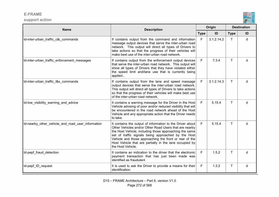
E-FRAME
support action
D15 – FRAME Architecture – Part 6, version V1.0
Page 272 of 568
Origin Destination Name Description
Type ID Type ID
td-inter-urban_traffic_c&i_commands If contains output from the command and information message output devices that serve the inter-urban road network. This output will direct all types of Drivers to take actions so that the progress of their vehicles will make best use of the inter-urban road network.
F 3.1.2.14.2 T d
td-inter-urban_traffic_enforcement_messages If contains output from the enforcement output devices that serve the inter-urban road network. This output will show all types of Drivers that they have violated either the speed limit and/lane use that is currently being applied..
F 7.3.4 T d
td-inter-urban_traffic_l&s_commands If contains output from the lane and speed message output devices that serve the inter-urban road network. This output will direct all types of Drivers to take actions so that the progress of their vehicles will make best use of the inter-urban road network.
F 3.1.2.14.3 T d
td-low_visibility_warning_and_advice It contains a warning message for the Driver in the Host Vehicle advising of poor and/or reduced visibility that will be encountered in the road network ahead of the Host Vehicle and any appropriate action that the Driver needs to take.
F 5.15.4 T d
td-nearby_other_vehicle_and_road_user_information It contains the output of information to the Driver about Other Vehicles and/or Other Road Users that are nearby the Host Vehicle, including those approaching the same set of traffic signals being approached by the Host Vehicle and those approaching the front or rear of the Host Vehicle that are partially in the lane occupied by the Host Vehicle.
F 5.15.4 T d
td-pepf_fraud_detection It contains an indication to the driver that the electronic payment transaction that has just been made was identified as fraudulent
F 1.5.2 T d
td-pepf_ID_request It is used to ask the Driver to provide a means for their identification.
F 1.3.2 T d

E-FRAME
support action
D15 – FRAME Architecture – Part 6, version V1.0
Page 273 of 568
Origin Destination Name Description
Type ID Type ID
td-pepf_payment_acceptance It is sent upon verification that the received payment is correct. The data flow includes the following elements: - date / time - user ID - location - service ID - other parameters allowing to define the service - amount of transaction - mode of payment (account number, time of actual debiting)
F 1.3.7 T d
td-pepf_payment_info_guidance It regroups different messages the purpose of which is to guide the Driver in their selection of the service they wish, and for the payment of this service. The data flow may include lists of available services, possible choices for parameter values for these services (schedules, locations, …), the list of contracts existing between the Driver and the different operators, etc.
F 1.3.4 T d
td-pepf_payment_request It contains the request for the payment corresponding to the service ordered by the Driver. The data flow includes the following elements: - service ID - other parameters defining precisely the service - request for information about payment means : - mode of payment - account ID - amount to be paid
F 1.3.7 T d
td-pepf_stop_command It represents the means by which the system signifies to the Driver that they have no right to use the requested service. A barrier, a specific light, or some other device may provide the signal to the Driver.
F 1.5.5 T d

E-FRAME
support action
D15 – FRAME Architecture – Part 6, version V1.0
Page 274 of 568
Origin Destination Name Description
Type ID Type ID
td-possible_command_&_warning_error It contains output to the Driver advising on a difference between the dynamic commands and warnings that are being output in the Vehicle and those being provided from the roadside.
F 5.16.2 T d
td-possible_speed_indication_error It contains in indication that is being output to the Driver in the Host Vehicle that there is a difference between the legal or dynamic speed limit, or road information that is being output to the Driver in the Host Vehicle and that being provided to the Driver from the roadside.
F 5.13.10 T d
td-priority_request_result It contains the result of a previous request from a Driver for priority at the signalised road junctions between the current Vehicle location and the specified destination. (Note: the result can be success or failure.)
F 9.1.1 T d
td-psle_record_request It represents the request sent to the Driver to provide one or several records corresponding to the vehicle.
F 7.1.3 T d
td-recommended_speed_or_legal_speed_limit_exceeded It contains a warning for the Driver of the Host Vehicle that the Vehicle is being driven in a way that the recommended speed and/or legal speed limit is currently being exceeded.
F 5.13.10 T d
td-road_curve_ahead_warning It contains a warning for the Driver of the Host Vehicle that it is approaching a curve in the road network and that the following action(s) should be taken, e.g. changes to Vehicle speed and/or trajectory, to ensure that the Vehicle travels safely on its current trajectory.
F 5.15.4 T d
td-route_guidance_instructions It contains the output of the Vehicle Trip Plan route guidance instructions to the Driver in the Vehicle.
F 5.14.5 T d
td-safety_behaviour_warning It contains a warning to the Driver of the Host Vehicle that the Vehicle is being driven in an unsafe manner, i.e. poor safety behaviour that may endanger other road users.
F 5.13.10 T d

E-FRAME
support action
D15 – FRAME Architecture – Part 6, version V1.0
Page 275 of 568
Origin Destination Name Description
Type ID Type ID
td-service_area_occupancy It contains the current service area occupancy (number of spaces) that is being output to Drivers.
F 3.1.5.3 T d
td-service_area_status It contains the current service area status that is being output to Drivers.
F 3.1.5.3 T d
td-slippery_road_surface_ahead_warning It contains a warning message for the Driver of the Host Vehicle that a slippery road surface will be encountered ahead of the Host Vehicle and any appropriate action that the Driver needs to take.
F 5.15.4 T d
td-slow_moving_objects_warning_and_advice It contains a warning to the Driver of the Host Vehicle that a slow moving object (e.g. person, animal, slow vehicle, including Vulnerable Road Users (VRU's)) is near the Vehicle and includes advice on any appropriate action that the Driver needs to take.
F 5.15.4 T d
td-stationary_emergency_vehicle_ahead_warning It contains the output of a warning message to the Driver of the Host Vehicle that a support/emergency vehicle is stationary in the path of the Host Vehicle trajectory.
F 5.15.4 T d
td-stationary_objects_warning_and_advice It contains a warning to the Driver of the Host Vehicle that a stationary object, including Vulnerable Road Users (VRU's), is near the Vehicle and includes advice on any appropriate action that the Driver needs to take.
F 5.15.4 T d
td-traffic_information It contains information for the Driver about predicted and current traffic conditions and queues in the geographic region of the Vehicle.
F 5.16.2 T d
td-traffic_queue_ahead_warning_and_advice It contains a warning message for the Driver in the Host Vehicle advising of traffic queue that will be encountered in the road network ahead of the Host Vehicle and any appropriate action that the Driver needs to take.
F 5.15.4 T d
td-traffic_regulations It contains “copies” of the current traffic signals to display to the driver.
F 5.16.2 T d

E-FRAME
support action
D15 – FRAME Architecture – Part 6, version V1.0
Page 276 of 568
Origin Destination Name Description
Type ID Type ID
td-traffic_signal_advisory_message It contains the output of information for the Driver of the Host Vehicle about the lane and speed to use so that the Vehicle can pass through the next set of traffic lights on green, i.e. without stopping.
F 5.15.4 T d
td-tunnel_status It contains information for a vehicle driver about the current status of tunnel(s) in the road network served by the system, e.g. open, closed, lane restrictions, etc.
F 3.1.7.4 T d
td-urban_traffic_enforcement_messages It contains the manifestation of the output of details of violators of traffic management commands to drivers of all types of vehicles using the urban road network. It is intended to act as a deterrent to future violations and/or give notice of impending possible prosecution of the driver for the violation.
F 7.3.3 T d
td-urban_traffic_indications It contains the manifestation of the output of lane use and speed commands to drivers of all types of vehicles using the urban road network. It will direct them to take actions so that their progress will make best use of the urban travel network.
F 3.1.1.5.23 T d
td-urban_traffic_messages It contains the output of messages to Drivers of all types of Vehicles using the urban road network that will direct them to take actions so that their progress will make best use of the urban travel network.
F 3.1.1.5.20 T d
td-urban_traffic_s&g_commands It contains the manifestation of the output of stop or go (s&g) commands, messages to drivers of all types of vehicles using the urban road network. It will direct them to take actions so that their progress will make best use of the urban travel network.
F 3.1.1.5.22 T d
td-vehicle_above_required_inter-urban_speeds It contains a warning message that is being output to the Driver of the Host Vehicle (identity included) that the Vehicle is being driven in a way that is making it exceed the legal and/or recommended inter-urban speed limits.
F 3.1.2.14.3 T d
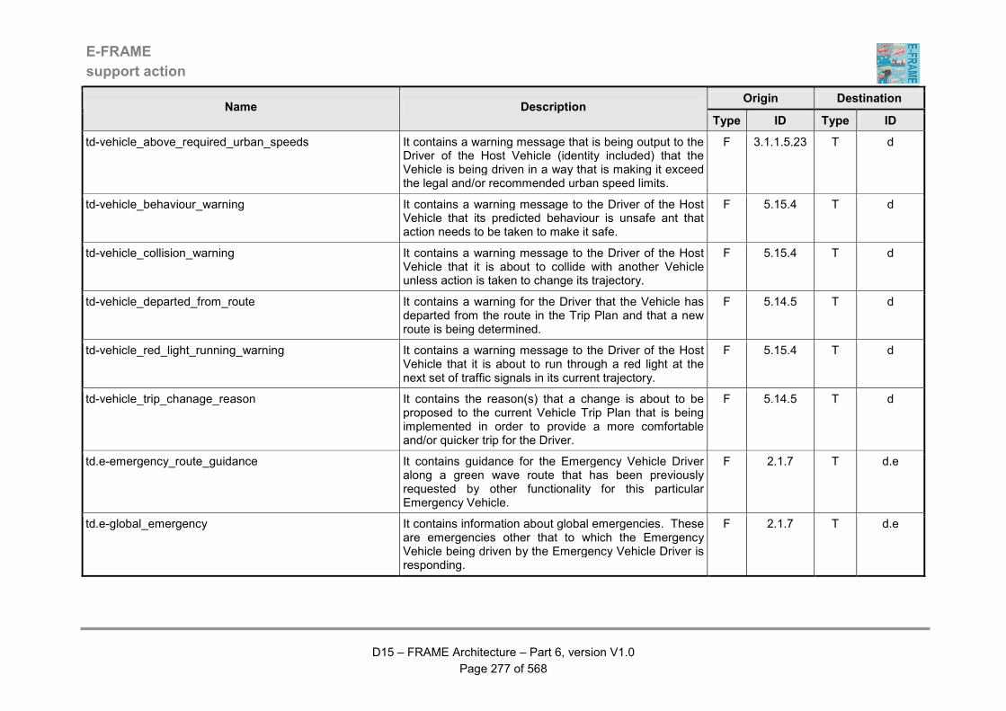
E-FRAME
support action
D15 – FRAME Architecture – Part 6, version V1.0
Page 277 of 568
Origin Destination Name Description
Type ID Type ID
td-vehicle_above_required_urban_speeds It contains a warning message that is being output to the Driver of the Host Vehicle (identity included) that the Vehicle is being driven in a way that is making it exceed the legal and/or recommended urban speed limits.
F 3.1.1.5.23 T d
td-vehicle_behaviour_warning It contains a warning message to the Driver of the Host Vehicle that its predicted behaviour is unsafe ant that action needs to be taken to make it safe.
F 5.15.4 T d
td-vehicle_collision_warning It contains a warning message to the Driver of the Host Vehicle that it is about to collide with another Vehicle unless action is taken to change its trajectory.
F 5.15.4 T d
td-vehicle_departed_from_route It contains a warning for the Driver that the Vehicle has departed from the route in the Trip Plan and that a new route is being determined.
F 5.14.5 T d
td-vehicle_red_light_running_warning It contains a warning message to the Driver of the Host Vehicle that it is about to run through a red light at the next set of traffic signals in its current trajectory.
F 5.15.4 T d
td-vehicle_trip_chanage_reason It contains the reason(s) that a change is about to be proposed to the current Vehicle Trip Plan that is being implemented in order to provide a more comfortable and/or quicker trip for the Driver.
F 5.14.5 T d
td.e-emergency_route_guidance It contains guidance for the Emergency Vehicle Driver along a green wave route that has been previously requested by other functionality for this particular Emergency Vehicle.
F 2.1.7 T d.e
td.e-global_emergency It contains information about global emergencies. These are emergencies other that to which the Emergency Vehicle being driven by the Emergency Vehicle Driver is responding.
F 2.1.7 T d.e
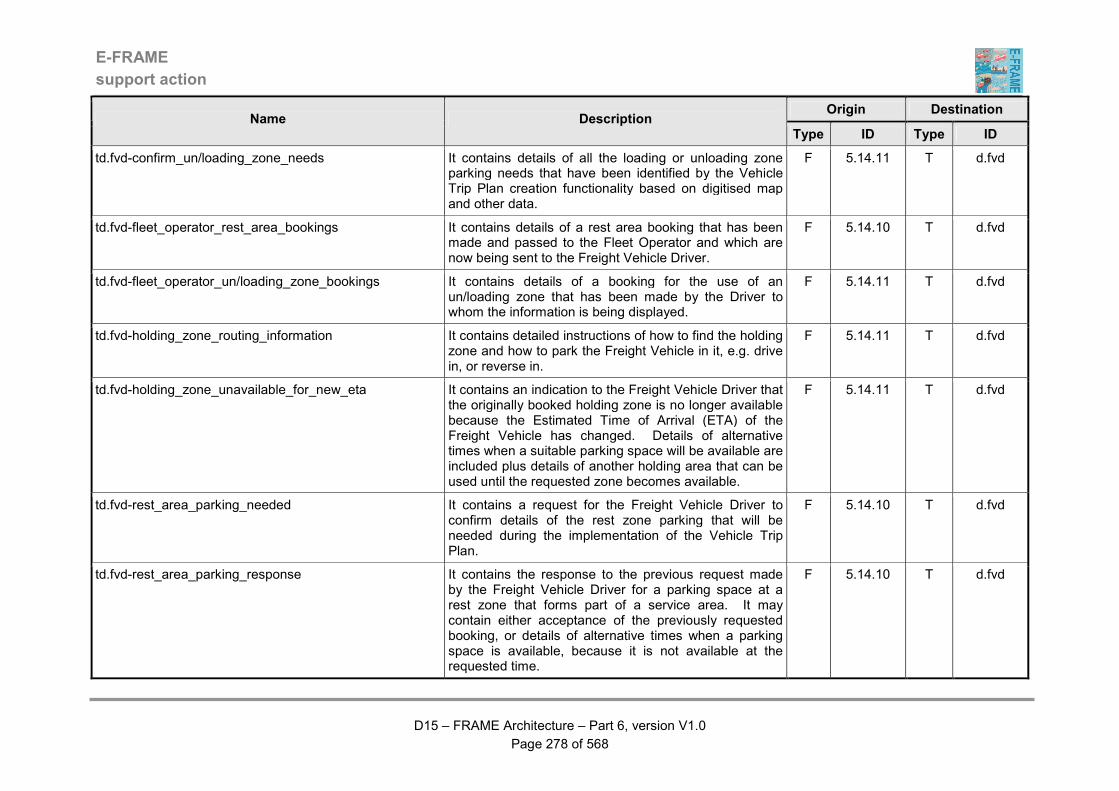
E-FRAME
support action
D15 – FRAME Architecture – Part 6, version V1.0
Page 278 of 568
Origin Destination Name Description
Type ID Type ID
td.fvd-confirm_un/loading_zone_needs It contains details of all the loading or unloading zone parking needs that have been identified by the Vehicle Trip Plan creation functionality based on digitised map and other data.
F 5.14.11 T d.fvd
td.fvd-fleet_operator_rest_area_bookings It contains details of a rest area booking that has been made and passed to the Fleet Operator and which are now being sent to the Freight Vehicle Driver.
F 5.14.10 T d.fvd
td.fvd-fleet_operator_un/loading_zone_bookings It contains details of a booking for the use of an un/loading zone that has been made by the Driver to whom the information is being displayed.
F 5.14.11 T d.fvd
td.fvd-holding_zone_routing_information It contains detailed instructions of how to find the holding zone and how to park the Freight Vehicle in it, e.g. drive in, or reverse in.
F 5.14.11 T d.fvd
td.fvd-holding_zone_unavailable_for_new_eta It contains an indication to the Freight Vehicle Driver that the originally booked holding zone is no longer available because the Estimated Time of Arrival (ETA) of the Freight Vehicle has changed. Details of alternative times when a suitable parking space will be available are included plus details of another holding area that can be used until the requested zone becomes available.
F 5.14.11 T d.fvd
td.fvd-rest_area_parking_needed It contains a request for the Freight Vehicle Driver to confirm details of the rest zone parking that will be needed during the implementation of the Vehicle Trip Plan.
F 5.14.10 T d.fvd
td.fvd-rest_area_parking_response It contains the response to the previous request made by the Freight Vehicle Driver for a parking space at a rest zone that forms part of a service area. It may contain either acceptance of the previously requested booking, or details of alternative times when a parking space is available, because it is not available at the requested time.
F 5.14.10 T d.fvd

E-FRAME
support action
D15 – FRAME Architecture – Part 6, version V1.0
Page 279 of 568
Origin Destination Name Description
Type ID Type ID
td.fvd-rest_area_parking_space_details It contains details of how to find the parking space in the rest zone of a service area that has been booked for the Freight Vehicle that the Freight Vehicle Driver is currently driving.
F 5.14.10 T d.fvd
td.fvd-rest_area_service_information It contains information about the services that are available for the Freight Vehicle Driver to use in the rest zone and other parts of the service area, where a parking place has been booked for the Freight Vehicle that they are currently driving.
F 5.14.10 T d.fvd
td.fvd-rest_area_unavailable_for_new_eta It contains an indication to the Freight Vehicle Driver that the originally booked parking space is no longer available because the Estimated Time of Arrival (ETA) of the Freight Vehicle has changed. Details of alternative times when a suitable parking space will be available are included.
F 5.14.10 T d.fvd
td.fvd-trip_output It contains data about the trip to be completed by the Driver and the Freight Vehicle.
F 8.3.1.1 T d.fvd
td.fvd-trip_output_2 It contains data about the trip to be completed by the Driver and the Freight Vehicle.
F 8.3.1.2 T d.fvd
td.fvd-trip_output_3 It contains data about the trip to be completed by the Driver and the Freight Vehicle.
F 8.3.1.3 T d.fvd
td.fvd-trip_output_4 It contains data about the trip to be completed by the Driver and the Freight Vehicle.
F 8.3.1.4 T d.fvd
td.fvd-trip_output_5 It contains data about the trip to be completed by the Driver and the Freight Vehicle.
F 8.3.2.1 T d.fvd
td.fvd-trip_output_6 It contains data about the trip to be completed by the Driver and the Freight Vehicle.
F 8.3.2.2 T d.fvd
td.fvd-trip_output_7 It contains data about the trip to be completed by the Driver and the Freight Vehicle.
F 8.3.2.3 T d.fvd
E-FRAME
support action
D15 – FRAME Architecture – Part 6, version V1.0
Page 280 of 568
Origin Destination Name Description
Type ID Type ID
td.fvd-trip_output_8 It contains data about the trip to be completed by the Driver and the Freight Vehicle.
F 8.3.2.4 T d.fvd
td.fvd-trip_output_9 It contains data about the trip to be completed by the Driver and the Freight Vehicle.
F 8.3.3 T d.fvd
td.fvd-un/loading_zone_routing_information It contains detailed instructions of how to find the loading or unloading area and how to park the Freight Vehicle in it, e.g. drive in, or reverse in.
F 5.14.11 T d.fvd
td.fvd-un/loading_zone_unavailable_for_new_eta It contains an indication to the Freight Vehicle Driver that the originally booked loading or unloading zone is no longer available because the Estimated Time of Arrival (ETA) of the Freight Vehicle has changed. Details of alternative times when a suitable parking space will be available are included plus details of the holding area that can be used until the requested zone becomes available.
F 5.14.11 T d.fvd
td.fvd-un/loading_zone_use_response It contains the response to the previous request made by the Freight Vehicle Driver for the use of a loading or unloading area. It may contain either acceptance of the previously requested booking, or a rejection. The rejection will be accompanied by details of alternative times when a space is available at the requested area or another suitable area, or details of a holding area that the Driver should use because the requested area is not available at the specified time.
F 5.14.11 T d.fvd
td.fvd-work_information It contains preliminary or confirmed work order to driver. F 8.2.2.3.3 T d.fvd
td.hgvd-route_guidance It contains an initial indication that the route previously requested by the Driver of a Heavy Goods Vehicle is ready for use, and then guidance instructions for its actual use.
F 9.4.3 T d.hgvd
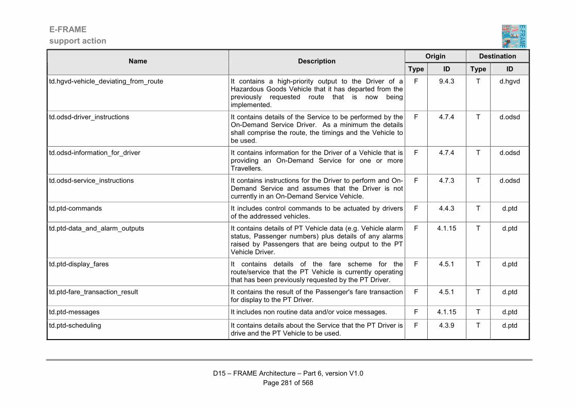
E-FRAME
support action
D15 – FRAME Architecture – Part 6, version V1.0
Page 281 of 568
Origin Destination Name Description
Type ID Type ID
td.hgvd-vehicle_deviating_from_route It contains a high-priority output to the Driver of a Hazardous Goods Vehicle that it has departed from the previously requested route that is now being implemented.
F 9.4.3 T d.hgvd
td.odsd-driver_instructions It contains details of the Service to be performed by the On-Demand Service Driver. As a minimum the details shall comprise the route, the timings and the Vehicle to be used.
F 4.7.4 T d.odsd
td.odsd-information_for_driver It contains information for the Driver of a Vehicle that is providing an On-Demand Service for one or more Travellers.
F 4.7.4 T d.odsd
td.odsd-service_instructions It contains instructions for the Driver to perform and On-Demand Service and assumes that the Driver is not currently in an On-Demand Service Vehicle.
F 4.7.3 T d.odsd
td.ptd-commands It includes control commands to be actuated by drivers of the addressed vehicles.
F 4.4.3 T d.ptd
td.ptd-data_and_alarm_outputs It contains details of PT Vehicle data (e.g. Vehicle alarm status, Passenger numbers) plus details of any alarms raised by Passengers that are being output to the PT Vehicle Driver.
F 4.1.15 T d.ptd
td.ptd-display_fares It contains details of the fare scheme for the route/service that the PT Vehicle is currently operating that has been previously requested by the PT Driver.
F 4.5.1 T d.ptd
td.ptd-fare_transaction_result It contains the result of the Passenger's fare transaction for display to the PT Driver.
F 4.5.1 T d.ptd
td.ptd-messages It includes non routine data and/or voice messages. F 4.1.15 T d.ptd
td.ptd-scheduling It contains details about the Service that the PT Driver is drive and the PT Vehicle to be used.
F 4.3.9 T d.ptd
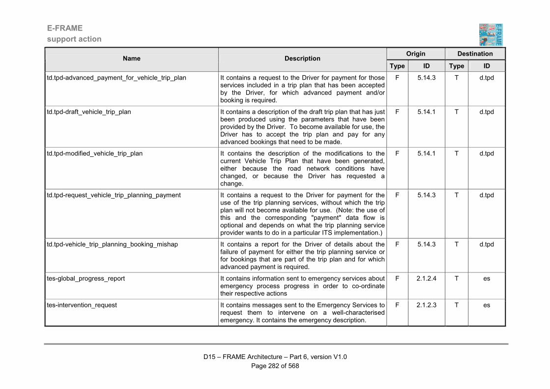
E-FRAME
support action
D15 – FRAME Architecture – Part 6, version V1.0
Page 282 of 568
Origin Destination Name Description
Type ID Type ID
td.tpd-advanced_payment_for_vehicle_trip_plan It contains a request to the Driver for payment for those services included in a trip plan that has been accepted by the Driver, for which advanced payment and/or booking is required.
F 5.14.3 T d.tpd
td.tpd-draft_vehicle_trip_plan It contains a description of the draft trip plan that has just been produced using the parameters that have been provided by the Driver. To become available for use, the Driver has to accept the trip plan and pay for any advanced bookings that need to be made.
F 5.14.1 T d.tpd
td.tpd-modified_vehicle_trip_plan It contains the description of the modifications to the current Vehicle Trip Plan that have been generated, either because the road network conditions have changed, or because the Driver has requested a change.
F 5.14.1 T d.tpd
td.tpd-request_vehicle_trip_planning_payment It contains a request to the Driver for payment for the use of the trip planning services, without which the trip plan will not become available for use. (Note: the use of this and the corresponding "payment" data flow is optional and depends on what the trip planning service provider wants to do in a particular ITS implementation.)
F 5.14.3 T d.tpd
td.tpd-vehicle_trip_planning_booking_mishap It contains a report for the Driver of details about the failure of payment for either the trip planning service or for bookings that are part of the trip plan and for which advanced payment is required.
F 5.14.3 T d.tpd
tes-global_progress_report It contains information sent to emergency services about emergency process progress in order to co-ordinate their respective actions
F 2.1.2.4 T es
tes-intervention_request It contains messages sent to the Emergency Services to request them to intervene on a well-characterised emergency. It contains the emergency description.
F 2.1.2.3 T es

E-FRAME
support action
D15 – FRAME Architecture – Part 6, version V1.0
Page 283 of 568
Origin Destination Name Description
Type ID Type ID
tes-stolen_vehicle_information It contains information about a stolen vehicle that has been notified to the system and is for use in its recovery.
F 2.2.2 T es
tesp-pepf_contract_statistics It contains information about the contracts established with the External Service Provider during a period specified in the request. The data flow includes the following elements: - External Service Provider ID - number of contracts for each service ID - location of these contracts - dates of contracts - modes of payment chosen - amount of contracts - other valuable information (depending on the service nature : for example : quality of service required, duration of contract, …)
F 1.1.2 T esp
tesp-pepf_transaction_analysis It contains information about the transactions performed for the benefit of the External Service Provider during a period specified. The data flow includes the following elements: - service provider ID - services ID - parameters chosen by the users for these services -corresponding amount of transactions - location of service utilisation - revenue generated by services managed by other information providers (revenue sharing) - revenue distributed to other information providers (revenue sharing) - total amount credited on each account
F 1.4.3 T esp
tesp.b-demand_data It contains data about the current state of any demand management strategies that have been implemented.
F 3.3.7 T esp.b
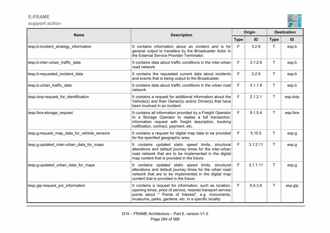
E-FRAME
support action
D15 – FRAME Architecture – Part 6, version V1.0
Page 284 of 568
Origin Destination Name Description
Type ID Type ID
tesp.b-incident_strategy_information It contains information about an incident and is for general output to travellers by the Broadcaster Actor in the External Service Provider Terminator.
F 3.2.9 T esp.b
tesp.b-inter-urban_traffic_data It contains data about traffic conditions in the inter-urban road network.
F 3.1.2.9 T esp.b
tesp.b-requested_incident_data It contains the requested current data about incidents and events that is being output to the Broadcaster.
F 3.2.9 T esp.b
tesp.b-urban_traffic_data It contains data about traffic conditions in the urban road network.
F 3.1.1.9 T esp.b
tesp.dvip-request_for_identification It contains a request for additional information about the Vehicle(s) and their Owner(s) and/or Driver(s) that have been involved in an incident.
F 2.1.2.1 T esp.dvip
tesp.fsra-storage_request It contains all information provided by a Freight Operator to a Storage Operator to realise a full transaction: information request with freight description, booking notification, contract, payment, etc.
F 8.1.5.4 T esp.fsra
tesp.g-request_map_data_for_vehicle_sensors It contains a request for digital map data to be provided for the specified geographic area.
F 5.15.5 T esp.g
tesp.g-updated_inter-urban_data_for_maps It contains updated static speed limits, structural alterations and default journey times for the inter-urban road network that are to be implemented in the digital map content that is provided in the future.
F 3.1.2.11 T esp.g
tesp.g-updated_urban_data_for_maps It contains updated static speed limits, structural alterations and default journey times for the urban road network that are to be implemented in the digital map content that is provided in the future.
F 3.1.1.11 T esp.g
tesp.gip-request_poi_information It contains a request for information, such as location, opening times, price of service, nearest transport service points about " Points of Interest", e.g. monuments, museums, parks, gardens. etc. in a specific locality
F 6.5.3.9 T esp.gip
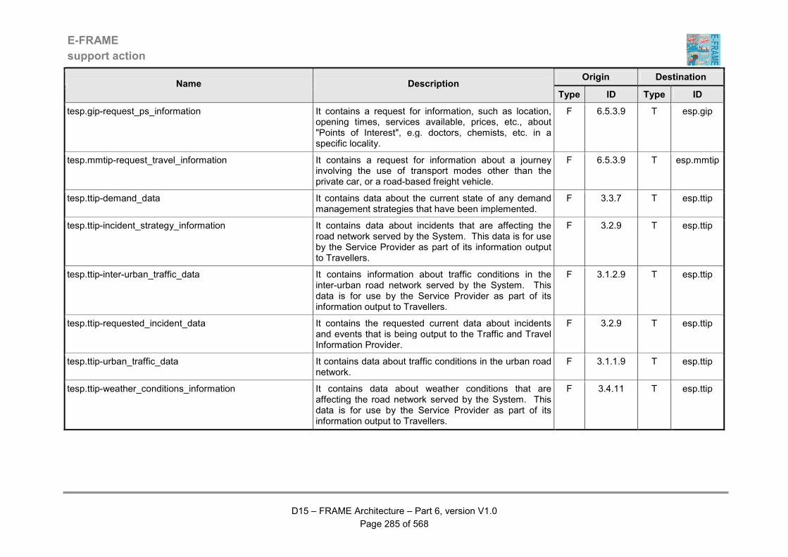
E-FRAME
support action
D15 – FRAME Architecture – Part 6, version V1.0
Page 285 of 568
Origin Destination Name Description
Type ID Type ID
tesp.gip-request_ps_information It contains a request for information, such as location, opening times, services available, prices, etc., about "Points of Interest", e.g. doctors, chemists, etc. in a specific locality.
F 6.5.3.9 T esp.gip
tesp.mmtip-request_travel_information It contains a request for information about a journey involving the use of transport modes other than the private car, or a road-based freight vehicle.
F 6.5.3.9 T esp.mmtip
tesp.ttip-demand_data It contains data about the current state of any demand management strategies that have been implemented.
F 3.3.7 T esp.ttip
tesp.ttip-incident_strategy_information It contains data about incidents that are affecting the road network served by the System. This data is for use by the Service Provider as part of its information output to Travellers.
F 3.2.9 T esp.ttip
tesp.ttip-inter-urban_traffic_data It contains information about traffic conditions in the inter-urban road network served by the System. This data is for use by the Service Provider as part of its information output to Travellers.
F 3.1.2.9 T esp.ttip
tesp.ttip-requested_incident_data It contains the requested current data about incidents and events that is being output to the Traffic and Travel Information Provider.
F 3.2.9 T esp.ttip
tesp.ttip-urban_traffic_data It contains data about traffic conditions in the urban road network.
F 3.1.1.9 T esp.ttip
tesp.ttip-weather_conditions_information It contains data about weather conditions that are affecting the road network served by the System. This data is for use by the Service Provider as part of its information output to Travellers.
F 3.4.11 T esp.ttip

E-FRAME
support action
D15 – FRAME Architecture – Part 6, version V1.0
Page 286 of 568
Origin Destination Name Description
Type ID Type ID
tesp.ttip_forecast_traffic_conditions_data It contains data about the forecast traffic conditions that are predicted to affect the road network served by the System. This data is for use by the Service Provider to use in the information it outputs to Travellers and to create a model of current and anticipated traffic conditions.
F 3.1.6.6 T esp.ttip
tesp.vra-additional_resource_request It contains all information sent by the Fleet Operator to the Vehicle Rental Agency to realise a full transaction: information request with vehicle/equipment description, booking notification, contract and payment.
F 8.2.2.1.2 T esp.vra
tfc-demand_service_payment It contains confirmation from the Financial Clearinghouse that payment for the On-Demand Service confirmed by the Traveller has been accepted.
F 4.7.1 T fc
tfc-pepf_account_status_request It contains a request for details of the current status of a Traveller's account that is used to purchase services. The data flow consists of the following items: - the EP account ID - the financial clearing-house which manages the source from which the money will be transferred - the ID of the source account
F 1.2.1 T fc
tfc-pepf_load_account_order It is used to ask the Financial Clearinghouse to transfer a certain amount from an account managed by it to an electronic payment account. The data flow includes the following elements: - date - user ID - ID of the financial clearing-house - EP account ID - ID of the account from which the money will be transferred - amount to be transferred
F 1.2.1 T fc
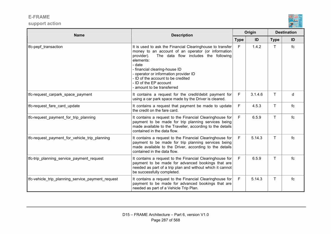
E-FRAME
support action
D15 – FRAME Architecture – Part 6, version V1.0
Page 287 of 568
Origin Destination Name Description
Type ID Type ID
tfc-pepf_transaction It is used to ask the Financial Clearinghouse to transfer money to an account of an operator (or information provider). The data flow includes the following elements: - date - financial clearing-house ID - operator or information provider ID - ID of the account to be credited - ID of the EP account - amount to be transferred
F 1.4.2 T fc
tfc-request_carpark_space_payment It contains a request for the credit/debit payment for using a car park space made by the Driver is cleared.
F 3.1.4.6 T d
tfc-request_fare_card_update It contains a request that payment be made to update the credit on the fare card.
F 4.5.3 T fc
tfc-request_payment_for_trip_planning It contains a request to the Financial Clearinghouse for payment to be made for trip planning services being made available to the Traveller, according to the details contained in the data flow.
F 6.5.9 T fc
tfc-request_payment_for_vehicle_trip_planning It contains a request to the Financial Clearinghouse for payment to be made for trip planning services being made available to the Driver, according to the details contained in the data flow.
F 5.14.3 T fc
tfc-trip_planning_service_payment_request It contains a request to the Financial Clearinghouse for payment to be made for advanced bookings that are needed as part of a trip plan and without which it cannot be successfully completed.
F 6.5.9 T fc
tfc-vehicle_trip_planning_service_payment_request It contains a request to the Financial Clearinghouse for payment to be made for advanced bookings that are needed as part of a Vehicle Trip Plan.
F 5.14.3 T fc
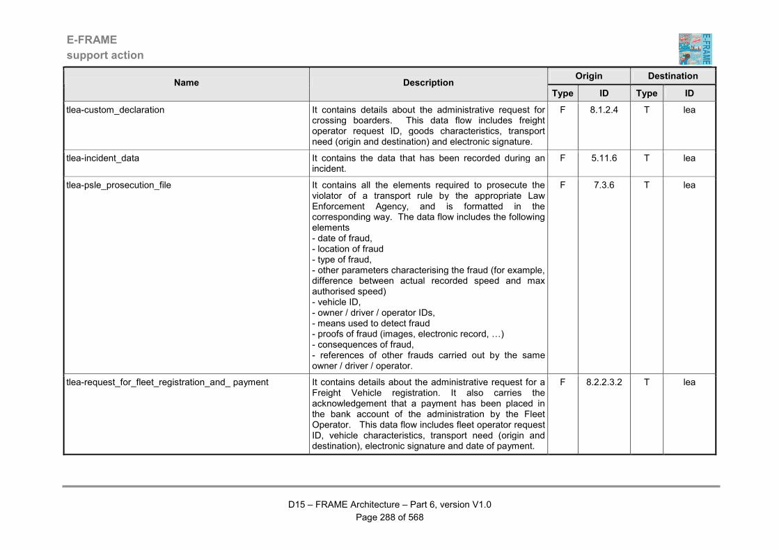
E-FRAME
support action
D15 – FRAME Architecture – Part 6, version V1.0
Page 288 of 568
Origin Destination Name Description
Type ID Type ID
tlea-custom_declaration It contains details about the administrative request for crossing boarders. This data flow includes freight operator request ID, goods characteristics, transport need (origin and destination) and electronic signature.
F 8.1.2.4 T lea
tlea-incident_data It contains the data that has been recorded during an incident.
F 5.11.6 T lea
tlea-psle_prosecution_file It contains all the elements required to prosecute the violator of a transport rule by the appropriate Law Enforcement Agency, and is formatted in the corresponding way. The data flow includes the following elements - date of fraud, - location of fraud - type of fraud, - other parameters characterising the fraud (for example, difference between actual recorded speed and max authorised speed) - vehicle ID, - owner / driver / operator IDs, - means used to detect fraud - proofs of fraud (images, electronic record, …) - consequences of fraud, - references of other frauds carried out by the same owner / driver / operator.
F 7.3.6 T lea
tlea-request_for_fleet_registration_and_ payment It contains details about the administrative request for a Freight Vehicle registration. It also carries the acknowledgement that a payment has been placed in the bank account of the administration by the Fleet Operator. This data flow includes fleet operator request ID, vehicle characteristics, transport need (origin and destination), electronic signature and date of payment.
F 8.2.2.3.2 T lea
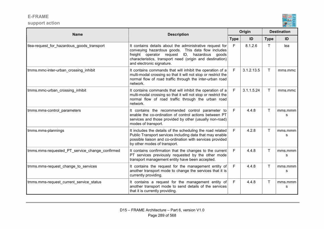
E-FRAME
support action
D15 – FRAME Architecture – Part 6, version V1.0
Page 289 of 568
Origin Destination Name Description
Type ID Type ID
tlea-request_for_hazardous_goods_transport It contains details about the administrative request for conveying hazardous goods. This data flow includes freight operator request ID, hazardous goods characteristics, transport need (origin and destination) and electronic signature.
F 8.1.2.6 T lea
tmms.mmc-inter-urban_crossing_inhibit It contains commands that will inhibit the operation of a multi-modal crossing so that it will not stop or restrict the normal flow of road traffic through the inter-urban road network.
F 3.1.2.13.5 T mms.mmc
tmms.mmc-urban_crossing_inhibit It contains commands that will inhibit the operation of a multi-modal crossing so that it will not stop or restrict the normal flow of road traffic through the urban road network.
F 3.1.1.5.24 T mms.mmc
tmms.mms-control_parameters It contains the recommended control parameter to enable the co-ordination of control actions between PT services and those provided by other (usually non-road) modes of transport.
F 4.4.8 T mms.mmms
tmms.mms-plannings It includes the details of the scheduling the road related Public Transport services including data that may enable possible liaison and co-ordination with services provided by other modes of transport.
F 4.2.8 T mms.mmms
tmms.mms-requested_PT_service_change_confirmed It contains confirmation that the changes to the current PT services previously requested by the other mode transport management entity have been accepted.
F 4.4.8 T mms.mmms
tmms.mms-request_change_to_services It contains the request for the management entity of another transport mode to change the services that it is currently providing.
F 4.4.8 T mms.mmms
tmms.mms-request_current_service_status It contains a request for the management entity of another transport mode to send details of the services that it is currently providing.
F 4.4.8 T mms.mmms
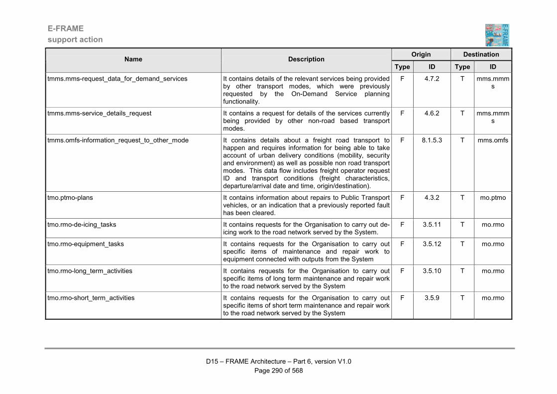
E-FRAME
support action
D15 – FRAME Architecture – Part 6, version V1.0
Page 290 of 568
Origin Destination Name Description
Type ID Type ID
tmms.mms-request_data_for_demand_services It contains details of the relevant services being provided by other transport modes, which were previously requested by the On-Demand Service planning functionality.
F 4.7.2 T mms.mmms
tmms.mms-service_details_request It contains a request for details of the services currently being provided by other non-road based transport modes.
F 4.6.2 T mms.mmms
tmms.omfs-information_request_to_other_mode It contains details about a freight road transport to happen and requires information for being able to take account of urban delivery conditions (mobility, security and environment) as well as possible non road transport modes. This data flow includes freight operator request ID and transport conditions (freight characteristics, departure/arrival date and time, origin/destination).
F 8.1.5.3 T mms.omfs
tmo.ptmo-plans It contains information about repairs to Public Transport vehicles, or an indication that a previously reported fault has been cleared.
F 4.3.2 T mo.ptmo
tmo.rmo-de-icing_tasks It contains requests for the Organisation to carry out de-icing work to the road network served by the System.
F 3.5.11 T mo.rmo
tmo.rmo-equipment_tasks It contains requests for the Organisation to carry out specific items of maintenance and repair work to equipment connected with outputs from the System
F 3.5.12 T mo.rmo
tmo.rmo-long_term_activities It contains requests for the Organisation to carry out specific items of long term maintenance and repair work to the road network served by the System
F 3.5.10 T mo.rmo
tmo.rmo-short_term_activities It contains requests for the Organisation to carry out specific items of short term maintenance and repair work to the road network served by the System
F 3.5.9 T mo.rmo
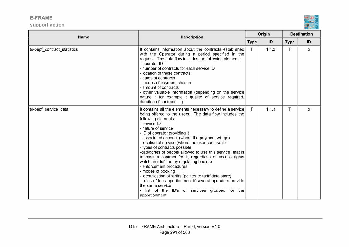
E-FRAME
support action
D15 – FRAME Architecture – Part 6, version V1.0
Page 291 of 568
Origin Destination Name Description
Type ID Type ID
to-pepf_contract_statistics It contains information about the contracts established with the Operator during a period specified in the request. The data flow includes the following elements: - operator ID - number of contracts for each service ID - location of these contracts - dates of contracts - modes of payment chosen - amount of contracts - other valuable information (depending on the service nature : for example : quality of service required, duration of contract, …)
F 1.1.2 T o
to-pepf_service_data It contains all the elements necessary to define a service being offered to the users. The data flow includes the following elements: - service ID - nature of service - ID of operator providing it - associated account (where the payment will go) - location of service (where the user can use it) - types of contracts possible -categories of people allowed to use this service (that is to pass a contract for it, regardless of access rights which are defined by regulating bodies) - enforcement procedures - modes of booking - identification of tariffs (pointer to tariff data store) - rules of fee apportionment if several operators provide the same service - list of the ID's of services grouped for the apportionment.
F 1.1.3 T o
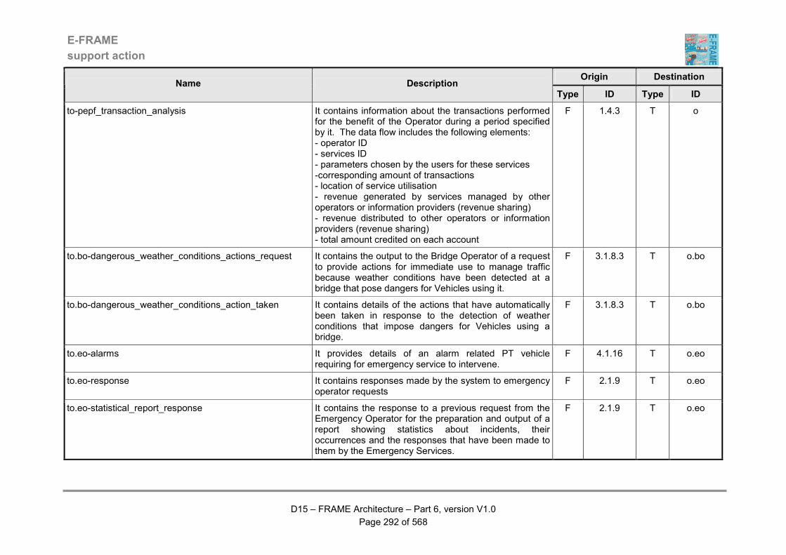
E-FRAME
support action
D15 – FRAME Architecture – Part 6, version V1.0
Page 292 of 568
Origin Destination Name Description
Type ID Type ID
to-pepf_transaction_analysis It contains information about the transactions performed for the benefit of the Operator during a period specified by it. The data flow includes the following elements: - operator ID - services ID - parameters chosen by the users for these services -corresponding amount of transactions - location of service utilisation - revenue generated by services managed by other operators or information providers (revenue sharing) - revenue distributed to other operators or information providers (revenue sharing) - total amount credited on each account
F 1.4.3 T o
to.bo-dangerous_weather_conditions_actions_request It contains the output to the Bridge Operator of a request to provide actions for immediate use to manage traffic because weather conditions have been detected at a bridge that pose dangers for Vehicles using it.
F 3.1.8.3 T o.bo
to.bo-dangerous_weather_conditions_action_taken It contains details of the actions that have automatically been taken in response to the detection of weather conditions that impose dangers for Vehicles using a bridge.
F 3.1.8.3 T o.bo
to.eo-alarms It provides details of an alarm related PT vehicle requiring for emergency service to intervene.
F 4.1.16 T o.eo
to.eo-response It contains responses made by the system to emergency operator requests
F 2.1.9 T o.eo
to.eo-statistical_report_response It contains the response to a previous request from the Emergency Operator for the preparation and output of a report showing statistics about incidents, their occurrences and the responses that have been made to them by the Emergency Services.
F 2.1.9 T o.eo
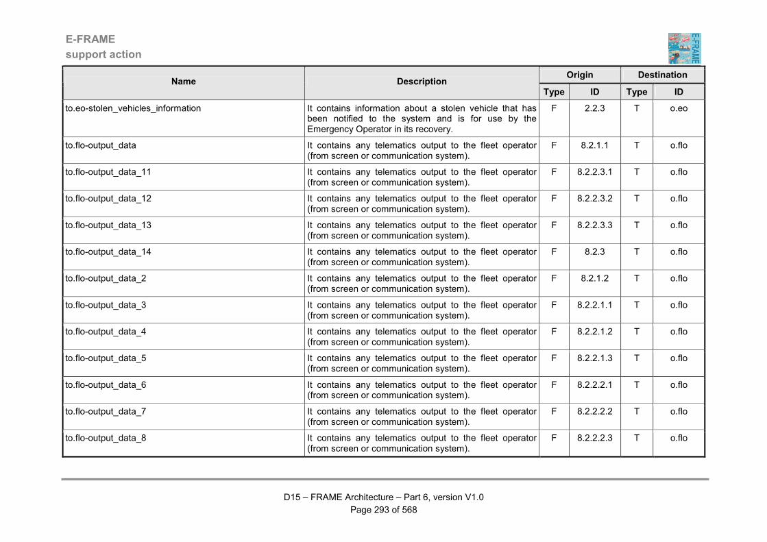
E-FRAME
support action
D15 – FRAME Architecture – Part 6, version V1.0
Page 293 of 568
Origin Destination Name Description
Type ID Type ID
to.eo-stolen_vehicles_information It contains information about a stolen vehicle that has been notified to the system and is for use by the Emergency Operator in its recovery.
F 2.2.3 T o.eo
to.flo-output_data It contains any telematics output to the fleet operator (from screen or communication system).
F 8.2.1.1 T o.flo
to.flo-output_data_11 It contains any telematics output to the fleet operator (from screen or communication system).
F 8.2.2.3.1 T o.flo
to.flo-output_data_12 It contains any telematics output to the fleet operator (from screen or communication system).
F 8.2.2.3.2 T o.flo
to.flo-output_data_13 It contains any telematics output to the fleet operator (from screen or communication system).
F 8.2.2.3.3 T o.flo
to.flo-output_data_14 It contains any telematics output to the fleet operator (from screen or communication system).
F 8.2.3 T o.flo
to.flo-output_data_2 It contains any telematics output to the fleet operator (from screen or communication system).
F 8.2.1.2 T o.flo
to.flo-output_data_3 It contains any telematics output to the fleet operator (from screen or communication system).
F 8.2.2.1.1 T o.flo
to.flo-output_data_4 It contains any telematics output to the fleet operator (from screen or communication system).
F 8.2.2.1.2 T o.flo
to.flo-output_data_5 It contains any telematics output to the fleet operator (from screen or communication system).
F 8.2.2.1.3 T o.flo
to.flo-output_data_6 It contains any telematics output to the fleet operator (from screen or communication system).
F 8.2.2.2.1 T o.flo
to.flo-output_data_7 It contains any telematics output to the fleet operator (from screen or communication system).
F 8.2.2.2.2 T o.flo
to.flo-output_data_8 It contains any telematics output to the fleet operator (from screen or communication system).
F 8.2.2.2.3 T o.flo

E-FRAME
support action
D15 – FRAME Architecture – Part 6, version V1.0
Page 294 of 568
Origin Destination Name Description
Type ID Type ID
to.flo-output_data_9 It contains any telematics output to the fleet operator (from screen or communication system).
F 8.2.2.2.6 T o.flo
to.flo-rest_area_booking_details It contains details of a rest area booking that has been made and is being sent to the Fleet Operator.
F 3.1.5.9 T o.flo
to.flo-un/loading_zone_booking_details It contains details of the un/loading zone bookings that have been made by a Heavy Goods Vehicle Driver and are being provided to the Fleet Operator.
F 9.5.7 T o.flo
to.fro-additional_data_needed_for_evaluation It contains a request for the Freight Management Operator to provide the specified additional data that is needed for the freight operation evaluation that was previously requested.
F 8.1.6 T o.fro
to.fro-approve_hazardous_goods_transport_request It contains a request to the Freight Management Operator to give approval for the Law Enforcement Agency to be asked to approve the movement of hazardous goods as part of a freight operation.
F 8.1.2.7 T o.fro
to.fro-customs_declaration_requested It contains details of the request that has been made for a customs declaration to be obtained.
F 8.1.2.7 T o.fro
to.fro-customs_declaration_request_response It contains details of the result of the request to the Law Enforcement Agency for the processing of a customs declaration.
F 8.1.2.7 T o.fro
to.fro-fleet_operator_data It contains information that is being output to the Freight Management Operator about the Fleet Operator that has been selected to receive a contract to move some freight.
F 8.1.1.7 T o.fro
to.fro-freight_operation_data_preparation_request It contains a request for the Freight Management Operator to approve the request to prepare all that is need for the freight operation to take place.
F 8.1.2.7 T o.fro
to.fro-freight_transport_management_data It contains data about the administration of freight transport requests for use by the Freight Management Operator.
F 8.1.1.7 T o.fro
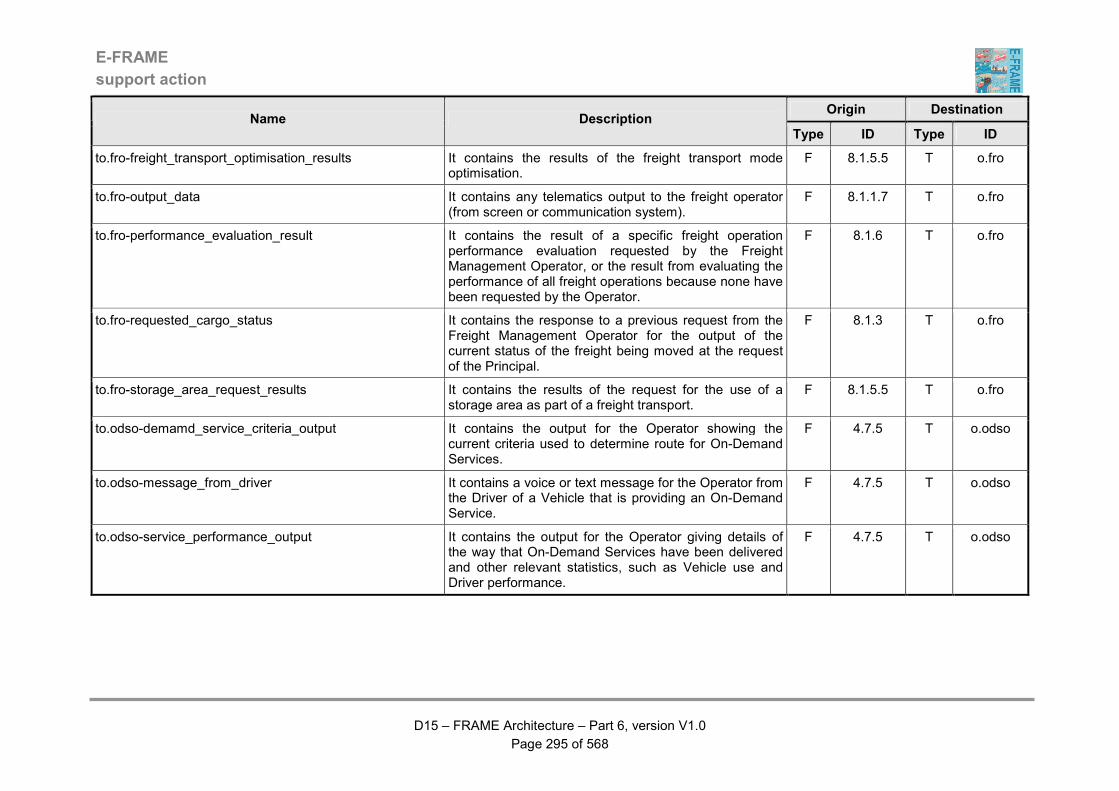
E-FRAME
support action
D15 – FRAME Architecture – Part 6, version V1.0
Page 295 of 568
Origin Destination Name Description
Type ID Type ID
to.fro-freight_transport_optimisation_results It contains the results of the freight transport mode optimisation.
F 8.1.5.5 T o.fro
to.fro-output_data It contains any telematics output to the freight operator (from screen or communication system).
F 8.1.1.7 T o.fro
to.fro-performance_evaluation_result It contains the result of a specific freight operation performance evaluation requested by the Freight Management Operator, or the result from evaluating the performance of all freight operations because none have been requested by the Operator.
F 8.1.6 T o.fro
to.fro-requested_cargo_status It contains the response to a previous request from the Freight Management Operator for the output of the current status of the freight being moved at the request of the Principal.
F 8.1.3 T o.fro
to.fro-storage_area_request_results It contains the results of the request for the use of a storage area as part of a freight transport.
F 8.1.5.5 T o.fro
to.odso-demamd_service_criteria_output It contains the output for the Operator showing the current criteria used to determine route for On-Demand Services.
F 4.7.5 T o.odso
to.odso-message_from_driver It contains a voice or text message for the Operator from the Driver of a Vehicle that is providing an On-Demand Service.
F 4.7.5 T o.odso
to.odso-service_performance_output It contains the output for the Operator giving details of the way that On-Demand Services have been delivered and other relevant statistics, such as Vehicle use and Driver performance.
F 4.7.5 T o.odso

E-FRAME
support action
D15 – FRAME Architecture – Part 6, version V1.0
Page 296 of 568
Origin Destination Name Description
Type ID Type ID
to.ov-lane_use_commands It contains commands for the Other Vehicle concerning lane use that the Host Vehicle has received that may be relevant to the Other Vehicle. The identity of the Host Vehicle will be included in the data so that the Other Vehicle knows from which Vehicle in the lane use commands were sent.
F 5.12.10 T v.ov
to.po-carpark_current_data It contains the output to the Parking Operator of the current occupancy and/or status of one or more car parks.
F 3.1.4.7 T o.po
to.po-carpark_payment_records It contains the output to the Parking Operator of all the car park payment transactions.
F 3.1.4.7 T o.po
to.po-carpark_static_data It contains output to the Parking Operator of the static data that is currently stored in the Car Park Data Store about one or more car parks.
F 3.1.4.7 T o.po
to.po-carpark_status_overrride_response It contains the response to the previous request from the Parking Operator for a current car park status to be overridden.
F 3.1.4.7 T o.po
to.po-confirm_rest_area_booking It contains a request for the Parking Operator to confirm the booking that is being made for the use of a parking space in a rest area that is part of a service area.
F 3.1.5.4 T o.po
to.po-service_area_current_data It contains the current occupancy and/or status of one or more service areas that is being output to the Parking Operator.
F 3.1.5.4 T o.po
to.po-service_area_static_data It contains output to the Parking Operator of the static data of one or more service areas that is currently stored in the Service Area Data Store.
F 3.1.5.4 T o.po
to.po-service_area_status_overrride_response It contains the response to the previous request from the Parking Operator for a current service area status to be overridden.
F 3.1.5.4 T o.po
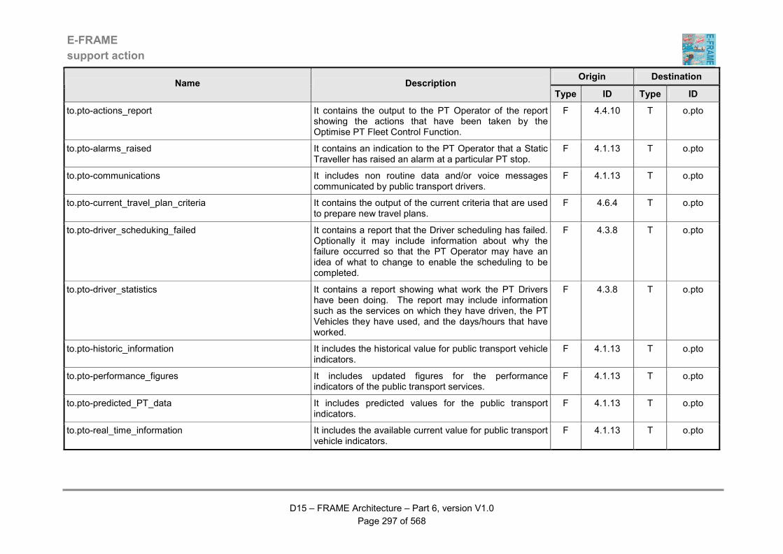
E-FRAME
support action
D15 – FRAME Architecture – Part 6, version V1.0
Page 297 of 568
Origin Destination Name Description
Type ID Type ID
to.pto-actions_report It contains the output to the PT Operator of the report showing the actions that have been taken by the Optimise PT Fleet Control Function.
F 4.4.10 T o.pto
to.pto-alarms_raised It contains an indication to the PT Operator that a Static Traveller has raised an alarm at a particular PT stop.
F 4.1.13 T o.pto
to.pto-communications It includes non routine data and/or voice messages communicated by public transport drivers.
F 4.1.13 T o.pto
to.pto-current_travel_plan_criteria It contains the output of the current criteria that are used to prepare new travel plans.
F 4.6.4 T o.pto
to.pto-driver_scheduking_failed It contains a report that the Driver scheduling has failed. Optionally it may include information about why the failure occurred so that the PT Operator may have an idea of what to change to enable the scheduling to be completed.
F 4.3.8 T o.pto
to.pto-driver_statistics It contains a report showing what work the PT Drivers have been doing. The report may include information such as the services on which they have driven, the PT Vehicles they have used, and the days/hours that have worked.
F 4.3.8 T o.pto
to.pto-historic_information It includes the historical value for public transport vehicle indicators.
F 4.1.13 T o.pto
to.pto-performance_figures It includes updated figures for the performance indicators of the public transport services.
F 4.1.13 T o.pto
to.pto-predicted_PT_data It includes predicted values for the public transport indicators.
F 4.1.13 T o.pto
to.pto-real_time_information It includes the available current value for public transport vehicle indicators.
F 4.1.13 T o.pto
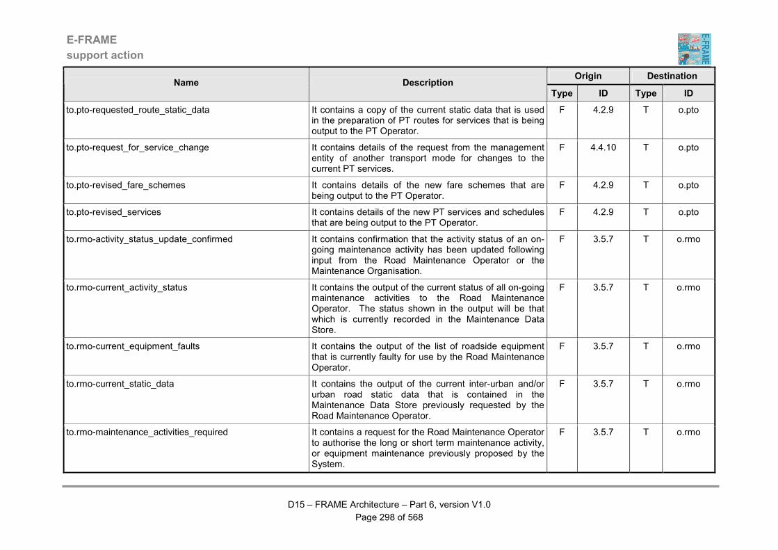
E-FRAME
support action
D15 – FRAME Architecture – Part 6, version V1.0
Page 298 of 568
Origin Destination Name Description
Type ID Type ID
to.pto-requested_route_static_data It contains a copy of the current static data that is used in the preparation of PT routes for services that is being output to the PT Operator.
F 4.2.9 T o.pto
to.pto-request_for_service_change It contains details of the request from the management entity of another transport mode for changes to the current PT services.
F 4.4.10 T o.pto
to.pto-revised_fare_schemes It contains details of the new fare schemes that are being output to the PT Operator.
F 4.2.9 T o.pto
to.pto-revised_services It contains details of the new PT services and schedules that are being output to the PT Operator.
F 4.2.9 T o.pto
to.rmo-activity_status_update_confirmed It contains confirmation that the activity status of an on-going maintenance activity has been updated following input from the Road Maintenance Operator or the Maintenance Organisation.
F 3.5.7 T o.rmo
to.rmo-current_activity_status It contains the output of the current status of all on-going maintenance activities to the Road Maintenance Operator. The status shown in the output will be that which is currently recorded in the Maintenance Data Store.
F 3.5.7 T o.rmo
to.rmo-current_equipment_faults It contains the output of the list of roadside equipment that is currently faulty for use by the Road Maintenance Operator.
F 3.5.7 T o.rmo
to.rmo-current_static_data It contains the output of the current inter-urban and/or urban road static data that is contained in the Maintenance Data Store previously requested by the Road Maintenance Operator.
F 3.5.7 T o.rmo
to.rmo-maintenance_activities_required It contains a request for the Road Maintenance Operator to authorise the long or short term maintenance activity, or equipment maintenance previously proposed by the System.
F 3.5.7 T o.rmo
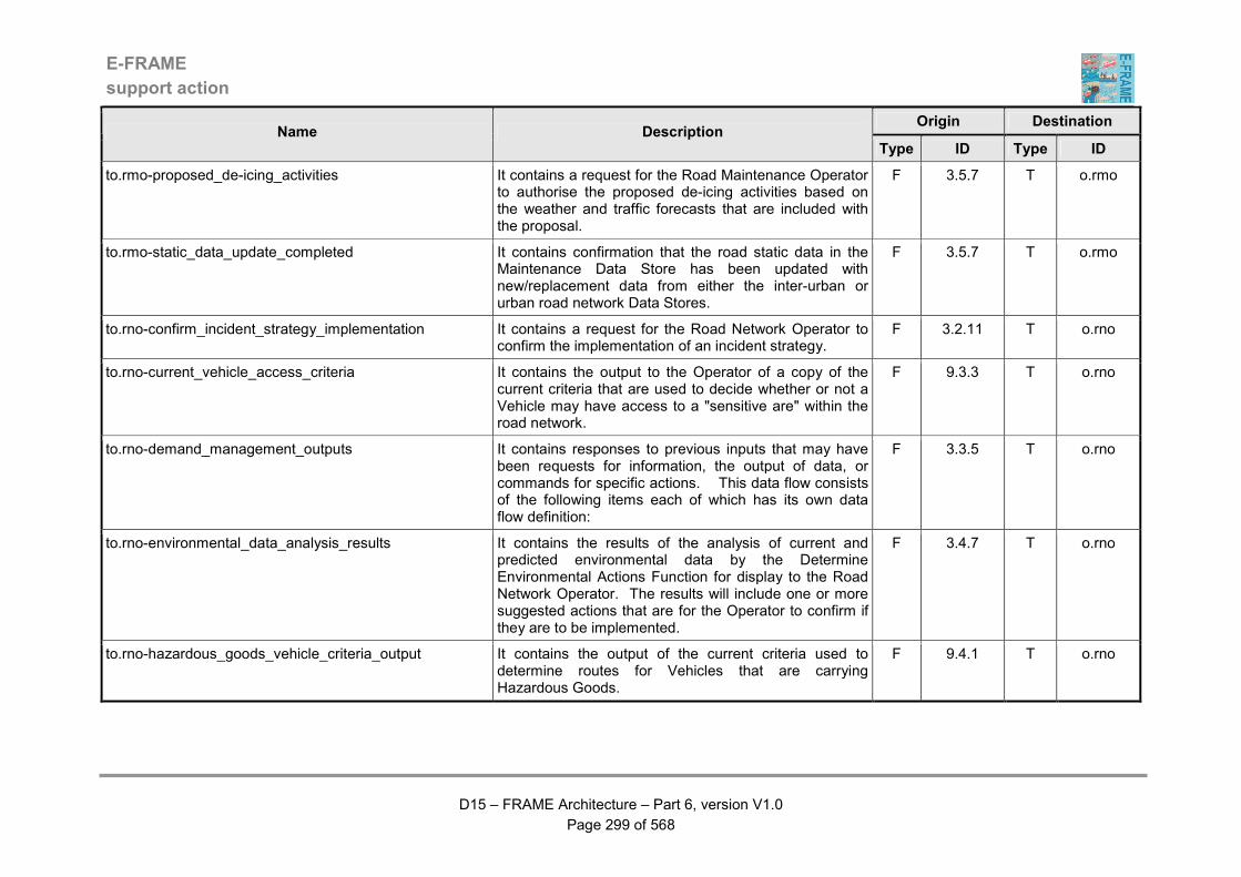
E-FRAME
support action
D15 – FRAME Architecture – Part 6, version V1.0
Page 299 of 568
Origin Destination Name Description
Type ID Type ID
to.rmo-proposed_de-icing_activities It contains a request for the Road Maintenance Operator to authorise the proposed de-icing activities based on the weather and traffic forecasts that are included with the proposal.
F 3.5.7 T o.rmo
to.rmo-static_data_update_completed It contains confirmation that the road static data in the Maintenance Data Store has been updated with new/replacement data from either the inter-urban or urban road network Data Stores.
F 3.5.7 T o.rmo
to.rno-confirm_incident_strategy_implementation It contains a request for the Road Network Operator to confirm the implementation of an incident strategy.
F 3.2.11 T o.rno
to.rno-current_vehicle_access_criteria It contains the output to the Operator of a copy of the current criteria that are used to decide whether or not a Vehicle may have access to a "sensitive are" within the road network.
F 9.3.3 T o.rno
to.rno-demand_management_outputs It contains responses to previous inputs that may have been requests for information, the output of data, or commands for specific actions. This data flow consists of the following items each of which has its own data flow definition:
F 3.3.5 T o.rno
to.rno-environmental_data_analysis_results It contains the results of the analysis of current and predicted environmental data by the Determine Environmental Actions Function for display to the Road Network Operator. The results will include one or more suggested actions that are for the Operator to confirm if they are to be implemented.
F 3.4.7 T o.rno
to.rno-hazardous_goods_vehicle_criteria_output It contains the output of the current criteria used to determine routes for Vehicles that are carrying Hazardous Goods.
F 9.4.1 T o.rno
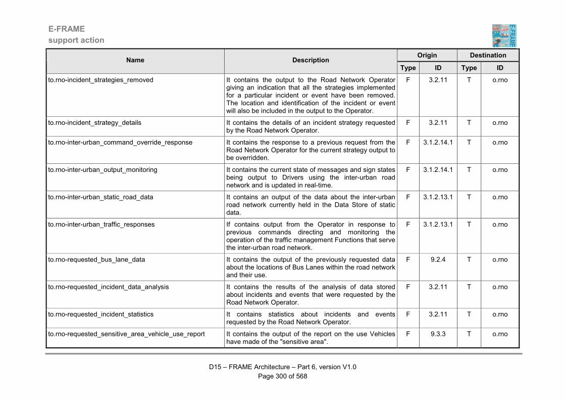
E-FRAME
support action
D15 – FRAME Architecture – Part 6, version V1.0
Page 300 of 568
Origin Destination Name Description
Type ID Type ID
to.rno-incident_strategies_removed It contains the output to the Road Network Operator giving an indication that all the strategies implemented for a particular incident or event have been removed. The location and identification of the incident or event will also be included in the output to the Operator.
F 3.2.11 T o.rno
to.rno-incident_strategy_details It contains the details of an incident strategy requested by the Road Network Operator.
F 3.2.11 T o.rno
to.rno-inter-urban_command_override_response It contains the response to a previous request from the Road Network Operator for the current strategy output to be overridden.
F 3.1.2.14.1 T o.rno
to.rno-inter-urban_output_monitoring It contains the current state of messages and sign states being output to Drivers using the inter-urban road network and is updated in real-time.
F 3.1.2.14.1 T o.rno
to.rno-inter-urban_static_road_data It contains an output of the data about the inter-urban road network currently held in the Data Store of static data.
F 3.1.2.13.1 T o.rno
to.rno-inter-urban_traffic_responses If contains output from the Operator in response to previous commands directing and monitoring the operation of the traffic management Functions that serve the inter-urban road network.
F 3.1.2.13.1 T o.rno
to.rno-requested_bus_lane_data It contains the output of the previously requested data about the locations of Bus Lanes within the road network and their use.
F 9.2.4 T o.rno
to.rno-requested_incident_data_analysis It contains the results of the analysis of data stored about incidents and events that were requested by the Road Network Operator.
F 3.2.11 T o.rno
to.rno-requested_incident_statistics It contains statistics about incidents and events requested by the Road Network Operator.
F 3.2.11 T o.rno
to.rno-requested_sensitive_area_vehicle_use_report It contains the output of the report on the use Vehicles have made of the "sensitive area".
F 9.3.3 T o.rno
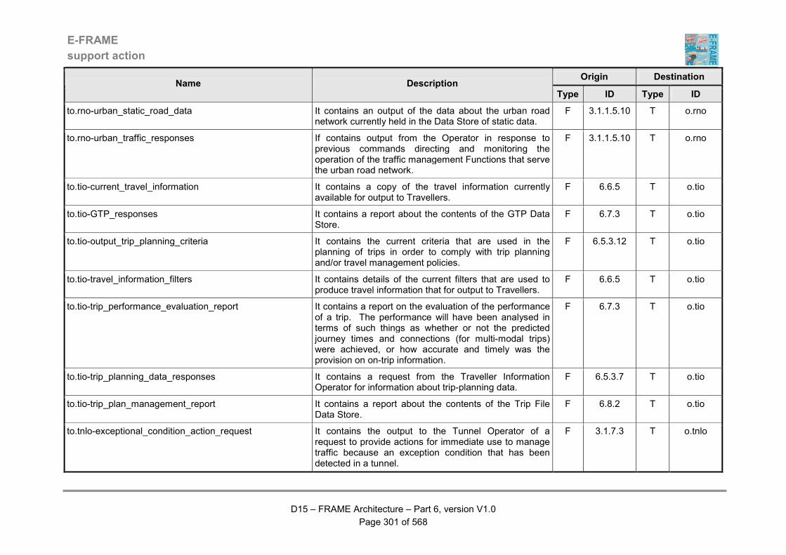
E-FRAME
support action
D15 – FRAME Architecture – Part 6, version V1.0
Page 301 of 568
Origin Destination Name Description
Type ID Type ID
to.rno-urban_static_road_data It contains an output of the data about the urban road network currently held in the Data Store of static data.
F 3.1.1.5.10 T o.rno
to.rno-urban_traffic_responses If contains output from the Operator in response to previous commands directing and monitoring the operation of the traffic management Functions that serve the urban road network.
F 3.1.1.5.10 T o.rno
to.tio-current_travel_information It contains a copy of the travel information currently available for output to Travellers.
F 6.6.5 T o.tio
to.tio-GTP_responses It contains a report about the contents of the GTP Data Store.
F 6.7.3 T o.tio
to.tio-output_trip_planning_criteria It contains the current criteria that are used in the planning of trips in order to comply with trip planning and/or travel management policies.
F 6.5.3.12 T o.tio
to.tio-travel_information_filters It contains details of the current filters that are used to produce travel information that for output to Travellers.
F 6.6.5 T o.tio
to.tio-trip_performance_evaluation_report It contains a report on the evaluation of the performance of a trip. The performance will have been analysed in terms of such things as whether or not the predicted journey times and connections (for multi-modal trips) were achieved, or how accurate and timely was the provision on on-trip information.
F 6.7.3 T o.tio
to.tio-trip_planning_data_responses It contains a request from the Traveller Information Operator for information about trip-planning data.
F 6.5.3.7 T o.tio
to.tio-trip_plan_management_report It contains a report about the contents of the Trip File Data Store.
F 6.8.2 T o.tio
to.tnlo-exceptional_condition_action_request It contains the output to the Tunnel Operator of a request to provide actions for immediate use to manage traffic because an exception condition that has been detected in a tunnel.
F 3.1.7.3 T o.tnlo
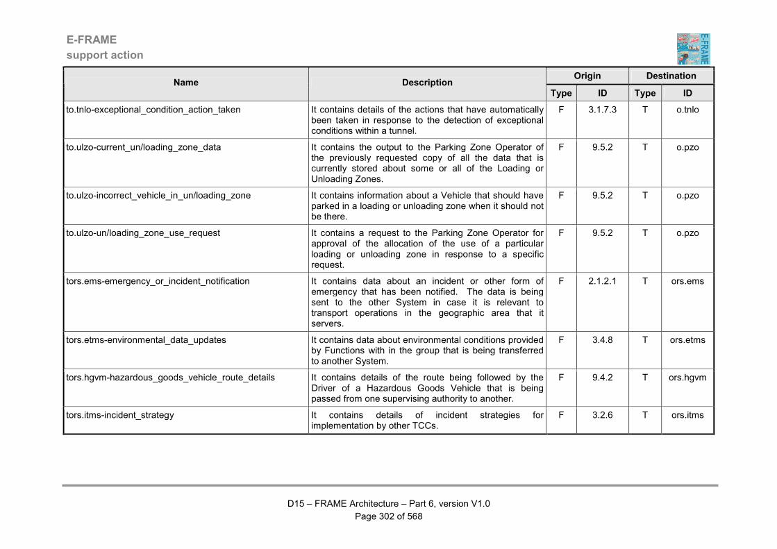
E-FRAME
support action
D15 – FRAME Architecture – Part 6, version V1.0
Page 302 of 568
Origin Destination Name Description
Type ID Type ID
to.tnlo-exceptional_condition_action_taken It contains details of the actions that have automatically been taken in response to the detection of exceptional conditions within a tunnel.
F 3.1.7.3 T o.tnlo
to.ulzo-current_un/loading_zone_data It contains the output to the Parking Zone Operator of the previously requested copy of all the data that is currently stored about some or all of the Loading or Unloading Zones.
F 9.5.2 T o.pzo
to.ulzo-incorrect_vehicle_in_un/loading_zone It contains information about a Vehicle that should have parked in a loading or unloading zone when it should not be there.
F 9.5.2 T o.pzo
to.ulzo-un/loading_zone_use_request It contains a request to the Parking Zone Operator for approval of the allocation of the use of a particular loading or unloading zone in response to a specific request.
F 9.5.2 T o.pzo
tors.ems-emergency_or_incident_notification It contains data about an incident or other form of emergency that has been notified. The data is being sent to the other System in case it is relevant to transport operations in the geographic area that it servers.
F 2.1.2.1 T ors.ems
tors.etms-environmental_data_updates It contains data about environmental conditions provided by Functions with in the group that is being transferred to another System.
F 3.4.8 T ors.etms
tors.hgvm-hazardous_goods_vehicle_route_details It contains details of the route being followed by the Driver of a Hazardous Goods Vehicle that is being passed from one supervising authority to another.
F 9.4.2 T ors.hgvm
tors.itms-incident_strategy It contains details of incident strategies for implementation by other TCCs.
F 3.2.6 T ors.itms
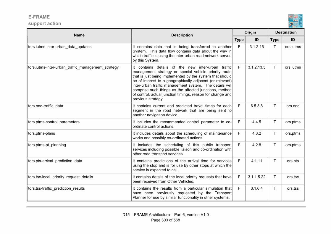
E-FRAME
support action
D15 – FRAME Architecture – Part 6, version V1.0
Page 303 of 568
Origin Destination Name Description
Type ID Type ID
tors.iutms-inter-urban_data_updates It contains data that is being transferred to another System. This data flow contains data about the way in which traffic is using the inter-urban road network served by this System.
F 3.1.2.16 T ors.iutms
tors.iutms-inter-urban_traffic_management_strategy It contains details of the new inter-urban traffic management strategy or special vehicle priority route that is just being implemented by the system that should be of interest to a geographically adjacent (or relevant) inter-urban traffic management system. The details will comprise such things as the affected junctions, method of control, actual junction timings, reason for change and previous strategy.
F 3.1.2.13.5 T ors.iutms
tors.ond-traffic_data It contains current and predicted travel times for each segment in the road network that are being sent to another navigation device.
F 6.5.3.8 T ors.ond
tors.ptms-control_parameters It includes the recommended control parameter to co-ordinate control actions.
F 4.4.5 T ors.ptms
tors.ptms-plans It includes details about the scheduling of maintenance works and possibly co-ordinated actions.
F 4.3.2 T ors.ptms
tors.ptms-pt_planning It includes the scheduling of this public transport services including possible liaison and co-ordination with other road transport services.
F 4.2.8 T ors.ptms
tors.pts-arrival_prediction_data It contains predictions of the arrival time for services using the stop and is for use by other stops at which the service is expected to call.
F 4.1.11 T ors.pts
tors.tsc-local_priority_request_details It contains details of the local priority requests that have been received from Other Vehicles.
F 3.1.1.5.22 T ors.tsc
tors.tss-traffic_prediction_results It contains the results from a particular simulation that have been previously requested by the Transport Planner for use by similar functionality in other systems.
F 3.1.6.4 T ors.tss
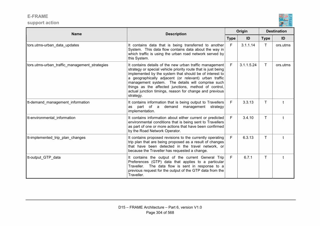
E-FRAME
support action
D15 – FRAME Architecture – Part 6, version V1.0
Page 304 of 568
Origin Destination Name Description
Type ID Type ID
tors.utms-urban_data_updates It contains data that is being transferred to another System. This data flow contains data about the way in which traffic is using the urban road network served by this System.
F 3.1.1.14 T ors.utms
tors.utms-urban_traffic_management_strategies It contains details of the new urban traffic management strategy or special vehicle priority route that is just being implemented by the system that should be of interest to a geographically adjacent (or relevant) urban traffic management system. The details will comprise such things as the affected junctions, method of control, actual junction timings, reason for change and previous strategy.
F 3.1.1.5.24 T ors.utms
tt-demand_management_information It contains information that is being output to Travellers as part of a demand management strategy implementation.
F 3.3.13 T t
tt-environmental_information It contains information about either current or predicted environmental conditions that is being sent to Travellers as part of one or more actions that have been confirmed by the Road Network Operator.
F 3.4.10 T t
tt-implemented_trip_plan_changes It contains proposed revisions to the currently operating trip plan that are being proposed as a result of changes that have been detected in the travel network, or because the Traveller has requested a change.
F 6.3.13 T t
tt-output_GTP_data It contains the output of the current General Trip Preferences (GTP) data that applies to a particular Traveller. The data flow is sent in response to a previous request for the output of the GTP data from the Traveller.
F 6.7.1 T t
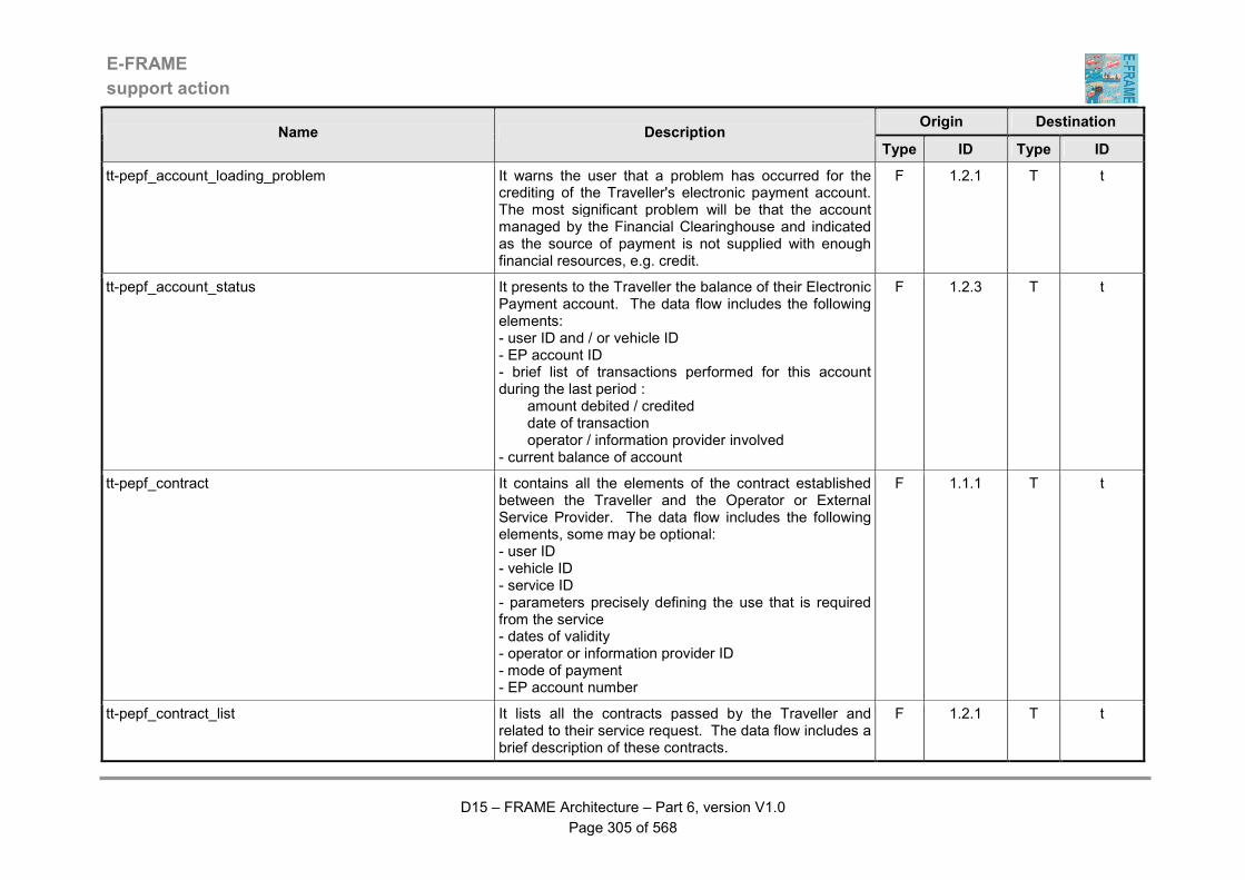
E-FRAME
support action
D15 – FRAME Architecture – Part 6, version V1.0
Page 305 of 568
Origin Destination Name Description
Type ID Type ID
tt-pepf_account_loading_problem It warns the user that a problem has occurred for the crediting of the Traveller's electronic payment account. The most significant problem will be that the account managed by the Financial Clearinghouse and indicated as the source of payment is not supplied with enough financial resources, e.g. credit.
F 1.2.1 T t
tt-pepf_account_status It presents to the Traveller the balance of their Electronic Payment account. The data flow includes the following elements: - user ID and / or vehicle ID - EP account ID - brief list of transactions performed for this account during the last period : amount debited / credited date of transaction operator / information provider involved - current balance of account
F 1.2.3 T t
tt-pepf_contract It contains all the elements of the contract established between the Traveller and the Operator or External Service Provider. The data flow includes the following elements, some may be optional: - user ID - vehicle ID - service ID - parameters precisely defining the use that is required from the service - dates of validity - operator or information provider ID - mode of payment - EP account number
F 1.1.1 T t
tt-pepf_contract_list It lists all the contracts passed by the Traveller and related to their service request. The data flow includes a brief description of these contracts.
F 1.2.1 T t
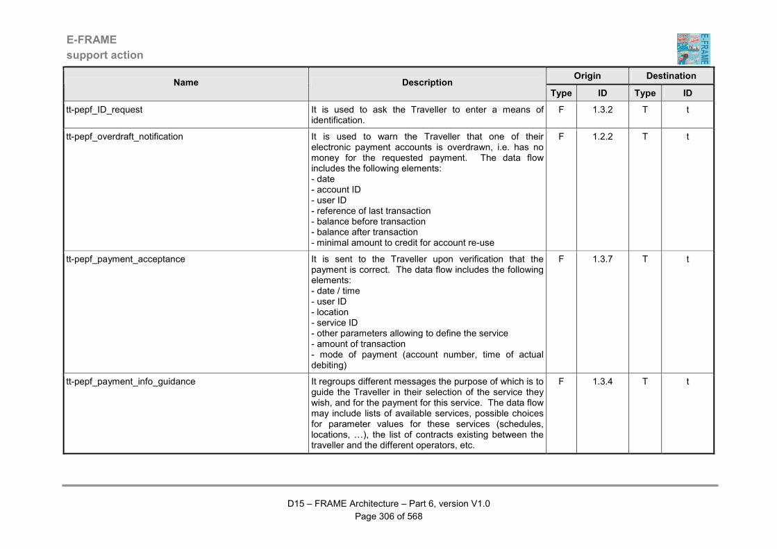
E-FRAME
support action
D15 – FRAME Architecture – Part 6, version V1.0
Page 306 of 568
Origin Destination Name Description
Type ID Type ID
tt-pepf_ID_request It is used to ask the Traveller to enter a means of identification.
F 1.3.2 T t
tt-pepf_overdraft_notification It is used to warn the Traveller that one of their electronic payment accounts is overdrawn, i.e. has no money for the requested payment. The data flow includes the following elements: - date - account ID - user ID - reference of last transaction - balance before transaction - balance after transaction - minimal amount to credit for account re-use
F 1.2.2 T t
tt-pepf_payment_acceptance It is sent to the Traveller upon verification that the payment is correct. The data flow includes the following elements: - date / time - user ID - location - service ID - other parameters allowing to define the service - amount of transaction - mode of payment (account number, time of actual debiting)
F 1.3.7 T t
tt-pepf_payment_info_guidance It regroups different messages the purpose of which is to guide the Traveller in their selection of the service they wish, and for the payment for this service. The data flow may include lists of available services, possible choices for parameter values for these services (schedules, locations, …), the list of contracts existing between the traveller and the different operators, etc.
F 1.3.4 T t
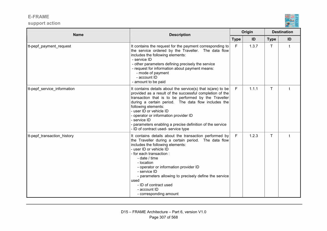
E-FRAME
support action
D15 – FRAME Architecture – Part 6, version V1.0
Page 307 of 568
Origin Destination Name Description
Type ID Type ID
tt-pepf_payment_request It contains the request for the payment corresponding to the service ordered by the Traveller. The data flow includes the following elements: - service ID - other parameters defining precisely the service - request for information about payment means: - mode of payment - account ID - amount to be paid
F 1.3.7 T t
tt-pepf_service_information It contains details about the service(s) that is(are) to be provided as a result of the successful completion of the transaction that is to be performed by the Traveller during a certain period. The data flow includes the following elements: - user ID or vehicle ID - operator or information provider ID - service ID - parameters enabling a precise definition of the service - ID of contract used- service type
F 1.1.1 T t
tt-pepf_transaction_history It contains details about the transaction performed by the Traveller during a certain period. The data flow includes the following elements: - user ID or vehicle ID - for each transaction : - date / time - location - operator or information provider ID - service ID - parameters allowing to precisely define the service used - ID of contract used - account ID - corresponding amount
F 1.2.3 T t
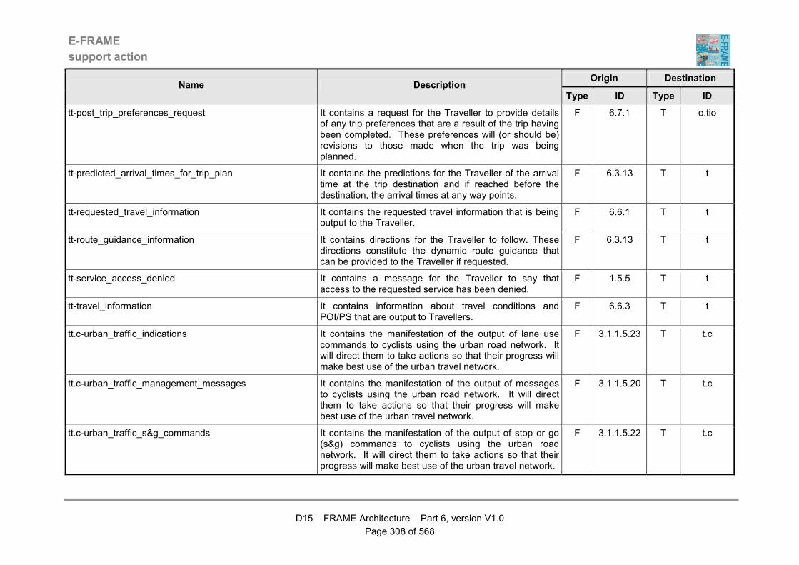
E-FRAME
support action
D15 – FRAME Architecture – Part 6, version V1.0
Page 308 of 568
Origin Destination Name Description
Type ID Type ID
tt-post_trip_preferences_request It contains a request for the Traveller to provide details of any trip preferences that are a result of the trip having been completed. These preferences will (or should be) revisions to those made when the trip was being planned.
F 6.7.1 T o.tio
tt-predicted_arrival_times_for_trip_plan It contains the predictions for the Traveller of the arrival time at the trip destination and if reached before the destination, the arrival times at any way points.
F 6.3.13 T t
tt-requested_travel_information It contains the requested travel information that is being output to the Traveller.
F 6.6.1 T t
tt-route_guidance_information It contains directions for the Traveller to follow. These directions constitute the dynamic route guidance that can be provided to the Traveller if requested.
F 6.3.13 T t
tt-service_access_denied It contains a message for the Traveller to say that access to the requested service has been denied.
F 1.5.5 T t
tt-travel_information It contains information about travel conditions and POI/PS that are output to Travellers.
F 6.6.3 T t
tt.c-urban_traffic_indications It contains the manifestation of the output of lane use commands to cyclists using the urban road network. It will direct them to take actions so that their progress will make best use of the urban travel network.
F 3.1.1.5.23 T t.c
tt.c-urban_traffic_management_messages It contains the manifestation of the output of messages to cyclists using the urban road network. It will direct them to take actions so that their progress will make best use of the urban travel network.
F 3.1.1.5.20 T t.c
tt.c-urban_traffic_s&g_commands It contains the manifestation of the output of stop or go (s&g) commands to cyclists using the urban road network. It will direct them to take actions so that their progress will make best use of the urban travel network.
F 3.1.1.5.22 T t.c
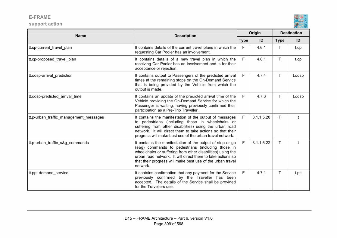
E-FRAME
support action
D15 – FRAME Architecture – Part 6, version V1.0
Page 309 of 568
Origin Destination Name Description
Type ID Type ID
tt.cp-current_travel_plan It contains details of the current travel plans in which the requesting Car Pooler has an involvement.
F 4.6.1 T t.cp
tt.cp-proposed_travel_plan It contains details of a new travel plan in which the receiving Car Pooler has an involvement and is for their acceptance or rejection.
F 4.6.1 T t.cp
tt.odsp-arrival_prediction It contains output to Passengers of the predicted arrival times at the remaining stops on the On-Demand Service that is being provided by the Vehicle from which the output is made.
F 4.7.4 T t.odsp
tt.odsp-predicted_arrival_time It contains an update of the predicted arrival time of the Vehicle providing the On-Demand Service for which the Passenger is waiting, having previously confirmed their participation as a Pre-Trip Traveller.
F 4.7.3 T t.odsp
tt.p-urban_traffic_management_messages It contains the manifestation of the output of messages to pedestrians (including those in wheelchairs or suffering from other disabilities) using the urban road network. It will direct them to take actions so that their progress will make best use of the urban travel network.
F 3.1.1.5.20 T t
tt.p-urban_traffic_s&g_commands It contains the manifestation of the output of stop or go (s&g) commands to pedestrians (including those in wheelchairs or suffering from other disabilities) using the urban road network. It will direct them to take actions so that their progress will make best use of the urban travel network.
F 3.1.1.5.22 T t
tt.ppt-demand_service It contains confirmation that any payment for the Service previously confirmed by the Traveller has been accepted. The details of the Service shall be provided for the Travellers use.
F 4.7.1 T t.ptt

E-FRAME
support action
D15 – FRAME Architecture – Part 6, version V1.0
Page 310 of 568
Origin Destination Name Description
Type ID Type ID
tt.ppt-proposed_demand_service It contains details of an On-Demand Service that has been created in response to a previous request from a Traveller. Details such as times of arrival and departure, route to be followed, use of other transport modes, type of Vehicle to be used and cost shall be included.
F 4.7.1 T t.ptt
tt.ptp-confirm_fare_credit_update It contains confirmation for the PT Passenger that their requested update of the credit on their fare card has been completed successfully.
F 4.5.3 T t.ptp
tt.ptp-display_current_fare_credit It contains the current level of credit available from the fare card belonging to the PT Passenger that requested its output.
F 4.5.3 T t.ptp
tt.ptp-fare_credit_after_journey It contains an indication for the PT Passenger of the amount of credit remaining on the fare card following payment for the current journey.
F 4.5.2 T t.ptp
tt.ptp-journey_fare_cost It contains output for the PT Passenger of the cost of the proposed journey.
F 4.5.2 T t.ptp
tt.ptp-no_fare_credit_for_journey It contains an indication for the PT Passenger that there is insufficient credit available on their fare card for the journey that they are proposing to make.
F 4.5.2 T t.ptp
tt.ptp-ok_to_travel It contains an indication that for the PT Passenger that the cost of the current journey has been successfully deducted from the credit on the fare card. The PT Passenger can therefore complete the journey.
F 4.5.2 T t.ptp
tt.ptp-passenger_emergency_response It contains the response to a previous emergency occurrence notification that has been received from a Public Transport Passenger.
F 4.1.14 T t.ptp
tt.ptp-predicted_PT_information It includes predicted values for the public transport indicators (e.g. arrival time, delays, etc) communicated via dedicated devices (e.g. on-board at spot displays).
F 4.1.9 T t.ptp
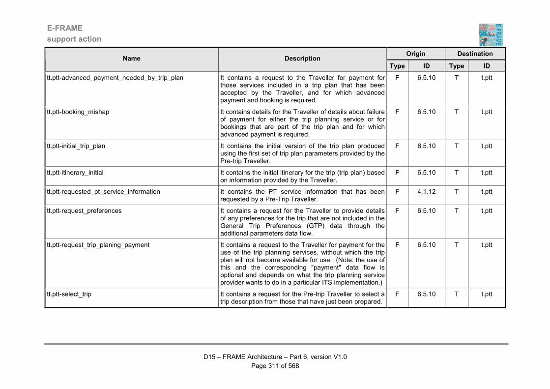
E-FRAME
support action
D15 – FRAME Architecture – Part 6, version V1.0
Page 311 of 568
Origin Destination Name Description
Type ID Type ID
tt.ptt-advanced_payment_needed_by_trip_plan It contains a request to the Traveller for payment for those services included in a trip plan that has been accepted by the Traveller, and for which advanced payment and booking is required.
F 6.5.10 T t.ptt
tt.ptt-booking_mishap It contains details for the Traveller of details about failure of payment for either the trip planning service or for bookings that are part of the trip plan and for which advanced payment is required.
F 6.5.10 T t.ptt
tt.ptt-initial_trip_plan It contains the initial version of the trip plan produced using the first set of trip plan parameters provided by the Pre-trip Traveller.
F 6.5.10 T t.ptt
tt.ptt-itinerary_initial It contains the initial itinerary for the trip (trip plan) based on information provided by the Traveller.
F 6.5.10 T t.ptt
tt.ptt-requested_pt_service_information It contains the PT service information that has been requested by a Pre-Trip Traveller.
F 4.1.12 T t.ptt
tt.ptt-request_preferences It contains a request for the Traveller to provide details of any preferences for the trip that are not included in the General Trip Preferences (GTP) data through the additional parameters data flow.
F 6.5.10 T t.ptt
tt.ptt-request_trip_planing_payment It contains a request to the Traveller for payment for the use of the trip planning services, without which the trip plan will not become available for use. (Note: the use of this and the corresponding "payment" data flow is optional and depends on what the trip planning service provider wants to do in a particular ITS implementation.)
F 6.5.10 T t.ptt
tt.ptt-select_trip It contains a request for the Pre-trip Traveller to select a trip description from those that have just been prepared.
F 6.5.10 T t.ptt
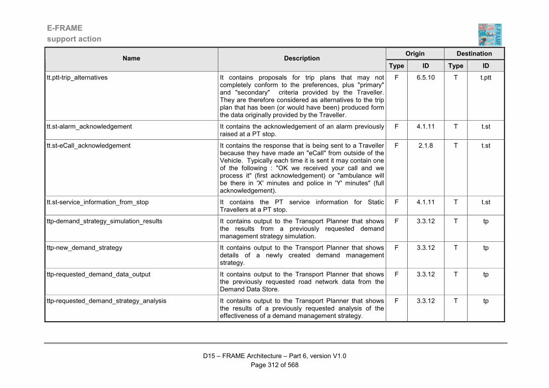
E-FRAME
support action
D15 – FRAME Architecture – Part 6, version V1.0
Page 312 of 568
Origin Destination Name Description
Type ID Type ID
tt.ptt-trip_alternatives It contains proposals for trip plans that may not completely conform to the preferences, plus "primary" and "secondary" criteria provided by the Traveller. They are therefore considered as alternatives to the trip plan that has been (or would have been) produced form the data originally provided by the Traveller.
F 6.5.10 T t.ptt
tt.st-alarm_acknowledgement It contains the acknowledgement of an alarm previously raised at a PT stop.
F 4.1.11 T t.st
tt.st-eCall_acknowledgement It contains the response that is being sent to a Traveller because they have made an "eCall" from outside of the Vehicle. Typically each time it is sent it may contain one of the following : "OK we received your call and we process it" (first acknowledgement) or "ambulance will be there in 'X' minutes and police in 'Y' minutes" (full acknowledgement).
F 2.1.8 T t.st
tt.st-service_information_from_stop It contains the PT service information for Static Travellers at a PT stop.
F 4.1.11 T t.st
ttp-demand_strategy_simulation_results It contains output to the Transport Planner that shows the results from a previously requested demand management strategy simulation.
F 3.3.12 T tp
ttp-new_demand_strategy It contains output to the Transport Planner that shows details of a newly created demand management strategy.
F 3.3.12 T tp
ttp-requested_demand_data_output It contains output to the Transport Planner that shows the previously requested road network data from the Demand Data Store.
F 3.3.12 T tp
ttp-requested_demand_strategy_analysis It contains output to the Transport Planner that shows the results of a previously requested analysis of the effectiveness of a demand management strategy.
F 3.3.12 T tp
E-FRAME
support action
D15 – FRAME Architecture – Part 6, version V1.0
Page 313 of 568
Origin Destination Name Description
Type ID Type ID
ttp-requested_road_network_data It contains the road network (model) data that has been previously requested by the Transport Planner.
F 3.1.6.5 T tp
ttp-requested_traffic_prediction_results It contains the traffic simulation results that are being sent to similar functionality in other Systems.
F 3.1.6.5 T tp
tv.fv-output_data It contains anything that is needed by this terminator. F 8.3.2.2 T v.fv
tv.hmi-eCall_response This data is used to show the response of the emergency services to a “Mayday Call”.
F 5.11.7 T v.hmi
tv.ov-collision_warning It contains data to be sent to the Other Vehicle to indicate that the possibility of a collision with it has been detected the Host Vehicle, the identity of which is included in the data.
F 5.12.10 T v.ov
tv.ov-emergency_brake_application It contains data from the Host Vehicle (including its identity) to indicate to the Other Vehicle that the Host Vehicle is performing an emergency brake manoeuvre.
F 5.12.10 T v.ov
tv.ov-ghost_driver_warning It contains data about a "non-equipped" Vehicle that has been detected travelling in the wrong direction on the carriageway being used by the Host Vehicle that may be of interest to the Other Vehicle.
F 5.12.10 T v.ov
tv.ov-goods_being_carried It contains data about the goods being carried by the Host Vehicle (including its identity) and is for use by the Other Vehicle.
F 5.12.10 T v.ov
tv.ov-host_vehicle_attitude_for_other_vehicle It contains data about the current attitude of the Host Vehicle (i.e. on its wheels, on its side, upside down, etc.) for use by the Other Vehicle.
F 5.12.10 T v.ov
tv.ov-host_vehicle_location_for_other_vehicle It contains the location of the Host Vehicle that is being sent to the Other Vehicle.
F 5.12.10 T v.ov
tv.ov-lane_changing_warning It contains data from the Host Vehicle (including its identity) indicating it is about to change lanes that is to be sent to the Other Vehicle.
F 5.12.10 T v.ov
E-FRAME
support action
D15 – FRAME Architecture – Part 6, version V1.0
Page 314 of 568
Origin Destination Name Description
Type ID Type ID
tv.ov-lights_anti-glare_request It contains a request to be sent to the Other Vehicle that is approaching the Host Vehicle to indicate that the beams from its headlights are too high and should be dipped. The request will include the identity of the Host Vehicle so that the Other Vehicle can determine which Vehicle is suffering from glare from its headlights.
F 5.12.10 T v.ov
tv.ov-other_platooning_data It contains the data concerned with performing platooning with one or more Vehicles that needs to be sent from the Host Vehicle to the Other Vehicle. The identity of the Host Vehicle will be included in the data so that the Other Vehicle knows from which Vehicle in the platoon the data was sent.
F 5.12.10 T v.ov
tv.ov-overtaking_vehicle_warning It contains data from the Host Vehicle (including its identity) about an overtaking manoeuvre that it is about to make that is for use by the Other Vehicle.
F 5.12.10 T v.ov
tv.ov-red_light_running_warning It contains a warning to the Other Vehicle from the Host Vehicle that it is about to run through a set of traffic signals that will be seen as red by its Driver, i.e. red light running. The warning will include the identity of the Host Vehicle so that the Other Vehicle can determine which Vehicle is red light running if there are several Vehicles that are approaching the same traffic signals.
F 5.12.10 T v.ov
tv.ov-regulations It contains traffic regulations that are available to the Host Vehicle that may be relevant to the Other Vehicle. The identity of the Host Vehicle will be included with the regulations so that the Other Vehicle knows from which Vehicle they were sent.
F 5.12.10 T v.ov
tv.ov-road_information It contains information about the road geometry and layout collected by the Host Vehicle that is being sent to the Other Vehicle. The identity of the Host Vehicle will be included in the information so that the Other Vehicle knows from which Vehicle it was sent.
F 5.12.10 T v.ov
E-FRAME
support action
D15 – FRAME Architecture – Part 6, version V1.0
Page 315 of 568
Origin Destination Name Description
Type ID Type ID
tv.ov-road_surface_state It contains data (including the Vehicle identity) about the road surface state in the local geographic area around the Host Vehicle that is being sent to the Other Vehicle.
F 5.12.10 T v.ov
tv.ov-safety_behaviour It contains information about the safety behaviour of the Host Vehicle (e.g. excessive lane changing or speed, or less than the minimum suggested headway) that is being sent to the Other Vehicle. The identity of the Host Vehicle will be included in the information so that the Other Vehicle knows from which Vehicle it was sent.
F 5.12.10 T v.ov
tv.ov-status_data It contains data concerning the status of the Host Vehicle (e.g. wipers active) and its Driver, as well as data about the road infrastructure where it is located and the Vehicle identity that is being sent to the Other Vehicle.
F 5.12.10 T v.ov
tv.ov-traffic_queue_ahead It contains data about a traffic queue that has been detected by the Host Vehicle and is for use by the Other Vehicle.
F 5.12.10 T v.ov
tv.ov-visibility_data It contains the level of visibility that has been detected by the Host Vehicle and is for use by the Other Vehicle.
F 5.12.10 T v.ov
tv.ptv-commands It includes control commands to be actuated by addressed vehicles.
F 4.4.3 T v.ptv
tv.vs-output_data It contains the data from functions in the Framework Architecture that are needed by various in-vehicle systems (e.g. ISA, and Lane Keeping).
F 5.12.7 T v.vs

E-FRAME
support action
D15 – FRAME Architecture – Part 6, version V1.0
Page 316 of 568
Table 3 - Descriptions of Data Stores
ID Name Description
D1.1 EP Contracts Data
This Data Store shall be used within the Provide Electronic Payments Facilities Area. It shall contain details of the different contracts set up between the users of ITS services and the corresponding operators. The data in the Store shall be structured in the following way: - user ID (number) - ID of organisation with whom user places contract (number) - ID's of services covered by the contract (numbers) - area covered (characters, e.g. nation, region, city, state, area name(s)) - supplementary parameters defining the service (numbers and/or characters) - period of validity (date strings for start and end) - tariffs (optional) (numbers - in currency) - reduction fees (optional) (numbers - in currency) - modes of payment (characters) - EP account ID (optional) (numbers) The Data Store shall enable functions to extract details about current contracts by specifying the user ID, operator ID, service ID.
D1.2 User's Account Data
This Data Store shall be used within the Provide Electronic Payments Facilities Area. It shall contain details of all the accounts used by the users (travellers) for the electronic payment of services. The data in the Store shall be structured in the following way: - user ID (number) - EP account ID's for each user ID (numbers - could be more than one) - supply for each account (characters) - current balance (numbers - currency) - brief history for each account: (characters, but including dates and transaction amounts) - periods of overdraft (date strings) - maximum overdraft reached (number - currency) This data shall be loaded, updated and retrieved by several Functions.
D1.3 Service Information
Data
This Data Store shall be used within the Provide Electronic Payments Facilities Area. It shall contain all the characteristics of the services that are available to the users, including the nature of those services and the identities of the organisations that are providing them.

E-FRAME
support action
D15 – FRAME Architecture – Part 6, version V1.0
Page 317 of 568
ID Name Description
The data in the Store shall be structured in the following way: - service ID (number) - nature of service (characters) - ID of organisation providing the service (number) - associated account, i.e. where the payment will go (characters and/or numbers) - location of service, i.e. where the user can use it (characters, e.g. nation, region, city, state, area) - types of contracts possible (characters) - categories of people allowed to use this service (that is to pass a contract for it, regardless of access rights which are defined by regulating bodies) (characters) - enforcement procedures (characters) - modes of booking (characters) - identification of tariffs (pointer to tariff data store) (numbers) - rules of fee apportionment if several operators provide the same service (characters) - list of the ID's of services grouped for the apportionment (numbers) The data in the Store shall be organised so that data for each service is kept together.
D1.4 Transactions Data
This Data Store shall be used within the Provide Electronic Payments Facilities Area. It shall contain a history all the electronic financial transactions performed by the users (travellers) regarding their use of ITS services. The data in the Store shall be structured the following way: - date of service use (date string) - place of service use (characters, e.g. nation, region, city, state, area names(s)) - service ID (number) - supplementary parameters defining the service (numbers and/or characters) - contract ID (number) - user ID (number) - ID of organisation with whom user places contract (number) - date of payment (date string) - mode of payment (characters) - ID of user's account used (number) - ID of operator's account used (number) - incident notification (characters)
D1.5 Tariffs Data This Data Store shall be used within the Provide Electronic Payments Facilities Area. It shall contain the tariffs of all the services available to the user.
E-FRAME
support action
D15 – FRAME Architecture – Part 6, version V1.0
Page 318 of 568
ID Name Description
The data in the Store shall be structured in the following way: - service ID (number) - characteristics of the precise usage done, for example, duration of service usage, location, date, etc. (characters) - tariff for the characteristic (numbers - in currency) - type of contract (characters) - discount rates (numbers - in currency) The data in the Store shall be organised so that data for each service is kept together. For each service there it shall be possible for there to be several characteristics and types of contract each with their own tariff.
D1.6 Fraud Data This Data Store shall be used within the Provide Electronic Payments Facilities Area. It shall contain all the frauds and a black list of users. The frauds (i.e. failure by the user to provide the correct payment that is required for the service) shall be those that have been detected through the use of services paid by electronic means. The details of these frauds shall include information such as, invalid payments, overdraft account, and breaching of an access control system. Their structure within this part of the Data Store shall be as follows: - date of fraud detection (date string) - date of message to enforcement bodies (date string) - location of fraud (characters and/or numbers, e.g. GPS/Galileo data) - user ID, if identified (number) - service ID (number) - nature of fraud (characters - descriptive text) - if overdraft account: - account ID (number) - amount of overdraft (number - in currency) - access control systems breaching, ID of these systems (number) - result (user blocked / user passing through) (characters) The black list of users shall identify those who have committed a fraud in some way, e.g. non-payment. Their structure within this part of the Data Store shall be as follows: - user ID (number) - nature of fraud(s) (characters - descriptive text) Note that it shall be possible for there to be more that one fraud that has been committed by each user in the black list.
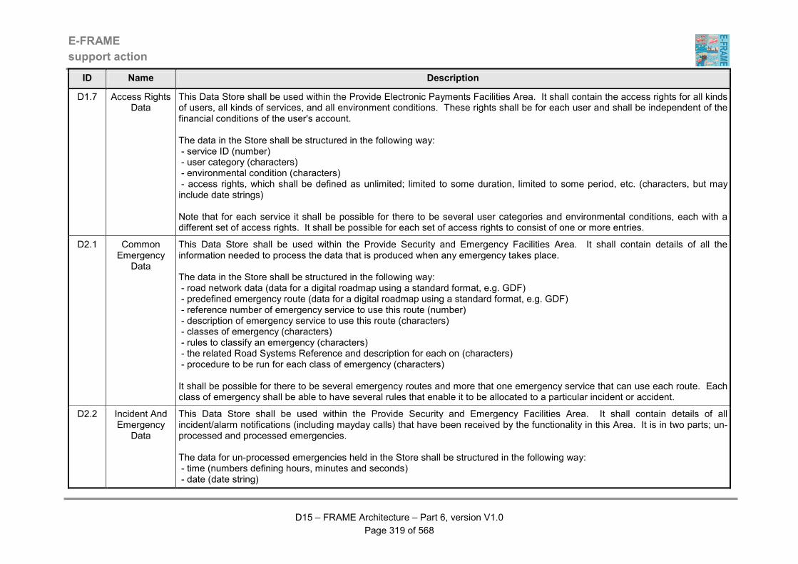
E-FRAME
support action
D15 – FRAME Architecture – Part 6, version V1.0
Page 319 of 568
ID Name Description
D1.7 Access Rights Data
This Data Store shall be used within the Provide Electronic Payments Facilities Area. It shall contain the access rights for all kinds of users, all kinds of services, and all environment conditions. These rights shall be for each user and shall be independent of the financial conditions of the user's account. The data in the Store shall be structured in the following way: - service ID (number) - user category (characters) - environmental condition (characters) - access rights, which shall be defined as unlimited; limited to some duration, limited to some period, etc. (characters, but may include date strings) Note that for each service it shall be possible for there to be several user categories and environmental conditions, each with a different set of access rights. It shall be possible for each set of access rights to consist of one or more entries.
D2.1 Common Emergency
Data
This Data Store shall be used within the Provide Security and Emergency Facilities Area. It shall contain details of all the information needed to process the data that is produced when any emergency takes place. The data in the Store shall be structured in the following way: - road network data (data for a digital roadmap using a standard format, e.g. GDF) - predefined emergency route (data for a digital roadmap using a standard format, e.g. GDF) - reference number of emergency service to use this route (number) - description of emergency service to use this route (characters) - classes of emergency (characters) - rules to classify an emergency (characters) - the related Road Systems Reference and description for each on (characters) - procedure to be run for each class of emergency (characters) It shall be possible for there to be several emergency routes and more that one emergency service that can use each route. Each class of emergency shall be able to have several rules that enable it to be allocated to a particular incident or accident.
D2.2 Incident And Emergency
Data
This Data Store shall be used within the Provide Security and Emergency Facilities Area. It shall contain details of all incident/alarm notifications (including mayday calls) that have been received by the functionality in this Area. It is in two parts; un-processed and processed emergencies. The data for un-processed emergencies held in the Store shall be structured in the following way: - time (numbers defining hours, minutes and seconds) - date (date string)
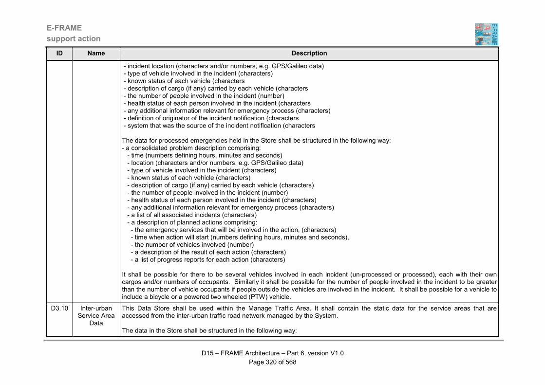
E-FRAME
support action
D15 – FRAME Architecture – Part 6, version V1.0
Page 320 of 568
ID Name Description
- incident location (characters and/or numbers, e.g. GPS/Galileo data) - type of vehicle involved in the incident (characters) - known status of each vehicle (characters - description of cargo (if any) carried by each vehicle (characters - the number of people involved in the incident (number) - health status of each person involved in the incident (characters - any additional information relevant for emergency process (characters) - definition of originator of the incident notification (characters - system that was the source of the incident notification (characters The data for processed emergencies held in the Store shall be structured in the following way: - a consolidated problem description comprising: - time (numbers defining hours, minutes and seconds) - location (characters and/or numbers, e.g. GPS/Galileo data) - type of vehicle involved in the incident (characters) - known status of each vehicle (characters) - description of cargo (if any) carried by each vehicle (characters) - the number of people involved in the incident (number) - health status of each person involved in the incident (characters) - any additional information relevant for emergency process (characters) - a list of all associated incidents (characters) - a description of planned actions comprising: - the emergency services that will be involved in the action, (characters) - time when action will start (numbers defining hours, minutes and seconds), - the number of vehicles involved (number) - a description of the result of each action (characters) - a list of progress reports for each action (characters) It shall be possible for there to be several vehicles involved in each incident (un-processed or processed), each with their own cargos and/or numbers of occupants. Similarly it shall be possible for the number of people involved in the incident to be greater than the number of vehicle occupants if people outside the vehicles are involved in the incident. It shall be possible for a vehicle to include a bicycle or a powered two wheeled (PTW) vehicle.
D3.10 Inter-urban Service Area
Data
This Data Store shall be used within the Manage Traffic Area. It shall contain the static data for the service areas that are accessed from the inter-urban traffic road network managed by the System. The data in the Store shall be structured in the following way:
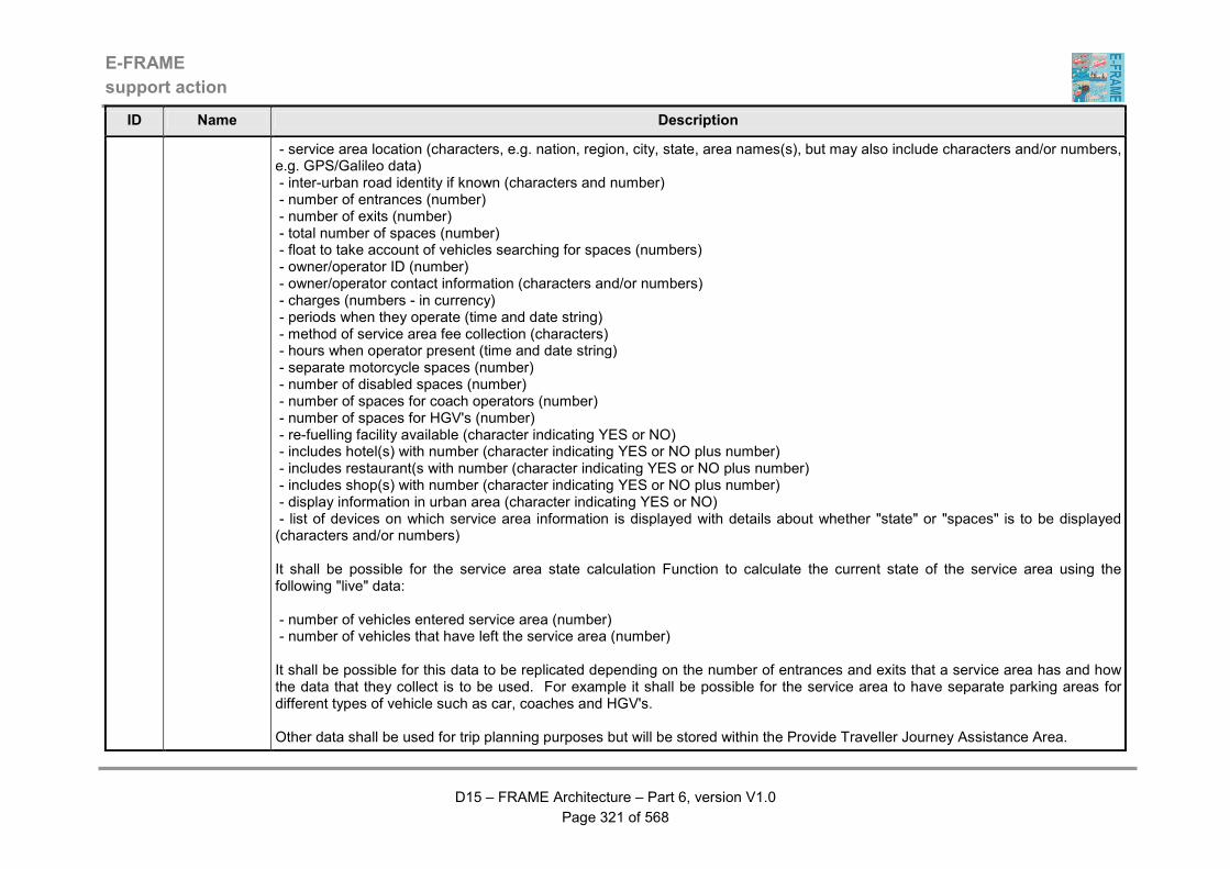
E-FRAME
support action
D15 – FRAME Architecture – Part 6, version V1.0
Page 321 of 568
ID Name Description
- service area location (characters, e.g. nation, region, city, state, area names(s), but may also include characters and/or numbers, e.g. GPS/Galileo data) - inter-urban road identity if known (characters and number) - number of entrances (number) - number of exits (number) - total number of spaces (number) - float to take account of vehicles searching for spaces (numbers) - owner/operator ID (number) - owner/operator contact information (characters and/or numbers) - charges (numbers - in currency) - periods when they operate (time and date string) - method of service area fee collection (characters) - hours when operator present (time and date string) - separate motorcycle spaces (number) - number of disabled spaces (number) - number of spaces for coach operators (number) - number of spaces for HGV's (number) - re-fuelling facility available (character indicating YES or NO) - includes hotel(s) with number (character indicating YES or NO plus number) - includes restaurant(s with number (character indicating YES or NO plus number) - includes shop(s) with number (character indicating YES or NO plus number) - display information in urban area (character indicating YES or NO) - list of devices on which service area information is displayed with details about whether "state" or "spaces" is to be displayed (characters and/or numbers) It shall be possible for the service area state calculation Function to calculate the current state of the service area using the following "live" data: - number of vehicles entered service area (number) - number of vehicles that have left the service area (number) It shall be possible for this data to be replicated depending on the number of entrances and exits that a service area has and how the data that they collect is to be used. For example it shall be possible for the service area to have separate parking areas for different types of vehicle such as car, coaches and HGV's. Other data shall be used for trip planning purposes but will be stored within the Provide Traveller Journey Assistance Area.
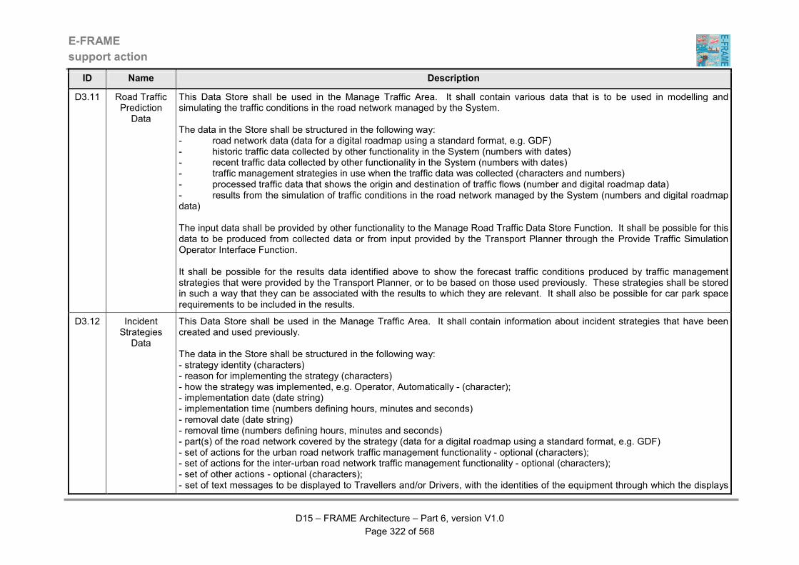
E-FRAME
support action
D15 – FRAME Architecture – Part 6, version V1.0
Page 322 of 568
ID Name Description
D3.11 Road Traffic Prediction
Data
This Data Store shall be used in the Manage Traffic Area. It shall contain various data that is to be used in modelling and simulating the traffic conditions in the road network managed by the System. The data in the Store shall be structured in the following way: - road network data (data for a digital roadmap using a standard format, e.g. GDF) - historic traffic data collected by other functionality in the System (numbers with dates) - recent traffic data collected by other functionality in the System (numbers with dates) - traffic management strategies in use when the traffic data was collected (characters and numbers) - processed traffic data that shows the origin and destination of traffic flows (number and digital roadmap data) - results from the simulation of traffic conditions in the road network managed by the System (numbers and digital roadmap data) The input data shall be provided by other functionality to the Manage Road Traffic Data Store Function. It shall be possible for this data to be produced from collected data or from input provided by the Transport Planner through the Provide Traffic Simulation Operator Interface Function. It shall be possible for the results data identified above to show the forecast traffic conditions produced by traffic management strategies that were provided by the Transport Planner, or to be based on those used previously. These strategies shall be stored in such a way that they can be associated with the results to which they are relevant. It shall also be possible for car park space requirements to be included in the results.
D3.12 Incident Strategies
Data
This Data Store shall be used in the Manage Traffic Area. It shall contain information about incident strategies that have been created and used previously. The data in the Store shall be structured in the following way: - strategy identity (characters) - reason for implementing the strategy (characters) - how the strategy was implemented, e.g. Operator, Automatically - (character); - implementation date (date string) - implementation time (numbers defining hours, minutes and seconds) - removal date (date string) - removal time (numbers defining hours, minutes and seconds) - part(s) of the road network covered by the strategy (data for a digital roadmap using a standard format, e.g. GDF) - set of actions for the urban road network traffic management functionality - optional (characters); - set of actions for the inter-urban road network traffic management functionality - optional (characters); - set of other actions - optional (characters); - set of text messages to be displayed to Travellers and/or Drivers, with the identities of the equipment through which the displays
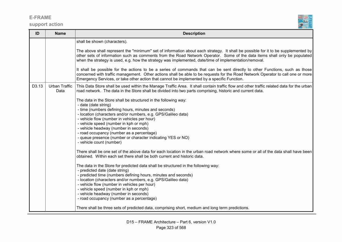
E-FRAME
support action
D15 – FRAME Architecture – Part 6, version V1.0
Page 323 of 568
ID Name Description
shall be shown (characters). The above shall represent the "minimum" set of information about each strategy. It shall be possible for it to be supplemented by other sets of information such as comments from the Road Network Operator. Some of the data items shall only be populated when the strategy is used, e.g. how the strategy was implemented, date/time of implementation/removal. It shall be possible for the actions to be a series of commands that can be sent directly to other Functions, such as those concerned with traffic management. Other actions shall be able to be requests for the Road Network Operator to call one or more Emergency Services, or take other action that cannot be implemented by a specific Function.
D3.13 Urban Traffic Data
This Data Store shall be used within the Manage Traffic Area. It shall contain traffic flow and other traffic related data for the urban road network. The data in the Store shall be divided into two parts comprising, historic and current data. The data in the Store shall be structured in the following way: - date (date string) - time (numbers defining hours, minutes and seconds) - location (characters and/or numbers, e.g. GPS/Galileo data) - vehicle flow (number in vehicles per hour) - vehicle speed (number in kph or mph) - vehicle headway (number in seconds) - road occupancy (number as a percentage) - queue presence (number or character indicating YES or NO) - vehicle count (number) There shall be one set of the above data for each location in the urban road network where some or all of the data shall have been obtained. Within each set there shall be both current and historic data. The data in the Store for predicted data shall be structured in the following way: - predicted date (date string) - predicted time (numbers defining hours, minutes and seconds) - location (characters and/or numbers, e.g. GPS/Galileo data) - vehicle flow (number in vehicles per hour) - vehicle speed (number in kph or mph) - vehicle headway (number in seconds) - road occupancy (number as a percentage) There shall be three sets of predicted data, comprising short, medium and long term predictions.
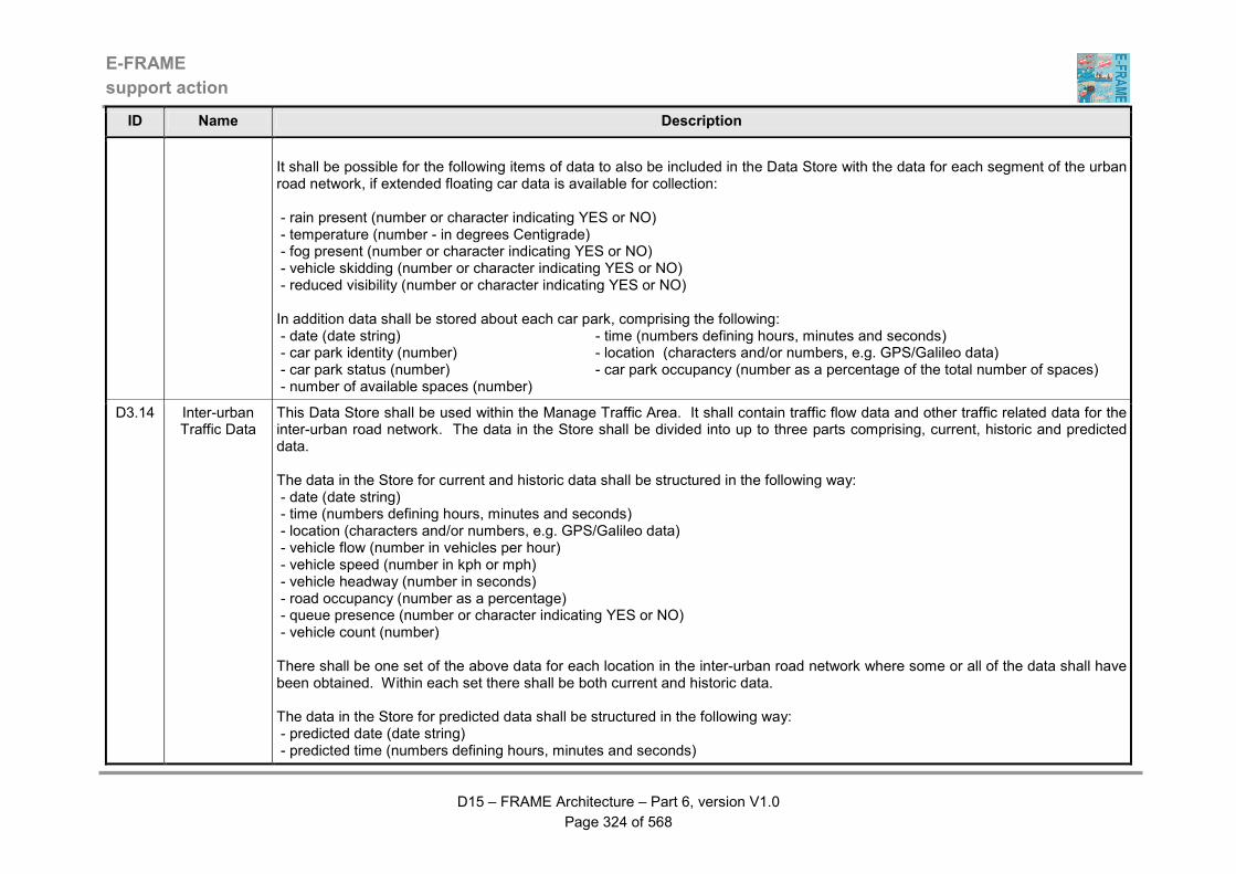
E-FRAME
support action
D15 – FRAME Architecture – Part 6, version V1.0
Page 324 of 568
ID Name Description
It shall be possible for the following items of data to also be included in the Data Store with the data for each segment of the urban road network, if extended floating car data is available for collection: - rain present (number or character indicating YES or NO) - temperature (number - in degrees Centigrade) - fog present (number or character indicating YES or NO) - vehicle skidding (number or character indicating YES or NO) - reduced visibility (number or character indicating YES or NO) In addition data shall be stored about each car park, comprising the following: - date (date string) - time (numbers defining hours, minutes and seconds) - car park identity (number) - location (characters and/or numbers, e.g. GPS/Galileo data) - car park status (number) - car park occupancy (number as a percentage of the total number of spaces) - number of available spaces (number)
D3.14 Inter-urban Traffic Data
This Data Store shall be used within the Manage Traffic Area. It shall contain traffic flow data and other traffic related data for the inter-urban road network. The data in the Store shall be divided into up to three parts comprising, current, historic and predicted data. The data in the Store for current and historic data shall be structured in the following way: - date (date string) - time (numbers defining hours, minutes and seconds) - location (characters and/or numbers, e.g. GPS/Galileo data) - vehicle flow (number in vehicles per hour) - vehicle speed (number in kph or mph) - vehicle headway (number in seconds) - road occupancy (number as a percentage) - queue presence (number or character indicating YES or NO) - vehicle count (number) There shall be one set of the above data for each location in the inter-urban road network where some or all of the data shall have been obtained. Within each set there shall be both current and historic data. The data in the Store for predicted data shall be structured in the following way: - predicted date (date string) - predicted time (numbers defining hours, minutes and seconds)
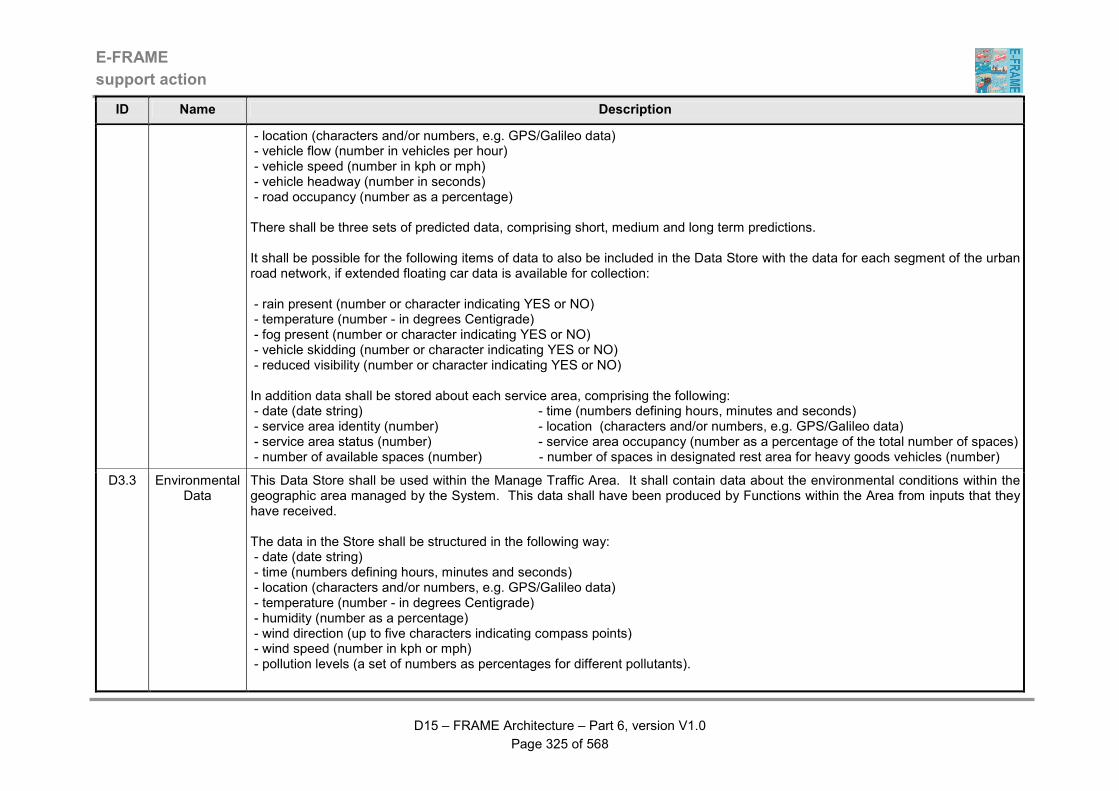
E-FRAME
support action
D15 – FRAME Architecture – Part 6, version V1.0
Page 325 of 568
ID Name Description
- location (characters and/or numbers, e.g. GPS/Galileo data) - vehicle flow (number in vehicles per hour) - vehicle speed (number in kph or mph) - vehicle headway (number in seconds) - road occupancy (number as a percentage) There shall be three sets of predicted data, comprising short, medium and long term predictions. It shall be possible for the following items of data to also be included in the Data Store with the data for each segment of the urban road network, if extended floating car data is available for collection: - rain present (number or character indicating YES or NO) - temperature (number - in degrees Centigrade) - fog present (number or character indicating YES or NO) - vehicle skidding (number or character indicating YES or NO) - reduced visibility (number or character indicating YES or NO) In addition data shall be stored about each service area, comprising the following: - date (date string) - time (numbers defining hours, minutes and seconds) - service area identity (number) - location (characters and/or numbers, e.g. GPS/Galileo data) - service area status (number) - service area occupancy (number as a percentage of the total number of spaces) - number of available spaces (number) - number of spaces in designated rest area for heavy goods vehicles (number)
D3.3 Environmental Data
This Data Store shall be used within the Manage Traffic Area. It shall contain data about the environmental conditions within the geographic area managed by the System. This data shall have been produced by Functions within the Area from inputs that they have received. The data in the Store shall be structured in the following way: - date (date string) - time (numbers defining hours, minutes and seconds) - location (characters and/or numbers, e.g. GPS/Galileo data) - temperature (number - in degrees Centigrade) - humidity (number as a percentage) - wind direction (up to five characters indicating compass points) - wind speed (number in kph or mph) - pollution levels (a set of numbers as percentages for different pollutants).

E-FRAME
support action
D15 – FRAME Architecture – Part 6, version V1.0
Page 326 of 568
ID Name Description
The number of entries shall be fixed by the number of times that samples are taken. It shall be possible for the number and type of pollutants recorded to vary from one location to another and from one System to another.
D3.4 Incident Data This Data Store shall be used within the Manage Traffic Area. It shall contain data collected about current and predicted incidents. The data in the Store shall be structured in the following way: - start date (date string) - start time (date string) - forecast duration (number - minutes) - actual duration (number - minutes) - incident location (characters and/or numbers, e.g. GPS/Galileo data) - incident type (characters) - incident severity (characters) - type and number of vehicles (characters for type(s) and numbers) - incident strategy used (characters) - emergency services vehicles used (characters for type(s) and numbers). The data in some of these entries shall be provided as the incident state changes, whilst in others it shall be updated as the incident impact progresses and remedial action is taken.
D3.5 Demand Data This Data Store shall be used within the Manage Traffic Area. It shall be split into two parts, one to contain data collected on the use of transport modes and the other to contain demand management strategies. The collected data in the Store shall be structured in the following way: - date (date string) - time (date string) - transport mode (characters) - amount of use (numbers as a percentage) The number of entries shall be fixed by the number of transport modes, the period over which they are stored The data about the demand re-balancing strategies in the Store shall be structured in the following way: - identity (characters) - actions (characters). The number of entries shall be fixed by the number of strategies.
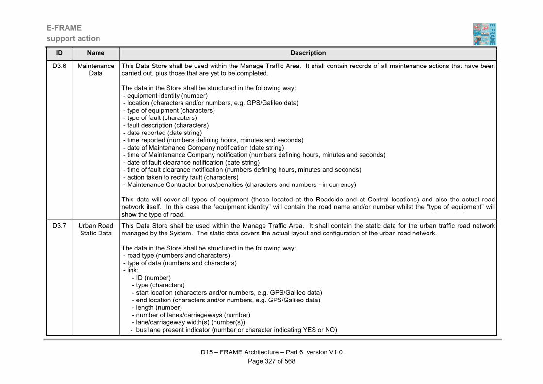
E-FRAME
support action
D15 – FRAME Architecture – Part 6, version V1.0
Page 327 of 568
ID Name Description
D3.6 Maintenance Data
This Data Store shall be used within the Manage Traffic Area. It shall contain records of all maintenance actions that have been carried out, plus those that are yet to be completed. The data in the Store shall be structured in the following way: - equipment identity (number) - location (characters and/or numbers, e.g. GPS/Galileo data) - type of equipment (characters) - type of fault (characters) - fault description (characters) - date reported (date string) - time reported (numbers defining hours, minutes and seconds) - date of Maintenance Company notification (date string) - time of Maintenance Company notification (numbers defining hours, minutes and seconds) - date of fault clearance notification (date string) - time of fault clearance notification (numbers defining hours, minutes and seconds) - action taken to rectify fault (characters) - Maintenance Contractor bonus/penalties (characters and numbers - in currency) This data will cover all types of equipment (those located at the Roadside and at Central locations) and also the actual road network itself. In this case the "equipment identity" will contain the road name and/or number whilst the "type of equipment" will show the type of road.
D3.7 Urban Road Static Data
This Data Store shall be used within the Manage Traffic Area. It shall contain the static data for the urban traffic road network managed by the System. The static data covers the actual layout and configuration of the urban road network. The data in the Store shall be structured in the following way: - road type (numbers and characters) - type of data (numbers and characters) - link: - ID (number) - type (characters) - start location (characters and/or numbers, e.g. GPS/Galileo data) - end location (characters and/or numbers, e.g. GPS/Galileo data) - length (number) - number of lanes/carriageways (number) - lane/carriageway width(s) (number(s)) - bus lane present indicator (number or character indicating YES or NO)
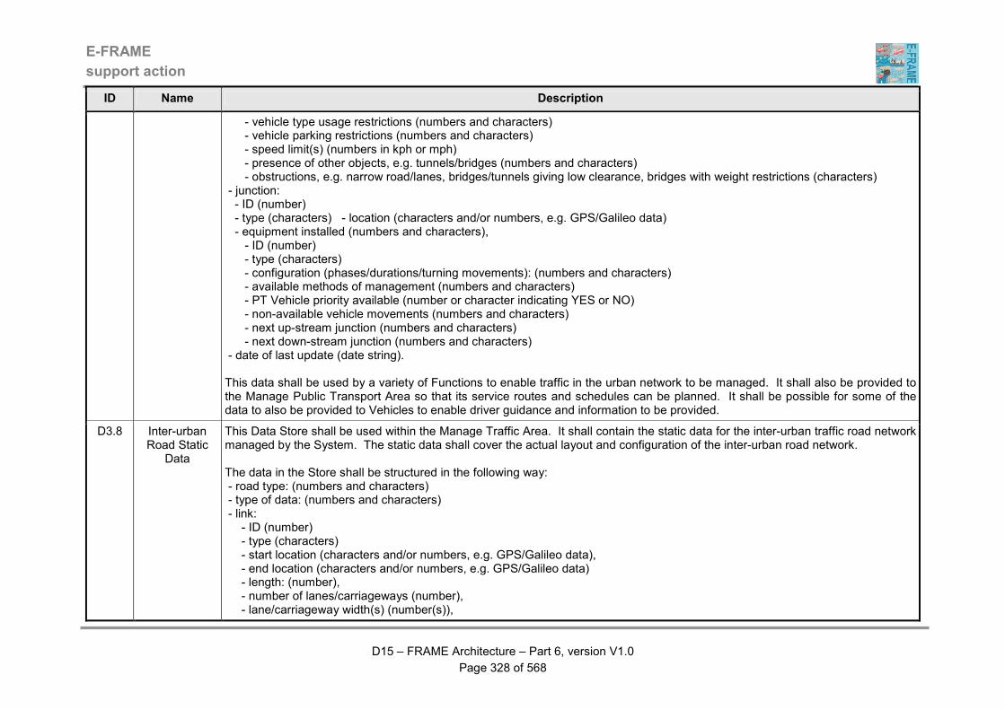
E-FRAME
support action
D15 – FRAME Architecture – Part 6, version V1.0
Page 328 of 568
ID Name Description
- vehicle type usage restrictions (numbers and characters) - vehicle parking restrictions (numbers and characters) - speed limit(s) (numbers in kph or mph) - presence of other objects, e.g. tunnels/bridges (numbers and characters) - obstructions, e.g. narrow road/lanes, bridges/tunnels giving low clearance, bridges with weight restrictions (characters) - junction: - ID (number) - type (characters) - location (characters and/or numbers, e.g. GPS/Galileo data) - equipment installed (numbers and characters), - ID (number) - type (characters) - configuration (phases/durations/turning movements): (numbers and characters) - available methods of management (numbers and characters) - PT Vehicle priority available (number or character indicating YES or NO) - non-available vehicle movements (numbers and characters) - next up-stream junction (numbers and characters) - next down-stream junction (numbers and characters) - date of last update (date string). This data shall be used by a variety of Functions to enable traffic in the urban network to be managed. It shall also be provided to the Manage Public Transport Area so that its service routes and schedules can be planned. It shall be possible for some of the data to also be provided to Vehicles to enable driver guidance and information to be provided.
D3.8 Inter-urban Road Static
Data
This Data Store shall be used within the Manage Traffic Area. It shall contain the static data for the inter-urban traffic road network managed by the System. The static data shall cover the actual layout and configuration of the inter-urban road network. The data in the Store shall be structured in the following way: - road type: (numbers and characters) - type of data: (numbers and characters) - link: - ID (number) - type (characters) - start location (characters and/or numbers, e.g. GPS/Galileo data), - end location (characters and/or numbers, e.g. GPS/Galileo data) - length: (number), - number of lanes/carriageways (number), - lane/carriageway width(s) (number(s)),

E-FRAME
support action
D15 – FRAME Architecture – Part 6, version V1.0
Page 329 of 568
ID Name Description
- vehicle type usage restrictions (numbers and characters), - vehicle parking restrictions (numbers and characters), - vehicle speed limit(s) (number(s) in kph or mph), - bus lane present indicator (number or character indicating YES or NO) - presence of other objects, e.g. tunnels/bridges (numbers and characters) - obstructions, e.g. narrow road/lanes, bridges/tunnels giving low clearance, bridges with weight restrictions (characters) - date of last update (date string). This data shall be used by a variety of Functions to enable traffic in the inter-urban network to be managed. It shall also be provided to the Manage Public Transport Area so that its service routes and schedules can be planned. It shall be possible for some data to also be provided to Vehicles to enable driver guidance and information to be provided.
D3.9 Urban Car Park Data
This Data Store shall be used within the Manage Traffic Area. It shall contain the static data for the car parks that are accessed from the urban traffic road network managed by the System. The data in the Store shall be structured in the following way: - car park location - number of entrances (number) - number of exits (number) - total number of spaces (number) - float to take account of vehicles searching for spaces (number) - owner/operator ID (number) - owner/operator contact information (characters and/or numbers (characters) - charges (numbers - in currency) - periods when they operate (time and date string) - method of car park fee collection (characters) - hours when operator present (time and date string) - separate cycle spaces (number) - separate motorcycle spaces (number) - number of disabled spaces (number) - display information in inter-urban area (character indicating YES or NO) - list of devices on which car park information is displayed with details about whether "state" or "spaces" is to be displayed (characters and/or numbers) It shall be possible for the car park state calculation Function to calculate the current state of the service area using the following "live" data: - number of vehicles entered car park (number)
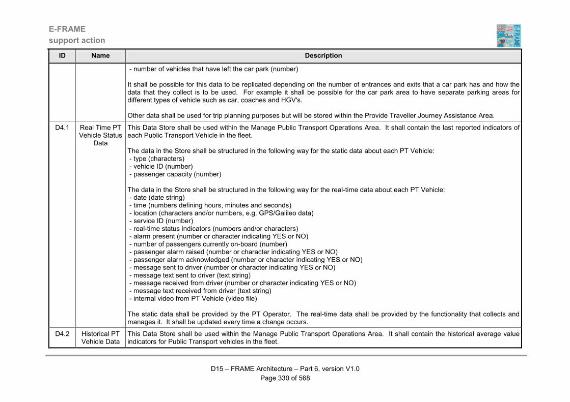
E-FRAME
support action
D15 – FRAME Architecture – Part 6, version V1.0
Page 330 of 568
ID Name Description
- number of vehicles that have left the car park (number) It shall be possible for this data to be replicated depending on the number of entrances and exits that a car park has and how the data that they collect is to be used. For example it shall be possible for the car park area to have separate parking areas for different types of vehicle such as car, coaches and HGV's. Other data shall be used for trip planning purposes but will be stored within the Provide Traveller Journey Assistance Area.
D4.1 Real Time PT Vehicle Status
Data
This Data Store shall be used within the Manage Public Transport Operations Area. It shall contain the last reported indicators of each Public Transport Vehicle in the fleet. The data in the Store shall be structured in the following way for the static data about each PT Vehicle: - type (characters) - vehicle ID (number) - passenger capacity (number) The data in the Store shall be structured in the following way for the real-time data about each PT Vehicle: - date (date string) - time (numbers defining hours, minutes and seconds) - location (characters and/or numbers, e.g. GPS/Galileo data) - service ID (number) - real-time status indicators (numbers and/or characters) - alarm present (number or character indicating YES or NO) - number of passengers currently on-board (number) - passenger alarm raised (number or character indicating YES or NO) - passenger alarm acknowledged (number or character indicating YES or NO) - message sent to driver (number or character indicating YES or NO) - message text sent to driver (text string) - message received from driver (number or character indicating YES or NO) - message text received from driver (text string) - internal video from PT Vehicle (video file) The static data shall be provided by the PT Operator. The real-time data shall be provided by the functionality that collects and manages it. It shall be updated every time a change occurs.
D4.2 Historical PT Vehicle Data
This Data Store shall be used within the Manage Public Transport Operations Area. It shall contain the historical average value indicators for Public Transport vehicles in the fleet.

E-FRAME
support action
D15 – FRAME Architecture – Part 6, version V1.0
Page 331 of 568
ID Name Description
The data in the Store shall be structured in the following way for the static data about each PT Vehicle: - type (characters) - vehicle ID (number) - passenger capacity (number) The data in the Store shall be structured in the following way for the real-time data about each PT Vehicle: - date (date string) - time (numbers defining hours, minutes and seconds) - location (characters and/or numbers, e.g. GPS/Galileo data) - service ID (number) - real-time status indicators (numbers and/or characters) - alarm present (number or character indicating YES or NO) - number of passengers currently on-board (number) - passenger alarm raised (number or character indicating YES or NO) - passenger alarm acknowledged (number or character indicating YES or NO) - message sent to driver (number or character indicating YES or NO) - message text sent to driver (text string) - message received from driver (number or character indicating YES or NO) - message text received from driver (text string) - internal video from PT Vehicle (video file) - scheduling for PT services It shall be possible for the information to be stored in such a way that it can be retrieved by route, by service, by type of vehicle etc. as needed. For each of the above categories as minimum the stored data shall be archived classified by type of day with the needed level of detail (working days, holidays, school days, off school days, rainy days, sunny days, traffic restriction days, etc). The level of detail shall be coherent with the detailed specification of the system: e.g. average travel time can be as detailed as calculated for every few meters of road along the route or distinguishing between characteristic stretches of road, or just between two terminals. The entries in the Data Store shall also include the exact description of the time, place and whatever else is needed to identify the scenario to which the set of data is referred to. Stored data shall be constantly updated with new measurements available and previously smoothed and validated. It shall be possible for the time slots used to store the data to vary according to the needs.
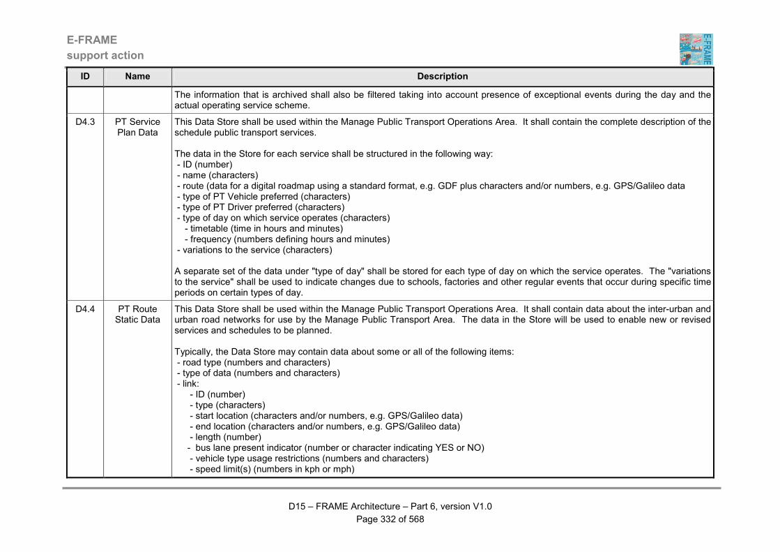
E-FRAME
support action
D15 – FRAME Architecture – Part 6, version V1.0
Page 332 of 568
ID Name Description
The information that is archived shall also be filtered taking into account presence of exceptional events during the day and the actual operating service scheme.
D4.3 PT Service Plan Data
This Data Store shall be used within the Manage Public Transport Operations Area. It shall contain the complete description of the schedule public transport services. The data in the Store for each service shall be structured in the following way: - ID (number) - name (characters) - route (data for a digital roadmap using a standard format, e.g. GDF plus characters and/or numbers, e.g. GPS/Galileo data - type of PT Vehicle preferred (characters) - type of PT Driver preferred (characters) - type of day on which service operates (characters) - timetable (time in hours and minutes) - frequency (numbers defining hours and minutes) - variations to the service (characters) A separate set of the data under "type of day" shall be stored for each type of day on which the service operates. The "variations to the service" shall be used to indicate changes due to schools, factories and other regular events that occur during specific time periods on certain types of day.
D4.4 PT Route Static Data
This Data Store shall be used within the Manage Public Transport Operations Area. It shall contain data about the inter-urban and urban road networks for use by the Manage Public Transport Area. The data in the Store will be used to enable new or revised services and schedules to be planned. Typically, the Data Store may contain data about some or all of the following items: - road type (numbers and characters) - type of data (numbers and characters) - link: - ID (number) - type (characters) - start location (characters and/or numbers, e.g. GPS/Galileo data) - end location (characters and/or numbers, e.g. GPS/Galileo data) - length (number) - bus lane present indicator (number or character indicating YES or NO) - vehicle type usage restrictions (numbers and characters) - speed limit(s) (numbers in kph or mph)
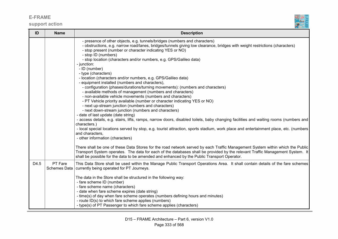
E-FRAME
support action
D15 – FRAME Architecture – Part 6, version V1.0
Page 333 of 568
ID Name Description
- presence of other objects, e.g. tunnels/bridges (numbers and characters) - obstructions, e.g. narrow road/lanes, bridges/tunnels giving low clearance, bridges with weight restrictions (characters) - stop present (number or character indicating YES or NO) - stop ID (numbers) - stop location (characters and/or numbers, e.g. GPS/Galileo data) - junction: - ID (number) - type (characters) - location (characters and/or numbers, e.g. GPS/Galileo data) - equipment installed (numbers and characters), - configuration (phases/durations/turning movements): (numbers and characters) - available methods of management (numbers and characters) - non-available vehicle movements (numbers and characters) - PT Vehicle priority available (number or character indicating YES or NO) - next up-stream junction (numbers and characters) - next down-stream junction (numbers and characters) - date of last update (date string) - access details, e.g. stairs, lifts, ramps, narrow doors, disabled toilets, baby changing facilities and waiting rooms (numbers and characters.) - local special locations served by stop, e.g. tourist attraction, sports stadium, work place and entertainment place, etc. (numbers and characters, - other information (characters) There shall be one of these Data Stores for the road network served by each Traffic Management System within which the Public Transport System operates. The data for each of the databases shall be provided by the relevant Traffic Management System. It shall be possible for the data to be amended and enhanced by the Public Transport Operator.
D4.5 PT Fare Schemes Data
This Data Store shall be used within the Manage Public Transport Operations Area. It shall contain details of the fare schemes currently being operated for PT Journeys. The data in the Store shall be structured in the following way: - fare scheme ID (number) - fare scheme name (characters) - date when fare scheme expires (date string) - time(s) of day when fare scheme operates (numbers defining hours and minutes) - route ID(s) to which fare scheme applies (numbers) - type(s) of PT Passenger to which fare scheme applies (characters)

E-FRAME
support action
D15 – FRAME Architecture – Part 6, version V1.0
Page 334 of 568
ID Name Description
For each type of PT Passenger, the following fare information shall be provided: - range ID's of stop to which fare applies (numbers) - numbers ID's of stops to which fare applies (numbers) There shall be one set of the above data for each fare scheme, which shall have a unique ID. It shall be possible for there to be several fare schemes for the same route to cover different times of day, days of the week, months, years, etc.
D4.6 Fare Card Data
This Data Store shall be used within the Manage Public Transport Operations Area. It shall contain details of the fare credit that is currently available for use by the PT Passenger. The data in the Store shall be structured in the following way: - amount of credit (number) - date of last top up (date string) - date of expiry (date string) This Data Store shall represent a PT "fare card" in its simplest form. As it goes with the PT passenger there is no need for any personal identification data.
D4.7 Vehicle Sharing Data
This Data Store shall be used within the Manage Public Transport Operations Area. It shall contain information used to enable the preparation of travel plans involving Vehicle sharing. As a minimum the data shall be divided into the following two parts: car pooler registration data and travel plan data. The car pooler registration data in the Store shall be structured in the following way: - ID (number) - registration date (date string) - contact details (text string) - origin of journey (characters and/or numbers, e.g. GPS/Galileo data) - destination of journey (characters and/or numbers, e.g. GPS/Galileo data) - own Vehicle available for sharing (number or character indicating YES or NO) - number of passengers to be carried in own Vehicle (number) The travel plan data in the Store shall be structured in the following way: - ID (number) - date of creation (date string) - origin (characters and/or numbers, e.g. GPS/Galileo data) - final destination (characters and/or numbers, e.g. GPS/Galileo data)
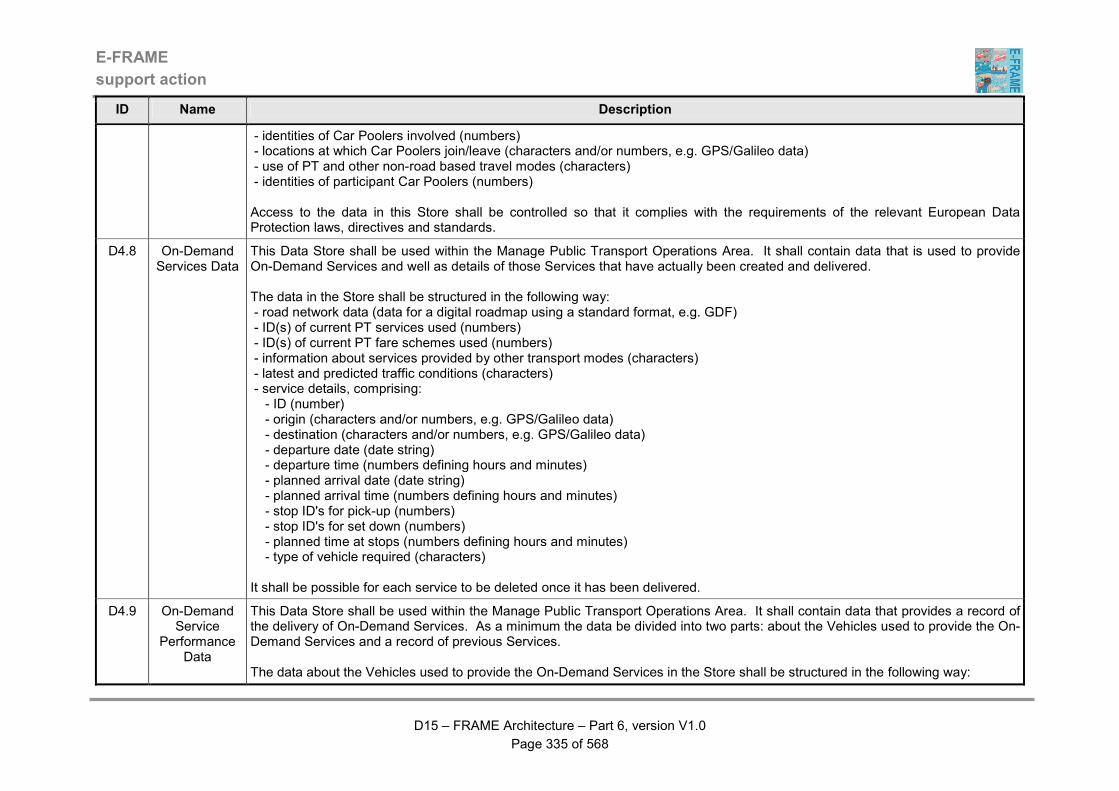
E-FRAME
support action
D15 – FRAME Architecture – Part 6, version V1.0
Page 335 of 568
ID Name Description
- identities of Car Poolers involved (numbers) - locations at which Car Poolers join/leave (characters and/or numbers, e.g. GPS/Galileo data) - use of PT and other non-road based travel modes (characters) - identities of participant Car Poolers (numbers) Access to the data in this Store shall be controlled so that it complies with the requirements of the relevant European Data Protection laws, directives and standards.
D4.8 On-Demand Services Data
This Data Store shall be used within the Manage Public Transport Operations Area. It shall contain data that is used to provide On-Demand Services and well as details of those Services that have actually been created and delivered. The data in the Store shall be structured in the following way: - road network data (data for a digital roadmap using a standard format, e.g. GDF) - ID(s) of current PT services used (numbers) - ID(s) of current PT fare schemes used (numbers) - information about services provided by other transport modes (characters) - latest and predicted traffic conditions (characters) - service details, comprising: - ID (number) - origin (characters and/or numbers, e.g. GPS/Galileo data) - destination (characters and/or numbers, e.g. GPS/Galileo data) - departure date (date string) - departure time (numbers defining hours and minutes) - planned arrival date (date string) - planned arrival time (numbers defining hours and minutes) - stop ID's for pick-up (numbers) - stop ID's for set down (numbers) - planned time at stops (numbers defining hours and minutes) - type of vehicle required (characters) It shall be possible for each service to be deleted once it has been delivered.
D4.9 On-Demand Service
Performance Data
This Data Store shall be used within the Manage Public Transport Operations Area. It shall contain data that provides a record of the delivery of On-Demand Services. As a minimum the data be divided into two parts: about the Vehicles used to provide the On-Demand Services and a record of previous Services. The data about the Vehicles used to provide the On-Demand Services in the Store shall be structured in the following way:
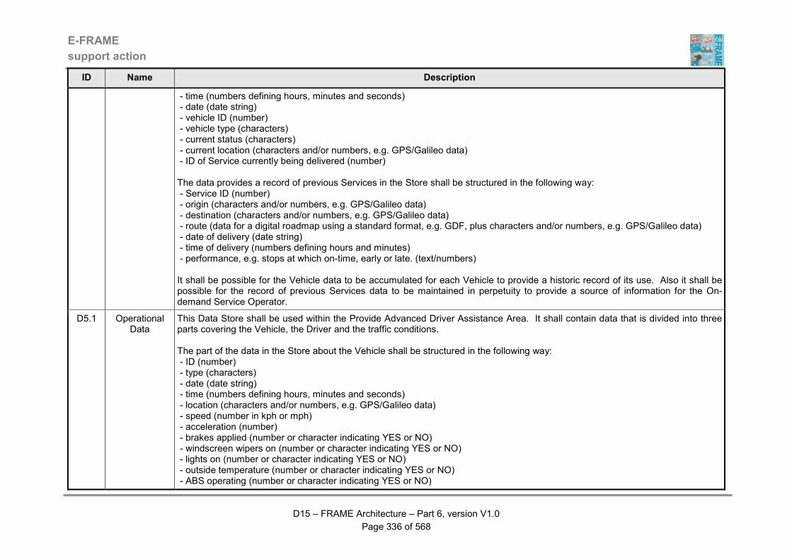
E-FRAME
support action
D15 – FRAME Architecture – Part 6, version V1.0
Page 336 of 568
ID Name Description
- time (numbers defining hours, minutes and seconds) - date (date string) - vehicle ID (number) - vehicle type (characters) - current status (characters) - current location (characters and/or numbers, e.g. GPS/Galileo data) - ID of Service currently being delivered (number) The data provides a record of previous Services in the Store shall be structured in the following way: - Service ID (number) - origin (characters and/or numbers, e.g. GPS/Galileo data) - destination (characters and/or numbers, e.g. GPS/Galileo data) - route (data for a digital roadmap using a standard format, e.g. GDF, plus characters and/or numbers, e.g. GPS/Galileo data) - date of delivery (date string) - time of delivery (numbers defining hours and minutes) - performance, e.g. stops at which on-time, early or late. (text/numbers) It shall be possible for the Vehicle data to be accumulated for each Vehicle to provide a historic record of its use. Also it shall be possible for the record of previous Services data to be maintained in perpetuity to provide a source of information for the On-demand Service Operator.
D5.1 Operational Data
This Data Store shall be used within the Provide Advanced Driver Assistance Area. It shall contain data that is divided into three parts covering the Vehicle, the Driver and the traffic conditions. The part of the data in the Store about the Vehicle shall be structured in the following way: - ID (number) - type (characters) - date (date string) - time (numbers defining hours, minutes and seconds) - location (characters and/or numbers, e.g. GPS/Galileo data) - speed (number in kph or mph) - acceleration (number) - brakes applied (number or character indicating YES or NO) - windscreen wipers on (number or character indicating YES or NO) - lights on (number or character indicating YES or NO) - outside temperature (number or character indicating YES or NO) - ABS operating (number or character indicating YES or NO)
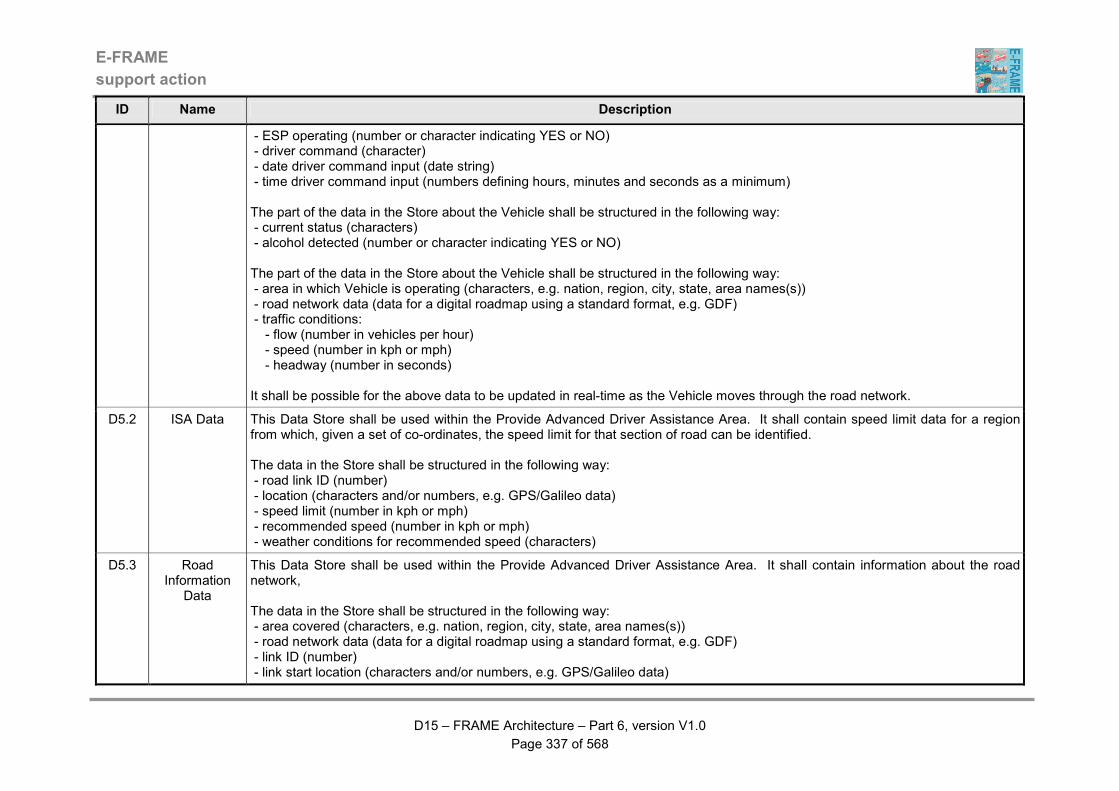
E-FRAME
support action
D15 – FRAME Architecture – Part 6, version V1.0
Page 337 of 568
ID Name Description
- ESP operating (number or character indicating YES or NO) - driver command (character) - date driver command input (date string) - time driver command input (numbers defining hours, minutes and seconds as a minimum) The part of the data in the Store about the Vehicle shall be structured in the following way: - current status (characters) - alcohol detected (number or character indicating YES or NO) The part of the data in the Store about the Vehicle shall be structured in the following way: - area in which Vehicle is operating (characters, e.g. nation, region, city, state, area names(s)) - road network data (data for a digital roadmap using a standard format, e.g. GDF) - traffic conditions: - flow (number in vehicles per hour) - speed (number in kph or mph) - headway (number in seconds) It shall be possible for the above data to be updated in real-time as the Vehicle moves through the road network.
D5.2 ISA Data This Data Store shall be used within the Provide Advanced Driver Assistance Area. It shall contain speed limit data for a region from which, given a set of co-ordinates, the speed limit for that section of road can be identified. The data in the Store shall be structured in the following way: - road link ID (number) - location (characters and/or numbers, e.g. GPS/Galileo data) - speed limit (number in kph or mph) - recommended speed (number in kph or mph) - weather conditions for recommended speed (characters)
D5.3 Road Information
Data
This Data Store shall be used within the Provide Advanced Driver Assistance Area. It shall contain information about the road network, The data in the Store shall be structured in the following way: - area covered (characters, e.g. nation, region, city, state, area names(s)) - road network data (data for a digital roadmap using a standard format, e.g. GDF) - link ID (number) - link start location (characters and/or numbers, e.g. GPS/Galileo data)

E-FRAME
support action
D15 – FRAME Architecture – Part 6, version V1.0
Page 338 of 568
ID Name Description
- link end location (characters and/or numbers, e.g. GPS/Galileo data) - number of lanes (number) - speed limit (number in kph or mph) - road information form other Vehicle (characters and numbers) It shall be possible for this data to be updated in real-time as the Vehicle moves through the road network, so that only the data relevant to the area around the Vehicle's current location is stored.
D5.4 Vehicle Trip Plans Data
This Data Store shall be used within the Provide In-vehicle Trip Planning High-level Function. It shall contain data that is the result of the process to create a Vehicle Trip Plan. The data in the Store shall be structured in the following way: - route ID (number) - route name (characters) - origin (characters and/or numbers, e.g. GPS/Galileo data) - destination (characters and/or numbers, e.g. GPS/Galileo data) - expected arrival time (numbers defining hours, minutes and seconds) - vehicle type for route (characters) - type of goods carried (characters) - route (data for a digital roadmap using a standard format, e.g. GDF, plus characters and/or numbers, e.g. GPS/Galileo data) - rest zone: - ID (number) - name (characters) - location (characters and/or numbers, e.g. GPS/Galileo data) - booked start date (date string) - booked start time (numbers defining hours, minutes and seconds) - booked stay duration (numbers defining hours, minutes and seconds) - un/loading zone: - ID (number) - name (characters) - location (characters and/or numbers, e.g. GPS/Galileo data) - booked start date (date string) - booked start time (numbers defining hours, minutes and seconds) - booked stay duration (numbers defining hours, minutes and seconds) - payments made: - what for (characters) - complete (number or character indicating YES or NO)

E-FRAME
support action
D15 – FRAME Architecture – Part 6, version V1.0
Page 339 of 568
ID Name Description
- other relevant data (characters and/or numbers) It shall be possible for data about more than one rest area and/or un/loading zone to be included and for payments to be recorded against some or all of these plus any pre-payment of road use charges. The data in this Store shall be retained for the prime purpose of supporting the Diver during the implementation of the Trip Plan. All the considerations that resulted in production of the Trip Plan are included in this Data Store.
D6.1 General Trip Preferences (GTP) Data
This Data Store shall be used within the Provide Traveller Journey Assistance Area. It shall contain the personalised data needed to support the Traveller during all of their trips. The support is provided both during the trip planning, as well as during the trip execution. The Store is also used to prevent cumbersome and error prone input of the same information by the Traveller. It serves as a memory to assist the Traveller during the entire trip, for all travel modes, during every phase of the trip. The data in the Store shall be structured in the following way: - Traveller’s ID (number) - Traveller driver licence ID (number or characters) - Traveller passport ID (number) - Traveller's preferred language (characters) - Traveller's disabilities (characters) - other Traveller information relevant to trip planning (characters) - Traveller's payment information (characters and/or numbers) - description of cargo to be carried on trip (characters) - number of passengers expected in Vehicle (number) - prime trip planning criterion (characters) - default departure location (characters and/or numbers, e.g. GPS/Galileo data) - default destination location (characters and/or numbers, e.g. GPS/Galileo data) - level of detail desired of trip itinerary (characters) - road toll payment method (characters) - vehicle breakdown assistance information (characters) - way of communication with Traveller while on-trip (characters + numbers) - route guidance facilitation parameters (characters) - preferred travel modes and classes (characters) - preferred hotel(s)/chain(s) (characters) - preferred car rental organisation(s) (characters) The data for each Traveller must be kept separate with no possibility of inadvertent access to the data for one Traveller by either another Traveller, or some form of un-authorised access.
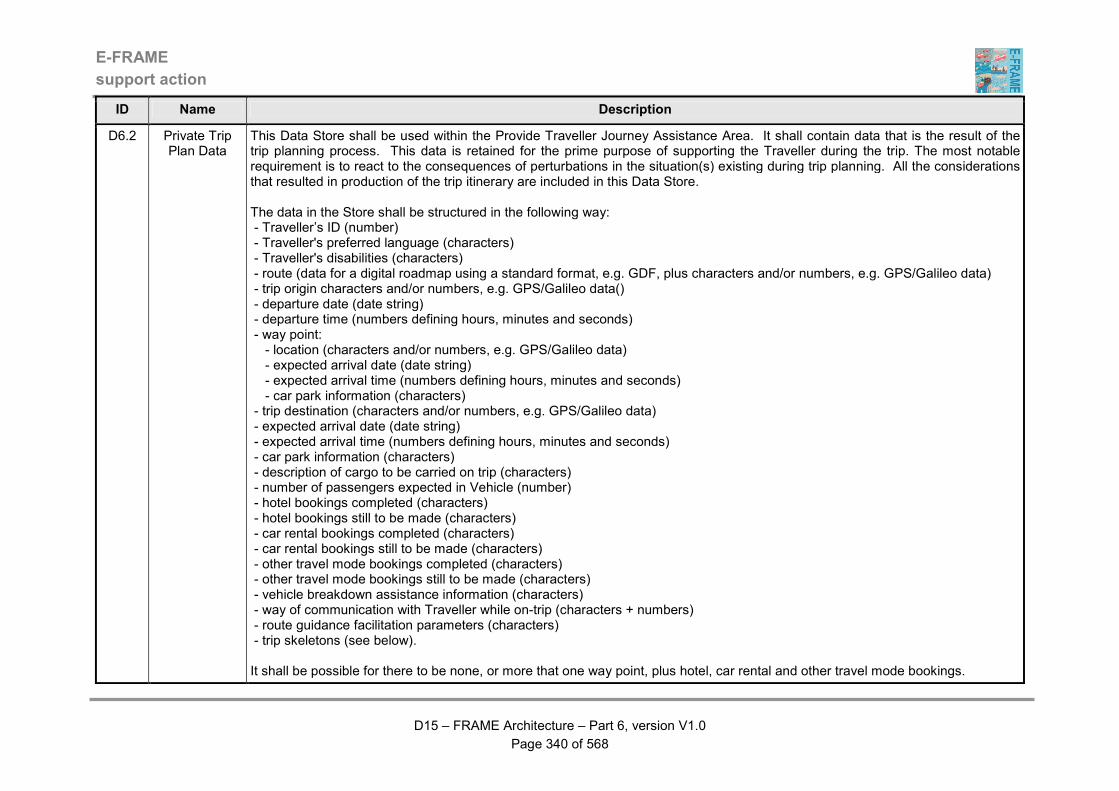
E-FRAME
support action
D15 – FRAME Architecture – Part 6, version V1.0
Page 340 of 568
ID Name Description
D6.2 Private Trip Plan Data
This Data Store shall be used within the Provide Traveller Journey Assistance Area. It shall contain data that is the result of the trip planning process. This data is retained for the prime purpose of supporting the Traveller during the trip. The most notable requirement is to react to the consequences of perturbations in the situation(s) existing during trip planning. All the considerations that resulted in production of the trip itinerary are included in this Data Store. The data in the Store shall be structured in the following way: - Traveller’s ID (number) - Traveller's preferred language (characters) - Traveller's disabilities (characters) - route (data for a digital roadmap using a standard format, e.g. GDF, plus characters and/or numbers, e.g. GPS/Galileo data) - trip origin characters and/or numbers, e.g. GPS/Galileo data() - departure date (date string) - departure time (numbers defining hours, minutes and seconds) - way point: - location (characters and/or numbers, e.g. GPS/Galileo data) - expected arrival date (date string) - expected arrival time (numbers defining hours, minutes and seconds) - car park information (characters) - trip destination (characters and/or numbers, e.g. GPS/Galileo data) - expected arrival date (date string) - expected arrival time (numbers defining hours, minutes and seconds) - car park information (characters) - description of cargo to be carried on trip (characters) - number of passengers expected in Vehicle (number) - hotel bookings completed (characters) - hotel bookings still to be made (characters) - car rental bookings completed (characters) - car rental bookings still to be made (characters) - other travel mode bookings completed (characters) - other travel mode bookings still to be made (characters) - vehicle breakdown assistance information (characters) - way of communication with Traveller while on-trip (characters + numbers) - route guidance facilitation parameters (characters) - trip skeletons (see below). It shall be possible for there to be none, or more that one way point, plus hotel, car rental and other travel mode bookings.
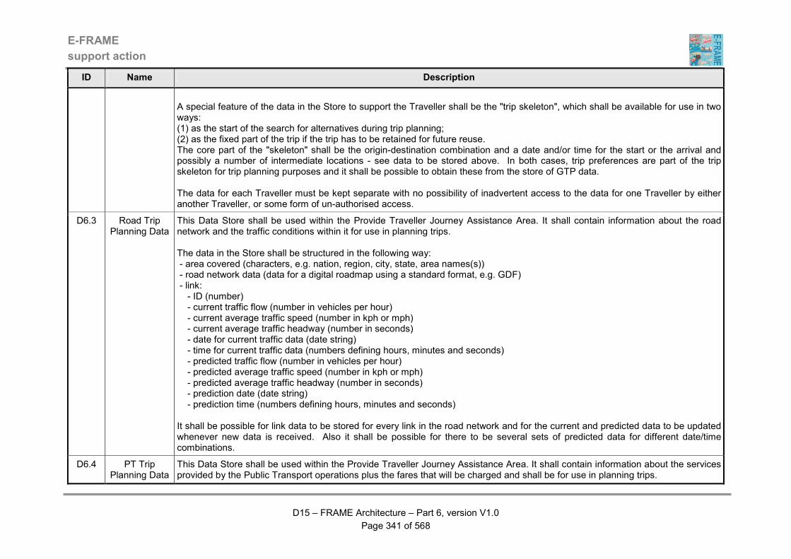
E-FRAME
support action
D15 – FRAME Architecture – Part 6, version V1.0
Page 341 of 568
ID Name Description
A special feature of the data in the Store to support the Traveller shall be the "trip skeleton", which shall be available for use in two ways: (1) as the start of the search for alternatives during trip planning; (2) as the fixed part of the trip if the trip has to be retained for future reuse. The core part of the "skeleton" shall be the origin-destination combination and a date and/or time for the start or the arrival and possibly a number of intermediate locations - see data to be stored above. In both cases, trip preferences are part of the trip skeleton for trip planning purposes and it shall be possible to obtain these from the store of GTP data. The data for each Traveller must be kept separate with no possibility of inadvertent access to the data for one Traveller by either another Traveller, or some form of un-authorised access.
D6.3 Road Trip Planning Data
This Data Store shall be used within the Provide Traveller Journey Assistance Area. It shall contain information about the road network and the traffic conditions within it for use in planning trips. The data in the Store shall be structured in the following way: - area covered (characters, e.g. nation, region, city, state, area names(s)) - road network data (data for a digital roadmap using a standard format, e.g. GDF) - link: - ID (number) - current traffic flow (number in vehicles per hour) - current average traffic speed (number in kph or mph) - current average traffic headway (number in seconds) - date for current traffic data (date string) - time for current traffic data (numbers defining hours, minutes and seconds) - predicted traffic flow (number in vehicles per hour) - predicted average traffic speed (number in kph or mph) - predicted average traffic headway (number in seconds) - prediction date (date string) - prediction time (numbers defining hours, minutes and seconds) It shall be possible for link data to be stored for every link in the road network and for the current and predicted data to be updated whenever new data is received. Also it shall be possible for there to be several sets of predicted data for different date/time combinations.
D6.4 PT Trip Planning Data
This Data Store shall be used within the Provide Traveller Journey Assistance Area. It shall contain information about the services provided by the Public Transport operations plus the fares that will be charged and shall be for use in planning trips.

E-FRAME
support action
D15 – FRAME Architecture – Part 6, version V1.0
Page 342 of 568
ID Name Description
The data in the Store for each service shall be structured in the following way: - ID (number) - name (characters) - route (data for a digital roadmap using a standard format, e.g. GDF plus characters and/or numbers, e.g. GPS/Galileo data - type of PT Vehicle preferred (characters) - type of PT Driver preferred (characters) - type of day on which service operates (characters) - timetable (time in hours and minutes) - frequency (numbers defining hours and minutes) - variations to the service (characters) The data in the Store shall be structured in the following way: - fare scheme ID (number) - fare scheme name (characters) - date when fare scheme expires (date string) - time(s) of day when fare scheme operates (numbers defining hours and minutes) - route ID(s) to which fare scheme applies (numbers) - type(s) of PT Passenger to which fare scheme applies (characters) For each type of PT Passenger, the following fare information shall be provided: - range ID's of stop to which fare applies (numbers) - numbers ID's of stops to which fare applies (numbers) The above data shall be provided by functionality in the Manage Public Transport Operations Area and shall be updated every time a change is made.
D6.5 Travel Information
Data
This Data Store shall be used within the Provide Traveller Journey Assistance Area. It shall contain travel information that has been produced from data collected by trip planning and other functionality. The data in the Store shall be structured in the following way: - Points of Interest (POI): - location (characters and/or numbers, e.g. GPS/Galileo data) - information (characters) - Personal Services (PS): - location (characters and/or numbers, e.g. GPS/Galileo data) - information (characters)
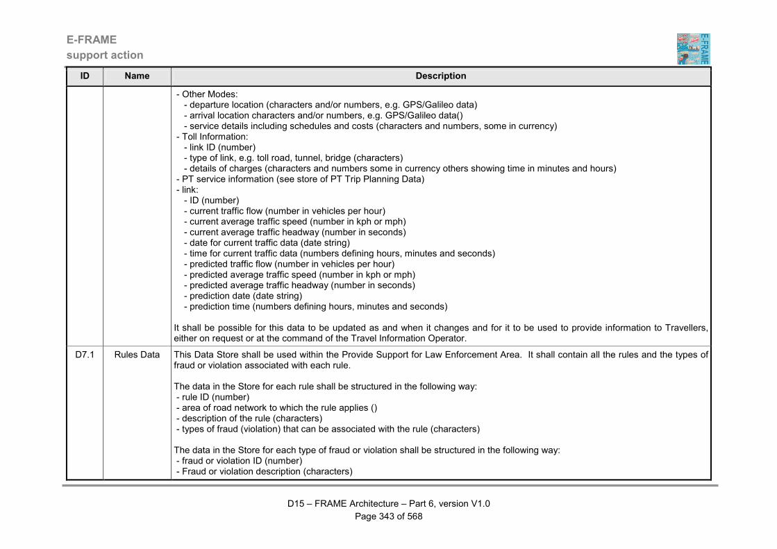
E-FRAME
support action
D15 – FRAME Architecture – Part 6, version V1.0
Page 343 of 568
ID Name Description
- Other Modes: - departure location (characters and/or numbers, e.g. GPS/Galileo data) - arrival location characters and/or numbers, e.g. GPS/Galileo data() - service details including schedules and costs (characters and numbers, some in currency) - Toll Information: - link ID (number) - type of link, e.g. toll road, tunnel, bridge (characters) - details of charges (characters and numbers some in currency others showing time in minutes and hours) - PT service information (see store of PT Trip Planning Data) - link: - ID (number) - current traffic flow (number in vehicles per hour) - current average traffic speed (number in kph or mph) - current average traffic headway (number in seconds) - date for current traffic data (date string) - time for current traffic data (numbers defining hours, minutes and seconds) - predicted traffic flow (number in vehicles per hour) - predicted average traffic speed (number in kph or mph) - predicted average traffic headway (number in seconds) - prediction date (date string) - prediction time (numbers defining hours, minutes and seconds) It shall be possible for this data to be updated as and when it changes and for it to be used to provide information to Travellers, either on request or at the command of the Travel Information Operator.
D7.1 Rules Data This Data Store shall be used within the Provide Support for Law Enforcement Area. It shall contain all the rules and the types of fraud or violation associated with each rule. The data in the Store for each rule shall be structured in the following way: - rule ID (number) - area of road network to which the rule applies () - description of the rule (characters) - types of fraud (violation) that can be associated with the rule (characters) The data in the Store for each type of fraud or violation shall be structured in the following way: - fraud or violation ID (number) - Fraud or violation description (characters)
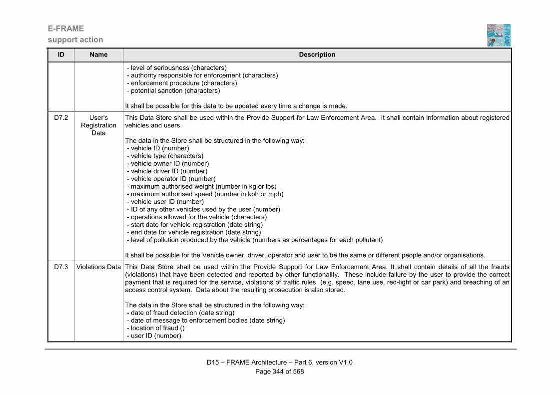
E-FRAME
support action
D15 – FRAME Architecture – Part 6, version V1.0
Page 344 of 568
ID Name Description
- level of seriousness (characters) - authority responsible for enforcement (characters) - enforcement procedure (characters) - potential sanction (characters) It shall be possible for this data to be updated every time a change is made.
D7.2 User's Registration
Data
This Data Store shall be used within the Provide Support for Law Enforcement Area. It shall contain information about registered vehicles and users. The data in the Store shall be structured in the following way: - vehicle ID (number) - vehicle type (characters) - vehicle owner ID (number) - vehicle driver ID (number) - vehicle operator ID (number) - maximum authorised weight (number in kg or lbs) - maximum authorised speed (number in kph or mph) - vehicle user ID (number) - ID of any other vehicles used by the user (number) - operations allowed for the vehicle (characters) - start date for vehicle registration (date string) - end date for vehicle registration (date string) - level of pollution produced by the vehicle (numbers as percentages for each pollutant) It shall be possible for the Vehicle owner, driver, operator and user to be the same or different people and/or organisations.
D7.3 Violations Data This Data Store shall be used within the Provide Support for Law Enforcement Area. It shall contain details of all the frauds (violations) that have been detected and reported by other functionality. These include failure by the user to provide the correct payment that is required for the service, violations of traffic rules (e.g. speed, lane use, red-light or car park) and breaching of an access control system. Data about the resulting prosecution is also stored. The data in the Store shall be structured in the following way: - date of fraud detection (date string) - date of message to enforcement bodies (date string) - location of fraud () - user ID (number)
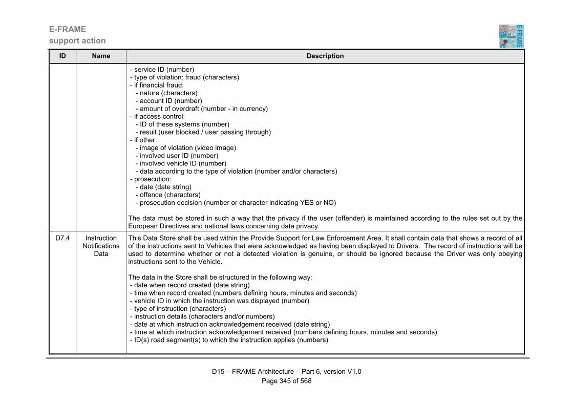
E-FRAME
support action
D15 – FRAME Architecture – Part 6, version V1.0
Page 345 of 568
ID Name Description
- service ID (number) - type of violation: fraud (characters) - if financial fraud: - nature (characters) - account ID (number) - amount of overdraft (number - in currency) - if access control: - ID of these systems (number) - result (user blocked / user passing through) - if other: - image of violation (video image) - involved user ID (number) - involved vehicle ID (number) - data according to the type of violation (number and/or characters) - prosecution: - date (date string) - offence (characters) - prosecution decision (number or character indicating YES or NO) The data must be stored in such a way that the privacy if the user (offender) is maintained according to the rules set out by the European Directives and national laws concerning data privacy.
D7.4 Instruction Notifications
Data
This Data Store shall be used within the Provide Support for Law Enforcement Area. It shall contain data that shows a record of all of the instructions sent to Vehicles that were acknowledged as having been displayed to Drivers. The record of instructions will be used to determine whether or not a detected violation is genuine, or should be ignored because the Driver was only obeying instructions sent to the Vehicle. The data in the Store shall be structured in the following way: - date when record created (date string) - time when record created (numbers defining hours, minutes and seconds) - vehicle ID in which the instruction was displayed (number) - type of instruction (characters) - instruction details (characters and/or numbers) - date at which instruction acknowledgement received (date string) - time at which instruction acknowledgement received (numbers defining hours, minutes and seconds) - ID(s) road segment(s) to which the instruction applies (numbers)
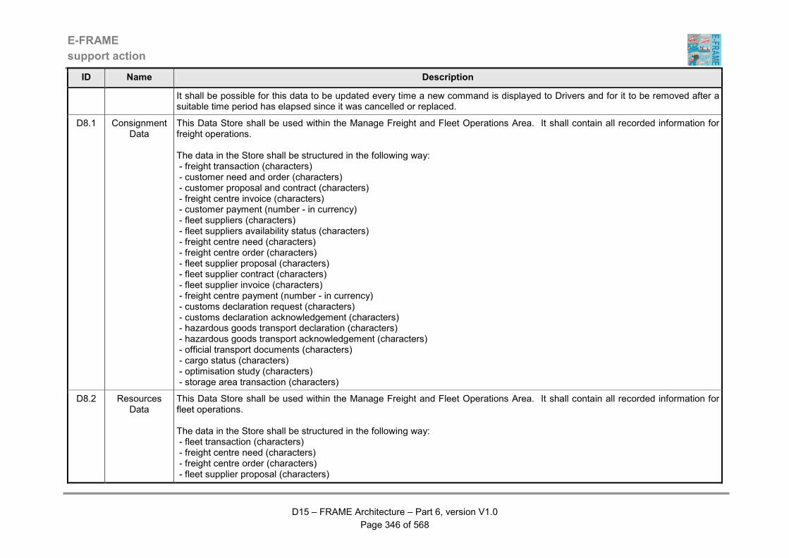
E-FRAME
support action
D15 – FRAME Architecture – Part 6, version V1.0
Page 346 of 568
ID Name Description
It shall be possible for this data to be updated every time a new command is displayed to Drivers and for it to be removed after a suitable time period has elapsed since it was cancelled or replaced.
D8.1 Consignment Data
This Data Store shall be used within the Manage Freight and Fleet Operations Area. It shall contain all recorded information for freight operations. The data in the Store shall be structured in the following way: - freight transaction (characters) - customer need and order (characters) - customer proposal and contract (characters) - freight centre invoice (characters) - customer payment (number - in currency) - fleet suppliers (characters) - fleet suppliers availability status (characters) - freight centre need (characters) - freight centre order (characters) - fleet supplier proposal (characters) - fleet supplier contract (characters) - fleet supplier invoice (characters) - freight centre payment (number - in currency) - customs declaration request (characters) - customs declaration acknowledgement (characters) - hazardous goods transport declaration (characters) - hazardous goods transport acknowledgement (characters) - official transport documents (characters) - cargo status (characters) - optimisation study (characters) - storage area transaction (characters)
D8.2 Resources Data
This Data Store shall be used within the Manage Freight and Fleet Operations Area. It shall contain all recorded information for fleet operations. The data in the Store shall be structured in the following way: - fleet transaction (characters) - freight centre need (characters) - freight centre order (characters) - fleet supplier proposal (characters)
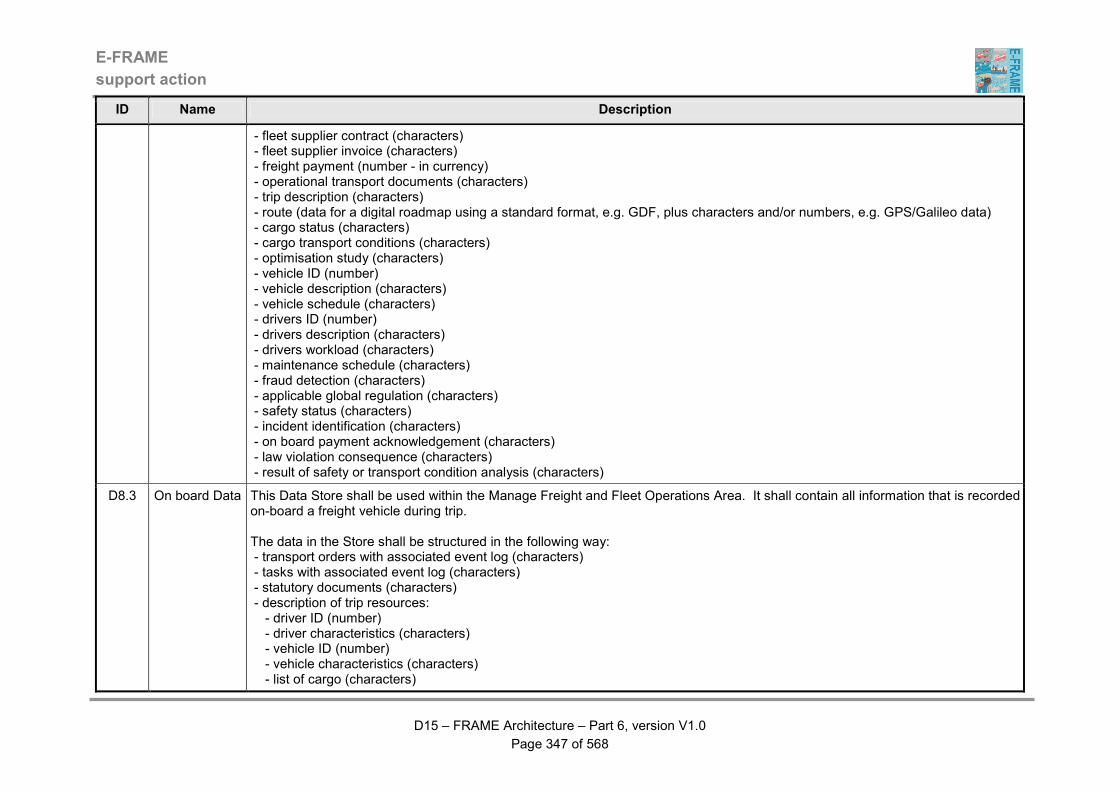
E-FRAME
support action
D15 – FRAME Architecture – Part 6, version V1.0
Page 347 of 568
ID Name Description
- fleet supplier contract (characters) - fleet supplier invoice (characters) - freight payment (number - in currency) - operational transport documents (characters) - trip description (characters) - route (data for a digital roadmap using a standard format, e.g. GDF, plus characters and/or numbers, e.g. GPS/Galileo data) - cargo status (characters) - cargo transport conditions (characters) - optimisation study (characters) - vehicle ID (number) - vehicle description (characters) - vehicle schedule (characters) - drivers ID (number) - drivers description (characters) - drivers workload (characters) - maintenance schedule (characters) - fraud detection (characters) - applicable global regulation (characters) - safety status (characters) - incident identification (characters) - on board payment acknowledgement (characters) - law violation consequence (characters) - result of safety or transport condition analysis (characters)
D8.3 On board Data This Data Store shall be used within the Manage Freight and Fleet Operations Area. It shall contain all information that is recorded on-board a freight vehicle during trip. The data in the Store shall be structured in the following way: - transport orders with associated event log (characters) - tasks with associated event log (characters) - statutory documents (characters) - description of trip resources: - driver ID (number) - driver characteristics (characters) - vehicle ID (number) - vehicle characteristics (characters) - list of cargo (characters)
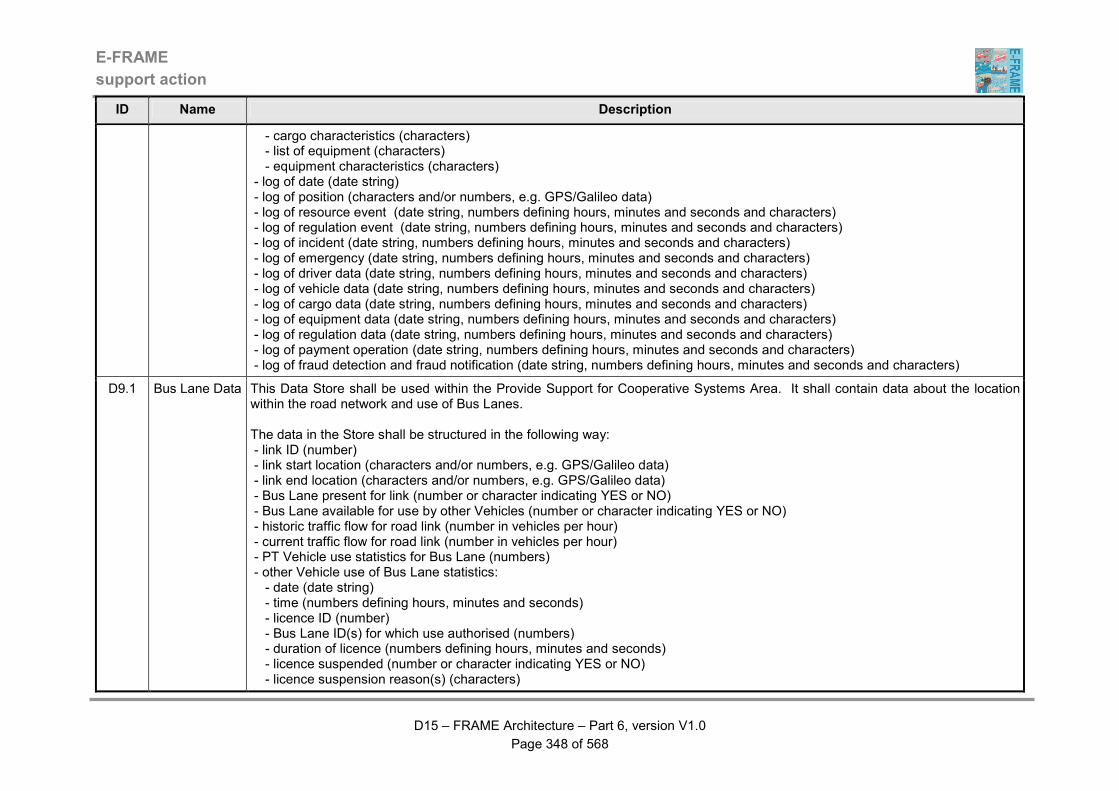
E-FRAME
support action
D15 – FRAME Architecture – Part 6, version V1.0
Page 348 of 568
ID Name Description
- cargo characteristics (characters) - list of equipment (characters) - equipment characteristics (characters) - log of date (date string) - log of position (characters and/or numbers, e.g. GPS/Galileo data) - log of resource event (date string, numbers defining hours, minutes and seconds and characters) - log of regulation event (date string, numbers defining hours, minutes and seconds and characters) - log of incident (date string, numbers defining hours, minutes and seconds and characters) - log of emergency (date string, numbers defining hours, minutes and seconds and characters) - log of driver data (date string, numbers defining hours, minutes and seconds and characters) - log of vehicle data (date string, numbers defining hours, minutes and seconds and characters) - log of cargo data (date string, numbers defining hours, minutes and seconds and characters) - log of equipment data (date string, numbers defining hours, minutes and seconds and characters) - log of regulation data (date string, numbers defining hours, minutes and seconds and characters) - log of payment operation (date string, numbers defining hours, minutes and seconds and characters) - log of fraud detection and fraud notification (date string, numbers defining hours, minutes and seconds and characters)
D9.1 Bus Lane Data This Data Store shall be used within the Provide Support for Cooperative Systems Area. It shall contain data about the location within the road network and use of Bus Lanes. The data in the Store shall be structured in the following way: - link ID (number) - link start location (characters and/or numbers, e.g. GPS/Galileo data) - link end location (characters and/or numbers, e.g. GPS/Galileo data) - Bus Lane present for link (number or character indicating YES or NO) - Bus Lane available for use by other Vehicles (number or character indicating YES or NO) - historic traffic flow for road link (number in vehicles per hour) - current traffic flow for road link (number in vehicles per hour) - PT Vehicle use statistics for Bus Lane (numbers) - other Vehicle use of Bus Lane statistics: - date (date string) - time (numbers defining hours, minutes and seconds) - licence ID (number) - Bus Lane ID(s) for which use authorised (numbers) - duration of licence (numbers defining hours, minutes and seconds) - licence suspended (number or character indicating YES or NO) - licence suspension reason(s) (characters)
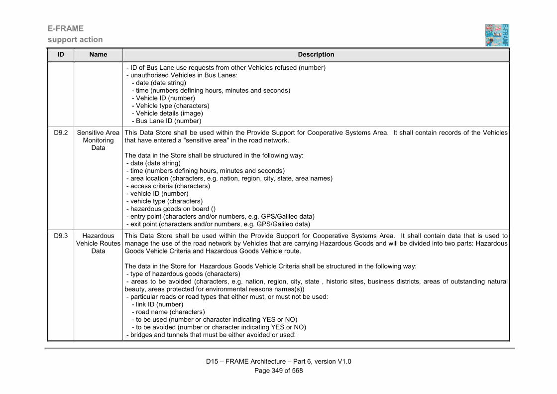
E-FRAME
support action
D15 – FRAME Architecture – Part 6, version V1.0
Page 349 of 568
ID Name Description
- ID of Bus Lane use requests from other Vehicles refused (number) - unauthorised Vehicles in Bus Lanes: - date (date string) - time (numbers defining hours, minutes and seconds) - Vehicle ID (number) - Vehicle type (characters) - Vehicle details (image) - Bus Lane ID (number)
D9.2 Sensitive Area Monitoring
Data
This Data Store shall be used within the Provide Support for Cooperative Systems Area. It shall contain records of the Vehicles that have entered a "sensitive area" in the road network. The data in the Store shall be structured in the following way: - date (date string) - time (numbers defining hours, minutes and seconds) - area location (characters, e.g. nation, region, city, state, area names) - access criteria (characters) - vehicle ID (number) - vehicle type (characters) - hazardous goods on board () - entry point (characters and/or numbers, e.g. GPS/Galileo data) - exit point (characters and/or numbers, e.g. GPS/Galileo data)
D9.3 Hazardous Vehicle Routes
Data
This Data Store shall be used within the Provide Support for Cooperative Systems Area. It shall contain data that is used to manage the use of the road network by Vehicles that are carrying Hazardous Goods and will be divided into two parts: Hazardous Goods Vehicle Criteria and Hazardous Goods Vehicle route. The data in the Store for Hazardous Goods Vehicle Criteria shall be structured in the following way: - type of hazardous goods (characters) - areas to be avoided (characters, e.g. nation, region, city, state , historic sites, business districts, areas of outstanding natural beauty, areas protected for environmental reasons names(s)) - particular roads or road types that either must, or must not be used: - link ID (number) - road name (characters) - to be used (number or character indicating YES or NO) - to be avoided (number or character indicating YES or NO) - bridges and tunnels that must be either avoided or used:
E-FRAME
support action
D15 – FRAME Architecture – Part 6, version V1.0
Page 350 of 568
ID Name Description
- bridge/tunnel ID (number) - bridge/tunnel name (characters) - to be used (number or character indicating YES or NO) - to be avoided (number or character indicating YES or NO) - the use or avoidance of particular service areas or rest zones within service areas: - service/rest area ID (number) - service/rest area name (characters) - to be used (number or character indicating YES or NO) - to be avoided (number or character indicating YES or NO) - the use or avoidance of car parks: - car park ID (number) - car park name (characters) - to be used (number or character indicating YES or NO) - to be avoided (number or character indicating YES or NO) - when Vehicles carrying Hazardous Goods are allowed to travel: - date (date string) - start time (numbers defining hours, minutes and seconds) - end time (numbers defining hours, minutes and seconds) The data in the Store for Hazardous Goods Vehicle routes shall be structured in the following way: - type of hazardous goods (characters) - vehicle type (characters) - route (data for a digital roadmap using a standard format, e.g. GDF, plus characters and/or numbers, e.g. GPS/Galileo data) - date last used (date string) - time last used (numbers defining hours, minutes and seconds) - currently in use (number or character indicating YES or NO)
D9.4 Loading or Unloading
Zone Use Data
This Data Store shall be used within the Provide Support for Cooperative Systems Area. It shall contain data about the use and characteristics of loading and unloading zones plus holding zones that are used by Freight Vehicles to pick-up and deliver goods. The data for each zone shall be split into two parts: static data and dynamic data The static data in the Store about each zone shall be structured in the following way: - zone location (characters and/or numbers, e.g. GPS/Galileo data) - zone size (number) - type of goods that the zone can accommodate (characters) - restrictions on use of the zone (characters) - type(s) of Vehicle that the zone will accommodate (characters)
E-FRAME
support action
D15 – FRAME Architecture – Part 6, version V1.0
Page 351 of 568
ID Name Description
- number(s) of Vehicles of different types that can be accommodated (number) - road network in and around zone (data for a digital roadmap using a standard format, e.g. GDF) - zone entry point (characters and/or numbers, e.g. GPS/Galileo data) - zone exit point characters and/or numbers, e.g. GPS/Galileo data() This static data shall be repeated for each zone of each type. The dynamic data in the Store about each zone shall be structured in the following way: - date when zone is booked (date string) - time when zone is booked (numbers defining hours, minutes and seconds) - number of Vehicles that have booked a place for date/time (number) - the ID of each Vehicle for each booking (number) - expected duration of stay for each booked Vehicle (numbers defining hours, minutes and seconds) - the ID of the Vehicle currently occupying the zone (number) It shall be possible for the dynamic data to be repeated for each booking of each type of zone and to be updated as soon as the data changes.

E-FRAME
support action
D15 – FRAME Architecture – Part 6, version V1.0
Page 352 of 568
Table 4 - Descriptions of Functions
ID Name Description Functional Requirements
1.1.1 Create EP Contract
This Function shall be capable of providing the following facilities: (1) A HMI through which the Traveller can establish a contract with an Electronic Fee Collection Operator, or a Service Provider. (2) The HMI shall present the Traveller with information about the different types of services available, and record the choices that they make for use by other functionality.
(a) read user's request : type of service on which information is required, (b) receive corresponding elements from the "Provide Traveller Journey Assistance" Function. (c) display corresponding information to the user (d) read user's choice (e) write contract (f) display the contract to the user, record it in the store of "EP contract" Data.
1.1.2 Establish Contract Statistics
This Function shall be capable of providing the following facilities: (1) The ability to process the different contracts made by the travellers to produce statistical information for the corresponding Electronic Fee Collection Operators, or Service Providers.
(a) process the different contracts (sent on a regular basis) to extract different kinds of information : e.g. number per service, chosen modes of payment, locations of contract set-up ... (b) send the resulting statistics to the corresponding operators and/or service providers
1.1.3 Manage Service Data
This Function shall be capable of providing the following facilities: (1) The ability to manage the content of the store of Service Information Data. (2) The management of the store shall enable an Operator to review the contents of the store, to add, delete, or amend the contents. (3) The management of the store shall also enable the contents of the store to be updated by Service Providers.
(a) when the trigger input data flow is received, check to see if a review command or data has been sent (b) if a review comment is received in (a), collect all of the current data from the store of Service Information Data using the other input data flow (c) send the data obtained in (b) to the Operator using the second other output data flow (d) if data was received in (a), send it to the store of Service Information Data using the first other output data flow, to add to, or amend the data the store currently contains (e) if a "delete" command was received in (a) then use the first other output data flow to send an appropriate delete command to the store of Service Information Data.
1.2.1 Load User's Account
This Function shall be capable of providing the following facilities:
(a) read traveller's ID (b) extract from the store of Contract Data the contracts that have already
E-FRAME
support action
D15 – FRAME Architecture – Part 6, version V1.0
Page 353 of 568
ID Name Description Functional Requirements
(1) A HMI that provides the Traveller with the ability to credit their Electronic Payment account. (2) The HMI shall also include the ability to display to the Traveller the different contracts available to that person, read the information related to the desired transaction. (3) In addition to the HMI, the ability to check the credit rating of the source account and if credit worthy, credit the Electronic Payment account, plus notify this to the Financial Clearinghouse terminator, and to the store of Transaction Data. (4) The ability to also check the amount that is being credited to an account previously included in the black list, and if the new balance is sufficient, send a message to the “Credit Control” Function to remove this account from the black-list.
been established for that person (c) present the traveller with this list of contracts (d) read the traveller's selection and the loading parameters (e) check the balance of the "source" account at the financial clearing-house (f) if source account does not have sufficient funds, display an error message to the traveller, (g) else, record loading transaction in the store of "transaction" Data, load the Electronic Payment account, and send the notification message to the financial clearing-house
1.2.2 Debit User's Account
This Function shall be capable of providing the following facilities: (1) The ability to debit the Traveller's Electronic Payment account as the result of the recently performed transaction. (2) If the Traveller's account becomes overdrawn the ability to send a message highlighting this situation to the “Credit Control” function.
(a) read the transaction message, and extract the user's ID, account ID, corresponding fee (b) get the balance of the EP account (c) debit the balance by the amount of the transaction, and record the operation in the stores of "transactions" Data and "user's account" Data (d) if the "user's account" is now overdrawn, send an overdraft message to the traveller and to "Credit Control".
1.2.3 Inform Users on
Transactions
This Function shall be capable of providing the following facilities: (1) A HMI through which the Traveller can be provided with a list of the transactions they have performed. (2) The HMI shall also provide the Traveller with the status of their Electronic Payment account(s). (3) Also the HMI shall only provide both types of information following a specific request from the
(a) read the traveller's request for information (b) if asked extract from the store of "user's account" Data the status of the traveller's account (c) if asked extract from the store of "transactions" Data the list of all the transactions performed by the traveller during the specified period, with the application of filters according to traveller's requests (d) present the information to the traveller.

E-FRAME
support action
D15 – FRAME Architecture – Part 6, version V1.0
Page 354 of 568
ID Name Description Functional Requirements
Traveller and shall only provide information that is directly relevant to that Traveller.
1.3.1 Detect User This Function shall be capable of providing the following facilities: (1) The ability to detect the approach of a Traveller or Vehicle. (2) When detected, the ability to trigger the other functionality in the Provide Electronic Payment Facilities Area.
(a) detect approaching vehicle or traveller, (b) send a detection message to the identify user Function
1.3.2 Identify User This Function shall be capable of providing the following facilities: (1) The ability to identify the Traveller, Driver or the Vehicle. (2) Having completed the identification, the ability to inform other functionality about the use that is being made of various parts of the road transport infrastructure, e.g. parking occupancy, time of travel between toll gates, etc.
(a) continuously monitor for the detection of a vehicle or traveller (b) when a vehicle or traveller is detected ask for identification (c) reads this identification (d) sends the identification to "Access and Credit Control" (e) extracts the last related transaction for this user from the "transaction" database (f) computes infrastructure usage information (g) sends it to other Functions
1.3.3 Check User's Contract
This Function shall be capable of providing the following facilities: (1) The ability to read the corresponding contracts, and verify the access rights, based on the user's ID. (2) If there is a "free ride" request, the ability to cancel the rest of the transaction.
(a) receive user ID and service request (b) extract corresponding contract from the store of "contract" Data (c) check the access rights by asking the "Access Control" Function, (d) sends the contract information back to the "inform and guide user" Function (e) in case of reception of a "free ride request", no further checks are performed
1.3.4 Inform and Guide User
This Function shall be capable of providing the following facilities: (1) A HMI through which the Traveller or Driver can be guided to provide the precise definition of the service that they want, and the way that they wish to pay for it. (2) The HMI shall also enable the Traveller or Driver to
(a) get the information about the service requested from the MPTO or PTJA areas, or directly from the user. (b) if these areas just ask for a tariff (and not a transaction), go to (g) (c) get user's ID (d) obtain the corresponding contracts (e) get user's choice of contract (f) check with "Access" and/or "Credit Control" and, if necessary, register
E-FRAME
support action
D15 – FRAME Architecture – Part 6, version V1.0
Page 355 of 568
ID Name Description Functional Requirements
select the appropriate contract, inform them about their rights to use the service, and display the associated price. (3) The ability for the Function to be activated by functionality in either the Manage Public Transport Operations Area or the Provide Traveller Journey Assistance Area, or even directly for simple operations. (4) The ability to ask for a credit check to be done on the Traveller or Driver and also to check to see whether an advance payment has been made. (5) The ability to initiate the recovery of any advanced payment, or else initiate the computation of the fee.
a violation. (g) send the choice and contract to 1.3.6 to check if advanced payment has been made (h) send the different elements to 1.3.5 to initiate the computation of the corresponding fee (i) if payment has already been completely made, send an agreement to the "Access Control" system (j) if not, reduce the fee by the amount already paid, send the elements to 1.3.7 to recover fees,
1.3.5 Compute Service Fee
This Function shall be capable of providing the following facilities: (1) The ability to calculate the fee corresponding to the service required by the user (Traveller or Driver), based on the characteristics of this service, and on the contract established by the user. (2) The ability to use the general tariffs for the service that are held in a store of Tariffs Data. (3) The ability to vary the fee depending on the current situation.
(a) analyse the contract to determine the tariff included for the specified service, taking into account the vehicle's position. (b) extract from the store of "tariffs" Data the corresponding fees (c) compute the exact fee, taking into account elements from the contract (rebates.…), and from the traffic conditions
1.3.6 Check Advanced Payment
This Function shall be capable of providing the following facilities: (1) The ability to verify whether the service required by the user (Traveller or Driver) has been paid for in advance. (2) The ability for the advanced payment to have covered the total amount required as payment for the service, or to have covered just part of the amount.
(a) read the service request, and the contract data (b) extract from the store of "transaction" Data the different transactions which could correspond to these elements (c) check if the service has actually been paid (d) send the answer to the Inform and Guide Users function
1.3.7 Recover Fee This Function shall be capable of providing the following facilities:
(a) receive payment elements from 1.3.4 or 1.3.5: amount, payment mode,
E-FRAME
support action
D15 – FRAME Architecture – Part 6, version V1.0
Page 356 of 568
ID Name Description Functional Requirements
(1) A HMI through which it shall be possible to ask the Traveller or Driver for payment for the selected service. (2) Once the Traveller or Driver has responded to the request for payment, the ability to check with “Credit Control” for the transaction to be validated. (3) If the transaction is not valid for some reason the ability to register it as a violation.
(b) ask the user for payment, (c) check the payment. If an account number is given, and if the number is on the black list, register a violation. if payment is correct : (d) confirm with "Credit Control" (e) in case of a payment made by a freight vehicle, send a receipt to the MFFO area. (f) send an acceptance message to the user
1.4.1 Distribute Fees
Revenue
This Function shall be capable of providing the following facilities: (1) The ability to apportion the payments received amongst the operators according to rules defined in the store of Service Information Data. (2) The ability to send the apportioned payment details to the functionality for crediting Service Operators' accounts.
(a) read the information about the transaction, and extract the operators ID and service concerned (b) extract from the store of "service information" Data the rules to be followed concerning the allocation of revenue for this service (c) compute the corresponding revenue for each operator (d) send the result to the Credit Operator's Account function
1.4.2 Credit Operator's Account
This Function shall be capable of providing the following facilities: (1) The ability to credit the accounts of the Service Operators by the amount that has already been calculated. (2) The ability to receive the calculated creidt amount from the functionality that distributes fees revenue.
(a) read the different elements included in the message coming from "Distribute Fee Revenues". (b) sends the credit order to the financial clearinghouse, including the fee, the originating account, and the account to be credited, (c) load the transaction into the store of "transactions" Data.
1.4.3 Inform Operators
on Transactions
This Function shall be capable of providing the following facilities: (1) An interface that enables for the Operators, and Service Providers to view all the transactions concerning the services that they provide. (2) The ability for the interface to only provide information to Operators and External Service Providers on request.
(a) get the request from the Operator or Service Provider, including its ID, services of interest, period, ...; (b) extract the corresponding transactions from the store of "transactions" Data, restricting retrieval to only these transactions are those concerning directly the requesting Operator or Service Provider, or those that resulted in some revenue for them; (c) process them to obtain the desired information; (d) present the results to the Operator or Service Provider.
E-FRAME
support action
D15 – FRAME Architecture – Part 6, version V1.0
Page 357 of 568
ID Name Description Functional Requirements
(3) The interface shall only have the ability to provide information to External Service Providers that is relevant to them and not information that is relevant to other Service Providers.
1.5.1 Check User's rights
This Function shall be capable of providing the following facilities: (1) The ability to determine the access rights of users (Travellers and Drivers) to the service(s) that they have requested. (2) The ability to use the ID of the user, or the characteristics of the Vehicle they are using, and traffic conditions in comparison with the access criteria obtained from the store of Access Rights Data to determine the users' access rights. (3) The ability to send the result of the access rights determination to the inform and guide user and/or the check user's rights functionality, depending on the origin of the request.
(a) get the user ID or vehicle's characteristics and the requested service (b) extract from the "access rights" database the corresponding access criteria (c) determine the access rights, taking into account actual traffic conditions (d) send the answer to the functions that need it.
1.5.2 Detect Payment Violations
This Function shall be capable of providing the following facilities: (1) The ability to check the status of a user’s (Traveller or Driver) account. (2) If an overdraft notification has been received for this account (or for several different accounts with the same owner), the ability to include the account(s) in the "black list", which means that the user shall not be allowed to use this account until sufficient funds have been provided to rectify the situation, unless an “agreement” message has been received.
(a) process the status changes of user's account: if an overdraft notification received write the account number in the black list. Conversely, if new account balance is above a certain threshold, remove it from the black list. (b) if an agreement message is received, indicate that the user is allowed to use the service. (c) send the fraud notification to the PSLE area (d) register s all payment violations in the store of "fraud" Data, and initiate a block on the use of that service.
1.5.3 Detect Access violations
This Function shall be capable of providing the following facilities: (1) The ability to register all attempts to use a service
(a) receive a fraud detection messages (b) sends a "block" command to the "Block Access" Function (c) send the fraud notification to the PSLE area (d) record the offence in the store of "fraud" Data.

E-FRAME
support action
D15 – FRAME Architecture – Part 6, version V1.0
Page 358 of 568
ID Name Description Functional Requirements
without having first fulfilled the required conditions. (2) If attempts have been made, the ability to block on the use of the service via the block access functionality and to register the offence in the store of Fraud Data.
1.5.5 Block Access to Service
This Function shall be capable of providing the following facilities: (1) The ability to control the access of a user (Traveller or Driver) to the requested service. (2) Upon detection of a violation, the ability to send a message to the access violations detection functionality. (3) If an accident has been detected, the ability to send a warning to functionality in the Manage Traffic Functional Area. (4) The ability to let the user proceed upon receipt of an agreement message from the violation detection functionality. (5) A HMI through which the user can be informed about whether or not access to the requested service has been granted.
(a) upon reception of a message indicating a violation, prevent the user from using a service (b) upon reception of a "free" command, allow the user to proceed (d) send a warning message to the manage traffic area
1.6.1 Manage Tariffs
This Function shall be capable of providing the following facilities: (1) The ability to manage the store of "tariffs" Data. (2) The ability to load the store with details of PT fares received from functionality in the Manage Public Transport Functional Area and/or details of charges for road use from functionality in the Manage Traffic Functional Area. (3) The ability to define within the store, the structure in which the "tariffs" data will be stored, with different structures being possible for PT fares and charges for road use.
(a) receive updates of tariff grids from the different operators, service providers, Public Transport operator, or demand management Function (b) reformat them, (c) fill the store of "tariffs" Data with the new tariff grids
E-FRAME
support action
D15 – FRAME Architecture – Part 6, version V1.0
Page 359 of 568
ID Name Description Functional Requirements
1.6.2 Manage Access Rights
This Function shall be capable of providing the following facilities: (1) The ability to manage the store of "access rights" Data. (2) The ability to load the store with criteria for access parts of the road network that can only be used if some form of charge is paid.
(a) receive updates of access rights criteria from the different operators, service providers, and from the "Manage Traffic" area. (b) reformat them, (c) fill the store of "access rights" Data with the data.
2.1.2.1 Identify and Classify
Emergencies
This Function shall be capable of providing the following facilities: (1) The ability to collect incident notifications from a variety of sources. (2) The capability to filter and obtain associated information (e.g. location, cargo status, Vehicle identification, Traveller identification) to produce the data needed for the planning of the appropriate response from the Emergency Services. (3) The ability to provide an initial (first) acknowledgement of incident notification to its source, e.g. eCall from inside or outside the Vehicle. (4) The ability to classify incidents and to provide data about them to other functionality so that the appropriate response can be planned and implemented and traffic management action can be taken.
(a) receive mayday call/incident notification (b) send immediate acknowledgement and incident notification for traffic management purpose (c) request for storage of the incident (d) associate to each one a confidence parameter (e) gather incident and increase associate confidence parameter (f) when confidence is right create an emergency (g) complete information on involved vehicle and traveller (h) request for storage of the emergency (i) request for emergency planning.
2.1.2.3 Plan Emergency Intervention
This Function shall be capable of providing the following facilities: (1) The ability to define and/or build the emergency plan that defines how the Emergency Services will respond a particular incident. (2) As part of the definition of the emergency plan, be able to select the required emergency services, use pre-defined response procedures, request (green
(a) wait for an emergency to be planned (b) load all information on emergency (c) choose the right procedure for the emergency (d) inside the procedure: - contact emergency services - plan their intervention : select the emergency route (pre-defined route or new computed one if needed) - send the selected route to emergency driver - store the plan
E-FRAME
support action
D15 – FRAME Architecture – Part 6, version V1.0
Page 360 of 568
ID Name Description Functional Requirements
wave) routes for Emergency Vehicles and request that the routes are implemented. (3) The ability to contact the required emergency services and establish with them the action plans.
- request for emergency processing.
2.1.2.4 Process Emergency Progress Reports
This Function shall be capable of providing the following facilities: (1) The ability to provide the full acknowledgement of the response to incidents to the originators. (2) The ability to prepare reports about the current progress with the response to incidents, i.e. how the emergency plan is being implemented. (3) The ability to provide updates to the functionality that provides the management of road traffic in the geographic area where the incident occurred.
(a) wait for an emergency to process (b) load all information on emergency (c) send fully informed acknowledgement to traveller and authorities (d) receive progress reports from emergency services (e) analyse them in order to verify that process is OK (f) collect them to send a global progress report to emergency services and relevant authorities (g) in case of any problem request for e-classification or re-planning (h) store all information on process.
2.1.2.5 Manage Incident and Emergency
Data
This Function shall be capable of providing the following facilities: (1) The ability to manage the contents of the Store of Incident and Emergency Data. (2) The ability to receive data about incidents and the way that their responses are being processed (emergemcy plans) and update them in the Store of Incident and Emergency Data. (3) The ability to pass on incident descriptions when they are received to the functionality for planning emergency interventions.
(a) store incident and emergency description when requested (b) load information from incident or emergency with the requested criteria (c) compute statistic from incident and emergency data.
2.1.5 Provide Access and Maintain Data for
Emergency
This Function shall be capable of providing the following facilities: (1) The maintenance of a Data Store containing data that is used during the processing of an incident or an emergency. (2) The ability to send requests for updates (refresh) of the route previously provided for an Emergency
(a) load /read data in response to request for emergency progressing (b) prepare emergency route to main districts of the controlled area and upgrade them when needed (c) upgrade road network map when necessary.
E-FRAME
support action
D15 – FRAME Architecture – Part 6, version V1.0
Page 361 of 568
ID Name Description Functional Requirements
Vehicle based on new data, or input from the Emergency Operator received from the Operator Interface Function. (3) The provision of data to the Emergency Operator following a specific request made through the Operator Interface Function. (4) The ability to receive data about an incident or emergency from the Emergency Services. (5) The ability to receive updated map data for use in the response to the incident or emergency. (6) The provision of common data for use in creating emergency intervention plans and classifying emergencies that has been.
2.1.7 Manage use of
Emergency Vehicle
This Function shall be capable of providing the following facilities: (1) The provision of a HMI through which the Emergency Vehicle Driver can be presented with details of the route to be followed by the Emergency Vehicle. (2) The ability to receive data from other functionality about the route that the Emergency Vehicle is to follow. (3) The ability to request that traffic signal intersection controllers provide local priority to the Emergency Vehicle in accordance with a route provided by the Emergency Vehicle Driver. (4) The ability to maintain the up to date details of the current location of the Emergency Vehicle for use in local priority requests. (5) The ability to request the deployment of "virtual cones" at an incident location, following a command from the Emergency Vehicle Driver. (6) The ability to inform other suitably equipped Vehicles that an Emergency Vehicle is approaching.
(a) continuously monitor for receipt of any of the input data flows (b) when the planned emergency route data flow is received in (a) implement the route that it contains (c) use the data in the digital map data for emergency vehicle and location data flows to determine which part of the emergency route is to be implemented next and for which guidance will be needed (d) using the results from (c), provide route guidance instructions to the emergency vehicle driver using the emergency route guidance data flow (e) use the data in (c) to determine which are the next road segments and use this data in the emergency vehicle approaching data flow which shall be sent to the Mange Infrastructure to Vehicle Communications function (f) the activities in (d) and (e) shall stop when the data in (b) and (c) shows that the emergency vehicle has reached the end of the green wave route (g) when the green wave request data flow is received in (a) from the emergency vehicle driver, use the data in the digital map data for emergency vehicle and location data flows to determine the location and identity of the next signalised junction in the direction of travel of the vehicle (h) put the data obtained in (g) into the emergency local priority request data flow and send it to the Output Stop & Go Commands function so that local priority can be provided (i) repeat (g) and (h) until the green wave request data flow contains a
E-FRAME
support action
D15 – FRAME Architecture – Part 6, version V1.0
Page 362 of 568
ID Name Description Functional Requirements
null indicating that priority is not longer required (j) when the deploy virtual cones data flow is received in (a) from the emergency vehicle driver, use the use the data in the digital map data for emergency vehicle and location data flows to determine where the virtual cones need to be deployed (k) put the data obtained in (j) into whichever is appropriate of the inter-urban virtual coned area request and/or urban virtual coned area request data flows and send them the appropriate Implement Traffic Control function (l) when the global emergency progress report data flow is received in (a) output its contents to the emergency vehicle driver in the global emergency data flow (m) when the individual emergency progress report data flow is received in (a) from the emergency vehicle driver, use its contents to create the report and send it to the Process Emergency Progress Reports function in the individual emergency progress report data flow.
2.1.8 Accept eCall input from outside the Vehicle
This Function shall be capable of providing the following facilities: (1) Enable a Traveller to send an "eCall" from a location that is outside the Vehicle. (2) Provide the Traveller with the acknowledgement for the "eCall" sent in (1). (3) Enable the Driver inside the Vehicle to be provided with a copy of the acknowledgement in (2). (4) Include suitable HMI's for both the Traveller outside the Vehicle and the Driver inside the Vehicle.
(a) wait for any traveller request (b) receive eCall (c) send it for process (d) wait for acknowledgement message (e) give contained information to traveller.
2.1.9 Provide Emergency Operator Interface
This Function shall be capable of providing the following facilities: (1) The provision of the HMI for the Emergency Operator so that emergencies and all related information can be managed. (2) Enable the Emergency Operator to manage the processing, classification and response to incidents or
(a) wait for request from operator and transmit it (b) wait for response and provide it to the operator.
E-FRAME
support action
D15 – FRAME Architecture – Part 6, version V1.0
Page 363 of 568
ID Name Description Functional Requirements
emergencies through Data Flow interfaces to other functionality. (3) Enable the Emergency Operator to request statistics about the occurrence of incidents and the responses to them.
2.2.1 Manage Stolen Vehicle Actions
This Function shall be capable of providing the following facilities: (1) The ability to collect the data sent to it by the actual stolen vehicle and forward it to other functionality that will send it to both the Emergency Operator and Emergency System terminators. (2) The ability to issue cancellation of the stolen Vehicle report when the appropriate data is received from the Vehicle.
(a) continuously monitor for the receipt of either of the input data flows (b) when the stolen vehicle notification data flow is received in (a) is received, re-format the data it contains as required (c) immediately (b) has been completed send notification to the functionality serving the emergency services in the stolen vehicle data for emergency services data flow and to the emergency operator in the stolen vehicle data for emergency operator data flow (d) keep an internal record of the stolen vehicle (e) when the data flow in (b) is received again but with a different location, repeat (b) and (c) (f) when the data flow in (b) is received again but with a notification that the vehicle is no longer stolen, repeat (b) and (c) and remove the internal record that was set up in (d) (g) when the send stop stolen vehicle message data flow is received, immediately send the stolen vehicle stop message to functionality in the Provide Advanced Driving Assistance Functional Area.
2.2.2 Manage Stolen Vehicle
Emergency Services Interface
This Function shall be capable of providing the following facilities: (1) An appropriate link to communicate to the Emergency Services the notification that a Vehicle has been stolen has been received. (2) The ability for the link to provide some form of alarm indication to draw the attention of the Emergency Services to the fact that a Vehicle has been stolen. (3) An appropriate link to communicate to the Emergency Services the notification that the stolen notification for a Vehicle has been cancelled, with again some form of alarm indication to draw the
(a) continuously monitor for the receipt of the stolen vehicle data for emergency services data flow (b) when the data flow in (a) is received, send the data it contains to the emergency services in the stolen vehicle information data flow (c) provide some form of alarm indication for the emergency system when the data in (b) is sent.
E-FRAME
support action
D15 – FRAME Architecture – Part 6, version V1.0
Page 364 of 568
ID Name Description Functional Requirements
attention to the new status.
2.2.3 Manage Stolen Vehicle
Emergency Operator Interface
This Function shall be capable of providing the following facilities: (1) An appropriatae HMI to communicate to the Emergency Services Operator the notification that a Vehicle has been stolen has been received. (2) The ability for the HMI to provide some form of alarm indication to draw the attention of the Emergency Operator to the fact that a Vehicle has been stolen. (3) An approprite HMI to communicate to the Emergency Services Operator the notification that the stolen notification for a Vehicle has been cancelled, with again some form of alarm indication to draw the attention to the new status.
(a) continuously monitor for the receipt of the stolen vehicle data for emergency operator data flow (b) when the data flow in (a) is received, send the data it contains to the emergency operator in the stolen vehicle information data flow (c) provide some form of audio/visual alarm indication to the emergency operator when the data in (b) is sent.
3.1.1.10 Collect Urban Traffic
Data
This Function shall be capable of providing the following facilities: (1) The collection of traffic flow data from sensors that are located within the urban road network managed by the System. (2) The sensors shall be capable of detecting the presence of all types of road Vehicle, from Bicycles to Heavy Goods Vehicles. (3) The processing of the raw input data provided by the sensors into actual traffic flow data, i.e. vehicle flow rates, vehicle speeds, etc. (4) The supply of the processed raw input data to other functionality in the Manage Traffic Functional Area for collation and use. Note that this Function shall not collect any data directly from Vehicles. It shall assume that all Vehicles are passive and not capable of providing data
(a) the presence of the trigger input data flow shall be continuously monitored (b) the analogue data representing raw traffic flow data obtained in (a) shall be processed into digital data such as, but not limited to, flow, speed, occupancy, headway, vehicle classification, and queue (c) the data for each point in the urban road network at which it was produced shall be kept separate (d) the trigger output data flows, shall be used to send the data in (c) to the urban road network traffic control and data management Functions.
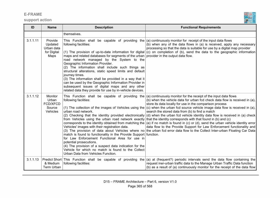
E-FRAME
support action
D15 – FRAME Architecture – Part 6, version V1.0
Page 365 of 568
ID Name Description Functional Requirements
themselves.
3.1.1.11 Provide Updated
Urban data for Digital Maps
This Function shall be capable of providing the following facilities: (1) The provision of up-to-date information for digital maps and related databases for segments of the urban road network managed by the System to the Geographic Information Provider. (2) The information shall include such things as structural alterations, static speed limits and default journey times. (3) The information shall be provided in a way that it can be used by the Geographic Information Provider in subsequent issues of digital maps and any other related data they provide for use by in-vehicle devices.
(a) continuously monitor for receipt of the input data flows (b) when any of the data flows in (a) is received, apply any necessary processing so that the data is suitable for use by a digital map provider (c) on completion of (b), send the data to the geographic information provider in the output data flow.
3.1.1.12 Monitor Urban
FCD/XFCD Source Vehicles
This Function shall be capable of providing the following facilities: (1) The collection of the images of Vehicles using the urban road network. (2) Checking that the identity provided electronically from Vehicles using the urban road network exactly corresponds to the identity obtained from matching the Vehicles' images with their registration data. (3) The provision of data about Vehicles where no match is found to functionality in the Provide Support for Law Enforcement Functional Area for use in potential prosecutions. (4) The provision of a suspect data indication for the Vehicle for which no match is found to the Collect Urban Data from Vehicles Function.
(a) continuously monitor for the receipt of the input data flows (b) when the vehicle data for urban fcd check data flow is received in (a), store its data locally for use in the comparison process (c) when the urban fcd source vehicle image data flow is received in (a), search the stored data from (b) to find a match (d) when the urban fcd vehicle identity data flow is received in (a) check that the identity corresponds with that found in (b) and (c) (e) if no match is found in (c) or (d), send the urban vehicle identity error data flow to the Provide Support for Law Enforcement functionality and the urban fcd error data flow to the Collect Inter-urban Floating Car Data function.
3.1.1.13 Predict Short & Medium Term Urban
This Function shall be capable of providing the following facilities:
(a) at (frequent?) periodic intervals send the data flow containing the request iner-urban traffic data to the Manage Urban Traffic Data function (b) as a result of (a) continuously monitor for the receipt of the data flow

E-FRAME
support action
D15 – FRAME Architecture – Part 6, version V1.0
Page 366 of 568
ID Name Description Functional Requirements
Conditions (1) The ability to create short and medium term predictions of urban traffic data. (2) The ability to create the predictions of short and medium term urban traffic data using algorithms that may be different in content and scope. (3) The ability to request and use current urban traffic data as the starting point for the predictions of short and medium term urban traffic data. (4) The ability to repeat the creation of the predicted short and medium term urban traffic data at (frequent?) periodic intervals.
containing the requested urban traffic data (c) when the data flow in (b) is received, create the predictions of short and medium term urban traffic data using appropriate algorithms that may be different in content and scope (d) when (c) is complete, put the results in the short & medium predicted urban traffic data flow and send it to the Manage Urban Traffic Data function.
3.1.1.14 Manage Urban Traffic
Data
This Function shall be capable of providing the following facilities: (1) The ability to manage the store of Inter-urban Traffic Data. (2) The ability to collect data about traffic conditions (i.e. traffic flows, road segment use, journey times, etc.) in the urban road network and car park data from other functionality in the Manage Traffic Functional Area. (3) The ability to receive data about traffic conditions (i.e. traffic flows, predicted road segment use (from trip plans), journey times, etc.) from functionality in the Provide Electronic Payment Facilities, Provide Support for Host Vehicle Systems and Provide Traveller Journey Assistance Functional Areas, plus the Cellular Communications Provider. (4) The ability to collate and fuse all data that is collected and received, using the inter-urban road network static data as a mechanism for achieving this where necessary. (5) The ability to exchange data collected by the Function with similar functionality in another instance of the System, through the Other Related System, Urban Traffic Management System.
(a) continuously monitor for receipt of any of the input data flows (b) when any of the data flows containing data about traffic using the urban road network is received, process the data, applying data fusion where the data relates to the same part of the road network (c) use the data received in the urban static data for traffic conditions data flow to determine the location and characteristics of the part of the urban road network to which the received data applies (d) convert the contents of data flow containing urban infrastructure usage data into actual traffic flows and apply it to the correct part(s) of the urban road network (e) load the results of (b) to (d) into the store of Urban Traffic Data, to provide the current traffic flow data and fusing it with data already in the store to provide a coherent set of historic traffic data for the urban network (f) also use the results of (b) to (d) to provide traffic data for other urban traffic management systems (g) analyse the results of (b) to (d) to determine where traffic queues are present and from use successive collections of data to determine the speed of propagation of the tail end of the queue (h) use the data received in the urban static data for traffic conditions data flow to determine the locations of the queues (i) send the results of (g) and (h) to the output warnings to the driver in the vehicle functionality (j) analyse the results of (b) to (d) to determine the current journey time for each segment of the urban road network store it in the store of Urban Traffic Data, fusing it with similar data already in the store to provide a
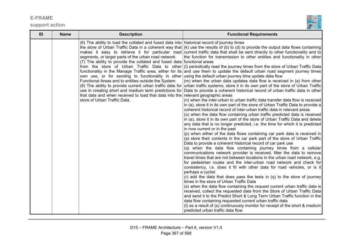
E-FRAME
support action
D15 – FRAME Architecture – Part 6, version V1.0
Page 367 of 568
ID Name Description Functional Requirements
(6) The ability to load the collated and fused data into the store of Urban Traffic Data in a coherent way that makes it easy to retrieve it for particular road segments, or larger parts of the urban road network. (7) The ability to provide the collated and fused data from the store of Urban Traffic Data to other functionality in the Manage Traffic area, either for its own use, or for sending to functionality in other Functional Areas and to entities outside the System. (8) The ability to provide current urban traffic data for use in creating short and medium term predictions for that data and when received to load that data into the store of Urban Traffic Data.
historical record of journey times (k) use the results of (b) to (d) to provide the output data flows containing current traffic data that shall be sent directly to other functionality and to the function for transmission to other entities and functionality in other functional areas (l) periodically read the journey times from the store of Urban Traffic Data and use them to update the default urban road segment journey times using the default urban journey time update data flow (m) when the urban data updates data flow is received in (a) from other urban traffic systems, store it in its own part of the store of Urban Traffic Data to provide a coherent historical record of urban traffic data in other relevant geographic areas (n) when the inter-urban to urban traffic data transfer data flow is received in (a), store it in its own part of the store of Urban Traffic Data to provide a coherent historical record of inter-urban traffic data in relevant areas (o) when the data flow containing urban traffic predicted data is received in (a), store it in its own part of the store of Urban Traffic Data and delete any data that is no longer predicted, i.e. the time for which it is predicted in now current or in the past (p) when either of the data flows containing car park data is received in (a) store their contents in the car park part of the store of Urban Traffic Data to provide a coherent historical record of car park use (q) when the data flow containing journey times from a cellular communications network provider is received, filter the data to remove travel times that are not between locations in the urban road network, e.g. for pedestrian routes and the inter-urban road network and check for consistency, i.e. does it fit with other data for road vehicles, or is it perhaps a cyclist (r) add the data that does pass the tests in (q) to the store of journey times in the store of Urban Traffic Data (s) when the data flow containing the request current urban traffic data is received, collect the requested data from the Store of Urban Traffic Data and send it to the Predict Short & Long Term Urban Traffic function in the data flow containing requested current urban traffic data (t) as a result of (s) continuously monitor for receipt of the short & medium predicted urban traffic data flow

E-FRAME
support action
D15 – FRAME Architecture – Part 6, version V1.0
Page 368 of 568
ID Name Description Functional Requirements
(u) when the data flow in (t) is received, load its contents int he store of Urban Traffic Data.
3.1.1.5.10 Provide Urban Traffic Operator Interface
This Function shall be capable of providing the following facilities: (1) The ability for the Road Network Operator to manage the control of traffic in the urban road network by changing the current urban traffic control strategy, except when it is imposed as part of an incident or demand management strategy, or to provide selective vehicle priority. (2) The ability of the Road Network Operator to examine and update the sequence of urban traffic control strategies that are implemented automatically, to see the "log" of previously implemented urban traffic control strategy changes and to provide data that will be used to update the store of Urban Road Static Data through the Manage Urban Static Traffic Data Function. (3) The provision of information to the Road Network Operator about the success or failure of any requested changes. (4) The ability of the Road Network Operator to request and be provided with the current contents of the store of Urban Road Static Data through the Manage Urban Static Traffic Data Function.
(a) continuously monitor for the receipt of the input data flows from the Operator (b) when the urban traffic commands data flow is received check that it is a valid instruction from the Operator and that all the parameters required by the command are present, otherwise get the Operator to provide them (c) if the data flow in (b) contains updates to the urban traffic management strategies that are implemented automatically, or a request for output of the current strategies then send them to the Provide Planned Urban Traffic Management function using the planned urban data update data flow (d) as a result of (c) wait for the planned urban data output data read data flow to arrive and when it does, output its contents to the Operator in the urban traffic responses data flow (e) if the data flow in (b) contains an actual command to change the way that the traffic using the urban road network is being managed, send it to the Implement Urban Traffic Commands function in the operator urban management request data flow (f) as a result of (e) wait for the operator urban management response data flow to be received and when it is, output its contents to the Operator in the urban traffic responses data flow (g) if the data flow received in (a) contains the urban static network data or a request for its output, send it to the Manage Urban Road Static Data function in the urban static data changes data flow (h) as a result of (g) wait for the operator urban road static data response data flow to be received and when it is, output its contents to the Operator in the data flow containing urban static road data (i) if the data flow in (b) contains a speed setting send it to the Manage Urban Traffic Speeds function in the operator urban speed override data flow (j) if the data flow in (b) contains an override to the current use of lanes in a segment of the urban road network, send it to the Manage Urban Road Network Lanes function in the urban operator lane override data flow.
3.1.1.5.11 Monitor This Function shall be capable of providing the (a) continuously monitor for the arrival of the vehicle list data flow and

E-FRAME
support action
D15 – FRAME Architecture – Part 6, version V1.0
Page 369 of 568
ID Name Description Functional Requirements
Access to Urban Zones
following facilities: (1) The detection of Vehicles approaching a part of the urban road network (zone or "sensitive area"), to which access is controlled. (2) The collection of the identity and a physical image of the Vehicle from sensors within the Function. (3) The ability to check the detected Vehicle identity with a list of permitted Vehicles that it has been given by the Provide Urban Traffic Commands Function, as part of the traffic management strategy being currently implemented. (4) The output of a warning message of no entry permission for display to Drivers of detected Vehicles whose identities do not match those on the permitted list. (5) The output of data about the detected Vehicle to the Manage Vehicle Access to Sensitive Areas Function.
when it arrives, up date the internal list with the information that it contains (b) continuously monitor for the arrival of the vehicle approaching data flow (b) when the data flow in (b) is received continuously monitor for the arrival of the vehicle image data flow (c) when the data flow in (c) arrives, determine the vehicle identity from the image and check it against the list provided in (a) (d) if no match is found, send a warning to the driver in the approaching urban zone data flow and send the vehicle identity data flow to the Prevent Access function (e) if a match is found, send an advisory message to the driver in the approaching urban zone data flow and data about the vehicle to the Manage Data about Vehicle use of Sensitive Areas function in the vehicle nearing urban sensitive area data flow.
3.1.1.5.12 Prevent Access to
Urban Zones
This Function shall be capable of providing the following facilities: (1) The ability to provide a physical barrier to prevent Vehicles from entering a part (zone) of the urban road network, to which access is controlled. (2) The receipt of data about the identity of Vehicles that do not have permission to enter the part of the urban road network (zone) to which access is controlled by the Function. (3) The output of a warning message to Drivers of Vehicles that do not have permission to enter the zone that a physical barrier may prevent them driving their Vehicles into the zone. (4) The provision of data to functionality in the Provide Support for Law Enforcement Functional Area about un-permitted Vehicles that have entered the zone so
(a) continuously monitor for the arrival of the vehicle identity and urban sensitive area access refused data flows (b) when either of the data flows in (a) is received, start monitoring for the vehicle entering urban zone data flow (c) when the data flow in (b) is received, send a warning of illegal entry to the driver in the entering urban zone data flow (d) if the data flow in (b) continues to show that the vehicle is entering the zone then send the vehicle entering message to the Provide Support for Law Enforcement functionality.
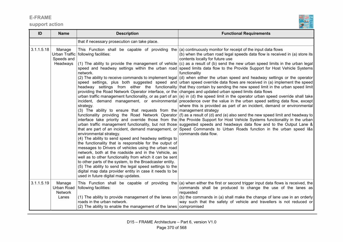
E-FRAME
support action
D15 – FRAME Architecture – Part 6, version V1.0
Page 370 of 568
ID Name Description Functional Requirements
that if necessary prosecution can take place.
3.1.1.5.18 Manage Urban Traffic Speeds and Headways
This Function shall be capable of providing the following facilities: (1) The ability to provide the management of vehicle speed and headway settings within the urban road network. (2) The ability to receive commands to implement legal speed settings, plus both suggested speed and headway settings from either the functionality providing the Road Network Operator interface, or the urban traffic management functionality, or as part of an incident, demand management, or environmental strategy. (3) The ability to ensure that requests from the functionality providing the Road Network Operator interface take priority and override those from the urban traffic management functionality, but not those that are part of an incident, demand management, or environmental strategy. (4) The ability to send speed and headway settings to the functionality that is responsible for the output of messages to Drivers of vehicles using the urban road network, both at the roadside and in the Vehicle, as well as to other functionality from which it can be sent to other parts of the system, to the Broadcaster entity. (5) The ability to send the legal speed settings to the digital map data provider entity in case it needs to be used in future digital map updates.
(a) continuously monitor for receipt of the input data flows (b) when the urban road legal speeds data flow is received in (a) store its contents locally for future use (c) as a result of (b) send the new urban speed limits in the urban legal speed limits data flow to the Provide Support for Host Vehicle Systems functionality (d) when either the urban speed and headway settings or the operator urban speed override data flows are received in (a) implement the speed that they contain by sending the new speed limit in the urban speed limit changes and updated urban speed limits data flows (e) in (d) the speed limit in the operator urban speed override shall take precedence over the value in the urban speed setting data flow, except where this is provided as part of an incident, demand or environmental management strategy (f) as a result of (d) and (e) also send the new speed limit and headway to the Provide Support for Host Vehicle Systems functionality in the urban suggested speeds and headways data flow and to the Output Lane & Speed Commands to Urban Roads function in the urban speed l&s commands data flow.
3.1.1.5.19 Manage Urban Road Network Lanes
This Function shall be capable of providing the following facilities: (1) The ability to provide management of the lanes on roads in the urban network. (2) The ability to enable the management of the lanes
(a) when either the first or second trigger input data flows is received, the commands shall be produced to change the use of the lanes as requested (b) the commands in (a) shall make the change of lane use in an orderly way such that the safety of vehicle and travellers is not reduced or compromised
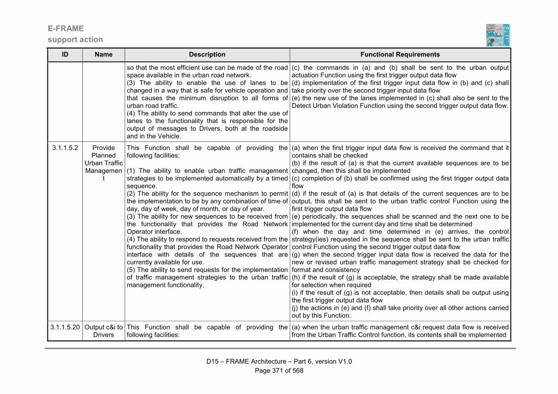
E-FRAME
support action
D15 – FRAME Architecture – Part 6, version V1.0
Page 371 of 568
ID Name Description Functional Requirements
so that the most efficient use can be made of the road space available in the urban road network. (3) The ability to enable the use of lanes to be changed in a way that is safe for vehicle operation and that causes the minimum disruption to all forms of urban road traffic. (4) The ability to send commands that alter the use of lanes to the functionality that is responsible for the output of messages to Drivers, both at the roadside and in the Vehicle.
(c) the commands in (a) and (b) shall be sent to the urban output actuation Function using the first trigger output data flow (d) implementation of the first trigger input data flow in (b) and (c) shall take priority over the second trigger input data flow (e) the new use of the lanes implemented in (c) shall also be sent to the Detect Urban Violation Function using the second trigger output data flow.
3.1.1.5.2 Provide Planned
Urban Traffic Managemen
t
This Function shall be capable of providing the following facilities: (1) The ability to enable urban traffic management strategies to be implemented automatically by a timed sequence. (2) The ability for the sequence mechanism to permit the implementation to be by any combination of time of day, day of week, day of month, or day of year. (3) The ability for new sequences to be received from the functionality that provides the Road Network Operator interface. (4) The ability to respond to requests received from the functionality that provides the Road Network Operator interface with details of the sequences that are currently available for use. (5) The ability to send requests for the implementation of traffic management strategies to the urban traffic management functionality.
(a) when the first trigger input data flow is received the command that it contains shall be checked (b) if the result of (a) is that the current available sequences are to be changed, then this shall be implemented (c) completion of (b) shall be confirmed using the first trigger output data flow (d) if the result of (a) is that details of the current sequences are to be output, this shall be sent to the urban traffic control Function using the first trigger output data flow (e) periodically, the sequences shall be scanned and the next one to be implemented for the current day and time shall be determined (f) when the day and time determined in (e) arrives, the control strategy(ies) requested in the sequence shall be sent to the urban traffic control Function using the second trigger output data flow (g) when the second trigger input data flow is received the data for the new or revised urban traffic management strategy shall be checked for format and consistency (h) if the result of (g) is acceptable, the strategy shall be made available for selection when required (i) if the result of (g) is not acceptable, then details shall be output using the first trigger output data flow (j) the actions in (e) and (f) shall take priority over all other actions carried out by this Function.
3.1.1.5.20 Output c&i to Drivers
This Function shall be capable of providing the following facilities:
(a) when the urban traffic management c&i request data flow is received from the Urban Traffic Control function, its contents shall be implemented

E-FRAME
support action
D15 – FRAME Architecture – Part 6, version V1.0
Page 372 of 568
ID Name Description Functional Requirements
using Urban Roads
(1) The ability to collect information for output to Drivers, Cyclists and Pedestrians from some or all of other functionality in the Manage Traffic Functional Area, functionality in the Provide Advanced Driver Assistance Functional Area and input from the Multi-Modal Crossings Actor. (2) The output of consistent and coherent information and/or commands to Drivers using the urban road network. (3) The ability for the outputs to be used to provide such things as, journey time information, commands for unexpected speed or lane use, weather condition and road surface warnings, etc. (4) The output of warning messages about the activity of a particular Vehicle will include its identity. (5) The ability to output data containing information and/or warning messages plus commands to other functionality for subsequent output to Vehicles as they pass by. (6) The ability of the outputs to make use of different display technologies, other than those in the Vehicle. (7) The monitoring of its operation and the reporting of any abnormalities to Maintenance Management functionality. (8) The reporting of a fault to the Maintenance Management facility if a Vehicle reports that what is being output by the Function is not the same as what is being received in the Vehicle.
(b) the implementation required in (a) shall be achieved through the output of the data flows to drivers, cyclists and pedestrians (c) the response to (b) shall be sent to the Urban Traffic Control function using the msg response data flow (d) if the response from (b) is that the data flows have not been output, data shall be sent to the Maintenance Management functionality using the c&i equipment fault data flow, and a device failed indication in the urban device status and urban traffic management c&i response data flows (e) when the incident warning messages or urban crossing information data flows are received, they shall be implemented as in (b) to (d) above (f) when the urban c&i display error data flow is received, check its contents to see if a difference has been found (g) if a difference has been found in (f) then send a device failed indication to the Evaluate Need for Equipment Maintenance function in the urban c&i equipment fault data flow and to the Implement Urban Traffic Commands function in the urban traffic management c&i response data flow (h) when any of the roadside vehicle lane departure warning, other vehicle lane departure warning, possible conflicts with vehicle movement, traffic queue ahead warning and advice, slow objects warning and advice, stationary emergency vehicle ahead warning data flows are received, or output the data that it includes in the host vehicle driver warning messages data flow to the driver and if it is included with the data, output the identity of the vehicle to which the warning applies (i) send the data in (h) to the Output Message Data to Following Vehicles function in the data for output to following vehicles data flow (j) the content of all of the outputs shall be monitored and if necessary revised to ensure that they are consistent and coherent.
3.1.1.5.21 Send Messages to Approaching
Urban Vehicles
This Function shall be capable of providing the following facilities: (1) The ability to receive and store data for information and warning messages plus commands that have been output to Drivers of preceding Vehicles using the urban road network.
(a) continuously monitor for receipt of the urban data for approaching vehicles data flow from the Ouput c&i to Divers using Urban Roads function (b) using internal sensors to detect the presence of approaching vehicles, putting the data in the urban vehicle presence for messages data flow from the traffic entity (c) when the data flow is received in (a) store its contents
E-FRAME
support action
D15 – FRAME Architecture – Part 6, version V1.0
Page 373 of 568
ID Name Description Functional Requirements
(2) Use internal sensors to detect that a Vehicle is approaching. (3) When an approaching Vehicle is detected, the ability to output to it the data for information and warning messages plus commands relevant to the management of traffic using the urban road network. (4) The ability to continue with the output to approaching Vehicles, changing the data every time it is changed, and stopping output if there is no data to transmit.
(d) an approach vehicle is detected in (b), output the data stored in (c) in the data flow containing approaching vehicles urban messages (e) repeat (c) for every approaching vehicle, unless there is no data to output (f) if the data flow received in (b) contains no data, clear the stored message data.
3.1.1.5.22 Output s&g Commands to Urban Roads
This Function shall be capable of providing the following facilities: (1) The provision of conventional "traffic light" type outputs to Drivers, Cyclists and Pedestrians using the urban road network. (2) The ability to send the "traffic light" type outputs directly to Vehicles for output to Drivers using in-Vehicle devices. (3) The ability to change the duration and sequence of the outputs according to data received from the following inputs: (a) Vehicle presence data from local Traffic via its own sensors; (b) Commands from the Implement Urban Traffic Commands Function; (c) Requests for local priority from Emergency Services (Centres and Vehicles), Public Transport Vehicles and Other Vehicles. (4) The assignment of priority of response to these inputs depending on their presence and when more than one is present, what the input from the Traffic Command Function allows. (5) The ability to respond to any of the above inputs according to the priority assignment, until the input that is being given priority is no longer present, in which
(a) when the s&g (stop and go) request data flow is received, its contents shall be implemented (b) the implementation required in (a) shall be achieved through the output of the data flows to drivers, cyclists and pedestrians (c) the response to (b) shall be sent to the Urban Traffic Control function using the s&g response data flow (d) for the "stop" instructions contained in (b), the time for which the stop signal will be present shall be calculated and sent to the Communicate with In-vehicle Systems function in the vehicle s&g input data flow (e) for both "stop" and "go" instructions contained in (b), the time to the next change shall be calculated and sent to the Predict Host Vehicle Trajectory function in the s&g output for in-vehicle red light warning data flow (f) if the response from (b) is that the data flows have not been output, data shall be sent to the Maintenance Management functionality using the s&g equipment fault data flow (g) if no commands are contained in the data flow in (a), or they permit either part or complete local operation, the arrival of the local traffic presence data flow shall be continuously monitored (h) when the data flow in (g) is received, the instructions in (b) to (f) shall be followed optimising the timings of the "stop" and "go" outputs to give the most efficient traffic flow through the controlled junction (i) when the local priority request is received in either of the data flows from a pedestrian, a cooperative vehicle or another instance of this function, in shall be implemented as in (b) to (f) above (j when the local priority request data flow is received from a Public

E-FRAME
support action
D15 – FRAME Architecture – Part 6, version V1.0
Page 374 of 568
ID Name Description Functional Requirements
case the Function shall implement the next highest priority input to produce the outputs. (6) The ability to use its own internal timings when none of the inputs identified above are available. (7) The ability to temporarily implement changes in the sequence of the outputs to accommodate "green wave" requests and to revert to using the highest priority inputs once the request has been fulfilled. (8) The ability to respond with an indication of whether or not a local priority request received from an Other Vehicle will be fulfilled and to fulfil priority requests from Other Vehicles based on the order in which they have been received, providing "failure" responses to those that have not been fulfilled. (9) The ability to provide an indication of the recommended speed profile for the Other Vehicle to arrive at the junction when the signal is green, based on data provided in its request for local priority. (10) The ability to give Emergency Vehicles the highest priority, followed by Public Transport Vehicles and lastly Other Vehicles when more that one local priority request is received. (11) The ability of the Road Network Operator to vary the order of priority in which requests are fulfilled whether they come from the same or different types of Vehicles. (12) The ability to send information about local priority requests that it has received to adjacent down stream instances of its functionality. (13) The ability to receive information about local priority requests from functionality located upstream of itself and to prepare for the arrival of the Vehicle, by temporarily adjusting its operating sequence so that it can be given priority at the most appropriate time so as not to impede the Vehicle's progress. (14) The ability to respond to local inputs from
Transport vehicle, it shall be implemented as in (b) to (f) above and take priority over the commands received in (a), (h) or (i) (k) when the local priority request data flow is received from the Emergency Services, it shall be implemented as in (b) to (e) above and take priority over the commands received in (a), (h), (i) or (j (l) when the incident warning s&g or urban crossing commands data flows are received, they shall be implemented as in (b) to (f) above (m the implementation in (l) shall take priority over all other commands (n) all of the outputs shall be monitored for consistency and coherence, so that for example a green conflict does not arise.
E-FRAME
support action
D15 – FRAME Architecture – Part 6, version V1.0
Page 375 of 568
ID Name Description Functional Requirements
Pedestrians if and when it is permitted within the sequence of outputs required by the Implement Urban Traffic Commands Function. (15) The ability to monitor its operation and report any malfunction to the Maintenance Management functionality. (16) The ability to ensure that all outputs are consistent, coherent and do not in anyway compromise the safe use of the urban road network, e.g. by ensuring that no green conflicts are produced.
3.1.1.5.23 Output Urban Lane & Speed
Commands
This Function shall be capable of providing the following facilities: (1) The ability to provide outputs that advise or command Drivers and/or Cyclists to use particular lane(s), and/or to drive at or below particular speeds and/or to maintain a particular headway between following Vehicles. (2) The ability to provide these outputs in response to commands from the Manage Urban Traffic Speeds and Headways Function. (3) The ability to provide these outputs using mechanisms that do not include in-vehicle displays or any type, and as a supplement to the outputs provided by the Output Commands & Information to Urban Roads Function. (4) The ability to send the data in these outputs to other functionality for output by In-vehicle displays.
(a) continuously monitor for the arrival of the urban speed and lane commands data flows, plus the display error and speed being exceeded data flows (b) when either the urban speed limit l&s comments or urban lane comments data flows in (a) is received, output its contents to drivers and cyclists in the appropriate traffic indications data flow and to the Manage Vehicle Communication to Driver function in the urban speed commands data flow (c) also send the urban l&s device status data flow to the Detect Urban Traffic Violations function (d) if the urban speed being exceeded data flow is received in (a), output its contents including the identity of the vehicle to which the message applies in the vehicle above required urban speeds data flow. (e) if for any reason the actions in (b) or (d) fail then send a device failed indication in the urban l&s device status data flow to the Detect Urban Traffic Violations function and in the urban traffic management l&s response data flow to the Implement Urban Traffic Commands function (f) if either of the urban l&s display error or urban speed display error data flows is received, check their contents to see if a difference has been found (g) if a difference has been found then again send a device failed indication in the urban l&s device status data flow to the Detect Urban Traffic Violations function and in the urban traffic management l&s response data flow to the Implement Urban Traffic Commands function.
3.1.1.5.24 Implement This Function shall be capable of providing the (a) continuously monitor for receipt of the operator urban traffic
E-FRAME
support action
D15 – FRAME Architecture – Part 6, version V1.0
Page 376 of 568
ID Name Description Functional Requirements
Urban Traffic Strategies
following facilities: (1) The provision of traffic management that enable Vehicles to make the most efficient use of the urban road network. (2) The automatic implementation of strategies for traffic management in a planned sequence according to the time of day and day of week. (3) The ability to output data for "stop&go" and/or "commands & information" messages directly to Vehicles so that their contents can be output to Drivers by an In-vehicle display mechanism. (4) The ability of the Road Network Operator to override the automatic implementation of one or more strategies using inputs made through the HMI provided by the Provide Urban Traffic Operator Interface Function. (5) The ability for the automatic strategy implementation to be temporarily overridden by inputs requiring green wave routes to be implemented for selected Vehicles. (6) The ability for the automatic strategy implementation to be overridden by requests for changes to the way that traffic is managed that are received from functionality in the Manage Incidents and Manage Demand High-level Functions in the Manage Traffic Functional Area. (7) The ability for the Road Network Operator to define the order of priority for the various inputs that can override the automatic strategy implementation. (8) The ability to adapt the traffic management strategies to suit the current and predicted traffic conditions using real-time data to identify the need for and content of the adaptations (adaptive traffic control). (9) The ability to apply traffic management strategies
management request, planned urban traffic management request, urban environmental inputs, urban demand management strategy and urban incident strategy request data flows (b) when any of the data flows in (a) is received, implement the traffic management commands that they contain using the contents of the data flow containing urban static data to determine which are the appropriate section(s) if the urban road network to which the commands apply (c) the commands in (b) shall be implemented using some or all of the urban bridge inputs, urban tunnel inputs, urban lane management, urban speed setting, urban traffic management s&g request, urban traffic management msg requests and urban recommended routes data flows, plus data sent to the Traffic Simulation functionality in the urban strategies in use data flow and data sent directly to In-vehicle functionality using the s&g outputs for driver display and c&i outputs for driver display data flows (d) the commands being implemented in (b) shall be filtered for applicability and sent to any other adjacent urban traffic management systems in the urban traffic management strategies data flow and to any relevant inter-urban traffic management systems in the urban to inter-urban traffic commands data flow (e) if the urban zoning strategy data flow is received, whichever is necessary of the data flows in (c) shall be sent plus the urban zone access vehicle list data flow (f) it shall be possible for the data flows containing current urban traffic conditions, urban traffic flow management data, predicted urban network data, bridge urban inputs and tunnel urban inputs to be continuously monitored and for their contents to be used to revise the detail of the commands being implemented in (b) thus providing adaptive traffic control (g) if the operator urban traffic management request was received in (a) and had led to the implementation of (b) and (c) then the operator urban traffic management response data flow shall be sent to the Provide Operator Interface function (h) as a result of (c) the receipt of the urban traffic management s&g response, urban traffic management l&s response and urban traffic management c&i response data flows shall be monitored (i) when any of the data flows in (h) is received their contents shall be
E-FRAME
support action
D15 – FRAME Architecture – Part 6, version V1.0
Page 377 of 568
ID Name Description Functional Requirements
to some or all of the urban road network managed by the System. (10) The ability to monitor the results from the implementation of strategies so that if necessary corrective action can be taken if the content of strategies are not followed. (11) The provision of details of the current and previously implemented strategies on some or all parts of the urban road network to the Road Network Operator through the Provide Urban Traffic Operator Interface Function.
checked to see if the commands in (c) are being followed (j) if the result of (i) is that the commands are not being followed, this shall be communicated to the Provide Operator Interface function in the operator urban management response data flow and to the Maintenance Management functionality in the urban response fault data flow (k) if the requirement is included in the contents of the data flows in (b) the contents of the data flows in (i) shall be used to revise the commands being sent in (c) (l) if either the inter-urban to urban traffic commands or urban traffic management strategy data flows is received, their contents shall be analysed if necessary new commands implemented as in (c) with the addition that requests may be sent to any relevant multi-modal management systems in the urban crossing inhibit data flow (m) if any of the urban emergency route request, green wave request, vehicle priority request and request demand vehicle priority data flows is received, its contents shall be implemented as in (b) and (c) above and shall take priority over any of the other inputs received in (a), (l) and (m) (n) of the data flows in (m) the contents of the urban emergency route request shall take priority over all the others, with the contents of the vehicle priority request data flow being the next highest in priority, followed by the contents of the demand vehicle priority data flow (o) if the inter-urban virtual coned area request data flow is received, implement the necessary lane closures and speed restrictions as in (b) and (c) above in order to prevent vehicles from entering the area around an accident (p) the commands in the operator urban traffic management request data flow received in (a) shall take precedence over all the inputs in (a) and (l) but not the inputs in (m) and (o) (q) the commands in the planned urban traffic management request data flow received in (a) shall take the lowest priority after all the other inputs in (a), (l), (m) and (o) (r) implementation of all the outputs in (c) shall be checked to ensure that the comments being implemented are consistent and coherent and do not contradict each other.
3.1.1.5.8 Detect Urban Traffic
This Function shall be capable of providing the following facilities:
(a) when the second or third trigger input data flows are received, the internal data describing the permitted vehicle movements within the urban
E-FRAME
support action
D15 – FRAME Architecture – Part 6, version V1.0
Page 378 of 568
ID Name Description Functional Requirements
Violations (1) The ability to detect violations of urban traffic management commands and report them to the law enforcement functionality. (2) The ability to only report a violation when it is detected that a vehicle does not follow the current urban traffic commands. (3) The ability for details of these commands to be provided by the urban traffic management functionality.
road network shall be updated (b) the first trigger input data flow shall be continuously monitored and converted into vehicle presence and speed data (c) the positions of vehicles produced by (b) shall be compared against that required by (a) (d) if a vehicle is found in an illegal position by (c), details of the vehicle, the time, date. place and nature of the violation shall be sent to functionality in the Provide Support for Law Enforcement Area using the trigger output data flow (e) when the fourth trigger input data flow is received, the internal data describing the permitted vehicle speed shall be updated (f) if the vehicle speed obtained from (b) exceeds that specified in (e), details of the vehicle, the time, date. place plus allowed and actual speeds shall be sent to functionality in the Provide Support for Law Enforcement Area using the trigger output data flow.
3.1.1.6 Manage Urban Static Traffic Data
This Function shall be capable of providing the following facilities: (1) The management of the store of Urban Road Static Data for use by the urban traffic management functionality. (2) The entry into the store of new and/or updated road network static data received from the Geographic Information Provider and/or the Road Network Operator via the operator interface functionality. (3) The provision from the store of current and/or updated road network static data that was provided by the Geographic Information Provider to the urban traffic management and road maintenance functionalities, plus the functionality in the Provide Support for Cooperative Systems, Manage Public Transport Operations and Provide Traveller Journey Assistance Functional Areas. (4) The provision of new and/or updated road network static data provided by the Road Network Operator to the functionality that will send the data to the
(a) continuously monitor for receipt of the urban static road data from the geographic information provider (b) when the data flow in (a) is received, load the data into the store of Urban Road Static Data using the urban static data update data flow, and updating the data already in the store (c) when (b) is complete, read all of the data from the store using the urban static data read data flow and send it to the functionality in the Manage Traffic and other Functional Areas using the appropriate data flows (d) when the urban static data changes data flow is received, repeat (b) and (c) and also send the data to the Provide Updated Urban data for Digital Maps function in the data flow containing urban new static data (e) when the operator urban traffic static data request data flow is received, collect all of the data from the store of Urban Road Static Data using the urban static data update data flow, and send it to the Provide Urban Traffic Operator Interface function using the operator urban road static data response data flow.
E-FRAME
support action
D15 – FRAME Architecture – Part 6, version V1.0
Page 379 of 568
ID Name Description Functional Requirements
Geographic Information Provider so that it can be used when digital map data is provided in the future. (5) The collection and loading into the store of static data about traffic regulations (i.e. speeds, access restrictions for certain Vehicle types to particular urban road segments, etc.) provided by the Road Network Operator, and its subsequent distribution to the functionality in the Provide Support for Law Enforcement, Provide Electronic Payment Facilities and Provide Support for Host Vehicle Systems Functional Areas.
3.1.1.8 Collect Urban Data
from Vehicles
This Function shall be capable of providing the following facilities: (1) The collection of Floating Car Data (FCD) and Extended Floating Car Data (XFCD) from suitable equipped Vehicles that are using the urban road network. (2) The Function shall expect the data to be the raw input data provided by functionality in the Vehicle and to contain location information, time plus Vehicle identity and status data. (3) The processing of the collected data to provide actual traffic flow data, e.g. flow, speed, for the urban road network, Vehicle status data, e.g. broken down, other road related data, e.g. rain, fog, slippery road, ice and to detect incidents. (4) The checking of the collected data for coherence and consistency both for individual Vehicles and for the traffic as a whole in each segment of the urban road network. (5) The exchange of data with the Monitor Urban FCD/XFCD Source Vehicles Function to confirm that the collected data actually comes from the Vehicles whose identities are included in the data, and to discard all data except traffic flow data from Vehicles
(a) continuously monitor for the arrival of the data flows containing the urban floating car and other data from vehicles (b) when either of the floating car data flows in (a) arrive, process their contents to determine traffic flow data and check this and any other data provided by in-vehicle systems for their plausibility (c) put the vehicle identity extracted from the data flows in (b) into the urban fcd vehicle identity data flow and send it to the Monitor Urban FCD/XFCD Source Vehicle function (d) when as a result of (c) the urban fcd error data flow is received, check to see if it includes an error indication (e) if an error indication is found in (d) discard all the data provided by the vehicle, except that from which urban traffic flow can be determined (f) if the safety behaviour status for urban data flow is received in (a) containing a warning of unsafe behaviour, discard all of the data from the vehicle as it will not be representative of the majority of vehicles using the urban road network (g) if the checks in (d) and (e) are satisfactory, plus there is no warning in (f), collate and fuse the data to provide a coherent and consistent set, separating out the urban traffic flow data, other data, e.g. slippery road, fog, rain, darkness, possible incidents and ice, for easy use by other functionality (h) fuse the traffic flow data from all vehicles so that for example, data for the same segment of the urban road network is aggregated and also fuse the data from the vehicle trip plans so that for example, the numbers of vehicle using or planning to use each segment of the urban road network

E-FRAME
support action
D15 – FRAME Architecture – Part 6, version V1.0
Page 380 of 568
ID Name Description Functional Requirements
being driven safely. (6) The provision of the processed and collected data to the Detect Incidents from Data and Urban Traffic Data Management Functions. (7) The ability to make all processed data anonymous so that the movement through the urban road network of specific Vehicles cannot be identified.
is calculated (i) send the data produced in (h) to the Provide Urban Traffic Data Management function in the data flow containing collected urban vehicle data (j) also send the urban traffic flow data and any available data about unusual conditions, e.g. rain and low temperatures, to the Incident Detection function in the urban XFCD for incident detection data flow.
3.1.1.9 Output Urban Traffic
Data
This Function shall be capable of providing the following facilities: (1) The output of data about current traffic conditions in the urban road network received from the Urban Traffic Data Management Function and data about speed limits and lane use received from the Manage Urban Traffic Speeds and Headways and Manage Urban Road Network Lanes Functions respectively. (2) Both sets of outputs shall be sent as soon as new data is received to functionality in the Provide Support for Host Vehicle Systems, Provide Support for Cooperative Systems, Provide Electronic Payment Facilities and Provide Traveller Journey Assistance Functional Areas, plus the Broadcast and Traffic and Travel Information Provider. (3) Both sets of outputs shall also be sent as soon as new data is received to the Broadcaster and Traffic and Travel Information Provider, or to the Broadcaster when it provides a request.
(a) continuously monitor for the receipt of the any of the input data flows (b) when the data flow urban traffic information request is received in (a), output the current traffic information to the broadcaster using the data flow containing urban traffic data (c) when the urban traffic data for output data flow is received in (a), store its contents locally updating any previously received data that has been changed (d) when (c) is complete, output the revised version of the urban traffic data to functionality in other Functional Areas, the broadcaster and the traffic and travel information provide in the appropriate output data flows (e) when either the urban lane instructions or the urban speed limit changes data flows are received in (a), repeat (c) and (d) for the data that they contain.
3.1.2.10 Collect Inter-urban Traffic
Data
This Function shall be capable of providing the following facilities: (1) The ability to collect traffic data from the inter-urban road network. (2) The ability for sensors within this Function to provide the data as raw input and for the sensors to be capable of detecting the presence of all types of road
(a) the presence of the trigger input data flow shall be continuously monitored (b) the analogue data representing raw traffic flow data obtained in (a) shall be processed into digital data such as, but not limited to, flow, speed, occupancy, headway, vehicle classification, and queue (c) the data for each point in the inter-urban road network at which it was produced shall be kept separate (d) the trigger output data flows, shall be used to send the data in (c) to
E-FRAME
support action
D15 – FRAME Architecture – Part 6, version V1.0
Page 381 of 568
ID Name Description Functional Requirements
vehicle, from bicycles to heavy freight vehicles. (3) The ability to process the raw input data provided by the sensors to provide actual traffic flow data, e.g. flow, speed, etc. (4) The ability to pass this processed data to other functionality for collation and use in traffic control.
the inter-urban road network traffic control and data management Functions.
3.1.2.11 Provide Updated
Inter-urban data for
Digital Maps
This Function shall be capable of providing the following facilities: (1) The ability to provide up-to-date information for digital maps and databases for segments of the inter-urban road network. (2) The ability for the information provided by this Function to include structural alteration, static speed limits and default journey times. (3) The ability to provide updated information to the digital map provider in order to be implemented in the next issue of digital maps as well as to in-vehicle devices for use in current and future planned journeys.
(a) continuously monitor for receipt of the input data flows (b) when any of the data flows in (a) is received, apply any necessary processing so that the data is suitable for use by a digital map provider (c) on completion of (b), send the data to the geographic information provider in the output data flow.
3.1.2.12 Monitor Inter-urban FCD/XFCD Source Vehicles
This Function shall be capable of providing the following facilities: (1) The ability to check that the identity of Vehicles using the inter-urban road network being provided electronically corresponds to the identity obtained from matching the Vehicles' images with their registration data. (2) The ability to collect the images of the Vehicles and use them in the comparison process. (3) If no correspondence is found, the ability to send all of the Vehicle information to other functionality for potential prosecution. (4) If no correspondence is found, the ability to send a lack of correspondence indication to the functionality responsible for collecting FCD/XFCD data from
(a) continuously monitor for the receipt of the input data flows (b) when the vehicle data for inter-urban fcd check data flow is received in (a), store its data locally for use in the comparison process (c) when the inter-urban fcd source vehicle image data flow is received in (a), search the stored data from (b) to find a match (d) when the inter-urban fcd vehicle identity data flow is received in (a) check that the identity corresponds with that found in (b) and (c) (e) if no match is found in (c) or (d), send the inter-urban vehicle identity error data flow to the Provide Support for Law Enforcement functionality and the inter-urban fcd error data flow to the Collect Inter-urban Floating Car Data function.

E-FRAME
support action
D15 – FRAME Architecture – Part 6, version V1.0
Page 382 of 568
ID Name Description Functional Requirements
Vehicles using the urban road network, so that the data can be marked as suspect.
3.1.2.13.1 Provide Inter-urban
Road Operator
Mgt Interface
This Function shall be capable of providing the following facilities: (1) A HMI that enables the Road Network Operator to manage the control of traffic using the inter-urban road network. (2) The HMI shall enable the Road Network Operator to provide commands that change the current inter-urban traffic control strategy and to override the use of lanes in the road network, except when it is imposed as part of an incident or demand management strategy, or to provide selective Vehicle priority. (3) The HMI shall have the ability to inform the Road Network Operator of the success or failure of the requested change. (4) The HMI shall have to ability to enable the Road Network Operator to examine and update the sequence of inter-urban traffic control strategies that are implemented automatically, and to see the "log" of previously implemented inter-urban traffic control strategy changes. (5) The HMI shall have to ability to output requests to the Road Network Operator for a check to be made of the availability of auxiliary lanes (hard shoulders), and for the Operator to provide an available/not available response so that traffic can be directed to use it, or not.
(a) continuously monitor for receipt of the inter-urban road static network data and inter-urban traffic management commands data flows from the Road Network Operator plus the operator inter-urban auxlane check request data flow from the Manage Lanes in the Inter-urban Road Network function (b) when the first data flow in (a) is received, check its contents and if it contains new and/or changes to the road network static data, send it to the Manage Inter-urban Static Road Data function in the inter-urban static data changes data flow (c) if the contents of the data flow received in (b) contains a request for the current inter-urban road network static data, send this request to the Manage Inter-urban Static Road Data function in the inter-urban static data changes data flow (d) as a result of (b) or (c), continuously monitor for receipt of the operator inter-urban road static data response data flow (e) when the data flow in (d) is received, ouput its contents to the Road Network Operator in the data flow containing inter-urban static road data (f) when the second data flow in (a) is received, check its contents and if they are an update, or a request for output, send them in the planned inter-urban data update data flow to the Manage Planned Inter-urban Strategy Changes function (g) as a result of (f) continuously monitor for receipt of the planned inter-urban data output data flow (h) when the data flow in (g) is received, output its contents to the Road Network Operator in the inter-urban traffic responses data flow (i) if as a result of (f) the second data flow in (a) is found to contain command(s) for change(s) in the management of traffic, decide which function(s) should receive the commands (j) if as a result of (i) the contents are a change to the current strategy, send the contents of the data flow in the operator inter-urban management request data flow to the Mangae Inter-urban Traffic Commands & Messages function (k) if as a result of (i) the contents are other changes, send the contents of the data flow in either the inter-urban operator lane override data flow to
E-FRAME
support action
D15 – FRAME Architecture – Part 6, version V1.0
Page 383 of 568
ID Name Description Functional Requirements
the Manage Lanes in the Inter-urban Road Network function, or in the inter-urban road legal speeds data flow to the Manage Inter-urban Road Network Speeds & Headways function (l) as a result of (j) continuously monitor for the receipt of the operator inter-urban management response data flow and when it is received, output its contents to the Road Network Operator in the inter-urban traffic responses data flow (m) if the third data flow in (a) is received, output its contents to the Road Network Operator in the inter-urban traffic responses data flow (n) as a result of (m) continuously monitor for receipt of the inter-urban traffic management commands data flow from the Road Network Operator (o) when the data flow in (n) is received, output its contents to the Manage Lanes in the Inter-urban Road Network function in the inter-urban auxlane check response data flow.
3.1.2.13.2 Check Access to Inter-urban Zones
This Function shall be capable of providing the following facilities: (1) The ability to detect Vehicles approaching a part of the inter-urban road network (zone or "sensitive area"), access to which is controlled. (2) The ability to obtain and the identity and a physical image of the Vehicle from its own sensors. (3) The ability to check the physical images of Vehicles obtained from its own sensors with a list of permitted Vehicles that it has been given by other functionality, as part of the traffic management strategy being currently implemented. (4) The ability to output a warning message to Drivers of Vehicles whose identities do not match those on the permitted list as they approach a point in the inter-urban road network that gives access to a zone. (5) The ability to send data about a Vehicle that has been detected approaching a zone to the functionality that manages access to sensitive areas.
(a) continuously monitor for the arrival of the vehicle list data flow and when it arrives, up date the internal list with the information that it contains (b) continuously monitor for the arrival of the vehicle approaching data flow (c) when the data flow in (b) is received continuously monitor for the arrival of the vehicle image data flow (d) when the data flow in (c) arrives, determine the vehicle identity from the image and check it against the list provided in (a) (e) if no match is found, send a warning to the driver in the approaching inter-urban zone data flow and send the vehicle identity data flow to the Prevent Access function (f) if a match is found, send an advisory message to the driver in the approaching inter-urban zone data flow and data about the vehicle to the Manage Data about Vehicle use of Sensitive Areas in the vehicle nearing inter-urban sensitive area data flow.

E-FRAME
support action
D15 – FRAME Architecture – Part 6, version V1.0
Page 384 of 568
ID Name Description Functional Requirements
3.1.2.13.3 Restrict Access to Inter-urban Zones
This Function shall be capable of providing the following facilities: (1) The ability to provide a physical barrier to prevent Vehicles from entering a part (zone) of the inter-urban road network, to which access is controlled. (2) The ability to output (zone) a warning message to Drivers that a physical barrier will prevent them driving their Vehicles into the zone. (3) If the Vehicles are detected actually entering the zone, the ability to send the Vehicle identity to the law enforcement functionality.
(a) continuously monitor for the arrival of the vehicle identity and inter-urban sensitive area access refused data flows (b) when either of the data flows in (a) is received, start monitoring for the vehicle entering inter-urban zone data flow (c) when the data flow in (b) is received, send a warning of illegal entry to the driver in the entering inter-urban zone data flow (d) if the data flow in (b) continues to show that the vehicle is entering the zone then send the vehicle entering message to the Provide Support for Law Enforcement functionality.
3.1.2.13.4 Manage Inter-urban
Road Network Speeds & Headways
This Function shall be capable of providing the following facilities: (1) The ability to provide the management of Vehicle speed and headway settings within the inter-urban road network. (2) The ability to receive commands to implement legal speed settings, plus both suggested speed and headway settings from either the functionality providing the Road Network Operator interface, or the inter-urban traffic management functionality, or as part of an incident, demand management, or environmental strategy. (3) The ability to ensure that requests from the Road Network Operator take priority and override those from the inter-urban traffic control functionality, but not override those that are part of an incident, demand management, or environmental strategy. (4) The ability to send speed and headway settings to the inter-urban functionality that is responsible for the output of messages to Drivers, both at the roadside and in the Vehicle, as well as to other functionality from which it can be sent to other parts of the system and to the Broadcaster.
(a) continuously monitor for receipt of the input data flows (b) when the inter-urban road legal speeds data flow is received in (a) store its contents locally for future use (c) as a result of (b) send the new inter-urban speed limits in the inter-urban legal speed limits data flow to the Provide Support for Host Vehicle Systems functionality (d) when either the inter-urban speed and headway settings or the operator inter-urban speed override data flows are received in (a) implement the speed that they contain by sending the new speed limit in the inter-urban speed limit changes and updated inter-urban speed limits data flows (e) in (d) the speed limit in the operator inter-urban speed override shall take precedence over the value in the inter-urban speed setting data flow, except where this is provided as part of an incident, demand or environmental management strategy (f) as a result of (d) and (e) also send the new speed limit and headway to the Provide Support for Host Vehicle Systems functionality in the inter-urban suggested speeds and headways data flow and to the Output Lane & Speed Commands to Inter-urban Roads function in the inter-urban speed l&s commands data flow.

E-FRAME
support action
D15 – FRAME Architecture – Part 6, version V1.0
Page 385 of 568
ID Name Description Functional Requirements
(5) The ability to send legal speed settings to the digital map data provider entity in case it needs to be used in future digital map updates.
3.1.2.13.5 Manage Inter-urban Traffic
Commands & Messages
This Function shall be capable of providing the following facilities: (1) The ability to provide traffic control facilities that enable the traffic to be managed so that the most efficient use is made of the inter-urban road network. (2) The ability to manage the implementation of traffic management strategies for the inter-urban road network in a planned sequence according to the time of day and day of week. (3) The ability for the traffic management strategies to include control of access to the inter-urban network (ramp metering), plus commands to manage the use of lanes in the carriageway (including the hard shoulder) and the maximum speeds for vehicles in each lane. (4) The ability for these strategies to be overridden by the Road Network Operator through the functionality providing their interface, as well as by inputs from the incident, demand and access management functionality. (5) The ability to use current, historic and predicted traffic data from the inter-urban network and to change in real-time the actual traffic management commands being sent for output to take account of variations in this data. (6) The ability to provide details of the current and previous implemented traffic management strategies on some or all parts of the inter-urban road network to the Road Network Operator through the functionality that provides their interface.
(a) continuously monitor for receipt of any of the input data flows (b) when the planned inter-urban traffic management request data flow is received in (a), action the strategy that it contains, by sending all or part of its contents in the inter-urban tunnel inputs, inter-urban bridge inputs, inter-urban crossing inhibit, inter-urban strategy details, inter-urban strategies in use, inter-urban strategy details for ramp metering, inter-urban zone access vehicle list, inter-urban lane management requests, inter-urban speed and headway settings, or inter-urban traffic management strategy, inter-urban to urban traffic commands data flows (c) when the data flow containing inter-urban static data is received in (a), store its contents for internal use (d) when the inter-urban zoning strategy data flow is received in (a), output its contents to the Check Access to Inter-urban Zones function in the inter-urban zone access vehicle list data flow (e) when any of the bridge inter-urban inputs, tunnel inter-urban inputs, inter-urban environmental inputs, or inter-urban demand management strategy data flows are received in (a), use their contents to modify the current traffic management strategy, and repeat (b) (f) when the data flow containing predicted inter-urban network data is received in (a), store its contents for internal use in calculateing recommended rroutes and send these in the inter-urban recommended routes data flow to the Plan Trip Details function (g) when either of the urban to inter-urban commands, or inter-urban traffic management strategy data flows are received in (a), use their contents to modify the current traffic management strategy, and repeat (b) (h) when the operator inter-urban management request data flow is received in (a), use their contents to modify the current traffic management strategy, repeat (b) and output the response to the Provide Inter-urban Road Operator Mgt Interface function in the operator inter-urban management response data flow.
3.1.2.13.6 Manage This Function shall be capable of providing the (a) when either the first or second trigger input data flows is received, the
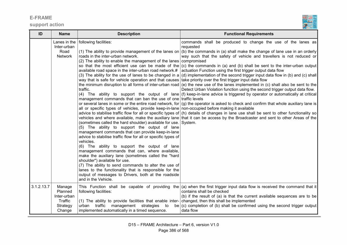
E-FRAME
support action
D15 – FRAME Architecture – Part 6, version V1.0
Page 386 of 568
ID Name Description Functional Requirements
Lanes in the Inter-urban
Road Network
following facilities: (1) The ability to provide management of the lanes on roads in the inter-urban network. (2) The ability to enable the management of the lanes so that the most efficient use can be made of the available road space in the inter-urban road network.# (3) The ability for the use of lanes to be changed in a way that is safe for vehicle operation and that causes the minimum disruption to all forms of inter-urban road traffic. (4) The ability to support the output of lane management commands that can ban the use of one or several lanes in some or the entire road network, for all or specific types of vehicles, provide keep-in-lane advice to stabilise traffic flow for all or specific types of vehicles and where available, make the auxiliary lane (sometimes called the hard shoulder) available for use. (5) The ability to support the output of lane management commands that can provide keep-in-lane advice to stabilise traffic flow for all or specific types of vehicles. (6) The ability to support the output of lane management commands that can, where available, make the auxiliary lane (sometimes called the "hard shoulder") available for use. (7) The ability to send commands to alter the use of lanes to the functionality that is responsible for the output of messages to Drivers, both at the roadside and in the Vehicle.
commands shall be produced to change the use of the lanes as requested (b) the commands in (a) shall make the change of lane use in an orderly way such that the safety of vehicle and travellers is not reduced or compromised (c) the commands in (a) and (b) shall be sent to the inter-urban output actuation Function using the first trigger output data flow (d) implementation of the second trigger input data flow in (b) and (c) shall take priority over the first trigger input data flow (e) the new use of the lanes implemented in (c) shall also be sent to the Detect Urban Violation function using the second trigger output data flow. (f) keep-in-lane advice is triggered by operator or automatically at critical traffic levels (g) the operator is asked to check and confirm that whole auxiliary lane is non-occupied before making it available (h) details of changes in lane use shall be sent to other functionality so that it can be access by the Broadcaster and sent to other Areas of the System.
3.1.2.13.7 Manage Planned
Inter-urban Traffic Strategy Change
This Function shall be capable of providing the following facilities: (1) The ability to provide facilities that enable inter-urban traffic management strategies to be implemented automatically in a timed sequence.
(a) when the first trigger input data flow is received the command that it contains shall be checked (b) if the result of (a) is that the current available sequences are to be changed, then this shall be implemented (c) completion of (b) shall be confirmed using the second trigger output data flow
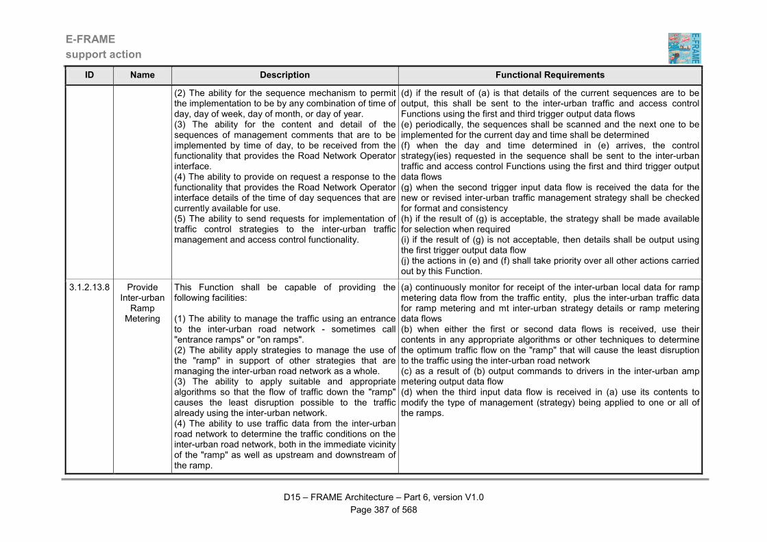
E-FRAME
support action
D15 – FRAME Architecture – Part 6, version V1.0
Page 387 of 568
ID Name Description Functional Requirements
(2) The ability for the sequence mechanism to permit the implementation to be by any combination of time of day, day of week, day of month, or day of year. (3) The ability for the content and detail of the sequences of management comments that are to be implemented by time of day, to be received from the functionality that provides the Road Network Operator interface. (4) The ability to provide on request a response to the functionality that provides the Road Network Operator interface details of the time of day sequences that are currently available for use. (5) The ability to send requests for implementation of traffic control strategies to the inter-urban traffic management and access control functionality.
(d) if the result of (a) is that details of the current sequences are to be output, this shall be sent to the inter-urban traffic and access control Functions using the first and third trigger output data flows (e) periodically, the sequences shall be scanned and the next one to be implemented for the current day and time shall be determined (f) when the day and time determined in (e) arrives, the control strategy(ies) requested in the sequence shall be sent to the inter-urban traffic and access control Functions using the first and third trigger output data flows (g) when the second trigger input data flow is received the data for the new or revised inter-urban traffic management strategy shall be checked for format and consistency (h) if the result of (g) is acceptable, the strategy shall be made available for selection when required (i) if the result of (g) is not acceptable, then details shall be output using the first trigger output data flow (j) the actions in (e) and (f) shall take priority over all other actions carried out by this Function.
3.1.2.13.8 Provide Inter-urban Ramp
Metering
This Function shall be capable of providing the following facilities: (1) The ability to manage the traffic using an entrance to the inter-urban road network - sometimes call "entrance ramps" or "on ramps". (2) The ability apply strategies to manage the use of the "ramp" in support of other strategies that are managing the inter-urban road network as a whole. (3) The ability to apply suitable and appropriate algorithms so that the flow of traffic down the "ramp" causes the least disruption possible to the traffic already using the inter-urban network. (4) The ability to use traffic data from the inter-urban road network to determine the traffic conditions on the inter-urban road network, both in the immediate vicinity of the "ramp" as well as upstream and downstream of the ramp.
(a) continuously monitor for receipt of the inter-urban local data for ramp metering data flow from the traffic entity, plus the inter-urban traffic data for ramp metering and mt inter-urban strategy details or ramp metering data flows (b) when either the first or second data flows is received, use their contents in any appropriate algorithms or other techniques to determine the optimum traffic flow on the "ramp" that will cause the least disruption to the traffic using the inter-urban road network (c) as a result of (b) output commands to drivers in the inter-urban amp metering output data flow (d) when the third input data flow is received in (a) use its contents to modify the type of management (strategy) being applied to one or all of the ramps.
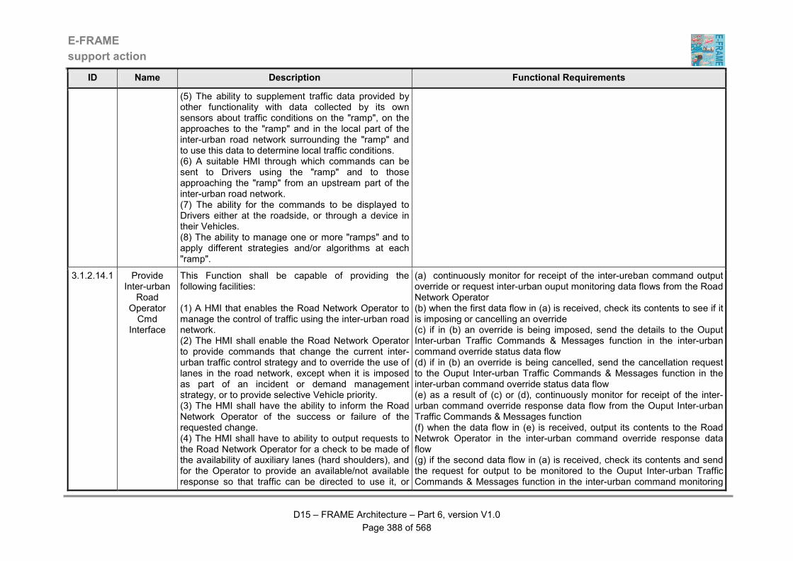
E-FRAME
support action
D15 – FRAME Architecture – Part 6, version V1.0
Page 388 of 568
ID Name Description Functional Requirements
(5) The ability to supplement traffic data provided by other functionality with data collected by its own sensors about traffic conditions on the "ramp", on the approaches to the "ramp" and in the local part of the inter-urban road network surrounding the "ramp" and to use this data to determine local traffic conditions. (6) A suitable HMI through which commands can be sent to Drivers using the "ramp" and to those approaching the "ramp" from an upstream part of the inter-urban road network. (7) The ability for the commands to be displayed to Drivers either at the roadside, or through a device in their Vehicles. (8) The ability to manage one or more "ramps" and to apply different strategies and/or algorithms at each "ramp".
3.1.2.14.1 Provide Inter-urban
Road Operator Cmd
Interface
This Function shall be capable of providing the following facilities: (1) A HMI that enables the Road Network Operator to manage the control of traffic using the inter-urban road network. (2) The HMI shall enable the Road Network Operator to provide commands that change the current inter-urban traffic control strategy and to override the use of lanes in the road network, except when it is imposed as part of an incident or demand management strategy, or to provide selective Vehicle priority. (3) The HMI shall have the ability to inform the Road Network Operator of the success or failure of the requested change. (4) The HMI shall have to ability to output requests to the Road Network Operator for a check to be made of the availability of auxiliary lanes (hard shoulders), and for the Operator to provide an available/not available response so that traffic can be directed to use it, or
(a) continuously monitor for receipt of the inter-ureban command output override or request inter-urban ouput monitoring data flows from the Road Network Operator (b) when the first data flow in (a) is received, check its contents to see if it is imposing or cancelling an override (c) if in (b) an override is being imposed, send the details to the Ouput Inter-urban Traffic Commands & Messages function in the inter-urban command override status data flow (d) if in (b) an override is being cancelled, send the cancellation request to the Ouput Inter-urban Traffic Commands & Messages function in the inter-urban command override status data flow (e) as a result of (c) or (d), continuously monitor for receipt of the inter-urban command override response data flow from the Ouput Inter-urban Traffic Commands & Messages function (f) when the data flow in (e) is received, output its contents to the Road Netwrok Operator in the inter-urban command override response data flow (g) if the second data flow in (a) is received, check its contents and send the request for output to be monitored to the Ouput Inter-urban Traffic Commands & Messages function in the inter-urban command monitoring
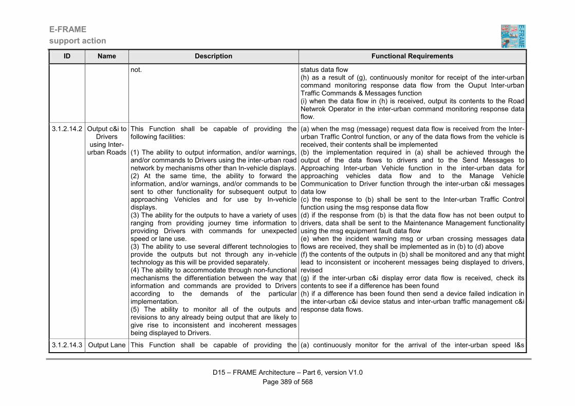
E-FRAME
support action
D15 – FRAME Architecture – Part 6, version V1.0
Page 389 of 568
ID Name Description Functional Requirements
not. status data flow (h) as a result of (g), continuously monitor for receipt of the inter-urban command monitoring response data flow from the Ouput Inter-urban Traffic Commands & Messages function (i) when the data flow in (h) is received, output its contents to the Road Netwrok Operator in the inter-urban command monitoring response data flow.
3.1.2.14.2 Output c&i to Drivers
using Inter-urban Roads
This Function shall be capable of providing the following facilities: (1) The ability to output information, and/or warnings, and/or commands to Drivers using the inter-urban road network by mechanisms other than In-vehicle displays. (2) At the same time, the ability to forward the information, and/or warnings, and/or commands to be sent to other functionality for subsequent output to approaching Vehicles and for use by In-vehicle displays. (3) The ability for the outputs to have a variety of uses ranging from providing journey time information to providing Drivers with commands for unexpected speed or lane use. (3) The ability to use several different technologies to provide the outputs but not through any in-vehicle technology as this will be provided separately. (4) The ability to accommodate through non-functional mechanisms the differentiation between the way that information and commands are provided to Drivers according to the demands of the particular implementation. (5) The ability to monitor all of the outputs and revisions to any already being output that are likely to give rise to inconsistent and incoherent messages being displayed to Drivers.
(a) when the msg (message) request data flow is received from the Inter-urban Traffic Control function, or any of the data flows from the vehicle is received, their contents shall be implemented (b) the implementation required in (a) shall be achieved through the output of the data flows to drivers and to the Send Messages to Approaching Inter-urban Vehicle function in the inter-urban data for approaching vehicles data flow and to the Manage Vehicle Communication to Driver function through the inter-urban c&i messages data low (c) the response to (b) shall be sent to the Inter-urban Traffic Control function using the msg response data flow (d) if the response from (b) is that the data flow has not been output to drivers, data shall be sent to the Maintenance Management functionality using the msg equipment fault data flow (e) when the incident warning msg or urban crossing messages data flows are received, they shall be implemented as in (b) to (d) above (f) the contents of the outputs in (b) shall be monitored and any that might lead to inconsistent or incoherent messages being displayed to drivers, revised (g) if the inter-urban c&i display error data flow is received, check its contents to see if a difference has been found (h) if a difference has been found then send a device failed indication in the inter-urban c&i device status and inter-urban traffic management c&i response data flows.
3.1.2.14.3 Output Lane This Function shall be capable of providing the (a) continuously monitor for the arrival of the inter-urban speed l&s

E-FRAME
support action
D15 – FRAME Architecture – Part 6, version V1.0
Page 390 of 568
ID Name Description Functional Requirements
& Speed Messages to Inter-urban Roads
following facilities: (1) The ability to provide outputs that can only provide commands to Drivers using the inter-urban road network. (2) The ability for these outputs to include regular speed and lane use commands and to supplement the outputs provided by other functionality. (3) The ability to use several different technologies to provide the outputs but not through any in-vehicle technology as this will be provided separately. (4) The ability to monitor all of the outputs and revisions to any already being output that are likely to give rise to inconsistent and incoherent messages being displayed to Drivers.
commands, inter-urban lane l&s commands, inter-urban speed display error, inter-urban incident warning l&s commands, inter-urban l&s display error and inter-urban speed being exceeded data flows (b) when either the inter-urban speed l&s commands or inter-urban lane l&s commands data flows in (a) is received, output its contents to drivers in the inter-urban traffic l&s commands data flow (c) also send the inter-urban l&s device status data flow to the Detect Inter-urban Traffic Violations function (d) if the inter-urban speed being exceeded data flow is received in (a), output its contents (including the vehicle identity) to the driver in the vehicle above required inter-urban speeds data flow (e) if for any reason the actions in (b) or (d) fail then send a device failed indication in the inter-urban device status data flow to the Detect Inter-urban Traffic Violations function and the inter-urban traffic management l&s response data flow to the Implement Inter-urban Traffic Commands function (f) the contents of the outputs in (b) shall be monitored and revisions provided to any that would generate inconsistent or incoherent messages being displayed to drivers (g) if either the inter-urban l&s display error or inter-urban speed display error data flows are received, check their contents to see if a difference has been found (h) if a difference is found (f) then again send a device failed indication in the inter-urban device status data flow to the Detect Inter-urban Traffic Violations function and the inter-urban traffic management l&s response data flow to the Evaluate Need for Equipment Maintenance function.
3.1.2.14.4 Output Inter-urban Traffic Commands & Messages
This Function shall be capable of providing the following facilities: (1) The ability to send for output the contents of traffic management strategies so that the most efficient use is made of the inter-urban road network. (2) The ability for the management strategies to include the output of messages to Drivers that will enable the use of road carriageway lanes, vehicle speeds and vehicle headways to be managed.
(a) continuously monitor for receipt of either of the inter-urban command monitoring or override data flows from the Provide Inter-urban Road Operator Cmd Interface function, or either of the "strategy details" data flows, or the inter-urban incident strategy, emergency route, or coned area strategy request data flow, or the current inter-urban traffic conditions data flow (b) when the selected inter-urban strategy details data flow is received in (a), check its contents and implement them by sending the inter-urban traffic management l&s reqyest and/ore inter-urban speed value and/or inter-urban traffic management c&i reqyest data flows to the Ouput Lane
E-FRAME
support action
D15 – FRAME Architecture – Part 6, version V1.0
Page 391 of 568
ID Name Description Functional Requirements
(3) The ability for these strategies to be overridden by the Road Network Operator through the functionality providing their interface, as well as by requests for access or use of particular lanes as part of a green wave route request for Emergency Vehicles. (4) The ability to use current, historic and predicted traffic data from the inter-urban network and to change in real-time the actual traffic management commands being sent for output to take account of variations in this data. (5) The ability to continuously adapt the management of the inter-urban road network to suit the actual detected traffic conditions. (6) The ability to provide details of the current and previous modes of control on some or all parts of the inter-urban road network to the Road Network Operator through the functionality that provides their interface. (7) The ability to monitor the results of the output of commands, so that alternative action can be taken if they are not followed.
& Speed Messages to Inter-urban Roads or Detect Violartions on Urban Roads, or Ouput Messages & Commands to Inter-urban Roads functions (c) as a result of (b) continuously monitor for receipt of the inter-urban traffic management l&s response and/or inter-urban traffic management c&i response data flows (d) when either of the data flows in (c) is received check its contents and if the ouput in (b) is not being performed correctly, send the details to the Manage Inter-urban Traffic Commands & Messages function in the inter-urban strategy command response failure data flow, plus also send details of the failure in the inter-urban strategy command output failure data flow to the Evaluate Need for Equipment Maintenance function (e) when any of the nter-urban incident strategy, emergency route, or coned area strategy request data flows is received in (a), check its contents and use them to override the outputs produced in (b) (f) as a result of (e) repeat (c) and (d) (g) wheb the current inter-urban traffic conditions data flow is received in (a) use its contents to modify any of the outputs being generated in (b) only (h) when the inter-urban command monitoring data flow is received in (a), check its contents and if they are a request for monitoring to start commence providing the contents of the output data flows in (b) to the Provide Inter-urban Road Operator Cmd Interface function in the data flow containing inter-urban command monitoring data (i) if the contents of the data flow in (h) were a request to stop a previously requested monitoring, then cease the activity in (h) (j) when the inter-urban command overridedata flow is received in (a), check its contents and if they are a request for an override, implement it unless any of the data flows in (e) area being actioned, in which case ignore the request (k) send the results of the action in (j) to the Provide Inter-urban Road Operator Cmd Interface function in the data flow containing inter-urban command override response
3.1.2.14.5 Detect Violations on Inter-urban Roads
This Function shall be capable of providing the following facilities: (1) The ability to detect violations of inter-urban traffic
(a) when the second or third trigger input data flows are received, the internal data describing the permitted vehicle movements within the inter-urban road network shall be updated (b) the first trigger input data flow shall be continuously monitored and
E-FRAME
support action
D15 – FRAME Architecture – Part 6, version V1.0
Page 392 of 568
ID Name Description Functional Requirements
control commands and report them to the law enforcement functionality. (2) The ability to only report a violation when it is detected that a Vehicle does not follow the current inter-urban traffic commands. (3) The ability for details of these commands to be provided by the inter-urban traffic management functionality.
converted into vehicle presence data (c) the positions of vehicles produced by (b) shall be compared against that required by (a) (d) if a vehicle is found in an illegal position by (c), details of the vehicle, the time, date. place and nature of the violation shall be sent to functionality in the Provide Support for Law Enforcement Area using the trigger output data flow (e) when the fourth trigger input data flow is received, the internal data describing the permitted vehicle speed shall be updated (f) if the vehicle speed obtained from (b) exceeds that specified in (e), details of the vehicle, the time, date. place plus allowed and actual speeds shall be sent to functionality in the Provide Support for Law Enforcement Area using the trigger output data flow.
3.1.2.14.6 Send Messages to Approaching Inter-urban Vehicles
This Function shall be capable of providing the following facilities: (1) The ability to receive and store data for information and warning messages plus commands that have been output to Drivers of preceding Vehicles using the inter-urban road network. (2) Use internal sensors to detect that a Vehicle is approaching. (3) When an approaching Vehicle is detected, the ability to output to it the data for information and warning messages plus commands relevant to the management of traffic using the inter-urban road network. (4) The ability to continue with the output to approaching Vehicles, changing the data every time it is changed, and stopping output if there is no data to transmit.
(a) continuously monitor for receipt of the urban data for approaching vehicles data flow from the Ouput Messages & Commands to Inter-urban Roads function (b) using internal sensors to detect the presence of approaching vehicles, putting the data in the inter-urban vehicle presence for messages data flow from the traffic entity (c) when the data flow is received in (a) store its contents (d) an approach vehicle is detected in (b), output the data stored in (c) in the data flow containing approaching vehicles inter-urban messages (e) repeat (c) for every approaching vehicle, unless there is no data to output (f) if the data flow received in (b) contains no data, clear the stored message data.
3.1.2.15 Predict Short & Medium Term Inter-
urban
This Function shall be capable of providing the following facilities: (1) The ability to create short and medium term
(a) at (frequent?) periodic intervals send the data flow containing the request iner-urban traffic data to the Manage Inter-urban Traffic Data function (b) as a result of (a) continuously monitor for the receipt of the data flow
E-FRAME
support action
D15 – FRAME Architecture – Part 6, version V1.0
Page 393 of 568
ID Name Description Functional Requirements
Conditions predictions of inter-urban traffic data. (2) The ability to create the predictions of short and medium term inter-urban traffic data using algorithms that may be different in content and scope. (3) The ability to request and use current inter-urban traffic data as the starting point for the predictions of short and medium term inter-urban traffic data. (4) The ability to repeat the creation of the predicted short and medium term inter-urban traffic data at (frequent?) periodic intervals.
containing the requested inter-urban traffic data (c) when the data flow in (b) is received, create the predictions of short and medium term inter-urban traffic data using appropriate algorithms that may be different in content and scope (d) when (c) is complete, put the results in the short & medium predicted inter-urban traffic data flow and send it to the Manage Inter-urban Traffic Data function.
3.1.2.16 Manage Inter-urban Traffic Data
This Function shall be capable of providing the following facilities: (1) The ability to manage the store of Inter-urban Traffic Data. (2) The ability to collect data about traffic conditions (i.e. traffic flows, road segment use, journey times, etc.) in the inter-urban road network and service area vehicle occupation data from other functionality in the Manage Traffic Functional Area. (3) The ability to receive data about traffic conditions (i.e. traffic flows, predicted road segment use (from trip plans), journey times, etc.) from functionality in the Provide Electronic Payment Facilities, Provide Support for Host Vehicle Systems and Provide Traveller Journey Assistance Functional Areas, plus the Cellular Communications Provider. (4) The ability to use the inter-urban road network static data to enable the collected and received data to be collated, fused and loaded in the store of Inter-urban Traffic Data in a coherent way that makes it easy to retrieve it for particular road segments, or larger parts of the inter-urban road network. (5) The ability to exchange data collected by the Function with similar functionality in another instance of the System, through the Other Related System,
(a) continuously monitor for receipt of any of the input data flows (b) when any of the data flows containing data about traffic using the inter-urban road network is received, process the data, applying data fusion where the data relates to the same part of the road network (c) use the data received in the inter-urban static data for traffic conditions data flow to determine the location and characteristics of the part of the inter-urban road network to which the received data applies (d) convert the contents of data flow containing inter-urban infrastructure usage data into actual traffic flows and apply it to the correct part(s) of the inter-urban road network (e) load the results of (b) to (d) into the store of Inter-urban Traffic Data, to provide the current traffic flow data and fusing it with data already in the store to provide a coherent set of historic traffic data for the inter-urban network (f) also use the results of (b) to (d) to provide traffic data for other inter-urban traffic management systems (g) analyse the results of (b) to (d) to determine where traffic queues are present and from use successive collections of data to determine the speed of propagation of the tail end of the queue (h) use the data received in the inter-urban static data for traffic conditions data flow to determine the locations of the queues (j) send the results of (g) and (h) to the output warnings to the driver in the vehicle functionality (j) analyse the results of (b) to (d) to determine the current journey time for each segment of the inter-urban road network and store it in the store of Inter-urban Traffic Data, fusing it with similar data already in the store
E-FRAME
support action
D15 – FRAME Architecture – Part 6, version V1.0
Page 394 of 568
ID Name Description Functional Requirements
Inter-urban Traffic Management System. (6) The ability to provide the collated and fused data from the store of Inter-urban Traffic Data to other functionality, including that responsible for the output of the processed data to other parts of the System and entities outside the System. (7) The ability to provide current inter-urban traffic data for use in creating short and medium term predictions for that data and when received to load that data into the store of Inter-urban Traffic Data.
to provide a coherent historical record of journey times (k) use the results of (b) to (d) and (j) to provide the output data flows containing current traffic data that shall be sent directly to other functionality and to the function for transmission to other entities and functionality in other functional areas (l) periodically read the journey times from the store of Inter-urban Traffic Data and use them to update the default inter-urban road segment journey times using the default inter-urban journey time update data flow (m) when the inter-urban data updates data flow is received in (a) from other inter-urban traffic systems, store it in its own part of the store of Inter-urban Traffic Data to provide a coherent historical record of inter-urban traffic data in other relevant geographic areas (n) when the urban to inter-urban traffic data transfer data flow is received in (a), store it in its own part of the store of Inter-urban Traffic Data to provide a coherent historical record of urban traffic data in relevant urban areas (o) when the data flow containing inter-urban traffic predicted data is received in (a), store it in its own part of the store of Inter-urban Traffic Data and delete any data that is no longer predicted, i.e. the time for which it is predicted in now current or in the past (p) when the data flow containing service area occupancy data is received in (a) store its contents in the service area part of the store of Inter-urban Traffic Data to provide a coherent historical record of service area use (q) when the data flow containing journey times from a cellular communications network provider is received, filter the data to remove travel times that are not between locations in the inter-urban road network, e.g. for pedestrian routes and the urban road network and check for consistency, i.e. does it fit with other data for road vehicles, or is it perhaps a cyclist (r) add the data that does pass the tests in (q) to the store of journey times in the store of Inter-urban Traffic Data (s) when the data flow containing the request current inter-urban traffic data is received, collect the requested data from the Store of Inter-urban Traffic Data and send it to the Predict Short & Long Term Inter-urban Traffic function in the data flow containing requested current inter-urban
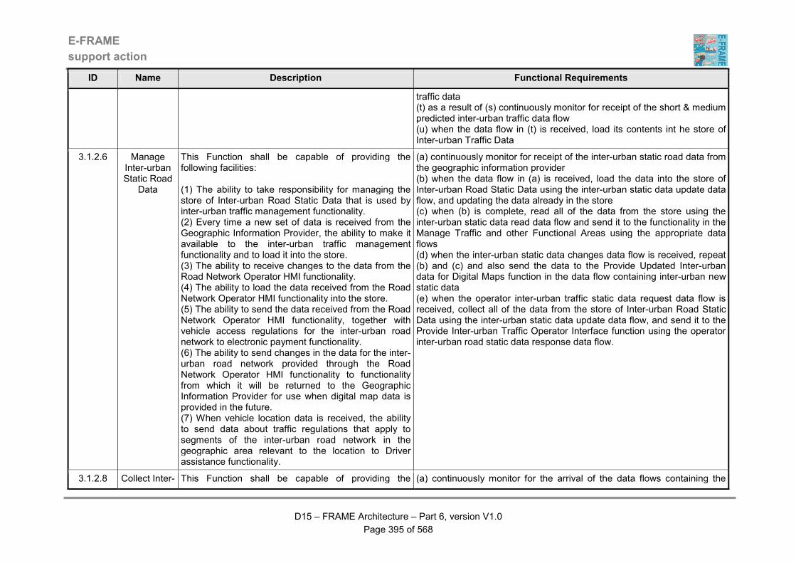
E-FRAME
support action
D15 – FRAME Architecture – Part 6, version V1.0
Page 395 of 568
ID Name Description Functional Requirements
traffic data (t) as a result of (s) continuously monitor for receipt of the short & medium predicted inter-urban traffic data flow (u) when the data flow in (t) is received, load its contents int he store of Inter-urban Traffic Data
3.1.2.6 Manage Inter-urban Static Road
Data
This Function shall be capable of providing the following facilities: (1) The ability to take responsibility for managing the store of Inter-urban Road Static Data that is used by inter-urban traffic management functionality. (2) Every time a new set of data is received from the Geographic Information Provider, the ability to make it available to the inter-urban traffic management functionality and to load it into the store. (3) The ability to receive changes to the data from the Road Network Operator HMI functionality. (4) The ability to load the data received from the Road Network Operator HMI functionality into the store. (5) The ability to send the data received from the Road Network Operator HMI functionality, together with vehicle access regulations for the inter-urban road network to electronic payment functionality. (6) The ability to send changes in the data for the inter-urban road network provided through the Road Network Operator HMI functionality to functionality from which it will be returned to the Geographic Information Provider for use when digital map data is provided in the future. (7) When vehicle location data is received, the ability to send data about traffic regulations that apply to segments of the inter-urban road network in the geographic area relevant to the location to Driver assistance functionality.
(a) continuously monitor for receipt of the inter-urban static road data from the geographic information provider (b) when the data flow in (a) is received, load the data into the store of Inter-urban Road Static Data using the inter-urban static data update data flow, and updating the data already in the store (c) when (b) is complete, read all of the data from the store using the inter-urban static data read data flow and send it to the functionality in the Manage Traffic and other Functional Areas using the appropriate data flows (d) when the inter-urban static data changes data flow is received, repeat (b) and (c) and also send the data to the Provide Updated Inter-urban data for Digital Maps function in the data flow containing inter-urban new static data (e) when the operator inter-urban traffic static data request data flow is received, collect all of the data from the store of Inter-urban Road Static Data using the inter-urban static data update data flow, and send it to the Provide Inter-urban Traffic Operator Interface function using the operator inter-urban road static data response data flow.
3.1.2.8 Collect Inter- This Function shall be capable of providing the (a) continuously monitor for the arrival of the data flows containing the

E-FRAME
support action
D15 – FRAME Architecture – Part 6, version V1.0
Page 396 of 568
ID Name Description Functional Requirements
urban Data from
Vehicles
following facilities: (1) The ability to collect Floating Car Data (FCD) and Extended Floating Car Data (XFCD) about Vehicles that are using the inter-urban road network. (2) The ability to collect the data as raw input from functionality within the Vehicles. (3) The raw input data shall be expected to contain location information, time and Vehicle status data. (4) The ability to process the collected data to provide actual traffic flow data, e.g. flow, speed, for the inter-urban road network, Vehicle status data, e.g. broken down, other road related data, e.g. rain, fog, slippery road, ice and to detect incidents. (5) As part of this processing, the ability to check the coherence and consistency of the data both for individual Vehicles and for the traffic as a whole in each segment of the inter-urban road network. (6) The ability to also check that the data it receives is actually coming from the Vehicle whose ID comes with it and that the safety behaviour of the Vehicle is acceptable. (7) If any of these checks fail, the ability for the data received for that Vehicle to be discarded, except if it is traffic flow data and the Vehicle is being driven safely. (8) The ability to pass the processed data to the incident management functionality for collation and to other traffic management functionality for use in managing the traffic using the inter-urban road network. (9) The ability to make all processed data anonymous so that the movement through the urban road network of specific Vehicles cannot be identified.
inter-urban floating car and any other data from vehicles (b) when either of the floating car data flows in (a) arrive, process their contents to determine traffic flow data and check this and any other data provided by in-vehicle systems for their plausibility (c) put the vehicle identity extracted from the data flows in (b) into the inter-urban fcd vehicle identity data flow and send it to the Monitor Inter-urban FCD/XFCD Source Vehicle function (d) when as a result of (c) the inter-urban fcd error data flow is received, check to see if it includes an error indication (e) if an error indication is found in (d) discard all the data provided by the vehicle, except that from which inter-urban traffic flow can be determined (f) if the safety behaviour status for urban data flow is received in (a) containing a warning of unsafe behaviour, discard all of the data from the vehicle as it will not be representative of the majority of vehicles using the urban road network (g) if the checks in (d) and (e) are satisfactory, plus there is no warning in (f), if the checks in (b) and (e) are satisfactory, collate and fuse the data to provide a coherent and consistent set, separating out the inter-urban traffic flow data, other data, e.g. slippery road, fog, rain, darkness, possible incidents and ice, for easy use by other functionality (h) fuse the traffic flow data from all vehicles so that for example, data for the same segment of the inter-urban road network is aggregated and also fuse the data from the vehicle trip plans so that for example, the numbers of vehicle using or planning to use each segment of the inter-urban road network is calculated (i) send the data produced in (h) to the Provide Inter-urban Traffic Data Management function in the data flow containing collected inter-urban vehicle data (j) also send the inter-urban traffic flow data and any available data about unusual conditions, e.g. rain and low temperatures, to the Incident Detection function in the inter-urban XFCD for incident detection data flow.
3.1.2.9 Output Inter-urban Traffic
Data
This Function shall be capable of providing the following facilities:
(a) continuously monitor for the receipt of the any of the input data flows (b) when the data flow inter-urban traffic information request is received in (a), output the current traffic information to the broadcaster using the data

E-FRAME
support action
D15 – FRAME Architecture – Part 6, version V1.0
Page 397 of 568
ID Name Description Functional Requirements
(1) The ability to periodically receive data about current traffic conditions in the inter-urban road network from the functionality that manages the store of Inter-urban Traffic Data, plus the functionality that manages lane use and maximum speeds within the inter-urban road network. (2) The ability to immediately output the data which has been received to other parts of the System or to entities that are outside of the System. (3) When a request is received from the Broadcaster entity, the ability to output the latest set of data that is available about inter-urban traffic conditions.
flow containing inter-urban traffic data (c) when the inter-urban traffic data for output data flow is received in (a), store its contents locally updating any previously received data that has been changed (d) when (c) is complete, output the revised version of the inter-urban traffic data to functionality in other Functional Areas, the broadcaster and the traffic and travel information provide in the appropriate output data flows (e) when either the inter-urban lane instructions or the inter-urban speed limit changes data flows are received in (a), repeat (c) and (d) for the data that they contain.
3.1.4.1 Monitor numbers of vehicles in Car Parks
This Function shall be capable of providing the following facilities: (1) The ability to detect vehicles using the entrances and exits of car parks in the urban road network. (2) The ability to collect the data as raw input by sensors that are capable of detecting the passage and presence of all types of road vehicle, from bicycles to Heavy Goods Vehicles (HGV's). (3) The ability to process the data to provide actual vehicle count data, i.e. numbers of vehicles, using the entrances and exits of each car park. (4) The ability to send the processed data to other functionality for collation and use in traffic management.
(a) the presence of the trigger input data flow shall be continuously monitored (b) the analogue data representing the raw traffic flow data obtained in (a) shall be converted into digital data that separately shows the numbers of vehicles entering and leaving the car park (c) the data for each car park in the urban road network shall be kept separate and split into vehicles entering and leaving (d) the trigger output data flow shall be used to send the data in (c) to the Calculate Car Park Occupancy and Status function.
3.1.4.2 Detect the occupancy of Car Park spaces
This Function shall be capable of providing the following facilities: (1) The ability to detect that a Vehicle is in a car park space. (2) The ability to collect this data as raw input by sensors that are capable of detecting the presence of a Vehicle and determining its type, e.g. car, bicycle,
(a) the presence of the trigger input data flow shall be continuously monitored (b) the analogue data representing the presence of a vehicle in each car park space obtained in (a) shall be converted into digital data from which the vehicle identity can be determined, of necessary only to the extent that one vehicle can be distinguished from another (c) the trigger output data flows shall be used to send the data in (b) to the Calculate Occupancy of Individual Car Park Spaces function.
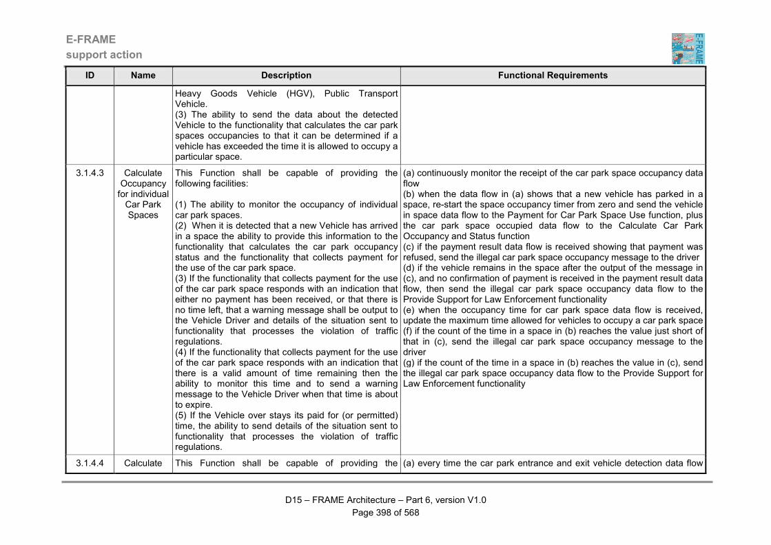
E-FRAME
support action
D15 – FRAME Architecture – Part 6, version V1.0
Page 398 of 568
ID Name Description Functional Requirements
Heavy Goods Vehicle (HGV), Public Transport Vehicle. (3) The ability to send the data about the detected Vehicle to the functionality that calculates the car park spaces occupancies to that it can be determined if a vehicle has exceeded the time it is allowed to occupy a particular space.
3.1.4.3 Calculate Occupancy for individual Car Park Spaces
This Function shall be capable of providing the following facilities: (1) The ability to monitor the occupancy of individual car park spaces. (2) When it is detected that a new Vehicle has arrived in a space the ability to provide this information to the functionality that calculates the car park occupancy status and the functionality that collects payment for the use of the car park space. (3) If the functionality that collects payment for the use of the car park space responds with an indication that either no payment has been received, or that there is no time left, that a warning message shall be output to the Vehicle Driver and details of the situation sent to functionality that processes the violation of traffic regulations. (4) If the functionality that collects payment for the use of the car park space responds with an indication that there is a valid amount of time remaining then the ability to monitor this time and to send a warning message to the Vehicle Driver when that time is about to expire. (5) If the Vehicle over stays its paid for (or permitted) time, the ability to send details of the situation sent to functionality that processes the violation of traffic regulations.
(a) continuously monitor the receipt of the car park space occupancy data flow (b) when the data flow in (a) shows that a new vehicle has parked in a space, re-start the space occupancy timer from zero and send the vehicle in space data flow to the Payment for Car Park Space Use function, plus the car park space occupied data flow to the Calculate Car Park Occupancy and Status function (c) if the payment result data flow is received showing that payment was refused, send the illegal car park space occupancy message to the driver (d) if the vehicle remains in the space after the output of the message in (c), and no confirmation of payment is received in the payment result data flow, then send the illegal car park space occupancy data flow to the Provide Support for Law Enforcement functionality (e) when the occupancy time for car park space data flow is received, update the maximum time allowed for vehicles to occupy a car park space (f) if the count of the time in a space in (b) reaches the value just short of that in (c), send the illegal car park space occupancy message to the driver (g) if the count of the time in a space in (b) reaches the value in (c), send the illegal car park space occupancy data flow to the Provide Support for Law Enforcement functionality
3.1.4.4 Calculate This Function shall be capable of providing the (a) every time the car park entrance and exit vehicle detection data flow
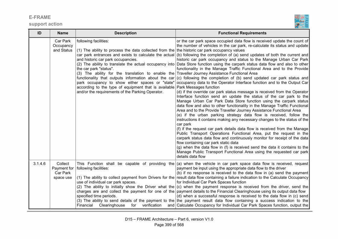
E-FRAME
support action
D15 – FRAME Architecture – Part 6, version V1.0
Page 399 of 568
ID Name Description Functional Requirements
Car Park Occupancy and Status
following facilities: (1) The ability to process the data collected from the car park entrances and exists to calculate the actual and historic car park occupancies. (2) The ability to translate the actual occupancy into the car park "status". (3) The ability for the translation to enable the functionality that outputs information about the car park occupancy to show either spaces or "state" according to the type of equipment that is available and/or the requirements of the Parking Operator.
or the car park space occupied data flow is received update the count of the number of vehicles in the car park, re-calculate its status and update the historic car park occupancy values (b) following the completion of (a) send updates of both the current and historic car park occupancy and status to the Manage Urban Car Park Data Store function using the carpark status data flow and also to other functionality in the Manage Traffic Functional Area and to the Provide Traveller Journey Assistance Functional Area (c) following the completion of (b) send updated car park status and occupancy data to the Operator Interface function and to the Output Car Park Messages function (d) if the override car park status message is received from the Operator Interface function send an update the status of the car park to the Manage Urban Car Park Data Store function using the carpark status data flow and also to other functionality in the Manage Traffic Functional Area and to the Provide Traveller Journey Assistance Functional Area (e) if the urban parking strategy data flow is received, follow the instructions it contains making any necessary changes to the status of the car park (f) if the request car park details data flow is received from the Manage Public Transport Operations Functional Area, put the request in the carpark status data flow and continuously monitor for receipt of the data flow containing car park static data (g) when the data flow in (f) is received send the data it contains to the Manage Public Transport Functional Area using the requested car park details data flow
3.1.4.6 Collect Payment for Car Park space use
This Function shall be capable of providing the following facilities: (1) The ability to collect payment from Drivers for the use of individual car park spaces. (2) The ability to initially show the Driver what the charges are and collect the payment for one of the specified time periods. (3) The ability to send details of the payment to the Financial Clearinghouse for verification and
(a) when the vehicle in car park space data flow is received, request payment be input using the appropriate data flow to the driver (b) if no response is received to the data flow in (a) send the payment result data flow containing a failure indication to the Calculate Occupancy for Individual Car Park Spaces function (c) when the payment response is received from the driver, send the payment details to the Financial Clearinghouse using its output data flow (d) when a successful response is received to the data flow in (c) send the payment result data flow containing a success indication to the Calculate Occupancy for Individual Car Park Spaces function, output the
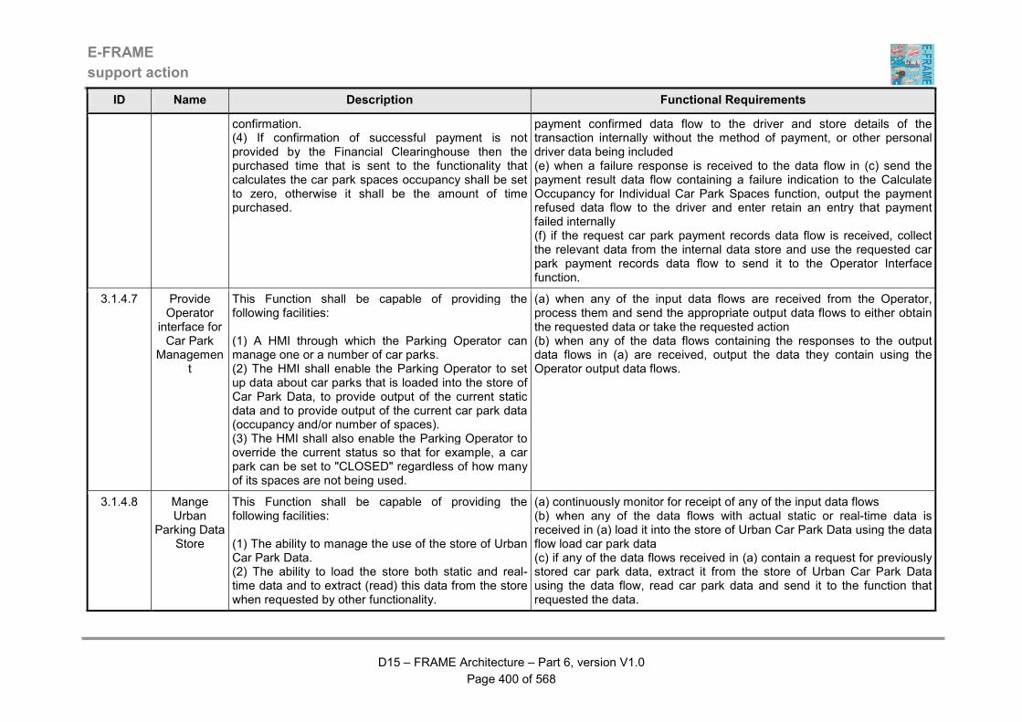
E-FRAME
support action
D15 – FRAME Architecture – Part 6, version V1.0
Page 400 of 568
ID Name Description Functional Requirements
confirmation. (4) If confirmation of successful payment is not provided by the Financial Clearinghouse then the purchased time that is sent to the functionality that calculates the car park spaces occupancy shall be set to zero, otherwise it shall be the amount of time purchased.
payment confirmed data flow to the driver and store details of the transaction internally without the method of payment, or other personal driver data being included (e) when a failure response is received to the data flow in (c) send the payment result data flow containing a failure indication to the Calculate Occupancy for Individual Car Park Spaces function, output the payment refused data flow to the driver and enter retain an entry that payment failed internally (f) if the request car park payment records data flow is received, collect the relevant data from the internal data store and use the requested car park payment records data flow to send it to the Operator Interface function.
3.1.4.7 Provide Operator
interface for Car Park
Management
This Function shall be capable of providing the following facilities: (1) A HMI through which the Parking Operator can manage one or a number of car parks. (2) The HMI shall enable the Parking Operator to set up data about car parks that is loaded into the store of Car Park Data, to provide output of the current static data and to provide output of the current car park data (occupancy and/or number of spaces). (3) The HMI shall also enable the Parking Operator to override the current status so that for example, a car park can be set to "CLOSED" regardless of how many of its spaces are not being used.
(a) when any of the input data flows are received from the Operator, process them and send the appropriate output data flows to either obtain the requested data or take the requested action (b) when any of the data flows containing the responses to the output data flows in (a) are received, output the data they contain using the Operator output data flows.
3.1.4.8 Mange Urban
Parking Data Store
This Function shall be capable of providing the following facilities: (1) The ability to manage the use of the store of Urban Car Park Data. (2) The ability to load the store both static and real-time data and to extract (read) this data from the store when requested by other functionality.
(a) continuously monitor for receipt of any of the input data flows (b) when any of the data flows with actual static or real-time data is received in (a) load it into the store of Urban Car Park Data using the data flow load car park data (c) if any of the data flows received in (a) contain a request for previously stored car park data, extract it from the store of Urban Car Park Data using the data flow, read car park data and send it to the function that requested the data.

E-FRAME
support action
D15 – FRAME Architecture – Part 6, version V1.0
Page 401 of 568
ID Name Description Functional Requirements
3.1.4.9 Output Car Park
Information to Drivers
This Function shall be capable of providing the following facilities: (1) The ability to provide output of information about car parks to Vehicle Drivers, which shall be updated as soon as new data is received. (2) The ability to output information about relevant service areas, if it is available from other functionality. (3) The ability for the output to show either the current car park occupancy (number of spaces) or the current status depending on what is required by the Parking Operator.
(a) if either the car park status or occupancy data flows, or the service area occupancy data flow are received, output their contents to the driver (b) if the car park output settings data flow is received, change all future outputs to the settings that it contains.
3.1.5.1 Monitor Service Area
Vehicle Occupation
This Function shall be capable of providing the following facilities: (1) The ability to collect traffic data from the entrances and exits of service area vehicle parks in the inter-urban road network. (2) The ability to collect this data as raw input by sensors that are capable of detecting the passage of all types of road Vehicle, from Bicycles to Heavy Freight Vehicles. (3) The ability for the raw input data to be processed to provide actual traffic count data, i.e. numbers of vehicles, at the entrances and exits of each service area vehicle park. (4) The ability for the resulting data to be passed to other functionality for collation and use in inter-urban traffic control.
(a) the presence of the trigger input data flow shall be continuously monitored (b) the analogue data representing the raw traffic flow data obtained in (a) shall be converted into digital data that separately shows the numbers of vehicles entering and leaving the service area vehicle park (c) the data for each service area vehicle park in the inter-urban road network shall be kept separate and split into vehicles entering and leaving (d) the trigger output data flows shall be used to send the data in (c) to the Calculate Service Area Occupancy and Status function.
3.1.5.2 Calculate Service Area Occupancy and Status
This Function shall be capable of providing the following facilities: (1) The ability to translate service area occupancy levels into service area "states". (2) The ability for the translation to enable the
(a) when the trigger output data flow is received, the data it contains shall be translated into a service area occupancy and status (b) when (a) is completed, send all the data flows containing service area occupancy to other parts of the Manage Traffic Functional Area and to the Manage Public Transport Operations Functional Area and load the data into the store of Inter-urban Service Area Data using service area status
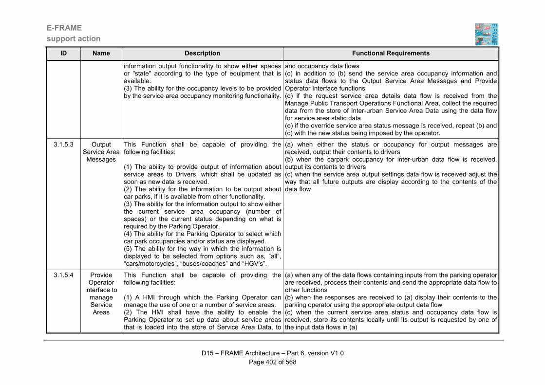
E-FRAME
support action
D15 – FRAME Architecture – Part 6, version V1.0
Page 402 of 568
ID Name Description Functional Requirements
information output functionality to show either spaces or "state" according to the type of equipment that is available. (3) The ability for the occupancy levels to be provided by the service area occupancy monitoring functionality.
and occupancy data flows (c) in addition to (b) send the service area occupancy information and status data flows to the Output Service Area Messages and Provide Operator Interface functions (d) if the request service area details data flow is received from the Manage Public Transport Operations Functional Area, collect the required data from the store of Inter-urban Service Area Data using the data flow for service area static data (e) if the override service area status message is received, repeat (b) and (c) with the new status being imposed by the operator.
3.1.5.3 Output Service Area Messages
This Function shall be capable of providing the following facilities: (1) The ability to provide output of information about service areas to Drivers, which shall be updated as soon as new data is received. (2) The ability for the information to be output about car parks, if it is available from other functionality. (3) The ability for the information output to show either the current service area occupancy (number of spaces) or the current status depending on what is required by the Parking Operator. (4) The ability for the Parking Operator to select which car park occupancies and/or status are displayed. (5) The ability for the way in which the information is displayed to be selected from options such as, “all”, “cars/motorcycles”, “buses/coaches” and “HGV’s”.
(a) when either the status or occupancy for output messages are received, output their contents to drivers (b) when the carpark occupancy for inter-urban data flow is received, output its contents to drivers (c) when the service area output settings data flow is received adjust the way that all future outputs are display according to the contents of the data flow
3.1.5.4 Provide Operator interface to manage Service Areas
This Function shall be capable of providing the following facilities: (1) A HMI through which the Parking Operator can manage the use of one or a number of service areas. (2) The HMI shall have the ability to enable the Parking Operator to set up data about service areas that is loaded into the store of Service Area Data, to
(a) when any of the data flows containing inputs from the parking operator are received, process their contents and send the appropriate data flow to other functions (b) when the responses are received to (a) display their contents to the parking operator using the appropriate output data flow (c) when the current service area status and occupancy data flow is received, store its contents locally until its output is requested by one of the input data flows in (a)
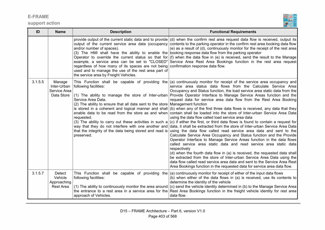
E-FRAME
support action
D15 – FRAME Architecture – Part 6, version V1.0
Page 403 of 568
ID Name Description Functional Requirements
provide output of the current static data and to provide output of the current service area data (occupancy and/or number of spaces). (3) The HMI shall have the ability to enable the Operator to override the current status so that for example, a service area can be set to "CLOSED" regardless of how many of its spaces are not being used and to manage the use of the rest area part of the service area by Freight Vehicles.
(d) when the confirm rest area request data flow is received, output its contents to the parking operator in the confirm rest area booking data flow (e) as a result of (d), continuously monitor for the receipt of the rest area booking response data flow from the parking operator (f) when the data flow in (e) is received, send the result to the Manage Service Area Rest Area Bookings function in the rest area request confirmation response data flow.
3.1.5.5 Manage Inter-Urban Service Area Data Store
This Function shall be capable of providing the following facilities: (1) The ability to manage the store of Inter-urban Service Area Data. (2) The ability to ensure that all data sent to the store is stored in a coherent and logical manner and shall enable data to be read from the store as and when requested. (3) The ability to carry out these activities in such a way that they do not interfere with one another and that the integrity of the data being stored and read is preserved.
(a) continuously monitor for receipt of the service area occupancy and service area status data flows from the Calculate Service Area Occupancy and Status function, the load service area static data from the Provide Operator Interface to Manage Service Areas function and the request data for service area data flow from the Rest Area Booking Management function (b) when any of the first three data flows is received, any data that they contain shall be loaded into the store of Inter-urban Service Area Data using the data flow called load service area data (c) if either the first, or third data flows is found to contain a request for data, it shall be extracted from the store of Inter-urban Service Area Data using the data flow called read service area data and sent to the Calculate Service Area Occupancy and Status function and the Provide Operator Interface to Manage Service Areas function in the data flows called service area static data and read service area static data respectively (d) when the fourth data flow in (a) is received, the requested data shall be extracted from the store of Inter-urban Service Area Data using the data flow called read service area data and sent to the Service Area Rest Area Bookings function in the requested data for service area data flow.
3.1.5.7 Detect Vehicle
Approaching Rest Area
This Function shall be capable of providing the following facilities: (1) The ability to continuously monitor the area around the entrance to a rest area in a service area for the approach of Vehicles.
(a) continuously monitor for receipt of either of the input data flows (b) when either of the data flows in (a) is received, use its contents to determine the identity of the vehicle (c) send the vehicle identity determined in (b) to the Manage Service Area Rest Area Bookings function in the freight vehicle identity for rest area data flow.
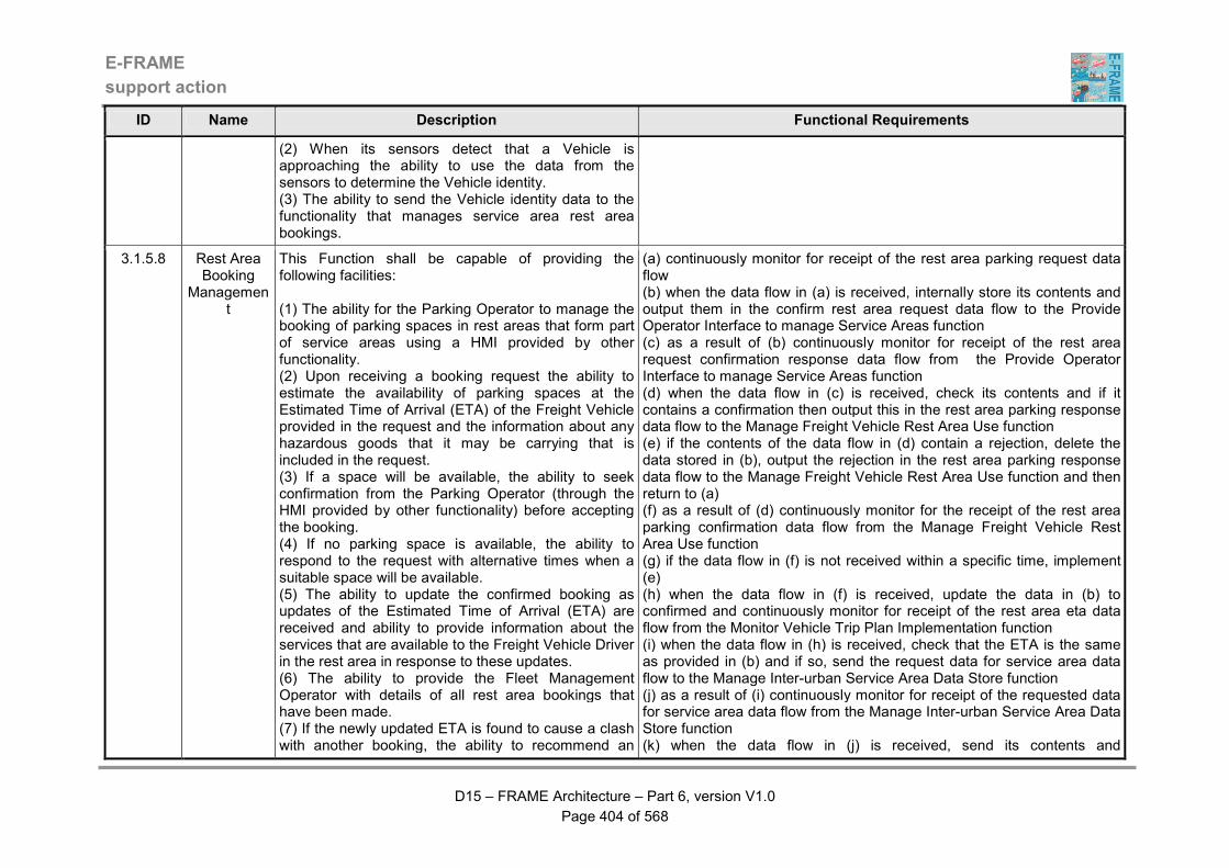
E-FRAME
support action
D15 – FRAME Architecture – Part 6, version V1.0
Page 404 of 568
ID Name Description Functional Requirements
(2) When its sensors detect that a Vehicle is approaching the ability to use the data from the sensors to determine the Vehicle identity. (3) The ability to send the Vehicle identity data to the functionality that manages service area rest area bookings.
3.1.5.8 Rest Area Booking
Management
This Function shall be capable of providing the following facilities: (1) The ability for the Parking Operator to manage the booking of parking spaces in rest areas that form part of service areas using a HMI provided by other functionality. (2) Upon receiving a booking request the ability to estimate the availability of parking spaces at the Estimated Time of Arrival (ETA) of the Freight Vehicle provided in the request and the information about any hazardous goods that it may be carrying that is included in the request. (3) If a space will be available, the ability to seek confirmation from the Parking Operator (through the HMI provided by other functionality) before accepting the booking. (4) If no parking space is available, the ability to respond to the request with alternative times when a suitable space will be available. (5) The ability to update the confirmed booking as updates of the Estimated Time of Arrival (ETA) are received and ability to provide information about the services that are available to the Freight Vehicle Driver in the rest area in response to these updates. (6) The ability to provide the Fleet Management Operator with details of all rest area bookings that have been made. (7) If the newly updated ETA is found to cause a clash with another booking, the ability to recommend an
(a) continuously monitor for receipt of the rest area parking request data flow (b) when the data flow in (a) is received, internally store its contents and output them in the confirm rest area request data flow to the Provide Operator Interface to manage Service Areas function (c) as a result of (b) continuously monitor for receipt of the rest area request confirmation response data flow from the Provide Operator Interface to manage Service Areas function (d) when the data flow in (c) is received, check its contents and if it contains a confirmation then output this in the rest area parking response data flow to the Manage Freight Vehicle Rest Area Use function (e) if the contents of the data flow in (d) contain a rejection, delete the data stored in (b), output the rejection in the rest area parking response data flow to the Manage Freight Vehicle Rest Area Use function and then return to (a) (f) as a result of (d) continuously monitor for the receipt of the rest area parking confirmation data flow from the Manage Freight Vehicle Rest Area Use function (g) if the data flow in (f) is not received within a specific time, implement (e) (h) when the data flow in (f) is received, update the data in (b) to confirmed and continuously monitor for receipt of the rest area eta data flow from the Monitor Vehicle Trip Plan Implementation function (i) when the data flow in (h) is received, check that the ETA is the same as provided in (b) and if so, send the request data for service area data flow to the Manage Inter-urban Service Area Data Store function (j) as a result of (i) continuously monitor for receipt of the requested data for service area data flow from the Manage Inter-urban Service Area Data Store function (k) when the data flow in (j) is received, send its contents and
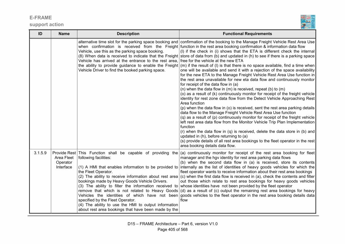
E-FRAME
support action
D15 – FRAME Architecture – Part 6, version V1.0
Page 405 of 568
ID Name Description Functional Requirements
alternative time slot for the parking space booking and when confirmation is received from the Freight Vehicle, use this as the parking space booking. (8) When data is received to indicate that the Freight Vehicle has arrived at the entrance to the rest area, the ability to provide guidance to enable the Freight Vehicle Driver to find the booked parking space.
confirmation of the booking to the Manage Freight Vehicle Rest Area Use function in the rest area booking confirmation & information data flow (l) if the check in (i) shows that the ETA is different check the internal store of data from (b) and updated in (h) to see if there is a parking space free for the vehicle at the new ETA (m) if the result of (l) is that there is no space available, find a time when one will be available and send it with a rejection of the space availability for the new ETA to the Manage Freight Vehicle Rest Area Use function in the rest area unavailable for new eta data flow and continuously monitor for receipt of the data flow in (a) (n) when the data flow in (m) is received, repeat (b) to (m) (o) as a result of (k) continuously monitor for receipt of the freight vehicle identity for rest zone data flow from the Detect Vehicle Approaching Rest Area function (p) when the data flow in (o) is received, sent the rest area parking details data flow to the Manage Freight Vehicle Rest Area Use function (q) as a result of (p) continuously monitor for receipt of the freight vehicle left rest area data flow from the Monitor Vehicle Trip Plan Implementation function (r) when the data flow in (q) is received, delete the data store in (b) and updated in (h), before returning to (a) (s) provide details of all rest area bookings to the fleet operator in the rest area booking details data flow.
3.1.5.9 Provide Rest Area Fleet Operator Interface
This Function shall be capable of providing the following facilities: (1) A HMI that enables information to be provided to the Fleet Operator. (2) The ability to receive information about rest area bookings made by Heavy Goods Vehicle Drivers. (3) The ability to filter the information received to remove that which is not related to Heavy Goods Vehicles the identities of which have not been specified by the Fleet Operator. (4) The ability to use the HMI to output information about rest area bookings that have been made by the
(a) continuously monitor for receipt of the rest area booking for fleet manager and the hgv identity for rest area parking data flows (b) when the second data flow in (a) is received, store its contents internally as the list of identities of heavy goods vehicles for which the fleet operator wants to receive information about their rest area bookings (c) when the first data flow is received in (a), check the contents and filter out those which relate to rest area bookings for heavy goods vehicles whose identities have not been provided by the fleet operator (d) as a result of (c) output the remaining rest area bookings for heavy goods vehicles to the fleet operator in the rest area booking details data flow
E-FRAME
support action
D15 – FRAME Architecture – Part 6, version V1.0
Page 406 of 568
ID Name Description Functional Requirements
Drivers of Heavy Goods Vehicles specified by the Fleet Operator.
3.1.6.1 Process Road
Network Static Data
This Function shall be capable of providing the following facilities: (1) The ability to receive road network static data from both urban and inter-urban functionality (2) The ability to process the received data so that it can be used in the road network model by the Traffic Simulation Engine functionality. (3) When the data has been processed it shall be sent to the functionality that manages the store of Traffic Simulation Data from where it can be obtained by the Traffic Simulation Engine functionality.
(a) continuously monitor for the arrival of the data flows containing static data for the inter-urban and/or urban road network (b)when either of the data flows in (a) is received, process the data into a coherent set that represents the road network managed by the system, integrating the new data with any that was received previously (c) when (b) is complete, send include the data in the network data for simulation data flow and send it to the store of Manage Traffic Simulation Data.
3.1.6.2 Process Road Traffic
Data
This Function shall be capable of providing the following facilities: (1) The ability to receive real-time traffic data from both urban and inter-urban functionality. (2) The ability to process the received data so that it can be used in the road network model by the Traffic Simulation Engine functionality. (3) It shall be possible for the processing to include the generation of origin/destination data for the road network and indications of unusual changes in current traffic data based on historical data. (4) When the data has been processed, the ability for the data to be sent to the functionality that manages the store of Traffic Simulation Data from where it can be obtained by the Traffic Simulation Engine functionality. (5) It shall be possible for road network (model) data to be provided and for historic traffic data to be provided periodically by the functionality managing the store of Traffic Simulation Data for use in the processing of the
(a) continuously monitor for the frequent arrival of the collected traffic data traffic predictions from the inter-urban and/or the urban road network (b) continuously monitor for the occasional arrival of the data flow containing the road network static data (c) use the data from (b) to build a model of the road network into which the data from (a) can be fused, i.e. the traffic flow data can be allocated to its correct part of the road network (d) whenever either of the data flows in (a) arrives, fuse the data that they contain into the model produced by (c) when (d) has been completed, send the collected traffic data to the Manage Traffic Simulation Data Store function in the data flow for processed road traffic data.
E-FRAME
support action
D15 – FRAME Architecture – Part 6, version V1.0
Page 407 of 568
ID Name Description Functional Requirements
traffic data.
3.1.6.3 Create Traffic
Predictions with
Simulation Methods
This Function shall be capable of providing the following facilities: (1) The ability to use a road network model and traffic data to provide predictions of traffic conditions for the road network. (2) It shall be possible for the current and historical traffic data plus road network data obtained on request from the functionality managing the Traffic Simulation Data to be used to provide the predictions. (3) The ability to use this data as input to a simulation engine that will predict what the traffic conditions shall be like as a result of various traffic management strategies that are provided by the Transport Planner, or have been used in the past in all or part of the road network. (4) The ability for these predictions to include the need for car park spaces and shall be produced at the request of the Transport Planner or at regular intervals that the Planner may specify. (5) When completed the ability to send the predicted traffic conditions and associated strategies to the functionality managing the store of Traffic Simulation Data.
(a) continuously monitor for the arrival of the operator simulation commands data flow (b) when the data flow in (a) arrives, start to carryout the instructions that it contains (c) send the request road data for simulation data flow to the Manage Traffic Simulation Data Store function (d) when as a result of (c) the road data for simulation data flow is received, produce a simulation of the traffic conditions that will exist in the road network according to the static and collected road data plus the traffic management strategies currently being used, and the traffic management and/or road network scenario(s) included in the operator simulation commands (e) when (d) is complete, send the simulation results back to the Manage Traffic Simulation Data Store function and send the simulation responses data flow to the Provide Operator Interface function.
3.1.6.4 Manage Traffic
Prediction Data Store
This Function shall be capable of providing the following facilities: (1) The ability to manage the use of the store of Road Traffic Simulation Data. (2) The ability to load into the store the road network model and traffic data from other functionality in a way that keeps the data coherent and consistent. (3) It shall be possible for there to be more than one model of the same road network to enable various
(a) when the road network data for simulation data flow is received load the data into the store of Road Traffic Simulation Data using the data flow load simulation data (b) use the data received in (a) in the road network data for collection data flow and send it to the Process Road Traffic Data function (c) when the processed road traffic data flow is received, load the data it contains into the store of Road Traffic Simulation Data using the data flow load simulation data (d) when either the inter-urban or urban strategies in use are received, again load their contents into the store of Road Traffic Simulation Data
E-FRAME
support action
D15 – FRAME Architecture – Part 6, version V1.0
Page 408 of 568
ID Name Description Functional Requirements
road configurations to be assessed for the effect on traffic. (4) The ability to enable the Traffic Simulation Engine functionality to obtain the data it needs to run simulations for each road network model and to store the results. (5) The ability to enable the Transport Planner to have access to the data in the store in a controlled manner so that changes can be made to the road network model and the results extracted for output to other functionality, either by specific request or following the automatic generation of new results by the Traffic Simulation Engine functionality. (6) If necessary the ability to be able to exchange data from the store with similar functionality in another instance of the System.
using the data flow road simulation data (e) when the request road data for simulation data flow is received collect all the relevant data from the store of Road Traffic Simulation Data using the data flow read simulation data (f) put the data collected in (e) into the road data for simulation data flow and send it to the Provide Traffic Simulation Engine function (g) when as a result of (f) the simulation results data flow is received, load the data into the store of Road Traffic Simulation Data using the data flow road simulation data (h) if the traffic simulation results data flow is received from other systems, load the data into the store of Road Traffic Simulation Data using the data flow load simulation data (i) if the send traffic simulation results for output data flow is received, collect the relevant simulation results plus the data about the traffic model itself from the store of Road Traffic Simulation Data using the data flow for read simulation data and send it to the Process Traffic Simulation Results function in the traffic simulation results for processing data flow and also to the other systems using the traffic simulation results data flow (j) if the request road network data flow is received, collect the requested data from the store of Road Traffic Simulation Data using the data flow read simulation data and send it to the Provide Traffic Simulation Operator Interface function in the data flow containing requested road network data (k) if the updated road network data flow is received, amend the data in the store of Road Traffic Simulation Data using the data flow load simulation data (l) if the request traffic simulations results data flow is received, collect the requested data from the store of Road Traffic Simulation Data using the data flow read simulation data and send it to the Provide Traffic Simulation Operator Interface function in the data flow containing requested traffic simulation results.
3.1.6.5 Provide Traffic
Predictions Operator Interface
This Function shall be capable of providing the following facilities: (1) An HMI through which the Transport Planner can perform various tasks.
(a) when any of the input data flows are received from the transport planner, process them and send the relevant data flow to either the Manage Traffic Simulation Data Store function or the Provide Traffic Simulation Engine function (b) when as a result of sending one of the data flows in (a) the response
E-FRAME
support action
D15 – FRAME Architecture – Part 6, version V1.0
Page 409 of 568
ID Name Description Functional Requirements
(2) The HMI shall enable these tasks to include the management of the operation of Traffic Simulation Engine functionality and the modification of the road network model through the functionality that manages the store of Traffic Simulation Data. (3) The HMI shall enable the Transport Planner to request access to view both the simulation results and the current road network data for all or any of the models plus in the case of traffic data for varying periods of time and parts of the road network.
is received from the appropriate destination function, output the received data to the transport planner using the appropriate output data flow.
3.1.6.6 Process Traffic
Prediction Results
This Function shall be capable of providing the following facilities: (1) The ability to receive from the functionality managing the store of Traffic Simulation Data the results of a simulation that have been produced by the Traffic Simulation Engine functionality. (2) The ability to process these results to provide coherent and comprehensive information about forecasts of traffic conditions and traffic management strategies. (3) The ability to automatically send this information to the appropriate functionality in the System.
(a) monitor for the receipt of the traffic simulation results for processing data flow (b) when the data flow in (b) is received, process the data it contains to produce and send each of the output data flows (c) include in the forecast traffic conditions data sent to the traffic and travel information provider data from which a traffic model can be produced.
3.1.7.1 Assess Tunnel
Status and Take Action
This Function shall be capable of providing the following facilities: (1) The ability to management the traffic using one or more tunnels that are located on the road network served by the System. (2) The ability to monitor one or more tunnels that are located on the road network served by the System. (3) The ability to collect data about the traffic, environmental and other conditions within the tunnel(s) that it is managing using its own sensors or data from sensors attached to other systems, plus data provided
(a) continuously monitor for receipt of any of the input data flows (b) continuously scan the input of the traffic conditions in tunnel or tunnel atmospheric conditions data flows to determine traffic and atmospheric conditions in the tunnel (c) from the data produced in (b) determine if the conditions have become exceptional, e.g. congested traffic, presence of smoke, high level of pollutant gasses (d) if an exceptional condition is determined in (c), check to see if a pre-define action is available and if so, implement it (e) the implementation in (d) shall take the form of the output of messages for drivers by sending the tunnel information outputs data flow to the Output Tunnel Information to Drivers function and/or the output of

E-FRAME
support action
D15 – FRAME Architecture – Part 6, version V1.0
Page 410 of 568
ID Name Description Functional Requirements
by other systems about the operation of equipment such as fans and fire suppressors in the tunnel(s). (4) The ability to automatically initiate action when unexpected conditions are detected, using actions that have been previously defined by the Tunnel Operator, including the output of messages to Drivers either directly in the tunnel(s) or through other roadside equipment outside the tunnel(s). (5) If no action is defined, the ability to use the Tunnel Operator HMI provided by other functionality to present the Operator with options for actions to be taken that must either be accepted or amended before they are implemented. (6) The ability to send both the actions taken and details about the unexpected conditions as an incident to the relevant part of other functionality within the System. (7 The ability to also receive the details of the content of messages informing Drivers about traffic management strategies that should be output to Drivers using the tunnel(s) that it is managing in the absence of any higher priority messages of its own once confirmation is received from the Tunnel Operator through the HMI provided by other functionality. (8) If any faults are detected with its sensors or other equipment, the ability to report this to the appropriate functionality within the System.
instructions to other systems by sending the tunnel system outputs data flow to tunnel management systems, plus providing data about a possible incident to the Classify and Identify Incidents function in the tunnel unexpected conditions data flow and putting the contents of the output messages into the tunnel inter-urban inputs and tunnel urban inputs data flows and sending them to the Implement Inter-urban Traffic Commands and Implement Urban Traffic Commands functions respectively (f) the tunnel operator shall also be informed of the action taken through output of the actions for tunnel operator to the Provide Tunnel Operator Interface function (g) as a result of (f) monitor for receipt of the tunnel action responses data flow and if necessary use its contents to revise the actions taken in (e) (h) if no pre-defined action is found in (d), the tunnel operator shall be requested to define an action through output of a request in the actions for tunnel operator to the Provide Tunnel Operator Interface function (i) as a result of (h) continuously monitor for receipt of the tunnel action definitions data flow (j when the data flow in (i) is received, implement its contents by repeating (e) and (f) (k) as a result of (e) continuously monitor for receipt of the tunnel system inputs data flow (l) when the data flow in (k) is received, check its contents and if the response is not as expected, put a fault indication in the tunnel equipment status data flow and send it to the Evaluate Need for Equipment Maintenance function (m) continuously monitor for receipt of the inter-urban tunnel inputs and urban tunnel inputs data flows (n) when either of the data flows in (m) is received, check its contents for relevance to the tunnel(s) being managed by the system and for conflict with any outputs that are already being made (o) if the answer to (n) is that the contents are not relevant and/or the are conflicts with outputs already being made then do nothing, otherwise put the contents in the tunnel information outputs data flow and send it to the Output Tunnel Information to Drivers function (p) if the tunnel operator action responses data flow is received without any output having been made to the Provide Tunnel Operator Interface
E-FRAME
support action
D15 – FRAME Architecture – Part 6, version V1.0
Page 411 of 568
ID Name Description Functional Requirements
function, store its contents as actions for future automatic implementation when exceptional conditions are detected in (b) and (c).
3.1.7.3 Provide Tunnel Operator Interface
This Function shall be capable of providing the following facilities: (1) An HMI through which the Tunnel Operator can monitor and manage the operation of tunnels in the road network managed by the System. (2) The ability of the HMI to inform the Tunnel Operator of any exceptional situations that have been detected, e.g. congestion, blocked lane, fire and pollution and of the action being automatically taken in response. (3) If the Tunnel Operator is advised that there are no pre-defined actions that can be taken, the HMI shall enable them to be defined by the Operator for immediate implementation. (4) The ability for the Tunnel Operator to set up actions in advance of the detection of any exceptional situations.
(a) continuously monitor for receipt of the actions for tunnel operator data flow (b) when the data flow in (a) is received, check its contents and if they list the actions to be automatically taken, output them to the tunnel operator in the exceptional condition action taken data flow (c) as a result of (b) continuously monitor for receipt of the exceptional condition action response data flow and when received send its contents to the Assess Tunnel Status and Take Action function in the tunnel action responses data flow (d) if the data flow in (a) contains a request for new actions to be provided, send this to the tunnel operator in the exceptional condition action request data flow (e) as a result of (d), monitor for receipt of the exceptional condition action request response data flow from the tunnel operator (f) when the data flow in (e) is received, send the new actions to the Assess Tunnel Status and Take Action function in the tunnel action definitions data flow (g) continuously monitor for receipt of the tunnel action definitions data flow from the tunnel operator (h) when the data flow in (g) is received, send its contents to the Assess Tunnel Status and Take Action function in the tunnel action definitions data flow.
3.1.7.4 Tunnel Information Output to Drivers
This Function shall be capable of providing the following facilities: (1) A HMI that will enable the output of information about the status of tunnels to Drivers using equipment that is outside of the vehicle. (2) The ability to provide facilities for the output of information about the status of tunnels to Drivers either in tunnels, or as they are about to enter them using an in-vehicle device. (3) It shall be possible for the information that is output
(a) continuously monitor for receipt of the tunnel information outputs data flow (b) when the data flow in (a) is received, output its contents to Drivers using the tunnel status data flow and send the tunnel status for drivers data flow to the Manage Vehicle Communication to Driver function (c) the data flows in (b) shall be maintained until replaced by a later receipt of the data flow in (a) (d) the data flows in (b) shall be output to all required devices in parallel.
E-FRAME
support action
D15 – FRAME Architecture – Part 6, version V1.0
Page 412 of 568
ID Name Description Functional Requirements
to be based on data provided by both other tunnel related functionality and other functionality within the System, e.g. for the purposes of traffic management. (4) It shall be possible for the output from equipment outside the vehicle to be provided in a variety of ways, such as signals (stop/go), lane use indicators, text based messages, or any combination of these. (5) It shall be possible for Drivers to clearly see which messages are to be obeyed (mandatory) and which are for information (warnings). (6) It shall be possible for the output from equipment outside the vehicle to be clearly visible in all types of ambient light conditions (including darkness). (7) It shall be possible for the output of messages from equipment outside that instruct Drivers not to enter a tunnel to use mechanisms to physically prevent Vehicle access to a tunnel.
3.1.8.1 Assess Bridge
Status and Take Action
This Function shall be capable of providing the following facilities: (1) The ability to manage the traffic using one or more bridges that are located on the road network served by the System. (2) The ability to monitor one or more bridges that are located on the road network served by the System. (3) The ability to collect weather and other conditions on the bridge(s) that it is managing using its own sensors and receive weather forecasts for the local geographic area(s) around the bridge(s). (4) The ability to automatically initiate action when conditions likely to endanger the traffic using the bridge(s) are detected, using actions that have been previously defined by the Bridge Operator, including the output of messages to Drivers either directly on the bridge or through other roadside equipment. (5) If no action is defined, the ability to use the Bridge
(a) continuously monitor for receipt of the input data flows (b) when the bridge action definitions data flow is received in (a) without there having been any outputs to the bridge operator with requests for action definitions, store its contents for future use (b) when the weather for bridges data flow, or current status data flow is received in (a) store its contents for future use (c) continuously scan the bridge weather conditions data flow and use sensors to determine the current atmospheric conditions at the bridge, e.g. temperature, wind speed and direction, precipitation and visibility and store the result for future use (d) periodically analyse the data collected in (b) and (c) and determine the effect that the current and forecast weather conditions will have on traffic using the bridge (e) if the result of (d) is that the passage of vehicles across the bridge will be endangered, implement the most appropriate action received in (b), through sending the contents of messages to Drivers in the bridge information outputs data flow to the Output Bridge Information to Drivers function, sending similar message contents for output to Drivers in the bridge inter-urban inputs and bridge urban inputs data flows to the
E-FRAME
support action
D15 – FRAME Architecture – Part 6, version V1.0
Page 413 of 568
ID Name Description Functional Requirements
Operator HMI provided by other functionality to present the Operator with options for actions to be taken that must either be accepted or amended before they are implemented. (6) The ability to send both the actions taken and details about the dangerous conditions as an incident to the relevant part of other functionality in the System. (7) The ability to also receive the details of the content of messages informing Drivers about traffic management strategies that it should output to Drivers using the bridges(s) that it is managing in the absence of any higher priority messages of its own once confirmation is received from the Bridge Operator. (8) If any faults are detected by its sensors or other equipment, the ability to report this to the appropriate functionality in the System.
Implement Inter-urban Traffic Commands and Implement Urban Traffic Commands functions respectively (f) in addition to (e) create an incident report, put it in the data flow and send it to the Classify and Identify Incidents function (g) if input is no longer detected in (b) or (c) send the bridge equipment status message with a fault indication to the Evaluate Need for Equipment Maintenance function.
3.1.8.3 Provide Bridge Operator Interface
This Function shall be capable of providing the following facilities: (1) An HMI through which the Bridge Operator can monitor and manage the operation of bridges in the road network managed by the System. (2) The ability of the HMI to enable the Bridge Operator to be informed of any dangerous weather conditions that have been detected, e.g. high winds, low temperatures and poor visibility, and of the action being automatically taken in response. (3) If the Bridge Operator is advised that there are no pre-defined actions that can be taken, the HMI shall enable them to be defined by the Operator for immediate implementation. (4) The ability for the Bridge Operator to set up actions in advance of the detection of any dangerous weather conditions.
(a) continuously monitor for receipt of the actions for bridge operator data flow (b) when the data flow in (a) is received, check its contents and if they list the actions taken, output them to the tunnel operator in the dangerous weather conditions action taken data flow (c) as a result of (b) continuously monitor for receipt of the weather condition action request response data flow and when it is received send its contents to the Asses Bridge Status and Take Action function in the bridge action responses data flow (d) if the data flow in (a) contains a request for new actions to be provided, send this to the tunnel operator in the dangerous weather conditions action request data flow (e) as a result of (d), monitor for receipt of the bridge action definitions data flow from the bridge operator (f) when the data flow in (e) is received, send the new actions to the Assess Bridge Status and Take Action function in the bridge action definitions data flow (g) continuously monitor for receipt of the bridge action definitions data flow from the bridge operator (h) when the data flow in (g) is received, send its contents to the Assess
E-FRAME
support action
D15 – FRAME Architecture – Part 6, version V1.0
Page 414 of 568
ID Name Description Functional Requirements
Tunnel Status and Take Action function in the tunnel operator action responses data flow.
3.1.8.4 Bridge Information Output to Drivers
This Function shall be capable of providing the following facilities: (1) A HMI that will enable the output of information about the status of bridges to Drivers using equipment that is outside of the vehicle. (2) The ability to provide facilities for the output of information about the status of bridges to Drivers either on bridges, or as they are about to cross them using an in-vehicle device. (3) It shall be possible for the information that is output to be based on data provided by both other bridge related functionality and other functionality within the System, e.g. for the purposes of traffic management. (4) It shall be possible for the output from equipment outside the vehicle to be provided in a variety of ways, such as signals (stop/go), lane use indicators, text based messages, or any combination of these. (5) It shall be possible for Drivers to clearly see which messages are to be obeyed (mandatory) and which are for information (warnings). (6) It shall be possible for the output from equipment outside the vehicle to be clearly visible in all types of ambient light conditions (including darkness). (7) It shall be possible for the output of messages from equipment outside that instruct Drivers not to cross a bridge to use mechanisms to physically prevent Vehicle and/or Pedestrian access to a bridge.
(a) continuously monitor for receipt of the bridge information outputs data flow (b) when the data flow in (a) is received, output its contents to Drivers using the bridge status data flow and send the bridge status for drivers data flow to the Manage Vehicle Communication to Driver function (c) the data flows in (b) shall be maintained until replaced by a later receipt of the data flow in (a) (d) the data flows in (b) shall be output to all required devices in parallel.
3.2.10 Manage Store of Incident Data
This Function shall be capable of providing the following facilities: (1) The ability to take responsibility for the management of data about incidents and the
(a) when the first trigger input data flow is received, the data that it contains shall be loaded into the store of Incident Data (b) when the second trigger input data flow arrives, if the request is for incident data the required data shall be obtained from the store of Incident Data
E-FRAME
support action
D15 – FRAME Architecture – Part 6, version V1.0
Page 415 of 568
ID Name Description Functional Requirements
production of statistical reports. (2) The ability to receive data about reported incidents and updates to that data from other functionality and incident data from other entities outside the System. (3) The ability to load all the data that is received into the store of Incident Data. (4) The ability to retrieve data from the store of Incident Data for assessment, when requested by other functionality in the System. (5) When a request is received from the functionality providing the HMI for the Road Network Operator, the ability to retrieve the data from the store of Incident Data and produce the required incident statistics reports.
(c) as a result of (b) the data shall be sent to the Operator interface Function in the first trigger output data flow (d) if the second trigger input data flow in (b) contains revised incident data, the data in the store of Incident Data shall be updated (e) if the second trigger input data flow in (b) requests a report, the required data shall be retrieved from the store of Incident Data (f) the data produced in (e) shall be processed into statistical form, and sent to the Operator interface Function in the first trigger output data flow (g) when the third trigger input data flow is received, the data it contains shall be loaded into the store of Incident Data (h) when the fourth trigger input data flow is received, the data about current and future incidents from the store of Incident Data shall be retrieved (i) the data retrieved in (f) shall be sent to the assessment Function in the second trigger output data flow (j) when the fifth trigger input data flow is received, the data it contains shall be loaded into the store of Incident Data (k) loading and obtaining data from the store of Incident Data shall use the other output and input data flows respectively (l) of the above, the activities in (h) and (a) shall take absolute priority over all other activities within the Function (m) the integrity and contents of the store of Incident Data shall be maintained and managed to make most efficient use of the space available whilst optimising data access time.
3.2.11 Provide Operator
Interface for Incident
Management
This Function shall be capable of providing the following facilities: (1) A HMI through which the Road Network Operator can control the management of incidents and the implementation of incident strategies. (2) The HMI shall enable the Road Network Operator to confirm the implementation of incident management strategies if needed, to input and update incident data in the store of Incident Data, and to manage the development of new incident management strategies. (3) The HMI shall enable the Road Network Operator
(a) when the first trigger input data flow is received, the command shall be checked for syntax and consistency (b) when (a) is complete, the action needed shall be determined (c) if the result of (b) is that the action needed is to output incident data or produce a statistical report, the request for the retrieval of the data and preparation of the report shall be sent to the Manage Store of Incident Data function using the first trigger output data flow (d) when the result of (c) is received through the third trigger input data flow, the contents shall be output directly to the Operator (e) if the result of (b) is that implementation of an incident management strategy is to be confirmed, or a new strategy is being provided, the data shall be sent to the incident assessment Function using the second
E-FRAME
support action
D15 – FRAME Architecture – Part 6, version V1.0
Page 416 of 568
ID Name Description Functional Requirements
to request and receive statistical reports on the occurrence of incidents and the use strategies.
trigger output data flow (f) if the result of (b) is that new incident data or assessment "rules" are being provided then the data shall be sent to the Identification and Classification function using the third trigger output data flow (g) when the third trigger input data flow is received, the contents shall be output to the operator using the other output data flow.
3.2.12 Detect Incidents from Data
This Function shall be capable of providing the following facilities: (1) The ability to analyse the data that it receives about traffic conditions in the road network to see if can detect that possibly incidents have occurred. (2) In the analysis of the data to detect incidents, the ability to enable the use of both data provided by other functionality and video image data as inputs. (3) The ability to analyse all types of data for patterns that suggest the occurrence of an incident and the ability for such patterns to be linked to the same incident if they occur in adjacent sections of the road network. (4) The ability for the term "incident" to include anything that is likely to impede the normal flow of traffic, including such things as wide/long loads and "ghost drivers", i.e. Vehicles travelling against the proscribed direction of traffic flow. (5) The ability to send details of a detected incident occurrence to the classification and storage functionality.
(a) continuously monitor for the receipt of data flows containing traffic data from other functionality (b) when any of the data flows in (a) are received, store the data internally and analyse it against other data already received to see if there is any abnormality in the flow of traffic using standard forms of analysis (c) if any abnormality is found as a result of (b) check that it is not related to other abnormalities elsewhere in the road network, e.g. in an adjacent downstream road segment (d) if related occurrences are found in (c) combine them together as part of the same incident (e) as a result of (b) and (d) store the possible incident occurrence locally for future use in the analysis of data that is subsequently received in (b) (f) also continuously monitor the input of data about traffic flow in the presence indication data flow (g) analyse it to determine if there is any abnormality in the flow of traffic including vehicles travelling against the proscribed flow, i.e. "ghost drivers", using standard forms of analysis (h) if a possible incident is detected in (g) store the possible incident occurrence locally for future use in the analysis of data that is subsequently received in (f) (i) as a result of (e) and (h) send details of the detected possible incident tot he Classify and Identify Incidents function in the data flow containing incident detection data.
3.2.13 Classify and Identify Incidents
This Function shall be capable of providing the following facilities: (1) The ability to identify and classify incidents. (2) The ability to use data about potential incidents that is provided by other functionality in other parts of the
(a) continuously monitor for receipt of any of the input data flows (b) when any of the data flows containing incident data is received in (a) analyse the data compare it with other data and build a "picture" of a possible incident (c) the analysis in (b) shall include the amalgamation of data that appears to be about two incidents into that for a single incident, e.g. the
E-FRAME
support action
D15 – FRAME Architecture – Part 6, version V1.0
Page 417 of 568
ID Name Description Functional Requirements
System, or data that it collects directly for itself. (3) The ability for the data from other parts of the System to have been received directly from terminators, or has been processed by other functionality from inputs that it has received. (4) The ability to determine that there is a good chance that the received data shows that an incident has occurred. (5) The ability to process the data to identify and classify the particular type of incident that it has been detected, according to the source using its own internal "rules" that may relate to some form of approved standard. (6) As part of the identification process, the ability to combine data that sensibly belongs to the same incident, e.g. the progressive advance of congestion following an accident. (7) The ability to analyse data about the weather to see if it will create a hazard for Vehicles. (8) When the identification and classification of the incident has been completed, the ability to send the data about it for storage and subsequent assessment of the necessary mitigation strategies by other functionality.
progressive formation of congestion due to a single incident (d) when the strike details or accident information data flows are received from the multi-modal system terminator, convert their contents into an incident in terms of the likely effect on road congestion and then make it an incident (e) when the weather data for incidents data flow is received from the weather systems terminator, analyse its contents to see if the expected weather conditions are likely to cause a hazard to drivers and if so, convert the data into that for an incident (f) when any of the data flows containing maintenance data is received in (a) convert it into roadworks data (g) when the data flow containing event data is received from the event organiser actor, determine its likely impact on the flow if traffic in the road network so that it can become an incident when the event occurs (h) when the data flow containing data from vehicles that are reporting themselves as incidents is received in (a), convert this data into data into that for an incident (i) when the environmental incident inputs data flow is received, analyse its contents to see if the consequences of the environmental incident are likely to cause a hazard to drivers and if so, convert the data into that for an incident (j) when the data flow containing incident detection data is received, check to see if it is related to data previously processed and if so amalgamate into that data so that "duplicate" incidents are not reported (k) as a result of (b) to (j) send the data about the incident in the data flow containing new incident data to the Manage Store of Incident Data function.
3.2.14 Send Incident Details to Vehicles
This Function shall be capable of providing the following facilities: (1) The ability to manage the output of instructions contained in an incident strategy to other functionality in the Vehicle in response to incidents that have been detected by other functionality. (2) The ability for the instructions that are sent out to require the output of information to the Drivers.
(a) continuously monitor for the receipt of the input data flows (b) when the location data flow is received in (a) store it locally and use it to determine the location (c) when the incident details data flow is received in (a) check to see if it contains new information about an existing or new incident that does not indicate that the incident is now closed (d) if the check in (b) is positive, check that the data is relevant to the location (e) if the check in (d) is positive (the data is relevant) put the data into the
E-FRAME
support action
D15 – FRAME Architecture – Part 6, version V1.0
Page 418 of 568
ID Name Description Functional Requirements
(3) The ability for the output of the instructions to Vehicles to begin as soon as the strategy information has been received, but only if it is relevant for the geographic location of the road network that is being managed by the System. (4) The ability to keep a local store of the strategies currently being implemented and delete them when their expiry time has passed, or when a strategy modification or removal indication arrives from the management functionality.
output data flow and send it to the appropriate functionality in the vehicle (f) in addition to the requirement in (b), store the data locally (g) if the check in (b) shows that a previous incident is now closed, repeat (c) and delete all data about the incident from the local store.
3.2.6 Assess Incidents and Devise Responses
This Function shall be capable of providing the following facilities: (1) The ability to manage the assessment of incident data and to devise strategies in response to incidents that have been detected by other functionality. (2) The ability to periodically review the data that has been collected about incidents and decide if any mitigation action is needed. (3) When mitigation action is needed the ability to either use an existing incident management strategy, or devise a new one. (4) The ability for an incident management strategy to involve a number of measures including changes to the current traffic management strategy, output of warning messages, plus the sending of comments and warnings to other functionality within the System. (5) The ability for the recipients of the warnings and comments shall be defined by the Road Network Operator through the functionality providing the HMI. (6) The ability for the recipients of the warnings and comments to vary from one strategy to another. (7) The ability to check the data and information that it sends for output as part of a strategy to ensure that it is consistent, i.e. all of the actions and warning messages are coherent and do not contradict each
(a) continuously monitor for the receipt of the inter-urban traffic data for incidents, urban traffic data for incidents and incident strategy data flows (b) when any of the data flows in (a) is received, store the data that they contain internally for future use (c) periodically send the data flow containing the request for stored incident data to the Manage Store of Incident Data function to collect new incident data from storage (d) when the response to (c) the incident data for assessment data flow is received, the data it contains shall be assessed for the need to take action on current or future incidents taking into account the data received in (a), tunnel conditions and the strategies being implemented by other incident management functionality (e) if as a result of (d) an incident management strategy needs to be implemented, the load incident strategies data flow shall be sent to retrieve the strategies that already exist (f) as a result of (e) the contents of the read incident strategies data flow shall be assessed to see if there is an appropriate incident strategy to implement (g) if no suitable strategy is found (f) the operator shall be informed by sending a no suitable strategy indication in the incident command response data flow to the Provide Operator Interface for Incident Management function (h) is as a result of (f) a strategy is found, then the confirm incident strategy implementation data flow shall be sent to the Provide Operator Interface function (i) if as a result of (h) the incident strategy implementation confirmed data

E-FRAME
support action
D15 – FRAME Architecture – Part 6, version V1.0
Page 419 of 568
ID Name Description Functional Requirements
other. (8) Before implementing a strategy, the ability to require that confirmation of its use is received from the functionality providing the HMI for the Road Network Operator. (9) The ability to create incident management strategies either in anticipation of an incident or event, or because none of the existing strategies are suitable, following a request from the Road Network Operator received through the functionality providing their HMI. (10) The ability to continually monitor the data that is being collected so that it can remove strategies when incidents or events are not longer in progress. (11) When all the strategies that have been implemented for a particular incident or event have been removed the ability to inform the Road Network Operator to signify that the incident or event has finished, using the functionality providing their HMI.
flow is received, indicating that the strategy in (h) shall be implemented, this shall be achieved by sending which ever of the incident strategy for.... data flows will send implementation commands to the appropriate functionality and to other incident management functionality through the incident strategy data flow (j) whilst carrying out (i), the contents of each of the output data flows shall be checked to ensure that their contents are consistent, compatible and coherent (k) following (h), (i) and (j) details of the action taken shall be sent back to the Manage Store of Incident Data function for storage using the data flow containing updated incident data and the incident strategy implemented data flow sent to the Provide Operator Interface function (l) following (k), if the incident data for assessment data flow is received, (d) shall be repeated and if necessary (h) to (j) shall be repeated (m) if as a result of (g), request incident strategy creation data flow is received, an appropriate strategy shall be created, taking account of the contents of the data flows identified in (a), and shall be sent to the store of Incident Strategy Data using the load incident strategies data flow (n) as a result of (m) the incident strategy created data flow shall be sent to the Provide Operator Interface function and a response awaited in the implement requested strategy data flow (o) when the response in (n) is received, the strategy in (m) shall be implemented, this shall be achieved by sending which ever of the incident strategy for.... data flows will send implementation commands to the appropriate functionality and to other incident management functionality through the incident strategy data flow (p) if the implement requested strategy data flow is received, the strategy shall be retrieved from the store of Incident Strategy Data and (h) through (k) repeated (q) if the implementation strategy command is received containing the identity of a strategy to be deleted, it shall be removed from the store of Incident Strategy Data and the incident strategy removed data flow sent to the Provide Operator Interface function.
3.2.7 Provide Incident
Mitigations
This Function shall be capable of providing the following facilities:
(a) on receipt of the input trigger data flow all of the output data flows shall be sent.
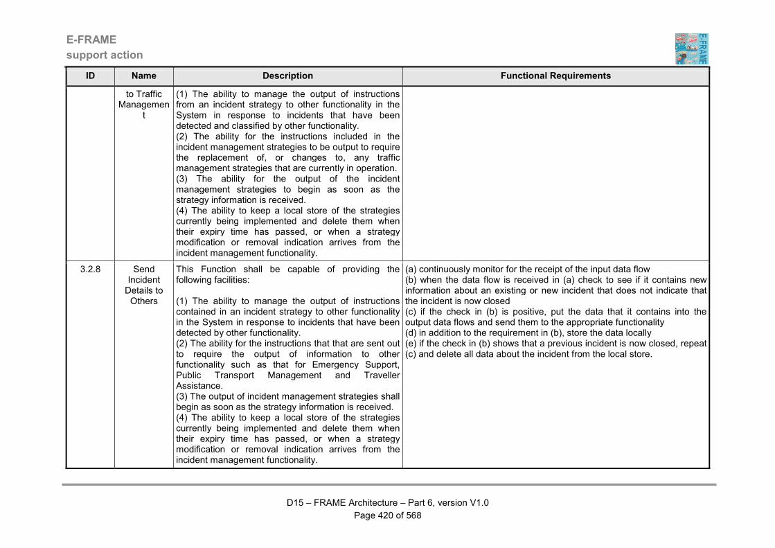
E-FRAME
support action
D15 – FRAME Architecture – Part 6, version V1.0
Page 420 of 568
ID Name Description Functional Requirements
to Traffic Managemen
t
(1) The ability to manage the output of instructions from an incident strategy to other functionality in the System in response to incidents that have been detected and classified by other functionality. (2) The ability for the instructions included in the incident management strategies to be output to require the replacement of, or changes to, any traffic management strategies that are currently in operation. (3) The ability for the output of the incident management strategies to begin as soon as the strategy information is received. (4) The ability to keep a local store of the strategies currently being implemented and delete them when their expiry time has passed, or when a strategy modification or removal indication arrives from the incident management functionality.
3.2.8 Send Incident Details to Others
This Function shall be capable of providing the following facilities: (1) The ability to manage the output of instructions contained in an incident strategy to other functionality in the System in response to incidents that have been detected by other functionality. (2) The ability for the instructions that that are sent out to require the output of information to other functionality such as that for Emergency Support, Public Transport Management and Traveller Assistance. (3) The output of incident management strategies shall begin as soon as the strategy information is received. (4) The ability to keep a local store of the strategies currently being implemented and delete them when their expiry time has passed, or when a strategy modification or removal indication arrives from the incident management functionality.
(a) continuously monitor for the receipt of the input data flow (b) when the data flow is received in (a) check to see if it contains new information about an existing or new incident that does not indicate that the incident is now closed (c) if the check in (b) is positive, put the data that it contains into the output data flows and send them to the appropriate functionality (d) in addition to the requirement in (b), store the data locally (e) if the check in (b) shows that a previous incident is now closed, repeat (c) and delete all data about the incident from the local store.
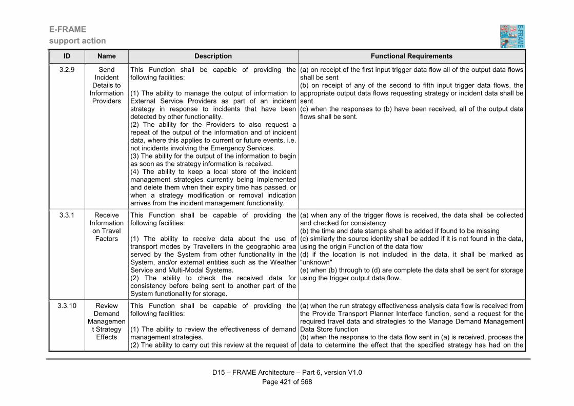
E-FRAME
support action
D15 – FRAME Architecture – Part 6, version V1.0
Page 421 of 568
ID Name Description Functional Requirements
3.2.9 Send Incident Details to Information Providers
This Function shall be capable of providing the following facilities: (1) The ability to manage the output of information to External Service Providers as part of an incident strategy in response to incidents that have been detected by other functionality. (2) The ability for the Providers to also request a repeat of the output of the information and of incident data, where this applies to current or future events, i.e. not incidents involving the Emergency Services. (3) The ability for the output of the information to begin as soon as the strategy information is received. (4) The ability to keep a local store of the incident management strategies currently being implemented and delete them when their expiry time has passed, or when a strategy modification or removal indication arrives from the incident management functionality.
(a) on receipt of the first input trigger data flow all of the output data flows shall be sent (b) on receipt of any of the second to fifth input trigger data flows, the appropriate output data flows requesting strategy or incident data shall be sent (c) when the responses to (b) have been received, all of the output data flows shall be sent.
3.3.1 Receive Information on Travel Factors
This Function shall be capable of providing the following facilities: (1) The ability to receive data about the use of transport modes by Travellers in the geographic area served by the System from other functionality in the System, and/or external entities such as the Weather Service and Multi-Modal Systems. (2) The ability to check the received data for consistency before being sent to another part of the System functionality for storage.
(a) when any of the trigger flows is received, the data shall be collected and checked for consistency (b) the time and date stamps shall be added if found to be missing (c) similarly the source identity shall be added if it is not found in the data, using the origin Function of the data flow (d) if the location is not included in the data, it shall be marked as "unknown" (e) when (b) through to (d) are complete the data shall be sent for storage using the trigger output data flow.
3.3.10 Review Demand
Management Strategy Effects
This Function shall be capable of providing the following facilities: (1) The ability to review the effectiveness of demand management strategies. (2) The ability to carry out this review at the request of
(a) when the run strategy effectiveness analysis data flow is received from the Provide Transport Planner Interface function, send a request for the required travel data and strategies to the Manage Demand Management Data Store function (b) when the response to the data flow sent in (a) is received, process the data to determine the effect that the specified strategy has had on the

E-FRAME
support action
D15 – FRAME Architecture – Part 6, version V1.0
Page 422 of 568
ID Name Description Functional Requirements
the Transport Planner who must have specified the data about the use of transport modes that is to be analysed. (3) The ability to send the results of the analysis of the effectiveness of demand management strategies to functionality providing the HMI for the Transport Planner.
demand for travel in the road network (c) when (b) has been completed send the results in the strategy effectiveness results data flow to the Provide Transport Planner Interface function.
3.3.11 Simulate Demand
Management Strategy
This Function shall be capable of providing the following facilities: (1) The ability to simulate the imposition of a demand management strategy. (2) The ability to carry out its simulations at the request of the Transport Planner who must specify the existing strategy that is to be simulated. (3) The ability to send the results of the simulation to the functionality providing the HMI for the Transport Planner.
(a) when the run demand strategy simulation data flow is received, send the request for data and strategies for simulation data flow tot he Manage Demand Management Data Store function (b) when the data and strategy for simulation data flows have been received, run the simulation to show what is expected to happen when the strategy is implemented (c) when (b) is completed, send the results in the demand strategy simulation results data flow to the Provide Transport Planner Interface function (d) if the new demand strategy for simulation data flow is received, send the request for data for simulation data flow tot he Manage Demand Management Data Store function (e) repeat (b) and (c).
3.3.12 Provide Transport Planner Managing Demand Access
This Function shall be capable of providing the following facilities: (1) An HMI through which the Transport Planner can manage a variety of activities. (2) The ability for the activities to include the creation of new demand management strategies, the review of previously activated strategies and the simulation of existing strategies.
(a) continuously monitor for the arrival of any of the data flows from the transport planner (b) when any of the data flows in (a) is received, process its contents and send the appropriate request data flow to its destination function (c) wait for the data flow containing the response to (b) to arrive (d) when the response data flow in (c) arrives output its contents to the transport planner in the appropriate output data flow.
3.3.13 Output Demand
Management Information
This Function shall be capable of providing the following facilities: (1) The ability to take responsibility for the output of information to Drivers and/or Travellers as part of a demand management strategy.
(a) when the demand management information data flow is received, send the appropriate parts of its contents to the driver and the traveller.
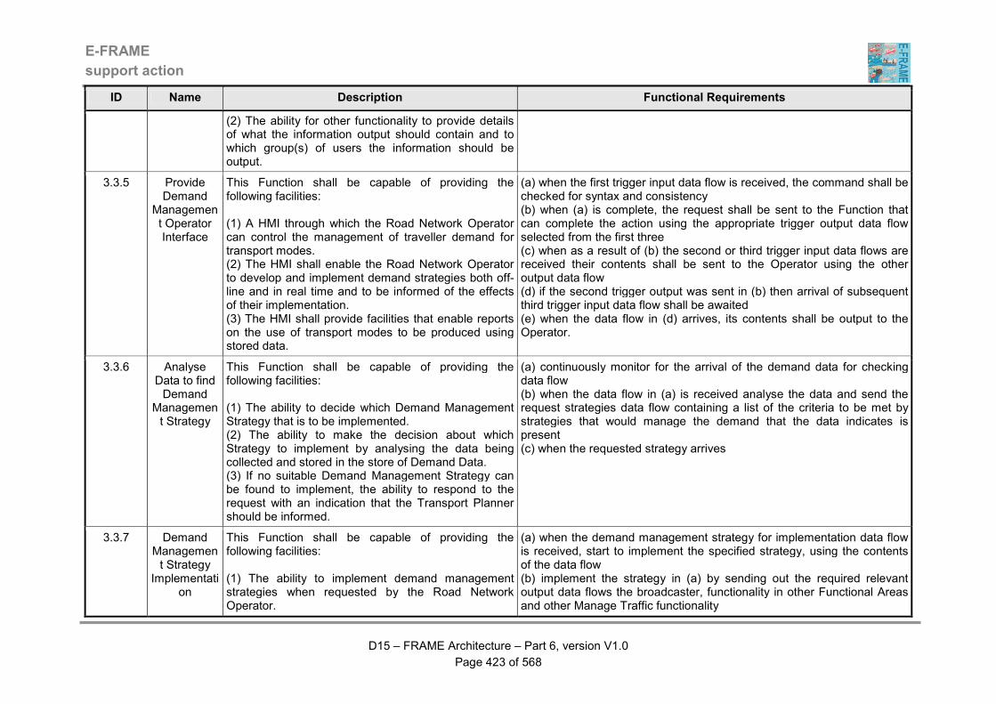
E-FRAME
support action
D15 – FRAME Architecture – Part 6, version V1.0
Page 423 of 568
ID Name Description Functional Requirements
(2) The ability for other functionality to provide details of what the information output should contain and to which group(s) of users the information should be output.
3.3.5 Provide Demand
Management Operator Interface
This Function shall be capable of providing the following facilities: (1) A HMI through which the Road Network Operator can control the management of traveller demand for transport modes. (2) The HMI shall enable the Road Network Operator to develop and implement demand strategies both off-line and in real time and to be informed of the effects of their implementation. (3) The HMI shall provide facilities that enable reports on the use of transport modes to be produced using stored data.
(a) when the first trigger input data flow is received, the command shall be checked for syntax and consistency (b) when (a) is complete, the request shall be sent to the Function that can complete the action using the appropriate trigger output data flow selected from the first three (c) when as a result of (b) the second or third trigger input data flows are received their contents shall be sent to the Operator using the other output data flow (d) if the second trigger output was sent in (b) then arrival of subsequent third trigger input data flow shall be awaited (e) when the data flow in (d) arrives, its contents shall be output to the Operator.
3.3.6 Analyse Data to find Demand
Management Strategy
This Function shall be capable of providing the following facilities: (1) The ability to decide which Demand Management Strategy that is to be implemented. (2) The ability to make the decision about which Strategy to implement by analysing the data being collected and stored in the store of Demand Data. (3) If no suitable Demand Management Strategy can be found to implement, the ability to respond to the request with an indication that the Transport Planner should be informed.
(a) continuously monitor for the arrival of the demand data for checking data flow (b) when the data flow in (a) is received analyse the data and send the request strategies data flow containing a list of the criteria to be met by strategies that would manage the demand that the data indicates is present (c) when the requested strategy arrives
3.3.7 Demand Management Strategy
Implementation
This Function shall be capable of providing the following facilities: (1) The ability to implement demand management strategies when requested by the Road Network Operator.
(a) when the demand management strategy for implementation data flow is received, start to implement the specified strategy, using the contents of the data flow (b) implement the strategy in (a) by sending out the required relevant output data flows the broadcaster, functionality in other Functional Areas and other Manage Traffic functionality
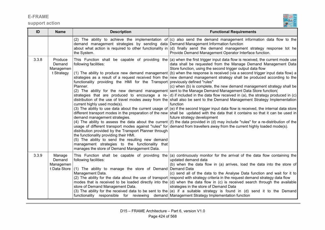
E-FRAME
support action
D15 – FRAME Architecture – Part 6, version V1.0
Page 424 of 568
ID Name Description Functional Requirements
(2) The ability to achieve the implementation of demand management strategies by sending data about what action is required to other functionality in the System.
(c) also send the demand management information data flow to the Demand Management Information function (d) finally send the demand management strategy response tot he Provide Demand Management Operator Interface function.
3.3.8 Produce Demand
Management Strategy
This Function shall be capable of providing the following facilities: (1) The ability to produce new demand management strategies as a result of a request received from the functionality providing the HMI for the Transport Planner. (2) The ability for the new demand management strategies that are produced to encourage a re-distribution of the use of travel modes away from the current highly used mode(s). (3) The ability to use data about the current usage of different transport modes in the preparation of the new demand management strategies. (4) The ability to assess the data about the current usage of different transport modes against "rules" for distribution provided by the Transport Planner through the functionality providing their HMI. (5) The ability to send the resulting new demand management strategies to the functionality that manages the store of Demand Management Data.
(a) when the first trigger input data flow is received, the current mode use data shall be requested from the Manage Demand Management Data Store function, using the second trigger output data flow (b) when the response is received (via a second trigger input data flow) a new demand management strategy shall be produced according to the previously defined "rules" (c) when (b) is complete, the new demand management strategy shall be sent to the Manage Demand Management Data Store function( d) if included in the data flow received in (a), the strategy produced in (c) shall also be sent to the Demand Management Strategy Implementation function (e) if the second trigger input data flow is received, the internal data store shall be updated with the data that it contains so that it can be used in future strategy development (f) the data provided in (d) may include "rules" for a re-distribution of the demand from travellers away from the current highly loaded mode(s).
3.3.9 Manage Demand
Management Data Store
This Function shall be capable of providing the following facilities: (1) The ability to manage the store of Demand Management Data. (2) The ability for the data about the use of transport modes that is received to be loaded directly into the store of Demand Management Data. (3) The ability for the received data to be sent to the functionality responsible for reviewing demand
(a) continuously monitor for the arrival of the data flow containing the updated demand data (b) when the data flow in (a) arrives, load the data into the store of Demand Data (c) send all of the data to the Analyse Data function and wait for it to respond with strategy criteria in the request demand strategy data flow (d) when the data flow in (c) is received search through the available strategies in the store of Demand Data (e) if a suitable strategy is found in (d) send it to the Demand Management Strategy Implementation function
E-FRAME
support action
D15 – FRAME Architecture – Part 6, version V1.0
Page 425 of 568
ID Name Description Functional Requirements
management strategies. (4) The ability to extract data from the Demand Management Data and send it to the appropriate functionality for use in the development of new demand management strategies.
(f) if no suitable strategy is found in (d) send the data for demand strategy development to the Produce Demand Management Strategy function (g) when as a result of (f) the developed demand strategy data flow is received, load it into the store of Demand Data and also send it to the Demand Management Strategy Implementation function (h) when any of data flows containing other the requests for data and/or strategies is received, respond by sending what was requested to the function that sent the data flow (i) when the request for the implementation of a particular strategy is received from the Provide Operator Interface function, implement (e) for that strategy.
3.4.1 Monitor Weather Conditions
This Function shall be capable of providing the following facilities: (1) The ability to collect data about weather conditions that are relevant to the operation of the road network managed by the System. (2) The ability for some or all of the data to come from Weather Systems or to be detected using sensors within the road network. (3) The ability to forward the collected data to other functionality for storage.
(a) when the first trigger data flow is received, the data that it contains shall be stored internally (b) the other input trigger data flow shall be continuously monitored for actual measured weather conditions (c) at periodic intervals the measured weather conditions shall be converted into digital data and collated with the data received in (a) (d) when (c) is complete, the data shall be sent to the Manage Environmental Conditions Data function using the trigger output data flow.
3.4.10 Output Environment
al Information
This Function shall be capable of providing the following facilities: (1) The ability to take responsibility for the output of information to Drivers and/or Travellers about environmental conditions. (2) Details of what the information output should contain and to which group(s) of users the information should be output will be provided to this Function by other functionality. (3) A HMI through which the environmental conditions information can be output to Drivers and/or Travellers.
(a) when the environment information data flow is received, send the appropriate parts of its contents to the driver and the traveller.
E-FRAME
support action
D15 – FRAME Architecture – Part 6, version V1.0
Page 426 of 568
ID Name Description Functional Requirements
3.4.11 Analyse Environmental Data and Implement Actions
This Function shall be capable of providing the following facilities: (1) The ability to analyse the environmental data when it is received from the functionality managing the store of Environmental Conditions data to see if any action is needed. (2) The ability to send the results of the analysis and any recommended action to the functionality providing the HMI for the Road Network Operator for confirmation of the action. (3) When conformation of the recommended action is received from the functionality providing the HMI for the Road Network Operator, the ability to send the data to other functionality in the System. (4) The ability to send a copy of the confirmed actions to the functionality that is managing the store of Environmental Conditions for loading into the data store. (5) If included in the recommended action, the ability to send the data about the environmental conditions to the functionality in the System that provides the HMI through which it can be output to Drivers and/or Travellers.
(a) when the environmental data for analysis data flow is received, process its contents and determine if any actions are needed (b) if as a result of (a) actions are needed, determine those that would be the most suitable and send them in the suggest environmental actions data flow to the Provide Environment Management Operator Interface function (c) if the contents of the confirm environmental actions data flow received in response to (b) contain a negative response, re-examine the actions that could be taken and if possible suggest alternatives (d) if the contents in (c) contain a positive response then implement the actions that were determined in (b) and send out the appropriate data flows to other Manage Traffic functionality and to functionality in other Functional Areas (e) also put any information that needs to be output into the environmental information data flow and send it to the Output Environmental Information function.
3.4.2 Monitor Atmospheric Pollution
This Function shall be capable of providing the following facilities: (1) The ability to provide data about atmospheric pollution in the road network. (2) The ability to provide the data about atmospheric pollution by continuously monitoring the weather conditions using sensors. (3) The ability to send the data resulting from the weather conditions monitoring to other functionality within the System for storage.
(a) the trigger input data flow shall be continuously monitored for actual measured pollution levels (b) at periodic intervals the measured weather conditions shall be converted into digital data (c) when (b) is complete, the data shall be sent to the Manage Environmental Conditions Data Store function using the output trigger flow.

E-FRAME
support action
D15 – FRAME Architecture – Part 6, version V1.0
Page 427 of 568
ID Name Description Functional Requirements
3.4.3 Monitor Noise
Pollution
This Function shall be capable of providing the following facilities: (1) The ability to provide data about noise pollution in the road network. (2) The ability to provide this data by continuously monitoring the noise levels using sensors. (3) The ability the data about noise resulting from the monitoring to other functionality within the System for storage.
(a) the trigger input data flow shall be continuously monitored for actual measured noise levels (b) at periodic intervals the measured noise levels shall be converted into digital data (c) when (b) is complete, the data shall be sent to the Manage Environmental Conditions Data Store function using the output trigger flow.
3.4.4 Predict Environmental Conditions
This Function shall be capable of providing the following facilities: (1) The ability to use data collected and stored by other functionality to predict the environmental conditions that will occur in and around the road network managed by the System. (2) The ability to use this collected and stored data with one or more algorithms and static data provided by the Road Network Operator to predict the environmental conditions that will be experienced by Travellers and/or Drivers. (3) The ability to send the data providing the predicted environmental conditions for storage by other functionality in the System.
(a) when the first trigger input data flow is received, the data shall be stored internally (b) when (a) is complete the prediction algorithm shall be run using the received data (c) the prediction algorithm must take account of such things as current and forecast weather conditions and the effects of the local terrain (d) the predictions resulting from (c) shall be sent to the Manage Environmental Conditions Data Store function in the output trigger data flow (e) when the second trigger flow is received, the static data stored internally within the Function and used by the prediction algorithm shall be updated.
3.4.7 Provide Environment Management Operator Interface
This Function shall be capable of providing the following facilities: (1) A HMI through which the Road Network Operator shall be able to manage the collection of environmental data, plus its analysis and use by other functionality within the System. (2) The HMI shall enable the Road Network Operator to request and be provided with output of the data currently being collected, prediction of environmental
(a) when the input data flows from the operator are received, check them for validity (b) if anything is found in (a) the operator shall be prompted for corrections (c) when (b) is completed, the action required shall be determined (d) if the result of (c) is that the static data used by the prediction algorithm is to be updated, the second trigger output data flow shall be sent to the Manage Environmental Conditions Data Store function so that the data can be loaded into the store (e) if the result of (c) is that the Manage Environmental Conditions Data

E-FRAME
support action
D15 – FRAME Architecture – Part 6, version V1.0
Page 428 of 568
ID Name Description Functional Requirements
conditions and historical data. (3) The HMI shall enable the Road Network Operator to request an analysis of the environmental data, receive the resulting suggested actions and confirm these actions. (4) The HMI shall enable the Road Network Operator to update the static data used in the prediction of environmental conditions.
Store function must carry out an action, send the request in the first trigger output data flow (f) as a result of (e), the arrival of the second input trigger data flow shall be awaited (g) when the data flow in (f) arrives, the response shall be sent to the operator using the other output data flow (h) if the suggest environmental actions data flow arrives, output its contents to the operator and await the arrival of confirmation or alternative actions in one of the input data flows being monitored in (a) (i) when the operator provides a response to the data output in (h) send it in the confirm environmental actions data flow to the Determine Environmental Actions function.
3.4.8 Manage Environmental Conditions Data Store
This Function shall be capable of providing the following facilities: (1) The ability to manage the store of Environmental Conditions Data. (2) In performing this activity, the ability to collect and collate environmental data provided by other functionality and from other System(s) and load this data into the store of Environmental Conditions Data. (3) Periodically or when requested by the Road Network Operator, the ability to retrieve data from the store of Environmental Conditions Data and send it to other functionality in the System. (4) The ability to retrieve data from the store of Environmental Conditions Data and send it to other functionality in the System and when returned, load the results back into the store. (5) When confirmed by the Road Network Operator, the ability to add to the store of Environmental Conditions Data any confirmed actions to reduce the impact of environmental conditions. (6) The ability to provide the Road Network Operator with copies of the stored data when requested by the Operator.
(a) when any but the third or fourth input trigger flows are received, their contents shall be loaded into the Environmental Conditions Data Store (b) when the third input trigger data flow is received, the appropriate actions in (c) to (g) shall be carried according to the contents of the command (c) data shall be sent to other Functions using the first, fifth and sixth trigger output data flows (d) data shall be sent to another Area using the seventh and eighth trigger output data flows (e) data shall be sent to the prediction Function using the second trigger output data flow (f) data shall be obtained from the store (analyse it for output if so requested) and sent to the Operator interface Function using the third trigger output data flow (g) data shall be sent to another System using the last (ninth) output trigger data flow (h) the actions in (c), (d), (e) and (g) shall be carried out at periodic intervals if not requested by the Operator (i) confirmation of requested data transfers shall be provided to the Operator when they are complete (j) all periodic data transfers shall be logged for later access by the Operator (k) when data in (a) above is loaded, the pollution levels shall be checked against pre-set levels
E-FRAME
support action
D15 – FRAME Architecture – Part 6, version V1.0
Page 429 of 568
ID Name Description Functional Requirements
(l) if the result of (j) shows that the levels are exceeded, the data shall be sent to the incident management Function using the fourth trigger output data flow (m) if the third trigger input data flow contains changes to the periods at which data is output, or to the pre-set levels in (j) above, the changes shall be made to the values in the Function's internal store (n) the completion of (l) shall be confirmed to the Operator using the third trigger output data flow (o) the integrity and contents of the store of Environmental Conditions Data shall be maintained and managed to make most efficient use of the space available whilst optimising data access time.
3.5.10 Evaluate Need for Long Term Maintenance
This Function shall be capable of providing the following facilities: (1) The ability to evaluate the long term maintenance needs of the road network and shall request any needed repair activities. (2) The ability to use the data to determine of warning should be issued to Drivers, and when these are required, send them to functionality in the Provide Advanced Driver Assistance Functional Area. (3) The ability to collect data about the use that traffic has been making of the road network and weather information. (4) The ability to compare road use data and weather information against what it means in terms of required long term maintenance. (5) The ability to produce recommended road maintenance activities from this comparison. (6) If the application of these recommended road maintenance activities is confirmed by the Road Maintenance Operator then the ability to request the Maintenance Organisation to carry out the work. (7) If the Maintenance Organisation is instructed to carry out the recommended road maintenance work, the ability to send information about these activities to
(a) continuously monitor for the receipt of the long term maintenance conditions, plus inter-urban and urban road use data flows (b) continuously gather data in the long term wearing state data flow (c) use the data collected in (a) and (b) to assess the need for long term road maintenance (d) if long term road maintenance is needed, determine its precise location using data from the inter-urban and urban road static data for long term maintenance data flows (e) as a result of (c) and (d) send the confirm long term maintenance data flow to the Provide Road Maintenance Operator Interface function (f) as a result of (e) continuously monitor for receipt of the long term maintenance confirmed data flow (g) when the data flow in (f) is received, send the instructions for the long term maintenance work to the maintenance organisation in the long term activities data flow and send the details in the confirmed long term maintenance activity data flow to the Provide Maintenance Data Store Management function (h) also when the data flow in (f) is received, send details of the maintenance work activities to other functionality in the long term maintenance data and long term maintenance conditions data flows (i) as a result of (g) continuously monitor for receipt of the long term maintenance activity update data flow from the maintenance organisation (j) when the data flow in (i) is received, repeat (h) with updated information and update the data about the activities in the store of Maintenance Data using the update long term maintenance activity data
E-FRAME
support action
D15 – FRAME Architecture – Part 6, version V1.0
Page 430 of 568
ID Name Description Functional Requirements
the Trip Planning and Incident Management functionalities as they will affect traffic and because they are roadworks. (8) The ability to keep a record of the current status of the requested long term maintenance activities, which shall be updated using the input from the Maintenance Organisation. (9) The ability to send the current status of the road maintenance activities to the store of Maintenance Data so that it can be accessed by the Road Maintenance Operator.
flow (k) whenever either the inter-urban or urban road static data for long term work data flows is received, store its contents locally for use in (d) above.
3.5.11 Evaluate Need for De-
icing
This Function shall be capable of providing the following facilities: (1) The ability to evaluate the need for the de-icing of roads and pavements. (2) The ability to collect data about the current state of the road and pavement surfaces and evaluate these against criteria for the need to apply de-icing. (3) When de-icing is found to be required, the ability to request the Maintenance Organisation to carry out the activity and send information about the activities to the Trip Planning and Incident Management functionalities. (4) The ability to keep a record of the current status of the requested de-icing activities, which shall be updated using the input from the Maintenance Organisation. (5) The ability to send the current de-icing activity status to the store of Maintenance Data so that it can be accessed by the Road Maintenance Operator.
(a) continuously monitor for receipt of either of the input data flows containing road static data or the predicted road network traffic data (b) when any of the data flows in (a) is received, store their contents internally for later use, if necessary replacing similar data that was stored after the previous receipt of a particular data flow (c) continuously monitor for receipt of the current conditions data flow from the road pavement and the ice formation conditions data flow from the weather systems (d) when either of the data flows in (c) is received, store their contents (e) every time (d) occurs, assess the need for de-icing activities based upon the data that has been received in the data flow in (c) and on the data received in (b) (f) put the de-icing activities proposed as a result of (e) in the proposed de-icing activities data flow and send it to the Provide Road Maintenance Operator Interface function (g) as a result of (f) continuously monitor for receipt of the confirmed de-icing activities data flow (h) when the data flow in (g) is received, put its contents in the de-icing tasks data flow and send it to the road maintenance organisation (i) as a result of (h) continuously monitor for receipt of the de-icing activity update data flow and when it is received, put its contents in the confirmed de-icing activity data flow and send it to the Provide Maintenance Data Store Management function.
3.5.12 Evaluate This Function shall be capable of providing the (a) continuously monitor for receipt of the various status and fault data
E-FRAME
support action
D15 – FRAME Architecture – Part 6, version V1.0
Page 431 of 568
ID Name Description Functional Requirements
Need for Equipment Maintenance
following facilities: (1) The ability to evaluate the need for maintenance of roadside and other equipment and request any needed repair activities. (2) The ability to collect information about equipment faults provided by other functionality in the System and to compare these with information about the activities needed to fix them. (3) The ability to maintain a record of preventative maintenance activities that may be required from time to time by the equipment. (4) From this comparison faults with recommended activities and the list of preventative maintenance, the ability to produce a list of actual maintenance work that needs to be carried out. (5) If the application of these activities is confirmed by the Road Maintenance Operator, the ability to request the Maintenance Organisation to carry out the work. (6) The ability to keep a list of the status of all outstanding roadside equipment faults and make this list available to the Road Maintenance Operator on request through the store of Maintenance Data. (7) The ability to update the list of all outstanding roadside equipment faults with information that it receives from the Maintenance Organisation.
flows from inter-urban and urban equipment (b) when any of the data flows in (a) is received, determine from its contents the nature of any fault (c) use the data from the inter-urban and urban equipment information data flows to determine where the faulty equipment is located and the organisation responsible for its maintenance and store this information locally (d) as a result of (c) send the confirm equipment maintenance data flow to the Provide Road Maintenance Operator Interface function (e) as a result of (d) continuously monitor for receipt of the equipment maintenance confirmed data flow (f) when the data flow in (e) is received, send instructions for the maintenance work to be carried out to the appropriate maintenance organisation in the equipment tasks data flow and send information about the work to the Provide Maintenance Data Store Management function in the confirmed equipment maintenance activity data flow (g) as a result of (f) continuously monitor for receipt of the equipment maintenance activity update data flow from the maintenance organisation(s) (h) when the data flow in (g) is received, update the data in the store of Maintenance Data by sending the confirmed equipment maintenance activity data flow with the updated information (i) repeat (g) and (h) until all equipment maintenance tasks have been completed (j) continuously monitor for receipt of either of the equipment information data flows (k) when either of the data flows in (j) is received, store the information it contains locally for use in (c) above (l) continuously monitor for receipt of the request current roadside equipment faults data flow (m) when the data flow in (l) is received, extract the required data from that stored locally in (c) above and send it to the Provide Road Maintenance Operator function in the current roadside equipment faults data flow.
3.5.7 Provide Road
This Function shall be capable of providing the following facilities:
(a) continuously monitor for receipt of any of the input data flows from other functionality in the system
E-FRAME
support action
D15 – FRAME Architecture – Part 6, version V1.0
Page 432 of 568
ID Name Description Functional Requirements
Maintenance Operator Interface
(1) A HMI through which the Road Maintenance Operator can manage the maintenance activities. (2) The ability for the HMI to enable the Road Maintenance Operator to confirm or reject both short term and long term maintenance activities plus de-icing activities, to review and update the criteria by which the need for maintenance and repair is decided and to monitor maintenance activities. (3) The ability for the HMI to enable the Road Maintenance Operator to update and display the current status of maintenance activities and the static data that defines any devices used to manage traffic using the road network, including such things as location, type, etc.
(b) when the confirm long term maintenance data flow is received in (a), put the data it contains into the maintenance activities required data flow and send it to the road maintenance operator (c) as a result of (b) continuously monitor for receipt of the confirm maintenance activities data flow from the road maintenance operator (d) when the data flow in (c) is received, put its contents into the long term maintenance confirmed data flow and send it to the Evaluate Need for Long Term Maintenance function (e) when the confirm short term maintenance data flow is received in (a), put the data it contains into the maintenance activities required data flow and send it to the road maintenance operator (f) as a result of (e) continuously monitor for receipt of the confirm maintenance activities data flow from the Road Maintenance Operator (g) when the data flow in (f) is received, put its contents into the short term maintenance confirmed data flow and send it to the Evaluate Need for Short Term Maintenance function (h) when the confirm equipment maintenance data flow is received in (a), put the data it contains into the maintenance activities required data flow and send it to the road maintenance operator (i) as a result of (h) continuously monitor for receipt of the confirm maintenance activities data flow from the road maintenance operator (j) when the data flow in (i) is received, put its contents into the equipment maintenance confirmed data flow and send it to the Evaluate Need for Equipment Maintenance function (k) when the proposed de-icing activities data flow is received in (a), put the data it contains into the proposed de-icing activities data flow and send it to the road maintenance operator (l) as a result of (k) continuously monitor for receipt of the confirmed de-icing activities data flow from the road maintenance operator (m) when the data flow in (l) is received, put its contents into the confirmed de-icing activities data flow and send it to the Evaluate Need for de-icing function (n) when the request activity status data flow is received from the road maintenance operator, put a request for the current activity status in the maintenance data updates data flow and send it to the Provide Maintenance Data Store Management function
E-FRAME
support action
D15 – FRAME Architecture – Part 6, version V1.0
Page 433 of 568
ID Name Description Functional Requirements
(o) as a result of (n) continuously monitor for receipt of the maintenance updates response data flow and when it is received, produce a report on current maintenance activities and send it to the road maintenance operator in the current activity status data flow (p) when the output current equipment faults data flow is received from the road maintenance operator, send the request current roadside equipment faults data flow to the Evaluate Need for Equipment Maintenance function (q) as a result of (p) continuously monitor for receipt of the current roadside equipment faults data flow and when it is received include it in the current equipment faults data flow and send it to the road maintenance operator (r) when either the request static data output data flow or the data flow update static data are received from the road maintenance operator, put the request or the data update in the maintenance data updates data flow and send it to the Provide Maintenance Data Store Management function (s) as a result of (r) continuously monitor for receipt of the maintenance updates response data flow and when it is received, either put the actual static data in the data flow containing current static data, or the result of the update in the static data update completed data flow and send them to the road maintenance operator.
3.5.8 Provide Maintenance Data Store Managemen
t
This Function shall be capable of providing the following facilities: (1) The ability to take responsibility for the management of the store of Maintenance Data. (2) The ability for the store of Maintenance Data to contain databases of maintenance operations, plus the road network, infrastructure and road-side equipment. (3) The ability for other maintenance functionality to obtain data from the store of Maintenance Data and for its contents to be changed through the operator interface functionality and HMI (4) The ability to update the data about maintenance activities using provided by other functionality and by the Maintenance Organisation.
(a) continuously monitor for the receipt of the two long term and two short term maintenance activity data flows plus the equipment maintenance activity data flow (b) when any of the data flows in (a) is received, update the contents of the store of Maintenance Data with their contents and determine the extent of any roadworks that will be required to complete the maintenance activities (c) as a result of (b) send information about the roadworks to other functionality that is responsible for incident management, trip planning and the management of the vehicle, in the roadworks data flows (d) continuously monitor for receipt of the maintenance data updates data flow (e) when the data flow in (d) is received, update the contents of the store of Maintenance Data, or if it contains a request, send the contents of the Store to the Provide Maintenance Operator Interface function
E-FRAME
support action
D15 – FRAME Architecture – Part 6, version V1.0
Page 434 of 568
ID Name Description Functional Requirements
(f) continuously monitor for receipt of the confirmed de-icing activity data flow (g) when the data flow in (f) is received, update the store of Maintenance Data with its contents.
3.5.9 Evaluate Needs for Short Term Maintenance
This Function shall be capable of providing the following facilities: (1) The ability to evaluate the short term maintenance needs of the road network and to request any needed repair activities. (2) The ability to use the data to determine the need for a warning to be issued to Drivers, and when these are required, the ability to send them to other functionality in the System. (3) The ability to use data about the amount of traffic that has been using the road network and weather information to evaluate its maintenance needs. (4) The ability to compare this data about the amount of traffic that has been using the road network and weather information with the parameters for activating short term maintenance activities and from this recommend the most appropriate activities to be carried out. (5) If the recommended short term maintenance activities are confirmed by the Road Maintenance Operator then the ability to request the Maintenance Organisation to carry out the work. (6) If the recommended short term maintenance activities are confirmed by the Road Maintenance Operator, the ability to send information about these activities to the Trip Planning and Incident Management functionalities as the maintenance activities will affect traffic and because they are roadworks. (7) The ability to keep a record of the current status of the requested short term maintenance activities, which
(a) continuously monitor for the receipt of the short term maintenance conditions data flow (b) continuously gather data in the short term wearing state data flow (c) use the data collected in (a) and (b) to assess the need for short term road maintenance (d) if short term road maintenance is needed, determine its precise location using data from the inter-urban and urban road static data for short term maintenance data flows (e) as a result of (c) and (d) send the confirm short term maintenance data flow to the Provide Road Maintenance Operator Interface function (f) as a result of (e) continuously monitor for receipt of the short term maintenance confirmed data flow (g) when the data flow in (f) is received, send the instructions for the short term maintenance work to the maintenance organisation in the short term activities data flow and send the details in the confirmed short term maintenance activity data flow to the Provide Maintenance Data Store Management function (h) also when the data flow in (f) is received, send details of the maintenance work activities to other functionality in the short term maintenance data and short term maintenance conditions data flows (i) as a result of (g) continuously monitor for receipt of the short term maintenance activity update data flow from the maintenance organisation (j) when the data flow in (i) is received, repeat (h) with updated information and update the data about the activities in the store of Maintenance Data using the update short term maintenance activity data flow (k) whenever either the inter-urban or urban road static data for short term work data flows is received, store its contents locally for use in (d) above.

E-FRAME
support action
D15 – FRAME Architecture – Part 6, version V1.0
Page 435 of 568
ID Name Description Functional Requirements
shall be updated using the input from the Maintenance Organisation. (8) The ability to send the current status of the requested short term maintenance activities to the Maintenance Data Store so that it can be accessed by the Road Maintenance Operator through their HMI.
4.1.10 Monitor On-board PT Vehicle Activity
This Function shall be capable of providing the following facilities: (1) The ability to monitor on-board activity amongst the Passengers on a PT vehicle. (2) If not provided in digital form, the ability to convert the data into this form and send it to other functionality.
(a) continuously monitor the internal spaces in the PT Vehicle using the data obtained from the vehicle internal view data flow (b) if the monitoring process in (a) shows what could be an incident send the relevant images to the Monitor PT Vehicle Status function in the vehicle internal images data flow.
4.1.11 Manage PT Vehicle Stop
This Function shall be capable of providing the following facilities: (1) The ability to manage the operation of a PT stop used by PT Vehicles using real-time, static and fare information that it has received from other PT management functionality and from other PT stops. (2) The ability to collate, filter and fuse all the received data and to present it at the PT Stop using a suitable HMI to Static Travellers, i.e. Travellers who have commenced their trips but are not actually moving because they are waiting for a PT service to arrive at the stop. (3) The data filtering process shall remove all information that is not relevant to PT Services that use the PT stop and because its location is known, any information that is not geographically relevant. (4) The ability to detect any unexpected activity in the area surrounding its location and provide an emergency call facility for use by Static Travellers at the PT stop. (5) When an emergency notification is received, the
(a) continuously monitor for the arrival of the data flows containing service information for stops, service change information for stops and arrival prediction data (b) when any of the data flows in (a) is received, process and filter their contents to remove information that is not relevant to and static travellers at the stop service by the function (c) output the results of (b) to the static traveller in the service information from stop or arrival prediction data flows (d) if the route static data for stops or fare schemes for stops data flows are received, store their data locally so that it can be used to determine which are the next and previous stops for each PT service (e) if the service information for stops is received in (a) send its contents to other stops in the data flow containing arrival prediction data (f) continuously monitor the traveller presence at stop data flow and for every change, send the passenger numbers at stop data flow to the Optimise PT Fleet Control function (g) continuously monitor for the receipt of the traveller emergency at stop data flow (h) when the data flow in (g) is received, send the PT stop alarm notification data flow to the functionality in the Provide Safety Emergency Facilities Functional Area (i) when as a result of (h) the PT stop alarm acknowledgement data flow
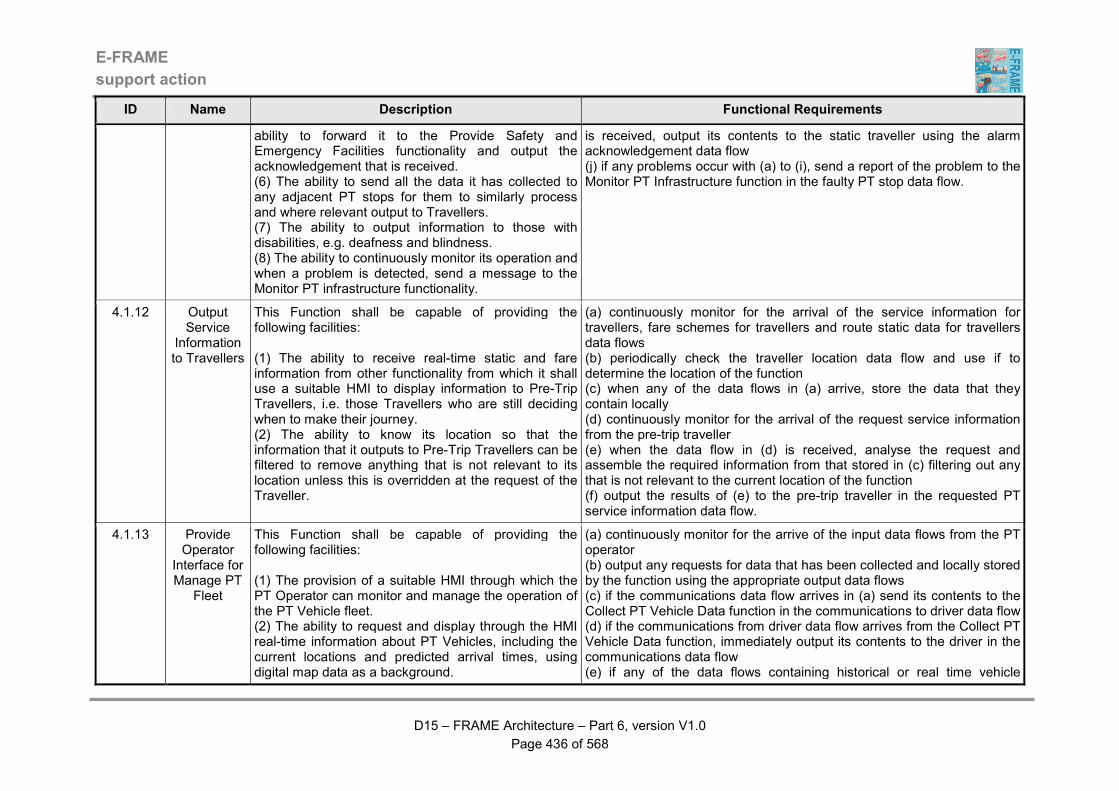
E-FRAME
support action
D15 – FRAME Architecture – Part 6, version V1.0
Page 436 of 568
ID Name Description Functional Requirements
ability to forward it to the Provide Safety and Emergency Facilities functionality and output the acknowledgement that is received. (6) The ability to send all the data it has collected to any adjacent PT stops for them to similarly process and where relevant output to Travellers. (7) The ability to output information to those with disabilities, e.g. deafness and blindness. (8) The ability to continuously monitor its operation and when a problem is detected, send a message to the Monitor PT infrastructure functionality.
is received, output its contents to the static traveller using the alarm acknowledgement data flow (j) if any problems occur with (a) to (i), send a report of the problem to the Monitor PT Infrastructure function in the faulty PT stop data flow.
4.1.12 Output Service
Information to Travellers
This Function shall be capable of providing the following facilities: (1) The ability to receive real-time static and fare information from other functionality from which it shall use a suitable HMI to display information to Pre-Trip Travellers, i.e. those Travellers who are still deciding when to make their journey. (2) The ability to know its location so that the information that it outputs to Pre-Trip Travellers can be filtered to remove anything that is not relevant to its location unless this is overridden at the request of the Traveller.
(a) continuously monitor for the arrival of the service information for travellers, fare schemes for travellers and route static data for travellers data flows (b) periodically check the traveller location data flow and use if to determine the location of the function (c) when any of the data flows in (a) arrive, store the data that they contain locally (d) continuously monitor for the arrival of the request service information from the pre-trip traveller (e) when the data flow in (d) is received, analyse the request and assemble the required information from that stored in (c) filtering out any that is not relevant to the current location of the function (f) output the results of (e) to the pre-trip traveller in the requested PT service information data flow.
4.1.13 Provide Operator
Interface for Manage PT
Fleet
This Function shall be capable of providing the following facilities: (1) The provision of a suitable HMI through which the PT Operator can monitor and manage the operation of the PT Vehicle fleet. (2) The ability to request and display through the HMI real-time information about PT Vehicles, including the current locations and predicted arrival times, using digital map data as a background.
(a) continuously monitor for the arrive of the input data flows from the PT operator (b) output any requests for data that has been collected and locally stored by the function using the appropriate output data flows (c) if the communications data flow arrives in (a) send its contents to the Collect PT Vehicle Data function in the communications to driver data flow (d) if the communications from driver data flow arrives from the Collect PT Vehicle Data function, immediately output its contents to the driver in the communications data flow (e) if any of the data flows containing historical or real time vehicle

E-FRAME
support action
D15 – FRAME Architecture – Part 6, version V1.0
Page 437 of 568
ID Name Description Functional Requirements
(3) The ability to request and display through the HMI data about the performance of the PT Vehicle fleet in the delivery of its services. (4) The ability to display through the HMI details of alarms raised by PT Passengers at PT Stops. (5) The ability to display and write, using a suitable HMI, messages that are exchanged with PT Drivers in PT Vehicles.
information, plus predicted PT vehicle data is received, store the data that they contain locally to await an output request from the PT operator in one of the data flows being continuously monitored in (a) (f) if the alarm at stop data flow is received, immediately output its contents to the PT operator in the alarms raised data flow (g) if the performance criteria data flow is received from the PT operator, send the calculate service performance data flow to the Calculate PT Service Performance function and await a response (h) when the calculated service performance data flow is received as a result of (g), output its contents to the PT operator in the performance figures data flow.
4.1.14 Provide PT Passnger Vehicle Alarm Facility
This Function shall be capable of providing the following facilities: (1) The ability to monitor for the receipt of alarms raised by PT Passengers on- board the PT Vehicle. (2) The ability to forward details of the alarms to the Monitor PT Vehicle functionality, (3) A suitable HMI through which the responses to alarms can be displayed to PT Passengers on- board the PT Vehicle.
(a) continuously monirot for receipt of the passenger emergency data flow (b) when the data flow in (a) is received, check for authenticity and if OK, output the details to the Monitor PT Vehicle Status function using the passenger alarm raised data flow; (c) as a result of (b), continuously monitor for receipt of the passenger alarm acknoledgement data flow; (d) when the data flow in (c) is received, output its contents to the PT Passengers in the passenger emergency response data flow.
4.1.15 Provide PT Vehicle Driver
Interface
This Function shall be capable of providing the following facilities: (1) Support for both data and voice dialog between the PT Vehicle and Driver and the Collect PT Vehicle Data functionality through a suitable HMI for use in situations that are not included in updates provided by regularly transmitted data, e.g. emergencies, special messages to drivers, etc. (2) The output of other PT Vehicle data and alarm information to the PT Driver through a suitable HMI. (3) The ability of the PT Driver to use a suitable HMI to request information about the service (schedule and fares) on which the PT Vehicle is to be used and for
(a) continuously monitor for the arrival of input data flows from PT vehicle drivers; (b) send messages from the PT vehicle driver to the Collect PT Vehicle Data function in the message from driver data flows (c) continuously monitor for the arrival of the message to driver data flow (g) when the data flow in (f) arrives immediately output its contents to the PT vehicle driver (h) continuously monitor for the receipt of the assign vehicle to service data flow from the PT driver (i) when the data flow in (h) arrives, put the identity of the service that it contains into the request schedule for vehicle and request fares for vehicle data flows and send them to the Plan New Service Schedule and Manage Fare Schemes Data Store functions (j) as a result of (i) continuously monitor for the receipt of the requested
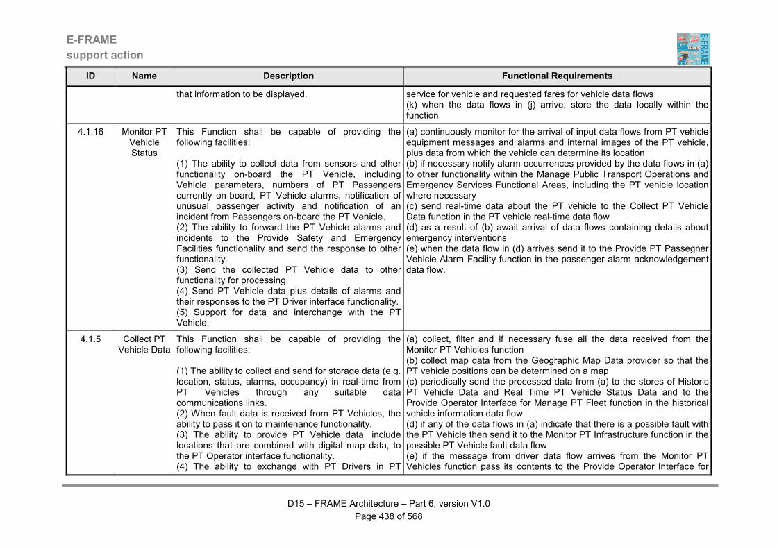
E-FRAME
support action
D15 – FRAME Architecture – Part 6, version V1.0
Page 438 of 568
ID Name Description Functional Requirements
that information to be displayed. service for vehicle and requested fares for vehicle data flows (k) when the data flows in (j) arrive, store the data locally within the function.
4.1.16 Monitor PT Vehicle Status
This Function shall be capable of providing the following facilities: (1) The ability to collect data from sensors and other functionality on-board the PT Vehicle, including Vehicle parameters, numbers of PT Passengers currently on-board, PT Vehicle alarms, notification of unusual passenger activity and notification of an incident from Passengers on-board the PT Vehicle. (2) The ability to forward the PT Vehicle alarms and incidents to the Provide Safety and Emergency Facilities functionality and send the response to other functionality. (3) Send the collected PT Vehicle data to other functionality for processing. (4) Send PT Vehicle data plus details of alarms and their responses to the PT Driver interface functionality. (5) Support for data and interchange with the PT Vehicle.
(a) continuously monitor for the arrival of input data flows from PT vehicle equipment messages and alarms and internal images of the PT vehicle, plus data from which the vehicle can determine its location (b) if necessary notify alarm occurrences provided by the data flows in (a) to other functionality within the Manage Public Transport Operations and Emergency Services Functional Areas, including the PT vehicle location where necessary (c) send real-time data about the PT vehicle to the Collect PT Vehicle Data function in the PT vehicle real-time data flow (d) as a result of (b) await arrival of data flows containing details about emergency interventions (e) when the data flow in (d) arrives send it to the Provide PT Passegner Vehicle Alarm Facility function in the passenger alarm acknowledgement data flow.
4.1.5 Collect PT Vehicle Data
This Function shall be capable of providing the following facilities: (1) The ability to collect and send for storage data (e.g. location, status, alarms, occupancy) in real-time from PT Vehicles through any suitable data communications links. (2) When fault data is received from PT Vehicles, the ability to pass it on to maintenance functionality. (3) The ability to provide PT Vehicle data, include locations that are combined with digital map data, to the PT Operator interface functionality. (4) The ability to exchange with PT Drivers in PT
(a) collect, filter and if necessary fuse all the data received from the Monitor PT Vehicles function (b) collect map data from the Geographic Map Data provider so that the PT vehicle positions can be determined on a map (c) periodically send the processed data from (a) to the stores of Historic PT Vehicle Data and Real Time PT Vehicle Status Data and to the Provide Operator Interface for Manage PT Fleet function in the historical vehicle information data flow (d) if any of the data flows in (a) indicate that there is a possible fault with the PT Vehicle then send it to the Monitor PT Infrastructure function in the possible PT Vehicle fault data flow (e) if the message from driver data flow arrives from the Monitor PT Vehicles function pass its contents to the Provide Operator Interface for
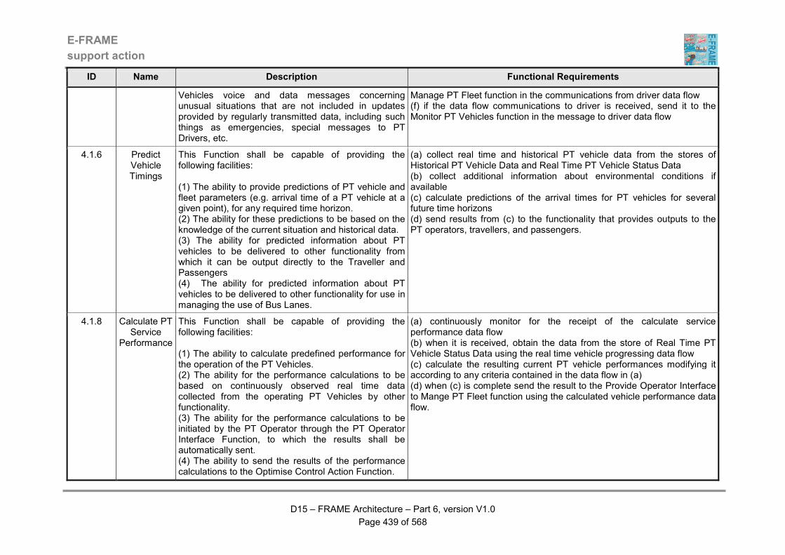
E-FRAME
support action
D15 – FRAME Architecture – Part 6, version V1.0
Page 439 of 568
ID Name Description Functional Requirements
Vehicles voice and data messages concerning unusual situations that are not included in updates provided by regularly transmitted data, including such things as emergencies, special messages to PT Drivers, etc.
Manage PT Fleet function in the communications from driver data flow (f) if the data flow communications to driver is received, send it to the Monitor PT Vehicles function in the message to driver data flow
4.1.6 Predict Vehicle Timings
This Function shall be capable of providing the following facilities: (1) The ability to provide predictions of PT vehicle and fleet parameters (e.g. arrival time of a PT vehicle at a given point), for any required time horizon. (2) The ability for these predictions to be based on the knowledge of the current situation and historical data. (3) The ability for predicted information about PT vehicles to be delivered to other functionality from which it can be output directly to the Traveller and Passengers (4) The ability for predicted information about PT vehicles to be delivered to other functionality for use in managing the use of Bus Lanes.
(a) collect real time and historical PT vehicle data from the stores of Historical PT Vehicle Data and Real Time PT Vehicle Status Data (b) collect additional information about environmental conditions if available (c) calculate predictions of the arrival times for PT vehicles for several future time horizons (d) send results from (c) to the functionality that provides outputs to the PT operators, travellers, and passengers.
4.1.8 Calculate PT Service
Performance
This Function shall be capable of providing the following facilities: (1) The ability to calculate predefined performance for the operation of the PT Vehicles. (2) The ability for the performance calculations to be based on continuously observed real time data collected from the operating PT Vehicles by other functionality. (3) The ability for the performance calculations to be initiated by the PT Operator through the PT Operator Interface Function, to which the results shall be automatically sent. (4) The ability to send the results of the performance calculations to the Optimise Control Action Function.
(a) continuously monitor for the receipt of the calculate service performance data flow (b) when it is received, obtain the data from the store of Real Time PT Vehicle Status Data using the real time vehicle progressing data flow (c) calculate the resulting current PT vehicle performances modifying it according to any criteria contained in the data flow in (a) (d) when (c) is complete send the result to the Provide Operator Interface to Mange PT Fleet function using the calculated vehicle performance data flow.
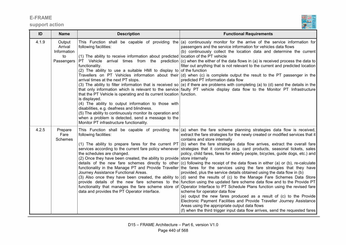
E-FRAME
support action
D15 – FRAME Architecture – Part 6, version V1.0
Page 440 of 568
ID Name Description Functional Requirements
4.1.9 Output Arrival
Information to
Passengers
This Function shall be capable of providing the following facilities: (1) The ability to receive information about predicted PT Vehicle arrival times from the prediction functionality. (2) The ability to use a suitable HMI to display to Travellers on PT Vehicles information about their arrival times at the next PT stops. (3) The ability to filter information that is received so that only information which is relevant to the service that the PT Vehicle is operating and its current location is displayed. (4) The ability to output information to those with disabilities, e.g. deafness and blindness. (5) The ability to continuously monitor its operation and when a problem is detected, send a message to the Monitor PT infrastructure functionality.
(a) continuously monitor for the arrive of the service information for passengers and the service information for vehicles data flows (b) continuously collect the location data and determine the current location of the PT vehicle (c) when the either of the data flows in (a) is received process the data to filter out anything that is not relevant to the current and predicted location of the function (d) when (c) is complete output the result to the PT passenger in the predicted PT information data flow (e) if there are problems with completing (a) to (d) send the details in the faulty PT vehicle display data flow to the Monitor PT Infrastructure function.
4.2.5 Prepare Fare
Schemes
This Function shall be capable of providing the following facilities: (1) The ability to prepare fares for the current PT services according to the current fare policy whenever the schedules are changed. (2) Once they have been created, the ability to provide details of the new fare schemes directly to other functionality in the Manage PT and Provide Traveller Journey Assistance Functional Areas. (3) Also once they have been created, the ability to provide details of the new fare schemes to the functionality that manages the fare scheme store of data and provides the PT Operator interface.
(a) when the fare scheme planning strategies data flow is received, extract the fare strategies for the newly created or modified services that it contains and store internally (b) when the fare strategies data flow arrives, extract the overall fare strategies that it contains (e.g. card products, seasonal tickets, sales policy, child fares, fares for elderly people, bicycles, guide dogs, etc.) and store internally (c) following the receipt of the data flows in either (a) or (b), re-calculate the fares for the services using the fare strategies that they have provided, plus the service details obtained using the data flow in (b) (d) send the results of (c) to the Manage Fare Schemes Data Store function using the updated fare scheme data flow and to the Provide PT Operator Interface to PT Schedule Plans function using the revised fare scheme for operator data flow (e) output the new fares produced as a result of (c) to the Provide Electronic Payment Facilities and Provide Traveller Journey Assistance Areas using the appropriate output data flows (f) when the third trigger input data flow arrives, send the requested fares

E-FRAME
support action
D15 – FRAME Architecture – Part 6, version V1.0
Page 441 of 568
ID Name Description Functional Requirements
back to the Manage Traffic Area using the first trigger output data flow.
4.2.6 Manage Fare
Schemes Data Store
This Function shall be capable of providing the following facilities: (1) The ability to manage the store of PT Fare Schemes, updating its contents every time a new set of fare schemes is received. (2) The ability to provide details of the current fare scheme whenever requests are received from other functionality.
(a) continuously monitor for the arrival of the updated fare scheme data flow (b) when the data flow in (a) arrives update the store of PT Fare Schemes Data with its contents using the load fare scheme data flow (c) also output the new fare scheme in the fare scheme for service data flow (d) when any of the PT driver request for fare scheme, request fares or request fares for vehicles data flows arrive, extract the requested data from the store of PT Fare Schemes Data and return it to the requesting function in the relevant data flow (e) if the updated fare scheme data flow contains a request from the Prepare Fare Schemes function for the current fare data respond with the requested data using the current fare scheme data flow.
4.2.7 Manage PT Route Data
Store
This Function shall be capable of providing the following facilities: (1) The ability to manage the store of PT Route Static Data, loading it with data provided by other functionality comprising data about the road network served by the PT operation and strategies that have been devised for its management. (2) The ability to provide data from the store for use in PT service schedule preparation, plus for use at PT stops, by Travellers preparing trip plans and in reports produced by other functionality at the request of the PT Operator.
(a) when either of the data flows containing urban road data or inter-urban road data is received, the data that it contains shall be loaded into the store of PT Route Static Data (b) when the route static data updates data flow is received, the data that it contains shall also be loaded into the store of PT Route Static Data (c) if the data flow containing a request for the current static data is received, the required data shall be obtained from the store of PT Route Static Data (d) when all the data in (c) has been obtained, it shall be sent to the Provide PT Operator Interface to PT Schedule Plans function in the route static data for reports data flow (e) every time the data flows in (a) or (b) are received, the data that they contain shall be sent to the Plan New Service Schedule function in the route data for planning data flow.
4.2.8 Plan New Service Schedule
This Function shall be capable of providing the following facilities: (1) The ability to prepare new schedules for PT services at the request of the PT Operator, taking account of constraints such as, the geographic area to
(a) collect planning strategies, plans for road works, other (Multi-Modal and similar, i.e. Road Related) services planning, plans for special events, predicted traffic conditions, historic journey times and specific service requests using the relevant input data flows (b) obtain the current operational service data, road network data and current plans from the store of PT Service Plan Data using the PT
E-FRAME
support action
D15 – FRAME Architecture – Part 6, version V1.0
Page 442 of 568
ID Name Description Functional Requirements
be served, quality of service parameters (e.g. frequency of Vehicles, required routes), timetables, synchronisation, PT Driver duty scheduling, co-ordination with other modes of transport, etc. (2) The ability to also prepare new schedules that are variations in the normal service provision when input is received about such things as special events, unusual traffic conditions, changes in the services provided by other PT operations, the occurrence of incidents that affect the flow of traffic in the road network and requests resulting from the implementation of a demand management strategy. (3) The ability to send the newly prepared schedules to the store of PT Service Plan Data for use by other PT functionality and to other Functional Areas, such Provide Traveller Journey Assistance, where it will be used to plan Travellers' trips. (4) The ability to also send newly prepared schedules to other instances of this functionality such as different PT service providers and the operators of other transport modes.
scheduling data flow (c) enable the operator to combine the above information and requirements and initiate the definition of a new service planning including fares strategies, using the service planning strategies data flow (d) make the selected new plan for services and fares available to other functions in the Manage PT and Manage Traffic Functional Areas using the relevant output data flows (e) also make the data available to other (Multi-Modal and similar, i.e. Road Related) systems using the planning output data flows (f) store the new services and schedules for future use in the store of PT Service Plans Data using the updated scheduling data flow (g) send the new services and schedules to the Provide PT Operator Interface to PT Schedule Plans function using the revised services and schedules data flow.
4.2.9 Provide PT Operator Interface to PT Schedule
Plans
This Function shall be capable of providing the following facilities: (1) A HMI through which the PT Operator can manage the creation of new PT service plans and fare schemes. (2) This HMI shall enable the preparation of new PT service plans and hence new fare schemes to be initiated and managed by the PT Operator. (3) It shall be possible for the same HMI to be used to output the contents of the new PT service plans and fare schemes, as well as to load and amend data in the store of PT Route Static Data and output the data that the store contains.
(a) continuously monitor for the receipt of any of the input data flows from the PT operator (b) when any of the data flows in (a) are received, process their contents (c) if the result of (b) is that updates to the static data have been provided, send the data to the Manage PT Route Data Store function using the route static data updates data flow (d) if the result of (b) is that service planning strategies have been provided send them to the Plan New Service Schedule function using the service planning strategies data flow (e) if the result of (b) is that fare planning strategies have been provided send them to the Plan Fare Schemes function using the fare scheme planning strategies data flow (f) if either of the revised services and schedules or revised fare schemes for operator data flows is received then output their contents to the PT operator using the appropriate data flow
E-FRAME
support action
D15 – FRAME Architecture – Part 6, version V1.0
Page 443 of 568
ID Name Description Functional Requirements
(g) if the result of (b) is that the PT operator has made a request for the current static data, then send the request to the Manage PT Route Data Store function using the data flow containing the request current static data (h) when the route static data for reports data flow is received in response to (g) output its contents to the PT operator using the appropriate data flow.
4.3.10 Provide PT Driver
Management
This Function shall be capable of providing the following facilities: (1) The ability to create mid and short term assignments for PT Drivers to the PT services that are currently being provided when either the Driver data or PT service schedules change. (2) The ability to assign PT Drivers to PT services based on information about them provided by the PT Operator and on their current availability, taking account of the number of hours that the Driver has worked and must comply with the applicable legal requirements for Driver hours. (3) The ability to collect data about PT Drivers that has been sent by other functionality.
(a) continuously monitor for receipt of the available services, revised driver service instructions and updated driver details data flows; (b) when any of the data flows in (a) is received, calculate the new driver schedules taking into account such things as age, experience, availability, driver working time regulations, PT service schedules, etc. (c) if (b) is successful, output the results to the Orivude PT Driver interface for management function in the new driver schedule data flow; (d) if (b) fails, send the driver scheduling failed message to the Provide PT Driver management PT Operator interface function in the driver scheduling failed data flow; (e) as a result of (c), continuously monitor for receipt of the updated driver status data flow; (f) when the data flow in (f) is received, update the internal store of driver details; (g) continuously monitor for receipt of the driver statistics request data flow; (h) when the data flow in (g) is received, create a report of the details and current status for the PT Driver ideintified in the request and send it to the Provide PT Driver management PT Operator interface function in the current driver statistics data flow.
4.3.2 Provide PT Maintenance
Co-ordination
This Function shall be capable of providing the following facilities: (1) The ability to optimise maintenance schedules based on relevant criteria. (2) The ability to include optimisation criteria such as faults reported for the PT infrastructure and Vehicles, as well as the current PT service plans and the
(a) continuously monitor for the receipt of the faulty equipment data flow (b) collect the details of the current planned services and the current maintenance plans of other systems in the relevant data flows (c) prepare a plan for maintenance intervention co-ordinated with other maintenance activities (d) communicate the plans to other functions and to the maintenance organisation (e) when notification is received that the repairs have been completed,
E-FRAME
support action
D15 – FRAME Architecture – Part 6, version V1.0
Page 444 of 568
ID Name Description Functional Requirements
maintenance plans of other PT operations. send the appropriate data flow.
4.3.6 Monitor PT Infrastructur
e
This Function shall be capable of providing the following facilities: (1) The ability to continuously monitor both the PT roadside infrastructure and PT Vehicles. (2) The ability to report faulty infrastructure and/or Vehicles to the maintenance co-ordination functionality.
(a) continuously monitor for the receipt of any of the "fault" input data flows (b) when one of the data flows in (a) is received, process the contents to verify that a genuine fault has been reported (c) if a fault is confirmed by the result of (b) the send the faulty equipment data flow to the Provide Maintenance Co-ordination function.
4.3.8 Provide PT Driver
management PT
Operator interface
This Function shall be capable of providing the following facilities: (1) A HMI through which the PT Operator can manage the creation of schedules for PT Drivers. (2) The ability to use this HMI to update the details about individual PT Drivers, such as age, ability, experience, availability, etc. after which a new schedule for the Driver's work will be created. (3) The ability to use the HMI to request and have output the current details about the PT Driver, including the current work schedule. (4) The ability to use the HMI to be provided with the reason(s) why the creation of a new PT Driver schedule has failed.
(a) continuously monitor for the receipt of either of the data flows fromt he PT Operator; (b) when the update driver details data flow is received in (a) send its contents to the Provide PT Driver Management function in the updated driver details data flow; (c) as a result of (b) continuously monitor for receipt of the driver scheduling failted data flow; (d) when the data flow in (c) is received, output the driver scheduling failed message to the PT Operator; (e) when the request driver statistics data flow is received in (a), send its contents to the Provide PT Driver Management function in the driver statistics request data flow; (f) as a result of (e) continuously monitor for receipt of the current driver statistics data flow; (g) when the data flow in (f) is received, output the driver statistics message to the PT Operator.
4.3.9 Provide PT Driver
interface for managemen
t
This Function shall be capable of providing the following facilities: (1) A HMI through which the PT Vehicle Driver can be provided with information about the duties they are to perform. (2) The ability for the PT Vehicle Driver to update the details of their current status through the HMI.
(a) continuously monitor for receipt of the new driver schedule data flow (b) when the data flow in (a) is received, output its contents in the scheduling data flow to the PT Driver; (c) as a result of (b) continuously monitor for receipt of the driver status data flow (d) when the data flow in (c) is received, send its contents to the Provide PT Driver Management function in the updated driver status data flow.
4.4.10 Provide PT This Function shall be capable of providing the (a) continuously monitor for the receipt of the change service delivery
E-FRAME
support action
D15 – FRAME Architecture – Part 6, version V1.0
Page 445 of 568
ID Name Description Functional Requirements
Operator Fleet Control Interface
following facilities: (1) A HMI through which the PT Operator can manage the operation of the PT Fleet. (2) The HMI shall enable the PT Operator to set the criteria which is used to decide if and when PT Vehicle or service priority is requested and to request the introduction of additional PT Vehicles. (3) The HMI shall enable the PT Operator to confirm additional PT Vehicles requested by other modes and to request report on the PT Control actions that have been taken. (4) The HMI shall enable the PT Operator to provide data about each PT Vehicle in the fleet so that real-time and historic data can be properly associated with each Vehicle.
criteria, request actions report data flows and PT vehicle static data from the PT operator (b) when the first data flow in (a) is received send the changed criteria to the Optimise PT Fleet Control function in the updated service delivery criteria data flow (c) when the second data flow in (a) is received send the request actions report data flow to the Optimise PT Fleet Control function (d) as a result of (c) continuously monitor for the receipt of the requested action report data flow (e) when the data flow in (d) is received, send its contents to the PT operator in the actions report data flow (f) continuously monitor for the receipt of the confirm PT service change data flow and when it is received send the request for service change data flow to the PT operator (g) when as a result of (f) the service change response data flow is received from the PT operator, out the result in the confirmed PT service change data flow to the Optimise PT Fleet Control function (h) when the third data flow in (a) is received, send the data that it contains to the store of Real Time PT Vehicle Status and the store of Historical PT Vehicle Data in the mpto_PT_vehicle_static_data_for_real_time_use and mpto_PT_vehicle_static_data_for_historic_use data flows respectively.
4.4.3 Control Vehicle Driving
This Function shall be capable of providing the following facilities: (1) The ability to convert the actions defined by the control strategies into commands to be acted upon directly by the controlled PT Vehicles or their Drivers. (2) The ability to control automatically driven PT Vehicles, if applicable and available,
(a) continuously monitor for the arrival of control strategy to be implemented in the control strategy data flow (b) transforms the strategy in a co-ordinated set of commands to PT vehicles and/or PT drivers and output them using the relevant data flows (d) continuously monitor for the arrival of feedback through the control feedback data flows (e) when the data flows in (d) arrive, send the data that they contain to the Optimise PT Fleet Control function in the data flow containing PT vehicle data.
4.4.5 Optimise PT Fleet Control
This Function shall be capable of providing the following facilities: (1) The ability to optimise actions to improve the
(a) continuously monitor for receipt of the updated service delivery criteria data flow (b) when the data flow in (a) is received, store the data that it contains for internal use within the function and send it to any other instances of this
E-FRAME
support action
D15 – FRAME Architecture – Part 6, version V1.0
Page 446 of 568
ID Name Description Functional Requirements
reliability and schedule adherence of PT services, due to such events as changes in Passenger numbers (e.g. high demand), PT Vehicle breakdown and incidents that have occurred that affect the flow of traffic through the road network. (2) The ability to change the current way that PT services are being operated, including sending revised instructions to PT Vehicle Drivers, and introducing extra PT Vehicles to support those already delivering the current services. (3) The ability to send to other functionality requests PT Vehicle priority for late running services or individual PT Vehicles and additional Vehicles added to services when Traveller demand is high. (4) The ability to exchange data with the functionality providing the HMI that enables the PT Operator to monitor and manage PT service delivery. (5) The ability to exchange data about PT service operation with other instances of PT management functionality, (6) The ability to interact through an interface function with other transport modes to enable co-operation on the maintenance and variation in PT services (7) The ability to use both real-time and historic PT Vehicle data in its actions and to record service information in the Store of historic PT Vehicle data.
function in the control parameters data flow (c) continuously monitor for receipt of the actions report request data flow (d) when the data flow in (c) is received collect the data needed fro the report from internal data stores plus the stores of Real Time PT Vehicle Status Data, Historical PT Vehicle Data and PT Service Plan Data and send it to the Provide PT Operator Interface for Fleet Control function in the requested action report data flow (e) when either of the observed performance figures or the passenger numbers at stop data flows is received, store the data for internal use within the function (f) when the incident details data flow is received, carryout an assessment of the need for changes in the PT services currently being provided (g) if any changes are needed send these to the Provide PT Operator Interface for Fleet Control function in the confirm PT service change data flow (h) as a result of (g) monitor for the receipt of the confirmed PT service change data flow and if when it arrives it contains a positive indication, implement the change to the services (i) as part of (h) send details of the revised services to PT vehicles, PT stops and to functionality in the Manage Traffic Functional Area (k) if the response in (h) is negative, repeat (f) (l) analyse the current service performance and if priority is needed for selected PT vehicles, send the service number for priority and priority PT vehicle identity data flows to the Request Vehicle Priority function (m) if as part of any of the above, changes are needed to the services provided by other transport modes then send the other mode service change request data flow to the Provide Interface to Other Modes function (n) as a result of (m) continuously monitor for the receipt of the other mode service change response data flow (o) when the data flow in (n) is received, implement (i) with the details of any service changes (p) continuously monitor for the receipt of the service change request from other mode data flow (q) when the data flow in (p) is received, determine whether or not the changes can be accommodated and if so repeat (g) to (i), except that if
E-FRAME
support action
D15 – FRAME Architecture – Part 6, version V1.0
Page 447 of 568
ID Name Description Functional Requirements
the response is negative repeat the first part of this instruction (r) if the response received in (q) was positive sent the service change response to other modes data flow to the Provide Interface to Other Modes function (s) if necessary for any of the above, send the request other mode service details data flow to the Provide Interface to Other Modes function and wait for receipt of a response in the other mode services data flow (t) if the control parameters data flow is received from another instance of the function, store its contents for local use in those of the above instructions that are appropriate.
4.4.6 Request Vehicle Priority
This Function shall be capable of providing the following facilities: (1) The ability to send requests for PT Vehicle priority to the Manage Traffic functionality as a result of requests being received from the Optimise PT Fleet Control function for priority to be given to particular PT Vehicles and/or PT services. (2) The ability to generate the priority request based on the expected arrival time of the target PT Vehicle.
(a) continuously monitor for the receipt of the service number for priority, priority PT vehicle identity and PT vehicle arrival data flows (b) when the first of the data flows in (a) is received, use the third data flow to work out which PT vehicles are affected and when they will be approaching signalised road junctions (c) send the vehicle priority request to functionality in the Manage Traffic Functional Area as and when priority is needed (d) when the second of the data flows in (a) is received, use the third data flow to work out when the PT vehicle will be approaching signalised road junctions and send the vehicle priority request data flow as in (c) above.
4.4.7 Manage use of Additional Vehicles
This Function shall be capable of providing the following facilities: (1) The ability to manage and co-ordinate the use of PT Vehicles that are not currently in use. (2) The ability to use these additional PT Vehicles as substitutes for faulty vehicles, or to re-enforce those on a particular service, either due to high Passenger loadings or delays.
(a) continuously monitor for the receipt of the unused PT vehicle status and the additional PT vehicle required data flows (b) when the data flow in (a) is received check the internal data to find any PT vehicles that are available (c) when an available PT vehicle is found, send the details to the PT Driver Management function in the revised driver service instructions data flow (d) also send the PT vehicle details to the Optimise PT Fleet Control function in the additional PT vehicle available data flow.
4.4.8 Provide Interface to Other Modes
This Function shall be capable of providing the following facilities: (1) The ability to provide links to other transport modes to enable PT services to be optimised. (2) The ability to support an exchange of information
(a) continuously monitor for the receipt of the PT service change request data flow (b) when the data flow in (a) arrives send the request to the Optimise PT Fleet Control function in the service change request from other mode data flow (c) as a result of (b) await the receipt of the service change response to

E-FRAME
support action
D15 – FRAME Architecture – Part 6, version V1.0
Page 448 of 568
ID Name Description Functional Requirements
with other transport modes so that the current PT services can be optimised to provide a better "fit" with those of the other modes.
other mode data flow (d) when the data flow in (c) arrives, forward the response to the other mode in the requested PT service change confirmed data flow (e) continuously monitor for the receipt of the other mode service change request data flow and when it is received, send the request change to services to the other mode (f) as a result of (e) continuously monitor for the receipt of the service change request response data flow from the other mode (g) when the data flow in (f) is received, send the data to the Optimise PT Fleet Control function in the other mode service change response data flow (h) continuously monitor for receipt of the request other mode service details data flow and when it is received, send the request current service status data flow to the other mode (i) as a result of (h), continuously monitor for the receipt of the current service status data flow and when it is received, send its contents to the Optimise PT Fleet Control function in the other mode services data flow (j) if the control parameters data flow is received from the other mode, store its data internally for local use in sending change requests to the other modes.
4.5.1 Provide PT Drivers access to Fares
This Function shall be capable of providing the following facilities: (1) A HMI to enable the PT Vehicle Driver to provide information about the date, time and route that the PT Vehicle is operating so that any fare information that is obtained is relevant. (2) The HMI shall also enable through which the PT Vehicle Driver can be provided with a display of the fares that are applicable to the current route being operated by the PT Vehicle. (3) The ability to obtain the most up to date fare information from the store of Fare Schemes Data through the Manage Fare Schemes Data Store function whenever the Driver makes a request.
(a) continuously monitor for the receipt of the request fares data flow from the PT driver and the results of fare transaction from the Vehicle Fare Credit for Journey function (b) when the first data flow in (a) is received, send the PT driver request for fare scheme data flow to the Manage Fare Scheme Data Store function (c) as a result of (b) monitor for receipt of the fare scheme for PT driver data flow (d) when the data flow in (c) arrives, output its contents to the PT driver in the display fares data flow (e) when the second data flow in (a) is received, output its contents to the PT driver in the fare transaction result data flow.
E-FRAME
support action
D15 – FRAME Architecture – Part 6, version V1.0
Page 449 of 568
ID Name Description Functional Requirements
4.5.2 Validate Fare Credit for Journey
This Function shall be capable of providing the following facilities: (1) The ability to manage the current level of fare credit in the "fare card" (store of Fare Card Data) to be managed so that there is always sufficient for the PT portion of the journey that the PT Passenger is about to make. (2) The ability to inform the PT Passenger the amount of fare credit available and whether or not it is sufficient for the PT portion of the journey. (3) If required the ability to include some form of access control mechanism for PT Passengers entering and/or leaving the PT Vehicle.
(a) continuously monitor for receipt of the request journey fare cost from the PT passenger (b) when the data flow in (a) arrives, check the cost and the fare credit balance in the function's internal store (c) if the result of (b) is that there is sufficient credit to pay for the journey output the results of (b) to the PT passenger in the journey fare cost and fare credit after journey data flows (d) if the result of (b) is that there is not sufficient credit to pay for the journey output the results of (b) to the PT passenger in the journey fare cost and no fare credit for journey data flows (e) as a result of (c) wait for receipt of the pay for journey data flow from the PT passenger (f) when the data flow in (e) is received, send the deduct fare credit for journey data flow to the store of Fare Card Data and the ok to travel message to the PT passenger (g) as a result of (f) await the receipt of the fare credit balance data flow and update the internal data store with its contents.
4.5.3 Provide PT Passenger access to Fare Credit
This Function shall be capable of providing the following facilities: (1) A HMI through which PT Passengers shall be able to see the amount of credit that they have on their "fare card" (store of Fare Card Data). (2) A (possibly) separate interface through which the PT Passenger can if necessary increase the amount of credit that they have on their "fare card". (3) An interface through which the Function can exchange of data with the Financial Clearinghouse to validate the purchase of additional credit for the "fare card".
(a) continuously monitor for the receipt of the current far credit request data flow from the PT passenger (b) when the data flow in (a) is received send a request for the current fare credit to the store of Fare Card Data in the update fare credit data flow (c) as a result of (b) continuously monitor for receipt of the current fare credit data flow and when it is received, output the result tot he PT passenger using the display current fare credit data flow (d) continuously monitor for receipt of the fare credit update data flow (e) when the data flow in (d) is received, send the request fare card update data flow to the financial clearinghouse (f) as a result of (e) monitor for receipt of the confirmed fare payment data flow from the financial clearinghouse (g) if the result in (f) is positive, send the update fare credit data flow to the store of Fare Card Data and output the confirm fare credit update to the PT passenger (h) if the result in (f) is negative (the requested payment has failed) send a failure message to the PT passenger in the confirm fare credit update data flow.
E-FRAME
support action
D15 – FRAME Architecture – Part 6, version V1.0
Page 450 of 568
ID Name Description Functional Requirements
4.6.1 Provide Car Pooler Interface
This Function shall be capable of providing the following facilities: (1) A HMI through which the Car Pooler can register or de-register to be included in vehicle sharing travel plans. (2) The HMI shall also enable the Car Pooler to take part in plans that they propose, or are proposed by other Car Poolers. (3) The ability through the HMI for Car Poolers to accept or reject any proposed travel plan to be shared with other Car Poolers and to request and view only those travel plans in which they are active participants. (4) The HMI shall also be capable of operating in a variety of locations and if necessary provide controlled access for registered Car Poolers.
(a) continuously monitor for the receipt of the travel needs data flow from the car pooler (b) when the data flow in (a) is received, check to see of the personal details of the car pooler are available (i.e. the car pooler has previously registered by providing their details) and if not, wait for receipt of the personal details data flow from the car pooler (c) when (b) has been completed, send the car pooler travel needs data flow to the Create Travel Plans for Vehicle Sharing function (d) when in (b) the personal details for the car pooler are received, send the to the Manage Vehicle Sharing Information function in the car pooler details data flow (e) as a result of (c) continuously monitor for receipt of the proposed travel plan from the Create Travel Plans for Vehicle Sharing function (f) when the data flow in (e) is received, send its contents to the car pooler in the proposed travel plan data flow (g) as a result of (f) await arrive of the accept travel plan data flow from the car pooler (h) if the data flow in (g) contains a negative response send the travel plan rejected data flow to the Create Travel Plans for Vehicle Sharing function and include the reasons for rejection that have been provided by the car pooler (i) if the data flow in (g) contains a positive response send the travel plan accepted data flow to the Create Travel Plans for Vehicle Sharing function (j) if the personal details data flow is received from the car pooler, send the data it contains to the Manage Vehicle Sharing Information function in the car pooler details data flow (k) if the deregistration data flow is received from the car pooler, send a delete indication to the Manage Vehicle Sharing Information function in the car pooler details data flow (l) continuously monitor for receipt of the car pooler location data flow and when it is received, use its contents in the above request for a travel plan.
4.6.2 Create Travel Plans for Vehicle Sharing
This Function shall be capable of providing the following facilities: (1) The ability for Car Poolers to create travel plans
(a) continuously monitor for receipt of the car pooler travel needs, travel plan criteria request and travel plan criteria update data flows (b) when as a result of (a) the car pooler travel needs data flow is received, send the request existing travel plans data flow to the Manage
E-FRAME
support action
D15 – FRAME Architecture – Part 6, version V1.0
Page 451 of 568
ID Name Description Functional Requirements
only in response to a request for a new travel plan from a Car Pooler. (2) The details of the travel plan must show the requesting Car Pooler showing how they will travel from their origin place to their desired destination using either their own Vehicle (with other Car Poolers) or as passengers in Vehicles belonging to one or more other Car Poolers. (3) It shall be possible for the implementation of a new travel plan to be conditional on its acceptance by any Car Poolers that will be affected, because their existing travel plans will be changed. (4) It shall also be possible for a travel plan to use of the current PT services, travel services provided by other modes and meeting points in car parks (5) The ability for the criteria used to create travel plans to be made available to the PT Operator through a HMI provided by a separate function. (6) It must not be possible for the PT Operator to obtain information about individual Car Poolers. (7) The ability to obtain data about existing travel plans and Car Poolers through the functionality that manages the store of Car Pooler Data. (8) The ability to exchange travel plan data with the functionality providing the HMI for Car Poolers, so that new travel plans can be displayed, modified and approved, at which point they will be sent to the functionality that manages the store of Car Pooler Data for future use. (9) The ability to modify created travel plans in response to requests from Car Poolers.
Vehicle Sharing Information function (c) also send the service details request to the Other Modes plus the request service area details and request car park details data flows to functionality in the Manage Traffic Functional Area (d) when as a result of (b) and (c) the requested data flows are received create a travel plan based on the travel needs, using the criteria provided by the PT operator, the data that has just been obtained and any other data that is stored internally about the inter-urban and urban road networks, plus PT service schedules and fares (e) when as a result of (d) a new travel plan has been created, send its details to the Provide Car Pooler Interface function in the proposed travel plan data flow (f) as a result of (e) monitor for the arrival of either the travel plan rejected or travel plan accepted data flows (g) if the travel plan rejected data flow is received in (f) then repeat (d) and (e) revising the travel plan according to the reasons for rejection provided by the car pooler (h) if the travel plan accepted data flow is received in (f) send it to the Manage Vehicle Sharing Information function using the accepted travel plan data flow (i) continuously monitor for the receipt of the inter-urban road network details, urban road network details, PT schedules for vehicle sharing and PT fares for vehicle sharing, internally storing the data that they contain whenever they are received (j) when the travel plan criteria request data flow in (a is received send the current criteria to the Provide Operator Interface for Vehicle Sharing function in the requested travel plan criteria data flow (l) when the travel plan criteria update data flow is received in (a) update the internal store with the new criteria and use them in all future travel plan creations as described in (d).
4.6.3 Manage Vehicle Sharing
Information
This Function shall be capable of providing the following facilities: (1) The ability to manage the store of Vehicle Sharing Data which contains data about Car Poolers and their
(a) continuously monitor for the receipt of the car pooler details, request current travel plan, request existing travel plans and accepted travel plan data flows (b) when as a result of (a) the car pooler details data flow is received, securely store its contents in the store of Vehicle Sharing Information

E-FRAME
support action
D15 – FRAME Architecture – Part 6, version V1.0
Page 452 of 568
ID Name Description Functional Requirements
travel plans. (2) As one part of the management activity, it shall be possible for a Car Pooler to register to take part in shared travel by providing sufficient data about the trips that they wish to make and their willingness to share their own Vehicle, or share Vehicles belonging to other Car Poolers. (3) Another part of the management activity shall enable a record to be kept of the currently accepted travel plans for use in new travel plans, or for retrieval by the Car Poolers involved in them. (4) A further part of the management activity shall control access to the store of Vehicle Sharing Data so that Car Poolers may only see the travel plans in which they are active participants. (5) The store of information about each Car Pooler must conform to the requirements of the relevant European Data Protection laws and any local variations that may have been introduced. (6) If notice of a Car Pooler de-registering is received from the Car Pooler interface functionality, details of the affected travel plans shall be sent back to that functionality for output to the other Car Poolers who are involved in them.
Data through the load vehicle sharing data flow, using this process as a means of registering the car pooler (c) when as a result of (a) the request current travel plan data flow is received, only collect the travel plan(s) for the registered car pooler that made the request from the store of Vehicle Sharing Information Data through the read vehicle sharing data flow and send that to the Provide Car Pooler Interface function in the requested current travel plan data flow (d) when as a result of (a) the request existing travel plans data flow is received, send collect all the existing travel plans from the store of Vehicle Sharing Information Data through the read vehicle sharing data flow and send them to the Create Travel Plans for Vehicle Sharing function using the requested travel plans data flow (e) when as a result of (a) the accepted travel plan data flow is received, securely store its contents in the store of Vehicle Sharing Information Data through the load vehicle sharing data flow.
4.6.4 Provide Operator
Interface for Vehicle Sharing
This Function shall be capable of providing the following facilities: (1) A HMI through which the PT Operator may have access to the criteria being used to create travel plans for Car Poolers. (2) The HMI shall enable the PT Operator to request and be provided with output showing the current criteria, and for the Operator to amend the criteria, (3) The HMI shall not enable the PT Operator to see any information about Car Poolers.
(a) continuously monitor for receipt of the request travel plan criteria and updated travel plan criteria data flows from the PT operator (b) when the first data flow in (a) is received send the travel plan criteria request data flow to the Manage Vehicle Sharing Data Store function (c) as a result of (b) await the receipt of the requested travel plan criteria data flow from the Manage Vehicle Sharing Data Store function and output its contents to the PT operator in the current travel plan criteria data flow (d) when the second data flow in (a) is received, send its contents to the Manage Vehicle Sharing Data Store function in the travel plan criteria update data flow.
E-FRAME
support action
D15 – FRAME Architecture – Part 6, version V1.0
Page 453 of 568
ID Name Description Functional Requirements
4.7.1 Provide On- Demand Service Traveller Interface
This Function shall be capable of providing the following facilities: (1) A HMI through which Pre-Trip Travellers can request an On-Demand Service for some or their entire proposed journey. (2) The HMI shall enable the Traveller to provide information about the proposed journey, such as origin, destination, required times of departure and arrival, plus any other relevant information, e.g. disabled, elderly, luggage and young children. (3) Once the Traveller has accepted the proposed service, the HMI shall also enable payment to be requested and only confirm acceptance once payment has been completed. (4) A separate interface through which payments can be transacted in a safe and secure way.
(a) when the request demand service data flow is received from the traveller, check that all the required input data is present and sent to the Plan Demand Service function (b) following (a) when the proposed demand service data flow is received, output the proposed service data flow to the traveller, including details of any payments that are required (c) following (b), when details of how any payment is to be made are provided by the traveller, send this information via secure link to the financial clearinghouse (d) following (d), when confirmation of successful payment is received from the financial clearinghouse, send the payment made message to the Plan Demand Service function (e) when the demand service confirmed message is received, send details of the service to the traveller.
4.7.2 Plan On-Demand Services
This Function shall be capable of providing the following facilities: (1) The ability to plan the On-Demand Services following requests from Pre-Trip Travellers. (2) The ability to plan the Services using the Traveller's requirements, plus data about the road network, current traffic conditions, current scheduled PT services, the services provided by other modes of transport and where appropriate any Services already in progress. (3) The ability to plan Services using routes that shall be the most efficient within the constraints provided by the Travellers in the Service requests and may make use of existing scheduled services provided by PT operations and those of other transport modes. (4) Once the Service route, timings and cost have been determined, it shall be possible for them to be sent to the Traveller interface functionality.
(a) continuously receive data about current road and traffic from the Manage Traffic functionality plus details of services from Manage Public Transport functionality and store it locally (b) when a request for an on-demand service is received from the traveller interface functionality, review all the planned and active on-demand services to see if there is a "fit" and if so send the proposal to use this service (including required payments) to the traveller interface functionality (c) if there is no "fit" with an existing on-demand service. use the collected data from (a) to determine the most efficient on-demand service using the current criteria and send details of it (including required payments) to the traveller interface functionality and load it into the store of On-Demand Services Data (d) when confirmation that any required payment has been made is received from the traveller interface functionality, finalise the proposed on-demand service and return it to the traveller interface functionality as well as to the Implement function and update it in the store of On-Demand Service Data (e) when a request for the current demand service criteria is received
E-FRAME
support action
D15 – FRAME Architecture – Part 6, version V1.0
Page 454 of 568
ID Name Description Functional Requirements
(5) When confirmation is received from the Traveller interface functionality, the Service details shall be sent to the implementation functionality, (6) If the Service is rejected, it shall be possible for the route and other Service parameters to be re-determined before they are again sent to the Traveller interface functionality. (7) The ability for the criteria used to produce the route for the Service to be updated by data from the functionality providing the HMI to the On-Demand Service Operator.
from the operator, respond to the operator interface functionality with the current data (f) when updates to the current demand service criteria are received, change the current locally held data for the criteria (g) when updates to the road network data are received from the operator, update to locally held data.
4.7.3 Implement On-Demand Service
This Function shall be capable of providing the following facilities: (1) The ability to implement On-Demand Services that have been confirmed by Pre-Trip Travellers. (2) For the implementation of a Service it shall be possible to use the most appropriate Vehicle and Driver and to provide the Driver with details of the Service. (3) Part of the Service implementation shall also include the provision of the participating Travellers with the predicted arrival time of the Vehicle delivering the Service at each Traveller's pick-up point. (4) During the Service implementation it shall be possible for contact to be maintained with the Vehicle delivering it, so that changes in location and status can be tracked, and messages (voice and data) can be exchanged with the Vehicle Driver. (5) The ability to determine whether or not the Vehicle delivering the Service is keeping to the schedule for the Service and if necessary request priority for the Vehicle at any of the signalised junctions on the route in order to regain compliance with the schedule. (6) The ability to propose modifications to the planned Service route to the Vehicle Driver, if this will improve
(a) when the confirmed demand service data flow is received, take the details of the service from it and set up an entry in the store of On-Demand Service Performance Data, to record how the service is performed (b) check the existing services in the store of On-Demand Service Performance Data to find an available driver, i.e. one that will be available to perform the new service (c) if the new service is not a modification to an existing service, send the instructions for its implementation direct to a driver identified in (b) in the service instructions data flow (d) if no acknowledgement is received to the data flow in (c) select another driver and repeat (c) (e) if the new service is a modification to an existing service, use the service instructions for demand driver data flow to send the instructions for its implementation to the Monitor On-Demand Service Vehicle function for output to its driver (f) send the predicted arrival time of the On-Demand Service Vehicle that is performing the new service to the on-demand service passenger using the arrival prediction data flow (note by accepting the service and making any payments, the pre-trip traveller has become an on-demand service passenger) (g) continuously monitor the vehicle status data flow from the Monitor On-Demand Service Vehicle function and update the entry for the service in the store of On-Demand Service Performance Data (h) use the data provided in (g) to calculate the predicted arrival time of
E-FRAME
support action
D15 – FRAME Architecture – Part 6, version V1.0
Page 455 of 568
ID Name Description Functional Requirements
the Service performance. (7) The ability to send information about Vehicles that are faulty to the maintenance management functionality and these Vehicles shall not be used until it is confirmed that they are now available for use. (8) The ability to create and store details of the performance of the delivery of Services and of the Vehicles involved so that they can be requested by and sent to the functionality providing the HMI for the On-Demand Service Operator.
the Vehicle at its next stop and use the demand service arrival prediction data flow to send it to the (i) if the message in (g) indicates that the vehicle needs priority at one more signalised road junctions, request this using the data flow to the Manage Traffic functionality Monitor On-Demand Service Vehicle function for output to the passenger (j) if the message in (g) indicates that the vehicle has a fault, then send the fault data flow to the Maintenance function (k) as a result of (j) use the store of On-Demand Service Performance Data to find a replacement vehicle and driver and provide new instructions to the driver for the completion of the service (l) when the vehicle repaired data flow is received, update its status in the store of On-Demand Service Performance Data so that it is now available for use on future services (m) if the message from driver data flow is received, immediately use the message from driver to operator data flow to send it to the Operator Interface function for output to the driver (n) if the message from operator to driver data flow is received, send its contents to the Monitor On-Demand Service Vehicle function for output to its driver (o) if the data flow requesting demand service performance is received the collect the relevant data from the store of On-Demand Service Performance Data and use the service performance data flow to send it to the Operator Interface function for output to the driver
4.7.4 Monitor On-Demand Service Vehicle
This Function shall be capable of providing the following facilities: (1) The ability to monitor the status of the Vehicle that is providing the On-Demand Service. (2) A HMI through which the Driver can exchange messages (voice and data) with the implementation functionality. (3) The ability to include a separate interface through which information can be provided to Passengers including updates on the arrival times at their drop-off points.
(a) when the message for the demand driver data flow is received, output its contents to the On-Demand Service driver using the driver information data flow (b) when the service instructions for demand driver data flow is received, output it to the On-Demand Service driver using the driver instructions data flow (c) when the demand service arrival prediction data flow is received, output its contents to the passengers using the arrival prediction data flow (d) when the message from vehicle data flow is received from the driver send its contents to the Implement On-Demand Service function using the message from demand driver data flow (e) use the data flow the vehicle location data flow to determine its
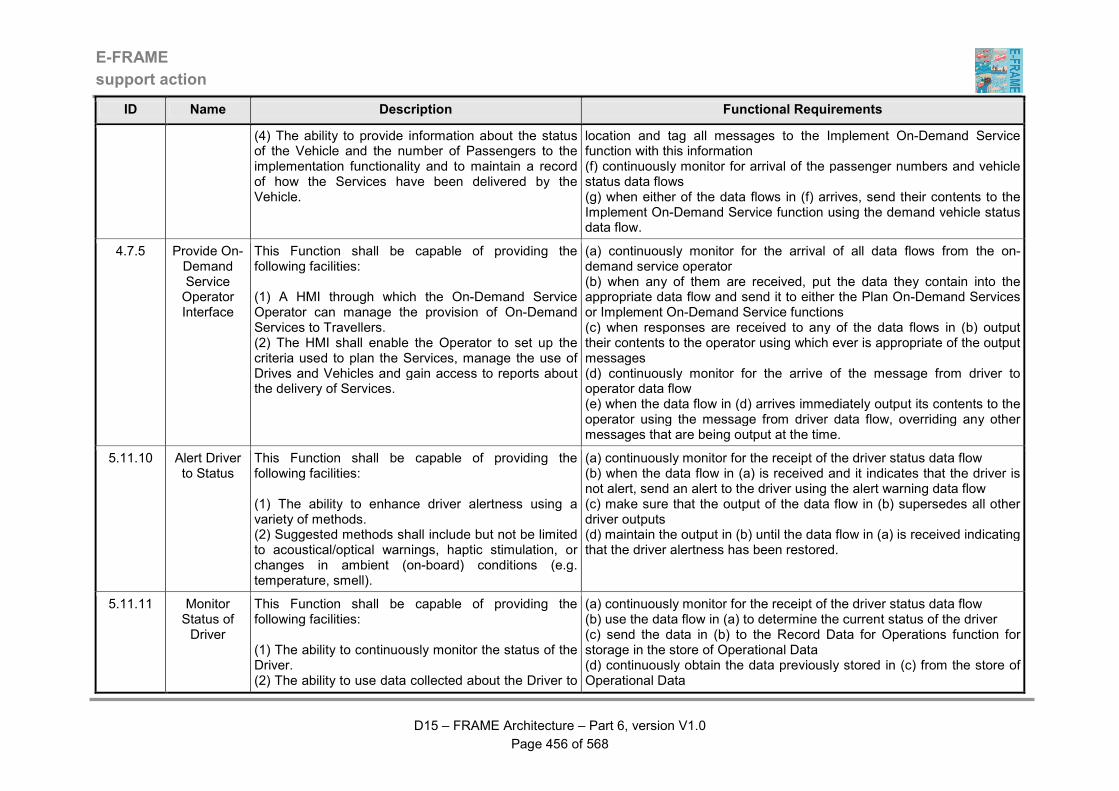
E-FRAME
support action
D15 – FRAME Architecture – Part 6, version V1.0
Page 456 of 568
ID Name Description Functional Requirements
(4) The ability to provide information about the status of the Vehicle and the number of Passengers to the implementation functionality and to maintain a record of how the Services have been delivered by the Vehicle.
location and tag all messages to the Implement On-Demand Service function with this information (f) continuously monitor for arrival of the passenger numbers and vehicle status data flows (g) when either of the data flows in (f) arrives, send their contents to the Implement On-Demand Service function using the demand vehicle status data flow.
4.7.5 Provide On-Demand Service Operator Interface
This Function shall be capable of providing the following facilities: (1) A HMI through which the On-Demand Service Operator can manage the provision of On-Demand Services to Travellers. (2) The HMI shall enable the Operator to set up the criteria used to plan the Services, manage the use of Drives and Vehicles and gain access to reports about the delivery of Services.
(a) continuously monitor for the arrival of all data flows from the on-demand service operator (b) when any of them are received, put the data they contain into the appropriate data flow and send it to either the Plan On-Demand Services or Implement On-Demand Service functions (c) when responses are received to any of the data flows in (b) output their contents to the operator using which ever is appropriate of the output messages (d) continuously monitor for the arrive of the message from driver to operator data flow (e) when the data flow in (d) arrives immediately output its contents to the operator using the message from driver data flow, overriding any other messages that are being output at the time.
5.11.10 Alert Driver to Status
This Function shall be capable of providing the following facilities: (1) The ability to enhance driver alertness using a variety of methods. (2) Suggested methods shall include but not be limited to acoustical/optical warnings, haptic stimulation, or changes in ambient (on-board) conditions (e.g. temperature, smell).
(a) continuously monitor for the receipt of the driver status data flow (b) when the data flow in (a) is received and it indicates that the driver is not alert, send an alert to the driver using the alert warning data flow (c) make sure that the output of the data flow in (b) supersedes all other driver outputs (d) maintain the output in (b) until the data flow in (a) is received indicating that the driver alertness has been restored.
5.11.11 Monitor Status of Driver
This Function shall be capable of providing the following facilities: (1) The ability to continuously monitor the status of the Driver. (2) The ability to use data collected about the Driver to
(a) continuously monitor for the receipt of the driver status data flow (b) use the data flow in (a) to determine the current status of the driver (c) send the data in (b) to the Record Data for Operations function for storage in the store of Operational Data (d) continuously obtain the data previously stored in (c) from the store of Operational Data
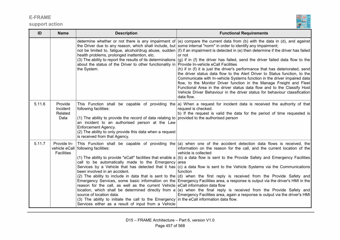
E-FRAME
support action
D15 – FRAME Architecture – Part 6, version V1.0
Page 457 of 568
ID Name Description Functional Requirements
determine whether or not there is any impairment of the Driver due to any reason, which shall include, but not be limited to, fatigue, alcohol/drug abuse, sudden health problems, prolonged inattention, etc. (3) The ability to report the results of its determinations about the status of the Driver to other functionality in the System.
(e) compare the current data from (b) with the data in (d), and against some internal "norm" in order to identify any impairment; (f) if an impairment is detected in (e) then determine if the driver has failed or not (g) if in (f) the driver has failed, send the driver failed data flow to the Provide In-vehicle eCall Facilities (h) if in (f) it is just the driver's performance that has deteriorated, send the driver status data flow to the Alert Driver to Status function, to the Communicate with In-vehicle Systems function in the driver impaired data flow, to the Monitor Driver function in the Manage Freight and Fleet Functional Area in the driver status data flow and to the Classify Host Vehicle Driver Behaviour in the driver status for behaviour classification data flow.
5.11.6 Provide Incident Related Data
This Function shall be capable of providing the following facilities: (1) The ability to provide the record of data relating to an incident to an authorised person at the Law Enforcement Agency. (2) The ability to only provide this data when a request is received from that Agency.
a) When a request for incident data is received the authority of that request is checked. b) If the request is valid the data for the period of time requested is provided to the authorised person
5.11.7 Provide In-vehicle eCall Facilities
This Function shall be capable of providing the following facilities: (1) The ability to provide "eCall" facilities that enable a call to be automatically made to the Emergency Services by a Vehicle that has detected that it has been involved in an accident. (2) The ability to include in data that is sent to the Emergency Services, some basic information on the reason for the call, as well as the current Vehicle location, which shall be determined directly from a source of location data. (3) The ability to initiate the call to the Emergency Services either as a result of input from a Vehicle
(a) when one of the accident detection data flows is received, the information on the reason for the call, and the current location of the vehicle is collected (b) a data flow is sent to the Provide Safety and Emergency Facilities area (c) a data flow is sent to the Vehicle Systems via the Communications function (d) when the first reply is received from the Provide Safety and Emergency Facilities area, a response is output via the driver's HMI in the eCall information data flow (e) when the final reply is received from the Provide Safety and Emergency Facilities area, again a response is output via the driver's HMI in the eCall information data flow.
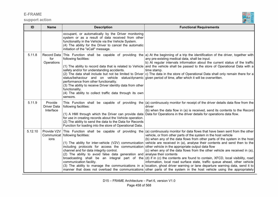
E-FRAME
support action
D15 – FRAME Architecture – Part 6, version V1.0
Page 458 of 568
ID Name Description Functional Requirements
occupant, or automatically by the Driver monitoring system or as a result of data received from other functionality in the Vehicle via the Vehicle System. (4) The ability for the Driver to cancel the automatic initiation of the "eCall" message.
5.11.8 Record Data for
Operations
This Function shall be capable of providing the following facilities: (1) The ability to record data that is related to Vehicle safety and/or for understanding accidents. (2) The data shall include but not be limited to Driver status/behaviour and on vehicle status/dynamic performance from other functionality. (3) The ability to receive Driver identity data from other functionality. (4) The ability to collect traffic data through its own sensors.
a) At the beginning of a trip the identification of the driver, together with any pre-existing medical data, shall be input. b) At regular intervals information about the current status of the traffic and the vehicle shall be passed to the store of Operational Data with a time stamp. c) The data in the store of Operational Data shall only remain there for a given period of time, after which it will be overwritten.
5.11.9 Provide Driver Data Interface
This Function shall be capable of providing the following facilities: (1) A HMI through which the Driver can provide data for use in creating records about the Vehicle operation. (2) The ability to send the data to the Data for Records Function for loading into the store of Operational Data.
(a) continuously monitor for receipt of the driver details data flow from the driver (b) when the data flow in (a) is received, send its contents to the Record Data for Operations in the driver details for operations data flow.
5.12.10 Provide V2V Communicat
ions
This Function shall be capable of providing the following facilities: (1) The ability for inter-vehicle (V2V) communication including protocols for access the communication channel and for data integrity control. (2) The ability to avoid false data generation and broadcasting shall be an integral part of the communication facility. (3) The ability to manage the communications in a manner that does not overload the communications
(a) continuously monitor for data flows that have been sent from the other vehicle, or from other parts of the system in the host vehicle (b) when any of the data flows from other parts of the system in the host vehicle are received in (a), analyse their contents and send then to the other vehicle in the appropriate output data flow (c) when any of the data flows from the other vehicle are received in (a), analyse their contents (d) if in (c) the contents are found to contain, XFCD, local visibility, road information, local road surface state, traffic queue ahead, other vehicle location, ghost driver warning or lane departure warning data, send it to other parts of the system in the host vehicle using the appropriately
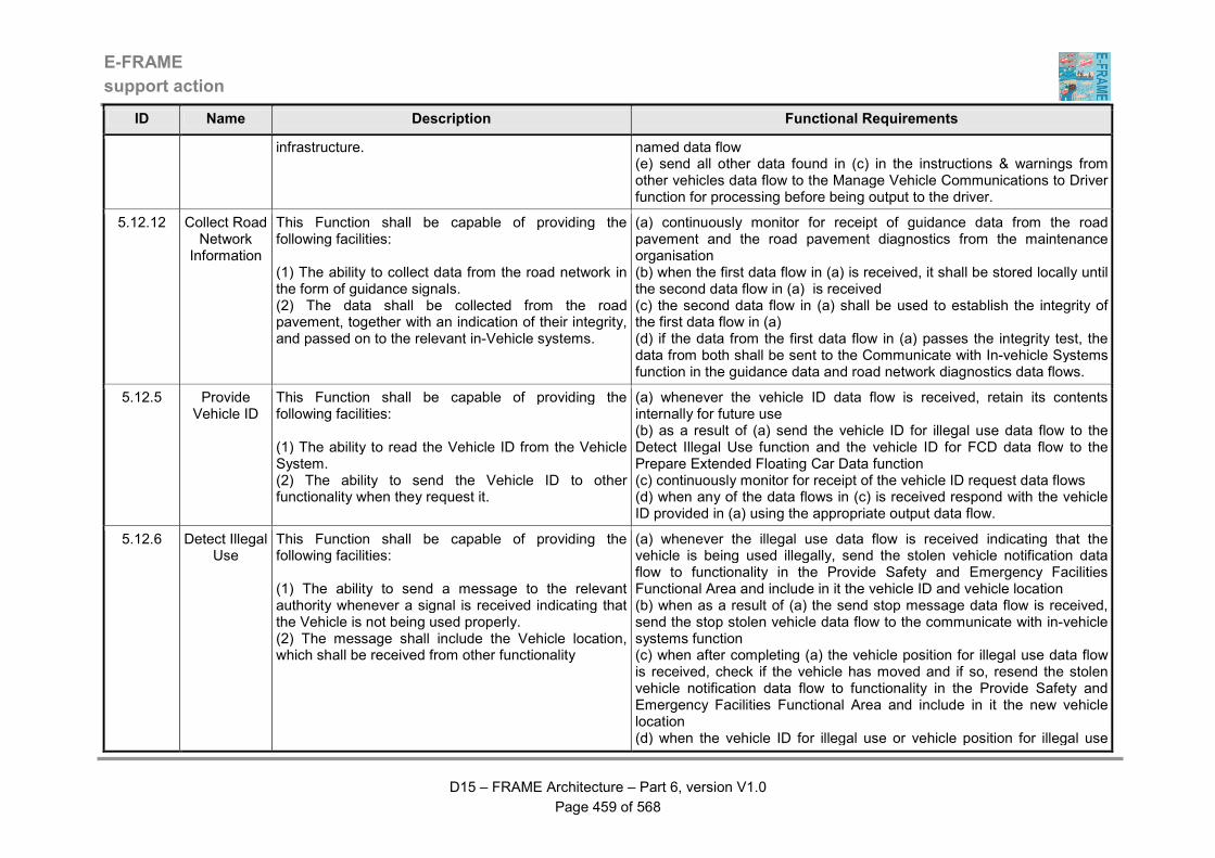
E-FRAME
support action
D15 – FRAME Architecture – Part 6, version V1.0
Page 459 of 568
ID Name Description Functional Requirements
infrastructure. named data flow (e) send all other data found in (c) in the instructions & warnings from other vehicles data flow to the Manage Vehicle Communications to Driver function for processing before being output to the driver.
5.12.12 Collect Road Network
Information
This Function shall be capable of providing the following facilities: (1) The ability to collect data from the road network in the form of guidance signals. (2) The data shall be collected from the road pavement, together with an indication of their integrity, and passed on to the relevant in-Vehicle systems.
(a) continuously monitor for receipt of guidance data from the road pavement and the road pavement diagnostics from the maintenance organisation (b) when the first data flow in (a) is received, it shall be stored locally until the second data flow in (a) is received (c) the second data flow in (a) shall be used to establish the integrity of the first data flow in (a) (d) if the data from the first data flow in (a) passes the integrity test, the data from both shall be sent to the Communicate with In-vehicle Systems function in the guidance data and road network diagnostics data flows.
5.12.5 Provide Vehicle ID
This Function shall be capable of providing the following facilities: (1) The ability to read the Vehicle ID from the Vehicle System. (2) The ability to send the Vehicle ID to other functionality when they request it.
(a) whenever the vehicle ID data flow is received, retain its contents internally for future use (b) as a result of (a) send the vehicle ID for illegal use data flow to the Detect Illegal Use function and the vehicle ID for FCD data flow to the Prepare Extended Floating Car Data function (c) continuously monitor for receipt of the vehicle ID request data flows (d) when any of the data flows in (c) is received respond with the vehicle ID provided in (a) using the appropriate output data flow.
5.12.6 Detect Illegal Use
This Function shall be capable of providing the following facilities: (1) The ability to send a message to the relevant authority whenever a signal is received indicating that the Vehicle is not being used properly. (2) The message shall include the Vehicle location, which shall be received from other functionality
(a) whenever the illegal use data flow is received indicating that the vehicle is being used illegally, send the stolen vehicle notification data flow to functionality in the Provide Safety and Emergency Facilities Functional Area and include in it the vehicle ID and vehicle location (b) when as a result of (a) the send stop message data flow is received, send the stop stolen vehicle data flow to the communicate with in-vehicle systems function (c) when after completing (a) the vehicle position for illegal use data flow is received, check if the vehicle has moved and if so, resend the stolen vehicle notification data flow to functionality in the Provide Safety and Emergency Facilities Functional Area and include in it the new vehicle location (d) when the vehicle ID for illegal use or vehicle position for illegal use

E-FRAME
support action
D15 – FRAME Architecture – Part 6, version V1.0
Page 460 of 568
ID Name Description Functional Requirements
data flows are received retain their contents for use when the vehicle is being used illegally.
5.12.7 Communicate with In-vehicle Systems
This Function shall be capable of providing the following facilities: (1) The ability to provide an interface between the systems inside the Vehicle and other functionality in the Host Vehicle. (2) The ability to extract a variety of data from the Vehicle Systems through a "read only" interface, so that the integrity and safety of the systems themselves and the Vehicle cannot be compromised. (3) The ability to continuously analyse the data from the Vehicle Systems and provide the relevant parts to other functionality in the Host Vehicle.
(a) continuously monitor for the receipt of the data flows from vehicle systems, the data flows from other functionality in the Provide Advanced Driver Assistance Functional Area containing data that is to be sent to vehicle systems and data flows containing inputs to vehicle systems from other functionality outside the Provide Advanced Driver Assistance Functional Area (b) when in (a) the input data flow from the vehicle systems is received, analyse its contents and send it in the appropriate data flows to other functionality in the system (c) when in (a) any of the input data flows from other functionality in the system are received, collate the data and send it to the vehicle systems in the output data flow (d) when in (a) any of the input data flows from other functionality outside the Provide Advanced Driver Assistance Functional Area are received, collate the data and send it to the vehicle systems in the output data flow.
5.13.10 Display Current Road
Information to Driver
This Function shall be capable of providing the following facilities: (1) The ability to receive both the current recommended speeds and headways and the legal speed limits for display to the Driver of the Host Vehicle. (2) A HMI that shall be able to display both speed limits, except when either there is no recommended speed limit, or it is greater than the legal speed limit. (3) If there is no recommended speed limit, or it is greater that the legal speed limit, the HMI shall have the ability to display the legal speed limit with a warning that there is no recommended speed limit. (4) If the speed of the Host Vehicle exceeds either the recommended speed or the legal speed limit, then the HMI shall display a warning message to the Driver. (5) The HMI shall only display the headway with the
(a) continuously monitor for receipt of any of the input data flows (b) whenever the road information for display data flow is received in (a), display its contents including the legal speed limit and the part of the road network (inter-urban or urban) that the host vehicle is using to the driver through the HMI using the current road information data flow (c) whenever the current recommended speed and headway data flow is received in (a), display its contents (including the reasons for changes) to the driver through the HMI using the current speed limits and headways output data flow (d) in (c) continue to display the recommended speed limit provided that it is less than the legal speed limit for the current and expected next road segments (e) if no recommended speed limit is received in (a), then only display the current legal speed limit received in (b) and output to the driver through the HMI with it an advisory message saying that there is no recommended speed limit (f) if the recommended speed limit received in (c) exceeds the legal speed limit received in (b) then only display the legal speed limit and output to

E-FRAME
support action
D15 – FRAME Architecture – Part 6, version V1.0
Page 461 of 568
ID Name Description Functional Requirements
recommended speed limit. (6) When any changes are made to the recommended speed and headway, the HMI shall be able to provide an indication of the reason for the change. (7) The HMI shall also have the ability to display a warning when the Host Vehicle is being driven in an unsafe manor, i.e. poor safety behaviour due to excessive speed, or maintaining less than the minimum headway. (8) The HMI shall be able to continuously update the display to provide the Driver with the speed and headway for the Host Vehicle's current and expected locations within the road network and to show or remove any unsafe driving warnings. (9) If for any reason the HMI does not receive any inputs, it shall have the ability to show a "system not working" indication.
the driver through the HMI an advisory message saying that there is no recommended speed limit (g) if no recommended or legal speed limits are received in (b) or (c) then output a message to the driver through the HMI in the current speed limit data flow saying the speed limit service is unavailable (h) when the roadside speed indication details data flow is received in (a) check the speed value it contains against the current legal and recommended speed limits that have been received in (b) and (c) (i) if a difference is found in (h), provide a warning of this to the driver in the possible speed indication error data flow and also send the data from which the same warning message can be produced to either the function (in the inter-urban speed being exceeded) or Output Lane & Speed Commands to Urban Roads function (in the urban speed being exceeded) depending on whether the vehicle is in the inter-urban or urban part of the road network (j) continue to send the output in (i) for as long as the difference persists and stop output of the possible speed indication error data flow when it does not (k) the output of the possible speed indication error data flow should only be made if a recommended or legal speed limit has been received in (b) or (c), i.e. the output must not be sent if there is no data with which to make a comparison (l) when the vehicle speed data flow is received in (a), check it against the legal speed limit received in (b) and the recommended speed received in (c) and display a warning to the driver if either is being exceeded by the vehicle in the recommended speed or legal speed limit exceeded data flow (m) if either of the data flows in (l) is sent then determine in which part of the road network (inter-urban or urban) the vehicle is located and send whichever is appropriate of the inter-urban speed being exceeded or urban speed being exceeded data flows to the Output Lane & Speed Commands to Inter-urban Roads or Output Lane & Speed Commands to Urban Roads functions respectively (n) the output of all speed limit information must be made in a standard way (o) whenever the fused road and traffic conditions data flow is received in
E-FRAME
support action
D15 – FRAME Architecture – Part 6, version V1.0
Page 462 of 568
ID Name Description Functional Requirements
(a), display its contents to the driver through the HMI using the current road and traffic conditions data flow (p) whenever the safety behaviour status for display data flow is received in (a), display the warning that it contains through the HMI using the safety behaviour warning data flow, for as long as the warning is received, it being removed when it ceases to be present (q) if none of the data flows is received in (a) for a period of time, the display shall show a "system not working" indication.
5.13.11 Fuse Extended
Floating Car Data
This Function shall be capable of providing the following facilities: (1) The ability to collect Extended Floating Car Data (XFCD) from the host Vehicle and the Other Vehicle plus fused data from the System that it has collected from other Vehicles. (2) The ability to collate and fuse all of the data that has been collected to provide a coherent and consistent view of the road and traffic situation around the host Vehicle. (3) The ability to send the data that has been collated and fused to the Driver Display Function.
(a) continuously monitor for the receipt of the input data flows (b) when any of the data flows in (a) is received, combine and fuse its contents to form a coherent and consistent set of traffic and road data for the area surrounding the host Vehicle (c) as part of (b) reject data from the Other Vehicle or from other system functionality if it is about a location, or about traffic that is travelling in a direction that is not relevant to the host Vehicle (d) store the results of the processing in (b) and (c) locally for use in (b) when either of the data flows in (a) is received again (e) send the results of (b) and (c) to the Display function.
5.13.12 Monitor Vehicle Safety
Behaviour
This Function shall be capable of providing the following facilities: (1) The ability to monitor the safety behaviour of the Vehicle. (2) The ability to receive data about the current location of the Vehicle, its speed and position, plus the legal and recommended speed limits for the road section that it is currently using. (3) The ability to use this data to determine whether or not the Vehicle is being driven in a safe manor. (4) The ability to consider unsafe behaviour to be such things as excessive speed and swerving from one lane to another.
(a) continuously monitor for the receipt of the input data flows (b) when the data flows containing actual, recommended and legal speeds are received in (a) determine if the vehicle is being driven such that it is exceeding any of the speed limits (c) when the data flow containing the vehicle position is received in (a) compare it with the previous position and the speed to see if the vehicle is being driven in an unsafe manor (d) if either of (b) or (c) results in the vehicle being found to be driven in an unsafe manor, i.e. exhibiting poor safety behaviour, send a warning indication for display to the driver in the safety behaviour status for display data flow (e) in addition to (d) also send poor safety behaviour warnings in the safety behaviour status for urban and safety behaviour status for inter-urban data flows.

E-FRAME
support action
D15 – FRAME Architecture – Part 6, version V1.0
Page 463 of 568
ID Name Description Functional Requirements
(5) It is determined that the Vehicle is being driven in an unsafe manor the ability to send a warning for display to the Driver and an indication of bad safety behaviour to the functionality that collects FCD/XFCD so that this data is not used to calculate traffic conditions.
5.13.6 Determine Vehicle Position
This Function shall be capable of providing the following facilities: (1) The ability to enable the Vehicle to determine its position. (2) The ability to determine the Vehicle position with the accuracy required by other functionality to provide their specific services to the Vehicle but as a minimum shall enable the Vehicle to determine its position relative to lanes in the road carriageway. (3) The ability to use data from the Location Data Source, In-vehicle system and its own sensors to determine a "dead reckoning" position and for generally improving positioning accuracy and reliability. (4) The ability to use map data to provide "map matching" so that the actual identity of the part of the road network in which the Vehicle is currently positioned can be determined. (5) The ability to provide updated position information to other functionality as soon as a change occurs.
(a) continuously monitor for the receipt of all the input data flows (b) whenever any of the input data flows changes, determine the new host vehicle position using the vehicle location for road information data flow (c) if the data in (b) is not available, use the data from the location from other vehicle and other vehicle relative position data flows to determine the location of the host vehicle (d) if no data is available in (b) or (c) use the contents of the dead reckoning data flow to determine the location of the host vehicle (e) use the data flow from the geographic information provider plus the results of (b), or (c) or (d) to determine the location of the vehicle within the road network, i.e. the identity of the road segment (f) when (b) to (e) are complete, send each of the output data flows to their respective functions.
5.13.7 Prepare Extended
Floating Car Data
This Function shall be capable of providing the following facilities: (1) The ability to use the inputs received from other functionality to produce data about the Vehicle such as its current speed, location, identity plus other information such as road and traffic states, location on a Vehicle Trip Plan, e.g. at a way point.
(a) continuously monitor for the receipt of each of the input data flows (b) use the contents of the vehicle position for fcd, vehicle ID for fcd, status data for fcd and current time 2 data flows to prepare the extended floating car data (c) check the location with each of the acknowledgement data flows received in (a) (d) if the status data for fcd data flow does not include sufficient data to provide what is expected to be contained in extended floating car data,

E-FRAME
support action
D15 – FRAME Architecture – Part 6, version V1.0
Page 464 of 568
ID Name Description Functional Requirements
(2) The ability to send this data to the Manage Traffic and Provide Traveller Journey Assistance functionality in the System, as well as to the Monitor Vehicle Safety Behaviour Function. (3) The ability to send the data to the Monitor Vehicle Safety Behaviour Function either at periodic intervals or triggered by events, depending on how often the input (raw) data changes so that Vehicles become probes within the road network. (4) If data about such things as road friction, aquaplaning, Vehicle breakdown and traffic incidents are not provided by the Vehicle systems, the ability to attempt to determine them from the data that it has received. (5) The ability to compose and send acknowledgement messages resulting from instructions received by Vehicles and displayed to Drivers. (6) The ability to send acknowledgement messages resulting from instructions received by Vehicles and displayed to Drivers to the Law Enforcement functionality in case there is a violation is detected as a result of instructions sent to Drivers.
review the data and deduce such things as road conditions, such as reduced road friction or aquaplaning and traffic conditions, such vehicle breakdown, traffic incident (i.e. congestion) (e) when (b), (c) and (d) are complete, use the data they have provided in each of the output data flows and send them to their respective functions in the other Functional Areas and to the Monitor Vehicle Safety Behaviour function.
5.13.8 Provide Suggested Speeds and Headways for ISA
This Function shall be capable of providing the following facilities: (1) The ability to provide support for the Driver by suggesting the optimal speed and headway for the Host Vehicle in both its current and expected locations in the road network. (2) In a suitably equipped Host Vehicle, the ability to enable it to automatically keep at or below the optimal speed (Intelligent Speed Adaptation - ISA) and headway. (3) Once the optimal speed and headway have been determined, the ability to send them for display to the Driver, to the Other Vehicle via the Vehicle
(a) continuously monitor for receipt of the vehicle position for ISA, inter-urban and urban speed settings, legal speed limit for ISA, weather conditions for ISA, ISA information and vehicle data for determining speed & headway data flows (b) when in (a) the ISA information data flow is received from the geographic information provider, load the speed limit that it contains into the store of ISA Data (c) when in (a) the legal speed limit for ISA data flow is received, load its contents into the store of ISA Information Data (d) when in (a) either of the inter-urban and urban suggested speeds and headways data flows are received, store the data internally for future use (e) when in (a) the weather conditions for ISA data flow is received, store its contents internally for late use (f) when in (a) the vehicle data for determining speed & headway data
E-FRAME
support action
D15 – FRAME Architecture – Part 6, version V1.0
Page 465 of 568
ID Name Description Functional Requirements
Communications Function and to the Monitor Vehicle Safety Behaviour Function. (4) The ability to ensure that the optimal speed is always less than or equal to the legal speed limit and enable it to vary from one road segment to another. (5) When sending the optimal speed and headway for display to the Driver, the ability to provide the reason(s) for any changes in the suggested speed and/or headway.
flow is received, store its contents internally for future use (g) when in (a) the vehicle position for ISA is received use its content to determine which of the speeds received in (b), (c) or (d) is the lowest and using the weather conditions received in (e) plus the vehicle data received in (f) calculate the optimum speed for the vehicle (h) as a result of (g) calculate the vehicle headway again using the weather conditions received in (e) plus the vehicle data received in (f) (i) if the answer to (h) is that the calculated headway is greater than that received in (d) use it in the data that is sent in the output data flows (j) send the results of (g) and (i) to the Display Current Speed Limit function using the current suggested speeds and headways data flow, to the Vehicle Communications function in the suggested speeds and headways from ISA data flow and to the Monitor Vehicle Safety Behaviour function in the suggested speed and headway for safety behaviour data flow (k) also as a result of (g) send the ISA acknowledgement data flow to the Prepare Extended Floating Car Data function.
5.13.9 Determine Applicable
Road Information
This Function shall be capable of providing the following facilities: (1) The ability to provide support for the Driver to determine the applicable road based information that can be displayed in the Host Vehicle. (2) The ability to include in the information the current legal speed limit and information about junctions that are being approached as the Host Vehicle moves through the road network. (3) The ability to receive digital map data from the Geographic Information Provider including legal speed limits and road signs, which shall be loaded into the store of Road Information Data. (4) The ability to use the data from the store together with the current location of the Host Vehicle in the road network to determine the current maximum legal speed for the Host Vehicle and any approaching changes in road geometry and layout for which signs
(a) continuously monitor for the receipt of the vehicle position for legal speed, legal speed limit and road information data plus inter-urban and urban legal speed limit override data flows (b) when in (a) any but the vehicle position data flow is received, load their contents into the store of Road Information Data using the load road information data flow (c) when in (a) the vehicle position for road information data flow is received and it has changed since it was last received, use the read road information data flow to obtain the relevant contents of the store of Road Information Data and determine what the legal speed limit should be plus other road based information that should be displayed to the driver (d) send the result of (c) to the Display Current Road Information function in the current road information data flow and to the Monitor Vehicle Safety Behaviour function in the legal speed for safety behaviour data flow (e) also send the current legal speed limit (either from the geographic information or as overridden) from (c) to the Prepare Extended Floating Car Data function in the legal speed for ISA data flow.
E-FRAME
support action
D15 – FRAME Architecture – Part 6, version V1.0
Page 466 of 568
ID Name Description Functional Requirements
are available. (5) If available the ability to apply any override of the legal speed limits provided by the Manage Traffic functionality. (6) The ability to send the legal or overridden speed limits to other functionality for display to the Driver and for use in monitoring the safety behaviour of the Vehicle.
5.14.1 Provide Driver
Interface for Trip
Planning
This Function shall be capable of providing the following facilities: (1) A HMI through which the Driver can create, initiate and modify Vehicle Trip Plans. (2) The HMI shall enable the Driver to provide data from which new Trip Plans can be created, draft Trip Plans modified, created Trip Plans accepted and implementing Trip Plans changed. (3) The HMI shall enable the Driver to initiate the implementation of a previously created Trip Plan.
(a) continuously monitor for receipt from the driver of the data flow containing vehicle trip plan data or the implement vehicle trip plan data flow (b) when first the data flow in (a) is received, send the data about the vehicle trip plan that is to be created to the Create and Revise Vehicle Trip Plan function in the data flow containing vehicle trip plan data (c) as a result of (b) continuously monitor for receipt of the vehicle trip plan draft data flow (d) when the data flow in (c) arrives, re-format its contents if required and output them to the driver in the draft vehicle trip plan data flow (e) as a result of (d), continuously monitor for receipt of either the modified vehicle trip plan data or vehicle trip plan accepted data flows (f) when the first data flow in (e) is received, use its contents to repeat (b) to (d) (g) when the second data flow in (e) is received, send the acceptance to the Create and Revise Vehicle Trip Plan function in the vehicle trip plan acceptance data flow (h) when the second data flow in (a) is received, send the details of the vehicle trip plan that is to be implemented to the Implement Vehicle Trip Plan and Track Vehicle function in the implement vehicle trip plan data flow (i) as a result of (h) continuously monitor for receipt of the revised vehicle trip plan for driver data flow (j) when the data flow in (i) is received, re-format its contents if required and output them to the driver in the modified vehicle trip plan data flow (k) as a result of (j) continuously monitor for the receipt of either the modify current vehicle trip plan or accept revised vehicle trip plan data flows
E-FRAME
support action
D15 – FRAME Architecture – Part 6, version V1.0
Page 467 of 568
ID Name Description Functional Requirements
(l) when the first data flow in (k) is received, put its contents into the data flow containing vehicle trip plan data and send it to the Create and Revised Vehicle Trip Plan function (m) as a result of (l) repeat (i) to (k) (n) when the second data flow in (k) is received, send the acceptance to the Create and Revise Vehicle Trip Plan function in the accept revised vehicle trip plan data flow.
5.14.10 Freight Vehicle Rest Area Use
Management
This Function shall be capable of providing the following facilities: (1) The ability to provide facilities that enable the Driver of a Freight Vehicle to book parking places at rest areas along the route they are about to follow in a Vehicle Trip Plan. (2) The ability to assume that these rest areas are part of what are called "service areas" elsewhere, managed by a Parking Operator and shall have to be used in order that Freight Vehicle Drivers can comply with the relevant European Working Time Directive(s). (3) The ability to enable a Freight Vehicle Driver to book a parking place in a rest area, based on the Expected Time of Arrival (ETA) according to the Vehicle Trip Plan. (4) If the booking is rejected, or the ETA changes as the Vehicle Trip Plan is implemented, the ability to enable the Freight Vehicle Driver to revise the parking space booking to match the new ETA. (5) The ability to provide the Freight Vehicle Driver with details of rest area bookings that have been made by the Fleet Operator. (6) When the Vehicle approaches the destination rest area, the ability to enable the Driver to be provided with details guidance about how to find the area and how to manoeuvre the Freight Vehicle into the booked parking space.
(a) continuously monitor for receipt of the trip plan with parking and/or un/loading need data flow from the Enable Driver to Make Payment function (b) when the data flow in (a) is received, check to see if rest areas need to be reserved by calculating the expected journey times between origin, and intermediate stopping points and the destination, and if it shows that they are not needed, send the vehicle trip plan to the Manage Freight Vehicle Parking function in the vehicle trip plan with parking needed data flow (c) if the result of (b) shows that rest area bookings are needed, send this to the freight vehicle driver in the rest area parking needed data flow and continuously monitor for receipt of the rest area parking request data flow from the freight vehicle driver (d) when the data flow in (c) is received, send its contents together with details of the planned route, estimated time of arrival from the data flow in (a) to the Manage Service Area Rest Area Bookings function in the rest area parking request data flow (e) as a result of (d) continuously monitor for receipt of the rest area parking response data flow from the Manage Service Area Rest Area Bookings function (f) when the data flow in (e) is received, output its contents to the freight vehicle driver in the rest area parking response data flow (g) as a result of (f) continuously monitor for receipt of the rest area parking response or revised rest area parking request data flows from the freight vehicle driver (h) if the second data flow is received in (g), repeat (d) to (g) (i) if the first data flow is received in (g), update the vehicle trip plan data included in the data flow received in (a), check to see if any un/loading parking needs to be booked and if not send all of the vehicle trip plan data
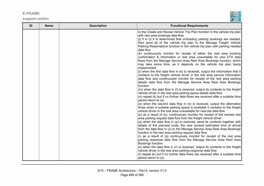
E-FRAME
support action
D15 – FRAME Architecture – Part 6, version V1.0
Page 468 of 568
ID Name Description Functional Requirements
to the Create and Revise Vehicle Trip Plan function in the vehicle trip plan with rest area bookings data flow (j) if in (i) it is determined that un/loading parking bookings are needed, then send all of the vehicle trip plan to the Manage Freight Vehicle Parking Reservations function in the vehicle trip plan with parking needed data flow (k) continuously monitor for receipt of either the rest area booking confirmation & information or rest area unavailable for new ETA data flows from the Manage Service Area Rest Area Bookings function, which may take some time, as it depends on the vehicle trip plan being implemented (l) when the first data flow in (k) is received, output the information that it contains to the freight vehicle driver in the rest area service information data flow and continuously monitor for receipt of the rest area parking details data flow from the Manage Service Area Rest Area Bookings function (m) when the data flow in (l) is received, output its contents to the freight vehicle driver in the rest area parking space details data flow (n) repeat (k) but if no further data flows are received after a suitable time period return to (a) (o) when the second data flow in (k) is received, output the alternative times when a suitable parking space is available it contains to the freight vehicle driver in the rest area unavailable for new eta data flow (p) as a result of (o), continuously monitor for receipt of the revised rest area parking request data flow from the freight vehicle driver (q) when the data flow in (p) is received, send its contents together with details of the planned route, the new revised estimated time of arrival from the data flow in (o) to the Manage Service Area Rest Area Bookings function in the rest area parking request data flow (r) as a result of (q) continuously monitor for receipt of the rest area parking response data flow from the Manage Service Area Rest Area Bookings function (s) when the data flow in (r) is received, output its contents to the freight vehicle driver in the rest area parking response data flow (t) repeat (k) but if no further data flows are received after a suitable time period return to (a)
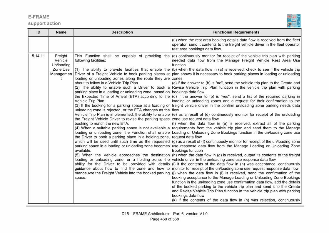
E-FRAME
support action
D15 – FRAME Architecture – Part 6, version V1.0
Page 469 of 568
ID Name Description Functional Requirements
(u) when the rest area booking details data flow is received from the fleet operator, send it contents to the freight vehicle driver in the fleet operator rest area bookings data flow.
5.14.11 Freight Vehicle
Un/loading Zone Use
Management
This Function shall be capable of providing the following facilities: (1) The ability to provide facilities that enable the Driver of a Freight Vehicle to book parking places at loading or unloading zones along the route they are about to follow in a Vehicle Trip Plan. (2) The ability to enable such a Driver to book a parking place in a loading or unloading zone, based on the Expected Time of Arrival (ETA) according to the Vehicle Trip Plan. (3) If the booking for a parking space at a loading or unloading zone is rejected, or the ETA changes as the Vehicle Trip Plan is implemented, the ability to enable the Freight Vehicle Driver to revise the parking space booking to match the new ETA. (4) When a suitable parking space is not available a loading or unloading zone, the Function shall enable the Driver to book a parking place in a holding zone, which will be used until such time as the requested parking space in a loading or unloading zone becomes available. (5) When the Vehicle approaches the destination loading or unloading zone, or a holding zone, the ability for the Driver to be provided with details guidance about how to find the zone and how to manoeuvre the Freight Vehicle into the booked parking space.
(a) continuously monitor for receipt of the vehicle trip plan with parking needed data flow from the Manage Freight Vehicle Rest Area Use function (b) when the data flow in (a) is received, check to see if the vehicle trip plan shows it is necessary to book parking places in loading or unloading zones (c) if the answer to (b) is "no", send the vehicle trip plan to the Create and Revise Vehicle Trip Plan function in the vehicle trip plan with parking bookings data flow (d) if the answer to (b) is "yes", send a list of the required parking in loading or unloading zones and a request for their confirmation to the freight vehicle driver in the confirm un/loading zone parking needs data flow (e) as a result of (d) continuously monitor for receipt of the un/loading zone use request data flow (f) when the data flow in (e) is received, extract all of the parking requirements from the vehicle trip plan and send them to the Manage Loading or Unloading Zone Bookings function in the un/loading zone use request data flow (g) as a result of (f) continuously monitor for receipt of the un/loading zone use response data flow from the Manage Loading or Unloading Zone Bookings function (h) when the data flow in (g) is received, output its contents to the freight vehicle driver in the un/loading zone use response data flow (i) if the contents of the data flow in (h) was acceptance, continuously monitor for receipt of the un/loading zone use request response data flow (j) when the data flow in (i) is received, send the confirmation of the booking acceptance to the Manage Loading or Unloading Zone Bookings function in the un/loading zone use confirmation data flow, add the details of the booked parking to the vehicle trip plan and send it to the Create and Revise Vehicle Trip Plan function in the vehicle trip plan with parking bookings data flow (k) if the contents of the data flow in (h) was rejection, continuously
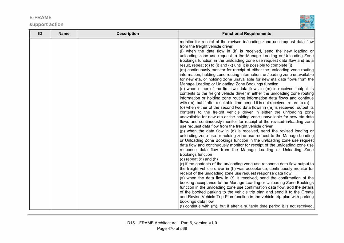
E-FRAME
support action
D15 – FRAME Architecture – Part 6, version V1.0
Page 470 of 568
ID Name Description Functional Requirements
monitor for receipt of the revised in/loading zone use request data flow from the freight vehicle driver (l) when the data flow in (k) is received, send the new loading or unloading zone use request to the Manage Loading or Unloading Zone Bookings function in the un/loading zone use request data flow and as a result, repeat (g) to (i) and (k) until it is possible to complete (j) (m) continuously monitor for receipt of either the un/loading zone routing information, holding zone routing information, un/loading zone unavailable for new eta, or holding zone unavailable for new eta data flows from the Manage Loading or Unloading Zone Bookings function (n) when either of the first two data flows in (m) is received, output its contents to the freight vehicle driver in either the un/loading zone routing information or holding zone routing information data flows and continue with (m), but if after a suitable time period it is not received, return to (a) (o) when either of the second two data flows in (m) is received, output its contents to the freight vehicle driver in either the un/loading zone unavailable for new eta or the holding zone unavailable for new eta data flows and continuously monitor for receipt of the revised in/loading zone use request data flow from the freight vehicle driver (p) when the data flow in (o) is received, send the revised loading or unloading zone use or holding zone use request to the Manage Loading or Unloading Zone Bookings function in the un/loading zone use request data flow and continuously monitor for receipt of the un/loading zone use response data flow from the Manage Loading or Unloading Zone Bookings function (q) repeat (g) and (h) (r) if the contents of the un/loading zone use response data flow output to the freight vehicle driver in (h) was acceptance, continuously monitor for receipt of the un/loading zone use request response data flow (s) when the data flow in (r) is received, send the confirmation of the booking acceptance to the Manage Loading or Unloading Zone Bookings function in the un/loading zone use confirmation data flow, add the details of the booked parking to the vehicle trip plan and send it to the Create and Revise Vehicle Trip Plan function in the vehicle trip plan with parking bookings data flow (t) continue with (m), but if after a suitable time period it is not received,
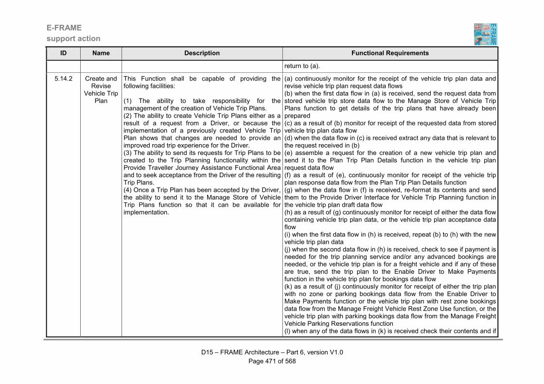
E-FRAME
support action
D15 – FRAME Architecture – Part 6, version V1.0
Page 471 of 568
ID Name Description Functional Requirements
return to (a).
5.14.2 Create and Revise
Vehicle Trip Plan
This Function shall be capable of providing the following facilities: (1) The ability to take responsibility for the management of the creation of Vehicle Trip Plans. (2) The ability to create Vehicle Trip Plans either as a result of a request from a Driver, or because the implementation of a previously created Vehicle Trip Plan shows that changes are needed to provide an improved road trip experience for the Driver. (3) The ability to send its requests for Trip Plans to be created to the Trip Planning functionality within the Provide Traveller Journey Assistance Functional Area and to seek acceptance from the Driver of the resulting Trip Plans. (4) Once a Trip Plan has been accepted by the Driver, the ability to send it to the Manage Store of Vehicle Trip Plans function so that it can be available for implementation.
(a) continuously monitor for the receipt of the vehicle trip plan data and revise vehicle trip plan request data flows (b) when the first data flow in (a) is received, send the request data from stored vehicle trip store data flow to the Manage Store of Vehicle Trip Plans function to get details of the trip plans that have already been prepared (c) as a result of (b) monitor for receipt of the requested data from stored vehicle trip plan data flow (d) when the data flow in (c) is received extract any data that is relevant to the request received in (b) (e) assemble a request for the creation of a new vehicle trip plan and send it to the Plan Trip Plan Details function in the vehicle trip plan request data flow (f) as a result of (e), continuously monitor for receipt of the vehicle trip plan response data flow from the Plan Trip Plan Details function (g) when the data flow in (f) is received, re-format its contents and send them to the Provide Driver Interface for Vehicle Trip Planning function in the vehicle trip plan draft data flow (h) as a result of (g) continuously monitor for receipt of either the data flow containing vehicle trip plan data, or the vehicle trip plan acceptance data flow (i) when the first data flow in (h) is received, repeat (b) to (h) with the new vehicle trip plan data (j) when the second data flow in (h) is received, check to see if payment is needed for the trip planning service and/or any advanced bookings are needed, or the vehicle trip plan is for a freight vehicle and if any of these are true, send the trip plan to the Enable Driver to Make Payments function in the vehicle trip plan for bookings data flow (k) as a result of (j) continuously monitor for receipt of either the trip plan with no zone or parking bookings data flow from the Enable Driver to Make Payments function or the vehicle trip plan with rest zone bookings data flow from the Manage Freight Vehicle Rest Zone Use function, or the vehicle trip plan with parking bookings data flow from the Manage Freight Vehicle Parking Reservations function (l) when any of the data flows in (k) is received check their contents and if

E-FRAME
support action
D15 – FRAME Architecture – Part 6, version V1.0
Page 472 of 568
ID Name Description Functional Requirements
it is not a success then delete the vehicle trip plan and return to (a) (m) when any of the data flows in (k) is received with a positive response, send the complete vehicle trip plan to the Manage Store of Vehicle Trip Plans function in the vehicle trip plan for store data flow (n) when the second data flow in (a) is received, re-format its contents into a new vehicle trip plan request and then repeat (e) (o) as a result of (n) continuously monitor for the receipt of the revised vehicle trip plan for approval data flow (p) when the data flow in (o) is received, re-format its contents and send them to the Provide Driver Interface for Vehicle Trip Planning function in the revised vehicle trip plan for driver data flow (q) as a result of (p) continuously monitor for receipt of either the data flow containing vehicle trip plan data, or the accept revised vehicle trip plan data flow (r) when the first data flow in (q) is received, repeat (e) and (j) to (m) with the new vehicle trip plan data (s) when the second data flow in (q) is received, send the complete vehicle trip plan to the Manage Store of Vehicle Trip Plans function in the vehicle trip plan for store data flow.
5.14.3 Enable Driver to Make
Payments
This Function shall be capable of providing the following facilities: (1) The ability to take responsibility for enabling the Driver to make any required payments for the trip planning service and/or make any required advanced payments for services included in the accepted Vehicle Trip Plan. (2) The ability to communicate directly with the Driver to obtain details of the payment mechanism that is to be used and to report on the success of failure of all of the payment transactions. (3) The ability to repeat all failed transactions for a defined number of times before abandoning the payment process and providing a payment failure response to the Create and Revise Vehicle Trip Plan Function.
(a) continuously monitor for receipt of the vehicle trip plan for bookings data flow (b) when the data flow in (a) is received, check its contents to see if any payment for the actual trip planning service is needed (c) if the answer to the question is (b) is yes, request payment from the driver in the request vehicle trip planning payment data flow (d) as a result of (c) continuously monitor for the receipt of the vehicle trip planning payment data flow (e) when the data flow in (d) is received, check for payment information and if found, send this to the financial clearinghouse in the request payment for vehicle trip planning data flow (f) as a result of (e), continuously monitor for receipt of the payment for vehicle trip planning response data flow from the financial clearinghouse (g) when the data flow in (f) is received, check to see if it was successful and if not, send the vehicle trip planning booking mishap data flow to the driver and repeat (c) to (f), or if failure has occurred a defined number of times, send a message to the driver that the trip plan will be deleted in the
E-FRAME
support action
D15 – FRAME Architecture – Part 6, version V1.0
Page 473 of 568
ID Name Description Functional Requirements
request vehicle trip planning payment data flow and send a failure response to the Create and Revise Vehicle Trip Plan function in the trip plan with no zone or parking bookings data flow (h) if in (b) no payment for the trip planning service is needed or the payment for the actual trip planning service in (c) to (g) has been successful, then check to see if any advanced payments are needed and if not send details of the vehicle trip plan to the Manage Freight Vehicle Rest Area Use function in the trip plan with zone of parking booking needed data flow (i) if the check in (h) shows that advanced payment for some part of the vehicle trip plan is needed, send details to the driver in the advanced payment for vehicle trip plan data flow (j) as a result of (i) continuously monitor for receipt of the vehicle trip plan booking approval data flow from the driver (k) when the data flow in (j) is received, check for payment information and if found, send this to the financial clearinghouse in the vehicle trip planning service payment request data flow (l) as a result of (k), continuously monitor for receipt of the vehicle trip planning service payment response data flow from the financial clearinghouse (m) when the data flow in (l) is received, check to see if it was successful and if not, send the vehicle trip planning booking mishap data flow to the driver, wait for the revised vehicle trip plan booking choices data flow and repeat (i) to (l) (n) if in (i) a negative or no response is received, or (i) to (l) have been repeated a defined number of times, send a message to the driver that the trip plan will be deleted in the request vehicle trip planning payment data flow and send a failure response to the Create and Revise Vehicle Trip Plan function in the trip plan with no zone or parking bookings data flow (o) if the response found in (m) showed that payment has been successfully made, send details of the vehicle trip plan to the Manage Freight Vehicle Rest Zone Use function in the trip plan with zone of parking booking needed data flow.
5.14.4 Implement Vehicle Trip
This Function shall be capable of providing the following facilities:
(a) continuously monitor for the receipt of the implement vehicle trip plan data flow
E-FRAME
support action
D15 – FRAME Architecture – Part 6, version V1.0
Page 474 of 568
ID Name Description Functional Requirements
Plan and Track Vehicle
(1) The ability to follow the progress of the Driver and implement each part of the Vehicle Trip Plan that they have requested. (2) The ability for a variety of tracking methods to be used to determine the actual location of the Vehicle that the Driver is using to implement the Trip Plan. (3) If no suitable tracking methods are available, the ability to use a form of dead reckoning. (4) As the Vehicle that the Driver is using to implement the Trip Plan moves through the road network, the ability to monitor progress against the Trip Plan and continually calculate the Estimated Time of Arrival (ETA) at the next way point, or Trip destination. (5) Based on the calculated ETA the ability to request assessment of any changes to conditions in the road network. (6) The ability to provide detailed route guidance which shall be sent to the Vehicle Human Machine Interface (HMI) Function for output to the Driver. (7) If a revised version of the trip plan currently being implemented is received, the ability to shall stop that trip plan and commence implementing the revised one.
(b) when the data flow in (a) is received, extract the Vehicle Trip Plan identity and send it to the Manage Store of Vehicle Trip Plans function in the request vehicle trip plan for implementation data flow (c) as a result of (b) continuously monitor for receipt of the vehicle trip plan for implementation data flow (d) when the data flow in (c) is received, extract the Trip description (e) continuously monitor for receipt of the vehicle location for trip monitoring data flow (f) when the data flow in (e) is received, use its contents and the stored digital map data to work out the location of the vehicle and compare with the start point of the Trip, obtained in (d) (g) if the vehicle is not at the start point for the trip, send the appropriate instructions to the Driver by sending them to the vehicle Human Machine Interface (HMI) in the vehicle trip plan guidance instructions data flow to get the vehicle to the start point (h) when the vehicle is at the Trip start point commence output of the route guidance instructions for the Trip to the Driver by sending them to the vehicle Human Machine Interface (HMI) in the vehicle trip plan guidance instructions data flow (i) put the data from (e) in the vehicle location for trip monitoring data flow and send it to the Monitor Vehicle Trip Plan Implementation for Driver function (j) put the destination of the vehicle from the trip plan in the provide destination for bus lane use data flow and send it to the Manage Vehicles using Bus Lanes function (k) continue with (e), (h), (i) and (j) until the Trip destination is reached (l) when the data flow containing vehicle trip plan implementation map data is received, store its data internally for use in (f) above.
5.14.5 Provide Driver Trip Guidance Interface
This Function shall be capable of providing the following facilities: (1) A HMI through which driving instructions and Estimated Time of Arrival (ETA) are output to the Driver. (2) The HMI shall be able to output both sets of information continuously, updating the output
(a) continuously monitor for the receipt of the input data flows (b) when any of the data flows in (a) is received, display its contents immediately (c) if no input is received after a set time interval, display a warning message to say that no data is available.
E-FRAME
support action
D15 – FRAME Architecture – Part 6, version V1.0
Page 475 of 568
ID Name Description Functional Requirements
immediately fresh data is received. (3) If no data is received from which to generate the output, the HMI shall be able to output a warning message to the Driver to indicate that there is nothing to display.
5.14.6 Monitor Vehicle Trip
Plan Implementati
on
This Function shall be capable of providing the following facilities: (1) The ability to monitor the progress that the Driver is making with the Vehicle Trip Plan that is currently being implemented. (2) The ability to use the current location of the Vehicle to check its progress with the Trip Plan implementation. (3) If the Vehicle Trip Plan is for a Freight Vehicle, the ability to update the Estimated Time of Arrival (ETA) so that any rest area or un/loading zone bookings can be re-validated. (4) When the Freight Vehicle leaves a rest area or un/loading zone, the ability to provide data showing that the parking space it has used can be booked by another Freight Vehicle. (5) If the Vehicle departs from the route in the Trip Plan, the ability to send a warning for output to the Driver and to request that a new route is created starting from the current location of the Vehicle. (6) The ability to continuously evaluate the data it receives about the road traffic conditions such as current and predicted traffic flows, road works, weather and incidents, plus the current Vehicle location and part of the Trip Plan that remains to be implemented, and to determine if there is any benefit in changing the current Vehicle Trip Plan. (7) If the results of the evaluation shows that there is some benefit to the Driver in changing the current Vehicle Trip Plan, the ability to request that this is
(a) continuously monitor for receipt of the data flows containing updates to the road traffic conditions and incidents (b) when any of the data flows are received in (a) update an internal store with the data that they contain (c) continuously monitor for receipt of the vehicle trip plan for monitoring data flow (d) when the data flow in (c) is received, extract the vehicle trip plan description and await the receipt of the vehicle location for trip plan monitoring data flow, but send data about way points in the trip plan to the Prepare Extended Floating Car Data function in the route information for xfcd data flow (e) when the data flow in (d) is received use the vehicle trip plan data to determine how far the vehicle has progressed through the trip plan and calculate the Estimated Time of Arrival (ETA) at the way points and the trip destination, using the data collected in (b) above (f) send the ETA data to the Provide Driver Trip Interface in the vehicle eta for driver data flow (g) use the data in (e) to determine the ETA for the next booked rest area, loading or unloading zone, or holding zone and send the result from the first to the Rest Area Booking Management function in the rest area eta data flow and from either the second or third to the Manage Loading or Unloading Zone Bookings function in un/loading zone eta or holding zone eta data flows respectively (h) when the data in (e) shows that the vehicle is leaving a rest zone, send this information to the Rest Area Booking Management function in the freight vehicle departing rest area data flow (i) also use the data in (e) to determine if the vehicle is departing from the route in the trip plan and if so, end the revise vehicle trip plan request data flow to the Create and Revise Vehicle Trip Plan function so that a new vehicle trip plan can be created, starting from the current location of the vehicle, and send a warning message in the vehicle departed from
E-FRAME
support action
D15 – FRAME Architecture – Part 6, version V1.0
Page 476 of 568
ID Name Description Functional Requirements
done, send a warning message with the reason for the change for output to the Driver and continue monitoring the use of the current Trip Plan until it is replaced. (8) As implementation of the Vehicle Trip Plan progresses, the ability to collect O-D and journey time data for the road network segments that are used in the trip and send them to the Inter-urban and Urban Traffic Data Collection functionality. (9) The ability to send data about way points in the Trip Plan to other in-vehicle functionality for inclusion in Extended Floating Car Data (XFCD).
route data flow to the Provide Driver Trip Interface function (j) again use the data in (e) to assess the progress that is being made with implementing the trip and check to see if the ETA is remaining constant or increasing, i.e. the trip will take longer that expected (k) if the trip will take longer than expected, send the revise vehicle trip plan request data flow to the Create and Revise Vehicle Trip Plan function so that a new vehicle trip plan can be created, starting from the current location of the vehicle (l) periodically send details of the route from the vehicle trip plan to the inter-urban and urban functionality in the vehicle trip plan route for inter-urban and vehicle trip plan route for urban data flows (m) as a result of (k) put the reason for the need to change the trip plan in the vehicle trip plan change reason for driver data flow and send it to the Provide Driver Trip Interface function (n) using the data from (e) to calculate the journey time for each segment of the road network that the vehicle uses and send it to the Manage Traffic functionality in which ever is appropriate of the inter-urban road use data from trip and urban road use data from trip data flows (o) continuously monitor for receipt of the vehicle location for trip plan monitoring data flow and when it is received, repeat (e) to (l) above, but once the data flow has been sent in (m) do not repeat until a new trip plan has been received in (c) (p) at the end of the trip, determine the original - destination (O-D) points and total journey time for the trip, taking account of any changes to the trip plan and send it to the Process Road Traffic Data function in the data flow containing vehicle trip plan o-d data.
5.14.7 Manage Store of
Vehicle Trip Plans
This Function shall be capable of providing the following facilities: (1) The ability to manage the store of Vehicle Trip Plans Data. (2) The ability to ensure that all data sent to the store is stored in a coherent and logical manner. (3) The ability to read data from the store as and when requested. (4) The ability to enable Trip Plans to be created in
(a) continuously monitor for receipt of either the request data for stored vehicle trip plans, vehicle trip plan for store, or request vehicle trip plan for implementation data flows (b) when the first data flow in (a) is received, extract the requested vehicle trip plan data from the store of Vehicle Trip Plans Data using the vehicle trip plan load and vehicle trip plan read data flows (c) as a result of (b) put the extracted data in the requested data from stored vehicle trip plan data flow and send it to the Create and Revise Vehicle Trip Plan function (d) when the second data flow is received in (a), load the vehicle trip plan
E-FRAME
support action
D15 – FRAME Architecture – Part 6, version V1.0
Page 477 of 568
ID Name Description Functional Requirements
advance of their use and for the same Trip Plan to be used whenever the Host Vehicle is used on the same journey, even though it may be driven by a different Driver. (5) The ability to carry out its activities in such a way that they do not interfere with one another and that the integrity of the data being stored and read is preserved.
data that it contains into the store of Vehicle Trip Plans Data using the vehicle trip plan load data flow (e) when the third data flow is received in (a) extract the requested vehicle trip plan from the store of Vehicle Trip Plans Data using the vehicle trip plan read data flow (f) as a result of (e) put the vehicle trip plan data in the vehicle trip plan for implementation and vehicle trip plan for monitoring data flows and send them to the Implement Vehicle Trip Plan and Track Vehicle and Monitor Vehicle Trip Plan Implementation functions respectively.
5.15.1.1 Detect Other Vehicles
near to Host Vehicle
This Function shall be capable of providing the following facilities: (1) The ability to take responsibility for processing information from sensors that detect the presence of Other Vehicles near to the Host Vehicle, i.e. the Vehicle in which it is operating. (2) The ability to process the sensor data to determine if any Vehicles are present, their location relative to the Host Vehicle and to determine their types and probably trajectories. (3) Once processing is complete, the ability to send the data in digital form to the Determine and store local Host Vehicle Conditions Function.
(a) continuously monitor the flow of input data (b) convert the data in (a) into a digital form to show the location of other vehicles relative to the host vehicle, plus their type (e.g. private car, PT, HGV, HGV with hazardous goods, Emergency), direction of travel (trajectory) and their movement status, e.g. slow moving (if several are slow moving then there is congestion), stationary (c) whenever a new vehicle is detected and/or at other intervals, send the results of (b) to the Determine and store local Host Vehicle conditions function in the vehicle detected nearby data flow.
5.15.1.2 Detect Other Road Users in nearby geographic
area
This Function shall be capable of providing the following facilities: (1) The ability to take responsibility for processing information from sensors that detect the presence of Other Road Users near to the Host Vehicle, i.e. the Vehicle in which it is operating. (2) The ability to process the sensor data to determine the type of Other Road User (cyclist, motorcyclist, Vulnerable Road User (VRU), "non-equipped" Vehicle) that is near by, their location relative to the Host Vehicle, and to determine its type and probably
(a) continuously monitor the flow of input data (b) convert the data in (a) into a digital form to show the location of other road users (e.g. bicycles, motorcycles and including those classed as Vulnerable Road User (VRU), "non-equipped" Vehicles) relative to the host vehicle, plus their type(s), direction of travel and whether or not they are capable of movement, e.g. they have fallen over and are not capable of immediate movement, or have restricted movement, e.g. VRU (c) whenever a new road user is detected and/or at other intervals, send the results of (b) to the Determine and store local Host Vehicle conditions function in the other road users nearby data flow.
E-FRAME
support action
D15 – FRAME Architecture – Part 6, version V1.0
Page 478 of 568
ID Name Description Functional Requirements
trajectory. (3) Once processing is complete, the ability to send the data in digital form to the Determine and store local Host Vehicle Conditions Function.
5.15.1.3 Detect Pedestrians near to Host Vehicle
This Function shall be capable of providing the following facilities: (1) The ability to take responsibility for processing information from sensors that detect the presence of Pedestrians near to the Host Vehicle, i.e. the Vehicle in which it is operating. (2) The ability to process the sensor data to determine the location of the Pedestrians (including Vulnerable Road Users (VRU's)) relative to the Host Vehicle and their probable trajectory. (3) Once processing is complete, the ability to send the data in digital form to the Determine and store local Host Vehicle Conditions Function.
(a) continuously monitor the flow of input data (b) convert the data in (a) into a digital form to show the location of pedestrians, including those classed as Vulnerable Road User (VRU), relative to the host vehicle and their probably trajectory (c) whenever a new pedestrian is detected and/or at other intervals, send the results of (b) to the Determine and store local Host Vehicle conditions function in the vehicle detected nearby data flow.
5.15.1.4 Detect Atmospheric Conditions near Host Vehicle
This Function shall be capable of providing the following facilities: (1) The ability to take responsibility for processing information from sensors that detect the atmospheric conditions near to the Host Vehicle, i.e. the Vehicle in which it is operating. (2) The ability to process the sensor data to determine such things as temperature, wind strength and direction (taking account of the Host Vehicle's direction of travel), the presence of rain, etc. (3) Once processing is complete, the ability to send the data in digital form to the Determine and store local Host Vehicle Conditions Function.
(a) continuously monitor the flow of input data (b) analyse the data in (a) to determine the atmospheric conditions that are local to the host vehicle, such as temperature, wind strength and direction (taking account of the host vehicle's direction of travel), the presence of rain, etc. (c) if necessary convert the results from (b) into digital data (d) whenever the atmospheric conditions change and/or at other intervals, send the results of (c) to the Determine and store local Host Vehicle conditions function in the data flow containing local vehicle environment data.
5.15.1.5 Detect Visibility in Host Vehicle
This Function shall be capable of providing the following facilities:
(a) continuously monitor the flow of input data (b) analyse the data in (a) to determine the visibility local to the host vehicle, and if not good, determine the reason, e.g. fog, rain, darkness
E-FRAME
support action
D15 – FRAME Architecture – Part 6, version V1.0
Page 479 of 568
ID Name Description Functional Requirements
vicinity (1) The ability to take responsibility for processing information from sensors that detect the level of visibility in the geographic area surrounding the Host Vehicle, i.e. the Vehicle in which it is operating. (2) The ability to process the sensor data to determine the level of visibility and the reason for it, e.g. fog, darkness. (3) Once processing is complete, the ability to send the data in digital form to the Determine and store local Host Vehicle Conditions Function.
(c) if necessary convert the results from (b) into digital data (d) whenever the visibility changes and/or at other intervals, send the results of (c) to the Determine and store local Host Vehicle conditions function in the data flow containing local visibility data.
5.15.1.6 Detect Road Surface
State in Host Vehicle vicinity
This Function shall be capable of providing the following facilities: (1) The ability to take responsibility for processing information from sensors that detect the state of the road surface near to the Host Vehicle, i.e. the Vehicle in which it is operating. (2) The ability to process the sensor data to determine if road surface is good, or if not what is the problem (e.g. slippery, broken) and why (e.g. oil spill, ice, mud, worn). (3) Once processing is complete, the ability to send the data in digital form to the Determine and store local Host Vehicle Conditions Function.
(a) continuously monitor the flow of input data (b) analyse the data in (a) to determine the state of the road surface immediately around the host vehicle (c) where the road surface state is found to be less than good, determine the reason, e.g. ice, rain, oil, mud. (d) if necessary convert the results from (b) and (c) into digital data (e) whenever the state of the road surface changes and/or at other intervals, send the results of (d) to the Determine and store local Host Vehicle conditions function in the local vehicle road surface conditions data flow.
5.15.1.7 Detect Stationary Objects in
Host Vehicle vicinity
This Function shall be capable of providing the following facilities: (1) The ability to take responsibility for processing information from sensors that detect the presence of Stationary Objects near to the Host Vehicle, i.e. the Vehicle in which it is operating. (2) The ability to process the sensor data to determine the location of the Stationary Objects and if they are in the road carriageway that is in the forward trajectory of the Host Vehicle, or if they are in the other
(a) continuously monitor the flow of input data (b) convert the data in (a) into a digital form to show the location of stationary objects relative to the host vehicle and the type of object, e.g. vehicle (including vehicle type, such as private car, PT, HGV, HGV with hazardous goods) and Emergency), Pedestrian, Vulnerable Road User (VRU), animal, rock, or any other form of stationary object (c) as part of the processing in (b) determine the distance of the detected object from the host vehicle (d) if necessary convert the results of (b) and (c) to digital data (e) whenever a new object is detected and/or at other intervals, send the results of (d) to the Determine and store local Host Vehicle conditions
E-FRAME
support action
D15 – FRAME Architecture – Part 6, version V1.0
Page 480 of 568
ID Name Description Functional Requirements
carriageway. (3) Once processing is complete, the ability to send the data in digital form to the Determine and store local Host Vehicle Conditions Function.
function in the local vehicle stationary objects data flow.
5.15.1.8 Detect Vehicle Attitude Status
This Function shall be capable of providing the following facilities: (1) The ability to continuously receive data about the current speed, trajectory and location of the Host Vehicle. (2) The ability to use the Host Vehicle current speed, trajectory and location to determine if it is in the correct attitude, i.e. has not fallen over, or turned upside down, or on its side. (3) The ability to send data for a warning message that the Host Vehicle is not in a proper attitude.
(a) continuously monitor for receipt of the vehicle location for attitude data flow from the Location Data Source and the vehicle data for attitude determination data flows (b) when either of the data flows in (a) is received, use it and other data to determine if the host vehicle is in the right attitude, i.e. on its wheels and the right way up, and has not rolled over on its side, or is upside down (c) if as a result of (b) the host vehicle is found to be in an incorrect attitude, send data for a warning message to the Collect & forward local Host Vehicle conditions function in the data for incorrect vehicle attitude warnings data flow.
5.15.3.1 Predict Host Vehicle
Trajectory
This Function shall be capable of providing the following facilities: (1) The ability to take responsibility for predicting the trajectory of the Host Vehicle, i.e. the Vehicle it which it is operating. (2) The ability to receive data about how the Host Vehicle is moving and its current location within the carriageway and within the road network. (3) From this data the ability to predict the immediate forward trajectory of the Host Vehicle, e.g. staying in lane, lane change, overtaking, turning, reversing, stopping and stationary. (4) The ability to classify whether the predicted immediate forward trajectory of the Vehicle is safe or not. (5) If the predicted immediate forward trajectory of the Vehicle is found to be unsafe, the ability to send a warning message for output to the Driver.
(a) continuously monitor for the receipt of any of the input data flows (b) when the vehicle location for trajectory data flow is received in (a) store its contents locally for use in (e), (i) and (j) (c) when the vehicle data for trajectory data flow in (a) is received, determine the immediate forward trajectory of the host vehicle and its likely action, e.g. stop, turn left or right, change lane, overtake and store it for future use in (d), (e), (i), (j) and (k) (d) send the result of (c) to the Classify Host Vehicle Driver Behaviour function in the vehicle trajectory for driver behaviour data flow (e) when the s&g in-vehicle data for red light warning data flow is received in (a), use the data in (c) to calculate if and when the host vehicle will run through a red light based on the vehicle location data received in (b) and ignoring any red lights at traffic signals not in its immediate forward trajectory (f) if the answer to (e) is that the vehicle will run through a red light send the red light running warning data flow to the Provide Vehicle Trajectory Information to Driver function and the host vehicle red light running data flow to the Provide V2V Communications function for transmission to other Vehicles in the area
E-FRAME
support action
D15 – FRAME Architecture – Part 6, version V1.0
Page 481 of 568
ID Name Description Functional Requirements
(6) The ability to also use the data it receives from traffic signals that are relevant to its trajectory showing when red (stop) and green (go) will be displayed to determine whether the Vehicle will run a red light. (7) If the data received from traffic signals shows that the Vehicle will run a red light, the ability to send a warning for output to the Driver of the Host Vehicle and also to Other Vehicles for output to their Drivers.
(g) the calculation in (e) shall be repeated to find out what advice should be give to the driver in terms of lane and speed for the minimum of delay to be experienced at the next set of traffic signals that the vehicle encounters using its current forward trajectory and speed (h) send the results from (g) to the Provide Vehicle Trajectory Information to Driver function in the traffic signal advisory message data flow (i) if the result of (c) is that the vehicle is about to depart from the lane that it is occupying, send the host vehicle lane departure warning data flow to the Provide Vehicle Trajectory Information to Driver function, the roadside vehicle lane departure warning data flow to the Output Commands & Information to Urban Roads function and the other vehicle lane departure warning data flow to the Provide V2V Communications function (j) use the data from (b) and (c) to determine if the host vehicle is about to enter a curve that has been classified as a black spot for that category of vehicle, and send suitable action(s) for the driver take in the road curve ahead warning data flow to the Provide Vehicle Trajectory Information to Driver function (k) also use the data from (b) and (c) to determine if the host vehicle is being driven the wrong way down the carriageway that it is occupying, i.e. it is a "ghost driver" (l) if the result of (k) is that the host vehicle is a "ghost driver", put data for a warning message to be output to the driver in the host vehicle with advice on the actions the driver must take into the ghost driving warning data flow and send it to the Provide Vehicle Trajectory Information to Driver function (m) if the result of (c) is that the host vehicle is about to change lanes check the other vehicle trajectory for host vehicle data flow received in (a) to see if the manoeuvre will cause conflict with another vehicle, e.g. overtaking one vehicle will cause the host vehicle to move into the path of an on- coming vehicle in the carriageway/lane being used for the overtaking (n) if the result of (m) is that the host vehicle will move into the carriageway/lane that is occupied by an approaching vehicle, send data for a warning message to the driver in the un-safe overtaking manoeuvre warning data flow to the Provide Vehicle Trajectory Information to Driver function and to the other vehicle in the un-safe overtaking warning for
E-FRAME
support action
D15 – FRAME Architecture – Part 6, version V1.0
Page 482 of 568
ID Name Description Functional Requirements
other vehicle data flow to the Provide V2V Communications function.
5.15.3.2 Analyse Road
Situation around Host Vehicle
This Function shall be capable of providing the following facilities: (1) The ability to determine the probability of a collision between the Host Vehicle (i.e. the Vehicle in which it is operating) and another Vehicle. (2) The ability to use data about the location of Other Vehicles in the vicinity of the Host Vehicle and the predicted immediate forward trajectory of the Host Vehicle to determine if there is a high possibility of collisions taking place between them. (3) The ability to perform this determination every time that the trajectory of the Host Vehicle or the position of Other Vehicles changes.
(a) continuously monitor for receipt for either of the input data flows (b) when either of the input data flows is received in (a), determine the probability of a collision between the Host Vehicle and Other Vehicles and/or Other Road Users nearby (c) if the result of (b) is that a collision is probable then determine the corrective action that needs to be taken by the Driver of the Host Vehicle (d) send the result of (c) together with a warning about a probably collision to the Provide Vehicle Trajectory Information to Driver function in the vehicle collision warning data flow (e) if the result of (b) is that no collision will take place, send the location of other vehicles and road users nearby to the Provide Vehicle Trajectory Information to Driver function in the nearby vehicles and road user information data flow (f) when the host vehicle is approaching a junction from a side road, the output data flow in (e) shall include advice on how and when the driver should move the vehicle into the main road (g) whatever the result of (b), always send a message to the Output Commands & Information to Urban Roads function in the possible conflicts with vehicle movement data flow (h) it shall be possible for several of the outputs identified in (d), (e) and (f) to be repeated as the vehicle moves through the same junction, or a succession of junctions in the road network and its situation changes relative to other vehicles, other road users, pedestrians and Vulnerable Road Users (VRU's).
5.15.3.3 Classify Host Vehicle
Driver Behaviour
This Function shall be capable of providing the following facilities: (1) The ability to take responsibility for classifying the expected behaviour of the Host Vehicle (i.e. the Vehicle in which it is operating) according to the status of its Driver. (2) The ability to receive data about the predicted immediate trajectory of the Host Vehicle from its current location within the carriageway and the road
(a) continuously monitor for the receipt of any of the input data flows (b) when the vehicle trajectory for driver behaviour data flow is received in (a) store its contents locally for future use (c) when the driver status for behaviour classification data flow is received in (a) analyse the driver behaviour and determine if in conjunction with the data received in (b) what the vehicle can be expected to do next and whether its operation can be classified as safe or not (d) if the driver status for behaviour classification data flow received in (a) is not OK, classify the future vehicle behaviour as un-safe even if the data in (b) shows that the predicted trajectory does not contain an un-safe
E-FRAME
support action
D15 – FRAME Architecture – Part 6, version V1.0
Page 483 of 568
ID Name Description Functional Requirements
network. (3) The ability to analyse the data received about the behaviour of the Driver of the Host Vehicle and use this together with the immediate trajectory to classify the future operation of the Vehicle as safe or un-safe. (4) If the behaviour of the Driver is shown to be un-safe, the ability to send a warning for output to the Driver of the Host Vehicle.
manoeuvre (e) if the results of either (c) or (d) is that the vehicle operation is classified as un-safe, determine the possible corrective action(s) that the driver should take to return the vehicle to safe operation (f) send the result of (e) together with a warning about un-safe behaviour to the Provide Vehicle Trajectory Information to Driver function in the vehicle behaviour warning data flow.
5.15.4 Provide Vehicle
Trajectory Information to Driver
This Function shall be capable of providing the following facilities: (1) The ability to take responsibility for the output of particular warning messages to the Driver of the Host Vehicle, i.e. the Vehicle in which it is operating. (2) A HMI through which these messages can be output to the Driver of the Host Vehicle. (3) The ability for these messages to warn the Driver that the Host Vehicle is being driven in an unsafe manner, or that it is about to collide with another Vehicle that is nearby. (4) The ability for the outputs of both messages to be made simultaneously and for possible corrective action to be suggested to the Driver.
(a) continuously monitor for receipt of any of the input data flows (b) when any of the data flows is received in (a) convert the data it contains into a message, format it and output it to the driver in the appropriate data flow (c) always ensure that the display of the "warning" messages take priority over the display of all other messages.
5.15.5 Collect & forward local Host Vehicle conditions
This Function shall be capable of providing the following facilities: (1) The ability to take responsibility for collecting all of the data about the situation around the Host Vehicle (i.e. the Vehicle in which it is operating) produced by sensors in the Host Vehicle. (2) The ability for the data about the situation around the Host Vehicle to include such things as the location and trajectories of other Vehicles, other road users, Pedestrians and Vulnerable Road Users, plus weather, road surface conditions and stationary
(a) continuously monitor for receipt of each of the input data flows (b) whenever the map data for vehicle sensors data flow is received from the geographic information provider, store its contents locally for use in (c) (c) when the data in the location data flow changes, compute a new host vehicle location and convert this into a digital map location to determine where the vehicle is currently located within the road network and send the this data to the Predict Host Vehicle Trajectory function in the vehicle location for trajectory data flow (d) use the result of (c) to determine whether or not there are any sharp curves in the road network that are nearby (e) if the digital map data does not enable (c) to be completed, request an update for the map data for the appropriate geographic area by sending

E-FRAME
support action
D15 – FRAME Architecture – Part 6, version V1.0
Page 484 of 568
ID Name Description Functional Requirements
objects that are near to the Host Vehicle. (3) The ability to store the collected data locally, i.e. within itself. (4) The ability to continuously update the data as it changes, even if the Host Vehicle is stationary. (5) The ability to take responsibility for the addition of the actual geographic location of the Host Vehicle, to the data it has collected about the situation surrounding it.
the request map data for vehicle sensors data flow to the geographic information provider (f) when the vehicle detected nearby data flow is received in (a), determine the location and trajectory of each detected vehicle and other road user relative to the host vehicle, storing the results locally and sending them to the Analyse Road Situation around Host Vehicle function in the location of other vehicles nearby data flow (g) when the traffic queue ahead from other vehicle data flow is received in (a), check to see if the data is relevant to the host vehicle and if so store locally for use in (h) (h) analyse the data in (f) and (g) to see if the other vehicles nearby are in a traffic queue and if this traffic queue, or that detected by the other vehicle is relevant to the host vehicle (i) if the answer to (h) is that it is, put data to generate a warning of queue ahead and advice for the driver message into the traffic queue ahead warning and advice data flow and send it to the Provide Vehicle Trajectory Information to Driver function, send similar data to the Output c&i to Drivers using Urban Roads function in the urban traffic queue ahead message data flow and the Output Messages & Commands to Inter-urban Roads function in the inter-urban traffic queue ahead message data flow, plus put data about a queue ahead in the traffic queue ahead for other vehicle data flow and send it to the Provided V2V Communications function (j) when the other road users nearby data flow is received in (a), determine the type, location and trajectory of each detected other road user relative to the host vehicle, storing the results locally (k) if a "non-equipped" vehicle is detected in (j) and its trajectory shows that it is travelling in the wrong direction for the carriageway it is using (i.e. it is a "ghost driver") send the ghost driver ahead detected warning data flow to the Provide Vehicle Trajectory Information to Driver function and the ghost driver warning for other vehicle data flow to the Provide V2V Communications function (l) when the ghost driver warning from other vehicle is received in (a), check to see if it is relevant to the host vehicle and if so send the ghost driver ahead detected warning data flow to the Provide Vehicle Trajectory Information to Driver function and the ghost driver warning for other

E-FRAME
support action
D15 – FRAME Architecture – Part 6, version V1.0
Page 485 of 568
ID Name Description Functional Requirements
vehicle data flow to the Provide V2V Communications function (m) when the pedestrians detected nearby data flow is received in (a), determine the location and probable trajectory of each detected pedestrian relative to the host vehicle, including whether they are currently or likely to be located in the trajectory of the host vehicle and store the results locally (n) when the data flow containing local vehicle atmospheric data is received in (a), store the results locally (o) when the local visibility from other vehicle data flow is received in (a) check to see if it will cause a problem to the host vehicle driver and if so, create data for a warning message and send it to the Provide Vehicle Trajectory Information to Driver function in the urban low visibility message data flow, to the Output c&i to Drivers using Urban Roads function in the low visibility warning and advice data flow and to the Output Messages & Commands to Inter-urban Roads function in the inter-urban low visibility message data flow (p) when the data flow containing local visibility from other vehicle is received in (a), check to see if it will cause a problem to the host vehicle driver and if so, create data for a warning message and send it to the Provide Vehicle Trajectory Information to Driver function in the low visibility warning, to the Output c&i to Drivers using Urban Roads function in the low visibility warning and advice data flow and to the Output Messages & Commands to Inter-urban Roads function in the inter-urban low visibility message data flow (q) when the data flow containing local vehicle road surface data is received in (a), store the results locally and also send it to the Provide V2V Communications function in the local road surface state for other vehicle data flow (r) when the local road surface state from other vehicle data flow is received in (a), store the results locally (s) from the data in (q) and (r) determine if the road surface ahead of the host vehicle is slippery and if so output the slippery road surface warning data flow to the Provide Vehicle Trajectory Information to Driver function (t) when the local vehicle stationary objects data flow is received in (a), determine the location and type of each detected stationary object relative to the host vehicle, including whether it is in the carriageway that is being
E-FRAME
support action
D15 – FRAME Architecture – Part 6, version V1.0
Page 486 of 568
ID Name Description Functional Requirements
used by the host vehicle or in another carriageway and send advice on what driving action to take to the Provide Vehicle Trajectory Information to Driver function in the stationary objects warning and advice data flow, to the Output c&i to Drivers using Urban Roads function in the urban stationary objects message data flow and to the Output Messages & Commands to Inter-urban Roads function in the inter-urban stationary objects message data flow (u) If the object in (t) is found to be a support/emergency vehicle, determine what action the driver should take and put this together with information about the location of the vehicle in the emergency vehicle stationary ahead data flow and send it to the Provide Vehicle Trajectory Information to Driver function, in the urban stationary emergency vehicle data flow and sent it to the Output c&i to Drivers using Urban Roads function and to the Output Messages & Commands to Inter-urban Roads function in the inter-urban stationary emergency vehicle data flow (v) if the data received in (f), (j) and (m) shows that what is being detected is in fact slow moving, determine its direction of travel and the advice that the driver of the host vehicle should be given (w) send the results of (v) to the Provide Vehicle Trajectory Information to Driver function in the slow object warning and advice data flow, to the Output c&i to Drivers using Urban Roads function in the urban slow object message data flow and to the Output Messages & Commands to Inter-urban Roads function in the inter-urban slow object message data flow (x) continuously send the data from (f) to the Determine Vehicle Location function in the other vehicle relative position data flow.
5.16.1 Manage Communication from Vehicle to Driver
This Function shall be capable of providing the following facilities: (1) The ability to receive dynamic warnings and instructions about various situations and events that will affect the progress of the Vehicle through the road network. (2) The ability to filter these dynamic warnings and instructions according to the current Vehicle location. (3) The ability to send the filtered dynamic warnings and instructions for display to the Driver.
(a) continuously monitor for receipt of any of the input data flows (b) when in (a) a new traffic regulation, lane command, or either of the queue information data flows are received, it shall be filtered according to the current location of the vehicle determined in (i) below (c) the resulting filtered data shall be passed on to the Output Commands and Dynamic Warnings function for display to the driver using the content for driver output data flow (d) the information shall also be sent in the information to other vehicles data flow to the Provide Vehicle to Vehicle Communications function so that it can be forwarded to other vehicle (e) whenever a new dynamic warning is received, it shall be passed on for
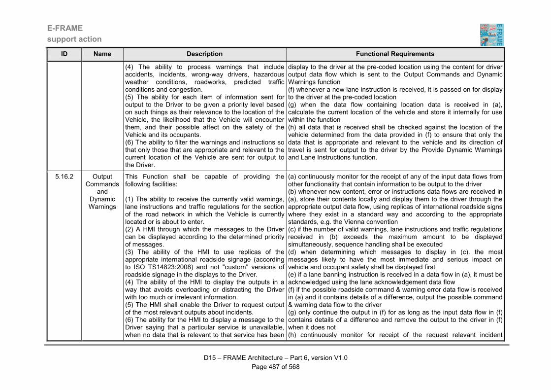
E-FRAME
support action
D15 – FRAME Architecture – Part 6, version V1.0
Page 487 of 568
ID Name Description Functional Requirements
(4) The ability to process warnings that include accidents, incidents, wrong-way drivers, hazardous weather conditions, roadworks, predicted traffic conditions and congestion. (5) The ability for each item of information sent for output to the Driver to be given a priority level based on such things as their relevance to the location of the Vehicle, the likelihood that the Vehicle will encounter them, and their possible affect on the safety of the Vehicle and its occupants. (6) The ability to filter the warnings and instructions so that only those that are appropriate and relevant to the current location of the Vehicle are sent for output to the Driver.
display to the driver at the pre-coded location using the content for driver output data flow which is sent to the Output Commands and Dynamic Warnings function (f) whenever a new lane instruction is received, it is passed on for display to the driver at the pre-coded location (g) when the data flow containing location data is received in (a), calculate the current location of the vehicle and store it internally for use within the function (h) all data that is received shall be checked against the location of the vehicle determined from the data provided in (f) to ensure that only the data that is appropriate and relevant to the vehicle and its direction of travel is sent for output to the driver by the Provide Dynamic Warnings and Lane Instructions function.
5.16.2 Output Commands
and Dynamic Warnings
This Function shall be capable of providing the following facilities: (1) The ability to receive the currently valid warnings, lane instructions and traffic regulations for the section of the road network in which the Vehicle is currently located or is about to enter. (2) A HMI through which the messages to the Driver can be displayed according to the determined priority of messages. (3) The ability of the HMI to use replicas of the appropriate international roadside signage (according to ISO TS14823:2008) and not "custom" versions of roadside signage in the displays to the Driver. (4) The ability of the HMI to display the outputs in a way that avoids overloading or distracting the Driver with too much or irrelevant information. (5) The HMI shall enable the Driver to request output of the most relevant outputs about incidents. (6) The ability for the HMI to display a message to the Driver saying that a particular service is unavailable, when no data that is relevant to that service has been
(a) continuously monitor for the receipt of any of the input data flows from other functionality that contain information to be output to the driver (b) whenever new content, error or instructions data flows are received in (a), store their contents locally and display them to the driver through the appropriate output data flow, using replicas of international roadside signs where they exist in a standard way and according to the appropriate standards, e.g. the Vienna convention (c) if the number of valid warnings, lane instructions and traffic regulations received in (b) exceeds the maximum amount to be displayed simultaneously, sequence handling shall be executed (d) when determining which messages to display in (c). the most messages likely to have the most immediate and serious impact on vehicle and occupant safety shall be displayed first (e) if a lane banning instruction is received in a data flow in (a), it must be acknowledged using the lane acknowledgement data flow (f) if the possible roadside command & warning error data flow is received in (a) and it contains details of a difference, output the possible command & warning data flow to the driver (g) only continue the output in (f) for as long as the input data flow in (f) contains details of a difference and remove the output to the driver in (f) when it does not (h) continuously monitor for receipt of the request relevant incident
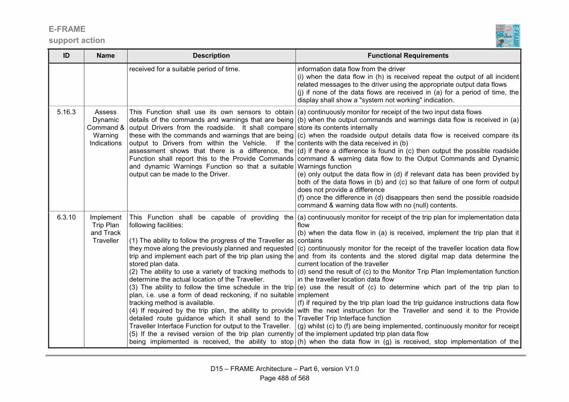
E-FRAME
support action
D15 – FRAME Architecture – Part 6, version V1.0
Page 488 of 568
ID Name Description Functional Requirements
received for a suitable period of time. information data flow from the driver (i) when the data flow in (h) is received repeat the output of all incident related messages to the driver using the appropriate output data flows (j) if none of the data flows are received in (a) for a period of time, the display shall show a "system not working" indication.
5.16.3 Assess Dynamic
Command & Warning Indications
This Function shall use its own sensors to obtain details of the commands and warnings that are being output Drivers from the roadside. It shall compare these with the commands and warnings that are being output to Drivers from within the Vehicle. If the assessment shows that there is a difference, the Function shall report this to the Provide Commands and dynamic Warnings Function so that a suitable output can be made to the Driver.
(a) continuously monitor for receipt of the two input data flows (b) when the output commands and warnings data flow is received in (a) store its contents internally (c) when the roadside output details data flow is received compare its contents with the data received in (b) (d) if there a difference is found in (c) then output the possible roadside command & warning data flow to the Output Commands and Dynamic Warnings function (e) only output the data flow in (d) if relevant data has been provided by both of the data flows in (b) and (c) so that failure of one form of output does not provide a difference (f) once the difference in (d) disappears then send the possible roadside command & warning data flow with no (null) contents.
6.3.10 Implement Trip Plan and Track Traveller
This Function shall be capable of providing the following facilities: (1) The ability to follow the progress of the Traveller as they move along the previously planned and requested trip and implement each part of the trip plan using the stored plan data. (2) The ability to use a variety of tracking methods to determine the actual location of the Traveller. (3) The ability to follow the time schedule in the trip plan, i.e. use a form of dead reckoning, if no suitable tracking method is available. (4) If required by the trip plan, the ability to provide detailed route guidance which it shall send to the Traveller Interface Function for output to the Traveller. (5) If the a revised version of the trip plan currently being implemented is received, the ability to stop
(a) continuously monitor for receipt of the trip plan for implementation data flow (b) when the data flow in (a) is received, implement the trip plan that it contains (c) continuously monitor for the receipt of the traveller location data flow and from its contents and the stored digital map data determine the current location of the traveller (d) send the result of (c) to the Monitor Trip Plan Implementation function in the traveller location data flow (e) use the result of (c) to determine which part of the trip plan to implement (f) if required by the trip plan load the trip guidance instructions data flow with the next instruction for the Traveller and send it to the Provide Traveller Trip Interface function (g) whilst (c) to (f) are being implemented, continuously monitor for receipt of the implement updated trip plan data flow (h) when the data flow in (g) is received, stop implementation of the
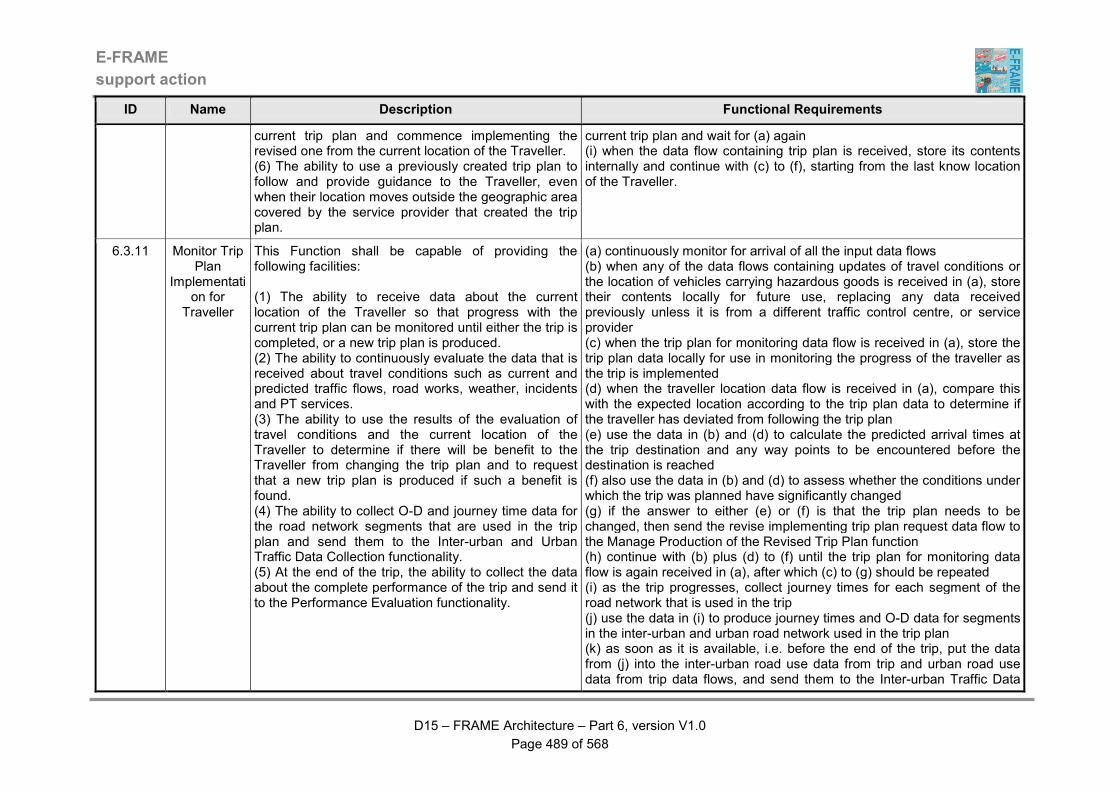
E-FRAME
support action
D15 – FRAME Architecture – Part 6, version V1.0
Page 489 of 568
ID Name Description Functional Requirements
current trip plan and commence implementing the revised one from the current location of the Traveller. (6) The ability to use a previously created trip plan to follow and provide guidance to the Traveller, even when their location moves outside the geographic area covered by the service provider that created the trip plan.
current trip plan and wait for (a) again (i) when the data flow containing trip plan is received, store its contents internally and continue with (c) to (f), starting from the last know location of the Traveller.
6.3.11 Monitor Trip Plan
Implementation for
Traveller
This Function shall be capable of providing the following facilities: (1) The ability to receive data about the current location of the Traveller so that progress with the current trip plan can be monitored until either the trip is completed, or a new trip plan is produced. (2) The ability to continuously evaluate the data that is received about travel conditions such as current and predicted traffic flows, road works, weather, incidents and PT services. (3) The ability to use the results of the evaluation of travel conditions and the current location of the Traveller to determine if there will be benefit to the Traveller from changing the trip plan and to request that a new trip plan is produced if such a benefit is found. (4) The ability to collect O-D and journey time data for the road network segments that are used in the trip plan and send them to the Inter-urban and Urban Traffic Data Collection functionality. (5) At the end of the trip, the ability to collect the data about the complete performance of the trip and send it to the Performance Evaluation functionality.
(a) continuously monitor for arrival of all the input data flows (b) when any of the data flows containing updates of travel conditions or the location of vehicles carrying hazardous goods is received in (a), store their contents locally for future use, replacing any data received previously unless it is from a different traffic control centre, or service provider (c) when the trip plan for monitoring data flow is received in (a), store the trip plan data locally for use in monitoring the progress of the traveller as the trip is implemented (d) when the traveller location data flow is received in (a), compare this with the expected location according to the trip plan data to determine if the traveller has deviated from following the trip plan (e) use the data in (b) and (d) to calculate the predicted arrival times at the trip destination and any way points to be encountered before the destination is reached (f) also use the data in (b) and (d) to assess whether the conditions under which the trip was planned have significantly changed (g) if the answer to either (e) or (f) is that the trip plan needs to be changed, then send the revise implementing trip plan request data flow to the Manage Production of the Revised Trip Plan function (h) continue with (b) plus (d) to (f) until the trip plan for monitoring data flow is again received in (a), after which (c) to (g) should be repeated (i) as the trip progresses, collect journey times for each segment of the road network that is used in the trip (j) use the data in (i) to produce journey times and O-D data for segments in the inter-urban and urban road network used in the trip plan (k) as soon as it is available, i.e. before the end of the trip, put the data from (j) into the inter-urban road use data from trip and urban road use data from trip data flows, and send them to the Inter-urban Traffic Data

E-FRAME
support action
D15 – FRAME Architecture – Part 6, version V1.0
Page 490 of 568
ID Name Description Functional Requirements
Management and Urban Traffic Data Management functions respectively (l) when the trip has been completed, collect data about its implementation, remove the Traveller identity and any other personal data and send it to the Evaluate Trip After Completion function in the trip completion report for evaluation data flow.
6.3.12 Manage Revised Trip
Plan Creation for Traveller
This Function shall be capable of providing the following facilities: (1) The ability to manage the production of revised trip plans whenever a change becomes necessary to the trip plan that is currently being implemented. (2) The ability to request changes to the trip plan either because it is not providing the best possible trip for the Traveller, or because the Traveller requests the change. (3) Once the request has been received, the ability to send it to the Trip Planning functionality for the creation of a new trip plan that starts from the last known location of the Traveller. (4) When the revised trip plan is received, the ability to use the Provide Traveller Trip Interface Function to establish that either the Traveller accepts the revised trip plan, or wishes to have further changes made. (5) Once the revised trip plan has been accepted, the ability to send it to the Manage Store of Trip Plan Data Function and to inform the Implement Trip Plan and Track Traveller Function that a revised trip plan is about to be provided.
(a) continuously monitor for receipt of the revise implementing trip plan request and trip plan changes request data flows (b) then the first data flow is received in (a), convert its contents into a request for a change to the trip plan and send it to the Trip Planning functionality in the trip plan update from traveller data flow (c) as a result of (b) continuously monitor for receipt of the revised trip plan data flow (d) when the data flow in (c) is received, send the details of the changes to the Provide Traveller Trip Interface function in the trip plan changes for traveller data flow (e) as a result of (d) continuously monitor for receipt of the trip plan changes response data flow (f) when the data flow in (e) is received, check its contents and if the changes have been accepted, send the trip plan update data flow to the Private Trip Plan management functionality and also send the implement updated trip plan data flow to the Implement Plan and Track Traveller function (g) if the response in (f) is a rejection, revise the trip plan requirements in accordance with the contents of the data flow and send them to the Trip Planning functionality in the trip plan update from traveller data flow (h) repeat (c) to (g) until acceptance (g) if the second data flow is received in (a) convert its contents into a request for a change to the trip plan and send it to the Trip Planning functionality in the trip plan update from traveller data flow (h) repeat (c) to (h) until acceptance.
6.3.13 Provide Traveller Trip
Interface
This Function shall be capable of providing the following facilities: (1) A HMI through which the Traveller can request the implementation of a trip plan, be given trip navigation
(a) continuously monitor for receipt of the trip plan implementation data flow (b) when the data flow in (a) is received, put the contents in the implement trip plan data flow and send it to the Manage Store of Trip Plan Data function
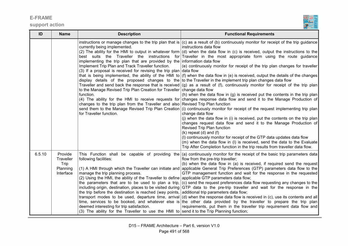
E-FRAME
support action
D15 – FRAME Architecture – Part 6, version V1.0
Page 491 of 568
ID Name Description Functional Requirements
instructions or manage changes to the trip plan that is currently being implemented. (2) The ability for the HMI to output in whatever form best suits the Traveller the instructions for implementing the trip plan that are provided by the Implement Trip Plan and Track Traveller function. (3) If a proposal is received for revising the trip plan that is being implemented, the ability of the HMI to display details of the proposed changes to the Traveller and send back the response that is received to the Manage Revised Trip Plan Creation for Traveller function. (4) The ability for the HMI to receive requests for changes to the trip plan from the Traveller and also send them to the Manage Revised Trip Plan Creation for Traveller function.
(c) as a result of (b) continuously monitor for receipt of the trip guidance instructions data flow (d) when the data flow in (c) is received, output the instructions to the Traveller in the most appropriate form using the route guidance information data flow (e) continuously monitor for receipt of the trip plan changes for traveller data flow (f) when the data flow in (e) is received, output the details of the changes to the Traveller in the implement trip plan changes data flow (g) as a result of (f), continuously monitor for receipt of the trip plan change data flow (h) when the data flow in (g) is received put the contents in the trip plan changes response data flow and send it to the Manage Production of Revised Trip Plan function (i) continuously monitor for receipt of the request implementing trip plan change data flow (j) when the data flow in (i) is received, put the contents on the trip plan changes request data flow and send it to the Manage Production of Revised Trip Plan function (k) repeat (d) and (f) (l) continuously monitor for receipt of the GTP data updates data flow (m) when the data flow in (l) is received, send the data to the Evaluate Trip After Completion function in the trip results from traveller data flow.
6.5.10 Provide Traveller Trip
Planning Interface
This Function shall be capable of providing the following facilities: (1) A HMI through which the Traveller can initiate and manage the trip planning process. (2) Using the HMI, the ability of the Traveller to define the parameters that are to be used to plan a trip, including origin, destination, places to be visited during the trip before the destination is reached (way points, transport modes to be used, departure time, arrival time, services to be booked, and whatever else is deemed interesting for trip satisfaction. (3) The ability for the Traveller to use the HMI to
(a) continuously monitor for the receipt of the basic trip parameters data flow from the pre-trip traveller; (b) when the data flow in (a) is received, if required send the request applicable General Trip Preferences (GTP) parameters data flow to the GTP management function and wait for the response in the requested applicable GTP parameters data flow; (c) send the request preferences data flow requesting any changes to the GTP data to the pre-trip traveller and wait for the response in the additional trip parameters data flow; (d) when the response data flow is received in (c), use its contents and all the other data provided by the traveller to prepare the trip plan requirements, put them in the traveller trip requirement data flow and send it to the Trip Planning function;
E-FRAME
support action
D15 – FRAME Architecture – Part 6, version V1.0
Page 492 of 568
ID Name Description Functional Requirements
request that these parameters are entered into the store of General Trip Preferences Data or to use data in this store to supplement that being provided for a particular trip. (4) When complete, the ability to send the requirements to the Trip Planning functionality so that the trip plan can be prepared. (5) The ability to use the HMI to present the prepared trip plan to the Traveller and for the Traveller to be able to refine any of the requirements and re-plan the trip until it fulfils their needs in an iterative way. (6) The ability to store successive trip plans internally so that they can be re-called by the Traveller if later versions turn out to be unsatisfactory. (7) Once a trip plan has been accepted by the Traveller, the Function shall send the details to the Function responsible for producing the travel itinerary or to the Function responsible for making any bookings that are included in the trip plan and/or paying for the trip planning process. (8) The ability for the Traveller to use the HMI to reject a trip plan and close the trip planning activity at any time and to delete any requirements that have been provided. (9) The ability for the Traveller to be informed through the HMI about any payments that are needed, either for the trip planning process itself, or for services that the Traveller has specified for inclusion in the trip. (10) It shall be possible for the Traveller to be asked to pay for the trip planning process either before it starts, or once a successful trip plan has been produced. (11) The ability of the Traveller to use the HMI to initiate payment for the trip planning service and/or any services that are required as part of the trip, and to be informed of the success or failure of the payment process.
(e) as a result of (d) wait for the receipt of the traveller trip description data flow from the Trip Planning function and when it is received, store the trip plan description internally for later use; (f) output the trip plan description received in (e) to the pre-trip traveller in the initial trip plan data flow; (g) as a result of (f) wait for a response from the pre-trip traveller in the modified trip parameters data flow; (h) use the data provided by the data flow in (g) to modify the original trip parameters, put them in the modified trip plan requirements data flow and send it to the Trip Planning function; (i) as a result of (h) await receipt of the traveller trip description data flow from the Trip Planning function and when it is received store the trip plan description internally for later use; (j) output the alternative trip plan description received in (i) to the pre-trip traveller in the trip alternatives data flow and wait for a response from the pre-trip traveller in the modified trip parameters data flow; (k) continue repeating (e) through (i) until no modified parameters are provided by the pre-trip traveller in the modified trip parameters data flow, but giving each revised trip plan description a new identity so that it can be retrieved instead of the other trip plan descriptions; (l) output the select trip data flow to the pre-trip traveller and await a response through the input of the trip selection data flow; (m) use the input in (l) to select the required trip plan description from the internal store and check to see if any bookings need to be made and paid for, or the trip plan service needs to be paid for; (n) if the answer in (m) is YES, send the selected trip plan description to the Make Trip Bookings and Payments function in the full trip description for bookings data flow; (o) as a result of (n) continuously monitor for receipt of either the request trip planning payment or advanced payment needed data flows from the Make Trip Planning Payment and Bookings function; (p) then the data flow in (o) is received, send either the request trip planning payment or advanced payment needed by trip plan data flows to the pre-trip traveller and await receipt of either the trip planning payment or booking approval data flows from the pre-trip traveller; (q) the either of the data flows in (p) is received, send either the trip
E-FRAME
support action
D15 – FRAME Architecture – Part 6, version V1.0
Page 493 of 568
ID Name Description Functional Requirements
(12) If the payment process fails, the ability to cancel the trip(s) that have been planned and to inform the Traveller of this through the HMI.
planning payment or the booking approval data flows to the Make Trip Booking and Payment function; (r) as a result of (q) continuously monitor for receipt of the full trip description with bookings, or booking mishap data flow from the Make Trip Booking and Payment function; (s) when the first data flow in (r) is received, inform the pre-trip traveller through the select trip data flow and send the selected trip plan description to the Manage Store of Trip Plan Data function in the plan ready for implementation data flow; (t) if the answer in (m) is NO, send the selected trip description to the Manage Store of Trip Plan Data function in the plan ready for implementation data flow.
6.5.3.10 Obtain Data for Traveller Information
This Function shall be capable of providing the following facilities: (1) The ability to obtain data for use in the provision of information to Travellers that will be provided by the Traveller Information functionality. (2) The ability to periodically pass to Traveller Information functionality the data that it has obtained from the store of Road Trip Planning Data and the store of PT Trip Planning Data, plus data about Points of Interest (POI) and Personal Services (PS) that it has been provided to it by the Plan Traveller Trip Function.
(a) continually obtain data about the current state of the road network from the store of Road Trip Planning Data (b) continually obtain data about Public Transport services from the store of PT Trip Planning Data (c) process the data received in (a) and (b) to produce the contents of the road and PT information data flows which should be output periodically.
6.5.3.11 Provide Green Wave
Routes
This Function shall be capable of providing the following facilities: (1) The ability to produce routes for Emergency Service and Other Vehicles as a result of specific requests. (2) For Emergency Vehicles, the ability to produce routes that enable them to reach the scene of an incident in the shortest possible time. (3) The purposes of the routes for Other Vehicles will be varied but must enable them to get from their
(a) the Function shall that uses the most appropriate part of the road network for the Emergency Vehicle, including but not limited to motorway networks, the secondary road network and so forth (b) the Function shall include information about the existing conditions on the route(s) presented (c) (d) the Function shall be able to assist Emergency Vehicles to achieve the shortest journey time to their destination (e) the Function shall provide safety recommendations.
E-FRAME
support action
D15 – FRAME Architecture – Part 6, version V1.0
Page 494 of 568
ID Name Description Functional Requirements
current location to the specified destination in the shortest possible time. (4) Routes for both types of Vehicles shall take account of the current and predicted traffic conditions and the times of the relevant green phases at all the signalised road junctions along the route. (5) Data about the routes shall include the identities of all the junctions and include the required average speed for each segment. (6) In some cases, the route may only contain one signalised road junction, in which case the objective of the route shall be achieved using local priority at the junction.
6.5.3.12 Provide Trip Planning Operator Interface
This Function shall be capable of providing the following facilities: (1) A HMI through which the Travel Information Operator can set up, view and modify criteria used to prepare and/or modify trip plans requested by Travellers. (2) It shall be possible for these criteria to ensure that all trip plans conform to travel and traffic management policies (if any) for the road network and the appropriate use of the available transport modes.
(a) continuously monitor for receipt of the input data flows from the travel information operator (b) when the update trip planning criteria data flow is received in (a) send the data to the Plan Traveller Trip Details function using the update trip planning criteria data flow (c) if the request trip planning criteria data flow is received in (a), send it to the Plan Traveller Trip Details function in the request trip planning criteria data flow (d) as a result of (c) monitor for the receipt of the requested trip planning criteria data flow (e) when the data flow in (d) arrives, output its contents to the travel information operator in the output trip planning criteria data flow.
6.5.3.13 Provide Data & Routes to
Fleet Operators & Drivers
This Function shall be capable of providing the following facilities: (1) The ability to provide data and routes to functionality serving Fleet Operators and Drivers at their request and contribute information about freight and hazardous goods that may be relevant to general trip planning. (2) On request from Fleet Operators and Drivers the ability to provide data that shall comprise specific
(a) continuously monitor for receipt of the freight and hazardous goods information plus on-board information and requests data flows (b) when either of the data flows in (a) is received, send their contents to the store of Road Trip Planning Data in the data flow containing store ffm and hazardous goods data (c) continuously monitor for receipt of any of the "request....situation" data flows (d) when any of the data flows in (c) is received, obtain the required data from the store of Road Trip Planning Data using the data flows called store ffm and hazardous goods data and retrieve road situation data
E-FRAME
support action
D15 – FRAME Architecture – Part 6, version V1.0
Page 495 of 568
ID Name Description Functional Requirements
items such as pollution, traffic and weather conditions, for which the Function shall obtain the current values from the store of Road Trip Planning Data. (3) When data is received from the Manage Freight and Fleet Operations functionality, the ability to store it in the store of Road Trip Planning Data. (4) On request from functionality connected to the Freight Operator and Hazardous Goods Vehicle Driver the Functions the ability to prepare routes using the parameters provided in the request and data from the store of Road Trip Planning Data.
(e) when the data in (d) has been retrieved, send it back to the Manage Freight and Fleet Operations (mffo) functionality that requested it using the "answer....situation" data flow that corresponds to the request (f) continuously monitor for receipt of the route optimisation request data flow from the Manage Freight and Fleet Operations (mffo) functionality and the hazardous goods vehicle route request data flow from the Provide Support for Cooperative Systems (pscs) functionality (g) when either of the data flows in (f) is received, prepare a route according to the parameters contains in the request and data that is retrieved from the store of Road Trip Planning Data using the data flows called store ffm and hazardous goods data and retrieve ffm route planning data (h) when the route has been prepared in (g) send it back to the Manage Freight and Fleet Operations (mffo) functionality and the Provide Support for Cooperative Systems (pscs) functionality in the route and hazardous goods vehicle route response data flows respectively.
6.5.3.3 Collect PT Data
This Function shall be capable of providing the following facilities: (1) The ability to collect Public Transport travel data for use in the preparation of trip plans for Travellers. (2) The ability to collect the data as it arrives from functionality in the Manage Public Transport Operations Functional Area. (3) The ability to load the data that has been collected into the store of PT Trip Planning Data and to manage all of the data in that store.
(a) the Function shall collect data as it arrives from functionality in the Manage Public Transport Operations Functional Area (b) the Function shall load the data into the store of PT Trip Planning Data as soon as it is received
6.5.3.7 Enable Operator Access to
Tip Planning Data
This Function shall be capable of providing the following facilities: (1) A HMI that enables the Travel Information Operator to have access to the contents of the stores of Road Trip Planning Data and PT Trip Planning Data. (2) The ability for the Operator to review and update the data in the stores including the provision of static
(a) when the trigger input data flow is received, check its contents (b) if it contains new data for either of the stores of Road Trip Planning Data or PT Trip Planning Data, then update the appropriate store (c) if the command in (a) contains a request for a report on the data that is in either of the stores in (b), then retrieve the data from the appropriate store (d) format the data from (c) into the required report format and content (e) when (d) is complete, output the data to the Travel Information
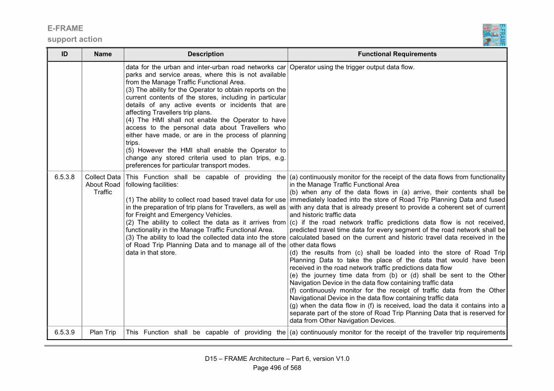
E-FRAME
support action
D15 – FRAME Architecture – Part 6, version V1.0
Page 496 of 568
ID Name Description Functional Requirements
data for the urban and inter-urban road networks car parks and service areas, where this is not available from the Manage Traffic Functional Area. (3) The ability for the Operator to obtain reports on the current contents of the stores, including in particular details of any active events or incidents that are affecting Travellers trip plans. (4) The HMI shall not enable the Operator to have access to the personal data about Travellers who either have made, or are in the process of planning trips. (5) However the HMI shall enable the Operator to change any stored criteria used to plan trips, e.g. preferences for particular transport modes.
Operator using the trigger output data flow.
6.5.3.8 Collect Data About Road
Traffic
This Function shall be capable of providing the following facilities: (1) The ability to collect road based travel data for use in the preparation of trip plans for Travellers, as well as for Freight and Emergency Vehicles. (2) The ability to collect the data as it arrives from functionality in the Manage Traffic Functional Area. (3) The ability to load the collected data into the store of Road Trip Planning Data and to manage all of the data in that store.
(a) continuously monitor for the receipt of the data flows from functionality in the Manage Traffic Functional Area (b) when any of the data flows in (a) arrive, their contents shall be immediately loaded into the store of Road Trip Planning Data and fused with any data that is already present to provide a coherent set of current and historic traffic data (c) if the road network traffic predictions data flow is not received, predicted travel time data for every segment of the road network shall be calculated based on the current and historic travel data received in the other data flows (d) the results from (c) shall be loaded into the store of Road Trip Planning Data to take the place of the data that would have been received in the road network traffic predictions data flow (e) the journey time data from (b) or (d) shall be sent to the Other Navigation Device in the data flow containing traffic data (f) continuously monitor for the receipt of traffic data from the Other Navigational Device in the data flow containing traffic data (g) when the data flow in (f) is received, load the data it contains into a separate part of the store of Road Trip Planning Data that is reserved for data from Other Navigation Devices.
6.5.3.9 Plan Trip This Function shall be capable of providing the (a) continuously monitor for the receipt of the traveller trip requirements
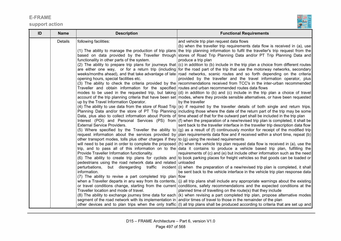
E-FRAME
support action
D15 – FRAME Architecture – Part 6, version V1.0
Page 497 of 568
ID Name Description Functional Requirements
Details following facilities: (1) The ability to manage the production of trip plans based on data provided by the Traveller through functionality in other parts of the system. (2) The ability to prepare trip plans for journeys that are either one way, or for a return trip (including weeks/months ahead), and that take advantage of late opening hours, special facilities etc. (3) The ability to check the criteria provided by the Traveller and obtain information for the specified modes to be used in the requested trip, but taking account of the trip planning criteria that have been set up by the Travel Information Operator. (4) The ability to use data from the store of Road Trip Planning Data and/or the store of PT Trip Planning Data, plus also to collect information about Points of Interest (POI) and Personal Services (PS) from External Service Providers. (5) Where specified by the Traveller the ability to request information about the services provided by other transport modes, tolls plus other charges if they will need to be paid in order to complete the proposed trip, and to pass all of this information on to the Provide Traveller Information functionality. (6) The ability to create trip plans for cyclists and pedestrians using the road network data and related perturbations, but disregarding traffic incident information. (7) The ability to revise a part completed trip plan when a Traveller departs in any way from its contents, or travel conditions change, starting from the current Traveller location and mode of travel. (8) The ability to exchange journey time data for each segment of the road network with its implementation in other devices and to plan trips when the only traffic
and vehicle trip plan request data flows (b) when the traveller trip requirements data flow is received in (a), use the trip planning information to fulfil the traveller's trip request from the stores of Road Trip Planning Data and/or PT Trip Planning Data and produce a trip plan (c) in addition to (b) include in the trip plan a choice from different routes for the road part of the trip that use the motorway networks, secondary road networks, scenic routes and so forth depending on the criteria provided by the traveller and the travel information operator, plus recommendations received from TCC's in the inter-urban recommended routes and urban recommended routes data flows (d) in addition to (b) and (c) include in the trip plan a choice of travel modes, where they provide sensible alternatives, or have been requested by the traveller (e) if required by the traveller details of both single and return trips, including those where the date of the return part of the trip may be some time ahead of that for the outward part shall be included in the trip plan (f) when the preparation of a new/revised trip plan is completed, it shall be sent back to the traveller interface in the traveller trip description data flow (g) as a result of (f) continuously monitor for receipt of the modified trip plan requirements data flow and if received within a short time, repeat (b) to (g) using the revised requirements (h) when the vehicle trip plan request data flow is received in (a), use the data it contains to produce a vehicle based trip plan, fulfilling the requirements of (c) and (e) but include other information such as the need to book parking places for freight vehicles so that goods can be loaded or unloaded (i) when the preparation of a new/revised trip plan is completed, it shall be sent back to the vehicle interface in the vehicle trip plan response data flow (j) all trip plans shall include any appropriate warnings about the existing conditions, safety recommendations and the expected conditions at the planned time of travelling on the route(s) that they include (k) when revising a part completed trip plan, propose alternative modes and/or times of travel to those in the remainder of the plan (l) all trip plans shall be produced according to criteria that are set up and
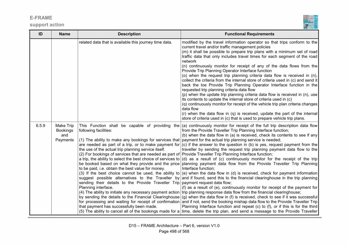
E-FRAME
support action
D15 – FRAME Architecture – Part 6, version V1.0
Page 498 of 568
ID Name Description Functional Requirements
related data that is available this journey time data. modified by the travel information operator so that trips conform to the current travel and/or traffic management policies (m) it shall be possible to prepare trip plans with a minimum set of road traffic data that only includes travel times for each segment of the road network (n) continuously monitor for receipt of any of the data flows from the Provide Trip Planning Operator Interface function (o) when the request trip planning criteria data flow is received in (n), collect the criteria from the internal store of criteria used in (c) and send it back the toe Provide Trip Planning Operator Interface function in the requested trip planning criteria data flow (p) when the update trip planning criteria data flow is received in (n), use its contents to update the internal store of criteria used in (c) (q) continuously monitor for receipt of the vehicle trip plan criteria changes data flow (r) when the data flow in (q) is received, update the part of the internal store of criteria used in (c) that is used to prepare vehicle trip plans.
6.5.9 Make Trip Bookings
and Payments
This Function shall be capable of providing the following facilities: (1) The ability to make any bookings for services that are needed as part of a trip, or to make payment for the use of the actual trip planning service itself. (2) For bookings of services that are needed as part of a trip, the ability to select the best choice of services to be booked based on what they provide and the price to be paid, i.e. obtain the best value for money. (3) If the best choice cannot be used, the ability to suggest possible alternatives to the Traveller by sending their details to the Provide Traveller Trip Planning interface. (4) The ability to initiate any necessary payment action by sending the details to the Financial Clearinghouse for processing and waiting for receipt of confirmation that payment has successfully been made. (5) The ability to cancel all of the bookings made for a
(a) continuously monitor for receipt of the full trip description data flow from the Provide Traveller Trip Planning Interface function; (b) when the data flow in (a) is received, check its contents to see if any payment for the actual trip planning service is needed; (c) if the answer to the question in (b) is yes, request payment from the traveller by sending the request trip planning payment data flow to the Provide Traveller Trip Planning Interface function; (d) as a result of (c) continuously monitor for the receipt of the trip planning payment data flow from the Provide Traveller Trip Planning Interface function; (e) when the data flow in (d) is received, check for payment information and if found, send this to the financial clearinghouse in the trip planning payment request data flow; (f) as a result of (e), continuously monitor for receipt of the payment for trip planning response data flow from the financial clearinghouse; (g) when the data flow in (f) is received, check to see if it was successful and if not, send the booking mishap data flow to the Provide Traveller Trip Planning Interface function and repeat (c) to (f), or if this is for the third time, delete the trip plan, and send a message to the Provide Traveller

E-FRAME
support action
D15 – FRAME Architecture – Part 6, version V1.0
Page 499 of 568
ID Name Description Functional Requirements
previous trip and send a confirmation message to the Provide Traveller Trip Planning interface when a "cancel bookings" request is received.
Trip Planning Interface function that the trip plan has been deleted in the request trip planning payment data flow; (h) if in (e) a negative response is received, delete the trip plan, and send a message to the Provide Traveller Trip Planning Interface function that the trip plan has been deleted in the request trip planning payment data flow; (i) if in (b) no trip planning payment is needed, then send details of the advanced payment(s) that are needed for the trip plan to the Provide Traveller Trip Planning Interface function in the advanced payment needed for trip plan data flow; (j) as a result of (i) continuously monitor for receipt of the booking approval data flow from the Provide Traveller Trip Planning Interface function; (k) when the data flow in (j) is received, check for payment information and if found, send this to the financial clearinghouse in the trip planning service payment request data flow (l) as a result of (k), continuously monitor for receipt of the trip planning service payment response data flow from the financial clearinghouse (m) when the data flow in (f) is received, check to see if it was successful and if not, send the booking mishap data flow to the Provide Traveller Trip Planning Interface function; (n) as a result of (m), continuously monitor for receipt of the revised booking choices data flow and repeat (i) to (l); (o) if in (k) a negative response is received, delete the trip plan, and send a message to the Provide Traveller Trip Planning Interface function that the trip plan has been deleted in the request trip planning payment data flow; (p) if the cancel bookings for trip data flow is received, repeat (m) and (n) and send a cancel booking instruction to the financial clearinghouse in the request payment for trip planning data flow.
6.6.1 Provide Traveller Information Interface
This Function shall be capable of providing the following facilities: (1) A HMI through which the Traveller may obtain information about travel conditions. (2) The ability to provide information for all current
(a) continuously monitor for the receipt of the input data flows (b) use the map data for travel information and location for information data flows received in (a) to provided digital map data on which to base information requested by the traveller and the current location of the traveller (c) when in (a) the traveller information request data flow is received,

E-FRAME
support action
D15 – FRAME Architecture – Part 6, version V1.0
Page 500 of 568
ID Name Description Functional Requirements
modes of travel in the area served by the System, including those not managed by the System, e.g. heavy rail, air and maritime. (3) The HMI shall enable the Traveller to request output of information and if desired may select criteria for its output. (4) The HMI shall no enable information to be output without a request from the Traveller. (5) The ability to obtain the relevant information from the store of Travel Information Data, or if not in the store then through a request from the Produce Travel Information Function. (6) If the current location is known then the ability to filter the information from the store of Travel Information Data to that which is location specific before output, although the filtering criteria shall be configurable by the Traveller. (7) The HMI shall enable the Traveller to configure the output so that it can be provided against a map background, or in different languages. (8) The HMI shall generate the output in a form that is easy to understand and be suitable for those with disabilities.
request the information from the store of Travel Information Data using the request travel information data flow (d) collect the requested information from the read travel information data flow when it is received and process it ready for output to the traveller (e) when all the information is present in (d) send the requested information to the traveller using the requested travel information data flow.
6.6.2 Produce Travel
Information
This Function shall be capable of providing the following facilities: (1) The ability to produce travel information using inputs it receives from other Functional Areas. (2) The ability to modify the inputs according to filters set by the Travel Information Operator to reflect policy and other factors, so that for example information about certain types of services, travel modes, Personal Services, or Points of Interest are not included in what is sent for output to the Traveller. (3) When the information is ready, the ability to respond to an Operator request that it is sent to a
(a) continuously monitor for the receipt of the input data flows that contain information that might be requested by the traveller (b) when any of the data flows in (a) is received, process its contents applying the filters (if any) that have been defined by the travel information operator (c) when (b) is complete, send the information to the Manage Travel Information Data Store function using the updated travel information data flow (d) if the request travel information filters data flow is received, respond to the Provide Travel Information Operator Interface function with the a copy of the current filters using the requested travel information filters data flow (e) if the updated travel information filters data flow is received, store the new filters internally for use in the generation of future travel information.
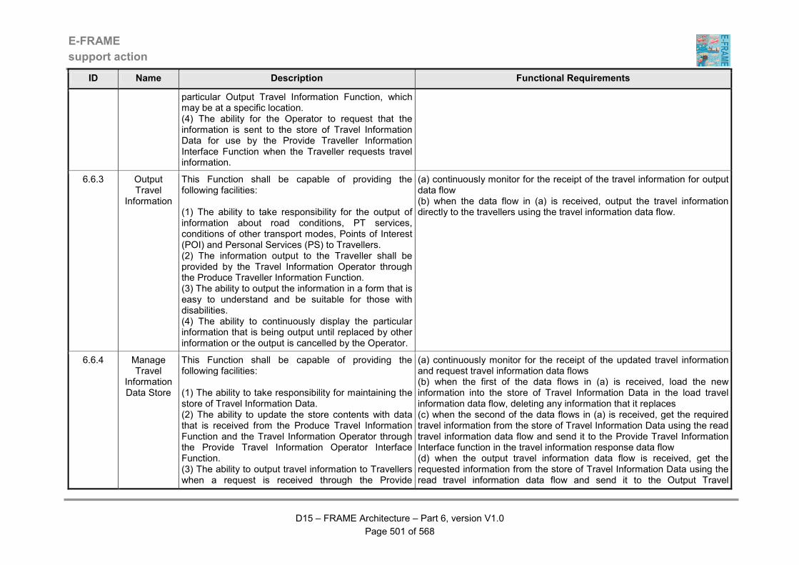
E-FRAME
support action
D15 – FRAME Architecture – Part 6, version V1.0
Page 501 of 568
ID Name Description Functional Requirements
particular Output Travel Information Function, which may be at a specific location. (4) The ability for the Operator to request that the information is sent to the store of Travel Information Data for use by the Provide Traveller Information Interface Function when the Traveller requests travel information.
6.6.3 Output Travel
Information
This Function shall be capable of providing the following facilities: (1) The ability to take responsibility for the output of information about road conditions, PT services, conditions of other transport modes, Points of Interest (POI) and Personal Services (PS) to Travellers. (2) The information output to the Traveller shall be provided by the Travel Information Operator through the Produce Traveller Information Function. (3) The ability to output the information in a form that is easy to understand and be suitable for those with disabilities. (4) The ability to continuously display the particular information that is being output until replaced by other information or the output is cancelled by the Operator.
(a) continuously monitor for the receipt of the travel information for output data flow (b) when the data flow in (a) is received, output the travel information directly to the travellers using the travel information data flow.
6.6.4 Manage Travel
Information Data Store
This Function shall be capable of providing the following facilities: (1) The ability to take responsibility for maintaining the store of Travel Information Data. (2) The ability to update the store contents with data that is received from the Produce Travel Information Function and the Travel Information Operator through the Provide Travel Information Operator Interface Function. (3) The ability to output travel information to Travellers when a request is received through the Provide
(a) continuously monitor for the receipt of the updated travel information and request travel information data flows (b) when the first of the data flows in (a) is received, load the new information into the store of Travel Information Data in the load travel information data flow, deleting any information that it replaces (c) when the second of the data flows in (a) is received, get the required travel information from the store of Travel Information Data using the read travel information data flow and send it to the Provide Travel Information Interface function in the travel information response data flow (d) when the output travel information data flow is received, get the requested information from the store of Travel Information Data using the read travel information data flow and send it to the Output Travel

E-FRAME
support action
D15 – FRAME Architecture – Part 6, version V1.0
Page 502 of 568
ID Name Description Functional Requirements
Traveller Information Interface Function. (4) The ability to output travel information to the Output Travel Information Function at the request of the Travel Information Operator. (5) The ability to provide data from the store to the Provide Travel Information Operator Interface Function as a result of a request from the Travel Information Operator.
Information function in the travel information for output data flow (e) when the request current travel information data flow is received, get all of the current information from the store of Travel Information Data using the read travel information data flow and send it to the Provide Travel Information Operator Interface function in the requested current travel information data flow.
6.6.5 Provide Travel
Information Operator Interface
This Function shall be capable of providing the following facilities: (1) A HMI through which the Travel Information Operator can monitor the provision of information to Travellers. (2) The HMI shall enable the Operator to update the information, amend the criteria used to filter the information that is to be provided, to obtain a copy of the current information and to direct that some of the information be directly output to Travellers.
(a) continuously monitor for the receipt of any of the input data flows from the operator (b) when any of the data flows in (a) is received, determine its contents and send the appropriate data flow to either the Produce Travel Information or Manage Travel Information Data Store functions (c) if either of the two data flows is received from the Produce Travel Information or Manage Travel Information Data Store functions, output the data they contain to the operator using the appropriate output data flow.
6.7.1 Define Traveller's General Trip Preferences
This Function shall be capable of providing the following facilities: (1) The ability for the Traveller to specify a set of factual data to be used as General Trip Preferences (GTP) for use each time they want to plan a trip. (2) There shall be no requirement for the Traveller to do this more than once and the data shall be used as a preparation to full personalisation. (3) Once a planned trip has been completed, the ability to ask the Traveller for any comments on the performance of the trip and any changes that are needed to the GTP data. (4) The ability to enable the Traveller to receive an output of their current GTP data and to amend that data, even if this is not the result of the performance of
(a) continuously monitor for the receipt of the input data flows (b) if the data flow received in (a) is from a traveller and contains GTP data send it to the Manage General Trip Preferences Storage function in the data flow containing GTP data, making sure that each time the data flow is sent, the Traveller identity is included (c) if the data flow received in (a) contains a request from the Traveller for their GTP data, use the data flow containing GTP data to request that the data is provided (d) when following (c) the data flow containing requested GTP data is received, provide output of the assembled GTP data to the Traveller (e) if the data flow received in (a) contains a request for the traveller to provide their post trip preferences, send the post trip preferences request data flow to the traveller (f) as a result of (e) monitor for the receipt of the post trip preferences data flow from the traveller (g) when the data flow in (f) is received, send its contents to the Evaluate

E-FRAME
support action
D15 – FRAME Architecture – Part 6, version V1.0
Page 503 of 568
ID Name Description Functional Requirements
a planned trip. Trip After Completion function in the post trip preferences data flow (h) as a result of (g) send any changes to the traveller's GTP data to the Manage General Trip Preferences Storage function in the GTP update data flow, not forgetting to include the traveller's identity (i) if no input from the traveller is received in (f) send a null response to the Evaluate Trip After Completion function in the post trip preferences data flow.
6.7.2 Evaluate Trip After Completion
This Function shall be capable of providing the following facilities: (1) The ability to evaluate the success of the trip planning and implementation. (2) The evaluation shall be based on data provided by the Support Trip functionality and optional input from the Traveller collected after the trip has been completed. (3) The ability to collect any required input as comments on the trip and on the support given using the Define Traveller's General Trip Preferences functionality. (4) The ability to send the results of the analysis of the trip performance for output to the Travel Information Operator through the Enable Operator Access to General Trip Preferences functionality.
(a) when the trip completion report for evaluation data flow is received, send the request post trip preferences data flow to the Define Traveller's General Trip Preferences function (b) if and when the post trip preferences data flow is received, analyse its contents for inclusion in the trip evaluation (c) the evaluation of the trip performance shall be carried out using the input from (a) and (b) (d) if necessary the evaluation in (c) shall be carried out without any input from the traveller in (b) (e) the results of (d) shall show how well the trip was performed, looking at parameters such as the journey time performance, relevance and timeliness of information provided to the Traveller during the trip, and the success with which connections between different modes of transport were made (f) the output from (e) shall be sent to the Enable Operator Access to General Trip Preferences in the trip evaluation report for output data flow.
6.7.3 Enable Operator Access to
Trip Information
This Function shall be capable of providing the following facilities: (1) A HMI that enables the Travel Information Operator to have access to the contents of the General Trip Preferences (GTP) Data Store. (2) The HMI shall enable the Travel Information Operator to output reports on the performance of planned trips. (3) The reports shall be produced using data that has been received from other functionality.
(a) when GTP request data flow is received from the Travel Information Operator, check its contents (b) if the command in (a) contains a request for a report on the data that is in the store of General Trip Preferences (GTP) Data, then request the data from the store using the data flow request copy of GTP data (c) when the data flow requested copy of GTP data is received in response to (b) format the data resulting from (b) into the required report format and content (d) when (c) is complete, output the data to the Travel Information Operator using the GTP responses data flow (e) when the trip evaluation report for output data flow is received, format
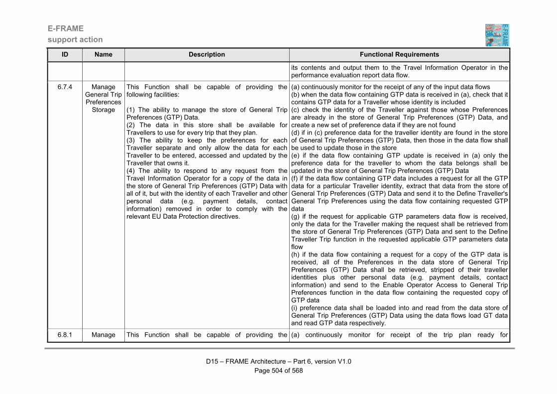
E-FRAME
support action
D15 – FRAME Architecture – Part 6, version V1.0
Page 504 of 568
ID Name Description Functional Requirements
its contents and output them to the Travel Information Operator in the performance evaluation report data flow.
6.7.4 Manage General Trip Preferences Storage
This Function shall be capable of providing the following facilities: (1) The ability to manage the store of General Trip Preferences (GTP) Data. (2) The data in this store shall be available for Travellers to use for every trip that they plan. (3) The ability to keep the preferences for each Traveller separate and only allow the data for each Traveller to be entered, accessed and updated by the Traveller that owns it. (4) The ability to respond to any request from the Travel Information Operator for a copy of the data in the store of General Trip Preferences (GTP) Data with all of it, but with the identity of each Traveller and other personal data (e.g. payment details, contact information) removed in order to comply with the relevant EU Data Protection directives.
(a) continuously monitor for the receipt of any of the input data flows (b) when the data flow containing GTP data is received in (a), check that it contains GTP data for a Traveller whose identity is included (c) check the identity of the Traveller against those whose Preferences are already in the store of General Trip Preferences (GTP) Data, and create a new set of preference data if they are not found (d) if in (c) preference data for the traveller identity are found in the store of General Trip Preferences (GTP) Data, then those in the data flow shall be used to update those in the store (e) if the data flow containing GTP update is received in (a) only the preference data for the traveller to whom the data belongs shall be updated in the store of General Trip Preferences (GTP) Data (f) if the data flow containing GTP data includes a request for all the GTP data for a particular Traveller identity, extract that data from the store of General Trip Preferences (GTP) Data and send it to the Define Traveller's General Trip Preferences using the data flow containing requested GTP data (g) if the request for applicable GTP parameters data flow is received, only the data for the Traveller making the request shall be retrieved from the store of General Trip Preferences (GTP) Data and sent to the Define Traveller Trip function in the requested applicable GTP parameters data flow (h) if the data flow containing a request for a copy of the GTP data is received, all of the Preferences in the data store of General Trip Preferences (GTP) Data shall be retrieved, stripped of their traveller identities plus other personal data (e.g. payment details, contact information) and send to the Enable Operator Access to General Trip Preferences function in the data flow containing the requested copy of GTP data (i) preference data shall be loaded into and read from the data store of General Trip Preferences (GTP) Data using the data flows load GT data and read GTP data respectively.
6.8.1 Manage This Function shall be capable of providing the (a) continuously monitor for receipt of the trip plan ready for

E-FRAME
support action
D15 – FRAME Architecture – Part 6, version V1.0
Page 505 of 568
ID Name Description Functional Requirements
Store of Trip Plan Data
following facilities: (1) The ability to manage the store of Private Trip Plan Data. (2) The store shall contain descriptions of all of the trip plans produced by each Traveller. (3) The ability to update the store contents whenever a Traveller prepares and finally accepts a new trip plan. (4) The ability to retrieve a prepared trip plan whenever the Traveller decides to implement a trip. (5) When a trip plan is retrieved for implementation, its description shall be sent to the Implement Trip Plan and Track Traveller Function and to the Monitor Trip Plan Implementation for Traveller Function.
implementation, implement trip plan, trip plan update from traveller and trip plan data request data flows (b) when the implement trip plan data flow is received in (a), use the data flows load trip plan data and read trip plan data to obtain the description of the requested trip plan from the store of Private Trip Plan Data (c) at the completion of (b), put the complete trip plan description in the trip plan for Implementation and trip plan for monitoring data flows and send them to the Implement Trip Plan and Track Traveller and Monitor Trip Plan Implementation functions respectively (d) when the trip plan ready for implementation data flow is received in (a), load the trip plan it contains into the store of Private Trip Plan Data using the data flow load trip plan data (e) when the trip plan update from traveller data flow is received in (a), again load the trip plan it contains into the store of Private Trip Plan Data using the data flow load trip plan data (f) when the trip plan data request data flow is received in (a), use the data flows load trip plan data and read trip plan data to obtain the description of the requested trip plan from the store of Private Trip Plan Data.
6.8.2 Provide Trip Plan
Management Operator Interface
This Function shall be capable of providing the following facilities: (1) A HMI for the Travel Information Operator. (2) The HMI shall enable the Operator to collect data from the store of Private Trip Plan Data about the content of the trip plans that are being produced. (3) The HMI shall have the ability to format and present the collected data to the Operator as a management report, with the identities and other personal details about the Travellers removed.
(a) continuously monitor for receipt of the trip plan management report request data flow from the travel information operator (b) when the data flow in (a) is received, put the request into the trip plan data request data flow and send it to the Manage Store of Trip Plan Data function (c) as a result of (b) continuously monitor for receipt of the trip plan data output data flow (d) when the data flow in (c) is received, produce a report about the requested trip plans, making sure that the identities of the travellers who created and use the trip plans are not included (e) output the result of (d) tot he travel information operator in the trip plan management report data flow.
7.1.2 Check Compliance
This Function shall be capable of providing the following facilities: (1) The ability to check the compliance of the recorded
(a) when the first trigger input data flow is received, analyse the measure to detect obvious frauds, using the guidelines received in the third and fourth other input data flows (b) if the vehicle ID is available, extract from the store of User Registration

E-FRAME
support action
D15 – FRAME Architecture – Part 6, version V1.0
Page 506 of 568
ID Name Description Functional Requirements
images with the established rules both in real-time and/or off-line. (2) For Vehicles that can be identified, the ability to extract from the store of User's Registration Data the information needed to check that the user is allowed to behave as in the recorded image. (3) For Vehicles that cannot be identified, the ability to request it from the Identify Violator Function, sending it an image of the violator extracted from the response. (4) The ability to use information sent by functionality in the Manage Freight and Fleet Operations Area. (5) The ability to apply the rules more or less strictly according to guidelines sent by functionality in the Manage Traffic Function Area. (6) Upon detection of a fraud, the ability to send the associated elements to the Process Fraud Notifications Function.
Data the clearance of the vehicle using the fifth other input data flow (c) when the data has been received in (b) receive the characteristics of the vehicle and its cargo from the Manage Freight and Fleet Operations Area, using the first and second other input data flows (d) if the vehicle ID cannot be determined in (b), use the first trigger output data flow to send the relevant image to the Identify Violator Function to get the ID (e) wait for the return of the vehicle ID in the second trigger input data flow (f) extract from the store of Rules Data the corresponding authorised values for the measured parameter, using the fifth other input data flow (g) compare the values, and if discrepancy less than that allowed by the guidelines take no further action (h) if discrepancy greater than that allowed by the guidelines, send the violator ID and other fraud elements to the Process Fraud Notification Function using the second and third trigger output data flows.
7.1.3 Get Vehicle Information
This Function shall be capable of providing the following facilities: (1) The ability to collect or measure some information about a Vehicle to check that it is complying with the rules enacted for the System. (2) The ability to process the information if it has been collected by functionality in other Functional Areas, or by actuators connected to the Function. (3) The ability to process the information provided to the Function even if it has not been systematically checked. (4) The ability to collect information such as "weight in motion", recording the weight per axle and total weight for Freight Vehicles, and it shall ask the Vehicle's Driver to provide records, or route, speed, etc. (5) The ability to receive guidelines from functionality in the Manage Traffic Functional Area about the way that rules should be applied and compliance checked.
(a) if the second trigger input data flow is received, carry out the measure of the parameter to be checked based on its contents (b) if the third or fourth trigger input data flows are received, collect the measure from the Manage Traffic Area (c) ask the Driver for the delivery of the record to be controlled using the third trigger output data flow (d) receive the record to be controlled from the Driver using the first other input data flow (e) ask the vehicle for its identification using the first trigger output data flow and wait for a response (f) receive the identification from the vehicle, if available using the second other input data flow (g) extract the useful information from the measure so that it can be analysed (h) send the measure to the Check Compliance Function using the second trigger output data flow.
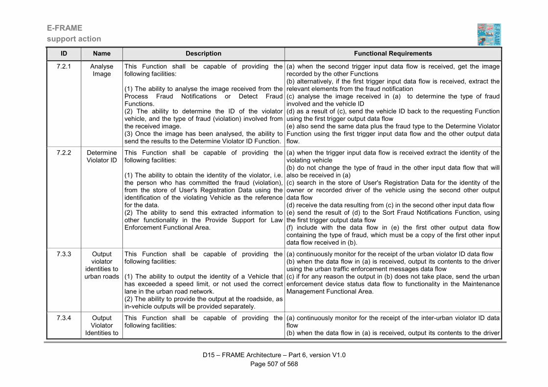
E-FRAME
support action
D15 – FRAME Architecture – Part 6, version V1.0
Page 507 of 568
ID Name Description Functional Requirements
7.2.1 Analyse Image
This Function shall be capable of providing the following facilities: (1) The ability to analyse the image received from the Process Fraud Notifications or Detect Fraud Functions. (2) The ability to determine the ID of the violator vehicle, and the type of fraud (violation) involved from the received image. (3) Once the image has been analysed, the ability to send the results to the Determine Violator ID Function.
(a) when the second trigger input data flow is received, get the image recorded by the other Functions (b) alternatively, if the first trigger input data flow is received, extract the relevant elements from the fraud notification (c) analyse the image received in (a) to determine the type of fraud involved and the vehicle ID (d) as a result of (c), send the vehicle ID back to the requesting Function using the first trigger output data flow (e) also send the same data plus the fraud type to the Determine Violator Function using the first trigger input data flow and the other output data flow.
7.2.2 Determine Violator ID
This Function shall be capable of providing the following facilities: (1) The ability to obtain the identity of the violator, i.e. the person who has committed the fraud (violation), from the store of User's Registration Data using the identification of the violating Vehicle as the reference for the data. (2) The ability to send this extracted information to other functionality in the Provide Support for Law Enforcement Functional Area.
(a) when the trigger input data flow is received extract the identity of the violating vehicle (b) do not change the type of fraud in the other input data flow that will also be received in (a) (c) search in the store of User's Registration Data for the identity of the owner or recorded driver of the vehicle using the second other output data flow (d) receive the data resulting from (c) in the second other input data flow (e) send the result of (d) to the Sort Fraud Notifications Function, using the first trigger output data flow (f) include with the data flow in (e) the first other output data flow containing the type of fraud, which must be a copy of the first other input data flow received in (b).
7.3.3 Output violator
identities to urban roads
This Function shall be capable of providing the following facilities: (1) The ability to output the identity of a Vehicle that has exceeded a speed limit, or not used the correct lane in the urban road network. (2) The ability to provide the output at the roadside, as in-vehicle outputs will be provided separately.
(a) continuously monitor for the receipt of the urban violator ID data flow (b) when the data flow in (a) is received, output its contents to the driver using the urban traffic enforcement messages data flow (c) if for any reason the output in (b) does not take place, send the urban enforcement device status data flow to functionality in the Maintenance Management Functional Area.
7.3.4 Output Violator
Identities to
This Function shall be capable of providing the following facilities:
(a) continuously monitor for the receipt of the inter-urban violator ID data flow (b) when the data flow in (a) is received, output its contents to the driver

E-FRAME
support action
D15 – FRAME Architecture – Part 6, version V1.0
Page 508 of 568
ID Name Description Functional Requirements
Inter-urban Roads
(1) The ability to output the identity of a Vehicle that has exceeded a speed limit, or not used the correct lane in the inter-urban road network. (2) The ability to provide the output at the roadside, as in-vehicle outputs will be provided separately.
using the inter-urban traffic enforcement messages data flow (c) if for any reason the output in (b) does not take place, send the inter-urban enforcement device status data flow to functionality in the Maintenance Management Functional Area.
7.3.5 Sort Fraud and Violation Notifications
This Function shall be capable of providing the following facilities: (1) The ability to carry out the classification of the fraud notifications received from the functionality in other Areas or directly from the Detect Fraud Function. (2) If the violator's identity is not included in the notification, the ability to send the data that is available to the Identify Violator Function for it to be retrieved. (3) The ability to carry out the classification according to different criteria: level of seriousness, field (road, financial, commercial…) and repeat offence. (4) Once the classification has been completed, the ability to send it together with all the other information about the violation to the Establish Prosecution File Function.
(a) continuously monitor for the receipt of any fraud (violation) notification sent by the other functionality (b) when any of the data flows in (a) is received, process it and extract the violator ID (b) if the violator ID is not in the notification received in (b), extract any elements useful for this identification, and send them to the Identify Violator Function, using the first other output data flow (c) await receipt of the data resulting from (b) which will arrive in the fifth trigger input data flow (d) note that the data flow in (c) will be accompanied by the fourth other input data flow (e) extract from the store of Violations Data the seriousness of the fraud, receiving the data in the third other input data flow (f) also search in the store of Violations Data to see if the violator has already committed other similar offences before, receiving the data in the second other input data flow (g) dispatch the notifications according to the format of the fraud in the first trigger output data flow to the Establish Prosecution File Function (h) send all the data about the fraud (violation) to the Fraud Function, using the second trigger output data flow (i) where the driver and/or vehicle ID is known, send the data to the Manage Traffic Area, using the appropriate of the first and second trigger output data flows, depending on whether the fraud (violation) was committed in the inter-urban or urban road network.
7.3.6 Create File for use in
Prosecution
This Function shall be capable of providing the following facilities: (1) The ability to send the file containing all the elements necessary for the prosecution of the violator to the right Law Enforcement Agency.
(a) receive all the elements related to the fraud (violation) in the first trigger input data flow (b) select the Law Enforcement Agency(ies) concerned by the fraud (violation) from the data received in (a) (c) if necessary extract information on previous offences from the store of Violations Data, receiving the data in the first other input data flow
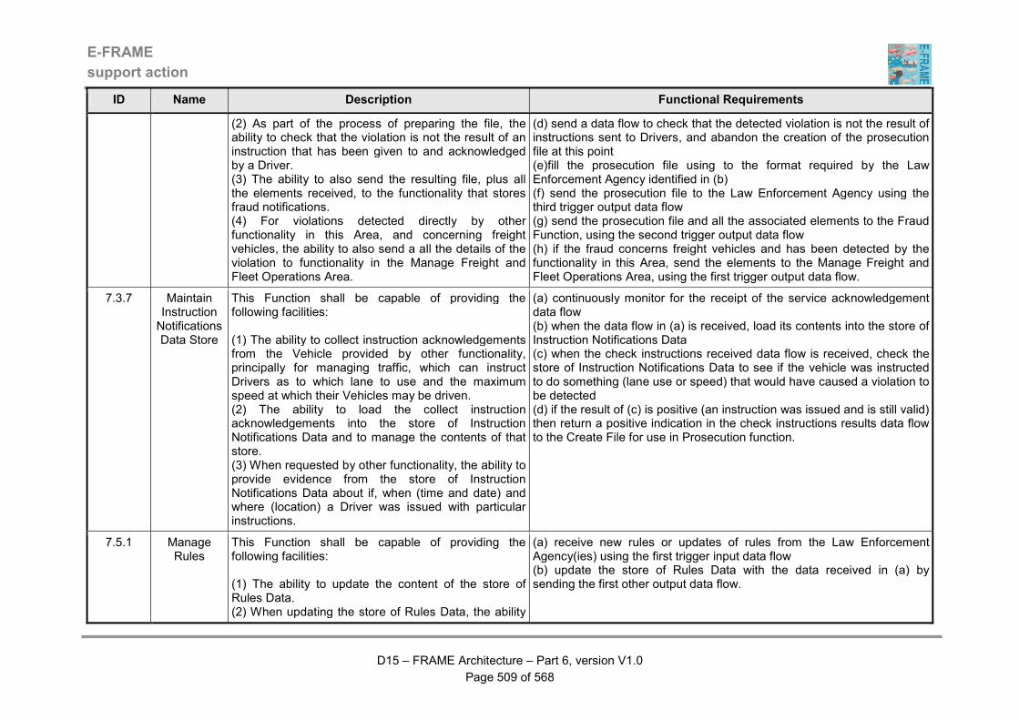
E-FRAME
support action
D15 – FRAME Architecture – Part 6, version V1.0
Page 509 of 568
ID Name Description Functional Requirements
(2) As part of the process of preparing the file, the ability to check that the violation is not the result of an instruction that has been given to and acknowledged by a Driver. (3) The ability to also send the resulting file, plus all the elements received, to the functionality that stores fraud notifications. (4) For violations detected directly by other functionality in this Area, and concerning freight vehicles, the ability to also send a all the details of the violation to functionality in the Manage Freight and Fleet Operations Area.
(d) send a data flow to check that the detected violation is not the result of instructions sent to Drivers, and abandon the creation of the prosecution file at this point (e)fill the prosecution file using to the format required by the Law Enforcement Agency identified in (b) (f) send the prosecution file to the Law Enforcement Agency using the third trigger output data flow (g) send the prosecution file and all the associated elements to the Fraud Function, using the second trigger output data flow (h) if the fraud concerns freight vehicles and has been detected by the functionality in this Area, send the elements to the Manage Freight and Fleet Operations Area, using the first trigger output data flow.
7.3.7 Maintain Instruction Notifications Data Store
This Function shall be capable of providing the following facilities: (1) The ability to collect instruction acknowledgements from the Vehicle provided by other functionality, principally for managing traffic, which can instruct Drivers as to which lane to use and the maximum speed at which their Vehicles may be driven. (2) The ability to load the collect instruction acknowledgements into the store of Instruction Notifications Data and to manage the contents of that store. (3) When requested by other functionality, the ability to provide evidence from the store of Instruction Notifications Data about if, when (time and date) and where (location) a Driver was issued with particular instructions.
(a) continuously monitor for the receipt of the service acknowledgement data flow (b) when the data flow in (a) is received, load its contents into the store of Instruction Notifications Data (c) when the check instructions received data flow is received, check the store of Instruction Notifications Data to see if the vehicle was instructed to do something (lane use or speed) that would have caused a violation to be detected (d) if the result of (c) is positive (an instruction was issued and is still valid) then return a positive indication in the check instructions results data flow to the Create File for use in Prosecution function.
7.5.1 Manage Rules
This Function shall be capable of providing the following facilities: (1) The ability to update the content of the store of Rules Data. (2) When updating the store of Rules Data, the ability
(a) receive new rules or updates of rules from the Law Enforcement Agency(ies) using the first trigger input data flow (b) update the store of Rules Data with the data received in (a) by sending the first other output data flow.
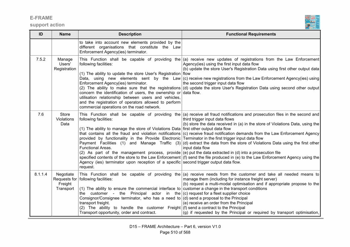
E-FRAME
support action
D15 – FRAME Architecture – Part 6, version V1.0
Page 510 of 568
ID Name Description Functional Requirements
to take into account new elements provided by the different organisations that constitute the Law Enforcement Agency(ies) terminator.
7.5.2 Manage Users'
Registration
This Function shall be capable of providing the following facilities: (1) The ability to update the store User's Registration Data, using new elements sent by the Law Enforcement Agency(ies) terminator. (2) The ability to make sure that the registrations concern the identification of users, the ownership or utilisation relationship between users and vehicles, and the registration of operators allowed to perform commercial operations on the road network.
(a) receive new updates of registrations from the Law Enforcement Agency(ies) using the first input data flow (b) update the store User's Registration Data using first other output data flow (c) receive new registrations from the Law Enforcement Agency(ies) using the second trigger input data flow (d) update the store User's Registration Data using second other output data flow.
7.6 Store Violations
Data
This Function shall be capable of providing the following facilities: (1) The ability to manage the store of Violations Data that contains all the fraud and violation notifications provided by functionality in the Provide Electronic Payment Facilities (1) and Manage Traffic (3) Functional Areas. (2) As part of the management process, provide specified contents of the store to the Law Enforcement Agency (ies) terminator upon reception of a specific request.
(a) receive all fraud notifications and prosecution files in the second and third trigger input data flows (b) store the data received in (a) in the store of Violations Data, using the first other output data flow (c) receive fraud notification demands from the Law Enforcement Agency Terminator in the first trigger input data flow (d) extract the data from the store of Violations Data using the first other input data flow (e) put the data extracted in (d) into a prosecution file (f) send the file produced in (e) to the Law Enforcement Agency using the second trigger output data flow.
8.1.1.4 Negotiate Requests for
Freight Transport
This Function shall be capable of providing the following facilities: (1) The ability to ensure the commercial interface to the customer - the Principal actor in the Consignor/Consignee terminator, who has a need to transport freight. (2) The ability to handle the customer Freight Transport opportunity, order and contract.
(a) receive needs from the customer and take all needed means to manage them (including for instance freight server) (b) request a multi-modal optimisation and if appropriate propose to the customer a change in the transport conditions (c) request for a fleet supplier choice (d) send a proposal to the Principal (e) receive an order from the Principal (f) send a contract to the Principal (g) if requested by the Principal or required by transport optimisation,
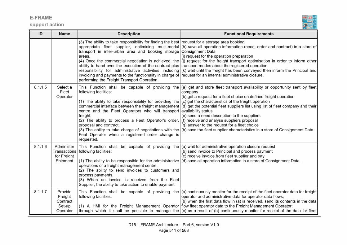
E-FRAME
support action
D15 – FRAME Architecture – Part 6, version V1.0
Page 511 of 568
ID Name Description Functional Requirements
(3) The ability to take responsibility for finding the best appropriate fleet supplier, optimising multi-modal transport in inter-urban area and booking storage areas. (4) Once the commercial negotiation is achieved, the ability to hand over the execution of the contract plus responsibility for administrative activities including invoicing and payments to the functionality in charge of performing the Freight Transport Operation.
request for a storage area booking (h) save all operation information (need, order and contract) in a store of Consignment Data (i) request for the operation preparation (j) request for the freight transport optimisation in order to inform other transport modes about the registered operation (k) wait until the freight has been conveyed then inform the Principal and request for an internal administrative closure.
8.1.1.5 Select a Fleet
Operator
This Function shall be capable of providing the following facilities: (1) The ability to take responsibility for providing the commercial interface between the freight management centre and the Fleet Operators who will transport freight. (2) The ability to process a Feet Operator's order, proposal and contract. (3) The ability to take charge of negotiations with the Feet Operator when a registered order change is requested.
(a) get and store fleet transport availability or opportunity sent by fleet company (b) get a request for a fleet choice on defined freight operation (c) get the characteristics of the freight operation (d) get the potential fleet suppliers list using list of fleet company and their availability status (e) send a need description to the suppliers (f) receive and analyse suppliers proposal (g) answer to the request for a fleet choice (h) save the fleet supplier characteristics in a store of Consignment Data.
8.1.1.6 Administer Transactions for Freight Shipment
This Function shall be capable of providing the following facilities: (1) The ability to be responsible for the administrative operations of a freight management centre. (2) The ability to send invoices to customers and process payments. (3) When an invoice is received from the Fleet Supplier, the ability to take action to enable payment.
(a) wait for administrative operation closure request (b) send invoice to Principal and process payment (c) receive invoice from fleet supplier and pay (d) save all operation information in a store of Consignment Data.
8.1.1.7 Provide Freight Contract Set-up Operator
This Function shall be capable of providing the following facilities: (1) A HMI for the Freight Management Operator through which it shall be possible to manage the
(a) continuously monitor for the receipt of the fleet operator data for freight operator and administrative data for operator data flows; (b) when the first data flow in (a) is received, send its contents in the data flow fleet operator data to the Freight Management Operator; (c) as a result of (b) continuously monitor for receipt of the data for fleet
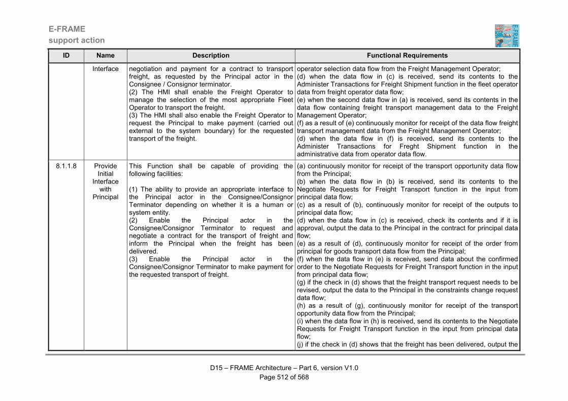
E-FRAME
support action
D15 – FRAME Architecture – Part 6, version V1.0
Page 512 of 568
ID Name Description Functional Requirements
Interface negotiation and payment for a contract to transport freight, as requested by the Principal actor in the Consignee / Consignor terminator. (2) The HMI shall enable the Freight Operator to manage the selection of the most appropriate Fleet Operator to transport the freight. (3) The HMI shall also enable the Freight Operator to request the Principal to make payment (carried out external to the system boundary) for the requested transport of the freight.
operator selection data flow from the Freight Management Operator; (d) when the data flow in (c) is received, send its contents to the Administer Transactions for Freight Shipment function in the fleet operator data from freight operator data flow; (e) when the second data flow in (a) is received, send its contents in the data flow containing freight transport management data to the Freight Management Operator; (f) as a result of (e) continuously monitor for receipt of the data flow freight transport management data from the Freight Management Operator; (d) when the data flow in (f) is received, send its contents to the Administer Transactions for Freght Shipment function in the administrative data from operator data flow.
8.1.1.8 Provide Initial
Interface with
Principal
This Function shall be capable of providing the following facilities: (1) The ability to provide an appropriate interface to the Principal actor in the Consignee/Consignor Terminator depending on whether it is a human or system entity. (2) Enable the Principal actor in the Consignee/Consignor Terminator to request and negotiate a contract for the transport of freight and inform the Principal when the freight has been delivered. (3) Enable the Principal actor in the Consignee/Consignor Terminator to make payment for the requested transport of freight.
(a) continuously monitor for receipt of the transport opportunity data flow from the Principal; (b) when the data flow in (b) is received, send its contents to the Negotiate Requests for Freight Transport function in the input from principal data flow; (c) as a result of (b), continuously monitor for receipt of the outputs to principal data flow; (d) when the data flow in (c) is received, check its contents and if it is approval, output the data to the Principal in the contract for principal data flow; (e) as a result of (d), continuously monitor for receipt of the order from principal for goods transport data flow from the Principal; (f) when the data flow in (e) is received, send data about the confirmed order to the Negotiate Requests for Freight Transport function in the input from principal data flow; (g) if the check in (d) shows that the freight transport request needs to be revised, output the data to the Principal in the constraints change request data flow; (h) as a result of (g), continuously monitor for receipt of the transport opportunity data flow from the Principal; (i) when the data flow in (h) is received, send its contents to the Negotiate Requests for Freight Transport function in the input from principal data flow; (j) if the check in (d) shows that the freight has been delivered, output the

E-FRAME
support action
D15 – FRAME Architecture – Part 6, version V1.0
Page 513 of 568
ID Name Description Functional Requirements
data to the Principal in the principal notice of delivery data flow.
8.1.2.4 Process Customs Declaration
This Function shall be capable of providing the following facilities: (1) The ability to take responsibility for providing the customs declaration where needed for a Freight Transport Operation. (2) The ability to obtain the declaration acknowledgement from the Law Enforcement Agency. (3) The ability to provide both of these facilities on request from other functionality.
(a) receive a request for custom declaration (b) get permission from the Freight Management Operator to send the declaration to the Law Enforcement Agency (c) make the declaration to the Law Enforcement terminator (d) receive the acknowledgement from the Law Enforcement terminator (e) save all operation information in a store of Consignment Data (f) notify about the acknowledgement.
8.1.2.5 Create and Deliver Official
Transport Documents
This Function shall be capable of providing the following facilities: (1) The ability to take responsibility for the preparation of documents needed to enable the Freight Transport Operation to proceed. (2) This responsibility shall include the ability to organise the provision of any official Freight Transport Operation information required, and in particular to cover customs and hazardous goods transport declaration. (3) This responsibility shall also include the ability to send the information to the Fleet Supplier when they are ready. (4) Once the documents have been completed and sent, the ability to hand over future activities to the functionality in charge of controlling the Freight Transport Operation.
(a) receive a request for freight transport operation preparation (b) get permission from the Freight Management Operator to proceed (c) analyse what are statutory process have to be realised (d) if needed request for a custom declaration (e) request if applicable for a hazardous goods transport administrative approval (f) fill the content of the official transport documents (g) send the official transport document to the fleet supplier and then (h) request for freight transport control.
8.1.2.6 Process Hazardous Goods
Transport Declaration
This Function shall be capable of providing the following facilities: (1) The ability to take responsible for providing a hazardous goods transport declaration for a Freight
(a) receive a request for hazardous goods transport approval to be obtained (b) request permission from the Freight Management Operator to proceed with contacting the Law Enforcement Agency (c) prepare all needed documents then require an approval from the Law

E-FRAME
support action
D15 – FRAME Architecture – Part 6, version V1.0
Page 514 of 568
ID Name Description Functional Requirements
Transport Operation. (2) The ability to obtain the declaration approval from the Law Enforcement Agency on request from other functionality once it has obtained the approval of the Freight Management Operator.
Enforcement Agency terminator (d) receive the approval from the Law Enforcement Agency terminator (e) save all operation information in a store of Consignment Data (f) inform about the approval.
8.1.2.7 Provide Setup Freight
Operation Operator Interface
This Function shall be capable of providing the following facilities: (1) A HMI that will enable the Freight Management Operator to manage the preparation of what is necessary for a Freight Transport Operation to take place. (2) The ability to receive data about what is needed to process the necessary clearances (e.g. customs and hazardous goods) so that a Freight Transport Operation can proceed. (3) The ability to use the HMI to obtain approval from the Freight Management Operator for other functionality to carry out the necessary processing, which will include the exchange of data with the Law Enforcement Agency.
(a) continuously monitor for receipt of the customs declaration requested, prepare freight operations data request and approve hazardous goods transport request data flows; (b) when the first data flow in (a) is received, send its contents to the Freight Management Operator in the customs declaration requested data flow; (c) as a result of (b) continuously monitor for receipt of the customs declaration request proceed data flow from the Freight Management Operator; (d) when the data flow in (c) is received, send its contents in the customs declaration submittal approved data flow; (e) when the second data flow in (a) is received, send its content to the Freight Management Operator in the freight operations data preparation request data flow; (f) as a result of (e), continuously monitor for receipt of the freight operations data preparation approved data flow from the Freight Management Operator; (g) when the data flow in (f) is received. send its contents in the prepare freight operations data approved data flow; (h) when the third data flow in (a) is received, send its contents to the Freight Management Operator in the approve hazardous goods transport request data flow; (i) as a result of (h) continuously monitor for receipt of the hazardous goods transport approved data flow from the Freight Management Operator; (j) when the data flow in (i) is received. send its contents in the hazardous goods transport request approved data flow. .
8.1.3 Control Freight/Carg
This Function shall be capable of providing the following facilities:
(a) when received save all operation information in the store of Consignment Data
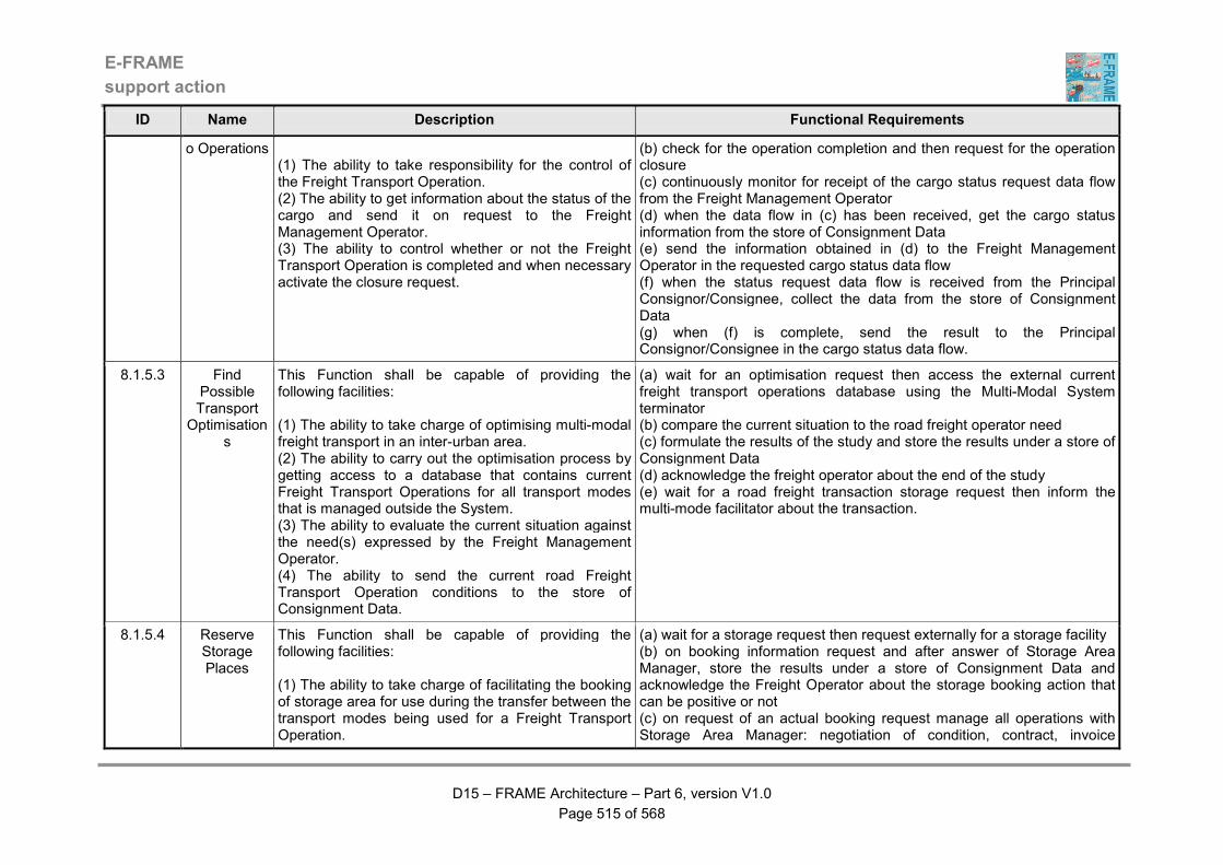
E-FRAME
support action
D15 – FRAME Architecture – Part 6, version V1.0
Page 515 of 568
ID Name Description Functional Requirements
o Operations (1) The ability to take responsibility for the control of the Freight Transport Operation. (2) The ability to get information about the status of the cargo and send it on request to the Freight Management Operator. (3) The ability to control whether or not the Freight Transport Operation is completed and when necessary activate the closure request.
(b) check for the operation completion and then request for the operation closure (c) continuously monitor for receipt of the cargo status request data flow from the Freight Management Operator (d) when the data flow in (c) has been received, get the cargo status information from the store of Consignment Data (e) send the information obtained in (d) to the Freight Management Operator in the requested cargo status data flow (f) when the status request data flow is received from the Principal Consignor/Consignee, collect the data from the store of Consignment Data (g) when (f) is complete, send the result to the Principal Consignor/Consignee in the cargo status data flow.
8.1.5.3 Find Possible Transport
Optimisations
This Function shall be capable of providing the following facilities: (1) The ability to take charge of optimising multi-modal freight transport in an inter-urban area. (2) The ability to carry out the optimisation process by getting access to a database that contains current Freight Transport Operations for all transport modes that is managed outside the System. (3) The ability to evaluate the current situation against the need(s) expressed by the Freight Management Operator. (4) The ability to send the current road Freight Transport Operation conditions to the store of Consignment Data.
(a) wait for an optimisation request then access the external current freight transport operations database using the Multi-Modal System terminator (b) compare the current situation to the road freight operator need (c) formulate the results of the study and store the results under a store of Consignment Data (d) acknowledge the freight operator about the end of the study (e) wait for a road freight transaction storage request then inform the multi-mode facilitator about the transaction.
8.1.5.4 Reserve Storage Places
This Function shall be capable of providing the following facilities: (1) The ability to take charge of facilitating the booking of storage area for use during the transfer between the transport modes being used for a Freight Transport Operation.
(a) wait for a storage request then request externally for a storage facility (b) on booking information request and after answer of Storage Area Manager, store the results under a store of Consignment Data and acknowledge the Freight Operator about the storage booking action that can be positive or not (c) on request of an actual booking request manage all operations with Storage Area Manager: negotiation of condition, contract, invoice
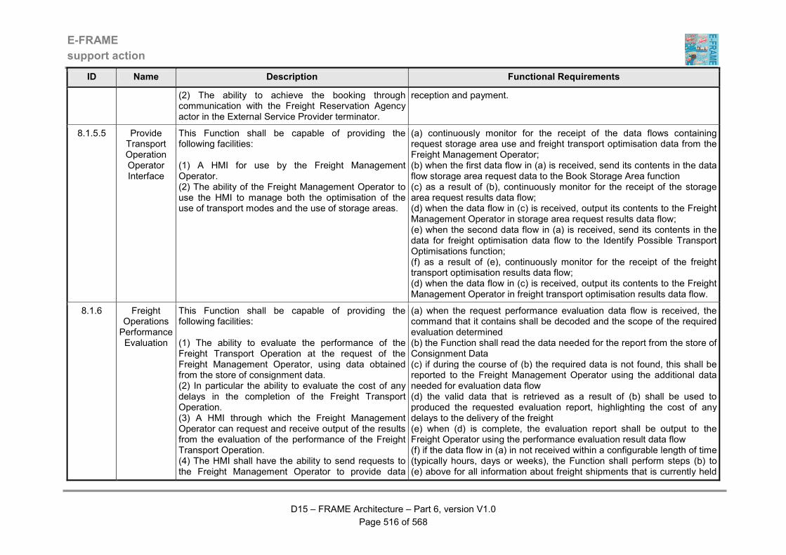
E-FRAME
support action
D15 – FRAME Architecture – Part 6, version V1.0
Page 516 of 568
ID Name Description Functional Requirements
(2) The ability to achieve the booking through communication with the Freight Reservation Agency actor in the External Service Provider terminator.
reception and payment.
8.1.5.5 Provide Transport Operation Operator Interface
This Function shall be capable of providing the following facilities: (1) A HMI for use by the Freight Management Operator. (2) The ability of the Freight Management Operator to use the HMI to manage both the optimisation of the use of transport modes and the use of storage areas.
(a) continuously monitor for the receipt of the data flows containing request storage area use and freight transport optimisation data from the Freight Management Operator; (b) when the first data flow in (a) is received, send its contents in the data flow storage area request data to the Book Storage Area function (c) as a result of (b), continuously monitor for the receipt of the storage area request results data flow; (d) when the data flow in (c) is received, output its contents to the Freight Management Operator in storage area request results data flow; (e) when the second data flow in (a) is received, send its contents in the data for freight optimisation data flow to the Identify Possible Transport Optimisations function; (f) as a result of (e), continuously monitor for the receipt of the freight transport optimisation results data flow; (d) when the data flow in (c) is received, output its contents to the Freight Management Operator in freight transport optimisation results data flow.
8.1.6 Freight Operations Performance Evaluation
This Function shall be capable of providing the following facilities: (1) The ability to evaluate the performance of the Freight Transport Operation at the request of the Freight Management Operator, using data obtained from the store of consignment data. (2) In particular the ability to evaluate the cost of any delays in the completion of the Freight Transport Operation. (3) A HMI through which the Freight Management Operator can request and receive output of the results from the evaluation of the performance of the Freight Transport Operation. (4) The HMI shall have the ability to send requests to the Freight Management Operator to provide data
(a) when the request performance evaluation data flow is received, the command that it contains shall be decoded and the scope of the required evaluation determined (b) the Function shall read the data needed for the report from the store of Consignment Data (c) if during the course of (b) the required data is not found, this shall be reported to the Freight Management Operator using the additional data needed for evaluation data flow (d) the valid data that is retrieved as a result of (b) shall be used to produced the requested evaluation report, highlighting the cost of any delays to the delivery of the freight (e) when (d) is complete, the evaluation report shall be output to the Freight Operator using the performance evaluation result data flow (f) if the data flow in (a) in not received within a configurable length of time (typically hours, days or weeks), the Function shall perform steps (b) to (e) above for all information about freight shipments that is currently held
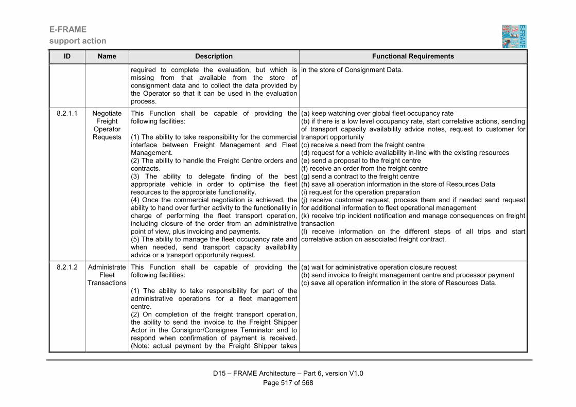
E-FRAME
support action
D15 – FRAME Architecture – Part 6, version V1.0
Page 517 of 568
ID Name Description Functional Requirements
required to complete the evaluation, but which is missing from that available from the store of consignment data and to collect the data provided by the Operator so that it can be used in the evaluation process.
in the store of Consignment Data.
8.2.1.1 Negotiate Freight Operator Requests
This Function shall be capable of providing the following facilities: (1) The ability to take responsibility for the commercial interface between Freight Management and Fleet Management. (2) The ability to handle the Freight Centre orders and contracts. (3) The ability to delegate finding of the best appropriate vehicle in order to optimise the fleet resources to the appropriate functionality. (4) Once the commercial negotiation is achieved, the ability to hand over further activity to the functionality in charge of performing the fleet transport operation, including closure of the order from an administrative point of view, plus invoicing and payments. (5) The ability to manage the fleet occupancy rate and when needed, send transport capacity availability advice or a transport opportunity request.
(a) keep watching over global fleet occupancy rate (b) if there is a low level occupancy rate, start correlative actions, sending of transport capacity availability advice notes, request to customer for transport opportunity (c) receive a need from the freight centre (d) request for a vehicle availability in-line with the existing resources (e) send a proposal to the freight centre (f) receive an order from the freight centre (g) send a contract to the freight centre (h) save all operation information in the store of Resources Data (i) request for the operation preparation (j) receive customer request, process them and if needed send request for additional information to fleet operational management (k) receive trip incident notification and manage consequences on freight transaction (l) receive information on the different steps of all trips and start correlative action on associated freight contract.
8.2.1.2 Administrate Fleet
Transactions
This Function shall be capable of providing the following facilities: (1) The ability to take responsibility for part of the administrative operations for a fleet management centre. (2) On completion of the freight transport operation, the ability to send the invoice to the Freight Shipper Actor in the Consignor/Consignee Terminator and to respond when confirmation of payment is received. (Note: actual payment by the Freight Shipper takes
(a) wait for administrative operation closure request (b) send invoice to freight management centre and processor payment (c) save all operation information in the store of Resources Data.
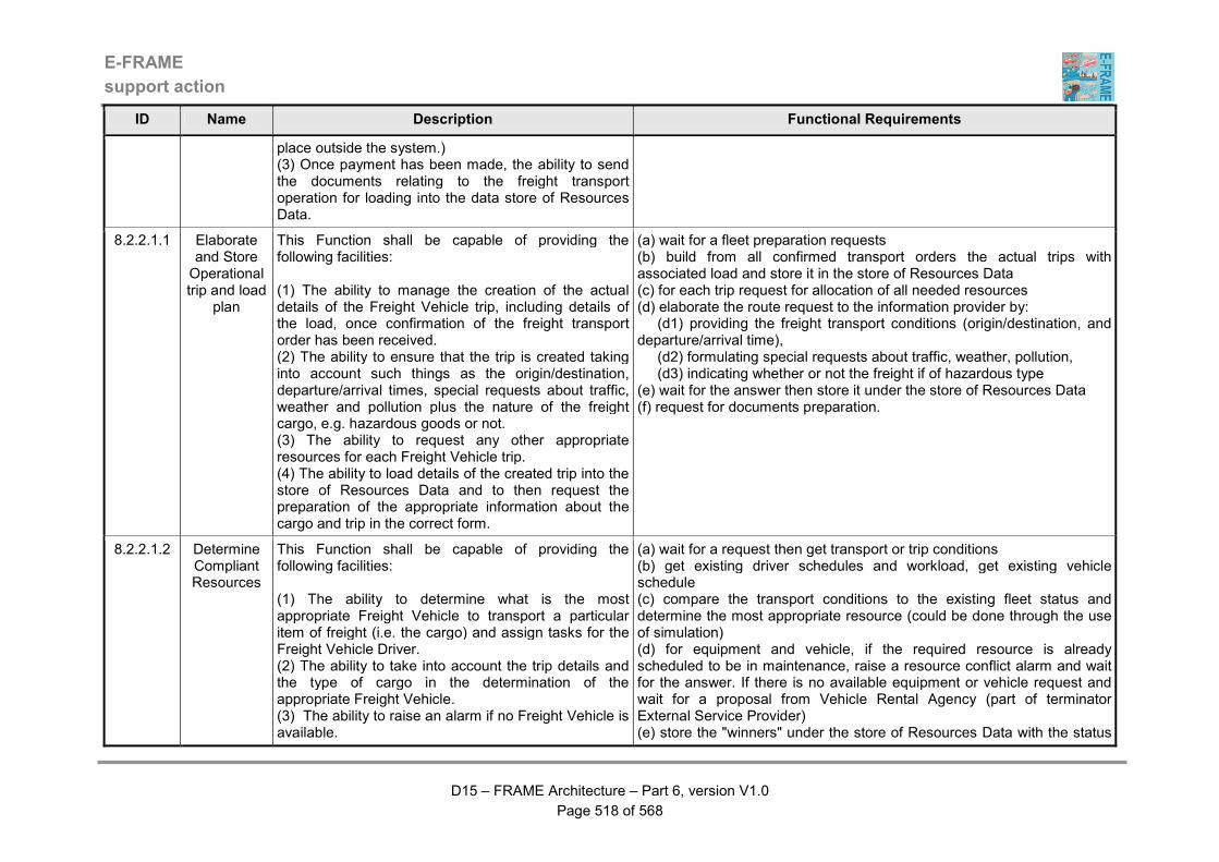
E-FRAME
support action
D15 – FRAME Architecture – Part 6, version V1.0
Page 518 of 568
ID Name Description Functional Requirements
place outside the system.) (3) Once payment has been made, the ability to send the documents relating to the freight transport operation for loading into the data store of Resources Data.
8.2.2.1.1 Elaborate and Store Operational trip and load
plan
This Function shall be capable of providing the following facilities: (1) The ability to manage the creation of the actual details of the Freight Vehicle trip, including details of the load, once confirmation of the freight transport order has been received. (2) The ability to ensure that the trip is created taking into account such things as the origin/destination, departure/arrival times, special requests about traffic, weather and pollution plus the nature of the freight cargo, e.g. hazardous goods or not. (3) The ability to request any other appropriate resources for each Freight Vehicle trip. (4) The ability to load details of the created trip into the store of Resources Data and to then request the preparation of the appropriate information about the cargo and trip in the correct form.
(a) wait for a fleet preparation requests (b) build from all confirmed transport orders the actual trips with associated load and store it in the store of Resources Data (c) for each trip request for allocation of all needed resources (d) elaborate the route request to the information provider by: (d1) providing the freight transport conditions (origin/destination, and departure/arrival time), (d2) formulating special requests about traffic, weather, pollution, (d3) indicating whether or not the freight if of hazardous type (e) wait for the answer then store it under the store of Resources Data (f) request for documents preparation.
8.2.2.1.2 Determine Compliant Resources
This Function shall be capable of providing the following facilities: (1) The ability to determine what is the most appropriate Freight Vehicle to transport a particular item of freight (i.e. the cargo) and assign tasks for the Freight Vehicle Driver. (2) The ability to take into account the trip details and the type of cargo in the determination of the appropriate Freight Vehicle. (3) The ability to raise an alarm if no Freight Vehicle is available.
(a) wait for a request then get transport or trip conditions (b) get existing driver schedules and workload, get existing vehicle schedule (c) compare the transport conditions to the existing fleet status and determine the most appropriate resource (could be done through the use of simulation) (d) for equipment and vehicle, if the required resource is already scheduled to be in maintenance, raise a resource conflict alarm and wait for the answer. If there is no available equipment or vehicle request and wait for a proposal from Vehicle Rental Agency (part of terminator External Service Provider) (e) store the "winners" under the store of Resources Data with the status
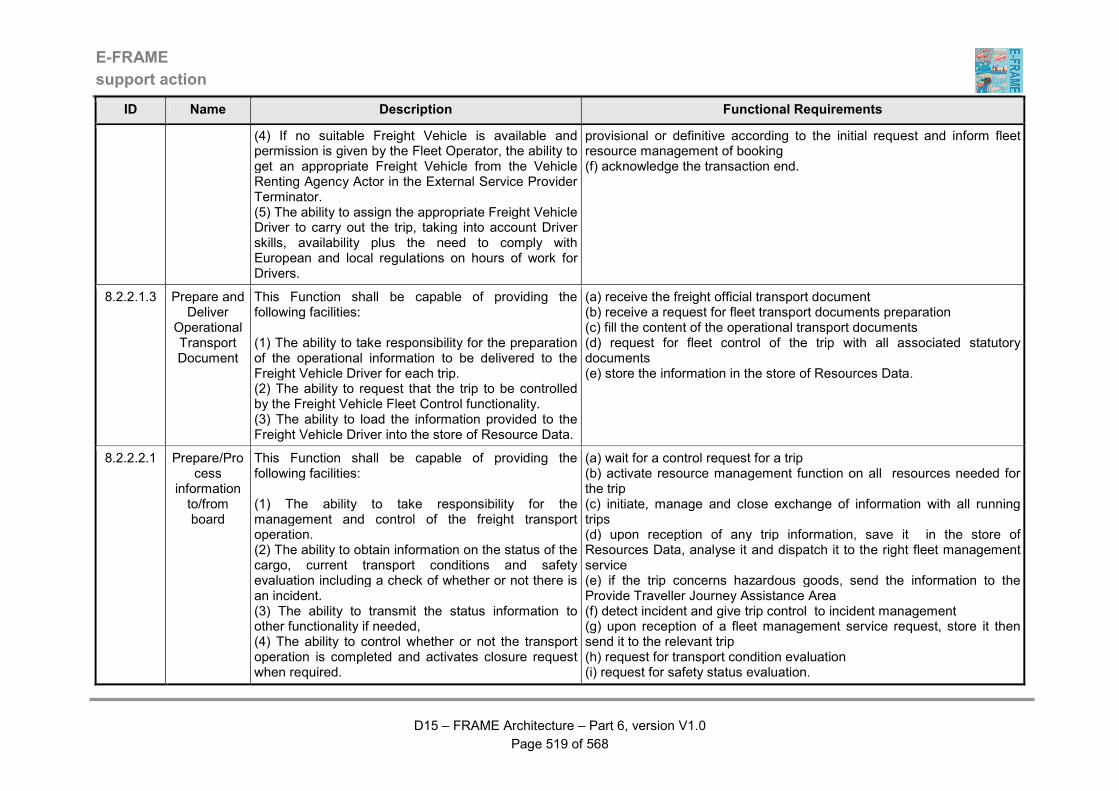
E-FRAME
support action
D15 – FRAME Architecture – Part 6, version V1.0
Page 519 of 568
ID Name Description Functional Requirements
(4) If no suitable Freight Vehicle is available and permission is given by the Fleet Operator, the ability to get an appropriate Freight Vehicle from the Vehicle Renting Agency Actor in the External Service Provider Terminator. (5) The ability to assign the appropriate Freight Vehicle Driver to carry out the trip, taking into account Driver skills, availability plus the need to comply with European and local regulations on hours of work for Drivers.
provisional or definitive according to the initial request and inform fleet resource management of booking (f) acknowledge the transaction end.
8.2.2.1.3 Prepare and Deliver
Operational Transport Document
This Function shall be capable of providing the following facilities: (1) The ability to take responsibility for the preparation of the operational information to be delivered to the Freight Vehicle Driver for each trip. (2) The ability to request that the trip to be controlled by the Freight Vehicle Fleet Control functionality. (3) The ability to load the information provided to the Freight Vehicle Driver into the store of Resource Data.
(a) receive the freight official transport document (b) receive a request for fleet transport documents preparation (c) fill the content of the operational transport documents (d) request for fleet control of the trip with all associated statutory documents (e) store the information in the store of Resources Data.
8.2.2.2.1 Prepare/Process
information to/from board
This Function shall be capable of providing the following facilities: (1) The ability to take responsibility for the management and control of the freight transport operation. (2) The ability to obtain information on the status of the cargo, current transport conditions and safety evaluation including a check of whether or not there is an incident. (3) The ability to transmit the status information to other functionality if needed, (4) The ability to control whether or not the transport operation is completed and activates closure request when required.
(a) wait for a control request for a trip (b) activate resource management function on all resources needed for the trip (c) initiate, manage and close exchange of information with all running trips (d) upon reception of any trip information, save it in the store of Resources Data, analyse it and dispatch it to the right fleet management service (e) if the trip concerns hazardous goods, send the information to the Provide Traveller Journey Assistance Area (f) detect incident and give trip control to incident management (g) upon reception of a fleet management service request, store it then send it to the relevant trip (h) request for transport condition evaluation (i) request for safety status evaluation.
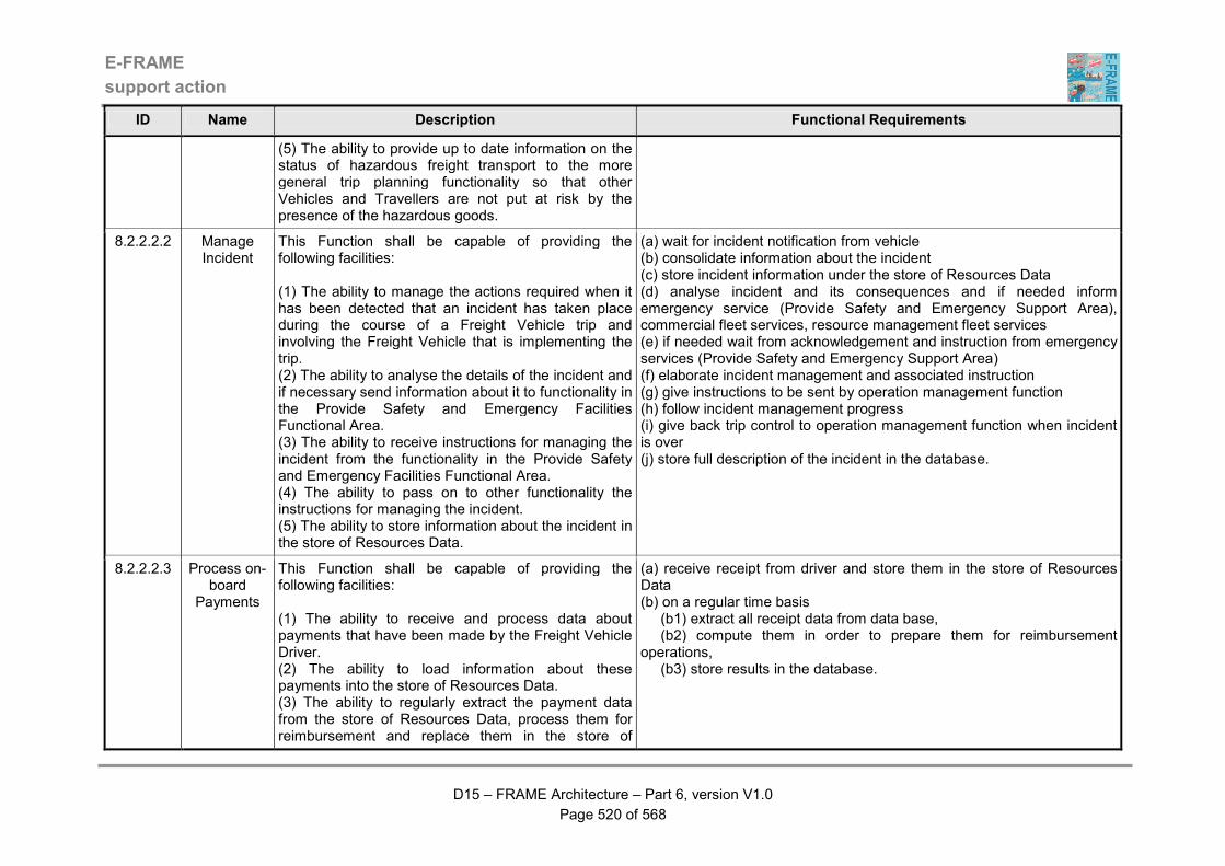
E-FRAME
support action
D15 – FRAME Architecture – Part 6, version V1.0
Page 520 of 568
ID Name Description Functional Requirements
(5) The ability to provide up to date information on the status of hazardous freight transport to the more general trip planning functionality so that other Vehicles and Travellers are not put at risk by the presence of the hazardous goods.
8.2.2.2.2 Manage Incident
This Function shall be capable of providing the following facilities: (1) The ability to manage the actions required when it has been detected that an incident has taken place during the course of a Freight Vehicle trip and involving the Freight Vehicle that is implementing the trip. (2) The ability to analyse the details of the incident and if necessary send information about it to functionality in the Provide Safety and Emergency Facilities Functional Area. (3) The ability to receive instructions for managing the incident from the functionality in the Provide Safety and Emergency Facilities Functional Area. (4) The ability to pass on to other functionality the instructions for managing the incident. (5) The ability to store information about the incident in the store of Resources Data.
(a) wait for incident notification from vehicle (b) consolidate information about the incident (c) store incident information under the store of Resources Data (d) analyse incident and its consequences and if needed inform emergency service (Provide Safety and Emergency Support Area), commercial fleet services, resource management fleet services (e) if needed wait from acknowledgement and instruction from emergency services (Provide Safety and Emergency Support Area) (f) elaborate incident management and associated instruction (g) give instructions to be sent by operation management function (h) follow incident management progress (i) give back trip control to operation management function when incident is over (j) store full description of the incident in the database.
8.2.2.2.3 Process on-board
Payments
This Function shall be capable of providing the following facilities: (1) The ability to receive and process data about payments that have been made by the Freight Vehicle Driver. (2) The ability to load information about these payments into the store of Resources Data. (3) The ability to regularly extract the payment data from the store of Resources Data, process them for reimbursement and replace them in the store of
(a) receive receipt from driver and store them in the store of Resources Data (b) on a regular time basis (b1) extract all receipt data from data base, (b2) compute them in order to prepare them for reimbursement operations, (b3) store results in the database.
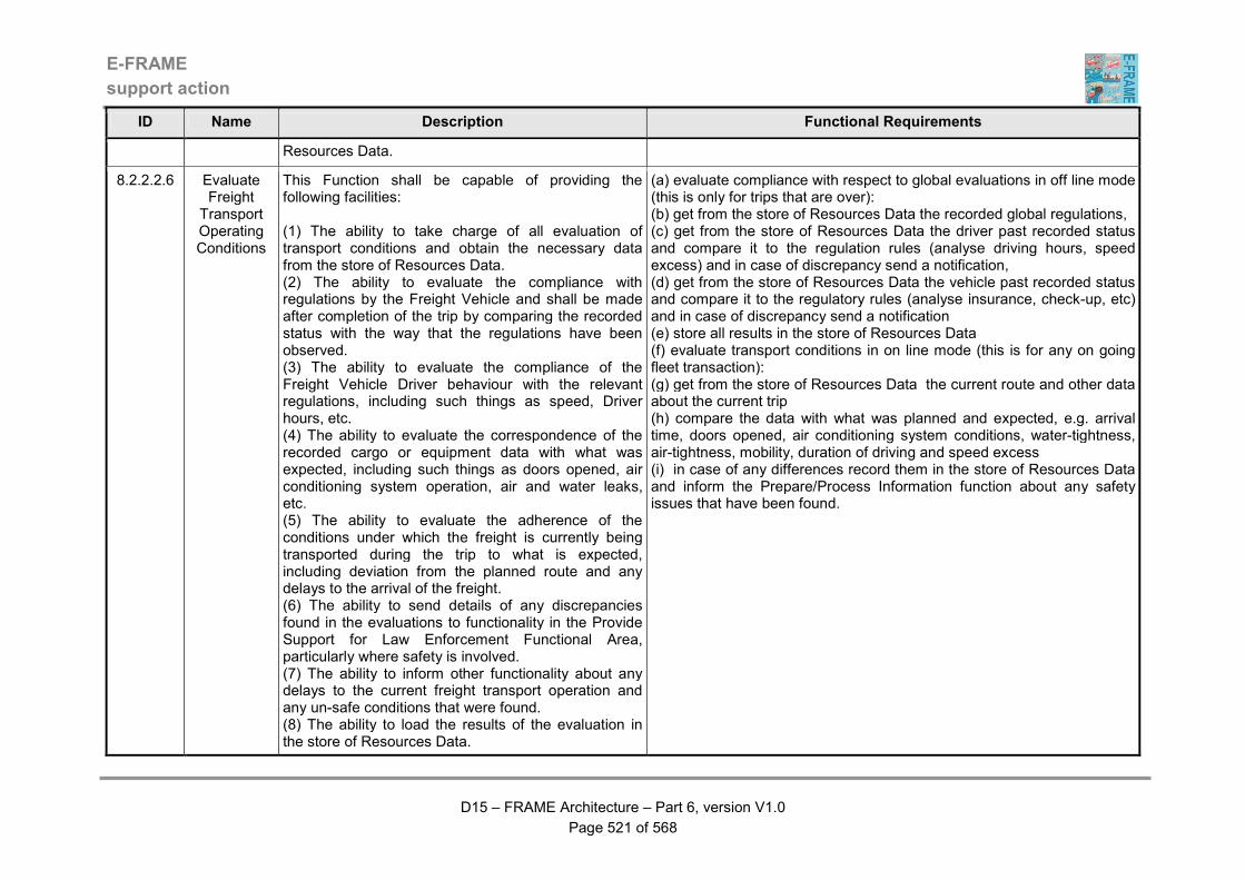
E-FRAME
support action
D15 – FRAME Architecture – Part 6, version V1.0
Page 521 of 568
ID Name Description Functional Requirements
Resources Data.
8.2.2.2.6 Evaluate Freight
Transport Operating Conditions
This Function shall be capable of providing the following facilities: (1) The ability to take charge of all evaluation of transport conditions and obtain the necessary data from the store of Resources Data. (2) The ability to evaluate the compliance with regulations by the Freight Vehicle and shall be made after completion of the trip by comparing the recorded status with the way that the regulations have been observed. (3) The ability to evaluate the compliance of the Freight Vehicle Driver behaviour with the relevant regulations, including such things as speed, Driver hours, etc. (4) The ability to evaluate the correspondence of the recorded cargo or equipment data with what was expected, including such things as doors opened, air conditioning system operation, air and water leaks, etc. (5) The ability to evaluate the adherence of the conditions under which the freight is currently being transported during the trip to what is expected, including deviation from the planned route and any delays to the arrival of the freight. (6) The ability to send details of any discrepancies found in the evaluations to functionality in the Provide Support for Law Enforcement Functional Area, particularly where safety is involved. (7) The ability to inform other functionality about any delays to the current freight transport operation and any un-safe conditions that were found. (8) The ability to load the results of the evaluation in the store of Resources Data.
(a) evaluate compliance with respect to global evaluations in off line mode (this is only for trips that are over): (b) get from the store of Resources Data the recorded global regulations, (c) get from the store of Resources Data the driver past recorded status and compare it to the regulation rules (analyse driving hours, speed excess) and in case of discrepancy send a notification, (d) get from the store of Resources Data the vehicle past recorded status and compare it to the regulatory rules (analyse insurance, check-up, etc) and in case of discrepancy send a notification (e) store all results in the store of Resources Data (f) evaluate transport conditions in on line mode (this is for any on going fleet transaction): (g) get from the store of Resources Data the current route and other data about the current trip (h) compare the data with what was planned and expected, e.g. arrival time, doors opened, air conditioning system conditions, water-tightness, air-tightness, mobility, duration of driving and speed excess (i) in case of any differences record them in the store of Resources Data and inform the Prepare/Process Information function about any safety issues that have been found.
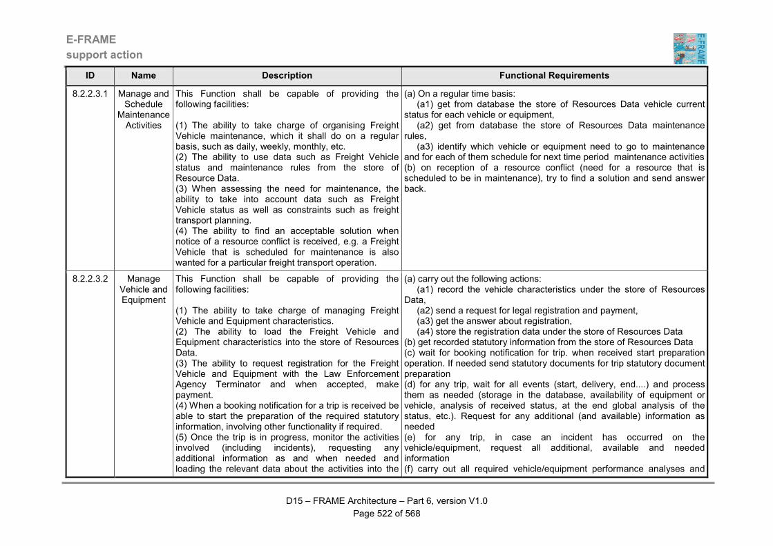
E-FRAME
support action
D15 – FRAME Architecture – Part 6, version V1.0
Page 522 of 568
ID Name Description Functional Requirements
8.2.2.3.1 Manage and Schedule
Maintenance Activities
This Function shall be capable of providing the following facilities: (1) The ability to take charge of organising Freight Vehicle maintenance, which it shall do on a regular basis, such as daily, weekly, monthly, etc. (2) The ability to use data such as Freight Vehicle status and maintenance rules from the store of Resource Data. (3) When assessing the need for maintenance, the ability to take into account data such as Freight Vehicle status as well as constraints such as freight transport planning. (4) The ability to find an acceptable solution when notice of a resource conflict is received, e.g. a Freight Vehicle that is scheduled for maintenance is also wanted for a particular freight transport operation.
(a) On a regular time basis: (a1) get from database the store of Resources Data vehicle current status for each vehicle or equipment, (a2) get from database the store of Resources Data maintenance rules, (a3) identify which vehicle or equipment need to go to maintenance and for each of them schedule for next time period maintenance activities (b) on reception of a resource conflict (need for a resource that is scheduled to be in maintenance), try to find a solution and send answer back.
8.2.2.3.2 Manage Vehicle and Equipment
This Function shall be capable of providing the following facilities: (1) The ability to take charge of managing Freight Vehicle and Equipment characteristics. (2) The ability to load the Freight Vehicle and Equipment characteristics into the store of Resources Data. (3) The ability to request registration for the Freight Vehicle and Equipment with the Law Enforcement Agency Terminator and when accepted, make payment. (4) When a booking notification for a trip is received be able to start the preparation of the required statutory information, involving other functionality if required. (5) Once the trip is in progress, monitor the activities involved (including incidents), requesting any additional information as and when needed and loading the relevant data about the activities into the
(a) carry out the following actions: (a1) record the vehicle characteristics under the store of Resources Data, (a2) send a request for legal registration and payment, (a3) get the answer about registration, (a4) store the registration data under the store of Resources Data (b) get recorded statutory information from the store of Resources Data (c) wait for booking notification for trip. when received start preparation operation. If needed send statutory documents for trip statutory document preparation (d) for any trip, wait for all events (start, delivery, end....) and process them as needed (storage in the database, availability of equipment or vehicle, analysis of received status, at the end global analysis of the status, etc.). Request for any additional (and available) information as needed (e) for any trip, in case an incident has occurred on the vehicle/equipment, request all additional, available and needed information (f) carry out all required vehicle/equipment performance analyses and
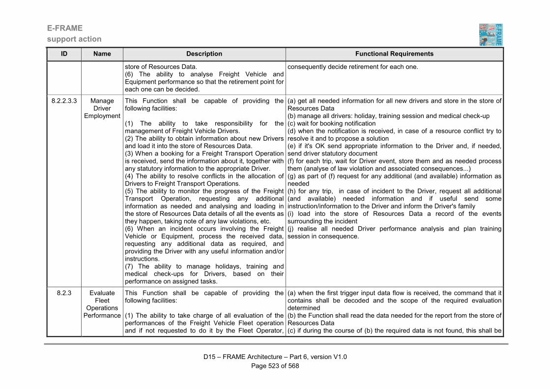
E-FRAME
support action
D15 – FRAME Architecture – Part 6, version V1.0
Page 523 of 568
ID Name Description Functional Requirements
store of Resources Data. (6) The ability to analyse Freight Vehicle and Equipment performance so that the retirement point for each one can be decided.
consequently decide retirement for each one.
8.2.2.3.3 Manage Driver
Employment
This Function shall be capable of providing the following facilities: (1) The ability to take responsibility for the management of Freight Vehicle Drivers. (2) The ability to obtain information about new Drivers and load it into the store of Resources Data. (3) When a booking for a Freight Transport Operation is received, send the information about it, together with any statutory information to the appropriate Driver. (4) The ability to resolve conflicts in the allocation of Drivers to Freight Transport Operations. (5) The ability to monitor the progress of the Freight Transport Operation, requesting any additional information as needed and analysing and loading in the store of Resources Data details of all the events as they happen, taking note of any law violations, etc. (6) When an incident occurs involving the Freight Vehicle or Equipment, process the received data, requesting any additional data as required, and providing the Driver with any useful information and/or instructions. (7) The ability to manage holidays, training and medical check-ups for Drivers, based on their performance on assigned tasks.
(a) get all needed information for all new drivers and store in the store of Resources Data (b) manage all drivers: holiday, training session and medical check-up (c) wait for booking notification (d) when the notification is received, in case of a resource conflict try to resolve it and to propose a solution (e) if it's OK send appropriate information to the Driver and, if needed, send driver statutory document (f) for each trip, wait for Driver event, store them and as needed process them (analyse of law violation and associated consequences...) (g) as part of (f) request for any additional (and available) information as needed (h) for any trip, in case of incident to the Driver, request all additional (and available) needed information and if useful send some instruction/information to the Driver and inform the Driver's family (i) load into the store of Resources Data a record of the events surrounding the incident (j) realise all needed Driver performance analysis and plan training session in consequence.
8.2.3 Evaluate Fleet
Operations Performance
This Function shall be capable of providing the following facilities: (1) The ability to take charge of all evaluation of the performances of the Freight Vehicle Fleet operation and if not requested to do it by the Fleet Operator,
(a) when the first trigger input data flow is received, the command that it contains shall be decoded and the scope of the required evaluation determined (b) the Function shall read the data needed for the report from the store of Resources Data (c) if during the course of (b) the required data is not found, this shall be
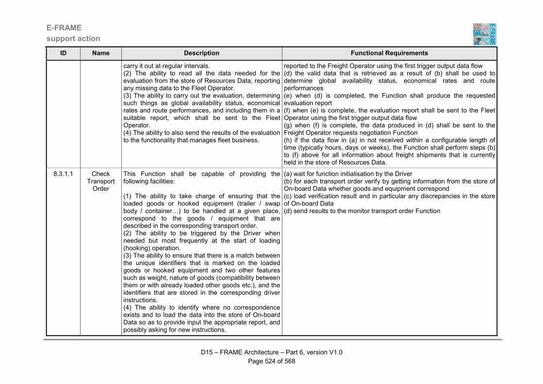
E-FRAME
support action
D15 – FRAME Architecture – Part 6, version V1.0
Page 524 of 568
ID Name Description Functional Requirements
carry it out at regular intervals. (2) The ability to read all the data needed for the evaluation from the store of Resources Data, reporting any missing data to the Fleet Operator. (3) The ability to carry out the evaluation, determining such things as global availability status, economical rates and route performances, and including them in a suitable report, which shall be sent to the Fleet Operator. (4) The ability to also send the results of the evaluation to the functionality that manages fleet business.
reported to the Freight Operator using the first trigger output data flow (d) the valid data that is retrieved as a result of (b) shall be used to determine global availability status, economical rates and route performances (e) when (d) is completed, the Function shall produce the requested evaluation report (f) when (e) is complete, the evaluation report shall be sent to the Fleet Operator using the first trigger output data flow (g) when (f) is complete, the data produced in (d) shall be sent to the Freight Operator requests negotiation Function (h) if the data flow in (a) in not received within a configurable length of time (typically hours, days or weeks), the Function shall perform steps (b) to (f) above for all information about freight shipments that is currently held in the store of Resources Data.
8.3.1.1 Check Transport Order
This Function shall be capable of providing the following facilities: (1) The ability to take charge of ensuring that the loaded goods or hooked equipment (trailer / swap body / container…) to be handled at a given place, correspond to the goods / equipment that are described in the corresponding transport order. (2) The ability to be triggered by the Driver when needed but most frequently at the start of loading (hooking) operation. (3) The ability to ensure that there is a match between the unique identifiers that is marked on the loaded goods or hooked equipment and two other features such as weight, nature of goods (compatibility between them or with already loaded other goods etc.), and the identifiers that are stored in the corresponding driver instructions. (4) The ability to identify where no correspondence exists and to load the data into the store of On-board Data so as to provide input the appropriate report, and possibly asking for new instructions.
(a) wait for function initialisation by the Driver (b) for each transport order verify by getting information from the store of On-board Data whether goods and equipment correspond (c) load verification result and in particular any discrepancies in the store of On-board Data (d) send results to the monitor transport order Function
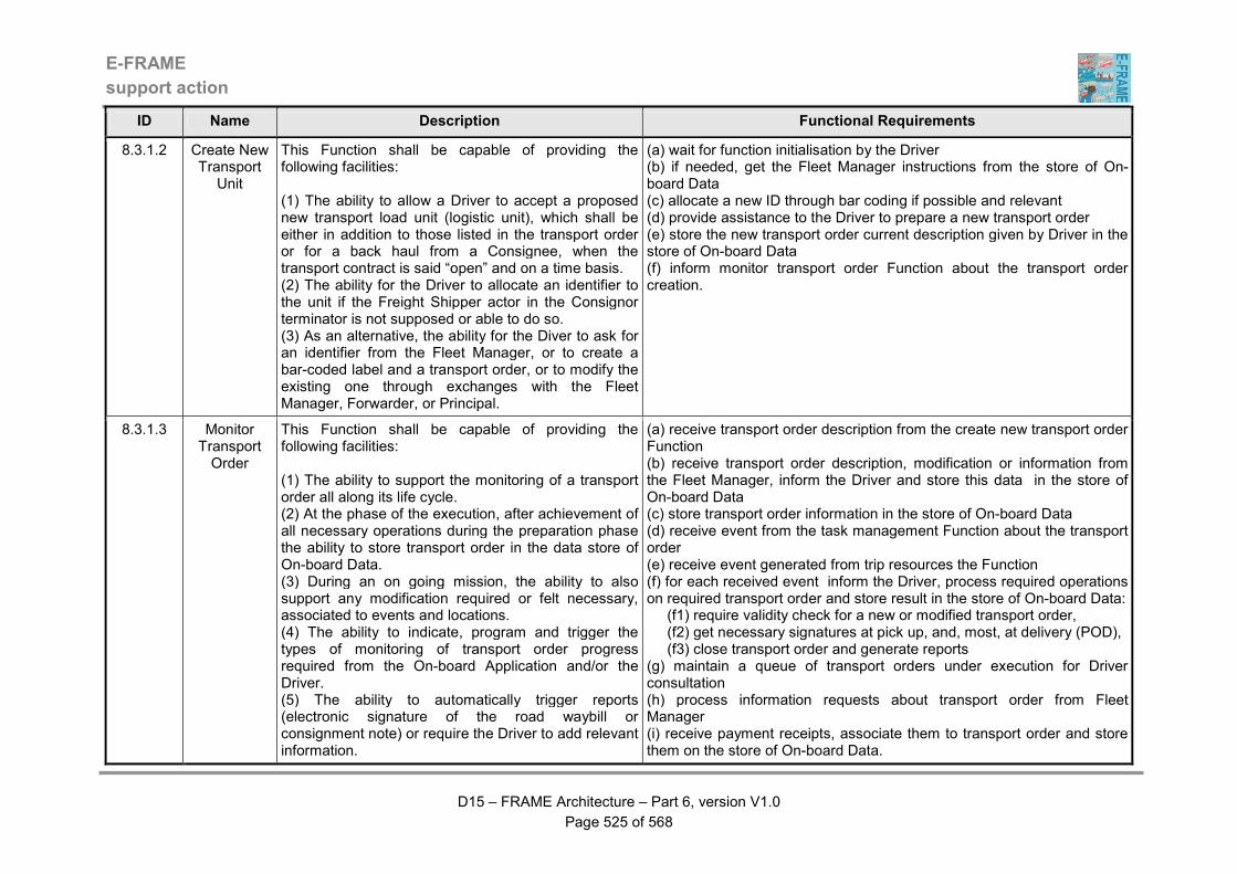
E-FRAME
support action
D15 – FRAME Architecture – Part 6, version V1.0
Page 525 of 568
ID Name Description Functional Requirements
8.3.1.2 Create New Transport
Unit
This Function shall be capable of providing the following facilities: (1) The ability to allow a Driver to accept a proposed new transport load unit (logistic unit), which shall be either in addition to those listed in the transport order or for a back haul from a Consignee, when the transport contract is said “open” and on a time basis. (2) The ability for the Driver to allocate an identifier to the unit if the Freight Shipper actor in the Consignor terminator is not supposed or able to do so. (3) As an alternative, the ability for the Diver to ask for an identifier from the Fleet Manager, or to create a bar-coded label and a transport order, or to modify the existing one through exchanges with the Fleet Manager, Forwarder, or Principal.
(a) wait for function initialisation by the Driver (b) if needed, get the Fleet Manager instructions from the store of On-board Data (c) allocate a new ID through bar coding if possible and relevant (d) provide assistance to the Driver to prepare a new transport order (e) store the new transport order current description given by Driver in the store of On-board Data (f) inform monitor transport order Function about the transport order creation.
8.3.1.3 Monitor Transport Order
This Function shall be capable of providing the following facilities: (1) The ability to support the monitoring of a transport order all along its life cycle. (2) At the phase of the execution, after achievement of all necessary operations during the preparation phase the ability to store transport order in the data store of On-board Data. (3) During an on going mission, the ability to also support any modification required or felt necessary, associated to events and locations. (4) The ability to indicate, program and trigger the types of monitoring of transport order progress required from the On-board Application and/or the Driver. (5) The ability to automatically trigger reports (electronic signature of the road waybill or consignment note) or require the Driver to add relevant information.
(a) receive transport order description from the create new transport order Function (b) receive transport order description, modification or information from the Fleet Manager, inform the Driver and store this data in the store of On-board Data (c) store transport order information in the store of On-board Data (d) receive event from the task management Function about the transport order (e) receive event generated from trip resources the Function (f) for each received event inform the Driver, process required operations on required transport order and store result in the store of On-board Data: (f1) require validity check for a new or modified transport order, (f2) get necessary signatures at pick up, and, most, at delivery (POD), (f3) close transport order and generate reports (g) maintain a queue of transport orders under execution for Driver consultation (h) process information requests about transport order from Fleet Manager (i) receive payment receipts, associate them to transport order and store them on the store of On-board Data.
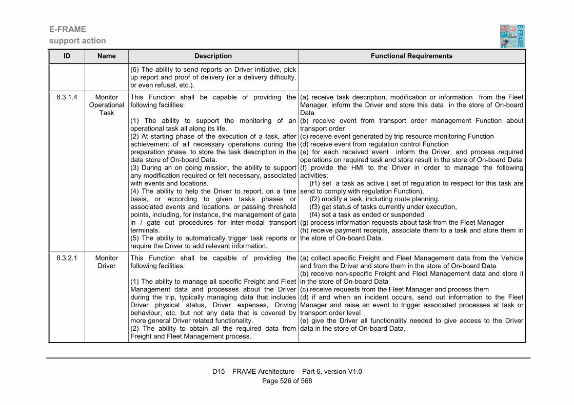
E-FRAME
support action
D15 – FRAME Architecture – Part 6, version V1.0
Page 526 of 568
ID Name Description Functional Requirements
(6) The ability to send reports on Driver initiative, pick up report and proof of delivery (or a delivery difficulty, or even refusal, etc.).
8.3.1.4 Monitor Operational
Task
This Function shall be capable of providing the following facilities: (1) The ability to support the monitoring of an operational task all along its life. (2) At starting phase of the execution of a task, after achievement of all necessary operations during the preparation phase, to store the task description in the data store of On-board Data. (3) During an on going mission, the ability to support any modification required or felt necessary, associated with events and locations. (4) The ability to help the Driver to report, on a time basis, or according to given tasks phases or associated events and locations, or passing threshold points, including, for instance, the management of gate in / gate out procedures for inter-modal transport terminals. (5) The ability to automatically trigger task reports or require the Driver to add relevant information.
(a) receive task description, modification or information from the Fleet Manager, inform the Driver and store this data in the store of On-board Data (b) receive event from transport order management Function about transport order (c) receive event generated by trip resource monitoring Function (d) receive event from regulation control Function (e) for each received event inform the Driver, and process required operations on required task and store result in the store of On-board Data (f) provide the HMI to the Driver in order to manage the following activities: (f1) set a task as active ( set of regulation to respect for this task are send to comply with regulation Function), (f2) modify a task, including route planning, (f3) get status of tasks currently under execution, (f4) set a task as ended or suspended (g) process information requests about task from the Fleet Manager (h) receive payment receipts, associate them to a task and store them in the store of On-board Data.
8.3.2.1 Monitor Driver
This Function shall be capable of providing the following facilities: (1) The ability to manage all specific Freight and Fleet Management data and processes about the Driver during the trip, typically managing data that includes Driver physical status, Driver expenses, Driving behaviour, etc. but not any data that is covered by more general Driver related functionality. (2) The ability to obtain all the required data from Freight and Fleet Management process.
(a) collect specific Freight and Fleet Management data from the Vehicle and from the Driver and store them in the store of On-board Data (b) receive non-specific Freight and Fleet Management data and store it in the store of On-board Data (c) receive requests from the Fleet Manager and process them (d) if and when an incident occurs, send out information to the Fleet Manager and raise an event to trigger associated processes at task or transport order level (e) give the Driver all functionality needed to give access to the Driver data in the store of On-board Data.
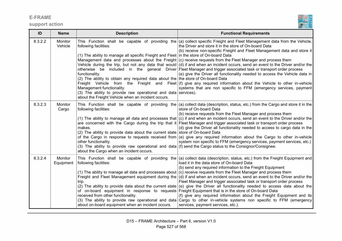
E-FRAME
support action
D15 – FRAME Architecture – Part 6, version V1.0
Page 527 of 568
ID Name Description Functional Requirements
8.3.2.2 Monitor Vehicle
This Function shall be capable of providing the following facilities: (1) The ability to manage all specific Freight and Fleet Management data and processes about the Freight Vehicle during the trip, but not any data that would otherwise be included in the general Driver functionality. (2) The ability to obtain any required data about the Freight Vehicle from the Freight and Fleet Management functionality. (3) The ability to provide raw operational and data about the Freight Vehicle when an incident occurs.
(a) collect specific Freight and Fleet Management data from the Vehicle, the Driver and store it in the store of On-board Data (b) receive non-specific Freight and Fleet Management data and store it in the store of On-board Data (c) receive requests from the Fleet Manager and process them (d) if and when an incident occurs, send an event to the Driver and/or the Fleet Manager and trigger associated task or transport order process (e) give the Driver all functionality needed to access the Vehicle data in the store of On-board Data (f) give any required information about the Vehicle to other in-vehicle systems that are non specific to FFM (emergency services, payment services).
8.3.2.3 Monitor Cargo
This Function shall be capable of providing the following facilities: (1) The ability to manage all data and processes that are concerned with the Cargo during the trip that it makes. (2) The ability to provide data about the current state of the Cargo in response to requests received from other functionality. (3) The ability to provide raw operational and data about the Cargo when an incident occurs.
(a) collect data (description, status, etc.) from the Cargo and store it in the store of On-board Data (b) receive requests from the Fleet Manager and process them (c) if and when an incident occurs, send an event to the Driver and/or the Fleet Manager and trigger associated task or transport order process (d) give the Driver all functionality needed to access to cargo data in the store of On-board Data (e) give any required information about the Cargo to other in-vehicle system non specific to FFM (emergency services, payment services, etc.) (f) send the Cargo status to the Consignor/Consignee.
8.3.2.4 Monitor Equipment
This Function shall be capable of providing the following facilities: (1) The ability to manage all data and processes about Freight and Fleet Management equipment during the trip. (2) The ability to provide data about the current state of on-board equipment in response to requests received from other functionality. (3) The ability to provide raw operational and data about on-board equipment when an incident occurs.
(a) collect data (description, status, etc.) from the Freight Equipment and load it in the data store of On-board Data (b) send any required information to the Freight Equipment (c) receive requests from the Fleet Manager and process them (d) if and when an incident occurs, send an event to the Driver and/or the Fleet Manager and trigger associated task or transport order process (e) give the Driver all functionality needed to access data about the Freight Equipment that is in the store of On-board Data (f) give any required information about the Freight Equipment and its Cargo to other in-vehicle systems non specific to FFM (emergency services, payment services, etc.).

E-FRAME
support action
D15 – FRAME Architecture – Part 6, version V1.0
Page 528 of 568
ID Name Description Functional Requirements
8.3.3 Comply with Regulation
This Function shall be capable of providing the following facilities: (1) The ability to check from on-board data the compliance of the Freight Vehicle with all applicable regulations, which may typically include the European Union’s social regulations as well as the availability on-board of statutory documents required for executing the transport order. (2) The ability to check from on-board data the compliance of the Freight Vehicle with other regulations that may include those covering compliance with road regulations such as speed limits, forbidden lanes / roads to heavy vehicles, weight limits - “Weigh in Motion” - etc. (3) The ability to give access to the on-board data to Legal Authorities through either a removable device storing all regulation data, or by communication with road-side system. (4) The ability to give access to the on-board data to the Fleet Manager. (5) The ability to guaranty the data against fraud, and from being accessed by unauthorised persons.
(a) for each task under execution receive a set of rules to be verified (b) get raw data from the store of On-board Data and check regulation compliance as required (once, on a time basis, etc.) (c) store the check result in the store of On-board Data (d) get the data from the store of On-board Data when requested, for the Driver, Fleet Manager and the Legal Authorities (e) if and when any non-compliance occurs, notify (by raising an event) the Driver, the monitor task Function and the Fleet Manager (f) receive fraud (violation) notification from the Legal Authorities, notify (by raising an event) the Driver, the monitor task Function and the Fleet Manager.
9.1.1 Provide Driver
Interface for Vehicle Priority
This Function shall be capable of providing the following facilities: (1) A HMI through which the Drivers can request priority for their Vehicle through the urban road network and receive the responses to these requests. (2) The HMI must require the Driver to indicate the destination and any mandatory "way points" so that a green wave route can be created. (3) The ability to send the data provided by the Driver through the HMI to the Priority Request functionality. (4) The HMI mist output the data from the Priority Request functionality as soon as it is received,
(a) when the vehicle priority request data flow is received, immediately send the request to the Process Priority Request function (b) when the input data flow containing the response to (a) is received, output the response data flow to the driver (c) when the other vehicle receiving priority data flow is received, output the green wave operating data flow tot he driver
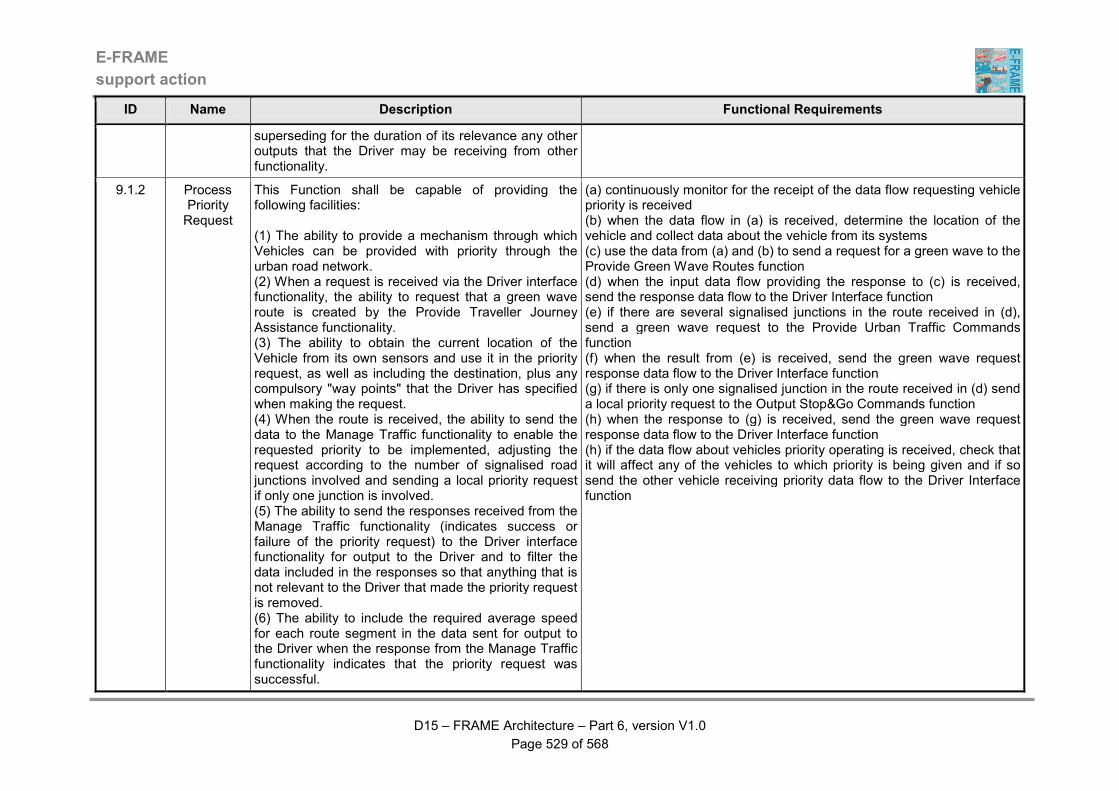
E-FRAME
support action
D15 – FRAME Architecture – Part 6, version V1.0
Page 529 of 568
ID Name Description Functional Requirements
superseding for the duration of its relevance any other outputs that the Driver may be receiving from other functionality.
9.1.2 Process Priority Request
This Function shall be capable of providing the following facilities: (1) The ability to provide a mechanism through which Vehicles can be provided with priority through the urban road network. (2) When a request is received via the Driver interface functionality, the ability to request that a green wave route is created by the Provide Traveller Journey Assistance functionality. (3) The ability to obtain the current location of the Vehicle from its own sensors and use it in the priority request, as well as including the destination, plus any compulsory "way points" that the Driver has specified when making the request. (4) When the route is received, the ability to send the data to the Manage Traffic functionality to enable the requested priority to be implemented, adjusting the request according to the number of signalised road junctions involved and sending a local priority request if only one junction is involved. (5) The ability to send the responses received from the Manage Traffic functionality (indicates success or failure of the priority request) to the Driver interface functionality for output to the Driver and to filter the data included in the responses so that anything that is not relevant to the Driver that made the priority request is removed. (6) The ability to include the required average speed for each route segment in the data sent for output to the Driver when the response from the Manage Traffic functionality indicates that the priority request was successful.
(a) continuously monitor for the receipt of the data flow requesting vehicle priority is received (b) when the data flow in (a) is received, determine the location of the vehicle and collect data about the vehicle from its systems (c) use the data from (a) and (b) to send a request for a green wave to the Provide Green Wave Routes function (d) when the input data flow providing the response to (c) is received, send the response data flow to the Driver Interface function (e) if there are several signalised junctions in the route received in (d), send a green wave request to the Provide Urban Traffic Commands function (f) when the result from (e) is received, send the green wave request response data flow to the Driver Interface function (g) if there is only one signalised junction in the route received in (d) send a local priority request to the Output Stop&Go Commands function (h) when the response to (g) is received, send the green wave request response data flow to the Driver Interface function (h) if the data flow about vehicles priority operating is received, check that it will affect any of the vehicles to which priority is being given and if so send the other vehicle receiving priority data flow to the Driver Interface function
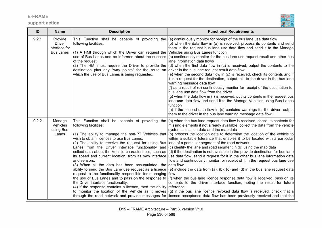
E-FRAME
support action
D15 – FRAME Architecture – Part 6, version V1.0
Page 530 of 568
ID Name Description Functional Requirements
9.2.1 Provide Driver
Interface for Bus Lanes
This Function shall be capable of providing the following facilities: (1) A HMI through which the Driver can request the use of Bus Lanes and be informed about the success of the request. (2) The HMI must require the Driver to provide the destination plus any "way points" for the route on which the use of Bus Lanes is being requested.
(a) continuously monitor for receipt of the bus lane use data flow (b) when the data flow in (a) is received, process its contents and send them in the request bus lane use data flow and send it to the Manage Vehicles using Bus Lanes function (c) continuously monitor for the bus lane use request result and other bus lane information data flows (d) when the first data flow in (c) is received, output the contents to the driver in the bus lane request result data flow (e) when the second data flow in (c) is received, check its contents and if it is a request for the destination, output this to the driver in the bus lane warning message data flow (f) as a result of (e) continuously monitor for receipt of the destination for bus lane use data flow from the driver (g) when the data flow in (f) is received, put its contents in the request bus lane use data flow and send it to the Manage Vehicles using Bus Lanes function (h) if the second data flow in (c) contains warnings for the driver, output them to the driver in the bus lane warning message data flow.
9.2.2 Manage Vehicles using Bus Lanes
This Function shall be capable of providing the following facilities: (1) The ability to manage the non-PT Vehicles that wish to obtain licences to use Bus Lanes. (2) The ability to receive the request for using Bus Lanes from the Driver interface functionality and collect data about the Vehicle characteristics, such as its speed and current location, from its own interface and sensors. (3) When all the data has been accumulated, the ability to send the Bus Lane use request as a licence request to the functionality responsible for managing the use of Bus Lanes and to pass on the response to the Driver interface functionality. (4) If the response contains a licence, then the ability to monitor the location of the Vehicle as it moves through the road network and provide messages for
(a) when the bus lane request data flow is received, check its contents for missing elements if not already available, collect the data from the vehicle systems, location data and the map data (b) process the location data to determine the location of the vehicle to within a suitable tolerance that enables it to be located with a particular lane of a particular segment of the road network (c) identify the lane and road segment in (b) using the map data (d) if the destination is not available in the provide destination for bus lane use data flow, send a request for it in the other bus lane information data flow and continuously monitor for receipt of it in the request bus lane use data flow (e) include the data from (a), (b), (c) and (d) in the bus lane request data flow (f) when the bus lane licence response data flow is received, pass on its contents to the driver interface function, noting the result for future reference (g) if the bus lane licence revoked data flow is received, check that a licence acceptance data flow has been previously received and that the
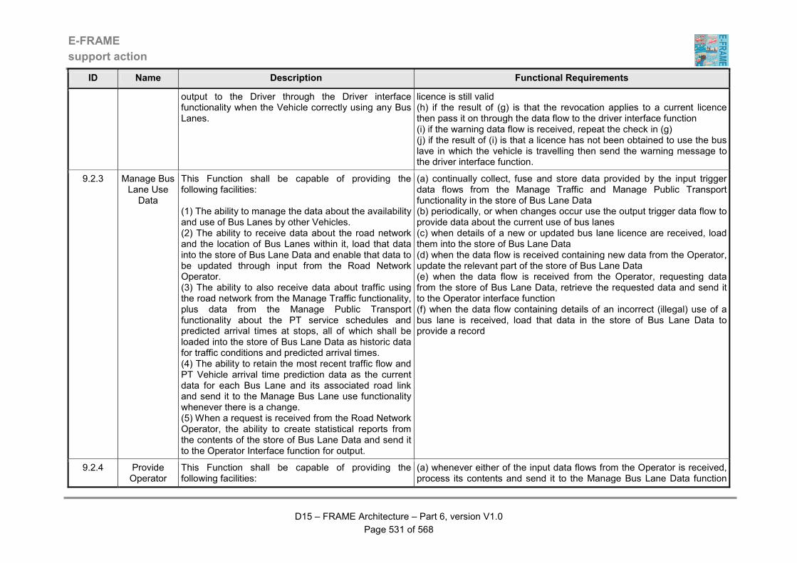
E-FRAME
support action
D15 – FRAME Architecture – Part 6, version V1.0
Page 531 of 568
ID Name Description Functional Requirements
output to the Driver through the Driver interface functionality when the Vehicle correctly using any Bus Lanes.
licence is still valid (h) if the result of (g) is that the revocation applies to a current licence then pass it on through the data flow to the driver interface function (i) if the warning data flow is received, repeat the check in (g) (j) if the result of (i) is that a licence has not been obtained to use the bus lave in which the vehicle is travelling then send the warning message to the driver interface function.
9.2.3 Manage Bus Lane Use Data
This Function shall be capable of providing the following facilities: (1) The ability to manage the data about the availability and use of Bus Lanes by other Vehicles. (2) The ability to receive data about the road network and the location of Bus Lanes within it, load that data into the store of Bus Lane Data and enable that data to be updated through input from the Road Network Operator. (3) The ability to also receive data about traffic using the road network from the Manage Traffic functionality, plus data from the Manage Public Transport functionality about the PT service schedules and predicted arrival times at stops, all of which shall be loaded into the store of Bus Lane Data as historic data for traffic conditions and predicted arrival times. (4) The ability to retain the most recent traffic flow and PT Vehicle arrival time prediction data as the current data for each Bus Lane and its associated road link and send it to the Manage Bus Lane use functionality whenever there is a change. (5) When a request is received from the Road Network Operator, the ability to create statistical reports from the contents of the store of Bus Lane Data and send it to the Operator Interface function for output.
(a) continually collect, fuse and store data provided by the input trigger data flows from the Manage Traffic and Manage Public Transport functionality in the store of Bus Lane Data (b) periodically, or when changes occur use the output trigger data flow to provide data about the current use of bus lanes (c) when details of a new or updated bus lane licence are received, load them into the store of Bus Lane Data (d) when the data flow is received containing new data from the Operator, update the relevant part of the store of Bus Lane Data (e) when the data flow is received from the Operator, requesting data from the store of Bus Lane Data, retrieve the requested data and send it to the Operator interface function (f) when the data flow containing details of an incorrect (illegal) use of a bus lane is received, load that data in the store of Bus Lane Data to provide a record
9.2.4 Provide Operator
This Function shall be capable of providing the following facilities:
(a) whenever either of the input data flows from the Operator is received, process its contents and send it to the Manage Bus Lane Data function
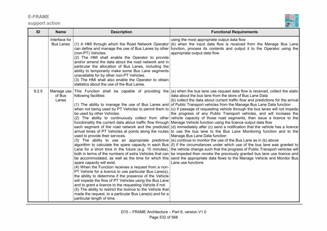
E-FRAME
support action
D15 – FRAME Architecture – Part 6, version V1.0
Page 532 of 568
ID Name Description Functional Requirements
Interface for Bus Lanes
(1) A HMI through which the Road Network Operator can define and manage the use of Bus Lanes by other (non-PT) Vehicles. (2) The HMI shall enable the Operator to provide and/or amend the data about the road network and in particular the allocation of Bus Lanes, including the ability to temporarily make some Bus Lane segments unavailable for by other non-PT Vehicles. (3) The HMI shall also enable the Operator to obtain statistics about the use of the Bus Lanes.
using the most appropriate output data flow (b) when the input data flow is received from the Manage Bus Lane function, process its contents and output it to the Operator using the appropriate output data flow.
9.2.5 Manage use of Bus Lanes
This Function shall be capable of providing the following facilities: (1) The ability to manage the use of Bus Lanes and when not being used by PT Vehicles to permit them to be used by other Vehicles. (2) The ability to continuously collect from other functionality the current data about traffic flow through each segment of the road network and the predicted arrival times of PT Vehicles at points along the routes used to provide their services. (3) The ability to use an appropriate predictive algorithm to calculate the spare capacity in each Bus Lane for a short time in the future (e.g. 15 minutes), both in terms of the numbers of extra Vehicles that can be accommodated, as well as the time for which this spare capacity will exist. (4) When the Function receives a request from a non-PT Vehicle for a licence to use particular Bus Lane(s), the ability to determine if the presence of the Vehicle will impede the flow of PT Vehicles using the Bus Lane and to grant a licence to the requesting Vehicle if not. (5) The ability to restrict the licence to the Vehicle that made the request, to a particular Bus Lane(s) and for a particular length of time.
(a) when the bus lane use request data flow is received, collect the static data about the bus lane from the store of Bus Lane Data (b) collect the data about current traffic flow and predictions for the arrival of Public Transport vehicles from the Manage Bus Lane Data function (c) if passage of requesting vehicle through the bus lanes will not impede the progress of any Public Transport vehicles, and will increase the vehicle capacity of those road segments, then issue a licence to the Manage Vehicle function using the licence output data flow (d) immediately after (c) send a notification that the vehicle has a licence to use the bus lane to the Bus Lane Monitoring function and to the Manage Bus Lane Data function (e) continue to monitor the use of the Bus Lane as in (b) above (f) if the circumstances under which use of the bus lane was granted to the vehicle change such that the progress of Public Transport vehicles will be impeded then revoke the previously granted bus lane use licence and send the appropriate data flows to the Manage Vehicle and Monitor Bus Lane use functions
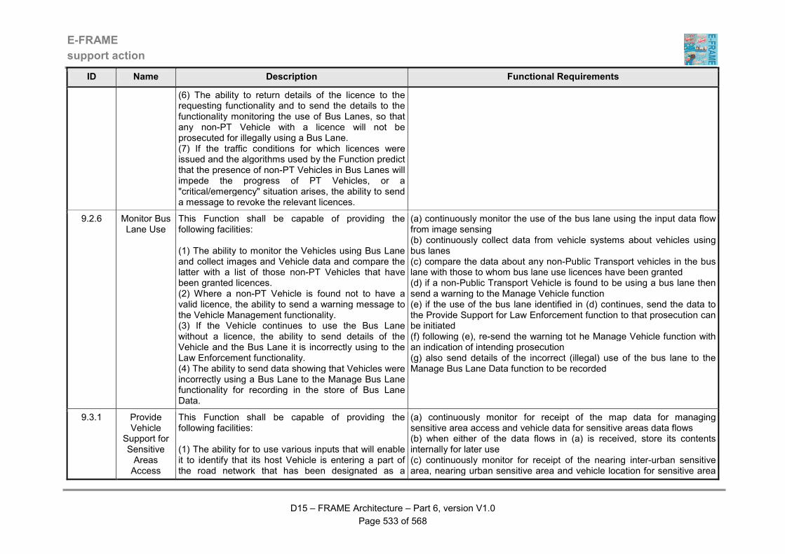
E-FRAME
support action
D15 – FRAME Architecture – Part 6, version V1.0
Page 533 of 568
ID Name Description Functional Requirements
(6) The ability to return details of the licence to the requesting functionality and to send the details to the functionality monitoring the use of Bus Lanes, so that any non-PT Vehicle with a licence will not be prosecuted for illegally using a Bus Lane. (7) If the traffic conditions for which licences were issued and the algorithms used by the Function predict that the presence of non-PT Vehicles in Bus Lanes will impede the progress of PT Vehicles, or a "critical/emergency" situation arises, the ability to send a message to revoke the relevant licences.
9.2.6 Monitor Bus Lane Use
This Function shall be capable of providing the following facilities: (1) The ability to monitor the Vehicles using Bus Lane and collect images and Vehicle data and compare the latter with a list of those non-PT Vehicles that have been granted licences. (2) Where a non-PT Vehicle is found not to have a valid licence, the ability to send a warning message to the Vehicle Management functionality. (3) If the Vehicle continues to use the Bus Lane without a licence, the ability to send details of the Vehicle and the Bus Lane it is incorrectly using to the Law Enforcement functionality. (4) The ability to send data showing that Vehicles were incorrectly using a Bus Lane to the Manage Bus Lane functionality for recording in the store of Bus Lane Data.
(a) continuously monitor the use of the bus lane using the input data flow from image sensing (b) continuously collect data from vehicle systems about vehicles using bus lanes (c) compare the data about any non-Public Transport vehicles in the bus lane with those to whom bus lane use licences have been granted (d) if a non-Public Transport Vehicle is found to be using a bus lane then send a warning to the Manage Vehicle function (e) if the use of the bus lane identified in (d) continues, send the data to the Provide Support for Law Enforcement function to that prosecution can be initiated (f) following (e), re-send the warning tot he Manage Vehicle function with an indication of intending prosecution (g) also send details of the incorrect (illegal) use of the bus lane to the Manage Bus Lane Data function to be recorded
9.3.1 Provide Vehicle
Support for Sensitive Areas Access
This Function shall be capable of providing the following facilities: (1) The ability for to use various inputs that will enable it to identify that its host Vehicle is entering a part of the road network that has been designated as a
(a) continuously monitor for receipt of the map data for managing sensitive area access and vehicle data for sensitive areas data flows (b) when either of the data flows in (a) is received, store its contents internally for later use (c) continuously monitor for receipt of the nearing inter-urban sensitive area, nearing urban sensitive area and vehicle location for sensitive area
E-FRAME
support action
D15 – FRAME Architecture – Part 6, version V1.0
Page 534 of 568
ID Name Description Functional Requirements
"sensitive are". (2) When it finds that the host Vehicle will be entering a "sensitive area", the ability to send an access request to the Manage Data about Vehicle use of Sensitive Areas function and include in the request details of the Vehicle identity, type and other details such as if hazardous goods are being carried. (3) If access is granted the ability to continuously provide data about the location of the host Vehicle so that it can be tracked whilst it is in the "sensitive area". (4) When it detects that its host Vehicle is leaving the "sensitive area" it shall provide this information to the Manage Data about Vehicle use of Sensitive Areas function and shall provide a report to the Driver of the host Vehicle via other functionality. (5) If the host Vehicle is not granted permission to access the "sensitive area" it shall output a message to the Driver, again via other functionality.
access data flows (d) when either of the first two data flows in (c) is received, collect the vehicle data stored in (b) and send it to the Manage Data about Vehicle use of Sensitive Areas function in the request sensitive area entry permission data flow (e) when the third data flow in (c) is received use the location data and the map data stored in (b) to determine the current location and compare this with the location of any "sensitive areas" in the map data (f) if as a result of (e) it is indicated that a "sensitive area" is about to be entered, collect the vehicle data also stored in (b) and send it to the Manage Data about Vehicle use of Sensitive Areas function in the request sensitive area entry permission data flow (g) as a result of (d) and (f) continuously monitor for receipt of the requested sensitive area entry permission data flow from the Manage Data about Vehicle use of Sensitive Areas function (h) when the data flow in (g) is received, determine if the result is that access has been granted or not (i) if the answer in (h) is that access has not been granted, use the results of (e) to determine whether the "sensitive area" is in the inter-urban or urban road network (j) depending on the result from (i) put the vehicle identify in either the inter-urban sensitive area access refused or urban sensitive area access refused data flow and send it to either the Prevent Access to Inter-urban Zones or the Prevent Access to Urban Zones function as appropriate (k) when (j) has been completed, putting a refusal response in the driver instructions for sensitive areas data flow before sending it to the Output Comments and Dynamic Warnings function (l) if the answer in (h) is that access has been granted, put a acceptance response plus any driver instructions containing in the data flow in (g) in the driver restrictions for sensitive areas data flow before sending it to the Output Comments and Dynamic Warnings function (m) as a result of (l) continuously monitor for receipt of the vehicle location for sensitive area access data flow (n) whenever the data flow in (m) is received, use the map data received in (b) to check that the location is still within the "sensitive area" (o) if the check in (n) shows that the location is still within the "sensitive

E-FRAME
support action
D15 – FRAME Architecture – Part 6, version V1.0
Page 535 of 568
ID Name Description Functional Requirements
area", send it to the Manage Data about Vehicle use of Sensitive Areas function in the current vehicle location in sensitive area data flow (p) if the check in (n) shows that the location is outside the "sensitive area", send this information to the Manage Data about Vehicle use of Sensitive Areas function in the vehicle leaving sensitive area data flow (q) having completed (p) create a report for the driver about the use of the "sensitive area" and send it to the Output Comments and Dynamic Warnings function in the driver report from sensitive area data flow.
9.3.2 Manage Data about Vehicle use of Sensitive
Areas
This Function shall be capable of providing the following facilities: (1) The ability to take responsibility for the management of the use of "sensitive areas". (2) The ability to receive requests from Vehicles to enter these "sensitive areas" and to grant access provided that certain criteria are fulfilled. (3) When access is granted, the ability to use the Vehicle location data that it receives to monitor the use Vehicles are making of the "sensitive areas" and to send instructions for output to Drivers via other functionality if and when required. (4) The ability to store information about the Vehicles that use the "sensitive areas" and the criteria for their admission in the store of Sensitive Area Monitoring Data. (5) The ability for the Road Network Operator to provide updates to the admission criteria and to see the current criteria through the Provide Operator Interface for Sensitive Area use Function.
(a) continuously monitor for receipt of the request sensitive area entry permission, plus update vehicle access criteria data flow and the data flow containing request current vehicle access data (b) when the first data flow in (a) is received, compare the Vehicle data that it contains with the criteria extracted from the store of Sensitive Area Monitoring Data using the data flow read sensitive area data (c) if the Vehicle fails the acceptance criteria, put this in the requested sensitive area entry permission data flow and send it to the Provide Vehicle Support for Sensitive Areas Access function (d) if the Vehicle passes the acceptance criteria, put this and any initial instructions for the vehicle driver in the requested sensitive area entry permission data flow and send it to the Provide Vehicle Support for Sensitive Areas Access function (e) as a result of (d) load the vehicle details into the store of Sensitive Area Monitoring Data using the data flow load sensitive area data and continuously monitor for receipt of the current vehicle location in sensitive area and vehicle leaving sensitive area data flows (f) when the first data flow in (e) is received, load the location with the associated vehicle identity into the store of Sensitive Area Monitoring Data using the data flow load sensitive area data (g) when the second data flow in (e) is received, close the data about the use by this particular Vehicle of the "sensitive area" in the store of Sensitive Area Monitoring Data using the data flow load sensitive area data (h) when the second data flow in (a) is received, update the criteria in the store of Sensitive Area Monitoring Data using the data flow load sensitive area data (i) when the third data flow in (a) is received, check its contents to see if it
E-FRAME
support action
D15 – FRAME Architecture – Part 6, version V1.0
Page 536 of 568
ID Name Description Functional Requirements
is a request for a copy of the current criteria, or for a report on the use vehicles have made of the "sensitive area" (j) if it is the first request in (i), collect the current criteria from the store of Sensitive Area Monitoring Data using the data flow read sensitive area data and send it to the Provide Operator Interface for Sensitive Area Use function in the data flow containing current vehicle access data (k) if it is the second request in (i), collect all the data about vehicles that have used the "sensitive area" and send it to the Provide Operator Interface for Sensitive Area Use function in the data flow containing current vehicle access data.
9.3.3 Provide Operator
Interface for Sensitive Area Use
This Function shall be capable of providing the following facilities: (1) A HMI through which the Road Network Operator can manage the criteria that are used to control the access of Vehicles to "sensitive areas" within the road network. (2) The ability for the Operator to use the HMI to request details of the current criteria and to update them. (3) The ability for the Operator to request and be provided with a report on the use that Vehicles have made of the "sensitive areas" in the road network.
(a) continuously monitor for receipt of the request current vehicle access criteria, update current vehicle access criteria and request sensitive area vehicle use report data flows (b) when the first data flow in (a) is received, put the request in the data flow request current vehicle access data and send it to the Manage Data about Vehicle user of Sensitive Areas function (c) as a result of (b) continuously monitor for receipt of the data flow current vehicle access data (d) when the data flow in (c) is received, output its contents to the Road Network Operator in the current vehicle access criteria data flow (e) when the second data flow in (a) is received, send the updated criteria to the Manage Data about Vehicle use of Sensitive Areas function in the update current vehicle access criteria data flow (f) when the third data flow in (a) is received, put the request in the data flow request current vehicle access data and send it to the Manage Data about Vehicle user of Sensitive Areas function (g) as a result of (b) continuously monitor for receipt of the data flow current vehicle access data (h) when the data flow in (g) is received, output its contents to the Road Network Operator in the requested sensitive area vehicle use report data flow.
9.4.1 Provide Manage
Hazardous Goods
This Function shall be capable of providing the following facilities: (1) A HMI through which the Road Network Operator
(a) continuously monitor for receipt of the hazardous goods vehicle criteria request or hazardous good criteria update data flows (b) when the first data flow in (a) is received, the contents shall be send to the Manage and Monitor Hazardous Goods Vehicle Routes function in the
E-FRAME
support action
D15 – FRAME Architecture – Part 6, version V1.0
Page 537 of 568
ID Name Description Functional Requirements
Operator Interface
can have access to the criteria used to determine routes for Vehicles that are carrying Hazardous Goods. (2) The ability for the Operator to use the HMI to either be provided with an output of the current criteria, or to update the current criteria.
hazardous goods vehicle route criteria input data flow (c) as a result of (b) continuously monitor for receipt of the hazardous goods vehicle criteria output data flow (d) when the data flow in (c) is received, its contents shall be output to the Road Network Operator in the hazardous goods vehicle criteria output data flow (e) when the second data flow in (a) is received, the contents shall be sent to the Manage and Monitor Hazardous Goods Vehicle Routes function in the hazardous goods vehicle route criteria input data flow.
9.4.2 Manage and Monitor
Hazardous Goods Vehicle Routes
This Function shall be capable of providing the following facilities: (1) The ability to manage the use of routes by Vehicles carrying Hazardous Goods. (2) The ability to get route for the Vehicle determined by the Trip Planning functionality using criteria provided by the Road Network Operator together with data about the actual route provided by the Driver through the a HMI on-board the Vehicle. (3) The ability to keep all routes that are determined plus the criteria used to do this, the Vehicle details, route origin and destination as a record of what was used and in case they may be useful in the future in the store of Hazardous Vehicle Routes Data. (4) When a route has been determined, the ability to send it to other functionality for actual implementation. (5) The ability to monitor the progress of the Vehicle along the determined route. (6) The ability to send a warning message to the Driver Interface Function to alert the Driver if the Vehicle is found to be deviating from the determined route. (7) The ability to send details of the route to another instance of itself and to receive details of routes from other instances of itself. (8) For routes received from other instances of itself, the ability to monitor the progress of the Vehicle
(a) continuously monitor for receipt of the hazardous goods vehicle route request data flow (b) when the data flow in (a) is received, extract the route determination criteria from the store of Hazardous Vehicle Routes Data using the hazardous routes data load and hazardous routes data read data flows (c) when (b) is complete, send the complete route determination data to the BBBB function in the hazardous goods vehicle route request data flow (d) continuously monitor for receipt of the hazardous goods vehicle route response data flow (e) when the data flow in (d) is received, load the route information into the store of Hazardous Vehicle Routes Data using the hazardous routes data load data flow (f) send the route information to the Provide Hazardous Goods Vehicle Route Management function in the hazardous goods vehicle route details data flow (g) continuously monitor for receipt of the hazardous goods vehicle route location data flow (h) when the data flow in (g) is received, check the location against the information about the route and if a deviation is found, send hazardous goods vehicle deviation from route data flow to the Provide Hazardous Goods Vehicle Driver Interface function (i) continuously monitor for the receipt of the hazardous goods vehicle incident strategy data flow from the Traffic Management functionality (j) when the data flow in (i) is received, assess the impact of the incident strategies on any routes that are currently being implemented (k) if as a result of (j) it is found that the uncompleted portions of any routes will be affected, repeat (c) to (f)
E-FRAME
support action
D15 – FRAME Architecture – Part 6, version V1.0
Page 538 of 568
ID Name Description Functional Requirements
according to the route and again send a warning message to the Driver Interface Function if a problem arises.
(l) if the contents of the data flow in (g) shows that the route the vehicle is following will take it outside of the geographic area administered by this function, send the information about the uncompleted portion of the route plus the appropriate vehicle and hazardous goods information to another instance of the function (other related system) in the hazardous goods vehicle route details data flow (m) continuously monitor for receipt of the hazardous goods vehicle route details data flow from another instance of the function (other related system) (n) when the data flow in (m) is received, continue with (g) and (h) (o) continuously monitor for receipt of the hazardous goods vehicle route criteria input data flow (p) when the data flow in (o) is received, if it contains an update to the existing criteria, load it into the store of Hazardous Vehicle Routes Data using the hazardous routes data load data flow (q) if the data flow in (o) contains a request for the output of the current criteria, extract it from the store of Hazardous Vehicle Routes Data using the hazardous routes data load and hazardous routes data read data flows and send it to the Provide Manage Hazardous Goods Operator Interface function in the hazardous goods vehicle route criteria output data flow.
9.4.3 Provide Hazardous Goods Vehicle Driver
Interface
This Function shall be capable of providing the following facilities: (1) A HMI through which the Driver of a Hazardous Goods Vehicle can request a route to a specified destination and be given guidance for its implementation. (2) The ability to determine the current Vehicle location and details about the Vehicle from other inputs. (3) When a route has been determined, the ability to provide instructions to the Driver for its implementation and to continuously provide the Vehicle location so that progress along the route can be monitored by other functionality. (4) If this other functionality sends a message that the
(a) continuously monitor for receipt of the route request details data flow from the driver plus the hazardous goods vehicle location and hazardous goods vehicle data for route data flows plus the hazardous goods information data flow from the Prepare/Process information to/from board function (b) when the first data flow in (a) is received, combine it with the data from the other three data flows in (a) and send the combined data to the Manage and Monitor Hazardous Goods Vehicle Routes function in the hazardous goods vehicle route request data flow (c) as a result of (b) continuously monitor for the receipt of the hazardous goods vehicle route status data flow from the Provide Hazardous Goods Vehicle Route Management function with a route ready indication (d) when the data flow in (c) is received, output a notification to the Driver that the route is ready for implementation in the route guidance data flow (e) as a result of (d), continuously monitor for receipt of the hazardous
E-FRAME
support action
D15 – FRAME Architecture – Part 6, version V1.0
Page 539 of 568
ID Name Description Functional Requirements
Vehicle is departing from the determined route, the ability to immediately output a warning to the Driver, making sure that this output takes priority of all other non-emergency outputs.
goods vehicle route guidance data flow (f) when the data flow in (e) is received, output its contents to the driver in the route guidance data flow (g) as a further result of (d), continuously send the data in the second data flow received in (a) to the Provide Hazardous Goods Vehicle Route Management function in the hazardous goods vehicle route location data flow and to the Provide Hazardous Goods Vehicle Route Management function in the hazardous goods vehicle current location data flow (h) continuously monitor for receipt of the hazardous goods vehicle deviating from route data flow (i) when the data flow in (h) is received, immediately output its contents to the driver in the vehicle deviating from route data flow, making sure that this output takes priority over all other non-emergency outputs (j) continuously monitor for receipt of the re-determine route request data flow from the Driver (k) when the data flow in (j) is received, collect all of the data used for the previous route request and repeat (b) to (i) (l) all the time that (e) to (g) are being implemented, continuously monitor for receipt of the hazardous goods vehicle route status data flow from the Provide Hazardous Goods Vehicle Route Management function (m) when the data flow in (l) is received with a route finished indication, output an appropriate message to the driver using the route guidance data flow and return to (a).
9.4.4 Provide Hazardous Goods Vehicle Route
Management
This Function shall be capable of providing the following facilities: (1) The ability to generate route guidance instructions for the implementation of a route that the Driver of a Hazardous Goods Vehicle has previously requested that can be sent to the Driver interface functionality. (2) The ability to receive updates of the Vehicle's location as it moves along the route. (3) The ability to use these updates to find the next appropriate set of instructions, which it will send to the Driver interface functionality. (4) The ability to manage the simultaneous use of
(a) continuously monitor for receipt of the hazardous goods vehicle route details data flow (b) when the data flow in (a) is received, store the route details locally and send the hazardous goods vehicle route status data flow to the Provide Hazardous Goods Vehicle Driver Interface function with a route ready indication (c) continuously monitor for receipt of the hazardous goods vehicle current location data flow (d) each time the data flow in (c) is received, search through the route details stored in (b) to find the next appropriate set of instructions according to the vehicle location provided in (c) (e) send the new instructions to the Provide Hazardous Goods Vehicle Driver Interface function in the hazardous goods vehicle route guidance
E-FRAME
support action
D15 – FRAME Architecture – Part 6, version V1.0
Page 540 of 568
ID Name Description Functional Requirements
route segments by Vehicles carrying different types of hazardous goods.
data flow (f) repeat (c) to (e) until the last instruction has been sent, when the hazardous goods vehicle route status data flow to the Provide Hazardous Goods Vehicle Driver Interface function with a route finished indication (g) if during the implementation of (c) to (e) the data flow in (a) is received again, repeat (b) to (f) for the new route.
9.5.2 Provide Loading/Unloading Zone Operator Interface
This Function shall be capable of providing the following facilities: (1) A HMI through which the Un/Loading Zone Operator can manage the use of parking places in loading or unloading zones and their associated holding zones. (2) The HMI shall enable the Un/Loading Zone Operator to confirm booking requests, plus obtain and update data about the zones. (3) If an incorrect Freight Vehicle is found to be using a parking place, the ability for the HMI to output information about the Vehicle to the Un/Loading Zone Operator.
(a) continuously monitor for receipt of the un/loading zone request and incorrect vehicle in un/loading zone from the Manage Loading or Unloading Zone Bookings function or the data flow containing a request current in/loading zone data and current un/loading zone data update from the parking zone operator (b) when the first data flow in (a) is received, output the request to the un/loading zone operator in the un/loading zone use request data flow and continuously monitor for the response in the un/loading zone use response data flow (c) when the data flow in (b) is received, pass on its contents to the Manage Loading or Unloading Zone Bookings function in the un/loading zone use response data flow (d) when the second data flow in (a) is received, output the vehicle identity to the un/loading zone operator in the incorrect vehicle in un/loading zone data flow (e) when the third data flow is received in (a) send the request to the Manage Store of Loading or Unloading Zone Use function in the data flow expected to contain the request un/loading zone data and continuously monitor for the receipt of the data flow containing the requested un/loading zone data (f) when the data flow in (e) is received, output its contents to the un/loading zone operator in the data flow containing current un/loading zone data (g) when the fourth data flow is received in (a), send the updates to the zone data to the Manage Store of Loading or Unloading Zone Use function in the data flow containing updated un/loading zone data.
9.5.3 Manage Store of
Loading or
This Function shall be capable of providing the following facilities:
(a) continuously monitor for receipt of the request un/loading zone status data flow from the Manage Loading or Unloading Zone Bookings function, or either of the data flows containing updated un/loading zone static data
E-FRAME
support action
D15 – FRAME Architecture – Part 6, version V1.0
Page 541 of 568
ID Name Description Functional Requirements
Unloading Zone Use
(1) The ability to manage the store of Loading or Unloading Zones Data, which contains data about Loading and Unloading zones plus their associated Holding Zones. (2) The ability to load into the store the data about each zone (e.g. location, number of places, use restrictions, use guidance) that is provided by the Parking Zone Operator via the Provide Loading/Unloading Zone Operator Interface function. (3) The ability to update the store with information about bookings for parking places in the zones so that it has access to a coherent and up to date record of the historical, current and forecast use.
or request un/loading zone data from the Provide loading/Unloading Zone Operator Interface function (b) when first or second data flows in (a) is received, check to see if it contains data to be loaded into the store of Loading or Unloading Zones Data and if it does use the data flow containing load zone use data to do this (c) when the first data flow is received in (a) , extract the requested data from the store of Loading or Unloading Zones Data using the data flows containing load zone use data and read zone use data and send it to the Manage Loading or Unloading Zone Bookings function in the requested un/loading zone status data flow (d) when the third data flow is received in (a) , extract the requested data from the store of Loading or Unloading Zones Data using the data flows containing load zone use data and read zone use data and send it to the Provide loading/Unloading Zone Operator Interface function in the data flow containing requested un/loading zone data.
9.5.4 Detect Vehicle Using
Loading or Unloading Zone
This Function shall be capable of providing the following facilities: (1) The ability to continuously monitor the use of each parking place in a Loading or Unloading. (2) The ability for its sensors to detect that a Vehicle is occupying a parking place and to use the data from the sensors to determine the Vehicle identity. (3) The ability to send the determined identity to the Manage Loading or Unloading Zone Bookings Function.
(a) continuously monitor for receipt of either of the input data flows (b) when either of the data flows in (a) is received use its contents to determine if the identity of the vehicle has changed (c) if a change is detected in (b) store the new vehicle identity locally and send it to the Manage Loading or Unloading Zone Bookings function in the freight vehicle identity for un/loading zone data flow.
9.5.5 Detect Vehicle Using Holding Zone
This Function shall be capable of providing the following facilities: (1) The ability to continuously monitor the use of each parking place in a Holding Zone. (2) The ability for its sensors to detect that a Vehicle is occupying a parking place and to use the data from the sensors to determine the Vehicle identity.
(a) continuously monitor for receipt of either of the input data flows (b) when either of the data flows in (a) is received, use its contents to determine the identity of the vehicle has changed (c) if a change is detected in (b) store the new vehicle identity locally and send it to the Manage Loading or Unloading Zone Bookings function in the freight vehicle identity for holding zone data flow.
E-FRAME
support action
D15 – FRAME Architecture – Part 6, version V1.0
Page 542 of 568
ID Name Description Functional Requirements
(3) The ability to send the determined identity to the Manage Loading or Unloading Zone Bookings Function.
9.5.6 Loading or Unloading Zone
Booking Managemen
t
This Function shall be capable of providing the following facilities: (1) The ability to take responsibility for managing the use of loading or unloading zones and holding zones that are used by Freight Vehicle to pick up and deliver goods. (2) The ability to receive requests from the Freight Vehicle Driver via the Vehicle Trip Planning functionality to book a parking place in a loading or unloading zone. (3) If a place is found to be free the ability to obtain confirmation from the Parking Zone Operator through the Provide Loading/Unloading Zone Operator Interface function. (4) If there is no parking place available to suit the request from the Freight Vehicle Driver, the ability to recommend alternative loading and unloading zones and/or to determine which is the best holding zone to use until a parking place becomes available. (5) The ability to check the booking against revisions to the Estimated Time of Arrival (ETA) provided by the Vehicle Trip Plan monitoring functionality and to provide guidance to the Freight Vehicle Driver interface functionality if the booking is still valid. (6) If the ETA has changed to the extent that the original booking is no longer valid and cannot be honoured then the ability to recommend alterative times, and/or alternative zones, and/or the use of a holding zone until a parking place becomes available. (7) The ability to receive the identity of each Freight Vehicle using each parking place and to send a message to the Parking Operator if an incorrect
(a) continuously monitor for receipt of the un/loading zone use request data flow from the Manage Freight Vehicle Loading/Unloading Zone Use function (b) when the data flow in (a) is received, use the request un/loading zone status and requested un/loading zone status data flows sent to and received from the Manage Store of Loading or Unloading Zone Use function to determine if the requested zone is free for the parameters included in the request (c) if the response to (b) is that zone is available, send it with a use request to the Provide Loading/Unloading Zone Operator Interface function in the request un/loading zone use data flow (d) as a result of (c) continuously monitor for receipt of the un/loading zone request response data flow (e) when the data flow in (d) is received, check its contents and if the answer is acceptance, send this to the Manage Freight Vehicle Loading/Unloading Zone Use function in the un/loading zone response data flow (f) if the response in (e) is rejection, use the same data flows as in (b) to find out when the zone will be available and/or when a holding zone will be available for use until the requested loading or unloading zone is available (g) send the results of (f) to the Manage Freight Vehicle Parking Reservations function in the loading or unloading zone response data flow (h) if the response to (b) is that the zone is not available at the times requested, use the same data flows as in (b) to find out when the zone will be available and/or when a holding zone will be available for use until the requested loading or unloading zone is available (i) send the response to (h) in the un/loading zone response data flow to the Manage Freight Vehicle Loading/Unloading Zone Use function (j) as a result of (e) or (i) continuously monitor for receipt of the un/loading zone use confirmation data flow (k) when the data flow in (j) is received with a positive response, send this
E-FRAME
support action
D15 – FRAME Architecture – Part 6, version V1.0
Page 543 of 568
ID Name Description Functional Requirements
Vehicle is found to be occupying the parking place. (8) The ability to update the booking information when a message is received from the Vehicle Trip Plan Monitoring functionality that the Freight Vehicle has left the parking place. (9) The ability to provide micro-routing information for use by Freight Vehicle Drivers to navigate in and around the un/loading zone.
to the Manage Store of Loading or Unloading Zone Use function in the request un/loading zone status data flow (l) if the data flow in (j) contains a rejection, repeat (b) to (j) using the contents of the data flow as the new request for use of a loading or unloading zone (m) continuously monitor for receipt of the un/loading zone eta or holding zone eta data flows from the Monitor Vehicle Trip Plan Implementation function (n) when either of the data flows in (m) is received, check that the previously booking zone is free using the data flows in (b) (o) if the result of (n) is positive, send the detailed information about how to find and use the loading or unloading zone or holding zone to the Manage Freight Vehicle Parking Use function in either the un/loading zone routing information or holding zone routing information data flows respectively (p) repeat (m), but if no further inputs of the data flow are received after a period of time, return to (a) (q) if the result of (n) is negative, use the data flows in (b) to find out when the zone will be available and/or when a suitable holding zone will be available for use until the requested loading or unloading zone is available (r) send the result of (q) to the Manage Freight Vehicle Loading/Unloading Zone Use function in either the un/loading zone unavailable for new eta or holding zone unavailable for new eta data flows respectively (s) as a result of (r) continuously monitor for receipt of the un/loading zone use request data flow from the Manage Freight Vehicle Loading/Unloading Zone Use function (t) repeat (b) to (i), and when successful repeat (j), but if no further inputs of the data flow are received after a period of time, return to (a) (u) continuously monitor for receipt of the freight vehicle identity for un/loading zone data flow from the Detect Vehicle Using Loading or Unloading Zone function (v) if the data flow in (u) shows a change in vehicle identity, check that it is the correct vehicle that is using the Loading or Unloading zone and if not send the incorrect vehicle using un/loading zone data flow to the Provide Loading/Unloading Zone Operator Interface function
E-FRAME
support action
D15 – FRAME Architecture – Part 6, version V1.0
Page 544 of 568
ID Name Description Functional Requirements
(w) if the data flow in (u) shows that the correct vehicle has now entered or left the Loading or Unloading zone update its status by sending the change in the request un/loading zone status data flow to the Manage Store of Loading or Unloading Zone Use function (x) repeat (u) to (w) for the freight vehicle identity for holding zone data flow from the Detect Vehicle Using Holding Zone function (y) continuously monitor for receipt of the freight vehicle left un/loading zone data flow from the Monitor Vehicle Trip Plan Implementation function (z) when the data flow in (y) is received, update the zone status by sending the change in the request un/loading zone status data flow to the Manage Store of Loading or Unloading Zone Use function.
9.5.7 Provide Un/loading Zone Fleet Operator Interface
This Function shall be capable of providing the following facilities: (1) A HMI that enables information to be provided to the Fleet Operator. (2) The ability to receive information about un/loading zone bookings made by Heavy Goods Vehicle Drivers. (3) The ability to filter the information received to remove that which is not related to Heavy Goods Vehicles the identities of which have not been specified by the Fleet Operator. (4) The ability to use the HMI to output information about un/loading zone bookings that have been made by the Drivers of Heavy Goods Vehicles specified by the Fleet Operator.
(a) continuously monitor for receipt of the un/loading zone booking for fleet manager and the hgv identity for un/loading zone booking data flows (b) when the second data flow in (a) is received, store its contents internally as the list of identities of heavy goods vehicles for which the fleet operator wants to receive information about their un/loading zone bookings (c) when the first data flow is received in (a), check the contents and filter out those which relate to un/loading zone bookings for heavy goods vehicles whose identities have not been provided by the fleet operator (d) as a result of (c) output the remaining un/loading zone bookings for heavy goods vehicles to the fleet operator in the un/loading zone booking details data flow
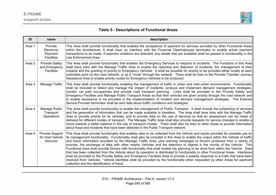
E-FRAME
support action
D15 – FRAME Architecture – Part 6, version V1.0
Page 545 of 568
Table 5 - Descriptions of Functional Areas
ID name description
Area 1 Provide Electronic Payment Facilities
This Area shall provide functionality that enables the acceptance of payment for services provided by other Functional Areas within the Architecture. It shall have an interface with the Financial Clearinghouse terminator to enable actual payment transactions to be made. If payment violations are detected, any details that are available shall be passed to functionality in the Law Enforcement Area.
Area 2 Provide Safety and Emergency
Facilities
This Area shall provide functionality that enables the Emergency Services to respond to incidents. The Functions in this Area shall have links with the Manage Traffic Area to enable the reporting and detection of incidents, the management of their impacts and the granting of priority to Emergency Vehicles. It shall be possible for priority to be provided either locally at each controlled point on the road network, or as a "route" through the network. There shall be links to the Provide Traveller Journey Assistance Area to enable priority routes for Emergency Vehicles to be produced.
Area 3 Manage Traffic This Area shall provide functionality enabling the management of traffic in urban and inter-urban environments. Functionality shall be included to detect and manage the impact of incidents, produce and implement demand management strategies, monitor car park occupancies and provide road transport planning. Links shall be provided to the Provide Safety and Emergency Facilities and Manage Public Transport Areas so that their vehicles are given priority through the road network and to enable assistance to be provided in the implementation of incident and demand management strategies. The External Service Provider terminator shall be sent data about traffic conditions and strategies.
Area 4 Manage Public Transport Operations
This Area shall provide functionality to enable the management of Public Transport. It shall include the scheduling of services and the generation of information that can be made available to travellers. The Area shall have links with the Manage Traffic Area to provide priority for its vehicles, and to provide data on the use of services so that an assessment can be made of demand for different modes of transport. The Manage Traffic Area shall also provide requests for service changes to enable a move towards a better balance in the use of transport modes. There shall also be links to other Areas to provide information about fraud and incidents that have been detected in the Public Transport network.
Area 5 Provide Support for Host Vehicle
Services
This Area shall provide functionality that enables data to be collected from the Vehicle and inputs provided for possible use by its management functionality. Functionality shall also be included in this Area to enable the output within the Vehicle of traffic and travel information provided by the Manage Traffic Area, plus warning messages to Drivers produced from a variety of sources, the exchange of data with other nearby Vehicles and the detection of objects in the vicinity of the Vehicle. This Functional Area shall provide Drivers with functionality that shall enable trip planning to be done from within the Vehicle. Data that has been collected from the Vehicle about its operation is distributed to functionality in other Functional Areas. Interfaces shall be provided to the Provide Safety and Emergency Facilities Area to provide a speedy response to e-Calls that have been received from Vehicles. Vehicle identities shall be provided by the functionality when requested by other Areas for payment collection and the identification of fraud.
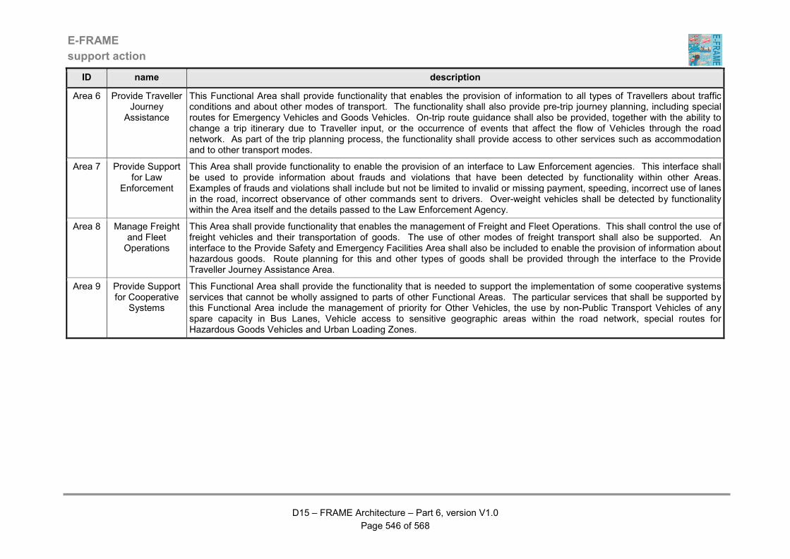
E-FRAME
support action
D15 – FRAME Architecture – Part 6, version V1.0
Page 546 of 568
ID name description
Area 6 Provide Traveller Journey
Assistance
This Functional Area shall provide functionality that enables the provision of information to all types of Travellers about traffic conditions and about other modes of transport. The functionality shall also provide pre-trip journey planning, including special routes for Emergency Vehicles and Goods Vehicles. On-trip route guidance shall also be provided, together with the ability to change a trip itinerary due to Traveller input, or the occurrence of events that affect the flow of Vehicles through the road network. As part of the trip planning process, the functionality shall provide access to other services such as accommodation and to other transport modes.
Area 7 Provide Support for Law
Enforcement
This Area shall provide functionality to enable the provision of an interface to Law Enforcement agencies. This interface shall be used to provide information about frauds and violations that have been detected by functionality within other Areas. Examples of frauds and violations shall include but not be limited to invalid or missing payment, speeding, incorrect use of lanes in the road, incorrect observance of other commands sent to drivers. Over-weight vehicles shall be detected by functionality within the Area itself and the details passed to the Law Enforcement Agency.
Area 8 Manage Freight and Fleet Operations
This Area shall provide functionality that enables the management of Freight and Fleet Operations. This shall control the use of freight vehicles and their transportation of goods. The use of other modes of freight transport shall also be supported. An interface to the Provide Safety and Emergency Facilities Area shall also be included to enable the provision of information about hazardous goods. Route planning for this and other types of goods shall be provided through the interface to the Provide Traveller Journey Assistance Area.
Area 9 Provide Support for Cooperative
Systems
This Functional Area shall provide the functionality that is needed to support the implementation of some cooperative systems services that cannot be wholly assigned to parts of other Functional Areas. The particular services that shall be supported by this Functional Area include the management of priority for Other Vehicles, the use by non-Public Transport Vehicles of any spare capacity in Bus Lanes, Vehicle access to sensitive geographic areas within the road network, special routes for Hazardous Goods Vehicles and Urban Loading Zones.
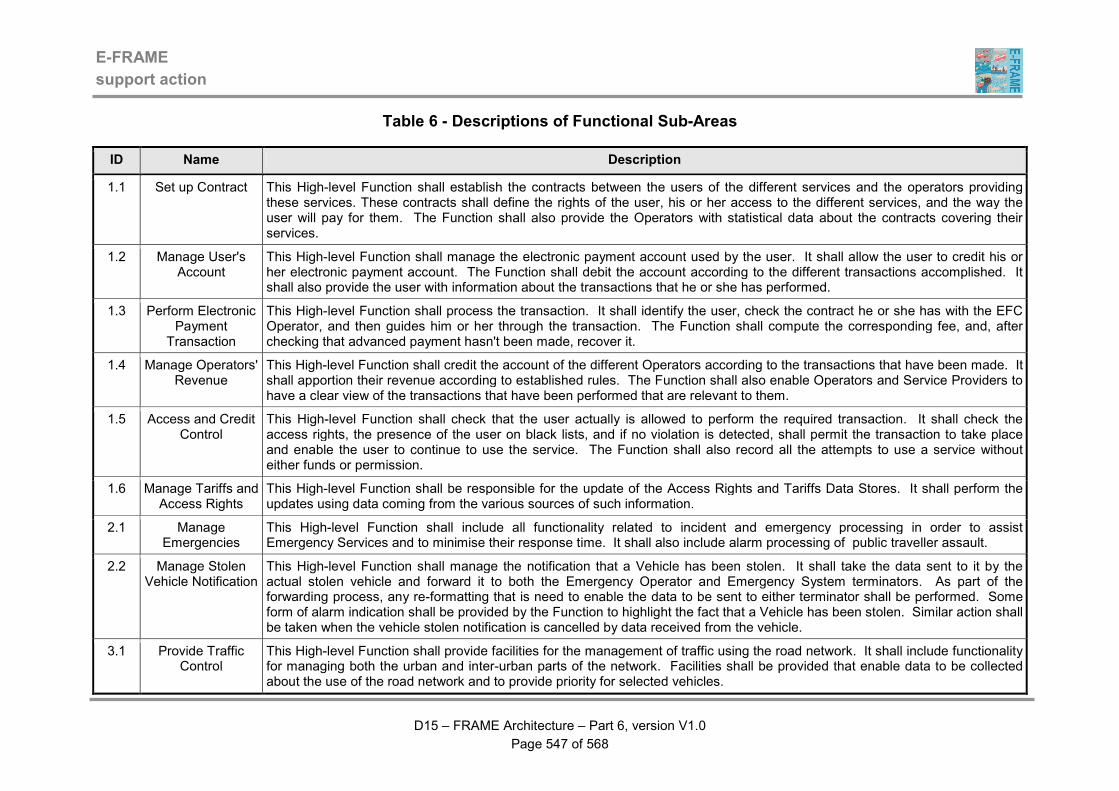
E-FRAME
support action
D15 – FRAME Architecture – Part 6, version V1.0
Page 547 of 568
Table 6 - Descriptions of Functional Sub-Areas
ID Name Description
1.1 Set up Contract This High-level Function shall establish the contracts between the users of the different services and the operators providing these services. These contracts shall define the rights of the user, his or her access to the different services, and the way the user will pay for them. The Function shall also provide the Operators with statistical data about the contracts covering their services.
1.2 Manage User's Account
This High-level Function shall manage the electronic payment account used by the user. It shall allow the user to credit his or her electronic payment account. The Function shall debit the account according to the different transactions accomplished. It shall also provide the user with information about the transactions that he or she has performed.
1.3 Perform Electronic Payment
Transaction
This High-level Function shall process the transaction. It shall identify the user, check the contract he or she has with the EFC Operator, and then guides him or her through the transaction. The Function shall compute the corresponding fee, and, after checking that advanced payment hasn't been made, recover it.
1.4 Manage Operators' Revenue
This High-level Function shall credit the account of the different Operators according to the transactions that have been made. It shall apportion their revenue according to established rules. The Function shall also enable Operators and Service Providers to have a clear view of the transactions that have been performed that are relevant to them.
1.5 Access and Credit Control
This High-level Function shall check that the user actually is allowed to perform the required transaction. It shall check the access rights, the presence of the user on black lists, and if no violation is detected, shall permit the transaction to take place and enable the user to continue to use the service. The Function shall also record all the attempts to use a service without either funds or permission.
1.6 Manage Tariffs and Access Rights
This High-level Function shall be responsible for the update of the Access Rights and Tariffs Data Stores. It shall perform the updates using data coming from the various sources of such information.
2.1 Manage Emergencies
This High-level Function shall include all functionality related to incident and emergency processing in order to assist Emergency Services and to minimise their response time. It shall also include alarm processing of public traveller assault.
2.2 Manage Stolen Vehicle Notification
This High-level Function shall manage the notification that a Vehicle has been stolen. It shall take the data sent to it by the actual stolen vehicle and forward it to both the Emergency Operator and Emergency System terminators. As part of the forwarding process, any re-formatting that is need to enable the data to be sent to either terminator shall be performed. Some form of alarm indication shall be provided by the Function to highlight the fact that a Vehicle has been stolen. Similar action shall be taken when the vehicle stolen notification is cancelled by data received from the vehicle.
3.1 Provide Traffic Control
This High-level Function shall provide facilities for the management of traffic using the road network. It shall include functionality for managing both the urban and inter-urban parts of the network. Facilities shall be provided that enable data to be collected about the use of the road network and to provide priority for selected vehicles.
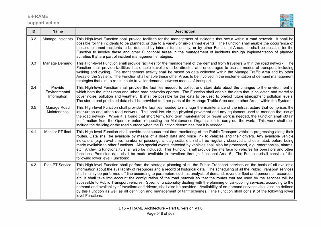
E-FRAME
support action
D15 – FRAME Architecture – Part 6, version V1.0
Page 548 of 568
ID Name Description
3.2 Manage Incidents This High-level Function shall provide facilities for the management of incidents that occur within a road network. It shall be possible for the incidents to be planned, or due to a variety of un-planned events. The Function shall enable the occurrence of these unplanned incidents to be detected by internal functionality, or by other Functional Areas. It shall be possible for the Function to involve these and other Functional Areas in the management of incidents through implementation of planned activities that are part of incident management strategies.
3.3 Manage Demand This High-level Function shall provide facilities for the management of the demand from travellers within the road network. The Function shall provide facilities that enable travellers to be directed and encouraged to use all modes of transport, including walking and cycling. The management activity shall be based on data collected within the Manage Traffic Area and by other Areas of the System. The Function shall enable these other Areas to be involved in the implementation of demand management strategies that aim to re-distribute traveller demand between modes of transport.
3.4 Provide Environmental Information
This High-level Function shall provide the facilities needed to collect and store data about the changes to the environment in which both the inter-urban and urban road networks operate. The Function shall enable the data that is collected and stored to cover noise, pollution and weather. It shall be possible for this data to be used to predict future atmospheric pollution levels. The stored and predicted data shall be provided to other parts of the Manage Traffic Area and to other Areas within the System.
3.5 Manage Road Maintenance
This High-level Function shall provide the facilities needed to manage the maintenance of the infrastructure that comprises the inter-urban and urban road network. This shall include the physical pavement and any equipment used to manage the use of the road network. When it is found that short term, long term maintenance or repair work is needed, the Function shall obtain confirmation from the Operator before requesting the Maintenance Organisation to carry out the work. This work shall also include the de-icing or the road surface when the Function determines that it is needed.
4.1 Monitor PT fleet This High-level Function shall provide continuous real time monitoring of the Public Transport vehicles progressing along their routes. Data shall be available by means of a direct data and voice link to vehicles and their drivers. Any available vehicle indicators (e.g. travel time, number of passengers, diagnostic, etc.) shall be regularly observed and estimated, before being made available to other functions. Also special events detected by vehicles shall also be processed, e.g. emergencies, alarms, etc. Archiving functionality shall also be included. This Function shall provide the interface to vehicles for operators and other functions. Predicted data shall be made available to travellers through functional Area 6. The Function shall consist of the following lower level Functions:
4.2 Plan PT Service This High-level Function shall perform the strategic planning of all the Public Transport services on the basis of all available information about the availability of resources and a record of historical data. The scheduling of all the Public Transport services shall mainly be performed off-line according to parameters such as analysis of demand, revenue, fleet and personnel resources, etc. It shall take into account the configuration of the road network so that the routes that are used by the services will be accessible to Public Transport vehicles. Specific functionality dealing with the planning of car-pooling services, according to the demand and availability of travellers and drivers, shall also be provided. Availability of on-demand services shall also be defined by this Function as well as all definition and management of tariff schemes. The Function shall consist of the following lower level Functions:

E-FRAME
support action
D15 – FRAME Architecture – Part 6, version V1.0
Page 549 of 568
ID Name Description
4.3 Provide PT Management
This High-level Function shall provide operation management functionality by managing drivers, crew and vehicles. It shall cover the provision of on-demand transport services to individual travellers and car sharing services. The Function shall continuously monitor the status of the infrastructure and vehicles and then deal with routine and non-routine maintenance. The Function shall consist of the following lower level Functions:
4.4 Control PT Fleet This High-level Function shall directly control in real-time the progressing and operation of Public Transport vehicles to guarantee the service reliability and schedule adherence. Functionality for the management of reserve vehicles and the possibility of requiring priority for vehicles shall be features included. The Function shall consist of the following lower level functions:
4.5 Provide PT Fare Facilities
This High-level Function shall provide facilities that enable fares to be collected for the use of Public Transport services. Fares are only collected using a "fare card" for which payment is collected via the Financial Clearinghouse. The use of cash (coins/notes) for fare payment is not supported by the functionality. Public Transport Passengers can top up their "fare cards" as and when they wish and with as much credit as they wish. Every time the "fare card" is used, the amount of credit that it contains is reduced by the cost for the use of the Public Transport service. The Public Transport Vehicle Driver is provided with in indication of whether or not the "fare card" transaction was successful or not.
4.6 Provide Facilities for Vehicle Sharing
This High-level Function provides facilities that support the sharing of Vehicles by Travellers making a journey. These Travellers are identified by the Car Pooler Actor and are able to set up travel plans for a journey in which they combine with other Car Poolers to share the use of their Vehicles. A travel plan may link up to the current PT services, or the services provided by other transport modes and may involve the use of car parks or service areas as places to start/finish particular segments of the journey. Once all the car poolers in a travel plan have accepted it, the implementation is up to them. Thus a travel plan may be for a single journey or for multiple repeats of the same journey, depending on the needs of the Car Poolers who are involved. For security reasons, a car pooler can only find out about the travel plan(s) in which they are personally involved and can only contact other car poolers in that travel plan through the communications mechanism that each provides. Payment for the Vehicle sharing is not included in the functionality.
4.7 Provide On-demand Services
This High-level Function shall provide functionality that enables Travellers to request that they be provided with an "on-demand" form of Public Transport service. It shall differ from the usual (or "standard") Public Transport service because the route and timing of the service is customised to suit one or more Travellers.
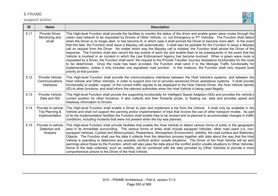
E-FRAME
support action
D15 – FRAME Architecture – Part 6, version V1.0
Page 550 of 568
ID Name Description
5.11 Provide Driver Monitoring and
eCall
This High-level Function shall provide the facilities to monitor the status of the driver and enable green wave routes through the urban road network to be requested by Drivers of Other Vehicle, i.e. not Emergency or PT Vehicles. The Function shall detect when the Driver is no longer alert, or has become ill, in which case it shall prompt the Driver to become more alert. In the event that this fails, the Function shall issue a Mayday call automatically. It shall also be possible for the Function to issue a Mayday call on request from the Driver. No matter which way the Mayday call is initiated, the Function shall advise the Driver of the response. The Function shall also record the key events of each trip and enable them to be subsequently in the event that the Vehicle is involved in an incident in which the Law Enforcement Agency has become involved. When a green wave route is requested by a Driver, the Function shall send the request to the Provide Traveller Journey Assistance functionality for the route to be determined. Once the route has been provided, the Function shall send it to the Manage Traffic functionality for implementation, unless it only includes one signalised road junction. In this instance, the Function shall only request local priority at that junction.
5.12 Provide Vehicle Communications
Interfaces
This High-level Function shall provide the communications interfaces between the Host Vehicle’s systems, and between the Host Vehicle and Other Vehicles, in order to support (but not to provide) advanced Driver assistance systems. It shall provide functionality to enable “copies” of the current traffic signals to be displayed to the Host Vehicle Driver, the Host Vehicle identity (ID) to other functions, and shall inform the relevant authorities when the Host Vehicle is being used illegally.
5.13 Provide Vehicle Data and ISA
This High-level Function shall provide the supporting functionality for Intelligent Speed Adaption (ISA) and provides the vehicle’s current position for other functions. It also collects and then forwards probe, or floating car, data and provides speed and headway information to Drivers.
5.14 Provide In-vehicle Trip Planning & Implementation
This High-level Function shall enable a Driver to plan and implement a trip from the Vehicle. It shall only be available in the Vehicle and shall not support the panning and/or implementation of trips that involve the use of other transport modes. As part of its trip implementation facilities the Function shall enable trips to be revised and re-planned to accommodate changes in traffic conditions, including incidents that were not present when the trip was planned.
5.15 Provide In-vehicle Detection and
Analysis
This High-level Function shall provide facilities that enable the Host Vehicle to detect various forms of entity in the geographic area in its immediate surrounding. The various forms of entity shall include equipped Vehicles, other road users (i.e. non-equipped Vehicles, Cyclists and Motorcyclists), Pedestrians, Atmospheric Environment, visibility, the road surface and Stationary Objects. The Function shall use the data it collects from the detection process together with data about the way that the Host Vehicle is operating to determine any possible conflicts and/or unsafe situations. The Driver of the Host Vehicle will be sent warnings about these by the Function, which will also pass the data about the conflict and/or unsafe situations to Other Vehicles. Some of the data collected, such as visibility, will be combined with the data provided by Other Vehicles to provide a more comprehensive picture to the Driver of the Host Vehicle.

E-FRAME
support action
D15 – FRAME Architecture – Part 6, version V1.0
Page 551 of 568
ID Name Description
5.16 Provide Outputs to Host Vehicle
Drivers
This High-level Function shall provide facilities that enable outputs of messages, warnings and other information to be provided to the Driver of the Host Vehicle. It shall display these messages in a pre-determined priority so that those with the highest priority are easily seen by the Driver and take precedence over those of lower priorities. The Function shall also compare the content of the messages, warnings and other information with what the Driver can see being displayed by equipment outside of the Vehicle, and report any differences.
6.3 Support Trip This High-level Function shall provide support for a trip. During the trip perturbations may come into existence which may influence the performance of the trip. Using the itinerary the consequences are evaluated and corrections are suggested to the on-trip traveller. Also routing instructions and possibly re-routing can be delivered. It shall be possible for the functionality in this High-Level Function to be used by the Traveller if they are in need of certain information about what is to be expected on the next leg(s) of the trip. In this instance it shall be possible for dedicated questions to be put to the Traffic and Travel Information (TTI) sub-functionality. Additionally it shall be possible for a "trip skeleton" to be used to extract more accurate and more selective information faster from the Support Trip facility.
6.5 Prepare Trip Plan This High-level Function shall include facilities for the generation of the initial trip under feedback of the traveller, taking into account all kinds of perturbations. Trip planning is the most complex and complete action to be performed by the Plan Trip facility, but on many occasions the traveller is interested in the planning of a trip from beginning to end, because that is a well-known thing and needs no further planning. In such a case the traveller usually is interested in the deviation from his/her expectation: travel and traffic information (TTI). While the Plan Trip function is able to access such information to develop the best trip plan possible, under the given circumstances, the TTI function is assumed to be incorporated in the Plan Trip function. For obvious reasons, the trip performed can be stored as a skeleton in the GTP and the traveller, when asking the system, will be informed about the perturbations ahead only. This will result in more selective information and a better user-orientation.
6.6 Provide Traveller Information
This High-level Function shall provide facilities that enable information to be provided to Travellers, either at the roadside, or by other means. Information about traffic conditions shall be provided at the roadside, but other forms of information, e.g. about Points of Interest, shall be available to Travellers through other mechanisms, e.g. a nomadic device.
6.7 Manage General Trip Preferences
This High-level Function shall be responsible for the management of the General Trip Preferences that the Traveller specifies for use in every trip that is planned. It shall enable the Traveller to set up these preferences and for the Travel Information Operator to be able to view them in an anonymous way, i.e. without knowing the identity of any of the Travellers to which they belong. The Function shall also enable the Traveller to modify their preferences as a result of completing a trip and for a report about the performance of the trip to be automatically provided to the Travel Information Operator.
6.8 Manage Trip Plans This High-level Function shall provide facilities for the management of the Private Trip Plan Data Store. It shall be able to accept data from of functionality to enable the trip plan created by the Traveller to be stored. When the Traveller requests that a previously prepared trip plan is implemented, this Function shall ensure that it is correctly provided to the trip plan implementation and monitoring functionality.

E-FRAME
support action
D15 – FRAME Architecture – Part 6, version V1.0
Page 552 of 568
ID Name Description
7.1 Detect Fraud or Violation
This High-level Function shall perform the detection of specific types of fraud not carried out by the other Functions, such as weight in motion. It shall measure the parameters to be controlled, if necessary ask for the identification of the user, get the authorised span of values for this parameter, compare it with the measure, and if a discrepancy is detected declare the fraud.
7.2 Identify Violator This High-level Function shall analyse the image or information included in the fraud notifications sent by functionality in the other Areas, or in the images sent by the "Detect Fraud" Function, to find out the identity of the violator. It shall use information stored in the "User Registration" database.
7.3 Process Fraud and Violation
Notifications
This High-level Function shall process all the fraud notifications detected throughout the System. It shall classify the notifications by kind of fraud, level of importance. If not already done, the Function shall ask for the identification of the violator. According to the kinds of violation, it shall build a prosecution file gathering all the information necessary for the Law Enforcement Agency terminator, and send it.
7.5 Manage Rules and Users'
Registrations
This High-level Function shall be charged with the upkeep of the Rules and Users' Registration stores. It shall update their content with new elements issued by the law enforcement agencies.
7.6 Store Violations Data
This Function shall be capable of providing the following facilities: (1) The ability to manage the store of Violations Data that contains all the fraud and violation notifications provided by functionality in the Provide Electronic Payment Facilities (1) and Manage Traffic (3) Functional Areas. (2) As part of the management process, provide specified contents of the store to the Law Enforcement Agency (ies) terminator upon reception of a specific request.
8.1 Manage Logistics and Freight
This High-level Function shall cover activities related to the logistic chain from the supplier to the receiver of goods. It shall include an inter-modal transport activity that shall enable the optimisation of the transport infrastructure with respect to mobility, security and environment constraints. The information shall be exchanged with a variety of sources within the Area, within other Areas, or externally through the terminators. The Function shall consist of the following lower level Functions:
8.2 Manage Commercial Fleet
This High-level Function shall cover activities related to the management, the planning, the control, the evaluation and the maintenance of a fleet centre and its resources. The information shall be exchanged with a variety of sources within the Area, within other Areas, or externally through the terminators. The Function shall consist of the following lower level Functions:

E-FRAME
support action
D15 – FRAME Architecture – Part 6, version V1.0
Page 553 of 568
ID Name Description
8.3 Manage vehicle/driver/carg
o/equipment
This High-level Function shall be in charge to manage the trip (i.e. all tasks needed by driver/vehicle/equipment to perform cargo transport orders). Fleet management of driver/vehicle/equipment (i.e. Maintenance, employment management) are excluded from that function. They shall be found within 8.2.2.3 Manage Fleet Resources. Consequently, it shall process all information coming directly from vehicle, driver, cargo and transport equipment (such as trailer) during trip. This function shall also realise the interface with fleet manager during the trip: direct visibility for the fleet manager to trip data, and reception and processing of operational and commercial instructions from fleet manager. The break down of this Function has been design accordingly to result provided by COMETA. The Function shall consist of the following lower level Functions:
9.1 Enable Other Vehicle Priority
Selection
This High-level Function shall provide facilities that enable Other Vehicles to request green waves through signalised road junctions on the route to their destinations. Once a green wave has been successfully requested, it will be implemented immediately through the Manage Traffic functionality. If there is only one signalised junction on the route, then the green wave will be implemented through a request for local priority at that junction. If priority conflicts arise at a junction, the functionality will give priority to Emergency Vehicles, then PT Vehicles and finally Other Vehicles. Priority conflicts between Other Vehicles will be resolved in favour of the Vehicle that first requested priority. Other Vehicles will be informed if their priority request has been successful or not, and will be provided with speed advice if successful. All Vehicles approaching a signalised junction will be informed if priority has been granted to any Vehicles approaching it.
9.2 Provide Access to Bus Lanes
This High-level Function shall provide functionality that enables flexible lane allocation. It is aimed principally at Bus Lanes and shall enable them to be used by other Vehicles, when PT Vehicles are not using them. Use of Bus Lanes by other Vehicles shall be granted through the allocation of a licence that applies to specific lanes and shall only be valid for a particular length of time. It shall only be possible for a licence to be granted to use some of the Bus Lanes on the route to the required destination. The use of the Bus Lanes shall be monitored and if other Vehicles are likely to impede the movement of PT Vehicles, they shall be requested to leave the Bus Lane at the end of the next section. If other Vehicles are found to be using a Bus Lane without a licence, their details shall be passed to Law Enforcement functionality for subsequent prosecution.
9.3 Mange Vehicle Access to
Sensitive Areas
This High-level Function shall provide functionality that shall enable the use of "sensitive areas" within the road network to be managed. It shall be possible for Vehicles to be barred from access to "sensitive areas" and for the entrance and exit to be monitored. When Vehicles are granted access to these "areas", instructions shall be passed to Drivers about their use.
9.4 Provide Hazardous Goods
Management
This High-level Function shall enable the routes used by Freight Vehicles carrying Hazardous Goods to be planned and for the use of these routes to be monitored. Drivers of these Vehicles shall be sent route guidance instructions so that they can follow the prepared route.
9.5 Manage Urban Loading Zones
This High-level Function shall provide functionality for the management of loading and unloading zones for Freight Vehicles in the urban road network. It shall enable Freight Vehicle Drivers and Fleet Operators to book time in particular zones for their Vehicles to load or unload freight and to update those booking as their expected time of arrival changes. If a particular requested zone is not available from the Freight Vehicle needs to use it, then the Driver shall be provided with instructions about the holding zone that is to be used as a place to park until the requested zone shall become available. Overall management of the zones shall be made available to the Parking Operator.
E-FRAME
support action
D15 – FRAME Architecture – Part 6, version V1.0
Page 554 of 568

E-FRAME
support action
D15 – FRAME Architecture – Part 6, version V1.0
Page 555 of 568
Table 7 - Descriptions of Terminators
Mnemonic Name Description
ae Ambient Environment
This Terminator shall represent the operational setting in which road-related ITS services interface and operate. It shall consist of weather effects such as snow, rain, fog, pollution effects such as dust, smoke, and man-made electromagnetic effects. This terminator is a physical entity from which data can be obtained. In this case the data shall be obtained through monitoring by appropriate functionality within the System. The data provided by this functionality shall enable Travellers to be informed about adverse conditions. The monitoring shall also enable Authorities and System Operators to choose relevant management strategies to minimise any adverse effects on the use of the road network
bti Bridge/Tunnel Infrastructure
This Terminator shall represent the entities that can detect physical conditions of bridges and tunnels. It shall consist of the following two Actors: Bridge Structures Tunnel Management System The conditions that these Actors can detect shall comprise such things as the status of the bridge or tunnel infrastructure, atmospheric pollution levels on the bridge or in the tunnel, smoke (tunnels only) and weather conditions (bridges only) and be provided as data inputs to the System.
ca Freight Equipment
This Terminator shall represent all devices in which goods can be transported with some level of protection. These devices are not road vehicles or parts of road vehicles. However it must be possible for them to be carried by road vehicles. The prime example of a device represented by this terminator is the freight container. In this case such a container will have some on-board intelligence with which the System can communicate and exchange data about the cargo being carried.
cc Consignor / Consignee
This Terminator shall represent human or physical entities that need freight (goods) to be transported from one place to place. It shall consist of the following two Actors: Freight Shipper Principal When the transport is being arranged, it shall be possible for the freight (goods) to be referred to as a “consignment”.
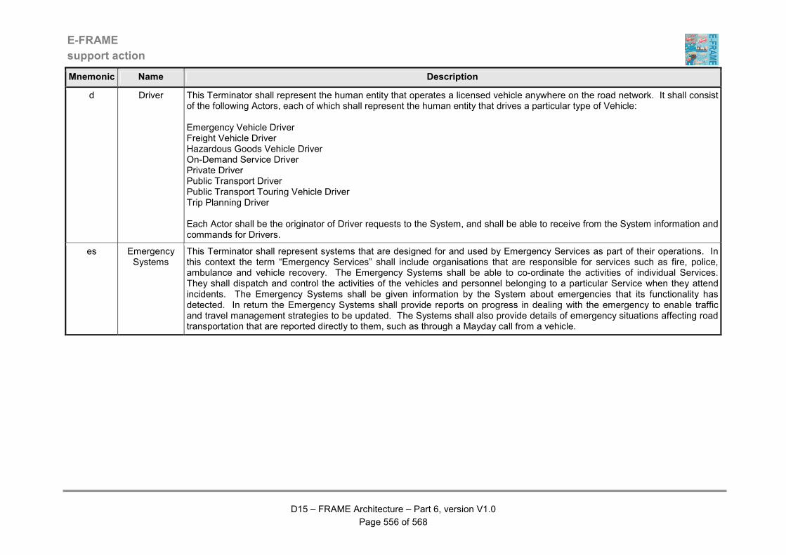
E-FRAME
support action
D15 – FRAME Architecture – Part 6, version V1.0
Page 556 of 568
Mnemonic Name Description
d Driver This Terminator shall represent the human entity that operates a licensed vehicle anywhere on the road network. It shall consist of the following Actors, each of which shall represent the human entity that drives a particular type of Vehicle: Emergency Vehicle Driver Freight Vehicle Driver Hazardous Goods Vehicle Driver On-Demand Service Driver Private Driver Public Transport Driver Public Transport Touring Vehicle Driver Trip Planning Driver Each Actor shall be the originator of Driver requests to the System, and shall be able to receive from the System information and commands for Drivers.
es Emergency Systems
This Terminator shall represent systems that are designed for and used by Emergency Services as part of their operations. In this context the term “Emergency Services” shall include organisations that are responsible for services such as fire, police, ambulance and vehicle recovery. The Emergency Systems shall be able to co-ordinate the activities of individual Services. They shall dispatch and control the activities of the vehicles and personnel belonging to a particular Service when they attend incidents. The Emergency Systems shall be given information by the System about emergencies that its functionality has detected. In return the Emergency Systems shall provide reports on progress in dealing with the emergency to enable traffic and travel management strategies to be updated. The Systems shall also provide details of emergency situations affecting road transportation that are reported directly to them, such as through a Mayday call from a vehicle.
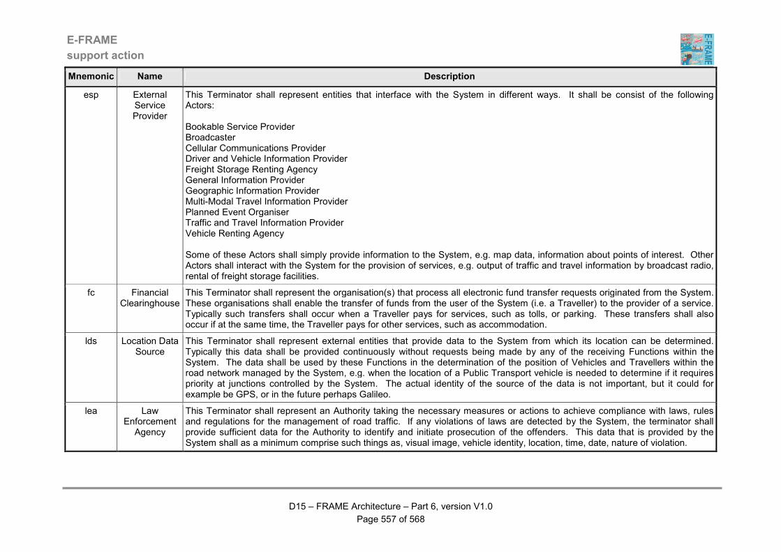
E-FRAME
support action
D15 – FRAME Architecture – Part 6, version V1.0
Page 557 of 568
Mnemonic Name Description
esp External Service Provider
This Terminator shall represent entities that interface with the System in different ways. It shall be consist of the following Actors: Bookable Service Provider Broadcaster Cellular Communications Provider Driver and Vehicle Information Provider Freight Storage Renting Agency General Information Provider Geographic Information Provider Multi-Modal Travel Information Provider Planned Event Organiser Traffic and Travel Information Provider Vehicle Renting Agency Some of these Actors shall simply provide information to the System, e.g. map data, information about points of interest. Other Actors shall interact with the System for the provision of services, e.g. output of traffic and travel information by broadcast radio, rental of freight storage facilities.
fc Financial Clearinghouse
This Terminator shall represent the organisation(s) that process all electronic fund transfer requests originated from the System. These organisations shall enable the transfer of funds from the user of the System (i.e. a Traveller) to the provider of a service. Typically such transfers shall occur when a Traveller pays for services, such as tolls, or parking. These transfers shall also occur if at the same time, the Traveller pays for other services, such as accommodation.
lds Location Data Source
This Terminator shall represent external entities that provide data to the System from which its location can be determined. Typically this data shall be provided continuously without requests being made by any of the receiving Functions within the System. The data shall be used by these Functions in the determination of the position of Vehicles and Travellers within the road network managed by the System, e.g. when the location of a Public Transport vehicle is needed to determine if it requires priority at junctions controlled by the System. The actual identity of the source of the data is not important, but it could for example be GPS, or in the future perhaps Galileo.
lea Law Enforcement
Agency
This Terminator shall represent an Authority taking the necessary measures or actions to achieve compliance with laws, rules and regulations for the management of road traffic. If any violations of laws are detected by the System, the terminator shall provide sufficient data for the Authority to identify and initiate prosecution of the offenders. This data that is provided by the System shall as a minimum comprise such things as, visual image, vehicle identity, location, time, date, nature of violation.
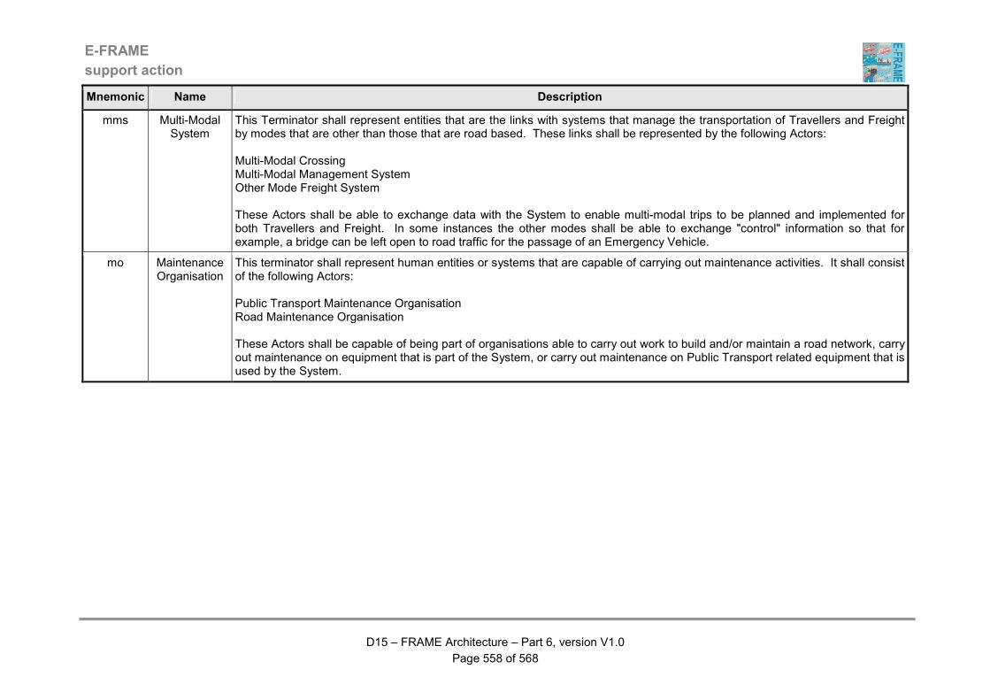
E-FRAME
support action
D15 – FRAME Architecture – Part 6, version V1.0
Page 558 of 568
Mnemonic Name Description
mms Multi-Modal System
This Terminator shall represent entities that are the links with systems that manage the transportation of Travellers and Freight by modes that are other than those that are road based. These links shall be represented by the following Actors: Multi-Modal Crossing Multi-Modal Management System Other Mode Freight System These Actors shall be able to exchange data with the System to enable multi-modal trips to be planned and implemented for both Travellers and Freight. In some instances the other modes shall be able to exchange "control" information so that for example, a bridge can be left open to road traffic for the passage of an Emergency Vehicle.
mo Maintenance Organisation
This terminator shall represent human entities or systems that are capable of carrying out maintenance activities. It shall consist of the following Actors: Public Transport Maintenance Organisation Road Maintenance Organisation These Actors shall be capable of being part of organisations able to carry out work to build and/or maintain a road network, carry out maintenance on equipment that is part of the System, or carry out maintenance on Public Transport related equipment that is used by the System.

E-FRAME
support action
D15 – FRAME Architecture – Part 6, version V1.0
Page 559 of 568
Mnemonic Name Description
o Operator This Terminator shall comprise a diverse set of human entities that can perform privileged interactions with the System, thereby contributing to the way in which it operates. It shall consist of the following Actors: Bridge Operator Emergency Operator Fleet Operator Freight Management Operator On-Demand Service Operator Parking Operator Public Transport Operator Road Maintenance Operator Road Network Operator Toll Operator Traveller Information Operator Tunnel Operator Un/Loading Zone Operator It shall be possible for the contribution to the operation of the System from each of these Actors to include the planning, monitoring, controlling and the evaluation of the System operation. These Actors shall be capable of carrying out all types of management of the way that the System operates. It shall be possible for some or all of them to be combined into a lesser number of entities for particular System implementations. Thus for example, it shall be possible for the Freight Operator and the Fleet Operator to be the same human entity if required by a particular implementation.
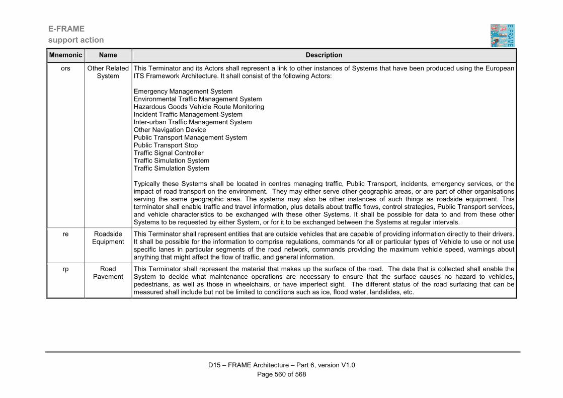
E-FRAME
support action
D15 – FRAME Architecture – Part 6, version V1.0
Page 560 of 568
Mnemonic Name Description
ors Other Related System
This Terminator and its Actors shall represent a link to other instances of Systems that have been produced using the European ITS Framework Architecture. It shall consist of the following Actors: Emergency Management System Environmental Traffic Management System Hazardous Goods Vehicle Route Monitoring Incident Traffic Management System Inter-urban Traffic Management System Other Navigation Device Public Transport Management System Public Transport Stop Traffic Signal Controller Traffic Simulation System Traffic Simulation System Typically these Systems shall be located in centres managing traffic, Public Transport, incidents, emergency services, or the impact of road transport on the environment. They may either serve other geographic areas, or are part of other organisations serving the same geographic area. The systems may also be other instances of such things as roadside equipment. This terminator shall enable traffic and travel information, plus details about traffic flows, control strategies, Public Transport services, and vehicle characteristics to be exchanged with these other Systems. It shall be possible for data to and from these other Systems to be requested by either System, or for it to be exchanged between the Systems at regular intervals.
re Roadside Equipment
This Terminator shall represent entities that are outside vehicles that are capable of providing information directly to their drivers. It shall be possible for the information to comprise regulations, commands for all or particular types of Vehicle to use or not use specific lanes in particular segments of the road network, commands providing the maximum vehicle speed, warnings about anything that might affect the flow of traffic, and general information.
rp Road Pavement
This Terminator shall represent the material that makes up the surface of the road. The data that is collected shall enable the System to decide what maintenance operations are necessary to ensure that the surface causes no hazard to vehicles, pedestrians, as well as those in wheelchairs, or have imperfect sight. The different status of the road surfacing that can be measured shall include but not be limited to conditions such as ice, flood water, landslides, etc.

E-FRAME
support action
D15 – FRAME Architecture – Part 6, version V1.0
Page 561 of 568
Mnemonic Name Description
t Traveller This Terminator shall represent a human entity that uses (or is about to use) transportation services provided by the System. These services shall comprise but not be limited to the provision of travel information and the ability to plan a trip, either before the trip has started, or as a "re-planning" exercise during a previously prepared trip that is now being implemented. This Terminator shall consist of the following Actors: Car-Pooler Cyclist On-Demand Service Passenger Pedestrian Pre-Trip Traveller Public Transport Passenger Static Traveller Vehicle Driver It shall be possible for the services to be available to these Actors through modes such as Public Transport, private car, cycling and walking. Travellers shall also be able to use other non-road based modes of transport through the interfaces provided by other terminators. Prior to a trip, the Pre-Trip Traveller Actor is used. Once Travellers embark on a trip they may become a Cyclist, a Driver, a Passenger or a Pedestrian depending on the mode(s) used between the origin and destination of the trip. When waiting at a Public Transport Stop, the Static Traveller Actor is used.
tp Transport Planner
This Terminator shall represent the human entities and/or systems that are responsible for planning changes to the structure of the road transportation network managed by the System. It shall be possible for them to use information gathered by the System and to provide input and guidance to enable the System to produce strategies that can be implemented to optimise transport network use. This optimisation may be required for incident management, or to influence the demands for particular modes of road transport so that particular transport policies may be implemented.
trfc Traffic This Terminator shall represent the movement of vehicles along a route. Traffic shall depict the vehicle population from which traffic surveillance information is collected and upon which traffic management measures are applied. It shall be possible for the movement of vehicles shown by this terminator to be manifest to the System in a number of forms. These shall include but not be limited to such things as video, laser or infra-red images, magnetic signature or any other way in which the presence of a vehicle can be determined.

E-FRAME
support action
D15 – FRAME Architecture – Part 6, version V1.0
Page 562 of 568
Mnemonic Name Description
v Vehicle This Terminator shall represent the Vehicle in terms of any functionality that it might contain the main purpose of which is the provision of ITS services. It consists of the following Actors which represent the different types of Vehicle that can use the road network managed by the System: Emergency Vehicle Freight Vehicle Hazardous Goods Vehicle Hazardous Goods Vehicle On-Demand Service Vehicle Other Vehicle Private Vehicle Public Transport Touring Vehicle Public Transport Vehicle Vehicle Systems Each of these Actors shall have interfaces to ITS related functionality in other areas and be able to collect and/or create ITS related data. The data shall be collected by sensors within the system and shall be limited to those that sense data about the road network in which the Vehicle is operating and those that monitor the condition of the Driver. The "Vehicle Systems" Actor shall have read only access to data provided by the Vehicle systems". It and the other Actors shall not be able to control the Vehicle.
ve Vehicle Environment
This Terminator shall represent the status of the environment in the geographic area that surrounds the Host Vehicle at any time. It shall consist of the following Actors, each of which represents a different type of object: Other Nearby Vehicles Other Road Users Stationary Object The status provided by each Actor shall relate to the surface of the roadway on which the Host Vehicle is moving and/or objects present in the surrounding geographic area. It shall be possible for some of these Actors to be using the road and/or their own designated parts of the geographic area, e.g. pedestrian pavements, cycle lanes and bus lanes.
ws Weather Systems
This Terminator shall provide general area weather information and weather forecasts to the System. The information shall comprise things such as temperature, fog, rain and wind (direction and strength), whilst the forecasts shall predict changes in these conditions. It shall be possible for both types of information to be provided on a regular basis or on request from the System.
E-FRAME
support action
D15 – FRAME Architecture – Part 6, version V1.0
Page 563 of 568
3 Why Terminators and Actors?
3.1 Introduction
The purpose of this Chapter is to provide the background to why we have Terminators and
Actors in the FRAME Architecture.
3.2 Why are Terminators and Actors?
Every ITS architecture needs to have a way of identifying entities with which its functionality
must exchange data, but which will be outside its scope. When the FRAME Architecture
was originally developed by the KAREN Project in 1998-2000, it was decided that these
entities outside of the Architecture will be represented by Terminators and Actors.
3.3 What is a Terminator?
A Terminator is the representation of an entity that is outside the FRAME Architecture and
is assumed to be outside any ITS architecture developed from it. A description is provided
for each Terminator, written in a formalised style of language. This description shows what
the Architecture expects the Terminator to do, I.e. how the Architecture expects the external
entity to behave.
3.4 What is an Actor?
Some entities can be present in various forms. The most obvious example is the Driver,
which can be considered as the person that is in control of any Vehicle. However some
parts of the FRAME Architecture need to exchange data with Drivers of particular types of
Vehicles, e.g. freight and public transport.
An Actor is a sub-form of a Terminator and provides a mechanism through which data can
be exchanged with a particular form of a Terminator. Thus for example the Driver
Terminator has both Freight Vehicle Driver and Public Transport Driver Actors.
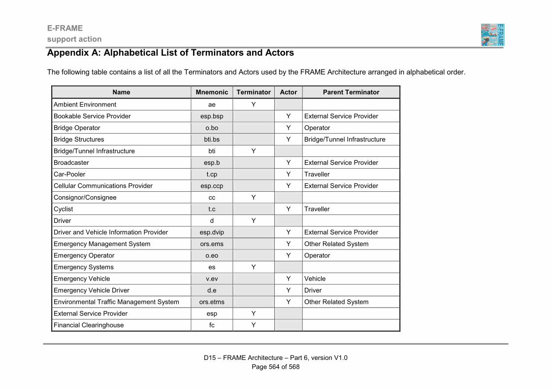
E-FRAME
support action
D15 – FRAME Architecture – Part 6, version V1.0
Page 564 of 568
Appendix A: Alphabetical List of Terminators and Actors
The following table contains a list of all the Terminators and Actors used by the FRAME Architecture arranged in alphabetical order.
Name Mnemonic Terminator Actor Parent Terminator
Ambient Environment ae Y
Bookable Service Provider esp.bsp Y External Service Provider
Bridge Operator o.bo Y Operator
Bridge Structures bti.bs Y Bridge/Tunnel Infrastructure
Bridge/Tunnel Infrastructure bti Y
Broadcaster esp.b Y External Service Provider
Car-Pooler t.cp Y Traveller
Cellular Communications Provider esp.ccp Y External Service Provider
Consignor/Consignee cc Y
Cyclist t.c Y Traveller
Driver d Y
Driver and Vehicle Information Provider esp.dvip Y External Service Provider
Emergency Management System ors.ems Y Other Related System
Emergency Operator o.eo Y Operator
Emergency Systems es Y
Emergency Vehicle v.ev Y Vehicle
Emergency Vehicle Driver d.e Y Driver
Environmental Traffic Management System ors.etms Y Other Related System
External Service Provider esp Y
Financial Clearinghouse fc Y
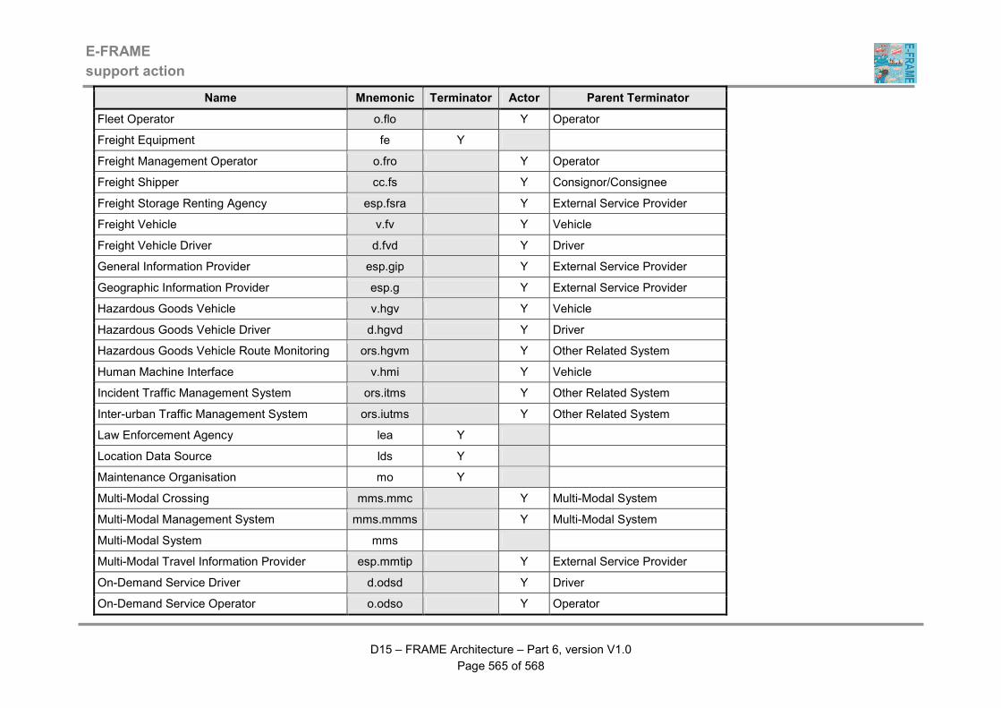
E-FRAME
support action
D15 – FRAME Architecture – Part 6, version V1.0
Page 565 of 568
Name Mnemonic Terminator Actor Parent Terminator
Fleet Operator o.flo Y Operator
Freight Equipment fe Y
Freight Management Operator o.fro Y Operator
Freight Shipper cc.fs Y Consignor/Consignee
Freight Storage Renting Agency esp.fsra Y External Service Provider
Freight Vehicle v.fv Y Vehicle
Freight Vehicle Driver d.fvd Y Driver
General Information Provider esp.gip Y External Service Provider
Geographic Information Provider esp.g Y External Service Provider
Hazardous Goods Vehicle v.hgv Y Vehicle
Hazardous Goods Vehicle Driver d.hgvd Y Driver
Hazardous Goods Vehicle Route Monitoring ors.hgvm Y Other Related System
Human Machine Interface v.hmi Y Vehicle
Incident Traffic Management System ors.itms Y Other Related System
Inter-urban Traffic Management System ors.iutms Y Other Related System
Law Enforcement Agency lea Y
Location Data Source lds Y
Maintenance Organisation mo Y
Multi-Modal Crossing mms.mmc Y Multi-Modal System
Multi-Modal Management System mms.mmms Y Multi-Modal System
Multi-Modal System mms
Multi-Modal Travel Information Provider esp.mmtip Y External Service Provider
On-Demand Service Driver d.odsd Y Driver
On-Demand Service Operator o.odso Y Operator

E-FRAME
support action
D15 – FRAME Architecture – Part 6, version V1.0
Page 566 of 568
Name Mnemonic Terminator Actor Parent Terminator
On-Demand Service Passenger t.odsp Y Traveller
On-Demand Service Vehicle v.odsv Y Vehicle
Operator o Y
Other Mode Freight System mms.omfs Y Multi-Modal System
Other Navigation Device ors.ond Y Other Related System
Other Nearby Vehicles ve.onv Y Vehicle Environment
Other Related System ors Y
Other Road Users ve.oru Y Vehicle Environment
Other Vehicle v.ov Y Vehicle
Parking Operator o.po Y Operator
Pedestrian t.p Y Traveller
Planned Event Organiser esp.peo Y External Service Provider
Pre-Trip Traveller t.ptt Y Traveller
Principal cc.p Y Consignor/Consignee
Private Driver d.pr Y Driver
Private Vehicle v.pv Y Vehicle
Public Transport Driver d.ptd Y Driver
Public Transport Maintenance Organisation mo.ptmo Y Maintenance Organisation
Public Transport Management System ors.ptms Y Other Related System
Public Transport Operator o.pto Y Operator
Public Transport Passenger t.ptp Y Traveller
Public Transport Stop ors.pts Y Other Related System
Public Transport Touring Vehicle v.pttv Y Vehicle
Public Transport Touring Vehicle Driver d.pttvd Y Driver

E-FRAME
support action
D15 – FRAME Architecture – Part 6, version V1.0
Page 567 of 568
Name Mnemonic Terminator Actor Parent Terminator
Public Transport Vehicle v.ptv Y Vehicle
Road Maintenance Operator o.rmo Y Operator
Road Maintenance Organisation mo.rmo Y Maintenance Organisation
Road Network Operator o.rno Y Operator
Road Pavement rp Y
Roadside Equipment re Y
Static Traveller t.st Y Traveller
Stationary Object ve.so Y Vehicle Environment
Toll Operator o.to Y Operator
Traffic trfc Y
Traffic and Travel Information Provider esp.ttip Y External Service Provider
Traffic Signal Controller ors.tsc Y Other Related System
Traffic Simulation System ors.tss Y Other Related System
Transport Planner tp Y
Traveller t Y
Traveller Information Operator o.tio Y Operator
Trip Planning Driver d.tpd Y Driver
Tunnel Management System bti.tms Y Bridge/Tunnel Infrastructure
Tunnel Operator o.tnlo Y Operator
Un/loading Zone Operator o.pzo Y Operator
Urban Traffic Management System ors.utms Y Other Related System
Vehicle v Y
Vehicle Driver t.vd Y Traveller
Vehicle Environment ve Y
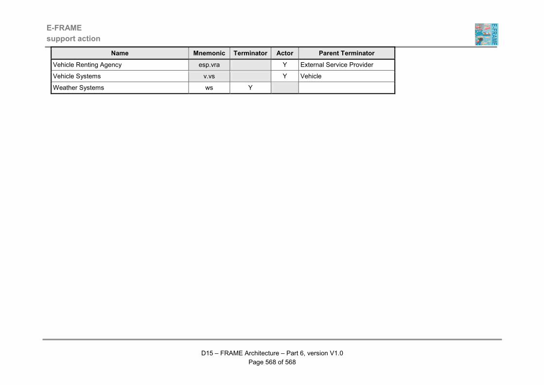
E-FRAME
support action
D15 – FRAME Architecture – Part 6, version V1.0
Page 568 of 568
Name Mnemonic Terminator Actor Parent Terminator
Vehicle Renting Agency esp.vra Y External Service Provider
Vehicle Systems v.vs Y Vehicle
Weather Systems ws Y