d301244x012 - dl8000 preset controller instruction … · dl8000 preset instruction manual revised...
TRANSCRIPT
Remote Automation Solutions
Part Number D301244X012
May 2017
DL8000 Preset Controller Instruction Manual

DL8000 Preset Instruction Manual
ii Revised May-2017
Revision Tracking Sheet
May 2017
This manual may be revised periodically to incorporate new or updated information. The revision date of each page appears at the bottom of the page opposite the page number. A change in revision date to any page also changes the date of the manual that appears on the front cover. Listed below is the revision date of each page (if applicable):
Page Revision
All pages May-2017
All pages
Mar-2012 Revised content in Chapters 1 through 3 and reorganized and enhanced appendixes (removed former Appendix B, Installation and Configuration, and Appendix C, Point Types; and added keypad display content as new Appendix E)
All pages May-2010
All pages Sep-2009 Removed Chapter 2, renumbered Chapters 3 and 4
All pages Oct-2008
All pages Jul-2008
All pages Feb-2008
All pages Oct-2007
Initial issue Nov-2006

DL8000 Preset Instruction Manual
Revised May-2017 Contents iii
Contents
Chapter 1 – Overview 1-1
1.1 DL8000 Overview ............................................................................................................. 1-1 1.2 Hardware .......................................................................................................................... 1-3
1.2.1 Housing ................................................................................................................. 1-3 1.2.2 Electronics ............................................................................................................. 1-5
1.3 Security Gateway .............................................................................................................. 1-6 1.4 Additional Technical Specifications .................................................................................. 1-6
Chapter 2 – Installation and Use 2-1
2.1 Housing ............................................................................................................................. 2-1 2.1.1 Class I Zone 1 Housing ......................................................................................... 2-2 2.1.2 Securing the Cover to the Class I Zone I Case ..................................................... 2-4 2.1.3 Class I Div 2 Housing ............................................................................................ 2-5
2.2 Card Cage ........................................................................................................................ 2-6 2.2.1 Backplane .............................................................................................................. 2-7
2.3 Central Processor Unit (CPU) .......................................................................................... 2-8 2.3.1 Installing and Removing Wire Channel Covers................................................... 2-10 2.3.2 Removing and Installing Module Covers ............................................................. 2-11 2.3.3 Removing the CPU Module ................................................................................. 2-11 2.3.4 Installing the CPU Module ................................................................................... 2-12
2.4 License Keys .................................................................................................................. 2-12 2.4.1 Installing a License Key ....................................................................................... 2-13 2.4.2 Removing a License Key ..................................................................................... 2-14
2.5 Installation Planning ........................................................................................................ 2-15 2.6 Mechanical Installation ................................................................................................... 2-15
2.6.1 Planning Considerations ..................................................................................... 2-16 2.7 Electrical Installation ....................................................................................................... 2-18
2.7.1 General Considerations ....................................................................................... 2-18 2.7.2 Field Wiring Installation Guidelines: .................................................................... 2-18 2.7.3 Electrical Wire and Cable Selection and Installation ........................................... 2-19 2.7.4 Input/Output Field Signal Wiring.......................................................................... 2-20 2.7.5 Electrical Grounds ............................................................................................... 2-20 2.7.6 Wire Conduit Selection and Installation .............................................................. 2-22
2.8 Operator Interface ........................................................................................................... 2-23 2.8.1 Keypad ................................................................................................................ 2-24 2.8.2 LED Status Indicators .......................................................................................... 2-25
Chapter 3 – Modules 3-1
3.1 Power Input Module .......................................................................................................... 3-1 3.1.1 12 Volt DC Power Input Module ............................................................................ 3-2
3.2 Input/Output Modules ....................................................................................................... 3-3 3.2.1 General Installation ............................................................................................... 3-5 3.2.2 Installing an I/O Module ......................................................................................... 3-6 3.2.3 Removing an I/O Module ....................................................................................... 3-7 3.2.4 Wiring I/O Modules ................................................................................................ 3-7 3.2.5 Analog Input (AI) Modules ..................................................................................... 3-7 3.2.6 Analog Output (AO) Modules ................................................................................ 3-9 3.2.7 Discrete Input (DI) Modules ................................................................................. 3-10 3.2.8 Pulse Input (PI) Modules ..................................................................................... 3-12

DL8000 Preset Instruction Manual
iv Contents Revised May-2017
3.2.9 Discrete Output (DO) Modules ............................................................................ 3-14 3.2.10 Discrete Output Relay (DOR) Modules ............................................................. 3-15 3.2.11 Resistance Temperature Detector (RTD) Input Modules .................................. 3-17 3.2.12 Alternating Current Input/Output (AC I/O) Module ............................................ 3-18 3.2.13 Advance Pulse Module (APM)........................................................................... 3-23 3.2.14 Thermocouple (TC) Input Module...................................................................... 3-27 3.2.15 Highway Addressable Remote Transducer (HART®) Module ........................... 3-30
3.3 Communication Modules and Ports................................................................................ 3-32 3.3.1 Wiring Communications ...................................................................................... 3-34 3.3.2 Local Operator Interface (LOI – Local Port) ........................................................ 3-35 3.3.3 Using the LOI ...................................................................................................... 3-36 3.3.4 Ethernet Communications ................................................................................... 3-36 3.3.5 EIA-232 (RS-232) Serial Communications.......................................................... 3-38 3.3.6 EIA-422/485 (RS-422/485) Serial Communications Module .............................. 3-39 3.3.7 EIA-422/485 (RS-422/485) Jumpers and Termination Resistors ....................... 3-40 3.3.8 Dial-up Modem Communications Module ........................................................... 3-41
3.4 Additional Technical Information .................................................................................... 3-43
Appendix A – Glossary A-1
Appendix B – Modbus Communications B-1
B.1 Modbus Communications ................................................................................................ B-1 B.2 Modbus Configuration ..................................................................................................... B-2
B.2.1 Modbus Configuration General Tab .................................................................... B-3 B.2.2 Modbus Configuration Scale Values Tab ............................................................ B-5
B.3 Modbus History ................................................................................................................ B-7 B.3.1 Modbus Configuration History Table Tab ............................................................ B-8
B.4 Modbus Events & Alarms Functionality ......................................................................... B-11 B.4.1 Reading Events & Alarms Register ................................................................... B-11 B.4.2 Acknowledging Events & Alarms ....................................................................... B-11
B.5 Modbus Registers .......................................................................................................... B-12 B.5.1 Modbus Configuration Registers Tab ................................................................ B-14 B.5.2 Modbus Conversion ........................................................................................... B-17
B.6 Modbus Master Table .................................................................................................... B-19 B.6.1 Modbus Configuration Master Table Tab .......................................................... B-20
B.7 Modbus Master Modem ................................................................................................. B-22 B.7.1 Modbus Configuration Master Modem Tab ....................................................... B-22
B.8 HMI Information ............................................................................................................. B-24 B.8.1 Sequential Blending ........................................................................................... B-24 B.8.2 Ratio Blending ................................................................................................... B-25
Appendix C – Wiring Diagrams C-1
C.1 Daniel Senior Sonic Meter to PI Module ......................................................................... C-1 C.2 Daniel 1818A and 1838 Turbine Pre-Amp to PI Module ................................................. C-2 C.3 Micro Motion RFT9739 & 2400S Transmitters to PI Module ........................................... C-3 C.4 Micro Motion RFT9739 & 2400S Transmitters to APM Module ...................................... C-4 C.5 3- and 4-Wire RTD to RTD Module ................................................................................. C-5 C.6 Daniel Senior Sonic Meter to APM Module ..................................................................... C-6 C.7 Daniel 1818A and 1838 Dual Turbine Pre-Amp to APM Module .................................... C-7 C.8 Daniel 1818A and 1838 Turbine Pre-Amp to APM Module ............................................. C-8 C.9 Two-Stage Valve with Two Limit Switches to APM Module ............................................ C-9 C.10 Micro Motion 1700 & 2700 Transmitter to PI Module ................................................... C-10
DL8000 Preset Instruction Manual
Revised May-2017 Contents v
Appendix D – Communications Protocols D-1
D.1 Introduction ...................................................................................................................... D-1 D.1.1 Communication Channels ................................................................................... D-2 D.1.2 Communications Failure ...................................................................................... D-2 D.1.3 Supported Protocols ............................................................................................ D-3 D.1.4 Configuration ....................................................................................................... D-5 D.1.5 Commands .......................................................................................................... D-6 D.1.6 Status Flags ......................................................................................................... D-7
D.2 Batch Control in Auto Mode ............................................................................................. D-8 D.2.1 Steps for Authorizing a Transaction .................................................................... D-8 D.2.2 Steps for Authorizing a Batch ............................................................................ D-11 D.2.3 Stop/End of Batch .............................................................................................. D-12 D.2.4 End of Transaction............................................................................................. D-13 D.2.5 Batching Status States ...................................................................................... D-14
D.3 Communications Commands ........................................................................................ D-15 D.3.1 Modbus Commands........................................................................................... D-15 D.3.2 DanLoad 6000 Protocol Commands ................................................................. D-30
D.4 Mapping Modbus Registers ........................................................................................... D-73 D.5 DanLoad 6000 Protocol Frame ..................................................................................... D-76 D.6 BCC Calculation ............................................................................................................ D-77 D.7 CRC-16 Checksum Table .............................................................................................. D-78 D.8 Status Flags Description [63,0,119] ............................................................................... D-80 D.9 Exception Codes ............................................................................................................ D-85 D.10 New/Unused DanLoad 6000 Exception Codes ............................................................ D-87 D.11 Alarm Logs .................................................................................................................... D-88 D.12 Error Codes ................................................................................................................... D-90
Appendix E – DL8000 Keypad Display E-1
E.1 Keypad Display Components .......................................................................................... E-1 E.1.1 Keypad ................................................................................................................. E-2 E.1.2 LED Status Indicators .......................................................................................... E-4 E.1.3 Liquid Crystal Display (LCD) ................................................................................ E-5 E.1.4 Power Failure ....................................................................................................... E-5 E.1.5 Operational Modes ............................................................................................... E-6
E.2 Loading Mode .................................................................................................................. E-6 E.2.1 Recipe Selection .................................................................................................. E-6 E.2.2 Invalid Recipe Selection ....................................................................................... E-7 E.2.3 Additive Selection ................................................................................................. E-7 E.2.4 Data Item Prompt ................................................................................................. E-7 E.2.5 Preset Quantity .................................................................................................... E-8 E.2.6 Invalid Preset ....................................................................................................... E-8 E.2.7 Loading ................................................................................................................ E-8 E.2.8 Transaction End Prompt .................................................................................... E-10 E.2.9 Conditional String Display for Temperature Correction String ........................... E-10
E.3 Program Mode ............................................................................................................... E-12 E.3.1 ROCLINK 800 Configuration .............................................................................. E-12 E.3.2 Log In ................................................................................................................. E-14 E.3.3 Initial Menu ......................................................................................................... E-14 E.3.4 Clear Alarms ...................................................................................................... E-15 E.3.5 Select Language ................................................................................................ E-15 E.3.6 Print Record ....................................................................................................... E-15 E.3.7 Display Setting ................................................................................................... E-16 E.3.8 Current Status .................................................................................................... E-16 E.3.9 Setup/ Configuration .......................................................................................... E-22 E.3.10 Generic TLP for Setup and Status ................................................................... E-45
DL8000 Preset Instruction Manual
vi Contents Revised May-2017
E.3.11 Online Help....................................................................................................... E-47 E.4 Calibration ...................................................................................................................... E-49
E.4.1 Calibrating Additive Meters ................................................................................ E-50 E.4.2 Calibrating Analog Input ..................................................................................... E-53 E.4.3 Calibrating RTDs ................................................................................................ E-55 E.4.4 Calibrating Product Meters ................................................................................ E-59
E.5 Diagnostics .................................................................................................................... E-75 E.5.1 Diagnosing Digital Outputs (DO) ....................................................................... E-75 E.5.2 Diagnosing Digital Inputs (DI) ............................................................................ E-76 E.5.3 Diagnosing Analog Outputs (AO) ...................................................................... E-81 E.5.4 Diagnosing Analog Inputs (AI) ........................................................................... E-85 E.5.5 Diagnosing AC Input/Outputs (AC I/O) .............................................................. E-89 E.5.6 Diagnosing RS-232 Communication Ports ........................................................ E-93 E.5.7 Diagnosing RS-485 Communication Ports ........................................................ E-97 E.5.8 Error Messages ................................................................................................ E-100 E.5.9 Translated Alarm and Status Messages .......................................................... E-101
Index I-1
DL8000 Preset Instruction Manual
Revised May-2017 Overview 1-1
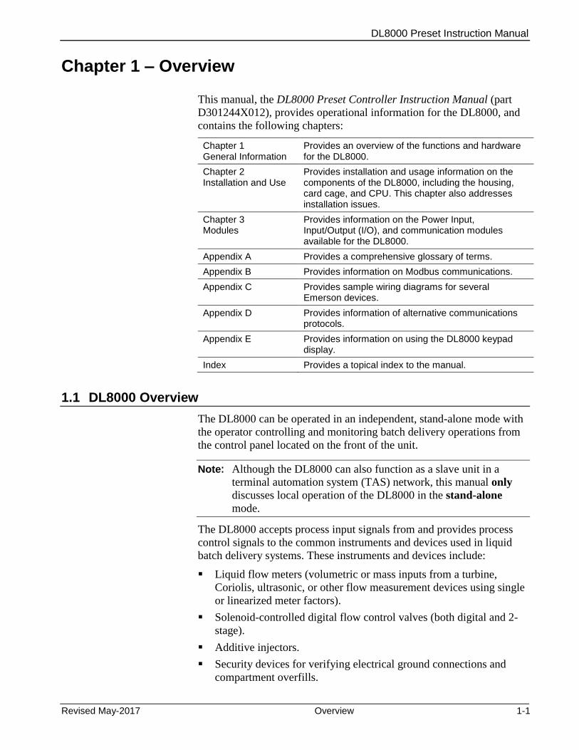
Chapter 1 – Overview
This manual, the DL8000 Preset Controller Instruction Manual (part
D301244X012), provides operational information for the DL8000, and
contains the following chapters:
Chapter 1 General Information
Provides an overview of the functions and hardware for the DL8000.
Chapter 2 Installation and Use
Provides installation and usage information on the components of the DL8000, including the housing, card cage, and CPU. This chapter also addresses installation issues.
Chapter 3 Modules
Provides information on the Power Input, Input/Output (I/O), and communication modules available for the DL8000.
Appendix A Provides a comprehensive glossary of terms.
Appendix B Provides information on Modbus communications.
Appendix C Provides sample wiring diagrams for several Emerson devices.
Appendix D Provides information of alternative communications protocols.
Appendix E Provides information on using the DL8000 keypad display.
Index Provides a topical index to the manual.
1.1 DL8000 Overview
The DL8000 can be operated in an independent, stand-alone mode with
the operator controlling and monitoring batch delivery operations from
the control panel located on the front of the unit.
Note: Although the DL8000 can also function as a slave unit in a
terminal automation system (TAS) network, this manual only
discusses local operation of the DL8000 in the stand-alone
mode.
The DL8000 accepts process input signals from and provides process
control signals to the common instruments and devices used in liquid
batch delivery systems. These instruments and devices include:
Liquid flow meters (volumetric or mass inputs from a turbine,
Coriolis, ultrasonic, or other flow measurement devices using single
or linearized meter factors).
Solenoid-controlled digital flow control valves (both digital and 2-
stage).
Additive injectors.
Security devices for verifying electrical ground connections and
compartment overfills.

DL8000 Preset Instruction Manual
1-2 Overview Revised May-2017
Electric motor driven pumps.
Motor operated block valves.
You can easily configure the DL8000 to deliver single component
liquids or to blend up to four liquid components in precise ratios, with
or without additive injection. Operator-selectable predefined delivery
control procedures (“recipes”) control the DL8000’s various possible
delivery and blending functions. Additive injection is controlled by
manual selection, recipe selection, or automatic selection from a
terminal automation system. These features allow one DL8000 and the
associated liquid delivery equipment to deliver many different
combinations of liquid products, based on requirements of the client or
receiver of the delivered product.
One common DL8000 application is to function as an on-site controller
for delivering refined liquid hydrocarbon products from loading
terminal storage tanks to mobile tanks (such as tanker trucks, rail cars,
or barges). Other applications include liquid component blending and /
or additive injection in refinery or chemical plant processes. In addition,
liquid components (with or without additive injection) can be blended
into flowing pipelines or into storage tanks. Figure 1-1 shows a typical
load rack installation with a DL8000 and associated equipment.
1: Pump Control Output 6. Temperature Probe
2. Density Transmitter 7. Valve Control
3. Pressure Transmitter 8. DL8000
4. Additive Injection Output(s) 9. Permissive Contacts
5. Meter Pulse Output
Figure 1-1. Typical DL8000 Load Rack

DL8000 Preset Instruction Manual
Revised May-2017 Overview 1-3
Warning Overfill protection is critically important to your site. If your site DOES NOT have overfill protection hardware installed, DO NOT set the Overrun Limit Quantity value (defined on the Alarm Setup tab of the Preset Setup screen in the Batching program) to zero. Setting that field to zero DISABLES overfill protection. Remote Automation Solutions is not responsible for damage resulting from disabling this critical safety feature.
Additionally, you MUST have a redundant safety system (such as Ground fault, Overfill) in place and operational. Otherwise, DO NOT use this product.
Factory Default Configuration
The DL8000 is factory-configured with a basic set of communication
and I/O modules to accommodate process I/O signals.
The default I/O module load—as well as any optional modules—is
determined during initial purchase. However, the I/O modules and
communications modules mix is field-reconfigurable, within the limits
of the DL8000’s central processing unit (CPU). The hardware
configuration determines the DL8000’s capacities for I/O signal
handling and the data logging/data communications.
Logical Functions The flow measurement and logical functions listed below are available
in all hardware configurations of the DL8000. However, each unique
installation requires a specific complement of I/O modules, based on
the actual devices the DL8000 monitors and controls.
The DL8000 can simultaneously monitor and control operation of up to
three flow meters, up to three flow control valves, and deliver up to four
products. The minimum configuration consists of one flow meter
measuring one component (liquid product), one control valve, one pump
start, and one permissive input. Product deliveries and component
blending deliveries are selected by up to 30 configurable recipes (batch
delivery/blending control procedures). The actual implementation of the
various possible process operations are covered in detail in other
sections of this manual.
1.2 Hardware
The DL8000 has two primary physical components: the external
housing and the internal electronics. Refer to Chapter 2, Installation
and Use, for details on installation.
1.2.1 Housing
The DL8000 uses either of two external housings:
A cast aluminum casing with stainless steel front cover bolts. It is
flame-proof (in accordance with Class I, Zone 1, Group IIB) and
weatherproof (in accordance with IP66).
A 14-gauge stainless steel box with 12-gauge stainless steel
mounting flanges, CSA-rated as a Type 4 enclosure. The door is

DL8000 Preset Instruction Manual
1-4 Overview Revised May-2017
made of 0.090 inch thick aluminum secured to the box with a
stainless steel piano hinge and two stainless steel spring latches.
Note: For specific details, refer to the technical specification DL8000
Preset (part D301255X012), available at
www.EmersonProcess.com/Remote.
A Front cover bolts
B Display
C Status LEDs
D Weights & Measures switch
E Operator keypad
Figure 1-2. DL8000 (in Class I, Zone 1 Enclosure)
Sixteen stainless steel front cover bolts (M10 – 1.5 metric) secure the lid
to the housing. Two of the front bolts are longer and drilled close to the
threaded ends, allowing placement of Weight & Measures seal wires to
prevent undetected access to the electronics.
Bolt holes are tapped to 13 mm (0.50 inches); require an 8 mm (5/16-
inch) Allen wrench, and torque to 24 to 29 Newton/meters (18 to 21
foot/pounds) of force.
The operator keypad provides 18 rugged, Hall-Effect pushkeys which
are impervious to chemicals commonly associated with petroleum
applications. A sealable Weights & Measures switch provides security
to flow measurement parameters.
Secured behind non-glare glass, the liquid crystal display (LCD)
provides an 8-line by 40-column message area for operator interface.
The display uses a photo sensor and temperature sensor which can be
A
E
B
C
D
DL8000 Preset Instruction Manual
Revised May-2017 Overview 1-5
set to automatically adjust contrast and backlighting for optimal
viewing.
Light-emitting diodes (LEDs) displaying the status of alarms, operating
mode, and permissive powers are located to the right of the display.
With the front cover bolts removed, the lid hinges down to reveal the
electronic compartment.
1.2.2 Electronics
The DL8000’s CPU sits inside the cast aluminum enclosure. The
DL8000 uses a highly innovative and versatile CPU with a backplane to
which the CPU, Power Input module, input/output (I/O) modules, and
communication modules connect. The DL8000 unit has nine module
slots, three of which (slots 1, 2, and 3) can house communication
modules.
The DL8000 uses a 12 volt dc Power Input module to convert 120 to
250 V ac external input power to the voltage levels required by the
unit’s electronics and to monitor voltage levels to ensure proper
operation. For more information on the Power Input module, refer to
Chapter 3, Modules.
The DL8000 supports a number of I/O modules, which can satisfy a
wide variety of field I/O requirements (refer to Chapter 3, Modules). I/O
modules include:
Analog Inputs (AI).
Analog Outputs (AO).
Discrete Inputs (DI).
Discrete Outputs (DO).
Digital Output Relay (DOR).
Alternating Current Input/Output (ACIO).
Advance Pulse Module (APM).
Pulse Inputs (PI) – High/Low Speed.
Resistance Temperature Detector Inputs (RTD).
Thermocouple (TC)
HART®
In addition to the built-in serial interface (the Local Operator Interface,
or LOI) and an Ethernet connection, the DL8000 also supports the
following communications modules:
EIA-232 Serial Communications.
EIA-422/485 Serial Communications.
Dial-up Modem.

DL8000 Preset Instruction Manual
1-6 Overview Revised May-2017
1.3 Security Gateway
For enhanced data security when using an IP/Ethernet connection,
Remote Automation Solutions recommends adding an industrial router
with VPN and firewall security. Recommended solutions include the
MOXA EDR-810, the Hirschman Eagle One, or the Phoenix mGuard
rs4000 (or equivalents). An example of how to install one of these
devices to the RTU/flow computer can be found in the Remote
Automation Solutions MOXA® Industrial Secure Router Installation
Guide (part number D301766X012). For further information, contact
your Local Business Partner or the individual vendor’s website.
1.4 Additional Technical Specifications
For further technical information on the DL8000, refer to the technical
specification DL8000 Preset (part D301255X012), available at
www.EmersonProcess.com/Remote.

DL8000 Preset Instruction Manual
Revised May-2017 Installation and Use 2-1
Chapter 2 – 0BInstallation and Use
In This Chapter
2.1 Housing.………………………………………………………………………. 2-1 2.1.1 Class I Zone 1 Housing .............................................................. 2-2 2.1.2 Securing the Cover to the Class I Zone I Case .......................... 2-4 2.1.3 Class I Div 2 Housing ................................................................. 2-5
2.2 Card Cage.…………………………………………………………………… 2-6 2.2.1 Backplane ................................................................................... 2-7
2.3 Central Processor Unit (CPU)………………………………………………. 2-8 2.3.1 BInstalling and Removing Wire Channel Covers...................... 2-10 2.3.2 Removing and Installing Module Covers .................................. 2-11 2.3.3 Removing the CPU Module ...................................................... 2-11 2.3.4 Installing the CPU Module ........................................................ 2-12
2.4 License Keys ……………………………………………………………….. 2-12 2.4.1 Installing a License Key ............................................................ 2-13 2.4.2 Removing a License Key .......................................................... 2-14
2.5 Installation Planning ……………………………………………………….. 2-15 2.6 Mechanical Installation ……………………………………………………. 2-15
2.6.1 Planning Considerations ........................................................... 2-16 2.7 Electrical Installation ………………………………………………………. 2-18
2.7.1 General Considerations ............................................................ 2-18 2.7.2 Field Wiring Installation Guidelines: ......................................... 2-18 2.7.3 Electrical Wire and Cable Selection and Installation ................ 2-19 2.7.4 Input/Output Field Signal Wiring ............................................... 2-20 2.7.5 Electrical Grounds .................................................................... 2-20 2.7.6 Wire Conduit Selection and Installation .................................... 2-22
2.8 Operator Interface …………………………………………………………. 2-23 2.8.1 Keypad ...................................................................................... 2-24 2.8.2 LED Status Indicators ............................................................... 2-25
This chapter describes the DL8000’s external housing, its internal
electronic components (the ROC800-Series CPU), and the specifics of
mechanical and electrical installation.
2.1 1BHousing
The DL8000 uses either of two external housings:
A cast aluminum casing with stainless steel front cover bolts. It is
flame-proof (in accordance with Class I, Zone 1, Group IIB) and
weatherproof (in accordance with IP66).
A 14-gauge stainless steel box with 12-gauge stainless steel
mounting flanges, CSA-rated as a Type 4 enclosure. The door is
made of 0.090 inch thick aluminum secured to the box with a
stainless steel piano hinge and two stainless steel spring latches.
DL8000 Preset Instruction Manual
2-2 Installation and Use Revised May-2017
2.1.1 9BClass I Zone 1 Housing
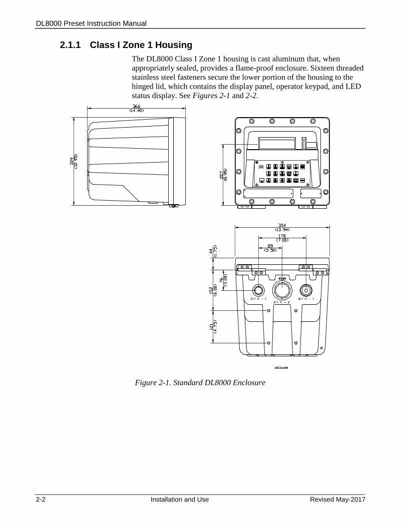
The DL8000 Class I Zone 1 housing is cast aluminum that, when
appropriately sealed, provides a flame-proof enclosure. Sixteen threaded
stainless steel fasteners secure the lower portion of the housing to the
hinged lid, which contains the display panel, operator keypad, and LED
status display. See Figures 2-1 and 2-2.
Figure 2-1. Standard DL8000 Enclosure

DL8000 Preset Instruction Manual
Revised May-2017 Installation and Use 2-3
Figure 2-2. Standard DL8000 Enclosure
Note: The four mounting holes on the bottom and back of the DL8000
case accept 10M (10mm) bolts.
The DL8000’s design makes it highly adaptable to a wide variety of
installations. Consequently, this manual cannot cover all possible
installation scenarios. Contact your local sales representative if you
require information concerning a specific installation not described in
this manual.
DL8000 Preset Instruction Manual
2-4 Installation and Use Revised May-2017
Planning is essential to a good installation. Because installation
requirements depend on many factors (such as the application, location,
ground conditions, climate, and accessibility), this document only
provides generalized guidelines.
2.1.2 10BSecuring the Cover to the Class I Zone I Case
The DL8000 ships from the factory with the cover secured to the case
with one stainless steel fastener (“bolt”). The remaining bolts are
bagged and included with the DL8000. You must install all bolts.
Warning Failure to install ALL cover bolts will compromise the flame-proof characteristics of the enclosure.
Caution The flanges between the case and the cover create a flameproof joint. Before you secure the cover to the case, make sure the surfaces are clean and free of damage.
To secure the DL8000 cover:
Notes:
You must use a torque wrench for this procedure.
The bolt in position 9 (see Figure 2-3) is factory-installed. Be sure
that the bolts you install in positions 12 and 8 are the two longer
bolts with pre-drilled holes (for the Weights & Measures seal wires).
1. Swing the DL8000 cover up against the case.
2. Insert a bolt in position 1 (refer to Figure 2-3) and finger-tighten the
bolt until you feel resistance.
3. Insert a bolt in position 2 (refer to Figure 2-3) and finger-tighten the
bolt until you feel resistance.
4. Repeat step 3 for bolts in positions 3 through 16.
5. Using a torque wrench, tighten the bolt in position 1 to
specifications (24 to 29 Newton/meters or 18 to 21 foot/pounds of
force).
6. Tighten bolts in positions 2 through 16 to specifications.
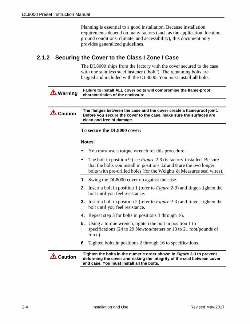
Caution Tighten the bolts in the numeric order shown in Figure 3-3 to prevent deforming the cover and risking the integrity of the seal between cover and case. You must install all the bolts.
DL8000 Preset Instruction Manual
Revised May-2017 Installation and Use 2-5
Figure 2-3. Bolt Tightening Sequence
2.1.3 11BClass I Div 2 Housing
The Class I, Division 2 housing includes a 14-gauge stainless steel box
with 12-gauge stainless steel mounting flanges. The door is made of
.090 inch thick aluminum and is secured to the box via a stainless steel
piano hinge and two stainless steel spring latches. The latches include
features for padlocking or installing wire seals. The assembly includes a
door stop that locks the door in position at approximately 120 degrees
from the closed position. The viewing window in the enclosure door is
made from scratch / UV resistant polycarbonate/acrylic blend
(PC/PMMA). The keypad bezel is mounted to the front of the door and
is made from UV resistant polycarbonate. The assembly is rated by
CSA as a Type 4 enclosure, and can be either pole-mounted or flush-
mounted.
8
2
11
15
1
5
9
13
7
12
16
3
4 6 10 14
DL8000 Preset Instruction Manual
2-6 Installation and Use Revised May-2017
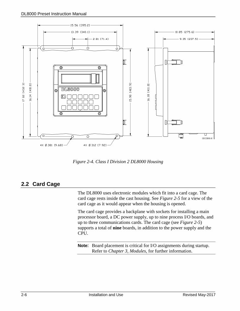
Figure 2-4. Class I Division 2 DL8000 Housing
2.2 2BCard Cage
The DL8000 uses electronic modules which fit into a card cage. The
card cage rests inside the cast housing. See Figure 2-5 for a view of the
card cage as it would appear when the housing is opened.
The card cage provides a backplane with sockets for installing a main
processor board, a DC power supply, up to nine process I/O boards, and
up to three communications cards. The card cage (see Figure 2-5)
supports a total of nine boards, in addition to the power supply and the
CPU.
Note: Board placement is critical for I/O assignments during startup.
Refer to Chapter 3, Modules, for further information.
DL8000 Preset Instruction Manual
Revised May-2017 Installation and Use 2-7
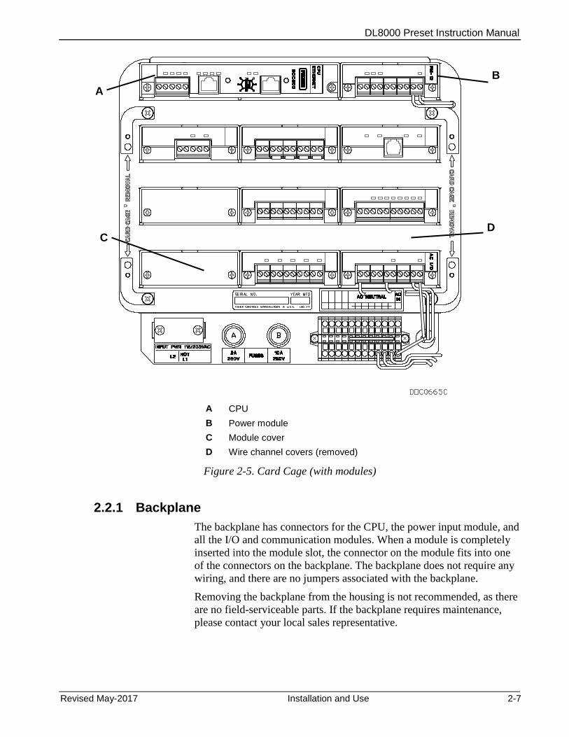
A CPU
B Power module
C Module cover
D Wire channel covers (removed)
Figure 2-5. Card Cage (with modules)
2.2.1 12BBackplane
The backplane has connectors for the CPU, the power input module, and
all the I/O and communication modules. When a module is completely
inserted into the module slot, the connector on the module fits into one
of the connectors on the backplane. The backplane does not require any
wiring, and there are no jumpers associated with the backplane.
Removing the backplane from the housing is not recommended, as there
are no field-serviceable parts. If the backplane requires maintenance,
please contact your local sales representative.
C
A
B
D

DL8000 Preset Instruction Manual
2-8 Installation and Use Revised May-2017
2.3 3BCentral Processor Unit (CPU)
The CPU contains the microprocessor, the firmware, connectors to the
backplane, three built-in communication ports (two with LEDs), a LED
low power wakeup button, a RESET button, the application license key
connectors, a STATUS LED indicating system integrity, and the main
processor. See Figure 2-6.
The 32-bit microprocessor is based on a Motorola® MPC862 Quad
Integrated Communications Controller (PowerQUICC™) PowerPC®
processor running at 65 MHz (in the Series 2 CPU module) or 50 MHz
(in the Series 1 CPU module).
The internal Sanyo 3 volt CR2430 lithium backup battery provides
backup of the data and the Real-Time Clock when the main power is not
connected.
Series 1 CPU Faceplate (Gray)
Series 2 CPU Faceplate (Black)
A Securing screw
B LED button
C LOI – EIA-232 (RS-232D)
D Status LED
E Ethernet port
F EIA0232 (RS0232C)
Figure 2-6. CPU Front View (Series 1 and Series 2 CPU Modules)
B
C x
D
E
F
A
A
A
A
B
C x
D
E
F
DL8000 Preset Instruction Manual
Revised May-2017 Installation and Use 2-9
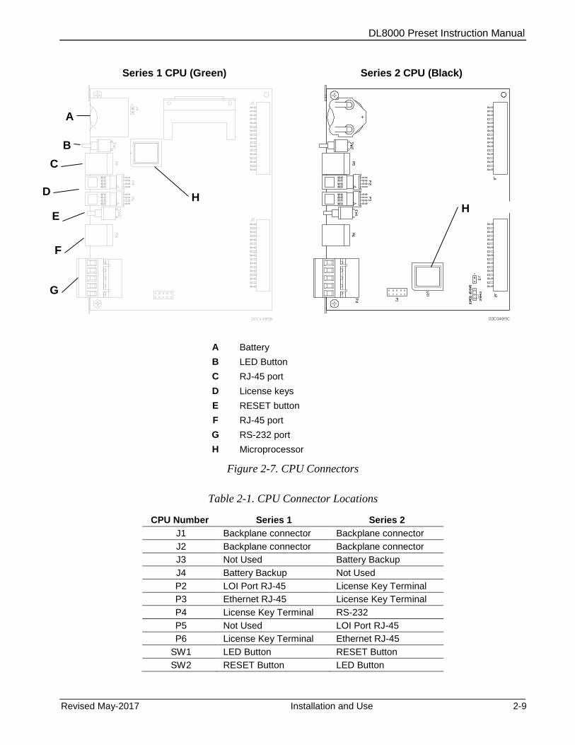
Series 1 CPU (Green) Series 2 CPU (Black)
A Battery
B LED Button
C RJ-45 port
D License keys
E RESET button
F RJ-45 port
G RS-232 port
H Microprocessor
Figure 2-7. CPU Connectors
Table 2-1. CPU Connector Locations
CPU Number Series 1 Series 2
J1 Backplane connector Backplane connector
J2 Backplane connector Backplane connector
J3 Not Used Battery Backup
J4 Battery Backup Not Used
P2 LOI Port RJ-45 License Key Terminal
P3 Ethernet RJ-45 License Key Terminal
P4 License Key Terminal RS-232
P5 Not Used LOI Port RJ-45
P6 License Key Terminal Ethernet RJ-45
SW1 LED Button RESET Button
SW2 RESET Button LED Button
A
B
D
E
C
H
H
F
G
DL8000 Preset Instruction Manual
2-10 Installation and Use Revised May-2017
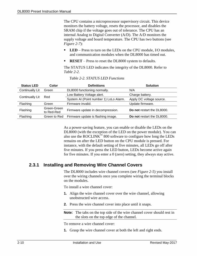
The CPU contains a microprocessor supervisory circuit. This device
monitors the battery voltage, resets the processor, and disables the
SRAM chip if the voltage goes out of tolerance. The CPU has an
internal Analog to Digital Converter (A/D). The A/D monitors the
supply voltage and board temperature. The CPU has two buttons (see
Figure 2-7):
LED – Press to turn on the LEDs on the CPU module, I/O modules,
and communication modules when the DL8000 has timed out.
RESET – Press to reset the DL8000 system to defaults.
The STATUS LED indicates the integrity of the DL8000. Refer to
Table 2-2.
Table 2-2. STATUS LED Functions
Status LED Color Definitions Solution
Continually Lit Green DL8000 functioning normally. N/A
Continually Lit Red Low Battery Voltage alert. Charge battery.
System AI (Point number 1) LoLo Alarm. Apply DC voltage source.
Flashing Green Firmware invalid. Update firmware.
Flashing Green-Green to Red-Red
Firmware update in decompression. Do not restart the DL8000.
Flashing Green to Red Firmware update is flashing image. Do not restart the DL8000.
As a power-saving feature, you can enable or disable the LEDs on the
DL8000 (with the exception of the LED on the power module). You can
also use the ROCLINK™ 800 software to configure how long the LEDs
remains on after the LED button on the CPU module is pressed. For
instance, with the default setting of five minutes, all LEDs go off after
five minutes. If you press the LED button, LEDs become active again
for five minutes. If you enter a 0 (zero) setting, they always stay active.
2.3.1 13BInstalling and Removing Wire Channel Covers
The DL8000 includes wire channel covers (see Figure 2-5) you install
over the wiring channels once you complete wiring the terminal blocks
on the modules.
To install a wire channel cover:
1. Align the wire channel cover over the wire channel, allowing
unobstructed wire access.
2. Press the wire channel cover into place until it snaps.
Note: The tabs on the top side of the wire channel cover should rest in
the slots on the top edge of the channel.
To remove a wire channel cover:
1. Grasp the wire channel cover at both the left and right ends.
DL8000 Preset Instruction Manual
Revised May-2017 Installation and Use 2-11
2. Start at the left or right and pull the wire channel cover out of the
wire channel.
2.3.2 14BRemoving and Installing Module Covers
Before you insert an I/O or communications module, remove the
module cover (see Figure 2-5) over the empty module slots in which
you intend to install the modules. Although you are not required to
remove the power to the DL8000 to perform this procedure, caution is
always advisable when working with a powered DL8000.
Caution To avoid circuit damage when working inside the unit, use appropriate electrostatic discharge precautions (such as wearing a grounded wrist strap).
When working on units located in a hazardous area (where explosive gases may be present), make sure the area is in a non-hazardous state before performing procedures. Performing these procedures in a hazardous area could result in personal injury or property damage.
To remove a module cover:
1. Remove the wire channel cover.
2. Unscrew the two captive screws on the face of the cover.
3. Using the tab at the top side of the module cover, lift the module
cover from the DL8000.
Note: If you remove a module for an extended period, install a module
cover over the empty module slot to keep dust and other matter
from getting into the DL8000.
To install a module cover:
1. Place the module cover over the module slot.
2. Tighten the two captive screws on the face of the cover.
3. Replace the wire channel cover.
2.3.3 15BRemoving the CPU Module
To remove the CPU module:
Caution Failure to exercise proper electrostatic discharge precautions (such as wearing a grounded wrist strap) may reset the processor or damage electronic components, resulting in interrupted operations.
When working on units located in a hazardous area (where explosive gases may be present), make sure the area is in a non-hazardous state before performing procedures. Performing these procedures in a hazardous area could result in personal injury or property damage.
1. Back up critical data.
DL8000 Preset Instruction Manual
2-12 Installation and Use Revised May-2017
Note: “Critical” data may include your device configuration file,
device alarms and events history, or displays.
2. Remove power from the DL8000.
3. Remove the wire channel cover.
4. Unscrew the two captive screws on the front of the CPU module and
remove the faceplate.
5. Place a small screwdriver under the ejector clip at the left or right of
the CPU module and lightly pry the CPU module out of its socket.
You may find it easiest to carefully pry on the left ejector clip a
little, and then carefully pry the right ejector. You will feel and hear
the CPU as it detaches from the backplane.
6. Remove the CPU module carefully. Make sure not to pull on any
cables attached to the CPU module.
2.3.4 16BInstalling the CPU Module
To install the CPU module:
Caution Failure to exercise proper electrostatic discharge precautions (such as wearing a grounded wrist strap) may reset the processor or damage electronic components, resulting in interrupted operations.
When working on units located in a hazardous area (where explosive gases may be present), make sure the area is in a non-hazardous state before performing procedures. Performing these procedures in a hazardous area could result in personal injury or property damage.
1. Slide the CPU module into the slot.
2. Press the CPU firmly into the slot, ensuring the ejector clips rest on
the module rail guides. The connectors at the back of the CPU
module fit securely into the connectors on the backplane.
3. Place the CPU faceplate on the CPU.
4. Tighten the two captive screws on the faceplate of the CPU module
firmly.
5. Replace the wire channel cover.
6. Return power to the DL8000.
2.4 4BLicense Keys
License keys with valid license codes grant access to applications or, in
some cases, allow optional firmware functionality to execute. In some
situations, a license key may also be required before you can run the
application. Examples of licensed applications include DS800
Development Suite software, meter run calculations, and various User C
programs (such as LiquidCalcs in this application). You can then
DL8000 Preset Instruction Manual
Revised May-2017 Installation and Use 2-13
configure these applications using ROCLINK 800 or the DS800
Development Suite software.
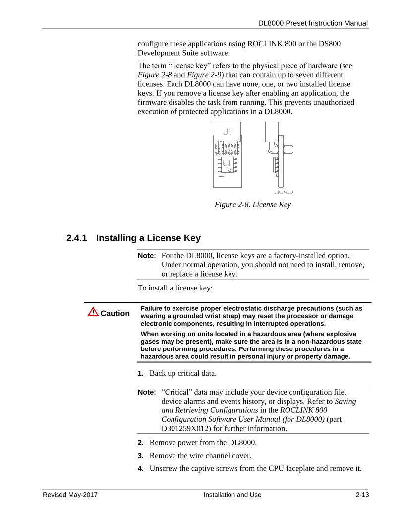
The term “license key” refers to the physical piece of hardware (see
Figure 2-8 and Figure 2-9) that can contain up to seven different
licenses. Each DL8000 can have none, one, or two installed license
keys. If you remove a license key after enabling an application, the
firmware disables the task from running. This prevents unauthorized
execution of protected applications in a DL8000.
Figure 2-8. License Key
2.4.1 17BInstalling a License Key
Note: For the DL8000, license keys are a factory-installed option.
Under normal operation, you should not need to install, remove,
or replace a license key.
To install a license key:
Caution Failure to exercise proper electrostatic discharge precautions (such as wearing a grounded wrist strap) may reset the processor or damage electronic components, resulting in interrupted operations.
When working on units located in a hazardous area (where explosive gases may be present), make sure the area is in a non-hazardous state before performing procedures. Performing these procedures in a hazardous area could result in personal injury or property damage.
1. Back up critical data.
Note: “Critical” data may include your device configuration file,
device alarms and events history, or displays. Refer to Saving
and Retrieving Configurations in the ROCLINK 800
Configuration Software User Manual (for DL8000) (part
D301259X012) for further information.
2. Remove power from the DL8000.
3. Remove the wire channel cover.
4. Unscrew the captive screws from the CPU faceplate and remove it.
DL8000 Preset Instruction Manual
2-14 Installation and Use Revised May-2017
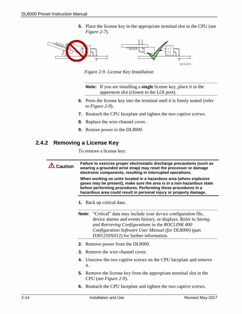
5. Place the license key in the appropriate terminal slot in the CPU (see
Figure 2-7).
Figure 2-9. License Key Installation
Note: If you are installing a single license key, place it in the
uppermost slot (closest to the LOI port).
6. Press the license key into the terminal until it is firmly seated (refer
to Figure 2-9).
7. Reattach the CPU faceplate and tighten the two captive screws.
8. Replace the wire channel cover.
9. Restore power to the DL8000.
2.4.2 18BRemoving a License Key
To remove a license key:
Caution Failure to exercise proper electrostatic discharge precautions (such as wearing a grounded wrist strap) may reset the processor or damage electronic components, resulting in interrupted operations.
When working on units located in a hazardous area (where explosive gases may be present), make sure the area is in a non-hazardous state before performing procedures. Performing these procedures in a hazardous area could result in personal injury or property damage.
1. Back up critical data.
Note: “Critical” data may include your device configuration file,
device alarms and events history, or displays. Refer to Saving
and Retrieving Configurations in the ROCLINK 800
Configuration Software User Manual (for DL8000) (part
D301259X012) for further information.
2. Remove power from the DL8000.
3. Remove the wire channel cover.
4. Unscrew the two captive screws on the CPU faceplate and remove
it.
5. Remove the license key from the appropriate terminal slot in the
CPU (see Figure 2-9).
6. Reattach the CPU faceplate and tighten the two captive screws.
DL8000 Preset Instruction Manual
Revised May-2017 Installation and Use 2-15
7. Replace the wire channel cover.
8. Restore power to the DL8000.
2.5 5BInstallation Planning
Installation planning is very important due to the DL8000’s physical
and functional reconfigurable capabilities. Installation planning consists
of the following three major tasks.
Assure that the DL8000 contains the required number and type of
process I/O boards to monitor and control the other devices in the
product delivery system.
Determine the functions the DL8000 will perform. You selectively
enable these functions during the DL8000’s configuration
procedure.
Design the mechanical/electrical installation with special
consideration for both the operator’s safety and ease-of-use and the
maintenance technicians’ safety and ease-of-access to instruments
and devices.
2.6 6BMechanical Installation
In planning the physical installation of the DL8000, consider ease of use
of the instrument with the operator in a safe and comfortable position.
Also consider how maintenance tasks may be performed without
disrupting ongoing product delivery operations in close proximity.
Drawing rough diagrams of normal operator actions during the different
possible batch delivery related tasks may be helpful. Note especially the
operator’s location in relation to the location of one or two tanker
vehicles and their related loading arm and bottom loading hose
connections.
Some location or position restrictions may be present when a DL8000 is
retrofitted or upgraded into an existing installation. However,
mechanical installation planning should still be performed. It may be
possible to correct an existing inconvenient controller mounting location
in a current loading rack installation when retrofitting a DL8000 at the
installation.
Following are the major steps performed during installation.
1. Plan the installation.
2. Fabricate device supports and lay electrical conduit.
3. Mount the DL8000 and other load rack devices.
4. Run and connect all wiring.
5. Verify and tag each wire.
DL8000 Preset Instruction Manual
2-16 Installation and Use Revised May-2017
6. Seal conduit within 50 mm (2 inches) of the DL8000.
Note: Install certified conduit plugs in any unused entries.
7. Secure cases and covers of all devices.
8. Apply electrical power.
9. Configure (set up) the DL8000 and any other devices as required.
10. Disable product block valves and additive block valves to
prevent any product or additive flow. Then verify system monitor
and control functions with dry piping.
11. Enable one product block valve at a time and one additive
injection system at a time. Then verify the piping integrity and
system operation in increments for each product and each additive
handling system.
12. Perform meter proves to determine DL8000 meter calibration.
2.6.1 19BPlanning Considerations
Consider the following points during DL8000 mechanical installation
planning:
Maintenance Access
The operator panel is hinged at the bottom side and opens down for
maintenance access. Route all conduit to the rear, sides, or bottom of
the unit. Do not locate any object under the DL8000 or in front of
the conduit connections for a distance of approximately 533 mm (21
inches) below the instrument.
Mounting Height
Recommended mounting height is approximately 1.14 to 1.27
meters (45 to 50 inches) above grade to the bottom of the DL8000
case (see Figure 2-2). Mounting height determines the ease of
viewing the display panel and ease of use of the keypad.
Mounting Position
North/south/east/west orientation of the operator control panel is
somewhat predetermined by the loading facility design. Consider the
location of the operator in relation to one or two tanker vehicles
present and connected at the loading island.
Mounting Fixtures
You must fabricate mounting fixtures for the DL8000. Each
DL8000 comes with four M10-1.5 x 15 mm metric thread bolts for
mounting. You can either rear-mount or bottom-mount the DL8000,
although bottom-mounting is preferred due to the DL8000’s weight.
The mounting attachment should be a 4 mm (0.16 inch) (minimum)
thick mild steel member with four 11.5 mm (0.44 inch) diameter
DL8000 Preset Instruction Manual
Revised May-2017 Installation and Use 2-17
holes that match the bolting pattern being used. The steel member
may be sheet, angle, channel, or another shape.
Center the forward pair of mounting screw holes in bottom-mount
fixtures no more than 19 mm (0.75 inch) from the edge. The case
has a taper to the rear. The standard case may need a shim at the rear
pair of screws to level the DL8000. Level the case to allow for the
best conduit alignment.
Special Installation Considerations
The DL8000 is designed for installation in an outdoor environment.
The instrument is weatherproof and explosion-proof in accordance
with applicable standards. Some of the following installation
suggestions concerning environmental protection describe accepted
engineering practices and should not be considered to be limitations
on the utility of the instrument.
If the loading rack or loading island area is covered, locate the
DL8000 so that the operator is protected or partially protected
from direct rainfall.
In tropical climates, place sunshades above the DL8000 and
other electronic instruments, such as process transmitters. Locate
sunshades to prevent direct sunlight on the instruments during
the hottest part of the day (10:00 to 15:00). Construct sunshades
of metal, fiberglass, or other suitable materials. Sunshades
should be rear-sloping to direct rain to the rear of the instrument
and away from the operator. Avoid sharp edges or corners on
sunshades to prevent injuries.
In desert areas or areas of blowing sand, install a cover to
protect the operator control panel during idle time. Continuous
blowing sand over an extended period of time can sandblast the
display panel and pushkey legends, affecting readability.
Fabricate a cover from raw materials or use a modified NEMA 4
weatherproof enclosure with a sealed rear cutout, placing it over
the operator panel. Use care in the design of any hinged cover so
that wind gusts do not move the cover and cause injuries. Any
cover design must allow for maintenance access to the DL8000.
The operator panel is hinged to open in the down direction for
maintenance access.
In areas of continuous high humidity, place a 76.2mm x
76.2mm (3-inch x 3-inch) desiccant pack inside the DL8000
case. Place desiccant packs so that any expansion due to
moisture absorption does not interfere with any of the equipment
or wiring inside the case. Two sources of desiccant packs are:
o Waterguard® Desiccants
PO Box 1079
16023 I-10 East, Suite 30
Channelview, TX 77530
DL8000 Preset Instruction Manual
2-18 Installation and Use Revised May-2017
o A+ Corporation
40462 Highway 42
Prarieville, LA 70769
2.7 7BElectrical Installation
Caution Shut off all sources of AC and DC power to the loading island site before installing the DL8000.
2.7.1 20BGeneral Considerations
Use any of three cable entries located on the bottom of the housing for
wiring access to the DL8000.
A threaded 25.4 mm (1-inch) female NPSM connection on the left
side of the unit (for AC power and control / status signals).
A spare threaded 25.4 mm (1-inch) female NPSM connection on the
right side of the unit (may be used for meter pulse wiring to
segregate meter pulse wiring from all other signals).
A threaded 50 mm (2-inch) female NPSM connection for DC
cabling and low voltage level signals in the center.
Caution Seal all cable entries within 50 mm (2 inches) of the enclosure with suitable sealing or potting compound.
2.7.2 21BField Wiring Installation Guidelines:
Route external AC and DC wiring in separate conduits.
Record cable and wire routing and interconnection information to
simplify the creation of as-built documentation for the system.
Provide remote circuit breakers and optional disconnect switches for
all AC and DC power input circuits.
Follow power and signal field wiring grounding standards.
Use only stranded copper wire, equal to or of larger gauges as
indicated on the basic wiring diagrams located at the rear of this
section. Take care not to cut or weaken wire strands during the
removal of insulation.
Clearly mark all wire ends with slip-on wire tags or similar devices.
Preferably, color-code the wire tags to indicate the voltage level and
mark tags with the specific signal name.
Cut power and signal wires with an additional length of
approximately 50 mm (2 inches) for service loops to allow terminal
board and connector removal.
DL8000 Preset Instruction Manual
Revised May-2017 Installation and Use 2-19
Position all wiring within the unit to avoid unnecessary crimping
and overcrowding and to insure proper clearance for the instrument
door and hinges.
After completion, thoroughly check the wiring to insure that input
AC power and all field I/O signals are correctly connected at the
DL8000 terminations and at the terminations located on the
corresponding field device.
2.7.3 22BElectrical Wire and Cable Selection and Installation
All wiring must conform to the National Electrical Code; to local, state,
or other jurisdictions; and to company standards and practices.
Following are recommendations for 115/230 Volts ac power wiring:
Use multi-strand copper conductor wire and cable when connecting
the DL8000 to the power source and the field devices.
Ensure that all wire and cable is in new condition and adheres to the
manufacturer's quality standards with the size, type of insulation,
and voltage rating.
Use the following recommended wire types and sizes for AC power
input to the DL8000:
Power feed should be 100 or 240 Volts ac, 50 to 60 Hertz, single
phase, three-wire. Locate a 15 Amp circuit breaker and
optionally a power disconnect switch in a safe area.
Use wire size AWG 14 for power feed for distances up to 250
feet.
Use wire size AWG 12 for power feed for distances of 250 to
500 feet.
Use wire size AWG 10 for power feed for distances of 500 to
1000 feet.
Note: Power feed distances greater than 1000 feet are not
recommended.
Single-conductor wiring must be THWN type, which is moisture
and heat-resistant thermoplastic with nylon jacket, approved for
dry-and-wet locations, and has a maximum operating
temperature of 75 degrees Celsius (167 degrees Fahrenheit). The
wire or cable jacket must contain the Underwriters Laboratories,
Inc. mark for Gasoline and Oil Resistant, II.
Ensure that shielded wires and cables for meter pulse signals have
shield-drain wires. The shield-drain wires must not be more than
two AWG sizes smaller than the conductors for the cable. The
shield-drain wire must be connected to ground at only one end of the
run.
DL8000 Preset Instruction Manual
2-20 Installation and Use Revised May-2017
Connect RS-485 serial data signals via two twisted pairs with
overall shield, AWG 28 to AWG 22. Ideally, the capacitance should
not be greater than 16 pF per foot (Belden 9842 for example). The
use of a signal common (ground) conductor connected to each
device is a recommended option. Capacitance greater than 16 pF per
foot may be used at reduced baud rates and/or with shorter data
communication cable runs.
Use AWG 28 to AWG 18 RS-232 single ended serial data signals
for cable lengths up to 15 meters (50 feet).
Ensure that all cables have either Teflon® or PVC exterior jackets.
Install insulated wire and cable in accordance with the
manufacturer's recommendation. Do not exceed maximum wire
tension, maximum insulation pressure, or minimum bending radius.
Use suitable lubrication during wire pulls in conduit to prevent wire
stress.
Place cable or wire markers at the terminations of all cables and
individual wires. Markers should contain the specific wire or cable
codes designated for that particular circuit. The wire and cable
markers should be legible and permanent.
Check all wiring connected to the DL8000 for continuity, proper
size, and proper classification. Verify the source or destination of
each circuit before connecting to the DL8000 and related devices.
2.7.4 23BInput/Output Field Signal Wiring
Following are recommendations for process signal wiring:
Use metal conduit for all process signal wiring.
Use separate conduits for AC and DC voltage circuits.
Ensure that all process signal wiring is a single, continuous length
between field devices and the DL8000, unless the length and/or
conduit runs require that multiple pulls be made. In these instances,
interconnect the individual conductors with suitable terminal blocks.
2.7.5 24BElectrical Grounds
Following are recommendations for electrical grounds:
A clamp type ground lug is located on the inside bottom front of the
case. Chassis ground conductors (color code green) inside the
DL8000 enclosure should be stranded, insulated, copper wire.
Connect these device chassis ground conductors to the clamp type
ground lug.
A clamp type ground lug is located on the outside of the case at the
rear of the lower right (facing the operator panel) casting rib.
DL8000 Preset Instruction Manual
Revised May-2017 Installation and Use 2-21
Connect this ground point to a copper ground rod as described
below.
Connect a single-point ground (the outside case ground lug) to a
copper-clad, ten-foot long, 19 mm (0.75 inch) diameter steel rod,
which is buried, full-length, vertically, into the soil as close to
the equipment as is practical. (Grounding rod furnished by
others.)
Note: We recommend cad welding the wire to the rod to ensure
proper grounding.
Resistance between the copper-clad steel ground rod and the
earth ground must not exceed 25 ohms. If necessary, additional
ground rods may be driven into the ground, while a spacing of
not less than 1.8 meters (6 feet) is used to separate each of the
ground rods. Additionally, the ground rods must be
interconnected with a continuous stranded wire, sized as
indicated below.
When several DL8000 units are located in close proximity, each
single-point equipment ground must be inter-connected to the
single point grounds of the other DL8000s. These inter-
enclosure equipment grounding connections must be “daisy-
chained” so that only one point of the grounding daisy-chain is
connected to the actual ground rod.
Size the equipment-grounding conductors used between DL8000
units and the copper-clad steel ground rod or for inter-enclosure
equipment ground connections according to the following
specifications:
Stranded, insulated, copper wire size AWG 8 for distances of
less than 4.5 meters (15 feet).
Stranded, insulated, copper wire size AWG 6 for distances of 4.5
to 9 meters (15 to 30 feet).
Stranded, insulated, copper wire size AWG 4 for distances of (9
to 30.5 meters (30 to 100 feet).
All inter-enclosure equipment-grounding conductors should be
protected by metallic conduit.
Shield-drain wires should be connected to ground at only one
end of the shielded conductor run.
External equipment (such as data printers or terminal automation
systems which are connected to the DL8000) should be powered
via isolation transformers to minimize the ground loops caused
by the internally shared safety and chassis grounds.
DL8000 Preset Instruction Manual
2-22 Installation and Use Revised May-2017
2.7.6 25BWire Conduit Selection and Installation
Following are recommendations for conduit installation:
Ensure that all conduit and the associated assembly and installation
materials used for the installation of the DL8000 are in new
condition and adhere to the manufacturer's quality standards.
Ensure that all conduit runs have an explosion-proof sealing
(potting) fitting located within 50 mm (2 inches) distance from the
conduit entrance to the DL8000.
Ensure that the conduit installation is vapor tight, with threaded hub
fittings, sealed conduit joints and gaskets on covers, or other
approved vapor-tight conduit fittings.
Square all conduit cutoffs. Cutoffs must be made by a cold cutting
tool, hacksaw, or by some other approved means that does not
deform the conduit ends or leave sharp edges.
Coat all conduit fitting threads, including factory-cut threads, with a
metal-bearing conducting grease (such as Crouse-Hinds STL or
equivalent) prior to assembly.
Temporarily cap the ends of all conduit runs immediately after
installation to prevent accumulation of water, dirt, or other
contaminants. Swab out conduits prior to installing the conductors.
Where applicable, install explosion-proof seals in the conduit.
Install drain fittings at the lowest point in the conduit run and install
seals at the point of entry to the DL8000 to prevent vapor passage
and accumulation of moisture.
Use liquid tight conduit fittings (such as Myers Scru-tite® or
equivalent) for conduit which is exposed to moisture.

DL8000 Preset Instruction Manual
Revised May-2017 Installation and Use 2-23
2.8 8BOperator Interface
Note: Refer to Appendix E, DL8000 Keypad Display, in this manual
for a complete discussion of the features and functionalities of
the DL8000 keypad display.
The DL8000’s keypad display has the following parts:
A: Display
B: LED Status Indicators
C: Keypad
Figure 2-10. DL8000 Operator Interface
Component Use
Keypad Enables the operator to select recipes, enter the desired quantity, and control batch deliveries.
Note: With appropriate authority, the operator can also program the DL8000.
Display A liquid crystal display (LCD) panel divided into two sections (right and left). Each section provides eight lines of up to 40 characters in width. The display and keypad provide the primary method for operating the DL8000.
LED Status Indicators Three light-emitting diodes (LEDs) display through the vertical window to the right of the LCD, indicating the DL8000’s operational status.
A
C
B
DL8000 Preset Instruction Manual
2-24 Installation and Use Revised May-2017
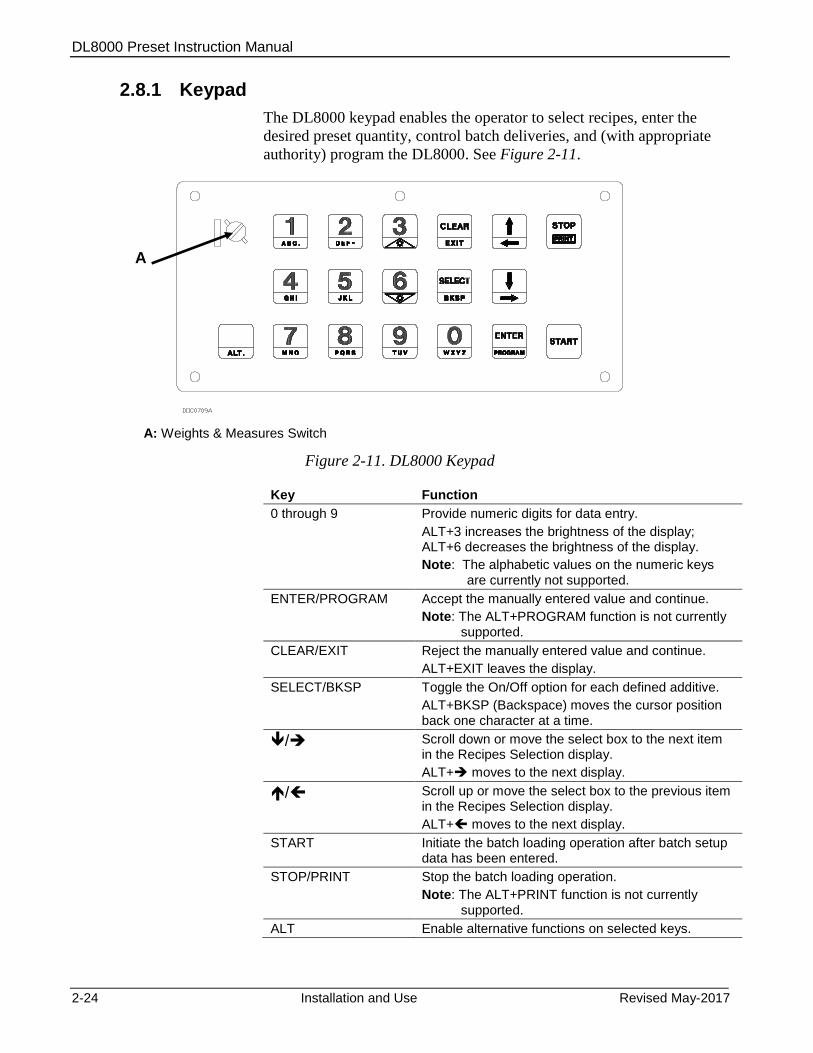
2.8.1 26BKeypad
The DL8000 keypad enables the operator to select recipes, enter the
desired preset quantity, control batch deliveries, and (with appropriate
authority) program the DL8000. See Figure 2-11.
A: Weights & Measures Switch
Figure 2-11. DL8000 Keypad
Key Function
0 through 9 Provide numeric digits for data entry.
ALT+3 increases the brightness of the display; ALT+6 decreases the brightness of the display.
Note: The alphabetic values on the numeric keys are currently not supported.
ENTER/PROGRAM Accept the manually entered value and continue.
Note: The ALT+PROGRAM function is not currently supported.
CLEAR/EXIT Reject the manually entered value and continue.
ALT+EXIT leaves the display.
SELECT/BKSP Toggle the On/Off option for each defined additive.
ALT+BKSP (Backspace) moves the cursor position back one character at a time.
/ Scroll down or move the select box to the next item in the Recipes Selection display.
ALT+ moves to the next display.
/ Scroll up or move the select box to the previous item in the Recipes Selection display.
ALT+ moves to the next display.
START Initiate the batch loading operation after batch setup data has been entered.
STOP/PRINT Stop the batch loading operation.
Note: The ALT+PRINT function is not currently supported.
ALT Enable alternative functions on selected keys.
A
DL8000 Preset Instruction Manual
Revised May-2017 Installation and Use 2-25
Note: The Weights & Measures switch, located in the left upper corner
of the keypad, is lockable and wire-sealable to restrict access to
the flow calculations.
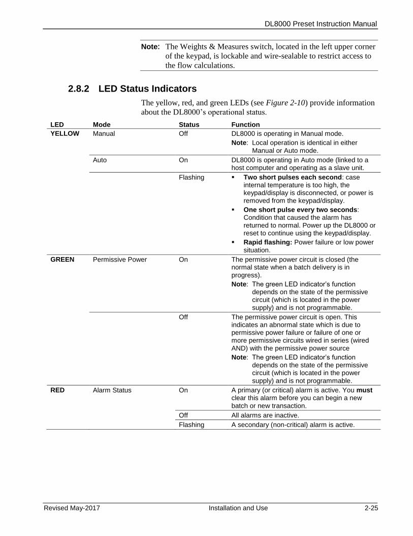
2.8.2 27BLED Status Indicators
The yellow, red, and green LEDs (see Figure 2-10) provide information
about the DL8000’s operational status.
LED Mode Status Function
YELLOW Manual Off DL8000 is operating in Manual mode.
Note: Local operation is identical in either Manual or Auto mode.
Auto On DL8000 is operating in Auto mode (linked to a host computer and operating as a slave unit.
Flashing Two short pulses each second: case internal temperature is too high, the keypad/display is disconnected, or power is removed from the keypad/display.
One short pulse every two seconds: Condition that caused the alarm has returned to normal. Power up the DL8000 or reset to continue using the keypad/display.
Rapid flashing: Power failure or low power situation.
GREEN Permissive Power On The permissive power circuit is closed (the normal state when a batch delivery is in progress).
Note: The green LED indicator’s function depends on the state of the permissive circuit (which is located in the power supply) and is not programmable.
Off The permissive power circuit is open. This indicates an abnormal state which is due to permissive power failure or failure of one or more permissive circuits wired in series (wired AND) with the permissive power source
Note: The green LED indicator’s function depends on the state of the permissive circuit (which is located in the power supply) and is not programmable.
RED Alarm Status On A primary (or critical) alarm is active. You must clear this alarm before you can begin a new batch or new transaction.
Off All alarms are inactive.
Flashing A secondary (non-critical) alarm is active.

DL8000 Preset Instruction Manual
2-26 Installation and Use Revised May-2017
This page is intentionally left blank.

DL8000 Preset Instruction Manual
Revised May-2017 Modules 3-1
Chapter 3 – Modules
In This Chapter
3.1 Power Input Module ............................................................................... 3-1 3.1.1 12 Volt DC Power Input Module ............................................... 3-2
3.2 Input/Output Modules ............................................................................ 3-3 3.2.1 General Installation ................................................................... 3-5 3.2.2 Installing an I/O Module ............................................................ 3-6 3.2.3 Removing an I/O Module .......................................................... 3-7 3.2.4 Wiring I/O Modules ................................................................... 3-7 3.2.5 Analog Input (AI) Modules ........................................................ 3-7 3.2.6 Analog Output (AO) Modules.................................................... 3-9 3.2.7 Discrete Input (DI) Modules .................................................... 3-10 3.2.8 Pulse Input (PI) Modules ........................................................ 3-12 3.2.9 Discrete Output (DO) Modules ............................................... 3-14 3.2.10 Discrete Output Relay (DOR) Modules .................................. 3-15 3.2.11 Resistance Temperature Detector (RTD) Input Modules ....... 3-17 3.2.12 Alternating Current Input/Output (AC I/O) Module ................. 3-18 3.2.13 Advance Pulse Module (APM) ................................................ 3-23 3.2.14 Thermocouple (TC) Input Module ........................................... 3-27 3.2.15 HART® Module ....................................................................... 3-30
3.3 Communication Modules and Ports ..................................................... 3-32 3.3.1 Wiring Communications .......................................................... 3-34 3.3.2 Local Operator Interface (LOI – Local Port) ........................... 3-35 3.3.3 Using the LOI .......................................................................... 3-36 3.3.4 Ethernet Communications ...................................................... 3-36 3.3.5 EIA-232 (RS-232) Serial Communications ............................. 3-38 3.3.6 EIA-422/485 (RS-422/485) Serial Communications
Module .................................................................................... 3-39 3.3.7 EIA-422/485 (RS-422/485) Jumpers & Termination
Resistors ................................................................................. 3-40 3.3.8 Dial-up Modem Communications Module ............................... 3-41
3.4 Additional Technical Information.......................................................... 3-43
This chapter describes the various power, input/output, and
communications modules the DL8000 uses. It also describes how to
install, remove, and wire the modules.
3.1 Power Input Module
The DL8000 uses a Power Input module to convert the voltage from the
AC power supply to the voltage levels the DL8000 unit’s electronics
require and to monitor voltage levels to ensure proper operation. All
DL8000 applications use the 12 volt Power Input module.
The Power Input module has removable terminal blocks for wiring and
servicing. The terminal blocks can accept wire sizes between 12 and 22
AWG (American Wire Gauge).
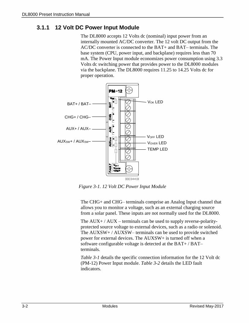
DL8000 Preset Instruction Manual
3-2 Modules Revised May-2017
3.1.1 12 Volt DC Power Input Module
The DL8000 accepts 12 Volts dc (nominal) input power from an
internally mounted AC/DC converter. The 12 volt DC output from the
AC/DC converter is connected to the BAT+ and BAT– terminals. The
base system (CPU, power input, and backplane) requires less than 70
mA. The Power Input module economizes power consumption using 3.3
Volts dc switching power that provides power to the DL8000 modules
via the backplane. The DL8000 requires 11.25 to 14.25 Volts dc for
proper operation.
Figure 3-1. 12 Volt DC Power Input Module
The CHG+ and CHG– terminals comprise an Analog Input channel that
allows you to monitor a voltage, such as an external charging source
from a solar panel. These inputs are not normally used for the DL8000.
The AUX+ / AUX – terminals can be used to supply reverse-polarity-
protected source voltage to external devices, such as a radio or solenoid.
The AUXSW+ / AUXSW– terminals can be used to provide switched
power for external devices. The AUXSW+ is turned off when a
software configurable voltage is detected at the BAT+ / BAT–
terminals.
Table 3-1 details the specific connection information for the 12 Volt dc
(PM-12) Power Input module. Table 3-2 details the LED fault
indicators.
VOK LED
VOFF LED
VOVER LED
TEMP LED
BAT+ / BAT–
CHG+ / CHG–
AUX+ / AUX–
AUXSW+ / AUXSW–
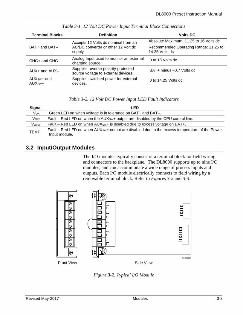
DL8000 Preset Instruction Manual
Revised May-2017 Modules 3-3
Table 3-1. 12 Volt DC Power Input Terminal Block Connections
Terminal Blocks Definition Volts DC
BAT+ and BAT– Accepts 12 Volts dc nominal from an AC/DC converter or other 12 Volt dc supply.
Absolute Maximum: 11.25 to 16 Volts dc
Recommended Operating Range: 11.25 to 14.25 Volts dc
CHG+ and CHG– Analog Input used to monitor an external charging source.
0 to 18 Volts dc
AUX+ and AUX– Supplies reverse-polarity-protected source voltage to external devices.
BAT+ minus 0.7 Volts dc
AUXSW+ and AUXSW–
Supplies switched power for external devices.
0 to 14.25 Volts dc
Table 3-2. 12 Volt DC Power Input LED Fault Indicators
Signal LED
VOK Green LED on when voltage is in tolerance on BAT+ and BAT–.
VOFF Fault – Red LED on when the AUXSW+ output are disabled by the CPU control line.
VOVER Fault – Red LED on when AUXSW+ is disabled due to excess voltage on BAT+.
TEMP Fault – Red LED on when AUXSW+ output are disabled due to the excess temperature of the Power Input module.
3.2 Input/Output Modules
The I/O modules typically consist of a terminal block for field wiring
and connectors to the backplane. The DL8000 supports up to nine I/O
modules, and can accommodate a wide range of process inputs and
outputs. Each I/O module electrically connects to field wiring by a
removable terminal block. Refer to Figures 3-2 and 3-3.
DOC0513A Front View Side View
Figure 3-2. Typical I/O Module
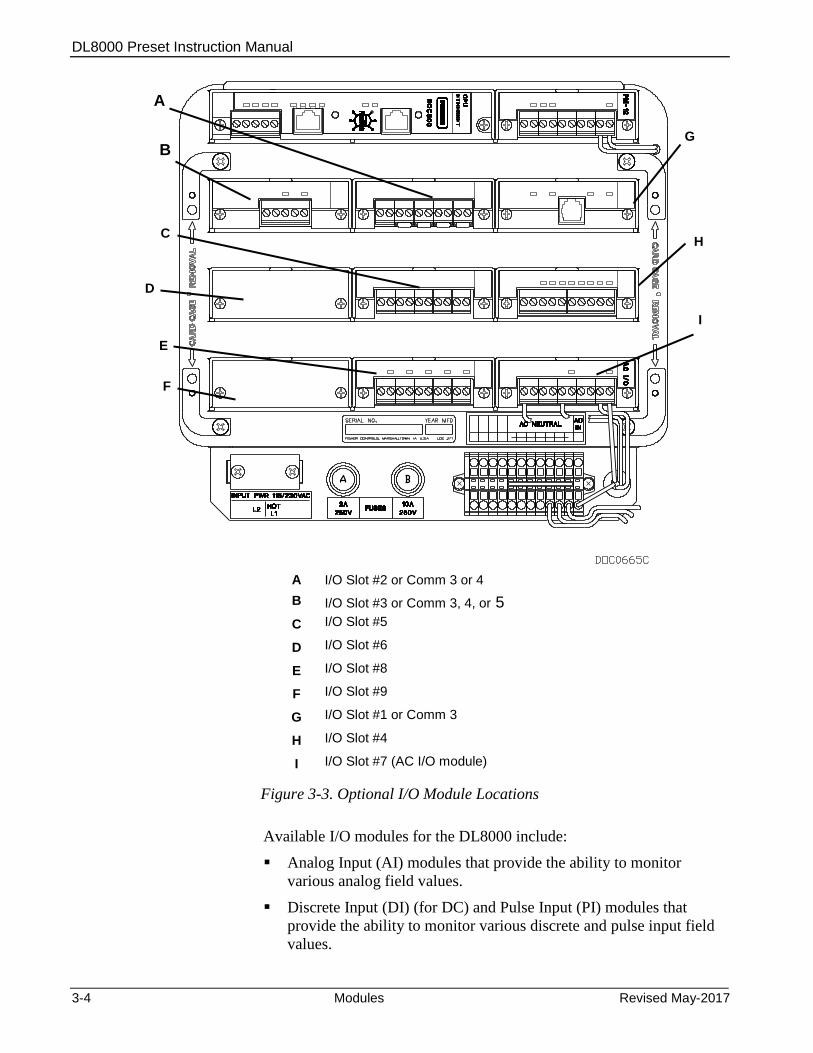
DL8000 Preset Instruction Manual
3-4 Modules Revised May-2017
A I/O Slot #2 or Comm 3 or 4
B I/O Slot #3 or Comm 3, 4, or 5
C I/O Slot #5
D I/O Slot #6
E I/O Slot #8
F I/O Slot #9
G I/O Slot #1 or Comm 3
H I/O Slot #4
I I/O Slot #7 (AC I/O module)
Figure 3-3. Optional I/O Module Locations
Available I/O modules for the DL8000 include:
Analog Input (AI) modules that provide the ability to monitor
various analog field values.
Discrete Input (DI) (for DC) and Pulse Input (PI) modules that
provide the ability to monitor various discrete and pulse input field
values.
G
A
B
H
D
C
E
F
I

DL8000 Preset Instruction Manual
Revised May-2017 Modules 3-5
Analog Output (AO), Discrete Output (DO), and Discrete Output
Relay (DOR) modules that provide the ability to control various
control devices.
The Alternating Current I/O Module (AC I/O) module provides the
ability to read the status of an AC input or control an AC output.
The Advance Pulse Module (APM) provides advanced functionality
typically found in liquids and gas measurement applications.
The RTD Input module provides the ability to monitor various
analog temperature field values.
The HART® interface module that enables the DL8000 to
communicate with devices using the Highway Addressable Remote
Transducer (HART) protocol as either Analog Inputs or Analog
Outputs.
Each module rests in a module slot at the front of the DL8000 housing.
I/O modules easily install into and remove from the module slots. You
can install and remove modules while the DL8000 is powered up (hot-
swappable). Modules may be installed directly into unused module slots
(hot-pluggable), and modules are self-identifying in the software. All
modules have removable terminal blocks to make servicing easy. I/O
modules can be added in any module slot.
Note: You can install comm modules only in slots 1, 2, or 3 of the
DL8000.
The I/O modules acquire power from the backplane. Each module has
an isolated DC/DC converter that provides logic, control, and field
power as required. The DL8000 has eliminated the need for fuses on the
I/O modules through the extensive use of current-limited short-circuit
protection and over voltage circuitry. Isolation is provided from other
modules and the backplane, power, and signal isolation. The I/O
modules are self-resetting after a fault clears.
3.2.1 General Installation
Each I/O module installs in the DL8000 in the same manner. You can
install any I/O module into any module socket, whether empty or in
place of another module.
Caution Failure to exercise proper electrostatic discharge precautions (such as wearing a grounded wrist strap) may reset the processor or damage electronic components, resulting in interrupted operations.
When installing units located in a hazardous area (where explosive gases may be present), make sure the area is in a non-hazardous state before performing procedures. Performing these procedures in a hazardous area could result in personal injury or property damage.
DL8000 Preset Instruction Manual
3-6 Modules Revised May-2017
You can insert or remove the I/O modules while power is connected to
the DL8000. If the DL8000 is powered, exercise caution while
performing the following steps to install a module.
Note: After you install a new I/O module or replace an existing I/O
module, it may be necessary to reconfigure the DL8000. To
change configuration parameters, use ROCLINK 800 software
to make changes to the new module. Any added modules (new
I/O points) start up with default configurations. Refer to the
ROCLINK 800 Configuration Software User Manual (for
DL8000) (part D301259X012).
3.2.2 Installing an I/O Module
To install an I/O module:
1. Remove the wire channel cover.
Note: Leaving the wire channel cover in place can prevent the
module from correctly connecting to the socket on the
backplane.
2. Perform one of the following:
If there was previously a module in the slot, unscrew the captive
screws and remove that module.
If the slot was previously unused, remove the module cover.
3. Insert the new I/O module into the module slot in the card cage.
Make sure the label on the front of the module is facing right side
up. Gently slide the module in place until it contacts the connectors
on the backplane.
Note: If the module stops and will not go any further, do not force
the module. Remove the module and see if the pins are bent.
If so, gently straighten the pin(s) and re-insert the module.
The back of the module must connect fully with the
connectors on the backplane.
4. Tighten the captive screws on the front of the module.
5. Wire the I/O module (refer to Section 3.2.4, Wiring I/O Modules).
6. Replace the wire channel cover.
Caution Never connect the sheath surrounding shielded wiring to a signal ground terminal or to the common terminal of an I/O module. Doing so makes the I/O module susceptible to static discharge, which can permanently damage the module. Connect the shielded wiring only to a suitable earth ground.
7. Connect to ROCLINK 800 software and login. The I/O modules are
self-identifying after re-connecting to ROCLINK 800 software.
DL8000 Preset Instruction Manual
Revised May-2017 Modules 3-7
8. Configure the I/O point.
3.2.3 Removing an I/O Module
To remove an I/O module:
1. Remove the wire channel cover.
2. Unscrew the two captive screws holding the module in place.
3. Gently pull the module’s lip out and remove the module from the
slot. You may need to gently wiggle the module.
4. Install a new module or install the module cover.
5. Screw the two captive screws to hold the module or cover in place.
6. Replace the wire channel cover.
3.2.4 Wiring I/O Modules
All modules have removable terminal blocks for convenient wiring and
servicing. The terminal blocks accommodate wire sizes between 12 and
22 AWG.
Caution Failure to exercise proper electrostatic discharge precautions (such as wearing a grounded wrist strap) may reset the processor or damage electronic components, resulting in interrupted operations.
To connect the wire to the removable block compression terminals:
1. Bare the end (¼ inch or 6.3mm maximum) of the wire.
2. Insert the bared end into the clamp beneath the termination screw.
3. Tighten the screw.
Expose a minimum of bare wire to prevent short circuits. Allow some
slack when making connections to prevent strain.
Note: All modules have removable terminal blocks for convenient
wiring and servicing. Twisted-pair cable is recommended for I/O
signal wiring. The removable terminal blocks accept wire sizes
between 12 and 22 AWG.
3.2.5 Analog Input (AI) Modules
The Analog Input (AI) modules (AI-12 and AI-16) have four scalable
channels, which typically measure either:
4 to 20 mA analog signal, with the use of a precision resistor
(supplied).
1 to 5 Volts dc signal.
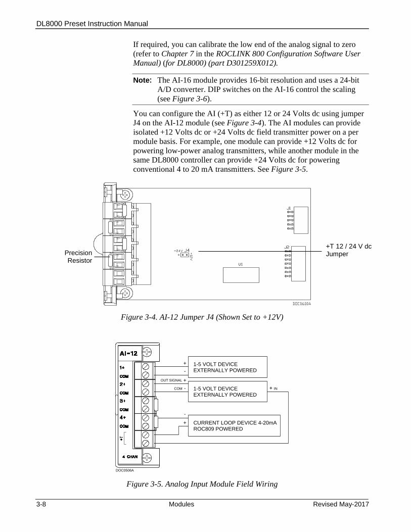
DL8000 Preset Instruction Manual
3-8 Modules Revised May-2017
If required, you can calibrate the low end of the analog signal to zero
(refer to Chapter 7 in the ROCLINK 800 Configuration Software User
Manual) (for DL8000) (part D301259X012).
Note: The AI-16 module provides 16-bit resolution and uses a 24-bit
A/D converter. DIP switches on the AI-16 control the scaling
(see Figure 3-6).
You can configure the AI (+T) as either 12 or 24 Volts dc using jumper
J4 on the AI-12 module (see Figure 3-4). The AI modules can provide
isolated +12 Volts dc or +24 Volts dc field transmitter power on a per
module basis. For example, one module can provide +12 Volts dc for
powering low-power analog transmitters, while another module in the
same DL8000 controller can provide +24 Volts dc for powering
conventional 4 to 20 mA transmitters. See Figure 3-5.
Figure 3-4. AI-12 Jumper J4 (Shown Set to +12V)
1-5 VOLT DEVICEEXTERNALLY POWERED
+
-
1-5 VOLT DEVICEEXTERNALLY POWERED
+
-
ROC809 POWEREDCURRENT LOOP DEVICE 4-20mA
-
+
OUT SIGNAL
COM IN
DOC0506A
Figure 3-5. Analog Input Module Field Wiring
Precision Resistor
+T 12 / 24 V dc Jumper
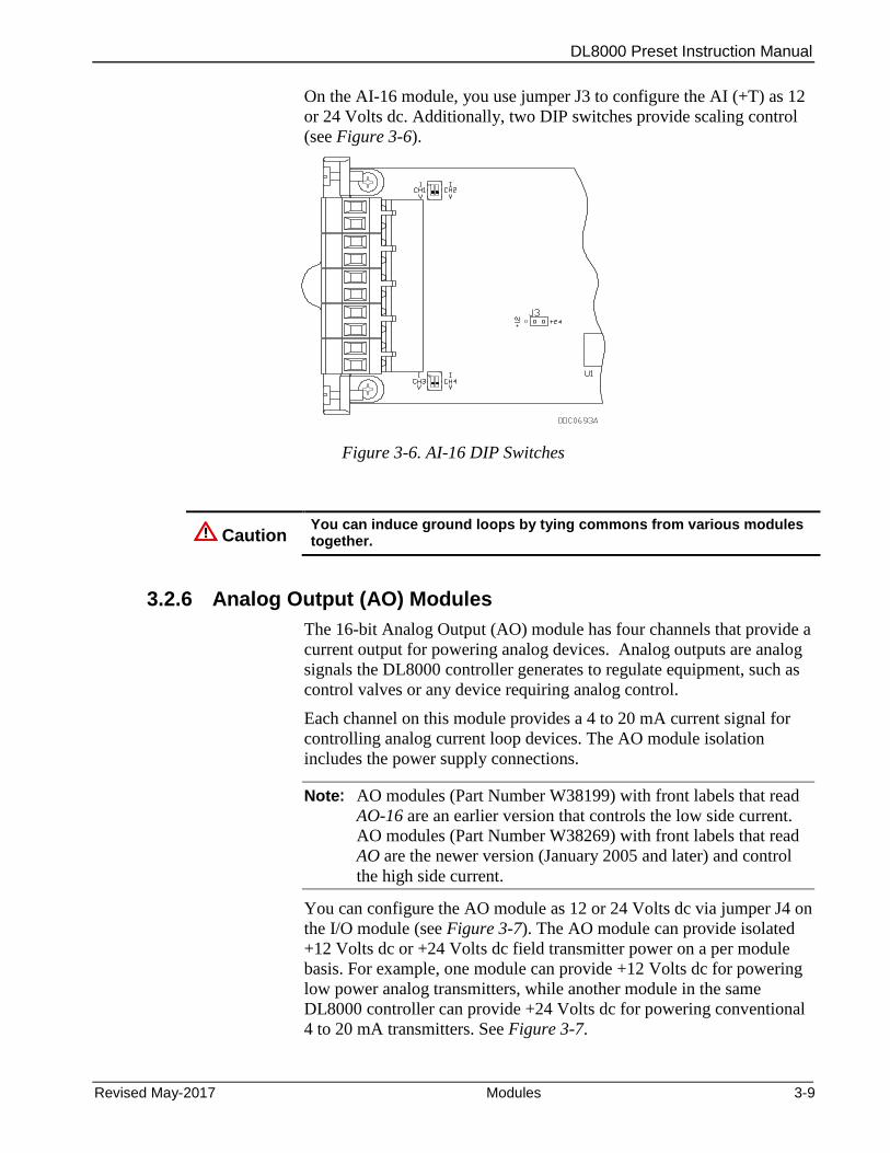
DL8000 Preset Instruction Manual
Revised May-2017 Modules 3-9
On the AI-16 module, you use jumper J3 to configure the AI (+T) as 12
or 24 Volts dc. Additionally, two DIP switches provide scaling control
(see Figure 3-6).
Figure 3-6. AI-16 DIP Switches
Caution You can induce ground loops by tying commons from various modules together.
3.2.6 Analog Output (AO) Modules
The 16-bit Analog Output (AO) module has four channels that provide a
current output for powering analog devices. Analog outputs are analog
signals the DL8000 controller generates to regulate equipment, such as
control valves or any device requiring analog control.
Each channel on this module provides a 4 to 20 mA current signal for
controlling analog current loop devices. The AO module isolation
includes the power supply connections.
Note: AO modules (Part Number W38199) with front labels that read
AO-16 are an earlier version that controls the low side current.
AO modules (Part Number W38269) with front labels that read
AO are the newer version (January 2005 and later) and control
the high side current.
You can configure the AO module as 12 or 24 Volts dc via jumper J4 on
the I/O module (see Figure 3-7). The AO module can provide isolated
+12 Volts dc or +24 Volts dc field transmitter power on a per module
basis. For example, one module can provide +12 Volts dc for powering
low power analog transmitters, while another module in the same
DL8000 controller can provide +24 Volts dc for powering conventional
4 to 20 mA transmitters. See Figure 3-7.
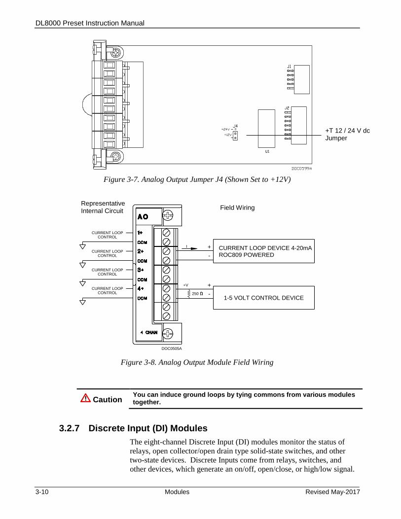
DL8000 Preset Instruction Manual
3-10 Modules Revised May-2017
Figure 3-7. Analog Output Jumper J4 (Shown Set to +12V)
+
-
I
+V
250
CONTROLCURRENT LOOP
DOC0505A
CONTROLCURRENT LOOP
CONTROLCURRENT LOOP
CONTROLCURRENT LOOP
+
-
ROC809 POWERED CURRENT LOOP DEVICE 4-20mA
1-5 VOLT CONTROL DEVICE
Figure 3-8. Analog Output Module Field Wiring
Caution You can induce ground loops by tying commons from various modules together.
3.2.7 Discrete Input (DI) Modules
The eight-channel Discrete Input (DI) modules monitor the status of
relays, open collector/open drain type solid-state switches, and other
two-state devices. Discrete Inputs come from relays, switches, and
other devices, which generate an on/off, open/close, or high/low signal.
+T 12 / 24 V dc Jumper
Representative Internal Circuit
Field Wiring

DL8000 Preset Instruction Manual
Revised May-2017 Modules 3-11
The DI module provides a source voltage for dry relay contacts or for an
open-collector solid-state switch.
The DI module’s LEDs light when each input is active.
You can configure each DI channel to function as a momentary or
latched DI (see the ROCLINK 800 Configuration Software User
Manual) (for DL8000) (part D301259X012). A latched DI remains in
the active state until reset. Other parameters can invert the field signal
and gather statistical information on the number of transitions and the
time accumulated in the on-state or off-state.
Caution The Discrete Input module operates with non-powered discrete devices, such as “dry” relay contacts or isolated solid-state switches. Use of the DI module with powered devices may cause improper operation or damage.
The DI module senses the current flow, which signals the electronics in
the DL8000 that the relay contacts have closed. When the contacts open,
current flow interrupts, and the DI module signals the electronics in the
DL8000 that the relay contacts have opened. A DL8000 can read a DI a
maximum of 250 times per second.
The left side of Figure 3-9 displays the internal circuitry while the right
side of the diagram displays possible field wiring.
+
-DRY CONTACT
ROC800 POWERED
+
-
+V
6.6KW
DOC0507A
CO
M
6
8
7
4
5
3
2
1
DI
8 CHAN
OPEN DRAIN TYPE DEVICEOR
OPEN COLLECTOR
EXTERNALLY POWERED
Figure 3-9. Discrete Input Module Field Wiring
Caution You can induce ground loops by tying commons from various modules together.
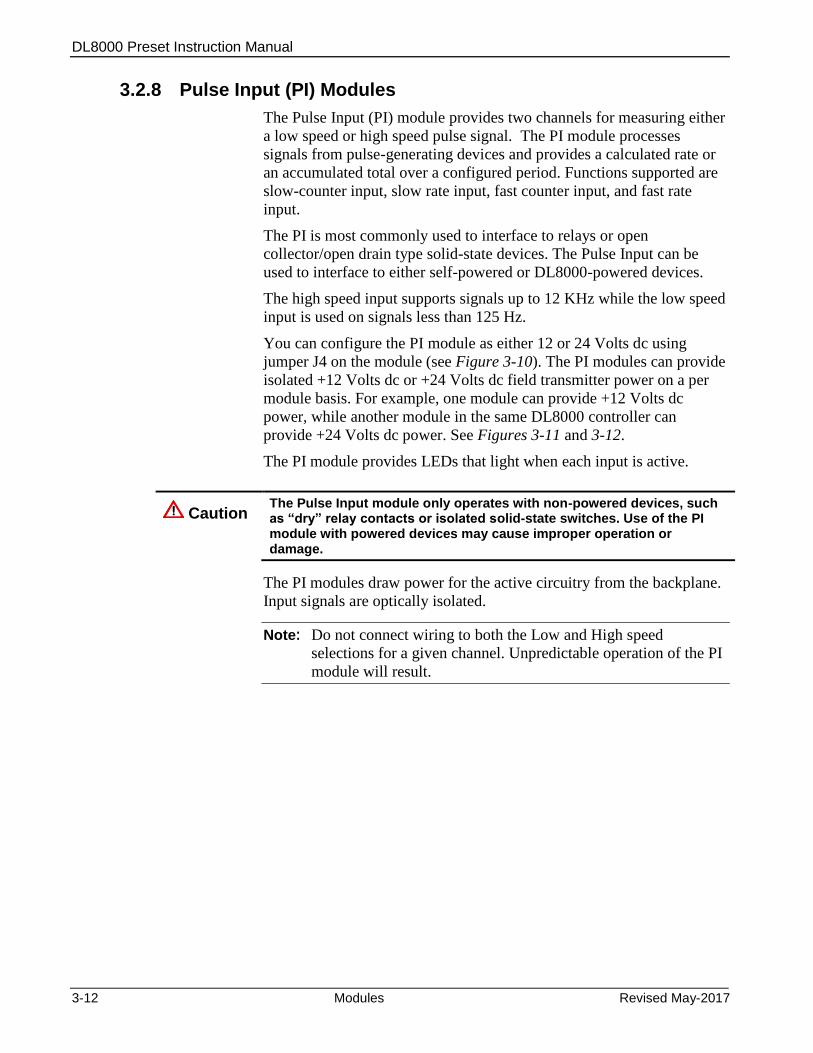
DL8000 Preset Instruction Manual
3-12 Modules Revised May-2017
3.2.8 Pulse Input (PI) Modules
The Pulse Input (PI) module provides two channels for measuring either
a low speed or high speed pulse signal. The PI module processes
signals from pulse-generating devices and provides a calculated rate or
an accumulated total over a configured period. Functions supported are
slow-counter input, slow rate input, fast counter input, and fast rate
input.
The PI is most commonly used to interface to relays or open
collector/open drain type solid-state devices. The Pulse Input can be
used to interface to either self-powered or DL8000-powered devices.
The high speed input supports signals up to 12 KHz while the low speed
input is used on signals less than 125 Hz.
You can configure the PI module as either 12 or 24 Volts dc using
jumper J4 on the module (see Figure 3-10). The PI modules can provide
isolated +12 Volts dc or +24 Volts dc field transmitter power on a per
module basis. For example, one module can provide +12 Volts dc
power, while another module in the same DL8000 controller can
provide +24 Volts dc power. See Figures 3-11 and 3-12.
The PI module provides LEDs that light when each input is active.
Caution The Pulse Input module only operates with non-powered devices, such as “dry” relay contacts or isolated solid-state switches. Use of the PI module with powered devices may cause improper operation or damage.
The PI modules draw power for the active circuitry from the backplane.
Input signals are optically isolated.
Note: Do not connect wiring to both the Low and High speed
selections for a given channel. Unpredictable operation of the PI
module will result.
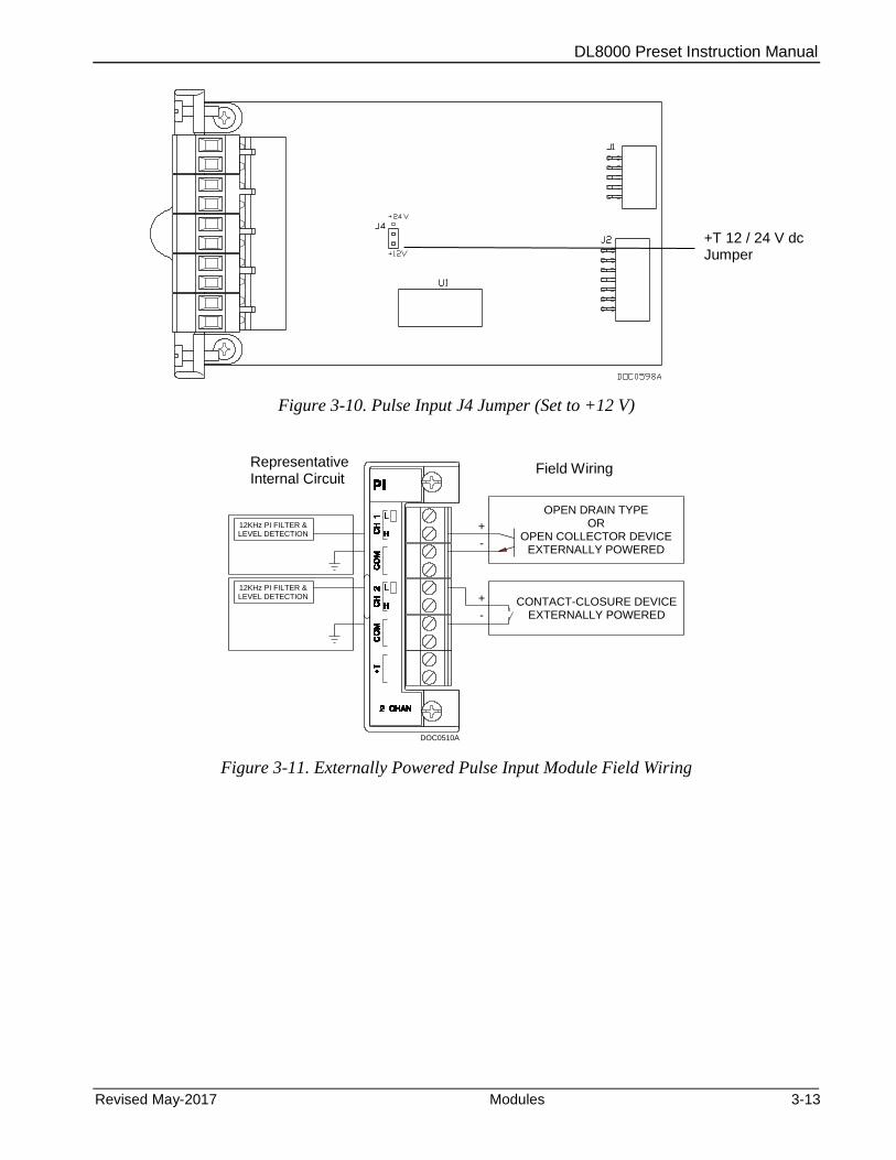
DL8000 Preset Instruction Manual
Revised May-2017 Modules 3-13
Figure 3-10. Pulse Input J4 Jumper (Set to +12 V)
+
-
OPEN DRAIN TYPEOR
OPEN COLLECTOR DEVICEEXTERNALLY POWERED
+
-
CONTACT-CLOSURE DEVICEEXTERNALLY POWERED
12KHz PI FILTER &LEVEL DETECTION
12KHz PI FILTER &LEVEL DETECTION
DOC0510A
Figure 3-11. Externally Powered Pulse Input Module Field Wiring
+T 12 / 24 V dc Jumper
Representative Internal Circuit
Field Wiring
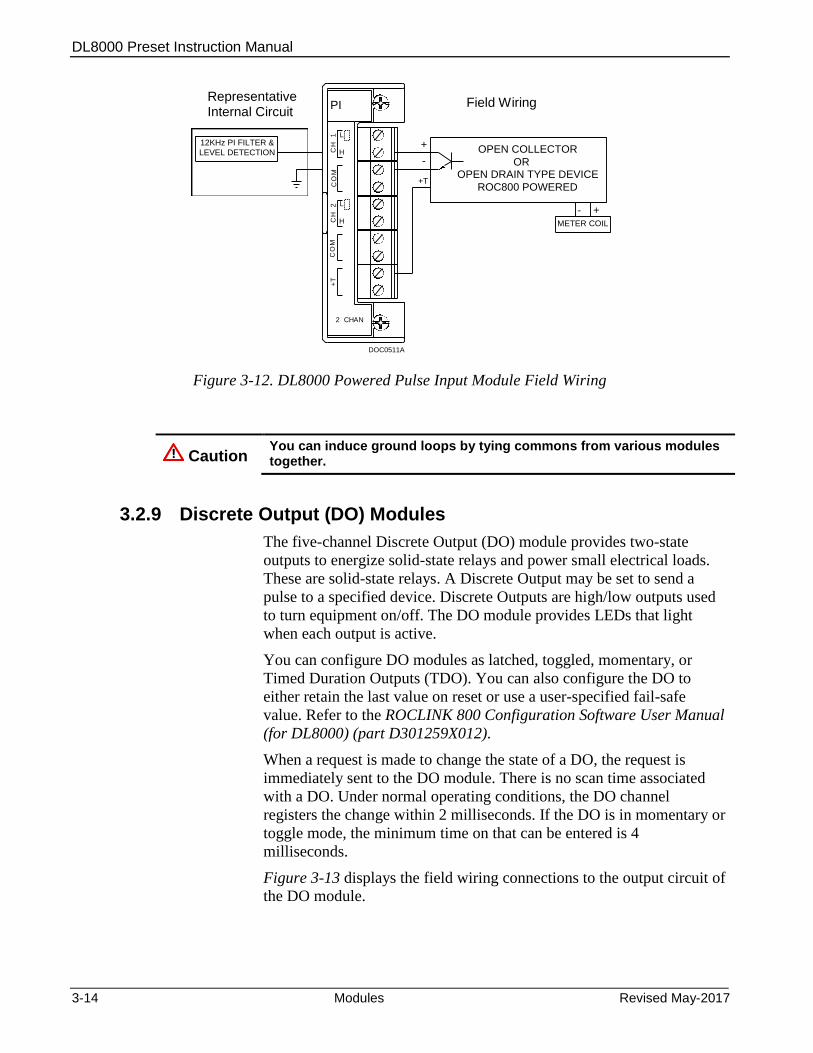
DL8000 Preset Instruction Manual
3-14 Modules Revised May-2017
+
-
12KHz PI FILTER &
LEVEL DETECTION
+T
METER COIL
- +
DOC0511A
H
L
H
L
CO
MC
H
2C
H
1+
T
PI
2 CHAN
OPEN DRAIN TYPE DEVICEOR
OPEN COLLECTOR
ROC800 POWERED
CO
M
Figure 3-12. DL8000 Powered Pulse Input Module Field Wiring
Caution You can induce ground loops by tying commons from various modules together.
3.2.9 Discrete Output (DO) Modules
The five-channel Discrete Output (DO) module provides two-state
outputs to energize solid-state relays and power small electrical loads.
These are solid-state relays. A Discrete Output may be set to send a
pulse to a specified device. Discrete Outputs are high/low outputs used
to turn equipment on/off. The DO module provides LEDs that light
when each output is active.
You can configure DO modules as latched, toggled, momentary, or
Timed Duration Outputs (TDO). You can also configure the DO to
either retain the last value on reset or use a user-specified fail-safe
value. Refer to the ROCLINK 800 Configuration Software User Manual
(for DL8000) (part D301259X012).
When a request is made to change the state of a DO, the request is
immediately sent to the DO module. There is no scan time associated
with a DO. Under normal operating conditions, the DO channel
registers the change within 2 milliseconds. If the DO is in momentary or
toggle mode, the minimum time on that can be entered is 4
milliseconds.
Figure 3-13 displays the field wiring connections to the output circuit of
the DO module.
Representative Internal Circuit
Field Wiring

DL8000 Preset Instruction Manual
Revised May-2017 Modules 3-15
Caution The Discrete Output module only operates with non-powered discrete devices, such as relay coils or solid-state switch inputs. Using the module with powered devices may cause improper operation or damage.
The DO modules draw power for the active circuitry from the
backplane. The DO module is current-limited for protection against
excessive current.
Note: When using a DO module to drive an inductive load (such as a
relay coil), place a suppression diode across the input terminals
to the load. This protects the module from the reverse Electro-
Motive Force (EMF) spike generated when the inductive load is
switched off.
+Vs
CONTROL
+
-
EXTERNALLY POWERED
DISCRETE DEVICE+
-
-
COM
COM
COM
COM
COM
DO
2+
3+
4+
5+
1+
5 CHAN
DOC0508A
Figure 3-13. Discrete Output Module Field Wiring
Caution You can induce ground loops by tying commons from various modules together.
3.2.10 Discrete Output Relay (DOR) Modules
The five-channel DO Relay (DOR) module provides LEDs that light
when each output is active. DOR modules use dual-state latching relays
to provide a set of normally open, dry contacts capable of switching 2 A
at 32 Volts dc across the complete operating temperature. Using
ROCLINK 800, you can configure the module as latched, toggled,
momentary, or Timed Duration Outputs (TDO). You can configure the
DOR either to retain the last value on reset or to use a user-specified
fail-safe value.
Representative Internal Circuit
Field Wiring
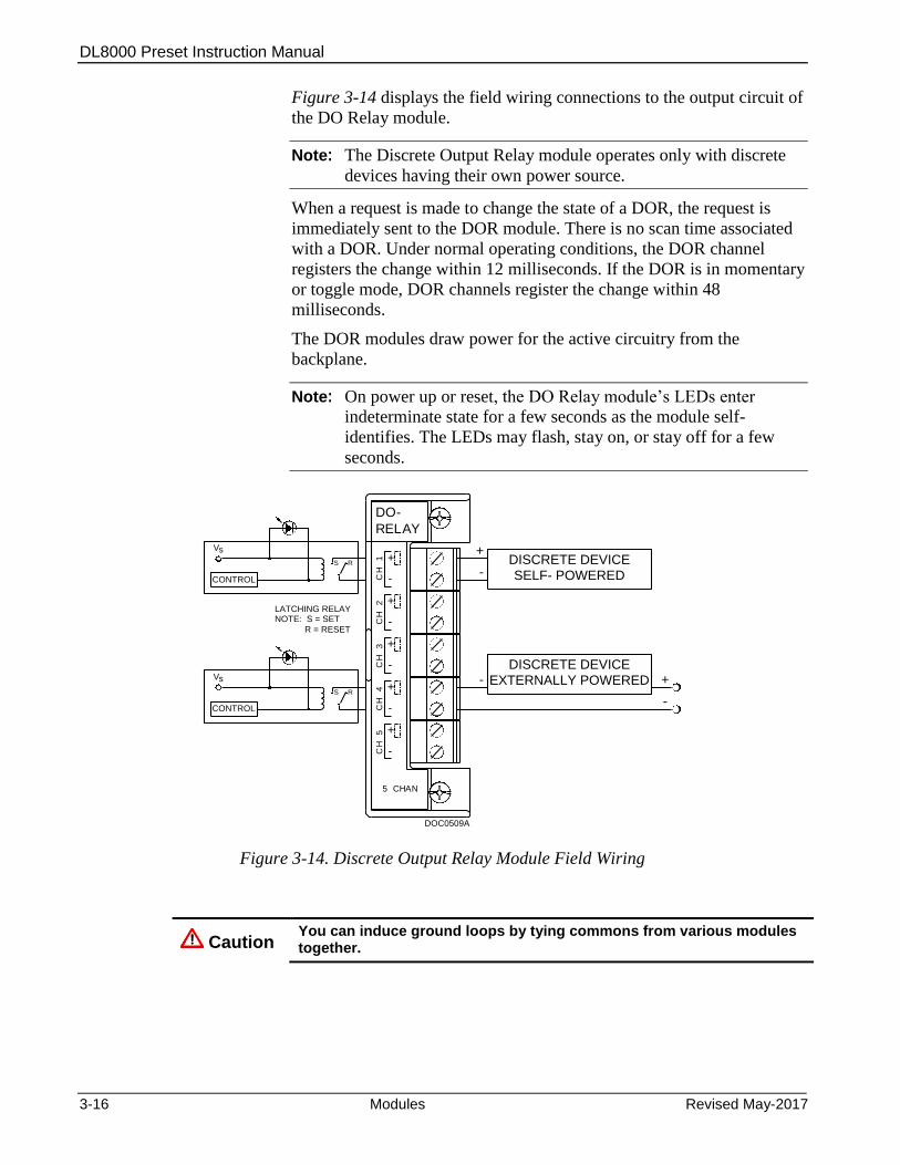
DL8000 Preset Instruction Manual
3-16 Modules Revised May-2017
Figure 3-14 displays the field wiring connections to the output circuit of
the DO Relay module.
Note: The Discrete Output Relay module operates only with discrete
devices having their own power source.
When a request is made to change the state of a DOR, the request is
immediately sent to the DOR module. There is no scan time associated
with a DOR. Under normal operating conditions, the DOR channel
registers the change within 12 milliseconds. If the DOR is in momentary
or toggle mode, DOR channels register the change within 48
milliseconds.
The DOR modules draw power for the active circuitry from the
backplane.
Note: On power up or reset, the DO Relay module’s LEDs enter
indeterminate state for a few seconds as the module self-
identifies. The LEDs may flash, stay on, or stay off for a few
seconds.
CONTROL
Vs
CONTROL
Vs EXTERNALLY POWERED
DISCRETE DEVICE+
-
-
+
SELF- POWERED
DISCRETE DEVICE-
+
+
-
-
-
-
+
+
+
-CH
1
CH
2
CH
3
CH
4
CH
5
-
Y
DO
RELA
5 CHAN
DOC0509A
RS
RS
LATCHING RELAYNOTE: S = SET
R = RESET
Figure 3-14. Discrete Output Relay Module Field Wiring
Caution You can induce ground loops by tying commons from various modules together.

DL8000 Preset Instruction Manual
Revised May-2017 Modules 3-17
3.2.11 Resistance Temperature Detector (RTD) Input Modules
The Resistance Temperature Detector (RTD) module monitors the
temperature signal from an RTD source. The module can accommodate
input from a two-, three-, or four-wire RTD source.
The active element of an RTD probe is a precision, temperature-
dependent resistor, made from a platinum alloy. The resistor has a
predictable positive temperature coefficient, meaning its resistance
increases with temperature. The RTD input module works by supplying
a small consistent current to the RTD probe and measuring the voltage
drop across it. Based on the voltage curve of the RTD, the signal is
converted to temperature by the DL8000 firmware.
The RTD input module monitors the temperature signal from a
Resistance Temperature Detector (RTD) sensor or probe. A 2-channel
16-bit RTD module is available. The RTD module isolation includes the
power supply connections.
The RTD modules draw power for the active circuitry from lines on the
backplane.
It may be more convenient to perform calibration before connecting the
field wiring. However, if the field wiring between the DL8000 and the
RTD probe is long enough to add a significant resistance, then perform
calibration in a manner that considers this.
Connecting the RTD Wiring
Temperature can be input through the Resistance Temperature
Detector (RTD) probe and circuitry. An RTD temperature probe
mounts directly to the piping using a thermowell. Protect RTD wires
either by a metal sheath or by conduit connected to a liquid-tight
conduit fitting. The RTD wires connect to the four screw terminals
designated “RTD” on the RTD module.
The DL8000 controller provides terminations for a four-wire 100-ohm
platinum RTD with a DIN 43760 curve. The RTD has an alpha equal to
0.00385 or 0.00392 //C. A two-wire or three-wire RTD probe can
be used instead of a four-wire probe; however, they may produce
measurement errors due to signal loss on the wiring. See Figure 3-15.
Wiring between the RTD probe and the DL8000 must be shielded wire,
with the shield grounded only at one end to prevent ground loops.
Ground loops cause RTD input signal errors.
Table 3-3. RTD Signal Routing
Signal Terminal Designation
CH 1 (REF) 1 Constant Current +
CH 1 (+) 2 V+ RTD
CH 1 (–) 3 V– RTD
CH 1 (RET) 4 Constant Current –
Not Connected 5 N/A
CH 2 (REF) 6 Constant Current +

DL8000 Preset Instruction Manual
3-18 Modules Revised May-2017
Signal Terminal Designation
CH 2 (+) 7 V+ RTD
CH 2 (–) 8 V– RTD
CH 2 (RET) 9 Constant Current –
Not Connected 10 N/A
Caution You can induce ground loops by tying commons from various modules together.
Figure 3-15. RTD Sensor Wiring Terminal Connections
Table 3-4. RTD Wiring
Terminal 4-Wire RTD 3-Wire RTD 2-Wire RTD
REF Red Jumper to + Jumper to +
+ Red Red, Jumper to REF Red, Jumper to REF
– White White White, Jumper to RET
RET White White Jumper to –
Note: The wire colors for the RTD being used may differ.
3.2.12 Alternating Current Input/Output (AC I/O) Module
Warning EMC issues restrict the use of the AC I/O module only to devices using a PM-12 power module. You CANNOT use the AC I/O module in a device that uses a PM-24 power module.
Switchable I/O and LEDs
The module has one bank of six DIP switches on its daughterboard
(see Figure 3-16), which controls the input/output status of each of the
six channels. Placing a switch in the ON position sets the
Jumper
4-Wire RTD 3-Wire RTD 2-Wire RTD
Red
Red
Red
Jumper
Red
Jumper
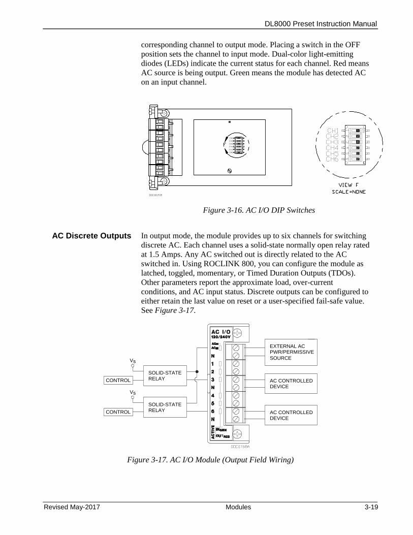
DL8000 Preset Instruction Manual
Revised May-2017 Modules 3-19
corresponding channel to output mode. Placing a switch in the OFF
position sets the channel to input mode. Dual-color light-emitting
diodes (LEDs) indicate the current status for each channel. Red means
AC source is being output. Green means the module has detected AC
on an input channel.
Figure 3-16. AC I/O DIP Switches
AC Discrete Outputs In output mode, the module provides up to six channels for switching
discrete AC. Each channel uses a solid-state normally open relay rated
at 1.5 Amps. Any AC switched out is directly related to the AC
switched in. Using ROCLINK 800, you can configure the module as
latched, toggled, momentary, or Timed Duration Outputs (TDOs).
Other parameters report the approximate load, over-current
conditions, and AC input status. Discrete outputs can be configured to
either retain the last value on reset or a user-specified fail-safe value.
See Figure 3-17.
EXTERNAL ACPWR/PERMISSIVE
AC CONTROLLEDDEVICE
AC CONTROLLEDDEVICE
CONTROL
SOLID-STATERELAY
Vs
CONTROL
SOLID-STATERELAY
Vs
SOURCE
Figure 3-17. AC I/O Module (Output Field Wiring)
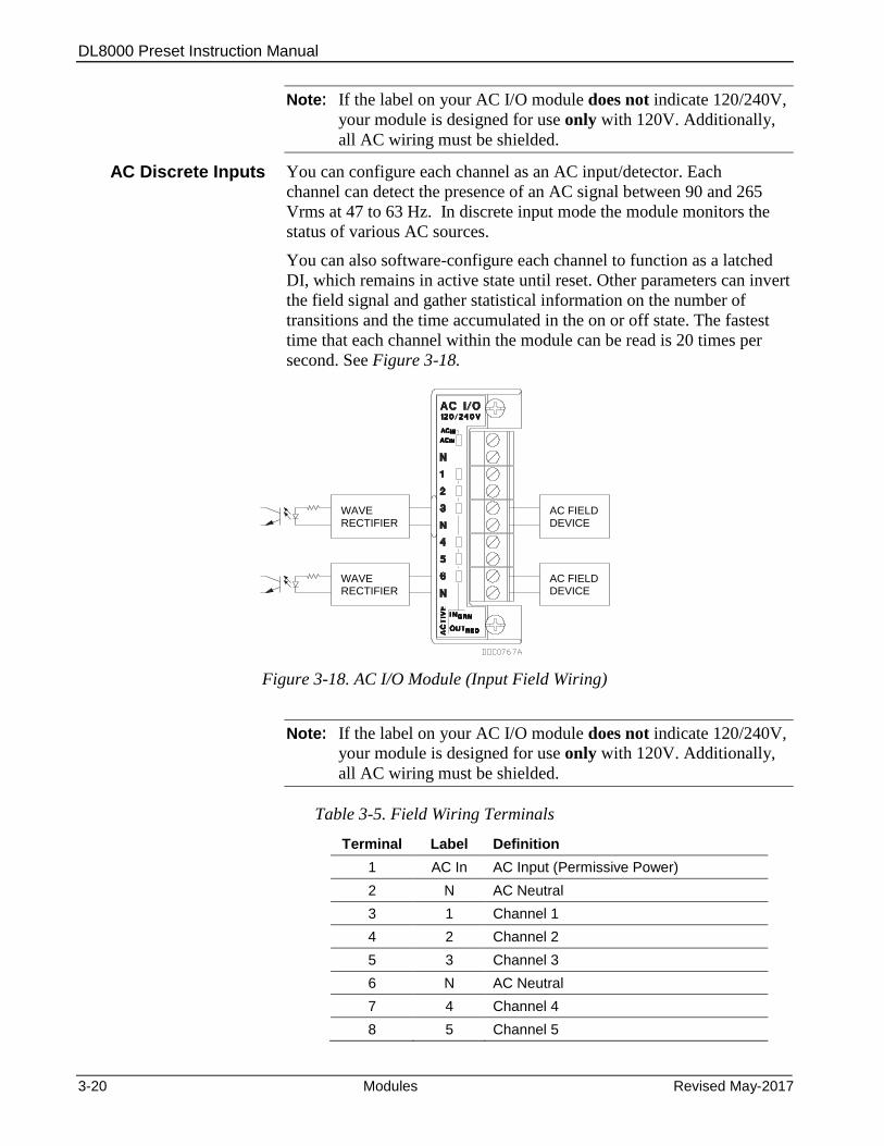
DL8000 Preset Instruction Manual
3-20 Modules Revised May-2017
Note: If the label on your AC I/O module does not indicate 120/240V,
your module is designed for use only with 120V. Additionally,
all AC wiring must be shielded.
AC Discrete Inputs You can configure each channel as an AC input/detector. Each
channel can detect the presence of an AC signal between 90 and 265
Vrms at 47 to 63 Hz. In discrete input mode the module monitors the
status of various AC sources.
You can also software-configure each channel to function as a latched
DI, which remains in active state until reset. Other parameters can invert
the field signal and gather statistical information on the number of
transitions and the time accumulated in the on or off state. The fastest
time that each channel within the module can be read is 20 times per
second. See Figure 3-18.
WAVERECTIFIER
AC FIELDDEVICE
WAVERECTIFIER
AC FIELDDEVICE
Figure 3-18. AC I/O Module (Input Field Wiring)
Note: If the label on your AC I/O module does not indicate 120/240V,
your module is designed for use only with 120V. Additionally,
all AC wiring must be shielded.
Table 3-5. Field Wiring Terminals
Terminal Label Definition
1 AC In AC Input (Permissive Power)
2 N AC Neutral
3 1 Channel 1
4 2 Channel 2
5 3 Channel 3
6 N AC Neutral
7 4 Channel 4
8 5 Channel 5

DL8000 Preset Instruction Manual
Revised May-2017 Modules 3-21
Terminal Label Definition
9 6 Channel 6
10 N AC Neutral
The field terminal wiring has the following definitions:
Term Definition
AC Input The AC power applied to this terminal is the source for any channel that is configured as an output. The input to this terminal should be externally fused with a 10 to 15 amp fuse. The channel has a green LED associated with it to indicate when power is applied. This terminal is typically wired to the permissive/safety circuitry so that if this circuit trips, all power is removed from the channels that are configured as AC outputs.
AC Neutral This terminal is connected to the system AC neutral and is used a reference for all AC power.
Channels 1 through 6
Depending upon the configuration of the DIP switch, each channel can be configured as an input or an output.
Multiple AC I/O Modules
If you need to install more than one AC I/O module in the DL8000,
wire the modules as shown in Figures 3-19 and 3-20.

DL8000 Preset Instruction Manual
3-22 Modules Revised May-2017
Figure 3-19. Wiring with Multiple AC I/O Modules
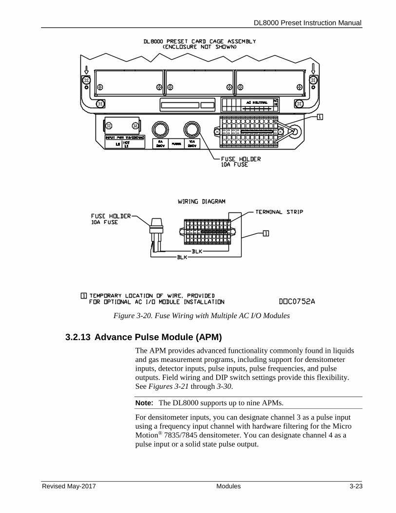
DL8000 Preset Instruction Manual
Revised May-2017 Modules 3-23
Figure 3-20. Fuse Wiring with Multiple AC I/O Modules
3.2.13 Advance Pulse Module (APM)
The APM provides advanced functionality commonly found in liquids
and gas measurement programs, including support for densitometer
inputs, detector inputs, pulse inputs, pulse frequencies, and pulse
outputs. Field wiring and DIP switch settings provide this flexibility.
See Figures 3-21 through 3-30.
Note: The DL8000 supports up to nine APMs.
For densitometer inputs, you can designate channel 3 as a pulse input
using a frequency input channel with hardware filtering for the Micro
Motion® 7835/7845 densitometer. You can designate channel 4 as a
pulse input or a solid state pulse output.
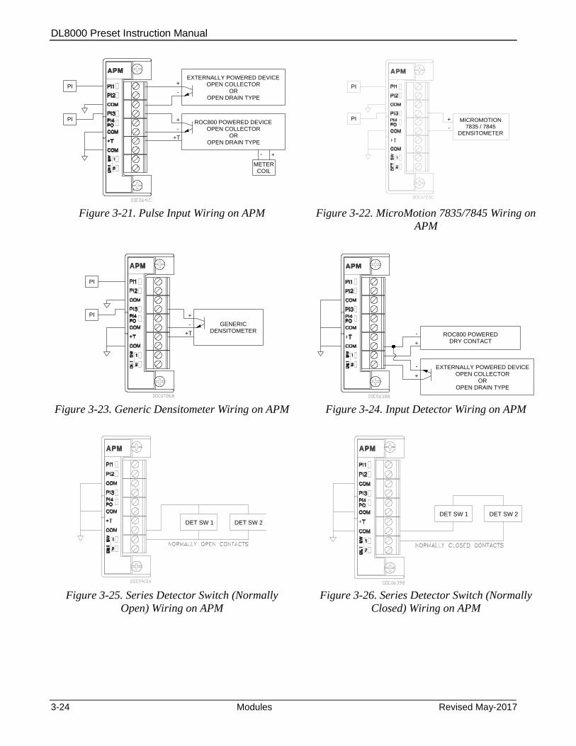
DL8000 Preset Instruction Manual
3-24 Modules Revised May-2017
-
+ OPEN COLLECTOREXTERNALLY POWERED DEVICE
OROPEN DRAIN TYPE
OPEN COLLECTORROC800 POWERED DEVICE
OROPEN DRAIN TYPE
-
+
+T
METER
- +
PI
COIL
PI
7835 / 7845MICROMOTION
-
+
DENSITOMETER
PI
PI
Figure 3-21. Pulse Input Wiring on APM Figure 3-22. MicroMotion 7835/7845 Wiring on
APM
DENSITOMETERGENERIC-
+
+T
PI
PI
-
+ DRY CONTACTROC800 POWERED
+ OPEN COLLECTOREXTERNALLY POWERED DEVICE
OROPEN DRAIN TYPE
-
Figure 3-23. Generic Densitometer Wiring on APM Figure 3-24. Input Detector Wiring on APM
DET SW 1 DET SW 2
DET SW 1 DET SW 2
Figure 3-25. Series Detector Switch (Normally
Open) Wiring on APM
Figure 3-26. Series Detector Switch (Normally
Closed) Wiring on APM
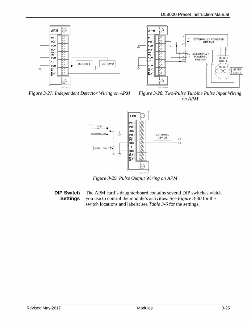
DL8000 Preset Instruction Manual
Revised May-2017 Modules 3-25
DET SW 1 DET SW 2
METER- +
METER
COIL 2
-
+
-
+
+TMETER
- +
POWEREDEXTERNALLY
PREAMP
PREAMPEXTERNALLY POWERED
+T
COIL 1
Figure 3-27. Independent Detector Wiring on APM Figure 3-28. Two-Pulse Turbine Pulse Input Wiring
on APM
DEVICEEXTERNAL
CONTROL
NO CONNECTION
+1210K
Figure 3-29. Pulse Output Wiring on APM
DIP Switch Settings
The APM card’s daughterboard contains several DIP switches which
you use to control the module’s activities. See Figure 3-30 for the
switch locations and labels; see Table 3-6 for the settings.
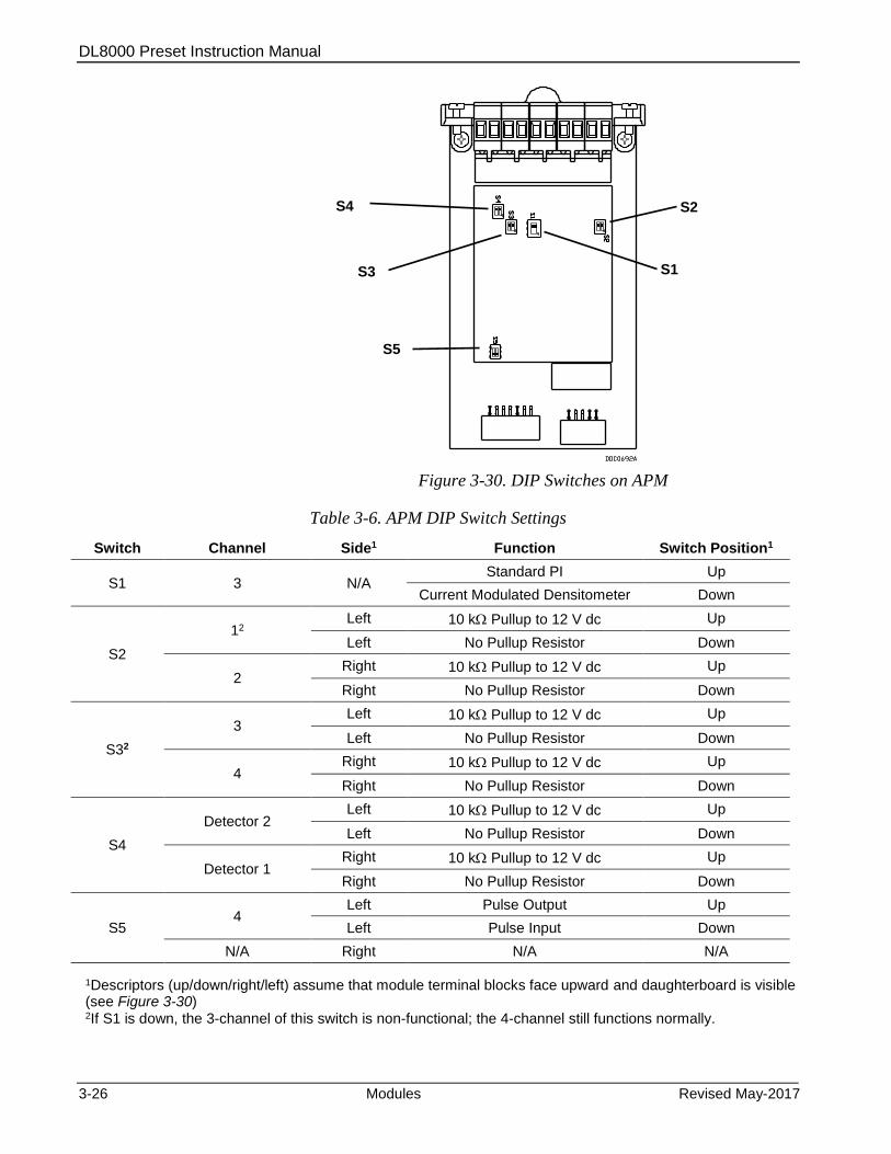
DL8000 Preset Instruction Manual
3-26 Modules Revised May-2017
Figure 3-30. DIP Switches on APM
Table 3-6. APM DIP Switch Settings
Switch Channel Side1 Function Switch Position1
S1 3 N/A Standard PI Up
Current Modulated Densitometer Down
S2
12 Left 10 k Pullup to 12 V dc Up
Left No Pullup Resistor Down
2 Right 10 k Pullup to 12 V dc Up
Right No Pullup Resistor Down
S32
3 Left 10 k Pullup to 12 V dc Up
Left No Pullup Resistor Down
4 Right 10 k Pullup to 12 V dc Up
Right No Pullup Resistor Down
S4
Detector 2 Left 10 k Pullup to 12 V dc Up
Left No Pullup Resistor Down
Detector 1 Right 10 k Pullup to 12 V dc Up
Right No Pullup Resistor Down
S5 4
Left Pulse Output Up
Left Pulse Input Down
N/A Right N/A N/A
1Descriptors (up/down/right/left) assume that module terminal blocks face upward and daughterboard is visible (see Figure 3-30) 2If S1 is down, the 3-channel of this switch is non-functional; the 4-channel still functions normally.
S2 S4
S1 S3
S5
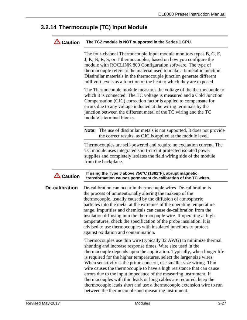
DL8000 Preset Instruction Manual
Revised May-2017 Modules 3-27
3.2.14 Thermocouple (TC) Input Module
Caution The TC2 module is NOT supported in the Series 1 CPU.
The four-channel Thermocouple Input module monitors types B, C, E,
J, K, N, R, S, or T thermocouples, based on how you configure the
module with ROCLINK 800 Configuration software. The type of
thermocouple refers to the material used to make a bimetallic junction.
Dissimilar materials in the thermocouple junction generate different
millivolt levels as a function of the heat to which they are exposed.
The Thermocouple module measures the voltage of the thermocouple to
which it is connected. The TC voltage is measured and a Cold Junction
Compensation (CJC) correction factor is applied to compensate for
errors due to any voltage inducted at the wiring terminals by the
junction between the different metal of the TC wiring and the TC
module’s terminal blocks.
Note: The use of dissimilar metals is not supported. It does not provide
the correct results, as CJC is applied at the module level.
Thermocouples are self-powered and require no excitation current. The
TC module uses integrated short-circuit protected isolated power
supplies and completely isolates the field wiring side of the module
from the backplane.
Caution If using the Type J above 750°C (1382°F), abrupt magnetic transformation causes permanent de-calibration of the TC wires.
De-calibration De-calibration can occur in thermocouple wires. De-calibration is
the process of unintentionally altering the makeup of the
thermocouple, usually caused by the diffusion of atmospheric
particles into the metal at the extremes of the operating temperature
range. Impurities and chemicals can cause de-calibration from the
insulation diffusing into the thermocouple wire. If operating at high
temperatures, check the specification of the probe insulation. It is
advised to use thermocouples with insulated junctions to protect
against oxidation and contamination.
Thermocouples use thin wire (typically 32 AWG) to minimize thermal
shunting and increase response times. Wire size used in the
thermocouple depends upon the application. Typically, when longer life
is required for the higher temperatures, select the larger size wires.
When sensitivity is the prime concern, use smaller size wiring. Thin
wire causes the thermocouple to have a high resistance that can cause
errors due to the input impedance of the measuring instrument. If
thermocouples with thin leads or long cables are required, keep the
thermocouple leads short and use a thermocouple extension wire to run
between the thermocouple and measuring instrument.
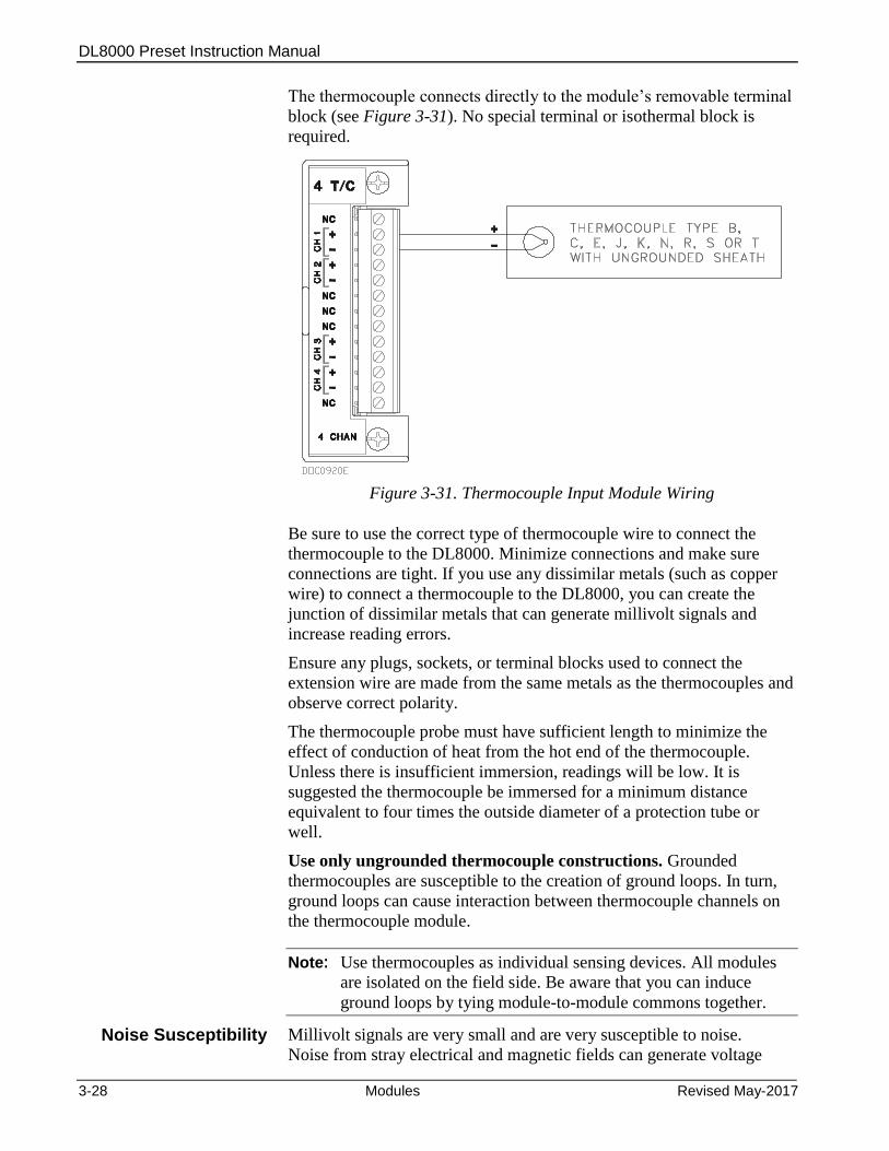
DL8000 Preset Instruction Manual
3-28 Modules Revised May-2017
The thermocouple connects directly to the module’s removable terminal
block (see Figure 3-31). No special terminal or isothermal block is
required.
Figure 3-31. Thermocouple Input Module Wiring
Be sure to use the correct type of thermocouple wire to connect the
thermocouple to the DL8000. Minimize connections and make sure
connections are tight. If you use any dissimilar metals (such as copper
wire) to connect a thermocouple to the DL8000, you can create the
junction of dissimilar metals that can generate millivolt signals and
increase reading errors.
Ensure any plugs, sockets, or terminal blocks used to connect the
extension wire are made from the same metals as the thermocouples and
observe correct polarity.
The thermocouple probe must have sufficient length to minimize the
effect of conduction of heat from the hot end of the thermocouple.
Unless there is insufficient immersion, readings will be low. It is
suggested the thermocouple be immersed for a minimum distance
equivalent to four times the outside diameter of a protection tube or
well.
Use only ungrounded thermocouple constructions. Grounded
thermocouples are susceptible to the creation of ground loops. In turn,
ground loops can cause interaction between thermocouple channels on
the thermocouple module.
Note: Use thermocouples as individual sensing devices. All modules
are isolated on the field side. Be aware that you can induce
ground loops by tying module-to-module commons together.
Noise Susceptibility Millivolt signals are very small and are very susceptible to noise.
Noise from stray electrical and magnetic fields can generate voltage
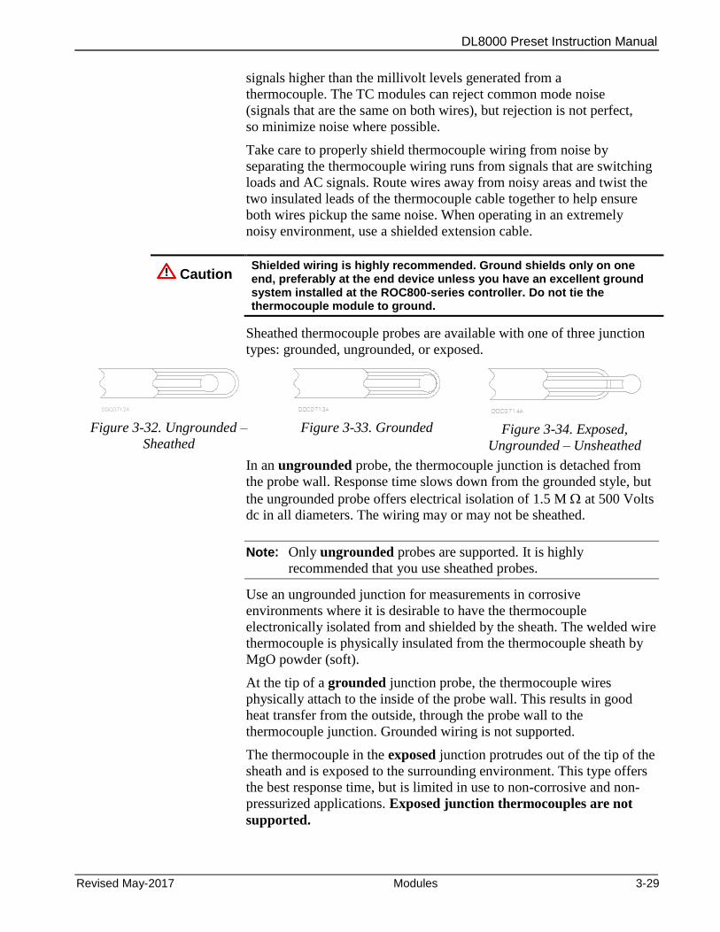
DL8000 Preset Instruction Manual
Revised May-2017 Modules 3-29
signals higher than the millivolt levels generated from a
thermocouple. The TC modules can reject common mode noise
(signals that are the same on both wires), but rejection is not perfect,
so minimize noise where possible.
Take care to properly shield thermocouple wiring from noise by
separating the thermocouple wiring runs from signals that are switching
loads and AC signals. Route wires away from noisy areas and twist the
two insulated leads of the thermocouple cable together to help ensure
both wires pickup the same noise. When operating in an extremely
noisy environment, use a shielded extension cable.
Caution Shielded wiring is highly recommended. Ground shields only on one end, preferably at the end device unless you have an excellent ground system installed at the ROC800-series controller. Do not tie the thermocouple module to ground.
Sheathed thermocouple probes are available with one of three junction
types: grounded, ungrounded, or exposed.
Figure 3-32. Ungrounded –
Sheathed
Figure 3-33. Grounded
Figure 3-34. Exposed,
Ungrounded – Unsheathed
In an ungrounded probe, the thermocouple junction is detached from
the probe wall. Response time slows down from the grounded style, but
the ungrounded probe offers electrical isolation of 1.5 M at 500 Volts
dc in all diameters. The wiring may or may not be sheathed.
Note: Only ungrounded probes are supported. It is highly
recommended that you use sheathed probes.
Use an ungrounded junction for measurements in corrosive
environments where it is desirable to have the thermocouple
electronically isolated from and shielded by the sheath. The welded wire
thermocouple is physically insulated from the thermocouple sheath by
MgO powder (soft).
At the tip of a grounded junction probe, the thermocouple wires
physically attach to the inside of the probe wall. This results in good
heat transfer from the outside, through the probe wall to the
thermocouple junction. Grounded wiring is not supported.
The thermocouple in the exposed junction protrudes out of the tip of the
sheath and is exposed to the surrounding environment. This type offers
the best response time, but is limited in use to non-corrosive and non-
pressurized applications. Exposed junction thermocouples are not
supported.
DL8000 Preset Instruction Manual
3-30 Modules Revised May-2017
Note: Avoid subjecting the thermocouple connections and
measurement instrument to sudden changes in temperature.
3.2.15 Highway Addressable Remote Transducer (HART®) Module
Notes:
The HART-2 module (labeled HART-2 with black faceplate)
replaces the HART module (with gray faceplate).
The DL8000 supports up to 5 HART modules located in slots 1-5.
The HART-2 module allows a DL8000 to communicate with HART
devices using the HART protocol. The HART-2 module receives
signals from and transmits signals to HART devices. LEDs provide a
visual indication of the status of each HART channel. Refer to Figures
3-35 to 3-37.
Note: HART Pass-Through requires you to use the HART Pass-
Through license key (FS8KY-6), which provides PlantWeb®
Smart Remote Automation functionality. This includes the
ability to pass HART data bi-directionally through the network
to AMS™ Device Manager software.
The module has four input/output channels. The HART-2 module uses
software-configurable switches, which allow you to set each channel as
input or output. When you set a channel as an input, you can configure
it for use in point-to-point or multi-drop mode (which typically connects
to some type of transmitter, such as a temperature reading). When you
configure a channel as an output, it reverts to point-to-point mode only.
The output supports a Digital Valve Controller (DVC). Each channel
has analog input capability intended for diagnostic and primary process
variable measurement.
Frequency Shift Keying
HART superimposes Frequency Shift Keying (FSK) signals on an
analog signal. This technique allows digital information to be passed
to and from the HART device on a 4 to 20 mA analog signal.
Point-to-Point Mode In point-to-point mode, the analog signal is still representative of the
measured variable. This mode allows communications with one
HART device per channel.
Multi-drop Mode In multi-drop mode, you can connect up to five HART devices (in
parallel) to each channel. As with the point-to-point mode, digital
communications are superimposed on the analog signal used to power
the HART devices. Each HART device in multi-drop mode requires 4
mA and the current does not represent any measured variable value.
With all four channels in the multi-drop mode, the DL8000 can
support a maximum of twenty HART devices.
DL8000 Preset Instruction Manual
Revised May-2017 Modules 3-31
A DL8000 equipped with a HART-2 module is considered to be a
HART Host (primary master) interface with a Class 1 Conformance
classification. The HART-2 module can also be configured with
ROCLINK 800 Configuration software for use as a secondary master in
redundant applications.
Most Universal and some Common Practice commands are supported.
For a list of the commands, refer to the ROC800-Series HART-2
Module technical specification sheet (ROC800:HART2). The supported
commands conform to HART Universal Command Specification
Revision 5.1 and Common Practice Command Specification Revision 7,
(HCF SPEC 127 and 151). Refer to www.hartcomm.org for more
information on the specifications.
The HART-2 module polls the channels simultaneously. If more than
one device is connected to a channel in a multi-drop configuration, the
module polls one device per channel at a time. The HART protocol
allows one second per poll for each device, so with five devices per
channel the maximum poll time for the channel would be five seconds.
Note: The DL8000 does not support HART devices configured in
Burst mode (in which the device sends information without a
prior request). If you have a HART device configured in burst
mode, use a hand-held field communicator to turn off burst
mode before you connect the device to the DL8000.
The HART-2 module provides “loop source” power (+T) and four
channels (1+ through 4+) for communications. The +T power is current-
limited.
DL8000-powered HART Devices
When using the DL8000 to power HART devices, connect terminal
+T in parallel to the positive (+) terminal on all of the HART devices,
regardless of the channel to which they are connected.
Wire channel 1+ to the negative (–) terminal of a single HART device,
or in parallel to the negative terminals of the devices. Likewise, wire
channel 2+ to the negative (–) terminal of a single HART device, or in
parallel to the negative terminals of a second group of HART devices
(see Figures 3-35 to 3-37).
Externally powered HART Devices
When powering HART devices by an external device, connect the
positive (+) terminal from the power source in parallel to the positive
(+) terminal on all of the HART devices, regardless of the channel to
which they are connected.
Wire channel 1+ on the HART-2 module to the positive (+) terminal of
the HART device. Connect the power source negative (–) terminal to
the channel’s COM terminal and to the negative (–) terminal of a single
HART device, or in parallel to the negative terminals of the HART
devices.

DL8000 Preset Instruction Manual
3-32 Modules Revised May-2017
Figure 3-35. Input Point-to-Point Wiring on
HART-2 Module
Figure 3-36. Input Multi-Drop Wiring on HART-
2 Module
Figure 3-37. Output Wiring on HART-2 Module
3.3 Communication Modules and Ports
The built-in communications and the optional communication modules
provide communications between the DL8000 and a host system or
external devices.
The DL8000 allows up to six communication ports. Three
communication ports are built-in on the CPU and up to three additional
ports may be added with communication modules. Table 3-7 displays
the types of communications available for the DL8000; Table 3-8
defines the LED indicators.
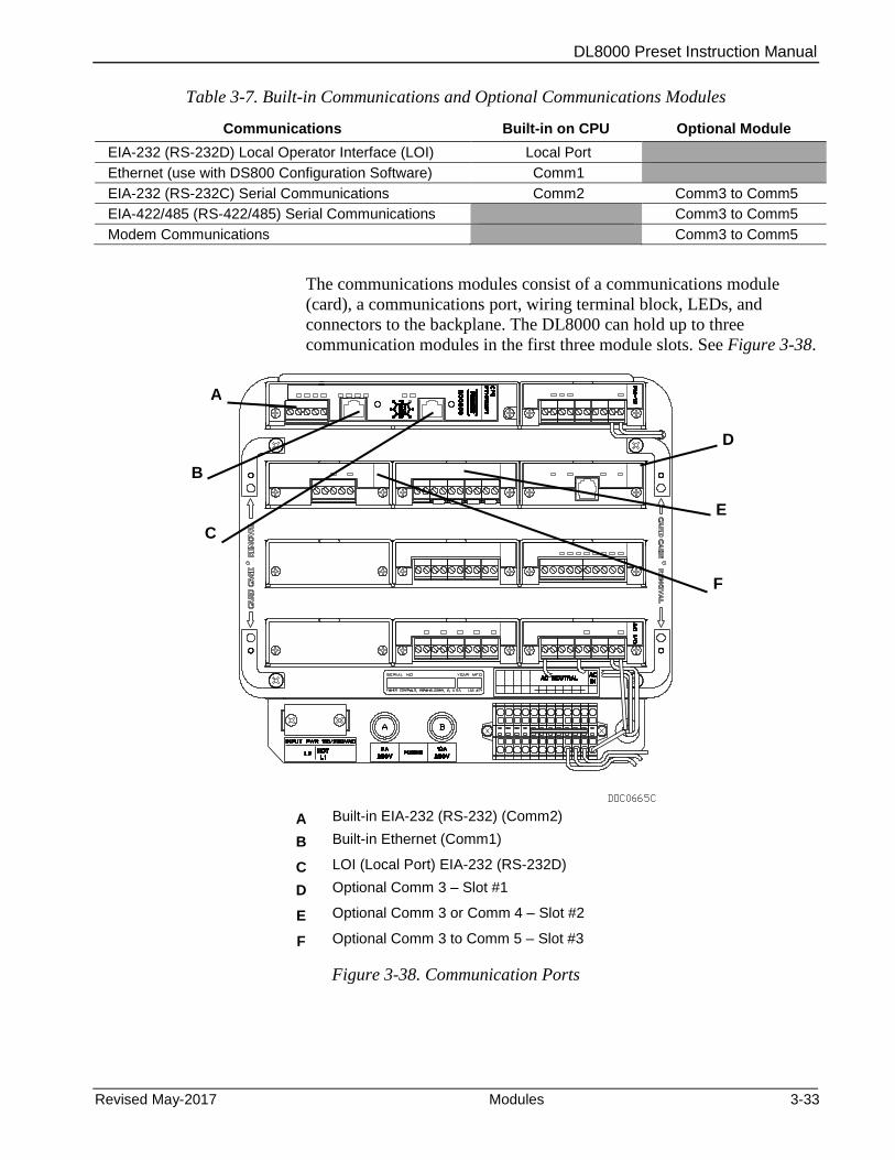
DL8000 Preset Instruction Manual
Revised May-2017 Modules 3-33
Table 3-7. Built-in Communications and Optional Communications Modules
Communications Built-in on CPU Optional Module
EIA-232 (RS-232D) Local Operator Interface (LOI) Local Port
Ethernet (use with DS800 Configuration Software) Comm1
EIA-232 (RS-232C) Serial Communications Comm2 Comm3 to Comm5
EIA-422/485 (RS-422/485) Serial Communications Comm3 to Comm5
Modem Communications Comm3 to Comm5
The communications modules consist of a communications module
(card), a communications port, wiring terminal block, LEDs, and
connectors to the backplane. The DL8000 can hold up to three
communication modules in the first three module slots. See Figure 3-38.
A Built-in EIA-232 (RS-232) (Comm2)
B Built-in Ethernet (Comm1)
C LOI (Local Port) EIA-232 (RS-232D)
D Optional Comm 3 – Slot #1
E Optional Comm 3 or Comm 4 – Slot #2
F Optional Comm 3 to Comm 5 – Slot #3
Figure 3-38. Communication Ports
C
B
A
E
F
D

DL8000 Preset Instruction Manual
3-34 Modules Revised May-2017
Table 3-8. Communication LED Indicator Definitions
Signals Action
CTS Clear To Send indicates the modem is ready to send.
CD Data Carrier Detect (DCD) indicates a valid carrier signal tone detected.
DSR Data Set Ready for ring indicator communication signal.
DTR Data Terminal Ready to answer an incoming call. When off, a connection disconnects.
RTS Ready To Send indicates ready to transmit.
RX Receive Data (RD) signal is being received.
TX Transmit Data (TD) signal is being transmitted.
Each communications module has surge protection in accordance with
the CE certification EN 61000. Each communications module is
completely isolated from other modules and the backplane, including
power and signal isolation, with the exception of the EIA-232 (RS-232)
module. The field interface has been designed to protect the electronics
in the module. Filtering is provided on each module to reduce
communication errors.
3.3.1 Wiring Communications
Signal wiring connections to the communications are made through the
communications port removable terminal bock connectors and through
RJ-11 and RJ-45 connectors. All modules have removable terminal
blocks for convenient wiring and servicing. The terminal blocks
accommodate wire sizes between 12 and 22 AWG.
Caution Failure to exercise proper electrostatic discharge precautions, such as wearing a grounded wrist strap may reset the processor or damage electronic components, resulting in interrupted operations.
To connect the wire to the removable block compression terminals:
1. Bare the end (¼ inch maximum) of the wire.
2. Insert the bared end into the clamp beneath the termination screw.
3. Tighten the screw.
Expose a minimum of bare wire to prevent short circuits. Allow some
slack when making connections to prevent strain.
Note: All modules have removable terminal blocks for convenient
wiring and servicing. Twisted-pair cable is recommended for I/O
signal wiring. The removable terminal blocks accept wire sizes
between 12 and 22 AWG.

DL8000 Preset Instruction Manual
Revised May-2017 Modules 3-35
3.3.2 Local Operator Interface (LOI – Local Port)
The Local Operator Interface (LOI) port provides direct
communications between the DL8000 and the serial port of an operator
interface device, such as a personal computer (PC). The interface
allows you to access the DL8000 with a direct connection using
ROCLINK 800 software for configuration and transfer of stored data.
The LOI uses the Local Port in ROCLINK 800 software.
The LOI terminal (RJ-45) on the CPU (see Figure 3-38) provides wiring
access to a built-in EIA-232 (RS-232) serial interface, which is capable
of 57.6K baud operation. The RJ-45 connector pin uses the data
terminal equipment (DTE) in the IEEE standard.
The LOI port supports ROC Plus and Modbus protocol
communications. The LOI also supports the log-on security feature of
the DL8000 if you enable the Security on LOI feature in ROCLINK 800
software.
Table 3-9 shows the signal routing of the CPU connections. Figure 3-39
shows the RJ-45 pin out.
Table 3-9. Built-in LOI EIA-232 Signal Routing
Signal LOI Function RJ-45 Pins on DL8000
Description
DTR Data Terminal
Ready 3
Originated by the DL8000 Data Terminal Equipment (DTE) to instruct the Data Communication Equipment (DCE) to set up a connection. DTE is running and ready to communicate.
GND Ground
(Common) 4
Reference ground between a DTE and a DCE and has a value 0 volts dc.
RX Receive 5 Data received by the DTE.
TX Transmit 6 Data sent by the DTE.
RTS Request to Send 8 Originated by the DTE to initiate transmission by the DCE.
Figure 3-39. RJ-45 Pin Out
The LOI terminal requires a D-Sub 9 pin (F) to RJ-45 modular
converter installed between the DL8000 and a personal computer (PC).
See Table 3-10.
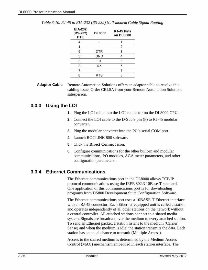
DL8000 Preset Instruction Manual
3-36 Modules Revised May-2017
Table 3-10. RJ-45 to EIA-232 (RS-232) Null-modem Cable Signal Routing
EIA-232 (RS-232)
DTE DL8000
RJ-45 Pins on DL8000
4 – 1
1 – 2
6 DTR 3
5 GND 4
3 TX 5
2 RX 6
7 – 7
8 RTS 8
Adaptor Cable Remote Automation Solutions offers an adaptor cable to resolve this
cabling issue. Order CBL8A from your Remote Automation Solutions
salesperson.
3.3.3 Using the LOI
1. Plug the LOI cable into the LOI connector on the DL8000 CPU.
2. Connect the LOI cable to the D-Sub 9 pin (F) to RJ-45 modular
converter.
3. Plug the modular converter into the PC’s serial COM port.
4. Launch ROCLINK 800 software.
5. Click the Direct Connect icon.
6. Configure communications for the other built-in and modular
communications, I/O modules, AGA meter parameters, and other
configuration parameters.
3.3.4 Ethernet Communications
The Ethernet communications port in the DL8000 allows TCP/IP
protocol communications using the IEEE 802.3 10Base-T standard.
One application of this communications port is for downloading
programs from DS800 Development Suite Configuration Software.
The Ethernet communications port uses a 10BASE-T Ethernet interface
with an RJ-45 connector. Each Ethernet-equipped unit is called a station
and operates independently of all other stations on the network without
a central controller. All attached stations connect to a shared media
system. Signals are broadcast over the medium to every attached station.
To send an Ethernet packet, a station listens to the medium (Carrier
Sense) and when the medium is idle, the station transmits the data. Each
station has an equal chance to transmit (Multiple Access).
Access to the shared medium is determined by the Medium Access
Control (MAC) mechanism embedded in each station interface. The

DL8000 Preset Instruction Manual
Revised May-2017 Modules 3-37
MAC mechanism is based on Carrier Sense Multiple Access with
Collision Detection (CSMA/CD). If two stations begin to transmit a
packet at the same instant, the stations stop transmitting (Collision
Detection). Transmission is rescheduled at a random time interval to
avoid the collision.
Link Ethernet networks together to form extended networks using
bridges and routers. Table 3-11 maps the LEDs to functions.
Table 3-11. Ethernet Signal LEDs
Signal Function
RX Lit when currently receiving.
TX Lit when currently transmitting.
COL Lit when Ethernet Packet Collision detected.
LNK Lit when Ethernet has linked.
Use a rugged industrial temperature HUB when connecting Ethernet
wiring in an environment that requires it.
The IEEE 802.3 10BASE-T standard requires that 10BASE-T
transceivers be able to transmit over a link using voice grade twisted-
pair telephone wiring that meets EIA/TIA Category four wire
specifications. Generally, links up to 100 meter (328 feet) long are
achievable for unshielded twisted-pair cable.
For each connector or patch panel in the link, subtract 12 meters (39.4
feet) from the 100-meter limit. This allows for links of up to 88 meters
(288 feet) using standard 24 AWG UTP (Unshielded Twisted-Pair) wire
and two patch panels within the link. Higher quality, low attenuation
cables may be required when using links greater than 88 meters.
The maximum insertion loss allowed for a 10BASE-T link is 11.5 dB at
all frequencies between 5.0 and 10.0 MHz. This includes the attenuation
of the cables, connectors, patch panels, and reflection losses due to
impedance mismatches to the link segment.
Intersymbol interference and reflections can cause jitter in the bit cell
timing, resulting in data errors. A 10BASE-T link must not generate
more than 5.0 nanoseconds of jitter. If your cable meets the impedance
requirements for a 10BASE-T link, jitter should not be a concern.
The maximum propagation delay of a 10BASE-T link segment must not
exceed 1000 nanoseconds.
Crosstalk is caused by signal coupling between the different cable pairs
contained within a multi-pair cable bundle. 10BASE-T transceivers are
designed so that you do not need to be concerned about cable crosstalk,
provided the cable meets all other requirements.
Noise can be caused by crosstalk of externally induced impulses.
Impulse noise may cause data errors if the impulses occur at very
specific times during data transmission. Generally, do not be concerned
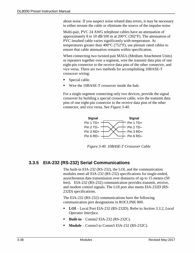
DL8000 Preset Instruction Manual
3-38 Modules Revised May-2017
about noise. If you suspect noise related data errors, it may be necessary
to either reroute the cable or eliminate the source of the impulse noise.
Multi-pair, PVC 24 AWG telephone cables have an attenuation of
approximately 8 to 10 dB/100 m at 200°C (392°F). The attenuation of
PVC insulted cable varies significantly with temperature. At
temperatures greater than 400°C (752°F), use plenum rated cables to
ensure that cable attenuation remains within specification.
When connecting two twisted-pair MAUs (Medium Attachment Units)
or repeaters together over a segment, wire the transmit data pins of one
eight-pin connector to the receive data pins of the other connector, and
vice versa. There are two methods for accomplishing 10BASE-T
crossover wiring:
Special cable.
Wire the 10BASE-T crossover inside the hub.
For a single segment connecting only two devices, provide the signal
crossover by building a special crossover cable, wire the transmit data
pins of one eight-pin connector to the receive data pins of the other
connector, and vice versa. See Figure 3-40.
Signal Signal
Pin 1 TD+ Pin 1 TD+
Pin 2 TD– Pin 2 TD–
Pin 3 RD+ Pin 3 RD+
Pin 6 RD– Pin 6 RD–
Figure 3-40. 10BASE-T Crossover Cable
3.3.5 EIA-232 (RS-232) Serial Communications
The built-in EIA-232 (RS-232), the LOI, and the communication
modules meet all EIA-232 (RS-232) specifications for single-ended,
asynchronous data transmission over distances of up to 15 meters (50
feet). EIA-232 (RS-232) communication provides transmit, receive,
and modem control signals. The LOI port also meets EIA-232D (RS-
232D) specifications.
The EIA-232 (RS-232) communications have the following
communication port designations in ROCLINK 800.
LOI – Local Port EIA-232 (RS-232D). Refer to Section 3.3.2, Local
Operator Interface.
Built-in – Comm2 EIA-232 (RS-232C).
Module – Comm3 to Comm5 EIA-232 (RS-232C).
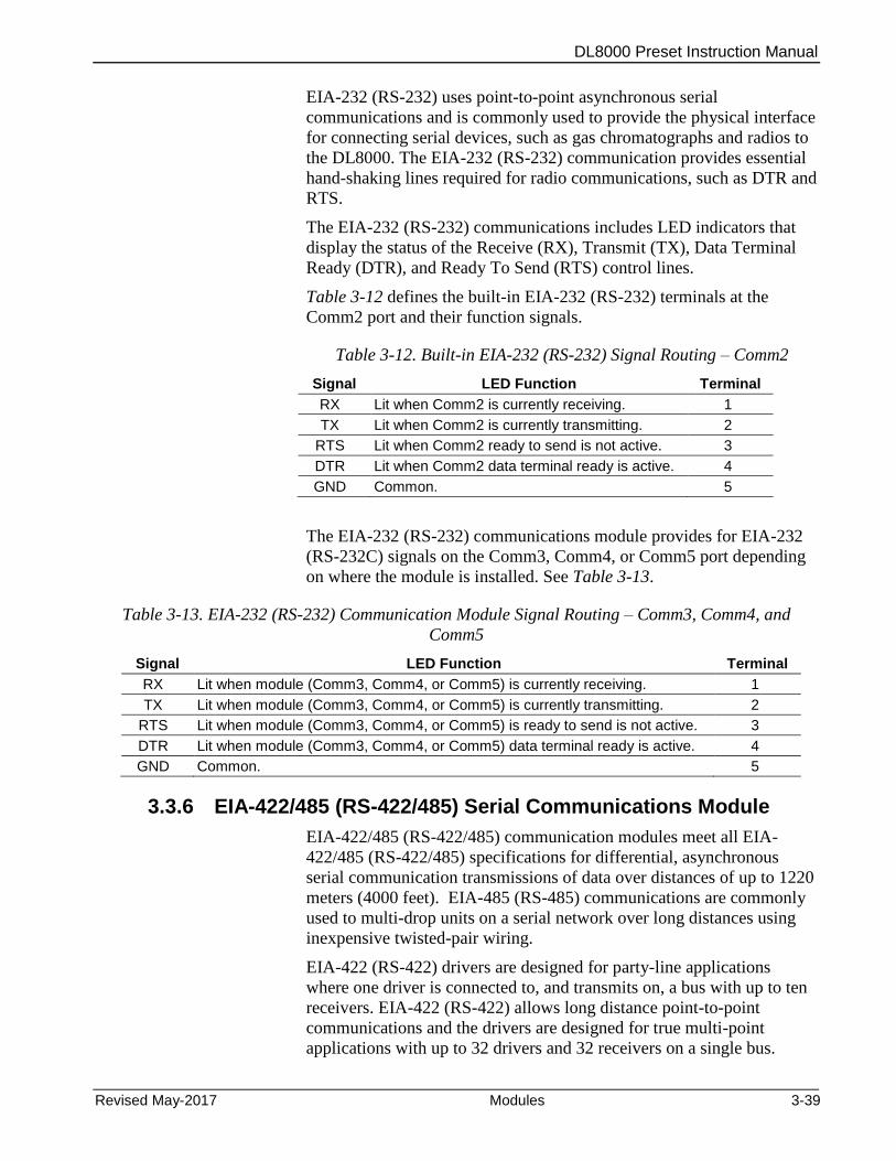
DL8000 Preset Instruction Manual
Revised May-2017 Modules 3-39
EIA-232 (RS-232) uses point-to-point asynchronous serial
communications and is commonly used to provide the physical interface
for connecting serial devices, such as gas chromatographs and radios to
the DL8000. The EIA-232 (RS-232) communication provides essential
hand-shaking lines required for radio communications, such as DTR and
RTS.
The EIA-232 (RS-232) communications includes LED indicators that
display the status of the Receive (RX), Transmit (TX), Data Terminal
Ready (DTR), and Ready To Send (RTS) control lines.
Table 3-12 defines the built-in EIA-232 (RS-232) terminals at the
Comm2 port and their function signals.
Table 3-12. Built-in EIA-232 (RS-232) Signal Routing – Comm2
Signal LED Function Terminal
RX Lit when Comm2 is currently receiving. 1
TX Lit when Comm2 is currently transmitting. 2
RTS Lit when Comm2 ready to send is not active. 3
DTR Lit when Comm2 data terminal ready is active. 4
GND Common. 5
The EIA-232 (RS-232) communications module provides for EIA-232
(RS-232C) signals on the Comm3, Comm4, or Comm5 port depending
on where the module is installed. See Table 3-13.
Table 3-13. EIA-232 (RS-232) Communication Module Signal Routing – Comm3, Comm4, and
Comm5
Signal LED Function Terminal
RX Lit when module (Comm3, Comm4, or Comm5) is currently receiving. 1
TX Lit when module (Comm3, Comm4, or Comm5) is currently transmitting. 2
RTS Lit when module (Comm3, Comm4, or Comm5) is ready to send is not active. 3
DTR Lit when module (Comm3, Comm4, or Comm5) data terminal ready is active. 4
GND Common. 5
3.3.6 EIA-422/485 (RS-422/485) Serial Communications Module
EIA-422/485 (RS-422/485) communication modules meet all EIA-
422/485 (RS-422/485) specifications for differential, asynchronous
serial communication transmissions of data over distances of up to 1220
meters (4000 feet). EIA-485 (RS-485) communications are commonly
used to multi-drop units on a serial network over long distances using
inexpensive twisted-pair wiring.
EIA-422 (RS-422) drivers are designed for party-line applications
where one driver is connected to, and transmits on, a bus with up to ten
receivers. EIA-422 (RS-422) allows long distance point-to-point
communications and the drivers are designed for true multi-point
applications with up to 32 drivers and 32 receivers on a single bus.

DL8000 Preset Instruction Manual
3-40 Modules Revised May-2017
The default values for the EIA-422/485 (RS-422/485) communications
are: 19200 Baud rate, 8 data bits, 1 stop bit, and no parity. The
maximum rate is 57.6K bps.
EIA-422/485 (RS-422/485) communication modules include LED
indicators that display the status of receive and transmit activity. See
Tables 3-14 and 3-15.
Table 3-14. EIA-422 (RS-422) Signal Routing – Comm3, Comm4, and Comm5
Signal RS-422 Function Terminal
A RX + Lit when module (Comm3, Comm4, or Comm5) is currently receiving. 1
B RX – None. 2
Y TX + Lit when module (Comm3, Comm4, or Comm5) is currently transmitting. 3
Z TX – None. 4
COM Common Ground. 5
Table 3-15. EIA-485 (RS-485) Signal Routing – Comm3, Comm4, and Comm5
Signal RS-485 Function Terminal
A RX / TX + Lit when module (Comm3, Comm4, or Comm5) is currently receiving. 1
B RX / TX – Lit when module (Comm3, Comm4, or Comm5) is currently transmitting. 2
Y No Connect None. 3
Z No Connect None. 4
COM Common Ground. 5
Note: The EIA-422/485 (RS-422/485) modules are isolated on the field
side.
Caution You can induce ground loops by tying commons from various modules together.
EIA-422/485 (RS-422/485) communications provides EIA-422/485
(RS-422/485) signals on the Comm3, Comm4, or Comm5 port
depending on where the module is installed. Wiring should be twisted-
pair cable, one pair for transmitting, and one pair for receiving. The
EIA-422 (RS-422) module uses four wires and the EIA-485 (RS-485)
uses two wires for connectivity.
3.3.7 EIA-422/485 (RS-422/485) Jumpers and Termination Resistors
Four jumpers—J3, J4, J5, and J6—are located on the EIA-422/485 (RS-
422/485) communications module (see Figure 3-41). These jumpers
determine in which mode the module runs (RS-422 or RS-485) and if
the module is terminated. See Tables 3-16 and 3-17.
Terminations are required on the two EIA-422/485 (RS-422/485)
communication modules located at the extremities of the circuit. That is
to say, the two outside modules require terminations in order to
complete the communications circuit.

DL8000 Preset Instruction Manual
Revised May-2017 Modules 3-41
Figure 3-41. EIA-422/485 (RS-422/485) J4 Jumper
Table 3-16. EIA-422 (RS-422) Module
Jumper Terminated Not Terminated
TER Out Half Full TER Out Half Full
J3 x x
J4 x x
J5 x x
J6 x x
Table 3-17. EIA-485 (RS-485) Module
Jumper Terminated Not Terminated
TER Out Half Full TER Out Half Full
J3 x x
J4 x x
J5 x x
J6 x x
3.3.8 Dial-up Modem Communications Module
The dial-up modem module interfaces to a Public-Switched Telephone
Network (PSTN) line. The dial-up modem module provides for a
telephone interface on the host port that is capable of both answering
and originating telephone calls. The dial-up modem module also
provides electronics that conserve power when the phone line is not in
use. The dial-up modem module requires a telephone line connection.
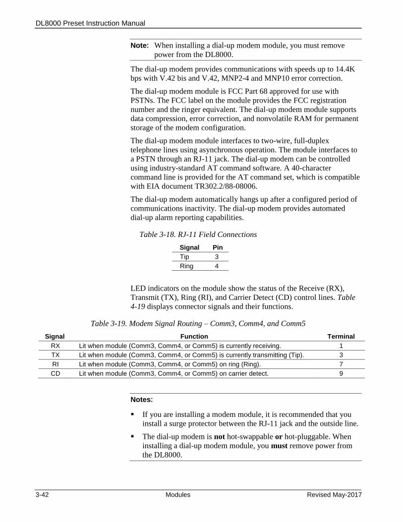
DL8000 Preset Instruction Manual
3-42 Modules Revised May-2017
Note: When installing a dial-up modem module, you must remove
power from the DL8000.
The dial-up modem provides communications with speeds up to 14.4K
bps with V.42 bis and V.42, MNP2-4 and MNP10 error correction.
The dial-up modem module is FCC Part 68 approved for use with
PSTNs. The FCC label on the module provides the FCC registration
number and the ringer equivalent. The dial-up modem module supports
data compression, error correction, and nonvolatile RAM for permanent
storage of the modem configuration.
The dial-up modem module interfaces to two-wire, full-duplex
telephone lines using asynchronous operation. The module interfaces to
a PSTN through an RJ-11 jack. The dial-up modem can be controlled
using industry-standard AT command software. A 40-character
command line is provided for the AT command set, which is compatible
with EIA document TR302.2/88-08006.
The dial-up modem automatically hangs up after a configured period of
communications inactivity. The dial-up modem provides automated
dial-up alarm reporting capabilities.
Table 3-18. RJ-11 Field Connections
Signal Pin
Tip 3
Ring 4
LED indicators on the module show the status of the Receive (RX),
Transmit (TX), Ring (RI), and Carrier Detect (CD) control lines. Table
4-19 displays connector signals and their functions.
Table 3-19. Modem Signal Routing – Comm3, Comm4, and Comm5
Signal Function Terminal
RX Lit when module (Comm3, Comm4, or Comm5) is currently receiving. 1
TX Lit when module (Comm3, Comm4, or Comm5) is currently transmitting (Tip). 3
RI Lit when module (Comm3, Comm4, or Comm5) on ring (Ring). 7
CD Lit when module (Comm3, Comm4, or Comm5) on carrier detect. 9
Notes:
If you are installing a modem module, it is recommended that you
install a surge protector between the RJ-11 jack and the outside line.
The dial-up modem is not hot-swappable or hot-pluggable. When
installing a dial-up modem module, you must remove power from
the DL8000.

DL8000 Preset Instruction Manual
Revised May-2017 Modules 3-43
3.4 Additional Technical Information
Refer to the following technical documentation (available at
www.EmersonProcess.com/Remote) for additional and most-current
information on each of the modules.
Table 3-20. I/O Module Technical Specifications
Name Form Number Part Number
ROC800-Series Analog Input Modules ROC800:AI D301238X012
ROC800-Series Alternating Current I/O Module ROC800:ACIO D301243X012
ROC800-Series Analog Output Module ROC800:AO D301260X012
ROC800-Series Advance Pulse Module ROC800:APM D301231X012
ROC800-Series Discrete Input Module ROC800:DI D301274X012
ROC800-Series Discrete Output Module ROC800:DO D301592X012
ROC800-Series Discrete Output Relay Module ROC800:DOR D301593X012
ROC800-Series HART®-2 Module ROC800:HART2 D301705X012
ROC800-Series MVS I/O Module ROC800:MVS D301277X012
ROC800-Series Pulse Input Module ROC800:PI D301275X012
ROC800-Series Resistance Temperature Detector Module ROC800:RTD D301574X012
ROC800-Series Thermocouple Module ROC800:TC2 D301689X012
ROC800-Series Power Input Modules ROC800:PWR D301192X012
ROC800-Series Communication Modules ROC800:COM D301171X012

DL8000 Preset Instruction Manual
3-44 Modules Revised May-2017
[This page is intentionally left blank.]
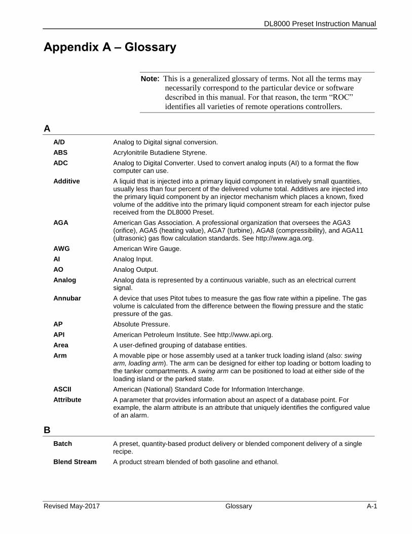
DL8000 Preset Instruction Manual
Revised May-2017 Glossary A-1
Appendix A – Glossary
Note: This is a generalized glossary of terms. Not all the terms may
necessarily correspond to the particular device or software
described in this manual. For that reason, the term “ROC”
identifies all varieties of remote operations controllers.
A
A/D Analog to Digital signal conversion.
ABS Acrylonitrile Butadiene Styrene.
ADC Analog to Digital Converter. Used to convert analog inputs (AI) to a format the flow computer can use.
Additive A liquid that is injected into a primary liquid component in relatively small quantities, usually less than four percent of the delivered volume total. Additives are injected into the primary liquid component by an injector mechanism which places a known, fixed volume of the additive into the primary liquid component stream for each injector pulse received from the DL8000 Preset.
AGA American Gas Association. A professional organization that oversees the AGA3 (orifice), AGA5 (heating value), AGA7 (turbine), AGA8 (compressibility), and AGA11 (ultrasonic) gas flow calculation standards. See http://www.aga.org.
AWG American Wire Gauge.
AI Analog Input.
AO Analog Output.
Analog Analog data is represented by a continuous variable, such as an electrical current signal.
Annubar A device that uses Pitot tubes to measure the gas flow rate within a pipeline. The gas volume is calculated from the difference between the flowing pressure and the static pressure of the gas.
AP Absolute Pressure.
API American Petroleum Institute. See http://www.api.org.
Area A user-defined grouping of database entities.
Arm A movable pipe or hose assembly used at a tanker truck loading island (also: swing arm, loading arm). The arm can be designed for either top loading or bottom loading to the tanker compartments. A swing arm can be positioned to load at either side of the loading island or the parked state.
ASCII American (National) Standard Code for Information Interchange.
Attribute A parameter that provides information about an aspect of a database point. For example, the alarm attribute is an attribute that uniquely identifies the configured value of an alarm.
B
Batch A preset, quantity-based product delivery or blended component delivery of a single recipe.
Blend Stream A product stream blended of both gasoline and ethanol.
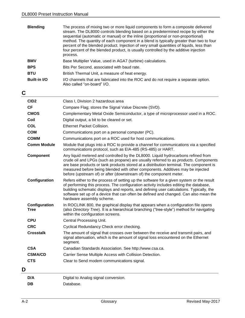
DL8000 Preset Instruction Manual
A-2 Glossary Revised May-2017
Blending The process of mixing two or more liquid components to form a composite delivered stream. The DL8000 controls blending based on a predetermined recipe by either the sequential (automatic or manual) or the inline (proportional or non-proportional) method. The quantity of each component in a blend is typically greater than two to four percent of the blended product. Injection of very small quantities of liquids, less than four percent of the blended product, is usually controlled by the additive injection process.
BMV Base Multiplier Value, used in AGA7 (turbine) calculations.
BPS Bits Per Second, associated with baud rate.
BTU British Thermal Unit, a measure of heat energy.
Built-in I/O I/O channels that are fabricated into the ROC and do not require a separate option. Also called “on-board” I/O.
C
CID2 Class I, Division 2 hazardous area
CF Compare Flag; stores the Signal Value Discrete (SVD).
CMOS Complementary Metal Oxide Semiconductor, a type of microprocessor used in a ROC.
Coil Digital output, a bit to be cleared or set.
COL Ethernet Packet Collision.
COM Communications port on a personal computer (PC).
COMM Communications port on a ROC used for host communications.
Comm Module Module that plugs into a ROC to provide a channel for communications via a specified communications protocol, such as EIA-485 (RS-485) or HART.
Component Any liquid metered and controlled by the DL8000. Liquid hydrocarbons refined from crude oil and LPGs (such as propane) are usually referred to as products. Components are base products or tank products stored at a distribution terminal. The component is measured before being blended with other components. Additives may be injected before (upstream of) or after (downstream of) the component meter.
Configuration Refers either to the process of setting up the software for a given system or the result of performing this process. The configuration activity includes editing the database, building schematic displays and reports, and defining user calculations. Typically, the software set up of a device that can often be defined and changed. Can also mean the hardware assembly scheme.
Configuration Tree
In ROCLINK 800, the graphical display that appears when a configuration file opens (also Directory Tree). It is a hierarchical branching (“tree-style”) method for navigating within the configuration screens.
CPU Central Processing Unit.
CRC Cyclical Redundancy Check error checking.
Crosstalk The amount of signal that crosses over between the receive and transmit pairs, and signal attenuation, which is the amount of signal loss encountered on the Ethernet segment.
CSA Canadian Standards Association. See http://www.csa.ca.
CSMA/CD Carrier Sense Multiple Access with Collision Detection.
CTS Clear to Send modem communications signal.
D
D/A Digital to Analog signal conversion.
DB Database.
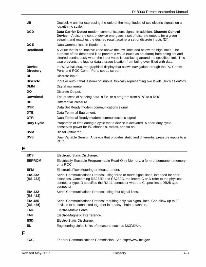
DL8000 Preset Instruction Manual
Revised May-2017 Glossary A-3
dB Decibel. A unit for expressing the ratio of the magnitudes of two electric signals on a logarithmic scale.
DCD Data Carrier Detect modem communications signal. In addition, Discrete Control Device – A discrete control device energizes a set of discrete outputs for a given setpoint and matches the desired result against a set of discrete inputs (DI).
DCE Data Communication Equipment.
Deadband A value that is an inactive zone above the low limits and below the high limits. The purpose of the deadband is to prevent a value (such as an alarm) from being set and cleared continuously when the input value is oscillating around the specified limit. This also prevents the logs or data storage location from being over-filled with data.
Device Directory
In ROCLINK 800, the graphical display that allows navigation through the PC Comm Ports and ROC Comm Ports set up screen.
DI Discrete Input.
Discrete Input or output that is non-continuous, typically representing two levels (such as on/off).
DMM Digital multimeter.
DO Discrete Output.
Download The process of sending data, a file, or a program from a PC to a ROC.
DP Differential Pressure.
DSR Data Set Ready modem communications signal.
DTE Data Terminal Equipment.
DTR Data Terminal Ready modem communications signal.
Duty Cycle Proportion of time during a cycle that a device is activated. A short duty cycle conserves power for I/O channels, radios, and so on.
DVM Digital voltmeter.
DVS Dual-Variable Sensor. A device that provides static and differential pressure inputs to a ROC.
E
EDS Electronic Static Discharge.
EEPROM Electrically Erasable Programmable Read-Only Memory, a form of permanent memory on a ROC.
EFM Electronic Flow Metering or Measurement.
EIA-232 (RS-232)
Serial Communications Protocol using three or more signal lines, intended for short distances. Concerning RS232D and RS232C, the letters C or D refer to the physical connector type. D specifies the RJ-11 connector where a C specifies a DB25 type connector.
EIA-422 (RS-422)
Serial Communications Protocol using four signal lines.
EIA-485 (RS-485)
Serial Communications Protocol requiring only two signal lines. Can allow up to 32 devices to be connected together in a daisy-chained fashion.
EMF Electro-Motive Force.
EMI Electro-Magnetic Interference.
ESD Electro-Static Discharge.
EU Engineering Units. Units of measure, such as MCF/DAY.
F
FCC Federal Communications Commission. See http://www.fcc.gov.

DL8000 Preset Instruction Manual
A-4 Glossary Revised May-2017
Firmware Internal software that is factory-loaded into a form of ROM. In a ROC, the firmware supplies the software used for gathering input data, converting raw input data values, storing values, and providing control signals.
FlashPAC module
ROM and RAM module for a ROC300-Series unit that contains the operating system, applications firmware, and communications protocol.
Flash ROM A type of read-only memory that can be electrically re-programmed. It is a form of permanent memory (requires no backup power). Also called Flash memory.
FloBoss A microprocess-based device that provides flow calculations, remote monitoring, and remote control. A FloBoss is a type of ROC.
FM Factory Mutual.
Force Write an ON/OFF, True/False, or 1/0 value to a coil.
FPV Compressibility Factor.
FSK Frequency Shift Keypad.
FST Function Sequence Table, a type of user-written program in a high-level language designed by Emerson Process Management’s Remote Automation Solutions Division.
Ft Foot or feet.
G
GFA Ground Fault Analysis.
GND Electrical ground, such as used by the ROC unit’s power supply.
GP Gauge Pressure.
Gross Quantity The indicated quantity times the meter factor derived from a meter proving of the flow meter at a specific flow rate. Calculation: gross quantity = indicated quantity times meter factor.
H
HART® Highway Addressable Remote Transducer.
Holding Register
Analog output number value to be read.
Hw Differential pressure.
Hz Hertz.
I, J
IC Integrated Circuit. Also, Industry Canada (more recently known as Measurement Canada), an organization that grants custody transfer approvals on certain ROC units.
ID Identification.
IEC Industrial Electrical Code or International Electrotechnical Commission. See http://www.iec.ch.
IEEE Institute of Electrical and Electronic Engineers. A professional organization that, in conjunction with the International Standards Organization (ISO), establishes and maintains the Open System Interconnection (OSI) reference model and an international standard for the organization of local area networks (LANs). Refer to http://www.ieee.org.
IMV Integral Multiplier Value, used in AGA3 (orifice) calculations.
Indicated Quantity
The change in the flow meter reading that occurs during a product flow measurement operation. (Not displayed by the DL8000 calculation: indicated quantity = end reading minus start reading.)
Input Digital input, a bit to be read.
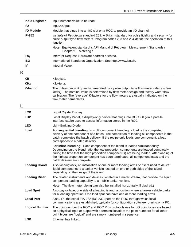
DL8000 Preset Instruction Manual
Revised May-2017 Glossary A-5
Input Register Input numeric value to be read.
I/O Input/Output.
I/O Module Module that plugs into an I/O slot on a ROC to provide an I/O channel.
IP-252 Institute of Petroleum standard 252. A British standard for pulse fidelity and security for pulse output type flow meters. Program codes 233 and 234 define the operation of this function.
Note: Equivalent standard is API Manual of Petroleum Measurement Standards / Chapter 5 - Metering /
IRQ Interrupt Request. Hardware address oriented.
ISO International Standards Organization. See http://www.iso.ch.
IV Integral Value.
K
KB Kilobytes.
KHz KiloHertz.
K-factor The pulses per unit quantity generated by a pulse output type flow meter (also system factor). The nominal value is determined by flow meter design and factory water flow calibration. The “average” K-factors for the flow meters are usually indicated on the flow meter nameplates.
L
LCD Liquid Crystal Display.
LDP Local Display Panel, a display-only device that plugs into ROC300 (via a parallel interface cable) used to access information stored in the ROC.
LED Light-Emitting Diode.
Load For sequential blending: In multi-component blending, a load is the completed delivery of one component of a batch. The completion of loading all components in the batch completes the batch delivery. If the recipe only loads one component, a load corresponds to a batch delivery.
For inline blending: Each component of the blend is loaded simultaneously. Depending on the blend ratio, the low-proportion components are loaded completely during the time that the high proportion component(s) are being loaded. After loading of the highest proportion component has been terminated, all component loads and the batch delivery are complete.
Loading Island Also loading rack; an installation of one or more loading arms or risers used to deliver liquid components to a tanker vehicle located on one or both sides of the island, depending on the design of the island.
Loading Riser The related instruments and devices, located in a meter stream, that provide the liquid component loading capability to a mobile tanker vehicle.
Note: The flow meter piping can also be installed horizontally, if desired.)
Load Spot Also bay or lane; one side of a loading island, a position where a tanker vehicle parks for a loading operation. One load spot can have one or more loading arms.
Local Port Also LOI; the serial EIA-232 (RS-232) port on the ROC through which local communications are established, typically for configuration software running on a PC.
Logical Number The point number the ROC and ROC Plus protocols use for I/O point types are based on a physical input or output with a terminal location; the point numbers for all other point types are “logical” and are simply numbered in sequence.
LNK Ethernet has linked.
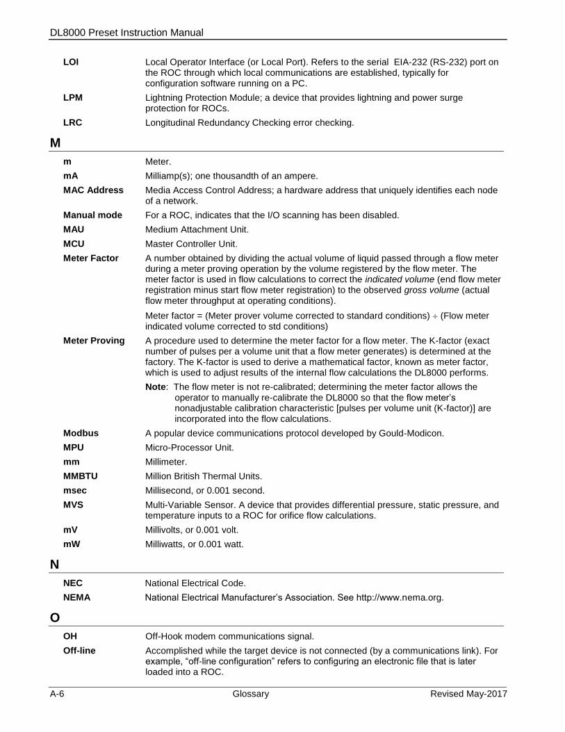
DL8000 Preset Instruction Manual
A-6 Glossary Revised May-2017
LOI Local Operator Interface (or Local Port). Refers to the serial EIA-232 (RS-232) port on the ROC through which local communications are established, typically for configuration software running on a PC.
LPM Lightning Protection Module; a device that provides lightning and power surge protection for ROCs.
LRC Longitudinal Redundancy Checking error checking.
M
m Meter.
mA Milliamp(s); one thousandth of an ampere.
MAC Address Media Access Control Address; a hardware address that uniquely identifies each node of a network.
Manual mode For a ROC, indicates that the I/O scanning has been disabled.
MAU Medium Attachment Unit.
MCU Master Controller Unit.
Meter Factor A number obtained by dividing the actual volume of liquid passed through a flow meter during a meter proving operation by the volume registered by the flow meter. The meter factor is used in flow calculations to correct the indicated volume (end flow meter registration minus start flow meter registration) to the observed gross volume (actual flow meter throughput at operating conditions).
Meter factor = (Meter prover volume corrected to standard conditions) (Flow meter indicated volume corrected to std conditions)
Meter Proving A procedure used to determine the meter factor for a flow meter. The K-factor (exact number of pulses per a volume unit that a flow meter generates) is determined at the factory. The K-factor is used to derive a mathematical factor, known as meter factor, which is used to adjust results of the internal flow calculations the DL8000 performs.
Note: The flow meter is not re-calibrated; determining the meter factor allows the operator to manually re-calibrate the DL8000 so that the flow meter’s nonadjustable calibration characteristic [pulses per volume unit (K-factor)] are incorporated into the flow calculations.
Modbus A popular device communications protocol developed by Gould-Modicon.
MPU Micro-Processor Unit.
mm Millimeter.
MMBTU Million British Thermal Units.
msec Millisecond, or 0.001 second.
MVS Multi-Variable Sensor. A device that provides differential pressure, static pressure, and temperature inputs to a ROC for orifice flow calculations.
mV Millivolts, or 0.001 volt.
mW Milliwatts, or 0.001 watt.
N
NEC National Electrical Code.
NEMA National Electrical Manufacturer’s Association. See http://www.nema.org.
O
OH Off-Hook modem communications signal.
Off-line Accomplished while the target device is not connected (by a communications link). For example, “off-line configuration” refers to configuring an electronic file that is later loaded into a ROC.

DL8000 Preset Instruction Manual
Revised May-2017 Glossary A-7
Ohms Units of electrical resistance.
On-line Accomplished while connected (by a communications link) to the target device. For example, “on-line configuration” refers to configuring a ROC800-Series unit while connected to it, so that you can view the current parameter values and immediately load new values.
Opcode Type of message protocol the ROC uses to communicate with the configuration software, as well as host computers with ROC driver software.
Operator Interface
Also LOI or Local Port; the serial EIA-232 (RS-232) port on the ROC through which local communications are established, typically for configuration software running on a PC.
Orifice meter A meter that records the flow rate of gas through a pipeline. The flow rate is calculated from the pressure differential created by the fluid passing through an orifice of a particular size and other parameters.
P, Q
Parameter A property of a point that typically can be configured or set. For example, the Point Tag ID is a parameter of an Analog Input point. Parameters are normally edited by using configuration software running on a PC.
PC Personal Computer.
Permissive A discrete signal from a device that is input to a discrete input in the DL8000. The DL8000 uses this signal to allow a product delivery to be initiated or allow a product delivery to continue. Permissive contacts are CLOSED in the normal or safe state and OPEN in the abnormal or unsafe state.
Pf Flowing pressure.
P/DP Pressure/Differential Pressure.
PI Pulse Input.
PID Proportional, Integral, and Derivative control feedback action.
PIT Periodic Timer Interrupt.
PLC Programmable Logic Controller.
Point Software-oriented term for an I/O channel or some other function, such as a flow calculation. Points are defined by a collection of parameters.
Point Number The physical location of an I/O point (module slot and channel) as installed in the ROC.
Point Type Defines the database point to be a specific type of point available to the system. The point type determines the basic functions of a point.
Preset Number value previously determined for a register.
Also:
A generic term that describes the functional instrument group to which the DL8000 belongs. The term originated from mechanical and electrical preset counters. The DL8000 provides much more versatility and capability compared to a simple mechanical or electrical preset counter.
PRI Primary PID control loop.
Primary Blend Stream Component
A blended product measured by a primary blend stream meter.
Primary Blend Stream Meter
A meter measuring the gasoline-ethanol blend.
Protocol A set of standards that enables communication or file transfers between two computers. Protocol parameters include baud rate, parity, data bits, stop bit, and the type of duplex.
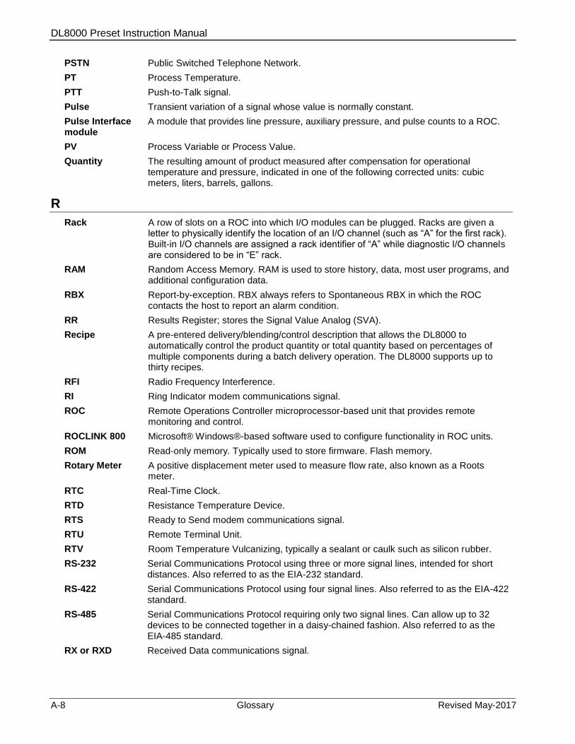
DL8000 Preset Instruction Manual
A-8 Glossary Revised May-2017
PSTN Public Switched Telephone Network.
PT Process Temperature.
PTT Push-to-Talk signal.
Pulse Transient variation of a signal whose value is normally constant.
Pulse Interface module
A module that provides line pressure, auxiliary pressure, and pulse counts to a ROC.
PV Process Variable or Process Value.
Quantity The resulting amount of product measured after compensation for operational temperature and pressure, indicated in one of the following corrected units: cubic meters, liters, barrels, gallons.
R
Rack A row of slots on a ROC into which I/O modules can be plugged. Racks are given a letter to physically identify the location of an I/O channel (such as “A” for the first rack). Built-in I/O channels are assigned a rack identifier of “A” while diagnostic I/O channels are considered to be in “E” rack.
RAM Random Access Memory. RAM is used to store history, data, most user programs, and additional configuration data.
RBX Report-by-exception. RBX always refers to Spontaneous RBX in which the ROC contacts the host to report an alarm condition.
RR Results Register; stores the Signal Value Analog (SVA).
Recipe A pre-entered delivery/blending/control description that allows the DL8000 to automatically control the product quantity or total quantity based on percentages of multiple components during a batch delivery operation. The DL8000 supports up to thirty recipes.
RFI Radio Frequency Interference.
RI Ring Indicator modem communications signal.
ROC Remote Operations Controller microprocessor-based unit that provides remote monitoring and control.
ROCLINK 800 Microsoft® Windows®-based software used to configure functionality in ROC units.
ROM Read-only memory. Typically used to store firmware. Flash memory.
Rotary Meter A positive displacement meter used to measure flow rate, also known as a Roots meter.
RTC Real-Time Clock.
RTD Resistance Temperature Device.
RTS Ready to Send modem communications signal.
RTU Remote Terminal Unit.
RTV Room Temperature Vulcanizing, typically a sealant or caulk such as silicon rubber.
RS-232 Serial Communications Protocol using three or more signal lines, intended for short distances. Also referred to as the EIA-232 standard.
RS-422 Serial Communications Protocol using four signal lines. Also referred to as the EIA-422 standard.
RS-485 Serial Communications Protocol requiring only two signal lines. Can allow up to 32 devices to be connected together in a daisy-chained fashion. Also referred to as the EIA-485 standard.
RX or RXD Received Data communications signal.
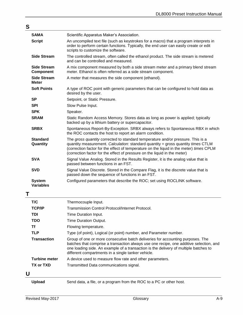
DL8000 Preset Instruction Manual
Revised May-2017 Glossary A-9
S
SAMA Scientific Apparatus Maker’s Association.
Script An uncompiled text file (such as keystrokes for a macro) that a program interprets in order to perform certain functions. Typically, the end user can easily create or edit scripts to customize the software.
Side Stream The controlled stream, often called the ethanol product. The side stream is metered and can be controlled and measured.
Side Stream Component
A mix component measured by both a side stream meter and a primary blend stream meter. Ethanol is often referred as a side stream component.
Side Stream Meter
A meter that measures the side component (ethanol).
Soft Points A type of ROC point with generic parameters that can be configured to hold data as desired by the user.
SP Setpoint, or Static Pressure.
SPI Slow Pulse Input.
SPK Speaker.
SRAM Static Random Access Memory. Stores data as long as power is applied; typically backed up by a lithium battery or supercapacitor.
SRBX Spontaneous Report-By-Exception. SRBX always refers to Spontaneous RBX in which the ROC contacts the host to report an alarm condition.
Standard Quantity
The gross quantity corrected to standard temperature and/or pressure. This is a quantity measurement. Calculation: standard quantity = gross quantity times CTLM (correction factor for the effect of temperature on the liquid in the meter) times CPLM (correction factor for the effect of pressure on the liquid in the meter)
SVA Signal Value Analog. Stored in the Results Register, it is the analog value that is passed between functions in an FST.
SVD Signal Value Discrete. Stored in the Compare Flag, it is the discrete value that is passed down the sequence of functions in an FST.
System Variables
Configured parameters that describe the ROC; set using ROCLINK software.
T
T/C Thermocouple Input.
TCP/IP Transmission Control Protocol/Internet Protocol.
TDI Time Duration Input.
TDO Time Duration Output.
Tf Flowing temperature.
TLP Type (of point), Logical (or point) number, and Parameter number.
Transaction Group of one or more consecutive batch deliveries for accounting purposes. The batches that comprise a transaction always use one recipe, one additive selection, and one loading side. An example of a transaction is the delivery of multiple batches to different compartments in a single tanker vehicle.
Turbine meter A device used to measure flow rate and other parameters.
TX or TXD Transmitted Data communications signal.
U
Upload Send data, a file, or a program from the ROC to a PC or other host.
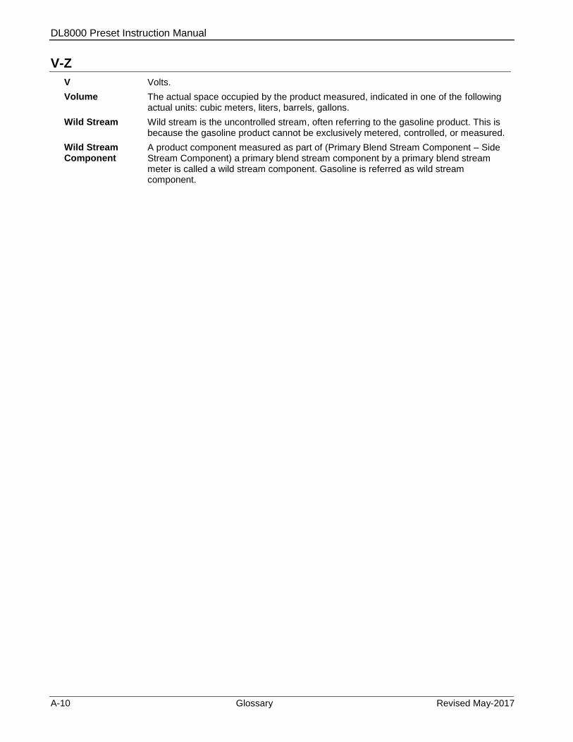
DL8000 Preset Instruction Manual
A-10 Glossary Revised May-2017
V-Z
V Volts.
Volume The actual space occupied by the product measured, indicated in one of the following actual units: cubic meters, liters, barrels, gallons.
Wild Stream Wild stream is the uncontrolled stream, often referring to the gasoline product. This is because the gasoline product cannot be exclusively metered, controlled, or measured.
Wild Stream Component
A product component measured as part of (Primary Blend Stream Component – Side Stream Component) a primary blend stream component by a primary blend stream meter is called a wild stream component. Gasoline is referred as wild stream component.
DL8000 Preset Instruction Manual
Revised May-2017 Modbus Communications B-1
Appendix B – Modbus Communications
This appendix describes how to configure a DL8000 for Modbus
communications.
Note: Refer to Chapter 3, Point Types, in the Preset Protocol
Specifications Manual (part D301254X012) for a discussion of
the point types and parameters associated with the DL8000
product.
B.1 Modbus Communications
The DL8000 includes the ability to communicate using the Modbus
protocol. This enables you to integrate the DL8000 and Modbus devices
into the same host/slave system.
The DL8000 can act either as a slave or a host device.
The Modbus Master mode of operation (enabled on the ROC > Comm
Ports screen) allows the DL8000 to simulate a master device that can
poll other devices for data and then store that data for parameter
updates, for use in FST Registers, user programs, and DS800 programs.
The DL8000 can also send commands to set outputs and write data to a
slave device. For more information on Modbus master configuration
and functionality, refer to Section A.6, Modbus Master Table.
In slave mode, the data link between the host device and the DL8000
requires the use of one of the following communications ports:
Ethernet Port on the CPU.
EIA-232 (RS-232) Serial Communications Card.
EIA-485 (RS-485) Serial Communications Card.
Dial-up Modem Communications Card.
Note: Master mode supports the Comm 2 to Comm 5 communication
ports. The LOI and Comm 1 (Ethernet) ports do not support
Modbus master mode.
If a serial or modem communications port is configured with a port
owner of ROC Plus Protocol/Modbus Slave, the DL8000 automatically
determines if the incoming communication request is in ROC protocol
or Modbus protocol. The DL8000 responds using the same protocol as
the incoming request.
The Ethernet communications port automatically determines if the
incoming communication request is in ROC protocol, Modbus RTU
encapsulated in TCP/IP, or Modbus TCP/IP protocol. The DL8000
responds using the same protocol as the incoming request.

DL8000 Preset Instruction Manual
B-2 Modbus Communications Revised May-2017
B.2 Modbus Configuration
From the ROCLINK 800 menu bar, select Configure > MODBUS. The
Modbus Configuration screen displays, showing the General tab (see
Figure B-1). Use the individual tabs to:
Tab Use
General Defines basic communication parameters
Scale Values Defines up to eight low and high floating point scale values and one low and high integer value for converting floating point numbers to a scaled integer.
Master Table Simulates Modbus settings.
Master Modem Configures modems and maps RTU addresses to phone numbers.
Registers Maps Modbus registers to TLP values using either point indexing or parameter indexing.
History Table Configures periodic and daily history values.
Figure B-1. Modbus Configuration – General Tab
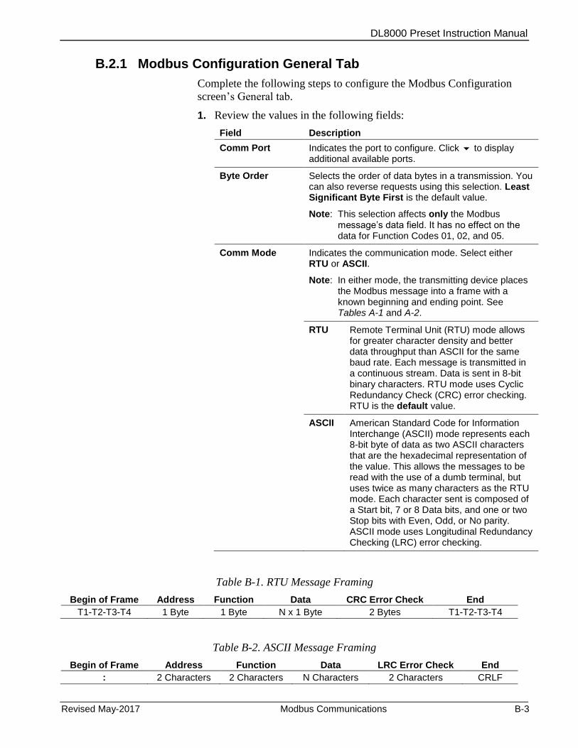
DL8000 Preset Instruction Manual
Revised May-2017 Modbus Communications B-3
B.2.1 Modbus Configuration General Tab
Complete the following steps to configure the Modbus Configuration
screen’s General tab.
1. Review the values in the following fields:
Field Description
Comm Port Indicates the port to configure. Click to display additional available ports.
Byte Order Selects the order of data bytes in a transmission. You can also reverse requests using this selection. Least Significant Byte First is the default value.
Note: This selection affects only the Modbus message’s data field. It has no effect on the data for Function Codes 01, 02, and 05.
Comm Mode Indicates the communication mode. Select either RTU or ASCII.
Note: In either mode, the transmitting device places the Modbus message into a frame with a known beginning and ending point. See Tables A-1 and A-2.
RTU Remote Terminal Unit (RTU) mode allows for greater character density and better data throughput than ASCII for the same baud rate. Each message is transmitted in a continuous stream. Data is sent in 8-bit binary characters. RTU mode uses Cyclic Redundancy Check (CRC) error checking. RTU is the default value.
ASCII American Standard Code for Information Interchange (ASCII) mode represents each 8-bit byte of data as two ASCII characters that are the hexadecimal representation of the value. This allows the messages to be read with the use of a dumb terminal, but uses twice as many characters as the RTU mode. Each character sent is composed of a Start bit, 7 or 8 Data bits, and one or two Stop bits with Even, Odd, or No parity. ASCII mode uses Longitudinal Redundancy Checking (LRC) error checking.
Table B-1. RTU Message Framing
Begin of Frame Address Function Data CRC Error Check End
T1-T2-T3-T4 1 Byte 1 Byte N x 1 Byte 2 Bytes T1-T2-T3-T4
Table B-2. ASCII Message Framing
Begin of Frame Address Function Data LRC Error Check End
: 2 Characters 2 Characters N Characters 2 Characters CRLF

DL8000 Preset Instruction Manual
B-4 Modbus Communications Revised May-2017
Field Description
Slave Mode This display-only field shows the error code for the last received Modbus message. This field is applicable only in slave mode. Valid values are:
0 No Error.
1 Illegal function.
2 Illegal data address.
3 Illegal data value.
Event Logging Enables the DL8000 to log all parameter changes made through Modbus in the Event log. Valid values are Enabled (log all events) or Disabled (allow events to be changed but do not log those events). The default is Enabled.
Start Polling Starts the Modbus Master polling sequence. Polling begins with the Starting Request entry on the Modbus Master Table and proceeds through the entries in the table. The system resets this check box when the polling sequence completes.
Note: You must have previously defined Modbus Master as the port owner (select ROC > Comm Ports > General tab).
Starting Request Defines the starting number (entry) on the Modbus Master Table from which polling begins.
Number of Requests
Indicates the total number of requests in this polling sequence.
Timeout Indicates, in seconds, the actual amount of time the DL8000 waits to receive a value message after it sends a request to the device.
Note: Do not enter zero (0) in this field.
Retries Controls the number of times (in addition to the initial attempt) the Master DL8000 tries to establish communications with the specified device before reporting a timeout error. Valid values are between 0 and 25. The default is 2.
Note: Use the Timeout field to adjust the amount of time between retries.
Continuous Polling
Indicates whether the system executes the polling sequence continually. Valid values are Enabled (the polling sequence executes continually) or Disabled (the polling sequence executes only on command). The default is Disabled.
Request Delay Sets, in seconds, a delay between polling request sequences.
Note: This field is valid only if you enable Continuous Polling.
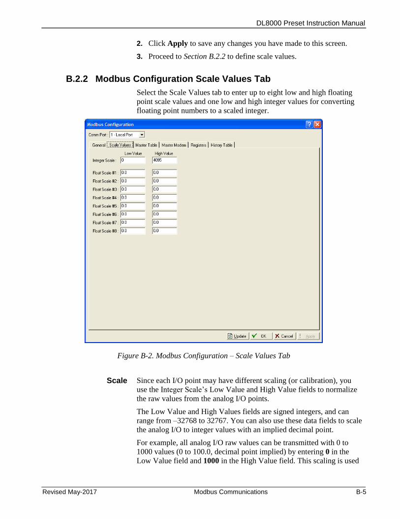
DL8000 Preset Instruction Manual
Revised May-2017 Modbus Communications B-5
2. Click Apply to save any changes you have made to this screen.
3. Proceed to Section B.2.2 to define scale values.
B.2.2 Modbus Configuration Scale Values Tab
Select the Scale Values tab to enter up to eight low and high floating
point scale values and one low and high integer values for converting
floating point numbers to a scaled integer.
Figure B-2. Modbus Configuration – Scale Values Tab
Scale Since each I/O point may have different scaling (or calibration), you
use the Integer Scale’s Low Value and High Value fields to normalize
the raw values from the analog I/O points.
The Low Value and High Values fields are signed integers, and can
range from –32768 to 32767. You can also use these data fields to scale
the analog I/O to integer values with an implied decimal point.
For example, all analog I/O raw values can be transmitted with 0 to
1000 values (0 to 100.0, decimal point implied) by entering 0 in the
Low Value field and 1000 in the High Value field. This scaling is used
DL8000 Preset Instruction Manual
B-6 Modbus Communications Revised May-2017
only on analog I/O specified by the I/O: AI raw A/D input (Type 3,
Parameter 17) and AO raw D/A output (Type 4, Parameter 17).
Float In host systems that do not accept floating point numbers, you can
specific up to eight sets of floating point ranges. This enables the host
to read and set floating point values (such as PID setpoints) as integer
values.
Note: The system converts the floating point values according to a
register or range of values you set in the Conversion field of the
Modbus Registers screen (Configure > MODBUS > Registers).
See Figure B-4.
Equations The system uses the following equations to convert floating point
values to integers:
Float Range = High Value Float Scale – Low Value Float Scale
Integer Range = High Value Integer Scale – Low Value Integer Scale
Adjusted Reading = Float Reading – Low Value Float Scale
Integer = Integer Range x Adjusted Reading + Low Value Integer Scale Float Range
The system uses the following equations to convert integers to floating
point values:
Float Range = High Value Float Scale – Low Value Float Scale
Integer Range = High Value Integer Scale – Low Value Integer Scale
Adjusted Integer = Integer Sent – Low Value Integer Scale
Float Value = Adjusted Integer x Float Range + Low Value Float Scale Integer Range
Complete the following steps to configure the Scale Value tab for the
Modbus Configuration screen.
1. Review the values in the following fields:
Field Description
Integer Scale, Low Value
Indicates the 0% value for scaling. Valid values are –32768 to 32767.
Integer Scale, High Value
Indicates the 100% value for scaling. Valid values are –32768 to 32767.
Float Scale 1 through 8
Indicates up to eight sets (Low Value and High Value) of floating point ranges the system uses when the host is not able to process floating point numbers.
2. Click Apply to save any changes you have made to this screen.
3. Proceed to Section B.3 to configure Modbus history options.
DL8000 Preset Instruction Manual
Revised May-2017 Modbus Communications B-7
B.3 Modbus History
Communications functionality in the DL8000 allows you to retrieve the
Periodic/Hourly and Daily history values and Event/Alarm records
through Modbus Protocol using Function Code 03. Each historical
record contains a time and date stamp on all of the history archives or
values for which you have configured the Register Number.
The system uses the Modbus Function Code 03 and the History Archive
Register to collect the archived data. Two separate Modbus registers
indicate the current Hourly and Daily history index. You configure these
on the Modbus Registers screen as the Hourly History Index Register
and the Daily History Index Register for the segment being referenced
(subtract 1 to get the last archived values). These indexes identify the
current history archive at which data is to be logged.
When the DL8000 receives a Function Code 03 request referencing the
Periodic History Index (commonly register 7161) or Daily History
Index (commonly register 7160), the host interprets the value returned
as an index into the specified history log. The host reads the indexes and
then compares the index to the last polled history index (which the host
maintains) to decide whether to request history.
If the host decides to request history, the reply message contains the
date and time stamp and historical values configured for the specified
register for that index.
For the DL8000, the response message contains two floating point
values for the time and date stamp of the history archive (time stamp =
HHMM and date stamp = MMDDYY) and floating point values for
each of the defined history points for that History Archive Register. The
history date stamp uses the current year and does not figure the number
of years since 1980. For example, if the current year is 2007, the year
(YY) for the date stamp would be 07. The DL8000 maps history
collection on the Modbus History Table.
Table B-3 summarizes the function calls and their associated register
and data fields.
Table B-3. Modbus History, Event, and Alarm Functionality
Function Code
Register Field Data Field Description
03 32 - Event/Alarm Register
Ignored1 Response contains Event and Alarm records2. Maximum number of bytes returned is 240 (12 records of 20 bytes each). Events are returned before Alarms are returned. See Table A-4 for the displayed format.
05 32 - Event/Alarm Register
Ignored After Events and Alarms have been returned, an acknowledgment occurs so that the same Events and Alarms are not returned on the next request.

DL8000 Preset Instruction Manual
B-8 Modbus Communications Revised May-2017
Function Code
Register Field Data Field Description
03 703 - Daily History
Daily History Archive Register Index (0 to 34)
Response contains two floating point values for the time and date stamp of the history archive (time stamp = HHMMSS and date stamp = MMDDYY) and floating point values for each of the defined history points for that History Archive Register.
03 704 - Hourly History
Hourly or Periodic History Archive Register Index (0 to 839)
Response contains two floating point values for the time and date stamp of the history archive (time stamp = HHMMSS and date stamp = MMDDYY) and floating point values for each of the defined history points for that History Archive Register.
1The Periodic Index, Daily Index, and Event/Alarm data fields address a history index number. 2The Event and Alarm Log record consists of the bytes shown in Table A-4. Table A-5 provides a breakdown of the bit map in bytes 1-2.
B.3.1 Modbus Configuration History Table Tab
The Modbus History Table allows you to configure the Periodic and
Daily history values and Event/Alarm records for retrieval through
Modbus Protocol, using Function Code 03. You define three registers to
retrieve the current date in the DL8000, the current time in the DL8000,
and Event/Alarm records. You can also use the Modbus History Table
to define the Periodic and Daily registers for up to twenty groups of
history points.
Note: Before configuring the Modbus History, be sure to completely
configure the History Segment and History Point.
To access this screen:
1. Select Configure > MODBUS. The Modbus Configuration screen
displays.
2. Select the History Table tab. The Modbus History Table displays.
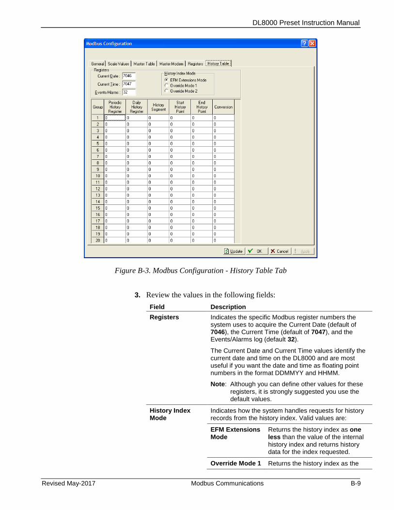
DL8000 Preset Instruction Manual
Revised May-2017 Modbus Communications B-9
Figure B-3. Modbus Configuration - History Table Tab
3. Review the values in the following fields:
Field Description
Registers Indicates the specific Modbus register numbers the system uses to acquire the Current Date (default of 7046), the Current Time (default of 7047), and the Events/Alarms log (default 32).
The Current Date and Current Time values identify the current date and time on the DL8000 and are most useful if you want the date and time as floating point numbers in the format DDMMYY and HHMM.
Note: Although you can define other values for these registers, it is strongly suggested you use the default values.
History Index Mode
Indicates how the system handles requests for history records from the history index. Valid values are:
EFM Extensions Mode
Returns the history index as one less than the value of the internal history index and returns history data for the index requested.
Override Mode 1 Returns the history index as the
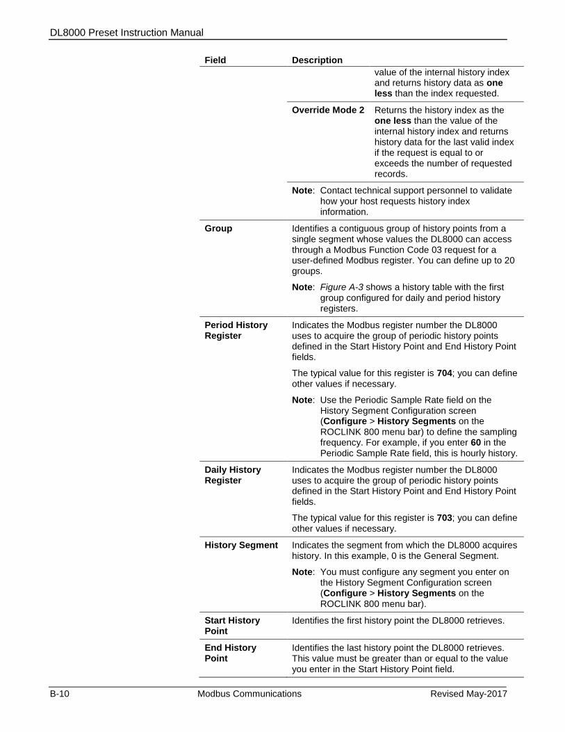
DL8000 Preset Instruction Manual
B-10 Modbus Communications Revised May-2017
Field Description
value of the internal history index and returns history data as one less than the index requested.
Override Mode 2 Returns the history index as the one less than the value of the internal history index and returns history data for the last valid index if the request is equal to or exceeds the number of requested records.
Note: Contact technical support personnel to validate how your host requests history index information.
Group Identifies a contiguous group of history points from a single segment whose values the DL8000 can access through a Modbus Function Code 03 request for a user-defined Modbus register. You can define up to 20 groups.
Note: Figure A-3 shows a history table with the first group configured for daily and period history registers.
Period History Register
Indicates the Modbus register number the DL8000 uses to acquire the group of periodic history points defined in the Start History Point and End History Point fields.
The typical value for this register is 704; you can define other values if necessary.
Note: Use the Periodic Sample Rate field on the History Segment Configuration screen (Configure > History Segments on the ROCLINK 800 menu bar) to define the sampling frequency. For example, if you enter 60 in the Periodic Sample Rate field, this is hourly history.
Daily History Register
Indicates the Modbus register number the DL8000 uses to acquire the group of periodic history points defined in the Start History Point and End History Point fields.
The typical value for this register is 703; you can define other values if necessary.
History Segment Indicates the segment from which the DL8000 acquires history. In this example, 0 is the General Segment.
Note: You must configure any segment you enter on the History Segment Configuration screen (Configure > History Segments on the ROCLINK 800 menu bar).
Start History Point
Identifies the first history point the DL8000 retrieves.
End History Point
Identifies the last history point the DL8000 retrieves. This value must be greater than or equal to the value you enter in the Start History Point field.
DL8000 Preset Instruction Manual
Revised May-2017 Modbus Communications B-11
Field Description
Conversion Indicates the type of conversion, if required, for the data. By default, the system returns these values as floating point numbers. See Table A-6 for a listing of convert codes.
4. Click Apply to save any changes you have made to this screen.
5. Proceed to Section A.4 to configure Modbus events and alarms.
B.4 Modbus Events & Alarms Functionality
The Event Log and Alarm Log have the same sized record format and
similar contents. The first word in a record is a bit map in which bit 9
indicates if the log record is an event (1) or an alarm (0). The meanings
of the other bits are specific to either the Event or the Alarm Log
records. See Table B-5.
The DL8000 supports Modbus with EFM extensions method for
retrieving alarms and events. When the DL8000 receives a Function
Code 03 request referencing defined Events/Alarms Register (usually
32), the DL8000 begins to collect records from first the Event Log and
then the Alarm Log, starting where the last poll left off. The DL8000
then collects records until either there are no more new events/alarms
or the maximum of twelve records have been collected. The DL8000
sends the information back to the host, which in return replies with
Function Code 05, referencing the same Events/Alarms Register and
indicating that the points have been received and that the host is ready
for the next twelve records.
B.4.1 Reading Events & Alarms Register
The Modbus request to read the Event & Alarm Log uses the standard
read Function Code 03. In this request, the number of registers is
included to maintain format compatibility but is ignored by the
receiving DL8000.
For the date stamp in the events and alarms returned, the year (YY) is
really the number of years since 1980 (for example, if the current year is
2007, the year (YY) for the date stamp would be 27).
B.4.2 Acknowledging Events & Alarms
The Modbus request to acknowledge the Event\Alarm Log uses
Function Code 05. For this request, the DL8000 always uses only one
register.
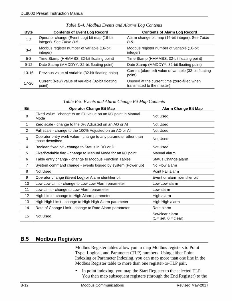
DL8000 Preset Instruction Manual
B-12 Modbus Communications Revised May-2017
Table B-4. Modbus Events and Alarms Log Contents
Byte Contents of Event Log Record Contents of Alarm Log Record
1-2 Operator change (Event Log) bit map (16-bit integer). See Table B-5.
Alarm change bit map (16-bit integer). See Table B-5.
3-4 Modbus register number of variable (16-bit integer)
Modbus register number of variable (16-bit integer)
5-8 Time Stamp (HHMMSS; 32-bit floating point) Time Stamp (HHMMSS; 32-bit floating point)
9-12 Date Stamp (MMDDYY; 32-bit floating point) Date Stamp (MMDDYY; 32-bit floating point)
13-16 Previous value of variable (32-bit floating point) Current (alarmed) value of variable (32-bit floating point)
17-20 Current (New) value of variable (32-bit floating point)
Unused at the current time (zero-filled when transmitted to the master)
Table B-5. Events and Alarm Change Bit Map Contents
Bit Operator Change Bit Map Alarm Change Bit Map
0 Fixed value - change to an EU value on an I/O point in Manual Mode
Not Used
1 Zero scale - change to the 0% Adjusted on an AO or AI Not Used
2 Full scale - change to the 100% Adjusted on an AO or AI Not Used
3 Operator entry work value - change to any parameter other than those described
Not Used
4 Boolean fixed bit - change to Status in DO or DI Not Used
5 Fixed/variable flag - change to Manual Mode for an I/O point Manual alarm
6 Table entry change - change to Modbus Function Tables Status Change alarm
7 System command change - events logged by system (Power up) No Flow alarm
8 Not Used Point Fail alarm
9 Operator change (Event Log) or Alarm identifier bit Event or alarm identifier bit
10 Low Low Limit - change to Low Low Alarm parameter Low Low alarm
11 Low Limit - change to Low Alarm parameter Low alarm
12 High Limit - change to High Alarm parameter High alarm
13 High High Limit - change to High High Alarm parameter High High alarm
14 Rate of Change Limit - change to Rate Alarm parameter Rate alarm
15 Not Used Set/clear alarm (1 = set, 0 = clear)
B.5 Modbus Registers
Modbus Register tables allow you to map Modbus registers to Point
Type, Logical, and Parameter (TLP) numbers. Using either Point
Indexing or Parameter Indexing, you can map more than one line in the
Modbus Register table to more than one register-to-TLP pair.
In point indexing, you map the Start Register to the selected TLP.
You then map subsequent registers (through the End Register) to the
DL8000 Preset Instruction Manual
Revised May-2017 Modbus Communications B-13
same point type and parameter and increment the point logical
number.
In parameter indexing, you map the Start Register to the selected
TLP. You then map subsequent registers (through the End Register)
to the same point type and point logical number, and increment
the parameter number.
Once you map a register, any Modbus request can reference it, provided
the TLP’s data type is appropriate for the function code.
Notes:
If the native DL8000 data type does not meet the requirements of
the Modbus host device, conversion codes are available to convert
the data to the required data type. Contact technical support
personnel.
You can select to have the mapping apply to all communication
ports or only a selected port.
When the DL8000 receives a Modbus request, it searches for the
referenced register(s). If the DL8000 finds a register number match, it
builds a response based on the device point type and parameter
configured in the table. If the DL8000 cannot locate a register number
match, it returns an error message.
To access the Modbus Registers screen, select Configure > MODBUS
> Registers tab. The Modbus Register screen displays (see Figure B-4).
The screen provides up to 24 register tables, each containing 15 table
entries. For each table entry, you can define multiple register using
either point indexing or parameter indexing.
Note: The DL8000 has no default values for the Modbus Register.
By making the registers continuous (that is, the Start Register address of
a new line is one greater than the End Register address of the previous
line), you can create a continuous data table for Modbus Function 3, 4,
or 16, up to the limit of 240 bytes. This type of data table allows you to
access all its data with a single request.
Map Periodic or Daily History index registers to the TLP for the
Periodic Index (Point Type 124, Parameter 5) or Daily Index (Point
Type 124, Parameter 6). In this TLP, the Logical number is the History
Segment number. Remember to create an index for each History
Segment from which you need to request history.
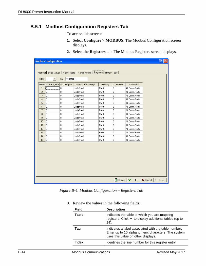
DL8000 Preset Instruction Manual
B-14 Modbus Communications Revised May-2017
B.5.1 Modbus Configuration Registers Tab
To access this screen:
1. Select Configure > MODBUS. The Modbus Configuration screen
displays.
2. Select the Registers tab. The Modbus Registers screen displays.
Figure B-4: Modbus Configuration – Registers Tab
3. Review the values in the following fields:
Field Description
Table Indicates the table to which you are mapping registers. Click to display additional tables (up to 24).
Tag Indicates a label associated with the table number. Enter up to 10 alphanumeric characters. The system uses this value on other displays.
Index Identifies the line number for this register entry.
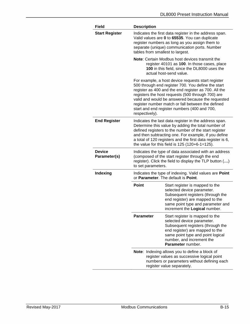
DL8000 Preset Instruction Manual
Revised May-2017 Modbus Communications B-15
Field Description
Start Register Indicates the first data register in the address span. Valid values are 0 to 65535. You can duplicate register numbers as long as you assign them to separate (unique) communication ports. Number tables from smallest to largest.
Note: Certain Modbus host devices transmit the register 40101 as 100. In those cases, place 100 in this field, since the DL8000 uses the actual host-send value.
For example, a host device requests start register 500 through end register 700. You define the start register as 400 and the end register as 700. All the registers the host requests (500 through 700) are valid and would be answered because the requested register number match or fall between the defined start and end register numbers (400 and 700, respectively).
End Register Indicates the last data register in the address span. Determine this value by adding the total number of defined registers to the number of the start register and then subtracting one. For example, if you define a total of 120 registers and the first data register is 6, the value for this field is 125 (120+6-1=125).
Device Parameter(s)
Indicates the type of data associated with an address (composed of the start register through the end register). Click the field to display the TLP button (…) to set parameters.
Indexing Indicates the type of indexing. Valid values are Point or Parameter. The default is Point.
Point Start register is mapped to the selected device parameter. Subsequent registers (through the end register) are mapped to the same point type and parameter and increment the Logical number.
Parameter Start register is mapped to the selected device parameter. Subsequent registers (through the end register) are mapped to the same point type and point logical number, and increment the Parameter number.
Note: Indexing allows you to define a block of register values as successive logical point numbers or parameters without defining each register value separately.
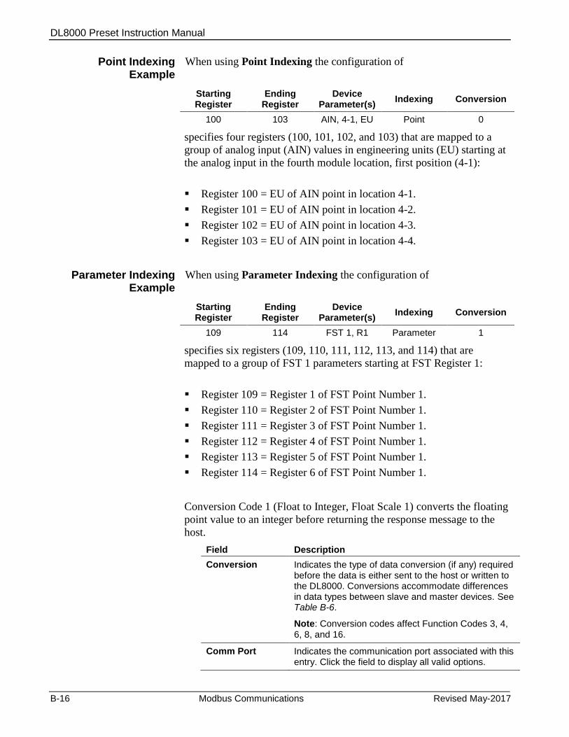
DL8000 Preset Instruction Manual
B-16 Modbus Communications Revised May-2017
Point Indexing Example
When using Point Indexing the configuration of
Starting Register
Ending Register
Device Parameter(s)
Indexing Conversion
100 103 AIN, 4-1, EU Point 0
specifies four registers (100, 101, 102, and 103) that are mapped to a
group of analog input (AIN) values in engineering units (EU) starting at
the analog input in the fourth module location, first position (4-1):
Register 100 = EU of AIN point in location 4-1.
Register 101 = EU of AIN point in location 4-2.
Register 102 = EU of AIN point in location 4-3.
Register 103 = EU of AIN point in location 4-4.
Parameter Indexing Example
When using Parameter Indexing the configuration of
Starting Register
Ending Register
Device Parameter(s)
Indexing Conversion
109 114 FST 1, R1 Parameter 1
specifies six registers (109, 110, 111, 112, 113, and 114) that are
mapped to a group of FST 1 parameters starting at FST Register 1:
Register 109 = Register 1 of FST Point Number 1.
Register 110 = Register 2 of FST Point Number 1.
Register 111 = Register 3 of FST Point Number 1.
Register 112 = Register 4 of FST Point Number 1.
Register 113 = Register 5 of FST Point Number 1.
Register 114 = Register 6 of FST Point Number 1.
Conversion Code 1 (Float to Integer, Float Scale 1) converts the floating
point value to an integer before returning the response message to the
host.
Field Description
Conversion Indicates the type of data conversion (if any) required before the data is either sent to the host or written to the DL8000. Conversions accommodate differences in data types between slave and master devices. See Table B-6.
Note: Conversion codes affect Function Codes 3, 4, 6, 8, and 16.
Comm Port Indicates the communication port associated with this entry. Click the field to display all valid options.

DL8000 Preset Instruction Manual
Revised May-2017 Modbus Communications B-17
Field Description
Register number must be unique for any given communications port. You can duplicate registers, as long as you assign them to separate ports. If a register number is duplicated within a port, the system uses the first occurrence of the register.
4. Click Apply to save any changes you have made to this screen.
5. Proceed to Section B.5.2 to configure Modbus conversions.
B.5.2 Modbus Conversion
Conversion codes convert data into a format that is compatible with a
Modbus device.
You use the Conversion field (present on both the Modbus Registers
and the Modbus History screens) to specify the type of conversion
required, if any, on the data before it is sent to the host or before it is
written to the DL8000. The conversions are used to account for
differences in data types between the master and slave devices.
Conversion codes 65 to 72 allow a 4-byte IEEE formatted floating point
number to be sent or received in two Modbus registers with the byte
orders configurable. ROCLINK 800 checks to ensure that an even
number of registers is requested, that the Start Register number does not
begin in the middle of a register pair, and that the number of registers
does not exceed the number of registers configured.
Table B-6. Modbus Conversion Codes
Convert Code
Description Slave
Function Definition
0 No Conversion
1 Float to integer, Float Scale 1 3,4
The Float to Integer conversion changes DL8000 floating point data to an integer for transmission to the host. The number of the Convert Code specifies which floating point scaling value is to be used for the conversion.
2 Float to integer, Float Scale 2 3,4
3 Float to integer, Float Scale 3 3,4
4 Float to integer, Float Scale 4 3,4
5 Float to integer, Float Scale 5 3,4
6 Float to integer, Float Scale 6 3,4
7 Float to integer, Float Scale 7 3,4
8 Float to integer, Float Scale 8 3,4
9 to 16 No Conversion 6,16
25 Any type to Float, No Scaling 3,4,6,16 When using Function Code 03 or 04, this conversion changes any data type (unsigned or signed Character, Integer, or Long) in the DL8000 to a specific point value for transmission to the host. When using Function Code 6 or 16, this
26 Any type to Signed Short Integer
3,4,6,16
27 Any type to Signed Long Integer
3,4,6,16
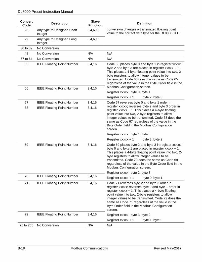
DL8000 Preset Instruction Manual
B-18 Modbus Communications Revised May-2017
Convert Code
Description Slave
Function Definition
28 Any type to Unsigned Short Integer
3,4,6,16 conversion changes a transmitted floating point value to the correct data type for the DL8000 TLP.
29 Any type to Unsigned Long Integer
3,4,6,16
30 to 32 No Conversion
48 No Conversion N/A N/A
57 to 64 No Conversion N/A N/A
65 IEEE Floating Point Number 3,4,16 Code 65 places byte 0 and byte 1 in register xxxxx; byte 2 and byte 3 are placed in register xxxxx + 1. This places a 4-byte floating point value into two, 2-byte registers to allow integer values to be transmitted. Code 66 does the same as Code 65 regardless of the value in the Byte Order field in the Modbus Configuration screen.
Register xxxxx byte 0, byte 1
Register xxxxx + 1 byte 2, byte 3
66 IEEE Floating Point Number 3,4,16
67 IEEE Floating Point Number 3,4,16 Code 67 reverses byte 0 and byte 1 order in register xxxxx; reverses byte 2 and byte 3 order in register xxxxx + 1. This places a 4-byte floating point value into two, 2-byte registers to allow integer values to be transmitted. Code 68 does the same as Code 67 regardless of the value in the Byte Order field in the Modbus Configuration screen.
Register xxxxx byte 1, byte 0
Register xxxxx + 1 byte 3, byte 2
68 IEEE Floating Point Number 3,4,16
69 IEEE Floating Point Number 3,4,16 Code 69 places byte 2 and byte 3 in register xxxxx; byte 0 and byte 1 are placed in register xxxxx + 1. This places a 4-byte floating point value into two, 2-byte registers to allow integer values to be transmitted. Code 70 does the same as Code 69 regardless of the value in the Byte Order field in the Modbus Configuration screen.
Register xxxxx byte 2, byte 3
Register xxxxx + 1 byte 0, byte 1 70 IEEE Floating Point Number 3,4,16
71 IEEE Floating Point Number 3,4,16 Code 71 reverses byte 2 and byte 3 order in register xxxxx; reverses byte 0 and byte 1 order in register xxxxx + 1. This places a 4-byte floating point value into two, 2-byte registers to allow integer values to be transmitted. Code 72 does the same as Code 71 regardless of the value in the Byte Order field in the Modbus Configuration screen.
Register xxxxx byte 3, byte 2
Register xxxxx + 1 byte 1, byte 0
72 IEEE Floating Point Number 3,4,16
75 to 255 No Conversion N/A N/A
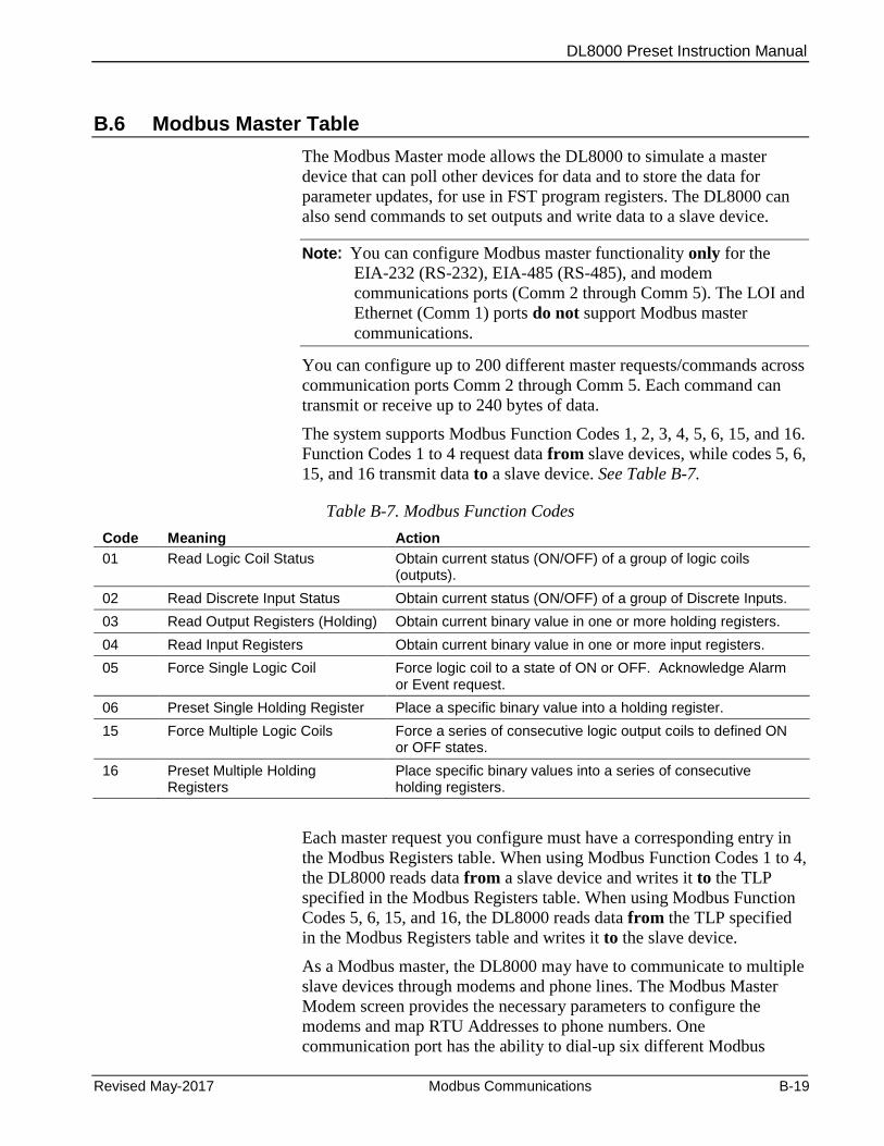
DL8000 Preset Instruction Manual
Revised May-2017 Modbus Communications B-19
B.6 Modbus Master Table
The Modbus Master mode allows the DL8000 to simulate a master
device that can poll other devices for data and to store the data for
parameter updates, for use in FST program registers. The DL8000 can
also send commands to set outputs and write data to a slave device.
Note: You can configure Modbus master functionality only for the
EIA-232 (RS-232), EIA-485 (RS-485), and modem
communications ports (Comm 2 through Comm 5). The LOI and
Ethernet (Comm 1) ports do not support Modbus master
communications.
You can configure up to 200 different master requests/commands across
communication ports Comm 2 through Comm 5. Each command can
transmit or receive up to 240 bytes of data.
The system supports Modbus Function Codes 1, 2, 3, 4, 5, 6, 15, and 16.
Function Codes 1 to 4 request data from slave devices, while codes 5, 6,
15, and 16 transmit data to a slave device. See Table B-7.
Table B-7. Modbus Function Codes
Code Meaning Action
01 Read Logic Coil Status Obtain current status (ON/OFF) of a group of logic coils (outputs).
02 Read Discrete Input Status Obtain current status (ON/OFF) of a group of Discrete Inputs.
03 Read Output Registers (Holding) Obtain current binary value in one or more holding registers.
04 Read Input Registers Obtain current binary value in one or more input registers.
05 Force Single Logic Coil Force logic coil to a state of ON or OFF. Acknowledge Alarm or Event request.
06 Preset Single Holding Register Place a specific binary value into a holding register.
15 Force Multiple Logic Coils Force a series of consecutive logic output coils to defined ON or OFF states.
16 Preset Multiple Holding Registers
Place specific binary values into a series of consecutive holding registers.
Each master request you configure must have a corresponding entry in
the Modbus Registers table. When using Modbus Function Codes 1 to 4,
the DL8000 reads data from a slave device and writes it to the TLP
specified in the Modbus Registers table. When using Modbus Function
Codes 5, 6, 15, and 16, the DL8000 reads data from the TLP specified
in the Modbus Registers table and writes it to the slave device.
As a Modbus master, the DL8000 may have to communicate to multiple
slave devices through modems and phone lines. The Modbus Master
Modem screen provides the necessary parameters to configure the
modems and map RTU Addresses to phone numbers. One
communication port has the ability to dial-up six different Modbus
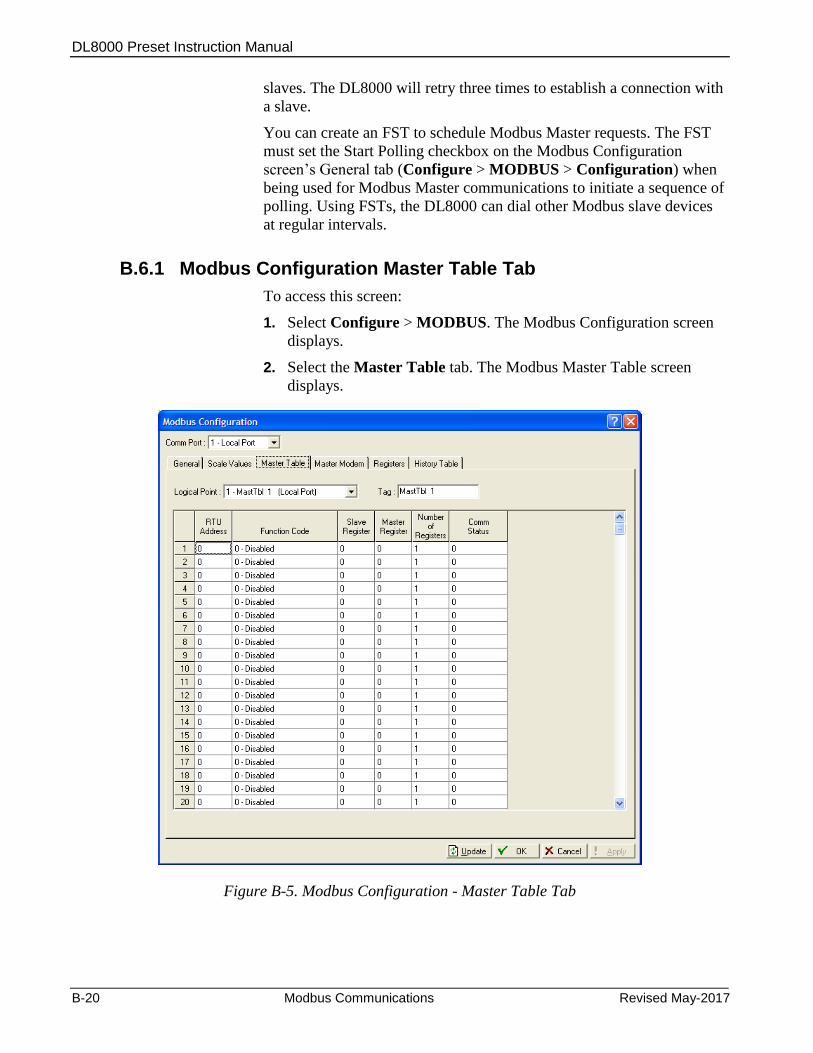
DL8000 Preset Instruction Manual
B-20 Modbus Communications Revised May-2017
slaves. The DL8000 will retry three times to establish a connection with
a slave.
You can create an FST to schedule Modbus Master requests. The FST
must set the Start Polling checkbox on the Modbus Configuration
screen’s General tab (Configure > MODBUS > Configuration) when
being used for Modbus Master communications to initiate a sequence of
polling. Using FSTs, the DL8000 can dial other Modbus slave devices
at regular intervals.
B.6.1 Modbus Configuration Master Table Tab
To access this screen:
1. Select Configure > MODBUS. The Modbus Configuration screen
displays.
2. Select the Master Table tab. The Modbus Master Table screen
displays.
Figure B-5. Modbus Configuration - Master Table Tab
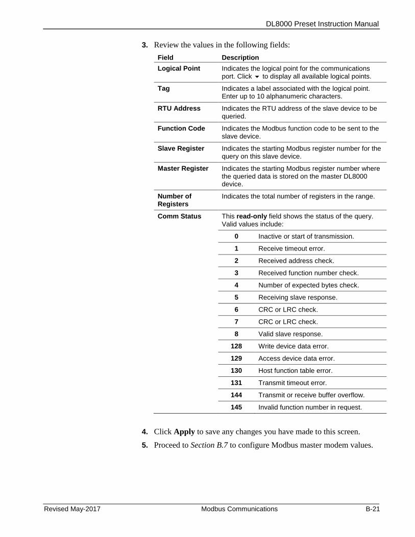
DL8000 Preset Instruction Manual
Revised May-2017 Modbus Communications B-21
3. Review the values in the following fields:
Field Description
Logical Point Indicates the logical point for the communications port. Click to display all available logical points.
Tag Indicates a label associated with the logical point. Enter up to 10 alphanumeric characters.
RTU Address Indicates the RTU address of the slave device to be queried.
Function Code Indicates the Modbus function code to be sent to the slave device.
Slave Register Indicates the starting Modbus register number for the query on this slave device.
Master Register Indicates the starting Modbus register number where the queried data is stored on the master DL8000 device.
Number of Registers
Indicates the total number of registers in the range.
Comm Status This read-only field shows the status of the query. Valid values include:
0 Inactive or start of transmission.
1 Receive timeout error.
2 Received address check.
3 Received function number check.
4 Number of expected bytes check.
5 Receiving slave response.
6 CRC or LRC check.
7 CRC or LRC check.
8 Valid slave response.
128 Write device data error.
129 Access device data error.
130 Host function table error.
131 Transmit timeout error.
144 Transmit or receive buffer overflow.
145 Invalid function number in request.
4. Click Apply to save any changes you have made to this screen.
5. Proceed to Section B.7 to configure Modbus master modem values.
DL8000 Preset Instruction Manual
B-22 Modbus Communications Revised May-2017
B.7 Modbus Master Modem
As a Modbus master, the DL8000 may have to communicate with
multiple slave devices through modems and phone lines. The Modbus
Master Modem screen provides the necessary parameters to configure
the modems and map RTU addresses to phone numbers.
Note: You can configure Modbus functionality only for
communications ports Comm 2 through Comm 5. The LOI and
Ethernet (Comm 1) ports do not support Modbus master
communications.
Each comm port can access to six RTU addresses. This point associates
Modbus slave RTU addresses to their respective phone numbers. Up to
six different Modbus slaves can be dialed through one communication
port. The DL8000 retries three times to establish a connection with a
slave.
B.7.1 Modbus Configuration Master Modem Tab
To access this screen:
1. Select Configure > MODBUS. The Modbus Configuration screen
displays.
2. Select the Master Table tab. The Master Modem screen displays.

DL8000 Preset Instruction Manual
Revised May-2017 Modbus Communications B-23
Figure B-6. Modbus Configuration - Master Modem tab
3. Review the values in the following fields:
Field Description
Comm Port Indicates the communication port location for hosting. Click to display all available logical points.
Tag Indicates a label associated with the communications port. Enter up to 10 alphanumeric characters.
Corresponding Comm Port
This read-only field shows the tag defined for the selected communications port.
Address Provides the RTU address of the slave device to be associated with the connect command. You can dial up to six different Modbus slaves through one communications port.
Connect Command
Indicates the telephone number (connect command) to be sent to the slave device.
4. Click Apply to save any changes you have made to this screen.
This completes the process of configuring the DL8000 for Modbus
communications.
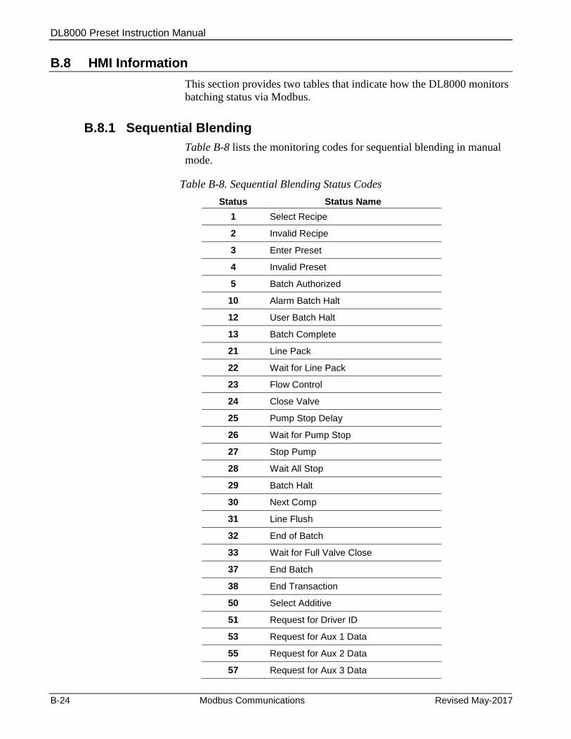
DL8000 Preset Instruction Manual
B-24 Modbus Communications Revised May-2017
B.8 HMI Information
This section provides two tables that indicate how the DL8000 monitors
batching status via Modbus.
B.8.1 Sequential Blending
Table B-8 lists the monitoring codes for sequential blending in manual
mode.
Table B-8. Sequential Blending Status Codes
Status Status Name
1 Select Recipe
2 Invalid Recipe
3 Enter Preset
4 Invalid Preset
5 Batch Authorized
10 Alarm Batch Halt
12 User Batch Halt
13 Batch Complete
21 Line Pack
22 Wait for Line Pack
23 Flow Control
24 Close Valve
25 Pump Stop Delay
26 Wait for Pump Stop
27 Stop Pump
28 Wait All Stop
29 Batch Halt
30 Next Comp
31 Line Flush
32 End of Batch
33 Wait for Full Valve Close
37 End Batch
38 End Transaction
50 Select Additive
51 Request for Driver ID
53 Request for Aux 1 Data
55 Request for Aux 2 Data
57 Request for Aux 3 Data
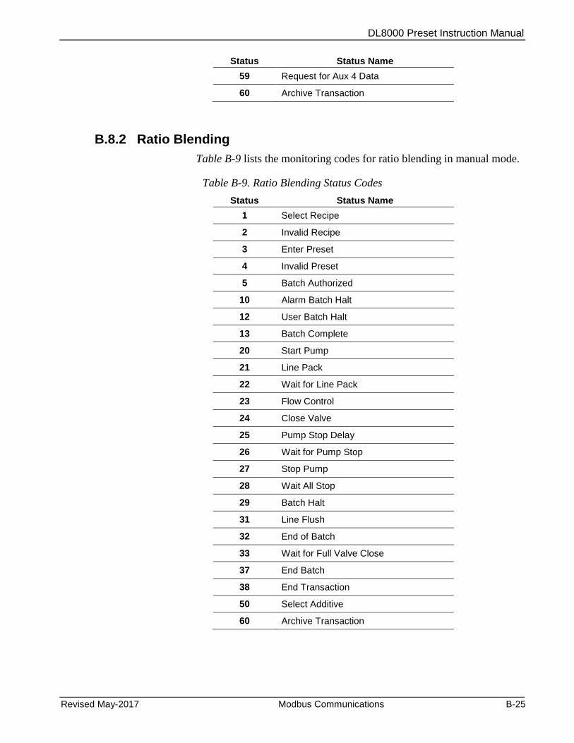
DL8000 Preset Instruction Manual
Revised May-2017 Modbus Communications B-25
Status Status Name
59 Request for Aux 4 Data
60 Archive Transaction
B.8.2 Ratio Blending
Table B-9 lists the monitoring codes for ratio blending in manual mode.
Table B-9. Ratio Blending Status Codes
Status Status Name
1 Select Recipe
2 Invalid Recipe
3 Enter Preset
4 Invalid Preset
5 Batch Authorized
10 Alarm Batch Halt
12 User Batch Halt
13 Batch Complete
20 Start Pump
21 Line Pack
22 Wait for Line Pack
23 Flow Control
24 Close Valve
25 Pump Stop Delay
26 Wait for Pump Stop
27 Stop Pump
28 Wait All Stop
29 Batch Halt
31 Line Flush
32 End of Batch
33 Wait for Full Valve Close
37 End Batch
38 End Transaction
50 Select Additive
60 Archive Transaction

DL8000 Preset Instruction Manual
B-26 Modbus Communications Revised May-2017
This page is intentionally left blank.
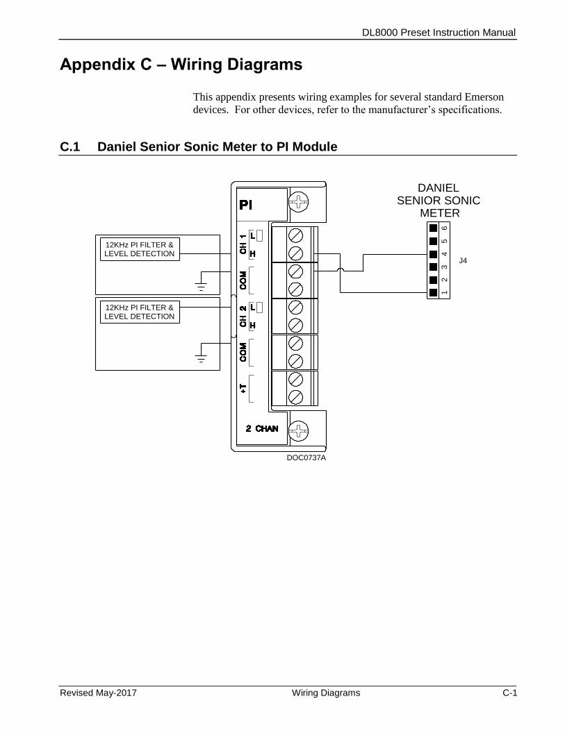
DL8000 Preset Instruction Manual
Revised May-2017 Wiring Diagrams C-1
Appendix C – Wiring Diagrams
This appendix presents wiring examples for several standard Emerson
devices. For other devices, refer to the manufacturer’s specifications.
C.1 Daniel Senior Sonic Meter to PI Module
12KHz PI FILTER &LEVEL DETECTION
12KHz PI FILTER &LEVEL DETECTION
DOC0737A
65
43
21
DANIEL SENIOR SONIC
METER
J4
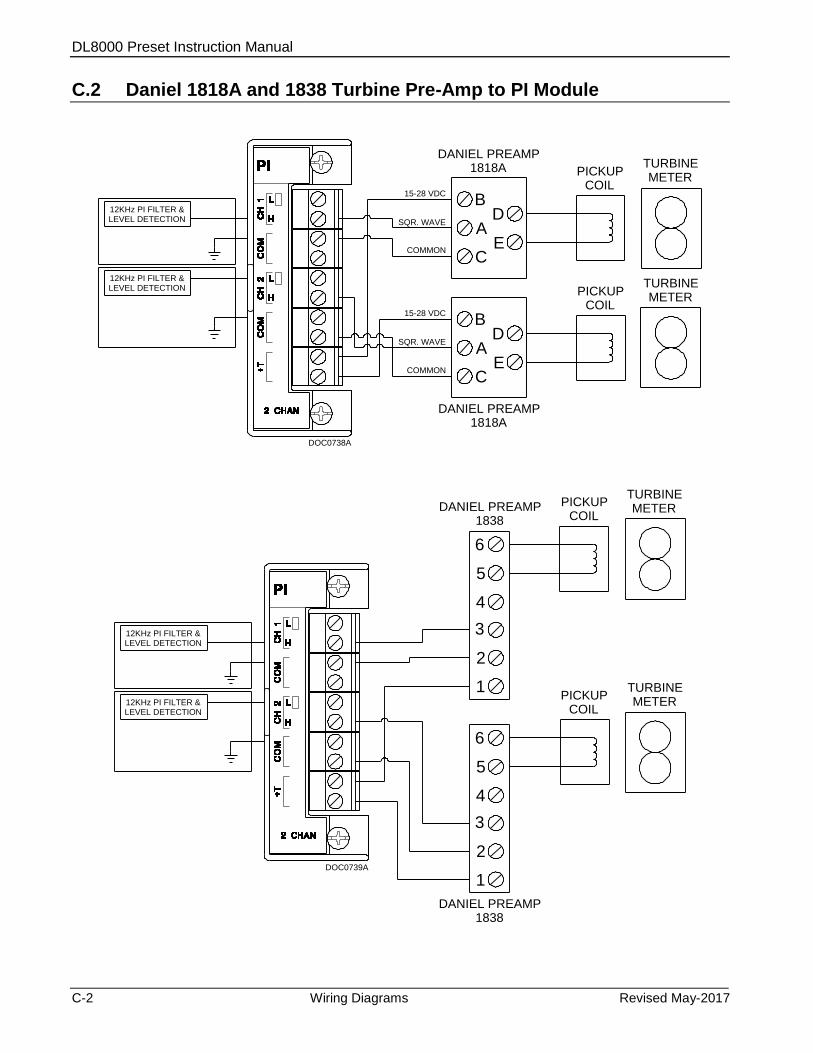
DL8000 Preset Instruction Manual
C-2 Wiring Diagrams Revised May-2017
C.2 Daniel 1818A and 1838 Turbine Pre-Amp to PI Module
12KHz PI FILTER &LEVEL DETECTION
12KHz PI FILTER &LEVEL DETECTION
DOC0738A
B
A
C
D
E
B
A
C
D
E
SQR. WAVE
COMMON
15-28 VDC
DANIEL PREAMP1818A
SQR. WAVE
COMMON
15-28 VDC
DANIEL PREAMP1818A
PICKUPCOIL
TURBINEMETER
TURBINEMETER
PICKUPCOIL
12KHz PI FILTER &LEVEL DETECTION
12KHz PI FILTER &LEVEL DETECTION
DOC0739A
6
5
4
PICKUPCOIL
TURBINEMETER
TURBINEMETER
PICKUPCOIL
3
2
1
6
5
4
3
2
1
DANIEL PREAMP1838
DANIEL PREAMP1838

DL8000 Preset Instruction Manual
Revised May-2017 Wiring Diagrams C-3
C.3 Micro Motion RFT9739 & 2400S Transmitters to PI Module
12KHz PI FILTER &LEVEL DETECTION
12KHz PI FILTER &LEVEL DETECTION
DOC0740A
14151617
14151617
MICRO MOTIONRFT9739
TRANSMITTER
MICRO MOTIONRFT9739
TRANSMITTER
12KHz PI FILTER &LEVEL DETECTION
12KHz PI FILTER &LEVEL DETECTION
DOC0741A
3412
3412
MICRO MOTION2400S
TRANSMITTER
MICRO MOTION2400S
TRANSMITTER
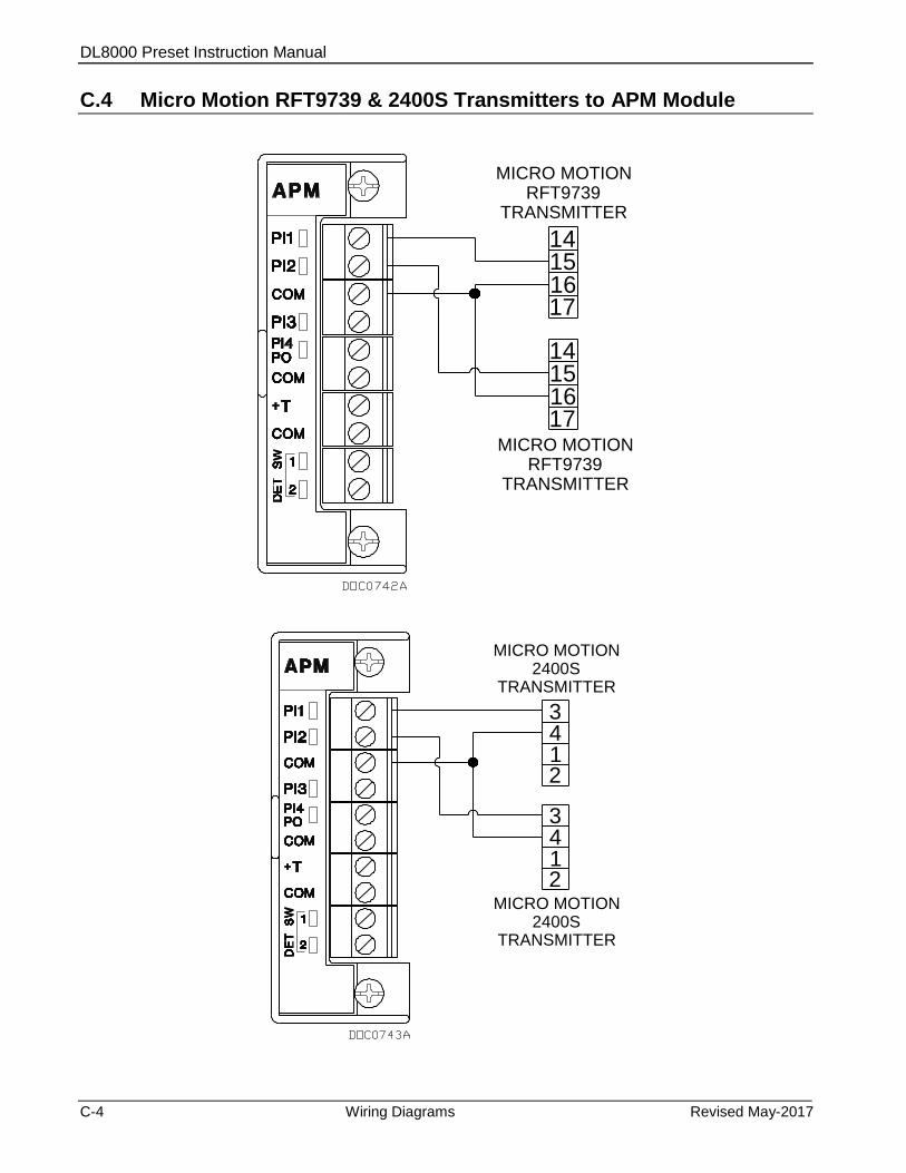
DL8000 Preset Instruction Manual
C-4 Wiring Diagrams Revised May-2017
C.4 Micro Motion RFT9739 & 2400S Transmitters to APM Module
14151617
14151617
MICRO MOTIONRFT9739
TRANSMITTER
MICRO MOTIONRFT9739
TRANSMITTER
3412
3412
MICRO MOTION2400S
TRANSMITTER
MICRO MOTION2400S
TRANSMITTER
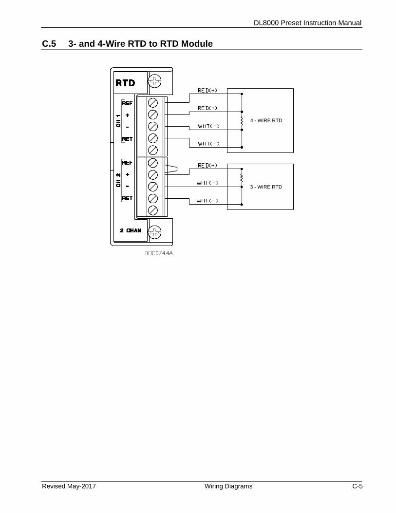
DL8000 Preset Instruction Manual
Revised May-2017 Wiring Diagrams C-5
C.5 3- and 4-Wire RTD to RTD Module
4 - WIRE RTD
3 - WIRE RTD
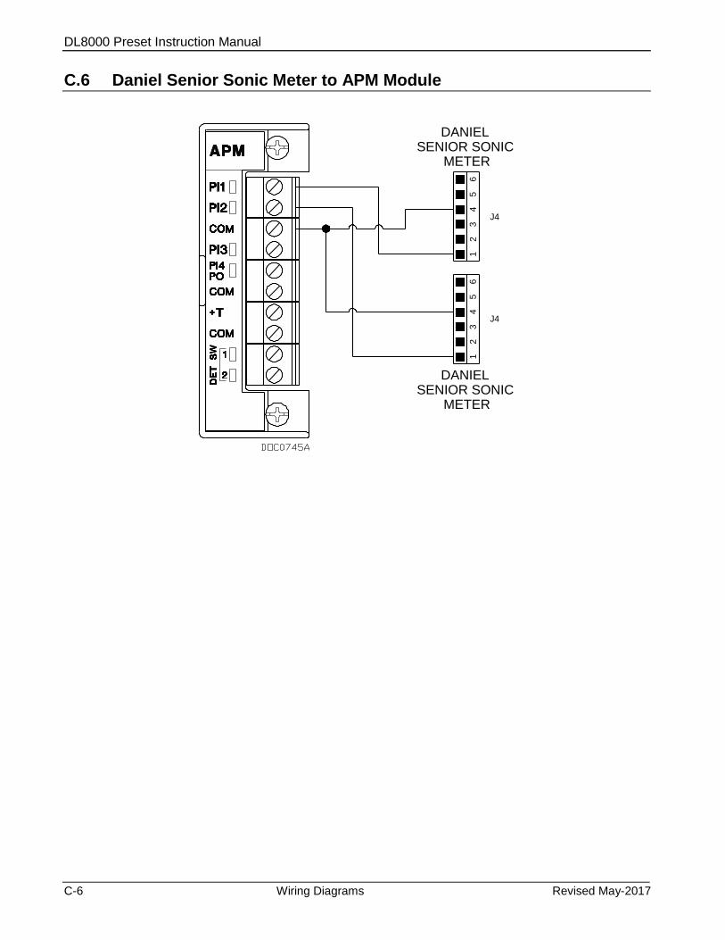
DL8000 Preset Instruction Manual
C-6 Wiring Diagrams Revised May-2017
C.6 Daniel Senior Sonic Meter to APM Module
65
43
21
65
43
21
DANIEL SENIOR SONIC
METER
J4
J4
DANIEL SENIOR SONIC
METER

DL8000 Preset Instruction Manual
Revised May-2017 Wiring Diagrams C-7
C.7 Daniel 1818A and 1838 Dual Turbine Pre-Amp to APM Module
B
A
C
D
E
B
A
C
D
E
SQR. WAVE
COMMON
15-28 VDC
DANIEL PREAMP1818A
SQR. WAVE
COMMON
15-28 VDC
DANIEL PREAMP1818A
PICKUPCOIL
TURBINEMETER
TURBINEMETER
PICKUPCOIL
6
5
4
PICKUPCOIL
TURBINEMETER
TURBINEMETER
PICKUPCOIL
3
2
1
6
5
4
3
2
1
DANIEL PREAMP1838
DANIEL PREAMP1838
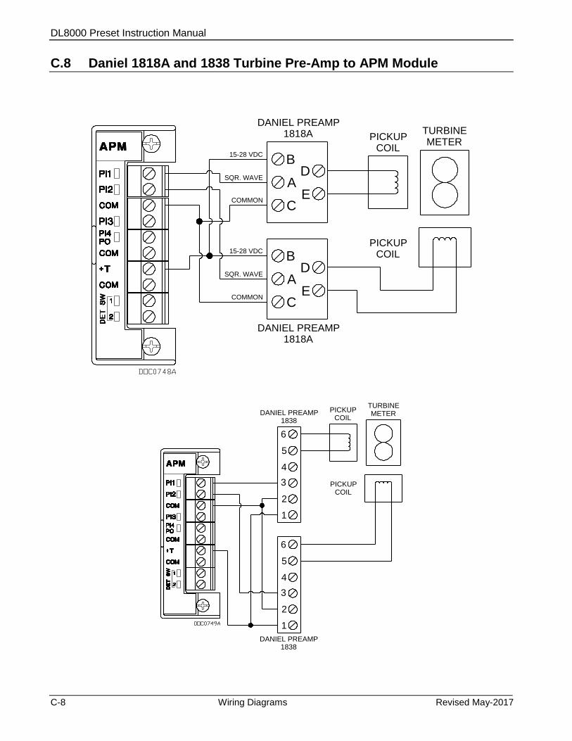
DL8000 Preset Instruction Manual
C-8 Wiring Diagrams Revised May-2017
C.8 Daniel 1818A and 1838 Turbine Pre-Amp to APM Module
B
A
C
D
E
B
A
C
D
E
SQR. WAVE
COMMON
15-28 VDC
DANIEL PREAMP1818A
SQR. WAVE
COMMON
15-28 VDC
DANIEL PREAMP1818A
PICKUPCOIL
TURBINEMETER
PICKUPCOIL
6
5
4
PICKUPCOIL
TURBINEMETER
PICKUPCOIL
3
2
1
6
5
4
3
2
1
DANIEL PREAMP1838
DANIEL PREAMP1838
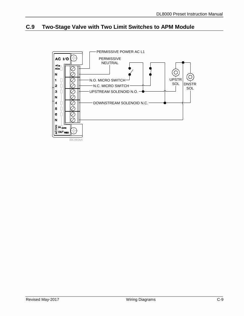
DL8000 Preset Instruction Manual
Revised May-2017 Wiring Diagrams C-9
C.9 Two-Stage Valve with Two Limit Switches to APM Module
PERMISSIVENEUTRAL
N.C. MICRO SWITCH
PERMISSIVE POWER AC L1
N.O. MICRO SWITCH
DOWNSTREAM SOLENOID N.C.
UPSTREAM SOLENOID N.O.
DNSTRSOL
UPSTRSOL
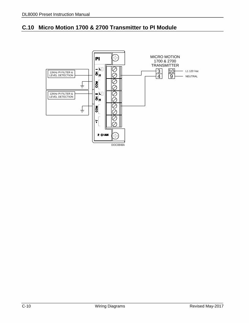
DL8000 Preset Instruction Manual
C-10 Wiring Diagrams Revised May-2017
C.10 Micro Motion 1700 & 2700 Transmitter to PI Module
12KHz PI FILTER &LEVEL DETECTION
12KHz PI FILTER &LEVEL DETECTION
DOC0848A
34
MICRO MOTION1700 & 2700
TRANSMITTER
109
L1 120 Vac
NEUTRAL
DL8000 Preset Instruction Manual
Revised May-2017 Communications Protocols D-1
Appendix D – Communications Protocols
This appendix details alternative protocols (other than the native
DL8000 protocol) you might use to communicate with the DL8000
preset controller. Currently, Remote Automation Solutions (RAS)
supports the Modbus® protocol (“Modbus,” developed by Modicon,
Inc.) and the DanLoad 6000 protocol (“DanLoad 6000,” developed by
Daniel, a division of Emerson Process Management).
D.1 Introduction
To communicate with a preset controller, a typical terminal automation
system (TAS) may use a communications protocol such as Modbus or
DanLoad 6000.
The TAS issues various commands that control preset operations and
complete batch delivery with or without operator assistance. Further, the
TAS can read configurable parameters, status parameters, and status
flags using Modbus registers or DanLoad 6000 read commands.
Note: This appendix provides information to enable backward
compatibility to an environment that may include DL8000
presets and DanLoad 6000 presets communicating through
either the DanLoad 6000 protocol or the Modbus protocol.
Although the DL8000 preset programs provide a software
interface you can use to define options and functions, your TAS
may require more specific mappings. Unlike DanLoad 6000
commands or Modbus registers, DL8000 parameters are
formatted as TLPs (Point Type, Logical No, Parameter No) and
are cited in the format [X,Y,Z] where X is the point type
number, Y is the logical number, and Z is the parameter number.
For that reason we also cite pertinent DL8000 parameters in the
format [X,Y,Z] and, when necessary, include specific code
values.
The Modbus protocol enables a TAS to:
Read or write configuration parameters
Read status parameters like totalizers, status flags, alarm status etc.
Control batch operation
The DanLoad 6000 protocol enables a TAS to control the entire batch
operation but limits access to configuration and status parameters.
Access the Operating Mode field on the Preset Setup screen’s General
Setup tab (parameter [63,0,36]) to select which of two operating modes
the preset uses to interact with a TAS. The operating mode limits the
accepted command codes. The operating modes are:
Automatic [value = 0]: The TAS maintains bi-directional
communications with the preset and monitors and controls batch
DL8000 Preset Instruction Manual
D-2 Communications Protocols Revised May-2017
delivery operations. All command codes can be used. You can
request status information and control preset operation.
Manual [value = 1]: The TAS maintains bi-directional
communications with the preset and monitors of batch delivery
operations. The TAS cannot control batch operation in this mode.
Consequently, only certain command codes (which are not for batch
control) can be used. You can request status information.
Table D-1 (in Section D.3, Communications Commands) lists the
commands supported in each protocol and the operating modes in which
they are valid.
Definitions/Acronyms/Abbreviations
This appendix uses the following acronyms:
BCC Block check character
FCV Flow control valve
K&D Keyboard and display
ROC Remote operations controller
TAS Terminal Automation System
W&M Weights & Measurement
D.1.1 Communication Channels
A TAS communicates with a preset using any of four comm ports:
COMM2 [63,0,32], COMM3 [63,0,49], COMM4 [63,0,139], or
COMM5 [63,0,149]. Each port has the following possible values: 0
(use no protocol), 1 (use Modbus protocol), or 2 (use DanLoad 6000
protocol).
Note: You can use Modbus simultaneously on more than one port. Use
ROCLINK 800’s Comm Ports screen (ROC > Comm Ports)
and select the Modbus Slave Only option to set the port owner
[95,x,43] as Modbus slave only [=51].
Unlike the Modbus protocol, the system supports the DanLoad 6000
protocol on only one serial port at a time. It recognizes and uses the first
port you configure for the DanLoad 6000 protocol.
D.1.2 Communications Failure
If you have configured a comm port for either Modbus or DanLoad
6000 protocol and the TAS is in automatic mode, the system scans for
communications failures. It raises an alarm when the DL8000 does not
receive a valid request on the specified comm port within the configured
time.
Note: You configure this timeout value using the Port 2 Timeout
through the Port 5 Timeout fields on the Preset Setup screen’s
General tab.
DL8000 Preset Instruction Manual
Revised May-2017 Communications Protocols D-3
This is a primary alarm and is not configurable. You can, however, set
the Port Timeout parameter to zero to disable the alarm for that port.
Parameters are:
COMM2 [63,0,152]
COMM3 [63,0,153]
COMM4 [63,0,154]
COMM5 [63,0,155]
Note: Use ROCLINK 800’s Comm Port screen (ROC > Comm Ports)
to specify the general settings of a serial port to define these
settings.
D.1.3 Supported Protocols
The TAS can communicate with a DL8000 using either the Modbus
protocol or the DanLoad 6000 protocol.
Modbus Protocol
You can configure a DL8000 to use either Modbus RTU or ASCII
transmission modes, and either Most Significant Byte (MSB) or Least
Significant Byte (LSB) orders. Set these values using the Comm
Mode and Byte Order fields on the General tab of ROCLINK 800’s
Modbus Configuration screen (Configure > MODBUS >
Configuration).
The Comm Mode option [117,x,0] controls the type of transmission
mode: RTU (Value=0) or ASCII (Value=1). The Byte Order option
[117,x,1] controls which byte is sent out first for floats, short integers,
and long integers. Valid values are Least Significant Byte First
(Value=0), associated with little-endian processors or Most Significant
Byte First (Value=1), associated with big-endian processors.
The Modbus protocol is a register-based protocol. You have to map
Modbus registers to the DL8000 TLP parameters. Refer to Section D.4,
Mapping Modbus Registers.
DanLoad 6000 Protocol
The DanLoad 6000 protocol is Modbus-compatible protocol, since it
uses Modbus RTU message framing. Modbus function codes for
normal queries and responses are 0x41 and 0x42 (hexadecimal). The
Modbus protocol reserves function codes 0x41 to 0x48 for user-
defined “custom functions.” Consequently, the DanLoad 6000
protocol is a customized Modbus protocol.
Under DanLoad 6000 protocol, the TAS system establishes
communication using a Start Communications command (hex value
0x21). This initializes the DanLoad 6000 alternating sequence function
code to the function code in the Start Communication command. The
operation at DanLoad 6000 remains unaffected by Start
Communications command (hex 0x21).

DL8000 Preset Instruction Manual
D-4 Communications Protocols Revised May-2017
The maximum query message length for Modbus RTU is 256 bytes
(including check characters). The same length is true for response
messages.
In DanLoad 6000 protocol, a normal query and response frame consists
of the following fields:
Address (one character)
Function code (one character) – alternating hexadecimal 0x41 and
0x42.
Data field length = N (one character) – including this character and
data field but excluding checksum bytes
Data field (=N-1 characters where first character is a command code
and subsequent characters area data for the command)
BCC checksum (two characters)
The exception response frame has the following format:
Address (one character)
Function code (one character) – 0xC1 and 0xC2 to indicate
“exception responses” to function codes 0x41 and 0x42 respectively
Data field length = N (one character)
Data field (=N-1 characters where first character is a command code
and subsequent characters are data for the command)
BCC checksum (two characters)
For further information, see Section D.5, DanLoad 6000 Protocol
Frame.
The destination station uses block check characters (BCCs) to verify the
accuracy of the data received. The receiving station calculates the BCC
for the command query message it receives and then compares the
calculated BCC with the received BCC. Any differences indicate a data
error; the destination does not reply to such command frames.
The DL8000 knows which function code to expect from the TAS. If it
receives hex 41h when it expects hex 42h or vice versa (and the
command is not a Start Communications command), the preset assumes
a retry by the TAS and retransmits exactly the last response sent to the
TAS on the communication channel.
Additionally, the DL8000:
Uses function codes C1h and C2h to indicate “exception responses”
to function codes 41h and 42h, respectively.
Does not respond to a “broadcast” messages (that is, where the
address field equals zero).
Operates as an addressable slave station, and “speaks only when
spoken to.”
The DL8000 does not respond to a message that is “incorrectly framed”
(that is, not its address, an unused function code, or an incorrect error
check). It also does not respond to a message that is “incomplete”
(containing either fewer or more characters than expected).
DL8000 Preset Instruction Manual
Revised May-2017 Communications Protocols D-5
Gross Volume is a default value for commands which return total
values. The DL8000 can return one other value, depending on what you
enter in the Preset Delivery Type field [63,0,29] on the Preset Setup
screen’s General Setup tab. Enter Mass (for mass total values) or
Standard (for net standard total values).
Using the DanLoad 6000 protocol, when the TAS communicates with
the preset, the preset does not check for the following:
If write command (for hex 0x0B, 0x0C, 0x27) is issued, the preset
does not check whether the TLP is a W&M type.
Note: Refer to the DanLoad 6000 Communications Specifications
Manual (Part Number 3-9000-674, Revision 2.1, publication
date September 1998) for details on the DanLoad 6000 protocol
and command request or query frame.
D.1.4 Configuration
To set up a serial port in the DL8000, use the following configurations:
Value Description
Device Address Sets the DL8000’s address [91,0,0]. Select Device Address from the Address to Use frame on the Device Information screen’s Internet tab (ROC > Information).
Serial Port Setting Configures the serial port. Set the following values on the Comm Port screen (ROC > Comm Ports).
Baud Rate Valid baud rates for the Modbus and DL6000 protocols are 300, 600, 1200, 2400, 4800. 9600, 19200, 38400, and 57600. [95,x,1] and [91,0,31 to 91,0,34]
Parity Sets parity error checking, in which the host adds a 1 or 0 bit to the character to make it even or odd. The receiver then decodes this value and an error occurs if the bit number is not correct. Valid values are 0 (no parity), 1 (odd parity), or 2 (even parity). [95,x,4]
Data Bits Sets the number of data bits in a character. Valid values are 7 or 8. [95,x,3]
Stop Bits Sets the number of stop bits in a character. Valid values are 1 or 2. [95,x,2]
DL8000 Preset Instruction Manual
D-6 Communications Protocols Revised May-2017
Value Description
Serial Port Setting (continued)
Port Owner Sets the program that currently “owns” or controls the port. [95,x,43] Valid values are:
ROC Plus Protocol/Modbus Slave (0)
Modbus Master (COMM1 through COMM5) (1)
DS800 (not valid for COMM1) (2)
LCD (3) I/O Module (Read-only) (4) User C++ Program 1 (5) User C++ Program 2 (6) User C++ Program 3 (7) User C++ Program 4 (8) User C++ Program 5 (9) User C++ Program 6 (10) User C++ Program 7 (11) User C++ Program 8 (12) ROC Plus Protocol only (50) Modbus Slave Only (51)
D.1.5 Commands
Under the DanLoad 6000 protocol, the command request frame contains
all the data required to execute a command. The TAS should send a
command request frame on the port configured for the DanLoad 6000
protocol. The DL8000 supports most of the DanLoad 6000 protocol
commands.
Under Modbus, however, you must use Modbus write function codes
for the respective command parameters before issuing a command to the
DL8000. The TAS then writes a command to the TA command
parameter [63,0,166].
The DL8000 processes this command or command request frame and
then writes any exception codes [63,0,168]. The value of 255 indicates
no exception. The DL8000 then checks for the following general
exceptions:
If the TAS-issued command should be a valid TAS command based
on operating mode.
If the TAS issues any command (other than Clear Status) when the
DL8000 is in program mode.
Note: Command-specific exceptions are included in the descriptions of
each command (see Sections D.3.1 and D.3.2).
If the system finds no exceptions during the processing of commands, it
sets and resets any required status flags [63,0,119] and controls the
DL8000 based on the command. Refer to Section D.9 and D.10 for a list
of exception codes the Modbus or DanLoad 6000 protocols might raise.
Although the exception code numbers raised are same for both Modbus
DL8000 Preset Instruction Manual
Revised May-2017 Communications Protocols D-7
and DanLoad 6000 protocols, the DanLoad 6000 protocol has additional
exceptions.
D.1.6 Status Flags
The Status Flags parameter [63,0,119] maintains various process values
which the TAS uses to monitor the status of both the DL8000 and the
overall batching operation.
Note: These values accumulate in the TLP and do not currently appear
on any system report or screen.
Bit (Decimal) Bit (Hex) Description
00 00 Operating Mode is Manual
01 01 Primary Alarm
02* 02* Passcode Entry in Progress
03* 03* Operation Timed Out
04* 04* Recipe Selected
05* 05* Additive Selected
06* 06* Preset Volume Entered
07* 07* Keypad Data Available
08 08 Program Code Value Changed
09* 09* Transaction in Progress
10* 0A* Batch in Progress
11* 0B* Key Pressed
12 0C Transaction Ended
13 0D Batch Ended
14* 0E* Batch Aborted (not started)
15* 0F* Intermediate Level Input Alarm Stopped batch (not currently supported)
16 10 Batch in Configuration Mode
17 11 Batch Authorized
18 12 Transaction Authorized
19 13 Transaction End Requested
20 14 K&D Locked Out to Automation System
21 15 Batch Stopped (Resumable)
22 16 Program Mode
23* 17* Flowing
An asterisk (*) indicates status flags that are reset when you power up
the DL8000. Refer to Section D.8, Status Flag Descriptions for a list of
status flags that the system sets or resets based on various conditions.
When the DL8000 is in Auto mode, you can clear some status flags
from the TAS using the Clear Status command (hex 0x13). You can
update the following flags:
DL8000 Preset Instruction Manual
D-8 Communications Protocols Revised May-2017
Operation Timed Out (0x03 bit)
Recipe Selected (0x04 bit)
Additive Selected (0x05 bit)
Preset Volume Entered (0x06 bit)
Keypad Data Available (0x07 bit).
Program Code Value Changed (0x08 bit).
Key Pressed (0x0B bit)
Transaction Ended (0x0C bit)
Batch Ended (0x0D bit)
Batch Aborted (0x0E bit)
Transaction End Requested (0x13 bit)
Program Mode (0x16 bit)
The K&D Locked Out flag indicates that the TAS cannot display
message on screen. You can use the timeout operation command [0x05]
to clear K&D Locked Out flag, but only when the batch is not in
progress. When the DL8000 displays a “Please Wait” message to the
operator, that message indicates that the operator should wait until next
command or message is received from the TAS.
D.2 Batch Control in Auto Mode
This section discusses the sequence of actions required to remotely
control the entire batching operations from a TAS.
D.2.1 Steps for Authorizing a Transaction
The DL8000 allows you to load a preset volume of a product, blend, or
recipe as a “batch.” The operator or the TAS sets the (preset) volume.
The batch begins when the operator presses the Start key on the preset.
The batch ends when delivery of product has stopped and cannot be
resumed without beginning a new batch. When a preset volume of a
multi-component sequential or in-line blend is loaded, this is just one
batch.
On the DL8000, one or more batches can load on a single “transaction.”
The system assigns each transaction a unique four-digit sequence
number when the transaction starts. Similarly, the system assigns each
batch within the transaction a unique four-digit sequence number when
that batch starts. All batches on a transaction have the same recipe and
the same additives and share the same operator-entered “data items.”
The system stores the transaction sequence number of the currently
loaded or the last loaded transaction at [63,0,124], and stores the batch
sequence number of the currently loaded or the last loaded batch at
[63,0,125].

DL8000 Preset Instruction Manual
Revised May-2017 Communications Protocols D-9
The following sections detail the steps to authorize a new recipe (that is,
a transaction).
Selecting a Recipe
Before a transaction can begin an operator must select a recipe. The
TAS can use the Prompt Recipe (hex 0x01) command and request the
DL8000 to prompt the operator for a recipe selection. The DL8000 then
displays a recipe selection screen on which the recipe names display
beginning with the first recipe up to the maximum number of configured
recipes [63,0,26]. The operator must select a recipe within configured
timeout time [63,0,171]; otherwise, the DL8000 aborts the operation
and sets a timeout flag (bit 3 in [63,0,119]).
Note: If you set the timeout to zero then a timeout does not occur.
When the operator selects a recipe, the DL8000 sets a Recipe Selected
flag (bit 4 in [63,0,119]) telling the TAS that it can read the recipe
selected. The Recipe Selected flag is subsequently cleared either by
another Prompt Recipe command or a Clear Status [0x13] command.
In the DanLoad 6000 protocol, the TAS reads the selected recipe
[63,0,118] using a Request Selected Recipe command (hex 0x02). In the
Modbus protocol, the TAS can directly read the value of the selected
recipe [63,0,118] using a read function code.
At this point, the TAS can either use the operator-selected recipe or its
own recipe to authorize a transaction. A new recipe [63,0,118] can be
changed by directly writing to recipe selection [63,0,10] without the
TAS issuing a Prompt Recipe command when a transaction is not
authorized, no primary alarms are active, and the Operation Timed Out
flag is not set. This means that if the TAS can determine the recipe
number without input from the operator, the Prompt Recipe and
Request Selected Recipe commands are not required.
Selecting One or More Additives
Up to six additives can be selected before the system authorizes a
transaction. The TAS can command the DL8000 to prompt the operator
for an additive selection using the Prompt Additive command (hex
0x03). A “suggested” additive [63,0,170] can display for the operator;
the selection of “no additives” is a valid additive selection.
When the system issues the Prompt Additive command, it locks the
keypad and display to the TAS. The DL8000 displays the additive
selection screen with the suggested additive. The operator must select an
additive within the timeout time [63,0,171]; otherwise, the system
aborts the operation and sets a timeout flag (bit 3 in [63,0,119]).
Note: If you set the timeout to zero then a timeout does not occur.
DL8000 Preset Instruction Manual
D-10 Communications Protocols Revised May-2017
When the operator selects an additive, DL8000 sets the additive selected
flag (bit 5 in [63,0,119]), indicating that the TAS can read the selected
additive. The additive selected flag is subsequently cleared either by
another Prompt Additive command or a Clear Status (hex 0x13)
command.
In the DanLoad 6000 protocol, the TAS reads the selected additive
bitmap [63,0,112] using Request Selected Additive command (hex
0x04). In the Modbus protocol, the TAS can directly read the selected
additive [63,0,112] using a read function code.
At this point the TAS can either use the operator-selected additive or its
own additive to authorize a transaction. A new additive bitmap
[63,0,112] can be changed by directly writing to the additive bitmap
[63,0,60] without the TAS issuing a command when the transaction is
not authorized, no primary alarms are active, and the Operation Timed
Out flag is not set. This means that if the TAS can determine the
additive selection without input from the operator, the Prompt Additive
and Request Selected Additive commands are not required.
Prompting for Auxiliary Data Items
The TAS can command the DL8000 to prompt the operator for data
(such as customer number, order number, or compartment number)
using the Display message (hex 0x1C) command.
Using the Number of Data Items field on the Preset Setup’s General tab,
you can define up to five auxiliary data items for the operator to
complete. You then use the Number of Data Items field to indicate the
number of prompts to display. If the auxiliary data index [63,0,178] is
not zero and the TAS issues this command, the DL8000 then prompts
the operator with appropriate messages Data Prompt 1 [63,0,187], Data
Prompt 2 [63,0,189], Data Prompt 3 [63,0,191], Data Prompt 4
[63,0,193], and Data Prompt 5 [63,0,195]. The number and sequence of
displayed data prompts depends on the value in the auxiliary data index
TLP.
When the operator enters data from the keypad, DL8000 sets a flag (bit
7 in [63,0,119]) to indicate when keypad data is available. Based on the
auxiliary data item number, the system writes data entered from the
keypad as Data Item 1 [63,0,188], Data Item 2 [63,0,190], Data Item 3
[63,0,192], Data Item 4 [63,0,194] and Data Item 5 [63,0,196].
If a transaction is not authorized and the Operation Timed Out flag is
not set (bits 18 and 3 in [63,0,119]), then the system can directly write
auxiliary data items 1 to 5 without the TAS issuing this command.
In the DanLoad 6000 protocol, the TAS obtains the keypad data using
the Request Keypad Data [0x1D] command. In the Modbus protocol,
the system can directly read entered data items from appropriate Data
item 1 through Data item 5.
DL8000 Preset Instruction Manual
Revised May-2017 Communications Protocols D-11
Authorizing the Transaction
The TAS “authorizes” a transaction using the Authorize Transaction
command (hex 0x06). This command:
Sets the recipe, additives, and data items.
Note: Write the recipe, additive, and data items before you issue
the Authorize Transaction command.
Sets the Transaction Authorized flag (bit 18 in [63,0,119]).
Clears the Additive Selected and Recipe Selected flags (bits 5 and 4
in [63,0,119]).
Displays (if it is not already) the loading screen.
Increments the transaction sequence number [63,0,124], which rolls
from 9999 to 0 to indicate the prospective sequence number of the
transaction (if it starts).
Note: The transaction does not actually start (“in progress”) until the
first batch starts. The DL8000 sets a Transaction in Progress flag
(bit 9 in [63,0,119]) to indicate that a transaction is actually in
progress.
D.2.2 Steps for Authorizing a Batch
The following sections explain the steps for authorizing a new batch for
loading the required preset.
Preset Volume for Batch
The TAS can command the DL8000 to prompt the operator for a preset
volume using the Prompt Preset Volume command (hex 0x08). When
the TAS issues this command, the DL8000 displays a preset selection
screen. This command can optionally send a “suggested preset volume”
[63,0,185].
The operator can either press Enter to accept the displayed preset or
press Alt + Backspace to change the preset volume. The operator must
enter the preset volume within the timeout time [63,0,171]; otherwise
the DL8000 aborts the operation and sets an Operation Timed Out flag
(bit 3 in [63,0,119]).
Note: If you set the timeout to zero then a timeout does not occur.
Once the operator enters a preset value, the system sets the preset
entered flag (bit 6 in [63,0,119]). The Preset Volume Entered flag is
subsequently cleared by another Prompt Preset Volume command or a
Clear Status (hex 0x13) command.
In the DanLoad 6000 protocol, the TAS can read the entered preset
volume [63,0,39] using a Request Preset Volume command (hex 0x09).
DL8000 Preset Instruction Manual
D-12 Communications Protocols Revised May-2017
In the Modbus protocol, the TAS can directly read the value at this
parameter using read function code.
If the batch is not authorized and the operation timeout flag is not set
(bits 17 and 3 in [63,0,119]) then new preset qty [63,0,39] can be
changed by directly writing to preset quantity [63,0,0] without the TAS
issuing this command. This means if the TAS can determine the batch
volume without input from the operator, the Prompt Preset Volume and
Request Preset Volume commands are not required.
Batch Authorization
The TAS issues an Authorize Batch command (hex 0x0A) to authorize a
new batch for given preset volume [63,0,39].
In the DanLoad 6000 protocol, the command request frame includes the
desired preset volume. For the Modbus protocol the preset value should
be directly written at preset quantity [63,0,0].
When the TAS issues the Authorize Batch command:
The DL8000 displays a loading screen which displays “Start to
Load” and “Stop to Abort” messages.
The system sets the batch authorized flag (bit 17 in [63,0,119])].
The system increments the batch sequence number [63,0,125] by 1
(which rolls from 9999 to 0) indicating the prospective sequence
number of the batch if started.
The operator initiates loading by pressing Start within the timeout time
[63,0,171]. If the batch is aborted (that is, if the operator presses Stop
instead of Start or the DL8000 times out waiting for the Start key to be
pressed), the DL8000 sets the batch aborted and timeout flags (bits 14
and 3), resets the batch authorized flag (bit 17 in [63,0,119]), and
reduces the batch sequence number [63,0,125] by 1.
Batch Start/Restart
The operator can press Start or the TAS can issue a Start/Restart Batch
command (hex 0x0E) to start a new batch or restart a batch which is in
progress but stopped (bits 10 and 21 in [63,0,119]), provided no active
alarm has a severity more than Info (for example, the Current Alarm
Type [63,0,64] has value 0 or 1).
When a batch has been started, the DL8000 sets a flag (bit 10 in
[63,0,119]) to indicate that a batch is in progress.
D.2.3 Stop/End of Batch
Batch delivery stops when any of the following conditions occurs -
The operator presses Stop.
DL8000 Preset Instruction Manual
Revised May-2017 Communications Protocols D-13
The TAS issues a Stop Batch command [0x0F] when the batch is in
progress and not stopped (bits 10 and 21 in [63,0,119]).
An alarm with a severity greater than info is raised (for example, the
Current Alarm Type [63,0,64] has a value more than 1).
A batch that is stopped because of these conditions may be restarted.
The DL8000 sets a flag (bit 21 in [63,0,119]) to indicate that the batch
has stopped and can be restarted.
A batch ends when either of the following conditions occurs -
The preset volume of all the components in the blend or recipe has
been delivered.
The TAS issues an End Batch command (hex 0x0D) when batch is
in progress and stopped (bits 10 and 21 in [63,0,119]).
Batch has been stopped when the batch remaining quantity [63,0,3]
is less than minimum preset quantity [63,0,27].
A batch that has ended cannot be restarted. The DL8000 sets a Batch
Ended flag (bit 13 in [63,0,119]) to indicate that the batch has ended and
is not restartable. The authorization of a new batch or the issue of a
Clear Status command clears the batch ended flag.
In the DanLoad 6000 protocol, the TAS uses the Batch Data by
Component command (hex 0x10) to obtain batch data (batch volumes,
component temperatures, batch sequence number, transaction sequence
number, and so on) for a batch that has ended.
D.2.4 End of Transaction
In automatic operating mode, any of the following conditions can end a
transaction:
The TAS issues an End Transaction command (hex 0x07) when the
transaction is authorized and there is no batch in progress (bits 18
and 10 in [63,0,119]).
The operating mode [63,0,36] is changed and transaction was
authorized.
The DL8000 was powered and a transaction in progress when the
DL8000 was powered down.
In manual operating mode, you can end a transaction by pressing Stop
on the DL8000, provided no batch is in progress.
In automatic mode, an operator can press Stop to request the TAS to
end the transaction. The DL8000 then sets the Transaction End
Requested flag (bit 19 in [63,0,119]). The TAS reviews this flag and
issues an End Transaction command (hex 0x07). When the DL8000
receives an End Transaction command, it sets a flag (bit 12 in
[63,0,119]) to indicate that the transaction has ended. The authorization
of a new transaction or the issue of a Clear Status command clears the
Transaction Ended flag.
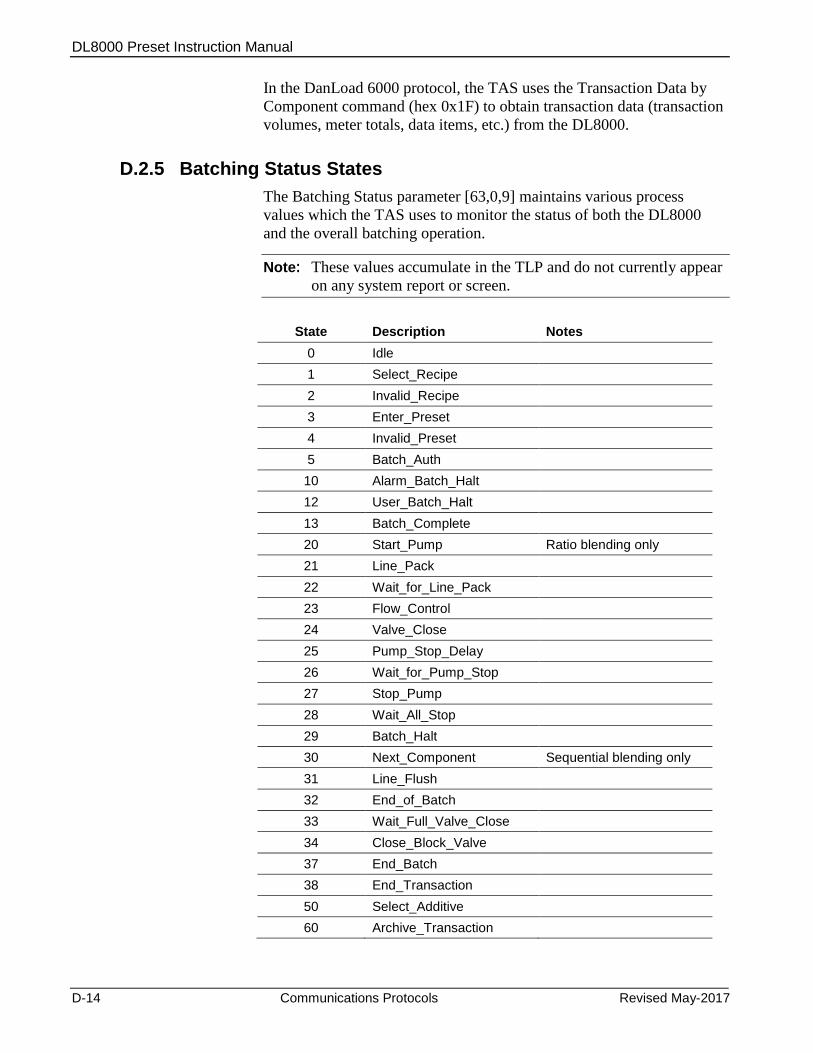
DL8000 Preset Instruction Manual
D-14 Communications Protocols Revised May-2017
In the DanLoad 6000 protocol, the TAS uses the Transaction Data by
Component command (hex 0x1F) to obtain transaction data (transaction
volumes, meter totals, data items, etc.) from the DL8000.
D.2.5 Batching Status States
The Batching Status parameter [63,0,9] maintains various process
values which the TAS uses to monitor the status of both the DL8000
and the overall batching operation.
Note: These values accumulate in the TLP and do not currently appear
on any system report or screen.
State Description Notes
0 Idle
1 Select_Recipe
2 Invalid_Recipe
3 Enter_Preset
4 Invalid_Preset
5 Batch_Auth
10 Alarm_Batch_Halt
12 User_Batch_Halt
13 Batch_Complete
20 Start_Pump Ratio blending only
21 Line_Pack
22 Wait_for_Line_Pack
23 Flow_Control
24 Valve_Close
25 Pump_Stop_Delay
26 Wait_for_Pump_Stop
27 Stop_Pump
28 Wait_All_Stop
29 Batch_Halt
30 Next_Component Sequential blending only
31 Line_Flush
32 End_of_Batch
33 Wait_Full_Valve_Close
34 Close_Block_Valve
37 End_Batch
38 End_Transaction
50 Select_Additive
60 Archive_Transaction

DL8000 Preset Instruction Manual
Revised May-2017 Communications Protocols D-15
D.3 Communications Commands
This section details all commands the Modbus and DanLoad 6000
protocols support.
D.3.1 Modbus Commands
You use Modbus commands when using the register-mapped Modbus
protocol. Table D-1 lists the executable commands available in the
Modbus protocol. These commands are called “executables” since they
force the DL8000 to perform certain kind of activities. The table also
specifies the operation mode in which each command is valid.
Table D-1. Modbus Executable Commands
Cmd No (decimal)
Cmd No (hex)
Command Name
Operating modes [Auto/Manual]
1 1 Prompt Recipe Auto
3 3 Prompt Additives Auto
5 5 Timeout Operation Auto
6 6 Authorize Transaction Auto
7 7 End Transaction Auto
8 8 Prompt Preset Volume Auto
10 A Authorize Batch Auto
13 D End Batch Auto
14 E Start/Restart Batch Auto
15 F Stop Batch Auto
19 13 Clear Status Auto
20 14 Reset Primary Alarms Auto
28 1C Display Message Auto
41 29 Set Date and Time Auto/Manual
48 30 Reset Unit Auto/Manual
55 37 Change Operating Mode Auto/Manual
56 38 Clear Display Auto
61 3D Report Alarm Auto/Manual
The following sections describe all the commands supported in the
Modbus protocol, including the supporting parameters required for the
execution of each command, status flags changed during each
command, and exceptions checked.
When using Modbus, you use function codes to write the data for
respective parameters required for the execution of commands in
advance before issuing the command to the DL8000. Refer to the
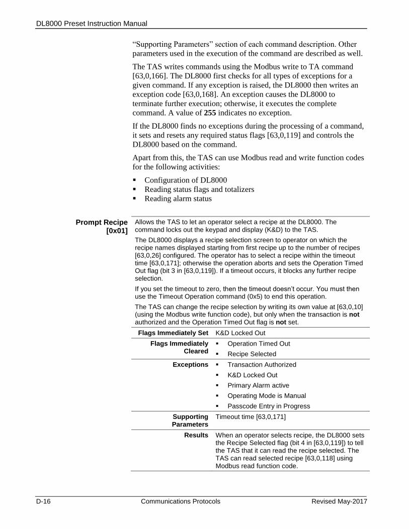
DL8000 Preset Instruction Manual
D-16 Communications Protocols Revised May-2017
“Supporting Parameters” section of each command description. Other
parameters used in the execution of the command are described as well.
The TAS writes commands using the Modbus write to TA command
[63,0,166]. The DL8000 first checks for all types of exceptions for a
given command. If any exception is raised, the DL8000 then writes an
exception code [63,0,168]. An exception causes the DL8000 to
terminate further execution; otherwise, it executes the complete
command. A value of 255 indicates no exception.
If the DL8000 finds no exceptions during the processing of a command,
it sets and resets any required status flags [63,0,119] and controls the
DL8000 based on the command.
Apart from this, the TAS can use Modbus read and write function codes
for the following activities:
Configuration of DL8000
Reading status flags and totalizers
Reading alarm status
Prompt Recipe [0x01]
Allows the TAS to let an operator select a recipe at the DL8000. The command locks out the keypad and display (K&D) to the TAS.
The DL8000 displays a recipe selection screen to operator on which the recipe names displayed starting from first recipe up to the number of recipes [63,0,26] configured. The operator has to select a recipe within the timeout time [63,0,171]; otherwise the operation aborts and sets the Operation Timed Out flag (bit 3 in [63,0,119]). If a timeout occurs, it blocks any further recipe selection.
If you set the timeout to zero, then the timeout doesn’t occur. You must then use the Timeout Operation command (0x5) to end this operation.
The TAS can change the recipe selection by writing its own value at [63,0,10] (using the Modbus write function code), but only when the transaction is not authorized and the Operation Timed Out flag is not set.
Flags Immediately Set K&D Locked Out
Flags Immediately Cleared
Operation Timed Out
Recipe Selected
Exceptions Transaction Authorized
K&D Locked Out
Primary Alarm active
Operating Mode is Manual
Passcode Entry in Progress
Supporting Parameters
Timeout time [63,0,171]
Results When an operator selects recipe, the DL8000 sets the Recipe Selected flag (bit 4 in [63,0,119]) to tell the TAS that it can read the recipe selected. The TAS can read selected recipe [63,0,118] using Modbus read function code.
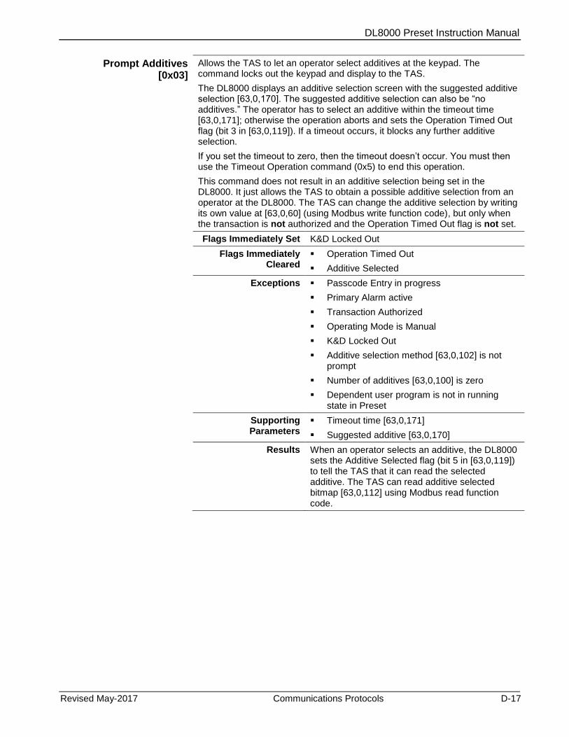
DL8000 Preset Instruction Manual
Revised May-2017 Communications Protocols D-17
Prompt Additives [0x03]
Allows the TAS to let an operator select additives at the keypad. The command locks out the keypad and display to the TAS.
The DL8000 displays an additive selection screen with the suggested additive selection [63,0,170]. The suggested additive selection can also be “no additives.” The operator has to select an additive within the timeout time [63,0,171]; otherwise the operation aborts and sets the Operation Timed Out flag (bit 3 in [63,0,119]). If a timeout occurs, it blocks any further additive selection.
If you set the timeout to zero, then the timeout doesn’t occur. You must then use the Timeout Operation command (0x5) to end this operation.
This command does not result in an additive selection being set in the DL8000. It just allows the TAS to obtain a possible additive selection from an operator at the DL8000. The TAS can change the additive selection by writing its own value at [63,0,60] (using Modbus write function code), but only when the transaction is not authorized and the Operation Timed Out flag is not set.
Flags Immediately Set K&D Locked Out
Flags Immediately Cleared
Operation Timed Out
Additive Selected
Exceptions Passcode Entry in progress
Primary Alarm active
Transaction Authorized
Operating Mode is Manual
K&D Locked Out
Additive selection method [63,0,102] is not prompt
Number of additives [63,0,100] is zero
Dependent user program is not in running state in Preset
Supporting Parameters
Timeout time [63,0,171]
Suggested additive [63,0,170]
Results When an operator selects an additive, the DL8000 sets the Additive Selected flag (bit 5 in [63,0,119]) to tell the TAS that it can read the selected additive. The TAS can read additive selected bitmap [63,0,112] using Modbus read function code.
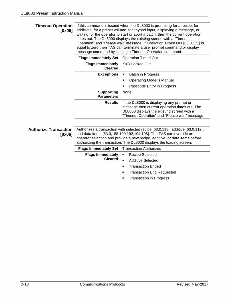
DL8000 Preset Instruction Manual
D-18 Communications Protocols Revised May-2017
Timeout Operation [0x05]
If this command is issued when the DL8000 is prompting for a recipe, for additives, for a preset volume, for keypad input, displaying a message, or waiting for the operator to start or abort a batch, then the current operation times out. The DL8000 displays the existing screen with a "Timeout Operation" and “Please wait” message. If Operation Timed Out [63,0,171] is equal to zero then TAS can terminate a user prompt command or display message command by issuing a Timeout Operation command.
Flags Immediately Set Operation Timed Out
Flags Immediately Cleared
K&D Locked Out
Exceptions Batch in Progress
Operating Mode is Manual
Passcode Entry in Progress
Supporting Parameters
None
Results If the DL8000 is displaying any prompt or message then current operation times out. The DL8000 displays the existing screen with a "Timeout Operation" and “Please wait” message.
Authorize Transaction [0x06]
Authorizes a transaction with selected recipe [63,0,118], additive [63,0,112], and data items [63,0,188;190;192;194;196]. The TAS can override an operator selection and provide a new recipe, additive, or data items before authorizing the transaction. The DL8000 displays the loading screen.
Flags Immediately Set Transaction Authorized
Flags Immediately Cleared
Recipe Selected
Additive Selected
Transaction Ended
Transaction End Requested
Transaction in Progress
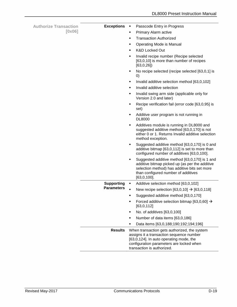
DL8000 Preset Instruction Manual
Revised May-2017 Communications Protocols D-19
Authorize Transaction [0x06]
Exceptions Passcode Entry in Progress
Primary Alarm active
Transaction Authorized
Operating Mode is Manual
K&D Locked Out
Invalid recipe number (Recipe selected [63,0,10] is more than number of recipes [63,0,26])
No recipe selected (recipe selected [63,0,1] is 0)
Invalid additive selection method [63,0,102]
Invalid additive selection
Invalid swing arm side (applicable only for Version 2.0 and later)
Recipe verification fail (error code [63,0,95] is set)
Additive user program is not running in DL8000
Additives module is running in DL8000 and suggested additive method [63,0,170] is not either 0 or 1. Returns Invalid additive selection method exception.
Suggested additive method [63,0,170] is 0 and additive bitmap [63,0,112] is set to more than configured number of additives [63,0,100].
Suggested additive method [63,0,170] is 1 and additive bitmap picked up (as per the additive selection method) has additive bits set more than configured number of additives [63,0,100].
Supporting Parameters
Additive selection method [63,0,102]
New recipe selection [63,0,10] [63,0,118]
Suggested additive method [63,0,170]
Forced additive selection bitmap [63,0,60] [63,0,112]
No. of additives [63,0,100]
Number of data items [63,0,186]
Data items [63,0,188;190;192;194;196]
Results When transaction gets authorized, the system assigns it a transaction sequence number [63,0,124]. In auto operating mode, the configuration parameters are locked when transaction is authorized.

DL8000 Preset Instruction Manual
D-20 Communications Protocols Revised May-2017
End Transaction [0x07]
Ends a transaction if a transaction is authorized. If a transaction is in progress and the DL8000 archive module is running, then the system archives the transaction and displays “Archiving Transaction” and “Please Wait” messages before ending the transaction. If the transaction is not in progress (that is, not a single batch is delivered in this transaction), then the transaction aborts. DL8000 displays a “Please wait” message until it receives the next command.
If an operator presses Stop while a transaction is in progress and the batch is not in progress or the batch is stopped, then the DL8000 sets the Transaction End Requested flag (bit 19 in [63,0,119]) to indicate the request for a transaction end. The TAS then can issue an End Transaction command.
Flags Immediately Set Transaction Ended
Flags Immediately Cleared
Transaction in Progress
Transaction Authorized
Transaction End Requested
Exceptions Batch in Progress
Operating Mode is Manual
No transaction authorized
Supporting Parameters
None
Results The transaction ends; if the transaction aborts without delivering a single batch, the system reduces the transaction sequence number [63,0,124] by one.
Prompt Preset Volume
[0x08]
Allows the TAS to let an operator enter a preset volume at the keypad. Issuing this command locks the keypad and display to the TAS. The DL8000 displays a preset selection screen. If the suggested preset volume [63,0,185] is greater than zero, the DL8000 “pre-types” the suggested preset volume. The operator can press Enter to accept displayed preset volume or press Alt + Backspace to enter another preset volume.
The operator must enter the preset within the timeout time [63,0,171]; otherwise the operation aborts and sets the Operation Timed Out flag (bit 3 in [63,0,119]).
If you set the timeout to zero, then the timeout doesn’t occur. You must then use the Timeout Operation command (0x05) to end this operation.
Flags Immediately Set K&D Locked Out
Flags Immediately Cleared
Operation Timed Out
Preset Volume Entered
Exceptions Passcode Entry in Progress
Batch in Progress
Primary Alarm active
Operating Mode is Manual
No transaction authorized
K&D Locked Out
Supporting Parameters
Suggested preset volume [63,0,185]
Preset volume entered [63,0,39]

DL8000 Preset Instruction Manual
Revised May-2017 Communications Protocols D-21
Prompt Preset Volume
[0x08]
Results When an operator enters the preset value, the DL8000 sets the Preset Volume Entered flag (bit 6 in [63,0,119]). A Prompt Preset Volume [0x08] command, Authorize Batch [0x0A] command, or a Clear Status [0x13] command clears this flag. After this the DL8000 displays the messages “Please Wait” and either “Preset Entered” or "Timeout Operation" (depending on the time out activity) and waits for a command. The TAS can read preset volume entered [63,0,39] using Modbus read function code.
Authorize Batch [0x0A]
Authorizes the batch for given preset volume [63,0,39]. When the batch authorizes, the DL8000 displays a loading screen. This also increments the batch sequence number [63,0,125] by 1 (which may roll from 9999 to 0) to indicate the prospective sequence number if the batch starts.
The operator must start loading within the timeout time [63,0,171]; otherwise the system sets the Operation Timed Out flag and automatically aborts the batch.
Flags Immediately Set K&D Locked Out
Batch Authorized
Flags Immediately Cleared
Preset Volume Entered
Operation Timed Out
Batch Ended
Batch Aborted
Batch Stopped
Batch in Progress
Exceptions Passcode Entry in Progress
Primary Alarm active
Batch Authorized
No transaction authorized
Operating Mode is Manual
K&D Locked Out
Invalid preset volume
Maximum batches delivered for transaction
Maximum Transaction Total (0x5F)
Tolerance error (0x5B)
Flow Rate Too Low/High
Supporting Parameters
Preset Volume Entered [63,0,39]
Timeout time [63,0,171]
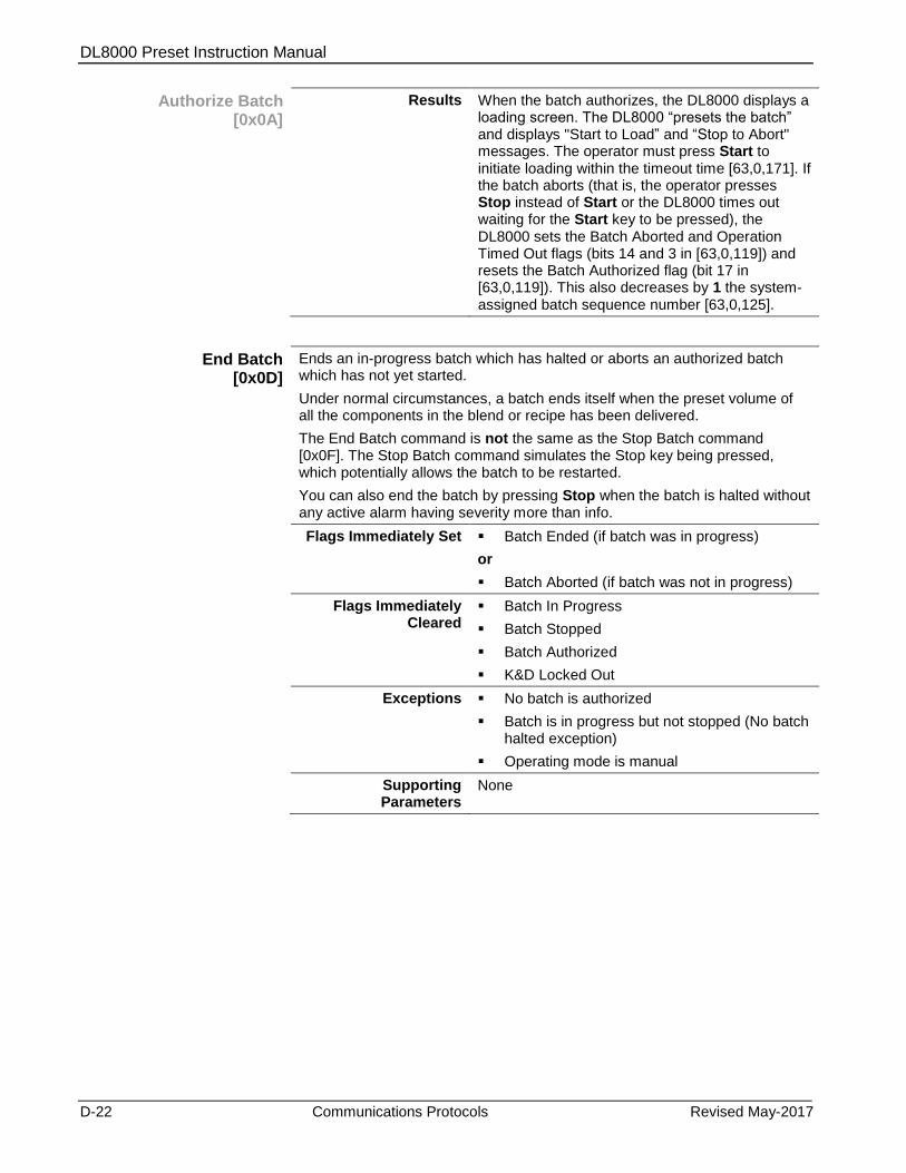
DL8000 Preset Instruction Manual
D-22 Communications Protocols Revised May-2017
Authorize Batch [0x0A]
Results When the batch authorizes, the DL8000 displays a loading screen. The DL8000 “presets the batch” and displays "Start to Load” and “Stop to Abort" messages. The operator must press Start to initiate loading within the timeout time [63,0,171]. If the batch aborts (that is, the operator presses Stop instead of Start or the DL8000 times out waiting for the Start key to be pressed), the DL8000 sets the Batch Aborted and Operation Timed Out flags (bits 14 and 3 in [63,0,119]) and resets the Batch Authorized flag (bit 17 in [63,0,119]). This also decreases by 1 the system-assigned batch sequence number [63,0,125].
End Batch [0x0D]
Ends an in-progress batch which has halted or aborts an authorized batch which has not yet started.
Under normal circumstances, a batch ends itself when the preset volume of all the components in the blend or recipe has been delivered.
The End Batch command is not the same as the Stop Batch command [0x0F]. The Stop Batch command simulates the Stop key being pressed, which potentially allows the batch to be restarted.
You can also end the batch by pressing Stop when the batch is halted without any active alarm having severity more than info.
Flags Immediately Set Batch Ended (if batch was in progress)
or
Batch Aborted (if batch was not in progress)
Flags Immediately Cleared
Batch In Progress
Batch Stopped
Batch Authorized
K&D Locked Out
Exceptions No batch is authorized
Batch is in progress but not stopped (No batch halted exception)
Operating mode is manual
Supporting Parameters
None

DL8000 Preset Instruction Manual
Revised May-2017 Communications Protocols D-23
End Batch [0x0D]
Results If batch ends, the DL8000 sets the Batch Ended flag to indicate that the batch has ended (which implies it cannot be restarted). If the archive module is running, then before ending the batch the system archives batch data and displays an "Archiving Batch" and “Please Wait” messages.
After completing the archiving, the DL8000 displays a “Please Wait” message and waits for a command from the TAS.
Setting the Batch Ended flag signals the TAS to request batch data.
If the batch aborts, the DL8000 sets the Batch Aborted flag, decreases by 1 the batch sequence number [63,0,125], and does not perform archiving. The DL8000 then displays a “Please Wait” message and waits for the next TAS command. The TAS can also use a Timeout Operation command [0x05] to abort a batch.
Use the Clear Status [0x13] command to clear the Batch Ended and Batch Aborted flags.
Start/Restart Batch [0x0E]
Starts a new batch that has been authorized but not in progress. You can also use this command to restart a batch in progress that has been stopped. To start a new batch, it must have been previously authorized using the Authorize Batch command [0x0A]. The batch must be halted without any active alarm having severity more than info for restarting a halted batch.
Use this command to “remote control” a DL8000 when an operator cannot be in the proximity of the DL8000. In these circumstances the TAS can entirely control the DL8000, which may not even be fitted with a display or keypad.
Flags Immediately Set Batch in Progress
Flags Immediately Cleared
Batch Stopped
Exceptions Primary Alarm active
Active alarm with severity more then info but less than primary (Alarm active exception - 0x5C)
No batch is authorized
No batch stopped
Operating Mode is Manual
Supporting Parameters
None
Results The DL8000 starts batch delivery (this is same as pressing Start).
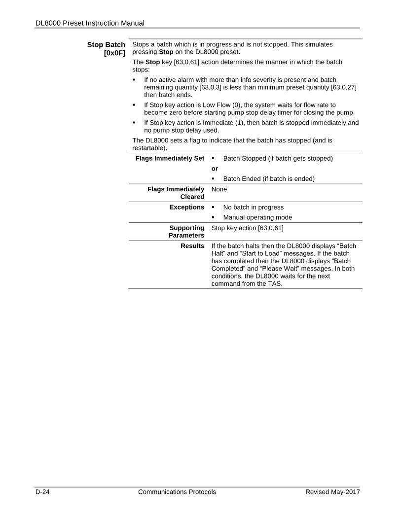
DL8000 Preset Instruction Manual
D-24 Communications Protocols Revised May-2017
Stop Batch [0x0F]
Stops a batch which is in progress and is not stopped. This simulates pressing Stop on the DL8000 preset.
The Stop key [63,0,61] action determines the manner in which the batch stops:
If no active alarm with more than info severity is present and batch remaining quantity [63,0,3] is less than minimum preset quantity [63,0,27] then batch ends.
If Stop key action is Low Flow (0), the system waits for flow rate to become zero before starting pump stop delay timer for closing the pump.
If Stop key action is Immediate (1), then batch is stopped immediately and no pump stop delay used.
The DL8000 sets a flag to indicate that the batch has stopped (and is restartable).
Flags Immediately Set Batch Stopped (if batch gets stopped)
or
Batch Ended (if batch is ended)
Flags Immediately Cleared
None
Exceptions No batch in progress
Manual operating mode
Supporting Parameters
Stop key action [63,0,61]
Results If the batch halts then the DL8000 displays “Batch Halt” and “Start to Load” messages. If the batch has completed then the DL8000 displays “Batch Completed” and “Please Wait” messages. In both conditions, the DL8000 waits for the next command from the TAS.

DL8000 Preset Instruction Manual
Revised May-2017 Communications Protocols D-25
Clear Status [0x13]
Allows the TAS to reset certain status flags. Copy status flags [63,0,172] indicates which flag should reset. If any bit is 1 in copy status flag then that flag resets when receiving this command. The following flags can be updated from the TAS:
Operation Timed Out (0x03 bit)
Recipe Selected (0x04 bit)
Additive Selected (0x05 bit)
Preset Volume Entered (0x06 bit)
Keypad Data Available (0x07 bit)
Program Code Value Changed (0x08 bit)
Key Pressed (0x0B bit)
Transaction Ended (0x0C bit)
Batch Ended (0x0D bit)
Batch Aborted (0x0E bit)
Transaction End Requested (0x13 bit)
Program Mode (0x16 bit)
When the DL8000 is in program mode, it can reset only the Program Mode flag; otherwise an exception occurs.
Note: If any of the flags requested to be reset are not allowed to be reset, then no flag resets out of those requested to be reset.
Flags Immediately Set None
Flags Immediately Cleared
Any flags this command requests to be cleared
Exceptions Status cannot reset
Operation mode is manual
Supporting Parameters
Copy status flags [63,0,172]
Results Reset of status flags as requested by the command.
Reset Primary Alarms [0x14]
Allows the TAS to reset one or all primary active alarms. If the chronologically oldest active primary alarm resets, this command has the same effect as a primary reset alarm via the alarm reset screen. All primary alarms reset if the alarm ID is 0xFF; otherwise, only the primary alarm with given alarm ID [63,0,173] resets.
This command basically allows the TAS operator to reset the primary alarm “remotely” without requiring a “hands-on” log-in to program mode for the DL8000.
The system raises the “Unable to Reset Alarm” exception if it cannot reset the configuration corrupted alarm.
Note: If all active primary alarms are requested to be reset and one of the raised alarms has a configuration corrupted alarm, the system first attempts to reset this alarm. If successful, it resets all other alarms.
Only active primary alarms reset. Alarms with severity more than info [1] but less than primary [4] which do not allow a batch to be started are not reset.
Flags Immediately Set None
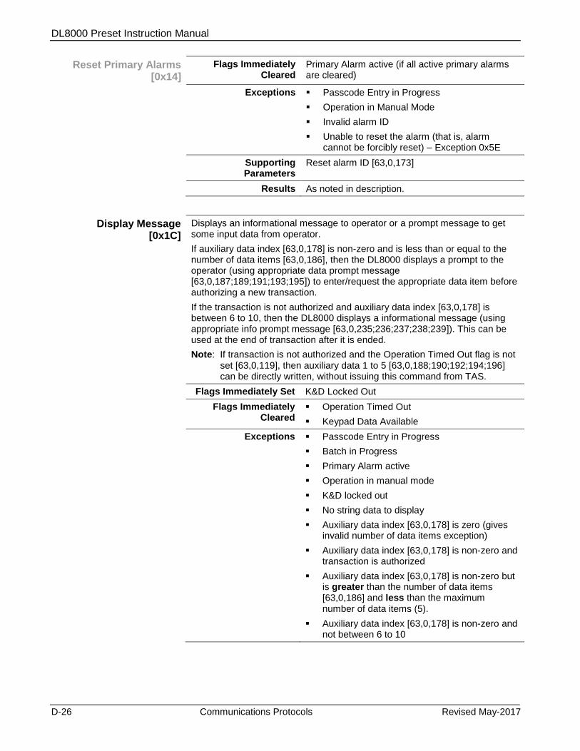
DL8000 Preset Instruction Manual
D-26 Communications Protocols Revised May-2017
Reset Primary Alarms [0x14]
Flags Immediately Cleared
Primary Alarm active (if all active primary alarms are cleared)
Exceptions Passcode Entry in Progress
Operation in Manual Mode
Invalid alarm ID
Unable to reset the alarm (that is, alarm cannot be forcibly reset) – Exception 0x5E
Supporting Parameters
Reset alarm ID [63,0,173]
Results As noted in description.
Display Message [0x1C]
Displays an informational message to operator or a prompt message to get some input data from operator.
If auxiliary data index [63,0,178] is non-zero and is less than or equal to the number of data items [63,0,186], then the DL8000 displays a prompt to the operator (using appropriate data prompt message [63,0,187;189;191;193;195]) to enter/request the appropriate data item before authorizing a new transaction.
If the transaction is not authorized and auxiliary data index [63,0,178] is between 6 to 10, then the DL8000 displays a informational message (using appropriate info prompt message [63,0,235;236;237;238;239]). This can be used at the end of transaction after it is ended.
Note: If transaction is not authorized and the Operation Timed Out flag is not set [63,0,119], then auxiliary data 1 to 5 [63,0,188;190;192;194;196] can be directly written, without issuing this command from TAS.
Flags Immediately Set K&D Locked Out
Flags Immediately Cleared
Operation Timed Out
Keypad Data Available
Exceptions Passcode Entry in Progress
Batch in Progress
Primary Alarm active
Operation in manual mode
K&D locked out
No string data to display
Auxiliary data index [63,0,178] is zero (gives invalid number of data items exception)
Auxiliary data index [63,0,178] is non-zero and transaction is authorized
Auxiliary data index [63,0,178] is non-zero but is greater than the number of data items [63,0,186] and less than the maximum number of data items (5).
Auxiliary data index [63,0,178] is non-zero and not between 6 to 10
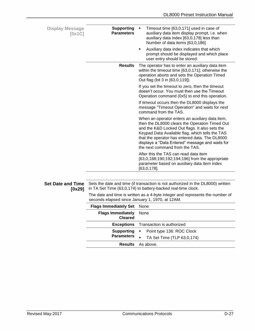
DL8000 Preset Instruction Manual
Revised May-2017 Communications Protocols D-27
Display Message [0x1C]
Supporting Parameters
Timeout time [63,0,171] used in case of auxiliary data item display prompt, i.e. when auxiliary data index [63,0,178] less than Number of data items [63,0,186]
Auxiliary data index indicates that which prompt should be displayed and which place user entry should be stored.
Results The operator has to enter an auxiliary data item within the timeout time [63,0,171]; otherwise the operation aborts and sets the Operation Timed Out flag (bit 3 in [63,0,119]).
If you set the timeout to zero, then the timeout doesn’t occur. You must then use the Timeout Operation command (0x5) to end this operation.
If timeout occurs then the DL8000 displays the message "Timeout Operation" and waits for next command from the TAS.
When an operator enters an auxiliary data item, then the DL8000 clears the Operation Timed Out and the K&D Locked Out flags. It also sets the Keypad Data Available flag, which tells the TAS that the operator has entered data. The DL8000 displays a “Data Entered” message and waits for the next command from the TAS.
After this the TAS can read data item [63,0,188;190;192;194;196] from the appropriate parameter based on auxiliary data item index [63,0,178].
Set Date and Time [0x29]
Sets the date and time (if transaction is not authorized in the DL8000) written in TA Set Time (63,0,174) to battery-backed real-time clock.
The date and time is written as a 4-byte integer and represents the number of seconds elapsed since January 1, 1970, at 12AM.
Flags Immediately Set None
Flags Immediately Cleared
None
Exceptions Transaction is authorized
Supporting Parameters
Point type 136: ROC Clock
TA Set Time (TLP 63,0,174)
Results As above.
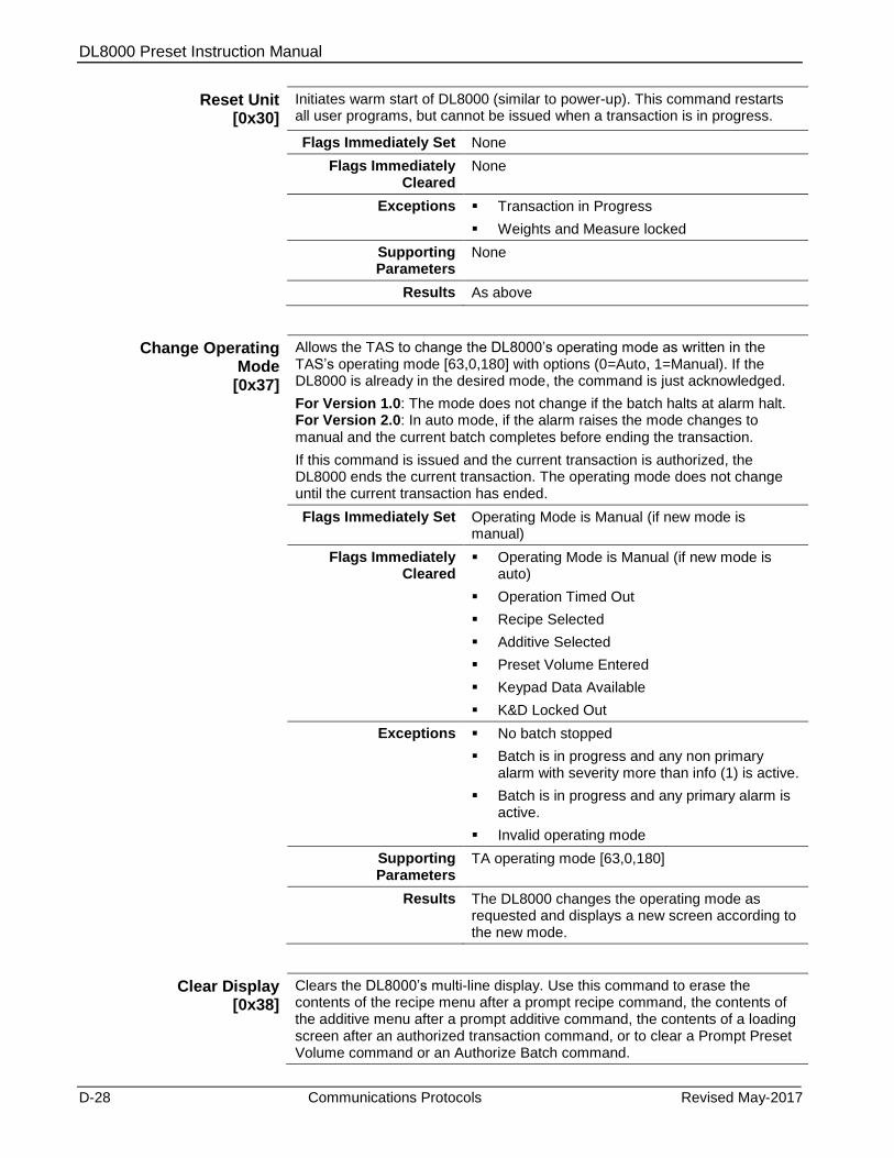
DL8000 Preset Instruction Manual
D-28 Communications Protocols Revised May-2017
Reset Unit [0x30]
Initiates warm start of DL8000 (similar to power-up). This command restarts all user programs, but cannot be issued when a transaction is in progress.
Flags Immediately Set None
Flags Immediately Cleared
None
Exceptions Transaction in Progress
Weights and Measure locked
Supporting Parameters
None
Results As above
Change Operating Mode
[0x37]
Allows the TAS to change the DL8000’s operating mode as written in the TAS’s operating mode [63,0,180] with options (0=Auto, 1=Manual). If the DL8000 is already in the desired mode, the command is just acknowledged.
For Version 1.0: The mode does not change if the batch halts at alarm halt. For Version 2.0: In auto mode, if the alarm raises the mode changes to manual and the current batch completes before ending the transaction.
If this command is issued and the current transaction is authorized, the DL8000 ends the current transaction. The operating mode does not change until the current transaction has ended.
Flags Immediately Set Operating Mode is Manual (if new mode is manual)
Flags Immediately Cleared
Operating Mode is Manual (if new mode is auto)
Operation Timed Out
Recipe Selected
Additive Selected
Preset Volume Entered
Keypad Data Available
K&D Locked Out
Exceptions No batch stopped
Batch is in progress and any non primary alarm with severity more than info (1) is active.
Batch is in progress and any primary alarm is active.
Invalid operating mode
Supporting Parameters
TA operating mode [63,0,180]
Results The DL8000 changes the operating mode as requested and displays a new screen according to the new mode.
Clear Display [0x38]
Clears the DL8000’s multi-line display. Use this command to erase the contents of the recipe menu after a prompt recipe command, the contents of the additive menu after a prompt additive command, the contents of a loading screen after an authorized transaction command, or to clear a Prompt Preset Volume command or an Authorize Batch command.
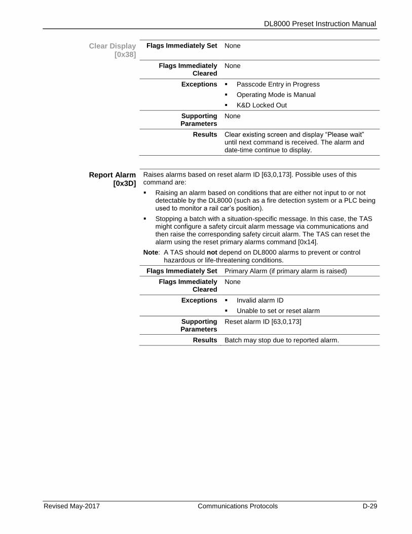
DL8000 Preset Instruction Manual
Revised May-2017 Communications Protocols D-29
Clear Display [0x38]
Flags Immediately Set None
Flags Immediately Cleared
None
Exceptions Passcode Entry in Progress
Operating Mode is Manual
K&D Locked Out
Supporting Parameters
None
Results Clear existing screen and display “Please wait” until next command is received. The alarm and date-time continue to display.
Report Alarm [0x3D]
Raises alarms based on reset alarm ID [63,0,173]. Possible uses of this command are:
Raising an alarm based on conditions that are either not input to or not detectable by the DL8000 (such as a fire detection system or a PLC being used to monitor a rail car’s position).
Stopping a batch with a situation-specific message. In this case, the TAS might configure a safety circuit alarm message via communications and then raise the corresponding safety circuit alarm. The TAS can reset the alarm using the reset primary alarms command [0x14].
Note: A TAS should not depend on DL8000 alarms to prevent or control hazardous or life-threatening conditions.
Flags Immediately Set Primary Alarm (if primary alarm is raised)
Flags Immediately Cleared
None
Exceptions Invalid alarm ID
Unable to set or reset alarm
Supporting Parameters
Reset alarm ID [63,0,173]
Results Batch may stop due to reported alarm.

DL8000 Preset Instruction Manual
D-30 Communications Protocols Revised May-2017
D.3.2 DanLoad 6000 Protocol Commands
The following table lists the DanLoad 6000 protocol commands,
indicates which DanLoad 6000 protocol commands the DL8000
supports, designates the operating mode (automatic or manual) in which
the command is valid, and notes which commands which are purely
read or write.
Table D-2. DanLoad 6000 Commands
Cmd No (decimal)
Cmd No (hex)
Command Name Valid modes (Automatic/Manual)
Command supported
Type
1 1 Prompt Recipe A Yes
2 2 Request Selected Recipe A Yes Read
3 3 Prompt Additives A Yes
4 4 Request Selected Additive A Yes Read
5 5 Timeout Operation A Yes
6 6 Authorize Transaction A Yes
7 7 End Transaction A Yes
8 8 Prompt Preset Volume A Yes
9 9 Request Preset Volume A Yes Read
10 A Authorize Batch A Yes
11 B Set Densities/Gravities A Yes Write
12 C Set Temperature A No
13 D End Batch A Yes
14 E Start/Restart Batch A Yes
15 F Stop Batch A Yes
16 10 Batch Data by Component A Yes Read
17 11 Additive Totalizer A/M Yes Read
18 12 Request Status A/M Yes Read
19 13 Clear Status A Yes
20 14 Reset Primary Alarms A Yes
21 15 Meter Totalizers A/M Yes Read
22 16 Component Totalizers A/M Yes Read
23 17 Unauthorized Flow A/M Yes Read
24 18 Data code value A/M No
25 19 Request Meter Values A/M Yes Read
26 1A Request Component Value A/M Yes Read
27 1B Request Power Fail Date and time
A/M Yes Read
28 1C Display Message A Yes
29 1D Request keypad data A Yes Read
30 1E Request Transaction Storage Status
A/M Yes Read

DL8000 Preset Instruction Manual
Revised May-2017 Communications Protocols D-31
Cmd No (decimal)
Cmd No (hex)
Command Name Valid modes (Automatic/Manual)
Command supported
Type
31 1F Transaction data by component
A/M Yes Read
32 20 Initialize Transaction Storage A/M Yes
33 21 Start Communication A/M Yes
34 22 Request program code values and attributes
A/M Yes Read
35 23 Set program code value A Yes Write
36 24 Modify program code attribute
A No
37 25 Request value changed attributes
A No
38 26 Clear value changed attributes
A No
39 27 Configure recipe A Yes Write
40 28 Get Date and Time A/M Yes Read
41 29 Set Date and Time A/M Yes Write
42 2A Request firmware version A/M Yes Read
43 2B Read input A/M No
44 2C Write output A/M No
45 2D DUART Diagnostic A/M No
46 2E ARCNET Diagnostic A/M No
47 2F Request crash data A/M No
48 30 Reset Unit A/M Yes
49 31 Last key pressed A/M Yes
50 32 RAM Tests A/M No
51 33 Swing arm side A/M Yes Read (only for version
2.0 and later)
52 34 Installed boards A/M No
53 35 Configure A/M No
54 36 Weight & Measure Switch A/M Yes Read
55 37 Change operating mode A/M Yes
56 38 Clear display A Yes
57 39 Request stored transaction A/M Yes
58 3A Request stored batch A/M Yes
59 3B Enhanced Start Communications
A/M Yes Read
60 3C Enhanced Request Status A/M Yes Read
61 3D Report Alarm A/M Yes
The DanLoad 6000 protocol contains all the data required to execute the
command in the command request frame. However, some differences
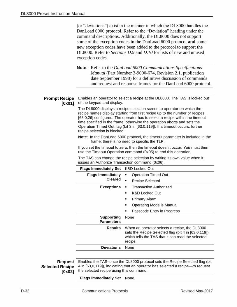
DL8000 Preset Instruction Manual
D-32 Communications Protocols Revised May-2017
(or “deviations”) exist in the manner in which the DL8000 handles the
DanLoad 6000 protocol. Refer to the “Deviation” heading under the
command descriptions. Additionally, the DL8000 does not support
some of the exception codes in the DanLoad 6000 protocol and some
new exception codes have been added to the protocol to support the
DL8000. Refer to Sections D.9 and D.10 for lists of new and unused
exception codes.
Note: Refer to the DanLoad 6000 Communications Specifications
Manual (Part Number 3-9000-674, Revision 2.1, publication
date September 1998) for a definitive discussion of commands
and request and response frames for the DanLoad 6000 protocol.
Prompt Recipe [0x01]
Enables an operator to select a recipe at the DL8000. The TAS is locked out of the keypad and display.
The DL8000 displays a recipe selection screen to operator on which the recipe names display starting from first recipe up to the number of recipes [63,0,26] configured. The operator has to select a recipe within the timeout time specified in the frame; otherwise the operation aborts and sets the Operation Timed Out flag (bit 3 in [63,0,119]). If a timeout occurs, further recipe selection is blocked.
Note: In the DanLoad 6000 protocol, the timeout parameter is included in the frame; there is no need to specific the TLP.
If you set the timeout to zero, then the timeout doesn’t occur. You must then use the Timeout Operation command (0x05) to end this operation.
The TAS can change the recipe selection by writing its own value when it issues an Authorize Transaction command (0x06).
Flags Immediately Set K&D Locked Out
Flags Immediately Cleared
Operation Timed Out
Recipe Selected
Exceptions Transaction Authorized
K&D Locked Out
Primary Alarm
Operating Mode is Manual
Passcode Entry in Progress
Supporting Parameters
None
Results When an operator selects a recipe, the DL8000 sets the Recipe Selected flag (bit 4 in [63,0,119]) which tells the TAS that it can read the selected recipe.
Deviations None
Request Selected Recipe
[0x02]
Enables the TAS–once the DL8000 protocol sets the Recipe Selected flag (bit 4 in [63,0,119]), indicating that an operator has selected a recipe—to request the selected recipe using this command.
Flags Immediately Set None

DL8000 Preset Instruction Manual
Revised May-2017 Communications Protocols D-33
Request Selected Recipe
[0x02]
Flags Immediately Cleared
None
Exceptions Primary Alarm
No Recipe Selected
Operating Mode is Manual
Supporting Parameters
As above
Results None
Deviations None
Prompt Additives
[0x03]
Enables an operator to select additives at the keypad. The TAS is locked out of the keypad and display.
The DL8000 displays an additive selection screen with the suggested additive selection received in command request frame. The suggested additive selection can be “no additives/” The operator has to select an additive within timeout time received in the command; otherwise, the operation aborts and sets the Operation Timed Out flag (bit 3 in [63,0,119]).
If you set the timeout to zero, then the timeout doesn’t occur. You must then use the Timeout Operation command (0x05) to end this operation.
This command does not result in an additive selection being set in the DL8000. It just enables the TAS to obtain a possible additive selection from an operator at the DL8000. The TAS can set the additive selection using the Authorize Transaction command.
Flags Immediately Set K&D Locked Out
Flags Immediately Cleared
Operation Timed Out
Additive Selected
Exceptions Passcode Entry in Progress
Primary Alarm
Transaction Authorized
Operating Mode is Manual
K&D Locked Out
Additive selection method [63,0,102] is not prompt
Number of additives [63,0,100] is zero
Dependent user program is not in running state in Preset.
Supporting Parameters
None
Results When operator selects additive, DL8000 sets Additive Selected flag (bit 5 in [63,0,119]) to indicate that the TAS can read the selected additive.

DL8000 Preset Instruction Manual
D-34 Communications Protocols Revised May-2017
Prompt Additives
[0x03]
Deviations Does not support the Transaction in Progress exception.
Supports additional exceptions such as Invalid Additive Selection Method and Module Not Loaded.
Supports additional exception Passcode Entry in Progress.
Request Selected Additives
[0x04]
Enables the TAS to request—once the DL8000 sets the additive flag (bit 5 in [63,0,119]) to indicate that the operator has selected additives—the selected additive using this command. The TAS specifies an additive selection in the Authorize Transaction command. This can be the operator-selected additive or an additive the TAS determines independently of the operator’s selection.
Flags Immediately Set None
Flags Immediately Cleared
None
Exceptions Primary Alarm
Transaction Authorized
Operating Mode is Manual
No additive selection made
Dependent user program is not in running state in Preset
Supporting Parameters
As above
Results None
Deviations Gives additional exception code (Dependent user program is not in running state in Preset) not present in original DanLoad 6000 protocol.
Timeout Operation
[0x05]
If this command is issued when the DL8000 is prompting for a recipe, for additives, for a preset volume, or for keypad input; displaying a message; or waiting for the operator to start or abort a batch, then the current operation times out. The DL8000 displays "Timeout Operation" and “Please wait” messages.
If the timeout time received with the earlier prompt or display command equals zero, then the TAS can terminate a user prompt command or display message command by issuing a Timeout Operation command.
Flags Immediately Set Operation Timed Out
Flags Immediately Cleared
K&D Locked Out
Exceptions Batch in Progress
Operating Mode is Manual
Passcode Entry in Progress
Supporting Parameters
None
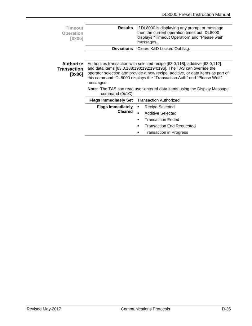
DL8000 Preset Instruction Manual
Revised May-2017 Communications Protocols D-35
Timeout Operation
[0x05]
Results If DL8000 is displaying any prompt or message then the current operation times out. DL8000 displays "Timeout Operation" and “Please wait” messages.
Deviations Clears K&D Locked Out flag.
Authorize Transaction
[0x06]
Authorizes transaction with selected recipe [63,0,118], additive [63,0,112], and data items [63,0,188;190;192;194;196]. The TAS can override the operator selection and provide a new recipe, additive, or data items as part of this command. DL8000 displays the “Transaction Auth” and “Please Wait” messages.
Note: The TAS can read user-entered data items using the Display Message command (0x1C).
Flags Immediately Set Transaction Authorized
Flags Immediately Cleared
Recipe Selected
Additive Selected
Transaction Ended
Transaction End Requested
Transaction in Progress

DL8000 Preset Instruction Manual
D-36 Communications Protocols Revised May-2017
Authorize Transaction
[0x06]
Exceptions Passcode Entry in Progress
Primary Alarm
Transaction Authorized
Operating Mode is Manual
K&D Locked Out
Invalid recipe number (Recipe selected [63,0,10] is more than number of recipes [63,0,26])
No recipe selected
Invalid additive selection method [63,0,102]
Invalid additive selection
Recipe verification fail
Additive user program is not running in DL8000 and suggested additive method received is 0 and forced additive bitmap received is non-zero.
Additives module is running in DL8000 and suggested additive selection method received is not 0 or 1. Returns Invalid additive selection method exception.
Suggested additive method received is 0 and additive bitmap [63,0,112] set more than configured number of additives [63,0,100].
Invalid Swing Arm Side
Invalid number of data prompts
Invalid additive selection method
Suggested additive method received is 1 and additive bitmap picked up as per the additive selection method has additive bits set more than configured number of additives [63,0,100].
Supporting Parameters
New recipe selected [63,0,118]
Suggested additive method [63,0,170]
Forced additive selection bitmap [63,0,112]
Number of additives [63,0,100]
Number of data items [63,0,186]
Data items [63,0,188;190;192;194;196]
Additive Selection Method [63,0,102]
Results When a transaction is authorized, the system assigns it a transaction sequence number [63,0,124]. All the configuration parameters are locked when transaction is authorized.
Deviations Additional exceptions supported:
Recipe Verification Fail
No Recipe Selected
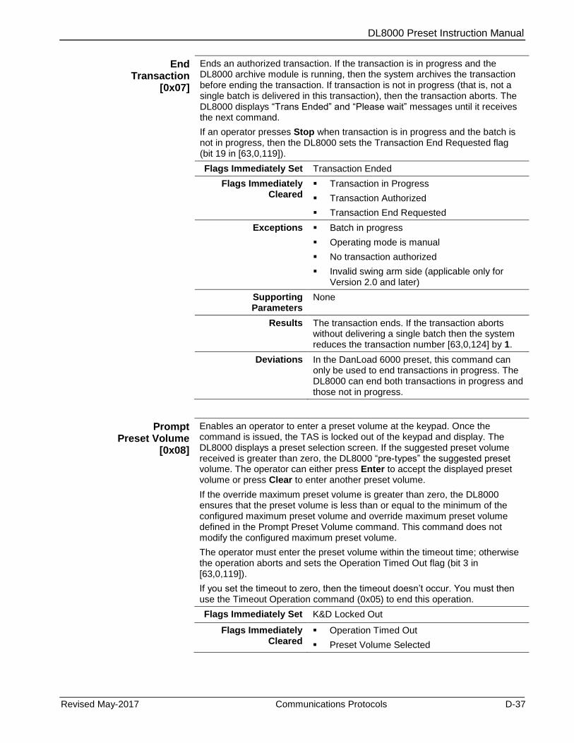
DL8000 Preset Instruction Manual
Revised May-2017 Communications Protocols D-37
End Transaction
[0x07]
Ends an authorized transaction. If the transaction is in progress and the DL8000 archive module is running, then the system archives the transaction before ending the transaction. If transaction is not in progress (that is, not a single batch is delivered in this transaction), then the transaction aborts. The DL8000 displays “Trans Ended” and “Please wait” messages until it receives the next command.
If an operator presses Stop when transaction is in progress and the batch is not in progress, then the DL8000 sets the Transaction End Requested flag (bit 19 in [63,0,119]).
Flags Immediately Set Transaction Ended
Flags Immediately Cleared
Transaction in Progress
Transaction Authorized
Transaction End Requested
Exceptions Batch in progress
Operating mode is manual
No transaction authorized
Invalid swing arm side (applicable only for Version 2.0 and later)
Supporting Parameters
None
Results The transaction ends. If the transaction aborts without delivering a single batch then the system reduces the transaction number [63,0,124] by 1.
Deviations In the DanLoad 6000 preset, this command can only be used to end transactions in progress. The DL8000 can end both transactions in progress and those not in progress.
Prompt Preset Volume
[0x08]
Enables an operator to enter a preset volume at the keypad. Once the command is issued, the TAS is locked out of the keypad and display. The DL8000 displays a preset selection screen. If the suggested preset volume received is greater than zero, the DL8000 “pre-types” the suggested preset volume. The operator can either press Enter to accept the displayed preset volume or press Clear to enter another preset volume.
If the override maximum preset volume is greater than zero, the DL8000 ensures that the preset volume is less than or equal to the minimum of the configured maximum preset volume and override maximum preset volume defined in the Prompt Preset Volume command. This command does not modify the configured maximum preset volume.
The operator must enter the preset volume within the timeout time; otherwise the operation aborts and sets the Operation Timed Out flag (bit 3 in [63,0,119]).
If you set the timeout to zero, then the timeout doesn’t occur. You must then use the Timeout Operation command (0x05) to end this operation.
Flags Immediately Set K&D Locked Out
Flags Immediately Cleared
Operation Timed Out
Preset Volume Selected
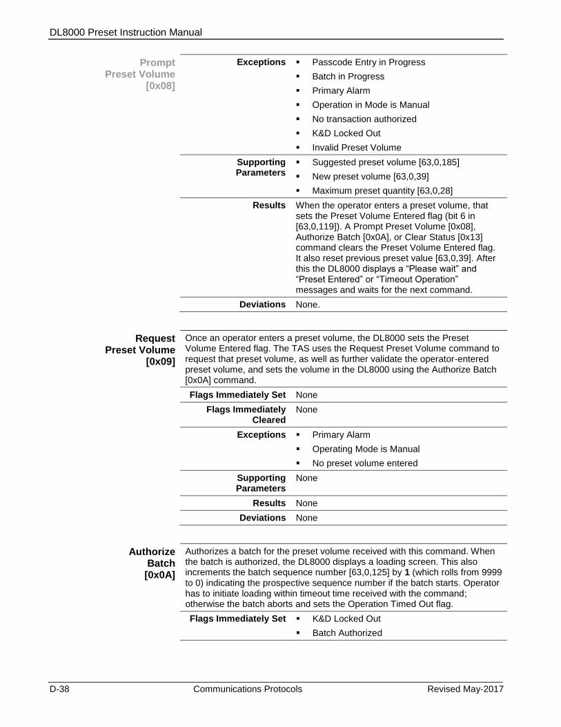
DL8000 Preset Instruction Manual
D-38 Communications Protocols Revised May-2017
Prompt Preset Volume
[0x08]
Exceptions Passcode Entry in Progress
Batch in Progress
Primary Alarm
Operation in Mode is Manual
No transaction authorized
K&D Locked Out
Invalid Preset Volume
Supporting Parameters
Suggested preset volume [63,0,185]
New preset volume [63,0,39]
Maximum preset quantity [63,0,28]
Results When the operator enters a preset volume, that sets the Preset Volume Entered flag (bit 6 in [63,0,119]). A Prompt Preset Volume [0x08], Authorize Batch [0x0A], or Clear Status [0x13] command clears the Preset Volume Entered flag. It also reset previous preset value [63,0,39]. After this the DL8000 displays a “Please wait” and “Preset Entered” or “Timeout Operation” messages and waits for the next command.
Deviations None.
Request Preset Volume
[0x09]
Once an operator enters a preset volume, the DL8000 sets the Preset Volume Entered flag. The TAS uses the Request Preset Volume command to request that preset volume, as well as further validate the operator-entered preset volume, and sets the volume in the DL8000 using the Authorize Batch [0x0A] command.
Flags Immediately Set None
Flags Immediately Cleared
None
Exceptions Primary Alarm
Operating Mode is Manual
No preset volume entered
Supporting Parameters
None
Results None
Deviations None
Authorize Batch [0x0A]
Authorizes a batch for the preset volume received with this command. When the batch is authorized, the DL8000 displays a loading screen. This also increments the batch sequence number [63,0,125] by 1 (which rolls from 9999 to 0) indicating the prospective sequence number if the batch starts. Operator has to initiate loading within timeout time received with the command; otherwise the batch aborts and sets the Operation Timed Out flag.
Flags Immediately Set K&D Locked Out
Batch Authorized
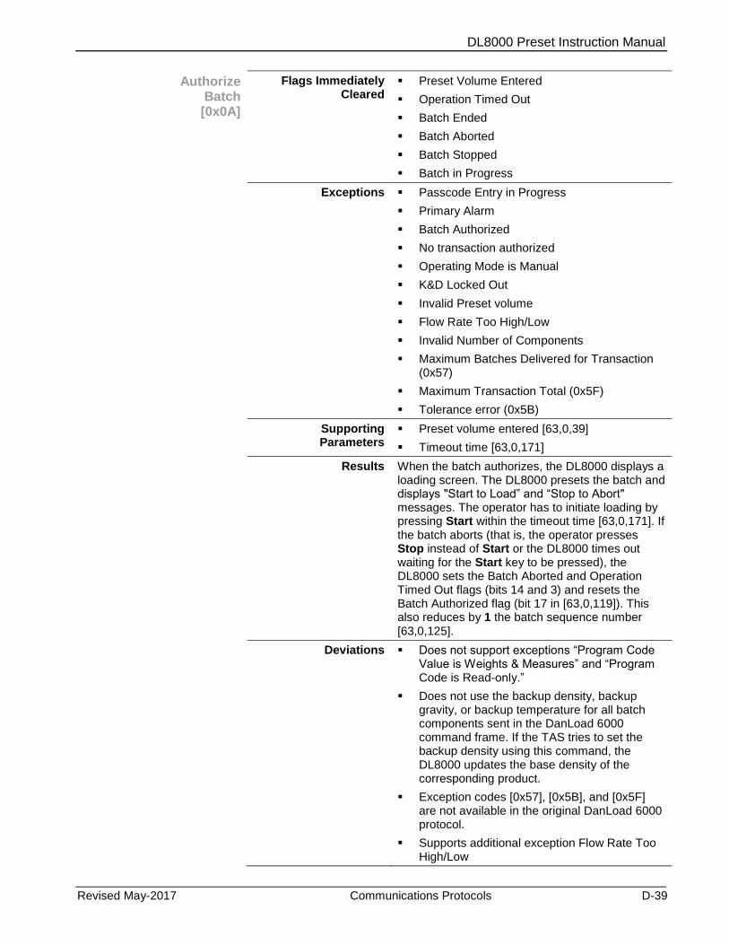
DL8000 Preset Instruction Manual
Revised May-2017 Communications Protocols D-39
Authorize Batch [0x0A]
Flags Immediately Cleared
Preset Volume Entered
Operation Timed Out
Batch Ended
Batch Aborted
Batch Stopped
Batch in Progress
Exceptions Passcode Entry in Progress
Primary Alarm
Batch Authorized
No transaction authorized
Operating Mode is Manual
K&D Locked Out
Invalid Preset volume
Flow Rate Too High/Low
Invalid Number of Components
Maximum Batches Delivered for Transaction (0x57)
Maximum Transaction Total (0x5F)
Tolerance error (0x5B)
Supporting Parameters
Preset volume entered [63,0,39]
Timeout time [63,0,171]
Results When the batch authorizes, the DL8000 displays a loading screen. The DL8000 presets the batch and displays "Start to Load” and “Stop to Abort" messages. The operator has to initiate loading by pressing Start within the timeout time [63,0,171]. If the batch aborts (that is, the operator presses Stop instead of Start or the DL8000 times out waiting for the Start key to be pressed), the DL8000 sets the Batch Aborted and Operation Timed Out flags (bits 14 and 3) and resets the Batch Authorized flag (bit 17 in [63,0,119]). This also reduces by 1 the batch sequence number [63,0,125].
Deviations Does not support exceptions “Program Code Value is Weights & Measures” and “Program Code is Read-only.”
Does not use the backup density, backup gravity, or backup temperature for all batch components sent in the DanLoad 6000 command frame. If the TAS tries to set the backup density using this command, the DL8000 updates the base density of the corresponding product.
Exception codes [0x57], [0x5B], and [0x5F] are not available in the original DanLoad 6000 protocol.
Supports additional exception Flow Rate Too High/Low
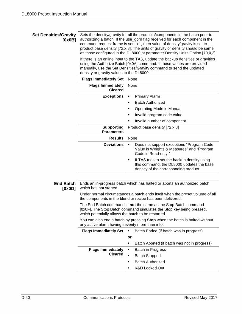
DL8000 Preset Instruction Manual
D-40 Communications Protocols Revised May-2017
Set Densities/Gravity [0x0B]
Sets the density/gravity for all the products/components in the batch prior to authorizing a batch. If the use_gord flag received for each component in the command request frame is set to 1, then value of density/gravity is set to product base density [72,x,8]. The units of gravity or density should be same as those configured in the DL8000 at parameter Density Units Option [70,0,3].
If there is an online input to the TAS, update the backup densities or gravities using the Authorize Batch [0x0A] command. If these values are provided manually, use the Set Densities/Gravity command to send the updated density or gravity values to the DL8000.
Flags Immediately Set None
Flags Immediately Cleared
None
Exceptions Primary Alarm
Batch Authorized
Operating Mode is Manual
Invalid program code value
Invalid number of component
Supporting Parameters
Product base density [72,x,8]
Results None
Deviations Does not support exceptions “Program Code Value is Weights & Measures” and “Program Code is Read-only.”
If TAS tries to set the backup density using this command, the DL8000 updates the base density of the corresponding product.
End Batch [0x0D]
Ends an in-progress batch which has halted or aborts an authorized batch which has not started.
Under normal circumstances a batch ends itself when the preset volume of all the components in the blend or recipe has been delivered.
The End Batch command is not the same as the Stop Batch command [0x0F]. The Stop Batch command simulates the Stop key being pressed, which potentially allows the batch to be restarted.
You can also end a batch by pressing Stop when the batch is halted without any active alarm having severity more than info.
Flags Immediately Set Batch Ended (if batch was in progress)
or
Batch Aborted (if batch was not in progress)
Flags Immediately Cleared
Batch in Progress
Batch Stopped
Batch Authorized
K&D Locked Out
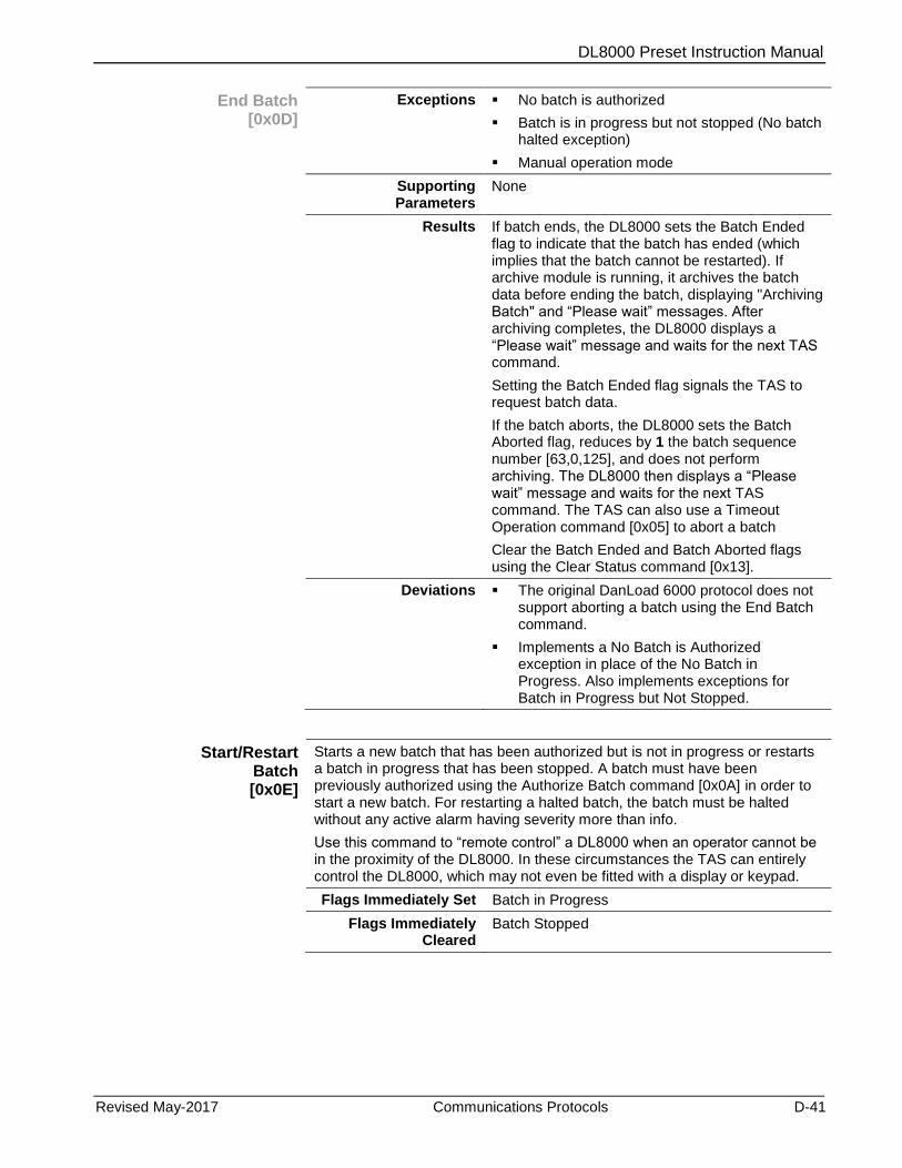
DL8000 Preset Instruction Manual
Revised May-2017 Communications Protocols D-41
End Batch [0x0D]
Exceptions No batch is authorized
Batch is in progress but not stopped (No batch halted exception)
Manual operation mode
Supporting Parameters
None
Results If batch ends, the DL8000 sets the Batch Ended flag to indicate that the batch has ended (which implies that the batch cannot be restarted). If archive module is running, it archives the batch data before ending the batch, displaying "Archiving Batch" and “Please wait” messages. After archiving completes, the DL8000 displays a “Please wait” message and waits for the next TAS command.
Setting the Batch Ended flag signals the TAS to request batch data.
If the batch aborts, the DL8000 sets the Batch Aborted flag, reduces by 1 the batch sequence number [63,0,125], and does not perform archiving. The DL8000 then displays a “Please wait” message and waits for the next TAS command. The TAS can also use a Timeout Operation command [0x05] to abort a batch
Clear the Batch Ended and Batch Aborted flags using the Clear Status command [0x13].
Deviations The original DanLoad 6000 protocol does not support aborting a batch using the End Batch command.
Implements a No Batch is Authorized exception in place of the No Batch in Progress. Also implements exceptions for Batch in Progress but Not Stopped.
Start/Restart Batch [0x0E]
Starts a new batch that has been authorized but is not in progress or restarts a batch in progress that has been stopped. A batch must have been previously authorized using the Authorize Batch command [0x0A] in order to start a new batch. For restarting a halted batch, the batch must be halted without any active alarm having severity more than info.
Use this command to “remote control” a DL8000 when an operator cannot be in the proximity of the DL8000. In these circumstances the TAS can entirely control the DL8000, which may not even be fitted with a display or keypad.
Flags Immediately Set Batch in Progress
Flags Immediately Cleared
Batch Stopped
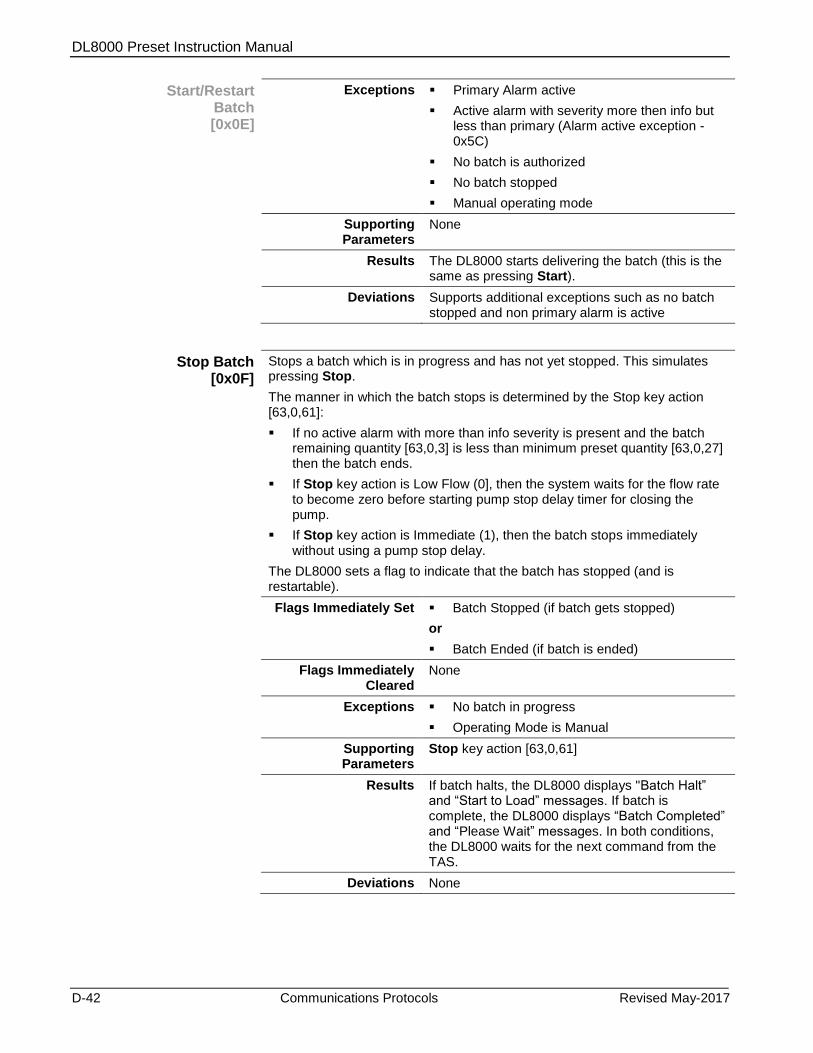
DL8000 Preset Instruction Manual
D-42 Communications Protocols Revised May-2017
Start/Restart Batch [0x0E]
Exceptions Primary Alarm active
Active alarm with severity more then info but less than primary (Alarm active exception - 0x5C)
No batch is authorized
No batch stopped
Manual operating mode
Supporting Parameters
None
Results The DL8000 starts delivering the batch (this is the same as pressing Start).
Deviations Supports additional exceptions such as no batch stopped and non primary alarm is active
Stop Batch [0x0F]
Stops a batch which is in progress and has not yet stopped. This simulates pressing Stop.
The manner in which the batch stops is determined by the Stop key action [63,0,61]:
If no active alarm with more than info severity is present and the batch remaining quantity [63,0,3] is less than minimum preset quantity [63,0,27] then the batch ends.
If Stop key action is Low Flow (0], then the system waits for the flow rate to become zero before starting pump stop delay timer for closing the pump.
If Stop key action is Immediate (1), then the batch stops immediately without using a pump stop delay.
The DL8000 sets a flag to indicate that the batch has stopped (and is restartable).
Flags Immediately Set Batch Stopped (if batch gets stopped)
or
Batch Ended (if batch is ended)
Flags Immediately Cleared
None
Exceptions No batch in progress
Operating Mode is Manual
Supporting Parameters
Stop key action [63,0,61]
Results If batch halts, the DL8000 displays "Batch Halt” and “Start to Load” messages. If batch is complete, the DL8000 displays “Batch Completed” and “Please Wait” messages. In both conditions, the DL8000 waits for the next command from the TAS.
Deviations None

DL8000 Preset Instruction Manual
Revised May-2017 Communications Protocols D-43
Batch Data by Component
[0x10]
Once a batch ends, the DL8000 sets a flag to indicate that the batch has ended and cannot be restarted. The TAS system can then use this command to request the data for the batch.
Flags Immediately Set None
Flags Immediately Cleared
None
Exceptions Operating Mode is Manual
No batch is ended
Supporting Parameters
Preset delivery type [63,0,29]
Results The response frame includes the following parameter values:
Batch sequence number [63,0,125]
Transaction sequence number [63,0,124]
Recipe number [63,0,118]
Current swing arm side [63,0,145] (applicable only for Version 2.0 and later)
Batch start date and time [63,0,232]
Batch end date and time [63,0,233]
Number of meters [63,0,20]
Number of components [63,0,21]
Number of additives [63,0,100]
Number of data prompts [63,0,186]
Meter Gross Batch start total snapshot [75,x,40]
Meter Net std or Mass Batch start total snapshot [75,x,41 or 42] based on delivery type
Meter Gross Batch end total snapshot [75,x,43]
Meter Net std or Mass Batch end total snapshot [75,x,44 or 45] based on delivery type
Component Gross Batch Totals [69,x,25]
Component Net std or Mass Batch Totals [69,x,27 or 28]
Component Avg (FWA) Batch Temperature [69,x,61]
Component Avg (FWA) Batch Density [69,x,100]
Component Avg (FWA) Batch Pressure [69,x,72]
Actual component % in batch [69,x,59]
Additive Batch totals [67,x,13]
Data items entered [63,0,188;190;192;194;196]

DL8000 Preset Instruction Manual
D-44 Communications Protocols Revised May-2017
Batch Data by Component
[0x10]
Deviations For Version 1.0: DL8000 does not support swing side arm, so it always returns a value of 1 in the command response frame.
For Version 2.0: None
Additive Totalizer [0x11]
Displays the free running totals of all additives according to the configured number of additives.
Flags Immediately Set None
Flags Immediately Cleared
None
Exceptions Additives Module is not running in preset.
Supporting Parameters
As below.
Results The response frame includes the following parameter values:
Number of additives [63,0,100]
Additive free running totals [67,x,12]
Deviations None
Request Status [0x12]
Displays the overall status of the DL8000. For the command response, see the Results section.
Status flags is a binary representation of the DL8000’s 32 status flags.
Safety circuit status is the current logical state (“open” or “closed”) of 8 general purpose safety circuit inputs. The least significant bit is safety circuit 1 etc. If you do not configure the safety circuit input then value of bit for respective safety circuit will be equal to unsafe state [0].
Alarm bitmaps indicate active (raised and not reset) alarms. The automation system can maintain a copy of the “alarm bytes” so that it can determine (for logging purposes) when alarms are raised or cleared.
Flags Immediately Set None
Flags Immediately Cleared
None
Exceptions None
Supporting Parameters As below
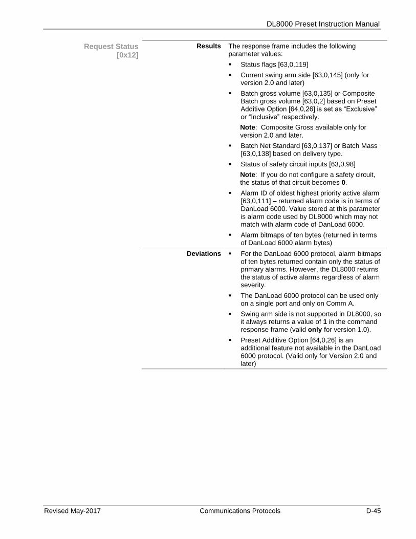
DL8000 Preset Instruction Manual
Revised May-2017 Communications Protocols D-45
Request Status [0x12]
Results The response frame includes the following parameter values:
Status flags [63,0,119]
Current swing arm side [63,0,145] (only for version 2.0 and later)
Batch gross volume [63,0,135] or Composite Batch gross volume [63,0,2] based on Preset Additive Option [64,0,26] is set as “Exclusive” or “Inclusive” respectively.
Note: Composite Gross available only for version 2.0 and later.
Batch Net Standard [63,0,137] or Batch Mass [63,0,138] based on delivery type.
Status of safety circuit inputs [63,0,98]
Note: If you do not configure a safety circuit, the status of that circuit becomes 0.
Alarm ID of oldest highest priority active alarm [63,0,111] – returned alarm code is in terms of DanLoad 6000. Value stored at this parameter is alarm code used by DL8000 which may not match with alarm code of DanLoad 6000.
Alarm bitmaps of ten bytes (returned in terms of DanLoad 6000 alarm bytes)
Deviations For the DanLoad 6000 protocol, alarm bitmaps of ten bytes returned contain only the status of primary alarms. However, the DL8000 returns the status of active alarms regardless of alarm severity.
The DanLoad 6000 protocol can be used only on a single port and only on Comm A.
Swing arm side is not supported in DL8000, so it always returns a value of 1 in the command response frame (valid only for version 1.0).
Preset Additive Option [64,0,26] is an additional feature not available in the DanLoad 6000 protocol. (Valid only for Version 2.0 and later)
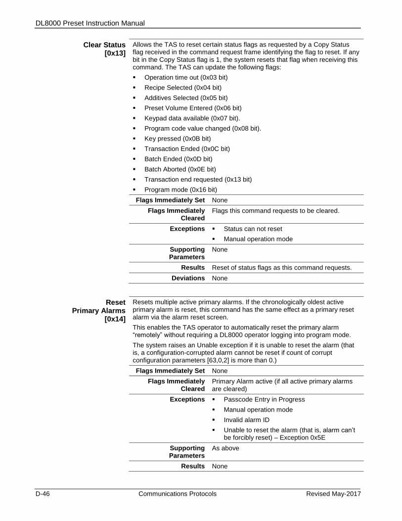
DL8000 Preset Instruction Manual
D-46 Communications Protocols Revised May-2017
Clear Status [0x13]
Allows the TAS to reset certain status flags as requested by a Copy Status flag received in the command request frame identifying the flag to reset. If any bit in the Copy Status flag is 1, the system resets that flag when receiving this command. The TAS can update the following flags:
Operation time out (0x03 bit)
Recipe Selected (0x04 bit)
Additives Selected (0x05 bit)
Preset Volume Entered (0x06 bit)
Keypad data available (0x07 bit).
Program code value changed (0x08 bit).
Key pressed (0x0B bit)
Transaction Ended (0x0C bit)
Batch Ended (0x0D bit)
Batch Aborted (0x0E bit)
Transaction end requested (0x13 bit)
Program mode (0x16 bit)
Flags Immediately Set None
Flags Immediately Cleared
Flags this command requests to be cleared.
Exceptions Status can not reset
Manual operation mode
Supporting Parameters
None
Results Reset of status flags as this command requests.
Deviations None
Reset Primary Alarms
[0x14]
Resets multiple active primary alarms. If the chronologically oldest active primary alarm is reset, this command has the same effect as a primary reset alarm via the alarm reset screen.
This enables the TAS operator to automatically reset the primary alarm “remotely” without requiring a DL8000 operator logging into program mode.
The system raises an Unable exception if it is unable to reset the alarm (that is, a configuration-corrupted alarm cannot be reset if count of corrupt configuration parameters [63,0,2] is more than 0.)
Flags Immediately Set None
Flags Immediately Cleared
Primary Alarm active (if all active primary alarms are cleared)
Exceptions Passcode Entry in Progress
Manual operation mode
Invalid alarm ID
Unable to reset the alarm (that is, alarm can’t be forcibly reset) – Exception 0x5E
Supporting Parameters
As above
Results None
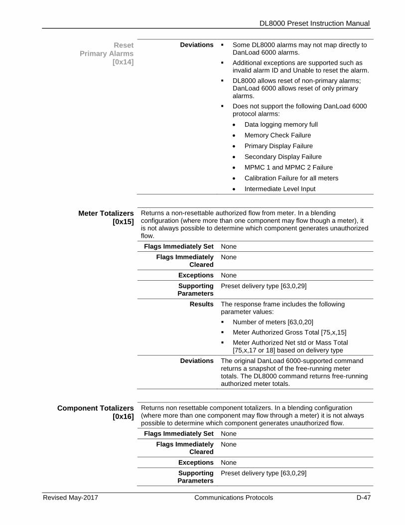
DL8000 Preset Instruction Manual
Revised May-2017 Communications Protocols D-47
Reset Primary Alarms
[0x14]
Deviations Some DL8000 alarms may not map directly to DanLoad 6000 alarms.
Additional exceptions are supported such as invalid alarm ID and Unable to reset the alarm.
DL8000 allows reset of non-primary alarms; DanLoad 6000 allows reset of only primary alarms.
Does not support the following DanLoad 6000 protocol alarms:
Data logging memory full
Memory Check Failure
Primary Display Failure
Secondary Display Failure
MPMC 1 and MPMC 2 Failure
Calibration Failure for all meters
Intermediate Level Input
Meter Totalizers [0x15]
Returns a non-resettable authorized flow from meter. In a blending configuration (where more than one component may flow though a meter), it is not always possible to determine which component generates unauthorized flow.
Flags Immediately Set None
Flags Immediately Cleared
None
Exceptions None
Supporting Parameters
Preset delivery type [63,0,29]
Results The response frame includes the following parameter values:
Number of meters [63,0,20]
Meter Authorized Gross Total [75,x,15]
Meter Authorized Net std or Mass Total [75,x,17 or 18] based on delivery type
Deviations The original DanLoad 6000-supported command returns a snapshot of the free-running meter totals. The DL8000 command returns free-running authorized meter totals.
Component Totalizers [0x16]
Returns non resettable component totalizers. In a blending configuration (where more than one component may flow through a meter) it is not always possible to determine which component generates unauthorized flow.
Flags Immediately Set None
Flags Immediately Cleared
None
Exceptions None
Supporting Parameters
Preset delivery type [63,0,29]
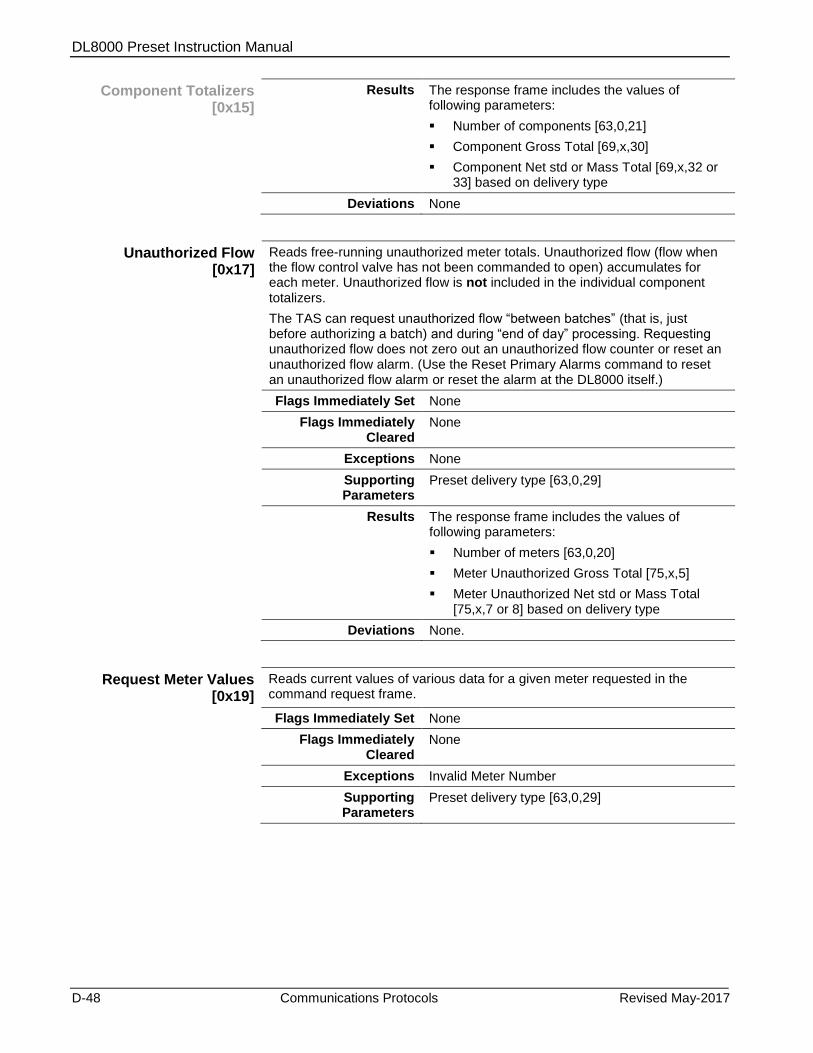
DL8000 Preset Instruction Manual
D-48 Communications Protocols Revised May-2017
Component Totalizers [0x15]
Results The response frame includes the values of following parameters:
Number of components [63,0,21]
Component Gross Total [69,x,30]
Component Net std or Mass Total [69,x,32 or 33] based on delivery type
Deviations None
Unauthorized Flow [0x17]
Reads free-running unauthorized meter totals. Unauthorized flow (flow when the flow control valve has not been commanded to open) accumulates for each meter. Unauthorized flow is not included in the individual component totalizers.
The TAS can request unauthorized flow “between batches” (that is, just before authorizing a batch) and during “end of day” processing. Requesting unauthorized flow does not zero out an unauthorized flow counter or reset an unauthorized flow alarm. (Use the Reset Primary Alarms command to reset an unauthorized flow alarm or reset the alarm at the DL8000 itself.)
Flags Immediately Set None
Flags Immediately Cleared
None
Exceptions None
Supporting Parameters
Preset delivery type [63,0,29]
Results The response frame includes the values of following parameters:
Number of meters [63,0,20]
Meter Unauthorized Gross Total [75,x,5]
Meter Unauthorized Net std or Mass Total [75,x,7 or 8] based on delivery type
Deviations None.
Request Meter Values [0x19]
Reads current values of various data for a given meter requested in the command request frame.
Flags Immediately Set None
Flags Immediately Cleared
None
Exceptions Invalid Meter Number
Supporting Parameters
Preset delivery type [63,0,29]
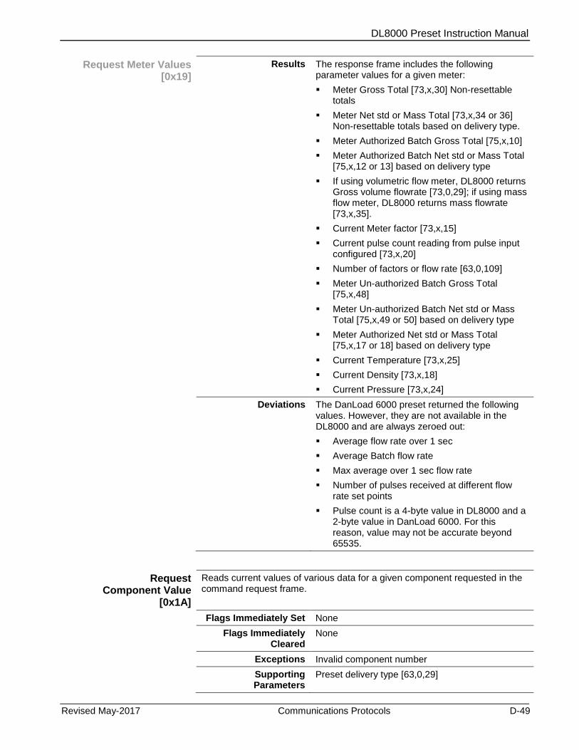
DL8000 Preset Instruction Manual
Revised May-2017 Communications Protocols D-49
Request Meter Values [0x19]
Results The response frame includes the following parameter values for a given meter:
Meter Gross Total [73,x,30] Non-resettable totals
Meter Net std or Mass Total [73,x,34 or 36] Non-resettable totals based on delivery type.
Meter Authorized Batch Gross Total [75,x,10]
Meter Authorized Batch Net std or Mass Total [75,x,12 or 13] based on delivery type
If using volumetric flow meter, DL8000 returns Gross volume flowrate [73,0,29]; if using mass flow meter, DL8000 returns mass flowrate [73,x,35].
Current Meter factor [73,x,15]
Current pulse count reading from pulse input configured [73,x,20]
Number of factors or flow rate [63,0,109]
Meter Un-authorized Batch Gross Total [75,x,48]
Meter Un-authorized Batch Net std or Mass Total [75,x,49 or 50] based on delivery type
Meter Authorized Net std or Mass Total [75,x,17 or 18] based on delivery type
Current Temperature [73,x,25]
Current Density [73,x,18]
Current Pressure [73,x,24]
Deviations The DanLoad 6000 preset returned the following values. However, they are not available in the DL8000 and are always zeroed out:
Average flow rate over 1 sec
Average Batch flow rate
Max average over 1 sec flow rate
Number of pulses received at different flow rate set points
Pulse count is a 4-byte value in DL8000 and a 2-byte value in DanLoad 6000. For this reason, value may not be accurate beyond 65535.
Request Component Value
[0x1A]
Reads current values of various data for a given component requested in the command request frame.
Flags Immediately Set None
Flags Immediately Cleared
None
Exceptions Invalid component number
Supporting Parameters
Preset delivery type [63,0,29]
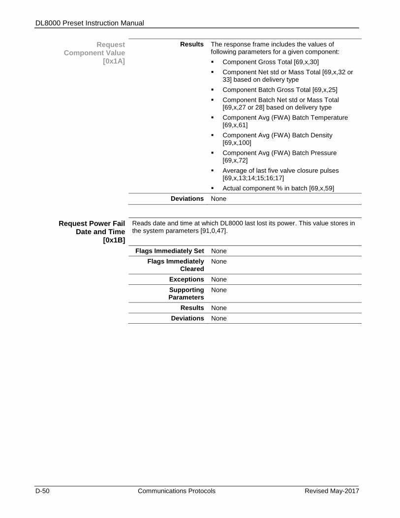
DL8000 Preset Instruction Manual
D-50 Communications Protocols Revised May-2017
Request Component Value
[0x1A]
Results The response frame includes the values of following parameters for a given component:
Component Gross Total [69,x,30]
Component Net std or Mass Total [69,x,32 or 33] based on delivery type
Component Batch Gross Total [69,x,25]
Component Batch Net std or Mass Total [69,x,27 or 28] based on delivery type
Component Avg (FWA) Batch Temperature [69,x,61]
Component Avg (FWA) Batch Density [69,x,100]
Component Avg (FWA) Batch Pressure [69,x,72]
Average of last five valve closure pulses [69,x,13;14;15;16;17]
Actual component % in batch [69,x,59]
Deviations None
Request Power Fail Date and Time
[0x1B]
Reads date and time at which DL8000 last lost its power. This value stores in the system parameters [91,0,47].
Flags Immediately Set None
Flags Immediately Cleared
None
Exceptions None
Supporting Parameters
None
Results None
Deviations None

DL8000 Preset Instruction Manual
Revised May-2017 Communications Protocols D-51
Display Message [0x1C]
Displays to the DL8000 operator either an informational message or a prompt message designed to get some input data.
The DL8000 prompts the operator with display data message text received in the command request frame [63,0,175] to enter/request data before authorizing a new batch. It clears data item [63,0,177].
The prompt field width received in the command request frame is limited between 0 to 8. If its value is less than 0, then 0 is assumed; if its value is more than 8, then 8 is assumed.
If the prompt field width is zero then it acts as a pure informational message command. If the prompt field width is non-zero then the operator can use the rest of the number of characters for the data. Pressing the Clear key clears the input field and restarts input entry. Pressing the Enter key terminates input entry. If an operator presses Enter when the input field is blank, the keypad data available to the automation system a value of 0.
If the timeout time received in the command request frame is less than 0, then the DL8000 uses the configured timeout time [63,0,171]. If timeout is set as zero then a timeout never occurs (that is, a message or prompt displays until the DL8000 receives a Timeout Operation command [0x05]). If timeout value received is greater than 0, then use received timeout value.
Valid input control values are:
0 = Display Numeric keys on display
1 = Display an asterisk (*) for each numeric key pressed
Flags Immediately Set K&D Locked Out
Flags Immediately Cleared
Operation Timed Out
Keypad Data Available
Exceptions Passcode Entry in Progress
Batch in Progress
Primary Alarm
Operating Mode is Manual
K&D Locked Out
Supporting Parameters
Prompt width [63,0,176]
Timeout time [63,0,171]
Display message input control [63,0,253]
Results The operator has to enter auxiliary data item within configured timeout time [63,0,171]; otherwise, the operation aborts and sets the Operation Timed Out flag (bit 3 in [63,0,119]). If a timeout occurs, the DL8000 displays a "Timeout Operation" message and waits for the next TAS command.
Once the operator enters auxiliary data item, the DL8000 clears the Operation Timed Out and K&D Locked Out flags. It also sets the Keypad Data Available flag, which tells the TAS that the operator has entered data. The DL8000 displays a “Data Entered” message and waits for the next TAS command.
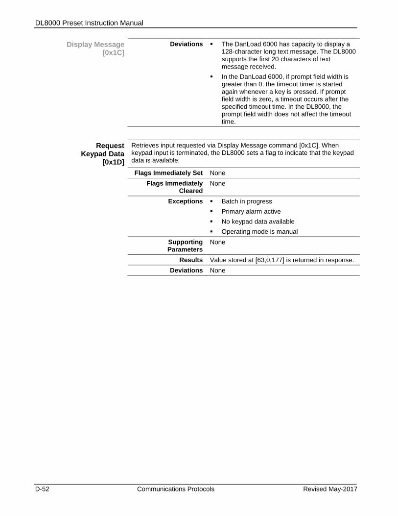
DL8000 Preset Instruction Manual
D-52 Communications Protocols Revised May-2017
Display Message [0x1C]
Deviations The DanLoad 6000 has capacity to display a 128-character long text message. The DL8000 supports the first 20 characters of text message received.
In the DanLoad 6000, if prompt field width is greater than 0, the timeout timer is started again whenever a key is pressed. If prompt field width is zero, a timeout occurs after the specified timeout time. In the DL8000, the prompt field width does not affect the timeout time.
Request Keypad Data
[0x1D]
Retrieves input requested via Display Message command [0x1C]. When keypad input is terminated, the DL8000 sets a flag to indicate that the keypad data is available.
Flags Immediately Set None
Flags Immediately Cleared
None
Exceptions Batch in progress
Primary alarm active
No keypad data available
Operating mode is manual
Supporting Parameters
None
Results Value stored at [63,0,177] is returned in response.
Deviations None
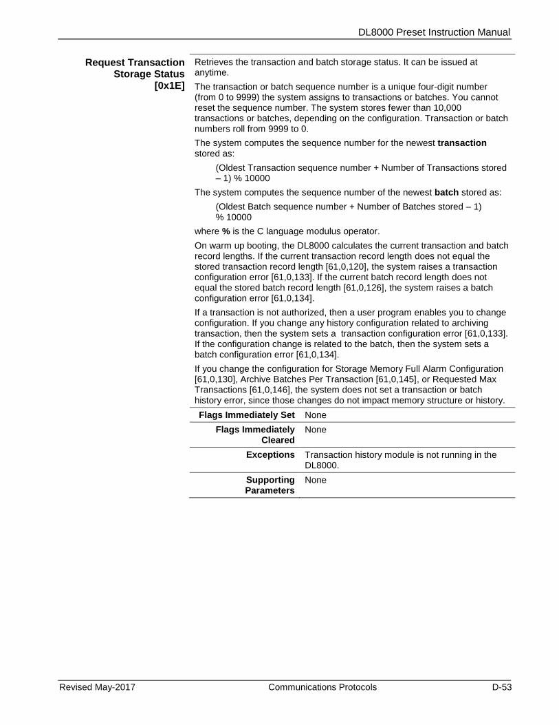
DL8000 Preset Instruction Manual
Revised May-2017 Communications Protocols D-53
Request Transaction Storage Status
[0x1E]
Retrieves the transaction and batch storage status. It can be issued at anytime.
The transaction or batch sequence number is a unique four-digit number (from 0 to 9999) the system assigns to transactions or batches. You cannot reset the sequence number. The system stores fewer than 10,000 transactions or batches, depending on the configuration. Transaction or batch numbers roll from 9999 to 0.
The system computes the sequence number for the newest transaction stored as:
(Oldest Transaction sequence number + Number of Transactions stored – 1) % 10000
The system computes the sequence number of the newest batch stored as:
(Oldest Batch sequence number + Number of Batches stored – 1) % 10000
where % is the C language modulus operator.
On warm up booting, the DL8000 calculates the current transaction and batch record lengths. If the current transaction record length does not equal the stored transaction record length [61,0,120], the system raises a transaction configuration error [61,0,133]. If the current batch record length does not equal the stored batch record length [61,0,126], the system raises a batch configuration error [61,0,134].
If a transaction is not authorized, then a user program enables you to change configuration. If you change any history configuration related to archiving transaction, then the system sets a transaction configuration error [61,0,133]. If the configuration change is related to the batch, then the system sets a batch configuration error [61,0,134].
If you change the configuration for Storage Memory Full Alarm Configuration [61,0,130], Archive Batches Per Transaction [61,0,145], or Requested Max Transactions [61,0,146], the system does not set a transaction or batch history error, since those changes do not impact memory structure or history.
Flags Immediately Set None
Flags Immediately Cleared
None
Exceptions Transaction history module is not running in the DL8000.
Supporting Parameters
None

DL8000 Preset Instruction Manual
D-54 Communications Protocols Revised May-2017
Request Transaction Storage Status
[0x1E]
Results The command response frame consists of the following parameter values:
Oldest Transaction sequence number stored [61,0,123]
Number of Transactions stored [61,0,122]
Maximum number of transactions that can be stored [61,0,121]
Transaction Configuration Error [61,0,133]
Oldest Batch sequence number stored [61,0,129]
Number of Batches stored [61,0,128]
Maximum number of batch that can be stored [61,0,127]
Batch Configuration Error [61,0,134]
Deviations None
Transaction Data by Component
[0x1F]
Requests data for the transaction after the current transaction has ended. The DL8000 sets a flag indicating that the transaction has ended. In manual operating mode, press Stop to end a transaction when there is a transaction in progress and no batch in progress. In automatic operating mode, you end a transaction using the End Transaction command [0x07].
Flags Immediately Set None
Flags Immediately Cleared
None
Exceptions No Transaction ended
Invalid transaction sequence number
Supporting Parameters
Preset delivery type [63,0,29]
DL8000 Preset Instruction Manual
Revised May-2017 Communications Protocols D-55
Transaction Data by Component
[0x1F]
Results The command response frame consists of the following parameter values:
Transaction sequence number [61,0,124] same as that received in command request frame
Recipe number [63,0,118]
Current swing arm side [63,0,145] (applicable valid only for Version 2.0 and later)
Transaction gross volume [63,0,140] or Composite Transaction gross volume [64,0,3] based on Preset Additive option [64,0,26] is set as “Exclusive” or “Inclusive” respectively.
Note: Composite Transaction available only in version 2.0 and later)
Transaction net-std volume or mass [63,0,142 or 143] based on delivery type
Transaction start date and time [63,0,230]
Transaction end date and time [63,0,231]
Number of meters [63,0,20]
Number of data prompts [63,0,186]
Meter Gross Transaction start total snapshot [75,x,34]
Meter Net std or Mass Transaction start total snapshot [75,x,35 or 36] based on delivery type
Meter Gross Transaction end total snapshot [75,x,37]
Meter Net std or Mass Transaction end total snapshot [75,x,38 or 39] based on delivery type
Data items entered [63,0,188;190;192;194;196] by operator in manual or downloaded by automation system in automatic
Deviations Preset Additive option [64,0,26] is additional feature not available in DanLoad 6000 protocol (applicable for Version 2.0 and later).
Swing arm side is not supported in DL8000, so its value returned in the command response frame is always 1 (applicable only for Version 1).
Initialize Transaction Storage
[0x20]
Clears all stored transaction history records and initializes them at zero.
Flags Immediately Set None
Flags Immediately Cleared
None
DL8000 Preset Instruction Manual
D-56 Communications Protocols Revised May-2017
Initialize Transaction Storage
[0x20]
Exceptions Transaction in Progress
Transaction history module is not running in preset
Supporting Parameters
None
Results Transaction storage initialization may take several seconds to complete. This command does not modify the rolling four-digit transaction and batch sequence numbers.
Deviations None
Start Communication [0x21]
Initiates communication between the TAS and the DL8000. When the DL8000 has experienced:
Powered-up/reset
Program mode exit
Communication failure alarm reset.
The TAS can start or initiate communication with the DL8000 using this command. If communications are already started when this command is received, then the communication link is re-initialized but operations at the DL8000 are unaffected. The command resets the alternating function code sequence, using function codes 41h or 42h for the query. The next (non-retry) query from the TAS should use the other function code (that is, if 41h initiates the query, 42h should be the next non-retry query).
Under the DanLoad 6000 protocol, until communications are established using this command, the DL8000 accepts no other command.
Operation of DL8000 remains unaffected by Start Communication command.
Flags Immediately Set None
Flags Immediately Cleared
None
Exceptions None
Supporting Parameters
None
Results The command response frame consists of the following parameters:
Number of meters [63,0,20]
Number of components [63,0,21]
Number of valves [63,0,19]
Number of factors or flow rate [63,0,109]
Number of recipes [63,0,26]
Number of additives [63,0,100]
Temperature Units Option [70,0,2]
Temperature correction option [71,x,28]
Pressure correction option [71,x,29]
DL8000 Preset Instruction Manual
Revised May-2017 Communications Protocols D-57
Start Communication [0x21]
Deviations The Temperature correction option [71x,28] values the DL8000 returns do not map directly to the DanLoad 6000 program codes (432, 435, etc.) for all values.
The Pressure correction option [71,x,29] values the DL8000 returns do not map directly to the DanLoad 6000 program codes (444, 447, etc.) for all values.
Request Program Code Values and Attributes
[0x22]
A program code value is a number. A program code identifies a variable (parameter) in DanLoad 6000. This parameter is mapped to DL8000. A program code value is the value of variable identified by the program code and can be a number of byte length depending on the program code. A program code’s attributes are the properties associated with that program code. Since TAS can request a range of program code values (from those which are supported) and attributes the response data field is variable field length.
The following program codes (with their data types) are supported for this release:
026 Unit Type (16-bit integer)
028 Language (8- bit integer)
042 Last Transaction Number(16-bit integer)
043 Last Batch No(16-bit integer)
044 Additive Unit(16-bit integer)
046 Density/Gravity Scale (8- bit integer)
067/070/073/076 Component 1 to 4 Meter Nos.(16-bit integer)
457/459/461/463 Backup density(32-bit integer)
Flags Immediately Set None
Flags Immediately Cleared
None
Exceptions 03h Response’s data field too long
44h Invalid program code number
Supporting Parameters
Unit Type [63,0,12]
Language [63,0,14]
Last Transaction Number [63,0,124]
Last Batch No [63,0,125]
Additive Unit [63,0,101]
Density/Gravity Scale [63,0,151]
Component 1 to 4 Meter Nos [69,X,7]
Backup density [72, X, 8]

DL8000 Preset Instruction Manual
D-58 Communications Protocols Revised May-2017
Request Program Code Values and Attributes
[0x22]
Results The DL8000 should respond with the value and attributes of the requested program codes (the ones which are supported).
Some parameters are returned after scaling. The scale can be a fixed multiplication factor or may depend on some other configurable parameter.
Scaled parameters are :
457/459/461/463 Backup density – scaling multiplication factor = 10 ^ (PC046 Density/Gravity Scale )
Deviations The program code attribute byte contains only the following flags:
00 - No attribute set.
01 - Read only.
02 - Weights and Measures.
The other flags are not supported.
Set Program Code Value
[0x23]
Use this to configure the DL8000 from a TAS. The DL8000 validates the program code value being sent and responds with exception code 45h if it is not valid.
The following program codes (with their data types) have been supported for this release:
026 Unit Type (16-bit integer)
028 Language (8- bit integer)
044 Additive Unit(16-bit integer)
046 Density/Gravity Scale (8- bit integer)
067/070/073/076 Component 1 to 4 Meter Nos.(16-bit integer)
457/459/461/463 Backup density(32-bit integer)
Flags Immediately Set None
Flags Immediately Cleared
None
Exceptions 04h Program code value is Weights and Measures.
09h Transaction in progress
0Ah Primary alarm active
11h Program code value is read only
15h Operating mode is manual
44h Invalid program code
45h Invalid program code value
Supporting Parameters
Unit Type [63, 0, 12]
Language [63, 0, 14]
Additive Unit [63, 0, 101]
Density/Gravity Scale [63, 0, 151]
Component 1 to 4 Meter Nos [69, X, 7]
Backup density [72, X, 8]
DL8000 Preset Instruction Manual
Revised May-2017 Communications Protocols D-59
Set Program Code Values
[0x23]
Results Some parameters are set after scaling. The scale can be a fixed multiplication factor or may depend on some other configurable parameter.
The scaled parameters are :
457/459/461/463 Backup density – scaling multiplication factor = 1 / (10 ^ (PC046 Density/Gravity Scale )
Deviations Transaction authorized exception is checked in place of Transaction in progress
Configure Recipe [0x27]
Use this command when configuring specific recipes.
Inline blending has special considerations. Set the low/high proportion flags carefully; it is possible that a particular component is high proportion (flag=0) for some recipes and low proportion (flag=1) for different recipes on the same DL8000. This is a function of the size of meter (and thus the usable range of flow rates) through which the component flows. You may need to modify the overall recipe low and high flow rates [68,x,23 and 24] if you modify component percentages through communications.
This command does not automatically increase or decrease the configured number of recipes [63,0,26].
Flags Immediately Set Program Code Value Changed
Flags Immediately Cleared
None
Exceptions Primary alarm active
Transaction authorized
Operating mode is manual
Invalid recipe number
Invalid Number of components (if number of components received in command request frame is not the same as the configured number of components)
Invalid Program Code Value (if component percentage received is more than 100 or any character received in delivery sequence is non-numeric or is more than ASCII equivalent of configured number of components)
Supporting Parameters
Recipe name [68,x,0]
Percentage of component 1 [68,x,1]
Percentage of component 2 [68,x,2]
Percentage of component 3 [68,x,3]
Percentage of component 4 [68,x,4]
Component Delivery Sequence or low/high proportion [68,x,17]
Number of components [63,0,21]
Results If no exceptions are raised then parameters received for the recipe get written to the above locations.
Deviations Supports additional exception such as Invalid program code value
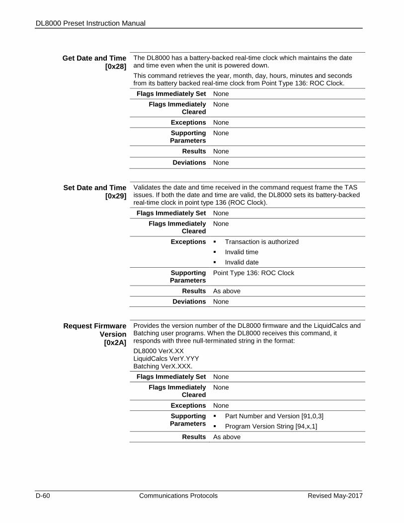
DL8000 Preset Instruction Manual
D-60 Communications Protocols Revised May-2017
Get Date and Time [0x28]
The DL8000 has a battery-backed real-time clock which maintains the date and time even when the unit is powered down.
This command retrieves the year, month, day, hours, minutes and seconds from its battery backed real-time clock from Point Type 136: ROC Clock.
Flags Immediately Set None
Flags Immediately Cleared
None
Exceptions None
Supporting Parameters
None
Results None
Deviations None
Set Date and Time [0x29]
Validates the date and time received in the command request frame the TAS issues. If both the date and time are valid, the DL8000 sets its battery-backed real-time clock in point type 136 (ROC Clock).
Flags Immediately Set None
Flags Immediately Cleared
None
Exceptions Transaction is authorized
Invalid time
Invalid date
Supporting Parameters
Point Type 136: ROC Clock
Results As above
Deviations None
Request Firmware Version
[0x2A]
Provides the version number of the DL8000 firmware and the LiquidCalcs and Batching user programs. When the DL8000 receives this command, it responds with three null-terminated string in the format:
DL8000 VerX.XX LiquidCalcs VerY.YYY Batching VerX.XXX.
Flags Immediately Set None
Flags Immediately Cleared
None
Exceptions None
Supporting Parameters
Part Number and Version [91,0,3]
Program Version String [94,x,1]
Results As above
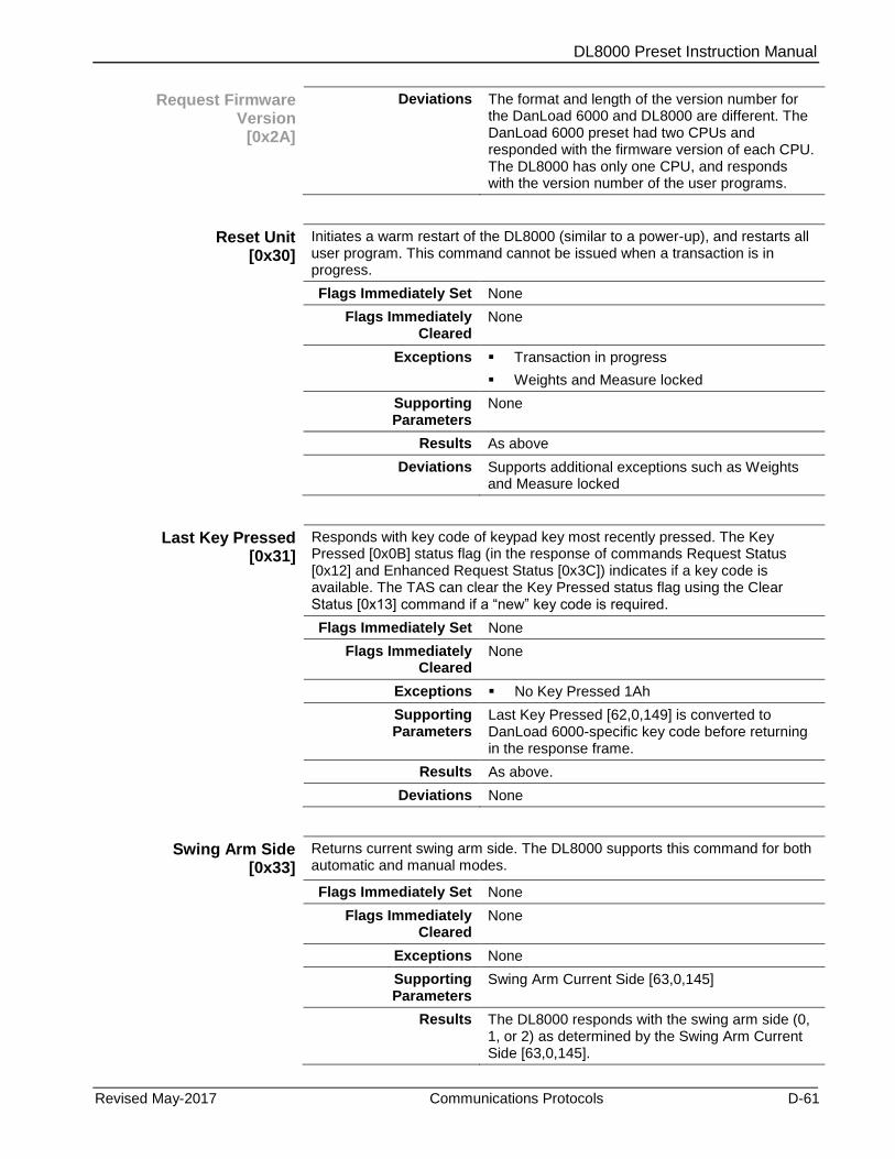
DL8000 Preset Instruction Manual
Revised May-2017 Communications Protocols D-61
Request Firmware Version
[0x2A]
Deviations The format and length of the version number for the DanLoad 6000 and DL8000 are different. The DanLoad 6000 preset had two CPUs and responded with the firmware version of each CPU. The DL8000 has only one CPU, and responds with the version number of the user programs.
Reset Unit [0x30]
Initiates a warm restart of the DL8000 (similar to a power-up), and restarts all user program. This command cannot be issued when a transaction is in progress.
Flags Immediately Set None
Flags Immediately Cleared
None
Exceptions Transaction in progress
Weights and Measure locked
Supporting Parameters
None
Results As above
Deviations Supports additional exceptions such as Weights and Measure locked
Last Key Pressed [0x31]
Responds with key code of keypad key most recently pressed. The Key Pressed [0x0B] status flag (in the response of commands Request Status [0x12] and Enhanced Request Status [0x3C]) indicates if a key code is available. The TAS can clear the Key Pressed status flag using the Clear Status [0x13] command if a “new” key code is required.
Flags Immediately Set None
Flags Immediately Cleared
None
Exceptions No Key Pressed 1Ah
Supporting Parameters
Last Key Pressed [62,0,149] is converted to DanLoad 6000-specific key code before returning in the response frame.
Results As above.
Deviations None
Swing Arm Side [0x33]
Returns current swing arm side. The DL8000 supports this command for both automatic and manual modes.
Flags Immediately Set None
Flags Immediately Cleared
None
Exceptions None
Supporting Parameters
Swing Arm Current Side [63,0,145]
Results The DL8000 responds with the swing arm side (0, 1, or 2) as determined by the Swing Arm Current Side [63,0,145].

DL8000 Preset Instruction Manual
D-62 Communications Protocols Revised May-2017
Swing Arm Side [0x33]
Deviations Swing arm features is not implemented in DL8000. Some TAS use current side, so DL8000 gives the value stored in [63,0,145] (applicable only for Version 1.0).
None (applicable only for Version 2.0 and later).
Weights & Measures Switch [0x36]
Reports the current state (0=Open or 1=Closed) of the Weights & Measures switch from location [62,0,148]. You cannot modify any defined Weights & Measures parameters when the Weights & Measures switch is closed.
Flags Immediately Set None
Flags Immediately Cleared
None
Exceptions None
Supporting Parameters
None
Results As above
Deviations None
Change Operating Mode
[0x37]
Allows the TAS to change the DL8000’s operating mode with options (0=Auto, 1=Manual) as received in the command request frame. If the DL8000 is already in the desired mode then the command is simply acknowledged.
For Version 1.0: Mode does not change if batch halts at alarm halt. For Version 2.0: In auto mode, if alarm raises then mode changes to manual and current batch completed before ending the transaction.
If transaction is authorized and this command is issued then the DL8000 ends the current transaction. The operating mode changes after the current transaction ends.
Flags Immediately Set Operating Mode is Manual (when new mode is manual)
Flags Immediately Cleared
Operating Mode is Manual (when new mode is auto)
Operation Timed Out
Recipe Selected
Additive Selected
Preset Volume Entered
Keypad Data Available
K&D Locked Out
Exceptions No batch stopped
Batch is in progress and any non primary alarm with severity more than info (1) is active.
Batch is in progress and any primary alarm is active.
Invalid operating mode
Supporting Parameters
None
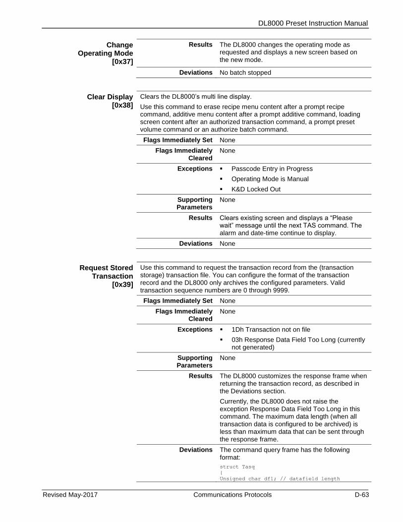
DL8000 Preset Instruction Manual
Revised May-2017 Communications Protocols D-63
Change Operating Mode
[0x37]
Results The DL8000 changes the operating mode as requested and displays a new screen based on the new mode.
Deviations No batch stopped
Clear Display [0x38]
Clears the DL8000’s multi line display.
Use this command to erase recipe menu content after a prompt recipe command, additive menu content after a prompt additive command, loading screen content after an authorized transaction command, a prompt preset volume command or an authorize batch command.
Flags Immediately Set None
Flags Immediately Cleared
None
Exceptions Passcode Entry in Progress
Operating Mode is Manual
K&D Locked Out
Supporting Parameters
None
Results Clears existing screen and displays a “Please wait” message until the next TAS command. The alarm and date-time continue to display.
Deviations None
Request Stored Transaction
[0x39]
Use this command to request the transaction record from the (transaction storage) transaction file. You can configure the format of the transaction record and the DL8000 only archives the configured parameters. Valid transaction sequence numbers are 0 through 9999.
Flags Immediately Set None
Flags Immediately Cleared
None
Exceptions 1Dh Transaction not on file
03h Response Data Field Too Long (currently not generated)
Supporting Parameters
None
Results The DL8000 customizes the response frame when returning the transaction record, as described in the Deviations section.
Currently, the DL8000 does not raise the exception Response Data Field Too Long in this command. The maximum data length (when all transaction data is configured to be archived) is less than maximum data that can be sent through the response frame.
Deviations The command query frame has the following format:
struct Tasq
Unsigned char dfl; // datafield length
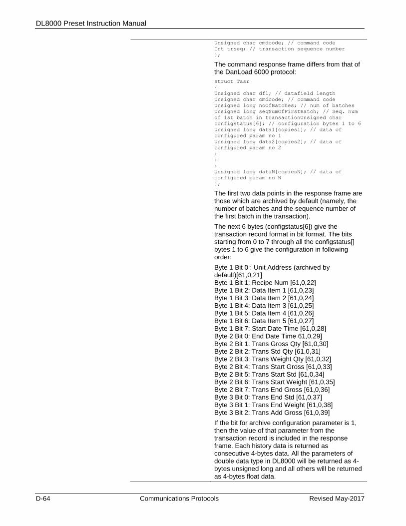
DL8000 Preset Instruction Manual
D-64 Communications Protocols Revised May-2017
Unsigned char cmdcode; // command code
Int trseq; // transaction sequence number
;
The command response frame differs from that of the DanLoad 6000 protocol:
struct Tasr
Unsigned char dfl; // datafield length
Unsigned char cmdcode; // command code
Unsigned long noOfBatches; // num of batches
Unsigned long seqNumOfFirstBatch; // Seq. num
of 1st batch in transactionUnsigned char
configstatus[6]; // configuration bytes 1 to 6
Unsigned long data1[copies1]; // data of
configured param no 1
Unsigned long data2[copies2]; // data of
configured param no 2
:
:
:
Unsigned long dataN[copiesN]; // data of
configured param no N
;
The first two data points in the response frame are those which are archived by default (namely, the number of batches and the sequence number of the first batch in the transaction).
The next 6 bytes (configstatus[6]) give the transaction record format in bit format. The bits starting from 0 to 7 through all the configstatus[] bytes 1 to 6 give the configuration in following order:
Byte 1 Bit 0 : Unit Address (archived by default)[61,0,21] Byte 1 Bit 1: Recipe Num [61,0,22] Byte 1 Bit 2: Data Item 1 [61,0,23] Byte 1 Bit 3: Data Item 2 [61,0,24] Byte 1 Bit 4: Data Item 3 [61,0,25] Byte 1 Bit 5: Data Item 4 [61,0,26] Byte 1 Bit 6: Data Item 5 [61,0,27] Byte 1 Bit 7: Start Date Time [61,0,28] Byte 2 Bit 0: End Date Time 61,0,29] Byte 2 Bit 1: Trans Gross Qty [61,0,30] Byte 2 Bit 2: Trans Std Qty [61,0,31] Byte 2 Bit 3: Trans Weight Qty [61,0,32] Byte 2 Bit 4: Trans Start Gross [61,0,33] Byte 2 Bit 5: Trans Start Std [61,0,34] Byte 2 Bit 6: Trans Start Weight [61,0,35] Byte 2 Bit 7: Trans End Gross [61,0,36] Byte 3 Bit 0: Trans End Std [61,0,37] Byte 3 Bit 1: Trans End Weight [61,0,38] Byte 3 Bit 2: Trans Add Gross [61,0,39]
If the bit for archive configuration parameter is 1, then the value of that parameter from the transaction record is included in the response frame. Each history data is returned as consecutive 4-bytes data. All the parameters of double data type in DL8000 will be returned as 4-bytes unsigned long and all others will be returned as 4-bytes float data.

DL8000 Preset Instruction Manual
Revised May-2017 Communications Protocols D-65
Some of the transaction data is archived by default and not configurable. Refer to Section C.2.5, Transaction History in Appendix C of the ROCLINK 800 Configuration Software User Manual (for DL8000), (Form A6240) for details.
The parameter values are returned in the same order in which the configuration bits are reported. All the copies archived for each configured archive parameter are returned in the response frame. The number of copies archived for each parameter is always fixed. For example, 4 for data referring to components, 4 for data referring to meters, and 6 for data referring to additives.
Example: If configstatus[6](hex) = 0D 90 00 00 00 00, then data following the configstatus[6] in the response frame is formatted as:
float Unit Address
float Data Item 1
float Data Item 2
float Trans Start Gross Meter 1
float Trans Start Gross Meter 2
float Trans Start Gross Meter 3
float Trans Start Gross Meter 4
float Trans End Gross Meter 1
float Trans End Gross Meter 2
float Trans End Gross Meter 3
float Trans End Gross Meter 4
Note: The DL8000 does not consider the multiplication factors used for returning some parameters in other DanLoad 6000 commands when returning the value (read from the archived data) in the response frame.
Request Stored Batch [0x3A]
Use this command to request the batch record from the (transaction storage) batch file. You can configure the format of the batch record; the DL8000 archives only the configured parameters. Valid batch sequence numbers are 0 through 9999.
Flags Immediately Set None
Flags Immediately Cleared
None
Exceptions 1Eh Batch not on file
03h Response Data Field Too Long
Supporting Parameters
None
Results The DL8000 customizes the response frame when returning the batch record, as described in the Deviation section.
Deviations The command query frame has the following format:
struct Tasq
Unsigned char dfl; // datafield length
Unsigned char cmdcode; // command code
baseq; // batch sequence number
;

DL8000 Preset Instruction Manual
D-66 Communications Protocols Revised May-2017
The command response frame differs from that of the DanLoad 6000 protocol:
struct Tasr
Unsigned char dfl // datafield length
Unsigned char cmdcode; // command code
Unsigned long transactionSeqNum; //
transaction sequence no. for this batch
Unsigned long configMode; // batch done in
configuration mode
Unsigned char configstatus[6]; //
configuration bytes 1 to 6
Unsigned long data1[copies1]; // data of
configured param no 1
Unsigned long data2[copies2]; // data of
configured param no 2
:
:
:
Unsigned long dataN[copiesN]; // data of
configured param no N
;
The first two data points in the response frame are those which are archived by default (namely, the transaction sequence no. for this batch and batch done in configuration mode).
The next 6 bytes (configstatus[6]) give the batch record format in bit format. The bits starting from 0 to 7 through all the configstatus[] bytes 1 to 6 give the configuration in following order:
Byte 1 Bit 0: Base Temp Option (archived by default) [61,0,5]
Byte 1 Bit 1: FWA Pressure [61,0,6]
Byte 1 Bit 2: FWA Base Density (archived by default) [61,0,7]
Byte 1 Bit 3: FWA Tempt (archived by default) [61,0,8]
Byte 1 Bit 4: Preset Qty [61,0,9]
Byte 1 Bit 5: Gross Qty (archived by default) [61,0,10]
Byte 1 Bit 6: Std Qty (archived by default) [61,0,11]
Byte 1 Bit 7: Weight [61,0,12]
Byte 2 Bit 0: Comp Gross Qty [61,0,13]
Byte 2 Bit 1: Comp Std Qty [61,0,14]
Byte 2 Bit 2: Comp Weight Qty [61,0,15]
Byte 2 Bit 3: Comp Temp [61,0,16]
Byte 2 Bit 4: Comp 1 Req Percentage [61,0,17]
Byte 2 Bit 5: Comp Batch Percentage [61,0,18]
Byte 2 Bit 6: Add Gross Qty [61,0,19]
Byte 2 Bit 7: Operating Mode [61,0,20]
Byte 3 Bit 0: Comp 2 Req Per [61,0,141]
Byte 3 Bit 1: Comp 3 Req Per [61,0,142]
Byte 3 Bit 2: Comp 4 Req Per [61,0,143]
DL8000 Preset Instruction Manual
Revised May-2017 Communications Protocols D-67
Byte 3 Bit 3: Comp Pressure [61,0,152]
Byte 3 Bit 4: Comp Base Density [61,0,153]
Byte 3 Bit 5: Batch Start Indicated [61,0,195]
Byte 3 Bit 6: Batch End Indicated [61,0,196]
Byte 3 Bit 7: Average component k-factor [61,0,205]
Byte 4 Bit 0: Average component meter factor (FWA) [61,0,206]
Byte 4 Bit 1: Average component CTL (FWA) [61,0,215]
Byte 4 Bit 2: Average component CPL (FWA) [61,0,216]
Byte 4 Bit 3: Comp Observed density [61,0,225]
Byte 4 Bit 4: Density Units (archived by default) [61,0,249]
If the bit for archive configuration parameter is 1, then the value of that parameter from the batch record is included in the response frame. Each history data is returned as consecutive 4-bytes data. All the parameters of double data type in DL8000 are returned as 4-bytes unsigned long and all others will be returned as 4-bytes float data.
Some of the batch data is archived by default and not configurable. Refer to Section C.2.5, Transaction History in Appendix C in the ROCLINK 800 Configuration Software User Manual (for DL8000), (Form A6240) for details.
The parameter values are returned in the same order in which the configuration bits are reported. All the copies archived for each configured archive parameter are returned in the response frame. The number of copies archived for each parameter is always fixed. For example, 4 for data referring to components, 4 for data referring to meters, and 6 for data referring to additives.
Example: If configstatus[6](hex) = 7D 01 00 10 00 00, then data following the configstatus[6] in the response frame has the format:
float Base Temp Option
float FWA Base Density
float FWA Temp
float Batch Preset Qty
unsigned long Batch Gross Qty
unsigned long Batch Std Qty
unsigned long Gross Qty Comp 1
unsigned long Gross Qty Comp 2
unsigned long Gross Qty Comp 3
unsigned long Gross Qty Comp 4
float Density Units
Note: The DL8000 does not consider the multiplication factors used for returning some parameters in other DanLoad 6000 commands when returning the value (read from the archived data) in the response
DL8000 Preset Instruction Manual
D-68 Communications Protocols Revised May-2017
frame.
Enhanced Start Communications
[0x3B]
This command is an alternative to the Start Communications command [0x21], with the following advantages:
It has a fixed length response.
Its response contains all values necessary to predict the lengths of all other responses from the DL8000 unit.
Its response informs the TAS of the configured language.
The TAS uses this command to initiate or start communication with the DL8000. When the DL8000 has experienced:
Powered-up/reset
Program mode exit
Communication failure alarm reset.
the TAS can start or initiate communication with the DL8000 using this command. If communications are already started when this command is received, then the communication link is re-initialized but operations at the DL8000 are unaffected. The command resets the alternating function code sequence, using function codes 41h or 42h for the query. The next (non-retry) query from the TAS should use the other function code (that is, if 41h initiates the query, 42h should be the next non-retry query).
The query is 6 characters long: address (1 character), function code (1 character), data field length (1 character), command code (1 character) and checksum (2 characters). A valid example Enhanced Start Communications command for a DL8000 at communication address 01h would be (in hexadecimal):
01 41 02 3B 11 7F and 01 42 02 3B E1 7F
Under the DanLoad 6000 protocol, until communications are established using this command, the DL8000 accepts no other command.
The TAS can use this language to select an appropriate “message file” for sending text to the DL8000.
Flags Immediately Set None
Flags Immediately Cleared
None
Exceptions None
Supporting Parameters
None

DL8000 Preset Instruction Manual
Revised May-2017 Communications Protocols D-69
Enhanced Start Communications
[0x3B]
Results The command response frame consists of the following parameters:
Number of meters [63,0,20]
Number of components [63,0,21]
Number of valves [63,0,19]
Number of factors or flow rate [63,0,109]
Number of recipes [63,0,26]
Number of additives [63,0,100]
Temperature Units Option [70,0,2]
Temperature correction option [71,x,28]
Pressure correction option [71,x,29]
Number of data items [63,0,186]
Language used [63,0,14]
Deviations The Temperature correction option [71,x,28] values the DL8000 returns do not directly map to the DanLoad 6000 program codes 432, 435, etc. for all values.
The Pressure correction option [71,x,29] values the DL8000 returns do not directly map to the DanLoad 6000 program codes 444, 447, etc. for all values.
Swing arm side is not supported on DL8000, so its value returned in the command response frame is always 1 (applicable only for Version 1.0).

DL8000 Preset Instruction Manual
D-70 Communications Protocols Revised May-2017
Enhanced Request Status [0x3C]
This command can be issued at any time to know the overall status of DL8000 unit. This command is an alternative to Request Status command [0x12].
This command has the following advantages over the Request Status [0x12] command:
Its response contains the recipe number, additive selection, and preset volume. The Request Selected Recipe [0x02], Request Selected Additives [0x04], and Request Preset Volume [0x09] commands may no longer be required; the relevant data are available to the TAS immediately when the corresponding status bits change. Response times are improved.
Its response contains the transaction storage status. The Request Transaction storage status command [0x1E] may no longer be required. This is particularly useful for “ticket printing” systems that upload batch and transaction data by watching for new records being written into the files.
This command has the following disadvantages over the Request Status [0x12] command:
Its response time is slightly slower, but not significantly slower.
Since there are no exceptions, it does not protect the TAS from making mistakes (such as using a recipe number when no recipe is selected and no transaction is authorized).
For the command response, see Results section below.
Status flags is a binary representation of the DL8000’s 32 status flags.
Safety circuit status is the current logical state (“open” or “closed”) of 8 general purpose safety circuit inputs. The least significant bit is safety circuit 1 etc. If you do not configure safety circuit input, then the value of bit for respective safety circuit will be equal to unsafe state [0].
Alarm bitmaps indicate active (raised and reset) alarms. The automation system can maintain a copy of the “alarm bytes” so that it can determine (for logging purposes) when alarms are raised or cleared.
The recipe number is valid while the recipe selected or the transaction authorized bits are set. (The recipe number authorized for the transaction need not be the same as the recipe number selected by the operator)
The additives selection bitmap is valid while the additives selected status bit is set.
The preset volume entered is valid while the preset volume entered or batch authorized status bits are set. For the former, it is the preset volume entered by the operator. For the latter, it is the preset volume authorized for the batch. (The preset volume authorized for the batch need not be the same as the preset volume entered by the operator).
Flags Immediately Set None
Flags Immediately Cleared
None
Exceptions None
Supporting Parameters As above
DL8000 Preset Instruction Manual
Revised May-2017 Communications Protocols D-71
Enhanced Request Status [0x3C]
Results The response frame includes the values of following parameters:
Status flags [63,0,119]
Current swing arm side [63,0,145] (applicable only in Version 2.0 and later)
Batch gross volume [63,0,135] or Composite Batch gross volume [64,0,2] based on Preset Additive option [64,0,26] is set as “Exclusive” or “Inclusive” respectively.
Note: Composite Batch Gross Volume available in Version 2.0 and later.
Batch net-std or Batch mass [63,0,137 or 138] based on delivery type
Status of safety circuit inputs [63,0,98]
Note: If you do not configure a safety circuit, the status of that circuit becomes 0.
Alarm ID of oldest highest priority active alarm [63,0,111] – returned alarm code is in terms of DanLoad 6000. Value stored at this parameter is alarm code used by DL8000 which may not match with alarm code of DanLoad 6000.
Alarm bitmaps of ten bytes (returned in terms of DanLoad 6000 alarm bytes)
Recipe number selected [63,0,118]
Additives selection bitmap [63,0,112]
Preset volume entered [63,0,39]
Oldest Transaction sequence number stored [61,0,123]
Number of Transactions stored [61,0,122]
Maximum number of transactions that can be stored [61,0,121]
Transaction Configuration Error [61,0,133]
Oldest Batch sequence number stored [61,0,129]
Number of Batches stored [61,0,128]
Maximum number of batch that can be stored [61,0,127]
Batch Configuration Error [61,0,134]
Deviations In the DanLoad 6000 and other commands the DL8000 supports via the DanLoad 6000 protocol, the totalizers return mass totals if delivery type is mass. Otherwise the totals are net standard volumes.
For the DanLoad 6000, alarm bitmaps of ten bytes retuned contains only the status of primary alarms. However, DL8000 returns the status of active alarms irrespective of alarm severity.
The DanLoad 6000 protocol can be used only on a single port and only on Comm A.
Preset Additive option [64,0,26] is additional feature not available in DanLoad 6000 protocol (applicable only in Version 2.0 and later).
DL8000 Preset Instruction Manual
D-72 Communications Protocols Revised May-2017
Report Alarm [0x3D]
Raises an alarm based on alarm code received in the command request frame. Possible uses of this command are:
Raising an alarm based on conditions that are either not input to or detectable by DL8000 (such as a fire detection system or a PLC being used to monitor a rail car’s position).
Stopping a batch with a situation-specific message. In this case, the automation system might configure a safety circuit alarm message via communications and then raise the corresponding safety circuit alarm. The automation system can reset the alarm using the Reset primary alarms command [0x14].
Note: A TAS should not depend on DL8000 alarms to prevent or control hazardous or life threatening conditions.
Flags Immediately Set Primary Alarm active (if primary alarm is raised)
Flags Immediately Cleared
None
Exceptions Invalid bit no. (that is, the alarm code in the command request frame is invalid)
Unable to set or reset alarm
Supporting Parameters
Alarm ID [63,0,173]
Results Batch may stop due to reported alarm.
Deviations Comm B is not supported.
Supports additional exception code “Unable to set or reset alarm”
Does not support the following DanLoad 6000 protocol alarms:
Data logging memory full
Memory Check Failure
Primary Display Failure
Secondary Display Failure
MPMC 1 and MPMC 2 Failure
Calibration Failure for all meters
Intermediate Level Input
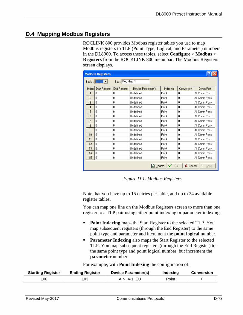
DL8000 Preset Instruction Manual
Revised May-2017 Communications Protocols D-73
D.4 Mapping Modbus Registers
ROCLINK 800 provides Modbus register tables you use to map
Modbus registers to TLP (Point Type, Logical, and Parameter) numbers
in the DL8000. To access these tables, select Configure > Modbus >
Registers from the ROCKLINK 800 menu bar. The Modbus Registers
screen displays.
Figure D-1. Modbus Registers
Note that you have up to 15 entries per table, and up to 24 available
register tables.
You can map one line on the Modbus Registers screen to more than one
register to a TLP pair using either point indexing or parameter indexing:
Point Indexing maps the Start Register to the selected TLP. You
map subsequent registers (through the End Register) to the same
point type and parameter and increment the point logical number.
Parameter Indexing also maps the Start Register to the selected
TLP. You map subsequent registers (through the End Register) to
the same point type and point logical number, but increment the
parameter number.
For example, with Point Indexing the configuration of:
Starting Register Ending Register Device Parameter(s) Indexing Conversion
100 103 AIN, 4-1, EU Point 0
DL8000 Preset Instruction Manual
D-74 Communications Protocols Revised May-2017
specifies four registers (100, 101, 102, and 103) that are mapped to a
group of analog input (AIN) values in engineering units (EU) starting at
the analog input in the fourth module location, first position (4-1), such
that:
Register 100 = EU of AIN point in location 4-1.
Register 101 = EU of AIN point in location 4-2.
Register 102 = EU of AIN point in location 4-3.
Register 103 = EU of AIN point in location 4-4.
With Parameter Indexing the configuration of:
Starting Register Ending Register Device Parameter(s) Indexing Conversion
109 114 FST 1,R1 Parameter 1
specifies six registers (109, 110, 111, 112, 113, and 114) that are
mapped to a group of FST 1 parameters starting at FST Register 1, such
that:
Modbus Register 109 = Register 1 of FST Point Number 1.
Modbus Register 110 = Register 2 of FST Point Number 1.
Modbus Register 111 = Register 3 of FST Point Number 1.
Modbus Register 112 = Register 4 of FST Point Number 1.
Modbus Register 113 = Register 5 of FST Point Number 1.
Modbus Register 114 = Register 6 of FST Point Number 1.
Conversion Code 1 (Float to Integer, Float Scale 1) converts the floating
point value to an integer before the response message returns to the host.
Once you map a register, any Modbus request can reference it,
providing the TLP’s data type is appropriate for the function code.
Note: If the native data type does not meet the requirements of the
Modbus Host device, conversion codes are available to convert
the data to the required data type. For the DL8000, you can
select to have the mapping apply to all communication ports or
on a selected port only.
When the system receives a Modbus request, it searches for the
referenced register(s). If it finds a matching register number, the system
builds a response based on the device point type and parameter
configured in the table. If the system cannot find a register number
match, it returns an error message.
A DL8000 has 24 available register tables, each table containing 15
entries.
You use either point indexing or parameter indexing to define multiple
registers for each table entry. By making the registers continuous (where
the Start Register address of a new line is one greater than the End
Register address of the previous line), you can create a continuous data

DL8000 Preset Instruction Manual
Revised May-2017 Communications Protocols D-75
table for Modbus Function 3, 4, or 16 up to the limit of 240 bytes. This
type of data table allows access to all its data with one request.
Periodic (Hourly) or Daily History Index registers should be mapped to
the TLP for the Periodic Index (Point Type 124, Parameter 5) or Daily
Index (Point Type 124, Parameter 6). In this TLP, the Logical number is
the History Segment number. Remember to create an index for each
History Segment from which you need to request history.
For Function Codes 01, 02, 05, and 15, the parameter specified should
be a single-byte parameter type, preferably a status parameter (only bit 0
is used), because this function packs the data into a binary format for
transmission. Each address span must be unique within the function for
proper operation. If not, the first valid address is used.
D.5 DanLoad 6000 Protocol Frame
The DanLoad 6000 protocol supports a maximum of 256 bytes in one
Request/Response frame. Numeric data is transmitted in binary with
LSB byte first and MSB byte last.
Frame queries, responses, and exception responses using the following
format:
ADR FN D1 D2 Dn BCC1 BCC2
Frame format for Normal Query and Response
ADR Address Field: 01h to FFh for individual module.
Address = 00h indicates Broadcast Request; means Only Process this Query But need not to reply back.
FN Function Fields: 41h or 42h
D1 Data Field character 1 indicates length of data field.
Data Field Length does not include device address, function code, or CRC bytes
D2 Data field character 2 indicates Command code
D3 Any data.
Note: String data remains Null Terminated in any Query/Response.
Dn Data field character n
BCC1 Block check character 1 is Error check field (CRC-16) character 1.
BCC2 Block check character 2 is Error check field (CRC-16) character 2.
Frame format for Exception Response
ADR Address Field: 01h to FFh for individual module.
FN Exception Response C1h and C2h for function codes 41h and 42h respectively.
DL8000 Preset Instruction Manual
D-76 Communications Protocols Revised May-2017
D1 Data Field character 1 indicates length of data remains 3 which includes D1, D2 and D3.
Data Field Length does not Include Device address, Function code and CRC bytes
D2 Data field character 2 indicates Command code
D3 Exception code
BCC1 Block check character 1 is Error check field (CRC-16) character 1.
BCC2 Block check character 2 is Error check field (CRC-16) character 2.
D.6 BCC Calculation
The destination station uses block check characters (BCCs) to verify the
accuracy of received data. The transmitting station calculates the BCC
for each message and transmits them. The receiving station then
calculates the BCC for each message it receives and then compares the
calculated BCCs to the received BCCs. A difference between two BCCs
indicates a data error and so that do not reply. While responding to
messages it is a good practice to calculate the BCC first and then make
frame and reply back to the TAS.
Following is an example of the steps involved in calculating the CRC-
16 using C language. Below is the CRC-16 calculation steps using C
language. Consider following sequence for CRC-16. CRC-16 Checksum
Table is given below.
Data Sequence: 01 41 02 21 (consisting of address byte, function code
and data fields)
1. Take two variables each of two-bytes size:
crcResult = FFFFh and tempVar = FFFFh.
2. Take another one byte variable dataByte = 01h (first byte of frame)
3. Repeat following steps for each data byte (dataByte) in the frame up
to last byte in frame
a. crcResult = crcResult << 8 (left shift by 8) –
Result = FFFF SHL 8 = FF00
b. tempVar = tempVar >> 8 (right shift by 8) –
Result = FFFF SHR 8 = 00FF
c. tempVar = tempVar ^ dataByte (EXOR operation) – dataByte
=01
Result = 00FF XOR 01 = 00FE
d. tempVar = crc16Table [tempVar] (Get value from CRC-16
table shown below using tempVar as an index)
Result = crc16Table [00FE] = 8180
DL8000 Preset Instruction Manual
Revised May-2017 Communications Protocols D-77
e. Get final CRC-16 answer of first byte by crcResult = crcResult ^
tempVar (EXOR operation)
Result = FF00 XOR 8180 = 7E80
f. Assign value of first CRC-16 to crcResult and tempVar
4. Finally after calculating CRC using last data byte of the frame the
result comes to be 90B4. This CRC-16 checksum should be
transmitted upper byte first (BCC1 = 90h) and lower byte second
(BCC2 = B4h), The complete message with CRC-16 checksum is:
01 41 02 21 90 B4
D.7 CRC-16 Checksum Table
Use the following database to calculate CRC-16 values for the DanLoad
6000 protocol frame.
Table D-3. CRC-16 Checksum
Const unsigned short crc16Table[256] =
0x0000, 0xc1c0, 0x81c1, 0x4001, 0x01c3, 0xc003, 0x8002, 0x41c2,
0x01c6, 0xc006, 0x8007, 0x41c7, 0x0005, 0xc1c5, 0x81c4, 0x4004,
0x01cc, 0xc00c, 0x800d, 0x41cd, 0x000f, 0xc1cf, 0x81ce, 0x400e,
0x000a, 0xc1ca, 0x81cb, 0x400b, 0x01c9, 0xc009, 0x8008, 0x41c8,
0x01d8, 0xc018, 0x8019, 0x41d9, 0x001b, 0xc1db, 0x81da, 0x401a,
0x001e, 0xc1de, 0x81df, 0x401f, 0x01dd, 0xc01d, 0x801c, 0x41dc,
0x0014, 0xc1d4, 0x81d5, 0x4015, 0x01d7, 0xc017, 0x8016, 0x41d6,
0x01d2, 0xc012, 0x8013, 0x41d3, 0x0011, 0xc1d1, 0x81d0, 0x4010,
0x01f0, 0xc030, 0x8031, 0x41f1, 0x0033, 0xc1f3, 0x81f2, 0x4032,
0x0036, 0xc1f6, 0x81f7, 0x4037, 0x01f5, 0xc035, 0x8034, 0x41f4,
0x003c, 0xc1fc, 0x81fd, 0x403d, 0x01ff, 0xc03f, 0x803e, 0x41fe,
0x01fa, 0xc03a, 0x803b, 0x41fb, 0x0039, 0xc1f9, 0x81f8, 0x4038,
0x0028, 0xc1e8, 0x81e9, 0x4029, 0x01eb, 0xc02b, 0x802a, 0x41ea,
0x01ee, 0xc02e, 0x802f, 0x41ef, 0x002d, 0xc1ed, 0x81ec, 0x402c,
0x01e4, 0xc024, 0x8025, 0x41e5, 0x0027, 0xc1e7, 0x81e6, 0x4026,
0x0022, 0xc1e2, 0x81e3, 0x4023, 0x01e1, 0xc021, 0x8020, 0x41e0,
0x01a0, 0xc060, 0x8061, 0x41a1, 0x0063, 0xc1a3, 0x81a2, 0x4062,
0x0066, 0xc1a6, 0x81a7, 0x4067, 0x01a5, 0xc065, 0x8064, 0x41a4,
0x006c, 0xc1ac, 0x81ad, 0x406d, 0x01af, 0xc06f, 0x806e, 0x41ae,
0x01aa, 0xc06a, 0x806b, 0x41ab, 0x0069, 0xc1a9, 0x81a8, 0x4068,
0x0078, 0xc1b8, 0x81b9, 0x4079, 0x01bb, 0xc07b, 0x807a, 0x41ba,
0x01be, 0xc07e, 0x807f, 0x41bf, 0x007d, 0xc1bd, 0x81bc, 0x407c,
0x01b4, 0xc074, 0x8075, 0x41b5, 0x0077, 0xc1b7, 0x81b6, 0x4076,
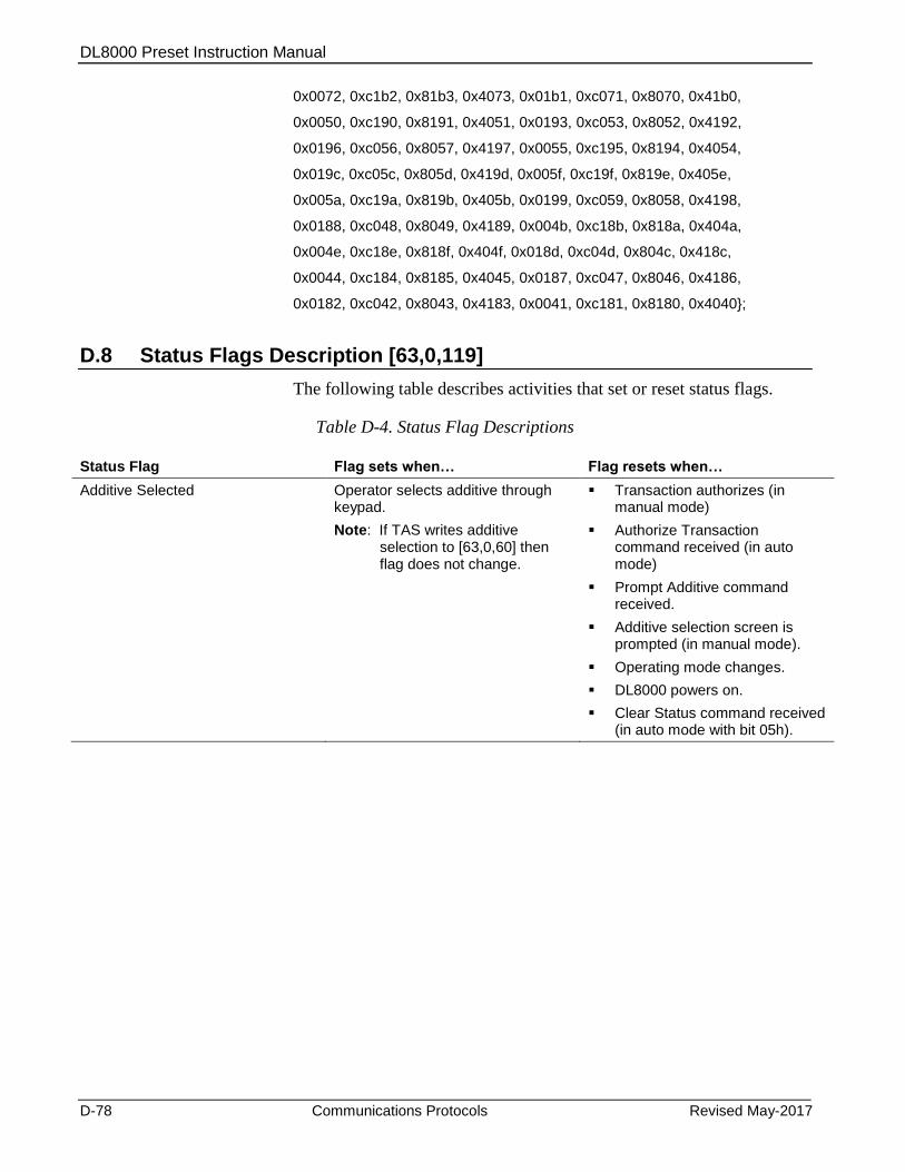
DL8000 Preset Instruction Manual
D-78 Communications Protocols Revised May-2017
0x0072, 0xc1b2, 0x81b3, 0x4073, 0x01b1, 0xc071, 0x8070, 0x41b0,
0x0050, 0xc190, 0x8191, 0x4051, 0x0193, 0xc053, 0x8052, 0x4192,
0x0196, 0xc056, 0x8057, 0x4197, 0x0055, 0xc195, 0x8194, 0x4054,
0x019c, 0xc05c, 0x805d, 0x419d, 0x005f, 0xc19f, 0x819e, 0x405e,
0x005a, 0xc19a, 0x819b, 0x405b, 0x0199, 0xc059, 0x8058, 0x4198,
0x0188, 0xc048, 0x8049, 0x4189, 0x004b, 0xc18b, 0x818a, 0x404a,
0x004e, 0xc18e, 0x818f, 0x404f, 0x018d, 0xc04d, 0x804c, 0x418c,
0x0044, 0xc184, 0x8185, 0x4045, 0x0187, 0xc047, 0x8046, 0x4186,
0x0182, 0xc042, 0x8043, 0x4183, 0x0041, 0xc181, 0x8180, 0x4040;
D.8 Status Flags Description [63,0,119]
The following table describes activities that set or reset status flags.
Table D-4. Status Flag Descriptions
Status Flag Flag sets when… Flag resets when…
Additive Selected Operator selects additive through keypad.
Note: If TAS writes additive selection to [63,0,60] then flag does not change.
Transaction authorizes (in manual mode)
Authorize Transaction command received (in auto mode)
Prompt Additive command received.
Additive selection screen is prompted (in manual mode).
Operating mode changes.
DL8000 powers on.
Clear Status command received (in auto mode with bit 05h).
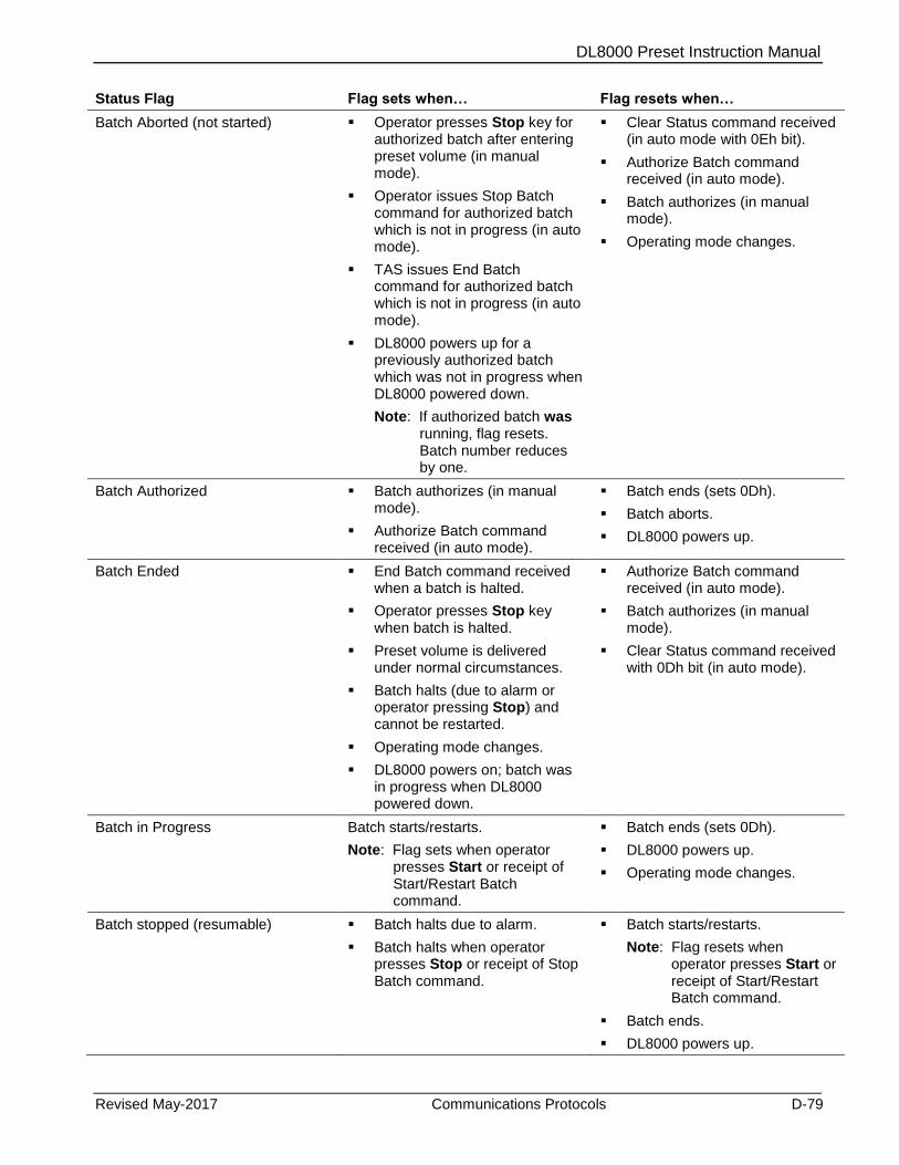
DL8000 Preset Instruction Manual
Revised May-2017 Communications Protocols D-79
Status Flag Flag sets when… Flag resets when…
Batch Aborted (not started) Operator presses Stop key for authorized batch after entering preset volume (in manual mode).
Operator issues Stop Batch command for authorized batch which is not in progress (in auto mode).
TAS issues End Batch command for authorized batch which is not in progress (in auto mode).
DL8000 powers up for a previously authorized batch which was not in progress when DL8000 powered down.
Note: If authorized batch was running, flag resets. Batch number reduces by one.
Clear Status command received (in auto mode with 0Eh bit).
Authorize Batch command received (in auto mode).
Batch authorizes (in manual mode).
Operating mode changes.
Batch Authorized Batch authorizes (in manual mode).
Authorize Batch command received (in auto mode).
Batch ends (sets 0Dh).
Batch aborts.
DL8000 powers up.
Batch Ended End Batch command received when a batch is halted.
Operator presses Stop key when batch is halted.
Preset volume is delivered under normal circumstances.
Batch halts (due to alarm or operator pressing Stop) and cannot be restarted.
Operating mode changes.
DL8000 powers on; batch was in progress when DL8000 powered down.
Authorize Batch command received (in auto mode).
Batch authorizes (in manual mode).
Clear Status command received with 0Dh bit (in auto mode).
Batch in Progress Batch starts/restarts.
Note: Flag sets when operator presses Start or receipt of Start/Restart Batch command.
Batch ends (sets 0Dh).
DL8000 powers up.
Operating mode changes.
Batch stopped (resumable) Batch halts due to alarm.
Batch halts when operator presses Stop or receipt of Stop Batch command.
Batch starts/restarts.
Note: Flag resets when operator presses Start or receipt of Start/Restart Batch command.
Batch ends.
DL8000 powers up.
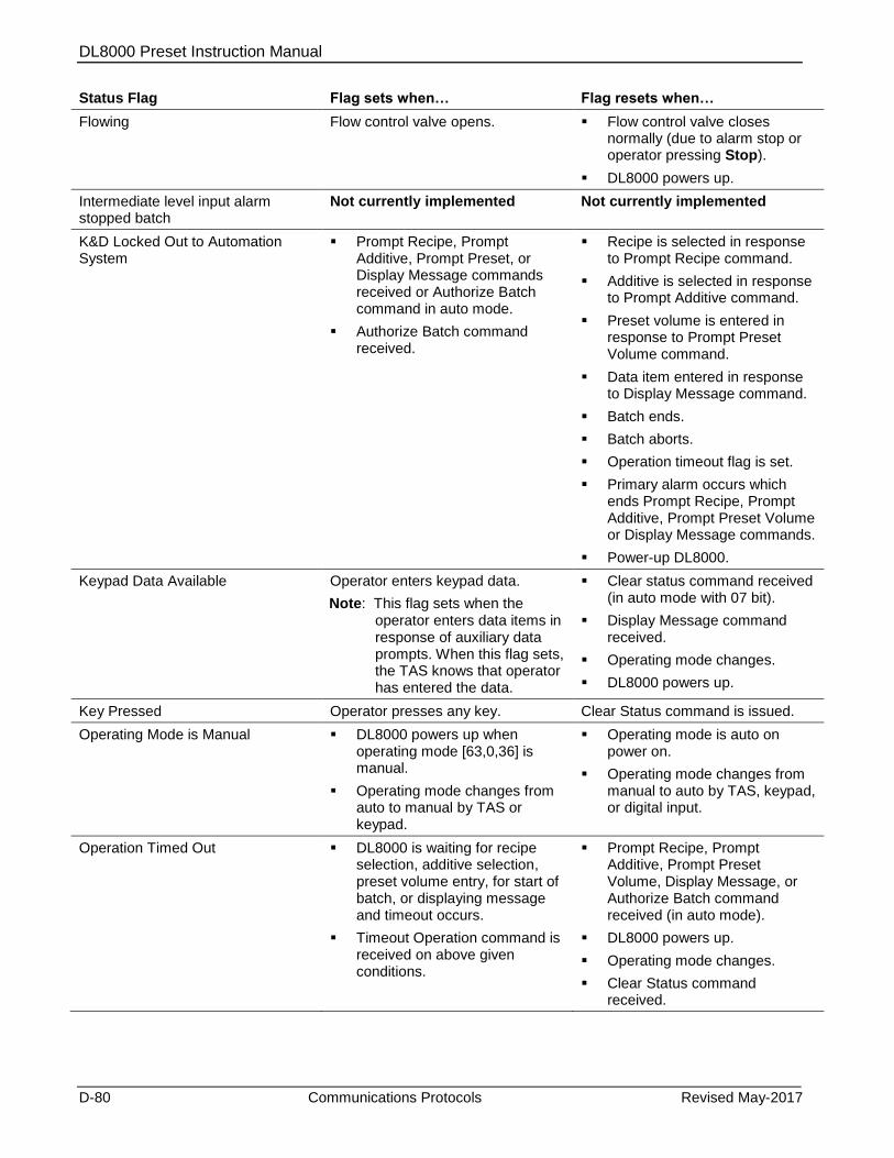
DL8000 Preset Instruction Manual
D-80 Communications Protocols Revised May-2017
Status Flag Flag sets when… Flag resets when…
Flowing Flow control valve opens. Flow control valve closes normally (due to alarm stop or operator pressing Stop).
DL8000 powers up.
Intermediate level input alarm stopped batch
Not currently implemented Not currently implemented
K&D Locked Out to Automation System
Prompt Recipe, Prompt Additive, Prompt Preset, or Display Message commands received or Authorize Batch command in auto mode.
Authorize Batch command received.
Recipe is selected in response to Prompt Recipe command.
Additive is selected in response to Prompt Additive command.
Preset volume is entered in response to Prompt Preset Volume command.
Data item entered in response to Display Message command.
Batch ends.
Batch aborts.
Operation timeout flag is set.
Primary alarm occurs which ends Prompt Recipe, Prompt Additive, Prompt Preset Volume or Display Message commands.
Power-up DL8000.
Keypad Data Available Operator enters keypad data.
Note: This flag sets when the operator enters data items in response of auxiliary data prompts. When this flag sets, the TAS knows that operator has entered the data.
Clear status command received (in auto mode with 07 bit).
Display Message command received.
Operating mode changes.
DL8000 powers up.
Key Pressed Operator presses any key. Clear Status command is issued.
Operating Mode is Manual DL8000 powers up when operating mode [63,0,36] is manual.
Operating mode changes from auto to manual by TAS or keypad.
Operating mode is auto on power on.
Operating mode changes from manual to auto by TAS, keypad, or digital input.
Operation Timed Out DL8000 is waiting for recipe selection, additive selection, preset volume entry, for start of batch, or displaying message and timeout occurs.
Timeout Operation command is received on above given conditions.
Prompt Recipe, Prompt Additive, Prompt Preset Volume, Display Message, or Authorize Batch command received (in auto mode).
DL8000 powers up.
Operating mode changes.
Clear Status command received.
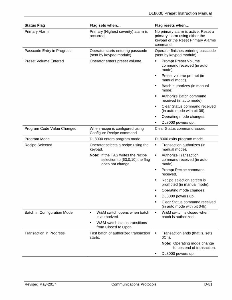
DL8000 Preset Instruction Manual
Revised May-2017 Communications Protocols D-81
Status Flag Flag sets when… Flag resets when…
Primary Alarm Primary (Highest severity) alarm is occurred.
No primary alarm is active. Reset a primary alarm using either the keypad or the Reset Primary Alarms command.
Passcode Entry in Progress Operator starts entering passcode (sent by keypad module)
Operator finishes entering passcode (sent by keypad module).
Preset Volume Entered Operator enters preset volume. Prompt Preset Volume command received (in auto mode).
Preset volume prompt (in manual mode).
Batch authorizes (in manual mode).
Authorize Batch command received (in auto mode).
Clear Status command received (in auto mode with bit 06).
Operating mode changes.
DL8000 powers up.
Program Code Value Changed When recipe is configured using Configure Recipe command
Clear Status command issued.
Program Mode DL8000 enters program mode. DL8000 exits program mode.
Recipe Selected Operator selects a recipe using the keypad.
Note: If the TAS writes the recipe selection to [63,0,10] the flag does not change.
Transaction authorizes (in manual mode).
Authorize Transaction command received (in auto mode).
Prompt Recipe command received.
Recipe selection screen is prompted (in manual mode).
Operating mode changes.
DL8000 powers up.
Clear Status command received (in auto mode with bit 04h).
Batch In Configuration Mode W&M switch opens when batch is authorized.
W&M switch status transitions from Closed to Open.
W&M switch is closed when batch is authorized.
Transaction in Progress First batch of authorized transaction starts.
Transaction ends (that is, sets 0Ch).
Note: Operating mode change forces end of transaction.
DL8000 powers up.

DL8000 Preset Instruction Manual
D-82 Communications Protocols Revised May-2017
Status Flag Flag sets when… Flag resets when…
Transaction Ended Operating mode changes while transaction in progress.
DL8000 powers on while transaction was in progress when DL8000 powered down.
End Transaction command received.
Note: This command should be received when no batch is authorized (that is, a previous batch has either completed or aborted).
Previous batch completes and operator presses Stop (in manual mode)
Clear Status command received (in auto mode with 0Ch bit).
Transaction authorizes (in manual mode).
Authorized Transaction command received (in auto mode).
Transaction Authorized Transaction authorizes (in manual mode)
Authorize Transaction command received (in auto mode).
DL8000 powers up.
Transaction ends or aborts.
Operating mode changes and transaction authorizes.
Operator presses Stop when for an authorized transaction and no batch is in progress (in manual mode).
End Transaction command received (in auto mode) for an authorized transaction and no batch is in progress.
DL8000 powers up when transaction was authorized but not started when DL8000 powered down.
Note: Transaction number decreases by one.
Transaction End Requested In auto mode, transaction is authorized, no batch is authorized and operator presses Stop (that is, batching status is SELECT_RECIPE or BATCH_COMPLETE and Stop is pressed).
In auto mode, transaction is authorized and batch is in progress and batch stopped at batching state is USER HALT, and operator presses Stop.
Authorize Transaction command received.
End Transaction command received.
Clear Status command received (with 13h bit).
Change Operating mode command ends transaction.

DL8000 Preset Instruction Manual
Revised May-2017 Communications Protocols D-83
D.9 Exception Codes
In automatic mode, the TAS sends various commands to control the
DL8000. Each command code can be accepted or rejected based on the
DL8000 status. If the command is rejected, then the DL8000 generates
an exception and writes the exception code to the TAS exception code
[63,0,168].
With the DanLoad 6000 protocol, the exception code is also returned in
the command response frame. Refer to the following table for
descriptions of all exception codes.
The DL8000 cannot respond to any TAS command until the Batching
program is running. Should the TAS write any command to the TA
Command TLP (63,0,166) before the Batching program has completed
booting up, the Batching program generates an Invalid Command alarm
(0x00) once it completes booting up, which the TAS can then read in
the TA Command Exception parameter TLP (63,0,168). However, the
Batching program then sets the TA Command parameter (63,0,166) to 0
in anticipation of the next TA command.
Table D-5. Exception Codes
Exception # (hex value) Description
FF No Exception
00 Invalid command code
01 Passcode entry in progress
02 No transaction ended
03 Response’s data field too long
04 Program code value is Weights and Measures
05 Reserved
06 No batch in progress
07 No transaction in progress
08 Batch in progress
09 Transaction in progress
0A Primary alarm active (for severity 4 alarm)
0B Batch authorized
0C Transaction authorized
0D Reserved
0E No keypad data available
0F Component not available
10 Additive not available
12 Status not set or cannot be reset
13 No additives configured
14 No batch authorized
15 Operating mode is manual
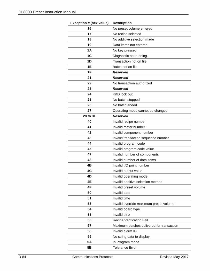
DL8000 Preset Instruction Manual
D-84 Communications Protocols Revised May-2017
Exception # (hex value) Description
16 No preset volume entered
17 No recipe selected
18 No additive selection made
19 Data items not entered
1A No key pressed
1C Diagnostic not running.
1D Transaction not on file
1E Batch not on file
1F Reserved
21 Reserved
22 No transaction authorized
23 Reserved
24 K&D lock out
25 No batch stopped
26 No batch ended
27 Operating mode cannot be changed
28 to 3F Reserved
40 Invalid recipe number
41 Invalid meter number
42 Invalid component number
43 Invalid transaction sequence number
44 Invalid program code
45 Invalid program code value
47 Invalid number of components
48 Invalid number of data items
4B Invalid I/O point number
4C Invalid output value
4D Invalid operating mode
4E Invalid additive selection method
4F Invalid preset volume
50 Invalid date
51 Invalid time
53 Invalid override maximum preset volume
54 Invalid board type
55 Invalid bit #
56 Recipe Verification Fail
57 Maximum batches delivered for transaction
58 Invalid alarm ID
59 No string data to display
5A In Program mode
5B Tolerance Error

DL8000 Preset Instruction Manual
Revised May-2017 Communications Protocols D-85
Exception # (hex value) Description
5C Alarm active (for severity 2 and 3 alarms)
5D Dependent user program is not in running state in Preset
5E Unable to reset or raise the alarm
5F Max Transaction Total
60 Flow Rate Too Low/High
61 Weights and Measure locked
D.10 New/Unused DanLoad 6000 Exception Codes
The following exception codes have been added to the DanLoad 6000
protocol to support the DL8000. These codes are not present in the
original DanLoad 6000 protocol.
Table D-6. New/Unused DanLoad 6000 Exception Codes
Exception # (hex value) Description
56 Recipe Verification Fail
57 Maximum batches delivered for transaction
58 Invalid alarm ID
59 No string data to display
5A In Program mode
5B Tolerance Error
5C Alarm active (for severity 2 and 3 alarms)
5D Dependent user program is not in running state in Preset
5E Unable to reset or raise the alarm
5F Max Transaction Total
60 Flow Rate Too Low/High
61 Weights and Measure locked
62 Invalid History Record
The following exception codes, present in the original DanLoad 6000
protocol, are not used with the DL8000.
Exception # (hex value) Description
11 Program code value is read only (not supported)
1B Diagnostic not started. (not implemented)
20 Number of recipes less than 2 (not implemented)
46 Invalid CPU number (not implemented)
4A Invalid I/O point type (not implemented)
52 Invalid data code (not implemented)
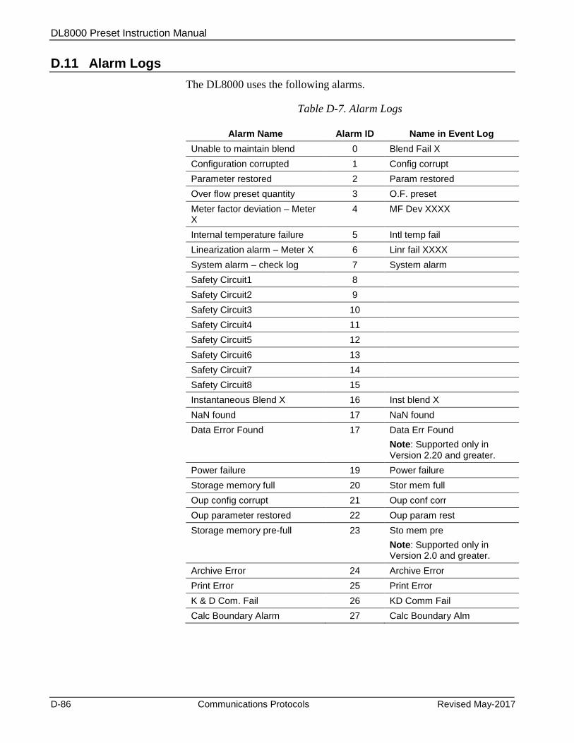
DL8000 Preset Instruction Manual
D-86 Communications Protocols Revised May-2017
D.11 Alarm Logs
The DL8000 uses the following alarms.
Table D-7. Alarm Logs
Alarm Name Alarm ID Name in Event Log
Unable to maintain blend 0 Blend Fail X
Configuration corrupted 1 Config corrupt
Parameter restored 2 Param restored
Over flow preset quantity 3 O.F. preset
Meter factor deviation – Meter X
4 MF Dev XXXX
Internal temperature failure 5 Intl temp fail
Linearization alarm – Meter X 6 Linr fail XXXX
System alarm – check log 7 System alarm
Safety Circuit1 8
Safety Circuit2 9
Safety Circuit3 10
Safety Circuit4 11
Safety Circuit5 12
Safety Circuit6 13
Safety Circuit7 14
Safety Circuit8 15
Instantaneous Blend X 16 Inst blend X
NaN found 17 NaN found
Data Error Found 17 Data Err Found
Note: Supported only in Version 2.20 and greater.
Power failure 19 Power failure
Storage memory full 20 Stor mem full
Oup config corrupt 21 Oup conf corr
Oup parameter restored 22 Oup param rest
Storage memory pre-full 23 Sto mem pre
Note: Supported only in Version 2.0 and greater.
Archive Error 24 Archive Error
Print Error 25 Print Error
K & D Com. Fail 26 KD Comm Fail
Calc Boundary Alarm 27 Calc Boundary Alm
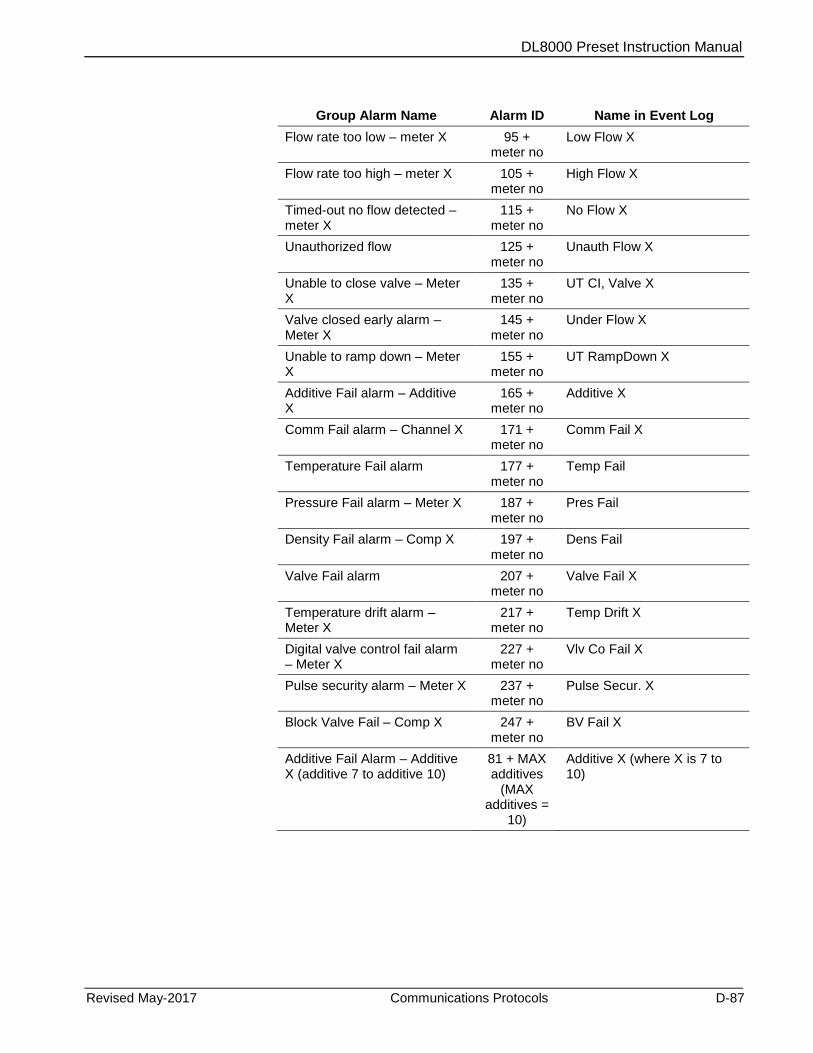
DL8000 Preset Instruction Manual
Revised May-2017 Communications Protocols D-87
Group Alarm Name Alarm ID Name in Event Log
Flow rate too low – meter X 95 + meter no
Low Flow X
Flow rate too high – meter X 105 + meter no
High Flow X
Timed-out no flow detected – meter X
115 + meter no
No Flow X
Unauthorized flow 125 + meter no
Unauth Flow X
Unable to close valve – Meter X
135 + meter no
UT CI, Valve X
Valve closed early alarm – Meter X
145 + meter no
Under Flow X
Unable to ramp down – Meter X
155 + meter no
UT RampDown X
Additive Fail alarm – Additive X
165 + meter no
Additive X
Comm Fail alarm – Channel X 171 + meter no
Comm Fail X
Temperature Fail alarm 177 + meter no
Temp Fail
Pressure Fail alarm – Meter X 187 + meter no
Pres Fail
Density Fail alarm – Comp X 197 + meter no
Dens Fail
Valve Fail alarm 207 + meter no
Valve Fail X
Temperature drift alarm – Meter X
217 + meter no
Temp Drift X
Digital valve control fail alarm – Meter X
227 + meter no
Vlv Co Fail X
Pulse security alarm – Meter X 237 + meter no
Pulse Secur. X
Block Valve Fail – Comp X 247 + meter no
BV Fail X
Additive Fail Alarm – Additive X (additive 7 to additive 10)
81 + MAX additives
(MAX additives =
10)
Additive X (where X is 7 to 10)

DL8000 Preset Instruction Manual
D-88 Communications Protocols Revised May-2017
D.12 Error Codes
Following are error codes for the DL8000 protocol.
Table D-8. Error Codes
Error Code [63,0,95] Reasons
0 No Error
1 Invalid recipe number
2 Incorrect delivery sequence or low proportion
3 Incorrect component ratios. This exception is raised if either of the following conditions is not satisfied.
Total of component ratios of all components configured in the recipe must equal 100%.
The component ratio of components not present in the recipe must be zero.
4 Invalid meter ID of a component used in the recipe.
5 Invalid valve ID, associated with a meter used by component used in the recipe.
6 Invalid primary component.
7 Target flow rate too low.
8 Target flow rate too high.
9 Incorrect side stream mask
10 Preset is not in the range of minimum and maximum preset.
11 Tolerance Allowed is no and blend ratio is out of the tolerance after considering the clean line quantity.
12 Number of batches delivered in current transaction is more than configured limit of maximum number of batches per transaction.
13 Transaction Total is greater than maximum transaction limit.
14 Archive configuration error.
15 Invalid additive selection.
16 Invalid preset additive option.
17 Invalid additive type.
18 Insufficient component preset.
19 Exceeded additive limit.
20 Reverse meter configured and delivery type not MAS
21 Reverse meter configured and unit type not sequential (auto/manual)

DL8000 Preset Instruction Manual
Revised May-2017 DL8000 Keypad Display E-1
Appendix E – DL8000 Keypad Display
The DL800 keypad display enables you to interact with the DL8000.
You can select recipes, enter the desired preset quantity, control batch
deliveries, and—with appropriate authority—program the DL8000.
Warning The keypad display uses port 2 (RS-232 on the CPU module) to communicate with the DL8000. The required baud rate for this port is 57.6K. Changing these values or assigning any other functionality to port 2 (such as the DanLoad 6000 or Modbus protocol) causes a communication failure to the keypad display.
E.1 Keypad Display Components
The keypad display has the following parts:
A. Display
B. LED Status Indicators
C. Keypad
Figure E-1. DL8000 Keypad Display Interface
A
C
B
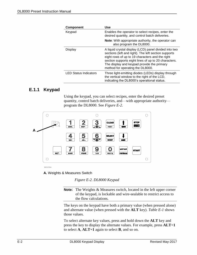
DL8000 Preset Instruction Manual
E-2 DL8000 Keypad Display Revised May-2017
Component Use
Keypad Enables the operator to select recipes, enter the desired quantity, and control batch deliveries.
Note: With appropriate authority, the operator can also program the DL8000.
Display A liquid crystal display (LCD) panel divided into two sections (left and right). The left section supports eight rows of up to 19 characters and the right section supports eight lines of up to 20 characters. The display and keypad provide the primary method for operating the DL8000.
LED Status Indicators Three light-emitting diodes (LEDs) display through the vertical window to the right of the LCD, indicating the DL8000’s operational status.
E.1.1 Keypad
Using the keypad, you can select recipes, enter the desired preset
quantity, control batch deliveries, and—with appropriate authority—
program the DL8000. See Figure E-2.
A. Weights & Measures Switch
Figure E-2. DL8000 Keypad
Note: The Weights & Measures switch, located in the left upper corner
of the keypad, is lockable and wire-sealable to restrict access to
the flow calculations.
The keys on the keypad have both a primary value (when pressed alone)
and alternate value (when pressed with the ALT key). Table E-1 shows
those values.
To select alternate key values, press and hold down the ALT key and
press the key to display the alternate values. For example, press ALT+1
to select A, ALT+1 again to select B, and so on.
A
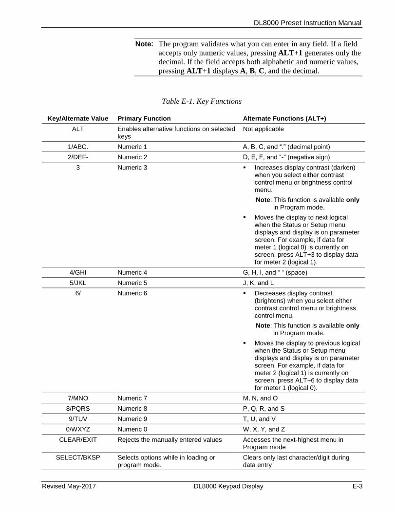
DL8000 Preset Instruction Manual
Revised May-2017 DL8000 Keypad Display E-3
Note: The program validates what you can enter in any field. If a field
accepts only numeric values, pressing ALT+1 generates only the
decimal. If the field accepts both alphabetic and numeric values,
pressing ALT+1 displays A, B, C, and the decimal.
Table E-1. Key Functions
Key/Alternate Value Primary Function Alternate Functions (ALT+)
ALT Enables alternative functions on selected keys
Not applicable
1/ABC. Numeric 1 A, B, C, and “.” (decimal point)
2/DEF- Numeric 2 D, E, F, and “-“ (negative sign)
3 Numeric 3 Increases display contrast (darken) when you select either contrast control menu or brightness control menu.
Note: This function is available only in Program mode.
Moves the display to next logical when the Status or Setup menu displays and display is on parameter screen. For example, if data for meter 1 (logical 0) is currently on screen, press ALT+3 to display data for meter 2 (logical 1).
4/GHI Numeric 4 G, H, I, and “ “ (space)
5/JKL Numeric 5 J, K, and L
6/
Numeric 6 Decreases display contrast (brightens) when you select either contrast control menu or brightness control menu.
Note: This function is available only in Program mode.
Moves the display to previous logical when the Status or Setup menu displays and display is on parameter screen. For example, if data for meter 2 (logical 1) is currently on screen, press ALT+6 to display data for meter 1 (logical 0).
7/MNO Numeric 7 M, N, and O
8/PQRS Numeric 8 P, Q, R, and S
9/TUV Numeric 9 T, U, and V
0/WXYZ Numeric 0 W, X, Y, and Z
CLEAR/EXIT Rejects the manually entered values Accesses the next-highest menu in Program mode
SELECT/BKSP Selects options while in loading or program mode.
Clears only last character/digit during data entry
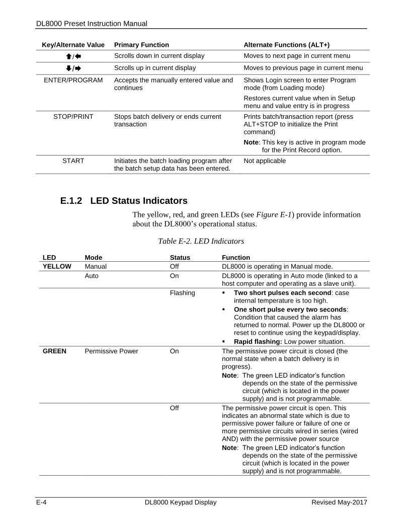
DL8000 Preset Instruction Manual
E-4 DL8000 Keypad Display Revised May-2017
Key/Alternate Value Primary Function Alternate Functions (ALT+)
/ Scrolls down in current display Moves to next page in current menu
/ Scrolls up in current display Moves to previous page in current menu
ENTER/PROGRAM Accepts the manually entered value and continues
Shows Login screen to enter Program mode (from Loading mode)
Restores current value when in Setup menu and value entry is in progress
STOP/PRINT Stops batch delivery or ends current transaction
Prints batch/transaction report (press ALT+STOP to initialize the Print command)
Note: This key is active in program mode for the Print Record option.
START Initiates the batch loading program after the batch setup data has been entered.
Not applicable
E.1.2 LED Status Indicators
The yellow, red, and green LEDs (see Figure E-1) provide information
about the DL8000’s operational status.
Table E-2. LED Indicators
LED Mode Status Function
YELLOW Manual Off DL8000 is operating in Manual mode.
Auto On DL8000 is operating in Auto mode (linked to a host computer and operating as a slave unit).
Flashing Two short pulses each second: case internal temperature is too high.
One short pulse every two seconds: Condition that caused the alarm has returned to normal. Power up the DL8000 or reset to continue using the keypad/display.
Rapid flashing: Low power situation.
GREEN Permissive Power On The permissive power circuit is closed (the normal state when a batch delivery is in progress).
Note: The green LED indicator’s function depends on the state of the permissive circuit (which is located in the power supply) and is not programmable.
Off The permissive power circuit is open. This indicates an abnormal state which is due to permissive power failure or failure of one or more permissive circuits wired in series (wired AND) with the permissive power source
Note: The green LED indicator’s function depends on the state of the permissive circuit (which is located in the power supply) and is not programmable.

DL8000 Preset Instruction Manual
Revised May-2017 DL8000 Keypad Display E-5
LED Mode Status Function
RED Alarm Status On A primary (or critical) alarm is active. You must clear this alarm before you can begin a new batch or new transaction.
Off All alarms are inactive.
Flashing A secondary (non-critical) alarm is active.
E.1.3 Liquid Crystal Display (LCD)
The DL8000 screen provides a Class 1, Div 1 liquid crystal display,
which displays text, numbers, and graphics. The LCD has two halves:
the left half displays 8 rows of 19 characters and the right half displays
8 rows of 20 characters (see Figure E-3). A single navigation program
controls the screen.
11/23/12 13:58:59
Select from the
Following Recipes
(ENTER to Continue)
Recipe #1
Recipe #2
Recipe #3
Recipe #4
Recipe #5
A. Weights & Measures Icon (in closed or locked position)
Figure E-3. LCD Screen (Loading Mode)
The Weights & Measures icon (shown locked in Figure E-3) always
appears in the upper left corner of the left-hand screen and indicates the
current status of the Weights & Measures switch.
E.1.4 Power Failure
If power fails to the keypad display (but not to the DL8000 itself) for
more than 5 seconds or if communications fail to the keypad display for
more than 5 seconds, the system generates the Keypad Display
Communications Failure (K & D Com. Fail) alarm (if you have
previously configured it [TLP 64,0,42]).
In the event of power failure, the program redisplays the screen when
power is restored. If the preset was in program mode when the power
failure occurred, the keypad display program exits program mode and
redisplays the most previous loading mode screen.
In the event of communications failure, the program redisplays the
screen when communications are restored. If the preset was in program
mode, the keypad display program exits program mode and redisplays
the most previous loading mode screen.
A
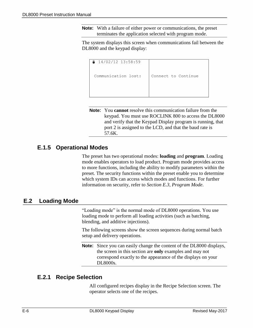
DL8000 Preset Instruction Manual
E-6 DL8000 Keypad Display Revised May-2017
Note: With a failure of either power or communications, the preset
terminates the application selected with program mode.
The system displays this screen when communications fail between the
DL8000 and the keypad display:
14/02/12 13:58:59
Communication lost:
Connect to Continue
Note: You cannot resolve this communication failure from the
keypad. You must use ROCLINK 800 to access the DL8000
and verify that the Keypad Display program is running, that
port 2 is assigned to the LCD, and that the baud rate is
57.6K.
E.1.5 Operational Modes
The preset has two operational modes: loading and program. Loading
mode enables operators to load product. Program mode provides access
to more functions, including the ability to modify parameters within the
preset. The security functions within the preset enable you to determine
which system IDs can access which modes and functions. For further
information on security, refer to Section E.3, Program Mode.
E.2 Loading Mode
“Loading mode” is the normal mode of DL8000 operations. You use
loading mode to perform all loading activities (such as batching,
blending, and additive injections).
The following screens show the screen sequences during normal batch
setup and delivery operations.
Note: Since you can easily change the content of the DL8000 displays,
the screen in this section are only examples and may not
correspond exactly to the appearance of the displays on your
DL8000s.
E.2.1 Recipe Selection
All configured recipes display in the Recipe Selection screen. The
operator selects one of the recipes.
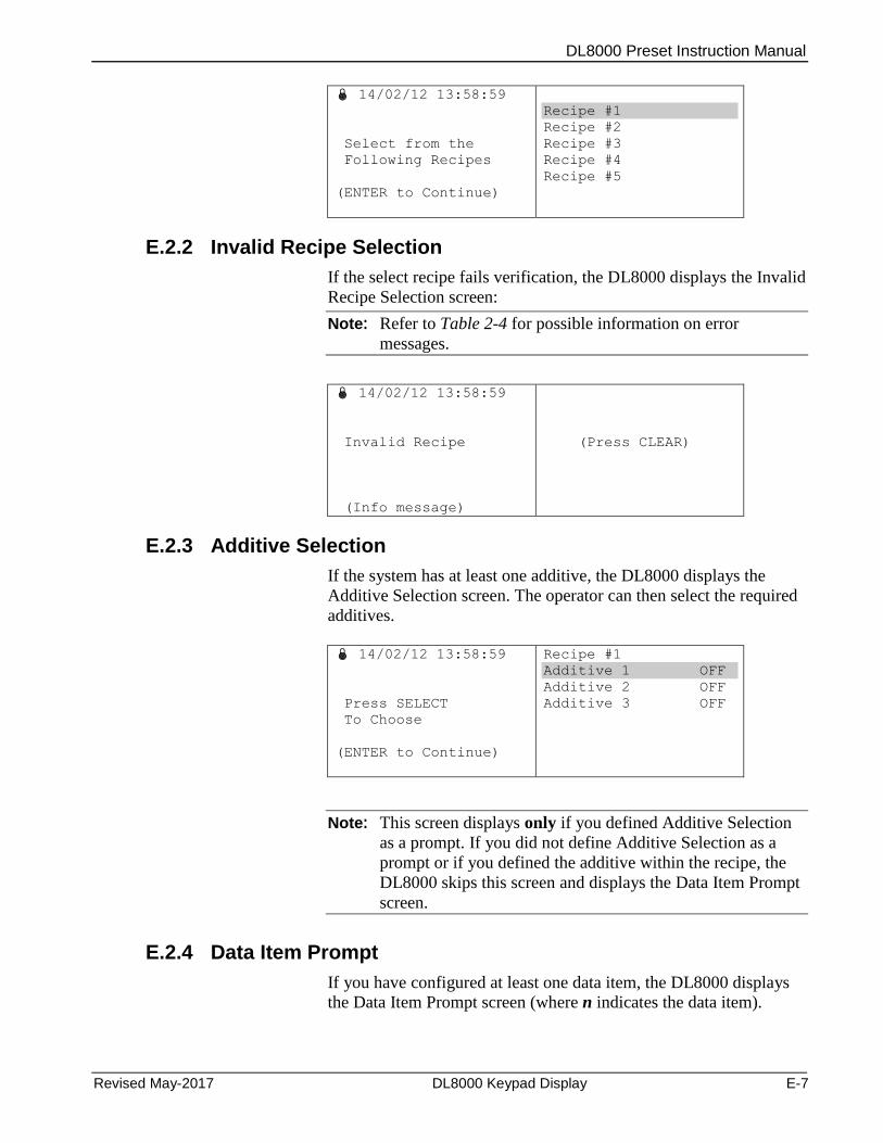
DL8000 Preset Instruction Manual
Revised May-2017 DL8000 Keypad Display E-7
14/02/12 13:58:59
Select from the
Following Recipes
(ENTER to Continue)
Recipe #1
Recipe #2
Recipe #3
Recipe #4
Recipe #5
E.2.2 Invalid Recipe Selection
If the select recipe fails verification, the DL8000 displays the Invalid
Recipe Selection screen:
Note: Refer to Table 2-4 for possible information on error
messages.
14/02/12 13:58:59
Invalid Recipe
(Info message)
(Press CLEAR)
E.2.3 Additive Selection
If the system has at least one additive, the DL8000 displays the
Additive Selection screen. The operator can then select the required
additives.
14/02/12 13:58:59
Press SELECT
To Choose
(ENTER to Continue)
Recipe #1
Additive 1 OFF
Additive 2 OFF
Additive 3 OFF
Note: This screen displays only if you defined Additive Selection
as a prompt. If you did not define Additive Selection as a
prompt or if you defined the additive within the recipe, the
DL8000 skips this screen and displays the Data Item Prompt
screen.
E.2.4 Data Item Prompt
If you have configured at least one data item, the DL8000 displays
the Data Item Prompt screen (where n indicates the data item).
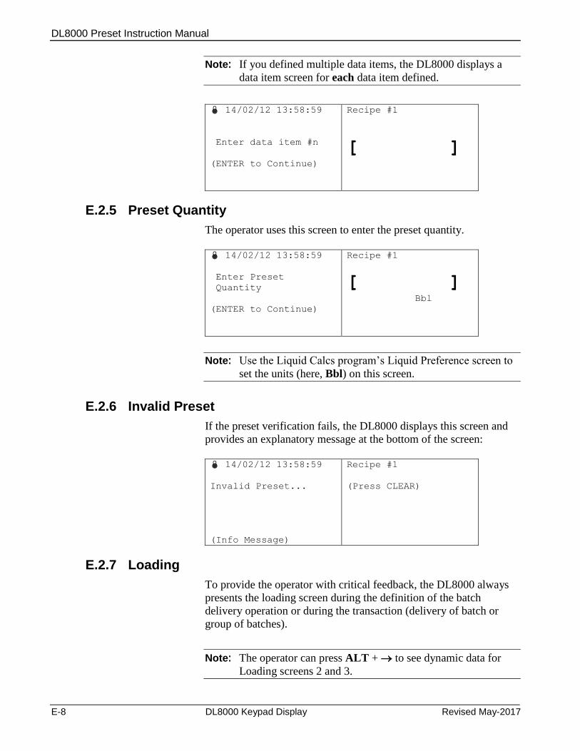
DL8000 Preset Instruction Manual
E-8 DL8000 Keypad Display Revised May-2017
Note: If you defined multiple data items, the DL8000 displays a
data item screen for each data item defined.
14/02/12 13:58:59
Enter data item #n
(ENTER to Continue)
Recipe #1
[ ]
E.2.5 Preset Quantity
The operator uses this screen to enter the preset quantity.
14/02/12 13:58:59
Enter Preset
Quantity
(ENTER to Continue)
Recipe #1
[ ] Bbl
Note: Use the Liquid Calcs program’s Liquid Preference screen to
set the units (here, Bbl) on this screen.
E.2.6 Invalid Preset
If the preset verification fails, the DL8000 displays this screen and
provides an explanatory message at the bottom of the screen:
14/02/12 13:58:59
Invalid Preset...
(Info Message)
Recipe #1
(Press CLEAR)
E.2.7 Loading
To provide the operator with critical feedback, the DL8000 always
presents the loading screen during the definition of the batch
delivery operation or during the transaction (delivery of batch or
group of batches).
Note: The operator can press ALT + to see dynamic data for
Loading screens 2 and 3.
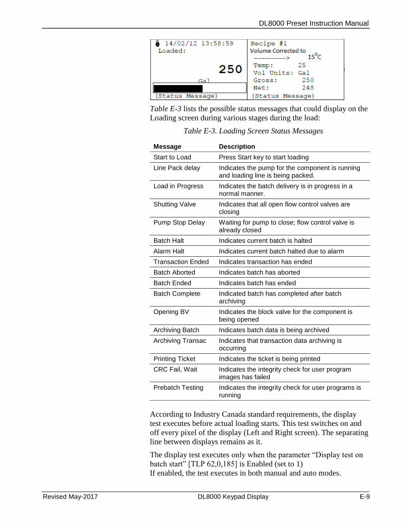
DL8000 Preset Instruction Manual
Revised May-2017 DL8000 Keypad Display E-9
Table E-3 lists the possible status messages that could display on the
Loading screen during various stages during the load:
Table E-3. Loading Screen Status Messages
Message Description
Start to Load Press Start key to start loading
Line Pack delay Indicates the pump for the component is running and loading line is being packed.
Load in Progress Indicates the batch delivery is in progress in a normal manner.
Shutting Valve Indicates that all open flow control valves are closing
Pump Stop Delay Waiting for pump to close; flow control valve is already closed
Batch Halt Indicates current batch is halted
Alarm Halt Indicates current batch halted due to alarm
Transaction Ended Indicates transaction has ended
Batch Aborted Indicates batch has aborted
Batch Ended Indicates batch has ended
Batch Complete Indicated batch has completed after batch archiving
Opening BV Indicates the block valve for the component is being opened
Archiving Batch Indicates batch data is being archived
Archiving Transac Indicates that transaction data archiving is occurring
Printing Ticket Indicates the ticket is being printed
CRC Fail, Wait Indicates the integrity check for user program images has failed
Prebatch Testing Indicates the integrity check for user programs is running
According to Industry Canada standard requirements, the display
test executes before actual loading starts. This test switches on and
off every pixel of the display (Left and Right screen). The separating
line between displays remains as it.
The display test executes only when the parameter “Display test on
batch start” [TLP 62,0,185] is Enabled (set to 1)
If enabled, the test executes in both manual and auto modes.
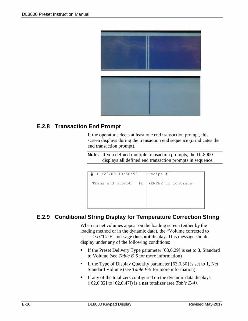
DL8000 Preset Instruction Manual
E-10 DL8000 Keypad Display Revised May-2017
E.2.8 Transaction End Prompt
If the operator selects at least one end transaction prompt, this
screen displays during the transaction end sequence (n indicates the
end transaction prompt).
Note: If you defined multiple transaction prompts, the DL8000
displays all defined end transaction prompts in sequence.
11/23/09 13:58:59
Trans end prompt #n
Recipe #1
(ENTER to continue)
E.2.9 Conditional String Display for Temperature Correction String
When no net volumes appear on the loading screen (either by the
loading method or in the dynamic data), the “Volume corrected to
-------->xx°C/°F” message does not display. This message should
display under any of the following conditions:
If the Preset Delivery Type parameter [63,0,29] is set to 3, Standard
to Volume (see Table E-5 for more information)
If the Type of Display Quantity parameter [63,0,30] is set to 1, Net
Standard Volume (see Table E-5 for more information).
If any of the totalizers configured on the dynamic data displays
([62,0,32] to [62,0,47]) is a net totalizer (see Table E-4).
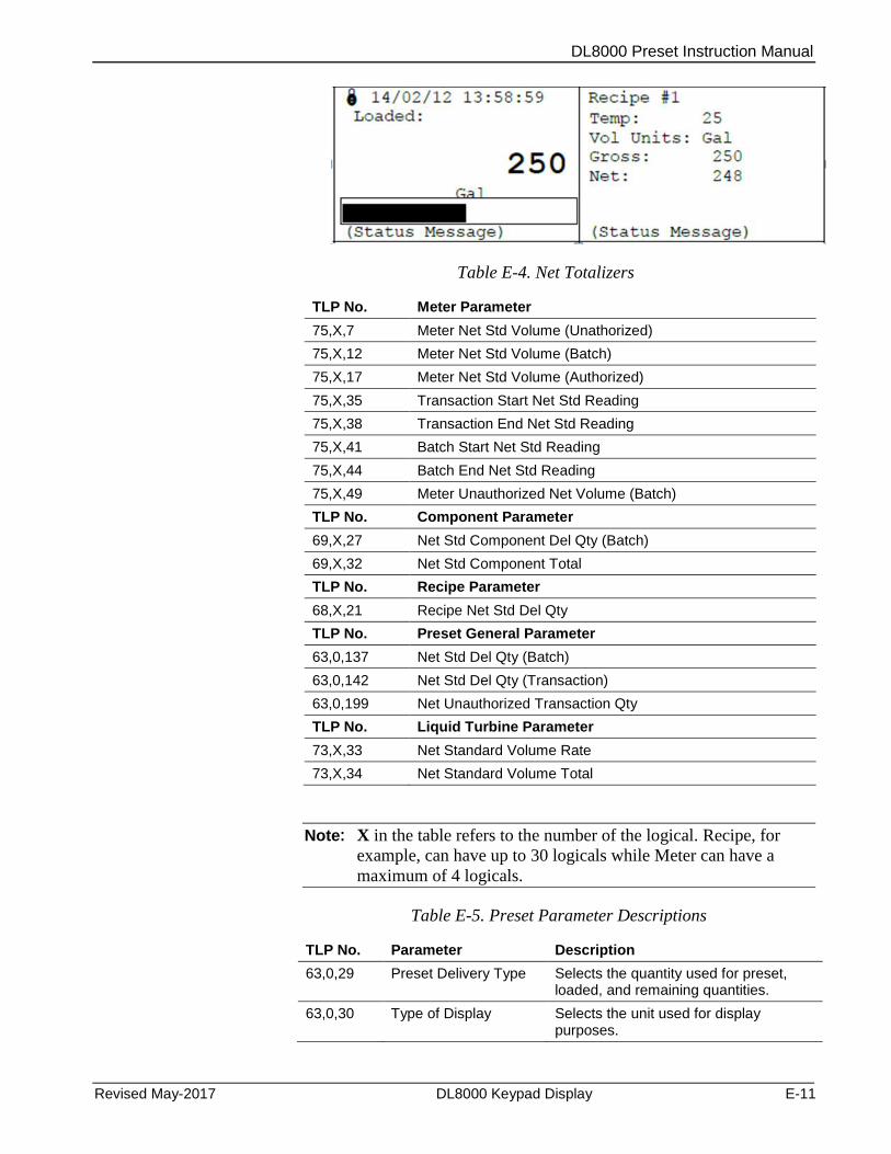
DL8000 Preset Instruction Manual
Revised May-2017 DL8000 Keypad Display E-11
Table E-4. Net Totalizers
TLP No. Meter Parameter
75,X,7 Meter Net Std Volume (Unathorized)
75,X,12 Meter Net Std Volume (Batch)
75,X,17 Meter Net Std Volume (Authorized)
75,X,35 Transaction Start Net Std Reading
75,X,38 Transaction End Net Std Reading
75,X,41 Batch Start Net Std Reading
75,X,44 Batch End Net Std Reading
75,X,49 Meter Unauthorized Net Volume (Batch)
TLP No. Component Parameter
69,X,27 Net Std Component Del Qty (Batch)
69,X,32 Net Std Component Total
TLP No. Recipe Parameter
68,X,21 Recipe Net Std Del Qty
TLP No. Preset General Parameter
63,0,137 Net Std Del Qty (Batch)
63,0,142 Net Std Del Qty (Transaction)
63,0,199 Net Unauthorized Transaction Qty
TLP No. Liquid Turbine Parameter
73,X,33 Net Standard Volume Rate
73,X,34 Net Standard Volume Total
Note: X in the table refers to the number of the logical. Recipe, for
example, can have up to 30 logicals while Meter can have a
maximum of 4 logicals.
Table E-5. Preset Parameter Descriptions
TLP No. Parameter Description
63,0,29 Preset Delivery Type Selects the quantity used for preset, loaded, and remaining quantities.
63,0,30 Type of Display Selects the unit used for display purposes.
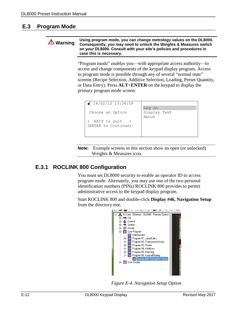
DL8000 Preset Instruction Manual
E-12 DL8000 Keypad Display Revised May-2017
E.3 Program Mode
Warning Using program mode, you can change metrology values on the DL8000. Consequently, you may need to unlock the Weights & Measures switch on your DL8000. Consult with your site’s policies and procedures in case this is necessary.
“Program mode” enables you—with appropriate access authority—to
access and change components of the keypad display program. Access
to program mode is possible through any of several “normal state”
screens (Recipe Selection, Additive Selection, Loading, Preset Quantity,
or Data Entry). Press ALT+ENTER on the keypad to display the
primary program mode screen:
14/02/12 13:58:59
Choose an Option
( EXIT to Quit )
(ENTER to Continue)
Log In
Display Test
About
Note: Example screens in this section show an open (or unlocked)
Weights & Measures icon.
E.3.1 ROCLINK 800 Configuration
You must set DL8000 security to enable an operator ID to access
program mode. Alternately, you may use one of the two personal
identification numbers (PINs) ROCLINK 800 provides to permit
administrative access to the keypad display program.
Start ROCLINK 800 and double-click Display #46, Navigation Setup
from the directory tree.
Figure E-4. Navigation Setup Option
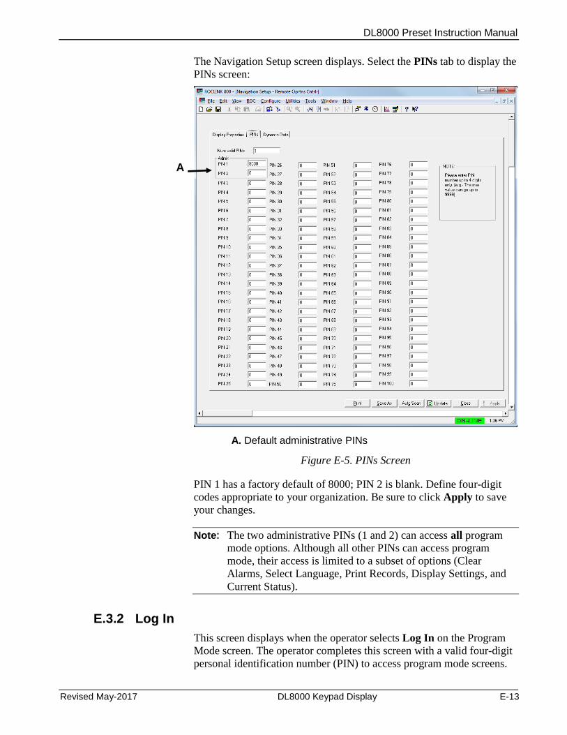
DL8000 Preset Instruction Manual
Revised May-2017 DL8000 Keypad Display E-13
The Navigation Setup screen displays. Select the PINs tab to display the
PINs screen:
A. Default administrative PINs
Figure E-5. PINs Screen
PIN 1 has a factory default of 8000; PIN 2 is blank. Define four-digit
codes appropriate to your organization. Be sure to click Apply to save
your changes.
Note: The two administrative PINs (1 and 2) can access all program
mode options. Although all other PINs can access program
mode, their access is limited to a subset of options (Clear
Alarms, Select Language, Print Records, Display Settings, and
Current Status).
E.3.2 Log In
This screen displays when the operator selects Log In on the Program
Mode screen. The operator completes this screen with a valid four-digit
personal identification number (PIN) to access program mode screens.
A
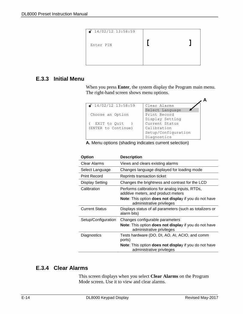
DL8000 Preset Instruction Manual
E-14 DL8000 Keypad Display Revised May-2017
14/02/12 13:58:59
Enter PIN
[ ]
E.3.3 Initial Menu
When you press Enter, the system display the Program main menu.
The right-hand screen shows menu options.
14/02/12 13:58:59
Choose an Option
( EXIT to Quit )
(ENTER to Continue)
Clear Alarms
Select Language
Print Record
Display Setting
Current Status
Calibration
Setup/Configuration
Diagnostics
A. Menu options (shading indicates current selection)
Option Description
Clear Alarms Views and clears existing alarms
Select Language Changes language displayed for loading mode
Print Record Reprints transaction ticket
Display Setting Changes the brightness and contrast for the LCD
Calibration Performs calibrations for analog inputs, RTDs, additive meters, and product meters
Note: This option does not display if you do not have administrative privileges
Current Status Displays status of all parameters (such as totalizers or alarm bits)
Setup/Configuration Changes configurable parameters
Note: This option does not display if you do not have administrative privileges
Diagnostics Tests hardware (DO, DI, AO, AI, ACIO, and comm ports)
Note: This option does not display if you do not have administrative privileges
E.3.4 Clear Alarms
This screen displays when you select Clear Alarms on the Program
Mode screen. Use it to view and clear alarms.
A
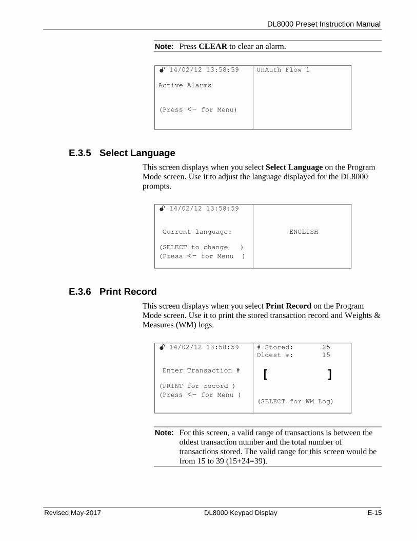
DL8000 Preset Instruction Manual
Revised May-2017 DL8000 Keypad Display E-15
Note: Press CLEAR to clear an alarm.
14/02/12 13:58:59
Active Alarms
(Press <– for Menu)
UnAuth Flow 1
E.3.5 Select Language
This screen displays when you select Select Language on the Program
Mode screen. Use it to adjust the language displayed for the DL8000
prompts.
14/02/12 13:58:59
Current language:
(SELECT to change )
(Press <– for Menu )
ENGLISH
E.3.6 Print Record
This screen displays when you select Print Record on the Program
Mode screen. Use it to print the stored transaction record and Weights &
Measures (WM) logs.
14/02/12 13:58:59
Enter Transaction #
(PRINT for record )
(Press <– for Menu )
# Stored: 25
Oldest #: 15
[ ]
(SELECT for WM Log)
Note: For this screen, a valid range of transactions is between the
oldest transaction number and the total number of
transactions stored. The valid range for this screen would be
from 15 to 39 (15+24=39).
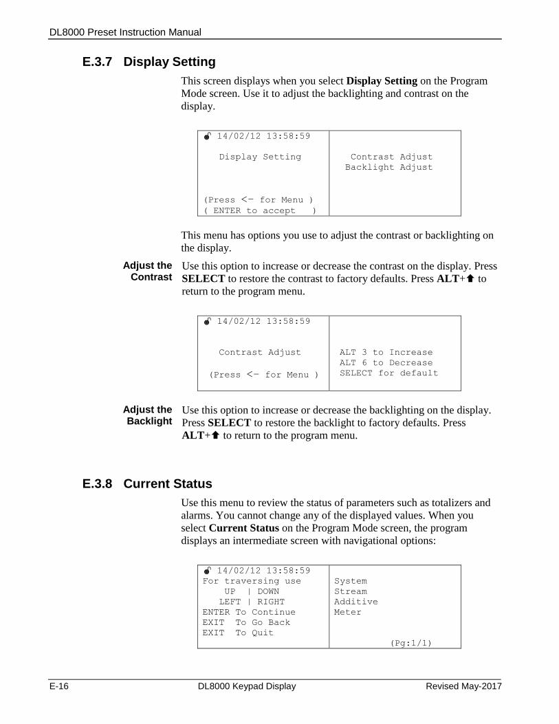
DL8000 Preset Instruction Manual
E-16 DL8000 Keypad Display Revised May-2017
E.3.7 Display Setting
This screen displays when you select Display Setting on the Program
Mode screen. Use it to adjust the backlighting and contrast on the
display.
14/02/12 13:58:59
Display Setting
(Press <– for Menu ) ( ENTER to accept )
Contrast Adjust
Backlight Adjust
This menu has options you use to adjust the contrast or backlighting on
the display.
Adjust the Contrast
Use this option to increase or decrease the contrast on the display. Press
SELECT to restore the contrast to factory defaults. Press ALT+ to
return to the program menu.
14/02/12 13:58:59
Contrast Adjust
(Press <– for Menu )
ALT 3 to Increase
ALT 6 to Decrease
SELECT for default
Adjust the Backlight
Use this option to increase or decrease the backlighting on the display.
Press SELECT to restore the backlight to factory defaults. Press
ALT+ to return to the program menu.
E.3.8 Current Status
Use this menu to review the status of parameters such as totalizers and
alarms. You cannot change any of the displayed values. When you
select Current Status on the Program Mode screen, the program
displays an intermediate screen with navigational options:
14/02/12 13:58:59
For traversing use
UP | DOWN
LEFT | RIGHT
ENTER To Continue
EXIT To Go Back
EXIT To Quit
System
Stream
Additive
Meter
(Pg:1/1)

DL8000 Preset Instruction Manual
Revised May-2017 DL8000 Keypad Display E-17
Press ENTER to continue. The program displays the Current Status
menu:
14/02/12 13:58:59
System
Stream
Additive
Meter
General
Batch
Transaction
Recipe
Alarm
(Pg:1/1)
The keypad display program does not display all the TLPs in the preset.
The program maintains a database which decides which TLPs you can
access through the Current Status menu and under which submenu those
TLPs reside. A TLP can be associated with any program or firmware.
Table E-6 shows which TLPs are available under which menu option.
Note: When the keypad display program is using the
Setup/Configuration, Current Status, Calibration, or Diagnostics
menu and an alarm occurs, the red LED blinks but no message
displays.
Table E-6. TLPs in Current Status Menus
SYSTEM Menu
General
(1 logical, point type 63)
Headings (Submenu Page 1) TLP
Trans No. 63,0,20
Batch No. 63,0,22
LastPowerDownTime 63,0,21
Current Alarm Type 63,0,9
Roll Over Lmt 63,0,16
Batch
(1 logical, point types 63 & 64)
Headings (Submenu Page 1) TLP
Batch Number 63,0,125
BtchStart DateTime 63,0,232
Btch End Date Time 63,0,233
Batch Gross Del. 63,0,135
Batch Mass Del. 63,0,138
Btch Net Std. Del. 63,0,137
Headings (Submenu Page 2) TLP
Temp FWA 63,0,132
Base Dens. FWA 63,0,179
SwingArm Curr Side 63,0,145
Net Mass Btch Tot 63,0,25
Blend Curr Flowrate 63,0,59
Cmpt Batch GrsDel 63,0,2
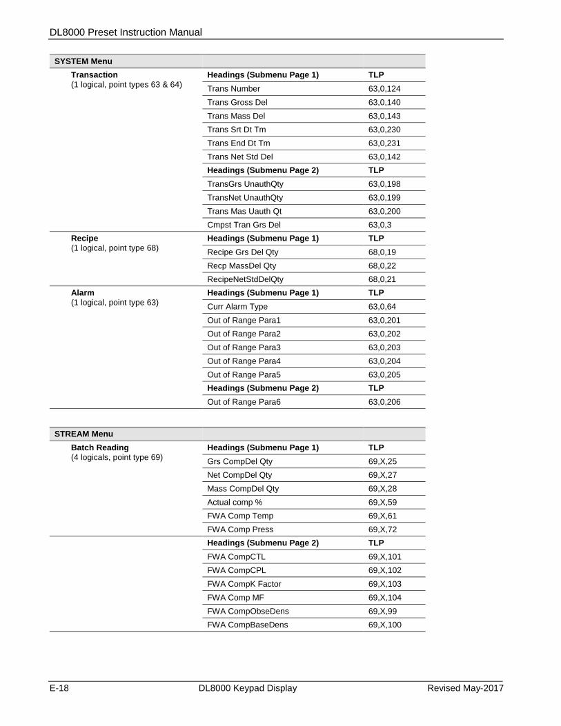
DL8000 Preset Instruction Manual
E-18 DL8000 Keypad Display Revised May-2017
SYSTEM Menu
Transaction
(1 logical, point types 63 & 64)
Headings (Submenu Page 1) TLP
Trans Number 63,0,124
Trans Gross Del 63,0,140
Trans Mass Del 63,0,143
Trans Srt Dt Tm 63,0,230
Trans End Dt Tm 63,0,231
Trans Net Std Del 63,0,142
Headings (Submenu Page 2) TLP
TransGrs UnauthQty 63,0,198
TransNet UnauthQty 63,0,199
Trans Mas Uauth Qt 63,0,200
Cmpst Tran Grs Del 63,0,3
Recipe
(1 logical, point type 68)
Headings (Submenu Page 1) TLP
Recipe Grs Del Qty 68,0,19
Recp MassDel Qty 68,0,22
RecipeNetStdDelQty 68,0,21
Alarm
(1 logical, point type 63)
Headings (Submenu Page 1) TLP
Curr Alarm Type 63,0,64
Out of Range Para1 63,0,201
Out of Range Para2 63,0,202
Out of Range Para3 63,0,203
Out of Range Para4 63,0,204
Out of Range Para5 63,0,205
Headings (Submenu Page 2) TLP
Out of Range Para6 63,0,206
STREAM Menu
Batch Reading
(4 logicals, point type 69)
Headings (Submenu Page 1) TLP
Grs CompDel Qty 69,X,25
Net CompDel Qty 69,X,27
Mass CompDel Qty 69,X,28
Actual comp % 69,X,59
FWA Comp Temp 69,X,61
FWA Comp Press 69,X,72
Headings (Submenu Page 2) TLP
FWA CompCTL 69,X,101
FWA CompCPL 69,X,102
FWA CompK Factor 69,X,103
FWA Comp MF 69,X,104
FWA CompObseDens 69,X,99
FWA CompBaseDens 69,X,100
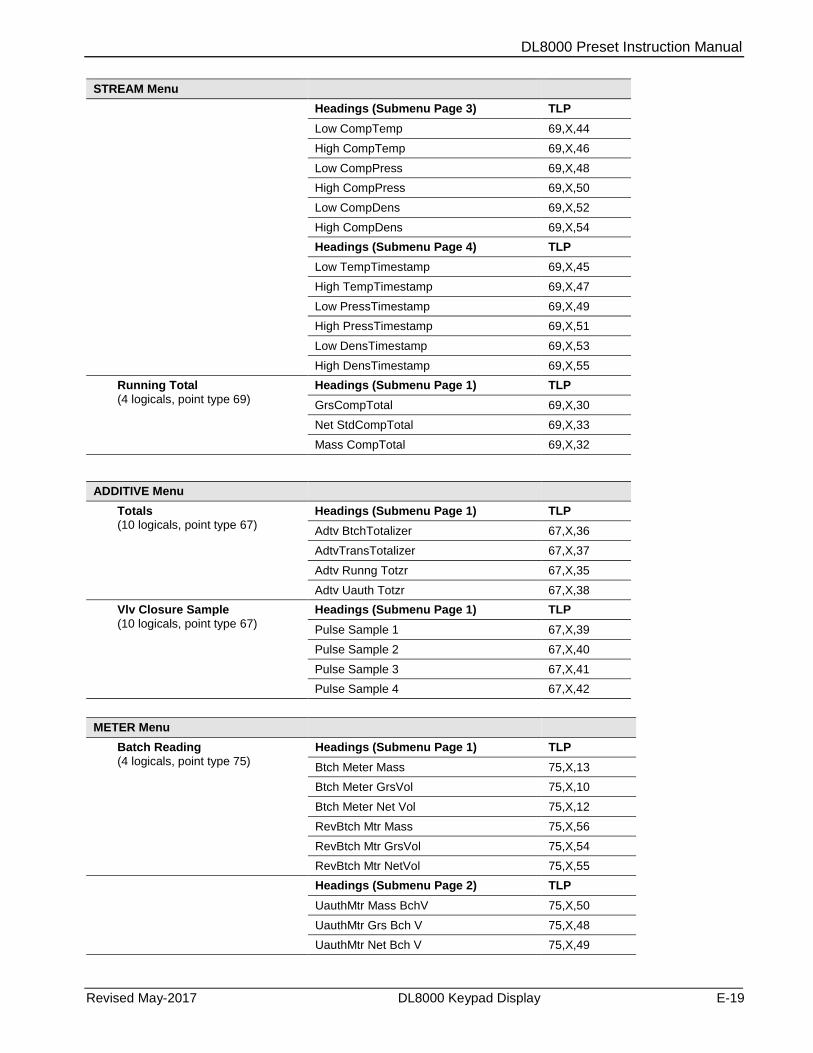
DL8000 Preset Instruction Manual
Revised May-2017 DL8000 Keypad Display E-19
STREAM Menu
Headings (Submenu Page 3) TLP
Low CompTemp 69,X,44
High CompTemp 69,X,46
Low CompPress 69,X,48
High CompPress 69,X,50
Low CompDens 69,X,52
High CompDens 69,X,54
Headings (Submenu Page 4) TLP
Low TempTimestamp 69,X,45
High TempTimestamp 69,X,47
Low PressTimestamp 69,X,49
High PressTimestamp 69,X,51
Low DensTimestamp 69,X,53
High DensTimestamp 69,X,55
Running Total
(4 logicals, point type 69)
Headings (Submenu Page 1) TLP
GrsCompTotal 69,X,30
Net StdCompTotal 69,X,33
Mass CompTotal 69,X,32
ADDITIVE Menu
Totals (10 logicals, point type 67)
Headings (Submenu Page 1) TLP
Adtv BtchTotalizer 67,X,36
AdtvTransTotalizer 67,X,37
Adtv Runng Totzr 67,X,35
Adtv Uauth Totzr 67,X,38
Vlv Closure Sample
(10 logicals, point type 67)
Headings (Submenu Page 1) TLP
Pulse Sample 1 67,X,39
Pulse Sample 2 67,X,40
Pulse Sample 3 67,X,41
Pulse Sample 4 67,X,42
METER Menu
Batch Reading
(4 logicals, point type 75)
Headings (Submenu Page 1) TLP
Btch Meter Mass 75,X,13
Btch Meter GrsVol 75,X,10
Btch Meter Net Vol 75,X,12
RevBtch Mtr Mass 75,X,56
RevBtch Mtr GrsVol 75,X,54
RevBtch Mtr NetVol 75,X,55
Headings (Submenu Page 2) TLP
UauthMtr Mass BchV 75,X,50
UauthMtr Grs Bch V 75,X,48
UauthMtr Net Bch V 75,X,49
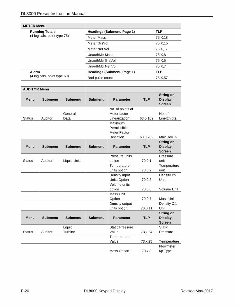
DL8000 Preset Instruction Manual
E-20 DL8000 Keypad Display Revised May-2017
METER Menu
Running Totals
(4 logicals, point type 75)
Headings (Submenu Page 1) TLP
Meter Mass 75,X,18
Meter GrsVol 75,X,15
Meter Net Vol 75,X,17
UnauthMtr Mass 75,X,8
UnauthMtr GrsVol 75,X,5
UnauthMtr Net Vol 75,X,7
Alarm (4 logicals, point type 69)
Headings (Submenu Page 1) TLP
Bad pulse count 75,X,57
AUDITOR Menu
Menu Submenu Submenu Submenu Parameter TLP
String on
Display
Screen
Status Auditor
General
Data
No. of points of
Meter factor
Linearization 63,0,109
No. of
Linerzn pts.
Maximum
Permissible
Meter Factor
Deviation 63,0,209 Max Dev %
Menu Submenu Submenu Submenu Parameter TLP
String on
Display
Screen
Status Auditor Liquid Units
Pressure units
option 70,0,1
Pressure
unit
Temperature
units option 70,0,2
Temperature
unit
Density Input
Units Option 70,0,3
Density I/p
Unit
Volume units
option 70,0,6 Volume Unit
Mass Unit
Option 70,0,7 Mass Unit
Density output
units option 70,0,11
Density O/p
Unit
Menu Submenu Submenu Submenu Parameter TLP
String on
Display
Screen
Status Auditor
Liquid
Turbine
Static Pressure
Value 73,x,24
Static
Pressure
Temperature
Value 73,x,25 Temperature
Mass Option 73,x,3
Flowmeter
I/p Type
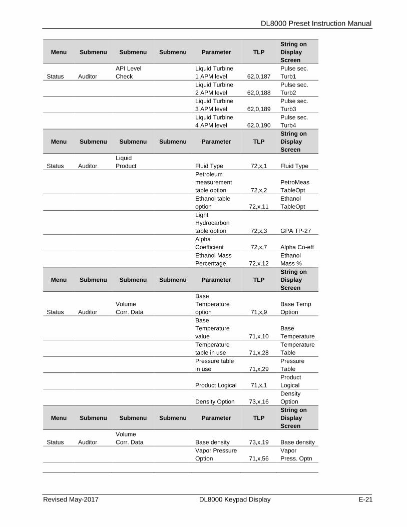
DL8000 Preset Instruction Manual
Revised May-2017 DL8000 Keypad Display E-21
Menu Submenu Submenu Submenu Parameter TLP
String on
Display
Screen
Status Auditor
API Level
Check
Liquid Turbine
1 APM level 62,0,187
Pulse sec.
Turb1
Liquid Turbine
2 APM level 62,0,188
Pulse sec.
Turb2
Liquid Turbine
3 APM level 62,0,189
Pulse sec.
Turb3
Liquid Turbine
4 APM level 62,0,190
Pulse sec.
Turb4
Menu Submenu Submenu Submenu Parameter TLP
String on
Display
Screen
Status Auditor
Liquid
Product Fluid Type 72,x,1 Fluid Type
Petroleum
measurement
table option 72,x,2
PetroMeas
TableOpt
Ethanol table
option 72,x,11
Ethanol
TableOpt
Light
Hydrocarbon
table option 72,x,3 GPA TP-27
Alpha
Coefficient 72,x,7 Alpha Co-eff
Ethanol Mass
Percentage 72,x,12
Ethanol
Mass %
Menu Submenu Submenu Submenu Parameter TLP
String on
Display
Screen
Status Auditor
Volume
Corr. Data
Base
Temperature
option 71,x,9
Base Temp
Option
Base
Temperature
value 71,x,10
Base
Temperature
Temperature
table in use 71,x,28
Temperature
Table
Pressure table
in use 71,x,29
Pressure
Table
Product Logical 71,x,1
Product
Logical
Density Option 73,x,16
Density
Option
Menu Submenu Submenu Submenu Parameter TLP
String on
Display
Screen
Status Auditor
Volume
Corr. Data
Base density 73,x,19 Base density
Vapor Pressure
Option 71,x,56
Vapor
Press. Optn

DL8000 Preset Instruction Manual
E-22 DL8000 Keypad Display Revised May-2017
Menu Submenu Submenu Submenu Parameter TLP
String on
Display
Screen
Status Auditor
Component
Details Comp. Name 69,x,6
Component
ID
Meter Factor/K-
Factor Option 69,x,74
M-Fact/K-
Fact Optn
Meter Factor 69,x,9 M-Fact
K-Factor 69,x,8 K-Fact
Master Meter
Factor 69,x,105
Master M-
Fact
Master MF % 69,x,106
Master M-
Fact %
Menu Submenu Submenu Submenu Parameter TLP
String on
Display
Screen
Meter Factor/K-
Factor 1 69,x,75
M-Fact/K-
Fact 1
Meter Factor/K-
Factor 2 69,x,77
M-Fact/K-
Fact 2
Meter Factor/K-
Factor 3 69,x,79
M-Fact/K-
Fact 3
Meter Factor/K-
Factor 4 69,x,81
M-Fact/K-
Fact 4
Meter Factor/K-
Factor 5 69,x,83
M-Fact/K-
Fact 5
Meter Factor/K-
Factor 6 69,x,85
M-Fact/K-
Fact 6
Menu Submenu Submenu Submenu Parameter TLP
String on
Display
Screen
Meter Factor/K-
Factor 7 69,x,87
M-Fact/K-
Fact 7
Meter Factor/K-
Factor 8 69,x,89
M-Fact/K-
Fact 8
Meter Factor/K-
Factor 9 69,x,91
M-Fact/K-
Fact 9
Meter Factor/K-
Factor 10 69,x,93
M-Fact/K-
Fact 10
Meter Factor/K-
Factor 11 69,x,95
M-Fact/K-
Fact 11
Meter Factor/K-
Factor 12 69,x,97
M-Fact/K-
Fact 12
E.3.9 Setup/ Configuration
This screen displays when you select Setup/Configuration on the
Program Mode screen. This is the first of three screens. Press to
select the next option or press ALT+ to move to the next screen:

DL8000 Preset Instruction Manual
Revised May-2017 DL8000 Keypad Display E-23
14/02/12 13:58:59
For traversing use
UP | DOWN
LEFT | RIGHT
ENTER To Continue
EXIT To Go Back
EXIT To Quit
System
Component
Meter
Valve
Recipe
Additive
(Pg:1/3)
14/02/12 13:58:59
For traversing use
UP | DOWN
LEFT | RIGHT
ENTER To Continue
EXIT To Go Back
EXIT To Quit
History
Unit
Liquid Setup
ROC Settings
Keypad Display
(Pg:2/3)
14/02/12 13:58:59
For traversing use
UP | DOWN
LEFT | RIGHT
ENTER To Continue
EXIT To Go Back
EXIT To Quit
Generic TLP Entry
COM Port Settings
Online Help
(Pg:3/3)
Press ENTER to access an option’s submenu (such as System on the
first screen):
14/02/12 13:58:59
System
Component
Meter
Valve
Recipe
Additive
General
Flush
Adtv Inline Config
Prompt
Driver Verificn
End O/P
(Pg:1/2)
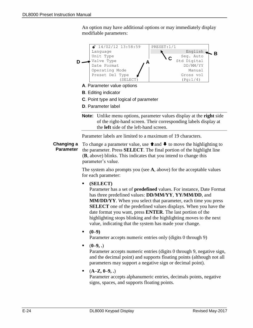
DL8000 Preset Instruction Manual
E-24 DL8000 Keypad Display Revised May-2017
An option may have additional options or may immediately display
modifiable parameters:
14/02/12 13:58:59
Language
Unit Type
Valve Type
Date Format
Operating Mode
Preset Del Type
(SELECT)
PRESET:1/1
English
Seg. Auto
Std Digital
DD/MM/YY
Manual
Gross vol
(Pg:1/4)
A. Parameter value options
B. Editing indicator
C. Point type and logical of parameter
D. Parameter label
Note: Unlike menu options, parameter values display at the right side
of the right-hand screen. Their corresponding labels display at
the left side of the left-hand screen.
Parameter labels are limited to a maximum of 19 characters.
Changing a Parameter
To change a parameter value, use and to move the highlighting to
the parameter. Press SELECT. The final portion of the highlight line
(B, above) blinks. This indicates that you intend to change this
parameter’s value.
The system also prompts you (see A, above) for the acceptable values
for each parameter:
(SELECT) Parameter has a set of predefined values. For instance, Date Format
has three predefined values: DD/MM/YY, YY/MM/DD, and
MM/DD/YY. When you select that parameter, each time you press
SELECT one of the predefined values displays. When you have the
date format you want, press ENTER. The last portion of the
highlighting stops blinking and the highlighting moves to the next
value, indicating that the system has made your change.
(0–9) Parameter accepts numeric entries only (digits 0 through 9)
(0–9, .)
Parameter accepts numeric entries (digits 0 through 9, negative sign,
and the decimal point) and supports floating points (although not all
parameters may support a negative sign or decimal point).
(A–Z, 0–9, .)
Parameter accepts alphanumeric entries, decimals points, negative
signs, spaces, and supports floating points.
B
A C
D
DL8000 Preset Instruction Manual
Revised May-2017 DL8000 Keypad Display E-25
(TLP)
Parameter accepts a TLP value [0,0,0]. To define a TLP, press
SELECT. The system displays valid IO module values. Press
ENTER to define a module. (If you select a module which is not
installed the message Req. Card not in Sys displays). The system
prompts you to choose a logical. Press SELECT to page through the
available values and press ENTER to choose a value. As soon as the
system validates your selection, it prompts you to select a parameter.
Press SELECT to page through the available values and press
ENTER to choose a value. Press ALT+ENTER to cancel a
selection while in data entry mode.
Note: WM displays in the last line of the right-hand screen if the
selected parameter is a Weights & Measures parameter and the
Weights & Measures switch is locked. In this case, you cannot
edit this parameter.
Clearing a Value
If you make an error during data entry, either press CLEAR (to clear
the entire entry) or use the BSKP key (ALT+SELECT) to clear just the
last character entered. While you are entering data, you can restore the
previous value by pressing ALT+ENTER.
Examples To enter AAA, press and hold down ALT. Press 1. The display first
shows a decimal point, then A. Repeat the process twice.
To enter ABC, press and hold down ALT. Press 1 twice. Wait a second,
and press 1 three times. Finally, press 1 four times.
Note: Pressing and holding down ALT and any key quickly displays
all the values sequentially for that key (., A, B, and C in the case
of the 1 key). Until you get used to the scroll speed, it is better to
press the keys individually to make sure you have the right
values.
A parameter group has parameters from a single point type. If the
parameter is from different point type, then the display shows the point
type name from last parameter only for whole screen
Setup Parameters Table E-7 shows the menus, sub menus, and associated parameters
under Setup/Configuration.
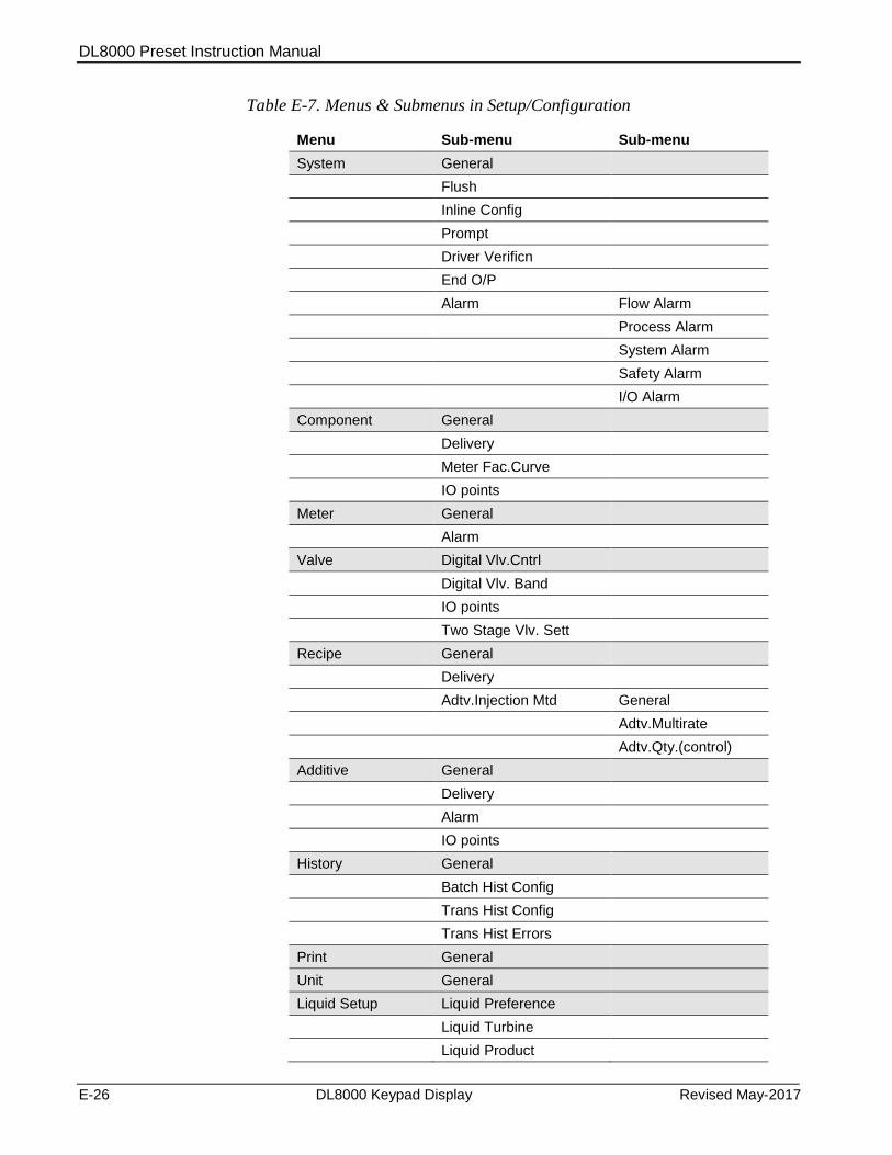
DL8000 Preset Instruction Manual
E-26 DL8000 Keypad Display Revised May-2017
Table E-7. Menus & Submenus in Setup/Configuration
Menu Sub-menu Sub-menu
System General
Flush
Inline Config
Prompt
Driver Verificn
End O/P
Alarm Flow Alarm
Process Alarm
System Alarm
Safety Alarm
I/O Alarm
Component General
Delivery
Meter Fac.Curve
IO points
Meter General
Alarm
Valve Digital Vlv.Cntrl
Digital Vlv. Band
IO points
Two Stage Vlv. Sett
Recipe General
Delivery
Adtv.Injection Mtd General
Adtv.Multirate
Adtv.Qty.(control)
Additive General
Delivery
Alarm
IO points
History General
Batch Hist Config
Trans Hist Config
Trans Hist Errors
Print General
Unit General
Liquid Setup Liquid Preference
Liquid Turbine
Liquid Product
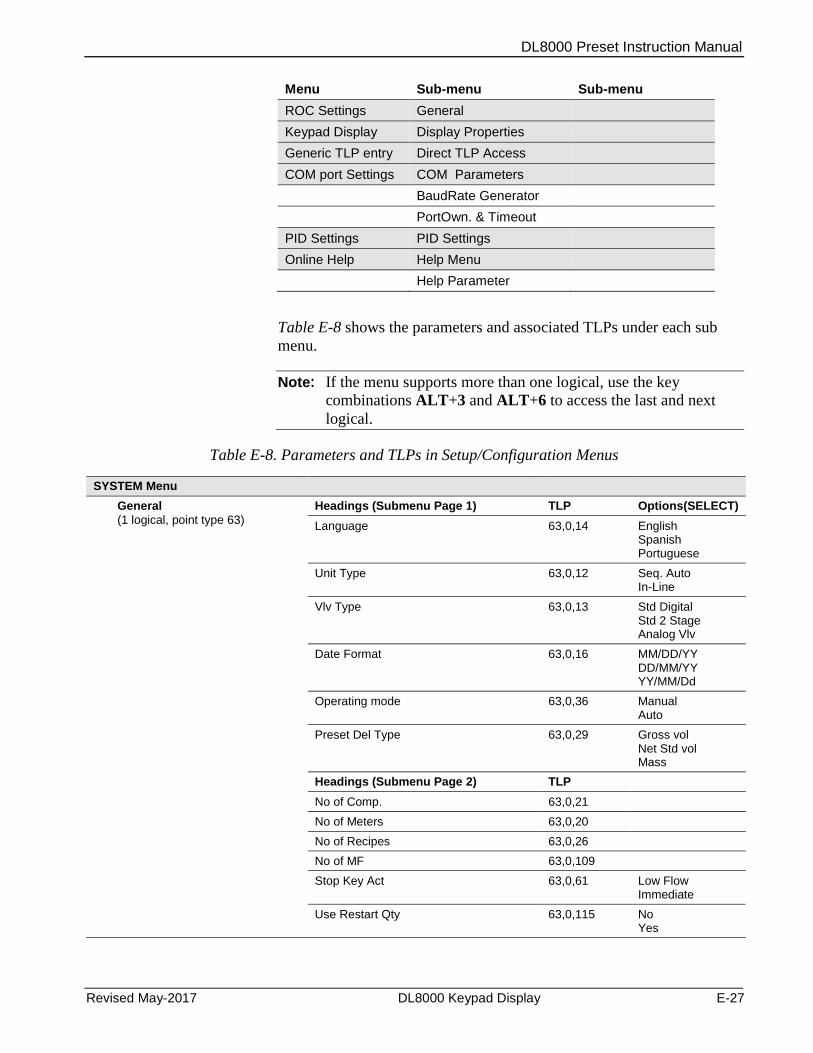
DL8000 Preset Instruction Manual
Revised May-2017 DL8000 Keypad Display E-27
Menu Sub-menu Sub-menu
ROC Settings General
Keypad Display Display Properties
Generic TLP entry Direct TLP Access
COM port Settings COM Parameters
BaudRate Generator
PortOwn. & Timeout
PID Settings PID Settings
Online Help Help Menu
Help Parameter
Table E-8 shows the parameters and associated TLPs under each sub
menu.
Note: If the menu supports more than one logical, use the key
combinations ALT+3 and ALT+6 to access the last and next
logical.
Table E-8. Parameters and TLPs in Setup/Configuration Menus
SYSTEM Menu
General
(1 logical, point type 63)
Headings (Submenu Page 1) TLP Options(SELECT)
Language 63,0,14 English Spanish Portuguese
Unit Type 63,0,12 Seq. Auto In-Line
Vlv Type 63,0,13 Std Digital Std 2 Stage Analog Vlv
Date Format 63,0,16 MM/DD/YY DD/MM/YY YY/MM/Dd
Operating mode 63,0,36 Manual Auto
Preset Del Type 63,0,29 Gross vol Net Std vol Mass
Headings (Submenu Page 2) TLP
No of Comp. 63,0,21
No of Meters 63,0,20
No of Recipes 63,0,26
No of MF 63,0,109
Stop Key Act 63,0,61 Low Flow Immediate
Use Restart Qty 63,0,115 No Yes
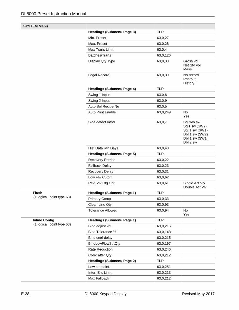
DL8000 Preset Instruction Manual
E-28 DL8000 Keypad Display Revised May-2017
SYSTEM Menu
Headings (Submenu Page 3) TLP
Min. Preset 63,0,27
Max. Preset 63,0,28
Max Trans Limit 63,0,4
Batches/Trans 63,0,126
Display Qty Type 63,0,30 Gross vol Net Std vol Mass
Legal Record 63,0,39 No record Printout History
Headings (Submenu Page 4) TLP
Swing 1 Input 63,0,8
Swing 2 Input 63,0,9
Auto Sel Recipe No 63,0,5
Auto Print Enable 63,0,249 No Yes
Side detect mthd 63,0,7 Sgl w/o sw Sgl1 sw (SW2) Sgl 1 sw (SW1) Dbl 1 sw (SW2) Dbl 1 sw (SW1_ Dbl 2 sw
Hist Data Rtn Days 63,0,43
Headings (Submenu Page 5) TLP
Recovery Retries 63,0,22
Fallback Delay 63,0,23
Recovery Delay 63,0,31
Low Flw Cutoff 63,0,62
Rev. Vlv Cfg Opt 63,0,61 Single Act Vlv Double Act Vlv
Flush
(1 logical, point type 63)
Headings (Submenu Page 1) TLP
Primary Comp 63,0,33
Clean Line Qty 63,0,93
Tolerance Allowed 63,0,94 No Yes
Inline Config
(1 logical, point type 63)
Headings (Submenu Page 1) TLP
Blnd adjust vol 63,0,216
Blnd Tolerance % 63,0,148
Blnd cntrl delay 63,0,215
BlndLowFlowStrtQty 63,0,197
Rate Reduction 63,0,246
Corrc after Qty 63,0,212
Headings (Submenu Page 2) TLP
Low set point 63,0,251
Inter. Err. Limit 63,0,213
Max Fallback 63,0,212
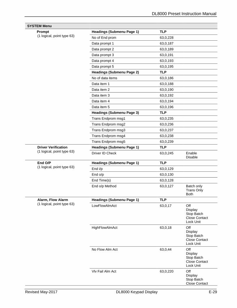
DL8000 Preset Instruction Manual
Revised May-2017 DL8000 Keypad Display E-29
SYSTEM Menu
Prompt
(1 logical, point type 63)
Headings (Submenu Page 1) TLP
No of End prom 63,0,228
Data prompt 1 63,0,187
Data prompt 2 63,0,189
Data prompt 3 63,0,191
Data prompt 4 63,0,193
Data prompt 5 63,0,195
Headings (Submenu Page 2) TLP
No of data items 63,0,186
Data item 1 63,0,188
Data item 2 63,0,190
Data item 3 63,0,192
Data item 4 63,0,194
Data item 5 63,0,196
Headings (Submenu Page 3) TLP
Trans Endprom msg1 63,0,235
Trans Endprom msg2 63,0,236
Trans Endprom msg3 63,0,237
Trans Endprom msg4 63,0,238
Trans Endprom msg5 63,0,239
Driver Verification
(1 logical, point type 63)
Headings (Submenu Page 1) TLP
Driver ID Check 63,0,245 Enable Disable
End O/P
(1 logical, point type 63)
Headings (Submenu Page 1) TLP
End i/p 63,0,129
End o/p 63,0,130
End Time(s) 63,0,128
End o/p Method 63,0,127 Batch only Trans Only Both
Alarm, Flow Alarm
(1 logical, point type 63)
Headings (Submenu Page 1) TLP
LowFlowAlmAct 63,0,17 Off Display Stop Batch Close Contact Lock Unit
HighFlowAlmAct 63,0,18 Off Display Stop Batch Close Contact Lock Unit
No Flow Alm Act 63,0,44 Off Display Stop Batch Close Contact Lock Unit
Vlv Fail Alm Act 63,0,220 Off Display Stop Batch Close Contact
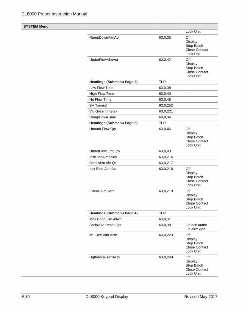
DL8000 Preset Instruction Manual
E-30 DL8000 Keypad Display Revised May-2017
SYSTEM Menu
Lock Unit
RampDownAlmAct 63,0,35 Off Display Stop Batch Close Contact Lock Unit
UnderFlowAlmAct 63,0,42 Off Display Stop Batch Close Contact Lock Unit
Headings (Submenu Page 2) TLP
Low Flow Time 63,0,38
High Flow Time 63,0,40
No Flow Time 63,0,45
BV Time(s) 63,0,252
Vlv close Time(s) 63,0,221
RampDownTime 63,0,34
Headings (Submenu Page 3) TLP
Unauth Flow Qty 63,0,46 Off Display Stop Batch Close Contact Lock Unit
UnderFlow Lmt Qty 63,0,43
InstBlndAlmdelay 63,0,214
Blnd Alrm aftr Qt 63,0,217
Inst Blnd Alm Act 63,0,218 Off Display Stop Batch Close Contact Lock Unit
Linear Alm Actn 63,0,219 Off Display Stop Batch Close Contact Lock Unit
Headings (Submenu Page 4) TLP
Max Badpulse Allwd 63,0,37
Badpulse Reset Opt 63,0,38 On bch autho On alrm gen
MF Dev Alm Actn 63,0,223 Off Display Stop Batch Close Contact Lock Unit
DgtlVlvFailAlmActn 63,0,240 Off Display Stop Batch Close Contact Lock Unit
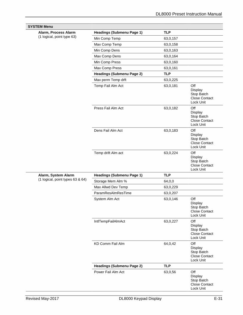
DL8000 Preset Instruction Manual
Revised May-2017 DL8000 Keypad Display E-31
SYSTEM Menu
Alarm, Process Alarm
(1 logical, point type 63)
Headings (Submenu Page 1) TLP
Min Comp Temp 63,0,157
Max Comp Temp 63,0,158
Min Comp Dens 63,0,163
Max Comp Dens 63,0,164
Min Comp Press 63,0,160
Max Comp Press 63,0,161
Headings (Submenu Page 2) TLP
Max perm Temp drft 63,0,225
Temp Fail Alm Act 63,0,181 Off Display Stop Batch Close Contact Lock Unit
Press Fail Alm Act 63,0,182 Off Display Stop Batch Close Contact Lock Unit
Dens Fail Alm Act 63,0,183 Off Display Stop Batch Close Contact Lock Unit
Temp drift Alm act 63,0,224 Off Display Stop Batch Close Contact Lock Unit
Alarm, System Alarm
(1 logical, point types 63 & 64)
Headings (Submenu Page 1) TLP
Storage Mem Alm % 64,0,0
Max Allwd Dev Temp 63,0,229
ParamResAlmResTime 63,0,207
System Alm Act 63,0,146 Off Display Stop Batch Close Contact Lock Unit
IntlTempFailAlmAct 63,0,227 Off Display Stop Batch Close Contact Lock Unit
KD Comm Fail Alm 64,0,42 Off Display Stop Batch Close Contact Lock Unit
Headings (Submenu Page 2) TLP
Power Fail Alm Act 63,0,56 Off Display Stop Batch Close Contact Lock Unit

DL8000 Preset Instruction Manual
E-32 DL8000 Keypad Display Revised May-2017
SYSTEM Menu
Calc Bound Alm Act 64,0,13 Off Display Stop Batch Close Contact Lock Unit
Alarm, Safety Alarm
(1 logical, point types 63 & 64)
Headings (Submenu Page 1) TLP
Circuit1 Alm Act 63,0,65 Off Display Stop Batch Close Contact Lock Unit
Circuit2 Alm Act 63,0,67 Off Display Stop Batch Close Contact Lock Unit
Circuit3 Alm Act 63,0,69 Off Display Stop Batch Close Contact Lock Unit
Circuit4 Alm Act 63,0,71 Off Display Stop Batch Close Contact Lock Unit
Circuit5 Alm Act 63,0,73 Off Display Stop Batch Close Contact Lock Unit
Circuit6 Alm Act 63,0,75 Off Display Stop Batch Close Contact Lock Unit
Headings (Submenu Page 2) TLP
Circuit7 Alm Act 63,0,77 Off Display Stop Batch Close Contact Lock Unit
Circuit8 Alm Act 63,0,79 Off Display Stop Batch Close Contact Lock Unit
Circuit 1 Type 64,0,10 Side indepn If ldng at S1 If idng at S2
Circuit 2 Type 64,0,11 Side indepn If ldng at S1 If idng at S2
Circuit 3 Type 64,0,12 Side indepn If ldng at S1 If idng at S2
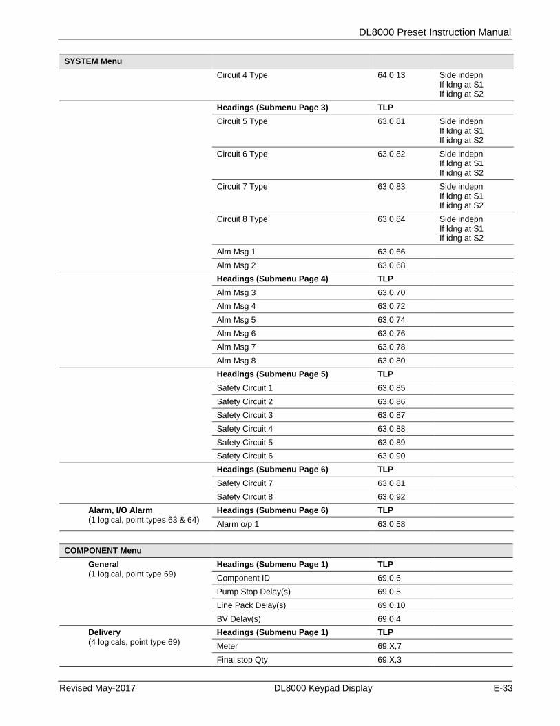
DL8000 Preset Instruction Manual
Revised May-2017 DL8000 Keypad Display E-33
SYSTEM Menu
Circuit 4 Type 64,0,13 Side indepn If ldng at S1 If idng at S2
Headings (Submenu Page 3) TLP
Circuit 5 Type 63,0,81 Side indepn If ldng at S1 If idng at S2
Circuit 6 Type 63,0,82 Side indepn If ldng at S1 If idng at S2
Circuit 7 Type 63,0,83 Side indepn If ldng at S1 If idng at S2
Circuit 8 Type 63,0,84 Side indepn If ldng at S1 If idng at S2
Alm Msg 1 63,0,66
Alm Msg 2 63,0,68
Headings (Submenu Page 4) TLP
Alm Msg 3 63,0,70
Alm Msg 4 63,0,72
Alm Msg 5 63,0,74
Alm Msg 6 63,0,76
Alm Msg 7 63,0,78
Alm Msg 8 63,0,80
Headings (Submenu Page 5) TLP
Safety Circuit 1 63,0,85
Safety Circuit 2 63,0,86
Safety Circuit 3 63,0,87
Safety Circuit 4 63,0,88
Safety Circuit 5 63,0,89
Safety Circuit 6 63,0,90
Headings (Submenu Page 6) TLP
Safety Circuit 7 63,0,81
Safety Circuit 8 63,0,92
Alarm, I/O Alarm
(1 logical, point types 63 & 64)
Headings (Submenu Page 6) TLP
Alarm o/p 1 63,0,58
COMPONENT Menu
General
(1 logical, point type 69)
Headings (Submenu Page 1) TLP
Component ID 69,0,6
Pump Stop Delay(s) 69,0,5
Line Pack Delay(s) 69,0,10
BV Delay(s) 69,0,4
Delivery
(4 logicals, point type 69)
Headings (Submenu Page 1) TLP
Meter 69,X,7
Final stop Qty 69,X,3
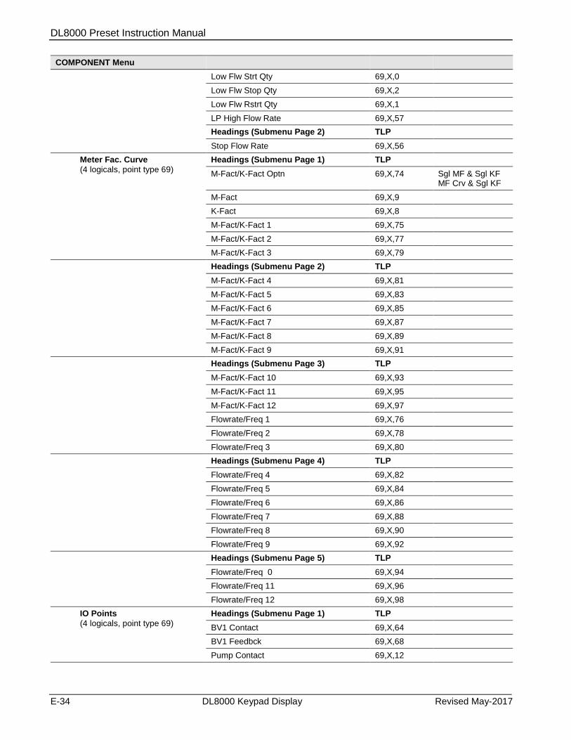
DL8000 Preset Instruction Manual
E-34 DL8000 Keypad Display Revised May-2017
COMPONENT Menu
Low Flw Strt Qty 69,X,0
Low Flw Stop Qty 69,X,2
Low Flw Rstrt Qty 69,X,1
LP High Flow Rate 69,X,57
Headings (Submenu Page 2) TLP
Stop Flow Rate 69,X,56
Meter Fac. Curve
(4 logicals, point type 69)
Headings (Submenu Page 1) TLP
M-Fact/K-Fact Optn 69,X,74 Sgl MF & Sgl KF MF Crv & Sgl KF
M-Fact 69,X,9
K-Fact 69,X,8
M-Fact/K-Fact 1 69,X,75
M-Fact/K-Fact 2 69,X,77
M-Fact/K-Fact 3 69,X,79
Headings (Submenu Page 2) TLP
M-Fact/K-Fact 4 69,X,81
M-Fact/K-Fact 5 69,X,83
M-Fact/K-Fact 6 69,X,85
M-Fact/K-Fact 7 69,X,87
M-Fact/K-Fact 8 69,X,89
M-Fact/K-Fact 9 69,X,91
Headings (Submenu Page 3) TLP
M-Fact/K-Fact 10 69,X,93
M-Fact/K-Fact 11 69,X,95
M-Fact/K-Fact 12 69,X,97
Flowrate/Freq 1 69,X,76
Flowrate/Freq 2 69,X,78
Flowrate/Freq 3 69,X,80
Headings (Submenu Page 4) TLP
Flowrate/Freq 4 69,X,82
Flowrate/Freq 5 69,X,84
Flowrate/Freq 6 69,X,86
Flowrate/Freq 7 69,X,88
Flowrate/Freq 8 69,X,90
Flowrate/Freq 9 69,X,92
Headings (Submenu Page 5) TLP
Flowrate/Freq 0 69,X,94
Flowrate/Freq 11 69,X,96
Flowrate/Freq 12 69,X,98
IO Points
(4 logicals, point type 69)
Headings (Submenu Page 1) TLP
BV1 Contact 69,X,64
BV1 Feedbck 69,X,68
Pump Contact 69,X,12
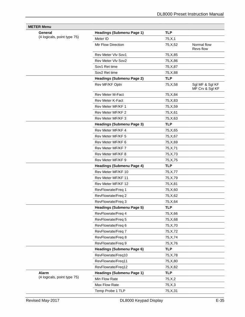
DL8000 Preset Instruction Manual
Revised May-2017 DL8000 Keypad Display E-35
METER Menu
General
(4 logicals, point type 75)
Headings (Submenu Page 1) TLP
Meter ID 75,X,1
Mtr Flow Direction 75,X,52 Normal flow Revs flow
Rev Meter Vlv Sov1 75,X,85
Rev Meter Vlv Sov2 75,X,86
Sov1 Ret time 75,X,87
Sov2 Ret time 75,X,88
Headings (Submenu Page 2) TLP
Rev MF/KF Optn 75,X,58 Sgl MF & Sgl KF MF Crv & Sgl KF
Rev Meter M-Fact 75,X,84
Rev Meter K-Fact 75,X,83
Rev Meter MF/KF 1 75,X,59
Rev Meter MF/KF 2 75,X,61
Rev Meter MF/KF 3 75,X,63
Headings (Submenu Page 3) TLP
Rev Meter MF/KF 4 75,X,65
Rev Meter MF/KF 5 75,X,67
Rev Meter MF/KF 6 75,X,69
Rev Meter MF/KF 7 75,X,71
Rev Meter MF/KF 8 75,X,73
Rev Meter MF/KF 9 75,X,75
Headings (Submenu Page 4) TLP
Rev Meter MF/KF 10 75,X,77
Rev Meter MF/KF 11 75,X,79
Rev Meter MF/KF 12 75,X,81
RevFlowrate/Freq 1 75,X,60
RevFlowrate/Freq 2 75,X,62
RevFlowrate/Freq 3 75,X,64
Headings (Submenu Page 5) TLP
RevFlowrate/Freq 4 75,X,66
RevFlowrate/Freq 5 75,X,68
RevFlowrate/Freq 6 75,X,70
RevFlowrate/Freq 7 75,X,72
RevFlowrate/Freq 8 75,X,74
RevFlowrate/Freq 9 75,X,76
Headings (Submenu Page 6) TLP
RevFlowrate/Freq10 75,X,78
RevFlowrate/Freq11 75,X,80
RevFlowrate/Freq12 75,X,82
Alarm
(4 logicals, point type 75)
Headings (Submenu Page 1) TLP
Min Flow Rate 75,X,2
Max Flow Rate 75,X,3
Temp Probe 1 TLP 75,X,31
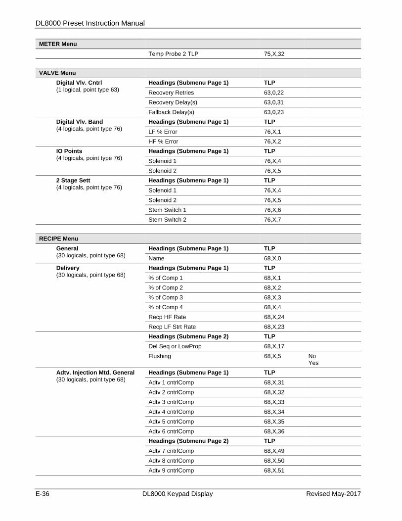
DL8000 Preset Instruction Manual
E-36 DL8000 Keypad Display Revised May-2017
METER Menu
Temp Probe 2 TLP 75,X,32
VALVE Menu
Digital Vlv. Cntrl
(1 logical, point type 63)
Headings (Submenu Page 1) TLP
Recovery Retries 63,0,22
Recovery Delay(s) 63,0,31
Fallback Delay(s) 63,0,23
Digital Vlv. Band
(4 logicals, point type 76)
Headings (Submenu Page 1) TLP
LF % Error 76,X,1
HF % Error 76,X,2
IO Points
(4 logicals, point type 76)
Headings (Submenu Page 1) TLP
Solenoid 1 76,X,4
Solenoid 2 76,X,5
2 Stage Sett
(4 logicals, point type 76)
Headings (Submenu Page 1) TLP
Solenoid 1 76,X,4
Solenoid 2 76,X,5
Stem Switch 1 76,X,6
Stem Switch 2 76,X,7
RECIPE Menu
General
(30 logicals, point type 68)
Headings (Submenu Page 1) TLP
Name 68,X,0
Delivery
(30 logicals, point type 68)
Headings (Submenu Page 1) TLP
% of Comp 1 68,X,1
% of Comp 2 68,X,2
% of Comp 3 68,X,3
% of Comp 4 68,X,4
Recp HF Rate 68,X,24
Recp LF Strt Rate 68,X,23
Headings (Submenu Page 2) TLP
Del Seq or LowProp 68,X,17
Flushing 68,X,5 No Yes
Adtv. Injection Mtd, General
(30 logicals, point type 68)
Headings (Submenu Page 1) TLP
Adtv 1 cntrlComp 68,X,31
Adtv 2 cntrlComp 68,X,32
Adtv 3 cntrlComp 68,X,33
Adtv 4 cntrlComp 68,X,34
Adtv 5 cntrlComp 68,X,35
Adtv 6 cntrlComp 68,X,36
Headings (Submenu Page 2) TLP
Adtv 7 cntrlComp 68,X,49
Adtv 8 cntrlComp 68,X,50
Adtv 9 cntrlComp 68,X,51
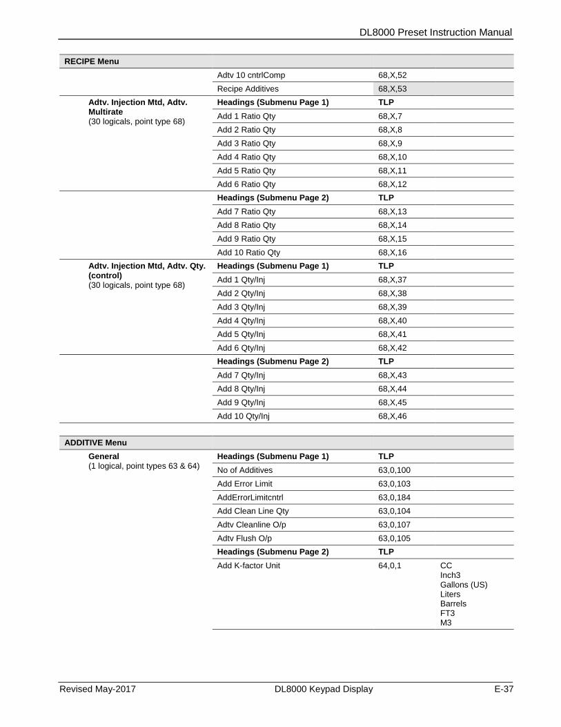
DL8000 Preset Instruction Manual
Revised May-2017 DL8000 Keypad Display E-37
RECIPE Menu
Adtv 10 cntrlComp 68,X,52
Recipe Additives 68,X,53
Adtv. Injection Mtd, Adtv. Multirate (30 logicals, point type 68)
Headings (Submenu Page 1) TLP
Add 1 Ratio Qty 68,X,7
Add 2 Ratio Qty 68,X,8
Add 3 Ratio Qty 68,X,9
Add 4 Ratio Qty 68,X,10
Add 5 Ratio Qty 68,X,11
Add 6 Ratio Qty 68,X,12
Headings (Submenu Page 2) TLP
Add 7 Ratio Qty 68,X,13
Add 8 Ratio Qty 68,X,14
Add 9 Ratio Qty 68,X,15
Add 10 Ratio Qty 68,X,16
Adtv. Injection Mtd, Adtv. Qty. (control) (30 logicals, point type 68)
Headings (Submenu Page 1) TLP
Add 1 Qty/Inj 68,X,37
Add 2 Qty/Inj 68,X,38
Add 3 Qty/Inj 68,X,39
Add 4 Qty/Inj 68,X,40
Add 5 Qty/Inj 68,X,41
Add 6 Qty/Inj 68,X,42
Headings (Submenu Page 2) TLP
Add 7 Qty/Inj 68,X,43
Add 8 Qty/Inj 68,X,44
Add 9 Qty/Inj 68,X,45
Add 10 Qty/Inj 68,X,46
ADDITIVE Menu
General (1 logical, point types 63 & 64)
Headings (Submenu Page 1) TLP
No of Additives 63,0,100
Add Error Limit 63,0,103
AddErrorLimitcntrl 63,0,184
Add Clean Line Qty 63,0,104
Adtv Cleanline O/p 63,0,107
Adtv Flush O/p 63,0,105
Headings (Submenu Page 2) TLP
Add K-factor Unit 64,0,1 CC Inch3 Gallons (US) Liters Barrels FT3 M3

DL8000 Preset Instruction Manual
E-38 DL8000 Keypad Display Revised May-2017
ADDITIVE Menu
AddSelectionMthd 63,0,102 CC Inch3 Gallons (US) Liters Barrels FT3 M3
Preset Add Option 64,0,26 Prompt Discrete I/P Recp Sel Recp Mlti Rt
Add PumpStopDelay 63,0,106 Exclusive Inclusive
Delivery
(10 logicals, point type 67)
Headings (Submenu Page 1) TLP
Ratio Qty 67,X,27
Add M-Fact 67,X,28
Volume per Pulses 67,X,2
Rtaio Cycle Inj % 67,X,17
Additive Type 67,X,8 Downstream Upstream
Vlv Closure Qty 67,X,47 Manual Auto
Headings (Submenu Page 2) TLP
Inj Method 67,X,1 Mechanical Handshake Control
Add Feedback Count 67,X,2
Alarm
(10 logicals, point type 67)
Headings (Submenu Page 1) TLP
Prod/AdtvLowLimit 67,X,20
Prod/AdtvHiLimit 67,X,21
AdtvUnAuthPlsRes T 67,X,44
Unauth Add Pulses 67,X,29
IO Points
(10 logicals, point type 67)
Headings (Submenu Page 1) TLP
Add Pump Output 67,X,9
Add Fb i/p 67,X,7
Adtv BV O/p 67,X,11
Adtv Ratio Vlv O/p 67,X,6
Discrete i/p Sel 67,X,26
HISTORY Menu
General
(1 logical, point type 61)
Headings (Submenu Page 1) TLP
Archive Btch/Trans 61,0,145
Requested Max Tx 61,0,146
Max no.Batch Archv 61,0,127
Max no.Trans Archv 61,0,121
StoMemFul AlmCfg 61,0,130
No of Rec to clear 61,0,125

DL8000 Preset Instruction Manual
Revised May-2017 DL8000 Keypad Display E-39
HISTORY Menu
Headings (Submenu Page 2) TLP
Clear History Opt 61,0,124 Choose An Option Clr Num of Records Release & Acquire
Batch Hist Config (1 logical, point type 61 & 65)
Headings (Submenu Page 1) TLP
Pressure (FWA) 61,0,6 Disabled Enabled
Preset Qty 61,0,9 Disabled Enabled
Gross Qty (Compo.) 61,0,245 Disabled Enabled
Mass 61,0,12 Disabled Enabled
Comp. Gross Qty 61,0,13 Disabled Enabled
Comp. Net Qty 61,0,14 Disabled Enabled
Headings (Submenu Page 2) TLP
Comp. Mass 61,0,15 Disabled Enabled
Comp. Temp 61,0,16 Disabled Enabled
Comp. Press 61,0,152 Disabled Enabled
Comp. Base Density 61,0,153 Disabled Enabled
Comp. Obs. Density 61,0,225 Disabled Enabled
Comp. 1 % 61,0,17 Disabled Enabled
Headings (Submenu Page 3) TLP
Comp. 2 % 61,0,141 Disabled Enabled
Comp. 3 % 61,0,142 Disabled Enabled
Comp. 4 % 61,0,143 Disabled Enabled
Actual Cmp % 61,0,18 Disabled Enabled
Adtv Gross Qty 61,0,19 Disabled Enabled
Operating Mode 61,0,20 Disabled Enabled
Headings (Submenu Page 4) TLP
Meter Start Ind. 61,0,195 Disabled Enabled
Meter End Ind. 61,0,196 Disabled Enabled
Component K-Fact 61,0,205 Disabled Enabled
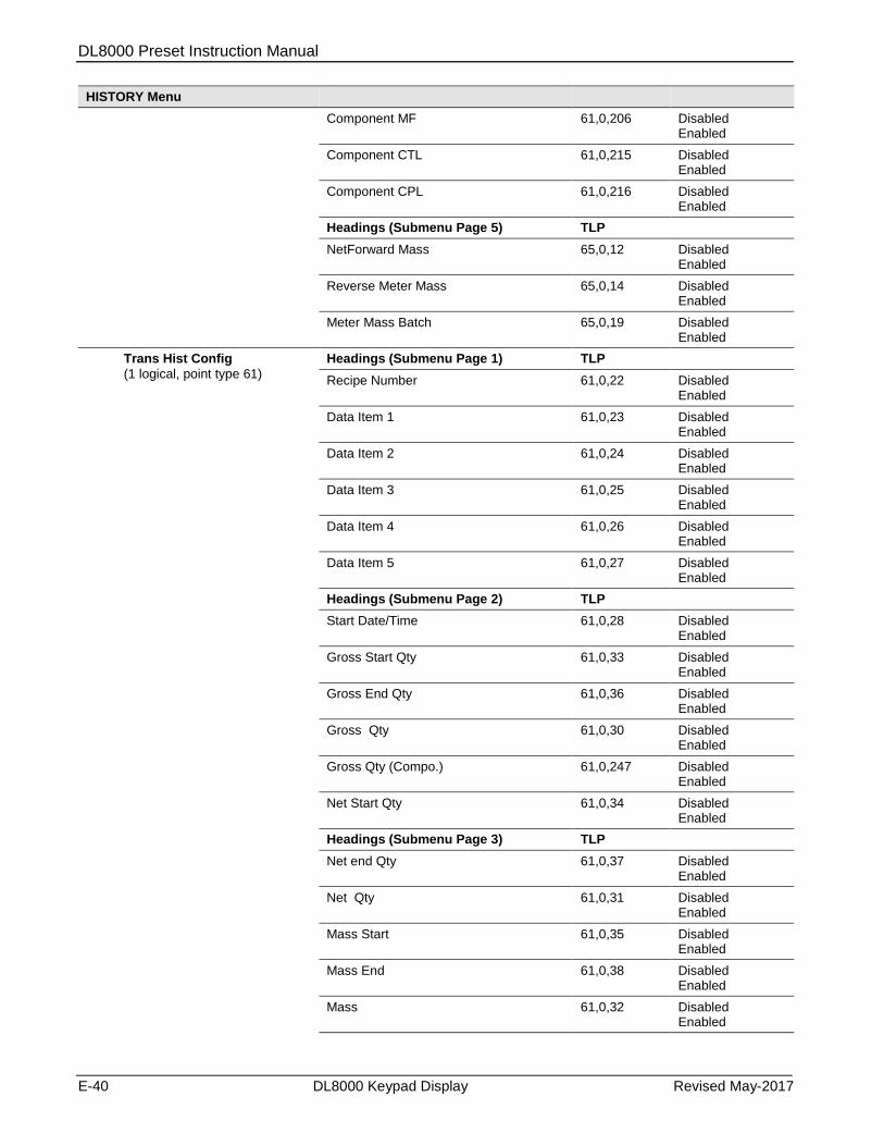
DL8000 Preset Instruction Manual
E-40 DL8000 Keypad Display Revised May-2017
HISTORY Menu
Component MF 61,0,206 Disabled Enabled
Component CTL 61,0,215 Disabled Enabled
Component CPL 61,0,216 Disabled Enabled
Headings (Submenu Page 5) TLP
NetForward Mass 65,0,12 Disabled Enabled
Reverse Meter Mass 65,0,14 Disabled Enabled
Meter Mass Batch 65,0,19 Disabled Enabled
Trans Hist Config
(1 logical, point type 61)
Headings (Submenu Page 1) TLP
Recipe Number 61,0,22 Disabled Enabled
Data Item 1 61,0,23 Disabled Enabled
Data Item 2 61,0,24 Disabled Enabled
Data Item 3 61,0,25 Disabled Enabled
Data Item 4 61,0,26 Disabled Enabled
Data Item 5 61,0,27 Disabled Enabled
Headings (Submenu Page 2) TLP
Start Date/Time 61,0,28 Disabled Enabled
Gross Start Qty 61,0,33 Disabled Enabled
Gross End Qty 61,0,36 Disabled Enabled
Gross Qty 61,0,30 Disabled Enabled
Gross Qty (Compo.) 61,0,247 Disabled Enabled
Net Start Qty 61,0,34 Disabled Enabled
Headings (Submenu Page 3) TLP
Net end Qty 61,0,37 Disabled Enabled
Net Qty 61,0,31 Disabled Enabled
Mass Start 61,0,35 Disabled Enabled
Mass End 61,0,38 Disabled Enabled
Mass 61,0,32 Disabled Enabled

DL8000 Preset Instruction Manual
Revised May-2017 DL8000 Keypad Display E-41
HISTORY Menu
Adtv Gross Qty 61,0,39 Disabled Enabled
Headings (Submenu Page 4) TLP
Swing Arm Side 61,0,231 Disabled Enabled
Trans Hist Errors
(1 logical, point type 61)
Headings (Submenu Page 1) TLP
Trans. Cfg Error 61,0,133 Read only
Batch Cfg Error 61,0,134 Read only
Acquire Mem Fail 61,0,144 Read only
PRINT Menu
General
(1 logical, point type 60)
Headings (Submenu Page 1) TLP
Display Tag 60,0,0
Printer Type 60,0,23 Serial Ethernet
Printer Port 60,0,2
Char Per Inches 60,0,9 Four Six Eight Twelve Fourteen Sixteen
Printer IP Address 60,0,1
Print Orientation 60,0,12 Portrait Landscape
Headings (Submenu Page 2) TLP
Trgt Disp To Print 60,0,7
UNIT Menu
General
(1 logical, point type 70)
Headings (Submenu Page 1) TLP
Mass Unit 70,0,7 Lb Kg Ton Tonne
Volume Unit 70,0,6 Gallons (US) Mfc Km3
Density Unit 70,0,3 Kg/m3 g/cm3 Lb/ft3 Lb/bbl Relative Density API Gravity
Pressure Unit 70,0,1 Psi Kpa Bar Kg/cm2
Temperature Unit 70,0,2 Deg C Deg F
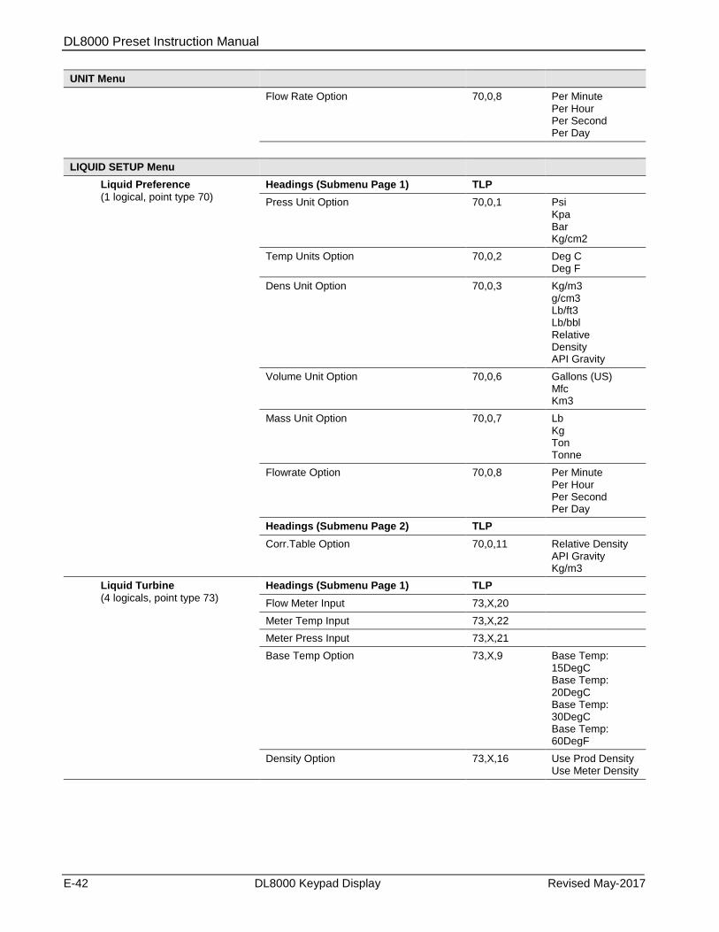
DL8000 Preset Instruction Manual
E-42 DL8000 Keypad Display Revised May-2017
UNIT Menu
Flow Rate Option 70,0,8 Per Minute Per Hour Per Second Per Day
LIQUID SETUP Menu
Liquid Preference
(1 logical, point type 70)
Headings (Submenu Page 1) TLP
Press Unit Option 70,0,1 Psi Kpa Bar Kg/cm2
Temp Units Option 70,0,2 Deg C Deg F
Dens Unit Option 70,0,3 Kg/m3 g/cm3 Lb/ft3 Lb/bbl Relative Density API Gravity
Volume Unit Option 70,0,6 Gallons (US) Mfc Km3
Mass Unit Option 70,0,7 Lb Kg Ton Tonne
Flowrate Option 70,0,8 Per Minute Per Hour Per Second Per Day
Headings (Submenu Page 2) TLP
Corr.Table Option 70,0,11 Relative Density API Gravity Kg/m3
Liquid Turbine
(4 logicals, point type 73)
Headings (Submenu Page 1) TLP
Flow Meter Input 73,X,20
Meter Temp Input 73,X,22
Meter Press Input 73,X,21
Base Temp Option 73,X,9 Base Temp: 15DegC Base Temp: 20DegC Base Temp: 30DegC Base Temp: 60DegF
Density Option 73,X,16 Use Prod Density Use Meter Density
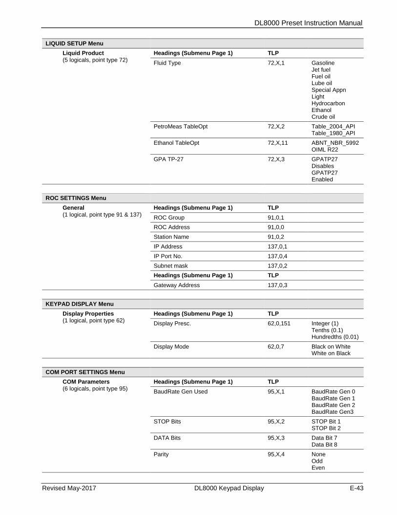
DL8000 Preset Instruction Manual
Revised May-2017 DL8000 Keypad Display E-43
LIQUID SETUP Menu
Liquid Product
(5 logicals, point type 72)
Headings (Submenu Page 1) TLP
Fluid Type 72,X,1 Gasoline Jet fuel Fuel oil Lube oil Special Appn Light Hydrocarbon Ethanol Crude oil
PetroMeas TableOpt 72,X,2 Table_2004_API Table_1980_API
Ethanol TableOpt 72,X,11 ABNT_NBR_5992 OIML R22
GPA TP-27 72,X,3 GPATP27 Disables GPATP27 Enabled
ROC SETTINGS Menu
General
(1 logical, point type 91 & 137)
Headings (Submenu Page 1) TLP
ROC Group 91,0,1
ROC Address 91,0,0
Station Name 91,0,2
IP Address 137,0,1
IP Port No. 137,0,4
Subnet mask 137,0,2
Headings (Submenu Page 1) TLP
Gateway Address 137,0,3
KEYPAD DISPLAY Menu
Display Properties (1 logical, point type 62)
Headings (Submenu Page 1) TLP
Display Presc. 62,0,151 Integer (1) Tenths (0.1) Hundredths (0.01)
Display Mode 62,0,7 Black on White White on Black
COM PORT SETTINGS Menu
COM Parameters
(6 logicals, point type 95)
Headings (Submenu Page 1) TLP
BaudRate Gen Used 95,X,1 BaudRate Gen 0 BaudRate Gen 1 BaudRate Gen 2 BaudRate Gen3
STOP Bits 95,X,2 STOP Bit 1 STOP Bit 2
DATA Bits 95,X,3 Data Bit 7 Data Bit 8
Parity 95,X,4 None Odd Even
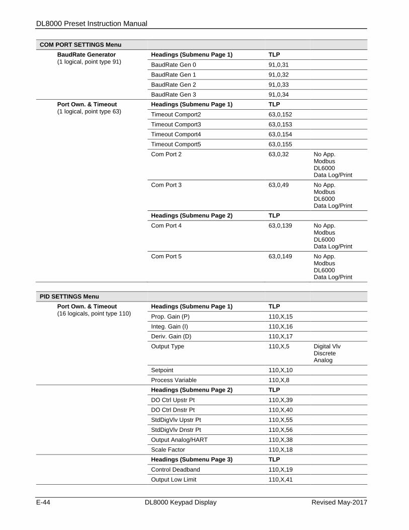
DL8000 Preset Instruction Manual
E-44 DL8000 Keypad Display Revised May-2017
COM PORT SETTINGS Menu
BaudRate Generator
(1 logical, point type 91)
Headings (Submenu Page 1) TLP
BaudRate Gen 0 91,0,31
BaudRate Gen 1 91,0,32
BaudRate Gen 2 91,0,33
BaudRate Gen 3 91,0,34
Port Own. & Timeout
(1 logical, point type 63)
Headings (Submenu Page 1) TLP
Timeout Comport2 63,0,152
Timeout Comport3 63,0,153
Timeout Comport4 63,0,154
Timeout Comport5 63,0,155
Com Port 2 63,0,32 No App. Modbus DL6000 Data Log/Print
Com Port 3 63,0,49 No App. Modbus DL6000 Data Log/Print
Headings (Submenu Page 2) TLP
Com Port 4 63,0,139 No App. Modbus DL6000 Data Log/Print
Com Port 5 63,0,149 No App. Modbus DL6000 Data Log/Print
PID SETTINGS Menu
Port Own. & Timeout
(16 logicals, point type 110)
Headings (Submenu Page 1) TLP
Prop. Gain (P) 110,X,15
Integ. Gain (I) 110,X,16
Deriv. Gain (D) 110,X,17
Output Type 110,X,5 Digital Vlv Discrete Analog
Setpoint 110,X,10
Process Variable 110,X,8
Headings (Submenu Page 2) TLP
DO Ctrl Upstr Pt 110,X,39
DO Ctrl Dnstr Pt 110,X,40
StdDigVlv Upstr Pt 110,X,55
StdDigVlv Dnstr Pt 110,X,56
Output Analog/HART 110,X,38
Scale Factor 110,X,18
Headings (Submenu Page 3) TLP
Control Deadband 110,X,19
Output Low Limit 110,X,41
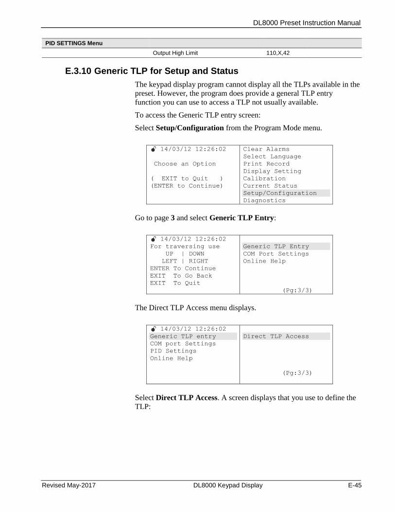
DL8000 Preset Instruction Manual
Revised May-2017 DL8000 Keypad Display E-45
PID SETTINGS Menu
Output High Limit 110,X,42
E.3.10 Generic TLP for Setup and Status
The keypad display program cannot display all the TLPs available in the
preset. However, the program does provide a general TLP entry
function you can use to access a TLP not usually available.
To access the Generic TLP entry screen:
Select Setup/Configuration from the Program Mode menu.
14/03/12 12:26:02
Choose an Option
( EXIT to Quit )
(ENTER to Continue)
Clear Alarms
Select Language
Print Record
Display Setting
Calibration
Current Status
Setup/Configuration
Diagnostics
Go to page 3 and select Generic TLP Entry:
14/03/12 12:26:02
For traversing use
UP | DOWN
LEFT | RIGHT
ENTER To Continue
EXIT To Go Back
EXIT To Quit
Generic TLP Entry
COM Port Settings
Online Help
(Pg:3/3)
The Direct TLP Access menu displays.
14/03/12 12:26:02
Generic TLP entry
COM port Settings
PID Settings
Online Help
Direct TLP Access
(Pg:3/3)
Select Direct TLP Access. A screen displays that you use to define the
TLP:

DL8000 Preset Instruction Manual
E-46 DL8000 Keypad Display Revised May-2017
14/03/12 12:26:02
Enter Type
Enter Logical
Enter Parameter
ENTER to Continue
EXIT to Quit
0
0
0
UP | DOWN
(0-9)
Press to access each value. Once you define the TLP, press Enter to
save your changes. The program validates the TLP you have entered.
(Press ALT+CLEAR to exit the Direct TLP access screen.)
If the TLP is valid, the program displays the current value of the TLP
and indicates the parameter’s read/write attribute.
14/03/12 12:26:02
TLP Entered
Current value
Param Attribute
ENTER to Continue
EXIT to Go Back
63 0 12
0
Read Write Cndl
If the parameter’s attribute is read/write or read/write conditional (and
the W&M switch is unlocked), the ENTER to Continue message at the
bottom of the screen indicates that you may enter a new value for the
TLP.
If the parameter is read-only, only the EXIT to Go Back message
displays at the bottom of the screen.
If the TLP you specify is invalid, the program displays the following
screen:
14/03/12 12:26:02
TLP Entered
Invalid TLP Entry
EXIT to Go Back
Press ALT+CLEAR to exit this screen and redisplay the parameter
entry screen.
If the TLP is read/write or read/write conditional and the W&M switch
is locked, the program displays the following message:

DL8000 Preset Instruction Manual
Revised May-2017 DL8000 Keypad Display E-47
14/03/12 12:26:02
TLP Entered
Current value
Param Attribute
ENTER to Continue
EXIT to Go Back
63 0 12
0
Read Write Cndl
Pls Open WM Switch
And Try again
Press ATL+CLEAR to exit and return to the TLP entry screen. You can
either enter a new value or open the W&M switch and press ENTER to
try again.
Once the system updates the TLP with the new value, it displays the
following screen:
14/03/12 12:26:02
TLP Entered
Current value
New Value
63 0 12
0
2
Press EXIT once to redisplay the TLP entry screen; press EXIT again
to exit the menu.
E.3.11 Online Help
The keypad program online help is an option on the last page of the
Setup/Configuration menu. These screens provide a quick on-demand
reference of control keys and how to navigate through the menus and
submenus.
Select Online Help to display two options.
14/03/12 12:26:02
For traversing use
UP | DOWN
LEFT | RIGHT
ENTER To Continue
EXIT To Go Back
EXIT To Quit
Generic TLP Entry
COM Port Settings
Online Help
(Pg:3/3)
14/03/12 12:26:02
Generic TLP Entry
COM Port Settings
Online Help
Help Menu
Help Parameter
(Pg:1/1)
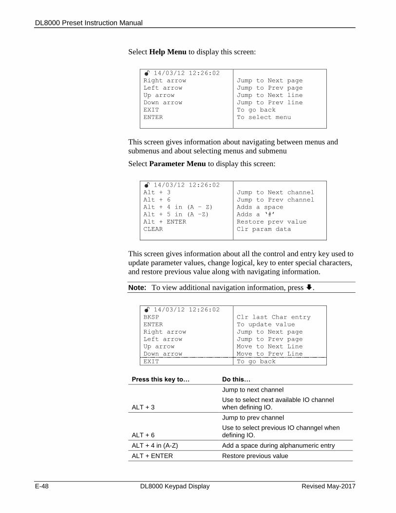
DL8000 Preset Instruction Manual
E-48 DL8000 Keypad Display Revised May-2017
Select Help Menu to display this screen:
14/03/12 12:26:02
Right arrow
Left arrow
Up arrow
Down arrow
EXIT
ENTER
Jump to Next page
Jump to Prev page
Jump to Next line
Jump to Prev line
To go back
To select menu
This screen gives information about navigating between menus and
submenus and about selecting menus and submenu
Select Parameter Menu to display this screen:
14/03/12 12:26:02
Alt + 3
Alt + 6
Alt + 4 in (A – Z)
Alt + 5 in (A –Z)
Alt + ENTER
CLEAR
Jump to Next channel
Jump to Prev channel
Adds a space
Adds a ‘#’
Restore prev value
Clr param data
This screen gives information about all the control and entry key used to
update parameter values, change logical, key to enter special characters,
and restore previous value along with navigating information.
Note: To view additional navigation information, press .
14/03/12 12:26:02
BKSP
ENTER
Right arrow
Left arrow
Up arrow
Down arrow
Clr last Char entry
To update value
Jump to Next page
Jump to Prev page
Move to Next Line
Move to Prev Line
EXIT To go back
Press this key to… Do this…
ALT + 3
Jump to next channel
Use to select next available IO channel when defining IO.
ALT + 6
Jump to prev channel
Use to select previous IO channgel when defining IO.
ALT + 4 in (A-Z) Add a space during alphanumeric entry
ALT + ENTER Restore previous value
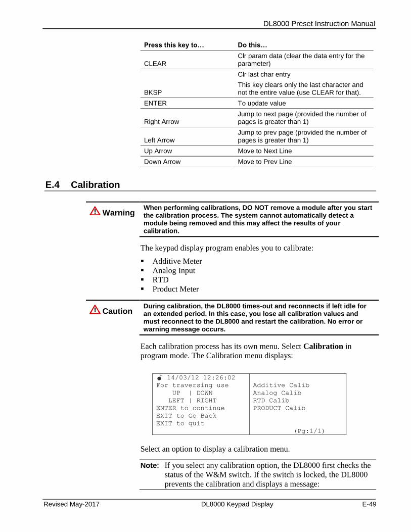
DL8000 Preset Instruction Manual
Revised May-2017 DL8000 Keypad Display E-49
Press this key to… Do this…
CLEAR Clr param data (clear the data entry for the parameter)
BKSP
Clr last char entry
This key clears only the last character and not the entire value (use CLEAR for that).
ENTER To update value
Right Arrow Jump to next page (provided the number of pages is greater than 1)
Left Arrow Jump to prev page (provided the number of pages is greater than 1)
Up Arrow Move to Next Line
Down Arrow Move to Prev Line
E.4 Calibration
Warning When performing calibrations, DO NOT remove a module after you start the calibration process. The system cannot automatically detect a module being removed and this may affect the results of your calibration.
The keypad display program enables you to calibrate:
Additive Meter
Analog Input
RTD
Product Meter
Caution During calibration, the DL8000 times-out and reconnects if left idle for an extended period. In this case, you lose all calibration values and must reconnect to the DL8000 and restart the calibration. No error or warning message occurs.
Each calibration process has its own menu. Select Calibration in
program mode. The Calibration menu displays:
14/03/12 12:26:02
For traversing use
UP | DOWN
LEFT | RIGHT
ENTER to continue
EXIT to Go Back
EXIT to quit
Additive Calib
Analog Calib
RTD Calib
PRODUCT Calib
(Pg:1/1)
Select an option to display a calibration menu.
Note: If you select any calibration option, the DL8000 first checks the
status of the W&M switch. If the switch is locked, the DL8000
prevents the calibration and displays a message:

DL8000 Preset Instruction Manual
E-50 DL8000 Keypad Display Revised May-2017
14/03/12 12:26:02
WM Switch is Closed
Pls open the Switch
And try again
You must open the W&M switch in order to perform calibrations.
E.4.1 Calibrating Additive Meters
Select Additive Calib to start the additive calibration process.
14/03/12 12:26:02
For traversing use
UP | DOWN
LEFT | RIGHT
ENTER to continue
EXIT to Go Back
EXIT to quit
Additive Calib
Analog Calib
RTD Calib
PRODUCT Calib
(Pg:1/1)
If no additives are currently configured, the preset displays the
following screen:
14/03/12 12:26:02
Adtv not configured
EXIT to quit
Press EXIT to quit; no calibration is possible.
In addition to the number of configured additives, the program can
display the following error messages:
Error Message Description
Adtv Prog. Not Available or Running
The additive program (#4) is not loaded or running.
Invalid Injection Method The value of the injection method [67,X,1] is not Control (value 3)
K.F not configured The Volume oper pulse/K –factor parameter [67,x,2] is set to 0
M.F not configured The Additive Meter Factor parameter [67,x,28] is set to 0
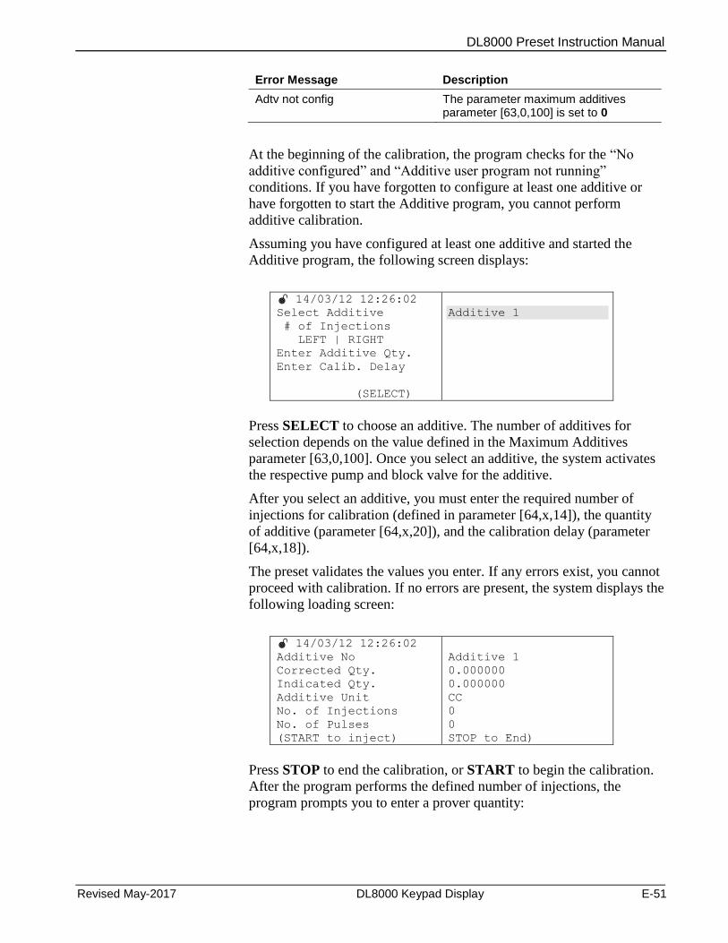
DL8000 Preset Instruction Manual
Revised May-2017 DL8000 Keypad Display E-51
Error Message Description
Adtv not config The parameter maximum additives parameter [63,0,100] is set to 0
At the beginning of the calibration, the program checks for the “No
additive configured” and “Additive user program not running”
conditions. If you have forgotten to configure at least one additive or
have forgotten to start the Additive program, you cannot perform
additive calibration.
Assuming you have configured at least one additive and started the
Additive program, the following screen displays:
14/03/12 12:26:02
Select Additive
# of Injections
LEFT | RIGHT
Enter Additive Qty.
Enter Calib. Delay
(SELECT)
Additive 1
Press SELECT to choose an additive. The number of additives for
selection depends on the value defined in the Maximum Additives
parameter [63,0,100]. Once you select an additive, the system activates
the respective pump and block valve for the additive.
After you select an additive, you must enter the required number of
injections for calibration (defined in parameter [64,x,14]), the quantity
of additive (parameter [64,x,20]), and the calibration delay (parameter
[64,x,18]).
The preset validates the values you enter. If any errors exist, you cannot
proceed with calibration. If no errors are present, the system displays the
following loading screen:
14/03/12 12:26:02
Additive No
Corrected Qty.
Indicated Qty.
Additive Unit
No. of Injections
No. of Pulses
(START to inject)
Additive 1
0.000000
0.000000
CC
0
0
STOP to End)
Press STOP to end the calibration, or START to begin the calibration.
After the program performs the defined number of injections, the
program prompts you to enter a prover quantity:
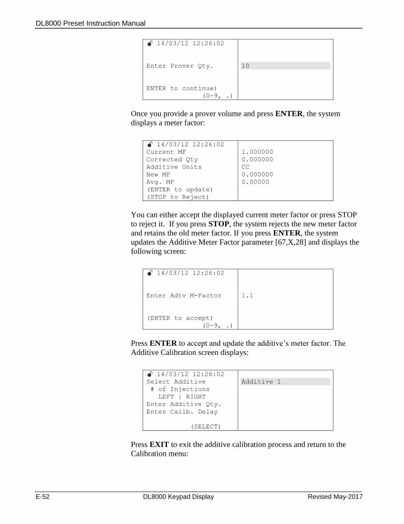
DL8000 Preset Instruction Manual
E-52 DL8000 Keypad Display Revised May-2017
14/03/12 12:26:02
Enter Prover Qty.
ENTER to continue)
(0-9, .)
10
Once you provide a prover volume and press ENTER, the system
displays a meter factor:
14/03/12 12:26:02
Current MF
Corrected Qty
Additive Units
New MF
Avg. MF
(ENTER to update)
(STOP to Reject)
1.000000
0.000000
CC
0.000000
0.00000
You can either accept the displayed current meter factor or press STOP
to reject it. If you press STOP, the system rejects the new meter factor
and retains the old meter factor. If you press ENTER, the system
updates the Additive Meter Factor parameter [67,X,28] and displays the
following screen:
14/03/12 12:26:02
Enter Adtv M-Factor
(ENTER to accept)
(0-9, .)
1.1
Press ENTER to accept and update the additive’s meter factor. The
Additive Calibration screen displays:
14/03/12 12:26:02
Select Additive
# of Injections
LEFT | RIGHT
Enter Additive Qty.
Enter Calib. Delay
(SELECT)
Additive 1
Press EXIT to exit the additive calibration process and return to the
Calibration menu:

DL8000 Preset Instruction Manual
Revised May-2017 DL8000 Keypad Display E-53
14/03/12 12:26:02
For traversing use
UP | DOWN
LEFT | RIGHT
ENTER to continue
EXIT to Go Back
EXIT to quit
Additive Calib
Analog Calib
RTD Calib
PRODUCT Calib
(Pg:1/1)
E.4.2 Calibrating Analog Input
Note: The preset must have an installed AI module to calibrate AI. If
you attempt an AI calibration without a module, the system
displays the message NO AI Card in system on the left-hand
screen.
To calibrate analog inputs, select the Analog Calib option on the
Calibration menu screen:
14/03/12 12:26:02
For traversing use
UP | DOWN
LEFT | RIGHT
ENTER to continue
EXIT to Go Back
EXIT to quit
Additive Calib
Analog Calib
RTD Calib
PRODUCT Calib
(Pg:1/1)
The system then displays all available analog inputs. Select an analog
input channel for calibration:
14/03/12 12:26:02
Sel Analog Ch
Sel No of Mid pt
(SELECT)
AI ch 1
Then choose the number of mid-points. Press SELECT to see the
available options (zero, 1, 2, and 3):
14/03/12 12:26:02
Sel Analog Ch
Sel No of Mid pt
(SELECT)
AI ch 1
Zero
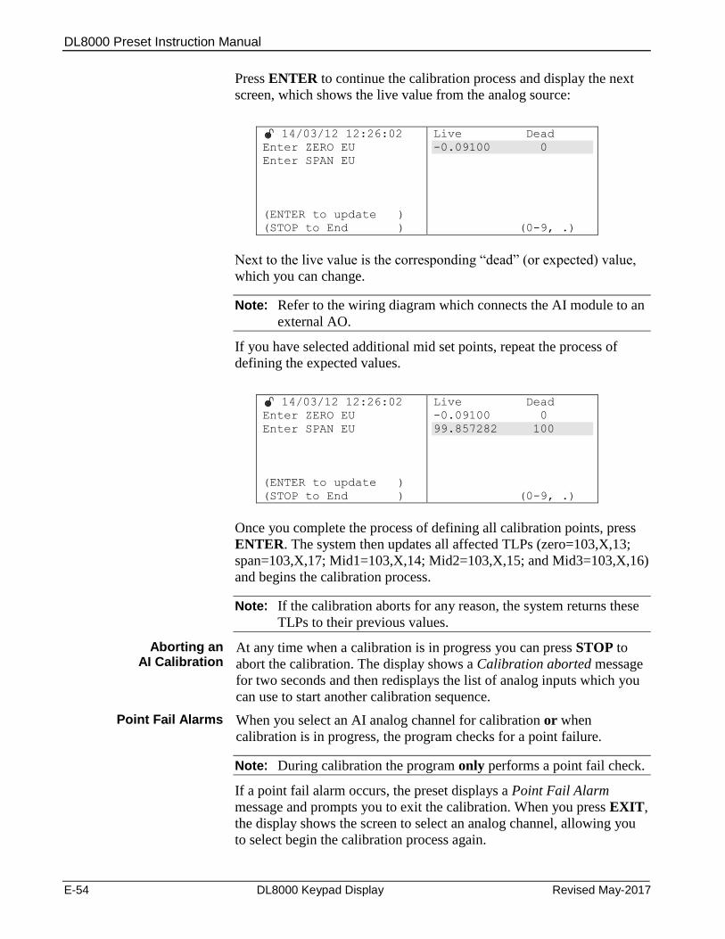
DL8000 Preset Instruction Manual
E-54 DL8000 Keypad Display Revised May-2017
Press ENTER to continue the calibration process and display the next
screen, which shows the live value from the analog source:
14/03/12 12:26:02
Enter ZERO EU
Enter SPAN EU
(ENTER to update )
(STOP to End )
Live Dead
-0.09100 0
(0-9, .)
Next to the live value is the corresponding “dead” (or expected) value,
which you can change.
Note: Refer to the wiring diagram which connects the AI module to an
external AO.
If you have selected additional mid set points, repeat the process of
defining the expected values.
14/03/12 12:26:02
Enter ZERO EU
Enter SPAN EU
(ENTER to update )
(STOP to End )
Live Dead
-0.09100 0
99.857282 100
(0-9, .)
Once you complete the process of defining all calibration points, press
ENTER. The system then updates all affected TLPs (zero=103,X,13;
span=103,X,17; Mid1=103,X,14; Mid2=103,X,15; and Mid3=103,X,16)
and begins the calibration process.
Note: If the calibration aborts for any reason, the system returns these
TLPs to their previous values.
Aborting an AI Calibration
At any time when a calibration is in progress you can press STOP to
abort the calibration. The display shows a Calibration aborted message
for two seconds and then redisplays the list of analog inputs which you
can use to start another calibration sequence.
Point Fail Alarms When you select an AI analog channel for calibration or when
calibration is in progress, the program checks for a point failure.
Note: During calibration the program only performs a point fail check.
If a point fail alarm occurs, the preset displays a Point Fail Alarm
message and prompts you to exit the calibration. When you press EXIT,
the display shows the screen to select an analog channel, allowing you
to select begin the calibration process again.
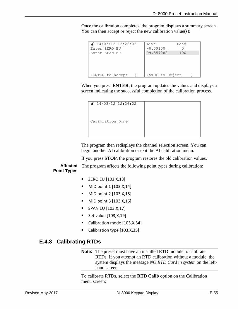
DL8000 Preset Instruction Manual
Revised May-2017 DL8000 Keypad Display E-55
Once the calibration completes, the program displays a summary screen.
You can then accept or reject the new calibration value(s):
14/03/12 12:26:02
Enter ZERO EU
Enter SPAN EU
(ENTER to accept )
Live Dead
-0.09100 0
99.857282 100
(STOP to Reject )
When you press ENTER, the program updates the values and displays a
screen indicating the successful completion of the calibration process.
14/03/12 12:26:02
Calibration Done
The program then redisplays the channel selection screen. You can
begin another AI calibration or exit the AI calibration menu.
If you press STOP, the program restores the old calibration values.
Affected Point Types
The program affects the following point types during calibration:
ZERO EU [103,X,13]
MID point 1 [103,X,14]
MID point 2 [103,X,15]
MID point 3 [103 X,16]
SPAN EU [103,X,17]
Set value [103,X,19]
Calibration mode [103,X,34]
Calibration type [103,X,35]
E.4.3 Calibrating RTDs
Note: The preset must have an installed RTD module to calibrate
RTDs. If you attempt an RTD calibration without a module, the
system displays the message NO RTD Card in system on the left-
hand screen.
To calibrate RTDs, select the RTD Calib option on the Calibration
menu screen:

DL8000 Preset Instruction Manual
E-56 DL8000 Keypad Display Revised May-2017
14/03/12 12:26:02
For traversing use
UP | DOWN
LEFT | RIGHT
ENTER to continue
EXIT to Go Back
EXIT to quit
Additive Calib
Analog Calib
RTD Calib
PRODUCT Calib
(Pg:1/1)
The preset displays all available RTD channels. In sequence, you select
the appropriate RTD channel, number of mid-points, and the units for
calibration:
14/03/12 12:26:02
Sel RTD Ch
Sel No of Mid pt
Sel Unit
Zero UE Value
Span EU Value
(SELECT)
RTD Ch 1
Once you select an RTD channel, the program shows the existing zero
and span values of the selected channel. You then enter the number of
mid-points and the units:
14/03/12 12:26:02
Sel RTD Ch
Sel No of Mid pt
Sel Unit
Zero UE Value
Span EU Value
(SELECT)
RTD Ch 1
Zero
100.000000
229.000000
14/03/12 12:26:02
Sel RTD Ch
Sel No of Mid pt
Sel Unit
Zero UE Value
Span EU Value
(SELECT)
RTD Ch 1
Zero
Ohms
100.000000
229.000000
Point Fail Alarm
Note: If a point fail alarm occurs for the selected channel, the system
displays a Point Fail alarm message at the bottom of the right-
hand screen (as shown above). This alarm does not stop the
calibration; it is provided for information only. During
calibration the program clears the message if the condition does
not exist.

DL8000 Preset Instruction Manual
Revised May-2017 DL8000 Keypad Display E-57
After you provide all the parameters required for calibration press
ENTER to continue. The program then displays the live value from an
external source with a corresponding “dead” (expected) value you can
change.
14/03/12 12:26:02
Enter ZERO EU
Enter SPAN EU
(ENTER to update )
(STOP to End )
Live Dead
80.3000003 80.5
(0-9, .)
Press ENTER to update the value. You then enter a span value:
14/03/12 12:26:02
Enter ZERO EU
Enter SPAN EU
(ENTER to update )
(STOP to End )
Live Dead
80.3000003 80.5
229.000000 228.99
(0-9, .)
If you need mid-points for calibration, enter those next.
The program checks all values you enter. If any value is not within
accepted ranges, the program displays the error message
InvdEntry!ReEnter:
14/03/12 12:26:02
Enter ZERO EU
Enter SPAN EU
(ENTER to update )
(STOP to End )
Live Dead
80.3000003 80.5
229.000000 228.99
InvdEntry!ReEnter
(0-9, .)
You must re-enter those values in order to proceed.
Valid ranges are:
RTD unit Minimum Range Maximum Range
Deg F -58.0 662.0
Deg C -50.0 350.0
Deg K 223.15 623.15
Deg R 401.67 1121.67
OHM 80.31 229.72
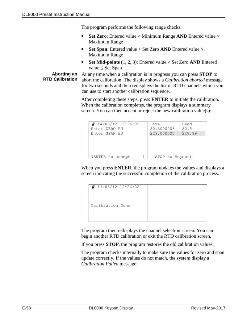
DL8000 Preset Instruction Manual
E-58 DL8000 Keypad Display Revised May-2017
The program performs the following range checks:
Set Zero: Entered value ≥ Minimum Range AND Entered value ≤
Maximum Range
Set Span: Entered value > Set Zero AND Entered value ≤
Maximum Range
Set Mid-points (1, 2, 3): Entered value ≥ Set Zero AND Entered
value ≤ Set Span
Aborting an RTD Calibration
At any time when a calibration is in progress you can press STOP to
abort the calibration. The display shows a Calibration aborted message
for two seconds and then redisplays the list of RTD channels which you
can use to start another calibration sequence.
After completing these steps, press ENTER to initiate the calibration.
When the calibration completes, the program displays a summary
screen. You can then accept or reject the new calibration value(s):
14/03/12 12:26:02
Enter ZERO EU
Enter SPAN EU
(ENTER to accept )
Live Dead
80.3000003 80.5
229.000000 228.99
(STOP to Reject)
When you press ENTER, the program updates the values and displays a
screen indicating the successful completion of the calibration process.
14/03/12 12:26:02
Calibration Done
The program then redisplays the channel selection screen. You can
begin another RTD calibration or exit the RTD calibration screen.
If you press STOP, the program restores the old calibration values.
The program checks internally to make sure the values for zero and span
update correctly. If the values do not match, the system display a
Calibration Failed message:
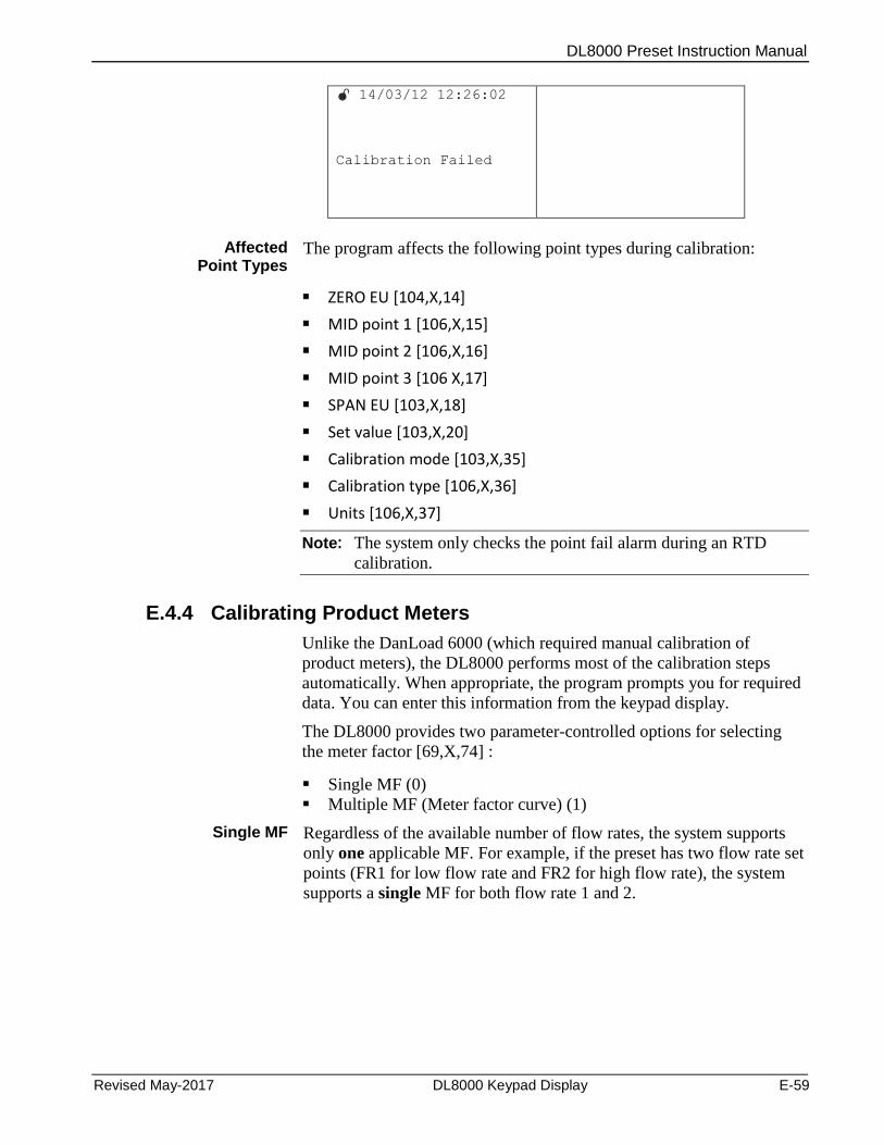
DL8000 Preset Instruction Manual
Revised May-2017 DL8000 Keypad Display E-59
14/03/12 12:26:02
Calibration Failed
Affected
Point Types The program affects the following point types during calibration:
ZERO EU [104,X,14]
MID point 1 [106,X,15]
MID point 2 [106,X,16]
MID point 3 [106 X,17]
SPAN EU [103,X,18]
Set value [103,X,20]
Calibration mode [103,X,35]
Calibration type [106,X,36]
Units [106,X,37]
Note: The system only checks the point fail alarm during an RTD
calibration.
E.4.4 Calibrating Product Meters
Unlike the DanLoad 6000 (which required manual calibration of
product meters), the DL8000 performs most of the calibration steps
automatically. When appropriate, the program prompts you for required
data. You can enter this information from the keypad display.
The DL8000 provides two parameter-controlled options for selecting
the meter factor [69,X,74] :
Single MF (0)
Multiple MF (Meter factor curve) (1)
Single MF Regardless of the available number of flow rates, the system supports
only one applicable MF. For example, if the preset has two flow rate set
points (FR1 for low flow rate and FR2 for high flow rate), the system
supports a single MF for both flow rate 1 and 2.
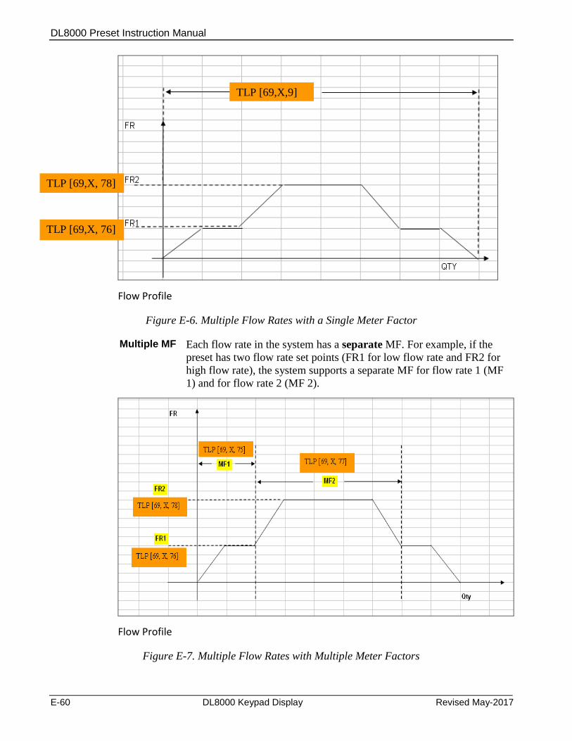
DL8000 Preset Instruction Manual
E-60 DL8000 Keypad Display Revised May-2017
Flow Profile
Figure E-6. Multiple Flow Rates with a Single Meter Factor
Multiple MF Each flow rate in the system has a separate MF. For example, if the
preset has two flow rate set points (FR1 for low flow rate and FR2 for
high flow rate), the system supports a separate MF for flow rate 1 (MF
1) and for flow rate 2 (MF 2).
Flow Profile
Figure E-7. Multiple Flow Rates with Multiple Meter Factors
TLP [69,X,9]
TLP [69,X, 76]
TLP [69,X, 78]
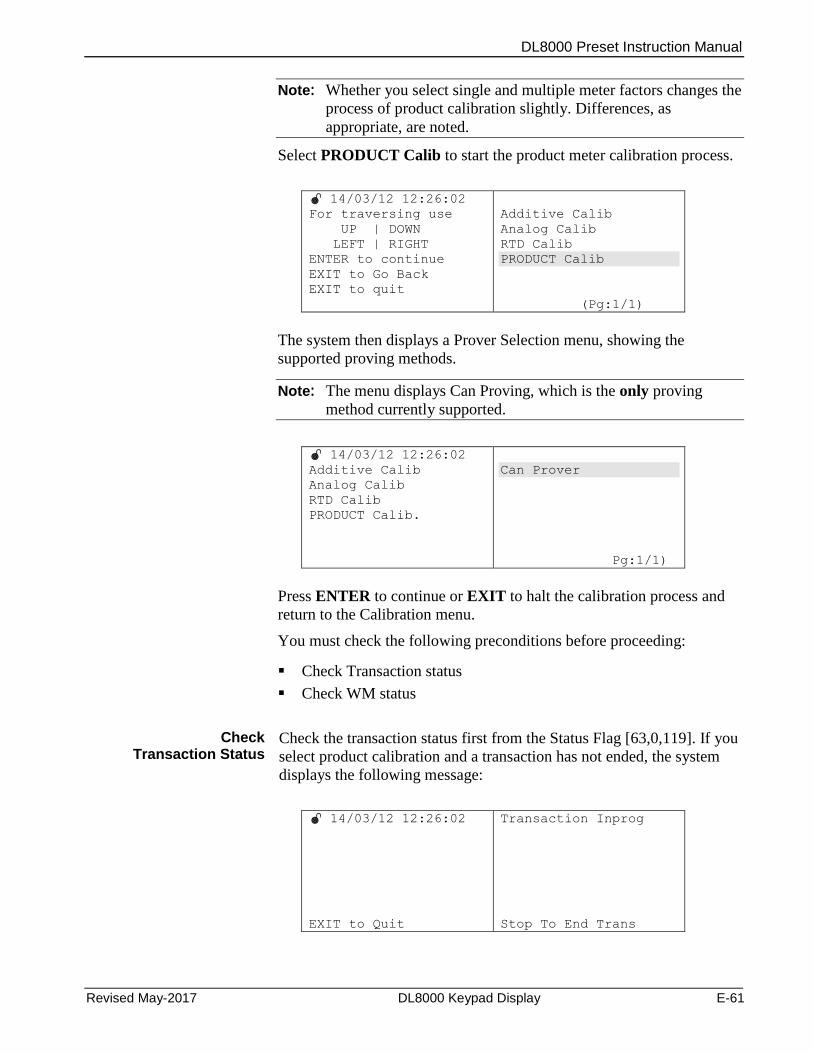
DL8000 Preset Instruction Manual
Revised May-2017 DL8000 Keypad Display E-61
Note: Whether you select single and multiple meter factors changes the
process of product calibration slightly. Differences, as
appropriate, are noted.
Select PRODUCT Calib to start the product meter calibration process.
14/03/12 12:26:02
For traversing use
UP | DOWN
LEFT | RIGHT
ENTER to continue
EXIT to Go Back
EXIT to quit
Additive Calib
Analog Calib
RTD Calib
PRODUCT Calib
(Pg:1/1)
The system then displays a Prover Selection menu, showing the
supported proving methods.
Note: The menu displays Can Proving, which is the only proving
method currently supported.
14/03/12 12:26:02
Additive Calib
Analog Calib
RTD Calib
PRODUCT Calib.
Can Prover
Pg:1/1)
Press ENTER to continue or EXIT to halt the calibration process and
return to the Calibration menu.
You must check the following preconditions before proceeding:
Check Transaction status
Check WM status
Check Transaction Status
Check the transaction status first from the Status Flag [63,0,119]. If you
select product calibration and a transaction has not ended, the system
displays the following message:
14/03/12 12:26:02
EXIT to Quit
Transaction Inprog
Stop To End Trans
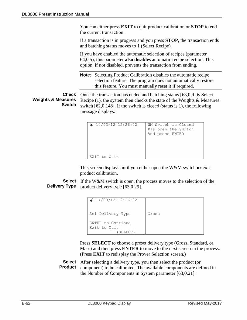
DL8000 Preset Instruction Manual
E-62 DL8000 Keypad Display Revised May-2017
You can either press EXIT to quit product calibration or STOP to end
the current transaction.
If a transaction is in progress and you press STOP, the transaction ends
and batching status moves to 1 (Select Recipe).
If you have enabled the automatic selection of recipes (parameter
64,0,5), this parameter also disables automatic recipe selection. This
option, if not disabled, prevents the transaction from ending.
Note: Selecting Product Calibration disables the automatic recipe
selection feature. The program does not automatically restore
this feature. You must manually reset it if required.
Check Weights & Measures
Switch
Once the transaction has ended and batching status [63,0,9] is Select
Recipe (1), the system then checks the state of the Weights & Measures
switch [62,0,148]. If the switch is closed (status is 1), the following
message displays:
14/03/12 12:26:02
EXIT to Quit
WM Switch is Closed
Pls open the Switch
And press ENTER
This screen displays until you either open the W&M switch or exit
product calibration.
Select Delivery Type
If the W&M switch is open, the process moves to the selection of the
product delivery type [63,0,29].
14/03/12 12:26:02
Sel Delivery Type
ENTER to Continue
Exit to Quit
(SELECT)
Gross
Press SELECT to choose a preset delivery type (Gross, Standard, or
Mass) and then press ENTER to move to the next screen in the process.
(Press EXIT to redisplay the Prover Selection screen.)
Select Product
After selecting a delivery type, you then select the product (or
component) to be calibrated. The available components are defined in
the Number of Components in System parameter [63,0,21].
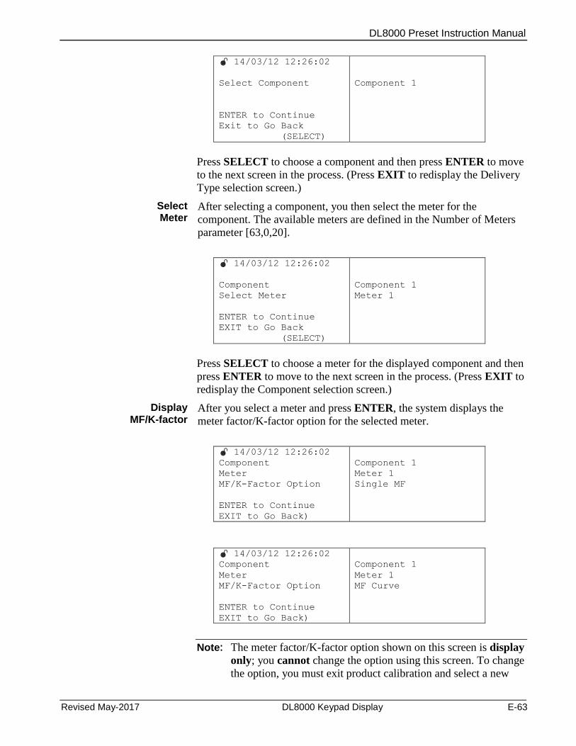
DL8000 Preset Instruction Manual
Revised May-2017 DL8000 Keypad Display E-63
14/03/12 12:26:02
Select Component
ENTER to Continue
Exit to Go Back
(SELECT)
Component 1
Press SELECT to choose a component and then press ENTER to move
to the next screen in the process. (Press EXIT to redisplay the Delivery
Type selection screen.)
Select Meter
After selecting a component, you then select the meter for the
component. The available meters are defined in the Number of Meters
parameter [63,0,20].
14/03/12 12:26:02
Component
Select Meter
ENTER to Continue
EXIT to Go Back
(SELECT)
Component 1
Meter 1
Press SELECT to choose a meter for the displayed component and then
press ENTER to move to the next screen in the process. (Press EXIT to
redisplay the Component selection screen.)
Display MF/K-factor
After you select a meter and press ENTER, the system displays the
meter factor/K-factor option for the selected meter.
14/03/12 12:26:02
Component
Meter
MF/K-Factor Option
ENTER to Continue
EXIT to Go Back)
Component 1
Meter 1
Single MF
14/03/12 12:26:02
Component
Meter
MF/K-Factor Option
ENTER to Continue
EXIT to Go Back)
Component 1
Meter 1
MF Curve
Note: The meter factor/K-factor option shown on this screen is display
only; you cannot change the option using this screen. To change
the option, you must exit product calibration and select a new
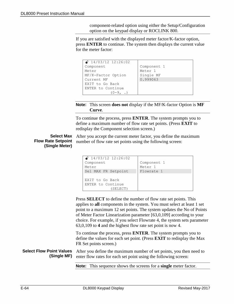
DL8000 Preset Instruction Manual
E-64 DL8000 Keypad Display Revised May-2017
component-related option using either the Setup/Configuration
option on the keypad display or ROCLINK 800.
If you are satisfied with the displayed meter factor/K-factor option,
press ENTER to continue. The system then displays the current value
for the meter factor:
14/03/12 12:26:02
Component
Meter
MF/K-Factor Option
Current MF
EXIT to Go Back
ENTER to Continue
(0-9, .)
Component 1
Meter 1
Single MF
0.999063
Note: This screen does not display if the MF/K-factor Option is MF
Curve.
To continue the process, press ENTER. The system prompts you to
define a maximum number of flow rate set points. (Press EXIT to
redisplay the Component selection screen.)
Select Max Flow Rate Setpoint
(Single Meter)
After you accept the current meter factor, you define the maximum
number of flow rate set points using the following screen:
14/03/12 12:26:02
Component
Meter
Sel MAX FR Setpoint
EXIT to Go Back
ENTER to Continue
(SELECT)
Component 1
Meter 1
Flowrate 1
Press SELECT to define the number of flow rate set points. This
applies to all components in the system. You must select at least 1 set
point to a maximum 12 set points. The system updates the No of Points
of Meter Factor Linearization parameter [63,0,109] according to your
choice. For example, if you select Flowrate 4, the system sets parameter
63,0,109 to 4 and the highest flow rate set point is now 4.
To continue the process, press ENTER. The system prompts you to
define the values for each set point. (Press EXIT to redisplay the Max
FR Set points screen.)
Select Flow Point Values (Single MF)
After you define the maximum number of set points, you then need to
enter flow rates for each set point using the following screen:
Note: This sequence shows the screens for a single meter factor.
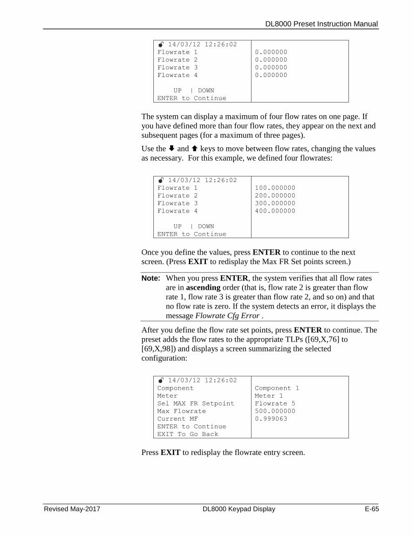
DL8000 Preset Instruction Manual
Revised May-2017 DL8000 Keypad Display E-65
14/03/12 12:26:02
Flowrate 1
Flowrate 2
Flowrate 3
Flowrate 4
UP | DOWN
ENTER to Continue
0.000000
0.000000
0.000000
0.000000
The system can display a maximum of four flow rates on one page. If
you have defined more than four flow rates, they appear on the next and
subsequent pages (for a maximum of three pages).
Use the and keys to move between flow rates, changing the values
as necessary. For this example, we defined four flowrates:
14/03/12 12:26:02
Flowrate 1
Flowrate 2
Flowrate 3
Flowrate 4
UP | DOWN
ENTER to Continue
100.000000
200.000000
300.000000
400.000000
Once you define the values, press ENTER to continue to the next
screen. (Press EXIT to redisplay the Max FR Set points screen.)
Note: When you press ENTER, the system verifies that all flow rates
are in ascending order (that is, flow rate 2 is greater than flow
rate 1, flow rate 3 is greater than flow rate 2, and so on) and that
no flow rate is zero. If the system detects an error, it displays the
message Flowrate Cfg Error .
After you define the flow rate set points, press ENTER to continue. The
preset adds the flow rates to the appropriate TLPs ([69,X,76] to
[69,X,98]) and displays a screen summarizing the selected
configuration:
14/03/12 12:26:02
Component
Meter
Sel MAX FR Setpoint
Max Flowrate
Current MF
ENTER to Continue
EXIT To Go Back
Component 1
Meter 1
Flowrate 5
500.000000
0.999063
Press EXIT to redisplay the flowrate entry screen.
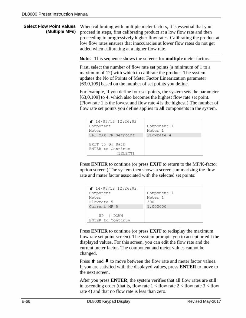
DL8000 Preset Instruction Manual
E-66 DL8000 Keypad Display Revised May-2017
Select Flow Point Values (Multiple MFs)
When calibrating with multiple meter factors, it is essential that you
proceed in steps, first calibrating product at a low flow rate and then
proceeding to progressively higher flow rates. Calibrating the product at
low flow rates ensures that inaccuracies at lower flow rates do not get
added when calibrating at a higher flow rate.
Note: This sequence shows the screens for multiple meter factors.
First, select the number of flow rate set points (a minimum of 1 to a
maximum of 12) with which to calibrate the product. The system
updates the No of Points of Meter Factor Linearization parameter
[63,0,109] based on the number of set points you define.
For example, if you define four set points, the system sets the parameter
[63,0,109] to 4, which also becomes the highest flow rate set point.
(Flow rate 1 is the lowest and flow rate 4 is the highest.) The number of
flow rate set points you define applies to all components in the system.
14/03/12 12:26:02
Component
Meter
Sel MAX FR Setpoint
EXIT to Go Back
ENTER to Continue
(SELECT)
Component 1
Meter 1
Flowrate 4
Press ENTER to continue (or press EXIT to return to the MF/K-factor
option screen.) The system then shows a screen summarizing the flow
rate and mater factor associated with the selected set points:
14/03/12 12:26:02
Component
Meter
Flowrate 5
Current MF 5
UP | DOWN
ENTER to Continue
Component 1
Meter 1
500
1.000000
Press ENTER to continue (or press EXIT to redisplay the maximum
flow rate set point screen). The system prompts you to accept or edit the
displayed values. For this screen, you can edit the flow rate and the
current meter factor. The component and meter values cannot be
changed.
Press and to move between the flow rate and meter factor values.
If you are satisfied with the displayed values, press ENTER to move to
the next screen.
After you press ENTER, the system verifies that all flow rates are still
in ascending order (that is, flow rate 1 < flow rate 2 < flow rate 3 < flow
rate 4) and that no flow rate is less than zero.

DL8000 Preset Instruction Manual
Revised May-2017 DL8000 Keypad Display E-67
If the system finds any problems, displays an error message:
14/03/12 12:26:02
EXIT To Go Back
Flowrate Cfg Error
To resolve any configuration errors, press EXIT to return to the
previous screen and re-define the flow rates.
When the system verifies the configuration, it updates all values and
displays a summary screen:
14/03/12 12:26:02
Component
Meter
Sel MAX FR SetPoint
Current MF
ENTER To Continue
EXIT To Go Back
Component 1
Meter 1
Flowrate 5
500.000000
1.000000
To change any value, press EXIT to redisplay the set flow rate set
points screen.
If you are satisfied with the summary display of values, press ENTER.
The preset configures recipe 1 using the identified components 100% of
the recipe. For example, if you select component 1, the system
configures recipe 1 as:
CMP 1 = 100% [68,0,1]
CMP 2 = 0 [68,0,2]
CMP3 = 0 [68,0,3]
CMP4 = 0 [68,0,4]
Seq. or Lo proportion = 1 [68,0,17]
Note: The Seq. or Lo proportion depends on the number of the
selected component. If you select component 2, the Seq. or
Lo Proportion value becomes 2.
Additionally, the system:
Sets Unit Type [63,0,12] as 0 (“Seq. Auto”)
Sets No. of batches per transaction [63,0,126] to 0 (zero)
Sets Disable the Flush [68,0,5] to 0
Sets No. of additives [63,0,100] to 0
Sets No. of data items [63,0,186] to 0
Sets the number of info parameters [63,0,228] to 0
Sets the number of data items [63,0,186] to 0
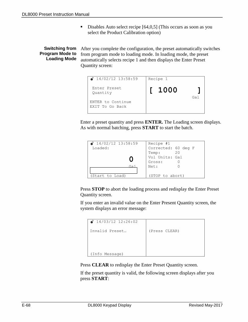
DL8000 Preset Instruction Manual
E-68 DL8000 Keypad Display Revised May-2017
Disables Auto select recipe [64,0,5] (This occurs as soon as you
select the Product Calibration option)
Switching from Program Mode to
Loading Mode
After you complete the configuration, the preset automatically switches
from program mode to loading mode. In loading mode, the preset
automatically selects recipe 1 and then displays the Enter Preset
Quantity screen:
14/02/12 13:58:59
Enter Preset
Quantity
ENTER to Continue
EXIT To Go Back
Recipe 1
[ 1000 ] Gal
Enter a preset quantity and press ENTER. The Loading screen displays.
As with normal batching, press START to start the batch.
14/02/12 13:58:59
Loaded:
0 Gal
(Start to Load)
Recipe #1
Corrected: 60 deg F
Temp: 20
Vol Units: Gal
Gross: 0
Net: 0
(STOP to abort)
Press STOP to abort the loading process and redisplay the Enter Preset
Quantity screen.
If you enter an invalid value on the Enter Present Quantity screen, the
system displays an error message:
14/03/12 12:26:02
Invalid Preset…
(Info Message)
(Press CLEAR)
Press CLEAR to redisplay the Enter Preset Quantity screen.
If the preset quantity is valid, the following screen displays after you
press START:
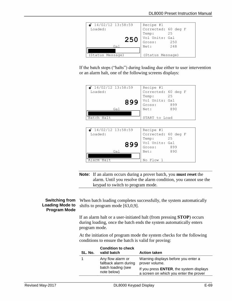
DL8000 Preset Instruction Manual
Revised May-2017 DL8000 Keypad Display E-69
14/02/12 13:58:59
Loaded:
250 Gal
(Status Message)
Recipe #1
Corrected: 60 deg F
Temp: 25
Vol Units: Gal
Gross: 250
Net: 248
(Status Message)
If the batch stops (“halts”) during loading due either to user intervention
or an alarm halt, one of the following screens displays:
14/02/12 13:58:59
Loaded:
899 Gal
Batch Halt
Recipe #1
Corrected: 60 deg F
Temp: 25
Vol Units: Gal
Gross: 899
Net: 890
START to Load
14/02/12 13:58:59
Loaded:
899 Gal
Alarm Halt
Recipe #1
Corrected: 60 deg F
Temp: 25
Vol Units: Gal
Gross: 899
Net: 890
No Flow 1
Note: If an alarm occurs during a prover batch, you must reset the
alarm. Until you resolve the alarm condition, you cannot use the
keypad to switch to program mode.
Switching from Loading Mode to
Program Mode
When batch loading completes successfully, the system automatically
shifts to program mode [63,0,9].
If an alarm halt or a user-initiated halt (from pressing STOP) occurs
during loading, once the batch ends the system automatically enters
program mode.
At the initiation of program mode the system checks for the following
conditions to ensure the batch is valid for proving:
SL. No.
Condition to check valid batch
Action taken
1 Any flow alarm or fallback alarm during batch loading (see note below)
Warning displays before you enter a prover volume.
If you press ENTER, the system displays a screen on which you enter the prover
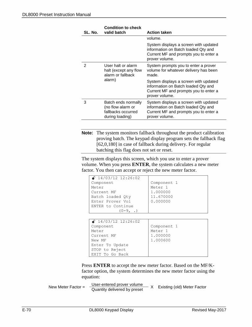
DL8000 Preset Instruction Manual
E-70 DL8000 Keypad Display Revised May-2017
SL. No.
Condition to check valid batch
Action taken
volume.
System displays a screen with updated information on Batch loaded Qty and Current MF and prompts you to enter a prover volume.
2 User halt or alarm halt (except any flow alarm or fallback alarm)
System prompts you to enter a prover volume for whatever delivery has been made.
System displays a screen with updated information on Batch loaded Qty and Current MF and prompts you to enter a prover volume.
3 Batch ends normally (no flow alarm or fallbacks occurred during loading)
System displays a screen with updated information on Batch loaded Qty and Current MF and prompts you to enter a prover volume.
Note: The system monitors fallback throughout the product calibration
proving batch. The keypad display program sets the fallback flag
[62,0,180] in case of fallback during delivery. For regular
batching this flag does not set or reset.
The system displays this screen, which you use to enter a prover
volume. When you press ENTER, the system calculates a new meter
factor. You then can accept or reject the new meter factor.
14/03/12 12:26:02
Component
Meter
Current MF
Batch loaded Qty
Enter Prover Vol
ENTER to Continue
(0-9, .)
Component 1
Meter 1
1.000000
11.670000
0.000000
14/03/12 12:26:02
Component
Meter
Current MF
New MF
Enter To Update
STOP to Reject
EXIT To Go Back
Component 1
Meter 1
1.000000
1.000600
Press ENTER to accept the new meter factor. Based on the MF/K-
factor option, the system determines the new meter factor using the
equation:
New Meter Factor = User-entered prover volume
X Existing (old) Meter Factor Quantity delivered by preset

DL8000 Preset Instruction Manual
Revised May-2017 DL8000 Keypad Display E-71
If you enter a prover volume of zero, the system retains the old meter
factor.
Single MF/K-factor Option
When you press ENTER, the system updates the meter factor parameter
[69,X,9] with the new value and displays a screen allowing you to rerun
the batch.
If you press STOP, the system retains the current meter factor
parameter value and displays a screen allowing you to rerun the batch.
If you press EXIT, the system redisplays the prover volume entry
screen, which you can use to re-enter the prover volume.
Multiple MF/K-factor Option
When you press ENTER, the system updates the meter factor using the
new value.
Depending upon the selected flow rate set point, the system updates the
meter factor to the appropriate TLP (that is, if 1 is the selected flow rate
set point, the system updates the parameter Meter Factor 1 [69,x,75].
Similarly, if the MAX FR SP is 4, the system updates the parameter
Meter Factor 4 [69,X,81] and then displays a screen allowing you to
rerun the batch.
If you press STOP, the system retains the current meter factor value
(Meter Factor, [69,X,81]), and then displays a screen allowing you to
rerun the batch.
If you press EXIT, the system redisplays the prover volume entry
screen which you can use to re-enter the prover volume.
Flow Alarm or Fallback Alarm During Proving
Batch Loading
If a flow alarm or fallback alarm occurs during batch delivery, the
system does not prompt you to enter a prover volume. Instead, the
system displays a warning screen showing the particular error:
14/03/12 12:26:02
WARNING!!!
Flow Alarm
during Batch
ENTER To Continue
EXIT To rerun
Note: Flow alarms include Low Flow, High Flow, No Flow,
Unauthorized Flow, and Unable to Close Valve.
14/03/12 12:26:02
WARNING!!!
Fallback
during Batch
ENTER To Continue
EXIT To rerun
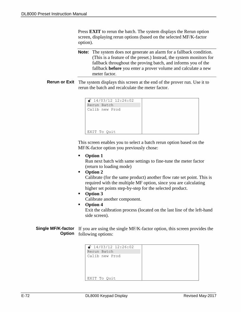
DL8000 Preset Instruction Manual
E-72 DL8000 Keypad Display Revised May-2017
Press EXIT to rerun the batch. The system displays the Rerun option
screen, displaying rerun options (based on the selected MF/K-factor
option).
Note: The system does not generate an alarm for a fallback condition.
(This is a feature of the preset.) Instead, the system monitors for
fallback throughout the proving batch, and informs you of the
fallback before you enter a prover volume and calculate a new
meter factor.
Rerun or Exit The system displays this screen at the end of the prover run. Use it to
rerun the batch and recalculate the meter factor.
14/03/12 12:26:02
Rerun Batch
Calib new Prod
EXIT To Quit
This screen enables you to select a batch rerun option based on the
MF/K-factor option you previously chose:
Option 1 Run next batch with same settings to fine-tune the meter factor
(return to loading mode)
Option 2 Calibrate (for the same product) another flow rate set point. This is
required with the multiple MF option, since you are calculating
higher set points step-by-step for the selected product.
Option 3 Calibrate another component.
Option 4 Exit the calibration process (located on the last line of the left-hand
side screen).
Single MF/K-factor Option
If you are using the single MF/K-factor option, this screen provides the
following options:
14/03/12 12:26:02
Rerun Batch
Calib new Prod
EXIT To Quit
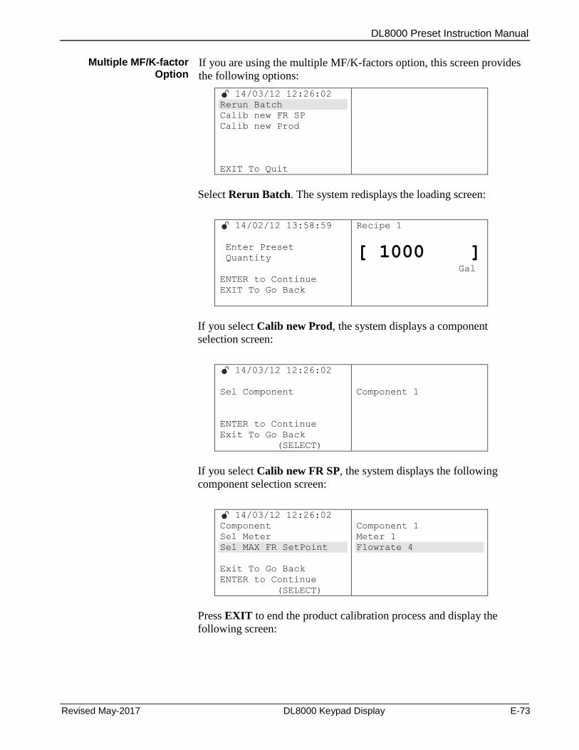
DL8000 Preset Instruction Manual
Revised May-2017 DL8000 Keypad Display E-73
Multiple MF/K-factor Option
If you are using the multiple MF/K-factors option, this screen provides
the following options:
14/03/12 12:26:02
Rerun Batch
Calib new FR SP
Calib new Prod
EXIT To Quit
Select Rerun Batch. The system redisplays the loading screen:
14/02/12 13:58:59
Enter Preset
Quantity
ENTER to Continue
EXIT To Go Back
Recipe 1
[ 1000 ] Gal
If you select Calib new Prod, the system displays a component
selection screen:
14/03/12 12:26:02
Sel Component
ENTER to Continue
Exit To Go Back
(SELECT)
Component 1
If you select Calib new FR SP, the system displays the following
component selection screen:
14/03/12 12:26:02
Component
Sel Meter
Sel MAX FR SetPoint
Exit To Go Back
ENTER to Continue
(SELECT)
Component 1
Meter 1
Flowrate 4
Press EXIT to end the product calibration process and display the
following screen:
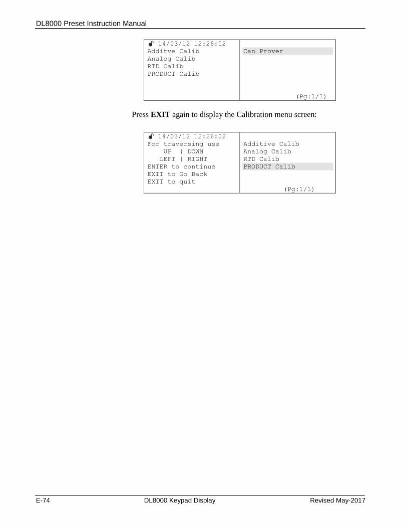
DL8000 Preset Instruction Manual
E-74 DL8000 Keypad Display Revised May-2017
14/03/12 12:26:02
Additve Calib
Analog Calib
RTD Calib
PRODUCT Calib
Can Prover
(Pg:1/1)
Press EXIT again to display the Calibration menu screen:
14/03/12 12:26:02
For traversing use
UP | DOWN
LEFT | RIGHT
ENTER to continue
EXIT to Go Back
EXIT to quit
Additive Calib
Analog Calib
RTD Calib
PRODUCT Calib
(Pg:1/1)
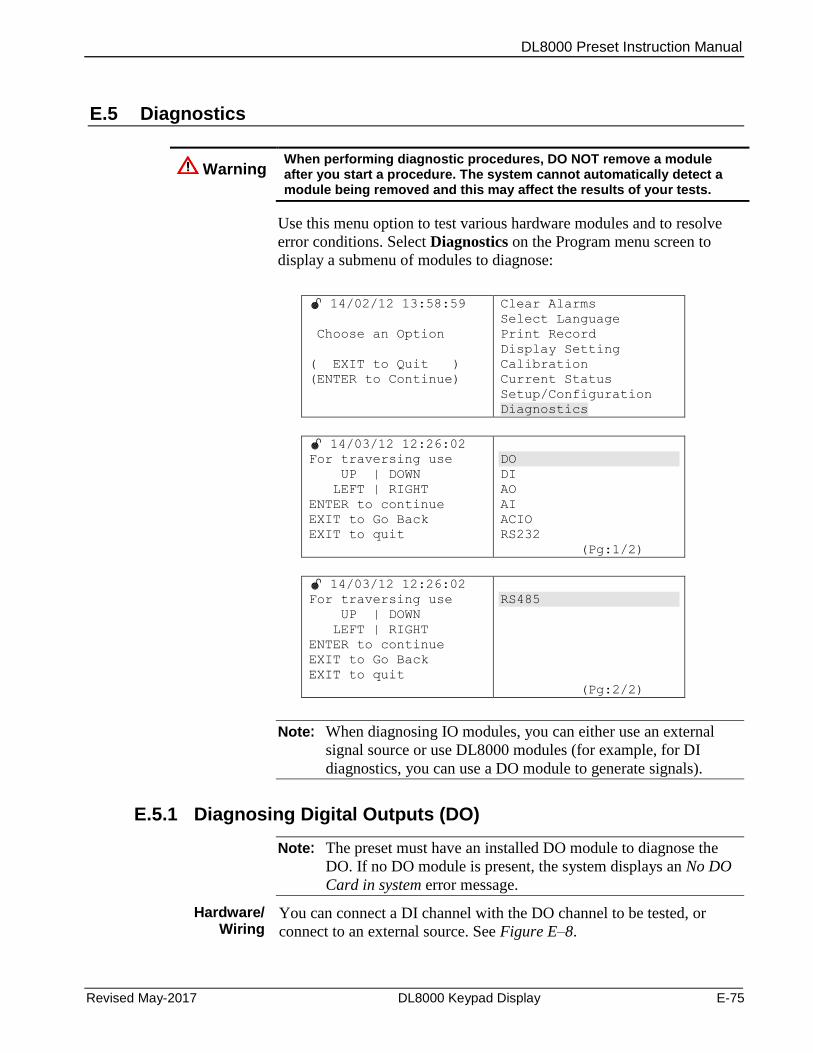
DL8000 Preset Instruction Manual
Revised May-2017 DL8000 Keypad Display E-75
E.5 Diagnostics
Warning When performing diagnostic procedures, DO NOT remove a module after you start a procedure. The system cannot automatically detect a module being removed and this may affect the results of your tests.
Use this menu option to test various hardware modules and to resolve
error conditions. Select Diagnostics on the Program menu screen to
display a submenu of modules to diagnose:
14/02/12 13:58:59
Choose an Option
( EXIT to Quit )
(ENTER to Continue)
Clear Alarms
Select Language
Print Record
Display Setting
Calibration
Current Status
Setup/Configuration
Diagnostics
14/03/12 12:26:02
For traversing use
UP | DOWN
LEFT | RIGHT
ENTER to continue
EXIT to Go Back
EXIT to quit
DO
DI
AO
AI
ACIO
RS232
(Pg:1/2)
14/03/12 12:26:02
For traversing use
UP | DOWN
LEFT | RIGHT
ENTER to continue
EXIT to Go Back
EXIT to quit
RS485
(Pg:2/2)
Note: When diagnosing IO modules, you can either use an external
signal source or use DL8000 modules (for example, for DI
diagnostics, you can use a DO module to generate signals).
E.5.1 Diagnosing Digital Outputs (DO)
Note: The preset must have an installed DO module to diagnose the
DO. If no DO module is present, the system displays an No DO
Card in system error message.
Hardware/ Wiring
You can connect a DI channel with the DO channel to be tested, or
connect to an external source. See Figure E–8.
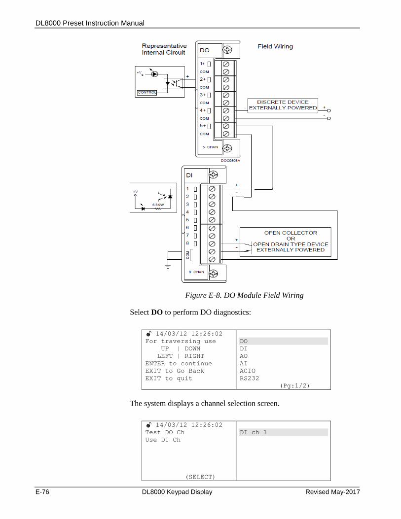
DL8000 Preset Instruction Manual
E-76 DL8000 Keypad Display Revised May-2017
Figure E-8. DO Module Field Wiring
Select DO to perform DO diagnostics:
14/03/12 12:26:02
For traversing use
UP | DOWN
LEFT | RIGHT
ENTER to continue
EXIT to Go Back
EXIT to quit
DO
DI
AO
AI
ACIO
RS232
(Pg:1/2)
The system displays a channel selection screen.
14/03/12 12:26:02
Test DO Ch
Use DI Ch
(SELECT)
DI ch 1
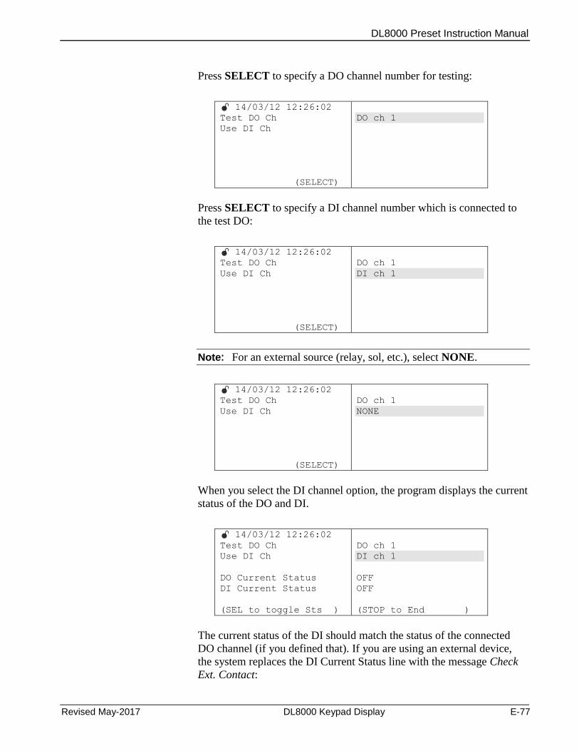
DL8000 Preset Instruction Manual
Revised May-2017 DL8000 Keypad Display E-77
Press SELECT to specify a DO channel number for testing:
14/03/12 12:26:02
Test DO Ch
Use DI Ch
(SELECT)
DO ch 1
Press SELECT to specify a DI channel number which is connected to
the test DO:
14/03/12 12:26:02
Test DO Ch
Use DI Ch
(SELECT)
DO ch 1
DI ch 1
Note: For an external source (relay, sol, etc.), select NONE.
14/03/12 12:26:02
Test DO Ch
Use DI Ch
(SELECT)
DO ch 1
NONE
When you select the DI channel option, the program displays the current
status of the DO and DI.
14/03/12 12:26:02
Test DO Ch
Use DI Ch
DO Current Status
DI Current Status
(SEL to toggle Sts )
DO ch 1
DI ch 1
OFF
OFF
(STOP to End )
The current status of the DI should match the status of the connected
DO channel (if you defined that). If you are using an external device,
the system replaces the DI Current Status line with the message Check
Ext. Contact:
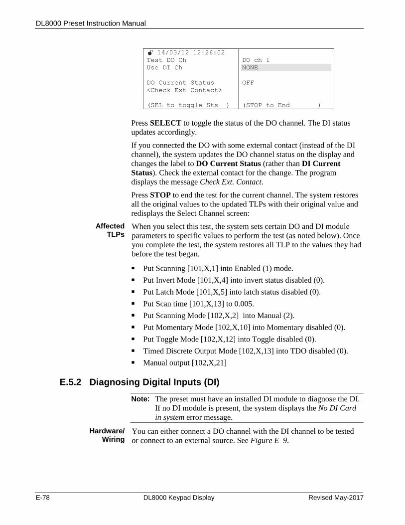
DL8000 Preset Instruction Manual
E-78 DL8000 Keypad Display Revised May-2017
14/03/12 12:26:02
Test DO Ch
Use DI Ch
DO Current Status
<Check Ext Contact>
(SEL to toggle Sts )
DO ch 1
NONE
OFF
(STOP to End )
Press SELECT to toggle the status of the DO channel. The DI status
updates accordingly.
If you connected the DO with some external contact (instead of the DI
channel), the system updates the DO channel status on the display and
changes the label to DO Current Status (rather than DI Current
Status). Check the external contact for the change. The program
displays the message Check Ext. Contact.
Press STOP to end the test for the current channel. The system restores
all the original values to the updated TLPs with their original value and
redisplays the Select Channel screen:
Affected TLPs
When you select this test, the system sets certain DO and DI module
parameters to specific values to perform the test (as noted below). Once
you complete the test, the system restores all TLP to the values they had
before the test began.
Put Scanning [101,X,1] into Enabled (1) mode.
Put Invert Mode [101,X,4] into invert status disabled (0).
Put Latch Mode [101,X,5] into latch status disabled (0).
Put Scan time [101,X,13] to 0.005.
Put Scanning Mode [102,X,2] into Manual (2).
Put Momentary Mode [102,X,10] into Momentary disabled (0).
Put Toggle Mode [102,X,12] into Toggle disabled (0).
Timed Discrete Output Mode [102,X,13] into TDO disabled (0).
Manual output [102,X,21]
E.5.2 Diagnosing Digital Inputs (DI)
Note: The preset must have an installed DI module to diagnose the DI.
If no DI module is present, the system displays the No DI Card
in system error message.
Hardware/ Wiring
You can either connect a DO channel with the DI channel to be tested
or connect to an external source. See Figure E–9.
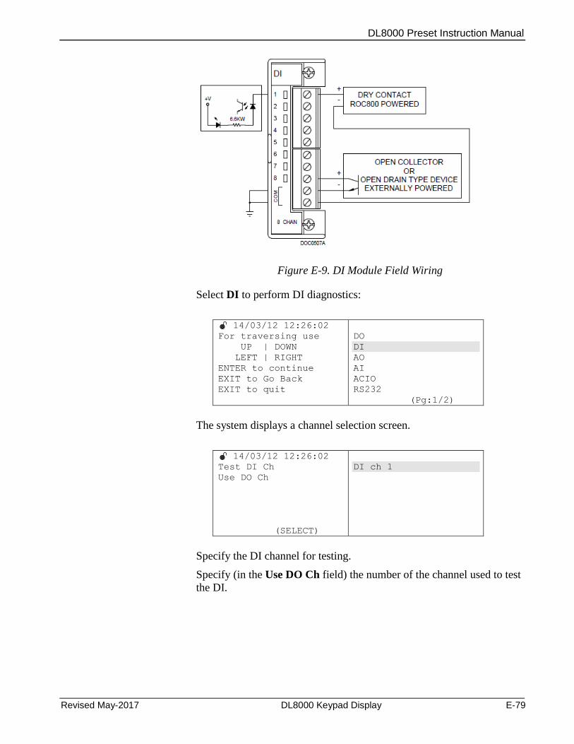
DL8000 Preset Instruction Manual
Revised May-2017 DL8000 Keypad Display E-79
Figure E-9. DI Module Field Wiring
Select DI to perform DI diagnostics:
14/03/12 12:26:02
For traversing use
UP | DOWN
LEFT | RIGHT
ENTER to continue
EXIT to Go Back
EXIT to quit
DO
DI
AO
AI
ACIO
RS232
(Pg:1/2)
The system displays a channel selection screen.
14/03/12 12:26:02
Test DI Ch
Use DO Ch
(SELECT)
DI ch 1
Specify the DI channel for testing.
Specify (in the Use DO Ch field) the number of the channel used to test
the DI.
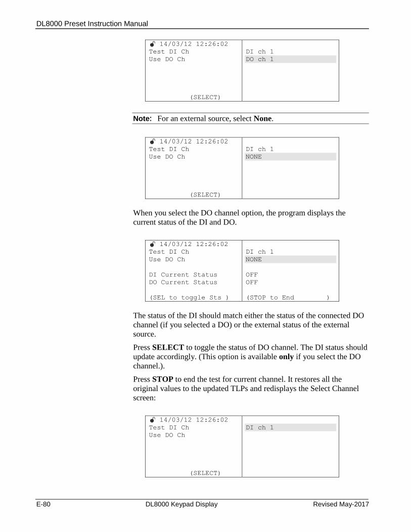
DL8000 Preset Instruction Manual
E-80 DL8000 Keypad Display Revised May-2017
14/03/12 12:26:02
Test DI Ch
Use DO Ch
(SELECT)
DI ch 1
DO ch 1
Note: For an external source, select None.
14/03/12 12:26:02
Test DI Ch
Use DO Ch
(SELECT)
DI ch 1
NONE
When you select the DO channel option, the program displays the
current status of the DI and DO.
14/03/12 12:26:02
Test DI Ch
Use DO Ch
DI Current Status
DO Current Status
(SEL to toggle Sts )
DI ch 1
NONE
OFF
OFF
(STOP to End )
The status of the DI should match either the status of the connected DO
channel (if you selected a DO) or the external status of the external
source.
Press SELECT to toggle the status of DO channel. The DI status should
update accordingly. (This option is available only if you select the DO
channel.).
Press STOP to end the test for current channel. It restores all the
original values to the updated TLPs and redisplays the Select Channel
screen:
14/03/12 12:26:02
Test DI Ch
Use DO Ch
(SELECT)
DI ch 1
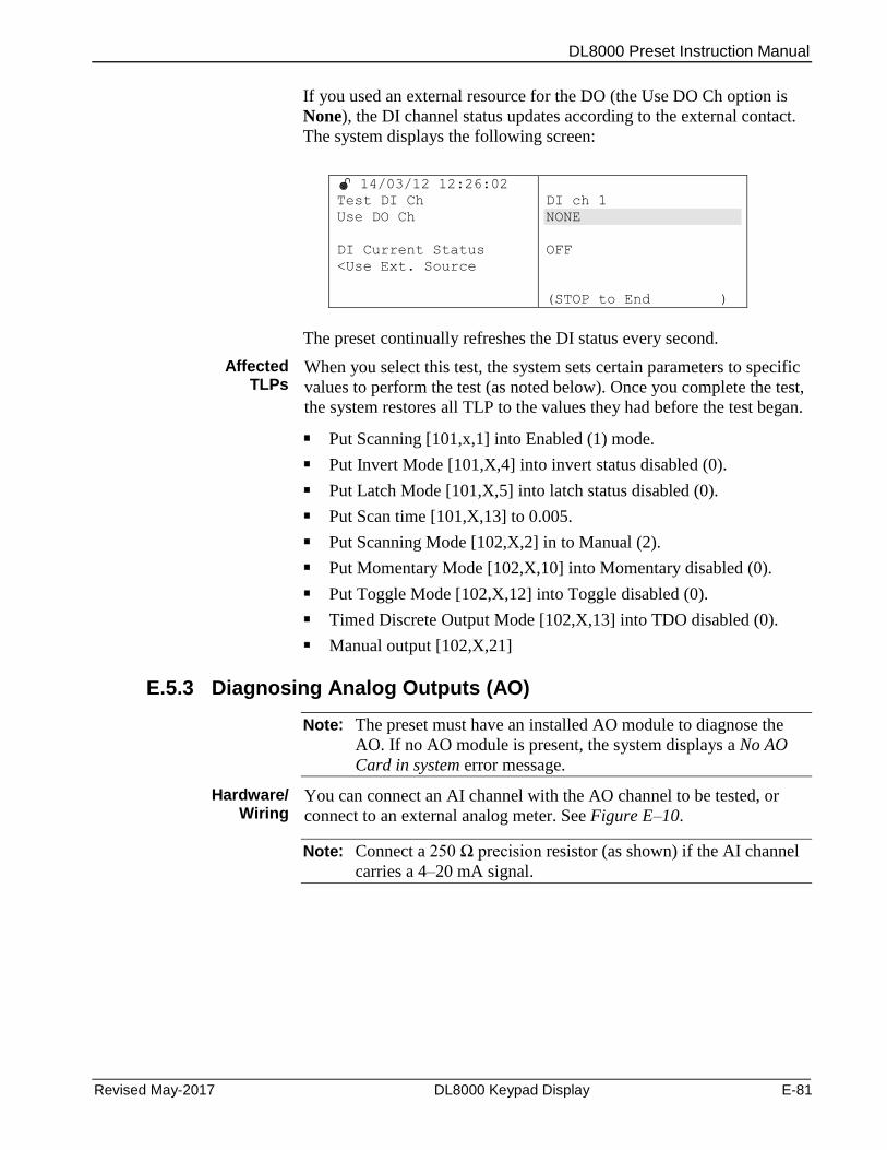
DL8000 Preset Instruction Manual
Revised May-2017 DL8000 Keypad Display E-81
If you used an external resource for the DO (the Use DO Ch option is
None), the DI channel status updates according to the external contact.
The system displays the following screen:
14/03/12 12:26:02
Test DI Ch
Use DO Ch
DI Current Status
<Use Ext. Source
DI ch 1
NONE
OFF
(STOP to End )
The preset continually refreshes the DI status every second.
Affected TLPs
When you select this test, the system sets certain parameters to specific
values to perform the test (as noted below). Once you complete the test,
the system restores all TLP to the values they had before the test began.
Put Scanning [101,x,1] into Enabled (1) mode.
Put Invert Mode [101,X,4] into invert status disabled (0).
Put Latch Mode [101,X,5] into latch status disabled (0).
Put Scan time [101,X,13] to 0.005.
Put Scanning Mode [102,X,2] in to Manual (2).
Put Momentary Mode [102,X,10] into Momentary disabled (0).
Put Toggle Mode [102,X,12] into Toggle disabled (0).
Timed Discrete Output Mode [102,X,13] into TDO disabled (0).
Manual output [102,X,21]
E.5.3 Diagnosing Analog Outputs (AO)
Note: The preset must have an installed AO module to diagnose the
AO. If no AO module is present, the system displays a No AO
Card in system error message.
Hardware/ Wiring
You can connect an AI channel with the AO channel to be tested, or
connect to an external analog meter. See Figure E–10.
Note: Connect a 250 Ω precision resistor (as shown) if the AI channel
carries a 4–20 mA signal.
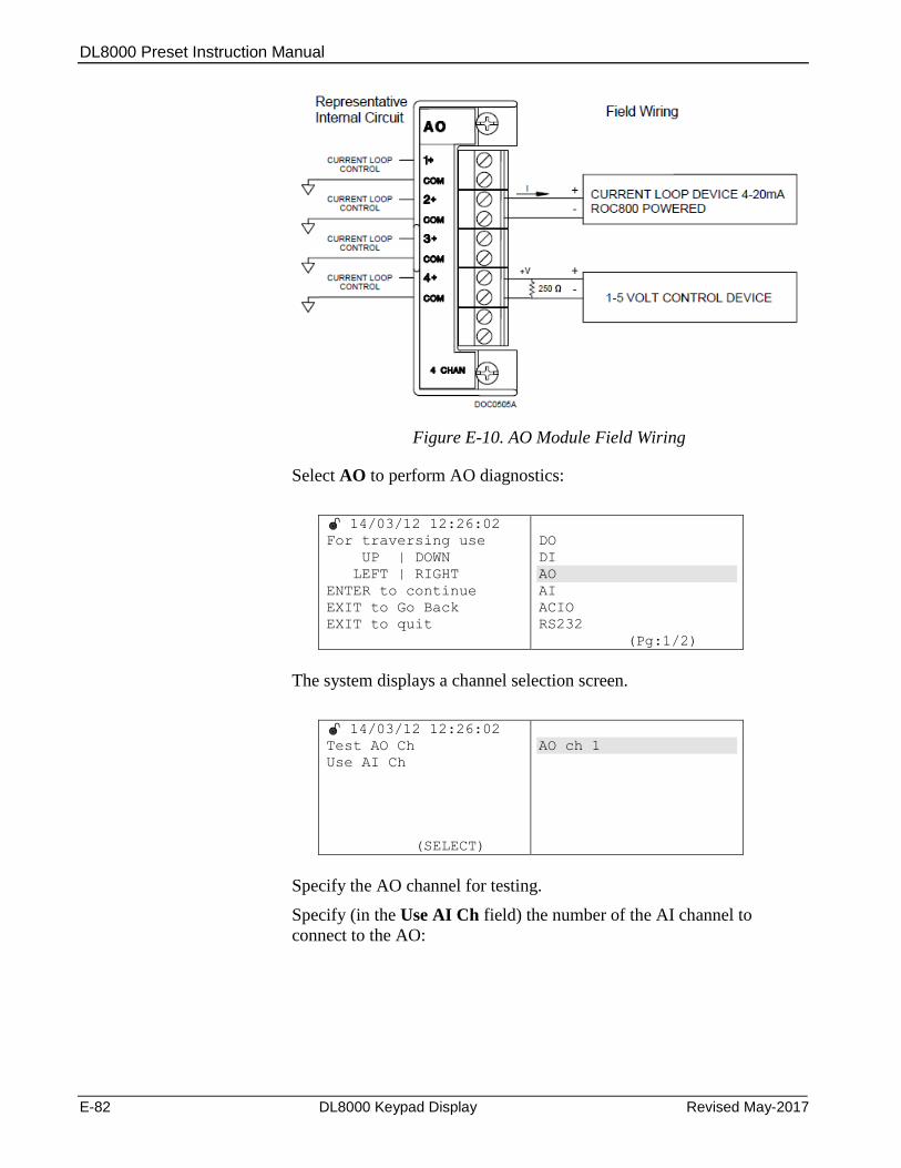
DL8000 Preset Instruction Manual
E-82 DL8000 Keypad Display Revised May-2017
Figure E-10. AO Module Field Wiring
Select AO to perform AO diagnostics:
14/03/12 12:26:02
For traversing use
UP | DOWN
LEFT | RIGHT
ENTER to continue
EXIT to Go Back
EXIT to quit
DO
DI
AO
AI
ACIO
RS232
(Pg:1/2)
The system displays a channel selection screen.
14/03/12 12:26:02
Test AO Ch
Use AI Ch
(SELECT)
AO ch 1
Specify the AO channel for testing.
Specify (in the Use AI Ch field) the number of the AI channel to
connect to the AO:
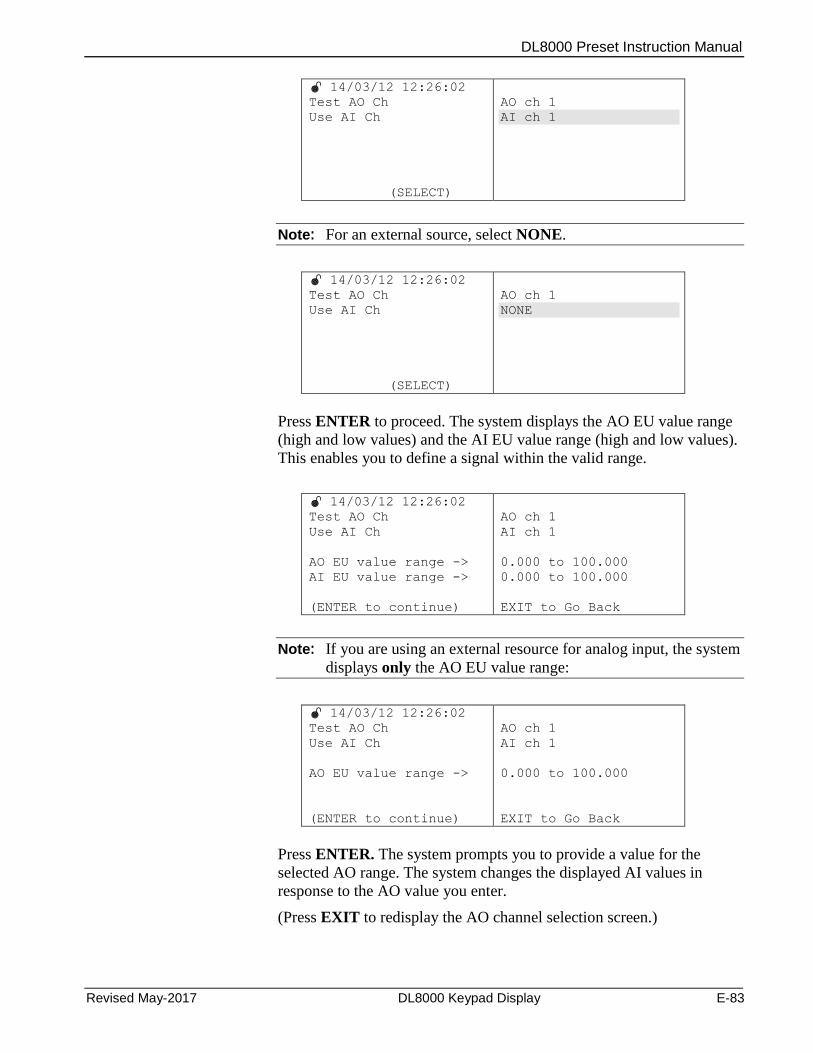
DL8000 Preset Instruction Manual
Revised May-2017 DL8000 Keypad Display E-83
14/03/12 12:26:02
Test AO Ch
Use AI Ch
(SELECT)
AO ch 1
AI ch 1
Note: For an external source, select NONE.
14/03/12 12:26:02
Test AO Ch
Use AI Ch
(SELECT)
AO ch 1
NONE
Press ENTER to proceed. The system displays the AO EU value range
(high and low values) and the AI EU value range (high and low values).
This enables you to define a signal within the valid range.
14/03/12 12:26:02
Test AO Ch
Use AI Ch
AO EU value range ->
AI EU value range ->
(ENTER to continue)
AO ch 1
AI ch 1
0.000 to 100.000
0.000 to 100.000
EXIT to Go Back
Note: If you are using an external resource for analog input, the system
displays only the AO EU value range:
14/03/12 12:26:02
Test AO Ch
Use AI Ch
AO EU value range ->
(ENTER to continue)
AO ch 1
AI ch 1
0.000 to 100.000
EXIT to Go Back
Press ENTER. The system prompts you to provide a value for the
selected AO range. The system changes the displayed AI values in
response to the AO value you enter.
(Press EXIT to redisplay the AO channel selection screen.)
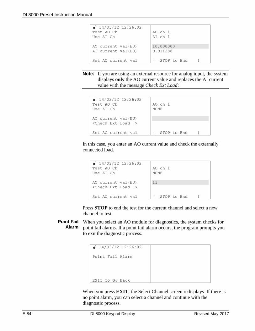
DL8000 Preset Instruction Manual
E-84 DL8000 Keypad Display Revised May-2017
14/03/12 12:26:02
Test AO Ch
Use AI Ch
AO current val(EU)
AI current val(EU)
Set AO current val
AO ch 1
AI ch 1
10.000000
9.911288
( STOP to End )
Note: If you are using an external resource for analog input, the system
displays only the AO current value and replaces the AI current
value with the message Check Ext Load:
14/03/12 12:26:02
Test AO Ch
Use AI Ch
AO current val(EU)
<Check Ext Load >
Set AO current val
AO ch 1
NONE
( STOP to End )
In this case, you enter an AO current value and check the externally
connected load.
14/03/12 12:26:02
Test AO Ch
Use AI Ch
AO current val(EU)
<Check Ext Load >
Set AO current val
AO ch 1
NONE
11
( STOP to End )
Press STOP to end the test for the current channel and select a new
channel to test.
Point Fail Alarm
When you select an AO module for diagnostics, the system checks for
point fail alarms. If a point fail alarm occurs, the program prompts you
to exit the diagnostic process.
14/03/12 12:26:02
Point Fail Alarm
EXIT To Go Back
When you press EXIT, the Select Channel screen redisplays. If there is
no point alarm, you can select a channel and continue with the
diagnostic process.
DL8000 Preset Instruction Manual
Revised May-2017 DL8000 Keypad Display E-85
Once the diagnosis is in process, the program checks only for the
following AI alarms:
Point fail alarm. (Terminate diagnostics)
Scanning manual alarm (Info alarm)
If multiple alarms occur, the system displays the alarm with the highest
priority. In this case, the Point Fail alarm has the highest priority, and
immediately terminated the diagnostic process.
While the diagnostic process is in progress, the system does not
consider alarms for the module under test.
Note: If the AO is connected to some external contact such as a digital
multi-meter, the results appear on the multi-meter instead of the
preset display.
Affected TLPs
When you select this test, the system sets certain AI and AO module
parameters to specific values to perform the test (as noted below). Once
you complete the test, the system restores all TLP to the values they had
before the test began.
Scanning [103,X,02]
Zero EU [103,X,13]
Mid Point EU #1 [103,X,14]
Mid Point EU #1 [103,X,5]
Mid Point EU #1 [103,X,16]
Span EU [103,X,17]
Scanning Mode [104,X,2]
Zero EU [104,X,10]
Span EU [104,X,1]
Manual Value [104,X,4]
E.5.4 Diagnosing Analog Inputs (AI)
Note: The preset must have an installed AI module to diagnose the AI.
If no AI module is present, the system displays a No AI Card in
system error message.
Hardware/ Wiring
You can connect an AO channel with the AI channel to be tested, or
connect to an external analog source. See Figure E–11.
Note: Connect a 250 Ω precision resistor (as shown) if the AI channel
carries a 4–20 mA signal.
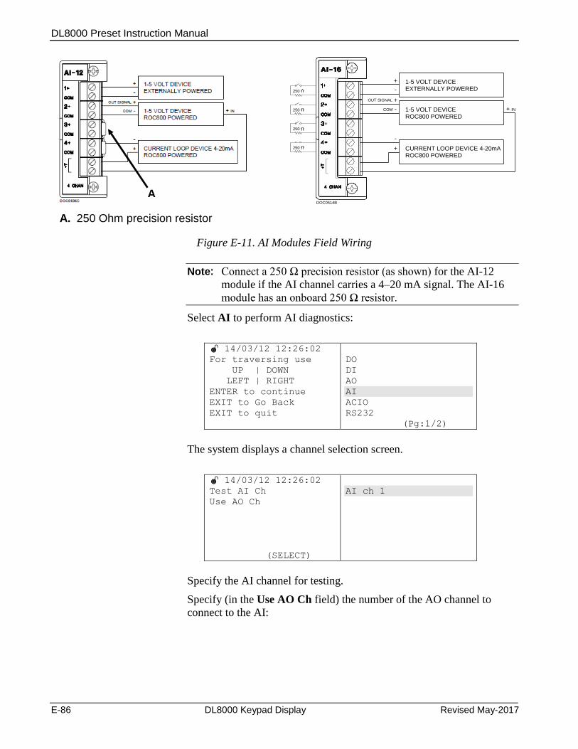
DL8000 Preset Instruction Manual
E-86 DL8000 Keypad Display Revised May-2017
+
+
+
OUT SIGNAL
COM
1-5 VOLT DEVICEEXTERNALLY POWERED
1-5 VOLT DEVICEROC800 POWERED
CURRENT LOOP DEVICE 4-20mA ROC800 POWERED
-
-
-
IN
DOC0514B
250
250
250
250
A. 250 Ohm precision resistor
Figure E-11. AI Modules Field Wiring
Note: Connect a 250 Ω precision resistor (as shown) for the AI-12
module if the AI channel carries a 4–20 mA signal. The AI-16
module has an onboard 250 Ω resistor.
Select AI to perform AI diagnostics:
14/03/12 12:26:02
For traversing use
UP | DOWN
LEFT | RIGHT
ENTER to continue
EXIT to Go Back
EXIT to quit
DO
DI
AO
AI
ACIO
RS232
(Pg:1/2)
The system displays a channel selection screen.
14/03/12 12:26:02
Test AI Ch
Use AO Ch
(SELECT)
AI ch 1
Specify the AI channel for testing.
Specify (in the Use AO Ch field) the number of the AO channel to
connect to the AI:
A
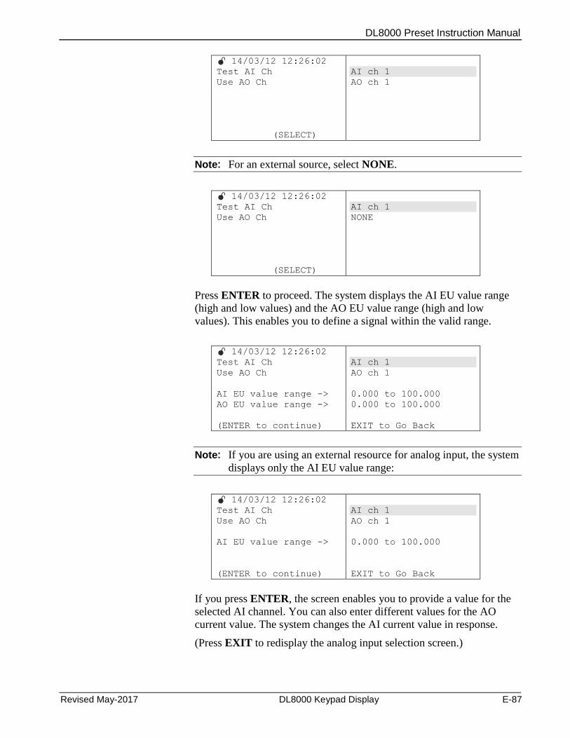
DL8000 Preset Instruction Manual
Revised May-2017 DL8000 Keypad Display E-87
14/03/12 12:26:02
Test AI Ch
Use AO Ch
(SELECT)
AI ch 1
AO ch 1
Note: For an external source, select NONE.
14/03/12 12:26:02
Test AI Ch
Use AO Ch
(SELECT)
AI ch 1
NONE
Press ENTER to proceed. The system displays the AI EU value range
(high and low values) and the AO EU value range (high and low
values). This enables you to define a signal within the valid range.
14/03/12 12:26:02
Test AI Ch
Use AO Ch
AI EU value range ->
AO EU value range ->
(ENTER to continue)
AI ch 1
AO ch 1
0.000 to 100.000
0.000 to 100.000
EXIT to Go Back
Note: If you are using an external resource for analog input, the system
displays only the AI EU value range:
14/03/12 12:26:02
Test AI Ch
Use AO Ch
AI EU value range ->
(ENTER to continue)
AI ch 1
AO ch 1
0.000 to 100.000
EXIT to Go Back
If you press ENTER, the screen enables you to provide a value for the
selected AI channel. You can also enter different values for the AO
current value. The system changes the AI current value in response.
(Press EXIT to redisplay the analog input selection screen.)
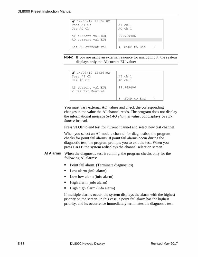
DL8000 Preset Instruction Manual
E-88 DL8000 Keypad Display Revised May-2017
14/03/12 12:26:02
Test AI Ch
Use AO Ch
AI current val(EU)
AO current val(EU)
Set AO current val
AI ch 1
AO ch 1
99.969406
( STOP to End )
Note: If you are using an external resource for analog input, the system
displays only the AI current EU value:
14/03/12 12:26:02
Test AI Ch
Use AO Ch
AI current val(EU)
< Use Ext Source>
AI ch 1
AO ch 1
99.969406
( STOP to End )
You must vary external AO values and check the corresponding
changes in the value the AI channel reads. The program does not display
the informational message Set AO channel value, but displays Use Ext
Source instead.
Press STOP to end test for current channel and select new test channel.
When you select an AI module channel for diagnostics, the program
checks for point fail alarms. If point fail alarms occur during the
diagnostic test, the program prompts you to exit the test. When you
press EXIT, the system redisplays the channel selection screen.
AI Alarms When the diagnostic test is running, the program checks only for the
following AI alarms:
Point fail alarm. (Terminate diagnostics)
Low alarm (info alarm)
Low low alarm (info alarm)
High alarm (info alarm)
High high alarm (info alarm)
If multiple alarms occur, the system displays the alarm with the highest
priority on the screen. In this case, a point fail alarm has the highest
priority, and its occurrence immediately terminates the diagnostic test:

DL8000 Preset Instruction Manual
Revised May-2017 DL8000 Keypad Display E-89
14/03/12 12:26:02
Point Fail Alarm
EXIT To Go Back
Additionally, the system does not show any alarms for the AI module
once diagnostics tests are in progress.
Note: If you connect the AI with an external contact instead of an AO
channel, the current AI value updates with the external contact.
Affected TLPs
When you select this test, the system sets certain AI and AO module
parameters to specific values to perform the test (as noted below). Once
you complete the test, the system restores all TLP to the values they had
before the test began.
Scanning [103,X,02]
Zero EU [103,X,13]
Mid Point EU #1 [103,X,14]
Mid Point EU #1 [103,X,15]
Mid Point EU #1 [103,X,16]
Span EU [103,X,17]
Scanning Mode [104,X,2]
Zero EU [104,X,10]
Span EU [104,X,11]
Manual Value [104,X,14]
E.5.5 Diagnosing AC Input/Outputs (AC I/O)
Note: The preset must have an installed AC I/O module to diagnose
the AC I/O. If no AC I/O module is present, the system displays
the No ACIO Card in system error message.
Hardware/ Wiring
Connect the AC output channel with AC load and provide an AC supply
(110 V or 230 V) to the AC I/O module. To test the AC output, you
need to select channels as output channel on the AC I/O module using
DIP switches on the module. (Refer to Chapter 3 of this manual for
more information on the DIP switch settings on the AC I/O module.)
See Figures E–12 and E-13.

DL8000 Preset Instruction Manual
E-90 DL8000 Keypad Display Revised May-2017
Figure E-12. AC I/O Module Output Field Wiring
Figure E-13. AC I/O Module Input Field Wiring
Select ACIO to perform AC I/O diagnostics:
14/03/12 12:26:02
For traversing use
UP | DOWN
LEFT | RIGHT
ENTER to continue
EXIT to Go Back
EXIT to quit
DO
DI
AO
AI
ACIO
RS232
(Pg:1/2)
The system displays a channel selection screen.

DL8000 Preset Instruction Manual
Revised May-2017 DL8000 Keypad Display E-91
14/03/12 12:26:02
Test AC Output Ch
Use AC Input Ch
(SELECT)
AC ch 7
AC ch 1
Specify the ACIO channel for testing. You can test only the AC ouput,
only the AC input, or both AC output and input.
To test the AC output, press SELECT to specify an AC output channel.
Selecting an AC input is optional, but if you select an AC input you
must also provide an external loop. In that case, the following screen
displays:
14/03/12 12:26:02
Use AC Output Ch
Use AC Input Ch
(SELECT)
AC ch 7
AC ch 1
You can test the AC output and AC input at the same time by creating a
loop-back connection and selecting the appropriate channels.
If you use an external device for testing, specify NONE for the AC
input channel. The system then indicates the channel. If you use an
external device to text, specify NONE for the AC input channel, and the
program displays the message Check Ext Contact.
14/03/12 12:26:02
Use AC Output Ch
Use AC Input Ch
(SELECT)
AC ch 7
NONE
If you use an external resource to perform AC Input testing, specify
NONE for Use AC Output Ch:
14/03/12 12:26:02
Use AC Output Ch
Use AC Input Ch
(SELECT)
NONE
AC ch 1
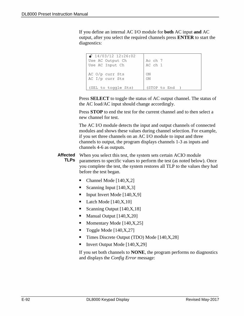
DL8000 Preset Instruction Manual
E-92 DL8000 Keypad Display Revised May-2017
If you define an internal AC I/O module for both AC input and AC
output, after you select the required channels press ENTER to start the
diagnostics:
14/03/12 12:26:02
Use AC Output Ch
Use AC Input Ch
AC O/p curr Sts
AC I/p curr Sts
(SEL to toggle Sts)
Ac ch 7
AC ch 1
ON
ON
(STOP to End )
Press SELECT to toggle the status of AC output channel. The status of
the AC load/AC input should change accordingly.
Press STOP to end the test for the current channel and to then select a
new channel for test.
The AC I/O module detects the input and output channels of connected
modules and shows these values during channel selection. For example,
if you set three channels on an AC I/O module to input and three
channels to output, the program displays channels 1-3 as inputs and
channels 4-6 as outputs.
Affected TLPs
When you select this test, the system sets certain ACIO module
parameters to specific values to perform the test (as noted below). Once
you complete the test, the system restores all TLP to the values they had
before the test began.
Channel Mode [140,X,2]
Scanning Input [140,X,3]
Input Invert Mode [140,X,9]
Latch Mode [140,X,10]
Scanning Output [140,X,18]
Manual Output [140,X,20]
Momentary Mode [140,X,25]
Toggle Mode [140,X,27]
Times Discrete Output (TDO) Mode [140,X,28]
Invert Output Mode [140,X,29]
If you set both channels to NONE, the program performs no diagnostics
and displays the Config Error message:

DL8000 Preset Instruction Manual
Revised May-2017 DL8000 Keypad Display E-93
14/03/12 12:26:02
Use AC Output Ch
Use AC Input Ch
<Config Error >
AC I/p curr Sts
(SEL to toggle Sts)
NONE
NONE
(STOP to End )
If you set Use AC Output ch to NONE and select an available AC
input channel, the program interprets this to mean you have connected
an external AC output to the selected input. The program displays the
message Use Ext. Source and shows only the status of the selected ACI
Input channel.
14/03/12 12:26:02
Use AC Output Ch
Use AC Input Ch
< Use Ext. Source >
AC I/p curr Sts
NONE
AC ch 1
ON
(STOP to End )
Note: If you use an external source, the program does not display a
SELECT option.
If you set Use AC Output ch to NONE and select an available AC
output channel, the program interprets this to mean you have connected
an external AC output to the external contact. The program displays the
message Check Ext. contact and enables a SELECT key you can use to
toggle the selected AO. The program checks the status of the external
contact according to the status of the toggled AC output.
14/03/12 12:26:02
Use AC Output Ch
Use AC Input Ch
AC O/p curr Sts
< Check Ext Contact >
(SEL to toggle Sts)
AC ch 7
NONE
OFF
(STOP to End )
E.5.6 Diagnosing RS-232 Communication Ports
Note: The preset must have an installed RS-232 module to diagnose
the RS-232 communications. If no RS-232 module is present,
the system displays a No RS232 Card in system error message.
Hardware/ Wiring
Connect the RX and TX pins of the port you want to test.
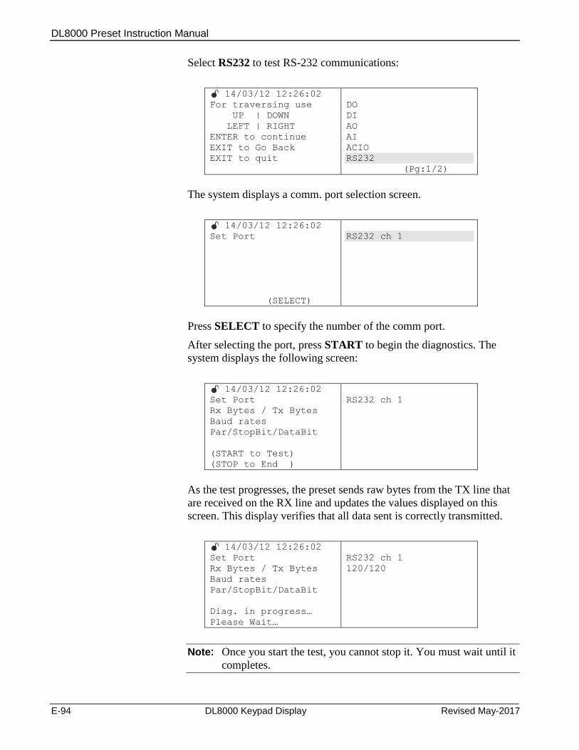
DL8000 Preset Instruction Manual
E-94 DL8000 Keypad Display Revised May-2017
Select RS232 to test RS-232 communications:
14/03/12 12:26:02
For traversing use
UP | DOWN
LEFT | RIGHT
ENTER to continue
EXIT to Go Back
EXIT to quit
DO
DI
AO
AI
ACIO
RS232
(Pg:1/2)
The system displays a comm. port selection screen.
14/03/12 12:26:02
Set Port
(SELECT)
RS232 ch 1
Press SELECT to specify the number of the comm port.
After selecting the port, press START to begin the diagnostics. The
system displays the following screen:
14/03/12 12:26:02
Set Port
Rx Bytes / Tx Bytes
Baud rates
Par/StopBit/DataBit
(START to Test)
(STOP to End )
RS232 ch 1
As the test progresses, the preset sends raw bytes from the TX line that
are received on the RX line and updates the values displayed on this
screen. This display verifies that all data sent is correctly transmitted.
14/03/12 12:26:02
Set Port
Rx Bytes / Tx Bytes
Baud rates
Par/StopBit/DataBit
Diag. in progress…
Please Wait…
RS232 ch 1
120/120
Note: Once you start the test, you cannot stop it. You must wait until it
completes.
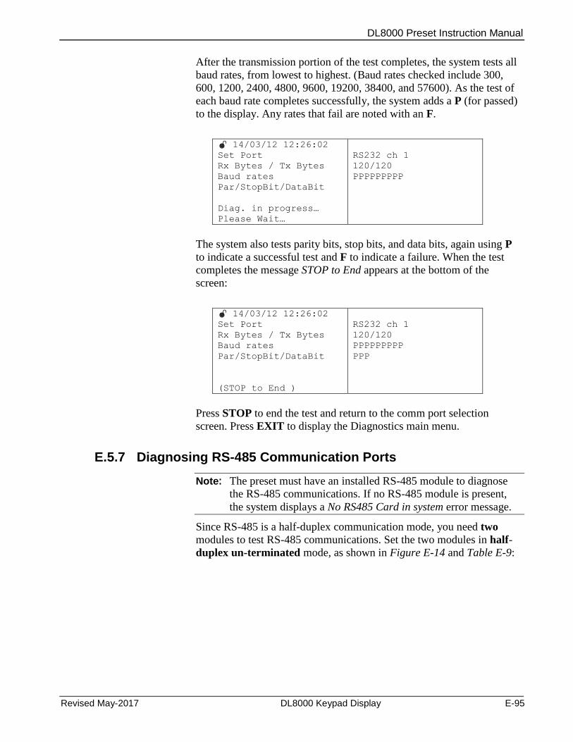
DL8000 Preset Instruction Manual
Revised May-2017 DL8000 Keypad Display E-95
After the transmission portion of the test completes, the system tests all
baud rates, from lowest to highest. (Baud rates checked include 300,
600, 1200, 2400, 4800, 9600, 19200, 38400, and 57600). As the test of
each baud rate completes successfully, the system adds a P (for passed)
to the display. Any rates that fail are noted with an F.
14/03/12 12:26:02
Set Port
Rx Bytes / Tx Bytes
Baud rates
Par/StopBit/DataBit
Diag. in progress…
Please Wait…
RS232 ch 1
120/120
PPPPPPPPP
The system also tests parity bits, stop bits, and data bits, again using P
to indicate a successful test and F to indicate a failure. When the test
completes the message STOP to End appears at the bottom of the
screen:
14/03/12 12:26:02
Set Port
Rx Bytes / Tx Bytes
Baud rates
Par/StopBit/DataBit
(STOP to End )
RS232 ch 1
120/120
PPPPPPPPP
PPP
Press STOP to end the test and return to the comm port selection
screen. Press EXIT to display the Diagnostics main menu.
E.5.7 Diagnosing RS-485 Communication Ports
Note: The preset must have an installed RS-485 module to diagnose
the RS-485 communications. If no RS-485 module is present,
the system displays a No RS485 Card in system error message.
Since RS-485 is a half-duplex communication mode, you need two
modules to test RS-485 communications. Set the two modules in half-
duplex un-terminated mode, as shown in Figure E-14 and Table E-9:
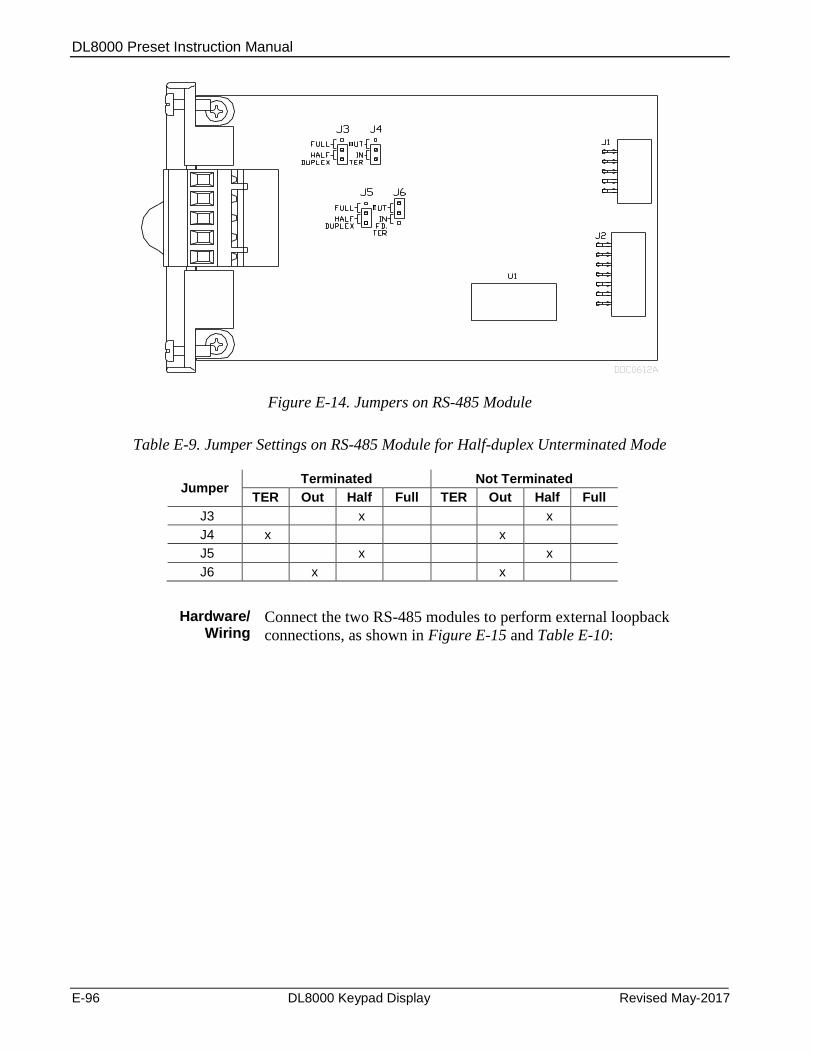
DL8000 Preset Instruction Manual
E-96 DL8000 Keypad Display Revised May-2017
Figure E-14. Jumpers on RS-485 Module
Table E-9. Jumper Settings on RS-485 Module for Half-duplex Unterminated Mode
Jumper Terminated Not Terminated
TER Out Half Full TER Out Half Full
J3 x x
J4 x x
J5 x x
J6 x x
Hardware/ Wiring
Connect the two RS-485 modules to perform external loopback
connections, as shown in Figure E-15 and Table E-10:
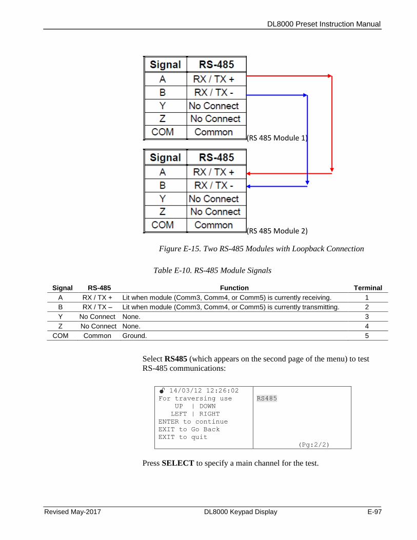
DL8000 Preset Instruction Manual
Revised May-2017 DL8000 Keypad Display E-97
(RS 485 Module 1)
(RS 485 Module 2)
Figure E-15. Two RS-485 Modules with Loopback Connection
Table E-10. RS-485 Module Signals
Signal RS-485 Function Terminal
A RX / TX + Lit when module (Comm3, Comm4, or Comm5) is currently receiving. 1
B RX / TX – Lit when module (Comm3, Comm4, or Comm5) is currently transmitting. 2
Y No Connect None. 3
Z No Connect None. 4
COM Common Ground. 5
Select RS485 (which appears on the second page of the menu) to test
RS-485 communications:
14/03/12 12:26:02
For traversing use
UP | DOWN
LEFT | RIGHT
ENTER to continue
EXIT to Go Back
EXIT to quit
RS485
(Pg:2/2)
Press SELECT to specify a main channel for the test.
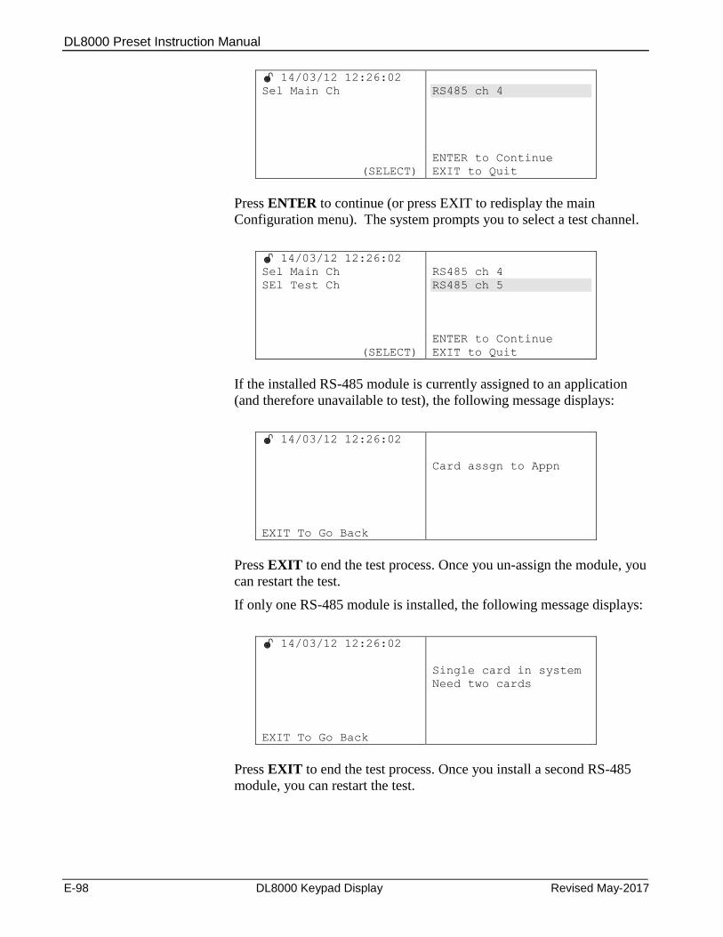
DL8000 Preset Instruction Manual
E-98 DL8000 Keypad Display Revised May-2017
14/03/12 12:26:02
Sel Main Ch
(SELECT)
RS485 ch 4
ENTER to Continue
EXIT to Quit
Press ENTER to continue (or press EXIT to redisplay the main
Configuration menu). The system prompts you to select a test channel.
14/03/12 12:26:02
Sel Main Ch
SEl Test Ch
(SELECT)
RS485 ch 4
RS485 ch 5
ENTER to Continue
EXIT to Quit
If the installed RS-485 module is currently assigned to an application
(and therefore unavailable to test), the following message displays:
14/03/12 12:26:02
EXIT To Go Back
Card assgn to Appn
Press EXIT to end the test process. Once you un-assign the module, you
can restart the test.
If only one RS-485 module is installed, the following message displays:
14/03/12 12:26:02
EXIT To Go Back
Single card in system
Need two cards
Press EXIT to end the test process. Once you install a second RS-485
module, you can restart the test.
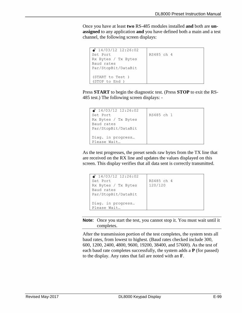
DL8000 Preset Instruction Manual
Revised May-2017 DL8000 Keypad Display E-99
Once you have at least two RS-485 modules installed and both are un-
assigned to any application and you have defined both a main and a test
channel, the following screen displays:
14/03/12 12:26:02
Set Port
Rx Bytes / Tx Bytes
Baud rates
Par/StopBit/DataBit
(START to Test )
(STOP to End )
RS485 ch 4
Press START to begin the diagnostic test. (Press STOP to exit the RS-
485 test.) The following screen displays: -
14/03/12 12:26:02
Set Port
Rx Bytes / Tx Bytes
Baud rates
Par/StopBit/DataBit
Diag. in progress…
Please Wait…
RS485 ch 1
As the test progresses, the preset sends raw bytes from the TX line that
are received on the RX line and updates the values displayed on this
screen. This display verifies that all data sent is correctly transmitted.
14/03/12 12:26:02
Set Port
Rx Bytes / Tx Bytes
Baud rates
Par/StopBit/DataBit
Diag. in progress…
Please Wait…
RS485 ch 4
120/120
Note: Once you start the test, you cannot stop it. You must wait until it
completes.
After the transmission portion of the test completes, the system tests all
baud rates, from lowest to highest. (Baud rates checked include 300,
600, 1200, 2400, 4800, 9600, 19200, 38400, and 57600). As the test of
each baud rate completes successfully, the system adds a P (for passed)
to the display. Any rates that fail are noted with an F.
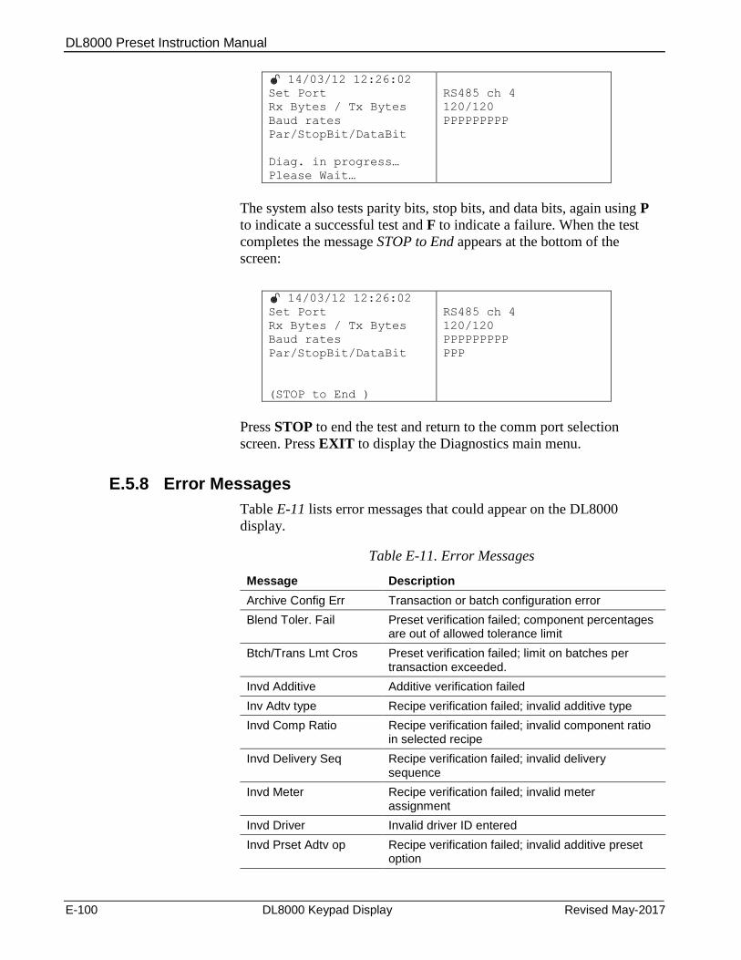
DL8000 Preset Instruction Manual
E-100 DL8000 Keypad Display Revised May-2017
14/03/12 12:26:02
Set Port
Rx Bytes / Tx Bytes
Baud rates
Par/StopBit/DataBit
Diag. in progress…
Please Wait…
RS485 ch 4
120/120
PPPPPPPPP
The system also tests parity bits, stop bits, and data bits, again using P
to indicate a successful test and F to indicate a failure. When the test
completes the message STOP to End appears at the bottom of the
screen:
14/03/12 12:26:02
Set Port
Rx Bytes / Tx Bytes
Baud rates
Par/StopBit/DataBit
(STOP to End )
RS485 ch 4
120/120
PPPPPPPPP
PPP
Press STOP to end the test and return to the comm port selection
screen. Press EXIT to display the Diagnostics main menu.
E.5.8 Error Messages
Table E-11 lists error messages that could appear on the DL8000
display.
Table E-11. Error Messages
Message Description
Archive Config Err Transaction or batch configuration error
Blend Toler. Fail Preset verification failed; component percentages are out of allowed tolerance limit
Btch/Trans Lmt Cros Preset verification failed; limit on batches per transaction exceeded.
Invd Additive Additive verification failed
Inv Adtv type Recipe verification failed; invalid additive type
Invd Comp Ratio Recipe verification failed; invalid component ratio in selected recipe
Invd Delivery Seq Recipe verification failed; invalid delivery sequence
Invd Meter Recipe verification failed; invalid meter assignment
Invd Driver Invalid driver ID entered
Invd Prset Adtv op Recipe verification failed; invalid additive preset option
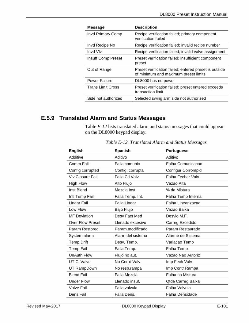
DL8000 Preset Instruction Manual
Revised May-2017 DL8000 Keypad Display E-101
Message Description
Invd Primary Comp Recipe verification failed; primary component verification failed
Invd Recipe No Recipe verification failed; invalid recipe number
Invd Vlv Recipe verification failed; invalid valve assignment
Insuff Comp Preset Preset verification failed; insufficient component preset
Out of Range Preset verification failed; entered preset is outside of minimum and maximum preset limits
Power Failure DL8000 has no power
Trans Limit Cross Preset verification failed; preset entered exceeds transaction limit
Side not authorized Selected swing arm side not authorized
E.5.9 Translated Alarm and Status Messages
Table E-12 lists translated alarm and status messages that could appear
on the DL8000 keypad display.
Table E-12. Translated Alarm and Status Messages
English Spanish Portuguese
Additive Aditivo Aditivo
Comm Fail Falla comunic Falha Comunicacao
Config corrupted Config. corrupta Configur Corrompid
Vlv Closure Fail Falla Ctl Valv Falha Fechar Valv
High Flow Alto Flujo Vazao Alta
Inst Blend Mezcla Inst. % da Mistura
Intl Temp Fail Falla Temp. Int. Falha Temp Interna
Linear Fail Falla Linear Falha Linearizacao
Low Flow Bajo Flujo Vazao Baixa
MF Deviation Desv Fact Med Desvio M.F.
Over Flow Preset Llenado excesivo Carreg Excedido
Param Restored Param.modificado Param Restaurado
System alarm Alarm del sistema Alarme de Sistema
Temp Drift Desv. Temp. Variacao Temp
Temp Fail Falla Temp. Falha Temp
UnAuth Flow Flujo no aut. Vazao Nao Autoriz
UT Cl.Valve No Cerró Valv. Imp Fech Valv
UT RampDown No resp.rampa Imp Contr Rampa
Blend Fail Falla Mezcla Falha na Mistura
Under Flow Llenado insuf. Qtde Carreg Baixa
Valve Fail Falla valvula Falha Valvula
Dens Fail Falla Dens. Falha Densidade
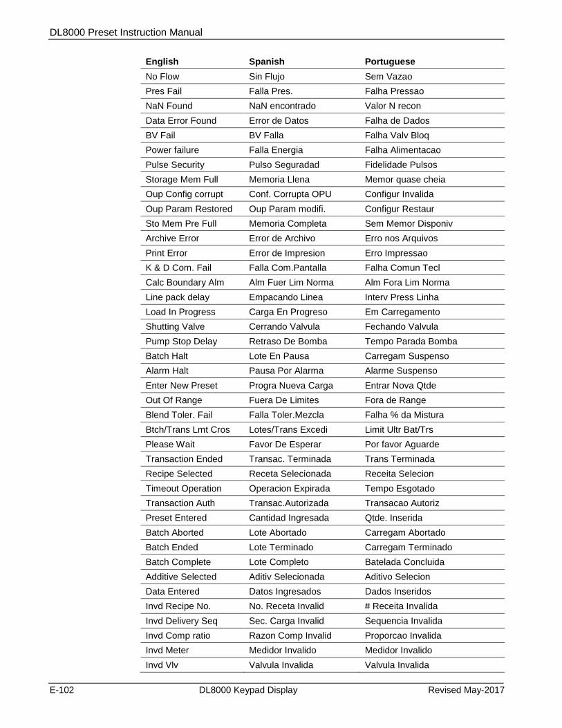
DL8000 Preset Instruction Manual
E-102 DL8000 Keypad Display Revised May-2017
English Spanish Portuguese
No Flow Sin Flujo Sem Vazao
Pres Fail Falla Pres. Falha Pressao
NaN Found NaN encontrado Valor N recon
Data Error Found Error de Datos Falha de Dados
BV Fail BV Falla Falha Valv Bloq
Power failure Falla Energia Falha Alimentacao
Pulse Security Pulso Seguradad Fidelidade Pulsos
Storage Mem Full Memoria Llena Memor quase cheia
Oup Config corrupt Conf. Corrupta OPU Configur Invalida
Oup Param Restored Oup Param modifi. Configur Restaur
Sto Mem Pre Full Memoria Completa Sem Memor Disponiv
Archive Error Error de Archivo Erro nos Arquivos
Print Error Error de Impresion Erro Impressao
K & D Com. Fail Falla Com.Pantalla Falha Comun Tecl
Calc Boundary Alm Alm Fuer Lim Norma Alm Fora Lim Norma
Line pack delay Empacando Linea Interv Press Linha
Load In Progress Carga En Progreso Em Carregamento
Shutting Valve Cerrando Valvula Fechando Valvula
Pump Stop Delay Retraso De Bomba Tempo Parada Bomba
Batch Halt Lote En Pausa Carregam Suspenso
Alarm Halt Pausa Por Alarma Alarme Suspenso
Enter New Preset Progra Nueva Carga Entrar Nova Qtde
Out Of Range Fuera De Limites Fora de Range
Blend Toler. Fail Falla Toler.Mezcla Falha % da Mistura
Btch/Trans Lmt Cros Lotes/Trans Excedi Limit Ultr Bat/Trs
Please Wait Favor De Esperar Por favor Aguarde
Transaction Ended Transac. Terminada Trans Terminada
Recipe Selected Receta Selecionada Receita Selecion
Timeout Operation Operacion Expirada Tempo Esgotado
Transaction Auth Transac.Autorizada Transacao Autoriz
Preset Entered Cantidad Ingresada Qtde. Inserida
Batch Aborted Lote Abortado Carregam Abortado
Batch Ended Lote Terminado Carregam Terminado
Batch Complete Lote Completo Batelada Concluida
Additive Selected Aditiv Selecionada Aditivo Selecion
Data Entered Datos Ingresados Dados Inseridos
Invd Recipe No. No. Receta Invalid # Receita Invalida
Invd Delivery Seq Sec. Carga Invalid Sequencia Invalida
Invd Comp ratio Razon Comp Invalid Proporcao Invalida
Invd Meter Medidor Invalido Medidor Invalido
Invd Vlv Valvula Invalida Valvula Invalida
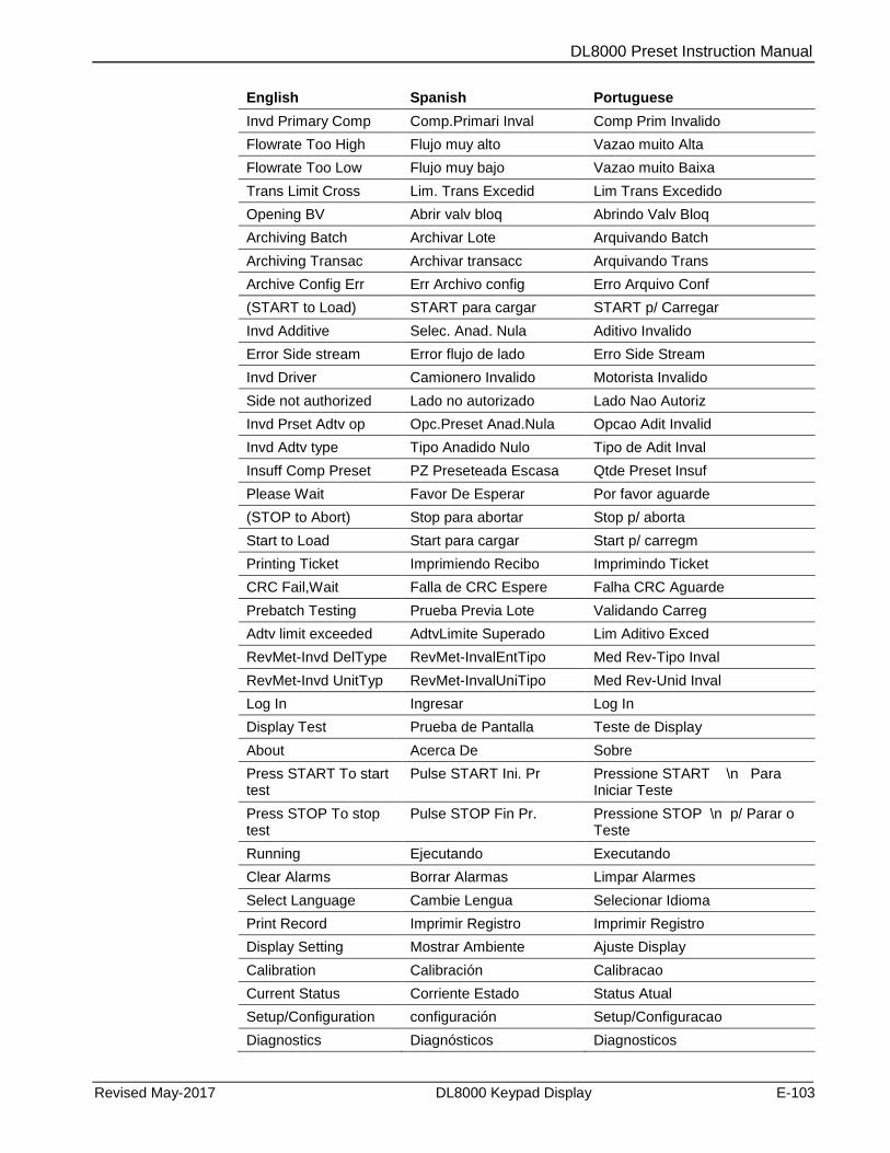
DL8000 Preset Instruction Manual
Revised May-2017 DL8000 Keypad Display E-103
English Spanish Portuguese
Invd Primary Comp Comp.Primari Inval Comp Prim Invalido
Flowrate Too High Flujo muy alto Vazao muito Alta
Flowrate Too Low Flujo muy bajo Vazao muito Baixa
Trans Limit Cross Lim. Trans Excedid Lim Trans Excedido
Opening BV Abrir valv bloq Abrindo Valv Bloq
Archiving Batch Archivar Lote Arquivando Batch
Archiving Transac Archivar transacc Arquivando Trans
Archive Config Err Err Archivo config Erro Arquivo Conf
(START to Load) START para cargar START p/ Carregar
Invd Additive Selec. Anad. Nula Aditivo Invalido
Error Side stream Error flujo de lado Erro Side Stream
Invd Driver Camionero Invalido Motorista Invalido
Side not authorized Lado no autorizado Lado Nao Autoriz
Invd Prset Adtv op Opc.Preset Anad.Nula Opcao Adit Invalid
Invd Adtv type Tipo Anadido Nulo Tipo de Adit Inval
Insuff Comp Preset PZ Preseteada Escasa Qtde Preset Insuf
Please Wait Favor De Esperar Por favor aguarde
(STOP to Abort) Stop para abortar Stop p/ aborta
Start to Load Start para cargar Start p/ carregm
Printing Ticket Imprimiendo Recibo Imprimindo Ticket
CRC Fail,Wait Falla de CRC Espere Falha CRC Aguarde
Prebatch Testing Prueba Previa Lote Validando Carreg
Adtv limit exceeded AdtvLimite Superado Lim Aditivo Exced
RevMet-Invd DelType RevMet-InvalEntTipo Med Rev-Tipo Inval
RevMet-Invd UnitTyp RevMet-InvalUniTipo Med Rev-Unid Inval
Log In Ingresar Log In
Display Test Prueba de Pantalla Teste de Display
About Acerca De Sobre
Press START To start test
Pulse START Ini. Pr Pressione START \n Para Iniciar Teste
Press STOP To stop test
Pulse STOP Fin Pr. Pressione STOP \n p/ Parar o Teste
Running Ejecutando Executando
Clear Alarms Borrar Alarmas Limpar Alarmes
Select Language Cambie Lengua Selecionar Idioma
Print Record Imprimir Registro Imprimir Registro
Display Setting Mostrar Ambiente Ajuste Display
Calibration Calibración Calibracao
Current Status Corriente Estado Status Atual
Setup/Configuration configuración Setup/Configuracao
Diagnostics Diagnósticos Diagnosticos
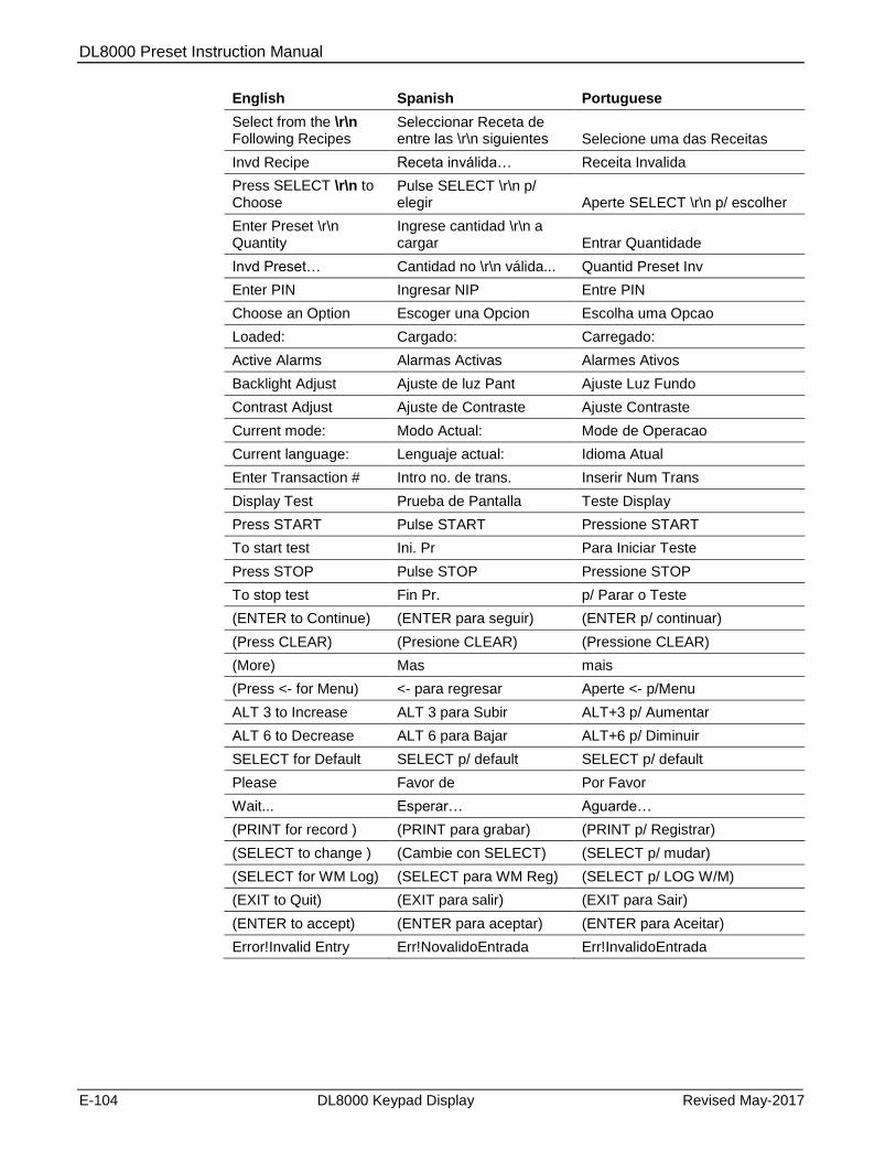
DL8000 Preset Instruction Manual
E-104 DL8000 Keypad Display Revised May-2017
English Spanish Portuguese
Select from the \r\n Following Recipes
Seleccionar Receta de entre las \r\n siguientes Selecione uma das Receitas
Invd Recipe Receta inválida… Receita Invalida
Press SELECT \r\n to Choose
Pulse SELECT \r\n p/ elegir Aperte SELECT \r\n p/ escolher
Enter Preset \r\n Quantity
Ingrese cantidad \r\n a cargar Entrar Quantidade
Invd Preset… Cantidad no \r\n válida... Quantid Preset Inv
Enter PIN Ingresar NIP Entre PIN
Choose an Option Escoger una Opcion Escolha uma Opcao
Loaded: Cargado: Carregado:
Active Alarms Alarmas Activas Alarmes Ativos
Backlight Adjust Ajuste de luz Pant Ajuste Luz Fundo
Contrast Adjust Ajuste de Contraste Ajuste Contraste
Current mode: Modo Actual: Mode de Operacao
Current language: Lenguaje actual: Idioma Atual
Enter Transaction # Intro no. de trans. Inserir Num Trans
Display Test Prueba de Pantalla Teste Display
Press START Pulse START Pressione START
To start test Ini. Pr Para Iniciar Teste
Press STOP Pulse STOP Pressione STOP
To stop test Fin Pr. p/ Parar o Teste
(ENTER to Continue) (ENTER para seguir) (ENTER p/ continuar)
(Press CLEAR) (Presione CLEAR) (Pressione CLEAR)
(More) Mas mais
(Press <- for Menu) <- para regresar Aperte <- p/Menu
ALT 3 to Increase ALT 3 para Subir ALT+3 p/ Aumentar
ALT 6 to Decrease ALT 6 para Bajar ALT+6 p/ Diminuir
SELECT for Default SELECT p/ default SELECT p/ default
Please Favor de Por Favor
Wait... Esperar… Aguarde…
(PRINT for record ) (PRINT para grabar) (PRINT p/ Registrar)
(SELECT to change ) (Cambie con SELECT) (SELECT p/ mudar)
(SELECT for WM Log) (SELECT para WM Reg) (SELECT p/ LOG W/M)
(EXIT to Quit) (EXIT para salir) (EXIT para Sair)
(ENTER to accept) (ENTER para aceptar) (ENTER para Aceitar)
Error!Invalid Entry Err!NovalidoEntrada Err!InvalidoEntrada
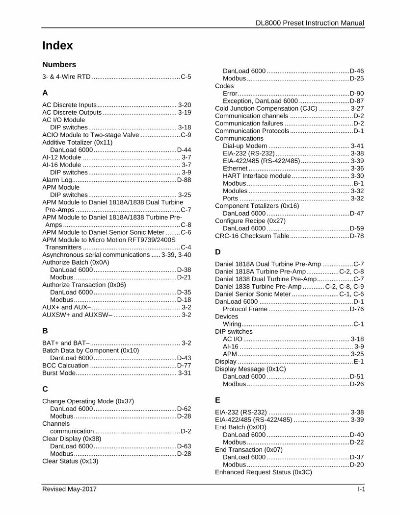
DL8000 Preset Instruction Manual
Revised May-2017 I-1
Index
Numbers
3- & 4-Wire RTD ................................................. C-5
A
AC Discrete Inputs ............................................ 3-20 AC Discrete Outputs ......................................... 3-19 AC I/O Module
DIP switches ................................................. 3-18 ACIO Module to Two-stage Valve ...................... C-9 Additive Totalizer (0x11)
DanLoad 6000 .............................................. D-44 AI-12 Module ...................................................... 3-7 AI-16 Module ...................................................... 3-7
DIP switches ................................................... 3-9 Alarm Log.......................................................... D-88 APM Module
DIP switches ................................................. 3-25 APM Module to Daniel 1818A/1838 Dual Turbine Pre-Amps .......................................................... C-7
APM Module to Daniel 1818A/1838 Turbine Pre-Amps ................................................................. C-8
APM Module to Daniel Senior Sonic Meter ........ C-6 APM Module to Micro Motion RFT9739/2400S Transmitters ...................................................... C-4
Asynchronous serial communications ..... 3-39, 3-40 Authorize Batch (0x0A)
DanLoad 6000 .............................................. D-38 Modbus ......................................................... D-21
Authorize Transaction (0x06) DanLoad 6000 .............................................. D-35 Modbus ......................................................... D-18
AUX+ and AUX– ................................................. 3-2 AUXSW+ and AUXSW– ..................................... 3-2
B
BAT+ and BAT– .................................................. 3-2 Batch Data by Component (0x10)
DanLoad 6000 .............................................. D-43 BCC Calcuation ................................................ D-77 Burst Mode........................................................ 3-31
C
Change Operating Mode (0x37) DanLoad 6000 .............................................. D-62 Modbus ......................................................... D-28
Channels communication ............................................... D-2
Clear Display (0x38) DanLoad 6000 .............................................. D-63 Modbus ......................................................... D-28
Clear Status (0x13)
DanLoad 6000 .............................................. D-46 Modbus ......................................................... D-25
Codes Error .............................................................. D-90 Exception, DanLoad 6000 ............................ D-87
Cold Junction Compensation (CJC) ................. 3-27 Communication channels ................................... D-2 Communication failures ...................................... D-2 Communication Protocols ................................... D-1 Communications
Dial-up Modem ............................................. 3-41 EIA-232 (RS-232) ......................................... 3-38 EIA-422/485 (RS-422/485) ........................... 3-39 Ethernet ........................................................ 3-36 HART Interface module ................................ 3-30 Modbus ........................................................... B-1 Modules ........................................................ 3-32 Ports ............................................................. 3-32
Component Totalizers (0x16) DanLoad 6000 .............................................. D-47
Configure Recipe (0x27) DanLoad 6000 .............................................. D-59
CRC-16 Checksum Table ................................. D-78
D
Daniel 1818A Dual Turbine Pre-Amp ................. C-7 Daniel 1818A Turbine Pre-Amp .................. C-2, C-8 Daniel 1838 Dual Turbine Pre-Amp .................... C-7 Daniel 1838 Turbine Pre-Amp ............ C-2, C-8, C-9 Daniel Senior Sonic Meter .......................... C-1, C-6 DanLoad 6000 .................................................... D-1
Protocol Frame ............................................. D-76 Devices
Wiring .............................................................. C-1 DIP switches
AC I/O ........................................................... 3-18 AI-16 ............................................................... 3-9 APM .............................................................. 3-25
Display ................................................................ E-1 Display Message (0x1C)
DanLoad 6000 .............................................. D-51 Modbus ......................................................... D-26
E
EIA-232 (RS-232) ............................................. 3-38 EIA-422/485 (RS-422/485) ............................... 3-39 End Batch (0x0D)
DanLoad 6000 .............................................. D-40 Modbus ......................................................... D-22
End Transaction (0x07) DanLoad 6000 .............................................. D-37 Modbus ......................................................... D-20
Enhanced Request Status (0x3C)
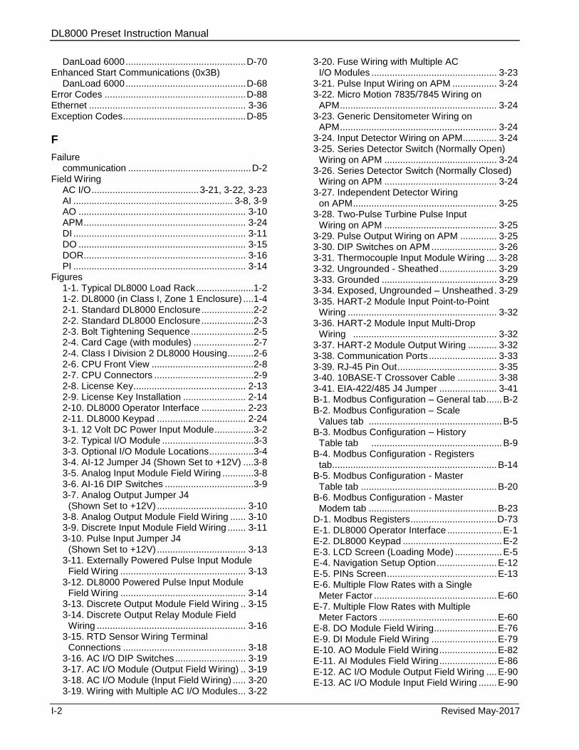
DL8000 Preset Instruction Manual
I-2 Revised May-2017
DanLoad 6000 .............................................. D-70 Enhanced Start Communications (0x3B)
DanLoad 6000 .............................................. D-68 Error Codes ...................................................... D-88 Ethernet ............................................................ 3-36 Exception Codes ............................................... D-85
F
Failure communication ............................................... D-2
Field Wiring AC I/O ......................................... 3-21, 3-22, 3-23 AI ............................................................. 3-8, 3-9 AO ................................................................ 3-10 APM .............................................................. 3-24 DI .................................................................. 3-11 DO ................................................................ 3-15 DOR .............................................................. 3-16 PI .................................................................. 3-14
Figures 1-1. Typical DL8000 Load Rack ......................1-2 1-2. DL8000 (in Class I, Zone 1 Enclosure) ....1-4 2-1. Standard DL8000 Enclosure ....................2-2 2-2. Standard DL8000 Enclosure ....................2-3 2-3. Bolt Tightening Sequence ........................2-5 2-4. Card Cage (with modules) .......................2-7 2-4. Class I Division 2 DL8000 Housing ..........2-6 2-6. CPU Front View .......................................2-8 2-7. CPU Connectors ......................................2-9 2-8. License Key ........................................... 2-13 2-9. License Key Installation ........................ 2-14 2-10. DL8000 Operator Interface ................. 2-23 2-11. DL8000 Keypad .................................. 2-24 3-1. 12 Volt DC Power Input Module ...............3-2 3-2. Typical I/O Module ...................................3-3 3-3. Optional I/O Module Locations .................3-4 3-4. AI-12 Jumper J4 (Shown Set to +12V) ....3-8 3-5. Analog Input Module Field Wiring ............3-8 3-6. AI-16 DIP Switches ..................................3-9 3-7. Analog Output Jumper J4
(Shown Set to +12V) .................................. 3-10 3-8. Analog Output Module Field Wiring ...... 3-10 3-9. Discrete Input Module Field Wiring ....... 3-11 3-10. Pulse Input Jumper J4
(Shown Set to +12V) .................................. 3-13 3-11. Externally Powered Pulse Input Module
Field Wiring ................................................ 3-13 3-12. DL8000 Powered Pulse Input Module
Field Wiring ................................................ 3-14 3-13. Discrete Output Module Field Wiring .. 3-15 3-14. Discrete Output Relay Module Field
Wiring ......................................................... 3-16 3-15. RTD Sensor Wiring Terminal
Connections ............................................... 3-18 3-16. AC I/O DIP Switches ........................... 3-19 3-17. AC I/O Module (Output Field Wiring) .. 3-19 3-18. AC I/O Module (Input Field Wiring) ..... 3-20 3-19. Wiring with Multiple AC I/O Modules... 3-22
3-20. Fuse Wiring with Multiple AC I/O Modules ................................................ 3-23
3-21. Pulse Input Wiring on APM ................. 3-24 3-22. Micro Motion 7835/7845 Wiring on
APM ............................................................ 3-24 3-23. Generic Densitometer Wiring on
APM ............................................................ 3-24 3-24. Input Detector Wiring on APM ............. 3-24 3-25. Series Detector Switch (Normally Open)
Wiring on APM ........................................... 3-24 3-26. Series Detector Switch (Normally Closed)
Wiring on APM ........................................... 3-24 3-27. Independent Detector Wiring
on APM ....................................................... 3-25 3-28. Two-Pulse Turbine Pulse Input
Wiring on APM ........................................... 3-25 3-29. Pulse Output Wiring on APM .............. 3-25 3-30. DIP Switches on APM ......................... 3-26 3-31. Thermocouple Input Module Wiring .... 3-28 3-32. Ungrounded - Sheathed ...................... 3-29 3-33. Grounded ............................................ 3-29 3-34. Exposed, Ungrounded – Unsheathed . 3-29 3-35. HART-2 Module Input Point-to-Point
Wiring ......................................................... 3-32 3-36. HART-2 Module Input Multi-Drop
Wiring ....................................................... 3-32 3-37. HART-2 Module Output Wiring ........... 3-32 3-38. Communication Ports .......................... 3-33 3-39. RJ-45 Pin Out ...................................... 3-35 3-40. 10BASE-T Crossover Cable ............... 3-38 3-41. EIA-422/485 J4 Jumper ...................... 3-41 B-1. Modbus Configuration – General tab ...... B-2 B-2. Modbus Configuration – Scale
Values tab ................................................... B-5 B-3. Modbus Configuration – History
Table tab .................................................. B-9 B-4. Modbus Configuration - Registers
tab............................................................... B-14 B-5. Modbus Configuration - Master
Table tab .................................................... B-20 B-6. Modbus Configuration - Master
Modem tab ................................................. B-23 D-1. Modbus Registers ................................. D-73 E-1. DL8000 Operator Interface ..................... E-1 E-2. DL8000 Keypad ...................................... E-2 E-3. LCD Screen (Loading Mode) .................. E-5 E-4. Navigation Setup Option ....................... E-12 E-5. PINs Screen .......................................... E-13 E-6. Multiple Flow Rates with a Single
Meter Factor ............................................... E-60 E-7. Multiple Flow Rates with Multiple
Meter Factors ............................................. E-60 E-8. DO Module Field Wiring ........................ E-76 E-9. DI Module Field Wiring ......................... E-79 E-10. AO Module Field Wiring ...................... E-82 E-11. AI Modules Field Wiring ...................... E-86 E-12. AC I/O Module Output Field Wiring .... E-90 E-13. AC I/O Module Input Field Wiring ....... E-90
DL8000 Preset Instruction Manual
Revised May-2017 I-3
E-14. Jumpers on RS-485 Module ............... E-96 E-15. Two RS-485 Modules with Loopback
Connection ................................................. E-97
G
Get Date and Time (0x28) DanLoad 6000 .............................................. D-60
Glossary .............................................................. A-1
H
HART module ................................................... 3-30 HART Pass-Through license key ..................... 3-30 HMI
Ratio blending............................................... B-25 Sequential blending ...................................... B-24
I
I/O Module .......................................................... 3-3 I/O modules
Specifications ............................................... 3-43 Thermocouple Inputs .................................... 3-27
Initialize Transaction Storage (0x20) DanLoad 6000 .............................................. D-55
Input Multi-drop wiring HART-2 module ............................................ 3-32
Input Point to Point wiring HART-2 module ............................................ 3-32
J
Jumpers EIA-422/485 (RS-422/485) ........................... 3-40
K
Keypad ................................................................ E-1
L
Last Key Pressed (0x31) DanLoad 6000 .............................................. D-61
Local Operator Interface (LOI) .......................... 3-35 Logs
Alarm ............................................................ D-88 LOI
Using ............................................................ 3-36
M
Mapping Modbus Registers .............................. D-73 Meter Totalizers (0x15)
DanLoad 6000 .............................................. D-47 Micro Motion 1700/2700 Transmitter ................ C-10 Micro Motion 2400S Transmitter................. C-3, C-4 Micro Motion RFT9739 Transmitter ............ C-3, C-4 Modbus ............................................................... B-1
Communications Ports ................................... B-1
Modbus Protocol ................................................. D-1 Modbus Registers
Mapping ........................................................ D-73 Modules .............................................................. 3-1
AC I/O ........................................................... 3-18 AI-12 ............................................................... 3-7 AI-16 ............................................................... 3-7 AO ................................................................... 3-9 APM .............................................................. 3-23 DI .................................................................. 3-10 Dial-up Modem ............................................. 3-41 DO ................................................................ 3-14 DOR .............................................................. 3-15 EIA-422/485 (RS-422/485) ........................... 3-39 I/O ................................................................... 3-3 Installing.......................................................... 3-6 PI .................................................................. 3-12 Power Input .................................................... 3-1 Removing........................................................ 3-7 RTD .............................................................. 3-17 Wiring .............................................................. 3-7
Monitoring codes Ratio blending ............................................... B-25 Sequential blending ...................................... B-24
Multiple AC I/O Modules Wiring ............................................................ 3-21
O
Output wiring HART-2 module ............................................ 3-32
Overfill Protection ................................................ 1-3
P
PI Module to Daniel 1818A/1838 Turbine Pre-Amps .......................................................... C-2
PI Module to Daniel Senior Sonic Meter ............. C-1 PI Module to Micro Motion 1700/2700 Transmitter ...................................................... C-10
PI Module to Micro Motion RFT9739/2400S Transmitters ...................................................... C-3
Port Local (LOI) .................................................... 3-35
Power Input Module ............................................ 3-1 Prompt Additives (0x03)
DanLoad 6000 .............................................. D-33 Modbus ......................................................... D-17
Prompt Preset Volume (0x08) DanLoad 6000 .............................................. D-37 Modbus ......................................................... D-20
Prompt Recipe (0x01) DanLoad 6000 .............................................. D-32 Modbus ......................................................... D-16
Protocol Commands DanLoad 6000
Additive Totalizer (0x11) .......................... D-44 Authorize Batch (0x0A) ............................ D-38 Authorize Transaction (0x06) ................... D-35

DL8000 Preset Instruction Manual
I-4 Revised May-2017
Batch Data by Component (0x10) ........... D-43 Change Operating Mode (0x37) .............. D-62 Clear Display (0x38) ................................ D-63 Clear Status (0x13) .................................. D-46 Component Totalizers (0x16)................... D-47 Configure Recipe (0x27) .......................... D-59 Display Message (0x1C) .......................... D-51 End Batch (0x0D) ..................................... D-40 End Transaction (0x07) ............................ D-37 Enhanced Request Status (0x3C) ........... D-70 Enhanced Start Communications (0x3B) . D-68 Get Date and Time (0x28) ....................... D-60 Initialize Transaction Storage (0x20) ....... D-55 Last Key Pressed (0x31) .......................... D-61 Meter Totalizers (0x15) ............................ D-47 Prompt Additives (0x03) ........................... D-33 Prompt Preset Volume (0x08) .................. D-37 Prompt Recipe (0x01) .............................. D-32 Report Alarm (0x3D) ................................ D-72 Request Command Value (0x1A) ............ D-49 Request Firmware Version (0x2A) ........... D-60 Request Keypad Data (0x1D) .................. D-52 Request Meter Values (0x19) .................. D-48 Request Power Fail Date and Time (0x1B) . D-
50 Request Preset Volume (0x09) ................ D-38 Request Program Code Values and Attributes
(0x22) ................................................... D-57 Request Selected Additives (0x04) .......... D-34 Request Selected Recipe (0x02) ............. D-32 Request Status (0x12) ............................. D-44 Request Stored Batch (0x3A) .................. D-65 Request Stored Transaction (0x39) ......... D-63 Request Transaction Storage
Status (0x1E) ....................................... D-53 Reset Primary Alarms (0x14) ................... D-46 Reset Unit (0x30) ..................................... D-61 Set Date and Time (0x29) ........................ D-60 Set Densities/Gravities (0x0B) ................. D-40 Set Program Code Value (0x23) .............. D-58 Start Communication (0x21) .................... D-56 Start/Restart Batch (0x0E) ....................... D-41 Step Batch (0x0F) .................................... D-42 Swing Arm Side (0x33) ............................ D-61 Timeout Operation (0x05) ........................ D-34 Transaction Data by Component (0x1F) .. D-54 Unauthorized Flow (0x17) ........................ D-48 Weights & Measures Switch (0x36) ......... D-62
Modbus Authorize Batch (0x0A) ............................ D-21 Authorize Transaction (0x06) ................... D-18 Change Operating Mode (0x37) .............. D-28 Clear Display (0x38) ................................ D-28 Clear Status (0x13) .................................. D-25 Display Message (0x1C) .......................... D-26 End Batch (0x0D) ..................................... D-22 End Transaction (0x07) ............................ D-20 Prompt Additives (0x03) ........................... D-17
Prompt Preset Volume (0x08) .................. D-20 Prompt Recipe (0x01) .............................. D-16 Report Alarm (0x3D) ................................ D-29 Reset Primary Alarms (0x14) ................... D-25 Reset Unit (0x30) ..................................... D-28 Start/Restart Batch (0x0E) ....................... D-23 Stop Batch (0x0F) .................................... D-24 Timeout Operation (0x05) ........................ D-18
Set Date and Time (0x29) ............................ D-27 Protocol Frame
DanLoad 6000 .............................................. D-76 Protocols
Communication ............................................... D-1
R
Report Alarm (0x3D) DanLoad 6000 .............................................. D-72 Modbus ......................................................... D-29
Request Command Value (0x1A) DanLoad 6000 .............................................. D-49
Request Firmware Version (0x2A) DanLoad 6000 .............................................. D-60
Request Keypad Data (0x1D) DanLoad 6000 .............................................. D-52
Request Meter Values (0x19) DanLoad 6000 .............................................. D-48
Request Power Fail Date and Time (0x1B) DanLoad 6000 .............................................. D-50
Request Preset Volume (0x09) DanLoad 6000 .............................................. D-38
Request Program Code Values and Attributes (0x22) DanLoad 6000 ..................... D-57
Request Selected Additives (0x04) DanLoad 6000 .............................................. D-34
Request Selected Recipe (0x02) DanLoad 6000 .............................................. D-32
Request Status (0x12) DanLoad 6000 .............................................. D-44
Request Stored Batch (0x3A) DanLoad 6000 .............................................. D-65
Request Stored Transaction (0x39) DanLoad 6000 .............................................. D-63
Request Transaction Storage Status (0x1E) DanLoad 6000 .............................................. D-53
Reset Primary Alarms (0x14) DanLoad 6000 .............................................. D-46 Modbus ......................................................... D-25
Reset Unit (0x30) DanLoad 6000 .............................................. D-61 Modbus ......................................................... D-28
RS-232 (EIA-232) ............................................. 3-38 RS-422/485 (EIA-422/485) ............................... 3-39 RTD Module to 3-/4-Wire RTD ........................... C-5
S
Serial communications ............................. 3-39, 3-41 Set Date and Time (0x29)
DL8000 Preset Instruction Manual
Revised May-2017 I-5
DanLoad 6000 .............................................. D-60 Modbus ......................................................... D-27
Set Densities/Gravities (0x0B) DanLoad 6000 .............................................. D-40
Set Program Code Value (0x23) DanLoad 6000 .............................................. D-58
Settings Jumpers & Termination Resistors
(EIA-422/485) ............................................. 3-40 Solar Panel ......................................................... 3-2 Specifications
I/O modules .................................................. 3-43 Start Communication (0x21)
DanLoad 6000 .............................................. D-56 Start/Restart Batch (0x0E)
DanLoad 6000 .............................................. D-41 Modbus ......................................................... D-23
Status flags ............................................... D-7, D-14 Status Flags Descriptions ................................. D-80 Stop Batch (0x0F)
DanLoad 6000 .............................................. D-42 Modbus ......................................................... D-24
Swing Arm Side (0x33) DanLoad 6000 .............................................. D-61
T
Tables 2-1. CPU Connector Locations ....................... 2-9 2-2. STATUS LED Functions ....................... 2-10 3-1. 12 Volt DC Power Input Terminal Block
Connections ................................................. 3-3 3-2. 12 Volt DC Power Input Module .............. 3-3 3-3. RTD Signal Routing .............................. 3-17 3-4. RTD Wiring ............................................ 3-18 3-5. Field Wiring Terminals .......................... 3-20 3-6. APM DIP Switch Settings ...................... 3-26 3-7. Built-in Communications and Optional
Communctions Modules ............................. 3-33 3-8. Communication LED Indicator Definitions 3-
34 3-9. Built-in LOI EIA-232 Signal Routing ...... 3-35 3-10. RJ-45 to EIA-232 (RS-232) Null-modem
Cable Signal Routing ................................. 3-36 3-11. Ethernet Signal .................................... 3-37 3-12. Built-in EIA-232 (RS-232) Signal Routing –
Comm2 ....................................................... 3-39 3-13. EIA-232 (RS-232) Communication Module
Signal Routing – Comm3, Comm4, and Comm5 ....................................................... 3-39
3-14. EIA-422 (RS-422) Signal Routing – Comm3, Comm4, and Comm5 .................. 3-40
3-15. EIA-485 (RS-485) Signal Routing – Comm3, Comm4, and Comm5 .................. 3-40
3-16. EIA-422 (RS-422) Module ................... 3-41 3-17. EIA-485 (RS-485) Module ................... 3-41 3-18. RJ-11 Field Connections ..................... 3-42 3-19. Modem Signal Routing – Comm3,
Comm4, and Comm5 ................................. 3-42
3-20. I/O Module Technical Specification ..... 3-43 B-1. RTU Message Framing ........................... B-3 B-2. ASCII Message Framing ......................... B-3 B-3. Modbus History, Event, and Alarm
Functionality ................................................. B-7 B-4. Modbus Events & Alarms Log
Contents ..................................................... B-12 B-5. Events & Alarm Change Bit Map
Contents ..................................................... B-12 B-6. Modbus Conversion Codes .................. B-17 B-7. Modbus Function Codes ....................... B-19 B-8. Sequential Blending Status Codes ....... B-24 B-9. Ratio Blending ....................................... B-25 D-1. Modbus Executable Commands ........... D-15 D-2. DanLoad 6000 Commands ................... D-30 D-3. CRC-16 Checksum ............................... D-78 D-4. Status Flag Descriptions ....................... D-80 D-5. Exception Codes ................................... D-85 D-6. New/Unused DanLoad 6000 Exception
Codes ......................................................... D-87 D-7. Alarm Logs ............................................ D-88 D-8. Error Codes .......................................... D-90 E-1. Key Functions ......................................... E-3 E-2. LED Indicators ........................................ E-4 E-3. Loading Screen Status Messages .......... E-9 E-4. Net Totalizers ........................................ E-11 E-5. Preset Parameter Descriptions ............. E-11 E-6. TLPs in Current Status Menus .............. E-17 E-7. Menus & Submenus in
Setup/Configuration .................................... E-26 E-8. Parameters and TLPs in
Setups/Configuration Menus ...................... E-27 E-9. Jumper Settings on RS-485 Module for
Half-duplex Unterminated Mode................. E-96 E-10. RS-485 Module Signals ...................... E-97 E-11. Error Messages ................................. E-100 E-12. Translated Alarm and Status
Messages ................................................. E-101 Temperature Detector
See Thermocouple Inputs ............................ 3-27 Terminology ........................................................ A-1 Thermocouple Inputs ........................................ 3-27 Timeout Operation (0x05)
DanLoad 6000 .............................................. D-34 Modbus ......................................................... D-18
Transaction Data by Component (0x1F) DanLoad 6000 .............................................. D-54
Two-stage Valve ................................................. C-9 Typical Load Rack .............................................. 1-2
U
Unauthorized Flow (0x17) DanLoad 6000 .............................................. D-48
Unused DanLoad6000 Exception codes .......... D-87 User Interface ..................................................... E-1

DL8000 Preset Instruction Manual
I-6 Revised May-2017
V
Voltage .................................................................3-1
W
Weights & Measures Switch (0x36) DanLoad 6000 .............................................. D-62
Wiring .................................................................. C-1 3- and 4-Wire RTD ......................................... C-5
Communication modules .............................. 3-34 Daniel Dual Turbine Pre-Amp ........................ C-7 Daniel Senior Sonic Meter ...................... C-1, C-6 Daniel Turbine Pre-Amp ......................... C-2, C-8 Micro Motion 1700/2700 Transmitter............ C-10 Micro Motion Transmitters ...................... C-3, C-4 Multiple AC I/O Modules ............................... 3-21 Two-stage Valve ............................................. C-9

DL8000 Preset Instruction Manual
Revised May-2017 I-7
[This page is intentionally left blank.]

DL8000 Preset Instruction Manual
For customer service and technical support, visit www.EmersonProcess.com/Remote/Support.
Global Headquarters, North America, and Latin America:
Emerson Automation Solutions Remote Automation Solutions 6005 Rogerdale Road Houston, TX 77072 U.S.A. T +1 281 879 2699 | F +1 281 988 4445 www.EmersonProcess.com/Remote
© 2014–2017 Remote Automation Solutions, a business unit of Emerson Automation Solutions. All rights reserved.
This publication is for informational purposes only. While every effort has been made to ensure accuracy, this publication shall not be read to include any warranty or guarantee, express or implied, including as regards the products or services described or their use or applicability. Remote Automation Solutions (RAS) reserves the right to modify or improve the designs or specifications of its products at any time without notice. All sales are governed by RAS terms and conditions which are available upon request. RAS accepts no responsibility for proper selection, use or maintenance of any product, which remains solely with the purchaser and/or end-user.
Europe: Emerson Automation Solutions Remote Automation Solutions Unit 8, Waterfront Business Park Dudley Road, Brierley Hill Dudley UK DY5 1LX T +44 1384 487200 | F +44 1384 487258
Middle East/Africa: Emerson Automation Solutions Remote Automation Solutions Emerson FZE P.O. Box 17033 Jebel Ali Free Zone – South 2 Dubai U.A.E. T +971 4 8118100 | F +971 4 8865465
Asia-Pacific: Emerson Automation Solutions Remote Automation Solutions 1 Pandan Crescent Singapore 128461 T +65 6777 8211| F +65 6777 0947
Remote Automation Solutions