d4.1 smart buildings scenario definition v1 - finseny · finseny d4.1 v1 page 1 (112)...
TRANSCRIPT

FINSENY D4.1 v1
Page 1 (112)
FI.ICT-2011-285135 FINSENY
D4.1 v1
Smart Buildings “scenario” definition
Contractual Date of Delivery to the CEC: 31th July 2011
Actual Date of Delivery to the CEC: 11st August 2011
Author(s): ACCIONA
Participant(s): Orange, SYNELIXIS, TI, ABBDE, TID, Grenoble INP
Workpackage: WP4 – Smart Buildings
Estimated person months: 15
Security: PU Nature: R
Version: 1
Total number of pages: 112
Abstract: This document is the first deliverable of the WP4 “Smart buildings” work package and reflects the work done in task 4.1 “Scenario Evaluation (System perimeter definition and general energy-related requirements)”. This work is a first step in order to synthesize the huge scope of the building domain in a set of use cases that can be further elaborated in order to elicit ICT requirements for a functional ICT architecture for Smart Buildings. The building domain is segmented in this document in different building typologies, for each of which the perimeter of the system, the external actors involved, the most relevant use cases and the relationships among all of them are described through UML use case diagrams.
The detailed definition of these use cases has been elaborated using inputs from the background expertise in previous projects of the partners participating in the task, and they have been homogenized using a common template derived from the one used for use cases description in the Intelligrid initiative.
Keyword list:
Smart energy, requirement identification, architecture development, FI-PPP, use cases, smart buildings, homes, offices, residential, data centre, hotels.
Disclaimer:
Not applicable

FINSENY D4.1 v1
Page 2 (112)
FINSENY D4.1 v1
Page 3 (112)
Executive Summary This deliverable aims to define the scope of the smart buildings domain, analysing different buildings typologies (smart homes, residential buildings, office buildings, data centres and hotels, also called scenarios in the context of this document) as holistic systems that encompass all the physical components of the building. For this analysis use cases are defined which deals with energy-related functions of the building which need the support of ICT systems. Use cases across the different scenarios defined share a set of common external actors, namely external and internal environment, organizations such as energy service companies or facility staff, and external entities such as electric utilities or the microgrid where the building might be inserted; while others actors are specific for each scenario.
For the analysis of scenarios the use case method is used, which is appropriate for the definition of the functionalities and targets of a system without actually saying how the system should accomplish its tasks. Use cases are described avoiding specification of ICT equipment and using the terminology of the smart energy domain. The perimeter of the system, together with the use cases and the actors, is depicted for each scenario in UML use case diagrams.
Smart homes scenario considers both isolated houses as well as individual apartments. Although certain smart home dwellers are environmentally conscious and therefore willing to monitor their energy consumption, solutions should take into account that majority of home dwellers will not adopt such behaviour, unless they are given services for optimizing primary energy use while maintaining the same level of energy service.
The residential buildings scenario considers as target system the building shell and common areas of residential buildings, excluding individual apartments/dwellings, which are targeted by the smart home scenario. Probably the main specificities of this scenario is that costs are mostly shared among multiple owners, which may encourage waste; larger size may enable technologies that are not cost-effective at the smart home level; and look and feel of the ICT solutions at building level is not as important a requirement as it may be at the level of individual dwellings.
Office buildings normally differentiate themselves from other scenarios in the limited control that is left to the end users (namely office workers) over the main energy-hungry subsystems of the buildings, such as HVAC systems. This means that important energy savings can be achieved through centralized energy strategies. However, office workers still retain certain control over some devices, and therefore have an impact on the global energy consumption of the building, therefore this scenario includes both use cases related to global energy management of the building and use cases oriented to raising energy awareness and promoting energy efficiency strategies of end users.
Data centres scenario is considered here as a special category within the industrial buildings domain, characterized by highly efficient and carefully optimized centres with increasing server density and capacity. Optimization of productivity per watt in order to reduce total costs of ownership involves the necessity to monitor and manage power consumption at different levels, such as rack, zone or the whole data centre.
Hotel buildings scenario, mainly focused on large hotels, is closely related to residential buildings, with the difference that hotel guests pay a fixed amount of money for a certain level of comfort, and can use as much energy as they may require. Therefore energy efficiency measures such as load shedding must take into account these restrictions and never decrease the level of comfort. Energy management will be based on the definition of a set of performance criteria (KPIs) by the hotel management.

FINSENY D4.1 v1
Page 4 (112)
Authors
Partner Name e-mail
ABB DE Igor Schitkow [email protected] ACCIONA José Luis Burón [email protected] ACCIONA Rafael Socorro [email protected] EDF Yves Dherbécourt [email protected] EDF Denis Bonneau [email protected] Orange Gilles Privat [email protected] Orange Hervé Haro [email protected] Grenoble INP Didier Boëda [email protected] SYNELIXIS Menelaos Perdikeas [email protected] SYNELIXIS F. Chatzipapadopoulos [email protected] TID Pierre Plaza [email protected] TI Valter Bella [email protected]

FINSENY D4.1 v1
Page 5 (112)
Table of Contents
1. Introduction and Methodology ...................... .......................................... 13
1.1 General approach ....................................................................................................................... 13 1.2 First election of use cases based on WP4 scope ........................................................................ 13 1.3 Selection of use cases based on ICT relevance .......................................................................... 13
2. The Overall Smart Building Domain ................. ....................................... 14
2.1 System scope ............................................................................................................................. 14 2.1.1 General assumptions ......................................................................................................... 14 2.1.2 Articulation with microgrids and distribution networks ................................................... 14 2.1.3 Intentional definition of entities included (equipment, appliances, components) in the
target system ..................................................................................................................... 14 2.1.4 Tentative extensional listing of subsystems included (equipment, appliances, components)
in the target system: example of the home domain ........................................................... 15 2.1.4.1 Household appliances ............................................................................................ 15 2.1.4.2 Rooms .................................................................................................................... 18
2.2 Generic actor categories ............................................................................................................ 19 2.2.1 Environment ...................................................................................................................... 19
2.2.1.1 External environment ............................................................................................. 19 2.2.1.2 Internal environment .............................................................................................. 19
2.2.2 People and organizations................................................................................................... 19 2.2.2.1 Energy Service Companies .................................................................................... 19 2.2.2.2 Facilities managers ................................................................................................ 19
2.2.3 External systems and physical entities .............................................................................. 19 2.3 Subdomains identified ............................................................................................................... 20
3. Home domain use cases ............................. ............................................. 20
3.1 Synoptic diagram ....................................................................................................................... 20 3.2 Specific home domain actors ..................................................................................................... 21
3.2.1 Home dwellers .................................................................................................................. 21 3.3 High-level use cases .................................................................................................................. 21
3.3.1 Monitor and manually Control Energy Use ...................................................................... 21 3.3.1.1 Characterization and perimeter of the high level use case ..................................... 21 3.3.1.2 Tentative listing of subsystems involved (equipment, appliances, components) ... 22 3.3.1.3 List of actors .......................................................................................................... 23
3.3.2 Optimize Home Energy Globally ...................................................................................... 24 3.3.3 Optimize home energy Locally ......................................................................................... 24 3.3.4 Generate and store Electricity Locally .............................................................................. 25
3.4 Detailed “energy monitoring and warning” use cases ............................................................... 25 3.4.1 Use case #1: Display the global energy consumption and costs using data from Smart
Meter and Metering Operator ........................................................................................... 25 3.4.1.1 Brief Description.................................................................................................... 25 3.4.1.2 Narrative (optional) ................................................................................................ 25 3.4.1.3 Actors involved, Contracts and Regulations .......................................................... 25 3.4.1.4 Relationships with other use cases ......................................................................... 25 3.4.1.5 Step by Step Analysis of Use Case ........................................................................ 25 3.4.1.6 ICT relevance of Use Case .................................................................................... 26 3.4.1.7 Assumptions of Use Case ...................................................................................... 26
3.4.2 Use case #2: Display the global and per appliance energy consumption and costs, either realized and/or forecasted. ................................................................................................ 26
3.4.2.1 Brief Description.................................................................................................... 26 3.4.2.2 Narrative (optional) ................................................................................................ 26 3.4.2.3 Actors involved, Contracts and Regulations .......................................................... 27 3.4.2.4 Relationships with other use cases ......................................................................... 27 3.4.2.5 Step by Step Analysis of Use Case ........................................................................ 27 3.4.2.6 ICT relevance of Use Case .................................................................................... 27 3.4.2.7 Assumptions of Use Case ...................................................................................... 27

FINSENY D4.1 v1
Page 6 (112)
3.4.1 Use case #1: Display the global energy consumption and costs using data from Smart Meter and Metering Operator ........................................................................................... 27
3.4.3 Use case #3: Warn the consumer if the available total power (in the home) is not sufficient to run a Smart Appliance .................................................................................. 27
3.4.3.1 Brief Description.................................................................................................... 27 3.4.3.2 Actors involved, Contracts and Regulations .......................................................... 28 3.4.3.3 Relationships with other use cases ......................................................................... 28 3.4.3.4 Step by Step Analysis of Use Case ........................................................................ 28 3.4.3.5 ICT relevance of Use Case .................................................................................... 28 3.4.3.6 Assumptions of Use Case ...................................................................................... 28
3.4.2 Use case #2: Display the global energy consumption and costs using data from Smart Meter and Metering Operator ........................................................................................... 28
3.5 Detailed “Manage demand” Use Cases ..................................................................................... 28 3.5.1 Characterization and perimeter of target systems (home, buildings, etc) .......................... 28
3.5.1.1 Tentative listing of subsystems included (equipment, appliances, components) ... 29 3.5.2 List of actors ..................................................................................................................... 29
3.5.2.1 Actor #1: Customer, Consumer (Person) ............................................................... 29 3.5.2.2 Actor #2: Metering Operator (Information system) .............................................. 30 3.5.2.3 Actor #3: Provider (Information system) .............................................................. 30 3.5.2.4 Actor #4: Distributor (Information system) ........................................................... 30
3.5.3 List of Use Cases............................................................................................................... 30 3.5.4 Use case #4: Direct load control ....................................................................................... 30 3.5.5 Use case #5: Dynamic pricing of electricity ..................................................................... 32 3.5.6 Use case #6: Emergency Load reduction .......................................................................... 33 3.5.7 Use case #7: Handle dynamic power cap .......................................................................... 34 3.5.8 Use case #8: Optimize energy in a home equipped with smart appliances and smart
generation and storage ...................................................................................................... 36
4. Residential Building Use Cases .................... .......................................... 39
4.1 Synoptic Diagram ...................................................................................................................... 39 4.1.1 Characterization with regard to other similar systems ...................................................... 40 4.1.2 Environment ...................................................................................................................... 41 4.1.3 Definition of subsystems included .................................................................................... 41 4.1.4 List of Actors .................................................................................................................... 41
4.1.4.1 Energy Inspector .................................................................................................... 41 4.1.4.2 Energy Manager ..................................................................................................... 41 4.1.4.3 Home Dweller ........................................................................................................ 42 4.1.4.4 Smart Home Energy Management System ............................................................ 42 4.1.4.5 Electricity Utility ................................................................................................... 42 4.1.4.6 Gas Utility .............................................................................................................. 42 4.1.4.7 Microgrid ............................................................................................................... 42
4.2 High-level use cases .................................................................................................................. 42 4.2.1 Monitor Energy Use .......................................................................................................... 43
4.2.1.1 Perimeter of the use case........................................................................................ 43 4.2.1.2 Tentative listing of subsystems involved ............................................................... 43 4.2.1.3 Actors involved ...................................................................................................... 44 4.2.1.4 Relationship with other use cases .......................................................................... 44 4.2.1.5 Step-by-step analysis ............................................................................................. 44 4.2.1.6 ICT Relevance of Use Case ................................................................................... 44
4.2.2 Support Online Community .............................................................................................. 44 4.2.2.1 Perimeter of the use case........................................................................................ 45 4.2.2.2 Tentative listing of subsystems involved ............................................................... 45 4.2.2.3 Actors involved ...................................................................................................... 46 4.2.2.4 Relationship with other use cases .......................................................................... 46 4.2.2.5 Step-by-step analysis ............................................................................................. 46 4.2.2.6 ICT Relevance of Use Case ................................................................................... 46
4.2.3 Generate Energy Locally................................................................................................... 47 4.2.3.1 Perimeter of the use case........................................................................................ 47 4.2.3.2 Tentative listing of subsystems involved ............................................................... 47 4.2.3.3 Actors involved ...................................................................................................... 48 4.2.3.4 Relationship with other use cases .......................................................................... 48

FINSENY D4.1 v1
Page 7 (112)
4.2.3.5 Step-by-step analysis ............................................................................................. 48 4.2.3.6 ICT Relevance of Use Case ................................................................................... 48
4.2.4 Provide Emergency Electricity ......................................................................................... 49 4.2.4.1 Perimeter of the use case........................................................................................ 49 4.2.4.2 Tentative listing of subsystems involved ............................................................... 49 4.2.4.3 Actors involved ...................................................................................................... 50 4.2.4.4 Relationship with other use cases .......................................................................... 50 4.2.4.5 Step-by-step analysis ............................................................................................. 50 4.2.4.6 ICT Relevance of Use Case ................................................................................... 50
4.2.5 Store Energy Locally ........................................................................................................ 50 4.2.5.1 Perimeter of the use case........................................................................................ 50 4.2.5.2 Tentative listing of subsystems involved ............................................................... 51 4.2.5.3 Actors involved ...................................................................................................... 52 4.2.5.4 Relationship with other use cases .......................................................................... 52 4.2.5.5 Step-by-step analysis ............................................................................................. 52 4.2.5.6 ICT Relevance of Use Case ................................................................................... 52
4.2.6 Optimize Energy Use ........................................................................................................ 52 4.3 Detailed use cases ...................................................................................................................... 53
4.3.1 Display Energy Consumption ........................................................................................... 53 4.3.1.1 Perimeter of the use case........................................................................................ 53 4.3.1.2 Actors Involved...................................................................................................... 53 4.3.1.3 Relationship with other use cases .......................................................................... 53 4.3.1.4 Step-by-step analysis ............................................................................................. 53 4.3.1.5 Contracts / Regulations .......................................................................................... 54 4.3.1.6 ICT relevance of Use Case .................................................................................... 54 4.3.1.7 Assumptions of Use Case ...................................................................................... 54
4.3.2 Provide Emergency Lighting ............................................................................................ 54 4.3.2.1 Perimeter of the use case........................................................................................ 55 4.3.2.2 Actors involved ...................................................................................................... 55 4.3.2.3 Relationship with other use cases .......................................................................... 55 4.3.2.4 Step-by-step analysis ............................................................................................. 55 4.3.2.5 Contracts / Regulations .......................................................................................... 56 4.3.2.6 ICT relevance of Use Case .................................................................................... 56 4.3.2.7 Assumptions of Use Case ...................................................................................... 56
4.3.3 Provide Graceful Elevator Shutdown ................................................................................ 56 4.3.3.1 Perimeter of the use case........................................................................................ 56 4.3.3.2 Actors involved ...................................................................................................... 57 4.3.3.3 Relationship with other use cases .......................................................................... 57 4.3.3.4 Step-by-step analysis ............................................................................................. 57 4.3.3.5 Contracts / Regulations .......................................................................................... 57 4.3.3.6 ICT relevance of Use Case .................................................................................... 58 4.3.3.7 Assumptions of Use Case ...................................................................................... 58
4.3.4 Store Electricity Locally ................................................................................................... 58 4.3.4.1 Perimeter of the use case........................................................................................ 58 4.3.4.2 Actors involved ...................................................................................................... 59 4.3.4.3 Relationship with other use cases .......................................................................... 59 4.3.4.4 Step-by-step analysis ............................................................................................. 59 4.3.4.5 Contracts / Regulations .......................................................................................... 59
4.3.5 Store Hot Water Locally ................................................................................................... 60 4.3.5.1 Perimeter of the use case........................................................................................ 60 4.3.5.2 Actors involved ...................................................................................................... 60 4.3.5.3 Relationship with other use cases .......................................................................... 61 4.3.5.4 Step-by-step analysis ............................................................................................. 61 4.3.5.5 Contracts / Regulations .......................................................................................... 61
4.3.6 Centrally Heat Water for Private Uses .............................................................................. 61 4.3.6.1 Perimeter of the use case........................................................................................ 61 4.3.6.2 Actors involved ...................................................................................................... 61 4.3.6.3 Relationship with other use cases .......................................................................... 62 4.3.6.4 Contracts / Regulations .......................................................................................... 62 4.3.6.5 Step-by-step analysis ............................................................................................. 62
4.3.7 Provide Communal Hot Water .......................................................................................... 62 4.3.7.1 Perimeter of the use case........................................................................................ 62

FINSENY D4.1 v1
Page 8 (112)
4.3.7.2 Actors involved ...................................................................................................... 62 4.3.7.3 Relationship with other use cases .......................................................................... 63 4.3.7.4 Step-by-step analysis ............................................................................................. 63 4.3.7.5 Contracts / Regulations .......................................................................................... 63
4.3.8 Optimize Lighting ............................................................................................................. 63 4.3.8.1 Perimeter of the use case........................................................................................ 63 4.3.8.2 Actors involved ...................................................................................................... 63 4.3.8.3 Relationship with other use cases. ......................................................................... 63 4.3.8.4 Contracts / Regulations .......................................................................................... 64
4.3.9 Optimize Indoor Climate Control ..................................................................................... 64 4.3.9.1 Perimeter of the use case........................................................................................ 64 4.3.9.2 Actors and relationship with other use cases ......................................................... 64 4.3.9.3 Contracts / Regulations .......................................................................................... 64
5. Office/public building use cases .................. ........................................... 65
5.1 Synoptic diagrams ..................................................................................................................... 65 5.2 High-level use cases .................................................................................................................. 66
5.2.1 Engage in energy supported activities ............................................................................... 66 5.2.2 Control energy use manually ............................................................................................ 67 5.2.3 Optimize energy use .......................................................................................................... 67 5.2.4 Shape demand ................................................................................................................... 67 5.2.5 Store energy ...................................................................................................................... 67
5.3 Detailed use cases ...................................................................................................................... 67 5.3.1 Check energy use .............................................................................................................. 67
5.3.1.1 Brief description .................................................................................................... 67 5.3.1.2 Narrative (optional) ................................................................................................ 68 5.3.1.3 Actors involved ...................................................................................................... 68 5.3.1.4 Information exchanged with actors ........................................................................ 69 5.3.1.5 Relationships with other use cases ......................................................................... 69 5.3.1.6 Activities/Services ................................................................................................. 69 5.3.1.7 Contracts/Regulations ............................................................................................ 69 5.3.1.8 Step by Step Analysis of Use Case ........................................................................ 69 5.3.1.9 Architectural issues in Interactions ........................................................................ 69 5.3.1.10 Sequence diagrams ................................................................................................ 69 5.3.1.11 ICT relevance of Use Case .................................................................................... 69 5.3.1.12 Assumptions of Use Case ...................................................................................... 70
5.3.2 Check acute alerts ............................................................................................................. 70 5.3.2.1 Brief description .................................................................................................... 70 5.3.2.2 Narrative (optional) ................................................................................................ 70 5.3.2.3 Actors involved ...................................................................................................... 70 5.3.2.4 Information exchanged with actors ........................................................................ 71 5.3.2.5 Relationships with other use cases ......................................................................... 71 5.3.2.6 Activities/Services ................................................................................................. 71 5.3.2.7 Contracts/Regulations ............................................................................................ 71 5.3.2.8 Step by Step Analysis of Use Case ........................................................................ 71 5.3.2.9 Architectural issues in Interactions ........................................................................ 71 5.3.2.10 Sequence diagrams ................................................................................................ 71 5.3.2.11 ICT relevance of Use Case .................................................................................... 71 5.3.2.12 Assumptions of Use Case ...................................................................................... 71
5.3.3 Allow Real-time DR events in the service centre ............................................................. 72 5.3.3.1 Brief description .................................................................................................... 72 5.3.3.2 Narrative (optional) ................................................................................................ 72 5.3.3.3 Actors involved ...................................................................................................... 72 5.3.3.4 Information exchanged with actors ........................................................................ 72 5.3.3.5 Relationships with other use cases ......................................................................... 72 5.3.3.6 Activities/Services ................................................................................................. 72 5.3.3.7 Contracts/Regulations ............................................................................................ 72 5.3.3.8 Step by Step Analysis of Use Case ........................................................................ 72 5.3.3.9 Architectural issues in Interactions ........................................................................ 73 5.3.3.10 Sequence diagrams ................................................................................................ 73 5.3.3.11 ICT relevance of Use Case .................................................................................... 73

FINSENY D4.1 v1
Page 9 (112)
5.3.3.12 Assumptions of Use Case ...................................................................................... 73 5.3.4 Check DR period in the office room ................................................................................. 73
5.3.4.1 Brief description .................................................................................................... 73 5.3.4.2 Narrative (optional) ................................................................................................ 73 5.3.4.3 Actors involved ...................................................................................................... 74 5.3.4.4 Information exchanged with actors ........................................................................ 74 5.3.4.5 Relationships with other use cases ......................................................................... 74 5.3.4.6 Activities/Services ................................................................................................. 75 5.3.4.7 Contracts/Regulations ............................................................................................ 75 5.3.4.8 Step by Step Analysis of Use Case ........................................................................ 75 5.3.4.9 Architectural issues in Interactions ........................................................................ 75 5.3.4.10 Sequence diagrams ................................................................................................ 75
5.3.5 Energy coaching ................................................................................................................ 75 5.3.5.1 Brief description .................................................................................................... 75 5.3.5.2 Narrative (optional) ................................................................................................ 75 5.3.5.3 Actors involved ...................................................................................................... 75 5.3.5.4 Information exchanged with actors ........................................................................ 76 5.3.5.5 Relationships with other use cases ......................................................................... 76 5.3.5.6 Activities/Services ................................................................................................. 76 5.3.5.7 Contracts/Regulations ............................................................................................ 76 5.3.5.8 Step by Step Analysis of Use Case ........................................................................ 76 5.3.5.9 Architectural issues in Interactions ........................................................................ 77 5.3.5.10 Sequence diagrams ................................................................................................ 77
5.3.6 Check benchmarking in districts ....................................................................................... 77 5.3.6.1 Brief description .................................................................................................... 77 5.3.6.2 Narrative (optional) ................................................................................................ 77 5.3.6.3 Actors involved ...................................................................................................... 77 5.3.6.4 Information exchanged with actors ........................................................................ 77 5.3.6.5 Relationships with other use cases ......................................................................... 77 5.3.6.6 Activities/Services ................................................................................................. 77 5.3.6.7 Contracts/Regulations ............................................................................................ 77 5.3.6.8 Step by Step Analysis of Use Case ........................................................................ 78 5.3.6.9 Architectural issues in Interactions ........................................................................ 78 5.3.6.10 Sequence diagrams ................................................................................................ 78
6. Data center use cases ............................. ................................................. 79
6.1 Synoptic diagram ....................................................................................................................... 79 6.2 High-level use cases .................................................................................................................. 80 6.3 Detailed use cases ...................................................................................................................... 80
6.3.1 Use case #1: Optimize the data center air conditioning .................................................... 80 6.3.1.1 Brief Description.................................................................................................... 80 6.3.1.2 Narrative (optional) ................................................................................................ 80 6.3.1.3 Actors involved ...................................................................................................... 81 6.3.1.4 Information exchanged with actors ........................................................................ 81 6.3.1.5 Relationships with other use cases ......................................................................... 81 6.3.1.6 Activities/Services ................................................................................................. 81 6.3.1.7 Contracts/Regulations ............................................................................................ 81 6.3.1.8 Step by Step Analysis of Use Case ........................................................................ 82 6.3.1.9 Architectural Issues in Interactions ........................................................................ 82 6.3.1.10 Sequence Diagrams ................................................................................................ 82 6.3.1.11 ICT relevance of Use Case ................................................................................... 82 6.3.1.12 Assumptions of Sub Use Cases .............................................................................. 82
6.3.2 Use case #2: Optimize the free-cooling in the data centers ............................................... 82 6.3.2.1 Brief Description.................................................................................................... 82 6.3.2.2 Narrative (optional) ................................................................................................ 83 6.3.2.3 Actors involved ...................................................................................................... 83 6.3.2.4 Information exchanged with actors ........................................................................ 83 6.3.2.5 Relationships with other use cases ......................................................................... 83 6.3.2.6 Activities/Services ................................................................................................. 83 6.3.2.7 Contracts/Regulations ............................................................................................ 84 6.3.2.8 Step by Step Analysis of Use Case ........................................................................ 84

FINSENY D4.1 v1
Page 10 (112)
6.3.2.9 Architectural Issues in Interactions ........................................................................ 84 6.3.2.10 Sequence Diagrams ................................................................................................ 84 6.3.2.11 ICT relevance of Use Case .................................................................................... 84 6.3.2.12 Assumptions of Sub Use Cases .............................................................................. 84
6.3.3 Use case #3: Optimize server power usage ....................................................................... 85 6.3.3.1 Brief Description.................................................................................................... 85 6.3.3.2 Narrative (optional) ................................................................................................ 85 6.3.3.3 Actors involved ...................................................................................................... 85 6.3.3.4 Information exchanged with actors ........................................................................ 86 6.3.3.5 Relationships with other use cases ......................................................................... 86 6.3.3.6 Activities/Services ................................................................................................. 86 6.3.3.7 Contracts/Regulations ............................................................................................ 86 6.3.3.8 Step by Step Analysis of Use Case ........................................................................ 87 6.3.3.9 Architectural Issues in Interactions ........................................................................ 87 6.3.3.10 Sequence Diagrams ................................................................................................ 87 6.3.3.11 ICT relevance of Use Case .................................................................................... 87 6.3.3.12 Assumptions of Sub Use Cases .............................................................................. 87
6.3.4 Use case #4: Manages business continuity........................................................................ 88 6.3.4.1 Brief Description.................................................................................................... 88 6.3.4.2 Narrative (optional) ................................................................................................ 88 6.3.4.3 Actors involved ...................................................................................................... 88 6.3.4.4 Information exchanged with actors ........................................................................ 88 6.3.4.5 Relationships with other use cases ......................................................................... 89 6.3.4.6 Activities/Services ................................................................................................. 89 6.3.4.7 Contracts/Regulations ............................................................................................ 89 6.3.4.8 Step by Step Analysis of Use Case ........................................................................ 89 6.3.4.9 Architectural Issues in Interactions ........................................................................ 90 6.3.4.10 Sequence Diagrams ................................................................................................ 90 6.3.4.11 ICT relevance of Use Case .................................................................................... 90 6.3.4.12 Assumptions of Use Case ...................................................................................... 90
6.3.5 Use case #5: Optimizes power workload maintaining a high quality of services (QoS) ... 90 6.3.5.1 Brief Description.................................................................................................... 90 6.3.5.2 Narrative (optional) ................................................................................................ 91 6.3.5.3 Actors involved ...................................................................................................... 91 6.3.5.4 Information exchanged with actors ........................................................................ 91 6.3.5.5 Relationships with other use cases ......................................................................... 92 6.3.5.6 Activities/Services ................................................................................................. 92 6.3.5.7 Contracts/Regulations ............................................................................................ 92 6.3.5.8 Step by Step Analysis of Use Case ........................................................................ 92 6.3.5.9 Architectural Issues in Interactions ........................................................................ 93 6.3.5.10 Sequence Diagrams ................................................................................................ 93 6.3.5.11 ICT relevance of Use Case .................................................................................... 93 6.3.5.12 Assumptions of Use Case ...................................................................................... 93
6.3.6 Use case #6: Choose between multiple service classes in function of the workloads priority .............................................................................................................................. 94
6.3.6.1 Brief Description.................................................................................................... 94 6.3.6.2 Narrative (optional) ................................................................................................ 94 6.3.6.3 Actors involved ...................................................................................................... 94 6.3.6.4 Information exchanged with actors ........................................................................ 94 6.3.6.5 Relationships with other use cases ......................................................................... 95 6.3.6.6 Activities/Services ................................................................................................. 95 6.3.6.7 Contracts/Regulations ............................................................................................ 95 6.3.6.8 Step by Step Analysis of Use Case ........................................................................ 96 6.3.6.9 Architectural Issues in Interactions ........................................................................ 96 6.3.6.10 Sequence Diagrams ................................................................................................ 96
7. Hotel use cases ................................... ...................................................... 97
7.1 Synoptic diagram ....................................................................................................................... 97 7.2 Detailed use cases ...................................................................................................................... 98
7.2.1 Use case #1: Execute strategy ........................................................................................... 98 7.2.1.1 Brief description .................................................................................................... 98

FINSENY D4.1 v1
Page 11 (112)
7.2.1.2 Narrative (optional) ................................................................................................ 98 7.2.1.3 Actors involved ...................................................................................................... 98 7.2.1.4 Information exchanged with actors ........................................................................ 98 7.2.1.5 Relationships with other use cases ......................................................................... 98 7.2.1.6 Activities/Services ................................................................................................. 98 7.2.1.7 Contracts/Regulations ............................................................................................ 99 7.2.1.8 Step by Step Analysis of Use Case ........................................................................ 99 7.2.1.9 Sequence diagrams ................................................................................................ 99
7.2.2 Use case #2: Define Energy KPIs ................................................................................... 100 7.2.2.1 Brief description .................................................................................................. 100 7.2.2.2 Narrative (optional) .............................................................................................. 100 7.2.2.3 Actors involved .................................................................................................... 100 7.2.2.4 Information exchanged with actors ...................................................................... 100 7.2.2.5 Relationships with other use cases ....................................................................... 100 7.2.2.6 Activities/Services ............................................................................................... 100 7.2.2.7 Contracts/Regulations .......................................................................................... 100 7.2.2.8 Step by Step Analysis of Use Case ...................................................................... 100 7.2.2.9 Sequence diagrams .............................................................................................. 101
7.2.3 Use case #3: Monitor KPIs ............................................................................................. 101 7.2.3.1 Brief description .................................................................................................. 101 7.2.3.2 Narrative (optional) .............................................................................................. 101 7.2.3.3 Actors involved .................................................................................................... 101 7.2.3.4 Information exchanged with actors ...................................................................... 101 7.2.3.5 Relationships with other use cases ....................................................................... 101 7.2.3.6 Activities/Services ............................................................................................... 101 7.2.3.7 Contracts/Regulations .......................................................................................... 101 7.2.3.8 Step by Step Analysis of Use Case ...................................................................... 101 7.2.3.9 Sequence diagrams .............................................................................................. 102
7.2.4 Use case #4: Set Prices .................................................................................................... 102 7.2.4.1 Brief description .................................................................................................. 102 7.2.4.2 Narrative (optional) .............................................................................................. 102 7.2.4.3 Actors involved .................................................................................................... 102 7.2.4.4 Information exchanged with actors ...................................................................... 102 7.2.4.5 Relationships with other use cases ....................................................................... 102 7.2.4.6 Activities/Services ............................................................................................... 102 7.2.4.7 Contracts/Regulations .......................................................................................... 102 7.2.4.8 Step by Step Analysis of Use Case ...................................................................... 102 7.2.4.9 Architectural issues in Interactions ...................................................................... 102 7.2.4.10 Sequence diagrams .............................................................................................. 103
7.2.5 Use case #5: Request load switch ................................................................................... 103 7.2.5.1 Brief description .................................................................................................. 103 7.2.5.2 Narrative (optional) .............................................................................................. 103 7.2.5.3 Actors involved .................................................................................................... 103 7.2.5.4 Information exchanged with actors ...................................................................... 103 7.2.5.5 Relationships with other use cases ....................................................................... 103 7.2.5.6 Activities/Services ............................................................................................... 103 7.2.5.7 Contracts/Regulations .......................................................................................... 103 7.2.5.8 Step by Step Analysis of Use Case ...................................................................... 103 7.2.5.9 Architectural issues in Interactions ...................................................................... 103 7.2.5.10 Sequence diagrams .............................................................................................. 103
7.2.6 Use case #6: Shed load .................................................................................................... 103 7.2.6.1 Brief description .................................................................................................. 103 7.2.6.2 Narrative (optional) .............................................................................................. 104 7.2.6.3 Actors involved .................................................................................................... 104 7.2.6.4 Information exchanged with actors ...................................................................... 104 7.2.6.5 Relationships with other use cases ....................................................................... 104 7.2.6.6 Activities/Services ............................................................................................... 104 7.2.6.7 Contracts/Regulations .......................................................................................... 104 7.2.6.8 Step by Step Analysis of Use Case ...................................................................... 104 7.2.6.9 Architectural issues in Interactions ...................................................................... 104 7.2.6.10 Sequence diagrams .............................................................................................. 105
7.2.7 Use case #7: Generate energy locally ............................................................................. 106

FINSENY D4.1 v1
Page 12 (112)
7.2.7.1 Brief description .................................................................................................. 106 7.2.7.2 Narrative (optional) .............................................................................................. 106 7.2.7.3 Actors involved .................................................................................................... 106 7.2.7.4 Information exchanged with actors ...................................................................... 106 7.2.7.5 Relationships with other use cases ....................................................................... 106 7.2.7.6 Activities/Services ............................................................................................... 106 7.2.7.7 Contracts/Regulations .......................................................................................... 106 7.2.7.8 Step by Step Analysis of Use Case ...................................................................... 106 7.2.7.9 Architectural issues in Interactions ...................................................................... 106 7.2.7.10 Sequence diagrams .............................................................................................. 106
7.2.8 Use case #8: Store Energy ............................................................................................... 106 7.2.8.1 Brief description .................................................................................................. 106 7.2.8.2 Narrative (optional) .............................................................................................. 106 7.2.8.3 Actors involved .................................................................................................... 107 7.2.8.4 Information exchanged with actors ...................................................................... 107 7.2.8.5 Relationships with other use cases ....................................................................... 107 7.2.8.6 Activities/Services ............................................................................................... 107 7.2.8.7 Contracts/Regulations .......................................................................................... 107 7.2.8.8 Step by Step Analysis of Use Case ...................................................................... 107 7.2.8.9 Architectural issues in Interactions ...................................................................... 107 7.2.8.10 Sequence diagrams .............................................................................................. 107
7.2.9 Use case #9: Request energy from the net ...................................................................... 107 7.2.9.1 Brief description .................................................................................................. 107 7.2.9.2 Narrative (optional) .............................................................................................. 107 7.2.9.3 Actors involved .................................................................................................... 107 7.2.9.4 Information exchanged with actors ...................................................................... 107 7.2.9.5 Relationships with other use cases ....................................................................... 107 7.2.9.6 Activities/Services ............................................................................................... 107 7.2.9.7 Contracts/Regulations .......................................................................................... 108 7.2.9.8 Step by Step Analysis of Use Case ...................................................................... 108 7.2.9.9 Architectural issues in Interactions ...................................................................... 108 7.2.9.10 Sequence diagrams .............................................................................................. 108
8. Conclusion ........................................ ...................................................... 109
Appendix I: the levels of knowledge in an informati on service ............... 110
Appendix II: Sequence diagrams of the detailed “Man age Demand” use cases (Home domain) ............................... .............................................. 111
Use case #4: Direct load control ........................................................................................................ 111 Use case #5: Dynamic pricing of electricity ...................................................................................... 112 Use case #6 : Emergency Load reduction ........................................................................................ 112

FINSENY D4.1 v1
Page 13 (112)
1. Introduction and Methodology
1.1 General approach
The general approach adopted in this task has been derived from well-known systems engineering design methodologies and techniques, especially the use case method, which aims to describe a set of scenarios within which different external actors interact with the system being defined in order to achieve some goal or complete certain task. One key feature of this method is that it is focused on the definition of requirements, that is, what the system to be developed must be able to do, but without defining how this should be accomplished. For this same reason, use cases are described using the terminology of the domain to which the envisaged system belongs, and not in specialized ICT terminology. This means that the system is treated as a black box, and the use cases capture what the external actors do with the system for achieving some goal, without dealing with the internals of the system.
1.2 First election of use cases based on WP4 scope
The first step for defining the scope of WP4 was to select the building typologies that would be targeted for eliciting use cases, based on multiple criteria such as their relevance due to the presence of special external actors or use cases that clearly differentiates them from other typologies, the expertise of the WP4 partners in the domain of each building typology, and the potential availability of demonstrators. The selected building typologies are:
• Smart Homes • Residential Buildings • Office Buildings • Data Centres • Hotel Buildings
Each building typology represents a different scenario for which external actors and use cases will be defined. For each typology it is important to define which components are considered to be included within the system perimeter. Then a combination of top-down an bottom-up approaches is adopted in the following way: on the basis of each type of building and building perimeter, high-level abstract use cases are defined and their interrelationships are depicted in a high-level UML use case diagram which includes external actors, together with a synthetic description of each use case. At the same time, specific use cases are collected from the background expertise of WP4 partners. In a next step, the relationship between these low-level use cases and the high-level use cases from which they derive is defined and detailed to a level which is sufficient for later identifying relevant ICT requirements by using an agreed simplified version of the IntelliGrid template.
1.3 Selection of use cases based on ICT relevance
Thus, the output of this task will help to narrow the scope of the domain when defining ICT requirements, as those use cases which are not found relevant because they do not lead to the definition of ICT requirements will be dropped out. Then it will be the work of task 4.2 to further elaborate the ICT relevant use cases defined in this deliverable, in order to be able to specify the corresponding ICT requirements.
FINSENY D4.1 v1
Page 14 (112)
2. The Overall Smart Building Domain
2.1 System scope
2.1.1 General assumptions In keeping with received system design methodology as outlined above, we start by defining a broad scope for this WP, narrowing it progressively as we go along. This WP addresses all types of buildings in a comprehensive way, as self-contained systems that encompass all the fixed, movable and mobile physical components of the building. The information systems that manage general and energy-related functions of the building are not considered to be an integral part of the building system at this stage. They are considered to operate on a different plane and as such will be addressed later in the ICT requirements phase. This means that use cases that are directly related to the ICT systems of the building, such as using multimedia communication systems for their own sake, or configuring, personalization and management of all ICT systems, are not addressed at this stage. On the other hand, use cases that correspond to specific “intrinsic” functions of the building but are in some way or another partially supported or assisted by ICT systems are taken in consideration and will translate into ICT requirements, along with those use cases that are not currently ICT-supported but are intended become so in the framework of the project. The energy use of the building is assumed to comprise all potential local sources of energy, with emphasis on renewable sources, and all potential means of storage of energy, with emphasis on electricity. As an energy carrier for external sources of energy, we restrict ourselves to electricity. The latter assumption is shared at the project level.
2.1.2 Articulation with microgrids and distribution netwo rks Buildings of all types discussed in the following are supposed to be integrated either in microgrids, within which they are supposed to be “peers” at the same level as other entities connected to the microgrid (such as renewable energy sources), or directly to a distribution network. In both cases a pivotal 2 way interface to the microgrid or the distribution network implements a proper “separation of concerns” between these nested levels of system integration. This interface is a double 2-way interface, coupling information and power in both directions, from the grid to the building (downstream control information & power consumed from the grid by the building) and from the building to the grid (upstream status data & locally stored or generated power fed by the building to the grid). As for control and data, this interface implements separation of concerns in a way that is merely conformant to received methodologies for the design of large information systems. More precisely this corresponds to the idea that the grid/microgrid should not have to know the details of the individual appliances and pieces of equipment (examples listed below) handled at the building level, only aggregate information being exchanged through the interface. If e.g. a load shifting or load shedding demand management request originating from the grid is transmitted through this interface, it need not and should not specify which appliance should be shifted or shed, it should specify only generic constraints (amount and duration of power to be shed) and it will be up to the building management system to decide which appliance should be shifted or shed, because only the building management system has the proper local context information to take a fully informed decision about this.
2.1.3 Intentional definition of entities included (equipment, appliances, components) in the target system In a very broad view, the target systems comprises all parts of the buildings and all pieces of building equipment that have a direct or indirect impact on the energy input and output of the building. This includes all appliances/apparatuses that consume, generate or store energy, the components of the building such as walls and windows that regulate the exchange of energy between the inside and the outside, but also, in a more indirect way, subsets of the building such as floors or rooms and that make sense as separate units for managing energy in the building. Note that human users of the building are included either, depending on their role, as actors or as part of the internal environment and never as part of the building system itself
FINSENY D4.1 v1
Page 15 (112)
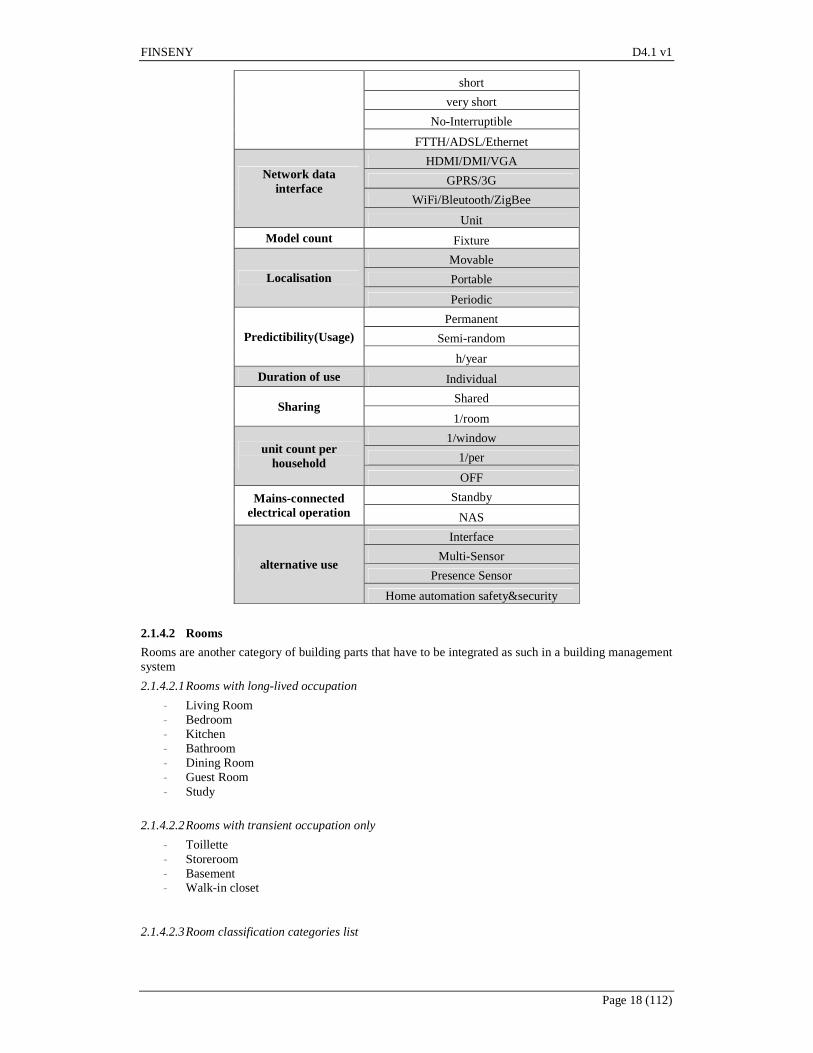
2.1.4 Tentative extensional listing of subsystems included (equipment, appliances, components) in the target system: example of the home domain The following provides a representative of the variety of appliances that would have to be addressed for a comprehensive home energy management system. They are classified below according to a “main use criterion”, and a list of complementary criteria that have to be taken for managing them in the framework of the home energy management system are into account are provided.
2.1.4.1 Household appliances
2.1.4.1.1 ICT appliances
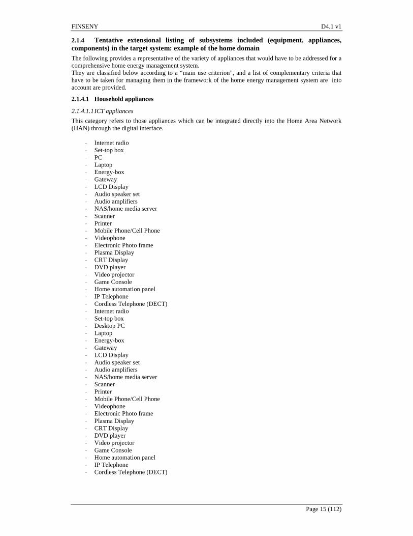
This category refers to those appliances which can be integrated directly into the Home Area Network (HAN) through the digital interface.
- Internet radio - Set-top box - PC - Laptop - Energy-box - Gateway - LCD Display - Audio speaker set - Audio amplifiers - NAS/home media server - Scanner - Printer - Mobile Phone/Cell Phone - Videophone - Electronic Photo frame - Plasma Display - CRT Display - DVD player - Video projector - Game Console - Home automation panel - IP Telephone - Cordless Telephone (DECT) - Internet radio - Set-top box - Desktop PC - Laptop - Energy-box - Gateway - LCD Display - Audio speaker set - Audio amplifiers - NAS/home media server - Scanner - Printer - Mobile Phone/Cell Phone - Videophone - Electronic Photo frame - Plasma Display - CRT Display - DVD player - Video projector - Game Console - Home automation panel - IP Telephone - Cordless Telephone (DECT)

FINSENY D4.1 v1
Page 16 (112)
2.1.4.1.2 Kitchen & Cleaning Appliances
This category refers to those appliances which are used for food & hygiene services.
- Fridge with Freezer - Dishwasher - Oven - Microwave - Freezer - Electric Kitchen stove - Espresso Machine - Fryers - Toaster - Kettle - Mini Oven - Gas kitchen stove - Washing machine - Dryer - Canister Vacuum cleaner
2.1.4.1.3 Home Automation Appliance (Domotic appliance)
This category refers to those appliances which can serve as the actuator for home automation.
- Electric shutters - Motorized windows - Electric curtain
2.1.4.1.4 HVAC equipment
This category refers to those appliances which are used for the indoor environmental comfort.
- Air conditioner (portable) - Electric Water heater - Electric radiator (fixed) - Heat recovery ventilation - Mechanical ventilation - Air conditioner (fixed) - Fan heater - Gas Water heater - Heat pump - Gas stove/boiler - Condensing gas boiler - Gas or oil boiler .1with accumulation tanks - Oil-fill radiator - Solar water heater
2.1.4.1.5 Electrical generation equipment
- Photovoltaic panels - Fuel cell - Microwind turbine
2.1.4.1.6 Electricity storage equipment
- Home battery system - EV batteries - Flywheels
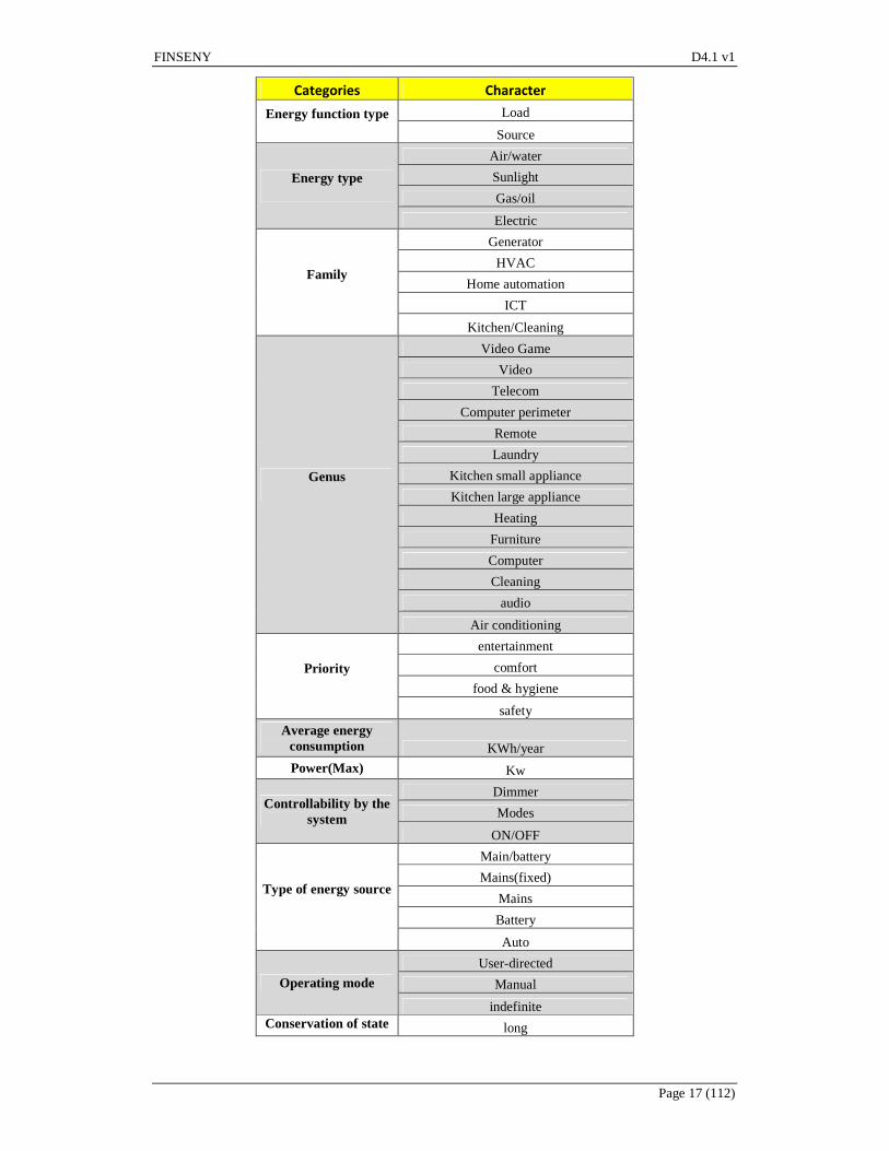
2.1.4.1.7 Household appliances complementary classification criteria
FINSENY D4.1 v1
Page 17 (112)
Categories Character
Energy function type
Load
Source
Energy type
Air/water
Sunlight
Gas/oil
Electric
Family
Generator
HVAC
Home automation
ICT
Kitchen/Cleaning
Genus
Video Game
Video
Telecom
Computer perimeter
Remote
Laundry
Kitchen small appliance
Kitchen large appliance
Heating
Furniture
Computer
Cleaning
audio
Air conditioning
Priority
entertainment
comfort
food & hygiene
safety
Average energy consumption KWh/year
Power(Max) Kw
Controllability by the system
Dimmer
Modes
ON/OFF
Type of energy source
Main/battery
Mains(fixed)
Mains
Battery
Auto
Operating mode
User-directed
Manual
indefinite Conservation of state long
FINSENY D4.1 v1
Page 18 (112)
short
very short
No-Interruptible
FTTH/ADSL/Ethernet
Network data interface
HDMI/DMI/VGA
GPRS/3G
WiFi/Bleutooth/ZigBee
Unit
Model count Fixture
Localisation
Movable
Portable
Periodic
Predictibility(Usage)
Permanent
Semi-random
h/year
Duration of use Individual
Sharing Shared
1/room
unit count per household
1/window
1/per
OFF
Mains-connected electrical operation
Standby
NAS
alternative use
Interface
Multi-Sensor
Presence Sensor
Home automation safety&security
2.1.4.2 Rooms
Rooms are another category of building parts that have to be integrated as such in a building management system
2.1.4.2.1 Rooms with long-lived occupation
- Living Room - Bedroom - Kitchen - Bathroom - Dining Room - Guest Room - Study
2.1.4.2.2 Rooms with transient occupation only
- Toillette - Storeroom - Basement - Walk-in closet
2.1.4.2.3 Room classification categories list

FINSENY D4.1 v1
Page 19 (112)
Categories Character
Mode of occupancy Multi
single
Energy Heated
No Heated
Duration of Occupancy
Long-lived
transient
2.2 Generic actor categories
(Specific actors will vary depending on each of the subdomains below)
2.2.1 Environment In a comprehensive definition, the environment of the building comprises everything that has an influence on the state of the building excluding all specific other actors listed below and everything that is part of the system as defined above. Environment t can be specialized into external an internal environments.
2.2.1.1 External environment
Comprises potentially some or all of the following more specialized actors:
• neighbouring buildings that may have a direct physical influence on the target building (e.g. through heat exchange). Note that any energy exchange between building that occurs through a microgrid is accounted for under the “microgrid management systems” actor
• the weather (actually lumping together more such factors as heat exchange from the atmosphere, solar radiation, as they have an influence on the energy functions of the building
2.2.1.2 Internal environment
Comprises internal factors that are directly under control of building systems, and are not within the perimeter of the building itself as defined above. More precisely this could correspond to:
• Activities of building users, inasmuch as they are not intentional interactions towards other use cases, or if they have side effects that impinge on the internal state of the building.
• Any factor of the external environment that “leaks” inside the building and cannot be controlled, e.g. natural lighting if openings cannot be controlled.
2.2.2 People and organizations This is where the different categories of buildings defined below make the largest difference, so that we prefer to define these categories of actors separately for each of the building types as defined below.
2.2.2.1 Energy Service Companies
These companies, who take over building energy management entirely on behalf of the building owner or tenant, already play a well-recognized role for the management of non-residential buildings, but their role is so far limited in the case of residential buildings due to the lack of an established business model for them in this domain, by contrast again to office and public buildings where energy performance contracts are well-established.
2.2.2.2 Facilities managers
Play a role for all types of buildings except individual homes
2.2.3 External systems and physical entities
As for energy supply systems, the emphasis is, as per assumptions above, placed on: • Electricity distribution grid • Microgrid in which the building is integrated, if relevant
but other energy carriers such as district heat or hydrogen could be taken into account. We normally do not consider the case of bilateral exchange of energy between two buildings, as it should be subsumed by microgrids

FINSENY D4.1 v1
Page 20 (112)
2.3 Subdomains identified
• The home domain • The residential building domain • The office/public building domain
For most cases, public buildings will differ from other types of office buildings mostly through the different roles of actors
• The industrial building domain We will address only a very special type of industrial buildings, namely data centers
• The hotel domain Under these we will address only hotels, which also intersect the residential building category. Small and medium-sized family-operated hotels are closer to residential buildings and will be included under these.
3. Home domain use cases
3.1 Synoptic diagram
The main Use Cases related to the home domain, and their dependencies, are shown in the diagram below.
Figure 1: High-level use cases for smart homes
FINSENY D4.1 v1
Page 21 (112)
From this diagram, can be seen four high level use cases, that are described in the following chapter.
3.2 Specific home domain actors
(Generic actors are described in section 2)
3.2.1 Home dwellers Represents all categories of persons who live in a home permanently, irrespective of their gender and status as owners, tenants, family members, etc. Distinctions can be made for more specialized roles/actors. A few home dwellers are specially aware of energy issues, these are the types of home dwellers who may wish to monitor their energy use in order to possibly proactively change their behaviour to conserve energy (i.e. voluntarily restrict their use of energy). Presenting this as a specialized role is meant to emphasize that it should not be expected that the majority of home dwellers will be doing this1. By contrast, generic home dwellers could benefit from and accept energy efficiency services that would optimize the use of primary energy while keeping the same level of energy service (or even improving the energy service) and for technically savvy who may wish to control. An even more “special” category of home dwellers will engage in proactively controlling their energy use for optimizing the cost, e.g. shifting uses of appliances to take advantage of variable prices. Again, singling these out as specialized type of users is meant to emphasize that the majority of users will not be doing this routinely and will instead expect the system to control energy use on their behalf, manual control being only an option (extension in use case parlance).
3.3 High-level use cases
3.3.1 Monitor and manually Control Energy Use
3.3.1.1 Characterization and perimeter of the high level use case
The home energy user willing to better know and master his power consumption and related costs may have different goals as: - forecasting what his next energy bill will be ; verifying that it will not increase in an unexpected way, - reducing his energy bill, with more or less constraints on his comfort, - reducing his impact on the environment, considering that energy consumption also leads to CO2
emissions. This high level use case is devoted to delivering information to the home energy user, so he may have the right information for him to understand what to do in order to achieve one or several of these goals and to manually control his appliances accordingly. Different ways to categorize or classify the information to deliver may be found. These classifications allow understanding the different types of detailed use cases that derivates from this high level use case.
1- Energy or power: Energy consumption is related to the amount of energy that is consumed in a certain period. For electricity, the unit of energy consumption, as said above, is the kWh (or Wh). Energy power is related to the electric power consumed at a given time; its unit is the kW (or W). It can be seen as a “speed of energy consumption”: if a device consumes 1kW during a period of 1 hour, then its consumption over this period will be 1 kWh. It is very common to see confusion between these two concepts. Energy consumption is generally well understood, as it is the “quantity” of consumed energy, such as the volume of oil consumed by a car, leading to the bill. And again, for many customers, monitoring energy consumption is in fact monitoring the energy bill. The power information has two main areas of interest:
- At first, as said above, it gives the speed of consumption. Then, if a high speed of consumption is seen for example in an on-peak period, it should be understood that it will lead to a high bill and that something should be done to lower this power until the off-peak period.
- Then, in most countries, the electricity contract of the customer is defining a limited subscribed power, and the home is equipped with a device that will power off the electrical installation if the
1 This as has been amply demonstrated by the disappointing take up of early commercial offerings for such services
FINSENY D4.1 v1
Page 22 (112)
power goes over this subscribed power – with a certain tolerance; this device is often a circuit breaker, but some smart meters are also performing this function. In order to avoid this disagreement to the user, it is important to warn him when the electricity power is reaching a value close to the subscribed power. And here again, this warning may be more or less explicit, according to the level of service and to the level of knowledge of the user ; just telling the user that there is only 500 W left under the subscribed power may not be enough if he is not aware of the value of the power of his appliances.
2- The level of detail of energy consumption/power information.
- Global level or appliance level: o Global: typically, the meter may be used, as it is already in the home for billing
purposes, and it may give the customer information on the global consumption of the home. This information may itself directly come from the meter, with a direct communication link between the meter and the device displaying the information, or come from the Information System of the metering operator, of the energy retailer or of any energy service provider who gets the metering data from the metering operator. This global consumption information may also come from a dedicated measurement device placed in the electrical board.
o Appliance: the energy consumption of the appliance may also be measured by smart plugs, by the smart appliances themselves, or by systems placed in the electrical board similar to those measuring the global consumption. In the most typical architecture, these devices are connected to a home gateway that may either directly report the information to the Interfaces (PC, smartphone, TV, …) of the home user, either send them to the cloud that can then be accessed through the Internet from the same type of interfaces.
- At different timescales : o Instant data: these are the live data that the customer can see about his consumption at
the time when he is looking. Typically, it is the instant power information (in W or kW), the current tariff period with, possibly, a recall of the associated tariff, the cumulated energy consumed from the beginning of the day, of the week, of the month, and the related cost. These data are typically collected locally from the meter or from other metering devices as described above, because they have to be available in a short delay, and also to be frequently refreshed.
o Daily, weekly, monthly: aggregated and historical values may be desirable to have a global understanding of the consumption and of its evolution over the days/weeks/months. At the contrary of the previous case, these data needs to be duly registered ad then processed and presented to the customer, and this is done the most frequently with websites to which the customer has to connect from his interfaces.
3- The choice of the energy and power units This choice has to be made according:
• the level of knowledge that the customer is able to understand and interpret. Generic considerations about the different levels of knowledge that has to be considered when designing an information service are given in Appendix I. It applies in particular to the choice of units. The kWh, for electricity, is meaningless for many people; a typical transformation of data to information is to choose a unit that can “talk” to the user, and to convert into this unit the raw data coming from energy measurements.
• the goal(s) of the user. If the goal is about reducing the bill, which is found to be the primary goal of the customers willing to deal with energy management, then the energy costs, in euros, has to be given. But it has to be noticed that the dynamic tariffs, where the price of the energy depends on the time of consumption, introduce some complexity for the customer, because the relationship between energy and price is not linear; complexity that, in turn, the energy information services have to lower by giving to the customer the hints and knowledge. The same reasoning applies with the CO2 emissions, whose relationship with energy consumption is of complexity even bigger than for cost and that is often much underestimated.
3.3.1.2 Tentative listing of subsystems involved (equipment, appliances, components)
The components involved in the use cases detailing this high level use case are listed in the table below. Some of them have been cited above.
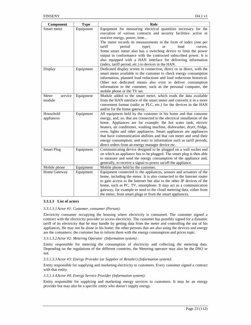
FINSENY D4.1 v1
Page 23 (112)
Component Type Role Smart meter Equipment Equipment for measuring electrical quantities necessary for the
execution of various contracts and security facilities: active or reactive energy, power, time... The meter records its measurements in the form of index (one per tariff period type) or load curves. Some smart meter also has a switching device to limit the power output in conformance with the contracted subscribed power. It is also equipped with a HAN interface for delivering information (index, tariff period, etc.) to devices in the HAN.
Display Equipment Dedicated display screen in connection, direct or in direct, with the smart meter available to the customer to check energy consumption information, planned load reductions and load reductions historical. Other not dedicated means also exist to deliver consumption information to the customer, such as the personal computer, the mobile phone or the TV set.
Meter service module
Equipment Module added to the smart meter, which reads the data available from the HAN interface of the smart meter and converts it in a more convenient format (radio or PLC, etc.) for the devices in the HAN and/or for the home gateway.
Household appliances
Equipment All equipment held by the customer in his home and that consume energy, and, so, that are connected to the electrical installation of the home. Appliances are for example: the hot water tank, electric heaters, air conditioner, washing machine, dishwasher, dryer, fridge, oven, lights and other appliances. Smart appliances are appliances that have communication abilities and that can meter and send their energy consumption, and react to information such as tariff periods, direct orders from an energy manager device etc.
Smart Plug Equipment Communicating device designed to be plugged on a wall socket and on which an appliance has to be plugged. The smart plug is then able to measure and send the energy consumption of the appliance and, generally, to receive a signal to power on/off the appliance.
Mobile phone Equipment Mobile phone held by the customer. Home Gateway Equipment Equipment connected to the appliances, sensors and actuators of the
home, including the meter. It is also connected to the Internet router to gain access to the Internet but also to the other IP devices of the home, such as PC, TV, smartphone. It may act as a communication gateway, for example to send to the cloud metering data, either from the meter, from smart plugs or from the smart appliances.
3.3.1.3 List of actors
3.3.1.3.1 Actor #1: Customer, consumer (Person):
Electricity consumer occupying the housing where electricity is consumed. The customer signed a contract with the electricity provider to access electricity. The customer has possibly signed for a dynamic tariff of its electricity that he may handle by getting data from the meter and controlling the use of his appliances. He may not be alone in his home: the other persons that are also using the devices and energy are the consumers: the customer has to inform them with the energy consumption and prices topic. 3.3.1.3.2 Actor #2: Metering Operator (Information system) :
Entity responsible for metering the consumption of electricity and collecting the metering data. Depending on the regulations of the different countries, the Metering operator may also be the DSO or not.
3.3.1.3.3 Actor #3: Energy Provider (or Supplier or Retailer) (Information system):
Entity responsible for supplying and marketing electricity to customers. Every customer signed a contract with that entity.
3.3.1.3.4 Actor #4: Energy Service Provider (Information system):
Entity responsible for supplying and marketing energy services to customers. It may be an energy provider but may also be a specific entity who doesn’t supply energy.

FINSENY D4.1 v1
Page 24 (112)
3.3.2 Optimize Home Energy Globally Smart Home and Buildings bring energy and load management functions on the demand side, together with local production means, that may benefit to many energy actors of the electrical system:
• Network operators: the ability to control the loads in the home may be seen and managed as a new reserve capacity, usually provided by parties having flexible production, in ancillary markets during the settlement period. The key-idea here is the utilization of real-time flexibility of end-users (prosumers) in balancing a control zone.
• Transport and Distribution Operators : peak loads going higher and higher would lead these operators to new investments to satisfy these very few peak periods in the year. Demand side management systems, included in the smart buildings and involving their electrical loads, allows to avoid these investments or, at least, to differ them. It may also be noticed that lowering the energy carried on the network also means lowering the losses in the network.
• Electricity producers: peak production means are built and owned by the producers to be used only a few days in a year. These investments, together with the fuel used to make them work, can also be avoided by DSM systems carried by the smart buildings.
• Electricity Retailers: the retailer, as being in contact with the end customer, is the actor that will make Energy management and Demand Response possible by making the key link between the electrical system and the end customer, for example through adapted dynamic tariffs, which have the key role to transmit to the customer simultaneously the signals of when the electrical system in under constraint, of how high is the constraint and of the related incentive that is given to the customer to adapt his consumption and his own production that it may choose to consume or to export to the grid. Also, services to the customer are key to succeed, to give the customer the tools to act and improve its satisfaction while getting his active participation to the system.
• Aggregators: the potential roles of an aggregator are described in the ADDRESS project. Being able to control a mass of homes, offices or commercial buildings, he may provide the network operator with reserve capacities similar to peak production means, usually operated when the prices on the electricity market are high. The role of aggregator may either be carried by existing or by new actors.
• End customers: they may have a lower energy bill, by lowering their energy consumption, by adopting dynamic tariffs and adapting their energy and load profile to them, or by contracting with an aggregator and accept, upon remuneration, to leave him control his loads. They also have more choice in tariffs and services. The high level use case “Optimize home energy locally” is describing below their point of view.
There is a common agreement about the general trend described above. However, on one hand, even if many actors may benefit from the smart home as a tool for better energy and load management, the market mechanisms to bring these benefits to the actors and make all this happen are still complex, and on another hand, the ROI of the tools and services for energy and load management is closely dependent from the energy price, which is generally considered not high enough yet for the investments in these tools to be worth.
3.3.3 Optimize home energy Locally Global optimization as described before optimizes home energy use with regard to constraints from the grid or microgrid, i.e. the larger electric system within which the home is integrated. By contrast, local optimization considers the home as a fully self-contained system and takes into account local criteria only. The optimization at the building scale is taken into account in order to not subordinate to optimization at broader scales (grid/microgrid). In practice, both types of optimization will have to be combined, even though their objectives may be partially at variance. At the very minimum, the building scale will mediate constraints (peak leveling/load shifting, smoother demand-response pattern, adaptation to (near) real-time pricing, etc.) from the larger scales through an intermediate level of control. Local optimization aims to manage all energy consumption, generation and storage components at the building scale in a comprehensive semi-autonomous supervision and control system. This system would have to interface with existing building management systems as well as with the distribution grid, local microgrids or any other larger scale energy management system. As for optimization, the emphasis is placed on energy consumption efficiency, as the minimization of the energy input for a given level of energy-based services to the building users. Energy input may itself be gauged by several criteria, mostly its cost, but also its carbon content. The output in terms of energy services could be gauged using purely quantitative measures in some cases (e.g. the temperature for heating services, the luminous intensity for lighting), possibly weighted by more qualitative or subjective criteria.

FINSENY D4.1 v1
Page 25 (112)
Among all energy efficiency measures, ICT-based efficiency requires the least amount of upfront material investment and can draw most easily upon a shared, non-rival infrastructure, comprising actuators/sensors, networks, software and the corresponding know-how. ICT-based efficiency complements the application of classical costlier measures such as upgrading appliances, weatherisation, insulation, etc. but does not replace or pre-require these measures
3.3.4 Generate and store Electricity Locally This abstract use case grouping serves as parent to detailed use cases that may inherit from both local optimization and global optimization Under local optimization, local energy generation and storage is intended for local consumption and in this case the home works similarly to a microgrid in autarkic mode, using locally generated energy buffered through local storage to reduce to the minimum its energy input (with cost or CO2 equivalence criteria, as outlined above). As for global optimization we have a very different concrete use case, a local generation is fed in to the grid and left to be optimized at higher level after having been aggregated with other sources. A similar distinction can be made for local storage which could be used as a resource for global distributed storage, though this is far from being the case presently.
3.4 Detailed “energy monitoring and warning” use cases
3.4.1 Use case #1: Display the global energy consumption and costs using data from Smart Meter and Metering Operator
3.4.1.1 Brief Description
The customer is presented with information about the global energy consumption of his/her house
3.4.1.2 Narrative (optional)
The Smart Meter provides a sub-set of its data, included instant power. Data are dispatched either periodically, or upon request and in case of transition (for example for tariff period change). The Smart Meter provides its data to the HAN either directly, using its own interface, either through a meter service module (see 3.3.1.2). This information may be directly received, treated, stored and displayed on a dedicated display, either in kWh or in €. It may also be collected by a Home Gateway, who hosts a Web application that collects data from HAN (Home Area Network) devices and organizes them for a user-friendly presentation. This Home Gateway either - exposes a web-based API, so that applications embedded in not dedicated displays, such as PC, TV or smartphone, may elaborate the data and provide different visualizations to the customer and the home user. The Smart Appliances may also receive over the HAN global metering data and total in-house energy consumption, and display a sub-set of available data, depending on the richness of its user interface.
3.4.1.3 Actors involved, Contracts and Regulations
Actors involved, as well as the contracts and regulations related to this use case, are described in 3.3.1.3.
3.4.1.4 Relationships with other use cases
This Use Case is a specialization of the high level Use Case “Monitor and manually Control Energy Use”.
3.4.1.5 Step by Step Analysis of Use Case
- The customer is presented with information about the global energy consumption of his/her house. - Consumption data are provided either directly from the Meter or by the meter service module. - Among the data coming from the Meter no information about costs is provided, as we suppose that,
according to the regulation, the Metering Operator could not be allowed to provide such information, the Energy Retailer being the only subject entitled to define energy rates for customers. Only the current tariff period may be retrieved from the meter, but not the pricing. Hence :
o either no energy cost is displayed, o either the customer has to manually enter the energy prices for the different tariff
periods on its displaying device, and the cost is calculated in the display device itself, o either the home gateway is able to retrieve the energy rates from a web service on the
Internet. If the provider of the energy information service is also the energy provider, he can provide this information and web service. If not, the customer has to provide the

FINSENY D4.1 v1
Page 26 (112)
energy prices on the Internet to this web service in order for the home gateway to retrieve and use them.
- Data can be presented in different formats (plain numbers, graphics, tables, etc.) in the Smart Appliance or in the Customer Interface.
3.4.1.6 ICT relevance of Use Case
ICT Criteria Sub Use Case Requirement Communication (e.g.
QoS, bandwidth, latency, reliability,
determinism, grade of distribution)
Data Management Service Bus supporting QoS
Data and context management (e.g. volume, models, mining, grade of
distribution)
Demand Side Monitoring High demand for context-based and
filtered data management
Processing (demand, grade of distribution)
Demand Side Monitoring Low demand for computing resources.
Service integration (openness, standard
interfaces) Demand Side Monitoring Conformance to Standards
Table: ICT Relevance of Use case #1
3.4.1.7 Assumptions of Use Case
Low level Use Case Preconditions or assumptions Demand-side Management All equipment necessary to monitor and control the power consumption.
Table: Assumptions of Use case #1
3.4.2 Use case #2: Display the global and per appliance energy consumption and costs, either realized and/or forecasted.
3.4.2.1 Brief Description
In this Use Case, added to the previous Use Case #1, the customer is also informed on the energy consumptions of the single appliances.
3.4.2.2 Narrative (optional)
- The Smart Meter and meter service module functionality is the same as in Use case #1. In addition, they also provide near real time instant power information to allow Smart Appliances to calibrate their energy consumptions with respect to the subscribed limited power.
- The Home Gateway functionality is extended from Use case #1. It provides to user appliances a single point of contact to publish their respective energy consumption and power information.
- Each appliance: either directly, in case of a smart appliance, or through a smart plug, displays its own energy consumption/power drawn data, dispatches its own energy consumption data over HAN, receives over HAN the total house energy consumption and displays the total house energy consumption.
- Forecast of the energy consumption may also be provided to the customer and home energy user. o Forecast of global energy consumption may be done by statistical analysis of the past
consumptions and taking into account the main characteristics of the household and of the appliances of the home, according the indications given by the user, as well as the season, the weather conditions and external temperature. This forecast is mainly used by the user as a reference, so he may compare his effective energy consumption to the forecasted one.
o Forecast of appliance energy consumption and related cost may be given to the appliance user before the start button is pressed, in order to help him to see the impact of the parameters of the cycles that he may select. This information is displayed to the user on the appliance display as soon as the selection of the parameters is made and before the effective start of the appliance.
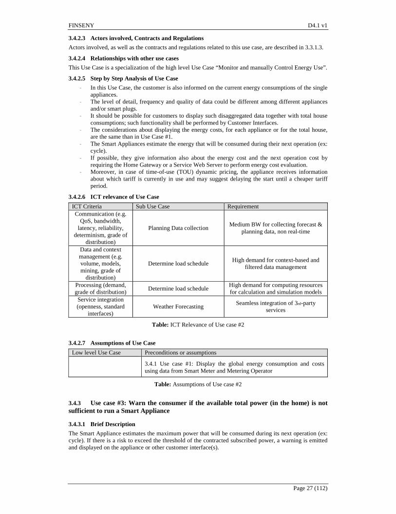
FINSENY D4.1 v1
Page 27 (112)
3.4.2.3 Actors involved, Contracts and Regulations
Actors involved, as well as the contracts and regulations related to this use case, are described in 3.3.1.3.
3.4.2.4 Relationships with other use cases
This Use Case is a specialization of the high level Use Case “Monitor and manually Control Energy Use”.
3.4.2.5 Step by Step Analysis of Use Case
- In this Use Case, the customer is also informed on the current energy consumptions of the single appliances.
- The level of detail, frequency and quality of data could be different among different appliances and/or smart plugs.
- It should be possible for customers to display such disaggregated data together with total house consumptions; such functionality shall be performed by Customer Interfaces.
- The considerations about displaying the energy costs, for each appliance or for the total house, are the same than in Use Case #1.
- The Smart Appliances estimate the energy that will be consumed during their next operation (ex: cycle).
- If possible, they give information also about the energy cost and the next operation cost by requiring the Home Gateway or a Service Web Server to perform energy cost evaluation.
- Moreover, in case of time-of-use (TOU) dynamic pricing, the appliance receives information about which tariff is currently in use and may suggest delaying the start until a cheaper tariff period.
3.4.2.6 ICT relevance of Use Case
ICT Criteria Sub Use Case Requirement Communication (e.g.
QoS, bandwidth, latency, reliability,
determinism, grade of distribution)
Planning Data collection Medium BW for collecting forecast &
planning data, non real-time
Data and context management (e.g. volume, models, mining, grade of
distribution)
Determine load schedule High demand for context-based and
filtered data management
Processing (demand, grade of distribution)
Determine load schedule High demand for computing resources for calculation and simulation models
Service integration (openness, standard
interfaces) Weather Forecasting
Seamless integration of 3rd-party services
Table: ICT Relevance of Use case #2
3.4.2.7 Assumptions of Use Case
Low level Use Case Preconditions or assumptions
3.4.1 Use case #1: Display the global energy consumption and costs using data from Smart Meter and Metering Operator
Table: Assumptions of Use case #2
3.4.3 Use case #3: Warn the consumer if the available total power (in the home) is not sufficient to run a Smart Appliance
3.4.3.1 Brief Description
The Smart Appliance estimates the maximum power that will be consumed during its next operation (ex: cycle). If there is a risk to exceed the threshold of the contracted subscribed power, a warning is emitted and displayed on the appliance or other customer interface(s).

FINSENY D4.1 v1
Page 28 (112)
3.4.3.2 Actors involved, Contracts and Regulations
Actors involved, as well as the contracts and regulations related to this use case, are described in 3.3.1.3.
3.4.3.3 Relationships with other use cases
This Use Case is a specialization of the high level Use Case “Monitor and manually Control Energy Use”.
3.4.3.4 Step by Step Analysis of Use Case
- The Smart Meter and meter service module functionality is the same as in Use case #2. - Each appliance:
o estimates the maximum power to be consumed to perform the next operation, o receives the information of subscribed power and of instant global power consumed by
the home at this moment, either from the Smart Meter, from the meter service module or from the HAN,
o deduces the available power in the home at this moment, o displays a warning to the user if it is not possible to run o and, eventually, sends the information that it is not possible to run through the HAN in
order to display it on Customer Interface(s).
3.4.3.5 ICT relevance of Use Case
ICT Criteria Sub Use Case Requirement Communication (e.g.
QoS, bandwidth, latency, reliability,
determinism, grade of distribution)
Planning Data collection Medium BW for collecting forecast &
planning data, non real-time
Data and context management (e.g. volume, models, mining, grade of
distribution)
Determine load schedule High demand for context-based and
filtered data management
Processing (demand, grade of distribution)
Determine load schedule High demand for computing resources for calculation and simulation models
Service integration (openness, standard
interfaces) Weather Forecasting
Seamless integration of 3rd-party services
Table: ICT Relevance of Use case #3
3.4.3.6 Assumptions of Use Case
Low level Use Case Preconditions or assumptions
3.4.2 Use case #2: Display the global energy consumption and costs using data from Smart Meter and Metering Operator
Table: Assumptions of Use case #3
3.5 Detailed “Manage demand” Use Cases
3.5.1 Characterization and perimeter of target systems (home, buildings, etc) This document suggests three Use Cases for Smart Homes in the field of load/demand management:
- The direct load control, - The dynamic pricing of electricity, - The emergency load reduction.
Are also provided two other use cases:
- the “Handle dynamic power cap”, that emphasizes on an alternative way for an operator to control the load in customer premises, by modifying remotely the limited maximum power consumed of the home
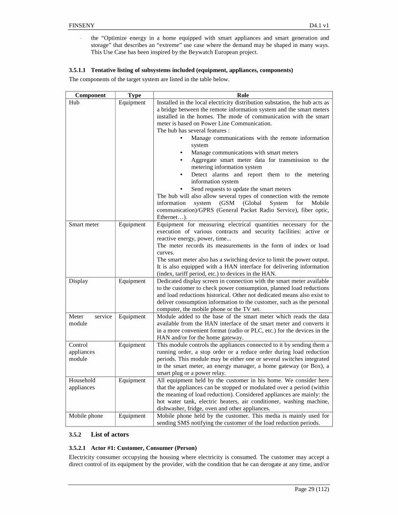
FINSENY D4.1 v1
Page 29 (112)
- the “Optimize energy in a home equipped with smart appliances and smart generation and storage” that describes an “extreme” use case where the demand may be shaped in many ways. This Use Case has been inspired by the Beywatch European project.
3.5.1.1 Tentative listing of subsystems included (equipment, appliances, components)
The components of the target system are listed in the table below.
Component Type Role Hub Equipment Installed in the local electricity distribution substation, the hub acts as
a bridge between the remote information system and the smart meters installed in the homes. The mode of communication with the smart meter is based on Power Line Communication. The hub has several features :
• Manage communications with the remote information system
• Manage communications with smart meters • Aggregate smart meter data for transmission to the
metering information system • Detect alarms and report them to the metering
information system • Send requests to update the smart meters
The hub will also allow several types of connection with the remote information system (GSM (Global System for Mobile communication)/GPRS (General Packet Radio Service), fiber optic, Ethernet…).
Smart meter Equipment Equipment for measuring electrical quantities necessary for the execution of various contracts and security facilities: active or reactive energy, power, time... The meter records its measurements in the form of index or load curves. The smart meter also has a switching device to limit the power output. It is also equipped with a HAN interface for delivering information (index, tariff period, etc.) to devices in the HAN.
Display Equipment Dedicated display screen in connection with the smart meter available to the customer to check power consumption, planned load reductions and load reductions historical. Other not dedicated means also exist to deliver consumption information to the customer, such as the personal computer, the mobile phone or the TV set.
Meter service module
Equipment Module added to the base of the smart meter which reads the data available from the HAN interface of the smart meter and converts it in a more convenient format (radio or PLC, etc.) for the devices in the HAN and/or for the home gateway.
Control appliances module
Equipment This module controls the appliances connected to it by sending them a running order, a stop order or a reduce order during load reduction periods. This module may be either one or several switches integrated in the smart meter, an energy manager, a home gateway (or Box), a smart plug or a power relay.
Household appliances
Equipment All equipment held by the customer in his home. We consider here that the appliances can be stopped or modulated over a period (within the meaning of load reduction). Considered appliances are mainly: the hot water tank, electric heaters, air conditioner, washing machine, dishwasher, fridge, oven and other appliances.
Mobile phone Equipment Mobile phone held by the customer. This media is mainly used for sending SMS notifying the customer of the load reduction periods.
3.5.2 List of actors
3.5.2.1 Actor #1: Customer, Consumer (Person)
Electricity consumer occupying the housing where electricity is consumed. The customer may accept a direct control of its equipment by the provider, with the condition that he can derogate at any time, and/or

FINSENY D4.1 v1
Page 30 (112)
a dynamic tariff of its electricity that he may handle by getting data from the meter and controlling the use of his appliances. The customer signed a contract with the electricity provider to access electricity and defining these modulation conditions.
3.5.2.2 Actor #2: Metering Operator (Information system)
Entity responsible for metering the consumption of electricity and collecting the metering data. Depending on the regulations of the different countries, the Metering operator may also be the DSO or not.
3.5.2.3 Actor #3: Provider (Information system)
Entity responsible for supplying and marketing electricity to customers. Every customer signed a contract with that entity.
3.5.2.4 Actor #4: Distributor (Information system)
Entity responsible for managing the distribution of electricity. He carries and delivers electricity to the customers.
3.5.3 List of Use Cases
3.5.4 Use case #4: Direct load control
3.5.4.1.1 Brief Description
The interruption of certain uses becomes a virtual means to solve peak loads on the grid. Each provider may contract with a number of his customers to agree to have some of his appliances interrupted a few hours per year. In exchange, the customer is rewarded for giving this facility. The direct load is triggered by the provider with notice of the customer
3.5.4.1.2 Step by Step Analysis of Use Case
Step number
Designation step Major actor Description of the step and exchanged data
Additional information
1 Load reduction notification
Provider The information system (IS) of the Provider informs the IS of the Metering Operator of a load reduction notification
With a notice
2 Announce of the load reduction notification
Provider The information system of the Provider sends a SMS on the customers mobile phone
3 Read the information Customer The Customer reads the load reduction notification on his mobile phone
4 Load reduction notification
Metering Operator
The information system of the Metering Operator sends the load reduction notification to the Hub
5 Load reduction notification
Hub The Hub sends the load reduction notification to the Smart Meter
6 Display of the load reduction notification
Smart Meter The Smart Meter advertises the load reduction notification on the display in the home
7 Exemption Customer The Customer can derogate before the start of the load reduction period
8 Announce of the start of the load reduction period
Smart Meter The Smart Meter displays the start of the load reduction period on the display
9 Load reduction order Smart Meter The Smart Meter gives the order of load reduction to the control appliances module

FINSENY D4.1 v1
Page 31 (112)
10 Start load reduction order
Control appliances module
The control appliances module controls the start of the load reduction on the Appliances
11 Exemption Customer The Customer can derogate during the load reduction period
12 End of load reduction period
Control appliances module
The control appliances module notifies to the appliances that the load reduction period is terminated
13 Announce of the end of the load reduction period
Smart Meter The Smart Meter informs the display the load reduction period is terminated
14* End of load reduction period
Smart Meter The Smart Meter informs the Hub that the load reduction period is terminated and sends to the Hub the load curve recorded for this period
15* End of load reduction period
Hub The Hub informs the information system of the Metering Operator that the load reduction period is terminated and also sends to it the load curve for this period
16* End of the load reduction period
Distributor The information system of the Metering Operator gives to the information system of the Provider information of the previous step
17* Adding in the load reduction log
Provider The information system of the Provider logs the information about the terminated load reduction and load curve for this customer
(*) : Steps from 14 to 17 are mainly used to go back to the Provider Information System the data (consumption, power, possible exemption ...) characterizing the client's response to the order of load reduction order. These both for statistical purposes, and thus better fit for future load reduction orders by the Provider (or load reduction operator) and for compensation or penalty of the customer, depending on whether or not derogate. The sequence diagram showing all these steps may be found in Appendix II.
3.5.4.1.3 ICT relevance of Use Case
ICT Criteria Sub Use Case Requirement Communication (e.g.
QoS, bandwidth, latency, reliability,
determinism, grade of distribution)
Automated Load Reduction Reliable communication with
transactional nature. Time-scale is secondary control.
Data and context management (e.g. volume, models, mining, grade of
distribution)
Automated Load Reduction High demand for context-based and
filtered data management
Processing (demand, grade of distribution)
Automated Load Reduction High demand for computing resources for calculation and simulation models
Service integration (openness, standard
interfaces) Automated Load Reduction
Publish open interfaces servicing higher level entities
Table: ICT Relevance of Use case #4

FINSENY D4.1 v1
Page 32 (112)
3.5.4.1.4 Assumptions of Use Case
Low level Use Case Preconditions or assumptions Monitoring Use case #1 Forecasting Use case #2
Table: Assumptions of Use case #4
3.5.5 Use case #5: Dynamic pricing of electricity
3.5.5.1.1 Brief Description
To move out peak loads, provider proposes a tariff of electricity higher during certain periods of the day or during certain days in order to invite his customers to delete or shift various uses or lower their consumptions in its housing during these periods. The regular daily and weekly price variation is known by the customer. For a small number of peak days, a special peak day tariff may apply, which is particularly high; the customer is informed before every peak day. These tariffs are made in order to encourage the customer to lower his consumptions during the most expensive periods; they may be handled either directly if the appliances are smart enough, or through a control appliances module which controls the equipment.
3.5.5.1.2 Step by Step Analysis of Use Case
Step number
Designation step Major actor Description of the step and exchanged data
Additional information
1 Peak load notification
Provider The information system of the Provider informs the information of the Metering Operator of a peak load notification
With a notice
2 Announce of the peak load notification
Provider The information system of the Provider sends a SMS on the customers mobile phone
3 Read the information Customer The Customer reads the peak load notification on his mobile phone
4 Peak load notification
Metering Operator
The information system of the Metering Operator sends the peak load notification to the Hub
5 Peak load notification
Hub The Hub sends the peak load notification to the Smart Meter
6 Display of the peak load notification
Smart Meter The Smart Meter advertises the peak load notification on the display in the home
7 Exemption Customer The Customer can derogate before the start of the peak load period
8 Announce of the start of the peak load period
Smart Meter The Smart Meter displays the peak load order on the display
9 Peak load order Smart Meter The Smart Meter gives the order of peak load to the control appliances module
10 Start peak load order Control appliances module
The control appliances module controls the start of the peak load mode/program on the Appliances
11 Exemption Customer The Customer can derogate during the peak load period
12 End of peak load period
Control appliances module
The control appliances module notifies to the appliances that the peak load period is terminated

FINSENY D4.1 v1
Page 33 (112)
3.5.5.1.3 ICT relevance
ICT Criteria Activity Requirement Communication (e.g.
QoS, bandwidth, latency, reliability,
determinism, grade of distribution)
Peak Load Notification Reliable communication with energy
provider
Data and context management (e.g. volume, models, mining, grade of
distribution)
Peak Load Notification Access to contract database
Processing (demand, grade of distribution)
Peak Load Notification
Service integration (openness, standard
interfaces) Peak Load Notification
Access to open interfaces for accessing the wholesale market participants
Table: ICT Relevance of Use case #5
3.5.5.1.4 Assumptions
Low level Use Case Preconditions or assumptions - -
Table: Assumptions of Use case #5
3.5.6 Use case #6: Emergency Load reduction
3.5.6.1.1 Brief Description
After the failure of the network or of a mean of production, the uses are relieved, without notice, to avoid a blackout. The use of these load reductions should be very marginal (less than 10 hours per year). The distributor controls these emergency load reductions.
3.5.6.1.2 Step by Step Analysis of Use Case
Step number
Designation step Major actor Description of the step and exchanged data
Additional information
1 Load reduction notification
Distributor The information system of the Distributor gives an emergency load reduction order to the Hub
A priori, no notice is given to the customer
2 Send the load reduction order
Hub The Hub gives the order to the Smart Meter
3 Announce of the start of the load reduction
Smart Meter The Smart Meter advertises the load reduction order on the display
4 Send the load reduction order
Smart Meter The Smart Meter send the load reduction order to the control appliances module
5 Start of the load reduction
Control appliances module
The control appliances module acts on appliances to start the load reduction period
6 End of load reduction
Control appliances module
The control appliances module acts on appliances to stop the load reduction period
7 Display of the end of the load reduction
Smart Meter The Smart Meter advertises the end of the load reduction on the display in the home
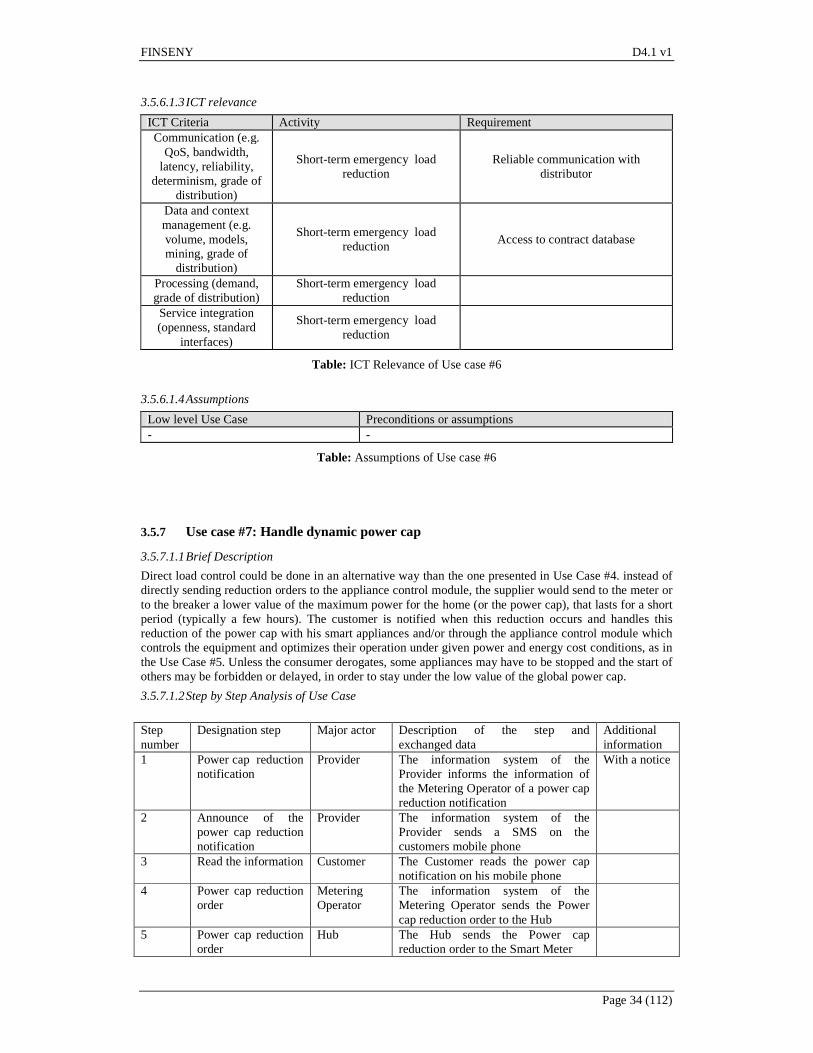
FINSENY D4.1 v1
Page 34 (112)
3.5.6.1.3 ICT relevance
ICT Criteria Activity Requirement Communication (e.g.
QoS, bandwidth, latency, reliability,
determinism, grade of distribution)
Short-term emergency load reduction
Reliable communication with distributor
Data and context management (e.g. volume, models, mining, grade of
distribution)
Short-term emergency load reduction
Access to contract database
Processing (demand, grade of distribution)
Short-term emergency load reduction
Service integration (openness, standard
interfaces)
Short-term emergency load reduction
Table: ICT Relevance of Use case #6
3.5.6.1.4 Assumptions
Low level Use Case Preconditions or assumptions - -
Table: Assumptions of Use case #6
3.5.7 Use case #7: Handle dynamic power cap
3.5.7.1.1 Brief Description
Direct load control could be done in an alternative way than the one presented in Use Case #4. instead of directly sending reduction orders to the appliance control module, the supplier would send to the meter or to the breaker a lower value of the maximum power for the home (or the power cap), that lasts for a short period (typically a few hours). The customer is notified when this reduction occurs and handles this reduction of the power cap with his smart appliances and/or through the appliance control module which controls the equipment and optimizes their operation under given power and energy cost conditions, as in the Use Case #5. Unless the consumer derogates, some appliances may have to be stopped and the start of others may be forbidden or delayed, in order to stay under the low value of the global power cap.
3.5.7.1.2 Step by Step Analysis of Use Case
Step number
Designation step Major actor Description of the step and exchanged data
Additional information
1 Power cap reduction notification
Provider The information system of the Provider informs the information of the Metering Operator of a power cap reduction notification
With a notice
2 Announce of the power cap reduction notification
Provider The information system of the Provider sends a SMS on the customers mobile phone
3 Read the information Customer The Customer reads the power cap notification on his mobile phone
4 Power cap reduction order
Metering Operator
The information system of the Metering Operator sends the Power cap reduction order to the Hub
5 Power cap reduction order
Hub The Hub sends the Power cap reduction order to the Smart Meter

FINSENY D4.1 v1
Page 35 (112)
6 Display of the Power cap reduction order
Smart Meter The Smart Meter advertises the Power cap reduction on the display in the home
7 Exemption Customer The Customer can derogate before the start of the Power cap reduction period
8 Announce of the start of the Power cap reduction period
Smart Meter The Smart Meter displays the Power cap reduction start on the display
9 Power cap reduction order
Smart Meter The Smart Meter gives the order of Power cap reduction to the control appliances module
10 Start to reduce power
Control appliances module
The control appliances module controls the start of the peak load mode/program on the Appliances
10 Start control of the power with respect to the reduced power cap
Smart Meter After a few seconds, The Smart meter starts to control that the power cap is reduced. If power exceeds the value of the reduced power cap; the home is disconnected. The consumer has to reconnect by pushing the connect button of the smart meter. This event may or may not be considered as an exemption.
11 Exemption Customer The Customer can derogate during the Power cap reduction period
12 End of Power cap reduction period
Smart Meter The Smart Meter goes back to a power cap equal to the contracted subscribed power and advertises it on the display in the home.
13 End of Power cap reduction period
Control appliances module
The control appliances module notifies to the appliances that the Power cap reduction period is terminated
3.5.7.1.3 ICT relevance
ICT Criteria Activity Requirement Communication (e.g.
QoS, bandwidth, latency, reliability,
determinism, grade of distribution)
Capacity reservation for managing short-term (business) risks
Reliable communication with energy provider
Data and context management (e.g. volume, models, mining, grade of
distribution)
Capacity reservation for managing short-term (business) risks
Access to contract database
Processing (demand, grade of distribution)
Capacity reservation for managing short-term (business) risks
Service integration (openness, standard
interfaces)
Capacity reservation for managing short-term (business) risks
Access to open interfaces for accessing the wholesale market participants
Table: ICT Relevance of Use Case #7
3.5.7.1.4 Assumptions
Low level Use Case Preconditions or assumptions Business interaction for capacity Realization of an electronic marketplace

FINSENY D4.1 v1
Page 36 (112)
Low level Use Case Preconditions or assumptions reservation for managing short term risks
Table: Assumptions of Use Case #7
3.5.8 Use case #8: Optimize energy in a home equipped with smart appliances and smart generation and storage
3.5.8.1.1 Brief Description
This use case describes an “extreme” use case where the demand may be shaped in many ways, and has been inspired by the Beywatch European project. The home is supposed to be equipped with
- Many smart appliances that are today under development : HVAC system, either for winter or summer, hot water tank, smart white goods (washing machine, dishwasher, dryer, fridge/freezer, …)
- Electrical vehicle, which may either consume energy for its needs but also store and make available a share of the stored energy in case of emergency needs on the grid.
- Thermal renewable sources, as solar thermal panel which may provide hot water for the domestic use but also for the washing machines
- Electric renewable generation, as Photovoltaic panels or wind turbines - Energy storage means, either in thermal form through the different appliances (as hot water tank
for heat storage, or fridge freezer for cold storage), or in battery. The smart home system has to handle all these devices in order to:
- Meet the targets of the home dwellers. They want to achieve some tasks with their appliances, to get clothes or dishes washed, to watch TV, to store and preserve food, to live in comfortable conditions and temperature etc. But they also will to master the cost of the energy, pay as less as possible, consume as less energy as possible, act in a sustainable way. And all this by keeping it simple, transparent and trustable.
- Take into account the “signals” sent by the utility and other actors of the energy system for demand side management purposes. These signals may be one or several among :
o Dynamic tariffs of energy, as described in Use Case #5 o Direct load control orders, as described in Use Case #4 o Emergency signals, as described in Use Case #6 o Dynamic feed in tariffs for the generation that is exported to the grid.
The home has to embed a home energy management system (HEMS), which is a specific device that generalizes the former appliance control module and that collaborates as a kind of conductor with all the smart components described above, in order to meet the home dwellers needs while optimizing at best the energy and energy costs, in a way that has to remain transparent and always leave the dweller free to derogate to the decisions of the system.
3.5.8.1.2 Step by Step Analysis of Use Case
Unlike the other use cases, this table doesn’t describe a step by step listing of actions but rather describe the behavior of the system in case of different type of events. Each case could in turn be detailed in sub use case: this is not done in this document that is more devoted to the collection of relevant use cases for FINSENY and the Future Internet PPP than to the detailed description of all the details. Case number
Designation case Major actor
Description of the case and exchanged data
Additional information
1 Daily scheduling HEMS At night, the HEMS performs a scheduling of the operation of regular uses (hot water tank, fridge/freezer, HVAC, …) according to forecasts (of weather and related generation, presence, energy prices –both for consumption and generation, etc). The result may be viewed by the dwellers on the display(s) of the HEMS and modified by them. The HEMS manages the operation of the devices accordingly.

FINSENY D4.1 v1
Page 37 (112)
2 Periodic hourly (or more frequent) monitoring and adjustment of schedule
HEMS, appliance
The HEMS monitors the operation of the regular uses (temperatures indoor, in the hot water tank, in the fridge/freezer …), and generation means (PV …), detects variations leading to an adaptation of the schedule, and makes and applies (display on the HEMS display(s), management of appliances …) the adaptations accordingly.
3 The user presses the “eco start” button of a Washing machine or Dishwasher, with limit end time.
HEMS, appliance
The HEMS schedules the best period and program of operation of the machine, adds it to the global schedule, displays it on the HEMS display(s) and manages the machine accordingly. He may also reschedule the operation of other devices in order to remain optimized with these new conditions
4 The notification of a direct load control and/or a dynamic peak tariff period and/or a low power cap period is received from the Smart Meter a few hours in advance
HEMS, grid, appliances
The HEMS computes one more time the daily schedules in order to optimize given these new conditions and applies it (display on the HEMS display(s), management of appliances). The conditions received from the Smart Meter are also displayed.
5 Emergency load reduction signal
HEMS, appliances
The HEMS interrupts its current program and goes into an energy reduced mode and manages the appliances accordingly so that the home energy consumption is minimized, or possibly zeroed if the local generation allows it. The event and the actions taken by the HEMS are displayed.
6 Exemption Customer, HEMS, appliances
At any time, the Customer can derogate very simply, either on the HEMS display(s) or on the appliance(s) itself. The HEMS then computes one more time the daily schedule and applies it (display, management).
3.5.8.1.3 ICT relevance of Use Case
ICT Criteria Activity Requirement Communication (e.g.
QoS, bandwidth, latency, reliability,
determinism, grade of distribution)
Planning data collection; consumption & generation
parameter adjustments; Incentive negotiations with the customer
Non-real-time, asynchronous data transport; reliable control information flow; transaction-based protocols for
incentive (price) negotiations
Data and context management (e.g. volume, models, mining, grade of
distribution)
Planning data collection system, e.g. access to contract database
(CDB)
Reliable mass data communication system, data models should be based on
IEC 61850 and IEC 61968.
Processing (demand, grade of distribution)
Forecasting, Planning & Revenue optimization
High demand for computing resources for calculation and simulation models
on weather and price forecasts, optimization & behavioural models
Service integration (openness, standard
Retail market, bidding & offering and weather forecast services
Seamless integration of internal & external services, open interfaces and

FINSENY D4.1 v1
Page 38 (112)
ICT Criteria Activity Requirement interfaces) data models
Table: ICT Relevance of Use Case #8
3.5.8.1.4 Assumptions of Sub Use Cases
Low level Use Case Preconditions or assumptions State analysis & subsequent actions The actual state is available Continuous determination of power control range
The actual range on energy resources is available
Forecasting energy production & consumption on different time scales
Forecasting data are available
Business interactions based on DR optimization
Incentives for customers are defined
Table: Assumptions of Use Case #8
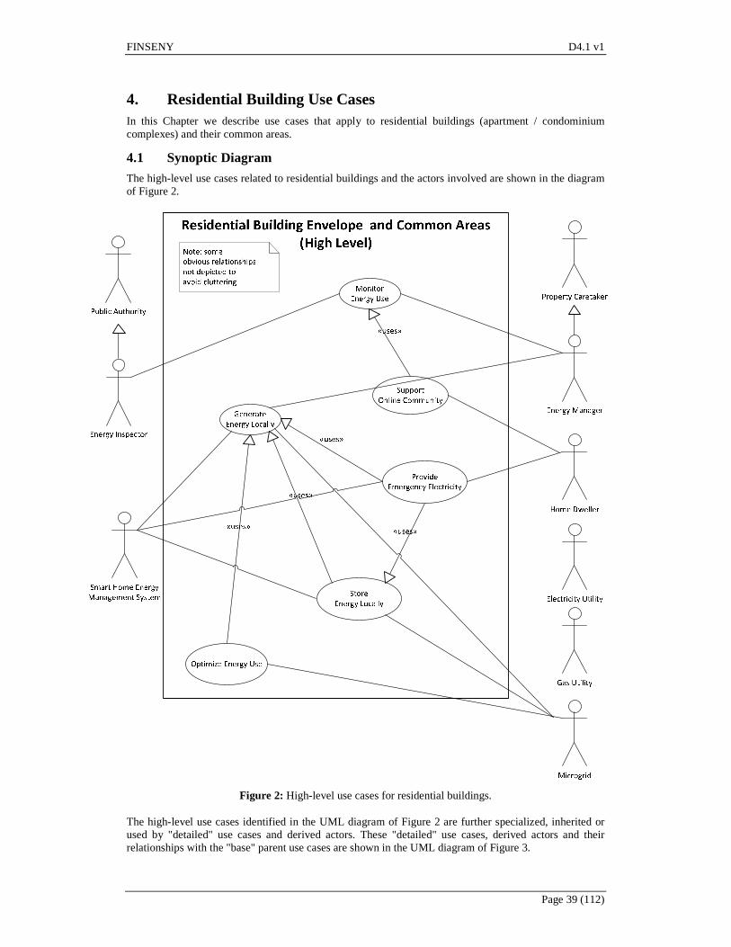
FINSENY D4.1 v1
Page 39 (112)
4. Residential Building Use Cases In this Chapter we describe use cases that apply to residential buildings (apartment / condominium complexes) and their common areas.
4.1 Synoptic Diagram
The high-level use cases related to residential buildings and the actors involved are shown in the diagram of Figure 2.
Figure 2: High-level use cases for residential buildings.
The high-level use cases identified in the UML diagram of Figure 2 are further specialized, inherited or used by "detailed" use cases and derived actors. These "detailed" use cases, derived actors and their relationships with the "base" parent use cases are shown in the UML diagram of Figure 3.
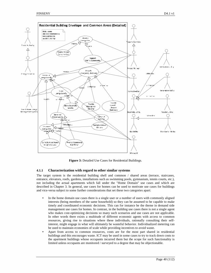
FINSENY D4.1 v1
Page 40 (112)
Figure 3: Detailed Use Cases for Residential Buildings.
4.1.1 Characterization with regard to other similar systems The target system is the residential building shell and common / shared areas (terrace, staircases, entrance, elevators, roofs, gardens, installations such as swimming pools, gymnasium, tennis courts, etc.), not including the actual apartments which fall under the "Home Domain" use cases and which are described in Chapter 3. In general, use cases for homes can be used to motivate use cases for buildings and vice-versa subject to some further considerations that set these two categories apart:
• In the home domain use cases there is a single user or a number of users with commonly aligned interests (being members of the same household) so they can be assumed to be capable to make timely and coordinated economic decisions. This can for instance be the theme in demand side management use cases for homes. In contrast, in the building use cases there is not a single agent who makes cost-optimizing decisions so many such scenarios and use cases are not applicable. In other words there exists a multitude of different economic agents with access to common resources, giving rise to situations where these individuals, rationally consulting their self-interest, might engage in what will ultimately be wasteful behavior. Individualized metering can be used to maintain economies of scale while providing incentives to avoid waste.
• Apart from access to common resources, costs are for the most part shared in residential buildings and this encourages waste. ICT may be used in some cases to try to track down costs to the apartment buildings whose occupants incurred them but the scope for such functionality is limited unless occupants are monitored / surveyed to a degree that may be objectionable.
FINSENY D4.1 v1
Page 41 (112)
• In residential building use cases the larger size, requirements and available surfaces may enable technologies which become cost-effective only when economies of scale come into play.
Other than when the above factors come into play, there is usually a homomorphism between home-level use cases and residential building use cases.
4.1.2 Environment The environment of the target system is comprised of the electrical distribution or reseller company, possibly the gas utility, the grid or micro-grid administrator, and (inwardly) of the actual apartments within the shell of the residential building. For the purposes of this Chapter we will sometimes also use the Microgrid actor to stand for the broader, external macro-grid.
4.1.3 Definition of subsystems included The target system comprises equipment to generate electricity (PV panels), produce heat (electric or gas heaters) store electricity (batteries, fuel cells, possibly fly-wheels), generate hot water (solar panels, hot water tanks - in the case of communal hot water), wiring and electricity / smart meters to interface with the external power supply, the micro-grid, and the apartments (for provision of emergency lighting) and other electrical equipment within the building (elevators, common areas lights) and electronics and software to store, display and visualize measurements and data as well as to interface with human users and other stakeholders over a web front-end. It also interfaces with the numerous smart home energy management systems within the building.
4.1.4 List of Actors In the sections that follow we provide descriptions for the following actors:
• Energy Inspector: Subsection 4.1.4.1 • Energy Manager: Subsection 4.1.4.2 • Home Dweller: Subsection 4.1.4.3 • Smart Home Energy Management System: Subsection 4.1.4.4 • Electricity Utility: Subsection 4.1.4.5 • Gas Utility: Subsection 4.1.4.6, and • Microgrid: Subsection 4.1.4.7.
The "Property Caretaker" and the "Public Authority" actors are not described as they represent parent actors which are specialized by the more concrete "Energy Manager" and "Energy Inspectors" actors respectively.
4.1.4.1 Energy Inspector
This actor is an engineer tasked to monitor and assess the energy requirements of the buildings and possibly issue a certificate or assign an energy profile grade to the building (depending on its energy needs). This actor is a specialization of the "Public Authority" actor. Note that in certain jurisdictions, he can also be a freelancer engineer (not a government employee). But even in those cases, he still has to register with a public authority and be approved (based on a formal screening process) before he can assume that role. Moreover, he acts in his capacity as an agent of a public authority, so in all senses, he can always be considered as a specialization of the "Public Authority" actor. The certificate he issues has legal power and is mandated by legislation. For instance, in Greece, apartments, houses and residential / office buildings cannot be leased / rented or sold unless the contract also includes, as an annex, an energy efficiency certificate issued by a competent energy inspector. In Greece, the Ministry of Energy and Climate Change maintains and publishes a register of engineers who have been so approved and who can issue such certificates, and even regulates their minimum fees. In terms of relationships with other actors, the Energy Inspector is hired by the Energy Manager due to regulatory requirements.
4.1.4.2 Energy Manager
This actor is a specialization of the Property Caretaker actor. Whereas the Property Caretaker is responsible with all aspects of proper building maintenance (including, for instance, cleaning common areas, lawns, pest control, safety regulations and requirements), the Energy Manager is concerned with the energy efficiency of the building and the correct operations / maintenance of energy-related equipment. This can include aspects of lighting, heating and air conditioning as well as local energy generation from renewable sources. In a small residential building the Property Caretaker and the Energy

FINSENY D4.1 v1
Page 42 (112)
Manager can be the same person or contracted company but it is typical in larger buildings for the Property Caretaker to employ the services of a specialized Energy Manager. In most of the use cases discussed in this Chapter the "Energy Manager" actor can use software to automate certain tasks or provide some sort of round-the-clock intelligence which can act on business rules configured by him. This software system is of course an agent of the "Energy Manager" actor and is not recognized as a separate actor.
4.1.4.3 Home Dweller
This actor represents a person residing in one of the apartments / condominiums inside the building. In terms of relationships with other actors, the Home Dweller interfaces with the Property Caretaker / Energy Manager on a monthly basis for the payment of bills and uses the services of the system whenever employing the common areas of the building. He is also using the services of a "Smart Home Energy Management" system. As a matter of fact in many use cases the Home Dweller actor assumes a slighter broader scope and can also include visitors but we didn't feel it was necessary to recognize a separate "visitor" actor.
4.1.4.4 Smart Home Energy Management System
This actor represents a number of apartment-specific systems that support the efficient energy management of a single residential unit within the building. In terms of relationships with other actors, the "Smart Home Energy Management System" actor provides a graphical interface to the home residents (instances of the "Home Dweller" actor) and interfaces with the building-wide energy management unit for the provision of emergency electricity and for the sharing of measurements at the community portal.
4.1.4.5 Electricity Utility
This is a parent actor that can conceivably be further specialized into generation, distribution and reseller utilities. It provides electrical energy to the building and issues bills.
4.1.4.6 Gas Utility
This actor corresponds to the organization that maintains the infrastructure and processes / issues the bills for delivering gas to the building.
4.1.4.7 Microgrid
A localized grouping of electricity generation, energy storage, and loads that normally operates connected to a traditional centralized grid (macrogrid). This single point of common coupling with the macrogrid can be disconnected allowing the Microgrid to then function autonomously. Actually, this actor in certain use cases can also be assumed to be the "normal" grid but with more advanced interfaces to allow communication of dynamic tariffs and a buy / sell market for energy. In these cases it is simply referred as the "external" grid and can be a microgrid or a macrogrid without loss of generality.
4.2 High-level use cases
In this section, we provide "high-level" use cases that are applicable to the domain of Residential Buildings:
• "Monitor Energy Use" use case: Section 4.2.1 • "Support Online Community" use case: Section 4.2.2 • "Generate Energy Locally" use case: Section 4.2.3 • "Provide Emergency Electricity" use case: Section 4.2.4 • "Store Energy Locally" use case: Section 4.2.5 • "Optimize Energy Use" use case: Section 4.2.6.
The above "high-level" use cases are then followed by "detailed" use cases (in Section 4.3). It should be clarified that the dichotomy between "high-level" and "detailed" use cases is not to be understood to imply a difference in the length of the textual description of each use case. In fact, the opposite is the case, "detailed" use cases can, in principle, be described more succinctly than the "high-level" use cases. This is on account of the re-use that's made possible through various mechanisms in UML (inclusion, extension, inheritance - also called generalization / specialization). In that sense, the "high-level" and "detailed" adjectives actually denote a dichotomy between "base" and "derived" use cases whereby the

FINSENY D4.1 v1
Page 43 (112)
"base" use case defines the framework for the use case and the "derived" use case re-uses or includes most of the "base" use cases functionality and then modifies it in some limited respect. Finally, since the hierarchy has more than two levels, it is possible for a use case to be both a derived use case for a use case "A" and a parent use case for a use case "B". In these cases, as well in cases where we felt that a particular use case was rather broad in scope or description (although lacking direct descendants in this document) we have somewhat arbitrarily decided the designation.
4.2.1 Monitor Energy Use This use case represents the function of monitoring the energy consumption at the building level (excluding energy used in the apartments). It includes electricity and gas. It is assumed that the residential building comprises the necessary sensors, communications network and database infrastructure to monitor, measure and store readings on energy (electricity or gas) consumption.
4.2.1.1 Perimeter of the use case
The perimeter of this use case is depicted in Figure 4 below.
Energy Inspector
Monitor
Energy Use
Support
Online Community
«uses»
Energy Manager
Display Energy
Consumption
«uses»
Figure 4: Perimeter of the "Monitor Energy Use" use case.
4.2.1.2 Tentative listing of subsystems involved
Component Type Role Smart (or intelligent) Meter
Hardware Equipment Equipment for measuring and reporting aspects of electrical energy usage of the building as a whole. Includes embedded electronics to allow the device to communicate such readings / measurements over a wired or wireless network.
Smart Gas Meter Hardware Equipment Equivalent to the "Smart Meter" described above, but for measuring gas consumption.
Smart plug Hardware Equipment Device with wireless communicating capabilities. Designed to be attached to a socket and provide power to a single appliance. The Smart plug is then able to provide readings of instant power and accumulated consumed energy. The Smart plug functions, in many respects, as a Smart Meter for a single appliance but may also accept commands to turn on / off the power. Such plugs can be useful for individual appliances located in the common areas of the building (e.g. light poles).
Database Hardware + Software system
System (relational database) used to store the readings collected by the various smart plugs or from a single, building-wide intelligent meter.
Web front-end Software platform Web server software platform, together with server-side bespoke software to expose a web-accessible interface for the readings collected above to be viewed, plotted or extracted in some appropriate electronic form by users. The web front-end is used by the "Display Energy Consumption" use case (described in Section 4.3.1) that

FINSENY D4.1 v1
Page 44 (112)
Component Type Role makes use of the facilities needed to capture and record the various measurements.
Controller Software Software service that periodically reads data from the Smart Meter and the various plugs, re-formats it, and commits it to the database.
4.2.1.3 Actors involved
Involved actors are the "Energy Inspector" and the "Energy Manager". Involved actors are provided with a near-real time view of current energy consumption through appropriate information exchange.
4.2.1.4 Relationship with other use cases
This high-level use case is used by the "Display Electricity Consumption" use case (Section 4.3.1) and the "Support Online Community" use case (Section 4.2.2). It can also be further specialized into monitor electricity consumption and monitor gas consumption use cases. These further specializations are not discussed in this document.
4.2.1.5 Step-by-step analysis
We assume that electricity and gas meters obtain readings on current energy consumption and store these values in a database to maintain a historical archive for optimization, auditing and billing purposes. This pre-supposes that metering equipment and a database to store readings are deployed and that the metering equipment provides an electronics, wired or wireless interface to collect readings by software without requiring a human to visual inspect the gauges. The current consumption of electricity / gas (e.g. over a short time period of a few hourly quarters at the most) is then continuously read and stored in the database. These readings can be used by the Energy Manager to, among other things; compare measurements against the bills issued by the electricity or gas supplier (and thus verify the correctness of the bills) or to assess the extent of savings made possible by the use of energy saving technologies and equipment.
4.2.1.6 ICT Relevance of Use Case
ICT Criteria Activity Requirement
Communication (e.g. QoS, bandwidth,
latency, reliability, determinism, grade of
distribution)
Communicating metering data outside the perimeter.
Slow-time or real-time condition for communicating the metering readings, depends on the services provided by
this use case to other use cases. In the case of real-time constraint, low latency is the most prominent
requirement. In both cases, high reliability is needed.
Data and context management (e.g. volume, models, mining, grade of
distribution)
Maintain historical archive of meterings.
Database maintaining historical data of the metering process. The database could reside within the building or be a more centralized one among a group of buildings depending on the smart
grid architecture.
Processing (demand, grade of distribution)
Low demand for processing resources in the case that metering data is not
being process within the perimeter of this use case.
Service integration (openness, standard
interfaces)
Communicating metering data outside the perimeter.
Interfaces for communicating data should comply to open standards.
4.2.2 Support Online Community This use case represents the function of providing a community portal shared by building residents where they can compare energy consumption profiles.

FINSENY D4.1 v1
Page 45 (112)
The basic idea behind this use case is that energy conservation and a greener life-style can also be encouraged by facilitating the formation of an online community of like-minded people who can use the online platform to share ideas, experiences, know-how, or even participate in competitions. Assuming a green residential building, which is inhabited by environment-conscious tenants / owners, the building can comprise ICT infrastructure that collects information / statistics of the various apartments, possibly also including the bills, and exports this information to a web front-end where it can be charted and visualized. This can allow the tenants to monitor the historical trend of their apartment in terms of energy and bills paid and also compare it against apartments of a similar profile. Using this interface tenants can have a verification of the efficacy of any measures they implement or compare their consumptions against similar apartments and provide or seek guidance. Competitions, possibly including prizes or other rewards, can also be arranged. There are obvious privacy requirements so it can be up to the tenants to configure how much information they divulge in the understanding that they expect the same reciprocally from their online “friends”. A profile mapping can be made out of the information, filled in by the neighbours, so that the comparison are made and shown in an anonymous way based on a profile id. An added benefit of considering this functionality within the scope of a single building is that the measurements of the various apartments are more easily comparable as the basic building materials and the technology / insulation properties of the building envelope are the same. Additionally, the hardware and software infrastructure costs (deployment and operations / maintenance) are shared and each apartment needs only a thin client (or simply a smartphone / tablet).
4.2.2.1 Perimeter of the use case
The perimeter of the "Support Online Community" use case is depicted in Figure 5 below.
Figure 5: Perimeter of the "Support Online Community" use case.
4.2.2.2 Tentative listing of subsystems involved
This use case requires mostly ICT subsystems that build on the foundation and the information collected and made available by the sub-systems identified in the "Monitor Energy Use" use case (Section 4.2.1). Component Type Role Database Hardware + Software
system The database is assumed to contain the various energy readings (power readings are not important in this scenario) together with user profiles and settings.
Web front-end Software platform Web server software platform, together with server-side software to expose a web-accessible interface. Using this interface (web site / community portal) the residents (instance of the "Home Dweller" actor) can, among other things, view and compare their own energy consumption, over time, with that of their neighbours (subject to privacy settings).
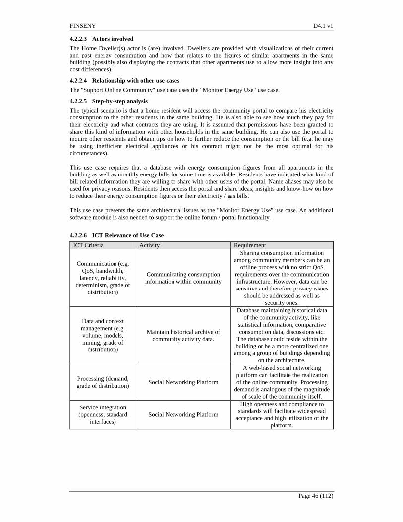
FINSENY D4.1 v1
Page 46 (112)
4.2.2.3 Actors involved
The Home Dweller(s) actor is (are) involved. Dwellers are provided with visualizations of their current and past energy consumption and how that relates to the figures of similar apartments in the same building (possibly also displaying the contracts that other apartments use to allow more insight into any cost differences).
4.2.2.4 Relationship with other use cases
The "Support Online Community" use case uses the "Monitor Energy Use" use case.
4.2.2.5 Step-by-step analysis
The typical scenario is that a home resident will access the community portal to compare his electricity consumption to the other residents in the same building. He is also able to see how much they pay for their electricity and what contracts they are using. It is assumed that permissions have been granted to share this kind of information with other households in the same building. He can also use the portal to inquire other residents and obtain tips on how to further reduce the consumption or the bill (e.g. he may be using inefficient electrical appliances or his contract might not be the most optimal for his circumstances). This use case requires that a database with energy consumption figures from all apartments in the building as well as monthly energy bills for some time is available. Residents have indicated what kind of bill-related information they are willing to share with other users of the portal. Name aliases may also be used for privacy reasons. Residents then access the portal and share ideas, insights and know-how on how to reduce their energy consumption figures or their electricity / gas bills. This use case presents the same architectural issues as the "Monitor Energy Use" use case. An additional software module is also needed to support the online forum / portal functionality.
4.2.2.6 ICT Relevance of Use Case
ICT Criteria Activity Requirement
Communication (e.g. QoS, bandwidth,
latency, reliability, determinism, grade of
distribution)
Communicating consumption information within community
Sharing consumption information among community members can be an
offline process with no strict QoS requirements over the communication infrastructure. However, data can be sensitive and therefore privacy issues
should be addressed as well as security ones.
Data and context management (e.g. volume, models, mining, grade of
distribution)
Maintain historical archive of community activity data.
Database maintaining historical data of the community activity, like
statistical information, comparative consumption data, discussions etc.
The database could reside within the building or be a more centralized one among a group of buildings depending
on the architecture.
Processing (demand, grade of distribution)
Social Networking Platform
A web-based social networking platform can facilitate the realization of the online community. Processing
demand is analogous of the magnitude of scale of the community itself.
Service integration (openness, standard
interfaces) Social Networking Platform
High openness and compliance to standards will facilitate widespread
acceptance and high utilization of the platform.
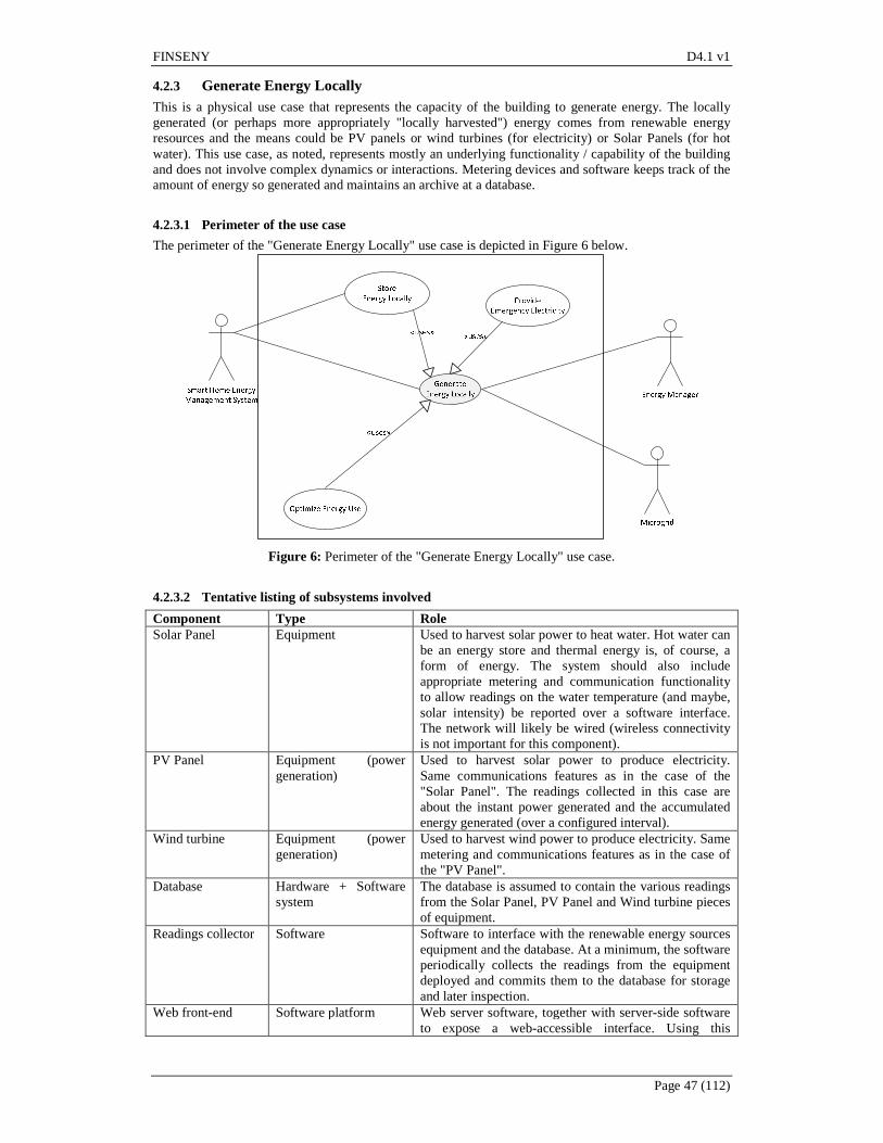
FINSENY D4.1 v1
Page 47 (112)
4.2.3 Generate Energy Locally This is a physical use case that represents the capacity of the building to generate energy. The locally generated (or perhaps more appropriately "locally harvested") energy comes from renewable energy resources and the means could be PV panels or wind turbines (for electricity) or Solar Panels (for hot water). This use case, as noted, represents mostly an underlying functionality / capability of the building and does not involve complex dynamics or interactions. Metering devices and software keeps track of the amount of energy so generated and maintains an archive at a database.
4.2.3.1 Perimeter of the use case
The perimeter of the "Generate Energy Locally" use case is depicted in Figure 6 below.
Figure 6: Perimeter of the "Generate Energy Locally" use case.
4.2.3.2 Tentative listing of subsystems involved
Component Type Role Solar Panel Equipment Used to harvest solar power to heat water. Hot water can
be an energy store and thermal energy is, of course, a form of energy. The system should also include appropriate metering and communication functionality to allow readings on the water temperature (and maybe, solar intensity) be reported over a software interface. The network will likely be wired (wireless connectivity is not important for this component).
PV Panel Equipment (power generation)
Used to harvest solar power to produce electricity. Same communications features as in the case of the "Solar Panel". The readings collected in this case are about the instant power generated and the accumulated energy generated (over a configured interval).
Wind turbine Equipment (power generation)
Used to harvest wind power to produce electricity. Same metering and communications features as in the case of the "PV Panel".
Database Hardware + Software system
The database is assumed to contain the various readings from the Solar Panel, PV Panel and Wind turbine pieces of equipment.
Readings collector Software Software to interface with the renewable energy sources equipment and the database. At a minimum, the software periodically collects the readings from the equipment deployed and commits them to the database for storage and later inspection.
Web front-end Software platform Web server software, together with server-side software to expose a web-accessible interface. Using this
FINSENY D4.1 v1
Page 48 (112)
Component Type Role interface (web site / community portal) the "Energy Manager" actor can view the figures on locally produced energy.
Microgrid Interfacing equipment
Equipment Interfacing equipment with the microgrid (can be a complex system involving electrical, electronics and software components). Used to obtain tariff information and to support the selling of the locally produced energy to the grid.
Smart home interfacing equipment
Equipment Interfacing equipment with the smart home (can be a complex system involving electrical, electronics and software components but on a lower wattage compared to the microgrid interfacing equipment). If the home dwellers are, collectively, the owners of the deployed equipment they can be informed, using this interface, on the amount of energy generated and the proceeds from its sale to the grid.
4.2.3.3 Actors involved
The capacity to locally generate energy is mainly used by the "Microgrid" actor. Readings and measurements are accessed by the "Energy Manager" actor. Configuration and interfacing also exists with the "Smart Home Energy Management System" actor (e.g. in cases where the locally generated energy is used by the apartments in case of a grid /microgrid failure or to monitor the amount of revenue collected).
4.2.3.4 Relationship with other use cases
The "Generate Energy Locally" use case is used by the "Store Energy Locally", "Provide Emergency Electricity" and the "Optimize Energy Use" use cases.
4.2.3.5 Step-by-step analysis
Depending on the implementation details and the targeted feature set, the functionality of this use case can range from simple, automated up to complex, software-driven interactions with the actors that employ it. The Microgrid has to be interconnected of course with the energy generation equipment at the building and a switch will allow the locally generated energy to be either sold to the grid or be used locally by the building (or stored, again, within the building). Such a switch could be conceivably controlled by software (this software acting as an agent of the "Energy Manager" actor) and the external grid could periodically announce (over a software interface) prices at which it is willing to buy energy from local producers or offer some other kind of benefit / incentive for participating in the grid. The Energy Manager of the building, with the consent of the Home Dwellers or the Property Caretaker (depending on who is the beneficiary of the proceeds from any such sales) can periodically revise / update the settings (e.g. instructing the building to sell the locally produced energy to the micro-grid whenever the price offered exceeds 19 cents / kWh).
4.2.3.6 ICT Relevance of Use Case
ICT Criteria Activity Requirement Communication (e.g.
QoS, bandwidth, latency, reliability,
determinism, grade of distribution)
Communication among smart home energy management system,
energy manager and microgrid.
Control as well as management information is exchanged among the actors of this use case. QoS criteria like reliability and latency should be
strict. Data and context management (e.g. volume, models, mining, grade of
distribution)
Energy production repository.
Store and retrieve data regarding, local production of energy along with energy market data. This data support decisions regarding whether or not to
generate energy locally.
Processing (demand, grade of distribution)
Local energy generation decision.
Several parameters should be taken into account in order to make the
decision to switching to local energy generation. Adequate processing
resources should be reserved for this process.
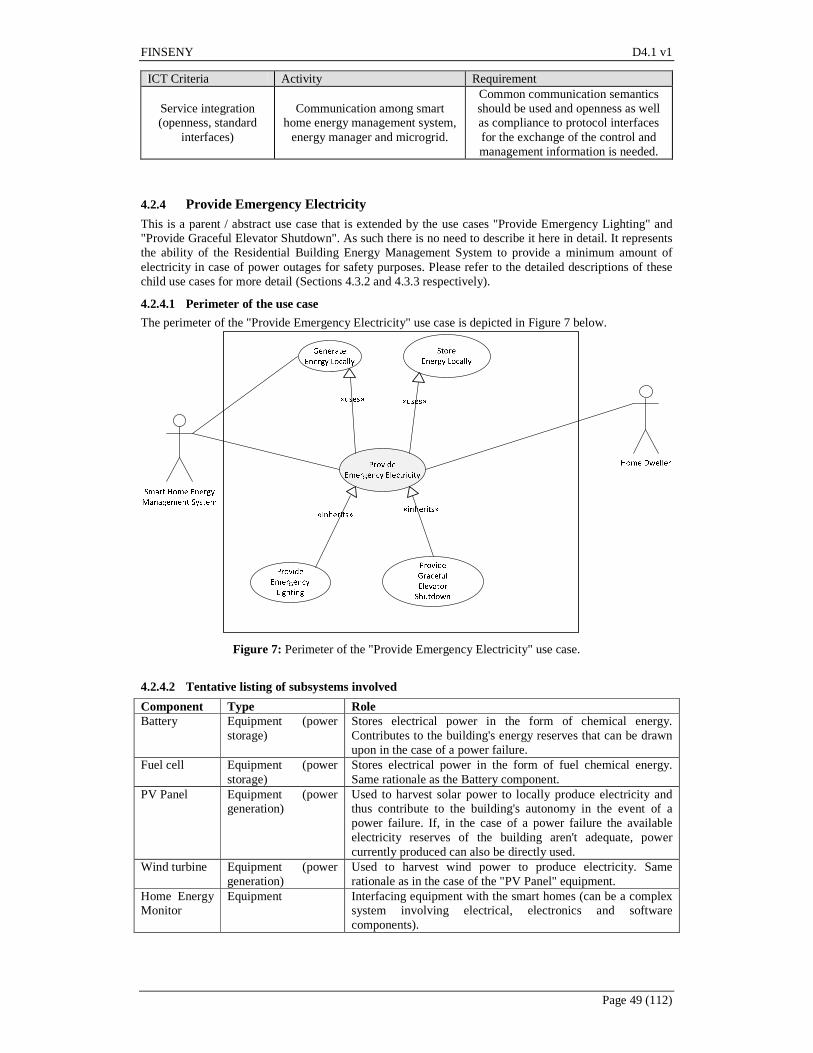
FINSENY D4.1 v1
Page 49 (112)
ICT Criteria Activity Requirement
Service integration (openness, standard
interfaces)
Communication among smart home energy management system,
energy manager and microgrid.
Common communication semantics should be used and openness as well as compliance to protocol interfaces for the exchange of the control and management information is needed.
4.2.4 Provide Emergency Electricity This is a parent / abstract use case that is extended by the use cases "Provide Emergency Lighting" and "Provide Graceful Elevator Shutdown". As such there is no need to describe it here in detail. It represents the ability of the Residential Building Energy Management System to provide a minimum amount of electricity in case of power outages for safety purposes. Please refer to the detailed descriptions of these child use cases for more detail (Sections 4.3.2 and 4.3.3 respectively).
4.2.4.1 Perimeter of the use case
The perimeter of the "Provide Emergency Electricity" use case is depicted in Figure 7 below.
Figure 7: Perimeter of the "Provide Emergency Electricity" use case.
4.2.4.2 Tentative listing of subsystems involved
Component Type Role Battery Equipment (power
storage) Stores electrical power in the form of chemical energy. Contributes to the building's energy reserves that can be drawn upon in the case of a power failure.
Fuel cell Equipment (power storage)
Stores electrical power in the form of fuel chemical energy. Same rationale as the Battery component.
PV Panel Equipment (power generation)
Used to harvest solar power to locally produce electricity and thus contribute to the building's autonomy in the event of a power failure. If, in the case of a power failure the available electricity reserves of the building aren't adequate, power currently produced can also be directly used.
Wind turbine Equipment (power generation)
Used to harvest wind power to produce electricity. Same rationale as in the case of the "PV Panel" equipment.
Home Energy Monitor
Equipment Interfacing equipment with the smart homes (can be a complex system involving electrical, electronics and software components).

FINSENY D4.1 v1
Page 50 (112)
4.2.4.3 Actors involved
The Home Dweller (and / or any visitor) are the beneficiaries of the effects of this use case. As an example, consider the case where a resident wishes, in case of a power failure, to use the locally stored energy in the building to illuminate his apartment. When such a power failure occurs, certain emergency lights in his apartment (or possibly also some electronic appliances to allow a smooth shutdown) continue to work as the "Provide Emergency Electricity" functionality is employed by the resident himself won't have to initiate any sort of action. It is assumed that the electronic / electrical interactions necessary to employ this functionality will be undertaken by the "Smart Home Energy Management System" actor and that the Home Dweller and / or Energy Manager have already configured the system as required.
4.2.4.4 Relationship with other use cases
The "Provide Emergency Electricity" use case is inherited by the "Provide Emergency Lighting" and the "Provide Graceful Elevator Shutdown" use cases. It also uses both the "Generate Energy Locally" and the "Store Energy Locally" use cases (as the emergency electricity can come either from locally harvested energy or from locally stored energy).
4.2.4.5 Step-by-step analysis
The step-by-step analysis in this paragraph is given mostly from the point of view of the "Smart Home Energy Management System" actor. When external power is lost, the house uses power from the building reserves and the home energy management system begins tracking the amount of energy so used. The home energy management system can also be used to shut down certain non-critical appliances or lights. Information on the duration of this incident and the amount of energy used is stored in the Smart Home Energy Management System and is made available to the Home Dweller for inspection.
4.2.4.6 ICT Relevance of Use Case
ICT Criteria Activity Requirement
Communication (e.g. QoS, bandwidth,
latency, reliability, determinism, grade of
distribution)
Communication among controlled devices and smart home energy
management system.
Control signals originate from the home energy management system and
should be delivered in real-time to devices. Therefore, low latency and reliability are strict requirements for the communication infrastructure.
Data and context management (e.g. volume, models, mining, grade of
distribution)
Emergency plan repository. Plans being created beforehand are stored in a database and instantly
retrieved in the case of an incident.
Processing (demand, grade of distribution)
Plan execution. Executing a predefined plan does not
require significant processing resources.
Service integration (openness, standard
interfaces)
Communication among smart home energy management system
and controlled devices.
Control communication of transactional nature that should comply to protocol standards
depending on the kind of the device that is being controlled.
4.2.5 Store Energy Locally This is an abstract / parent use case that is further specialized / inherited by the "Store Electricity Locally" and "Store Hot Water Locally" use cases. It represents the ability to store energy (electricity or hot water) locally using equipment like batteries, fuel cells, hot water tanks, etc.
4.2.5.1 Perimeter of the use case
The perimeter of the "Store Energy Locally" use case is depicted in Figure 8 below.

FINSENY D4.1 v1
Page 51 (112)
Figure 8: Perimeter of the "Store Energy Locally" use case.
4.2.5.2 Tentative listing of subsystems involved
Component Type Role Solar Panel Equipment Harvests solar power and transforms it in thermal energy. Hot Water Tank Passive
equipment Used to store thermal energy for hot water in the apartments (Section 4.3.6) or swimming pool (Section 4.3.7).
Battery Equipment (power storage)
Stores electrical power in the form of chemical energy. Contributes to the building's energy reserves that can be drawn upon in the case of a power failure.
Fuel cell Equipment (power storage)
Stores electrical power in the form of fuel chemical energy. Same rationale as the Battery component.
PV Panel Equipment (power generation)
Used to harvest solar power to locally produce electricity and recharge batteries / fuel cells.
Wind turbine Equipment (power generation)
Used to harvest wind power to produce electricity. Same rationale as in the case of the "PV Panel" equipment.
Microgrid Interfacing equipment
Equipment Interfacing equipment with the microgrid (can be a complex system involving electrical, electronics and software components).
Smart Home Interfacing equipment
Equipment Interfacing equipment with the smart homes (can be a complex system involving electrical, electronics and software components).
Optimizer Hardware and Software system
There are two possible sources for energy to be stored: (a) energy that is locally generated and (b) grid energy. The decision on which of the two to employ, and in what ratio or extent and for how long can be the subject of optimizations performed by a software component that has access to (among others) available pricing information (current and forecasted), current status of the reserves, historical requirements (used to make estimates) and so on. This component should also comprise a web front-end (to allow the "Energy Manger" actor to configure it) and a database.

FINSENY D4.1 v1
Page 52 (112)
4.2.5.3 Actors involved
This use case relates with the "Generate Energy Locally" use case in the sense that the energy so generated can either be sold to the Microgrid or be diverted to the building's own energy store. Therefore it is, again, the "Microgrid" actor that basically interacts with this use case by setting the buy price for locally produced electricity and thus affecting the decision of the system to either store this energy or sell it. Also, the "Energy Manager" actor is involved in configuring the system for this functionality. For instance, the system should also have a human interface to allow the Energy Manager to calibrate the conditions and criteria that the system uses to decide whether to store the energy (as opposed to selling it to the grid). The "Smart Home Energy Management System" actor is also involved since it can draw from the reserves of stored energy in case of emergencies.
4.2.5.4 Relationship with other use cases
The use case "Store Energy Locally" uses the "Generate Energy Locally" use case since one source of energy for storage is the energy that is locally produced at the building (the other being the energy sold by the grid). It is used, in turn, by the "Provide Emergency Electricity" use case since the energy so stored can be used during an emergency. It is also inherited by the use cases "Store Electricity Locally" and "Store Hot Water Locally" since hot water is, in itself, a form of energy. Please refer to the descriptions of these detailed use cases in Sections 4.3.4 and 4.3.5 respectively.
4.2.5.5 Step-by-step analysis
The activation of the functionality of this use case does not directly involve any actors except the Microgrid (which would otherwise receive the locally produced energy). The configuration of the use case involves the "Energy Manager" actor who has to configure the logic and the thresholds the system uses to decide whether to store the locally harvested energy or sell it to the Microgrid. Obviously the price at which the grid / Microgrid is buying energy is a critical factor but so is the current or projected reserves of energy stored in the building (to allow for emergency electricity), the configured "desired" level of reserves, or the current or projected energy needs of the building itself (e.g. lighting and air-conditioning of common areas).
4.2.5.6 ICT Relevance of Use Case
ICT Criteria Activity Requirement Communication (e.g.
QoS, bandwidth, latency, reliability,
determinism, grade of distribution)
Communication among smart home energy management system,
energy manager and microgrid.
Control as well as management information is exchanged among the actors of this use case. QoS criteria like reliability and latency should be
strict. Data and context management (e.g. volume, models, mining, grade of
distribution)
Energy storage repository.
Store and retrieve data regarding, local storage of energy along with
energy market data. This data support decisions regarding whether or not to
generate energy locally.
Processing (demand, grade of distribution)
Optimize energy storage.
Several parameters should be taken into account in order to optimize the way and sources to be used to store
energy. Adequate processing resources should be reserved for this
process.
Service integration (openness, standard
interfaces)
Communication among smart home energy management system,
energy manager and microgrid.
Common communication semantics should be used and openness as well as compliance to protocol interfaces for the exchange of the control and management information is needed.
4.2.6 Optimize Energy Use This is an abstract use case that's specialized by a number of detailed use cases ("Centrally Heat Water for Private Uses", "Provide Communal Hot Water", "Optimize Lighting" and "Optimize Indoor Climate Control"). These detailed use cases are described in Sections 4.3.6, 4.3.7, 4.3.8, and 4.3.9 respectively. As

FINSENY D4.1 v1
Page 53 (112)
such the parent use case "Optimize Energy Use" is not described here in detail. In general, we can say that it represents the ability of the residential building energy management system to have a beneficial effect on the energy consumption patterns of the building, either with respect to conserving energy or optimizing costs or delivering benefits to the external grid / micro-grid by helping shape the energy load. Please refer to the presentation of the relevant detailed use cases for more detail.
4.3 Detailed use cases
This Section provides the so-called "detailed" use cases. These use cases, as noted in the introduction of Section 4.2 are actually derived use cases that are related to the "high-level" (or "base" use cases) with one of the relationship stereotypes that UML makes possible between use cases (inclusion, extension and generalization / specialization). These derived use cases can use the inheritance mechanisms to leverage on the functionality that is already described and factored into the high-level use cases; accordingly their textual descriptions can be shorter in most cases.
4.3.1 Display Energy Consumption This use case allows an actor to display or produce reports of the current as well as of the historical energy consumption at the building level (excluding energy used in the apartments). It includes both electricity and gas (cumulatively or separately). The use case is understood to allow plots, graphs and extracts (for data-interchange purposes) to be easily obtained through a web-based GUI. This use case obviously relies on the "Monitor Energy Use" use case (Section 4.2.1) and "simply" adds the ability to visualize and extract detailed information / data from the database.
4.3.1.1 Perimeter of the use case
The perimeter of the "Display Energy Consumption" use case is depicted in Figure 9 below.
Figure 9: Perimeter of the "Display Energy Consumption" use case.
4.3.1.2 Actors Involved
The actors involved are the Energy Inspector and the Energy Manager. Involved actors are provided with near-real time and historical visualizations of current energy consumption (electricity and gas).
4.3.1.3 Relationship with other use cases
The "Display Energy Consumption" use case obviously relies on and "uses" (in the UML sense) the "Monitor Energy Use" use case. It can also be further specialized into: display electricity consumption and display gas consumption. These latter use cases are rather obvious specialization of the functionality we describe in this section and so are not treated independently in this document.
4.3.1.4 Step-by-step analysis
Historical electricity and gas meters readings are assumed to be available in a database and are constantly updated with additional, near-real time readings. Both present and past values are drawn from the database by the web-based front-end and can be visualized, plotted or extracted on demand. As a precondition, this use case assumes that a database with stored past readings is available and is constantly populated. Human users (instances of the "Energy Inspector" or "Energy Manager" or, conceivably, other actors) can then visit the web-based front-end and request the visualization or extraction of specific plot series. A typical three-tiered web server architecture is also assumed. The building hosts (e.g. in a computer room), the two back-end tiers (the web/application server and the database). Clients access the information from a typical web browser (could be a thin client or a smartphone / tablet). If connectivity outside the building is also required then Internet access should also be factored in. The back-end could

FINSENY D4.1 v1
Page 54 (112)
utilize a communal Internet access facility. Such a facility might make sense from economies of scale perspective and to also exploit the multiplexing potential when providing Internet access to independent households within the same building.
4.3.1.5 Contracts / Regulations
The metering facility, on its own can report only energy consumption; not price information. If price information is also to be given then the facility system should also have access to contract information and the algorithm used to calculate price. In certain jurisdictions this is not so straightforward as the energy bills are also used to include various other tariffs and taxes (e.g. real estate tax, local council / municipality taxes, state TV contribution) and are frequently revised. The system could alternative use the contract information to calculate only the "net" price of energy (not taking into consideration additional surcharges) but the resulting difference between the price reported by the system and the actual bill may be frustrating to consumers. Finally, in many cases even calculating the "net cost" is not very straightforward as the algorithm can be quite complicated or it might be too complex / impractical to configure and continuously maintain the system with all information necessary to compute the bill.
4.3.1.6 ICT relevance of Use Case
ICT Criteria Use Case Requirement
Communication (e.g. QoS, bandwidth, latency, reliability,
determinism, grade of distribution)
Demand Side Monitoring
Partially strict real-time, high volume;
Protocol Types: Transaction-based, Request/Response, publish/Subscribe;
Traffic Management
Data and context management (e.g. volume, models, mining,
grade of distribution)
Demand Side Monitoring
CIM of monitored data
Processing (demand, grade of distribution)
Demand Side Monitoring
Interface to the Database: High data volume
Service integration (openness, standard interfaces)
Demand Side Monitoring
Conformance to Standards
Table: ICT Relevance of Use Case “Display Energy Consumption”
4.3.1.7 Assumptions of Use Case
Low level Use Case Preconditions or assumptions
Demand-side Monitoring All equipment necessary to monitor and control the power consumption.
Table: Assumptions of Use Case “Display Energy Consumption”
4.3.2 Provide Emergency Lighting This use case uses the power stored at the building level or the power generated by building-level Photo-Voltaic panels or Wind turbines to provide emergency lighting in the common areas or, also, private apartments, if so configured, in the event of a grid power failure. For reasons of economies of scale it makes sense to deploy renewable energy generating equipment such as PV panels at the building level. For similar reasons, storage of energy can be centralized. E.g. high energy batteries or fuel cells may be located at the basement and used to store energy for the whole building. This kind of energy can then be used in the event of an external grid power failure to provide

FINSENY D4.1 v1
Page 55 (112)
lighting that is essential for safety reasons either in the common areas of the building or inside the apartments (we can imagine safely lighting fixtures that use this central source of power). So when the external power grid fails, energy stored at the grid level can be used to maintain lighting at dark corridors, staircases or provide limited (dimmed) lights to the apartments, even beyond what is strictly required for safety reasons.
4.3.2.1 Perimeter of the use case
The perimeter of the "Provide Emergency Lighting" use case is depicted in Figure 10 below.
Figure 10: Perimeter of the "Provide Emergency Lighting" use case.
4.3.2.2 Actors involved
The main actors involved are the Energy Manager (for configuring the desired behaviour), the Home Dwellers (including visitors) and the various Home Energy Management Systems. In terms of information exchanged with these actors we note that the amount of energy stored and its gradual depletion over time in the course of an incident should be available for inspection by the Energy Manager or the residents. So we can imagine that the central storage system is connected with electronics to the building database / web portal to allow these readings to be displayed. Additionally, and so as to avoid waste, emergency lights at the apartments should be lit only for the apartments that are currently occupied and after consulting an astronomical clock to decide the amount of available sunlight. To implement this, it is necessary that the Home Energy Management System is interconnected with the Building-level Energy Management system. Presumably the Home Energy Management System is able to report to the Building-level Energy Management System if there are people currently in the apartment. This can be done via motion detectors, electricity consumption meters (if the oven is on there is likely somebody in the apartment) or alarm / electronic lock settings (if the alarm is armed there is nobody in the apartment). Security of this information and inability of third parties to access it, especially in real time, is an obvious concern. The Energy Manager actor should also be able to configure appropriate business rules that determine various details of this service (e.g. for how long the emergency lighting should be made available to apartments, the threshold of available sunlight above which the service should be disabled, or the extent of dimming in case of dimmable lights).
4.3.2.3 Relationship with other use cases
The "Provide Emergency Lighting" is a specialization of the "Provide Emergency Electricity" use case. The use case also uses the "Generate Energy Locally" use case as the energy required to operate the safety lights does not come from the batteries but rather directly from the available PV panels (if, of course, such energy is available at the time of the incident).
4.3.2.4 Step-by-step analysis
This use cases presupposes that there is available stored power centrally at the building or that the power currently produced at the renewable sources is adequate. The use case is triggered by a failure in the external power grid. A relay connects the power stored at the building batteries or that currently generated at the PV panels to a circuit that includes safety lights at

FINSENY D4.1 v1
Page 56 (112)
corridors and staircases and maybe certain currently occupied apartments. During the incident readings on the available remaining stored power are available. When the external power is restored, the building's stored power supply will be replenished (from the external grid) to account for any depletion during the incident. In terms of architectural issues, this use case requires interconnection with the Smart Home Energy Management Systems to avoid turning on the safety lights at un-occupied apartments.
4.3.2.5 Contracts / Regulations
In many jurisdictions, and depending on the type, size and intended use of the building, safety lights may be mandated by the building code. In this section however we describe a more refined version where the lights may be used to enable some limited continuation of certain household activities, and one that's provided more as an extra convenience and less as a real emergency measure. For instance, the system could provide just enough light to enable someone to move around the apartment and maybe do some chores (as opposed to just finding the way to the nearest exit).
4.3.2.6 ICT relevance of Use Case
ICT Criteria Use Case Requirement Communication (e.g.
QoS, bandwidth, latency, reliability,
determinism, grade of distribution)
Energy Supply Reliable communication with very low
latency among control entities
Data and context management (e.g. volume, models, mining, grade of
distribution)
Source of energy Selection High demand for context-based and
filtered data management
Processing (demand, grade of distribution)
Planning of energy supply
High demand for computing resources for calculation and simulation models
Service integration (openness, standard
interfaces) Energy Supply
Publish open interfaces servicing higher level entities
Table: ICT Relevance of Use Case “Provide Emergency Lighting”
4.3.2.7 Assumptions of Use Case
Use Case Preconditions or assumptions Monitoring
Table: Assumptions of Use Case “Provide Emergency Lighting”
4.3.3 Provide Graceful Elevator Shutdown The idea behind this use case is to allow the system to employ the power stored at the building level to provide emergency electricity in the elevator shafts, when and where necessary, in the event of a grid power failure. The focus here is mostly elevators and, in particular, elevators that were currently in motion or / and had passengers in when the power failure occurred. The narrative is pretty much the same as with the "Provide Emergency Lighting" use case with the difference that here the target is elevators and not lights. Emphasis is placed on occupied elevators where a graceful shutdown is necessary to allow people to exit (so as to avoid trapped people). In contrast to the safety lights scenario the goal here is not to ensure the sustained operation of the elevators, but rather operation till the nearest floor to allow people to exit. This is to economize on the available stored energy since it is also used on other safety features.
4.3.3.1 Perimeter of the use case
The perimeter of the "Provide Graceful Elevator Shutdown" use case is depicted in Figure 11 below.
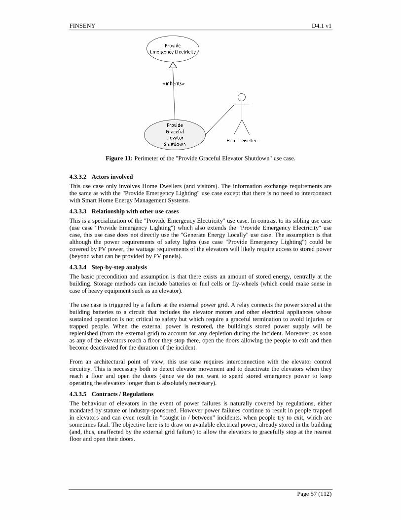
FINSENY D4.1 v1
Page 57 (112)
Figure 11: Perimeter of the "Provide Graceful Elevator Shutdown" use case.
4.3.3.2 Actors involved
This use case only involves Home Dwellers (and visitors). The information exchange requirements are the same as with the "Provide Emergency Lighting" use case except that there is no need to interconnect with Smart Home Energy Management Systems.
4.3.3.3 Relationship with other use cases
This is a specialization of the "Provide Emergency Electricity" use case. In contrast to its sibling use case (use case "Provide Emergency Lighting") which also extends the "Provide Emergency Electricity" use case, this use case does not directly use the "Generate Energy Locally" use case. The assumption is that although the power requirements of safety lights (use case "Provide Emergency Lighting") could be covered by PV power, the wattage requirements of the elevators will likely require access to stored power (beyond what can be provided by PV panels).
4.3.3.4 Step-by-step analysis
The basic precondition and assumption is that there exists an amount of stored energy, centrally at the building. Storage methods can include batteries or fuel cells or fly-wheels (which could make sense in case of heavy equipment such as an elevator). The use case is triggered by a failure at the external power grid. A relay connects the power stored at the building batteries to a circuit that includes the elevator motors and other electrical appliances whose sustained operation is not critical to safety but which require a graceful termination to avoid injuries or trapped people. When the external power is restored, the building's stored power supply will be replenished (from the external grid) to account for any depletion during the incident. Moreover, as soon as any of the elevators reach a floor they stop there, open the doors allowing the people to exit and then become deactivated for the duration of the incident. From an architectural point of view, this use case requires interconnection with the elevator control circuitry. This is necessary both to detect elevator movement and to deactivate the elevators when they reach a floor and open the doors (since we do not want to spend stored emergency power to keep operating the elevators longer than is absolutely necessary).
4.3.3.5 Contracts / Regulations
The behaviour of elevators in the event of power failures is naturally covered by regulations, either mandated by stature or industry-sponsored. However power failures continue to result in people trapped in elevators and can even result in "caught-in / between" incidents, when people try to exit, which are sometimes fatal. The objective here is to draw on available electrical power, already stored in the building (and, thus, unaffected by the external grid failure) to allow the elevators to gracefully stop at the nearest floor and open their doors.
FINSENY D4.1 v1
Page 58 (112)
4.3.3.6 ICT relevance of Use Case
ICT Criteria Use Case Requirement Communication (e.g.
QoS, bandwidth, latency, reliability,
determinism, grade of distribution)
Energy Supply Reliable communication with very low
latency among control entities
Data and context management (e.g. volume, models, mining, grade of
distribution)
Source of energy Selection High demand for context-based and
filtered data management
Processing (demand, grade of distribution)
Planning of energy supply
High demand for computing resources for calculation and simulation models
Service integration (openness, standard
interfaces) Energy Supply
Publish open interfaces servicing higher level entities
Table: ICT Relevance of Use Case “Provide Graceful Elevator Shutdown”
4.3.3.7 Assumptions of Use Case
Use Case Preconditions or assumptions Monitoring
Table: Assumptions of Use Case “Provide Graceful Elevator Shutdown”
4.3.4 Store Electricity Locally This is another "physical" use case that represents the capacity of the building to store electricity locally and the availability of an ICT infrastructure to allow monitoring and historical / real-time reporting of:
• how these locally stored energy reserves are built (i.e. which are the sources contributing to the electricity store - locally harvested energy or grid) and,
• how they are depleted (e.g. which are the loads that draw from this electricity store). We will not describe it in detail or in terms of its interactions between actors as it is rather trivial, and mostly "physical", in this perspective. The means to store energy can include batteries, fuel cells or more exotic pieces of equipment such as fly-wheels. This use case is obviously a specialization of the "Store Energy Locally".
4.3.4.1 Perimeter of the use case
The perimeter of this use case is shown in Figure 12 below.

FINSENY D4.1 v1
Page 59 (112)
Figure 12: Perimeter of the "Store Electricity Locally" use case.
4.3.4.2 Actors involved
The actors using this use case are the Energy Manager (for the whole building) and the "Smart Home Energy Management System" (for each apartment / condominium).
4.3.4.3 Relationship with other use cases
The "Store Electricity Locally" use case is used by the "Provide Emergency Electricity" use case. It is also, obviously, a specialization of the "Store Energy Locally" use case.
4.3.4.4 Step-by-step analysis
Electricity is produced locally using renewable energy sources like PV panels or wind turbines. It can also be bought from the grid (when the price is exceptionally low) - if it makes economic sense to store this electricity in anticipation of near-term future needs (taking also into consideration the cost of storage and the inevitable losses). Meters monitor, over time, the amount of energy drawn by the building's "energy tank" as well as the source of that energy (locally produced or external grid). Energy requests depleting the tank are also monitored and tracked. Moreover, we can envision ICT-heavy scenarios whereby the Energy Manger is able to configure the system so it can act based on pre-set criteria in a semi-autonomous or even fully autonomous way. In other words, a software module can be used to interface with the locally available renewable energy sources and the external grid and decide, for instance, when to buy energy, when to sell it (as opposed to using it locally), which percentage of the locally produced energy to store, or how low to allow the energy reserves to fall before trying to replenish them. This software module can act on business rules configured by the Energy Manager over a graphical interface (in that sense it acts as an agent of the "Energy Manager"). In these scenarios, the external grid (micro- or macro-grid) also becomes an actor involved in this use case and has to exchange price information with the Energy Manager (or the software acting on his behalf). For instance, the Energy Manager needs to know the price of electricity not just "now", but also what the tariff will or might be one or two hours down the road, to determine if it's worthwhile to buy some energy from the external grid simply for the purpose of storing it. Actually, the algorithm to decide that could get quite complicated as it would also need to take into account the projected power generated at the renewable energy sources of the building as well as likely demands that may be anticipated on the stored energy.
4.3.4.5 Contracts / Regulations
The contract with the external grid (micro- or macro- ) obviously comes to play in regard to this use case. The tariff, or the various tariffs, foreseen in the contract for the selling / buying of energy at different times of day need to be configured in the system to allow optimized decisions to be made. In the case of
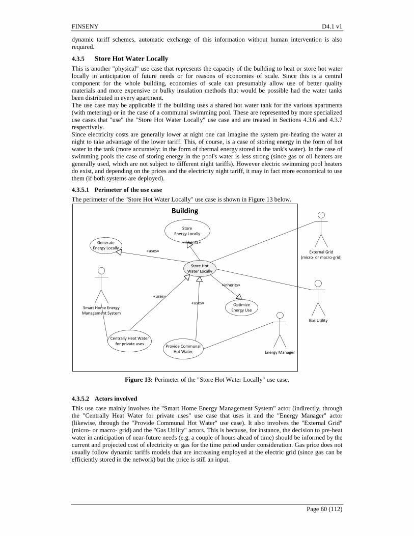
FINSENY D4.1 v1
Page 60 (112)
dynamic tariff schemes, automatic exchange of this information without human intervention is also required.
4.3.5 Store Hot Water Locally This is another "physical" use case that represents the capacity of the building to heat or store hot water locally in anticipation of future needs or for reasons of economies of scale. Since this is a central component for the whole building, economies of scale can presumably allow use of better quality materials and more expensive or bulky insulation methods that would be possible had the water tanks been distributed in every apartment. The use case may be applicable if the building uses a shared hot water tank for the various apartments (with metering) or in the case of a communal swimming pool. These are represented by more specialized use cases that "use" the "Store Hot Water Locally" use case and are treated in Sections 4.3.6 and 4.3.7 respectively. Since electricity costs are generally lower at night one can imagine the system pre-heating the water at night to take advantage of the lower tariff. This, of course, is a case of storing energy in the form of hot water in the tank (more accurately: in the form of thermal energy stored in the tank's water). In the case of swimming pools the case of storing energy in the pool's water is less strong (since gas or oil heaters are generally used, which are not subject to different night tariffs). However electric swimming pool heaters do exist, and depending on the prices and the electricity night tariff, it may in fact more economical to use them (if both systems are deployed).
4.3.5.1 Perimeter of the use case
The perimeter of the "Store Hot Water Locally" use case is shown in Figure 13 below.
Store
Energy Locally
Store Hot
Water Locally
«inherits»
Centrally Heat Water
for private uses
«uses»
Optimize
Energy Use
«inherits»
Generate
Energy Locally
Energy Manager
External Grid
(micro‐ or macro‐grid)
«uses»
Building
Provide Communal
Hot Water
«uses»Smart Home Energy
Management System
Gas Utility
Figure 13: Perimeter of the "Store Hot Water Locally" use case.
4.3.5.2 Actors involved
This use case mainly involves the "Smart Home Energy Management System" actor (indirectly, through the "Centrally Heat Water for private uses" use case that uses it and the "Energy Manager" actor (likewise, through the "Provide Communal Hot Water" use case). It also involves the "External Grid" (micro- or macro- grid) and the "Gas Utility" actors. This is because, for instance, the decision to pre-heat water in anticipation of near-future needs (e.g. a couple of hours ahead of time) should be informed by the current and projected cost of electricity or gas for the time period under consideration. Gas price does not usually follow dynamic tariffs models that are increasing employed at the electric grid (since gas can be efficiently stored in the network) but the price is still an input.

FINSENY D4.1 v1
Page 61 (112)
4.3.5.3 Relationship with other use cases
This is a pre-requisite use case for the use cases "Centrally Heat Water for Private Uses" and "Provide Communal Hot Water". It also uses the "Generate Energy Locally" use case (since the energy required to heat the water may also come from local renewable energy sources). Finally, it is a specialization of both the "Store Energy Locally" (obviously) and of the "Optimize Energy Use" use cases.
4.3.5.4 Step-by-step analysis
There is a homomorphism between the step-by-step analysis of the "Store Hot Water Locally" use case and the similar analysis of the "Store Electricity Locally" use case to the extent that electricity is used to heat the water. Indeed, using electricity to heat stored water is, in a sense, a case of locally storing or at least "pre-buying" electricity (since this electricity will not be demanded later). For this reason we do not provide a separate step-by-step analysis of the "Store Hot Water Locally" use case.
4.3.5.5 Contracts / Regulations
Applicable to this use case are the gas and electricity contracts and their foreseen tariffs.
4.3.6 Centrally Heat Water for Private Uses This use case allows the system to provide hot water 24/7 (or for other extended time periods less than 24/7) for all building residents while at the same time maintain a metering capacity capable of allocating costs to specific apartments. Certain buildings, for reasons of economies of scale, include infrastructure to centrally heat hot water and make it available to residents. This infrastructure can include PV panels, solar panels, highly efficient water heaters, or highly insulated hot water tanks. Reasons for doing so at a central, building level can include economies of scale, reduced maintenance requirements or even civil engineering considerations. However access to a communal resource encourages waste so the idea here is to combine the central infrastructure with metering appliances that can measure the hot water consumption of each household. In this way all residents gain from the economies of scale and the reduced maintenance while at the same time being charged only in relation to their actual usage.
4.3.6.1 Perimeter of the use case
The perimeter of the "Centrally Heat Water for Private Uses" is depicted in Figure 16 that follows.
Figure 14: Perimeter of the "Centrally Heat Water for Private Uses" use case.
4.3.6.2 Actors involved
This use cases involves the "Home Dweller", the "Smart Home Energy Management System" and the "Microgrid" actors. The latter can also represent a typical (macro-) grid together with a dynamic tariff system and a method for communicating changing tariffs to the building. Finally, the "Gas Utility" actor is also involved if gas is used to heat the water.

FINSENY D4.1 v1
Page 62 (112)
4.3.6.3 Relationship with other use cases
This use case uses the "Generate Energy Locally" and the "Store Hot Water Locally" use cases and is a specialization of the "Optimize Energy Use" high-level use case.
4.3.6.4 Contracts / Regulations
Same as in use case "Store Hot Water Locally" (section 4.3.5).
4.3.6.5 Step-by-step analysis
This use case requires hydraulic meters capable of measuring hot water consumption either in terms of volume or in terms of calories / temperature or both. These metering devices should have the necessary electronics to allow readings to be collected by software over a wired or wireless LAN (e.g WiFi). These readings will then be used to calculate monthly bills or otherwise amortize the cost to the various apartments based on usage. The system encompasses PV and Solar panels installed at the roof of the building. Distribution of heat and hot water is carried out by means of a primary circuit and interface points at each apartment. If the incoming water temperature is lower than the required, regular apartment boiler is used. The system measures values at the interface point and calculates consumption and charges. The system-user interface in the control panel in each apartment allows to: (a) program the required temperature of the hot water, (b) program the heating on a daily / weekly basis, (c) visualize consumptions, (d) supervise the system functioning (alarms, indicators). Role of ICT is to monitor use of hot water per apartment and to provide web-based front-end for each apartment to allow tracking by end users and to do billing. This is because simply sharing the cost with a static formula (as opposed to actually monitoring consumption) encourages waste. The web front-end can also be used by energy experts and building managers to provide historical data and charting / plotting functionality (reports) as well as other generic information.
4.3.7 Provide Communal Hot Water This use case foresees the installation of solar panels and use of thermal energy to heat water in a shared tank for use in common resources (e.g. swimming pool). This use case is adapted from the Best Energy project no. 238889 ICT-PSP, Built Environments Sustainability and Technology in Energy / Deliverable D1.1 / pilot B1 (Paco Yoldi Sports Centre) and synthesized with ideas coming from BeyWatch project (www.beywatch.eu).
4.3.7.1 Perimeter of the use case
The perimeter of the "Provide Communal Hot Water" use case is depicted in Figure 15 below.
Figure 15: Perimeter of the "Provide Communal Hot Water" use case.
4.3.7.2 Actors involved
This use cases involves the "Energy Manager" actor and the external grid (micro- or macro-grid). The "Gas Utility" actor may also be involved when gas is used to heat the water.

FINSENY D4.1 v1
Page 63 (112)
4.3.7.3 Relationship with other use cases
This use case uses the "Generate Energy Locally" and the "Store Hot Water Locally" use cases and is a specialization of the "Optimize Energy Use" high-level use case.
4.3.7.4 Step-by-step analysis
The Energy Manager (or some software acting on his behalf and customized using high-level business rules) configures the selected temperature of the swimming pool and the hours during the day when this temperature should be reached. He also configures the amount of energy the system should use for that purpose from the locally renewable energy sources and criteria for procuring this energy from the external grid or the gas utility (e.g. price information). The system also has information on the current and projected energy cost for a one-day period ahead as well as projections for the power to be generated at the local sources. Based on this information and following a complex optimization the system uses the right amount of energy and buys energy from the grid at the right time to ensure that the swimming pool water temperature is at the desired levels, with the lowest cost.
4.3.7.5 Contracts / Regulations
Same as in use case "Store Hot Water Locally" (section 4.3.5).
4.3.8 Optimize Lighting This use cases features a smart lighting system to conserve electricity and reduce costs in the lighting of common areas in the building. The system is ICT-based and fully automated and is used for controlling lights in all common areas of the building. The system makes use of motion detection sensors, an astronomical clock (sunrise and sunset) and dimmable lights. This system is considered an agent of the "Energy Manager" actor who is responsible for configuring high-level business rules on which the system acts.
4.3.8.1 Perimeter of the use case
The perimeter of the "Optimize Lighting" use case is depicted in Figure 16 that follows.
Figure 16: Perimeter of the "Optimize Lighting" use case.
4.3.8.2 Actors involved
The use case involves the "Energy Manager" actor or the automated "smart-building" software that acts on his behalf. It also involves the "Microgrid" actor since electricity price information is an input to any decision on what source of power to use to lit the lights (e.g. use locally generated power, locally stored power or grid power).
4.3.8.3 Relationship with other use cases.
The use case "Optimize Lighting" is a specialization of the "Optimize Energy Use" use case and uses the "Generate Energy Locally" and "Store Electricity Locally" use case since the power used to lit the lights can come from local renewable energy sources, stored energy or the external grid. We assume that in most cases the locally harvested energy will be used, at least in daytime but the software controlling this
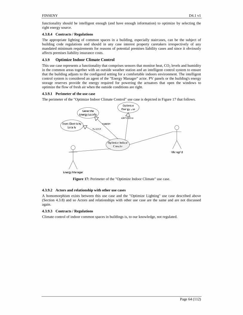
FINSENY D4.1 v1
Page 64 (112)
functionality should be intelligent enough (and have enough information) to optimize by selecting the right energy source.
4.3.8.4 Contracts / Regulations
The appropriate lighting of common spaces in a building, especially staircases, can be the subject of building code regulations and should in any case interest property caretakers irrespectively of any mandated minimum requirements for reasons of potential premises liability cases and since it obviously affects premises liability insurance costs.
4.3.9 Optimize Indoor Climate Control This use case represents a functionality that comprises sensors that monitor heat, CO2 levels and humidity in the common areas together with an outside weather station and an intelligent control system to ensure that the building adjusts to the configured setting for a comfortable indoors environment. The intelligent control system is considered an agent of the "Energy Manager" actor. PV panels or the building's energy storage reserves provide the energy required for powering the actuators that open the windows to optimize the flow of fresh air when the outside conditions are right.
4.3.9.1 Perimeter of the use case
The perimeter of the "Optimize Indoor Climate Control" use case is depicted in Figure 17 that follows.
Figure 17: Perimeter of the "Optimize Indoor Climate" use case.
4.3.9.2 Actors and relationship with other use cases
A homomorphism exists between this use case and the "Optimize Lighting" use case described above (Section 4.3.8) and so Actors and relationships with other use case are the same and are not discussed again.
4.3.9.3 Contracts / Regulations
Climate control of indoor common spaces in buildings is, to our knowledge, not regulated.
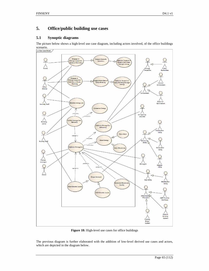
FINSENY D4.1 v1
Page 65 (112)
5. Office/public building use cases
5.1 Synoptic diagrams
The picture below shows a high-level use case diagram, including actors involved, of the office buildings scenario.
Figure 18: High-level use cases for office buildings
The previous diagram is further elaborated with the addition of low-level derived use cases and actors, which are depicted in the diagram below.
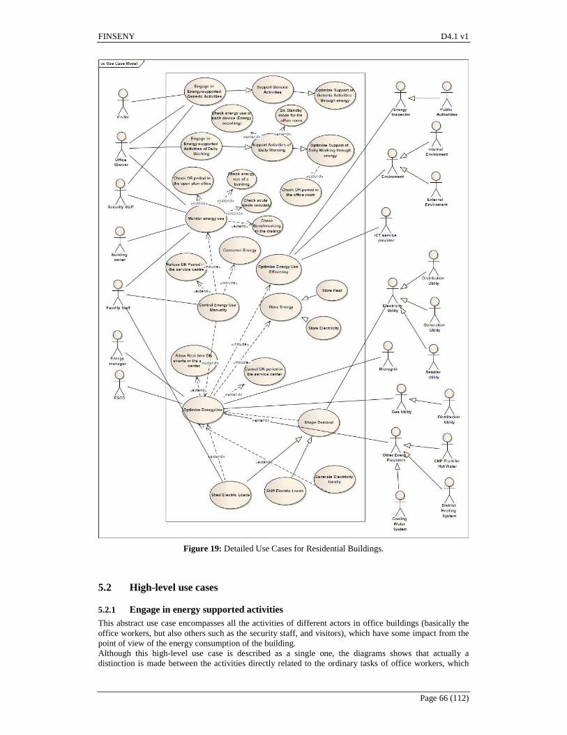
FINSENY D4.1 v1
Page 66 (112)
Figure 19: Detailed Use Cases for Residential Buildings.
5.2 High-level use cases
5.2.1 Engage in energy supported activities This abstract use case encompasses all the activities of different actors in office buildings (basically the office workers, but also others such as the security staff, and visitors), which have some impact from the point of view of the energy consumption of the building. Although this high-level use case is described as a single one, the diagrams shows that actually a distinction is made between the activities directly related to the ordinary tasks of office workers, which
FINSENY D4.1 v1
Page 67 (112)
are generally considered the most relevant with regard to energy consumption (e.g. use of computers), and what has been called “generic activities”, which can be associated both to office workers, visitors and security staff (e.g. use of elevators). It should be noted that not only energy demanding activities are included here, but also manual actions addressing energy conservation (e.g. turn off PC when leaving the office).
5.2.2 Control energy use manually In office buildings it is generally considered that manual control of energy use (except for simple control actions associated to all office building users, such as manually turning-off the PC when leaving, as mentioned in the previous use case) is an action performed by the facility staff of the building, who are in charge for instance of manually setting the levels of the HVAC installations of the building. This high-level use case is then further specialized in other three use cases, which are Monitor Energy Use, Conserve Energy and Optimize Energy Use. The facility staff will have the possibility to override the automatic control actions of the Building Energy Management System, in order to adapt its behavior to certain situations that could not be foreseen by that system.
5.2.3 Optimize energy use This is an abstract use case that's extended by the "Shape Demand", "Generate Electricity locally" and “Shed Electric Loads” use cases. It represents the ability of the building energy management system to impart a beneficial effect on the energy consumption patterns of the building, either with respect to conserving energy or optimizing costs or delivering benefits to the external grid / micro-grid by helping shape the energy load.
5.2.4 Shape demand This is an abstract / parent use case that is further specialized / inherited by the "Shed Electric Loads" and "Shift Electric Loads" use cases. The idea is to have a smart grid that can control certain things that require a lot of energy to shape demand. There are many things that, within certain parameters, can be played with to match electrical supply and demand. They include such things as load control devices, smart thermostats and home energy consoles. They are essential to allow customers to reduce or shift their power use during peak demand periods. Shape demand plays a key role in several areas: pricing, emergency response, grid reliability, infrastructure planning and design, operations, and deferral.
5.2.5 Store energy This is an abstract / parent use case that is further specialized / inherited by the "Store Electricity" and "Store Heat" use cases. It represents the ability to store energy (electricity or hot water) locally using available technological means like batteries, fuel cells, hot water tanks, etc. The application of these technologies in buildings has the following advantages: the ability to narrow the gap between the peak and off-peak loads of electricity demand; the ability to save operative fees by shifting the electrical consumption from peak periods to off-peak periods since the cost of electricity at night is 1/3–1/5 of that during the day; the ability to utilize solar energy continuously, storing solar energy during the day, and releasing it at night, particularly for space heating in winter by reducing diurnal temperature fluctuation thus improving the degree of thermal comfort; the ability to store the natural cooling by ventilation at night in summer and to release it to decrease the room temperature during the day, thus reducing the cooling load of air conditioning.
5.3 Detailed use cases
5.3.1 Check energy use
5.3.1.1 Brief description
The BEMS provides regularly updated historic, real-time and/or forecast energy usage data of the office building via displays/information screens/web browsers to the end-users with the goal to motivate the staff to use energy conservatively. The BEMS also provides weather forecast and predictions of indoor environment conditions.
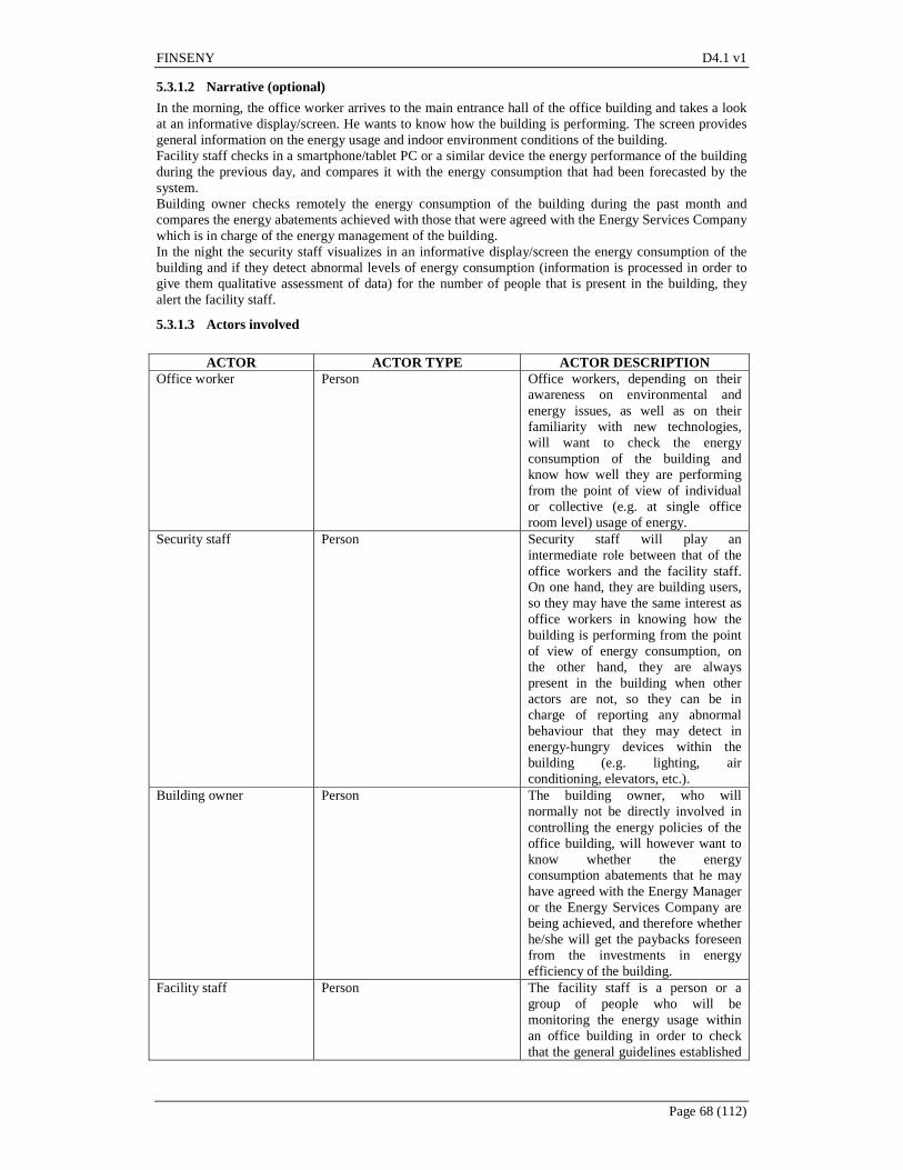
FINSENY D4.1 v1
Page 68 (112)
5.3.1.2 Narrative (optional)
In the morning, the office worker arrives to the main entrance hall of the office building and takes a look at an informative display/screen. He wants to know how the building is performing. The screen provides general information on the energy usage and indoor environment conditions of the building. Facility staff checks in a smartphone/tablet PC or a similar device the energy performance of the building during the previous day, and compares it with the energy consumption that had been forecasted by the system. Building owner checks remotely the energy consumption of the building during the past month and compares the energy abatements achieved with those that were agreed with the Energy Services Company which is in charge of the energy management of the building. In the night the security staff visualizes in an informative display/screen the energy consumption of the building and if they detect abnormal levels of energy consumption (information is processed in order to give them qualitative assessment of data) for the number of people that is present in the building, they alert the facility staff.
5.3.1.3 Actors involved
ACTOR ACTOR TYPE ACTOR DESCRIPTION
Office worker Person Office workers, depending on their awareness on environmental and energy issues, as well as on their familiarity with new technologies, will want to check the energy consumption of the building and know how well they are performing from the point of view of individual or collective (e.g. at single office room level) usage of energy.
Security staff Person Security staff will play an intermediate role between that of the office workers and the facility staff. On one hand, they are building users, so they may have the same interest as office workers in knowing how the building is performing from the point of view of energy consumption, on the other hand, they are always present in the building when other actors are not, so they can be in charge of reporting any abnormal behaviour that they may detect in energy-hungry devices within the building (e.g. lighting, air conditioning, elevators, etc.).
Building owner Person The building owner, who will normally not be directly involved in controlling the energy policies of the office building, will however want to know whether the energy consumption abatements that he may have agreed with the Energy Manager or the Energy Services Company are being achieved, and therefore whether he/she will get the paybacks foreseen from the investments in energy efficiency of the building.
Facility staff Person The facility staff is a person or a group of people who will be monitoring the energy usage within an office building in order to check that the general guidelines established
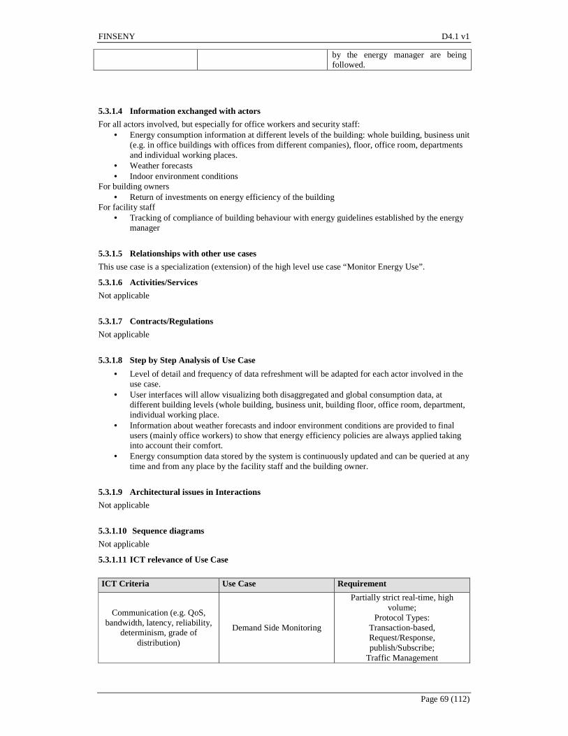
FINSENY D4.1 v1
Page 69 (112)
by the energy manager are being followed.
5.3.1.4 Information exchanged with actors
For all actors involved, but especially for office workers and security staff: • Energy consumption information at different levels of the building: whole building, business unit
(e.g. in office buildings with offices from different companies), floor, office room, departments and individual working places.
• Weather forecasts • Indoor environment conditions
For building owners • Return of investments on energy efficiency of the building
For facility staff • Tracking of compliance of building behaviour with energy guidelines established by the energy
manager
5.3.1.5 Relationships with other use cases
This use case is a specialization (extension) of the high level use case “Monitor Energy Use”.
5.3.1.6 Activities/Services
Not applicable
5.3.1.7 Contracts/Regulations
Not applicable
5.3.1.8 Step by Step Analysis of Use Case
• Level of detail and frequency of data refreshment will be adapted for each actor involved in the use case.
• User interfaces will allow visualizing both disaggregated and global consumption data, at different building levels (whole building, business unit, building floor, office room, department, individual working place.
• Information about weather forecasts and indoor environment conditions are provided to final users (mainly office workers) to show that energy efficiency policies are always applied taking into account their comfort.
• Energy consumption data stored by the system is continuously updated and can be queried at any time and from any place by the facility staff and the building owner.
5.3.1.9 Architectural issues in Interactions
Not applicable
5.3.1.10 Sequence diagrams Not applicable
5.3.1.11 ICT relevance of Use Case
ICT Criteria Use Case Requirement
Communication (e.g. QoS, bandwidth, latency, reliability,
determinism, grade of distribution)
Demand Side Monitoring
Partially strict real-time, high volume;
Protocol Types: Transaction-based, Request/Response, publish/Subscribe;
Traffic Management

FINSENY D4.1 v1
Page 70 (112)
Data and context management (e.g. volume, models, mining,
grade of distribution) Demand Side Monitoring CIM of monitored data
Processing (demand, grade of distribution)
Demand Side Monitoring Interface to the Database:
High data volume
Service integration (openness, standard interfaces)
Demand Side Monitoring Conformance to Standards
Table: ICT Relevance of Use Case “Check Energy Use”
5.3.1.12 Assumptions of Use Case
Low level Use Case Preconditions or assumptions
Demand-side Monitoring All equipment necessary to monitor and control the power consumption.
Table: Assumptions of Use Case “Check Energy Use”
5.3.2 Check acute alerts
5.3.2.1 Brief description
Information about the energy use of the office building is available remotely. If an anomaly situation is detected, an alert will be sent.
5.3.2.2 Narrative (optional)
All the devices inside the building that consume, store and create energy are sensorized by the system. This information may be directly received, treated, stored and displayed on a dedicated display or a smartphone. The directives of consumption are set by the energy manager and they are used to find out if there is any abnormal situation. If so, certain kind of alerts could be sent to the facility staff in order to warn them as soon as possible and let them act in order to recover the normal way of working. These alarms are sent using an internet connection, so they are accessible remotely.
5.3.2.3 Actors involved
ACTOR ACTOR TYPE ACTOR DESCRIPTION
Facility staff Person The facility staff is a person or a group of people who will be monitoring the energy usage within an office building in order to check that the general guidelines established by the energy manager are being followed.
ICT services provider Information system Entity responsible for providing information and communication technologies services to the building users. These services could provide an information flow among the different devices and actors.

FINSENY D4.1 v1
Page 71 (112)
5.3.2.4 Information exchanged with actors
• Energy used by the devices inside the building. • Alerts, in anomaly situations.
5.3.2.5 Relationships with other use cases
This Use Case is a specialization of the high level Use Case “Monitor Energy Use”
5.3.2.6 Activities/Services
Not applicable
5.3.2.7 Contracts/Regulations
Not applicable
5.3.2.8 Step by Step Analysis of Use Case
In the morning, the facility worker wakes up and checks his smartphone the building consumption situation. He can see overall consumption values as well as information on single devices and sensors. This information is available all the time remotely. Last night was a quite one, because no alerts arrived to his smartphone.
5.3.2.9 Architectural issues in Interactions
Not applicable
5.3.2.10 Sequence diagrams Not applicable
5.3.2.11 ICT relevance of Use Case
ICT Criteria Activity Requirement Communication (e.g.
QoS, bandwidth, latency, reliability,
determinism, grade of distribution)
Short-term emergency load reduction
Reliable communication with distributor
Data and context management (e.g. volume, models, mining, grade of
distribution)
Short-term emergency load reduction
Access to contract database
Processing (demand, grade of distribution)
Short-term emergency load reduction
Service integration (openness, standard
interfaces)
Short-term emergency load reduction
Table: ICT Relevance of Use case “Check Acute Alert”
5.3.2.12 Assumptions of Use Case
Low level Use Case Preconditions or assumptions - -
Table: Assumptions of Use case “Check Acute Alert”

FINSENY D4.1 v1
Page 72 (112)
5.3.3 Allow Real-time DR events in the service centre
5.3.3.1 Brief description
Real-time Demand Response (DR) events are received by the energy manager in the building. The energy manager could decide the better strategies to take advantage of these events.
5.3.3.2 Narrative (optional)
The Building energy management system receives real-time DR events from the electricity utility and performs predefined strategies on them. Then, it informs the energy manager about start, course, and effect of these actions. The energy manager is allowed to override these actions if needed. The BEMS receives price information from utilities for upcoming periods (e.g. day-ahead) and transfer this information to the energy manager. The energy manager could adapt the intended strategy and lock his decisions.
5.3.3.3 Actors involved
ACTOR ACTOR TYPE ACTOR DESCRIPTION Energy manager Person Person (or group of people) in charge
of monitor and control the energy use inside the office building. They follow the guidelines established by the energy manager.
Electricity Utility Information system Entity responsible for supplying and marketing electricity to customers. Every customer signed a contract with that entity.
5.3.3.4 Information exchanged with actors
Electricity price
5.3.3.5 Relationships with other use cases
This Use Case is a specialization of the high level Use Case “Optimize Energy Use”
5.3.3.6 Activities/Services
Not applicable
5.3.3.7 Contracts/Regulations
Not applicable
5.3.3.8 Step by Step Analysis of Use Case
In the afternoon, the energy manager is sitting in the service center. He receives a signal to his mobile phone that a DR event happened and that the BEMS has started pre-programmed demand response strategies in the building. If the DR event comes at a time when the reduction in end-user services is not desirable, the energy manager is able to override the DR event remotely by using his smartphone or by logging into the building BEMS. The energy manager wants to follow the execution of the pre-programmed demand response strategies. The energy manager logs in remotely to the BEMS by using his PC. Energy manager sees from the BEMS UI, which strategies have been initiated in the building, and the possible alarm signals. The energy manager sees that zone control, air distribution, central plant, and lighting strategies have been initiated. The energy manager also notices that the whole building demand dropped 400 kW (i.e. 400 €/h at the
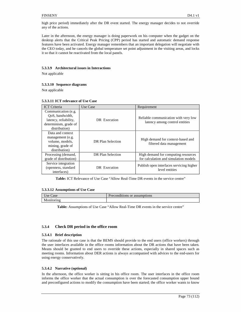
FINSENY D4.1 v1
Page 73 (112)
high price period) immediately after the DR event started. The energy manager decides to not override any of the actions. Later in the afternoon, the energy manager is doing paperwork on his computer when the gadget on the desktop alerts that the Critical Peak Pricing (CPP) period has started and automatic demand response features have been activated. Energy manager remembers that an important delegation will negotiate with the CEO today, and he cancels the global temperature set point adjustment in the visiting areas, and locks it so that it cannot be reactivated from the local panels.
5.3.3.9 Architectural issues in Interactions
Not applicable
5.3.3.10 Sequence diagrams Not applicable
5.3.3.11 ICT relevance of Use Case
ICT Criteria Use Case Requirement Communication (e.g.
QoS, bandwidth, latency, reliability,
determinism, grade of distribution)
DR Execution Reliable communication with very low
latency among control entities
Data and context management (e.g. volume, models, mining, grade of
distribution)
DR Plan Selection High demand for context-based and
filtered data management
Processing (demand, grade of distribution)
DR Plan Selection
High demand for computing resources for calculation and simulation models
Service integration (openness, standard
interfaces) DR Execution
Publish open interfaces servicing higher level entities
Table: ICT Relevance of Use Case “Allow Real-Time DR events in the service centre”
5.3.3.12 Assumptions of Use Case
Use Case Preconditions or assumptions Monitoring
Table: Assumptions of Use Case “Allow Real-Time DR events in the service centre”
5.3.4 Check DR period in the office room
5.3.4.1 Brief description
The rationale of this use case is that the BEMS should provide to the end users (office workers) through the user interfaces available in the office rooms information about the DR actions that have been taken. Means should be granted to end users to override these actions, especially in shared spaces such as meeting rooms. Information about DER actions is always accompanied with advices to the end-users for using energy conservatively.
5.3.4.2 Narrative (optional)
In the afternoon, the office worker is sitting in his office room. The user interfaces in the office room informs the office worker that the actual consumption is over the forecasted consumption upper bound and preconfigured actions to modify the consumption have been started; the office worker wants to know

FINSENY D4.1 v1
Page 74 (112)
what is happening in detail and checks the user interface. The user interface informs that in order to save energy, the system sets up the temperature set point value from 21 to 23 °C (in order to reduce the air conditioner load). The system also advices the office worker to dim the office room lights and open the blinds in order to decrease the lighting load, making more use of natural light. Later, the office worker walks to the coffee area of the building to meet a colleague. The user interface near the coffee machine informs also about the actions that are being taken in order to reduce energy consumption below the upper levels that have been exceeded, which includes turning off decorative lighting, dim/turn off lights in corridors and other common areas.
5.3.4.3 Actors involved
ACTOR ACTOR TYPE ACTOR DESCRIPTION Office worker Person Office workers are the main actors of
this use case, as they need to be informed of the DR actions that are being taken and which may have an impact on their comfort or in the activities that they have programmed (e.g. a meeting with an important client). Information about DR actions must be accompanied with specific advices on actions that the office worker can take in order to reduce the energy consumption, thus the commitment of the office worker with the energy policies of the building is stimulated.
Security staff Person Security staff can also be informed of DR actions, although they will normally neither be able to override these actions, nor they will be given advices on how to save energy.
Facility staff Person Facility staff: facility staff can also get the same information as the office workers, although the interaction of this actor with DR actions will normally be articulated through use case #3, which regulates the interaction of the energy manager (and subsequently, of the facility staff) with the DR policies
5.3.4.4 Information exchanged with actors
Actors involved will get the same information: • Alerts on start of DR actions • Details on the specific DR actions that are being taken, both in office rooms and in common
areas • Information about actions that can be overridden by the user if needed • Advices to the user for saving energy and thus contribute to abate energy consumption below the
limits that have been exceeded.
5.3.4.5 Relationships with other use cases
This use case is a specialization (extension) of the high level use case “Monitor energy use”. As the DR actions can imply also actions voluntarily taken by the office workers to save energy, this use case is also related to the high level use case “engage in energy-supported activities”.
FINSENY D4.1 v1
Page 75 (112)
5.3.4.6 Activities/Services
Not applicable
5.3.4.7 Contracts/Regulations
Not applicable
5.3.4.8 Step by Step Analysis of Use Case
• The use case is always initiated by a DR event which is notified with a generic alert (e.g. blinking lights) to the actors involved (mainly office workers, but also security staff and facility staff).
• Then it is up to the user to get more information through the user interfaces about the specific DR actions that are going to be taken. Such information shall include:
o Strategies that are being followed (e.g. modification of temperature and lighting set-points), customized to office rooms and common areas.
o Customized advices to the user on specific actions that can be voluntarily taken to save energy.
o Information about actions that can be overridden by the user. • If the user wants it, feedback can be provided on the energy savings achieved by the DR event. • Once that the actions taken by the system and the users achieves to bring back the energy
consumption below the allowed levels, the generic alert which initiated this use case ends.
5.3.4.9 Architectural issues in Interactions
Not applicable
5.3.4.10 Sequence diagrams
Not applicable
5.3.5 Energy coaching
5.3.5.1 Brief description
This use case consists on a bidirectional exchange of information between the end users and the Building Energy Management System. On one hand the BEMS provides the end users with information about the amount of energy consumption and costs associated to each energy hungry device they normally use, on the other hand the BEMS learns from the ordinary behaviour of the end-users in order to adapt the operation of the devices. A concrete example of this is to switch the office room status to a standby condition (for lighting, and maybe HVAC) when the user leaves the office.
5.3.5.2 Narrative (optional)
An environmentally and energy conscious office worker wants to find ways to save electricity and to decrease emissions. He doesn't know how much each device in the office room consumes. He sends a request to the BEMS and receives information on electricity consumption of each device in last day/month/year. "I didn't know how much energy the computer and the lighting consumes and how much it costs. From now on I will turn the computer on the sleeping mode when I don't use it, and shut down the lights if the blinds are open". Conversely, at 5 pm, the office worker leaves the office room. The system has learned that he will not come back until tomorrow. After a couple of minutes, the office room goes to standby mode. The system shuts down all unnecessary equipment, the lights are shut down and the air conditioner is turned off.
5.3.5.3 Actors involved
ACTOR ACTOR TYPE ACTOR DESCRIPTION Office worker Person Only office workers are involved in
this use case, as it focuses on the interaction of this actor with the
FINSENY D4.1 v1
Page 76 (112)
BEMS. In one direction, information flows from the BEMS to the users providing information about the energy consumption and costs associated to each device, while in the opposite direction the BEMS gets information about the behavioural patterns of the users in order to automatically apply more energy efficient strategies.
5.3.5.4 Information exchanged with actors
The actor involved in this use case (office worker) will be exchanging the following types of information with the user:
• Energy profiles of energy-hungry devices which the office worker normally uses, including detailed information on different operating modes that each device may have (e.g. giving information on the savings that can be achieved by switching a PC to sleeping mode when it is not used
• CO2 equivalent emissions associated to the profiled devices. • Energy costs associated to the profiled devices. • Behavioural patterns of the user • Actual behaviour of the user
5.3.5.5 Relationships with other use cases
This use case is a specialization (extension) of the use case “Support activities of daily working”, which is itself a derived use case from the high-level use case “Engage in Energy Supported Activities”.
5.3.5.6 Activities/Services
Not applicable
5.3.5.7 Contracts/Regulations
Not applicable
5.3.5.8 Step by Step Analysis of Use Case
• This use case can be triggered by two different situations: o A significant behavioural action taken by the end user, which is registered by the
BEMS (e.g. Entrance and exit from the office room). In this case the main steps of the use case will be the following:
� The BEMS checks the registered action with the behavioural patterns which have been previously stored by the system for the end user.
� From the previous comparison, the BEMS decides which actions can be taken in order to save energy (e.g. switch devices to standby mode), and triggers them.
� The stored behavioural patterns are updated with the last registered user actions.
o A request from the end user of information about energy profiles of energy-hungry devices. In this case the main steps of the use case will be the following:
� The user selects the type of device from which he/she wants to retrieve energy profiles
� The BEMS provides information on energy profile of the selected device, including energy consumption, CO2 equivalent emissions and associated energy costs.
� The user can request detailed information on the energy consumption for each operating mode of a device.

FINSENY D4.1 v1
Page 77 (112)
5.3.5.9 Architectural issues in Interactions
Not applicable
5.3.5.10 Sequence diagrams
Not applicable
5.3.6 Check benchmarking in districts
5.3.6.1 Brief description
The energy consumption data from buildings in the district is obtained and provided to the end-user to enable benchmarking.
5.3.6.2 Narrative (optional)
The energy consumed by the office building in the district is monitored and save in a historical database. This is possible because the energy managers of the different buildings have agreed on that previously. This information is used for making comparison among all the office buildings. The building that consumes less energy in a certain time period will be on the top of the classification. Then, all the office workers will be informed and that will help to improve the user awareness about energy consumption.
5.3.6.3 Actors involved
ACTOR ACTOR TYPE ACTOR DESCRIPTION Facility staff Person The facility staff is a person or a
group of people who will be monitoring the energy usage within an office building in order to check that the general guidelines established by the energy manager are being followed.
ICT services provider Information system Entity responsible for providing information and communication technologies services to the building users. These services could provide an information flow among the different devices and actors.
Energy manager Person Person (or group of people) in charge of monitor and control the energy use inside the office building. They follow the guidelines established by the energy manager.
5.3.6.4 Information exchanged with actors
• Energy consumed.
5.3.6.5 Relationships with other use cases
This Use Case is a specialization of the high level Use Case “Monitor Energy Use”
5.3.6.6 Activities/Services
Not applicable
5.3.6.7 Contracts/Regulations
Not applicable

FINSENY D4.1 v1
Page 78 (112)
5.3.6.8 Step by Step Analysis of Use Case
Before leaving the service center the facility worker checks the district energy portal in which a set of office buildings have agreed to share their energy usage. He sees that his office building has reduced its energy consumption and is now ranked second in the specific energy consumption benchmark. The facility worker clicks the leading building in the list for more detailed information and sees that it hasn’t been used since the previous company left two months ago. The facility worker inform to the energy manager. The energy manager writes a short piece of news to his company intranet and congratulates the users of his office building for the first place in the benchmark among occupied offices.
5.3.6.9 Architectural issues in Interactions
Not applicable
5.3.6.10 Sequence diagrams
Not applicable

FINSENY D4.1 v1
Page 79 (112)
6. Data center use cases The evolution of cloud computing has resulted in highly efficient and carefully optimized data centers with increased server density and capacity that makes considerations on energy consumption and utilization extremely critical along with several other factors that were not as significant in smaller data centers of the past. The goal of energy management usage models is to optimize productivity per watt in order to reduce total cost of ownership (TCO). Requirements include the capability to monitor and cap power in real-time at server, rack, zone, and data center levels. This means the ability to monitor and manage aggregated power consumption within a rack, zone, or data center based on available power and cooling resources. Another important target in the data center is to maintain a high quality of service (QoS) even when the power consumption is reduced.
6.1 Synoptic diagram
Here below is shown an UML diagram at a high level of abstraction about the data center management.
Figure 20: High level Use Cases for Data Centres.

FINSENY D4.1 v1
Page 80 (112)
6.2 High-level use cases
Optimizing data center infrastructure involves these six high-level use cases:
1) Optimize the conditioning power consumption
2) Optimize the free-cooling power consumption:
3) Optimize the power consumed by servers
4) Manage the continuity and autonomy of the service
5) Optimize power workload maintaining a high quality of services (QoS):
6) Present priority levels for business service at the end customer, saving anyway energy In general, in these six high-level use cases are involved the following five actors: Actor #1 Data center Supervisor: collects all kind of data center measures coming from sensors and Smart Info power meter and sends them to the facility manager. Actor #2 Workload Profiler: creates HW/SW consumption profiles through tables with various workload profiles and a performance loss target not to be exceeded. Develops and executes a series of experiments to characterize how much energy capping can be applied before the performance target is hit. Actor #3 Facility Manager: in concert with the Workload Profiler, it optimizes the data center power consumption performances through SW tasks and actuating system management. (Intelligent Power Node Manager SW, Energy Management SW, Uninterrupted Power Supplies (UPSs), air conditioner, free cooler, etc.) Actor #4 Business Client: it’s a company that commissioned a service at the data center (e.g.: a WEB portal). Actor #5 Financial Manager: Person in the data center that is responsible for cost accounting and developing financial strategies for an industrial or commercial business. He also formulates the best commercial offering to a service requested (e.g.: a WEB portal) from a business client, guaranteeing to him a high quality of service (QoS).
6.3 Detailed use cases
The detailed use cases that will be described here following are related to the above listed high-level use cases and to the interaction between the actors before listed.
6.3.1 Use case #1: Optimize the data center air conditioning
6.3.1.1 Brief Description
The air conditioning systems (with their heat pump for winter) comes to represent 50% of the consumption of a data center. A real-time monitoring of temperatures (which vary with the load of servers) allows significant savings in energy consumption.
6.3.1.2 Narrative (optional)
As the temperature is not uniformly distributed in the local data center, a set of temperature sensors ensure a local detection of the same. These sensors send wirelessly (e.g.: ZigBee technology) information to a collection point. The information gathered can activate in real time, wireless-actuators in order to turn on or off the air conditioners.

FINSENY D4.1 v1
Page 81 (112)
6.3.1.3 Actors involved
ACTOR ACTOR TYPE ACTOR DESCRIPTION
Data center Supervisor Person Person that reports, at the Facility Manager, about abnormal local temperatures or humidity, or excessive consumption of air conditioning
Facility Manager Person Person that optimizes local temperature, humidity and power consumption through Hardware and Software command.
6.3.1.4 Information exchanged with actors
The following information is transferred between the actors:
ACTOR INPUT INFORMATION OUTPUT Data center Supervisor All kind of data center measures
coming from sensors and Smart Info power meter
Reports for the Facility Manager about abnormal local tempe-ratures or humidity, or excessive consumption of air conditioning
Facility Manager Anomalies reported by the Data center Supervisor
Hardware and software command to optimize local temperature, humidity and power consumption
6.3.1.5 Relationships with other use cases
This case use is related to the use case # 2
6.3.1.6 Activities/Services
Here following are listed and described the activities and/or services involved in this use-case:
- Data center Supervisor: collects all kind of data center measures coming from sensors and Smart Info power meter and sends them to the facility manager.
- Facility Manager: in concert with the Data center Supervisor, it optimizes the data center power
consumption performances and the actuating system management for air conditioner, free cooler, etc.
6.3.1.7 Contracts/Regulations
In this use case there is not a form of contract between the data center and a business client. The purpose of this use case is to reduce the power consumed inside the data center, which is reflected into lower costs of energy tariff to pay at the energy retailer. So the only form of contract is that between the data center and energy retailer.

FINSENY D4.1 v1
Page 82 (112)
6.3.1.8 Step by Step Analysis of Use Case
- Sensors detect, in real time, the temperature values at different points in the data center - A monitoring system compares the values collected for each sensor with those defined as
acceptable operating margins - If the temperature values recorded were above or below the acceptable operating margins, the
monitoring system sends radio commands to the actuators that turn on or off the air conditioners.
6.3.1.9 Architectural Issues in Interactions
None
6.3.1.10 Sequence Diagrams
Not requested at this abstraction level of the description
6.3.1.11 ICT relevance of Use Case
ICT Criteria Activity Requirement Communication (e.g.
QoS, bandwidth, latency, reliability,
determinism, grade of distribution)
Planning data collection; consumption & generation
parameter adjustments; Incentive negotiations with the customer
Non-real-time, asynchronous data transport; reliable control information flow; transaction-based protocols for
incentive (price) negotiations
Data and context management (e.g. volume, models, mining, grade of
distribution)
Planning data collection system, e.g. access to contract database
(CDB)
Reliable mass data communication system, data models should be based on
IEC 61850 and IEC 61968.
Processing (demand, grade of distribution)
Forecasting, Planning & Revenue optimization
High demand for computing resources for calculation and simulation models
on weather and price forecasts, optimization & behavioural models
Service integration (openness, standard
interfaces) weather forecast services
Seamless integration of internal & external services, open interfaces and
data models
Table: ICT Relevance of Use Case “Optimize the data centre air conditioning”
6.3.1.12 Assumptions of Sub Use Cases
Low level Use Case Preconditions or assumptions State analysis & subsequent actions The actual state is available Continuous determination of power control range
The actual range on energy resources is available
Forecasting energy production & consumption on different time scales
Forecasting data are available
Table: Assumptions of Use Case “Optimize the data centre air conditioning”
6.3.2 Use case #2: Optimize the free-cooling in the data centers
6.3.2.1 Brief Description
Free cooling is an economical method of using low external air temperatures to assist in chilling water, which can then be used for industrial process, or air conditioning systems in green data centers. The free-cooling systems are so much less expensive of the air conditioners in terms of power consumption. However, unlike air conditioners, their efficiency must take into account the humidity factor. A real-time monitoring of humidity allows to the system to operate with adequate ventilation. HVAC (Heating,

FINSENY D4.1 v1
Page 83 (112)
Ventilation, and Air Conditioning) refers to technology of indoor data-center environmental comfort. HVAC system design is a major sub-discipline of mechanical engineering, based on the principles of thermodynamics, fluid mechanics, and heat transfer. In HVAC in winter months, large commercial buildings’ interior spaces may need cooling, even while perimeter spaces may need heating. Free cooling is the production of chilled water without the use of a chiller, and can be used generally in the late fall, winter and early spring, in the Northern Hemisphere.
6.3.2.2 Narrative (optional)
The sensors detect, in real time, the temperature values at different points in the data center. A monitoring system compares the values collected for each humidity sensor with those defined as acceptable operating margins If the humidity values recorded were above or below the acceptable operating margins, the monitoring system sends radio commands to the actuators that change the air flow or cause to temporarily intervene air conditioners for the dehumidification.
6.3.2.3 Actors involved
ACTOR ACTOR TYPE ACTOR DESCRIPTION
Data center Supervisor Person Person that reports, at the Facility Manager, about abnormal local temperatures or humidity, or excessive consumption of air conditioning
Facility Manager Person Person that optimizes local temperature, humidity and power consumption through Hardware and Software tools.
6.3.2.4 Information exchanged with actors
The following information is transferred between the actors:
ACTOR INPUT INFORMATION OUTPUT Data center Supervisor All kind of data center measures
coming from sensors and Smart Info power meter
Reports for the Facility Manager about abnormal local tempe-ratures or humidity, or excessive consumption of air conditioning
Facility Manager Anomalies reported by the Data center Supervisor
Hardware and software command to optimize local temperature, humidity and power consumption
6.3.2.5 Relationships with other use cases
This case use is related to the use case # 1
6.3.2.6 Activities/Services
Here following are listed and described the activities and/or services involved in this use-case:
- Data center Supervisor: collects all kind of data center measures coming from sensors and Smart Info power meter and sends them to the facility manager.
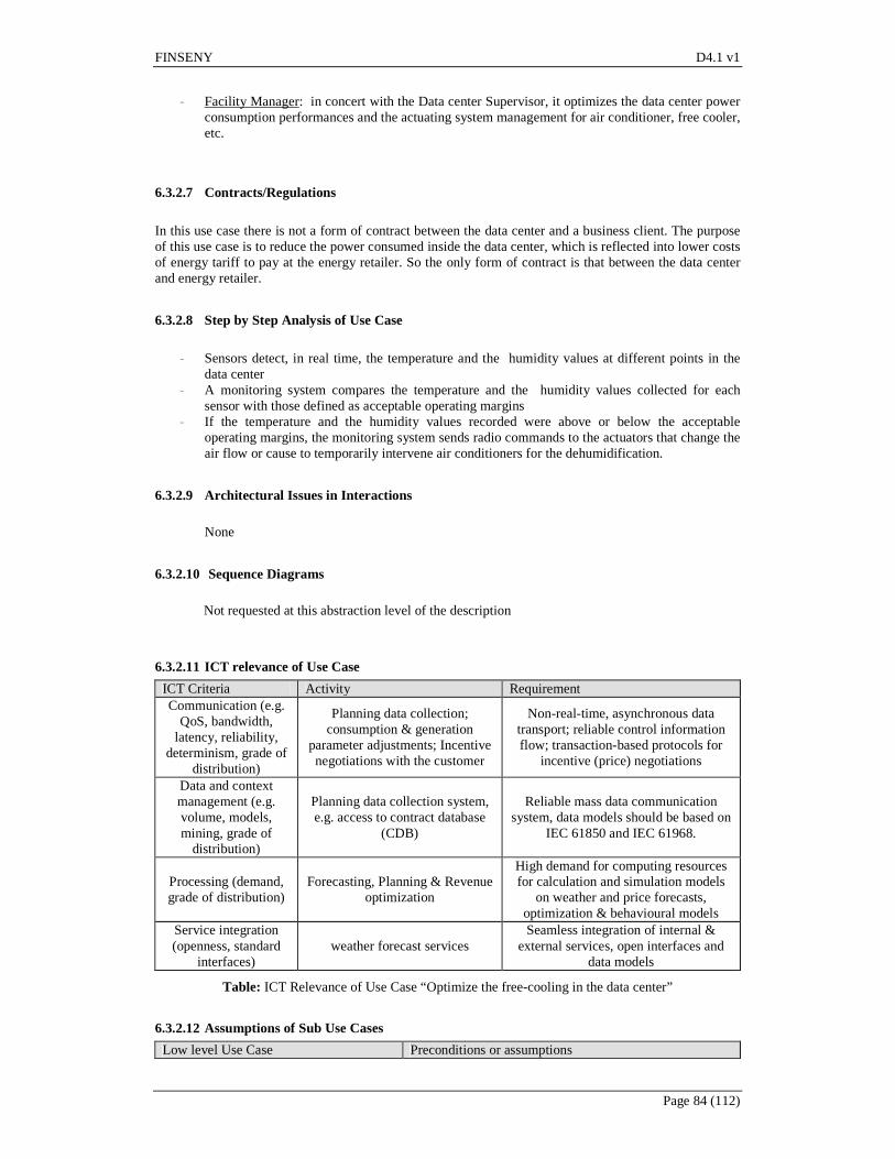
FINSENY D4.1 v1
Page 84 (112)
- Facility Manager: in concert with the Data center Supervisor, it optimizes the data center power
consumption performances and the actuating system management for air conditioner, free cooler, etc.
6.3.2.7 Contracts/Regulations
In this use case there is not a form of contract between the data center and a business client. The purpose of this use case is to reduce the power consumed inside the data center, which is reflected into lower costs of energy tariff to pay at the energy retailer. So the only form of contract is that between the data center and energy retailer.
6.3.2.8 Step by Step Analysis of Use Case
- Sensors detect, in real time, the temperature and the humidity values at different points in the
data center - A monitoring system compares the temperature and the humidity values collected for each
sensor with those defined as acceptable operating margins - If the temperature and the humidity values recorded were above or below the acceptable
operating margins, the monitoring system sends radio commands to the actuators that change the air flow or cause to temporarily intervene air conditioners for the dehumidification.
6.3.2.9 Architectural Issues in Interactions
None
6.3.2.10 Sequence Diagrams
Not requested at this abstraction level of the description
6.3.2.11 ICT relevance of Use Case
ICT Criteria Activity Requirement Communication (e.g.
QoS, bandwidth, latency, reliability,
determinism, grade of distribution)
Planning data collection; consumption & generation
parameter adjustments; Incentive negotiations with the customer
Non-real-time, asynchronous data transport; reliable control information flow; transaction-based protocols for
incentive (price) negotiations
Data and context management (e.g. volume, models, mining, grade of
distribution)
Planning data collection system, e.g. access to contract database
(CDB)
Reliable mass data communication system, data models should be based on
IEC 61850 and IEC 61968.
Processing (demand, grade of distribution)
Forecasting, Planning & Revenue optimization
High demand for computing resources for calculation and simulation models
on weather and price forecasts, optimization & behavioural models
Service integration (openness, standard
interfaces) weather forecast services
Seamless integration of internal & external services, open interfaces and
data models
Table: ICT Relevance of Use Case “Optimize the free-cooling in the data center”
6.3.2.12 Assumptions of Sub Use Cases
Low level Use Case Preconditions or assumptions

FINSENY D4.1 v1
Page 85 (112)
Low level Use Case Preconditions or assumptions State analysis & subsequent actions The actual state is available Continuous determination of power control range
The actual range on energy resources is available
Forecasting energy production & consumption on different time scales
Forecasting data are available
Table: Assumptions of Use Case “Optimize the free-cooling in the data center”
6.3.3 Use case #3: Optimize server power usage
6.3.3.1 Brief Description
The collection of real-time power consumption data constitutes an essential capability for power monitoring. Without this data, the best approximation for server power usage comes from the manufacturer’s specifications. To use the nameplate numbers as a guidepost requires the allowance of a hefty safety margin. To honor the safety margin in turn leads to data center power over-provisioning and stranded power that needs to be allocated in case it is needed, but is very unlikely to be used. This situation results in over-provisioned data center power, overcooling of IT equipment, and increased total cost of ownership (TCO). The steps described in this use case act as a “load balancer”, in order to determine how many additional servers having similar power cap settings can be added to the rack without overshooting the power quota allocated.
6.3.3.2 Narrative (optional)
Power Guard Rail and Optimization of Rack Density by imposing power guard to prevent server power consumption from straying beyond preset limit. The deterministic power limit and guaranteed server power consumption ceiling helps maximize server count per rack and therefore return of investment of capital expenditure per available rack power when rack is under power budget with negligible or no per server performance impact. Power consumption of each server should be monitored over a long period either in production or in a simulated environment generating load similar to production. Monitoring real production servers is recommended to avoid undesired performance impact. Duration should be days or weeks or a quarter depending on the application life cycle scenarios and usage. Record the maximum power demand during the period. Performing the above exercise for other servers it’s possible to determine the total power cap applied to the servers in a rack. The difference between the total power cap assigned to the rack and power quota allocated for the rack would provide guidance on how many additional servers having similar power cap settings can be added to the rack without overshooting the power quota allocated. Since we will be adding addition servers into the rack, the overall performance of the system increases further keeping within the power envelope allocated by the hosting provider.
6.3.3.3 Actors involved
ACTOR ACTOR TYPE ACTOR DESCRIPTION
Workload Profiler Person Person that creates, through HW/SW tools, a server power consumption profiles using tables with various workload profiles.
Data center Supervisor Person Person that reports, at the Facility Manager, the power consumption of the servers.

FINSENY D4.1 v1
Page 86 (112)
Facility Manager Person Person that optimizes the power consumption of the servers keeping in account the information coming from the Workload profiler.
6.3.3.4 Information exchanged with actors
The following information is transferred between the actors:
ACTOR INPUT INFORMATION OUTPUT Workload Profiler Results of the experiments to
characterize how much energy capping can be applied before the performance target is hit.
Information for the Facility Manager about how much energy capping can be applied before the performance target is hit.
Data center Supervisor Power consumption of the servers coming from the Smart power meters of the data center.
Reports to the Facility Manager and to the Workload Profiler about the actual power consumption of the servers.
Facility Manager Actual power consumption of the server and applicable energy capping reported by the Data center Supervisor and from the Workload Profiler
HW/SW commands to optimize the power consumption of the servers without penalize the quality of their services (QoS)
6.3.3.5 Relationships with other use cases
This case use is related to the use case #4 and # 5
6.3.3.6 Activities/Services
Here following are listed and described the activities and/or services involved in this use-case:
- Workload Profiler: creates HW/SW consumption profiles through tables with various workload profiles and a performance loss target not to be exceeded. Develops and executes a series of experiments to characterize how much energy capping can be applied to the servers before the performance target is hit.
- Data center Supervisor: collects all the information about the power consumption of the servers coming from the Smart power meters of the data center and sends them to the Facility Manager and to the Workload Profiler.
- Facility Manager: collects the actual power consumption of the server and the applicable energy capping reported respectively by the Data center Supervisor and from the Workload Profiler. Then he sends HW/SW commands to optimize the power consumption of the servers without penalize the quality of their services (QoS).
6.3.3.7 Contracts/Regulations
In this use case there is not a form of contract between the data center and a business client. The purpose of this use case is to reduce the power consumed inside the data center, which is reflected into lower costs of energy tariff to pay at the energy retailer. So the only form of contract is that between the data center and energy retailer.
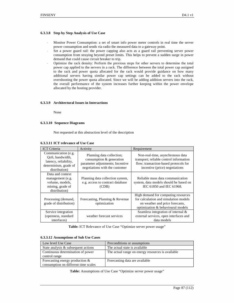
FINSENY D4.1 v1
Page 87 (112)
6.3.3.8 Step by Step Analysis of Use Case
- Monitor Power Consumption: a set of smart info power meter controls in real time the server
power consumption and sends via radio the measured data to a gateway point. - Set a power guard rail: the power capping also acts as a guard rail preventing server power
consumption from straying beyond preset limits. This helps to prevent a sudden surge in power demand that could cause circuit breaker to trip.
- Optimize the rack density: Perform the previous steps for other servers to determine the total power cap applied to the servers in a rack. The difference between the total power cap assigned to the rack and power quota allocated for the rack would provide guidance on how many additional servers having similar power cap settings can be added to the rack without overshooting the power quota allocated. Since we will be adding addition servers into the rack, the overall performance of the system increases further keeping within the power envelope allocated by the hosting provider.
6.3.3.9 Architectural Issues in Interactions
None
6.3.3.10 Sequence Diagrams
Not requested at this abstraction level of the description
6.3.3.11 ICT relevance of Use Case
ICT Criteria Activity Requirement Communication (e.g.
QoS, bandwidth, latency, reliability,
determinism, grade of distribution)
Planning data collection; consumption & generation
parameter adjustments; Incentive negotiations with the customer
Non-real-time, asynchronous data transport; reliable control information flow; transaction-based protocols for
incentive (price) negotiations
Data and context management (e.g. volume, models, mining, grade of
distribution)
Planning data collection system, e.g. access to contract database
(CDB)
Reliable mass data communication system, data models should be based on
IEC 61850 and IEC 61968.
Processing (demand, grade of distribution)
Forecasting, Planning & Revenue optimization
High demand for computing resources for calculation and simulation models
on weather and price forecasts, optimization & behavioural models
Service integration (openness, standard
interfaces) weather forecast services
Seamless integration of internal & external services, open interfaces and
data models
Table: ICT Relevance of Use Case “Optimize server power usage”
6.3.3.12 Assumptions of Sub Use Cases
Low level Use Case Preconditions or assumptions State analysis & subsequent actions The actual state is available Continuous determination of power control range
The actual range on energy resources is available
Forecasting energy production & consumption on different time scales
Forecasting data are available
Table: Assumptions of Use Case “Optimize server power usage”

FINSENY D4.1 v1
Page 88 (112)
6.3.4 Use case #4: Manages business continuity
6.3.4.1 Brief Description
When unforeseen circumstances like power outage and cooling system failure occurs, a service continuity optimization is made possible through an Intelligent Power Node Manager SW and an Energy Management SW that force the servers to a lower power consumption and to a low heat generation. In these scenarios it may be appropriate to set aggressively lower power caps though performance would be affected. Please note all servers may not meet the aggressive power limit that is set. It depends on the application that is running and if the minimum power limit that can be honored which depends on the operating system and the application load at that point. The use case illustrates how it works at a data center location or a group of servers.
6.3.4.2 Narrative (optional)
During primary AC power outage scenarios for part of all of data center, aggressive power capping can be applied to servers to reduce power consumption. This reduces the power drain on the Uninterrupted Power Supplies (UPSs) increasing the duration the servers can remain operational before on-site generators restore power and cooling. Similarly, if there is a cooling systems failure, the impacted servers can be applied a lower power cap to reduce power consumption and heat generation until the cooling system is restored. Of course not all servers may meet the aggressive power limit that is set. It depends on the application that is running and if the minimum power limit that can be honored which depends on the operating system and the application load at that point.
6.3.4.3 Actors involved
ACTOR ACTOR TYPE ACTOR DESCRIPTION
Workload Profiler Person Person that creates, through HW/SW tools, a server power consumption profiles using tables with various workload profiles.
Data center Supervisor Person Person that reports in real time to the Facility Manager and to the Workload Profiler about the actual temperature, humidity and power consumption of the servers. He also warns about the power outage and about cooling system failure occurs in the data center.
Facility Manager Person Person that optimizes the power consumption of the servers keeping in account the information coming from the Workload profiler and from the Data center supervisor.
6.3.4.4 Information exchanged with actors
The following information is transferred between the actors:
ACTOR INPUT INFORMATION OUTPUT Workload Profiler Results of the experiments to Information for the Facility Manager
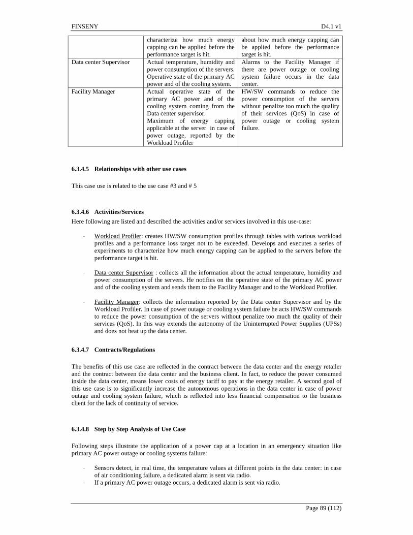
FINSENY D4.1 v1
Page 89 (112)
characterize how much energy capping can be applied before the performance target is hit.
about how much energy capping can be applied before the performance target is hit.
Data center Supervisor Actual temperature, humidity and power consumption of the servers. Operative state of the primary AC power and of the cooling system.
Alarms to the Facility Manager if there are power outage or cooling system failure occurs in the data center.
Facility Manager Actual operative state of the primary AC power and of the cooling system coming from the Data center supervisor. Maximum of energy capping applicable at the server in case of power outage, reported by the Workload Profiler
HW/SW commands to reduce the power consumption of the servers without penalize too much the quality of their services (QoS) in case of power outage or cooling system failure.
6.3.4.5 Relationships with other use cases
This case use is related to the use case #3 and # 5
6.3.4.6 Activities/Services
Here following are listed and described the activities and/or services involved in this use-case:
- Workload Profiler: creates HW/SW consumption profiles through tables with various workload profiles and a performance loss target not to be exceeded. Develops and executes a series of experiments to characterize how much energy capping can be applied to the servers before the performance target is hit.
- Data center Supervisor : collects all the information about the actual temperature, humidity and
power consumption of the servers. He notifies on the operative state of the primary AC power and of the cooling system and sends them to the Facility Manager and to the Workload Profiler.
- Facility Manager: collects the information reported by the Data center Supervisor and by the
Workload Profiler. In case of power outage or cooling system failure he acts HW/SW commands to reduce the power consumption of the servers without penalize too much the quality of their services (QoS). In this way extends the autonomy of the Uninterrupted Power Supplies (UPSs) and does not heat up the data center.
6.3.4.7 Contracts/Regulations
The benefits of this use case are reflected in the contract between the data center and the energy retailer and the contract between the data center and the business client. In fact, to reduce the power consumed inside the data center, means lower costs of energy tariff to pay at the energy retailer. A second goal of this use case is to significantly increase the autonomous operations in the data center in case of power outage and cooling system failure, which is reflected into less financial compensation to the business client for the lack of continuity of service.
6.3.4.8 Step by Step Analysis of Use Case
Following steps illustrate the application of a power cap at a location in an emergency situation like primary AC power outage or cooling systems failure:
- Sensors detect, in real time, the temperature values at different points in the data center: in case of air conditioning failure, a dedicated alarm is sent via radio.
- If a primary AC power outage occurs, a dedicated alarm is sent via radio.

FINSENY D4.1 v1
Page 90 (112)
- When a temperature alarm or a primary AC power outage alarm occurs the Uninterrupted Power Supplies (UPSs) is activated and, at the same time, the maximum allowing power for rack of servers is reduced by the Facility Manager through an Intelligent Power Node Manager SW and an Energy Management SW in order to increase the autonomy.
- In this way extends the autonomy of the Uninterrupted Power Supplies (UPSs) and does not heat up the data center.
6.3.4.9 Architectural Issues in Interactions
None
6.3.4.10 Sequence Diagrams
Not requested at this abstraction level of the description
6.3.4.11 ICT relevance of Use Case
ICT Criteria Sub Use Case Requirement Communication (e.g.
QoS, bandwidth, latency, reliability,
determinism, grade of distribution)
Automated Load Reduction Reliable communication with
transactional nature. Time-scale is secondary control.
Data and context management (e.g. volume, models, mining, grade of
distribution)
Automated Load Reduction High demand for context-based and
filtered data management
Processing (demand, grade of distribution)
Automated Load Reduction High demand for computing resources for calculation and simulation models
Service integration (openness, standard
interfaces) Automated Load Reduction
Publish open interfaces servicing higher level entities
Table: ICT Relevance of Use Case #4
6.3.4.12 Assumptions of Use Case
Low level Use Case Preconditions or assumptions Monitoring Forecasting
Table: Assumptions of Use Case #4
6.3.5 Use case #5: Optimizes power workload maintaining a high quality of services (QoS)
6.3.5.1 Brief Description
Workload profiles are built and a maximum performance loss target set. Experiments determine how much capping can be applied before the performance target is hit. The approach is to match actual performance against service level requirements. In this way, using an Energy Management SW, for workloads that were not processor intensive, it’s possible to optimize server power consumption by approximately 20 percent without an impact on performance. For workloads that were processor

FINSENY D4.1 v1
Page 91 (112)
intensive, typically, for a 10 percent power reduction, performance decreased by 14 percent. In this way the data center financial manager can offer at the business client the best service quality at the lowest price and at the lowest power consumption.
6.3.5.2 Narrative (optional)
IT organizations face significant data center power and cooling challenges. So, companies seek alternative approaches that focus on more efficient use of existing data center power. Power optimization of the workloads is one such approach to achieve power efficiency. Power optimization requires a table with various workload profiles and a performance loss target not to be exceeded. Developers perform a series of experiments to characterize how much capping can be applied before the performance target is hit. Aftrwards, during normal operations, the applications engineer sets power capping targets based on the prior measurements. The system is now said to be “optimized,” because the impact of the application of these caps is now known. The main benefit of this approach is to match actual Quality of Service (QoS) against service level requirements. In this way the financial manager can offer at the business client the highest quality of service at the lowest price and at the lowest power consumption.
6.3.5.3 Actors involved
ACTOR ACTOR TYPE ACTOR DESCRIPTION
Workload Profiler Person Person that creates, through HW/SW tools, a server power consumption profiles using tables with various workload profiles.
Data center Supervisor Person Person that reports in real time to the Facility Manager and to the Workload Profiler about the actual power consumption of the servers.
Facility Manager Person Person that optimizes the power consumption of the servers keeping in account the information coming from the Workload profiler and from the Data center supervisor.
Financial Manager Person Person in the data center that is responsible for cost accounting and developing financial strategies for an industrial or commercial business. He also formulates the best commercial offering to a service requested (e.g.: a WEB portal) from a business client, guaranteeing to him a high quality of service (QoS).
Business Client Company Company that commissioned a service at the data center (e.g.: a WEB portal).
6.3.5.4 Information exchanged with actors
The following information is transferred between the actors:
ACTOR INPUT INFORMATION OUTPUT Workload Profiler Results of the experiments to
characterize how much energy capping can be applied before the performance target is hit.
Information for the Facility Manager about how much energy capping can be applied before the performance target is hit.
Data center Supervisor Power consumption of the servers coming from the Smart power meters of the data center.
Reports to the Facility Manager and to the Workload Profiler about the actual power consumption of the
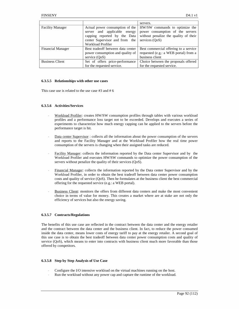
FINSENY D4.1 v1
Page 92 (112)
servers. Facility Manager Actual power consumption of the
server and applicable energy capping reported by the Data center Supervisor and from the Workload Profiler
HW/SW commands to optimize the power consumption of the servers without penalize the quality of their services (QoS)
Financial Manager Best tradeoff between data center power consumption and quality of service (QoS)
Best commercial offering to a service requested (e.g.: a WEB portal) from a business client
Business Client Set of offers price-performance for the requested service.
Choice between the proposals offered for the requested service.
6.3.5.5 Relationships with other use cases
This case use is related to the use case #3 and # 6
6.3.5.6 Activities/Services
- Workload Profiler: creates HW/SW consumption profiles through tables with various workload
profiles and a performance loss target not to be exceeded. Develops and executes a series of experiments to characterize how much energy capping can be applied to the servers before the performance target is hit.
- Data center Supervisor : collects all the information about the power consumption of the servers
and reports to the Facility Manager and at the Workload Profiler how the real time power consumption of the servers is changing when their assigned tasks are reduced.
- Facility Manager: collects the information reported by the Data center Supervisor and by the
Workload Profiler and executes HW/SW commands to optimize the power consumption of the servers without penalize the quality of their services (QoS).
- Financial Manager: collects the information reported by the Data center Supervisor and by the Workload Profiler, in order to obtain the best tradeoff between data center power consumption costs and quality of service (QoS). Then he formulates at the business client the best commercial offering for the requested service (e.g.: a WEB portal).
- Business Client: monitors the offers from different data centers and make the most convenient
choice in terms of value for money. This creates a market where are at stake are not only the efficiency of services but also the energy saving.
6.3.5.7 Contracts/Regulations
The benefits of this use case are reflected in the contract between the data center and the energy retailer and the contract between the data center and the business client. In fact, to reduce the power consumed inside the data center, means lower costs of energy tariff to pay at the energy retailer. A second goal of this use case is to obtain the best tradeoff between data center power consumption costs and quality of service (QoS), which means to enter into contracts with business client much more favorable than those offered by competitors.
6.3.5.8 Step by Step Analysis of Use Case
- Configure the I/O intensive workload on the virtual machines running on the host. - Run the workload without any power cap and capture the runtime of the workload.
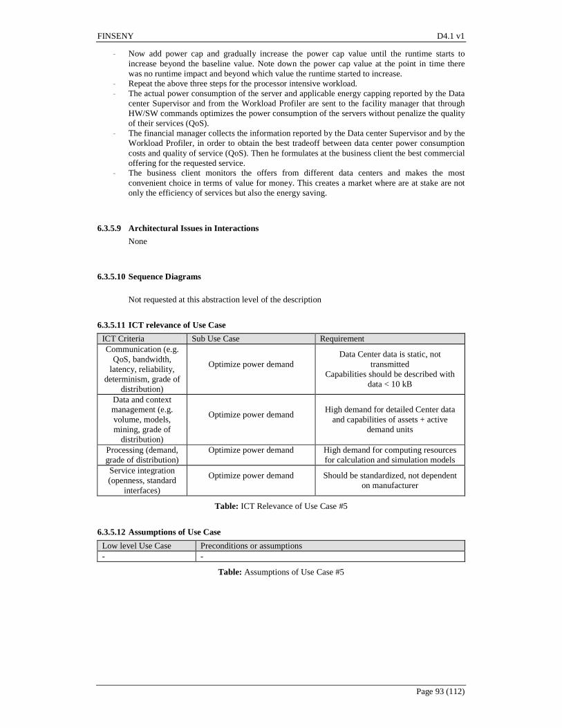
FINSENY D4.1 v1
Page 93 (112)
- Now add power cap and gradually increase the power cap value until the runtime starts to increase beyond the baseline value. Note down the power cap value at the point in time there was no runtime impact and beyond which value the runtime started to increase.
- Repeat the above three steps for the processor intensive workload. - The actual power consumption of the server and applicable energy capping reported by the Data
center Supervisor and from the Workload Profiler are sent to the facility manager that through HW/SW commands optimizes the power consumption of the servers without penalize the quality of their services (QoS).
- The financial manager collects the information reported by the Data center Supervisor and by the Workload Profiler, in order to obtain the best tradeoff between data center power consumption costs and quality of service (QoS). Then he formulates at the business client the best commercial offering for the requested service.
- The business client monitors the offers from different data centers and makes the most convenient choice in terms of value for money. This creates a market where are at stake are not only the efficiency of services but also the energy saving.
6.3.5.9 Architectural Issues in Interactions
None
6.3.5.10 Sequence Diagrams
Not requested at this abstraction level of the description
6.3.5.11 ICT relevance of Use Case
ICT Criteria Sub Use Case Requirement Communication (e.g.
QoS, bandwidth, latency, reliability,
determinism, grade of distribution)
Optimize power demand
Data Center data is static, not transmitted
Capabilities should be described with data < 10 kB
Data and context management (e.g. volume, models, mining, grade of
distribution)
Optimize power demand
High demand for detailed Center data and capabilities of assets + active
demand units
Processing (demand, grade of distribution)
Optimize power demand
High demand for computing resources for calculation and simulation models
Service integration (openness, standard
interfaces)
Optimize power demand
Should be standardized, not dependent on manufacturer
Table: ICT Relevance of Use Case #5
6.3.5.12 Assumptions of Use Case
Low level Use Case Preconditions or assumptions - -
Table: Assumptions of Use Case #5
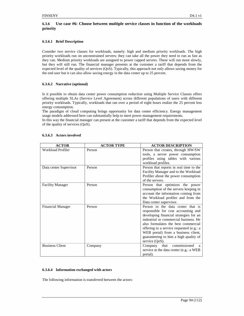
FINSENY D4.1 v1
Page 94 (112)
6.3.6 Use case #6: Choose between multiple service classes in function of the workloads priority
6.3.6.1 Brief Description
Consider two service classes for workloads, namely: high and medium priority workloads. The high priority workloads run on unconstrained servers; they can take all the power they need to run as fast as they can. Medium priority workloads are assigned to power capped servers. These will run more slowly, but they will still run. The financial manager presents at the customer a tariff that depends from the expected level of the quality of services (QoS). Typically, this approach not only allows saving money for the end user but it can also allow saving energy in the data center up to 25 percent.
6.3.6.2 Narrative (optional)
Is it possible to obtain data center power consumption reduction using Multiple Service Classes offers offering multiple SLAs (Service Level Agreement) across different populations of users with different priority workloads. Typically, workloads that ran over a period of eight hours realize the 25 percent less energy consumption. The paradigm of cloud computing brings opportunity for data center efficiency. Energy management usage models addressed here can substantially help to meet power management requirements. In this way the financial manager can present at the customer a tariff that depends from the expected level of the quality of services (QoS).
6.3.6.3 Actors involved
ACTOR ACTOR TYPE ACTOR DESCRIPTION
Workload Profiler Person Person that creates, through HW/SW tools, a server power consumption profiles using tables with various workload profiles.
Data center Supervisor Person Person that reports in real time to the Facility Manager and to the Workload Profiler about the power consumption of the servers.
Facility Manager Person Person that optimizes the power consumption of the servers keeping in account the information coming from the Workload profiler and from the Data center supervisor.
Financial Manager Person Person in the data center that is responsible for cost accounting and developing financial strategies for an industrial or commercial business. He also formulates the best commercial offering to a service requested (e.g.: a WEB portal) from a business client, guaranteeing to him a high quality of service (QoS).
Business Client Company Company that commissioned a service at the data center (e.g.: a WEB portal).
6.3.6.4 Information exchanged with actors
The following information is transferred between the actors:

FINSENY D4.1 v1
Page 95 (112)
ACTOR INPUT INFORMATION OUTPUT Workload Profiler Results of the experiments to
characterize how much energy capping can be applied before the performance target is hit.
Information for the Facility Manager about how much energy capping can be applied before the performance target is hit.
Data center Supervisor Power consumption of the servers coming from the Smart power meters of the data center.
Reports to the Facility Manager and to the Workload Profiler about the actual power consumption of the servers.
Facility Manager Actual power consumption of the server and applicable energy capping reported by the Data center Supervisor and from the Workload Profiler
HW/SW commands to optimize the power consumption of the servers without penalize the quality of medium-low priority services (QoS)
Financial Manager Best tradeoff between data center power consumption and quality of medium-low priority service (QoS)
Best commercial offering for kind of service (high-medium-low priority service) requested from a business client (e.g.: for a WEB portal).
Business Client Set of offers price-performance for the requested service.
Choice between the proposals offered for the requested service.
6.3.6.5 Relationships with other use cases
This case use is related to the use case #3 and # 5
6.3.6.6 Activities/Services
- Workload Profiler: characterizes the medium-low priority workloads that are assigned to power
capped servers. Then he creates HW/SW consumption profiles through tables with various workload profiles and a performance loss target not to be exceeded. Develops and executes a series of experiments to characterize how much energy capping can be applied to the servers before the performance target is hit.
- Data center Supervisor: collects all the information about the power consumption of the servers
and reports to the Facility Manager and at the Workload Profiler how the real time power consumption of the servers is changing when their assigned task priorities are reduced.
- Facility Manager: collects the information reported by the Data center Supervisor and by the
Workload Profiler and executes HW/SW commands to optimize the power consumption of the servers without penalize too much the quality of their medium-low priority services (QoS).
- Financial Manager: collects the information reported by the Data center Supervisor and by the
Workload Profiler, in order to obtain the best tradeoff between data center power consumption costs and quality of service (QoS). Then he formulates at the business client the best commercial offering for kind of service (e.g.: high-medium-low priority service for a WEB portal).
- Business Client: monitors the offers from different data centers and make the most convenient
choice in terms of value for money. This creates a market where are at stake are not only the efficiency of services but also the energy saving.
6.3.6.7 Contracts/Regulations
In this use case the business client enters into a contract with the data center where the rate is proportional to the class of service chosen. The methodology described in this use case allows not only saves money for the end user, but can also allow you to save energy in data centers up to 25 percent. This savings means that also the contract between the data center and the energy retailer will cost less.
FINSENY D4.1 v1
Page 96 (112)
6.3.6.8 Step by Step Analysis of Use Case
- Learn and tune phase: run the application through a few daily cycles with no power management
mechanisms to establish the baseline power consumption. This means running the machines 24/7 with no power capping. Note the baseline energy consumption in this operating mode.
- Establish the allocation schedule for parked and active server sub-pools. Re-run the workload to establish that there is no gross over-allocation or under-allocation. The allocation can be done by time-of-day or in more sophisticated schemes as a control feedback loop that uses KPI (application’s key performance indicators) monitoring.
- Overlay the power capping schedule to establish the different service classes and perform power consumption curve shaping.
- Re-run the system for a few days to ensure there are no gross mismatches between the power allocation algorithms and workload demand
- Deploy the system previously tuned and monitor the KPIs for a few weeks to ensure there were no corner cases left behind.
- At this point the system can be released for production. - The actual power consumption of the server and applicable energy capping reported by the Data
center Supervisor and from the Workload Profiler are sent to the facility manager that through HW/SW commands optimizes the power consumption of the servers without penalize the quality of their services (QoS).
- The financial manager collects the information reported by the Data center Supervisor and by the Workload Profiler and executes HW/SW commands to optimize the power consumption of the servers without penalize too much the quality of their medium-low priority services (QoS).
- The business client monitors the offers from different data centers and makes the most convenient choice in terms of value for money. This creates a market where are at stake are not only the efficiency of services but also the energy saving.
6.3.6.9 Architectural Issues in Interactions
None
6.3.6.10 Sequence Diagrams
Not requested at this abstraction level of the description
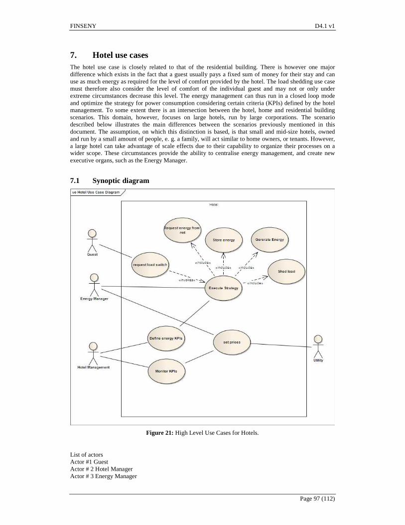
FINSENY D4.1 v1
Page 97 (112)
7. Hotel use cases The hotel use case is closely related to that of the residential building. There is however one major difference which exists in the fact that a guest usually pays a fixed sum of money for their stay and can use as much energy as required for the level of comfort provided by the hotel. The load shedding use case must therefore also consider the level of comfort of the individual guest and may not or only under extreme circumstances decrease this level. The energy management can thus run in a closed loop mode and optimize the strategy for power consumption considering certain criteria (KPIs) defined by the hotel management. To some extent there is an intersection between the hotel, home and residential building scenarios. This domain, however, focuses on large hotels, run by large corporations. The scenario described below illustrates the main differences between the scenarios previously mentioned in this document. The assumption, on which this distinction is based, is that small and mid-size hotels, owned and run by a small amount of people, e. g. a family, will act similar to home owners, or tenants. However, a large hotel can take advantage of scale effects due to their capability to organize their processes on a wider scope. These circumstances provide the ability to centralise energy management, and create new executive organs, such as the Energy Manager.
7.1 Synoptic diagram
Figure 21: High Level Use Cases for Hotels.
List of actors Actor #1 Guest Actor # 2 Hotel Manager Actor # 3 Energy Manager

FINSENY D4.1 v1
Page 98 (112)
Actor # 4 Utility
7.2 Detailed use cases
7.2.1 Use case #1: Execute strategy
7.2.1.1 Brief description
The strategy includes energy consumption and generation. In collaboration with the utility a hotel can participate at the energy exchange and offer positive and negative reserve energy. A strategy includes a tolerance range in temperature (swimming pool, room) which has an effect on the possible energy reserve that can be offered. In addition to that energy storage can be installed in order to optimize against a set of KPIs defined by Hotel Management.
7.2.1.2 Narrative (optional)
Based on the KPIs defined previously, the strategy has to be defined and executed. The definition has to take into account not only the KPIs but also certain degrees of freedom and constraints, e.g. storage capacity, temperature deviations. In this context, actions are methods to reduce consumption of a certain kind of energy, replacing one form of energy consumed with another or reducing the price off an energy form consumed. The strategy includes the degrees of freedom in which the energy manager can take actions. This may include e.g. temperature levels for the room temperature in different bands: comfortable, acceptable and inacceptable, all relative to the temperature set by the guest. The execution operates under the assumption, that all actions which do not reduce the level of comfort will always be executed. All other available actions have to balance cost and benefit. The definition of this balance is in the strategy. One example could be the heating of hot water in a thermally isolated local storage with cheap electricity to prepare for the increase in demand in the morning. This demand can be predicted based e.g. on the number of guests. The execution of the strategy may also be based on static information such as occupancy of a room (number of persons, wake-up time if set) as well as dynamic information such as motion detectors or occupancy sensors. By dynamically setting the price for the different energy forms, the utility influences the execution of the strategy.
7.2.1.3 Actors involved
Hotel Management sets the strategy by defining KPIs which is executed be the Energy Manager Energy Manager executes the strategy. The Energy Manager also acts as gateway for the price information in the control loop. Guest influences the load Utility defines the price of energy
7.2.1.4 Information exchanged with actors
Energy Manager: Energy price information Energy Manager: Energy storage levels Energy Manager: Price of locally generated energy Energy Manager: current load situation and prediction Hotel Management: KPI Guest: Load switch request
7.2.1.5 Relationships with other use cases
Included use cases: Shed load Generate energy locally Store energy Request energy from the net
7.2.1.6 Activities/Services
Not applicable.
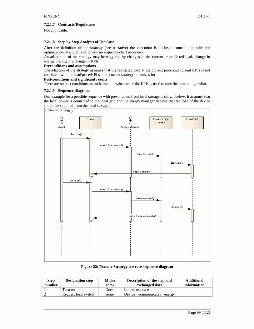
FINSENY D4.1 v1
Page 99 (112)
7.2.1.7 Contracts/Regulations
Not applicable.
7.2.1.8 Step by Step Analysis of Use Case
After the definition of the strategy (see narrative) the execution is a closed control loop with the optimization of a quality criterion (no sequence chart necessary). An adaptation of the strategy may be triggered by changes in the current or predicted load, change in energy pricing or a change in KPIs. Preconditions and assumptions The adaption of the strategy assumes that the requested load at the current price and current KPIs is not consistent with the load/price/KPI set the current strategy optimizes for. Post-conditions and significant results There are no post conditions as such, but an evaluation of the KPIs is used to tune the control algorithm.
7.2.1.9 Sequence diagrams
One example for a possible sequence with power taken from local storage is shown below. It assumes that the local power is connected to the local grid and the energy manager decides that the load of the device should be supplied from the local storage.
Figure 22: Execute Strategy use case sequence diagram
Step
number Designation step Major
actor Description of the step and
exchanged data Additional information
1 Turn on Guest Initiate use case 2 Request load switch none Device communicates energy

FINSENY D4.1 v1
Page 100 (112)
requirements to energy manager 3 Increase load Energy
Manager
4 Stabilize none Part of control loop 5 Supply energy none Part of control loop 6 Turn off Guest Initiate use case 7 Request load switch none 8 Decrease load Energy
Manager
9 Stabilize none Part of control loop 10 Turn off energy
supply none Part of control loop
7.2.2 Use case #2: Define Energy KPIs
7.2.2.1 Brief description
The Hotel Management defines certain key performance indicators (KPIs), which characterize the performance of the hotel building automation system with regard to energy.
7.2.2.2 Narrative (optional)
The definition of KPIs is essential since the control strategy which is executed in use case#1 will try to optimize, usually minimize or maximize, the KPIs. Typical KPIs can include the energy consumption relative to the time of day or price, distribution of the relative price levels at which energy is purchased or total energy consumption/price for energy consumed over a given period. The KPIs are a guideline and optimization criterion for the energy manager. Usually the fulfillment of the KPIs is closely coupled to the compensation of the person or organization responsible for the Energy Management, which is why the KPIs are monitored to create a feedback, see also use case #3. For each KPI not only the parameter but also the desired value is defined. Typically, one or more tolerance band s is defined and instances where the parameter leaves the band are recorded. Another option is to define the ratio between time within and outside of the tolerance band.
7.2.2.3 Actors involved
The Hotel Management is responsible for defining the KPIs. Through the influence on the execution strategy (see use case #1), the Energy Manager is involved.
7.2.2.4 Information exchanged with actors
The Hotel Management sets the KPIs, initially without, later with the input of the performance of the control loop (Use case #1). The Energy Manager can tune the execution strategy with regard to the known KPIs.
7.2.2.5 Relationships with other use cases
Not applicable.
7.2.2.6 Activities/Services
Not applicable.
7.2.2.7 Contracts/Regulations
Not applicable.
7.2.2.8 Step by Step Analysis of Use Case
Steps to implement use case Initially, only the definition is part of the use case. Later, the performance of the control loop can be tracked and optimized by correction of existing of introduction of new KPIs. Preconditions and assumptions

FINSENY D4.1 v1
Page 101 (112)
The use case assumes that Hotel Management can make an informed decision about energy related KPIs. Currently this is surely the case for those KPIs related to financial and customer/guest satisfaction, but network related issues may require specialized knowledge (consultants). We also have to assume that the infrastructure required by the KPIs is given. A KPI “Percentage of electricity from local generation from gas” does not make sense if no possibility to convert gas to electricity exists locally. Post-conditions and significant results The only result of the use case are the KPIs or and update of a given set of KPIs.
7.2.2.9 Sequence diagrams
Since the use case only consists of one (initially) or two steps (consider feedback, update KPIs), no sequence diagram is given.
7.2.3 Use case #3: Monitor KPIs
7.2.3.1 Brief description
The system provides predefined KPIs like energy consumption, cost, etc. to the Hotel Management
7.2.3.2 Narrative (optional)
After KPIs are defined and the strategy is executed, certain measurement values exist in the system. This is usually the case in sensors or if they are networked, in data collectors. Both sensors and data collectors are not actors but parts of the system. These measurement values can be processed by a n expert system to create KPIs by interpreting them by the rules given in use case #2. The important step in this use case is the interpretation of the raw values into information which can be processed by Hotel Management. This usually includes the connection of two time series like energy consumption and price.
7.2.3.3 Actors involved
Strictly speaking there is no actor involved in this use case but the hotel management receives the results.
7.2.3.4 Information exchanged with actors
The raw measurement values converted to KPI-relevant information are transferred to the Hotel Management.
7.2.3.5 Relationships with other use cases
Not applicable.
7.2.3.6 Activities/Services
Not applicable.
7.2.3.7 Contracts/Regulations
Not applicable.
7.2.3.8 Step by Step Analysis of Use Case
Triggered either by a timer or on request by Hotel Management, the use case is executed. Preconditions and assumptions The use case operates under the assumption that enough relevant data has been recorded to calculate the KPIs. If this is not the case, e.g. the sample size is not statistically relevant or another data source suggests that the data set contains outliers, the Hotel management must be informed about this. Post-conditions and significant results
FINSENY D4.1 v1
Page 102 (112)
The use case results in a set of KPIs which the Hotel Management can use to tune the execution strategy used in use case #1.b
7.2.3.9 Sequence diagrams
Not required.
7.2.4 Use case #4: Set Prices
7.2.4.1 Brief description
Depending on the current production and load situation on the grid or an extrapolation of the current situation the utility can change the price of different forms of energy.
7.2.4.2 Narrative (optional)
Despite the fact that the main part of this use case actually takes part outside of the system we decided to model it inside because of the major effect it has on the system. Due to the fact that some of the major KPIs will be financial there has to be a mapping to price. Additionally the fact that the execution of the strategy is a feedback loop makes maters more sensitive to volatility in price.
7.2.4.3 Actors involved
Utility defines the prices Energy management adapts the execution strategy
7.2.4.4 Information exchanged with actors
The information transferred is the price per defined unit of energy, which may be positive or negative. It may also include an extrapolation of future prices or an interval thereof.
7.2.4.5 Relationships with other use cases
Not applicable.
7.2.4.6 Activities/Services
Not applicable.
7.2.4.7 Contracts/Regulations
Not applicable.
7.2.4.8 Step by Step Analysis of Use Case
The main content of the use case is the communication of defined prices to the energy manager. How the prices are determined is irrelevant to the system, since it can only react to the incentives given by the utility. Preconditions and assumptions The use case assumes that if there are predefined “rules of the game” such as service level agreements, maximum price levels or maximum deviations per time unit, these will be respected by the utility. No check is performed on the side of the energy manager. Post-conditions and significant results The post condition is an updated price for energy.
7.2.4.9 Architectural issues in Interactions
An updates price for energy has to lead to a reevaluation of the execution strategy and possibly an adaption.
FINSENY D4.1 v1
Page 103 (112)
7.2.4.10 Sequence diagrams No sequence chart necessary.
7.2.5 Use case #5: Request load switch
7.2.5.1 Brief description
An actor, typically a guest, requests to switch a load on or off. The request influences the total load of the system, which then has to be stabilized according to the rules implemented by the Energy Manager and the KPIs defined by Hotel Management.
7.2.5.2 Narrative (optional)
Not applicable.
7.2.5.3 Actors involved
Guest requests the load switch Energy management has to implement a strategy to consider the load change.
7.2.5.4 Information exchanged with actors
Requested load switch (e.g. amount, duration, …)
7.2.5.5 Relationships with other use cases
Not applicable.
7.2.5.6 Activities/Services
Not applicable.
7.2.5.7 Contracts/Regulations
Not applicable.
7.2.5.8 Step by Step Analysis of Use Case
See use case #1. Preconditions and assumptions The underlying assumptions are that the switch, which the guest requests is physically possible and economically reasonable. If it is not economically reasonable, it may be delayed or executed partly such as delayed heating of water of dimming of lights. Post-conditions and significant results Switch has been executed. This has to be assured to a degree which satisfies the level of comfort for the guest.
7.2.5.9 Architectural issues in Interactions
7.2.5.10 Sequence diagrams See use case #1.
7.2.6 Use case #6: Shed load
7.2.6.1 Brief description
The energy manager decides to disconnect certain loads from the network, according to the strategy defined.
FINSENY D4.1 v1
Page 104 (112)
7.2.6.2 Narrative (optional)
As a predefined level of comfort for the guest is the main aim for the building automation system, turning off loads which serve this goal must be done in a planned manner. This can include a temporary and thus acceptable degradation of service, a reaction to decreased current or predicted demand or changes in current or predicted environmental conditions. Load shedding can also serve as an extreme measure to ensure network stability.
7.2.6.3 Actors involved
Energy Manager executes the strategy. The Energy Manager also acts as gateway for the price information in the control loop. Guest influences the load Utility defines the price of energy
7.2.6.4 Information exchanged with actors
The guest influences the load situation. The utility communicates price information and stability information to the energy manager.
7.2.6.5 Relationships with other use cases
Extension of Use case #1
7.2.6.6 Activities/Services
Not applicable.
7.2.6.7 Contracts/Regulations
Not applicable.
7.2.6.8 Step by Step Analysis of Use Case
Preconditions and assumptions The Energy Manager must either be aware of the current load situation or must be able to determine it in a predefined time.
7.2.6.9 Architectural issues in Interactions
Not applicable.

FINSENY D4.1 v1
Page 105 (112)
7.2.6.10 Sequence diagrams
Figure 23: Shed Load use case sequence diagram
Step
number Designation step Major
actor Description of the step and
exchanged data Additional
information 1 Possible network
instability Utility Initiate use case. The utility
informs the Energy Manager about imminent network instability and orders a load decrease to stabilize the network.
2 Backup possible? Energy Manager
The Energy Manager checks if the current load can be sustained by the local storage capability
Additionally, a check whether or not energy can be generated locally is possible.
3 No None Answer of the local energy storage
4 Turn off Energy Manager
The Energy Manager turns of enough devices to meet the load decrease necessary to

FINSENY D4.1 v1
Page 106 (112)
stabilize the network.
7.2.7 Use case #7: Generate energy locally
7.2.7.1 Brief description
In order to cope with spikes in demand or drops in supply, the Energy Manager decides to generate some energy locally. Especially for renewable energy sources the decision to generate energy locally may also be triggered by external factors such as wind speed, intensity of sunlight, etc.
7.2.7.2 Narrative (optional)
Not applicable.
7.2.7.3 Actors involved
Energy Manager: Executes the strategy Utility
7.2.7.4 Information exchanged with actors
Price and load situation
7.2.7.5 Relationships with other use cases
Extension Use case #1
7.2.7.6 Activities/Services
Not applicable.
7.2.7.7 Contracts/Regulations
Not applicable.
7.2.7.8 Step by Step Analysis of Use Case
Preconditions and assumptions A precondition to this use case is that the facility required exists.
7.2.7.9 Architectural issues in Interactions
Not applicable.
7.2.7.10 Sequence diagrams See use case #1, #6
7.2.8 Use case #8: Store Energy
7.2.8.1 Brief description
Based on the current load/price situation and a prediction, energy from the grid is stored locally for future use
7.2.8.2 Narrative (optional)
Depending on the current price and load situation and a prediction of price/load, the energy manager executes the strategy of use case #1 by storing energy for future use. This can be done by preserving the kind of energy (storing electricity in batteries) or converting the energy form (using cheap electricity to heat water for use in the near future).
FINSENY D4.1 v1
Page 107 (112)
7.2.8.3 Actors involved
Energy Manager Utility
7.2.8.4 Information exchanged with actors
Load and price, current and prediction
7.2.8.5 Relationships with other use cases
Extension Use case #1
7.2.8.6 Activities/Services
Not applicable.
7.2.8.7 Contracts/Regulations
Not applicable.
7.2.8.8 Step by Step Analysis of Use Case
See use case #1 Preconditions and assumptions The precondition is that the possibility to store a given kind of energy exists and storage capacity is still available.
7.2.8.9 Architectural issues in Interactions
Not applicable.
7.2.8.10 Sequence diagrams See use case #1, #6
7.2.9 Use case #9: Request energy from the net
7.2.9.1 Brief description
The energy manager requests energy from network.
7.2.9.2 Narrative (optional)
In order to supply the local grid with energy, the energy manager requests energy from the utility. This should be the standard use case to provide energy to the local grid.
7.2.9.3 Actors involved
Energy Manager Utility
7.2.9.4 Information exchanged with actors
Energy consumption (electricity, heat, water)
7.2.9.5 Relationships with other use cases
Extension Use case #1
7.2.9.6 Activities/Services
Not applicable.
FINSENY D4.1 v1
Page 108 (112)
7.2.9.7 Contracts/Regulations
Not applicable.
7.2.9.8 Step by Step Analysis of Use Case
Not applicable.
7.2.9.9 Architectural issues in Interactions
Not applicable.
7.2.9.10 Sequence diagrams
See use case #1, #6
FINSENY D4.1 v1
Page 109 (112)
8. Conclusion The main outputs of this document have been the definition of the perimeter of the system for a representative selection of building typologies (smart homes, residential buildings, office buildings, data centres and hotel buildings), external actors, main use cases and relationships among them. The elaboration of UML use case diagrams for each scenario has been a valuable tool for focusing the efforts of task 4.1 on first fixing the scope of the scenario, making it easier in a further step to elaborate detailed use cases descriptions using as inputs the background of the partners obtained in previous research projects. Use cases have been described avoiding the description of specific ICT solutions, as the main objective has been to define the functionalities and targets of the system, but not what the system consists of. Therefore the use cases are a starting point from which specific ICT requirements will be elaborated in task 4.2 of the project.
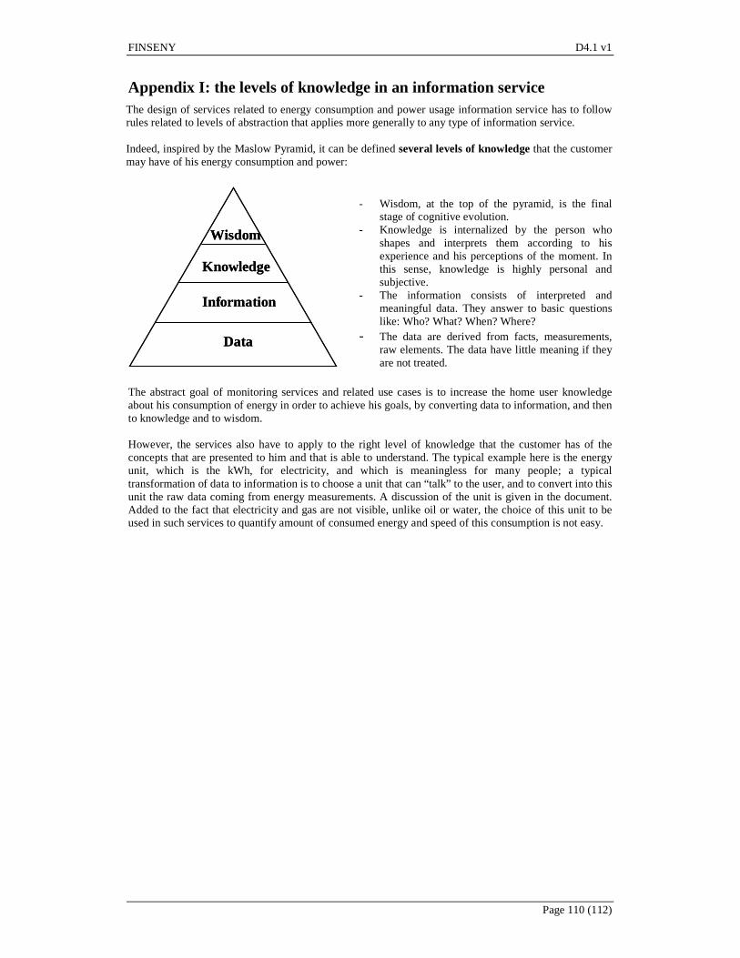
FINSENY D4.1 v1
Page 110 (112)
Appendix I: the levels of knowledge in an information service The design of services related to energy consumption and power usage information service has to follow rules related to levels of abstraction that applies more generally to any type of information service. Indeed, inspired by the Maslow Pyramid, it can be defined several levels of knowledge that the customer may have of his energy consumption and power:
Data
Information
Knowledge
Wisdom
Data
Information
Knowledge
Wisdom
- Wisdom, at the top of the pyramid, is the final
stage of cognitive evolution. - Knowledge is internalized by the person who
shapes and interprets them according to his experience and his perceptions of the moment. In this sense, knowledge is highly personal and subjective.
- The information consists of interpreted and meaningful data. They answer to basic questions like: Who? What? When? Where?
- The data are derived from facts, measurements, raw elements. The data have little meaning if they are not treated.
The abstract goal of monitoring services and related use cases is to increase the home user knowledge about his consumption of energy in order to achieve his goals, by converting data to information, and then to knowledge and to wisdom. However, the services also have to apply to the right level of knowledge that the customer has of the concepts that are presented to him and that is able to understand. The typical example here is the energy unit, which is the kWh, for electricity, and which is meaningless for many people; a typical transformation of data to information is to choose a unit that can “talk” to the user, and to convert into this unit the raw data coming from energy measurements. A discussion of the unit is given in the document. Added to the fact that electricity and gas are not visible, unlike oil or water, the choice of this unit to be used in such services to quantify amount of consumed energy and speed of this consumption is not easy.

FINSENY D4.1 v1
Page 111 (112)
Appendix II: Sequence diagrams of the detailed “Manage Demand” use cases (Home domain) The sequence diagrams of the detailed use cases # 4 to 6 related to the demand management and showing them step by step are the following
Use case #4: Direct load control
:Customer:Distributor
1. loadReductionNotificationToD(SmartMeterReferences,period)
4. loadReductionNotificationToH(SmartMeterReferences,period)
:Provider
<Notice>
2. loadReductionOnSMSToC()
16. loadReductionAppraisal(SmartMeterReferences)
17. addingInTheLoadReduc tionLog(SmartMeterReferences)
1. loadReductionNotificationToD(SmartMeterReferences,period)
Hub
15. endLoadReduction(SmartMeterReferences)
4. loadReductionNotificationToH(SmartMeterReferences,period)
Smart meter
14. endLoadReductionToH(SmartMeterReferences)
5. loadReductionNotificationToSM(SmartMeterReferences,period)
Controlappliances
module
7. exemption()
9. loadReductionOrder(period)
<Load reduc tion>11. exemption()
Display
6. loadReductionNotificationToD(SmartMeterReferences,period)
8. announceStartOfLoadReduction(period)
13. endLoadReduction()
10. startLoadReduc tion(period)
Appliance
12. endLoadReduction()
Mobile phone
3. readingInformation()
2. loadReductionOnSMSToC()
Load reduction on a preset period
Disseminate not ice of load reduction

FINSENY D4.1 v1
Page 112 (112)
Use case #5: Dynamic pricing of electricity
:Provider
<Notice>
:Dis tributor
1. peakLoadNotification(SmartMeterReferences,period)
Hub
4. peakLoadNotificationToH(SmartMeterReferences,period)
Smart Meter
5. peakLoadNotificationToSM(SmartMeterReferences,period)
Controlappliances
module
9. peakLoadOrder(period)
<(Peak load>
Display
6. peakLoadNotificationToD(SmartMeterReferences,period)
8. announceStartPeakLoad(period)
Appliance
10. startPeakLoad(period)
12. endPeakLoad()
2. peakLoadNotificationBySMS(SmartMeterReferences,period)
Mobile phone
3. readingInformation()
:Customer
7. exemption()
11. exemption()
Disseminate peak load not if ication
Dy namic pricing of electricity on a preset period
Use case #6 : Emergency Load reduction
:Distributor Hub
1. LoadReductionOrder(SmartMeterReferences,periode)
2. LoadReductionOrderToSM(SmartMeterRefrences,period)
Smart Meter Controlappliances
module
<Load reductionc>
4. loadReductionOrder(period)
3. announceStartLoadReduction(period)
Display
7. announceEndLoadreduction()
Appl iance
5. startLoadReduction(period)
6. endLoadreduction()