d42.21 - specification documentation and deployment of the ... · d42.21 specification...
TRANSCRIPT
Driving Innovation in Crisis Management for European Resilience
D42.21 - Specification documentation and
deployment of the prototype and final
integration platform
Grant agreement number: 607798
Start date of the project: 2014-05-01
Duration: 54 months
Due date of deliverable: M11
Actual submission date: 2015-06-30
Lead Beneficiary: ATOS (Jaime Martín, German Herrero and Ignacio Llamas)
Contributing beneficiaries: DLR (Julia Zillies)
FRQ (Gerhard Zuba, Thomas Obritzhauser)
GMV (Héctor Naranjo, Raúl Valencia)
JRC (Daniele Galliano, Francesco Mugnai)
TCS (Bruno Quere, Edith Felix, Laurent Dubost)
Keywords:
Architecture, portfolio of tools, requirements, experiments, integration, interoperability, SOA,
Operational environment, interfaces, Common Information Space
Dissemination level:
PU ☒
PP ☐
RE ☐
CO ☐

D42.21 Specification documentation and
deployment of the prototype and final integration platform
©DRIVER Consortium 2 June 2015
Release History
Version Date Description Release by
V0.1 1-May-2015 Initial Version / Table of Contents ATOS
V0.2 12-May-2015 Agreed Table of Contents ATOS
V0.3 2-June-2015 Content incorporated from ATOS, FRQ and
GMV
ATOS
V0.4 12-June-2015 Some updated in structure and content ATOS
V0.5 15-June-2015 Updates in contents from partners ATOS
V0.6 22-June-2015 First version ready for review ATOS
V1.0 30-June-2015 Final Version ATOS

D42.21 Specification documentation and
deployment of the prototype and final integration platform
©DRIVER Consortium 3 June 2015
Table of Contents
Executive Summary ................................................................................................................................. 8
1 Introduction ................................................................................................................................... 10
1.1 Introduction and Purpose ..................................................................................................... 10
1.2 Scope ..................................................................................................................................... 10
1.3 Document Structure .............................................................................................................. 11
2 SOTA of standards and technologies ............................................................................................. 12
2.1 Introduction ........................................................................................................................... 12
2.2 Information and Communications Technologies .................................................................. 12
2.2.1 Service Oriented Architecture (SOA) ................................................................................. 12
2.2.2 Enterprise Service Bus (ESB) .............................................................................................. 13
2.2.3 Web-services ..................................................................................................................... 13
2.2.4 Simple Object Access Protocol (SOAP) .............................................................................. 14
2.2.5 Representational State Transfer (RESTful) ........................................................................ 14
2.2.6 JavaScript Object Notation (JSON) .................................................................................... 15
2.2.7 eXtensible Markup Language (XML) .................................................................................. 16
2.2.8 Windows Communication Foundation (WCF) ................................................................... 17
2.2.9 Resource Description Framework (RDF) ........................................................................... 17
2.3 Crisis Management Standards and Technologies.................................................................. 18
2.3.1 Recommendations ............................................................................................................. 21
3 Integration Platform ....................................................................................................................... 23
3.1 Selected Technologies and Standards ................................................................................... 23
3.1.1 Service Oriented Architecture and related ICT ................................................................. 23
3.1.2 Distribution Element (EDXL DE) ......................................................................................... 23
3.1.3 Tactical Situation Object (TSO) .......................................................................................... 23
3.1.4 Common Alerting Protocol (CAP) ...................................................................................... 24
3.1.5 GIS Standards .................................................................................................................... 25
3.2 Portfolio of CM tools ............................................................................................................. 25
3.3 Architecture Requirements ................................................................................................... 28
3.4 Common Architecture Description ........................................................................................ 31
3.4.1 CIS, Common Information Space ....................................................................................... 31
3.4.2 Common Information Space Architecture Options ........................................................... 34

D42.21 Specification documentation and
deployment of the prototype and final integration platform
©DRIVER Consortium 4 June 2015
3.4.3 Common Information Space Supporting Tools ................................................................. 36
3.4.4 Background from other projects ....................................................................................... 39
4 Experiments ................................................................................................................................... 41
4.1 EXPE 40: Enhanced contribution of airborne sensors ........................................................... 41
4.1.1 Objectives .......................................................................................................................... 41
4.1.2 Experiment Description ..................................................................................................... 41
4.2 EXPE 41: Operational Data Lift .............................................................................................. 44
4.3 EXPE 42: Interaction with citizens and volunteers ................................................................ 46
4.3.1 Expe 42 goals ..................................................................................................................... 46
4.3.2 Expe 42 set-up ................................................................................................................... 48
4.3.3 Expe 42 information space ................................................................................................ 48
4.4 EXPE 43: From Planning to Tasking ....................................................................................... 48
4.4.1 Components Services ........................................................................................................ 48
4.4.2 Implementation Description ............................................................................................. 50
4.5 EXPE 44: Enhanced logistics .................................................................................................. 51
4.5.1 Components Services ........................................................................................................ 51
4.5.2 Implementation Description ............................................................................................. 52
4.6 EXPE 45: Situation assessment and Crisis dynamics ............................................................. 53
4.6.1 Tools .................................................................................................................................. 54
5 Conclusion ...................................................................................................................................... 58
Annex 1 SOA .......................................................................................................................................... 60
SOA Architecture ............................................................................................................................... 60
SOA Architectural Constraints ........................................................................................................ 60
Interfaces ....................................................................................................................................... 61
Messages ........................................................................................................................................ 61
RESTful Web Services ..................................................................................................................... 61
Architecture Based on SOA ................................................................................................................ 62
Services Visibility ............................................................................................................................ 64
Services Capabilities ....................................................................................................................... 64
Bibliography ........................................................................................................................................... 65
References ............................................................................................................................................. 66

D42.21 Specification documentation and
deployment of the prototype and final integration platform
©DRIVER Consortium 5 Public
List of Tables
Table 1: Interoperability Standards _____________________________________________________________ 19
Table 2: Summary of Standards Evaluation ______________________________________________________ 21
Table 3: CM Tools TRL _______________________________________________________________________ 28
Table 4: Architecture Requirements ____________________________________________________________ 31
Table 5: EXPE 40 Data Flow ___________________________________________________________________ 44
Table 6: EXPE 41 data flow ___________________________________________________________________ 46
Table 7: EXPE 42 Integration of tools ___________________________________________________________ 48
Table 8: Contribution of services for coordination and cooperation and structured command and control ____ 49
Table 9: EXPE 45 Tools _______________________________________________________________________ 56
List of Figures
Figure 1: Portfolio of tools: preliminary classification ______________________________________________ 26
Figure 2: CIS Adaptor architecture _____________________________________________________________ 32
Figure 3: Socrates CSS architectural approach ____________________________________________________ 35
Figure 4: Office 365 Security Control ____________________________________________________________ 37
Figure 5: Cyris functional view _________________________________________________________________ 37
Figure 6: Ingest based Common Information Space adaptor _________________________________________ 38
Figure 7: ODYSSEY Security Architecture Methodology _____________________________________________ 39
Figure 8: EXPE40 Data Exchange_______________________________________________________________ 42
Figure 9: EXPE 41 Operational Data Lift _________________________________________________________ 45
Figure 10: EXPE42 Crisis Communication ________________________________________________________ 47
Figure 11: EXPE42 volunteer management ______________________________________________________ 47
Figure 12: EXPE 43 SoS architecture ____________________________________________________________ 51
Figure 13: EXPE 44 involved tools ______________________________________________________________ 52
Figure 14: EXPE 44 Logistics Experiment _________________________________________________________ 53

D42.21 Specification documentation and
deployment of the prototype and final integration platform
©DRIVER Consortium 6 Public
List of Acronyms
Abbreviation /
acronym
Description
ANSSI Age e Natio ale de la S u it des S st es d I fo atio F a e
CAP Common Alerting Protocol
CEK Content Encryption Key
CIS Common Information Space
COP Common Operational Picture
CM Crisis Management
CSA Co seil Sup ieu de l Audio isuel F a e
CSS Common Shared Services
DE Distribution Element (EDXL standard)
DM Disaster management
ERCC Emergency Response Coordination Centre
ECML European Crisis Management Laboratory
EDXL Emergency Data Exchange Language
ESB Enterprise Service Bus
FIPS Federal Information Processing Standard
FTP File Transfer Protocol
GIS Geographic Information System
HSM Hardware Security Module
KEK Key Encryption Key
KML Keyhole Markup Language
JSON JavaScript Object Notation
NIST National Institute of Standards and Technology (United States of
America)
P2P Peer To Peer
OGC Open Geospatial Consortium
RDF Resource Description Framework
REST Representational State Transfer
RGS Référentiel général de sécurité (ANSSI, France)
SAML Security Assertion Markup Language
SOA Service Oriented Architecture
SOAP Simple Object Access Protocol

D42.21 Specification documentation and
deployment of the prototype and final integration platform
©DRIVER Consortium 7 Public
SON Self Organized Network
SOS System of Systems
SE2 Subproject Experiment 2
SP Subproject (main subdivision of DRIVER)
TRL Technology Readiness Level
WFS Web Feature Service
WMS Web Map Service
WP Work Package
XACML eXtensible Access Control Markup Language
XML eXtensible Markup Language

D42.21 Specification documentation and
deployment of the prototype and final integration platform
©DRIVER Consortium 8 Public
Executive Summary
DRIVER s Work Package 42 Architecture for Strengthened Responses aims at designing the software
architecture that will enable the testing of the SP4 experiments which will assemble a selection of
Crisis Management (CM) tools provided by WP43 Situation Assessment Tools, WP44 Tasking and
Resource Management Tools and WP45 Secured Interoperability Tools.
This architecture has to meet the following requirements:
• To enable the connectivity of existing operational tools (legacy systems, SP4 operational
tools)
• To be compatible with the SP2 test-bed environment (e.g.: simulators, evaluation modules)
• To enable the management of a secured heterogeneous community
• To enable the development of a service based technical system of systems
• To prepare the secured cloud deployment experiment
The purpose of this deliverable is to provide an integration platform for the SP4 technical tools. The
architecture of this Integration platform will be based on the Service Oriented Architecture (SOA)
paradigm. It will make extensive use of existing state of the art standards and platforms and will
choose components coming from the open source community (e.g: IP, SOA, ESB, Web-services,
SOAP, J2E, XML, KML, RDF … . It will provide basic common services and will be designed in
coherence with the SP2 test-bed and related to the interoperability Standards task of WP45, Task
45.1, and with the aim of providing valuable input to WP46, Integration & Transverse experiment.
A Common Information Space (CIS) will be used to enable the secured information exchange
between the participating applications. It is based on the basis that in a SOA context, every
application can offer data, information provider, and/or receive data, information consumer, and is
agnostic concerning the other partners in the Information space.
Within the CIS, the architecture defines the CIS Adaptor as the connector used by the tools to get
access to the shared information space. Each tool will implement this adaptor according to the
defined common architecture so that interoperability is guaranteed.
The CIS communication between the different tools will be done by an implementation of the CIS
distributor. There are several options to implement it, like Common Shared Services, Peer To Peer or
Enterprise Service Bus. Also there are other supporting tools that could be used to enhance the
functionality of the CIS like Cyris or Ingest.
Further details of the architecture will be provided in coming deliverables and they will include
information about:
• Further details in the scope of the Specification documentation and deployment of the
prototype and final integration platform
• Interfaces specifications and integration guidelines
• Documentation and deployment of prototype and final secured system access control
• Secured cloud deployment and documentation

D42.21 Specification documentation and
deployment of the prototype and final integration platform
©DRIVER Consortium 9 Public
This document is the first version of Specification documentation and deployment of the prototype
and final integration platform. There will be a second iteration of this document that will provide
further details and more deep understanding for the final integration platform.

D42.21 Specification documentation and
deployment of the prototype and final integration platform
©DRIVER Consortium 10 Public
1 Introduction
1.1 Introduction and Purpose
SP4 aims at strengthening the response effort in European Union by filling the main improvement
needs of the responders such as: interoperability, information sharing, situation assessment, early
warning, resource management, tasking, capacity building, and interaction with citizens. It addresses
all bodies of the responder community (i.e.: fire-brigade, public health, police, civil security, and etc.),
all phases (preparedness & response) and all levels (from local to European).
The purpose of WP42 Architecture for Strengthened Responses is to provide a suitable architecture
for the experiments that will be carried out in SP4 and SP6.
On the one hand, a portfolio of tools was prepared in SP4 covering tools from WP43 Situation
Assessment Tools, WP44 Tasking and Resource Management Tools and WP45 Secured
Interoperability Tools. The tools were evaluated and assessed and furthermore they were classified in
accordance with the main features they had.
On the other hand, six experiments are being defined within the scope of SP4, and each of them will
focus on a specific topic and will use a subset of the tools of the portfolio.
The a hite tu e s ai ai is to enable the exchange of current information between the involved
tools. It has to be flexible enough to be used in all the experiments, enabling services enough to fulfil
their needs, so that involved tools may have a suitable framework with the required interoperability
for experiments to be performed properly.
1.2 Scope
The scope of WP42 is the description of the technical architecture to be used in the experiments
covering the:
Definition of the architectural technical guidelines
Specification documentation and deployment of the prototype and final integration
platform
Interfaces specifications and integration guidelines
Documentation and deployment of prototype and final secured system access control
Secured cloud deployment (prototype & final) and documentation
This deliverable describes the component, tools and services that WP43, WP44 and WP45 will use for
the development of the experiments together with the integration platform for the integration of
SP4 technical tools. This architecture will be based on the Service Oriented Architecture (SOA)
paradigm. It will make extensive use of existing state of the art standards and platforms and will
choose components coming from the open source community (e.g: IP, SOA, ESB, Web-services,
SOAP, J2E, XML, KML, RDF… . It will provide basic common services and will be designed in coherence
with the SP2 test-bed and related to the interoperability Standards task of WP45.
This document is the first component document, and following documents will provide detailed
information about the components part of the integration platform.
D42.21 Specification documentation and
deployment of the prototype and final integration platform
©DRIVER Consortium 11 Public
1.3 Document Structure
Besides this introductory chapter, the deliverable contains the following sections:
Chapter 2, introduces available tools and technologies to be used within the integration platform and
the experiments from both the ICT and the CM perspectives.
Chapter 3, describes the integration platform where all the tools will be used to perform the
following experiments. It includes the architecture, the components and the functionality they
provide.
Chapter 4, Overview of experiments: it provides a description of the experiments, with focus on
integration platform and components.
Chapter 5, provides a conclusion of this document and way ahead.
D42.21 Specification documentation and
deployment of the prototype and final integration platform
©DRIVER Consortium 12 Public
2 SOTA of standards and technologies
2.1 Introduction
When defining the Integration Platform for the SP4 technical tools and more specifically, when
defining the architecture of this Integration Platform, it is important to establish a good basis in
which the fundamentals of the design will be built. In this case, the first issue that needs to be
addressed is the presentation of the available standards and technologies that can be used to build
this Integration Platform. This is performed through an initial overview of the available technologies
and standards in the scope of Service architectures and Crisis Management so we are able to
establish a start point for defining the used standards and technologies.
The aim of the Integration Platform is to use the Service Oriented Architecture (SOA) paradigm. It will
make extensive use of existing state of the art standards and platforms and will choose components
coming from the open source community (e.g: IP, SOA, ESB, Web-services, SOAP, J2E, XML, KML,
RDF… . It will provide basic common services such as mail, routing, stack management.
2.2 Information and Communications Technologies
2.2.1 Service Oriented Architecture (SOA)
Service Oriented Architecture (SOA) is a paradigm for organizing and utilizing distributed capabilities
that may be under the control of different ownership domains. In general, entities (people and
organizations) create capabilities to solve or support a solution for the problems they face in the
course of their business. It is natural to think of o e pe so s eeds ei g et apa ilities offe ed so eo e else; o , i the o ld of dist i uted o puti g, o e o pute age t s e ui e e ts
being met by a computer agent belonging to a different owner. There is not necessarily a one-to-one
correlation between needs and capabilities; the granularity of needs and capabilities vary from
fundamental to complex, and any given need may require the combining of numerous capabilities
while any single capability may address more than one need.
Service Oriented Architecture is the natural evolution of distributed computing based on request-
reply structure for synchronous and asynchronous services. The individual function elements are
modularized and presented as services for consumer applications. The key point is that these services
are loosely coupled and the service interface is independent of the implementation of the service.
SOA services have self-describing interfaces in platform-independent XML documents. Web Services
Description Language (WSDL) is the standard used to describe the services.
When using SOA, there are some key concepts that need to be explained in advance. WSDL, UDDI,
and SOAP are the fundamental pieces of the SOA infrastructure. WSDL is used to describe the
service; Universal Description , Discovery, and Integration or UDDI, to register and look up the
services; and Simple Object Access Protocol or SOAP, as a transport layer to send messages between
service consumer and service provider. While SOAP is the default mechanism for Web services,
alternative technologies accomplish other types of bindings for a service. A consumer can search for
D42.21 Specification documentation and
deployment of the prototype and final integration platform
©DRIVER Consortium 13 Public
a service in the UDDI registry, get the WSDL for the service that has the description, and invoke the
service using SOAP.
2.2.2 Enterprise Service Bus (ESB)
An ESB is the mechanism by which messages are transported between a client and a service. ESB
refers to a software architecture style that provides an abstraction layer on top of an implementation
of an enterprise messaging system. In addition to this basic capability, an ESB should offer the
following facilities:
A message queuing capability.
Message routing.
Message transformation.
Adapters for legacy applications
Implementation of a security model including authentication and support for WS-Security.
Support for Web service protocols including those specified by the major specifications.
Support for monitoring and logging message activity.
The benefit of using an ESB within a SOA is that it eases the process of creating an SOA by reducing
the number of point-to-point connections required to allow services to communicate each other.
Within the boundaries of an ESB, support for multiple protocols and data transformation enables
heterogeneous services to behave as if they were homogeneous. Adapters allow us to expose legacy
systems as services without programming. The support for reliable and secure messaging and
queuing is also available through straight-forward configuration rather than coding. Add in the
availability of logging and access control for governance and ESB can be a very useful tool indeed.
The downside is that it takes time and effort to develop sufficient familiarity with an ESB tool in order
to achieve the maximum benefit from it.
An ESB does not provide a Service Oriented Architecture, but provides the features with which one
may be implemented and is not necessarily web-services based. The requestor and provider of the
service within an ESB do not have to agree on the message format, message transport or even the
target address.
2.2.3 Web-services
The application of Web services allows the constitution of an SOA. In general, a Web service is a
specific kind of service which can be identified unambiguously by an URI and which uses Internet
standards such as HTTP for transport.
The World Wide Web Consortium (W3C) provides a more specific and accurate definition:
A We se i e is a soft a e s ste desig ed to suppo t i te ope a le a hi e-to-machine
interaction over a network. It has an interface described in a machine-processable format
(specifically WSDL). Other systems interact with the Web service in a manner prescribed by its
description using SOAP messages, typically conveyed using HTTP with an XML serialization in
conjunction with other Web- elated sta da ds. [W C We Se i es Architecture Group]1.
1 Web Services Architecture Working Group http://www.w3.org/2002/ws/arch/

D42.21 Specification documentation and
deployment of the prototype and final integration platform
©DRIVER Consortium 14 Public
According to this definition Web services are built on top of well-known and platform-independent
protocols fulfilling the key requirements of an SOA: the dynamic discovery and invocation of a service
is provided by UDDI, WSDL, and SOAP. The usage of XML supports the required platform-
independence, and HTTP offers internet-wide interoperability.
In conclusion, web services typically interact applying SOAP messages to exchange XML data. The
web services interfaces can be described using the Web Service Definition Language (WSDL) while
the Universal Description , Discovery, and Integration (UDDI) standard constitutes a protocol for
directory services enabling clients to locate web services and examine the details.
There seems to be general confusion about the relationship between SOA and Web services. In an
April 2003 Gartner report, Yefim V. Natis2 makes the distinction as follows: "Web services are about
technology specifications, whereas SOA is a software design principle. Notably, Web services' WSDL
is an SOA-suitable interface definition standard: this is where Web services and SOA fundamentally
connect." Fundamentally, SOA is an architectural pattern, while Web services are services
implemented using a set of standards; Web services is one of the ways you can implement SOA. The
benefit of implementing SOA with Web services is that you achieve a platform-neutral approach to
accessing services and better interoperability as more and more vendors support more and more
Web services specifications.
2.2.4 Simple Object Access Protocol (SOAP)
SOAP is a communication protocol used between applications that stands for Simple Object Access
Protocol. This protocol is based on XML and is basically a format for sending messages through
Internet between different services in different platforms using different programming languages. It
is simple and extensible.
SOAP is used primarily for making remote procedure calls across machine and network boundaries.
SOAP has these primary advantages:
Neutrality: Posting data over the HTTP protocol means not only that the delivery mechanism
is widely available but also that SOAP is able to get past firewalls that pose problems for
other methods.
Independence: SOAP uses the open standard of XML to format the data, which makes it
easily extendable and well supported.
Extensibility: Because SOAP is a wire protocol based on XML and HTTP, it is possibly the most
widely interoperable protocol to date.
This XML-based protocol consists of three parts:
An envelope, which defines the message structure and how to process it
A set of encoding rules for expressing instances of application-defined datatypes
A convention for representing procedure calls and responses
2.2.5 Representational State Transfer (RESTful)
More than a decade after its introduction, REST (Representational State Transfer) has become one of
the most important technologies for Web applications. Its importance is likely to continue growing
2 https://www.gartner.com/doc/391595/serviceoriented-architecture-scenario

D42.21 Specification documentation and
deployment of the prototype and final integration platform
©DRIVER Consortium 15 Public
quickly as all technologies move towards an API orientation. Every major development language now
includes frameworks for building RESTful Web services. As such, it is important for Web developers
and architects to have a clear understanding of REST and RESTful services. While REST stands for
Representational State Transfer, which is an architectural style for networked hypermedia
applications, it is primarily used to build Web services that are lightweight, maintainable, and
scalable. A service based on REST is called a RESTful service. REST is not dependent on any protocol,
but almost every RESTful service uses HTTP as its underlying protocol.
Every system uses resources. These resources can be pictures, video files, Web pages, business
information, or anything that can be represented in a computer-based system. The purpose of a
service is to provide a window to its clients so that they can access these resources. Service architects
and developers want this service to be easy to implement, maintainable, extensible, and scalable. A
RESTful design promises that.
As a programming approach, REST is a lightweight alternative to Web Services and RPC. Much like
Web Services, a REST service is:
• Platform-independent (you don't care if the server is Unix, the client is a Mac, or anything
else),
• Language-independent (C# can talk to Java, etc.),
• Standards-based (runs on top of HTTP), and
• Can easily be used in the presence of firewalls.
2.2.6 JavaScript Object Notation (JSON)
JSON is an open standard format that uses human-readable text to transmit data objects consisting
of attribute–value pairs. It is used primarily to transmit data between a server and web application,
as an alternative to XML. Although originally derived from the JavaScript scripting language, JSON is a
language-independent data format. Code for parsing and generating JSON data is readily available in
many programming languages. 3
JSON grew out of a need for stateful, real-time server-to-browser communication without using
browser plugins such as Flash or Java applets, which were the dominant method in the early 2000s.
Douglas Crockford was the first to specify and popularize the JSON format. The acronym was coined
at State Software, a company co-founded by Crockford, Chip Morningstar and Robert F. Napiltonia in
April 2001 and funded by Tesla Ventures. The co-founders agreed to build a system that used
standard browser capabilities and provided an abstraction layer for Web developers to create
stateful Web applications that had a persistent duplex connection to a Web server by holding the
two HTTP connections open and recycling them before standard browser time-outs if no further data
were exchanged. The idea for the State Application Framework was developed by Morningstar at
State Software. It was used in a project at Communities.com for Cartoon Network, which used a plug-
in with a proprietary messaging format to manipulate DHTML elements (this system is also owned by
3DO). Upon discovery of early Ajax capabilities, digiGroups, Noosh, and others used frames to pass
information into the user browsers' visual field without refreshing a Web application's visual context,
realizing real-time rich Web applications using only the standard HTTP, HTML and JavaScript
capabilities. Crockford then found that JavaScript could be used as an object-based messaging format
for such a system.
3 https://en.wikipedia.org/wiki/JSON

D42.21 Specification documentation and
deployment of the prototype and final integration platform
©DRIVER Consortium 16 Public
Although JSON was originally based on a non-strict subset of the JavaScript scripting language
(specifically, Standard ECMA-262 3rd Edition—December 1999) and is commonly used with that
language, it is a language-independent data format. Code for parsing and generating JSON data is
readily available for a large variety of programming languages. JSON's Web site lists JSON libraries by
language.
JSON is promoted as a low-overhead alternative to XML as both of these formats have widespread
support for creation, reading and decoding in the real-world situations where they are commonly
used.
2.2.7 eXtensible Markup Language (XML)
XML is a markup language for documents containing structured information. The essence of XML is in
its name: eXtensible Markup Language.
Extensible: XML is extensible. It lets you define your own tags, the order and number in
which they occur, and how they should be processed. Another way to think about
extensibility is to consider that XML allows all of us to extend our notion of what a document
is: it can be a file that lives on a file server, or it can be a transient piece of data that flows
between two computer systems (as in the case of Web Services).
Markup: The most recognizable feature of XML is its tags, or elements (to be more accurate).
In fact, the elements you will create in XML will be very similar to the elements you have
already been creating in your HTML documents. However, XML allows you to define your
own set of tags.
Language: XML is a language that is very similar to HTML. It is much more flexible than HTML
e ause it allo s ou to eate ou o usto tags. Ho e e , it s i po ta t to ealize that
XML is not just a language. XML is a meta-language: a language that allows us to create or
define other languages. For example, with XML we can create other languages, such as RSS,
MathML (a mathematical markup language), and even tools like eXtensible Stylesheet
Language Transformations (XSLT)4.
XML is not a replacement for HTML. XML and HTML were designed with different goals:
XML was designed to describe data, with focus on what data is
HTML was designed to display data, with focus on how data looks
HTML is about displaying information, while XML is is a software and hardware independent tool for
carrying information.
XSD (XML Schema Definition), a recommendation of the World Wide Web Consortium (W3C),
specifies how to formally describe the elements in an Extensible Markup Language (XML) document.
It can be used by programmers to verify each piece of item content in a document. They can check if
it adheres to the description of the element it is placed in. 5
Like all XML schema languages, XSD can be used to express a set of rules to which an XML document
must conform in order to be considered "valid" according to that schema. However, unlike most
other schema languages, XSD was also designed with the intent that determination of a document's
4 http://www.sitepoint.com/really-good-introduction-xml/).
5 https://en.wikipedia.org/wiki/XML_Schema_(W3C).
D42.21 Specification documentation and
deployment of the prototype and final integration platform
©DRIVER Consortium 17 Public
validity would produce a collection of information adhering to specific data types. Such a post-
validation infoset can be useful in the development of XML document processing software.
2.2.8 Windows Communication Foundation (WCF)
Windows Communication Foundation (WCF) is a framework for building service-oriented
applications. Using WCF, you can send data as asynchronous messages from one service endpoint to
another. A service endpoint can be part of a continuously available service hosted by IIS, or it can be
a service hosted in an application. An endpoint can be a client of a service that requests data from a
service endpoint. The messages can be as simple as a single character or word sent as XML, or as
complex as a stream of binary data. A few sample scenarios include:
A secure service to process business transactions.
A service that supplies current data to others, such as a traffic report or other monitoring
service.
A chat service that allows two people to communicate or exchange data in real time.
A dashboard application that polls one or more services for data and presents it in a logical
presentation.
Exposing a workflow implemented using Windows Workflow Foundation as a WCF service.
A Silverlight application to poll a service for the latest data feeds.
While creating such applications was possible prior to the existence of WCF, WCF makes the
development of endpoints easier than ever. In summary, WCF is designed to offer a manageable
approach to creating Web services and Web service clients. 6
2.2.9 Resource Description Framework (RDF)
The Resource Description Framework (RDF) is an infrastructure that enables the encoding, exchange
and reuse of structured metadata. RDF is an application of XML that imposes needed structural
constraints to provide unambiguous methods of expressing semantics. RDF additionally provides a
means for publishing both human-readable and machine-processable vocabularies designed to
encourage the reuse and extension of metadata semantics among disparate information
communities. The structural constraints RDF imposes to support the consistent encoding and
exchange of standardized metadata provides for the interchangeability of separate packages of
metadata defined by different resource description communities.
RDF is a flexible schema-less data model. It is one of the core technologies of the Semantic Web and
the current W3C standard to represent data on the web. As mentioned, it is a data model. It can be
compared to the relational model which is the way you organize data in a relational database: group
related things in tables with attributes, create links between tables, etc. RDF is just another way of
organizing your data as a graph. RDF is a graph. A graph is a representation of objects that are
connected by links. In other words, you can have two things which are related in some way through a
link that connects them. Take for example the following sentence: Austin is the capital of Texas. The
two things in this sentence are Austin and Texas. These two things are related by the link "is the
capital of."
6 https://msdn.microsoft.com/en-us/library/ms731082(v=vs.110).aspx

D42.21 Specification documentation and
deployment of the prototype and final integration platform
©DRIVER Consortium 18 Public
The W3C published a specification of RDF's data model and an XML serialization as a
recommendation in 1999. RDF/XML is a syntax implementation to serialize an RDF graph as an XML
documents (other serialization formats exist like JSON-LD, based on JSON, etc.). From now on in this
document RDF should be understood as RDF/XML.
2.3 Crisis Management Standards and Technologies
The following section is based on the information generated as a result of task T45.1 Interoperability
standards of DRIVER and compiled in the document D45.1 [1] and also on the information generated
as a result of this task T42.2.
Interoperability standards offer the following benefits:
• Reduce life cycle costs: the cost to develop, integrate and support systems is reduced by
eli i ati g sto epipe i ple e tatio s. • Reduce development and integration time: common communications prevent the
reinvention of the wheel, allow for code and conceptual re-use and speed integration since
proven technology is employed.
• Framework for technology insertion: with a common interface, as new technologies are
created, those technologies can easily be integrated with minor modifications and known
and documented consequences into existing systems.
T45.1 has analyzed existing relevant prominent standards, for instance: EDXL, OGC standards for geo-
data and sensor data or the TSO standard from FP6-OASIS for semantic interoperability.
In the context of the DRIVER project we focus on interoperability between first-responders and crisis
management organizations within the EU. Collaboration and coordination there can take place at
various levels and between a wide variety of organizations. We can distinguish collaboration within
hierarchical structures but also across hierarchical structures and at local level (local accident
management), at cross-border regional level within a country), at international cross-border level
between adjacent regions, at international level between member states and for coordination
purposes at EU-level.
In the survey of interoperability standards performed in T45.1 the most common standards
specifically designed for crisis management domain and standards for exchange of maps, imagery
and spatial data are described and summarized here as reference.
In the scope of the actual task T42.2, some investigation work has been performed to complete and
review the previous information from T45.1 so that it better reflects the actual situation of the
standards and technologies within Crisis Management.
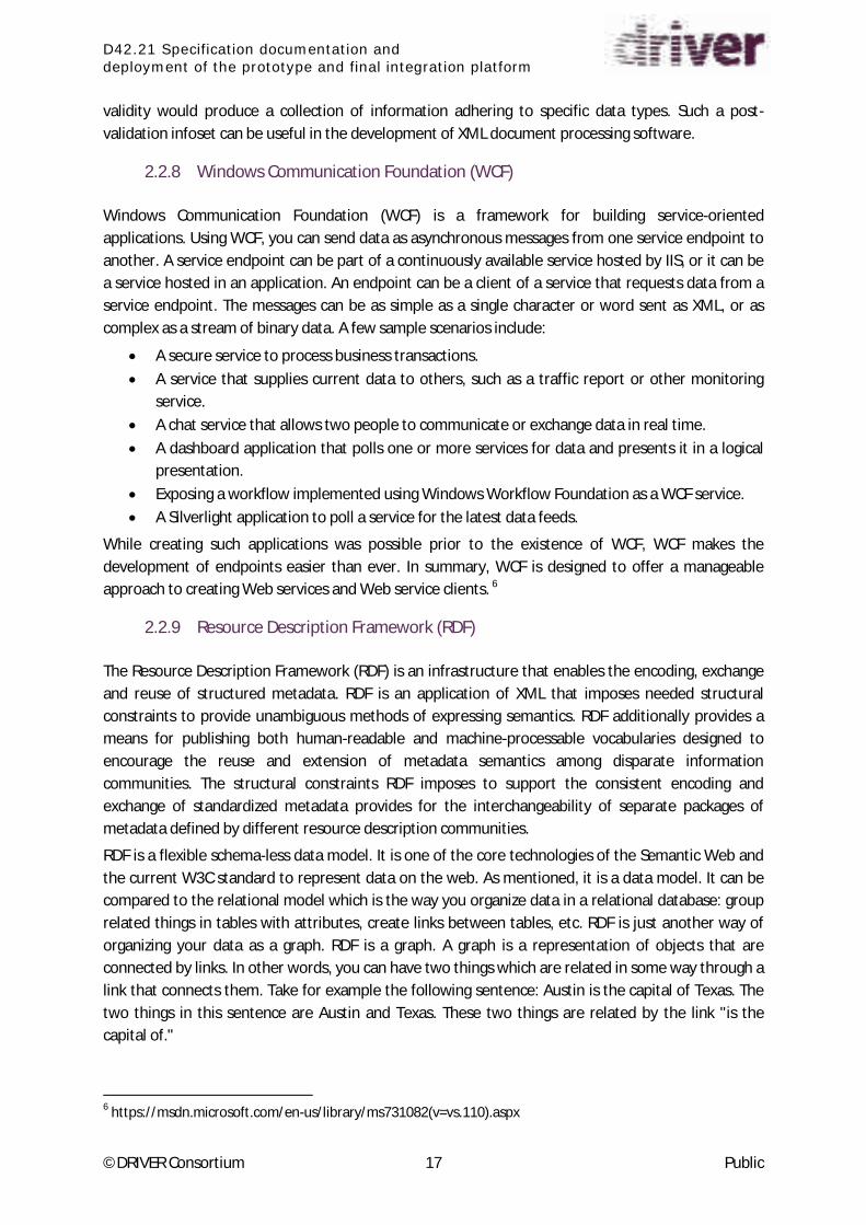
The following Table 1 summarizes the list of standards for map, spatial data and imagery:
Interoperability Standards Full name
EDXL Emergency Data Exchange Language
CAP Common Alerting Protocol
JC3IEDM Joint Consultation, Command and Control Information
Exchange Data Model
D42.21 Specification documentation and
deployment of the prototype and final integration platform
©DRIVER Consortium 19 Public
Interoperability Standards Full name
NF399 Norme Française 399
TSO/EMSI Tactical Situation Object/Emergency Management Shared
Information
KML Keyhole Markup Language
GeoTIFF Geo Tagged Image File Format
Esri Shapefiles Geospatial vector data format for geographic information
system (GIS) software.
GeoJSON Geographic JavaScript Object Notation
WMS Web Map Service
WFS Web Feature Service
SAML Security Assertion Markup Language
XACML eXtensible Access Control Markup Language
XMPP eXtensible Messaging and Presence Protocol
CMIS Content Management Interoperability Services
PFIF People Finder Interchange Format
Military Imagery Standards STANAG 4545, STANAG 4609
Table 1: Interoperability Standards
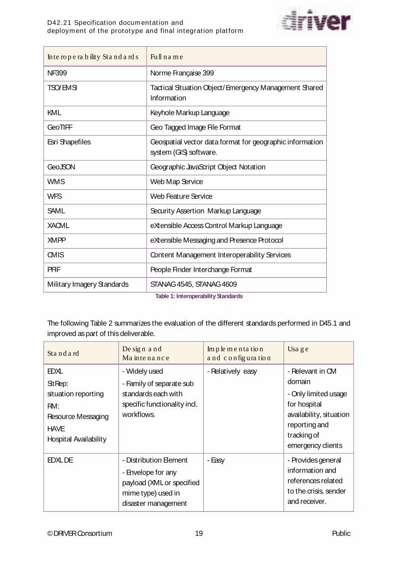
The following Table 2 summarizes the evaluation of the different standards performed in D45.1 and
improved as part of this deliverable.
Standard Design and
Maintenance
Implementation
and configuration
Usage
EDXL
SitRep:
situation reporting
RM:
Resource Messaging
HAVE
Hospital Availability
- Widely used
- Family of separate sub
standards each with
specific functionality incl.
workflows.
- Relatively easy - Relevant in CM
domain
- Only limited usage
for hospital
availability, situation
reporting and
tracking of
emergency clients
EDXL DE - Distribution Element
- Envelope for any
payload (XML or specified
mime type) used in
disaster management
- Easy - Provides general
information and
references related
to the crisis, sender
and receiver.

D42.21 Specification documentation and
deployment of the prototype and final integration platform
©DRIVER Consortium 20 Public
Standard Design and
Maintenance
Implementation
and configuration
Usage
CAP - Widely used
- Simple standard
- Relatively easy - Only for early
warning purposes.
JC3IEDM - Mature standard
- Very complex standard,
complex maintenance
- Complex - Developed for
military purposes
NF399 - Widely used in France
- Specific French values.
Difficult to implement in
other countries.
- Limited to incident
management
TSO/EMSI - Accepted standard by
big number of
organizations.
- Difficult maintenance
- Limited to incident
management
KML - Depends on using of
right tools
- Based on widely
accepted XML.
- KMZ (compressed
version) is preferred
- Widely used, also
for crisis
management.
GeoTIFF - Active development has
stalled since 1990s
- Stable, cheap and
common format
- Widely used and many
stable software libraries
and components
available
- Widely used for
aerial/ satellite
image
Esri Shape files - De facto format for
vector data
- Simple and cheap
- Widely used and many
stable software libraries
and components
available
- Widely used for
vector data
GeoJSON - Depends on availability
of parsers
- Widely used
WMS - Very solid but
sometimes difficulties in
styling geographic
features
- Widely used and many
stable software libraries
and components
available
- Offers easy way to
provide digital map
display
functionalities
WFS - Very solid - Widely used and many
stable software libraries
and components
available
- WFS and WMS in
combination provide
powerful
functionalities

D42.21 Specification documentation and
deployment of the prototype and final integration platform
©DRIVER Consortium 21 Public
Standard Design and
Maintenance
Implementation
and configuration
Usage
SAML - Open standard targeting
business to business
environments
- Well designed and
easy to maintain
- Open standard
targeting business to
business
environments
XACML - Well proven and clear
design but complex rules
design
XMPP - Based on widely
accepted XML
- General purpose
nature allows using
XMPP in any domain.
- QoS not assured
- Not suited for
binary data
CMIS - Well suited for
interoperability between
Content Management
systems
- Widely used
PFIF - Promoting convergence
and all data is traceable
- People Finder
Interchange Format
for information
about missing or
displaced people
SensorML, SOS - Designed for sensor
data exchange
-Based on XML and web
services
STANAG 4545 - Needs complicated
pre/post-processing
- Explicit byte counts
can cause
misinterpretations.
- Developed for
military domain but
also suitable for CM
domain
STANAG 4609 - Developed for
military domain.
Suitability for CM
domain should be
carefully analyzed.
Table 2: Summary of Standards Evaluation
2.3.1 Recommendations
Finally, there are a couple of recommendations that need to be addressed when deciding which of
these standards are more suitable for each situation:

D42.21 Specification documentation and
deployment of the prototype and final integration platform
©DRIVER Consortium 22 Public
1. In the context of DRIVER, an interoperability gap is identified for Incident Management
Information for volunteers. It is recommended to start developing step-by-step standard
for this areas and test and refine these in DRIVER experiments.
2. It is recommended to use the EDXL, CAP, TSO standards within DRIVER and find out
during experiments to what extent the standards fulfil the needs of crisis management
users.
3. For the exchange of geographic information, it is recommended to use standards
provided by OGC (http://www.opengeospatial.org/ ), Esri Shape files, and GeoTIFF.
A limited amount of geo data can be exchanged by using file transfer (e.g. KML, GeoTIFF).
For large geospatial data it is recommended to expose corresponding services providing
just the requested information (e.g. WMS, WFS).
4. Providing a consistent and federated access control to the data accessed and exchanged
seems an important added value of a Common Information Space. The SAML standard to
be applied in front of Crisis Management tools and applications should enable a good
interoperability to deploy a Single Sign On solution across a CM system of systems.

D42.21 Specification documentation and
deployment of the prototype and final integration platform
©DRIVER Consortium 23 Public
3 Integration Platform
In this chapter we are presenting the Integration Platform, the selected technologies to be used to
implement it and how is the basic architecture description.
3.1 Selected Technologies and Standards
3.1.1 Service Oriented Architecture and related ICT
For the implementation of the integration architecture Service Oriented Architecture (SOA) based on
RESTful Web Services is implemented as it is described for Common Information Space introduction
later in this document. Further details are available at Annex 1 SOA.
For generic purpose, the Unicode Character Set and UTF-8 Encoding must be used.
3.1.2 Distribution Element (EDXL DE)
The EDXL DE V 2.0 is defined as a standard draft issued by the OASIS Emergency Management TC7
http://docs.oasis-open.org/emergency/edxl-de/v2.0/csprd02/edxl-de-v2.0-csprd02.odt.
It provides a standard message distribution format for data sharing among emergency information
systems, and it serves two important purposes:
(1) The DE 2.0 allows an organization to wrap separate but related pieces of emergency
i fo atio , i ludi g a of the EDXL essage t pes, i to a si gle pa kage fo easier and
more useful distribution;
(2) The DE 2.0 allows an organizatio to add ess the pa kage to o ga izatio s o i di iduals with specified roles, located in specified locations or those interested in specified keywords.
Every message exchanged in the Common Information Space shall be encapsulated in an EDXL DE
envelope in order to identify and provide information to enable the routing of encapsulated
payloads, called Content Objects. One EDXL DE may contain several different Content Objects if they
belong to the same sender, time stamp and descriptive information given in the EDXL DE.
The authentication and authorization of information in the CIS should be handled by the data
provided in the DE.
3.1.3 Tactical Situation Object (TSO)
The TSO (Tactical Situation Object) was developed under the EU-FP6- OASIS project (2004-2008) and
approved as a CEN Workshop Agreement (CWA) in October 20088.
Based on the results from previous CWA, ISO/PRF TR 223519 (Societal security - Emergency
management - Message structure for exchange of information), still under development at the
7 http://www.oasis-open.org/committees/emergency/
8 CEN, "CEN Workshop agreement CWA 15931, Disaster and emergency management-Shared Situation
Awareness", Feb 2009. https://www.oasis-open.org/committees/download.php/42411/CWA_15931-1.pdf 9 http://www.iso.org/iso/home/store/catalogue_tc/catalogue_detail.htm?csnumber=57384

D42.21 Specification documentation and
deployment of the prototype and final integration platform
©DRIVER Consortium 24 Public
moment of writing this document, is adopting TSO as the message structure for the exchange of
situational awareness information in emergency management scenarios.
The TSO is used to transfer the view of an emergency situation as seen by a particular observer at a
particular time to another observer, thus contributing to the situational awareness of the various
parties regarding a given disaster or crisis event. The message can be used peer-to-peer for observers
(either from the same or different organisations) at the same level of the command hierarchy, or
used to send information up and down the hierarchy.
The TSO message follows an XML structure (that is embedded into an EDXL DE envelope for its
transfer) based on a concrete object model whose main entities are:
the events, understood as something that takes place which an agency should respond to
(e.g. a natural or man-made disaster),
the resources available to support or help in the response to the events, and
the missions aimed at handling the events and thus reducing their impact.
The objective of the TSO specification is to ensure that the semantics of an individual message are
unambiguous; however, it does not prescribe how to merge messages or how to transfer them.
3.1.4 Common Alerting Protocol (CAP)
The Common Alerting Protocol is a standard provided by OASIS10
, standard definition is provided at
http://docs.oasis-open.org/emergency/cap/v1.2/CAP-v1.2-os.doc. CAP is a simple but general format
for exchanging all-hazard emergency alerts and public warnings over all kinds of networks.
The CAP protocol is used in the DRIVER Common Information Space (CIS) in its current version V1.2,
in order to communicate alerts, warnings and notifications from any application that detects a critical
situation (e.g. call center, sensor system, mobile device) to all interested systems (e.g. common
operational picture, public alerting device).
The CAP message is sent embedded in the EDXL DE envelope. The consistency of redundant data in
the envelope and the payload (CAP message) has to be guaranteed by the sending adaptor. It is
possible that the sender information differs between EDXL DE and CAP, e.g. in case of forwarded
messages. For authentication and authorization purpose, always the information in the envelope
counts and the sender is responsible to maintain confidentiality of forwarded messages.
The sender of CAP messages is further responsible to be in line with the standard and to avoid
sending corrupted messages. The receiver of CAP messages shall accept all features defined in the
sta da d. If the e ei e a t p o ess a CAP essage, it should reply with a CAP error message to the
sender (status=system, msgType=error).
In addition to the data elements defined within the standard, additional information might be
provided in <parameters>. These parameters can be specified in CAP profiles to be agreed upon
between specific applications, and might be ignored by applications not concerned with the profile.
Further on the DRIVER project may recommend a European CAP profile that defines specific use of
optional attributes and value lists in the context of European CDM (example: see Australian CAP
profile,
http://docs.oasis-open.org/emergency/edxl-cap1.2-au/v1.0/cs01/edxl-cap1.2-au-v1.0-cs01.doc )
10
http://www.oasis-open.org/

D42.21 Specification documentation and
deployment of the prototype and final integration platform
©DRIVER Consortium 25 Public
3.1.5 GIS Standards
Geospatial information to be handled as a map layer can be embedded in the EDXL DE as Content
O je t Othe Co te t o -XML). The geospatial information has in this case to follow the selected
standards.
The applicable GIS standards are described in D45. 1 – Interoperability Standards [1]. For the
implementation of the CIS the following were selected:
WMS (Web Map Service) and WFS (Web Feature Service) are standards defined by OGC11
. The data
(map information) is provided as Web Service. The information transmitted in the CIS is just the URL
where the service can be consumed. The service itself will not be routed over the CIS. All necessary
meta-data and service descriptions needed for the consumption of the service have to be exposed
and can be queried at the service location. The scope of services is assumed as provided by
GeoServer12
.
GeoTiff is a public domain raster image format which provides geographical metadata. As GeoTiff
files tend to be very large, only small and limited images shall be transmitted in this format. For large
images (e.g. satellite or aerial images of a wider area), the image provider shall render the images
and transform them into WMS.
ShapeFile is the de fa to sta da d fo at fo e to data. O e shapefile o sists of o e tha o e physical file: main file containing geometric objects like points or polygons, the data-file which stores
additional data for each geometric object, the index-file holding an index to each record in the data-
file. Depending on the used tools other accompanying files might exist e.g. holding spatial projection
details. So shapefiles are handled as archives (ZIP) containing all files belo gi g to o e shapefile .
3.2 Portfolio of CM tools
Du i g DRIVER s SP I itial I e to of tools eeti g, that took pla e at Ai -en-Provence, France, in
November 2014, a series of demonstration sessions were carried out in which several tools in the
scope of WP43, WP44 and WP45 were presented and evaluated. These tools were initially classified
into different categories according to the main features they include. This classification was
improved during the efforts developed within SP4, and it is shown by the next diagram:
11
http://www.opengeospatial.org/ 12
http://geoserver.org/

D42.21 Specification documentation and
deployment of the prototype and final integration platform
©DRIVER Consortium 26 Public
Figure 1: Portfolio of tools: preliminary classification
The green boxes in Figure 1 represent the categories where these tools were classified into when
they were evaluated during the SP4 Initial Inventory of tools, while coloured boxes depict each tool
according to the respective Technology Readiness Level. As explained before, this classification was
made according to the main features shown by the tools. The connectors between categories
represent the potential exchange of data between the tools encompassed by them. This data
e ha ge ould e suppo ted the tools g ouped u de the I fo atio E ha ge atego .
It has to be also noted that some of the tools include features that were considered related not only
to SP4, but also to other SPs. This is for instance the case of SUMO tool i to the atego Suppo ti g tools asso iated to SP -test ed tools , the tools lassified i to the Citize o olu tee s a d Volu tee i g itize s atego ies asso iated to SP o i to the TRAINING atego asso iated to
SP5), as shown by Figure 1.
The maturity of the tools is evaluated according to the Technology Readiness Levels (TRL).
The 9 levels as defined by the European Commission (extracted from HORIZON 2020 – WORK
PROGRAMME 2014-2015) are:
1. TRL 1 – basic principles observed
2. TRL 2 – technology concept formulated
3. TRL 3 – experimental proof of concept
4. TRL 4 – technology validated in lab
5. TRL 5 – technology validated in relevant environment (industrially relevant environment in
the case of key enabling technologies)
6. TRL 6 – technology demonstrated in relevant environment (industrially relevant environment
in the case of key enabling technologies)
7. TRL 7 – system prototype demonstration in operational environment
8. TRL 8 – system complete and qualified
9. TRL 9 – actual system proven in operational environment (competitive manufacturing in the
case of key enabling technologies; or in space)

D42.21 Specification documentation and
deployment of the prototype and final integration platform
©DRIVER Consortium 27 Public
The Technology Readiness Levels (TRL) of each tool has been self-evaluated by tools providers.
Tool Category TRL
RIB Dangerous substances Supporting tool 9
Large Event Shared situation awareness 8
Ingest Information Exchange 8
Crowdtasker Volunteer Citizens 4-5
COP Shared situation awareness 6
Socrates-CSS Information Exchange 7
Socrates FR First responders Local C2 6
Socrates OC Shared situation awareness 8
Socrates TSK Shared situation awareness 6
ESS Supporting tool 7
UFLY Digital sensors 5
3K Supporting tool 6
EmerT Supporting tool 6
ZKI Digital sensors 6
SUMO Supporting tool 1-9
IO-DA Planning 4-5
Delphi Supporting tool 7
DSS-Logistics Supporting tool 3
DEWS Supporting tool 7
PROCEED Training 3-8
PRoTect Resources management 8
SITRA Shared situation awareness 3-6
GDACS mobile Volunteer Citizens 6
HumLog Supporting tool 9
AnyLogic Supporting tool 9
Dashboard Supporting tool 9
Dashboard SUCCESS Supporting tool 8
Mego Supporting tool 9

D42.21 Specification documentation and
deployment of the prototype and final integration platform
©DRIVER Consortium 28 Public
Tool Category TRL
EvacuAid Planning 6
SafeTrip Volunteer Citizens 8
Crisis Wall Shared situation awareness 7
LUPP First responders Local C2 9
Asphodèle First responders Local C2 9
Table 3: CM Tools TRL
3.3 Architecture Requirements
The Architecture requirements list has been refined and reworked from the list that was provided as
part of D42.1 [2] and that has been used as input for the work on this section. The requirements are
now classified according to different categories.
Functional Requirements: Functional requirements of the system that are expressed in the
natural language style (as opposed to Use Cases).
1. A common information space (CIS) will handle the sharing of data among the tools
providing a publishing-subscribing mechanism.
2. As basic service, the information space shall not store data for operational purposes,
it shall only connect systems and transport data.
3. A situatio a age shall e a le to ope up a spe ifi i fo atio spa e fo a specific crisis situation and to invite participants.
4. The CIS should ensure that the exchanged data are syntactically correct.
5. It shall be possible to add value added services (VAS) within the CIS. e.g. for providing
aggregated data, for translating data, for collaboration of stakeholders and
esta lish e t of a t adi g zo e , et . Documentation and Help: Requirements for on-line user documentation, help systems, help
about notices, etc.
Usability: Requirements that affect the usability of the system, like language, accessibility,
User Interfaces, etc.
Security: Security requirements of the system defining its needed ability to safeguard data
against loss or exposure, and to resist disruption by outside partners. Security is the ability to
protect an IT system against malicious use whilst at the same time allowing legitimate use.
6. Authentication will be required for a tool to connect to the CIS.
7. CIS would provide a certification authorization mechanism so that only tools with the
required security level would be granted access to classified data.
8. CIS should provide Audit and Logging tools.
Availability and Reliability: Non Functional Requirements regarding availability, reliability
and planned maintenance.
Performance and Capacity: Capacity and performance levels the system must satisfy.
Performance is the degree to which a system or component accomplishes its designated

D42.21 Specification documentation and
deployment of the prototype and final integration platform
©DRIVER Consortium 29 Public
functions within given constraints, such as speed, accuracy, or memory usage. Capacity is a
measure of the resource usage of the system (e.g. memory, disk space, process threads)
9. Scalability is to be supported.
Supportability: Requirements that will enhance the supportability or maintainability of the
system, like support documentation, corrective maintenance, etc.
Systems Management and Manageability: System management requirements of the system
and concerns the operations and administration of the software and hardware systems, like
starting and stopping, backup and recovery, etc.
10. CIS should offer the possibility to be administrated so that topology and
configuration could be updated.
Data Integrity: Concerns the ability of the system to protect data and preserve transactions,
like data persistency, etc.
Interface: Interfaces that must be supported by the application, either user interfaces or
software interfaces, like web, database, client, etc.
11. Interfaces will be defined for interoperability.
Business Constraints: Business constraints that the system must satisfy.
Technical Constraints: Technical constraints that the system must satisfy.
12. Interface shall be technology-agnostic.
13. CIS shall be technology-agnostic.
14. A common standard format for the exchange of information in the CIS should be
agreed at SP4 level, it will be used by all tools involved by means of an adaptor
whenever needed.
15. Original format can be consumed to avoid data loss by double conversion
16. Interoperability on the semantic layer shall be partially ensured by using common
taxonomy, so that it can be understood by all connected systems.
Applicable Standards: Requirements in terms of applicable standards, like XML, UTF-8, CAP,
TSO, etc.
Licensing Requirements: Any licensing enforcement requirements or other usage restriction
requirements which are to be exhibited by the software, like limited usage, open source, etc.
Legal, Copyright and Other Notices: Any necessary legal disclaimers, warranties, copyright
notices, patent notice, wordmark, trademark, or logo compliance issues for the software.
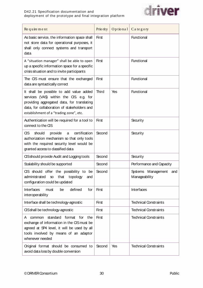
As a summary, find bellow a table with the complete list of the requirements:
Requirement Priority Optional Category
A common information space (CIS) must
handle the sharing of data among the tools
providing a publishing-subscribing
mechanism
First Functional
D42.21 Specification documentation and
deployment of the prototype and final integration platform
©DRIVER Consortium 30 Public
Requirement Priority Optional Category
As basic service, the information space shall
not store data for operational purposes, it
shall only connect systems and transport
data
First Functional
A situatio a age shall e a le to ope up a specific information space for a specific
crisis situation and to invite participants
First Functional
The CIS must ensure that the exchanged
data are syntactically correct
First Functional
It shall be possible to add value added
services (VAS) within the CIS. e.g. for
providing aggregated data, for translating
data, for collaboration of stakeholders and
esta lish e t of a t adi g zo e , et .
Third Yes Functional
Authentication will be required for a tool to
connect to the CIS
First Security
CIS should provide a certification
authorization mechanism so that only tools
with the required security level would be
granted access to classified data
Second Security
CIS should provide Audit and Logging tools Second Security
Scalability should be supported Second Performance and Capacity
CIS should offer the possibility to be
administrated so that topology and
configuration could be updated
Second Systems Management and
Manageability
Interfaces must be defined for
interoperability
First Interfaces
Interface shall be technology-agnostic First Technical Constraints
CIS shall be technology-agnostic First Technical Constraints
A common standard format for the
exchange of information in the CIS must be
agreed at SP4 level, it will be used by all
tools involved by means of an adaptor
whenever needed
First Technical Constraints
Original format should be consumed to
avoid data loss by double conversion
Second Yes Technical Constraints

D42.21 Specification documentation and
deployment of the prototype and final integration platform
©DRIVER Consortium 31 Public
Requirement Priority Optional Category
Interoperability on the semantic layer
should be partially ensured by using
common taxonomy, so that it can be
understood by all connected systems
Second Technical Constraints
Table 4: Architecture Requirements
3.4 Common Architecture Description
This section describes the common architecture design that has been decided to implement the
System of Systems. It is mainly based on the Service Oriented Architecture approach, and the specific
implementation guidelines are described as the Common Information Space or CIS.
3.4.1 CIS, Common Information Space
The requirements and principles of the Common Information Space as an Integration Platform
(middleware) that enables the secured information exchange between the participating applications
are defined in [2] D42.1, section 4.3.
Every application integrated in the CIS can offer data (information provider) and/or receive data
(information consumer) in standardized formats and via defined communication protocols without
the need for particular interfaces between dedicated partners. If the application uses data
communication protocols that are not supported by CIS, the protocols have to be converted by
adaptors. Beyond the harmonisation of data connection (physical interoperability) and data formats
(syntactical interoperability), key terms and taxonomies are translated by the adaptors from the
proprietary form of the provider to a standardised form in the CIS and back to the proprietary form
of the receiver.
When an application joins the CIS, it has to register its services in order to enable other applications
to address the offered services. A metadata model enables the applications to find out services that
fit with their own purpose. The registration process might be subject of authorisation and role
concepts (to be elaborated) in order to establish a protection hierarchy and to prohibit unauthorised
access to sensitive data.
The Common Information Space is a data sharing platform but not a data repository, a d it does t have any business logic concerning interpretation and processing of the transported data.
Nevertheless, value added services can be attached to the CIS and made available for authorised
users (e.g. logging and legal recordi g, epo ti g, o ito i g … .
3.4.1.1 CIS Adaptors
The Adaptors link the participating tools to the Common Information Space. For every tool and every
used data protocol, a specific adaptor has to be implemented. Adaptor templates will be provided by
the project team in order to enable the tool providers to write their adaptors in an easy and fast way.
The Adaptors stay in the responsibility and run on the server of the tool owner. Every access to the

D42.21 Specification documentation and
deployment of the prototype and final integration platform
©DRIVER Consortium 32 Public
data hosted by the Adaptor is monitored by the authorisation concept implemented in the Adaptors
and is recorded for audit and tracing purposes.
Every Adaptor consists of three parts:
A. CIS Connector: manages the communication with the tool and translates proprietary
protocols to standards. The Connector is written by the tool provider based on the template.
B. CIS Core: manages central functions in a uniform way. Value added services can be
integrated in the Core (available for the whole system f systems).
C. CIS Distributor: manages the connections inside the CIS and the data exchange with the
other Adaptors in the CIS.
Figure 2: CIS Adaptor architecture
3.4.1.2 CIS Connector
The CIS Connector handles the communication on the side of the tool – that means it covers all code
specific to the protocols the tool uses. Therefore it has to be assembled and configured by the tool
owner or manufacturer based on the adaptor template.
The template consists on components providing the following functions:
Network connectivity module receives/sends messages from/to the tool according the used
network protocol.
Templates for REST, SOAP and RSS connections will be prepared in the first step. The tool
owner has to maintain network configuration tables with the addresses of the services to be
connected.
Data format converter transfers proprietary data formats of the message to/from the
standard messages exchanged in CIS (this step may be bypassed if the tool already uses the
appropriate standard).

D42.21 Specification documentation and
deployment of the prototype and final integration platform
©DRIVER Consortium 33 Public
Taxonomy translator replaces proprietary key values and enumerations by standardized ones
and vice versa, based on translation tables to be provided by the tool owner (ambiguities and
gaps between the taxonomies have to be resolved in the translation tables and may lead to
loss of information).
EDXL DE generator assembles the parameters for the EDXL Distribution Element that
envelops all messages distributed in CIS. The template will provide a minimum set of default
values that might be extended by the developer of the CIS connector. I.e. security related
parameters can be added dependent on the message content.
Logging, for debugging purposes only.
3.4.1.3 CIS Core
The CIS Co e a t e odified the adapto p o ide . It a ages e t al CIS featu es, pa tl ased on the EDXL DE parameters transferred:
Authentication assures that incoming messages originate from a trusted partner application,
according to the service registration.
Authorization services control the flow of information and protect sensitive data from
unauthorized access. Appropriate encryption mechanisms will be defined and implemented.
Validation of the transferred messages assures the formal correctness and application of
standards. Improperly formatted messages will be rejected.
EDXL DE Wrapper packs the information into an EDXL Distribution Element (envelope) that
adds meta-information to the payload message.
Object Buffer function stores large binary objects (message attachments) in an accessible
store (e.g. FTP server) and replaces them by the URI in the message.
Message Buffer stores all outgoing messages in order to enable the partner applications to
query previous messages, e.g. in the case of sync after network interruption.
Value Added Services (optional plug-ins) may make use of the transferred information e.g.
for message logging, auditing, reporting or statistics.
3.4.1.4 CIS Distributor
The CIS Distributor manages and synchronizes the message exchange between the various partner
applications in the CIS.
It supports two different distribution mechanisms:
1. Push technology Publish – Subscribe: The information provider posts a message to CIS.
The distributor sends the message to all information consumers (other Adaptors) that have
ee egiste ed o this se i e i fo atio t pe, topi . The pu lishe does t care if the
message is actually received by all the subscribers. This mechanism suits for public
information.
2. Pull technology Request – Response: The information consumer asks a dedicated information
provider for defined pieces of information. The CIS will support criteria based on the EDXL DE
structure, e.g. time sent, target area, content key word. The information provider (CIS Core)
decides if the requestor is an authorized information consumer, and answers the request
with appropriate messages that have been stored in the Message Buffer. The request-

D42.21 Specification documentation and
deployment of the prototype and final integration platform
©DRIVER Consortium 34 Public
response method can be combined with a notification mechanism that publishes the
existence of a new message but not the content.
3.4.1.5 CIS Service Registration
In order to deploy the CIS onto a given network (either being accessible from the Internet or not), CIS
servers will be installed and run on one or more nodes (depending on the network size) that will be
accessible from the rest of the nodes connected to the network. Tools will be added to CIS through
the specific adaptor by providing to the users the corresponding credentials (that might consist for
instance of an identifier and a password, depending on the implemented authentication and
authorization mechanism) and the locator of the specific network resource where the corresponding
CIS server is running. The users will be also provided with the specific interface to be followed in
order to correctly access CIS services.
For instance, in case of an implementation based on Web Services, application servers would be
installed in one or more network nodes where the specific Web Services would be registered.
Tool providers developing CIS adaptors would need to implement a Web Service client according to
the CIS Web Se i es i te fa e, hi h ould e defi ed i the WSDL available at the corresponding
address (URL). Authorized users would then be able to make use of the CIS services by calling the
operations defined in the mentioned interface.
3.4.1.6 CIS Data Security
Security shall be designed from the beginning in order to ease a security by design paradigm.
Therefore, CIS Core part embeds means to take in charge the first main security functionalities such
as authentication of the sender and authentication and authorization of the access to the data.
To meet CIS general purpose, generic enough solutions should be implemented, based on well-
known open standards.
Signature of EDXL messages shall be a good means to check the authentication of the issuer of the
data. CIS Core shall then behave as an Enforcement Point where the signature is checked before the
message could be sent to the CIS.
For Authorization, assuming that a common Identity Management Service is available, refinements
using the XACML standards could be proposed.
3.4.2 Common Information Space Architecture Options
As the Common Information Space defines the architecture to be implemented for the
intercommunication between different systems and the interexchange of Crisis Management related
information there are some options that can be used to implement the distribution channel between
different CM tools within CIS. This means that it is possible to select different CIS solutions based on
the chosen distribution option and also to interconnect different CIS solutions as it is possible to
check in the next sections. For the CIS distribution options the following candidates are presented:
Common Shared Services
Peer To Peer
Enterprise Service Bus
These options are described in detail in the following sections.
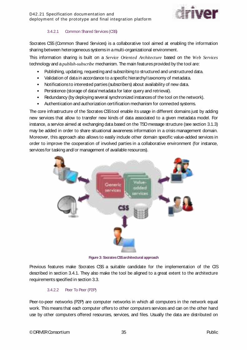
D42.21 Specification documentation and
deployment of the prototype and final integration platform
©DRIVER Consortium 35 Public
3.4.2.1 Common Shared Services (CSS)
Socrates CSS (Common Shared Services) is a collaborative tool aimed at enabling the information
sharing between heterogeneous systems in a multi-organizational environment.
This information sharing is built on a Service Oriented Architecture based on the Web Services
technology and a publish-subscribe mechanism. The main features provided by the tool are:
• Publishing, updating, requesting and subscribing to structured and unstructured data.
• Validation of data in accordance to a specific hierarchy/taxonomy of metadata.
• Notifications to interested parties (subscribers) about availability of new data.
• Persistence (storage of data/metadata for later query and retrieval).
• Redundancy (by deploying several synchronized instances of the tool on the network).
• Authentication and authorization certification mechanism for connected systems.
The core infrastructure of the Socrates CSS tool enable its usage in different domains just by adding
new services that allow to transfer new kinds of data associated to a given metadata model. For
instance, a service aimed at exchanging data based on the TSO message structure (see section 3.1.3)
may be added in order to share situational awareness information in a crisis management domain.
Moreover, this approach also allows to easily include other domain specific value-added services in
order to improve the cooperation of involved parties in a collaborative environment (for instance,
services for tasking and/or management of available resources).
Figure 3: Socrates CSS architectural approach
Previous features make Socrates CSS a suitable candidate for the implementation of the CIS
described in section 3.4.1. They also make the tool be aligned to a great extent to the architecture
requirements specified in section 3.3.
3.4.2.2 Peer To Peer (P2P)
Peer-to-peer networks (P2P) are computer networks in which all computers in the network equal
work. This means that each computer offers to other computers services and can on the other hand
use by other computers offered resources, services, and files. Usually the data are distributed on

D42.21 Specification documentation and
deployment of the prototype and final integration platform
©DRIVER Consortium 36 Public
many computers. The peer-to-peer approach is a decentralized concept, without a central server,
such as the Internet. Each computer of such a network can be connected to several other computers.
P2P Networks will be separated into 2 groups:
Simple Peer To Peer Network or Self Organised Network (SON)
Simple peer-to-peer networks organize themselves as Self Organized Network (SON), they are
decentralized and have no server. In such a decentralized peer-to-peer network, the workgroup
employees provide mutually resources.
Super Peer Network
A further development of peer-to-peer network with central server components is the super-peer
networks. In such a configuration particularly powerful peers are connected to super-peers that
provide the server services and organize the network. They are responsible for the routing of data
from the remote client to the backbone network.
3.4.2.3 Enterprise Service Bus (ESB)
An Enterprise Service Bus (ESB) is a software architecture model used for designing and
implementing communication between mutually interacting software applications in a Service-
Oriented Architecture (SOA). It handles the messaging between systems in a standard way. This
allows you to communicate with the "bus" in the same exact way across all your platforms. This
means that data files are passed to and from their destinations based on established guidelines that
are common to all parties sharing the information to ensure that the data maintains its integrity as it
is routed. The multi-language and multi-platform design of an ESB allows enterprises to process data
between applications from various sources.
3.4.3 Common Information Space Supporting Tools
As part of the Common Information Space definition is possible to include some supporting tools that
could help CIS solutions with specific functionality that is not part of the basic required CIS functions.
These are the CIS supporting tools that could help CIS solution with the following functions:
3.4.3.1 Cyris for Office 365
Cyris for Office 365 is a solution which protects data and manages identity and access for Office 365
and Azure data storage. It is meant for sensitive data which cannot be disclosed publicly and should
remain in an internal environment. It provides a solution for Owned and Managed Encryption with
Customer Keys, as opposed to other built-in Microsoft solutions.

D42.21 Specification documentation and
deployment of the prototype and final integration platform
©DRIVER Consortium 37 Public
Figure 4: Office 365 Security Control
Cyris comprises the two main features:
• Encryption capabilities for object storage over a Cloud
• A complete Authorization portal to manage identity and access, enabling a secure object
exchange over the Cloud.
Figure 5: Cyris functional view
Cyris behaves like a broker which proposes encryption and strong security architecture including:
• Encryption of the data according to various security profiles (algorithms, key length, type of
encryption, padding)
• Robust key management (CEK, KEK); Thales trusted crypto libraries

D42.21 Specification documentation and
deployment of the prototype and final integration platform
©DRIVER Consortium 38 Public
• Use of certified HSMs (FIPS 140-3 compliant)
• Standards and security requirements, regulations and recommendations (CSA, ANSSI, RGS,
NIST)
3.4.3.2 INGEST
I gest p o ides data t a sfo atio a d p oto ol adaptatio apa ilities. It s ased o the Tale d open source software. In the Common Information Space architecture, it could be the base for the
development of the adaptors.
Figure 6: Ingest based Common Information Space adaptor
Ingest provides tools to define and run adaptation at the following levels:
Protocol with syntactic validation
Format with syntactic validation
Semantic
The protocol adaptation part is responsible on one hand of the technical link with the Driver tool of
legacy system and on the other hand of the technical link with the communication infrastructure of
CIS. It is responsible of the syntactic validity with the protocols definition.
The format adaptation part is responsible of the extraction and insertion of the data according to the
used data formats. It grants the syntactic validity with the formats definition.
The semantic adaptation part is responsible of the technical and semantic translation of the data
between formats and protocols. It could use the translation tables of the Common Information
Space.

D42.21 Specification documentation and
deployment of the prototype and final integration platform
©DRIVER Consortium 39 Public
3.4.4 Background from other projects
As part of the investigation work delivered to define CIS architecture other projects have been
analyzed with some benefits for the work of this task. The following projects were the most relevant:
3.4.4.1 ODYSSEY
Globalization has been accompanied by a dramatic increase in organized and transnational crime and
terrorism. It takes many forms and includes homicide, genocide, honour killings, trafficking in drugs,
weapons, smuggling of human beings and the laundering of the proceeds of crime. Such activities
present a threat not only to citizens and their communities, due to lives being destroyed by violence,
threats and intimidation, drugs and societies living in fear of organized crime; but also a global threat.
These threats undermine the democratic and economic basis of societies through the investment of
illegal money by international cartels, corruption, a weakening of institutions and a loss of
confidence in the rule of law. Enabling cooperation across the EU is vital. Whilst there is both political
and operational commitment to share data and there is no shortage of ballistics and crime
information data across the EU, there is currently no technical means to do this. ODYSSEY project [4]
progressed on the necessary research and development to fill this gap and provide a Platform to
demonstrate the effect and potential of an EU wide Platform using technical forensic data and crime
information. The Project developed a secure interoperable situation awareness platform for the
automated management, processing, sharing, analysis and use of ballistics data and crime
information to combat organized crime and terrorism.
The main aim of ODYSSEY project is to define a security layered architecture able to support a secure
Pan-European ballistics and crime information intelligence network aiming to tackle organized crime
and terrorism.
Figure 7: ODYSSEY Security Architecture Methodology
The approach used was based in three major aspects related to security architecture:
Deployment and
Infrastructure
Network
Host
Layer-by-Layer
Distribution
Application
DataSecurity Framework
Authentication
Input Validation
Sensitive Data
Authorization
Cryptography
Audit & Logging
1
2
3

D42.21 Specification documentation and
deployment of the prototype and final integration platform
©DRIVER Consortium 40 Public
Deployment and infrastructure. At this level, the constraints imposed by the underlying
infrastructure-layer security and the operational practices in use should be considered.
Security framework. The security framework includes considerations at both the
architectural and design level that have the most impact on security and where security
incidents often arise. The main categories included are: authentication, authorization, input
validation, exception management.
Layer-by-layer analysis. Consider the logical layers of the system, and define the security
choices within application, distribution, and data access logic layers.

D42.21 Specification documentation and
deployment of the prototype and final integration platform
©DRIVER Consortium 41 Public
4 Experiments
4.1 EXPE 40: Enhanced contribution of airborne sensors
4.1.1 Objectives
The objective of EXPE40 is to integrate selected systems that are related to the airborne sensor suite.
In preparation of the following experiments (JE1, FD) the interoperability of the complete airborne
sensing system with its aerial and ground components will be verified through this experiment. With
regards to the ACRIMAS gaps, it add esses ai l the Ea l Wa i g Capa ilities Gap a d Acquisition of information from external sources Gap .
4.1.2 Experiment Description
EXPE is the o du tio of a eal flight t ial e e uted at DLR s esea h ai po t i B au s h eig. The experiment will take place during the first two weeks of September 2015. During the first week,
DLR s K a era system and its relevant onboard equipment will be attached to the RPAS
demonstrator. During the flights, the datalink connection between air-based and ground-based
components will be verified. On ground, imagery data will be shared between participating tools. The
following tools are going to be part of EXPE40:
RPAS-demonstrator
U-Fly
3K camera system
EmerT
Sumo
ZKI
During the experiment, all tools can share data through a common server. The aerial sensor data will
be provided in Geotiff format and shared over MTP. The ZKI creates all information in its Service Lab
at the Earth Observation Center in Oberpfaffenhofen and provides all derived information such as
flood masks and flood maps (2D and 3D) via a FTP server that is hosted at the Mobile Traffic Data
Platform (TDP).

D42.21 Specification documentation and
deployment of the prototype and final integration platform
©DRIVER Consortium 42 Public
Figure 8: EXPE40 Data Exchange
I age data ill e isualized th ough the use of DLR s esea h g ou d o t ol statio U-Fly and
DLR s e te fo satellite i fo atio ZKI. DLR s tools E e T a d Su o ill also take i to a ou t extracted traffic information.
The experiment will illustrate aerial sensor processing in a flooding crisis: A nearby lake (Tankumsee)
will be used as a basis for a simulated flooding. Based on first geographical information about the
extensions of the flooding, U-FLY will determine an optimal flight path for the RPAS demonstrator to
collect real-time sensor images of the affected area. During the RPAS-flight the sensor data will be
provided to the ground systems. ZKI will provide flood mapping images based on the collected aerial
images, which will be shared with U-FLY, EmerT and SUMO. A second flight with a scan pattern over
the flooding area and nearby major road networks (e.g. highway A2) will be dynamically planned and
executed to:
Detect unusable traffic infrastructure (EmerT/SUMO)
Provide efficient route planning based on traffic data (EmerT/SUMO)
Illustrate sensor adaptive flight planning (e.g. person detection) (U-FLY)
During the experiment, the data exchange will be carried out independently from the Common
Information Space (CIS). The connection via CIS will be established and tested within the preparation
and execution of EXPE44. If the flight trials are successfully conducted, collected data can be stored
and used during this EXPE44.
3K Camera System
ZKI EmerT/Sumo
U-Fly

D42.21 Specification documentation and
deployment of the prototype and final integration platform
©DRIVER Consortium 43 Public
Tool Data Flow Direction Format/protocol Transformation
U-Fly Georeferenced
aerial and
satellite images
Input geoTiff / MTP
(sensor data)
Validated Flight
Plans
Output XML (flight
planning)
3K Camera
System
Georeferenced
aerial images
Automatically
extracted traffic
parameters from
the aerial images
(vehicle
positions, driving
direction, and
speed)
Output Geotiff via ftp
PostGresQL
database entries to
EmerT tool
EmerT Georeferenced
aerial images
(3K)
Automatically
extracted traffic
parameters (3K)
Road-network
(OSM / NAVTEQ)
Traffic data
Input Geotiff via ftp
PostGresQL
database entries to
EmerT tool
Database import
Database import
Aerial images
and traffic data
to support the
analysis of
situation
Isochrone-map
risk routing
which includes
likelihoods of
risks for possible
routes
Output PostGresQL
database
OGC web services
and REST Services

D42.21 Specification documentation and
deployment of the prototype and final integration platform
©DRIVER Consortium 44 Public
Tool Data Flow Direction Format/protocol Transformation
Traffic-data
fusion and
prediction
Sumo Road-network
Traffic Data
Simulation
Scenario
Input PostGresQL
database
XML
ZKI (1) Flood mask,
(2) Flood maps,
(2D, focus on3D)
Upload on FTP
hosted at Mobile
Traffic data
platform (TDP)
Exchange via FTP
protocol: (1) as
ESRI Shape file
(*shp), (2) 2D maps
as GeoTIFF,
JPEG+JGW, and
optional
KML/KMZM; 3D
representation is
provided as PDF
Table 5: EXPE 40 Data Flow
4.2 EXPE 41: Operational Data Lift
The objective of EXPE41: Operational Data Lift, is to optimize the information workflow between
local and higher levels of command. It is designed in the perspective of WP46, and SP6 Final Demo
which will be also hosted by Valabre.
The experiment will be prepared and executed with Pole Risques and EPLFM at Valabre (France), in
November 2015. It is addressing an operational gap which was described by an EMIZ officer in Aix-
en-Provence during the Initial Inventory of Tools. With regards to the ACRIMAS [3] gaps, it addresses
ai l the U de sta di g the elief effo t as a hole Gap .
The following SP4 tools will be involved in Experiment 41:
Local level: Lupp, Asphodèle
Regional level: Large Event, COP
Political level: Crisis Wall
The main SP2 tool involved will be the new Simulator (EPLFM), which enables the simulation of crisis
management operations on a large fictitious Island (Valabre Island).
The scenario will be a complex crisis: forest fire with industrial cascading effect. At the local level, the
actors will be Fire Brigade, Health and Police. The experiment will be structured like an exercise
where local, regional and political level will be played, the major focus being the elaboration of the
Common Operational Picture (at regional and political level). The Common Operational Picture will

D42.21 Specification documentation and
deployment of the prototype and final integration platform
©DRIVER Consortium 45 Public
be elaborated on Large Event and Cop Tools at regional level by merging information sent from local
level by Asphodèle and LUPP tools.
The experiment process will consist in playing the same scenario twice: once with tools supporting
the elaboration of the Common Operational Picture, and once without tools, following the current
manual procedure. In manual procedure, the systems at each level are not connected and the
information about the situation is sent by voice communication or manual exchange like e-mail.
The time and effort required will be measured and compared for both process (manual and
supported by tools) and the quality of information produced in the Common Operational Pictures will
be compared to the ground truth known by the simulator of EPLFM. Relevant criteria and indicators
will be defined with end-users.
Figure 9: EXPE 41 Operational Data Lift
The following Table 6 lists the data flows to be used during the experiment 41.
The direction column points out the direction of the information.
The format/protocol column describes the format and the protocol to be used to exchange the
information.
The transformation column point out the transformations needed to comply with the common
architecture.
Tool Data flow Direction Format/protocol Transformation
Crisis Wall Situation Input To be defined
Large Event Situation Input EDXL CAP
Protocol to be defined
Situation Output To be defined
COP Situation Input
EDXL CAP
To be confirmed

D42.21 Specification documentation and
deployment of the prototype and final integration platform
©DRIVER Consortium 46 Public
Tool Data flow Direction Format/protocol Transformation
Asphodèle Situation Output To be confirmed
LUPP Situation Output EDXL CAP
To be confirmed
Table 6: EXPE 41 data flow
4.3 EXPE 42: Interaction with citizens and volunteers
4.3.1 Expe 42 goals
EXPE42 aims at the evaluation of usability and value of tools and processes for the interaction of
professional responders with citizens in the context of specifically designed scenarios, and to explore
the capabilities of the tools to integrate in the system of systems. The subsequent Transverse (WP46)
and Joint (WP63, WP64, WP66) experiments are based on the results of EXPE42 and will use selected
tools in combination with tools and procedures of the other work packages and evaluate the
integration of tools, data and procedures in a comprehensive, realistic disaster scenario.
The i te a tio of espo de s o ga isatio s ith itize s a d olu tee s is ele a t fo oth, SP and SP4. SP3 is interested how citizens can be supported contributing to the crisis handling and how
relevant information can be effectively transmitted to the public before and during a crisis. SP4
however investigates how the knowledge and information available at citizens can be leveraged for
increasing situational awareness, how crisis managers and commanders can control and direct the
cooperativeness of volunteers and how they can be enabled to broadcast warnings and situational
reports to the affected people.
Interaction with citizens and volunteers as experimented in Expe42 covers two main aspects:
1. Crisis communication with citizens during all phases.
Broadcast of information (warnings and current situation reports) to the public by the Crisis
Managers, based on the situation awareness and common operational picture
Collect information from the public that amends the available situation awareness,
represented in the common operational picture
from social media analysis
querying information from volunteers (citizens as sensors)

D42.21 Specification documentation and
deployment of the prototype and final integration platform
©DRIVER Consortium 47 Public
Figure 10: EXPE42 Crisis Communication
2. Organising and tasking of spontaneous and pre-registered volunteers during preparedness
and response phase
Manage volunteers that are not affiliated to responder organisations; organisation and
activation of pre-organised volunteers.
Assign tasks to the volunteers that can be performed in a safe way without guidance and
supervision by professional responders; micro-tasking and crowd tasking.
Figure 11: EXPE42 volunteer management
C o d sou i g, so ial edia a al sis
Pu li a i g a d ale ti g
A ti ati g & taski g sele ted olu tee s
Task feed a k a e di g situatio a a e ess
C isis oo di atio
A ti ated olu tee s
suppo ti g espo de s

D42.21 Specification documentation and
deployment of the prototype and final integration platform
©DRIVER Consortium 48 Public
4.3.2 Expe 42 set-up
Expe42 will consist of two small experiments, concentrating on volunteer registration, activation and
crowd tasking, and of a large event including crowd tasking and crisis communication. The latter will
be a large flood scenario, using the THG platform
The tool COP provides the situation map with the common operational picture providing a source of
information to be transferred to the public, and as decision support for the crisis manager with
volunteer management. The crowd tasking results are also displayed as an information layer in COP.
CrowdTasker (management tool for the CM and mobile app for the volunteers) is the tool for
volunteer registration, activation and tasking.
The crisis communication will be exercised with the tools GDACSmobile and SafeTrip.
The tools DEWS and MEGO will create the (simulated) alerts and flood warnings that form the
scenario background for THG exercise.
4.3.3 Expe 42 information space
The following Table 7 shows the integration of tools and the planned data flow.
Information Provider Type of
Information Transfer
Information
Consumer
DEWS water levels CAP MEGO
MEGO flooded areas ShapeFile COP
COP warnings for areas CAP or manually SafeTrip
COP warnings for areas CAP or manually GDACSmobile
GDACSmobile social media analysis CAP COP
COP situation awareness manually CrowdTasker
CrowdTasker task feedback (photos,
questionnaires)
EDXL
OtherObject
COP
Table 7: EXPE 42 Integration of tools
4.4 EXPE 43: From Planning to Tasking
4.4.1 Components Services
EXPE 43 is focused on the tasking and management of resources during preparedness and response
phases in a cross-border crisis scenario.
In order to enable effective crisis preparedness and response including tasking and resource
management activities, efficient coordination and cooperation as well as structured command and
control is required amongst the involved organizations, agencies and other parties. In particular, it
should be possible to:
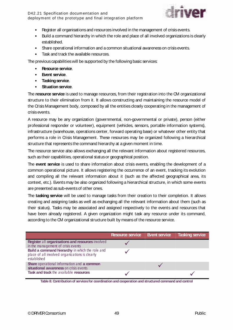
D42.21 Specification documentation and
deployment of the prototype and final integration platform
©DRIVER Consortium 49 Public
• Register all organisations and resources involved in the management of crisis events.
• Build a command hierarchy in which the role and place of all involved organizations is clearly
established.
• Share operational information and a common situational awareness on crisis events.
• Task and track the available resources.
The previous capabilities will be supported by the following basic services:
• Resource service.
• Event service.
• Tasking service.
• Situation service.
The resource service is used to manage resources, from their registration into the CM organizational
structure to their elimination from it. It allows constructing and maintaining the resource model of
the Crisis Management body, composed by all the entities closely cooperating in the management of
crisis events.
A resource may be any organization (governmental, non-governmental or private), person (either
professional responder or volunteer), equipment (vehicles, sensors, portable information systems),
infrastructure (warehouse, operations center, forward operating base) or whatever other entity that
performs a role in Crisis Management. These resources may be organized following a hierarchical
structure that represents the command hierarchy at a given moment in time.
The resource service also allows exchanging all the relevant information about registered resources,
such as their capabilities, operational status or geographical position.
The event service is used to share information about crisis events, enabling the development of a
common operational picture. It allows registering the occurrence of an event, tracking its evolution
and compiling all the relevant information about it (such as the affected geographical area, its
context, etc.). Events may be also organized following a hierarchical structure, in which some events
are presented as sub-events of other ones.
The tasking service will be used to manage tasks from their creation to their completion. It allows
creating and assigning tasks as well as exchanging all the relevant information about them (such as
their status). Tasks may be associated and assigned respectively to the events and resources that
have been already registered. A given organization might task any resource under its command,
according to the CM organizational structure built by means of the resource service.
Resource service Event service Tasking service
Register all organisations and resources involved in the management of crisis events Build a command hierarchy in which the role and place of all involved organizations is clearly established
Share operational information and a common situational awareness on crisis events Task and track the available resources
Table 8: Contribution of services for coordination and cooperation and structured command and control
D42.21 Specification documentation and
deployment of the prototype and final integration platform
©DRIVER Consortium 50 Public
Data gathered by means of the three previous services would be integrated into a whole that relates
events, resources and tasks. This whole represents a complete and coherent picture of the
operational situation, which will be characterized at any given moment by:
• The ongoing events,
• The tasks aimed to handle the events and
• The resources that have been made available to handle the events (and thus, those which
may be assigned previous tasks).
The situation service allows getting the complete situation status at any given moment in time. This
service is intended to be used mainly by those tools that, while not specifically devoted to tasking,
resource or event management, may need to have info about the situation (e.g., simulation or
analysis tools).
4.4.2 Implementation Description
The experiment will include two main use cases, being the first one focused on the preparedness and
planning phase and the second one on the response phase:
• Capacity building and capacity mapping (focused on crisis preparedness phase). The users
will define the resource model of the CM organizational structure, by registering all
organizations and resources that are involved in (or made available for) the management of
crisis events. A command hierarchy, in which the role and place of all involved organizations
and resources is clearly established, will be defined.
Contingency plans will be also defined for the crisis event(s) associated to the specific
scenario to be developed in the experiment.
• Tasking and capacity monitoring. The users will exchange operational information (in order
to share a common situational awareness) and task and track the available resources under
their command. The activities will include, among others:
o Notification of crisis events by on-field resources to their command. This information
(or at least the part which is relevant) will be spread amongst levels.
o Assignment of tasks to resources in order to handle the crisis events. Resources will
report on their assigned tasks: the information they provide will be monitored by
taskers at the corresponding level, which may then distribute this info to other levels
if necessary.
o Resources will report also on their status (either they have been assigned tasks or
not), which will be monitored by both the taskers and the resource managers. These
will then make the corresponding decisions to continue tackling the crisis.
These activities will be done iteratively during the response phase.
The e pe i e t s S ste of S ste s SoS suppo ti g the a ti ities asso iated to these use ases ill integrate the following tools: IO-DA Suite (ARMINES), LUPP (MSB), SITRA (FOI), PROCEED (ITTI),
PROTECT (EDI), ESS (GMV Sistemas) and the Socrates suite – composed by Socrates CSS, Socrates
FR, Socrates OC and Socrates TSK tools – (GMV).

D42.21 Specification documentation and
deployment of the prototype and final integration platform
©DRIVER Consortium 51 Public
Figure 12: EXPE 43 SoS architecture
As shown in Figure 12: EXPE 43 SoS architecture, the central element of the SoS is the Socrates CSS
tool, which builds up a Service Oriented Architecture that implements the services specified in
previous section.
EXPE s use cases are intended to involve several (at least, two) organisational levels (either from a
geographical perspective, that would for instance include international, national or regional levels, or
from a command perspective, including the strategic, tactical and operational levels), and different
organisations and actors (performing one or more of the following generic roles: resource, resource
manager, analyst, decision-maker, tasker and taskee) are expected to be involved. The specific
organisations and actors are still to be agreed with the platform providers, MSB (Sweden) and ITTI
(Poland), and might consist, for instance, of responder agencies such as firemen or medical staff and
actors such as strategic, tactical or operational commanders.
4.5 EXPE 44: Enhanced logistics
4.5.1 Components Services
The aim of the Logistics Experiment is to model and simulate several relief chain setups in order to
measure its performance as well as giving support to logistics experts in the response of the crisis.
This will be done with a series of simulations that will provide insights in identifying bottlenecks in
the preparedness of the crisis as well as improvement potentials as best routes to move goods,
people or any resource during the crisis response. Additionally we will test a protocol (currently
under research) for crisis situations, which has been identified as one of the gaps in logistics in this
context, as some end-users as UME13
.
The purpose of this experiment is to explore a logistics framework that provide logistics crisis
managers to overcome problems associated with coordinated logistics operations and supporting
crisis preparedness by evaluating the efficiency and capacity of storage and transport of resources.
13
UME: Spanish Military Emergency Unit

D42.21 Specification documentation and
deployment of the prototype and final integration platform
©DRIVER Consortium 52 Public
Figure 13: EXPE 44 involved tools
The expected outcomes of the experiment are:
From a strategic view, exploring the capabilities of the logistics infrastructure for the
management and o ga izatio of the logisti s esou es people, goods…
From a technological view, validate the interface between different IT assets (knowledge
sharing through CIS)
Exploring systemic risks and vulnerabilities to global supply chains and transport network and
an associated action protocol for crisis management
The experiment will be defined and executed together with THW at Stuttgart (Germany), in March
2016. The scenario will be a flood crisis on the Magdeburg area, as they are a flood risk area. The
experiment is in the process of being structured, but it be based on the preparation of the crisis with
an exercise of preparedness of the current logistics in the area, as well as the coordination between
logistics actors and response crisis managers (in this case, municipalities are responsible of the
management of the crisis). The experiment will be based on the evaluation and comparison of the
actual process with process with the support of tools and strategic preparation
The following SP4 tools will be involved in Experiment 44:
Preparedness level: Anylogic, Humlog, Delphi
Response level: Emer-T, SUMO, U-Fly, DSS
4.5.2 Implementation Description
One of the success criteria of the experiment is the validation and testing logistics crisis management
protocol and tools, including the elaboration of recommendation actions to logistics stakeholders
and public entities. To achieve this goal, all tools involved in the experiment should be part of the CIS
implementation decided for the experiment and able to share information
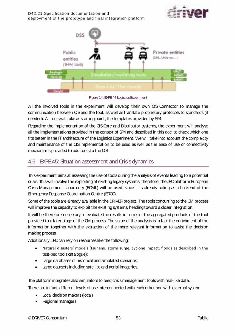
D42.21 Specification documentation and
deployment of the prototype and final integration platform
©DRIVER Consortium 53 Public
Figure 14: EXPE 44 Logistics Experiment
All the involved tools in the experiment will develop their own CIS Connector to manage the
communication between CIS and the tool, as well as translate proprietary protocols to standards (if
needed). All tools will take as starting point, the templates provided by SP4.
Regarding the implementation of the CIS Core and Distributor systems, the experiment will analyse
all the implementations provided in the context of SP4 and described in this doc, to check which one
fits better in the IT architecture of the Logistics Experiment. We will take into account the complexity
and maintenance of the CIS implementation to be used as well as the ease of use or connectivity
mechanisms provided to add tools to the CIS.
4.6 EXPE 45: Situation assessment and Crisis dynamics
This experiment aims at assessing the use of tools during the analysis of events leading to a potential
crisis. This will involve the exploiting of existing legacy systems; therefore, the JRC platform European
Crisis Management Laboratory (ECML) will be used, since it is already acting as a backend of the
Emergency Response Coordination Centre (ERCC).
Some of the tools are already available in the DRIVER project. The tools concurring to the CM process
will improve the capacity to exploit the existing systems, heading toward a closer integration.
It will be therefore necessary to evaluate the results in terms of the aggregated products of the tool
provided to a later stage of the CM process. The value of the analysis is in fact the enrichment of the
information together with the extraction of the more relevant information to assist the decision
making process.
Additionally, JRC can rely on resources like the following:
Natu al disaste s odels tsu a i, sto su ge, lo e i pa t, floods as des i ed i the test-bed tools catalogue);
Large databases of historical and simulated scenarios;
Large datasets including satellite and aerial imageries.
The platform integrates also simulators to feed crisis management tools with real-like data.
There are in fact, different levels of use interconnected with each other and with external system:
• Local decision makers (local)
• Regional managers
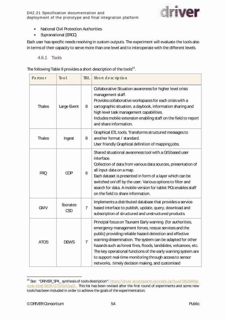
D42.21 Specification documentation and
deployment of the prototype and final integration platform
©DRIVER Consortium 54 Public
• National Civil Protection Authorities
• Supranational (ERCC)
Each user has specific needs resolving in custom outputs. The experiment will evaluate the tools also
in terms of their capacity to serve more than one level and to interoperate with the different levels.
4.6.1 Tools
The following Table 9 provides a short description of the tools14
.
Partner Tool TRL Short description
Thales Large Event 8
Collaborative Situation awareness for higher level crisis
management staff.
Provides collaborative workspaces for each crisis with a
cartographic situation, a daybook, information sharing and
high level task management capabilities.
Includes mobile extension enabling staff on the field to report
and share information.
Thales Ingest 8
Graphical ETL tools. Transforms structured messages to
another format / standard.
User friendly Graphical definition of mapping jobs.
FRQ COP 6
Shared situational awareness tool with a GIS based user
interface.
Collection of data from various data sources, presentation of
all input data on a map.
Each dataset is presented in form of a layer which can be
switched on/off by the user. Various options to filter and
search for data. A mobile version for tablet PCs enables staff
on the field to share information.
GMV Socrates
CSD 7
Implements a distributed database that provides a service
based interface to publish, update, query, download and
subscription of structured and unstructured products.
ATOS DEWS 7
Principal focus on Tsunami Early warning (for authorities,
emergency management forces, rescue services and the
public) providing reliable hazard detection and effective
warning dissemination. The system can be adapted for other
hazards such as forest fires, floods, landslides, volcanoes, etc.
The key operational functions of the early warning system are
to support real-time monitoring through access to sensor
networks, timely decision making, and customised
14
See: DRIVER_SP4_ synthesis of tools description : https://driver.atosresearch.eu/index.jsp?uuid=96c8d68d-
ecde-42a9-9828-f37520e53ad3 . This list has been revised after the first round of experiments and some new
tools has been included in order to achieve the goals of the experimentation.

D42.21 Specification documentation and
deployment of the prototype and final integration platform
©DRIVER Consortium 55 Public
Partner Tool TRL Short description
dissemination of warnings messages.
FOI SITRA 6
SITRA is a tools suite accessed through a front-end for
situation reasoning and risk assessment:
* Operational Picture with relevant information.
* Risk/threat model development tool: create models that
can be used to predict events, get early warnings and assess
risks.
* Context Aware Reporting system: Android app that can be
used for reporting events/incidents by using formal terms
defined in an ontology.
HKV Dashboard 9
Presents data and information from all sorts of sources in one
overview on mobile devices, whilst the data history is left at
its source. The information is presented in several
visualisation types (graphs, text, gauges) The dashboard
screens are user oriented and preformatted by the
information manager.
JRC Crisis Wall 7
Gathers live data from various sources of crisis information
(GDACS, EMM, ECHOFLASH.) and stores it.
A web client tailored specifically for use on a large wall touch
screen allows the user to search, filter, group and organise
this data into events. Users can also create events directly,
add analysis and populate them with items.
Event reports can be generated and shared.
Data from the CrisisWall can be viewed through mobile
applications.
JRC TAT 6 Tsunami Analysis Tool
MSB RIB 8
Decision support database and search engine for first
responders with data on most relevant aspects of
approximately 3700 toxic substances
GEO-APP LAMPO 7 Landslide Assessment through Multi Parameter Observations.
Its aim is to gather in real-time sufficient information from
different sources in order to help decision makers in finding
out if and when a landslide is approaching its collapse. It has
been developed in Air (Adobe integrated runtime).
SELEX DSS 7 Decision Support System aim to collect Integrate and
Compute heterogeneous data, from various sensor networks
in order to strengthen control and monitoring systems
OBSERVIS OBSHARE 9 It is a Tactical/Situational Awareness System (T/SAS) which
collects, visualizes and shares

D42.21 Specification documentation and
deployment of the prototype and final integration platform
©DRIVER Consortium 56 Public
Partner Tool TRL Short description
information between field and command personnel through
browser based user interfaces and mobile
applications. It is a perfect tool for sharing of information in
inter-agency operations
Table 9: EXPE 45 Tools
In order to provide a comparative analysis among the tools, we identified 3 main categories: while
the first and the second pertain respectively to collaborative situation awareness and early warning
tools (e.g. COP, CRISIS WALL, SITRA, DEWS, TAT etc.), the third refers more to communication and
information related-tools (RIB, LAMPO, INGEST).
The main hypothesis we aim to verify are:
1. The tools will improve the capacity to exploit existing systems;
2. The tools will improve Decision Making in Crisis Management (e.g. improve the extraction of
relevant information);
3. The tools will improve information sharing and flows.
Considering the complexity of the experiment and in order to carry out efficient experimentation
activities, the experiment is split into three different levels of analysis. The common aim is to
produce a valuable outcome (e.g. reports, graphical interfaces, alert messages) and to take informed
decisions on the basis of the reports produced. While type one deals with the understanding of a
report written on a given scenario, type two is more concerned with the interpretation of a layout
structure. The third analysis is similar to the first with a difference pertaining to decision making. In
this case, in fact, the report will be read, interpreted and evaluated by a high level decision maker
(e.g. ERCC).
Additionally, expected outcomes (technical and non-technical) and verified (through evidence-based
data out o es ill e a al zed. I the o te t of EXPE , tools a e o side ed as so io-te h i al apparatuses, therefore both technical and social aspects will be analyzed.
Furthermore, these questions are part of the methodological design:
• Does the tool contribute to the function it is supposed to contribute to? (Indicators to be
defined)
• How are tasks performed?
• Are these tools of interest to a certain user group that is currently not using them?
• What is the added value of each tool? (Indicators to be defined)
• What is the level of complexity of each tool?
• Is the tool user friendly? If yes, to what extent?
There will be no unfair comparison with tools the evaluators are already familiar with. The
e aluato s tea ill ha ge a o di gl to the s ope a d the topi of the tool. It ill e ope to all DRIVER partners volunteering to apply for it.
D42.21 Specification documentation and
deployment of the prototype and final integration platform
©DRIVER Consortium 57 Public
The design of the experiment will involve the tool provider, in o de to eate a ad hoc test including the evaluation criteria (common criterion: technological maturity level).
DRIVER Tasks involved (main & supporting):
• T43.1 Damage and Needs Assessment
• T43.3 Crisis dynamics & early warning
• T43.5 Shared situation awareness
• T44.1 Capacity Building and Capacity Mapping Tools
• T45.2 Collaborative tools (supporting)
• T45.3 Structured information exchange (supporting)
D42.21 Specification documentation and
deployment of the prototype and final integration platform
©DRIVER Consortium 58 Public
5 Conclusion
DRIVER involves several groups of tools of different kinds. Some of them will be used together to
carry out experiments in the scope of SP4, which will be useful for the Joint Experiments as well.
The common architecture design has been addressed and presented to enable the different tools
and services to connect together. Firstly, we introduced the available technologies and standards to
show the options available to implement the common architecture. Secondly, we presented the
selected technologies and standards and introduced the rationale behind the selection. The
architecture definition was described as well as how to implement the common communication
space to exchange information between the different tools. Finally we presented an early report on
how the different SP4 experiments are using the common architecture.
The main purpose of the document was successfully addressed by describing the Common
Information Space as the integration architecture that all experiments coming from SP4 will use to
interconnect the different tools. The main topics for this process were:
• List and describe the available technologies, from the Information and Communication
Technologies space and from the Crisis Management space. Including a short analysis on the
potential benefits and disadvantages of using them as part of the integration platform.
• Short list of the selected technologies, focusing on Crisis Management technologies and
standards, as the available tools to build a System of Systems that could be used to integrate
the different Crisis Management tools. This task was focused on the description of each
standard so that the reasons for using them as part of the integration architecture are
explained.
• With the selected tools the Common Information Space is presented and described in the
internal architectural components. The main focus is on the CIS Adaptor and its components
that are used to enable the Tools providers to connect to the CIS and use it to exchange
information. These components are the Connector, the Core and the Distributor.
• As part of the CIS description, the optional implementation technologies for the CIS
Distributor are presented, including Common Shared Space, Peer2Peer and Enterprise
Service Bus. Other supporting tools are also described to enrich the CIS architecture
functionality.
• Finally, the SP4 experiments are described with the focus on the actual implementation state
as part of each experiment path to implement the CIS architecture to interconnect the
different tools.
A deeper description and more detailed information are going to be included in the next iteration of
this document.
More details will be provided during the next tasks of the WP42 in close cooperation with WP46 and
considering as well the SP2 test-bed architecture.
Next steps will be the following:
• Define how the tools will cooperate with each other in the experiments:
o Identifying the data that will be shared
o The formats they are in compliance with and

D42.21 Specification documentation and
deployment of the prototype and final integration platform
©DRIVER Consortium 59 Public
o Other technical constraints they might have
Define the standard interface implementation that is required by the tools to implement the
CIS Adaptor, the common interface that each tool will need to implement in order to be
connected to the CIS
Get deeper information and requirements description for each one of the defined interfaces
within CIS architecture.
o Approaches coming from other European Commission projects such as EPISECC
Investigate and define on the required security requirements for the integration of each and
every tool that uses CIS
o Approaches coming from other European Commission projects such as ODYSSEY
Progress into the implementation of CIS that is performed by each experiment.
D42.21 Specification documentation and
deployment of the prototype and final integration platform
©DRIVER Consortium 60 Public
Annex 1 SOA
SOA Architecture
Service Oriented Architecture (SOA) is a key concept of modern information technology. Current
Crisis Management software has to cope with the heterogeneous nature of the services, addressing
complex issues such as distributed software, application integration, diverse platforms and protocols,
and various devices. SOA along with Web Services allows seamless integration by abstraction from
complexity thus providing an approach to deal with the challenges of such complex software
environments.
Service Oriented Architecture (SOA) is an architectural style based on loosely coupled interacting
software components that provide services. A service is a piece of functionality made available by a
service provider in order to deliver end results for a service consumer. A service consumer sends a
service request to a service provider. The service provider returns a response to the service
consumer containing the expected results. In Service Oriented Computing (SOC), services are the
crucial element to develop applications. SOC applies SOA to organize software applications and
infrastructure into a set of interacting services.
SOA applies a service model consisting of a set of interconnected services communicating through
standard interfaces and messaging protocols. Basic services, their descriptions and basic operations
as publish, discovery, selection, and bind constitute the basic SOA.
SOA constitutes a concept to provide services to clients through published interfaces and to
coordinate interaction through the exchange of messages. Generally, the basic SOA describes the
relationship between three kinds of participants: the service providers, the registry, and the service
requestors. The service represents a logical separation of declaration and implementation, its
implementation is hidden from the client and can be subject to changes which may not influence the
client so long as the service interface stays unchanged.
An important mechanism in a SOA is the Dynamic Discovery of services:
The interaction model of the basic SOA consists of three key players, the service providers, the
service requestors, and the intermediating directory service. First, the service providers register with
the directory service, then clients can query the directory service for providers and browse the
exposed service capabilities. Typically a directory service supports:
• a look-up service for clients
• scalability of the service model: services can be added incrementally
• dynamic composition of the services: the client can decide at runtime which services to use
SOA Architectural Constraints
In order to achieve loose coupling between components, SOA is based on two major architectural
constraints where:

D42.21 Specification documentation and
deployment of the prototype and final integration platform
©DRIVER Consortium 61 Public
1. Interfaces are defined for all participating services. Only generic semantics are encoded at
the interfaces. The interfaces should be universally available for all providers and consumers.
2. Messages are described and constrained by an extensible scheme and delivered through the
interfaces.
Interfaces
The interface constitutes a contract defining the functionality of the service in a platform-
independent manner. This implies that the invocation mechanism (protocols, descriptions, and
discovery) must comply with widely accepted standards enabling a client to use the service from
anywhere applying any OS or programming language.
A discovery service (e.g. a directory service) provides clients with a look-up mechanism supporting
dynamic locating and invoking.
Services are self-describing. They advertise the service capabilities, interface, behavior, and quality.
Services may publish several descriptions. The service interface description publishes the service
signature, e.g. its input, output, and error messages. The (expected) behavior is described by the
behavior description and the QoS (Quality of Service) describes both functional and non-functional
service quality attributes, e.g. performance, security attributes, reliability, etc.
Services exhibit several other properties. They are stateless, this means that users can use them
without knowing the current conditions of the service, the service maintains its own state. The
interaction between services is loosely coupled, that is the services must not share common modules
(e.g. GUI or storage) or data model. The usage of services is location-transparent, e.g. clients do not
have to know if the service is local or only accessible over a network. These properties enable and
support rapid and low-cost composition of services for distributed applications.
Messages
Message passing is a form of communication for inter-module interaction. Processes communicate
with each other by sending and receiving messages, where each sent mechanism must match the
corresponding receive mechanism. Services communicate with each other and with consumers using
messages. The service interface defines the messages a service can process. To achieve platform-and
language-independency, messages are typically constructed using XML documents that comply with
the corresponding XML Schemas. In contrast to Remote Procedure Call (RPC) the mechanism is an
asynchronous communication, directly supported by message passing.
A schema limits the vocabulary and structure of messages. An extensible schema allows new versions
of services to be introduced without modifying existing services.
RESTful Web Services
More than a decade after its introduction, REST has become one of the most important technologies
for Web applications. Its importance is likely to continue growing quickly as all technologies move
towards an API orientation. Every major development language now includes frameworks for
building RESTful Web services. As such, it is important for Web developers and architects to have a
clear understanding of REST and RESTful services. While REST stands for Representational State
Transfer, which is an architectural style for networked hypermedia applications, it is primarily used to
D42.21 Specification documentation and
deployment of the prototype and final integration platform
©DRIVER Consortium 62 Public
build Web services that are lightweight, maintainable, and scalable. A service based on REST is called
a RESTful service. REST is not dependent on any protocol, but almost every RESTful service uses HTTP
as its underlying protocol.
Every system uses resources. These resources can be pictures, video files, Web pages, business
information, or anything that can be represented in a computer-based system. The purpose of a
service is to provide a window to its clients so that they can access these resources. Service architects
and developers want this service to be easy to implement, maintainable, extensible, and scalable. A
RESTful design promises that.
As a programming approach, REST is a lightweight alternative to Web Services and RPC. Much like
Web Services, a REST service is:
• Platform-independent (you don't care if the server is Unix, the client is a Mac, or anything
else),
• Language-independent (C# can talk to Java, etc.),
• Standards-based (runs on top of HTTP), and
• Can easily be used in the presence of firewalls.
Like Web Services, REST offers no built-in security features, encryption, session management, QoS
guarantees, etc. But also as with Web Services, these can be added by building on top of HTTP:
• For security, username/password tokens are often used.
• For encryption, REST can be used on top of HTTPS (secure sockets).
• ... Etc.
One thing that is not part of a good REST design is cookies: The "ST" in "REST" stands for "State
Transfer", and indeed, in a good REST design operations are self-contained, and each request carries
with it (transfers) all the information (state) that the server needs in order to complete it.
Every system uses resources. These resources can be pictures, video files, Web pages, business
information, or anything that can be represented in a computer-based system. The purpose of a
service is to provide a window to its clients so that they can access these resources. Service architects
and developers want this service to be easy to implement, maintainable, extensible, and scalable. A
RESTful design promises that and more. In general, RESTful services should have following properties
and features:
• Representations
• Messages
• URIs
• Uniform interface
• Stateless
• Links between resources
• Caching
Architecture Based on SOA
The perceived value of SOA is that it provides a powerful framework for matching needs and
capabilities and for combining capabilities to address those needs.

D42.21 Specification documentation and
deployment of the prototype and final integration platform
©DRIVER Consortium 63 Public
Visibility, interaction, and effect are key concepts for describing the SOA paradigm. Visibility refers to
the capacity for those with needs and those with capabilities to be able to see each other. This is
typically done by providing descriptions for such aspects as functions and technical requirements,
related constraints and policies, and mechanisms for access or response. The descriptions need to be
in a form (or can be transformed to a form) in which their syntax and semantics are widely accessible
and understandable.
Whereas visibility introduces the possibilities for matching needs to capabilities (and vice versa),
interaction is the activity of using a capability. Typically mediated by the exchange of messages, an
interaction proceeds through a series of information exchanges and invoked actions. There are many
facets of interaction; but they are all grounded in a particular execution context – the set of technical
and business elements that form a path between those with needs and those with capabilities. This
permits service providers and consumers to interact and provides a decision point for any policies
and contracts that may be in force.
The purpose of using a capability is to realize one or more real world effects. At its core, an
i te a tio is a a t as opposed to a o je t a d the esult of a i te a tio is a effe t o a
set/series of effects). This effect may be the return of information or the change in the state of
entities (known or unknown) that are involved in the interaction.
We are careful to distinguish between public actions and private actions; private actions are
inherently unknown by other parties. On the other hand, public actions result in changes to the state
that is shared between at least those involved in the current execution context and possibly shared
by others. Real world effects are, then, couched in terms of changes to this shared state. The
expected real world effects form an important part of the decision on whether a particular capability
matches similarly described needs. At the interaction stage, the description of real world effects
establishes the expectations of those using the capability. Note, it is not possible to describe every
effect from using a capability. A cornerstone of SOA is that capabilities can be used without needing
to know all the details.
This description of SOA has yet to mention what is usually considered the central concept: the
se i e. The ou se i e is defi ed i di tio a ies as The pe fo a e of o k a fu tio one
fo a othe . Ho e e , se i e, as the te is ge e all u de stood, also o i es the following
related ideas:
• The capability to perform work for another.
• The specification of the work offered for another.
• The offer to perform work for another.
These concepts emphasize a distinction between a capability and the ability to bring that capability
to bear. While both needs and capabilities exist independently of SOA, in SOA, services are the
mechanism by which needs and capabilities are brought together.
SOA is a means of organizing solutions that promotes reuse, growth and interoperability. It is not
itself a solution to domain problems but rather an organizing and delivery paradigm that enables one
to get o e alue f o use oth of apa ilities hi h a e lo all o ed a d those u de the
control of others. It also enables one to express solutions in a way that makes it easier to modify or
evolve the identified solution or to try alternate solutions. SOA does not provide any domain
elements of a solution that do not exist without SOA.
D42.21 Specification documentation and
deployment of the prototype and final integration platform
©DRIVER Consortium 64 Public
Note that while an SOA service brings together needs and capabilities, the provider of the underlying
capability may not be the same entity that eventually provides the service which accesses that
capability. In reality, the entity with the domain expertise to create, maintain, and evolve a given
capability may not have the expertise or the desire to create, maintain, and evolve its service access.
The concepts of visibility, interaction, and effect apply directly to services in the same manner as
these were described for the general SOA paradigm. Visibility is promoted through the service
description which contains the information necessary to interact with the service and describes this
in such terms as the service inputs, outputs, and associated semantics. The service description also
conveys what is accomplished when the service is invoked and the conditions for using the service.
In general, entities (people and organizations) offer capabilities and act as service providers. Those
with needs who make use of services are referred to as service consumers. The service description
allows prospective consumers to decide if the service is suitable for their current needs and
establishes whether a consumer satisfies any requirements of the service provider. (Note, service
providers and service consumers are sometimes referred to jointly as service participants.)
Services Visibility
Introduces the possibilities for matching needs to capabilities (and vice versa),
Services Capabilities
Interaction is the activity of using a capability

D42.21 Specification documentation and
deployment of the prototype and final integration platform
©DRIVER Consortium 65 Public
Bibliography
Rick Kazman, Claus Nielsen, Klaus Schmid, "Understanding Patterns for System-of- Systems
Integration", CMU/SEI-2013-TR-017 , December 2013
Robert Palmqvist, SAAB, Dr. Lars Schylberg, SAAB, Dr. Allen Jones, The Boeing Company, Legacy
services capability Pattern, V1.10, NCOIC, December 11 2009
"SOA Blueprint: A Toolbox for Architects", Issue LXXI, March/April 2013, Service technology magazine
"Emergency Services Operational Net-Centric Pattern", V1.0, NCOIC, December 2013
Office of the Deputy Under Secretary of Defense for Acquisition and Technology, Systems and
Software Engineering. Systems Engineering Guide for Systems of Systems, Version 1.0. Washington,
DC: ODUSD(A&T)SSE, 2008.
Designing for adaptability and evolution in system of systems engineering (DANSE) "Conceptual and
architecture principles of SoS design and semantic interoperability of systems platform and SoS
design Tool-Net D_8.1.1+D_8.2.1", October 2012
Comprehensive Modelling for Advanced Systems of Systems (Compass), Report on Guidelines for
System Integration for SoS , D21.4, September 2013
Learn REST: A Tutorial http://rest.elkstein.org/
Learn REST: A RESTful Tutorial http://www.restapitutorial.com/
An Introduction to the Resource Description Framework
http://www.dlib.org/dlib/may98/miller/05miller.html
What is service-oriented architecture? An introduction to SOA
http://www.javaworld.com/article/2071889/soa/what-is-service-oriented-architecture.html

D42.21 Specification documentation and
deployment of the prototype and final integration platform
©DRIVER Consortium 66 Public
References
[1] DRIVER Deliverable D45.1: Report on Data Interoperability Standards, 2015
[2] DRIVER Deliverable D42.1 - Final report on architecture design, 2015
[3] ACRIMAS project http://www.acrimas.eu/
[4] ODYSSEY project http://research.shu.ac.uk/aces/odyssey/