d4d-n safety limit switch data sheet - omron · safety limit switch small, ... roller lever and...
TRANSCRIPT
D4D-N
2
Safety Limit Switch
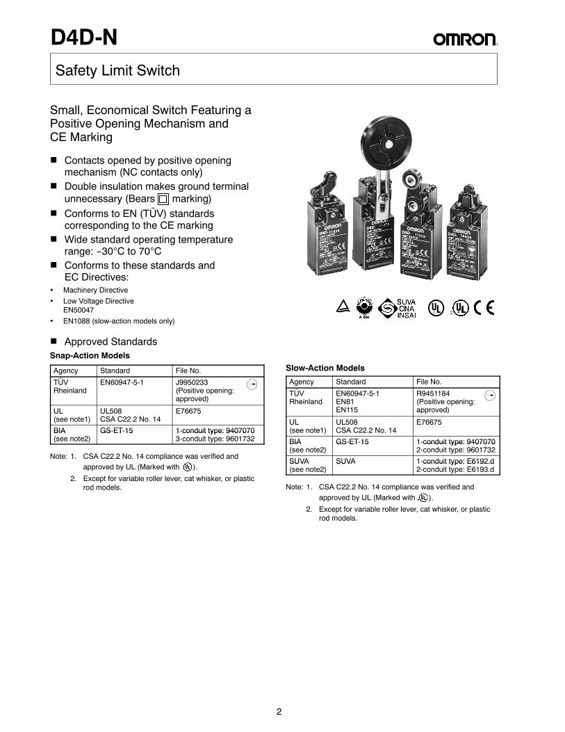
Small, Economical Switch Featuring aPositive Opening Mechanism andCE Marking
H Contacts opened by positive openingmechanism (NC contacts only)
H Double insulation makes ground terminalunnecessary (Bears marking)
H Conforms to EN (TÜV) standardscorresponding to the CE marking
H Wide standard operating temperaturerange: --30°C to 70°C
H Conforms to these standards andEC Directives:
• Machinery Directive• Low Voltage Directive
EN50047• EN1088 (slow-action models only)
E u
H Approved StandardsSnap-Action Models
Agency Standard File No.
TÜVRheinland
EN60947-5-1 J9950233(Positive opening:approved)
UL(see note1)
UL508CSA C22.2 No. 14
E76675
BIA GS-ET-15 1-conduit type: 9407070BIA(see note2)
GS ET 15 1 conduit type: 94070703-conduit type: 9601732
Note: 1. CSA C22.2 No. 14 compliance was verified andapproved by UL (Marked with ).
2. Except for variable roller lever, cat whisker, or plasticrod models.
Slow-Action Models
Agency Standard File No.
TÜVRheinland
EN60947-5-1EN81EN115
R9451184(Positive opening:approved)
UL(see note1)
UL508CSA C22.2 No. 14
E76675
BIA GS-ET-15 1-conduit type: 9407070BIA(see note2)
GS ET 15 1 conduit type: 94070702-conduit type: 9601732
SUVA SUVA 1-conduit type: E6192.dSUVA(see note2)
SUVA 1 conduit type: E6192.d2-conduit type: E6193.d
Note: 1. CSA C22.2 No. 14 compliance was verified andapproved by UL (Marked with ).
2. Except for variable roller lever, cat whisker, or plasticrod models.
D4D-N
3
Ordering Information
D4D-jjjjN1 2 3
J MODEL NUMBER LEGEND
1. Conduit1: Pg13.5 (1-conduit) European type2: G1/2 (1-conduit) Japanese type3: 1/2-14NPT (1-conduit) North American type5: Pg13.5 (2-conduit) European type6: G1/2 (2-conduit) Japanese type2. Built-in Switch1: 1NC/1NO (Snap-action)5: 1NC/1NO (Slow-action)A: 2NC (Slow-action)
3. Head and Actuator20: Roller lever (standard, resin lever)21: Adjustable roller lever22: Roller lever (metal lever)27: Adjustable roller lever (with 50 dia. rubber roller)31: Top plunger32: Top roller plunger62: One-way roller arm lever (horizontal)72: One-way roller arm lever (vertical)80: Cat whisker87: Plastic rodRE: Fork lever lock (right operation)LE: Fork lever lock (left operation)
J SWITCHES
Actuator Conduit size/type Built-in switch mechanism/ yp
1NC/1NO (Snap-action) 1NC/1NO (Slow-action) 2NC (Slow-action)
Positiveopening
Partnumber
Positiveopening
Partnumber
Positiveopening
Partnumber
Roller lever( i l )
1-conduit Pg13.5 (European) D4D-1120N D4D-1520N D4D-1A20N(resin lever) G1/2 (Japanese) D4D-2120N D4D-2520N D4D-2A20N
1/2-14NPT(North American)
D4D-3120N D4D-3520N D4D-3A20N
2-conduit Pg13.5 (European) D4D-5120N D4D-5520N D4D-5A20N
G1/2 (Japanese) D4D-6120N D4D-6520N D4D-6A20N
Roller lever( t l l )
1-conduit Pg13.5 (European) D4D-1122N D4D-1522N D4D-1A22N(metal lever) G1/2 (Japanese) D4D-2122N D4D-2522N D4D-2A22N
1/2-14NPT(North American)
D4D-3122N D4D-3522N D4D-3A22N
2-conduit Pg13.5 (European) D4D-5122N D4D-5522N D4D-5A22N
G1/2 (Japanese) D4D-6122N D4D-6522N D4D-6A22N
Adjustablell l
1-conduit Pg13.5 (European) --- D4D-1121N D4D-1521N D4D-1A21Njroller lever G1/2 (Japanese) D4D-2121N (See D4D-2521N
(SeeD4D-2A21N
1/2-14NPT(North American)
D4D-3121N(SeeNote 1) D4D-3521N
(SeeNote 1) D4D-3A21N
2-conduit Pg13.5 (European) D4D-5121N D4D-5521N D4D-5A21N
G1/2 (Japanese) D4D-6121N D4D-6521N D4D-6A21N
Adjustablell l
1-conduit Pg13.5 (European) D4D-1127N D4D-1527N D4D-1A27Njroller lever(with rubber
G1/2 (Japanese)(S
D4D-2127N(See
D4D-2527N(See
D4D-2A27N(with rubberroller) 1/2-14NPT
(North American)
(SeeNote 1) D4D-3127N
(SeeNote 1) D4D-3527N
(SeeNote 1) D4D-3A27N
2-conduit Pg13.5 (European) D4D-5127N D4D-5527N D4D-5A27N
G1/2 (Japanese) D4D-6127N D4D-6527N D4D-6A27N
(This table continues on the next page.)
Note: 1. The Switches are marked with “ ” indicating approval by TÜV Rheinland for the positive opening mechanism. Adjustableroller lever and fork lever lock models are approved by TÜV Rheinland for the positive opening mechanism, but not by theGS-ET-15 standard (BIA) nor by SUVA.
2. Right operation: Contact 11-12 is positively opened, when the lever on the right is lowered.Left operation: Contact 11-12 is positively opened, when the lever on the left is lowered.
D4D-N
4
Ordering Information -- continued from previous page
Actuator Conduit size/type Built-in switch mechanism/ yp
1NC/1NO (Snap-action) 1NC/1NO (Slow-action) 2NC (Slow-action)
Positiveopening
Partnumber
Positiveopening
Partnumber
Positiveopening
Partnumber
Plunger 1-conduit Pg13.5 (European) D4D-1131N D4D-1531N D4D-1A31Ng
G1/2 (Japanese) D4D-2131N D4D-2531N D4D-2A31N
1/2-14NPT(North American)
D4D-3131N D4D-3531N D4D-3A31N
2-conduit Pg13.5 (European) D4D-5131N D4D-5531N D4D-5A31N
G1/2 (Japanese) D4D-6131N D4D-6531N D4D-6A31N
Rollerl
1-conduit Pg13.5 (European) D4D-1132N D4D-1532N D4D-1A32Nplunger G1/2 (Japanese) D4D-2132N D4D-2532N D4D-2A32N
1/2-14NPT(North American)
D4D-3132N D4D-3532N D4D-3A32N
2-conduit Pg13.5 (European) D4D-5132N D4D-5532N D4D-5A32N
G1/2 (Japanese) D4D-6132N D4D-6532N D4D-6A32N
One-wayll
1-conduit Pg13.5 (European) D4D-1162N D4D-1562N D4D-1A62Nyroller armlever G1/2 (Japanese) D4D-2162N D4D-2562N D4D-2A62Nlever(horizontal) 1/2-14NPT
(North American)D4D-3162N D4D-3562N D4D-3A62N
2-conduit Pg13.5 (European) D4D-5162N D4D-5562N D4D-5A62N
G1/2 (Japanese) D4D-6162N D4D-6562N D4D-6A62N
One-wayll
1-conduit Pg13.5(European) D4D-1172N D4D-1572N D4D-1A72Nyrollerarm lever
G1/2 (Japanese) D4D-2172N D4D-2572N D4D-2A72Narm lever(vertical) 1/2-14NPT
(North American)D4D-3172N D4D-3572N D4D-3A72N
2-conduit Pg13.5 (European) D4D-5172N D4D-5572N D4D-5A72N
G1/2 (Japanese) D4D-6172N D4D-6572N D4D-6A72N
Fork leverl k ( i ht
1-conduit Pg13.5 (European) --- --- D4D-15REN D4D-1ARENlock (rightoperation)
G1/2 (Japanese)(See
D4D-25REN (SeeN t 1)
D4D-2ARENoperation)(See Note 2) 1/2-14NPT
(North American)
(SeeNote 1) D4D-35REN
(SeeNote 1)
D4D-3AREN
2-conduit Pg13.5 (European) D4D-55REN D4D-5AREN
G1/2 (Japanese) D4D-65REN D4D-6AREN
Fork leverl k (l ft
1-conduit Pg13.5 (European) --- --- D4D-15LEN D4D-1ALENlock (leftoperation)
G1/2 (Japanese)(See
D4D-25LEN (See D4D-2ALENoperation)(See Note 2) 1/2-14NPT
(North American)
(SeeNote 1) D4D-35LEN
(SeeNote 1) D4D-3ALEN
2-conduit Pg13.5 (European) D4D-55LEN D4D-5ALEN
G1/2 (Japanese) D4D-65LEN D4D-6ALEN
Cat whisker 1-conduit Pg13.5 (European) --- D4D-1180N --- --- --- D4D-1A80N
G1/2 (Japanese) D4D-2180N --- D4D-2A80N
1/2-14NPT(North American)
D4D-3180N --- D4D-3A80N
2-conduit Pg13.5 (European) D4D-5180N --- D4D-5A80N
G1/2 (Japanese) D4D-6180N --- D4D-6A80N
Plastic rod 1-conduit Pg13.5 (European) --- D4D-1187N --- --- --- D4D-1A87N
G1/2 (Japanese) D4D-2187N --- D4D-2A87N
1/2-14NPT(North American)
D4D-3187N --- D4D-3A87N
2-conduit Pg13.5 (European) D4D-5187N --- D4D-5A87N
G1/2 (Japanese) D4D-6187N --- D4D-6A87N
Note: 1. The Switches are marked with “ ” indicating approval by TÜV Rheinland for the positive opening mechanism. Adjustableroller lever and fork lever lock models are approved by TÜV Rheinland for the positive opening mechanism, but not by theGS-ET-15 standard (BIA) nor by SUVA.
2. Right operation: Contact 11-12 is positively opened, when the lever on the right is lowered.Left operation: Contact 11-1 (Japanese) 2 is positively opened, when the lever on the left is lowered.
D4D-N
5
SpecificationsJ APPROVED STANDARD RATINGSTÜV (EN60947-5-1)
Utilization category AC-15
Rated operating current (Ie) 2 A
Rated operating voltage (Ue) 400 V
Note: As protection against short-circuiting, use either a gI-type or gG-type 10-A fuse that conforms to IEC269.
UL/CSA (UL508/CSA C22.2 No. 14)A600 (D4D-j5jjN, D4D-jAjjN)
Type Rated voltage Carry current Current Volt-amperesyp g y
Make Break Make Break
Slow-action 120 VAC240 VAC480 VAC600 VAC
10 A 60 A30 A15 A7.5 A12 A
6 A3 A1.5 A1.2 A
7,200 VA 720 VA
B600 (D4D-j1jjN)
Type Rated voltage Carry current Current Volt-amperesyp g y
Make Break Make Break
Snap-action 120 VAC240 VAC480 VAC600 VAC
5 A 30 A15 A7.5 A6 A
3 A1.5 A0.75 A0.6 A
3,600 VA 360 VA
D4D-N
6
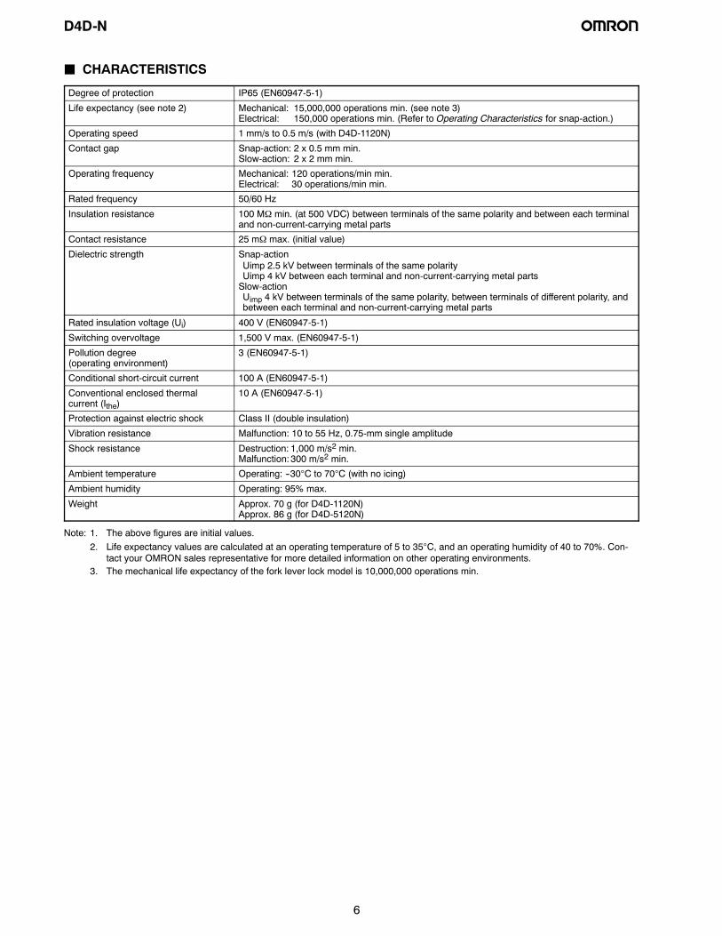
J CHARACTERISTICS
Degree of protection IP65 (EN60947-5-1)
Life expectancy (see note 2) Mechanical: 15,000,000 operations min. (see note 3)Electrical: 150,000 operations min. (Refer to Operating Characteristics for snap-action.)
Operating speed 1 mm/s to 0.5 m/s (with D4D-1120N)
Contact gap Snap-action: 2 x 0.5 mm min.Slow-action: 2 x 2 mm min.
Operating frequency Mechanical: 120 operations/min min.Electrical: 30 operations/min min.
Rated frequency 50/60 Hz
Insulation resistance 100 MΩ min. (at 500 VDC) between terminals of the same polarity and between each terminaland non-current-carrying metal parts
Contact resistance 25 mΩ max. (initial value)
Dielectric strength Snap-actionUimp 2.5 kV between terminals of the same polarityUimp 4 kV between each terminal and non-current-carrying metal partsSlow-actionUimp 4 kV between terminals of the same polarity, between terminals of different polarity, andbetween each terminal and non-current-carrying metal parts
Rated insulation voltage (Ui) 400 V (EN60947-5-1)
Switching overvoltage 1,500 V max. (EN60947-5-1)
Pollution degree(operating environment)
3 (EN60947-5-1)
Conditional short-circuit current 100 A (EN60947-5-1)
Conventional enclosed thermalcurrent (Ithe)
10 A (EN60947-5-1)
Protection against electric shock Class II (double insulation)
Vibration resistance Malfunction: 10 to 55 Hz, 0.75-mm single amplitude
Shock resistance Destruction: 1,000 m/s2 min.Malfunction: 300 m/s2 min.
Ambient temperature Operating: --30°C to 70°C (with no icing)
Ambient humidity Operating: 95% max.
Weight Approx. 70 g (for D4D-1120N)Approx. 86 g (for D4D-5120N)
Note: 1. The above figures are initial values.2. Life expectancy values are calculated at an operating temperature of 5 to 35°C, and an operating humidity of 40 to 70%. Con-
tact your OMRON sales representative for more detailed information on other operating environments.3. The mechanical life expectancy of the fork lever lock model is 10,000,000 operations min.
D4D-N
7
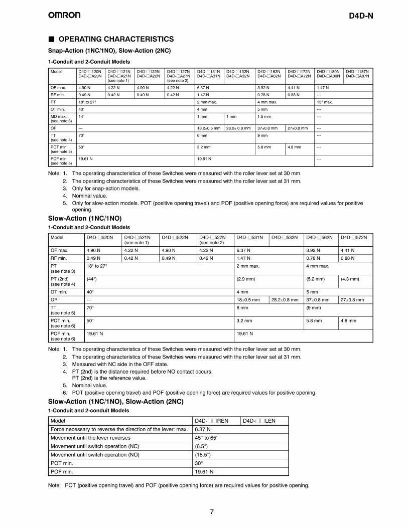
J OPERATING CHARACTERISTICSSnap-Action (1NC/1NO), Slow-Action (2NC)
1-Conduit and 2-Conduit Models
Model D4D-j120ND4D-jA20N
D4D-j121ND4D-jA21N(see note 1)
D4D-j122ND4D-jA22N
D4D-j127ND4D-jA27N(see note 2)
D4D-j131ND4D-jA31N
D4D-j132ND4D-jA32N
D4D-j162ND4D-jA62N
D4D-j172ND4D-jA72N
D4D-j180ND4D-jA80N
D4D-j187ND4D-jA87N
OF max. 4.90 N 4.22 N 4.90 N 4.22 N 6.37 N 3.92 N 4.41 N 1.47 N
RF min. 0.49 N 0.42 N 0.49 N 0.42 N 1.47 N 0.78 N 0.88 N ---
PT 18° to 27° 2 mm max. 4 mm max. 15° max.
OT min. 40° 4 mm 5 mm ---
MD max.(see note 3)
14° 1 mm 1 mm 1.5 mm ---
OP --- 18.2±0.5 mm 28.2± 0.8 mm 37±0.8 mm 27±0.8 mm ---
TT(see note 4)
70° 6 mm 9 mm ---
POT min.(see note 5)
50° 3.2 mm 5.8 mm 4.8 mm ---
POF min.(see note 5)
19.61 N 19.61 N ---
Note: 1. The operating characteristics of these Switches were measured with the roller lever set at 30 mm2. The operating characteristics of these Switches were measured with the roller lever set at 31 mm.3. Only for snap-action models.4. Nominal value.5. Only for slow-action models. POT (positive opening travel) and POF (positive opening force) are required values for positive
opening.
Slow-Action (1NC/1NO)1-Conduit and 2-Conduit Models
Model D4D-j520N D4D-j521N(see note 1)
D4D-j522N D4D-j527N(see note 2)
D4D-j531N D4D-j532N D4D-j562N D4D-j572N
OF max. 4.90 N 4.22 N 4.90 N 4.22 N 6.37 N 3.92 N 4.41 N
RF min. 0.49 N 0.42 N 0.49 N 0.42 N 1.47 N 0.78 N 0.88 N
PT(see note 3)
18° to 27° 2 mm max. 4 mm max.
PT (2nd)(see note 4)
(44°) (2.9 mm) (5.2 mm) (4.3 mm)
OT min. 40° 4 mm 5 mm
OP --- 18±0.5 mm 28.2±0.8 mm 37±0.8 mm 27±0.8 mm
TT(see note 5)
70° 6 mm (9 mm)
POT min.(see note 6)
50° 3.2 mm 5.8 mm 4.8 mm
POF min.(see note 6)
19.61 N 19.61 N
Note: 1. The operating characteristics of these Switches were measured with the roller lever set at 30 mm.2. The operating characteristics of these Switches were measured with the roller lever set at 31 mm.3. Measured with NC side in the OFF state.4. PT (2nd) is the distance required before NO contact occurs.
PT (2nd) is the reference value.5. Nominal value.6. POT (positive opening travel) and POF (positive opening force) are required values for positive opening.
Slow-Action (1NC/1NO), Slow-Action (2NC)1-Conduit and 2-conduit Models
Model D4D-jjREN D4D-jjLEN
Force necessary to reverse the direction of the lever: max. 6.37 N
Movement until the lever reverses 45° to 65°
Movement until switch operation (NC) (6.5°)
Movement until switch operation (NO) (18.5°)
POT min. 30°
POF min. 19.61 N
Note: POT (positive opening travel) and POF (positive opening force) are required values for positive opening.

D4D-N
8
Engineering DataJ ELECTRICAL LIFE EXPECTANCY (1NC/1NO CONTACT, SNAP-ACTION)(cosφ = 1)
Operations
(x10
)3
Switching current (A)Operations
(x10
)3
Switching current (A)
(cosφ = 0.4)
Operating frequencies:30 operations/min, cosφ = 1
Operating frequencies:30 operations/min,cosφ = 0.4
250 VAC
400 VAC
250 VAC
400 VAC
10,000
7,0005,000
3,000
1,000700
500
300
10,000
7,0005,000
3,000
1,000700
500
300
NomenclatureHeadWith roller lever models, the direction of the switch head canbe varied to any of the four directions by loosening the rollerlever switch screws at the four corners of the head.
Conduit Opening
Available in two different types of conduit threads:Pg 13.5: European standard (1-conduit, 2-conduit)G 1/2: Japanese standard (1-conduit, 2-conduit)1/2-14NPT: US standard (1-conduit)
Safety-Oriented Lever SettingGrooves which engage the lever every 90° are cut in theoperation indicator disk to prevent the lever from slippingagainst the rotary shaft.There are resin-lever and metal-lever types.
CoverEasy to open and wire. (One mounting screw and oppo-site side is for hinge mounting.)
Contact MaterialAg alloy
Built-in SwitchWide switch variations.Snap-action: 1NC/1NOSlow-action: 1NC/1NO
2NC
Conduit Cap
Can be used as a simple connector under good envi-ronmental conditions.
D4D-N
9
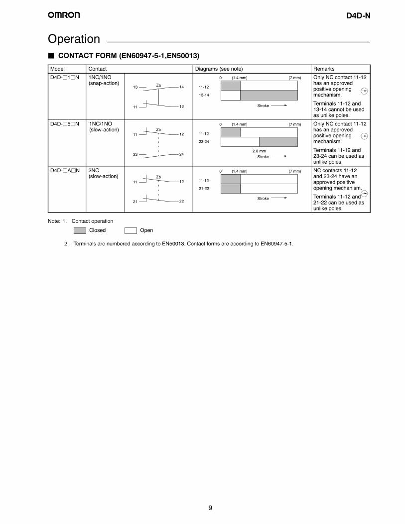
OperationJ CONTACT FORM (EN60947-5-1,EN50013)
Model Contact Diagrams (see note) Remarks
D4D-j1jN 1NC/1NO(snap-action)
13
11
Za 14
12
11-12
13-14
0 (1.4 mm) (7 mm)
Stroke
Only NC contact 11-12has an approvedpositive openingmechanism.
Terminals 11-12 and13-14 cannot be usedas unlike poles.
D4D-j5jN 1NC/1NO(slow-action)
23
11Zb
24
12 11-12
23-24
0 (1.4 mm) (7 mm)
2.8 mmStroke
Only NC contact 11-12has an approvedpositive openingmechanism.
Terminals 11-12 and23-24 can be used asunlike poles.
D4D-jAjN 2NC(slow-action)
11Zb
12
21 22
11-12
21-22
0 (1.4 mm) (7 mm)
Stroke
NC contacts 11-12and 23-24 have anapproved positiveopening mechanism.
Terminals 11-12 and21-22 can be used asunlike poles.
Closed Open
Note: 1. Contact operation
2. Terminals are numbered according to EN50013. Contact forms are according to EN60947-5-1.

D4D-N
10
J POSITIVE OPENING MECHANISM1NC/1NO Contact (Snap-Action)
Conforms to EN60947-5-1 Positive OpeningIf metal deposition between mating contacts occurs on the NC contact side, they can be pulled apart by the shearing force and tensileforce generated when part B of the safety cam or plunger engages part A of the movable contact blade. When the safety cam or plungeris moved in the direction of the black arrow, the Limit Switch releases.
1. When metal deposition occurs. 2. When contacts are being pulled apart. 3. When contacts are completelypulled apart.
Movable contactblade
Movable contact
Plunger
Safety cam
Fixed contact (NC)
Safety cam directlypushes up themovable contactblade.
AB
Conforms to EN60947-5-1 Positive Opening
When metal deposition occurs, the contactsare separated from each other by the plungerbeing pushed in.Contact spring
Return spring
Fixed contact (NC)
Movable contact
Plunger
1NC/1NO Contact (Slow-Action)
Conforms to EN60947-5-1 Positive Opening
When metal deposition occurs, the contactsare separated from each other by the plungerbeing pushed in.
Contact spring
Return spring
Fixed contact (NC)
Movable contact
Plunger
2NC Contact (Slow-Action)
D4D-N
11
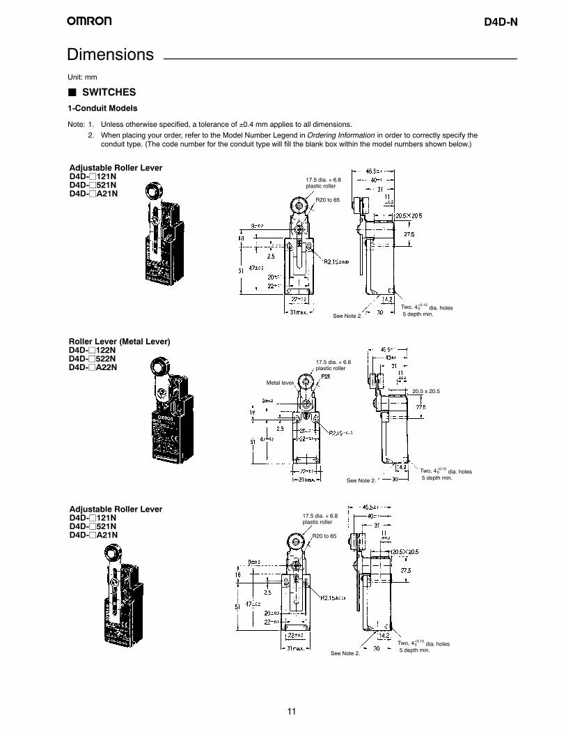
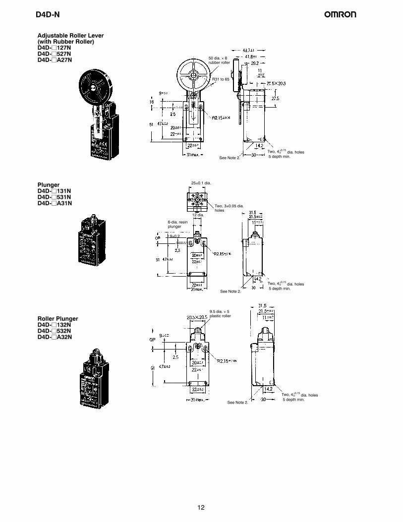
Dimensions
Adjustable Roller LeverD4D-j121ND4D-j521ND4D-jA21N
Two, 4+0.150 dia. holes5 depth min.
17.5 dia. × 6.8plastic roller
R20 to 65
See Note 2.
J SWITCHES1-Conduit Models
Note: 1. Unless otherwise specified, a tolerance of ±0.4 mm applies to all dimensions.2. When placing your order, refer to the Model Number Legend in Ordering Information in order to correctly specify the
conduit type. (The code number for the conduit type will fill the blank box within the model numbers shown below.)
Two, 4+0.150 dia. holes5 depth min.
17.5 dia. × 6.8plastic roller
20.5 x 20.5
Metal lever
Roller Lever (Metal Lever)D4D-j122ND4D-j522ND4D-jA22N
Unit: mm
See Note 2.
Adjustable Roller LeverD4D-j121ND4D-j521ND4D-jA21N
Two, 4+0.150 dia. holes5 depth min.
17.5 dia. × 6.8plastic roller
R20 to 65
See Note 2.
D4D-N
12
Adjustable Roller Lever(with Rubber Roller)D4D-j127ND4D-j527ND4D-jA27N
Two, 4+0.150 dia. holes5 depth min.
R31 to 65
50 dia. × 8rubber roller
See Note 2.
PlungerD4D-j131ND4D-j531ND4D-jA31N
Roller PlungerD4D-j132ND4D-j532ND4D-jA32N
Two, 4+0.150 dia. holes5 depth min.
Two, 3±0.05 dia.holes
Two, 4+0.150 dia. holes5 depth min.
9.5 dia. × 5plastic roller
6-dia. resinplunger
25±0.1 dia.
12 dia.
9±0.2
See Note 2.
See Note 2.
D4D-N
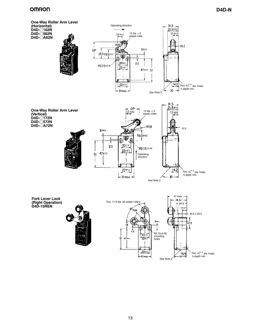
13
One-Way Roller Arm Lever(Vertical)D4D-j172ND4D-j572ND4D-jA72N
One-Way Roller Arm Lever(Horizontal)D4D-j162ND4D-j562ND4D-jA62N
12 dia. × 5plastic roller
Two, 4+0.150 dia. holes5 depth min.
Two, 4+0.150 dia. holes5 depth min.
12 dia. × 5plastic roller
Operating direction
Operatingdirection
10.2
Fork Lever Lock(Right Operation)D4D-15REN
47 max.
20.5 x 20.5
Two, 4+0.150 dia. holes5 depth min.
Two, 17.5 dia. x8 rubber rollers
R2.15±0.05mountingholes
See Note 2.
See Note 2.
See Note 2.

D4D-N
14
Cat WhiskerD4D-jj80N
Fork Lever Lock(Left Operation)D4D-15LEN
Plastic RodD4D-jj87N
20.5 x 20.5
Two, 4+0.150 dia. holes5 depth min.
Sealing cap
R2.15±0.5mountingholes
16.6 dia.
1.2-dia.stainlesssteel wire
Two, 4+0.150 dia. holes5 depth min.
Sealingcap
Resin rod
16.6 dia.
R2.15±0.5mountingholes
47 max.
20.5 x 20.5
Two, 4+0.150 dia. holes5 depth min.
Two, 17.5 dia. x8rubber rollers
R2.15±0.05 mounting holes
See Note 2.
See Note 2.
See Note 2.
D4D-N
15
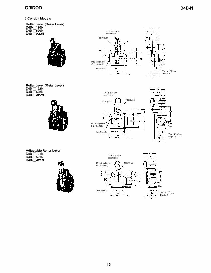
2-Conduit Models
Roller Lever (Resin Lever)D4D-j120ND4D-j520ND4D-jA20N
17.5 dia. x 6.8resin roller
Depth: 5Two, 4 +0.15
0 dia.
Mounting holes(R2.15±0.05) Cap
25 dia.
Resin lever20.5×20.5
See Note 2.
Roller Lever (Metal Lever)D4D-j122ND4D-j522ND4D-jA22N
17.5 dia. x 6.8resin roller
Depth: 5Two, 4 +0.15
0 dia.
Mounting holes(R2.15±0.05) Cap
25 dia.
Resin lever 20.5 X 20.5R20 to 65
See Note 2.
Adjustable Roller LeverD4D-j121ND4D-j521ND4D-jA21N
Depth: 5Two, 4 +0.15
0 dia.
17.5 dia. x 6.8resin roller
Cap
Mounting holes(R2.15±0.05)
25 dia.
20.5×20.5R20 to 65
See Note 2.
D4D-N
16
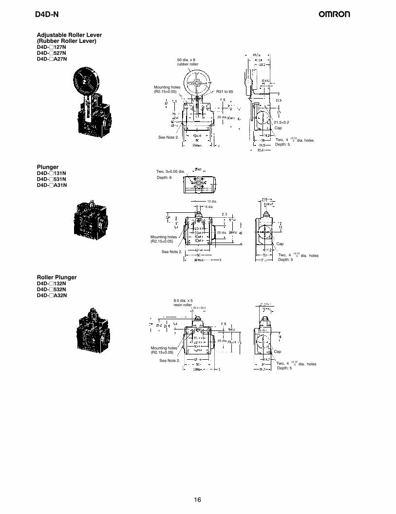
Adjustable Roller Lever(Rubber Roller Lever)D4D-j127ND4D-j527ND4D-jA27N
Depth: 5Two, 4 +0.15
0 dia. holes
50 dia. x 8rubber roller
Cap
Mounting holes(R2.15±0.05)
25 dia.
21.5±0.2
20.5×20.5
R31 to 65
See Note 2.
PlungerD4D-j131ND4D-j531ND4D-jA31N
Depth: 5Two, 4 +0.15
0 dia. holes
Cap
Depth: 6
Mounting holes(R2.15±0.05)
25 dia.
6 dia.
12 dia.
Two, 3±0.05 dia.
See Note 2.
Roller PlungerD4D-j132ND4D-j532ND4D-jA32N
9.5 dia. x 5resin roller
Depth: 5Two, 4 +0.15
0 dia. holes
CapMounting holes(R2.15±0.05)
25 dia.
20.5×20.5
See Note 2.
D4D-N
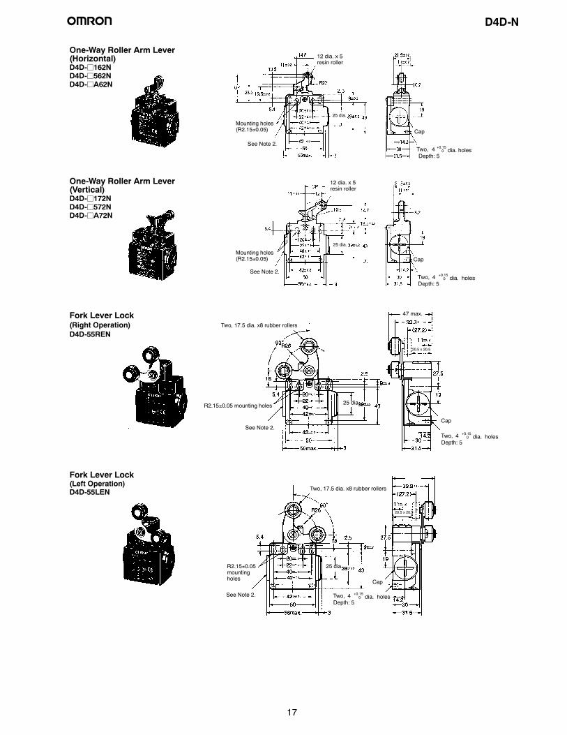
17
One-Way Roller Arm Lever(Horizontal)D4D-j162ND4D-j562ND4D-jA62N
Depth: 5Two, 4 +0.15
0 dia. holes
12 dia. x 5resin roller
CapMounting holes(R2.15±0.05)
25 dia.
See Note 2.
One-Way Roller Arm Lever(Vertical)D4D-j172ND4D-j572ND4D-jA72N
12 dia. x 5resin roller
Depth: 5Two, 4 +0.15
0 dia. holes
CapMounting holes(R2.15±0.05)
25 dia.
See Note 2.
Fork Lever Lock(Right Operation)D4D-55REN
Two, 17.5 dia. x8 rubber rollers
R2.15±0.05 mounting holes
Cap
47 max.
20.5 x 20.5
25 dia.
Depth: 5Two, 4 +0.15
0 dia. holes
See Note 2.
Fork Lever Lock(Left Operation)D4D-55LEN
R2.15±0.05mountingholes Cap
Two, 17.5 dia. x8 rubber rollers
20.5 x 20.5
25 dia.
Depth: 5Two, 4 +0.15
0 dia. holesSee Note 2.
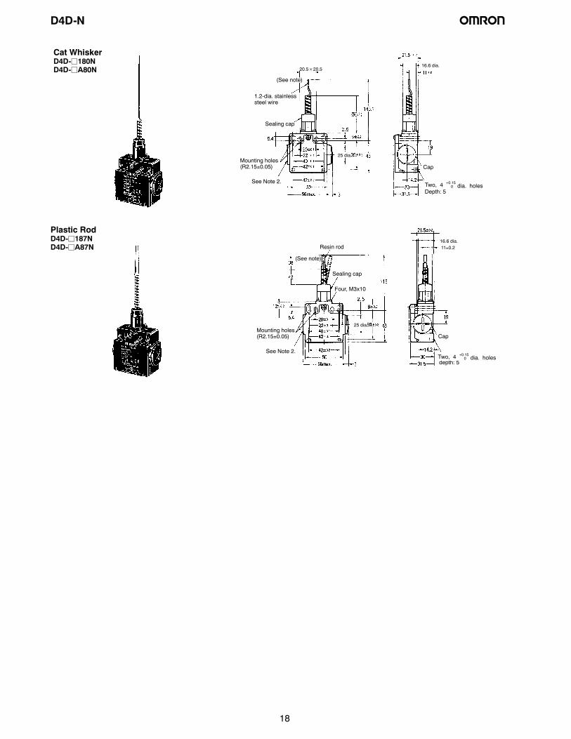
D4D-N
18
Cat WhiskerD4D-j180ND4D-jA80N
Cap
Depth: 5Two, 4 +0.15
0 dia. holes
1.2-dia. stainlesssteel wire
Sealing cap
Mounting holes(R2.15±0.05)
25 dia.
16.6 dia.
(See note)
20.5×20.5
See Note 2.
Plastic RodD4D-j187ND4D-jA87N Resin rod
Sealing cap
Cap
depth: 5Two, 4 +0.15
0 dia. holes
Mounting holes(R2.15±0.05)
Four, M3x10
16.6 dia.
(See note)
25 dia.
11±0.2
See Note 2.
D4D-N
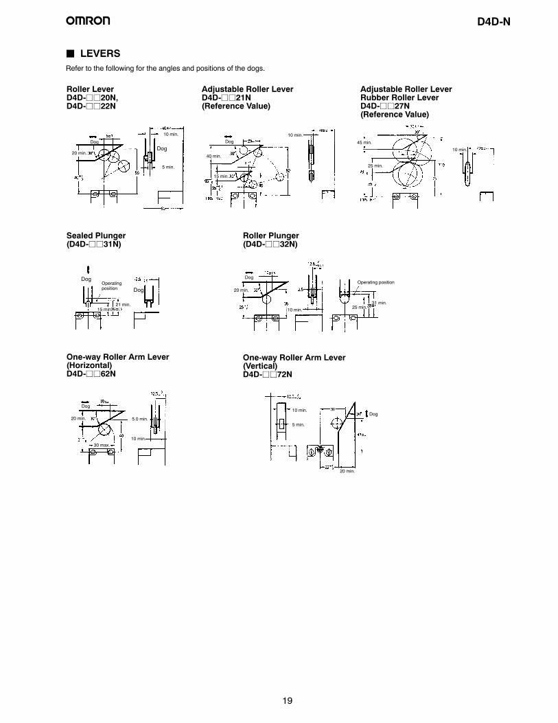
19
J LEVERSRefer to the following for the angles and positions of the dogs.
Roller LeverD4D-jj20N,D4D-jj22N
Adjustable Roller LeverD4D-jj21N(Reference Value)
Adjustable Roller LeverRubber Roller LeverD4D-jj27N(Reference Value)
Sealed Plunger(D4D-jj31N)
Roller Plunger(D4D-jj32N)
One-way Roller Arm Lever(Horizontal)D4D-jj62N
One-way Roller Arm Lever(Vertical)D4D-jj72N
DogDog
20 min.
5 min.
10 min.
Dog10 min.
40 min.
15 min.
25 min.
10 min.
Dog
Dog
21 min.15 min.
Dog
20 min.
10 min.
31 min.
Dog
20 min.
10 min.
5.0 min.
10 min.
5 min.
20 min.
45 min.
Operatingposition
Operating position
25 min.
Dog
30 max.

D4D-N
20
Precautions! CAUTION
Do not use metal connectors or conduits to wire the LimitSwitch, otherwise the conduit of the Limit Switch may breakand an electric shock may be received.
• If the D4D-jN is applied to an emergency stop circuit orsafety circuit for prevention of injury, use a D4D-jN modelthat has an NC contact equipped with a force-separationmechanism, and make sure that the D4D-jN operates in thepositive mode. Furthermore, secure the D4D-jN with screwsor equivalent parts that are tightened in a single direction sothat the D4D-jN cannot be easily removed. Then provide aprotection cover for the D4D-jN and post a warning labelnear the D4D-jN.
• Be sure to connect a fuse with a breaking current 1.5 to 2times larger than the rated current to the Limit Switch in par-allel in order to protect the Limit Switch from damage due toshort-circuiting.
• When using the Limit Switch for the EN ratings, use the gI orgG 10-A fuse.
J CORRECT USEOperating EnvironmentThe Limit Switch is intended for indoor use only. Using the LimitSwitch outdoors may result in a malfunction.
Correct Tightening TorqueA loose screw may result in a malfunction. Be sure to tighteneach screw to the proper tightening torque as shown below.
No. Type Torque
1 Terminal screw 0.59 to 0.78 N S m
2 Cover mounting screw 0.78 to 0.88 N S m
3 Head mounting screw 0.78 to 0.88 N S m
4 Lever mounting screw 1.57 to 1.77 N S m
5 Switch mounting screw(M4)
0.49 to 0.69 N S m
6 Connector 1.77 to 2.16 N S m1.37 to 1.77 N S m(see note)
7 Cap screw 1.27 to 1.67 N S m
Note: This applies to the 1/2-14NPT connector.
MountingFasten the Switch with two M4 Allen-head bolts and washers. Pro-vide a stud with a diameter of 4-0.05/-0.15 and a height of 4.8 mmmax. at two places as shown below so that the Switch is firmly fixedat four points.
Mounting Holes/Studs
1-Conduit Models
4.8 mm high max.4--0.05--0.15 dia.
4.8 mm high max.4 --0.15 dia.--0.05
2-Conduit Models
D4D-N
21
Changing the Lever Angle• To change the angle of the lever, loosen the lever mounting
screw. Then the lever can be set at any angle in 7.5°increments.
• The length of a variable roller lever can be changed byloosening the lever mounting screw.
• The lever mounting position may be inside out after removingthe lever mounting screw. Make sure that the lever will nottouch the Switch when the lever is mounted inside out.
Changing the Head DirectionIf the head direction has been changed, check the torque of eachscrewandmakesure that the screwsare freeof foreign substances,and that each screw is tightened to the proper torque.
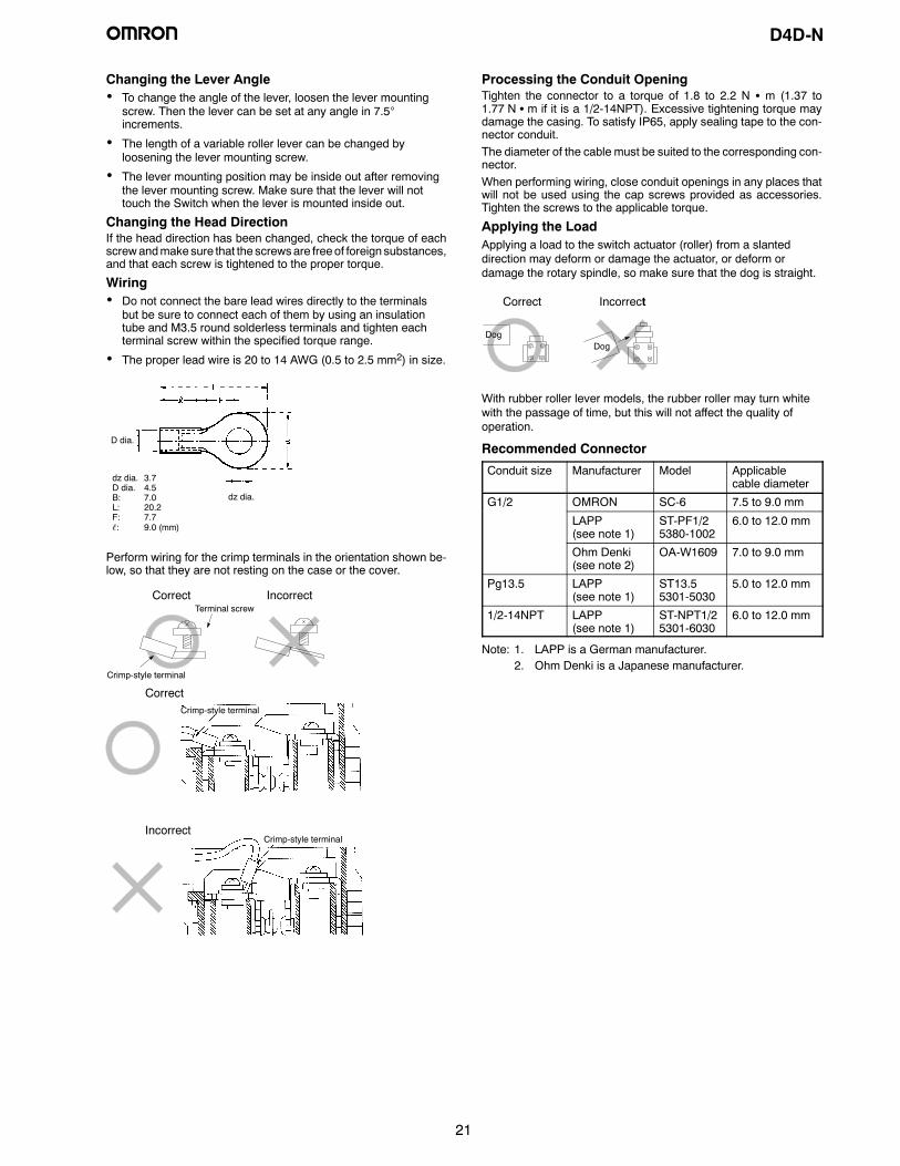
Wiring• Do not connect the bare lead wires directly to the terminals
but be sure to connect each of them by using an insulationtube and M3.5 round solderless terminals and tighten eachterminal screw within the specified torque range.
• The proper lead wire is 20 to 14 AWG (0.5 to 2.5 mm2) in size.
dz dia. 3.7D dia. 4.5B: 7.0L: 20.2F: 7.7ℓ: 9.0 (mm)
D dia.
dz dia.
Perform wiring for the crimp terminals in the orientation shown be-low, so that they are not resting on the case or the cover.
Crimp-style terminal
Terminal screwCorrect Incorrect
Crimp-style terminal
Crimp-style terminal
Correct
Incorrect
Processing the Conduit OpeningTighten the connector to a torque of 1.8 to 2.2 N S m (1.37 to1.77 N S m if it is a 1/2-14NPT). Excessive tightening torque maydamage the casing. To satisfy IP65, apply sealing tape to the con-nector conduit.The diameter of the cable must be suited to the corresponding con-nector.When performing wiring, close conduit openings in any places thatwill not be used using the cap screws provided as accessories.Tighten the screws to the applicable torque.
Applying the LoadApplying a load to the switch actuator (roller) from a slanteddirection may deform or damage the actuator, or deform ordamage the rotary spindle, so make sure that the dog is straight.
DogDog
Correct Incorrect
With rubber roller lever models, the rubber roller may turn whitewith the passage of time, but this will not affect the quality ofoperation.
Recommended Connector
Conduit size Manufacturer Model Applicablecable diameter
G1/2 OMRON SC-6 7.5 to 9.0 mm
LAPP(see note 1)
ST-PF1/25380-1002
6.0 to 12.0 mm
Ohm Denki(see note 2)
OA-W1609 7.0 to 9.0 mm
Pg13.5 LAPP(see note 1)
ST13.55301-5030
5.0 to 12.0 mm
1/2-14NPT LAPP(see note 1)
ST-NPT1/25301-6030
6.0 to 12.0 mm
Note: 1. LAPP is a German manufacturer.2. Ohm Denki is a Japanese manufacturer.
OMRON ON-LINEGlobal - http://www.omron.comUSA - http://www.omron.com/oeiCanada - http://www.omron.ca
ALL DIMENSIONS SHOWN ARE IN MILLIMETERS. To convert millimeters into inches, divide by 25.4
Cat. No. GC SAFETY-2 Printed in USA
OMRON CANADA, INC.885 Milner AvenueToronto, Ontario M1B 5V8
416-286-6465
OMRON ELECTRONICS LLCOne Commerce DriveSchaumburg, IL 60173
847-843-7900For US technical support or other inquiries:
800-556-6766
2/03 Specifications subject to change without notice