d5-1 communication standards within ban and pan · 2.3body area networks and personal ... d5-1...
TRANSCRIPT

Remote Accessibility to Diabetes Management and Therapy in
Operational healthcare Networks.
REACTION (FP7 248590)
D5-1 Communication standards within BAN and PAN
Date 2010-08-31
Version 1.1
Dissemination Level: Public

D5-1 Communication standards within BAN and PAN REACTION (FP7 248590)
VERSION 1.1 2 of 95 DATE 2010-08-30
Table of Content
1 Executive summary ................................................................................................. 6
2 Introduction................................................................................................................ 8
2.1 Overview of the REACTION project .................................................................. 8 2.2 Wired and Wireless communications ................................................................ 8
2.2.1 Electromagnetic spectrum.......................................................................... 9 2.2.2 OSI model ................................................................................................... 11
2.3 Body Area Networks and Personal Area Networks ...................................... 13
2.4 Purpose, context and scope of this deliverable ............................................. 15 2.4.1 Structure of the Document ....................................................................... 16
3 Network communication standards & technologies .................................... 17
3.1 Wireless communications.................................................................................. 17 3.1.1 Bluetooth (IEEE 802.15.1) ....................................................................... 17
3.1.2 Bluetooth Low Energy............................................................................... 25 3.1.3 ZigBee (IEEE 802.15.4)............................................................................ 26
3.1.4 Z-Wave ........................................................................................................ 30 3.1.5 WiFi (IEEE 802.11).................................................................................... 32 3.1.6 RFID............................................................................................................. 35
3.1.7 IrDA .............................................................................................................. 37 3.1.8 Near Field Communication....................................................................... 39
3.1.1 Wireless USB ............................................................................................. 41 3.2 Wired communications ...................................................................................... 43
3.2.1 RS-232 ........................................................................................................ 43
3.2.2 USB.............................................................................................................. 45 3.3 Summary & Comparison of Communication Standards............................... 48
4 Networking and discovery ................................................................................... 52
4.1 Device and sensor discovery............................................................................ 52 4.1.1 UPnP ........................................................................................................... 52
4.1.2 SLP .............................................................................................................. 55 4.1.3 SDP.............................................................................................................. 56
4.1.4 Jini 56 4.1.5 RESTful ....................................................................................................... 57
4.1 P2P technology ................................................................................................... 58
4.2 Networked smart objects ................................................................................... 61 4.2.1 Smart object design................................................................................... 62
4.2.2 Lightweight operating systems and stacks ............................................ 63 4.2.3 IPSO ............................................................................................................ 65 4.2.4 Wireless Sensing of contextual information .......................................... 66
4.3 IPv6 ....................................................................................................................... 69 4.3.1 6LoWPAN ................................................................................................... 70
4.3.1 IPv6 in healthcare ...................................................................................... 72
5 Hydra Middleware in REACTION ........................................................................ 74
5.1 Hydra run-time architecture .............................................................................. 74
5.2 Discovery and management of devices in Hydra .......................................... 77
6 Data Semantic Interoperability ........................................................................... 80

D5-1 Communication standards within BAN and PAN REACTION (FP7 248590)
VERSION 1.1 3 of 95 DATE 2010-08-30
6.1 IEEE 11073.......................................................................................................... 80 6.2 Continua Health Alliance ................................................................................... 82
7 Definitions, Terminologies and Acronyms...................................................... 88
7.1 Abbreviations and Acronyms ............................................................................ 88
8 List of figures and tables...................................................................................... 91
8.1 Tables ................................................................................................................... 91 8.2 Figures.................................................................................................................. 91
9 References ............................................................................................................... 93

D5-1 Communication standards within BAN and PAN REACTION (FP7 248590)
VERSION 1.1 4 of 95 DATE 2010-08-30
Document control page
Code D5.1_Communication-standards-within-BAN-and-PAN.doc
Version 1.1
Date 2010-08-31
Dissemination level PU
Category R
Participant Partner(s) FORTH-ICS, CNET, DELTA
Author(s) Georgios Zacharioudakis, Franco Chiarugi, Vishwas Lakkundi, Peter Rosengren, Rasmus Grønbek Haahr
Verified and approved by
Work Package WP5
Fragment No
Distribution List All
Abstract This deliverable contains an overview of the communication standards that exist in the fields of Body Area Networks (BAN) and Personal Area Networks (PAN) and a comparison of their aspects and their relevance to REACTION.
Comments
Status
Draft Task leader accepted
WP leader accepted Technical supervisor accepted Medical Engineering supervisor accepted
Medical supervisor accepted Quality manager checked Project Coordinator accepted
Action requested
to be revised by partners involved in the preparation of the deliverable
for approval of the task leader for approval of the WP leader for approval of the Technical Manager
for approval of the Medical Engineering Manager for approval of the Medical Manager for approval of the Quality Manager
for approval of the Project Coordinator Deadline for action: N/A
Keywords BAN & PAN, communication standards, networking, devices, technologies, protocols
References
Previous Versions
Version Notes
Version Author(s) Date Changes made
0.1 G. Zacharioudakis 2010-06-22 Initial template
0.5 Vishwas Lakkundi, Peter Rosengren, Rasmus Grønbek
Haahr
Contributed content
0.6 G. Zacharioudakis Integrated all contributions
0.9 G. Zacharioudakis 2010-08-09 Revised and completed some sections. First draft available for internal review .
1.0 G. Zacharioudakis, Rasmus Grønbek Haahr, Karsten
Hoppe, Stelios Louloudakis
2010-08-28 Revised based on comments from the internal review ers
1.1 G. Zacharioudakis 2010-08-30 Minor corrections.
1.1 2010-08-31 Final version submitted to the European Commission

D5-1 Communication standards within BAN and PAN REACTION (FP7 248590)
VERSION 1.1 5 of 95 DATE 2010-08-30
Internal review history
Reviewed by Date Comments made
DELTA (Rasmus Grønbek
Haahr, Karsten Hoppe)
2010-08-24 Add introduction for various topics
(wired & wireless communications, networking layers, BAN & PAN etc). Re-structure the organization of the
document. Modify various sections or parts of the document.
FORTHNET (Stelios Louloudakis)
2010-08-20 Correction of various errors. Suggestions for re-structuring of
some sections.

D5-1 Communication standards within BAN and PAN REACTION (FP7 248590)
VERSION 1.1 6 of 95 DATE 2010-08-30
1 Executive summary
The aim of this document is to present a brief analysis, in the context of the REACTION project, of the communication standards and technologies within Body
Area Networks (BAN) and Personal Area Networks (PAN). This deliverable is an outcome of the task T5.1 ―Network architecture and analysis‖, as described in the description of work.
The REACTION project aims to develop a technological platform and pilot
applications to improve long term diabetes management in inpatient and outpatient environments. Features of the technology include continuous blood glucose monitoring, monitoring of significant events, monitoring and predicting risks and/or
related disease indicators, decision on therapy and treatments, education on life style factors such as obesity and exercise and, ultimately, automated closed-loop delivery
of insulin. The current document presents an overview of the communication technologies and
standards which apply to body area and personal area networks, their main characteristics and a brief comparison of their key properties in relation to
REACTION project. In addition, the document presents an overview of other networking issues of BAN and PANs, relevant to REACTION, such as device and service discovery, P2P technologies and networks of smart objects.
Also, the document includes an overview of the Hydra middleware which is going to
be used in the REACTION project. The Hydra middleware will be the connecting software component between the sensors, devices and the back-end systems, and a key module for the integration of these to a functioning system. As such, its role to
the formulation and communication in BAN and PANS is crucial and we focus on its architecture and its abilities on discovery and management of devices, as many
protocols and standards will have to be implemented in Hydra in order to be used in REACTION.
Finally, the document presents Continua Health Alliance and the ISO/IEEE 11073 standard, as a means to seamlessly integrate the various different communication
protocols and enable interoperability in using them, resulting in an architecture which does not care nor is restricted by the current communication technologies. Although it addresses issues of higher layers than the communication technologies which is the
core of this document, it is important to present why the adoption of higher layer standards can homogenize the lower layers and improve the interoperability of the
various system components. The deliverable aims to assist the architectural and technical decisions and to be
used in the design procedures of the various sub-systems of the project. The target audience of this document is all REACTION partners and particularly the technical
partners responsible for designing and implementing technical solutions. The document assumes a general knowledge on network communications and electrical engineering.

D5-1 Communication standards within BAN and PAN REACTION (FP7 248590)
VERSION 1.1 7 of 95 DATE 2010-08-30
The document structure includes an overview of the various communication standards in BAN and PAN in section 3 and a summary with a small comparison
between their technological characteristics in section 3.3. In section 4 there is an introduction to networked smart objects and in section 4.1 a presentation of various
discovery protocols. In section 4.1 is included a presentation of relevant projects which use P2P technology and in section 5 there is an overview of the Hydra middleware, as the mediator component which will encapsulate the presented
technologies and architecture. Finally in section 6 we present an overview of the Continua Health Alliance and the ISO/IEEE 11073 standard.

D5-1 Communication standards within BAN and PAN REACTION (FP7 248590)
VERSION 1.1 8 of 95 DATE 2010-08-30
2 Introduction
2.1 Overview of the REACTION project
The REACTION project aims to develop an integrated approach to improved long term management of diabetes through continuous glucose monitoring, monitoring of
significant events, monitoring and predicting risks and/or related disease indicators, decision on therapy and treatments, education on life style factors such as obesity
and exercise and, ultimately, automated closed-loop delivery of insulin. Technically, the REACTION platform will be structured as an interoperable peer-to-
peer communication platform based on service oriented architecture (SoA) where all functionalities, including the measurement acquisition performed by sensors and/or
devices, are represented as services and applications consist of a series of services properly orchestrated in order to perform a desired workflow. The REACTION platform also will make extensive use of dynamic ontologies and advanced data
management capabilities offering algorithms for clinical assessment and evaluation.
A range of REACTION services will be developed targeted to the management of insulin-dependent diabetic patients in different clinical environments. The services aim to improve continuous glucose monitoring (CGM) and insulin therapy by
contextualized glycemic control based on patient activity, nutrition, interfering drugs, stress level, etc. for a proper evaluation and adjustments of basal and bolus doses.
Decision support will assist healthcare professionals, patients and informal carers to make correct choices about glucose control, nutrition, exercise and insulin dosage, and thus to reach a better management of diabetes therapy.
REACTION will further develop complementary services targeted at the long term
management of all diabetic patients, Type I and Type II. Integrated monitoring, education, and risk evaluation will ensure all patients remain at healthy and safe blood glucose levels, with early detection of onset of complications.
Security and safety of the proposed services will be studied and necessary solutions
to minimize risks and preserve privacy will be implemented. Legal framework for patient safety and liability as well as privacy and ethical concerns will be analyzed and an outline of a policy framework will be defined. Moreover, impacts on health
care organizations and structures will be analyzed and health-economics and business models will be developed.
2.2 Wired and Wireless communications
We define communication (wired or wireless), as the transmission of data or
information over a distance. The distances involved can vary from short (i.e. a few centimetres) to very long (i.e. thousands of kilometres). Depending on the medium over which we transfer this information, we either categorize the communication to
wired or wireless. The term ―wired‖ is used in a more general meaning, to include not only plain wires but also fiber optic communication, or any other solid transport
medium. A typical case of wired communication is telephone networks.

D5-1 Communication standards within BAN and PAN REACTION (FP7 248590)
VERSION 1.1 9 of 95 DATE 2010-08-30
On the other hand, with wireless communication we refer to any kind of communication which does not use wires, electrical conductors or any other type of
solid medium. Again, the distance can vary from very short to very long and some typical examples of wireless communication are television, GPS receivers and
remote control units for home appliances. There are several other categorizations of communications, depending on the primary categorization criterion that we choose. We can use as criteria the distance
of communication, the speed, the transport medium etc. Specifically in wireless communications, we can further categorize the communication to various types
according the specific spectrum in which they operate, such as RF (radio frequency), microwave and infrared communication.
2.2.1 Electromagnetic spectrum
In contrast to the wired communication, where we can use multiple wires to avoid
interference problems and we can have dedicated wiring for specific purposes, in wireless communication there is one single resource, used as the transmission medium, shared by all. Light, colours, microwaves, radio; they all make use of the
electromagnetic spectrum (see Figure 1).
Figure 1 : Electromagnetic spectrum range and usage
1
1 http://www.kollewin.com/EX/09-15-03/SURA_Electromagnetic_Spectrum_Full_Chart.jpg

D5-1 Communication standards within BAN and PAN REACTION (FP7 248590)
VERSION 1.1 10 of 95 DATE 2010-08-30
Each frequency has different physical properties, which are utilized in order to achieve greater effectiveness of the specific purpose it is used. Depending on the
frequency (or inversely, by the wavelength) a wave can be transmitted in greater or shorter distances, it can be absorbed or distorted by the landscape or the human
body, it can affect human tissues or it can require small amounts of energy. For this reason, some specific frequencies have greater value for communication purposes than others.
The frequencies of the electromagnetic spectrum which are appropriate for use for
communications are treated as a public resource, so their usage is regulated by national authorities or international organisations (such as ITU –International Telecommunication Union2). These organizations determine which frequency ranges
can be used for what purpose and by whom. This regulation permits on one hand the interoperability of systems through the usage of common frequencies and on the
other hand the protection from interferences, especially on critical communications, as it is aviation for example. The usage of some frequencies can be restricted (e.g. for military purposes), can be regulated by the guidelines of national or international
authorities (e.g. television), or can be publicly available (e.g. ISM band -Industrial, Scientific and Medical band).
The ISM band is of particular importance to the REACTION project, because it is commonly used by most of the communication technologies which are used in BAN
and PAN applications. The ISM band is actually a set of bands, which cover multiple frequencies. The Table 1 below summarizes the frequencies of the ISM band:
Frequency range [Hz] Center frequency [Hz] Availability
6.765–6.795 MHz 6.780 MHz Subject to local regulations
13.553–13.567 MHz 13.560 MHz
26.957–27.283 MHz 27.120 MHz
40.66–40.70 MHz 40.68 MHz
433.05–434.79 MHz 433.92 MHz
902–928 MHz 915 MHz Subject to local regulations
2.400–2.500 GHz 2.450 GHz
5.725–5.875 GHz 5.800 GHz
24–24.25 GHz 24.125 GHz
61–61.5 GHz 61.25 GHz Subject to local regulations
122–123 GHz 122.5 GHz Subject to local regulations
244–246 GHz 245 GHz Subject to local regulations Table 1 : ISM band frequencies
3 4
As we know from physics, the superposition of different waves results in a new wave pattern. This means that in the telecommunications domain, the transmission in the same frequencies of two or more transmitters, causes interferences to the signal as it
travel from its source to the receiver. When we cannot avoid the case where many transmitters transmit to the same frequency, as it frequently happens in the ISM band
since its usage is unrestricted and publicly available, we use technological methods
2 http://www.itu.int/
3 http://en.wikipedia.org/wiki/ISM_band
4 http://www.itu.int/ITU-R/terrestrial/ faq/index.html#g013

D5-1 Communication standards within BAN and PAN REACTION (FP7 248590)
VERSION 1.1 11 of 95 DATE 2010-08-30
to achieve correct transmission of the signal, which are called modulation methods. Using modulation, we can achieve correct transmission of a signal, even if there are
simultaneous transmissions over the same frequencies. The most fundamental digital modulation methods, which are also referred later to this document when we present
specific communication standards, are PSK (phase-shift keying), FSK (frequency-shift keying), ASK (amplitude-shift keying) and QAM (quadrature amplitude modulation). There are many variations of these modulation techniques; for more
details on these and many more see [WikiMod].
2.2.2 OSI model
Communication systems are complex structures which involve many technological or scientific disciplines. In order to sub-divide the complexity of the communications to
smaller parts, the OSI (Open Systems Interconnection) model has been developed from the ISO (International Organization for Standardization) which is a model of how
to divide the communication into layers. A layer is a collection of conceptually similar functions that provide services to the layer above it and receive services from the layer below it.
Figure 2 : OSI model
5
The OSI layers along with their services and responsibilities are shown schematically
in Figure 2. In brief, their description is as follows [OSIModel]: 1. Physical. Defines the electrical and physical specifications for devices and the
transmission medium (such as copper, optical cable or radio frequencies). The
5 http://www.networkstuff.eu/images/6/61/OSI_General_v1.png

D5-1 Communication standards within BAN and PAN REACTION (FP7 248590)
VERSION 1.1 12 of 95 DATE 2010-08-30
major services of this layer are: to establish the connection to the communication medium, to share the communication resources to multiple
users, to modulate the transmitted data over the communication channel, to define electrical and optical signalling, voltage levels, data transmission rates,
as well as mechanical specifications. It is responsible for activating, maintaining and deactivating the physical link. It handles a raw bits stream and places it on the wire to be picked up by the Physical layer at the receiving
node. 2. Data-Link. Provides the procedural means to transfer data between network
entities and to detect and possibly correct errors that may occur in the Physical layer. It provides transparent network services to the Network layer so the Network layer can be ignorant about the underlying physical network
topology. It is responsible for reassembling bits, taken of the wire by the Physical layer, to frames, and makes sure they are in the correct order and
requests retransmission of frames in case an error occurs. It provides error checking and flow control. The Data-Link can be further subdivided to the LLC and the MAC sub-layers.
a. LLC (Logical Link Control) is the upper sub-layer of the Data Link which masks the underlying physical network technologies by hiding their
differences to provide a single interface to the Network layer. Additionally, this layer is responsible for sequencing and acknowledgements of individual frames.
b. MAC (Media Access Control) takes care of physical addressing and allows upper layers access to the physical media, handles frame
addressing, error checking. It converts the frames into bits to pass them on to the Physical layer and vice versa.
3. Network. Converts the segments from the Transport layer into packets (or
datagrams) and is responsible for path determination, routing and the delivery of packets across internetworks. The network layer treats these packets
independently, without recognizing any relationship between those individual packets. It relies on higher layers for reliable delivery and sequencing. It is also responsible for logical addressing, for example IP addressing.
4. Transport. It converts the data received from the upper layers into segments
and prepares them for transport. The Transport layer is responsible for end-to-
end (source-to-destination) delivery of entire messages. It allows data to be transferred reliably and uses sequencing to guarantee that it will be delivered in the same order that it was sent. It also provides services such as error
checking and flow control (in software). 5. Session. Establishes, maintains, and terminates end-to-end connections
(sessions) between two applications on two network nodes. It controls the dialogue between the source and destination node.
6. Presentation. This layer 'represents' the data in a particular format to the
Application layer. It defines encryption, compression, conversion and other coding functions. It provides independence from data representation by
translating between application and network formats. It transforms data into the form that the application accepts.
7. Application. It provides network services directly to the user's application
such as a web browser or email client so this layer is said to be "closest to the user". This layer interacts with software applications that implement a
communicating component. Application layer functions typically include

D5-1 Communication standards within BAN and PAN REACTION (FP7 248590)
VERSION 1.1 13 of 95 DATE 2010-08-30
identifying communication partners, determining resource availability, and synchronizing communication.
The OSI model and its layers can help us understand some fundamental
categorization of topics in wireless communications, their interaction, overlapping or conflicts in the context of the REACTION project. The structure of this document has loosely followed the same layering of these topics, i.e. the network communication
standards and technologies, the higher level networking issues and the data structures and their interoperation on a semantic level.
The physical properties of the electromagnetic spectrum and the frequencies which are used in RF communication are in close relation with the Physical layer of each of the communication standards which we examine later. The operating frequencies
affect the achieved data rate, the energy consumption and the possible interferences from other applications.
The networking in wireless communications is another important topic. Networks can form dynamically when nodes come to proximity, efficient discovery of devices and services is an important issue and the architecture of the formed network affects the
layers and applications which operate on it. The middleware which runs to the communicating nodes is of high importance. In the
REACTION project specifically, the Hydra middleware affects and is affected by the various standards and the network topologies which come to action, since some components must be implemented to support them or services running over the
network must be able to use them. Finally, the data structures and the corresponding standards (such as IEEE 11073)
can provide a common view on the underlying data, homogenize the various networks and abstract the specific technology barriers.
2.3 Body Area Networks and Personal Area Networks
In the communications field, one categorization of the various types of networks is performed based on the typical or maximum area which a network can cover and
transmit data. In contrast with the terms LAN (Local Area Network) and WAN (Wide Area Network), which are used to denote the type of a network which covers an area
such as a house, a housing complex or a city, the terms BAN (Body Area Network) and PAN (Personal Area Network) are used to denote a network of a smaller scale, analogous to humans, their dimensions and their personal area, i.e. a few meters or
less. These terms are used to denote the proximity of interest (depending on the application) to a specific person and not the actual capability of their underlying
technology, which in some cases might be capable of delivering a wider coverage. So, the same network and the same technology could be characterized by different terms depending on its application, and not its maximum coverage allowed by the
technology which may vary. Based on this reason, we use the terms BAN and PAN interchangeably or in conjunction many times, depending on the specific case.
The term BAN usually refers to networks with very limited coverage which cover only a person‘s body or refers to networks with applications having to do only with that
specific person and not his surroundings. The term PAN usually refers to wider networks in contrast to a BAN, or the applications which use it involve not only that
specific person but also his surroundings, e.g. other computers in proximity area, environmental sensors or devices of other individuals in proximity.

D5-1 Communication standards within BAN and PAN REACTION (FP7 248590)
VERSION 1.1 14 of 95 DATE 2010-08-30
In this document, we consider a BAN to be a subset of PAN, which requires coverage of smaller area, which involves sensors or devices in very close proximity
to an individual, and which consists of wearable or even implantable sensors. We use the term PAN to refer to somewhat more extended coverage networks, which
involve sensors or devices close to an individual (e.g. inside the same room) and which might involve not only sensors monitoring an individual but also his environment and his surroundings. Both BAN and PANs can be used for
communication among the sensors and devices themselves, or for connecting to a higher level network.
The rapid growth of sensors, low power integrated circuits, wireless communications and relevant technologies, has enabled also extensive development of applications in
the fields of PAN and BAN, such as monitoring, healthcare, ambient intelligence applications, home automation etc. In order to provide smart, intuitive and
unrestricting applications to the users, the preferred communication technologies for PAN and BAN are wireless communications, since they allow the user to be on the move, to formulate dynamic networks by adding and removing components at will,
and to integrate seamlessly without requiring high expertise from users. Since wireless communication is the norm in BAN and PAN, we frequently refer to them as
WBAN (wireless BAN) and WPAN (wireless PAN) respectively. From the abovementioned applications, the healthcare domain applications are of
highly importance to the REACTION project. A number of sensors can be integrated into a wireless body area network, which can be used for computer assisted
rehabilitation or early detection of medical conditions. Continuous monitoring, logging of vital signs, automatic acquisition of measurements, remote monitoring by doctors, smart systems which act to save the life of a patient are some of these applications.
The BAN and PAN area applications rely on the feasibility of wearing sensors or even implanting very small bio-sensors inside the human body that are comfortable
and that don't impair normal activities. The implanted sensors in the human body will collect various physiological changes in order to monitor the patient's health status no matter their location. The information will be transmitted wirelessly to an external
processing unit. This device will instantly transmit all information in real time to the doctors throughout the world. If an emergency is detected, the physicians will
immediately inform the patient through the computer system by sending appropriate messages or alarms, or specific actions could be taken automatically based or smart systems and rules defined by the doctors. In addition, PAN applications can collect
information also about the environment of a patient, which helps doctors and the smart systems to correlate the collected health measurements, to filter or to validate
them. This is another reason why we use in conjunction the terms BAN and PAN in this document, because it is not always clear in which circumstances is enough for the networks and their applications to cover only the body area, and in which we
need information about the environment and the wider personal area of a patient.
A typical BAN or PAN could include or require vital sign monitoring sensors and devices, motion detectors (such as accelerometers) or other kind of equipment to track and locate an individual, environmental sensors and communication technology
(usually wireless) for the communication between those network components or communication and transmission of gathered information to other, back end systems.

D5-1 Communication standards within BAN and PAN REACTION (FP7 248590)
VERSION 1.1 15 of 95 DATE 2010-08-30
In this context, a number of issues and challenges may exist when we refer to BAN and PAN. Interoperability, security, privacy, measurement validation, data
consistency, communication efficiency, power consumption and other issues arise and usually a trade-off must be made between the desired functionality and the
technological feasibility.
2.4 Purpose, context and scope of this deliverable
In this document, in order to assist the architecture design and the technological decisions for the communication between intra-PAN components, and between PAN components with backend infrastructure, we collect and analyse all the
communication protocols and technologies which apply in the body and personal area networks. We interpret the body and personal area networks, as short-range
communication (within a range of a few meters) and we select the standards which apply to this rule, excluding wide area communication standards and non-standardized technologies. We categorize the distinct technological properties of
each technology and we make a comparison between them in terms of energy consumption, cost, speed and data rate, adoption by the industry and availability of
devices and applications. Although the document focuses on the communication standards within BAN and PAN, we bear in mind that it will be part of a wider system, which communicates with backend systems, so we try to keep up also with standards
which can be used in gateway or mediator components.
Apart from the communication standards, we present also some other protocols and technologies, such as data exchange guidelines, device discovery, and P2P architectures which are necessary to clarify and complement the usage of the
abovementioned standards. In addition, it has been decided within the project consortium (see DoW) that the Hydra middleware will be used in REACTION as a
software component to integrate various technologies, to mediate in the communication process between various devices and sensors, and to facilitate interoperability of technologies and semantic integration of data. In this context, we
include an overview of the Hydra middleware, and its underlying assistive architectures such as P2P networking technology, discovery protocols and the notion
of networked smart objects. With this information, it can be clearly indicated the possible use of the standards presented previously, and how these technologies play an assistive or complementary role.
In addition, we believe that the semantic integration of the exchanged data in health
systems and frameworks, such as the REACTION project, can enormously enhance the interoperability and homogenization of the underlying communication layers, and provide an abstraction which makes it easier (or meaningless) to choose a specific
communication protocol as it unifies all of them under the same data model. In this context, the project consortium has chosen to follow the guidelines of Continua
Health Alliance, which aims at ensuring interoperability between components, systems, and subsystems incorporated within health systems. We include in this document a short overview on Continua Alliance, its architecture and its guidelines,
along with the IEEE 11073 standard on which the Personal Health Devices standards of the various communication protocols are based on.

D5-1 Communication standards within BAN and PAN REACTION (FP7 248590)
VERSION 1.1 16 of 95 DATE 2010-08-30
The scope of this document is to cover all the standards used within personal area networks, in the context of REACTION project and the health domain, and is
addressed to all partners of the consortium and especially to the technical partners who will make architectural choices and will design the various REACTION systems.
The document assumes a general knowledge of network communications and electrical engineering.
2.4.1 Structure of the Document
The remaining document is structured as follows: In chapter 3 we list the communication standards and technologies for the BAN and
PAN, a brief overview of their architecture and their technological characteristics and a short summary which compares them in the context of REACTION. In chapter 4 we
examine networking and discovery issues, networked smart objects, device and sensor discovery protocols, and peer-to-peer technology. In chapter 5 we take a look on the Hydra middleware, its architecture, its discovery and management
mechanisms and its role in the context of REACTION. In chapter 6 we make a brief overview of the data structures and data interoperability issues in healthcare and how
they are handled with the introduction of relevant standards such as IEEE 11073 and the guidelines of the Continua Alliance.

D5-1 Communication standards within BAN and PAN REACTION (FP7 248590)
VERSION 1.1 17 of 95 DATE 2010-08-30
3 Network communication standards & technologies
This section aims at providing a brief overview of the existing communication standards in the area of BAN and PAN. We deal only with technologies which have
been standardized and are not proprietary or still experimental.
3.1 Wireless communications
3.1.1 Bluetooth (IEEE 802.15.1)
3.1.1.1 Overview
Bluetooth is an open wireless technology standard for exchanging data over short distances from fixed and mobile devices, by using short length radio waves and
creating personal area networks (PANs). Bluetooth was initially created by telecoms vendor Ericsson in 1994, and today is managed by the Bluetooth Special Interest Group. Although it was originally conceived as a cable replacement technology, a
wireless alternative to RS-232 data cables, in its current specification it can connect several devices, forming small short range networks.
In its initial version v1.0, Bluetooth had many problems and the interoperability between manufacturers was limited. In later versions Bluetooth specification was
improved and it was ratified as an IEEE standard (IEEE 802.15.1), part of the 802.15 working group for Wireless Personal Area Networks (WPANs). In the latest version of
the Bluetooth specification v4.0 [BTspec4], the Core Specification has included 3 protocols, the Classic Bluetooth which consists of legacy protocols, Bluetooth High Speed which is based on Wi-Fi and Bluetooth Low Energy. Bluetooth Low Energy will
be further analysed to section 3.1.2 of this document due to the highly importance it holds to REACTION project.
3.1.1.2 Architecture
Bluetooth uses a radio technology called frequency-hopping spread spectrum, which chops up the data being sent and transmits chunks of it on up to 79 bands of 1 MHz
width in the range 2402-2480 MHz. This is in the globally unlicensed Industrial, Scientific and Medical (ISM) 2.4 GHz short-range radio frequency band. In classic Bluetooth, which is also referred to as basic rate (BR) mode, the
modulation is Gaussian frequency-shift keying (GFSK). In later versions the modulation was improved to Adaptive frequency-hopping spread spectrum (AFH),
which improves resistance to radio frequency interference by avoiding the use of crowded frequencies in the hopping sequence.

D5-1 Communication standards within BAN and PAN REACTION (FP7 248590)
VERSION 1.1 18 of 95 DATE 2010-08-30
Figure 3 : Example of Bluetooth network topology (M: Master, S: Slave, P; Parked)
Bluetooth is a packet-based protocol with a master-slave structure. A master Bluetooth device can communicate with up to seven slave devices and this network
group of up to eight devices is called a piconet. All devices share the master's clock and the devices can switch roles, by agreement, and the slave can become the
master at any time. The Bluetooth Core Specification allows connecting two or more piconets together to form a scatternet, with some devices acting as a bridge by simultaneously playing the master role in one piconet and the slave role in another.
Within a common location a number of independent piconets may exist. Each piconet
has a different physical channel (that is a different master device and an independent timing and hopping sequence.) A Bluetooth device may participate concurrently in two or more piconets. It does this on a time-division multiplexing basis. A Bluetooth
device can never be a master of more than one piconet, since the piconet is defined by synchronization to the master‘s Bluetooth clock. A Bluetooth device may be a
slave in many independent piconets. A Bluetooth device that is a member of two or more piconets is said to be involved in a scatternet. Involvement in a scatternet does not necessarily imply any network
routing capability or function in the Bluetooth device. The Bluetooth core protocols do not offer such functionality, which is the responsibility of higher level protocols
outside the scope of the Bluetooth core specification. Packet exchange is based on the basic clock, defined by the master, which ticks at
312.5 µs intervals. Two clock ticks make up a slot of 625 µs; two slots make up a slot pair of 1250 µs. In the simple case of single-slot packets the master transmits in even
slots and receives in odd slots; the slave, conversely, receives in even slots and transmits in odd slots. Packets may be 1, 3 or 5 slots long but in all cases the master transmition will begin in even slots and the slave transmition in odd slots.

D5-1 Communication standards within BAN and PAN REACTION (FP7 248590)
VERSION 1.1 19 of 95 DATE 2010-08-30
At any given time, data can be transferred between the master and one other device. The master switches rapidly from one device to another in a round-robin fashion.
Simultaneous transmission from the master to multiple other devices is possible via broadcast mode, although it is not used much.
The Bluetooth data transport system follows a layered architecture and all Bluetooth operational modes follow the same generic transport architecture, which is shown in
Figure 4
Figure 4 : Bluetooth generic data transport architecture
For efficiency and legacy reasons, the Bluetooth transport architecture includes a
sub-division of the logical layer, distinguishing between logical links and logical transports. This sub-division provides a general (and commonly understood) concept
of a logical link that provides an independent transport between two or more devices. More details about the entities which build the hierarchy of the transport architecture are shown in Figure 5.
Figure 5 : Bluetooth transport architecture entities and hierarchy

D5-1 Communication standards within BAN and PAN REACTION (FP7 248590)
VERSION 1.1 20 of 95 DATE 2010-08-30
3.1.1.2.1 Operational procedures and modes
The typical operational mode of a Bluetooth device is to be connected to other Bluetooth devices (in a piconet) and exchanging data with that Bluetooth device. As
Bluetooth is an ad-hoc wireless communications technology there are also a number of operational procedures that enable piconets to be formed so that the subsequent communications can take place. Procedures and modes are applied at different
layers in the architecture and therefore a device may be engaged in a number of these procedures and modes concurrently.
Inquiry (Discovering) Procedure. Bluetooth devices use the inquiry
procedure to discover nearby devices, or to be discovered by devices in their locality.
Extended Inquiry Response. An Extended Inquiry Response can be used to
provide miscellaneous information during the inquiry response procedure. Paging (Connecting) Procedure. The procedure for forming connections. It
is an asymmetrical procedure and requires that one Bluetooth device carries out the page (connection) procedure while the other Bluetooth device is connectable (page scanning.)
Connected Mode. After a successful connection procedure, the devices are
physically connected to each other within a piconet. This means that there is a
piconet physical channel to which they are both connected, there is a physical link between the devices, and there are also logical links.
Hold Mode. Hold mode is not a general device mode, but applies to
unreserved slots on the physical link. When in this mode, the physical link is only active during slots that are reserved for the operation of certain link types.
Sniff Mode. Sniff mode is not a general device mode. Devices that have their
logical transports in sniff mode may use the absent periods to engage in
activity on another physical channel, or to enter reduced power mode. Parked State. A slave device may remain connected to a piconet but have its
physical link in the parked state. When the physical link to a slave device is parked this means that there are restrictions on when the master and slave may communicate.
Role switch procedure. The role switch procedure is a method for swapping
the roles of two devices connected in a piconet.
Enhanced Data Rate. Enhanced data rate (EDR) is a method of extending
the capacity and types of Bluetooth packets for the purposes of increasing the
maximum throughput, providing better support for multiple connections, and lowering power consumption, while the remainder of the architecture is unchanged.
3.1.1.2.2 Profiles
A Bluetooth profile is an interface specification for the communication between devices. The way a device uses Bluetooth technology depends on its profile capabilities, in other words which subset of Bluetooth profiles is compatible with in
order to use the desired services. A Bluetooth profile resides on top of the Bluetooth Core Specification and, optionally,
additional protocols. The profiles provide standards which manufacturers follow to
D5-1 Communication standards within BAN and PAN REACTION (FP7 248590)
VERSION 1.1 21 of 95 DATE 2010-08-30
allow devices to use Bluetooth in the intended manner and each profile specification contains information usually regarding the dependencies on other formats, on the
suggested user interface formats and on specific parts of the Bluetooth protocol stack which are used by the protocol. Below are listed some indicative profiles.
Serial Port Profile (SPP). SPP defines how to set up virtual serial ports and
connect two Bluetooth enabled devices. It emulates a serial cable to provide a simple substitute for existing RS-232, including the familiar control signals.
Personal Area Networking Profile (PAN). PAN describes how two or
more Bluetooth enabled devices can form an ad-hoc network and how the same mechanism can be used to access a remote network through a network
access point, i.e. makes it possible for a Bluetooth device to access LAN, WAN or Internet via another device that has a physical connection to the network. This profile replaces the earlier LAP profile (LAN Access Profile).
Health Device Profile (HDP). HDP is a profile designed to facilitate
transmission and reception of Medical Device data. The Health Device Profile
consists of two parts. One specifies the transfer protocols that should be used for medical data in the Bluetooth stack. The other describes the structure of the actual medical data. While the first part is specified by the Bluetooth SIG
Medical Working Group directly, the other part refers to the ISO/IEEE 11073 specification which defines the data exchange between medical devices to
various transmission media.
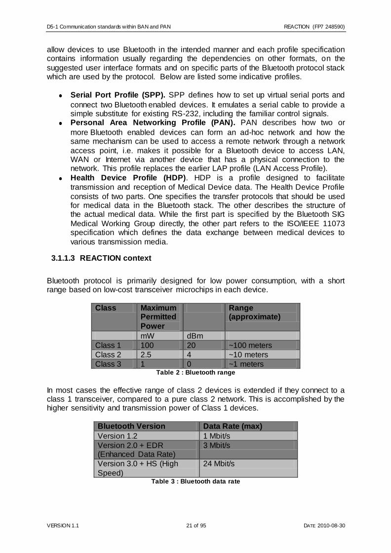
3.1.1.3 REACTION context
Bluetooth protocol is primarily designed for low power consumption, with a short range based on low-cost transceiver microchips in each device.
Class Maximum
Permitted
Power
Range (approximate)
mW dBm
Class 1 100 20 ~100 meters
Class 2 2.5 4 ~10 meters
Class 3 1 0 ~1 meters Table 2 : Bluetooth range
In most cases the effective range of class 2 devices is extended if they connect to a class 1 transceiver, compared to a pure class 2 network. This is accomplished by the higher sensitivity and transmission power of Class 1 devices.
Bluetooth Version Data Rate (max)
Version 1.2 1 Mbit/s
Version 2.0 + EDR (Enhanced Data Rate)
3 Mbit/s
Version 3.0 + HS (High
Speed)
24 Mbit/s
Table 3 : Bluetooth data rate

D5-1 Communication standards within BAN and PAN REACTION (FP7 248590)
VERSION 1.1 22 of 95 DATE 2010-08-30
While the Bluetooth Core Specification does mandate minimums for range, the range of the technology is application specific and is not limited. Manufacturers may tune
their implementations to the range needed to support individual use cases. In the protocol which features additional High Speed capabilities, the fast data rate is not
performed by Bluetooth link itself. Instead, the Bluetooth link is used for negotiation and establishment, and the high data rate traffic is carried over an 802.11 link. In latest version of the Specification, Bluetooth v4.0, the Bluetooth High Speed has
been included as a separate protocol to the Core Specification.
Technology properties Bluetooth
Primary usage intention, typical applications
Domestic / industrial
Topology Star (piconet)
Interoperability
Transmit frequency 2400 MHz
Throughput 1-2 Mbit/s
Current consumption @ 3,7 V (Tx)
< 30 mA
Price (component cost, royalty fees)
$ 4-5
# Suppliers > 10
Range ~ 10 m (class 2) 1 / 10 / 100 m
Frequency hopping, # channels
Yes
Encryption Yes
IEEE standard 802.15.1
Max number of nodes in a net
8/piconet
Max number of node hops N/A
Modulation type GFSK / AFH Table 4 : Bluetooth technology properties
The alternative technologies for Bluetooth are seemingly two. For short-range and
low energy communication an alternative technology is ZigBee, while for wider range and higher data transfer rates is Wi-Fi.
Although Bluetooth and Wi-Fi have many similar applications such as setting up networks, printing, or transferring files, Wi-Fi is intended primarily for resident
equipment and its applications, in wireless local area networks (WLAN). Wi-Fi is intended as a replacement for cabling for general local area network access in work
areas. Bluetooth is intended for non-resident equipment and its applications, in wireless personal area networks (WPAN). Wi-Fi is wireless version of a traditional Ethernet network, and requires configuration to set up shared resources, transmit
files, and to set up audio links, such as headsets and hands-free devices. Wi-Fi uses the same radio frequencies as Bluetooth, but with higher power, resulting in a faster
connection and better range from the base station, but also higher power consumption.

D5-1 Communication standards within BAN and PAN REACTION (FP7 248590)
VERSION 1.1 23 of 95 DATE 2010-08-30
ZigBee is a prominent technology standard, although it hasn‘t been highly adopted by a large groups of manufacturers and developers yet. It targets mainly the low cost,
low energy, and low complexity sensors and devices, such as the control applications industry.
3.1.1.3.1 Bluetooth & Health applications
Bluetooth is a near-distance wireless technology that is very suitable for many
medical applications. Wireless sensors in hospitals, homes (assisted living) and applications using a GSM//3GPP networked infrastructure for forwarding medical
data to a central server are just few examples but particular applications using Bluetooth in mobile phones as kind of a gateway are very interesting and comparable to the intentions of REACTION.
Bluetooth Radio chipsets are utilized in millions of phones worldwide, resulting in
constant downward pressure for ROM-based HCI Bluetooth Radios. Nonetheless, in order to use a HCI BT Radio, a separate host microcontroller is needed and this host controller need to be able to run the Bluetooth Host Stack, the IEEE 11073 code, as
well as the specific device application. As long as the proper Bluetooth Host Stack is used, this hosted approach is radio independent, and allows the manufacturer to
replace radios as the specification and need change, without having to re-engineer the software/platform and framework. The other model (embedded approach) is using Flash to utilize a Bluetooth radio which supports the complete Bluetooth Host
Stack, IEEE 11073 specification and an Application Framework running on the Bluetooth Radio‘s baseband. While this embedded approach sometimes result in a
lower upfront cost, maintaining this framework can be complex and the design is tied to a specific radio implementation.
Bluetooth SIG, the industrial association for Bluetooth manufacturers, has standardized the Bluetooth Health Device Profile (HDP (Figure 6)) for transmitting
medical data using Bluetooth where HDP is an application profile that allows for source devices, such as blood pressure monitors, weight scales, and glucose meters to exchange data with sink devices such as mobile phones, laptops and health
appliances. In REACTION the Bluetooth can be seen as a core part of the product strategy and therefore it is essential to select a robust and radio/platform/OS
independent Bluetooth Host Stack. The selected Host Stack should support the latest Bluetooth specifications because the reason is that the Bluetooth specifications are constantly evolving with new profiles and features, such as Bluetooth Low Energy.
The chosen REACTION stack should allow a fair degree of abstraction from the Operating System and Radio/Hardware dependencies, allowing the platform to
seamlessly migrate from one host stack version to another.

D5-1 Communication standards within BAN and PAN REACTION (FP7 248590)
VERSION 1.1 24 of 95 DATE 2010-08-30
Figure 6 : Bluetooth HDP architecture
Bluetooth is currently a short range point to point wireless technology with moderate throughput. The Bluetooth SIG [BTSIG] has created a Health Care Profile that has
been adopted as a Continua profile. Continua Health Alliance (see section 6.2), a coalition of health care and technology companies charged with establishing a
system of interoperable personal telehealth solutions, selected Bluetooth wireless technology (IEEE 802.15) for its health device guidelines. Once finalized, Continua will include the upcoming Bluetooth wireless technology specification in version two
of its Continua Health Alliance Design Guidelines. The selection of Bluetooth technology extends the current Continua standard for the Bluetooth Health Device
Profile, according to Bluetooth Special Interest Group (SIG). Therefore, Bluetooth is (besides ZigBee) regarded as the main communication protocol for the networked infrastructure of REACTION.
Bluetooth SIG also works closely with the previously described IEEE 11073 protocol which standardizes the format for medical data (chapter 6.1). The Health Device
Profile therefore consists of two parts (Figure 7). One specifies the transfer protocols that should be used for medical data in the Bluetooth stack. The other describes the
structure of the actual medical data. While the first part is directly specified by the Bluetooth SIG Medical Working Group, the other part refers to the ISO/IEEE 11073 specification and thereby defines the data exchange between medical devices to
various transmission media.
D5-1 Communication standards within BAN and PAN REACTION (FP7 248590)
VERSION 1.1 25 of 95 DATE 2010-08-30
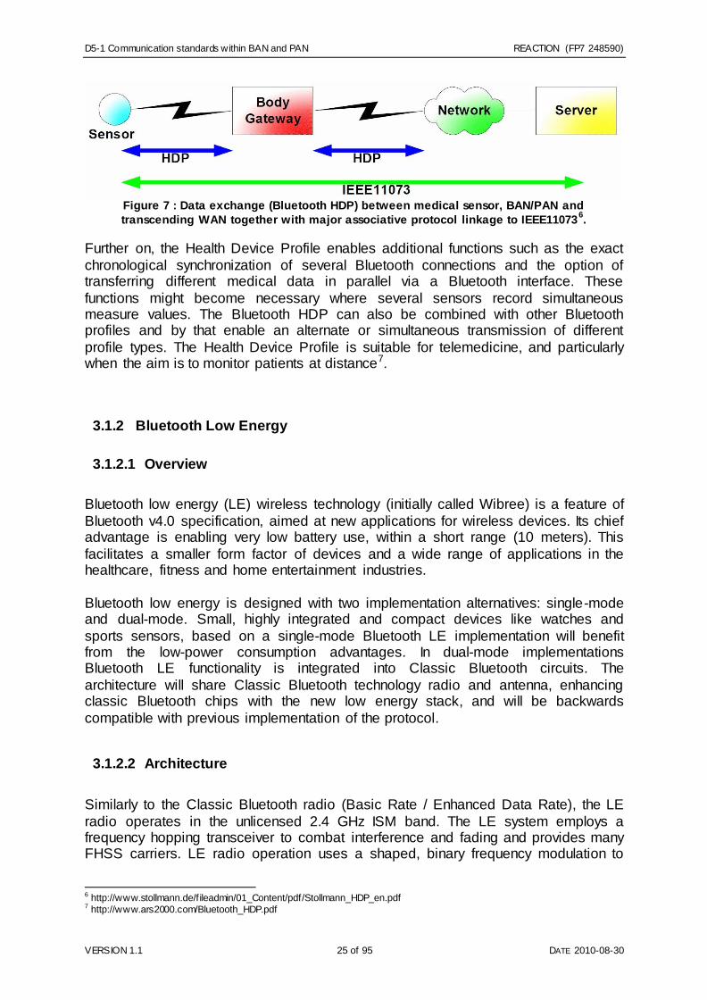
Figure 7 : Data exchange (Bluetooth HDP) between medical sensor, BAN/PAN and
transcending WAN together with major associative protocol linkage to IEEE110736.
Further on, the Health Device Profile enables additional functions such as the exact
chronological synchronization of several Bluetooth connections and the option of transferring different medical data in parallel via a Bluetooth interface. These
functions might become necessary where several sensors record simultaneous measure values. The Bluetooth HDP can also be combined with other Bluetooth profiles and by that enable an alternate or simultaneous transmission of different
profile types. The Health Device Profile is suitable for telemedicine, and particularly when the aim is to monitor patients at distance7.
3.1.2 Bluetooth Low Energy
3.1.2.1 Overview
Bluetooth low energy (LE) wireless technology (initially called Wibree) is a feature of
Bluetooth v4.0 specification, aimed at new applications for wireless devices. Its chief advantage is enabling very low battery use, within a short range (10 meters). This
facilitates a smaller form factor of devices and a wide range of applications in the healthcare, fitness and home entertainment industries.
Bluetooth low energy is designed with two implementation alternatives: single-mode and dual-mode. Small, highly integrated and compact devices like watches and
sports sensors, based on a single-mode Bluetooth LE implementation will benefit from the low-power consumption advantages. In dual-mode implementations Bluetooth LE functionality is integrated into Classic Bluetooth circuits. The
architecture will share Classic Bluetooth technology radio and antenna, enhancing classic Bluetooth chips with the new low energy stack, and will be backwards
compatible with previous implementation of the protocol.
3.1.2.2 Architecture
Similarly to the Classic Bluetooth radio (Basic Rate / Enhanced Data Rate), the LE
radio operates in the unlicensed 2.4 GHz ISM band. The LE system employs a frequency hopping transceiver to combat interference and fading and provides many FHSS carriers. LE radio operation uses a shaped, binary frequency modulation to
6 http://www.stollmann.de/f ileadmin/01_Content/pdf/Stollmann_HDP_en.pdf 7 http://www.ars2000.com/Bluetooth_HDP.pdf

D5-1 Communication standards within BAN and PAN REACTION (FP7 248590)
VERSION 1.1 26 of 95 DATE 2010-08-30
minimize transceiver complexity. The symbol rate is 1 Megasymbol per second (Ms/s) supporting the bit rate of 1 Megabit per second (Mb/s).
LE employs two multiple access schemes: Frequency division multiple access
(FDMA) and time division multiple access (TDMA). Forty (40) physical channels, separated by 2 MHz, are used in the FDMA scheme. Three (3) are used as advertising channels and 37 are used as data channels. A TDMA based polling
scheme is used in which one device transmits a packet at a predetermined time and a corresponding device responds with a packet after a predetermined interval.
Physical links between slaves in a piconet are not supported. At this time, slaves are not permitted to have physical links to more than one master at a time and role
changes between a master and slave device are also not permitted.
Technical Specification Classic Bluetooth Bluetooth LE
Radio frequency 2.4 GHz 2.4GHz Range 10 m (100m on class 3) 10 m Data rate (max.) 1-3 Mb/s 1Mb/s Slaves in a piconet 7 Implementation dependent Voice capability Yes No Network topology Scatternet Star-bus Current consumption <30 mA <15 mA Profiles Yes Yes
Table 5 : Comparison of Bluetooth and Bluetooth LE properties
3.1.3 ZigBee (IEEE 802.15.4)
3.1.3.1 Overview
ZigBee is a WPAN standard for a suite of high level communication protocols using small, low-power digital devices with short range radios. Typically used for industrial
automation and domestic light control applications, ZigBee is governed by the ZigBee Alliance [ZigBee], a group of companies which maintain and publish the standard.
3.1.3.2 Architecture
ZigBee operates in either of the Industrial, Scientific and Medical (ISM) bands around 900 MHz and 2.4 GHz and is intended to be a simpler, low cost alternative to standard Bluetooth. As such, the ZigBee chip vendors typically offer integrated
solutions with ZigBee radio, microprocessor unit and flash in one ASIC. These devices deliver fast wakeup times of approximately 20 msec compared to Bluetooth
system‘s 3 seconds wakeup. This enables the systems to be in sleep mode most of the time and go into idle mode on demand, thereby saving valuable battery power.
ZigBee 2007, now the current stack release, contains two stack profiles, stack profile 1 (simply called ZigBee), for home and light commercial use, and stack profile 2
(called ZigBee Pro). ZigBee Pro offers more features, such as multi -casting, many-to-one routing and high security with Symmetric-Key Key Exchange (SKKE), while

D5-1 Communication standards within BAN and PAN REACTION (FP7 248590)
VERSION 1.1 27 of 95 DATE 2010-08-30
ZigBee (stack profile 1) offers a smaller footprint in RAM and flash. Both offer full mesh networking and work with all ZigBee application profiles.
Working in star, mesh or tree
topology, ZigBee allows systems with up to 65k nodes and up to 32 node hops, equivalent to a total
range of 960 m, given the estimated point-to-point range of up
to 30 meters when operating at 900 MHz.
As a royalty free protocol, capable of operating in either the 900 MHz area with relatively long range as a consequence of longer wavelength, or the globally license
free 2.4 GHz band, ZigBee is the current preferred technology by Sony, Philips, Panasonic and Samsung. ZigBee; however, has yet to find its place as a de facto standard in medical electrical systems. A major obstacle in this effort is the
technology‘s lack of ability to use adaptive frequency hopping for better data integrity.
Below in Table 6 we summarize the most typical properties of the ZigBee protocol:
Unique technology properties ZigBee
Primary usage intention, typical applications Domestic / industrial
Topology Star / mesh / tree
Interoperability No
Transmit frequency 900/2400 MHz
Throughput 40/250 kb/s
Current consumption @ 3,7 V (Tx) 25 mA
Price (component cost, royalty fees) $3
# Suppliers <10
PAN Coordinator
Full Function Device
Reduced Function Device
Device Associations
Figure 8 : ZigBee network topology

D5-1 Communication standards within BAN and PAN REACTION (FP7 248590)
VERSION 1.1 28 of 95 DATE 2010-08-30
Range 30 / 10 m
Frequency hopping, # channels No (16 ch)
Encryption Yes
IEEE standard 802.15.4
Max number of nodes in a net 65.000
Max number of node hops 32
Modulation type QPSK
Table 6 : ZigBee technology properties
3.1.3.3 REACTION context
The ZigBee Alliance has developed a Health Care Profile (Figure 9) that integrates
with the existing ZigBee profiles8. This is also, like for Bluetooth SIG, adopted as a Continua profile where the ZigBee Health Care9 provides a global standard for interoperable wireless devices enabling secure and reliable monitoring and
management of noncritical, low-acuity healthcare services targeted at chronic disease. Furthermore, ZigBee Health Care Profile promotes aging independence,
overall health, wellness and fitness by being designed for use in homes, fitness centers, retirement communities, nursing homes and a variety of medical care facilities. The ZigBee Health care comes with some for the REACTION project
interesting features such as presented in the list below:
Independent aging; makes it possible to reliably monitor patient on remote through real-time location capabilities, safety and activity monitoring sensors for home and professional use.
Chronic disease management; collaboration between devices for managing multiple chronic diseases are opened and functionality promised by
communication stability.
Health and wellness; ZigBee Health Care offers bodily worn sensors for sport
and fitness. Features are: precision time stamping, optimized application data rates, and data streaming.
Technology; the standard that ZigBee incorporates (IEEE 802.15.4) comes
with long battery life, wireless range up to 70m indoors and up to 400m outdoors, networking flexibilities, supports multiple network topologies. By
providing highly scalable solutions for devices ZigBee can integrate monitoring devices such as enabling vital sign monitors to display data from devices.
8 ZigBee selected by Continua Health Alliance for next generation guidelines.‖ 9 June 2009. http://zigbee.org/imw p/idms/popups/pop_download.asp?contentID=16015. 9 ZigBee Alliance. ZigBee Health Care Overview. 14 June 2010.
http://www.zigbee.org/Markets/ZigBeeHealthCare/Overview.aspx

D5-1 Communication standards within BAN and PAN REACTION (FP7 248590)
VERSION 1.1 29 of 95 DATE 2010-08-30
Figure 9 : ZigBee Health Care architecture
According to the ZigBee Health Care it will help people live healthier, happier
independent lives. It lowers healthcare costs by promoting wellness, fitness and reducing in-patient stays, without sacrificing convenience or mobility. A study made by J.H. Hong et al, confirms this by showing that their study using a portable patient
monitoring system that combines PDA and wireless communication technology to obtain biological signals from subjects without any constraints10 is valid and of
favourable kind for the REACTION project. It has two types of transmission mode, which are total signal transmission mode and HR (heart rate)/SC (step count) transmission mode. The developed system uses a ZigBee wireless PAN, which can
be operated in low-power mode. The transmitter has three-axial acceleration sensor, ECG amplifier and ZigBee communication controller. In total signal transmission
mode, it can send data 60 packets per second whose transmission speed corresponds to 300 ECG samples and 60 acceleration samples. In HR/SC transmission mode, it can calculate heart rate from ECG data with 216 samples per
second and step count from acceleration data and send a packet every cardiac cycle. The developed equipment showed the possibility of real-time monitoring of the elderly or the disabled in their daily life11.
10 J.H. Hong, N.J Kim, E.J Cha, and Tae-Soo Lee. ―Development of Zigbee-based Mobile Healthcare System.‖ World Congress on Medical Physics and Biomedical Engineering 2006 August 27 – September 1, 2006 COEX Seoul, Korea “Imaging the Future Medicine”. Seoul, Korea: IFMBE Proceedings, 2006. 4065-4075. 11 http://zigbee.org/imw p/idms/popups/pop_download.asp?contentID=16015

D5-1 Communication standards within BAN and PAN REACTION (FP7 248590)
VERSION 1.1 30 of 95 DATE 2010-08-30
3.1.4 Z-Wave
3.1.4.1 Overview
Z-Wave is a proprietary low-power wireless technology designed specifically for home automation and remote control applications. It is based on an innovative mesh networking technology that routes 2-way command signals from one Z-Wave device
to another, around any obstacles or radio dead spots that might occur throughout the home [ZWave]. Z-Wave control can be added to almost any domestic electronic
device such as appliances, window shades, thermostats and home lighting. Z-Wave unifies all home electronics into an integrated wireless network, with no complicated programming and no new cables to run. Any Z-Wave enabled device can be
effortlessly added to this network, and many non-Z-Wave devices can be made compatible by simply plugging them into a Z-Wave accessory module. All the
products based on the Z-Wave standard are regulated by the Z-Wave Alliance.
3.1.4.2 Architecture
Z-Wave uses a source-routed mesh network topology consisting of one or more controllers and a number of slave devices as shown in Figure 10. A controller
initiates and sends out control commands to other nodes, and slave nodes reply on and execute those commands. Slave nodes can also be ordered to forward commands to other nodes, which make it possible for the controller to communicate
with out of reach nodes. A portable controller can change its position in the network, whereas a static controller has a fixed position. A static controller is typically a
secondary controller in a Z-Wave network.
Figure 10 : Z-Wave topology with control devices and slave nodes
Z-Wave is based on a low bandwidth half-duplex protocol designed for reliable wireless communication in a low cost control network. The protocol's main purpose is to communicate short control messages in a reliable manner from a control unit to
1
2
3
Static controller Routing slave on
battery power
Slaves
Portable controller

D5-1 Communication standards within BAN and PAN REACTION (FP7 248590)
VERSION 1.1 31 of 95 DATE 2010-08-30
one or more nodes in the network. The protocol is not designed to transfer large amounts of data or to transfer any kind of streaming or timing critical data. The
protocol consist of 4 layers, the MAC layer that controls the RF media, the Transfer Layer that controls the transmitting and receiving of frames, the Routing Layer that
controls the routing of frames in the network, and finally the Application Layer that controls the payload in the transmitted and received frames.
3.1.4.3 REACTION context
3.1.4.3.1 Applications
Z-Wave is designed for residential and light commercial applications such as lighting control, thermostats, garage doors and access control, security systems, blinds and drapes, Internet gateways, PC applications, media canter integration, and universal
remote controls as shown in Image y. Unlike conventional home control systems, which require a major up-front investment, Z-Wave is a modular technology and
consumers can add as much or as little control to their homes as they like and build their Z-Wave capabilities over time. Typical application scenarios include: Lighting: One-touch control over any interior or exterior lights, with automated
routines and customized ambient environments. Home entertainment: Effortlessly control multiple systems throughout the house,
through walls, floors and cabinets. HVAC: Control and automate heating, ventilation and air conditioning systems for
maximum comfort and energy savings. Safety and security: Z-Wave devices can activate other Z-Wave devices and
notify the homeowner when security systems are tripped. Windows and coverings: Operate motorized shades by remote control, or through
commands from other Z-Wave devices. Appliance controls: Easily add kitchen, laundry, workroom and garden appliances
to a home network.
Figure 11 : Z-Wave application scenarios

D5-1 Communication standards within BAN and PAN REACTION (FP7 248590)
VERSION 1.1 32 of 95 DATE 2010-08-30
3.1.4.3.2 Comparison with other technologies
Unlike Wi-Fi and other IEEE 802.11-based wireless LAN systems that are designed
primarily for high-bandwidth data, Z-Wave operates in the sub-gigahertz frequency range and is optimized for low-overhead commands. By operating in the 900 MHz
ISM band Z-Wave signals are more powerful and can penetrate through longer distances (including walls, floors, and ceilings) with more power than a 2.4 GHz signal.
Compared to the X10 standard, Z-Wave is more reliable and can handle complex
applications involving hundreds of nodes, whereas X10 is ideal for simple applications such as controlling a lamp across the room. Moreover, unlike powerline carrier systems (such asX10, Insteon, HomePlug CC, CEBus, and LON Radio
Frequency) Z-Wave does not suffer from impedance loading when additional transmitters are added to a network. In fact, the more devices in an RF mesh network
the stronger and more fault-tolerant it becomes. Unlike other common lighting control systems, Z-Wave eliminates the need for a
central controller, thus dramatically lowering the costs, by allowing each device to become an intelligent transceiver by sending and receiving command information
wirelessly.
3.1.5 WiFi (IEEE 802.11)
3.1.5.1 Overview
A wireless fidelity (Wi-Fi) network is used to connect computers to each other, to the
Internet, and also to wired networks. Current Wi-Fi networks operate in the ISM bands (2.4GHz, 5GHz), offer speeds up to 54Mbps and support quality of service (QoS) with managed levels for data, voice as well as video applications. Their
medium access is based on the carrier sense multiple access/collision avoidance (CSMA/CA) principle.
3.1.5.2 Architecture
The IEEE802.11 standard specifies the physical and medium access control layers of a WLAN. The technology is developed and standardized further in a number of
working groups. Below we give a summary of the currently available sub standards:
IEEE 802.11b : This standard - ratified in 1999 - specifies WLAN systems
operating in the frequency range of 2.4 - 2.4835 GHz with a data rate of up to 11 Mbps that is comparable to a fixed Ethernet. It uses direct sequence
spread spectrum/complementary code keying (DSSS/CCK) technology. Moreover, this revision promises interoperability among products of different vendors and compatibility with legacy 802.11 products. Although 802.11b
products have had a significant share in the WLAN market, the problem of interference within the 2.4GHz ISM band from other devices including medical
equipment and household appliances led to the creation of the 802.11a standard operating in the 5 GHz range.

D5-1 Communication standards within BAN and PAN REACTION (FP7 248590)
VERSION 1.1 33 of 95 DATE 2010-08-30
IEEE 802.11a : This standard enables the transmission of voice and data with
high data rates (up to 54 Mbps). The devices operate in frequency bands of 5.15 - 5.35 GHz and 5.47 - 5.725 GHz. These frequency ranges are also used by other applications such as satellites, amateur radio and radar, which have
priority over data communications. The orthogonal frequency division multiplexing (OFDM) transmission technique is used to minimise signal delay
spread that is caused by multi-path propagation especially in indoor environments. The maximum range is about 50 m. However, as 802.11a is not compatible with 802.11b and since the 5 GHz spectrum is not license-free
globally, an enhanced version of 802.11b resulted in the 802.11g standard ratified in 2003.
IEEE 802.11g : Operating in the unregulated 2.4 GHz range, this standard
supports compatibilty with 802.11b devices. It defines two optional modulation schemes: packet binary convolution code (PBCC) that supports 22 Mbps and
33 Mbps data rates, and OFDM that offers 54 Mbps data rate. The disadvantages of IEEE 802.11b concerning non-overlapping networks and
noise sensitivity are also valid for devices built using this standard. It offers a range of 50-100 m.
IEEE 802.11n : IEEE 802.11n builds on previous 802.11 standards by adding
multiple-input multiple-output (MIMO) antenna technology and 40 MHz channels to the PHY layer, and frame aggregation to the MAC layer. It can
operate in both 2.4 GHz and 5 GHz frequency bands. These enhancements offer significant interference mitigation as well as increase in the maximum raw data rate from 54 Mbps to 600 Mbps. Several "draft-N" products based on
draft 2.0 of IEEE 802.11n specification are available in the market since 2007, though the standard has been ratified only recently.
Other IEEE 802.11 working group standards such as 802.11h/j/k/s and so on are extensions or offshoots of Wi-Fi technology that each serves a specific purpose and
there are also other region-specific standardization activities such as HIPERLAN standards developed by ETSI, which are similar to the IEEE 802.11 standards.
Wi-Fi networks support two modes: ad-hoc and infrastructure. The ad-hoc mode allows stations to instantly form a WLAN, allowing all stations to communicate
directly with each other in a peer-to-peer fashion as shown in Figure 12.
Figure 12 : WLAN network topologies: (a) ad-hoc and (b) infrastructure

D5-1 Communication standards within BAN and PAN REACTION (FP7 248590)
VERSION 1.1 34 of 95 DATE 2010-08-30
In the infrastructure mode, the network consists of an access point (AP), through which devices communicate with each other, with the AP coordinating access to a
shared medium among all devices and also ensuring support for QoS. An AP built into a typical Wi-Fi router has a range of 45m indoors and 90m outdoors.
Additionally, Wi-Fi networks support the Wi-Fi protected access (WPA2) security technology, which replaces the less secure wired equivalent privacy (WEP).
3.1.5.3 REACTION context
The application of WLAN has been most visible in the consumer electronics
segment. WLAN being a mature technology has been already implemented in PCs, laptops and even cell phones. Modules for own device development are also available. Off-the-shelf modules are available with a PC card or a PCI interface.
Mainly due to their high output power levels and other constraints, Wi-Fi devices are
not a candidate for wireless body area networking. However, in the context of the REACTION project, WLAN can be used to extend the range of WBAN devices as shown in Figure 13, and to connect to other external networks via a gateway.
Figure 13 : Extending WBAN range using WLAN
However, coexistence of WBAN and WLAN devices is a major challenge as both the technologies operate in the same 2.4 GHz unlicensed ISM band as shown in Figure
14, and moreover, WLAN devices are not only virtually omnipresent but also transmit at a much higher power level. This mutual interference results in significant
deterioration of overall performance. This issue needs to be properly addressed taking into consideration all the realistic scenarios and environments relevant to REACTION.

D5-1 Communication standards within BAN and PAN REACTION (FP7 248590)
VERSION 1.1 35 of 95 DATE 2010-08-30
Figure 14 : WBAN and WLAN channels in the ISM band
3.1.6 RFID
3.1.6.1 Overview
RFID (Radio Frequency IDentification) is a communication technology that enables point-to-point wireless communication, typically used for identifying the whereabouts
of humans, animals or goods, but lately also serving the purpose of payment registration and even sensor applications.
The technology is open, with the RFID Journal as the trusted source of objective information. RFID Journal is founded and edited by guru Mark Roberti.
3.1.6.2 Architecture
An RFID system consists of a reader (―master‖) and a tag (―slave‖). RFID tags come in a broad range of shapes and sizes depending on the frequency range and antenna
design. As a general rule, the decision to use one tag over another depends on several factors including physical environment, required read range, and even the
physical properties of the material that you are tagging. There are three RFID tag types: active, passive, and semi-active. Because active and semi-active tags use an on-board power source to power the tag response, they are typically capable of much
longer read ranges. Passive tags, on the other hand, are powered by electromagnetic energy from an interrogator‘s command. This technique significantly lowers the cost of the tag, but it also limits the read range and creates significant –
but interesting – design challenges. For example, RFID tags specified by the ISO18000-6C standard are passive tags.
A typical RFID tag consists of a microchip attached to a radio antenna mounted on a substrate. The typical chip can store approximately 2 kilobytes of data. For example,
information about a product or shipment—date of manufacture, destination and sell-by date—can be written to a tag.
To retrieve the data stored on an RFID tag, you need a reader. A typical reader is a device that has one or more antennas that emit radio waves and receive signals back
from the tag. The reader then passes the information in digital form to a computer system.

D5-1 Communication standards within BAN and PAN REACTION (FP7 248590)
VERSION 1.1 36 of 95 DATE 2010-08-30
Figure 15 : Typical RFID Reader / Tag system (source: National Instruments 2010)
RFID tags are easy to conceal or incorporate in other items with chip sizes down to 0.05 x 0.05 mm and a cost in 2010 of less than 20 eurocents.
RFID operates at a number of different frequencies:
Low-frequency (LowFID): 125–134.2 kHz and 140–148.5 kHz
High-frequency (HighFID): 13.56 MHz
Ultra-High-frequency (UltraHighFID): 850-950 MHz
Microwave (MicroFID): 2.4-2.45 MHz
LowFID and HighFID tags can be used globally without a license. UltraHighFID and MicroFID tags cannot be used globally as there is no single global standard.
The frequency used affects the read ranges, as antennas are small and inherently ineffective at lower frequencies due to large, negative antenna gains:
Frequency Range Example Standard
LowFID 125 kHz < 20 cm ISO 18000-6A HighFID 13.56 MHz < 100 cm ISO 18000-3 UltraHighFID 900 MHz 10 m ISO 18000-6C MicroFID 2.4 GHz 30 m ISO 18000-4
Table 7 : RFID frequencies and ranges
3.1.6.3 REACTION context
RFID seems to have a promising future in medical electrical systems with more than 60% of the top medical device companies using passive Ultra-HighFID RFID in 2010.
Other applications are:
Contact-less payment (credit card)
Access management
Tracking of goods and RFID in retail
Tracking of persons and animals
Toll collection and contactless payment
Machine readable travel documents
Sensor networks
Airport baggage tracking logistics

D5-1 Communication standards within BAN and PAN REACTION (FP7 248590)
VERSION 1.1 37 of 95 DATE 2010-08-30
RFID tag with antenna, printed on a barcode label
RFID tag for implant into human hand
3.1.7 IrDA
3.1.7.1 Overview
The Infrared Data Association (IrDA) is an industry based group of companies that have developed the specifications for a communication protocol standard for short-
range data exchange over infrared light, for uses such as personal area networks (PANs). The IrDA protocol was developed as a communication standard especially suited for low cost, short range, cross-platform and point-to-point communications at
a range of speeds.
IrDA interfaces are used in commodity appliances, laptops, mobile phones and various test and measurement equipment. Nowadays it is commonly being replaced by Bluetooth and other short-range communication protocols, due to its inherent
disadvantage that it requires direct line of sight between the communicating devices. Apart from IrDA there are also other similar infrared communications systems that
operate outside IrDA specifications and should not be confused with it, such as the CIR (Consumer IR), which is commonly used in TV remote controls, which is based on a raw protocol using sequences of pulse and space.
3.1.7.2 Architecture
In Figure 16 is illustrated the stack of the most common IrDA protocol layers.

D5-1 Communication standards within BAN and PAN REACTION (FP7 248590)
VERSION 1.1 38 of 95 DATE 2010-08-30
Figure 16. IrDA protocol layers
The required layers of an IrDA protocol stack include the following:
IrPHY: Physical Layer. Specifies optical characteristics, encoding of data, and
framing for various speeds. IrLAP: Link Access Protocol. Establishes the basic reliable connection.
IrLMP: Link Management Protocol. Multiplexes services and applications on
the LAP connection.
IAS: Information Access Service. Provides an index service (―yellow pages‖) of
services on a device.
The optional protocols, listed below, depend upon the particular application:
TinyTP: Tiny Transport Protocol. Adds per-channel flow control to keep things
moving smoothly. This is a very important function and is required in many cases.
IrOBEX: The Object Exchange protocol. Easy transfer of files and other data
objects
IrCOMM: Serial and Parallel Port emulation, enabling existing apps that use
serial and parallel communications to use IR without change.
IrLAN: Local Area Network access, enabling walk-up IR LAN access for
laptops and other devices.
The most important specifications of the IrPHY are:
Range: standard: 1 m; low power: 0.2 m
Angle: minimum cone ±15°
Speed: 2.4 Kbit/s to 1 Gbit/s
Modulation: baseband, no carrier
Infrared window
Wavelength: 875 ± 30 nm

D5-1 Communication standards within BAN and PAN REACTION (FP7 248590)
VERSION 1.1 39 of 95 DATE 2010-08-30
Transmission rates fall into various categories, listed in speed order: SIR, MIR, FIR, VFIR, UFIR, and Giga-IR. Serial Infrared (SIR) speeds cover those transmission
speeds normally supported by an RS-232 port (9.6 Kbit/s - 115.2 Kbit/s). The Giga-IR protocol supports transmission speeds of 512 Mbit/s and 1 Gbit/s (125 MB/s) and
uses 2-ASK and 4-ASK modulation.
3.1.7.3 REACTION context
IrDA was popular on laptops and mobile phones during the previous decade. However, it has been displaced by other wireless technologies such as Wi-Fi and
Bluetooth, favoured because they don't need a direct line of sight, and can therefore support a greater set of devices and applications. Its major disadvantage to other wireless technologies is the fact that it requires direct
line of sight between the communicating devices and that it cannot penetrate or by-pass solid objects, such as walls. The user has to align the communicating devices
with each other, or the devices must be anchored to fixed locations, rendering this technology too limiting for usage in Ambient Intelligence applications. Nevertheless, one major advantage of this technology still remains that it is not
based on radio communication, making it usable in some environments where interference makes radio-based wireless technologies unusable or undesirable.
Furthermore, the fact that the communication, although wireless, it is short-range and not omnidirectional, restricts and reduces some security concerns encountered in other wireless technologies. This makes IrDA protocol still usable in some
applications such as payment systems.
3.1.8 Near Field Communication
3.1.8.1 Overview
Near Field Communication (NFC) is a short-range high frequency wireless
communication technology which enables the exchange of data between devices over about a 10-20cm distance. The technology is an extension of the ISO/IEC
14443 proximity card standard, and so it is compatible with existing ISO 14443 smartcards and readers, as well as with other NFC devices.
The ISO/IEC 14443 international standard defines the transmission protocols for communicating with identification cards and proximity cards. The standard defines
the properties for the reader (proximity coupling device, or PCD) and for the card (proximity integrated circuit card, or PICC). The standard is implemented and used in various contactless payment systems, biometric passports, smart cards and
contactless credit cards.
3.1.8.2 Architecture
Similar to ISO/IEC 14443, NFC communicates via magnetic field induction, where
two loop antennas are located within each other's near field. It operates within the unlicensed radio frequency ISM band of 13.56 MHz, with a bandwidth of 14 KHz. The

D5-1 Communication standards within BAN and PAN REACTION (FP7 248590)
VERSION 1.1 40 of 95 DATE 2010-08-30
working distance with compact standard antennas is up to 20 cm, with usual range around 10 cm. The supported data rates are between 100 - 800 Kbit/s.
NFC works in two modes: Passive Communication Mode: The Initiator device (e.g. reader) provides a
carrier field and the Target device (e.g. card) answers by modulating existing field. In this mode, the Target device may draw its operating power from the
Initiator provided electromagnetic field, thus making the Target device a transponder.
Active Communication Mode: Both Initiator and Target device communicate
by alternately generating their own field. A device deactivates its RF field while it is waiting for data. In this mode, both devices typically need to have a power
supply. NFC primarily targets the mobile phones industry, to provide new applications and
usage schemes. For example, the mobile phone could play the role of an ―electronic wallet‖ and displace the usage of credit cards; it could replace smart cards such as
transportation and identification cards. Also, the mobile phone could be a reader for other cards (or other NFC devices), allowing easy transfer of money, reading nearby RFID (such as advertisements), reading food or drug tags, shopping carts in super
markets, etc.
3.1.8.3 REACTION context
Although NFC can be used for wireless communication, is primarily intended for very short range (contactless) but, nevertheless, not remote communication. It does not
support big data rates, and in most implementations it favours the Passive communication mode, which does not assume power supply for both of the
communicating devices. Below we summarize a comparison on some of the technological characteristics between NFC and Bluetooth:
NFC Classic Bluetooth Bluetooth LE
Standardisation
body ISO/IEC Bluetooth SIG
Network type Point to point WPAN Range 10-20cm 10 m (varies with device class) Frequency 13.56 MHz 2.4 GHz Bit-rate 100-800 Kbit/s 1-3 Mbit/s
(2 Mbit/s) 1 Mbit/s
(200 Kbit/s) Set up time < 0.1 s < 6 s < 1 s Power
consumption 15 mA (read) < 30 mA
(varies with class)
< 15 mA (transmit)
Table 8 : Comparison of NFC and Bluetooth technological properties
As we see, NFC is not a candidate technology for replacing Bluetooth or other WPAN communication standards, but it can be an enhancing add-on characteristic on future
mobile phones and other mobile devices such as tablet PCs, which could read RFID tags or smart cards, communicate via point to point links with other devices in proximity. Also, a foreseen usage is to provide faster discovery and connection time
between Bluetooth devices, by taking advantage of the small set up time and low power consumption when they are brought in close proximity. In such a case, instead

D5-1 Communication standards within BAN and PAN REACTION (FP7 248590)
VERSION 1.1 41 of 95 DATE 2010-08-30
of relying to the Bluetooth inquiry and paging procedures, the discovery and connection between Bluetooth devices could be accelerated by information exchange
using NFC.
3.1.1 Wireless USB
3.1.1.1 Overview
Wireless universal serial bus (WUSB) is a logical evolution of USB that combines
speed and security of wired technology with the ease-of-use feature of wireless technology. WUSB intends to support robust high-speed wireless connectivity by
utilizing ultra-wideband (UWB) radio platform developed by the WiMedia Alliance. WUSB is the first high-speed wireless personal interconnection technology that meets the needs of multimedia consumer electronics (CE), PC peripherals, and
mobile devices. It preserves the functionality of wired USB while also unwiring the cable connection and providing enhanced support for streaming media CE devices
and peripherals. Its performance is targeted at 480Mbps at 3 meters and 110Mbps at 10 meters.
3.1.1.2 Architecture
A WUSB system consists of a host and a number of devices. The host can logically
connect to as many as 127 devices [WUSBspec]. It initiates and schedules data transfers to the devices in the cluster, allotting time slots and bandwidth to each connected device. WUSB clusters use a simple hub and spoke topology, with point-
to-point connections between the host and the connected devices as shown in Figure 17.
Figure 17 : WUSB topology
WUSB host is the ‗hub‘ at the centre and each device sits at the end of a ‗spoke‘. Each ‗spoke‘ is a point-to-point connection between the host and the device. This is
similar to the host-to-device architecture used for wired USB. For ease of use, WUSB employs an asymmetric host-centric model that confines complexity to the host. WUSB clusters coexist within a spatially overlapping environment with minimum

D5-1 Communication standards within BAN and PAN REACTION (FP7 248590)
VERSION 1.1 42 of 95 DATE 2010-08-30
interference, thus allowing a number of other WUSB clusters to be present within the same radio cell [WUSBwp].
3.1.1.3 REACTION context
3.1.1.3.1 Applications
Wireless USB benefits from both the success of wired USB in the PC market and growing demand for wireless technologies in the booming CE market. The shift to
wireless revitalises existing markets and contributes to the creation of new markets, particularly for multimedia devices that can take advantage of high data rates. For
instance, WUSB makes possible next-generation notebook PCs with fewer I/O connectors and a more compact design, as well as digital AV equipment that can wirelessly transmit high-definition video as depicted in Figure 18.
In the home environment, WUSB eliminates the tangle of cables connecting PCs and peripherals such as printers, scanners, monitors, and digital cameras. In addition, it
wirelessly connects myriad home products, including PCs, stereos, HDTVs, STBs, DVD players, video recorders, digital AV equipment, and the growing class of devices with rich functionality and multimedia capabilities. It supports individual high-
speed wireless personal area networks (WPAN) for entertainment, home office equipment, gaming, and audio devices.
In the office environment, WUSB offers a broad range of time-saving and productivity-enhancing applications. Users of portable devices such as notebook PCs
and cell phones can connect to printers and scanners quickly and easily as well as share printers, scanners and storage devices, back up files quickly, exchange large
files without sending them through e-mail, and synchronize their documents to a network—all without any wires.
Figure 18 : Typical WUSB usage scenarios
Typical video delivery with standard SDTV/DVD consumes between 3 Mbps and 7 Mbps, while HDTV uses between 19 Mbps and 24 Mbps. A point distribution technology such as WUSB with an effective bandwidth of 480 Mbps could manage
multiple HDTV streams. Host buffering could enable a network backbone to

D5-1 Communication standards within BAN and PAN REACTION (FP7 248590)
VERSION 1.1 43 of 95 DATE 2010-08-30
effectively distribute content to all distribution hosts, enhancing the quality of experience for all users.
A new class of WUSB dual-role devices is projected to eliminate wires in many usage
scenarios and enable new uses not previously possible. These devices will offer both limited host and device capabilities, similar to that experienced with USB On-The-Go. USB OTG is the wired USB specification defining dual-role devices which can act as
either hosts or peripherals, and can connect to PCs or other portable devices through the same connector.
3.2 Wired communications
3.2.1 RS-232
3.2.1.1 Overview
RS-232 (Recommended Standard 232) is a standard for serial binary data and control signals in wired communication between devices, and it was commonly used
in computer serial ports. The standard defines the electrical characteristics and timing of signals, the meaning of signals, and the physical size and pinout of connectors.
For many years, an RS-232-compatible port was a standard feature for wired communications on most computers. It remained in widespread use into the late
1990s but in more recent years it has largely been replaced by other wired interface standards, such as USB. RS-232 is still used to connect older, legacy devices. Since special purpose equipment, as is the case of medical devices, are usually expensive
and are not replaced often if there is not any driving need, we expect that this kind of equipment can still be found in use even in modern facilities, so we include a brief
analysis of the standard to this document for completeness purposes.
3.2.1.2 Architecture
In RS-232, user data is sent as a time-series of bits. Both synchronous and asynchronous transmissions are supported by the standard. In addition to the data
circuits, the standard defines a number of control circuits used to manage the connection between the DTE (Data Terminal Equipment) and DCE (Data Circuit-terminating Equipment). Each data or control circuit only operates in one direction,
which is signalling from a DTE to the attached DCE or the reverse. Since transmit data and receive data are separate circuits, the interface can operate in a full
duplex manner, supporting concurrent data flow in both directions. The standard does not define character framing within the data stream, or character encoding.
RS-232 can be found on different connectors and there are special specifications for each of them, with the most common being Sub-D 25 pins, Sub-D 9 pins and RJ45
(similar to telephone connectors). Each connector corresponds either to a ―male‖ or ―female‖ type connector.
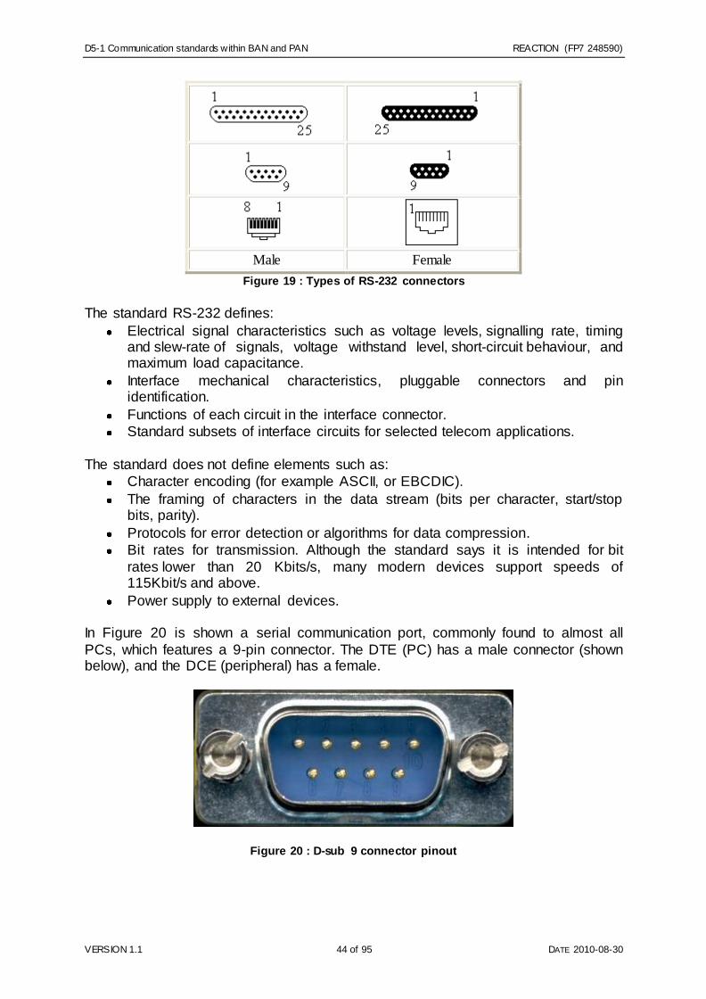
D5-1 Communication standards within BAN and PAN REACTION (FP7 248590)
VERSION 1.1 44 of 95 DATE 2010-08-30
Male Female
Figure 19 : Types of RS-232 connectors
The standard RS-232 defines:
Electrical signal characteristics such as voltage levels, signalling rate, timing and slew-rate of signals, voltage withstand level, short-circuit behaviour, and maximum load capacitance.
Interface mechanical characteristics, pluggable connectors and pin identification.
Functions of each circuit in the interface connector.
Standard subsets of interface circuits for selected telecom applications.
The standard does not define elements such as:
Character encoding (for example ASCII, or EBCDIC).
The framing of characters in the data stream (bits per character, start/stop bits, parity).
Protocols for error detection or algorithms for data compression.
Bit rates for transmission. Although the standard says it is intended for bit
rates lower than 20 Kbits/s, many modern devices support speeds of 115Kbit/s and above.
Power supply to external devices. In Figure 20 is shown a serial communication port, commonly found to almost all
PCs, which features a 9-pin connector. The DTE (PC) has a male connector (shown below), and the DCE (peripheral) has a female.
Figure 20 : D-sub 9 connector pinout

D5-1 Communication standards within BAN and PAN REACTION (FP7 248590)
VERSION 1.1 45 of 95 DATE 2010-08-30
3.2.1.3 REACTION context
Because the application of RS-232 has extended far beyond the original purpose of
interconnecting a terminal with a modem, successor standards have been developed to address the limitations. Today, RS-232 is considered obsolete and it has been
replaced by other technologies such as USB. Nevertheless, many legacy systems which use RS-232 is still possible to be found in usage, since they might be expensive to be replaced or they might be parts of a greater system and replacing
them would require the changing of a lot of components.
Issues with the RS-232 standard include:
The large voltage swings and requirement for positive and negative supplies
increases power consumption of the interface and complicates power supply design. The voltage swing requirement also limits the upper speed of a compatible interface.
Single-ended signalling referred to a common signal ground limits the noise immunity and transmission distance.
Multi-drop connection among more than two devices is not defined. While multi-drop "workarounds" have been devised, they have limitations in speed and compatibility.
Asymmetrical definitions of the two ends of the link make the assignment of the role of a newly developed device problematic; the designer must decide on
either a DTE-like or DCE-like interface and which connector pin assignments to use.
The absence or misconnection of flow control (handshaking) signals, resulting in buffer overflow or communications lock-up.
No method is specified for sending power to a device. Although a small
amount of current can be extracted from the connecting lines, this is only suitable for low power devices.
The connectors recommended in the standard are large compared to current practice.
Incorrect communications function (DTE vs. DCE) for the cable in use, resulting in the reversal of the Transmit and Receive data lines as well as one or more handshaking lines.
Incorrect connector gender or pin configuration, preventing cable connectors from mating properly.
The standard does not define a maximum cable length but instead defines the
maximum capacitance that a compliant drive circuit must tolerate. A widely-used rule of thumb indicates that cables more than 50 feet (~15 metres) long will have too much capacitance, unless special cables are used. By using low-capacitance cables,
full speed communication can be maintained over larger distances up to about 1,000 feet.
3.2.2 USB
3.2.2.1 Overview
Universal Serial Bus (USB) is a specification to establish communication between devices and a host controller (usually personal computers). USB is intended to

D5-1 Communication standards within BAN and PAN REACTION (FP7 248590)
VERSION 1.1 46 of 95 DATE 2010-08-30
replace many varieties of serial and parallel ports, and to connect computer peripherals such as mice keyboard, printers, digital cameras, flash drives etc. For
most of these devices and similar applications USB has become the standard connection method.
3.2.2.2 Architecture
The Universal Serial Bus (USB) is a wired point to point connection technology that is
capable of high throughput (480Mbit/s for USB 2.0 and 4800Mbit/s for USB 3.0). The USB signals are transmitted through a twisted-pair data (channels) cable and prior to
USB 3.0 these commonly used half-duplex differential signalling to reduce the electromagnetic noise effects in long lines. The USB 3.0 uses far more complex by introducing two additional pairs of shielded twisted wires and interoperable contacts.
These data channels permit a higher data rate as well as full duplex operation. A USB connection is always between a host (or a hub, e.g. PC) at the connector end
and a device (or hub's upstream port, e.g. a biosensor's transport gate) at the other end. Transmission in any USB data is toggled in data lines between two different states. USB encodes data using the NRZI convention (i.e. a method of mapping a
binary signal to a physical signal for transmission) and a USB connection is always between a host or hub at the "A" connector end, and a device or hub's "upstream"
port at the other end [USBIF]. The most common and widely used wired protocol to communicate between the data acquisition devices and the hub is USB.
3.2.2.3 REACTION context
3.2.2.3.1 USB in healthcare
The USB Implementers Forum has created a Device Class Definition for Personal Healthcare Devices that has been adopted as a Continua profile. USB defines class
codes to identify any devices functionality and to load device drivers. The relevant class code and USB interface for the REACTION platform is one for personal
healthcare: 0Fh. The main reason USB has become so prevalent is that it is the first of the wired
communication protocols to become a standard of the Continua Health Alliance while offering personalised health and wellness management solutions. Looking for a
higher data rate option (up to 400Mbps) than the first certified communication standard (Bluetooth), Continua gave focus on USB. The USB Implementers Forum had long a working group to solidify the personal healthcare device (PHDC)
specification. Figure 21 shows an example of a USB stack with PHDC support. The new PHDC specification enabled health-related devices to connect via USB to
consumer electronic products, such as PCs and health appliances. Interoperability of health-related devices and consumer electronic products facilitates the communication between patient and doctor, individual and fitness coach, or elderly
person and a remote caregiver.
There are three main areas targeted by the USB personal healthcare device class [USBHealth] [USBPHDD]:

D5-1 Communication standards within BAN and PAN REACTION (FP7 248590)
VERSION 1.1 47 of 95 DATE 2010-08-30
Health and wellness: consumers could use a USB device, such as an exercise watch or a heart rate monitor, to connect to electronic devices, such
as a PC or a mobile phone; this information may be sent to a coach or caregiver for evaluation and assessment
Disease management: individuals with a chronic condition may want to manage their care by sending information from blood pressure cuffs or glucose monitors to tools such as health appliances or mobile health devices;
this information can then be sent to a caregiver for action and analysis Ageing independently: information from USB devices that monitor daily
living, such as motion sensors, can be sent to consumer electronics devices, such as a health appliance or PC, and on to remote caregivers or family members.
In 2008 the Continua Health Alliance approved the PHDC of USB, which is a specific
class for use in home portable medical devices. By then it became approved for use on Continua certified telehealth systems. Freescale Semiconductor provides the industry‘s premier ‗Continua Ready‘ Personal Health Care Device PHDC USB
solution with the Medical Applications USB Stack [USBMedStack]. This stack, based on USB‘s PHDC and IEEE-11073, provides the standard communication interface that
the next-generation medical devices require. The Medical Applications USB Stack is downloadable, easy to use and serves as a complementary source code solution. The stack allows developers to expand the connectivity of their medical devices by
using USB instead of alternative connectivity interfaces. The Medical Applications USB Stack standardises a medical USB device and creates complement with
medical industry standards such as the Continua Health Alliance. The stack expands high-speed connectivity options, speeds up product development and ensures operability across multiple vendors.
Figure 21 : Showing a block diagram of a USB stack with PHDC support.

D5-1 Communication standards within BAN and PAN REACTION (FP7 248590)
VERSION 1.1 48 of 95 DATE 2010-08-30
As the next generation of healthcare will most definitely be the telehealth generation do not only telehealth systems increase the level of patient care, but telehealth also
show promises of lowering healthcare costs. Presumably, the communication technologies used in these systems will come and go and wireless protocols such as
ZigBee and Bluetooth Low Energy are beginning to gain traction in the market as well as within the Continua Health Alliance. But as telehealth also requires a fast data rate and huge install base USB technology ensures that it will continue to be used in
telehealth systems and medical devices for years to come [USB_PHD].
3.3 Summary & Comparison of Communication Standards
It is necessary to stress out that the technologies presented in this document, are not competing in the context of REACTION. Each of these standards has some unique
characteristics which make it stand out, and although it would be ideal for simplicity and interoperability to be able to choose only one technology for all the spectrum of applications in REACTION, it is clearly evident that this is impossible. Not only do we
want to take advantage of all the different characteristics that each technology could offer us, but also there are many custom off-the-shelf devices (COTS) which we want
to take advantage of, which use different technologies or different and incompatible versions of them. Furthermore, from the user perspective, the different kinds of technologies come second to importance, with more important being the ability to use
all of them in a seamless way and to use data structures and semantics as a unifying factor, as we analyse in chapter 6.
Below (Table 9) we summarize some of the key technological characteristics of the most prominent and most suitable for the REACTION project WBAN / WPAN
technologies.

D5-1 Communication standards within BAN and PAN REACTION (FP7 248590)
VERSION 1.1 49 of 95 DATE 2010-08-30
ZW ZB BT BTLE
Primary usage intention, typical applications
Domestic Domestic / industrial
Domestic / industrial Domestic / medical
Topology Mesh Star / mesh / tree Star Star
Interoperability No No Yes Yes
Transmit frequency 900 MHz 900/2400 MHz 2400 MHz 2400 MHz
Throughput 40 kb/s 40/250 kb/s 1-2Mbits (up to 24Mbits at
HighSpeed)
1000 kb/s
Current consumption @ 3,7 V (Tx)
35 mA 25 mA 30 mA 15 mA
Price (component cost, royalty fees)
$4 $3 $1
# Suppliers 1 <10 10+ 10+
Range 30 m 30 / 10 m 10m
(1-100m)
10 m
Frequency hopping, # channels
No (1 ch) No (16 ch) Yes Yes (40 ch)
Encryption Yes Yes Yes Yes IEEE standard No 802.15.4 802.15.1 802.15.1
Max number of nodes in a net 232 65.000 7/piconet , Unlimited/ scatternet
Unlimited
Max number of node hops 4 32 N/A N/A
Modulation type BFSK QPSK GFSK / AFH GFSK
Table 9 : Comparison of various wireless technologies
Of all these wireless technologies, Bluetooth Low Energy seems to stand out as a
preferred technology, for the trade-offs it offers between range, power consumption, data rate, industry acceptance and compatibility/interoperability potentials. BLE is
designed specifically focused at medical devices, offering yearlong battery up-time from a single coin cell, acceptable range (5-10m), high transmission data integrity (40 channels FHSS technique), and the ability to use any coming dual mode Bluetooth
device to act as the counterpart RF endpoint, offering any cellular phone or personal computer in the proximity of the wearer to act as Internet gateway, this again
resulting in vast opportunities in data collection. BLE has faster wakeup times than ZigBee, more channels, frequency hopping, lower power usage, cheaper component cost, no need for transmitter partner other than a standard cell phone or any other BT
device and universal inter-compatibility compared to ZigBee. ZigBee is designed for home automation mesh networks with non-critical data and large(r) batteries. BLE is
designed specifically for transmitting exactly the kind of medical data, REACTION is believed to use; specific condition information with the least possible amount of power. Compared to the RFID, which can be powered entirely from the radio waves
of the master, BLE offers far longer range and faster data rates. Standard Bluetooth, wireless USB and especially Wi-Fi is designed for continuous streaming of data, not
power optimal information packages, and these technologies would seem less optimal if not actually ill-timed for the purpose. IrDA needs somewhat line-of-sight, and RS232 and conventional USB are not wireless, so these technologies should
compete at other premises. Nevertheless, BTLE is still a new technology, with its Specification (Bluetooth v4.0) having been approved only recently, and we expect

D5-1 Communication standards within BAN and PAN REACTION (FP7 248590)
VERSION 1.1 50 of 95 DATE 2010-08-30
that it will take some time for the technology to become widely available to consumer devices and to become a common denominator for the sensor industry.
In Figure 22 are depicted in summary the most prominent wireless technologies in
the WBAN / WPAN area, in terms of their range and their data rate. In the horizontal axis are listed in ascending order of their range, usually in the scale of 1-100 meters, while in the vertical axis they are categorized in order of their (theoretical) data rate.
Since their achieved data rate depends heavily on their power consumption, we can more or less assume that this categorization depicts also the order of magnitude of
their power consumption. The technologies of most relevance to the WBAN / WPAN field have a data rate usually around 1Mbps, but depending on the actual protocol, their power
consumption and the device class, the data rate can vary from a few Kbps to a few Mbps.
Figure 22 : Showing distribution of various communication protocols data rate and range
12
It is evident from this figure that no single technology is perfectly balanced to include
all of the needed characteristics. Finding the appropriate protocol depends very much on the specific use case and a trade-off between data rate, power consumption,
range and other factors, such as mobility, connectivity, stability, storage capabilities, routing protocols, data formats, streaming data transfers. A single technology cannot cover all requirements of REACTION project, but only a
combination of many technologies, under an umbrella of common data models and formats. For example, choosing a technology such as Wi-Fi provides higher data rates, but it is usually more expensive, demands more power and some static
infrastructure. So, it might not be attractive as a technology for WBAN, but can be perfectly suited for usage on tablet PCs or smart phones acting as gateways to the
rest of the network. On the contrary, Bluetooth LE does not have a wide range, but its low power consumption can actuate small footprint sensors which are perfectly suited for the medical applications in the context of REACTION.
12 http://eecatalog.com/medical/f iles/2009/09/28a.jpg

D5-1 Communication standards within BAN and PAN REACTION (FP7 248590)
VERSION 1.1 51 of 95 DATE 2010-08-30
As there are many standards there also exists a diverse range of applications but despite this diversity it is assumed that four primary parameters guide the
requirements of wireless medical technology:
the range over which the device(s) needs to operate,
the amount of data that needs to be transferred,
the throughout speed needed to fulfil accurate estimations,
the frequency of these transfers – how often data needs to be sent, and
the power available – typically whether it is battery or main powered.
Regardless, the range for a given output power and data rate is at most identical. A common feature is that at very high data rates the range will instead decrease and
for any telehealth solution an obvious fact is that if a smaller range is required, such as for body or personal devices, then the output power can be reduced to instead
save battery life. So although the decision on output power may vary among various applications, each of these technologies can be implemented in such way to meet the range required. For example, very low amounts of data transferred is
synonymous with ultra-low power and that is because physics demands a certain amount of power in sending data over the air regardless of the standard. Therefore it
is clear that a device that streams large quantities of data can never be low power unless the power consumption is tailored to be fast and quickly emptying.
As some devices in telehealth send data on occasion then the overall power consumption also can be low. Examples are weighing scales, lifestyle devices (e.g.
pedometers), fitness products, and the range of sensors required for assisted living (typically devices sending simple state information). Conversely, if the major requirement in a telehealth solution is to transfer large amounts of data, the choice is
likely to be Wi-Fi (IPv6), Bluetooth or ZigBee.
A defining reason for the choice of wireless can also be the topology of the connection. If we have a static device that connects to the internet, Wi-Fi is a fair choice. If it is a mobile device which is more likely to connect to a mobile phone or a
tablet PC, then Bluetooth and ZigBee are among the choices. Regardless, in all cases it is straightforward to relay any data received via short range wireless that in
turn connect to the Internet via some hub, gateway or host. In the end we need to realise that in order for Reaction to be a successful platform it
must be inclusive. Many customers will require access to Continua devices, while at the same time there are many potential users/customers who have already invested
into non-Continua compliant devices, and do not plan to make new hardware investments within the next 5-6 years. Therefore we need to also support access to a reasonable set of these legacy devices. The developments in Wireless Sensor
Networks towards solutions based on IPv6 makes it also necessary to look for long-term support for IPv6, which is the most appealing solution since it will then build on
completely standardised technology.

D5-1 Communication standards within BAN and PAN REACTION (FP7 248590)
VERSION 1.1 52 of 95 DATE 2010-08-30
4 Networking and discovery
4.1 Device and sensor discovery
A fundamental aspect of networked embedded devices and sensors is how a device and its services become known to the other devices and applications in the network.
In REACTION we have to assume limited or no possibilities of configuration or hardcoding at the client site. So when REACTION software is installed in for instance
the patients home or on a mobile device, the software itself has to discover the device available and initialise a communication with them. This process is called Device and service discovery.
This section exemplifies standards (de facto and de jure) which might have an impact
on the REACTION platform in terms of implementation and compliance or have an influence on its design. These primarily include standards for device networking and interoperability.
4.1.1 UPnP
Universal Plug and Play (UPnP) is a set of computer network protocols promulgated by the UPnP Forum. The goals of UPnP are to allow devices to connect seamlessly and to simplify the implementation of networks in home (data sharing,
communications, and entertainment) and corporate environments. UPnP achieves this by defining and publishing UPnP device control protocols built upon open,
Internet-based communication standards. The UPnP architecture offers pervasive peer-to-peer network connectivity of PCs, intelligent appliances and wireless devices. The UPnP architecture is a distributed, open networking architecture that uses
TCP/IP and HTTP. It enables seamless proximity networking in addition to data transfer between networked devices at home, in the office and everywhere in
between. It enables data communication between any two devices under the command of any control device in the network. UPnP has a number of characteristics:
Media and device independence. UPnP technology can run on any medium
including phone lines, power lines, Ethernet, IR (IrDA), RF (WiFi, Bluetooth), and FireWire. No device drivers are used; common protocols are used instead.
Common base protocols. Base protocol sets (Device Control Protocols, DCP) are used, on a per-device basis.
User interface (UI) Control. UPnP architecture enables vendor control over device user interface and interaction using the web browser.
Operating system and programming language independence. Any operating system and any programming language can be used to build UPnP products. UPnP does not specify or constrain the design of an API for applications
running on control points. OS vendors may create APIs that suit their customer's needs. UPnP enables vendor control over device UI and
interaction using the browser as well as conventional application programmatic control.

D5-1 Communication standards within BAN and PAN REACTION (FP7 248590)
VERSION 1.1 53 of 95 DATE 2010-08-30
Internet-based technologies. UPnP technology is built upon IP, TCP, UDP,
HTTP, and XML, among others.
Programmatic control. UPnP architecture also enables conventional application programmatic control.
Extensibility. Each UPnP product can have value-added services layered on top of the basic device architecture by the individual manufacturers.
The UPnP architecture supports zero-configuration, invisible networking and automatic discovery for a breadth of device categories from a wide range of vendors.
Devices can dynamically join a network, obtain IP addresses, announce their names, convey their capabilities upon request, and learn about the presence and capabilities
of other devices. DHCP and DNS servers are optional. A device can leave a network smoothly and automatically without leaving any unwanted state information behind.
As a concrete example of a current device description approach we briefly look at the device modelling and access as defined by the Device Control Protocols (DCP) of
UPnP.
Figure 23 showing inherited functionalities in a digital security camera.
In this example (Figure 23) the device (a Digital Security Camera) is described by a simple functional device model, showing the set of services this type of device may
expose. In this case there are functions for accessing still and motion images as well as controlling basic camera settings (e.g. white balance). The device description is represented in an XML structure following the UPnP device type format.

D5-1 Communication standards within BAN and PAN REACTION (FP7 248590)
VERSION 1.1 54 of 95 DATE 2010-08-30
The above description provides a model template for the UPnP device type DigitalSecurityCamera identified by the deviceType URN defined by the UPnP
standard. The device description includes a list of service descriptions for the device functionality. A service list may be extended with manufacturer specific services in
addition to the ones prescribed by the UPnP device type. A service description list identifies each service by its service type and ID and list
URLs for control and functions. The camera device type supports two services for camera control settings, access to still images and access to motion images.
<service> <serviceType>urn:schemas-upnporg:service:DigitalSecurityCameraSettings:1</serviceType>
<serviceId>urn:upnporg:serviceId:DigitalSecurityCameraSettings</serviceId> <SCPDURL>URL to service description</SCPDURL> <controlURL>URL for control</controlURL>
<eventSubURL>URL for eventing</eventSubURL> </service> <service> <serviceType>urn:schemas-upnporg:service:DigitalSecurityCameraStillImage:1</serviceType>
<serviceId>urn:upnporg:serviceId:DigitalSecurityCameraStillImage</serviceId> <SCPDURL>URL to service description</SCPDURL> <controlURL>URL for control</controlURL> <eventSubURL>URL for eventing</eventSubURL>
</service> <service> <serviceType>urn:schemas-upnporg:service:DigitalSecurityCameraMotionImage:1</serviceType>
<serviceId>urn:upnporg:serviceId:DigitalSecurityCameraMotionImage</serviceId>
<SCPDURL>URL to service description</SCPDURL> <controlURL>URL for control</controlURL> <eventSubURL>URL for eventing</eventSubURL>
</service>
<root xmlns="urn:schemas-upnp-org:device-1-0">
<specVersion> …. </specVersion> <URLBase>base URL for all relative URLs</URLBase>
<device> <deviceType>urn:schemas-upnporg:device:DigitalSecurityCamera:1</deviceType> <friendlyName>short user-friendly title</friendlyName>
<manufacturer>manufacturer name</manufacturer> <manufacturerURL>URL to manufacturer site</manufacturerURL> <modelDescription>long user-friendly title</modelDescription> <modelName>model name</modelName>
<modelNumber>model number</modelNumber> <modelURL>URL to model site</modelURL> <serialNumber>manufacturer's serial number</serialNumber> <UDN>uuid:UUID</UDN>
<UPC>Universal Product Code</UPC> <iconList> <icon>…</icon> </iconList>
<serviceList> <service>..</service>
……… Declarations for other services added by UPnP vendor (if any) go here
</serviceList> <deviceList>
Description of embedded devices added by UPnP vendor (if any) goes here </deviceList>
<presentationURL>URL for presentation</presentationURL>
</device> </root>

D5-1 Communication standards within BAN and PAN REACTION (FP7 248590)
VERSION 1.1 55 of 95 DATE 2010-08-30
An individual service may have a set of state variables on which it operates, e.g., the default encoding for images. Any product, that exposes a device description referring
to a specific UPnP device type, is required to implement mandatory descriptive elements and services as described in the corresponding DCP documentation. The
UPnP device template framework provides a fairly simple and open model for device description and service access. The model provides for extensibility through the XML-based description model.
4.1.2 SLP
Service Location Protocol (SLP) is developed by the IETF (Internet Engineering Task
Force) SvrLoc working group and is currently available in Version 2. The SLP is a track protocol that provides a framework that allows networking applications to discover the existence, location, and configuration of networked services in networks.
In order to locate services on the network, users of network applications traditionally have been forced to specifically name the host or network address of the machine
that provides that specific desired service, e.g. printer machine x on floor y. Instead, the SLP instead in a sense publish what services are available and on what location and thereby eliminate the need for users to know the names of network hosts. The
aim of this protocol is to be a vendor independent standard and is therefore designed for TCP/IP networks. It is scalable up to large networks there the SLP architecture
offers its service through three main components:
User Agents (UA) perform service discoveries that is on behalf of the user or
application (i.e. client);
Service Agents (SA) advertise the location and characteristics of services.
Directory Agents (DA) collect service addresses and information received from SA's in their database. It then can respond to any service requests from UAs.
SLP works in the following way: before a contact is possible between a client (UA or SA) and the DA, it must discover the existence of the DA. For this there are three
different methods for DA discovery. These are static, active, and passive methods. With static discovery, SLP agents obtain the address of the DA through DHCP where
the necessary DHCP options for the SLP are defined. The DHCP servers in turn distribute the addresses of any specific DAs to hosts that request them. But this is different between so called active and passive discoveries. In active discovery, UAs
and SAs send service requests to the SLP multicast group address (i.e. 239.255.255.253) by which a DA can listen on this address. By so the DA will
eventually receive a service request whereby it via unicast can respond directly to the requesting agent. The passive discovery enables DAs to periodically send out multicast advertisements for their services and where UAs and SAs learn the DA
address from the received advertisements. This way the addresses are able to contact the DA themselves via unicast. Any services advertised by SA are done by
using a Service URL and a Service Template. The Service URL contains the IP address of the service, the port number, and path. Service Templates specify the attributes that characterize the service and their default values [Bettsetter2000]. It is
possible to find online an open-source implementation of the SLP such as the OpenSLP project13 which is suitable for commercial and non-commercial applications such as for the REACTION project.
13 http://w w w .openslp.org/

D5-1 Communication standards within BAN and PAN REACTION (FP7 248590)
VERSION 1.1 56 of 95 DATE 2010-08-30
4.1.3 SDP
Service Discovery Protocol (SDP) is part of the Bluetooth protocol stack and is used
to locate services provided by or available via a Bluetooth device (SDP description can be found in the Bluetooth specification part E). SDP is configured to suit the
dynamic nature of ad hoc communications such as the one found in REACTION where it can address service discovery specifically for the eHealth environment. SDP would help the REACTION platform to focus on discovering services, where it also
would support the following inquiries:
Search for services by service type.
Search for services by service attributes.
Service browsing without a priori knowledge of the service characteristics.
The SDP lacks functionality for accessing services but once the services are
discovered with SDP they also can be selected, accessed, and used by mechanisms that are not necessarily included in the SDP. Examples of other service discovery
protocols are the already mentioned SLP but also the Salutation (architecture that solves problems with service discovery and utilization among a broad set of appliances in an environment). Nonetheless, the SDP can coexist with these and
other service discovery protocols but is at the same time independent from them.
4.1.4 Jini
Jini is an architecture with a purpose to federate groups of devices and software components into a single, dynamic distributed system. Jini as a system provide mechanisms for service construction, lookup, communication, and use in most
distributed systems. There are three important protocols (discovery, join, and lookup) in Jini that make it persistent as an architecture through its connection technology.
This technology consists of an infrastructure and a programming model which address the fundamental issues of how devices connect with each other to create a unscripted community. A pair of these protocols (discovery/join) occurs when a
device is plugged in somewhere in the network. The Jini discovery then occurs when a service is looking for a lookup service by which it registers. The Jini join on the
other hand occurs when a service has located a lookup service and requests to join it. Finally, the Jini lookup occurs when a client or user needs to locate and invoke a service that is described by its interface type.
Between a client, a service provider and a lookup service there are some interaction steps that are required in order to establish a service to be used by the client in the
network community.
1. Service provider locates a lookup service by multicasting a request on the local network or a remote lookup service known to it in priori.
2. A service provider registers a service object and its service attributes with the
lookup service. This service object contains Java programming language interface for the service, including the methods that users and applications will
invoke to execute the service, along with any other descriptive attributes. 3. A client requests a service by Java type and, perhaps, other service attributes.
A copy of the service object is moved to the client and used by the client to
talk to the service. Then, client interacts directly with the service provider via the service object.

D5-1 Communication standards within BAN and PAN REACTION (FP7 248590)
VERSION 1.1 57 of 95 DATE 2010-08-30
By using the Java Remote Method Invocation protocols Jini technology allows to
move code around the network and these network services run on top of the Jini software architecture [Lee2002].
4.1.5 RESTful
RESTful is a partly EU funded project that has built an architecture for IP-based
sensor networks. By RESTful applications can be built on top of low-power IP-based sensor networks and where the application in this example (augmented reality
application) is built with off-the-shelf software components and with no sensor network-specific code. Sensor data in the application is collected using a RESTful web service architecture. This architecture consists of a web server on each mote
serves sensor data to the application. A standard RESTful web service library is used by the application in order to communicate with the sensors in the sensor network.
Figure 24 : RESTful supports multiple link layers and with seamless network bridging, the
sensor networks become a natural part of the IP network
The RESTful system uses automatic service discovery based on the IP service
discovery protocol SLP where the services offered by each sensor node is displayed in the augmented reality screen. This demonstrates how this IP-based sensor
network system architecture running on top of the Contiki operating system mentioned in chapter 4.2.2.2. The system architecture for IP-based sensor networks that underpins this example also provides best-effort data collection, reliable stream
transfer, and service discovery. All this is possible while being interoperable with existing network infrastructures and applications.
While the architecture is not tied to any specific low-power radio technology it also can communicate across heterogeneous systems. To maintain flexibility, the
architecture uses strict layering and this is by the help of the protocols in the IP protocol stack (IPv6, UDP, TCP, HTTP). Additionally, by a seamless network bridging
it is possible to make the sensor network part of the IPv6 network by which the view that these protocols are assumed to be too heavy weight for resource constrained sensor networks are challenged.
The RESTful web service interface/system (Figure 24) is designed around six principles: ease of integration, leverage of existing tools, layering, low-power
operation, simplicity and portability. RESTful provides three basic mechanisms at the

D5-1 Communication standards within BAN and PAN REACTION (FP7 248590)
VERSION 1.1 58 of 95 DATE 2010-08-30
application layer: service discovery, best-effort many-to-one data collection with UDP, and one-to-one reliable transport with TCP. All protocols in this architecture are
drawn from the IP framework and the service discovery is implemented with the SLP, best-effort data collection on top of the UDP, and reliable one-to-one data delivery
with the TCP [Yazar2010].
4.1 P2P technology
In order to ensure last meter communication for REACTION patients' sphere, Peer-To-Peer networks will be examined. Peer-to-peer (P2P) is a style of networking in which a group of computers communicate directly with each other, rather than
through a central server. P2P is abbreviated for peer-to-peer and can be any distributed network architecture
composed of participants that make a portion of their resources (such as processing power, disk storage or network bandwidth) directly available to other network participants. This is made without the need for a central coordination instances (such
as servers or stable hosts). In contrast to the traditional client–server model (drawing A in Figure 25) where only servers supply, and clients consume, these Peers can be
both suppliers and consumers of resources [Schollmeier2002]. By removing the nodes in a P2P network without significant impact on the network, this network is typically dynamically is said to be formed as an 'ad-hoc' solution where the distributed
architecture of an application in such a P2P system will provide enhanced scalability and service robustness.
Figure 25 : showing centralised, decentralised and a distributed P2P network14
14 http://w w w .rand.org/pubs/research_memoranda/RM3420/fig1.GIF

D5-1 Communication standards within BAN and PAN REACTION (FP7 248590)
VERSION 1.1 59 of 95 DATE 2010-08-30
A P2P system usually implements an application layer overlay network on top of the original and/or physical network topology and these are used for indexing and peer
discovery (how this is done in the Hydra Middleware will be discussed in chapter 5). The Internet Protocol (IP) network typically exchange the content directly with the
application layer but the exception is anonymous P2P systems which implement an extra routing layer(s) in order to conceal the source or destination identity. In structured peer-to-peer networks, connections in the overlay are fixed as they typically use distributed hash table-based (DHT) indexing [Kelaskar2002]. DHTs are part
of a decentralised/distributed system in which a hash table is used in order to provide
as lookup service. This lookup service is made of key and value pairs that are stored in the DHT, and any participating node can by that retrieve the value associated with
a certain given key. At the same time the responsibility for maintaining the key mapping is distributed among the nodes themselves and possibility for a minimal disruption is achieved. By that, DHT form an infrastructure that can be used to build
P2P networks and especially the utilization of efficient resource discovery in a grid computing system [Ranjan2007].
On the other hand, unstructured P2P networks will not provide organizational
algorithms or network connective optimizations as these are originally not determined by any algorithm within the three models unstructured architecture compose. These are pure P2P systems which only consists of equipotent peers (non-functional
infrastructure) and one routing layer, hybrid P2P systems are like the previous but allow super-nodes (infrastructure nodes that edict functional infrastructure) see
example in Figure 26, and centralised P2P systems where a central server/module is used for function indexing and system bootstrapping.

D5-1 Communication standards within BAN and PAN REACTION (FP7 248590)
VERSION 1.1 60 of 95 DATE 2010-08-30
Figure 26 : A hierarchical super-peer network for distributed artefacts15
In any P2P network, clients provide resources and these might include bandwidth,
storage space, and computing power. Also, as nodes arrive and their demand on the system increases, the total capacity of the system also should increase. In contrast, in a typical client–server architecture, clients share only their demands with the
system, but not their resources. In this case, as more clients join the system, fewer resources are available to serve each client. A P2P network that is distributed
increases robustness and when deploying a centralised index server it also prohibits any single point of failure in such a system. As mentioned earlier, a P2P network is typically used for connecting nodes via
largely ad hoc connections. By these nodes, real time data or anything in a digital format is passed using any P2P technology. This is made possible by links that exist
between any two nodes and where these know of each other. In other words, if a participating peer knows any location of another peer in the P2P network, then this first peer will have a directed edge to the latter in the overlay network and based on
how these nodes are linked within the overlay network, a classification of the P2P network as structured or unstructured is made possible.
15 http://delos-old.isti.cnr.it/new sletter/issue2/feature1/f igure3.gif

D5-1 Communication standards within BAN and PAN REACTION (FP7 248590)
VERSION 1.1 61 of 95 DATE 2010-08-30
Most of the popular P2P networks are unstructured but in order to ensure
collaboration of different P2P nodes in the REACTION Patients‟ Sphere, the main
emphasis in this task will be given to structured P2P networks that employ a globally consistent protocol to ensure that any node can efficiently route a search to some
peer that has the desired file, even if the file is extremely rare. Such a guarantee necessitates a more structured pattern of overlay links. By far the most common type
of structured P2P network is the distributed hash table (DHT), in which a variant of consistent hashing is used to assign ownership of each file to a particular peer, in a way analogous to a traditional hash table's assignment of each key to a particular
array slot. Since the platform is so called network agnostic, the applications need to be able to adapt network access and protocols to the specific requirements of the
application in question. As a part of the network architectural analysis in this deliverable, the different requirements for network protocols will be analysed from the usage scenarios and the requirement engineering phase derived in WP2 and the
most suitable network architecture will be drafted here.
There are several P2P systems available one of the most widely used is JXTA. It is a set of open, generalised peer to peer protocols from Sun Microsystems enabling any
connected device on the network to communicate and collaborate. It is an open source project with its main objectives focussing on providing interoperability,
platform independence and ubiquity. In JXTA, the protocols are defined as a set of xml messages that allow any device
connected to a network to exchange messages in a decentralised manner. JXTA tries to address the limitation or P2P computing by allowing the communication and
collaborations of devices in a network independent of the underlying network topology. These JXTA protocols are considered to be language independent, platform independent, and network agnostic. JXTA allows any peer to interact directly
with any other peer and resource even when they are behind a firewall or NAT or on different network transports. JXTA can be implemented in C/C++, Java, Perl and
numerous other languages.
4.2 Networked smart objects
Smart objects are generally considered to be small computers that have a sensor or an actuator that connect to a communication device. They are embedded in objects
such as engines, thermometers, switches, and industry machinery. There is a wide range of application areas in which smart objects are implemented: home
automation, factory monitoring, smart cities, smart grids, and structural health management systems. Smart objects, by being the new generation of devices that have bidirectional wireless communication and sensors, provide real-time data such
as temperature, pressure, vibrations, and energy measurement. These can be battery-operated and typically have three components: a CPU (8-, 16- or 32-bit
micro-controller), few kb memory and a low-power wireless communication device (from few Kbits/s to few hundreds of Kbit/s). Small size and price makes it ideal when in need of developing devices, i.e. smart objects, by own.

D5-1 Communication standards within BAN and PAN REACTION (FP7 248590)
VERSION 1.1 62 of 95 DATE 2010-08-30
In REACTION, apart from using off-the-shelf sensors and devices, it is of high relevance the ability to develop such ―smart objects‖, and to formulate BANs and
PANs consisting of these. This can be for developing and experimenting purposes, for simulation of sensors and devices which there aren‘t available in the market right
now, to integrate sensors and devices which rely on proprietary protocols and in any case to have a means of integrating functionality which is not readily available, in a transparent way.
The following sections are presented in this deliverable in order to give full
understanding on why standards eventually are necessary in a distributed system such as the REACTION platform where sensors, motes and gateways perform data fusion of gathered bio- and contextual data. As the REACTION platform is developed
to be a web service technology it also intends to provide standard, simple and lightweight mechanisms for exchanging structured and typed information between
services in a decentralised and distributed environment. This information exchange needs to be transported by proper and, more significantly, by a standardised way. Therefore these chapters are essential as they foster the premises behind this
deliverables' analysis of the communication standards that exist in the fields of BAN and PAN and a comparison of their aspects and their relevance to the REACTION
project.
4.2.1 Smart object design
In a network of sensors each one of the smart objects have some kind of passive or active technology (i.e. embedded computer) that transmits data to a recipient module
(gateway, hub, etc.). In practical, sensor technology (active) can be modelled as on the figure below (Figure 27). A Programmable Interface Controller (PIC) is connected to a signal conditioning interface that gets inputs from various sensors and especially
relevant in this case are sensors like glucose meter, pulse and EEG. A microcontroller such as the PIC needs to have certain parts in order to function, i.e.
I/O, timer, ADC (converting analog signals to digital data, i.e. transformation of bioelectrical signals to interpretable data values), and also in this case a USB driver in order to connect to external device, gateway, etc. In the figure below the
components can be interlinked depending on how mobile integrated a solution has the aim to become. In our figure, the PIC can integrate all of the components around
it except for the test strips as these physically must be detached when taking blood samples. Otherwise, following all of the relationship arrows in the figure, a solution could also hold plausible protocol communication between these points, i.e. the
sensors, the PIC, audio alert, and the LCD. It all depends on how well integrated a smart object solution must become in order to fulfil the medical objectives but also on
the sensor(s) in use, e.g. heavy processing sensors might be better off with independent communication ports to a gateway or hub.

D5-1 Communication standards within BAN and PAN REACTION (FP7 248590)
VERSION 1.1 63 of 95 DATE 2010-08-30
Figure 27 : Example of a home glucose meter circuit with microcontroller
16.
When deploying a sensor and its key components according to a environment as the
figure above, it is important to consider what sensor type is needed (what signals to read), the amount of processing power at stake, how to supply for energy, what kind of feedback is needed to the user, what communication protocol to use, and what
standard is best suitable. Moreover, if necessary, it is also important to consider a light weight Operating System (OS) on the microcontroller. The heavier an OS is, the
more energy is required to make it run together with immediate loss of technical perseverance. Consequently, there is also a higher risk of patient health as the data retrieval is not reliable.
4.2.2 Lightweight operating systems and stacks
An embedded operating system is a small and stripped operating system for embedded computer systems such as sensor devices. It is stripped in the sense that
it excludes most functions that non-embedded computer systems have but keeps those that are substantial. In a networked system embedded operating systems are more often premised as communication between sensors and/or recipient module
requires so. Therefore, embedded operating systems are compact and efficient from the purposes they serve. There are several embedded operating systems but here
we review those that mainly handle sensor networks.
4.2.2.1 TinyOS
Another open source operating system is TinyOS which is designed for wireless
embedded sensor networks. It features a component-based architecture which enables rapid innovation and implementation while minimizing code size as required
by the severe memory constraints inherent in sensor networks.
16 http://w w w .microchip.com/stellent/idcplg?IdcService=SS_GET_PAGE&nodeId=2716

D5-1 Communication standards within BAN and PAN REACTION (FP7 248590)
VERSION 1.1 64 of 95 DATE 2010-08-30
4.2.2.2 Contiki
As an open source project, Contiki is a highly portable, multi-tasking operating
system for memory-efficient networked embedded systems and wireless sensor networks. Contiki has been used is a great variety of projects, such as road tunnel
fire monitoring, intrusion detection, water monitoring in the Baltic Sea, and in surveillance networks. The Swedish Institute for Computer Science (SICS) designed Contiki so that it would be used for microcontrollers with small amounts of memory. A
typical Contiki configuration is 2 kilobytes of RAM and 40 kilobytes of ROM. Contiki offers a low-power radio communication with full IP networking, network interaction
by Unix-like command shell interface, power-efficiency with the help of a software-based power profiling mechanism that monitor each sensor node, on-node storage through Contiki's Coffee File System, simulators, and the programming model (C
language) has an event-driven kernel suitable for the REACTION platform push data transfer model. Within Contiki solutions the preferred future communication protocol
claims to be IPv6 which is more discussed in chapter 4.3. For the Contiki OS the same group have developed an open-source implementation
of RPL which is the proposed standard routing protocol for IPv6 in low-power and loosely coupled networks. Its name is ContikiRPL and works by building and
maintaining directed acyclic graphs toward root nodes. The implementation of ContikiRPL is fully integrated with the Contiki operating system. Testing show that memory footprints are smaller than 5 kb of ROM and 0.5 kb of RAM [ContikiRPL].
4.2.2.3 lwIP
Web Service technologies in REACTION will provide standard, simple and
lightweight mechanisms for exchanging structured and typed information between services in a decentralised and distributed environment. Traditional Service Oriented Architectures (SOAs) are based on the client/server architecture where a server
application, hosted by an always-on end system, provides services to many other client applications hosted by sometimes-on end systems. The server has a fixed,
well-known IP address. However, it is a usual phenomenon in a client/server application, a single server host to be incapable of keeping up with all the requests from its clients. For this reason, clusters of hosts, sometimes referred as server farm,
are often used to create a powerful virtual server in client/server architectures. In this context, providers typically publish service interfaces on index services which provide
white/yellow pages functionalities. Proxies are created on the BAN or PAN node (in this case a mobile phone) and the proxies virtualises the device vis-à-vis the REACTION platform. Any service will think it is communicating with the device, where
in fact it is communicating with the proxy. The proxies are embedded in the BAN or the PAN node, which presumably have more computing power than the device has.
Once proxies are in place, all communication is based on the IP protocol. In turn, a PAN will connect the patient to loosely coupled ambient sensors. Communication protocols with built-in reflective properties (such as Bluetooth and ZigBee) will be
preferred, but other communication protocols will also be supported and preferably those that lower communication pressure and strengthen performance.
One such communication protocol in an embedded system would be the lwIP (Lightweight TCP/IP stack). This is a small independent implementation of the
TCP/IP protocol suite that has been developed by Adam Dunkels at the Computer and Networks Architectures (CNA) lab at the Swedish Institute of Computer Science

D5-1 Communication standards within BAN and PAN REACTION (FP7 248590)
VERSION 1.1 65 of 95 DATE 2010-08-30
(SICS). While having a full scale TCP, the lwIP TCP/IP implementation is reducing resource usage and thereby makes lwIP suitable for use in particularly embedded
systems with tens of kilobytes of free RAM and room for around 40 kilobytes of code ROM. Some of the features of the lwIP are:
IP (Internet Protocol) including packet forwarding over multiple network interfaces.
ICMP (Internet Control Message Protocol) for network maintenance and debugging.
UDP (User Datagram Protocol) including experimental UDP-lite extensions.
TCP (Transmission Control Protocol) with congestion control, RTT estimation
and fast recovery/fast retransmit.
Specialized raw API for enhanced performance.
Optional Berkeley-alike socket API.
DHCP (Dynamic Host Configuration Protocol).
PPP (Point-to-Point Protocol).
ARP (Address Resolution Protocol) for Ethernet.
lwIP17 is licensed under the BSD licence, is free to use and has since its release stimulated a lot of interest in many commercial products. lwIP can be ported to
several platforms and operating systems and can also be run either with or without an underlying OS.
4.2.3 IPSO
Smart objects and their domain is becoming increasingly vast and for every new kind
of sensor type, new applications and solutions are being created and implemented. People talk about "smart cities", "smart grids", home and building automation, industrial applications, asset tracking, utility metering and of course health care
application areas. They are all taking the rich history and adaptability of IP into consideration. Surely, companies and consumers are ready for the level of
automation that smart objects can bring and in order to satisfy the growing demand of information and standardization in the domain of the Internet of Things, IPSO (an open and informal association) has been created with more than 27 companies that
have decided to join their efforts so that the demand of future adoptions of smart objects can come true.
The IPSO18 Alliance's aim is to promote IP as premier solution for communication and use for smart objects, organize interoperability tests, understand the industries
and markets where smart objects can have an effective role. Its role will complement the work of entities (not to define technologies but to document the use of IP-based
technologies) such as the Internet Engineering Task Force (IETF), Institute of Electrical and Electronics Engineers (IEEE) or the ISA which develop and ratify technical standards in the Internet community. As IPSO also supports the use of
6LoWPAN and lightweight OS, this alliance can come to play a contributing role in the REACTION project.
17 http://savannah.nongnu.org/projects/lw ip/ 18 http://w w w .ipso-alliance.org/

D5-1 Communication standards within BAN and PAN REACTION (FP7 248590)
VERSION 1.1 66 of 95 DATE 2010-08-30
4.2.4 Wireless Sensing of contextual information
As we discussed previously, in order to validate measurements of patients or to
correlate them with environmental information for medical reasons (for example the temperature of the environment), we need a number of sensors which can provide
that kind of information. In many cases there aren‘t readily available in the market such kind of sensors, or they don‘t implement the communication protocols which we prefer. In such a case, there are available in the market some development kits,
boards and relevant equipment which enable us to build such smart objects or sensing devices from scratch. Below we examine some relevant technological
solutions which might be of interest to REACTION project. Apart from the sensors which we list below, a great number of different sensors exist in the market which can be combined using these kits, and tailored to the specific application.
A mote or a module as it is more commonly called is by our earlier example in Figure
27 is the joint conception of PIC, signal and power management as well as sensors. It is a collection of these on the same physical board or 'box'. This brings more mobility of smart objects in smart environments. For REACTION motes are of top
interest to provide contextual information regarding the environment such as temperature, humidity, but could also be of interest for monitoring purposes such as
motion sensing in a home. There are several motes commercially available. One such example is the Z1 mote, manufactured by Zolertia19. We will describe it more closely here to understand the implications for the communication infrastructure in
REACTION.
Zolertia has developed a low-power wireless module named Z1, a WSN mote. The module/mote is a general purpose development platform for wireless sensor networks (WSN). The Z1 is a platform that is equipped with two on board digital
sensors (accelerometer and temperature) and gives a developer all the necessary functionality to start building smart networks from scratch. Z1 supports IPv6 both
through the TinyOs and Contiki operating systems described above. By using IPv6 you can connect your applications directly to the Internet of Things
(IoT) where Z1 is compatible with a 6lowpan implementation provided by TinyOS called blip. Nevertheless it's not compatible out of the box and it's necessary to make
a few minor changes to blip to make it work but all procedures are supported online. Furthermore, by the Z1 backwards compatibility based on MSP430+CC2420 it gives support for some of the most currently employed open source operative systems and
stacks like the current TinyOS and the oncoming Contiki (both reviewed in chapters 4.2.2.1 and 4.2.2.2).

D5-1 Communication standards within BAN and PAN REACTION (FP7 248590)
VERSION 1.1 67 of 95 DATE 2010-08-30
Figure 28 : Overview of the Z1 WSN mote
19
The Zolertia Z1 mote (Figure 28) gives maximum flexibility and expandability while
improving low power consumption with most versatile and low power sensors such as phidgets. Moreover it also gives out of the box support for these. It comes with a
MicroUSB for power and communications but also gives the possibility to connect via an embedded or external antenna. Finally, the Z1 comes with an expansion connector for GPIO‘s, digital buses, interrupts and Analog I/O‘s.
The Z1 mote can easily be combined with Phidgets sensors which are available as a
set of plug and play building parts for low cost USB sensing and control from a computer. These phidgets can be combined and embedded wherever they physically may roam. www.phidgets.com give a wide range of different sensor types such as
distance/range, force/pressure, touch, motion, environmental, input and voltage/current and all are available for purchase online. Phidgets.com also provides
a API that takes care of the USB complexity and applications can be developed by many programming languages such as C/C++, C#, Java, Python, etc.
Figure 29 : pH/ORP phidget sensor adapter.
The pH/ORP Adapter (Figure 29) Interfaces to a pH or ORP glass electrode through
a BNC connector and feeds the data measured to an Analog Input on a PhidgetInterface board or the Zolertia Z1. This sensor enables measurement of pH,
record oxidation (Oxidation-Reduction Potentials (ORP)), and can monitor ion and gas concentrations presented to the sensor.
19 http://w w w .zolertia.com/

D5-1 Communication standards within BAN and PAN REACTION (FP7 248590)
VERSION 1.1 68 of 95 DATE 2010-08-30
Figure 30 : Phidget humidity and temperature sensor.
This phidget sensor (Figure 30) can measure relative humidity from 10% to 95% with a typical error of ±2%RH at 55% RH. It also can measure ambient temperature in the range of -50°C to +150° C with a typical error of ±0.75°C in the 0°C to 100°C range. It
might be useful in REACTION for adding contextual data such as environmental humidity and temperature to exclude body temperature biases.
Figure 31 : Phidget spatial sensor.
Another phidget sensor that might become handy regarding contextual information in
REACTION is the 1056 - PhidgetSpatial 3/3/3, see Figure 31. It measures static and dynamic acceleration in 3 axes, up to 5g while it also measures magnetic field in 3-axes up to ±4 Gauss. Finally this spatial sensor measures angular rotation in 3 axes,
up to ±400° per second. The sensor is developed and tested to ensure that the output data correlates to physical real life motion. This to not only rely on sensor data
sheets for device specifications. The sensor is equipped with a compass that is continuously calibrated for changes in sensitivity and offset. Further it handles errors introduced by magnetic fields and distortion of the earth's magnetic field. This
problem may by the phidget sensor be compensated out by using a calibration program to calculate the correction factors to feed the device. The built in gyroscope
axis as well as the spatial sensor accelerometers are calibrated at the factory for sensitivity to rotation, cross-axis misalignment and sensitivity to positive and negative acceleration.

D5-1 Communication standards within BAN and PAN REACTION (FP7 248590)
VERSION 1.1 69 of 95 DATE 2010-08-30
Figure 32 : Phidget sensor that provides touch as input control.
The last example of a phidget sensor is the 1016 PhidgetCircularTouch (Figure 32). This sensor detects changes in the capacitance between the on-board electrodes
and the object making contact. The 1016 can also be mounted behind a sheet of glass or plastic. The use of the sensor is simply by sliding a finger along the touch sensor. This varies the Analog Input 0 value from 0 to 1000 in approximately 125
discrete steps. When the finger finally is removed then the final measured value is retained. Two Digital Inputs are used to convey additional information: Digital Input 0
is True when contact is made with the Phidget, and Digital Input 1 is True when a finger or object comes in close proximity to the board. The Analog Input value is valid when both Digital Inputs are true20. This sensor can be useful in REACTION if the
project group decides that the patient sphere should consist of a BAN/PAN hub or gateway with a simple touch screen user interface.
4.3 IPv6
The Internet Protocol version 4 (IPv4) is today suffering from an acute shortage of available address space for allocation (with what is the standard of 32 bits). The
reason behind it is the exponentially increasing network devices that are connected both in the wired and the wireless domain. Therefore, there exists a 6 th version, IPv6
(with what is to be the new standard address space of 128 bits) that has become the successor protocol to the currently exhausted IPv4. Although communication technologies such as the IEEE 802.15.4 (IPv4 (and v6)) has been developed in a
rapid pace the applications that make use of smart objects have not and this is due to proprietary or half-closed systems with partial or non-interoperable systems, i.e.
computers communicating with their own protocols via complex multi-protocol gateways. This has been a technological discomfort so far but as these networks today more and more operate on fully E2E IP-based architectures one could assume
the problem would be dissolved. But when it comes to sensor architectures that do not rely on an IP-basis and instead deploy a protocol-translation gateway model they
thereby re-energize the problem of complexity in design, management and deployment of multi-protocol gateways. The complexity lies within the non-efficient network fragmentation due to inconsistent routing, QoS, transport and network
recovery techniques. Although there indeed exist systems that use a network architecture with a protocol-translation gateway, E2E IP architectures are widespread
acknowledged to be the only alternative to design a scalable and efficient network that use a vast number of communicating smart objects.
As IP show that it has a long history of giving communication a mechanism for general-purpose computers and network servers and although it was thought to be
too heavy to run on highly constrained networked devices also show that by providing lightweight IP stacks IP is regarded to meet most design issues with limited processing power and constrained energy consumption. This is made possible by
IP's standardized, lightweight, and of course platform-independent network access to devices and other networked such, i.e. smart objects. The reason behind its
technological facility is that IP virtually runs over any underlying communication technology from high-speed wired Ethernet links, low-power 802.15.4 radios
20 http://w w w .phidgets.com/

D5-1 Communication standards within BAN and PAN REACTION (FP7 248590)
VERSION 1.1 70 of 95 DATE 2010-08-30
including WiFi 802.11 set ups, to long-range radio technology such as GPRS and 3G.
Figure 33 : IPv6 layered architecture with communication flexibility
21.
Background architecture in IP (Figure 33) is of a layered kind and where IP is allowed to run over a wide assortment of physical and MAC layers and from which it gives a
media-independence. The IP layer is guiding the packet delivery across the network by addressing of the hosts, packet forwarding and including routing of these. Also visible in the figure above is UDP which has the aim to provide datagram service
where it forwards data chunk that applications send in. This is though done without delivery guaranty and flow control but still it is useful when immediate delivery is
required and when reliability at the same time is not requested. The ICMP reports errors and in IPv6 it is also used for addressing auto configuration and discovery of neighbouring devices/IP stacks. TCP provides a reliable packet transport layer as
long as a network path exists between some endpoints. Application data and a set of headers are the common contents in IP packets where the packet headers consists
of protocol data such as addresses, sequence numbers and flags and each separate protocol in the IP stack contributes with its own header to the common packets. Additionally there is a way to compress headers for low-power and low-speed links
so that these evade any transmission of redundant header data. It is possible, without protocol translation gateways, for IP to provide an E2E communication
between smart objects. This is as mentioned earlier in this subchapter, protocol gateways are inherently complex to design and manage and a E2E IP architecture exclude this problem by suspending failure in intermediate routers with the help of
alternating pathways throughout the network. Further, in the IP architecture, communication protocols can change without influencing the underlying network by
letting routers independently operate the protocols that run over them.
4.3.1 6LoWPAN
Compressing headers in IPv6 low-power operations are further enhanced by
6LoWPAN that instead provides an IPv6 transport over a low-power 802.15.4 radio (e.g. LoWPAN). This compresses instead the standard IPv6's 48 bytes and UDP
headers to approximately 6 bytes. IP datagrams and packets in a 6LoWPAN system communicates information between nodes. In a wireless network (WPAN), which is
21 IPSO Alliance. (2008). IP for smart objects. Authored by Adam Dunkels and JP Vasseur.

D5-1 Communication standards within BAN and PAN REACTION (FP7 248590)
VERSION 1.1 71 of 95 DATE 2010-08-30
part of a 6LoWPAN system, IPv6 packets are used and therefore essential protocol within 6LoWPAN. IPv6 is, as mentioned in previous section, a delivery protocol for
transferring packets across data networks, including the Internet, Ethernet and important for the REACTION project and this deliverable, also Personal Area
Networks (PANs). By natively communicating with IP, 6LoWPAN networks are connected to other IP networks by using IP routers and operate on their edges where they act as stub networks. Therefore, 6LoWPAN can be connected to other IP
networks by one or more border routers forwarding IP datagrams among many medias. Scoped multicast is used by IPv6 as an integral part of its architecture and
where core IPv6 components (Neighbour Discovery (ND)) use this for address resolution, duplicate address detection and router discovery. Finally, stateless address auto configuration (SAA) makes it easier to configure and manage IPv6
devices by enabling particular nodes so that these can assign themselves meaningful addresses.
How capabilities such as fragmentation, compression, and layer-two forwarding are represented in an 802.15.4 frame are defined the 6LoWPAN format specification.
However, the implementation itself of these capabilities is out of that document‘s scope. 6LoWPAN‘s dependencies on the specific operations defined in the 802.15.4
MAC are minimal and only supports essentially any MAC protocol that provides the 802.15.4 frame format. Consequently, the 6LoWPAN format doesn‘t specify how IPv6 capabilities, i.e. ND and SAA, are orchestrated in order to make the LoWPAN
consistent with the adaptation layer. There are two important architectural issues for IPv6 over LoWPAN. These describe how link-level factors inform routing and at what
layer datagram forwarding occurs within the LoWPAN. By tradition, any IP routing should independently occur at the network layer away from the underlying links that implement the individual hops. 6LoWPAN, in its role as an adaptation between the
link (layer two) and the network (layer three), can support routing at either these layer. The first architectural issue/type is a mesh under organisation where the
network stack performs no IP routing within the LoWPAN but instead lets the adaptation layer to seek to mask the lack of full broadcast at the physical level. By transparently routing and forwarding packets within the LoWPAN and by emulating a
full broadcast link, the LoWPAN provides a certain compatibility with IPv6 protocols. Mesh topologies, such as this one, require multiple radio hop and forwarding and
where link-local multicast simultaneously must deliver packets to all nodes in the entire (6)LoWPAN. The other architectural type is a route over organisation that performs routing at the IP layer. Route over organisation use each node in its
network and serve them as an IP router. Unlike mesh under, route over supports layer three forwarding mechanisms within the LoWPAN. This can utilize any network-
layer capabilities defined by IP, i.e. IPv6 routing. Route over IPv6 also lets IP routing protocols span different link technologies, enabling better integration into more capable networks. It also lets IP based protocols constrain IP communication to local
radio coverage, rather than an entire (6)LoWPAN. In a summary, the 6LoWPAN components are: addressing and auto configuration (allowing reduced header
overhead and maintaining privacy by using a local scope token), neighbour discovery (node discover neighbours, maintain reachable information, configure default routes, and propagate configuration parameters), routing (operates using incomplete

D5-1 Communication standards within BAN and PAN REACTION (FP7 248590)
VERSION 1.1 72 of 95 DATE 2010-08-30
information and tolerates some inconsistency), and security (takes advantage of the strong AES-128 link-layer security mechanisms provided by IEEE 802.15.4)22
.
4.3.1 IPv6 in healthcare
Using smart objects such as biosensors in IPv6 gives various data processing tools
(e.g. communication flexibility) that in turn undertake multidimensional analysis of the huge amount of data collected. The healthcare professionals commonly use any data visualization techniques to be able to spot any underlying medical condition that may,
for example, require intervention by physicians. IPv6 biosensors come with some advantages for the medical industry. These are:
Improved performance over the wireless networks as IPv6 is developed keeping in mind the increased transition from the wired to the wireless
networks and the increasing addition of nodes requiring unique network addresses. This makes IPv6 better suited to network devices over a wireless
network such as biosensors.
Increased address space offered by IPv6 allows the biosensors to have a
unique IP address that is a prerequisite for them to be directly connected to the Internet for applications such as remote diagnostics and telecare.
Optimisation for high-speed IPv6 data transfers by is tested to support
communications over high-speed multi-gigabit per second (Gbps) data networks. Many critical medical applications are expected to use the high-
speed data networks for communication purposes. The previous IPv4 protocol was as mentioned earlier in this chapter not optimized for such high-speed data transfers.
Enhanced wireless security features, is and always been a critical issue in wireless networks. It becomes also more important when the network is being
utilized by medical applications. IPv6 offers enhanced security features that make it appropriate to be used for medical biosensor in a wireless communication network.
Optimized for always-on real-time networks is being optimised by IPv6 protocols by WiFi 802.11 and WiMAX. This applies very well with the network
requirements of the biosensors used in any medical industry. As a result, IPv6 biosensors are well suited to provide all the real-time information requirements
in the medical industry23.
22 IPSO Alliance. (2009). 6LoWPAN: incorporating IEEE 802.15.4 into the IP architecture. Authored by Jonathan Hui and David Culler. 23 http://www.ipv6.com/articles/applications/Medical-Industry-v6-Sensors.htm

D5-1 Communication standards within BAN and PAN REACTION (FP7 248590)
VERSION 1.1 73 of 95 DATE 2010-08-30
Figure 34 : Certification logo for IPv6 ready smart objects/devices.
It can then be concluded that biosensors deploying IPv6/6LoWPAN protocols will play a critical role in offering monitoring and diagnostic facilities to healthcare in a pervasive and a more and more networked world. IPv6 and the Rural Health Care
Pilot Program in Colorado Telehealth Network comment on the prospective of IPv6 in telecare and eHealth in general by saying: ―[...] a ubiquitous nationwide broadband
network dedicated to health care will enhance the health care community‘s ability to provide a rapid and coordinated response in the event of a national crisis‖24.
For the REACTON project it is crucial to conceptualise the platform pro-actively and to allow for any kind of communication protocol to be connected to it. Implementing
interface for IPv6 stacks and allowing such smart object/devices (Figure 34) to connect is significant for future adoptability of the platform and further extension of disease management/RPM.
24 National Institute of Standards and Technology. (2008). [USGV6] A Profile for IPv6 in the US Government.
https://spaces.internet2.edu/download/attachments/8961/rhcp_ipv6.pdf.

D5-1 Communication standards within BAN and PAN REACTION (FP7 248590)
VERSION 1.1 74 of 95 DATE 2010-08-30
5 Hydra Middleware in REACTION
Mobility in healthcare is a more and more important topic and challenges in the mobile domain are mobile applications and services, middleware for mobile
communications, security mechanisms, network architectures, technologies, and protocols for wireless and mobile communications which clearly cannot be solved in short term. Therefore it is important to address aspects of long term evolution and
security aspects in the design and specification by establishing a high flexibility with respect to used methods and algorithms. The Hydra middleware provides: 1)
Discovery mechanism, 2) Low level protocols, 3) Service execution, 4) Virtualisation (IEEEx73) and 5) security and trust policies which can directly be used by the developer of REACTION applications.
Hydra applications are built by programming networked ambient intelligent devices.
Devices are made programmable by the Hydra middleware through proxies as well as by embedded components. Whatever the method, it is transparent to application developers, as they access all devices based on a pure service and event based
programming model. In order to support open and dynamic networks, the device protocols need to provide descriptions of the capabilities of the supported devices.
This includes device identity and functional interfaces (services) and possibly also additional information such as details about the manufacturer, the model and the version. Powerful instruments for device modelling and description are central in the
Hydra architecture, as in all networks of devices and the ―Internet of things‖. A number of efforts have been launched or are in pursuit to promote device modelling
and management function to facilitate device interoperability in ambient intelligence environments similar to those are supported by Hydra.
5.1 Hydra run-time architecture
The Hydra middleware incorporates support for self-discovery of devices. When a
Hydra enabled device is introduced to the BAN or PAN, the middleware is able to discover and configure the device automatically. In Figure 35 we see an example of a
Hydra device network. Hydra distinguishes between two different devices. More powerful devices are capable of running the Hydra middleware natively and smaller devices that are too constrained or closed to run the middleware. For the latter
devices, proxies are used. The proxies are embedded in the BAN or the PAN node, which presumably have more computing power than the device has. Once proxies
are in place, all communication is based on the IP protocol. If we look again on the figure below (Figure 35) that illustrates the two cases, we will
see on the right the terminal that directly can incorporate Hydra middleware and is able to establish communication with services on the REACTION platform. In the
situation on the left, the devices cannot operate the Hydra middleware (because they are too resource constrained or have proprietary interfaces). In this case, proxies are created on the BAN or PAN node (in this case a mobile phone). The proxies
virtualises the device vis-à-vis the REACTION platform. Any service will think it is communicating with the device, where in fact it is communicating with the proxy.

D5-1 Communication standards within BAN and PAN REACTION (FP7 248590)
VERSION 1.1 75 of 95 DATE 2010-08-30
Figure 35 : Incorporation of devices using the Hydra middleware.
The Hydra middleware provides: 1) Discovery mechanism, 2) Low level protocols, 3)
Service execution, 4) Virtualisation (IEEEx73) and 5) security and trust policies which can directly be used by the developer of REACTION applications. The whole process of the Hydra middleware management of devices and services is reviewed on the
following page.

D5-1 Communication standards within BAN and PAN REACTION (FP7 248590)
VERSION 1.1 76 of 95 DATE 2010-08-30
Figure 36 : Hydra run-time P2P architecture.
The figure above (Figure 36) both illustrates local discovery of physical devices as well as P2P discovery between two local networks and is described by the following points directly below here.
1. A Bluetooth phone comes into a local network (lower right). 2. The phone is discovered by the Bluetooth Discovery Manager running on site
B. The Bluetooth Discovery Manager extracts as much information from the phone as possible and forwards it to the Ontology Manager at site B.
3. The Ontology Manager reasons and concludes it has found a device of type Basic Phone, it instructs the Bluetooth Discovery Manager to create a proxy and an interface for such a device.
4. The BT Discovery Manager creates a Hydra Device that consists of a Phone DeviceManager and a Bluetooth Device Service Manager. These two modules
are encapsulated into a three web services, a Phone Web Service that exposes the phone functions (SendSMS, ReadSMS etc), the generic Hydra Web Service and the Energy Web Service.
5. In addition to the web services, also the same service but UPnP based are created, so that the device can be accessed either using web services or
UPnP depending on the requirements of an application. 6. The Discovery Manager then dispatches the Hydra Device and uses Network
Manager to create an Hydra identifier, HID, which is registered with the
Network Manager. 7. The Hydra Device uses a UPnP broadcast message to announce itself in the
local network The Hydra Device is discovered by the Application Device Manager, who updates the Device Application Catalogue.

D5-1 Communication standards within BAN and PAN REACTION (FP7 248590)
VERSION 1.1 77 of 95 DATE 2010-08-30
8. The Hydra Device is now fully functional and available for applications and other devices in the local network on site B.
9. The Network Managers in site B and in site A are using P2P techniques to synchronise their own databases of Hydra identifiers.
10. An External Discovery Manager is running on site A and will discovery that a new device has appeared on site B. It uses the SOAP tunnelling mechanism of the Network Manager A to query about the device description of the remote
device. Network Manager B receives this request and resolves it using its internal HID database. It results in a local web service call being made to the
Phone‘s generic Hydra Web Service. 11. The result of the WS call is then returned to the External Discovery Manager
at site A, which now has enough information to create a local proxy for the
Phone on site B. 12. In the same way this local Hydra Device is discovered in the local network at
site A and registered in the Device Application Catalogue. 13. One thing that now needs to be done is to bind the Phone to a local
application identifier. Applications running in site A needs to be able to refer to
the devices they need to use, without knowing their physical address or IP-address. These bindings are set up by the Application Device Manager
through a rule set provided by the application developers. 14. In this case the Phone is now bound to the local identifier ―Peters Phone‖ and
an application on site A can now invoke services on the phone referring to it
as ―Peters Phone‖. When the call SendSMS is done from site A it is routed using the P2P, SOAP tunnelling and local web service invocation on site B.
5.2 Discovery and management of devices in Hydra
In Hydra, the Application Device Manager () manages all knowledge regarding
devices that have been discovered and are active in the Hydra network. The Application Device Manager knows about devices from a network perspective but does not handle the locations or context of the devices. The Application Device
Manager's main functions are discovery of new (and existing) devices, semantically resolves the device type and available services based on the Device Ontology,
creates a service interface for the device, manages semantic device descriptions, provides semantic device aggregation and manages the Device Application Catalogue.

D5-1 Communication standards within BAN and PAN REACTION (FP7 248590)
VERSION 1.1 78 of 95 DATE 2010-08-30
Figure 37 : showing the Hydra Application Device Manager interface with underlying
relationships.
Device Discovery is one of the major functions of the Application Device Manager and the aim is to discover new devices in the network. It will support user-initiated
discovery as well as automatic schemes. For each device protocol such as Bluetooth and ZigBee there is a dedicated discovery module (Figure 38) that manages the
protocol specifics. This can be extended by need. Discovery managers run on Hydra gateways where they look for remote devices such as Bluetooth devices.
Device Application Catalogue keeps track of and manages all devices that are currently active within one application. It is a view on the Device Ontology. It can be
queried about existing devices and their status. It can also provide service interfaces for the different devices upon request. The Device Application Catalogue will also keep track of when the device entered the system, when it was last heard of and its
current state. The Device Service Manager is responsible for generating a service interface for a certain device. It will create web services as well as UPnP services.
Discovery Manager is the base class for all discovery managers in the Hydra Middleware. A discovery manager is part of the Application Device Manager. A
discovery manager keeps track of the devices it has discovered. As long as the devices are unresolved they are treated as Embedded devices of the Discovery
Manager. A discovery manager runs locally on a gateway/PC where it looks for remote devices such as Bluetooth or RF switches devices. The discovery manager

D5-1 Communication standards within BAN and PAN REACTION (FP7 248590)
VERSION 1.1 79 of 95 DATE 2010-08-30
has direct access to the device objects it has created. The Discovery Manager is part of the implementation (a sub-manager) of the Application Device Manager. This (sub-
) manager also implements the base class for all protocol specific discovery managers in Hydra. A discovery manager keeps track of the devices it has
discovered. As long as the devices are unresolved they are treated as embedded devices of the Discovery Manager. A discovery manager runs locally on a gateway/PC where it looks for remote devices such as Bluetooth devices.
Figure 38 : The dedicated discovery module in Hydra Discovery Manager that handles separate
device protocols.

D5-1 Communication standards within BAN and PAN REACTION (FP7 248590)
VERSION 1.1 80 of 95 DATE 2010-08-30
6 Data Semantic Interoperability
6.1 IEEE 11073
The formation of an ISO/IEEE 11073 personal health device data work group has enabled plug-and-play interoperability for personal health devices by developing new
standards within the family of existing ISO/IEEE 11073 standards for medical device communications. These new standards address transport-independent application
and information profiles between personal telehealth devices and monitors. The reviewed standards give adequate descriptions on the postulated novel technologies within the REACTION project and should therefore be regarded as crucial for the
REACTION platform and its discrete device implementation.
For the project cause, the selected IEEE standard is the one of 11073 that addresses Medical / Health Device Communication Standards in a family of ISO, IEEE, and CEN. These joint standards address the interoperability of medical devices. The
ISO/IEEE 11073 standard family defines parts of a system, with which it is possible, to exchange and evaluate vital signs data between different medical devices, as well
as remote control these devices. Of specific interest to the REACTION platform are the set of standards defined for
personal health devices. These are based on IEEE 11073-20601:2008 as the base standard (Figure 39), which defines an optimised exchange protocol. This standard
supports a set of device specializations, each of which profiles a specific device, including the glucose meter (IEEE 11073-10417:2009) and insulin pump (IEEE P11073-10419).
The Personal Health Devices standards are built on IEEE 11073-10101
(standardised nomenclature) and IEEE 11073-10201:2005 (domain information model) and are optimised by using a simplified communication model and reduced hierarchical model. Its exchange protocol is optimised for low power and low
bandwidth by being binary based and using an association based model, where common, unchanging data is transmitted only once, and only the attribute changes
are transmitted. IEEE 11073-20601:2008 (see Figure 39) is designed to be independent of the
transport layer, defining generic characteristics that must be provided by any given transport layer. Industry consortia have defined versions of their technology to
support IEEE 11073-20601:2008 in a standard way. This currently includes the ZigBee Health Care Profile[ZBHealth] [ZBContinua], the Bluetooth Health Device Profile [BTSIGHDP] and the USB Personal Healthcare Device Class [USB_PHD].

D5-1 Communication standards within BAN and PAN REACTION (FP7 248590)
VERSION 1.1 81 of 95 DATE 2010-08-30
Figure 39 : PAN Interface (from Continua Design Guidelines V1.5)
Currently, standards for the devices (Table 10) are defined for use, and these represent the devices perceived with the greatest level of interest for use. More standards for devices are being considered as interest for the IEEE 11073 grows.
Specialisation Standard Status
Basic ECG (1 to 3 lead) IEEE P11073-10406 In development
Blood pressure IEEE 11073-10407:2008 Standard Body composition analyser IEEE P11073-10420 In development Glucose meter IEEE 11073-10415:2009 Standard
Independent living activity hub
IEEE 11073-10471:2008 Standard
INR IEEE P11073-10418 In development
Insulin pump IEEE P11073-10419 In development Medication monitor IEEE 11073-10472:2010 Standard Peak flow IEEE P11073-10421 In development
Pulse Oximeter IEEE 11073-10404:2008 Standard Thermometer IEEE 11073-10408:2008 Standard Weighing scales IEEE 11073-10415:2008 Standard
Table 10 : IEEE 11073 Personal Health Device Standards
IEEE 11073-20601:2008 provides a generalised object modelling methodology, which has been used to develop the existing device specialisations and may be used to model new devices such as may be developed as part of the REACTION project.
Take the weighing scale as an example, as shown in Figure 40 on the next page.
OPTIMIZED DATA EXCHANGE PROTOCOL LAYER
TRANSPORT LAYER
Bluetooth Health Device Profile USB Personal Healthcare Device Class
ISO/IEEE Std 11073-20601
DEVICE SPECIALIZATION LAYER
Pulse Oximeter
Blood Pressure
Glucose Meter
Thermometer Weighing Scale
Independent Living Activity Hub
Cardiovascular Fitness & Activity
Strength & Fitness Activity
Lower Layer Protocols
Higher Layer Protocols
ZigBee Health Care Profile

D5-1 Communication standards within BAN and PAN REACTION (FP7 248590)
VERSION 1.1 82 of 95 DATE 2010-08-30
class PHD-Weighing Scale
Weighing Scale
Body Weight
1..*
1
Body Height
0..*
Body Mass Index
0..*
Numeric NumericNumeric
1 1
MDS
class PHD-Weighing Scale
Weighing Scale
Body Weight
1..*
1
Body Height
0..*
Body Mass Index
0..*
Numeric NumericNumeric
1 1
MDS
Figure 40 : Object model for Weighing Scale following IEEE 11073-10415:2008
The approach of IEEE 11073-20601 is to use a two level hierarchy, with the top level being the MDS (Medical Device System) object. This object has predefined attributes
that are used to specify the type of the device and aspects that are general to all devices (manufacturer, unique id).
Beneath the MDS are the objects that report observed values. These objects are predefined with attributes that take values to define the specifics of the observed
value (type of data, units, etc). The approach is generic, and so IEEE 11073-20601:2008 may be used to describe
any simple medical device, such as is to be used in the REACTION platform. Furthermore, the existing specialisations can act as templates for different categories
of device. A further important aspect of the use of IEEE 11073-20601:2008 is that the object
models form the basis of further messaging, such that the IHE-PCD01 message takes its structure directly from the object model of the device. In addition, the
nomenclature of IEEE 11073-10101 is used directly for the IHE-PCD01 message.
6.2 Continua Health Alliance
The Continua Health Alliance25 was formed to establish an ecosystem of
interoperable personal health systems that empower people and organizations to better manage their health and wellness. This goal was to be accomplished by
ensuring interoperability between components, systems, and subsystems incorporated within these health systems. To achieve this aim, Continua established a Technical Working Group (TWG) to select the standards and specifications and
25 http://w w w .continuaalliance.org/

D5-1 Communication standards within BAN and PAN REACTION (FP7 248590)
VERSION 1.1 83 of 95 DATE 2010-08-30
define Design Guidelines to further clarify the standards and specifications to ensure interoperability might be achieved.
The Continua Health Alliance is comprised of technology, medical device and health
care industry leaders dedicated to making personal telehealth a reality. The objectives include:
Developing design guidelines that will enable vendors to build interoperable sensors, home networks, telehealth platforms, and health and wellness
services. Establishing a product certification program with a consumer-recognizable
logo signifying the promise of interoperability across certified products.
Collaborating with government regulatory agencies to provide methods for safe and effective management of diverse vendor solutions.
Working with leaders in the health care industries to develop new ways to address the costs of providing personal telehealth systems.
In order to build trust and ensure customer peace of mind, Continua Health Alliance has created a product certification program with a recognizable logo signifying
interoperability with other certified products. The Continua Health Alliance's Design Guidelines contains references to the standards and specifications that Continua selected for ensuring interoperability of devices. It also contains additional Design
Guidelines for interoperability that further clarify these standards and specifications by reducing options in the underlying standard or specification or by adding a feature
missing in the underlying standard or specification. These Continua Alliance guidelines focus on the following interfaces: PAN-IF - A common Interface to Personal Area Network health devices, xHRN-IF - An interface between Disease
Management Services (DMS) WAN devices (i.e. xHR Senders) and Electronic Health Record (EHR) devices (i.e. xHR Receivers). These guidelines were specifically
written for device manufacturers that intend to go through the Continua Certification process with their devices, companies that integrate Continua devices in systems and subsystems, and test labs that certify compliance to Continua specifications.
Project membership in the Continua Health Alliance has been an intermittent subject of discussion and should be settled in an early project stage.

D5-1 Communication standards within BAN and PAN REACTION (FP7 248590)
VERSION 1.1 84 of 95 DATE 2010-08-30
Figure 41 : Sensor-LAN Conceptual Setup (from Continua Sensor LAN Interface Design
Guidelines)
The Continua Architecture, Figure 41, is similar in aspect to the REACTION platform,
and is designed to accomplish similar goals. The architecture depicted in figure below corresponds to the patient‘s sphere, and includes the wireless and wired
sensor connections of the Continua Sensor-LAN interface, that conveys sensor data to the Application Hosting Device (AHD), Figure 42 on next page. The AHD acts, in effect as a gateway and forwards the data to the WAN device in the healthcare
enterprise over the Continua WAN interface. This corresponds to the internal parts of the data management layer of the REACTION platform and could by ease be
implemented so.
Figure 42 : Model showing how AHD may collect observations from multiple PAN devices at any given point in time and a single PAN device may deliver data to multiple persistent
sessions. Likewise, an AHD may deliver these observations to zero or more WAN devices.

D5-1 Communication standards within BAN and PAN REACTION (FP7 248590)
VERSION 1.1 85 of 95 DATE 2010-08-30
To extract AHD processes into a larger view here is a presentation of the Continua topology, Figure 43, which is four tier (three interfaces), that also resembles the
topology of the REACTION platform.
WAN-IF
Application
Hosting Device
PAN
Device
PAN-IF
LAN
Device
LAN-IF
HRN-IF
WAN
Device
HRN
Device
*
0..1
*
*
*
*
*
*
Figure 43 : Continua Topology (from Continua Design Guidelines V1.5)
In the patient‘s sphere, the PAN-IF and LAN-IF match the BAN, the AHD matches Access Layer Gateway. In the REACTION platform, the WAN device matches the
Data Management layer. In the Health Information Systems sphere the HRN (Health Record Network) Device matches the information cloud. Within the Continua
architecture, the protocols for each interface, PAN-IF, LAN-IF, WAN-IF and HRN-IF are fully defined, whereas the functionality of the devices is left to be defined by the application. Note that this is a ―push‖ based model, with data being moved through
the system in response to an event. The Continua model considers this most closely matches the workflow of health. At the HRN, the model may become ―pull‖ as users
access the information. Currently, the interfaces are defined as:
PAN-IF – data and semantic interoperability based on IEEE 11073-20601
as data exchange protocol, IEEE 11073-104xx for device specialization, Bluetooth and ZigBee as wireless network connection
LAN-IF – data and semantic interoperability based on IEEE 11073-20601 as data exchange protocol, IEEE 11073-104xx for device
specialization, USB as wired connection
WAN-IF – data and semantic interoperability based on IHE-PCD01 as data
exchange protocol, web services (WS) used as transport
HRN-IF – data and semantic interoperability based on HL7 CDA R2,
profiled by the Personal Healthcare Monitoring (PHM) Implementation Guide.
The Continua Health Alliance has already a number of certified devices in the market but as more products are on the way a major next step will be to demonstrate system

D5-1 Communication standards within BAN and PAN REACTION (FP7 248590)
VERSION 1.1 86 of 95 DATE 2010-08-30
roll out and deployment in the hands of the consumer. For this to happen, the Continua Health Alliance is focusing on two major steps. The first step involves
existing telehealth services that transitions to Continua standards. Here there are significant propulsive forces for telehealth providers to adopt the Continua guidelines.
The reason is to be able to purchase devices from multiple manufacturers, supporting a single interface which will reduce overall system cost and complexity. The second step involves the mobile phone sector and to stimulate the standard
adoption there. This is prepared by Continua selecting Bluetooth and thereby paved the way for a wide range of health and fitness services to be offered.
Figure 44 : Continua data flow, technologies & protocols
26
Beyond the immediate product launches, the Continua Health Alliance is also generating extensions to its guidelines to address high volume consumer products.
These extensions exploit the introduction of Bluetooth Low Energy, and ZigBee to address in-home networks for independent living.
Figure 45 : Continua certification logotype.
As the Continua Health Alliance works on making interoperability a reality, there is
also a worry that in its quest and statement that a Continua certified product (see logo in Figure 45) will be able to communicate with any other Continua certified
product, the lack of support between wired and wireless connections will fail. Or you as a consumer must look for both Bluetooth as well as USB logos and in the future
26
Jon Adams, Freescale Semiconductors , ―ZigBee - Control Your World: ZigBee Remote Control and ZigBee HealthCare‖,
http://w w w .zigbee.org/imw p/dow nload.asp?ContentID=17853

D5-1 Communication standards within BAN and PAN REACTION (FP7 248590)
VERSION 1.1 87 of 95 DATE 2010-08-30
even ZigBee logos in order to make interoperability possible. But seemingly Continua has fulfilled the one logo guaranteeing interoperable health and medical devices by
offering a set of tools that enable the development of health services. As summary, the Continua Health Alliance has done a good job of overcoming the hurdle of
interoperability and REACTION should certainly adopt the guidelines offered27. There is though a possible conflict that comes with Continua and a P2P QoS, i.e.
Continua's push approach through a P2P architecture and the flexibility strived after in the REACTION project does not technically correspond. In REACTION it is
assumed that someone authorized can get access to a patient's sensor or other device in order to configure, calibrate, error check etc. and thereby also need to pass firewalls etc. This is hard if Continua only allows for a push model approach while a
backwards (i.e. pull approach) technique permits reverse control in a P2P network. This part needs to be further discussed in a project section that does not involve P2P
or a network based protocol analysis but can be referred to on a higher ground where medical standards are discussed and applied, e.g. D4.1: State-of-the-art report.
27 http://blog.cambridgeconsultants.com/w ireless-medical/the-continua-health-alliance-w here-next/

D5-1 Communication standards within BAN and PAN REACTION (FP7 248590)
VERSION 1.1 88 of 95 DATE 2010-08-30
7 Definitions, Terminologies and Acronyms
For the purposes of this deliverable, and in the context of the Networks and Communications domain, the following abbreviations and acronyms apply.
7.1 Abbreviations and Acronyms
Term Definition
3G 3rd Generation
3GPP 3rd Generation Partnership Project
6LowPAN IPv6 over Low power Wireless Personal Area Networks
ADC Analog-Digital Converter
AFH Adaptive Frequency-hopping
AFHS Adaptive Frequency-hopping Spectrum
AHD Application Hosting Device
AP Access Point
ARP Address Resolution Protocol
ASCII American Standard Code for Information Exchange
ASIC Application Specific Integrated Circuit
ASK Amplitude Shift Keying
AV Audio-Visual
BAN Body Area Netowrk
Bluetooth SIG Bluetooth Special Interest Group
BR Basic Rate
BT Bluetooth
BTLE Bluetooth Low Energy
CDA Clinical Document Architecture
CE Consumer Electronics
CIR Consumer Infrared
COTS Custom off the shelf
CPU Central Processing Unit
DA Directory Agent
DCE Data Circuit-terminating Equipment
DCP Device Control Protocols
DHCP Dynamic Host Configuration Protocol
DHT Distributed Hash Table
DNS Domain Name System
DTE Data Terminal Equipment
E2E End-to-End
EBCDIC Extended Binary Coded Decimal Interchange Code
EDR Enhanced Data Rate
EEG Electroencephalography
EHR Electronic Health Record
FDMA Frequency Division Multiple Access
FHSS Frequency-Hopping Spread Spectrum
FIPA Foundation for Intelligent Physical Agents
GFSK Gaussian Frequency-Shift Keying
GPRS General Packet Radio Service
GSM Global System for Mobile communications

D5-1 Communication standards within BAN and PAN REACTION (FP7 248590)
VERSION 1.1 89 of 95 DATE 2010-08-30
HCI Host Controller Interface
HDP Health Device Profile
HDTV High Definition TV
HL7 Health Level 7
HR Heart Rate
HS High Speed
HTTP HyperText Transfer Protocol
HVAC Heating, Ventilating and Air Conditioning
ICMP Internet Control Message Protocol
IEEE Institute of Electrical and Electronics Engineers
IETF Internet Engineering Task Force
IHE-PCD01 Integrating the Healthcare Enterprise-Patient Care Devices technical framework version1
IPv4 (IPv6) Internet Protocol version 4 (version 6)
IR Infrared
IrDA Infrared Data Association
ISM band Industrial Scientific and Medical band
ISO International Standards Organisation
LE Low Energy
LoWPAN Low power Wireless Personal Area Network
MAC Media Access Control
MCAP Multichannel Adaptation Protocol
MIMO Multiple-Input Multiple-Output
ND Neighbour Discovery
NFC Near Field Communication
NRZI Non Return to Zero Inverted
ORP Oxidation-Reduction Potentials
OS Operating System
P2P Peer-to-Peer
PAN Personal Area Network
PAN-IF Personal Area Network Interface
PCD Proximity Coupling Device
PDA Personal Digital Assistant
PHDC Personal Healthcare Device
PHM Personal Healthcare Monitoring
PIC Programmable Interface Controller
PICC Proximity Integrated Circuit Card
PPP Point-to-Point Protocol
QoS Quality of Service
RAM Random Access Memory
RF Radio Frequency
RFID Radio Frequency Identification
ROM Read-Only Memory
RS-232 Recommended Standard 232
RTT Round-Trip Time
SA Service Agent
SAA Stateless Address Auto configuration
SC Step Count
SDP Service Discovery Protocol
SKKE Symmetric-Key Key Exchange
SLP Service Location Protocol
SOA Service Oriented Architecture
SPP Serial Port Profile
TCP Transmission Control Protocol
TDMA Time Division Multiple Access

D5-1 Communication standards within BAN and PAN REACTION (FP7 248590)
VERSION 1.1 90 of 95 DATE 2010-08-30
UA User Agent
UDP User Datagram Protocol
UI User Interface
UPnP Universal Plug and Play
USB Universal Serial Bus
UWB Ultra WideBand
WAN Wide Area Network
WAP WiFi protected access
WBAN Wireless Body Area Network
WEP Wired Equivalent Privacy
WiFi Wireless Fidelity
WiMAX Worldwide interoperability for Microwave Access
WPAN Wireless Personal Area Network
WS Web Services
WSDL Web Service Definition Language
WUSB Wireless USB
XML Extensible Markup Language
ZW Z-Wave

D5-1 Communication standards within BAN and PAN REACTION (FP7 248590)
VERSION 1.1 91 of 95 DATE 2010-08-30
8 List of figures and tables
8.1 Tables
Table 1 : ISM band frequencies ......................................................................................... 10
Table 2 : Bluetooth range ..................................................................................................... 21 Table 3 : Bluetooth data rate ............................................................................................... 21
Table 4 : Bluetooth technology properties ......................................................................... 22 Table 5 : Comparison of Bluetooth and Bluetooth LE properties .................................. 26 Table 6 : ZigBee technology properties ............................................................................. 28
Table 7 : RFID frequencies and ranges ............................................................................. 36 Table 8 : Comparison of NFC and Bluetooth technological properties ......................... 40
Table 9 : Comparison of various wireless technologies .................................................. 49 Table 10 : IEEE 11073 Personal Health Device Standards ........................................... 81
8.2 Figures
Figure 1 : Electromagnetic spectrum range and usage .................................................... 9
Figure 2 : OSI model ............................................................................................................. 11 Figure 3 : Example of Bluetooth network topology (M: Master, S: Slave, P; Parked) 18
Figure 4 : Bluetooth generic data transport architecture ................................................. 19 Figure 5 : Bluetooth transport architecture entities and hierarchy ................................. 19 Figure 6 : Bluetooth HDP architecture ............................................................................... 24
Figure 7 : Data exchange (Bluetooth HDP) between medical sensor, BAN/PAN and transcending WAN together with major associative protocol linkage to IEEE11073. 25
Figure 8 : ZigBee network topology .................................................................................... 27 Figure 9 : ZigBee Health Care architecture....................................................................... 29 Figure 10 : Z-Wave topology with control devices and slave nodes ............................. 30
Figure 11 : Z-Wave application scenarios ......................................................................... 31 Figure 12 : WLAN network topologies: (a) ad-hoc and (b) infrastructure ..................... 33
Figure 13 : Extending WBAN range using WLAN ............................................................ 34 Figure 14 : WBAN and WLAN channels in the ISM band ............................................... 35 Figure 15 : Typical RFID Reader / Tag system (source: National Instruments 2010) 36
Figure 16. IrDA protocol layers............................................................................................ 38 Figure 17 : WUSB topology ................................................................................................. 41
Figure 18 : Typical WUSB usage scenarios...................................................................... 42 Figure 19 : Types of RS-232 connectors ........................................................................... 44 Figure 20 : D-sub 9 connector pinout ................................................................................. 44
Figure 21 : Showing a block diagram of a USB stack with PHDC support. ................. 47 Figure 22 : Showing distribution of various communication protocols data rate and
range........................................................................................................................................ 50 Figure 23 showing inherited functionalities in a digital security camera....................... 53 Figure 24 : RESTful supports multiple link layers and with seamless network bridging,
the sensor networks become a natural part of the IP network ....................................... 57 Figure 25 : showing centralised, decentralised and a distributed P2P network .......... 58
Figure 26 : A hierarchical super-peer network for distributed artefacts ........................ 60

D5-1 Communication standards within BAN and PAN REACTION (FP7 248590)
VERSION 1.1 92 of 95 DATE 2010-08-30
Figure 27 : Example of a home glucose meter circuit with microcontroller. ................. 63 Figure 28 : Overview of the Z1 WSN mote........................................................................ 67
Figure 29 : pH/ORP phidget sensor adapter..................................................................... 67 Figure 30 : Phidget humidity and temperature sensor. ................................................... 68
Figure 31 : Phidget spatial sensor. ..................................................................................... 68 Figure 32 : Phidget sensor that provides touch as input control.................................... 69 Figure 33 : IPv6 layered architecture with communication flexibility. ............................ 70
Figure 34 : Certification logo for IPv6 ready smart objects/devices. ............................. 73 Figure 35 : Incorporation of devices using the Hydra middleware. ............................... 75
Figure 36 : Hydra run-time P2P architecture. ................................................................... 76 Figure 37 : showing the Hydra Application Device Manager interface with underlying relationships. .......................................................................................................................... 78
Figure 38 : The dedicated discovery module in Hydra Discovery Manager that handles separate device protocols. .................................................................................... 79
Figure 39 : PAN Interface (from Continua Design Guidelines V1.5) ............................. 81 Figure 40 : Object model for Weighing Scale following IEEE 11073-10415:2008...... 82 Figure 41 : Sensor-LAN Conceptual Setup (from Continua Sensor LAN Interface
Design Guidelines) ................................................................................................................ 84 Figure 42 : Model showing how AHD may collect observations from multiple PAN
devices at any given point in time and a single PAN device may deliver data to multiple persistent sessions. Likewise, an AHD may deliver these observations to zero or more WAN devices. ................................................................................................. 84
Figure 43 : Continua Topology (from Continua Design Guidelines V1.5) .................... 85 Figure 44 : Continua data flow, technologies & protocols ............................................... 86
Figure 45 : Continua certification logotype. ....................................................................... 86

D5-1 Communication standards within BAN and PAN REACTION (FP7 248590)
VERSION 1.1 93 of 95 DATE 2010-08-30
9 References
Below are listed references to sources for further information on the issues presented in this deliverable, as well as references to resources used for the production of the
document. Some of these references are included also as footnotes on several locations within this document and are listed below for index completeness.
The referred web sites and resources were valid in the course of writing this document (2010, August).
Bergenti2006
Federico Bergenti et al, ―Context-aware Service Coordination for Mobile e-Health Applications‖. ECEH 2006: 119-130, available at
http://liawww.epfl.ch/~schumach/publications/Bergenti%20et%20al%20-%20Context-aware%20Service%20Coordination%20for%20Mobile%20e-Health%20Applications.pdf
Bettsetter2000 Bettsetter et al, (2000). A comparison of service discovery protocols and implementation of the service location protocol. Academic report. Technische Universitat Munchen (TUM). Institute of
Communication Networks. Munich, Germany.
Bilstrup2008 K. Bilstrup, 'A Preliminary Study of Wireless Body Area Networks', Technical Report IDE0854, Halmstad University, Sweden, Aug 2008.
Boniface2005
Mike Boniface, Paul Wilken, ―ARTEMIS: Towards a Secure Interoperability Infrastructure for Healthcare Information Systems‖, Stud Health Technol Inform. 2005;112:181-9, available at
http://www.srdc.metu.edu.tr/webpage/projects/artemis/publications/Boniface-HG05-security-interoperability_final.doc
BTHDP2008 Bluetooth Health Device Profile, (2008) http://www.stollmann.de/fileadmin/01_Content/pdf/Stollmann_HDP_en.pdf
BTHDP2009 Bluetooth Health Device Profile, (2009)
http://www.ars2000.com/Bluetooth_HDP.pdf
BTSIG Bluetooth SIG (2010) http://www.bluetooth.com/
BTSIGHDP Bluetooth SIG Press Release ―BLUETOOTH TECHNOLOGY CHOSEN AS HEALTH DEVICE STANDARD‖ (2009), available at
http://www.bluetooth.com/English/Press/Pages/PressReleasesDetail.aspx?ID=13
BTspec4 Bluetooth Specification v4.0, available at http://www.bluetooth.com/SiteCollectionDocuments/Core_V40.zip
CAMI_RS232 CAMI Research Inc (2006), ―The RS-232 Standard‖, available at http://www.camiresearch.com/Data_Com_Basics/RS232_standard.html
CASCOM CASCOM project (2007),
http://www.ist-cascom.org/
Chung2009 Yeh-Ching Chung et al (2009), ―Medicare-Grid: A Grid Based E-Health System‖, available at http://rntanp.com/winbis09_submission_7.pdf
CNET2009 CNET news article (2009), ―Can peer-to-peer coexist with network security?‖, available at http://news.cnet.com/8301-1009_3-10190426-83.html
ContAlliance Continua Health Alliance (2010)
http://www.continuaalliance.org/
Contiki The Contiki Operating System (2010) http://www.sics.se/contiki/
ContikiRPL
Nicolas Tsiftes et al.,. ―Poster Abstract: Low-Power Wireless IPv6 Routing with ContikiRPL‖, In Proceedings of ACM/IEEE IPSN'10, available at
http://www.sics.se/contiki/tutorials/contikirpl-the-new-default-contiki-ipv6/6lowpan-routing-protocol.html
DasIPv6Bio Kaushik Das, ―Medical Industry using IPv6 BioSensors‖, article available at http://www.ipv6.com/articles/applications/Medical -Industry-v6-Sensors.htm
DELOS2004 DELOS Network of Excellence on Digital Libraries, Digital Library Architecture (2004), available at
http://delos-old.isti.cnr.it/newsletter/issue2/feature1/
EllisysWUSB Ellisys SA (2006) ―Challenges of Migrating to Wireless USB‖, available at http://www.ellisys.com/technology/usb_to_wireless.pdf

D5-1 Communication standards within BAN and PAN REACTION (FP7 248590)
VERSION 1.1 94 of 95 DATE 2010-08-30
Gascon2008 David Gascón (2008), ―802.15.4 vs ZigBee‖, available at http://sensor-networks.org/index.php?page=0823123150
Hauer2009
J. Hauer, V. Handziski, and A. Wolisz, ‗Experimental Study of the Impact of WLAN Interference on
IEEE 802.15.4 Body Area Networks‘, Proc. of 6th European Conf. on Wireless Sensor Networks (EWSN), Ireland, Feb 2009.
Helin2006
Heikki Helin, et al., ―Efficient Networking for Pervasive eHealth Applications‖, ECEH 2006: 167-178, available at
http://liawww.epfl.ch/~schumach/publications/Helin%20et%20al%20-%20Efficient%20Networking%20for%20Pervasive%20eHealth%20Applications%20-%20eceh06-final%20version.pdf
IEEE802.11 The IEEE 802.11 working group (2010),
http://grouper.ieee.org/groups/802/11
IPSO IPSO Alliance, http://www.ipso-alliance.org/
IrDA Infrared Data Association (2010) http://www.irda.org/
IwIP lwIP - A Lightweight TCP/IP stack,
http://savannah.nongnu.org/projects/lwip/
Kelaskar2002 Kelaskar, M et al. (2002). A Study of Discovery Mechanisms for Peer-to-Peer Applications. In Proceedings of the 2nd IEEE/ACM International Symposium on Cluster Computing and the Grid, p444.
Lee2002 Choonhwa Lee and Sumi Helal. (2002). Protocols for service discovery in dynamic and mobile
networks. In International Journal of Computer Research . Volume 11, Number 1, pp. 1-12.
OSIModel OSI model and layers (2010), available at http://www.techexams.net/technotes/networkplus/osimodel.shtml
Outram2005 N. Outram et al (2005), Workshop on Biomedical Informatics and collaboration with the Research Infrastructure projects Report, 18-19 March, Brussels.
Phidgets Phidgets Inc, Sensors and Controls,
http://www.phidgets.com/
QImagingUSB QImaging company technical analysis, ―FireWire vs. USB 2.0‖, available at http://www.qimaging.com/support/pdfs/ firewire_usb_technote.pdf
Ranjan2007 Ranjan, R, et al. (2007). Decentralised Resource Discovery Service for Large Scale Federated Grids, available at
http://gridbus.org/papers/DecentralisedDiscoveryGridFed-eScience2007.pdf
RFIDHealth The RFID in Healthcare Consortium, (2010) http://www.rfidinhealthcare.org/
Schollmeier2002 Rüdiger Schollmeier. (2002). A Definition of Peer-to-Peer Networking for the Classification of Peer-to-Peer Architectures and Applications, In Proceedings of the First International Conference on Peer-
to-Peer Computing, IEEE.
TALTechRS232 TALTech Inc, ―Introduction to Serial Communications‖, available at http://www.taltech.com/resources/intro-sc.html
USB_PHD USB Implementers Forum, Inc., ―Universal Serial Bus; device class definition for Personal Healthcare Devices.‖ Vers. 1.0. 8 November 2007, available at
http://www.usb.org/developers/devclass_docs/Personal_Healthcare_1.zip
USBHealth medicaldevicenetwork.com (2010), ―Connecting Healthcare with USB‖, available at http://www.medicaldevice-network.com/projects/connectinghealthcare/
USBIF USB Implementers Forum (2010), http://www.usb.org/
USBMedStack Freescale Semiconductor (2010), ―Medical Applications USB Stack: Users Guide‖, available at
http://cache.freescale.com/files/microcontrollers/doc/user_guide/MEDUSBUG.pdf
USBPHDD Xbit Laboratories (2007), ―USB Personal Healthcare Devices in Development‖, available at http://www.xbitlabs.com/news/other/display/20070403121551.html
WikiBT Wikipedia article on ―Bluetooth‖ (2010), available at http://en.wikipedia.org/wiki/Bluetooth
WikiBTLE Wikipedia article on ―Bluetooth Low Energy‖ (2010), available at
http://en.wikipedia.org/wiki/Bluetooth_low_energy
WikiCloud Wikipedia article on ―Cloud computing‖ (2010), available at http://en.wikipedia.org/wiki/Cloud_computing
WikiMod Wikipedia article on ―Modulation‖ (2010), available at http://en.wikipedia.org/wiki/Modulation

D5-1 Communication standards within BAN and PAN REACTION (FP7 248590)
VERSION 1.1 95 of 95 DATE 2010-08-30
WiMedia WiMedia Alliance (2010), http://www.wimedia.org/
WirelessGA Wireless Gigabit Alliance (2010)
http://wirelessgigabitalliance.org/
WUSBspec WUSB Specification Revision 1.0, May 2005, available at http://www.usb.org
WUSBwp Wireless USB White Paper, Feb 2004, available at http://www.intel.com
Yazar2010 Dogan Yazar et al, (2010), ―Demo Abstract: Augmenting Reality with IP-based Sensor Networks‖, available at http://www.sics.se/~adam/yazar10augmenting.pdf
ZBContinua ―ZigBee selected by Continua Health Alliance for next generation guidelines‖ (2009), ava ilable at
http://zigbee.org/imwp/idms/popups/pop_download.asp?contentID=16015
ZBHealth ZigBee Health Care Overview (2010), available at http://www.zigbee.org/Markets/ZigBeeHealthCare/Overview.aspx
ZigBee ZigBee Alliance (2010) http://zigbee.org/
ZWave Z-wave protocol overview, May 2007, available at http://www.zen-sys.com