d5.1 relationships between orchestrators, controllers, slicing … · 5g programmable...
TRANSCRIPT

5G Programmable Infrastructure Converging disaggre-gated network and compUte REsources
D5.1 Relationships between Orchestrators, Controllers,
slicing systems
This project has received funding from the European Union’s Framework
Programme Horizon 2020 for research, technological development and
demonstration
5G PPP Research and Validation of critical technologies and systems
Project Start Date: June 1st, 2017 Duration: 30 months
Call: H2020-ICT-2016-2 Date of delivery: 30th November, 2018
Topic: ICT-07-2017 Version 1.0
Project co-funded by the European Commission
Under the H2020 programme
Dissemination Level: Public

Grant Agreement Number: 762057
Project Name: 5G Programmable Infrastructure Converging dis-aggregated network and compUte REsources
Project Acronym: 5G-PICTURE
Document Number: D5.1
Document Title: Relationships between Orchestrators, Controllers, slicing systems
Version: 1.0
Delivery Date: 30th November 2018
Responsible: Zeetta Networks (ZN)
Editor(s):
Azahar Machwe (ZN), Crispin Dent-Young (ZN), Sevil Dräxler (UPB), Holger Karl (UPB)
Authors: Azahar Machwe (ZN), Crispin Dent-Young (ZN), Sevil Dräxler (UPB), Hadi Razzaghi Kouchaksaraei (UPB), Ilker Demirkol (i2CAT-UPC), Daniel Camps-Mur (i2CAT), Kostas Choumas (UTH), Kostas Katsalis (HWDU), Konstantinos Samdanis (HWDU), Thierno Diallo (UNIVBRIS-HPN), Ioanna Mesogiti (COS), Elina Theodoropoulou (COS), Fofy Setaki (COS), Chia-Yu Chang (EUR).
Keywords: Network Function Virtualization, Software-Defined Networking, Network Slicing, 5G Operating System.
Status: Final
Dissemination Level Public
Project URL: http://www.5g-picture-project.eu/

5G-PICTURE Deliverable
H2020-ICT-2016-2017-762057 Page 3 of 114 30. Nov. 2018
Revision History
Rev. N Description Author Date
0 Table of contents and document structure UPB, ZN 29.06.2018
0.1 Updated and integrated definitions, some component
description, main interactions in 5G OS, acronyms UPB 20.07.2018
0.1.1 NFV state of the art and 5GTANGO UPB 30.07.2018
0.1.2 Multi-version service support implementation starting
points UPB 31.07.2018
0.1.3 SoTA: 5G ESSENCE ZN 19.08.2018
0.1.4 3GPP SoTA, open-source software and EU projects
5G-NORMA, 5G-MoNaRCH HWDU 23.08.2018
0.2 Integrated the updated sections since Rev. 1 UPB 27.08.2018
0.2.3 DO, DC, MDO in components and interfaces UTH 29.08.2018
0.2.1 SoTA: 5GINFIRE UNIVBRIS 06.09.2018
0.2.2 Use cases and validation ZN 09.09.2018
0.3.4 DO, DC in components and interfaces ZN 16.09.2018
0.2.3 DO, DC, MDO in components and interfaces ZN 17.09.2018
0.3 Integrated and reviewed updates since Rev. 2 UPB 17.09.2018
0.3.1 SoTA COHERENT, SliceNet EUR 18.09.2018
0.3.2 DO, DC in components and interfaces EUR 18.09.2018
0.3.3 SoTA MetroHaul ZN 19.09.2018
0.3.4 I2CAT+ZN implementation plans I2CAT 19.09.2018
0.3.5 Introduction and MDO, DO, DC in components and in-
terfaces UPB 20.09.2018
0.3.6 SoTA MATILDA COS 03.10.2018
0.4 Integrated the updated sections since Rev. 3 UPB 08.10.2018
0.5 Restructured the deliverable UPB 10.10.2018
0.6 Extra interfaces in MDO, DO, DC UTH 11.10.2018
0.6.1 SoTA NGMN and ONF slicing ZN 14.10.2018
0.6.2 Descriptors in 5G OS ZN 15.10.2018
0.6.3 5G OS Overview, multi-version PoC description UPB 19.10.2018
0.7 Review and revision of all sections
ZN, UPB, UTH, i2CAT, HWDU,
COS, UNIVBRIS, EUR
23.10.2018
0.7.1 Conclusion UPB 30.10.2018
0.7.2 Introduction ZN, UNIVBRIS 02.11.2018
0.7.3 State of the art UTH, EUR, ZN 03.11.2018

5G-PICTURE Deliverable
H2020-ICT-2016-2017-762057 Page 4 of 114 30. Nov. 2018
0.7.4 Updated/Refined material on service management COS 05.11.2018
0.7.5 Scalability analysis UPB, UTH 06.11.2018
0.7.6 Revision of introduction, SoTA, Conclusion UPB, ZN 06.11.2018
0.7.7 Revision and integration of changes since Rev. 7 UPB 06.11.2018
0.8 Document review UPB, ZN, i2CAT 08.11.2018
0.8.1 Addressing Review 1 ZN 09.11.2018
0.8.2 Addressing Review 2 ZN 12.11.2018
0.8.3 Editing and reviewing the document UPB 15.11.2018
0.8.4 Editing and reviewing the document UPB 16.11.2018
0.9 Final review and comments addressed ZN, UPB 27.11.2018
1.0 Final review and submission to the EC IHP 30.11.2018

5G-PICTURE Deliverable
H2020-ICT-2016-2017-762057 Page 5 of 114 30. Nov. 2018
Table of Contents Executive Summary .................................................................................................................. 11
1 Introduction ....................................................................................................................... 12
1.1 Definitions .............................................................................................................................. 14 1.1.1 Stakeholders ............................................................................................................................................. 14 1.1.2 Resources and Infrastructure.................................................................................................................... 14
1.2 Network Functions, Services, and Slices ................................................................................... 15
1.3 Relationship with other Work Packages .................................................................................. 16
Organisation of the document........................................................................................................... 17
2 State of the Art and Related Work ...................................................................................... 18
2.1 Studies and Standardization Activities ..................................................................................... 18 2.1.1 NFV MANO ................................................................................................................................................ 18 2.1.2 Network Control and Slicing ..................................................................................................................... 19
2.2 Open-Source Solutions ............................................................................................................ 22
2.3 Commercial Solutions ............................................................................................................. 24
2.4 Related Projects...................................................................................................................... 25 2.4.1 5G-XHaul ................................................................................................................................................... 25 2.4.2 5GTANGO .................................................................................................................................................. 26 2.4.3 5G ESSENCE ............................................................................................................................................... 26 2.4.4 MetroHaul ................................................................................................................................................. 26 2.4.5 5G-NORMA ............................................................................................................................................... 27 2.4.6 5G-MoNArch ............................................................................................................................................. 27 2.4.7 5GinFIRE .................................................................................................................................................... 28 2.4.8 5GCity ........................................................................................................................................................ 28 2.4.9 COHERENT ................................................................................................................................................ 30 2.4.10 SliceNet ..................................................................................................................................................... 31 2.4.11 MATILDA ................................................................................................................................................... 33 2.4.12 5G UK Test Network .................................................................................................................................. 33
2.5 Summary ................................................................................................................................ 34
3 5G Operating System ......................................................................................................... 35
3.1 Main Interactions in 5G OS ...................................................................................................... 35
3.2 5G OS Architectural Framework .............................................................................................. 36
3.3 Slice Management in 5G OS .................................................................................................... 39 3.3.1 Slice Request Descriptor ........................................................................................................................... 39 3.3.2 Service-Level Agreement .......................................................................................................................... 39 3.3.3 Physical Network Function Descriptor (PNFD) .......................................................................................... 40 3.3.4 Challenge of Programmable Physical Network Functions ........................................................................ 40 3.3.5 Descriptor Processing ............................................................................................................................... 41 3.3.6 Slice Instance Response ............................................................................................................................ 43 3.3.7 Types of Slices ........................................................................................................................................... 44 3.3.8 Slice Creation ............................................................................................................................................ 45
3.4 Slice Update and Deletion ....................................................................................................... 48

5G-PICTURE Deliverable
H2020-ICT-2016-2017-762057 Page 6 of 114 30. Nov. 2018
3.5 5G OS Components and Interfaces .......................................................................................... 48 3.5.1 Service Management ................................................................................................................................ 48 3.5.2 Multi-Domain Orchestrator ...................................................................................................................... 50 3.5.3 Domain Orchestrator ................................................................................................................................ 51 3.5.4 Domain Controller .................................................................................................................................... 52 3.5.5 NFV MANO ................................................................................................................................................ 55
4 Proof-of-Concept Implementation Plans ............................................................................. 57
4.1 PoC: Orchestration of multi-version network services .............................................................. 57
4.2 PoC: Orchestration of Connectivity and Functions in Fixed and Wireless Networks ................... 58 4.2.1 Controller Orchestration Protocol (COP) .................................................................................................. 60 4.2.2 OSM Integration........................................................................................................................................ 60 4.2.3 NetOS as a Domain Orchestrator .............................................................................................................. 60 4.2.4 NetOS as a Controller ................................................................................................................................ 62 4.2.5 RAN Domain Controller ............................................................................................................................. 63
4.3 PoC: Orchestration of multiple controllers and NFV MANO systems ......................................... 63
4.4 PoC: Orchestration of RAN, CN, and Edge domain controllers................................................... 64
4.5 PoC: Orchestration of Time-Shared Optical Network (TSON) in the Optical Transport network . 66 4.5.1 TSON Domain Orchestrator ...................................................................................................................... 67 4.5.2 TSON Domain Controller ........................................................................................................................... 69
5 5G OS Validation ................................................................................................................ 70
5.1 Mega-Event/Stadium Vertical ................................................................................................. 70 5.1.1 Example use-case descriptions ................................................................................................................. 70 5.1.2 Mega-event/Stadium Solution using 5G OS.............................................................................................. 71 5.1.3 Descriptor Flow in Mega-Event/Stadium Solution.................................................................................... 76
5.2 Rail Vertical ............................................................................................................................ 77 5.2.1 Example use-case descriptions ................................................................................................................. 78 5.2.2 Rail Solution using 5G OS .......................................................................................................................... 79 5.2.3 Rail Company as the 5G OS Operator ....................................................................................................... 81 5.2.4 Descriptor Flow in Rail Company as 5G OS Operator ............................................................................... 83 5.2.5 Rail Company as Infrastructure Provider .................................................................................................. 84 5.2.6 Descriptor Flow in Rail Company as Infrastructure Provider .................................................................... 89
5.3 5G OS Scalability Analysis ....................................................................................................... 90
5.4 Scalable Controller Placement ................................................................................................. 94
6 Conclusions ........................................................................................................................ 96
7 References ......................................................................................................................... 97
8 Acronyms ......................................................................................................................... 100
Annex I: MATILDA Application Graph Metamodel ................................................................... 101
Annex II: MATILDA Network-Aware Application Graph Metamodel ........................................ 106
Annex III: MATILDA Runtime Policies Metamodel ................................................................... 109
Annex IV: Verification of 5G OS in Rail Vertical Scenario ......................................................... 110

5G-PICTURE Deliverable
H2020-ICT-2016-2017-762057 Page 7 of 114 30. Nov. 2018
List of Figures
Figure 1: 5G OS high-level architecture. ......................................................................................................... 13
Figure 2: Relationship of 5G OS to 5G-PICTURE WP3 and WP4. ................................................................. 16
Figure 3: ETSI NFV reference architecture. .................................................................................................... 19
Figure 4: NGMN service partnership behaviour [9]. ........................................................................................ 19
Figure 5: SDN Controller Architecture for Network Slicing (ONF, February 2016). ........................................ 21
Figure 6: 5GCity high-level architecture. ......................................................................................................... 30
Figure 7: COHERENT framework for hierarchical control scheme. ................................................................ 31
Figure 8: SliceNet vision. ................................................................................................................................. 32
Figure 9: SliceNet overall architecture. ............................................................................................................ 32
Figure 10: High-level interactions of stakeholders. ......................................................................................... 35
Figure 11: 5G OS major components and stakeholders. ................................................................................ 37
Figure 12: 5G-PICTURE Operator providing its own access and core resources. ......................................... 37
Figure 13: Example 5G-PICTURE Operator using own and 3rd-Party infrastructure. ..................................... 38
Figure 14: 5G OS architecture. ........................................................................................................................ 38
Figure 15: 5G-PICTURE Slice Request Descriptor. ........................................................................................ 39
Figure 16: Descriptor journey through 5G OS. ................................................................................................ 42
Figure 17: 5G-PICTURE Slice Instance Descriptor. ........................................................................................ 43
Figure 18: Virtual Operator (Base Slice) mechanism. ..................................................................................... 46
Figure 19: Broker (Guide Slice) mechanism.................................................................................................... 47
Figure 20 Example negotiation process between operators for connecting a new domain to a 5G OS instance. .................................................................................................................................................................. 51
Figure 21: Overview of interactions between MDO, DO, DC and MANO. ...................................................... 52
Figure 22: Hierarchical DO-DO interaction. ..................................................................................................... 53
Figure 23: SDN Controller – NFV Orchestrator Interface options [23]. ........................................................... 55
Figure 24: Multi-version service orchestrator high-level architecture. ............................................................. 57
Figure 25: Overview of stadium demo scenario. ............................................................................................. 59
Figure 26: Proposed setup – detailed view. .................................................................................................... 59
Figure 27: Ensemble Connector's internal OpenStack architecture. ............................................................... 60
Figure 28: NetOS high-level internal architecture. .......................................................................................... 61
Figure 29: DO - MANO interaction, example from NetOS. .............................................................................. 62
Figure 30: Joint Access+BH WiFi use case and architecture. ........................................................................ 63
Figure 31: Orchestration of MANOs and domain controllers. .......................................................................... 64
Figure 32: Mosaic5G Schema. ........................................................................................................................ 65
Figure 33: Interfaces between different Mosaic5G components. .................................................................... 65
Figure 34: Overview of the TSON orchestration. ............................................................................................ 66
Figure 35: Detailed implementation of the orchestration of the TSON. ........................................................... 67

5G-PICTURE Deliverable
H2020-ICT-2016-2017-762057 Page 8 of 114 30. Nov. 2018
Figure 36: General architecture of DO of TSON domain. ............................................................................... 68
Figure 37: Example of request to configure the end-to-end connectivity via TSON network. ......................... 68
Figure 38: Solution for Stadium using 5G OS. ................................................................................................ 72
Figure 39: Requested Slice: Stadium. ............................................................................................................. 73
Figure 40: Creating an End-to-End Slice: Base Slice Approach. .................................................................... 74
Figure 41: Creating an End-to-End Slice: Guide slice approach. .................................................................... 76
Figure 42: Descriptor Flow in Mega-event/Stadium Solution. ......................................................................... 77
Figure 43: Rail company as the 5G OS Operator ........................................................................................... 80
Figure 44: Requested Slice: Rail Scenario. ..................................................................................................... 81
Figure 45: Rail as 5G-PICTURE Operator, Base Slice approach. .................................................................. 82
Figure 46: Descriptor flow - Rail as 5G OS Operator ...................................................................................... 84
Figure 47: 5G-PICTURE Operator distinct from the Rail company, single point of integration with different rail networks. .................................................................................................................................................. 85
Figure 48: 5G-PICTURE Operator distinct from the Rail company, individual integration with each rail network .................................................................................................................................................................. 86
Figure 49: Guide Slice - single Rail domain. ................................................................................................... 87
Figure 50: Guide Slice - multiple Rail domains................................................................................................ 88
Figure 51: Descriptor flow - single Rail domain. .............................................................................................. 89
Figure 52: Descriptor flow - multiple Rail domains. ......................................................................................... 90
Figure 53: Template for embedding 5G OS in the underlying infrastructure. .................................................. 91
Figure 54: Simplified model of PoPs where 5G OS instances are embedded. ............................................... 91
Figure 55: Number of 5G OS components in relation to the number of slice requests. .................................. 92
Figure 56: Number of required DO instances in relation to the number of slice requests. ............................. 92
Figure 57: Number of required DC instances in relation to the number of slice requests. .............................. 93
Figure 58: Number of required MANO instances in relation to the number of slice requests. ........................ 93
Figure 59: Total 5G OS slice processing time in relation to the number of slice requests. ............................. 93
Figure 60: Number of CPU core used by 5G OS in relation to the number of slice requests. ........................ 94
Figure 61: Optimal number of required controllers. ......................................................................................... 94
Figure 62: Performance comparison between the optimal and heuristic solutions. ........................................ 95
Figure 63: MATILDA Component element .................................................................................................... 101
Figure 64: Distribution element ...................................................................................................................... 102
Figure 65: Exposed interface element ........................................................................................................... 102
Figure 66: Required interface element .......................................................................................................... 102
Figure 67: Configuration element .................................................................................................................. 102
Figure 68: Volume element ........................................................................................................................... 103
Figure 69: Minimum execution requirements element .................................................................................. 103
Figure 70: Exposed metrics element ............................................................................................................. 103
Figure 71: Capability element ........................................................................................................................ 103
Figure 72: Service mesh element .................................................................................................................. 104

5G-PICTURE Deliverable
H2020-ICT-2016-2017-762057 Page 9 of 114 30. Nov. 2018
Figure 73: Slice Intent – Resource constraints element ................................................................................ 104
Figure 74: Slice Intent – Graph link QoS constraints element ................................................................ 105
Figure 75: Overview of the slice intent .......................................................................................................... 106
Figure 76: High-level view of constraints ...................................................................................................... 106
Figure 77: The two types of component hosting constraints ......................................................................... 106
Figure 78: The details of a resource constraint ............................................................................................. 107
Figure 79: The details of a location constraint ............................................................................................... 107
Figure 80: The details of the graph link constraints ....................................................................................... 108
Figure 81: The details of the access constraints ........................................................................................... 108
Figure 82: Indicative logical functions ...................................................................................................... 108
Figure 83: Policies conditions high -level view ............................................................................................. 109
Figure 84: Policies actions high-level View .................................................................................................. 109
Figure 85: Rail as 5G OS Operator, Guide Slice approach. .......................................................................... 111
Figure 86: Base Slice – single Rail domain. .................................................................................................. 112
Figure 87: Base Slice – multiple Rail domains. ............................................................................................. 113

5G-PICTURE Deliverable
H2020-ICT-2016-2017-762057 Page 10 of 114 30. Nov. 2018
List of Tables
Table 1: RAN slicing state-of-the-art comparison: ........................................................................................... 22
Table 2: Existing solutions mapped to 5G OS components. ........................................................................... 34
Table 3: Projects mapped to 5G OS goals. ..................................................................................................... 34
Table 4: Slice attributes. .................................................................................................................................. 45
Table 5: Underlay attributes. ........................................................................................................................... 45

5G-PICTURE Deliverable
H2020-ICT-2016-2017-762057 Page 11 of 114 30. Nov. 2018
Executive Summary
This document is deliverable, D5.1: “Relationships between Orchestrators, Controllers, slicing systems”, for Task 5.1: “Concept, architecture, and interfaces for versatile controller structures bridging SDN controllers, NFV orchestrators and slicing systems” of the 5G-PICTURE project. This deliverable provides an architecture that describes the major relationships between orchestrators, controllers and resources. The architecture sup-ports operations (requests/responses) in terms of network slices that contain virtual and physical network func-tions and pure connectivity. To describe the interfaces, high-level request and response descriptors are pro-vided. The unique challenges posed by programmable physical network functions are also investigated. Vali-dation is also carried out using simplified yet relevant vertical use-cases from the Rail (Transport) and Sta-dium/Mega-event verticals. Implementation plans, based on the presented architecture, are also presented that belong to MS9: “Define prototyping scenario details”.
Deliverables 5.2: “Auto-adaptive hierarchies” (due May 2019) will provide further details about hierarchical relationships between orchestrators and controllers introduced in this document. Deliverable 5.3: “Support for multi-version services” (due May 2019) will provide additional information on the orchestrator components discussed in this document, specifically how it deals with multi-version services using different functional splits (an input from Work Package 4). Finally, for Deliverable 5.4: “Integrated prototype (across tasks and work packages)” (due Nov. 2019) this document provides a blueprint for prototype construction activities.

5G-PICTURE Deliverable
H2020-ICT-2016-2017-762057 Page 12 of 114 30. Nov. 2018
1 Introduction
5G-PICTURE proposes the Dis-Aggregated Radio Access Network (DA-RAN) concept to overcome the limi-tations of Distributed- and Cloud-RAN (D-RAN and C-RAN) approaches. Realizing DA-RAN requires the dis-aggregation of the programmable physical and virtual networking, compute, and storage resources across wireless, optical, and compute/storage domains. Such a large-scale, common pool of heterogeneous re-sources exploiting different technologies is known as the 5G infrastructure, which can be used to host different services with different requirements. In this setup, the service and infrastructure providers need appropriate tools and mechanisms for efficiently managing their services and resources, as well as handling the requests from their customers.
Hardware programmability and network softwarisation are the two major requirements for realising this, which are being investigated in the context of the 5G-PICTURE project. In this document, we focus on network soft-warisation. We describe the relationship between controllers, orchestrators and other important components enabling Network Function Virtualization (NFV), Software-Defined Networking (SDN), and network slicing. These components abstract away the complexities of the underlying heterogeneous infrastructure. The com-puter operating system is a convenient analogy to use to present this.
A computer operating system faces the major challenges of:
1. Providing control over heterogeneous resources.
2. Creating a layer of abstraction over the resources.
3. Presenting abstracted resources, northbound, through one or more consistent programmable APIs.
4. Supporting virtualisation of resources through containers and virtual machines.
5. Creating a platform with cross-cutting functionalities (e.g., logging, security) that allow applications
and services to be developed and run (using different levels of API – direct or via OS libraries).
We present the 5G Operating System (5G OS), which faces the same set of challenges at a larger scale, specifically:
1. Larger diversity and quantity of resources (e.g., different network resources, compute, storage).
2. Dealing with shared resources (multiple resources providers).
3. Communication with components over a best-effort network link.
4. Problems with inter-operability.
The layers of a conventional OS are:
1. Physical resources at the lowest level.
2. Hardware and virtual device drivers that provide low-level programmable access to the resources.
3. OS Kernel Libraries that provide mid-level programmable access to the resources.
4. OS tools and virtualisation libraries that provide additional functions (e.g., file management, web
browsing).
5. Virtualisation manager, which allows creation and deployment of services/applications that utilise the
physical resources directly or indirectly (e.g., through a container).
Similarly, the 5G OS (see Figure 1) has layers that correspond to the above layers. Both are running over actual physical resources (e.g., compute and network).
They have a common requirement of drivers for hardware and virtual devices. In case of the 5G OS, these can be thought of as southbound plugins that can communicate with the underlying resource. These drivers are provided as southbound plugins to the Controller and virtualized infrastructure manager in NFV Manage-ment and Orchestration (MANO) (ETSI, Network Functions Virtualisation (NFV); Management and Orchestration) (see Figure 1).

5G-PICTURE Deliverable
H2020-ICT-2016-2017-762057 Page 13 of 114 30. Nov. 2018
Both require the next layer-up of an abstraction that is built over low-level drivers and provides control of resources. In case of 5G OS, these are controller applications (e.g., OpenDayLight1) and virtual network func-tion managers in NFV MANO that allow programmatic control of the resource, while the exact mechanism (southbound plugins) are hidden from their users.
The 5G OS Orchestration layer that works over the control interfaces is similar to the OS Tools and other system software that coordinate over multiple resource interfaces to provide the required service. In case of 5G OS, these are Orchestration applications (e.g. ONAP2) and the NFV orchestrator in NFV MANO. An ex-ample from a conventional OS is a music streaming service that needs to coordinate between the file system and the network to stream music.
At the highest layer we have a Service Management layer in the 5G OS that corresponds to the virtualisation manager of a conventional OS, where each service represents a request for set of resources and functions. For example, in a conventional OS, a service called Music Streaming Server. The definition of this service requires the OS base, libraries and application to be installed and configured before the music streaming service is active.
This document does not attempt to re-invent the wheel by proposing an architecture for 5G Networks with details of various components, which is applicable to all possible scenarios. Instead it focuses on an architec-ture in terms of four major components: service management, orchestrator, controller and NFV MANO. Differ-ent interactions between these components are described in this document. We have used some specific scenarios in the context of 5G-PICTURE to validate this architecture.
This architecture is a blueprint for implementation activities, providing reference interaction patterns for differ-ent components, as well as the expected role of those components. It is also attempting to bring together control of physical and virtual resources with orchestration over compute and network, which will be repre-sented using the network slice abstraction. Different implementation activities will be carried out by the project partners that realise parts of the 5G OS architecture. This should provide a smooth build-up to the final demon-strations that attempt to show real world use of parts of this framework.
Figure 1: 5G OS high-level architecture.
1 https://www.opendaylight.org/
2 https://www.onap.org/

5G-PICTURE Deliverable
H2020-ICT-2016-2017-762057 Page 14 of 114 30. Nov. 2018
1.1 Definitions
In this section, we define the terms and concepts used throughout this document.
1.1.1 Stakeholders
5G-PICTURE Operator operates an instance of 5G OS to provision, manage, and control resources and ser-vices for 5G-PICTURE Tenants. It regulates the access to and usage of the resources provided by Infrastruc-ture Providers via 5G OS. Examples of 5G-PICTURE Operators include mobile network operators, private network owners (e.g., stadiums and other venues), third parties with access to infrastructure (managed by an Infrastructure Provider) under an agreement.
Infrastructure Provider provides network, storage and compute resources to third parties via programmable interfaces that they expose towards 5G OS.
Equipment Vendor is the physical 5G equipment manufacturer/reseller. It also provides the relevant software interfaces that are used by the 5G OS for resource and service orchestration and management.
VNF/PNF Developer develops VNFs and PNFs.
5G-PICTURE Tenant requests the provisioning of resources and/or services from a 5G-PICTURE operator using the 5G OS in a dynamic way to satisfy a clear business requirement (e.g., high data rate, low latency, securer links for robotic surgery). Examples of 5G-PICTURE Tenants include ISPs, verticals, and third parties providing services to verticals.
End Users consume the service offered by a 5G-PICTURE Tenant. End users can be static or mobile.
1.1.2 Resources and Infrastructure
Virtual and physical network, compute, and storage resources provide connectivity, computation, and storage capabilities, respectively. Resources can be computing hardware, FPGAs, physical switches providing virtual switches, virtual OLT3, etc.
A domain is a group of resources that are related to each other in a certain way, for example:
they may be providing a functionality using certain technologies. For example, connectivity can be
provided using DWDM, OTN, Ethernet, Radio-Access technologies and MPLS, making them differ-
ent technology domains. Technology domains may also contain multiple different technologies. For
example, an optical domain might contain a mix of DWDM and OTN devices.
they may be governed by the same administrative policies. For example, Infrastructure Providers
may define certain policies for accessing and using their resources. Similarly, 5G-PICTURE Opera-
tors may enforce certain policies for managing the lifecycle of services and resources that they provi-
sion. These policies form different administrative domains. An administrative domain may in turn
consist of multiple technology domains. For simplicity, we assume each technology domain belongs
to a single administrative domain.
Additionally, a domain may also include all or some of 5G OS components that are required for controlling, managing, orchestrating the domain resources. Domains expose different interfaces to 5G OS components and stakeholders, e.g., monitoring APIs, configuration APIs, resource request APIs, etc.
Referring to Figure 1, a controller within a single domain is referred to as a Domain Controller (DC), similarly an orchestrator within a single domain is called a Domain Orchestrator (DO). An orchestrator that spans multiple DOs and is responsible for full service instantiation is called a Multi-Domain Orchestrator (MDO).
Infrastructure is a combination of different resources, possibly spanning across multiple technology domains and administrative domains. An infrastructure may include all types of resources, i.e., connectivity, computa-tion, storage or only a subset of them. Specifically: 5G-PICTURE Infrastructure is a combination of virtual and physical connectivity, computation, and storage resources including multiple technologies, provided by multiple Infrastructure Providers.
3 http://opencord.org/wp-content/uploads/2016/03/Virtual-OLT.pdf

5G-PICTURE Deliverable
H2020-ICT-2016-2017-762057 Page 15 of 114 30. Nov. 2018
1.2 Network Functions, Services, and Slices
Virtual and physical network functions (VNFs/PNFs – NFs) implement the programmable network layer functions or application components, like cloud-based microservices. Instances of virtual and physical network functions can be deployed on top of an infrastructure to deliver a certain functionality (e.g., connectivity, packet processing, data storage, custom application, etc.).
We refer to the location in the infrastructure where an NF is deployed at a point of presence (PoP). For example, the PoP can be a data center consisting of virtual/physical resources for VNFs or a physical network providing resources for PNFs such as switches and firewalls.
A network function is described using a virtual/physical network function descriptor (VNFD/PNFD). The lifecycle of network functions is managed by a 5G OS instance. The lifecycle management decisions and operations for network functions:
may be defined and performed by the 5G-PICTURE Operator, as (generic or custom-tailored) poli-
cies applied to network functions provisioned under the control of this operator (NFaaS offered by
the 5G-PICTURE Operator), or
may be defined by the 5G-PICTURE Tenant that requests the network function (usually as a part of
a service) and performed by the 5G-PICTURE Operator that provisions the network function. This
can be done in the format that is allowed and supported by the corresponding 5G-PICTURE Opera-
tor, e.g., as part of the NF description, by providing additional scripts or executables, or enforced via
the Service Portal. These definitions may override the generic policies, ensuring a function-specific
lifecycle management (PaaS offered by the 5G-PICTURE Operator).
A network service (NS) is defined as chains of different virtual network functions (VNFs) and/or physical network functions (PNFs). A network service instance consists of at least one NF instance. The chaining is defined as a network function forwarding graph (NFFG), which represents the included NFs and how they need to be connected to each other to deliver the desired service.
A network service descriptor (NSD) describes the topology (in terms of VNFDs, PNFDs, and NFFGs) and requirements of a network service. The lifecycle of a service instance is managed by a 5G OS instance. The lifecycle management decisions and operations for services:
may be defined and performed by the 5G-PICTURE Operator, as (generic or custom-tailored) poli-
cies applied to services provisioned under the control of this operator (NSaaS offered by the 5G-PIC-
TURE Operator), or
may be defined by the 5G-PICTURE Tenant that requests the service and performed by the 5G-PIC-
TURE Operator that provisions the. This can be done in the format allowed and supported by the
5G-PICTURE Operator, e.g., as part of the NF description, by providing additional scripts or executa-
bles, or enforced via the Service Portal. These definitions may override the generic policies, ensuring
a service-specific lifecycle management (PaaS offered by the 5G-PICTURE Operator).
A slice is shared or dedicated subset of an infrastructure, which may include (chains of) network service instances deployed in it. A slice instance may depend on other slice instances. In this document, we use the terms slice and service interchangeably, as all slices represent a service and all services are provided over one or more slice of resources.
Slices are described using slice blueprints (SBP) or slice descriptors. The lifecycle of a slice instance is managed by a 5G OS instance. The lifecycle management decisions and operations for slices:
may be defined and performed by the 5G-PICTURE Operator that provisions the slice, as (generic or
custom-tailored) policies applied to slices under the control of this operator (SaaS offered by the 5G-
PICTURE Operator),
may be defined by the 5G-PICTURE Tenant that requests the slice and performed by the 5G-PIC-
TURE Operator that provisions the slice. This can be done in the format that is allowed and supported
by the corresponding 5G-PICTURE Operator, e.g., as part of the slice description, by providing addi-
tional scripts or executables, or enforced via the Service Portal (PaaS offered by the 5G-PICTURE
Operator), or

5G-PICTURE Deliverable
H2020-ICT-2016-2017-762057 Page 16 of 114 30. Nov. 2018
may be defined and performed by the 5G-PICTURE Tenant that requests the slice, using its own 5G
OS instance. This case allows further slicing and reselling of slices (IaaS offered by the 5G-PIC-
TURE Operator).
1.3 Relationship with other Work Packages
The 5G OS is the concept that describes what components are developed and how they interact with network functions and resources. Its main function is to map services defined by the 5G-PICTURE Tenants into specific requests southbound.
Work Package 5 (the parent work package of this document) is responsible for creating 5G OS components that orchestrate, control and configure the physical and virtual functions and resources (compute and network). These functions are provided by Work Package 4. The resources are provided by Work Package 3 (both to Work Package 4 functions and to 5G OS). In Figure 2, we can see this relationship among the works packages 3, 4, and 5.
The types of supported resource requests as well as the resources offered by Work Package 3 devices through programmable data plane interfaces are described further in Deliverables 3.1 and 3.2.
The types of function requests supported and functions offered, by Work Package 4 (both physical and virtual), are further described in Deliverable 4.2.
This document in the above context describes the 5G OS architecture, which will be implemented in several proof-of-concept implementations incorporating functions (relevant to Work Package 4) and programmable resources (relevant to Work Package 3).
Figure 2: Relationship of 5G OS to 5G-PICTURE WP3 and WP4.

5G-PICTURE Deliverable
H2020-ICT-2016-2017-762057 Page 17 of 114 30. Nov. 2018
Organisation of the document
We present the state-of-art in Section 2. This section describes the relevant open-source and commercial solutions as well as the orchestration/control systems implemented in related projects. Their relevance to 5G OS is also established.
In Section 3, we provide in detail the different components and interfaces of 5G OS. In addition, we describe the generic data model and how it handles the different service requests. We also provide information about network slicing and how it fits into the 5G OS framework.
Section 4 includes the proof-of-concept implementation plans related to 5G OS. To showcase the 5G OS concept, some technical components described in WP4 will be integrated and implemented within the 5G OS framework. This also includes information related to MS9 of WP5.
We validate of the concept of the 5G OS in Section 5 in the context of different use cases from the Rail (Transport) vertical and Stadium/Mega-event vertical. We also provide some results from 5G OS scalability investigations.
We conclude the document with a summary of the discussions.

5G-PICTURE Deliverable
H2020-ICT-2016-2017-762057 Page 18 of 114 30. Nov. 2018
2 State of the Art and Related Work
In this section, we first give an overview of related work in the three main areas of interest in 5G OS, namely, network control, NFV management and orchestration, and slice orchestration. In Section 2.1 we describe re-cent studies and standardization activities. In Section 2.2, we describe the relevant open-source solutions, which can be used for composing 5G OS instances, followed by the description of the relevant commercial efforts in our areas of interest in Section 2.3. Finally, in Section 2.4, we analyse the solutions and activities of different 5G-PPP and other projects in these fields and position the 5G OS goals against them. Section 2.5 includes a summary of the related aspects of the presented solutions to 5G OS.
We focus our descriptions and analysis on the following aspects:
1. Network Control:
a. Architectures for network control systems.
b. Components supporting programmable access to network resources.
2. NFV MANO:
a. Architectures for NFV MANO systems.
b. Components providing service and compute resource orchestration.
3. Slice orchestration using network control and NFV MANO.
a. Architectures for network slicing systems.
b. Components providing orchestration of network slices (e.g., controllers that can provide a
slice over a given technology such as Ethernet) over heterogeneous networks that contain
compute, connectivity, and PNFs.
2.1 Studies and Standardization Activities
NFV MANO architecture has been the focus of several studies and standards organizations recently. Most of the activities in the field of network slicing also include architectures and recommendations with respect to network control. In contrast to the approach of 5G OS, these activities are mostly independent from NFV MANO. Here, we give an overview of the architecture that we use as a reference for the NFV MANO component in 5G OS. Then, we study the related work on network control and slicing in a joint manner. The goal of 5G OS is to bring the concepts and advancements in these three areas closer to each other.
2.1.1 NFV MANO
Multiple standardization bodies including the Internet Engineering Task Force (IETF) NFVRG charter [31], the Open Platform for NFV (OPNFV) industrial forum [45], and the TM Forum’s ZOOM proposed MANO architec-ture and developed corresponding reference implementations. However, the NFV reference architecture intro-duced by European Telecommunications Standards Institute (ETSI) NFV Industrial Specification Group (ISG) [23] is currently the most popular one, with numerous open-source and commercial implantations.
Figure 3 shows the ETSI NFV reference architecture, which consists of three main management components as the following.
Network Function Virtualisation Orchestrator (NFVO): is responsible for deployment and dynamic opti-
misation of network services. It receives network service requests (in the form of NS and VNF de-
scriptors) from an external entity (e.g., OSS) and coordinates the deployment and configuration of VNF
instances across NFVI domains.
Virtual Network Function Manager (VNFM): carries out the lifecycle management of individual VNF
instances which includes VNF configuration, monitoring, termination, and scaling.
Virtualized Infrastructure Manager (VIM): is responsible for providing control and monitoring over NFV
infrastructures. It manages compute, network, and storage resources of a Point of Presence (PoP) (e.g.,
datacentre) and exposes interfaces for resources control and VNF images management.

5G-PICTURE Deliverable
H2020-ICT-2016-2017-762057 Page 19 of 114 30. Nov. 2018
Figure 3: ETSI NFV reference architecture.
Figure 4: NGMN service partnership behaviour [9].
2.1.2 Network Control and Slicing
The concept of network slices has been refined by NGMN [9], adopted and adapted by the main Telecom manufacturers like Huawei, Ericsson and Nokia. According to the NGMN definition, a 5G network slice sup-ports the communication service of a particular connection type with specific requirements and configurations for handling the control and data plane. NGMN defines important constructs that we also use in the context of 5G OS, such as service instances, network slice instances, sub-network instances (sub-slice instances in 5G OS), network blueprints, sub-network blueprints, physical/virtual resources and network functions. Apart from defining relationships between network and sub-network instances as well as their dependence on resources (virtual and physical), network functions and infrastructure, the report also defines hosting-hosted relationships between network slices (Figure 4). This is referred to as Service Partnership Behaviour.
The service partnership behaviour between a P-Hosting (hosting the service) and a P-Hosted (service being hosted), is based on an SLA between the two P-Hosting supports:
the resources for the realization and scaling of a service instance (for a business service) or a network slice instance to satisfy a service requested by P-Hosted.

5G-PICTURE Deliverable
H2020-ICT-2016-2017-762057 Page 20 of 114 30. Nov. 2018
the configuration information required for a realization of a service instance or a network slice instance, to satisfy the service requested by P-Hosted; this may consist of P-Hosting controlled network functions, parameters etc. associated with the service request made by P-Hosted
The P-Hosted requests the needed service-level features and the P-Hosting creates (or scales) the service instance (for the business service) or a network slice instance to be offered to the P-Hosted. P-Hosted is given indirect control by allowing access to P-Hosting functions that are invoked under the control of the P-Hosting orchestration function.
P-Hosting should be able to:
offer resources to one or more P-Hosted entities, with adequate isolation among the resources that
are offered to different P-Hosted entities
utilize P-Hosting resources, as its own based on the requirements of a requested service instance or
a network slice instance (e.g. IMS profile, delegated HSS, etc.)
A more generic definition for slicing is described by Nikaein et al. [39], where a network slice can be defined as a composition of adequately configured network functions, network applications and underlying cloud infra-structures that are bundled together to meet the requirement of a specific use case. The concept is strongly coupled with SDN/NFV technologies [40] [36]. Rost et al. [50] exploit SDN and NFV technologies to enable a dynamic sharing of network resources among operators. Katsalis et al. [33] present a technical approach for slicing the LTE network.
In the LTE domain, 3GPP SA2, SA5 and 3GPP radio access network (RAN) groups are building technical specifications to integrate network slicing in the upcoming specifications. Network slicing requirements are described by Silva et al. [55] and 3GPP TR22.951, TR22.864 and TR23.799.
3GPP Architecture Working Group SA2 defined two distinct types of active network sharing architectures as documented in 3GPP TS 23.251, SA5 extended the legacy network management paradigm to accommodate network sharing requirements in 3GPP TS 32.130 considering the corresponding network sharing architec-tures.
3GPP considers a solution to enforce network slicing using the eDECOR concept (3GPP, TR 23.711, release 14), and more recently a technical report on study and provisioning of network slicing for 5G networks and services (3GPP, TR 28.801 and TS 28.531, release 15). One of the objectives of these activities is to combine the concept of 3GPP RAN sharing and eDECOR to create an end-to-end network slice. TS 23.501 defines the Stage 2 system architecture for the 5G system natively supporting network slicing and TS23.502 is defining the necessary procedures to enable network slicing.
The ONF considers network slicing as one of the most important applications of software-defined networking (SDN). It provides an architecture for an SDN controller that supports slicing [43]. This architecture is shown in Figure 5.
The two key principles of the architecture are the client contexts and the resource groups. Client context pro-vides complete set of abstract resources, client service attributes and supporting control logic, which is equiv-alent to a slice. The resource group is a major component of the client context, representing the resources granted to the slice instance, including network, compute, and storage resources, making use of required resource groups available to the controller at southbound. Virtual resources represent infrastructure resources that are created from the SDN controller’s underlying resources through the process of virtualization, and that are exposed to the client by way of a mapping function. Support resources represent functions hosted in the SDN controller itself. A corresponding server context enables use of resource groups by the next layer up. This enables hierarchical slicing by virtualisation of resources at each level.

5G-PICTURE Deliverable
H2020-ICT-2016-2017-762057 Page 21 of 114 30. Nov. 2018
Figure 5: SDN Controller Architecture for Network Slicing [43].
As the RAN domain is one of the important domains considered in 5G OS, we further analyse RAN slicing. The reason behind such a specific focus on the RAN domain is the following observations: (1) there exist some stringent time-critical functions at the RAN domain, which will influence the service satisfaction, (2) a number of compute-intensive RAN operations, such as large matrix inversion and channel decoder, need dynamic and efficient resource provisioning, and (3) coordinated/centralized RAN processing can be applied to significantly improve user and network performances, like the coordinated multi-point (CoMP) processing.
A specialized orchestrator functionality is required to enable RAN slicing in 5G OS. This also means that RAN slicing must be supported by all the different components involved in the 5G OS. For example, if the MDO requests a RAN Slice, the DOs, NFV MANOs and DCs involved must have the ability to provision the compute and connectivity to satisfy the stringent performance requirements. This includes solving the multi-version placement problem where certain RAN operations (e.g., those related to matrix operations) must be run on specialized hardware (e.g. Graphics Units) to meet the performance requirements.
The RAN slicing notion is the natural evolution of the RAN sharing concept introduced since 3G/4G era. Also, as the origin of the RAN slicing concept, the idea of network slicing aims to consider a collection of logical overlay networks over a physical network [54]. Practically, the actions taken by one slice will not negatively affect other slices [53], even if they share the same physical infrastructure. We can notice that this isolation characteristic provided by the network slicing is an ideal match to the multi-service aspect of 5G. Hence, sev-eral standardization bodies and industry forums highlight the E2E service architecture for multiple services, e.g., ITU-T [32], NGMN alliance [38], 5G-PPP [7] and global system for mobile communications association (GSMA) [29]. Moreover, 3GPP mentions the RAN slicing realization principles in TR38.801 [1] and TR 38.804 [2] which can be enabled through the software-defined RAN (SD-RAN) concept that decouples the control plane (CP) processing from the user plane (UP) processing.
Other enablers for RAN slicing, highlighted by ONF [41], are the RAN virtualization and disaggregation, through which the overall RAN service can be composed with high flexibly and scalability to serve multiple innovative services from underlying virtualized and disaggregated RAN entities. To conclude, there are four technology enablers for the RAN slicing, i.e., RAN sharing, E2E service orientation, software-defined RAN, and RAN virtualization and disaggregation.
Table 1 gives an overview of different studies in this area, including the solution level and showing three as-pects: (a) radio resource allocation model, (b) control plane function, and (c) user plane function. In order to
serve various flavours of slice, the flexibility and effectiveness of these three aspects shall be achieved simul-taneously through a unified RAN slicing solution. To this end, the aim of RAN slicing is to flexibly support

5G-PICTURE Deliverable
H2020-ICT-2016-2017-762057 Page 22 of 114 30. Nov. 2018
various slice requirements (e.g., isolation) and elastically improve multiplexing gains (e.g., sharing) in terms of (1) the new set of radio resource abstractions, (2) network service composition and customization for modu-
larized RAN, and (3) flexibility and adaptability to different RAN deployment scenarios ranging from monolithic to disaggregated. All the above requirements must be supported by all the components of the 5G OS deployed by the 5G-PICTURE Operator, to be able to provide RAN slices.
Table 1: RAN slicing state-of-the-art comparison:
Authors (Year) Solution
level Radio resource
Control plane function
User plane function
Aijaz [8] (2017) Gateway
level Learning-based virtualized
resource sharing - -
Gudipati et al. [30] (2014)
BS level Physical 3D
resource sharing Dedicated
Dedicated till pro-grammable radio
Nakao et al. [37] (2017) BS level Dedicated
spectrum allocation Dedicated Dedicated
Marabissi & Fantacci [35] (2017)
BS level Virtualized
resource sharing Dedicated Dedicated
Sallent et al. [52] (2017) BS level Physical
resource sharing Split into tenant- spe-
cific and common Shared
Rost et al. [51] (2017) BS level Physical
resource sharing Split into cell and user-
specific Dedicated till real-time RLC
Ksentini & Nikaein [34] (2017)
BS level Flexible
resource sharing Dedicated Shared
Foukas et al. [28] (2017) BS level Virtualized
resource sharing Split into cell and user-
specific Dedicated till PHY
Ferrús et al. [27] (2018) BS level Physical
resource sharing Dedicated
Dedicated or shared till PHY
Chang & Nikaein [13] (2018)
BS level Physical or virtualized
resource sharing Split into cell and user/slice-specific
Support different lev-els of isolation and
sharing
2.2 Open-Source Solutions
OpenDayLight (ODL)4 is a modular open platform for customizing and automating networks of any size and scale, being one of the most prominent DC in 5G OS. ODL code has been integrated or embedded in more than 35 vendor solutions and apps and can be utilised within a range of services. It is also at the core of broader open source frameworks, including ONAP, OpenStack, and OPNFV. The ODL platform is designed to allow downstream users and solution providers maximum flexibility in building a controller to fit their needs. The modular design of the ODL platform allows anyone in the ODL ecosystem to leverage services created by others; to write and incorporate their own; and to share their work with others. ODL includes support for the broadest set of protocols in any SDN platform – OpenFlow, OVSDB, NETCONF, BGP and many more – that improve programmability of modern networks and solve a range of user needs.
Ryu5 is a component-based SDN framework. Ryu provides software components with well-defined API that make it easy for developers to create new network management and control applications. Ryu supports various protocols for managing network devices, such as OpenFlow, NETCONF, OF-config, etc., Ryu fully supports OpenFlow 1.0-1.5 and Nicira Extensions. All of the code is freely available under the Apache 2.0 license and its execution does not demand many computing resources. It can be used as a DC component in 5G OS.
Open Source MANO (OSM)6 is an NFV management and orchestration framework implemented by the ETSI working group to meet the requirements of production NFV network. OSM is built by integrating Open-Source software initiatives such as Riftware7 as network service orchestrator and GUI, Open-MANO as resource or-
4 https://www.opendaylight.org/ 5 https://osrg.github.io/ryu/ 6 https://osm.etsi.org/ 7 https://www.riftio.com/tag/rift-ware/
5G-PICTURE Deliverable
H2020-ICT-2016-2017-762057 Page 23 of 114 30. Nov. 2018
chestrator, and Juju as a configuration manager. OSM supports cloud management systems such as Open-Stack8, AWS9, and VMware10 and SDN controllers such as OpenDayLight (ODL)11. It has recently launched its fourth release with an improved architecture for having a more efficient behaviour and much leaner footprint. The new version also provides a northbound interface which makes it more open and straightforward to inte-grate with pluggable modules and external systems. OSM features and capabilities make it suitable to be used as the DO and NFV MANO components of 5G OS.
SONATA12 is another MANO framework nearly aligned with ETSI NFV information model which can also be used as the DO and NFV MANO components of 5G OS. SONATA consist of two main components, including a Service Development Kit (SDK) aimed at accelerating the development of network services, and a Service Platform responsible for providing the resource and service orchestration and management. SONATA Service Platform has a modular architecture in which MANO functionalities such as service placement and scaling are implemented in functional blocks, called plugins. This allows new functionalities to be added to the service platform easily by adding and integrating new plugins thus providing a high degree of programmability and flexibility [21]. SONATA release 4 has also been launched recently with new features such as slice and policy managers.
Open Network Automation Platform (ONAP)13 can also provide 5G OS DC, DO and NFV MANO function-alities. ONAP has resulted from the union of two open-source MANO initiatives including OPEN-O and Open-ECOMP under the Linux Foundation banner. Using ONAP, one can design, create, orchestrate, monitor and manage the lifecycle of physical and virtual network functions. ONAP addresses automated deployment and management and policies optimisation through an intelligent operation of the network resource using big data and Artificial Intelligent (AI) [19].
X-MANO14 is a MANO framework implemented in the H2020 VITAL project that aims at integrating Terrestrial and Satellite networks through the applicability of SDN and NFV technologies. X-MANO provides network service orchestration across different administrative and technological domains. It addresses several cross-domain orchestration challenges and requirements such as business aspects and architectural considerations, confidentiality, and life-cycle management. For the architectural consideration, X-MANO supports hierarchical, cascading and peer-to-peer architectural solutions via a flexible and deployment-agnostic federation interface between different administrative and technological domains. To meet confidentiality requirement, X-MANO provides a set of abstractions which allows each domain to advertise its capabilities, resources, and VNFs without exposing details of implementation to external entities. Finally, to overcome the multi-domain life-cycle management challenges, X–MANO introduces the concept of programmable network service based on a do-main specific scripting language to allow network service developers to use a flexible programmable Multi-Domain Network Service Descriptor (MDNS) to customise the network services deployment and management [5]. X-MANO can be used as the MDO component of 5G OS.
Extensible Service ChAin Prototyping Environment (ESCAPE) [17] can also be considered to provide 5G OS MDO functionalities. ESCAPE was implemented based on the architecture proposed by EU FP7 UNIFY project, aiming at unifying cloud and carrier network. Like X-MANO, ESCAPE can provide network service orchestration across different administrative and technological domains. It also supports recursive orchestra-tion. ESCAPE architecture consists of three layers including the service layer, orchestrator layer, and infra-structure layer. Service requests are received on a specific REST API of the service layer. The service layer then sends the requested Service Function Chain (SFC) to the orchestration layer to map the service compo-nents to its global resource view. Finally, calculated sub-services are sent to the corresponding local orches-trators in order to initiate the service.
8 https://www.openstack.org/ 9 https://aws.amazon.com/ 10 https://www.vmware.com/ 11 https://www.opendaylight.org/ 12 http://sonata-nfv.eu/ 13 https://www.onap.org/ 14 https://github.com/5g-empower/x-mano

5G-PICTURE Deliverable
H2020-ICT-2016-2017-762057 Page 24 of 114 30. Nov. 2018
JOX15 aims to create new vantage points on 5G orchestration targeting the edge network that will allow new policies to handle strict latency or bandwidth requirements on per slice basis. Although there are many or-chestration solutions available like Raft-IO in OSM [8], ONAP [3], and OpenStack Tacker [9], they do not offer lifecycle management support on per network slice basis. Furthermore, the operation at the edge of network is fundamentally different from that of the datacentre, with a very sophisticated control plane and strict require-ments for the Radio Access Network (RAN) processing. For the LTE network, issues like resource manage-ment and isolation between slices are discussed in 3GPP TR 28.801, but still no mature orchestration solution exists in the context of network slicing. The core JOX characteristics and innovations are summarized as follows: slice-specific lifecycle management and a powerful northbound API; core services facilitate the opti-mization of the orchestration procedures; a message-bus based plugin framework is exploited for communi-cating with VIMs. JOX also supports RAN-specific plugins, like for example FlexRAN, in order to control the physical or virtualized LTE eNodeBs; slice descriptors are coupled with the service configuration. Network slice logic can be easily introduced as an application for slice optimization. To this end, JOX can cover DO and DC functionalities in 5G OS.
2.3 Commercial Solutions
Cisco Network Service Orchestrator (NSO) [15] is a multi-domain orchestration platform that provides lifecy-cle service automation for hybrid networks. It provides functionalities to accelerate network service design and delivery across multiple domains. NSO management and orchestration functions include Telco cloud orches-tration, NFVO, and VNFM.
The Blue Planet SDN/NFV Orchestration platform [11] is an orchestration solution provided by Ciena16 which integrates the orchestration management and analytics capabilities. Its objectives include the automa-tion and virtualization of network service across physical and virtual domains. It supports use cases such as SDWAN service orchestration, NFV-based service automation, and CORD orchestration.
The Oracle Communications Network Service Orchestration solution [44] is a platform for orchestrating, automating, and optimising VNF and network service lifecycle management, which consist of BSS/OSS, ser-vice portals, and orchestrators. The platform has two environments for deploying the network services includ-ing the design-time and the run-time environments. The design-time is used to design, define and program the network services and the run-time environment is responsible for executing the services and managing their lifecycles [19].
Ericsson Network Manager [22] is a management system which provides a unified multi-layer, multi-domain management systems. Domains supported by Ericsson Network Manager includes SDN, NFV, radio, transport and core networks. It also offers VNFM, network slicing, and network analytics functionalities.
NetOS17 is an orchestration and control product from Zeetta Networks. It is based on the OpenDayLight frame-work which has been extended to provide driver implementations for different technologies and vendors. The guiding principle is to abstract away heterogeneous hardware and to implement standard models (such as OVSDB and OpenROADM) on top, where available. Some examples include: drivers for configuring different openflow switches, WiFi Access Controllers and Open Optical Line System Transponders. NetOS will be used as a slicing engine that is able to orchestrate and slice heterogeneous hardware and compute resources.
Ensemble Connector18 is ADVA’s high-performance switching and virtualization platform for hosting multi-vendor VNFs. Because of its extensibility and modularity, service providers can select specific data path func-tionality to support any deployment model at the customer premises, at the central office, or in the cloud data centre. Integrated Open Interfaces and standard APIs simplify deployment and integration of third-party VNFs, northbound management platforms, including NFV MANO, and operations and business support systems. The summaries below provide an overview of the essential components and features, and how they work together:
15 http://mosaic-5g.io/jox/
16 https://www.ciena.com/
17 https://zeetta.com/technology/netos/
18 https://www.advaoptical.com/en/products/network-virtualization/ensemble-connector

5G-PICTURE Deliverable
H2020-ICT-2016-2017-762057 Page 25 of 114 30. Nov. 2018
1. A wide array of standard Commercial Off-the-Shelf (COTS) Server hardware is supported, ranging
from low-cost Intel Atom-based devices all the way up to multi-socket Intel Denverton and Xeon
servers.
2. By utilizing DPDK hardware acceleration, the forwarding performance of the Virtual Switch is faster,
more efficient, and provides more consistent latency than Open vSwitch.
3. Standardized Carrier Ethernet (CE) 2.0 software functions enable a single server to host not only
standard VNFs, but also to present a CE 2.0 UNI on any Ethernet port on the server. In many cases,
this ability eliminates the need for an external NID.
4. Virtual Routing Functions (VRFs) separate IP forwarding domains. The forwarding tables of a VRF
can be built with static rules or dynamically through the border gateway protocol (BGP). Each VRF
can provide Network Address Translation (NAT) and DHCP server functions on designated VRF in-
terfaces.
5. Zero Touch Provisioning allows service providers to ship an unconfigured server to a customer site
and then commission it securely without technical intervention on premise.
6. Telco Management interfaces include NETCONF/YANG, SNMP, SSH, Y.1731, and two-way active
measurement protocol (TWAMP).
7. Security features are provided at multiple levels:
a. Network layer – Supports IKE, EAP-RADIUS and firewall profiles.
b. Virtualization layer – Runs VNFs as virtual machines, limits exposure of the VNF to host ex-
ploitations, uses X-Auth-Token headers for API calls and VNF attestation through checksum
validation.
c. Management layer – Provides role-based access across multiple privilege levels, SSH key-
based login, Radius and TACACS, Lockout on multiple failed logins, 2-factor authentication,
and IPSec encryption of the management tunnel.
d. Application layer – Provides software-based encryption of data plane traffic.
8. Instances can be arranged into High Availability configurations with an active/standby instance us-
ing Virtual Router Redundancy Protocol (VRRP) from hosted VNF configurations.
9. The self-contained Embedded OpenStack Cloud enables cloud-native deployments without the
issues created when separating an OpenStack controller from its agents.
10. High-assurance Encryption protection of any data in transit is provided by seamless integration with
ADVA’s ConnectGuard19 Cloud technology.
2.4 Related Projects
In this section we describe the projects that have a similar focus as 5G OS and we highlight their differences to 5G OS.
2.4.1 5G-XHaul20
The project defined a novel transport network architecture for future 5G mobile networks with support for multi-tenancy. The proposed architecture is composed of a hybrid wireless network segment, composed of both V-Band 60 GHz and Sub-6 technologies, which connects small cells to the wired network. Macro-cells are con-nected with a combination of passive and active optical technologies, namely WDM-PON and TSON. The heterogeneous 5G-XHaul network is operated with an SDN-based control plane, which allows to provide con-nectivity services across multiple transport network domains. The main technical feature offered by 5G-XHaul is the ability to transport multiple RAN functional splits, spanning from FH to BH, over a single transport network architecture.
5G-XHaul focus was only the network domain, and no concrete proposal was made on how to integrate with the compute domain. Within the context of 5G-PICTURE, the whole 5G-XHaul network can be understood as a network domain controllable through the 5G-XHaul control plane, which can be orchestrated by 5G OS
19 https://www.advaoptical.com/en/innovation/network-security
20 https://www.5g-xhaul-project.eu/

5G-PICTURE Deliverable
H2020-ICT-2016-2017-762057 Page 26 of 114 30. Nov. 2018
components. 5G-PICTURE builds on the developments carried out in 5G-XHaul, while covering unexplored aspects like the integration with the compute domain.
2.4.2 5GTANGO21
The project aims at supporting the development, validation, management and orchestration of network ser-vices for vertical use cases including advanced manufacturing and immersive media. 5GTANGO is being built upon the SONATA project, extending SONATA SDK and Service Platform to support development, manage-ment and orchestration of vertical application requirements. 5GTANGO also includes a Validation and Verifi-cation (V&V) framework, which aims at validating and verifying appropriate operation of VNFs and NSs by ensuring that they pass a range of tests and meet a core set of requirements.
Within the 5GTANGO Service Platform, a Network Slice Manager, aligned with 3GPP activities, considering vertical application requirements and defined SLA, will be implemented. Within this Slice Manager, two main components can be identified, including a Slice Lifecycle Manager and a Slice2NS Mapper. While the Slice Lifecycle Manager is responsible for assigning services and applications to network slices as well as managing the lifecycle of these slices, the Slice2NS Mapper maps network slices to network services [16].
Although both 5GTANGO and 5G-PICTURE are about providing means to manage and orchestrate end-to-end network services using SDN, NFV, and slicing technologies, 5GTANGO focuses more on creating, vali-dating, and verifying network services using the aforementioned tools (SDK and V&V). From the network ser-vice point of view, while the focus of 5G-PICTURE is on converged frontal and backhaul services, 5GTANGO attempts to support vertical application's requirements.
2.4.3 5G ESSENCE22
The project builds on the work done in the 5G-Public Private Partnership (PPP) Phase-1 SESAME project, on Mobile Edge Compute and centralized Software Defined Radio Access Networks (cSD-RAN). The project aims to take the work done in SESAME forward by developing a distributed edge cloud environment using a two-tier approach where “Light Data Centers” provide latency sensitive services to the user from the network edge and “Main Data Centers” provide resources for computing intensive networking applications.
Main focus of this project is complementary to that of 5G-PICTURE as they focus on Radio Resource Man-agement, Self-Organizing Networks (for Radio), close interactions between resource orchestration and service orchestration and inclusion of multiple Radio Access Technologies, A good example of complementary aspects of the project is the area of network virtualization where 5G ESSENCE focusses on Radio Access Networks and 5G-PICTURE on the transport and access networks of all kinds. Both projects have clear focus on VNFs and their use in network virtualization. One interesting aspect of 5G ESSENCE that aligns it with 5G-PICTURE is their overall aim to give the so-called last-mile infrastructure owners an opportunity to act as a neutral host network and service provider [14]. In 5G-PICTURE the concept goes beyond this to include not just the last-mile infrastructure owner but also the various intermediate entities (e.g., transport infrastructure providers and cloud providers), while keeping in mind the high variance in the day-to-day data traffic and how virtualisation can enable on-demand scaling. One of the demo use-cases in 5G-PICTURE, for example, is around the mega-event concept where spiking demand needs to be met using next-generation radio access technologies (such as massive MIMO) without static resource allocations (dynamic resource scaling in both access and the core).
2.4.4 MetroHaul23
This project is a 5G-PPP Horizon 2020 project that aims to design and build a ‘smart optical metro infrastruc-ture’ which can support 5G services requiring low latency, high bandwidth and edge compute by providing scalable, low-cost data-pipes across a metro-area network. The physical layer of the project consists of filtered and filter-less disaggregated optical nodes with attached compute. These are of two types: Access-Metro Edge Node (AMEN) and Metro-Core Edge Node (MCEN). The software control stack consists of SDN controllers that provide support for the Metro connectivity as well as the DC network. OSM is being used as an orchestrator that decides VNF placements at the edge or cloud. Another unique aspect is the Monitoring and Data Analytics
21 https://5gtango.eu/
22 http://www.5g-essence-h2020.eu
23 https://metro-haul.eu/

5G-PICTURE Deliverable
H2020-ICT-2016-2017-762057 Page 27 of 114 30. Nov. 2018
framework that is used to monitor the network and collect data from it, for machine learning algorithms that provide feedback to the orchestrator in terms of simple instructions.
This project has interesting overlaps with 5G-PICTURE. 5G-PICTURE is taking a unified view of Access, Metro and Core networks, MetroHaul only focuses on the Metro network. 5G-PICTURE focuses on different access, metro and core technologies (e.g. WiFi, mmWave, massive MIMO, TSON), MetroHaul mainly focuses on op-tical nodes (ROADMs, Bandwidth Variable Transponders etc.) in the context of a metro network. Finally, net-work slicing for MetroHaul focuses on the data centre interconnect scenario – where VNF placement decisions and providing connectivity between them are the major problems. In 5G-PICTURE, network slicing includes both VNFs and PNFs (e.g., virtual access points, virtual switches running on physical switches) therefore the question of correct function splits between PNF and VNF becomes important.
One interesting area of alignment between the two projects is the demo use-case. In MetroHaul one of the demos aims to show resource scalability in a metro network made up of AMEN and MCEN type of nodes where high bandwidth video service is provided across the metro network. This combines the use of low-cost optical nodes with edge-compute (AMEN and MCEN) to aggregate video. Therefore, only aggregated traffic is sent over long-haul links. In 5G-PICTURE, a demo aims to enable high bandwidth video service by providing programmatic control of the access and core networks as well as local compute and cloud compute. This will also show provisioning of end-to-end slices on top of heterogeneous infrastructure.
2.4.5 5G-NORMA24
This project introduced a novel concept of network control by extending the software-defined routing (switch-ing) approach to all kinds of mobile NFs from both data and control layer, with a focus on wireless control functions, such as scheduling or interference control. For this purpose, 5G-NORMA has defined two controller types (SDM-C and SDM-X where SDM stands for Software-Defined Mobile) that split between the logic of the NF and the part that has to be controlled (agent). Generally, the logic comprises the traditional control plane part of a NF and is realized as an SDM-C application, while the agent consists of the user plane (data layer) part. The major objective of the SDM-C is to abstract from technology-specific or implementation-specific as-pects of the NFs. It has northbound interfaces (NBIs) towards different Control Applications implementing, e.g., QoE/QoS control or mobility management (MM). NBIs are used to enforce the conditions defined by the SDM-C applications that have to be realized on NFs for a given traffic flow identifier in order to fulfil the targeted SLA. For instance, via this interface, the MM application passes to the SDM-C the exact configuration infor-mation for data layer NFs enforcing the selected mobility management scheme. If such (re)configuration re-quests include a re-selection of VNFs or a re-composition of a chain of NFs, the SDM-C passes an according request for re-orchestration to the SDM-O. Further, the SDM-C is in charge of building the path for data layer service chains and adjusting the VNF parameters in order to accommodate QoS, policy enforcement, or legal interception requirements.
5G-NORMA concentrates on the orchestration of 5G RAN architectures considering a decentralized core net-work. The assumption is that all network functions are virtualised taking into account both shared and isolated means of resource allocation per slice. Unlike 5G-NORMA, 5G OS considers the entire network infrastructure including RAN, transport and core network, analysing initially the service requests before providing a network slice template that can be applied into the different parts of the network considering both virtualized and phys-ical functions.
2.4.6 5G-MoNArch25
The project is focused on a flexible, adaptable, and programmable architecture for 5G. Inter-slice control and cross-domain management, experiment-driven modelling and optimization, native cloud-enabled protocol stack are innovative enablers for the sliced network. The concepts and enablers are brought into practice through prototype implementations, deploying the devised architecture in two testbeds (the sea port in Ham-burg and the touristic city in Turin) instantiating slices that include the functional innovations of network resili-ence and resource elasticity, respectively.
5G-MoNArch will evolve 5G-PPP Phase 1 concepts to a fully-fledged architecture, develop prototype imple-mentations and apply these prototypes to the representative use cases. 5G MoNArch’s specific technical goal is to use network slicing, which capitalizes on the capabilities of software-defined networking (SDN), network
24 http://www.it.uc3m.es/wnl/5gnorma/
25 https://5g-monarch.eu/

5G-PICTURE Deliverable
H2020-ICT-2016-2017-762057 Page 28 of 114 30. Nov. 2018
functions virtualization (NFV), orchestration of access network and core network functions, and analytics, to support a variety of use cases in vertical industries such as automotive, healthcare, and media. Network slicing is a technique where the network is logically (not physically) sectorised, so that separate services are sup-ported by each separate logical network. As 5G networks need to support simultaneously various services with different requirements, network slicing will be a crucial aspect of the network architecture, providing flexi-ble and adaptive networks which fulfil the 5G requirements.
The 5G-MoNArch architecture design will enhance the Phase 1 concepts with three enabling innovations, which are worked out: a) Inter-slice control and cross-domain management, to enable the coordination across slices and domains b) Experiment-driven optimization, to leverage experimental results to design highly per-forming algorithms and c) Cloud-enabled protocol stack, to gain flexibility in the orchestration of virtualized functions
In both the 5G-PICTURE and 5G-MoNArch projects inter-slice control and cross-domain management, to en-able the coordination across slices and domains are investigated. However, in 5G-PICTURE the special re-quirements when functional splitting and flexible functional slitting are deployed in the virtualised RAN are inherently considered by the 5G OS solution.
2.4.7 5GinFIRE26
The project builds and extends the 5G NFV-based ecosystem to facilitate the deployment of the vertical indus-tries. 5GinFIRE main goals are [5]:
Establish the first NFV-enabled experimental testbed capable to instantiating and supporting vertical industries.
Provide the details of the implementation and operate vertical drawn from the automotive industry on the top of the Open5G-NFV common experimental facility.
Develop open source Management and orchestration (MANO) functionality and toolsets for experimental architecture instantiation featuring automation of development process, orchestration and lifecycle management aiming at enabling truly Open Experimentation that fosters innovation.
Enable in tested and extra-tested demonstrations in an open reference platform.
Open software and APIs for rapid prototyping and inclusion of the new building block functionalities with the necessary metadata definition.
Accelerate the formation of the a European-initiated, global-reach, long-term sustainable community and liaise with other relevant initiatives to further the goals of this project.
To achieve to these objectives, the 5GinFIRE builds an orchestrator system platform. The realization of this platform is constituted by multi-site NFV ecosystem where the hardware and the software resources that sup-port the virtualized networks, computational and storage resources will be locate in different administrative domains.
In this project, the release two of the OSM is used to the platform deployment as an orchestrator. SO, module provides the point of the contact for the external entities to interact the OSM system. It is also responsible to the lifecycle management of the network services. The RO module manages the allocation and the configura-tion of the computing, storage and network resources under the via SDN controller the different VIM specific to the administrative domains [57].
This project is directly relevant to 5G-PICTURE as it attempts to orchestrate over multiple NFV sites. This is an important stepping stone towards realising the full 5G OS concept, which would also include multi-domain connectivity, PNFs and multi-version service/slice instantiation.
2.4.8 5GCity27
The project aims to distribute the multi-tenant edge infrastructure through a city by using orchestration and service programming to integrate 5G services managed by a neutral host. To achieve its objectives, 5G City designs and high-level orchestration architecture called “5GCity high-level” [4] (Figure 6).
This architecture is divided into 3 parts [3]:
26 https://5ginfire.eu/
27 https://www.5gcity.eu/

5G-PICTURE Deliverable
H2020-ICT-2016-2017-762057 Page 29 of 114 30. Nov. 2018
The service layer.
The orchestration and control layer.
Infrastructure layer.
The service layer provides the tools and defines the requirements to deploy the NFVs and the network services. The orchestration and control layer constitute the more important part of the 5GCity architecture by supporting the lifecycle and orchestrating the 5G services. It consists of:
A dashboard that represents the entry point of the system, connecting to the orchestrator.
The monitoring component.
The Authentication, Authorization and Accounting (AAA).
The orchestrator, which is the main functional part this architecture. It permits to manage homogenous
and non-homogenous set of the physical resources. It also provides an abstraction of the physical
resources. It is composed to:
o A resource Placement, which computes and optimizes the allocation of VNFs over different
physical resource domains.
o A Slice Manager configure the different virtualized or non-virtualized elements and functions to
be easily deployed and reused.
o SLA Manager, which ensures and maintain the required Quality of Service of the different de-
ployed services.
o NFV Orchestrator and MEC components uses extended OSM to support the different compo-
nent and functionalities of the architecture. It is able to manage the Multi access edge applica-
tion according the ETSI MEC specification.
o An Infrastructure Abstraction provides an abstract of the different elements of the underlying
infrastructure.
o A WAN Resource manager manages the resources of the lower layers.
The Virtualized Infrastructure Managers (VIM) control and manages the Network Function Virtualiza-
tion Infrastructure (NFVI) in the infrastructure domain of the operator. 5GCity is able to handle several
kinds of NFVI and divides into 3 different types of VIM:
o VIM-Core: located in the city data center, it performs the operation of the homogenous physical
resources.
o VIM-Edge: operates non-homogenous physical resources. It is in the street cabinets in the
city.
o VIM-Extended Edge: operates a non-homogenous and resource-constrained set of the de-
vices located at the extended edge like IoT sensors.
SDN controllers program the different interfaces of each VIM to establish the end-to-end connectiv-ity.
The infrastructure layer manages the physical resources via the city-edge infrastructure.
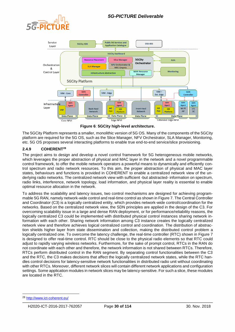
5G-PICTURE Deliverable
H2020-ICT-2016-2017-762057 Page 30 of 114 30. Nov. 2018
Figure 6: 5GCity high-level architecture.
The 5GCity Platform represents a smaller, monolithic version of 5G OS. Many of the components of the 5GCity platform are required for the 5G OS, such as the Slice Manager, NFV Orchestrator, SLA Manager, Monitoring, etc. 5G OS proposes several interacting platforms to enable true end-to-end service/slice provisioning.
2.4.9 COHERENT28
The project aims to design and develop a novel control framework for 5G heterogeneous mobile networks, which leverages the proper abstraction of physical and MAC layer in the network and a novel programmable control framework, to offer the mobile network operators a powerful means to dynamically and efficiently con-trol spectrum and radio network resources. To this aim, the proper abstraction of physical and MAC layer states, behaviours and functions is provided in COHERENT to enable a centralized network view of the un-derlying radio networks. The centralized network view with sufficient -but abstracted- information on spectrum, radio links, interference, network topology, load information, and physical layer reality is essential to enable optimal resource allocation in the network.
To address the scalability and latency issues, two control mechanisms are designed for achieving program-mable 5G RAN, namely network-wide control and real-time control as shown in Figure 7. The Central Controller and Coordinator (C3) is a logically centralized entity, which provides network-wide control/coordination for the networks. Based on the centralized network view, the SDN principles are applied in the design of the C3. For overcoming scalability issue in a large and dense RAN deployment, or for performance/reliability reasons, the logically centralized C3 could be implemented with distributed physical control instances sharing network in-formation with each other. Sharing network information among C3 instance creates the logically centralized network view and therefore achieves logical centralized control and coordination. The distribution of abstrac-tion shields higher layer from state dissemination and collection, making the distributed control problem a logically centralized one. To overcome the latency challenge, the real-time controller (RTC) shown in Figure 7 is designed to offer real-time control. RTC should be close to the physical radio elements so that RTC could adjust to rapidly varying wireless networks. Furthermore, for the sake of prompt control, RTCs in the RAN do not coordinate with each other and therefore, the network information is not shared between RTCs. Therefore, RTCs perform distributed control in the RAN segment. By separating control functionalities between the C3 and the RTC, the C3 makes decisions that affect the logically centralized network states, while the RTC han-dles control decisions for latency-sensitive network functionalities in distributed radio unit without coordinating with other RTCs. Moreover, different network slices will contain different network applications and configuration settings. Some application modules in network slices may be latency-sensitive. For such a slice, these modules are located in the RTC.
28 http://www.ict-coherent.eu/

5G-PICTURE Deliverable
H2020-ICT-2016-2017-762057 Page 31 of 114 30. Nov. 2018
Figure 7: COHERENT framework for hierarchical control scheme.
In summary, 5G OS devised in the 5G-PICTURE project can leverage the unified programmable control frame-work and multiple control applications provided by the COHERENT project to coordinate the underlying heter-ogeneous mobile networks as a whole for each network slice. Moreover, 5G-PICTURE will extend the network programmability from the focused RAN by COHERENT to multiple domains in an end-to-end manner.
2.4.10 SliceNet29
This is a 5G-PPP project that focuses on network slicing. It proposes network slicing as a cornerstone tech-nology in 5G networks, and addresses the associated challenges in managing, controlling and orchestrating the new services for users especially vertical sectors, thereby maximising the potential of 5G infrastructures and their services by leveraging advanced software networking and cognitive network management. In Figure 8, the overall vision for SliceNet is showed where its aim is to design, prototype and demonstrate an innovative, verticals-oriented, QoE-driven 5G network slicing framework focusing on cognitive network management and control for end-to-end slicing operation and slice-based/enabled services across multiple operator domains in SDN/NFV-enabled 5G networks. SliceNet will tackle a number of issues in terms of fine-grained and integrated management, QoE modelling & management, customisable control, cross-plane coordination and orchestra-tion, slicing scalability, security, resource efficiency and interoperability across multiple domains.
The overall architecture of SliceNet comprises by two architectural domains as depicted in Figure 9. One is the advanced managed domain (infrastructure, services and control) imposed by the requirements of 5G sys-tems where software defined network and slicing, SDN, NFV, and other architectural designs and principles for 5G performances will be fully integrated and thus establish an integrated, programmable, slicing-ready infrastructure for 5G services in SliceNet. The other is the innovative management domain (management and orchestration) that is able to cognitively manage this infrastructure and its new services by addressing a set of technological challenges such as multi-tenancy, multi-operator, multi-domain, programmable data plane, plug-gable control plane and cross-layer orchestration. Figure 9 shows an overview of the SliceNet architecture where this division between the managed infrastructure and the management architecture is across five layers to allow the creation of a modular, extensible and scalable framework.
29 https://slicenet.eu/

5G-PICTURE Deliverable
H2020-ICT-2016-2017-762057 Page 32 of 114 30. Nov. 2018
Figure 8: SliceNet vision.
Figure 9: SliceNet overall architecture.
From a bottom-up perspective, the first layer (L1 in Figure 9) is the Infrastructure Layer, representing the 5G physical and vertical infrastructure deployments. Cloud computing technologies are utilised and the Multi-ac-cess Edge Computing (MEC) paradigm is integrated to push virtualised resources to the edge of the network. The Network Function (NF) Layer (L2) comprises all the services (mainly NFV services in SliceNet) running on top of the underlying infrastructure. The Network Slicing Layer (L3) is decoupled from the NF Layer following the SDN paradigm to gain a holistic, logically centralised control of the geographically distributed services. The Sliced Plug & Play (P&P) Control Layer (L4) is a new layer introduced by SliceNet as a novel extension of the multi-tenant concept now embracing the SDN world. This layer will provide a novel P&P functionality of the control plane so that it is customised and isolated for a particular vertical customer differentiating itself from the common control plane for all the users of the infrastructure. This layer enables hosting P&P control appli-cations provided by the vertical business, for example a QoE Optimization application to fulfil the requirements of a given vertical business. Finally, the Business Service Slice Layer (L5) provides the highly customisable Slice-as-a-Service to a range of vertical businesses with diverging use case requirements.

5G-PICTURE Deliverable
H2020-ICT-2016-2017-762057 Page 33 of 114 30. Nov. 2018
We can observe that there are several overlapping aspects between the SliceNet and the 5G OS vision in terms of providing multi-domain orchestration and control functionalities over the underlying network functions. However, SliceNet approach focuses more on enabling the cognitive management and orchestration via QoE monitoring, decision-making and self-optimization for autonomous network management.
2.4.11 MATILDA30
The project aims to design and implement an end-to-end 5G service operational framework tackling the design, development and orchestration of 5G-ready applications and 5G network services over programmable infra-structure, following a unified programmability model and a set of control abstractions. MATILDA defines as 5G-Ready application a distributed-by-nature application consisting of several cloud native components that (1) collaborate to fulfil their operational scope and (2) rely on a service mesh as a means of network abstraction.
The project aims at devising and realizing a radical shift in the development of software for 5G-ready applica-tions as well as VNFs and PNFs and network services, through the adoption of a unified programmability model, the definition of proper abstractions and the creation of an open development environment that may be used by application as well as VNF developers.
Intelligent and unified orchestration mechanisms will be applied for the automated placement of the 5G-ready applications and the creation and maintenance of the required network slices. Deployment and runtime policies enforcement is provided through a set of optimisation mechanisms providing deployment plans based on high level objectives and a set of mechanisms supporting runtime adaptation of the application components and/or network functions based on policies defined on behalf of a services provider.
Multi-site management of the cloud/edge computing and IoT resources is supported by a multi-site virtualized infrastructure manager, while the lifecycle management of the supported VNF Graphs (VNF-FGs) as well as a set of network management activities are provided by a multi-site NFV Orchestrator (NFVO). Network and application-oriented analytics and profiling mechanisms are supported based on real-time as well as a poste-riori processing of the collected data from a set of monitoring streams. The developed 5G-ready application components, applications, VNFs and application-aware network services are made available for open-source or commercial purposes, re-use and extension through a 5G marketplace.
In the context of MATILDA, a significant amount of effort is placed on defining a standard framework for the description of 5G-ready services (component and graphs) at service abstraction layer using a set of re-usable metamodels, namely the Chainable Application Component & 5G-ready Application Graph Metamodel, the VNF/PNF & VNF Forwarding Graph Metamodel, the Network-aware Application Graph Metamodel and the Deployment and Runtime Policy Metamodel. These metamodels include the service components’ compute and network requirements and are intended to serve the purpose of providing a description of the services requested by verticals/tenants from the Telecom Service Provider and the means to derive the corresponding SLAs. In this respect, this piece of work performed in MATILDA project can be considered complementary to 5G-PICTURE activities that focus more on the network and less on the applications’ layer and can be exploited by and adjusted to 5G OS. In particular, these metamodels have been considered in the definition/specification of 5G OS Service Management layer, including the Service Portal (SP) and OSS/BSS components, with regard to the definition of common descriptors for the high-level requests of stakeholders and the corresponding SLAs.
2.4.12 5G UK Test Network31
This is a UK Department of Culture, Sports and Media funded project. It aims to create the first 5G testbed network for researchers and 5G service developers. It consists of two testbed islands (located in Bristol and London respectively) connected to each other by high capacity links. Each island has an NFV Orchestrator (OSM) and integrated SDN Controller (within OSM MANO – using its SDN Assist function) for inter-island connectivity [18]. These are similar to the MANO component in 5G OS.
The island NFV Orchestrator is in turn orchestrated over by the 5G UK Exchange Orchestrator. The 5G UK Exchange Orchestrator is the end-user facing interface that uses the service abstraction to allow experimenters to use available functions and hardware to create their own services to test over a 5G network. This component is same as the 5G OS Domain Orchestrator component. This project highlights innovative integration of NFV orchestration, datacentre and WAN controllers, which allows novel services to be tested.
30 http://www.matilda-5g.eu/ 31 http://www.bristol.ac.uk/engineering/research/smart/projects/uk-5g/

5G-PICTURE Deliverable
H2020-ICT-2016-2017-762057 Page 34 of 114 30. Nov. 2018
2.5 Summary
We summarise the state of the art in the context of 5G OS in the following two tables. Table 2 maps the software components described in this section to 5G OS components: Multi-domain Orchestrator, Domain Orchestrator, Domain Controller and NFV MANO. Table 3 lists the relevance of the projects described in this section to 5G-PICTURE project.
Table 2: Existing solutions mapped to 5G OS components.
Software Component 5G OS Mapping
X-MANO Multi-Domain Orchestrator
ESCAPE Multi-Domain Orchestrator
ONAP Domain Orchestrator / Domain Controller / NFV MANO
OSM Domain Orchestrator / NFV MANO
SONATA Domain Orchestrator / NFV MANO
NetOS Domain Orchestrator / Domain Controller
Jox Domain Orchestrator / Domain Controller
OpenDaylight Domain Controller
Ryu Domain Controller
Table 3: Projects mapped to 5G OS goals.
Project Related aspects to 5G OS
5G-XHaul Hierarchical software-defined network control over a het-
erogeneous network
5GTANGO Orchestrate and manage end-to-end network ser-
vices/slices
5G ESSENCE Orchestrate network, data centres and edge-compute
MetroHaul Orchestrate network, data centres and edge-compute
5G NORMA Split software-defined network control over PNFs and
VNFs
5G-MoNArch Orchestrate and manage end-to-end network ser-
vices/slices
5GinFIRE Developing infrastructure (testbed and components) rele-vant to 5G OS, namely: Orchestrator platform based on
OSM
5GCity Architecture representing a monolithic relationship be-
tween orchestrators, controllers and NFV MANO
COHERENT RAN Programmability
SliceNet Architecture for a multi-level network slicing system
MATILDA Service descriptors and meta-models
5G UK Test Net-work
Architecture for cross domain orchestration based on hier-archical orchestration

5G-PICTURE Deliverable
H2020-ICT-2016-2017-762057 Page 35 of 114 30. Nov. 2018
3 5G Operating System
As described in Section 2, there are several completed and ongoing projects designing concepts and solutions for network control, NFV management and orchestration, as well as network and compute slicing. Most of these solutions often provide a common set of required features in their specific category but also differ and specialize in many aspects. For example, most of NFV MANO frameworks can instantiate services, defined using semantically similar descriptors in each framework, using a Virtualized Infrastructure Manager (VIM) like OpenStack. However, very few solutions actually include an implementation of a multi-VIM MANO framework (for example OSM – with restrictions). Similarly, there are advanced SDN control solutions available but not all of them can be conveniently used together with an available NFV MANO solution.
This leaves us with mostly incompatible, limited, and isolated solutions in the areas of network control, NFV MANO, and slicing. Given the complexity and heterogeneity of the 5G infrastructure as well as the broad range of services with different requirements that are hosted on this infrastructure, we obviously need more: we need the ability to use the strengths, specialties, and features of different solutions in each of these three areas in an integrated and consistent way.
This best-of-breed approach is encapsulated within the concept of 5G OS. In Deliverable 2.2 [6], we have described the 5G OS and its high-level architecture as an attempt to tackle this issue. In this section, we give a brief overview of 5G OS architecture and how it is designed to provide an integration of these three areas. In Section 4 we provide details of implementation plans based on the 5G OS concept. In Section 5 we validate the 5G OS concept against two use-cases taken from Rail (Transport) and Stadium/Mega-event verticals.
3.1 Main Interactions in 5G OS
Figure 10 shows a high-level overview of relationships of the entities defined in Chapter 1. These relationships build the basis of the 5G OS architecture.
Equipment Vendors and VNF/PNF developers provide the hardware and software resources and functions to Infrastructure Providers. Infrastructure Providers combine these resources into an infrastructure that is used by 5G-PICTURE Operators. A 5G-PICTURE Operator may assume the role of an Infrastructure Provider, using its own resources. It may also use different infrastructure from different Infrastructure providers.
5G-PICTURE Tenants (or simply a Tenant) request and use services and slices provisioned by 5G-PICTURE Operators (or simply an Operator). These roles are relative; an actor playing the role of a Tenant can in turn play the role of an Operator for some other Tenant. Services can be defined and provided in different ways:
Figure 10: High-level interactions of stakeholders.

5G-PICTURE Deliverable
H2020-ICT-2016-2017-762057 Page 36 of 114 30. Nov. 2018
5G-PICTURE Operator may acquire VNFs/PNFs directly from VNF/PNF Developers and offer pre-defined services that are requested and used by 5G-PICTURE Tenants. 5G-PICTURE Operator may also assume the role of a VNF/PNF Developer, developing the NFs it needs.
5G-PICTURE Tenants may submit their desired VNFs/PNFs (acquired from VNF/PND Developers) to be deployed and orchestrated by the 5G-PICTURE Operator. 5G-PICTURE Tenant may as well assume the role of a VNF/PNF Developer, developing the NFs it needs.
These services are used to provide certain applications and functionalities to End Users, who interact with 5G-PICTURE Tenants.
Among these stakeholders, 5G-PICTURE Tenants, 5G-PICTURE Operators, and Infrastructure Providers di-rectly use and interact with 5G OS instances. The remaining stakeholders do not have direct interactions with 5G OS components.
3.2 5G OS Architectural Framework
The interaction with 5G OS starts with a 5G-PICTURE Tenant requesting a Service/Slice for a specific purpose. The request may be ad-hoc or selected from a catalogue. They also need to activate, monitor and deactivate services. This requires a Service Management component.
Once the Service request has been processed, it needs to be sent to a component that is able to orchestrate across available resources to implement the service.
Such an orchestrator component may have direct or indirect (delegated) access to the control components that provide access to resources. The nature of this interaction is based on the administrative and technological domain structure. For example, different types of resources need specialized resource management function-alities. Another important consideration is whether any of the infrastructure components required to implement the requested service is provided by an external provider, as this would normally create an administrative domain boundary.
This provides an overall component model that consists of orchestrators and controllers. Orchestration inter-faces handle request for services, whereas control interfaces handle requests for resources.
Depending on the domain structure, the orchestration components are split into two depending on what they orchestrate over:
1. Orchestration within a domain over one or more of the following:
a. Other domains, e.g., different technology domains within one administrative domain.
b. Compute resources.
c. Network resources.
d. Physical functions.
2. Orchestration across domains.
We refer to the component providing orchestration within a domain as the Domain Orchestrator. The compo-nent providing orchestration across domains is referred to as a Multi-Domain Orchestrator.
Any component that provide access to connectivity and physical network function resources within a domain is called a Domain Controllers. Any component that provides access to compute resources for virtual network functions within a domain is called the NFV MANO component in that domain.
Figure 11 shows an overview of the major components in the 5G OS architectural framework. A 5G OS in-stance is owned and operated by a 5G-PICTURE Operator. The Service Management (SM) and Multi-Domain Orchestrator (MDO), in case of a multi-domain infrastructure, are the two major components operated directly under the policies of the 5G-PICTURE Operator. The SM is the interface between tenant-facing and resource-related service management operations. The MDO is responsible for the end-to-end slice orchestration.

5G-PICTURE Deliverable
H2020-ICT-2016-2017-762057 Page 37 of 114 30. Nov. 2018
Figure 11: 5G OS major components and stakeholders.
A 5G-PICTURE Operator uses its 5G OS instance to manage services and slices on top of the infrastructure provided by Infrastructure Provider(s). The 5G-PICTURE Operator assumes the role of an Infrastructure Pro-vider if it is using its own infrastructure. For example, Figure 12 shows an example RAN Operator who is at the same time the provider of its access and core resources.
Depending on the administrative and technological heterogeneity of the underlying domains, each MDO may be in touch with several DO components, responsible for (sub-)slice orchestration within their domains. For example, Figure 13 shows a 5G-PICTURE Operator running a 5G OS instance. This operator is at the same time the provider for its own networking infrastructure. Additionally, it can provision services using compute resources from a 3rd-party Infrastructure Provider. The MDO component of this RAN operator is configured to orchestrate DOs from two different administrative domains. For simplicity, the rest of the components in the 3rd-party administrative domain are not shown in this figure.
Figure 12: 5G-PICTURE Operator providing its own access and core resources.

5G-PICTURE Deliverable
H2020-ICT-2016-2017-762057 Page 38 of 114 30. Nov. 2018
Figure 13: Example 5G-PICTURE Operator using own and 3rd-Party infrastructure.
Figure 14: 5G OS architecture.
Within each domain, Domain Controller (DC) and NFV Management and Orchestration (NFV MANO) compo-nents are responsible for the lifecycle management operations of the actual sub-slices and network functions.
5G OS architecture is shown in Figure 14. This includes components that are required for building a functioning system and provide cross-cutting functionalities. For example, a Service Portal must be designed for 5G-PIC-TURE Tenants to access and control their running services, configure the provisioned slices, etc. OSS and BSS systems must be in place for 5G-PICTURE Operators to control the operational and business aspects of their administrative domains. The striped components in this figure, while crucial, are not of specific interest within this project. In this document, we focus on the relationships among slice management, network control, and NFV MANO components. The cross-cutting functionalities like monitoring, service and slice catalogues for storing the descriptors, as well as the repositories for storing information about live instances of services and slices have been studied in networking and compute contexts. We present an architectural framework. Using this framework and based on the requirements of the target system, the concrete system architecture with the required components can be extracted. For our proof-of-concept implementations of 5G OS (described in Section 4), we will rely on existing solutions for the cross-cutting functionalities.

5G-PICTURE Deliverable
H2020-ICT-2016-2017-762057 Page 39 of 114 30. Nov. 2018
We describe the responsibilities of 5G OS components and the major interfaces among them in more detail in the rest of this section.
3.3 Slice Management in 5G OS
In this section, we give an overview of 5G OS slice descriptors and how these descriptors are modified and forwarded among 5G OS components.
3.3.1 Slice Request Descriptor
From the technical perspective, there are certain standard elements required to request network slices. The main purpose of a Slice Descriptor is to collect these standard elements. In this project, we rely on the work carried out by standards organizations such as ETSI for a comprehensive description of the slice request and slice descriptors. Specifically, we base our definitions on the OSM Information Model Rel. 2 (ETSI, 2017), which provides many of the standard elements such as VNF and Virtual Link descriptors. These descriptors are supported by the implementation of the OSM, which will be a part of our proof-of-concept implementations.
In Figure 15, We present the 5G-PICTURE Slice Descriptor in the form of a content definition, built over the OSM Information Model. The request descriptor extends the OSM Information Model by:
1. adding the Service-Level Agreement (SLA) construct.
2. elaborating on the Physical Network Function (ETSI, Network Functions Virtualisation (NFV) Release
2; Management and Orchestration; Network Service Templates Specification (RGS/NFV-
IFA014ed241), 2018) descriptor. PNF descriptors are not the core area of concern in the OSM model
but are required in the context of 5G OS because a slice may be made up of VNFs as well as PNFs.
It is important to note the following about the Slice Descriptor definition:
1. It is defining the attributes and information that a slice definition can contain.
2. It is not imposing specific representation via formal models.
3. It is not imposing specific integration points and API styles.
In this section, we describe the SLA and PNF descriptors in detail and refer the reader to the OSM Information Model for the remaining elements of the Slice Request Descriptor.
Figure 15: 5G-PICTURE Slice Request Descriptor.
3.3.2 Service-Level Agreement
Each service has a set of resource and performance guarantees attached to it, which has been agreed upon between the provider and the requester of the service. For example, the Infrastructure Provider and the 5G-PICTURE Operator make agreements regarding the provisioned service (e.g., the guaranteed bandwidth).

5G-PICTURE Deliverable
H2020-ICT-2016-2017-762057 Page 40 of 114 30. Nov. 2018
The 5G-PICTURE Operator and the 5G-PICTURE Tenant also need an agreement about the attributes of the service (e.g., the guaranteed availability, minimum data rate, maximum latency, etc.) These guarantees are described in the Service-Level Agreement (SLA) associated with the service.
SLA is used by the service requester to indicate the nature of requests in terms of number of slices that may be required, frequency of requests, complexity of requests, and the duration of the slices. This will help the service provider to optimize its slicing strategy. For example, if a requester indicates large number of short-lived requests, then the provider may wish to allocate a dedicated slice to the requester, which can be easily sliced further. On the other hand, if the requester indicates few long-lived slices, then it may not be practical to reserve resources in advance.
In the context of the Slice Request Descriptor, we use the SLA construct to indicate the expected levels of service from the slice, by the 5G-PICTURE Tenant. This is independent of the Link/Node QoS options like the general resource availability and recover time of resources.
3.3.3 Physical Network Function Descriptor (PNFD)
5G-PICTURE Deliverable 4.2 classifies the taxonomy of “on-boardable” functions considered in 5G-PICTURE into three groups:
Group 1: Functions packaged in a Virtual Machine (VM).
Group 2: Functions instantiated through configuring a VNF or a PNF like a controller or a switch.
Group 3: Functions deployed by instantiating a program made for a special-purpose hardware, e.g.,
an FPGA.
The functions of Group 2 and Group 3 are described by a PNFD, whereas the functions of Group 1 are de-scribed by a VNF Descriptor (VNFD).
The requests for PNFs can be defined and handled in two ways, depending on the type of the corresponding slice and the associated SLA:
1. The PNF request is bound to a specific device and includes the unique identifier of the device.
2. The PNF request includes the required functionality and the device that can provide it is selected by
5G OS.
The OSM Service Template for NFV [25] specifies the PNFD in terms of identification and connectivity aspects of the physical device. The connection points (CPs) between the PNF and the virtual link are described in the Pnfd information element by the attribute: pnfExtCp. The pnfExtCp element extends the Cpd element, which provides the following important attributes:
Layer Protocol: Identifies a protocol that the connection point of the corresponding Connection Point Descriptor (CPD) support for connectivity purposes (e.g. Ethernet, MPLS, ODU2, IPV4, IPV6, Pseudo-Wire, etc.). This also determines which type of address to assign to the connection point at instantiation time [25].
Trunk Mode: Specifies whether multiple VLANs are supported or not over the connection point.
This corresponds to the first type of PNF request that is bound to a specific device. It does not cover the second type, where no explicit binding is done and the choice is made by the provider layer among existing devices that offer the requested function (e.g., OpenFlow tables or access control). In addition to that, the OSM ap-proach does not cover the case of programmable Physical Network Functions (pPNFs) that are programmed using protocol- and target-independent intermediate languages such as P432. These functions will be produced in the context of 5G-PICTURE Work Package 4. We describe this issue in the following section.
3.3.4 Challenge of Programmable Physical Network Functions
Programmable PNFs (pPNFs) aim to provide the flexibility of a software implementation with the performance of a hardware implementation. This flexibility comes from the intermediate step of mapping, for example, a P4 program to the target hardware where it will run and preparing a specific binary for that target. Running the function on hardware provides an improved performance compared to running it as a VM- or container-based VNF. However, this comes with the challenge that if there are different hardware platforms in the network that
32 https://p4.org/

5G-PICTURE Deliverable
H2020-ICT-2016-2017-762057 Page 41 of 114 30. Nov. 2018
can host the function, then to utilise pPNFs across the network, specific images must exist for that function for each target platform.
Comparing this to the ETSI NFV approach where VNFs are implemented in VMs, standard resources are CPU, storage, and network. The function images produced are not specific to any one type of VIM. Therefore, the ETSI MANO system can deploy VNFs with greater flexibility.
In the context of P4, after obtaining the target-specific image of the P4 program, it must be sent to the P4 target for installation. Upon successful installation, configuration APIs are auto-generated, which allow the function to be configured using a P4Runtime agent.
This dependency on the target device requires the PNFD to describe additional properties of the target platform, as well as the services being requested from the platform to handle pPNFs.
ONOS33 provides integration with P4-based pPNFs via the Pipeconf Service and the Device Provider compo-nent. It packages together the function-specific information (pipeline model) with target-specific information such as binary files to be used for deployment of the pPNF on a target device to allow centralized management and control of pPNFs on available platforms.
The descriptor for ONOS has the following pieces of information [12]:
1. Target Platform Driver.
2. Target Platform Agent address and port.
3. Device identifier.
4. pPNF identifier.
To generalise, in the context of 5G OS, for a tenant to request a PNF they would need to provide one of the two pieces of information below:
Platform identifier and capabilities – to be used by the orchestrator for placing the function.
Specific Target device identifier – placement already provided.
Once a placement decision has been made (triggered by the PNF request above) then to request PNF instan-tiation from the layer below, the layer below the orchestrator would need to provide:
1. A specific device supporting that target platform.
2. Resource reservations on the device.
To enable Group 2 functions, the target platform will need to be configured to point to the application that will use the resources the platform provides (e.g. OpenFlow tables).
To enable Group 3 functions, the function image corresponding to the platform will need to be provided and deployed on it. Following that, the correct configuration needs to be provided (by the Orchestrator) based on the slice request.
3.3.5 Descriptor Processing
Descriptors are generated and processed by each component of the 5G OS. Figure 16 shows this process. The interaction starts with the 5G-PICTURE Tenant requesting a service (slice). This descriptor is provided to the SM, which maps the service to one or more end-to-end slices. Each of these end-to-end slices have their own request descriptors, which are passed to the MDO. The MDO component breaks apart the end-to-end slice into smaller slices (sub-slices) and generate request descriptors for the layer below. This process contin-ues at the next level for the DO component. This represents the main interactions in 5G OS for a slice request.
The concept here is that the Descriptor Schema remains the same over different layers of 5G OS but different instances are created using:
Direct mapping from the request descriptor received via the northbound interface.
Transforming the request descriptor received via the northbound interface.
Look-ups of descriptors based on the request descriptor received via the northbound interface.
Enrichment of the received descriptors, e.g., by: o Providing access information (e.g., credentials).
33 https://onosproject.org/

5G-PICTURE Deliverable
H2020-ICT-2016-2017-762057 Page 42 of 114 30. Nov. 2018
o Providing additional operational information for the layers below (e.g., SLA policy and tenant information).
A Slice Instance Descriptor describes various Control, Monitoring and Management APIs associated with the Slice Instance that is returned in response to the Slice Request Descriptor, as shown in Figure 17. This allows the requestor to access the control, monitoring and management functionalities of the slice. The Slice Instance Descriptor should contain (at a minimum) the Monitoring API. This should support both a simple traffic light status as well as a more complicated data-based API.
The Control API for the slice can be:
1. Internal to the slice with no external visibility.
2. Available externally via different mechanisms:
a. specified in the request as one of the two options below:
i. As a VNF with control links to the devices in the slice (e.g., an OpenFlow controller VNF).
ii. As a slice control configuration that enables devices to be controlled by external controller applications.
b. externally provided – in this case, the Slice Instance Descriptor that is returned must point to the control interface of the controllable node in the slice.
Figure 16: Descriptor journey through 5G OS.
The above mechanisms provide an additional layer of flexibility to the existing slice definitions. For example, Infrastructure Providers can now provide special-purpose hardware, such as GPUs, to execute certain func-tions (e.g., those that require matrix operations in radio access networks). This allows slices with novel func-tional splits, which were earlier not feasible due to the low performance of the functions over general-purpose hardware.

5G-PICTURE Deliverable
H2020-ICT-2016-2017-762057 Page 43 of 114 30. Nov. 2018
3.3.6 Slice Instance Response
The Slice Instance Descriptor contains for each of the Monitoring, Management, and Control section a combi-nation of service name (tag), the associated service endpoint (with protocol identifier), and any other infor-mation that could help the requester of the slice use that functionality (such as links to API documentation).
Figure 17: 5G-PICTURE Slice Instance Descriptor.
We show some examples of Slice Response Descriptor in terms of content. The formatting used in these examples is not a proposal for the Slice Response Descriptor formatting but merely used to show the different components that may exist in such a descriptor.
The following example shows a descriptor of the slice instance containing a single OpenFlow switch with con-trol (OpenFlow), configuration/management (ovsdb and cli) and monitoring available. Each capability has an associated endpoint and other information.
Inventory: {
switch1: {
control: {
dpid: 0123456789,
endpoint: openflow14://192.168.0.100:6653
},
management: [{
endpoint: ssh://192.168.0.100,
username: xyz,
password: changeme
},
{
Endpoint: ovsdb://192.168.0.100
}],
monitoring: {
endpoint http://192.168.0.100:8080/stats,
documentation: http://www.switch_manufacturer.com/doc/model/index.html,
username: mon,
password: changeme
}
}
}
The next example shows a switch that can only be managed (ovsdb) and monitored (no control endpoint).
Inventory: {
switch1: {
management: [{
endpoint: ssh://192.168.0.100,
username: xyz,

5G-PICTURE Deliverable
H2020-ICT-2016-2017-762057 Page 44 of 114 30. Nov. 2018
password: changeme
},
{
Endpoint: ovsdb://192.168.0.100
}],
monitoring: {
endpoint http://192.168.0.100:8080/stats,
documentation: http://www.switch_manufacturer.com/doc/model/index.html,
username: mon,
password: changeme
}
}
}
Finally, the following example represents a switch that can only be monitored.
Inventory: {
switch1: {
monitoring: {
endpoint http://192.168.0.100:8080/stats,
documentation: http://www.switch_manufacturer.com/doc/model/index.html,
username: mon,
password: changeme
}
}
}
In case of slice response propagation from the Controller and MANO layers back to the 5G-PICTURE Tenant, the control and configuration endpoints may be removed. Each endpoint in the response at each level will either be utilised at the next level up or passed upwards to be utilised by a higher-level component.
For example, if 5G-PICTURE Tenant requests a slice/service that can only be monitored, then the configura-tion and control endpoints must be utilised by Orchestrator components to provide control and configuration to the slice. The monitoring endpoint can be passed up directly or through a layer of abstraction/indirection.
On the other hand, if the 5G-PICTURE Tenant requests a fully configurable and controllable slice/service, then the configuration and control endpoints must be passed up directly or through a layer of abstraction/indirection. Here it is assumed that the 5G-PICTURE Tenant will provide its own control and configuration software to utilise those endpoints.
Our aim is to avoid multiple endpoint consumers as this will then require complex access management to the endpoint to ensure the multiple consumers do not over-write or block each other.
It is possible (as mentioned above) to transform the endpoint through a layer of abstraction/indirection. In this case, the Control API of a certain type is consumed by a component which then provides its own control API to the layer above. This has two benefits:
1. Allows hiding actual resource information, which is important as the resources may belong to different
providers.
2. Allows simplification of APIs to better focus on the required behaviour.
3.3.7 Types of Slices
In case of multiple Infrastructure Providers, the 5G-PICTURE Operator has to map and translate different parts of a slice request to different Infrastructure Providers. In this case the 5G-PICTURE Operator should either function as a Resource Broker or a Virtual Operator or a combination of both. These modes of operation require different support from 5G OS and are suitable for different types of slices. In this section, we describe different slice types and link them with the mode of operation of the 5G-PICTURE Operator.

5G-PICTURE Deliverable
H2020-ICT-2016-2017-762057 Page 45 of 114 30. Nov. 2018
Base Slice provides slice control API, which is used to create slices on top of the Base Slice (full control within the resource/service SLA is allowed). Base Slice is required for Wholesale Service Providers, who want to create different slices based on the Base Slice (e.g., per Vertical Slice). Upon slicing in the MDO layer, this option pushes the problem of domain interconnection to the layer below, i.e., to the DOs. This mode can be used when the type of slices to be provided are not defined beforehand, because the tenant is allowed to submit custom slice descriptors (such as the Virtual Operator use-case). This does require the Base Slice to be fully controllable so that it can be sliced again.
Guide Slice contains domains (including resources and/or provided services) and instantiated links between them. This represents a topology of connected resource pools and provided services, which are used as a skeleton for stitching together sub-slices to create an end-to-end slice. The MDO then acts as a broker of resources, where a successful resource negotiation results in a slice being created. This method is useful for Service Providers that need to provision a large number of similar slices (e.g., content distribution, IoT, etc.) rapidly. The 5G-PICTURE Operator will then be able to request (broker) resources from the providers using the Guide Slice. Once the resources have been secured, the slice creation can proceed quickly as connectivity between domains has already been established.
Generic Slice is useful for a mixed-mode operation, where a Guide Slice may be used to abstract the underlay and to help construct one or more Base Slices. The Base and Guide Slices provide different views of the system: At each layer of 5G OS, the Guide Slice represent the lower layers (underlay), e.g., DOs for MDOs and the corresponding Base Slices represent the upper layer (overlay), e.g., SM for MDO. In this model, at the layer interacting with the Infrastructure Providers, a Broker model is used, whereas for the layers interacting with the Tenants, a Virtual Operator model is used. Another option here is to use different modes with different providers, where a part of the slice is assembled by Virtual Operator model and remaining by the Broker model.
Table 4 and Table 5 further describe the attributes of theses slice types and the underlay attributes represented by them.
Table 4: Slice attributes.
Attribute Guide Slice (Broker) Base Slice
(Virtual Operator) Generic Slice (Mixed Mode)
Level of Detail Domain abstracted Flexible (based on slice de-
scriptor) Variable level of detail
Pre-placement Inter-domain links are
fixed None required
Some or all inter-do-main links are fixed
Read-Only Yes Flexible (based on slice de-
scriptor)
Portions operating un-der the broker model
may be read-only
Table 5: Underlay attributes.
Type of Slice Things have been removed from Un-
derlay
Things have been ab-stracted from Underlay
Things have been re-served from Under-
lay
Guide Slice Yes, inter-domain links that are not
used
Yes, domain as nodes and networks as inter-domain
links Yes, interdomain links
Base Slice Optional Optional Yes, a full virtualised
network
Generic Slice Optional Optional Yes, a combination of
virtualised network and inter-domain links
3.3.8 Slice Creation
A simple slice request-response model between a Slice Requester (5G-PICTURE Tenant) and a Slice Provider (5G-PICTURE Operator) works when all the required infrastructure (which includes virtual and physical re-sources) are directly controlled by the Slice Provider (5G-PICTURE Operator). The Provider then has to map requests to resources it controls.

5G-PICTURE Deliverable
H2020-ICT-2016-2017-762057 Page 46 of 114 30. Nov. 2018
In case the Slice Provider has to depend upon different Infrastructure Providers (which is likely to be the more common case), then it has to decide the placement problem, i.e., which Infrastructure Provider to use (which involves resource reservation). This is especially true if the resource is in high demand. We identify two ways of solving this problem:
End-to-End Solution (Virtual Operator): The Slice Provider behaves like a Virtual Operator and decides the placement and the connectivity between different Infrastructure Providers (see Figure 18). Solutions are built using different algorithms such as depth-first (placement then connectivity), breadth-first (connectivity followed by placement) or sequential (placement-connectivity chain). Clearly, this is a multi-objective, multi-constraint problem to solve with a time dimension attached to it and will be affected by changes in the relationships among different participants.
At the Infrastructure Provider level, each of them has to solve again a subset of the problem solved by the Slice Provider with the hard constraint of ensuring external connectivity.
In this mode, one optimal strategy is to create an end-to-end Base Slice based on the Service Offering (Steps 1-3 in Figure 18) which represents a fully functional network as required by the Slice Provider to service its customers (5G-PICTURE Tenants). This slice can then be further sliced in any way by the Slice Provider to easily provide slices to its customers (Steps 4-9 in Figure 18). This has the advantage of abstracting away resources/functions not required to be exposed to the 5G-PICTURE Tenant, as well as allowing easy slicing based on ad-hoc requests. Here the 5G-PICTURE Operator is behaving like a Virtual Operator.
Figure 18: Virtual Operator (Base Slice) mechanism.

5G-PICTURE Deliverable
H2020-ICT-2016-2017-762057 Page 47 of 114 30. Nov. 2018
Figure 19: Broker (Guide Slice) mechanism.
Guide Slice Solution (Broker): Slice Provider behaves like a Broker and requests a Guide Slice (see Figure 19), based on its actual and perceived requirements, which contains:
1. bulk-links among Infrastructure Providers which may be shared by traffic for a given Slice Provider.
2. resources of interest offered by each of the Infrastructure Providers domains (perhaps with reserva-
tions).
At the time of requesting a slice, the only problem that the Slice Provider must solve is that of placement, as the connectivity between domains is already specified. Each placement is then a sub-slice restricted to the Infrastructure Provider’s domain where it is placed, connected to specific external links (based on the place-ment decisions).
Once each Infrastructure Provider returns a sub-slice (see Figure 19 Steps 1, 2, 3) the Slice Provider has to simply aggregate these into a slice upon receiving a Slice Request (see Figure 19 Steps 4, 5, 6, 7). The Infrastructure Provider in each sub-slice will need to solve the problem locally only. There is an issue of the domain connectivity being provided and therefore becoming a static constraint for the slice creation process. In the degenerate case, the full physical channel is available for slicing between two domains but in the normal case, it is assumed that inter-domain links would have a very high capacity (order of 100G or more) and a fraction of this would be allocated to the inter-domain connectivity between two Infrastructure Providers for the 5G-PICTURE Operator. Therefore, if the inter-domain links are to be re-sized then this should be possible without impacting existing slices.
These two ways of slicing extend to any level in 5G OS and occur between any requesting-providing compo-nents. For example, at the MDO-DO level, each Infrastructure Provider may provide a DO interface. The MDO then has to solve the placement and resource provisioning problem across the available DOs. The solution is partitioned and passed to the corresponding DOs (5G-PICTURE Operator acting as a Virtual Operator). Alter-natively, the MDO, based on the solution and the Guide Slice, may request resources from the DOs (5G-PICTURE Operator acting as a Broker). Similarly, at the DO-DC level, the DO has similar interaction with DCs, where each DC would be responsible for, e.g., a technical domain like Optical Transport, RAN, etc.

5G-PICTURE Deliverable
H2020-ICT-2016-2017-762057 Page 48 of 114 30. Nov. 2018
3.4 Slice Update and Deletion
Slice updates are difficult, especially if the service provided by the slice cannot be disrupted. Such updates may be required either because the slice/service definition has been changed by the 5G-PICTURE Tenant or something has changed in the resource layer (e.g., a link or a node is down) that requires swapping out im-pacted resources. Implementing this is not the main focus of the 5G-PICTURE demos.
Slice deletions are carried out in the following manner:
1. Traffic is blocked from going into the slice (data plane)
2. All northbound APIs are disabled, including translation/abstraction components
3. Resources associated with the Slice are released
3.5 5G OS Components and Interfaces
In this section, we describe the interactions between 5G OS components in detail. The slice processing steps described in Section 3.3 happen in each one of these components. Different components act on different pieces of information included in the descriptors.
3.5.1 Service Management
The requests and interactions of 5G-PICTURE Operators and Tenants are received at OSS/BSS and Service Portal (SP) components, respectively, and handed over to the corresponding 5G OS component via the Ser-vice Management component. The idea is to make requesting a service as simple as possible for the Tenant. The SM component has the following responsibilities:
1. Processing requests received from 5G-PICTURE tenants or end users (e.g., in terms of functionality
and service-level objectives – SLOs):
a. Converting the requests into 5G OS descriptors for the MDO, where one such operation is of
enriching descriptor by catalogue lookup.
b. Ensuring proper Authentication, Accounting and Authorization checks.
2. Maintaining Service-Level Agreements (SLAs) with the Tenant – and ensuring these constraints are
obeyed by all the layers of 5G OS.
3. Presenting Service information to the Tenant.
We describe these responsibilities in more details as follows.
High-Level service requests
High-level service request descriptors abstract the underlying infrastructure, while providing the necessary details with respect to the required resources, the restrictions related to service provisioning, and the runtime policies. In the context of 5G-PICTURE, we have analysed different options for the format of these descriptors. One of the most concrete and complete ones are those derived from the MATILDA project34. In the definition of the 5G OS this work has been taken into account and has been used in terms of validating the 5G OS capability to support these SM information flows.
In particular, the MATILDA project has defined a set of metamodels, i.e., templates (formal descriptors) of high-level service requests, of their interpretation to slice requests and of the slice instances to serve these requests. We link these metamodels with 5G OS as follows.
The Application Graph Metamodel, which constitutes a template to describe application components
to be hosted and is based on the requirements that are imposed by the tenant (vertical or virtual
resources provider)
o This corresponds to indicative high-level service requests to be defined by the 5G-PICTURE
Tenants in the context of 5G-PICTURE.
The Network-Aware Application Graph and Runtime Policies Metamodels (also known as Slice Intent
Metamodel), which constitutes a template for the representation of all requirements that should be
satisfied by a telco provider during the creation of a service/slice supporting the application.
34 http://www.matilda-5g.eu/

5G-PICTURE Deliverable
H2020-ICT-2016-2017-762057 Page 49 of 114 30. Nov. 2018
o This corresponds to indicative formal descriptors in terms of compute and network resource
requirements, (the “Slice Request” defined in 5G-PICTURE) to be interpreted by the 5G OS
and materialised by the underlying 5G-PICTURE infrastructure layers.
The Slice Metamodel, which constitutes the translation of the Slice Intent Metamodel into specific
resources allocations over the actually deployed network and compute infrastructures.
o This corresponds to the “Slice Instance Response” of the 5G-PICTURE infrastructure with
regard to the slice/resources that will provide the materialization of the Slice Intent by
MDOs/DOs, DCs, and NFV MANO components.
The MATILDA Application Graph Metamodel can be considered as a description of the business logic part of the compute resource components to be requested and the network link constraints between them, giving a high-level service request. The metamodel provides a formal description for each compute resource compo-nent requested, namely: (i) Distribution, (ii) Exposed Interface, (iii) Configuration, (iv) Volume, (v) Minimum Execution Requirements, (vi) Exposed Metric, (vii) Required Interface, and (viii) Capability. The metamodel provides also the formal description of the network links, i.e., interfaces between these compute resource components in the form of constraints.
This MATILDA metamodel follows the principles of abstract information representation of the resource request, non-imposing of specific integration points and API styles, does not preclude extensions to OSM Information Model, and is generic enough to be applicable/tailored to various tenants/services requests. Therefore, these models can be used within 5G OS. Details about the Application Graph Metamodel’s component and graph descriptors can be found in Annex I: MATILDA Application Graph Metamodel [47].
Conversion of high-level requests into formal resource demand descriptors
The high-level service request is converted by the SM into descriptors in terms of compute and network re-source requirements, in order to be interpreted by the 5G OS and materialised by the underlying infrastructure layers.
The MATILDA “Network-Aware Application Graph Metamodel” can be considered as an example of such de-scriptors that be handled by the SM and the 5G OS. In particular, this metamodel consists of four elements, namely: (i) an identifier that uniquely characterizes a Slice Request; (ii) a Service Mesh Identifier that uniquely characterizes a service graph; (iii) a set of constraints that have to be satisfied by the underlying infrastructure resources provisioning and (iv) a set of logical functions that have to be supported.
The set of logical functions corresponds to the inclusion and configuration of specific VNFs/PNFs within the slice to be provisioned. More details about the Network-Aware Application Graph Metamodel can be found in [Annex II: MATILDA Network-Aware Application Graph Metamodel] [48].
The Network Aware Application Graph Metamodel however is not sufficient for the deployment and modifica-tion of the slice over time. Thus, this metamodel is complemented with the Runtime Policies Metamodel, as shown in [Annex III: MATILDA Runtime Policies Metamodel] [49]. This metamodel consists of a set of expres-sions indicating the conditions over which one or more actions are triggered. Conditions as well as actions may be related with various stakeholders and mechanisms, and may involve monitoring of various metrics associated with the functionality managed in the service level, configuration options, resource usage metrics, profiling information, virtual links QoS characteristics as well as overall resources usage metrics of the instan-tiated network slices.
The SM forwards the Slice Request (along with the runtime policies) to the underlying MDO.
SLA Definition and Maintenance
Finally, the SM processes are responsible to provide the means to define and monitor the maintenance of the SLAs between the 5G-PICTURE Tenant and the 5G-PICTURE operator. To this end, the SM exposes func-tionalities related to the definition of the service characteristics and quality guarantees provided by the 5G-PICTURE Operator – known as Service-Level Agreement Template (SLAT), and the specification of the Ser-vice-Level Objectives (SLOs).
The capabilities of the infrastructure are the base of the definition of new SLATs, leveraging existing connec-tivity and cloud services SLAs provided by Infrastructure Providers. Indicative SLAs/SLATs have been pro-

5G-PICTURE Deliverable
H2020-ICT-2016-2017-762057 Page 50 of 114 30. Nov. 2018
vided with the 5G-XHAUL project [46], which can be further extended to support 5G-PICTURE resource dis-aggregation, dynamic slice setup and modification, dynamic VNF/PNFs deployment, incorporation of MEC capabilities, etc.
3.5.2 Multi-Domain Orchestrator
The MDO provides and maintains services/slices that span over multiple domains. A domain may consist of:
One or more PoPs.
Networks providing connectivity between different PoPs (e.g., Metro and Core networks) or between
PoPs and host devices of end users (e.g., Access and Metro networks).
Physical resources for slicing, e.g., physical switches providing virtual switches or DWDM nodes providing high-QoS data pipes as well as required control components.
The MDO receives slice descriptors from SM together with the action it needs to perform on the corresponding slice, e.g., instantiation, termination, etc. The MDO has the following responsibilities:
Maintaining a catalogue of the domains it is responsible for and the capabilities such as resource types
and link/interface data rates, exposed to the MDO from each domain.
Deciding which domain can realize and is responsible for which sub-slice of the requested slice (place-
ment).
Requesting corresponding DOs to create, configure, instantiate, pause, terminate, or modify the re-
quired sub-slices.
Creating, configuring, instantiating, pausing, terminating, or modifying the connectivity among sub-
slices provided by Dos.
Maintaining a repository of existing slice instances in its responsibility area.
Each MDO may interact with multiple DOs depending on the number and organization of domains in the net-work. Upon connecting a new domain to the MDO, the operators/providers of the corresponding domains need to negotiate the provided resources. The MDO maintains an overview of the capabilities in the underlying infrastructure, including the type of resources available in different domains. This information is provided to the MDO by the corresponding DO of the domains. The capability data exposed to the MDO depends on the corresponding agreements between the MDO and each DO. For example, it can vary from a big-switch ab-straction to the detailed topology of the domains being exposed to the MDO. Figure 20 shows an example negotiation process between Operator A running a 5G OS instance, who wants to access resources from a domain X, provided and operated by Operator X. The MDO of Operator A needs to maintain information about the connected DOs and the capabilities they offer in an internal catalogue. This negotiation process is out of the scope of our planned implementation activities with 5G-PICTURE.
The MDO also needs to maintain information on the used resources in each domain for slice instances, which is provided by a resource discovery process, APIs provided by infrastructure providers, or using monitoring systems running in the corresponding domains.
Using the information on the capabilities of the different domains and based on the requirements of the re-quested slice, the MDO performs a slice placement calculation, deciding which part of the end-to-end slice will be handled by which DO.
According to the placement results, the MDO divides the slice descriptor and creates sub-slice descriptors. These descriptors are forwarded to the DOs, accompanied by the concrete action to be performed.
Once the required actions are performed by the DOs, a sub-slice instance descriptor is returned to the MDO.

5G-PICTURE Deliverable
H2020-ICT-2016-2017-762057 Page 51 of 114 30. Nov. 2018
Figure 20 Example negotiation process between operators for connecting a new domain to a 5G OS instance.
APIs to DOs
(Sub-)slice descriptors represent the communication between MDOs and DOs. This communication is very similar to the one between SM and MDO, since again a (sub-)slice description is given from the one entity to the other.
APIs to other MDOs
In case of geographically distributed domains being controlled by one 5G-PICTURE Operator, multiple MDOs might be required for efficiently and effectively covering the existing domains. For example, this might be needed where a roaming application profile needs to be set in multiple countries. The cooperating MDOs may be organized hierarchically, where the primary MDO receives the slice descriptor from the SM, replicates the descriptors and passes them to the corresponding MDO for further processing. They may also be organised using P2P connections, where in this case there is no one primary MDO for all the requests and the SM directs each request to the appropriate MDO.
3.5.3 Domain Orchestrator
The DO provides the sub-slice requested by the MDO. For this, the DO requests the creation of the corre-sponding sub-slices from the underlying Domain Controllers and NFV MANO instances.
In case the domain where a specific DO is responsible consists of different WAN-interconnected PoPs, the DO interacts with one or more NFV MANO components for the orchestration of compute resources. Addition-ally, the DO should interact with a specific Domain Controller that is responsible for providing the inter-PoP connectivity, namely, the WAN Infrastructure Manager (WIM).
If the domain does not offer any compute resources, the DO only interacts with Domain Controller(s) for the control of virtual and/or physical network resources.
In general, the DO is responsible for interacting with all the components associated with various devices in that domain, whether those are compute-related (e.g., OSM) or physical network devices (e.g., OpenFlow Switches, WiFi Access Points) or virtual network devices (e.g., OVS). As shown in Figure 21, each DO is responsible for converting sub-slice requests received from the corresponding MDO into more focused sub-slice requests in terms of compute, storage, and connectivity resources, depending on the organization of the DO and the offered resource types.
The important DO-related APIs are described in the following sections.

5G-PICTURE Deliverable
H2020-ICT-2016-2017-762057 Page 52 of 114 30. Nov. 2018
APIs to Domain Controllers (DCs)
The Connectivity and Function descriptors represent communication between DO and DCs. These could be standardised by building wrappers around available APIs (which may be vendor-specific). Another alternative, if the DO is already integrated with established APIs, is to map descriptors to already existing features in these APIs. Then, if equivalent features are supported by the established APIs, there is no need to build wrappers.
Note that the relation between DO and DC can follow either 1:1 or 1:n manner. The former one relies on the single domain mapping between DO and DC, where the resource request can be directly derived from the slice requests, e.g., from the service throughput requirements to the wired link data rate provisioning. The latter one will rely on the DO to convert a single slice request to the resources among several underlying domains, for instance, a MEC service will require the resource provisioning for both radio access network (towards end-users) and core network (towards content server) domains to guarantee the service QoS requirements. The massive machine-type communication service is another example. The DO should leverage all available radio technologies (RATs), such as Wi-Fi, LTE and 5G, to satisfy a large number of connected devices using the corresponding technology-dependent DCs.
Figure 21: Overview of interactions between MDO, DO, DC and MANO.
APIs to other DOs
DOs interact with other DOs in a hierarchical way (see Figure 22). In this case, for each DO pair, the re-sources orchestrated and provisioned by the DO in the lower level of hierarchy are perceived as an underlay slice for the DO in the higher level of hierarchy and similarly, the resources orchestrated and provisioned by the DO in the upper level are considered as an overlay on top of the underlay slice. The DO providing the underlay slice will have the functionality to map Slice Descriptors (requests) to the actual resources controlled by different DCs.
3.5.4 Domain Controller
The Domain Controller performs multiple roles within a domain, depending on what devices and resources the domain contains and what the domain is being used for (e.g., pure connectivity, VNF with connectivity, etc.). A domain may consist of one or more PoPs offering compute and/or network resources. We describe some important scenarios for domain controllers in the rest of this section.
Domain Controller within the a single PoP
The compute/storage resources within PoPs are managed using instances of the NFV MANO component. DCs are responsible for the networking resources of the domain. Specifically, to provide connectivity within the PoP as well as to direct outbound traffic (relative to the PoP) to the correct external interface with the required encapsulation.
Domain Controller in a connectivity-only scenario
In this scenario, the domain consists of virtual and physical network resources. The DC in this scenario oper-ates over these network resources and provides connectivity across that domain based on the connectivity

5G-PICTURE Deliverable
H2020-ICT-2016-2017-762057 Page 53 of 114 30. Nov. 2018
requests (e.g., from the DO). An example is a set of L2 SDN switches controlled via OpenFlow (the Network API) with the DC supporting RESTCONF (API to the Domain Controller).
Figure 22: Hierarchical DO-DO interaction.
Domain Controller in a multi-PoP scenario
In this scenario, there are three major responsibility areas: PoPs providing compute resources (i.e., datacen-tres), the PoP internal network, and the WAN for PoP interconnection. Inter- and intra-PoP networking is pro-vided by network devices (both physical and virtual).
The DC of such a multi-PoP domain consists the following components:
A single DC-WAN, responsible for the inter-connection of the PoPs.
DC-LANs, the same number as the number of PoPs belonging to this domain. Each DC-LAN is re-sponsible for the intra-connectivity inside a PoP.
The control of both virtual bridges and physical network equipment could be assigned to a hierarchy of con-trollers, as it is also studied in the 5G-XHaul project. The compute nodes, called Edge Transport Nodes (ETNs) in 5G-XHaul, are controlled by the ETN agents, while the physical network equipment, called Transport Nodes (TNs) in 5G-XHaul, are controlled by the TN agents. The ETN and TN agents map to the DC-LAN and DC-WAN components respectively. These agents together with the L0-L1-L2 controllers developed in 5G-XHaul create the 5G-XHaul controller hierarchy, which will be the skeleton of the DC design and implementation in the 5G OS prototypes.
Clustering for auto-adaptive orchestration of the network resources is an extension on the 5G-XHaul controller hierarchy, which will be offered in the DC in the context of 5G-PICTURE. For example, considering a domain that is extended with new compute nodes and new network switches connecting these nodes, the existing L0 controllers could be multiplied in replicas that will be organized in clusters.

5G-PICTURE Deliverable
H2020-ICT-2016-2017-762057 Page 54 of 114 30. Nov. 2018
APIs to other DCs
DCs support hierarchical organisation due to the reason of real-time requirements, i.e., the control logics should be separated according to the level of real-timeliness guarantees. The real-time DC shall be placed as close as possible to the concerned domain infrastructures, while the non-real-time DC should be centralized to take the coordination benefits. Considering the radio access network (RAN) domain as an example, the distributed hard-real-time control agent should be collocated with each DU to provide the MAC/PHY layer control with pre-defined hard delay guarantees; however, the soft-real-time part should be centralized at the CU level to provide L3 (and even higher layers) control over several connected DUs to only guarantee an average delay within a tolerance. Such hierarchical DCs imply that the overall control decisions must be made over different time scales, but the distributed DC will rely on the decisions made by the centralized DC to make its own decisions. For instance, the centralized DC can configure the applied carrier frequency and frequency bandwidth, while the distributed DC will base on such configuration to allocate per-user radio resource block. The hierarchical DC characteristic allow the heterogeneous distribution of DCs corresponding to the applied technology. For example, a centralized DC at the CU level can be the aggregation point of heterogeneous DCs at the DU level leveraging Wi-Fi and LTE.
APIs from the Network being Sliced
A virtualized network can expose established device APIs (e.g., Openflow, NetCONF) to allow direct integra-tion with off-the-shelf controllers. It can also expose generic APIs to allow simpler integrations with custom controllers.
APIs to DO
This interface will be used by the DO to request the creation of connectivity between PoPs. For example, a request for an overlay L2 network inter-connecting PoPs, using the DC-WAN component.
An example of such an API is a RESTCONF-based northbound interface in the DC that provides connectivity services.
APIs to NFV MANO
The interaction between controllers and NFV MANO is described in this section. Without this interaction any VNFs defined within a PoP would not be able to communicate with other VNFs, irrespective of whether they were running in the same PoP or a different one.
ETSI defines five possible integration points for the SDN Controller in the NFV MANO architecture [23] out of these the cases of interest are (quoted directly from [23]):
Case 1: SDN controller functionality merged with the VIM functionality, in such case the two functions are not distinguishable
Case 2: SDN controller as a VNF is typically the case of an SDN controller Virtualised as a VNF itself or being part of a VNF. This VNF might be logically part of the NFVI and therefore belong to a special infrastructure tenant or belong to an independent tenant
Case 3: SDN controller in the NFVI is a classic case of SDN controller for the network con-nectivity in the NFVI, where the SDN controller is not implemented as a VNF
Case 4: SDN controller part of the OSS
A controller communicates with NFV MANO using different interfaces, based on the integration case, as shown below:

5G-PICTURE Deliverable
H2020-ICT-2016-2017-762057 Page 55 of 114 30. Nov. 2018
Figure 23: SDN Controller – NFV Orchestrator Interface options [23].
The VIM integration case (Case 1) uses the Or-Vi interface to communicate with the NFVO and the OSS/BSS integration case (Case 4) uses the Os-Ma interface. For Case 2 and Case 3 communication is indirect via the VNFM and VIM respectively.
In general, the main purpose of the DC-MANO interface is to allow the MANO system to configure the local network, “within” and “around” the PoP (defined in the following), based on the compute requirements. The case of “within the PoP” refers to instantiating the supporting network around a deployed VNF to provide connectivity to other VNFs in the same PoP. This includes:
virtual switch configuration at the PoP edge.
edge, aggregation and core network configuration.
modification of connectivity resulting from VNF migration, failover and scaling operations.
The case of “around the PoP” refers to providing a deployed VNF connectivity to the outside world. This second requirement involves co-ordinating with a WAN Controller to achieve interconnect between WAN and the PoP, specifically for:
physical and logical interfaces for traffic interconnect between WAN and PoP.
encapsulation scheme being used (e.g. VLAN ids, Tunnel ids, MPLS labels) in both directions.
QoS requirements.
WAN path requirements (subject to QoS requirements).
The above interconnect represents a contract between the PoP and WAN, which should not be impacted by changes to the internal network. For example, if the VNF migrates from one compute node of the PoP to another, the connectivity to the WAN gateway should be modified.
3.5.5 NFV MANO
The NFV MANO is responsible for the lifecycle management of the compute, storage and networking (depend-ing on chosen integration option) resources in a compute facility (e.g. datacentres, edge-compute nodes). The DO communicates with the NFV MANO to initiate the development of new VNFs, when a new sub-slice request is received. The NFV MANO consists of three main components i) the NFV Orchestrator (NFVO), ii) the VNF Management (VNFM) and iii) the VIM as described in the ETSI NFV MANO architecture.

5G-PICTURE Deliverable
H2020-ICT-2016-2017-762057 Page 56 of 114 30. Nov. 2018
APIs to other MANOs
The most common scenario is to use a single MANO instance in each domain that includes compute/storage resources. However, for scalability and resilience issues, it is possible to have a hierarchy or a P2P mesh of connected MANO instances. The MANO-MANO API for their communication will is the same as the DO-MANO API.
APIs to DO
The current specification of ETSI NFV MANO sheds some light on the way that NFVO accepts the slice de-scriptor and translates this to a request of a group of resources. In particular, NFVO consists of two functions, the Service Orchestrator (SO) and the Resource Orchestrator (RO), where the SO accepts the slice descriptor and talks to the RO, that is responsible for reserve the appropriate resources. This API will be exploited in our architecture for the communication between DO and MANO.
APIs to Infrastructure
The communication to the Infrastructure is implemented through the VIM. The VIM is the one that talks to the hypervisor, creates the VNFs based on the underlying deployment target (e.g., virtual machines or containers) and deploys them to the host machines. Again, the current specification of ETSI NFV MANO defines this API.
APIs to DC
The MANO-DC API could be a RESTCONF northbound interface of the DC. In particular, the MANO instance needs to talk only to the DC-LAN component of DC, which is mapped to this MANO instance, in order to request the connectivity of the VNFs deployed in the corresponding PoPs.
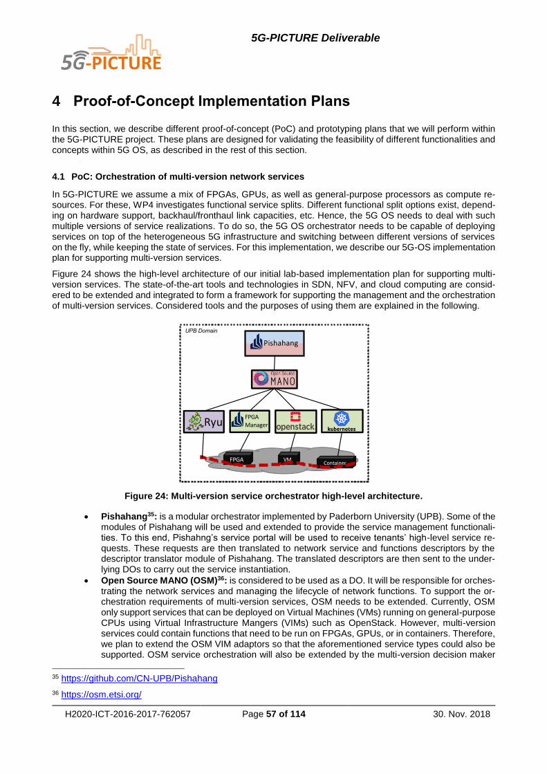
5G-PICTURE Deliverable
H2020-ICT-2016-2017-762057 Page 57 of 114 30. Nov. 2018
4 Proof-of-Concept Implementation Plans
In this section, we describe different proof-of-concept (PoC) and prototyping plans that we will perform within the 5G-PICTURE project. These plans are designed for validating the feasibility of different functionalities and concepts within 5G OS, as described in the rest of this section.
4.1 PoC: Orchestration of multi-version network services
In 5G-PICTURE we assume a mix of FPGAs, GPUs, as well as general-purpose processors as compute re-sources. For these, WP4 investigates functional service splits. Different functional split options exist, depend-ing on hardware support, backhaul/fronthaul link capacities, etc. Hence, the 5G OS needs to deal with such multiple versions of service realizations. To do so, the 5G OS orchestrator needs to be capable of deploying services on top of the heterogeneous 5G infrastructure and switching between different versions of services on the fly, while keeping the state of services. For this implementation, we describe our 5G-OS implementation plan for supporting multi-version services.
Figure 24 shows the high-level architecture of our initial lab-based implementation plan for supporting multi-version services. The state-of-the-art tools and technologies in SDN, NFV, and cloud computing are consid-ered to be extended and integrated to form a framework for supporting the management and the orchestration of multi-version services. Considered tools and the purposes of using them are explained in the following.
Figure 24: Multi-version service orchestrator high-level architecture.
Pishahang35: is a modular orchestrator implemented by Paderborn University (UPB). Some of the modules of Pishahang will be used and extended to provide the service management functionali-ties. To this end, Pishahng’s service portal will be used to receive tenants’ high-level service re-quests. These requests are then translated to network service and functions descriptors by the descriptor translator module of Pishahang. The translated descriptors are then sent to the under-lying DOs to carry out the service instantiation.
Open Source MANO (OSM)36: is considered to be used as a DO. It will be responsible for orches-trating the network services and managing the lifecycle of network functions. To support the or-chestration requirements of multi-version services, OSM needs to be extended. Currently, OSM only support services that can be deployed on Virtual Machines (VMs) running on general-purpose CPUs using Virtual Infrastructure Mangers (VIMs) such as OpenStack. However, multi-version services could contain functions that need to be run on FPGAs, GPUs, or in containers. Therefore, we plan to extend the OSM VIM adaptors so that the aforementioned service types could also be supported. OSM service orchestration will also be extended by the multi-version decision maker
35 https://github.com/CN-UPB/Pishahang
36 https://osm.etsi.org/
UPB Domain
ContainerVMFPGA
RyuFPGA Manager
Pishahang

5G-PICTURE Deliverable
H2020-ICT-2016-2017-762057 Page 58 of 114 30. Nov. 2018
component. This component takes the decision of which version of a network service should be selected for deployment.
Open Stack37: will work as a 5G OS NFV orchestrator in our implementation plan. It will be in charge of managing the lifecycle of VM-based network functions. Through a REST API, Open-Stack receives the network function instantiation requests from OSM and reacts accordingly. Be-side instantiating, updating, and terminating the VMs, OpenStack can also provide service function chaining using the SFC plugin.
Kubernetes38: will also act as an NFV orchestrator. It will be responsible for managing the lifecycle of container- and GPU-based network functions. Kubernetes management functionalities need to be extended to provide the service function chaining among container-based network functions.
UPB’s FPGA manager: is considered to be used as an NFV manger that can provide manage-ment and orchestration for FPGA-based network functions. The FPGA manager and OSM ex-change management messages through REST interfaces.
Ryu39: is an SDN controller which will be used in our framework to provide connectivity across different VIMs. Communicating with OSM thorough REST APIs, Ryu will be in charge of providing the network function chaining across virtual infrastructures.
4.2 PoC: Orchestration of Connectivity and Functions in Fixed and Wireless Networks
This PoC is aligned with the proposed use-case for WP6 Stadium demo, “Crowdsourced Video in a Stadium Environment”. The environment consists of fixed network as well as wireless network (both for access and backhaul), as shown in Figure 25.
The fixed network will be controlled by the NetOS Controller40 and the wireless network (access and backhaul) will be controlled by i2CAT controllers. NetOS will provide orchestration over the network. OSM is the chosen MANO platform. Further work is ongoing to investigate serverless architectures to provide compute (e.g., func-tion as a service using open source components like Apache Open Whisk).
Initially, the work will focus on integrating NetOS with i2CAT controllers for access and backhaul (see Figure 25) and creating network service descriptors for any end-user applications (e.g., Video Streaming) and any other services required (e.g. access control).
Specifically, the implementation plan includes the following steps.
1. Define northbound descriptors for NetOS Orchestrator – OSM deployment.
2. Create NetOS Orchestrator integration with ODL (wireless backhaul) using COP.
3. Create NetOS Orchestrator integration with ODL (access) using REST.
4. Integrate NetOS Orchestrator – NetOS Controller.
5. Create VNFs for Crowd Sourced Video App.
6. Prepare lab test-bed for validation.
7. Prepare Stadium test-bed for validation.
37 https://www.openstack.org/ 38 https://kubernetes.io/ 39 https://osrg.github.io/ryu/ 40 http://www.zeetta.com/netos/

5G-PICTURE Deliverable
H2020-ICT-2016-2017-762057 Page 59 of 114 30. Nov. 2018
Figure 25: Overview of stadium demo scenario.
Figure 26: Proposed setup – detailed view.
Zeetta will provide fixed network infrastructure for the lab test-bed and enable access to the infrastructure at the Stadium test-bed for the demonstration (part of Work Package 6). Zeetta will also provide NetOS Orches-trator and Controller and implement integration with i2Cat Controllers for wireless backhaul and access. i2CAT will provide WiFi access points, backhaul elements and software required. i2CAT will also provide support to Zeetta to integrate COP and REST interfaces with NetOS. The work done in Work Package 5 (current work package) will form the base for the northbound descriptors.

5G-PICTURE Deliverable
H2020-ICT-2016-2017-762057 Page 60 of 114 30. Nov. 2018
4.2.1 Controller Orchestration Protocol (COP)
COP is a technology agnostic interface to request E2E connections defined in 5G-XHaul41. The reason that we integrate it here is that we will not need to integrate NetOS with anything else regarding backhaul. In reality the involved software would be NetOS, Level 1 controller, ODL controller (wireless backhaul). This is shown in Figure 26. There is an alternative to COP, which is to use a custom API that is available to instantiate paths.
4.2.2 OSM Integration
Depending on availability of suitable VNFs, OSM would be used as the ETSI-MANO framework. The plan is to use the OSM REST APIs (specifically Service Orchestrator and Resource Orchestrator APIs) to integrate with NetOS (see Figure 28).
ADVA will provide the compute infrastructure for NFV MANO (OSM). The Cloud-in-a-box architecture of the Ensemble Connector introduced in Section 2.3. Based on OpenStack services and open APIs, as shown in Figure 27, it allows further integration with ESTI MANO-compliant OSM for supporting end-to-end VNFs and network service lifecycle management across multiple cloud platforms. This is represented by the dashed box in Figure 26.
Figure 27: Ensemble Connector's internal OpenStack architecture.
4.2.3 NetOS as a Domain Orchestrator
In this section, we describe how NetOS in the role of a Domain Orchestrator performs network slicing and interfaces with an NFV MANO instance.
Network slicing using NetOS
The NetOS Slicing Engine provides network slices. This requires the ability to orchestrate across one or more Domain Controllers to produce a network slice. For example, if a network slice contains different technologies (such as optical, Ethernet, wireless) then these are likely to have different controllers.
The NetOS Slicing Engine contains four interfaces of importance (see Figure 28)
1. Slice Definition – Configuration (SD-C)
2. Slice Definition – Operational (SD-O)
3. Slice Use – Configuration (SU-C)
4. Slice Use – Operational (SU-O)
Two classes of APIs allow Slice Definition and Slice Use. Slice Definition includes the ability to view available resources, request new slices, modify existing slices and release unused slices. Slice Use include the ability to monitor, configure, and control all the elements of a slice. This consists of one or more APIs corresponding to the elements in the slice. For example, if a slice contains OpenFlow switches and OVSDB-capable elements, then the Slice Use API would consist of two parts – a part to provide OpenFlow-based control and a part to configure OVSDB.
41 https://www.5g-xhaul-project.eu/

5G-PICTURE Deliverable
H2020-ICT-2016-2017-762057 Page 61 of 114 30. Nov. 2018
Figure 28: NetOS high-level internal architecture.
As NetOS is based on the OpenDaylight framework, it follows the concept of providing an Operational version and a Configuration version datastore for each data model. MD-SAL component in OpenDaylight provides the corresponding Operational and Configuration REST APIs based on these data models. Operational APIs pro-vide a read-only view of the state as it exists currently. This is read from the southbound API, directly from the device. For example, an OpenFlow Operational API would provide a read-only view of existing flows on a switch. Configuration APIs provide a read-write view of the state as it is expected to be. Changes to this are reflected southbound. Eventually once the configuration state is applied southbound the new state should be reflected in the corresponding Operational APIs.
Putting the two concepts together:
1. Slice Definition – Configuration API will allow slice definers (could be the Service Provider or 5G-
PICTURE Operator) to create, read, update and delete slices
2. Slice Definition – Operational API will allow definers to examine available resources to create their
slice
3. Slice Use – Configuration API will allow slice users (5G-PICTURE Tenants) to configure and
control their slices (via relevant sub-APIs corresponding to each element type present in the
network)
4. Slice Use – Operational API will allow the slice users to monitor their slices and provide an
operational view of their virtual network
The layered aspect of these APIs is shown in Figure 28. The orchestration element in NetOS allows for the creation of slices by mapping slice elements on to underlay network. For this, it consumes the SD-O API from the layer below. It is also tasked with providing the SD-O API to the layer above. The mapping is written in the Mapping datastore.
Once the mapping is done the implementation has driver agents that drive the mapping to the next layer down via available controllers, using the SU-C and SU-O APIs provided by that layer. It is also responsible for pro-jecting the required SU-C and SU-O APIs to the next layer up. This should correspond with the requested slice.
SU-C and SU-O also provide convenient wrappers to integrate NetOS with different resource providers such as OSM via the SO or RO interfaces (providing compute and storage), OpenDaylight for vanilla OpenFlow, and OVSDB via REST. It also enables uniform point of integration for vendor-specific APIs. As long as a driver can be created to translate a specific underlay API associated with a resource to the common model, that resource can be sliced.

5G-PICTURE Deliverable
H2020-ICT-2016-2017-762057 Page 62 of 114 30. Nov. 2018
NetOS-NFV MANO Interaction
As shown in Figure 29, the underlay network’s SU-O and SU-C also represent APIs provided by a virtual device instantiated using MANO. OSM is the reference NFV MANO implementation that will be used for this implementation. Figure 29 also shows how NetOS, as a DO, interacts with NFV MANO via the DO-MANO interface.
The Orchestrator component shown in Figure 29, will decide when virtual resources are required. Alternatively, depending on the domain structure, this could be part of the request coming from the MDO. The Orchestrator will also need to decide which OSM and within that which datacentre to place the virtual functions in. The next step is to request instantiation of the virtual devices. Once instantiation is successful the devices are provided to the Implementation component (Figure 29) via the Mapping store. The driver on the Implementation side will make use of the underlay network’s SU-O and SU-C APIs to slice the virtual device.
For example, in Figure 29 a simple OVS scenario is shown. Here the Orchestrator requires two OVS switches interconnected by a WAN link. Once the placement decision has been made, the virtual resource manager requests OSM to instantiate the OVS switch VNFs. Once successful, SD-O is updated with the virtual devices as new resources via the OSM agent. Then the Orchestration engine assigns those virtual devices to a slice. Once the assignment is complete, the OVSDB implementation configures the virtual devices.
Figure 29: DO - MANO interaction, example from NetOS.
The WAN link between the two virtual devices is mapped to a TAPI [42] style link. Here we are skipping the internal DC network – assuming that OSM configures connectivity to the edge of the DC.
4.2.4 NetOS as a Controller
The implementation side (see Figure 28) uses controller functions to drive the layer below via the Slice Use - Configuration and Operational interfaces provided to slice users (described in Section 5.3.4). At the lowest layer the SU-C and SU-O will correspond to raw APIs (possibly vendor-specific) that provide direct access to the physical network and resources.
After the first level of slicing, a common model is used so that SU-C and SU-O APIs have a standard appear-ance from the next layer up. This enables recursive slicing but creates an additional burden of resource man-agement at each layer. This approach also complicates the orchestration, as at each layer the request to resource mapping has to be created (and maintained thereafter) before the next layer up can be sliced. A single-layer slicing engine is a degenerate case of this, where only one layer of slicing is allowed over the actual physical network and resources. In this case, resource management is done only at the lowest layer and orchestration is also relatively easy.

5G-PICTURE Deliverable
H2020-ICT-2016-2017-762057 Page 63 of 114 30. Nov. 2018
4.2.5 RAN Domain Controller
For the control of RAN domain operations, we need additional controllers. One such operation is the manage-ment of points of presence, e.g., to instantiate a new virtual access point (vAP) with provided credentials, the RAN PHY settings such as the channel/band to use, the transport tunnel association, etc.
Such control for WiFi Access can be achieved through the use of OpenDayLight and NETCONF interfaces towards WiFi Access Points. Within 5G-PICTURE, this will be implemented as illustrated and detailed in Figure 30. The left part of Figure 30 depicts an example use case, where WiFi Small Cells are deployed in an outdoor area mounted on lamp-posts, and various slices composed of a set of dynamically instantiated virtual Access Points delivering a specific connectivity service. This functionality is considered for various applications in a stadium scenario, such as providing connectivity services in the Fan Zone. In the right part of Figure 30, we illustrate the software architecture of the WiFi controller that will be integrated with the overall 5GOS to orches-trate the various services deployed in the stadium.
Figure 30: Joint Access+BH WiFi use case and architecture.
4.3 PoC: Orchestration of multiple controllers and NFV MANO systems
The main responsibility of the MANO component is to deploy a network service, which is to deploy the VNFs used by this service and build their interconnection. MANO uses Virtual Infrastructure Manager (VIM) to deploy the VNFs and sometimes uses multiple VIMs, each one responsible for a single PoP. In many of the use cases of our interest, there are networks services that need geographically distributed resources, thus they require VNFs that are not located on the same PoP. For example, an LTE service could rely on VNFs implementing the LTE core, which should be located in a centralized datacenter (PoP), and VNFs used for the LTE RAN, which could be spread to multiple PoPs covering as much area as it is possible. The existing non-commercial implementations of MANO are not able yet to deploy these geographically distributed services. They talk only to a single VIM, responsible for a single PoP, in order to deploy the whole service to this PoP.
The focus of this task is to make MANO able to deploy this kind of services, by spreading the VNFs of such a service to multiple PoPs, where each PoP is managed by one of the MANO’s orchestrated VIMs. The challenge is the VNFs’ interconnection, since it requires the dynamic connectivity of the involved PoPs, which is not provided yet from the existing MANO’s implementations. The goal of this task is to create a MANO implemen-tation that will be able to force the DC(s) component(s) for providing the dynamic interconnection between the VIMs. This implementation relies on the following three software products.
OpenDaylight (ODL) as DC
OpenStack (OpSt) as VIM, and
Open Source MANO (OSM) as MANO

5G-PICTURE Deliverable
H2020-ICT-2016-2017-762057 Page 64 of 114 30. Nov. 2018
In Figure 31, we present a simple scenario with two OpSt instances, being the VIMs of two PoPs. These two PoPs are physical interconnected through two different network segments (e.g. the one uses WiFi and the other uses optical). The OSM instance on top, that is the MANO component, communicates with the Orches-tration-proxy, which is appeared as a single VIM instance to OSM. In this way, for the OSM’s perspective, the VNF’s deployment is assigned to a single VIM. However, the VNFs are spread to both OpSt instances (the two first VNFs are deployed to the left OpSt and the other two to the right OpSt) and simultaneously the underlying ODL instances, being the DCs of this domain, configure the network segments to allow the con-nectivity between the VNF 2 and VNF 3.
Figure 31: Orchestration of MANOs and domain controllers.
Finally, the Bscontrol service is used for the configuration of the interfaces connecting PoPs to the network segments. Bscontrol is a special software produced by UTH for the provision of wireless connectivity using either WiFi, LTE or millimetre wave (mmWave) technologies. It abstracts the hardware resources and their configuration methods (e.g. TR169, SNMP, MySQL), and provides a REST-based API that can be called for setting up the physical interconnection parameters of the equipment (e.g. WiFi AP to WiFi STA connection, LTE UE to LTE network, etc.).
In summary, UTH’s software is able to assistant the deployment of network services, using Orchestration-proxy/Bscontrol to configure the various network segments that rely on different networking technologies and OSM/OpSt to deploy the VNFs.
4.4 PoC: Orchestration of RAN, CN, and Edge domain controllers
In this PoC, we are targeting to develop multiple Domain Controllers (DCs) and Domain Orchestrator (DO). More specifically, the following elements are included:
FlexRAN (RAN Domain Controller) is a flexibly and programmable platform to apply the SDN princi-ple at the RAN domain to control RAN in a real-time manner. Moreover, we plan to extend the FlexRAN design as a unified and customized control framework architecture for underlying heteroge-neous and disaggregated RAN nodes.
LL-MEC (CN/Edge Domain Controller) is an ETSI-aligned MEC platform that can act as software-defined core network controller. It is expected to extend current implementation work for the future 5G core network (5GC).
JOX (Domain Orchestrator) is an event-driven Juju-based service orchestrator core with several plugins to interact with different network domains, e.g., RAN and CN. The future extension will be to support heterogeneous and disaggregated RAN deployments.
Further, we will provide the Store repository that includes a constellation of platform packages, software de-velopment kits (SDKs), network control applications and datasets. Following Figure 32 depicts the overall

5G-PICTURE Deliverable
H2020-ICT-2016-2017-762057 Page 65 of 114 30. Nov. 2018
schema of our development plan, i.e., Mosaic5G42, and its relations over the underlying OpenAirInterface (OAI) RAN and OAI CN that are supportable by FlexRAN and LL-MEC correspondingly.
Figure 32: Mosaic5G Schema.
Figure 33: Interfaces between different Mosaic5G components.
Besides these intended implementation plan over Mosaic5G, we will also focus on the interfaces between (1) FlexRAN and LL-MEC (i.e., between DCs) and (2) JOX and FlexRAN/LL-MEC (i.e., between DO and DC) as depicted in Figure 33. The former interface can enable the cross-domain control behavior to provide real-time information exchange to better facilitate the end-to-end resource slicing for instantiated network slices. For instance, a proportional amount of radio resource as well as backhaul capacity can be provided to a slice in order to reduce the resource under- or over-utilization. Further usages will be explored in more details for upcoming deliverables. While the second interface rely on the JOX plugins (see following figure) exploiting a
42 http://mosaic-5g.io/

5G-PICTURE Deliverable
H2020-ICT-2016-2017-762057 Page 66 of 114 30. Nov. 2018
message bus to support the plugin communication subsystem and a JAgent integrated with the Domain Con-troller (e.g., FlexRAN) to support heterogeneous and disaggregated RAN deployments.
Last but not least, the open data and API works as an interface for communicating with the underlying Control Applications to enable verticals to develop and deploy specialized 5G services on top of the Mosaic5G eco-system. We can observe that there are two API levels, in which the high-level API in technology-agnostic, while the low-level one is not. And the corresponding SDKs, namely, the Platform SDKs (cf. the SDK above FlexRAN, LL-MEC and JOX in Figure 33) at the first level and the App SDKs, decouple the control logic from the user plane actions following SDN principles. They also enable to extract aggregated and structured network configuration, status and topology information in the form of instantaneous/current network graphs that allow for a better data analysis and decision-making. Moreover, the SDKs facilitate the development of extendable network Control Apps that coordinate with one another.
4.5 PoC: Orchestration of Time-Shared Optical Network (TSON) in the Optical Transport network
To support the heterogeneous network with different granularity and different latency requirements, the optical transport network should be elastic. In 5G-PICTURE, the Time-Shared Optical Network (TSON) developed by the HPN UNIVBRIS is proposed as an elastic optical network technology. To manage the resources and con-figure the TSON network, an orchestration system is built on top of this network. Our implementation starts by the DO. In this section we are going to define the different interface from the DO to the TSON network.
The implementation plan of HPN consists of orchestrating the TSON resources through the DO an DC, as described in Figure 34. The figure depicts the high-level architecture to orchestrate the TSON network.it is composed by:
OSM located in the DO, is able to receive the different requests from the MDO and sends a request to
the controller.
OpenDaylight (ODL), located in the DC, which receives the request from OSM and configures the
different TSON nodes.
TSON nodes based on FPGA are located in the resource domain and constitute the optical transport
network.
Figure 34: Overview of the TSON orchestration.
Figure 35 depicts the different components to be developed in WP5 in 5G-PICTURE in order to provide the TSON orchestration.
This work is essentially focusing on:
Developing a RESTCONF API on both DC and DO sides to allow the RO of OSM to send the re-
quests to the ODL controller and to receive the notifications.

5G-PICTURE Deliverable
H2020-ICT-2016-2017-762057 Page 67 of 114 30. Nov. 2018
Developing an OpenFlow agent based on the new design of TSON. The OpenFlow agent running on
top of the TSON node translates OpenFlow messages to the LUT frames in order to configure the
FPGA of the TSON node.
Extending the OpenFlow message to handle the size of the TSON frame. Indeed, the current exten-
sion deals with the number of the slices in the frame. To benefit fully from the TSON features and to
increase the flexibility, it is necessary to the control the size of the frame via the SDN controller.
Designing and implementing the TSON Computation Path module. This module will be integrated in
the ODL controller. It will be able to provide the path based on the number of time-slices, the size of
the frame, the bandwidth and the latency.
Testing and validating this architecture. It will consist of implementing end-to-end connectivity based
on the functional split option employed. The functional split will be performed with OAI, where we will
set up the functional split option 6 and option 7. In this case we should declare the RAN-OAI as a
PNF. The current OSM doesn’t support the PNF therefore the RO should be extended to handle the
RAN-OAI PNF.
Figure 35: Detailed implementation of the orchestration of the TSON.
In summary, the work plan is divided into 4 parts. The first part is to design and to implement the interface between the DO and DC based on RESTCONF interface. The second part is to design and to implement the interface between DC and Resources (RD) by extending the OpenFlow messages. Then, the third part consists of developing an ODL module to compute the path in the TSON network. Finally, the last part consists of testing and validating this architecture.
4.5.1 TSON Domain Orchestrator
The TSON network provides L2 network slices based on the VLAN tags. In this part, the components in the DO and the different interfaces from the DO to the other components of the 5G OS are described.
The DO of the TSON network comprises an OSM and a proxy (Figure 36). The proxy is an API based on the 5G-PICTURE descriptor. It receives the sub domain request from the MDO and sends the appropriate slice instance descriptor to the MDO. It also translates the 5G-PICTURE sub-slice request to the understandable demand by the SO. It could implement the interface to communicate with the other determined DO. The OSM through SO, receives the request to configure the TSON slice network from the proxy and sets the implemented TSON WIM connector to send the request to the DC where a REST API has been developed. This request should contain the TSON endpoints, the bandwidth, the latency and the VLAN tag since that the TSON support only the L2 network slices (Figure 37).

5G-PICTURE Deliverable
H2020-ICT-2016-2017-762057 Page 68 of 114 30. Nov. 2018
Figure 36: General architecture of DO of TSON domain.
Figure 37: Example of request to configure the end-to-end connectivity via TSON network.

5G-PICTURE Deliverable
H2020-ICT-2016-2017-762057 Page 69 of 114 30. Nov. 2018
4.5.2 TSON Domain Controller
The TSON domain controller is composed by the ODL SDN controller and by the API called TSON path Com-putation (TPC) which determines the shortest path according to the requested bandwidth and the latency, as well as the end points and the available resources. A RESTCONF API is developed to communicate with the DO. The request is forwarded to the TPC which are going to calculate the path according to the current topol-ogy and request. The result of the calculation path is sent to the ODL controller which is going to configure the selected TSON nodes via the OpenFlow message. To configure them, the OpenFlow protocol have to be extended. This OpenFlow extension constitutes the main protocol of the DC-RD interface. These extensions allow configuring the number of time slots, the size of the frame, the size of the time slot and the size of the overhead of the TSON frame in orders to fully control the parameters and the resources of TSON node.

5G-PICTURE Deliverable
H2020-ICT-2016-2017-762057 Page 70 of 114 30. Nov. 2018
5 5G OS Validation
Mega-event/Stadium and Rail are two important verticals for the 5G-PICTURE project (for details see D2.1). In this section, two 5G use-cases derived from these verticals are introduced to validate 5G OS architecture. We also present our simulation results regarding the scalability of 5G OS in this section. In the interest of readability, we present the use-cases and the validation in the same section.
5.1 Mega-Event/Stadium Vertical
In a mega-event and/or stadium scenario, there are likely to be a wide variety of services operating before, during, and after the event. Some examples include: broadcast services (e.g. VR streams, high-definition and standard-definition), infrastructure services (e.g. CCTV, advertising, tills, sensors and ticketing), and third-party services (e.g. betting, social media and personal communication applications).
These services may be provided by different service providers using resources from different infrastructure providers (such as cloud computing, edge-computing, transport network and access network). Therefore, most services will depend on resources not controlled directly by the service provider (this includes resources ne-gotiated with the stadium/venue for the last-mile access).
From the point of view of the venue, multiple service providers will require a dedicated network or connectivity to their virtual/physical devices and applications over the shared network infrastructure. This brings in require-ment for ensuring standard interfaces to request access to shared resources owned by third-party infrastruc-ture providers as well as ensuring the appropriate level of isolation, security, resilience and control. In other words, service providers will make use of slices of the shared infrastructure and will require mechanisms to negotiate the appropriate levels of isolation, security, resilience and control as well as suitable performance KPIs. These KPIs are expected to align with those described for the categories already identified in ITU-T 5G Services [32] as follows:
1. Massive Machine Type Communications: the venue as a part of a smart city environment (e.g., sen-
sors deployed at the venue for safety, environmental monitoring and crowd control).
2. Ultra-reliable and Low-latency communications: as part of the next generation multimedia services
access to low-latency communications would be required.
3. High-speed Mobile Broadband: this is where the venue infrastructure could be augmented with tem-
porary radio access infrastructure to provide high-speed mobile broadband to large number of people
concentrated in a small area.
5.1.1 Example use-case descriptions
During a mega-event, there is likely to be a Broadcast Service with a combination of wireless and wired cam-eras with different capabilities (e.g., HD, non-HD, 4K, 3D etc.). A broadcaster would also have some remote back-end to distribute the video and an edge deployment at the stadium to do video aggregation/editing. All these different islands would need to be connected via transport links with sufficient bandwidth and low latency. These transport links may pass through multiple different networks. Finally, the broadcaster would need to deploy control and configuration infrastructure to setup and manage the Broadcast Service (including deploy-ing software components, controlling hardware as well as scaling resources up/down as required).
From the venue owner’s perspective, a standard interface is required to allow service providers to request resources, i.e., slices (ideally via an automated interaction). The network should also provide strong isolation guarantees to ensure different services running on top of the same infrastructure do not disrupt each other, i.e., slicing.
Important use-cases associated with this vertical are as follows.
Use 1.1: A broadcaster wants to setup their own virtual slice using different providers, which includes the stadium/venue, for a mega-event. This use-case is related to the planned project pilot where the virtual network includes:
Cloud Compute.
Edge Compute.
WiFi Access Points.

5G-PICTURE Deliverable
H2020-ICT-2016-2017-762057 Page 71 of 114 30. Nov. 2018
Ethernet Ports.
Layer 2 and Layer 3 Access Network with:
o QoS.
o MAC-based access.
o Monitoring.
Use 1.2: A broadcaster wants to scale up/down cloud compute resources and bandwidth as if the virtual net-work was a real network under their exclusive control. For example, to free network resources for use by event-goers when broadcasting is not in progress or is happening at a reduced level.
Use 1.3: A broadcaster wants to control Network Access for their network directly – so that they can handle addition and removal of devices such as cameras, drones in real-time without having the delay and adminis-trative overhead of interacting with the venue or other network provider.
Use 1.4: A broadcaster wants to monitor the fault state and performance of their virtual network in real time. This will allow them to quickly identify and assess and mitigate impacts of outages to their service without necessarily having to wait for the network provider (e.g., by moving resources/connections to a different un-derlay network).
Use 1.5: A broadcaster wants to release resources when the mega-event is over
Use 1.6: A venue owner wants to provide different virtual networks to different service providers and for their own use with different capabilities such as:
Compute.
QoS.
Monitoring.
Network Control.
Wireless/Wired Access.
Network Access Control.
Use 1.7: A venue owner wants to manage all virtual networks it provides, which includes:
Troubleshooting.
Accounting resource usage.
Configure virtual and physical devices.
Service monitoring.
5.1.2 Mega-event/Stadium Solution using 5G OS
In this section, a solution for the Mega-event use-case is provided (see Figure 38), using 5G OS. It is assumed that a telecoms provider (5G Operator A in the figure) is running 5G OS Service Management and Multi-domain Orchestrator components and allows different Tenants (e.g., broadcaster from the use-case) to deploy their own services on shared infrastructure.
The 5G Operator A also has agreements with various Infrastructure Providers to provide connectivity (Domain B and Domain C), compute (Datacentre) and edge access network (Stadium). One of the infrastructure pro-viders is the venue where the broadcaster is going to be telecasting live. Each Infrastructure provider is running a Domain Orchestrator (DO) and various flavours of Domain Controllers and MANO stacks.
The Stadium consists of both fixed and wireless infrastructure including SDN switches, WiFi access points as well as compute setup with a suitable MANO stack (e.g. OSM). It is assumed that some form of connectivity already exists between the 5G OS Operator A and the Stadium.
For example, in Figure 38 the Stadium is running one Domain Orchestrator, two Domain Controllers (one for wireless and one for wired) as well as a MANO stack to provide edge-compute resources.

5G-PICTURE Deliverable
H2020-ICT-2016-2017-762057 Page 72 of 114 30. Nov. 2018
Figure 38: Solution for Stadium using 5G OS.
The generic sequence of end-to-end slice creation is as follows:
1. Tenant activates a service via the 5G Operator A’s Service Management interface
a. Service requests specific Access Points at the Stadium as well as defines QoS and Network
Access device whitelist, this is done by using configuration templates associated with the
service
2. Service Management enriches the Service request and passes to Multi-domain Orchestrator
3. MDO needs to map and translate request to various infrastructure providers it knows off to obtain
optimal resource allocation
a. DO of Datacentre provides compute to run video distribution services
b. DO of Domain B and C provide pure connectivity to the Datacentre with strict QoS
c. DO of 5G Operator A provides pure connectivity between the Stadium and the datacentre
with strict QoS
d. DO of the Stadium provides edge-compute and access via WiFi (selected Access Points and
SSIDs) and wired Ethernet interfaces
e. DO of the Stadium also provides network access control (device MAC-based) function (can
be provided using a real device or a virtual function)
4. Once resource allocation is confirmed the various functions are deployed and connectivity initiated;
which marks the completion of the end-to-end slice creation process
5. Once the end-to-end slice has been created the service is considered to be ‘alive’ and corresponding
monitoring, management and configuration interfaces can be brought on-line to allow the Tenant
(broadcaster) to fully control their service.
The requested slice is shown in Figure 39. Both Base Slice approach (Virtual Operator model) and the Guide Slice approach (Operator as Broker) are described in the next sections.

5G-PICTURE Deliverable
H2020-ICT-2016-2017-762057 Page 73 of 114 30. Nov. 2018
Figure 39: Requested Slice: Stadium.
Creating an End-to-End Slice: Base Slice Approach
The Base Slice approach has been described previously (see Section 3.3.7) To recap, it involves creating one or more end-to-end slices across all the available domains to be used as a base for different types of tenant slices.
Figure 40 shows how the Base Slice approach is applied to the Mega-event/Stadium use-case. On the left-hand side, the physical network is shown as it exists. On the extreme right-hand side, the virtual network slice is shown, which implements the requested service to provide broadcast from the stadium, pre-process and aggregate it, and then distribute it.

5G-PICTURE Deliverable
H2020-ICT-2016-2017-762057 Page 74 of 114 30. Nov. 2018
Figure 40: Creating an End-to-End Slice: Base Slice Approach.
The sequence of service creation is as follows.
1. In preparation for Tenant requests the 5G Operator A would create one or more base-slices from the resources provided by the infrastructure provider. These provide an abstraction for resources held across every domain. For example, in this case the base-slice would contain resources assigned to 5G Operator A from the following domains:
a. Stadium – providing edge access and compute at that location.
b. Domain A – its own domain, where resources are earmarked for Tenant use – separate from
resources required for internal and other uses.
c. Domain B – providing connectivity to Datacentre.
d. Domain C – providing connectivity to Datacentre.
e. Datacentre – providing compute facility.
2. Tenant via the Service Management system requests a Service to be initiated which contains WiFi access points at the stadium, applications for video editing and aggregation to be deployed at the stadium, application to be deployed for video distribution in the cloud, function to be deployed at the stadium for network access control along with connectivity constraints (QoS).
3. The request is passed to the MDO which in turn maps and translates service request into requests for compute, connectivity and access while ensuring constraints related to QoS and placement (e.g. WiFi access points, video editing/aggregation and network access control at the stadium).

5G-PICTURE Deliverable
H2020-ICT-2016-2017-762057 Page 75 of 114 30. Nov. 2018
4. The Slicing Engine operates upon the base slice to create a service specific slice for the Tenant (Broadcaster) with the required functions chained as per the service definition.
For this approach, we make the following assumptions:
1. When creating the base slice all providers will give resources that are controlled directly by the 5G Operator A (for example pre-provisioning resources) or the resource will be a static one (e.g. link). Otherwise it would be impossible for the 5G Operator to further slice the base slice.
2. Inter-domain links are statically defined to ensure the domains can link up with each other and with the MDO (5G Operator A).
Creating an End-to-End Slice: Guide Slice Approach
The Guide slice approach has been described previously. To recap, it involves creating a guide slice which consists of domains and links between them. This guide slice is then used as a ‘reference’ to create slices at run-time based on services requested by the Tenant. This can be thought of as a stitching together of sub-slices to create an end-to-end slice where each sub-slice lives in a domain. The advantage of the guide slice approach is that while it does not possess the flexibility of a base-slice, it simplifies the MDO orchestration and placement problem by removing the problem of domain interconnect (which is pushed to the layer below in case of Base Slice approach). Major components and actors remain the same as Base-Slice approach, see Figure 41 for details.
The sequence of Service creation:
1. In preparation for Tenant requests the 5G Operator A creates a guide slice from the resources pro-
vided by the infrastructure provider. This contains reservations for all available resources for Tenant
use, across every connected domain.
2. Tenant via the Service Management system requests a Service to be initiated which contains Wifi
access points at the stadium, applications for video editing and aggregation to be deployed at the
stadium, application to be deployed for video distribution in the cloud, function to be deployed at the
stadium for network access control along with connectivity constraints (QoS).
3. The request is passed to the MDO which in turn maps and translates service request into requests for
compute, connectivity and access while ensuring constraints related to QoS and placement (e.g. Wifi
access points, video editing/aggregation and network access control at the stadium).
4. The Slicing Engine, which is part of the Orchestrator component (MDO and/or DO), looks up the guide
slice and allocates sub-slices in each domain to provide required connectivity and functions.
5. The sub-slices are connected, based on the pre-defined domain interconnect, to create a service spe-
cific slice for the Tenant (Broadcaster) with the required functions chained as per the service definition.
For this approach, we make the following assumptions:
1) Through the guide slice all providers will give an accurate indication of resources available for the
5G Operator A via the guide slice.
2) Inter-domain links are pre-defined to ensure the domains can link up with each other and with the
MDO (5G Operator A) and placement decisions are simplified.

5G-PICTURE Deliverable
H2020-ICT-2016-2017-762057 Page 76 of 114 30. Nov. 2018
Figure 41: Creating an End-to-End Slice: Guide slice approach.
5.1.3 Descriptor Flow in Mega-Event/Stadium Solution
This section describes how a service request flows through different 5G OS components owned by different actors. Slice Request Descriptors (also referred to as Blueprints) and Instance Descriptors have been de-scribed in detail in previous sections.
Figure 42 shows the descriptor flow in detail. The tenant passes a Service Descriptor to the Service Manage-ment component which generates one or more Slice Blueprints based on the Service Descriptor. These Slice Blueprints are then further mapped and translated by the Multi-Domain Orchestrator to different DOs. DO-specific Sub-Slice Blueprints are generated by this process. Each DO further process these Sub-Slice Blue-prints into corresponding Function and/or Connectivity Descriptors which is passed to respective Domain Con-trollers under the DO.
In case of the Stadium use-case, the more complex work has to be done by the Stadium DO as it has to orchestrate over Virtual Function resources (MANO for edge compute), physical function resources (e.g., for Network Access Control) and connectivity (wireless and wired) resources. For Operator A, Domain B and Domain C, the primary resource being requested is the connectivity between the Stadium and the Datacentre with a strict QoS requirement. For the Datacentre a standard MANO Stack (e.g. OSM) is implemented which requires a Function Descriptor.
In response, each orchestrator component must return a Slice Instance Descriptor to indicate type and location of instantiated resources. The Stadium DO must return the following:

5G-PICTURE Deliverable
H2020-ICT-2016-2017-762057 Page 77 of 114 30. Nov. 2018
1. endpoint to manage Network Access Control (e.g. REST API to add/remove allowed MAC ad-
dresses)
2. endpoint or URL to access the video editing/aggregation server
3. monitor Wifi access points (mainly read-only)
4. monitor switches and links
Similarly, those Infrastructure Providers providing connectivity must return APIs that allow the Tenant to mon-itor those links. Finally, the Datacentre would return the endpoint or URL to access the video broadcast server.
Figure 42: Descriptor Flow in Mega-event/Stadium Solution.
5.2 Rail Vertical
In the Rail vertical, there are likely to be a wide variety of services operating in parallel, some of them operating 24x7, others based on specific events. Some examples include: infrastructure services (e.g., rail network mon-itoring, CCTV, advertising, tills, signalling, and sensors) and third-party services (e.g., mobile broadband, con-tent distribution, and telephony).
Similar to the mega-event/stadium scenario, these services would be provided either directly by the Rail com-pany or by third-party providers. In both the cases there may be requirement for external resources for com-pute, interconnect and access.
In some regions the track and associated infrastructure is owned and operated by a separate business from the train operator. In this case, even the access side will span across two separate domains. For simplicity, we will assume there is a single monolithic rail company in the rest of this description but we consider both scenarios for the actual validation.
From the point of view of the Rail company (just as is the case with the venue owner), multiple service providers will require their dedicated network or connectivity to their virtual/physical devices and applications over the shared network infrastructure. Apart from that, some other non-trivial aspects of this network are highlighted below:
1. The geographical spread of the network.
2. The mobility of the trains and associated use of wireless.
3. Safety critical nature of some of the services operating on the network.
4. The possibility of the transition between different administrative domains as part of a rail journey.

5G-PICTURE Deliverable
H2020-ICT-2016-2017-762057 Page 78 of 114 30. Nov. 2018
This related to the ITU-T 5G Services (ITU-T focus group, 2017) as follows:
1. Massive Machine Type Communications: the rail network is a massive sensor network (e.g. sensors
deployed at stations, crossing, bridges, tunnels, environmental monitoring and on the train itself)
2. Ultra-reliable and Low-latency communications: required for communication between trains and be-
tween the train and controller, this combines both human to human communication as well as ma-
chine to machine (driverless trains)
3. High-speed Mobile Broadband: one of the persistent problems is access to reliable high-speed
broadband on-board a train especially a ‘high-speed’ train
5.2.1 Example use-case descriptions
A Rail company would want to use the same network to provide different classes of services – from mission-critical to purely third-party over-the-top services. These services may be provided by the Rail company or by a third-party. In both the cases, a standard mechanism to request and manage resources is required.
From the Rail company perspective, its trains are likely to transit through regions where other Rail providers control the infrastructure. Therefore, as a minimum requirement to provide un-interrupted service, connectivity to the end users (e.g., passengers on the train or the train itself) must be provided across all the regions the train travels through.
To support third-party service providers over a rail network, a standard interface is required to allow service providers to request resources (ideally via an automated interaction). The network should also provide strong isolation guarantees to ensure different services running on top of the same infrastructure do not disrupt each other.
Important use-cases associated with the vertical are as follows.
Use 1.1: A service wants to setup their own virtual network using different providers to provide services to rail passengers throughout the rail network. The virtual network must include:
Cloud Compute.
Edge Compute.
Wifi Access Points.
Network access control (e.g. via smart-phone application or captive portal)
Layer 1 passive WDM Transport Network with:
o QoT (Quality of Transmission).
o Monitoring.
o Configuration.
Layer 2 and Layer 3 Access Network with:
o QoS.
o Monitoring.
Use 1.2: A service provider wants to scale up/down cloud compute resources, number of WiFi Access Points and Access bandwidth as if the virtual network was a real network under their exclusive control
Use 1.3: A service provider wants to control hosts on the network and allow/disallow access to the network using different methods such as a Captive Portal
Use 1.4: A service provider wants to monitor the fault state and performance of their virtual network
Use 1.5: A service provider wants to release resources during off-peak hours
Use 1.6: A rail company wants to provide different virtual networks to different service providers and for their own use with different capabilities such as:
Compute.
QoS.
Monitoring.
Network Control.

5G-PICTURE Deliverable
H2020-ICT-2016-2017-762057 Page 79 of 114 30. Nov. 2018
Wireless Access.
Network Access Control.
Passive WDM Transport Control and Traffic Aggregation.
Use 1.7: A rail company wants to manage all virtual networks it provides, which includes:
Troubleshooting.
Accounting resource usage.
Configure virtual and physical devices.
Service monitoring.
5.2.2 Rail Solution using 5G OS
From the perspective of the Rail company, two main solution types are possible, depending on which entity is defined as the 5G-PICTURE Operator:
1. Rail Company is the 5G-PICTURE Operator (see Figure 43).
2. Rail Company is an Infrastructure Provider for a 5G-PICTURE Operator providing services over the Rail network.
Type 2 solution can further be subdivided into two c depending on whether the 5G OS Operator (who is distinct from the Rail Network) can:
1. work with a single Rail network for all regions because of existing agreements between Rail networks, where one network represents the group within the network.
2. negotiate with individual Rail networks for each region to get complete coverage.
The specific application being deployed over the network service is not of importance as most applications will require some sort of cloud presence, as well as connectivity to the client application on a smart-phone or other mobile-compute device. Apart from this, there is also the wider customer WiFi use-case.
The requested slice for this scenario is shown in Figure 44.

5G-PICTURE Deliverable
H2020-ICT-2016-2017-762057 Page 80 of 114 30. Nov. 2018
Figure 43: Rail company as the 5G OS Operator

5G-PICTURE Deliverable
H2020-ICT-2016-2017-762057 Page 81 of 114 30. Nov. 2018
Figure 44: Requested Slice: Rail Scenario.
5.2.3 Rail Company as the 5G OS Operator
With the Rail company as the 5G OS Operator all the services it provides (e.g., passenger-facing, infrastruc-ture-related, corporate, etc.) can be unified over the same physical network using network virtualisation. The Rail company can also allow selected third-parties to deploy their services over the Rail network.
In this case, the Rail company will operate the Service Management and Multi-Domain Orchestrator compo-nents to provide end-to-end network virtualisation (i.e., slices) as well as Domain Orchestrators (for their net-work) and Domain Controllers (see Figure 43) to allow access to network resources for the purposes of virtu-alisation.
The MDO will also integrate with DOs of other networks – whether those are other Rail networks operating in different transit regions (Rail company B in Figure 43) or compute infrastructure providers (Datacentre in Figure 43) or connectivity providers (Domain B and C in Figure 43).
The following section describes the Base Slice approach which is more relevant to the Rail Company as the 5G-PICTURE Operator scenario. This is driven by the discussions with the vertical representatives and their
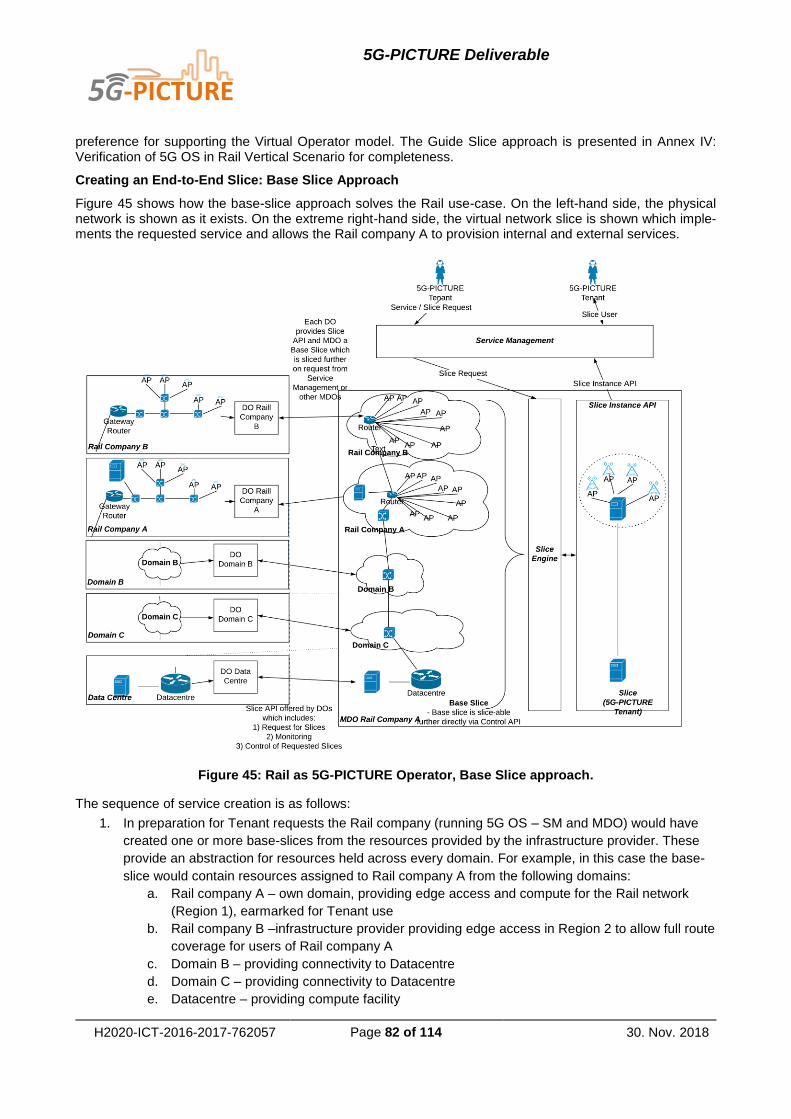
5G-PICTURE Deliverable
H2020-ICT-2016-2017-762057 Page 82 of 114 30. Nov. 2018
preference for supporting the Virtual Operator model. The Guide Slice approach is presented in Annex IV: Verification of 5G OS in Rail Vertical Scenario for completeness.
Creating an End-to-End Slice: Base Slice Approach
Figure 45 shows how the base-slice approach solves the Rail use-case. On the left-hand side, the physical network is shown as it exists. On the extreme right-hand side, the virtual network slice is shown which imple-ments the requested service and allows the Rail company A to provision internal and external services.
Figure 45: Rail as 5G-PICTURE Operator, Base Slice approach.
The sequence of service creation is as follows:
1. In preparation for Tenant requests the Rail company (running 5G OS – SM and MDO) would have
created one or more base-slices from the resources provided by the infrastructure provider. These
provide an abstraction for resources held across every domain. For example, in this case the base-
slice would contain resources assigned to Rail company A from the following domains:
a. Rail company A – own domain, providing edge access and compute for the Rail network
(Region 1), earmarked for Tenant use
b. Rail company B –infrastructure provider providing edge access in Region 2 to allow full route
coverage for users of Rail company A
c. Domain B – providing connectivity to Datacentre
d. Domain C – providing connectivity to Datacentre
e. Datacentre – providing compute facility

5G-PICTURE Deliverable
H2020-ICT-2016-2017-762057 Page 83 of 114 30. Nov. 2018
2. Tenant via the Service Management system requests a Service to be initiated which contains all
edge access points in Region 1 and Region 2, application servers to be deployed in the cloud and
edge, connectivity with QoS constraints
3. The request is passed to the MDO which in turn maps and translates service request into requests
for compute, connectivity and access while ensuring constraints related to QoS and placement
4. The Slicing Engine operates upon the base slice to create a service specific slice for the Tenant
(third-party Service Provider or Rail company A) with the required functions chained as per the ser-
vice definition
For this approach, we make the following assumptions:
1. When creating the base slice all providers will give resources that can be controlled directly by the
5G OS Operator (Rail company A) or the resource will be a static one (e.g. link). Otherwise it would
be impossible for the 5G OS Operator to further slice the base slice
2. Inter-domain links are statically defined to ensure the domains can link up with each other and with
the MDO (Rail company A)
5.2.4 Descriptor Flow in Rail Company as 5G OS Operator
This section describes how a service request flows through different 5G OS components owned by different actors. Figure 46 shows the descriptor flow in detail. The tenant passes in a Service Descriptor to the Service Management component, which generates one or more Slice Blueprints based on the Service Descriptor.
These Slice Blueprints are then further mapped and translated by the Multi-Domain Orchestrator for different DOs. DO-specific Sub-Slice Blueprints are generated by this process. Each DO further processes these Sub-Slice Blueprints into corresponding Function and/or Connectivity Descriptors, which are passed to the respec-tive Domain Controllers under the DO.
In case of the Rail use-case, the more complex work has to be done by the Rail company A DO, as it orches-trates over virtual function resources (MANO for edge compute), physical function resources (e.g., for QoS), and connectivity (wireless and wired) resources.
For Rail company A, Rail company B, Domain B, and Domain C, the primary resource being requested is the connectivity between the Rail company A and B and the Datacentre with strict QoS requirements. For the Datacentre, a standard NFV MANO component (e.g., OSM) is implemented, which requires a Function De-scriptor.

5G-PICTURE Deliverable
H2020-ICT-2016-2017-762057 Page 84 of 114 30. Nov. 2018
Figure 46: Descriptor flow - Rail as 5G OS Operator
In response, each Orchestrator component must return a Slice Instance Descriptor to indicate type and location of instantiated resources. The Rail company A DO must return the following:
1. endpoint to manage hosts
2. endpoint to monitor WiFi access points (mainly read-only)
3. endpoint to monitor mmWave links
4. endpoint to monitor switches and links
5. endpoint to monitor head- and tail-ends of passive WDM transport
Similarly, those Infrastructure Providers providing connectivity must return APIs that allow the tenant to monitor those links. Finally, the Datacentre would return the endpoint or URL to access the deployed service.
5.2.5 Rail Company as Infrastructure Provider
The Rail company as an infrastructure provider can allow selected third-party service providers to provide their services to their passengers and other classes of users. The Service Management and MDO components will be operated by the 5G Operator A. The requested slice remains the same as shown in Figure 44.
In this case, the Rail company will operate a Domain Orchestrator component and provide access to 5G-PICTURE Operators (e.g., 5G Operator A). There are two possible options to implement such services given the requirement for the connectivity to span multiple regions with different Rail companies owning the infra-structure there:
1. Primary rail infrastructure provider fronts for other rail infrastructure providers in the regions of interest
(see Figure 47).
2. Each rail infrastructure provider (per region) interacts directly with the 5G-PICTURE Operator (see
Figure 48).

5G-PICTURE Deliverable
H2020-ICT-2016-2017-762057 Page 85 of 114 30. Nov. 2018
Figure 47: 5G-PICTURE Operator distinct from the Rail company, single point of integration with dif-
ferent rail networks.
The MDO being operated by 5G Operator A will also integrate with Domain Orchestrators (DO) of other net-works – whether those are other Rail networks operating in different transit regions (Rail company B – via option 1 or 2 as above) or compute infrastructure providers (Data centre) or connectivity providers (Domain B and C).

5G-PICTURE Deliverable
H2020-ICT-2016-2017-762057 Page 86 of 114 30. Nov. 2018
Figure 48: 5G-PICTURE Operator distinct from the Rail company, individual integration with each rail network

5G-PICTURE Deliverable
H2020-ICT-2016-2017-762057 Page 87 of 114 30. Nov. 2018
Creating an End-to-End Slice: Guide Slice Approach
Figure 49: Guide Slice - single Rail domain.
Like the Base Slice approach, the Guide Slice approach can be used in both single rail domain and multi-rail domain scenarios.
Figure 49 shows how the Guide Slice approach solves the Rail use-case, in case Rail company A provides access to Rail company B via its own Domain Orchestrator. On the left-hand side, the physical network is shown as it exists. On the extreme right-hand side, the virtual network slice is shown which implements the requested service and allows the 5G Operator A to provision internal and external services.

5G-PICTURE Deliverable
H2020-ICT-2016-2017-762057 Page 88 of 114 30. Nov. 2018
Figure 50: Guide Slice - multiple Rail domains.
Figure 50 shows how the Guide Slice approach solves the Rail use-case in case Rail company A and Rail company B use their own Domain Orchestrator to directly integrate with 5G Operator A.
The sequence of service creation is as follows:
1. In preparation for Tenant requests the 5G OS Operator (5G Operator A) would have created a guide
slice from the resources provided by the infrastructure provider. This contains reservations for all
available resources for Tenant use, across every connected domain.
2. Tenant via the Service Management system requests a Service to be initiated which contains all
edge access points in Region 1 and Region 2, application servers to be deployed in the cloud and
edge, connectivity with QoS constraints
3. The request is passed to the MDO which in turn maps and translates service request into requests
for compute, connectivity and access while ensuring constraints related to QoS and placement
4. The Slicing Engine looks up the guide slice and allocates sub-slices in each domain to provide re-
quired connectivity and functions
5. The sub-slices are connected, based on the pre-defined domain interconnect, to create a service
specific slice for the Tenant (third-party Service Provider) with the required functions chained as per
the service definition
For this approach, we make the following assumptions:

5G-PICTURE Deliverable
H2020-ICT-2016-2017-762057 Page 89 of 114 30. Nov. 2018
1. Through the Guide Slice all providers will give an accurate indication of resources available for the
5G OS Operator (5G Operator A)
2. Inter-domain links are pre-defined to ensure the domains can link up with each other and with the
MDO (5G Operator A) and placement decisions are simplified
5.2.6 Descriptor Flow in Rail Company as Infrastructure Provider
In this section, descriptor flow in both single-rail and multi-rail domain scenarios is described.
Figure 51 shows the descriptor flow in detail for the single rail domain case. The tenant passes in a Service Descriptor to the Service Management component which generates one or more Slice Blueprints based on the Service Descriptor. These Slice Blueprints are then further mapped and translated by the Multi-Domain Or-chestrator for different DOs. DO-specific Sub-Slice Blueprints are generated by this process. Each DO further process these Sub-Slice Blueprints into corresponding Function and/or Connectivity Descriptors, which are passed to respective Domain Controllers under the DO.
For single-interface operation, the DO of Rail company A must be aware of the special relationship with DO of Rail company B giving rise to an additional mapping layer between the two.
For Rail company A, Rail company B, Domain B, and Domain C, the primary resource being requested is the connectivity between the users of 5G Operator A and the Datacentre with strict QoS requirements. For the Datacentre a standard NFV MANO component (e.g., OSM) is implemented, which requires a Function De-scriptor. A MANO stack is also requested for edge-compute from Rail company A.
Figure 51: Descriptor flow - single Rail domain.
Figure 52 shows the descriptor flow in detail for the multi-rail domain case. The basic flow remains the same. The difference is that different descriptors are required for Rail company A and Rail company B DOs. Unlike the single-interface case, the two Rail company DOs may or may not be aware of each other. The provisioning requirements from each provider remain the same as the previous case.

5G-PICTURE Deliverable
H2020-ICT-2016-2017-762057 Page 90 of 114 30. Nov. 2018
Figure 52: Descriptor flow - multiple Rail domains.
In response, each Orchestrator component must return a Slice Instance Descriptor to indicate type and location of instantiated resources. The Rail company A DO must return the following:
1. endpoint to manage hosts.
2. endpoint to monitor Wifi access points (mainly read-only).
3. endpoint to monitor mmWave links.
4. endpoint to monitor switches and links.
5. endpoint to monitor head- and tail-ends of passive WDM transport.
Similarly, those Infrastructure Providers providing connectivity must return APIs that allow the Tenant to mon-itor those links. Finally, the Datacentre would return the endpoint or URL to access the deployed service.
5.3 5G OS Scalability Analysis
In this section, we provide our results from a simulation-based study of 5G OS scalability in terms of processing time and resource usage. For these simulations, we have used an adapted version of the joint scaling, place-ment, and routing optimization problem for virtual services from Dräxler et al. [20]. We have implemented the adapted optimization algorithm as a Python program and have used the Gurobi Optimizer 8.0.143 for solving the mixed integer linear program.
The input to this problem is the description of the service to be embedded into a network, the topology of the network and its link and node capacities, as well the location of the flow starting points and the corresponding traffic injected into the service from this location. The algorithm decides how many instances of each service
43 http://www.gurobi.com/
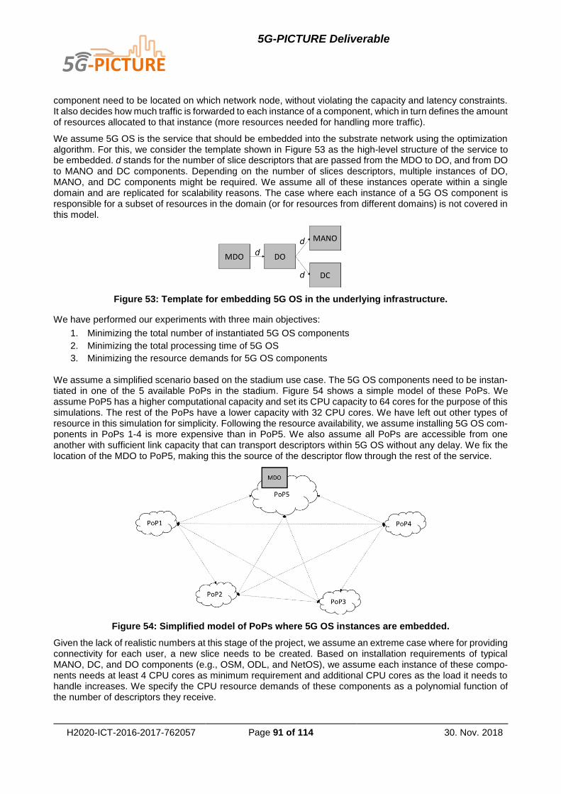
5G-PICTURE Deliverable
H2020-ICT-2016-2017-762057 Page 91 of 114 30. Nov. 2018
component need to be located on which network node, without violating the capacity and latency constraints. It also decides how much traffic is forwarded to each instance of a component, which in turn defines the amount of resources allocated to that instance (more resources needed for handling more traffic).
We assume 5G OS is the service that should be embedded into the substrate network using the optimization algorithm. For this, we consider the template shown in Figure 53 as the high-level structure of the service to be embedded. d stands for the number of slice descriptors that are passed from the MDO to DO, and from DO to MANO and DC components. Depending on the number of slices descriptors, multiple instances of DO, MANO, and DC components might be required. We assume all of these instances operate within a single domain and are replicated for scalability reasons. The case where each instance of a 5G OS component is responsible for a subset of resources in the domain (or for resources from different domains) is not covered in this model.
Figure 53: Template for embedding 5G OS in the underlying infrastructure.
We have performed our experiments with three main objectives:
1. Minimizing the total number of instantiated 5G OS components
2. Minimizing the total processing time of 5G OS
3. Minimizing the resource demands for 5G OS components
We assume a simplified scenario based on the stadium use case. The 5G OS components need to be instan-tiated in one of the 5 available PoPs in the stadium. Figure 54 shows a simple model of these PoPs. We assume PoP5 has a higher computational capacity and set its CPU capacity to 64 cores for the purpose of this simulations. The rest of the PoPs have a lower capacity with 32 CPU cores. We have left out other types of resource in this simulation for simplicity. Following the resource availability, we assume installing 5G OS com-ponents in PoPs 1-4 is more expensive than in PoP5. We also assume all PoPs are accessible from one another with sufficient link capacity that can transport descriptors within 5G OS without any delay. We fix the location of the MDO to PoP5, making this the source of the descriptor flow through the rest of the service.
Figure 54: Simplified model of PoPs where 5G OS instances are embedded.
Given the lack of realistic numbers at this stage of the project, we assume an extreme case where for providing connectivity for each user, a new slice needs to be created. Based on installation requirements of typical MANO, DC, and DO components (e.g., OSM, ODL, and NetOS), we assume each instance of these compo-nents needs at least 4 CPU cores as minimum requirement and additional CPU cores as the load it needs to handle increases. We specify the CPU resource demands of these components as a polynomial function of the number of descriptors they receive.

5G-PICTURE Deliverable
H2020-ICT-2016-2017-762057 Page 92 of 114 30. Nov. 2018
We assume every DO instance needs 1 second to process every request before forwarding it to the DC and MANO components. Each MANO instance needs around 10 seconds for resource allocation per slice and each DC instance needs around 5 seconds for this. We set a limit of 90 seconds for each component to process the descriptors it receives.
The stadium considered in the mega-event/stadium use case in 5G-PICTURE has a capacity of 27000 people. We have increased the number of connectivity requests from 0 to 30000 in steps of 1000 and observed the values of different metrics described as follows. The number of instances from each component should be adapted to the number of users that require connectivity. That is, we want to show that our flexible architecture allows the DO, DC, and MANO components to scale as necessary according to the load.
As shown in Figure 55, the total number of required instances begins with a minimum of 4 instances (one instance from MDO, DO, DC, and MANO each). As shown in the figure, these instances are sufficient for handling up to 5000 slices (in the specified time limit). By increasing the number of slices, the total number of required instances also increases. Figure 56-Figure 58 show the breakdown of required instances from each component. Between around 10000 and 17000 slices, the number of required DOs does not seem to be very stable. This might be because of the smaller processing time of DO compared to the other components, which gives the optimization algorithm more freedom to decide the optimal number of required instances for DO, as its influence on the final processing time is limited. Number of required DCs increases slower than the number of required MANOs. This is again related to the higher processing time required by the MANO, which forces the algorithm to scale out MANO early on.
The maximum number of instances for each 5G OS component is 5, which is the number of PoPs. With 28000 slice requests, the instances are over-loaded and the algorithm cannot find any feasible mapping of 5G OS components to the available resources without violating the constraints. One of these constraints is the upper bound of processing latency for slices, which is respected in all solutions up to 28000 slices, as shown in Figure 59. This shows, as expected, one factor that limits the scalability of the 5G OS is the resource availability in the underlying infrastructure.
Figure 55: Number of 5G OS components in relation to the number of slice requests.
Figure 56: Number of required DO instances in relation to the number of slice requests.

5G-PICTURE Deliverable
H2020-ICT-2016-2017-762057 Page 93 of 114 30. Nov. 2018
Figure 57: Number of required DC instances in relation to the number of slice requests.
Figure 58: Number of required MANO instances in relation to the number of slice requests.
Figure 59: Total 5G OS slice processing time in relation to the number of slice requests.
Figure 60 shows the total number of CPU cores required for hosting 5G OS components. The resource de-mand increases consistently with increasing load that 5G OS needs to handle. Using this model, resource planning for hosting 5G OS components should be straightforward, in case a good estimation of the load is given.

5G-PICTURE Deliverable
H2020-ICT-2016-2017-762057 Page 94 of 114 30. Nov. 2018
Figure 60: Number of CPU core used by 5G OS in relation to the number of slice requests.
5.4 Scalable Controller Placement
The switch networks inter-connecting the PoPs have to be controlled by one or more controllers. The most simplified model dictates the use of a single controller for each network domain, which is placed next to the switch that has the shortest average distance to the other switches. However, scalability and resilience issues prompted us to research on the usage of a more extended set of controllers for each domain. In particular, instead of using a single controller, we replace this with a cluster of controllers that communicate one with the other and share a common view of the same network. The problem in this case is to decide how many con-trollers should be used in this cluster, and where should they be placed?
This is an optimization problem which can be defined in various ways, depending on the objectives. In our case, the objective is the minimization of the total control traffic, and this is a Quadratic Assignment Problem (QAP), that has been proven to be NP-hard and unscalable for networks with more than 30 switches. Thus, we performed simulations to retrieve the most important parameters of this problem and used the results to develop a heuristic and quick method proposing solutions close to the optimal ones.
Assuming that i) βs is the control traffic required for the connection of a switch to a controller, ii) βc is the control traffic required for sending one controller to the other all the information related to one switch and iii) f is the average number of flows in every switch, then the optimal number C* of controllers in the cluster that is respon-sible for a network of S switches is presented in Figure 61, for 7 representative network topologies.
Figure 61: Optimal number of required controllers.
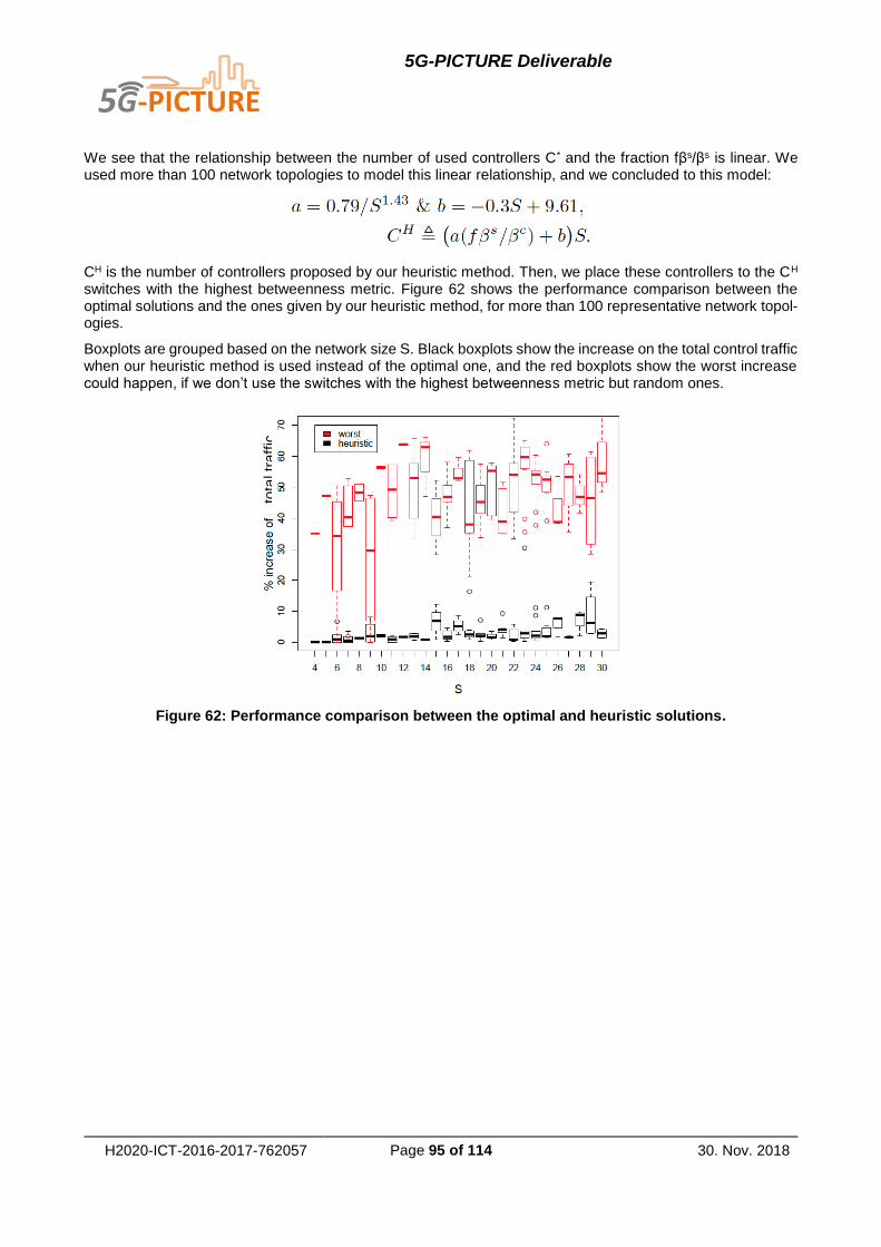
5G-PICTURE Deliverable
H2020-ICT-2016-2017-762057 Page 95 of 114 30. Nov. 2018
We see that the relationship between the number of used controllers C* and the fraction fβs/βs is linear. We used more than 100 network topologies to model this linear relationship, and we concluded to this model:
CH is the number of controllers proposed by our heuristic method. Then, we place these controllers to the CH switches with the highest betweenness metric. Figure 62 shows the performance comparison between the optimal solutions and the ones given by our heuristic method, for more than 100 representative network topol-ogies.
Boxplots are grouped based on the network size S. Black boxplots show the increase on the total control traffic when our heuristic method is used instead of the optimal one, and the red boxplots show the worst increase could happen, if we don’t use the switches with the highest betweenness metric but random ones.
Figure 62: Performance comparison between the optimal and heuristic solutions.
tota
l tr
aff
ic

5G-PICTURE Deliverable
H2020-ICT-2016-2017-762057 Page 96 of 114 30. Nov. 2018
6 Conclusions
In this document, we have provided a detailed description of the design and realization of 5G OS (see Section 4). Our architectural framework captures possible relationships among our three major areas of interest, namely, slicing systems, network controllers, and NFV management and orchestration systems. This frame-work allows infrastructure providers and operators to extract and deploy the desired operating system to control the heterogeneous, multi-technology and multi-domain infrastructure and manage slices and services on top of it. 5G OS architecture is composed of multiple components, each of which provides functionalities related to one of the mentioned areas. For example, while multi-domain orchestrator is responsible for orchestrating the end-to-end slices, domain controller provides network control functionalities and NFV MANO manages and orchestrates the virtual network functions. We presented the detailed description of functionalities provided by each component as well as the interfaces among them.
We have provided a comprehensive state of the art and related work, including standardization activities and academic studies in the fields of slicing, network control, and NFV MANO. We have also described existing open-source and commercial solutions in these areas and how they can be integrated to form a 5G OS in-stance. Additionally, we have analysed relevant 5G-PPP and other and positioned the goals of 5G OS against these activities.
We have described different ongoing and planned prototyping scenarios, designed as proof of different con-cepts we cover by 5G OS in the framework of the 5G-PICTURE project. These concepts include orchestration of (i) multi-version network services, (ii) connectivity and function in fixed and wireless networks, (iii) multiple controllers and NFV MANO systems, (iv) RAN, CN, and edge domain controllers, and (v) TSON in the optical transport network. We have provided a detailed description for each scenario, however, as we gain more insights during the progress of the project and development of the components, some of these implementations plans might be changed and enhanced (e.g., the option of using SONATA instead of OSM as a domain or-chestrator for orchestration of multi-version services, if it is proven to be more suitable for the 5G-PICTURE implementation, is being investigated).
As mega-event/stadium and rail are two important verticals for 5G-PICTURE, we have validated the 5G OS architecture by introducing the 5G use cases derived from these two verticals. A detailed description of these use cases and the usage of 5G OS for the realization of these use cases is given in this deliverable.
We have also presented simulation results showing the scalability of the adaptable, hierarchical design of 5G OS. Our results show that scaling 5G OS components (i.e., instantiating several instances of domain orches-trators, domain controllers, and NFV MANO components) helps keeping service-level requirements like latency when service and slice instantiation requests increase. Of course, resource demands for hosting 5G OS com-ponents and the management and communication overhead among different instances of a component put a practical limit on how far 5G OS can be expanded and distributed.
Finally, we have described further results regarding the controller placement problem, providing a scalable network control solution. We have investigated how many controllers need to be placed in different parts of a network, considering the control traffic among different controller instances as well as the control traffic be-tween controllers and switches.
5G-PICTURE Deliverable
H2020-ICT-2016-2017-762057 Page 97 of 114 30. Nov. 2018
7 References
[1] 3GPP. (2017). TR 38.801 Study on new radio access technology: Radio access architecture and interfaces (Release 14).
[2] 3GPP. (2017). TR 38.804 Study on new radio access technology: Radio Interface Protocol Aspects (Release 14).
[3] 5GCity project. (2018). Deliverable 2.2: 5GCity Architecture and Interfaces Definition. 5GCity project.
[4] 5GCity project. (2018). Deliverable 4.1: Orchestrator design, service programming and mchine learnig models. 5GCity project.
[5] 5GINFIRE Consortium. (2017). project objectives. (5GINFIRE Consortium) Retrieved from https://5ginfire.eu/project-objectives/
[6] 5G-PICTURE. (2018). D2.2 System architecture and preliminary evaluations.
[7] 5GPPP Architecture Working Group. (2017). View on 5G architecture (version 2.0).
[8] Aijaz, A. (2018, 9). Hap − SliceR: A radio resource slicing framework for 5G networks with haptic communications. IEEE Systems Journal, 12(3), pp. 2285–2296.
[9] Alliance, N. (2016). Description of Network Slicing concept. NGMN 5G.
[10] Alliance, N. (2016). Description of Network Slicing concept. NGMN 5G P, 1.
[11] BluePlanet. (n.d.). BLUE PLANET SOFTWARE SUITE. Retrieved from http://media.ciena.com/documents/BP_Blue_Planet_PB.pdf
[12] Cascone, C. (2018, May 15). ONOS+P4 Tutorial. (ONOS) Retrieved November 2, 2018, from https://wiki.onosproject.org/pages/viewpage.action?pageId=16122675
[13] Chang, C.-Y., & Navid, N. (2018). RAN runtime slicing system for flexible and dynamic service execution environment. IEEE Access, 6, pp. 34018-34042.
[14] Chochliouros, I., Giannoulakis, I., Spiliopoulou, A., Belesioti, M., Kostopoulos, A., Sfakianakis, E., . . . Agapiou, S. (2017). A Novel Architectural Concept for Enhanced 5G Network. CSCC 2017.
[15] Cisco Inc. (n.d.). Retrieved 08 1, 2018, from https://www.cisco.com/c/en/us/products/collateral/cloud-systems-management/network-services-orchestrator/datasheet-c78-734576.html
[16] Cosmas, J., Zafeiropoulos, A., Gouvas, P., Fotopoulou, E., Tsiolis, G., Xirofotos, T., . . . Barros, M. (2018). Enabling Vertical Industries Adoption of 5G Technologies: a Cartography of evolving solutions. European conference on networks and communications (EuCNC). Ljubljana.
[17] Csoma, A., Sonkoly, B., Csikor, L., Németh, F., Gulyas, A., Tavernier, W., & Sahhaf, S. (2014). ESCAPE: Extensible Service ChAin Prototyping Environment using Mininet, Click, NETCONF and POX. ACM Conference on SIGCOMM. New York.
[18] D. Gkounis, N. U. (2018). Demonstration of the 5GUK Exchange: A Lightweight Platform for Dynamic End-to-End Orchestration of Softwarized 5G Networks,. European Conference on Optical Communication (ECOC).
[19] de Sousa, N., Perez, D., Rosa, R., Santos, M., & Rothenberg, C. (n.d.). Network Service Orchestration: A Survey. IEEE COMMUNICATIONS SURVEYS & TUTORIALS 1.
[20] Dräxler, S., Karl, H., & Mann, Z. A. (2018). JASPER: Joint Optimization of Scaling, Placement, and Routing of Virtual Network Services. IEEE Transactions on Network and Service Management, 15(3), 946-960.
[21] Dräxler, S., Karl, H., Peuster, M., Kouchaksaraei, H., Bredel, M., Lessmann, J., . . . Xilouris, G. (2017). SONATA: Service programming and orchestration for virtualized software networks. IEEE International Conference on Communications Workshops (ICC Workshops). Paris.
[22] Ericsson Inc. (n.d.). Ericsson Network Manager. Retrieved 08 09, 2018, from https://www.ericsson.com/ourportfolio/digital-services-products/network-manager?nav=productcategory
[23] ETSI. (2015). Network Functions Virtualisation (NFV); Ecosystem; Report on SDN Usage in NFV Architectural Framework (Ref: DGS/NFV-EVE005).
[24] ETSI. (2017). OSM Information Model, Release 2. ETSI.
[25] ETSI. (2018). Network Functions Virtualisation (NFV) Release 2; Management and Orchestration; Network Service Templates Specification (RGS/NFV-IFA014ed241). ETSI.

5G-PICTURE Deliverable
H2020-ICT-2016-2017-762057 Page 98 of 114 30. Nov. 2018
[26] ETSI. (n.d.). Network Functions Virtualisation (NFV); Management and Orchestration. Retrieved 08 10, 2018, from https://www.etsi.org/deliver/etsi_gs/NFV-MAN/001_099/001/01.01.01_60/gs_nfv-man001v010101p.pdf
[27] Ferrus, R., Sallent, O., Perez-Romero, J., & Agusti, R. (2018, 5). On 5G Radio Access Network Slicing: Radio Interface Protocol Features and Configuration. IEEE Communications Magazine, 56(5), pp. 184-192.
[28] Foukas, X., Marina, M. K., & Kontovasilis, K. (2017). Orion: RAN Slicing for a Flexible and Cost-Effective Multi-Service Mobile Network Architecture. Proceedings of the 23rd Annual International Conference on Mobile Computing and Networking (MobiCom'17), (pp. 127-140).
[29] GSMA. (2018). Network slicing use case requirements.
[30] Gudipati, A., Perry, D., Li, L. E., & Katti, S. (2013). SoftRAN: Software defined radio access network. Proceedings of the Second ACM SIGCOMM Workshop on Hot Topics in Software Defined Networking (HotSDN ’13), (pp. 25-30).
[31] IETF. (n.d.). Network Function Virtualization Research Group. Retrieved 08 10, 2018, from https://irtf.org/nfvrg
[32] ITU-T focus group. (2017). IMT-2020 deliverables.
[33] Katsalis, K., Nikaein, N., Schiller, E., Ksentini, A., & Braun, T. (2017). Network slices toward 5g communications: Slicing the LTE network,. IEEE Communications Magazine, vol. 55, no. 8, pp. 146–154.
[34] Ksentini, A., & Nikaein, N. (2017). Toward enforcing network slicing on RAN: Flexibility and resources abstraction. IEEE Communications Magazine, 55(6), pp. 102-108.
[35] Marabissi, D., & Fantacci, R. (2017). Heterogeneous public safety network architecture based on RAN slicing. IEEE Access, 5, pp. 24668–24677.
[36] Mijumbi, R., Serrat, J., Gorricho, J.-L., Bouten, N., Turck, F. D., & Boutaba, R. (2015). Network Function Virtualization: State-of-the-art and Research Challenges. IEEE Communications Surveys & Tutorials, vol. 18, no. c, pp. 1–1.
[37] Nakao, A., Du, P., Kiriha, Y., Granelli, F., Gebremariam, A. A., Taleb, T., & Bagaa, M. (2017). End-to-end network slicing for 5G mobile networks. Journal of Information Processing, 25, pp. 153-163.
[38] NGMN Alliance. (2016). Description of network slicing concept (version 1.0.8).
[39] Nikaein, N., Schiller, E., Favraud, R., Katsalis, K., Stavropoulos, D., Alyafawi, I., . . . Korakis, T. (2015). Network Store: Exploring Slicing in Future 5G Networks. ACM MobiArch, pp. 8–13.
[40] Nunes, B., Mendonca, M., Nguyen, X., Obraczka, K., & Turletti, T. (2014). A Survey of Software-Defined Networking: Past, Present, and Future of Programmable Networks. IEEE Communications surveys & tutorials, vol. 16, no. 3.
[41] ONF. (2017). M-cord as an open reference solution for 5g enablement. CORD Project White paper.
[42] ONF. (2017). Transport API (TAPI) 2.0 Overview. ONF.
[43] ONF. (February 2016). ONF TR-521 “SDN architecture - Issue 1.1". ONF.
[44] Oracle Communications . (n.d.). Oracle Communications Network Service Orchestration Solution. Retrieved from http://www.oracle.com/us/industries/communications/network-service-orchestration-ds-2412291.pdf
[45] Price, C., & Rivera, S. (n.d.). OPNFV: An open platform to accelerate NFV. Retrieved 08 10, 2018, from https://networkbuilders.intel.com/docs/OPNFV_WhitePaper_Final.pdf
[46] project, 5.-X. (2018). D3.3 - 5G-XHAUL Algorithms and Service Design and Evaluation.
[47] project, M. (2018). D1.2 - Chainable Application Component & 5G-Ready Application Graph Metamodel.
[48] project, M. (2018). D1.4 - Network-Aware Application Graph Metamodel.
[49] project, M. (2018). D1.5 - Deployment and Runtime Policy Metamodel.
[50] Rost, P., Banchs, A., Berberana, I., Breitbach, M., Doll, M., Droste, H., . . . Sayadi, B. (May 2015). Mobile network architecture evolution toward 5G. IEEE Communications Magazine, vol. 54, no. 5, pp. 84–91.
[51] Rost, P., Mannweiler, C., Michalopoulos, D. S., Sartori, C., Sciancalepore, V., Sastry, N., . . . Bakker, H. (2017, 5). Network slicing to enable scalability and flexibility in 5G mobile networks. IEEE Communications magazine, 5, pp. 72-79.

5G-PICTURE Deliverable
H2020-ICT-2016-2017-762057 Page 99 of 114 30. Nov. 2018
[52] Sallent, O., Perez-Romero, J., Ferrus, R., & Agusti, R. (2017, 10). On radio access network slicing from a radio resource management perspective. IEEE Wireless Communications, 24(5), pp. 166-174.
[53] Sherwood, R., Chan, M., Covington, A., Gibb, G., Flajslik, M., Handigol, N., . . . Parulkar, G. (2010, 1). Sherwood, Rob and Chan, Michael and Covington, Adam and Gibb, Glen and Flajslik, Mario and Handigol, Nikhil and Huang, Te-Yuan and Kazemian, Peyman and Kobayashi, Masayoshi and Naous, Jad and others. ACM SIGCOMM Computer Communication Review, 40(1), pp. 129-130.
[54] Shrestha, S., Lee, J., & Chong, S. (2008). Virtualization and slicing of wireless mesh network. Proceedings of Conference on Future Internet Technologies.
[55] Silva, I. D., Ayoubi, S. E., Boldi, O. M., Bulakci, O., Schellmann, P. S., Monserrat, J. F., . . . al., D. T. (2016). 5G RAN Architecture and Functional Design. 5G PPP White paper.
[56] Troia, S., Rodriguez, A., & et.al. (2018). Machine-Learning-Assisted Routing in SDN-based Optical Networks. European Conference on Optical Communications (ECOC 2018).
[57] Vidal, D. R. (2018). Deliverable D4.1 - Operational MANO Platform. 5GINFIRE Consortium.

5G-PICTURE Deliverable
H2020-ICT-2016-2017-762057 Page 100 of 114 30. Nov. 2018
8 Acronyms
Acronym Description
5G OS 5G Operating System
DC Domain Controller
DO Domain Orchestrator
IaaS Infrastructure as a Service
MANO Management and Orchestration
MDO Multi-Domain Orchestrator
NF Network Function
NFaaS NF as a Service
NFFG Network Function Forwarding Graph
NFV Network Function Virtualization
NFVO Network Function Virtualization Orchestration
NS Network Service
NSaaS NS as a Service
NSD NS Descriptor
PaaS Platform as a Service
PNF Physical Network Function
PNFD PNF Descriptor
pPNF Programmable PNF
PoP Point of Presence
QoS Quality of Service
RAN Radio Access Network
SaaS Slice as a Service
SBP Slice Blueprint
SDN Software-Defined Networking
SFC Service Function Chaining
SLA Service-Level Agreement
SLO Service-Level Objective
SM Service Management
TSON Time-Shared Optical Network
VIM Virtualized Infrastructure Manager
VNF Virtual Network Function
VNFD VNF Descriptor
VNFM VNF Manager
WIM Wide-Area Network Infrastructure Manager
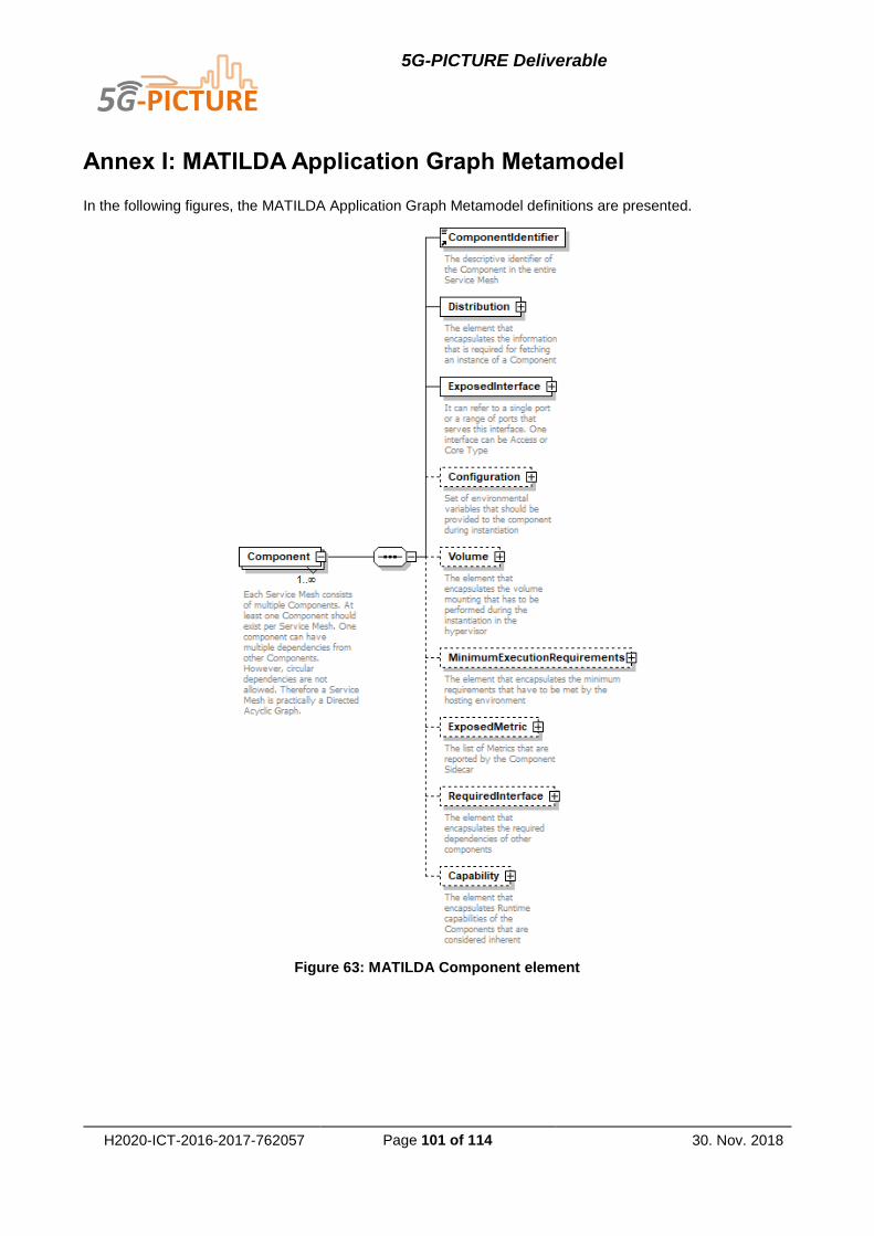
5G-PICTURE Deliverable
H2020-ICT-2016-2017-762057 Page 101 of 114 30. Nov. 2018
Annex I: MATILDA Application Graph Metamodel
In the following figures, the MATILDA Application Graph Metamodel definitions are presented.
Figure 63: MATILDA Component element

5G-PICTURE Deliverable
H2020-ICT-2016-2017-762057 Page 102 of 114 30. Nov. 2018
Figure 64: Distribution element
Figure 65: Exposed interface element
Figure 66: Required interface element
Figure 67: Configuration element

5G-PICTURE Deliverable
H2020-ICT-2016-2017-762057 Page 103 of 114 30. Nov. 2018
Figure 68: Volume element
Figure 69: Minimum execution requirements element
Figure 70: Exposed metrics element
Figure 71: Capability element
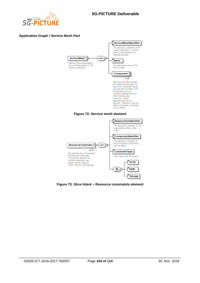
5G-PICTURE Deliverable
H2020-ICT-2016-2017-762057 Page 104 of 114 30. Nov. 2018
Application Graph / Service Mesh Part
Figure 72: Service mesh element
Figure 73: Slice Intent – Resource constraints element

5G-PICTURE Deliverable
H2020-ICT-2016-2017-762057 Page 105 of 114 30. Nov. 2018
Figure 74: Slice Intent – Graph link QoS constraints element

5G-PICTURE Deliverable
H2020-ICT-2016-2017-762057 Page 106 of 114 30. Nov. 2018
Annex II: MATILDA Network-Aware Application Graph Meta-
model
In the following figures, the MATILDA Network Aware Application Graph Metamodel definitions are presented.
Figure 75: Overview of the slice intent
Figure 76: High-level view of constraints
Figure 77: The two types of component hosting constraints

5G-PICTURE Deliverable
H2020-ICT-2016-2017-762057 Page 107 of 114 30. Nov. 2018
Figure 78: The details of a resource constraint
Figure 79: The details of a location constraint

5G-PICTURE Deliverable
H2020-ICT-2016-2017-762057 Page 108 of 114 30. Nov. 2018
Figure 80: The details of the graph link constraints
Figure 81: The details of the access constraints
Figure 82: Indicative logical functions

5G-PICTURE Deliverable
H2020-ICT-2016-2017-762057 Page 109 of 114 30. Nov. 2018
Annex III: MATILDA Runtime Policies Metamodel
In the following figures, the MATILDA Runtime Policies Metamodel definitions are presented.
Figure 83: Policies conditions high -level view
Figure 84: Policies actions high-level View

5G-PICTURE Deliverable
H2020-ICT-2016-2017-762057 Page 110 of 114 30. Nov. 2018
Annex IV: Verification of 5G OS in Rail Vertical Scenario
Rail Company as 5G OS Operator: Creating an End-to-End Slice – Guide Slice Approach
Major components and actors remain the same as Base-Slice approach, see for details.
The sequence of Service creation:
1) In preparation for Tenant requests the 5G OS Operator (Rail company A) would have created a
guide slice from the resources provided by the infrastructure provider. This contains reservations for
all available resources for Tenant use, across every connected domain.
2) Tenant via the Service Management system requests a Service to be initiated which contains all
edge access points in Region 1 and Region 2, application servers to be deployed in the cloud and
edge, connectivity with QoS constraints
3) The request is passed to the MDO which in turn maps and translates service request into requests
for compute, connectivity and access while ensuring constraints related to QoS and placement
4) The Slicing Engine looks up the guide slice and allocates sub-slices in each domain to provide re-
quired connectivity and functions
5) The sub-slices are connected, based on the pre-defined domain interconnect, to create a service
specific slice for the Tenant (third-party Service Provider or Rail company A) with the required func-
tions chained as per the service definition
For this approach, we make the following assumptions:
1) Through the Guide Slice all providers will give an accurate indication of resources available for the
5G OS Operator (Rail company A)
2) Inter-domain links are pre-defined to ensure the domains can link up with each other and with the
MDO (Rail company A) and placement decisions are simplified

5G-PICTURE Deliverable
H2020-ICT-2016-2017-762057 Page 111 of 114 30. Nov. 2018
Figure 85: Rail as 5G OS Operator, Guide Slice approach.
Rail Company as Infrastructure Provider: Creating an End-to-End Slice – Base Slice Approach
The Base Slice approach can be used in both single rail domain and multi-rail domain scenarios.
Figure 86 shows how the Base Slice approach solves the Rail use-case in case Rail company A provides access to Rail company B via its own Domain Orchestrator. On the left-hand side, the physical network is shown as it exists. On the extreme right-hand side, the virtual network slice is shown which implements the requested service and allows the 5G Operator A to provision internal and external services. With a single interface for different Rail operators the orchestration task for the MDO is slightly simplified.

5G-PICTURE Deliverable
H2020-ICT-2016-2017-762057 Page 112 of 114 30. Nov. 2018
Figure 86: Base Slice – single Rail domain.

5G-PICTURE Deliverable
H2020-ICT-2016-2017-762057 Page 113 of 114 30. Nov. 2018
Figure 87: Base Slice – multiple Rail domains.
Figure 87 shows how the Base Slice approach solves the Rail use-case in case Rail company A and Rail company B use their own Domain Orchestrator to directly integrate with 5G Operator A. This scenario contains additional complexity to coordinate between two separate networks to provide seamless connectivity to rail passengers.
The sequence of Service creation:
1. In preparation for Tenant requests the 5G Operator A (running 5G OS – SM and MDO) would have
created one or more base-slices from the resources provided by the infrastructure provider. These
provide an abstraction for resources held across every domain. For example, in this case the base-
slice would contain resources assigned to Rail company A from the following domains:
a. Rail company A – own domain, providing edge access and compute for the Rail network (Re-
gion 1), earmarked for Tenant use.
b. Rail company B –infrastructure provider providing edge access in Region to allow full route
coverage for users of Rail company A, in case of single interface Rail company B resources
would be exposed via Rail company A’s Domain Orchestrator.
c. Domain B – providing connectivity to Datacentre.
d. Domain C – providing connectivity to Datacentre.
e. Datacentre – providing compute facility.

5G-PICTURE Deliverable
H2020-ICT-2016-2017-762057 Page 114 of 114 30. Nov. 2018
2. Tenant via the Service Management system requests a Service to be initiated which contains all edge
access points in Region 1 and Region 2, application servers to be deployed in the cloud and edge,
connectivity with QoS constraints
3. The request is passed to the MDO which in turn maps and translates service request into requests for
compute, connectivity and access while ensuring constraints related to QoS and placement
4. The Slicing Engine operates upon the base slice to create a service specific slice for the Tenant (third-
party Service Provider) with the required functions chained as per the service definition
For this approach, we make the following assumptions:
1. When creating the base slice all providers will give resources that can be controlled directly by the 5G
OS Operator (5G Operator A) or the resource will be a static one (e.g. link). Otherwise it would be
impossible for the 5G OS Operator to further slice the base slice.
2. Inter-domain links are statically defined to ensure the domains can link up with each other and with
the MDO (5G Operator A).