d5.1.3 - proof-of-concept prototype of defense mechanismsnuno/papers/massif_d513_sept12.pdf ·...
TRANSCRIPT

MAnagement of Security information and events
in Service InFrastructures
MASSIF FP7-257475
D5.1.3 - Proof-of-concept Prototype of
Defense Mechanisms
Activity A5 Work Package WP5.1
Due Date M24 Submission Date 2012-09-28
Main Author(s) Nuno Neves (editor) (FFCUL)
Contributors Alysson Bessani (FFCUL), Eric Vial (FFCUL), Miguel Garcia (FFCUL), Ricardo Fonseca (FFCUL), Hossein Rouhani (FFCUL), Paulo Veríssimo (FFCUL)
Version v1.0 Status Final
Dissemination Level
PU Nature P
Keywords Resilient communication; Node defense mechanisms
Reviewers Cesario Di Sarno (CINI)
Rodrigo Diaz Rodriguez (ATOS)
Part of the Seventh
Framework Programme
Funded by the EC - DG INFSO

MASSIF - FP7-257475
D5.1.3 - Proof-of-concept Prototype of Defense Mechanisms
© 2012 MASSIF Project 2/33
Version history
Rev Date Author Comments
V0.2 2012-06-11 Nuno Neves (FFCUL) Release first internal draft.
V0.4 2012-9-3 Nuno Neves (FFCUL) Release second internal draft for revision.
V0.6 2012-9-21 Nuno Neves (FFCUL) Applied the various changes due to the internal review, and released the draft for the project review.
V0.8 2012-9-25 Nuno Neves (FFCUL) Applied changes due to reviews by project partners.
V1.0 2012-09-28 Elsa Prieto (Atos) Final review and official delivery

MASSIF - FP7-257475
D5.1.3 - Proof-of-concept Prototype of Defense Mechanisms
© 2012 MASSIF Project 3/33
Glossary of Acronyms
BFT Byzantine Fault Tolerance
CEP Complex Event Processing
COTS Component of the Shelf
DOS Denial of Service
DoW Description of Work
EC European Commission
EU European Union
FIFO First-In First-Out
FP7 Seventh Framework Programme
HTTP Hypertext Transfer Protocol
IDS Intrusion Detection System
IP Internet Protocol
IPsec Internet Protocol Security
ISP Internet Service Provider
IT Intrusion Tolerant
MASSIF MAnagement of Security information and events in Service InFrastructures
MIS MASSIF Information Switch
MTU Maximum Transmission Unit
OS Operating System
PU Public Usage
R&D Research & Development
REB Resilient Event Bus
SIEM Security Information and Event Management
SMR State Machine Replication
SSL Secure Socket Layer
TCP Transmission Control Protocol
TLS Transport Layer Security
TOM Total Order Multicast
TPM Trusted Platform Module
UDP User Datagram Protocol
VM Virtual Machine
VMM Virtual Machine Manager

MASSIF - FP7-257475
D5.1.3 - Proof-of-concept Prototype of Defense Mechanisms
© 2012 MASSIF Project 4/33
Executive Summary
This deliverable describes the prototype implementation of two of the resilient mechanisms developed within the MASSIF project. Generically, the resilient mechanisms aim at augmenting the SIEM system capabilities to operate correctly under adverse conditions. Faults of accidental nature, such as node crashes or link failures, can impact the normal functioning of the system, by preventing for instance the events collected by the sensors from reaching the correlation engine where they are processed. Due to a SIEM system’s contribution to the management of the network, by keeping an updated view of the behaviour and security status, it can become target of various kinds of attacks that aim at compromising the execution in different ways, including modifying or destroying the sensor data. To address some of these issues, the MASSIF project has designed a Resilient Event Bus (REB) and a Highly Resilient Core-MIS.
REB provides a generic data dissemination service that is resilient to faults and attacks. The service is implemented by protocols running amongst the MASSIF Information Switches (MIS). The REB is mainly in charge of disseminating the events collected by the edge-MIS, after being pre-processed by the Data services implemented in the same edge-MIS, to the core-side services. The REB delivers the information to the core-MIS, which then uses a reliable channel to forward it to the final destination (e.g., the correlation engine). This does not preclude core services from transmitting data to the edges, and in fact that happens when commands have to be sent to enforce remediation actions on the edge devices. In order to tolerate various types of faults, the REB employs a number of techniques, such as erasure encoding algorithms, network status monitoring through probing, and concurrent data transmission through alternative paths by exploring multihoming and one-hop rerouting.
The core-MIS acts as data forwarder, receiving traffic from the outside of the core network and resending it towards the core services (and vice versa). In parallel, it protects the core services from external attacks, acting pretty much as a sophisticated firewall, ensuring that the core network operates in a more benign way. This is achieved by implementing a number of filters that ensure that (ideally) all attacks from outside would have been prevented from entering. Since the core-MIS stays at the border of the core network, it can become the target of attacks. Therefore, in MASSIF, we have designed a highly resilient implementation of the core-MIS that implements intrusion-tolerant replication techniques, in order to survive not only external attacks, but also the malicious compromise of some of its components.

MASSIF - FP7-257475
D5.1.3 - Proof-of-concept Prototype of Defense Mechanisms
© 2012 MASSIF Project 5/33
Table of Contents
1. Introduction .......................................................................................................................... 7
1.1 Guidelines Analysis ........................................................................................................ 8
1.2 Glossary adopted in this deliverable ............................................................................. 8
2. Prototype in a Nutshell ......................................................................................................... 9
2.1 Purpose, Scope and Functionality ................................................................................. 9
2.2 List of Components and their actual Release Numbers ................................................ 9
3. Prototype Deployment ........................................................................................................ 10
3.1 Pre-requisites .............................................................................................................. 10
3.2 Installation Procedure ................................................................................................. 10
3.3 How to Verify the Installation ..................................................................................... 12
3.4 Licensing ...................................................................................................................... 12
4. Architecture Prototype Design ............................................................................................ 13
4.1 Prototype Context ....................................................................................................... 13
4.2 Prototype Component Structure ................................................................................ 13
4.3 API Information ........................................................................................................... 14
5. Prototype Implementation.................................................................................................. 16
5.1 REB implementation.................................................................................................... 16
5.1.1 Main components ............................................................................................... 16
5.1.2 Packet structure .................................................................................................. 17
5.1.3 Two interaction examples ................................................................................... 22
5.1.4 Sequence diagrams ............................................................................................. 24
5.1.5 Class diagram....................................................................................................... 26
5.2 Core-MIS implementation ........................................................................................... 27
5.2.1 Information flows among the main components ............................................... 27
5.2.2 Message format .................................................................................................. 30
5.2.3 Class Diagram ...................................................................................................... 31
6. Conclusions ......................................................................................................................... 32
6.1 Self-evaluation and Assessment ................................................................................. 32
6.2 Roadmap for Future Releases ..................................................................................... 32
MASSIF - FP7-257475
D5.1.3 - Proof-of-concept Prototype of Defense Mechanisms
© 2012 MASSIF Project 6/33
List of Figures
Figure 1: MASSIF architecture structural view - payload (brown) vs. SIEM (blue). ...................... 7
Figure 2: Syntax for the file nodes.cfg. ........................................................................................ 11
Figure 3: Syntax for the file keys_<id>.cfg. ................................................................................. 11
Figure 4: Configurable variables at the core-MIS components site. ........................................... 12
Figure 5: Syntax for the deployment script (in the current prototype for a demonstration). .... 12
Figure 6: Overview of the REB and core-MIS components interactions. .................................... 13
Figure 7: High-level view of the REB Interface. ........................................................................... 14
Figure 8: Structure of a REB packet (sizes in bytes). ................................................................... 18
Figure 9: Structure of a packet header. ...................................................................................... 18
Figure 10: Structure of a segment header plus data inside a packet. ......................................... 19
Figure 11: Structure of an encoded block inside a packet. ......................................................... 20
Figure 12: Structure of a selective acknowledgment inside a packet. ........................................ 20
Figure 13: Structure of handshake messages inside a packet. ................................................... 22
Figure 14: Interaction of the components in a sending scenario. .............................................. 22
Figure 15: Interaction of the components in multiple receiving scenarios. ............................... 23
Figure 16: Sequence diagram for the sending operation............................................................ 24
Figure 17: Sequence diagram for the receiving operation. ........................................................ 25
Figure 18: Overview (of a subset) of the class diagram. ............................................................. 27
Figure 19: Core-MIS agent: this component makes the interaction with external sensors. ...... 28
Figure 20 : Pre-filter: this component is the first filter of the core-MIS. .................................... 29
Figure 21: Filter: this is the main component of core-MIS. ........................................................ 29
Figure 22: Post-filter: the last filter of core-MIS that delivers the data to the final destination.30
Figure 23: Message format for the data transmitted by the core-MIS agent............................. 30
Figure 24: Core-MIS class diagram (simplified view). ................................................................. 31

MASSIF - FP7-257475
D5.1.3 - Proof-of-concept Prototype of Defense Mechanisms
© 2012 MASSIF Project 7/33
1. Introduction
This deliverable presents the implementation details of two components developed within the MASSIF project to enhance the resilience of a SIEM infrastructure. This prototype includes the Resilient Event Bus (REB) and a Highly Resilient core-MIS implementation. Figure 1 has a representation of the MASSIF architecture structural view, where we have represented the REB and the core-MIS (for more details see [4]).
Figure 1: MASSIF architecture structural view - payload (brown) vs. SIEM (blue).
The REB supports a data dissemination service amongst the MIS that is resilient to both network and node faults. Therefore, even if an attacker is able to disrupt part of the network or is capable of compromising one of the MIS, the remaining ones should continue to communicate correctly. The REB employs a number of techniques to accomplish this objective, such as erasure encoding algorithms, network status monitoring through probing, and concurrent data transmission through alternative paths. The core-MIS forwards data traffic in and out of the core SIEM services network (called core facility). This task is performed in such a way that external attacks are filtered out, to ensure that core-services execute in a (more) benign environment. Since the core-MIS might become the target of external attackers, it is implemented using intrusion-tolerant replication techniques. This allows for correct operation either if some of its components fail accidentally (e.g., one of the replicas crashes) or if they are compromised by an attacker (e.g., the adversary creates an intrusion in one of the replicas).
For more details, a complete description of the design of these two resilient mechanisms is provided in MASSIF deliverable D5.1.2 [1].
MASSIF - FP7-257475
D5.1.3 - Proof-of-concept Prototype of Defense Mechanisms
© 2012 MASSIF Project 8/33
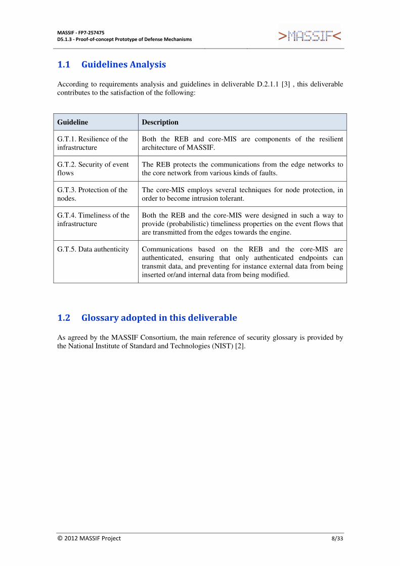
1.1 Guidelines Analysis
According to requirements analysis and guidelines in deliverable D.2.1.1 [3] , this deliverable contributes to the satisfaction of the following:
Guideline Description
G.T.1. Resilience of the infrastructure
Both the REB and core-MIS are components of the resilient architecture of MASSIF.
G.T.2. Security of event flows
The REB protects the communications from the edge networks to the core network from various kinds of faults.
G.T.3. Protection of the nodes.
The core-MIS employs several techniques for node protection, in order to become intrusion tolerant.
G.T.4. Timeliness of the infrastructure
Both the REB and the core-MIS were designed in such a way to provide (probabilistic) timeliness properties on the event flows that are transmitted from the edges towards the engine.
G.T.5. Data authenticity Communications based on the REB and the core-MIS are authenticated, ensuring that only authenticated endpoints can transmit data, and preventing for instance external data from being inserted or/and internal data from being modified.
1.2 Glossary adopted in this deliverable
As agreed by the MASSIF Consortium, the main reference of security glossary is provided by the National Institute of Standard and Technologies (NIST) [2].

MASSIF - FP7-257475
D5.1.3 - Proof-of-concept Prototype of Defense Mechanisms
© 2012 MASSIF Project 9/33
2. Prototype in a Nutshell
2.1 Purpose, Scope and Functionality
The deliverable covers the prototype of two resilient components developed in MASSIF, namely REB and core-MIS.
The REB is the component responsible for disseminating the events (and other security information), collected by the sensors in the monitored system (called the payload system) and after being processed by the MASSIF Data services in the edge-MIS nodes, towards the core-MIS. Since this communication occurs potentially over open networks, such as the Internet, it might suffer different kinds of faults of either accidental nature or due to malicious attacks. Therefore, the REB needs to implement a number of measures to ensure that these faults can be addressed, either by using redundancy or by detecting and next recovering from them. For example, regarding detection, the REB uses an adaptive probing mechanism to determine the current status of the paths to a certain destination with respect to delays and loss rates. Redundancy is applied at several levels, such as by employing erasure coding algorithms to add repair information to the data, and also by transferring the data concurrently over various paths.
The core-MIS stays at the perimeter of the core facility, receiving the event data from the edge-MIS and forwarding it to the final core service (alternatively, it might also need to send commands in the opposite direction, e.g., to reconfigure devices/components located in the edge facilities). Since the core services might become the target of external attacks, the core-MIS implements filtering rules to prevent arbitrary traffic from entering the core facility, acting essentially as a sophisticated firewall. This ensures that the execution environment of the core facility is much more benign, becoming free of many types of external attacks. However, due to its role in the architecture, the core-MIS may have to sustain different forms of attacks, trying for instance to stop the communications. An adversary may also try to compromise the core-MIS, and then corrupt the sensor data to evade the detection of other attacks being carried out at the edge facilities. For this reason, the core-MIS is implemented using replication mechanisms that are capable to tolerating intrusions, i.e., an attacker can take control of some of the replicas, but the remaining ones can still ensure a correct service.
2.2 List of Components and their actual Release Numbers
The main outcome of this deliverable is a prototype for the REB and the core-MIS as presented in deliverable D5.1.2 [1]. These prototypes already include an implementation of many of the resilient techniques that were described in the deliverable, but we intend to continue to improve them during the third year of the project.
• MASSIF Resilient Event Bus, version 1.0
• MASSIF Core-MIS, version 1.0

MASSIF - FP7-257475
D5.1.3 - Proof-of-concept Prototype of Defense Mechanisms
© 2012 MASSIF Project 10/33
3. Prototype Deployment
3.1 Pre-requisites
The REB is available as a Java library that provides an API for other Java applications. There are no external dependencies (no third party libraries) required when using the REB. The set of REB classes comes pre-built inside a Jar archive and some configuration files. The source code is also provided and an Ant file exists for automated class building. In addition, there is a tool for generating random secret keys for pairs of REB nodes.
To compile or use the REB library, it is required version 1.7 of the Oracle JDK. To use the automated building mechanism, it is also required version 1.8.4 of the Apache Ant tool.
The core-MIS was also developed in Java, and depends on the REB for the communication. It is built using BFT-SMaRt, a Byzantine fault tolerance communication protocol library (also written in Java) [6].
To run the core-MIS, it is required version 1.6 (or greater) of the Oracle JDK. To compile the source code it is required the Apache Ant tool version 1.8 and the BFT-SMaRt library. For the deployment of the core-MIS components it is needed SSH (to perform a secure copy to various virtual machines) and a Unix shell.
3.2 Installation Procedure
The installation procedure of REB is relatively simple because all classes come pre-packaged in a Jar file. To build the REB classes using Ant, open a terminal to the directory where the REB was extracted (a file named “build.xml” is available in the directory) and run the command ant. To clean the build run the command ant clean.
To use the key generation tool, you need to first build the class files as explained before, and then set the following environment variables:
• REB_HOME="path to where REB was extracted"
• PATH=${REB_HOME}:${PATH}
Then run the command genkeys <REB node 1> <REB node 2> <...>, which generates one secret key for every pair of the indicated nodes and stores the keys on a different file per node.
The current version of the REB uses a static configuration for the overlay that defines the set of nodes that may participate in the communications (some of them may be down or disconnected). When a REB node starts up it is assigned a unique identifier (based on a string assigned by the administrator --- see below), which is referred to as the local ID. Based on this local ID, a node can get the information about the whole overlay network by reading a few configuration files. The files are put in a predefined place in the local machine by the administrator of the SIEM. The following information can be obtained:
• Network addresses: A REB node receives packets in specific IP socket addresses (IP address + UDP port). The ports can be different across the overlay, depending on the machine where the node is located. If a machine has multihoming, then several IP addresses are assigned, one for each physical connection. When this happens, the configuration file has the list of IP addresses that can be used;

MASSIF - FP7-257475
D5.1.3 - Proof-of-concept Prototype of Defense Mechanisms
© 2012 MASSIF Project 11/33
• Pair-wise shared keys: Every pair of nodes shares a secret cryptographic key for secure communication. Each key is stored in a separate file that is statically distributed to the relevant nodes and not shared by any third party.
Figure 2: Syntax for the file nodes.cfg.
Figure 3: Syntax for the file keys_<id>.cfg.
The first file is nodes.cfg, and it includes an identification for every node consisting of a string and a set of IP socket addresses. Copies of the nodes file have to be placed in every machine that hosts a REB node. Figure 2 shows the syntax for a configuration file. The second kind of

MASSIF - FP7-257475
D5.1.3 - Proof-of-concept Prototype of Defense Mechanisms
© 2012 MASSIF Project 12/33
file is keys_<id>.cfg, and it contains the secret symmetric keys that a specific local node shares with the remaining remote nodes. There must be an individual key file per node, each containing as many keys as the number of the remaining nodes - the tool genkeys can be used to assist in the creation of these files. Figure 3 shows the syntax for a key configuration file.
The installation of the core-MIS components is performed with a deployment script, after the core-MIS compilation. Due to the number of machines that core-MIS may use, this script must be configured by setting a few variables. An example of these configuration variables is presented in Figure 4.
The administrator runs the massif_deploy script in order to place the code in the correct (virtual) machines. It can deploy all code at once or just one specific component's code (see example in Figure 5).
Each core-MIS component has a java properties file (i.e., key value file) to setup a number of configuration parameters. These parameters include: communication socket ports, the IPs, internal queue buffer sizes, path of shared keys, cryptography algorithms, and also properties to simulate attacks. The core-MIS components do not need any argument input when run, since every parameter is set in the properties files.
3.3 How to Verify the Installation
The installation of the REB can be checked by running a simple test program, called test.java, between a pair of nodes. This program is also included in the distribution of the REB.
The core-MIS installation can be checked by running an experimental configuration, which checks the event flow between the two edges of the communication, i.e., from a event generator at the edge-MIS to the engine.
3.4 Licensing
The REB and Core-MIS were developed by FFCUL, and are currently made available to all partners of the MASSIF project. In the future, there is the intent to make these components available to the general public as open-source projects.
./massif_deploy {all|core|engine|london|madrid|paris|attacker}
REPLICAS="10.10.5.218 10.10.5.89 10.10.5.142 10.10.5.167"
COREMIS="10.10.2.39"
ATTACKER="10.10.5.25"
ENGINE="10.10.5.234"
LONDON="10.10.5.5"
PARIS="10.10.5.16"
MADRID="10.10.5.26"
Figure 4: Configurable variables at the core-MIS components site.
Figure 5: Syntax for the deployment script (in the current prototype for a demonstration).

MASSIF - FP7-257475
D5.1.3 - Proof-of-concept Prototype of Defense Mechanisms
© 2012 MASSIF Project 13/33
4. Architecture Prototype Design
4.1 Prototype Context
In the context of the MASSIF SIEM [4], the Resilient Event Bus (REB) role is to take the events collected by the data services, and then forward them towards the core services, namely the parallel complex event processing (CEP) engine. This service should be performed in a timely robust manner because, on one side, the core services should provide an updated view of the current state of the payload system (in order for instance to have alarms generated with small delays), and on the other side, the communication substrate might be open, and therefore targeted by attacks (e.g., the Internet). The REB may also need to return information from the core services towards the edges, when for instance it is necessary to change the configuration of the SIEM and payload systems to apply remediation operations.
The core-MIS stays in front of the core services network, acting as a gateway to forward the information arriving from the REB towards its final destination (a certain core service). Due to its location in the network, the core-MIS might become a prime target of attacks, either to make it inoperable (and, therefore, prevent the core services from reaching the rest of the SIEM system) or to trick it to transmit malicious data to the core services. To address these concerns, we have developed a highly resilient design of the core-MIS, which is able to tolerate various kinds of faults (including intrusions in some of its components) and performs advanced filtering operations. A discussion on the main ideas behind the resilient architecture of the MASSIF SIEM appeared in [4] and [5], and the design of the REB and core-MIS components is provided in [1].
4.2 Prototype Component Structure
Figure 6: Overview of the REB and core-MIS components interactions.
Here we present an overview of the interactions between the main components of the prototype, REB and core-MIS, and its external components. Figure 6 shows the main components of the core-MIS, together with the REB. For simplicity, we will describe the data flow from the edges to the core.

MASSIF - FP7-257475
D5.1.3 - Proof-of-concept Prototype of Defense Mechanisms
© 2012 MASSIF Project 14/33
The REB has a local component that runs locally in each MIS node, either edge-MIS or core-MIS. This component is used for data transmission between a sender MIS node and a receiver MIS node.
The core-MIS mainly consists in three components: core-MIS agent (a), core-MIS (Pre-filters and Filters) (b), and Post-filter (c). The core-MIS agent is placed in the edge-MIS devices, and its mission is to add authentication information to the event data and transmit the data to a few Pre-filters, so that even if a Pre-filter behaves erroneously (e.g., because it was compromised by an adversary), the correct data is still delivered to the CEP engine. The core-MIS agent uses the REB for the communications.
The core-MIS is a replicated system, and it includes two levels of filtering performed by the Pre-filters and Filters respectively. In order to make this system intrusion-tolerant up to f faults, the core-MIS needs at least f + 1 Pre-filters and 3f + 1 Filters [1]. The communication between the Pre-filters and Filters is performed by a total order multicast channel that is implemented by the BFT-SMaRt library. This multicast channel ensures that every Filter replica processes the messages in the same order, and therefore, that replicas produce equivalent results (when they are operating correctly). Filters run in different virtual machines with diverse operating systems to avoid common flaws at this level, and therefore avert that an intruded Filter can be used to rapidly compromise the remaining Filters.
The Post-filter is located in the engine system, and it receives the data forwarded by the Filters. Since some of the Filters maybe controlled by an adversary (up to f of them), they can produce erroneous values. To address this issue, the Post-Filter makes a vote on the received messages from the different Filters, ensuring that only valid events are delivered to the CEP engine. The communication among the Filters and the Post-Filter occurs inside the core network, where the expected level of threat is relatively small. Therefore, this communication is carried out through out of the box reliable channels (e.g., TCP or SSL+TCP).
4.3 API Information
Figure 7: High-level view of the REB Interface.

MASSIF - FP7-257475
D5.1.3 - Proof-of-concept Prototype of Defense Mechanisms
© 2012 MASSIF Project 15/33
A high-level description of the API offered by the REB was presented in deliverable D5.1.2 [1]. For convenience, we show in Figure 7 a copy of this API. The initialization calls create and destroy a REB object, which is what applications use directly to control the communication in the local node. Communications is done using the send and receive calls, which may be blocking or non-blocking, according to the user needs. Additionally, information about the local node or any of the configured remote nodes can be accessed through information calls. Node identifiers are provided as strings, which contain the same names defined in the nodes configuration file.
In the project, we envision deployment scenarios where different resilient mechanisms might be used, for example, a SIEM might decide only to rely to the REB while in other cases it uses a combination of the REB together with the Resilient core-MIS. Therefore, in order to make the integration of these two mechanisms as transparent as possible, we tried to keep their interfaces equal --- the interface of the Resilient core-MIS component on the edge-MIS and on the core services (e.g., the engine) is equivalent to the REB, as displayed in Figure 7.

MASSIF - FP7-257475
D5.1.3 - Proof-of-concept Prototype of Defense Mechanisms
© 2012 MASSIF Project 16/33
5. Prototype Implementation
This section provides some details about the implementation of the REB and the highly resilient core-MIS. It is assumed in the description that the reader is familiar with the fundamental ideas of the design of these components, which were presented in Deliverable 5.1.2 [1].
5.1 REB implementation
5.1.1 Main components
The main components of a REB node include Threads, Queues and Sessions. Together, they form a state machine capable of handling events from multiple sources and performing the corresponding actions accordingly. The REB state machine interacts with application threads and with the network, thus providing the expected communication between the local node and other remote nodes.
Threads
A REB node uses three threads internally (plus one in special cases) to run its state machine (note that this excludes any JVM threads that handle operations such as automatic garbage collection). Those threads are a Dispatcher Thread, a Receiver Thread and a Sender Thread.
The Dispatcher Thread is responsible for handling events from the application threads, events from the Receiver Thread, and events due to a timer that expires (timeouts). It is also responsible for producing events to any other thread, including an application one.
The Receiver Thread is responsible for handling events from the network and for producing events to any other thread, including an application one.
Finally, the Sender Thread is responsible for handling events from the Main Dispatcher Thread and the Receiver Thread. It only produces events to the network.
There is one more thread which is used when the application requests a special type of sending operation, namely an asynchronous one. This thread is called the Asynchronous Dispatcher
Thread and handles all the asynchronous send requests. From the point of view of the Dispatcher Thread, the Asynchronous Dispatcher Thread is just another application thread because it provides messages using the same execution logic.
From the point of view of the REB, an application thread is also considered part of the state machine since it is both an event source and an event destination.
Queues
The main functions of the REB node’s queues are to provide an ordered delivery of messages and a flow control mechanism applied to the communication. Application messages are copied to the queues in FIFO order and the queues have statically defined capacity bounds for limiting the flow. Three types of queues are distinguished: a segment queue, a local receive queue and a remote receive queue. There is one of each of these queues for each remote node that is configured at the local node (i.e., each local “remote node object” contains its own set of queues).
Segment queues are accessed by application threads and the Dispatcher Thread. Application threads copy messages to these queues and the Dispatcher Thread retrieves the buffered messages into segments to be transmitted.

MASSIF - FP7-257475
D5.1.3 - Proof-of-concept Prototype of Defense Mechanisms
© 2012 MASSIF Project 17/33
Local receive queues are accessed by application threads and the Receiver Thread (additionally, the Dispatcher Thread may also access these queues for session maintenance). The Receiver Thread copies received segments to these queues and application threads retrieve bytes from these queues in order to deliver received messages.
Remote receive queues are accessed only by the Dispatcher Thread. They represent a view of the opposite receive queues for the corresponding remote nodes, maintaining a delivery (or acknowledged) status of individual transmitted segments.
There is one more queue which is not associated to any remote node in particular. It is the queue utilized by the Sender Thread to receive events from the Dispatcher and Receiver Threads. Here, the events are simple packet send requests with an associated remote address and local address (a REB node is capable of multihoming). Packets that are provided by the Dispatcher Thread have the local node as the source, while packets that are provided by the Receiver Thread have a specific remote node as the source. This latter case occurs when the local node acts as an intermediary node (or a router) in the communication between two other nodes, by forwarding received packets to their destinations. The usage of this queue in this situation is essential to prevent DoS attacks that attempt to cause starvation of local packets.
Sessions
Sessions are required for successful communication between two nodes, and they are used to authenticate both parties in the exchange of messages. A session provides a full duplex communication (messages may be transmitted in both ways simultaneously) but does not allow a “half-open” or “half close” situation like in TCP. For this reason, when a session is established between two nodes, it must be maintained at both sides even when only one of the nodes is transmitting data. Similarly, when a session is closed, both sending and receiving is disallowed until a new session is established.
A session has an associated (temporary) symmetric key that is exchanged securely between the two nodes during session establishment (which is protected using the pre-configured shared keys in the node [1]). This key is used to provide the necessary authentication and additional message integrity validation using MACs which are appended to transmitted packets.
Sessions are initiated automatically by a REB node whenever the application tries to send a message to a remote node. Therefore, an application has no control over the sessions and they are handled internally by the Dispatcher Thread.
Currently, there is no explicit session close mechanism implemented, so the only way for sessions to be closed is for one of the session owners to terminate (e.g., by simply destroying the local REB object). Eventually, the surviving REB node will detect a session timeout and will close it properly. However, a session may also be closed at a local node if the remote node crashes and recovers immediately in time to request a new session before the previous one times out at the local node.
5.1.2 Packet structure
REB uses UDP as the underlying transport protocol, so data is transmitted inside UDP datagrams. A UDP datagram indicates its size in the UDP header and is transmitted entirely in one IP datagram, unless IP fragmentation occurs (however, we restrict the maximum UDP datagram size to minimize this situation). Due to the use of UDP, we say that the communication in REB is message oriented, meaning that a transmitted REB packet by one node is either received in its entirety by another node or not at all. For this reason, a REB node can immediately start processing a received packet from a UDP socket, without needing to reassemble the transmitted packet from multiple received fragments.

MASSIF - FP7-257475
D5.1.3 - Proof-of-concept Prototype of Defense Mechanisms
© 2012 MASSIF Project 18/33
A REB packet contains a route header that must always exist, since it is required by a node to know the exact overlay routes used in the transmission of data. A packet also has one or two MACs in order to authenticate the involved parties and to provide message integrity verification.
Figure 8: Structure of a REB packet (sizes in bytes).
Figure 8 illustrates the general structure of a REB packet. The route header is 11 bytes wide and each MAC has 32 bytes. Depending on the type of data that is transmitted, the remaining contents have a specific structure inside a packet. Types of data include encoded blocks, tiny segments, acknowledgments and handshake messages.
Route header
The route header of a REB packet contains the information about a specific overlay route, which includes a source node, a destination node, and optionally an intermediary node. It also contains bit flag values which are used to identify the type of data that follows the header.
Figure 9: Structure of a packet header.
Figure 9 shows the structure of a packet header. The node ID fields are 16-bit values that represent numerical forms of the node identification strings (such as “sen4” or “eng2”). The IDs range from 1 to 65,535, and a value of 0 represents a null ID that is used in the intermediary ID field if a direct route is used.
The address fields are 8-bit values that represent ordinal numbers associated to a node’s IP socket address. The ordinal value of an address of a particular node corresponds to the position of that address in the line defining the node in the nodes configuration file (see Section 3.2). The address ordinals are ranged from 1 to 255, and, like the IDs, a value of 0 represents a null address. The null address is used in the intermediary address fields if a direct route.

MASSIF - FP7-257475
D5.1.3 - Proof-of-concept Prototype of Defense Mechanisms
© 2012 MASSIF Project 19/33
The flags field is 8-bit wide and contains several bit flags that identify the type of data that follows the header. The flags used in regular data transmission are:
• TINY - if only this flag is set, a node will process the data as a tiny segment (that is, the segment has a length sufficiently small to fit entirely inside a REB packet);
• LUBY - if only this flag is set, a node will process the data as a block from a segment encoded with an erasure code (currently, Luby Transform (LT) Codes);
• SACK - if only this flag is set, a node will process the data as a Selective Acknowledgment;
Flags INIT and RESP are used to identify handshake messages. Handshake messages are of three kinds, INIT, INIT RESP and RESP. Flags INIT and RESP, when each being the only set flag, represent an INIT and a RESP message, respectively. When both are set (and no more flags), they represent an INIT RESP message. The flag RFSH, shorthand for “refresh”, is used to distinguish two kinds of a RESP message (associated to the need for cleanup operations if the session was reset).
Segments and blocks
A segment is associated to a different type depending on its size. If the size is less than or equal to the network Maximum Transmission Unit (MTU) size minus the headers (of IP, UDP, and REB), then the segment is transmitted entirely inside one UDP datagram. This type of segment is referred to as a tiny segment.
If on the other hand the segment size is greater than this limit, the segment is first encoded using erasure codes, generating a fixed number of blocks (N). These blocks are then transmitted block by block, each one in a separated UDP datagram. This type of segment is referred to as an encoded segment, and each REB packet is said to carry an encoded block.
For control packets, depending on the data that is transmitted, they can be considered tiny or encoded. For example, a probe packet that is used to force a destination node to transmit an acknowledgment is simply a tiny segment with zero length data.
A REB packet carrying a tiny segment or an encoded block is distinguished by the flags TINY and LUBY. However, when a destination node receives a packet, it needs to know the size of the whole segment being transmitted. It also needs to determine which specific segment or block has arrived, so that it can be put in the right place of the local receive queue.
Figure 10: Structure of a segment header plus data inside a packet.
Figure 10 shows the structure of a segment header plus data inside a packet. The first field is a 32-bit number that indicates the size in bytes of the original segment, that is, the segment being transmitted in the packet if it is a tiny segment or the segment before encoding if the packet contains an encoded block. In both cases it is possible to know the size of the data inside the packet using the original segment size --- if it is a tiny segment, the data size is trivially the original segment size; if it is an encoded block, the data size is calculated by in the same manner

MASSIF - FP7-257475
D5.1.3 - Proof-of-concept Prototype of Defense Mechanisms
© 2012 MASSIF Project 20/33
as the source node when it generated encoded blocks. The original segment size is particularly helpful when an encoded block is being transmitted because it allows the destination node to remove any padding added by the LT Codes [7] after decoding the original segment.
The second field is a 24-bit sequence number identifying the transmitted segment, and the third field is a 16-bit sequence number identifying the encoded block within the encoded segment (if the data is a tiny segment this sequence number is zeroed and not used).
Figure 11: Structure of an encoded block inside a packet.
The LT Codes algorithm splits the original segment in a fixed number of source blocks, and produces encoded blocks with the same size as the source ones. In order to perform the encoding, the LT codes use a few pseudo-random numbers, which are necessary at the receiver to reconstruct the original data. Therefore, together with the encoded block it is necessary to transmit the seed for the pseudo-random number generator. Figure 11 shows the structure of an encoded block.
Figure 12: Structure of a selective acknowledgment inside a packet.
Selective acknowledgment
A selective acknowledgment is transmitted whenever a destination node receives a complete segment (either by finishing decoding segment or by receiving a tiny segment), or whenever it receives a probe packet (a tiny segment with zero-length data). The acknowledgment includes information about the status of the received segments in the local receive queue, and about

MASSIF - FP7-257475
D5.1.3 - Proof-of-concept Prototype of Defense Mechanisms
© 2012 MASSIF Project 21/33
specific blocks within encoded segments. It also includes the window size of the queue, so that the source node may limit the transmission flow in remote receive queue.
Figure 12 shows the structure of a selective acknowledgment inside a packet. The first field is a 32-bit number indicating the window size. The second field carries a 24-bit cumulative sequence number that acknowledges the receipt of all the segments with sequence numbers below or equal to that number. The third field is an 8-bit number indicating the number of segments that have status information in the rest of the acknowledgment.
The information for each segment contains the corresponding 24-bit sequence number and an 8-bit number indicating the number of block pairs that are included. If the segment being acknowledged has been fully received (either is a tiny segment or a decoded segment), this number is always zero.
For each encoded segment, the receive status information is indicated as a list of block pairs. Each of this pairs contains two 16-bit sequence numbers identifying the first and last blocks of a contiguous range of acknowledged blocks. Since the size of an acknowledgment is restricted by the maximum allowed data size inside a packet, it can happen that there no space to acknowledge some of received segments/blocks (even if they are fully received). For this reason, a selective acknowledgment includes status information of the segments in increasing order of sequence number, starting by the undelivered segment with lowest sequence number. Block pairs are also indicated in increasing order of sequence number.
Additionally, an acknowledgment that is transmitted at a later time may contain less information about some segments than the previous. This may happen because local receive queues are allowed to discard received segments and blocks if they need to reclaim space for other segments with lower sequence numbers. This particular scenario only occurs because nodes typically send more encoded blocks than the number of blocks they register as being transmitted in their remote receive queues --- this is an optimistic strategy that takes advantage of the property of the LT Codes, in which only a subset of the transmitted blocks is necessary to decode the segment.
A received acknowledgment may be a duplicate of a previously received one, or may be one that arrived out of order. For this reason, the source node needs to identify these duplicates and old acknowledgments and discard them. This, however, is not achieved perfectly since it is possible for a destination node to discard segments/blocks in its local receive queue and transmit an acknowledgment with less information than the previous one. Nevertheless, the status information about the segment with lowest sequence number being transmitted never rolls back and thus the source node takes advantage of that to detect received acknowledgments that are surely older than the expected one.
Handshake messages
Handshake messages are used when a session between two nodes is being established. The node that initiates the sessions is referred to as the initiator node, whereas the node that responds to the session initiation is referred to as the respondent node.
Figure 13 shows the structure of an INIT, an INIT RESP and a RESP handshake message inside a packet. In each of the messages, a nonce is a “one-time” value used to prevent replay attacks. Message RESP has two additional fields which are only considered when flag RFSH is set. These two fields represent control sequence numbers used to synchronize the initiator and respondent queues when an established session expires and needs to be refreshed (typically because of a segment sequence number overflow).
Handshake nonces are constructed in REB by appending a random integer to a timestamp with microsecond resolution.

MASSIF - FP7-257475
D5.1.3 - Proof-of-concept Prototype of Defense Mechanisms
© 2012 MASSIF Project 22/33
Figure 13: Structure of handshake messages inside a packet.
5.1.3 Two interaction examples
We will use two examples to explain the fundamental interactions among the main components of a local REB node. The first interaction example is for a message sending scenario. Figure 14 shows the example. Here an application thread is copying a message to the segment queue associated to the indicated remote node (given the destination node ID).
Figure 14: Interaction of the components in a sending scenario.

MASSIF - FP7-257475
D5.1.3 - Proof-of-concept Prototype of Defense Mechanisms
© 2012 MASSIF Project 23/33
The local object for the remote node also contains the respective remote receive queue, which is accessed exclusively by the Dispatcher Thread. The figure shows the dispatcher thread extracting a segment from the segment queue and placing it on the remote receive queue for transmission. Inside the remote receive queue, a segment is transmitted block by block, after the segment is encoded using an erasure code (currently we are using an implementation of LT Codes). Each block is transmitted through a different overlay route, which is indicated to the Sender Thread by specifying different IP socket addresses (remote and local).
Figure 15: Interaction of the components in multiple receiving scenarios.
The second interaction example shows three different receiving scenarios simultaneously. Figure 15 shows the example. Packets that arrive from the network are aggregated by the Receiver Thread using a demultiplexer (in Java this is a java.nio.Selector object, which is the equivalent of the select call from C).
Three packets arrive to the node. The first packet (the top right one inside the Receiver Thread) contains a destination that is not the local node. This is the forwarding scenario in which the local node has the role of an intermediary in the communication of two other nodes. Here, the packet is simply given to the Sender Thread, which will eventually transmit it to the correct destination.
The second packet (corresponding to an ACK) is addressed to the local node. This packet is given to the Dispatcher Thread for processing. Since the packet contains various control information, such the acknowledgement of the packets that were correctly received remotely, it is used to update the local view of the state of communications with the remote node. This information is kept in the right remote receive queue, associated to the object for the remote node identified in the packet source.

MASSIF - FP7-257475
D5.1.3 - Proof-of-concept Prototype of Defense Mechanisms
© 2012 MASSIF Project 24/33
The last received packet (the one on the left containing data) is addressed to the local node, so it is placed by the Receiver Thread in the appropriate local receive queue.
Figure 16: Sequence diagram for the sending operation.
5.1.4 Sequence diagrams
This section presents two sequence diagrams that illustrate the sequence of events for a sending operation and a receiving operation.
Figure 16 shows a sending operation initiated by the application. Here, the application thread selects the appropriate remote node object from a RemoteNodesMap instance in order to access the respective segment queue. Then, according to how many bytes are currently in the segment
MASSIF - FP7-257475
D5.1.3 - Proof-of-concept Prototype of Defense Mechanisms
© 2012 MASSIF Project 25/33
queue, the application thread loops until the whole message is copied into the queue (blocking when it has to wait for space).
After completing the copy of the message to the queue, the application thread notifies the dispatcher thread of the new data. This prompts the dispatcher thread to inspect the current state of the communication with the remote node and take the appropriate action according to how many bytes are available it its remote receive queue. Furthermore, if there is no established session by the time the dispatcher thread inspects the queues, then a new one is established before any messages are retrieved from the segment queue.
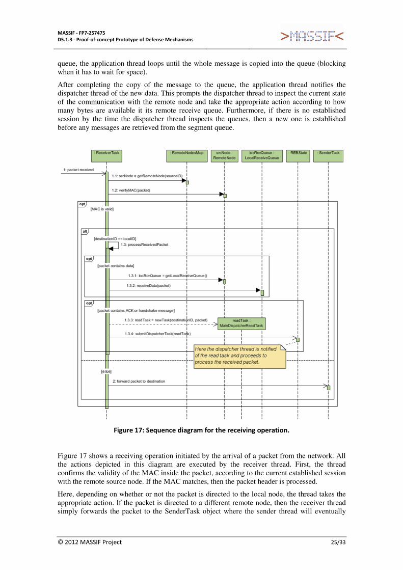
Figure 17: Sequence diagram for the receiving operation.
Figure 17 shows a receiving operation initiated by the arrival of a packet from the network. All the actions depicted in this diagram are executed by the receiver thread. First, the thread confirms the validity of the MAC inside the packet, according to the current established session with the remote source node. If the MAC matches, then the packet header is processed.
Here, depending on whether or not the packet is directed to the local node, the thread takes the appropriate action. If the packet is directed to a different remote node, then the receiver thread simply forwards the packet to the SenderTask object where the sender thread will eventually

MASSIF - FP7-257475
D5.1.3 - Proof-of-concept Prototype of Defense Mechanisms
© 2012 MASSIF Project 26/33
transmit the packet to its destination. Otherwise, the packet contents are processed. Here, if the header indicates an ACK or a handshake message, the receiver thread simply hands over the packet to the dispatcher thread, where the appropriate action will be taken. If the packet contains a data segment/block, then the receiver thread handles the received packet in the local receive queue.
5.1.5 Class diagram
The implementation of the REB library contains multiple classes organized in different packages. Figure 18 show a class diagram for the most important classes of the main package core.reb.
Class REB provides the immediate interface for the application, whereas the remaining classes in the diagram are only used internally and are not directly accessed by the application. Notable classes are the several classes of the form {*}Task, whose instances represent actions performed by the internal threads.
Classes ReceiverTask and SenderTask only have one instance each throughout the execution of a REB node and run cyclically, since their respective threads (Receiver and Sender threads) must actively wait for events coming from the network (receiver) or other threads (sender).
In contrast, classes of the form MainDispatcher{*}Task have multiple instances which are each one constructed and run once every time the dispatcher thread must perform some action triggered by an event coming from the application, the receiver thread or a timeout.
Class REBState only has one instance that holds the current state of the REB node, and which contains most of the logic for the execution of the dispatcher thread.
Other notable classes are the classes of the form {*}Queue and the class SessionManager which have multiple instances, each one specific to a particular configured remote node. Class SessionManager handles the current session between the local node and the respective remote node.
Notice the usage of the class Authenticator there, where two distinct instances are used by the manager, a session authenticator and a master authenticator. The former is used to calculate and append a MAC to a sendable data packet (data segment/block or an ACK) - the MAC directed to the destination node. This authenticator depends on the current established session and uses the session key to generate and verify the MAC. The latter authenticator is used to calculate and append a second MAC to a sendable data packet - which is directed to the intermediary node – or to append a MAC to a sendable packet with a handshake message. This authenticator does not depend on any session and uses the original shared secret key configured at start-up (this means that a node is always able to send packets to an intermediary, despite not having an established session with it).

MASSIF - FP7-257475
D5.1.3 - Proof-of-concept Prototype of Defense Mechanisms
© 2012 MASSIF Project 27/33
Figure 18: Overview (of a subset) of the class diagram.
5.2 Core-MIS implementation
5.2.1 Information flows among the main components
This section presents the main information flows among the core-MIS components and the external components, such as the data services and the CEP engine. An overview of these flows is available in Section 4.2.

MASSIF - FP7-257475
D5.1.3 - Proof-of-concept Prototype of Defense Mechanisms
© 2012 MASSIF Project 28/33
Figure 19: Core-MIS agent: this component makes the interaction with external sensors.
The core-MIS agent receives information produced by the sensors in the playload systems, typically provided by the data services (represented as “sensor” in Figure 19). This information is transmitted through a TCP connection in the local edge-MIS host1, where the agent has one thread in charge of listening on a pre-defined port. The data is then put in a queue for transmission to a destination in the core network. The core-MIS agent assigns a distinct sequence number to the data, and appends a MAC vector. The MAC vector contains a different MAC for each Filter, which is based on distinct a shared key (there is a separate shared key between the agent and every Filter). The MAC algorithm is HmacSHA256. Next, the core-MIS agent sends the message through the REB to the Pre-filters.
In the other way around, the Core-MIS receives messages from the REB that were transmitted by the Pre-filters. It then votes the messages until a certain quorum (f+1) of equal responses have arrived. Then, the agent puts the voted message in a queue for transmission. A separate thread collects these messages and sends them to the data services via the TCP local host connection.
1 Alternatively, the data services could be linked with the core-MIS agent, and a simple method call
could be performed.

MASSIF - FP7-257475
D5.1.3 - Proof-of-concept Prototype of Defense Mechanisms
© 2012 MASSIF Project 29/33
Figure 20 : Pre-filter: this component is the first filter of the core-MIS.
The Pre-filter receives messages from the REB and puts them in a queue (see Figure 20). Then, it performs some checks on the message, namely it determines if the source of the message is authorized to transmit to the core network. It also prevents malicious Edge-MIS from performing denial-of-service (DoS) attacks, by enforcing a grant protocol that limits the amount of traffic that can be sent from a source. Messages outside this grant are discarded. Once the checks are passed, the Pre-filter invokes BFT-SMaRt to multicast the message to all Filters with a total order protocol.
On the traffic towards the edge-MIS, the Pre-filter first votes on the messages produced by the Filters, and then forwards the voted message using the REB.
Figure 21: Filter: this is the main component of core-MIS.
The BFT-SMaRt library runs a consensus between the several Filter replicas (see Figure 21). After the message is ordered by BFT-SMaRt, every Filter will receive and process the message. The Filter performs the following actions: 1) verify the sequence number of the message, assigned by the core-MIS agent; 2) verify the authenticity and integrity of the message, by checking the corresponding MAC in the vector. If the sequence number is within a threshold, but is not the expected sequence number, then Filter puts the message in a queue waiting for the previous messages to arrive, and then delivers the queued messages to Post-filter. Otherwise, if
MASSIF - FP7-257475
D5.1.3 - Proof-of-concept Prototype of Defense Mechanisms
© 2012 MASSIF Project 30/33
the message is outside the threshold, then it is discarded. The message with the right sequence number is then forwarded to the Post-filter via BFT-SMaRt.
For communications in the opposite direction, the Filter receives from the Post-filter the messages also via BFT-SMaRt. Then they are forwarded to the Pre-filters.
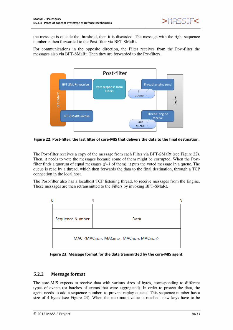
Figure 22: Post-filter: the last filter of core-MIS that delivers the data to the final destination.
The Post-filter receives a copy of the message from each Filter via BFT-SMaRt (see Figure 22). Then, it needs to vote the messages because some of them might be corrupted. When the Post-filter finds a quorum of equal messages (f+1 of them), it puts the voted message in a queue. The queue is read by a thread, which then forwards the data to the final destination, through a TCP connection in the local host.
The Post-filter also has a localhost TCP listening thread, to receive messages from the Engine. These messages are then retransmitted to the Filters by invoking BFT-SMaRt.
Figure 23: Message format for the data transmitted by the core-MIS agent.
5.2.2 Message format
The core-MIS expects to receive data with various sizes of bytes, corresponding to different types of events (or batches of events that were aggregated). In order to protect the data, the agent needs to add a sequence number, to prevent replay attacks. This sequence number has a size of 4 bytes (see Figure 23). When the maximum value is reached, new keys have to be

MASSIF - FP7-257475
D5.1.3 - Proof-of-concept Prototype of Defense Mechanisms
© 2012 MASSIF Project 31/33
established among the agent and Filters. Additionally, the whole data is integrity protected with a MAC vector, containing a MAC for each Filter (the figure assumes that there are 4 Filters).
The MAC vector is removed from the message by the Filters, as they forward it to the Post-filter. The sequence number is removed by the Post-filter, before delivering the message to the final destination.
5.2.3 Class Diagram
The implementation of the core-MIS contains multiple classes organized in different packages. Figure 24 shows a class diagram with the most important classes of the main package Filters.
Every filter has a package: PostFilter (top left corner of the figure); PreFilter (bottom left corner); and Filter (bottom right corner). Although not shown in the figure, for sake of simplicity and visibility, these filters communicate through BFT-SMaRt (PreFilter with Filter, and PostFilter with Filter). Some classes are not connected to any other class because they exchange data with external components (marked by the notes in the figure). The package communications contains the classes that provide threads to receive and send messages via the REB.
Figure 24: Core-MIS class diagram (simplified view).

MASSIF - FP7-257475
D5.1.3 - Proof-of-concept Prototype of Defense Mechanisms
© 2012 MASSIF Project 32/33
6. Conclusions
6.1 Self-evaluation and Assessment
This deliverable provides details on the prototype of the REB and the highly resilient core-MIS. The REB is responsible for the communication among the MIS nodes, ensuring that data is delivered securely and timely with a high probability. A number of mechanisms were implemented in the REB, such as erasure encoding to add repair information to the transmitted data, and the use of alternative paths over the existing physical network infrastructure. The core-MIS acts as a forwarder of data that is transmitted from the edge networks towards the core services. It implements a number of filters to prevent external data from entering into the core network. Since the core-MIS can become the target of attacks, it uses redundancy to tolerate not only accidental replica failures, but also the intrusion of a subset of the replicas.
6.2 Roadmap for Future Releases
Many of the resilient mechanisms presented in deliverable D5.1.2 have already been implemented in the current prototypes. Over the third year of the project, we intend to implement the remaining functionality and other potential improvements, and make further releases of the prototypes. However, these releases are not expected to change the interfaces of the prototypes, and therefore, they do not affect the integration efforts within the project.
Additionally, we intend to include a performance analysis of the prototypes, under various network and failure conditions, in the next deliverable D5.1.4 from WP5.1.
MASSIF - FP7-257475
D5.1.3 - Proof-of-concept Prototype of Defense Mechanisms
© 2012 MASSIF Project 33/33
References
[1] MASSIF Consortium. Deliverable D5.1.2 - Preliminary Defense Services and Protocols. Project MASSIF EC FP7-257475, September 2012.
[2] R. Kissel. Glossary of key information security terms. NIST Interagency Reports NIST IR 7298 Revision 1, National Institute of Standards and Technology, February 2011.
[3] MASSIF Consortium. Deliverable D2.1.1 - Scenario requirements. Project MASSIF EC FP7-257475. April 2011.
[4] MASSIF Consortium. Architecture Document. Project MASSIF EC FP7-257475, April 2012.
[5] MASSIF Consortium. Deliverable D5.1.1 - Preliminary Resilient Framework Architecture. Project MASSIF EC FP7-257475, September 2011.
[6] BFT-SMaRt, http://code.google.com/p/bft-smart/, accessed in September 2012.
[7] M. Luby. LT codes. In Proceedings of the 43rd Symposium on Foundations of Computer Science, pages 271–280, 2002.