d5.2.1development and deployment environment v1€¦ · development and deployment environment...
TRANSCRIPT

PROPRIETARY RIGHTS STATEMENT
This document contains information, which is proprietary to the OpenIoT Consortium. This document contains information, which is proprietary to the OpenIoT Consortium.
Neither this document nor the information contained herein shall be used, duplicated or communicated by any means to any third party, in whole or in parts, except with prior written consent of the consortium
SEVENTH FRAMEWORK PROGRAMME Specific Targeted Research Project
Project Number: FP7–SMARTCITIES–2013(ICT) Project Acronym: VITAL
Project Number: 608682
Project Title: Virtualized programmable InTerfAces for innovative cost-effective IoT depLoyments in smart cities
D5.2.1Development and Deployment Environment V1
Document Id: VITAL-D521-300715-Draft
File Name: VITAL-D521-300715-Draft.doc
Document reference: Deliverable 5.2.1
Version : V07
Editor : Katerina Roukounaki, John Soldatos
Organisation : AIT
Date : 30 / 07 / 2015
Document type: Deliverable
Security: PU (Public)
Copyright 2015 VITAL Consortium
Ref. Ares(2015)3591765 - 01/09/2015

Deliverable 5.2.1: Development and Deployment Environment V1
Copyright 2015 VITAL Consortium 1
DOCUMENT HISTORY
Rev. Author(s) Organisation(s) Date Comments
V01 Katerina Roukounaki AIT 10/05/15 Document structure and Table of
Contents
V02 Katerina Roukounaki AIT 15/05/15 First draft
V025 John
Soldatos AIT 18/05/15 Introduction and various edits
V03 Katerina Roukounaki AIT 26/05/15 Added sections 2.1 and 3
V035 John
Soldatos AIT 28/05/15 Conclusions and formatting
V04 Katerina Roukounaki AIT 29/05/15 Added sample workflow #4
V045 John Soldatos AIT 29/05/15 Edits and Quality Control; Enhancements in Sections 1 & 2
V05 Katerina Roukounaki AIT 30/05/15 Enhancements in Section 4
V06 Katerina Roukounaki AIT 30/05/15 Added Section 5, Enhancements in
Sections 4, 6 and 7
V07 Aqeel Kasmi NUIG 30/06/15 Technical Review
V08 Anne Heilmreich NUIG 30/07/15 Quality Review
V09 Martin Serrano NUIG 30/07/15 Circulated for Approval
Draft Martin Serrano NUIG 30/07/15 EC Submitted

Deliverable 5.2.1: Development and Deployment Environment V1
Copyright 2015 VITAL Consortium 2
TABLE OF CONTENTS
DOCUMENT HISTORY ............................................................................................... 1 1 INTRODUCTION ................................................................................................... 5
1.1 Scope .............................................................................................................. 5 1.2 Audience ......................................................................................................... 5 1.3 Summary ........................................................................................................ 5 1.4 Structure ......................................................................................................... 6
2 BACKGROUND INFORMATION .......................................................................... 7 2.1 State of the art ................................................................................................ 7 2.2 NODE-RED ..................................................................................................... 8
2.2.1 Node-RED editor ...................................................................................... 8 2.2.2 Node examples ...................................................................................... 10
2.2.2.1 http in .................................................................................................. 10 2.2.2.2 http response ...................................................................................... 10 2.2.2.3 http request ......................................................................................... 10 2.2.2.4 function ............................................................................................... 10 2.2.2.5 mqtt out ............................................................................................... 10 2.2.2.6 template .............................................................................................. 11
2.2.3 Sample flow ............................................................................................ 11 2.2.4 Node-RED runtime ................................................................................. 12 2.2.5 Extending Node-RED ............................................................................. 14
3 VITAL DEVELOPMENT ENVIRONMENT OVERVIEW ...................................... 15
4 PROTOTYPE IMPLEMENTATION ..................................................................... 16
5 VITAL NODES .................................................................................................... 21 5.1 PPI implementations ..................................................................................... 21
5.1.1 PPI ......................................................................................................... 22 5.1.2 system .................................................................................................... 22 5.1.3 sensors ................................................................................................... 22 5.1.4 services .................................................................................................. 22 5.1.5 data ........................................................................................................ 23
5.2 Resource Discovery ...................................................................................... 23 5.2.1 resource discovery ................................................................................. 23 5.2.2 discover sensors .................................................................................... 23

Deliverable 5.2.1: Development and Deployment Environment V1
Copyright 2015 VITAL Consortium 3
6 SAMPLE WORKFLOWS AND APPLICATIONS ............................................... 24 6.1 Sample workflow #1: Find the last observation made by a specific traffic sensor ... 24 6.2 Sample workflow #2: Show the location of a specific traffic sensor on a map. ................. 25 6.3 Sample workflow #3: Show all venues with available desk spaces near the current location of a user on a map .. 27 6.4 Sample workflow #4: Predict the next observation that a specific traffic sensor will make .. 30
7 FUTURE WORK, OUTLOOK AND CONCLUSIONS ......................................... 32
8 REFERENCES .................................................................................................... 33
LIST OF FIGURES FIGURE 1: NODE-RED FLOW EDITOR. ........................................................................................................ 9 FIGURE 2: HELLO WORLD IN NODE-RED. ................................................................................................. 12 FIGURE 3: NODE-RED “HELLO WORLD” EXAMPLE. ................................................................................... 14 FIGURE 4: POSITION OF DEVELOPMENT AND DEPLOYMENT ENVIRONMENT IN THE VITAL ARCHITECTURE. ..... 15 FIGURE 5: DEVELOPMENT AND DEPLOYMENT ENVIRONMENT OVERVIEW. ..................................................... 16 FIGURE 6: EXPOSURE OF RESOURCE DISCOVERY FUNCTIONALITIES THROUGH THE DEVELOPMENT TOOL. .... 17 FIGURE 7: DEVELOPMENT AND DEPLOYMENT ENVIRONMENT ARCHITECTURE OVERVIEW. ............................. 18 FIGURE 8: AUTHENTICATION. ................................................................................................................... 19 FIGURE 9: VITAL DEVELOPMENT AND DEPLOYMENT ENVIRONMENT. ........................................................... 20 FIGURE 10: NODE PALETTE ENHANCED WITH VITAL-RELATED NODES. ....................................................... 21 FIGURE 11: FIND THE LAST OBSERVATION MADE BY A SENSOR. .................................................................. 24 FIGURE 12: SHOW THE LOCATION OF A SENSOR ON A MAP. ........................................................................ 26 FIGURE 13: SHOW ALL VENUES WITH AVAILABLE DESK SPACES ON A MAP. .................................................. 28 FIGURE 14: PREDICT THE NEXT OBSERVATION THAT A SENSOR WILL MAKE. ................................................. 31
LIST OF TABLES TABLE 1: TEMPLATE. ............................................................................................................................... 11 TABLE 2: JSON REPRESENTATION OF HELLO WORLD FLOW. ...................................................................... 12 TABLE 3: FLOW CONFIGURATION EXAMPLE. ............................................................................................... 13 TABLE 4: TECHNOLOGIES USED FOR THE IMPLEMENTATION OF THE FIRST RELEASE OF THE VITAL DEVELOPMENT & DEPLOYMENT ENVIRONMENT. ........... 20 TABLE 5: JSON REPRESENTATION OF SAMPLE WORKFLOW #1. ................................................................. 25 TABLE 6: JSON REPRESENTATION OF SAMPLE WORKFLOW #2. ................................................................. 26 TABLE 7: JSON REPRESENTATION OF SAMPLE WORKFLOW #3. ................................................................. 29 TABLE 8: JSON REPRESENTATION OF SAMPLE WORKFLOW #4. ................................................................. 31

Deliverable 5.2.1: Development and Deployment Environment V1
Copyright 2015 VITAL Consortium 4
TERMS AND ACRONYMS
ARIMA Auto-Regressive Integrated Moving Average
BPM Business Process Management
CEP Complex Event Processing
CSV Comma-Separated Values
HTTP HyperText Transfer Protocol
ICE Integrated Cloud Environment
ICO Internet Connected Object
ICO Internet Connected Object
IDE Integrated Development Environment
JSON JavaScript Object Notation MDA Model-Driven Architecture
npm Node Package Manager
OSGi Open Services Gateway initiative
PPI Platform Provider Interface
QoS Quality of Service
RFID Radio-Frequency IDentification
SLA Service-Level Agreement
SSO Single Sign-On
VUAI Virtualized Unified Access Interface
WSN Wireless Sensor Network

Deliverable 5.2.1: Development and Deployment Environment V1
Copyright 2015 VITAL Consortium 5
1 INTRODUCTION
1.1 Scope
VITAL is developing a platform for semantically interoperable smart city applications, notably applications that leverage IoT data and services from the wide range of (legacy) IoT systems that are typically available in smart cities. WP5 of the project is devoted to research and development of tools for the monitoring, management, implementation and deployment of smart city applications based on the VITAL platform and the associated semantically interoperable paradigm. The tools include a visual environment for smart city application development, which is meant to facilitate smart city solution providers in building applications over the VITAL platform by easing the tasks of accessing, processing and combining IoT data and services from multiple IoT systems deployed in a smart city. The environment should enable application builders to access the complete set of VITAL application development functionalities, without having to resort to and use other tools. The present deliverable is devoted to the description of the first version of the project’s development and deployment environment. A second and final version of this deliverable will be produced later based on the project’s work plan. As illustrated in the following paragraphs, the development and deployment environment builds upon readily available open-source tools for handling and processing data and service flows, in an effort to accelerate its production, while at the same time optimising value for money. Furthermore, the VITAL development and deployment environment is built as an integral module of the VITAL platform, and thus respects the structuring principles laid out in its architecture, including interfaces and interactions to other VITAL modules.
1.2 Audience
The deliverable is primarily addressed to developers, integrators and providers of integrated solutions in smart cities. The developers and integrators are the primary and obvious end-users of the tools presented in this deliverable. In a wider context, the content of the deliverable is expected to be of interest to IoT and smart city researchers, notably researchers working on novel tools and techniques for application development, including Integrated Development Environments (IDEs), model-driven architectures and more. In the scope of the VITAL project, we expect the tools to attract the attention of the team members that are developing and integrating use cases in the scope of VITAL WP6, i.e. use cases in the scope of the Smarter Working scenario for Camden and the Traffic Management scenario for Istanbul.
1.3 Summary
The deliverable starts with a discussion about Integrated Development Environments for IoT and smart city application development. Along with this discussion, background components and environments used to implement the prototype are presented, notably the Node-RED platform. The presentation of Node-RED facilitates the understanding of how information flows can be implemented and processed.

Deliverable 5.2.1: Development and Deployment Environment V1
Copyright 2015 VITAL Consortium 6
Accordingly, a description of the prototype implementation is provided, starting with a short overview followed by a detailed description of all changes that have been made, in order to adapt Node-RED to the needs of the VITAL project. Furthermore, the document includes a set of examples, which present the use of the VITAL development and deployment environment towards implementing data stream workflows, which are associated with the VITAL use cases, i.e. the applications developed for Camden and Istanbul. One of the workflows exploits data analytics using the R environment, thus providing a concrete example on how analytics functionalities could be used within the VITAL integrated development and deployment environment.
1.4 Structure
The deliverable has the following structure:
• Section 2, following this introductory section, provides background information for understanding the scope, functionality and implementation of the development and deployment environment available as part of this deliverable.
• Section 3 positions the environment in the overall VITAL architecture.
• Section 4 illustrates the technical implementation of the environment.
• Section 5 describes the extra VITAL-related nodes that have been created and added to Node-RED
• Section 6 presents the use of the development and deployment environment for the implementation of workflows that are related to the Camden and Istanbul applications.
• Section 7 is the concluding section of the deliverable, which includes also a discussion of the features and functionalities planned for the second release of the environment.

Deliverable 5.2.1: Development and Deployment Environment V1
Copyright 2015 VITAL Consortium 7
2 BACKGROUND INFORMATION
2.1 State of the art
Integrated Development Environment (IDE) is an application that aims to facilitate software development, i.e. help software developers in developing, debugging, testing, building and deploying their applications. User interface builders (with drag-n-drop functionality), error checking, templates to get programmers started, and auto-generation of boilerplate code are only few of the features that IDEs offer and that have contributed to their increasing popularity. Traditionally, in order to use an IDE, developers need to download it, install it on their machine (together with any dependencies that it may have), and execute it. In this scenario, everything takes place on the development machine. Integrated Cloud Environments (ICEs) have come to change this workflow, by turning development environments from products into services. ICEs are essentially IDEs that are usually web accessible, and that leverage the Cloud into the software development lifecycle. In order to use an ICE, developers do not need to install any more tools on their machines; all they need to do is log into a web site (that acts as the entry point to the ICE), and start using it. In this case, most of the tasks take place in the Cloud; some ICEs use the Cloud even to store the developers’ code. At the moment, there are IDEs to support the development of desktop, web, mobile, and other types of applications. However, little work has been done to produce tools that assist developers that write applications in the IoT field. In particular, several tools and environments have been introduced as part of WSN (Wireless Sensor Network) platforms (e.g. [Aberer07], [Chatzigiannakis07]) and RFID (Radio-frequency Identification) platforms (e.g. [Anagnostopoulos09]). However, only recently the issue of Model-Driven Architectures (MDAs) and visual IDEs for IoT applications has been addressed (e.g. [Patel11], [Patel13]). Recently, we have witnessed the emergence of IoT development environments associated with mainstream IDE projects, such as Eclipse Kura1, which is an Eclipse IoT project2 that provides a framework for M2M service gateways (i.e. devices that act as mediators in the machine-to-machine and the machine-to-Cloud communication). Kura facilitates the development, deployment and remote management of M2M applications, and its use requires only the installation of an Eclipse plugin on the developer’s machine. It is based on Java and OSGi3, the dynamic module system for Java, and it can be used to turn a Raspberry Pi or a BeagleBone Black into an IoT gateway. Node-RED is another open-source project that is focused on IoT. This project is reused and extended as part of the prototype implementation comprising the present deliverable. So, we present it in the following paragraph in order to facilitate the understanding of our approach and implementation.
1 http://www.eclipse.org/kura 2 http://iot.eclipse.org 2 http://iot.eclipse.org 3 http://www.osgi.org

Deliverable 5.2.1: Development and Deployment Environment V1
Copyright 2015 VITAL Consortium 8
2.2 NODE-RED
Node-RED4 is an open-source5 tool for wiring the Internet of Things, created by the Emerging Technology team of IBM. One of its creators, Dave Conway-Jones, noted in EclipseCon 2014 that Node-RED is for events, what a word processor is for words, a spreadsheet is for numbers, and a presentation is for ideas: a tool that allows users to coordinate them. Nodes and flows are the two fundamental concepts in Node-RED. A node is a well-defined piece of functionality. Based on the number of its input and output ports, a node can be of one of the following types:
• an input node, which is a node that has one or more output ports
• an output node, which is a node that has one input port
• a function node, which is a node that has one input port and one or more output ports
Nodes can be wired together into what is called a flow. Input nodes sit at the start of a flow, output nodes sit at the end of a flow, and finally function nodes sit in the middle of a flow. Flows can be considered as programs, and nodes as the blocks that can be used to build them. The Node-RED platform comprises two components: (1) a browser-based editor that allows us to design flows (i.e. programs), and (2) a light-weight runtime where we can deploy and execute our flows. Finally, Node-RED can be run as a standalone application, but it can also be embedded into another application.
2.2.1 Node-RED editor
Node-RED provides a browser-based flow editor for creating flows and deploying them on the Node-RED runtime. Figure 1 shows how the Node-RED editor looks like.
4 http://nodered.org 5 Distributed under the Apache 2.0 license.

Deliverable 5.2.1: Development and Deployment Environment V1
Copyright 2015 VITAL Consortium 9
Figure 1: Node-RED flow editor.
On the left side of the editor is the palette of nodes that we can use to build our flows. Node-RED comes with an initial set of nodes that includes, among others, nodes that make HTTP requests, that convert messages in CSV format to JavaScript objects, that execute system commands, that tweet messages, and nodes that perform sentiment analysis. More information about some of the nodes that are currently available in Node-RED are given in Section 2.2.2. In order to create a flow, we drag the nodes we need from the palette, drop them into the workspace (located in the centre of the editor), set their properties, and wire them together. In order to have more space to work, Node-RED supports multiple, tabbed workspaces. Once we have created our flows, we can deploy them to the Node-RED runtime, using the Deploy button located at the top of the editor. In Node-RED we can also define subflows, which can be thought of as node templates that can be re-used. Subflows can be created, edited and deleted. Each subflow is represented as a single node in the workspace. Once created, it appears in the palette, and we can drag and drop it into the workspace as many times as we need, creating a new instance of it each time. Similar to a node, a subflow has zero or one input and zero or more outputs. Flows in Node-RED are represented and stored using JSON. This makes flows re-usable, since they can be easily imported and exported. Node-RED provides a built-in library to import flows from and export flows to. We can also share in the Node-RED Library6 any flows we have created, so that they can be re-used by other users.
6 http://flows.nodered.org

Deliverable 5.2.1: Development and Deployment Environment V1
Copyright 2015 VITAL Consortium 10
2.2.2 Node examples
This section gives a short overview of some of the nodes that are available in Node-RED core node set. In order to better understand how these nodes communicate (through messages), refer to Section 2.2.4.
2.2.2.1 http in
http in nodes are input nodes that listen for HTTP requests, thus allowing the creation of simple web services. These nodes only receive HTTP requests; they do not respond back to them. This is something that is done further down the flow by http response or function nodes. The messages sent by these nodes contain both the request (that has been received) and the response (that should be later filled and sent). Among the properties of http in nodes are the URL, where the node accepts HTTP requests, and the HTTP method that the node supports. The URL is relative to a Node-RED configuration property called HTTP node root that specifies the root URL for nodes that provide HTTP endpoints.
2.2.2.2 http response
http response nodes are output nodes that send responses back to HTTP requests that http in nodes have previously received. It is either an http response node or a function node that can be used together with an http in node for the creation of simple web services. The messages sent to these nodes contain information about the response that they should send out.
2.2.2.3 http request
http request nodes can be used to make HTTP requests. The messages received by these nodes contain information about the request they should make, whereas the messages sent by them contain information about the response they got for the corresponding request. The properties of these nodes include, among others, the HTTP method to use, the URL to make the request to, what the node should expect to get back as a response (UTF-8, binary or JSON), as well as whether basic authentication is required.
2.2.2.4 function
function nodes represent function blocks written in JavaScript that can do practically anything. The message that a function node receives is passed to the function block as a JavaScript object called msg. The function block is expected to either return the message(s) that should be passed to the next nodes, or to send them itself.
2.2.2.5 mqtt out
An mqtt out node is an output node that connects to an MQTT broker, and publishes a message to a topic. The message that an mqtt out node receives contains details about the message to publish, as well as how and where to publish it.

Deliverable 5.2.1: Development and Deployment Environment V1
Copyright 2015 VITAL Consortium 11
The properties of mqtt out nodes include the Quality of Service (QoS) level, whether the message should be retained, details about how to connect to the broker, and the topic where the message should be published.
2.2.2.6 template
Template nodes create new messages based on the messages they receive and a provided template. The supported templates are: mustache, HTML, JSON and markdown. A template node uses its input message to fill in the gaps in a template, thereby producing its output message. For example, a template node can be used to create simple web pages.
2.2.3 Sample flow
This section presents a sample flow built using Node-RED. The flow:
• receives HTTP GET requests at /say-hello
• retrieves the value of the query parameter name
• responds with an HTML page that says hello In order to implement this flow, the following nodes are required:
• an http in node
• a template node
• an http response node We drag the above nodes from the palette into the workspace. We set the method of the http in node to GET and its URL to /say-hello. We provide the following template to the template node.
Table 1: Template.
<html> <head> <title>Say hello to {{req.query.name}}.</title> </head> <body> <h4>Hello, {{req.query.name}}!</h4> </body> </html>
Finally, we wire the output of the http in node to the input of the template node, and the output of the template node to the input of the http response node. The final result is shown in Figure 2.

Deliverable 5.2.1: Development and Deployment Environment V1
Copyright 2015 VITAL Consortium 12
Figure 2: Hello world in Node-RED.
As mentioned in Section 2.2.1, flows in Node-RED are represented using JSON. The JSON representation of the flow described above follows.
Table 2: JSON representation of Hello world flow.
[{"id":"3c3ee40c.c3c11c","type":"http in","name":"","url":"/say-hello","method":"get","swaggerDoc":"","x":149,"y":122,"z":"a9c02355.563fe","wires":[["37cbc6d3.c8343a"]]},{"id":"f444ed7.f0bbb1","type":"http response","name":"","x":483,"y":313,"z":"a9c02355.563fe","wires":[]},{"id":"37cbc6d3.c8343a","type":"template","name":"","field":"payload","format":"handlebars","template":"<html>\n <head>\n <title>Say hello to {{req.query.name}}.</title>\n </head>\n <body>\n <h4>Hello, {{req.query.name}}!</h4> \n </body>\n</html>","x":280,"y":246,"z":"a9c02355.563fe","wires":[["f444ed7.f0bbb1"]]}]
2.2.4 Node-RED runtime
A flow designed with the Node-RED editor is nothing more than a sketch; the nodes it contains do not work (an http in node, for example, does not listen for incoming HTTP requests). In order to make it work, the flow needs to be deployed on what is called the Node-RED runtime (i.e. the server side of Node-RED). A flow configuration is a JSON-formatted description of one or more flows. This is an example of a configuration that contains the description of the flow we presented in the previous section (marked in red).

Deliverable 5.2.1: Development and Deployment Environment V1
Copyright 2015 VITAL Consortium 13
Table 3: Flow configuration example. [{"type":"tab","id":"a9c02355.563fe","label":"Sheet 1"},{"id":"13257eec.669069","type":"websocket-listener","path":"/ws/stations","wholemsg":"false"},{"id":"3c3ee40c.c3c11c","type":"http in","name":"","url":"/say-hello","method":"get","swaggerDoc":"","x":149,"y":122,"z":"a9c02355.563fe","wires":[["37cbc6d3.c8343a"]]},{"id":"f444ed7.f0bbb1","type":"http response","name":"","x":483,"y":313,"z":"a9c02355.563fe","wires":[]},{"id":"37cbc6d3.c8343a","type":"template","name":"","field":"payload","format":"handlebars","template":"<html>\n <head>\n <title>Say hello to {{req.query.name}}.</title>\n </head>\n <body>\n <h4>Hello, {{req.query.name}}!</h4> \n </body>\n</html>","x":280,"y":246,"z":"a9c02355.563fe","wires":[["f444ed7.f0bbb1"]]}]
At any point in time, there is a single active flow configuration in Node-RED that describes the deployed flows at that time. So, if we want to change the flows that are deployed on the Node-RED runtime, all we need to do is replace the active flow configuration with a new one. Every time we start a new session with the flow editor, what we see is the flows that are deployed on the runtime at this particular point in time. If we make any changes to these flows (e.g. if we add a new flow, or if we change a node in an existing flow), and we want to deploy these changes to the runtime, we are given three options:
• to deploy only the modified nodes
• to deploy only the modified flows
• to deploy everything In all three cases, some nodes need to stop before the new flow configuration can be applied. In the first case, these are only the modified nodes, in the second case these are only the nodes in the modified flows, whereas in the third case all nodes are stopped. Following that, the runtime parses the new flow configuration, instantiates all the nodes described in it (based on the properties set for each one of them), and starts them. It also saves the configuration in a file, and uses that file during its subsequent startups. The Node-RED runtime can be thought of as the place where nodes live. Nodes are created, started and stopped. A node can be stopped and re-started more than once during its lifetime. A node can also exchange messages with other nodes; in particular a node can receive messages from the up-stream nodes in a flow, and send messages to the down-stream nodes. Finally, while running, a node can share its current status with the Node-RED editor. Once we deploy the flow we designed in the previous section (by pressing the Deploy button in the Node-RED editor), we can use it, as shown in Figure 3.

Deliverable 5.2.1: Development and Deployment Environment V1
Copyright 2015 VITAL Consortium 14
Figure 3: Node-RED “Hello World” example.
2.2.5 Extending Node-RED
The Node-RED palette can be extended with new nodes. We can search for new nodes to install in the Node-RED Library7, as well as in the npm repository (as packages with the keyword node-red). Nodes that read from and write to MongoDB, or nodes that interact with a Pibrella Raspberry Pi add-on board are some of the nodes that we can find there. Another way to extend the node palette is by creating our own nodes. Each node is defined in a pair of files: a JavaScript file that defines what the node does (i.e. its runtime functionality), and an HTML file that defines how the node appears in the editor and its help text. A pair of JavaScript and HTML files actually defines a node set that contains one or more nodes. Nodes can be packaged as npm modules, and then published to the npm repository.
7 http://flows.nodered.org

Deliverable 5.2.1: Development and Deployment Environment V1
Copyright 2015 VITAL Consortium 15
3 VITAL DEVELOPMENT ENVIRONMENT OVERVIEW
One of the key goals of the VITAL project is to facilitate the development, deployment and operation of IoT applications and services. The VITAL development and deployment environment contributes to the achievement of this goal by allowing developers to access and compose the various capabilities that the VITAL framework offers, in order to implement smart city applications. Figure 4 depicts the position of the development and deployment environment in the VITAL architecture.
Figure 4: Position of development and deployment environment in the VITAL
architecture. The development and deployment environment is expected to integrate the following functionalities provided by the VITAL framework:
• Resource (i.e. ICO and service) discovery
• Complex Event Processing (CEP)
• Filtering
• IoT system, ICO, data stream, security, configuration, SLA (Service Level Agreements) and VITAL component management
• Business Process Management (BPM) as implemented through the VITAL Orchestrator module (in D4.4)
Part of the development and deployment environment is the VITAL development tool that serves as a single entry point to developers that want to build and deploy IoT applications that transcend multiple IoT platforms, architectures and business contexts by leveraging the capabilities provided by the VITAL framework. All these capabilities are exposed through Virtualized Unified Access Interfaces (VUAIs).

Deliverable 5.2.1: Development and Deployment Environment V1
Copyright 2015 VITAL Consortium 16
4 PROTOTYPE IMPLEMENTATION
The primary goal of the development and deployment environment is to integrate all functionalities provided by the VITAL platform and make them accessible to smart city application developers through a single tool, the VITAL development tool. All mechanisms to be integrated into that tool are exposed through VUAIs. Most VUAIs are currently implemented as RESTful web services, thus making Node-RED ideal as the basis for the implementation of the VITAL development tool. The growing number of nodes that are available for Node-RED, as well as its simplicity, user-friendliness and extensibility contributed also to this decision. As shown in Figure 5, we have built the development tool based on Node-RED, but we have also enhanced it with a number of VITAL-related nodes, as well as with functionalities provided by R8, a programming language and an environment for statistical computing and graphics. The result is an easy-to-use tool that also enables its users to perform a number of VITAL-related (e.g. retrieval of IoT system metadata) and data analysis (e.g. data value prediction or data clustering) tasks.
Figure 5: Development and deployment environment overview.
As mentioned above, the VITAL development tool is expected to enable IoT application developers to use all functionalities exposed by the VITAL platform in an easy and straight-forward way. In the language of Node-RED this means only one thing: nodes. The palette of the development tool, apart from the nodes already present in Node-RED, contains also one node for each piece of functionality offered by a VITAL component. For example, Figure 6 depicts the node that corresponds to the sensor discovery functionality. That way developers can exploit any VITAL functionality by just adding the corresponding node in their flow and setting its
8 http://www.r-project.org

Deliverable 5.2.1: Development and Deployment Environment V1
Copyright 2015 VITAL Consortium 17
properties. While the flow is running, the node interacts with the appropriate VITAL component in order to perform its tasks. It is obvious from the above, that the primary goal of these VITAL nodes is to facilitate the use of VITAL capabilities by hiding as many implementation and formatting details from the developers as possible.
Figure 6: Exposure of Resource Discovery functionalities through the
development tool. Although Node-RED might so far seem cut out for the VITAL needs, due to its immaturity (the project started two years ago), Node-RED has certain limitations that affect the way it can be used in VITAL, with the most important being related to user management. Initially, Node-RED was a user-less system. This effectively meant that, once we started a Node-RED instance, anyone that could point their browser to the URL of the editor could edit the flows that were being executed in the runtime. In the current version of Node-RED (0.10.6), multiple users with possibly different permissions can log into the editor of the same Node-RED instance, but the execution of multiple isolated flows in the same runtime is still not supported. The VITAL platform supports multiple users, and each one of these users should be able to design, implement and manage their own workflows in an independent and isolated way. Thus we ended up in the architecture depicted in Figure 7, where each VITAL user has a dedicated Node-RED instance that they can use in order to build and deploy their flows.

Deliverable 5.2.1: Development and Deployment Environment V1
Copyright 2015 VITAL Consortium 18
Figure 7: Development and deployment environment architecture overview.
In order to be able to direct each VITAL user to the Node-RED instance that has been created for them, we have developed the router. The router is a web application that is responsible for the user authentication, as well as for re-directing an authenticated user to the Node-RED instance that is associated with them. VITAL users register to the router. Whenever a registered user wants to manage their workflows, they log into the router. Once the user has been successfully authenticated, the router looks up into its local repository (1) the host where the Node-RED instance that is dedicated to the user is running and (2) the port where the Node-RED editor of that instance can be accessed. If there is no running instance for the user, the router creates one. This effectively means that the router creates a clone of the Node-RED codebase, sets all necessary settings (see below), and starts it. Once the new Node-RED instance has been successfully created, the router saves the new mapping into its local repository for future reference. At this point all that the router needs to do is re-direct the user to the dedicated Node-RED editor.The problem with this setup is that, although we have limited the access to the router only to VITAL users, we have not done the same with the Node-RED instances. Anyone that has the corresponding URL can access a Node-RED instance. In order to allow only to the user that owns the Node-RED instance to access it, but without having to log in again (after they have been successfully authenticated by the router), we must (1) enable user authentication in all Node-RED instances and (2) define a user in each Node-RED instance that has the same username and password with the corresponding VITAL user, to whom this Node-RED instance belongs. Both these requirements can be satisfied by setting the appropriate values in the settings file of each Node-RED instance that the router creates.

Deliverable 5.2.1: Development and Deployment Environment V1
Copyright 2015 VITAL Consortium 19
Based on the above, before the router re-directs an authenticated user to the appropriate Node-RED editor, it needs to contact the Node-RED instance (i.e. perform an HTTP POST to /auth/token), and exchange the credentials of the user with an access token. Once the router has obtained the access token, it can finally re-direct the user to the Node-RED editor with the access token set in the Authorization header. The authentication process is depicted in Figure 8.
Figure 8: Authentication.
In this scheme, the user can also access directly their Node-RED editor (rather than through the router). Only this time, if they provide no access token or if the access token they provide has expired, they will be prompted to enter their credentials by the Node-RED platform (rather than by the router). Note that the current version of the development and deployment environment runs in a stand-alone mode; VITAL users are expected to register with the router, in order to be able to manage their workflows. In order to properly integrate the development tool with the VITAL Platform in the future, we will need to use the Single Sign-On (SSO) mechanism that has been specified for all VITAL components. Figure 9 shows how the development and deployment environment looks like.

Deliverable 5.2.1: Development and Deployment Environment V1
Copyright 2015 VITAL Consortium 20
Figure 9: VITAL development and deployment environment.
Table 4 lists the different tools, frameworks and modules that have been used for the implementation of the current version of the development and deployment environment.
Table 4: Technologies used for the implementation of the first release of the VITAL development & deployment environment.
Technology Version Information Express 4.12.4 Web application framework
Grunt 0.1.13 Task runner
Node.js 0.10.34 Platform
rstats 0.3.1 npm module for interfacing with R
sqlite3 3.0.8 npm module for the sqlite3 library
Deliverable 5.2.1: Development and Deployment Environment V1
Copyright 2015 VITAL Consortium 21
5 VITAL NODES
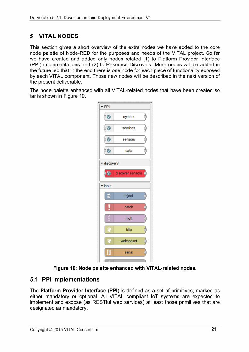
This section gives a short overview of the extra nodes we have added to the core node palette of Node-RED for the purposes and needs of the VITAL project. So far we have created and added only nodes related (1) to Platform Provider Interface (PPI) implementations and (2) to Resource Discovery. More nodes will be added in the future, so that in the end there is one node for each piece of functionality exposed by each VITAL component. Those new nodes will be described in the next version of the present deliverable. The node palette enhanced with all VITAL-related nodes that have been created so far is shown in Figure 10.
Figure 10: Node palette enhanced with VITAL-related nodes.
5.1 PPI implementations
The Platform Provider Interface (PPI) is defined as a set of primitives, marked as either mandatory or optional. All VITAL compliant IoT systems are expected to implement and expose (as RESTful web services) at least those primitives that are designated as mandatory.

Deliverable 5.2.1: Development and Deployment Environment V1
Copyright 2015 VITAL Consortium 22
This section presents a number of nodes that we have created in order to directly use the PPI primitive implementations (i.e. the RESTful web services that implement those primitives) exposed by any VITAL compliant IoT system.
5.1.1 PPI
PPI nodes are configuration nodes that store information about how to access the PPI implementation of a VITAL compliant IoT system (e.g. its base URL). Configuration nodes is a special category of nodes in Node-RED that can be used for sharing configuration among nodes. For example, PPI nodes can be used by system and services nodes (see below) in order to select the PPI implementation they want to access, without having to specify more than once details on how to access it. The properties of these nodes include the base URL of the PPI implementation, as well as whether basic authentication is required (in which case a username and a password can also be provided).
5.1.2 system
System nodes can be used to retrieve metadata about a PPI compliant IoT system. When a system node receives a message, the node makes an HTTP POST request to BASE_URL/metadata (where BASE_URL is the base URL of a PPI implementation, see Section 5.1.1), and then sends out a message that contains the response to that request (i.e. the metadata about the IoT system in JSON-LD format). The properties of these nodes include the PPI implementation to retrieve metadata about (see Section 5.1.1).
5.1.3 sensors
Sensors nodes are function nodes that retrieve metadata about sensors that a VITAL compliant IoT system manages. The messages sent to these nodes can be used to filter the sensors to retrieve metadata for (based on their ID and type), whereas the messages sent by these nodes contain the retrieved sensor metadata in JSON-LD format. Behind the scenes, a sensors node makes an HTTP POST request to BASE_URL/sensor/metadata (where BASE_URL is the base URL of a PPI implementation, see Section 5.1.1). The properties of these nodes include the PPI implementation of the IoT system that manages the sensors to retrieve metadata for (see Section 5.1.1).
5.1.4 services
Services nodes can be used to retrieve metadata about IoT services that a PPI compliant IoT system provides. The message that a services node receives may contain information, which can be used to filter the services to retrieve metadata for (based on their ID and type), whereas the message that a services node sends contains the retrieved service metadata in JSON-LD format. The services node is responsible for making an HTTP POST request to BASE_URL/sensor/metadata (where BASE_URL is the base URL of a PPI implementation, see Section 5.1.1), in order to fetch the requested metadata.

Deliverable 5.2.1: Development and Deployment Environment V1
Copyright 2015 VITAL Consortium 23
The properties of these nodes include the PPI implementation of the IoT system that provides the services to retrieve metadata for (see Section 5.1.1).
5.1.5 data
Data nodes are function nodes that pull observations made by sensors managed by a PPI compliant IoT system. Input messages may contain information, which can be used to filter the observations to fetch (based on the corresponding sensor, property and time), whereas output messages contain the retrieved observations in JSON-LD format. In order to fetch the observations that match the specified criteria, the data node first retrieves information about how to access the GetObservations operation of the ObservationService provided by the IoT system, and then uses that information in order to access the appropriate web service and retrieve the requested observations. The properties of these nodes include the PPI implementation of the IoT system that manages the sensors to retrieve observations from (see Section 5.1.1).
5.2 Resource Discovery
Resource Discovery is the VITAL component that is responsible for discovering sensors and IoT services that match specific criteria. This section presents the extra nodes that we have added to the node palette and that can be used to access the functionalities exposed by that component.
5.2.1 resource discovery
Resource discovery nodes are configuration nodes that store information about how to access the Resource Discovery component of an instance of the VITAL platform. The properties of these nodes include the base URL of the component, as well as whether basic authentication is required (in which case a username and a password can also be provided).
5.2.2 discover sensors
Discover sensors nodes are function nodes that can be used to discover sensors that reside within a certain radius from a certain point (latitude-longitude).The messages received by these nodes contain the radius, the latitude and the longitude. The messages sent by these nodes include metadata (in JSON-LD format) about the discovered sensors. Behind the scenes, the node makes an HTTP request to the appropriate Resource Discovery component. The properties of these nodes include the Resource Discovery component to access in order to retrieve the requested information (see Section 5.2.1).

Deliverable 5.2.1: Development and Deployment Environment V1
Copyright 2015 VITAL Consortium 24
6 SAMPLE WORKFLOWS AND APPLICATIONS
The purpose of this section is to present a number of workflows related to the two VITAL integrated scenarios (Smarter Working for Camden, and Traffic Management for Istanbul), and to describe how we would implement them using the VITAL development tool.
6.1 Sample workflow #1: Find the last observation made by a specific traffic sensor
We use the development tool to implement a web service that accepts HTTP GET requests, which contain the URI of a traffic sensor in a sensor parameter in the query string, and responds with the last observation made by that sensor. For the implementation of the web service, we make use of an implementation of the PPI specification provided for the traffic sensors in Istanbul. Figure 11 shows the final workflow for this scenario, as well as how we can use it, once we have deployed it, in order to get the last speed value observed by the sensor with URI http://104.131.128.70:8080/istanbul-traffic/sensor/320-F.
Figure 11: Find the last observation made by a sensor.
The flow consists of the following nodes:
• an http in node that accepts HTTP GET requests at /last-observation • a function node that extracts the sensor URI from the query string of the request,
and uses http://vital-iot.eu/ontology/ns/Speed as the property URI • a data node that retrieves the last observation made by that sensor for that
property

Deliverable 5.2.1: Development and Deployment Environment V1
Copyright 2015 VITAL Consortium 25
• an http response node that responds to the initial HTTP request with the observation value.
The following JSON represents the flow described above, and can be used to import the flow directly into the Node-RED editor.
Table 5: JSON Representation of sample workflow #1. [{"id":"85f3f420.7a0c08","type":"PPI","url":"http://104.131.128.70:8080/istanbul-traffic/ppi"},{"id":"d0b752aa.2f48b","type":"http in","name":"","url":"/last-observation","method":"get","swaggerDoc":"","x":108,"y":61,"z":"3fab8646.c0547a","wires":[["fa7bb40d.058448"]]},{"id":"fa7bb40d.058448","type":"function","name":"","func":"context.global.msg = msg;\nvar omsg = {};\nomsg.sensor = [ msg.req.query.sensor ];\nomsg.property = 'http://vital-iot.eu/ontology/ns/Speed';\nreturn omsg;","outputs":1,"noerr":0,"x":209,"y":199,"z":"3fab8646.c0547a","wires":[["7c4557f6.83baa8"]]},{"id":"7c4557f6.83baa8","type":"data","ppi":"85f3f420.7a0c08","name":"","x":363,"y":273,"z":"3fab8646.c0547a","wires":[["e9a2536d.165db"]]},{"id":"e9a2536d.165db","type":"function","name":"","func":"var result = msg.payload[0]['http://purl.oclc.org/NET/ssnx/ssn#observationResult'][0];\nvar value = result['http://purl.oclc.org/NET/ssnx/ssn#hasValue'][0]['http://vital-iot.eu/ontology/ns/value'][0]['@value'];\ncontext.global.msg.payload = 'Last observation: ' + value + ' Km/h';\nreturn context.global.msg;","outputs":1,"noerr":0,"x":475,"y":195,"z":"3fab8646.c0547a","wires":[["d52d0261.2ad3"]]},{"id":"d52d0261.2ad3","type":"http response","name":"","x":585,"y":61,"z":"3fab8646.c0547a","wires":[]}]
6.2 Sample workflow #2: Show the location of a specific traffic sensor on a map.
Here we need to implement a web service that accepts HTTP GET requests, which contain the URI of a traffic sensor in a sensor parameter in the query string, and responds with a static HTML page that contains a map with a marker set on the location of that sensor. For the purposes of this web service, we use again the PPI implementation for Istanbul traffic sensors. The flow we have designed for this scenario is shown in Figure 12. The same figure illustrates the result of using that flow, after it has been deployed, namely a map with a marker on it that depicts the location of the sensor with URI http://104.131.128.70:8080/istanbul-traffic/sensor/320-F.

Deliverable 5.2.1: Development and Deployment Environment V1
Copyright 2015 VITAL Consortium 26
Figure 12: Show the location of a sensor on a map.
The flow comprises six nodes:
• an http in node that accepts HTTP GET requests at /locate-sensor • a function node that extracts the sensor URI from the query string of the request • a sensors node that retrieves metadata about the sensor with that URI • a function node that extracts the name, the longitude and the latitude of the
sensor from the retrieved metadata • a template node that creates an HTML page with the name of the sensor in the
title, and a map with a marker at the location of the sensor • an http response node that responds to the initial HTTP request with the that
HTML page The flow is represented by the following JSON.
Table 6: JSON Representation of sample workflow #2. [{"id":"85f3f420.7a0c08","type":"PPI","url":"http://104.131.128.70:8080/istanbul-traffic/ppi"},{"id":"5a2c0151.a5d4","type":"http in","name":"","url":"/locate-sensor","method":"get","swaggerDoc":"","x":123,"y":91,"z":"f596439d.0a69c","wires":[["d6228cc8.29dd7"]]},{"id":"d6228cc8.29dd7","type":"function","name":"","func":"context.global.msg = msg;\nvar omsg = {};\nomsg.id = [ msg.req.query.sensor ];\nreturn omsg;","outputs":1,"noerr":0,"x":266,"y":219,"z":"f596439d.0a69c","wires":[["676a3ec6.9895c"]]},{"id":"676a3ec6.9895c","type":"sensors","ppi":"85f3f420.7a0c08","name":"","x":389,"y":324,"z":"f596439d.0a69c","wires":[["f358baa8.0ca748"]]},{"id":"a0b98309.5f468","type":"htt

Deliverable 5.2.1: Development and Deployment Environment V1
Copyright 2015 VITAL Consortium 27
p response","name":"","x":764,"y":100,"z":"f596439d.0a69c","wires":[]},{"id":"f358baa8.0ca748","type":"function","name":"","func":"var loc = msg.payload[0]['http://vital-iot.eu/ontology/ns/hasLastKnownLocation'];\nvar lat = loc[0]['http://www.w3.org/2003/01/geo/wgs84_pos#lat'][0]['@value'];\nvar lon = loc[0]['http://www.w3.org/2003/01/geo/wgs84_pos#lon'][0]['@value'];\nvar sensor = msg.payload[0]['rdfs:label'][0]['@value'];\ncontext.global.msg.payload = {};\ncontext.global.msg.payload.lat = lat;\ncontext.global.msg.payload.lon = lon;\ncontext.global.msg.payload.sensor = sensor;\ncontext.global.msg.headers = { 'Content-Type': 'text/html'};\nreturn context.global.msg;","outputs":1,"noerr":0,"x":490,"y":215,"z":"f596439d.0a69c","wires":[["e5979059.1a687"]]},{"id":"e5979059.1a687","type":"template","name":"","field":"payload","format":"handlebars","template":"<!DOCTYPE html>\n<html>\n<head>\n<title>{{payload.sensor}}</title>\n<script type=\"text/javascript\" src=\"http://ajax.googleapis.com/ajax/libs/jquery/1.6.4/jquery.min.js\"></script>\n<script type=\"text/javascript\" src=\"http://maps.google.com/maps/api/js?sensor=true\"></script>\n<style type=\"text/css\" media=\"screen\">\n#map {\n width: 600px;\n height: 400px;\n}\n</style>\n</head>\n<body>\n <div id=\"map\"></div>\n <script type=\"text/javascript\">\n $(document).ready(function(){\n var latlng = new google.maps.LatLng({{payload.lat}}, {{payload.lon}});\n var div = document.getElementById('map');\n var map = new google.maps.Map(div, {\n center: latlng,\n zoom: 13,\n mapTypeId: google.maps.MapTypeId.ROADMAP\n });\n var marker = new google.maps.Marker({\n position: latlng,\n map: map,\n title: 'Hello World!'\n });\n });\n </script>\n</body>\n</html>","x":599,"y":100,"z":"f596439d.0a69c","wires":[["a0b98309.5f468"]]}]
6.3 Sample workflow #3: Show all venues with available desk spaces near the current location of a user on a map
In this case, we use the VITAL development and deployment environment in order to provide a web service that accepts HTTP GET requests, which contain in the query string:
• the longitude of the current user location in a lon parameter • the latitude of the current user location in a lat parameter • a radius (in Km) in a radius parameter
The service responds with a static HTML page that contains a map with markers for all venues that have at least one available desk space and that reside within the specified range from the current location of the user.

Deliverable 5.2.1: Development and Deployment Environment V1
Copyright 2015 VITAL Consortium 28
In the Camden scenario, we have defined a virtual sensor for each venue. One of the properties that this sensor observes is the number of desk spaces that are available in that venue at a specific point in time. This effectively means that discovering venues in a specific area is translated into discovering sensors in that area, and getting the number of currently available desk spaces in a venue is translated into getting the last observation made by the corresponding sensor for the “number-of-available-desk-spaces” property. Figure 13 shows the flow we built in order to implement the web service described above. It also depicts the result of the web service being used by someone located in Camden that wants to get information about all venues within a 2 Km range.
Figure 13: Show all venues with available desk spaces on a map.
In this case the flow contains the following eight nodes wired together:
• an http in node that accepts HTTP GET requests at /find-space • a function node that extracts the longitude, the latitude and the radius from the
query string of the request • a discover sensors node that retrieves metadata about sensors located within
that radius from that point • a function node that extracts the sensor URIs, names and locations from the
retrieved metadata, and uses http://vital-iot.eu/ontology/ns/AvailableDesks as the property URI
• a data node that retrieves the last observation made by each one of those sensors for that property

Deliverable 5.2.1: Development and Deployment Environment V1
Copyright 2015 VITAL Consortium 29
• a function node that combines the sensor metadata and their last observations, in order to find and keep the venues that have at least one available desk space
• a template node that creates an HTML page that displays a map, and places a marker on it for each venue (when a marker is clicked the name of the venue, together with the number of desk spaces available in it are displayed)
• an http response node that responds to the initial HTTP request with that HTML page
This flow was more complicated, and is thus represented by the following, quite extended JSON.
Table 7: JSON Representation of sample workflow #3. [{"id":"e948c5e6.16b738","type":"PPI","url":"http://localhost:1880"},{"id":"69c6c49f.96393c","type":"resource discovery","url":"http://localhost:1880/discover-sensors"},{"id":"c1f8c136.3e074","type":"discover sensors","discovery":"69c6c49f.96393c","name":"","x":284,"y":288,"z":"e698e8e7.196718","wires":[["e324ed19.1cdb1"]]},{"id":"ced89f6e.31276","type":"http in","name":"","url":"/find-space","method":"get","swaggerDoc":"","x":104,"y":59,"z":"e698e8e7.196718","wires":[["1ed2949a.e12d6b"]]},{"id":"1ed2949a.e12d6b","type":"function","name":"","func":"context.global.msg = msg;\nvar omsg = {};\nomsg.latitude = msg.req.query.lat;\nomsg.longitude = msg.req.query.lon;\nomsg.radius = msg.req.query.radius;\nreturn omsg;","outputs":1,"noerr":0,"x":162,"y":158,"z":"e698e8e7.196718","wires":[["c1f8c136.3e074"]]},{"id":"e324ed19.1cdb1","type":"function","name":"","func":"var venues = {};\nvar ids = [];\nfor(var i = 0; i < msg.payload.length; i++) {\n var venue = msg.payload[i];\n var id = venue['@id'];\n var nname = venue['rdfs:label'][0]['@value'];\n var loc = venue['http://vital-iot.eu/ontology/ns/hasLastKnownLocation'][0];\n var lon = loc['http://www.w3.org/2003/01/geo/wgs84_pos#lon'][0]['@value'];\n var lat = loc['http://www.w3.org/2003/01/geo/wgs84_pos#lat'][0]['@value'];\n venues[id] = { 'id': id, 'name': nname, 'lat': lat, 'lon': lon};\n ids.push(id);\n}\n\ncontext.global.venues = venues;\nvar omsg = {};\nomsg.sensor = ids;\nomsg.property = 'http://vital-iot.eu/ontology/ns/AvailableDesks';\nreturn omsg;","outputs":1,"noerr":0,"x":373,"y":158,"z":"e698e8e7.196718","wires":[["fc123bc3.03edc8"]]},{"id":"79f2a314.860d5c","type":"http response","name":"","x":768,"y":58,"z":"e698e8e7.196718","wires":[]},{"id":"fc123bc3.03edc8","type":"data","ppi":"e948c5e6.16b738","name":"","x":492,"y":289,"z":"e698e8e7.196718","wires":[["625836a0.9da7c8"]]},{"id":"625836a0.9da7c8","type":"function","name":"","func":"var venues = [];\nfor(var i = 0; i < msg.payload.length; i++) {\n var observation = msg.payload[i];\n var sensor = observation['http://purl.oclc.org/NET/ssnx/ssn#observedBy'][0]['@value'];\n var result = observation['http://purl.oclc.org/NET/ssnx/ssn#observationResult'][0];\n var desks = result['http://purl.oclc.org/NET/ssnx/ssn#hasValue'][0]['http://vital-iot.eu/ontology/ns/value'][0]['@value'];\n if(desks > 0) {\n var venue = context.global.venues[sensor];\n

Deliverable 5.2.1: Development and Deployment Environment V1
Copyright 2015 VITAL Consortium 30
venues.push({ 'id': i, 'name': venue.name, 'lat': venue.lat, 'lon': venue.lon, 'desks': desks });\n }\n}\ncontext.global.msg.headers = { 'Content-Type': 'text/html' };\ncontext.global.msg.payload = venues;\nreturn context.global.msg;","outputs":1,"noerr":0,"x":589,"y":160,"z":"e698e8e7.196718","wires":[["44acd316.bb532c"]]},{"id":"44acd316.bb532c","type":"template","name":"","field":"payload","format":"handlebars","template":"<!DOCTYPE html>\n<html>\n<head>\n<title>Available desks</title>\n<script type=\"text/javascript\" src=\"http://ajax.googleapis.com/ajax/libs/jquery/1.6.4/jquery.min.js\"></script>\n<script type=\"text/javascript\" src=\"http://maps.google.com/maps/api/js?sensor=true\"></script>\n<style type=\"text/css\" media=\"screen\">\n#map {\n width: 600px;\n height: 400px;\n}\n</style>\n</head>\n<body>\n <div id=\"map\"></div>\n <script type=\"text/javascript\">\n $(document).ready(function(){\n var latlng;\n {{#payload}}\n latlng = new google.maps.LatLng({{lat}}, {{lon}});\n {{/payload}}\n var div = document.getElementById('map');\n var map = new google.maps.Map(div, {\n center: latlng,\n zoom: 13,\n mapTypeId: google.maps.MapTypeId.ROADMAP\n });\n \n {{#payload}}\n var marker_{{id}} = new google.maps.Marker({\n position: new google.maps.LatLng({{lat}}, {{lon}}),\n map: map,\n title: 'Hello World!'\n });\n var infowindow_{{id}} = new google.maps.InfoWindow({\n content: \"<h4>{{name}}</h4>Available desks: {{desks}}\"\n });\n google.maps.event.addListener(marker_{{id}}, 'click', function() {\n infowindow_{{id}}.open(map,marker_{{id}});\n });\n {{/payload}}\n\n });\n </script>\n</body>\n</html>","x":631,"y":58,"z":"e698e8e7.196718","wires":[["79f2a314.860d5c"]]}]
6.4 Sample workflow #4: Predict the next observation that a specific traffic sensor will make
rstats9 is an interface to R for Node.js. We use the development tool and rstats, in order to implement a web service that accepts HTTP GET requests, which contain the URI of a traffic sensor in a sensor parameter in the query string, and responds with a prediction for the next observation that that sensor will make. We use again the implementation of the PPI specification for the traffic sensors installed in Istanbul. The final flow implemented with the development tool is depicted in Figure 14, as well as an example of using it to get a prediction for the next observation from sensor with URI http://104.131.128.70:8080/istanbul-traffic/sensor/32-F.
9 https://www.npmjs.com/package/rstats

Deliverable 5.2.1: Development and Deployment Environment V1
Copyright 2015 VITAL Consortium 31
Figure 14: Predict the next observation that a sensor will make.
The above flow contains five nodes:
• an http in node that accepts HTTP GET requests at /predict-next-observation • a function node that that extracts the sensor URI from the query string of the
request, and uses http://vital-iot.eu/ontology/ns/Speed as the property URI • a data node that retrieves all observations made by that sensor for that property
since the beginning of 2015 • a function node that retrieves the values from the returned observations, and
uses R to predict the value of the next observation according to the best ARIMA model (using the forecast R package)
• an http response node that responds to the initial HTTP request with that value The JSON representation of the above flow follows.
Table 8: JSON Representation of sample workflow #4. [{"id":"85f3f420.7a0c08","type":"PPI","url":"http://104.131.128.70:8080/istanbul-traffic/ppi"},{"id":"62675c32.9d98a4","type":"http in","name":"","url":"/predict-next-observation","method":"get","swaggerDoc":"","x":138,"y":60,"z":"1aba0adf.e545f5","wires":[["a1dc6e.ff5e239"]]},{"id":"799cf6a4.866308","type":"http response","name":"","x":590,"y":69,"z":"1aba0adf.e545f5","wires":[]},{"id":"a1dc6e.ff5e239","type":"function","name":"","func":"context.global.msg = msg;\nvar omsg = {};\nomsg.sensor = [ msg.req.query.sensor ];\nomsg.property = 'http://vital-iot.eu/ontology/ns/Speed';\nmsg.payload.from = '2015-01-01T00:00:00+02:00';\nreturn omsg;","outputs":1,"noerr":0,"x":215,"y":174,"z":"1aba0adf.e545f5","wires":[["2b8eb4a9.d4714c"]]},{"id":"4c4fa1d5.b3b06","type":"function","name":"","func":"var values = [];\nfor(var i = 0; i <

Deliverable 5.2.1: Development and Deployment Environment V1
Copyright 2015 VITAL Consortium 32
msg.payload.length; i++) {\n var observation = msg.payload[i];\n var result = observation['http://purl.oclc.org/NET/ssnx/ssn#observationResult'][0];\n var value = result['http://purl.oclc.org/NET/ssnx/ssn#hasValue'][0]['http://vital-iot.eu/ontology/ns/value'][0]['@value'];\n values.push(value);\n}\nvar r;\nif(context.global.r)\n r = context.global.r;\nelse {\n r = new context.global.rstats.session();\n context.global.r = r;\n}\nr.parseEvalQ('library(forecast)');\nr.parseEvalQ('value <- c(' + values.join(', ') + ')');\nr.parseEvalQ('sensor<-ts(value,frequency=24)');\nr.parseEvalQ('fit <- auto.arima(sensor)');\nr.parseEvalQ('LH.pred<-predict(fit,n.ahead=1)');\nvar prediction = r.parseEval(\"LH.pred$pred\");\ncontext.global.msg.payload = prediction[0];\nreturn context.global.msg;","outputs":1,"noerr":0,"x":457,"y":176,"z":"1aba0adf.e545f5","wires":[["799cf6a4.866308"]]},{"id":"2b8eb4a9.d4714c","type":"data","ppi":"85f3f420.7a0c08","name":"","x":368,"y":253,"z":"1aba0adf.e545f5","wires":[["4c4fa1d5.b3b06"]]}]
7 FUTURE WORK, OUTLOOK AND CONCLUSIONS
The VITAL development and deployment environment is essentially a toolset for IoT application developers that is expected to:
• Ensure virtualized access to the IoT systems integrated into the VITAL platform (namely to the sensors they manage and to the services they provide).
• Support the functionalities provided by the VITAL platform (namely resource discovery, CEP, filtering, BPM, and management).
We have based the first version of the VITAL development and deployment environment on Node-RED, a tool for the Internet of Things. So far, this choice has contributed to the satisfaction of the above expectations. Node-RED is an open-source, extendable tool with a widening user community that until now has been proved sufficient based on the requirements of the VITAL integrated scenarios. We have already started using the environment, in order to build a first prototype of the back-end for the Smarter Working app for Camden Town. During this process we expect not only to assess the suitability of Node-RED for VITAL, but also to end up with nodes and/or subflows that will comprise the VITAL developer toolbox. At the moment, we have already created a set of nodes that we intend to enhance at a later stage. Finally, the current version of the VITAL development and deployment environment has not been fully integrated into the VUTAL platform. It is in our immediate plans to make it interact with OpenAM, in order to support Single Sign-On in the way prescribed by VITAL. We also intend to gradually integrate all VITAL capabilities in it, thus turning it into the single entry point that developers will use to access the complete set of functionalities provided by the VITAL framework.

Deliverable 5.2.1: Development and Deployment Environment V1
Copyright 2015 VITAL Consortium 33
8 REFERENCES
[Aberer07] Karl Aberer, Manfred Hauswirth, Ali Salehi: Infrastructure for Data Processing in Large-Scale Interconnected Sensor Networks. MDM 2007: 198-205. [Anagnostopoulos09] Achilleas Anagnostopoulos, John Soldatos, Sotiris G. Michalakos: REFiLL: A lightweight programmable middleware platform for cost effective RFID application development. Pervasive and Mobile Computing 5(1): 49-63 (2009). [Atzori10] L. Atzori, A. Iera, and G. Morabito. The internet of things: A survey. Computer Networks, 54(15):2787 2805, 2010. [Cassou10] D. Cassou, J. Bruneau, J. Mercadal, Q. Enard, E. Balland, N. Loriant, and C. Consel. Towards a tool-based development methodology for sense/compute/control applications. In Proceedings of the ACM international conference companion on Object oriented programming systems languages and applications companion, pages 247-248. ACM, 2010. [Chatzigiannakis07] Ioannis Chatzigiannakis, Georgios Mylonas, Sotiris E. Nikoletseas: 50 ways to build your application: A survey of middleware and systems for Wireless Sensor Networks. ETFA 2007: 466-473 [Patel11] P. Patel, A. Pathak, T. Teixeira, and V. Issarny. Towards application development for the internet of things. In Proceedings of the 8th Middleware Doctoral Symposium, page 5. ACM, 2011. [Patel13] Pankesh Patel, Animesh Pathak, Damien Cassou, Valérie Issarny, «Enabling High-Level Application Development in the Internet of Things», Sensor Systems and Software, Lecture Notes of the Institute for Computer Sciences, Social Informatics and Telecommunications Engineering Volume 122, 2013, pp 111-126