d8.2 - use case automotive definition v1.22 · cloud-based rapid elastic ma nufacturing wp8 –...
TRANSCRIPT
Cloud-based Rapid Elastic MAnufacturing
WP8 – Piloting & Validation: Use Case II: Automotive
D8.2
Use Case II (Automotive) Definition
Deliverable Lead: TANet
Contributing Partners: ASC, DFKI, TUV, UBI, TCO, ICE, DNIT
Delivery Date: 23/12/2015
Dissemination Level: Public
Version 1.22
This deliverable will provide the extended version of the Automotive Use Case. It includes an in-depth definition of the Tenneco UK Plant scenarios (including the concrete data sources), more detailed estimations of the required equipment for the testbed, and the metrics needed for the later evaluation of the Use Case implementations. This final version will be used by T8.2 to specify what needs to be done in the Use Case implementation.

CREMA WP8 Public Template
D8.2 - Use Case Automotive Definition v1.22.docx Document Version: 1.22
Date: 2015-12-28
Status: For Approval Page: 2 / 57
http://www.crema-project.eu Copyright © CREMA Project Consortium. All Rights Reserved. Grant Agreement No.: 637066
Document Status
Deliverable Lead Simon Osborne, TANet
Internal Reviewer 1 Aitor Murguzur, IKER
Internal Reviewer 2 Jemai Jaouhar, UBI
Type Deliverable
Work Package WP8: Piloting & Validation: Use Case II: Automotive
ID D8.2: Use Case II Automotive
Due Date 12/2015
Delivery Date 12/2015
Status For Approval
Note
This deliverable is subject to final acceptance by the European Commission.
Disclaimer
The views represented in this document only reflect the views of the authors and not the views of the European Union. The European Union is not liable for any use that may be made of the information contained in this document.
Furthermore, the information is provided “as is” and no guarantee or warranty is given that the information is fit for any particular purpose. The user of the information uses it at its sole risk and liability.

CREMA WP8 Public Template
D8.2 - Use Case Automotive Definition v1.22.docx Document Version: 1.22
Date: 2015-12-28
Status: For Approval Page: 3 / 57
http://www.crema-project.eu Copyright © CREMA Project Consortium. All Rights Reserved. Grant Agreement No.: 637066
Project Partners
Ascora GmbH, Germany
Dot NET IT, United Kingdom
Technische Universität Wien, Austria
Technology Application Network Limited, United Kingdom
German Research Center for Artificial Intelligence, Germany
IKERLAN S. Coop., Spain
Ubisense, United Kingdom
Tenneco-Walker (U.K.) Limited, United Kingdom
FAGOR ARRASATE S. Coop., Spain
Goizper, Spain
Information Catalyst, United Kingdom

CREMA WP8 Public Template
D8.2 - Use Case Automotive Definition v1.22.docx Document Version: 1.22
Date: 2015-12-28
Status: For Approval Page: 4 / 57
http://www.crema-project.eu Copyright © CREMA Project Consortium. All Rights Reserved. Grant Agreement No.: 637066
Executive Summary
The CREMA Use Case II Automotive Definition (T8.1) provides a detailed description of the Tenneco shop floor scenario where Tenneco in the UK produce their exhaust systems for major Automotive OEMs. It highlights the challenges faced by Tenneco to keep plant efficiency and productivity high by increasing visibility of the shop floor assets and aiding process improvement. Tenneco require a platform to support production flexibility and reduce manufacturing errors whilst supporting information flow between their plants across Europe.
This document is the second and final deliverable from T8.1, the first submitted M6 (D8.1) provided a high level outline and scope of the automotive scenario, in particular it described the processes, systems, resources required to carry out the Use Case, and those staff who have a vested interest in the processes. From this, a series of core themes were derived that were intended to direct the Requirements Analysis and User Stories development effort in T2.4, and subsequently this current deliverable.
This deliverable (D8.2) builds upon that last deliverable with the purpose to finalise a specification for the Automotive Use Case to enable its implementation and later evaluation. It includes a precise, in-depth definition of the scenarios, including the concrete data sources, estimations of the required equipment for the testbeds, and the metrics needed for the later evaluation of the use case implementations. The stages of the Use Case storylines are described in detail, putting in to context what will be done and seen by the stakeholders and the resultant outcomes, with an aim of making clear the purpose and the value of the application of CREMA. In addition an initial implementation plan is defined to guide the subsequent implementation effort.
This deliverables highlights the production related data flows and sources that will be provided to the CREMA platform, by interfacing with Industreweb Global and Collect which is a data collection and intelligence platform developed and installed by Control 2K to pull data from the production process. In addition the accurate positional data provided by Ubisense Smart Factory is utilised to track assets and as a result detect machine operator errors. Furthermore CPS and wearable technology is to be used to present data to the operator / maintenance person via Smart Glasses technology by providing overlaid data to the headset wearer.
In the further course of the project, this document will be used by T8.2 Use Case II (Automotive) Implementation to define what needs to be done to carry out the implementation of the scenarios for the Automotive Use Case.

CREMA WP8 Public Template
D8.2 - Use Case Automotive Definition v1.22.docx Document Version: 1.22
Date: 2015-12-28
Status: For Approval Page: 5 / 57
http://www.crema-project.eu Copyright © CREMA Project Consortium. All Rights Reserved. Grant Agreement No.: 637066
Table of Contents
1.1 CREMA Project Overview ...................................................................................... 7
1.2 Deliverable Purpose, Scope and Context .............................................................. 7
1.3 Document Status and Target Audience ................................................................. 8
1.4 Abbreviations and Glossary ................................................................................... 8
1.5 Document Structure ............................................................................................... 8
2 Automotive Use Case Definition ................................................................................... 10
2.1 Automotive Use Case Scenario Definition Summary ........................................... 11
2.2 Detailed User Stories ........................................................................................... 12
2.2.1 Generic Storyline ...................................................................................... 13
2.2.2 Automotive Scenario A: Elastic Manufacturing ......................................... 21
2.2.3 Automotive Scenario B: Quality Control Production ................................. 28
2.3 Systems, Data Sources and Models .................................................................... 31
2.3.1 Industreweb Global ................................................................................... 31
2.3.1.1 Services to be developed .......................................................... 33
2.3.1.2 Streaming .................................................................................. 35
2.3.2 Industreweb Collect .................................................................................. 37
2.3.2.1 ATS Robot Controller + Siemens HMI ...................................... 37
2.3.2.2 Siemens S7 PLC ....................................................................... 38
2.3.3 Ubisense Smart Factory ........................................................................... 39
2.3.3.1 RESTful Web service interface ................................................. 39
2.3.4 Data Sources ............................................................................................ 40
2.4 Process Definitions .............................................................................................. 42
2.4.1 Master Process Model to co-ordinate and start production ...................... 42
2.4.2 Process to Allocate resource to meet production demand ....................... 43
2.4.3 Process to Start Production ...................................................................... 44
2.4.4 Process to start Manufacture of Exhaust .................................................. 45
2.5 Outputs ................................................................................................................ 49
2.5.1 Analytics ................................................................................................... 49
2.5.2 Monitoring & Business Rules .................................................................... 49
2.5.3 Optimisation ............................................................................................. 50
3 Automotive Use Case Evaluation ................................................................................. 51
3.1 Evaluation Equipment and Testbeds ................................................................... 51
3.2 Evaluation Metrics ............................................................................................... 53
4 Implementation Plan ..................................................................................................... 56
5 Conclusion ................................................................................................................... 57

CREMA WP8 Public Template
D8.2 - Use Case Automotive Definition v1.22.docx Document Version: 1.22
Date: 2015-12-28
Status: For Approval Page: 6 / 57
http://www.crema-project.eu Copyright © CREMA Project Consortium. All Rights Reserved. Grant Agreement No.: 637066
List of Figures, Tables and Listings
Figures
Figure 1: Typical layout of exhaust welding cell ................................................................. 10
Figure 2: Current Tenneco exhaust production process .................................................... 12
Figure 3: View of systems actors and process workflow in Tenneco exhaust manufacture ........................................................................................................................................... 13
Figure 4: SVA View Service ............................................................................................... 15
Figure 5: MPM Marketplace Mock-up UI - General Information ......................................... 16
Figure 6: PDE Process Designer Web Mock-up UI ........................................................... 17
Figure 7: PDE example BPMN Task Data Input/Output Mock-up UI ................................. 17
Figure 8: PDE BPMN Service Task Selection Mock-up UI ................................................ 18
Figure 9: PRU Executes a Process Model Mock-up UI...................................................... 19
Figure 10: PRU List all Instantiated Proxy Service Wrappers Mock-up UI ......................... 20
Figure 11: Ubisense Smart Factory Localisation Sensor ................................................... 22
Figure 12: Ubisense Virtual Map showing the layout, robot zones and user...................... 22
Figure 13: Ubisense Smart Factory tags (from left to right: head unit with integrated A-battery, case for external battery, head unit) ...................................................................... 23
Figure 14: MPM Marketplace Mock-up UI - General Information ....................................... 24
Figure 15: MPM Marketplace Mock-up UI – Payment ....................................................... 25
Figure 16: PRU Executes a Process Model Mock-up UI.................................................... 26
Figure 17: DHS Semantic Mapper Mock-up UI .................................................................. 27
Figure 18: DHS Semantic Mapper (Search for Candidates) Mock-up UI ........................... 28
Figure 19: Outline architecture of Industreweb Global ....................................................... 33
Figure 20: Outline architecture of IW Collect ..................................................................... 37
Figure 21: ATS Robot controller software running on a Siemens HMI ............................... 38
Figure 22: Siemens 1200 PLC used on the ABB robot production cells ............................ 39
Figure 23: Process design for the Master Process Model to co-ordinate and start production .......................................................................................................................... 43
Figure 24: Sub-Process design for the allocation of resource to meet production demand ........................................................................................................................................... 44
Figure 25 Sub-Process design for starting the robot cell production .................................. 45
Figure 26 Sub-Process design to co-ordinate exhaust production [part 1] ........................ 47
Figure 27 Sub-Process design to co-ordinate exhaust production [part 2] ........................ 48
Figure 28: Pilot area for the Tenneco Use Case ................................................................ 51
Figure 29: Plan view of Pilot Area modelled in Ubisense Smart Factory ........................... 52
Figure 30: ABB 6-Axis Robot used in the Tenneco Use Case implementation .................. 53
Figure 31 Initial Implementation Plan for the Automotive Use Case .................................. 56
Tables
Table 1: Data stream items ................................................................................................ 40
Table 2: Web service data ................................................................................................. 41
Table 3: Automotive Scenario A Elastic Manufacturing Evaluation Metrics ....................... 54
Table 4: Automotive Scenario B Quality Control Evaluation Metrics .................................. 55

CREMA WP8 Public Template
D8.2 - Use Case Automotive Definition v1.22.docx Document Version: 1.22
Date: 2015-12-28
Status: For Approval Page: 7 / 57
http://www.crema-project.eu Copyright © CREMA Project Consortium. All Rights Reserved. Grant Agreement No.: 637066
Introduction
CREMA – Cloud-based Rapid Elastic MAnufacturing – is a project funded by the Horizon 2020 Programme of the European Commission under Grant Agreement No. 637066.
Within this deliverable, with help of Use Case II Automotive (T8.1, D8.1), Requirements Analysis and User Stories (T2.4, D2.9) and Global Architecture Definition (T3.1, D3.1), the specification and evaluation metrics of the Automotive Use Case are defined. This will enable the subsequent implementation and later evaluation of Use Case II, and aid a common understanding of its objectives and scope within project technical partners and also the associated industrial partner Tenneco (TCO).
1.1 CREMA Project Overview
CREMA aims at simplifying the establishment, management, adaptation, and monitoring of dynamic, cross-organisational manufacturing processes following Cloud manufacturing principles. CREMA will also provide the means to integrate data from distributed locations as if the complete manufacturing was carried out on the same shop floor, by integrating extra- and inter-plant manufacturing assets and making them “mobile”.
CREMA will be built upon concepts and methods from the fields of Virtual Factories, Service-oriented Computing, Ubiquitous Computing, Cyber-Physical Systems, the Internet of Things and the Internet of Services, and naturally and most importantly Cloud computing. To achieve its goals, the project will define tools and approaches in these areas:
• Manufacturing Virtualisation & Interoperability
• Cloud Manufacturing Process and Optimisation Framework
• Cloud Manufacturing Collaboration, Knowledge and Stakeholder Interaction Framework
Thus, to achieve its goals, CREMA conducts original research and applies technologies from the fields of full end-to-end integration of Cloud manufacturing, integration of manufacturing assets and corresponding data sources, the design and execution of manufacturing processes, to the end user support via collaboration and interaction tools. For more information, please refer to the project Website1.
1.2 Deliverable Purpose, Scope and Context
The purpose of this deliverable is to provide a detailed guidance on Use Case specification and help with requirements capture, so we can have a clear picture of the full scope of the automotive scenario and position for latter measurement, evaluation period (D8.1.2). With this aim, this Use Case Definition Document details the current automotive scenarios including the processes, systems, resources required to carry out, and those staff who have a vested interest.
The initial Use Case overview was presented in the Project Proposal Document, while some other preliminary ideas were also presented in the Vision Consensus Document. The scope of this deliverable is to provide more details relating to the application of CREMA within the WP8 efforts.
1 http://www.crema-project.eu/

CREMA WP8 Public Template
D8.2 - Use Case Automotive Definition v1.22.docx Document Version: 1.22
Date: 2015-12-28
Status: For Approval Page: 8 / 57
http://www.crema-project.eu Copyright © CREMA Project Consortium. All Rights Reserved. Grant Agreement No.: 637066
1.3 Document Status and Target Audience
This document is listed in the Description of Action (DOA) as “public”, since it validates the real applicability of CREMA in industrial, real-life settings and thus can serve as a reference for future adoption in Cloud Manufacturing and Industrial Internet scenarios.
Moreover, although this document is mainly aimed at the projects partners, it can be helpful for the wider scientific and industrial community, e.g., as a motivating scenario in scientific publications.
1.4 Abbreviations and Glossary
A glossary of common terms and roles related to the realisation of CREMA as well as a list of abbreviations is provided as an online glossary2 / abbreviations list3.
In order to assist in the referencing of Use Cases, User Stories and User Resources from later deliverables, including the requirements definitions to be defined in D2.9, the following reference schema has been implemented:
Use Case UC-T.1
User Resource UR-T.1
Roles T-PRDENG
1.5 Document Structure
This deliverable is broken down into the following sections:
• Section 1 (Present Status of the Automotive Use Case): Provides an introduction for this deliverable, including a general overview of the project, and outlines the purpose, scope, context, status, and target audience of this deliverable.
2 http://crema-project.eu/glossary 3 http://crema-project.eu/abbreviations
Use Case number
Use Case partner reference (T = Tenneco, U = UBISENSE)
Use Case
User resource number
Use Case partner reference (T = Tenneco, U = UBISENSE)
User resource
Role Use Case partner reference (T = Tenneco, U = UBISENSE)

CREMA WP8 Public Template
D8.2 - Use Case Automotive Definition v1.22.docx Document Version: 1.22
Date: 2015-12-28
Status: For Approval Page: 9 / 57
http://www.crema-project.eu Copyright © CREMA Project Consortium. All Rights Reserved. Grant Agreement No.: 637066
• Section 2 (Automotive Use Case Definition): Outlines the outcomes of the previous deliverable and describes in detail the Automotive Use Case narrative, data sources and process definitions.
• Section 3: (Automotive Use Evaluation): Describes the testing scenarios, equipment and the metrics used to later evaluate the success of the CREMA platform within the automotive context.
• Section 4: (Implementation Plan): Provides an initial plan for the stages of the Automotive Use Case implementation.
• References: Provides the details of the references mentioned in the document

CREMA WP8 Public Template
D8.2 - Use Case Automotive Definition v1.22.docx Document Version: 1.22
Date: 2015-12-28
Status: For Approval Page: 10 / 57
http://www.crema-project.eu Copyright © CREMA Project Consortium. All Rights Reserved. Grant Agreement No.: 637066
2 Automotive Use Case Definition
Tenneco UK is a manufacturing plant serving the clean air division of Tenneco and is a Tier 1 exhaust supplier to a number of OEM automotive companies around Europe. Like all manufacturing companies, Tenneco UK (hereafter referred to as Tenneco) is looking forward to continuously improving efficiencies and incorporate new technology to gain commercial advantage in a very competitive marketplace. With the new developments in Cloud technology and Big Data handling Tenneco is looking to benefit from the development proposed by the CREMA project and look at avenues of asset virtualisation, monitoring and alerting as well as other key technologies.
The exhaust production with Tenneco centres on a robot welding cells and subsequent test cells. Welding cells use ABB multi axis robot utilising a metal inert gas (MIG) welding process as shown in Figure 1.
Figure 1: Typical layout of exhaust welding cell
The CREMA platform objectives align closely with those that Tenneco are seeking to acquire by allowing assets on the shop floor to be connected to and be virtualised exposing shop-floor data to be analysed and optimised. The ultimate goal is to improve the plant efficiency and make working practices easier to implement and monitor. By virtualising the resources of Tenneco, more detailed analysis can be conducted and methods to optimise process design can be developed.
Tenneco seeks to connect the currently fragmented production processes and in doing so be able to more successfully manage them. Valuable efficiency and machine status data from the production processes coupled with data from legacy systems and positional data from key production assets will provide greater insight into the plant efficiency and ultimately highlight and therefore eliminate production issues. These features are

CREMA WP8 Public Template
D8.2 - Use Case Automotive Definition v1.22.docx Document Version: 1.22
Date: 2015-12-28
Status: For Approval Page: 11 / 57
http://www.crema-project.eu Copyright © CREMA Project Consortium. All Rights Reserved. Grant Agreement No.: 637066
incorporated in the Industrial Internet of Things (IIoT) and the Cloud Manufacturing Services that CREMA will bring to the shop floor.
2.1 Automotive Use Case Scenario Definition Summary
This deliverable is the second and final revision of the Use Case II (Automotive) Definition deliverable. As the focus of this final deliverable on providing the detail to be able to implement the Use Case in task T8.2, the outcomes of the previous interim deliverable at month 6 will be described in this section in order to make clear how the core themes of this final deliverable have been arrived at.
In the previous deliverable a high level description and scope of the automotive scenario was defined, in particular it detailed the current automotive scenarios including the processes, systems, resources required to carry out the Use Case, and those staff who have a vested interest in the processes. From this, a series of core themes were derived that were intended to direct the Requirements Analysis and User Stories development effort in T2.4, and subsequently this current deliverable.
In D2.9 Requirements Analysis and User Stories it was determined that the methodology for collating the requirements was to refine the User Scenarios proposed in the first revision of the Use Case Definition deliverable into a series of User Stories comprising a series of well-defined steps. These original high level User Scenarios described the typical business domain processes and the typical issues faced by the end users that they would like to resolve.
For the Automotive Use Case there were two User Stories defined, relating to an Elastic Manufacturing theme and a Quality theme through the use of CPS. In addition to these there was also defined a Generic Storyline which represented actions that are common to both Use Cases.
In the previous interim deliverable the stakeholders and systems used within the Use Case were introduced. In relation to the stakeholders those both inside Tenneco and outside the organisation were identified, and are listed below by according to their roles:
• Plant Manager (T-PLTMGR)
• Production Manager (T-PRDMGR)
• Quality Manager (T-QLTMGR)
• Maintenance Manager (T-MAINMGR)
• Material, Parts and Logistics (MP&L) Manager (T-MPLMGR)
• Production Engineer (T-PRDENG)
• Quality Engineer (T-QLTENG)
• Process Engineer (T-PROENG)
• Operator (T-OPERTR)
• Customer (T-CUSTMR)
• Supplier (T-SUPPLR)
Production cells work according to a production schedule which is formulated by the Production engineer and Material Planning & Logistics (MP&L) based on demand from their customers. Figure 2 shows the overall Tenneco Scenario of the types of cells found on the shop floor. Each of these resources are essentially stand-alone systems with no interconnectivity or interaction between them.

CREMA WP8 Public Template
D8.2 - Use Case Automotive Definition v1.22.docx Document Version: 1.22
Date: 2015-12-28
Status: For Approval Page: 12 / 57
http://www.crema-project.eu Copyright © CREMA Project Consortium. All Rights Reserved. Grant Agreement No.: 637066
Figure 2: Current Tenneco exhaust production process
The scheduling of production is based on the batch process method where a level of stock is agreed internally and with suppliers of the raw materials or complementary components sourced from its supply chain. This is subject to fluctuations as customer demands for exhaust systems rise and fall. Despite these fluctuations, customer lead time estimates are expected to be kept to a minimum as they in turn can plan their own schedule.
In relation to the systems all software platforms and hardware solutions were described that are used by or support the production process. These are now refined to those with a direct impact on the concrete data sources and functionality of the Use Case. They are described in detail in section 2.3 Systems, Data Sources and Models.
2.2 Detailed User Stories
The following section elaborates the User Stories outlined above. This includes the activities of the main stakeholder roles within Tenneco, mock-ups of the UI’s that users will see, details of data connections, and interfacing between systems and the CREMA platform. This will enable a clear understanding of the Use Case and therefore provide a view of what will need to be implemented in T8.2 Use Case Implementation. Furthermore, it will enable evaluation metrics to be more easily defined.
Figure 3 shows a high level view of the envisaged system described within the two Automotive Use Case scenarios, including the systems, key production assets and production flow.

CREMA WP8 Public Template
D8.2 - Use Case Automotive Definition v1.22.docx Document Version: 1.22
Date: 2015-12-28
Status: For Approval Page: 13 / 57
http://www.crema-project.eu Copyright © CREMA Project Consortium. All Rights Reserved. Grant Agreement No.: 637066
IW Global
Robot Cell 1 Robot Cell 2
Test Cell 1 Test Cell 2 Goods OutSt
ora
ge
Ra
ck
Sto
rag
e R
ac
k
Sto
rag
e R
ac
k
Machine
Operator
Machine
Operator
Machine
Operator
Machine
Operator
Siemens
PLCATS
Siemens
PLCATS
CREMA
UBI
Smart Factory
Exhaust
UI
CollectCollect
Collect Collect
Collect Collect
Services
Engine Data Alarms
Simulated Robot
Cell
Localisation Tag
Ubisense
Smart Factory
localisation
sensors
Figure 3: View of systems actors and process workflow in Tenneco exhaust manufacture
2.2.1 Generic Storyline
The Generic storyline was defined to represent the functionality that is common to both Use Cases. It encapsulates steps that have been extracted from the Automotive and Machine Maintenance storylines although the actors who are the stakeholders will be different in both cases.
In the Tenneco case the Generic storyline relates to the Process Engineer describing the service interface to represent the manufacturing assets through the use of the Industreweb platform as a middleware and Smart Factory to bring a context of asset position tracking and alerting. From this the Process Engineer is able to model the process for selecting manufacturing resource to meet customer demand and the main exhaust production process itself including checking for correct process setup.

CREMA WP8 Public Template
D8.2 - Use Case Automotive Definition v1.22.docx Document Version: 1.22
Date: 2015-12-28
Status: For Approval Page: 14 / 57
http://www.crema-project.eu Copyright © CREMA Project Consortium. All Rights Reserved. Grant Agreement No.: 637066
Step Description
G1 If no software-machine interface (CPS) for a machine integration is available, then a CPS service needs to be created. CREMA Task 4.4 CPS, Sensor Abstraction and Virtualisation provides a unified approach to accessing CPS and sensors through the Sensor Abstraction Layer.
NB: Industreweb (IW), FAGOR DATALOGGER, Ubisense SmartFactory (SF) count as existing CPS services.
For IW Global a Restful Web Service will be implemented that provides methods that fulfil those required by those defined in the Cyber-Physical Systems, Sensor Abstraction and Virtualisation section of the D30 Function Specification deliverable. The data collected from the shop floor systems by IW Collect units will be amalgamated by IW Global, to make it the singular point of contact for shop floor data.
G2 A technical user creates the Proxy Service Wrapper for the three types of Concrete Services: External Services, Internal Software Services and CPS services.
In order to achieve this, a Docker image must be created for the IW Global web services which represent the Robot cells, Test cells and Machine Operators, and the Ubisense SF instance. Docker is an open platform for building, shipping and running distributed applications. The Docker image is in essence acting as a wrapper for the service that can be instantiated dependent on demand for the underlying service. To do this, the Process Engineer would use the Docker Client that is installed locally on his PC. He would do this only once for each service he wished to add to the CREMA marketplace.
G3 Technical user creates a simple HTML Form GUI and enters the data to describe and semantically annotate the service.
The Process Engineers would log in to CREMA and using the CREMA Service Virtualisation and Abstraction (SVA) UI they would create a new Service Template. Once they had populated the main service description details they can populate the semantic annotation to describe the service. This will provide the details of the characteristics of the robot welding cells, test cells and human operators within the manufacturing area. These characteristics will enable the services to be selected to suit the tasks defined in the production process. Finally the Process Engineer can provide and upload the Docker image executable file.
Figure 4 shows the mock-up of the SVA UI for describing the service and uploading the Docker image file.

CREMA WP8 Public Template
D8.2 - Use Case Automotive Definition v1.22.docx Document Version: 1.22
Date: 2015-12-28
Status: For Approval Page: 15 / 57
http://www.crema-project.eu Copyright © CREMA Project Consortium. All Rights Reserved. Grant Agreement No.: 637066
Figure 4: SVA View Service
G4 Clicking update/save will store the Proxy Service Wrapper (and binary in the case of Internal Software Services), the description and the annotation in the Service Repository. The Service Repository is included in the CREMA MPM.
The is a simple step, that will ultimately see the services for the robot cells, the test cells and the shop floor operators saved to the CREMA Cloud-based RAID Infrastructure (CRI). Once this has been completed the services will be available when designing the process model for the production process and in the CREMA Marketplace (MPM) as shown in Figure 5.

CREMA WP8 Public Template
D8.2 - Use Case Automotive Definition v1.22.docx Document Version: 1.22
Date: 2015-12-28
Status: For Approval Page: 16 / 57
http://www.crema-project.eu Copyright © CREMA Project Consortium. All Rights Reserved. Grant Agreement No.: 637066
Figure 5: MPM Marketplace Mock-up UI - General Information
G5 Add a service in Process Designer workbench by dragging it in from the Palette to become a process step.
The Process Engineer would start a new process design in the Cloud Collaborative Design Time Environment (PDE) to describe the production of the exhaust. The Process Engineer drags an empty task onto the design canvas. Clicking on this task will provide them with a context pad where they can configure it as a service task. Once the task has been chosen as a service task the Process Engineer then chooses the implementation type as an “Abstract Service”. They will then be able to select the appropriate abstract service from the MPM.
Figure 6 shows the PDE mock-up for the configuration of a task in the process design that the Process Engineer would use.

CREMA WP8 Public Template
D8.2 - Use Case Automotive Definition v1.22.docx Document Version: 1.22
Date: 2015-12-28
Status: For Approval Page: 17 / 57
http://www.crema-project.eu Copyright © CREMA Project Consortium. All Rights Reserved. Grant Agreement No.: 637066
Figure 6: PDE Process Designer Web Mock-up UI
G6 Process steps are connected together including inputs and outputs and suitably configured.
The Process Engineer will use the PDE to design the process for scheduling and co-ordination of the exhaust manufacturing activities such as in the example shown in Figure 7. The full designs for the manufacturing process are provided in more detail in section 2.4.
Figure 7: PDE example BPMN Task Data Input/Output Mock-up UI

CREMA WP8 Public Template
D8.2 - Use Case Automotive Definition v1.22.docx Document Version: 1.22
Date: 2015-12-28
Status: For Approval Page: 18 / 57
http://www.crema-project.eu Copyright © CREMA Project Consortium. All Rights Reserved. Grant Agreement No.: 637066
G7 A human designer may select a Concrete Service from the CREMA MPM that fulfils the “abstract service” for the activity.
When the Process Engineer selects service tasks on the PDE he can choose the implementation type of either “Concrete” or “Abstract” based on this a list of services that you can choose will be provided from MPM. When selecting one service to fulfil the task the Service “Get Availability” method is checked to ensure that it is available for use.
For the Tenneco Use Case, these concrete services will be those provided by IW Global and Ubisense SF. For IW Global the services will represent the robot cells, the test cells and the shop floor operators, and for SF the services will represent the tooling units that get mounted to the robot beams suitable for the specific model of exhaust and the manufactured exhaust units themselves to track their progress the production line. His selection initially is based on the resources within the plant he is based at.
Figure 8 shows a mock-up of how the Process Engineer would make a selection of suitable services.
Figure 8: PDE BPMN Service Task Selection Mock-up UI
G8 The concrete service becomes a “default” for that process step in that process.
Upon selection of a concrete process the Process Engineer has indicated that that specific service should be the default one. A default service may be replaced at runtime should the service become unavailable or if the Design Time and Runtime Optimisation (ODERU) is applied and a “better” service is proposed. In the case of the production process described in section 0 the pilot robot and test cells will be the default concrete services.
G9 For abstract services Design Time Optimisation may be invoked to find Concrete Services (from the CREMA MPM) which match the description of the Abstract Services. The human process designer may either replace the Abstract Service with a found Concrete Service or link one or more found services to the Abstract Services. In the latter case the designer may also select one service as a default.
The Process Engineer, when completing his process design, uses the Design Time Optimisation

CREMA WP8 Public Template
D8.2 - Use Case Automotive Definition v1.22.docx Document Version: 1.22
Date: 2015-12-28
Status: For Approval Page: 19 / 57
http://www.crema-project.eu Copyright © CREMA Project Consortium. All Rights Reserved. Grant Agreement No.: 637066
(ODE) to verify that the concrete services selected through his decision process are the most suitable.
Choosing an abstract service in design time when it comes to compose/optimise a service plan using the ODE it will look at the semantic annotations that were provided in the MPM for this abstract service and try and find a concrete service to use.
G10 Add Concrete Service by dragging in a service from the CREMA ODE, which gets the Concrete Service from the CREMA MPM.
Dragging a service task to the design canvas in the PDE which can then have an implementation type set as Concrete or Abstract. Choosing either will then allow the Process Engineer to select an appropriate service from the MPM.
G11 Based on the Process design and the process steps a sequence of service instances are invoked by the CREMA PRU; if there is no instance of an Internal Software Service, the CREMA OSL will instantiate it.
The Process Engineer runs the process he designed in the PRU, as shown in Figure 9, which causes the IW Global and SF services to be instantiated through the OSL “spinning up” the Docker image.
Figure 9: PRU Executes a Process Model Mock-up UI
G12 Each service is checked to see if the service is available at the needed time (by instantiating the service and calling a “check-if-available” interface). This does not apply for Internal Software Services since the cloud enables scaling.
The OSL checks to see whether the IW Global and SF services are available by calling the “Get Availability” method of the service. IW Global checks with IW Collect to see if the Robot cells, and Test cells are tied up with production. At this time all services are available and therefore IW Global returns "state": "available".
G13 OSL reserves it at that time via the CREMA MPM (if it’s not already booked for the target timeslot). This then starts the billing ‘clock/counter’ for that particular service.
The Leasing and Re-leasing service calls the “Available” method on the service proxy wrapper that in turn calls the concrete IW service for each of the robots that have been allocated for meeting the production schedule. If the service returns “available” the OSL books the robot services. A list of running services can be viewed by the Process and Production engineers with

CREMA WP8 Public Template
D8.2 - Use Case Automotive Definition v1.22.docx Document Version: 1.22
Date: 2015-12-28
Status: For Approval Page: 20 / 57
http://www.crema-project.eu Copyright © CREMA Project Consortium. All Rights Reserved. Grant Agreement No.: 637066
an indication of when the process was started and with the facility to directly terminate them as shown in Figure 10 below.
Figure 10: PRU List all Instantiated Proxy Service Wrappers Mock-up UI
G14 After the service is leased it is called to be executed.
The PRU then calls the Start method on the proxy service wrapper, and passes the endpoint of the PRE as a location to stream to, which in turn calls the start method on IW for that specific robot and also SF. IW Global will then display a message to the operator on the IW Global web UI and also call the IW Collect for that specific robot which will notify the ATS robot controller. The robot will not start automatically due to machine setup and safety considerations but the machine operator will be made aware that they should start the process. Upon receiving the start method call IW Global will start streaming to the PRU end point that was provided. The specific data that will be streamed is described in sections 2.3.1.2.
G15 If it’s not available as an internal software service, a new instance gets instantiated and this service would get called during runtime.
Should the robot service return “blocked” the, OSL detects the unavailability and sends this information back to the PRU, then the PRU asks then the ODERU for a new service will select an alternative service based on its service description and instantiate it and again check its availability. If all is ok this will be started in the manner described in the previous step.
G16 If it’s a non-instantiable service (CREMA External Software Services) or it’s not available, CREMA OSL will notify the CREMA PRE which will pause the process and trigger the Runtime Optimisation.
In relation to the Tenneco Use Case this step is not applicable as all the external software services will be represented by IW Global and SF.
G17 When a process stops because of an error (NB not terminated), the Runtime Optimisation gets triggered by the CREMA PRU.
If any of the services associated to IW Global or SF stop because the underlying software is

CREMA WP8 Public Template
D8.2 - Use Case Automotive Definition v1.22.docx Document Version: 1.22
Date: 2015-12-28
Status: For Approval Page: 21 / 57
http://www.crema-project.eu Copyright © CREMA Project Consortium. All Rights Reserved. Grant Agreement No.: 637066
closed, loses network connectivity or experiences an error the ORU is called to select an alternative service. In the Tenneco Use Case a machine operator Service will become unavailable because the corresponding machine operator has to leave work unexpectedly. As a result the ORU is called.
G18 Runtime optimisation tries to find an alternative solution utilising the Service Repository and composes an adapted process.
The ORU searches the service repository to identify an alternative machine operator service with a sufficiently similar service description. This will be based on the machine operator’s capability to operate the production cell, and also take account of the schedule for the service in the MPM which relates to their shift pattern within the factory. In this case an operator from another production line will be selected that has an equivalent skill set.
G19 If Optimisation finds a potential solution, then a human is notified by the CREMA PRU via the Dashboard. For example, it may present the old and different revised processes for the user to choose or select the new one. To visualise the process a subcomponent of the Process Designer will be used. Revised processes might be stored in the Cloud Storage if a valid process model was calculated.
When the above step happens, the Process or Production engineers would need to confirm the machine operator service being proposed as a replacement to ensure the selection is a good match for the production process.
G20 If the proposed new service is accepted the CREMA PRU is informed about the optimised and accepted process and the revised process step(s) continued to be executed along with the existing steps.
The machine operator service is included in the process and when the proxy service wrapper “Start Service” method is called it will trigger the operator to proceed to the robot cell station to perform the machine operator role.
G21 If no solution is found. A warning is shown to managers and the process terminates.
Should no suitable machine operator be available in the factory then the process for running that production line must be stopped.
2.2.2 Automotive Scenario A: Elastic Manufacturing
The Elastic Manufacturing Scenario is specific to the Tenneco Automotive Use Case and relates to the variation of resources necessary to meet production demand. Currently when demand increases to the point where existing manufacturing resources cannot satisfy it, additional production cells need to be installed and commissioned. This is costly and also subject to a long lead time to get a production cell fully commissioned, so it is not a responsive solution. The demonstration of elastic manufacturing in this scenario allows Tenneco to engage suitable manufacturing assets from other plants in the Tenneco group in a flexible manner.
Step Description
A1 Industreweb and Ubisense SMARTFACTORY are implemented within the factory sites.
The Maintenance engineer and a Ubisense engineer who sets up and commissions the Smart Factory sensor system which is defined more clearly in section 3.1.

CREMA WP8 Public Template
D8.2 - Use Case Automotive Definition v1.22.docx Document Version: 1.22
Date: 2015-12-28
Status: For Approval Page: 22 / 57
http://www.crema-project.eu Copyright © CREMA Project Consortium. All Rights Reserved. Grant Agreement No.: 637066
Figure 11: Ubisense Smart Factory Localisation Sensor
In addition the configuration of the Ubisense Smart Factory software is carried out and the production area used for the Use Case is modelled as a plant view. This will include the definition of four zones for the monitoring of production asset positions which are described in more details in section 3.1.
Figure 12: Ubisense Virtual Map showing the layout, robot zones and user
A2 All the products and tooling are tagged.
The Tenneco Maintenance engineer and the Ubisense commissioning engineer attach the Ubisense tracking tags to the robot tooling assemblies so that it is known what tools are present inside the robot cell when producing a particular model of exhaust.

CREMA WP8 Public Template
D8.2 - Use Case Automotive Definition v1.22.docx Document Version: 1.22
Date: 2015-12-28
Status: For Approval Page: 23 / 57
http://www.crema-project.eu Copyright © CREMA Project Consortium. All Rights Reserved. Grant Agreement No.: 637066
A tool in the context of a Tenneco robot is a fixture that is used to hold the exhaust components in position whilst the components are welded together. They are mounted to the production bed plate of the robot, and are put in position by an operator when they change over the product model, as dictated by their production schedule. Each product produced has an associated ‘tool recipe’ that defines what tools must be used, and this will be retrieved at run-time by IW Global. The impact of fitting a wrong tool will be that the shape of the exhaust will be wrong or that welds will be incorrect and probably subject to quality issues. These errors have a big impact and are critical to detect and resolve. In addition, a localisation tag will be mounted to every finished exhaust product prior to leaving the robot production zone. This will be done by the machine operator attaching in a non-permanent way to the end of the exhaust. Assuming that no alerts were generated during the production process the machine operator will remove the tag once the exhaust reaches the final Goods Out zone. Finally the machine operators wear tags, so as there are three cells and three shifts there are nine tags in total for the production line considered. The application of these tags are described in Generic Storyline 2.2.1.
Figure 13: Ubisense Smart Factory tags (from left to right: head unit with integrated A-battery, case for external battery, head unit)
A3 All the robot cells, the test cells, including those in other Tenneco plants are made available in the Marketplace.
To do this the Process Engineer will create a Service using the UI of SVA (T4.5). This then stores the data in the MPM. This will involve the provision of general information describing the service so that its functionality can be identified. Figure 14 shows a mock-up of the MPM UI showing the list of services currently registered along with their description and current availability status. In addition the Process Engineer will be able to view further service details by clicking on a service and viewing them at the bottom of the screen.

CREMA WP8 Public Template
D8.2 - Use Case Automotive Definition v1.22.docx Document Version: 1.22
Date: 2015-12-28
Status: For Approval Page: 24 / 57
http://www.crema-project.eu Copyright © CREMA Project Consortium. All Rights Reserved. Grant Agreement No.: 637066
Figure 14: MPM Marketplace Mock-up UI - General Information
In addition to the basic information the Process Engineer will need to provide payment information so that when a payments can be made for the resource when it is leased by a customer. The Process Engineer specifies the payment details for the services for the Tenneco production assets by entering them in the MPM UI as shown in the UI mock-up in Figure 15.

CREMA WP8 Public Template
D8.2 - Use Case Automotive Definition v1.22.docx Document Version: 1.22
Date: 2015-12-28
Status: For Approval Page: 25 / 57
http://www.crema-project.eu Copyright © CREMA Project Consortium. All Rights Reserved. Grant Agreement No.: 637066
Figure 15: MPM Marketplace Mock-up UI – Payment
A4 A Process Model is designed to check the alignment of the number of robot cells with the production schedule.
The Process Engineer designs a Process Module using the PDE to determine the number of robots required to meet production demand. The functionality and design of this process are outlined in section 2.4.2.
A5 User runs process manually or on a schedule.
The Production engineer logs into the PRU UI and selects the process that relates to the exhaust production. As shown in the UI mock-up in Figure 16 the Production engineer views a list of processes and executes the exhaust production process by clicking play.

CREMA WP8 Public Template
D8.2 - Use Case Automotive Definition v1.22.docx Document Version: 1.22
Date: 2015-12-28
Status: For Approval Page: 26 / 57
http://www.crema-project.eu Copyright © CREMA Project Consortium. All Rights Reserved. Grant Agreement No.: 637066
Figure 16: PRU Executes a Process Model Mock-up UI
A6 The Process steps service calls Industreweb Global to find out the number of active robot cells.
The PRU calls IW Global to retrieve the total number of robots engaged in production. This is used to determine how many additional robots are required in later steps to meet production demand.
A7 Call Industreweb for the number of necessary robot cells.
The PRU calls IW Global to retrieve the production schedule which is a collection of order items each with a quantity total. It then calls the BDA to determine what the average production output is for the robot cells and for each order in the schedule it divides the quantity required by the average production output to give the number of robots required.
A8 Individual Process steps can be flagged (e.g. additional attribute on the service or an intrinsic service) to send to data handling components such as the cloud storage, big data analytics or monitoring either continually or in batch dependent on the source data. In the designed process it was decided to add an intrinsic step to pass the data batch to the BDA component. If this simplification is not possible, a step to send data has to be added for every sensor. During the process execution when the robot has starts its production cycle the PRU triggers the stream data method of the robot service, which calls IW Global to opens a TCP/IP socket connection to stream to the PRU. This will then commit the data to the CRI to enable the BDA to later perform analytics on the resultant production data.
A9 An if-step (maybe a script task) checking local process variables is also in the process which checks if the number of required robot cells is lower than the number of needed robot cells and if yes a CPS Service is called to shut down a number of machines and log this act.
This functionality is dealt with by the process defined in section 2.4.2 which releases services if the total number of robots is greater than the order total divided by the average robot cell output from the BDA.
A10 If the number of required robot calls is higher than the number of available robot cells, an optimisation step is kicked off.
There is a sudden change in demand for exhaust products that is reflected in the production schedule output from IW Global. When this occurs the MP&L manager is able to call the ORU that will optimise the selection of robots based on the criteria of maximum OEE and minimum cost.
A11 The Optimisation checks if another manufacturing service is available to replace the robot service. Similar machines are found at Tenneco’s plant in Germany. The ORU suggests services from the MPM that can then be allocated and in this case the service

CREMA WP8 Public Template
D8.2 - Use Case Automotive Definition v1.22.docx Document Version: 1.22
Date: 2015-12-28
Status: For Approval Page: 27 / 57
http://www.crema-project.eu Copyright © CREMA Project Consortium. All Rights Reserved. Grant Agreement No.: 637066
returned represents a robot cell in the Tenneco plant in Edenkoben, Germany where exhaust manufacturing is also conducted. Before the service is deployed it is simulated through the IW Simulation component. This will save Energy due to the fact it’s simulated and a real robot does not have to be tested for production suitability / readiness.
A12 Deploy the new service and use machine in Germany if Manager agreed, continuing the process.
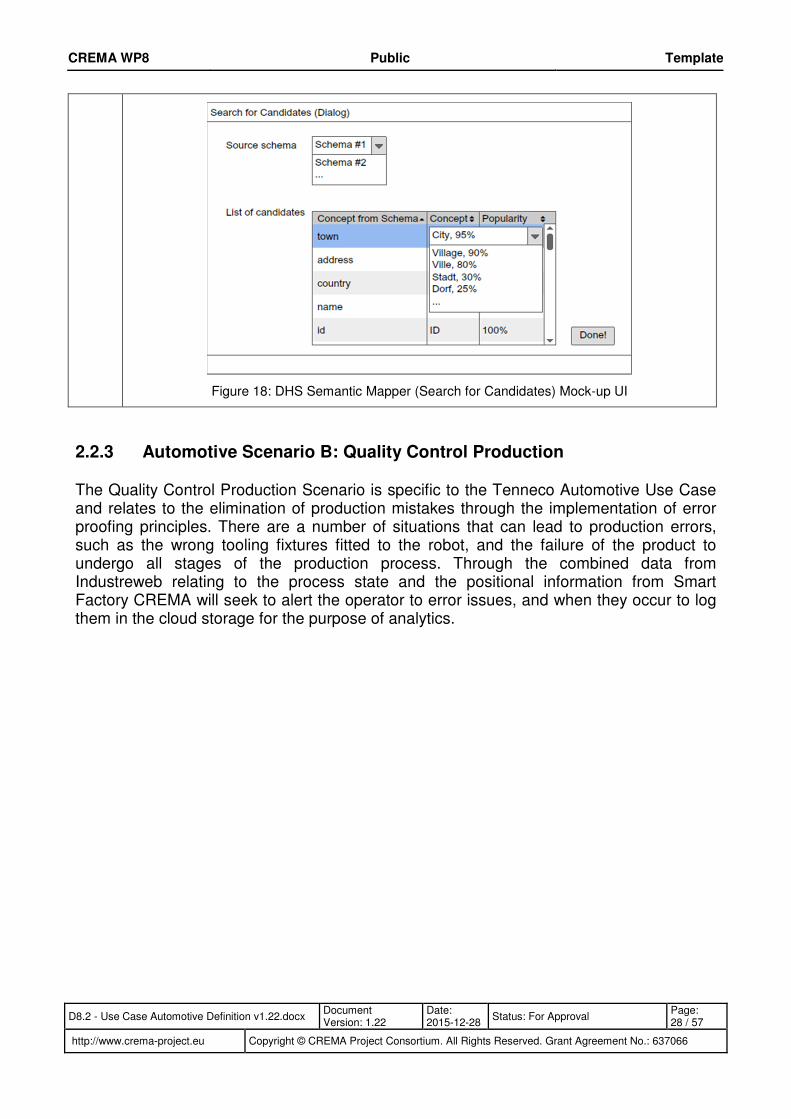
The OSL calls the service proxy wrapper “Get Availability” method for the Edenkoben robot cell which returns “available”, and so the service is leased and started in the same way as the originally allocated services. For this robot cell the format of the streaming data returned related to monitoring of the welding temperature is in a different format to those in the UK plants. As a result the Process Engineer must use the DHS component to transform the data so that the data stored in the CRI for robot cells in both plants is inline. To perform the mapping between the German robot cell and those in the UK the Process Engineer would use Talend Open Studio for Data Integration. This open-source tool already allows the generation of maps, and transformation jobs, between several types of data formats and schemas. Figure 17 shows the Semantic Mapper, in which the table in the middle shows the concepts after the Process Engineer has searched for concept candidates.
Figure 17: DHS Semantic Mapper Mock-up UI
In Figure 18 it shows the results of having searched for potential concepts that could match the robot welding temperature output. The source and target schemas are internally analysed, and the concepts are displayed following the table style, as shown in Figure 17.
CREMA WP8 Public Template
D8.2 - Use Case Automotive Definition v1.22.docx Document Version: 1.22
Date: 2015-12-28
Status: For Approval Page: 28 / 57
http://www.crema-project.eu Copyright © CREMA Project Consortium. All Rights Reserved. Grant Agreement No.: 637066
Figure 18: DHS Semantic Mapper (Search for Candidates) Mock-up UI
2.2.3 Automotive Scenario B: Quality Control Production
The Quality Control Production Scenario is specific to the Tenneco Automotive Use Case and relates to the elimination of production mistakes through the implementation of error proofing principles. There are a number of situations that can lead to production errors, such as the wrong tooling fixtures fitted to the robot, and the failure of the product to undergo all stages of the production process. Through the combined data from Industreweb relating to the process state and the positional information from Smart Factory CREMA will seek to alert the operator to error issues, and when they occur to log them in the cloud storage for the purpose of analytics.

CREMA WP8 Public Template
D8.2 - Use Case Automotive Definition v1.22.docx Document Version: 1.22
Date: 2015-12-28
Status: For Approval Page: 29 / 57
http://www.crema-project.eu Copyright © CREMA Project Consortium. All Rights Reserved. Grant Agreement No.: 637066
Step Description
B1 There is a line of cells (3 manufacturing robot cells and 2 test cells) each connected via Industreweb, each which has been put into the Marketplace.
The staged of creating proxy service wrappers for the IW Global services is described in 2.2.1.
B2 Tenneco designs a process to manufacture exhausts from cats, pipes, flanges, etc. (Note that the rest of this sequences is only discussing this process at runtime)
The Process Engineer has designed the process to handle the manufacture of the exhaust. This is outlined in more detail in section 2.4.4. The services that represent the machine operator initially have a default concrete service defined, or in other words a specific machine operator is selected for each production cell. When the process is started the OSL contacts the proxy service wrapper for the Operator service by calling its “Get Availability” method. IW Global then checks to see if the Machine Operator is available by alerting on their Smart headset and the operator confirms that they are available and therefore IW Global returns "state": "available".
B3 The first process step checks via a service that the tooling fitted matches the Tool recipe to perform that stage of manufacture and for that model.
The PRU executes the Exhaust manufacture process and the after selecting the next job from the ATS robot controller, the Machine operator may be instructed to do a tool change. Should this be the case the Operator is able to see the required tools to manufacture the model of exhaust from the “tool recipe” displayed on the ATS screen.
B4 Tooling is checked via Industreweb.
If a tool change is required, which is normally the case when the model of exhaust is changed over, then the process will need to co-ordinate the machine operator to fit the correct tools. This process starts by retrieving the tool recipe from the IW Global by calling the “Get Schedule” method and passing in the date range, in this case for the forthcoming month.
B5 If no robot cell is suitably configured, a worker is instructed in a head visor to configure the correct tooling for the robot cell if it is not already configured correctly and a process step (represented by an internal software service) continually runs until it is suitably configured.
The process accesses the “Get Zone Assets” method of the SF web service to retrieve the list of tool assets from within the first robot cell at that instant, and checks to see if any tools in the zone are not in the recipe returned in the previous step. If there is a tool that is in the zone but not on the recipe the PCE will notify the operator through their smart headset the tool name which is incorrect.
B6 This process step validates via Industreweb if tooling is now correct.
The PRU loop continues until the tools present in the zone fully match the tooling recipe, and at which point the process continues.
B7 Process step instructs the worker via a service using their head visor to put in the required components (cats, pipes, flanges,) into the machine.
Once the correct tools are fitted the PRU calls a services that calls the “GetJobComponents” method of the robot web service is contacted which returns a list of components parts to make up the required exhaust model. The machine operator receives a message “Load Exhaust Components” through their headset via the PCE to load the components into the machine, which contains the list of components to load.
B8 A process step ensures the parts get validated by location sensors.
The PRU calls a services that calls the “ComponentsLoaded” method of the robot web service which calls IW Global and in turn call IW Collect to interrogate the Siemens PLC on the cell to detect if the sensor feedback shows the components are fitted in place. There are numerous

CREMA WP8 Public Template
D8.2 - Use Case Automotive Definition v1.22.docx Document Version: 1.22
Date: 2015-12-28
Status: For Approval Page: 30 / 57
http://www.crema-project.eu Copyright © CREMA Project Consortium. All Rights Reserved. Grant Agreement No.: 637066
discrete proximity sensors that detect the presence of the metal component parts when fitted. If the sensor status of all sensors is true then IW Global will return “true”, and the PRU should continue executing the process.
B9 If an incorrect part is identified the workers Pro-Glove shows a notification via a light and the process step repeats until the parts are at the right location.
The machine operator can be notified through the PCE regarding the correct fitment of the tooling fixtures as they are tagged with Smart Factory tags. As the individual component parts that are assembled to for the exhaust are not tagged the machine operator cannot be notified of whether the correct parts are fitted, but as mentioned above when positions have a component located the PRU will recognise this. For the purpose of the Tenneco Use Case notifications will be through the Smart Headset or equivalent Google Android enabled device, and due to the lack of availability the Smart Glove will initially not be utilised.
B10 The parts get welded by the robot cell and produce an exhaust (product).
The machine operator visually monitors the process as the welding is done. Should there be an error during the process the PCE will prompt the machine operator with because IW Global stream the machine status to the PRU. This can be displayed on the Smart Headset device. Also during the welding process the temperature of the weld is streamed to the message bus and the BDA receives the data from there so that the BDA can be utilised to identify a correlation between welding temperature and the OEE quality of the product.
In addition if the operator confirms through their Smart Headset that the welding cycle has finished the PRU will commit data to the CRI with a reference to the current job and the completion of the welding process:
e.g. TNCO-HP-00103:CELL1_WELD:OK
B11 The head visor instructs the worker to test the product in a first testing cell.
Once the welding process has been completed and the machine operator confirms that has occurred without any issues, they are instructed to unload the exhaust and to put in on the storage rack for the subsequent test cell. The next operator then gets a notification through their smart headset from the PCE to test the next product.
Once the first test process has been completed and the machine operator confirms that has occurred without any quality issues, they are instructed to unload the exhaust and to put in on the storage rack for the subsequent test cell.
As the CPS technology is still at an early stage of adoption the Automotive Use Case will seek to investigate a number of headset devices.
B12 The head visor instructs the worker the worker to test the product in a second testing cell.
The next operator then gets a notification through their smart headset from the PCE to test the next product.
B13 The head visor instructs the worker to place the tested product in the product stock for delivery.
Once the first test process has been completed and the machine operator confirms that has occurred without any quality issues, they are instructed to unload the exhaust and to put in on the storage rack for goods out represented by the “Good Out” zone.
B15 When a product reaches the first or second zone, a data-flag is set on the metadata of the product.
If the operator confirms through their Smart Headset that a welding or testing cycle has finished the PRU will commit data to the CRI via an internal service with a reference to the current job, the name of the production cell and the result of the cycle:

CREMA WP8 Public Template
D8.2 - Use Case Automotive Definition v1.22.docx Document Version: 1.22
Date: 2015-12-28
Status: For Approval Page: 31 / 57
http://www.crema-project.eu Copyright © CREMA Project Consortium. All Rights Reserved. Grant Agreement No.: 637066
e.g. TNCO-HP-00103:CELL3_TEST:OK
If there is a quality issue the PRU will commit data to the CRI:
e.g. TNCO-HP-00103:CELL3_TEST:FAIL
B16 When the product reaches the delivery zone, if both tested flags are not true a warning is raised on the visor identifying the quality issue and the product ID and requesting the worker to retest.
When the UBI Smart Factory data stream indicates that the finished exhaust has entered the Goods Out zone The MON component will check to see if the CRI has meta data stored for that job number that relates to the three previous cells having been completed successfully. If this is ok then no alert is triggered, but should a test cell have been missed out or resulted in a failure condition then the MON will trigger an alert. This will commit data to the CRI relating to the event and also notify the operator “Invalid product in Goods Out zone: TNCO-HP-00103”
B17 The product is produced and is ready to be shipped. Regular end of process (without optimisation).
The exhaust product has been successfully manufactured and tested which result in the end of the process.
2.3 Systems, Data Sources and Models
This section will look at the systems that will be used in order to implement the Automotive Use Case and the specific sources of data that will be provided by them. These will be the sources of data that will provide CREMA with the information relating to the manufacturing process and the production schedule, and also the position of the production assets within the plant.
Primarily the majority of data will be made available through the Industreweb platform that is currently installed at Tenneco. This platform acts as a middleware and solves the issue of accessing data in diverse systems and pulling it together to support process monitoring, alerting and co-ordination. The system has solutions for connecting to both modern systems such as Ethernet enabled control systems and smart sensors, as well as legacy kit that might have little or no interface facility.
The other source of data will be the Ubisense Smart Factory that will provide near real-time positional data for key production assets within the process that have a positioning tag on them. This will then be used to identify production issues by knowing that the wrong assets are in certain zones and that others have failed to enter all the zones necessary to be correctly manufactured.
2.3.1 Industreweb Global
Industreweb (IW) Global is a web based platform founded on Microsoft .Net technology that can be installed within a manufacturing facility to collect data from a variety of “smart” data sources such as IIOT devices and IW Collect nodes. Devices are able to transmit data to IW Global through both push and pull methods, through common IOT protocols including MQTT4, XMPP5, DDS6, and AMQP7.
4 MQ Telemetry Transport 5 Extensible Messaging and Presence Protocol 6 Data Distribution Service for Real-Time Systems

CREMA WP8 Public Template
D8.2 - Use Case Automotive Definition v1.22.docx Document Version: 1.22
Date: 2015-12-28
Status: For Approval Page: 32 / 57
http://www.crema-project.eu Copyright © CREMA Project Consortium. All Rights Reserved. Grant Agreement No.: 637066
Internally IW Global has a service based architecture that provides the following service types:
• Workflow: Provides business logic workflows using Windows Workflow Foundation
• Security: Provides the logic for authorising and authenticating users
• Messaging: Allows messages to be sent using common media such as email, SMS and social media
• Alarms: Provides alerts and errors to be triggered to notify users
• Reporting: Allows reports to be generated from collated data
• Ontology: Provides semantic modelling of assets and data
• Profile: Provide custom data to be defined for different user types
• Asset: Configuration of devices that are connected to IW Global
• Transform: Provides a facility to map between different data structure
• Simulation: To provide connection to augmented reality systems and thereby align them with the data retrieved from the manufacturing facility sensors, devices and systems.
• Bus: Provides bus communication connectivity
Another key aspect of IW Global is the provision of customisable UI for different staff within the company which provides support for page layouts that are editable, coupled with AngularJS widgets that enable real-time data presentation and the facility for users to trigger events and enter data relating to the process. Figure 19 shows a high level architecture of Industreweb and the services it provides and the interaction with the CREMA platform through the implemented web service interface.
7 Advanced Message Queuing Protocol

CREMA WP8 Public Template
D8.2 - Use Case Automotive Definition v1.22.docx Document Version: 1.22
Date: 2015-12-28
Status: For Approval Page: 33 / 57
http://www.crema-project.eu Copyright © CREMA Project Consortium. All Rights Reserved. Grant Agreement No.: 637066
Global
Services
WorkflowSecurity Messaging ReportingAlarms OntologyProfile Transform
Umbraco UI
CREMA Cloud Platform
Process
Engineer
Production
Engineer
Quality
Engineer
Operator CustomerSupplier
Tenneco
T4.2 Data
Harmonisation
Services
MP&L
T4.1 Data Model,
Model Library
and Profiles
Asset
T6.2 Monitoring
and Alerting
T4.5 Service
Virtualisation and
Abstraction
Bus
T4.4 Cyber-
Physical Systems,
Sensor
Abstraction and
Virtualisation
T4.3 Cloud Based
RAID
Infrastructure
T5.1 Cloud
Collaborative
Process Design
Time
Environment
T5.2 Cloud
Process and
Messaging
Runtime
Environment
T5.3 On-Demand
Service Leasing
and Releasing
T5.4 Design-Time
Optimisation
T6.1 Marketplace
and Monetisation
T5.5 Run-Time
Optimisation
T6.3
Manufacturing
Big Data,
Knowledge and
Analytics
T6.4 Agile
Personal
Collaboration
Environment
T6.5 Dashboard
& Visualisation
Simulation
SOAP / REST API
Figure 19: Outline architecture of Industreweb Global
2.3.1.1 Services to be developed
Since this is a second iteration, based on the outcomes of the Functional and Technical specifications it has been possible to determine the outline service interface that is required to implement the Automotive Use Case. This is partly due to the fact that the draft BPMN8 process designs to fulfil this Use Case have been defined the and therefore the services required to complete the desired functionality.
IW Global will provide a RESTful Web service interface for each of the manufacturing assets it’s responsible for. The endpoint will take the form shown below:
https://global.ifog.eu/assets/123/getAvailability
8 Business Process Model and Notation

CREMA WP8 Public Template
D8.2 - Use Case Automotive Definition v1.22.docx Document Version: 1.22
Date: 2015-12-28
Status: For Approval Page: 34 / 57
http://www.crema-project.eu Copyright © CREMA Project Consortium. All Rights Reserved. Grant Agreement No.: 637066
The following section shows a list of the service methods available for the purposes of the automotive Use Case.
Method “Start Service”
Description:
Starts an execution of a service.
Example:
https://global.ifog.eu/assets/123/
Method “Get Availability”
Description:
Get a response to see if the service is currently available.
Example:
https://global.ifog.eu/assets/123/availability/
Method “Get Schedule”
Description:
Gets a schedule a collection of orders where an order includes the product name, product reference and the quantity to be produced.
Example:
https://global.ifog.eu/assets/123/schedule/
Method “Get Job Components”
Description:
Gets a list of components for the current product being produced in the current job. This will comprise a collection of named components and their component reference.
Example:
https://global.ifog.eu/assets/123/jobcomponents/
Method “Process Ready”
Description:
Returns a Boolean to indicate whether the cell is ready to operate. In the case of the robot welding cell this will be if the components are all loaded and all associated safety systems are ok then it returns ‘true’.
Example:
https://global.ifog.eu/assets/123/componentsloaded/

CREMA WP8 Public Template
D8.2 - Use Case Automotive Definition v1.22.docx Document Version: 1.22
Date: 2015-12-28
Status: For Approval Page: 35 / 57
http://www.crema-project.eu Copyright © CREMA Project Consortium. All Rights Reserved. Grant Agreement No.: 637066
Method “Get Sensor Values”
Description:
Gets all sensor values and associated time stamps for all sensors on that IW Collect node
Example:
https://global.ifog.eu/assets/123/sensors/
Method “Get Sensor Value”
Description:
Gets the single sensor value and an associated time stamp
Example:
https://global.ifog.eu/assets/123/sensors/weldtemperature
2.3.1.2 Streaming
When the “Start Service” method is called IW Global will start streaming data to the monitoring service URL supplied as an incoming argument. The stream will be achieved by establishing a TCP/IP socket to the PRU, and will be based on the AMQP protocol. The data streamed will relate to the specific manufacturing asset called, and will include the following:
OEE
Overall equipment effectiveness (OEE) is a hierarchy of metrics developed in the 1960s to evaluate how effectively a manufacturing operation is utilized. Tenneco use this value as a KPI for their machine performance. As part of the service stream both the calculated OEE value but also the three component values of Availability, Performance and Quality will be included so that they can be stored in the CRI for use by the BDA.
The OEE calculation is quite simple and is based on the following sub calculations:
Availability = Operating Time / Planned Production Time
Performance = Ideal Cycle Time / (Operating Time / Total Pieces)
Quality = Good Pieces / Total Pieces
OEE = Availability x Performance x Quality
Equation 1 OEE calculation example
OEE = 0.8881 x 0.8611 x 0.9780
= 0.7479 or 74.79%
Welding Temperature

CREMA WP8 Public Template
D8.2 - Use Case Automotive Definition v1.22.docx Document Version: 1.22
Date: 2015-12-28
Status: For Approval Page: 36 / 57
http://www.crema-project.eu Copyright © CREMA Project Consortium. All Rights Reserved. Grant Agreement No.: 637066
The welding temperature will be supplied as part of the data stream which for the robots in Tenneco Highpoint will be supplied in Fahrenheit, whilst it will be provided in Centigrade. This will therefore require the use of the DHS component to map between the values in order to ensure that the BDA will later be able to make a comparative analysis across all robot cells about how welding temperature affects quality. The process of exhaust fabrication in the Tenneco production facilities is based on Metal Inert Gas (MIG) welding, also known as Gas Metal Arc Welding (GTAW). It has a high deposition rate process that involves feeding a wire continuously toward the heated weld tip, and temperatures operate in a range of 6,000-8,000 °C. For the purpose of the prototype area this has significant safety implications and as such a simulated variable heat source on the robot arm will be used and monitored using a thermocouple.
Machine Status
The status of each machine will also be included. This will enable the machine operator to be notified of the operational state of the machine and also the status can be stored in the CRI in order to build up metrics about common maintenance issues. The following table shows the list of available machine states: Name Description
Running RUN – Machine is cycling normally
Downtime The machine is stopped due to one of the following issues:
D1 – Changeover
D2 – Changeover fine adjustments
D3 – First off check
D4 – Waiting material (External supplier)
D5 – Waiting material (Internal logistics)
D6 – Waiting material (Ten. E/Vale)
D7 – M/C breakdown (Setters)
D8 – M/C breakdown (Maintenance)
D9 – M/C breakdown (Contractors)
D10 – Process issues (Tooling)
D11 – Process issues (Incorrect to gauge)
D12 – Process issues (Weld)
D13 – Process issues – Supplied material (cell to cell)
D14 – Process issues – Supplied material (supplier to cell)
D15 – QC problem (Quality)
D16 – Change consumable (Weld tips / wire)
D13 – Change consumable (Wiper dies saw blades etc.)
Rest Break BRK – The machine operator is on rest break

CREMA WP8 Public Template
D8.2 - Use Case Automotive Definition v1.22.docx Document Version: 1.22
Date: 2015-12-28
Status: For Approval Page: 37 / 57
http://www.crema-project.eu Copyright © CREMA Project Consortium. All Rights Reserved. Grant Agreement No.: 637066
2.3.2 Industreweb Collect
Industreweb (IW) Collect is a high speed data engine that interfaces with a range of systems and devices with the aim of extracting business critical data. The primary objective of Collect is to solve getting data from sources that may prove to be normally difficult or require a bespoke solution. Data sources can include industrial control systems (e.g. PLC9, CNC10) both modern models with Ethernet capability and legacy equipment, wireless networks and devices such as ZigBee, and industrial networks such as Profinet, Profibus, Modbus and AS-interface.
It includes a rule engine to enable events to be detected and reacted upon with actions that can affect other devices, submit data to a range of data stores or notify a human user through a number of supported media.
In the Tenneco Use Case, IW Collect will be used to interface with the Siemens PLC and the ATS robot controller used in the robot cell. Figure 20 shows the high level architecture of IW Collect, the services it provides, and the interaction between IW Collect and the production sensors and control systems on the manufacturing process itself.
Collect
Services
Engine Data Alarms
MS Access
MS SQL Server
MySql
Industrial Control System:
PLC, CNC, Robot Controller
Global
SOAP / REST Service
<XML>ASi ZigBee
SOAP / REST Service
Collect
Services
EngineVisualisatio
nAlarms
Oculus Rift
Figure 20: Outline architecture of IW Collect
2.3.2.1 ATS Robot Controller + Siemens HMI
The ATS production software is used to orchestrate the ABB welding robot cell. It allows machine operators to view and select their production schedule, setup the machine and view active and historic alerts and warnings. The underlying system stores its data in a Microsoft SQL Server which is available for querying to access data relating to Robot Cell
9 Programmable Logic Control 10 Computer Numeric Control

CREMA WP8 Public Template
D8.2 - Use Case Automotive Definition v1.22.docx Document Version: 1.22
Date: 2015-12-28
Status: For Approval Page: 38 / 57
http://www.crema-project.eu Copyright © CREMA Project Consortium. All Rights Reserved. Grant Agreement No.: 637066
production status and historic errors. Figure 21 shows the ATS robot controller software used to orchestrate the production process which is running on an industrial Siemens HMI panel PC. The touch screen application is designed to take operator input relating to job selection, its configuration and the associated component setup for that job. The data store for the application is Microsoft SQL Server express and this will provide IW collect with necessary data for the selected job and components and the production status.
Figure 21: ATS Robot controller software running on a Siemens HMI
2.3.2.2 Siemens S7 PLC
The robot production cells use a Siemens S7 1200 PLC, as shown in Figure 22, in order to monitor the discrete and analogue sensors on the robot. These include safety devices, pneumatic and hydraulic pressure, and the status of whether tooling is correctly seated on the beams. In addition a temperature sensor will be mounted to the robot arm and then interfaced with the PLC in order to allow the temperature of the simulated welding process to be monitored. This will be used a part of the streaming data returned to CREMA.
IW Collect interacts directly with this device using the OPC protocol to allow the memory areas of the PLC to be interrogated at runtime. This is achieved using OPC Data Access (OPC DA) which is a group of standards that provide specifications for communicating real-time data from data acquisition devices such as PLCs to display and interface devices like Human-Machine Interfaces (HMI). The specifications focus on the real-time continuous communication of data, and includes three attributes (1) the data value, (2) the quality of the value, and (3) a timestamp. The OPC DA specification states that these three attributes have to be returned to an OPC client making a request. Therefore, if the data source is not capable of providing a timestamp, for example, the OPC DA server must create a timestamp. IW Collect can provide these attributes back to IW Global and in turn they can be included as part of the data returned in the data stream and discrete web service calls top CREMA.

CREMA WP8 Public Template
D8.2 - Use Case Automotive Definition v1.22.docx Document Version: 1.22
Date: 2015-12-28
Status: For Approval Page: 39 / 57
http://www.crema-project.eu Copyright © CREMA Project Consortium. All Rights Reserved. Grant Agreement No.: 637066
Figure 22: Siemens 1200 PLC used on the ABB robot production cells
2.3.3 Ubisense Smart Factory
In order to evaluate the location data of assets within the plant environment additional Use Case scenarios will be considered to use the Ubisense Smart Factory (SF) platform. Smart Factory gathers location data through its best-in-class Real-Time Location System (RTLS), which includes hardware tags and sensors that connect via UWB radio signals, to pinpoint the exact location and identity of assets in the manufacturing process. It combines this data with information from existing plant systems and devices to deliver a virtual interpretation of exactly what’s going on in the factory. This delivers visibility of real-time process interactions, providing insights and control.
2.3.3.1 RESTful Web service interface
Ubisense SF is developing a web service which enables the Marketplace and Service Leasing/Releasing components to create, delete or access the sensor data or any other properties (i.e. sensor data) of the modelled assets from the shop floor environment. Following RESTful web service methods have been defined and will be implemented.
Get Simple Property Value:
This method gets the value of a particular complex property given a particular set of keys. Hence, it would output the name of the zone an asset is located in.
Get Complex Property Values:
Gets all the rows for a particular complex property. This will for instance enable to read all the names of assets located within a certain zone.
Start Object Property Stream: This method allows to establish a property value stream of a given Object based on its Id. As such, it outputs a stream of location data containing the name of the zone each time an asset is moving and entering a new zone.

2.3.4 Data Sources
The following tables summarise the individual data items that are made available to the CREMA platform within the Automotive Use Case. Table 1 relates to data that is included within the Robot cell data stream, and Table 2 relates to discrete data returned from the web service methods of IW Global.
Table 1: Data stream items
Item Description Source Data Range Frequency
Availability Amount of time a machine is available for production expressed as a percentage.
IW Global / Collect Decimal 0-100 1s
Performance How efficiently the machine outputs expressed as a percentage.
IW Global / Collect Decimal 0-100 1s
Quality The proportion of good parts expressed as a percentage.
IW Global / Collect Decimal 0-100 1s
OEE Final KPI for machine performance expressed as a percentage.
IW Global / Collect Decimal 0-100 1s
Machine Status The current machine status. If stopped it relates to the nature of the machine stoppage.
IW Global / Collect String 3 char length 1s
Welding Temperature The temperature at the tip of the robot arm during welding
IW Global / Collect / S7 PLC Decimal 0-150 1ms
Asset position Location of each tagged production asset within the exhaust production area.
Ubisense SF String N/A Variable (0.2-1s)

CREMA WP8 Public Template
D8.2 - Use Case Automotive Definition v1.22.docx Document Version: 1.22
Date: 2015-12-28
Status: For Approval Page: 41 / 57
http://www.crema-project.eu Copyright © CREMA Project Consortium. All Rights Reserved. Grant Agreement No.: 637066
Table 2: Web service data
Item Description Source Data
Orders Collection of Orders IW Global / ATS JSON collection of Orders
Components Collection of Components IW Global / ATS JSON collection of Components
Process Ready Returns if the cell is ready for the machine operator to run
IW Global / Collect / S7 PLC Boolean

2.4 Process Definitions
For the Tenneco Use Case the control of the main manufacturing process is modelled in the CREMA Cloud Collaborative Process Design Time Environment (PDE). The objectives of this process are listed below:
• Determine the number of manufacturing robot cells required to meet the production schedule.
• Select, assign and optimise the services for the robot cells necessary to meet that calculated demand
• Start the production activity
• React to changes in production schedule and lease or release robot cell services accordingly
• Monitor for production errors and prompt the human machine operator to resolve
• Monitor the machine efficiency KPI and alert when it becomes low
• Capture data associated with the welding temperature in order to perform analytics to identify causes of quality issues
2.4.1 Master Process Model to co-ordinate and start production
The purpose of the process design shown in Figure 23 is to retrieve the production schedule from IW Global and to determine how many robot production cells will be required to meet that schedule. Once the schedule has been retrieved it instantiates a process to allocate the necessary resource, and optimise for the most appropriate robots based on set criteria. Having done this, a sub process is instantiated that will trigger the allocated resource to start production.

CREMA WP8 Public Template
D8.2 - Use Case Automotive Definition v1.22.docx Document Version: 1.22
Date: 2015-12-28
Status: For Approval Page: 43 / 57
http://www.crema-project.eu Copyright © CREMA Project Consortium. All Rights Reserved. Grant Agreement No.: 637066
Figure 23: Process design for the Master Process Model to co-ordinate and start production
2.4.2 Process to Allocate resource to meet production demand
The sub-process design shown in Figure 24 is called by the master process and its purpose is to select the appropriate number of robots to meet the orders in the production schedule. This is done by a loop that checks to see if the number of allocated robots is less than the number required and if it is, then more are robots allocated by selecting them from the CREMA Marketplace. As this process can be called again should there be a dip in product demand it also checks to see if the number of robots currently allocated is too high. If this is the case, then they are released from production. This process will also be the focus of the runtime optimisation, which will use the criteria of maximising OEE and minimising cost and therefore make the most optimal selection of the services that will meet these objectives.

CREMA WP8 Public Template
D8.2 - Use Case Automotive Definition v1.22.docx Document Version: 1.22
Date: 2015-12-28
Status: For Approval Page: 44 / 57
http://www.crema-project.eu Copyright © CREMA Project Consortium. All Rights Reserved. Grant Agreement No.: 637066
Figure 24: Sub-Process design for the allocation of resource to meet production demand
2.4.3 Process to Start Production
The sub-process design shown in Figure 25 is called by the master process and its purpose is to loop through the robots allocated for exhaust production triggers the Start method of the service for that robot. This method, via the Docker wrapper, will call IW Global and in turn this will be communicated to ATS robot controller software. If a service has been selected that is not from within Tenneco then an appropriate request to start production is made depending on the interface for that service. Within this Use Case the

CREMA WP8 Public Template
D8.2 - Use Case Automotive Definition v1.22.docx Document Version: 1.22
Date: 2015-12-28
Status: For Approval Page: 45 / 57
http://www.crema-project.eu Copyright © CREMA Project Consortium. All Rights Reserved. Grant Agreement No.: 637066
robot services selected are from within the Tenneco organisation but in different locations / countries so this is not an issue.
Figure 25 Sub-Process design for starting the robot cell production
2.4.4 Process to start Manufacture of Exhaust
The sub-process design shown in Figure 26 and Figure 27 is called by the Start Production process and its purpose is to co-ordinate the manufacture of the exhaust. This includes managing the flow of the product through the process but also guiding and alerting the human operators who load the parts, tools and control the production and testing process.
To aid understanding areas have been highlighted and annotated with the function that they perform. In Figure 26 the light blue highlighted area relates to a loop to constantly check that the tooling present in the robot cell matches that specified by the tooling recipe that is returned by IW Global. The light red area relates to the production process being started which then triggers the data stream from IW Global reflecting the robot cell

CREMA WP8 Public Template
D8.2 - Use Case Automotive Definition v1.22.docx Document Version: 1.22
Date: 2015-12-28
Status: For Approval Page: 46 / 57
http://www.crema-project.eu Copyright © CREMA Project Consortium. All Rights Reserved. Grant Agreement No.: 637066
production status. In Figure 27 the light green area relates to the product continuing through the subsequent production test stages. As this occurs it is annotated with meta-data and the light yellow area shows where it is monitored to ensure that all stages are completed successfully.

CREMA WP8 Public Template
D8.2 - Use Case Automotive Definition v1.22.docx Document Version: 1.22
Date: 2015-12-28
Status: For Approval Page: 47 / 57
http://www.crema-project.eu Copyright © CREMA Project Consortium. All Rights Reserved. Grant Agreement No.: 637066
Figure 26 Sub-Process design to co-ordinate exhaust production [part 1]
Start Production
Check correct tooling fitted to the robot

CREMA WP8 Public Template
D8.2 - Use Case Automotive Definition v1.22.docx Document Version: 1.22
Date: 2015-12-28
Status: For Approval Page: 48 / 57
http://www.crema-project.eu Copyright © CREMA Project Consortium. All Rights Reserved. Grant Agreement No.: 637066
Figure 27 Sub-Process design to co-ordinate exhaust production [part 2]
Continue production and annotate
the exhaust as it completes each stage.
Monitor production to
ensure exhaust completes all
stages

CREMA WP8 Public Template
D8.2 - Use Case Automotive Definition v1.22.docx Document Version: 1.22
Date: 2015-12-28
Status: For Approval Page: 49 / 57
http://www.crema-project.eu Copyright © CREMA Project Consortium. All Rights Reserved. Grant Agreement No.: 637066
2.5 Outputs
This section will summarise the outputs of the Use Case from a CREMA perspective so that it will be clear how the scenarios will utilise and test the performance of the CREMA components. Whilst there are numerous components within the overall platform the sections below will describe outputs as perceived from the End Users perspective.
2.5.1 Analytics
For the Automotive Use Case the BDA will be used in order to enable a clearer view of production issues that currently are now achievable with the currently implemented systems. Presently there is a situation where data may be captured from various systems however the volume of data and the fact that it is from multiple sources means that to extract insightful information makes it extremely difficult and excessively time consuming. For this reason Tenneco aim to use the BDA to provide details of the most problematic Machine stoppage reasons and also how the impact on the welding temperature affects the production quality.
In the case of the first the machine state data which is streamed by IW Global to CREMA provides a series of machine failure categories. How these impact on the OEE availability data will be analysed to provide an insight as to the primary impact on OEE due to machine failure or stoppage.
In the second case the data streamed to CREMA by IW Global via IW Collect from the temperature sensor mounted to the welding head will be analysed against the OEE quality data for the corresponding period of time in order to identify a correlation between the product quality and the temperature during the welding process.
The ultimate aim is to be able to act upon this knowledge in order to make practical changes to the machine and the process to increase the OEE KPI of the process.
2.5.2 Monitoring & Business Rules
Within this Use Case, there will be a need to monitor the process for production errors caused by human machine operator mistakes. To achieve this, the MON component will be used, for which business rules will be defined that will specify error conditions to alert to.
The situation that needs to be monitored is described in section 2.2.3 where the welded product must continue through the process of for testing. Failure to do this will need to generate an alert as the product that fails to complete all steps of the process successfully must be rejected or sent for re-work and cannot enter the zone for goods-out. Upon completion of a successful stage of the production process, meta-data will be assigned against the product reference in the CRI. Should the product enter any of the subsequent test cells or goods out zone, and the product fail to have a full complement of meta-data, the MON will create an alert that will show on the DBV and also be displayed on the machine operator’s smart glasses.

CREMA WP8 Public Template
D8.2 - Use Case Automotive Definition v1.22.docx Document Version: 1.22
Date: 2015-12-28
Status: For Approval Page: 50 / 57
http://www.crema-project.eu Copyright © CREMA Project Consortium. All Rights Reserved. Grant Agreement No.: 637066
2.5.3 Optimisation
Optimisation of processes as performed by ODERU is separated into design time optimisation (ODE) and runtime optimisation (ORU). Design time optimisation supports the Process Designer in finding optimal services for semantically annotated process models. In contrast, runtime optimisation is concerned with optimising running process instances. In both cases, ODERU performs functional optimisation as well as non-functional optimisation.
Functional optimisation is a simulation of effects of service execution by means of state-based planning. For example, in the section 2.2.2, ODERU will identify robot cells which are capable of performing a certain type of welding operation for the given product type.
Non-functional optimisation simulates execution of service plans and, given a set of constraints the outcome, is a combination of services according to the original plan. In section 2.2.2 this might for example mean selecting the right robot services in order to maximize OEE while minimizing costs, minimising cost and energy consumption, whilst respecting deadlines.
At design time, ODERU will take into account information about service availability at the MPM, historic information about the OEE KPI from the BDA, as well as forecasted KPI data based on simulation and trend analysis. This will include the throughput of a robot in the past and its expected throughput when starting process instances from the process model at hand.
At runtime, ODERU additionally will consider current OEE provided as a data stream. Changes in service availability reported by MPM as well as leasability according to OSL are considered. At runtime, ODERU keeps considering updates of the running process instance while being executed. For this, it also considers the current execution state of the process instance itself, as reported by PRU. In context of the Automotive Scenarios, the streaming OEE will be implemented by means of IW Global.

CREMA WP8 Public Template
D8.2 - Use Case Automotive Definition v1.22.docx Document Version: 1.22
Date: 2015-12-28
Status: For Approval Page: 51 / 57
http://www.crema-project.eu Copyright © CREMA Project Consortium. All Rights Reserved. Grant Agreement No.: 637066
3 Automotive Use Case Evaluation
In order to evaluate the Tenneco Use Case storylines, the scenario is to be modelled in a prototype area at the Waterton Technology Centre, which is the location of TANet member Control 2K. Tenneco have located Robot cells at the centre for the purpose of testing, prototyping and training of staff, and therefore this provide the ideal environment to implement and test CREMA against the agreed objectives.
3.1 Evaluation Equipment and Testbeds
In order to evaluate the Tenneco Automotive Use Case, the narratives that were define in section 2.2 will be implemented within a pilot area. The pilot area, located at the Waterton Technology Centre (WTC), is currently used by Tenneco to prototype, test systems and train production staff and is therefore the ideal location to effectively evaluate the project outcomes. It will utilise the same systems as used in the Tenneco Highpoint facility and therefore provide a realistic evaluation scenario without the concerns of having a restriction on day to day production that would normally occur within the plant environment.
Figure 28: Pilot area for the Tenneco Use Case
Figure 28 shows a 3D view model of the machine tool facility (MTF) room at (WTC) where the pilot area is located. As with the Tenneco Highpoint facility the exhaust production line comprises robotic cells and test cells. These are subsequently defined by zone areas in close proximity to one another, setup in UBI Smart Factory. Figure 29 shows the plan view of the MTF with the pilot area zones highlighted.

CREMA WP8 Public Template
D8.2 - Use Case Automotive Definition v1.22.docx Document Version: 1.22
Date: 2015-12-28
Status: For Approval Page: 52 / 57
http://www.crema-project.eu Copyright © CREMA Project Consortium. All Rights Reserved. Grant Agreement No.: 637066
Figure 29: Plan view of Pilot Area modelled in Ubisense Smart Factory
• Zone 1: Robot Cell 1
This will simulate the manufacture of the exhaust unit from the following component parts: pipes, hangers, flanges and catalytic convertors. The primary activity is the robot arm welding these components together to form the finished exhaust. The zone is based on the area within the perimeter of the robot enclosure and is used to track the presence of the tools used to hold the exhaust during welding, in order to check that they are correct for that particular model of exhaust. Once the exhaust welding is complete the operator must manually unload it and place it on a rack ready for the next operator to load into the first test cell.
Zone 1
Zone 2
Zone 3
Zone 4

CREMA WP8 Public Template
D8.2 - Use Case Automotive Definition v1.22.docx Document Version: 1.22
Date: 2015-12-28
Status: For Approval Page: 53 / 57
http://www.crema-project.eu Copyright © CREMA Project Consortium. All Rights Reserved. Grant Agreement No.: 637066
• Zone 2 & 3: Test Cell 1 & 2
This will simulate the testing conducted on the finished exhaust. At the start of the process the operator manually loads the exhaust into the test cell and in doing so it will have been brought into the zone.
• Zone 4: Goods Out
This zone will be where the completed and fully tested exhausts are stored. If the product has failed to enter all zones then, as mentioned above, this will be reflected by an alert visible on the CREMA Dashboard and also to the Operator via the IW Global UI.
Figure 30: ABB 6-Axis Robot used in the Tenneco Use Case implementation
3.2 Evaluation Metrics
In relation to the two storylines outlined within the Automotive Use Case Tenneco wish to gain improvements in production performance and quality whilst being able to cater rapidly for increases in production demand. To assess the impact of the use of the CREMA platform on the systems used by Tenneco within the testbed implementation it is necessary to establish the current baseline performance and define target values that are based on best estimates.

CREMA WP8 Public Template
D8.2 - Use Case Automotive Definition v1.22.docx Document Version: 1.22
Date: 2015-12-28
Status: For Approval Page: 54 / 57
http://www.crema-project.eu Copyright © CREMA Project Consortium. All Rights Reserved. Grant Agreement No.: 637066
In Automotive Scenario A: Elastic Manufacturing the aim is to be able to select manufacturing resource to meet demand, and then adapt to changes in demand and select the most appropriate assets based on certain criteria and engage them within the manufacturing process. The following table defines KPI’s which will be used to evaluate the performance of Use Case scenario A:
Table 3: Automotive Scenario A Elastic Manufacturing Evaluation Metrics
Metric Description Baseline Target
Speed to allocate production schedule to manufacturing assets
Increase speed to allocate production schedule to manufacturing assets
6 hours 1 hours
Increased total OEE Increased total OEE through selection of the solution optimised for the highest OEE capability
60% OEE 70% OEE
Time to engage additional manufacturing assets
Reduce the time to bring in a new manufacturing asset to meet demand that cannot be satisfied by current resources
6 months 2 weeks
In Automotive Scenario B: Quality Control Production the aim is to reduce errors in production due to human error and thereby improve quality. The following table defines KPI’s which will be used to evaluate the performance of Use Case scenario B:

CREMA WP8 Public Template
D8.2 - Use Case Automotive Definition v1.22.docx Document Version: 1.22
Date: 2015-12-28
Status: For Approval Page: 55 / 57
http://www.crema-project.eu Copyright © CREMA Project Consortium. All Rights Reserved. Grant Agreement No.: 637066
Table 4: Automotive Scenario B Quality Control Evaluation Metrics
Metric Description Baseline Target
Rate of tool selection error detection
Improve tooling errors through automatic detection
75% 100%
Tooling error resolution time
Improve how quickly tooling errors can be resolved by rapid detection and operator notification
10 minutes 4 minutes
Rate of product testing error detection
Improve the rate of products that fail to complete all test cells
65% 100%
Increased OEE “quality” Increase the quality component of the OEE KPI through the reduction in human related errors
55% 75%
Increased OEE “availability”
Increase the availability component of the OEE KPI through more rapid notification and resolution of errors
60% 70%

CREMA WP8 Public Template
D8.2 - Use Case Automotive Definition v1.22.docx Document Version: 1.22
Date: 2015-12-28
Status: For Approval Page: 56 / 57
http://www.crema-project.eu Copyright © CREMA Project Consortium. All Rights Reserved. Grant Agreement No.: 637066
4 Implementation Plan
As outlined in the introduction the purpose of this updated deliverable is to provide a detailed plan for the implementation of the Use Case in the next WP8 task. T8.2 will involve the implementation of the Automotive Use Case starting in M18 and finishing in M35. This section will outline an initial implementation plan including stage and estimated delivery dates to provide a framework to work to. The following shows the implementation stages:
Stage Sub Tasks Estimated Due Date
Stage 1 Install and commission prototyping area
Install and commission prototype Robot cell
M18
Install and commission Industreweb Global and Collect
M18
Install and commission Ubisense Smart Factory
M18
Install and commission prototype test cells
M20
Stage 2 Integration with the CREMA cloud
Integrate Ubisense Service
M21
Integrate Ubisense TCP Data Stream
M21
Integrate Ubisense Service
M21
Integrate Industreweb TCP Data Stream
M22
Stage 3 Implement CPS / Wearables Implement Smart Glasses
M24
Implement Smart Glove M25
Stage 4 System Testing Test the overall integrated testbed
M27
Conduct Use Case testing Execute the Use Case scenario functionality in line with the specification in D8.2
M30
Figure 31 Initial Implementation Plan for the Automotive Use Case

CREMA WP8 Public Template
D8.2 - Use Case Automotive Definition v1.22.docx Document Version: 1.22
Date: 2015-12-28
Status: For Approval Page: 57 / 57
http://www.crema-project.eu Copyright © CREMA Project Consortium. All Rights Reserved. Grant Agreement No.: 637066
5 Conclusion
Through the implementation of the Automotive Use Case, Tenneco are expecting to gain insights on the true efficiency of their robot cells and the supporting production processes as well as satisfying their primary customer through more timely production and quality related data. Furthermore the implementation of error proofing by utilising of Industreweb and Ubisense Smart Factory will support Tenneco in achieving a zero defect strategy, whilst demonstrating the ability of CREMA to interface with a variety of systems.
The specification detailed in this deliverable will guide the next task T8.2 Use Case II (Automotive) Implementation which starts in M18. It describes the resources required, the technical configuration, functionality to be demonstrated, timeline for implementation, and also the validation criteria in order to measure the success of the platform.
The next deliverable (D8.3) will document the activities carried out during the execution of the piloting tasks of the Automotive use case, specifying how the actual implementation conformed to the original specification from D8.2.