dam safety guidelines - access washington
TRANSCRIPT

i
DAM SAFETY GUIDELINES
Part IV:
Dam Design and Construction
Water Resources ProgramDam Safety Office
P.O. Box 47600Olympia, WA 98504-7600
(360) 407-6208
July 199392-55D

ii

iii
DAM DESIGN AND CONSTRUCTION GUIDELINES
TABLE OF CONTENTS
INTRODUCTION....................................................................................................................................................... 1
OVERVIEW................................................................................................................................................................ 1
GOVERNING DESIGN PHILOSOPHY.................................................................................................................. 2
CONSEQUENCE DEPENDENT DESIGN LEVELS ............................................................................................... 2BALANCED PROTECTION.................................................................................................................................... 2REDUNDANCY ....................................................................................................................................................... 3SURVIVABILITY ..................................................................................................................................................... 3INSPECTABILITY ................................................................................................................................................... 3SERVICEABILITY ................................................................................................................................................... 3GUIDANCE, RECOMMENDATIONS AND REQUIREMENTS.............................................................................. 4
CHAPTER 1 - IMPOUNDING BARRIER CLASSIFICATION............................................................................ 5
IMPOUNDING BARRIER SIZE AND RESERVOIR OPERATION CLASSIFICATION.................................... 51.1.1 OBJECTIVE: .................................................................................................................................................. 51.1.2 APPLICABILITY: ........................................................................................................................................... 5
CHAPTER 2 - CRITICAL PROJECT ELEMENTS............................................................................................... 7
2.1 DESIGN/PERFORMANCE GOALS FOR CRITICAL PROJECT ELEMENTS .......................................... 72.1.1 APPLICATION:.............................................................................................................................................. 72.1.2 OBJECTIVE: .................................................................................................................................................. 72.1.3 DECISION FRAMEWORK PHILOSOPHY:................................................................................................... 72.1.4 TERMINOLOGY: ........................................................................................................................................... 82.1.5 DECISION FRAMEWORK:............................................................................................................................ 92.1.5 REFERENCES: ............................................................................................................................................ 112.2 BARRIER STATIC STABILITY ................................................................................................................. 132.2.1 OBJECTIVE: ................................................................................................................................................ 132.2.2 DESIGN PRACTICE: ................................................................................................................................... 132.2.3 SPECIALIZED ISSUES:.............................................................................................................................. 192.2.4 REFERENCES: ........................................................................................................................................... 202.3 BARRIER SEISMIC STABILITY ............................................................................................................... 212.3.1 OBJECTIVE: ................................................................................................................................................ 212.3.2 APPLICABILITY AND FOCUS:................................................................................................................... 212.3.3 OVERVIEW: ................................................................................................................................................. 212.3.4 TWO TRACKED SEISMIC ASSESSMENT APPROACH: ............................................................................ 222.3.5 ESTIMATING SITE SPECIFIC GROUND MOTIONS FOR ANALYSES: ................................................... 232.3.6 REQUIRED MINIMUM SCOPE OF SEISMIC ANALYSES: ....................................................................... 262.3.7 CONDITIONS REQUIRING REMEDIAL ACTION TO TREAT A POTENTIAL LIQUEFIABLE ZONE: ... 262.3.8 TYPICAL PRACTICE TO ADDRESS IDENTIFIED LIQUEFACTION CONCERNS:................................. 272.3.9 TECHNICAL RESOURCES: ........................................................................................................................ 282.3.8 REFERENCES.............................................................................................................................................. 302.4 INFLOW DESIGN FLOOD.......................................................................................................................... 332.4.1 APPLICATION:............................................................................................................................................ 332.4.2 HISTORICAL PERSPECTIVE ON FLOODS IN WASHINGTON:............................................................... 332.4.3 DESIGN PRACTICE - RAINFALL-RUNOFF MODELING:................................................................. 342.4.5 DETERMINING THE INFLOW DESIGN FLOOD:..................................................................................... 382.4.7 REFERENCES.............................................................................................................................................. 39

iv
2.4A INCREMENTAL DAMAGE ANALYSIS ............................................................................................... 412.4A.1 APPLICATION: ................................................................................................................................... 412.4A.2 OBJECTIVE:........................................................................................................................................ 412.4A.3 DETERMINING APPLICABILITY: ..................................................................................................... 412.4A.3 ANALYSIS METHODOLOGY:............................................................................................................. 412.4A.5 REFERENCES ..................................................................................................................................... 45
CHAPTER 3 - GEOTECHNICAL ISSUES ........................................................................................................... 47
3.1 EXPLORATIONS........................................................................................................................................... 473.1.1 APPLICABILITY: ......................................................................................................................................... 473.1.2 EXPLORATION PROGRAM OBJECTIVES: ............................................................................................... 473.1.3 DAM SAFETY OFFICE OBJECTIVES:....................................................................................................... 473.1.4 MINIMUM EXPLORATION PROGRAM:.................................................................................................... 473.1.5 ENGINEERING DESIGN CONSIDERATIONS: .......................................................................................... 483.1.6 REFERENCE MATERIALS:......................................................................................................................... 493.1.7 REFERENCES.............................................................................................................................................. 513.2 EMBANKMENT GEOMETRY AND ZONING ......................................................................................... 533.2.1 OBJECTIVE: ................................................................................................................................................ 533.2.2 REQUIREMENTS\MINIMUMS FOR THE EMBANKMENT CROSS-SECTION:........................................ 533.2.3 REFERENCES: ............................................................................................................................................ 563.3 SEEPAGE CONTROL.................................................................................................................................. 573.3.1 INTRODUCTION: ........................................................................................................................................ 573.3.2 OBJECTIVES: .............................................................................................................................................. 573.3.3 OPTIMIZING DESIGN: ............................................................................................................................... 573.3.4 DESIGN PHILOSOPHY:.............................................................................................................................. 573.3.5 DESIGN CONSIDERATIONS: ..................................................................................................................... 583.3.6 ENGINEERING PRACTICE......................................................................................................................... 583.3.7 REFERENCES: ............................................................................................................................................ 623.3.A FILTERS .................................................................................................................................................. 633.3.A.1 OBJECTIVE:............................................................................................................................................ 633.3.A.2 DESIGN PHILOSOPHY: ......................................................................................................................... 633.3.A.3 OPTIMIZING DESIGN:........................................................................................................................... 633.3.A.4 APPLICABILITY:..................................................................................................................................... 633.3.A.5 REFERENCES: ........................................................................................................................................ 693.3.B CONDUIT SEEPAGE CONTROL - FILTER-DRAIN DIAPHRAGMS................................................. 703.3.B.1 OBJECTIVE:............................................................................................................................................ 703.3.B.2 REQUIREMENT:..................................................................................................................................... 703.3.B.3 ENGINEERING CONCERNS: ................................................................................................................. 703.3.B.4 DESIGN APPROACH:............................................................................................................................. 703.3.B.5 REFERENCES: ........................................................................................................................................ 733.3.C CONCRETE LINED SPILLWAY SEEPAGE CONTROL ..................................................................... 753.3.C.1 OBJECTIVE:............................................................................................................................................ 753.3.C.2 DESIGN APPROACH: ............................................................................................................................ 753.3.C.3 UNDERDRAIN REQUIREMENTS ....................................................................................................... 763.4 GEOSYNTHETICS ...................................................................................................................................... 773.4.1 OBJECTIVE: ............................................................................................................................................... 773.4.2 ENGINEERING CONCERNS: .................................................................................................................... 773.4.3 DESIGN REQUIREMENTS\MINIMUMS: .................................................................................................. 773.4.4 SPECIAL ISSUES:....................................................................................................................................... 793.4.5 REFERENCES: ........................................................................................................................................... 803.5 EMBANKMENT EROSION CONTROL AND WAVE PROTECTION .................................................... 813.5.1 OBJECTIVES: ............................................................................................................................................. 813.5.2 ENGINEERING CONCERNS: .................................................................................................................... 813.5.3 DESIGN PHILOSOPHY:............................................................................................................................. 81

v
3.5.4 DESIGN PRACTICE: .................................................................................................................................. 813.5.5 REFERENCES: ........................................................................................................................................... 85
CHAPTER 4 - HYDRAULIC ELEMENTS AND ISSUES ................................................................................... 87
4.1 LOW LEVEL OUTLET CONDUITS........................................................................................................... 874.1.1 APPLICATIONS:.......................................................................................................................................... 874.1.2 OBJECTIVE: ................................................................................................................................................ 874.1.3 ENGINEERING CONCERNS:...................................................................................................................... 874.1.3 DESIGN PHILOSOPHY:.............................................................................................................................. 884.1.4 PAST EXPERIENCES WITH INADEQUATE CONDUIT DESIGN PRACTICES: ...................................... 894.1.5 DESIGN PRACTICE: ................................................................................................................................... 904.1.6 REFERENCES.............................................................................................................................................. 954.1A PRESSURIZED CONDUITS................................................................................................................... 964.1A.1 APPLICATION: ................................................................................................................................... 964.1A.2 OBJECTIVE:........................................................................................................................................ 964.1A.3 ENGINEERING CONCERNS: ............................................................................................................. 964.1A.4 DESIGN PHILOSOPHY: ..................................................................................................................... 964.1A.6 DESIGN PRACTICE:........................................................................................................................... 964.2 PRINCIPAL OR SERVICE SPILLWAY ..................................................................................................... 984.2.1 OBJECTIVE: ................................................................................................................................................ 984.2.2 COMMON TYPES OF PRINCIPAL SPILLWAYS:....................................................................................... 984.2.3 ENGINEERING CONCERNS:...................................................................................................................... 984.2.4 EXPERIENCE/CURRENT ENGINEERING PRACTICE FOR VARIOUS SPILLWAY ELEMENTS.......... 1014.2.4.1 Conveyance Channels/Chutes............................................................................................................ 1014.2.5 REFERENCES: .......................................................................................................................................... 1034.3 EMERGENCY SPILLWAYS..................................................................................................................... 1054.3.1 OBJECTIVE: .............................................................................................................................................. 1054.3.2 DESIGN PHILOSOPHY:............................................................................................................................ 1054.3.3 COMMON TYPES OF EMERGENCY SPILLWAYS: ................................................................................. 1054.3.4 ENGINEERING CONCERNS:.................................................................................................................... 1054.3.5 EXPERIENCE/CURRENT ENGINEERING PRACTICE FOR VARIOUS SPILLWAY FEATURES .......... 1074.3.6 REFERENCES............................................................................................................................................ 1094.4 ENERGY STILLING BASINS................................................................................................................... 1114.4.1 OBJECTIVE: .............................................................................................................................................. 1114.4.2 APPLICABILITY: ...................................................................................................................................... 1114.4.3 ENGINEERING CONCERNS:.................................................................................................................... 1114.4.4 DESIGN PHILOSOPHY:............................................................................................................................ 1114.4.5 DESIGN PRACTICE: ................................................................................................................................. 1124.4.6 REFERENCES............................................................................................................................................ 1144.5 DEBRIS PROTECTION FOR HYDRAULIC STRUCTURES.................................................................. 1154.5.1 OBJECTIVES: ............................................................................................................................................ 1154.5.2 ENGINEERING CONCERNS:.................................................................................................................... 1154.5.4 DESIGN PRACTICE: ................................................................................................................................. 1154.5.5 PAST EXPERIENCE: ................................................................................................................................. 1174.5.6 REFERENCES............................................................................................................................................ 1184.6 RESERVOIR FREEBOARD ...................................................................................................................... 1194.6.1 APPLICATION:.......................................................................................................................................... 1194.6.2 OBJECTIVES: ............................................................................................................................................ 1194.6.3 DESIGN PHILOSOPHY:............................................................................................................................ 1194.6.5 DESIGN MINIMUMS................................................................................................................................. 1264.6.6 REFERENCES............................................................................................................................................ 127
CHAPTER 5 - STRUCTURAL ELEMENTS AND ISSUES .............................................................................. 129
5.1 OBJECTIVE: .............................................................................................................................................. 129

vi
5.2 APPLICABILITY: ...................................................................................................................................... 1295.3 DESIGN PHILOSOPHY: ........................................................................................................................... 1295.4 RECOMMENDED DESIGN PRACTICE:................................................................................................. 1295.5 REQUIRED DESIGN PRACTICE:............................................................................................................ 1315.6 REFERENCES............................................................................................................................................ 133
CHAPTER 6 - ELECTRICAL/MECHANICAL ELEMENTS AND ISSUES .................................................. 135
6.1 OBJECTIVE: .............................................................................................................................................. 1356.2 DESIGN PHILOSOPHY: ........................................................................................................................... 1356.3 ENGINEERING PRACTICE:..................................................................................................................... 1356.4 REFERENCES............................................................................................................................................ 137
CHAPTER 7 - CONSTRUCTION SPECIFICATIONS...................................................................................... 139
7.1 OBJECTIVES: ............................................................................................................................................ 1397.2 ENGINEERING CONCERNS:................................................................................................................... 1397.3 COMMENTARY:....................................................................................................................................... 142
CHAPTER 8 - OPERATIONAL AND MONITORING ISSUES....................................................................... 145
8.1 OBJECTIVES: ............................................................................................................................................ 1458.2 APPLICABILITY: ...................................................................................................................................... 1458.3 ENGINEERING CONCERNS:................................................................................................................... 1458.4 DISCUSSION: ............................................................................................................................................ 1458.5 OPERATION PLAN:.................................................................................................................................. 1458.6 MONITORING PROGRAM....................................................................................................................... 1478.7 REQUIRED MINIMUM OPERATION AND INSTRUMENTATION PROGRAMS:............................. 1498.8 REFERENCES:........................................................................................................................................... 150
APPENDIX A - GLOSSARY................................................................................................................................. 151
APPENDIX B - SUMMARY OF REQUIREMENTS.......................................................................................... 163
1
DAM DESIGN AND CONSTRUCTION GUIDELINES
INTRODUCTION
Dams which are under the jurisdiction of the Dam Safety Office (DSO) of the Department of Ecology aredefined by statute (Chapter 90.03 RCW) and rule (Chapter 173-175 WAC) to be structures which canimpound more than 10 acre-feet of water. This definition is broad in scope and applies to typical damsused for: domestic, municipal and irrigation water supply, hydropower, and recreation. It also applies toother dam and storage facilities such as: stormwater detention, domestic sewage lagoons, animal wastelagoons, industrial waste storage, mine tailings storage, etc.
This wide range of project types represents a variety of operational constraints and correspondingengineering design considerations. Recognizing this diversity, these Guidelines attempt to address bothnormal and frequently encountered engineering issues as they affect a broad range of project types. However, the principal focus of this document is the earthen dam of small to intermediate size, whichrepresents the majority of the projects constructed in Washington.
This document seeks to outline a rational engineering approach to address the majority of cases. Clearly,individual projects may pose unique problems that require specialized measures. Where engineers facesuch cases, it will be their responsibility to demonstrate that their approach satisfactorily addresses thepertinent engineering issues.
These Guidelines are not intended to be a comprehensive summary of current knowledge on dam designand construction as an extensive amount of information exists in hundreds of technical articles, designmanuals and textbooks. The Guidelines are also not intended to be a detailed "cookbook" of proceduresand requirements. Rather, the approach taken herein emphasizes a broader perspective, focusing on thelarger topics of: Design Philosophy; Identification of Engineering Considerations; Discussion of PastExperience and Current Engineering Practice; and Recommendations or Requirements. Efforts havebeen made to include those technical references which the DSO has found to be of particular value indam design and construction.
OVERVIEW
These guidelines on dam design and construction were developed based on current engineering practice. They also reflect a philosophy of design, herein termed the Governing Design Philosophy, which makesuse of several design principles. These principles provide a framework for evaluating and establishingwhat design levels and design approaches are appropriate for the various elements of a project. Thesedesign principles are presented in the following sections titled Consequence Dependent Design Levels,Balanced Protection, Redundancy, Survivability, Inspectability and Serviceability.
2
GOVERNING DESIGN PHILOSOPHY
CONSEQUENCE DEPENDENT DESIGN LEVELSIt is standard practice in the civil engineering community that the degree of conservatism in design becommensurate with the intended use and the consequences of failure of a given system element. If thefailure of a given system element does not pose a public safety concern, then the design level/loading isusually based on economic considerations and the effects of a disruption of operation of the system.
A contrasting situation is where the failure of a given element could pose a threat of loss of life. In thesecases, the design events/loadings are typically very conservative to provide protection from theconsequences of a failure. And, as the potential magnitude for loss of life and property damage resultingfrom a failure increases, the design levels/loadings become increasingly more stringent. This concept istermed Consequence Dependent Design Levels.
The physical size of a project element, its importance to project performance and the cost of replacementor repair are other characteristics which affect the choice of design levels and loadings. It is logical thata large dam represents a greater capital investment than a small dam and warrants greater protection byway of more stringent design levels.
Thus, the size and importance of a project element and the consequences of failure of that element areprimary considerations in establishing minimum design levels. These issues will be discussed in thepresentation of the design considerations for the various project elements throughout the guidelines.
In particular, it will be seen that design levels and requirements are markedly more stringent for thosecritical elements whose failure could lead to an uncontrolled release of the reservoir and pose a risk todownstream inhabitants.
BALANCED PROTECTIONA dam is comprised of numerous critical elements and, like the old chain adage, "is only as strong as theweakest link". Special attention must be given to the design and construction of the critical elements. Inparticular, care must be exercised to achieve a balance in the level of protection provided in the design ofthe various critical elements. Application of excessive design conservatism to any one element withoutconsideration of other elements will not necessarily result in increased project safety. Thus, a balancedapproach is needed during the design phase of a project to provide assurances of acceptable reliability ofthe entire system.
There is great value in incorporating a systems approach in the philosophy of design for the project. It isimportant that a conscious decision is made to examine the various design levels, and that efforts aremade to strike a balance among the design levels/loadings used in design of the critical project elements. This concept is termed Balanced Protection.
Experience has shown that the causes of dam failures have typically been associated with three generalcategories of project elements. Approximately one-third of the failures have occurred in each of the threecategories: spillways; outlet conduits; and the impounding barrier and foundation. These three generalcategories therefore comprise the primary critical elements. Failure mechanisms have typically been:overtopping by floodwaters on inadequate spillways; internal erosion along outlet conduits or throughconduit joints; and internal erosion through earthen embankments and foundations or instability of

3
impounding barriers and foundations.
Special emphasis has been given in the guidelines to providing reasonably consistent design levels andbalanced protection to critical elements in these three general categories. In addition, the guidelinespresent information on various defense mechanisms for the failure mechanisms listed above.
REDUNDANCYThe principal of Redundancy has always been a common feature employed in engineering design. Redundant elements provide backup protection for the primary element or system and increase thereliability of system operation. Redundant elements are necessary design features for many of the criticalproject elements to achieve the high levels of reliability required in dam design and construction.Redundancy concepts are used throughout the Guidelines.
SURVIVABILITYThe minimum design levels/loading conditions for critical elements of a project are usually very stringentfor situations where the valley downstream of the dam is inhabited. This is particularly true for thedesign levels for Inflow Design Floods and Earthquakes. Frequently, the design levels are sufficientlystringent that it is prohibitively expensive to construct a project where there would be "zero damage" tothe project if the design event(s) occurred.
One solution to this problem is to employ the principle of Survivability; that is, to design project featureswhich allow damage to occur to the project, provided that the structural integrity of the impoundingbarrier is not jeopardized and control of the reservoir is maintained. The basic premise is that the designevents are so rare that it is unlikely that they will occur during the project life.Therefore, it is often economically attractive to accept the potential for future project damages andassociated repair costs in those situations where the damages would not jeopardize project safety orpublic safety.
Survivability concepts are applicable to the design of several elements presented in the guidelines. Mostnotably, survivability concepts are appropriate for design of emergency spillways and energy dissipationbasins where tolerable amounts of erosion may be acceptable. Likewise, some settlement anddeformation may be allowable on earthen embankments following a major earthquake.
INSPECTABILITYThe design of some project elements is governed by the need to provide a practical means for inspectionand long-term monitoring. This is a constraint in addition to the usual considerations of design levels,loadings and functionality. This is often the case when man-made materials are used in the constructionof the element and proper operation and safety are dependent on maintenance and/or long-term durabilityof the construction materials. There are a number of project elements discussed in the Guidelines whosedesign incorporates the principal of Inspectability to allow proper inspection and monitoring.
SERVICEABILITYMost dams have expected service lives of 100 years or more. This lengthy life span and the frequentlyharsh service environment pose long term maintenance, repair and upgrade problems. To the extentpracticable, the design should anticipate these problems and include provisions to allow refurbishing orupgrading in the future. This is the principal of Serviceability. It is a design consideration for such

4
elements as hydraulic inlet/outlet works, spillways and conduits and is a design philosophy which isutilized in many sections of the Guidelines.
GUIDANCE, RECOMMENDATIONS AND REQUIREMENTSAs discussed in the introduction, this document is intended to provide a broad perspective on designphilosophy, engineering design considerations, past experiences and current engineering and constructionpractices. As the title states the information presented here is intended primarily to provide engineeringguidance. Where there is a variety of possible approaches and where a preference is warranted,recommendations are made based on past experience or current accepted practice. In a limited number ofsituations, requirements are identified. To avoid regulations misinterpretation between guidance,recommendations and requirements, all requirements are clearly identified by inclusion of the terms,required or requirement in the subsection heading.
5
CHAPTER 1 - IMPOUNDING BARRIER CLASSIFICATION
IMPOUNDING BARRIER SIZE AND RESERVOIR OPERATION CLASSIFICATION
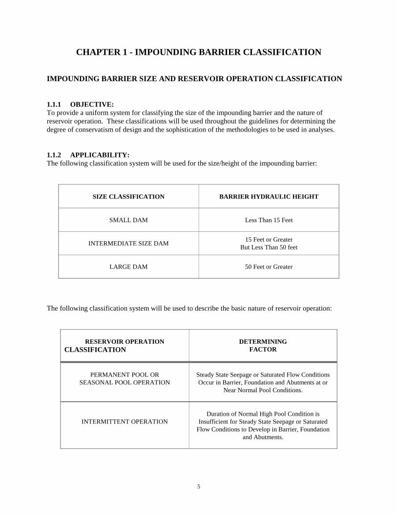
1.1.1 OBJECTIVE:To provide a uniform system for classifying the size of the impounding barrier and the nature of reservoir operation. These classifications will be used throughout the guidelines for determining thedegree of conservatism of design and the sophistication of the methodologies to be used in analyses.
1.1.2 APPLICABILITY:The following classification system will be used for the size/height of the impounding barrier:
SIZE CLASSIFICATION BARRIER HYDRAULIC HEIGHT
SMALL DAM Less Than 15 Feet
INTERMEDIATE SIZE DAM 15 Feet or GreaterBut Less Than 50 feet
LARGE DAM 50 Feet or Greater
The following classification system will be used to describe the basic nature of reservoir operation:
RESERVOIR OPERATIONCLASSIFICATION
DETERMININGFACTOR
PERMANENT POOL ORSEASONAL POOL OPERATION
Steady State Seepage or Saturated Flow ConditionsOccur in Barrier, Foundation and Abutments at or
Near Normal Pool Conditions.
INTERMITTENT OPERATIONDuration of Normal High Pool Condition is
Insufficient for Steady State Seepage or SaturatedFlow Conditions to Develop in Barrier, Foundation
and Abutments.

6

7
CHAPTER 2 - CRITICAL PROJECT ELEMENTS
2.1 DESIGN/PERFORMANCE GOALS FOR CRITICAL PROJECT ELEMENTS
Critical project elements are those elements of a project whose failure could result in dam failure and anuncontrolled release of the reservoir. Critical project elements and associated design events/loadingconditions are applicable to such features as: emergency spillways (design floods); impounding barriers(static and seismic loadings); outlet conduits (conduit integrity and seepage control); and impoundingbarriers and foundations (seepage control).
2.1.1 APPLICATION:This section provides an overview of the general principles and procedures used to selectdesign/performance goals. Specific details and worksheets for application of the Decision Frameworkconcepts are contained in Technical Note 2 of the Dam Safety Guidelines entitled Selection ofDesign/Performance Goals for Critical Project Elements1.
2.1.2 OBJECTIVE:To provide a Decision Framework for selecting design/performance goals for critical project elementswhich incorporates the concepts of Consequence Dependent Design Levels and Balanced Protection.
2.1.3 DECISION FRAMEWORK PHILOSOPHY:The decision methodologies presented in this section utilize probabilistic concepts for setting thedesign/performance goals to be used for design or evaluation of the various critical project elements. Probabilistic methods were chosen because they offered the capability of implementing a BalancedProtection approach for selecting design/performance goals across the range of engineering disciplines.
Balanced Protection - At the present time, the various engineering disciplines involved in dam designutilize methodologies and design events/loading conditions which are either deterministic, combinedprobabilistic-deterministic, or probabilistic in nature. This variety in methodologies has often resulted inthe various elements of a project being designed to widely different standards - often affording quitedissimilar levels of protection from failure. This is in sharp contrast to the balanced protection concept. The approach advocated here is to set a common design/performance goal for the design or evaluation ofeach critical project element and to utilize methodologies and standard practices which assist inproviding reasonably consistent levels of protection for the critical project elements.
The decision framework also utilizes the concept of Consequent Dependent Design Levels by settingincreasingly more stringent design/performance goals as the consequences of failure become moresevere.
Consequent Dependent Design Levels - It is standard practice in the civil engineering community thatthe degree of conservatism in design be commensurate with the intended use and the consequences offailure of a given system element. If the failure of a particular element does not pose a public safetyconcern, then the design level/loading condition is usually based on economic considerations and theeffects of operational disruption. A contrasting case is the situation where the failure of a given elementcould pose a threat of loss of life. The design levels/loadings for the critical elements are typically veryconservative. And, as the potential magnitude of loss of life and/or property damage resulting from adam failure increases, the design levels/loadings become increasingly more stringent.

8
The consequences of a dam failure include such diverse effects as the potential for loss of life,downstream property damage, and the loss of the capital investment in the dam and the economicbenefits provided by the project. Because of this diversity in potential effects, a number of indicatorparameters (Table 1) have been identified to reflect the nature and severity of the consequences.
TABLE 1 - NUMERICAL RATING FORMAT FOR ADDITIVE WEIGHTING SCHEMEFOR ASSESSING CONSEQUENCES OF DAM FAILURE
CONSEQUENCECATEGORIES
CONSEQUENCERATING POINTS
INDICATORPARAMETER
CONSIDERATIONS
CAPITAL VALUEOF PROJECT
0 - 150 DAM HEIGHT Capital Value of Dam
0 - 75 PROJECTBENEFITS
Revenue Generation orValue of Reservoir Contents
0 - 75 CATASTROPHICINDEX
Ratio of Dam Breach PeakDischarge to 100 Year Flood
POTENTIAL FORLOSS OF LIFE
0 - 300 POPULATIONAT RISK
Population at Risk Potential forFuture Development
0 - 100 ADEQUACY OFWARNING
Likely Adequacy of Warning inEvent of Dam Failure
POTENTIAL FOR PROPERTY DAMAGE
0 - 250
ITEMSDAMAGED
ORSERVICES
DISRUPTED
Residential and CommercialProperty
Roads, Bridges, TransportationFacilities
Lifeline Facilities CommunityServices
Environmental Degradation fromReservoir Contents (Tailings,Wastes, etc.)
2.1.4 TERMINOLOGY:The following terms are used in this section and in Technical Note 21.
Design/Performance Goal - A goal for the performance of critical project elements which may be usedin design or evaluation. It is expressed as an Annual Exceedance Probability (AEP) and is a measure ofthe chance of adverse behavior, or failure of a critical project element.
Annual Exceedance Probability (AEP) - The chance that a specified magnitude of some phenomenonof interest is equaled or exceeded during a given year.
Design Step - An integer value from one through eight which is used as an index for increasinglystringent design/performance goals (Figure 1).
Reliability - The likelihood of successful performance of a given project element. It may be measured

9
on an annualized basis or for some specified time period of interest, such as the project life. Mathematically, reliability is expressed as:
RELIABILITY = 1 - PROBABILITY [Adverse Behavior or Failure] (1)
Design Level - In general usage, design level is a generic term used to describe the relative conservatismof a particular design event or loading condition. In many engineering applications, the actual level ofprotection provided by a specified design level may not be known with accuracy.
2.1.5 DECISION FRAMEWORK:The Decision Framework is implemented through a Design Step Format (Figure 1) which utilizes eightsteps where design/performance goals and corresponding design events and loading conditions becomeincreasingly more stringent in progressing from step 1 through step 8. Design step 1 is applicable whenthe downstream consequences of a dam failure would be minimal and there would be no potential forloss of life. The design/performance goal at step 1 has an Annual Exceedance Probability (AEP) of 1 in500 - one chance in 500 of being equaled or exceeded in a given year.
Design step 8 is applicable where the consequences of failure could be catastrophic with hundreds oflives at risk. In this situation, very extreme design events and loading conditions are appropriate for theextremely high levels of reliability needed to provide proper protection of public safety. Design step 8corresponds to theoretical maximum design events and loading conditions. In those cases where atheoretical maximum does not exist for the design loading under consideration, the maximumdesign/performance goal is set at an AEP of 10-6.
Additive-Weighting Scheme - Selection of the Design Step and corresponding design/performance goalis accomplished using an additive-weighting scheme2,3 to incorporate all of the consequence informationinto a numerical format (consequence rating points) to provide guidance in decision-making. Thedesign/performance goal is determined based on the magnitude of the consequence rating points (Figure1).
Application of the selected design/performance goal is accomplished through a Design Step Formatincorporating 8 design steps (Figure 1). The selected design step is used as an index for specific designlevels, design events and design loading conditions for the various critical project elements.
The approach taken here is to use the broad spectrum of engineering design practice as a reference forsetting benchmarks for design levels. While direct situational comparisons are few, there are enoughsimilarities to provide sound guidance1. This approach provides a means of setting design levels whichare consistent with levels of safety provided by other engineering disciplines and by existing governmentregulation in other engineering and product safety areas.
Often during the preliminary stages of project planning, there is a need to make a quick assessment of theDesign Step. This can usually be accomplished by use of Table 2 which shows the general relationshipbetween the Design Step and the commonly used Downstream Hazard Classification.

10
CUMULATIVE CONSEQUENCE RATING POINTS
200 300 400 500 600 700 800
1/500 AEP 1 2 3 4 5 6 7 8 THEORETICAL MAXIMUM EVENT
D E S I G N S T E P
10-3 10-4 10-5 10-6
DESIGN/PERFORMANCE GOAL - ANNUAL EXCEEDANCE PROBABILITY
FIGURE 1. DESIGN STEP FORMAT AND CONSEQUENCE RATING POINTS
TABLE 2 - RELATIONSHIP OF DESIGN STEP TODOWNSTREAM HAZARD CLASSIFICATION
DOWNSTREAMHAZARD
POTENTIAL
DOWNSTREAMHAZARD
CLASSIFICATION
POPULATIONAT RISK
ECONOMIC LOSSGENERIC
DESCRIPTIONS
ENVIRONMENTALDAMAGES
TYPICALDESIGN
STEP
LOW 3 0
Minimal.No inhabited structures.
Limited agriculturedevelopment.
No deleteriousmaterials in reservoir 1 - 2
SIGNIFICANT 2 1 to 6
Appreciable.1 or 2 inhabited structures.Notable agriculture or work
sites.Secondary highway and/or
rail lines.
Limited water qualityDegradation from
reservoir contents andonly short termconsequences
3 - 4
HIGH 1C 7 to 30
Major.3 to 10 inhabited structures.Low density suburban area
with some industry andwork sites.
Primary highways and raillines.
3 - 6
HIGH 1B 31-300
Extreme.11 to 100 inhabited
structures.Medium density suburban
or urban area withassociated industry,
property and transportationfeatures.
Severe water qualityDegradation potential
from reservoircontents
and long term effectson aquatic and
human life
4 - 8
HIGH 1A More than 300
Extreme.More than 100 inhabited
structures.Highly developed, densely
populated suburban orurban area with associated
industry, property,transportation and
community life linefeatures.
8

11
2.1.5 REFERENCES:
1. Schaefer, M.G., Selection of Design/Performance Goals for Critical Project Elements, TechnicalNote 2, Dam Safety Guidelines, Washington State Department of Ecology, Olympia, WA., July,1992.
2. Hayes J.B., The Complete Problem Solver, Lawrence Erlbaum Associates Publishers, Hillsdale, N.J.,1989.
3. Keeney, R.L., Raiffa, H., Decisions With Multiple Objectives: Preferences and Value Tradeoffs,John Wiley and Sons, 1976.

12

13
2.2 BARRIER STATIC STABILITY
2.2.1 OBJECTIVE:Minimize the likelihood of an embankment or abutment failure during construction and in service.
2.2.2 DESIGN PRACTICE:Requirements/Minimums - All embankments must equal or exceed the minimums cited in Table 11 forthe steady seepage case. In many instances the need for end-of-construction and sudden drawdownanalyses can be dismissed by inspection. Specifically, an analysis of the end-of-construction stability isnot required when the outer shells of the embankment consist of relatively pervious soils that areexpected to dissipate excess pore pressures almost at the rate of their generation. A rapid drawdownanalysis may be omitted if the lowlevel outlet system can only drop the pool a few feet per day when it isin an elevated state.
TABLE 1 - MINIMUM FACTORS OF SAFETY FOR EARTH AND ROCKFILL DAMSa)
Design Condition Minimum Factor of SafetyEnd of Construction 1.3b)
Sudden drawdown from maximum pool 1.0c)
Sudden drawdown from spillway crest 1.2c)
Steady seepage with maximum storage pool 1.5
Notes: a) Not applicable to embankments on clay shale foundations; higher safety factorsshould be used for these conditions.
b) For embankments over 50 feet high on relatively weak foundation use minimumfactor of safety of 1.4.
c) The safety factor should be a minimum of 1.5 when drawdown rate and pore waterpressures developed from flow nets are used in stability analyses.
Current Practice - Analyses are routinely conducted with 2-dimensional slope stability models, basedon limit equilibrium procedures. A satisfactory design is considered achieved when the factor of safetyexceeds the generally accepted minimums listed in Table 1. The conscientious designer typicallyperforms sensitivity studies to confirm that the design meets minimum factors of safety for reasonablevariations in the magnitude of key model parameters.
Probabilistic Based Stability Approach - The DSO accepts the factor of safety methodology to justifya given embankment cross-section; it will continue to do so for the foreseeable future. None the less thismethod has major shortcomings. Ideally, current practice would employ static stability analyses whichprovided a clear measure of the actual reliability of the embankment or abutment slope; it does not. Furthermore, the factor of safety approach, as routinely applied to static slope stability evaluations, isintuitively disquieting in that there is no provision to increase or decrease the design minimum based onthe downstream hazard setting. These shortcomings hamper efforts to rationally improve embankmentreliability as the consequences of failure increase.
As an alternative, the DSO espouses the use of probabilistic based, capacity/demand reliability methodssuch as those proposed by Vanmarcke2 and Whitman3. We recognize that the majority of the engineeringcommunity has serious reservations about such an approach. The principal objection to the application

14
of probabilistic methods to embankment design is that it typically has not afforded a "meaningful"treatment of "extreme events". Here "meaningful" refers to the ability of the analysis to give a level ofconfidence in the likely occurrence of an "extreme event" that the designer would feel comfortable indeciding whether additional action was warranted. "Extreme events" is a term employed to describe anyof a number of problems that would likely control the stability analysis but are themselves generallydifficult to factor into the analysis with any confidence. This difficulty may spring from an inability topredict the position at which such an extreme event may occur even though the designer recognizes thepotential occurrence of such events. Or, conversely, the engineer may not even have considered thepossibility of a given type of extreme event occurring and thus not have factored this element into theanalysis. The principal examples of what the DSO considers to be extreme events are:
Missing an extensive weak seam in the foundation in the explorations,
Cracks developing within the embankment that allow near reservoir head levels to developwithin the downstream portion of the embankment4,5, and
Pervious features in the abutments or foundations producing large hydraulic gradients in thedownstream portion of the embankment.
Such extreme events are not readily factored into the analysis by assuming that the variable of interesthas a lognormal distribution about the mean.
Some of the difficulties of formulating a probabilistic model of embankment stability have beenaddressed by the application of fuzzy number theory. Santamarina, et. al.6, identified the followingqualitative parameters as elements in their assessment of embankment stability:
• Qualifications of the engineer-designer,• Extent and quality of the geologic assessment at the site,• Quality of the available data,• Quality of the design method,• Completeness of the design of the structure,• Importance of design errors or omissions,• Contractor's prior record,• Supervision during construction,• Quality of field controls during construction,• Importance of construction errors,• Difficulties during construction,• Monitoring program,• In-service inspection,• Malfunctions during the life of the structure, and• Maintenance program.
A few common themes standout in reviewing the preceding list.
First and foremost, the embankment stability analysis represents an artificial distinction and isbut one of a number of steps in a larger process of achieving a stable embankment. Specifically,the development of a suitable embankment section does not end with documenting by numericalanalysis that the section exceeds some minimum target stability parameter. It is an on-going,"cradle to grave" endeavor spanning site investigation, design, construction and finally the
15
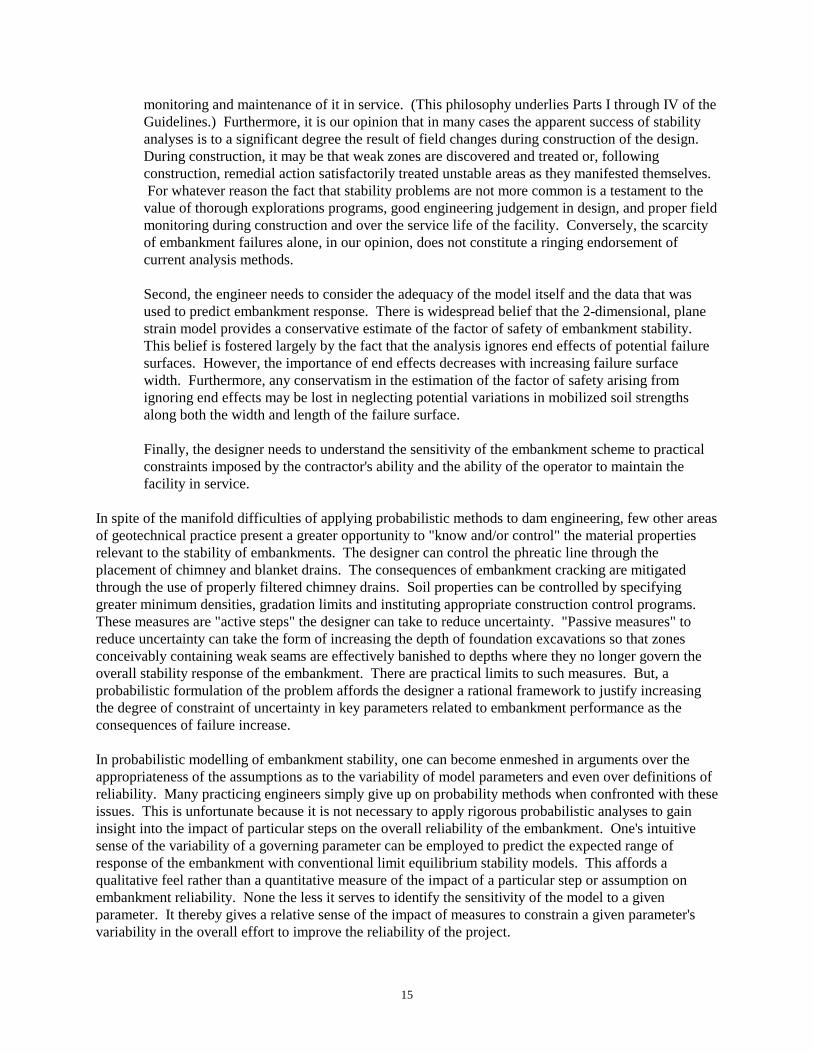
monitoring and maintenance of it in service. (This philosophy underlies Parts I through IV of theGuidelines.) Furthermore, it is our opinion that in many cases the apparent success of stabilityanalyses is to a significant degree the result of field changes during construction of the design. During construction, it may be that weak zones are discovered and treated or, followingconstruction, remedial action satisfactorily treated unstable areas as they manifested themselves. For whatever reason the fact that stability problems are not more common is a testament to thevalue of thorough explorations programs, good engineering judgement in design, and proper fieldmonitoring during construction and over the service life of the facility. Conversely, the scarcityof embankment failures alone, in our opinion, does not constitute a ringing endorsement ofcurrent analysis methods. Second, the engineer needs to consider the adequacy of the model itself and the data that wasused to predict embankment response. There is widespread belief that the 2-dimensional, planestrain model provides a conservative estimate of the factor of safety of embankment stability. This belief is fostered largely by the fact that the analysis ignores end effects of potential failuresurfaces. However, the importance of end effects decreases with increasing failure surfacewidth. Furthermore, any conservatism in the estimation of the factor of safety arising fromignoring end effects may be lost in neglecting potential variations in mobilized soil strengthsalong both the width and length of the failure surface.
Finally, the designer needs to understand the sensitivity of the embankment scheme to practicalconstraints imposed by the contractor's ability and the ability of the operator to maintain thefacility in service.
In spite of the manifold difficulties of applying probabilistic methods to dam engineering, few other areasof geotechnical practice present a greater opportunity to "know and/or control" the material propertiesrelevant to the stability of embankments. The designer can control the phreatic line through theplacement of chimney and blanket drains. The consequences of embankment cracking are mitigatedthrough the use of properly filtered chimney drains. Soil properties can be controlled by specifyinggreater minimum densities, gradation limits and instituting appropriate construction control programs. These measures are "active steps" the designer can take to reduce uncertainty. "Passive measures" toreduce uncertainty can take the form of increasing the depth of foundation excavations so that zonesconceivably containing weak seams are effectively banished to depths where they no longer govern theoverall stability response of the embankment. There are practical limits to such measures. But, aprobabilistic formulation of the problem affords the designer a rational framework to justify increasingthe degree of constraint of uncertainty in key parameters related to embankment performance as theconsequences of failure increase.
In probabilistic modelling of embankment stability, one can become enmeshed in arguments over theappropriateness of the assumptions as to the variability of model parameters and even over definitions ofreliability. Many practicing engineers simply give up on probability methods when confronted with theseissues. This is unfortunate because it is not necessary to apply rigorous probabilistic analyses to gaininsight into the impact of particular steps on the overall reliability of the embankment. One's intuitivesense of the variability of a governing parameter can be employed to predict the expected range ofresponse of the embankment with conventional limit equilibrium stability models. This affords aqualitative feel rather than a quantitative measure of the impact of a particular step or assumption onembankment reliability. None the less it serves to identify the sensitivity of the model to a givenparameter. It thereby gives a relative sense of the impact of measures to constrain a given parameter'svariability in the overall effort to improve the reliability of the project.

16
Table 2 summarizes the principal components and our qualitative sense of their overall impact on theperformance of actual embankments. The Table illustrates our belief that the response of the dam andfoundation is governed largely by the position of the phreatic surface, the occurrence of concentratedseeps and the potential presence of some unknown, weak layer in the foundation or abutments.
Regarding weak foundation seams, the engineer should recognize that the typical mode and frequency offield testing allow ample opportunity to miss a weak seam. This should be a sobering thought to thedesign engineer. Ideally, it will prompt them to incorporate "reality checks" and mitigative measures inthe design that reduce the impact of unanticipated conditions particularly in the foundation phase of thework. Regarding concentrated seeps and the phreatic surface, conventional slope stability models do notreadily allow considering the impact of embankment cracking that could conceivably introduce near-fullreservoir, head levels into the downstream portion of the embankment. Furthermore, it is rare that we seea stability analysis that even attempts to approximate the impact of differing horizontal and verticalpermeabilities on the position of the phreatic surface. Recognizing the potential variability of thephreatic surface and its crucial impact on overall embankment stability, we want to limit the "volatility"of this aspect of the problem. The magnitude of the restriction ideally should be a function of theconsequences of a failure. The process of constraining the variability in the phreatic surface andmitigating the impact of embankment cracking normally involves the construction of chimney andblanket drains. The extreme value probability problems of identifying anomalous pervious seams and theextent of potential embankment cracking are circumvented. Instead, the drainage features control theposition of the phreatic surface and transect cracks, dissipating high water pressures. This is a restatmentof the approach advocated by Dr. DeMello in his 17th Rankine Lecture7. There he argued that thedesigner should take steps to "transform" the problem from one of dealing with extremes to one ofdealing with averages, i.e., a design feature that blunts or smoothes out the effects of extreme loadings. In effect, the designer is bringing the actual dam closer to the idealized, simplified structure modelled.
The process of improving embankment reliability involves a number of steps that span the scoping of theinitial exploration program to detailing the operation and maintenance plan. Beginning with theexploration program, the scope of foundation and abutments investigations should be keyed to theconsequences of failure. Obviously, the problem is trivial if competent rock or otherwise suitableoverburden deposits are exposed at shallow depths. Any surficial, unsuitable materials would beremoved as a practical expedient. Where overburden depths make removal impractical or where theabutment contains pervious or weak seams that likewise present great difficulties in treating, judgementmust be employed that is seasoned by due consideration of the consequences. If the level of uncertaintyremains substantial and the consequences of failure are large, then the presumption of the existence ofweak and/or pervious zones in the foundations should be made and design measures employed thatprovide the necessary factor of safety given the possible existence of such zones. Addressing weak zoneand pervious features concerns would include such measures as:
Strength concerns
Conducting a secondary exploration program targeted at characterizing conditions within somecritical depth as determined from preliminary stability assessments,
Flattening embankment slopes,
Providing a buttress for the abutments,
Overexcavating the upper phases of the foundation and/or the provision of key trenches,

17
MIT
IGA
TIO
N
____
____
____
_
Nor
mal
var
ianc
e co
nsid
ered
in ra
nge
of st
reng
thpa
ram
eter
s.
Spec
ify m
inim
um c
ompa
ctio
n le
vel a
nd c
onst
ruct
ion
cont
rol p
rogr
am in
con
stru
ctio
n do
cum
ents
.
Expa
nd e
xplo
ratio
n pr
ogra
m to
bet
ter c
hara
cter
ize
subs
urfa
ce c
ondi
tions
.
Che
ck fo
r sen
sitiv
e so
ils; i
.e.,
thos
e w
ith si
gnifi
cant
diffe
rent
pea
k to
resi
dual
stre
ngth
ratio
, des
ign
for t
hepo
ssib
le o
ccur
renc
e of
pot
entia
l wea
k zo
nes.
Prov
ide
chim
ney
and
blan
ket d
rain
s to
inte
rcep
t and
disc
harg
e se
epag
e an
d co
nstra
in p
hrea
tic su
rface
s to
the
drai
n co
nfig
urat
ion.
Expa
nd se
epag
e cu
toff
feat
ures
and
ext
end
the
chim
ney
drai
n de
eper
into
the
abut
men
ts a
nd fo
unda
tion.
Em
ploy
blan
ket d
rain
s ove
r the
dow
nstre
amem
bank
men
t/sub
grad
e co
ntac
t.
Labo
rato
ry te
stin
g to
det
erm
ine
pore
pre
ssur
e be
havi
orun
der r
epre
sent
ativ
e lo
adin
g; w
here
app
ropr
iate
, con
duct
field
mon
itorin
g du
ring
cons
truct
ion.
Eval
uate
abn
orm
al z
ones
as p
ossi
ble
plan
es o
f wea
knes
s;us
e bl
ock
segm
ents
to fo
rce
trial
failu
re su
rface
to p
ass
thro
ugh
such
zon
es.
PRIN
CIP
AL
SOU
RC
E O
F D
IFFE
REN
CES
BET
WEE
N M
OD
EL &
AC
TUA
L EM
BA
NK
MEN
T R
ESPO
NSE
____
____
____
_
F
rictio
n an
gle
dete
rmin
ed b
y di
rect
shea
r tes
ts re
flect
ing
the
failu
re p
lane
alo
ng a
hor
izon
tal s
urfa
ce ra
ther
than
on
the
wea
kest
p
lane
.
N
ot a
ccou
ntin
g fo
r the
redu
ctio
n in
fric
tion
angl
e fo
r gra
in
bre
akag
e un
der l
arge
con
finin
g st
ress
es.
Emba
nkm
ent: Stre
ngth
pro
perti
es d
eter
min
ed o
n a
degr
ee o
f com
pact
ion
si
gnifi
cant
ly g
reat
er th
an th
at a
ctua
lly a
chie
ved
durin
g
con
stru
ctio
n.
Abu
tmen
ts a
nd F
ound
atio
n:Fa
ilure
to d
etec
t pre
senc
e of
a w
eak
zone
whe
re a
ctua
l stre
ngth
pa
ram
eter
s are
sign
ifica
ntly
less
than
ass
umed
val
ues.
Inap
prop
riate
use
of p
eak
frict
ion
angl
es ra
ther
than
resi
dual
angl
es fo
r sen
sitiv
e so
ils.
Emba
nkm
ent: (Cra
cks)
– U
nant
icip
ated
cra
ckin
g an
d hy
drau
lic fr
actu
ring
p
robl
ems m
ay in
trodu
ce n
ear r
eser
voir
pres
sure
leve
ls in
to th
e
dow
nstre
am p
ortio
n of
the
emba
nkm
ent.
(Inac
cura
te m
odel
ing
of se
epag
e) –
Hor
izon
tal a
nd v
ertic
al
perm
eabi
litie
s tha
t are
une
qual
and
var
y th
roug
hout
the
em
bank
men
t. T
his m
ay p
rodu
ce si
gnifi
cant
diff
eren
ces i
n th
epo
re
pre
ssur
e re
gim
e be
twee
n th
e m
odel
and
the
actu
alem
bank
men
t.
Abu
tmen
ts a
nd F
ound
atio
n:
Und
etec
ted
perv
ious
seam
s pro
duci
ng g
reat
er th
an a
ntic
ipat
ed
wat
er p
ress
ures
in th
e do
wns
tream
em
bank
men
t/sub
grad
eco
ntac
t.
(End
of C
onst
ruct
ion
Prob
lem
s) –
Por
e Pr
essu
re re
spon
se o
f
co
mpa
cted
soils
The
appr
opria
tene
ss o
f a p
artic
ular
tria
l sur
face
shap
e is
a fu
nctio
n of
the
emba
nkm
ent g
eom
etry
and
the
conf
igur
atio
n an
d lo
catio
n of
any
mat
eria
llyw
eake
r em
bank
men
t zon
es.
MO
DEL
SEN
SITI
VIT
Y T
OPA
RA
MET
ER V
AR
IAN
CE
Min
imal
Effe
ct
Min
imal
Effe
ct
Sign
ifica
nt E
ffect
Pote
ntia
l Maj
or E
ffect
Pote
ntia
l Maj
or E
ffect
Var
iabl
e
MO
DEL
PA
RA
MET
ER
Soil
Uni
t Wei
ghts
Shea
r Stre
ngth
Gro
und
Wat
er/P
ore
Pres
sure
Reg
ime
Tria
l Fai
lure
Sur
face
(Blo
ck o
r Circ
ular
)
TAB
LE 2
STA
TIC
SLO
PE S
TAB
ILIT
Y M
OD
EL V
AR
IAN
CE
18
Increasing the minimum level of compaction, and
Providing drainage zones in buttresses at the subgrade contact to take full advantage of thebuttress weight.
Pervious feature concerns
Flaring the core footprint at the abutment and foundation contact to lengthen the seepage path,
Extending cutoffs and chimney drains deeper into abutments and the foundations,
Oversizing the drains to accommodate abnormally large volumes of seepage, and
Employing an asymmetrical embankment cross-section that places the core zone as far upstreamas practicable to maintain the majority of the dam in a drained state.
During construction a suitable inspection effort must be made to confirm that the project is constructed inaccordance with the design. To this end the construction documents need to:
Clearly define what constitutes acceptable and conversely unacceptable subgrade conditions.
Require the inspection of the prepared foundation by a qualified engineer familiar with theprincipal engineering assumptions supporting the design.
This topic is also discussed in Section 7, Specifications. In short, assessing static stability involves"reality checks" to confirm that the principal design assumptions were equaled or exceeded in the field. To accomplish this, field personnel must be qualified to recognize an adverse situation.
Following construction the owner and operator must be provided with guidance to assist them in therecognition of an adverse situation, should one develop. The DSO publication Guidelines forDeveloping Dam Operation and Maintenance Manuals and Emergency Action Plans are available toassist in this area.
Reliability Standards - The annual probability of failure scheme outlined in the Sections on DesignFloods (2.4) and Seismic Stability (2.3) is not readily applicable to slope stability problems. Theprincipal reason the annual probability approach is not as desirable in static stability problems is in thenature of the design loading. In floods and earthquakes the protection comes in the fact that the designevent the facility must survive has an extremely remote chance of occurring. However, in static slopestability problems nearly the maximum load is applied during the first filling and this load is maintainedlargely unabated for the remainder of the service life of the project. Therefore, the design goal is toprovide a capacity (ultimate potential shear strength) greatly in excess of demand (that fraction of theshear strength that must be mobilized to just equal the driving forces).
As a practical matter it is doubtful that any recognized engineering body is going to step forward andendorse some tiered reliability standard. The liability such an endorsement would likely carry woulddiscourage most reputable individuals. Thus, for the foreseeable future those electing to use reliabilitymethods likely will employ a hybrid approach involving both:
Documenting that factors of safety cited in Table 1 are achieved, along with
19
Providing a measure of the reliability of this calculated factor of safety given a best estimate ofthe variability of the parameters that govern the model response.
The second step will largely be done for the designer's piece of mind. This task should reassure theengineer that the model has accounted for the normal variability typically encountered with soils and thatthose elements introducing the greatest uncertainty have been appropriately treated or constrained.
2.2.3 SPECIALIZED ISSUES:Abutment Stability - Analyses tend to concentrate on the stability of the embankment. However, there aresituations where one must also consider the stability of temporary abutment cut slopes. This likelyoccurs when the abutments consist of competent sands and silty sands and the slope of the abutments isat or steeper than the angle of repose of the soils. The act of stripping and removal of unsuitable soilsfrom the slope and toe areas can overstress the soils and induce a slide. The problem may become acutewhere the slide deprives support for the upper reaches of the slope and precipitates ongoing slides up theslope. Where this situation is anticipated, due consideration should be given to staging the strippingoperation so that only a small portion of the slope is unsupported at any one time. The specificationswould need to identify the maximum allowable stripped swath between the top of the working surface ofthe fill and undisturbed ground.Reservoir Rim Stability - The reservoir rim should be reviewed to determine whether there is thepotential for slope movements into the reservoir that could generate damaging waves against theembankment or block hydraulic elements of the outlet works. No specific requirements on the nature ofthe investigation are set forth by the DSO. This is due primarily to the fact that reservoir rim instabilityhas not posed a significant problem for the typical earthen dam that this guidance document covers. Significant reservoir rim stability problems have been encountered in Washington. However, theproblems have been associated primarily with major reservoirs. Accordingly, the owners have had theresources and desire to conduct extensive investigation into the problem and to aggressively pursuit a fix.
It is unlikely that the smaller earthen embankment project (the target of this guidance document) wouldhave a significant reservoir rim stability problem identified. But, assuming this is the case, it would beprudent in the majority of cases for the developer to abandon the site in favor of a less difficult one.

20
2.2.4 REFERENCES:
1. Wilson, Stanley D., Marsal, Raul J., Current Trends in Design and Construction of EmbankmentDams, ASCE, 1979, p. 32.
2. Vanmarcke, E.H., Probabilistic Stability Analysis of Earth Slopes, Engineering Geology, ElsevierScientific Publishing Co., Vol. 16, 1980, pp. 29-50.
3. Whitman, R. V., Evaluating Calculated Risk in Geotechical Engineering, Journal of GeotechnicalEngineering, Vol 110, No. 2, 1984, pp. 145-188.
4. Dascal, O., Peculiar Behavior of the Manicouagan 3 Dam's Core, International Conference on CaseHistories in Geotechnical Engineering, May 1984, University of Missouri-Rolla, Vol. 2, pp. 561-569.
5. Sherard, J.L., Hydraulic Fracturing in Embankment Dams, Volpe, Richard L., Kelly William E.,(eds.), Seepage and Leakage from Dams and Impoundments, ASCE National Convention, Denver,CO., May 1985, pp. 115-141.
6. Santamarina, J.C., Altschaeffl, A.G., Chameau, J.L., Reliability of Slopes: Incorporating QualitativeInformation, (preprint), Paper 92, Transportation Research Board, 71st Annual Meeting, January 12-16, 1992, Washington, D.C..
7. DeMello, V.F.B., Reflections on Design Decisions of Practical Significance to Embankment Dams,Geotechnique, Vol. 27, No. 3, 1977, p. 293.
General References on Conventional Slope Stability Methods
8. U.S. Bureau of Reclamation, Design Standards No. 13, Embankment Dams, Chapter 4, StaticStability Analyses.
9. Duncan, J. M., and Buchignani, A. C., An Engineering Manual for Slope Stability Studies,University of California, Berkeley, March 1975.
10. U.S. Corps of Engineers, Engineering and Design: Stability of Earth and Rockfill Dams, EM 1110-2-1902, 1970.

21
2.3 BARRIER SEISMIC STABILITY
2.3.1 OBJECTIVE:The project should be configured so as to be able to experience earthquakes without releasing thereservoir contents except under an appropriately remote level of earthquake shaking.
2.3.2 APPLICABILITY AND FOCUS:Impoundments can be broken down into two main groups: earthen embankments and concrete structures. The principal focus of the guidelines is on earthen embankments. Concrete structures, i.e., gravity, archand roller compacted concrete impounding barriers are not discussed in any depth. This is due to thefollowing rationale. Concrete structures present a number of unique design problems. Generally, onlyspecialty firms, well versed in the peculiarities posed by such structures, are qualified to formulate asuitable design. It would be misleading to imply that these guidelines could somehow substitute for therequisite experience and judgment necessary to design a suitable concrete impounding structure.
It is also not the intention of these guidelines to present a detail methodology for the dynamic analysis ofembankment dams. Instead, the focus of this section is to provide guidance on the minimum scope ofanalysis that the DSO considers appropriate for various seismological settings, embankment materials,and consequences of failure. In addition, the principal schemes routinely employed to address seismicstability concerns are discussed.
2.3.3 OVERVIEW:For completeness sake, a few comments on the dynamic behavior of concrete structures are presented. Concrete structures have performed well when subjected to strong earthquakes. The most notableconcrete dam failures, St. Francis and Malpasset1 occurred as a result of weak foundation layers ratherthan structural problems within the dams. Historically, foundation failures have posed the principalthreat to concrete structures. Dams have experienced extensive earthquake induced cracking thatnecessitated extensive remedial work2. But, the DSO is not aware of any concrete dam where acatastrophic release of the reservoir resulted from earthquake induced cracking of the structure. Wherefailures have occurred, the problem arose as the result of deterioration of the rock mass properties in theabutments or foundation due to the action of applied static and dynamic stresses and/or the impact ofseepage. Again, these guidelines are not intended to address the difficult foundation conditions that haveposed problems in the past. The assessment of the performance of rock foundations for concretestructures should be undertaken only by those well versed in the process.
Earthen embankments, the principal focus of this section, theoretically fail as the result of the dam beingovertopped or the cross-section breached. The breach scenario conceivably could occur through relativedisplacement vertical and/or horizontal between either side of a fault that passes through the damfootprint. The DSO is not aware of any failures directly attributed to such a mechanism. Where thepotential for such fault movements was anticipated in the design, embankments have been provided withwide core zones, broad non-cohesive crack filler zones and enlarged drainage features3 to accommodatelarge, localized relative displacements in the embankment section.
Embankment overtopping remains the principal mechanism of earthquake induced failures. Typically thedam crest settles or drops a distance greater than the available freeboard. The overtopping flow rapidlybreaches the embankment section, leading to a failure of the dam.
Seiches generated in the reservoir also potentially could overtop the embankment, presenting erosionconcerns. At Hebgen Dam in a 1959 earthquake the caretaker reportedly observed a series of waves

22
overtop the embankment. The caretaker estimated4 that one wave overtopped the dam for a duration of10 minutes with a maximum depth of some 3 feet. Considerable erosion damage occurred but the damdid not fail. In fact the DSO is not aware of an actual failure precipitated by a seiche. The absence ofsuch failures in part may be responsible for the limited amount of research done in this area. Again, thisissue is beyond the scope of these guidelines. If readers elect to pursue the issue, they might begin withthe US Army Coastal Engineering Research Center's Shore Protection Manual5.
2.3.4 TWO TRACKED SEISMIC ASSESSMENT APPROACH:The behavior of embankments under earthquake loading is normally idealized as two distinct behaviors:1) a deformation response and 2) the buildup of pore water pressures that, in extreme cases, can lead to aliquefaction condition. The Bureau of Reclamation's6 idealization of the process is an excellent summaryof the dual track analysis approach.
Deformation Analysis - The deformation response is the summation of the predicted displacements inthe embankment and foundation that occur in the brief moments that the combined inertial and staticforces exceed the shearing resistance of a surface in a segment of the embankment and/or the foundation.The static stresses alone are insufficient to maintain sliding of this mass. Normally, some reduction inshear strength properties is applied to the soil to account for the build-up of pore water pressure from thecyclic loading. The actual analysis begins with a pseudo-static assessment of the dam to determine ayield acceleration, kyield. Kyield is the acceleration in percent of gravity that produces a factor of safety of1 on a trial slip surface whose failure would compromise the ability of the dam to impound the reservoir.Kyield is then compared to kmax, the estimated average maximum acceleration the failure surface underconsideration is predicted to experience under the design earthquake. Kmax is a function of the maximumcrest acceleration (ümax) and the ratio of the depth of the failure zone under consideration to that of theembankment height. The quantity ümax can be determined by performing non-linear, wave propagationanalyses such as the pseudo two-dimensional SHAKE7 program or by empirical procedures such as thoseoutlined by Makdisi and Seed8. Ambraseys and Sarma9 and Makdisi and Seed8 developed and publishedsimilar data in the form of curves relating ümax to kmax. If the analysis shows kyield exceeds kmax, theconcern over displacements is dismissed by inspection. If kyield is less than kmax, then an empiricalrelationship is used to estimate the magnitude of movement. This relationship is a function principally ofthe ratio of kmax to kyield, the predominant period of the embankment/foundation system and the magnitudeof the earthquake.
The preceding discussion outlines the simplified deformation analysis procedure developed by Makdisiand Seed10. An approach incorporating probabilistic concepts has been formulated by Yegian, Marcianoand Ghahraman11. The Corps of Engineers employs a similar analysis methodology to that of Makdisiand Seed developed by Ambraseys and Sarma12.
The results of a deformation analysis are considered "order of magnitude"13. Therefore, considerablejudgement is required in the determination of what constitutes satisfactory performance. Ideally, thepredicted settlement would be a small fraction of the available freeboard. The selection of a suitable"small fraction" depends on the overall confidence in the characterization of the embankment andfoundation soils, the reliability of the estimated peak acceleration, the extent of the crest involved in thesliding mass and the consequences of failure.
Liquefaction Analysis - The deformation model in its various formulations does not adequately predictthe behavior of soils susceptible to a rapid buildup of pore water pressures under cyclic loading. Thisclass of soils consists principally of saturated, loose to medium dense, non-plastic silts; fine, uniformlygraded, sands; and mixtures of silt, sand and gravel. For these soils the dynamic loading transfers a
23
portion of the stress in the soil structure unto the pore water phase of the saturated soil. For there to be asignificant build up of pore water pressure, the drainage of the soil has to be considerably less than therate of pore pressure rise. Where liquefaction occurs the soil generally loses a large fraction of itsstrength. If failure occurs, it generally happens after the earthquake where the temporarily lower soilstrength properties can not resist the existing system of imposed static loads.
There are a number of methodologies employed to evaluate the potential for a liquefaction failure. Theyinclude empirical methods based on Standard Penetration blow counts, sophisticated laboratory testingand dynamic analyses such as the Cyclic Stress Ratio and steady state approaches, among others. Anexcellent synopsis of the various analysis procedures is presented in the National Research Councilpublication Liquefaction of Soils During Earthquakes14. Specifics on various components of conductinga dynamic analysis are discussed by Idriss and Duncan15.
Seismic Evaluation Methodologies - The DSO does not endorse a particular method for the assessmentof deformations and the potential for a liquefaction condition to occur. In fact, there are differing levelsof sophistication employed in the various analysis schemes. The need for a particular degree ofsophistication in a given analysis is a function of the anticipated level of probable ground motion,susceptibility of the soils to strength loss and pore water pressure build up under dynamic loadings andthe downstream hazard setting.
2.3.5 ESTIMATING SITE SPECIFIC GROUND MOTIONS FOR ANALYSES:The following outlines the general steps the engineer would take in developing design ground motions tobe used in a conducting a seismic assessment. In recognition of the fact that detailed seismic studiesoften are unavailable at a proposed project site, a process is discussed to estimate ground motions fromexisting public domain, seismic risk studies.
Step 1: Estimate the character of the design ground motions at foundation level at the site.
Methodologies for Selection of Earthquakes to Include in Analysis - The methods of selectingearthquakes for the prediction of ground motions at foundation level can be broadly grouped into threecategories: deterministic, probabilistic and hybrid (both deterministic and probabilistic components).
In the deterministic approach, all seismogenic features, believed capable of generating damaging groundmotions at the project site, are evaluated for the maximum credible earthquake (MCE). This is thelargest magnitude earthquake the feature is judged capable of producing. The estimated magnitude is afunction of among other factors, past seismic activity on this feature or other similar features, thedimensions of the fault surface or locked segment of the plate, the type of fault movement and rates ofplate convergence.
In the probabilistic approach earthquakes of lesser magnitude than the MCE in addition to the MCE areconsidered. The estimated frequency of occurrence of the various magnitude events is postulated and anannual probability of experiencing a given level of ground motions is calculated for the site. Idriss16
presents an excellent description of the probabilistic seismic risk assessment process.
In the hybrid approach identifiable seismogenic features are treated in either a deterministic orprobabilistic manner. Probabilistic models are used to predict the occurrence of random earthquakes,i.e., earthquakes that cannot be tied to a particular geologic structure. This would include the deepearthquakes occurring within the subducting Juan de Fuca Plate beneath Western Washington andrandom earthquakes in the overriding North American Plate (NAP), such as the 1872 earthquake.

24
Accordingly, in seismic assessments of projects in the Puget Sound area a random MCE of Magnitude6½ within the NAP has been a common assumption. For projects situated in the North Cascades arandom Magnitude 7+ crustal earthquake has been included in the principal seismic risk studies of thepast decade. In the remainder of the state, a random event ranging in magnitude from 5¼ to 6¼ hasroutinely been assumed.
The hybrid approach in our experience is typically employed for the seismic assessment of major dams inWashington. This is because a comprehensive seismic risk analysis must deal with the possibility of arandom seismic event occurring conceivably anywhere beneath a project sited in Washington State. However, the level of conservatism in seismic assessments does not place a random event directlybeneath the project site. Typical practice has been to assume some minimum radius beyond which therandom event is allowed to occur. This minimum radius is determined by probabilistic analyses thatshow the likelihood of experiencing such an event at lesser hypocentral distances to be appropriatelyremote.
Seismology Studies - A few of the more important sources of information on seismicity withinWashington known to the DSO are discussed in Section 2.3.9.
Design or Reliability Levels - The present hybrid scheme where MCEs and random earthquakes areconsidered, works well for major projects with high downstream hazard settings. However, goodpractice is not clearly defined for the small to medium sized projects with moderate downstream hazardsettings. Yet, it is this class of dams which constitute the vast majority of projects in this state. Thestepped design scheme presented in Chapter 2.1 affords a rational, consistent way to address the issue ofappropriate minimum design levels for this class of small to medium projects. Specifically, for projectswhere the calculated Performance Goal is Step 3 or less, the DSO would accept a design where thereliability under seismic loading meets or exceeds the level cited in Figure 1, Chapter 2.1. To evaluateprojects for seismic stability beyond design step 3 on a purely probabilistic basis, implies seismologistshave a better understanding of the magnitude, distribution and frequency of seismic events inWashington then presently exists. Where greater reliability is required, designers are forced into makingdecisions on qualitative rather than quantitative reasoning. This is accomplished by including greaterdesign events, more conservative estimates of attenuation relationships, larger design spectra, andrequiring increased reliability in design features.
Peak Acceleration - Ideally, the designer will use recorded earthquake time histories from earthquakes ofthe approximate design magnitude, recorded at similar hypocentral distances and on similar foundationconditions as that anticipated for the actual project. Furthermore, a number of representative timehistories will be used to account for bias in any one record and/or to develop a design spectra that betterenvelopes the range of anticipated response spectra at the site. The principal source of earthquake timehistories in the US is the National Geophysical Data Center (NGDC) (303) 447-2020 in Colorado. NGDC can provide records sorted on the basis of country, magnitude, free field or building records,source to site distance, and maximum acceleration and velocity. Other sources of earthquake recordsinclude the California Division of Mines and Geology Strong Motion Instrumentation Program (916)322-3105. This program recently published recorded ground motions for the subduction events thatoccurred in the Cape Mendocino area in 1992. These event records are important additions to the database for estimating ground motions associated with large magnitude interface events such as arepostulated for the Washington Coast.
Unfortunately, there are insufficient acceleration time histories to cover the suite of potential eventsnormally considered at a given site. Thus, some form of attenuation relationship is employed todetermine the appropriate peak acceleration that should be used to scale a recorded or synthetic

25
accelerogram or response spectrum for use at the project site. Various relationships are used to estimatethe attentuation in earthquake ground motions between the source and the project site. An excellentsummary of the various relationships is presented by Green17. Green notes the significant differencesbetween the relationships developed by various researchers and recommends using a number ofattenuation relationships to minimize bias conceivably introduced by a particular relationship. Crouse18
has published an attenuation relationship for the Cascadia subduction zone that was developed based ondata specific to subduction zones around the world that exhibit similarities to Washington.
In the absence of site specific earthquake studies, as a first approximation to the maximum bedrockacceleration, Plates 3 and 4 of USGS Open File Report 80-47119 can be used. These Plates presentestimates of peak acceleration on rock with a 90% probability of non-exceedance in 50 years and 250years, respectively. The equivalent annual probabilities of exceedance are approximately 1 in 500 and 1in 2500. Thus, these Plates provide acceleration maps corresponding to Steps 1 and 3 of the of the 8-stepDesign Level scheme set forth in Chapter 2.1. The DSO views these Plates as conservative in that theyreflect the impact of shallow, smaller magnitude (Magnitude 5½±) earthquakes very near each node usedto establish the acceleration contours. These maps reflect appropriate design levels for "peakacceleration sensitive" structures such as buildings but are conservative when used with earthenembankments. For earthen structures, the acceleration spectra and the duration of loading (number ofcycles) are both key parameters in the severity of the load. The acceleration values mapped on the Platesare associated with only a few cycles of ground motion.
USGS Report 80-471 predates the discovery of evidence supporting the past occurrence of great interfaceearthquakes on the Cascadia Subduction Zone and the recently postulated Seattle Fault20. In the opinionof the DSO the principal impact to Plates 3 and 4, if Cascadia Interface events were included, would beto increase bedrock accelerations west of the 123° Longitude. The magnitude of the accelerations wouldbe a function of the assumed maximum eastern edge of the locked sections of the interface between theJuan de Fuca and NA Plates and the frequency with which events have occurred. There is considerablecontroversy regarding both these items. Prior to the development of a consensus, the DSO will useaccelerations on the order of 0.25g to 0.35g with larger values used for higher Design steps and for sitesincreasingly west of Puget Sound. The Seattle Fault, presuming it will be accepted as a seismogenicfeature, at this point is probably best treated in a deterministic manner. Based on the magnitude of uplift,the Seattle Fault appears capable of generating an earthquake on the order of Magnitude 7¼.
Acceleration Response Spectra - Seed et. al21 analyzed 104 accelerograms recorded on differingfoundation conditions. Using statistical procedures they developed four "Averaged AccelerationSpectra" appropriate for soft to medium clay and sand, deep cohesionless soils, stiff soil conditions androck. The spectra were normalized by dividing the spectra by the maximum ground acceleration. Themaximum ground acceleration is equivalent to the spectral acceleration at very short periods22. Thus, adesign acceleration spectra at a given site can be approximated by multiplying the peak accelerationvalue obtained from publications such as USGS Open File Report 80-471 times the appropriatenormalized average acceleration spectra. This process yields an estimate of the spectral accelerations atthe foundation level. It is intended to provide guidance to the designer of projects that fall within thefirst three design steps. Ideally, the designer will seek the services of those well versed in seismology todevelop a more appropriate spectra for the site. But, in those cases where this proves impractical, thepreceding discussion provides at least a ballpark approximation to the minimum ground motions thatshould be considered.
Step 2: Evaluate amplification of bedrock motions within the foundation and embankmentsection. - The acceleration spectra or design time history of ground motions developed in the previous

26
step must be evaluated for amplification effects in any overlying foundation soils and the embankment. Ideally, several time histories that have response spectra appropriate for site conditions will be used in adynamic analysis of the embankment. Failing this, an approximation of site amplification effects can beobtained by methods outlined by Makdisi and Seed8. The method yields an estimate of the maximumcrest acceleration through an iterative process that considers the effects of strain dependent shear anddamping moduli and acceleration spectra differences at predicted damping levels.
2.3.6 REQUIRED MINIMUM SCOPE OF SEISMIC ANALYSES:The following, widely quoted, criteria23 outline the scope of earthquake studies required by the DSO.
Seismic concerns dismissed by Inspection when all the following apply:
1) The dam is a well-built (densely compacted) and peak accelerations are 0.2g or less, or thedam is constructed of clay soils, is on clay or rock foundations and peak accelerations are0.35g or less;
2) The slopes of the dam are 3 horizontal to 1 vertical or flatter;
3) The static factors of safety of the critical failure surfaces involving the crest (other than theinfinite slope case) are greater than 1.5 under loading conditions expected prior to anearthquake; and
4) The freeboard at the time of the earthquake is a minimum of 2 to 3 percent of theembankment height (not less than 3 feet). Fault displacement and reservoir seiches should beconsidered as separate problems.
Conduct Deformation and Liquefaction Assessments when:
1) The above criteria are not met.
2.3.7 CONDITIONS REQUIRING REMEDIAL ACTION TO TREAT A POTENTIAL LIQUEFIABLE ZONE:Where the preceding analysis predicts a soil deposit to be potentially liquefiable, generally the DSO willrequire the treatment or removal of these soils. The following comments cover the principal exceptionswhere the DSO will not require the removal or treatment of an identified potential liquefiable zone.
New Dams - The DSO will accept a design that leaves potentially liquefiable soils in the foundation forsmall dams (up to 15 feet high) where,
A failure of the dam would not result in any loss of life, and
The potentially liquefiable zone is of sufficient depth and areal extent that it is not practicable toremove or stabilize it.
In addition, the DSO will not require the removal of liquefiable materials from within the footprint of thedam under the following conditions.
The likelihood of experiencing earthquake induced ground motions capable of causing a
27
liquefaction failure of the dike while the facility impounds a significant pool is smaller than thedesign annual exceedance probability determined as specified in Chapter 2.1, (Here, one couldgo to greater design steps than level 3.) and
The owner agrees in writing to accept the potential risk to the facility posed by leavingpotentially liquefiable soils within the embankment footprint.
The above generally applies to new stormwater detention facilities.
Existing Dams - Where there is an identified liquefaction concern, no treatment of liquefiable zones willbe required if the annual probability of failure is equal to or less than the design annual exceedanceprobability established on the basis of the downstream hazard, see Chapter 2.1.
In certain cases the DSO will allow a facility with an identified liquefaction concern to remain in service,but mandate severely lowered pool levels. The pool restriction must be shown to preclude a completeloss of freeboard in the event the dam is subjected to the design earthquake and undergoes crestsettlement.
2.3.8 TYPICAL PRACTICE TO ADDRESS IDENTIFIED LIQUEFACTION CONCERNS:New Projects - Where seismic stability concerns are documented, the resolution of these concernstypically has a common thread. As a practical matter, this involves one or more of the following steps:
Removing and replacing potential liquefiable soils in the foundation,
Limiting the saturated portion of the embankment and foundation by the judicious layout ofdrains.
Providing relatively large freeboard levels to accommodate potential embankment crestsettlements.
Employing restrain devices to limit the potential movement of the embankment in the eventportions of it liquefy.
Constructing wide transition zones and large filters to minimize the likelihood of faultdisplacement compromising the integrity of critical zones.
Existing Dams - Since the structure is already in place it is generally impractical to completely removethe zones in the embankment and/or the foundation that are judged susceptible to instability underdynamic loading. This leaves two principal avenues to address liquefaction concerns:
Construct berms to constrain in place the liquefiable zones so that their strength loss will notjeopardize the overall stability of the embankment. Seed et al.24 present data on the undrainedshear strength of soils following liquefaction that has been back-calculated from past failures. This data is of assistance in the design of such containment berms.
Provide additional drainage features to lower the phreatic surface or ideally, maintain thepotentially liquefiable zones in an unsaturated condition. As a practical matter, this solution isrestricted to the central and downstream portions of embankments.

28
There are a number of exotic solutions such as in situ densification, stone columns, cellular diaphragmsand chemical stabilization. However, these specialty areas are outside the scope of this guidancedocument.
2.3.9 TECHNICAL RESOURCES:The DSO will develop a technical note dealing at greater depth with seismic design. The principal focusof this technical note will be to catalogue source materials covering the various seismogenic zones in theregion that conceivably could produce damaging ground motions in Washington State. This cataloguewould include data on such elements as known seismogenic features, the magnitude-frequencyrelationships for earthquakes, focal depths, time histories considered representative of earthquakes and/orresponse spectra. Ideally, this would serve the designer in identifying the seismogenic zones that couldconceivably produce earthquakes large enough to require inclusion in the seismic analysis of the projectunder consideration.
Regional seismicity studies abound. They have been performed either by or under the auspices of theBureau of Reclamation, Corps of Engineers, the Nuclear or Hydropower communities, FederalEmergency Management Agency, state Resource agencies and as academic projects. The principalrepositories for these studies are:
Corps of Engineers Library in Seattle
Department of Natural Resources Library in Olympia
Regional Office of the Federal Energy Regulatory Commission in Portland (The seismic studiesdone as a part of the Part 12 requirements are available for public review.)
Department of Ecology Dam Safety Office files.
The following is a brief summary of the more important studies and reports:
Overview of the Pacific Northwest - There are a number of studies that provide a general view ofseismicity in the Pacific Northwest. Principal among these is the work of Perkins et al.19 where somenine seismogenic zones are identified that either lie within or include parts of Washington or that areclose enough to affect areas of the state. Data is provided on annual occurrence rates of earthquakesfrom magnitude 4 to 8+ for 0.6 magnitude intervals. The accompanying text briefly describes theassumptions regarding the approximate focus. Peak accelerations are predicted on rock. The anticipatedpeak accelerations on rock are mapped for return periods of 100, 500 and 2500 years. These correspondto annual probabilities of exceedance of nearly 1 in a 100, 500 and 2500. As previously noted, in lieu ofmore site-specific studies, this document provides a means of estimating acceleration levels for projectsfalling within the first three design steps as outlined in Chapter 2.1.
Regional Studies - The Bureau of Reclamation (BR) and the Corps of Engineers (COE) have sponsoredand/or performed a number of regional seismological assessments of their projects. The COE projectsgenerally lie west of the Cascades or along the Columbia or Snake Rivers. The COE reports aregenerally project specific. Conversely, the BR has a considerable number of projects in the central andeastern regions of Washington and accordingly they have sponsored more detailed regional analyses. Prime examples of these are the two seismotectonic studies done for the Northern Cascades25 and theWalla Walla Section of the Columbia Plateau26. The reports identify surface features and discuss theirseismic potential. Data is presented on the estimated magnitude and recurrence intervals for the range ofearthquake magnitudes believed plausible for the seismic zone or feature.

29
The hydropower community has also performed seismological studies to support the design and/or thesafety of existing facilities. Normally, these studies include a time history for the design event alongwith response spectra and estimates of the magnitude-frequency relationship for various earthquakemagnitudes.
The State Department of Natural Resources Geologic Section produces a number of valuable documentsregarding seismicity and maintains one of the most complete libraries of reference materials relating tothe geology of Washington State. Their extensive collection of detailed geologic maps is of particularvalue.
Postulated Interface Subduction Event - The National Earthquake Hazards Reduction Program (NEHRP)has sponsored numerous studies27 to investigate the question of whether recently postulated, earthquakesat the interface between tectonic plates are plausible. A convincing body of evidence has been amassedsupporting the past occurrence of such events. Various approaches have been employed to estimate themagnitude, to develop a plausible time history and to predict a recurrence interval for such events.28,29
The Washington Public Power Supply System has sponsored extensive research into the seismicity of thePacific Northwest. This body in conjunction with the Nuclear Regulation Commission has studied andreported on the recently postulated past occurrence of subduction earthquakes off the Pacific NorthwestCoast. The Draft report30 on the Satsop Project accepted as a plausible scenario a Moment MagnitudeMw 8¼ with the probable occurrence of some 5 events in the last 3000 years. The lineal zone formaximum energy release is believe likely to be a short distance off the Washington Coast31. Aspreviously noted Crouse18 has developed a model to evaluate the attenuation of the earthquake motionsfrom the zone of maximum energy release that is purported to be representative of both deep intra-plateevents and postulated interface events.
Regional Earthquake Catalogues - The Geophysics Program at the University of Washington operates aSeismology Laboratory and seismograph network across the state and in northern Oregon. A detailedcatalog of seismic events detected by the network is maintained and published periodically by theDepartment of Natural Resources as an Information Circular of the Division of Geology and EarthResources, e.g. Circular 8432. A listing can be obtained of the seismic activity proximate to a project siteanywhere in the state.
In identifying the preceding key studies and repositories of data, it was not the intent of the DSO toobviate the need for a competent seismologic assessment of the project site. Instead, citing the abovesources was an attempt to more widely disseminate some of the more important studies and resourcesthat have come to the attention of the DSO through our role as regulators. As in the past major projectswill continue to include input from engineering geologists and seismologist well versed on the region. This is not our target audience. Instead, the DSO hopes to alert the smaller engineering firms to the datadeveloped on major projects so that they can include such data in their analysis, where appropriate. Where seismic concerns are of a greater magnitude, the engineer and owner will be better informed torecognize early on the need for qualified consultants specializing in seismic design.

30
2.3.8 REFERENCES
1. Earthquake Engineering for Concrete Dams: Design, Performance, and Research Needs, NationalResearch Council, National Academy Press, Washington, D.C., 1990, p. 10.
2. Ibid., pg. 6.
3. Idriss, I.M., Duncan, J.M., "Earthquake Response Analysis of Embankment Dams", Advanced DamEngineering for Design, Construction, and Rehabilitation, Jansen, R.B. (ed.), Van NostrandReinhold, 1988, pgs. 251-252.
4. Sherard, J.L., Woodward, R.J., Gizienski, S.F., and Clevenger, W.A., Earth and Earth-Rock Dams,John Wiley and Sons, 1963, pg. 165.
5. Shore Protection Manual, U.S. Army Coastal Engineering Research Center, U.S. GovernmentPrinting Office, Washington, D.C., 1973, Vol. 1, pgs. 3-78 to 3-80.
6. Design Standards No. 13-Embankment Dams Chapter 13 - Seismic Design and Fixed Table Analysis,U.S. Department of the Interior, Bureau of Reclamation, Denver, Colorado, December 1989, pg. 6.
7. Schnabel, P.B., Lysmer, J., Seed, H.B., Shake A Computer Program for Earthquake ResponseAnalysis of Horizontally Layered Sites, Report No. UCB/EERC-72-12, University of California,Berkeley, December 1972.
8. Makdisi, F.I., Seed, H.B., A Simplified Procedure for Estimating Earthquake-Induced Deformationsin Dams and Embankments, Report No. UCB/EERC-77/19, University of California, Berkeley,August 1977, pgs. A1-A15.
9. Ambraseys, N.N., Sarma, S.K., "The Response of Earth Dams to Strong Earthquakes", Geotechnique,Vol. 17, September 1967, pgs. 181-213.
10. Makdisi, F.I., Seed, H.B., op. cit., pg. 16.
11. Yegian, M.K., Marciano, E.A., Ghahraman, V.G., "Earthquake-Induced Permanent Deformations:Probabilistic Approach", Journal of Geotechnical Engineering, Vol. 117, No. 1, January, 1991.
12. Hynes-Griffin, M.E., Franklin, A.G., Rationalizing the Seismic Coefficient Method, MiscellaneousPaper GL-84-13, Final Report, Waterways Experiment Station, Corps of Engineers, GL, Vicksburg,Miss., July 1984.
13. Marcuson III, W.F., Hadala, P.F., Franklin, A.G., Current Methods of Dynamic Analysis for SeismicStability of Earth Dams, Engineering Geology, Vol. 16, 1980, p. 27.
14. National Research Council, Liquefaction of Soils During Earthquakes, Report No. CETS-EE-001,Committee on Earthquake Engineering, National Academy Press, Washington, D.C., 1985.
15. Op. cit., Idriss, I.M., Duncan, J.M., pgs. 239-255.
16. Idriss, I.M., "Evaluating Seismic Risk in Engineering Practice", Proceedings of the 11th InternationalConference on Soil Mechanics and Foundation Engineering, San Francisco, August 12-16, 1985,

31
A.A. Balkema (Publ.), pgs. 255-320.
17. Green, K.G., "Earthquake Ground Motions for the Evaluation of Dams", Association of State DamSafety Officials, Western Regional Technical Seminar, Seismic Evaluation of Existing Dams, Sept.26-27, 1990.
18. Crouse, C.B., (May 1991), Ground Motion Attenuation Equations for Earthquakes on the CascadiaSubduction Zone, Earthquake Spectra, Vol. 7, No. 2, pp. 201-236.
19. Perkins, D.M., Thenhaus, P.C., Hanson, S.L., Ziony, J. I. and Algermissen, S.T., ProbabilisticEstimates of Maximum Seismic Horizontal Ground Motion on Rock in the Pacific Northwest and theAdjacent Outer Continental Shelf, USGS Open-File Report 80-471, 1980.
20. Bucknam, R.C., et. al, "Abrupt Uplift Within the Past 1700 Years at Southern Puget Sound,Washington", Science, Vol. 258, December 1992, pgs. 1611-1614.
21. Seed, H.B., Ugas, C., Lysmer, J., "Site-Dependent Spectra for Earthquake-Resistant Design",Bulletin of the Seismological Society of America, Vol. 66, No. 1, February 1976, pgs. 225-234.
22. Mohraz, B., Elghadamsi, F.E., "Earthquake Ground Motion and Response Spectra", The SeismicDesign Handbook, Naeim, F. (ed.), Van Nostrand Reinhold, New York, 1989, pg. 57.
23. Seed, H.B., Makdisi, F.I., DeAlba, P., The Performance of Dams during Earthquakes, Report No.UCB/EERC-77/20, University of California, Berkeley, August 1977.
24. Seed, H.B., Seed, R.B., Harder, L.F., Jong, H, Re-evaluation of the Slide in the Lower San FernandoDam in the Earthquake of Feb. 9, 1971, Report No. UCB/EERC-88/04, University of California,Berkeley, April 1988, pg. 12.
25. Geomatrix Consultants, Seismotectonic Evaluation, North Cascade Mountains Geomorphic Province,prepared for U.S. Bureau of Reclamation, December 1988.
26. Geomatrix Consultants, Seismotectonic Evaluation, Walla Walla Section of the ColumbiaGeomorphic Province, prepared for U.S. Bureau of Reclamation, April 1990.
27. Hays, W.W., ed., Workshop on Evaluation of Earthquake Hazards and Risk in the Puget Sound andPortland Areas, Proceedings of Conference XLVIII, Portland, Oregon, March 28-30, 1989: U.S.Geological Survey Open-File Report 89-465. (This is one in a series of annual conferenceproceedings.)
28. Cohee, B.P., Somerville, P.B., Abrahamson, N.A., "Ground Motions from Hypothesized Mw=8Subduction Earthquakes in the Pacific Northwest", 1989, submitted to Bulletin of the SeismologicalSociety of America.
29. Silva, W.J., Wong, I.G., Darragh, R.B., "Engineering Characterization of Earthquake Strong GroundMotions with Applications to the Pacific Northwest", preprint of paper submitted to USGSProfessional Paper on "Assessing and Reducing Earthquake Hazards in the Pacific Northwest", 1990.
30. Draft Safety Evaluation by the Office of Nuclear Reactor Regulation Relating to Geology andSeismology, Washington Public Power Supply System, Nuclear Project No. 3, Docket No. 50-508,

32
January 4, 1991.
31. Savage, J.C. and Lisowski, M. (April 5, 1991), Strain Measurements and the Potential for a GreatSubduction Earthquake Off the Coast of Washington, Science, Vol. 252, pp
32. Qamar, A., Ludwin, R., Crosson, R., Malone, S., Earthquake Hypocenters in Washington andNorthern Oregon - 1982-1986, Washington Division of Geology and Earth Resources InformationCircular 84, 1987, pgs. 78.

33
2.4 INFLOW DESIGN FLOOD
2.4.1 APPLICATION:Design flood hydrographs are used in sizing the hydraulic features of spillways and in determiningfloodwater storage requirements for a project. The Inflow Design Flood (IDF) is the extreme loadingcondition used to design or evaluate the project's spillway(s). It is the largest flood that a given project isdesigned to safely accommodate.
2.4.2 HISTORICAL PERSPECTIVE ON FLOODS IN WASHINGTON:Floods in Washington occur in response to a variety of conditions. Floods may be produced by majorrainfall events, by combined rainfall and snowmelt events or by rapid snowmelt. Extreme floods, such asInflow Design Floods (IDFs) are produced by either extreme rainfall or by extreme rainfall incombination with snowmelt.
The physical dimensions of a given dam and reservoir project make either flood peak discharge or acombination of flood peak and runoff volume the controlling design considerations. Thus, floodcharacteristics such as peak discharge, runoff volume and flood duration, as described by the floodhydrograph, need to be considered during project design.
Characteristics of extreme floods, such as an IDF, are determined by a number of meteorologic,hydrologic and hydraulic factors. In particular, the magnitude and duration of the precipitation event andits temporal and spatial distribution are dominant factors in determining the resultant flood hydrograph.
Short Duration Extreme Storms - Short duration extreme storms (1 to 6 hours duration) are warmseason events in both eastern and western Washington. These "thunderstorm" events are characterizedby very high intensity rainfall for an isolated period during the storm. They can produce very flashyflood hydrographs with a very large peak discharge. In eastern Washington, thunderstorm events canproduce severe flooding on small watersheds and are commonly the controlling design event. Conversely, in western Washington, thunderstorm events rarely produce flooding of the magnitudeproduced by longer duration precipitation events. Thunderstorms in western Washington can sometimesbe the controlling design event on small urbanized watersheds where much of the land area is covered byimpervious surfaces.
Intermediate Duration Extreme Storms - Intermediate duration extreme storms (12 to 18 hoursduration) occur generally in fall to early winter in eastern and western Washington, but can also occur inthe warm season in eastern Washington. These events typically contain high rainfall intensities for aperiod of several hours, and produce floods which are flashy, have a large flood peak and a moderaterunoff volume. Occasionally, this type of storm is the controlling design event in western Washingtonfor projects with limited floodwater storage capability.
Long Duration Extreme Storms - Long duration extreme storms (24 to 72 hours duration) occurpredominantly in the late fall and winter months in eastern and western Washington. These eventstypically contain moderate and uniform rainfall intensities and have a large total rainfall depth. Thesestorms produce a flood with a sustained flood peak which is well supported by a large runoff volume. This type of storm is often the controlling design event in western Washington. It may also be thecontrolling design event in eastern Washington at projects with a large floodwater storage capability or atprojects where the tributary watershed is very large.
Snowmelt Contribution to Flooding - Snowmelt floods are the controlling design events only on very
34
large watersheds where the watershed size is much larger than the areal coverage of any candidate designstorm. For smaller watersheds, snowmelt tends to uniformly add to the flood hydrograph produced by anextreme precipitation event and has a greater affect on increasing runoff volume than on increasing theflood peak discharge.
2.4.3 DESIGN PRACTICE - RAINFALL-RUNOFF MODELING:Inflow design flood hydrographs are normally computed using rainfall-runoff computermodels7,8,9,10,11,13,14. There are a number of factors which must be considered in conducting the rainfall-runoff modeling to properly evaluate the flood response of the watershed and in determining thecontrolling design storm/flood event for the project. Those factors can be lumped into two generalcategories: factors associated with the precipitation event(s) which generate the floods; and factorsassociated with the conditions in the watershed and at the project at the beginning of the storm/floodevent. Those two categories of factors are discussed in the following sections.
2.4.3.1 Rainfall Modeling - Design Storm ConsiderationsPrecipitation data are a primary input to the rainfall-runoff computer models. Consideration of the itemsdiscussed in section 2.4.2 above, indicates that it is usually necessary to compute flood hydrographs forseveral storm durations and associated storm types to determine which flood characteristics will controlthe design of the project. The controlling flood is labeled the Inflow Design Flood (IDF).
To compute a flood hydrograph, information is needed about the magnitude, and temporal and spatialdistribution of the candidate design storms. Each of these are discussed below.
Design Storm Magnitude - The magnitude of the precipitation depth used in the design storm isdependent upon the design step selected to meet the required design/performance goal for the project. Using the 8-Step format, described in section 2.1, design storms range from a minimum of a 500 yearevent (Step 1) to a maximum of Probable Maximum Precipitation (PMP) at Step 8. Procedures fordetermining the design step and the corresponding design/performance goal are described in detail inTechnical Note 2, Selection of Design/Performance Goals for Critical Project Elements.
As discussed previously, the storm duration (short, intermediate or long duration) which will generate theflood that controls the project design will not normally be known prior to conducting the flood analyses. Therefore, several design storm candidates, representing various durations, should be developed for usein the flood analyses. Estimation of the magnitude of the candidate design storms for the variousdurations is based on procedures developed by Schaefer 1,2. These procedures are described in TechnicalNote 3, Design Storm Construction.
To summarize the design procedure, a precipitation depth is computed for each of the three candidatedesign storm durations. A 2 hour amount is computed for the short duration storm, a6 hour amount is computed for the intermediate duration storm, and a 24 hour amount is computed forthe long duration storm - each precipitation amount corresponding to the design step and level of designprotection selected from procedures described in Technical Note 2.
If design step 8 is appropriate, the design storm magnitude corresponds to PMP which is estimated to bethe theoretical maximum amount possible for a given duration. Information on computing a site specificPMP is contained in National Weather Service (NWS) Hydrometeorological Report No. 57 (HMR-43)3,which will replace HMR-43.

35
The design step determined by procedures described in Technical Note 2 and the precipitation depthassociated with the design/performance goal are considered to be minimum acceptable levels. Damowners and their engineering consultants are encouraged to provide as much design protection beyondthese levels as practicable.
Design Storm Temporal Distribution - The temporal characteristics of extreme storms are inherentlystochastic. Pertinent storm characteristics such as seasonality of occurrence, macro storm patterns,precipitation depth-duration relationships, time of occurrence and the temporal distribution of highintensity storm segments can best be described in probabilistic terms. Probabilistic based procedures forconstruction of dimensionless hyetographs have been developed by Schaefer2 and are described inEcology publication 89-51 entitled Characteristics of Extreme Precipitation Events in Washington Stateand incorporated into Technical Note 3, Design Storm Construction. The probabilistic methodologiesdescribed in those reports allow the practitioner to predetermine the degree of conservatism to be appliedin developing synthetic design storms. Using these methodologies, it is possible to construct a widevariety of dimensionless hyetographs. Hyetographs can be developed for typical conditions which areuseful in estimating synthetic flood frequency curves. Hyetographs can also be developed whichrepresent more severe conditions suitable for use in computation of design floods.
Design Storm Spatial Distribution - There exists only a limited amount of detailed data on the spatialcharacteristics of extreme storms. For this reason, probabilistic procedures to account for the decay ofstorm intensity with areal coverage have not been developed. The approach recommended here is to usestandard deterministic depth-area duration curves. Acceptable methods are described in Schaefer2,HMR-43/573 and NOAA Atlas #24.
Design Storm Hyetograph Construction - Recommended procedures and worksheets for constructionof design storm hyetographs are contained in Technical Note 3 of the Dam Safety Guidelines.
2.4.3.2 Runoff Modeling - Initial ConditionsAs discussed previously, rainfall-runoff modeling is normally used to compute flood hydrographs. Whilecharacteristics of the design storm are dominant factors in the computation of the design flood, there area number of other meteorologic and hydrologic considerations which are also important. To conductflood analyses, information is needed on the conditions which are likely to exist in the tributarywatershed prior to the occurrence of the design storm. The first consideration, which sets the stage forother initial conditions, is the season of occurrence of the extreme storm/design event.
Design Storm Seasonality - Initial watershed and reservoir conditions are strongly influenced by theclimatic characteristics associated with the season of occurrence of the storm type being investigated. Areview of observed extreme storms (Schaefer2) has shown that the seasonality of occurrence of extremestorms is strongly related to storm duration.
Recommendations - The time of year during which a candidate design storm is assumed to occur is to bechosen with consideration of the seasonality of observed extreme storms for the specified storm duration(short, intermediate, or long duration). The time of year (month) selected should represent a time forwhich 10% or more of extreme storms have been observed to occur and which is associated withmeteorologic and hydrologic conditions conducive to generation of floods. Information in Schaefer2 andin HMR-43/573 can be used to aid in selection of the month of occurrence based on the historical record.
In particular, seasonality of occurrence directly influences several initial conditions which are factors inthe flood analyses. Those initial conditions include the following which are discussed below.

36
• Streamflow or other inflow into the reservoir• Soil moisture conditions and associated runoff characteristics• Snowpack water equivalent, air temperature and wind speeds needed for snowmelt
computation• Reservoir level
Initial Reservoir Inflow - Natural Streamflow - Experience has shown that meteorologic conditionsantecedent to extreme storms in Washington are not significantly different from those conditions whichwould otherwise normally exist during a given time of year (Schaefer2).
Recommendations - In most design situations, initial streamflow can be taken to be that discharge whichwould normally be expected to occur during the time of year when the design storm is assumed to occur.
Where the design or operation of a project during flood conditions is sensitive to the magnitude ofnormal inflow, a more conservative initial inflow should be assumed. In this situation, a discharge with 1in 10 chance of being exceeded during the selected month would be a reasonable assumption.
Information on monthly streamflow statistics can be obtained from publications prepared by the UnitedStates Geological Survey (USGS)17,18,19,20. In actual applications, most project sites do not havestreamflow gages within their tributary watershed. Transposition of streamflow statistics fromhydrologically similar watersheds is normally used in these cases.
Initial Reservoir Inflow - Other Sources - Some projects receive inflow from sources other than fromnatural streamflow. These sources of inflow are usually controlled by pumps, diversion works, etc.
Recommendations - The magnitude of inflow from other sources is to be based on one of two conditions.If the source is unregulated, the inflow magnitude should correspond to the performance goal AEPobtained from procedures in Technical Note 2. If the source of inflow is regulated, the inflow shouldcorrespond to the discharge which would be expected to occur during flood conditions. The aboveguidance should be conservatively interpreted for site specific conditions.
Initial Soil Moisture Conditions and Runoff Characteristics - The soil moisture conditions whichexist at the time of an extreme storm significantly affect the volume of runoff which will be produced bythe storm. The soil moisture conditions are, in turn, determined by the meteorologic conditions whichprevail in the days and weeks prior to the occurrence of the extreme storm.
Recommendations - Soil moisture and runoff parameters chosen for use in rainfall-runoff modelingshould be selected based on the typical meteorologic conditions to be expected for the time of yearassociated with the occurrence of the design storm. In those cases where soil moisture and runoffparameters cannot be confirmed by calibration of the model with observed rainfall-runoff data,streamflow data, or by soil moisture water budgets, conservative estimates of the parameters should beselected.
With regard to estimation of short duration thunderstorm runoff, infiltration-based runoff models havegenerally been found to perform best and are preferred.
In western Washington, many of the glaciated areas in Puget Sound contain deep, relatively pervioussoils. The combination of moderate rainfall intensities and pervious soils results in a condition where

37
little of the runoff occurs as overland flow. The majority of the runoff can occur as shallow subsurfaceflow or interflow and exhibit longer watershed response characteristics (time lags) than that for surfacerunoff. Where interflow is expected to be a significant contribution to runoff, computations must beconducted to explicitly account for the volume and timing of interflow. Computation proceduresapplicable to interflow conditions are described in Dinicola12, HSPF13 and COE14.
Initial Snowpack and Snowmelt Runoff Computation - For watersheds roughly less than1000 mi², the peak discharge of extreme floods is governed primarily by the magnitude and duration ofthe high intensity portion of the extreme storm. Runoff rates from snowmelt tend to be relativelyuniform and, as such, tend to uniformly augment flood discharge. For these reasons, snowpack andsnowmelt runoff considerations are usually more important on projects sensitive to flood volume ratherthan flood peak discharge.
Recommendations - The decision to include snowmelt in a flood analyses should be based on thelikelihood of having a snowpack at the time that the design storm is assumed to occur. If a snowpack islikely at the time of year of the design storm, then its magnitude (water equivalent) should be based onthe historical snowpacks experienced in the watershed. Specifically, snowpack must be considered whenthe typical duration of snow on ground (for a contiguous period) is in excess of 20% of the season ofinterest. For modeling purposes in watersheds with both foothills and mountainous zones, this will likelyresult in the use of no snowpack in the lowest zone(s) and a large snowpack in the high elevationmountainous zones.
In modeling application, increasingly conservative snowpack assumptions should be used with higherdesign steps, as shown in Table 1.
TABLE 1 - EXCEEDANCE PROBABILITIES FOR SELECTION OF PARAMETER VALUESFOR USE IN SNOWMELT RUNOFF COMPUTATION
METEOROLOGIC D E S I G N S T E PPARAMETER 1 - 3 4 8
SnowpackWater Equivalent
1 in 2 orAverage Value
1 in 5 1 in 20
Temperature andWind Values
1 in 2 orAverage Value
1 in 5 TheoreticalMaximums from
HMR-43 or HMR-57
Snowpack and water equivalent data may be obtained from Phillips22, the NWS21, and from the Soil Conservation Service (SCS)23.
For snowmelt computations, information is needed for air temperatures, temperature lapse rates and windspeeds which accompany the design storm. Selection of appropriate values should be based onconditions which have occurred during observed extreme storms. This information may be obtainedfrom Climatological Bulletins published by the NWS21 and Phillips22. Theoretical maximum values maybe obtained from NWS publication HMR-43/573. As above, increasingly conservative temperature andwind values should be used with higher design steps as shown in Table 1.
Initial Reservoir Level - The reservoir level at the start of the design flood determines the storageavailable for accommodating floodwaters. Depending on the magnitude of storage available and themagnitude of the flood runoff volume, the initial reservoir level can be a significant factor in determininghow the projects perform during floods.

38
Recommendations - The reservoir level which is assumed to be present at the start of the design floodshould be determined based on the expected operation of the project. The selection of a starting levelshould be based on the time of year when the design storm is assumed to occur, the reservoir inflowsexpected at that time and the proposed reservoir operation scheme.
For projects with ungated spillways, it is common to assume the reservoir level to be at or above theinvert of the principal spillway. In those cases where insufficient data is available to ascertain the likelyinitial reservoir level or where the reservoir level is highly variable, a suitably conservative estimateshould be used.
2.4.5 DETERMINING THE INFLOW DESIGN FLOOD:The IDF is selected from amongst the flood hydrographs generated by the various candidate designstorms for the selected design step. The IDF is taken to be the flood hydrograph that will produce thehighest reservoir level and whose flood characteristics would place the most stringent design conditionson the project.
Many of the rainfall-runoff computer models referenced previously have the capability to perform floodrouting. They can be used to route flood hydrographs through the project's reservoir to determinespillway outflows and the maximum reservoir water surface elevation.
2.4.5.1 Sensitivity AnalysesMany of the parameters used in rainfall-runoff modeling are stochastic in nature and are highly variable.Yet, the parameter values assumed to be present at the onset of the design storm can significantly affectthe resultant flood.
Recommendations - Sensitivity analyses should be conducted on those parameter values which areanticipated to be a source of uncertainties to determine the sensitivity of the resultant flood hydrograph. Potential sources of uncertainty would include factors such as: the temporal distribution of the designstorm; soil moisture deficits and soil infiltration rates; unit hydrograph lag times; snowpack magnitudes;and initial reservoir levels. The results of any sensitivity studies should be used as a basis for finalselection of the IDF.
The candidate design flood may be accepted as the Inflow Design Flood if the value of the sensitiveparameter(s) used in the analyses has less than 1 chance in 10 of being exceeded during the season ofinterest.

39
2.4.7 REFERENCES
PRECIPITATION:
1. Schaefer, M.G., Regional Analysis of Precipitation Annual Maxima in Washington State, WaterResources Research, Vol. 26, No.1, pp. 119-132, January 1990.
2. Schaefer, M.G., Characteristics of Extreme Precipitation events in Washington State, WashingtonState Department of Ecology, Publication 89-51, October 1989.
3. NWS, National Weather Service, Hydrometeorological Report 43, Probable Maximum Precipitationfor the Pacific Northwest, U.S. Department of Commerce, NOAA, U.S. Weather Bureau,Washington D.C., 1966.
NWS, National Weather Service, Hydrometeorological Report 57, Probable Maximum Precipitationfor the Pacific Northwest, U.S. Department of Commerce, NOAA, U.S. Weather Bureau,Washington D.C., replaces HMR-43, 1994.
4. Miller, J.F., Frederick, R.H. and Tracey, R.S., NOAA ATLAS 2, Precipitation - Frequency Atlas ofthe Western United States, Volume IX - Washington, U.S. Department of Commerce, NOAA,National Weather Service, Washington D.C., 1973.
5. Frederick, R.H., Miller, J.F., Richards, F.P. and Schwerdt, R.W., Interduration PrecipitationRelations for Storms - Western United States, Technical Report NWS 27, NOAA, Washington D.C.,1981
6. Melone, A.M., Regional Analysis of the Time Distribution of Rainfall, Canadian Society of CivilEngineering, Annual Conference, Saskatoon, SK., May 27-31, 1985.
RAINFALL-RUNOFF MODELS:
7. U.S. Army Corps of Engineers, HEC-1, Flood Hydrograph Package, Hydrologic Engineering Center,Davis, CA., February 1990.
8. Soil Conservation Service, TR-20, Computer Program for Project Formulation, U.S. Department ofAgriculture, Technical Release No. 20, March 1969.
9. Soil Conservation Service, TR-55, Urban Hydrology for Small Watersheds, U.S. Department ofAgriculture, Technical Release No. 55, January 1975.
10. U.S. Environmental Protection Agency, SWMM, Surface Water Management Model, Version 3,EPA-600/2-84-109a, June 1984.
11. Holtan, H.N., et.al., USDAHL-74 Revised Model of Watershed Hydrology, Technical Bulletin No.1518, Agricultural Research Service, U.S. Department of Agriculture, Washington D.C., 1975.
12. Dinicola, R.S., Characterization and Simulation of Rainfall-Runoff Relations for Headwater Basinsin Western King and Snohomish Counties, Washington, US Geological Survey, Water ResourcesInvestigations Report 89-4052, Tacoma WA, 1990.

40
13. HSPF, Hydrological Simulation Program - Fortran, U.S. Environmental Protection Agency, Version10, Athens GA, 1990.
14. U.S. Army Corps of Engineers, Runoff from Snowmelt, Engineering and Design Manual EM 1110-2-1406, January 1960.
STREAMFLOW DATA:
15. USGS, United States Geological Survey, Water Resources Data - Washington, Annual Periodical,1961-present, Pacific Northwest District, Tacoma, WA.
16. USGS, United States Geological Survey, Miscellaneous Streamflow Measurements - in the State ofWashington 1980 - January 1961, Water Supply Bulletin No. 23, Pacific Northwest District, Tacoma,WA.
17. USGS, United States Geological Survey, Streamflow Statistics and Drainage Basin Characteristicsfor the Puget Sound Region, Washington, Volume I - Western and Southern Puget Sound, Open FileReport 84-144-A, 1985.
18. USGS, Streamflow Statistics and Drainage Basin Characteristics for the Puget Sound Region,Washington, Volume II - Eastern Puget Sound from Seattle to the Canadian Border, Open FileReport 84-144B, 1985.
19. USGS, Streamflow Statistics and Drainage Basin Characteristics for the Southwestern and EasternRegions, Washington, Volume I - Southwestern Washington, Open File Report 84-145-A, 1985.
20. USGS, Streamflow Statistics and Drainage Basin Characteristics for the Southwestern and EasternRegions, Washington, Volume II - Eastern Washington, Open File Report 84-145-B, 1985.
CLIMATOLOGICAL DATA:
21. NCDC, National Climatic Data Center, Climatological Data-Washington, Monthly Periodical, 1900-present, NOAA, Asheville, NC.
22. Phillips, E.J., Washington Climate, Multiple Volumes by County, Washington State UniversityExtension Service, Pullman, WA.
23. SCS, Soil Conservation Service, Basin Outlook Reports, Monthly Periodical, U.S. Department ofAgriculture, Spokane, WA.
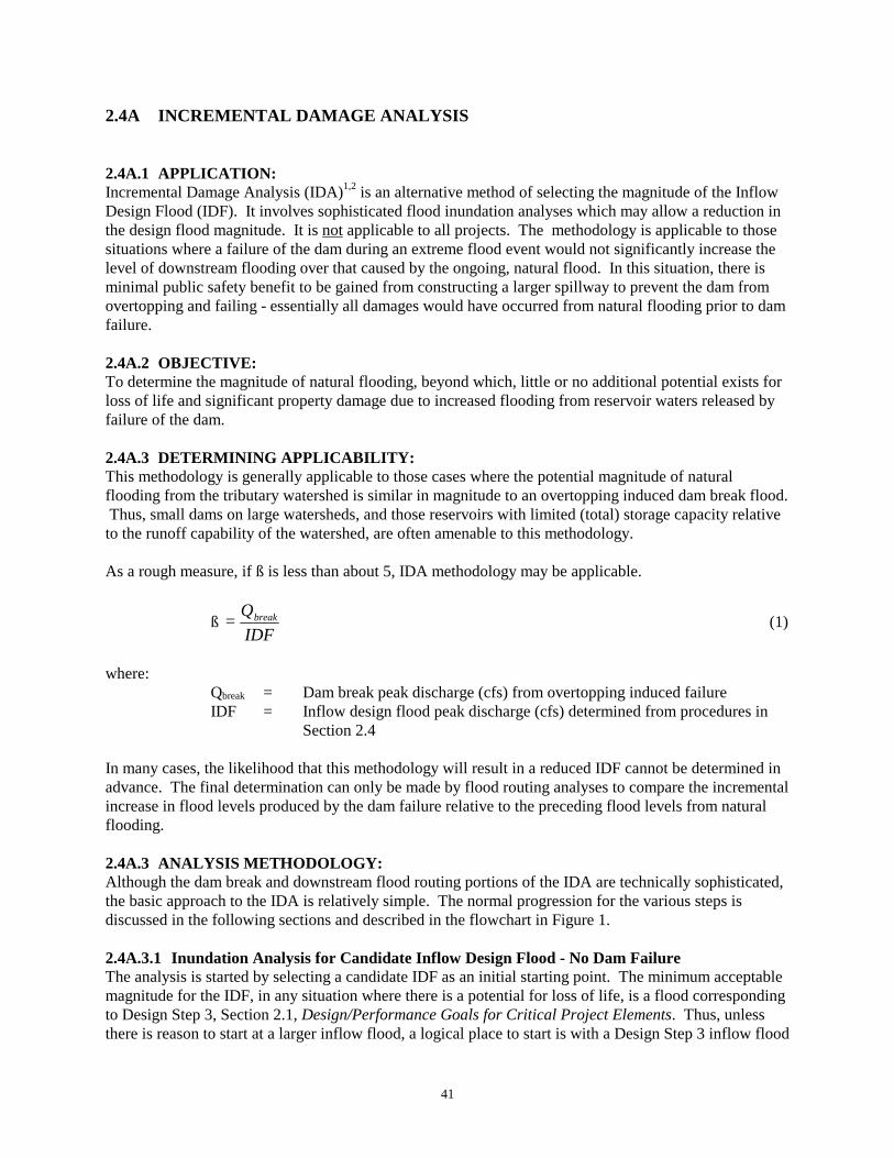
41
2.4A INCREMENTAL DAMAGE ANALYSIS
2.4A.1 APPLICATION:Incremental Damage Analysis (IDA)1,2 is an alternative method of selecting the magnitude of the InflowDesign Flood (IDF). It involves sophisticated flood inundation analyses which may allow a reduction inthe design flood magnitude. It is not applicable to all projects. The methodology is applicable to thosesituations where a failure of the dam during an extreme flood event would not significantly increase thelevel of downstream flooding over that caused by the ongoing, natural flood. In this situation, there isminimal public safety benefit to be gained from constructing a larger spillway to prevent the dam fromovertopping and failing - essentially all damages would have occurred from natural flooding prior to damfailure.
2.4A.2 OBJECTIVE:To determine the magnitude of natural flooding, beyond which, little or no additional potential exists forloss of life and significant property damage due to increased flooding from reservoir waters released byfailure of the dam. 2.4A.3 DETERMINING APPLICABILITY:This methodology is generally applicable to those cases where the potential magnitude of naturalflooding from the tributary watershed is similar in magnitude to an overtopping induced dam break flood. Thus, small dams on large watersheds, and those reservoirs with limited (total) storage capacity relativeto the runoff capability of the watershed, are often amenable to this methodology.
As a rough measure, if ß is less than about 5, IDA methodology may be applicable.
ßIDFQ= break (1)
where:Qbreak = Dam break peak discharge (cfs) from overtopping induced failureIDF = Inflow design flood peak discharge (cfs) determined from procedures in
Section 2.4
In many cases, the likelihood that this methodology will result in a reduced IDF cannot be determined inadvance. The final determination can only be made by flood routing analyses to compare the incrementalincrease in flood levels produced by the dam failure relative to the preceding flood levels from naturalflooding.
2.4A.3 ANALYSIS METHODOLOGY:Although the dam break and downstream flood routing portions of the IDA are technically sophisticated,the basic approach to the IDA is relatively simple. The normal progression for the various steps isdiscussed in the following sections and described in the flowchart in Figure 1.
2.4A.3.1 Inundation Analysis for Candidate Inflow Design Flood - No Dam FailureThe analysis is started by selecting a candidate IDF as an initial starting point. The minimum acceptablemagnitude for the IDF, in any situation where there is a potential for loss of life, is a flood correspondingto Design Step 3, Section 2.1, Design/Performance Goals for Critical Project Elements. Thus, unlessthere is reason to start at a larger inflow flood, a logical place to start is with a Design Step 3 inflow flood

42
hydrograph developed in accordance with procedures described in Section 2.4, Inflow Design Flood.
Reservoir routing procedures, such as used in computer models HEC-13 and DAMBRK4, are normallyused to determine the flood hydrograph released through the spillway(s) at the dam. Hydraulic routingprocedures are usually used to route the flood through the downstream valley and determine the floodlevels and areal extent of inundation. This sets the base level, against which the incremental increase inflood levels caused by a dam failure are to be measured.
2.4A.3.2 Dam Break Inundation AnalysisThe second step in the analysis is to determine the flood levels and areal extent of inundation producedby a failure of the dam as a result of overtopping by floodwaters. The magnitude of the inflow floodused to initiate failure of the dam should be selected sufficiently large as to produce a depth ofovertopping which would likely cause failure of the dam. This often corresponds to an inflow flood inthe range of 110% to 135% of the candidate IDF. Regardless of the magnitude of the inflow flood usedto initiate failure, the dam should not be assumed to fail until the reservoir level is at or near its maximumlevel in response to the peak discharge of the inflow flood.
Sophistication of Analyses Required - Detailed inundation information is needed to properly assess theincremental damages. This usually requires that sophisticated flood routing procedures be employed inthe inundation analyses. Recommended procedures for conducting dam break analyses are described inthe Dam Safety Guidelines Technical Note 1, Dam Break Inundation Analysis and Downstream HazardClassification7.
Requirements/Minimums - There are two general cases to be considered in selecting an appropriatecomputer flood routing model. The first case is where an accurate analyses of the attenuation of the dambreak flood is not needed and a conservative solution (no or minimal attenuation) is adequate. In thissituation, a computer model such as HEC-13, employing a hydrologic routing procedure withoutattenuation would be acceptable.
Conversely, when the attenuation of the dam break flood hydrograph is an important consideration,sophisticated hydraulic routing computation procedures, such as employed in DAMBRK4 are necessary. In either case, flood routing must be continued to a point sufficiently far downstream that no significantthreat remains to life or property from the dam failure.
2.4A.3.3 Assess the Incremental Increase in Damages and HazardsThe third step is to assess the incremental increase in damages and hazards posed by the dam break flood. Both the Federal Energy Regulatory Commission (FERC)1 and the State of Colorado2 have criteriawhere an incremental increase in flood level of 2 feet or less is not judged to pose a significant increasein hazard. In addition, the U.S. Bureau of Reclamation (USBR) have developed extensive guidelines6 toassist in assessing the hazards posed by floodwaters. Figure 2 contains one such guideline - a hazardassessment curve for the hazard posed by various combinations of floodwater velocity and depth. TheUSBR has also developed hazard assessment curves for flood hazards at mobile homes and to passengerautomobiles.

43
DETERMINE DOWNSTREAM INUNDATIONFROM CANDIDATE IDF
FOR THE CASE OF NO DAM FAILURE1
CONDUCT DAM BREAK INUNDATIONANALYSIS
FORDAM FAILURE CAUSED BY OVERTOPPING
SELECT A LARGER CANDIDATE IDFAND
CONTINUE THE ANALYSES
2 4
ASSESS THE POTENTIAL HAZARDSPOSED BY THE INCREMENTAL INCREASEIN FLOODING FROM THE DAM FAILURE
Significant Increase in Hazard
3
Minimal Increasein Hazard
CONFIRM ACCEPTABILITY OFCANDIDATE IDF 5
FIGURE 1 - FLOWCHART FOR CONDUCTING INCREMENTAL DAMAGE ANALYSES
Recommendations/Minimums - The general criteria for an incremental flood level increase of 2 feet orless1,2 and the hazard assessment curves and guidelines developed by the USBR6 represent the bestinformation currently available. These are considered acceptable criteria for assessing the hazards fromincremental increases in flooding.
If the incremental increases in flood levels along the affected reaches of the watercourse are judged topose a significant risk to life, then a larger candidate IDF is selected and the IDA process described in theflowchart in Figure 1 is started over.
2.4A.3.4 Confirm the Validity of the Solution - Sensitivity AnalysesIf the incremental increases in flooding are deemed not to be significant, the final step in the analysis isto confirm the validity of the solution. This is accomplished by conducting sensitivity analyses on thoseparameters which have the greatest influence on the resultant flood levels along the downstreamwatercourse. In many applications, the assumed breach characteristics, such as breach dimensions andelapsed time for breach development are parameters that have a significant affect. Use of computerprogram BREACH8 can be used to estimate the breach characteristics and may help reduce the range ofbreach parameters to be evaluated in the sensitivity analyses.
The channel and overbank roughness coefficients can also have a significant influence on the incrementalincreases in flooding and are often included as elements of a sensitivity analyses. Additional informationon sensitivity analyses are contained in Technical Note 17.

44
0
1
2
3
4
5
0 1 2 3 4 5 6 7 8 9 10
FLOODWATER VELOCITY (Feet/Sec)
FLO
OD
WAT
ER D
EPTH
(Fe
et)
High Danger Zone
Judgement Zone
Low Danger Zone
FIGURE 2 - HAZARD ASSESSMENT CURVE FOR FLOOD DANGER TO ADULTSFROM FLOOD VELOCITY AND FLOOD DEPTH
Selection of the Inflow Design Flood (IDF) - If the sensitivity analyses indicate that changes in themagnitude of assumed parameters within the range of reasonably expected values does not alter theconclusion of no significant increase in hazard, then the IDA is concluded. The IDF is selected as thecandidate IDF that was used to establish the base level of flooding for the current stage of analyses.
Alternatively, if the sensitivity analyses indicate that the downstream flood levels are significantlyaffected by reasonable changes in breach characteristics or routing parameters, then a larger candidateIDF is selected and the analyses is restarted using more conservative breach characteristics and/or routingparameters.
Requirements/Minimums - As discussed previously, the minimum inflow design flood acceptable foruse in Incremental Damage Analyses is the flood corresponding to Design Step 3, Section 2.1Design/Performance Goals for Critical Project Elements. This is consistent with design applications forany situation where there is the potential for loss of life in the event of a dam failure.

45
2.4A.5 REFERENCES
1. Federal Energy Regulatory Commission, Engineering Guidelines for Evaluation of HydropowerProjects, Office of Hydropower Licensing, FERC 0119-2, Chapter II and Appendix IIC, April, 1991.
2. State of Colorado, Rules and Regulations for Dam Safety and Dam Construction, Rule 5.A.(5)(c),September 30, 1988.
3. US Army Corps of Engineers, HEC-1, Flood Hydrograph Package, USER's Manual, HydrologicEngineering Center, U.S. Army Corps of Engineers, Davis, CA, September, 1981.
4. Fread, D.L., DAMBRK: The NWS-Dam Break Flood Forecasting Model, Office of Hydrology,National Weather Service, Silver Spring, MD, June 20, 1988.
5. USBR, Guidelines for Defining Inundated Areas Downstream from Bureau of Reclamation Dams,Bureau of Reclamation, Denver, CO, June, 1982.
6. USBR, Downstream Hazard Classification Guidelines, ACER Technical Memorandum No. 11,Bureau of Reclamation, Denver, CO, December, 1988.
7. Schaefer, M.G., Technical Note 1, Dam Break Inundation Analysis and Downstream HazardClassification, Dam Safety Guidelines, Washington State Department of Ecology, Olympia, WA.,July, 1992.
8. Fread, D.L., BREACH: An Erosion Model for Earthen Dam Failures, Hydrologic ResearchLaboratory, NOAA, NWS, June, 1987.
9. Pansic, N. and Borg, J.E., Determining Inflow Design Floods for a System Of Dams, Hydro Review,pp 60-67, September, 1992.

46

47
CHAPTER 3 - GEOTECHNICAL ISSUES
3.1 EXPLORATIONS
3.1.1 APPLICABILITY:The focus of this document is earthen embankments. Concrete structures generally require specializedinvestigations that should only be done by those experienced in this particular area.
3.1.2 EXPLORATION PROGRAM OBJECTIVES:Engineering Geology Investigation - Assess geologic hazards potentially affecting the siteincluding: the seismic setting, reservoir rim stability, potential adverse behavior of thefoundation and abutments. Provide guidance in refining the scope of the subsurface explorationprogram.
Subsurface Explorations - Characterized the subsurface conditions in the foundation andabutments and identify suitable sources of construction material.
3.1.3 DAM SAFETY OFFICE OBJECTIVES:To provide guidance on the minimum level of explorations necessary to develop and support thedesign of an impoundment for an "average case". An "average case" would be a project site thatpresents no significant foundation problems. The exploration program serves primarily toidentify the depth to a suitable foundation stratum and confirm that adequate quantities ofacceptable borrow materials are available.
To identify public domain information sources that may be of assistance to the project proponentand their engineer. The intent is not to supplant the services of an engineering geologist orgeotechnical engineer, but rather to help the project proponent recognize early on the scope offoundation issues that will likely have to be addressed. Ideally, they will then seek the servicesof such firms.
To identify some of the common difficult foundation conditions with which the designer mustcontend.
Ideally, all projects would employ the services of a geotechnical engineering firm. However, this is notthe case for many low and medium sized projects. Instead, the general civil engineering firm of recordoften elects to perform these tasks itself. To encourage owners to acquire the services of geotechnicalengineers, the DSO seeks to illustrate to project proponents the valuable service they provide. Ultimately, where difficult or unusual foundation problems are encountered, the DSO will require thatgeotechnical expertise be sought to resolve the concern.
3.1.4 MINIMUM EXPLORATION PROGRAM:Table 1 presents a summary of the minimum elements of an exploration program that must be undertakento support a project design submittal. This minimum level is considered appropriate for those projectsites that do not present significant foundation problems.

48
TABLE 1 - MINIMUM REQUIRED EXPLORATION PROGRAM
EXPLORATION METHODS EARTHENEMBANKMENTS
LOW MEDIUM HIGHBORROW
SITESBackhoe Test Pits ✓ ✓ ✓ ✓ 2
Borings ✓ 1 ✓ ¹ ✓ ✓ 1,2
Geophysical Explorations ✓ ² ✓ 2
Permeability Tests ✓ ² ✓
NOTES:¹ Borings appropriate where overburden has appreciable thickness² Desirable on a case by case basis
3.1.5 ENGINEERING DESIGN CONSIDERATIONS:Earthen embankments are frequently founded in part or wholly in the natural overburden. Thus, thebehavior of the overburden column must be investigated to confirm that it will perform satisfactorilyunder the changes in stress and pore water conditions imposed by constructing the dam. A number ofexcellent publications covering the exploration phase of a project have been developed by the Corps1 andBureau2, among others. In addition, it is important that one reviews case histories of past failures tobetter understand how significant geologic features were either missed, misunderstood or misjudged intheir response. The 1929 work by Terzaghi3 is a classic study in this area, among others4,5.
Numerous excellent summaries of the geology in Washington are available. Of particular note in thisarea is the 1989 compendium of articles in Bulletin 786 published by the Department of NaturalResources in association with the state section of the Association of Engineering Geologists.
The principal problems posed by soils in Washington are as follows:
Borrow site soils are often difficult to compact because their moisture contents are excessivelywet or dry of optimum moisture content. Generally, soils in eastern Washington are on the dryside while those in western Washington are on the wet side.
Glacially deposited, gap graded soils are present that are susceptible to the piping of the finer soilfraction from themselves and/or adjacent zones7.
In the western foothills of the Cascades the till ridges contain isolated, embedded, openworkgravel seams. These features pose seepage concerns and on occasion have resulted in pipingfailures8.
In much of southeast and south central Washington loess is present9,10. Loess is a weaklycemented, low density, fine grained soil deposit that potentially will collapse upon saturation.
Alluvial valleys have heterogeneous foundation conditions that include buried pervious channels(stream meanders) and loose, saturated soils that are susceptible to strength loss upon earthquakeshaking.
Rock foundations frequently are encountered at foundation level or at such shallow depths that the

49
performance of the rock must be considered in the design. The following section discusses the principalrock conditions that have significant potential impacts on the structural integrity and performance of theimpounding facility. These items are:
Conglomerate and mudstone/siltstone rock foundations. These materials are highly competent inan undisturbed state but are susceptible to rapid deterioration under the combined influences ofexposure to air, relieve of overburden pressure, standing water at the surface and overworking bythe passage of construction traffic. On the abutments these weak rock materials are susceptibleto extensive cracking as the surface is stripped of the overburden and allowed to dry. Considerable care is required to protect the material from deterioration. Typical measures toprotect the formation are described in Chapter 7, Specifications.
Sandstone Formations. These materials exhibit a number of problems. Typical of most rocks,the joints can pass large volumes of seepage. However, sandstones that are relatively clean anduniformly graded, medium to coarse can have significant primary permeabilities. Also, likemudstone formations, sandstone can be susceptible to rapid deterioration of the surface uponexposure to the elements. Again measures are often necessary to minimize the progressivedegradation of the rock surface, such as capping the surface with gunite.
Highly jointed basalt cap rock that is directly overlain by a thin veneer of fine grained plasticsoils. The fine soil layer is susceptible to "blowing out" through the rock fractures under theaction of seepage.
Horizontally layered, Columbia River Basalt in Central and Southeast Washington. Basalt istypically encountered at or very near the ground surface in this region. The basalt was buildup ina series of flows with extended periods of time elapsing between flows. A vegetative cover oftendeveloped between successive flows that introduced impurities into the top and base of eachflow. These impurities along with the extensive surface cracking arising from rapid cooling,produced a rock formation with high horizontal and vertical permeabilities along flow contactsand at shrinkage cracks, respectively. In addition, due to the layered nature of the rockformation, valley sidewalls have abrupt steps in the rock surface rather than a uniform grade. The stepped rock sidewalls pose significant rock surface preparation and sealing problems.
Explorations should not be considered as completed with the submission of the engineering reports. It iscrucial that the individuals performing the initial site investigations continue to examine field conditionsexposed during the course of construction. This provides an opportunity to confirm that field conditionsare consistent with the understanding developed from the analysis of the boring program and that formedthe basis of the design.
3.1.6 REFERENCE MATERIALS:Table 2 summarizes the principal repositories for geologic and foundation studies covering WashingtonState.

50
TABLE 2 - GEOLOGIC INFORMATION REPOSITORIES
ITEM SOURCEAerial Photographs Department of Natural Resources (DNR)
Photos and Map Sales(360) 902-1234
County Soil Surveys Department of AgricultureSoil Conservation Service FieldOffice for the Appropriate County
Black and White Copies of the Soil Overlay Maps DNRPhoto and Map Sales(360) 902-1234
Text of Soil Survey DNR Library(360) 902-1450
Geologic Maps DNR LibraryGeologic Reports General Publication Listings Statewide
Publications of the Washington Division of Geology and Earth Resources, Washington Division of Geology and Earth Resources, December 1991
DNR Library(360) 902-1450
By Individual County(Summaries for 26 of 39 counties are available);e.g., Bibliography of the Geology and Mineral
Resources of Jefferson County, Washington, Compiled by Manson, Connie J., Department of Natural Resources, December 1990.
DNR Library
Survey DocumentEngineering Geology in Washington, Galster,
Richard (ed.), Washington Division of Geology and Earth Resources, Bulletin 78, 2 Volumes.
DNR Library
Well Logs Regional Offices of the Department of Ecology

51
3.1.7 REFERENCES
1. US Army Corps of Engineers, Engineering and Design Manual - Geological Investigations, EM1110-1-1801, Change 2, April 1978.
2. Design Standards No. 13 - Embankment Dams, Chapter 12 - Foundation and Earth MaterialsInvestigation, U.S. Department of the Interior, Bureau of Reclamation, Denver, Colorado, October1989.
3. Terzaghi, K., "Effect of Minor Geologic Details on the Safety of Dams", Geology and Engineeringfor Dams and Reservoirs, American Institute of Mining And Metallurgical Technical Publication215, 1929, pp. 31-46.
4. Osterberg, J.O., "Failures in Exploration Programs", Dowding, C.H., ed., Site Characterization andExploration, Proceedings - Specialty Workshop, Northwestern University, June 12-14, 1978, pp. 3-9.
5. Kiersch, G. and James, L.B., "Errors of Geologic Judgment and the Impact on Engineering Work",The Heritage of Engineering Geology: The First 100 Years, G. Kiersch, ed., Vol. 3, GeologicalSociety of America, Boulder, Colorado, 1991, pp. 517-557.
6. Galster, Richard W. (Chairman), Engineering Geology in Washington, Washington Division ofGeology and Earth Resources, Bulletin 78, Washington State Department of Natural Resources, 2Volumes, 1989.
7. Sherard, J.L., "Sinkholes in Dams of Coarse Broadly Graded Soils", 13th ICOLD Congress, India,Vol. II, 1979, pp. 25-35.
8. Kiersch, G. and James, L.B., op. cit., p. 526.
9. Lobdell, G.T., "Hydroconsolidation Potential of Palouse Loess", ASCE Journal of the GeotechnicalEngineering Division, (1981), Vol. 107, No. GT6, pp. 733-742.
10. Olson, B.O., "Loess Soils in Southeastern Washington", ASCE Journal of the GeotechnicalEngineering Division, (1979), Vol. 105, No. GT6, pp. 786-791.

52

53
3.2 EMBANKMENT GEOMETRY AND ZONING
3.2.1 OBJECTIVE:Provide an overview of the elements required for a typical earthen embankment cross-section.
3.2.2 REQUIREMENTS\MINIMUMS FOR THE EMBANKMENT CROSS-SECTION:Table 1 presents a summary of the principal design elements of an embankment cross-section. The Tablecities whether a particular element is recommended or required and identifies the appropriate section ofthe Guidelines where further details are provided. However, a number of embankment cross-sectionfeatures are not discussed elsewhere in these guidelines. For such items, further clarification follows.
Abutment-Foundation Preparation - To minimize the potential for cracking where there are abruptchanges in slope geometry, the slopes should be laid back to a maximum slope of ¼H on 1V. Overhangsare normally removed or infilled with concrete to achieve the overall desired maximum slope. The needto regrade slopes is greatly diminished by the use of properly graded filters and drains. In the light ofthis, where regrading of the slope poses a particular hardship, an enlarged filter-drainage feature will beconsidered as an acceptable alternate to slope regrading. The designer is not required to regrade theabutment, downstream of the chimney drain that protects the core.
Where rock is exposed at the abutment and foundation, the surface should be scaled of any loose rock. Joints should be cleaned and filled with a plastic grout. Where the surface is highly jointed,consideration should be given to following the joint treatment by pouring a cover slab of concrete. TheCorps1 and Swiger2 present excellent summaries of foundation preparation details.
A foundation grouting program is outside the scope of this discussion.
Cutoff Trench - Cutoffs should extend down to a suitable rock or low permeability soil layer. It isessential that the cutoff extend fully through any pervious overburden zones. Cedergren3 demonstratedthat partial cutoffs do not fully address exit gradient concerns. Where it is impractical to excavate in thedry to a suitable low permeability zone, soil-bentonite or cement-bentonite trenches have beensuccessfully employed. The discussions regarding the use of cutoffs in alluvium would apply to only asmall number of projects. Generally, it will be necessary to remove pervious alluvium from within thedam footprint due to seismic stability concerns. The few exceptions to removal would likely involvestormwater detention facilities where the likelihood of a liquefaction failure of the alluvium foundation atthe same time the facility is impounding water would be extremely remote.
The minimum base width of cutoff trenches should be sized to allow the operation of self-propelled,heavy duty compactors. In most instances this will necessitate a minimum base width of 8 ft. Thedownstream side of the cutoff should be provided with a filter zone that is hydraulically connected to thedrainage system. To minimize the potential for arching of the overlying embankment fill and to facilitateplacement of the downstream filter, the cutoff sideslopes should be laid back on a maximum inclinationof 1H on 1V.
Core Section - The DSO will accept a properly filtered core that is on the order of 25% of the head atany given elevation. This position is based on the satisfactory performance of thin core structuresdescribed by Sherard and Dunnigan4. Thinner cores will be considered if:
A core soil is available that can be appropriately compacted,

54
TABLE 1 - EMBANKMENT SECTION DESIGN ELEMENTS
ELEMENT EARTHEN EMBANKMENTSSmall Medium Large
GUIDELINEREFERENCE
FOUNDATION CUTOFF Cutoff Trench Rock Contact Sealing
Req'dA
Req'dBReq'dA
Req'dBReq'dA
Req'dB3.23.2
LOW LEVEL OUTLET PIPE Req'dC Req'd Req'd 4.1
DRAINS ChimneyBlanketToe Drains
RecomD
RecomRecom
Req'dReq'dE,F
_____G
Req'dReq'dE,F
_____G
3.33.3
FILTERS Filter Criteria met EverywhereH
Pipes - Filter/Drain DiaphragmIReq'dReq'd
Req'dReq'd
Req'dReq'd
3.3.A3.3.B
SIDESLOPES To be determined by engineering analysisJ 2.2
FREEBOARD To be determined by engineering analysis 4.6CREST Width
CamberL____K
To be determined by engineering analysisEROSION PROTECTION Upstream Face
Downstream Face Crest Downstream Groins
RecomRecomM
Req'dRecomN
Req'dReq'dReq'd
Recom
Req'dReq'dReq'dReq'd
3.53.5
INSTRUMENTATION Reservoir Staff Gauge Settlement Monuments Piezometers Weirs/Pipe to Measure Seepage
Req'dRecomO
RecomRecom
Req'dReq'd
RecomReq'd
Req'dReq'd
RecomReq'd
8888
A The subgrade should be stripped of any pervious surficial zone to found the cutoff on a suitable, low permeability zone.B Any rock exposures should be sealed within the limits of the cutoff trench to prevent the loss of embankment materials into
the foundations. Ideally, rock exposures upstream and downstream of the cutoff should be sealed and drained, respectively.C For diked impoundments <10 feet high, the outlet may be omitted if it is practicable to lower the pool by syphoning.D For small stormwater detention facilities, the DSO will consider eliminating the chimney drain where it can be demonstrated
that neither excessive seepage is likely to develop in the abutments nor that the phreatic surface will penetrate a significantdepth into the upstream surface.
E Where the foundations are relatively pervious, finger drains would provide an acceptable alternative to a blanket drain.F The blanket drain should extend up the abutment. The extent of the abutment coverage should be a function of the
magnitude and the nature of the seepage anticipated to emerge from the contact. Where isolated pervious features areindicated, separate finger drains should be considered within the blanket to safely carry off the concentrated flow andfacilitate monitoring flow character.
G This would normally be a subelement of the blanket drain. Where the blanket drain has a large hydraulic capacity relative tothe anticipated seepage flow and it is configured to efficiently shunt flow to one or a few points, a toe drain is not required.
H The zones should be internally stable in that they satisfy filter criteria for themselves. Plus, filter criteria must be satisfied atall zone contacts including the embankment interface with the foundation and abutments.
I Applicable to all conduits extending through or underlying the embankment cross section.J For small dams, bearing on a competent foundation, constructed of a well compacted clay, the DSO will accept a design
with 3H on 1V upstream and 2H on 1V downstream slopes without a supporting engineering analysis.K The larger of 8 feet or the quantity 2(H)½ + 3.L Based on anticipated magnitude of crest settlement and conservatism in the level of freeboard provided.M Determination based on ability to maintain a thick vegetative cover or erosion resistance of exposed soil.N The need for erosion protection should be based on the volume of runoff and the erosion resistance of the groin area soils.O Monuments should be provided where freeboard is a minimum and significant settlements are anticipated.

55
The core is suitably inclined to minimize the potential for hanging up on the shells, and
The minimum section will allow the operation of suitable heavy compaction equipment.
Where there is a concern of excessive seepage through the abutments and/or foundations and a thin coresection is desired, the DSO will consider a design where the core section is flared at the base andabutment contact.
Details on the compaction of the core are presented in the specifications section of the Guidelines,Chapter 7.
Sherard and Dunnigan4 present an excellent summary of good construction practice for zoned, earthenembankments. Their principal points are as follows: (Comments of the DSO are shown in italics.)
Cracking problems with the core are best addressed through the use of downstream filters.
Downstream filters satisfactorily address the consequences of core cracking that prompted theuse of upstream sand layers as crack fillers. Consequently, the upstream sand filter may beomitted.
Clay cores have been provided with a series of progressively coarser zones (moving upstream) toprevent the migration of fines under a rapid drawdown of the pool. The low hydraulic gradientstending to erode the core into the upstream shell under such conditions are judged inadequate tocause significant migration of fines. Accordingly, it is recommended that a 6 inch minusquarried rock will serve as an adequate barrier to significant upstream loss of a clay core.
It is the authors' opinion that the central core cross-section is equally acceptable to an upstreaminclined core section. While this conclusion holds concerning cracking, the upstream, inclinedcore design offers significant benefits in areas of high seismicity such as in western and portionsof central Washington. Here it is desirable to maintain as much of the dam section aspracticable unsaturated to minimize strength loss upon cyclic loading. The excellentperformance of concrete faced rockfill dams during earthquakes is a testament to theeffectiveness of minimizing the saturated portion of the fill.
Shells - The use of zoned embankments provides a practical means of making the best use of readilyavailable materials. Typically it involves the incorporation of coarse rock fill into the embankmentsection that is derived from the spillway excavation. The broad range of particle sizes generally makesconventional density testing impractical. A procedural method of compaction is typically required forconstruction of these zones of the embankment. To determine an appropriate procedure, a test fill shouldbe constructed to determine the appropriate number of coverages of a heavy duty, dynamic compactor fora typical lift thickness. Bertram5 discusses the employment of a test fill for controlling the placement ofcoarse, broadly graded rock fill.
The shells generally contain an appreciable fraction of coarse rock. Provisions are typically made to rakeout the largest rock fragments to the exterior face. This zone generally serves as a suitable erosionresistant, downstream facing.

56
3.2.3 REFERENCES:
1. Department of the Army, Corps of Engineers, Foundation Preparation, CW 02219, March 1981.
2. Swiger, W.F., "Preparation of Rock Foundations for Embankment Dams", in Hirschfeld, R.C., andPoulos, S.J., eds., Embankment Dam Engineering Casagrande Volume, 1973, pp. 355-364.
3. Ibid., Cedergren, H.R., "Seepage Control in Earth Dams", pp. 30-32.
4. Sherard, J.L. and Dunnigan, L.P., 1985, Filters and Leakage Control in Embankment Dams. In R.L.Volpe and W.E. Kelly (ed.), Seepage and Leakage from Dams and Impoundments. Proceeding of aGeotechnical Engineering Division symposium in Denver, Colorado, May 5, 1985. AmericanSociety of Civil Engineers. New York, N.Y., pp. 1-30.
5. Op. Cit., Hirschfeld, R.C., and Poulos, S.J., eds., Bertram, G.E., "Field Tests for CompactedRockfill", pp. 1-20.

57
3.3 SEEPAGE CONTROL
3.3.1 INTRODUCTION:Thirty-eight percent of dam failures over the period 1900 to 1975 have been attributed to piping andseepage1. From a balanced risk point of view, this aspect of design should be receiving the same level ofscrutiny as the design flood and that of static and seismic slope stability. However, our experience inreviewing designs too often has been that embankment designs have ignored the seepage issue or haveutilized unrealistic assumptions as to the magnitude of the problem and the efficiency of design features.In particular, filter criteria are routinely overlooked. Seepage volumes and phreatic surfaces areestimated from idealized homogeneous embankment sections that do not reasonably account for actualfield conditions. Drain capacities are optimistically estimated without due attention paid to limiting thecontent and the plasticity of the minus No. 200 sieve fraction. The potential for concentrated seepagedeveloping is not yet widely appreciated. The potential for cracks to develop in relatively imperviousembankment zones, the foundation and abutments is not routinely recognized. Likewise, the use of filter-drainage diaphragms for controlling seepage along the perimeter of structures passing throughembankments remains the exception, not the rule.
Satisfactorily addressing seepage concerns is not simply a matter of constructing a suitable imperviouszone along with adequate drainage features. One must address filter issues, embankment zoning,foundation geometry among other factors. The generalized concerns associated with seepage areconsidered in this section. The Filter section deals with preventing of piping of fines from individualzones under the action of seepage. Finally, the Filter/Drain Diaphragm and Underdrains sections discussthe treatment of both concentrated and diffuse seepage.
Requirements for the inclusion of specific embankment features to address seepage concerns arepresented in Sections 3.2 and 3.3A, B, and C.
3.3.2 OBJECTIVES:Control the portion of the embankment and abutment that will become saturated.
Force significant changes in hydraulic gradient; i.e., maximum rate of head loss and/or flowdirection to occur where it is most desirable.
Limit seepage volumes.
3.3.3 OPTIMIZING DESIGN:To the extent practicable, position drains to maximize the effective stresses in the embankmentand foundation.
Configure seepage outlets to facilitate measuring flow volumes and character.
3.3.4 DESIGN PHILOSOPHY:We espouse the position taken by Dr. DeMello in his 17th Rankine lecture2. Dr. DeMello argued that thedesigner should take steps to "transform" problems from one of dealing with extremes to one of dealingwith averages. This typically involves incorporating some design feature that intercepts and blunts orsmoothes out the effects of extreme loadings. In effect, the designer is bringing the actual dam closer tothe idealized, simplified structure he modelled.
58
3.3.5 DESIGN CONSIDERATIONS:The goal of seepage control is to prevent the development or mitigate the impact of the following:
Cracks in the low permeability section of the embankment,
Cracks at the embankment contact with appurtenance works, the abutments and the foundation,and
Excessive seepage beneath or around the dam through the abutments or the foundation. (Excessive seepage here is considered that rate which leads to instability of the zone; i.e., piping,slides or boiling.)
The principal problems that arise from a failure to satisfactorily address these issues are:
Cracks potentially can expand through the erosion of their sidewalls. In extreme cases, thecracks can develop into a "pipe". If the pipe only extends partially through the embankment, itmay introduce a volume of seepage into the downstream zone that induces a slide. If the pipeextends through the majority of the embankment, it may eventually "blow out" the upstream"plug" of the pipe, forming a continuous channel through the dam. The concentrated flowthrough the channel can then rapidly enlarge the channel and fail the dam.
Relatively stable cracks may develop that are resistant to rapid erosion of their sidewalls. Thesefeatures can introduce near full reservoir pressure heads along seams which are hydraulicallyconnected to the crack. This has prompted concern as to the overall stability of the downstreamportion of the embankment.
Highly pervious zones, particularly "open work" clean gravelly seams undetected in theabutments and foundations, can pass large volumes of seepage for considerable distances withlittle head loss. The discharge area for these zones on the abutment typically experience shallowslides. On rare occasions, the flow is large enough to "blow out" the hillside or cause "boiling"of foundation soils.
3.3.6 ENGINEERING PRACTICEConsideration of seepage control should be factored into all aspects of the project's investigation, design,construction and monitoring!
Exploration Phase - In this stage of the project, the goal is to identify potential "problems" the designmust address. The explorations of near surface conditions should include a series of test pits. The pitsidewalls afford probably the best opportunity to view subsurface conditions prior to opening up the areaduring construction.
The field investigator should be alert to conditions that pose seepage and/or embankment crackingconcerns. Features that potentially have a significant impact on these problems are as follows:
Seepage
"Channels" or seams of clean, uniformly graded, coarse sands to "open work" gravels.
Open jointed rock or pervious joints between rock flows, such as are typically found in the
59
Columbia River Basalt flows of eastern Washington.
Buried stream meanders that can pass large seepage volumes and potentially pose pipingconcerns. They are generally not encountered in the explorations but it is prudent to assume thatbroad, relatively flat valley bottoms probably contain such features.
Cracking
Steep and/or abruptly stepped rock surfaces in the abutment or foundation.
Highly compressible soil strata in the foundations.
Stress relief cracking deeper in the abutments. This is of particular concern where the abutmentis a narrow, steeply sided ridge or the abutment contains a deep ravine proximate to the dam.
In most cases, it is prudent to remain skeptical that all the significant seepage problems have beenrevealed by the exploration program.
Design Phase - Designers should always bear in mind two thoughts. First, they should look to activelyconstrain the seepage regime to some desired configuration. "Actively constrain" consists of providingmeasures that block or intercept seepage such as cutoff trenches and blanket and chimney drains. Thiscontrasts with the more passive approach where drainage features are provided with the expectation thatthey will "influence" seepage gradients at a distance. As an example of the "passive approach", a toe orhorizontal blanket drain is often provided with the expectation that it will act as a "sink", whose effectpropagates through the embankment pulling down the phreatic surface. This approach frequently is atodds with actual field behavior. Second, designers should bear in mind the limitations of the analysesthey are using. Stated conversely, they should clearly recognize that small singularities in fieldperformance not accounted for in the analysis may control the overall field response of the elementmodelled. For example, finite element seepage analyses are available that will reflect the impact ofcomplex zoning with differing horizontal and vertical permeabilities. But, these models have no practicalway of realistically predicting and accounting for the potential opening and widening of cracks. Thedesigner must recognize the need to address potential cracking problems based on case histories. Oncethe problem of cracking is appropriately treated, finite element seepage models provide a valuable tool inpredicting average pore pressures and seepage volumes associated with complex embankment zoning.
As previously noted, cracking and excessive seepage are the principal issues of concern. The designshould incorporate means of minimizing the likelihood of cracks occurring. This involves treating oravoiding conditions likely to produce cracking such as:
Appropriately shaping the embankment contact with the foundation and abutments to removeabrupt changes in grade.
Avoiding symmetrical, zoned embankment cross-sections. The relatively compressible core can"hang up" on the stiffer upstream and downstream shells. A significant fraction of theoverburden pressure in the core can be transferred through beam action to the stiffer shell zones. This reduces the confining stress at greater depths in the core. In extreme cases it can lead tohydraulic fracturing. It is preferable to incline the axis of the core zone.
Removing highly compressible zones from within the dam footprint. Constructing the

60
embankment over soft, compressible zones in the foundation or abutments increases the potentialfor large differential strains to develop proximate to the edge of soft zones or around abruptchanges in the thickness of such zones. These large strains are often associated with cracking.
Restricting the water content of the core materials during compaction to optimum or wet ofoptimum moisture content. Compaction on the dry side of optimum moisture produces a more"brittle" soil structure. This structure has an increased tendency to crack in undergoingsettlements and in changes in stress in service.
In addition, it should be recognized that even under the best of practice, cracks can still occur3. Thedesign needs to include measures to blunt the impact of potential cracks. This consist principally ofproviding chimney and blanket drains. The chimney drain is an inclined zone or zones of graded materialthat safely conducts the seepage emerging through the low permeability section of the embankmentthrough the dam. Where necessary, a filter zone is provided to satisfy filter criteria for the upstreamzone. The chimney drain functions in two ways to blunt the effect of cracks. First, the drain restricts theseepage volume through the crack to that of the upstream element of the chimney drain. Second, fineseroded from the crack sidewalls are carried to the contact between the low permeability section of theembankment and the chimney drain. These eroded fines in test simulations of the process, form a lowpermeability "cake" at the contact4. This dramatically reduces the flow rates and allows the crack sidewalls to swell and pinch off the crack. The chimney drain should extend down to the surface of afoundation layer that forms a practical low permeability cutoff to significant underseepage.
To the extent practicable, measures to minimize the volume of seepage through the foundation andabutments should be employed. This typically involves sealing rock exposures at the foundation andabutment contact and construction of a cutoff through any pervious soil strata of the foundation andabutments. Typical practice in sealing rock surfaces involves using compressed air equipment to blowoff any loose rock fragments and to clean out the upper portion of rock cracks. Some hand cleaning isinvariably necessary. Larger cracks are then filled, generally by hand packing them with a sand-cementmixture. This is followed by brooming a sand-cement mix over the rock surface to seal fine cracks. Thepurpose of the foundation treatment is to prevent the piping of the embankment soils into fractures in therock and to minimize the volume of seepage passing through cracks. Measures to reduce seepage withinthe foundations such as grouting are beyond the scope of these guidelines.
Major dams have been constructed where the dam is supported on relatively pervious foundations. Overthe life of many of these projects elaborate systems of relief wells, upstream blankets and diaphragmwalls have been added to address stability concerns. In recognition of the problems these dams haveexperienced, the DSO normally requires the construction of cutoffs for all dams bearing in perviousstrata. However, particularly in the abutments suitable low permeability zones may not be located withindistances that make it practical to establish a cutoff. Where this is the case the designer has two principaloptions. First, a conventional low permeability zone can be constructed back into the abutments to takeadvantage of the reduction in seepage forces due to the increased seepage path. Alternatively, a highlypervious zone can be constructed back into the abutments that is hydraulically connected to the internaldrainage system. This scheme relies on redirecting seepage in the abutments or foundation into theembankment drains. The redirection area is selected based on its ability to withstand the anticipatedseepage forces. The redirection area normally lies near the center of the embankment cross-sectionwhere the vertical and lateral confining stresses acting in the soils are greatest. This is preferable toallowing seepage under potentially relatively high exit gradients to emerge out of the abutment orfoundation near the downstream toe. Here, in extreme cases the seepage forces may exceed the effectivesoil stresses resisting movement. In such cases, a sidehill blow out or a boiling type condition maydevelop in the foundations.

61
Horizontal blanket drains or finger drains are routinely provided to augment the chimney drain incontrolling seepage. The two principal conditions warranting their use arise from the need to treatseepage emerging from the abutments or foundations. First, the chimney drain is not as effective atcontrolling seepage moving through the abutments as it is through the embankment cross-section. This isthe case often because seepage emerging from the abutments is only partly originating from the reservoir. A significant portion of the seepage within the downstream portion of the embankment may includegroundwater flow emerging from deep within the abutment. The chimney drain normally has onlyminimal impact on such seepage. Second, it is prudent to augment the chimney drain when thedownstream portion of the dam is founded on alluvium and there is potential for significant seepagepassing beneath the cutoff and feeding the alluvial foundation.
Dams frequently have lives approaching a hundred years. This lengthy service life poses long termdurability issues. Although recent advances in plastics technology have greatly improved theperformance of these materials, we strongly favor the use of granular materials over plastic or metalpipes as drains in the central portion of an embankment section. Ideally, metal and plastic pipesassociated with seepage control elements are used in applications where they can be readily replaced andtheir failure would not likely have a serious impact on the overall integrity of the impounding barrier.
Construction Specifications and Construction Control Program - As noted in the exploration section,the excavations for the dam footprint particularly for seepage control measures often provide the deepest,continuous exposures of foundation and abutment conditions. The designer should take advantage of thisopportunity to confirm the appropriateness of the design assumptions. To do so, in addition to describingthe work, the specifications should include a description of anticipated foundation and abutmentconditions. Ideally, the specifications should go on to define what constitutes unsuitable conditions. This helps field personnel recognize when unanticipated conditions are present, increases the likelihoodthat unsuitable materials will be removed and lessens the opportunities for the contractor to claimchanged conditions. This should be reinforced in the development of the construction control plan, seePart II of the guidelines.

62
3.3.7 REFERENCES:
1. Mantei, C. Leo, 1985, Seepage Control for Embankment Dams USBR Practice, In R.L. Volpe andW.E. Kelly (eds.), Seepage and Leakage from Dams and Impoundments. Proceedings of aGeotechnical Engineering Division symposium in Denver, Co., May 5, 1985, American Society ofEngineers, New York, N.Y., p. 229.
2. DeMello, V.F.B., "Reflections on Design Decisions of Practical Significance to Embankment Dams",Geotechnique, Vol. 27, No. 3, 1977, p. 293.
3. Kulwahy, F.H., and Gurtowski, T.M., "Load Transfer and Hydraulic Fracturing in Zoned Dams",Journal of the Geotechnical Engineering Division, ASCE, Vol. 102, GT9, Proc. Paper 12400, 1976,pp. 963-974.
4. Sherard, J.L., Dunnigan, L.P. and Talbot, J.R., 1984, Filters for Silts and Clays. American Society ofCivil Engineers. Journal of Geotechnical Engineering 110(6) June 1984, p. 707.

63
3.3.A FILTERS
3.3.A.1 OBJECTIVE:Minimize the loss of soil particles, particularly the "fine" soil fraction, from the embankment andfoundation.
3.3.A.2 DESIGN PHILOSOPHY:Filters are considered as "insurance" that the various design features of which they form a sub-element,will maintain their integrity and function as intended.
3.3.A.3 OPTIMIZING DESIGN:The filters gradation should be selected so as to provide the greatest hydraulic capacity practicable.
3.3.A.4 APPLICABILITY:The provisions of this section apply to those cases where the filters need only have a permeability equalto or marginally greater than the base soil. Essentially, it applies in those cases where the filter is notrequired to materially affect the average hydraulic gradient in the adjacent layers. For example, thesecriteria satisfactorily define a suitable upstream filter for a chimney drain. The highly pervious chimneydrain provides the necessary hydraulic capacity to discharge the volume of seepage. The filter servesonly to prevent the piping of fines and to cap off any concentrated leaks. The stability of the dam wouldnot be materially changed if the permeability of the filter match that of the adjacent upstream layer. Conversely, the following filter criteria may not be adequate for a drainage blanket that encapsulateshighly pervious finger drains beneath the downstream embankment section. Here it is important to havemuch higher permeabilities than the base soil. This is necessary to facilitate the movement of seepage tothe pervious finger drains. For broadly graded filters with a maximum allowable fines content of 5%, thefilter zone may severely restrict flow to the pervious finger drains. Thus, higher hydraulic gradients willpersist further downstream in the base soil and the efficiency of the finger drains is reduced.
Filter Criteria Background - The Soil Conservation Service (SCS) conducted extensive research intothe issue of filter criteria in the 1980's. The results of this work were first broadly disseminated throughthe Journal of Geotechnical Engineering in 19841,2. Additional refinements were made on the testprocedure and the current methodology was first presented in 19853. The work was subsequentlyorganized into a design note4 by the SCS. The Bureau of Reclamation essentially adopted the SCSapproach in their Design Standards5.
The Dam Safety Office uses the SCS approach in the evaluation of proposed filter designs. The SCSprocedure for selecting filter criteria follows. Occasional comments are inserted to address specializedissues that were not included in the SCS Note. These comments appear in italics to delineate them as ouropinion and not necessarily shared by the SCS.
SCS SOIL MECHANICS NOTE NO. 1, 210-VI, GUIDE FOR DETERMINING THEGRADATION OF SAND AND GRAVEL FILTERS, REVISED, JANUARY 1986.
I. Purpose
This note presents criteria for determining the grain-size distribution (gradation) of sand and gravel filtersneeded to prevent internal erosion or piping of soil in embankments or foundations of hydraulic
64
structures.
These criteria are results of an extensive laboratory filter study carried out by the soil conservationservice at the Soil Mechanics Laboratory in Lincoln, Nebraska, during the period 1980-1985. (1,2,3,6)
II. Definitions
Base Soil - Any soil through which water moves into a filter or drainage system.
d15, d85 and d100 sizes - Particle sizes (mm) corresponding respectively to 15, 85 and 100 percent finer bydry weight from the gradation curve of the base soil.
D5, D10, D15, D60, D85, and D100 sizes - Particle sizes (mm) corresponding to the 5, 10, 15, 60, 85, and 100percent finer by dry weight from the gradation curve of the filter.
Gradation curve (grain-size distribution) - Plot of the distribution of particle sizes in a base soil ormaterial used for filters or drains.
Drain - a designed pervious zone, layer, or other feature used to reduce seepage pressures and carrywater.
Filter - Sand or sand and gravel having a gradation designed to prevent movement of a base soil byflowing water. Fabrics or other filter materials are not included in this note.
Fines - That portion of a soil finer than a No. 200 (0.075 mm) U.S. Standard sieve.
Soil category - One of four types of base soil materials based on the percentage finer than the No. 200(0.075 mm) U.S. Standard sieve.
III. Basic Purpose of Filters and Drains
Filters are placed in embankment zones, foundations or other areas of hydraulic structures for twopurposes:
1. To intercept cracks or openings in a base soil to prevent the erosion of soil particles by water passingthrough the openings. The filter is graded so that soil particles cannot pass through the filter voids. They are caught at the filter face, preventing further erosion and concentrated flow through cracks oropenings.
2. To intercept seepage passing through the pores of the soil, thereby preventing the movement of soilparticles at the discharge point (piping). Piping occurs when seepage gradients or pressures are highenough to produce erosive discharge velocities in the base soil. The filter zone is usually placedupstream of the discharge point where sufficient confinement prevents uplift or blow-off of the filter.
Drains consist of sand, sand and gravel, or gravel mixtures placed in embankments, foundations, andbackfill of hydraulic structures, or in other locations to reduce seepage pressure. A drain's mostimportant design feature is its capacity to reduce seepage pressures and carry collected water to a safeoutlet. Drains are often used downstream of or in addition to a filter to provide outlet capacity.
65
IV. Permeability and Capacity
The laboratory filter study clearly demonstrated that a graded filter designed in accordance with thecriteria contained in this note will seal a crack. The sealing begins whenever water runs through a crackor opening and carries soil particles to the filter face or causes filling or closing of the crack. Anysubsequent flow is through the pores of the soil. Therefore, when filters are designed to intercept cracks,the permeability used to determine drain capacity is computed for saturated steady state flow through thepores of the base soil material.
Where it can be demonstrated that saturated steady state flow will not develop (i.e., dry dams having anormal drawdown within 10 days), capacity is not a necessary design requirement. Filters designed toprotect against leakage and erosion in cracks are to have a thickness that compensates for the negativeeffects of material segregation and contamination during construction and ensures continuity (will notsustain a crack) during differential movements.
A drain of coarser materials immediately downstream of the filter or a perforated pipe in the filter isneeded if seepage through the pores of the base soil material exceeds the capacity of the filter. Thecoarser materials must be properly graded using filter criteria in this note to prevent movement of thefilter. Perforated pipes may also be used in the coarser materials to increase the capacity of the drain.
V. Determining Filter Gradation Limits
Determine filter gradation limits using the following steps:
1. Determine the gradation curve (grain-size distribution) of the base soil material. Use enough samplesto define the range of grain-size for the base soil or soils and design the filter gradation based on thebase soil that requires the smallest D15 size.
2. Proceed to step 4 if the base soil contains no gravel (material larger than No.4 sieve).
3. Prepare adjusted gradation curves for soils with particles larger than the No. 4 (4.75 mm) sieve:
a. Obtain a correction factor by dividing 100 by the percent passing the No. 4 (4.75 mm) sieve size.
b. Multiply the percentage passing each sieve size of the base soil smaller than No. 4 (4.75 mm) bythe correction factor from step 3a.
c. Plot these adjusted percentages to obtain a new gradation curve.
d. Use the adjusted curve to determine the percent passing the No. 200 (0.075 mm) sieve in step 4.
4. Place the base soil in a category based on the percent passing the No. 200 (0.075 mm) sieve inaccordance with Table 1.
5. Determine the maximum D15 size for the filter in accordance with Table 2. Note that the maximumD15 is not required to be smaller than 0.20 mm.

66
TABLE 1 - CATEGORIES OF BASE SOIL MATERIALS
Category Percent finer than the No. 200(0.075 mm) sieve
1 > 852 40-853 15-394 < 15
TABLE 2 - CRITERIA FOR FILTERS
Base soilcategory
Base soil description, and percent finerthan No. 200 (0.075mm) sieve 1/
Filter criteria 2/
1 Fine silts and clays; more than 85%finer.
3/ D15 ≤ 9 x d85
2 Sands, silts, clays, and silty and clayeysands; 40 to 85% finer.
D15 ≤ 0.7 mm
3 Silty and clayey sands and gravels; 15to 39% finer.
4,5/ D15 ≤ 40 - A (4 x d85 - 0.7mm) + 0.7mm 40 - 15
4 Sands and gravels; less than 15% finer. 6/ D15 ≤ 4 x d85
1/ Category designation for soil containing particles larger then 4.75 mm is determined from a gradation curve of thebase soil which has been adjusted to 100% passing the No. 4 (4.75 mm) sieve.
2/ Filters are to have a maximum particle size of 3 inches (75 mm) and a maximum of 5% passing the No. 200 (0.075mm) sieve (as determined by wet sieving ASTM C-117-80) with the plasticity index (PI) of the fines equal to zero. PI is determined on the material passing the No. 40 (0.425 mm) sieve in accordance with ASTM-D-4318. Toensure sufficient permeability, filters are to have a D15 size equal to or greater than 4 x d15 but no smaller than 0.1mm.
3/ When 9 x d85 is less than 0.2 mm, use 0.2 mm.
4/ A = percent passing the No. 200 (0.075 mm) sieve after any regrading.
5/ When 4 x d85 is less than 0.7 mm, use 0.7 mm.
6/ In category 4, the d85 may be determined from the original gradation curve of the base soil without adjustments forparticles larger than 4.75 mm.
6. To ensure sufficient permeability, set the minimum D15 greater than or equal to 4 x d15 of the basesoil but no less than 0.1 mm.
COMMENTARY
A principal difference between the SCS and Bureau versions of their filter design guidelines is over theissue of permeability. The Bureau identifies the criteria as being applicable to "zones or elements ofdrainage systems where filtering is the prime need and pore pressure or head buildup is not likely to beof any consequence"7. The SCS does not explicitly discuss the applicability issue with regard tohydraulic capacity. Instead, Step 6 simply requires that D15 be greater than 4 x d15 to "ensure sufficientpermeability".

67
It must be remembered that permeability is a function of a number of factors including density, grain sizedistribution, particle shape and the percentage of fines. Considering the effect simply of fines, Figure 1demonstrates that the allowance of as much as 5% (Step 7) can be large. The Figure predicts thepermeability of a washed, fine to medium sand may be as much as a factor of 100 greater than a similarsand with 5% silt fines. If one were to use the approximate relationship that K is proportional to thesquare of the d15 particle diameter8, the requirement of D15 ≤ 4 d15 would as a minimum increasepermeability roughly 16 times. As a practical matter, it is unlikely that D15/d15 would be less than 10. Thus, 5% fines in the filter conceivably could reduce the filter permeability roughly to that of thefoundation. If the other variables influencing filter permeability are considered, there is the potential forfurther reductions or increases in the filter permeability.
FIGURE 1 - EFFECTS OF 200 MINUS FRACTION ON PERMEABILITY
PERCENT BY WEIGHT PASSING NO. 200 SIEVE
SOURCE: U.S. Naval Design Manual - Soil Mechanics, Foundations and Earth Structures,NAVFAC DM-7, U.S. Naval Publications, Philadelphia, October 1971, pg. 7-8-10.
Therefore, it is appropriate in our opinion to perform permeability testing of filters, if they are expected
CO
EFFE
CIE
NT
OF
PER
MEA
BILI
TY, K
, FT/
MIN

68
to be free draining relative to the base soil. This issue is discussed further in the seepage section of thischapter.
7. Set the maximum particle size at 3 in. (75 mm) and the maximum passing the No. 200 (0.075 mm)sieve at 5 percent. The portion of the filter material passing the No. 40 (0.425 mm) sieve must haveplasticity index (PI) of zero when tested in accordance with ASTM D-4318.
8. Design the filter limits within the maximum and minimum values determined in steps 5, 6, and 7. Standard gradations may be used if desired. Plot the limit values on Form SCS ENG 130 (Grain SizeClassification Sheet) and connect all the minimum and maximum points with straight lines. Tominimize segregation and related effects, filters should have relatively uniform grain-size distributioncurves, without "gap grading" - sharp breaks in curvature indicating absence of certain particle sizes. This may require setting limits that reduce the broadness of filters within the maximum andminimum values determined. Sand filters with D90 less than about 20 mm generally do not needlimitations on filter broadness to prevent segregation. For coarser filters and gravel zones that serveboth as filters and drains, the ratio D90/D10 should decrease rapidly with increasing D10 size. Thelimits in Table 3 are suggested for preventing segregation during construction of these coarser filters.
TABLE 3 - D10 AND D90 LIMITS FOR PREVENTING SEGREGATION
Minimum D10
(mm)Maximum D90
(mm)<0.5 20
0.5 - 1.0 251.0 - 2.0 302.0 - 5.0 405.0 - 10 5010 - 50 60
9. Design filters adjacent to perforated pipe to have a D85 size no smaller than the perforation diameter.For critical structure drains where rapid gradient reversal (surging) is probable, it is recommendedthat the D15 size of the material surrounding the pipe be no smaller than the perforation size.

69
3.3.A.5 REFERENCES:
1. Sherard, J.L., Dunnigan, L.P. and Talbot, J.R., 1984, Filters for Silts and Clays. American Society ofCivil Engineers. Journal of Geotechnical Engineering 110(6) June 1984: p. 701-718.
2. Sherard, J.L., Dunnigan, L.P. and Talbot, J.R., 1984, Basic Properties of Sand and Gravel Filters. American Society of Civil Engineers, Journal of Geotechnical Engineering, Vol. 110, No. 6, June1984: p. 684-700.
3. Sherard, J.L. and Dunnigan, L.P., 1985, Filters and Leakage Control in Embankment Dams. In R.L.Volpe and W.E. Kelly (ed.), Seepage and Leakage from Dams and Impoundments. Proceeding of aGeotechnical Engineering Division symposium in Denver, Colorado, May 5, 1985. AmericanSociety of Civil Engineers. New York, N.Y., p. 1-30.
4. U.S. Dept. of Agriculture, Soil Conservation Service Engineering Division, Soil Mechanics Note No.1 210-VI, "Guide for Determining the Gradation of Sand & Gravel Filters", revised January 1986.
5. U.S. Dept. of the Interior, Bureau of Reclamation, Engineering and Research Center, "DesignStandards, No. 13, Embankment Dams", Chapter 5, Protective Filters, May 1987.
6. Talbot, J.R. and Ralston, D.C., 1985, Earth Dam Seepage Control, SCS Experience. In R.L. Volpeand W.E. Kelly (ed.), Seepage and Leakage from Dams and Impoundments. Proceedings of aGeotechnical Engineering Division Symposium in Denver, Colorado, May 5, 1985. AmericanSociety of Civil Engineers. New York, N.Y., p. 44-65.
7. Op cit., U.S. Dept. of the Interior, Section 5.7 (General Criteria).
8. Op cit., U.S. Dept. of the Interior, Section 5.8 (General Criteria).
70
3.3.B CONDUIT SEEPAGE CONTROL - FILTER-DRAIN DIAPHRAGMS
3.3.B.1 OBJECTIVE:Provide a reliable, low cost, easily constructed, measure to address seepage and piping concerns alongconduits.
3.3.B.2 REQUIREMENT:All low level, outlet conduits embedded within the soil phase of the embankment or foundation shall beprovided with filter-drain diaphragms.
3.3.B.3 ENGINEERING CONCERNS:Seepage along conduits pose two principal problems. The first class of problems arise from wetting ofthe soils. The seepage saturates a portion of the embankment around the pipe, increasing forces tendingto cause movement while reducing the resistance of the soils to such movement. Typically, this seepageproduces only shallow surficial slides in the immediate area of the pipe outfall. The seepage is more of anuisance than a significant threat to the integrity of the dam. The water frequently ponds around the pipeoutfall, where it fosters the growth of a thick vegetative zone. This vegetation inhibits inspection andattracts burrowing animals. Infrequently, the volume of seepage can precipitate deeper slides that requireprompt attention to prevent further sliding or "piping" that could conceivably breach the impoundment.
The second class of problems is associated with seepage eroding soils supporting the pipe. The loss ofsubgrade support for the pipe can cause joints to open or damage seals between pipe sections. Thisconcern underlies the DSO requirement that conduits be encased in concrete when the dam heightexceeds 15 feet. This policy effectively minimizes this problem as a threat to dam integrity.
3.3.B.4 DESIGN APPROACH:Past Engineering Practice - A series of metal or concrete collars were placed at intervals around thepipe. Their purpose was to lengthen the seepage path water must follow as it moves along the exterior ofthe pipe. The "rule of thumb" was to provide a sufficient number of collars to increase the seepage pathby 20 to 30% over the actual pipe length.1 There has been a growing recognition that this approach wasonly marginally successful at addressing the problem in many cases. The poor performance of collars isbelieved due in a large measure to the low level of compaction achieved along the pipe. The collarslimited the segments of the pipe wherein it was feasible to operate highly efficient, self-propelledcompactors up to the sides of the pipe. Much of the compaction had to be accomplished with lesseffective, hand operated compactors that could get into narrow confined areas.
Recommended Practice - The designer should take all reasonable precautions to minimize seepagealong conduits. This normally involves foregoing the cutoff collars. Instead, low permeable bedding andbackfill zones are provided along the reach of the pipe passing through the low permeability zone of thedam. Where the pipe will be concrete encased, the sidewalls of the pipe encasement should be batteredinward to facilitate operating heavy compaction equipment up against the encasement. Havingminimized seepage, the designer then needs to provide a suitable feature to intercept any seepage thatbypasses upstream control measures. In our experience this can effectively be accomplished byproviding a filter-drain diaphragm.

FIGURE 1 - FILTER DIAPHRAGM SCHEME
12 inch minwidth
Principal spillway orLow level outlet pipe Filter diaphragm
A
AB
B
Note: Figure prepared with mino
3D
D
Drain outlet (Start
1.5D71
Section A-A
Section B-B
Pipe
r modifications from conc
3
D
downstream side offilter diaphragm)
Stop at rock surface if lessthan 1.5D beneath structure
Typically ASTM C-33fine aggregate forconcrete
eptual deta
Drainage layer(Typically, pea gravel orother highly perviousmaterials meeting filtercriteria for theencapsulating zone.
Encapsulating filter layer(6 inch minimum)
ils in Talbot and Ralston2.

72
The filter-drain diaphragm scheme was developed by the Soil Conservation Service (SCS). The principleelements of the SCS scheme are shown in Figure 1. This figure is a derivative of a drawing included inan article by James Talbot and David Ralston2 of the SCS. The diaphragm consists of a zone of sand andgravel orientated perpendicular to the pipe. The sand and gravel gradition is selected to satisfy filtercriteria for the soils immediately upstream. A pervious drain is normally provided beneath the pipe fromthe downstream side of the diaphragm to the discharge point at the embankment toe. The pervious drainfunctions to both provide a pipe bedding zone and to carry off any seepage. The pervious drain normallyhas to be fully encapsulated with a graded filter to minimize the intrusion of fines into the drain.
Where the dam cross-section includes a chimney drain, this feature should functions as a suitablediaphragm. In such cases it is then only necessary to provide a suitable bedding layer and drain for thepipe sections downstream of the chimney drain.
The success of the diaphragm is attributed to number of factors. First, it permits the operation ofefficient self-propelled compactors adjacent to the pipe. Second, in the event there is significant seepagealong the pipe, the flow generally carries entrained fines plucked from the soil matrix. These fines cometo rest on the upstream side of the diaphragm where they form a low permeability "cake". This "cake"then controls the rate of further seepage, dramatically reducing flow volumes.

73
3.3.B.5 REFERENCES:
1. Bureau of Reclamation, Design of Small Dams, 3d Edition, Department of the Interior, p. 474, 1987.
2. Talbot, J.R. and Ralston, D.C., 1985, Earth Dam Seepage Control, SCS Experience, In R.L. Volpeand W.E. Kelly (ed.), Seepage and Leakage from Dams and Impoundments, Proceedings of aGeotechnical Engineering Division Symposium in Denver, Colorado, May 5, 1985. AmericanSociety of Civil Engineers. New York, N.Y., p. 59.

74

75
3.3.C CONCRETE LINED SPILLWAY SEEPAGE CONTROL
3.3.C.1 OBJECTIVE:Minimize the buildup of water pressures behind the concrete walls and floor of the spillway.
3.3.C.2 DESIGN APPROACH: Four principal avenues of seepage have to be considered. These avenues are:
Reservoir seepage moving through the embankment,
Seepage from the abutment that may include a major component that is reservoir driven,
Surface runoff infiltration, and
Leakage from flow in the spillway channel.
The method of addressing these sources of seepage fall into two broad categories, blocking or restrictingthe passage of seepage and intercepting and draining away seepage. The following presents the typicalapproaches to addressing the problem.
SEEPAGE SOURCE
Reservoir
ENGINEERING TREATMENT
Minimize the volume of seepage by casting the spillway floor directlyagainst the low permeability (core) section of the embankment. Usesoils of equal or lesser permeability than that of the adjacent soils whenbackfilling the sidewalls of the spillway within and upstream of thelimits of the core section.
If practicable, extend the chimney drain up to the spillway floor andpartially up the sidewalls to intercept and carry off any seepage movingalong the soil-concrete contact.
Abutments The following steps are normally considered part of the effort to treatseepage at the embankment contact with the abutments. Yet, they serveto materially reduce seepage concerns with the spillway.
Low Permeability Zone at Embankment-Abutment Contact - Ifpracticable, pervious features should be removed and backfilled with alean concrete or grout. If impractical, such features should be cappedwith grout.
Embankment-Abutment Contact Downstream of the Core -Intercept and divert seepage at the embankment-abutment contact. Thetype of drainage measures should be a function of the anticipatedmagnitude and pattern of seepage emerging from the abutment. Wherethe abutment has a low seepage potential, such as a rock with tightjoints or a clay or siltstone, the chimney drain likely will suffice. Whenisolated pervious features are present in an otherwise relativelyimpervious abutment, finger drains should relieve the concentrated
76
seeps. Finally, if the abutment has a complicated network of perviousfeatures or is simply, uniformly pervious, a blanket drain should beconstructed over the embankment-abutment contact.
Surface Water Infiltration The ground surface should be contoured to facilitate runoff.
A low permeable cap should be placed to minimize infiltration downthe concrete-soil contact of the spillway walls.
Where considerable surface runoff from adjacent areas will flow untothe dam, a paved ditch or other system should be provided to interceptand safely conduct the flow down the groin.
Flow in theSpillway
Water stops must be provided in all horizontal joints and in verticaljoints to the top of the wetted section of the channel.
3.3.C.3 UNDERDRAIN REQUIREMENTSAll concrete lined chutes that serve as principal spillways shall be provided with underdrains. Theupstream edge of the underdrain should lie at the downstream side of the core or in the case of ahomogeneous embankment proximate to the downstream side of the crest. For a nominal cost anunderdrain provides:
Uniform subgrade support for the spillway slab, and
Facilitates drainage of any seepage or leakage through deteriorating water stops or cracks in theconcrete. The presence of water beneath the slab would otherwise pose frost action and/or upliftproblems.
Underdrains may be omitted in the following circumstances. These circumstances are:
The spillway will be cast directly on rock. In this eventuality footing drains probably will benecessary for the sidewalls of the spillway, or
The avenues of seepage have been appropriately cutoff and the concrete chute serves as anemergency spillway that is expected to pass flows only a few times over the project life.
Where the subgrade is highly pervious, a series of isolated drains may be provided in lieu of a continuousblanket drain. The isolated drains normally are constructed adjacent to the joint between spillway slabs.Here the drain can pick up water passing through defects in the waterstop.

77
3.4 GEOSYNTHETICS
3.4.1 OBJECTIVE:Provide a geosynthetic compatible with the impounded fluid or slurry that will survive anticipated strainsin service, deterioration from UV exposure and vandalism over a lengthy service life.
3.4.2 ENGINEERING CONCERNS:
• Durability in service. The durability of the principal geomembranes types is well recognized and hasnot presented significant design and/or performance problems1. Experienced designers are generallyfamiliar with the strengths and limitations of the various geosynthetics so that they are able to readilymatch an appropriate material to the expected service environment.
• Low friction angles of elements of the "geosynthetic sandwich" or elements in direct contact with thegeosynthetics. The friction angle between a geotextile and a soil typically is on the order of 24 to26°. This represents a reduction of as much as 25% from the soil to soil friction angle of typicalsands2. Significantly lower friction angles have been determined for geomembranes in contact withone another, other types of geosynthetics or adjacent soil layers. Friction angles as low as 8 to 9°have been measured for HDPE geomembranes in contact with geotextiles and other HDPE geonetmaterials3. Therefore, the designer must consider the potential plane of weakness introduced intotheir scheme when geosynthetics are employed.
• Tendency to use synthetics in new applications before appropriately documenting their suitability forthe actual environment and service conditions; particularly compatibility problems. For example,there is considerable product development underway to address the environmental stress crackingproblems with HDPE. The industry recently introduced a Very Low Density Polyethylene (VLDPE)geomembrane that exhibited much improved resistance to environmental stress cracking. Thematerial was marketed as a hybrid HDPE without the environmental stress cracking problem. Thesignificant poorer performance of this material from that of HDPE in resisting degradation whenexposed to a broad range of compounds was not prominently discussed in the trade literature. Aconsiderable period of time elapsed before it became common knowledge that VLDPE wasunsatisfactory for the impoundment of some wastes. Specifically, this geomembrane is inappropriatefor a number of strong acids, various ketones, and alcohols, among other solutions. It is incumbenton the designers that they demonstrate the proposed liner material has been used successfully in theproposed application elsewhere. Or, if this is a new application, some form of compatibility testingshould be performed on a representative sample of the waste material to document the suitability ofthe geosynthetic in the proposed application.
• Basing designs on material properties from uniaxial testing that does not properly reflect thebehavior of the geosynthetic in actual service. Designs should be formulated on the basis of testingthat best reflects the type of service conditions it will be required to resist. The frequentlyunrealistic, uniaxial test results should be used principally as a indicator of quality between two ofthe same type sheets. But, the design should be based on actual 2-dimensional or 3-dimensionalmaterials testing and/or case histories.
3.4.3 DESIGN REQUIREMENTS\MINIMUMS:Redundancy - The DSO will not accept a project design where a geosynthetic is the sole elementemployed to perform a "critical function". A "critical function" is defined as an element of the

78
impounding barrier that were it to fail, there could be a catastrophic release of the reservoir. A redundantdesign feature is required to provide reasonable assurance of satisfactory long term performance. Thisredundant feature need not achieve the same level of overall performance as the geosynthetic element; itsimply must prevent an uncontrolled release of the reservoir contents. For example, if an intactgeomembrane lining is necessary to prevent the washout of a pervious embankment, an additional lowpermeability zone would have to be provided. However, if the embankment materials are themselvessufficiently impervious such that a failure of the liner would not precipitate their failure, then no furtherredundant elements are required to satisfy DSO concerns as to stability. Obviously, regulatory bodiesother than the DSO may place additional requirements on the project to address pollution concerns.
Materials Quality ControlGeomembranes must meet or exceed the minimum specifications of the relevant sections of the NationalSanitation Foundation Code 54-19914 [Phone (313) 769-8010] or other recognized standard.
Various bodies, including the American Society of Testing Materials (ASTM) and Task Force #25(AASHTO-ABC-ARBTA), have developed tests for controlling geotextile quality. The DSO cites nospecific materials criteria for geotextiles because quality control problems have not been an issue withthem in our experience. The principal concerns with regard to the use of geotextiles in dams have beenthe specification of too light weight of a fabric or the wrong type of fabric. In general, a woven fabric isselected where strengthening and/or reinforcing are the sole tasks the geotextile performs. Where thegeotextile functions principally to filter or provide a cushion between the subgrade and overlyinggeosynthetic, non-woven materials are typically specified.
Liner Installer's Qualifications - The specifications shall cite the minimum experience the contractormust have had in the installation of the particular type of liner(s) they will be responsible for placing. This normally includes a minimum square footage of successfully installed geomembrane of the type(s)proposed for the facility.
Installation Scheme - It is typical practice for the DSO to approve plans where the liner phase of theproject is only outlined in conceptual detail. The approval of the plans carries the proviso that thesuccessful prime contractor will require their lining subcontractor to submit to the DSO details of theirlining scheme for review and comment. This submittal shall detail the layout scheme for the individualgeomembrane panels including the manufacturer's identification number for each panel. This allowscorrelating test results on representative samples of the geosynthetic to the individual sheets forming theliner.
Field Seam Testing - The DSO shall be provided with details of the testing program to confirm itcorresponds with accepted practice. Guidance on accepted field practice is contained in the EPAdocument EPA/530/SW-91/0515. The Geosynthetics Research Institute (GRI) at Drexel University (215)895-2343 also publishes excellent Standards of Practice6 for field seaming and geosynthetics materialstesting. The testing program will be reviewed by the DSO to confirm that it conforms to acceptedpractice.
Again, the DSO is primarily concerned with the prevention of a breach of the reservoir. The Ownershould recognize that other regulatory bodies may require more stringent quality assurance/qualitycontrol programs to be performed by independent, third parties when dealing with noxious materials. Our minimum scope of testing would not likely satisfy the most stringent of other regulatory bodies.

79
3.4.4 SPECIAL ISSUES:Wind Damage - To prevent wind damage of the geomembrane, where ponds will be empty a significantportion of their service lives, provisions should be included to hold down the liner. Normally, this isaccomplished by placing a suitable erosion resistant, zoned, soil cover. However, where vandalism is notconsidered a problem and the liner is resistant to ultraviolet degradation, liners have been successfulanchored by draping soil filled, corrugated HDPE pipes at intervals around the interior pond sideslopes. The pipes normally are tied to anchor posts beyond the limits of the liner.
Filtration Issues in the Selection of a Geotextile - There is a growing recognition that past filter criteriahave not adequately dealt with the problems posed by gap graded soils with an appreciable fines content. The prinicipal problem with these soils has been a tendency for the fines to move to the geotextile wherethey clog it and reduce hydraulic capacity. DeBerardino7 presents an excellent overview of currentpractice in filtration design addressing this problem.

80
3.4.5 REFERENCES:
1. Giroud, J.P., "Are Geosynthetics Durable Enough to be Used in Dams?", Water Power & DamConstruction, Vol. 41, No. 2, Feb. 1989, pp. 12-13.
2. Koerner, Robert M., Designing with Geosynthetics, 2nd Edition, Prentice Hall Publ. Co., 1990, pp.83.
3. Seed, R.B., Mitchell, J.K., Seed, H.B., Slope Stability Failure Investigation: Landfill Unit B-19,Phase I-A, Kettleman Hills, California, Report No. UCB/GT/88-01, Department of CivilEngineering, U. of Berkeley, California, July 1988, pp. 92.
4. NSF Joint Committee on Flexible Membrane Liners, Standard 54 Flexible Membrane Liners, NSF54-1991, Revised May 1991.
5. U. S. EPA, Technical Guidance Document: Inspection Techniques for the Fabrication ofGeomembrane Field Seams, EPA/530/SW-91/051, May 1991.
6. Geosynthetic Research Institute, GRI Test Method GM-6, Standard Practice for Pressurized AirChannel Test for Dual Seamed Geomembranes, Drexel University, Philadelphia, PA, AdoptedOctober 1989.
7. DeBerardino, Steve, "Filtration design: A look at the state-of-the-practice", Geotechnical FabricsReport, Vol. 11, No. 8, Nov. 1993, pp. 4-10.
81
3.5 EMBANKMENT EROSION CONTROL AND WAVE PROTECTION
3.5.1 OBJECTIVES:To protect the crest and slopes of earthfill dams from erosion resulting from storm runoff, wave action, orvehicular traffic. Discourage the growth of undesirable vegetation such as trees, dense brush and otherdeep rooted plants.
3.5.2 ENGINEERING CONCERNS:The following problems can develop as a result of inadequate slope and/or erosion protection on earthfilldams:
Reservoir wave action can erode the upstream face at the normal pool level, creating a beach orshelf. This "beaching" can reduce the embankment crest width. In severe cases (e.g. large wavesduring a major flood breaking against highly erodible embankment materials) the wave actioncould, over time, erode through the crest and breach the dam.
Runoff from storms and/or snowmelt can result in the formation of gullies on the slopes. Sucherosion can lead to gradual deterioration of the slopes. In severe cases, erosional gullies couldbackcut through the crest, reduce the freeboard and result in overtopping during a flood.
Vehicular traffic across the dam can leave deep ruts, which collect water that saturates the crestand leads to greater rutting. Eventually, water collecting in the ruts overtops or breaches thenetwork of ruts, discharging onto the embankment face. This concentrated discharge can formgullies on the dam slope where the soil is erodible.
Trees and dense brush growing on the dam obscure conditions, hampering visual inspection. Thevegetation provides attractive habitat for burrowing animals. Tree roots can create seepage pathsthrough the embankment and allow internal erosion of the embankment to occur. Finally,uprooting of large trees during high winds can leave voids in the embankment, locally reducingthe stability of the embankment.
3.5.3 DESIGN PHILOSOPHY:In general, slope and erosion protection features are important, but not critical elements of the dam. Although it is possible for a dam to fail because of inadequate slope protection, to date there are noknown cases of a dam failure by wave or runoff erosion. Thus, erosion protection features are usuallydesigned with consideration to the costs associated with initial construction, project operation and longterm maintenance.
Slope protection for the upstream face of the dam, such as riprap, is often designed using the concept ofSurvivability, i.e. to accept some damage during an extreme wind condition, provided that the waveerosion does not lead to a failure of the dam. The engineering considerations for design of slopeprotection and erosion control features are discussed below.
3.5.4 DESIGN PRACTICE:
Upstream Slope Protection - The upstream slope primarily needs protection from wave action. Formost earthen dams, common practice is to employ a riprap blanket. Normally, the riprap extends fromthe crest to several feet below the normal low water line. The primary factor in the design of the riprap

82
blanket is the maximum wave height. The maximum wave height is governed by the design wind speed,reservoir fetch, wave run up, and wave setup. The determination of the design wave height is discussedin greater detail in Section 4.6, Reservoir Freeboard.
Downstream Slope Protection - The downstream slope primarily needs protection to prevent erosionfrom surface runoff. Normally, a vegetative cover of native grasses will provide suitable protectionagainst erosion. The Seed Specification Guide11 provides assistance in the selection of an appropriatevegetative cover. In the more arid areas of the state, however, precipitation is insufficient to support agrass cover. In these areas, protection by a facing of cobbles or rock may be necessary. The groin areasoften need additional protection, as runoff collects there. Thus, the groins may need a riprap blanketprotection to prevent the formation of erosion gullies.
Crest Protection - Where vehicular (or animal) traffic across the dam crest is anticipated, an erosionresistant surfacing may be needed to minimize rutting and erosion. For dams where little or no vehiculartraffic is expected, erosion protection similar to that on the downstream slope should be sufficient.
Landscaping - Trees, dense brush and other deep rooted vegetation should not be planted as landscapingor for erosion protection on dams. In some special cases (notably stormwater detention ponds), smallshallow rooted trees and low growing brush are allowed as landscaping, provided they do not hindervisual inspection.
3.5.4.1 Wave Protection
Riprap Blanket - Median Stone Size - In general, dumped riprap is the erosion control measure mostfrequently used for protecting the upstream face of earthen dams from wave action. The size of stonesneeded is dependent upon the magnitude of wind generated waves, the steepness of the waves, the slopeof the dam face, and the unit weight and angularity of the stones. Technical references and proceduresfor computing the magnitude of wind generated waves are contained in Section 4.6, Reservoir Freeboard.
Additional technical information on the determination of wave characteristics and required stone sizes iscontained in COE4, Cassidy5 and Ahrens6. Those references were used to develop Table 1 whichcontains general guidance in the selection of median stone size (D50) as a function of the design waveheight. It should be noted that Table 1 was prepared for earthen embankments with upstream slopes of3H:1V. The median stone size needed for slopes other than 3:1 can be determined by use of scalingfactors contained in Table 2.
The values contained in Table 1 are applicable to angular rock. If rounded or sub-rounded stones areused, the median stone size should be increased by as much as 40% to offset the reduced interlockingability of rounded stone. Finally, the riprap must be durable. The rock must be resistant to breakageupon repeated wetting and under freeze-thaw action.

83
TABLE 1. GUIDANCE IN SELECTION OF MEDIAN STONE SIZE (D50)FOR RIPRAP LININGS ON DAMS WITH 3:1 UPSTREAM FACE
WAVE HEIGHT (FEET)
0.50 1.00 2.00 3.00 4.00 5.00 6.00MEDIAN STONE SIZE
D50 (INCHES)2.0 4.0 8.0 12.0 15.0 18.0 24.0
TABLE 2. SCALING OF RIPRAP SIZE FOR SLOPE OF EMBANKMENT
SLOPE OF UPSTREAM FACE OF DAM (H:V)
2:1 3:1 4:1 5:1 6:1RIPRAP SCALING FACTOR
Ratio to Stone Sizes for 3:1 Slope1.28 1.00 0.81 0.73 0.68
Riprap Blanket - Gradation - Several research investigations have been conducted to determinesuitable gradations of stones comprising the riprap blanket and the developed criteria1,2,4,5,8,9 can be usedto prepare a gradation specification. However, for most small and intermediate size projects, theincreased costs associated with screening the rock and confirming that a specified gradation has beenobtained, precludes setting and achieving tight gradation controls.
As a practical matter, a suitable gradation can be obtained by specifying the riprap be reasonably wellgraded with a specific minimum stone size (Dmin), median stone size (D50) and maximum stone size(Dmax).
Research by Lefebvre et al9 has demonstrated the importance of achieving a gradation of stone sizeswhich are reasonably well graded with a minimum of fines. The following scaling factors have beenfound to produce an acceptable gradation7:
Dmin = 0.25(D50) (1)
1.25(D50) <Dmax < 1.50(D50) (2)
Riprap Blanket - Thickness - A variety of criteria exists1,2,3,4,5,6,8 for determining the thickness of theriprap blanket, usually as a function of the median stone size or largest stone size. Common practice is touse a thickness of 1.5 to 2 times the median stone size. As a practical consideration, the blanketthickness should be greater than the maximum stone size so that no single stone locally comprises theblanket.
In general, the blanket thickness is treated as a cure-all for a number of a considerations.

84
Oftentimes, rock of sufficient size is unavailable, or the desired gradation cannot be achievedeconomically due to limitations at the quarry. Common practice in these cases is to compensate byincreasing the blanket thickness and to accept potential increased maintenance costs if damaged fromextreme wind/wave action.
"Constructability" limitations governs the selection of the minimum blanket thickness where the analysisshows cobble size stones to be adequate. Here, a minimum blanket thickness on the order of 8 inches isappropriate. Lesser thicknesses, while theoretically justifiable, could result in inadequate thicknesseslocally given the normal variance in blanket thickness achieved in the field.
Riprap Blanket - Filter Underlayment - Most riprap failures are due to the lack of filters, or the use ofinadequate filters beneath the riprap blanket. Therefore, a filter is needed under the riprap layer toprevent erosion of the underlying soil through the voids in the riprap. The filter can consist of either agranular material, or a geotextile. The exception is the case where the underlying soil has a sufficientcoarse soil fraction to meet filter criteria for the riprap.

85
3.5.5 REFERENCES:
WIND SPEED AND WAVE HEIGHTRefer to Section 4-6, Reservoir Freeboard
RIPRAP DESIGN/SIZING1. U.S.D.A. Soil Conservation Service, Riprap for Slope Protection Against Wave Action, Technical
Release No. 69, February, 1983.
2. U.S. Army Corps of Engineers, Earth and Rock Fill Dams, General Design and ConstructionConsiderations, Appendix C, EM 1110-2-2300, May, 1982.
3. U.S. Bureau of Reclamation, Design Standards No. 13, Embankment Dams, Chapter 7, Denver, CO,1984.
4. U.S. Army Corps of Engineers, Shore Protection Manual, Volumes I,II,III, Coastal EngineeringResearch Center, Fort Belvoir, Virginia, 1984.
5. Cassidy, J.J., Riprap Design, Fundamentals of Hydraulics and Hydrology of Dam Design, ShortCourse - University of Missouri, Rolla, 1981.
6. Ahrens, J.P., Large Wave Tank Tests of Riprap Stability, Tech. Memorandum No. 51, U.S. ArmyCorps of Engineers Coastal Engineering Research Center, Ft. Belvoir, Virginia, 1975.
7. King County Surface Water Management Division, Surface Water Design Manual, King CountyDepartment of Public Works, 1990, pp4.3.7-2
8. U.S. Army Corps of Engineers, Hydraulic Design of Flood Control Channels, Design Manual EM1110-2-1601, 1970.
9. Lefebvre, G., Rohan, K., Mahrez, B.B., and Dascal, O., Field Performance and Analysis of SteepRiprap, ASCE Journal of Geotechnical Eng., Vol 118, No. 9, 1992, pp 1431-48.
DOWNSTREAM SLOPE PROTECTION10. U.S. Bureau of Reclamation, Design of Small Dams, Sections 6.23 and 6.24, pp 265-267, Denver,
CO, Third Edition, 1987.
VEGETATIVE COVER FOR SLOPE PROTECTION TREES ON DAMS11. Washington State Department of Agriculture, Seed Branch, Seed Specification Guide, Yakima, WA,
1980.
12. Weaver, J. D. and Tschantz, B. A., Tree Growth on Earthen Dams: A Survey of State Policy andPractice, Civil Engineering Dept., Univ. of Tennessee, Knoxville, TN, 1988.

86

87
CHAPTER 4 - HYDRAULIC ELEMENTS AND ISSUES
4.1 LOW LEVEL OUTLET CONDUITS
4.1.1 APPLICATIONS:There are three basic applications for conduits which pass through embankment dams or are locatedwithin the footprint of dams. These include: low level outlets for release of reservoir waters to supplyproject water needs; outlet conduits for drop inlet or gated tower spillways; and general use pressurizedconduits within the footprint of the dam principally for water or wastewater transmission.
This section primarily addresses issues related to the design and construction of low level outlet conduits. However, this section is also applicable to the general geotechnical/structural issues related to conduitsfor drop inlet and gated tower spillways, and other non-pressurized conduits.The hydraulic aspects of conduit design for drop inlet and gated tower spillways are discussed in Section4.2 Principal Spillways. Other issues concerning general purpose pressurized conduits are discussed inSection 4.1A Pressurized Conduits.
4.1.2 OBJECTIVE:Provide a durable, low level outlet that has the necessary hydraulic capacity for project needs and thatcan be readily inspected and renovated.
4.1.3 ENGINEERING CONCERNS:Outlet conduits through earthen embankments must perform under relatively unique and severe serviceconditions. Conduits may be exposed to high seepage gradients along their perimeter. They experiencesignificant variation in the level of stresses along their length due to differing heights of overlyingembankments. The stress state generally changes over the life of the pipe as portions of the embankmentbecomes saturated under steady-state or seasonally varying seepage conditions. The pipe is alsosubjected to transverse and longitudinal stresses arising from the relatively large horizontal and verticalstrains of the encapsulating soil as it consolidates. Subgrade support may vary significantly and inducelarge localized stresses in the pipe as it is forced to "bridge over" softer subgrade areas.
Because of these harsh service conditions, conduit related problems have, on occasion, occurred at damsin the U.S. In particular, approximately one sixth of all dam failures can be attributed to problems withconduits. The failures generally are of two types. The first class of problems are those where theintegrity of the pipe is lost either by joint failures or through breaches in the pipe wall. The second classof problems are those caused by excessive seepage along the pipe perimeter where the seepage watersmay originate from the reservoir, or from leakage out of the conduit.
Given the above background information, it is readily seen that the design of an outlet conduit for anearthen embankment must address a variety of hydraulic, geotechnical and structural concerns.
Hydraulic Concerns - The principal hydraulic design concerns for low level outlet conduits are:
Positioning it sufficiently low in the reservoir that the major portion of the reservoir storagevolume can be evacuated, but not so low as to be affected by sedimentation buildup1,2 over thelife of the project.
Providing sufficient discharge capacity to meet project demands and anticipated future needs.

88
Providing adequate hydraulic capacity to drawdown the reservoir in some reasonable period oftime for emergency purposes or for inspection and repair of project elements which are normallysubmerged.
Including features to reduce the potential for slug flow and hydraulic transients in the pipe.
Designing the layout of valves to allow for conduit inspection and repairs, and providingredundant shut-off capabilities to prevent an uncontrolled release of reservoir waters if a systemcomponent were to fail.
Geotechnical/Structural Concerns - The principal geotechnical/structural design considerations for allconduits which pass through earthen embankments include:
Maintaining the integrity of the individual lengths of pipe and the joints between pipe sections inundergoing the strains produced by long term static and dynamic loadings.
Minimizing the likelihood of overstressing the pipe during installation and, after completion ofthe facility, under normal service conditions.
Minimizing seepage along the perimeter of the pipe.
Improving the durability of the conduit considering corrosion, abrasion and free-thaw action.
Providing a means to facilitate inspection of the pipe.
Incorporating features in the design to allow for future renovation of the pipe.
4.1.3 DESIGN PHILOSOPHY:Outlet conduits are considered critical project elements and design features are necessary which addressthe relatively unique and severe service condition of conduits within dams. The concepts of Redundancy,Inspectability, Serviceability, and Consequent Dependent Design Features are all pertinent to the designand construction of conduits.
Redundancy - Redundant design features are appropriate in several areas. There is a need for redundantvalves to allow for conduit inspection and repair, and to provide for emergency shutoff. Redundantfeatures are also needed for those elements which have experienced problems in the past. These includedefense mechanisms such as reinforcing pipe joints, increasing pipe wall thickness and minimizingseepage and piping potentials.
Inspectability\Performance Monitoring - Conduits are susceptible to corrosion, abrasion and long termdeterioration. It is important to include features in the design which allow for inspection and monitoringof the condition of the conduit. In the past, inspection capabilities were very limited. Now, detailedvisual inspection can be accomplished with remote video units. Accommodation of the aboveconsiderations suggests specifying a minimum pipe diameter and selecting favorable locations for valvesand gates. Use of seepage interception features such as filter-drain diaphragms also allow themeasurement of seepage and long term monitoring for any adverse changes.
Serviceability - It is reasonable to expect that the useful life of the dam may far exceed the service life of

89
the conduit. Provisions are needed in the design to allow for future renovation. This is normallyaccomplished by providing oversized conduits, straight alignments and locating valves where they can bereadily removed or at least will not obstruct the future sleeving of the conduit.
Consequent Dependent Design Features - The design scheme for outlet conduits should becomeincreasingly more conservative as the consequences of failure become more severe. Ideally, it would bedesirable to utilize the Design Steps/Levels (Section 2.1) employed in other areas of design. However,quantitative procedures are not currently available to assess the level of safety afforded by various designschemes for conduits. This suggests a qualitative rather than quantitative approach. Therefore, thedesign philosophy used here is to incrementally increase the defense mechanisms and the general level ofconservatism as the consequences of a conduit/dam failure become more severe. This approachconsiders such factors as: the consequences of failure and the downstream hazard classification; the sizeof the dam; and whether the facility will have a permanent pool, or, like some flood control dams, onlyhave a significant reservoir depth during and immediately following a flood event.
The Design Philosophy described above has been used to develop the design minimums andrecommended design practices described in Section 4.1.5 Design Practices and listed inTables 3 and 4.
4.1.4 PAST EXPERIENCES WITH INADEQUATE CONDUIT DESIGN PRACTICES:
Utility Conduit Design Practice - A significant number of the plans that have been received by ouroffice over the years have included unacceptable conduit design schemes. Utility line practices haveoften been applied to the design of conduits within dams. Specifically: relatively free-draining beddingmaterials have been called out for the full length of the conduit; filter criteria have not been satisfied forthe surrounding soils; and hay bales have been specified to be placed atop the pipe through themaximum embankment section to reduce pipe stresses through "arch action". While these designpractices have often performed satisfactorily for utilities, they are inappropriate for conduits in dams. Itis imperative that the designer take steps to preclude piping of embankment and foundation soils. Failureto do so could result in the formation of voids within the embankment. Should the voids progressivelyextend upstream, eventually a blow out of the embankment will occur. Alternatively, if the void growsvertically, a sink hole can develop. If only the fines are lost from within portions of the soil matrix, voidsmay not be produced, but there could be a significant increase in permeability and associated seepagevolumes. This increase in seepage may cause slides to occur in the downstream face where the flowemerges. While placing hay bales in deep utility trenches may be a practical means of reducing the classof pipe necessary, in dams this practice could lead to hydraulic fracturing locally that could havedisastrous consequences.
Rigid Seepage Cutoff Collars - Some standard textbooks still recommend rigid cutoffs along the pipe tolimit seepage. However, experience has shown that rigid seepage cutoffs may create as many problems(stress concentrations on the pipe, inability to compact around the collars) as they are purported to solve. It should be remembered that the principal concern that prompted the original use of seepage cutoffcollars was to minimize seepage along the conduit and to also prevent piping of materials in this confinedarea where it is difficult to achieve the desired level of compaction.
With current design and construction practices, there are measures available to minimize seepage (Table2), which in combination with filter-drain diaphragms (Section 3.3B, Conduit Seepage Control - Filter-Drain Diaphragms) address both the seepage and piping issues. In most cases, they offer a relatively low

90
cost, simple to construct, improved alternative to the rigid cutoff collar. The many advantages of thisdesign have allowed it to rapidly supplant the traditional, but less effective rigid cutoff collar.
4.1.5 DESIGN PRACTICE:The following sections present some commonly used design schemes and mitigative measures to addressthe wide range of engineering concerns described in the previous sections.
4.1.5.1 Hydraulic CapacityThe primary consideration is that the low level outlet conduit has sufficient hydraulic capacity to meetcurrent project demands and anticipated future needs. The second consideration is that provisions areincorporated to allow for the timely drawdown of the reservoir in response to emergencies and forpurposes of inspection and repairs of project elements which are normally submerged. For small damsand reservoirs, this may be satisfactorily accomplished by pumps or siphons. However, for largereservoirs, the low level outlet works, in combination with other in-place hydraulic structures are the onlypractical means of lowering the reservoir. Therefore, the determination of the hydraulic capacity of thelow level outlet conduit is usually governed by this requirement rather than on the water use needs.
Recommendations - There are no hard and fast rules for setting the period of time during which the lowlevel outlet should be capable of drawing down the reservoir. Periods of several days for small projectsto several weeks for large projects appear reasonable. Whatever time span is selected, it is important tofactor in the expected quantity of reservoir inflow in addition to the reservoir storage volume. The finaldetermination is left to the project engineer to be based on site specific project considerations. Additional guidance on this subject can be obtained from US Bureau of Reclamation (USBR)publications3,4.
4.1.5.2 Vents for Pressurized ConduitsUnder high reservoir heads, large negative pressures can develop immediately downstream of partiallyopen upstream gates and valves and lead to cavitation damage. Also, partial vacuum pressures can occurin long conduits when the conduits are being dewatered if the upstream valve is closed. Under adversecircumstances this can lead to vacuum buckling of the pipe.
Requirements - An atmospheric vent is required immediately downstream of the upstream gate or valveon pressurized low level outlet conduits at intermediate and large dams to minimize the effects ofcavitation and/or vacuum buckling. Information on vent sizing is contained in SCS6 and US Army Corpsof Engineers (COE) design manuals5 on outlet works.
4.1.5.3 Vents for Non-Pressurized ConduitsSlug flow and "make and break" siphon action can occur in outlet conduits leading from drop inletspillways and other intake structures. These hydraulic transients can result in large scale vibration andpressure surges in the conduit and surging and poorly distributed flow in the energy stilling basin orreceiving channel.
Requirements - An atmospheric vent is needed at the entrance of the conduit to stabilize the flow andpreclude the occurrence of siphon action and slug flow. See also Section 4.2.4.2 Principal Spillways.
4.1.5.4 Valving for Pressurized ConduitsIn most cases, regulation of reservoir releases for pressurized conduits is controlled by a valve at thedownstream end of the conduit. Provisions are needed to allow draining of the conduit for inspection andfor shut-off in the event of a conduit related emergency.

91
Requirements - All pressurized conduits must have an upstream valve or other means of effecting ashut-off.
4.1.5.5 Structural IssuesA variety of structural concerns arise as a result of either foundation conditions, the non-uniform loadingconditions from the overlying embankment or from construction loads. Table 1 identifies a number ofcommon problems and measures that can be taken to mitigate the problems.
TABLE 1 - STRUCTURAL ISSUES FOR CONDUITS
STRUCTURAL PROBLEM MITIGATION MEASURES
Uneven subgrade support and/or pyramid shaped overburdenload generating differential horizontal and vertical strains inthe soil encapsulating the pipe
Where practicable, lower pipe grade to bear uniformly onrock. If impractical, provide a structural fill pad beneath pipefootprint
Provide a concrete cradle or full concrete encasement of thepipe
Obtaining a dense, low permeability zone along the pipeOverbuild the working surface of the fill, excavate a trench toaccommodate the pipe and a concrete cradle zone, or ideallyfull pipe encasement
Tendency for all strains along the pipe to be relieved at thejoints
Use concrete cradle or full concrete encasement so pipe actsmonolithically rather than as an assemblage of rigid lengthswhere horizontal and vertical strains are relieved at the joints
Provide reinforcing at pipe joint
Adequate pipe strength and integrity for lengthy service life (About 50 dams in Washington are 80 years or older)
Specifying heavier gauge or thicker walled pipe
Providing for future relining or sleeving by specifyingoversized pipe and maintaining straight alignments
Overstressing of the pipe during installation
Installing the pipe in a trench
Concrete encasement
Controlling construction traffic near the conduit
Considering potential construction loads when specifying theclass of pipe
4.1.5.6 Service/Durability Issues - Corrosion/AbrasionCorrosion may result from naturally occurring waters or as a result of action of wastewater(s) at waterquality projects or mine waste runoff at mining projects. Abrasion usually occurs as a result of sedimentwhich is entrained in the water. Studies have also shown that clear water will abrade concrete atvelocities in excess of about 25 ft/sec. Whatever the cause, corrosion and abrasion reduce the service lifeof the conduit.
Mitigative Measures - Use of plastic pipe in conjunction with concrete encasement or use of precastreinforced concrete pipe are effective means of combating corrosion. In some applications, use of heavygauge pipe and/or asphalt or concrete linings are also effective against both corrosion and abrasion.

92
Regardless of the preventative measures taken, monitoring of the conduit condition is necessary toconfirm the continued safe performance.
4.1.5.7 Seepage IssuesA major cause of conduit related problems is seepage moving along the perimeter of the conduit. Adiscussion of this issue is contained in Section 3.3B Conduit Seepage Control - Filter-Drain Diaphragmsand several technical articles referenced in that section. A number of measures commonly used tomitigate the seepage concerns are described in Table 2.
TABLE 2 - SEEPAGE ISSUES ALONG CONDUITS
SEEPAGE PROBLEMS MITIGATION MEASURES
Potential For Excess Seepage along the OutsidePerimeter of the Pipe
Employ a low permeability soil as a backfill material
Take extra care to achieve a low in-place permeability by including aspecification which fully describes the requirements and performancegoals for compaction adjacent to conduits. Also provide full timeinspection of this work
Confirm that filter criteria is satisfied between the backfill and theadjacent soils
Batter the sides of concrete encasement of pipes to facilitate the operationof compaction equipment next to the encased pipe
Overbuild the working surface of the fill, excavate a neatline trench toaccommodate the pipe and fill the trench with concrete to fully encase thepipe
Provide for the controlled interception and discharge of seepage byconstructing a filter-drain drainage diaphragm for the pipe, as describedin Section 3.3B.4
4.1.5.8 Summary of Requirements and Recommended PracticesA summary of the design minimums, general requirements and recommended design practices presentedin the previous sections for the more common engineering concerns are listed in Tables 3 and 4. Inpreparing these tables it is also recognized that some latitude in the design is necessary to reasonablyaddress the large variations in the size and scope of projects constructed in Washington. The goal inthese guidelines is to present a technically sound design philosophy with a reasonably consistent level ofdesign reliability between projects with roughly similar downstream hazard classifications.
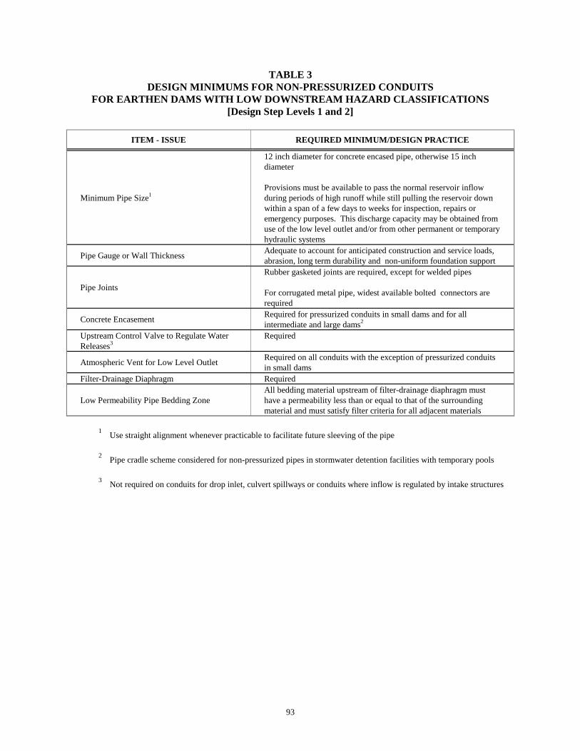
93
TABLE 3DESIGN MINIMUMS FOR NON-PRESSURIZED CONDUITS
FOR EARTHEN DAMS WITH LOW DOWNSTREAM HAZARD CLASSIFICATIONS[Design Step Levels 1 and 2]
ITEM - ISSUE REQUIRED MINIMUM/DESIGN PRACTICE
Minimum Pipe Size1
12 inch diameter for concrete encased pipe, otherwise 15 inchdiameter
Provisions must be available to pass the normal reservoir inflowduring periods of high runoff while still pulling the reservoir downwithin a span of a few days to weeks for inspection, repairs oremergency purposes. This discharge capacity may be obtained fromuse of the low level outlet and/or from other permanent or temporaryhydraulic systems
Pipe Gauge or Wall Thickness Adequate to account for anticipated construction and service loads,abrasion, long term durability and non-uniform foundation support
Pipe Joints
Rubber gasketed joints are required, except for welded pipes
For corrugated metal pipe, widest available bolted connectors arerequired
Concrete Encasement Required for pressurized conduits in small dams and for allintermediate and large dams2
Upstream Control Valve to Regulate WaterReleases3
Required
Atmospheric Vent for Low Level Outlet Required on all conduits with the exception of pressurized conduitsin small dams
Filter-Drainage Diaphragm Required
Low Permeability Pipe Bedding ZoneAll bedding material upstream of filter-drainage diaphragm musthave a permeability less than or equal to that of the surroundingmaterial and must satisfy filter criteria for all adjacent materials
1 Use straight alignment whenever practicable to facilitate future sleeving of the pipe
2 Pipe cradle scheme considered for non-pressurized pipes in stormwater detention facilities with temporary pools 3 Not required on conduits for drop inlet, culvert spillways or conduits where inflow is regulated by intake structures

94
TABLE 4DESIGN MINIMUMS FOR CONDUITS FOR EARTHEN DAMS
WITH HIGH OR SIGNIFICANT DOWNSTREAM HAZARD CLASSIFICATIONS[Design Step Levels 3 and Greater]
ITEM - ISSUEPERMANENT OR SEASONAL POOL TEMPORARY POOL/INTERMITTENT
RESERVOIR OPERATIONSMALL DAM INTERMEDIATE
DAMLARGEDAM
SMALL DAM INTERMEDIATEDAM
LARGEDAM
Minimum Pipe Diameter1,2,3 12" 12" 12" 12" 12" 12"Complete Concrete Encasement of
Pipe4Required5 Required Required Required5 Required5 Required5
Upstream Shutoff or Control Valve6 Required Required Required Required7 Required7 Required7
Atmospheric Vent for Low LevelOutlet
Required Required Required Required Required Required
Low Permeability Foundation andBackfill
All earthen materials upstream of filter-drainagediaphragm must have a permeability less than or equal to
that of the surrounding material and must satisfy filtercriteria for all adjacent materials
All earthen materials upstream of filter-drainagediaphragm must have a permeability less than or equal to
that of the surrounding material and must satisfy filtercriteria for all adjacent materials
Filter-Drainage Diaphragm Required Required8 Required8 Required Required8 Required8
1 Use straight alignment whenever practicable to facilitate future sleeving of the pipe 2 Outlet should be sized to be able to pass the normal reservoir inflow during the high runoff period while still capable of pulling the reservoir down within a span of a few
weeks 3 Pipe gauge or wall thickness adequate to account for abrasion, long term durability and other site-specific concerns 4 Minimum of 6 inches of reinforced concrete for encasement of pipe section 5 Pipe cradle in combination with precast reinforced concrete pipe may be used where the design can be justified on the basis of favorable site conditions 6 Not required for conduits on drop inlet spillways and for conduits where the inflow is regulated by intake structures 7 May not be required for stormwater detention and other flood control projects 8 The chimney drain zone (Section 3.2 Embankment Geometry and Zoning) generally satisfies this requirement

95
4.1.6 REFERENCES
1. Soil Conservation Service, National Engineering Handbook, Section 3 Sedimentation, US Dept. ofAgriculture, Washington DC, 1971.
2. Bureau of Reclamation, Design of Small Dams, Appendix A, Reservoir Sedimentation, US Dept. ofInterior, Denver CO, 1987.
3. Bureau of Reclamation, Criteria and Guidelines for Evacuating Reservoir Storage Reservoirs andSizing Low-level Outlet Works, ACER Technical Memorandum No. 3, US Dept. of Interior, DenverCO, 1982.
4. Bureau of Reclamation, Design of Small Dams, Chapter 10, Outlet Works, US Dept. of Interior,Denver CO, pp 435-489, 1987.
5. US Army Corps of Engineers, Hydraulic Design of Reservoir Outlet Works, EM 1110-2-1602,Washington DC, October 1980.
6. Soil Conservation Service, Gated Outlet Appurtenances, Earth Dams, Technical Release No. 46, USDept. of Agriculture, Washington DC, 1969.

96
4.1A PRESSURIZED CONDUITS
4.1A.1 APPLICATION:This section applies to the design and construction of pressurized conduits which pass through or arerouted within, beneath, or along the embankment or the exterior embankment(s) in the case of a multi-celled impoundment.
4.1A.2 OBJECTIVE:Provide a highly reliable system where miss-operation or failure of a system component will not lead to adam failure and catastrophic release of the reservoir.
4.1A.3 ENGINEERING CONCERNS:The principal Dam Safety concerns are:
• Minimizing the potential for seepage problems along the pipe perimeter,
• Containing the pressurized flow in the event of a failure of the pipe wall or joint so that therelease does not sluice away the adjacent embankment,
• Configuring the conduit intake and/or outfall so that the flow does not scour the subgrade or, in the case of lined impoundments, pull up or abrade the geomembrane,
• Protecting the pipe from possible over-stressing during construction, and
• Accommodating stresses and pressure surges in pipe joints from vibrations induced bypumping equipment and operation of the system valves.
4.1A.4 DESIGN PHILOSOPHY:Pressurized conduits should be kept off embankments to the extent practicable. Where they mustpenetrate through the embankment, that section of the pipe within the embankment footprint must beencased in concrete. Exceptions are discussed in the following section.
4.1A.6 DESIGN PRACTICE:The design features for pressurized conduits are similar to those used in the design of outlet conduits.
4.1A.6.1 Concrete Encasement RequirementsTo the extent practicable, pressurized conduits should be routed outside of the embankment toe. Wherethe pipe is within the embankment footprint, it shall be encased in concrete. There are a few limitedexceptions to this requirement.
Conduits - The requirement for concrete encasement may be waived if the engineer can show that: 1) thedownstream hazard setting is low and there would be no potential for loss of life in the event of a damfailure, 2) although a significant portion of the embankment could be sluiced away, an uncontrolledrelease of the reservoir contents is unlikely and 3) the owner acknowledges acceptance of the increaserisked (albeit small) of adverse performance of this element.
Mine tailings discharge lines - Tailings discharge lines are normally placed along the interior sideslopesof the dam section in impoundments retaining industrial process slurries. Generally, the slurry system

97
discharges from a number of points along the interior face. A beach of tails forms immediately downgradient of the discharge line. Erosion protection is unnecessary in most cases around the dischargepoints. However, in some instances it is necessary to route a section of the slurry supply lines on or overthe dam crest. Where it is necessary to frequently move these lines, it is generally impractical to provideconcrete or some other form of permanent encasement for the piping. The DSO has accepted schemeswhere "critical pipe runs", those segments of pipe located within or upon the exterior dikes, were sleevedby placing these lines inside of larger, jointed, corrugated metal pipes. In the event of a pipe or pipe jointfailure, the sleeving would contain the flow and minimize the erosion damage to the areas immediatelyaround the end sections of the sleeve.
4.1A.6.2 Pipe Settlement and Vibration ConsiderationsPumping equipment is frequently placed on a structural pad proximate to the point the conduit emergesfrom the embankment. Consideration must be given to the potential effects on the pipe of static anddynamic movement of the pump and its foundation pad. The particular sections of concern to the overallstability of the reservoir would be those sections of pipe within the embankment and the first fewsections projecting downstream beyond the dam toe. The design of the pipe should incorporate measuresto allow it to accommodate the stresses and movements induced by potential settlement of the pumpfoundation pad. Likewise, the foundation pad and pipe should be designed so that they do notsignificantly respond to the predominant periods of the dynamic forces generated by running the pump.
The hydrodynamics of pressurized flow causes both static and dynamic loads to be placed on piping,particularly where there are abrupt changes in direction. Pipe anchors and thrust blocks may be requiredto resist the forces generated by changes in momentum of the flow.
4.1A.6.3 Recommendations on ValvingIt is standard practice to provide some form of shut-off valve upstream of the pump to allow the pump tobe removed and serviced without draining the reservoir. It is also desirable to have a means of drainingthe pipeline downstream of the pump. These items may be omitted where other elements in the systemwill accomplish these functions.

98
4.2 PRINCIPAL OR SERVICE SPILLWAY
4.2.1 OBJECTIVE:Provide control of reservoir levels for reservoir inflows ranging from normal inflows to moderate floodflows.
4.2.2 COMMON TYPES OF PRINCIPAL SPILLWAYS:There are a wide variety of hydraulic structures which are used as principal spillways. The morecommon spillway types are listed in Table 1 and technical design information can be obtained from thedesign manuals and technical articles in Section 4.2.5 References.
TABLE 1 COMMON TYPES OF PRINCIPAL SPILLWAYS
GENERAL APPLICABILITY OF SPILLWAY TYPE
SPILLWAY TYPE SMALL DAMINTERMEDIATE
AND LARGEDAMS
OFF-CHANNELSTORAGE
FACILITIES
REGIONALSTORMWATER
DETENTION PONDSChute ✓ ✓ ✓ ✓
Chute with Bascule Gate ✓
Chute with OGEE Weir ✓ ✓
Chute with Stoplog Entrance ✓
Chute with Gated Entrance ✓
Culvert ✓ ✓ ✓
Drop Inlet ✓ ✓ ✓
Gated Tower ✓ ✓ ✓ ✓
Labyrinth ✓ ✓ ✓
Morning Glory ✓
Open Channel ✓
Side Channel ✓
4.2.3 ENGINEERING CONCERNS:Given the wide variety of spillway types listed above, there is a similar wide range of engineeringconcerns. Some of the concerns are specific to the spillway type. However, the following list ofengineering concerns is generally applicable to most spillway types and may aid in the selection of aspillway type for a particular application. Each of these engineering concerns are discussed in thefollowing sections.
• Long Term Durability• Desired Mode of Reservoir Operation• Flexibility to Change Reservoir Operational Mode• Expected Frequency of Site Visits by Operator• Ease of Maintenance, Inspection and Future Repair• Positive Control of Discharge• Resistance to Debris Blockage• Need for Atmospheric Venting or Aeration• Potential for Ice Damage• Energy Dissipation at Spillway Outlet• Fish Passage Considerations

99
4.2.3.1 Long Term DurabilityThe principal spillway generally operates frequently and thus is exposed to repeated hydraulic loadings. These forces can cause abrasion, corrosion, vibration, etc., which can accelerate wear, scour and generaldeterioration. Particular care should be exercised when selecting a spillway type and constructionmaterial(s) to provide for durability.
Requirements/Minimums - Concrete mix design and design of reinforced concrete elements should bedeveloped with specific attention to durability issues as outlined in Chapter 5 Structural Elements andIssues.
4.2.3.2 Desired Mode of Reservoir OperationThe manner in which the reservoir is to be operated is a primary consideration in the selection of aspillway type and size. Particular attention should be given to matching the spillway dischargecharacteristics to the range of anticipated inflows.
4.2.3.3 Flexibility to Change Reservoir Operational ModeDuring the life of a project, there sometimes arises the need to change the way in which the reservoir isbeing operated. This situation commonly occurs on small on-stream reservoirs where insufficientstreamflow data is available during the design stage to properly size the spillway. This is also true forflood control structures in urban areas where the streamflow characteristics are changing with increaseddevelopment. In these types of situations, discharge features should be built into the spillway headworksto allow the flexibility to change operation as dictated by the needs of the project.
4.2.3.4 Expected Frequency of Site Visits by OperatorThe availability of a project operator and the frequency of site visits influences the selection of thespillway type. In those cases where a full time operator or highly reliable remote operation cannot beprovided, the spillway must be ungated and self regulating. This is often the case on small andintermediate sized projects. This situation also means that more simplified and conservative reservoiroperation schemes are appropriate and that greater design conservatism should be applied to issues suchas debris protection.
4.2.3.5 Ease of Maintenance, Inspection and Future RepairsAll man-made hydraulic elements deteriorate with aging. It is important that elements of the spillwayand appurtenances be constructed in such a manner which will allow for easy maintenance andinspection. Likewise, the useful life of most dams far exceeds the life expectancy of the man-madehydraulic structures. Consideration should be given during design to provide features which will allowfor rehabilitation at some future time.
4.2.3.6 Positive Control of DischargeFor most spillway types, there is one location, the discharge control point, which determines therelationship between reservoir stage and discharge. There are other spillway types such as drop inletspillways, culvert spillways, and chute spillways with rapidly converging sidewalls where there may be ashift in control location with increase in reservoir stage. This shift in control can be accompanied bysurging and/or slug flow which can cause increased hydraulic loadings. This often produces vibration ofthe hydraulic structure and surging of flow in the outlet channel. These situations should be avoided orminimized to the extent practicable.
Whenever possible, measures should be taken during design to provide for positive control of thedischarge by establishing one discharge control point. For those spillway types where there are multiple

100
discharge control points, sufficient analyses should be conducted during design to properly assess thespillway hydraulics. Design features should be employed to provide a smooth transition as control shiftsfrom one control point to the other.
4.2.3.7 Resistance to Debris BlockageFloating debris often accompanies moderate and extreme flood flows. Trashracks and/or log booms arenecessary features to minimize debris blockage and the associated reduction of discharge capacity of theprincipal spillway. The discussion of debris protection and control measures is contained in Section 4.5Debris Protection for Hydraulic Structures.
4.2.3.8 Need for Atmospheric Venting or AerationVenting of outlet conduits for culvert spillways, drop inlet spillways and morning glory spillways isusually needed to preclude the occurrence of slug flow. Likewise, aeration of the nappe just below thecrest on drop inlet and morning glory spillways is needed to stabilize the flow pattern. For spillways onsmall projects, the venting requirements can be reasonably estimated using information developed by theSCS14. For large morning glory spillways, computer and physical model studies are normally used todetermine the air requirements.
For high dams with steep conveyance chutes, flow velocities often exceed 60 feet/second. In these cases,cavitation may occur downstream of small surface irregularities29. Extra care is needed duringconstruction to produce a smooth surface free of irregularities, particularly at joints. Alternatively,aeration of the flow has been found to be effective at minimizing cavitation damage. Discussions byPinto et al.26 and Rutschmann and Volkart27 contain design information for entraining air into the highvelocity flow.
4.2.3.9 Potential for Ice DamageThere is the potential for forces produced by ice to damage structures which are subject to severefreezing conditions. In general, structures which are located within the geometry of the impoundingbarrier are reasonably protected by the barrier. By contrast, exposed structures such as free standingtowers are subject to the full force produced by ice pressures and ice movement. Ice forces24,25 must beconsidered in the design of these structures.
4.2.3.10 Energy Dissipation at Spillway OutletDuring moderate to extreme floods, flow conditions are usually supercritical at the terminus of thespillway conveyance section (chute, conduit, etc.). The discharge is characterized as having highvelocities and severe soil erosion capability. For these reasons, measures must be taken to dissipate theexcess energy and control the flow before returning it to the receiving stream. Measures must be taken toassure that any erosion which occurs during the design flood does not jeopardize the integrity of thespillway or the impounding barrier. Use of survivability design concepts may be helpful in achievingeconomy in the construction of Energy Stilling Basins.
Requirements/Minimums:Energy dissipation and erosion control measures must be provided at the terminus of the conveyancesection of the principal spillway. Information on energy dissipation structures is contained in Section 4.4Energy Stilling Basins and Erosion Protection.
4.2.3.11 Fish Passage ConsiderationsInformation on fish passage requirements can be obtained by contacting representatives of theDepartments of Fisheries and Wildlife.

101
4.2.4 EXPERIENCE/CURRENT ENGINEERING PRACTICE FOR VARIOUS SPILLWAY ELEMENTS
The following topics address issues which are frequently encountered during design and reflectengineering design practice on principal spillways:
4.2.4.1 Conveyance Channels/Chutes
Channel Freeboard - Freeboard is needed in spillway conveyance channels to accommodate wave action,air entrainment17, splash and to provide for uncertainties in estimating the surface water profile undersupercritical flow conditions. Experience has shown that a reasonable value of freeboard20 can beestimated from:
Channel Freeboard (ft) = 2.0 + .025 V [y].333 (1)
where: V = Velocity of flow (ft/sec) at a given locationy = Depth of flow (ft) at a given location
Convergence and Divergence of Channel Sidewalls - Wherever possible, chute sidewalls should bedesigned symmetrical to the channel centerline to minimize unevenly distributed flow, cross-waves,standing waves and splash. Experience has shown20 that the maximum angular convergence ordivergence (θθθθ) of the sidewall with respect to the channel centerline is governed by:
FTan
31)( ≤θ (2)
where: F = Froude number, and
gyV=F (3)
where: V = Velocity (ft/sec) at the given locationg = Gravitational acceleration (32.2 ft/sec2)y = Depth of flow (ft) at the given location
Contraction - Expansion Joints - Contraction-expansion joints must be provided on spillway chutes tomaintain floor alignment while allowing for floor slab movement. The joint must be supported by acorbel-like pad.
Waterstops - Experience has shown that waterstops are an essential design detail for concrete spillwaychutes. They serve to minimize the flow of water through contraction-expansion joints which couldallow uplift pressures to develop beneath the floor slab. When used at construction joints, waterstops actto minimize the contact of oxygenated waters from reaching the reinforcing steel. This tends to prolongthe useable life of the spillway.
Underdrains - Drains are required beneath contraction-expansion joints to prevent joint leakage fromsaturating the subgrade beneath the spillway slab and/or producing uplift pressures. It is common

102
practice to use drains in combination with waterstops as design features of concrete chute spillways. SeeSection 3.3C Concrete Lined Spillway Seepage Control for further information.
4.2.4.2 Conveyance Conduits - Non-Pressurized Under Normal Conditions
Full Pipe Flow - Full pipe flow, which occurs as a result of a transfer of the discharge control point, willnot be allowed unless it can be designed to occur in a manner with minimal surging of the flow andresultant hydraulic transient pressures.
Conduit Design - Part Full Pipe Flow - To avoid pressurized flow and problems posed by slug flow, theconduit should be designed with sufficient slope to restrict the maximum depth (Ymax) to less than thatrepresenting 70 percent of full pipe flow by area. For circular sections with diameter D, this represents:
Ymax ≤ .66D (4)
A positive flow control device such as an eyebrow18 or fixed sluice gate at the entrance to circularconduit will normally be needed to stabilize the flow hydraulics. The conduit must be vented to theatmosphere, with the air vent placed immediately downstream of the eyebrow18.
4.2.4.3 Drop Inlet Spillways
Connection of Riser to Outlet Conduit - On small sized projects, drop inlet spillways are oftenconstructed from sections of reinforced concrete pipe (RCP) or corrugated metal pipe (CMP). In thesecases, the vertical riser section must be suitably founded on a structural pad of reinforced concrete. Theconnection between the riser and outlet conduit must be encased by reinforced concrete and thisencasement should also tie into the concrete foundation pad. The inlet structure must be shown to bestable under the effects of buoyancy.
Riser Floor - Particular care should be given to the construction of the floor of the vertical riser. Thisarea is subjected to high velocity, very turbulent flow conditions which accelerate erosion of theconcrete. Additional wearing surface should be provided by overbuilding this section. See Chapter 5Structural Elements and Issues for a discussion of concrete durability.
Outlet Conduit - The outlet conduit for a drop inlet spillway should include an atmospheric vent andeyebrow as described above in section 4.2.4.2. Technical information on the hydraulic design of outletconduits is contained in SCS14, Schaefer18 and USBR20.

103
4.2.5 REFERENCES:
WEIR COEFFICIENTS - DISCHARGE RATING CURVES1. Bradley, J.N., Discharge Coefficients for Irregular Overfall Spillways, Engineering Monograph No.
9, U.S. Bureau of Reclamation, March 1952.
2. Hager, W.H., Discharge Characteristics of Gated Standard Spillways, Water Power and DamConstruction, January 1988.
3. Afshar, A., The Development of Labyrinth Spillway Designs, Water Power and Dam Construction,May 1988.
4. Maynard, S.T., General Spillway Investigation, U.S. Army Corps of Engineers, WaterwayExperiment Station, Technical Report HL-85-1, March 1985.
5. Bodhaine, G.L., Measurement of Peak Discharge at Culverts by Indirect Methods, U.S. GeologicalSurvey Publication, Application of Hydraulics, Chapter A3, 1968.
6. Federal Highway Administration, Hydraulic Charts for the Selection of Highway Culverts, HydraulicEngineering Circular No. 5, December 1965.
7. Federal Highway Administration, Hydraulic Design of Improved Inlets for Culverts, HydraulicEngineering Circular No. 13, August 1972.
8. American Iron and Steel Institute, Handbook of Steel Drainage and Highway Construction Products,Second Edition, 1971.
9. Brater, E.F., and H.W. King, Handbook of Hydraulics, McGraw Hill, Sixth Edition, 1976.
10. Huising, H., Measurement of Peak Discharge at Dams by Indirect Methods, U.S. Geological SurveyPublication, Applications of Hydraulics, Chapter A5, Book 3, 1967.
GENERAL SPILLWAY DESIGN11. U.S. Army Corps of Engineers, Hydraulic Design of Spillways, Engineering Manual EM1110-2-
1603, March 1965.
12. U.S. Army Corps of Engineers, Hydraulic Design of Outlet Works, Engineering Manual EM1110-2-1602
13. U.S. Bureau of Reclamation, Design of Small Dams, Third Edition, pp. 339-434, 1987.
14. Soil Conservation Service, Drop Spillways, Section 11, National Engineering Handbook #4.
15. Soil Conservation Service, Chute Spillways, Section 14, National Engineering Handbook #4.
16. Aisenberg, A.J., et.al., Design of Small Canal Structures, U.S. Bureau of Reclamation, Denver Co.,1974.
17. Chow, V.T., Open Channel Hydraulics, McGraw-Hill, 1959.

104
DROP INLET SPILLWAYS18. Schaefer, M.G., Shaft Spillways, Fundamental Hydraulics and Hydrology of Dam Design, University
of Missouri Short Course, May 1981, Available through Dam Safety Section, Dept. of Ecology,Olympia, Washington.
19. Creager, William P., Joel P. Justin, and Julian Hinds, Engineering for Dams, John Wiley & Sons,Inc., 1966, pp. 227-243.
20. Bureau of Reclamation, Design of Small Dams, U.S. Department of Interior, U.S. GovernmentPrinting Office, Washington, D.C., 3rd Edition, 1987, pp. 407-421, 565-583.
21. Wagner, W.E., Morning Glory Shaft Spillways: Determination of Pressure-Controlled Profiles,Transactions, ASCE, Vol. 121, 1956, p. 345.
22. Soil Conservation Service, Gated Outlet Appurtenances, Technical Release #46, June 1969.
ICE LOADINGS23. Gerard, R., River and Lake Ice Processes Relevant to Ice Loads, ASCE, Journal of Structural
Engineering, pp. 121-138, March 1983.
24. Sodhi, D.S., and F.D. Haynes, Measurement of Ice Forces on Structures, ASCE Journal of StructuralEngineering, pp. 139-155, March 1983.
25. U.S. Army Corps of Engineers, Ice Engineering, Engineering Man., EM1110-2-1612, 1982.
MISCELLANEOUS26. Pinto, N.L., et al, Aeration of High Velocity Flows, Parts 1 and 2, Water Power and Dam
Construction, February, March 1982.
27. Rutschmann, P., and P. Volkart, Spillway Chute Aeration, Water Power and Dam Construction,January 1988.
28. Akhmedov, T.K., Calculation of the Depth of Scour in Rock Downstream of a Spillway, WaterPower and Dam Construction, December 1988.
29. Falvey, H.T., Cavitation in Chutes and Spillways, U.S. Bureau of Reclamation, EngineeringMonograph No. 42, April 1990.
30. Peyras,L., Royet, P. and Degoutte, G., Flow and Energy Dissipation Over Stepped Gabion Weirs,ASCE Journal of Hydraulic Engineering, Vol. 118, No.5, May 1990.

105
4.3 EMERGENCY SPILLWAYS
4.3.1 OBJECTIVE:Passage of moderate to extreme flood flows and control of the reservoir level to an elevation below thedam crest.
4.3.2 DESIGN PHILOSOPHY:Emergency spillways are normally designed to operate only in response to moderate or extreme floods,perhaps once or twice during the life of the project. Because of this infrequent operation, economy indesign and construction can sometimes be accomplished for small and intermediate size dams by utilizingthe concept of Survivability. That is, erosional damage can often be tolerated provided the damage doesnot jeopardize the structural integrity of the impounding barrier or allow an uncontrolled release of thereservoir waters. This may be accomplished by locating the emergency spillway in an area witherosional resistant materials or by providing sufficient structural features to limit erosional damage. Inall cases, sufficient measures must be taken to preclude the uncontrolled release of reservoir watersthrough a breached spillway.
4.3.3 COMMON TYPES OF EMERGENCY SPILLWAYS:Emergency spillways are intended to pass large flood flows. Those spillway types which have largedischarge capacity and can be constructed with reasonable economy are usually selected. The morecommon emergency spillway types and their applicability are described in Table 1.
TABLE 1. COMMON TYPES OF EMERGENCY SPILLWAYS
GENERAL APPLICABILITY OF SPILLWAY TYPE
SPILLWAY TYPE SMALL DAM INTERMEDIATEAND LARGE
DAMS
OFF-CHANNELSTORAGE
FACILITIES
REGIONALSTORMWATER
DETENTION PONDSChute ✓ ✓ ✓ ✓
Gated Chute ✓
Gabion Lined Chute ✓ ✓ ✓
Culvert ✓
Drop Inlet ✓ ✓ ✓
Labyrinth ✓ ✓ ✓
Open Channel ✓ ✓ ✓ ✓
Side Channel ✓
Spillway types which do not require human intervention for operation provide increased likelihood ofproper performance during unusual flood conditions. These constraints often make unregulated, wide,open channel and chute spillways the preferred choices. Conversely, large projects designedfor flood control typically employ gated spillways to provide greater regulation of the flood releases.
4.3.4 ENGINEERING CONCERNS:An emergency spillway is a critical project element whose proper operation during extreme floodconditions is essential to prevent overtopping of the impounding barrier. The passage of extreme floodflows and the conditions associated with extreme floods pose several general engineering concerns anddesign issues which must be addressed. These conditions, concerns and issues include:
• Frequency of Operation
106
• Operator Intervention• Resistance to Debris Blockage• Positive Control of Discharge• Limiting Erosional Damage• Duration of Operation• Need for Atmospheric Venting or Aeration of the Flow
Technical design information on these and related topics can be obtained from the design manuals andtechnical articles in the References, Sections 4.2.5, 4.3.6. Likewise, related topics are discussed inSection 4.2 Principal and Service Spillways.
4.3.4.1 Frequency of OperationThe selection of the frequency of operation of the emergency spillway is at the discretion of the designengineer. Common practice is to design the principal spillway to accommodate floods with a magnitudeup to the 50 year or 100 year recurrence level or more. The emergency spillway would then be utilized topass floodwaters in excess of the capacity of the principal spillway. This approach usually results in theemergency spillway operating only once or twice in the life of the project. This allows the concept ofsurvivability to be used in designing erosional control features for the emergency spillway.
4.3.4.2 Operator InterventionIn general, spillways which do not require operator intervention (unregulated spillways) provide a greatermargin of safety and predictability for proper operation during extreme flood conditions. In those caseswhere gated emergency spillways are utilized, proper procedures and decision points must be clearlydefined in the Operation and Maintenance (O & M) Manuals.
Requirements/Minimums - Dam tenders must periodically review procedures and receive training asneeded to attain a very high degree of reliability for operation of the project under extreme conditions. Dam tender(s) responsible for operation of gated spillways must be on-site during flood conditions. Remote, telemetered operation of any gates must have backup by on-site operators during extreme floodconditions.
4.3.4.3 Resistance to Debris BlockageFloating debris often accompanies moderate and extreme flood flows particularly from heavily forested,steep, mountainous areas. Features of the spillway and approach area should be incorporated to allowpassage of floating debris, or debris control features such as log booms should be utilized. Thediscussion of debris protection and control measures is contained in Section 4.5 Debris Protection forHydraulic Structures.
4.3.4.4 Positive Control of DischargeMeasures need to be taken during the design process to provide for positive control of the discharge byestablishing either one discharge control point or to provide a smooth transition between dischargecontrol points. See Section 4.2.3.6 for further information.
4.3.4.5 Limiting Erosional DamageHeadward erosion along the spillway outlet channel is the primary mechanism which causes erosionalbreaching of unlined spillways2. Headward erosion normally initiates at channel locations where thechannel bedslope flattens or changes abruptly such as at the spillway outfall.
As previously discussed in Section 4.2.2 Design Philosophy, sufficient measures must be taken to

107
preclude erosional breaching of the emergency spillway. On small and intermediate sized dams, this canoften be accomplished using erosion protection measures such as: vegetative linings; riprap or gabionlinings; grouted riprap; and buried concrete erosion cutoff walls.
On large dams where large spillway discharges produce very high velocities, the only practical ways tolimit erosion, particularly headward erosion, are to locate the spillway on erosion resistant bedrock or toconstruct channel linings from roller compacted concrete16 or conventional reinforced concrete.
4.3.4.6 Duration of OperationIf survivability design concepts are used, the elapsed time that the spillway passes flow can be animportant consideration. If the design event is a short duration thunderstorm event, then the spillwaymay only be subjected to a limited period of high energy erosional forces. In contrast, if the design eventis a winter long-duration storm, the spillway may be subjected to a protracted period of erosion. Theduration and intensity of erosional forces should be considered in the design of erosion protectionfeatures which limit but do not eliminate erosional damage.
4.4.3.7 Need for Atmospheric Venting or Aeration of the FlowVenting requirements for culvert spillways, drop inlet spillways and morning glory spillways arediscussed in Section 4.2.3.8. Issues regarding cavitation and aeration of high velocity flow are alsodiscussed in that section.
4.3.5 EXPERIENCE/CURRENT ENGINEERING PRACTICE FOR VARIOUS SPILLWAY FEATURES
The following topics address issues which are frequently encountered during design and reflect commonengineering design practice for various features of emergency spillways at small and intermediate sizedams. Related topics are also discussed in Section 4.2 Principal and Service Spillways.
4.3.5.1 Vegetation Lined Open Channel SpillwaysGrass lined emergency spillways are often practical solutions for small dams where climatic conditionswill support a good grass cover. Wide, shallow, open channels with moderate slopes are usually selectedto limit velocities and erosion damage. Information from the SCS1,2 and Chow11 provide guidance on thedesign of grass lined spillways.
4.3.5.2 Riprap Lined Open Channel SpillwaysExperience has shown that loose riprap has very limited applicability on channel bedslopes steeper thanabout 20H:1V. Model tests conducted by the U.S. Bureau of Reclamation10, Colorado State University4
and Abt and Johnson12 also indicate that loose riprap has low reliability in protecting embankments fromovertopping flows when unit discharges are large. The combination of steep slopes, high energy,unevenly distributed flow, variability and segregation of riprap gradation during placement combine torestrict usage of loose riprap to more moderate channel slopes, velocities and unit discharges.
Recommendations - Use of loose riprap for channel protection should generally be restricted to slopesless than about 5 percent. Conventional riprap sizing criteria 13,14,15 should be applied conservatively. Inaddition, riprap should be augmented by the use of headward erosion cutoff walls to restrict unraveling ofthe riprap lining.
4.3.5.3 Gabion Lined Chute SpillwaysGabion lined chute spillways are sometimes used on small dams where the valley is narrow and the

108
emergency spillway is placed on the embankment. This is often the case on small flood control dams inurban areas.
Requirements/Minimums - The typical mode of failure of gabions is by a loss of subgrade support. This occurs when velocities are sufficiently high to cause movement of the rockfill in the baskets, whichin turn causes the baskets to deform. This exposes the underlying filter and subgrade to erosion. Topreclude this occurrence, current design practice recommended by gabion manufacturers for gabionconstruction in high velocity areas is to underlay the gabion baskets with a non-woven geotextilematerial. The geotextile is then underlain with a sand and gravel filter which meets filter criteria for boththe subgrade and the gabion rockfill. See also Section 3.3A Filters. Current literature on gabions4
indicates maximum permissible velocities as shown I n Table 2.
TABLE 2 PERMISSIBLE VELOCITIES FOR GABIONS4
GABION BASKETTHICKNESS
PERMISSIBLEVELOCITY
6 Inches 11 ft/sec9 Inches 13 ft/sec
12 Inches 15 ft/sec18 Inches 17 ft/sec36 Inches 21 ft/sec
Additional buried gabions should be constructed at the spillway crest and toe of the slope to provideanchorage and act as shear keys.
4.3.5.4 Headward Erosion Cutoff WallsHeadward erosion cutoff walls can be effective at limiting the upstream migration of erosional damage. Ideally, the wall should penetrate to an erosion resistant layer of the foundation. The wall should alsoextend sufficiently far into the channel sidewalls to preclude an erosional end-run of the wall. Inaddition, the wall should be designed with a geometry which provides overturning resistance if the wallis partially undermined. This is usually accomplished by constructing the walls in the shape of achevron, with the apex pointed upstream, or by adding counterforts to the wall.
Recommendations - A series of cutoff walls constructed from concrete, gabions or grouted riprap can beused in conjunction with grass linings or loose riprap to retard the erosional rate and provide adequatetime for passing the design flood at small and intermediate dams.
Also, in these situations, it is often desirable to employ a channel layout where the deepest waters,highest velocities and greatest erosional potential occurs in those areas of the channel furthest from thedam. This can be accomplished by utilizing a minor cross-slope to the channel to place the deepersections of the channel furthest from the dam. Care must also be taken in this arrangement to evaluatethe effect of the increased erosional potential at the deepened section.
4.3.5.5 Culvert Spillways for Off-Channel Storage FacilitiesCulvert spillways are often an economical solution for discharging excess floodwaters from off-channelstorage reservoirs. The culverts should be sized to accommodate the design storm event in combinationwith the maximum diverted or pumped inflow.

109
4.3.6 REFERENCES
1. Soil Conservation Service, National Engineering Handbook, Section 4, Multiple Chapters onSpillway Hydraulics and Design, U.S. Dept. of Agriculture.
2. Soil Conservation Service, A Guide for Design and Layout of Earth Emergency Spillways as Part ofEmergency Spillway Systems for Earth Dams, Technical Release No. 52, Feb. 1973.
3. Stephenson, D., Rockfill Hydraulic Engineering, Elsevier Scientific Publishing Co., 1979.
4. Colorado State University, Hydraulic Tests on Reno Mattresses, Engineering Research Center forTerra Aqua Co., Reno, NV.
5. Federal Highway Administration, Minimizing Embankment Damage During Overtopping Flow,FHWA-RD-88-181, November 1988.
6. Afshar, A., The Development of Labyrinth Spillway Designs, Water Power and Dam Construction,May 1988.
7. Falvey, H.T., Cavitation in Chutes and Spillways, U.S. Bureau of Reclamation, EngineeringMonograph No. 42, April 1990.
8. Sorensen, R.M., Stepped Spillway Hydraulic Model Investigation, Lehigh University, ASCEHydraulics Division Specialty Conference,
9. Young, M.F., Feasibility Study of a Stepped Spillway, ASCE Hydraulics Division SpecialtyConference, Jackson MS, August 1982.
10. Powledge, G.R. and Dooge, R.A., Overtopping of Small Dams - An Alternative for Dam Safety,Hydraulics and Hydrology in the Small Computer Age, Vol. 2, ASCE Hydraulics Division SpecialtyConference, 1985.
11. Chow, V.T., Open Channel Hydraulics, McGraw-Hill, 1959.
12. Abt, R., and Johnson, T.L., Riprap Design for Overtopping Flow, ASCE Journal of HydraulicEngineering, Vol 117, No. 8, August, 1991 pp 959-972.
13. U.S. Army Corps of Engineers, Shore Protection Manual, Volume II, Coastal Engineering ResearchCenter, Fort Belvoir, Virginia, 1973, pp7-205.
14. U.S. Bureau of Reclamation, Design of Small Dams, U.S. Department of Interior, U.S. GovernmentPrinting Office, Washington, D.C., 3rd Edition, 1987.
15. Maynord, S.T., Practical Riprap Design, U.S. Army Corps of Engineers Waterways ExperimentStation, Vicksburg MS, Miscellaneous Paper H-78-7, June 1978.
16. Reeves, G.N., Planned Overtopping of Embankments Using Roller Compacted Concrete, ASCEHydraulics Division Specialty Conference, Orlando, FL, August 1985.
17. Peyras,L., Royet, P. and Degoutte, G., Flow and Energy Dissipation Over Stepped Gabion Weirs,

110
ASCE Journal of Hydraulic Engineering, Vol. 118, No.5, May 1990.

111
4.4 ENERGY STILLING BASINS
4.4.1 OBJECTIVE:Provide a means for dissipating the energy and controlling the velocity of discharge exiting fromspillways and outlet works to prevent damaging erosion and scour of the dam embankment, foundationand/or streambed.
4.4.2 APPLICABILITY:Energy stilling basins are required for outlet works and principal spillways. Stilling basins may take theform of a simple riprap lined basin for outlet works required to pass small discharges, or may beelaborate reinforced concrete structures for principal spillways with large, high velocity discharges.
4.4.3 ENGINEERING CONCERNS:Releases of large discharges from outlet works and spillways are usually characterized as having highenergy levels. The discharge velocity is typically much greater than the velocity the receiving stream haspreviously experienced under natural conditions. Unless adequate energy dissipation is provided, severeerosion and scour of the foundation and/or natural streambed can result. Such erosion can progress in theupstream direction (headward erosion) and undermine and/or erode the spillway outfall. Uncheckedheadward erosion could jeopardize the integrity and stability of the dam.
The need for, and degree of, energy dissipation and/or erosion protection generally depends on severalfactors, including:
• The erosion resistance of the foundation or streambed material• The velocity and magnitude of the discharge, particularly the unit discharge• The frequency of occurrence and duration of both normal discharges and flood flows• The type of spillway or outlet• Environmental concerns (e.g. the need for fish passage and preservation of fish habitat)
4.4.4 DESIGN PHILOSOPHY:Energy stilling basins are considered critical project elements for those situations where their failurecould lead to a failure of the dam. Two design approaches are in common practice. The first approachsizes the stilling basin based on the maximum potential discharge the stilling basin would ever berequired to accommodate. The second approach utilizes Survivability concepts to size the stilling basinand erosion protection features to achieve acceptable performance under extreme flood discharges. Bothapproaches are briefly described below.
Size of Energy Stilling Basin Based on Maximum Potential Discharge - In this approach, the size ofthe basin, and it's energy dissipation and downstream erosion control features are designed to withstandthe maximum anticipated discharges with minimal erosional damage. Common applications for thisapproach are for hydraulic structures such as:
Outlet Works - For outlet works, the maximum discharge is governed by the reservoir head, conduit sizeand conduit valving arrangements. The maximum discharge is commonly used as the design dischargefor sizing the stilling basin.
Principal Spillways on Large Dams with Erodible Foundations - At large dams with erodiblefoundations, the combination of large unit discharges and high velocities warrant a very conservativeapproach. In these cases, the discharge used to size and design the energy stilling basin is based on the

112
maximum discharge from the spillway in response to the Inflow Design Flood (IDF).
Size of Energy Stilling Basin Based on Survivability Concepts - Conversely, in this approach it isallowable to accept substantial erosional damage during an extreme event, provided the integrity orstability of the dam is not jeopardized. The basic premise is to provide defense mechanisms, such asoversized stilling basin end walls and side walls, to preclude undermining and catastrophic erosion whichcould jeopardize the stilling basin and the dam in the event of an extreme flood event. This approach isoften used at small and intermediate size dams where project owners are amenable to accepting a smallrisk of some potential future erosion damage and repair costs in exchange for savings in initialconstruction cost. Common applications of this approach include:
Principal Spillways on Small and Intermediate Size Dams - The limited duration and smaller magnitudeof flood flows at small and intermediate size dams often allow the use of survivability concepts to beeffectively employed. A design discharge corresponding to the 100 year flood peak discharge iscommonly used for sizing the stilling basin and energy dissipation features.
Principal Spillways on Large Dams with Erosion Resistant Foundations - The presence of erosionresistant foundations may preclude the potential for headward erosion to undermine the stilling basin andessentially eliminate concerns for erosion to jeopardize the dam. In these cases, survivability conceptsare directly applicable and there is discretion in setting the discharge for design of the energy stillingbasin. Common practice is to use a discharge in the range of the 500 year recurrence flood for sizing thestilling basin.
4.4.5 DESIGN PRACTICE:The hydraulic procedures used in design of energy stilling basins are well detailed in numeroustextbooks4,7 technical references1,3,4,5,6,7 and design manuals2,8,9. The purpose of the following sections isto provide some background reference information and to highlight some important designconsiderations.
4.4.5.1 Common Types of Energy Stilling BasinsA multitude of energy stilling basins and dissipators have been developed for spillways and outlets overthe years. The selection of a specific type of dissipator is left to the designer. In general, thestilling basins can be grouped into the following categories:
ENERGY STILLING BASINS FOR CHUTE SPILLWAYS
• USBR Types I, II and III - Hydraulic Jump Type Basins1,2
• Saint Anthony Falls (SAF) Stilling Basin2,4
• USBR Type IX - Baffled Chute Spillway1,2
• Contra Costa Basin (for small dams)3,8
ENERGY STILLING BASINS FOR CONDUIT SPILLWAYS OR OUTLETS
• USBR Type VI - Impact Type Basin1,2,9
• Contra Costa Basin3,8
• SCS Plunge Pool5
• USBR Plunge Basin1
ENERGY STILLING BASINS FOR HIGH OVERFLOW SPILLWAYS

113
• USBR Type VII - Submerged Bucket1
• Flip Bucket Energy Dissipator1
4.4.5.2 Headward Erosion ProtectionHeadward erosion protection features are necessary to prevent undermining and other erosional damageof the stilling basin. These features are considered critical project elements and must be designed towithstand the maximum design flood discharge for spillways, or the maximum discharge capacity foroutlet works. This is normally accomplished by the construction of oversized erosion cutoff walls whichextend beneath, and outward from, the end of the stilling basin. The cutoff walls should be extendedsufficiently far beneath the stilling basin end sill to either penetrate an erosion resistant material, or beextended a conservative distance below any anticipated scour depth which could result from passage ofthe maximum design flood discharge.
4.4.5.3 Erosion Protection for Outlet ChannelsErosion protection in the form of riprap, grouted riprap, or gabions is normally needed downstream of thestilling basin to protect the natural streambed from erosion and scour. Survivability concepts are oftenused in selecting and designing the protection in this area - provided adequate headward erosionprotection for the stilling basin has been incorporated in the design. A number of references8,10,11 onriprap are available to assist in the selection of the riprap size, gradation and lining thickness (see alsoSection 3.5 Embankment Erosion Control and Wave Protection).
4.4.5.4 Tailwater ConditionsAnalysis of the tailwater conditions for the stilling basin is essential to the proper design of many typesof stilling basins. A tailwater discharge rating curve depicting the relationship between discharge and thecorresponding water surface elevation in the receiving stream is necessary to evaluate the performance ofthe basin and in determining if/when "sweepout" of the basin will occur. Information from the analysisof stilling basin exit velocities and depths is also used in evaluating the necessary penetration ofheadward erosion cutoff walls and in sizing riprap or other channel erosion protection measures.

114
4.4.6 REFERENCES
1. Bureau of Reclamation, Design of Small Dams, pp 387-403 (Spillways), pp 463-464 (Outlets), ThirdEdition, US Dept of Interior, Denver, CO, 1987.
2. Bureau of Reclamation, Hydraulic Design of Stilling Basins and Energy Dissipators, EngineeringMonograph No. 25, US Dept of Interior, Denver CO, 1974.
3. Keim, S. R., The Contra Costa Energy Dissipator, Proceedings ASCE Hydraulics Division, March1962, pp 109-122.
4. Chow, V.T., Open Channel Hydraulics, McGraw-Hill Book Co., NY, 1959, pp 415-417.
5. Soil Conservation Service, Riprap Lined Plunge Pool for Cantilever Outlet, Design Note No. 6, Deptof Agriculture, Washington D.C., 1986.
6. Donnelly, Charles A. and Blaisduell, Fred W., Straight Drop Spillway Stilling Basin, ASCE Journalof the Hydraulics Division, May 1965.
7. Elevatorski, E., A., Hydraulic Energy Dissipators, McGraw Hill, New York, 1959.
8. Federal Highway Administration, Hydraulic Design of Energy Dissipators for Culverts and Channels,Hydraulic Circular No. 14, US Dept. of Transportation, September, 1983.
9. Bureau of Reclamation, Hydraulic Design of Stilling Basin for Pipe and Culvert Outlets, ResearchReport No. 24, US Dept of Interior, Denver CO, 1978.
10. U.S. Army Corps of Engineers, Shore Protection Manual, Volume II, pp 7-205, Coastal EngineeringResearch Center, Fort Belvoir, Virginia, 1973.
11. King County Surface Water Management Division, Surface Water Design Manual, King CountyDepartment of Public Works, 1990, pp4.3.7-2

115
4.5 DEBRIS PROTECTION FOR HYDRAULIC STRUCTURES
4.5.1 OBJECTIVES:Prevent floating debris in the reservoir from accumulating and blocking the spillway entrance. Preventsubmerged debris from blocking and/or entering low level outlet works.
4.5.2 ENGINEERING CONCERNS:
Spillway - Natural watersheds that are heavily forested, and urbanized watersheds can produce asignificant quantity of floating debris, especially during floods. This debris can accumulate in thespillway entrance or near the discharge control section and reduce the spillway discharge capacity. As aresult, the reservoir freeboard would be reduced, and in extreme cases, the dam could be overtopped.
Outlet Works - Submerged logs and debris can clog the intake or the outlet works, reducing thedischarge capacity. In addition, debris could enter the conduit and damage control gates and valves, orhamper normal operation.
4.5.3 DESIGN PHILOSOPHY:
Spillways - For spillways, debris protection is a critical element of design. Failure of the debrisprotection could lead to an accumulation of debris, reduction of spillway discharge capacity, andovertopping and failure of the dam. Thus, trashracks, debris barriers and log booms should be designedconservatively, to minimize the possibility of spillway blockage.
Outlet Works - For outlet works, debris protection is an important, but non-critical element of design. Failure of debris protection features for outlet works could result in damage or reduce the dischargecapacity, but would not lead to a dam failure. Outlet works debris protection should be designed withserviceability in mind by making provisions to allow clearing of the debris as needed.
4.5.4 DESIGN PRACTICE:
4.5.4.1 SpillwaysDebris protection features for spillways would include such items as floating log booms or fixed in-placedebris barriers. The choice of debris protection is dependent on the type of spillway used. Drop inlet(morning glory) spillways and conduit spillways are very susceptible to debris blockage. For thesespillways, cage type trashracks are typically installed at the spillway entrance. The spacing between thetrashrack bars is normally sized so that smaller organic debris such as leaves and small branches can passthrough, while larger debris is retained on the rack. In order to prevent the larger debris from choking offthe spillway flow, the trashrack usually has a surface area several times greater than the area of thespillway entrance.
Open channel spillways, (e.g chute and overflow spillways) are less susceptible to debris blockage. Forthese spillways, floating booms are normally used. Floating booms are often constructed of treatedtimber logs or hollow steel pipe sections with the ends welded shut, which are chained together andanchored to the shore upstream from the spillway.

116
In some cases, debris barriers can be an economical alternative to log-booms. These structures serve thesame purpose as log-booms and typically consist of a series of posts or piles driven into the spillwayapproach channel to snag floating debris, particularly large logs and downed trees, before they enter thespillway.
Recommendations/Requirements/Minimums - In those cases where floating debris is anticipated to bea problem during extreme floods, measures must be taken to minimize spillway blockage and theassociated reduction in discharge capacity. Standard methods of minimizing debris problems include:
Log Booms - Log booms should be located sufficiently far upstream of the spillway entrance to be in areservoir location where the approach velocity is relatively low. This will reduce the forces on the boomanchors and reduce energy losses in the approach channel. Ideally, approach velocities under designflood conditions should be less than 1 ft. per second. Alternatively, measures must be taken to provideassurance of the effectiveness of the boom during flood conditions. Log booms should also beconstructed with sufficient freedom of movement to be capable of floating freely up to the maximumdesign reservoir level.
Deepened Approach Channel - The approach channel/area to the emergency spillway should besufficiently deep that floating debris does not get hung up on the channel bed and partially block theapproach to the spillway.
Mechanical Removal - In those cases where control or passage of the debris cannot be accomplished witha high degree of reliability, mechanical methods of removal may be used. Prior arrangements should bemade to have equipment available during extreme flood conditions which is capable of physical removalor control of the debris.
Over-Design of Spillway Capacity and/or Freeboard - The spillway discharge capacity may be over-designed relative to that needed for accommodating the design flood to account for partial debrisblockage. In addition, the dam crest elevation can be raised to give greater floodwater storage capacity toaccount for the reduction in discharge capacity from partial debris blockage.
Trashracks - Tightly spaced bars on trashracks, resembling grating, are easily clogged by small debris. Reduced discharge capacity on culvert spillways and drop inlet spillways from debris collection ongrating type trashracks have been responsible for several dam failures in the U.S.
To minimize this potential problem, trashracks should be designed with a surface area of from 3 to 5times that of the entrance area which it is protecting. Bar spacing on the trashrack should be as large aspracticable, subject to the constraint that whatever passes through the trashrack must freely pass throughthe conveyance conduit or channel. For projects located near developed areas, bar spacings must also notbe so large as to pose an attractive nuisance and be a threat to the safety of children who could fallthrough the openings.
Debris barriers - Debris barriers should be constructed with adequate cross-sectional area for debriscollection and be placed sufficiently far upstream of the spillway mouth to minimize restriction of theflow.
4.5.4.2 Outlet WorksThe design of a trashrack at the entrance to the conduit for the outlet works is dependent on severalfactors, including: the size of the conduit; the likely magnitude of debris, both quantity and dimensions;

117
the type of control device; the need for excluding small debris from the outflow; and the needs of thewater users.
Recommendations:
Trashracks - Trashracks for outlet works should be oversized to provide for a debris collection area of1.5 to 5 times that of the intake opening, dependent upon the magnitude of the expected debris problemand the ease with which debris can be cleared. Bar spacing for trashracks for outlet works can bedetermined in the same manner as that discussed above for spillways.
4.5.5 PAST EXPERIENCE:Timber log booms tend to become waterlogged with age and partially sink, allowing debris to pass overthe top of the boom. Thus, timber booms must be replaced several times during the life of the facility. Alternative materials for log booms would include using sections of aluminum pipe or thin wall steelpipe, with the ends welded shut to allow the sections to float.
Off channel diked impoundments, such as sewage lagoons, city reservoirs and waterski ponds, whereminimal debris can enter the reservoir, often require little or no debris protection measures.

118
4.5.6 REFERENCES
TRASHRACKS FOR OUTLET WORKS
1. U.S. Bureau of Reclamation, Design of Small Dams, Sections 10.9 and 10.15, Denver, CO, Third Edition, 1987.
DEBRIS BARRIERS
2. Washington State, Dept. of Transportation, Highway Hydraulic Manual, Section 3.06.00, M23-03(HB)

119
4.6 RESERVOIR FREEBOARD
4.6.1 APPLICATION:The magnitude of reservoir freeboard is used to establish the elevation of the dam crest relative to thenormal or maximum operating levels of the reservoir.
4.6.2 OBJECTIVES:Provide a buffer for protection against dam overtopping by reservoir waters for those cases whereovertopping could produce serious damage or erosional failure of the embankment.
Reservoir freeboard is evaluated at two reservoir conditions - normal pool condition and maximum poolduring passage of the inflow design flood. The more stringent design considerations at these tworeservoir conditions are used to establish the elevation of the dam crest. Freeboard at these twoconditions is defined as:
Normal Freeboard - the vertical distance between the normal storage elevation (normal high poollevel) and the dam crest elevation.
Minimum Freeboard - the vertical distance between the maximum reservoir water surface elevationattained during passage of the inflow design flood and the dam crest elevation.
4.6.3 DESIGN PHILOSOPHY:
Earthen Dams - It is standard practice for reservoir freeboard to be determined in a conservativemanner. However, while erosional damage has occurred at earthen dams due to intermittent overtoppingby wave action, there are no known cases where wave erosion has resulted in dam failure. For thisreason, the determination of reservoir freeboard is considered an important but not critical element ofdesign. Therefore, it has been standard practice that conservative design conditions, but not necessarilytheoretical maximum design conditions, are used to determine the magnitude of freeboard needed.
Concrete Dams - In most cases, concrete dams can withstand significant overtopping by either waves orfloodwaters without damage. Exceptions are when the abutments or foundation are comprised ofmaterials which are susceptible to erosional damage and when erosion could jeopardize the stability orintegrity of the structure or allow release of the reservoir contents. Standard practice has been to useconservative procedures and judgement in the determination of reservoir freeboard for concrete dams.
Engineering Judgement - It will be seen later that there are many factors to be considered in selectingthe reservoir freeboard and that some factors are not easily quantified. Thus, considerable engineeringjudgement is necessary when evaluating the various factors and in arriving at a finaldetermination/selection of the reservoir freeboard.
4.6.4 ENGINEERING DESIGN CONSIDERATIONS:Determination of the magnitude of reservoir freeboard should be based on a number of considerations,any one of which, or combinations of which, may govern in a particular application. There are fourgeneral categories of considerations to be evaluated in selecting the amount of reservoir freeboard. Eachof these considerations are listed below and discussed in the following sections.
• Wind/wave action for the cases when the reservoir is at normal pool condition and when thereservoir is at its maximum level during passage of the inflow design flood
120
• Embankment settlement
• Uncertainties in design or uncertainties associated with project operation
• Exposure to geologic hazards
4.6.4.1 Wind/Wave ActionIn most cases, the magnitude of wind generated waves is the dominant factor in determining reservoirfreeboard. The magnitude of wind generated waves is, in turn, primarily determined by the magnitudeand direction of the extreme winds which can affect the site. A further complication is that site specifictopographic and meteorologic characteristics greatly influence the behavior of the winds at a given site. Site specific characteristics include such features as: the orientation of the upstream face of the damrelative to the likely direction of extreme winds; the project setting (sheltering or funneling of winds bysurface topography); and the seasonality of the extreme winds relative to the likely reservoir water levelat the time of extreme wind. These complications not withstanding, standard procedures for estimatingthe effects of wind/wave action and required freeboard are discussed in the following sections.
Extreme Wind Characteristics - As mentioned previously, the magnitude and direction of extremesustained winds are dominant factors in assessing wind/wave action on reservoirs. Unfortunately, mostdata available on extreme winds are for instantaneous maxima. It is common knowledge that wind gustsand other short duration wind bursts are larger than sustained winds. Thus, procedures are needed toestimate sustained wind speeds from available data sources.
Very little site specific extreme wind magnitude-frequency-duration data10,11 exists for locations inWashington. Most information currently available was obtained from a small number of sites8,9,10,11,12,13
and reflects generalized characteristics for both magnitude-frequency-duration and predominant directionfor observed extreme winds.
Analyses of wind magnitude-duration characteristics for Washington10 indicates that sustained windspeeds can be estimated based on the magnitude of recorded instantaneous wind speeds. The one minutesustained wind speed can be estimated based on the instantaneous value9 by:
W1 = (Winst - 10) (1)
where: W1 = One Minute Sustained Wind Speed (MPH)Winst = Instantaneous Wind Speed (MPH), at 25 Feet above the Ground
Average sustained wind speeds for durations greater than 1 minute can be obtained as a ratio of W1 basedon Figure 19.
Likewise, limited data is available on the directions of observed extreme winds10,11. Figure 2 depicts thepublished data for selected sites. It can be seen that most extreme winds have a southern or westerncomponent which usually reflects the source as being winter storms originating off the Pacific Ocean. Nonetheless, in most applications, local information will be needed to supplement the data shown inFigure 2.
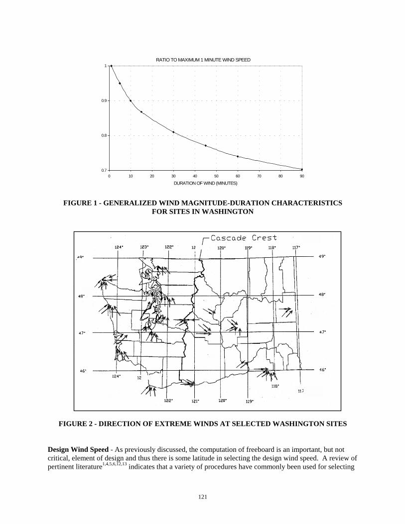
121
RATIO TO MAXIMUM 1 MINUTE WIND SPEED
0.7
0.8
0.9
1
0 10 20 30 40 50 60 70 80 90
DURATION OF WIND (MINUTES)
FIGURE 1 - GENERALIZED WIND MAGNITUDE-DURATION CHARACTERISTICSFOR SITES IN WASHINGTON
FIGURE 2 - DIRECTION OF EXTREME WINDS AT SELECTED WASHIN
Design Wind Speed - As previously discussed, the computation of freeboard is an impcritical, element of design and thus there is some latitude in selecting the design wind spertinent literature1,4,5,6,12,13 indicates that a variety of procedures have commonly been u
G
op
TON SITES
rtant, but noteed. A review ofsed for selecting
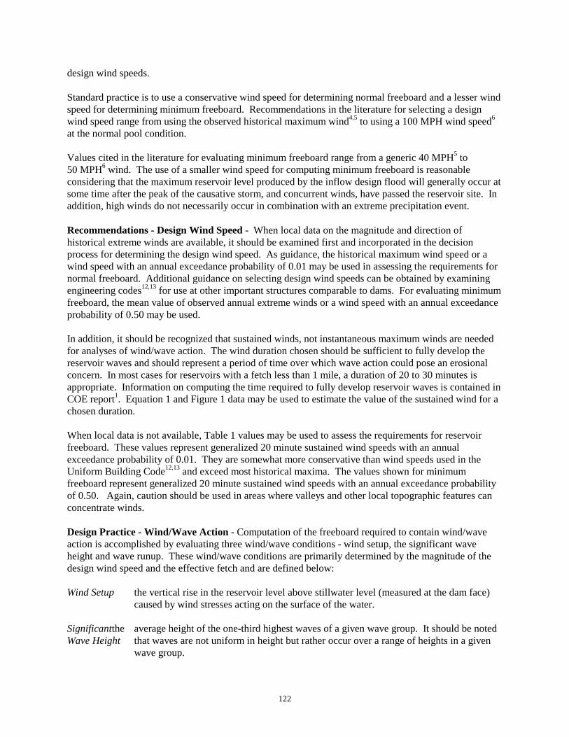
122
design wind speeds.
Standard practice is to use a conservative wind speed for determining normal freeboard and a lesser windspeed for determining minimum freeboard. Recommendations in the literature for selecting a designwind speed range from using the observed historical maximum wind4,5 to using a 100 MPH wind speed6
at the normal pool condition.
Values cited in the literature for evaluating minimum freeboard range from a generic 40 MPH5 to50 MPH6 wind. The use of a smaller wind speed for computing minimum freeboard is reasonableconsidering that the maximum reservoir level produced by the inflow design flood will generally occur atsome time after the peak of the causative storm, and concurrent winds, have passed the reservoir site. Inaddition, high winds do not necessarily occur in combination with an extreme precipitation event.
Recommendations - Design Wind Speed - When local data on the magnitude and direction ofhistorical extreme winds are available, it should be examined first and incorporated in the decisionprocess for determining the design wind speed. As guidance, the historical maximum wind speed or awind speed with an annual exceedance probability of 0.01 may be used in assessing the requirements fornormal freeboard. Additional guidance on selecting design wind speeds can be obtained by examiningengineering codes12,13 for use at other important structures comparable to dams. For evaluating minimumfreeboard, the mean value of observed annual extreme winds or a wind speed with an annual exceedanceprobability of 0.50 may be used.
In addition, it should be recognized that sustained winds, not instantaneous maximum winds are neededfor analyses of wind/wave action. The wind duration chosen should be sufficient to fully develop thereservoir waves and should represent a period of time over which wave action could pose an erosionalconcern. In most cases for reservoirs with a fetch less than 1 mile, a duration of 20 to 30 minutes isappropriate. Information on computing the time required to fully develop reservoir waves is contained inCOE report1. Equation 1 and Figure 1 data may be used to estimate the value of the sustained wind for achosen duration.
When local data is not available, Table 1 values may be used to assess the requirements for reservoirfreeboard. These values represent generalized 20 minute sustained wind speeds with an annualexceedance probability of 0.01. They are somewhat more conservative than wind speeds used in theUniform Building Code12,13 and exceed most historical maxima. The values shown for minimumfreeboard represent generalized 20 minute sustained wind speeds with an annual exceedance probabilityof 0.50. Again, caution should be used in areas where valleys and other local topographic features canconcentrate winds.
Design Practice - Wind/Wave Action - Computation of the freeboard required to contain wind/waveaction is accomplished by evaluating three wind/wave conditions - wind setup, the significant waveheight and wave runup. These wind/wave conditions are primarily determined by the magnitude of thedesign wind speed and the effective fetch and are defined below:
Wind Setup the vertical rise in the reservoir level above stillwater level (measured at the dam face)caused by wind stresses acting on the surface of the water.
Significantthe average height of the one-third highest waves of a given wave group. It should be notedWave Height that waves are not uniform in height but rather occur over a range of heights in a given
wave group.
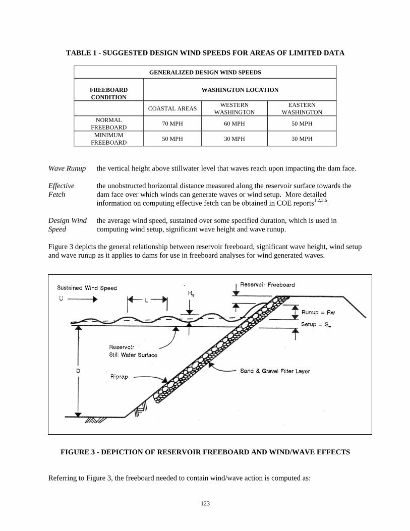
123
TABLE 1 - SUGGESTED DESIGN WIND SPEEDS FOR AREAS OF LIMITED DATA
GENERALIZED DESIGN WIND SPEEDS
FREEBOARDCONDITION
WASHINGTON LOCATION
COASTAL AREAS WESTERNWASHINGTON
EASTERNWASHINGTON
NORMALFREEBOARD 70 MPH 60 MPH 50 MPH
MINIMUMFREEBOARD 50 MPH 30 MPH 30 MPH
Wave Runup the vertical height above stillwater level that waves reach upon impacting the dam face.
Effective the unobstructed horizontal distance measured along the reservoir surface towards theFetch dam face over which winds can generate waves or wind setup. More detailed
information on computing effective fetch can be obtained in COE reports1,2,3,6.
Design Wind the average wind speed, sustained over some specified duration, which is used inSpeed computing wind setup, significant wave height and wave runup.
Figure 3 depicts the general relationship between reservoir freeboard, significant wave height, wind setupand wave runup as it applies to dams for use in freeboard analyses for wind generated waves.
FIGURE 3 - DEPICTION OF RESERVOIR FREEBOARD AND WIND/WAVE EFFECTS
Referring to Figure 3, the freeboard needed to contain wind/wave action is computed as:
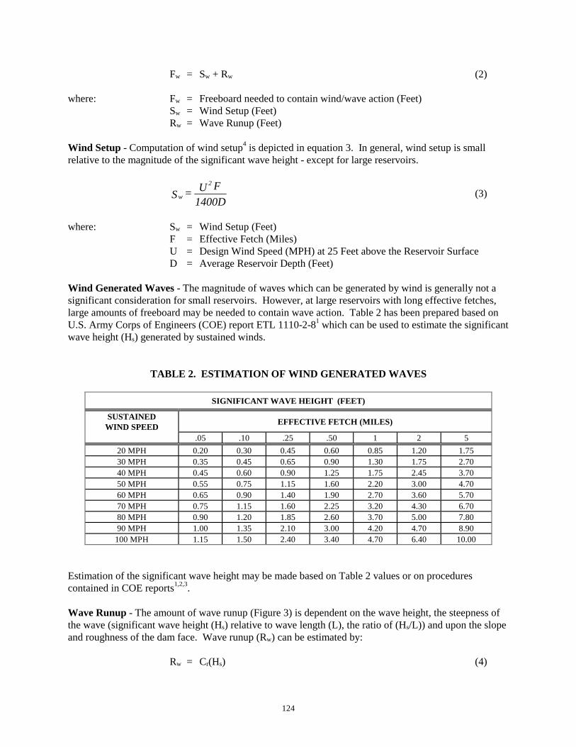
124
Fw = Sw + Rw (2)
where: Fw = Freeboard needed to contain wind/wave action (Feet)Sw = Wind Setup (Feet)Rw = Wave Runup (Feet)
Wind Setup - Computation of wind setup4 is depicted in equation 3. In general, wind setup is smallrelative to the magnitude of the significant wave height - except for large reservoirs.
1400DFU=S
2
w (3)
where: Sw = Wind Setup (Feet)F = Effective Fetch (Miles)U = Design Wind Speed (MPH) at 25 Feet above the Reservoir SurfaceD = Average Reservoir Depth (Feet)
Wind Generated Waves - The magnitude of waves which can be generated by wind is generally not asignificant consideration for small reservoirs. However, at large reservoirs with long effective fetches,large amounts of freeboard may be needed to contain wave action. Table 2 has been prepared based onU.S. Army Corps of Engineers (COE) report ETL 1110-2-81 which can be used to estimate the significantwave height (Hs) generated by sustained winds.
TABLE 2. ESTIMATION OF WIND GENERATED WAVES
SIGNIFICANT WAVE HEIGHT (FEET)
SUSTAINEDWIND SPEED EFFECTIVE FETCH (MILES)
.05 .10 .25 .50 1 2 520 MPH 0.20 0.30 0.45 0.60 0.85 1.20 1.7530 MPH 0.35 0.45 0.65 0.90 1.30 1.75 2.7040 MPH 0.45 0.60 0.90 1.25 1.75 2.45 3.7050 MPH 0.55 0.75 1.15 1.60 2.20 3.00 4.7060 MPH 0.65 0.90 1.40 1.90 2.70 3.60 5.7070 MPH 0.75 1.15 1.60 2.25 3.20 4.30 6.7080 MPH 0.90 1.20 1.85 2.60 3.70 5.00 7.8090 MPH 1.00 1.35 2.10 3.00 4.20 4.70 8.90
100 MPH 1.15 1.50 2.40 3.40 4.70 6.40 10.00
Estimation of the significant wave height may be made based on Table 2 values or on procedurescontained in COE reports1,2,3.
Wave Runup - The amount of wave runup (Figure 3) is dependent on the wave height, the steepness ofthe wave (significant wave height (Hs) relative to wave length (L), the ratio of (Hs/L)) and upon the slopeand roughness of the dam face. Wave runup (Rw) can be estimated by:
Rw = Cr(Hs) (4)
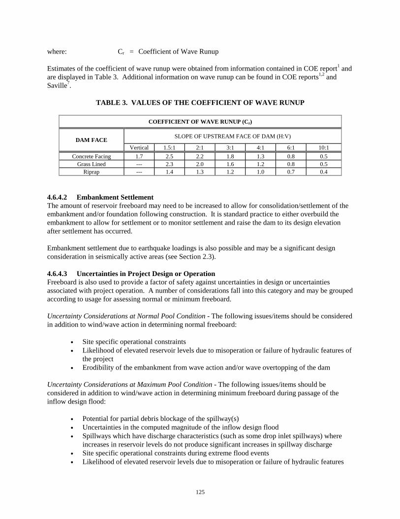
125
where: Cr = Coefficient of Wave Runup
Estimates of the coefficient of wave runup were obtained from information contained in COE report1 andare displayed in Table 3. Additional information on wave runup can be found in COE reports1,2 andSaville7.
TABLE 3. VALUES OF THE COEFFICIENT OF WAVE RUNUP
COEFFICIENT OF WAVE RUNUP (Cr)
DAM FACE SLOPE OF UPSTREAM FACE OF DAM (H:V)
Vertical 1.5:1 2:1 3:1 4:1 6:1 10:1Concrete Facing 1.7 2.5 2.2 1.8 1.3 0.8 0.5
Grass Lined --- 2.3 2.0 1.6 1.2 0.8 0.5Riprap --- 1.4 1.3 1.2 1.0 0.7 0.4
4.6.4.2 Embankment SettlementThe amount of reservoir freeboard may need to be increased to allow for consolidation/settlement of theembankment and/or foundation following construction. It is standard practice to either overbuild theembankment to allow for settlement or to monitor settlement and raise the dam to its design elevationafter settlement has occurred.
Embankment settlement due to earthquake loadings is also possible and may be a significant designconsideration in seismically active areas (see Section 2.3).
4.6.4.3 Uncertainties in Project Design or OperationFreeboard is also used to provide a factor of safety against uncertainties in design or uncertaintiesassociated with project operation. A number of considerations fall into this category and may be groupedaccording to usage for assessing normal or minimum freeboard.
Uncertainty Considerations at Normal Pool Condition - The following issues/items should be consideredin addition to wind/wave action in determining normal freeboard:
• Site specific operational constraints• Likelihood of elevated reservoir levels due to misoperation or failure of hydraulic features of
the project• Erodibility of the embankment from wave action and/or wave overtopping of the dam
Uncertainty Considerations at Maximum Pool Condition - The following issues/items should beconsidered in addition to wind/wave action in determining minimum freeboard during passage of theinflow design flood:
• Potential for partial debris blockage of the spillway(s)• Uncertainties in the computed magnitude of the inflow design flood• Spillways which have discharge characteristics (such as some drop inlet spillways) where
increases in reservoir levels do not produce significant increases in spillway discharge• Site specific operational constraints during extreme flood events• Likelihood of elevated reservoir levels due to misoperation or failure of hydraulic features

126
during an extreme flood event• Erodibility of the embankment from wave action and/or wave overtopping of the dam
4.6.4.4 Geologic HazardsThe geologic setting in Washington poses some unusual considerations which may need to be assessedduring the planning and design stages of the project. While geologic hazards are not designconsiderations at most sites, they can be significant concerns at some projects. The following listidentifies those concerns which could influence the magnitude of freeboard required at a given project.
• Waves produced by landslides into the reservoir• Seiches produced by earthquake motions• Mudflows and other hazards associated with volcanos
4.6.5 DESIGN MINIMUMSAs indicated in the previous discussion, there are numerous factors to be considered in selectingfreeboard. Table 4 has been prepared to provide initial guidance in selecting freeboard. These values areto be considered as minimums and are not intended to supersede larger values obtained from thoroughanalyses of wind/wave action and engineering judgement used in assessing all pertinent factors.
TABLE 4. DESIGN MINIMUMS IN SELECTING RESERVOIR FREEBOARD
RESERVOIR FREEBOARD(FEET) SMALL DAM INTERMEDIATE
DAM LARGE DAM
NORMAL FREEBOARD 2.00 3.50 5.00
MINIMUM FREEBOARD 0.50 0.75 1.00

127
4.6.6 REFERENCES
1. U.S. Army Corps of Engineers, Computation of Freeboard Allowances for Waves in Reservoirs, ETL1110-2-8, Office of the Chief of Engineers, Wash. D.C., 1966.
2. U.S. Army Corps of Engineers, Shore Protection Manual, Volumes I,II,III, Coastal EngineeringResearch Center, Fort Belvoir, Virginia, 1973.
3. Smith, J.M., U.S. Army Corps of Engineers, Wind-Wave Generation on Restricted Fetches, CoastalEngineering Research Center, Waterways Experiment Station, Vicksburg, MS., 1991.
4. Johnson, S.H., and Anderson, D.C., Environmental Protection Agency, Freeboard Determination andManagement in Hazardous Waste Surface Impoundments, Hazardous Waste Engineering ResearchCenter, Cincinnati OH, Sept, 1988.
5. Cassidy, J.J., Reservoir Freeboard Design, Fundamental Hydraulics and Hydrology of Dam Design,Short Course - University of Missouri, Rolla, 1981.
6. U.S. Bureau of Reclamation, Design of Small Dams, Third Edition, 1987, Denver, CO, pp255-258.
7. Saville Jr., T., An Approximation of the Wave Runup Frequency Distribution, Proceedings 8thConference on Coastal Engineering, Mexico City, 1962.
8. Thom, H.C.S., New Distribution of Extreme Winds in the United States, ASCE Journal of theStructural Division, July 1968.
9. Simiu,E., Changery, M.J., and Filliben, J.J., Extreme Wind Speeds at 129 Stations in the ContiguousUnited States, U.S. Department of Commerce, National Bureau of Standards, March, 1973.
10. U.S. Army Corps of Engineers, Seattle District, Unpublished Data on the Magnitude-Frequency-Duration of Observed Winds at Selected Stations in Washington, 1987.
11. Washington State University, Agricultural Extension Service, Washington Climate, Multiple VolumeSeries by County.
12. International Conference of Building Officials, Uniform Building Code, 1988.
13. ASCE, Minimum Design Loads for Buildings and Other Structures, American Society of CivilEngineers, July, 1990.

128

129
CHAPTER 5 - STRUCTURAL ELEMENTS AND ISSUES
5.1 OBJECTIVE:To insure that concrete meets minimum durability levels and performs as intended for the life of theproject.
5.2 APPLICABILITY:This discussion deals primarily with spillway slabs and walls, chutes, energy dissipaters, and othermiscellaneous project appurtenances constructed of concrete. It is not intended to serve as a guide forimpounding barriers built using mass or roller-compacted concrete, even though many of the samerecommendations would be applicable.
5.3 DESIGN PHILOSOPHY:Combining proper materials and good construction techniques usually add little extra cost to a project. The "payback" in increased design life and/or lowered maintenance costs, generally well outweighs anyexpenditures associated with the added attention to design and construction control.
5.4 RECOMMENDED DESIGN PRACTICE:Concrete structures for dams are subject to an extreme environment that can greatly shorten their servicelife. Specifically, concrete will be exposed to: hydraulic pressures, wet-dry and freeze-thaw cycles,abrasion and erosion from sediment-laden water, and static and seismic loadings. Repairing deterioratedconcrete structures frequently approaches efforts similar in scope to original construction, with all of theattendant costs, dangers, and environmental consequences. The difficulties associated with repairingconcrete argue strongly for undertaking every cost-effective, practical step that will improve the overalldurability and service life of concrete structures.
Given the potential for an extended life of some 100 years or more, it is prudent to assume that it will benecessary to retrofit the structure at some future time. Accordingly, measures to minimize the difficultiesand scope of the work necessary to restore the structure should be incorporated into the design.
The following four areas in the DSO's experience are too often inadequately addressed:
• Proper concrete mix design.
• Good construction practice.
• Sufficient concrete cover on reinforcing steel.
• Provision of control joints to limit cracking.
Concrete Mix Design Recommendations - One of the major threats to concrete in a damp or wetenvironment is the deterioration resulting from cycles of freezing and thawing of the moist concrete. Saturated concrete forms ice within the pore structure when it is cooled to the point of freezing. Sincewater expands upon freezing, hydraulic pressures build up in the pore structure. If there is no relief forthese pressures or the strength of the concrete is low, the concrete begins a slow deterioration frommicrocracking. This increases the permeability of the concrete locally which hastens the deteriorationprocess as the volume of water available for freezing is increased. The surficial concrete becomes weakand drummy and the net structural section is decreased. Eventually this process can significantly weakenthe structure. Usually, a more immediate effect is to degrade cover concrete over reinforcing steel to the

130
point where corrosion of the reinforcing becomes the most serious consequence. Rust and spalling overthe bars both decreases the amount of steel and lessens bond, reducing the effectiveness of thereinforcing.
The principal method of minimizing freeze-thaw damage is the utilization of an air entraining agent inthe concrete. Secondary measures include:
Using the lowest practical water/cement ratio (w/c ratio) - A superplasticizer is normallyemployed to reduce water in the mix, while still providing the desirable level of "workability" ofthe mix.
Selecting a cement content based on both strength and durability concerns.
Reducing the permeability of the concrete - Increased cement content, proper concreteconsolidation by vibration, with a suitably graded aggregate, limit water saturation of concrete. This in turn limits the mass of concrete affected by freeze-thaw action.
In some instances, designers have limited the cement content because of their concerns of heat buildupfrom cement hydration and attendant temperature-induced cracking. However, such concerns areprimarily associated with mass concrete pours. This is not normally an issue with the wall/slab typestructures discussed here, except during "hot weather," as defined in ACI 318-891.
AIR-ENTRAINMENTa
Nominal Max.Aggregate Size
(inches)
Air Content(%)
Severe Exposure Moderate Exposure3/8 7½ 61/2 7 5½3/4 6 51 6 4½1 5½ 4½2 5 43 4½ 3½
a Reference 3, Table 5-4
MAXIMUM WATER-CEMENT RATIOSa
Exposure Condition Max. W/C Ratio (by Weight)Concrete usually inundated or Dry 0.50Freeze and Thaw ZoneConcrete Frequently Moist
0.45
a Excerpts from ACI 318-89, Table 4.1.2

131
CEMENT CONTENTa
Exposure(Based on # of Freeze/Thaw Cycles) Cement Content, lb. per cu. yd.b
Severec Freeze-Thaw 564Moderatedd Exposure 517Little or No Exposure 470
a Does not apply to lean concrete fills b Reference 3, Chapter 7, Proportioning normal weight concrete.c Severe exposure is "one where, in a cold climate the concrete may be in almost continuous contact with moisture
prior to freezing..", Reference 1.,d Moderate exposure is one where, in a cold climate, the concrete will be only occasionally exposed to moisture
prior to freezing..", Reference 1.
Good Construction Practices - It should be recognized that a suitably designed concrete mix in thetruck can be enhanced or compromised by construction practices in placing it and how it is treated as ithydrates. Ideally, construction practices will be geared to: enhancing surface curing, minimizing thebleeding of mix water to surfaces and thereby increasing the w/c ratio in this zone, and maximizingconcrete density.
• Proper curing of concrete is primarily a matter of facilitating the process of hydrating thesurficial zone of concrete. Specifically, the goal is to assure that sufficient water remains ofthe concrete mix water to complete the hydration process. This normally is accomplished byeither periodically flooding the surface to replace water lost through evaporation or sealingthe surface to minimize evaporative losses. Where a high degree of hydration is achieved,the concrete exhibits a reduced permeability, increased erosion resistance and a lowersusceptibility to the leaching of the cementious elements from the cement paste. Onecommon failure the DSO has observed that potentially lessens the degree of concretehydration is the use of wooden forms that have not been sufficiently prewetted. The woodtends to absorb water from the surface layer of the concrete, removing water necessary forproper hydration of the cement.
• Steel troweling densifies slab surfaces and renders them less permeable. Properconsolidation of internal concrete accomplishes the same thing, increasing the density andlessening permeability of the interior concrete. Removal of surface irregularities bytroweling will also improve concrete erosion and abrasion resistance.
5.5 REQUIRED DESIGN PRACTICE:Required Minimum Concrete Cover - Research has shown that carbon dioxide in the atmospherereacts with the surficial zone of concrete, replacing calcium hydroxide and tobermorite gel(3CaO·2SiO2·3H2O) with calcium carbonate. This reduces the pH of the affected concrete significantly. The pH change transforms the affected concrete from an environment that inhibits corrosion of thereinforcing to an environment that is potentially corrosive. The degree of corrosion of the reinforcing isa function of the availability of oxygen and the quantity of absorbed or capillary water around the steel. Key to minimizing corrosion of the reinforcing is achieving a dense, low-permeability, concrete cover. This restricts the penetration depth and the concentrations of those elements driving the corrosionprocess beneath the concrete surface. As one would expect, research shows that proper concrete mix

132
design and construction practices are crucial to achieving dense, low permeability concrete. Specifically,research on factors influencing carbonation depth showed an increase in carbonation depth for weakconcretes, low cement content mixes and in environments with relatively high carbon dioxide levels, i.e.urban settings. Where particularly aggressive conditions are anticipated, the designer may wish toconsider the use of epoxy-coated reinforcing to prolong the service life.
The preceding discussion focused on concrete cover as a deterrent to carbonation and associatedcorrosion of the reinforcing. A number of designers routinely increase cover depths over ACI minimumsin this harsh environment. This is done, among other reasons, to provide a greater service life byincreasing the tolerable loss of cover before the reinforcing is affected. Furthermore, it facilitates thetask of placing a concrete overlay. Thus, the recommendations that follow are minimums. Increasingthe minimum cover will likely improve life cycle costs for concrete elements of the project.
CONCRETE COVER FOR STEEL REINFORCEMENT1
Location Minimum Cover, InchesConcrete cast against and permanentlyexposed to earth (or backfill) 3
Concrete exposed to earth or weather 2
Concrete not exposed to weather or in contactwith ground 1½
1 Reference 1, 7.7 - Concrete Cover for Reinforcement
Joints (General Discussion) - Concrete undergoes many volumetric changes during its life. Shrinkageoccurs as the result of the loss of moisture, carbonation, and cooling-related contraction. Expansionoccurs as the result of creep, the absorption of moisture and temperature increases. Cracks are the resultof these volumetric changes that take place in the presence of restraint. The concrete is not free toexpand or contract and stresses, generally tensile, develop in excess of the strength of the concrete.
In the concrete construction covered in this chapter (principally walls and slabs), the designer usuallyemploys a single joint to accommodate expansion and contraction of concrete members. While a rationalanalysis is possible for joint spacing, in practice calculated joint spacings are routinely reduced toaccount for non-uniform subgrade restraint and the potential for high thermal gradients. For most wallsand slabs, joint spacing is on the order of 15 to 40 feet. Again, smaller spacings are used when relativelylarge thermal gradients are anticipated and on the estimated degree of slab restraint.
Joint Requirements - Where control joints are necessary and they shall be submerged continuously orintermittently, they shall include a waterstop.

133
5.6 REFERENCES
1. "Building Code Requirements for Reinforced Concrete, ACI 318-89, and Commentary, ACI 318R-89," American Concrete Institute, Detroit, MI, 1989
2. Concrete Manual, 8th Edition, U.S. Dept. of Interior, Bureau of Reclamation, Denver, Colo., 1988
3. Design and Control of Concrete Mixtures, 13th Edition; Kosmatka, Steven and Panarese, William;Portland Cement Association, Skokie, Il, 1988

134

135
CHAPTER 6 - ELECTRICAL/MECHANICAL ELEMENTS AND ISSUES
6.1 OBJECTIVE:To provide reliability levels commensurate with the design levels cited for Critical Project Elements,Section 2.1, in those electrical and mechanical elements required to function properly to prevent a failureof the impoundment under extreme loadings.
6.2 DESIGN PHILOSOPHY:Individual pieces of electrical and mechanical equipment are not designed for levels of reliabilityapproaching that cited in Chapter 2.1. To achieve the desired level of functioning, it is necessary to takea systems approach similar to that used in the nuclear or airline industry. There, redundant systems areprovided to accomplish a particular task. By providing enough backup systems, the likelihood of all thebackups for a critical system not functioning in a given instance can be made sufficiently remote.
This systems approach requires that the main system and redundant elements meet certain constraints. These include the following:
• A suitable maintenance and testing program must be implemented so that the primary systemand each of the redundant elements can reasonably be presumed to remain functional.
• The failure of one actuating system should not "lock up" the equipment preventing redundantsystems from operating it.
• Independent power sources, delivery systems and controls should be provided to actuate acritical mechanism.
• Instrumentation should be provided to give accurate information on the functioning ofcritical systems.
• An emergency action plan that provides for the use of redundant systems must be developed,and the staff periodically tested in implementing it in realistic, simulated emergencies.
6.3 ENGINEERING PRACTICE:Good engineering practice involves considering, among other things, the following:
Operation & Control• Protecting the controls for the system from unauthorized operation by vandals.
• Identifying a responsible, trained party to operate and maintain the system.
• Recognizing the potential for misoperation of the equipment and, to the extent practicable,incorporate measures to minimize the adverse consequences of misuse. As examples, closingrates for valves should be restricted to rates that will not generate large hydraulic transientsor where flashboards are used, their tripping should not unduly ramp the river.

136
• Ideally, where conditions are approaching failure, the equipment will have a "fail safe" modeof operation that requires no intervention on the part of the operators. For example, on aproject with a gated spillway, should the pool level encroach upon the minimum level offreeboard and contrary to the operating scheme, the gates remain closed, the gate(s) willautomatically be operated according to some predetermined rule curve.
Design
• To the extent practical in design, the modes of failure should be constrained to maximize"running time" and provide some limited but residual functioning or capacity. The firstcategory would include such items as an early warning system to provide timely notice of anabnormal operating condition. In the latter case, should the system fail, ideally it willcontinue to have some remaining capacity. For example, with run-of-the-river hydroelectricprojects, all of the river flow may be diverted into the powerhouse forebay and then outthrough the turbines. If the plant intertie to the power grid is lost, the electrical load on theturbine is removed. Ideally, the turbines have been designed to continue to pass flows in a"no load" operating mode. If this capacity is not provided, there will be significant wavesgenerated in the forebay associated with the sudden shutdown of the flow through theturbines. In the short term, these waves can pose an overtopping concern1. If the reductionin flow through the turbines is not accommodated by increasing flows at the diversionstructure, the low spot in the system will eventually be overtopped with potentially disastrousconsequences.
• The design should account for the extreme loadings that may occur in operation. The impactof vibrations and hydraulic transients acting on gates and piping during the opening andclosing of these elements should be considered in design.
• A locking system should be provided to maintain a particular operational configurationwhere a number of operational states are possible. For example, movable ring gates onmorning glory spillways should not rely solely on hydraulic pressure to maintain them at agiven stage for a protracted period due to the concern for bleeding off of hydraulic pressure.
Periodic Testing
• It should be recognize that there may be problems in operation not anticipated in the design. The system should be tested under as realistic of emergency conditions as practicable toconfirm the system performs as intended. For instance in testing spillway gates, the gatesshould be "bounced" with the pool at an elevated level.
• Separate tests should be conducted on the main and backup systems, not individual elementsof the various systems. Failure to test an auxiliary system as a whole may fail to show a"weak link" common to all systems. For instance, all actuating mechanisms may requirehydraulic fluid from a common reservoir. Should the hydraulic system leak, insufficientfluid may be available to operate the backup system.

137
6.4 REFERENCES
1. Region X Interagency Hazard Mitigation Team, Interagency Flood Hazard Mitigation Report, InResponse to the July 26, 1986 Disaster Declaration, State of Washington, FEMA-769-DR, November10, 1986, pg. 3.

138

139
CHAPTER 7 - CONSTRUCTION SPECIFICATIONS
7.1 OBJECTIVES:
• Identify the goal of the work,
• Describe the assumed, existing conditions (primarily associated with foundation work),
• Provide for testing to control quality,
• Outline a means of dealing with unanticipated or changed conditions and a program forcorrecting deficiencies in construction,
• Protect completed elements of the project, and
• Assure completion of tasks in a timely manner.
7.2 ENGINEERING CONCERNS:Dams pose specialized engineering problems. One must contend with significant seepage forces, longterm settlements, harsh service conditions and long service lives. Moreover, it often is not enough thatone specifies the use of quality materials. The specifier must consider the changes that are likely tooccur in the material resulting from construction practices and normal service conditions. Ideally, thespecifications anticipate problems and include provisions to minimize or mitigate their impact. Theprincipal elements of this process are:
Requiring qualified contractors - A significant portion of the work associated with dams is outside thescope of normal construction practice. Dewatering of large excavations is often required along withtreating problem soils. Extensive subgrade work is often necessary, involving the shaping of rocksurfaces and slush grouting of fractures. Much of the concrete work involves specialized surfacetreatments and curing appropriate for harsh service conditions. Geosynthetics are being usedincreasingly in dam construction. Ideally, the specifications include provisions requiring contractors'bids to document past satisfactory completion of similar work.
Treating and controlling groundwater during construction - Springs are often encountered within thefootprint of the dam. The treatment of springs varies depending on where they occur within the damfootprint. The principal design consideration common to all is that the "fix" not allow themovement of soils into or out of, such features. Within the core section, springs should be treated bothto prevent the loss of fines and so as not to adversely affect compaction of the adjacent core materialsand minimize seepage. Downstream of the core, seeps should be tied into the drainage system.
The construction specifications should require the contractor to maintain the working surface of the fillfree of standing water so that fill compaction can be accomplished in the dry. The specificationstypically note the need to treat wet areas and control groundwater. However, the specific manner oftreatment and/or control is left up to the contractor. To confirm that the work will be accomplished in asuitable manner, the specifications should require the contractor to submit a dewatering plan to theengineer for review and comment.

140
Controlling material properties - The specifications should describe the minimum character to beachieved in the "final product". For example, in subgrade preparation the type of soils anticipated as asuitable bearing surface in the foundation and on the abutments should be described; conversely, whatconstitutes unsuitable soils should be identified. Acceptable density or consistency levels of subgradesoils should be cited. The goal is to assure that field conditions, crucial to the performance of thestructure, meet or exceed the assumptions of the designer.
In compacting moisture sensitive, fine grained soils it is generally impractical to adjust the moisturecontent more than about 2 percent after it is deposited on the working surface of the fill. Where a highlyimpervious, uniform clay liner is required, the specifications normally require that moisture conditioningof the fill be accomplished in the borrow pit. This illustrates the need for the specifier to be aware of thepractical constraints faced by the contractor. To the extent practicable, the specifications need toanticipate difficulties in construction and, in limited cases, require special measures of the contractor.
Controlling construction practices - Properly timing the phases of work on dams can be crucial. Muchof the construction must be scheduled around the weather. Usually, the earthwork has to beaccomplished in the dry season. Projects are often constructed within a river channel. Where the periodof construction of these projects will extend through the runoff season, the site must be maintained in astate to survive the runoff from a potential flood event. This is a particular concern in earthenembankments if the dam section has not reached a sufficient height to have a functional spillway. Thelowlevel outlet pipes are often sized to accommodate the runoff from an unusual storm, predicated onhaving achieved a minimum embankment height. The designer assumed that the flow could beaccommodated through a combination of storage and lowlevel outlet capacity. This approach isreasonable provided there is some means of assuring that the contractor has constructed the embankmentto the necessary elevation. The specifications need to provide the field engineer with the tools to requirethe contractor to undertake and complete crucial phases of the project in a timely manner, consistent withforeseeable weather and surface water flow constraints. The principal element in this is the requirementthat the contractor work up a schedule which clearly identifies a practical construction timeline that dulyconsiders the preceding factors. Ideally, the contractor is made responsible for accomplishing theminimum work necessary for the project to survive a winter shutdown rather than the owner's fieldengineer. The basic thrust of the above comments is to put requirements in the contract documents thatput the onus on the contractor to achieve project milestones. The engineer should not be left in theposition of having to cajole the contractor into accomplishing crucial aspects of the project in a timelymanner.
Dam projects frequently involve esoteric construction problems. Where the plans call for an unusualtask, the specifications should require that the contractor detail the proposed scheme to accomplish thework. It is crucial that the scheme is received with sufficient lead time for the engineer to confirm thatthe approach is practical.
Where specialty work is necessary, or adverse conditions are expected to complicate normal tasks, it isprudent to have the contractor demonstrate the suitability of his proposed construction scheme underrealistic field conditions. For instance, say the purpose is to construct a low permeability soil lining byblending bentonite into the subgrade. The amount of bentonite along with the mixing and compactionprocess are generally left up to the contractor with the proviso that the completed liner exhibit apermeability less than some specified figure. The contractor, prior to starting the actual liner, should berequired to complete a test section that reasonably simulates actual construction practice on the project. This would include utilizing the blending equipment (generally a rotovator), a number of differentbentonite mixes at differing compacted densities with the type of compactor that will be use for the

141
actual liner, and finally testing the process on both representative embankment slopes and bottomsections. Permeability tests should then be conducted to demonstrate the appropriateness of a particularmix and construction procedure.
As previously noted, a key element of the specifications is a description of the product you are trying toachieve. Conversely, it is important often to describe what is to be avoided or minimized. Gravelly claysderived from in place, highly weathered basalt, are often employed for a core material in Washington. The gravel fraction is generally angular and has a coarse gradation. When properly handled the soilforms a highly impermeable, competent core. However, segregation problems have occurred on occasionwith this material. The problems generally occur due to improper handling or working of it on the fillsurface. Ideally, the fill should be dumped from scrapers so that there is minimal need for furthermovement of the material prior to compaction. When the soil is dumped in piles from trucks, as is oftendone, the piles must be spread to form a uniform lift. The spreading operation must be done with care tominimize segregation. In spreading, there is a tendency for the coarser gravels and the occasional cobbleto be "raked" out of the pile and deposited with other coarse fragments together in a "pocket" where thetractor stops. The overall gradation of the soils within these pockets may not have sufficient fines to fillthe interstices between the larger fragments. The presence of these features can lead to increasedseepage and, on rare occasions, to piping problems.
Segregation can also occur when the contractor does not bring up the working surface of the filluniformly. Normally, this occurs where the embankment has a number of different zones and thecontractor continues to place coarse shell materials during wet weather, that is not conducive to theplacement of the moisture sensitive core materials. Two problems arise. First, inadequate compaction isgenerally achieved near the face of the temporary slope at the zone contact. Second, there is a tendencyfor the larger soil particles to roll down this slope and form a significantly coarser zone at the chimneydrain contact and at the upstream shell/core contact. This potentially increases seepage and pipingproblems. Ideally, such problems are anticipated by the designer, based on the characterization of theborrow site by the geotechnical investigation. Where such problems are expected, the specificationsneed to clearly state what is acceptable and unacceptable in the compacted fill. There should be amaximum particle size limitation and a proviso that the coarser materials should not be nested but insteadbe well distributed throughout the fill. Second, the specifications should provide for the excavation oftest trenches periodically to confirm that the desired soil structure is achieved. The method of bestachieving this soil structure should be left up to the contractor. He can choose to employ a grizzly orother means to accomplish the required product.
Protecting completed elements of the work - Once an element has been completed satisfactorily, itdoes not necessarily follow that it remains in an acceptable condition. A suitably compacted soil can bechanged to an unacceptable material through frost action, subsequent overworking of the area underconstruction traffic or even allowing a fine grained soil to dry out and crack. Thus, the specificationsneed to require that the work be protected. This is normally accomplished by requiring that thecontractor remove or rework soils exhibiting specified deficiencies.
A problem routinely encountered in suitably founding the dam is the transition of hard tills andmudstones into a slurry under the combined action of stress release, air slaking, and surface water flows. The contractor exposes competent foundation materials which within the span of a few minutes turns to amuck. In extreme cases this deterioration of the foundation has led to the unnecessary overexcavation oftens of thousands of yards on a single project. Eventually, a practical scheme is worked out to overcomethe problem. This generally involves: intercepting all surface flows and piping them around theexcavation area, excavating a large element of the dam footprint down to within roughly a foot of final

142
grade, dropping the ground water level in the foundations locally, and then, in rapid succession,excavating the last foot of disturbed material, high pressure air cleaning of the surface followedimmediately by the capping of the area with embankment fill. This final phase of excavation can befacilitated by welding a flat plate across the teeth of the backhoe. The flat plate minimizes the depth ofdisturbed material which has to be removed in the subsequent air cleaning operation.
This rapid breakdown of the subgrade poses difficult construction problems for such features as narrow,concrete diaphragm cutoff walls. The wall is excavated and a considerable period of time elapses beforethe reinforcing steel and water stops are placed and concrete poured. During this period, the base of thetrench is being gradually filled by loose materials sloughing from the excavation walls, and ground wateris flowing down the base of the trench. This flow tends to wash away the fines from the material at thebase of the trench, leaving a relatively pervious sandy gravel that may be contiguous along the entiretrench base. Obviously, the presence of such a relatively pervious zone immediately beneath the cutoffwall largely defeats the purpose of the wall. The problem is reduced somewhat by mucking out thetrench immediately prior to placing panels of pre-tied reinforcing panels. However, it is still usuallynecessary to use an air driven suction pipe to clear the residual muck immediately ahead of the concreteplacement. The above details were provided to illustrate the fact that the specifier needs to understandthe difficulties faced by the contractor in the field. If a particularly difficult construction feature isrequired, then the specifications need to clearly outline what constitutes an acceptable condition prior tothe placement of concrete. In this instance, the specifications should require that concrete be poured on asuitable low permeable till stripped of unsuitable zones.
Embankment fill is susceptible to being overworked by the action of construction traffic. Often theconstruction equipment is working in a confined space and access to and from the dam is concentrated ina few areas. The specifications should provide for the removal of soft areas, "pumped" by traffic action.
Contamination of filter zones is a concern. To minimize this problem, it is prudent for the specificationsto require that "crossing areas" be identified for construction traffic. These crossing areas are typicallyprotected by placing a geotextile cap and, if appropriate, a thin wearing course for the equipment.
The issue of keeping frozen soils from incorporation into the working surface of the fill should beaddressed in the specifications. Again, the actual means of accomplishing the goal should be left to thecontractor. Typically, where the frost problem is not too severe, the contractor can "blanket" the lastcompacted lift of the shift with a loose lift. This loose layer acts as an insulator. Depending on thedegree of frost penetration, the layer is either incorporated into the fill or removed as unsuitable. Incolder weather, the construction season may be prolonged if the filling operation is double shifted. Filling can proceed as long as the time for excavation, placement and burial is insufficient for the soil tofreeze.
Pipe designs are generally predicated on the normal stresses under service conditions. However, thestresses associated with placing the pipe and the operation of traffic over the pipe prior to placingadequate cover can be greater than allowable loads. The specifications need to clearly state the minimumcure time for concrete encasement to harden and the minimum cover over the pipe prior to the operationof construction traffic.
7.3 COMMENTARY:Some of the failures to deal with the special problems posed in dam construction spring from a naturaldesire not to "reinvent the wheel". Rather than draft a new specification to cover an aspect of theconstruction, writers frequently "cut and paste" provisions from other projects. Increasingly,

143
specifications do not explicitly describe the elements of the work. Instead, the work is required tocomply with the provisions of the Standard Specifications published by the Washington StateDepartment of Transportation (DOT) in conjunction with the Washington Chapter of the AmericanPublic Works Association. This document provides reasonable provisions governing the construction ofroadways and utilities. However, it was not intended to cover the peculiar problems posed inconstructing embankments to permanently retain bodies of water. The specifications need to beappropriately modified if they are to be used for dam construction.
For example, Section 2-03.3(14), Method C of the Standard Specifications is increasingly cited as acompaction specification. This requires that the embankment fill be compacted to a minimum of 95percent of the maximum density determined by DOT Test Procedure 606 (non-granular soils) or 609(granular soils). Test Procedure 609 roughly corresponds to ASTM Procedure D 698 (Standard Proctor); Test Procedure 606 is something done only by the DOT. First, the soils frequently used in constructingthe shells of dams fall into the granular soil category and one would have to go to the DOT to develop acompaction curve. Second, as noted in the compaction subsection of Chapter 3.2, compaction oftenmust be a minimum of 95 percent of the Modified Proctor Maximum Density. The DOT does notcurrently have an equivalent standard. Finally, the DOT specifications require that field tests of thedegree of compaction be accomplished with a Washington State Densometer or nuclear gauge.Washington Densometers are not widely used, even by the DOT at present, and many test labs do nothave a nuclear gauge. Presumably, the specifications requiring Test Procedure 606 and use of the aparticular densometer are frequently simply ignored during construction. It would be preferable tospecify generally accepted standard procedures for the contractor.

144

145
CHAPTER 8 - OPERATIONAL AND MONITORING ISSUES
8.1 OBJECTIVES:Identify operational issues that need to be addressed to ensure long term safety of the dam and outline theminimum scope of instrumentation and monitoring.
8.2 APPLICABILITY:This discussion is intended to cover the great majority of small to intermediate size earthen embankmentsthat typically have few operational elements and receive relatively infrequent visits by the dam tender. Much of the basic discussion would apply to larger projects. But, the redundancy in discharge facilities,stricter operational constraints and the additional equipment and manpower typically available at largerprojects generally allow and necessitate considerably more elaborate operational and monitoringschemes. This complexity and the site-specific character of these larger facility operation plans placethem outside the scope of the general discussions here.
The instrumentation discussion covers the elements necessary to confirm that the structure is performingin general accordance with the designers' assumptions. The need for further instrumentation toinvestigate an adverse change in the behavior of the impounding structure and/or the foundation, isoutside the scope of this discussion.
8.3 ENGINEERING CONCERNS:Operation - Improper operation and maintenance of the reservoir can impair the safety of the dam and inextreme cases, lead to failure. Project information and operating instructions, critical to the performanceof the dam, may be forgotten or lost in the transfer of ownership or the changing of dam tenders, if notincluded in an operation and maintenance plan.
Monitoring - Instrumentation and the monitoring of that instrumentation, can provide timely notice of anadverse change in the state of the impoundment. In particular, changes in seepage character and/orvolume, abnormal settlement patterns, slope movements, etc., frequently are symptoms of deterioration inthe embankment and foundations. Instrumentation and the dutiful recording and analysis of thegenerated data are crucial to the timely identification of significant trends in the performance of theimpounding barrier.
8.4 DISCUSSION:Overview - General guidance in the development of operation plans is presented in Ecology publications"Guidelines for Developing Dam Operation and Maintenance Manuals" and Chapters 7 and 9 of Part IIIof the Guidelines, "An Owner's Guidance Manual". These documents also provide guidance on theselection of instrumentation and the drafting of monitoring programs.
Integrating the Operation, Monitoring and Emergency Action Plans - It is important to recognize therelationship between the Operation and Maintenance Program, the Monitoring Program and theEmergency Action Plan. Together they represent a continuum of responses to various event scenarios atthe project. Key to the development of these plans is the identification of the foreseeable range of eventsthat could beset the facility and the "scripting" of appropriate responses.
8.5 OPERATION PLAN:The hallmarks of a good operation plan are:

146
• A responsible individual is named to carry out the plan and provisions are included requiringthis individual to document routine compliance with the scheme.
• The inclusion of a comprehensive list of the normal and reasonably foreseeable extremeoperational conditions the facility could be subjected to, and appropriate "scripts" formanaging the project through the various scenarios.
• The monitoring program and emergency action plan, if necessary, are integrated into theprovisions of the operation plan. Data is required from the monitoring program in carryingout the scripts of the operation plan. An "alert phase" is included in the operational schemeproviding a transition period as an unusual event unfolds prior to imminent failure.
• To the extent practicable, the facility is designed to survive extreme loading conditionswithout the need for intervention by the dam tender. Ideally, the scripted response is builtinto the design and requires no action by the operator. For example, an ungated, emergencyspillway is preferable to a gated unit that would require some "action" to obtain maximumcapacity.
• Where action by the tender is required, it is crucial that the conditions precipitating thataction are triggered early in the course of an event. This allows greater time to "ramp up"changes in facility operation and reduces the risk to the dam tender in accomplishingrequired operations under high pool or other extreme conditions.
• Actions in the script the dam tender must follow are tied to clear benchmarks. For externalproblems such as floods, predetermined pool levels and rates of reservoir rise should initiateaction. For earthquakes, the inspection and precautionary drawdown of the pool should bedictated by the occurrence of a seismic event larger than some specified magnitude within aspecified region centered on the project. For internal structural problems such as piping,excessive seepage or embankment slides, the operation plan should require lowering of thepool and provide guidance on whether conditions warrant implementing the emergencyaction plan.
The following discusses specific issues and elements in an operation plan.
• Stoplog Operation: Stoplogs are frequently used in spillways for regulation of the reservoirlevel, or to increase the storage capacity of the reservoir. Normally, the dam size, reservoircapacity, and spillway discharge are designed to provide the maximum possible storagewhile retaining the ability to pass the Inflow Design Flood (IDF). However, in some cases,stop logs can be used to temporarily raise the water level during times when the occurrenceof the IDF is least likely and removed to provide flood storage when the IDF is more likely. The seasonal placement and removal of the stop ogs must be described in the Operation andMaintenance (O&M) Plan and approved by the Dam Safety Office.
• Access: In designing gate or valve controls for outlets, spillways or other critical operatingequipment, care should be taken to provide for safe access under both normal and emergencyconditions. This would entail placing critical outlet or spillway controls in an easilyaccessible location such as the dam crest, or in a location well above the normal reservoirlevel or flood level.
147
• Vandalism: Vandalism is often a problem at facilities. Valves are opened and oftendamaged. Debris is jammed into the housing around valve stems and into the entrances ormouths of pipes. Monitoring devices are smashed. To the extent practicable, operating andmonitoring equipment should be placed inside protective devices. Furthermore, theprotective devices should be configured to make vandalism as difficult as practicable. Thiswould include: making them unobtrusive, placing them flush or below surrounding grade andrestricting vehicle access. Finally, the designer must assume that valves conceivably couldbe prevented from operating or conversely, opened to their maximum rating. This potentialfor misoperation should be considered in the design and factored into the operational plan.
• Backup Operation: Electrically controlled gates and valves for outlets and spillways shouldbe provided with backup, manual controls. The backup controls should be easily accessibleduring a major flood or other emergency situation.
• Operation Instructions: An operation plan should provide clear, complete, step-by-stepinstructions for operating all mechanisms associated with a dam. Instructions on the generaloperation of the reservoir, including any inflow and outlet ditches, should be given. Theinstructions should cite the maximum pool levels to be allowed at different times of the year,permissible outlet releases, and operation of the outlet to limit or prevent spillway flow.
8.6 MONITORING PROGRAMGeneral - Because of the wide variety of dams within the purview of the Dam Safety Office, it isimpractical to develop an all-encompassing plan, covering every project. However, there are generalissues that typically must be addressed at each project. The remainder of this section discusses thesetypical elements of a monitoring program. Section 8.7 summarizes the specific requirements germane tosmall, intermediate and large dams.
Instrumentation - As in the operation plan, the engineer should incorporate features in the dam cross-section during design to minimize the need for instrumentation. The designer is encouraged (in somecases required) to actively constrain the variability of crucial elements influencing embankmentperformance. First, this serves to improve the overall reliability of the structure and second, it obviatesthe need for sophisticated monitoring with all the attendant problems with data analysis, equipmentfailures, misreadings and the cost of running the program.
Where instrumentation is necessary, the design should facilitate the use of the simplest type ofinstrumentation. For example, one of the principal factors affecting embankment stability is the positionof the phreatic surface in the embankment cross-section. Various types of observation wells have beenemployed in the past to confirm the designer's assumptions as to the position of the phreatic surface. Considerable controversy and money has been spent to explain anomalous observation well readings. The inclusion of chimney and blanket drains in the design (espoused in Chapter 3.2) provides a positivemeans of controlling the position of the phreatic surface within the embankment. The other parametersof interest in monitoring groundwater in the embankment are the volume and character of the seepage. Collector drains embedded within the chimney drains and outlet pipes or free draining gravel zoneswithin the blanket drain, afford the opportunity to easily monitor seepage volumes and recoverrepresentative water samples. These water samples can be collected in clear jars and a visual assessmentmade as to whether entrained fines are present that would indicate "piping" is occurring. In the case ofmeasuring seepage, a simple v-notch weir or bucket and stop watch system can be employed to determinethe volume of flow. Further refinements in flow monitoring can be achieved by providing a number ofoutlets for the drains in the abutments and at intervals along the valley floor. Such a scheme provides the

148
ability to evaluate differential seepage across the dam footprint at a nominal cost.
We see three key elements in conducting a successful monitoring program:
• An operation plan that requires the taking of monitoring data and the dutiful carrying out ofthe observation program,
• The timely evaluation of that data for significant changes or adverse trends in anticipatedbehavior, and
• A script in the operation plan to follow when the monitoring suggests significant changes areoccurring.
It should be noted that many of the adverse changes in the dam occur at a gradual rate. Eventually, thedeterioration passes some trigger level and further degradation may occur at a precipitous rate. Thegradual deterioration phase may be so lengthy that the dam tender is not aware of the adverse trend. Often, initial concerns as to seepage and slumps are relieved or forgotten when the situation continueswithout appearing to dramatically worsen; familiarity with a problem breeds complacency.
Photographs - One of the most effective tools at maintaining a perspective on the state of the dam is theperiodic photographing of the embankment and downstream toe. Ideally, a set of photographs would betaken each year. The individual sets of photographs should be compared with one another. The principalitem of interest to be looking for are changes in the type and area of vegetative cover. This gives an earlyindication of any changes in seepage conditions taking place within the embankment and foundations. More dramatic changes such as slumps and piping features would most likely follow sometime after thevegetative changes. Ideally, the changes in vegetation would have initiated an appropriate response. However, in the event these changes are missed, more dramatic changes such as surficial creeping of theembankment, piping or other problems likely would be picked up in a comparison of photographs and anappropriate response triggered.
Log Book - Along with a photographic record, a log book of observations and monitoring data should bemaintained. The log book should note significant events, cite normal maintenance and operational tasksperformed, and record and plot any observations and monitoring data on the performance of the structureand appurtenances. Abnormal performance of the structure should trigger an appropriate response in theoperation plan. It should be recognized that normal and abnormal performance probably will not beknown until after the structure has been put in service and steady state conditions have developed in thefoundations and embankment. For the majority of small dams under consideration here, this conditionprobably will be achieved within a year or so of first filling. At this point, the monitoring programdeveloped by the designer should be reviewed to confirm that it appropriately covers the range of actualobserved conditions. In addition, the designer's initial monitoring program should have included anincreased frequency of readings to obtain a clear picture of embankment performance fluctuations inresponse to various loadings. After obtaining a history of readings, the data should be reviewed. Specifically, monitoring data should be evaluated to determine: 1) what is a normal reading and whatshould constitute a significant abnormal reading, 2) the minimum frequency of readings necessary tomodel a particular aspect of dam performance, and 3) the best means of plotting data and how the datashould be used in the operation plan.

149
8.7 REQUIRED MINIMUM OPERATION AND INSTRUMENTATION PROGRAMS:
All projects shall have an Operation and Maintenance Plan as per WAC 173-175-210. Where theoperation plan allows the seasonal use of stoplogs, the scheme for stoplog use must be approved by theDam Safety Office.
Table 1 summarizes the minimum instrumentation program for impoundments.
TABLE 1 - EMBANKMENT INSTRUMENTATION
DAM SIZE CLASSIFICATION MINIMUM INSTRUMENTATION ELEMENTS
SMALL DAM(Less Than 15 Feet High)
• Reservoir staff gage.
INTERMEDIATE SIZE DAM(15 Feet to 50 feet in height)
• Reservoir staff gage.• Underdrain outlet volume measurement scheme.• Simple settlement/displacement monuments in the dam crest
referenced to a fixed point on either abutment.
LARGE DAM(50 Feet or Greater in height)
• Reservoir staff gage.• Underdrain outlet volume measurement scheme.• Simple settlement/displacement monuments in the dam crest
referenced to a fixed point on either abutment.

150
8.8 REFERENCES:
1. U.S. Bureau of Reclamation, Training Aids for Dam Safety, Module: How to organize an Operationand Maintenance Program, U.S. Government Printing Office, Denver, CO., 1990.

151
APPENDIX AGLOSSARY
Abutment - That contact location at either end and beneath the flanks of a dam where the artificial barrierjoins or faces against the natural earth or rock foundation material upon which the dam is constructed. The left and right abutments of dams are defined with the observer viewing the dam looking in thedownstream direction.
Appurtenant Works - Structures such as outlet works and associated gates and valves; water conveyancestructures such as spillways channels, fish ladders, tunnels, pipelines or penstocks; powerhouse sections;and navigation locks, either in the dam or separate therefrom.
Axis of dam - The vertical plane or curved surface, chosen by a designer, appearing as a line, in plan orin cross-section, to which the horizontal dimensions of the dam are referenced.
Baffle block - A block, usually of concrete, constructed in a channel or stilling basin to dissipate theenergy of water flowing at high velocity.
Base thickness - Also referred to as base width. The maximum thickness or width of the dam measuredhorizontally between upstream and downstream faces and normal to the axis of the dam, but excludingprojections for outlets, or other appurtenant structures.
Bedrock - The consolidated body of natural solid mineral matter which underlies the overburden soils.
Berm - A nearly horizontal step in the sloping profile of an embankment dam.
Borrow area - The area from which material for an embankment is excavated.
Breach - An eroded opening through a dam which drains the reservoir. A controlled breach is aconstructed opening. An uncontrolled breach is an unintentional opening which allows uncontrolleddischarge from the reservoir.
Channel - A general term for any natural or artificial facility for conveying water.
Compaction - Mechanical action which increases the density by reducing the voids in a material.
Conduit - A closed channel to convey water through, around, or under a dam.
Construction joint - The interface between two successive placings or pours of concrete where bond, andnot permanent separation, is intended.
Core - A zone of low permeability material in an embankment dam. The core is sometimes referred to ascentral core, inclined core, puddle clay core, rolled clay core, or impervious zone.
Crest Length - The total horizontal distance measured along the axis of the dam, at the elevation of thetop of the dam, between abutments or ends of the dam. Where applicable, this includes the spillway,powerhouse sections and navigation locks, where they form a continuous part of the impoundingstructure.

152
Crest thickness (top width) - The thickness or width of a dam at the level of the top of dam (excludingcorbels or parapets). In general, the term thickness is used for gravity and arch dams, and width is usedfor other dams.
Critical Project Element - An element of a project whose failure could result in the uncontrolled releaseof the reservoir.
Cross section - An elevation view of a dam formed by passing a plane through the dam perpendicular tothe axis.
Cutoff trench - A foundation excavation later to be backfilled with material so as to limit seepage beneatha dam.
Dam - Any artificial barrier and/or any controlling works, together with appurtenant works that can ordoes impound or divert water.
a. Arch dam. A concrete or masonry dam which is curved upstream so as to transmit the majorpart of the water load to the abutments.
b. Cofferdam. A temporary structure enclosing all or part of the construction area so thatconstruction can proceed in the dry. A diversion cofferdam diverts a stream into a pipe,channel, tunnel, or other watercourse.
c. Crib dam. A gravity dam built up of boxes, crossed timbers or gabions, filled with earth orrock.
d. Diversion dam. A dam built to divert water from a waterway or stream into a differentwatercourse.
e. Earth dam. An embankment dam in which more than 50% of the total volume is formed ofcompacted earth material generally smaller than 3-inch size.
f. Embankment dam. Any dam constructed of excavated natural materials or of industrialwaste materials.
g. Gravity dam. A dam constructed of concrete and/or masonry which relies on its weight andinternal strength for stability.
h. Hydraulic fill dam. An earth dam constructed of materials, often dredged, which areconveyed and placed by suspension in flowing water.
i. Industrial waste dam. An embankment dam, usually built in stages, to create storage for thedisposal of waste products from an industrial process. The waste products are conveyed asfine material suspended in water to the reservoir impounded by the embankment. Theembankment may be built of conventional materials but sometimes incorporates suitablewaste products.
j. Masonry dam. Any dam constructed mainly of stone, brick, or concrete blocks jointed withmortar. A dam having only a masonry facing should not be referred to as a masonry dam.

153
k. Mine tailings dam. An industrial waste dam in which the waste materials come from miningoperations or mineral processing.
l. Regulating dam. A dam impounding a reservoir from which water is released to regulate theflow downstream.
m. Rockfill dam. An embankment dam in which more than 50% of the total volume iscomprised of compacted or dumped cobbles, boulders, rock fragments, or quarried rockgenerally larger than 3-inch size.
n. Roller compacted concrete dam. A concrete gravity dam constructed by the use of a dry mixconcrete transported by conventional construction equipment and compacted by rolling,usually with vibratory rollers.
o. Saddle dam (or dike). A subsidiary dam of any type constructed across a saddle or low pointon the perimeter of a reservoir.
p. Tailings dam. See mine tailings dam.
Dam failure - The uncontrolled release of impounded water. It is recognized that there are lesser degreesof failure and that any malfunction or abnormality outside the design assumptions and parameters whichadversely affect a dam's primary function of impounding water is properly considered a failure. Theyare, however, normally amenable to corrective action.
Dam Height - The effective hydraulic height of a dam as measured by the vertical distance from thenatural bed of the stream or watercourse at the downstream toe of the impounding barrier to themaximum storage elevation. If the dam is not across a stream or watercourse, the height is measuredfrom the lowest elevation of the outside limit of the impounding barrier to the maximum storageelevation.
Design Step Level - An integer value between one and ten used to designate increasingly stringent designloadings and conditions for design of critical project elements.
Dike - See saddle dam.
Diversion channel, canal, or tunnel - A waterway used to divert water from its natural course. The termis generally applied to a temporary arrangement, e.g. to by-pass water around a dam site duringconstruction. "Channel" is normally used instead of "canal" when the waterway is short.
Downstream Hazard Classification - A rating to describe the potential for loss of human life and/orproperty damage if the dam were to fail and release the reservoir onto downstream areas. Downstreamhazard classifications of 3, 2 and 1C, 1B, 1A correspond to low, significant and high downstream hazardclasses respectively.
Drain, blanket - A layer of pervious material placed to facilitate drainage of the foundation and/orembankment.
Drain, chimney - A vertical or inclined layer of pervious material in an embankment to facilitate andcontrol drainage of the embankment fill.

154
Drain, toe - A system of pipe and/or pervious material along the downstream toe of a dam used to collectseepage from the foundation and embankment and convey it to a free outlet.
Drainage area - The area which drains to a particular point on a river or stream.
Drawdown - The difference between a water level and a lower water level in a reservoir within aparticular time. Used as a verb, it is the lowering of the water surface.
Earthquake - A sudden motion or trembling in the earth caused by the abrupt release of accumulatedstress along a fault.
Emergency Action Plan (EAP) - A plan of action to be taken to reduce the potential for property damageand loss of life in an area affected by a dam failure.
Emergency Condition - A situation where life and property are at imminent risk and actions are neededwithin minutes or hours to initiate corrective actions and/or warn the public.]
Emergency Spillway - Any secondary spillway which is designed to be operated very infrequently andpossibly in anticipation of some degree of structural damage or erosion to the spillway during operation.
Energy dissipator - A device constructed in a waterway to reduce the kinetic energy of fast flowingwater.
Epicenter - The point on the earth's surface located vertically above the point of origin of an earthquake.
Exigency Condition - A situation where the impounding structure is significantly underdesignedaccording to generally accepted engineering standards or is in a deteriorated condition and life andproperty are clearly at risk. Although present conditions do not pose an imminent threat, if adverseconditions were to occur, the situation could quickly become an emergency.
Fault - A fracture or fracture zone in the earth crust along which there has been displacement of the twosides relative to one another.
Fault, Active - A fault which, because of its present tectonic setting, can undergo movement from time totime in the immediate geologic future.
Fault, Capable - An active fault that is judged capable of producing macro-earthquakes and exhibits oneor more of the following characteristics:
a. Movement at or near the ground surface at least once within the past 35,000 years.
b. Macroseismicity (3.5 magnitude Richter or greater) instrumentally determined with recordsof sufficient precision to demonstrate a direct relationship with the fault.
c. A structural relationship to a capable fault such that movement on one fault could bereasonably expected to cause movement on the other.
d. Established patterns of microseismicity which define a fault, with historic macroseismicitythat can reasonably be associated with the fault.

155
Fetch - The straight line distance across a body of water subject to wind forces. The fetch is one of thefactors used in calculating wave heights in a reservoir.
Filter (filter zone) - One or more layers of granular material graded (either naturally or by selection) so asto allow seepage through or within the layers while preventing the migration of material from adjacentzones.
Flashboards - Structural members of timber, concrete, or steel placed in channels or on the crest of aspillway to raise the reservoir water level but that may be quickly removed in the event of a flood.
Flip bucket - An energy dissipator located at the downstream end of a spillway and shaped so that waterflowing at a high velocity is deflected upwards in a trajectory away from the foundation of the spillway.
Flood - A temporary rise in water levels resulting in inundation of areas not normally covered by water. May be expressed in terms of probability of exceedance per year such as one percent chance flood orexpressed as a fraction of the probable maximum flood or other reference flood.
Floodplain - An area adjoining a body of water or natural stream that has been or may be covered byfloodwater.
Freeboard - The vertical distance between the dam crest elevation and some reservoir level of interest.
Fuse Plug Spillway - A form of auxiliary spillway consisting of a low embankment designed to beovertopped and washed away during an exceptionally large flood.
Gate - A movable, watertight barrier for the control of water in a waterway.
a. Bascule gate. See flap gate.
b. Bulkhead gate. A gate used either for temporary closure of a channel or conduit beforedewatering it for inspection or maintenance or for closure against flowing water when thehead difference is small, e.g., for diversion tunnel closure.
c. Crest gate (spillway gate). A gate on the crest of a spillway to control the discharge orreservoir water level.
d. Drum gate. A type of spillway gate consisting of a long hollow drum. The drum may beheld in its raised position by the water pressure in a flotation chamber beneath the drum.
e. Emergency gate. A standby or auxiliary gate used when the normal means of water controlis not available. Sometimes referred to as guard gate.
f. Fixed wheel gate (fixed roller gate) (fixed axle gate). A gate having wheels or rollersmounted on the end posts of the gate. The wheels bear against rails fixed in side grooves orgate guides.
g. Flap gate. A gate hinged along one edge, usually either the top or bottom edge. Examples ofbottom-hinged flap gates are tilting gates and fish belly gates so called from their shape incross section.

156
h. Flood gate. A gate to control flood release from a reservoir.
i. Outlet gate. A gate controlling the flow of water through a reservoir outlet.
j. Radial gate (Tainter gate). A gate with a curved upstream plate and radial arms hinged topiers or other supporting structure.
k. Regulating gate (regulating valve). A gate or valve that operates under full pressure flowconditions to regulate the rate of discharge.
l. Roller drum gate. See drum gate.
m. Roller gate (stoney gate). A gate for large openings that bears on a train of rollers in eachgate guide.
n. Skimmer gate. A gate at the spillway crest whose prime purpose is to control the release ofdebris and logs with a limited amount of water. It is usually a bottom hinged flap or Basculegate.
o. Slide gate (sluice gate). A gate that can be opened or closed by sliding in supporting guides.
Gate chamber (valve chamber) - A room from which a gate or valve can be operated, or sometimes inwhich the gate is located.
Geotextiles - Any fabric or textile when used as an engineering material in conjunction with soil,foundations or rock. Geotextiles have the following uses: drainage, filtration, separation of materials,reinforcement, moisture barriers, and erosion protection.
Groin - The area along the contact (or intersection) of the face of a dam with the abutments.
Grout - A fluidized material that is injected into soil, rock, concrete, or other construction material to sealopenings and to lower the permeability and/or provide additional structural strength. There are fourmajor types of grouting materials: chemical; cement; clay; and bitumen.
Grout curtain - One or more zones, usually thin, in the foundation into which grout is injected to reduceseepage under or around a dam.
Hydraulic Height - The vertical difference between the maximum design water level and the lowest pointin the original streambed.
Hydrograph - A graphical representation of discharge, stage, or other hydraulic property with respect totime for a particular location on a watercourse.
Hydrograph, Breach or Dam Failure - A flood hydrograph resulting from a dam breach.
Hydrograph, Unit - A hydrograph with a volume of one inch of runoff resulting from a storm of aspecified duration and areal distribution. Hydrographs from other storms of the same duration anddistribution are assumed to have the same time base but with ordinates of flow in proportion to the runoffvolumes.

157
Hypocenter - The point or focus within the earth which is the center of an earthquake and the origin of itselastic waves.
Impounding Barrier - The structural element of the dam that has the primary purpose of impounding ordiverting water. It may be constructed of natural and/or man-made materials.
Incident - The occurrence of any dam-related event where problems or conditions arise which may haveposed a threat to the safety or integrity of the project or which may have posed a threat of loss of life orwhich resulted in loss of life.
Inflow Design Flood (IDF) - The reservoir inflow flood hydrograph used for sizing the spillways and fordetermining freeboard. It represents the largest flood that a given project is designed to safelyaccommodate.
Instrumentation - An arrangement of devices installed into or near dams (i.e., piezometers, inclinometer,strain gages, measurement points, etc.) which provide for measurements that can be used to evaluate thestructural behavior and performance parameters of the structure.
Intake - Any structure in a reservoir, dam or river through which water can be discharged.
Inundation map - A map delineating the area that would be flooded by a particular flood event.
Liquefaction - A condition whereby soil undergoes continued deformation at a constant low residualstress or with low residual resistance, due to the buildup and maintenance of high pore water pressures,which reduces the effective confining pressure to a very low value. Pore pressure buildup leading toliquefaction may be due either to static or cyclic stress applications and the possibility of its occurrencewill depend on the void ratio or relative density of a cohesionless soil and the confining pressure.
Logboom - A chain of logs, drums, or pontoons secured end to end and floating on the surface of areservoir so as to divert floating debris, trash, and logs.
Maximum design water level - The maximum water elevation including the flood surcharge, that a dam isdesigned to withstand.
Maximum flood control level - The highest elevation of the flood control storage.
Maximum Storage Elevation - The maximum attainable water surface elevation of the reservoir pool thatcould occur during extreme operating conditions. This elevation normally corresponds to the crestelevation of the dam.
Minimum operating level - The lowest level to which the reservoir is drawn down under normaloperating conditions.
Normal Pool Height - The vertical distance between the lowest point of the upstream toe of theimpounding barrier and the normal storage elevation.
Normal Storage Elevation - The normal maximum operating pool level in a reservoir. Where theprincipal spillway is ungated, the normal storage elevation is usually established by the level of thespillway crest.

158
Observation well - A hole used to observe the groundwater surface at atmospheric pressure within soil orrock.
100 Year Floodplain - The area inundated during the passage of a flood with a peak discharge having aone percent chance of being equalled or exceeded in any given year at a specified location on awatercourse.
Outlet - A conduit and/or channel structure for the controlled release of the contents normally impoundedby a dam and reservoir.
Parapet wall - A solid wall built along the top of a dam (upstream or downstream edge) used forornamentation, for safety of vehicles and pedestrians, or to prevent overtopping caused by wave runup.
Penstock - A pressurized pipeline or shaft between the reservoir and hydraulic machinery.
Periodic Inspection - A detailed inspection of the dam and appurtenant works conducted on regularintervals and includes, as necessary, associated engineering analyses to confirm the continued safeoperation of the project.
Phreatic surface - The free surface of water seeping at atmospheric pressure through soil or rock.
Piezometer - An instrument used for measuring fluid pressure (air or water) within soil, rock, or concrete.
Piping - The progressive development of internal erosion within a soil mass by seepage.
Plunge pool - A natural or artificially created pool that dissipates the energy of free falling water.
Population At Risk - The number of people who may be present in areas downstream of a dam and couldbe at risk in the event of a dam failure.
Principal Spillway (or Service Spillway) - A spillway designed to provide continuous or frequent releasesfrom a reservoir, without significant damage to either the dam or its appurtenant structures.
Probable Maximum Flood (PMF) - The most severe flood that is considered reasonable possible at a siteas a result of meteorologic and hydrologic conditions.
Probability - The likelihood of an event occurring.
Probable Maximum Precipitation (PMP) - Theoretically, the greatest depth of precipitation for a givenduration that is physically possible over a given size storm area at a particular geographical location.
Reservoir - Any basin that contains or will contain the water impounded by a dam.
Reservoir Routing - The procedures used to determine the attenuating effect of reservoir storage on aflood as it passes through a reservoir.
Reservoir surface area - The area covered by a reservoir when filled to a specified level.
Riprap - A layer of large uncoursed stone, precast blocks, bags of cement or other suitable material,

159
generally placed on the upstream slopes of an embankment or along a watercourse as protection againstwave action, erosion or scour. Riprap is usually placed by dumping or other mechanical methods and insome cases is hand placed. It consists of pieces of relatively large size as distinguished from a gravelblanket.
Risk - The relationship between the consequences resulting from an adverse event and its probability ofoccurrence.
Risk assessment - As applied to dam safety, the process of identifying the likelihood and consequences ofdam failure to provide the basis for informed decisions on a course of action.
Rule Curve - The rules and procedures used to regulate reservoir levels and project operation for variousreservoir inflows and for both normal and unusual seasonal conditions.
Safety Evaluation Flood(SEF) - The largest flood for which the safety of a dam and appurtenant structureis to be evaluated.
Slope - Inclination from the horizontal. Sometimes referred to as batter when measured from vertical.
Spillway - A channel structure and/or conduit for the safe release of surplus water or floodwater.
Spillway channel - An open channel or closed conduit conveying water from the spillway inletdownstream.
Spillway chute - A steeply sloping spillway channel that conveys discharges at super-critical velocities.
Spillway crest - The lowest level at which water can flow over or through the spillway.
Spillway, Shaft - A vertical or inclined shaft into which water spills and then is conveyed through, under,or around a dam by means of a conduit or tunnel. If the upper part of the shaft is splayed out andterminates in a circular horizontal weir, it is termed a bellmouth or morning glory spillway.
Stilling basin - A basin constructed to dissipate the energy of rapidly flowing water, e.g., from a spillwayor outlet, and to protect the riverbed from erosion.
Stoplogs - Large logs, timbers, or steel beams placed on top of each other with their ends held in guideson each side of a channel or conduit so as to provide a cheaper or more easily handled means oftemporary closure than a bulkhead gate.
Storage - The retention of water or delay of runoff either by planned operation, as in a reservoir, or bytemporary filling of overflow areas, as in the progression of a flood wave through a natural streamchannel. Definitions of specific types of storage in reservoirs are:
a. Dead storage. The storage that lies below the invert of the lowest outlet and that, therefore,cannot readily be withdrawn from the reservoir.
b. Inactive storage. The storage volume of a reservoir between the crest of the invert of thelowest outlet and the minimum operating level.
c. Active storage. The volume of the reservoir that is available for some use such as power

160
generation, irrigation, flood control, water supply, etc. The bottom elevation is the minimumoperating level.
d. Live storage. The sum of the active and the inactive storage.
e. Reservoir capacity. The sum of the dead and live storage of the reservoir.
f. Flood surcharge. The storage volume between the top of the active storage and the designwater level.
Structural Height - The vertical distance between the lowest point of the excavated foundation to the topof the dam.
Surficial Inspection - A visual inspection conducted to identify obvious defects or changed conditions.
Sweepout - The hydraulic condition in a hydraulic jump energy stilling basin where there is insufficienttailwater depth to offset the hydrodynamic forces of the incoming discharge. The hydraulic jump is"swept" out of the basin and the downstream receiving stream is subjected to the full erosional forces ofthe high velocity discharge.
Thrust block - A massive block of concrete built to withstand a thrust or pull.
Toe of dam - The junction of the face of a dam with the ground surface. For concrete dams, see heel.
Trashrack - A device located at an intake to prevent floating or submerged debris from entering theintake.
Tunnel - A long underground excavation with two or more openings to the surface, usually having auniform cross section used for access, conveying flows, etc.
Valve - A device fitted to a pipeline or orifice in which the closure member is either rotated or movedtransversely or longitudinally in the waterway so as to control or stop the flow.
Watershed divide - The divide or boundary between catchment areas (or drainage areas).
Wave runup - The vertical height above the stillwater level to which water from a specific wave will runup the face of a structure or embankment.
Weir - A notch of regular form through which water flows.
a. Weir, broad-crested. An overflow structure on which the nappe is supported for anappreciable length in the direction of flow.
b. Weir, measuring. A device for measuring the rate of flow of water. It generally consists of arectangular, trapezoidal, triangular, or other shaped notch, located in a vertical, thin plateover which water flows. The height of water above the weir crest is used to determine therate of flow.
c. Weir, ogee. A reverse curve, shaped like an elongated letter "S." The downstream faces ofoverflow spillways are often made to this shape.

161
Wind setup - The vertical rise in the stillwater level at the face of a structure or embankment caused bywind stresses on the surface of the water.
SOURCE:
Interagency Committee on Dam Safety, Task Group on Glossary of Terms, Glossary of Terms for DamSafety, Federal Emergency Management Agency, February 1988.

162

163
APPENDIX B
SUMMARY OF REQUIREMENTS

164

165
GEOTECHNICAL ISSUESMINIMUM REQUIRED EXPLORATION PROGRAM
EXPLORATION METHODS EARTHEN EMBANKMENTSMALL INTERMEDIATE LARGE
BORROWSITES
BACKHOE TEST PITS ✓ ✓ ✓ ✓ 2
BORINGS ✓ 1 ✓ 1 ✓ ✓ 1,2
GEOPHYSICAL EXPLORATIONS ✓ 2 ✓ 2
PERMEABILITY TESTS ✓ 2 ✓1 Borings appropriate where overburden has appreciable thickness2 Desirable on a case by case basis
EMBANKMENT GEOMETRY AND ZONINGELEMENT EARTHEN EMBANKMENTS
SMALLINTERMEDIATE LARGEGUIDELINE
REFERENCEFOUNDATION CUTOFF Cutoff Trench
Rock Contact SealingReq'dA
Req'dBReq'dA
Req'dBReq'dA
Req'dB3.23.2
LOW LEVEL OUTLET PIPE Req'dC Req'd Req'd 4.1
DRAINS ChimneyBlanketToe Drains
RecomD
RecomRecom
Req'dReq'dE,F
______G
Req'dReq'dE,F
______G
3.33.3
FILTERS Filter Criteria met EverywhereH Req'dReq'd
Req'dReq'd
Req'dReq'd
3.3.A3.3.B
SIDESLOPES To be determined by engineering analysisJ 2.2
FREEBOARD To be determined by engineering analysis 4.6
CREST______K
To be determined by engineering analysisEROSION PROTECTION Upstream Face
Downstream FaceCrestDownstream Groins
RecomRecomM
Req'dRecomN
Req'dReq'dReq'd
Recom
Req'dReq'dReq'dReq'd
3.53.5
INSTRUMENTATION Reservoir Staff GaugeSettlement MonumentsPiezometersWeirs/Pipe to Measure Seepage
Req'dRecomO
RecomRecomM
Req'dReq'd
RecomRecom
Req'dReq'd
RecomReq'd
8888
A The subgrade should be stripped of any pervious surficial zone to found the cutoff on a suitable, lowpermeability zone
B Any rock exposures should be sealed within the limits of the cutoff trench to prevent the loss of embankmentmaterials into the foundations. Ideally, rock exposures upstream and downstream of the cutoff should be sealedand drained, respectively.
C For diked impoundments <10 feet high, the outlet may be omitted if it is practicable to lower the pool bysiphoning.
D For small stormwater detention facilities, the DSO will consider eliminating the chimney drain where it can bedemonstrated that neither excessive seepage is likely to develop in the abutments nor that the phreatic surfacewill penetrate a significant depth into the upstream surface.
E Where the foundations are relatively pervious, finger drains would provide an acceptable alternative to a blanketdrain.
F The blanket drain should extend up the abutment. The extent of the abutment coverage should be a function ofthe magnitude and the nature of the seepage anticipated to emerge from the contact. Where isolated perviousfeatures are indicated, separate finger drains should be considered within the blanket to safely carry off theconcentrated flow and facilitate monitoring flow character.
G This would normally be a subelement of the blanket drain. Where the blanket drain has a large hydrauliccapacity relative to the anticipated seepage flow and it is configured to efficiently shunt flow to one or a fewpoints, a toe drain is not required.
H The zones should be internally stable in that they satisfy filter criteria for themselves. Plus, filter criteria must besatisfied at all zone contacts including the embankment interface with the foundation and abutments.
I Applicable to all conduits extending through or underlying the embankment cross-section.

166
J For small dams, bearing on a competent foundation, constructed of a well compacted clay, the DSO will accepta design with 3H on 1V upstream and 2H on 1 V downstream slopes without a supporting engineering analysis.
K The larger of 8 feet or the quantity 2(H)1/2 + 3.L Based on anticipated magnitude of crest settlement and conservatism in the level of freeboard provided.M Determination based on ability to maintain a thick vegetative cover or erosion resistance of exposed soil.N The need for erosion protection should be based on the volume of runoff and the erosion resistance of the groin
area soils.O Monuments should be provided where freeboard is a minimum and significant settlements are anticipated.
FILTERSCATEGORIES OF BASE SOIL MATERIALS
Category Percent finer than the No. 200
1 >852 40-853 15-394 <15
CRITERIA FOR FILTERSBase soilcategory
Base soil description, and percent finer than No. 200(0.075mm) sieve 1/
Filter criteria 2/
1 Fine silts and clays; more than 85% finer. 3/ D15 <9 x d85
2 Sands, silts, clays, and silty and clayey sands; 40 to85% finer.
D15 < 0.7 mm
3 Silty and clayey sands and gravels; 15 to 39% finer. 4,5/ D15 < 154040
−−A
(4 x d85 - 0.7mm) + 0.7mm
4 Sands and gravels; less than 15% finer. 6/ D15 < 4 x d85
1/ Category designation for soil containing particles larger than 4.75 mm is determined from a gradation curve of thebase soil which has been adjusted to 100% passing the No. 4 (4.75 mm) sieve.
2/ Filters are to have a maximum particle size of 3 inches (75 mm) and a maximum of 5% passing the No. 200(0.075 mm) sieve (as determined by wet sieving ASTM C-117-80) with the plasticity index (PI) of the fines equal tozero. PI is determined on the material passing the No. 40 (0.425 mm) sieve in accordance with ASTM-D-4318. Toensure sufficient permeability, filters are to have a D15 size equal to or great than 4 x d15 but no smaller than 0.1mm.
3/ When 9 x d85 is less than 0.2 mm, use 0.2 mm.4/ A = percent passing the No. 200 (0.075 mm) sieve after any regrading.5/ When 4 x d85 is less than 0.7 mm, use 0.7 mm.6/ In category 4, the d85 may e determined from the original gradation curve of the base soil without adjustments for
particles larger than 4.75 mm.
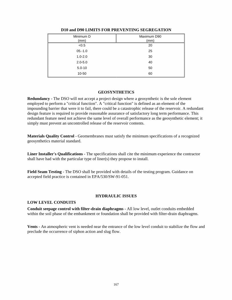
167
D10 and D90 LIMITS FOR PREVENTING SEGREGATIONMinimum D
(mm)Maximum D90
(mm)<0.5 20
05.-1.0 251.0-2.0 302.0-5.0 405.0-10 5010-50 60
GEOSYNTHETICSRedundancy - The DSO will not accept a project design where a geosynthetic is the sole elementemployed to perform a "critical function". A "critical function" is defined as an element of theimpounding barrier that were it to fail, there could be a catastrophic release of the reservoir. A redundantdesign feature is required to provide reasonable assurance of satisfactory long term performance. Thisredundant feature need not achieve the same level of overall performance as the geosynthetic element; itsimply must prevent an uncontrolled release of the reservoir contents.
Materials Quality Control - Geomembranes must satisfy the minimum specifications of a recognizedgeosynthetics material standard.
Liner Installer's Qualifications - The specifications shall cite the minimum experience the contractorshall have had with the particular type of liner(s) they propose to install.
Field Seam Testing - The DSO shall be provided with details of the testing program. Guidance onaccepted field practice is contained in EPA/530/SW-91-051.
HYDRAULIC ISSUESLOW LEVEL CONDUITSConduit seepage control with filter-drain diaphragms - All low level, outlet conduits embeddedwithin the soil phase of the embankment or foundation shall be provided with filter-drain diaphragms.
Vents - An atmospheric vent is needed near the entrance of the low level conduit to stabilize the flow andpreclude the occurrence of siphon action and slug flow.

168
DESIGN MINIMUMS FOR NON-PRESSURIZED CONDUITSFOR EARTHEN DAMS WITH LOW DOWNSTREAM HAZARD CLASSIFICATIONS
(Design Step Levels 1 and 2)
ITEM - ISSUE REQUIRED MINIMUM/DESIGN PRACTICEMinimum Pipe Size1 12 inch diameter for concrete encased pipe, otherwise 15
inch diameterProvisions must be available to pass the normal reservoirinflow during periods of high runoff while still pulling thereservoir down within a span of a few days to weeks for
inspection, repairs or emergency purposes. This dischargecapacity may be obtained from use of the low level outlet
and/or from other permanent or temporary hydraulic systemsPipe Gauge or Wall Thickness Adequate considering anticipated construction and service
loads, abrasion, service life and varying subgrade supportPipe Joints Rubber gasketed joints are required, except for welded
pipesFor corrugated metal pipe, widest available bolted
connectors are required.Concrete Encasement Required for pressurized conduits din small dams and for all
conduits in intermediate and large dams2
Upstream Control Valve to RegulateWater Releases3
Required
Atmospheric Vent for Low Level Outlet Required on all conduits with the exception of pressurizedconduits in small dams
Filter-Drainage Diaphragm RequiredLow Permeability Pipe Bedding Zone Bedding soil upstream of the filter-drainage diaphragm must
be of equal or lower permeability than that of the adjacentsoil and must satisfy filter criteria for all surrounding soils.
1 Use straight alignment whenever practicable to facilitate future sleeving of the pipe2 Pipe cradle scheme considered for non-pressurized pipes in stormwater detention facilities with temporary pools3 Not required on conduits for drop inlet, culvert spillways or conduits where inflow is regulated by intake
structures

169
DESIGN MINIMUMS FOR CONDUITS FOR EARTHEN DAMSWITH HIGH OR SIGNIFICANT DOWNSTREAM HAZARD CLASSIFICATIONS
(Design Step Levels 3 and Greater)ITEM - ISSUE PERMANENT OR SEASONAL POOL TEMPORARY POOL/INTERMITTENT RESERVOIR
OPERATIONSMALL DAM INTERMEDIATE
DAMLARGE DAM SMALL DAM INTERMEDIATE
DAMLARGE DAM
Minimum pipe Diameter1,2,3 12" 12" 12" 12" 12" 12"Complete ConcreteEncasement of Pipe4
Required5 Required Required Required5 Required5 Required5
Upstream Shutoff or ControlValve6
Required Required Required Required7 Required7 Required7
Atmospheric Vent for LowLevel Outlet
Required Required Required Required Required Required
Low Permeability Foundationand Backfill
All earthen materials upstream of filter-drainagediaphragm must have a permeability less than or equalto that of the surrounding material and must satisfy filtercriteria for all adjacent materials.
All earthen materials upstream of filter-drainagediaphragm must have a permeability less than or equalto that of the surrounding material and must satisfy filtercriteria for all adjacent materials.
Filter-Drainage Diaphragm Required Required8 Required8 Required Required8 Required8
1 Use straight alignment whenever practicable to facilitate future sleeving of the pipe2 Outlet should be sized to be able to pass the normal reservoir inflow during the high runoff period while still capable of pulling the reservoir down
within a span of a few weeks3 Pipe gauge or wall thickness adequate to account for abrasion, long term durability and other site-specific concerns4 Minimum of 6 inches of reinforced concrete for encasement of pipe section5 Pipe cradle in combination with precast reinforced concrete pipe may be used where the design can be justified on the basis of favorable site
conditions6 Not required for conduits on drop inlet spillways and for conduits where the inflow is regulated by intake structures7 May not be required for stormwater detention and other flood control projects8 The chimney drain zone (Section 3.2 Embankment Geometry and Zoning) generally satisfies this requirement

170
PRESSURIZED CONDUITSConcrete Encasement - To the extent practicable, pressurized conduits should be routed outside of theembankment toe. Where the pipe is within the embankment footprint, it shall be encased in concrete. Theprincipal exceptions to encasement are:
Conduits - The requirement for concrete encasement may be waived if the engineer can showthat: 1) the downstream hazard setting is low, 2) although a significant portion of theembankment could be sluiced away, an uncontrolled release of the reservoir contents is unlikelyand 3) the owner acknowledges acceptance of the increase risked of problems.
Mine tailings discharge lines - Often sections of the slurry lines are routed over the dam crest.Where it is necessary to frequently move these lines, it is generally impractical to provideconcrete or other forms of encasement for the piping. The DSO has accepted schemes where"critical pipe runs", those segments of pipe located within or upon the exterior dikes, weresleeved by running these lines inside of larger, jointed, corrugated metal pipes.
Vents - An atmospheric vent is required immediately downstream of the upstream gate of valve onpressurized low level outlet conduits at intermediate and large dams to minimize the effects of cavitationand/or vacuum buckling.
Valving - Pressurized pipes require valves or other means of shut-off at the upstream end.
PRINCIPAL OR SERVICE SPILLWAY
Concrete lined spillway underdrains - All concrete lined chutes that serve as principal spillways shallbe provided with underdrains. Underdrains may be omitted in the following circumstances:
The spillway will be cast directly on rock. In this eventuality footing drains probably will benecessary for the sidewalls of the spillway, or
The avenues of seepage have been properly cutoff and the concrete chute serves as an emergencyspillway that passes flows only a few times over the project life.
Atmospheric Venting or Aeration - Venting of outlet conduits for culvert spillways, drop inletspillways and morning glory spillways is usually needed to preclude the occurrence of slug flow.Likewise, aeration of the nappe just below the crest on drop inlet and morning glory spillways is neededto stabilize the flow pattern.
Energy Dissipation at Spillway Outlet - During large floods, flow conditions are usually supercriticalat the terminus of the spillway conveyance section (chute, conduit, etc.). The discharge is characterizedas having high velocities and severe soil erosion capability. Measures must be taken to dissipate theexcess energy and control the flow before returning it to the receiving stream. It is anticipated thatreturning flows to the receiving channel still will precipitate some degree of erosion under extreme floodflows. Measures must be taken to assure that this erosion will not jeopardize the integrity of the spillwayor the impounding barrier.
Contraction & Expansion Joints for Spillway Chutes - Contraction-expansion joints must be providedto maintain floor alignment while allowing for floor slab movement. The joint must be supported by a
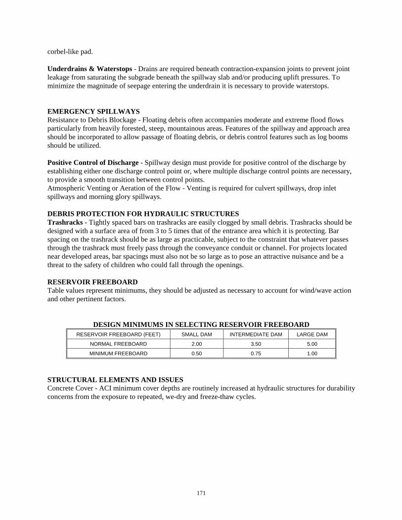
171
corbel-like pad.
Underdrains & Waterstops - Drains are required beneath contraction-expansion joints to prevent jointleakage from saturating the subgrade beneath the spillway slab and/or producing uplift pressures. Tominimize the magnitude of seepage entering the underdrain it is necessary to provide waterstops.
EMERGENCY SPILLWAYSResistance to Debris Blockage - Floating debris often accompanies moderate and extreme flood flowsparticularly from heavily forested, steep, mountainous areas. Features of the spillway and approach areashould be incorporated to allow passage of floating debris, or debris control features such as log boomsshould be utilized.
Positive Control of Discharge - Spillway design must provide for positive control of the discharge byestablishing either one discharge control point or, where multiple discharge control points are necessary,to provide a smooth transition between control points.Atmospheric Venting or Aeration of the Flow - Venting is required for culvert spillways, drop inletspillways and morning glory spillways.
DEBRIS PROTECTION FOR HYDRAULIC STRUCTURESTrashracks - Tightly spaced bars on trashracks are easily clogged by small debris. Trashracks should bedesigned with a surface area of from 3 to 5 times that of the entrance area which it is protecting. Barspacing on the trashrack should be as large as practicable, subject to the constraint that whatever passesthrough the trashrack must freely pass through the conveyance conduit or channel. For projects locatednear developed areas, bar spacings must also not be so large as to pose an attractive nuisance and be athreat to the safety of children who could fall through the openings.
RESERVOIR FREEBOARDTable values represent minimums, they should be adjusted as necessary to account for wind/wave actionand other pertinent factors.
DESIGN MINIMUMS IN SELECTING RESERVOIR FREEBOARDRESERVOIR FREEBOARD (FEET) SMALL DAM INTERMEDIATE DAM LARGE DAM
NORMAL FREEBOARD 2.00 3.50 5.00
MINIMUM FREEBOARD 0.50 0.75 1.00
STRUCTURAL ELEMENTS AND ISSUESConcrete Cover - ACI minimum cover depths are routinely increased at hydraulic structures for durabilityconcerns from the exposure to repeated, we-dry and freeze-thaw cycles.

172
CONCRETE COVER FOR STEEL REINFORCEMENT
Location Minimum Cover, InchesConcrete cast against and permanentlyexposed to earth (or backfill)
3
Concrete exposed to earth or weather 2
Concrete not exposed to weather or incontact with ground 1½
Joints and Waterstops - While a rational analysis is possible for joint spacing, in practice calculatedjoint spacings are routinely reduced to account for non-uniform subgrade restraint and the potential forhigh thermal gradients. For most walls and slabs, joint spacing is on the order of 15 to 40 feet. Smallerspacings are used when relatively large thermal gradients are anticipated and on the estimated degree ofslab restraint. Where control joints are necessary and they shall be submerged continuously orintermittently, they shall include a waterstop.
OPERATION AND MAINTENANCE PLANS
All projects shall have an Operation and Maintenance Plan as per WAC 173-175-210. Where theoperation plan allows the seasonal use of stop logs, the scheme for stop log use must be approved by theDam Safety office.
Remote, telemetered operation of any gates must have back up by on-site operators during extreme floodconditions.
INSTRUMENTATION PROGRAMS
EMBANKMENT INSTRUMENTATION
DAM SIZE CLASSIFICATION MINIMUM INSTRUMENTATION ELEMENTS
SMALL DAM
(Less Than 15 Feet High)
• Reservoir staff gage.
INTERMEDIATE SIZE DAM
(15 Feet to 50 Feet in Height)
• Reservoir staff gage.
• Underdrain outlet volume measurement scheme.
• Simple settlement/displacement monuments in the damcrest referenced to a fix points on either abutment.
LARGE DAM
(50 Feet or Greater in Height)
• Reservoir staff gage.
• Underdrain outlet volume measurement scheme.
• Simple settlement/displacement monuments in the damcrest referenced to a fix points on either abutment.