dam safety program technical note 8...
TRANSCRIPT

DAM SAFETY PROGRAM
TECHNICAL NOTE 8
SPECIFICATIONS REQUIREMENTS FOR DAMS
Prepared for:
Montana Department of Natural Resources and Conservation Water Resources Division Water Operations Bureau
Dam Safety Program PO Box 201601
Helena, MT 59620-1601
Prepared by:
DOWL HKM 222 N. 32ndStreet, Suite 700
Billings, MT 59101
V1.1 October 2012

ii

iii
TABLE OF CONTENTS
LIST OF TABLES ...........................................................................................................iv
LIST OF APPENDICES ..................................................................................................iv
OVERVIEW ....................................................................................................................v
1.0 INTRODUCTION .....................................................................................................1-1
1.1 PURPOSE ......................................................................................................1-1
1.2 TARGET AUDIENCE ..................................................................................1-3
2.0 IMPORTANCE OF SPECIFICATIONS FOR PROJECT SUCCESS ......................2-1
2.1 APPROPRIATE FOR PROJECT ..................................................................2-1
2.2 REFERENCE DURING CONSTRUCTION ................................................2-3
2.3 CONSISTENT ...............................................................................................2-3
2.4 COMPLETE ..................................................................................................2-4
2.5 COORDINATION .........................................................................................2-4
3.0 METHODS OF SPECIFYING ..................................................................................3-1
3.1 DESCRIPTIVE SPECIFICATIONS .............................................................3-1
3.2 PERFORMANCE SPECIFICATIONS .........................................................3-1
3.3 REFERENCE STANDARD SPECIFICATIONS .........................................3-2
3.4 PROPRIETARY SPECIFICATIONS ...........................................................3-2
4.0 PROJECT MANUAL ................................................................................................4-1
4.1 RECOMMENDED ORGANIZATION SYSTEM ........................................4-1
4.2 SPECIFICATION FORMAT ........................................................................4-4
4.3 PROCUREMENT AND CONTRACTING REQUIREMENTS
(DIVISION 00) ...........................................................................................4-4
5.0 RECOMMENDED PROJECT MANUAL COMPONENTS ....................................5-12
5.1 INTRODUCTORY INFORMATION ...........................................................5-12
5.2 BIDDING/PROCUREMENT INFORMATION ...........................................5-12
5.3 CONTRACT REQUIREMENTS & GENERAL CONDITIONS .................5-13
5.4 GENERAL REQUIREMENTS (DIVISION 1).............................................5-13
5.5 SITE WORK (DIVISION 2) .........................................................................5-14
5.6 CONCRETE (DIVISION 3) ..........................................................................5-15

iv
5.7 OTHER DIVISIONS .....................................................................................5-15
6.0 SPECIAL CONSIDERATIONS FOR DAMS ..........................................................6-12
6.1 COFFERDAMS & STREAM DIVERSION .................................................6-12
6.2 DEWATERING .............................................................................................6-12
6.3 FOUNDATION INSPECTION, PROTECTION & TREATMENT .............6-12
6.4 IMPERVIOUS FILL AT STRUCTURES & ABUTMENTS .......................6-13
6.5 EMBANKMENT LIFT SURFACES ............................................................6-13
6.6 FILTERS AND DRAINS ..............................................................................6-14
6.7 SITE DRAINAGE .........................................................................................6-14
6.8 SEASONAL SHUTDOWN ...........................................................................6-14
7.0 SUBMITTALS ..........................................................................................................7-1
7.1 SUBMITTAL REVIEW & APPROVAL ......................................................7-1
7.2 SUBMITTALS FOR INFORMATION ONLY.............................................7-1
7.3 SUBMITTAL SCHEDULE ...........................................................................7-1
8.0 REFERENCES ..........................................................................................................8-1
LIST OF TABLES
TABLE 4-1 MASTERSPEC DIVISIONS (PRE-2004 VERSION) .........................4-2
TABLE 4-2 MASTERSPEC DIVISIONS (2011 VERSION) ..................................4-3
LIST OF APPENDICES
APPENDIX A Section & Page Format for Specifications
APPENDIX B NRCS Standard Specifications - Earthwork

v
DAM SAFETY PROGRAM
TECHNICAL NOTE 8 (TN8)
SPECIFICATIONS REQUIREMENTS FOR DAMS
Overview
Technical Note 8 (TN8) is provided to assist and guide engineers and professionals in
preparing construction specifications for Montana high hazard dams. The Dam Safety
Program intends TN8 to provide consistent guidelines to adequately define the construction
requirements needed to complete a project in conformance with the design intent
TN8 contains a discussion of construction documents as it applies to general civil
engineering projects followed by more specific considerations that commonly apply to
Montana dam construction.
The preparation of Technical Specifications for construction or repair of High Hazard Dams
needs to be performed by a Professional Engineer that is competent in the area of practice. It
is the responsibility of this professional to apply sound engineering judgment when using
technical references. This publication is intended solely for use by professional personnel
who are competent to evaluate the significance and limitations of the information provided
herein, and who accept total responsibility for the application of this information. Anyone
making use of this information assumes all liability from such use.

vi

1-1
DAM SAFETY PROGRAM
TECHNICAL NOTE 8 (TN8)
SPECIFICATIONS REQUIREMENTS FOR DAMS
1.0 INTRODUCTION
This technical note is intended to provide practical technical guidance to design professionals
engaged in the preparation of construction documents for high hazard dams in Montana. Our
goal is to provide information, references and procedures relevant to the dam safety rules for
Montana for preparation of construction specifications that contribute to a construction
process that provides a finished product in conformance with the design intent.
This document was prepared by DOWL HKM, under contract to the Montana Department of
Natural Resources and Conservation (DNRC) Dam Safety Program. The DOWL HKM work
was directed by Jason H. Thom, P.E. Users of this document are encouraged to provide
feedback and recommendations on its contents. Please send your comments to:
Montana Dam Safety Program
Department of Natural Resources and Conservation (DNRC) P.O. Box 201601
Helena, MT 59620-1601 [email protected]
The Montana Dam Safety Program operates within the DNRC Water Resources Division’s
Water Operations Bureau. Funding for the preparation of this document was provided
through the Federal Emergency Management Agency (FEMA) National Dam Safety
Program.
TN8 will be revised and updated as new technical references are made available.
1.1 PURPOSE
The purpose of TN8 is to assist and provide guidance to engineers and professionals for
preparation of specifications that adequately define the construction requirements needed to

1-2
complete a project in conformance with the design intent. TN8 is not a regulatory document
and the references and procedures provided can be modified to suit the needs of the user.
The Dam Safety Program intends for TN8 to provide guidance for consistent specifications
but recognizes that professionals may use other technical resources, accompanied with
relevant reasons for their use. Other agencies and funding sources may also have specific
requirements that need to be included to meet the specific needs of particular projects.
Additional detail about preparation and organization of construction documents is available
from a number of sources. The Construction Specifications Institute (CSI) is an organization
dedicated to “…improving specification practices in the construction and allied industries.”
CSI publishes numerous guidance documents and provides training and certification in
specification writing. A number of their documents are listed in the references section of
TN8 and their web site is at www.csinet.org. Standard construction documents and forms are
available from the Engineers Joint Contract Documents Committee (EJCDC) which is a joint
organization of the National Society of Professional Engineers (NSPE), American Council of
Engineering Companies (ACEC), American Society of Civil Engineers (ASCE), and the
Associated General Contractors of America (AGC). These standard documents are endorsed
by CSI. Use of EJCDC standard documents is preferred by the Montana Dam Safety
Program.
The terms Project Manual, Specifications (or Technical Specifications), Construction
Documents, Contract Documents and Drawings will be utilized within TN8. The meanings
of these terms are summarized below:
Project Manual represents the written construction documents including the
introductory information, procurement requirements, contracting requirements and
the specifications. Often additional information, such as geotechnical data reports, is
included as supplemental appendices within the Project Manual. In practice, the
Project Manual is frequently referred to as the specifications but the Project Manual
includes other materials beyond the specifications. The sections of the project

1-3
manual are usually bound together to provide a comprehensive book with the various
documents organized in a standardized format and order.
Specifications refer to the written description of the work to be performed. This
section of the Project manual covers the technical requirements and the term technical
specifications may also be used. The specifications are a part of the contract
documents but generally do not deal with the contract terms, general requirements
and administration aspects of the construction requirements. The specifications are
intended to describe the work to be performed and define products, materials and
workmanship requirements of the construction.
Construction Documents are the comprehensive written and graphic documents
prepared or assembled by the design professional (Engineer) to communicate the
design for construction and administering the construction contract. This includes the
Project Manual and the construction drawings.
Contract Documents are the portions of the construction documents directly identified
in the construction contract as pertaining to that contract. These typically include the
contracting requirements, the specifications and the contract drawings.
Drawings are the graphic representations of the project to communicate the design
and construction requirements. Drawings are often also referred to as the plans. In
general, the term Drawings (or Plans) refer to the documents prepared by the
Engineer in advance of construction. However, supplemental drawings produced
during the construction stage, such as shop drawings, are also an important part of the
graphic communication included in the term Drawings.
1.2 TARGET AUDIENCE
TN8 is for use by engineers and professionals experienced in design and rehabilitation of
dams and appurtenant structures. Professional judgment is required in the preparation of
specifications for construction of high hazard dams, regardless of guidance provided by TN8.

1-4
Users of TN8 are expected to be familiar with the design and construction of dams and
competent in applying that knowledge to the unique aspects of each project. DOWL HKM,
DNRC and the Dam Safety Program are not responsible for the use and interpretation of TN8
contents.

2-1
2.0 IMPORTANCE OF SPECIFICATIONS FOR PROJECT SUCCESS
The primary purpose of the construction documents is to adequately define and communicate
the construction requirements needed to complete a project in conformance with the design
intent. The concept of adequate communication is a key issue in regards to organization,
format and content of the specifications. Misunderstanding or confusion on the part of the
builder will most likely result in construction of a project that does not meet the design intent
with potential for costly or even catastrophic consequences. Clear and concise information
that is appropriate for the project, provides ready reference and that is consistent and
complete are necessary aspects. Proper definition of the roles, responsibilities and authority
of the various members of the construction team is also needed.
2.1 APPROPRIATE FOR PROJECT
Producing specifications that are appropriate for the nature of the project is an essential
aspect of adequate communication to the construction team. The specifications should
address the specific needs of the project and should not include extraneous information that is
not relevant.
Information in the specifications should have the appropriate level of detail and complexity
for the project. A simple minor repair should be quite brief when compared to a project that
includes a complex combination of zoned fills, drains, a concrete spillway and outlet works.
Extra information that is not relevant could create “clutter” that obscures the important
relevant information.
Consideration should be given to the normal practices of likely bidders and suppliers for the
project. Smaller dam repairs located in remote areas of Montana often are constructed by
local contractors and local suppliers. For example, utilizing a concrete mix that includes
special features that are readily available in urban areas may not be readily available in
remote rural areas.
Whether it is appropriate to use standardized specifications should be carefully evaluated.
Some projects may require the use of a given standard – for example a grant or loan used to

2-2
fund the construction may require using the standard specification of an agency such as the
NRCS or Bureau of Reclamation. If a standard specification is required, it should be
carefully reviewed by the designer to ensure that the specific aspects of the project are
included and appropriately defined in the specifications. The organization and presentation
of standard specifications requires special attention to be sure they clearly communicate the
aspects that apply to the project. Standard specifications typically include a broad range of
components that cover aspects that are not applicable to the project and this can contribute to
confusion and mistakes by the construction team.
Some standard specifications such as the Montana Public Works (MPW) or Montana
Department of Transportation (MDT) standard specifications are generally not appropriate
for use in dam construction projects. These specifications were developed for road and
utilities projects without consideration to special requirements often included in construction
associated with dams. The typical Project Manual based on standard specifications, such as
MPW or MDT, consists of a small project manual that references the standard specifications
and identifies specific deviations from the standard for the project. The standard
specifications are a separate published reference book that is obtained from the agency
responsible for producing and publishing the standard – in many cases the standard is
copyrighted material. The construction team is expected to have the separately published
standard specifications in-hand and to be familiar with their application. This concept is very
useful for the cities and agencies that developed the standards as it provides consistency that
becomes very familiar to the construction team as they perform multiple projects following
the standards. However, most dam construction projects in Montana do not benefit from the
standardized specifications because of the unique characteristics of each dam and the need
for two separate references (Project Manual and Standard Specification) which may cause
confusion and errors during construction. Besides, the standard specifications, such as MDT
or MPW, often include some aspects that are not acceptable for construction of a dam.
Many design firms utilize master guideline specifications to efficiently develop project
specifications. These master guidelines allow the specification writer to produce the
specifications by editing pre-written text. The firm may have developed in-house master
2-3
guidelines or there are commercially available master guideline specifications, such as
MASTERSPEC, SPECTEXT and SpecLink. Guideline specifications for specific products
developed by product manufacturers are also available. When using guideline specifications
it is imperative that the designer carefully review and edit the specifications to make them
appropriate for the project.
2.2 REFERENCE DURING CONSTRUCTION
In order to effectively communicate the detailed requirements for construction, it is important
that the specifications are organized and formatted to serve as a useful reference to the
construction team. Concise and well-organized specifications provide ready answers to
specific questions that arise during construction.
The specifications should be organized in a logical and consistent order that is useful for the
construction team. It is important that the information is presented concisely and completely
in the appropriate location. It is also important to avoid duplication of information in various
locations – this will lead to potential contradictions and ambiguities within the specifications.
The format of each specification section and of the pages should be consistent throughout.
Following CSI guidelines for uniform subject location, section numbering, section format
and page format is recommended. Further discussion regarding organization and format of
the Project Manual is provided in Section 4 of this Technical Note.
2.3 CONSISTENT
The construction documents need to be consistent in the use of terms and writing style.
Words should be carefully selected and used for precise meaning. Once a term is selected
(i.e. Drain Gravel, Zone 1 Embankment, etc.) it should be consistently used throughout the
documents – including the Drawings. Interchangeably using different names for the same
material (such as core zone, clay fill, zone 1) in the specifications and drawings will lead to
confusion. The use of capitalization of certain words should also be consistent.
Capitalization of the first letter of certain specific nouns can be utilized to indicate a precise

2-4
meaning that is defined in the documents, while lack of the capitalization then implies a
general meaning of the word.
The writing style and sentence structure should also be consistent throughout the documents.
Short and concise sentences written in the declarative or imperative mood avoids ambiguity.
Avoid complicated sentences by using multiple simple sentences that eliminate ambiguity.
2.4 COMPLETE
The construction documents need to completely define the requirements of the work.
Ambiguous terms or missing information can result in construction deviating from the design
intent. Clear definition of the required materials characteristics, quality and tolerances
provides a basis to require correction of items not meeting the requirements.
2.5 COORDINATION
The roles and responsibilities of the various parties involved in the construction of the project
need to be defined and clearly identified. Along with an understanding of the authority and
responsibility for each party, an effective plan for communication between the parties should
be established.

3-1
3.0 METHODS OF SPECIFYING
Four methods for specifying construction are performance, descriptive, reference standard
and proprietary. Project specifications often use more than one of these methods and each
method may have advantages for a specific item. However, care should be taken to ensure
that combining methods does not result in a conflicting requirement that is not easily
resolved.
3.1 DESCRIPTIVE SPECIFICATIONS
Descriptive specifications involve a detailed description of the product, workmanship and
installation. This method describes the process that is required and the contractor would not
be responsible for results so long as the process is followed. Using a purely descriptive
method for specifications becomes very complex and involved. It removes the opportunity
for the contractor to develop innovative approaches. However, the descriptive method may
be preferred for some aspects of the construction. For example, the compaction of clay core
zone material should be performed with tamping feet compactors that have characteristics
suitable to ensure complete kneading of the clay and elimination of lift lines. Requirements
for scarifying a clay lift surface before placing an overlying lift would be another example of
a descriptively specified construction requirement.
Descriptive specifications run a risk of the designer establishing control over means and
methods of construction that should be the responsibility of the contractor.
3.2 PERFORMANCE SPECIFICATIONS
Performance specifications describe the desired end result, rather than the means to that end.
A requirement of concrete compressive strength of 4,000 psi at 28-days is a performance
specification. Some features of performance are very hard to define or measure in the
completed product, so it is very common that specifications include a combination of
descriptive and performance. “Concrete shall have a minimum cement content of 564 pounds
per cubic yard; a maximum w/c ratio of 0.45; and a 28-day compressive strength of 4,000

3-2
psi.” Performance specifications leave more latitude up to the contractor for alternative
methods and innovative approaches.
3.3 REFERENCE STANDARD SPECIFICATIONS
Reference standard specifications take advantage of broadly established standards that are
accepted in the industry. The standards may be published by trade associations, professional
societies, government agencies and institutional organizations. The reference standards are
incorporated into the specifications by reference and become a part of the specifications just
as if the entire text had been included. Examples of reference standards include ASTM
(American Society for Testing and Materials), ACI (American Concrete Institute
International) and ANSI/ASME (American National Standards Institute/American Society of
Mechanical Engineers).
It is the responsibility of the designer to be familiar with the reference standard and to use it
appropriately in the specifications. Other specification requirements must be compatible
with the standards or include appropriate language to clarify the modifications to the
standards. There may also be conflicts between standards if two or more standards are
referenced for a given product. Some standards include workmanship and quality control
requirements that contradict with other requirements of the specifications. Many standards
contain options or classes to select. For example, the wall strength class for a concrete pipe
needs to be incorporated in the reference to the standard. If the designer does not specify the
option, the decision is given to the contractor who should be expected to select the lowest
cost option.
3.4 PROPRIETARY SPECIFICATIONS
Proprietary specifications designate a specific product from a given manufacturer brand,
model and other unique characteristics. Designating specific requirements that can only be
met by one product, without naming the company or product, could also be considered a
proprietary specification. Proprietary specifications offer the advantage of close control over
the selection of a product and developing the design based on the precise details of that
product. Proprietary specifications may also be desired when there is a specific product that

3-3
offers distinct advantages to the project goals. The disadvantage of proprietary specifications
is that they reduce or eliminate competition. Most government funding sources will require
that the specifications allow alternative products to promote competition.
Proprietary specifications are often written with a provision for substitution of an “or equal”
product. A description of the criteria to establish whether a substitution is equal should be
included to provide a pre-established basis for acceptance or rejection. Including a legitimate
“or-equal” alternative will generally overcome the non-exclusive requirements and promote
competition.

3-4

4-1
4.0 PROJECT MANUAL
The Project Manual contains the written documents for procuring, contracting and
performing the construction of the project. It is important that the Project Manual be
organized and formatted in a logic and consistent manner to ensure effective communication.
A consistent, standardized approach to the location of information simplifies the retrieval of
the information and reduces the possibility of errors.
4.1 RECOMMENDED ORGANIZATION SYSTEM
MasterFormat is a registered trademark of the Construction Specifications Institute (CSI) is
the most widely used system in North America for organizing the information in a Project
Manual. This system provides a master list of numbers and titles for the procurement and
contract requirements as well as the specification sections to produce a standardized Project
Manual. This system divides the Project Manual into two groups, the Procurement and
Contracting Requirements Group and the Specifications Group. The groups are broken into
Sub-groups, the sub-groups are broken into Divisions and the divisions consist of groups of
Sections. This standardized organization structure allows information to be placed in a pre-
determined location within the document which makes use of the documents much easier.
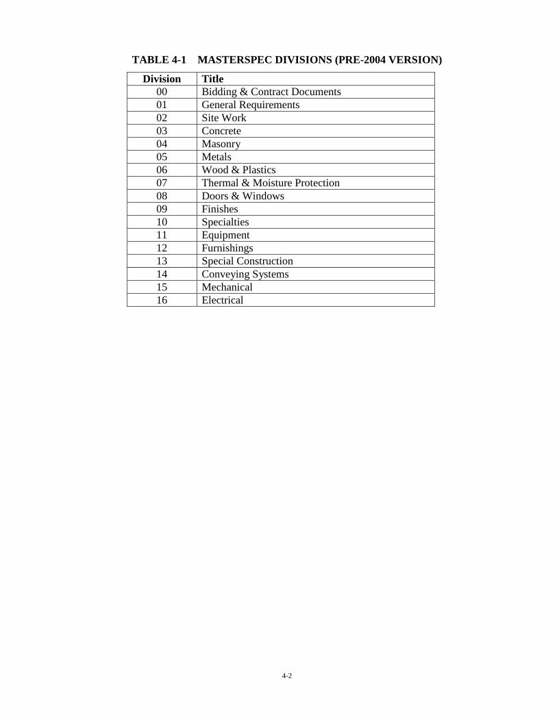
Prior to 2004 the CSI MasterFormat system consisted of Division 0, which contained the
Procurement and Contracting Requirements, and 16 specifications Divisions as shown in
Table 4-1. The MasterFormat system underwent a major revision in 2004 to expand the
system to better serve a broader range of the construction industry as the original system was
developed for building constrction. The expanded system re-organized the specifications
divisions as shown in Table 4-2. At this time, the design and construction industry in
Montana is in early stages of transition from the original system. While the expanded system
is preferred, the original system is still in common use.
4-2
TABLE 4-1 MASTERSPEC DIVISIONS (PRE-2004 VERSION)
Division Title 00 Bidding & Contract Documents 01 General Requirements 02 Site Work 03 Concrete 04 Masonry 05 Metals 06 Wood & Plastics 07 Thermal & Moisture Protection 08 Doors & Windows 09 Finishes 10 Specialties 11 Equipment 12 Furnishings 13 Special Construction 14 Conveying Systems 15 Mechanical 16 Electrical

4-3
TABLE 4-2 MASTERSPEC DIVISIONS (2011 VERSION)
Division Title 00 Procurement & Contract Requirements 01 General Requirements 02 Existing Conditions 03 Concrete 04 Masonry 05 Metals 06 Wood, Plastics & composites 07 Thermal & Moisture Protection 08 Openings 09 Finishes 10 Specialties 11 Equipment 12 Furnishings 13 Special Construction 14 Conveying Equipment
15-20 Reserved for future expansion 21 Fire Suppression 22 Plumbing 23 Heating, Ventilating & Air Conditioning (HVAC) 24 Reserved for future expansion 25 Integrated Automation 26 Electrical 27 Communications 28 Electronic Safety & Security
29-30 Reserved for future expansion 31 Earthwork 32 Exterior Improvements 33 Utilities 34 Transportation 35 Waterway & Marine Construction
36-39 Reserved for future expansion 40 Process Integration 41 Material Processing & Handling Equipment 42 Process Heating, Cooling & Drying Equipment
43 Process Gas & Liquid Handling, Purification & Storage Equipment
44 Pollution & Waste Control Equipment 45 Industry-Specific Manufacturing Equipment 46 Water & Wastewater Equipment 47 Reserved for future expansion 48 Electrical Power Generation 49 Reserved for future expansion

4-4
Additional guidance on uniform location of information for construction documents has been
developed by the American Institute of Architects (AIA) and the Engineers’ Joint Contract
Documents Committee (EJCDC) and is presented in EJCDC Document 1910-16.
4.2 SPECIFICATION FORMAT
A consistent and standardized format for organizing information within a section also aids in
simplifying retrieval of information and provides clarity of communication. The CSI three-
part SectionFormat and page layout (PageFormat) are a format that is recommended. This
format is summarized in Appendix A. CSI explains the three parts in the publication
“SectionFormat ©1997” as follows:
• PART 1 GENERAL: Describes administrative, procedural, and temporary
requirements unique to the section. PART 1 is an extension of subjects
covered in Division 1 and amplifies information unique to the section.
• PART 2 PRODUCTS: Describes materials, products, equipment, fabrication,
mixes, systems and assemblies that are required for incorporation in the
project. Materials and products are included with the quality level required.
• PART 3 EXECUTION: Describes installation or application, including
preparatory actions and post-installation cleaning and protection. Site-built
assemblies and site-manufactured products and systems are included.
4.3 PROCUREMENT AND CONTRACTING REQUIREMENTS (DIVISION 00)
The procurement and contracting requirements division should contain the information on
the terms for soliciting and establishing pricing for the work, contract forms and the
conditions of the contract. These documents have important legal consequences that should
be carefully reviewed by the owner with adequate legal counsel. Public owners and funding
agencies may have specific legal requirements that need to be incorporated in these
documents. The use of standardized forms and conditions, such as those developed by
EJCDC is encouraged. Where modifications and supplemental requirements are needed to

4-5
the standardized forms, it is important to ensure that a modification of the language does not
create ambiguity or assign unintended legal obligations to the parties involved.
The procurement requirements for bidding typically include an advertisement and/or
invitation to bid, instructions to bidders, the bid form, bid security and additional
certifications that may be required of bidders. The procurement requirements are not part of
the contract documents but are the basis for establishing agreement between the owner and
contractor.
The contracting requirements typically include the agreement form, project forms
(performance bond, payment bond, certifications), and the conditions of the contract. The
agreement form is the basic document that identifies the project, parties to the contract,
contract documents, scope of work, time requirements, cost and payment terms, and
signatures of the parties to the contract. Project forms include the performance bond,
materials and labor payment bond, and other certifications that may be required. The
conditions of the contract define the basic rights, responsibilities, and relationships of the
parties involved in the performance. Conditions of the contract often include standardized
General Conditions and project-specific Supplementary Conditions.

4-6
5-12
5.0 RECOMMENDED PROJECT MANUAL COMPONENTS
Each project is unique and the development of a Project manual should reflect the unique
requirements of that project. However, there are a number of items that are typical to most
projects that should be included to provide a clear understanding of the project requirements
and the roles and responsibilities of the parties involved.
5.1 INTRODUCTORY INFORMATION
The project manual should have a cover that clearly identifies the project. An inside cover
with the project name, project location, name and address of owner, name and address of
engineer, date and other relevant information. The introductory information should also
include space for certifications and seals of those responsible for the contents of the Project
manual. A table of contents that identifies the sections of the document is needed. In
addition to the table of contents, a list of the drawings and other documents bound separately
should be provided.
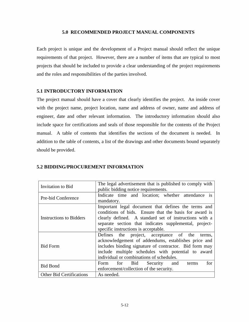
5.2 BIDDING/PROCUREMENT INFORMATION
Invitation to Bid The legal advertisement that is published to comply with public bidding notice requirements.
Pre-bid Conference Indicate time and location; whether attendance is mandatory.
Instructions to Bidders
Important legal document that defines the terms and conditions of bids. Ensure that the basis for award is clearly defined. A standard set of instructions with a separate section that indicates supplemental, project-specific instructions is acceptable.
Bid Form
Defines the project, acceptance of the terms, acknowledgement of addendums, establishes price and includes binding signature of contractor. Bid form may include multiple schedules with potential to award individual or combinations of schedules.
Bid Bond Form for Bid Security and terms for enforcement/collection of the security.
Other Bid Certifications As needed.

5-13
5.3 CONTRACT REQUIREMENTS & GENERAL CONDITIONS
Agreement Form
Defines the Work, The Project, parties to the contract, contract time, liquidated damages, contract price, payment terms and identifies contract documents. Also includes signatures and corporate seals of the contracting parties.
Performance and Payment Bonds
Montana Dam Safety Regulations require a Performance Bond be obtained by the contractor in an amount of at least 100% of the cost of the project. A Payment Bond is typically required for public works projects and most private owners.
Other Certifications As needed
General Conditions of the Contract
Standardized terms that define the basic rights, responsibilities, and relationships of the parties. Typically standardized documents such as EJCDC are utilized.
Supplemental Conditions
Project-specific conditions to the contract to modify and expand the general conditions. Insurance, wage rates, retainage and alternative dispute resolution clauses are examples of potential items in the supplemental conditions.
Project Forms
Some preparers include the project forms that will be utilized for administration of the contract. These may include items such as transmittal forms, progress pay estimate forms, change order forms, and close-out forms.
5.4 GENERAL REQUIREMENTS (DIVISION 1)
Summary of Work Overview of the work and general requirements that may not warrant a separate specification section.
Measurement & Payment Provide a clear definition of each payment item and the methods for measurement of work.
Construction Surveying Define roles and responsibilities for construction surveying and records.
Scheduling Requirements
Some projects may include special coordination and scheduling requirements. Clearly define requirements, roles and responsibilities of the parties.

5-14
Submittal Procedures
Responsibilities and procedures for submittal and review of work-related submittals are critically important. A formal process to ensure clear communication and approval is required. Submittals provide added specific detail of actual procedures, materials and equipment beyond the drawings and specifications. Further discussion is provided in Section 8 below.
Quality Assurance/Quality Control Define roles and responsibilities for quality assurance (QA) and Quality Control (QC). Who is performing testing, reporting requirements, etc.
Temporary Facilities
Items such as field offices, erosion control during construction, traffic control, and temporary utilities may need roles and responsibilites defined.
Closeout Procedures Details of the process, responsibilities, and documentation of the project completion.
5.5 SITE WORK (DIVISION 2)
Earthwork
Earthwork could be many sections for various aspects of a complex project or a single section for a simple project. Typical items covered could include clearing, stripping, excavation, dewatering, foundation considerations, fill materials, compaction requirements, slope protection and testing requirements.
Drains
Drains are a key feature in the design and performance of dams. Special attention should be given to materials requirements, installation, inspection and protection of internal drainage features.
Roadways & Surfacing As needed Fencing As needed
Reclamation & Restoration
Requirements for topsoil, vegetation restoration and erosion control need to be defined. Define responsibilities for maintenance and re-seeding while permanent vegetation is being re-established.

5-15
5.6 CONCRETE (DIVISION 3)
Concrete Forming
Define acceptable formwork materials, accessories, tolerances, etc. Forming, accessories and reinforcement may be incorporated into one concrete section for simple projects.
Concrete Accessories Define materials such as anchors, inserts, waterstops, joint filler, etc.
Concrete Reinforcing
Cast-in-Place Concrete Requirements for concrete mixes, delivery, placement, testing, protection, curing, tolerances, and repairs.
PreCast Concrete As needed.
5.7 OTHER DIVISIONS
Division 5 - Metals Structural steel, gratings, handrails, etc..
Division 11 - Equipment Water Control Gates and other manufactured equipment.
Division 16 - Electrical As needed.

6-12
6.0 SPECIAL CONSIDERATIONS FOR DAMS
There are some aspects of construction for dams that are critical for proper performance of
the completed project or that may otherwise require special attention. Some common issues
are discussed below.
6.1 COFFERDAMS & STREAM DIVERSION
Control and diversion of water during construction and repairs of dams can be a significant
aspect of achieving successful completion. The site must be adequately protected for surface
water inflows to allow for construction activities. Diversion of streamflow past the work can
be a challenging issue. The work needs to be protected against damage from floods and
considerations to maintain safety from dam failure during construction are necessary.
Specifications should establish the requirements that need to be attained and clearly assign
responsibilities to the appropriate parties for compliance with the requirements.
Considerations for diversions and water control may have significant impacts on the
scheduling and sequencing of the work.
6.2 DEWATERING
In addition to control of surface water at the construction site, considerations to dewater the
work and foundation also need to be included for most projects. Water collecting in the work
area can prevent the ability to properly place materials as well as potential to saturate and
damage foundation conditions. Proper control of groundwater around and under excavations
is necessary to prevent potential instability and softening of foundations. The dewatering
plan should be planned and reviewed well in advance of implementation. Roles and
responsibilities for design, implementation and monitoring should be clearly defined in the
specifications.
6.3 FOUNDATION INSPECTION, PROTECTION & TREATMENT
Special considerations for foundation inspections, protection and foundation treatments are
another important aspect of dam construction. It is essential that the designer verifies that the
actual foundation conditions that are encountered are appropriate for the design assumptions.

6-13
The saying that “the geotechnical investigation is not complete until construction has been
completed” is an important concept to remember. Foundation treatments that match the
actual conditions encountered and that are properly constructed are necessary. The
specifications must include adequate measures with provisions to allow adjustments during
construction to ensure that appropriate foundation protection and treatment is attained.
6.4 IMPERVIOUS FILL AT STRUCTURES & ABUTMENTS
An area that is typically difficult to attain desired results relates to the placement and
compaction of impervious material adjacent to structures (such as outlet conduits) and rock
abutments. These areas typically preclude access by large equipment that is utilized in more
open areas of the embankment fill. The presence of a hard concrete structure or hard bedrock
adjacent to clay fill can lead to “bridging” of overburden stresses to the hard features and
reduced confining stress of the clay fill. The reduced stress may lead to increased seepage
and potential piping along the contact between the hard surface and the clay. It can even lead
to a very dangerous “hydraulic fracture” situation in which hydraulic forces within the clay
become greater than the confining stresses on the clay causing sudden development of a
seepage crack through the clay zone.
Specifying higher moisture content in the clay that is placed in special compaction areas is a
common requirement to increase the plasticity and reduce potential for seepage and cracking.
Special compaction requirements using hand operated tampers and pneumatic wheel-rolling
should be specified for these areas. Special compaction areas should also receive extra
observation and testing efforts.
6.5 EMBANKMENT LIFT SURFACES
Compaction and traffic on lift surfaces within the embankment can lead to smooth surfaces
and unbounded lifts that may have significantly higher permeability in the horizontal
direction. Proper compaction equipment and treatment of lift surfaces should be specified for
embankment core zone materials. Smooth drum compaction is generally not acceptable and

6-14
tamping foot compactors with adequate length of tamping feet is a typical requirement.
Disking of smooth surfaces should be required.
6.6 FILTERS AND DRAINS
Filters and drains in dams is another critical design element that must be constructed
properly. This is an area that needs special attention in the specifications. The Montana
Dam Safety Program Technical Note 4 (TN4) contains guidance on design, specification and
inspection requirements for filters and drains.
6.7 SITE DRAINAGE
The specifications should include provisions to direct site drainage away from the work. On-
site precipitation runoff should be controlled to prevent contamination of filter materials,
erosion and deposition, or collecting in undesired areas to saturate completed fill or subgrade.
6.8 SEASONAL SHUTDOWN
If a project is of a magnitude to require seasonal shutdowns of the construction operation, the
specifications need to address measures that will protect the completed work and procedures
to validate the previously completed work prior to resuming construction

6-15

7-1
7.0 SUBMITTALS
During construction, the contractor is typically required to submit product data, shop
drawings, samples, schedules and work plans to the engineer for review. These submittals
convey additional detailed information of construction and serve as an important quality
assurance step in the project. The submittal process serves as a documentation and
communication aspect that provides specific information for completing the design intent.
7.1 SUBMITTAL REVIEW & APPROVAL
The specifications should clearly define the formal submittal process that includes what
information is to be submitted, the number of copies to submit, the time required for review
and the distribution of reviewed submittal. A summary list of submittals for the project
should be developed by the engineer. The review of submittals is an important process and
should be carefully documented. The approval language should clearly define the limitations
of review and the responsibilities of the parties in regard to the information on the submittals.
7.2 SUBMITTALS FOR INFORMATION ONLY
Some submittals may be requested for information and coordination during construction but
only deal with items that are under the contractor’s sole control. There should be a process
defined in regards to these submittals that ensures the submittal does not confuse the roles
and responsibilities of the engineer and contractor. Submittals that convey information that
is solely the contractor’s responsibility should be designated “for information only” and
should not be subject to the engineer accepting or rejecting the information.
7.3 SUBMITTAL SCHEDULE
An anticipated listing of submittals should be included in the specifications to serve as a
listing to track the progress of providing the necessary information. The initial listing should
be expanded during construction to document the progress of all submittals, reviews,
acceptance, rejection and revisions.

8-1
8.0 REFERENCES
“Construction Specifications Practice Guide.” The Construction Specifications Institute.
Published by John Wylie & Sons, Inc., Hoboken, New Jersey. 2011. “Master Format, 2011 Update.” The Construction Specifications Institute; 110 South Union
Street, Suite 100; Alexandria, VA 22314; www.csinet.org. 2011. “The Project Resource Manual; CSI Manual of Practice.” The Construction Specifications
Institute. Published by McGraw-Hill Companies, Inc., New York, New York. 2005.

APPENDIX A
Section & Page Format for Specifications


APPENDIX B
This appendix contains NRCS standard specification sections for embankment dams. These
specifications provide typical requirements included in specifying the construction of dams
to serve as examples for the designer in preparation of specifications. Note that the format of
these specifications does not follow the CSI format or organization of information that is
recommended in this Technical Note (See Appendix A for preferred format).


Part 642
National Engineering Handbook
National Standard Construction
Specifications
Chapter 2
(210-VI-NEH, May 2001)
1. Applicability
Construction Specification 21 is applicable to alltypes of excavation. The specification definesclasses of excavation and includes special re-quirements for certain types of excavation, butdoes not establish and define all types of excava-tion. It is intended that the types of excavation beestablished on a job or project basis, as needed.
The class of excavation defines the kind of mate-rial to be excavated. The type defines the func-tional purpose of the excavation. Establishedtypes of excavation may include (but are notrestricted to):
• Foundation excavation with or withoutstripping
• Cutoff, keyway, or core trench excavation
• Channel excavation
• Structure excavation
• Auxiliary spillway excavation
• Abutment shaping excavation
• Borrow area excavation
Any of the established types may include excava-tion of materials in any class. However, the exca-vation of a given class of material may be moredifficult in one type of excavation than in an-other. These factors must be carefully consideredas a basis for establishing types of excavation tobe designated on the drawings and listed in thebid schedule.
For projects involving considerable quantities ofexcavation of different classes of material underconditions that vary in different part of theworks, bids must be asked, and payments made,on the basis of both type and class of excavation.For such projects, the bid schedule must be setup in terms of both type and class of excavation(for example: channel excavation, common; andchannel excavation, rock).
Instructions for useConstruction Specification 21—Excavation
For projects involving only one type of excavationand for projects involving small quantities ofexcavation, it may be sufficient to include onlythe classes of excavation in the bid schedule.
2. Material specifications
No material specifications complement Construc-tion Specification 21, Excavation.
3. Included items
Items to be included in contract specificationsand drawings follow:
a. The horizontal and vertical extent of eachtype of excavation. Indicate the verticalextent as approximate where the exactdepth required is not known.
b. Designation and definition of types ofexcavation.
c. Excavation pay limits when method 1,section 9, is used.
d. Surface finish requirements, such as grad-ing tolerances. This may be especiallyimportant at the crest of an auxiliary spill-way.
e. The location and limits of all borrow areas.Outline all surface grading requirementsfollowing completion of borrow materialutilization.
f. The location and limits of all waste areas.When borrow areas serve also as wasteareas, coordination of construction activi-ties may be important.
g. Boring logs and test pit logs pertinent to allareas to be excavated. In addition to de-scriptions of materials, logs must alsoinclude water table elevations and dates ofobservation , where applicable. For pur-poses of the construction drawings, noindications of correlation of materials
21–I–1

Part 642
National Engineering Handbook
National Standard Construction
Specifications
Chapter 2
(210-VI-NEH, May 2001)
between logs shall be shown. Interpretationof materials is to be avoided and left to thecontractor for determination.
h. Existing access and haul roads.
i. Special requirements for dewatering andkeeping the excavation dry, with crossreference to Construction Specification 11,Removal of Water, where applicable.
j. Special requirements for control of blast-ing, including written plans and approvals,if applicable.
k. Special requirements for control of ero-sion, water pollution, and air pollution,with cross reference to Construction Speci-fication 5, Pollution Control, as applicable.
l. Requirements for control of the size grada-tion of excavated rock where necessary toobtain material of a particular gradation forrock fill or riprap.
m. Methods of measurement and payment, ifthe standard specification includes morethan one method.
n. Requirements for concrete to fill voidsfrom overexcavation (refer to ConstructionSpecification 31, Concrete for Major Struc-tures, or 32, Structure Concrete) if require-ments in section 8 are not adequate.
4. Methods
Section 4, Use of excavated materials
Method 1—Intended for use when the quality,condition, and relative location of significantquantities of the materials to be excavated areknown to be suited to the economic constructionof the required earthfills and earth backfills, andparticularly where alternate sources of materialare less desirable or do not exist.
Method 2—Intended for use when the knowndata indicate that the use of alternate sources ofearthfill materials may result in more economicalconstruction of the required earthfills and earthbackfills.
Section 5, Disposal of waste materials
Method 1—Intended for use when areas forwasting unsuitable and/or excess materials areavailable at the site, when the waste fill willbeneficially supplement the function of the per-manent works, or if no known market is availablefor such waste materials as may be produced.
Method 2—Intended for use when areas forwasting unsuitable and excess material are notreadily available at the site or if a known marketfor such waste materials is readily available.
Section 9, Measurement and payment
Note in section 10 when volume calculationsother than the average cross-sectional end areamethod are used and describe the applicablemethod. Example: In lieu of computing excava-
tion volumes by the method of average cross-
sectional end areas, the volume may be computed
by the prismoidal formula method with the assis-
tance of computer aided design program.
Method 1—Intended for excavations where thepay limits can best be defined on the drawings.
Method 2—Intended for excavations bounded bysimple plane surfaces and constant or graduallyvarying cross section throughout.
Method 3—Intended for excavations where thelower limits are determinable only by examina-tion of the materials encountered and where thelower limits have been designated on the draw-ings as approximate or to be determined by theengineer during construction.
Method 4—Intended for structure excavationbounded by fairly simple plane surfaces wherepay limits are not shown on the drawings.
When specifications are prepared using elec-tronic procedures and all methods but one aredeleted for use in a contract specification, delete
21–I–2

Part 642
National Engineering Handbook
National Standard Construction
Specifications
Chapter 2
(210-VI-NEH, May 2001)
from the last paragraph All Methods The follow-
ing provisions apply to all methods of mea-
surement and payment. Left justify the remain-ing text.
5. Items of work and construction details
Starting at the top of page 21–5, prepare andoutline job specific "Items of Work and Construc-tion Details" (IWCD) in accordance with theseinstructions. For ease of utilization, the use ofrecyclable color paper for the IWCD should beconsidered.
21–I–3

(210-VI-NEH, May 2001)

(210-VI-NEH, May 2001)
Construction Specification 21—Excavation
1. Scope
The work shall consist of the excavation required by the drawings and specifications and disposal of theexcavated materials.
2. Classification
Excavation is classified as common excavation, rock excavation, or unclassified excavation in accor-dance with the following definitions or is designated as unclassified.
Common excavation is defined as the excavation of all materials that can be excavated, transported,and unloaded using heavy ripping equipment and wheel tractor-scrapers with pusher tractors or that canbe excavated and dumped into place or loaded onto hauling equipment by excavators having a ratedcapacity of one cubic yard or larger and equipped with attachments (shovel, bucket, backhoe, dragline,or clam shell) appropriate to the material type, character, and nature of the materials.
Rock excavation is defined as the excavation of all hard, compacted, or cemented materials that requireblasting or the use of ripping and excavating equipment larger than defined for common excavation. Theexcavation and removal of isolated boulders or rock fragments larger than 1 cubic yard encountered inmaterials otherwise conforming to the definition of common excavation shall be classified as rock exca-vation. The presence of isolated boulders or rock fragments larger than 1 cubic yard is not in itself suffi-cient cause to change the classification of the surrounding material.
For the purpose of these classifications, the following definitions shall apply:
Heavy ripping equipment is a rear-mounted, heavy duty, single-tooth, ripping attachment mountedon a track type tractor having a power rating of at least 250 flywheel horsepower unless otherwisespecified in section 10.
Wheel tractor-scraper is a self-loading (not elevating) and unloading scraper having a struck bowlcapacity of at least 12 cubic yards.
Pusher tractor is a track type tractor having a power rating of at least 250 flywheel horsepowerequipped with appropriate attachments.
Unclassified excavation is defined as the excavation of all materials encountered, including rockmaterials, regardless of their nature or the manner in which they are removed.
3. Blasting
The transportation, handling, storage, and use of dynamite and other explosives shall be directed andsupervised by a person(s) of proven experience and ability who is authorized and qualified to conductblasting operations.
Blasting shall be done in a manner as to prevent damage to the work or unnecessary fracturing of theunderlying rock materials and shall conform to any special requirements in section 10 of this specifica-tion. When specified in section 10, the contractor shall furnish the engineer, in writing, a blasting planbefore blasting operations begin.
21–1

(210-VI-NEH, May 2001)
4. Use of excavated material
Method 1—To the extent they are needed, all suitable material from the specified excavations shall beused in the construction of required permanent earthfill or rockfill. The suitability of material for spe-cific purposes is determined by the engineer. The contractor shall not waste or otherwise dispose ofsuitable excavated material.
Method 2—Suitable material from the specified excavations may be used in the construction of re-quired earthfill or rockfill. The suitability of material for specific purposes is determined by the engineer.
5. Disposal of waste materials
Method 1—All surplus or unsuitable excavated materials are designated as waste and shall be disposedof at the locations shown on the drawings.
Method 2—All surplus or unsuitable excavated materials are designated as waste and shall be disposedof by the contractor at sites of his own choosing away from the site of the work. The disposal shall be inan environmentally acceptable manner that does not violate local rules and regulations.
6. Excavation limits
Excavations shall comply with OSHA Construction Industry Standards (29CFR Part 1926) Subpart P,Excavations, Trenching, and Shoring. All excavations shall be completed and maintained in a safe andstable condition throughout the total construction phase. Structure and trench excavations shall becompleted to the specified elevations and to the length and width required to safely install, adjust, andremove any forms, bracing, or supports necessary for the installation of the work. Excavations outsidethe lines and limits shown on the drawings or specified herein required to meet safety requirementsshall be the responsibility of the contractor in constructing and maintaining a safe and stable excavation.
7. Borrow excavation
When the quantities of suitable material obtained from specified excavations are insufficient to con-struct the specified earthfills and earth backfills, additional material shall be obtained from the desig-nated borrow areas. The extent and depth of borrow pits within the limits of the designated borrowareas shall be as specified in section 10 or as approved by the engineer.
Borrow pits shall be excavated and finally dressed to blend with the existing topography and sloped toprevent ponding and to provide drainage.
8. Overexcavation
Excavation in rock beyond the specified lines and grades shall be corrected by filling the resulting voidswith portland cement concrete made of materials and mix proportions approved by the engineer. Con-crete that will be exposed to the atmosphere when construction is completed shall meet the require-ments of concrete selected for use under Construction Specification 31, Concrete for Major Structures,or 32, Structure Concrete, as appropriate.
Concrete that will be permanently covered shall contain not less than five bags of cement per cubicyard. The concrete shall be placed and cured as specified by the engineer.
Excavation in earth beyond the specified lines and grades shall be corrected by filling the resulting voidswith approved, compacted earthfill. The exception to this is that if the earth is to become the subgradefor riprap, rockfill, sand or gravel bedding, or drainfill, the voids may be filled with material conformingto the specifications for the riprap, rockfill, bedding, or drainfill. Before correcting an overexcavationcondition, the contractor shall review the planned corrective action with the engineer and obtain ap-proval of the corrective measures.
21–2

(210-VI-NEH, May 2001)
9. Measurement and payment
For items of work for which specific unit prices are established in the contract, the volume of each typeand class of excavation within the specified pay limits is measured and computed to the nearest cubicyard by the method of average cross-sectional end areas or by methods outlined in section 10 of thisspecification. Regardless of quantities excavated, the measurement for payment is made to the specifiedpay limits except that excavation outside the specified lines and grades directed by the engineer toremove unsuitable material is included. Excavation required because unsuitable conditions result fromthe contractor's improper construction operations, as determined by the engineer, is not included formeasurement and payment.
Method 1—The pay limits shall be as designated on the drawings.
Method 2—The pay limits shall be defined as follows:
a. The upper limit shall be the original ground surface as it existed before the start of constructionoperations except that where excavation is performed within areas designated for previous exca-vation or earthfill, the upper limit shall be the modified ground surface resulting from the speci-fied previous excavation or earthfill.
b. The lower and lateral limits shall be the neat lines and grades shown on the drawings.
Method 3 —The pay limits shall be defined as follows:
a. The upper limit shall be the original ground surface as it existed before the start of constructionoperations except that where excavation is performed within areas designated for previous exca-vation or earthfill, the upper limit shall be the modified ground surface resulting from the speci-fied previous excavation or earthfill.
b. The lower and lateral limits shall be the true surface of the completed excavation as directed bythe engineer.
Method 4—The pay limits shall be defined as follows:
a. The upper limit shall be the original ground surface as it existed before the start of constructionoperations except that where excavation is performed within areas designated for previous exca-vation or earthfill, the upper limit shall be the modified ground surface resulting from the speci-fied previous excavation or earthfill.
b. The lower limit shall be at the bottom surface of the proposed structure.
c. The lateral limits shall be 18 inches outside of the outside surface of the proposed structure orshall be vertical planes 18 inches outside of and parallel to the footings, whichever gives the largerpay quantity, except as provided in d below.
d. For trapezoidal channel linings or similar structures that are to be supported upon the sides of theexcavation without intervening forms, the lateral limits shall be at the underside of the proposedlining or structure.
e. For the purposes of the definitions in b, c, and d, above, any specified bedding or drainfill directlybeneath or beside the structure will be considered to be a part of the structure.
All methods—The following provisions apply to all methods of measurement and payment.
Payment for each type and class of excavation is made at the contract unit price for that type and classof excavation. Such payment will constitute full compensation for all labor, materials, equipment, and allother items necessary and incidental to the performance of the work except that extra payment forbackfilling overexcavation will be made in accordance with the following provisions.
21–3

(210-VI-NEH, May 2001)
Payment for backfilling overexcavation, as specified in section 8 of this specification, is made only if theexcavation outside specified lines and grades is directed by the engineer to remove unsuitable materialand if the unsuitable condition is not a result of the contractor's improper construction operations asdetermined by the engineer.
Compensation for any item of work described in the contract, but not listed in the bid schedule is in-cluded in the payment for the item of work to which it is made subsidiary. Such items and the items towhich they are made subsidiary are identified in section 10 of this specification.
10. Items of work and construction details
21–4

Part 642
National Engineering Handbook
National Standard Construction
Specifications
Chapter 2
(210-VI-NEH, May 2001)
1. Applicability
Construction Specification 23 is applicable to alltypes of earthfill including fill sections con-structed of rocky soils and embankments con-structed of soft or friable rock that is expected tobreak down during compaction.
2. Material specifications
No material specifications complement Construc-tion Specification 23.
3. Included items
Items to be included in the contract specifica-tions and drawings
a. Complete plans and cross sections of therequired earthfills and earth backfills.
b. Pay limits, where applicable.
c. Borrow areas or other sources of material.
d. Designation and description of the types ofmaterial required in the various parts of thework.
e. Maximum allowable size of rock particles.
f. Special requirements for foundation prepa-ration.
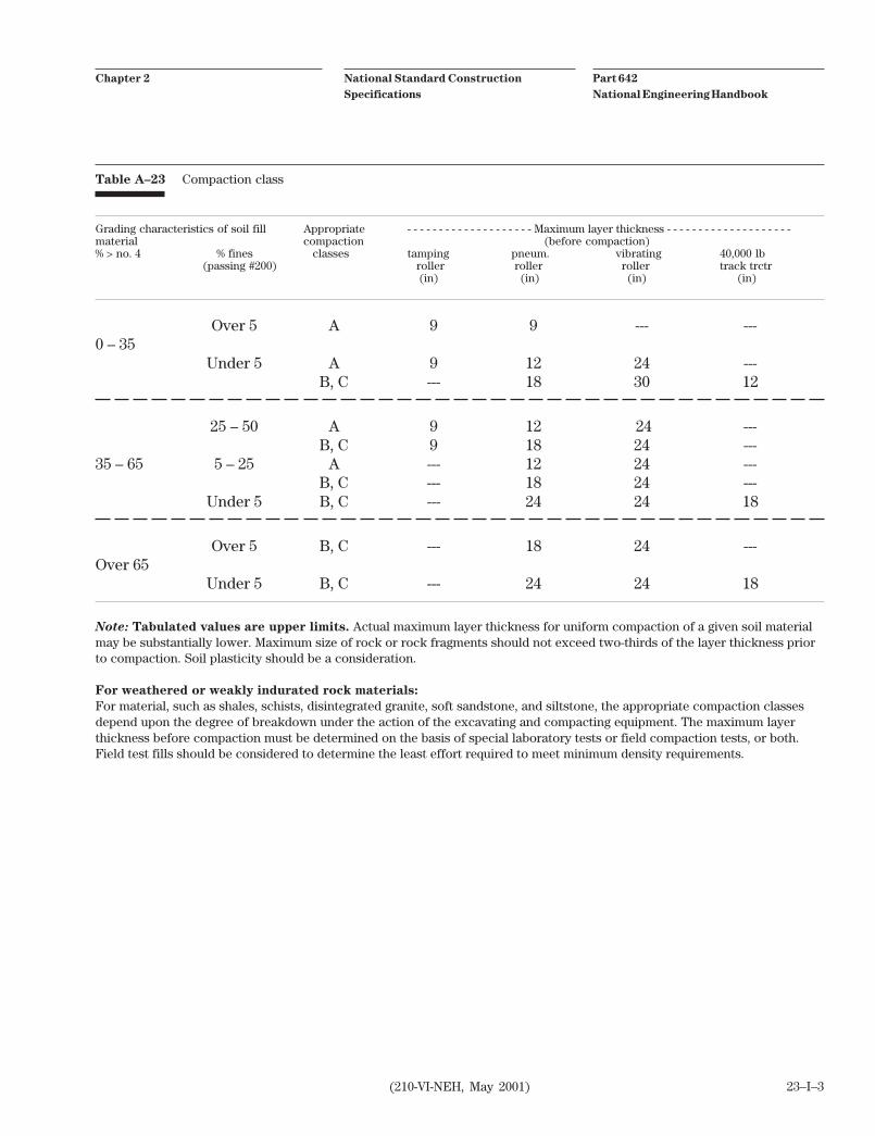
g. Maximum layer thickness before compac-tion for earthfill. (Table A-23 may be usedas a guide. This table gives upper limits forthe general classes of material listed. Thespecified maximum layer thickness mayneed to be substantially less than the tabu-lated value to obtain adequate compac-tion.)
h. Maximum layer thickness before compac-tion for earth backfill by manually directedpower tampers. (The maximum thicknessthat can be adequately compacted dependsupon the tampers and upon the soil beingplaced. It varies from about 4 inches forplastic clays to about 8 inches for coarsegrained material of low plasticity.)
23–I–1
i. Special instructions for sectional or phasedconstruction, where applicable.
j. Allowable range of moisture content foreach item. For example:
(1) "The moisture content of the fill matrixat the time of compaction shall beneither less than 2 percent below opti-mum moisture content nor more than 2percent above optimum moisture con-tent."
(2) "The moisture content of the fill mate-rial shall be maintained within thelimits required to: (a) prevent bulkingor dilatance of the material under theaction of the hauling or compactingequipment, (b) prevent the adherenceof the earthfill material to the treadsand tracks of the equipment, and (c)ensure the crushing and blending of thesoil clods and aggregations into a rea-sonably homogeneous mass."
k. Compaction class for each item. (Table A-23 may be used as a guide.)
l. For Class A compaction—Compaction testmethod and required percent of maximumdensity. Typical compaction test results, ifapplicable.
m. For Class B compaction—Minimum massdensity.
n. For Class C compaction—Type of roller,minimum weight or contact pressure ofroller, minimum vibrating force and fre-quency for vibrating roller, and minimumnumber of passes.
o. Special rapid methods for moisture control(quick dry, speedy, alcohol, nuclear gauge),if used. These methods are only used onsoils where they prove to be a reliableapproximation to ASTM D 2216. Whenrapid methods are used, a reference to the
Instructions for useConstruction Specification 23—Earthfill

Part 642
National Engineering Handbook
National Standard Construction
Specifications
Chapter 2
(210-VI-NEH, May 2001)
procedure to be followed should be in-cluded.
p. When the family of curves and the one-point Proctor is the intended method forsoil density standard determination andverification, it should be referenced and sospecified in section 10.
q. Special requirements, where applicable, forplacing earth backfill adjacent to struc-tures, such as reduced compactive effortfor high, thin walled structures. This mayinclude monitoring stresses and wall move-ments and/or specifying minimum in-placeconcrete strength requirements before theforms or other supports are removed orearth backfilling commences. Minimuminplace concrete strength requirementsshall be determined by the designer andclearly stated.
r. Required minimum strength of concrete,determined according to section 6, forstarting compaction of backfill adjacent tostructures, if applicable. Use of minimumstrength is encouraged over minimumtimes listed in section 6.
s. Methods of measurement and payment.
t. Embedded structures or other elementswhose volume will be excluded from theearthfill volume for payment. Major itemsmay be listed for exclusion. The cost ofmeasuring, computing, checking,recordkeeping, and other similar activitiesmust clearly justify the exclusion.
u. Special requirements pertaining to furnish-ing and applying water including desig-nated source and details of ownership andwater rights, if applicable, and water qual-ity requirements if quality may be a con-cern.
v. Special requirements for control of ero-sion, water pollution, and air pollution,with appropriate cross reference to Con-struction Specification 5, Pollution Control.
w. Surface finish requirements, such as com-pleted surface grade tolerances.
4. Methods
Section 9, Measurement and payment
Method 1—Intended for structure earth backfilland other cases where pay limits can best beshown on the drawings.
The selected methods for pay limits must becompatible with those selected for use in Con-struction Specification 21, Excavation.
Methods 6 or 7 must be used with any or all meth-ods 1 through 5.
a. Method 6 is intended for use when noseparate payment is to be made for water.
b. Method 7 is intended for use with Con-struction Specification 10, Water for Con-struction, when the contractor is to be paidunder a separate item for the water neededto bring the earthfill and earth backfillmaterials to the specified moisture content.
When specifications are prepared using elec-tronic procedures and all methods but one aredeleted for use in a contract specification, deletefrom the last paragraph All Methods The fol-
lowing provisions apply to all methods of
measurement and payment. Left justify theremaining text.
5. Items of work and construction details
Starting at the top of page 23–6, prepare andoutline job specific "Items of Work and Construc-tion Details" (IWCD) in accordance with theseinstructions. For ease of utilization, the use ofrecyclable color paper for the IWCD should beconsidered.
23–I–2
Part 642
National Engineering Handbook
National Standard Construction
Specifications
Chapter 2
(210-VI-NEH, May 2001)
Table A–23 Compaction class
Grading characteristics of soil fill Appropriate - - - - - - - - - - - - - - - - - - - - Maximum layer thickness - - - - - - - - - - - - - - - - - - - -material compaction (before compaction)% > no. 4 % fines classes tamping pneum. vibrating 40,000 lb
(passing #200) roller roller roller track trctr (in) (in) (in) (in)
Over 5 A 9 9 --- ---0 – 35
Under 5 A 9 12 24 ---B, C --- 18 30 12
25 – 50 A 9 12 24 ---B, C 9 18 24 ---
35 – 65 5 – 25 A --- 12 24 ---B, C --- 18 24 ---
Under 5 B, C --- 24 24 18
Over 5 B, C --- 18 24 ---Over 65
Under 5 B, C --- 24 24 18
Note: Tabulated values are upper limits. Actual maximum layer thickness for uniform compaction of a given soil materialmay be substantially lower. Maximum size of rock or rock fragments should not exceed two-thirds of the layer thickness priorto compaction. Soil plasticity should be a consideration.
For weathered or weakly indurated rock materials:
For material, such as shales, schists, disintegrated granite, soft sandstone, and siltstone, the appropriate compaction classesdepend upon the degree of breakdown under the action of the excavating and compacting equipment. The maximum layerthickness before compaction must be determined on the basis of special laboratory tests or field compaction tests, or both.Field test fills should be considered to determine the least effort required to meet minimum density requirements.
23–I–3

(210-VI-NEH, May 2001)

(210-VI-NEH, May 2001)
Construction Specification 23—Earthfill
1. Scope
The work consists of the construction of earth embankments, other earthfills, and earth backfills re-quired by the drawings and specifications.
Earthfill is composed of natural earth materials that can be placed and compacted by constructionequipment operated in a conventional manner.
Earth backfill is composed of natural earth material placed and compacted in confined spaces or adja-cent to structures (including pipes) by hand tamping, manually directed power tampers or vibratingplates, or their equivalent.
2. Material
All fill material shall be obtained from required excavations and designated borrow areas. The selection,blending, routing, and disposition of material in the various fills shall be subject to approval by the engi-neer.
Fill materials shall contain no frozen soil, sod, brush, roots, or other perishable material. Rock particleslarger than the maximum size specified for each type of fill shall be removed prior to compaction of thefill.
The types of material used in the various fills shall be as listed and described in the specifications anddrawings.
3. Foundation preparation
Foundations for earthfill shall be stripped to remove vegetation and other unsuitable material or shall beexcavated as specified.
Except as otherwise specified, earth foundation surfaces shall be graded to remove surface irregularitiesand shall be scarified parallel to the axis of the fill or otherwise acceptably scored and loosened to aminimum depth of 2 inches. The moisture content of the loosened material shall be controlled as speci-fied for the earthfill, and the surface material of the foundation shall be compacted and bonded with thefirst layer of earthfill as specified for subsequent layers of earthfill.
Earth abutment surfaces shall be free of loose, uncompacted earth in excess of 2 inches in depth normalto the slope and shall be at such a moisture content that the earthfill can be compacted against them toproduce a good bond between the fill and the abutments.
Rock foundation and abutment surfaces shall be cleared of all loose material by hand or other effectivemeans and shall be free of standing water when fill is placed upon them. Occasional rock outcrops inearth foundations for earthfill, except in dams and other structures designed to restrain the movementof water, shall not require special treatment if they do not interfere with compaction of the foundationand initial layers of the fill or the bond between the foundation and the fill.
Foundation and abutment surfaces shall be no steeper than one horizontal to one vertical unless other-wise specified. Test pits or other cavities shall be filled with compacted earthfill conforming to the speci-fications for the earthfill to be placed upon the foundation.
23–1

(210-VI-NEH, May 2001)
4. Placement
Earthfill shall not be placed until the required excavation and foundation preparation have been com-pleted and the foundation has been inspected and approved by the engineer. Earthfill shall not be placedupon a frozen surface nor shall snow, ice, or frozen material be incorporated in the earthfill matrix.
Earthfill shall be placed in approximately horizontal layers. The thickness of each layer before compac-tion shall not exceed the maximum thickness specified in section 10 or shown on the drawings. Materi-als placed by dumping in piles or windrows shall be spread uniformly to not more than the specifiedthickness before being compacted.
Hand compacted earth backfill shall be placed in layers whose thickness before compaction does notexceed the maximum thickness specified for layers of earth backfill compacted by manually directedpower tampers.
Earth backfill shall be placed in a manner that prevents damage to the structures and allows the struc-tures to assume the loads from the earth backfill gradually and uniformly. The height of the earth back-fill adjacent to a structure shall be increased at approximately the same rate on all sides of the structure.
Earthfill and earth backfill in dams, levees, and other structures designed to restrain the movement ofwater shall be placed to meet the following additional requirements:
(a) The distribution of materials throughout each zone shall be essentially uniform, and the earthfillshall be free from lenses, pockets, streaks, or layers of material differing substantially in tex-ture, moisture content, or gradation from the surrounding material. Zone earthfills shall beconstructed concurrently unless otherwise specified.
(b) If the surface of any layer becomes too hard and smooth for proper bond with the succeedinglayer, it shall be scarified parallel to the axis of the fill to a depth of not less than 2 inches beforethe next layer is placed.
(c) The top surface of embankments shall be maintained approximately level during constructionwith two exceptions: A crown or cross-slope of about 2 percent shall be maintained to ensureeffective drainage, or as otherwise specified for drainfill or sectional zones.
(d) Dam embankments shall be constructed in continuous layers from abutment to abutment ex-cept where openings to facilitate construction or to allow the passage of streamflow duringconstruction are specifically authorized in the contract.
(e) Embankments built at different levels as described under (c) or (d) above shall be constructedso that the slope of the bonding surfaces between embankment in place and embankment to beplaced is not steeper than 3 feet horizontal to 1 foot vertical. The bonding surface of the em-bankment in place shall be stripped of all material not meeting the requirements of this specifi-cation and shall be scarified, moistened, and recompacted when the new earthfill is placedagainst it. This ensures a good bond with the new earthfill and obtains the specified moisturecontent and density at the contact of the inplace and new earthfills.
5. Control of moisture content
During placement and compaction of earthfill and earth backfill, the moisture content of the materialbeing placed shall be maintained within the specified range.
The application of water to the earthfill material shall be accomplished at the borrow areas insofar aspracticable. Water may be applied by sprinkling the material after placement on the earthfill, if neces-sary. Uniform moisture distribution shall be obtained by disking.
Material that is too wet when deposited on the earthfill shall either be removed or be dried to the speci-fied moisture content prior to compaction.
23–2
(210-VI-NEH, May 2001)
If the top surface of the preceding layer of compacted earthfill or a foundation or abutment surface in thezone of contact with the earthfill becomes too dry to permit suitable bond, it shall either be removed orscarified and moistened by sprinkling to an acceptable moisture content before placement of the nextlayer of earthfill.
6. Compaction
Earthfill—Earthfill shall be compacted according to the following requirements for the class of com-paction specified:
Class A compaction—Each layer of earthfill shall be compacted as necessary to provide thedensity of the earthfill matrix not less than the minimum density specified in Section 10 oridentified on the drawings. The earthfill matrix is defined as the portion of the earthfill mate-rial finer than the maximum particle size used in the compaction test method specified.
Class B compaction—Each layer of earthfill shall be compacted to a mass density not lessthan the minimum density specified.
Class C compaction—Each layer of earthfill shall be compacted by the specified number ofpasses of the type and weight of roller or other equipment specified or by an approved equiva-lent method. Each pass shall consist of at least one passage of the roller wheel or drum overthe entire surface of the layer.
Earth backfill—Earth backfill adjacent to structures shall be compacted to a density equivalent to thatof the surrounding inplace earth material or adjacent required earthfill or earth backfill. Compactionshall be accomplished by hand tamping or manually directed power tampers, plate vibrators, walk-behind, miniature, or self-propelled rollers. Unless otherwise specified heavy equipment including back-hoe mounted power tampers or vibrating compactors and manually directed vibrating rollers shall notbe operated within 2 feet of any structure. Towed or self-propelled vibrating rollers shall not be operatedwithin 5 feet of any structure. Compaction by means of drop weights operating from a crane or hoist isnot permitted.
The passage of heavy equipment will not be allowed:
• Over cast-in-place conduits within 14-days after placement of the concrete
• Over cradled or bedded precast conduits within 7 days after placement of the concrete cradle orbedding
• Over any type of conduit until the backfill has been placed above the top surface of the structureto a height equal to one-half the clear span width of the structure or pipe or 2 feet, whichever isgreater, except as may be specified in section 10.
Compacting of earth backfill adjacent to structures shall not be started until the concrete has attainedthe strength specified in section 10 for this purpose. The strength is determined by compression testingof test cylinders cast by the contractor's quality control personnel for this purpose and cured at the worksite in the manner specified in ASTM C 31 for determining when a structure may be put into service.
When the required strength of the concrete is not specified as described above, compaction of earthbackfill adjacent to structures shall not be started until the following time intervals have elapsed afterplacement of the concrete.
23–3

(210-VI-NEH, May 2001)
Structure Time interval (days)
Vertical or near-vertical walls with earth loading on one side only 14
Walls backfilled on both sides simultaneously 7
Conduits and spillway risers, cast-in-place (with inside forms in place) 7
Conduits and spillway risers, cast-in-place (inside forms removed) 14
Conduits, pre-cast, cradled 2
Conduits, pre-cast, bedded 1
Cantilever outlet bents (backfilled both sides simultaneously) 3
7. Reworking or removal and replacement of defective earthfill
Earthfill placed at densities lower than the specified minimum density or at moisture contents outsidethe specified acceptable range of moisture content or otherwise not conforming to the requirements ofthe specifications shall be reworked to meet the requirements or removed and replaced by acceptableearthfill. The replacement earthfill and the foundation, abutment, and earthfill surfaces upon which it isplaced shall conform to all requirements of this specification for foundation preparation, approval,placement, moisture control, and compaction.
8. Testing
During the course of the work, the engineer will perform quality assurance tests required to identifymaterial; determine compaction characteristics; determine moisture content; and determine density ofearthfill in place. Tests performed by the engineer will be used to verify that the earthfills conform tocontract requirements of the specifications and not as a replacement for the contractor's quality controlprogram. The contractor shall perform all quality control testing in conformance with the approvedquality control system for Method 1 and the approved quality control plan for Method 2 in ConstructionSpecification 94, Contractor Quality Control as required to assure that work performed meets contractrequirements.
Densities of earthfill requiring Class A compaction will be determined in accordance with ASTM D 1556,D 2167, D 2922, or D 2937 except that the volume and moist weight of included rock particles larger thanthose used in the compaction test method specified for the type of fill will be determined and deductedfrom the volume and moist weight of the total sample before computation of density or, if using thenuclear gauge, added to the specified density to bring it to the measure of equivalent composition forcomparison. The density so computed is used to determine the percent compaction of the earthfill ma-trix. Unless otherwise specified, moisture content is determined by one of the following methods: ASTMD 2216, D 3017, D 4643, D 4944, or D 4959.
9. Measurement and payment
For items of work for which specific unit prices are established in the contract, the volume of each typeand compaction class of earthfill and earth backfill within the specified zone boundaries and pay limitsis measured and computed to the nearest cubic yard by the method of average cross-sectional end areas.Unless otherwise specified in section 10, no deduction in volume is made for embedded items, such as,but not limited to, conduits, inlet structures, outlet structures, embankment drains, sand diaphragm andoutlet, and their appurtenances.
23–4

(210-VI-NEH, May 2001)
The pay limits shall be as defined below, with the further provision that earthfill required to fill voidsresulting from overexcavation of the foundation, outside the specified lines and grades, will be includedin the measurement for payment only under the following conditions:
• Where such overexcavation is directed by the engineer to remove unsuitable material, and
• Where the unsuitable condition is not a result of the contractor's improper construction opera-tions as determined by the engineer.
Earthfill beyond the specified lines and grades to backfill excavation required for compliance withOSHA requirements will be considered subsidiary to the earthfill bid item(s).
Method 1—The pay limits shall be as designated on the drawings.
Method 2—The pay limits shall be the measured surface of the foundation when approved for place-ment of the earthfill and the specified neat lines of the earthfill surface.
Method 3—The pay limits shall be the measured surface of the foundation when approved for place-ment of the earthfill and the measured surface of the completed earthfill.
Method 4—The pay limits shall be the specified pay limits for excavation and the specified neat lines ofthe earthfill surface.
Method 5—The pay limits shall be the specified pay limits for excavation and the measured surface ofthe completed earthfill.
Method 6—Payment for each type and compaction class of earthfill and earth backfill is made at thecontract unit price for that type and compaction class of earthfill. Such payment will constitute fullcompensation for all labor, material, equipment, and all other items necessary and incidental to theperformance of the work.
Method 7—Payment for each type and compaction class of earthfill and earth backfill is made at thecontract unit price for that type and compaction class of earthfill. Such payment will constitute fullcompensation for all labor, material, equipment, and all other items necessary and incidental to theperformance of the work except furnishing, transporting, and applying water to the foundation andearthfill material. Water applied to the foundation and earthfill material is measured and payment madeas specified in Construction Specification 10.
All methods—The following provisions apply to all methods of measurement and payment. Compensa-tion for any item of work described in the contract, but not listed in the bid schedule is included in thepayment for the item of work to which it is made subsidiary. Such items and the items to which they aremade subsidiary are identified in section 10 of this specification.
10. Items of work and construction details
23–5

(210-VI-NEH, May 2001)

Part 642
National Engineering Handbook
National Standard Construction
Specifications
Chapter 2
(210-VI-NEH, May 2001)
1. Applicability
Construction Specification 24 is applicable to theplacing of drainfill in all types of structure drain-age systems, such as:
a. Drainage systems installed beneath con-crete structures, lining, or pavements
b. Wall drains for concrete structures
c. Embankment drainage systems
d. Interceptor drains installed adjacent tostructures
e. Foundation drains
2. Material specifications
Material Specification 521, Aggregates forDrainfill and Filters, complements ConstructionSpecification 24.
3. Included items
Items to be included in contract specificationsand drawings
a. The location, extent, and dimensions ofeach drain.
b. The grading limits of each type of drainfill.
c. The allowable percentage of material (non-plastic) passing No. 200 Sieve.
d. The source of drainfill materials, whenapplicable.
e. Specifications for control of moisture ifrequired. If water is to be added and is tobe included in a separate pay item forwater, add the statement in section 9: Wa-
ter applied to the drainfill material is
measured and payment made as specified
in Construction Specification 10, Water
for Construction.
f. Class of compaction. Also specify theweight and number of passes of the com-pacting equipment required if more thanthe minimum amounts specified in Section
Instructions for useConstruction Specification 24—Drainfill
6. (Class A provides for control of compac-tion by minimum density requirementsdetermined by ASTM D 698 for fine grainmaterial. Classes I, II, and III specify themethod of compaction. Relative densitytests during construction generally shouldbe made in connection with the methodspecifications to evaluate the compactionbeing accomplished and be compared totest data outlined in ASTM D4254. Class I isintended for use where highest densitiesare required, Class II is intermediate, andClass III may be used for wall drains inuncompacted backfill or for other applica-tions where strength is not important.
Specify in section 9 the ASTM D 698 proce-dure to be modified to consist of one pointvalue for maximum dry density determinedon an oven-dried representative sample ofthe drainfill material. The procedure shallbe repeated three times to obtain an aver-age value for the one point.
When specifying Class II compaction, notein section 9 the method (a, b, or c) thatapplies. Note also if one or more of themethods are to be excluded.
g. Special requirements for placing drainfilladjacent to new concrete as set forth insection 4.
4. Methods
Section 2, Material
Method 1—Intended for use in specifications fordrainage systems in areas where commercialaggregate is available in sufficient quantity tomeet project needs.
24–I–1

Part 642
National Engineering Handbook
National Standard Construction
Specifications
Chapter 2
(210-VI-NEH, May 2001)
Method 2—Intended to be used in specificationsfor drainage systems in areas where the contrac-tor will need to process the material from desig-nated sources.
Section 8, Measurement and payment
Method 1—Intended for use when quantities aredetermined from volume measurements andpayment is made to the nearest cubic yard.
Method 2—Intended for use when quantities aredetermined by weight and payment is by the ton.
5. Items of work and construction details
Starting at the top of page 24–4, prepare andoutline job specific "Items of Work and Construc-tion Details" (IWCD) in accordance with theseinstructions. For ease of utilization, the use ofrecyclable color paper for the IWCD should beconsidered.
24–I–2

(210-VI-NEH, May 2001)
Construction Specification 24—Drainfill
1. Scope
The work consists of furnishing, placing, and compacting drainfill required in the construction of struc-ture drainage systems.
2. Material
Method 1—Drainfill material shall conform to the requirements of Material Specification 521, Aggre-gates for Drainfill and Filters. A minimum of 30 days before delivery of materials to the site, the contrac-tor shall inform the engineer in writing of the source(s) from which drainfill material will be obtained.The contractor shall provide the engineer free access to the source(s) for the purpose of obtainingsamples for testing.
Method 2—Drainfill material shall be sand, gravel, or crushed stone, or mixtures thereof, obtained fromthe specified sources. The material shall be selected as necessary to avoid the inclusion of organic mat-ter, clay balls, excessive fine particles, or other substances that would interfere with their free-drainingproperties.
3. Base preparation
Foundation surface and trenches shall be clean and free of organic matter, loose soil, foreign substance,and standing water when the drainfill is placed. Earth surfaces upon or against which drainfill will beplaced shall not be scarified.
4. Placement
Drainfill shall not be placed until the subgrade has been inspected and approved by the engineer.Drainfill shall not be placed over or around pipe or drain tile until the installation of the pipe or tile hasbeen inspected and approved.
Drainfill shall be placed uniformly in layers not to exceed 12 inches thick before compaction. Whencompaction is accomplished by manually controlled equipment, the layers shall not exceed 8 inchesthick. The material shall be placed to avoid segregation of particle sizes and to ensure the continuity andintegrity of all zones. No foreign material shall be allowed to become intermixed with or otherwisecontaminate the drainfill.
Traffic shall not be permitted to cross over drains at random. Equipment cross-overs shall be main-tained, and the number and location of such crossovers shall be established and approved before thebeginning of drainfill placement. Each crossover shall be cleaned of all contaminating material and shallbe inspected and approved by the engineer before the placement of additional drainfill material.
Any damage to the foundation surface or the trench sides or bottom occurring during placement ofdrainfill shall be repaired before drainfill placement is continued.
The upper surface of drainfill constructed concurrently with adjacent zones of earthfill shall be main-tained at a minimum elevation of 1 foot above the upper surface of adjacent earthfill.
Drainfill over and/or around pipe or drain tile shall be placed to avoid any displacement in line or gradeof the pipe or tile.
Drainfill shall not be placed adjacent to structures until the concrete has attained the strength specifiedin section 9 of this specification. The strength shall be determined by compression testing of concrete
24–1

(210-VI-NEH, May 2001)
test cylinders cast and field cured at the project site in accordance with ASTM Method C 31 for determin-ing when a structure may be placed into service.
When the required strength of the concrete is not specified as described above, placement of drainfilladjacent to concrete structures shall not be commenced until the following item intervals have elapsedfollowing placement of the concrete:
Structure type Time interval (days)
Vertical or near-vertical wall with earth loading on one side only 14(retaining walls and counterforts)
Walls backfilled on both sides simultaneously 7
Conduits and galleries, cast-in-place(with inside forms in place) 7(inside forms removed) 14
Conduits, precast, cradled 2
Conduits, precast, bedded 1
Cantilever outlet bents backfilled on both sides simultaneously 3
5. Control of moisture
The moisture content of drainfill material shall be controlled as specified in section 9 of this specifica-tion. When additional water is required, it shall be applied in a manner to avoid excessive wetting toadjacent earthfill. Except as specified in section 9 of this specification, control of moisture content willnot be required.
6. Compaction
Drainfill shall be compacted according to the following requirements for the class of compaction speci-fied:
Class A compaction—For drainfill materials with more than 70 percent passing the 3/4 inch sieve, eachlayer of drainfill shall be compacted to a minimum dry density of not less than the density specified insection 9 of this specification as determined by ASTM D 698. For drainfill materials with 70 percent orless passing the 3/4 inch sieve, each layer of drainfill shall be compacted to a relative density of not lessthan 70 percent as determined by ASTM D 4254.
Class I compaction—Each layer of drainfill shall be compacted by a minimum of two passes over theentire surface with a steel-drum vibrating roller weighing at least 5 tons and exerting a vertical vibratingforce of not less than 20,000 pounds at a minimum frequency of 1,200 times per minute, or by an ap-proved equivalent method.
Class II compaction—Each layer of drainfill shall be compacted by one of the following methods or byan approved equivalent method. (A pass is defined as at least one complete coverage of the roller wheel,tire, or drum over the entire surface for each layer.)
a. A minimum of two passes over the entire surface with a pneumatic-tired roller exerting a mini-mum pressure of 75 pounds per square inch.
b. A minimum of four passes over the entire surface with the track of a crawler-type tractor weighingat least 20 tons.
c. Controlled movement of the hauling equipment so that the entire surface is traversed by not lessthan one tread track of the loaded hauling equipment.
24–2

(210-VI-NEH, May 2001)
Class III compaction—No compaction will be required beyond that resulting from the placing andspreading operations.
When compaction other than Class III compaction is specified, material placed in trenches or otherlocations inaccessible to heavy equipment shall be compacted by manually controlled pneumatic orvibrating tampers as specified in section 9 of this specification.
Heavy equipment shall not be operated within 2 feet of any structure. Vibrating rollers shall not be oper-ated within 5 feet of any structure. Compaction by means of drop weights operating from cranes, hoists,or similar equipment will not be permitted.
7. Testing
The contractor shall conduct such tests as necessary to verify that the drainfill material and the inplacedrainfill meets the specification requirements.
The engineer shall be granted access to perform such tests as are required to verify that the drainfillmaterials and the drainfill in place meets the requirements of the specifications. These tests are notintended to provide the contractor with information needed to assure that the materials and workman-ship meet the specification requirements. These verification tests will not relieve the contractor of theresponsibility of performing required tests for that purpose.
8. Measurement and payment
Method 1—For items of work for which specific unit prices are established in the contract, the volumeof drainfill within the neat lines shown on the drawings are measured and computed to the nearest cubicyard. Where the engineer directs placement of drainfill outside the neat lines to replace unsuitable foun-dation material, the volume of such drainfill is included. The volume included is only to the extent thatthe unsuitable condition is not a result of the contractor's improper construction operation in the deter-mination of the engineer.
Payment for drainfill is made at the contract unit price for each type of drainfill, complete in place.Except as otherwise specified in section 9 of this specification, such payment will constitute full com-pensation for all labor, equipment, material, and all other items necessary and incidental to the perfor-mance of the work.
Method 2—For items of work for which specific unit prices are established in the contract, the quantityof drainfill placed within the specified limits is computed to the nearest 0.1 ton by actual weight. Wherethe engineer directs placement of drainfill outside the neat lines to replace unsuitable foundation mate-rial, the weight of such drainfill is included. The weight included is only to the extent that the unsuitablecondition is not a result of the contractor's improper construction operation in the determination of theengineer.
Payment for drainfill is made at the contract unit price for each type of drainfill, complete in place.Except as otherwise specified in section 9 of this specification, such payment will constitute full com-pensation for all labor, equipment, material, and all other items necessary and incidental to the perfor-mance of the work.
Compensation for any item of work described in the contract, but not included in the bid schedule isincluded in the payment for the item of work to which it is made subsidiary. Such items and the items towhich they are made subsidiary are identified in section 9 of this specification.
9. Items of work and construction details
24–3

(210-VI-NEH, May 2001)
Part 642
National Engineering Handbook
National Standard Construction
Specifications
Chapter 2
(210-VI-NEH, May 2001)
1. Applicability
Construction Specification 25 is applicable torockfill constructed of hard, durable rock withsufficiently open grading to drain freely. It doesnot apply to riprap slope protection nor toearthfill constructed of rocky soils or of soft rockthat is expected to break down during compac-tion activities.
2. Material specifications
No material specifications complement Construc-tion Specification 25.
3. Included items
Items to be included in contract specificationsand drawings
a. Complete plans and cross-sections of therequired fills. Include any required con-struction tolerances measured from thelines and grades shown on the drawings.
b. Zoning plans, including gradation require-ments for material in each zone.
c. Specifications for bedding.
d. Pay limits where applicable.
e. The source of each type of fill.
f. Screening or other processing require-ments.
g. Specifications for wetting during place-ment and compaction, if required. If wateris to be added and is to be included in theseparate pay item for water, add the state-ment: Water applied to the fill material
will be measured and payment will be
made as specified in Construction Speci-
fication 10, Water for Construction.
Instructions for useConstruction Specification 25—Rockfill
h. Class of compaction for rockfill. Specifymore passes or heavier equipment if testfills or other sources of information indi-cate the need for it. (Class I is intended foruse where the highest degree of compac-tion is required. Class II is intermediate,and Class III is for use where no specialcompaction is needed.)
When specifying Class II compaction, notein section 10 the method (a, b, or c) thatapplies. Note also if one or more of themethods are to be excluded.
i. Class of compaction for bedding. Alsospecify more passes or heavier equipmentif more than minimum amounts specifiedin section 8 may be needed.
4. Methods
Section 5, Placement
Method 1—Intended for use whenever the grad-ing of materials within the fill is not a criticalelement of the design.
Method 2—Intended for use when the piping orcracking potential of the core zone is a criticalelement of the design or when the percentage oflarge rock is relatively low and special slopeprotection is desired.
5. Items of work and construction details
Starting at the top of page 25–4, prepare andoutline job specific "Items of Work and Construc-tion Details" (IWCD) in accordance with theseinstructions. For ease of utilization, the use ofrecyclable color paper for the IWCD should beconsidered.
25–I–1