daniel 788 digital liquid control valve - automation … daniel documents... · february 2012...
TRANSCRIPT

Product DatasheetFebruary 2012
Liquid Control Valves
Daniel™ 788 DigitalLiquid Control Valve


Product Datasheet788 Liquid Control Valve
Page 1
Daniel 788 Digital Control Valve
Overview The Daniel 788 Digital Control Valve is designed to provide precise flow rate control and batch delivery of fluid products when used with an electronic batch control device (preset).
The Daniel 788 Digital Control Valve is automatically controlled by the preset for low flow start-up, high flow rate control, low flow shutdown, and final shut off. This valve also provides for maximum flowmeter accuracy by maintaining a constant flow rate with varying line pressures. The Daniel 788 Digital Control Valve features an external pilot control loop that consists of a normally open solenoid pilot, a normally closed solenoid pilot, strainer and opening/closing controls.
Applications
The Daniel 788 Digital Control Valve can be used in any application requiring precise flow rate control with batch capability when used with an electronic preset capable of digital valve control including loading and off-loading (truck, railcar, ship, barge, etc).
Features and Benefits�� Precise�flow�rate�and�batch�control
�� Modular�construction�--�All�internal�parts�including�seat�and�seat�ring�may�be�removed�as�a�cartridge�assembly�without�the�need�to�remove�the�valve�body�from�the�system�piping
�� No�diaphragms�or�stuffing�boxes
�� 45°�body�design�assures�high�capacity�and�low�� ���pressure�drop
�� Positive�(bubble�tight�to�Class�VI)�shut-off
�� Linear�control�characteristics�with�uniform�response�� ����speed
�� Fail-safe�closure�on�loss�of�power
�� Aggressive�Products�(AP)�Option�with�Teflon®�� ����elastomers

Product Datasheet788 Liquid Control Valve
Page 2
Documentation and Approvals�� UL�and�CSA�Listed
�� Class�I�-�Groups�C�and�D
�� Class�II�-�Groups�E,�F�and�G
�� Explosion�Proof�NEMA�Types�7C,�7D,�9E,�9F,�9G�and�� �������waterproof�NEMA�Type�4
�� CE�(ATEX,�PED�[or�SEP]�and�EMR)
�� �ATEX�II�2G/D�EEx�d�IIC�T6-T4
Maximum Operating Pressure Differential (MOPD) Across Pilots
150 ANSI Standard
�� 150�psid�(1,035�kPa)
�� 285�psid�(1,967�kPa)�(optional)
300 ANSI Standard
�� 740�psid�(5,106�kPa)
Flange Connections / Ratings (ANSI)
Valve Size 150 lbs. ANSI MWP at 38ºC
300 lbs. ANSIMWP at 38ºC
2" - 8" 285 psi 740 psi
Flange Connections / Ratings (DIN)
Valve Size DIN PN16MWP
at 38ºC
DIN PN25MWP
at 38ºC
DIN PN40MWP
at 38ºC
DIN PN64MWP
at 38ºCDN50 - DN300 16 bar 25 bar 40 bar 51 bar
MWP: Maximum Working Pressure
Temperature Range* �� -20ºF�to�150ºF�(-29ºC�to�66ºC)�
�� Optional�250ºF�(121ºC)
* Subject to material specifications
Valve Capacity
Valve Size
2" 3" 4" 6" 8"
Cv (GPM) 86 186 309 688 1,296
Standard SpecificationsPlease consult Daniel if your requirements are outside the specifications noted below. Other product and material offerings may be available depending on the applica-tion. For world area locations and contact information, refer to the back page of the data sheet.

Product Datasheet788 Liquid Control Valve
Page 3
Materials of ConstructionMain Valve Body
�� Steel�-�ASTM-A352-GR-LCC
Main Valve Cylinder
�� 2"�-�4"�Stainless�Steel�Heat�Treaded�17-4�pH
� 6" - 8" Carbon Steel, Nickel Coated
Main Valve Piston
�� 2"�-�8"�304�Stainless�Steel
Seat Ring
�� 2"�-�6"�304�Stainless�Steel
�� 8"�Carbon�Steel,�Nickel�Coated
O-Rings
�� Viton®�(Standard)
�� �Available�in�Neoprene,�EPR,�Kalrez®,�Teflon®�("AP"�Valves)�(Optional)
Other Internal Parts
�� Stainless�Steel
Pilot Valve / Strainer / Needle Valve Trim
�� Stainless�Steel
Pilot O-rings
�� Viton®,�Kalrez®�or�Teflon®
Tubing and Fittings
�� Steel�(Standard)
� Stainless Steel (Optional)
Standard Equipment�� Pre-wired�solenoids�(optional�for�CE�execution)
�� Opening�and�closing�speed�controls
�� Self-cleaning�strainer�(pilot�inlet)
�� Stainless�steel�solenoid�pilots
�� Steel�tubing�and�fittings
Optional Equipment�� Pre-wiring�for�valves�with�CE�solenoids
�� Manual�override
�� Valve�position�indicator
�� Thermal�relief
�� Stainless�steel�tubing�and�fittings
Aggressive Products OptionThe use of aggressive additives or oxygenates call for the Aggressive Products, or AP option. The AP option valve cylinder incorporates cup-seals (Teflon® Bal Seals) and an O-ring made from appropriate materials for such challenging conditions. Materials for pilots such as low swell nitrile (main valve static O-rings) and Kalrez® or Teflon® are available.
Approximate Shipping Weight and Volume
Valve Size150 ANSI 300 ANSI
Shipping Weights Shipping Volume Shipping Weights Shipping Volume
lbs. Kgs. Cubic Feet
Cubic Meters
lbs. Kgs. Cubic Feet
Cubic Meters
2" 60 27 1.7 .047 65 29 1.8 .0503" 105 48 2.4 .067 115 52 2.5 .0704" 140 64 2.5 .071 165 75 3.1 .0876" 250 114 4.9 .137 290 132 6.0 .1698" 400 181 8.9 .253 465 212 10.0 .283

Product Datasheet788 Liquid Control Valve
Page 4
Valve Size
A B1
No IndicatorB2
With IndicatorC
2" 10.25" 9" 11" 8.25"260 mm 229 mm 279 mm 210 mm
3" 11" 9" 12" 8.75"279 mm 229 mm 305 mm 222 mm
4" 13" 9" 12.5" 9"330 mm 229 mm 318 mm 229 mm
6" 17" 12" 15.75" 11"432 mm 305 mm 400 mm 279 mm
8" 22.25" 15" 17.5" 11.75"565 mm 381 mm 445 mm 298 mm
No indicator
With indicator
1
2
Product Datasheet788 Liquid Control Valve
Page 5
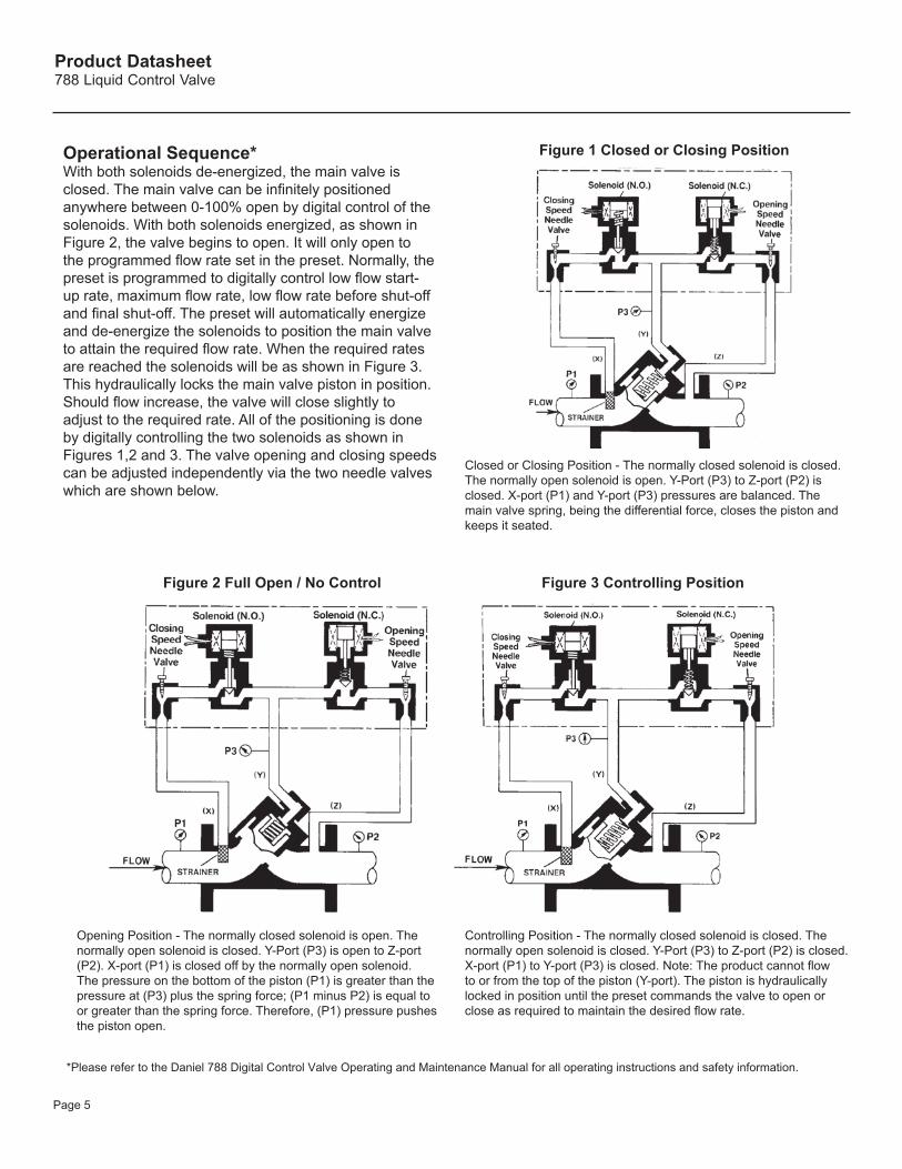
Operational Sequence*With both solenoids de-energized, the main valve isclosed. The main valve can be infinitely positioned anywhere between 0-100% open by digital control of the solenoids. With both solenoids energized, as shown in Figure 2, the valve begins to open. It will only open to the programmed flow rate set in the preset. Normally, the preset is programmed to digitally control low flow start-up rate, maximum flow rate, low flow rate before shut-off and final shut-off. The preset will automatically energize and de-energize the solenoids to position the main valve to attain the required flow rate. When the required rates are reached the solenoids will be as shown in Figure 3. This hydraulically locks the main valve piston in position. Should flow increase, the valve will close slightly to adjust to the required rate. All of the positioning is done by digitally controlling the two solenoids as shown in Figures 1,2 and 3. The valve opening and closing speeds can be adjusted independently via the two needle valves which are shown below.
Closed or Closing Position - The normally closed solenoid is closed. The normally open solenoid is open. Y-Port (P3) to Z-port (P2) is closed. X-port (P1) and Y-port (P3) pressures are balanced. The main valve spring, being the differential force, closes the piston and keeps it seated.
Figure 1 Closed or Closing Position
Figure 2 Full Open / No Control Figure 3 Controlling Position
Opening Position - The normally closed solenoid is open. The normally open solenoid is closed. Y-Port (P3) is open to Z-port (P2). X-port (P1) is closed off by the normally open solenoid. The pressure on the bottom of the piston (P1) is greater than the pressure at (P3) plus the spring force; (P1 minus P2) is equal to or greater than the spring force. Therefore, (P1) pressure pushes the piston open.
Controlling Position - The normally closed solenoid is closed. The normally open solenoid is closed. Y-Port (P3) to Z-port (P2) is closed. X-port (P1) to Y-port (P3) is closed. Note: The product cannot flow to or from the top of the piston (Y-port). The piston is hydraulically locked in position until the preset commands the valve to open or close as required to maintain the desired flow rate.
*Please refer to the Daniel 788 Digital Control Valve Operating and Maintenance Manual for all operating instructions and safety information.

Product Datasheet788 Liquid Control Valve
Page 6
Load Rack Installation with Daniel 788 Digital Control Valve for Ratio Blending
Typical ApplicationsThe most common application of the Daniel Model 788 Digital Control Valve is for truck loading. The figure below shows the Daniel 788 Digital Control Valve working with turbine meters and electronic preset to precisely control flow rates, batch quantities and blend ratio's of various products being loaded.
PRESET
Product Datasheet788 Liquid Control Valve
Page 7
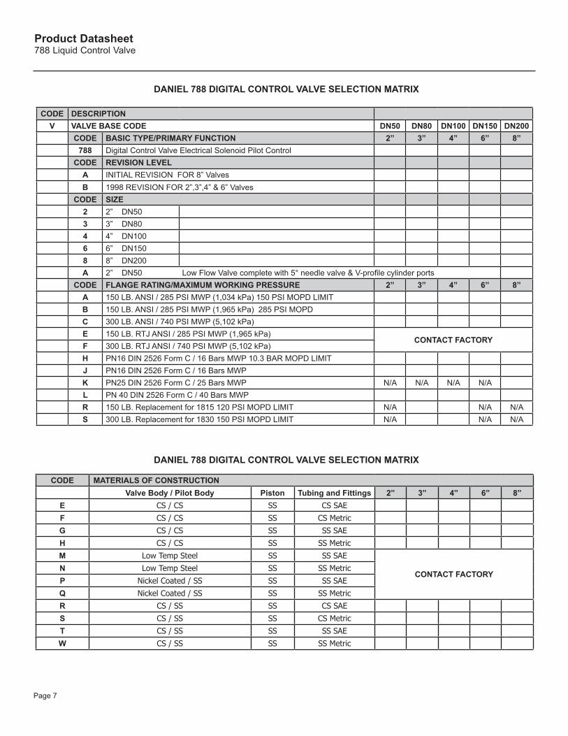
CODE DESCRIPTIONV VALVE BASE CODE DN50 DN80 DN100 DN150 DN200
CODE BASIC TYPE/PRIMARY FUNCTION 2” 3” 4” 6” 8”788 Digital Control Valve Electrical Solenoid Pilot Control
CODE REVISION LEVELA INITIAL REVISION FOR 8” ValvesB 1998 REVISION FOR 2”,3”,4” & 6” Valves
CODE SIZE2 2” DN503 3” DN804 4” DN1006 6” DN1508 8” DN200A 2” DN50 Low Flow Valve complete with 5° needle valve & V-profile cylinder ports
CODE FLANGE RATING/MAXIMUM WORKING PRESSURE 2” 3” 4” 6” 8”A 150 LB. ANSI / 285 PSI MWP (1,034 kPa) 150 PSI MOPD LIMITB 150 LB. ANSI / 285 PSI MWP (1,965 kPa) 285 PSI MOPDC 300 LB. ANSI / 740 PSI MWP (5,102 kPa)E 150 LB. RTJ ANSI / 285 PSI MWP (1,965 kPa)
CONTACT FACTORYF 300 LB. RTJ ANSI / 740 PSI MWP (5,102 kPa)H PN16 DIN 2526 Form C / 16 Bars MWP 10.3 BAR MOPD LIMITJ PN16 DIN 2526 Form C / 16 Bars MWP K PN25 DIN 2526 Form C / 25 Bars MWP N/A N/A N/A N/AL PN 40 DIN 2526 Form C / 40 Bars MWPR 150 LB. Replacement for 1815 120 PSI MOPD LIMIT N/A N/A N/AS 300 LB. Replacement for 1830 150 PSI MOPD LIMIT N/A N/A N/A
DANIEL 788 DIGITAL CONTROL VALVE SELECTION MATRIX
CODE MATERIALS OF CONSTRUCTIONValve Body / Pilot Body Piston Tubing and Fittings 2” 3” 4” 6” 8”
E CS / CS SS CS SAE
F CS / CS SS CS Metric
G CS / CS SS SS SAE
H CS / CS SS SS Metric
M Low Temp Steel SS SS SAE
CONTACT FACTORYN Low Temp Steel SS SS Metric
P Nickel Coated / SS SS SS SAE
Q Nickel Coated / SS SS SS Metric
R CS / SS SS CS SAE
S CS / SS SS CS Metric
T CS / SS SS SS SAE
W CS / SS SS SS Metric
DANIEL 788 DIGITAL CONTROL VALVE SELECTION MATRIX

Product Datasheet788 Liquid Control Valve
Page 8
CODE ELASTOMERS 2” 3” 4” 6” 8”2 All Viton® (for 150 PSI MOPD use option P)
3 All Viton® for LPG4 Main Valve: AP Model
Teflon® Dynamic/Low Swell Nitrile Static O-RingsPilot: Kalrez® Dynamic/Low Swell
Nitrile Static O-rings
788 Digital (150 PSI MOPD)788 Digital (285/740 PSI MOPD)
Use option N
5 Main Valve: AP ModelTeflon® Dynamic/Low Swell Nitrile Static O-RingsPilot: All Kalrez® O-rings
788 Digital (150 PSI MOPD)788 Digital (285/740 PSI MOPD)
Use option N
6 All EPRCONTACT FACTORY7 All Neoprene
8 All Nitrile9 AP Model Valve with All Teflon® Pilot O-
rings.788 Digital (MOPD: 135 PSI NC, 101 PSI NO) Use option M
A Standard Valve with All Viton® for LPG O-rings 788 Digital (150 PSI MOPD) Use option 3
B AP Model Valve with All Viton® Pilot O-rings.
K Standard Valve : Pilot with Teflon® Seats (120 PSI MOPD) N/A N/A N/A N/A N/A
L AP Valve: Pilot with Teflon® Seats (120 PSI MOPD) N/A N/A N/A N/A N/A
M Main Valve: AP ModelTeflon® Dynamic/Low Swell Nitrile Static O-RingsPilot: All Teflon® O-Rings
788 Digital (150 PSI MOPD)
N AP Valve: Pilot- all Kalrez® 788 Digital (150 PSI MOPD)
P Standard Valve: Pilot- all Viton® 788 Digital (150 PSI MOPD)
CODE FIRST PILOT VARIABLE - VOLTAGEA None
Voltage:1 6 Vdc N/A2 12 Vdc
3 24 Vdc
4 48 Vdc
5 110 Vdc N/A6 110/120 Vac
7 220/240 Vac
8 440/480 Vac

Product Datasheet788 Liquid Control Valve
Page 9
CODE SECOND FUNCTIONA NONE
CODE SECOND PILOT VARIABLE -SPRING RANGE OR VOLTAGEA NONE
CODE OPTIONSThermal
ReliefXYZ
BlockA None NoneC XD XQ X X
CODE OPTIONS POSITIONManual
OverrideCheckValve
VisualIndicator
Indicatorw/1 switch
Indicat. w2 switches 2” 3” 4” 6” 8”
A None None None None NoneB XC X XD X X N/AE X XF X XG X X X N/AH X X XJ X X XK XM X X N X XP X XQ X N/AR XS XT Pos. indicator complete with guard and no switch
CODE APPROVALSA NoneC Material Test Reports (Main valve pressure retaining parts only)D NACE with Material Test Reports (MTRs) (Main valve pressure retaining parts only)E UL/CSA Certified Electric ComponentG UL/CSA Certified Electric Component and MTRs (Main valve pressure retaining parts only)H UL/CSA Certified Electric Component and NACE with MTRs (Main valve pressure retaining parts only)
CENELEC APPROVALS NO LONGER AVAILABLE3 CE (ATEX ll 2G/D EEx em II T5-T3) 4 CE (EEx em ll) & MTRs5 CE (EEx em ll) NACE + MTR’s6 CE (ATEX ll 2G/D EEx d llC T6-T4)7 CE (EEx d ll) & MTRs8 CE (EEx d ll) NACE +& MTR’s
DANIEL 788 DIGITAL CONTROL VALVE SELECTION MATRIX

Product Datasheet788 Liquid Control Valve
Page 10
Ordering InformationWhen ordering, the following information must be supplied:
�� Size
�� Flange�connections
�� Product,�product�viscosity,�product�specific�gravity
�� Minimum�and�maximum�operating�temperature
�� Minimum�and�maximum�flow�rate
�� Minimum,�normal�and�maximum�operating�pressure
�� Control�functions�to�be�performed
�� O-ring�material
�� Control�pilot�materials
�� Tubing�material
�� Voltage�required

Product Datasheet788 Liquid Control Valve
Page 11
This page is intentionally blank.


©2012�Daniel�Measurement�and�Control,�Inc.��All�Rights�Reserved.��Unauthorized�duplication�in�whole�or�in�part�is�prohibited.��Printed�in�the�USA.�DAN-LIQ-DS-788-0212
Daniel�Measurement�and�Control,�Inc.�(“Daniel”)�is�an�Emerson�Process�Management�business�unit.�The�Daniel�name�and�logo�are�trademarks�of�Daniel�Industries,�Inc.�The�Emerson�logo�is�a�trademark�and�service�mark�of�Emerson�Electric�Co.�All�other�trademarks�are�the�property�of�their�respective�companies.��
Emerson Process Management
Daniel�Measurement�and�Control,�Inc.�North�America�/�Latin�America:�Headquarters�USA�-�Houston,�Texas�T�+1.713.467.6000�USA�Toll�Free�1.888.FLOW.001
www.Daniel.com
Europe:�Stirling,�Scotland,�UK� ���T�+44.1786.433400�
Middle�East,�Africa:�Dubai,�UAE�T�+971.4.811.8100�
Asia�Pacific:�Singapore� �T�+65.6777.8211