daniels laser cutter manual - university of toronto · approved materials: millboard, cardboard,...
TRANSCRIPT

Daniels Laser Cutter Manual
Laser Cutter Manual
Hours of Operation:Daytime:Monday to Friday: 10am - 5pm
After Hours:Monday to Friday: 5pm - 10pmSaturaday: 12pm - 5pm
Booking:Please book Daytime and Afterhours Nicholas, laser time may also be booked with Johnny.
Monitoring:During daytime hours the Fabrication technologist is availble, afterhours the Laser Cutting TA on duty will covers the laser cutters.
Pricing:Laser cutting is 10$ per half hour, students may sign up for a maximum of 1.5 hrs in a day. During peak periods there is a maximum sign up of three 1.5hr timeslots in one week. There are no refunds issued for missed sessions, please consider this at the time of booking.
Materials:Johnny sells various materials pre-cut to laser bed size, the price and materials list is located on the Daniels site under the laser cutting page.
Test:Everyone who uses the laser cutter must pass the mandatory test. If you passed it last year, please read this manual before using, or sit in on a tutorial as a refresher.Tutorials will be offered regularly. Watch for a schedule to be posted. There is a maximum of four students for each tutorial. The tutorials are about 2 hours long.

Laser Cutter Manual
WARNING:
The laser cutter is a potentially dangerous machine that needs to be treated with respect and supervised at all times.Approved materials: Millboard, cardboard, plexiglass, MDF, basswood.
Do not cut or engrave GLASS, METAL, FOAMCORE, ANYTHING TOXIC WHEN BURNED, OR LEXAN(Lexan is a plastic that resembles plexiglass and other clear plastics).
For everything else, ask Nicholas or the Laser Cutter TAs.If inappropriate materials are used, dangerous fumes may be produced (e.g., chlorine). If in doubt, ask Nicholas or the Laser Cutter TAs.
This document is an overview, and does not substitute for passing the test.Heed all advice in this manual. If you don’t and something goes wrong... you may be held responsible.
Table of Contents
1.0 The Equipment2.0 Laser Cutter Setup3.0 File Setup4.0 Final Steps5.0 Troubleshooting Guide6.0 Power and Speed Settings

Laser Cutter Manual 1.0 The Equipment
Window Exhaust FanMake sure this is running to extract air from the room.
Laser Cutter VentillationThis system also services lab next door and MUST BE ON when laser cutting. Failure to do so could result in a cracked lens - a new one costs $500.
East Laser Cutter
West Laser Cutter
The Set UpTHERE ARE FOUR THINGS TO TURN ON (or at least to make sure that they are ON.)
1. LIGHTS 2. LASER CUTTER 3. FILTRATION SYSTEM 4. COMPUTER
West Laser Cutter East Laser Cutter IMPORTANT: Always make sure the ventillation is on, the small green LED needs to be on, failure to do so can cause lens damage.

Laser Cutter Manual 2.0 Laser Cutter Setup
Laser Lid
Lens Housing
Control Panel
Laser BedFocus Stick Holster
APPROACH LASER CUTTING WITH CAUTION AND CARE, AND YOU SHOULD HAVE NO PROBLEMS
Place the focus stick (found to the left of the bed) on top of the material beneath the laser carriage.Notice that there is a notch on the stick—this should face the laser carriage.Press the up and down arrows to raise or lower the bed until the notch fits against the bottom of the laser head. It should fit snugly just at the point before it kicks out.The Z height settings will appear on the display: Z POSITION Z 0.075in. The cursor will be flashing on the first decimal place - in this case “5”. Hit the right key to move the cursor to the second decimal place. This will result in much smaller movements of the bed up and down that are easier to control.Once the focus stick is in its proper place return it back to its original place with the flat edge of the base lined up with the rail. It needs to be flat otherwise it can throw the housing off its rails. This requires Nicholas or the Laser TA’s assistance and could result in downtime of the machine.Press the Z button once more to return the laser head to its home. The control panel should say READY. ADJUST “Z” EVERY TIME YOU USE A NEW MATERIAL THICKNESS.
Correct Placement
Incorrect Placement
Once in Z height selection use the up down arrows to focus the z axis, left and right arrows allow for percision selction in z axis movement.
Before placing your material in the bed, press“Z”, adjust the height to allow your material to be placed in the bed.This is done before placing the material, in case the bed is too high.
Making sure that your material will fit under the nozzle, place it in the bed and TAPE IT DOWN FLAT. There is a lot of air flow in the machine, which can tend to lift the material off the bed.

Laser Cutter Manual 2.1 Laser Cutter SetupClose the lid and take a look at the display.
It will show a file name, and power and speed settings. To go to a previous or next file, use the UCP control on the computer to change files, they will display on the laser cutter display.Check your power and speed settings. They will be the ones for the first colour in the list that you’re using. The color order will be the sequence the laser cutter follow, the exception is a raster layer which will proceed the vector layer. When you are certain that everything is ready to go press start to begin.
TROUBLE SHOOTING TIP:If your power and speed settings read “00.0” and “0.0”, you have likely not set all lineweights to “0”and will have to go back to the AutoCAD file, and re-submit.Select all shapes and check the lineweight pull down menu. If it does not say go back to the line weight and change to “0.0”
MAKING YOUR LIFE EASIER TIPYou may want to open the lid and make sure that it’s cutting through, to tape the material down more, or to check on something. Before you do this, hit “PAUSE” to temporarily pause the cut.Once you’re finished checking, close the lid and hit “RESUME”.Opening the lid without hitting pause first will cancel the file, and you will have to start over.DO THIS ONLY IN AN EMERGENCY IF SOMETHING IS DRASTICALLY WRONG,OR MATERIALS HAVE CAUGHT FIRE.
Pause / UnpauseStart

Laser Cutter Manual 3.0 File Setup and Preparation [AutoCAD]The key to a good laser cutting experience is preparation. Making sure that you are comfortable using the equipment, and preparing your AutoCAD file for cutting are critical. You don’t have a lot of time in this room, so make it count.LaserTAs are not responsible for helping students learn to use AutoCADThings you can do at your computer beforehand:PREPARE YOUR SHAPES FOR CUTTING- draw shapes- scale shapesIt may take some math at the beginning, but in the long run it’s easiest. Scale your shapes so that you cut them at 1:1.Example: you’re building a model at 1:200, and your building would have a footprint of 10 m x 15 m. This would translate to 50 mm x 75 mm for your model. If you draw your shape at this size (or scale all of you shapes at once) you won’t have to mess with the scaling option come cutting time.
SET COLOURS BASED ON LASER CUTTER SETTINGSThe laser cutter uses the colour information to indicate what power and speed settings to use.Use basic autocad colours. Example: you have some shapes that you want to cut, and you want to score a pattern onto some of them. Change the colours of the “CUT” lines to GREEN for example, and the “SCORE” lines to RED. Setting up layers based on the cut order and color can help you move and change cut layer sequence quickly, it will also give more flexiblity to turn layers on and off.
SET LINEWEIGHTS TO “0.00 mm”Select all shapes and make sure that the lineweights are set to 0.
DRAW REFERENCE BOX (BED SIZE) - SEE TEMPLATES ON DANIELS SITEThe bed size to be used is 17.75” x 31.75” (or 450 mm x 806mm). Draw a box that size around your shapes to make sure that they will all fit in the laser bed. If you buy material from Johnny, he can cut it to bed size for you, always check you material size most sold material is 31.75’’ by 17.75’’. Otherwise, cut it yourself...preferably at your cutting table...before you get to the laser cutting room.If your material is smaller than bed size, draw a second box the size of your piece of material tomake sure that your shapes fit. Always double check your material size to make sure your work will fit within the material.
TIPSDon’t use splines. They don’t cut so well. Explode all blocks. Don’t try and cut 3D shapes; make sure all points are on the XY plane. Make sure there are no duplicate lines.
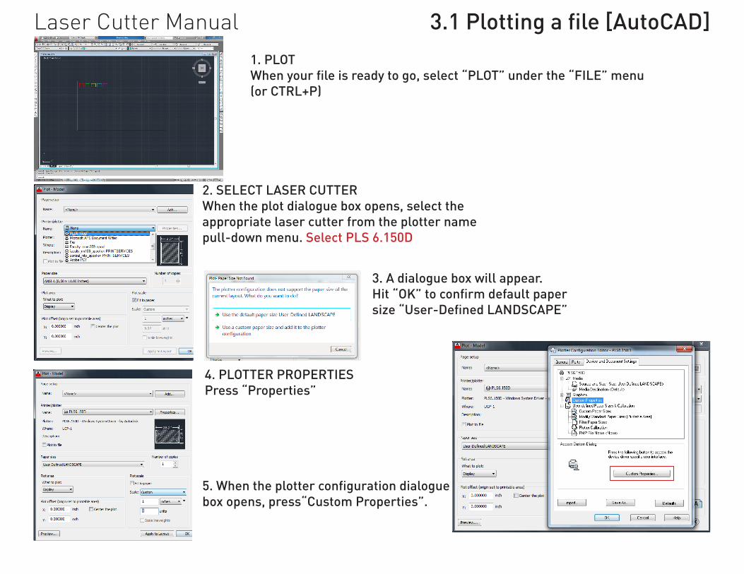
Laser Cutter Manual 3.1Plottingafile[AutoCAD]1. PLOTWhenyourfileisreadytogo,select“PLOT”underthe“FILE”menu(or CTRL+P)
2. SELECT LASER CUTTERWhen the plot dialogue box opens, select the appropriate laser cutter from the plotter name pull-down menu. Select PLS 6.150D
3. A dialogue box will appear.Hit“OK”toconfirmdefaultpapersize“User-DefinedLANDSCAPE”
4. PLOTTER PROPERTIESPress “Properties”
5.Whentheplotterconfigurationdialoguebox opens, press“Custom Properties”.

Laser Cutter Manual 3.2 Laser Cutter PropertiesFor each of the
colours that you are using, toggle the Mode
drop down and select the option “VECT” .
Set all other colours to “SKIP”.
Air Assist.This is CRITICAL.ALWAYS make sure that this is ON for all of the colours - even the colors not set to cut.Set the Flow drop down menu to “Air”. The Flow Rate should be always set to 100%.
Pen ModeFor each of the colours that you are using, toggle the drop down menu and select “VECT” Set all other colours to “SKIP”.
In the Laser Cutter Properties dilogue box there are several things to be changed.
For each of the colours to be used, set the following:- Pen Mode- Air Assist- Power and speed settings.(instructions on next page)
To make it easier on yourself, you can create a settings file that will be saved to your network account for use in the future.Choose a name related to thematerial used, such as “Model_ 1_4_inch_basswood”. You can load these settings again for your next cut file, or sometime down the road.
For each of the colours to be used, take the following steps to set power and speed:1- select row2- set speed and power using scroll bar, or type it in.3 - Hit “Set” otherwise, settings will revert to previous.PPI settings do not typically need to be changed. 500 ppi works in most situations. Occasionally, when cutting plexiglass at a fairly high speed, the cut may have a jagged edge. This can sometimes be alleviated by upping the ppi to 1000.
Before exiting this dialogue box, take a final look to make sure that the settings are correct, and that AIR FLOW IS ON.
Make sure Z Axis is turned off and have your drawing flattened to the C Plane, otherwise object may get omitted.
Always make sure Laser is set to Both, this is crucial as cutting power will not be full if not set to BOTH!

Laser Cutter Manual 3.3 Plotting a File [AutoCAD]
Back at the Properties dialogue box, select “ok”.You will be asked to either create a temporary PC3 file or to ‘save changes to the following file.Click on the save changes option’ and select “ok”.“Save changes” will keep the settings of the last cut file. This should be used if you have several files that have the same layer system and same material.Now back in the Plot dialogue box, make sure that you can see all Options, or hit the little arrow in the bottom right corner.
There are four things to change in this window:1. drawing orientation2. scale3. origin4. what to plot(make sure Plot style table is set to “None” not “Monochrome”)a. Plot Offset = 0 for both x and yb. Scale = 1:1 in mm (or inches, depending on your drawing units)c. Drawing orientation = LANDSCAPEd. What to plot?Select “Window” which will bring you back to your drawing where you will be asked to select “first corner”. Select the upper left corner of the BED SIZED rectangle. When asked for the second corner, select the bottom right corner of the bed sized rectangle.A
B
C
D

PLOT PREVIEW:This is your last chance to make sure that your scaling is correct, and that everything looks ok.The black line around the left and bottom edges of the “paper” appears because the bed is ACTUALLY a bit bigger than we say it is. (This extra tolerance is needed to ensure that the bed is not damaged.)You are now ready to send your plot file!
PLOT PREVIEW:
You can do this in a few ways:- click the printer iconOR, - right click and select “Plot”OR, - hit ESC and then plot fromdialogue box.If something is wrong, and you’renot ready to plot, hit ESC toreturn to the plot dialogue box.
Laser Cutter Manual 3.3 Plotting a File [AutoCAD]

Laser Cutter Manual 3.4Plottingafile[Rhinoceros]
PrintWhen your file is ready to go, select “Print” under the “FILE” menu or press the printer icon. (or CTRL+P) or type print into the command line. This will bring up the printing dialog box.
The same steps taken in 3.0 file set up and preparation are applicable to printing from Rhinoceros. When Printing from Rhinoceros make sure all you linework is flattened to the z plane. You can project your line work to the c plane by typing “ProjectToCPlane” when asked to delete input objects type y and enter.
Set the line type in Rhinoceros to Continuous and the Print width to Hairline. This is required to plot to the laser cutter.
The line weigths can also be changed by pressing each line and selecting hairline or by highlighting your linework and under the properties tab select the print width tab and set to hairline.

Select the PLS6.15D from the print driver selection, set to user defined lan-scape. Make sure page orientation is set to Landscape.
Set the Output type to “Vector Output” and set the Output Color to “Print Color”
Set the Viewoutput and scale to top, this should already be set. Set the window to the plotting boundary (31.75’’ by 17.75’’) or 806mm by 450mm. Press “Set” to define the plotting boundary, when the boundary has been set press “No” to Change Scale to Fit Window Area.
Set the scale at 1:1, always scale your work before lasercutting. Attempting to scale with the driver can lead to less then desired results. It is always recommended to scale prior to laser cutting.
Once the file prep is done press “Properties” to activate the Laser Settings dialog page for the PLS6.15D. The Same printer setting dialog will appear as when printing from AutoCAD. Create your setting and press ok, remeber as in AutoCAD to have the flow set to “Air” and Flow Rate to “100%”. once set press ok
Laser Cutter Manual 3.5Plottingafile[Rhinoceros]
Once all the setting are established press print to plot the laser file to the UCS Controller.

Laser Cutter Manual 3.4 Universal Control Panel
The Universal Control Panel can be lauched from the desktop Icon after a file has been plotted from AutoCAD or Rhinoceros
The Univercal Control Panel can also be launched from the notifications bar once a file has been plotted from AutoCAD or Rhinoceros.
The Universal Control Panel allows for files to be started, paused and timed from the computer. Files can also be started from the control panel on the laser cutter. All plotted files can be viewed in the control panel, listed in order from most recently plotted. The UCP is a visual interface to the laser cutter.

Laser Cutter Manual 3.4 Universal Control PanelFiles are listed in order of plot, you can scroll through previous files and and resend. The UCP gives a visual interface to the plots sent from autocad to the laser cutter. The arrows will advance to previous or recent plots.
The laser cutter can be paused and started from this panel. This can also be done at the laser cutter control panel. The pause button will turn red once the laser cutter has been paused.To unpause the pause button must be pressed, not the play button.
The time estimator allows for quick simulation of the laser cutting plot. The simulations are accurate and the timer in the top right corner of the UCP will count down the current job.
The time estimator button, activates the time estimator.
The current file being displayed
You can double check you plotted power and speed settings of the current show file by clicking on settings, this will lauch the power and speed setting interface.

Laser Cutter Manual 4.0 Final Steps
PROTECTING YOURSELF AND THE MACHINE TIPIf there is a noticeable decrease in cutting efficiency between boards, or if settings that cut thorugh evenly are barely even scoring the surface PAUSE THE MACHINE (or STOP it - depending on the urgency) and speak with Nicholas or Laser TA on duty.This could be a sign of a dirty or damaged lens.
Once you file has been cut, tape down your work, this will help you keep track of your cut shapes and will prevent work from falling into the laser honeycomb bed.
ALWAYS CLEAN UP AFTER YOURSELF AND TAKE ANY DRIVES/USB KEYS INSERTED INTO THE COMPUTERS.

Problem
Print preview does not look right.
Power & Speed Settings read as “0” on display. Raster / Pen Data is Empty Error.
Cutting odd or extra shapes, or going back over the same lines.
Not Cutting through.
Burning
Possible Cause
- Scaling problem. Go back and check that scale is correct.- page orientation, x/y offset or other. Hit ESC from preview and check.- plot style settings set to “Monochrome”. Hit ESC from preview and check. Change to “None”.
- Lineweights not set to “0”. FIx, and re-send the plot.
- Cutting odd or extra shapes, or going back over the same lines.Splines, blocks, 3d shapes, or double lines. Go back to AutoCAD file and check. Fix as required.
- Incorrect power & speed settings- z-height improperly set- air assist not on. Stop immediately and fix. Also contact: Nicholas (during the day) or on-duty Laser TA (after hours) so that they can check the lens.- something more serious - Stop immediately and contact: Nicholas (during the day)or on-duty Laser TA (after hours)
- Incorrect power & speed settings- z-height improperly set- gas assist not on. Stop immediately and fix. Also contact: Nicholas (during the day) or on-duty Laser TA (after hours) so that they can check the lens.- something more serious - Stop immediately and contact: Nicholas (during the day) or on-duty Laser TA (after hours)
Laser Cutter Manual 5.0 Trouble Shooting Guide

Laser Cutter Manual