darpa scenario discussion fia-np pi meeting, nov 19,20 ...€¦ · darpa scenario discussion fia-np...
TRANSCRIPT

DARPA Scenario Discussion FIA-NP PI Meeting, Nov 19,20
Arlington, VA
MobilityFirst Project Team Contact: [email protected]

General Scenario
2
Internet Disrupted backbone
Area of deployment: multiple active players: mobile users (vehicles, robots, humans, etc.), data mules, numerous sensor types. Temporary Data and compute and UAV can be deployed in limited quantities. Inter area communications are limited to parent command center.
Command centers: connected through reliable backbone (initially SATCOM, later relay towers or aerostats). Provide computing and storage resources.
Unavailable cellular access
TDS = Temporary Data Store UAV = Unmanned Aerial Vehicle
Limited resources
TDS
Limited resources
Mobile Users
Data Mules
Sensors
UAV
Designated area of deployment
Command Centers

Relevance of MobilityFirst Architecture to DARPA Scenario
• MF architecture explicitly aimed at robustness, disconnection, security, mobility (both networks and devices), and is thus responsive to emergency response/tactical net scenarios
• Storage-aware ad-hoc and DTN with routing protocols serve as foundation for MF networks (R3, CNF)
• New routing abstractions enable expression of the properties of mobile/wireless links, access networks
• Native support for multicast at routing layer (…key to efficient group communication)
• Segmented (hop-by-hop ) transport (Hop, MFTP)

Relevance of MobilityFirst Architecture to DARPA Scenario (cont.)
• New “self-certifying named object” (GUID) service layer + secure routing plane narrow waist of MF! – Mobility & disconnection support common case (..late binding)
• Flexible, secure naming using GUIDs: interface, device, content, service, or (recursively) groups thereof
• Context-based group communication, e.g., “send msg to emergency personnel near Times Square”
• QoE mechanisms including SID (service ID) and virtual net (VN) with application-aware priority routing
• Optional compute layer for in-network services

Network Setup & Restoration

Stage 1: Local Discovery and Regional Routing Bootstrap
GUID1 GUID2 GUID2 …
GUID in link layer
bootstrap
GUID1 …
Link probe broadcast
GUID1 Neighbor info
GUID1 Neighbor info
Link state update
Merging of MANET and DTN
Local Command Center
MF GSTAR Intra-domain Routing

Stage 2: Regional Name Resolution Bootstrap
GNRS 1 GNRS 2
1. No connection
GNRS 1,2
2. Link established
GNRS 1,2
GNRS 1,2,3
GNRS 1,2,3
Local GNRS
3. Local command center established
4. Local GNRS delegated to local command center
Local NCS Name certification
service

Stage 3: Build Out Global Network
Inter-Domain Protocol Exchange (e.g. EIR NSP)
GW Router
EIR Agent
Net A
Net B
Net C

DHT based Global Name
Resolution Service
Stage 4: Global Name Resolution Bootstrap
EIR Agent
GNRS Agent
GNRS Agent
GNRS Agent
DHT-based peering
Net A
Net B
Net C

DHT based Global Name
Resolution Service
Stage 5: Establish Computing & Content Delivery Services
EIR Agent
GNRS Agent
GNRS Agent
GNRS Agent
DHT
Net A
Net B
Net C
Content Service (access via Content GUID Lookup in GNRS)
Naming Service
Cloud Service (access via Service GUID Lookup in GNRS)

Challenges and Questions

1a. Network Topology Control
Removing links • In the disaster, access points like hospitals,
shelters might face high # of links. • This should be avoided by reducing # of
links via ad hoc topology control algorithms
Adding links • Extra (temporal) links should be added to
the less-connected areas – satellites, UAVs and vehicles with WiFi functionalities can be used as links
Isolated areas

1b. Disrupted Network Routing (Intra-domain) Three distinct MF mechanisms: storage, late binding and DTN
Connectivity
Wired Wireless Ad-hoc DTN
2
3
1
A
B
4
5
Mules
Dest Next Hop SETT LETT
2 2 13332 13332
3 3 66666 66666
Dest Next Hop Availability
4 2 0.44
5 3 0.6
Long
term
link
qua
lity
Short term link quality
Stable
Forward
Store GSTAR Forwarding
Intra-partition table Inter-partition table
Data mules as routers

aNodeA <bandwidth,latency, availability,…> aNodeB
aNodeA<bandwidth,latency, availability,…> aNodeD
1b. Disrupted Network Routing (Inter-domain) EIR Routing provides abstractions for satellite mcast, data mules, ..
Network A Network B Network C
(Command Center)
Data mule as a virtual link
aNode A
aNode B aNode C
Aggregation nodes (aNodes) and virtual links (vLinks) as abstractions to express inter-domain topology
Topology does not change with
mobility
aNode D
vLink characteristics of data mule
Network state packet of network A
vLink characteristics of the satellite link

dst. movement
1.b. Hop-by-hop forwarding with disruption tolerant transport layer
15
1. infrastructure based connection is down
2. data transmitted when connection is available
3. no connection to dst triggers a storage event
4. transport layer periodically retry sending data; succeeds when conn. becomes available
MF proxy router
GNRS
Chunk stored due to disconn.
late binding of NA data
delivered to new location
Regular storage service for mobility
Storage service in DTN scenario
segment-wise reliability

1c. Dynamic Storage and Computation in MF
16
TDS
GUID NA
Data Service X A, B
Service Y A, B
Global Name Resolution Service
OTA link Satellite down-link Satellite up-link
Inherently multicast
push(sensor data, Data-Service Y, MCAST)
Network A Network B
Src: Sn
Dest: Serv. Y
SID : 0x1E
Data:<Ln, Rn> Pluggable compute layer
Src: S1
Dest: Serv. Y
SID : 0x1E
Data:<Ln, Rn> Src: S1,…
Dest: Serv. Y
SID : 0x1E
Data:<Lavg, Ravg>

2a. Data Discovery and Distributed Storage Named Content Caching & Retrieval in MF
Network A Network B
Network C (Command Center)
Content Med
GUID NA
Data Service X A, B
Content Med C
Global Name Resolution Service
Mobile Users
push(Content Med, MCAST)
Content Med
A,B,C
Content Med
get(Content Med, ANYCAST) send(Content Med)
Content cached at local sites
Updated GNRS

2b. Security Toolbox in MF • No single root of trust:
– We want to move away from the single root of trust (c.f. ICANN) – This gives a decentralized model of trust, e.g. each country manages its
own NCS, or one can shop around for the NCS that meets their needs • Self-authenticating names
– Public key cryptography provides the ability to prove ownership of the address if the public key is associated with the address
• Apply access control to information that could facilitate attacks • Intentional receipt: recipients should be able to specify what reaches it
– Support intrusion detection and prevention • Disruption tolerance as a means to withstand “broken” or “being damaged”
parts of the network • Understanding the applications that run on top of the network
– Network traffic as a signature for intrusions and bad traffic

2b. Two-Tier Name Resolution: GUIDs, NCS, GNRS
[19]
Network Entity’s Three Attributes:
- User-level descriptor - Network-level identifier - Routable Topological address
Two Core Services: - Name Certificate & Resolution Service (NCRS) - Global Name Resolution Service (GNRS)

2b. GNS: Decoupling certification and resolution
Nam
e: “A
lice’
s ph
one”
TLD name services
Auth. name services
Root name service (ICANN, US. Dept. of Commerce)
Certificate search services
GUID=X, GN
S=Auspice Domain name system Global name system
3
3
4
4 1
0 Local name services
1
Local name services
2 Name certification services
Managed DNS services
MobilityFirst global name services
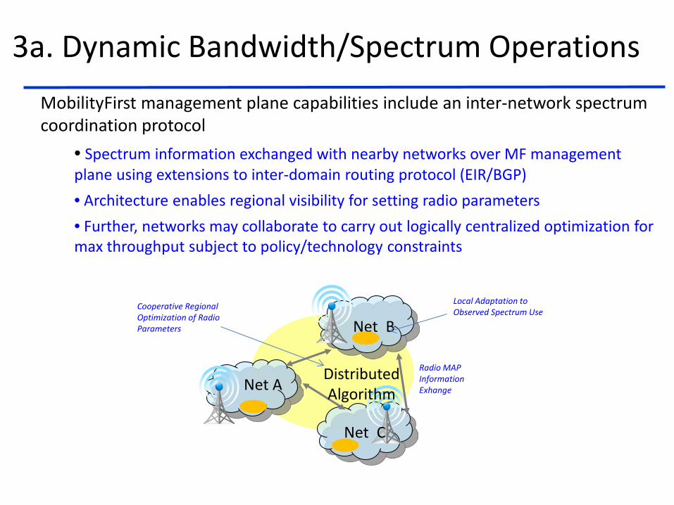
3a. Dynamic Bandwidth/Spectrum Operations
Net A
Net B
Net C
Distributed Algorithm
Radio MAP Information Exhange
MobilityFirst management plane capabilities include an inter-network spectrum coordination protocol
• Spectrum information exchanged with nearby networks over MF management plane using extensions to inter-domain routing protocol (EIR/BGP) • Architecture enables regional visibility for setting radio parameters • Further, networks may collaborate to carry out logically centralized optimization for max throughput subject to policy/technology constraints
Local Adaptation to Observed Spectrum Use Cooperative Regional
Optimization of Radio Parameters

WINLAB
3a. Dynamic Bandwidth/Spectrum Operations (cont.) Distributed Spectrum Algorithms Enabled by MF Mgmt Plane
Non-adaptive parameter selection (NAPS) Explicit query-response only on initialization Intended for low-cost devices with simple radios
Adaptive Parameter Selection (APS) Initialization procedure same as NAPS Additional periodic spectrum usage updates provided by its radio neighbors
Global Coordinated Resource Packing (GCRP) Algorithm aims to maximize network capacity subject
to fairness or other constraints Involves iterative logically centralized algorithm for optimal resource packing between co-existing networks

4a. QoS/QoE Capabilities: Service ID (SID) and Virtual Net (VN) features in MF
23
Network A Network B Network C
Network D
Src: Network C
…
SID4, SID5
Src: Network C
…
SID4, SID5
Src: Network D
…
SID5
Src: Network C
…
SID5
Src: Network C
…
SID4, SID5 Src: Network B
…
SID4
… SID4 Data
… SID5 Data
Network state packets Telescopic flooding
Data packet expressing user priority through SID
GNRS Service Plane GUID Locator VN Type
VNID_1 VR1, VR2, … Yes
VR1 Network A Yes
VR5 Network D Yes
VR1 VR2
VR5
• Virtual network for medical needs
• Application specific routing based on QoS guarantees